JP7586800B2 - Apparatus and method for determining the state of solid-liquid separation - Google Patents
Apparatus and method for determining the state of solid-liquid separation Download PDFInfo
- Publication number
- JP7586800B2 JP7586800B2 JP2021164349A JP2021164349A JP7586800B2 JP 7586800 B2 JP7586800 B2 JP 7586800B2 JP 2021164349 A JP2021164349 A JP 2021164349A JP 2021164349 A JP2021164349 A JP 2021164349A JP 7586800 B2 JP7586800 B2 JP 7586800B2
- Authority
- JP
- Japan
- Prior art keywords
- separated water
- solid
- liquid separation
- flocculant
- gutter
- Prior art date
- Legal status (The legal status is an assumption and is not a legal conclusion. Google has not performed a legal analysis and makes no representation as to the accuracy of the status listed.)
- Active
Links
Images


Landscapes
- Image Analysis (AREA)
- Treatment Of Sludge (AREA)
Description
本発明は、凝集剤を用いて固液分離する際に、当該凝集剤の量が適正であるか否かを判別する固液分離の状態判別装置及び固液分離の状態判別方法に関するものである。 The present invention relates to a solid-liquid separation state determination device and a solid-liquid separation state determination method that determine whether the amount of flocculant is appropriate when performing solid-liquid separation using a flocculant.
従来、汚泥やスラリーなどの懸濁液を濁質と液体とに分離させる固液分離装置や、油分を含む排水を油分と水分とに分離させる油水分離装置が使用されている。 Conventionally, solid-liquid separators have been used to separate suspensions such as sludge and slurry into turbid matter and liquid, and oil-water separators have been used to separate wastewater containing oil into oil and water.
これら固液分離装置や油水分離装置においては、懸濁液や排水などの被処理水に凝集剤を添加することによって凝集フロックを形成させて固形物と分離水を分離することが行われるため、添加する凝集剤の適正量を管理することは、設備の安定運転やコスト最適化の観点から重要である。その際、処理対象となる汚泥、スラリー、排水などの被処理水中の懸濁物質や油脂の濃度やその他排水の性状は経時的に変動するため、適正な凝集剤の量を適時で把握する必要がある。 In these solid-liquid and oil-water separation devices, a coagulant is added to the water being treated, such as a suspension or wastewater, to form coagulated flocs and separate the solids from the separated water. Therefore, managing the appropriate amount of coagulant added is important from the perspective of stable operation of the equipment and cost optimization. In this case, the concentration of suspended solids and oils in the water being treated, such as sludge, slurry, and wastewater, as well as other wastewater properties, fluctuate over time, so it is necessary to know the appropriate amount of coagulant in a timely manner.
特許文献1と特許文献2には、凝集剤を添加して懸濁物質を凝集させた凝集フロックを含む汚泥(原液)の一部を汚泥処理から迂回させて、凝集状態が視認可能な検視窓を有する検視装置に導き、この検視装置によって凝集フロックの状態を撮影して汚泥中の凝集フロックの割合を画像解析により判別し、適正な凝集剤の添加量となるように制御することが開示されている。
また特許文献3には、加圧浮上法による固液分離を行う際に、被処理水に凝集剤を注入して懸濁物質を凝集フロックとした凝集反応装置部分、あるいは凝集フロックに気泡を付着させて浮上させた浮上分離装置部分を撮影して画像解析により被処理水の水質の状態を判断する方法が開示されている。 Patent Document 3 also discloses a method for determining the quality of the water being treated by photographing the part of the flocculation reaction device in which a flocculant is injected into the water being treated to turn suspended matter into flocs, or the part of the flotation separation device in which air bubbles are attached to the flocs to make them float, when performing solid-liquid separation using the pressurized flotation method, and analyzing the images.
上記特許文献1~3には、上述のように、凝集フロックを含む汚泥、即ち被処理水を撮影して監視することで適正な凝集剤の添加量を把握する方法が開示されているが、当該凝集フロックを含む汚泥を撮影した見た目の判別だけではその後の固液分離工程での当該凝集フロックの影響度合いが分からない場合があるため、適正な凝集剤の添加量を把握できない虞があった。即ち例えば、見た目では凝集フロックの凝集状態が良好であっても、通常よりも弾力のない凝集フロックが生成されているような場合は、固液分離工程で上手く固液分離ができない場合などがあった。
As mentioned above,
そこで本願発明者は、固液分離後の分離水の状態を判別する方法について検討した。この方法によれば、分離水中に残った凝集フロックの量を測定することで、固液分離工程での固液分離が良好であったか否かを容易に判別することができる。しかし、固液分離後の分離水を直接監視することは、以下の点で困難であった。 The inventors of the present application therefore investigated a method for determining the state of the separated water after solid-liquid separation. With this method, it is possible to easily determine whether or not solid-liquid separation was successful in the solid-liquid separation process by measuring the amount of aggregated flocs remaining in the separated water. However, it was difficult to directly monitor the separated water after solid-liquid separation for the following reasons:
(1)固液分離装置によって分離した後の分離水は発泡していることが多く、このためこの分離水を溜めておく分離水水槽の水面をその上方から撮影する場合、泡が邪魔をして分離水の状態が上手く撮影できない。 (1) The separated water that has been separated by the solid-liquid separator is often foamy. For this reason, when photographing the surface of the separated water tank that holds the separated water from above, the foam gets in the way and it is difficult to get a good picture of the state of the separated water.
(2)上記泡を避けるなどの理由で、濁質計などのセンサーを分離水中に水没させて分離水の状態を監視しようとする場合、特に高分子凝集剤を使用すると、当該センサー部分に凝集フロックが付着することがあるため、当該付着を除去する必要が生じるなどメンテナンス性が悪いばかりか、当該センサーによって測定ができたとしても信頼できるデータの取得が一時的になる虞があった。この問題は水没させたカメラによって撮影を行う場合も同様に生じ、継続的に撮影することは困難であった。 (2) When attempting to monitor the state of the separated water by submerging a sensor such as a turbidity meter in the separated water to avoid the above-mentioned bubbles, particularly when using a polymer flocculant, flocs may adhere to the sensor, making it necessary to remove the adhesions, and not only is this difficult to maintain, but even if the sensor can make measurements, there is a risk that reliable data will only be obtained temporarily. This problem also occurs when taking pictures using a submerged camera, making it difficult to take pictures continuously.
本発明は上述の点に鑑みてなされたものでありその目的は、凝集剤の適正な添加量を高い精度で把握することができる固液分離の状態判別装置及び固液分離の状態判別方法を提供することにある。 The present invention has been made in consideration of the above points, and its purpose is to provide a solid-liquid separation state determination device and a solid-liquid separation state determination method that can determine the appropriate amount of flocculant to be added with high accuracy.
本発明にかかる固液分離の状態判別装置は、被処理水中に凝集剤を添加して凝集した懸濁物質を分離し分離水を得る固液分離手段と、前記固液分離手段によって得られた分離水で発生した気泡を、当該分離水を移送する流路の過程で分離する気泡分離手段と、前記流路中の気泡が分離された分離水を滞留させる分離水滞留手段と、前記分離水滞留手段による分離水の滞留部分を撮影し、画像情報を得る撮像手段と、前記画像情報に基づいて、前記凝集剤の過不足を判別する判別手段と、を有し、前記気泡分離手段は、傾斜して設置され、前記分離水を流下させる流路中で前記気泡を当該分離水から分離する樋を具備して構成され、前記分離水滞留手段による分離水の滞留部分は、前記樋の途中において当該樋を流れる分離水が撹拌流速を維持した状態で滞留する部分であることを特徴としている。
上記固液分離手段には、汚泥やスラリーなどの懸濁液を濁質と液体とに分離させる固液分離手段の他、油分を含む排水を油分と水分とに分離させる固液分離手段も含む。
前記判別手段による凝集剤の過不足の判別結果に基づいて、当該判別結果をリアルタイムに運転管理者にアナウンスしたり、あるいは適正量になるように下記する凝集剤添加量制御手段を用いて固液分離手段にフィードバック制御したりする。また手動によって添加する凝集剤の量を制御しても良い。
本発明によれば、固液分離手段によって懸濁物質、即ち凝集フロックなどを分離した後の分離水中に残った懸濁物質の状態を測定するので、当該固液分離手段での懸濁物質の固液分離が良好に行われたか否かを直接判断できて凝集剤の過不足を正確に判別でき、これによって凝集剤の適正な添加量を高精度に把握することができる。
また上述のように、固液分離手段によって懸濁物質を分離した後の分離水は発泡していることが多いが、本発明によれば、気泡分離手段によって気泡を分離するので、分離水の状態を画像情報から正確に判別することができる。
さらに本発明によれば、気泡が分離された状態の分離水を、分離水滞留手段によって流路の過程で一時滞留させた状態とするので、撮像手段が当該滞留部分を撮像することで、緩やかな流れとなっている分離水を撮像でき、より正確に分離水の状態を判別することができる。
The solid-liquid separation state determination device of the present invention comprises solid-liquid separation means for adding a coagulant to the water to be treated to separate the coagulated suspended matter and obtain separated water, air bubble separation means for separating air bubbles generated in the separated water obtained by the solid-liquid separation means during the course of the flow path through which the separated water is transported, separated water retention means for retaining the separated water from which the air bubbles have been separated in the flow path, imaging means for photographing the portion of the separated water retained by the separated water retention means and obtaining image information, and determination means for determining whether the coagulant is insufficient or excess based on the image information , wherein the air bubble separation means is configured to be installed at an angle and to include a gutter that separates the air bubbles from the separated water in the flow path through which the separated water flows downward, and the portion of the separated water retained by the separated water retention means is a portion midway through the gutter where the separated water flowing through the gutter retains while maintaining a stirring flow velocity .
The solid-liquid separation means includes a solid-liquid separation means for separating a suspension such as sludge or slurry into a turbid matter and a liquid, as well as a solid-liquid separation means for separating wastewater containing oil into an oil and a water component.
Based on the result of the determination of whether the flocculant is insufficient or excessive, the determination result is announced to the operation manager in real time, or the amount of flocculant added is fed back to the solid-liquid separation means by using the flocculant addition amount control means described below so that the amount is an appropriate amount. The amount of flocculant added may also be manually controlled.
According to the present invention, the state of the suspended matter remaining in the separated water after the suspended matter, i.e., flocs and the like, has been separated by the solid-liquid separation means is measured, so that it is possible to directly judge whether the solid-liquid separation of the suspended matter has been performed satisfactorily by the solid-liquid separation means and accurately determine whether there is an excess or deficiency of flocculant, thereby making it possible to grasp with high precision the appropriate amount of flocculant to be added.
As described above, the separated water obtained after separation of suspended matter by the solid-liquid separation means often contains bubbles. However, according to the present invention, the bubbles are separated by the bubble separation means, so that the state of the separated water can be accurately determined from the image information.
Furthermore, according to the present invention, the separated water from which the air bubbles have been separated is temporarily retained in the course of the flow path by the separated water retention means, so that the imaging means can image the retained portion, thereby capturing an image of the separated water flowing gently, and the state of the separated water can be determined more accurately.
また本発明によれば、固液分離手段によって懸濁物質が分離される過程で発泡した分離水を、樋の上に流下させることで、流下の途中に気泡を大気中にスムーズに放出でき、容易且つ効率よく分離水から気泡を分離することができる。 Furthermore , according to the present invention, the separated water that has foamed during the process of separating suspended matter by the solid-liquid separation means is allowed to flow down the gutter, whereby air bubbles can be smoothly released into the atmosphere as it flows down, making it possible to easily and efficiently separate air bubbles from the separated water.
また本発明によれば、滞留部分における分離水が撹拌流速を維持するので、当該滞留部分に懸濁物質が堆積したり浮上して覆ったりすることなく混合、分散されるため、流下してくる分離水の状態を連続して精度よく判別することができる。 Furthermore , according to the present invention, the separated water in the stagnant portion maintains its stirring flow rate, so that suspended matter is mixed and dispersed without accumulating in the stagnant portion or floating up to cover it, and therefore the condition of the separated water flowing down can be continuously and accurately determined.
また本発明は、上記特徴に加え、前記分離水滞留手段は、前記樋の途中に設置されて当該樋を流れる分離水を撹拌流速を維持した状態で滞留させる堰を具備して構成されていることを特徴としている。
本発明によれば、分離水の滞留部分を簡単な構造で構成することができる。
In addition to the above-mentioned features, the present invention is characterized in that the separated water retention means is configured to include a weir installed midway along the gutter to retain the separated water flowing through the gutter while maintaining the agitated flow rate.
According to the present invention, the portion where the separated water remains can be constructed with a simple structure.
また本発明は、上記特徴に加え、前記気泡分離手段の上流側において、前記分離水に消泡剤を注入する消泡剤注入手段を有することを特徴としている。
本発明によれば、気泡分離手段によって気泡を分離する前に、消泡剤を注入するので、より効果的に分離水から気泡を除去でき、分離水の状態をより正確に判別することができ、監視することができる。
In addition to the above features, the present invention is characterized in that it further comprises an antifoaming agent injection means for injecting an antifoaming agent into the separated water upstream of the air bubble separating means.
According to the present invention, an antifoaming agent is injected before the air bubbles are separated by the air bubble separating means, so that the air bubbles can be more effectively removed from the separated water, and the state of the separated water can be more accurately determined and monitored.
また本発明は、上記特徴に加え、前記判別手段による凝集剤の過不足の判別結果に基づいて、前記被処理水に添加される凝集剤の適正量を制御する凝集剤添加量制御手段を有することを特徴としている。
これによって、凝集剤の添加量を適正なものにすることができる。
In addition to the above-mentioned features, the present invention is characterized in that it has a flocculant addition amount control means for controlling the appropriate amount of flocculant to be added to the treated water based on the result of the determination by the determination means as to whether the flocculant is insufficient or excess.
This allows the amount of flocculant to be adjusted appropriately.
また本発明は、上記特徴に加え、前記気泡分離手段及び分離水滞留手段に付着する懸濁物質を洗浄液によって洗浄する洗浄機構を設置することを特徴としている。
これによって、気泡分離手段及び分離水滞留手段を常に懸濁物質が付着・堆積しない良好な状態としておくことができる。
In addition to the above features, the present invention is characterized in that a washing mechanism is provided for washing suspended solids adhering to the air bubble separating means and the separated water retaining means with a washing liquid.
This makes it possible to always keep the air bubble separating means and the separated water retaining means in a good condition with no adhesion or accumulation of suspended solids.
また本発明は、上記特徴に加え、前記分離水を前記気泡分離手段に供給する供給量を調節する分離水流量調整手段を有することを特徴としている。
分離水流量調整手段としては、例えばインバーター制御によるポンプを用いる。
これによって、分離水中に残った懸濁物質の状態を測定するのに適した量の分離水を気泡分離手段に供給することができる。
In addition to the above features, the present invention is characterized by further comprising a separated water flow rate adjusting means for adjusting the amount of the separated water supplied to the air bubble separating means.
As the separated water flow rate adjusting means, for example, an inverter-controlled pump is used.
This makes it possible to supply an amount of separated water suitable for measuring the state of the suspended matter remaining in the separated water to the air bubble separating means.
また本発明にかかる固液分離の状態判別方法は、被処理水中に凝集剤を添加する凝集剤添加工程と、前記凝集剤添加後の凝集した懸濁物質を分離し分離水を得る固液分離工程と、前記固液分離工程によって得られた分離水において発生した気泡を、分離水を移送する流路の過程で分離する気泡分離工程と、前記流路中の気泡が分離された分離水を滞留させる分離水滞留工程と、前記分離水滞留工程による分離水の滞留部分を撮影し、画像情報を得る画像撮像工程と、前記画像情報に基づいて、前記凝集剤の過不足を判別する判別工程と、前記判別工程の判別結果に基づいて、リアルタイムに適正量になるように凝集剤添加量を制御する凝集剤添加量制御工程と、を有し、前記気泡分離工程は、傾斜して設置された樋の中に前記分離水を流下させる流路中で前記気泡を当該分離水から分離する工程であり、前記分離水滞留工程によって分離水を滞留させる部分は、前記樋の途中において当該樋を流れる分離水を撹拌流速を維持した状態で滞留させる部分であることを特徴としている。 The method for determining the state of solid-liquid separation according to the present invention includes a flocculant addition step of adding a flocculant to the water to be treated, a solid-liquid separation step of separating the flocculated suspended matter after the addition of the flocculant to obtain separated water, an air bubble separation step of separating air bubbles generated in the separated water obtained by the solid-liquid separation step during the course of a flow path for transporting the separated water, a separated water retention step of retaining the separated water from which the air bubbles have been separated in the flow path, an image capturing step of photographing the retained portion of the separated water by the separated water retention step to obtain image information, a determination step of determining whether the flocculant is insufficient or excessive based on the image information, and a flocculant addition amount control step of controlling the amount of flocculant to be added so that the amount is appropriate in real time based on the determination result of the determination step , wherein the air bubble separation step is a step of separating the air bubbles from the separated water in a flow path through which the separated water flows down a gutter installed at an angle, and the portion where the separated water is retained by the separated water retention step is a portion where the separated water flowing through the gutter is retained in a state where the agitated flow rate is maintained in the middle of the gutter .
本発明によれば、分離水の状態を正確に判別することができ、凝集剤の適正な添加量を高い精度で把握することができる。 According to the present invention, the state of the separated water can be accurately determined, and the appropriate amount of flocculant to be added can be determined with high precision.
以下、本発明の実施形態を、図面を参照して詳細に説明する。
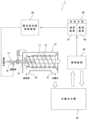
図1は本発明の一実施形態にかかる固液分離の状態判別装置1の概略構成図である。同図に示すように固液分離の状態判別装置1は、凝集剤を添加した被処理水を固形物と分離水とに分離する固液分離手段である固液分離装置10と、固液分離装置10から排出された分離水を貯留する分離水水槽30と、分離水水槽30内の分離水の一部を用いて分離水の固液分離状態を検視する検視装置(気泡分離手段と分離水滞留手段と撮像手段)40と、検視装置40で得られたデータを用いて固液分離状態を判別する判別手段60と、判別手段60からの指示によって凝集剤の量を制御する薬品添加量制御装置(凝集剤添加量制御手段)90と、を具備して構成されている。
Hereinafter, an embodiment of the present invention will be described in detail with reference to the drawings.
Fig. 1 is a schematic diagram of a solid-liquid separation
固液分離の対象である被処理水の具体例としては、生汚泥・余剰汚泥・消化汚泥などの下水汚泥、し尿、浄化槽汚泥などの懸濁物質を含む汚泥・スラリーや、含油排水などがある。 Specific examples of treated water that can be subjected to solid-liquid separation include sewage sludge such as raw sludge, excess sludge, and digested sludge, sludge and slurries containing suspended solids such as human waste and septic tank sludge, and oil-containing wastewater.
図1に示すようにこの実施形態では、固液分離装置10として遠心脱水機を用いている。固液分離装置10は、同一回転軸を中心にして異なる回転速度で回転する外胴回転筒11及び内胴スクリューコンベア13と、回転軸に固定して設置される被処理水供給管15と、を具備している。
As shown in FIG. 1, in this embodiment, a centrifugal dehydrator is used as the solid-
被処理水供給管15の一端部に接続された供給配管17から供給される被処理水(この例の場合は汚泥)は、凝集剤配管19から凝集剤が添加された後に機内に導入され、機内の被処理水供給管15の端部から排出される。機内に排出された被処理水は凝集フロックである汚泥フロックを形成し、加速・回転され、固形物と水の比重差に働く重力の数千倍の遠心力により、沈殿汚泥と分離水に分離される。
The water to be treated (sludge in this example) supplied from the
分離水は、外胴回転筒11の末端を介して分離水排出口21より外部に排出される。一方、外胴回転筒11の内壁に沈降した固形物は外胴回転筒11よりやや遅い速度で回転する内胴スクリューコンベア13で脱水されながら搬送され、外胴回転筒11のもう一方の末端を介して固形物排出口23より機外に排出される。
The separated water is discharged to the outside from the separated
なお固液分離装置10は、上記遠心脱水機に限定されず、他の各種固液分離装置、例えばスクリュープレス脱水機、ベルトプレス脱水機、濃縮機(回転円板式脱液装置〔例えば株式会社研電社製のスリットセーバー〕、加圧浮上、常圧浮上)などを用いて構成しても良い。なお、上記各種固液分離装置の中でも遠心脱水機は分離水に発泡が起こり易いので、本発明を適用して特に好適である。
The solid-
分離水水槽30は、固液分離装置10において分離した分離水を一時貯留しておく水槽である。なお場合によっては、この分離水水槽30を介さず、固液分離装置10から排出された分離水の一部を直接検視装置40に導入する構成としても良い。
The
図2は検視装置40の概略構成側面図である。同図に示すように、検視装置40は、分離水水槽30から分離水流量調整手段であるポンプ41によって吸い上げた分離水を、斜めに傾斜させて設置した樋43(図2ではその底板のみ示す)の上部から下方に向けて流し、当該流路F1の中に形成した滞留部分F2をその上方から撮像手段45によって撮像し、樋43の下端に達した分離水を分離水水槽30に戻すように構成されている。
Figure 2 is a schematic side view of the
図3は上記樋43の部分の要部概略斜視図、図4は上記樋43を下流側(図2の矢印B方向)から見た概略側面図である。これらの図に示すように、樋43は、横断面コ字状であって上面が開放された形状に形成され、これによって水路431を形成している。水路431の幅は、例えば、2.5cm~5cm程度とする。水路431の途中には、堰433が形成されている。堰433は、前記水路431の底面と左右両側面に至り且つ水路431の深さよりも低い高さの板体によって構成されている。樋43には、その傾斜角度を変更する図示しない傾斜角度調整手段が設置されている。樋43の傾斜角度を変更することで、水路431内を流れる分離水の流速を変更することができる。
Figure 3 is a schematic perspective view of the
樋43は、この樋43に流す分離水の表面が大気に開放されるため、当該分離水から気泡分を大気中に効率よく放出させることができる。言い換えれば、分離水の気泡分を分離するために一度分離水を大気に開放する必要から、樋43に分離水を流すこととしたのである。
Because the surface of the separated water flowing through the
また分離水に含まれる水と凝集フロックなどの懸濁物を均等に流すため、樋43を傾斜構造とする必要がある。なぜなら、樋43を例えば水平に設置すると、分離水がよどんでしまう部分が生じ、よどんだ部分とよどんでいない部分とで懸濁物の量が変わったり、懸濁物が沈降して溜まってしまう部分が生じたりして、水と懸濁物が均等に流れず、正確な懸濁物の量が検出できないからである。
In addition, in order to allow the water and suspended solids such as flocs contained in the separated water to flow evenly, the
堰433は、固液分離装置10で分離できなかった懸濁物を含む分離水の状態を画像或いは動画で判別できるように分離水を滞留させるため、樋43の下流側に設置される。言い換えれば樋43の上流側において分離水中の気泡を大気中に放出させた後の分離水を滞留させて懸濁物の状態が分かるように撮影するために、樋43の下流側に堰433を設置している。一方、懸濁物が前記滞留部分F2に堆積したり浮上して覆ったりしないようにするため、即ち、分離水が懸濁物を撹拌する撹拌流速を維持した状態で滞留させるため、樋43の勾配(傾斜角度)を5~50%、さらに望ましくは20~35%の下がり勾配としている。
The
撮像手段45はカメラであって、水路431の上方から堰433の少し上流側の部分、即ち滞留部分F2を撮影し、その画像情報を図1に示す判別手段60に送信する。画像情報としては、静止画像データでも良いし、動画データでも良い。またカラーでもモノクロでも良いが、正確な情報入手のためにはカラーが望ましい。撮影する面積は、分離できなかった懸濁物や分離水の状態(濁度など)を画像あるいは動画で判別できるように、1cm2以上であることが望ましく、画像分類の精度を上げるためには2cm2以上がより好ましい。また水路431の底面積に対する分離水の供給量が多すぎると、凝集フロックと分離水を上手く分けて撮影することが困難になり、また少なすぎると、凝集フロックが上手く流れずに水路431に堆積などしてしまう。そのため分離水の供給は、水路431の幅に対して、10~500cm3-分離水/(分・cm-幅)が望ましい。
The imaging means 45 is a camera, which captures an image of the portion slightly upstream of the
樋43への分離水の供給は、ポンプ41によって行われるが、ポンプ41を省略し、分離水水槽30から直接自然流下によって供給する構造にしても良いし、また固液分離装置10から排出された分離水の一部を、分離水水槽30を介さずに直接自然流下によって供給する構造にしても良い。
The separated water is supplied to the
また分離水水槽30から樋43に至る配管、即ち樋43の上流側の配管には、消泡剤を投入(混合)させる消泡剤注入手段47が設けられている。これによって分離水の発泡量が多い場合は、消泡剤を添加することができる。消泡剤は、分離水中の泡を消泡する薬剤である。消泡剤注入手段47は、消泡剤添加後の滞留時間を確保するため、樋43に至る配管の長さを長くすることで構成しても良いし、配管の途中に撹拌槽を設置することで構成しても良い。滞留時間は10~15秒以上が望ましい。また消泡剤注入手段47はポンプ41の下流側に設置しても良い。
In addition, the piping from the separated
また樋43の上流側上部の左右位置には、図4に示すように、一対の洗浄水噴出ノズル435a,435bが設置されている。両洗浄水噴出ノズル435a,435bは、正面から見て樋43の水路431の形状に沿ったL字形状を有しており、その先端には多数のノズルnが形成されている。
As shown in FIG. 4, a pair of cleaning
各ノズルnからは、図3の矢印で示すように、樋43の水路431の底面と左右両側面に洗浄水を噴出し、汚れた水路431の内表面を洗浄する。洗浄は定期的に行い、洗浄の際は間欠的にジェット噴霧することが好ましい。
As shown by the arrows in Figure 3, each nozzle n sprays cleaning water onto the bottom and both left and right sides of the
なお、洗浄水噴出ノズル435a,435bは、上述のように、樋43の形状に沿ったL字形状が望ましいが、平らなI字形状などの他の各種形状でも良い。その場合も、樋43の形状に沿わせて設置することが望ましい。また、上記例では洗浄水を上流から下流に向けて噴出したが、下流から上流に向けて噴出しても良いし、樋43の底面や左右両側面に対して垂直方向などから噴出しても良い。
As described above, the cleaning
図1に戻って、判別手段60は、前記撮像手段45から受信した画像情報に基づいて、前記固液分離装置10に投入する被処理水に注入する凝集剤の分量の過不足を判定する手段であり、この例では、演算装置61と監視装置63とを具備して構成されている。演算装置61はこの例ではパーソナルコンピュータを使用して現場側に設置し、監視装置63はこの例ではクラウドサーバを使用している。
Returning to FIG. 1, the discrimination means 60 is a means for determining whether the amount of flocculant injected into the treated water fed into the solid-
演算装置61は、前記画像情報を入力して分離水の状態を出力する画像分類モデル(画像判別モデル、機械学習モデル)を用いて、前記撮像手段45から受信・入力した画像情報を分類・判別する。機械学習アルゴリズムの例としては、SVR法(サポートベクター回帰法)、PLS法(部分最小二乗法:Partial Least Squares)、ディープラーニング法(深層学習法)、ランダムフォレスト法、または決定木法などが挙げられる。本実施形態では、ネットワーク構造としてCNN(畳み込みニューラルネットワーク)を用いたディープラーニング法が採用されるが、本発明はこれに限定されない。画像認識技術としては分類、物体検出、セグメンテーションが挙げられる。
The
本実施形態では、分類が採用されるが、本発明はこれに限定されない。機械学習の手法としては、教師あり学習でも良いし、教師無し学習でも良い。入力する画像としては、上述のように、カラーの静止画でも良いし、動画データの一部を切り取った静止画像を用いても良く、所定時間間隔、例えば20秒間隔に1回、当該画像情報中の凝集フロックの混入状態(さらには濁度、以下同様)に対して、画像認識を行い、どのような状態となるかを数値(凝集フロックの数や領域の割合)あるいは所定のカテゴリ(分離水の状態の良し悪しや、凝集剤の投入量の過不足など)で出力する。 In this embodiment, classification is adopted, but the present invention is not limited to this. The machine learning method may be supervised learning or unsupervised learning. As described above, the input image may be a color still image, or a still image cut out from a part of video data. Image recognition is performed on the mixed state of the flocs in the image information (and turbidity, the same below) at a predetermined time interval, for example once every 20 seconds, and the state is output as a numerical value (number of flocs or percentage of area) or a predetermined category (good or bad state of separated water, excess or shortage of flocculant input, etc.).
混入状態の判断は、画像分類での判断でも良いし、物体検出による画像中の凝集フロックの数を用いて判断しても良いし、セグメンテーションによる画像中の凝集フロックの領域と分離水の領域の割合(面積比)を用いて判断してもよい。何れの判断基準に入っているかによって、凝集剤の投入量が適正であるか否かが判別できる。 The contamination state can be determined by image classification, by object detection using the number of flocs in the image, or by segmentation using the ratio (area ratio) of the area of flocs to the area of separated water in the image. Depending on which criterion is met, it can be determined whether the amount of flocculant added is appropriate or not.
上記構築した画像解析により構築した機械学習モデルは、定期的に更新しても良いし、任意のタイミングで更新しても良い。また搭載する機械学習モデルは、1つであっても良いし複数であっても良い。また機械学習モデルをこの演算装置61によって構築することも出来るし、別のコンピュータで構築した機械学習モデルを本演算装置61に移植することも出来る。
The machine learning model constructed by the image analysis constructed above may be updated periodically or at any time. The number of machine learning models to be installed may be one or multiple. The machine learning model may be constructed by this
図6は本実施形態の画像分類における画像の状態と、分類内容と、各分類に対応する数値とを示す図である。 Figure 6 shows the state of an image in image classification in this embodiment, the classification contents, and the numerical values corresponding to each classification.
同図の最上段に示す画像は、凝集フロックが存在しない状態であって、これは凝集剤の投入量が過剰であることを示しており、数値は「1」としている。同図の2段目に示す画像は、凝集フロックが少量存在した状態であって、これは凝集剤の投入量が適正であることを示しており、数値は「0.66」としている。 The image shown in the top row of the figure shows a state where no flocculated flocs are present, indicating that an excessive amount of flocculant has been added, and is given a numerical value of "1." The image shown in the second row of the figure shows a state where a small amount of flocculated flocs is present, indicating that an appropriate amount of flocculant has been added, and is given a numerical value of "0.66."
同図の3段目に示す画像は、凝集フロックがやや多量に存在した状態であって、これは凝集剤の投入量がやや不足していることを示しており、数値は「0.33」としている。同図の最下段に示す画像は、凝集フロックが多量に存在した状態であって、これは凝集剤の投入量が不足であることを示しており、数値は「0」としている。なお本実施形態では4種類の凝集フロック混入状態の分類(4分類)としているが、本発明は4分類に限定されず、例えば過剰・不足の2分類や、過剰・適正・不足の3分類や、過剰・やや過剰・適正・やや不足・不足の5分類など、他の複数分類であっても良い。 The image shown in the third row of the figure shows a state in which there is a slightly large amount of flocculated flocs, indicating that the amount of flocculant added is slightly insufficient, and the numerical value is "0.33". The image shown in the bottom row of the figure shows a state in which there is a large amount of flocculated flocs, indicating that the amount of flocculant added is insufficient, and the numerical value is "0". Note that in this embodiment, four types of flocculated floc mixing states are classified (four classifications), but the present invention is not limited to four classifications, and other multiple classifications may be used, such as two classifications of excess and shortage, three classifications of excess, appropriate, and shortage, or five classifications of excess, slightly excess, appropriate, slightly insufficient, and shortage.
監視装置63は、前記演算装置61からの複数種類(この例では4種類)の凝集フロック混入状態に関する所定時間毎、この例では20秒毎の数値とそのときの画像とをクラウド上で入力し、当該数値データから移動平均を算出し、当該移動平均値から凝集フロック混入状態を判別する。
The
そして図5に示すような画像G1が生成できる画像データを作成する。画像G1には、演算装置61から入力した4種類の凝集フロック混入状態(1と0.66と0.33と0の4種類)の時系列グラフG11と、当該入力データを用いて算出した移動平均グラフG13と、撮影している画像・動画の映像画面G15と、前記グラフG11,G13の凡例や警報表示や制御の閾値の設定内容などの各種データ表示部G17とを、同一画面に表示できるようにしている。
Image data is then created that can generate image G1 as shown in Figure 5. Image G1 is capable of displaying on the same screen a time series graph G11 of the four types of floc mixing states (four types: 1, 0.66, 0.33, and 0) input from the
この画像データの送信先は、例えば前記演算装置61であってもよいし、この固液分離システム1とは別の場所にある中央監視室に設置したコンピュータであってもよい。何れの場合も、設置された演算装置61やコンピュータの表示画面に上記画像G1を表示する。この画像G1には、時系列グラフG11と移動平均グラフG13と映像画面G15とを同一画面上に表示するので、分離水における凝集フロック混入状態の時間的変化を即座に把握でき、的確な制御を行うことができる。
The destination of this image data may be, for example, the
監視装置63は、上記分離水における凝集フロック混入状態のデータを用いて、添加する凝集剤の過不足を判断する。例えば、画面G1の移動平均グラフG13において、数値が「0.66」よりも小さくなっている時間が所定時間以上になると凝集剤の添加量を増加させる添加量指示データを前記演算装置61に出力し、数値が「0.66」よりも大きくなっている時間が所定時間以上になると凝集剤の添加量を減少させる添加量指示データを前記演算装置61に出力する。当該添加量指示データは、演算装置61から薬品添加量制御装置90に送信され、凝集剤の添加量が制御される。なお添加量指示データは、監視装置63から直接薬品添加量制御装置90に送信するように構成しても良い。
The
監視装置63は、例えば凝集剤の量を調節しても適正な凝集フロック混入状態に制御できない場合など、システムに異常が生じた場合は警報を発信することができる。警報は、固液分離システム1を設置した現地に対して行っても良いし、当該固液分離システム1から離れた中央管理室に対して行っても良いし、個人の携帯端末に対して行っても良い。
The
なおこの例では、演算装置61としてパーソナルコンピュータを使用し、監視装置63としてクラウドサーバを使用したが、演算装置61をクラウドサーバで構成しても良いし、監視装置63をパーソナルコンピュータを使用して現場側に設置してもよい。また演算装置61と監視装置63を同一のパーソナルコンピュータで構成しても良いし、両者をクラウドサーバで構成しても良いなど、種々の変更が可能である。
In this example, a personal computer is used as the
薬品添加量制御装置90は、演算装置61などからの添加量指示データを受けて、薬品(凝集剤)の添加量を制御する。薬品は無機系凝集剤であっても良いし、有機系凝集剤であっても良いし、無機系凝集剤と有機系凝集剤の併用でも良い。本発明は、より発泡し易い有機系凝集剤を用いた場合に適用して特に好適である。薬品添加量制御装置90は、単独の装置として設置しても良いし、固液分離装置10の制御盤に組み込むように設置しても良い。
The chemical addition
以上のように構成されている固液分離の状態判別装置1において、供給配管17から固液分離装置10に被処理水を供給し、同時に凝集剤配管19から被処理水に所定量の凝集剤を注入し、前述のように固液分離装置10を駆動して固形物である沈殿汚泥と分離水とを分離する。分離水排出口21から排出された分離水は、分離水水槽30に導入される。この実施形態のように固液分離装置10として遠心脱水機を用いた場合は分離水が発泡し易く、分離水中の気泡の量が多い。
In the solid-liquid separation
次に、分離水水槽30中の分離水の一部をポンプ41によって吸い上げて検視装置40に供給し、樋43の上部からその水路431内に分離水を流す。水路431の上面は大気中に露出しているので、分離水中の気泡はスムーズに効果的に大気中に放出されて除かれる。気泡が除かれた分離水は、滞留部分F2において滞留するので、当該分離水の滞留部分F2をその上方から撮像手段45が撮影する。
Next, a portion of the separated water in the separated
この滞留部分F2では、前記固液分離装置10で分離できなかった凝集フロックと分離水とが、凝集フロックが沈殿したりまたは表面に浮き上がったりしないで、適度に混合された状態となっているので、分離水における凝集フロック混入状態を正確に撮影することができる。
In this retention portion F2, the flocs that could not be separated by the solid-
本実施形態にかかる検視装置40によれば、上述のように樋43の傾斜角度が傾斜角度調整手段によって任意に調整可能なので、樋43に流す分離水を分離水から気泡を除去するのに適した流速(流量)であって、且つ凝集フロックが樋43に滞留しない流速であり、さらに堰433手前の滞留領域F2に撹拌流速を付与できて凝集フロックが沈降又は浮上滞留しない状態の流速となるように、その傾斜角度を容易に設定することができる。さらに樋43の傾斜角度は、滞留領域の流速が撮像手段45による撮影がし易い程度の流速になるようにも容易に調整可能である。
According to the
〔実施例〕
次に、上記固液分離システム1を用いた運転実施例を説明する。
固液分離装置10として図1に示す遠心脱水機を用いる。また被処理水として、消化汚泥と重力濃縮初沈汚泥(TS比 消化:重力≒2:1)を混合した汚泥を用いる(TS:トータルスラッジ(総固形物量)、以下同様)。汚泥供給量は10.8m3/hで一定とする。また汚泥濃度は2.3~2.4%-TSであった。
[Example]
Next, an operational example using the solid-
The centrifugal dehydrator shown in Fig. 1 is used as the solid-
薬品添加量制御装置90から供給する凝集剤として、ポリマー(カチオン系高分子凝集剤)を用いる。また薬品添加量制御装置90に用いる凝集剤注入ポンプとして図示しないインバーター制御のポンプを用い、判別手段60からのポリマー過不足の判断結果に基づいて凝集剤添加量を調整した。
A polymer (cationic polymer flocculant) is used as the flocculant supplied from the chemical addition
演算装置61は、上述のように現地に設置したパーソナルコンピュータ(上記4つの分類を行う機械学習モデルを搭載した)を用い、上記CNNを用いた画像分類モデルを搭載し、カラーの静止画を入力し、20秒に1回、上記4つの分類の内の何れかを数値として出力する構成とした。
The
監視装置63は、上述のようにクラウドサーバを利用し、ポリマー過不足の判断結果を監視者に提供した。これを受け監視者が、薬品添加量制御装置90の制御指示値を下記基準に従い調整することによって、ポリマー添加量(対TSポリマー注入率(%))を調整した。
ポリマー過剰(1.0~0.8)の場合 → 1.20~1.46%
適正(0.8~0.6)の場合 → 変更なし(現状のまま)
やや不足(0.6~0.4)の場合 → 1.50%
不足(0.4~0)の場合 → 1.50%
The
In the case of excess polymer (1.0 to 0.8) → 1.20 to 1.46%
If it is appropriate (0.8 to 0.6) → No change (current state)
In case of slight shortage (0.6 to 0.4) → 1.50%
In case of shortage (0.4 to 0) → 1.50%
検視装置40は、前記図2に示す構成の検視装置40を用いた。水路431の底面や側面は定期的に洗浄水を当てて間欠で洗浄した。撮影する面積は2cm2とした。分離水の供給量は水路431の幅に対して、90cm3-分離水/(分・cm-幅)とした。樋43の勾配値を30%とした。20秒に1回の頻度でカラーの静止画を撮像し、前記演算装置61に送信した。そして30分に1回、固液分離装置10から排出される固形物の含水率を測定した。
The
一方、上記実施例に対する比較例として、上記検視装置40、判別手段60、薬液添加量制御装置90を使用せず、上記と同一構成の固液分離装置10に、同一汚泥、同一汚泥供給量の被処理水を供給し、ポリマー量(対TSポリマー注入率(%))を1.50%に固定して添加した。そして30分に1回、固液分離装置10から排出される固形物の含水率を測定した。上記実施例と比較例の結果を、下記表1に示す。
On the other hand, as a comparative example to the above embodiment, the
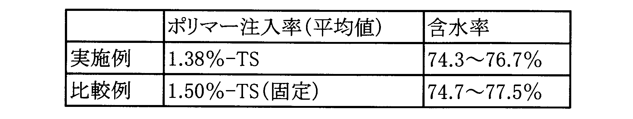
表1に示すように、対TSポリマー注入率は、実施例では平均1.38%であり、比較例では1.5%で固定したものであり、従って本固液分離システム1を用いることにより、ポリマー注入量を削減することができた。また表1に示すように、含水率は上記実施例では74.3~76.7%、比較例では74.7~77.5%であり、実施例、比較例ともに同等であった。
As shown in Table 1, the average polymer injection rate to TS was 1.38% in the examples and was fixed at 1.5% in the comparative example, and therefore the amount of polymer injected could be reduced by using this solid-
上記検視装置40を用いることによって、分離水中の気泡が効果的に除去されていることが目視によっても確認できた。このため上記固液分離システム1を用いれば、気泡が除かれた分離液が経時的に連続してリアルタイムで検知できて図5に示すような凝集フロックの状態がはっきり分かる画像G1が表示でき、リアルタイムでポリマー添加量の過不足が正確に分かり、また判別手段60からの指示によって適切なポリマー添加量を指示できることが分かった。
By using the above-mentioned
以上説明したように、固液分離の状態判別装置1は、汚泥などの被処理水中に凝集剤を添加して凝集した懸濁物質を分離し分離水を得る固液分離手段である固液分離装置10と、前記固液分離装置10によって得られた分離水に発生する気泡を、当該分離水を移送する流路の過程で分離する気泡分離手段(検視装置40の樋43)と、前記流路中の気泡が分離された分離水を滞留させる分離水滞留手段(検視装置40の堰433)と、前記分離水滞留手段による分離水の滞留部分F2を撮影し画像情報を得る撮像手段45と、前記画像情報に基づいて、前記凝集剤の過不足を判別する判別手段60と、を有して構成されている。
As described above, the solid-liquid separation
このように、固液分離装置10によって懸濁物質を分離した後の分離水中に残った懸濁物質の状態を測定するので、固液分離装置10での懸濁物質の固液分離が良好に行われたか否かを直接判断できて凝集剤の過不足を正確に判別でき、これによって凝集剤の適正な添加量を高精度に把握することができる。
In this way, the state of the suspended matter remaining in the separated water after separation by the solid-
また上述のように、固液分離装置10によって懸濁物質を分離した後の分離水は、発泡していることが多いが、本発明によれば、気泡分離手段(樋43)によって気泡を分離するので、分離水の状態を画像情報から正確に判別することができる。
As mentioned above, the separated water after the suspended solids are separated by the solid-
さらに、気泡が分離された状態の分離水を、分離水滞留手段(堰433)によって流路の過程で一時滞留させた状態とするので、撮像手段45が当該滞留部分F2を撮像することで、緩やかな流れとなっている分離水を撮像でき、より正確に分離水の状態を判別することができる。 Furthermore, the separated water from which the air bubbles have been separated is temporarily retained in the flow path by the separated water retention means (weir 433), so that the imaging means 45 can capture an image of the retained portion F2, thereby capturing an image of the separated water that is flowing slowly, and the state of the separated water can be determined more accurately.
また前記気泡分離手段は、傾斜して設置され、前記分離水を流下させる流路中で前記気泡を当該分離水から分離する樋43を具備する構造なので、固液分離手段によって懸濁物質が分離される過程で発泡した分離水を、樋43の上に流下させることで、流下の途中に気泡を大気中にスムーズに放出でき、容易且つ効率よく分離水から気泡を分離することができる。
The air bubble separation means is installed at an angle and has a structure including a
また前記分離水滞留手段による分離水の滞留部分F2は、前記樋43の途中において当該樋43を流れる分離水が撹拌流速を維持した状態で滞留する滞留部分F2なので、当該滞留部分F2に懸濁物質が堆積したり浮上して覆ったりすることはなく、流下してくる分離水の状態を連続して精度よく判別することができる。
The separated water retention portion F2 created by the separated water retention means is a retention portion F2 where the separated water flowing through the
また分離水滞留手段は、樋43の途中に設置されて当該樋43を流れる分離水を撹拌流速を維持した状態で滞留させる堰433を具備して構成されているので、分離水の滞留部分F2を簡単な構造で構成することができる。
The separated water retention means is configured with a
また気泡分離手段(樋43)の上流側において、分離水に消泡剤を注入する消泡剤注入手段47を設けているので、より効果的に分離水から気泡を除去でき、分離水の状態をより正確に判別することができ、監視することができる。 In addition, an antifoaming agent injection means 47 for injecting an antifoaming agent into the separated water is provided upstream of the air bubble separation means (gutter 43), so air bubbles can be removed from the separated water more effectively, and the state of the separated water can be determined and monitored more accurately.
また判別手段60による凝集剤の過不足の判別結果に基づいて、被処理水に添加される凝集剤の適正量を制御する凝集剤添加量制御手段である薬品添加量制御装置90を有するので、凝集剤の添加量を適正なものにすることができる。
The system also has a chemical addition
また気泡分離手段(樋43)及び分離水滞留手段(堰433)に付着する懸濁物質を洗浄液によって洗浄する洗浄機構(洗浄水噴出ノズル435a,435b)を設置したので、気泡分離手段及び分離水滞留手段を常に懸濁物質が付着・堆積しない良好な状態としておくことができる。
In addition, a cleaning mechanism (cleaning
また分離水を気泡分離手段(樋43)に供給する供給量を調節する分離水流量調整手段(ポンプ41)を設置したので、分離水中の懸濁物質の状態を測定するのに適した量の分離水を気泡分離手段に供給することができる。 In addition, a separated water flow rate adjustment means (pump 41) is installed to adjust the amount of separated water supplied to the bubble separation means (gutter 43), so that an appropriate amount of separated water can be supplied to the bubble separation means for measuring the state of suspended matter in the separated water.
以上本発明の実施形態を説明したが、本発明は上記実施形態に限定されるものではなく、特許請求の範囲、及び明細書と図面に記載された技術的思想の範囲内において種々の変形が可能である。なお直接明細書及び図面に記載がない何れの形状や構造や材質であっても、本願発明の作用・効果を奏する以上、本願発明の技術的思想の範囲内である。 Although the embodiment of the present invention has been described above, the present invention is not limited to the above embodiment, and various modifications are possible within the scope of the claims and the technical ideas described in the specification and drawings. Furthermore, any shape, structure, or material not directly described in the specification and drawings is within the scope of the technical ideas of the present invention as long as it provides the functions and effects of the present invention.
例えば、上記実施形態では、固液分離手段として汚泥やスラリーなどの懸濁液を濁質と液体とに分離させる固液分離装置の例を説明したが、油分を含む排水を油分と水分とに分離させる油水分離装置も、固液分離手段として同様に適用することができる。 For example, in the above embodiment, an example of a solid-liquid separation device that separates a suspension such as sludge or slurry into turbidity and liquid has been described as a solid-liquid separation means, but an oil-water separation device that separates wastewater containing oil into oil and water can also be used as a solid-liquid separation means.
また上記実施形態では、気泡分離手段を構成する樋43に設けた堰433によって分離水滞留手段を構成したが、堰433を設けず、樋43だけで気泡分離手段と分離水滞留手段の両者を構成しても良い。この場合、気泡分離手段を構成する樋43の傾斜角度を小さくすることでその中を流れる分離水の流速を遅くし且つ樋43内を流れる分離水の水深をある程度深くし、これによって樋43の流路F1全体を撹拌流速を有する滞留部分とすればよい。また樋43の内面を下流方向に向かって上下に波打つ形状など、平面形状以外の形状に形成し、これによって凹となっている部分に分離水が滞留する滞留部分を形成し、これによって分離水滞留手段を構成しても良い。
In the above embodiment, the separated water retention means is constituted by the
また、上記記載及び各図で示した実施形態は、その目的及び構成等に矛盾がない限り、互いの記載内容を組み合わせることが可能である。また、上記記載及び各図の記載内容は、その一部であっても、それぞれ独立した実施形態になり得るものであり、本発明の実施形態は上記記載及び各図を組み合わせた一つの実施形態に限定されるものではない。 The above description and the embodiments shown in each figure can be combined as long as there is no contradiction in the purpose and configuration. The above description and the descriptions in each figure can each be an independent embodiment, even if only in part, and the embodiment of the present invention is not limited to a single embodiment that combines the above description and each figure.
1 固液分離の状態判別装置(固液分離監視装置)
10 固液分離装置(固液分離手段)
41 ポンプ(分離水流量調整手段)
43 樋(気泡分離手段)
433 堰(分離水滞留手段)
F1 流路
F2 滞留部分
435a,435b 洗浄水噴出ノズル(洗浄機構)
45 撮像手段
47 消泡剤注入手段
60 判別手段
61 演算装置
63 監視装置
90 薬品添加量制御装置(凝集剤添加量制御手段)
1. Solid-liquid separation status determination device (solid-liquid separation monitoring device)
10 Solid-liquid separation device (solid-liquid separation means)
41 Pump (separated water flow rate adjustment means)
43 Gutter (air bubble separation means)
433 Weir (separated water retention means)
F1: Flow path F2:
45 Imaging means 47 Defoaming agent injection means 60 Discrimination means 61
Claims (7)
前記固液分離手段によって得られた分離水で発生した気泡を、当該分離水を移送する流路の過程で分離する気泡分離手段と、
前記流路中の気泡が分離された分離水を滞留させる分離水滞留手段と、
前記分離水滞留手段による分離水の滞留部分を撮影し、画像情報を得る撮像手段と、
前記画像情報に基づいて、前記凝集剤の過不足を判別する判別手段と、
を有し、
前記気泡分離手段は、傾斜して設置され、前記分離水を流下させる流路中で前記気泡を当該分離水から分離する樋を具備して構成され、
前記分離水滞留手段による分離水の滞留部分は、前記樋の途中において当該樋を流れる分離水が撹拌流速を維持した状態で滞留する部分であることを特徴とする固液分離の状態判別装置。 a solid-liquid separation means for adding a flocculant to the water to be treated to separate flocculated suspended solids and obtain separated water;
a bubble separating means for separating bubbles generated in the separated water obtained by the solid-liquid separating means during the course of transporting the separated water through a flow path;
a separated water retaining means for retaining the separated water from which the air bubbles have been separated in the flow path;
an imaging means for photographing a portion of the separated water retained by the separated water retaining means and obtaining image information;
A discrimination means for discriminating whether the flocculant is insufficient or excessive based on the image information;
having
the air bubble separating means is provided with a gutter that is inclined and separates the air bubbles from the separated water in a flow path through which the separated water flows;
A solid-liquid separation state determining device, characterized in that the portion of separated water retained by the separated water retaining means is a portion midway through the gutter where the separated water flowing through the gutter retains while maintaining an agitation flow rate .
前記分離水滞留手段は、前記樋の途中に設置されて当該樋を流れる分離水を撹拌流速を維持した状態で滞留させる堰を具備して構成されていることを特徴とする固液分離の状態判別装置。 The solid-liquid separation state determination device according to claim 1 ,
The separated water retention means is configured to include a weir installed midway through the gutter to retain the separated water flowing through the gutter while maintaining a stirring flow rate.
前記気泡分離手段の上流側において、前記分離水に消泡剤を注入する消泡剤注入手段を有することを特徴とする固液分離の状態判別装置。 The solid-liquid separation state determination device according to claim 1 or 2 ,
2. A solid-liquid separation state determining device comprising: an antifoaming agent injection means for injecting an antifoaming agent into the separated water, the antifoaming agent being disposed upstream of the air bubble separating means.
前記判別手段による凝集剤の過不足の判別結果に基づいて、前記被処理水に添加される凝集剤の適正量を制御する凝集剤添加量制御手段を有することを特徴とする固液分離の状態判別装置。 The solid-liquid separation state determination device according to any one of claims 1 to 3 ,
A solid-liquid separation state determination device characterized by having a flocculant addition amount control means for controlling the appropriate amount of flocculant to be added to the treated water based on the result of the determination by the determination means as to whether the flocculant is insufficient or excess.
前記気泡分離手段及び分離水滞留手段に付着する懸濁物質を洗浄液によって洗浄する洗浄機構を設置することを特徴とする固液分離の状態判別装置。 The solid-liquid separation state determination device according to any one of claims 1 to 4 ,
2. A solid-liquid separation state determining device comprising: a washing mechanism for washing suspended solids adhering to the air bubble separating means and the separated water retaining means with a washing liquid.
前記分離水を前記気泡分離手段に供給する供給量を調節する分離水流量調整手段を有することを特徴とする固液分離の状態判別装置。 The solid-liquid separation state determination device according to any one of claims 1 to 5 ,
A solid-liquid separation state determining device comprising a separated water flow rate adjusting means for adjusting the amount of separated water supplied to the air bubble separating means.
前記凝集剤添加後の凝集した懸濁物質を分離し分離水を得る固液分離工程と、
前記固液分離工程によって得られた分離水において発生した気泡を、分離水を移送する流路の過程で分離する気泡分離工程と、
前記流路中の気泡が分離された分離水を滞留させる分離水滞留工程と、
前記分離水滞留工程による分離水の滞留部分を撮影し、画像情報を得る画像撮像工程と、
前記画像情報に基づいて、前記凝集剤の過不足を判別する判別工程と、
前記判別工程の判別結果に基づいて、リアルタイムに適正量になるように凝集剤添加量を制御する凝集剤添加量制御工程と、
を有し、
前記気泡分離工程は、傾斜して設置された樋の中に前記分離水を流下させる流路中で前記気泡を当該分離水から分離する工程であり、
前記分離水滞留工程によって分離水を滞留させる部分は、前記樋の途中において当該樋を流れる分離水を撹拌流速を維持した状態で滞留させる部分である
ことを特徴とする固液分離の状態判別方法。 a flocculant addition step of adding a flocculant to the water to be treated;
A solid-liquid separation step of separating the flocculated suspended matter after the addition of the flocculant to obtain separated water;
A bubble separation step of separating bubbles generated in the separated water obtained by the solid-liquid separation step in the course of transporting the separated water through a flow path;
a separated water retaining step of retaining the separated water from which the air bubbles have been separated in the flow path;
an image capturing step of capturing an image of a portion of the separated water retained in the separated water retaining step to obtain image information;
a determining step of determining whether the flocculant is insufficient or excessive based on the image information;
a flocculant addition amount control step of controlling the flocculant addition amount so that the flocculant addition amount becomes an appropriate amount in real time based on the discrimination result of the discrimination step;
having
The air bubble separating step is a step of separating the air bubbles from the separated water in a flow path that causes the separated water to flow down into a gutter that is installed at an angle,
The portion where the separated water is retained by the separated water retaining step is a portion in the middle of the gutter where the separated water flowing through the gutter is retained while maintaining the agitation flow rate.
A method for determining the state of solid-liquid separation.
Priority Applications (1)
| Application Number | Priority Date | Filing Date | Title |
|---|---|---|---|
| JP2021164349A JP7586800B2 (en) | 2021-10-05 | 2021-10-05 | Apparatus and method for determining the state of solid-liquid separation |
Applications Claiming Priority (1)
| Application Number | Priority Date | Filing Date | Title |
|---|---|---|---|
| JP2021164349A JP7586800B2 (en) | 2021-10-05 | 2021-10-05 | Apparatus and method for determining the state of solid-liquid separation |
Publications (2)
| Publication Number | Publication Date |
|---|---|
| JP2023055167A JP2023055167A (en) | 2023-04-17 |
| JP7586800B2 true JP7586800B2 (en) | 2024-11-19 |
Family
ID=85986133
Family Applications (1)
| Application Number | Title | Priority Date | Filing Date |
|---|---|---|---|
| JP2021164349A Active JP7586800B2 (en) | 2021-10-05 | 2021-10-05 | Apparatus and method for determining the state of solid-liquid separation |
Country Status (1)
| Country | Link |
|---|---|
| JP (1) | JP7586800B2 (en) |
Families Citing this family (1)
| Publication number | Priority date | Publication date | Assignee | Title |
|---|---|---|---|---|
| JP7813596B2 (en) * | 2022-02-09 | 2026-02-13 | カナデビア株式会社 | Dehydration Treatment System |
Citations (2)
| Publication number | Priority date | Publication date | Assignee | Title |
|---|---|---|---|---|
| JP2020146614A (en) | 2019-03-12 | 2020-09-17 | 株式会社日立製作所 | Sludge treatment system and sludge treatment method |
| JP2021037508A (en) | 2019-08-30 | 2021-03-11 | 水ing株式会社 | Dehydration system |
Family Cites Families (3)
| Publication number | Priority date | Publication date | Assignee | Title |
|---|---|---|---|---|
| JPS6345000A (en) * | 1986-04-02 | 1988-02-25 | Masataka Sugawara | Device for flocculating sludge of water treatment |
| JPH09299995A (en) * | 1996-05-20 | 1997-11-25 | Meidensha Corp | Antifoaming device in sewage sludge treatment |
| JP3967462B2 (en) * | 1998-06-04 | 2007-08-29 | 富士電機ホールディングス株式会社 | Flocculant injection amount determination device |
-
2021
- 2021-10-05 JP JP2021164349A patent/JP7586800B2/en active Active
Patent Citations (2)
| Publication number | Priority date | Publication date | Assignee | Title |
|---|---|---|---|---|
| JP2020146614A (en) | 2019-03-12 | 2020-09-17 | 株式会社日立製作所 | Sludge treatment system and sludge treatment method |
| JP2021037508A (en) | 2019-08-30 | 2021-03-11 | 水ing株式会社 | Dehydration system |
Also Published As
| Publication number | Publication date |
|---|---|
| JP2023055167A (en) | 2023-04-17 |
Similar Documents
| Publication | Publication Date | Title |
|---|---|---|
| US20140131259A1 (en) | System and Methods of Determining Liquid Phase Turbidity of Multiphase Wastewater | |
| CN110586338B (en) | Online visual flotation system detector for flotation dosing control | |
| US10059608B2 (en) | Method and plant for treatment of aqueous dispersion | |
| KR20180036508A (en) | Wastewater treatment device and wastewater treatment method | |
| JP2022140787A (en) | Sludge treatment method | |
| JP6726696B2 (en) | Diluted sludge imaging system, flocculant addition amount control system, sludge concentration system, diluted sludge imaging method | |
| JP7586800B2 (en) | Apparatus and method for determining the state of solid-liquid separation | |
| JP7056825B2 (en) | Solid-liquid separator | |
| JP7481967B2 (en) | Flow device and water quality testing system | |
| JP2019055362A (en) | Membrane filtration device and membrane filtration method | |
| JP4217309B2 (en) | Water quality measuring device | |
| JP2022119488A (en) | Pressure floating separation apparatus and method of operating pressure floating separation apparatus | |
| JP6028532B2 (en) | Wastewater treatment equipment | |
| CN110586339B (en) | Tailing slurry treatment device for online visual flotation system detector | |
| KR101761246B1 (en) | Dissolved air flotation apparatus having level control type floating tank | |
| JP6270655B2 (en) | Flock aggregation condition control method, floc aggregation condition control device, water treatment method and water treatment apparatus | |
| JP6754680B2 (en) | How to operate the pressurized flotation separator and the pressurized flotation separator | |
| JP2010137187A (en) | Belt-type concentrator and method for operating the same | |
| RU2688619C1 (en) | Method and apparatus for treating water | |
| JP7813596B2 (en) | Dehydration Treatment System | |
| KR20230092606A (en) | Multi-parameter water quality measuring instrument with the function of removing foreign substances and air bubbles | |
| JP2023012235A (en) | Machine learning device, data processing system, inference device and machine learning method | |
| CN207511960U (en) | Efficient current stabilization coagulation air-float equipment | |
| JP2025082002A (en) | Flock imaging system, turbid water treatment system, and chemical liquid injection control method in turbid water treatment system | |
| JP7239358B2 (en) | Belt filtration device and control method for belt filtration device |
Legal Events
| Date | Code | Title | Description |
|---|---|---|---|
| A621 | Written request for application examination |
Free format text: JAPANESE INTERMEDIATE CODE: A621 Effective date: 20231225 |
|
| A977 | Report on retrieval |
Free format text: JAPANESE INTERMEDIATE CODE: A971007 Effective date: 20240726 |
|
| A131 | Notification of reasons for refusal |
Free format text: JAPANESE INTERMEDIATE CODE: A131 Effective date: 20240730 |
|
| A521 | Request for written amendment filed |
Free format text: JAPANESE INTERMEDIATE CODE: A523 Effective date: 20240909 |
|
| TRDD | Decision of grant or rejection written | ||
| A01 | Written decision to grant a patent or to grant a registration (utility model) |
Free format text: JAPANESE INTERMEDIATE CODE: A01 Effective date: 20241022 |
|
| A61 | First payment of annual fees (during grant procedure) |
Free format text: JAPANESE INTERMEDIATE CODE: A61 Effective date: 20241107 |
|
| R150 | Certificate of patent or registration of utility model |
Ref document number: 7586800 Country of ref document: JP Free format text: JAPANESE INTERMEDIATE CODE: R150 |