JP7586552B2 - Coating device control method - Google Patents
Coating device control method Download PDFInfo
- Publication number
- JP7586552B2 JP7586552B2 JP2023549253A JP2023549253A JP7586552B2 JP 7586552 B2 JP7586552 B2 JP 7586552B2 JP 2023549253 A JP2023549253 A JP 2023549253A JP 2023549253 A JP2023549253 A JP 2023549253A JP 7586552 B2 JP7586552 B2 JP 7586552B2
- Authority
- JP
- Japan
- Prior art keywords
- rotation
- drum
- disk
- coating
- posture
- Prior art date
- Legal status (The legal status is an assumption and is not a legal conclusion. Google has not performed a legal analysis and makes no representation as to the accuracy of the status listed.)
- Active
Links
Images


Classifications
-
- A—HUMAN NECESSITIES
- A23—FOODS OR FOODSTUFFS; TREATMENT THEREOF, NOT COVERED BY OTHER CLASSES
- A23G—COCOA; COCOA PRODUCTS, e.g. CHOCOLATE; SUBSTITUTES FOR COCOA OR COCOA PRODUCTS; CONFECTIONERY; CHEWING GUM; ICE-CREAM; PREPARATION THEREOF
- A23G3/00—Sweetmeats; Confectionery; Marzipan; Coated or filled products
- A23G3/02—Apparatus specially adapted for manufacture or treatment of sweetmeats or confectionery; Accessories therefor
- A23G3/20—Apparatus for coating or filling sweetmeats or confectionery
- A23G3/26—Apparatus for coating by tumbling with a liquid or powder, spraying device-associated, drum, rotating pan
-
- B—PERFORMING OPERATIONS; TRANSPORTING
- B05—SPRAYING OR ATOMISING IN GENERAL; APPLYING FLUENT MATERIALS TO SURFACES, IN GENERAL
- B05C—APPARATUS FOR APPLYING FLUENT MATERIALS TO SURFACES, IN GENERAL
- B05C3/00—Apparatus in which the work is brought into contact with a bulk quantity of liquid or other fluent material
- B05C3/02—Apparatus in which the work is brought into contact with a bulk quantity of liquid or other fluent material the work being immersed in the liquid or other fluent material
- B05C3/04—Apparatus in which the work is brought into contact with a bulk quantity of liquid or other fluent material the work being immersed in the liquid or other fluent material with special provision for agitating the work or the liquid or other fluent material
- B05C3/08—Apparatus in which the work is brought into contact with a bulk quantity of liquid or other fluent material the work being immersed in the liquid or other fluent material with special provision for agitating the work or the liquid or other fluent material the work and the liquid or other fluent material being agitated together in a container, e.g. tumbled
-
- B—PERFORMING OPERATIONS; TRANSPORTING
- B01—PHYSICAL OR CHEMICAL PROCESSES OR APPARATUS IN GENERAL
- B01J—CHEMICAL OR PHYSICAL PROCESSES, e.g. CATALYSIS OR COLLOID CHEMISTRY; THEIR RELEVANT APPARATUS
- B01J2/00—Processes or devices for granulating materials, e.g. fertilisers in general; Rendering particulate materials free flowing in general, e.g. making them hydrophobic
- B01J2/12—Processes or devices for granulating materials, e.g. fertilisers in general; Rendering particulate materials free flowing in general, e.g. making them hydrophobic in rotating drums
-
- B—PERFORMING OPERATIONS; TRANSPORTING
- B01—PHYSICAL OR CHEMICAL PROCESSES OR APPARATUS IN GENERAL
- B01J—CHEMICAL OR PHYSICAL PROCESSES, e.g. CATALYSIS OR COLLOID CHEMISTRY; THEIR RELEVANT APPARATUS
- B01J2/00—Processes or devices for granulating materials, e.g. fertilisers in general; Rendering particulate materials free flowing in general, e.g. making them hydrophobic
- B01J2/14—Processes or devices for granulating materials, e.g. fertilisers in general; Rendering particulate materials free flowing in general, e.g. making them hydrophobic in rotating dishes or pans
-
- A—HUMAN NECESSITIES
- A23—FOODS OR FOODSTUFFS; TREATMENT THEREOF, NOT COVERED BY OTHER CLASSES
- A23G—COCOA; COCOA PRODUCTS, e.g. CHOCOLATE; SUBSTITUTES FOR COCOA OR COCOA PRODUCTS; CONFECTIONERY; CHEWING GUM; ICE-CREAM; PREPARATION THEREOF
- A23G3/00—Sweetmeats; Confectionery; Marzipan; Coated or filled products
- A23G3/0002—Processes of manufacture not relating to composition and compounding ingredients
- A23G3/0095—Coating by tumbling with a liquid or powder, spraying device-associated, drum, rotating pan
-
- A—HUMAN NECESSITIES
- A23—FOODS OR FOODSTUFFS; TREATMENT THEREOF, NOT COVERED BY OTHER CLASSES
- A23G—COCOA; COCOA PRODUCTS, e.g. CHOCOLATE; SUBSTITUTES FOR COCOA OR COCOA PRODUCTS; CONFECTIONERY; CHEWING GUM; ICE-CREAM; PREPARATION THEREOF
- A23G4/00—Chewing gum
- A23G4/02—Apparatus specially adapted for manufacture or treatment of chewing gum
- A23G4/025—Apparatus specially adapted for manufacture or treatment of chewing gum for coating or surface-finishing
Landscapes
- Chemical & Material Sciences (AREA)
- Organic Chemistry (AREA)
- Chemical Kinetics & Catalysis (AREA)
- Life Sciences & Earth Sciences (AREA)
- Engineering & Computer Science (AREA)
- Food Science & Technology (AREA)
- Polymers & Plastics (AREA)
- Coating Apparatus (AREA)
- Confectionery (AREA)
- Glanulating (AREA)
Description
本発明は、コーティング装置の制御方法に関するものである。 The present invention relates to a method for controlling a coating apparatus.
特許文献1には、ドラム及びディスクの各々が個別に回転可能なコーティング槽を有するコーティング装置が開示されている。このものは、コーティング槽の姿勢を、回転軸を鉛直にした起立姿勢と、回転軸を鉛直に対して所定の角度傾斜させた傾斜姿勢と、に変更することが可能である。このコーティング装置は、コーティング槽が起立姿勢と、傾斜姿勢と、の各々の場合において、ドラム及びディスクの各々の回転速度や回転方向を個別に変更させることができる。例えば、コーティング槽を起立姿勢にした状態において、コーティング対象物を投入してディスクを一方向に回転させる。すると、コーティング対象物には遠心力が付与され、ドラムの内周面に到達する。この際、ドラムを他方向に回転させておくことによって、ドラムに到達したコーティング対象物に攪拌力が付与され、コーティング対象物が速やかにディスクの中心寄りに向けて流れ下る。これによって、特許文献1のものは、コーティング対象物をコーティング槽内において、活発に流動させることができ、コーティング対象物のコーティングに要する時間を短縮できる。さらに、起立姿勢における上記の動作の後、コーティング槽を傾斜姿勢にして、ディスクとともにドラムを一方向に回転させることによって、各コーティング対象物のコーティングの斑を抑えることができる。
ここで、コーティングの途中に起立姿勢(ドラムとディスクの回転方向が逆向き)から傾斜姿勢(ドラムとディスクの回転方向が同じ向き)へコーティング槽の姿勢を変更する際に、ドラム及びディスクの両方の回転を止めることは、コーティング対象物がコーティング槽の内周面にくっついてしまうおそれがあるので好ましくない。このため、コーティングの実行中には、ドラム又はディスクのいずれかが常に回転していることが好ましい。ここで、ディスクの回転を継続させてドラムの回転のみを止めると、ディスクによって遠心力が付加されたコーティング対象物がドラムにぶつかることによってドラムが連れ回りしてしまい、回転方向を変更することができなくなるおそれがある。 Here, when changing the position of the coating tank from an upright position (drum and disk rotate in opposite directions) to an inclined position (drum and disk rotate in the same direction) during coating, it is not preferable to stop the rotation of both the drum and disk, as this may cause the object to be coated to stick to the inner surface of the coating tank. For this reason, it is preferable that either the drum or the disk is constantly rotating while coating is being performed. Here, if the disk continues to rotate and only the drum rotation is stopped, the object to be coated, to which centrifugal force has been applied by the disk, may collide with the drum, causing the drum to rotate along with it, making it impossible to change the direction of rotation.
本開示のコーティング装置の制御方法は、上記のような事情に基づいて完成されたものであって、コーティング対象物を良好にコーティングすることができるコーティング装置の制御方法を提供することを目的とする。The coating device control method disclosed herein has been completed based on the above circumstances, and aims to provide a coating device control method that can satisfactorily coat the object to be coated.
本発明のコーティング装置の制御方法は、
筒状をなす回転可能なドラムと、前記ドラムの下面を塞ぐように配されているとともに、前記ドラムと同軸状の回転を可能とされた皿状のディスクと、を有するコーティング槽を備えるコーティング装置の制御方法であって、
前記コーティング槽の姿勢を、前記コーティング槽の回転軸を鉛直方向に向けた起立姿勢にし、前記ドラムを一方向に回転させるとともに、前記ディスクを他方向に回転させる第1回転工程と、
前記コーティング槽の姿勢を、前記回転軸を前記鉛直方向に対して傾けた傾斜姿勢にし、前記ドラム及び前記ディスクを前記一方向に回転させる第2回転工程と、
を実行する。
The method for controlling a coating apparatus of the present invention comprises the steps of:
A method for controlling a coating apparatus including a coating tank having a cylindrical rotatable drum and a dish-shaped disk arranged to close a lower surface of the drum and capable of rotating coaxially with the drum, comprising the steps of:
a first rotation step of setting the coating vessel in an upright position with a rotation axis of the coating vessel oriented vertically, rotating the drum in one direction, and rotating the disk in another direction;
a second rotation step of rotating the coating tank in such a manner that the rotation shaft is inclined with respect to the vertical direction, and rotating the drum and the disk in the one direction;
Execute.
第1回転工程によって、コーティング対象物のコーティングに要する時間を短縮できるとともに、第2回転工程によって、各コーティング対象物のコーティングの斑を抑えることができ、これによってコーティング対象物を良好にコーティングすることができる。The first rotation process shortens the time required to coat the objects to be coated, and the second rotation process reduces unevenness in the coating of each object to be coated, thereby enabling the objects to be coated well.
<実施形態1>
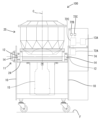
以下、本発明を具体化した実施形態1を図1から図8を参照して説明する。本発明の制御方法が実行されるコーティング装置100は、コーティング槽25を有する。コーティング槽25の中で、例えばチョコレート菓子、チューイングガム、豆菓子、錠剤等の核となるコーティング対象物(以下、センターともいう)の表面に、チョコレートやシロップ、砂糖などのコーティング剤からなる被覆層を形成することができる。コーティング槽25は、床面Fに載置された基台10に設けた傾動機構11により、図1に示す起立姿勢(コーティング槽25の回転軸Cが概ね鉛直方向となる姿勢)と図3に示す傾斜姿勢(コーティング槽25の回転軸Cが鉛直方向に対して斜め方向となる姿勢)との間で姿勢を変更することができる。コーティング槽25は、ステンレス製のアンダープレート26と、ステンレス製のドラム28Aと、ステンレス製のディスク38Aとを有する。
<
Hereinafter, a first embodiment of the present invention will be described with reference to Figs. 1 to 8. A
コーティング装置100は、センターの種類に応じて、起立姿勢でのコーティング処理と傾斜姿勢でのコーティング処理とを併用する使用形態と、起立姿勢又は傾斜姿勢の何れか一方の姿勢でのみコーティング処理を行う使用形態との、いずれの使用形態にも対応することができる。以下の説明において、上下方向は、図1に表れる向きをそのまま上方及び下方と定義し、コーティング槽25が起立姿勢である状態を基準とする。Depending on the type of center, the
傾動機構11は、図2に示すように、基台10に水平方向に間隔を空けて設けた一対の水平な傾動軸12と、傾動軸12を所定の角度回転させるための傾動モータ13Aと、を備えて構成されている。傾動軸12には、傾動モータ13Aにおいて生じた回転力が伝達される。傾動モータ13Aは、基台10に設けられた収容部74に収容され、制御装置72に電気的に接続されている(図2、7参照)。制御装置72は、収容部74に収容されている。傾動モータ13Aの回転速度や回転方向は、制御装置72によって制御される。傾動軸12の両端部には、コーティング槽25を支持する一対の傾動フレーム14が一体的に傾動し得るように取り付けられている。一対の傾動フレーム14にはベースプレート24が固定されている。As shown in FIG. 2, the
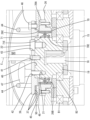
ベースプレート24には、第1モータ15と第2モータ17とが、ベースプレート24と一体的に傾動し得るように取り付けられている。図4に示すように、第1モータ15は、コーティング槽25の回転軸Cと同軸状に上向きに突出した第1駆動軸16を有する。第1駆動軸16は、正逆両方向に回転する動力伝達軸である。第1駆動軸16には、ほぼ円柱形をなす回転部材19が第1駆動軸16とともに一体的に回転し得るように設けられている。回転部材19は、ベアリングB2を介してベースプレート24の上方に配置されている。
The
第2モータ17は、第1駆動軸16と平行であって上向きに突出する第2駆動軸18を有する。第2モータ17は、第1モータ15に対して偏心した位置関係に配置されている。したがって、第2駆動軸18は、第1駆動軸16とは独立して、正逆両方向に回転するようになっている。第2駆動軸18には、駆動ギヤ23が一体回転し得るように取り付けられている。第1モータ15及び第2モータ17の各々は、制御装置72に電気的に接続され(図7参照)、これらの回転速度や回転方向が制御装置72によって個別に作動するように制御される。なお、第1駆動軸16と第2駆動軸18は、ベースプレート24を貫通してその上方へ突出している。The
[アンダープレートの構成]
アンダープレート26は、上面が下向きに凹んだ円形の皿状をなす。アンダープレート26は、ベアリングB1を介すことによって、第1駆動軸16と同軸状に且つ第1駆動軸16に対して相対回転し得るように(つまり、第1駆動軸16とは独立して回転し得るように)ベースプレート24に支持されている。アンダープレート26の中心部には、アンダープレート26と同心の円環状をなした円環部材26Aが設けられている。円環部材26Aの内側の開口は、アンダープレート26と同心の円形をなす貫通孔26Bを構成する。円環部材26Aの上面における貫通孔26Bの内周縁には、全周にわたって上向きに突出する円環形の突部26Cが設けられている(図5参照)。
[Underplate configuration]
The
円環部材26Aの貫通孔26Bには、円環状をなした第1シール部材70及び円環状をなした第2シール部材71が嵌め込まれている。第2シール部材71は、第1シール部材70の上方に設けられている。具体的には、第1シール部材70と、第2シール部材71とは、上下方向に隣接している。第2シール部材71の上端は、突部26Cの上端と概ね同じ高さに配置されている。第1シール部材70及び第2シール部材71には、例えば、公知のオイルシールが用いられる。A
第1シール部材70及び第2シール部材71には、第1駆動軸16の回転部材19が挿通されている。つまり、回転部材19は、アンダープレート26に貫通する貫通孔26Bに挿通されている。回転部材19の外周面には、第1シール部材70のリップ70E、及び第2シール部材71のリップ71Eが接触している。第1シール部材70及び第2シール部材71は、回転部材19の外周面と貫通孔26Bの内周面との間を液密状に埋めるように設けられている。The rotating
第1シール部材70よりも下方に配置されたベアリングB1,B2は、グリス等の潤滑剤(すなわち流体)を注入し得る構成とされている。第1シール部材70は、ベアリングB1,B2からはみ出したグリス等の潤滑剤が貫通孔26B内を上向きに移動することを規制する機能を有している。The bearings B1 and B2, which are disposed below the
アンダープレート26の下面における外周縁部には、アンダープレート26と同軸状の内歯歯車27が一体的に回転し得るように取り付けられている(図4参照)。内歯歯車27は、第2駆動軸18の駆動ギヤ23に噛み合っている。駆動ギヤ23と内歯歯車27とが噛み合うことによって、第2モータ17によって生じた回転力がアンダープレート26に伝達され、アンダープレート26が回転軸C周りの一方向及び他方向へ回転駆動されるようになっている。An
[ドラムの構成]
ドラム28Aは、図1に示すように、全体として上下両面が開放された概ね円筒状をなしている。ドラム28Aは、絞り部29、本体部30、及びテーパ部31を有している。ドラム28Aは、アンダープレート26に固定され、アンダープレート26と一体的に回転可能である。絞り部29は、上方に向かって縮径した形態をなし、12の台形状構成面29Aを、周方向に並べて構成されている。
[Drum configuration]
As shown in Fig. 1, the
本体部30は、絞り部29の下端縁に連なっており、上端から下端に至るまで径寸法がほぼ一定の形態をなしている。本体部30の内周面は、平面状をなす12の長方形状構成面30Aを周方向に並べて構成されている。本体部30の上端縁と絞り部29の下端縁とは、図示しない磁石によって連結している。絞り部29は、持ち上げることによって、本体部30から容易に取り外すことができる。The
テーパ部31は、本体部30の下端縁に連なって、下方に向かって次第に縮径した形態をなしている。テーパ部31は、12の上向き三角形状構成面31Aと、12の下向き三角形状構成面31Bとを、周方向に交互に並べて構成されている。テーパ部31は、下方に向かって次第に縮径した形態をなしている。The tapered
ドラム28Aは、図4に示すように、円環状に形成されたPTFE(ポリテトラフルオロエチレン)等の合成樹脂製のガスケット34を介し、アンダープレート26の上端部に設けられた鍔部35に対して同軸状に一体回転し得るように、且つ離脱可能に取り付けられている。アンダープレート26は、ドラム28Aのテーパ部31の下面の開口を塞いでいる。As shown in Figure 4, the
[ディスクの構成]
ディスク38Aは、図4、6に示すように、円盤状のディスク本体部73と、円環形の補強部53とを備えている。ディスク本体部73は、円板状の取付部材39、及び円環形をなす機能部材48を同軸状に組み付けて皿状をなすように構成されている。図5に示すように、取付部材39の中心部の下側には、上向きに凹む凹部40が形成されている。取付部材39には、中心貫通孔41と、偏心貫通孔42と、逃がし孔43と、が形成されている。中心貫通孔41は、取付部材39の中心位置において取付部材39を上下方向に貫通している。偏心貫通孔42は、取付部材39の中心から偏心して回転部材19の偏心雌ネジ孔21と対応する位置において、取付部材39を上下方向に貫通している。逃がし孔43は、取付部材39の中心から偏心してピン22と対応する位置において、取付部材39を上下方向に貫通している。取付部材39の上面には、一対のハンドル44が設けられている。取付部材39の外周縁部の下側には、全周にわたって上向きに凹ませた外周縁凹部45が形成されている。
[Disk configuration]
As shown in Figs. 4 and 6, the
取付部材39は、凹部40を回転部材19の上端部に嵌合させて回転部材19に載置されることによって、回転部材19に対して同軸状、且つ径方向への相対変位を規制された状態で組み付けられる。そして、偏心貫通孔42に貫通させたハンドル付きボルト47を偏心雌ネジ孔21に締め込むことによって、取付部材39は、回転部材19に対して、上方への相対変位を規制されるとともに、一体回転するように固定される。逃がし孔43には、回転部材19のピン22が嵌合され、取付部材39の回転部材19に対する周方向の位置決めがなされる。The mounting
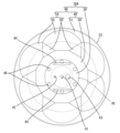
機能部材48は、図4、6に示すように、外面部49と、外面部49の上面側を覆う形態の内面部54とからなる。外面部49は、水平な円形をなす環状部50と、環状部50の外周縁から斜め外上方へ延出するテーパ状の傾斜部51とからなる。外面部49(傾斜部51)の外周縁部(最上端縁部)には、その外周面に沿って径方向の寸法を大きくした補強部53が設けられている。補強部53によって、外面部49(つまり、ディスク38A)の外周縁が真円形に維持される。
As shown in Figures 4 and 6, the
内面部54は、その内周縁を環状部50の上面に対して隙間なく連ねるとともに、傾斜部51よりも小さい傾斜角度で斜め外上方へ延出したテーパ状をなす。内面部54の外周縁(最上端縁)は、外面部49の内面(上面)に隙間なく連なっている。内面部54の内面(上面)は、全体として擂り鉢状をなしている。具体的には、内面部54は、図6に示すように、花びら形をなす概ね平面状の6つの扇形不連続面55と、二等辺三角形状をなす概ね平面状の6つの三角形不連続面56とを有している。The
6つの扇形不連続面55と6つの三角形不連続面56のそれぞれは、周方向において等角度ピッチで配置され、扇形不連続面55と三角形不連続面56とが周方向において交互に隣接して並んでいる。周方向に隣合う扇形不連続面55と三角形不連続面56との境界線は、周方向に交差する向きに延び、扇形不連続面55と三角形不連続面56とが面一状ではなく鈍角状(つまり、不連続状)に連なる。したがって、この内面部54の上面に載置されたセンターは、隣接する扇形不連続面55と三角形不連続面56との間の鈍角状の境界に引っ掛かり易く、内面部54上において周方向に滑り難くなっている。The six
扇形不連続面55の内側の縁部、及び三角形不連続面56の内側の縁部は、環状部50の内周縁部に沿っている。三角形不連続面56の最も外周側の頂点部は、隣接する扇形不連続面55の鋭角状端部の間に挟まるように配置されている。扇形不連続面55の外周縁は、その全領域が傾斜部51の外周縁よりも内側に位置している。The inner edge of the sector-shaped
機能部材48は、図5に示すように、環状部50の内周縁部を取付部材39の外周縁凹部45に対して下方から嵌合させ、複数のスペーサ37を介して外周縁凹部45の下面に取り付けられている。具体的には、取付部材39の外周縁部を板厚方向に貫通させた6つのボルト46(図6参照)を環状部50に締め込むことによって、機能部材48は取付部材39に取り付けられている。機能部材48は、取付部材39に対し水平方向(径方向及び周方向)への相対回転を規制された状態で組み付けられている。As shown in Fig. 5, the
こうして構成されたディスク38Aは、アンダープレート26の上方おいて、ドラム28Aの下面を塞ぐように配置されている。ディスク38Aは、第1駆動軸16に対し回転部材19を介して一体的に回転可能に結合されている。つまり、第1駆動軸16は、ディスク38Aに第1モータ15の回転力を伝達する。ディスク38Aは、ドラム28Aと同軸状の回転が可能とされている。ディスク38Aの補強部53(外周縁)は、ドラム28Aのテーパ部31の下端部の内周面に沿うように配されている。つまり、ディスク38Aは、ドラム28Aのテーパ部31の下面の開口を塞いでいる。ディスク38Aの補強部53の外周面と、ドラム28Aのテーパ部31の下端部の内周面との間には隙間Gが設けられている。隙間Gは、ディスク38Aの全周にわたって、概ね一定である。The
[制御装置の構成]
制御装置72は、例えばマイクロコンピュータを主体として構成されたPLC(Programmable Logic Controller)又はPC(Programmable Controller)等が用いられる。制御装置72は、傾動モータ13A、第1モータ15、及び第2モータ17の回転速度や回転方向を制御する機能を有している。制御装置72には、図2、7に示すように、コーティング槽25の姿勢が起立姿勢であるか傾斜姿勢であるかを検知する姿勢検知センサ72Aが電気的に接続されている。姿勢検知センサ72Aは、収容部74に収容されている。さらに、制御装置72には、第1ボタン72B、及び第2ボタン72Cが電気的に接続され、例えば、使用者が押下し易い位置である収容部74の上面に取り付けられている。
[Configuration of the control device]
The
第1ボタン72Bを押下すると、制御装置72は、ドラム28Aを一方向に回転させるように第2モータ17の回転方向を制御するとともに、ディスク38Aを他方向に回転させるように第1モータ15の回転方向を制御する。さらに、姿勢検知センサ72Aからの信号が起立姿勢に対応した信号でない場合、制御装置72は、コーティング槽25の姿勢を傾斜姿勢から起立姿勢に変更させるように傾動モータ13Aの動作を制御する。このように、第1ボタン72Bを押下すると、制御装置72は、コーティング槽25を起立姿勢にして、ドラム28Aを一方向に回転させ、ディスク38Aを他方向に回転させる第1回転工程を実行する。When the
第2ボタン72Cを押下すると、制御装置72は、ドラム28Aを一方向に回転させるように第2モータ17の回転方向を制御するとともに、ディスク38Aも一方向に回転させるように第1モータ15の回転方向を制御する。さらに、姿勢検知センサ72Aからの信号が傾斜姿勢に対応した信号でない場合、制御装置72は、コーティング槽25の姿勢を起立姿勢から傾斜姿勢に変更させるように傾動モータ13Aの動作を制御する。When the
既に第1ボタン72Bが押下された状態(すなわち、第1回転工程を実行中)で、第2ボタン72Cを押下した場合、制御装置72は、コーティング槽25の姿勢を起立姿勢から傾斜姿勢に変更させるように傾動モータ13Aの動作を制御して、姿勢変更工程を実行する。When the
姿勢変更工程を実行中において、制御装置72は、他方向に回転するディスク38Aの回転を停止させるように第1モータ15の回転速度を制御する。そして、ディスク38Aの回転が停止した後、制御装置72は、ディスク38Aを一方向へ回転させるように第1モータ15の回転方向を制御する。さらに、制御装置72は、回転軸C周りの一方向に回転するディスク38Aの回転速度がドラム28Aの回転速度と同じになるように、第1モータ15の回転速度を制御する。制御装置72は、コーティング槽25の姿勢が傾斜姿勢に至る前(すなわち、姿勢変更工程が完了する前)に、ディスク38Aの回転速度をドラム28Aの回転速度と同じにする。制御装置72は、姿勢変更工程が完了すると、第2回転工程を実行する。こうして、制御装置72は、第1回転工程、姿勢変更工程、及び第2回転工程の順番で各工程を実行する。During the posture change process, the
[コーティング装置の制御方法について]
次に、本実施形態のコーティング装置100の制御方法の一例を説明する。先ず、ドラム28Aとアンダープレート26が回転していない状態でコーティング槽25内にセンターを投入する。そして、図8におけるステップS1において、制御装置72は、第1ボタン72Bが押下されたか否かを判定する。ステップS1において、第1ボタン72Bが押下されていないと制御装置72が判別する(ステップS1におけるNo)と、第1回転工程を開始せず、待機状態になる。ステップS1において、第1ボタン72Bを押下されたと制御装置72が判別する(ステップS1におけるYes)と、ステップS2に移行する。
[Method of controlling the coating device]
Next, an example of a control method for the
ステップS2に移行すると、制御装置72は、第1回転工程を実行する。具体的には、制御装置72は、ドラム28Aとアンダープレート26を比較的低速で一方向に回転させるとともに、ディスク38Aを高速で他方向に回転させる。このとき、姿勢検知センサ72Aからの信号が起立姿勢に対応した信号でない場合、制御装置72は、コーティング槽25の姿勢をコーティング槽25の回転軸Cを鉛直方向に向けた起立姿勢に変更させるように傾動モータ13Aの動作を制御する。When the process proceeds to step S2, the
投入されたセンターは、ディスク38A上において扇形不連続面55と三角形不連続面56との境界による引っ掛かり作用により回転力を付与され、遠心力により機能部材48のテーパ状をなす上面とドラム28Aの内壁に沿って螺旋方向に上向きに移動する。そして、センターは、表層に出現して重力により螺旋方向に滑落してディスク38Aの中心寄りに戻り、再びディスク38Aにより回転駆動される。第1回転工程において、コーティング槽25内のセンターは、このような渦流状の循環流動を繰り返す。この渦流状の循環流動によって撹拌されているセンター群にコーティング剤を散布すれば、各センターの表面に被覆層が形成される。The inserted centers are given a rotational force by the catch action of the boundary between the sector
この渦流を利用したコーティング方法では、センターに遠心力を付与するためにディスク38Aを高速で回転させる。このため、センター群の流動速度が速く、撹拌効果も高いので、コーティング処理が短時間で済むという利点がある。なお、このときのドラム28Aの一方向への回転速度は、0rpm(すなわち回転を停止)から60rpm程度である。一方、ディスク38Aの他方向への回転速度は、50から300rpmである。In this coating method using vortex currents, the
次に、ステップS3に移行する。ステップS3において制御装置72は、第2ボタン72Cが押下されていない(ステップS3におけるNo)と判別すると、ステップS3の判定を繰り返し実行しつつ、第1回転工程の実行を継続する。ステップS3において、制御装置72は、第2ボタン72Cが押下された(ステップS3におけるYes)と判別すると、ステップS4に移行する。Next, the process proceeds to step S3. If the
ステップS4に移行すると、制御装置72は、コーティング槽25の姿勢を起立姿勢から傾斜姿勢に変更する姿勢変更工程を実行する。姿勢変更工程は、第1回転工程と第2回転工程との間に実効される。そして、姿勢変更工程の実行開始と同時に、又は姿勢変更工程の実行中に、制御装置72は、他方向に回転するディスク38Aの回転速度の減速を開始する。そして、ディスク38Aの回転が停止した後、制御装置72は、ディスク38Aを一方向に回転させる。つまり、制御装置72は、姿勢変更工程の実行中に、ディスク38Aの回転方向を他方向から一方向へ切り替える。
When proceeding to step S4, the
そして、制御装置72は、コーティング槽25の姿勢が傾斜姿勢に至る前(すなわち、姿勢変更工程の実行中)に、ディスク38Aの一方向への回転速度をドラム28Aと同じ回転速度に到達させる。そして、コーティング槽25の姿勢が傾斜姿勢に至り、姿勢変更工程が終了すると、ステップS5に移行する。Then, before the attitude of the
ステップS5に移行すると、制御装置72は、第2回転工程を実行する。第2回転工程では、コーティング槽25の姿勢を、回転軸Cを鉛直方向に対して傾いた傾斜姿勢にし、ドラム28A及びディスク38Aを一方向に回転させる。When the process proceeds to step S5, the
第2回転工程では、コーティング槽25内に投入されたセンターは、コーティング槽25の内周(ドラム28Aの内壁面とディスク38Aの上面)との摩擦や、扇形不連続面55及び三角形不連続面56による引っ掛かり作用によって、回転方向前方へ持ちあげられる。そして、センターは、自重により滑落して、ドラム28Aの内壁面との摩擦や、扇形不連続面55及び三角形不連続面56による引っ掛かり作用によって再び持ち上げられる。第2回転工程において、コーティング槽25内のセンターは、このような循環流動を繰り返す。これによって、各センターにおけるコーティングの仕上がりのばらつきを抑えることができる。このときのコーティング槽25の鉛直方向に対する傾き角度は、45°から70°が好ましい。In the second rotation step, the centers put into the
第2回転工程において、コーティング槽25を高速回転させると、センター群が、強い遠心力によってコーティング槽25の内周に張り付いた状態となって循環流動しなくなるため、コーティング槽25は比較的低速で回転駆動される。具体的には、ドラム28A及びディスク38Aの回転速度は、第1回転工程のときと異なり、5rpmから50rpm程度にされる。In the second rotation process, if the
<実施形態の作用及び効果>
このコーティング装置の制御方法は、筒状のドラム28Aと、皿状のディスク38Aと、を有するコーティング槽25を備えたコーティング装置の制御方法である。ドラム28Aは、回転可能である。ディスク38Aは、ドラム28Aの下面を塞ぐように配されているとともに、ドラム28Aと同軸状の回転が可能である。このコーティング装置の制御方法は、第1回転工程と、第2回転工程と、を実行する。第1回転工程は、ドラム28Aとディスク38Aとを有するコーティング槽25の姿勢を、コーティング槽25の回転軸Cを鉛直方向に向けた起立姿勢にし、ドラム28Aを回転軸C周りの一方向に回転させるとともに、ディスク38Aを回転軸C周りの他方向に回転させる。第2回転工程は、コーティング槽25の姿勢を、回転軸Cを鉛直方向に対して傾いた傾斜姿勢にし、ドラム28A及びディスク38Aを回転軸C周りの一方向に回転させる。
<Actions and Effects of the Embodiments>
This control method of the coating apparatus is a control method of the coating apparatus equipped with a
この構成によれば、第1回転工程によって、コーティング対象物のコーティングに要する時間を短縮できるとともに、第2回転工程によって、各コーティング対象物のコーティングの斑を抑えることができる。この2つの回転工程によって、コーティング対象物を良好にコーティングすることができる。 With this configuration, the first rotation process can shorten the time required to coat the objects to be coated, and the second rotation process can suppress unevenness in the coating of each object to be coated. These two rotation processes can provide a good coating to the objects to be coated.
このコーティング装置の制御方法は、第1回転工程と第2回転工程との間に、コーティング槽25の姿勢を起立姿勢から傾斜姿勢に変更する姿勢変更工程をさらに備えている。姿勢変更工程を実行中は、ドラム28Aの回転方向を回転軸C周りの一方向に維持し、姿勢変更工程の実行開始と同時に、又は姿勢変更工程の実行中に、ディスク38Aの回転軸C周りの回転速度の減速を開始する。この構成によれば、第1回転工程において、ディスク38Aの回転速度が減速しないので、第1回転工程を確実に実行することができる。This coating apparatus control method further includes a posture change process between the first and second rotation processes, in which the posture of the
このコーティング装置の制御方法は、姿勢変更工程の実行中に、ディスク38Aの回転方向を回転軸C周りの他方向から回転軸C周りの一方向へ切り替える。この構成によれば、第1回転工程及び第2回転工程の実行中にディスク38Aの回転方向を切り替えずに済むので、第1回転工程及び第2回転工程においてディスク38Aの回転が停止することを避けることができる。これにより、第1回転工程及び第2回転工程を確実に実行することができる。また、コーティング槽25が起立姿勢のときに、ディスク38Aの回転方向をドラム28Aの回転方向に揃えてしまうと、個々のコーティング対象物は、コーティング槽25の内周面に張り付いた状態で同期回転し、コーティング対象物同士の相対的な変位が生じ難くなってしまうため、コーティング対象物同士でくっついてしまう。これに対して、このコーティング装置の制御方法は、姿勢変更工程の実行中にディスク38Aの回転方向をドラム28Aの回転方向に揃えるので、個々のコーティング対象物は自重により落下し易くなり、コーティング対象物同士の相対的な変位が生じ難くなることを抑制することができる。
In this control method of the coating device, the rotation direction of the
このコーティング装置の制御方法は、姿勢変更工程の実行中に、ディスク38Aの回転軸C周りの一方向への回転速度を、ドラム28Aと同じ回転速度に到達させる。この構成によれば、第2回転工程を実行する前に、ディスク38Aとドラム28Aの回転速度を合わせ、ディスク38Aとドラム28Aとを一体的に回転させることができるので、コーティング対象物の運動が止まることが無く、コーティング槽25の内周面にくっつかずに第2回転工程に移行することができる。
<他の実施形態>
本発明は上記記述及び図面によって説明した実施形態に限定されるものではなく、その趣旨を逸脱しない範囲において種々の構成で実現することができる。例えば、上述した実施形態や後述する実施形態の様々な特徴は、発明の趣旨を逸脱せず且つ矛盾しない組み合わせであればどのように組み合わせてもよい。また、その技術的特徴が本明細書中に必須なものとして説明されていなければ、適宜、削除することが可能である。
(1)上記実施形態とは異なり、コーティング槽にアルミ等の軽金属、メッキされた鋼材や、ウレタンゴム、UPE(超高分子量ポリエチレン)、POM(ポリアセタール)等の合成樹脂等を用いてもよい。
(2)上記実施形態とは異なり、第1回転工程において、コーティング槽の回転軸を鉛直方向に対して僅かに(15°程度)傾けてもよい。この場合でも、良好にコーティング処理を行うことができる。
(3)上記実施形態とは異なり、第2回転工程において、ドラムとディスクの回転方向を回転軸周りの一方向に揃えた上で、ドラムとディスクの回転速度を僅かに異ならせてもよい。この場合、ディスクの回転速度は、ドラムの回転速度より早くてもよく、遅くてもよい。
(4)上記実施形態とは異なり、第2モータからドラムへの回転力の伝達手段として、外歯歯車にドラム用駆動機構の駆動軸を係合させてもよい。また、ベルトを介して回転力を伝達させたり、アイドラーやローラーを介して回転力を伝達させたりしてもよい。
(5)上記実施形態とは異なり、ドラムの上面の開口を、ドラムとは別体の蓋によって閉鎖できるようにしてもよい。この場合、蓋は、ドラムに対してヒンジ等により開閉動作を可能に且つドラムからは簡単には外せないように取り付けられていてもよく、ドラムに対してボルトや凹凸嵌合などにより比較的簡単に着脱できるようなものであってもよい。
(6)上記実施形態とは異なり、姿勢変更工程において、起立姿勢から傾斜姿勢へ変更を開始するタイミングは、ディスクの回転速度の減速を開始するタイミングに対して僅かに早くてもよく、僅かに遅くてもよい。また、起立姿勢から傾斜姿勢へ変更を完了するタイミングは、ディスクの回転速度がドラムの回転速度に到達するタイミングに対して僅かに早くてもよい。
In this control method for the coating apparatus, the rotation speed of the
<Other embodiments>
The present invention is not limited to the embodiments described above and in the drawings, and may be realized in various configurations without departing from the spirit of the present invention. For example, the various features of the above-mentioned embodiments and the embodiments to be described later may be combined in any combination that does not deviate from the spirit of the invention and is not contradictory. Furthermore, if a technical feature is not described in this specification as being essential, it may be deleted as appropriate.
(1) Unlike the above embodiment, the coating tank may be made of a light metal such as aluminum, plated steel, or a synthetic resin such as urethane rubber, UPE (ultra-high molecular weight polyethylene), or POM (polyacetal).
(2) Unlike the above embodiment, in the first rotation step, the rotation axis of the coating tank may be inclined slightly (by about 15°) with respect to the vertical direction. Even in this case, the coating process can be performed satisfactorily.
(3) Unlike the above embodiment, in the second rotation step, the rotation directions of the drum and the disk may be aligned in one direction around the rotation axis, and the rotation speeds of the drum and the disk may be slightly different from each other. In this case, the rotation speed of the disk may be faster or slower than the rotation speed of the drum.
(4) Unlike the above embodiment, the drive shaft of the drum drive mechanism may be engaged with the external gear as a means for transmitting the rotational force from the second motor to the drum. Also, the rotational force may be transmitted via a belt, an idler, or a roller.
(5) Unlike the above embodiment, the opening on the top surface of the drum may be closed by a lid separate from the drum. In this case, the lid may be attached to the drum by a hinge or the like so as to be openable and closable but not easily detachable from the drum, or may be relatively easily attached and detachable to the drum by bolts or a concave-convex fit.
(6) Unlike the above embodiment, in the posture changing process, the timing at which the posture starts to change from the upright posture to the inclined posture may be slightly earlier or later than the timing at which the disk rotation speed starts to decelerate, and the timing at which the posture changes from the upright posture to the inclined posture may be completed slightly earlier than the timing at which the disk rotation speed reaches the drum rotation speed.
25…コーティング槽
28A…ドラム
38A…ディスク
100…コーティング装置
C…回転軸
S2…第1回転工程
S4…姿勢変更工程
S5…第2回転工程
25:
Claims (3)
前記コーティング槽の姿勢を、前記コーティング槽の回転軸を鉛直方向に向けた起立姿勢にし、前記ドラムを一方向に回転させるとともに、前記ディスクを他方向に回転させる第1回転工程と、
前記コーティング槽の姿勢を、前記回転軸を前記鉛直方向に対して傾けた傾斜姿勢にし、前記ドラム及び前記ディスクを前記一方向に回転させる第2回転工程と、
を実行し、
前記第1回転工程と前記第2回転工程との間に、前記コーティング槽の姿勢を前記起立姿勢から前記傾斜姿勢に変更する姿勢変更工程をさらに備え、
前記姿勢変更工程を実行中は、前記ドラムの回転方向を前記一方向に維持し、
前記姿勢変更工程の実行開始と同時に、又は前記姿勢変更工程の実行中に、前記ディスクの回転速度の減速を開始するコーティング装置の制御方法。 A method for controlling a coating apparatus including a coating tank having a cylindrical rotatable drum and a dish-shaped disk arranged to close a lower surface of the drum and capable of rotating coaxially with the drum, comprising the steps of:
a first rotation step of setting the coating vessel in an upright position with a rotation axis of the coating vessel oriented vertically, rotating the drum in one direction, and rotating the disk in another direction;
a second rotation step of rotating the coating tank in such a manner that the rotation shaft is inclined with respect to the vertical direction, and rotating the drum and the disk in the one direction;
Run
a posture changing step of changing a posture of the coating tank from the upright posture to the inclined posture between the first rotation step and the second rotation step,
During the position changing step, the rotation direction of the drum is maintained in the one direction;
A method for controlling a coating apparatus , comprising the steps of: starting to reduce the rotational speed of the disk simultaneously with the start of execution of the attitude changing step; or during execution of the attitude changing step .
Applications Claiming Priority (1)
| Application Number | Priority Date | Filing Date | Title |
|---|---|---|---|
| PCT/JP2021/035073 WO2023047529A1 (en) | 2021-09-24 | 2021-09-24 | Control method of coating device |
Publications (2)
| Publication Number | Publication Date |
|---|---|
| JPWO2023047529A1 JPWO2023047529A1 (en) | 2023-03-30 |
| JP7586552B2 true JP7586552B2 (en) | 2024-11-19 |
Family
ID=85719360
Family Applications (1)
| Application Number | Title | Priority Date | Filing Date |
|---|---|---|---|
| JP2023549253A Active JP7586552B2 (en) | 2021-09-24 | 2021-09-24 | Coating device control method |
Country Status (4)
| Country | Link |
|---|---|
| US (1) | US12558703B2 (en) |
| EP (1) | EP4406640A4 (en) |
| JP (1) | JP7586552B2 (en) |
| WO (1) | WO2023047529A1 (en) |
Families Citing this family (2)
| Publication number | Priority date | Publication date | Assignee | Title |
|---|---|---|---|---|
| CN118575975B (en) * | 2024-06-12 | 2025-10-03 | 喀什疆果果农业科技有限公司 | A powder coating device for nut processing |
| CN118719445B (en) * | 2024-09-03 | 2024-11-22 | 介休市金盛碳素有限公司 | A graphite electrode impregnation device and impregnation method thereof |
Citations (2)
| Publication number | Priority date | Publication date | Assignee | Title |
|---|---|---|---|---|
| JP2011189233A (en) | 2010-03-12 | 2011-09-29 | Tipton Corp | Coating apparatus and coating vessel |
| JP2012183500A (en) | 2011-03-07 | 2012-09-27 | Tipton Corp | Coating apparatus |
Family Cites Families (1)
| Publication number | Priority date | Publication date | Assignee | Title |
|---|---|---|---|---|
| JP2009078232A (en) * | 2007-09-26 | 2009-04-16 | Omnibus:Kk | Coating device |
-
2021
- 2021-09-24 EP EP21958405.9A patent/EP4406640A4/en active Pending
- 2021-09-24 WO PCT/JP2021/035073 patent/WO2023047529A1/en not_active Ceased
- 2021-09-24 US US18/569,151 patent/US12558703B2/en active Active
- 2021-09-24 JP JP2023549253A patent/JP7586552B2/en active Active
Patent Citations (2)
| Publication number | Priority date | Publication date | Assignee | Title |
|---|---|---|---|---|
| JP2011189233A (en) | 2010-03-12 | 2011-09-29 | Tipton Corp | Coating apparatus and coating vessel |
| JP2012183500A (en) | 2011-03-07 | 2012-09-27 | Tipton Corp | Coating apparatus |
Also Published As
| Publication number | Publication date |
|---|---|
| WO2023047529A1 (en) | 2023-03-30 |
| JPWO2023047529A1 (en) | 2023-03-30 |
| EP4406640A1 (en) | 2024-07-31 |
| US12558703B2 (en) | 2026-02-24 |
| US20240286162A1 (en) | 2024-08-29 |
| EP4406640A4 (en) | 2025-07-23 |
Similar Documents
| Publication | Publication Date | Title |
|---|---|---|
| JP7586552B2 (en) | Coating device control method | |
| JP5032693B2 (en) | rice cooker | |
| RU2768399C1 (en) | Hygienic mixer | |
| KR200462500Y1 (en) | auto mixing container for cosmetic | |
| US5890803A (en) | Conical mixing device comprising at least one mixing screw and a fast rotating horizontal rotor on a vertical drive shaft | |
| JP3088067B2 (en) | Defoaming stirrer | |
| CN111035228B (en) | Cooking method and apparatus thereof | |
| JPH08173784A (en) | Kneading device and kneading method | |
| JP2011189232A (en) | Coating apparatus | |
| JP5154522B2 (en) | Material filling apparatus and material filling method | |
| JP4685959B1 (en) | Coating device and coating tank | |
| CN110973983B (en) | Cooking Equipment | |
| JP4398451B2 (en) | Stirrer | |
| JP5603808B2 (en) | Coating equipment | |
| JP2005021810A (en) | Coating apparatus | |
| WO2023047528A1 (en) | Seal structure for coating tank | |
| JPH07227165A (en) | Cooking apparatus | |
| US5029673A (en) | Lubrication system for rotary clamp | |
| WO2023047527A1 (en) | Coating tank disc and coating tank | |
| US9867384B2 (en) | Greek yogurt making device | |
| JPH07227166A (en) | Butter producing apparatus | |
| JP2004016692A (en) | Automatic bread maker | |
| JP4021556B2 (en) | Defoaming device | |
| KR102895105B1 (en) | Mixing apparatus and food mixing automation system including the same | |
| KR100395963B1 (en) | Tray rotating device for microwave oven |
Legal Events
| Date | Code | Title | Description |
|---|---|---|---|
| A621 | Written request for application examination |
Free format text: JAPANESE INTERMEDIATE CODE: A621 Effective date: 20231116 |
|
| A131 | Notification of reasons for refusal |
Free format text: JAPANESE INTERMEDIATE CODE: A131 Effective date: 20240820 |
|
| A521 | Request for written amendment filed |
Free format text: JAPANESE INTERMEDIATE CODE: A523 Effective date: 20240924 |
|
| TRDD | Decision of grant or rejection written | ||
| A01 | Written decision to grant a patent or to grant a registration (utility model) |
Free format text: JAPANESE INTERMEDIATE CODE: A01 Effective date: 20241029 |
|
| A61 | First payment of annual fees (during grant procedure) |
Free format text: JAPANESE INTERMEDIATE CODE: A61 Effective date: 20241030 |
|
| R150 | Certificate of patent or registration of utility model |
Ref document number: 7586552 Country of ref document: JP Free format text: JAPANESE INTERMEDIATE CODE: R150 |