JP7582007B2 - Engine stop position control device - Google Patents
Engine stop position control device Download PDFInfo
- Publication number
- JP7582007B2 JP7582007B2 JP2021051346A JP2021051346A JP7582007B2 JP 7582007 B2 JP7582007 B2 JP 7582007B2 JP 2021051346 A JP2021051346 A JP 2021051346A JP 2021051346 A JP2021051346 A JP 2021051346A JP 7582007 B2 JP7582007 B2 JP 7582007B2
- Authority
- JP
- Japan
- Prior art keywords
- cylinder
- engine
- intake
- opening
- stop
- Prior art date
- Legal status (The legal status is an assumption and is not a legal conclusion. Google has not performed a legal analysis and makes no representation as to the accuracy of the status listed.)
- Active
Links
Images


Landscapes
- Output Control And Ontrol Of Special Type Engine (AREA)
- Control Of Vehicle Engines Or Engines For Specific Uses (AREA)
- Electrical Control Of Air Or Fuel Supplied To Internal-Combustion Engine (AREA)
- Combined Controls Of Internal Combustion Engines (AREA)
Description
本発明は、クランク軸を回転させてエンジンを強制的に始動可能な始動手段を備えるエンジンに設けられる停止位置制御装置に関する。 The present invention relates to a stop position control device that is installed in an engine that has a starting means that can forcibly start the engine by rotating the crankshaft.
従来より、エンジンが搭載された車両では、燃費性能の改善を図るために、エンジンを自動的に停止させるとともに、その後、始動手段を用いてエンジンを強制的に始動させることが行われている。 Conventionally, in vehicles equipped with an engine, the engine has been automatically stopped and then forcibly started using a starting means in order to improve fuel efficiency.
ここで、複数の気筒を備える多気筒エンジンでは、エンジンを始動させるために始動手段に求められるトルクがエンジン停止時の各気筒の位置(各気筒のピストン位置)に応じて変化することから、エンジン停止時に各気筒の位置を始動に適した位置にすることが求められる。 In a multi-cylinder engine, the torque required of the starting means to start the engine varies depending on the position of each cylinder (the piston position of each cylinder) when the engine is stopped, so it is necessary to set the position of each cylinder to a position suitable for starting when the engine is stopped.
これに対して、例えば、特許文献1のエンジンでは、エンジンの停止直前に次のような制御を実施している。つまり、膨張行程で停止する気筒である停止時膨張行程気筒(特許文献1における最終膨張気筒)の吸気が完了した後にスロットル弁の開度を大きくして、圧縮行程で停止する気筒である停止時圧縮行程気筒(特許文献1における最終圧縮気筒)の吸気量を増大させる制御を実施している。
In response to this, for example, the engine of
特許文献1のエンジンでは、停止時圧縮行程気筒の吸気量の増大によって当該気筒のピストンの上昇が抑制される。そのため、停止時圧縮行程気筒の停止位置が所望の位置よりも上死点側にずれるのを抑制できる。しかしながら、スロットル弁の開度を増大させると、停止時圧縮行程気筒内および吸気通路内の空気量が増大する。その結果、エンジン始動時の各気筒の吸気量の酸素濃度が大きくなってエンジン始動直後のNOx生成量が増大しやすくなる。
In the engine of
本発明は、上記のような事情に鑑みてなされたものであり、エンジン停止時の各気筒の位置を始動に適した位置に制御しつつ、エンジン始動直後のNOxの生成量の増大を防止できるエンジンの停止位置制御装置を提供することを目的とする。 The present invention was made in consideration of the above circumstances, and aims to provide an engine stop position control device that can control the position of each cylinder when the engine is stopped to a position suitable for starting, while preventing an increase in the amount of NOx generated immediately after the engine is started.
上記課題を解決するためのものとして、本発明は、複数の気筒と、各気筒に燃料を供給する燃料供給手段と、各気筒に往復動可能に設けられたピストンと、ピストンの往復動に連動して回転するクランク軸と、クランク軸を回転させてエンジンを強制的に始動可能な始動手段と、各気筒に導入される吸気が流通する吸気通路と、各気筒から導出される排気ガスが流通する排気通路とを備えるエンジンに設けられる停止位置制御装置であって、前記吸気通路に配設されて当該吸気通路を開閉するスロットル弁と、前記スロットル弁よりも下流の前記吸気通路と前記排気通路とを接続して排気ガスの一部であるEGRガスを前記吸気通路に還流させるEGR通路と、前記EGR通路を開閉するEGR弁と、前記燃料供給手段、前記スロットル弁および前記EGR弁を含むエンジンの各部を制御して、所定のエンジン停止条件が成立すると前記燃料供給手段による気筒内への燃料供給を停止する燃料カットを実施する制御手段とを備え、前記制御手段は、前記燃料カットの実施後に、圧縮行程で停止する気筒である停止時圧縮行程気筒の停止位置を予測するとともに、予測した前記停止時圧縮行程気筒の停止位置が所定の目標範囲よりも上死点側である場合は、前記停止時圧縮行程気筒の停止直前の吸気行程中に前記スロットル弁の開度あるいは前記EGR弁の開度を増大させる弁開度増大制御を実施し、前記制御手段は、前記吸気通路内の酸素濃度が所定の基準濃度未満であるという第1条件が成立する場合は、前記スロットル弁の開度を増大させる制御を前記弁開度増大制御として実施し、前記吸気通路内の酸素濃度が前記基準濃度以上であるという第2条件が成立する場合は、前記EGR弁の開度を増大させる制御を前記弁開度増大制御として実施する、ことを特徴とする(請求項1)。 In order to solve the above problems, the present invention provides a stop position control device provided in an engine having a plurality of cylinders, a fuel supply means for supplying fuel to each cylinder, a piston provided in each cylinder so as to be capable of reciprocating, a crankshaft that rotates in conjunction with the reciprocating movement of the piston, a starting means capable of forcibly starting the engine by rotating the crankshaft, an intake passage through which intake air introduced into each cylinder flows, and an exhaust passage through which exhaust gas discharged from each cylinder flows, the stop position control device including a throttle valve provided in the intake passage and opening and closing the intake passage, an EGR passage that connects the intake passage downstream of the throttle valve to the exhaust passage and recirculates EGR gas, which is a part of the exhaust gas, to the intake passage, an EGR valve that opens and closes the EGR passage, and controls each part of the engine including the fuel supply means, the throttle valve, and the EGR valve to start the fuel supply when a predetermined engine stop condition is established. and a control means for performing a fuel cut to stop the fuel supply to the cylinder by the fuel cut means. The control means predicts the stop position of a stop-time compression stroke cylinder, which is a cylinder that stops during the compression stroke after the fuel cut is performed, and if the predicted stop position of the stop-time compression stroke cylinder is on the top dead center side of a predetermined target range, performs a valve opening increase control to increase the opening of the throttle valve or the EGR valve during the intake stroke immediately before the stop of the stop-time compression stroke cylinder. If a first condition is satisfied that the oxygen concentration in the intake passage is less than a predetermined reference concentration, the control means performs the control to increase the opening of the throttle valve as the valve opening increase control, and if a second condition is satisfied that the oxygen concentration in the intake passage is equal to or greater than the reference concentration, the control means performs the control to increase the opening of the EGR valve as the valve opening increase control (claim 1).
本発明によれば、停止時圧縮行程気筒の停止位置が目標範囲よりも上死点側であるとが予測された場合に、停止時圧縮行程気筒の停止直前の吸気行程中にスロットル弁あるいはEGR弁の開度が増大されて当該停止時圧縮行程気筒に導入される空気あるいはEGRガスの量が増大されて当該気筒の吸気量が増大される。そのため、停止時圧縮行程気筒のピストンの上昇を抑えて、当該気筒の停止位置が目標範囲よりも上死点側にずれること、つまり、気筒の停止位置が始動に適した範囲からずれる可能性を小さくできる。 According to the present invention, when the stopping position of the stopped compression stroke cylinder is predicted to be closer to the top dead center than the target range, the opening of the throttle valve or EGR valve is increased during the intake stroke immediately before the stopped compression stroke cylinder is stopped, increasing the amount of air or EGR gas introduced into the stopped compression stroke cylinder, thereby increasing the intake amount of the cylinder. Therefore, the rise of the piston of the stopped compression stroke cylinder is suppressed, and the stopping position of the cylinder is less likely to deviate from the target range to the top dead center side, that is, the stopping position of the cylinder is less likely to deviate from the range suitable for starting.
しかも、本発明では、吸気通路内の酸素濃度が所定の基準濃度以上の時は、EGR弁の開度が増大されてEGRガスの増大によって吸気量が増大される。EGRガスは、排気通路から吸気通路に還流されるガスであり、既燃ガスを含むことでその酸素濃度は低い。そのため、EGRガスの量を増大させても、停止時圧縮行程気筒および吸気弁が開弁している他の気筒の酸素濃度の増大は抑制される。従って、本発明によれば、上記のように気筒の停止位置が目標範囲からずれる可能性を小さくしつつ、吸気通路内の酸素濃度が所定の基準濃度以上の時に各気筒の酸素濃度がさらに増大すること、および、これに伴ってエンジン始動時のNOx生成量が増大するのを抑制できる。 Moreover, in the present invention, when the oxygen concentration in the intake passage is equal to or higher than a predetermined reference concentration, the opening of the EGR valve is increased, and the intake volume is increased by increasing the EGR gas. EGR gas is a gas that is recirculated from the exhaust passage to the intake passage, and since it contains burnt gas, its oxygen concentration is low. Therefore, even if the amount of EGR gas is increased, the increase in oxygen concentration in the stopped compression stroke cylinder and other cylinders whose intake valves are open is suppressed. Therefore, according to the present invention, while reducing the possibility that the cylinder stop position deviates from the target range as described above, it is possible to suppress the further increase in oxygen concentration in each cylinder when the oxygen concentration in the intake passage is equal to or higher than a predetermined reference concentration, and the associated increase in the amount of NOx generated at engine start.
また、上記酸素濃度が基準濃度未満の時は、スロットル弁の開度が増大されて空気の増大によって吸気量が増大される。そのため、上記酸素濃度が基準濃度未満の時には、各気筒の酸素濃度が過度に低くなるのを防止でき、エンジン始動時の混合気の燃焼性を確保して良好な始動を実現できる。 In addition, when the oxygen concentration is below the reference concentration, the throttle valve opening is increased to increase the amount of intake air by increasing the amount of air. Therefore, when the oxygen concentration is below the reference concentration, the oxygen concentration in each cylinder can be prevented from becoming excessively low, ensuring the combustibility of the mixture when the engine is started, and achieving a good start.
前記構成において、好ましくは、前記第1条件の成立時、前記制御手段は、予測した前記停止時圧縮行程気筒の停止位置に基づいて前記スロットル弁の開度を変更する(請求項2)。 In the above configuration, preferably, when the first condition is satisfied, the control means changes the opening of the throttle valve based on the predicted stop position of the stop-time compression stroke cylinder (claim 2).
この構成によれば、停止時圧縮行程気筒の停止位置に基づいて当該気筒に導入される空気の量が調整されるので、当該気筒の停止位置をより確実に目標範囲内にすることができる。 With this configuration, the amount of air introduced into the cylinder during the compression stroke at the time of stopping is adjusted based on the stopping position of the cylinder, so that the stopping position of the cylinder can be more reliably kept within the target range.
前記構成において、好ましくは、前記第2条件の成立時、前記制御手段は、予測した前記停止時圧縮行程気筒の停止位置に基づいて前記EGR弁の開度を変更する(請求項3)。 In the above configuration, preferably, when the second condition is satisfied, the control means changes the opening of the EGR valve based on the predicted stop position of the stop-time compression stroke cylinder (claim 3).
この構成によれば、停止時圧縮行程気筒の停止位置に基づいて当該気筒に導入されるEGRガスの量が調整されるので、当該気筒の停止位置をより確実に目標範囲内にすることができる。 With this configuration, the amount of EGR gas introduced into the cylinder is adjusted based on the stop position of the compression stroke cylinder when stopped, so the stop position of the cylinder can be more reliably kept within the target range.
前記構成において、好ましくは、前記エンジンは、前記排気通路に設けられたタービンと前記吸気通路に設けられたコンプレッサとを含むターボ過給機を備え、前記EGR通路は、前記タービンよりも上流側の前記排気通路に接続されている(請求項4)。 In the above configuration, preferably, the engine is equipped with a turbocharger including a turbine provided in the exhaust passage and a compressor provided in the intake passage, and the EGR passage is connected to the exhaust passage upstream of the turbine (claim 4).
この構成では、仮にEGR通路をタービンの下流側の排気通路に接続した場合に比べて、EGR通路の通路長が短くなる。そのため、EGR弁を開弁した後、早期にEGRガスを吸気通路および気筒内に導入することができる。従って、上記第2条件の成立時において、エンジンが完全停止する前に確実に停止時圧縮行程気筒に導入されるEGRガスの量すなわち吸気の量を増大させることができ、停止時圧縮行程気筒の停止位置をより確実に目標範囲内にすることができる。 In this configuration, the length of the EGR passage is shorter than if the EGR passage were connected to the exhaust passage downstream of the turbine. Therefore, EGR gas can be introduced into the intake passage and cylinders soon after the EGR valve is opened. Therefore, when the second condition is met, the amount of EGR gas introduced into the compression stroke cylinder at the time of stop, i.e., the amount of intake air, can be reliably increased before the engine comes to a complete stop, and the stop position of the compression stroke cylinder at the time of stop can be more reliably kept within the target range.
以上説明したように、本発明のエンジンの停止位置制御装置によれば、エンジン停止時の各気筒の位置を始動に適した位置に制御しつつ、エンジン始動直後のNOxの生成量の増大を防止できる。 As described above, the engine stop position control device of the present invention can control the position of each cylinder when the engine is stopped to a position suitable for starting, while preventing an increase in the amount of NOx generated immediately after the engine is started.
(1)全体構成
図1は、本発明の実施形態に係るエンジンの停止位置制御装置が適用されるエンジンEを搭載した車両100の概略構成図である。本実施形態では、車両100は、エンジンEとモータMとを車両100(車輪101)の駆動源として備えるハイブリッド車両である。モータMは、請求項の「始動手段」に相当する。
(1) Overall Configuration Fig. 1 is a schematic diagram of a
図1に示すように、車両100は、車輪101、エンジンEおよびモータMに加えて、エンジンEの出力軸とモータMの回転軸とを断接可能に連結するクラッチ102、モータMとの間で電力の授受を行うバッテリ103、モータMに連結された変速機104、車輪101に連結されたドライブシャフト106、デファレンシャルギア等を含み変速機104とドライブシャフト106とを連結する動力伝達装置105を備える。
As shown in FIG. 1, in addition to
(エンジン構成)
図2は、エンジンEの概略構成図である。エンジンEは、エンジン本体1と、エンジン本体1に導入される吸気が流通する吸気通路30、エンジン本体1から排出される排気ガスが流通する排気通路40、排気通路40を流通する排気ガスの一部であるEGRガスを吸気通路30に還流させるEGR装置44を備える。また、エンジンEは、ターボ過給機46を備えており、排気通路40に設けられたタービン48と、吸気通路30に設けられてタービン48により回転駆動されるコンプレッサ47とを有する。本実施形態のエンジンEは、4サイクルのディーゼルエンジンであり、軽油を主成分とする燃料の供給を受けて駆動する。
(Engine configuration)
2 is a schematic diagram of the engine E. The engine E includes an
エンジン本体1は、気筒2が形成されたシリンダブロック3と、シリンダブロック3を覆うシリンダヘッド4とを有する。
The
図3は、エンジン本体1の概略断面図である。図3に示すように、本実施形態のエンジンEは直列6気筒エンジンであり、エンジン本体1(詳細にはシリンダブロック3)には一列に並ぶ6つの気筒2(気筒2の配列方向に沿って一方側から順に、第1気筒2A、第2気筒2B、第3気筒2C、第4気筒2D、第5気筒2Eおよび第6気筒2F)が形成されている。
Figure 3 is a schematic cross-sectional view of the
各気筒2にはそれぞれピストン5が往復摺動可能に収容されている。各気筒2内のピストン5の上方には燃焼室6が区画されている。各ピストン5はコネクティングロッド8を介してクランク軸7と連結されている。各ピストン5の往復運動に応じて、クランク軸7はその中心軸回りに回転する。
A
シリンダヘッド4には、気筒2(燃焼室6)内に燃料を噴射するインジェクタ15が、各気筒2につき1つずつ取り付けられている。ピストン5は、供給された燃料と空気との混合気が燃焼室6で燃焼し、その燃焼による膨張力で押し下げられることで往復運動する。インジェクタ15は、請求項の「燃料供給手段」に相当する。
An
シリンダヘッド4には、各気筒2(燃焼室6)に吸気を導入するための吸気ポート9と、吸気ポート9を開閉する吸気弁11と、各気筒2(燃焼室6)で生成された排気ガスを導出するための排気ポート10と、排気ポート10を開閉する排気弁12とが、各気筒2に対応してそれぞれ設けられている。エンジン本体1のバルブ形式は、吸気2バルブ×排気2バルブの4バルブ形式であって、各気筒2につき吸気ポート9および排気ポート10が2つずつ設けられるとともに、各気筒2につき吸気弁11および排気弁12も2つずつ設けられている。
The cylinder head 4 is provided with
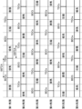
図4は、各気筒2で実施される行程を示した図である。上記のようにエンジンEは4サイクルエンジンである。これより、各気筒2では、吸気行程→圧縮行程→膨張行程→排気行程がこの順で連続して実施される。また、エンジンEは直列6気筒エンジンである。これより、各気筒2A~2Fに設けられたピストン5は120°CA(クランク角度で120度)の位相差をもって往復動するとともに、120°CA毎に第1気筒2A→第5気筒2E→第3気筒2C→第6気筒2F→第2気筒2B→第4気筒2Dの順で燃焼が行われることになる。
Figure 4 shows the strokes performed in each cylinder 2. As mentioned above, engine E is a four-stroke engine. Thus, in each cylinder 2, the intake stroke → compression stroke → expansion stroke → exhaust stroke are performed consecutively in this order. Engine E is also an in-line six-cylinder engine. Thus, the
ここで、本明細書でいう吸気、圧縮、膨張、排気行程は、1燃焼サイクルつまりクランク軸7が2回転する期間(360°CA)をクランク角度で4等分した期間であってそれぞれ吸気、圧縮、膨張、排気が主として行われる期間のことを指す。
Here, the intake, compression, expansion, and exhaust strokes referred to in this specification refer to the periods obtained by dividing one combustion cycle, i.e. the period during which the
具体的に、本明細書でいう吸気行程は、吸気弁11が実際に開弁を開始してから閉弁するまでの期間ではなく、ピストン5が排気上死点TDCeと吸気下死点BDCiとの間に位置する期間を指す。また、圧縮行程は、ピストン5が吸気下死点BDCiと圧縮上死点TDCcとの間に位置する期間を指す。また、膨張行程は、ピストン5が圧縮上死点TDCcと膨張下死点BDCeとの間に位置する期間を指す。また、排気行程は、ピストン5が膨張下死点BDCeと排気上死点TDCeとの間に位置する期間を指す。
Specifically, the intake stroke in this specification does not refer to the period from when the
なお、圧縮上死点TDCcとは、ピストン5の往復動範囲のうちの最も上側(シリンダヘッド4に近い側)となる位置であって、吸気弁11の閉弁後且つ排気弁12の開弁前にピストン5が到達する位置である。そして、膨張下死点BDCe、排気上死点TDCe、吸気下死点BDCiは、それぞれ、ピストン5が圧縮上死点TDCcにある状態からクランク軸7が180°CA、360°CA、540°CA正回転したときのピストン5の位置である。以下では、適宜、ピストン5の位置を気筒2の位置として説明する。
Note that compression top dead center TDCc is the uppermost position (closest to cylinder head 4) of the reciprocating range of
各気筒2の吸気弁11はシリンダヘッド4に配設された吸気カム軸を含む動弁機構13によって駆動される。吸気弁11用の動弁機構13には、各吸気弁11の開閉時期を一括して変更可能な吸気S-VT13aが内蔵されている。同様に、各気筒2の排気弁12はシリンダヘッド4に配設された排気カム軸を含む動弁機構14によって駆動される。排気弁12用の動弁機構14にも、各排気弁12の開閉時期を一括して変更可能な排気S-VT14aが内蔵されている。吸気S-VT13a(排気S-VT14a)は、いわゆる位相式の可変機構であり、各吸気弁11(各排気弁12)の開弁開始時期IVO(EVO)および閉弁時期IVC(EVC)を同時にかつ同量だけ変更する。
The
吸気通路30は、吸気ポート9と連通するようにシリンダヘッド4の一側面に接続されている。吸気通路30には、上流側から順にエアクリーナ31、コンプレッサ47、スロットル弁32、インタークーラ33およびサージタンク34が設けられている。コンプレッサ47は、上記のようにタービン48に回転駆動されて、コンプレッサ47を通過する空気を圧縮(過給)する。気筒2(燃焼室6)には、コンプレッサ47で圧縮された後、インタークーラ33で冷やされた空気が導入される。スロットル弁32は、吸気通路30を開閉可能なバルブである。吸気通路30を流通する空気の量、ひいては、気筒2(燃焼室6)に導入される吸気の量は、スロットル弁32の開度に応じて変更される。
The
排気通路40は、排気ポート10と連通するようにシリンダヘッド4の他側面に接続されている。排気通路40には、上流側から順にタービン48、排気ガスを浄化するための排気浄化装置41が設けられている。排気浄化装置41には、三元触媒42と、DPF(ディーゼル・パティキュレート・フィルタ)43とが内蔵されている。タービン48は排気通路40を流れる排気ガスのエネルギーを受けて回転し、これに連動してコンプレッサ47は回転する。
The
EGR装置44は、排気通路40と吸気通路30とを接続するEGR通路44Aと、EGR通路44Aに設けられたEGR弁45とを備える。EGR通路44Aは、排気通路40におけるタービン48よりも上流側の部分と、吸気通路30におけるインタークーラ33とサージタンク34との間の部分とを接続している。EGR弁45は、EGR通路44Aを開閉可能なバルブである。吸気通路30に還流されるEGRガスの量、ひいては、気筒2(燃焼室6)に導入されるEGRガスの量は、はEGR弁45の開度に応じて変更される。なお、EGR通路44Aには、排気通路40から吸気通路30に還流される排気ガス(EGRガス)を熱交換により冷却するEGRクーラ(図略)が配置されている。
The
(2)制御系統
図5は、車両100の制御系統を示すブロック図である。図5に示したコントローラ200は、モータMとエンジンE等を統括的に制御するためのマイクロプロセッサであり、周知のCPU、ROM、RAM等から構成されている。コントローラ200は、請求項の「制御手段」に相当する。
(2) Control System Fig. 5 is a block diagram showing the control system of the
コントローラ200には、車両100に設けられた各種センサによる検出信号が入力される。
Detection signals from various sensors installed in the
具体的に、エンジンEのシリンダブロック3には、クランク軸7の回転角度つまりエンジン回転数を検出するためのクランク角センサSN1が設けられている。エンジンEのシリンダヘッド4には、吸気用の動弁機構13に含まれる吸気カムの角度を検出するためのカム角センサSN2が設けられている。コントローラ200は、カム角センサSN2の検出信号とクランク角センサSN1の検出信号とに基づいて、どの気筒が何行程にあるのかを判別する。エンジンEの吸気通路30のスロットル弁32よりも下流側の部分には、この部分を通過する吸気の圧力を検出するためのインマニ圧センサSN3が設けられている。以下では、吸気通路30のスロットル弁32よりも下流側の部分を通過する吸気の圧力をインマニ圧という。なお、本明細書でいう吸気は、気筒2(燃焼室6)内に導入されるガスのことを指し、気筒2内に空気に加えてEGRガスが導入される場合はEGRガスと空気とを含むガスのことを指す。エンジンEの排気通路40には、排気通路40を通過する排気ガスに含まれる酸素の濃度である排気O2濃度を検出するための排気O2センサSN4が設けられている。排気O2センサSN4は、タービン48と排気浄化装置41との間に配置されている。また、車両100には、モータMの回転数を検出するモータ回転数センサSN5、車両100を運転するドライバーにより操作されるアクセルペダルの開度であるアクセル開度を検出するアクセル開度センサSN6、車速を検出する車速センサSN7等が設けられている。コントローラ200には、これらセンサSN1~SN7によって検出された情報が逐次入力される。
Specifically, the cylinder block 3 of the engine E is provided with a crank angle sensor SN1 for detecting the rotation angle of the
コントローラ200は、各センサからの入力情報に基づいて種々の判定や演算等を実行して、吸気S-VT13a、排気S-VT14a、インジェクタ15、スロットル弁32およびEGR弁45等のエンジンEの各部、モータMおよびクラッチ102等を制御する。
The
本実施形態では、エンジンEの稼働中、吸気弁11が常に吸気下死点BDCiよりも遅角側で閉弁するように構成されており、コントローラ200は、これが実現されるように吸気S-VT13aを制御する。
In this embodiment, the
また、本実施形態では、基本的な車両100の走行モードがモータMのみによって車輪101が駆動されるEVモードに設定されて、モータMの出力のみでは不十分な場合等にのみエンジンEが駆動されるエンジン駆動モードに切り替えられるようになっており、コントローラ200は車速等に基づいて走行モードの切り替えを行う。
In addition, in this embodiment, the basic driving mode of the
具体的に、コントローラ200は、車両100の走行状態およびアクセルペダルの操作状態から、エンジンEを始動させる条件であるエンジン始動条件が成立したか否か、および、エンジンEを停止させる条件であるエンジン停止条件が成立したか否かを判定する。例えば、コントローラ200は、エンジンEの停止中に、車速が所定のエンジン始動速度以上、且つ、アクセルペダルの開度が所定のエンジン始動開度以上になるとエンジン始動条件が成立したと判定する。また、コントローラ200は、エンジンEの駆動中に、車速が所定のエンジン停止速度未満、あるいは、アクセルペダルの開度が所定のエンジン停止開度未満になるとエンジン停止条件が成立したと判定する。コントローラ200は、車速センサSN7およびアクセル開度センサSN6の検出結果等に基づいて、上記の各条件が成立するか否かを逐次判定する。
Specifically, the
コントローラ200は、エンジン始動条件が成立したと判定すると、エンジンEを始動させるエンジン始動制御を実施する。エンジン始動制御では、コントローラ200は、まず、クラッチ102を開放状態から締結状態へと移行させる。クラッチ102が締結状態になるとモータMの出力がエンジンEに伝達される。これにより、エンジンEはモータMによって強制的に回転駆動される。つまり、エンジンEのクランキングが開始される。クランキングが開始すると、次に、コントローラ200は、吸気下死点BDCi付近で停止していた気筒2に対して、その圧縮行程中にインジェクタ15から最初の燃料を噴射させてこれを自着火燃焼させる。その後は、通常のエンジン制御に移り、コントローラ200は、インジェクタ15から各気筒2に順次燃料を噴射させていく。ここで、上記のように、クラッチ102は締結状態とされる。これより、モータMおよび変速機104等を介してエンジンEの駆動力は車輪101に伝達されることになる。
When the
また、コントローラ200は、エンジン停止条件が成立したと判定すると、エンジンEを停止するためのエンジン停止制御を実施する。エンジン停止制御では、コントローラ200は、まず、インジェクタ15から各気筒2への燃料供給を停止する燃料カットを実施する。燃料供給が停止されることで、エンジン回転数は低下していきエンジンは停止する。ここで、エンジン回転数が低くなると、エンジン本体1とこれを支持しているエンジンマウントとが共振してエンジン本体1の振動が増大するおそれがある。そこで、エンジン停止制御として、コントローラ200は、スロットル弁32を全閉にする制御を実施する。つまり、スロットル弁32を全閉にすることでエンジン回転数を早期に低下させ、これによりエンジン回転数が共振回転数となる期間を短く抑えるようにする。具体的には、コントローラ200は、燃料カットの実施後、エンジン回転数が所定のスロットル閉弁回転数N1以下になるとスロットル弁32を全閉に向けて閉弁させていく。また、コントローラ200は、エンジン停止条件の成立時において、エンジンEが停止すると(エンジンEの回転数が0になると)、クラッチ102を締結状態から開放状態に切り替える。
When the
(エンジン停止位置制御)
次に、エンジン停止制御の実施後、つまり、燃料カットが実施され且つスロットル弁32が全閉にされた後に、コントローラ200によって実施される停止位置制御について説明する。停止位置制御は、エンジンEの停止時の各気筒2(各気筒2のピストン5)の位置を所定の目標範囲内にするための制御である。
(Engine stop position control)
Next, a description will be given of the stop position control that is performed by the
以下では、エンジンEの停止時、詳細には、エンジン回転数が0であってエンジンEが完全に停止しているときのことを、単にエンジン停止時という。また、エンジン停止時の各気筒2(各気筒2のピストン5)の位置を気筒停止位置という。
In the following, the time when the engine E is stopped, specifically when the engine speed is 0 and the engine E is completely stopped, is simply referred to as the time when the engine is stopped. In addition, the position of each cylinder 2 (
また、本明細書では、エンジン停止時(エンジンEが完全に停止したとき)の行程が圧縮行程で、且つ、ピストン5の位置が圧縮上死点(TDCc)から圧縮上死点前(BTDCc)120°CAまでの範囲にある気筒を、停止時圧縮行程気筒という。また、燃焼順序が停止時圧縮行程気筒の1つ前の気筒であって、エンジン停止時(エンジンEが完全に停止したとき)の行程が膨張行程で、且つ、ピストン5の位置が圧縮上死点(TDCc)から圧縮上死点後(ATDCc)120°CAまでの範囲にある気筒を、停止時膨張行程気筒という。また、燃焼順序が停止時圧縮行程気筒の1つ後の気筒であって、エンジン停止時(エンジンEが完全に停止したとき)の行程が吸気行程あるいは圧縮行程であり、且つ、ピストン5の位置が吸気下死点前(BBDCi)60°CAから吸気下死点後(ABDCi)60°CAまでの範囲にある気筒を、停止時圧縮移行気筒という。
In addition, in this specification, a cylinder whose stroke when the engine is stopped (when engine E is completely stopped) is the compression stroke and whose
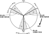
図6は、気筒停止位置と、この気筒停止位置で停止したエンジンEをその後始動させるために必要なモータMのトルクの最小値(以下、適宜、始動用トルクという)との関係を示したグラフである。図6の横軸には、停止時圧縮行程気筒、停止時圧縮移行気筒、停止時膨張行程気筒の各位置も合わせて示している。図7は、気筒停止位置の目標範囲であって、これに対応する停止時圧縮行程気筒、停止時圧縮移行気筒および停止時膨張行程気筒の各停止位置を示した図である。図7では、円の最上点を上死点(TDC)、最下点を下死点(BDC)とし、時計回りに進むほどピストン5の位置が遅角側になるように各気筒2の位置(各気筒2のピストン5の位置)を示している。
Figure 6 is a graph showing the relationship between the cylinder stop position and the minimum torque of the motor M required to subsequently start the engine E that has stopped at this cylinder stop position (hereinafter, appropriately, referred to as the starting torque). The horizontal axis of Figure 6 also shows the positions of the compression stroke cylinder at the stop, the compression transition cylinder at the stop, and the expansion stroke cylinder at the stop. Figure 7 is a diagram showing the target range of the cylinder stop position and the corresponding stop positions of the compression stroke cylinder at the stop, the compression transition cylinder at the stop, and the expansion stroke cylinder at the stop. In Figure 7, the top point of the circle is the top dead center (TDC), the bottom point is the bottom dead center (BDC), and the position of each cylinder 2 (the position of the
図6に示すように、始動用トルクは気筒停止位置によって変化する。始動用トルクが最小となるのは、気筒停止位置が図6の実線に示す位置のときであって、停止時圧縮行程気筒が圧縮上死点前(BTDCc)60°CAの位置にあり、停止時膨張行程気筒が圧縮上死点後(ATDCc)60°CAの位置にあり、停止時圧縮移行気筒が吸気下死点(BDCi)にあるときである。つまり、停止時圧縮行程気筒と停止時膨張行程気筒の各ピストン5が上死点に対して互いに同じ位置にあるときに、始動用トルクは最小となる。以下、この始動用トルクが最小となるときの気筒停止位置を最適位置P0という。
As shown in FIG. 6, the starting torque varies depending on the cylinder stop position. The starting torque is minimum when the cylinder stop position is as shown by the solid line in FIG. 6, the stop-time compression stroke cylinder is at 60° CA before compression top dead center (BTDCc), the stop-time expansion stroke cylinder is at 60° CA after compression top dead center (ATDCc), and the stop-time compression transition cylinder is at intake bottom dead center (BDCi). In other words, the starting torque is minimum when the
気筒停止位置の目標範囲は、始動用トルクが所定の基準トルクT1以下となる位置であって、最適位置P0よりも進角側の第1位置P1から最適位置P0よりも遅角側の第2位置P2までの範囲に設定されている。基準トルクT1は、始動用トルクの最大値と最小値の間の値に設定されている。そして、これに対応して、第1位置P1は、停止時圧縮行程気筒の位置が圧縮上死点前(BTDCc)75°CAであり、停止時圧縮移行気筒の位置が吸気下死点前(BBDCi)15°CAであり、停止時膨張行程気筒の位置が圧縮上死点後(ATDCc)45°CAにある位置に設定されている。また、第2位置P2は、停止時圧縮行程気筒の位置が圧縮上死点前(BTDCc)40°CAであり、停止時圧縮移行気筒の位置が吸気下死点後(ABDCi)20°CAであり、停止時膨張行程気筒の位置が圧縮上死点後(ATDCc)80°CAである位置に設定されている。 The target range of the cylinder stop position is a position where the starting torque is equal to or less than a predetermined reference torque T1, and is set in a range from a first position P1 on the advanced side of the optimal position P0 to a second position P2 on the retarded side of the optimal position P0. The reference torque T1 is set to a value between the maximum and minimum values of the starting torque. Correspondingly, the first position P1 is set to a position where the position of the compression stroke cylinder at the time of stopping is 75° CA before the compression top dead center (BTDCc), the position of the compression transition cylinder at the time of stopping is 15° CA before the intake bottom dead center (BBDCi), and the position of the expansion stroke cylinder at the time of stopping is 45° CA after the compression top dead center (ATDCc). In addition, the second position P2 is set to a position where the position of the stopped compression stroke cylinder is 40° CA before compression top dead center (BTDCc), the position of the stopped compression transition cylinder is 20° CA after intake bottom dead center (ABDCi), and the position of the stopped expansion stroke cylinder is 80° CA after compression top dead center (ATDCc).
コントローラ200は、停止位置制御として、気筒停止位置が目標範囲X0よりも遅角側になるのを防止する吸気遅角制御と、気筒停止位置が目標範囲X0よりも進角側になるのを防止する弁開度増大制御とを実施する。
As stop position control, the
図8のフローチャートを用いて、停止位置制御の具体的な手順を説明する。図8のフローチャートのステップS1は、エンジン停止制御が行われた後に実施される。 The specific steps of the stop position control will be described using the flowchart in Figure 8. Step S1 in the flowchart in Figure 8 is performed after engine stop control has been performed.
ステップS1にて、コントローラ200は、エンジン回転数が基準回転数N2未満に低下したか否かを判定する。コントローラ200は、クランク角センサSN1の検出結果に基づいてこの判定を行う。基準回転数N2は、予め設定されてコントローラ200に記憶されている。ステップS1の判定がNOであってエンジン回転数が基準回転数N2以上であると判定した場合、コントローラ200は、ステップS1を繰り返してエンジン回転数が基準回転数N2未満になるのを待つ。一方、ステップS1の判定がYESであってエンジン回転数が基準回転数N2未満になったと判定すると、コントローラ200はステップS2に進む。
In step S1, the
ステップS2にて、コントローラ200は、吸気S-VT13aによって吸気弁11の位相を遅角させて、吸気弁11の閉弁時期である吸気閉弁時期IVCを第1基準時期まで遅角させる(吸気遅角制御)。第1基準時期は、予め設定されてコントローラ200に記憶されている。第1基準時期は、エンジン停止制御実施直後(スロットル弁32を全閉する制御の実施直後)の吸気閉弁時期IVCよりも遅角側、且つ、後述する第2基準時期よりも進角側の時期に設定されている。
In step S2, the
次に、ステップS3にて、コントローラ200は、エンジンEが停止する時期であるエンジン停止時期と、気筒停止位置つまりエンジンEが停止するときの各ピストン5の位置を予測する。コントローラ200は、インマニ圧センサSN3の検出値、クランク角センサSN1の検出値、カム角センサSN2の検出値等に基づいて、上記の時期および位置を予測する。ステップS3の後はステップS4に進む。
Next, in step S3, the
ステップS4にて、コントローラ200は、ステップS3の予測結果に基づいて2圧縮上死点通過後にエンジンが停止するか否かを判定する。具体的に、ステップS4では、コントローラ200は、現時点からエンジンが停止するまでの間に、圧縮上死点(TDCc)を超える気筒が2つであるか否かを判定する。
In step S4, the
ステップS4の判定がNOであって、現時点から2圧縮上死点通過後のタイミングではまだエンジンEは停止しないと判定すると、コントローラ200は、ステップS3に戻りエンジン停止時期と気筒停止位置の予測を継続する。
If the determination in step S4 is NO, and it is determined that engine E will not stop at the timing two compression strokes after the current time,
一方、ステップS4の判定がYESであって2圧縮上死点通過後にエンジンが停止すると判定すると、コントローラ200はステップS5に進む。ステップS5にて、コントローラ200は、ステップS3で予測した気筒停止位置(以下、予測気筒停止位置という)が要回避範囲X1に含まれるか否かを判定する。要回避範囲X1は、図9に示すように、目標範囲X0よりも遅角側の範囲であって、停止時圧縮行程気筒のピストン5が、目標範囲X0のうちの最も遅角側の位置(第2位置P2に対応する圧縮上死点前(BTDCc)40°CA)となる状態から、停止時圧縮行程気筒のピストン5が圧縮上死点(TDCc)となる状態までの範囲に設定されている。つまり、ステップS5では、予測された停止時圧縮行程気筒の停止位置が、その目標範囲よりも上死点(圧縮上死点TDCc)に近い位置であるか否かが判定されることになる。
On the other hand, if the determination in step S4 is YES and it is determined that the engine will stop after passing the second compression top dead center, the
ステップS5の判定がYESであって予測気筒停止位置が要回避範囲X1に含まれると判定した場合(予測した停止時圧縮行程気筒の停止位置が目標範囲X0よりも上死点側であると判定した場合)、ステップS6にて、コントローラ200は吸気増大量を設定する(弁開度増大制御)。後述するようにステップS5の判定がYESの場合は、停止時圧縮行程気筒の吸気量を増大させるようになっており、上記の吸気増大量は、この吸気量の増大量の目標値である。
If the determination in step S5 is YES and it is determined that the predicted cylinder stop position is within the avoidance range X1 (if it is determined that the predicted stop position of the compression stroke cylinder at the time of stopping is closer to the top dead center side than the target range X0), in step S6, the
コントローラ200は、予測された停止時圧縮行程気筒のピストン5の停止位置の目標範囲からのずれ量(目標範囲のうちの最も遅角側の第2位置P2からのずれ量)が大きいほど、上記の吸気増大量が大きくなるようにこれを設定する。ステップS6の後は、ステップS7に進む。
The
ステップS7にて、コントローラ200は、インマニO2濃度が所定の基準濃度以上であるか否かを判定する(弁開度増大制御)。インマニO2濃度は、スロットル弁32よりも下流側の吸気通路30内のガスの酸素濃度である。コントローラ200は、ステップS4の判定がYESとなったとき、つまり、2圧縮上死点通過後にエンジンEが停止すると判定したときのインマニO2濃度に基づいてこの判定を行う。本実施形態では、コントローラ200は、エンジン稼働中、逐次、排気O2センサSN4の検出値に基づいてインマニO2濃度を予測しており、ステップS7ではこの予測値を用いて上記判定を行う。基準濃度は、予め設定されてコントローラ200に記憶されている。基準濃度は、大気中の酸素濃度よりもわずかに低い値(例えば20%程度)に設定されている。
In step S7, the
ステップS7の判定がNOであってインマニO2濃度が基準濃度未満の場合、ステップS8に進み、コントローラ200は、スロットル弁32の開度の増大量であるスロットル開度増大量を算出する(弁開度増大制御)。つまり、気筒停止位置が要回避範囲X1にあり、且つ、インマニO2濃度が基準濃度未満の場合は、スロットル弁32の開度を大きくする(開き側にする)ようになっており、ステップS8ではこの開度の増大量を算出する。コントローラ200は、ステップS6で設定した吸気増大量に基づいてスロットル開度増大量を設定する。スロットル開度増大量は、ステップS6で設定された吸気増大量が大きいほど大きい値になるように設定される。ステップS8の後はステップS9に進む。
If the determination in step S7 is NO and the intake manifold O2 concentration is less than the reference concentration, the process proceeds to step S8, where the
ステップS9にて、コントローラ200は、ステップS8で算出したスロットル開度増大量分、スロットル弁32の開度を増大させる(弁開度増大制御)。ステップS9の後はステップS12に進む。
In step S9, the
一方、ステップS7の判定がYESであってインマニO2濃度が基準濃度以上の場合、ステップS10に進み、コントローラ200は、EGR弁45の開度の増大量であるEGR開度増大量を算出する(弁開度増大制御)。つまり、気筒停止位置が要回避範囲X1にあり、且つ、インマニO2濃度が基準濃度以上の場合は、EGR弁45の開度を大きくする(開き側にする)ようになっており、ステップS10ではこの開度の増大量を算出する。コントローラ200は、ステップS6で設定した吸気増大量に基づいてEGR開度増大量を設定する。EGR開度増大量は、吸気増大量が大きいほど大きい値になるように設定される。
On the other hand, if the determination in step S7 is YES and the intake manifold O2 concentration is equal to or higher than the reference concentration, the process proceeds to step S10, where the
ステップS10の後はステップS11に進む。ステップS11にて、コントローラ200は、ステップS10で算出したEGR開度増大量分、EGR弁45の開度を増大させる(弁開度増大制御)。ステップS11の後はステップS12に進む。なお、ステップS9を実施してスロットル弁32の開度を増大させる場合、EGR弁45の開度は変更されず2圧縮上死点通過後にエンジンEが停止すると判定されたときの開度に維持される。また、ステップS11を実施してEGR弁45の開度を増大させる場合、スロットル弁32の開度は変更されず2圧縮上死点通過後にエンジンEが停止すると判定されたときの開度に維持される。
After step S10, the process proceeds to step S11. In step S11, the
ステップS5~S11は、ステップS4にて2圧縮上死点通過後にエンジンEが停止すると判定された直後に実施される。2圧縮上死点通過後にエンジンEが停止すると判定されるタイミングは、停止時圧縮行程気筒がエンジン停止直前の排気上死点TDCeに位置するタイミングから排気上死点TDCe後120°CAに位置するタイミングまでの期間、つまり、停止時圧縮行程気筒が吸気行程にある期間に含まれる。これより、ステップS9のスロットル弁32の開度の増大あるいはステップS11のEGR弁45の開度の増大は、停止時圧縮行程気筒のエンジン停止直前の吸気行程中に実施される。
Steps S5 to S11 are performed immediately after it is determined in step S4 that engine E will stop after passing second compression top dead center. The timing at which it is determined that engine E will stop after passing second compression top dead center is included in the period from when the stopped compression stroke cylinder is at exhaust top dead center TDCe just before the engine stops to when it is at 120° CA after exhaust top dead center TDCe, that is, the period during which the stopped compression stroke cylinder is in the intake stroke. Thus, the increase in the opening of the
ステップS12では、コントローラ200は、吸気S-VT13aによって吸気弁11の位相の遅角を遅角させて吸気閉弁時期IVCを第2基準時期まで遅角させる制御を実施する(吸気遅角制御)。吸気閉弁時期IVCが第2基準時期に到達すると、コントローラ200は処理(停止位置制御)を終了する。第2基準時期は予め設定されてコントローラ200に記憶されている。例えば、第2基準時期は、吸気閉弁時期IVCがとり得る時期のうち最も遅角側の時期に設定される。なお、ステップS12は、ステップS4の判定がYESになるのとほぼ同時に実施されるようになっており、2圧縮上死点通過後にエンジンEが停止すると判定されると、吸気弁11の位相は徐々に遅角されていく。
In step S12, the
ここで、上記ステップS5の判定がYESで且つステップS7の判定がNOの場合が、請求項における「第1条件が成立した場合」および「第1条件の成立時」に相当し、上記ステップS5の判定がYESで且つステップS7の判定がYESの場合が、請求項における「第2条件が成立した場合」および「第2条件の成立時」に相当する。 Here, the case where the judgment in step S5 is YES and the judgment in step S7 is NO corresponds to "if the first condition is met" and "when the first condition is met" in the claims, and the case where the judgment in step S5 is YES and the judgment in step S7 is YES corresponds to "if the second condition is met" and "when the second condition is met" in the claims.
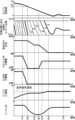
図10、図11は、上記の停止位置制御を実施したときの各パラメータの時間変化を示したタイムチャートである。図10、図11には、上から順に、エンジン回転数、圧縮行程にある気筒2のピストン5の位置、吸気弁11の位相、スロットル弁32の開度、EGR弁45の開度、インマニO2濃度、インマニ圧の各チャートを示している。図10は、予測気筒停止位置が要回避範囲X1であると判定され(ステップS5の判定がYESで)、且つ、2圧縮上死点通過後にエンジンEが停止すると判定されたときのインマニO2濃度が基準濃度未満のとき(ステップS7の判定がNOのとき)のチャートである。図11は、予測気筒停止位置が要回避範囲X1であると判定され(ステップS5の判定がYESで)、且つ、2圧縮上死点通過後にエンジンEが停止すると判定されたときのインマニO2濃度が基準濃度以上のとき(ステップS7の判定がYESのとき)のチャートである。なお、図10、図11には、燃料カット実施後の各パラメータの時間変化を示している。
10 and 11 are time charts showing the time change of each parameter when the above-mentioned stop position control is performed. In FIG. 10 and FIG. 11, from the top, the charts of the engine speed, the position of the
図10、図11に示すように、燃料カットが実施された後、エンジン回転数は徐々に低下していく。図10、図11の例では、時刻t1にてエンジン回転数がスロットル閉弁回転数N1以下になる。これに伴い、時刻t1にてスロットル弁32の閉弁が開始されて、その後スロットル弁32は全閉になる。また、スロットル弁32の閉弁後の時刻t2にてエンジン回転数が基準回転数N2未満になると、吸気弁11の位相が遅角される。図10、図11の例では、時刻t3にて吸気閉弁時期IVCが第1基準時期に到達し、これに伴って吸気弁11の位相の遅角は停止され、吸気閉弁時期IVCは第1基準時期に維持される。
As shown in Figures 10 and 11, after fuel cut is performed, the engine speed gradually decreases. In the example of Figures 10 and 11, the engine speed becomes equal to or lower than the throttle closing speed N1 at time t1. Accordingly, the
図10、図11の例では、時刻t3後の時刻t4にて、2圧縮上死点通過後にエンジンEが停止すると判定される。具体的に、図10、図11の例では、第4気筒2Dと第1気筒2Aとが圧縮上死点TDCcを超えた後、且つ、第5気筒2Eが圧縮上死点TDCcに到達する前に(到達することなく)エンジンEが停止するようになっており、第4気筒2Dよりも燃焼順序が1つ前の第2気筒2Bが圧縮上死点TDCcを超えた直後の時刻t4にて、2圧縮上死点通過後にエンジンEが停止すると判定される。なお、この例では、第5気筒2Eが停止時圧縮行程気筒になる。
10 and 11, at time t4 after time t3, it is determined that the engine E will stop after passing the second compression top dead center. Specifically, in the example of FIG. 10 and FIG. 11, the engine E stops after the
時刻t4にて2圧縮上死点通過後にエンジンEが停止すると判定されると、時刻t4直後から吸気弁11の位相の遅角つまり吸気閉弁時期IVCの遅角が再開される。図10、図11の例では、時刻t6にて吸気閉弁時期IVCが第2基準時期に到達し、これに伴って吸気弁11の位相の遅角は停止され、吸気閉弁時期IVCは第2基準時期に維持される。そして、時刻t6後の時刻t7にてエンジンEは完全停止する。
When it is determined at time t4 that engine E will stop after passing top dead center of the second compression stroke, retarding of the phase of the
また、時刻t4直後に予測気筒停止位置が要回避範囲X1であるか否かの判定が行われる。このとき、予測気筒停止位置が要回避範囲X1であると判定された場合は、その直後にインマニO2濃度が基準濃度未満か否かの判定が行われる。そして、この判定が行われたときのインマニO2濃度が基準濃度未満の場合は、図10に示すように、EGR弁45の開度は上記判定以前つまり時刻t4以前の開度に維持される。本実施形態では、スロットル弁32と同様にEGR弁45も時刻t2にて閉弁されて時刻t2からしばらく後に全閉となる。これより、EGR弁45は時刻t4以降も全閉に維持される。一方で、インマニO2濃度が基準濃度未満の場合は、上記判定が行われた直後つまり時刻t4直後にスロットル弁32の開度は増大される。その後、時刻t5にて、上記のスロットル開度増大量分だけスロットル弁32の開度が増大すると、スロットル弁32の開度の増大が停止されて、スロットル弁32の開度は増大後の開度に維持される。
Also, immediately after time t4, a determination is made as to whether the predicted cylinder stop position is in the avoidance required range X1. At this time, if it is determined that the predicted cylinder stop position is in the avoidance required range X1, a determination is made immediately thereafter as to whether the intake manifold O2 concentration is less than the reference concentration. If the intake manifold O2 concentration is less than the reference concentration when this determination is made, the opening degree of the
このように、予測気筒停止位置が要回避範囲X1であると判定され、且つ、インマニO2濃度が基準濃度未満であると判定された場合は、この判定が行われた時刻t4直後からスロットル弁32の開度が増大され、これにより、図10に示すように、時刻t4以降インマニO2濃度およびインマニ圧は増大していく。
In this way, when it is determined that the predicted cylinder stop position is in the avoidance range X1 and the intake manifold O2 concentration is less than the reference concentration, the opening degree of the
一方、予測気筒停止位置が要回避範囲X1であると判定された場合であっても、インマニO2濃度が基準濃度以上と判定された場合は、図11に示すように、この判定が行われた時刻t4以降もスロットル弁32の開度は時刻t4以前の開度つまり全閉に維持される。一方、インマニO2濃度が基準濃度以上の場合は、時刻t4直後にEGR弁45の開度が増大される。そして、時刻t5にて、上記のEGR開度増大量分だけEGR弁45の開度が増大すると、EGR弁45の開度の増大が停止されて、EGR弁45の開度は増大後の開度に維持される。
On the other hand, even if it is determined that the predicted cylinder stop position is in the avoidance required range X1, if it is determined that the intake manifold O2 concentration is equal to or higher than the reference concentration, the opening degree of the
図11に示すように、EGR弁45の開度が増大された場合でも、スロットル弁32の開度が増大された場合と同様に、時刻t4以降インマニ圧は増大していく。一方、上記のようにスロットル弁32の開度が増大された場合は時刻t4以降にインマニO2濃度が増大していくのに対し、EGR弁45の開度が増大された場合は、図11に示すように、時刻t4以降のインマニO2濃度はほとんど上昇せず時刻t4以前の濃度がほぼ維持される。
11, even when the opening of the
なお、時刻t4にて予測気筒停止位置が要回避範囲X1ではないと判定された場合は、スロットル弁32およびEGR弁45の開度は時刻t4以前の値(本実施形態では、いずれも全閉)に維持される。
If it is determined at time t4 that the predicted cylinder stop position is not in the avoidance range X1, the openings of the
(作用等)
以上のように、上記実施形態では、2圧縮上死点通過後にエンジンEが停止すると判定されると吸気弁11の位相を遅角する吸気遅角制御が実施される。そのため、停止時圧縮行程気筒が目標範囲X0よりも下死点側にずれるのを抑制できる。
(Action, etc.)
As described above, in the above embodiment, when it is determined that the engine E will stop after the second compression top dead center, the intake retard control is performed to retard the phase of the
具体的に、図10、図11に示すように、時刻t2にてスロットル弁32の閉弁を開始するとインマニ圧は低下していく。また、スロットル弁32が全閉になった後もエンジン回転数の低下に伴ってインマニ圧は低下していく。ところが、スロットル弁32およびEGR弁45の開度を増大させない場合であっても、エンジン本体1の吸気の吸い込み力が低下すること、また、スロットル弁32周辺等から吸気通路30内に吸気が漏洩してくることに起因して、エンジン停止直前の所定時期からインマニ圧は徐々に増大していく。エンジン停止直前において、停止時圧縮行程気筒の吸気行程は、停止時膨張行程気筒の吸気行程の後に実施される。そのため、エンジン停止直前のインマニ圧が増大していく状態で、仮に吸気閉弁時期IVCを一定の時期に維持すると、インマニ圧の増大に伴って、停止時膨張行程気筒の吸気量よりも停止時膨張行程気筒の吸気量の方が多くなりやすい。そして、吸気から停止時圧縮行程気筒のピストン5に付与される力の方が、吸気から停止時膨張行程気筒のピストン5に付与される力よりも大きくなりやすく、停止時圧縮行程気筒の停止位置が目標範囲X0よりも下死点側にずれるおそれ、つまり、気筒停止位置が図12の実線に示すように目標範囲X0から進角側にずれるおそれがある。
Specifically, as shown in FIG. 10 and FIG. 11, when the
これに対して、上記吸気遅角制御を実施してエンジン停止直前に吸気弁11の位相を遅角すれば、エンジン停止直前の停止時圧縮行程気筒の吸気閉弁時期IVCの吸気下死点BDCiに対する遅角量を、停止時膨張行程気筒の当該遅角量よりも大きくして、エンジン停止直前における停止時圧縮行程気筒の吸気ポート9への吸気の吹き返し量を停止時膨張行程気筒の吹き返し量よりも大きくできる。これより、吸気から停止時圧縮行程気筒のピストン5に付与される力が、吸気から停止時膨張行程気筒のピストン5に付与される力に対して過大になるのを防止でき、停止時圧縮行程気筒の停止位置が目標範囲X0よりも下死点側にずれるのを抑制できる。
On the other hand, by implementing the intake retard control and retarding the phase of the
また、エンジン停止直前のエンジン回転数の低下具合やピストンの摺動抵抗の大きさ等によっては、停止時圧縮行程気筒の停止位置が目標範囲X0よりも上死点側にずれる可能性がある。これに対して、上記実施形態では、停止時圧縮行程気筒の停止位置が目標範囲X0よりも上死点側であると予測されると、エンジン停止直前の停止時圧縮行程気筒の吸気行程中にスロットル弁32あるいはEGR弁45の開度を増大する弁開度増大制御が実施される。そのため、停止時圧縮行程気筒の停止位置が目標範囲X0よりも上死点側にずれるのを抑制できる。
In addition, depending on the degree of engine speed reduction just before the engine is stopped and the magnitude of the sliding resistance of the piston, the stopping position of the compression stroke cylinder at the time of stopping may deviate from the target range X0 toward the top dead center side. In contrast, in the above embodiment, if the stopping position of the compression stroke cylinder at the time of stopping is predicted to be closer to the top dead center side than the target range X0, valve opening increase control is implemented to increase the opening of the
具体的に、スロットル弁32の開度が増大されると気筒2(燃焼室6)内に導入される空気が増大して吸気量が増大する。また、EGR弁45の開度が増大されると、気筒2(燃焼室6)内に導入されるEGRガスが増大して吸気量が増大する。上記のように、エンジン停止直前、停止時圧縮行程気筒の吸気行程は、停止時膨張行程気筒の吸気行程の後に実施される。そのため、弁開度増大制御を実施して、停止時圧縮行程気筒が吸気行程中のときにスロットル弁32あるいはEGR弁45の開度を増大させれば、停止時圧縮行程気筒の吸気量を停止時膨張行程気筒の吸気量よりも多くして、吸気が停止時圧縮行程気筒のピストン5に付与する力を、吸気が停止時膨張行程気筒のピストン5に付与する力よりも大きくできる。従って、停止時圧縮行程気筒の停止位置が目標範囲X0よりも上死点側にずれるのを抑制できる。
Specifically, when the opening of the
このように、上記実施形態によれば、停止時圧縮行程気筒の停止位置ひいては気筒停止位置が目標範囲X0よりも下死点側および上死点側にずれるのを抑制できる。これより、上記実施形態によれば、エンジンを始動するのに費やされるモータMのトルクをより確実に小さくできる。 In this way, according to the above embodiment, the stop position of the compression stroke cylinder at the time of stopping can be prevented from shifting toward the bottom dead center or top dead center from the target range X0. As a result, according to the above embodiment, the torque of the motor M consumed to start the engine can be more reliably reduced.
しかも、上記実施形態では、インマニO2濃度つまり吸気通路30内の酸素濃度が基準濃度以上の場合は、弁開度増大制御としてEGR弁45の開度を増大する制御が実施されて、EGRガスの増大によって吸気量が増大される。EGRガスは、既燃ガスを含むことでその酸素濃度は低い。これより、EGRガスの増大によって吸気量を増大させても吸気通路30内の酸素濃度および気筒2(燃焼室6)内の酸素濃度の増大は抑制される。そのため、上記実施形態によれば、停止時圧縮行程気筒の停止位置が目標範囲X0よりも上死点側にずれるのを抑制しつつ、吸気通路30内の酸素濃度が基準濃度以上の場合に、吸気通路30および気筒2(燃焼室6)内の酸素濃度がさらに増大するのを防止できる。ここで、エンジン停止直前の吸気通路30および気筒2(燃焼室6)内の酸素濃度が高いと、エンジン停止後もこの濃度がほぼ維持されることから、次にエンジンEを始動したときにエンジンEにて生成されるNOx量が多くなってしまう。従って、上記実施形態によれば、停止時圧縮行程気筒の停止位置が目標範囲X0よりも上死点側にずれるのを抑制しつつ、エンジン始動時のNOxの生成量が増大するのを抑制できる。
Moreover, in the above embodiment, when the intake manifold O2 concentration, i.e., the oxygen concentration in the
また、上記実施形態では、インマニO2濃度つまり吸気通路30内の酸素濃度が基準濃度未満の場合は、弁開度増大制御としてスロットル弁32の開度を増大する制御が実施されて、空気の増大によって吸気量が増大される。そのため、吸気通路30内の酸素濃度が比較的低い場合に、吸気通路30および気筒2(燃焼室6)内の酸素濃度がさらに低くなるのが防止される。従って、停止時圧縮行程気筒の停止位置が目標範囲X0よりも上死点側にずれるのを抑制しつつ、エンジン始動時の気筒2(燃焼室6)内の酸素濃度を確保して始動時の混合気の燃焼性ひいては始動性を良好にできる。
In the above embodiment, when the intake manifold O2 concentration, i.e., the oxygen concentration in the
また、上記実施形態では、スロットル弁32およびEGR弁45の開度を増大させる場合において、予測された停止時圧縮行程気筒の停止位置の目標範囲X0からのずれ量に基づいて上記の吸気増大量が設定され、この吸気増大量に基づいてスロットル弁32およびEGR弁45の開度の増大量が設定される。つまり、予測された停止時圧縮行程気筒の停止位置に基づいてスロットル弁32およびEGR弁45の開度の増大量が設定される。そのため、これらの開度を、停止時圧縮行程気筒の停止位置を目標範囲X0内の位置にできる開度に確実に変更して、当該停止位置をより確実に目標範囲X0内の位置にすることができる。
In addition, in the above embodiment, when the opening of the
また、上記実施形態では、EGR通路44Aがタービン48よりも上流側の排気通路40に接続されている。つまり、EGR通路44Aがタービン48の下流側の排気通路40に接続される場合に比べて、EGR通路44Aの通路長が短くなるように排気通路40に接続されている。そのため、EGR弁45を開弁した後、早期にEGRガスを吸気通路30および停止時圧縮行程気筒に導入することができる。従って、予測気筒停止位置が要回避範囲X1に含まれると判定され且つEGR弁45の開度を増大させる場合において、エンジンEが完全停止する前に確実に停止時圧縮行程気筒に導入されるEGRガスの量を増大させることができ、当該気筒の停止位置をより確実に目標範囲X0内にすることができる。
In addition, in the above embodiment, the
(変形例)
上記実施形態では、エンジンEの停止直前に吸気弁11の位相を遅角する吸気遅角制御を常に実施する場合を説明したが、予測気筒停止位置が目標範囲X0よりも遅角側である等の所定の条件成立時のみに当該制御を実施してもよい。また、吸気遅角制御は省略してもよい。
(Modification)
In the above embodiment, the intake retard control for retarding the phase of the
上記実施形態では、弁開度増大制御において、スロットル弁32およびEGR弁45の開度の増大量を、予測された停止時圧縮行程気筒の停止位置に基づいて設定した場合を説明したが、当該停止位置に関わらず上記増大量を一定の量としてもよい。
In the above embodiment, the amount of increase in the opening of the
また、上記実施形態では、エンジンEが6つの気筒2を有する6気筒エンジンの場合を説明したが、エンジンEの気筒数はこれに限らず4つ等であってもよい。 In addition, in the above embodiment, the engine E is described as a six-cylinder engine having six cylinders 2, but the number of cylinders of the engine E is not limited to this and may be four, etc.
1 エンジン本体
2 気筒
5 ピストン
7 クランク軸
11 吸気弁
13a 吸気S-VT
15 インジェクタ(燃料供給手段)
30 吸気通路
32 スロットル弁
40 排気通路
44A EGR通路
45 EGR弁
200 コントローラ(制御手段)
E エンジン
M モータ(始動手段)
15 Injector (fuel supply means)
30
E engine M motor (starting means)
Claims (4)
前記吸気通路に配設されて当該吸気通路を開閉するスロットル弁と、
前記スロットル弁よりも下流の前記吸気通路と前記排気通路とを接続して排気ガスの一部であるEGRガスを前記吸気通路に還流させるEGR通路と、
前記EGR通路を開閉するEGR弁と、
前記燃料供給手段、前記スロットル弁および前記EGR弁を含むエンジンの各部を制御して、所定のエンジン停止条件が成立すると前記燃料供給手段による気筒内への燃料供給を停止する燃料カットを実施する制御手段とを備え、
前記制御手段は、前記燃料カットの実施後に、圧縮行程で停止する気筒である停止時圧縮行程気筒の停止位置を予測するとともに、予測した前記停止時圧縮行程気筒の停止位置が所定の目標範囲よりも上死点側である場合は、前記停止時圧縮行程気筒の停止直前の吸気行程中に前記スロットル弁の開度あるいは前記EGR弁の開度を増大させる弁開度増大制御を実施し、
前記制御手段は、前記吸気通路内の酸素濃度が所定の基準濃度未満であるという第1条件が成立する場合は、前記スロットル弁の開度を増大させる制御を前記弁開度増大制御として実施し、前記吸気通路内の酸素濃度が前記基準濃度以上であるという第2条件が成立する場合は、前記EGR弁の開度を増大させる制御を前記弁開度増大制御として実施する、ことを特徴とするエンジンの停止位置制御装置。 A stop position control device provided in an engine having a plurality of cylinders, a fuel supply means for supplying fuel to each cylinder, a piston reciprocatingly provided in each cylinder, a crankshaft that rotates in conjunction with the reciprocating movement of the piston, a starting means for forcibly starting the engine by rotating the crankshaft, an intake passage through which intake air introduced into each cylinder flows, and an exhaust passage through which exhaust gas discharged from each cylinder flows,
a throttle valve disposed in the intake passage for opening and closing the intake passage;
an EGR passage that connects the intake passage downstream of the throttle valve with the exhaust passage and recirculates EGR gas, which is a part of the exhaust gas, to the intake passage;
an EGR valve that opens and closes the EGR passage;
a control means for controlling each part of the engine including the fuel supply means, the throttle valve, and the EGR valve, and for executing a fuel cut to stop the supply of fuel into the cylinders by the fuel supply means when a predetermined engine stop condition is established,
the control means predicts a stop position of a stopped compression stroke cylinder, which is a cylinder that stops during a compression stroke after the fuel cut is performed, and when the predicted stop position of the stopped compression stroke cylinder is on the top dead center side of a predetermined target range, performs a valve opening increase control to increase an opening of the throttle valve or an opening of the EGR valve during an intake stroke immediately before the stop of the stopped compression stroke cylinder;
an intake passage having an oxygen concentration in the intake passage that is greater than a predetermined reference concentration, the control means increasing the opening of the throttle valve as the valve opening increase control when a first condition is satisfied, and increasing the opening of the EGR valve as the valve opening increase control when a second condition is satisfied, the oxygen concentration in the intake passage that is greater than or equal to the reference concentration.
前記第1条件の成立時、前記制御手段は、予測した前記停止時圧縮行程気筒の停止位置に基づいて前記スロットル弁の開度を変更する、ことを特徴とするエンジンの停止位置制御装置。 2. The engine stop position control device according to claim 1,
2. An engine stop position control device comprising: a control means for changing an opening degree of the throttle valve based on a predicted stop position of the compression stroke cylinder at the time of stop when the first condition is satisfied.
前記第2条件の成立時、前記制御手段は、予測した前記停止時圧縮行程気筒の停止位置に基づいて前記EGR弁の開度を変更する、ことを特徴とするエンジンの停止位置制御装置。 3. The engine stop position control device according to claim 1,
When the second condition is satisfied, the control means changes an opening degree of the EGR valve based on the predicted stop position of the compression stroke cylinder at the time of stop.
前記エンジンは、前記排気通路に設けられたタービンと前記吸気通路に設けられたコンプレッサとを含むターボ過給機を備え、
前記EGR通路は、前記タービンよりも上流側の前記排気通路に接続されている、ことを特徴とするエンジンの停止位置制御装置。
In the engine stop position control device according to any one of claims 1 to 3,
the engine includes a turbocharger including a turbine provided in the exhaust passage and a compressor provided in the intake passage,
13. An engine stop position control device, comprising: an exhaust gas recirculation (EGR) passage connected to an exhaust passage upstream of the turbine;
Priority Applications (1)
| Application Number | Priority Date | Filing Date | Title |
|---|---|---|---|
| JP2021051346A JP7582007B2 (en) | 2021-03-25 | 2021-03-25 | Engine stop position control device |
Applications Claiming Priority (1)
| Application Number | Priority Date | Filing Date | Title |
|---|---|---|---|
| JP2021051346A JP7582007B2 (en) | 2021-03-25 | 2021-03-25 | Engine stop position control device |
Publications (2)
| Publication Number | Publication Date |
|---|---|
| JP2022149281A JP2022149281A (en) | 2022-10-06 |
| JP7582007B2 true JP7582007B2 (en) | 2024-11-13 |
Family
ID=83462936
Family Applications (1)
| Application Number | Title | Priority Date | Filing Date |
|---|---|---|---|
| JP2021051346A Active JP7582007B2 (en) | 2021-03-25 | 2021-03-25 | Engine stop position control device |
Country Status (1)
| Country | Link |
|---|---|
| JP (1) | JP7582007B2 (en) |
Citations (6)
| Publication number | Priority date | Publication date | Assignee | Title |
|---|---|---|---|---|
| JP2009085200A (en) | 2007-10-03 | 2009-04-23 | Mazda Motor Corp | Device for controlling diesel engine |
| US20100275871A1 (en) | 2008-05-26 | 2010-11-04 | Toyota Jidosha Kabushiki Kaisha | Device for starting an engine |
| WO2012137237A1 (en) | 2011-04-01 | 2012-10-11 | トヨタ自動車株式会社 | Method of controlling operation of internal combustion engine |
| JP2014218929A (en) | 2013-05-08 | 2014-11-20 | マツダ株式会社 | Start control device for premixing compression ignition type engine |
| JP2018025175A (en) | 2016-08-12 | 2018-02-15 | マツダ株式会社 | Control method and control system for vehicle |
| JP2019100265A (en) | 2017-12-04 | 2019-06-24 | マツダ株式会社 | Start control device of engine |
-
2021
- 2021-03-25 JP JP2021051346A patent/JP7582007B2/en active Active
Patent Citations (6)
| Publication number | Priority date | Publication date | Assignee | Title |
|---|---|---|---|---|
| JP2009085200A (en) | 2007-10-03 | 2009-04-23 | Mazda Motor Corp | Device for controlling diesel engine |
| US20100275871A1 (en) | 2008-05-26 | 2010-11-04 | Toyota Jidosha Kabushiki Kaisha | Device for starting an engine |
| WO2012137237A1 (en) | 2011-04-01 | 2012-10-11 | トヨタ自動車株式会社 | Method of controlling operation of internal combustion engine |
| JP2014218929A (en) | 2013-05-08 | 2014-11-20 | マツダ株式会社 | Start control device for premixing compression ignition type engine |
| JP2018025175A (en) | 2016-08-12 | 2018-02-15 | マツダ株式会社 | Control method and control system for vehicle |
| JP2019100265A (en) | 2017-12-04 | 2019-06-24 | マツダ株式会社 | Start control device of engine |
Also Published As
| Publication number | Publication date |
|---|---|
| JP2022149281A (en) | 2022-10-06 |
Similar Documents
| Publication | Publication Date | Title |
|---|---|---|
| JP4957611B2 (en) | Control method for internal combustion engine | |
| JP4816812B2 (en) | Control device for internal combustion engine | |
| JP4525517B2 (en) | Internal combustion engine | |
| WO2013080454A1 (en) | Device and method for controlling spark-ignition gasoline engine | |
| JP4124224B2 (en) | Control device for four-cycle premixed compression self-ignition internal combustion engine | |
| JP4952732B2 (en) | Internal combustion engine control method and internal combustion engine control system | |
| JP5979031B2 (en) | Spark ignition engine | |
| JP5126424B1 (en) | Control device for internal combustion engine | |
| JP2000073803A (en) | In-cylinder injection gasoline engine | |
| JP5842406B2 (en) | Lean burn engine with turbocharger | |
| JP2018184837A (en) | Control device of internal combustion engine | |
| JP7635595B2 (en) | Engine stop position control device | |
| JP2009074366A (en) | Variable valve operating device for internal combustion engine | |
| JP7379857B2 (en) | Engine control device and control method | |
| JP7582007B2 (en) | Engine stop position control device | |
| JP7647226B2 (en) | Engine start control device | |
| JP2009299623A (en) | Control device for internal combustion engine | |
| JP2009103014A (en) | Control device for internal combustion engine | |
| JP2015048839A (en) | Valve timing control device for internal combustion engine | |
| JP2005291044A (en) | Multi-cylinder engine with turbo type supercharger | |
| JP4957542B2 (en) | Intake control device for internal combustion engine | |
| JP2020176573A (en) | Premixed compression ignition engine controller | |
| JP2010024908A (en) | Method and internal combustion engine system for controlling internal combustion engine for vehicle | |
| EP2570645B1 (en) | Control device for internal combustion engine | |
| JP2021110283A (en) | Cylinder resting device for internal combustion engine |
Legal Events
| Date | Code | Title | Description |
|---|---|---|---|
| A621 | Written request for application examination |
Free format text: JAPANESE INTERMEDIATE CODE: A621 Effective date: 20240123 |
|
| A977 | Report on retrieval |
Free format text: JAPANESE INTERMEDIATE CODE: A971007 Effective date: 20240822 |
|
| TRDD | Decision of grant or rejection written | ||
| A01 | Written decision to grant a patent or to grant a registration (utility model) |
Free format text: JAPANESE INTERMEDIATE CODE: A01 Effective date: 20241001 |
|
| A61 | First payment of annual fees (during grant procedure) |
Free format text: JAPANESE INTERMEDIATE CODE: A61 Effective date: 20241014 |
|
| R150 | Certificate of patent or registration of utility model |
Ref document number: 7582007 Country of ref document: JP Free format text: JAPANESE INTERMEDIATE CODE: R150 |