JP7581319B2 - Scroll Pump - Google Patents
Scroll Pump Download PDFInfo
- Publication number
- JP7581319B2 JP7581319B2 JP2022503842A JP2022503842A JP7581319B2 JP 7581319 B2 JP7581319 B2 JP 7581319B2 JP 2022503842 A JP2022503842 A JP 2022503842A JP 2022503842 A JP2022503842 A JP 2022503842A JP 7581319 B2 JP7581319 B2 JP 7581319B2
- Authority
- JP
- Japan
- Prior art keywords
- scroll
- pad
- wall
- spiral wall
- pump
- Prior art date
- Legal status (The legal status is an assumption and is not a legal conclusion. Google has not performed a legal analysis and makes no representation as to the accuracy of the status listed.)
- Active
Links
Images

Classifications
-
- F—MECHANICAL ENGINEERING; LIGHTING; HEATING; WEAPONS; BLASTING
- F04—POSITIVE - DISPLACEMENT MACHINES FOR LIQUIDS; PUMPS FOR LIQUIDS OR ELASTIC FLUIDS
- F04C—ROTARY-PISTON, OR OSCILLATING-PISTON, POSITIVE-DISPLACEMENT MACHINES FOR LIQUIDS; ROTARY-PISTON, OR OSCILLATING-PISTON, POSITIVE-DISPLACEMENT PUMPS
- F04C18/00—Rotary-piston pumps specially adapted for elastic fluids
- F04C18/02—Rotary-piston pumps specially adapted for elastic fluids of arcuate-engagement type, i.e. with circular translatory movement of co-operating members, each member having the same number of teeth or tooth-equivalents
- F04C18/0207—Rotary-piston pumps specially adapted for elastic fluids of arcuate-engagement type, i.e. with circular translatory movement of co-operating members, each member having the same number of teeth or tooth-equivalents both members having co-operating elements in spiral form
- F04C18/0215—Rotary-piston pumps specially adapted for elastic fluids of arcuate-engagement type, i.e. with circular translatory movement of co-operating members, each member having the same number of teeth or tooth-equivalents both members having co-operating elements in spiral form where only one member is moving
-
- F—MECHANICAL ENGINEERING; LIGHTING; HEATING; WEAPONS; BLASTING
- F04—POSITIVE - DISPLACEMENT MACHINES FOR LIQUIDS; PUMPS FOR LIQUIDS OR ELASTIC FLUIDS
- F04C—ROTARY-PISTON, OR OSCILLATING-PISTON, POSITIVE-DISPLACEMENT MACHINES FOR LIQUIDS; ROTARY-PISTON, OR OSCILLATING-PISTON, POSITIVE-DISPLACEMENT PUMPS
- F04C15/00—Component parts, details or accessories of machines, pumps or pumping installations, not provided for in groups F04C2/00 - F04C14/00
- F04C15/0003—Sealing arrangements in rotary-piston machines or pumps
- F04C15/0023—Axial sealings for working fluid
-
- F—MECHANICAL ENGINEERING; LIGHTING; HEATING; WEAPONS; BLASTING
- F04—POSITIVE - DISPLACEMENT MACHINES FOR LIQUIDS; PUMPS FOR LIQUIDS OR ELASTIC FLUIDS
- F04C—ROTARY-PISTON, OR OSCILLATING-PISTON, POSITIVE-DISPLACEMENT MACHINES FOR LIQUIDS; ROTARY-PISTON, OR OSCILLATING-PISTON, POSITIVE-DISPLACEMENT PUMPS
- F04C18/00—Rotary-piston pumps specially adapted for elastic fluids
- F04C18/02—Rotary-piston pumps specially adapted for elastic fluids of arcuate-engagement type, i.e. with circular translatory movement of co-operating members, each member having the same number of teeth or tooth-equivalents
- F04C18/0207—Rotary-piston pumps specially adapted for elastic fluids of arcuate-engagement type, i.e. with circular translatory movement of co-operating members, each member having the same number of teeth or tooth-equivalents both members having co-operating elements in spiral form
- F04C18/0246—Details concerning the involute wraps or their base, e.g. geometry
- F04C18/0253—Details concerning the base
-
- F—MECHANICAL ENGINEERING; LIGHTING; HEATING; WEAPONS; BLASTING
- F04—POSITIVE - DISPLACEMENT MACHINES FOR LIQUIDS; PUMPS FOR LIQUIDS OR ELASTIC FLUIDS
- F04C—ROTARY-PISTON, OR OSCILLATING-PISTON, POSITIVE-DISPLACEMENT MACHINES FOR LIQUIDS; ROTARY-PISTON, OR OSCILLATING-PISTON, POSITIVE-DISPLACEMENT PUMPS
- F04C2/00—Rotary-piston machines or pumps
- F04C2/02—Rotary-piston machines or pumps of arcuate-engagement type, i.e. with circular translatory movement of co-operating members, each member having the same number of teeth or tooth-equivalents
- F04C2/025—Rotary-piston machines or pumps of arcuate-engagement type, i.e. with circular translatory movement of co-operating members, each member having the same number of teeth or tooth-equivalents the moving and the stationary member having co-operating elements in spiral form
-
- F—MECHANICAL ENGINEERING; LIGHTING; HEATING; WEAPONS; BLASTING
- F04—POSITIVE - DISPLACEMENT MACHINES FOR LIQUIDS; PUMPS FOR LIQUIDS OR ELASTIC FLUIDS
- F04C—ROTARY-PISTON, OR OSCILLATING-PISTON, POSITIVE-DISPLACEMENT MACHINES FOR LIQUIDS; ROTARY-PISTON, OR OSCILLATING-PISTON, POSITIVE-DISPLACEMENT PUMPS
- F04C27/00—Sealing arrangements in rotary-piston pumps specially adapted for elastic fluids
- F04C27/005—Axial sealings for working fluid
-
- F—MECHANICAL ENGINEERING; LIGHTING; HEATING; WEAPONS; BLASTING
- F04—POSITIVE - DISPLACEMENT MACHINES FOR LIQUIDS; PUMPS FOR LIQUIDS OR ELASTIC FLUIDS
- F04C—ROTARY-PISTON, OR OSCILLATING-PISTON, POSITIVE-DISPLACEMENT MACHINES FOR LIQUIDS; ROTARY-PISTON, OR OSCILLATING-PISTON, POSITIVE-DISPLACEMENT PUMPS
- F04C2240/00—Components
- F04C2240/80—Other components
- F04C2240/801—Wear plates
-
- F—MECHANICAL ENGINEERING; LIGHTING; HEATING; WEAPONS; BLASTING
- F04—POSITIVE - DISPLACEMENT MACHINES FOR LIQUIDS; PUMPS FOR LIQUIDS OR ELASTIC FLUIDS
- F04C—ROTARY-PISTON, OR OSCILLATING-PISTON, POSITIVE-DISPLACEMENT MACHINES FOR LIQUIDS; ROTARY-PISTON, OR OSCILLATING-PISTON, POSITIVE-DISPLACEMENT PUMPS
- F04C23/00—Combinations of two or more pumps, each being of rotary-piston or oscillating-piston type, specially adapted for elastic fluids; Pumping installations specially adapted for elastic fluids; Multi-stage pumps specially adapted for elastic fluids
- F04C23/008—Hermetic pumps
-
- F—MECHANICAL ENGINEERING; LIGHTING; HEATING; WEAPONS; BLASTING
- F04—POSITIVE - DISPLACEMENT MACHINES FOR LIQUIDS; PUMPS FOR LIQUIDS OR ELASTIC FLUIDS
- F04C—ROTARY-PISTON, OR OSCILLATING-PISTON, POSITIVE-DISPLACEMENT MACHINES FOR LIQUIDS; ROTARY-PISTON, OR OSCILLATING-PISTON, POSITIVE-DISPLACEMENT PUMPS
- F04C27/00—Sealing arrangements in rotary-piston pumps specially adapted for elastic fluids
-
- F—MECHANICAL ENGINEERING; LIGHTING; HEATING; WEAPONS; BLASTING
- F05—INDEXING SCHEMES RELATING TO ENGINES OR PUMPS IN VARIOUS SUBCLASSES OF CLASSES F01-F04
- F05C—INDEXING SCHEME RELATING TO MATERIALS, MATERIAL PROPERTIES OR MATERIAL CHARACTERISTICS FOR MACHINES, ENGINES OR PUMPS OTHER THAN NON-POSITIVE-DISPLACEMENT MACHINES OR ENGINES
- F05C2225/00—Synthetic polymers, e.g. plastics; Rubber
- F05C2225/04—PTFE [PolyTetraFluorEthylene]
Landscapes
- Engineering & Computer Science (AREA)
- Mechanical Engineering (AREA)
- General Engineering & Computer Science (AREA)
- Rotary Pumps (AREA)
- Applications Or Details Of Rotary Compressors (AREA)
Description
本発明は、スクロールポンプに関する。 The present invention relates to a scroll pump.
スクロールポンプは、様々な異なる産業(例えば、半導体製造)で使用される公知のタイプのポンプである。スクロールポンプは、流体をポンプ送給するために、2つの互いにかみ合った「スクロール」の相対運動を利用して動作する。 Scroll pumps are a well-known type of pump used in a variety of different industries (e.g., semiconductor manufacturing). Scroll pumps work by utilizing the relative motion of two intermeshing "scrolls" to pump fluid.
スクロールポンプでは、2つのスクロールの間の接触部にシールを保持し、スクロールポンプの特定の領域に不要な流体が漏れるのを阻止することが望ましい傾向がある。また、スクロールポンプの構成要素の耐久性を向上させることが望ましい傾向がある。 In scroll pumps, it is often desirable to maintain a seal at the interface between the two scrolls to prevent unwanted fluid leakage into certain areas of the scroll pump. It is also often desirable to improve the durability of scroll pump components.
本発明の第1の態様によれば、スクロールポンプが提供され、スクロールポンプは、第1の螺旋壁を含む第1のスクロールと;第1の螺旋壁と互いにかみ合う第2の螺旋壁を含む第2のスクロールと;第1のスクロール及び第2のスクロールとは異なる材料から形成されたパッドと;を備え、パッドは、第1のスクロールと第2のスクロールとの間で、第1の螺旋壁及び第2の螺旋壁の半径方向内側の配置されている。 According to a first aspect of the present invention, a scroll pump is provided, the scroll pump comprising: a first scroll including a first helical wall; a second scroll including a second helical wall intermeshing with the first helical wall; and a pad formed of a material different from the first scroll and the second scroll; the pad is disposed between the first scroll and the second scroll, radially inward of the first helical wall and the second helical wall.
スクロールポンプは、パッドを介して第1のスクロール及び第2スクロールを互いに付勢させるように構成された付勢装置をさらに備えることができる。
パッドは、ポリマー材料から形成することができる。
The scroll pump may further include a biasing device configured to bias the first scroll and the second scroll toward one another via the pad.
The pad may be formed from a polymeric material.
第1のスクロール及び/又は第2のスクロールは、金属材料から形成することができる。
パッドは、ポリテトラフルオロエチレン材料から形成することができる。
第1のスクロール及び/又は第2のスクロールは、アルミニウムから形成することができる。
The first scroll and/or the second scroll may be formed from a metallic material.
The pad may be formed from a polytetrafluoroethylene material.
The first scroll and/or the second scroll may be formed from aluminum.
スクロールポンプは、第1のスクロールと第2のスクロールとの間に配置されたチャンネルシールをさらに備えることができる。
パッドは、チャンネルシールと一体形成することができる。
パッドは、チャンネルシールと同じ材料で形成することができる。
The scroll pump may further include a channel seal disposed between the first scroll and the second scroll.
The pad may be integrally formed with the channel seal.
The pad may be formed from the same material as the channel seal.
スクロールポンプは、第1のスクロール及び第2のスクロールとは異なる材料から形成された第1のパッドを備えることができ、第1のパッドは、第1のスクロールと第2のスクロールとの間で、第1の螺旋壁及び第2の螺旋壁の半径方向外側に位置し、第1のスクロールと第2のスクロールとの間で、第1の螺旋壁及び第2の螺旋壁の半径方向内側に位置するパッドは、第2のパッドとすることができる。 The scroll pump may include a first pad formed from a material different from that of the first scroll and the second scroll, the first pad being located radially outward of the first spiral wall and the second spiral wall between the first scroll and the second scroll, and the pad located radially inward of the first spiral wall and the second spiral wall between the first scroll and the second scroll may be the second pad.
第2のパッドは、第1のパッドと同じ材料で形成することができる。
第1のパッド及び/又は第2のパッドは、チャンネルシールと同じ材料から形成することができる。
第1のパッド及び/又は第2のパッドは、チャンネルシールと一体形成することができる。
The second pad may be formed of the same material as the first pad.
The first pad and/or the second pad may be formed from the same material as the channel seal.
The first pad and/or the second pad may be integrally formed with the channel seal.
第1のスクロール及び第2のスクロールの各々は、中央開口を備えることができる。第2のパッドは、中央開口に隣接することができる。
スクロールポンプは、第2のスクロールに結合され、第2のスクロールを第1のスクロールに対して旋回させるように構成された駆動軸をさらに備えることができる。
駆動軸は、中央開口を貫通して延びることができる。
パッドは、複数の突出部を備えることができる。
The first scroll and the second scroll may each include a central opening. The second pad may be adjacent to the central opening.
The scroll pump may further include a drive shaft coupled to the second scroll and configured to orbit the second scroll relative to the first scroll.
The drive shaft may extend through the central opening.
The pad may include a plurality of protrusions.
本発明の第2の態様によれば、流体をポンプ送給するための第1の態様のスクロールポンプの使用が提供される。 According to a second aspect of the present invention, there is provided a use of the scroll pump of the first aspect for pumping a fluid.
本発明の第3の態様によれば、スクロールポンプが提供され、スクロールポンプは、第1の螺旋壁を含む第1のスクロールと;第1の螺旋壁と互いにかみ合う第2の螺旋壁を含む第2のスクロールと;第1のスクロール及び第2のスクロールとは異なる材料から形成されたパッドと;を備え、パッドは、第1のスクロールと第2のスクロールとの間で、第1の螺旋壁及び第2の螺旋壁の半径方向外側の配置されている。 According to a third aspect of the present invention, a scroll pump is provided, the scroll pump comprising: a first scroll including a first helical wall; a second scroll including a second helical wall intermeshing with the first helical wall; and a pad formed of a material different from the first scroll and the second scroll; the pad is disposed between the first scroll and the second scroll, radially outward of the first helical wall and the second helical wall.
スクロールポンプは、パッドを介して第1のスクロール及び第2スクロールを互いに付勢させるように構成された付勢装置をさらに備えることができる。
パッドは、ポリマー材料から形成することができる。
The scroll pump may further include a biasing device configured to bias the first scroll and the second scroll toward one another via the pad.
The pad may be formed from a polymeric material.
第1のスクロール及び/又は第2のスクロールは、金属材料から形成することができる。
パッドは、ポリテトラフルオロエチレン材料から形成することができる。
第1のスクロール及び/又は第2のスクロールは、アルミニウムから形成することができる。
The first scroll and/or the second scroll may be formed from a metallic material.
The pad may be formed from a polytetrafluoroethylene material.
The first scroll and/or the second scroll may be formed from aluminum.
スクロールポンプは、第1のスクロールと第2のスクロールとの間に配置されたチャンネルシールをさらに備えることができる。
パッドは、チャンネルシールと一体形成することができる。
パッドは、チャンネルシールと同じ材料で形成することができる。
The scroll pump may further include a channel seal disposed between the first scroll and the second scroll.
The pad may be integrally formed with the channel seal.
The pad may be formed from the same material as the channel seal.
スクロールポンプは、第1のスクロール及び第2のスクロールとは異なる材料から形成された第2のパッドを備えることができ、第2のパッドは、第1のスクロールと第2のスクロールとの間で、第1の螺旋壁及び第2の螺旋壁の半径方向内側に位置し、第1のスクロールと第2のスクロールとの間で、第1の螺旋壁及び第2の螺旋壁の半径方向外側に位置するパッドは、第1のパッドとすることができる。 The scroll pump may include a second pad formed from a material different from that of the first scroll and the second scroll, the second pad being located radially inward of the first spiral wall and the second spiral wall between the first scroll and the second scroll, and the pad located radially outward of the first spiral wall and the second spiral wall between the first scroll and the second scroll may be the first pad.
第2のパッドは、第1のパッドと同じ材料で形成することができる。
第1のパッド及び/又は第2のパッドは、チャンネルシールと同じ材料から形成することができる。
第1のパッド及び/又は第2のパッドは、チャンネルシールと一体形成することができる。
The second pad may be formed of the same material as the first pad.
The first pad and/or the second pad may be formed from the same material as the channel seal.
The first pad and/or the second pad may be integrally formed with the channel seal.
第1のスクロール及び第2のスクロールの各々は、中央開口を備えることができる。第2のパッドは、中央開口に隣接することができる。
駆動軸は、中央開口を貫通して延びることができる。
パッドは、複数の突出部を備えることができる。
The first scroll and the second scroll may each include a central opening. The second pad may be adjacent to the central opening.
The drive shaft may extend through the central opening.
The pad may include a plurality of protrusions.
本発明の第4の態様によれば、流体をポンプ送給するための第3の態様のスクロールポンプの使用が提供される。 According to a fourth aspect of the present invention, there is provided a use of the scroll pump of the third aspect for pumping a fluid.
図1は、一実施形態によるスクロールポンプ100を示す概略図(縮尺通りではない)である。
スクロールポンプ100は、シェル110、固定スクロール120、旋回スクロール130、駆動軸140、アクチュエータ150、複数の軸受160、付勢装置170、及びパッド180を備える。
FIG. 1 is a schematic diagram (not to scale) illustrating a
The
本実施形態では、シェル110と固定スクロール120とが一緒になってスクロールポンプ100の全体ハウジングを形成し、その中にスクロールポンプ100の残りの構成要素が配置されている。しかしながら、他の実施形態では、固定スクロール120は、スクロールポンプ100の全体ハウジングの一部を形成せず、代わりに全体ハウジングの中に完全に位置することができることが理解されるであろう。
In this embodiment, the
旋回スクロール130は、スクロールポンプ100の全体ハウジングの中に配置され、固定スクロール120と互いにかみ合う。旋回スクロール130は、スクロールポンプ100の入口(図示せず)からスクロールポンプ100の出口(図示せず)に流体をポンプ送給するために、固定スクロール120に対して旋回するように構成されている。固定スクロール120に対する旋回スクロール130の旋回によって流体がポンプ送給される物理的機構はよく知られており、本明細書では説明しない。
The orbiting
固定スクロール120は、第1の基部122、第1の螺旋壁124、及び外壁126を備える。旋回スクロール130は、第2の基部132及び第2の螺旋壁134を備える。
The
第1の螺旋壁124は、第1の基部122から第2の基部132に向かって垂直に延びる。外壁126は、第1の基部122から第2の基部132に向かって垂直に延びる。外壁126は、第1の螺旋壁124の半径方向外側に位置し、固定スクロール120の外周を規定する。従って、外壁126は、第1の螺旋壁124の周囲に広がる。第2の螺旋壁134は、第2の基部132から第1基部122に向かって垂直に延びる。第2の基部132は、第2の螺旋壁134の半径方向外側に位置し、旋回スクロール130の外周を規定する周縁部136を備える。本実施形態では、第1の基部122、第1の螺旋壁124、外壁126は、互いに一体的に形成される。また、本実施形態では、第2の基部132及び第2の螺旋壁134は、互いに一体的に形成される。
The first
第1の螺旋壁124及び第2の螺旋壁134は、第1の螺旋壁124の端面が第2の基部132の対向面と接触し、第2の螺旋壁134の端面が第1の基部122の対向面と接触するように、互いにかみ合う。このように、第1の基部122、第1の螺旋壁124、第2の基部132、及び第2の螺旋壁134は、一緒になって、固定スクロール120と旋回スクロール130との間の空間を規定し、この空間は、動作時にスクロールポンプ100によって流体をポンプ送給するために使用される。第1の螺旋壁124及び第2の螺旋壁134の各々は、螺旋壁の各巻きの間にそれぞれの螺旋形状のチャンネルを規定する。
The first and second
駆動軸140は、旋回スクロール130に結合され、旋回スクロール130の旋回を駆動するために回転するように構成されている。駆動軸140は、スクロールポンプ120の全体ハウジングの中に配置されている。本実施形態では、駆動軸140は、駆動軸140の回転を容易にする複数の軸受160を介して、旋回スクロール130及びシェル110に結合されている。
The
アクチュエータ150(例えば、モータ)は、駆動軸140に結合され、駆動軸140を作動させて、旋回スクロール130の旋回を駆動するために駆動軸140を回転させるように構成されている。アクチュエータ150は、スクロールポンプ120の全体ハウジングの中に配置されている。
An actuator 150 (e.g., a motor) is coupled to the
付勢装置170は、固定スクロール120及び旋回スクロール130を互いに付勢させるように構成されている。より詳細的には、付勢装置170は、旋回スクロール130が固定スクロール120に対して軸方向に負荷をかけるように、旋回スクロール130を固定スクロール120に向かって付勢するように構成されている。より詳細には、付勢は、第1の螺旋壁124の端面が第2の基部132の対向面に押し付けられ、第2の螺旋壁134の端面が第1の基部122の対向面に押し付けられるようなものである。従って、固定スクロール120及び旋回スクロール130にかかる軸方向荷重の一部は、第1の螺旋壁124及び第2の螺旋壁134の端面によって支持される。付勢装置170によって引き起こされる軸方向荷重は、第1の螺旋壁124及び第2の螺旋壁134の端面と、第1の基部122及び第2基部132のそれぞれの対向面との間のシールを維持する。これは、固定スクロール120と旋回スクロール130との間の空間の異なる半径部分の間で流体の望ましくない漏れを防止するように作用する傾向がある。本実施形態では、付勢装置170は、駆動軸140を介して旋回スクロール130に力を及ぼして、旋回スクロール130を固定スクロール120に向かって付勢するように構成された1又は2以上のバネを備える。
The
パッド180は、第1の螺旋壁124及び第2の螺旋壁134の半径方向外側に配置されている。より詳細には、パッド180は、固定スクロール120の外壁126と、旋回スクロール130の基部132との間に位置する。より詳細には、パッド180は、パッド180が外壁126及び周縁部136の両方に接触するように、外壁126と第2基部132の周縁部136との間に配置されている。換言すると、パッド180は、第2の基部132の外壁126と周縁部136との間に挟まれている。このように、パッド180は、固定スクロール120及び旋回スクロール130にかかる軸方向荷重の一部がパッド180によって支持されるように配置されている。従って、周縁部136は、パッド180を介して外壁126に対して付勢される。パッド180は、固定スクロール120及び旋回スクロール130とは異なる材料で形成されている。
The
本実施形態では、パッド180は、固定スクロール120の外壁126に埋め込まれた環状リング材料である。パッド180は、固定スクロール120及び旋回スクロール130が作られた1又は複数の材料に接触して摺動した場合に耐摩耗性が高い材料から形成される。例えば、パッド180は、1年から10年の耐用年数で、0.2m/sから5m/sの摺動速度で10Nから1000Nの接触荷重に耐えることができる。例えば、第1のパッド180は、ポリマー材料(例えば、ポリテトラフルオロエチレン材料、耐摩耗性を向上させるために随意的に炭素及び/又はガラスを含む)から形成することができ、固定スクロール120及び旋回スクロール130は、金属材料(例えば、アルミニウム、マグネシウム、又はチタンなどの軽量金属材料)から形成することができる。アルミニウムは、比較的低コストの軽量材料であるため、特に好ましいであろう。
In this embodiment, the
本実施形態では、旋回スクロール130が固定スクロール120に対して旋回するスクロールポンプ100の動作時、第1の螺旋壁124及び第2の螺旋壁134の端面は、第1の基部122及び第2の基部124のそれぞれの対向面に接触して摺動する。これは、上述の軸方向荷重と相まって、スクロールポンプ100の動作時に端面が大きな摩擦力を受ける傾向があることを意味する。軸方向荷重の少なくとも一部を支持するパッド180の存在は、軸方向荷重のより小さな割合が第1の螺旋壁124及び第2の螺旋壁134の端面によって支持されることを意味する傾向がある。これは、結果的に、第1の螺旋状壁124及び第2の螺旋状壁134の端面にかかる摩擦力を減少させる傾向があり、これは、螺旋状壁124,134の摩耗を減少させる傾向がある。
In this embodiment, during operation of the
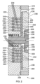
図2は、別の実施形態によるスクロールポンプ200の一部の断面図を示す概略図(縮尺通りではない)である。
スクロールポンプ200は、シェル210、固定スクロール220、旋回スクロール230、駆動軸240、アクチュエータ(図示せず)、複数の軸受(図示せず)、付勢装置(図示せず)、第1のパッド280と、第2パッド290、第1のチャンネルシール300、及び第2のチャンネルシール310を備える。
FIG. 2 is a schematic diagram (not to scale) illustrating a cross-sectional view of a portion of a
The
本実施形態では、シェル210及び固定スクロール220は、一緒になってスクロールポンプ200の全体ハウジングを形成し、その中にスクロールポンプ200の残りの構成要素が配置されている。しかしながら、他の実施形態では、固定スクロール220は、スクロールポンプ200の全体ハウジングの一部を形成せず、代わりに全体ハウジングの中に完全に位置することができることが理解されるであろう。
In this embodiment, the
旋回スクロール230は、スクロールポンプ200の全体ハウジングの中に配置され、固定スクロール220と互いにかみ合う。旋回スクロール230は、スクロールポンプ200の入口(図示せず)からスクロールポンプ200の出口(図示せず)に流体をポンプ送給するために、固定スクロール220に対して旋回するように構成されている。固定スクロール220に対する旋回スクロール230の旋回によって流体がポンプ送給される物理的機構はよく知られており、本明細書では説明しない。
The
固定スクロール220は、第1の基部222、第1の螺旋壁224、外壁226、及び内壁228を備える。旋回スクロール230は、第2の基部232及び第2の螺旋壁234を備える。本実施形態では、固定スクロール220及び旋回スクロール230の各々は、中央開口を有する。
The fixed
第1の螺旋壁224は、第1の基部222から第2に基部232に向かって垂直に延びる。外壁226は、第1の基部222から第2の基部232に向かって垂直に延びる。外壁226は、第1の螺旋壁224の半径方向外側に位置し、固定スクロール220の外周を規定する。従って、外壁226は、第1の螺旋壁224の周囲に広がる。第2の螺旋壁234は、第2の基部232から第1の基部222に向かって垂直に延びる。内壁228は、第1の基部222から第2の基部232に向かって垂直に延びる。内壁228は、中央開口と第1の螺旋壁224との間で、第1の螺旋壁224の半径方向内側に位置する。内壁228は、固定スクロール220の中央開口に隣接する。
The
第2の基部232は、第2の螺旋壁234の半径方向外側に位置し、旋回スクロール230の外周を規定する周縁部236を備える。また、第2の基部232は、旋回スクロール230の中央開口と第の2螺旋壁234との間で、第2の螺旋壁234の半径方向内側に位置する半径方向内側部分238を備える。半径方向内側部分238は、中央開口に隣接する。本実施形態では、第1の基部222、第1の螺旋壁224、外壁226は、互いに一体的に形成される。また、本実施形態では、第2の基部232及び第2の螺旋壁234は、互いに一体的に形成される。
The
第1のチャンネルシール300及び第2のチャンネルシール310は、固定スクロール220と旋回スクロール230との間のチャンネルに配置されたシールである。第1のチャンネルシール300は、第2の基部232に隣接し、第2の螺旋壁234によって規定されるチャンネルの幅に完全に広がる。第1のチャンネルシール300は、第1の螺旋壁224と第2の基部232との間に位置する。第2のチャンネルシール310は、第1の基部222に隣接し、第1の螺旋壁224によって規定されるチャンネルの幅に完全に広がる。第2のチャンネルシール310は、第2の螺旋壁234と第1の基部222との間に位置する。
The
第1の螺旋壁224及び第2の螺旋壁234は、第1の螺旋壁224の端面が第1のチャンネルシール300の対向面と接触し、第2の螺旋壁234の端面が第2のチャンネルシール310の対向面と接触するように、互いにかみ合う。このように、第1のチャンネルシール300、第1の螺旋壁224、第2のチャンネルシール310、及び第2の螺旋壁234は、一緒になって、固定スクロール220と旋回スクロール230との間の空間を規定し、この空間は、動作時にスクロールポンプ200によって流体をポンプ送給するために使用される。
The
駆動軸240は、旋回スクロール230に結合され、旋回スクロール230の旋回を駆動するために回転するように構成されている。駆動軸240は、スクロールポンプ220の全体ハウジングの中に配置されている。本実施形態では、駆動軸240は、駆動軸240の回転を容易にする複数の軸受を介して、旋回スクロール230及びシェル210に結合されている。本実施形態では、駆動軸240は、固定スクロール220及び旋回スクロール230の中央開口を貫通して延びている。この構成は、ポンプの排気口に軸受を配置することができる傾向があり、これは軸受のグリース及び汚染物をポンプの吸気口から遠ざける傾向がある。
The
アクチュエータ(例えばモータ)は、駆動軸240に結合され、駆動軸240を作動させて、旋回スクロール230の旋回を駆動するために駆動軸240を回転させるように構成されている。アクチュエータは、スクロールポンプ220の全体ハウジングの中に配置されている。
An actuator (e.g., a motor) is coupled to the
付勢装置は、固定スクロール220及び旋回スクロール230を互いに付勢させるように構成されている。より詳細には、付勢装置は、旋回スクロール230が固定スクロール220に対して軸方向に負荷をかけるように、旋回スクロール230を固定スクロール220に向かって付勢するように構成されている。より詳細には、付勢は、第1の螺旋壁224の端面が第1のチャンネルシール300の対向面に押し付けられ、第2の螺旋壁234の端面が第2のチャンネルシール310の対向面に押し付けられるようなものである。従って、固定スクロール220及び旋回スクロール230にかかる軸方向荷重の一部は、第1の螺旋壁224及び第2の螺旋壁234の端面によって支持される。付勢装置によって引き起こされる軸方向荷重は、第1の螺旋壁224及び第2の螺旋壁234の端面と、第1の基部222及び第2の基部232のそれぞれの対向面との間のシールを維持する。これは、固定スクロール220と旋回スクロール230の間の空間の異なる半径部分の間で流体の望ましくない漏れを防止するように作用する傾向がある。本実施形態では、付勢装置は、駆動軸240を介して旋回スクロール230に力を及ぼして、旋回スクロール230を固定スクロール220に向かって付勢するように構成された1又は2以上のバネを備える。
The biasing device is configured to bias the fixed
第1のパッド280は、第1の螺旋壁224及び第2の螺旋壁234の半径方向外側に配置されている。より詳細には、第1のパッド280は、固定スクロール220の外壁226と、旋回スクロール230の基部232との間に位置する。より詳細には、第1のパッド280は、第1パッド280が外壁226及び周縁部236の両方に接触するように、外壁226と第2ベース232の周縁部236との間に配置されている。換言すると、第1のパッド280は、第2ベース232の外壁226と周縁部236との間に挟まれている。このように、第1のパッド280は、固定スクロール220及び旋回スクロール230にかかる軸方向荷重の一部が第1パッド280によって支持されるように配置されている。従って、周縁部236は、第1のパッド280を介して外壁226に対して付勢される。第1のパッド280は、固定スクロール220及び旋回スクロール230とは異なる材料で形成されている。
The
本実施形態では、第1のパッド280は、第1のチャンネルシール300と一体形成されている。また、第1のパッド280は、第1のチャンネルシール300と同じ厚さである。換言すると、第1のパッド280は、第1のチャンネルシール300の延長線上にあると言うことができる。本実施形態では、第1パッド280は、固定スクロール220及び旋回スクロール230が作られた1又は複数の材料に接触して摺動した場合に耐摩耗性が高い材料から形成される。例えば、第1のパッド280は、1年から10年の耐用年数で、0.2m/sから5m/sの摺動速度で10Nから1000Nの接触荷重に耐えることができる。例えば、第1のパッド280は、ポリマー材料(例えば、ポリテトラフルオロエチレン材料、耐摩耗性を向上させるために随意的に炭素及び/又はガラスを含む)から形成することができ、固定スクロール220及び旋回スクロール230は、金属材料(例えば、アルミニウム、マグネシウム、チタンなどの軽量金属材料)から形成することができる。アルミニウムは、比較的低コストの軽量材料であるため、特に好ましいであろう。
In this embodiment, the
第2のパッド190は、第1の螺旋壁224及び第2の螺旋壁234の半径方向内側に配置されている。より詳細には、第2のパッド290は、固定スクロール220の内壁228と、旋回スクロール230の基部232との間に位置する。より詳細には、第2のパッド290は、第2のパッド290が内壁228及び半径方向内側部分238の両方と接触するように、内壁228と第2の基部232の半径方向内側部分238との間に配置されている。換言すると、第2パッド290は、内壁228と半径方向内側部分238との間に挟まれている。第2のパッド290は、固定スクロール220及び旋回スクロール230の中央開口と、第1の螺旋壁224及び第2の螺旋壁234との間で、第1の螺旋壁224及び第2の螺旋壁234の半径方向内側に位置する。第2のパッド290は、中央開口に隣接する。
The second pad 190 is disposed radially inward of the
このように、第2のパッド290は、固定スクロール220及び旋回スクロール230にかかる軸方向荷重の一部が第2パッド290によって支持されるように配置されている。従って、半径方向内側部分238は、第2のパッド290を介して内壁228に対して付勢される。第2のパッド290は、固定スクロール220及び旋回スクロール230とは異なる材料で形成されている。
In this manner, the
本実施形態では、第2のパッド290は、第1のチャンネルシール300と一体形成されている。また、第2のパッド290は、第1のチャンネルシール300と同じ厚さである。換言すると、第2のパッド290は、第1のチャンネルシール300の延長線上にあると言うことができる。本実施形態では、第2のパッド290は、第1のパッド280と同じ材料から形成されている。本実施形態では、第2のパッド290は、固定スクロール220及び旋回スクロール230が作られた1又は複数の材料に接触して摺動した場合に耐摩耗性が高い材料から形成される。例えば、第2のパッド290は、1年から10年の耐用年数で、0.2m/sから5m/sの摺動速度で10Nから1000Nの接触荷重に耐えることができる。例えば、第2のパッド290は、ポリマー材料(例えば、ポリテトラフルオロエチレン材料、耐摩耗性を向上させるために随意的に炭素及び/又はガラスを含む)から形成しることができ、固定スクロール220及び旋回スクロール230は、金属材料(例えば、アルミニウム、マグネシウム、チタンなどの軽量金属材料)から形成することができる。アルミニウムは、比較的低コストの軽量材料であるため、特に好ましいであろう。
In this embodiment, the
本実施形態では、旋回スクロール230が固定スクロール220に対して旋回するスクロールポンプ200の動作時、第1の螺旋壁224及び第2の螺旋壁234の端面は、第1のチャンネルシール300及び第2のチャンネルシール310のそれぞれの対向面に接触して摺動する。これは、上述の軸方向荷重と相まって、第1の螺旋壁224及び第2の螺旋壁234の端面とチャンネルシール300、310のそれぞれの対向面とが、スクロールポンプ200の動作時に摩擦力を受ける傾向があることを意味する。
In this embodiment, during operation of the
軸方向荷重の少なくとも一部を支持する第1のパッド280及び第2のパッド290の存在は、軸方向荷重の小さな割合が第1の螺旋壁224及び第2の螺旋壁234の端面、並びにチャンネルシール300、310のそれぞれの対向面によって支持されることを意味する傾向がある。これは、結果的に、第1の螺旋壁224及び第2の螺旋壁234の端面、並びにチャンネルシール300、310のそれぞれの対向面にかかる摩擦力を減少させる傾向がある。
The presence of the
また、第2のパッド290は、固定スクロールと旋回スクロールとの間の空間への望ましくない流体の流入及び流出を防止する傾向がある追加のシールを提供する。これは、スクロールポンプ200の他の部分(例えば、アクチュエータを含むハウジング部分)に真空が形成されるのを防止する傾向があり、また、ポンプ送給された流体がスクロールポンプ200の他の部分(例えば、アクチュエータを含むハウジング部分)に入るのを防止する傾向がある。
The
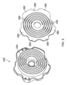
図3は、旋回スクロール230及び第1のチャンネルシール300の斜視図を示す概略図(縮尺通りではない)である。
チャンネルシール300は、第2の螺旋壁234が螺旋状の隙間302を貫通してぴったりと嵌合することができるように、第2の螺旋壁234の形状及び大きさと一致する螺旋状の隙間302を備える。また、チャンネルシール300は、駆動軸240がチャンネルシール300を貫通して延びることができるように、旋回スクロール230の中央開口の形状及びサイズと一致する中央開口を備える。
FIG. 3 is a schematic diagram (not to scale) showing a perspective view of the
The
本実施形態では、第1のパッド280は、その間に切り欠き部分を有する複数の突出部282を備える。突起部の間の切り欠き部分は、スクロールポンプ200の他の部分が存在するための空間(例えば、旋回スクロールの回転を防止する機構のための空間及び/又は旋回スクロール上にカバーを固定するねじのための空間)を提供する。これは、突出部282がない第1のパッド280と比較して、ポンプ全体のサイズを小さくすることができる傾向がある。
結果としてスクロールポンプが提供される。
In this embodiment, the
As a result, a scroll pump is provided.
好都合には、上述の実施形態では、スクロールポンプの動作時に、螺旋壁の摩耗が減少する傾向がある。従って、スクロールポンプは、全体的な耐久性が向上する傾向がある。 Advantageously, the above-described embodiments tend to reduce wear on the helical wall during operation of the scroll pump. Thus, the scroll pump tends to have improved overall durability.
好都合には、上述のスクロールポンプは、スクロールポンプの壁及びシールが損傷しないように、スクロールポンプの圧力-速度値を比較的低く保つことができる傾向がある。 Advantageously, the scroll pumps described above tend to be able to keep the scroll pump pressure-speed values relatively low so that the scroll pump walls and seals are not damaged.
好都合には、チャンネルシールを含む実施形態では、チャンネルシールは、スクロールポンプの動作時に摩耗が減少する傾向がある。従って、チャンネルシールは、全体的な耐久性が向上する傾向がある。 Advantageously, in embodiments including channel seals, the channel seals tend to experience reduced wear during operation of the scroll pump. Thus, the channel seals tend to have improved overall durability.
好都合には、パッドがチャンネルシールと一体形成される実施形態では、パッドは、別個に製造されるのではなく、チャンネルシールと一緒に製造することができるので、容易に製造することができる傾向がある。また、チャンネルシールとパッドを一体にすることで、チャンネルシール及びパッドを同じ厚さで容易に製造することができる傾向がある。このように、スクロール壁とチャンネルシールとの間の端部間隙をゼロに近づけることは、ポンプ送球された流体の漏れを最小限に抑え、ポンプ性能を最大化することができる傾向がある。 Advantageously, in embodiments in which the pads are integrally formed with the channel seals, the pads tend to be easier to manufacture since they can be manufactured along with the channel seals rather than being manufactured separately. Also, by integrating the channel seals and pads, the channel seals and pads tend to be easier to manufacture with the same thickness. In this manner, achieving close to zero end clearance between the scroll wall and the channel seals tends to minimize leakage of pumped fluid and maximize pump performance.
上記の実施形態では、付勢装置は、1又は2以上のバネを備える。しかしながら、他の実施形態では、付勢装置は、1又は2以上のバネの代わりに、又はそれに加えて、付勢をもたらす別のタイプの装置を備える。 In the above embodiments, the biasing device comprises one or more springs. However, in other embodiments, the biasing device comprises another type of device that provides a bias instead of or in addition to the one or more springs.
上記の実施形態では、外壁は、固定スクロールから延びる。しかしながら、他の実施形態では、外壁は、代わりに旋回スクロールから延びる。 In the above embodiment, the outer wall extends from the fixed scroll. However, in other embodiments, the outer wall extends from the orbiting scroll instead.
図2の上記の実施形態では、スクロールポンプは、第2のパッドを備え、スクロールは、中央開口を備える。しかしながら、他の実施形態では、スクロールポンプは、中央開口がない第2のパッドを備える。いくつかの実施形態では、スクロールポンプは、第2のパッドなしで中央開口を備える。いくつかの実施形態では、第2のパッド及び中央開口の全てが省略される。 In the above embodiment of FIG. 2, the scroll pump includes a second pad and the scroll includes a central opening. However, in other embodiments, the scroll pump includes a second pad without a central opening. In some embodiments, the scroll pump includes a central opening without a second pad. In some embodiments, the second pad and the central opening are omitted altogether.
図2の上記の実施形態では、パッド280,290に起因して、パッド280,290と一致するシール界面(すなわち、第1の螺旋壁224と第1のチャンネルシール300とで形成される界面)に対する螺旋壁上の摩耗速度が非常に低くなる傾向がある。いくつかの実施形態では、第2の螺旋壁234は、第1の螺旋壁224よりも高い(例えば、5から10ミクロンだけ)。これらの実施形態では、すべての荷重が最初に第2の螺旋壁234の端面にかかることになり、これにより、パッド280、290及び第1のチャンネルシール300が固定スクロール220と接触するまで、第2のチャンネルシール310が急速に摩耗することになる。これは、動作時にシール界面に対して両方の螺旋壁がほぼゼロの間隙を有することを保証する傾向がある。もしくは、いくつかの実施形態では、第2のチャンネルシール310は、ばね付勢されたチャンネルシールであり、これは、動作の最初の瞬間からシール界面に対して両方の螺旋壁がほぼゼロの間隙を有することを保証する傾向がある。
In the above embodiment of FIG. 2, the
100、200 スクロールポンプ
110、210 シェル
120、220 固定スクロール
122、222 第1の基部
124、224 第1の螺旋壁
126、226 外壁
130、230 旋回スクロール
132、232 第2の基部
134、234 第2の螺旋壁
136、236 周縁部
140、240 駆動軸
150,250 アクチュエータ
160 軸受
170 付勢装置
180 パッド
228 内壁
238 半径方向内側部分
280 第1のパッド
282 突起部
290 第2のパッド
300 第1のチャンネルシール
302 螺旋状の隙間
310 第2のチャンネルシール
100, 200
Claims (12)
基部と該基部から延び前記第1の螺旋壁と互いにかみ合う第2の螺旋壁とを含む第2のスクロールと、
前記第1のスクロール及び前記第2のスクロールとは異なる材料から形成され、前記第1の螺旋壁及び前記第2の螺旋壁の半径方向外側に配置されている第1のパッドと、
前記第1のスクロール及び前記第2のスクロールとは異なる材料から形成され、前記第1のスクロールと前記第2のスクロールとの間で前記第1の螺旋壁及び前記第2の螺旋壁の半径方向内側、且つ、軸線方向において前記第1のスクロールの内壁と前記第2のスクロールの基部との間に配置されている第2のパッドであって、前記内壁と前記第2のパッドが前記第1のスクロールと第2のスクロールとの間の空間から中央開口への流体流出を阻止する第2のパッドと、
前記第1のパッド及び前記第2のパッドを介して前記第1のスクロール及び前記第2のスクロールを互いに対して付勢させるように構成された付勢装置と、を備えている、
ことを特徴とするスクロールポンプ。 a first scroll including a first spiral wall and an inner wall located radially inward of the first spiral wall ;
a second scroll including a base and a second spiral wall extending from the base and intermeshing with the first spiral wall;
a first pad formed of a material different from that of the first scroll and the second scroll and disposed radially outward of the first spiral wall and the second spiral wall;
a second pad formed from a material different from that of the first scroll and the second scroll, the second pad being disposed between the first scroll and the second scroll, radially inward of the first spiral wall and the second spiral wall , and between an inner wall of the first scroll and a base of the second scroll in an axial direction, the inner wall and the second pad preventing fluid from flowing out of a space between the first scroll and the second scroll to a central opening;
a biasing device configured to bias the first scroll and the second scroll toward each other via the first pad and the second pad.
A scroll pump characterized by:
請求項1に記載のスクロールポンプ。 one or both of the first pad and the second pad are formed from a polymer material, and the first scroll and the second scroll are formed from a metallic material.
2. The scroll pump of claim 1.
請求項2に記載のスクロールポンプ。 one or both of the first pad and the second pad are formed from a polytetrafluoroethylene material, and the first scroll and the second scroll are formed from aluminum.
3. The scroll pump of claim 2.
請求項1から3のいずれか1項に記載のスクロールポンプ。 further comprising a channel seal disposed between the first scroll and the second scroll.
The scroll pump according to any one of claims 1 to 3.
請求項4に記載のスクロールポンプ。 One or both of the first pad and the second pad are integrally formed with the channel seal.
5. The scroll pump according to claim 4.
請求項4又は5に記載のスクロールポンプ。 One or both of the first pad and the second pad are formed of the same material as the channel seal.
6. The scroll pump according to claim 4 or 5.
請求項1から6のいずれか1項に記載のスクロールポンプ。 The second pad is formed from the same material as the first pad.
The scroll pump according to any one of claims 1 to 6.
請求項1から7のいずれか1項に記載のスクロールポンプ。 each of the first scroll and the second scroll includes a central opening, and the second pad is adjacent to the central opening;
The scroll pump according to any one of claims 1 to 7.
請求項1から8のいずれか1項に記載のスクロールポンプ。 a drive shaft coupled to the second scroll and configured to orbit the second scroll relative to the first scroll.
A scroll pump according to any one of claims 1 to 8.
請求項8に従属する請求項9に記載のスクロールポンプ。 The drive shaft extends through the central opening.
A scroll pump according to claim 9 depending on claim 8 .
請求項1から10のいずれか1項に記載のスクロールポンプ。 The first pad includes a plurality of protrusions.
The scroll pump according to any one of claims 1 to 10.
Applications Claiming Priority (3)
| Application Number | Priority Date | Filing Date | Title |
|---|---|---|---|
| GB1910471.0 | 2019-07-22 | ||
| GB1910471.0A GB2585903B (en) | 2019-07-22 | 2019-07-22 | Scroll Pump |
| PCT/EP2020/070630 WO2021013872A1 (en) | 2019-07-22 | 2020-07-22 | Scroll pump |
Publications (3)
| Publication Number | Publication Date |
|---|---|
| JP2022542034A JP2022542034A (en) | 2022-09-29 |
| JP2022542034A5 JP2022542034A5 (en) | 2023-07-21 |
| JP7581319B2 true JP7581319B2 (en) | 2024-11-12 |
Family
ID=67839694
Family Applications (1)
| Application Number | Title | Priority Date | Filing Date |
|---|---|---|---|
| JP2022503842A Active JP7581319B2 (en) | 2019-07-22 | 2020-07-22 | Scroll Pump |
Country Status (6)
| Country | Link |
|---|---|
| US (1) | US12049891B2 (en) |
| EP (1) | EP4004372B1 (en) |
| JP (1) | JP7581319B2 (en) |
| CN (1) | CN114174679B (en) |
| GB (1) | GB2585903B (en) |
| WO (1) | WO2021013872A1 (en) |
Families Citing this family (1)
| Publication number | Priority date | Publication date | Assignee | Title |
|---|---|---|---|---|
| GB2625552B (en) * | 2022-12-20 | 2025-10-10 | Edwards Ltd | Seal for scroll pump |
Citations (1)
| Publication number | Priority date | Publication date | Assignee | Title |
|---|---|---|---|---|
| JP2009115055A (en) | 2007-11-09 | 2009-05-28 | Daikin Ind Ltd | Rotary fluid machine |
Family Cites Families (25)
| Publication number | Priority date | Publication date | Assignee | Title |
|---|---|---|---|---|
| US4160629A (en) * | 1977-06-17 | 1979-07-10 | Arthur D. Little, Inc. | Liquid immersible scroll pump |
| US4259043A (en) * | 1977-06-17 | 1981-03-31 | Arthur D. Little, Inc. | Thrust bearing/coupling component for orbiting scroll-type machinery and scroll-type machinery incorporating the same |
| JPS5823516B2 (en) | 1978-09-04 | 1983-05-16 | サンデン株式会社 | positive displacement fluid compression device |
| JPS5851289A (en) | 1981-09-22 | 1983-03-25 | Hitachi Ltd | Fluid compressor |
| JPH0633780B2 (en) | 1984-07-31 | 1994-05-02 | 株式会社東芝 | Scroll compressor |
| JPS61258989A (en) * | 1985-05-10 | 1986-11-17 | Hitachi Ltd | Scroll fluid machine |
| JP2556099B2 (en) | 1988-06-29 | 1996-11-20 | 三菱電機株式会社 | Scroll compressor |
| AU632332B2 (en) * | 1989-06-20 | 1992-12-24 | Sanden Corporation | Scroll type fluid displacement apparatus |
| US5192202A (en) * | 1990-12-08 | 1993-03-09 | Gold Star Co., Ltd. | Scroll-type compressor with an apparatus for restraining compressed fluid from being leaked |
| JP2855388B2 (en) * | 1992-07-15 | 1999-02-10 | 株式会社いすゞセラミックス研究所 | A multi-cylinder gas engine equipped with a turbocharger with a generator and motor |
| US5383772A (en) * | 1993-11-04 | 1995-01-24 | Tecumseh Products Company | Scroll compressor stabilizer ring |
| JPH09126165A (en) * | 1995-10-30 | 1997-05-13 | Mitsubishi Heavy Ind Ltd | Scroll type fluid machinery |
| US5727934A (en) | 1995-10-30 | 1998-03-17 | Mitsubishi Jukogyo Kabushiki Kaisha | Scroll type fluid machine having a thin plate for each scroll |
| JPH10141255A (en) | 1996-11-01 | 1998-05-26 | Nisshin Seisakusho:Kk | Scroll compressor |
| US6146119A (en) * | 1997-11-18 | 2000-11-14 | Carrier Corporation | Pressure actuated seal |
| WO2000006906A1 (en) | 1998-07-30 | 2000-02-10 | Varian, Inc. | Scroll-type vacuum pump |
| JP2002221170A (en) | 2001-01-25 | 2002-08-09 | Toyota Industries Corp | Scroll compressor |
| JP2003286974A (en) * | 2002-03-26 | 2003-10-10 | Matsushita Electric Works Ltd | Scroll fluid machine |
| GB0319513D0 (en) * | 2003-08-19 | 2003-09-17 | Boc Group Plc | Scroll compressor and scroll wall arrangement therefor |
| GB0823184D0 (en) | 2008-12-19 | 2009-01-28 | Edwards Ltd | Scroll compressor |
| GB0912162D0 (en) | 2009-07-14 | 2009-08-26 | Edwards Ltd | Scroll compressor |
| JP5535155B2 (en) | 2011-09-05 | 2014-07-02 | 株式会社コガネイ | Flow path switching valve and fluid material discharge control device using the same |
| GB2548607B (en) | 2016-03-23 | 2020-05-06 | Edwards Ltd | Scroll pump tip sealing |
| GB201610896D0 (en) | 2016-06-22 | 2016-08-03 | Edwards Ltd | Vacuum scroll pump |
| CN207960944U (en) | 2018-03-21 | 2018-10-12 | 宁波汇峰聚威科技股份有限公司 | A kind of floating sealing structure of screw compressor |
-
2019
- 2019-07-22 GB GB1910471.0A patent/GB2585903B/en active Active
-
2020
- 2020-07-22 JP JP2022503842A patent/JP7581319B2/en active Active
- 2020-07-22 WO PCT/EP2020/070630 patent/WO2021013872A1/en not_active Ceased
- 2020-07-22 EP EP20745157.6A patent/EP4004372B1/en active Active
- 2020-07-22 CN CN202080052944.7A patent/CN114174679B/en active Active
- 2020-07-22 US US17/628,784 patent/US12049891B2/en active Active
Patent Citations (1)
| Publication number | Priority date | Publication date | Assignee | Title |
|---|---|---|---|---|
| JP2009115055A (en) | 2007-11-09 | 2009-05-28 | Daikin Ind Ltd | Rotary fluid machine |
Also Published As
| Publication number | Publication date |
|---|---|
| US12049891B2 (en) | 2024-07-30 |
| CN114174679A (en) | 2022-03-11 |
| GB2585903A (en) | 2021-01-27 |
| US20220397115A1 (en) | 2022-12-15 |
| JP2022542034A (en) | 2022-09-29 |
| EP4004372B1 (en) | 2025-09-03 |
| CN114174679B (en) | 2023-11-24 |
| GB2585903B (en) | 2021-12-08 |
| EP4004372A1 (en) | 2022-06-01 |
| GB201910471D0 (en) | 2019-09-04 |
| WO2021013872A1 (en) | 2021-01-28 |
Similar Documents
| Publication | Publication Date | Title |
|---|---|---|
| US10975868B2 (en) | Compressor with floating seal | |
| CN209654237U (en) | Polymer composites insertion part for screw compressor | |
| JP3671447B2 (en) | Bearing holding structure | |
| JP7581319B2 (en) | Scroll Pump | |
| CN1683793A (en) | Scroll compressor | |
| CN103382938A (en) | Scroll compressor with unloader assembly | |
| JP2020502409A (en) | Pump sealing | |
| JP7699764B2 (en) | Scroll Pump | |
| CN114867941B (en) | Scroll type fluid machine | |
| CN212643043U (en) | scroll compressor | |
| JPH02277985A (en) | Scroll type fluid machine | |
| JP3588450B2 (en) | Anti-axial force anti-rotation bearing for scroll compressor, improved anti-rotation device for scroll compressor, and scroll compressor with anti-axial force anti-rotation device | |
| CN110621879B (en) | Scroll fluid machine | |
| JP7010202B2 (en) | Fluid machine | |
| JPH09250467A (en) | Scroll type fluid machinery | |
| JP2002317793A (en) | Movable inner ring of pump | |
| JP7824736B2 (en) | Annular seal member for scroll compressor | |
| JPH09268983A (en) | Scroll type fluid machine | |
| WO2020121809A1 (en) | Fluid machine | |
| GB2625552A (en) | Seal for scroll pump | |
| JP3687279B2 (en) | Scroll compressor | |
| EP1087141A2 (en) | Scroll-type compressor | |
| JP2025076057A (en) | Oil-free scroll compressor | |
| WO2025089301A1 (en) | Scroll fluid machine | |
| CN113915124A (en) | Scroll compressor having a plurality of scroll members |
Legal Events
| Date | Code | Title | Description |
|---|---|---|---|
| A521 | Request for written amendment filed |
Free format text: JAPANESE INTERMEDIATE CODE: A523 Effective date: 20230712 |
|
| A621 | Written request for application examination |
Free format text: JAPANESE INTERMEDIATE CODE: A621 Effective date: 20230712 |
|
| A977 | Report on retrieval |
Free format text: JAPANESE INTERMEDIATE CODE: A971007 Effective date: 20240313 |
|
| A131 | Notification of reasons for refusal |
Free format text: JAPANESE INTERMEDIATE CODE: A131 Effective date: 20240321 |
|
| A521 | Request for written amendment filed |
Free format text: JAPANESE INTERMEDIATE CODE: A523 Effective date: 20240618 |
|
| TRDD | Decision of grant or rejection written | ||
| A01 | Written decision to grant a patent or to grant a registration (utility model) |
Free format text: JAPANESE INTERMEDIATE CODE: A01 Effective date: 20240930 |
|
| A61 | First payment of annual fees (during grant procedure) |
Free format text: JAPANESE INTERMEDIATE CODE: A61 Effective date: 20241030 |
|
| R150 | Certificate of patent or registration of utility model |
Ref document number: 7581319 Country of ref document: JP Free format text: JAPANESE INTERMEDIATE CODE: R150 |