JP7580997B2 - Apparatus and method for inserting object - Google Patents
Apparatus and method for inserting object Download PDFInfo
- Publication number
- JP7580997B2 JP7580997B2 JP2020161904A JP2020161904A JP7580997B2 JP 7580997 B2 JP7580997 B2 JP 7580997B2 JP 2020161904 A JP2020161904 A JP 2020161904A JP 2020161904 A JP2020161904 A JP 2020161904A JP 7580997 B2 JP7580997 B2 JP 7580997B2
- Authority
- JP
- Japan
- Prior art keywords
- hole
- reaction force
- gripped
- unit
- insertion device
- Prior art date
- Legal status (The legal status is an assumption and is not a legal conclusion. Google has not performed a legal analysis and makes no representation as to the accuracy of the status listed.)
- Active
Links
Images


Landscapes
- Manipulator (AREA)
Description
本発明は把持物挿入装置及び方法に係り、特に、挿入対象物に形成された穴を探索し、その穴に把持物を挿入するものに好適な把持物挿入装置及び方法に関する。 The present invention relates to an object insertion device and method, and in particular to an object insertion device and method suitable for searching for a hole formed in an object to be inserted and inserting an object into the hole.
製造業界での組み立て作業において、ある部品を別の部品に挿入することは一般的なタスクである。それを達成するため、組み立て部品を移動させる多自由度ロボットなどの3D位置決め装置、組み立て部品を把持する把持部、把持される部品(以下、把持物という)、把持物が挿入される穴が形成されているワーク、把持物をワークの穴に挿入する時に生じる反力を検出する反力検出部で構成されるシステムが知られている。 In assembly work in the manufacturing industry, inserting one part into another is a common task. To accomplish this, systems are known that are composed of a 3D positioning device such as a multi-degree-of-freedom robot that moves the assembly parts, a gripping unit that grips the assembly parts, the part to be gripped (hereinafter referred to as the gripped object), a workpiece in which a hole is formed through which the gripped object will be inserted, and a reaction force detection unit that detects the reaction force generated when the gripped object is inserted into the hole in the workpiece.
このシステムを制御して部品挿入作業を実行するには、挿入対象の穴の近くのワーク表面に把持物を押し付け、把持物をワーク表面にスライドさせ、反力検出部で測定した反力とトルクにより、挿入対象の穴の中心位置を推定する方法が一般的である。 The general method for controlling this system to perform the part insertion task is to press the gripped object against the work surface near the hole to be inserted, slide the gripped object over the work surface, and estimate the center position of the hole to be inserted based on the reaction force and torque measured by the reaction force detection unit.
しかし、上記した方法は、穴の周りのワーク表面の摩擦係数が高い場合、把持物の挿入部分が摩擦力によって引っかかれ、ロボットに必要な労力が高くなり、穴を検出するためのトルクと力の信号がノイズに覆われるため、挿入対象の穴の中心位置を推定することが難しくなっていた。 However, with the above method, when the coefficient of friction of the workpiece surface around the hole is high, the insertion part of the gripped object is scratched by the frictional force, increasing the effort required by the robot, and making it difficult to estimate the center position of the hole to be inserted because the torque and force signals for detecting the hole are covered by noise.
この問題を解決するために、ロボットを用いた穴探索方法が特許文献1に記載されている。この特許文献1には、把持物を特定のθ角度に傾け、挿入対象の穴があると予想される決められたワークの領域の中で傾けた把持物を数回スライドさせ、反力検出部で検出された把持物のせん断力により穴の中心位置を推定する穴探索方法が開示されている。
To solve this problem, a hole searching method using a robot is described in
しかしながら、上述した特許文献1に記載されている穴探索方法は、穴の中心位置を推定するために、把持した対象物を広い範囲で何度もスライドさせる必要があり、穴の探索に時間が掛かり把持物の挿入操作が長時間に及ぶという課題がある。
However, the hole search method described in
本発明は上述の点に鑑みなされたもので、その目的とするところは、高い摩擦係数を有する挿入対象物の表面に形成された穴を迅速に発見し、その穴に短時間で把持物が挿入できる把持物挿入装置及び方法を提供することにある。 The present invention has been made in consideration of the above points, and its purpose is to provide an object insertion device and method that can quickly find holes formed on the surface of an object to be inserted that has a high coefficient of friction, and can insert an object into the hole in a short time.
本発明の把持物挿入装置は、上記目的を達成するために、把持物駆動部に把持された把持物を挿入対象物に押し当てながら走査させ、前記挿入対象物に形成された断面が円形の穴を探索し、前記把持物が前記穴に前記把持物駆動部により挿入される把持物挿入装置であって、
前記把持物駆動部を制御する制御部と、前記把持物が前記挿入対象物から受ける反力を検出する反力検出部と、前記反力検出部が検出した信号に基づいて前記把持物が前記穴の中心に向かう方向を演算する演算部と、を備え、
前記演算部は、前記反力検出部で検出された前記反力が予め定められた閾値を超えた際に、前記反力検出部で検出された前記反力の向きが前記穴の中心に向かう方向を演算し、前記制御部は、前記演算部で演算した結果に基づき、前記把持物を前記穴に挿入するように前記把持物駆動部を制御することを特徴とする。
In order to achieve the above object, the present invention provides an object insertion device, which includes a grasped object drive unit that scans an object held by the grasped object drive unit while pressing the object against an insertion object, searches for a hole having a circular cross section formed in the insertion object, and inserts the object into the hole by the grasped object drive unit,
A control unit that controls the object drive unit, a reaction force detection unit that detects a reaction force that the object receives from the insertion target, and a calculation unit that calculates a direction in which the object moves toward the center of the hole based on a signal detected by the reaction force detection unit,
The calculation unit calculates the direction in which the reaction force detected by the reaction force detection unit faces the center of the hole when the reaction force detected by the reaction force detection unit exceeds a predetermined threshold value, and the control unit controls the object drive unit to insert the object into the hole based on the result of the calculation by the calculation unit.
また、本発明の把持物挿入方法は、上記目的を達成するために、把持物駆動部に把持された把持物を挿入対象物に押し当てながら走査させ、前記挿入対象物に形成された断面が円形の穴を探索し、前記把持物が前記穴に前記把持物駆動部により挿入される把持物挿入方法であって、
前記把持物が前記挿入対象物から受ける反力を反力検出部で検出し、前記反力検出部で検出された前記反力が予め定められた閾値を超えた際に、前記反力検出部で検出された前記反力の向きが前記穴の中心に向かう方向を演算部で演算し、前記演算部で演算した結果に基づき、前記把持物を前記穴に挿入するように制御部で前記把持物駆動部を制御することを特徴とする。
In order to achieve the above object, the present invention provides a method for inserting an object, comprising the steps of: pressing an object held by a object drive unit against an object to be inserted while scanning the object; searching for a hole having a circular cross section formed in the object to be inserted; and inserting the object into the hole by the object drive unit,
The method is characterized in that a reaction force that the object to be held receives from the object to be inserted is detected by a reaction force detection unit, and when the reaction force detected by the reaction force detection unit exceeds a predetermined threshold value, a calculation unit calculates the direction of the reaction force detected by the reaction force detection unit toward the center of the hole, and based on the result of the calculation by the calculation unit, a control unit controls the object to be held drive unit so as to insert the object to the hole.
本発明によれば、高い摩擦係数を有する挿入対象物表面に形成された穴を迅速に発見し、その穴に短時間で把持物が挿入できる。 According to the present invention, holes formed on the surface of an object to be inserted that have a high coefficient of friction can be quickly found, and the object to be held can be inserted into the hole in a short time.
以下、図示した実施例に基づいて本発明の把持物挿入装置及び方法を説明する。なお、各図において、同一構成部品には同符号を使用する。 The object insertion device and method of the present invention will be described below based on the illustrated embodiment. Note that the same reference numerals are used for the same components in each figure.
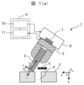
図1(a)から図1(f)に、本発明の把持物挿入装置1の実施例1の概略構成と、その把持物挿入装置1による把持物2を挿入対象物であるワーク3に形成された穴4へ、把持物駆動部であるロボット6及び把持部5を用いて挿入する挿入手順を示す。
Figures 1(a) to 1(f) show a schematic configuration of a first embodiment of the gripped
図1(a)に示すように、本実施例の把持物挿入装置1は、把持物(例えば、エレベーター用アンカーボルト等)2と、穴4が開けられたワーク(例えば、エレベーター昇降路内のコンクリート壁等)3と、把持部(例えば、ロボットハンド等)5と、ロボット6と、ロボット6及び把持部5を制御する制御部10と、把持物2がワーク3から受ける反力を検出する反力検出部(例えば、力覚センサ等)7と、反力検出部7が検出した信号に基づいて穴4の中心方向を演算する演算部11とから概略構成され、制御部10と演算部11で制御装置9を構成している。
As shown in FIG. 1(a), the gripped
そして、本実施例の把持物挿入装置1では、演算部11は、反力検出部7で検出された反力が予め定められた閾値を超えた際に、反力検出部7で検出された反力の向きから穴4の中心方向を演算し、制御部10は、演算部11が演算した結果に基づき、把持物2を穴4に挿入するようにロボット6及び把持部(ロボットハンド)5を制御するものである。
In the
実施例1におけるワーク3の表面は平らであり、この場合には、制御部10は、把持物2をワーク3の表面に対してθ角度傾けた状態で、ワーク3の表面を走査するようにロボット6及び把持部(ロボットハンド)5を制御する。
In Example 1, the surface of the
この際には、把持物2をワーク3の表面に対してθ角度傾けた状態で走査し、反力検出部7で検出された反力が予め定められた閾値を超えた後に、把持物2の底部が穴4の形成方向(図1(a)の下方向)となるように、把持物2と穴4の接触点を中心に穴4の軸方向回りに把持物2を回転させる。
In this case, the
また、後述するが把持物2の底部を穴4の形成方向に向くように把持物2を回転させた後に、穴4の形成方向にさらに把持物2を押し付け、把持物2を穴4の縁の3点に接触させ、穴4の縁と把持物2の3点の接触点と穴4と把持物2の寸法との座標系により、穴4の中心位置を求めるようにしている。
As will be described later, after rotating the object to be held 2 so that the bottom of the object to be held 2 faces the direction in which the
なお、本実施例における把持物2と穴4は円筒形で、その把持物2と穴4の直径は同じにする。ただし、本実施例の把持物挿入装置1では、穴4の直径は、把持物2の直径よりも大きくてもよい。また、ロボット6は、三次元空間で把持物2の位置と姿勢を変更できるものであればよい。
In this embodiment, the
次に、本実施例における把持物2の挿入手順を図1(a)から図1(f)を用いて説明する。
Next, the procedure for inserting the
先ず、把持物2をワーク3の座標系OwのX軸回りに0度以上90度未満のθ角度に傾斜させ、反力検出部7で検出したz方向の把持物2がワーク3を押し付ける力が予め定められた閾値を超えるまで、把持物2を把持物2の座標系Opのz方向にワーク3に向けて移動させる(把持物2をz方向(斜め下方)に押し付ける)。その後、把持物2をz方向に押し付けながら、把持物2をワーク3の表面に沿って太線矢印Sのようにスライドさせる(図1(a)参照)。
First, the
ワーク3を押し付ける領域は、カメラと穴検出アルゴリズムなどで事前に検出した穴4の中心位置8の近くの表面であるが、カメラと穴検出アルゴリズムだけで穴4の中心位置8を正確に検出することが困難なため、穴4の探索が必要である。また、カメラと穴検出アルゴリズムで穴4の検出を正確にできても、ロボット6の位置決め精度、若しくは把持部5のがたにより、位置決めエラーを生じることもあるため、穴4の探索が必要になる。
The area against which the
把持物2をワーク3の表面に沿ってスライドを開始した後に、把持物2の一部が穴4に入り、把持物2が穴4の縁に接触し、把持物2の座標系Opのy方向の力が予め定められた閾値を超えると、把持物2の移動を停止させる(図1(b)参照)。
After starting to slide the
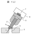
把持物2は、ワーク3の表面に沿ってスライドしながらOp座標系のz方向に押し付けられるため、把持物2がワーク3の表面に接触する部分が穴4に入ると、把持物3はさらにz方向に移動し、把持物2の側面の一部が必ず穴4の縁に接触する。次に、把持物2の底面を穴4の縁に接触するまで、さらにOp座標系の+z方向に把持物2を移動させる(図1(c)参照)。
The
図2(a)及び図2(b)は、図1(c)の把持物2とワーク3の接触状態の詳細を示す図である。
Figures 2(a) and 2(b) are diagrams showing the details of the contact state between the
図2(a)及び図2(b)に示すように、図1(c)の状態では、把持物2が穴4の縁の3点(接触点21、22、23)に接触する。ワーク3に接触可能に傾けられた把持物2の面積は、図2(a)に示すような把持物2の断面だと考えられる。その断面は、図2(b)に示す短軸rと長軸r/sinθの楕円である。この楕円を半径rの穴4の表面に設置すると、把持物2と穴4との3つの接触点21、22、23が得られる。
As shown in Figures 2(a) and 2(b), in the state of Figure 1(c), the
接触点21は、把持物2の側面と穴4の縁の接触点であり、接触点22及び23は、把持物2の底面と穴4の縁との接触点である。
図2(b)では、穴4の原点が(xo、yo)、楕円面積の原点は(xe、ye)、接触点21、22及び23の位置を(x21、y21)、(x22、y22)及び(x23、y23)でそれぞれ表される。
In FIG. 2(b), the origin of
作業座標フレームOw上の接触点21、22、23の位置は、次のように与えられる。即ち、(xo、yo)は(0、0)であることにすると、各接触点の位置を下記の(1)から(6)式で求められる。 The positions of the contact points 21, 22, and 23 on the work coordinate frame Ow are given as follows: That is, if (x o , y o ) is (0, 0), the position of each contact point can be obtained by the following equations (1) to (6).
![]()
![]()
![]()
![]()


また、把持物2と穴4の縁との接触点を用いて、三角法による下記の(7)から(10)式で穴4の中心位置8を求めることができる。
In addition, the contact point between the
![]()
![]()

![]()
![]()

上記の式でP1は把持物2の底面の中心位置、P2は把持物2の側面と穴4の縁との接触点21、P3は把持物2の中心軸がワーク3の平面と交差する点であり、上記の式で上付きのOp及びOwは、それぞれ把持物2の座標系またはワーク3の座標系内の位置を表し、
In the above formula, P1 is the center position of the bottom surface of the gripped
![]()
![]()
は、Op座標系からOw座標系への変換行列である。 is the transformation matrix from the Op coordinate system to the Ow coordinate system.
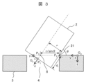
図3は、三角関数の計算に使用される把持物2と穴4の詳細寸法と穴4の中心位置8を計算するための位置を示す図である。
Figure 3 shows the detailed dimensions of the
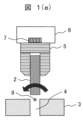
穴4の中心位置8が求められた後、把持物2はOp座標系の-z方向にdr(図3参照)だけ後退して完全に穴4から離れる(図1(d)参照)。その後、Ow座標系のx軸で穴4の中心位置8を中心にx軸回りに把持物2が回転する(図1(e)参照)。最後に、把持物2がOw座標系の+z軸方向に移動され、穴4に挿入される(図1(f)参照)。
After the
図4は、ワーク3の座標系のy軸における探索移動パス41が穴4の中心位置8を通過しない場合の処理アルゴリズムを示す上面図である。
Figure 4 is a top view showing the processing algorithm when the
ワーク3の座標系のy軸における探索移動パス41が穴4の中心位置8を通過しない場合、把持物2が接触点42で穴4の縁に接触すると、生成された反力Fはx軸とy軸に分布し、力の方向は穴4の中心位置8に向くようになる(図3参照)。その後、図1(c)に示すステップに進むには、把持物2を接触点42を中心にOw座標系のz軸回りに回転させるだけでよい。
If the
ロバスト性を高めるため、穴4の中心位置8の方向を確認することが可能となる。その場合、図4の(a)に示す探索移動パス41で得られた新たな方向に把持物2の側面が穴4の逆側(接触点42の逆側)の縁に接触(接触点44)するまで移動する(図4の(b)に示す探索移動パス43)。その時に発生した反力Fが探索移動パス43と逆方向に向いていることが分かれば、穴4の中心位置8が探索移動パス43にあることがわかる。その後、図1(c)に示すステップに進めれば、把持物2の挿入が可能になる。
To improve robustness, it is possible to confirm the direction of the
なお、探索移動パス43に進めるには、把持物2の傾きを変更する必要がある。それを実現するには、把持物2を接触点42を中心にOw座標系のz軸回りに回転させればよい。
Note that in order to proceed to the
図5に、本実施例で把持物2の挿入を行うための制御アルゴリズムのフローチャートを示す。このフローチャートは、図4の(b)に示す探索移動パス43で穴4の中心位置8を確認しない場合のアルゴリズムである。
Figure 5 shows a flowchart of the control algorithm for inserting the
図5に示すように、先ずは周知の画像認識による穴検出方法により、穴4の中心位置8を大まかに検出する(ステップ501)。把持物2をワーク3の表面に対してθ角度傾け(ステップ502、図1(a))、Opのz軸方向に把持物2をワーク3に押し付ける(ステップ503、図1(b))。
As shown in Figure 5, first, the
次に、Opのy軸の反力Fyが既定の閾値を超えるまで(ステップ505、図1(b))、把持物2をワーク3の座標系のy方向にスライドさせる(ステップ504)。次に、Opのx軸の反力Fxも既定の閾値(通常値はゼロ)を超えると(ステップ506)、穴4の中心位置8の方向が演算部11で計算され、把持物2の底面を穴4の中心位置8の方向に向けるように必要な回転量が演算部11で計算される(ステップ507)。そして、把持物2を接触点21を中心にOwのz軸回りに回転させ、把持物2の底部を穴4に向ける(ステップ508)。
Next, the
次に、把持物2をz方向の力Fzの既定の閾値を超えるまで(ステップ510)+z軸方向に移動させる(ステップ509、図1(c))。そして、穴4の中心位置8を算出し(ステップ511)、把持物2をOpの-z軸方向にdrだけ移動させる(ステップ512、図1(d))。
Next, the
次に、把持物2を穴4の中心位置8を中心にθ度回転させる(ステップ513、図1(e))。最後に、把持物2をOwの+z方向に移動させ、把持物2を穴4に挿入する(ステップ514、図1(f))。
Next, the
このような本実施例によれば、高い摩擦係数を有するワーク3の表面に形成された穴4を迅速に発見し、その穴4に短時間で把持物2を挿入できる効果がある。
This embodiment has the effect of quickly finding
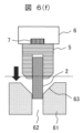
図6(a)から図6(f)に、本発明の把持物挿入装置1Aの実施例2の概略構成と、その把持物挿入装置1Aによる把持物2を挿入対象物であるワーク61に形成された穴62へ、把持物駆動部であるロボット6及び把持部5を用いて挿入する挿入手順を示すが、本実施例では、ワーク61の穴62にはテーパ63が形成されている。このテーパ63は、穴62の開口部を広くするためである。
Figures 6(a) to 6(f) show a schematic configuration of Example 2 of the gripped
図6(a)に示すように、本実施例の把持物挿入装置1Aは、把持物(例えば、エレベーター用アンカーボルト等)2と、穴62が開けられたワーク(例えば、エレベーター昇降路内のコンクリート壁等)61と、把持部(例えば、ロボットハンド等)5と、ロボット6と、ロボット6及び把持部5を制御する制御部10と、把持物2がワーク61から受ける反力を検出する反力検出部(例えば、力覚センサ等)7と、反力検出部7が検出した信号に基づいて穴62の中心方向を演算する演算部11とから概略構成されている。
As shown in FIG. 6(a), the gripped
また、演算部11は、穴62の軸方向の穴62から離れた初期位置から把持物2をワーク61に接触した位置までの移動距離を演算する移動距離演算手段65と、移動距離演算手段65で演算した移動距離により、穴62への接近有無の判断及び/又は穴62に近づいていることの認識、穴62から離れていることの判定を行う穴近接度判定手段66と、穴近接度判定手段66の判定により、穴62の探索のための進行移動量を調整する進行移動量調整手段67とを備え、この演算部11と制御部10で制御装置9を構成している。
The
そして、本実施例の把持物挿入装置1Aでは、演算部11は、反力検出部7で検出された反力が予め定められた閾値を超えた際に、反力検出部7で検出された反力の向きから穴62の中心方向を演算し、制御部10は、演算部11が演算した結果に基づき、把持物2を穴62に挿入するようにロボット6及び把持部5を制御するものであるが、本実施例では、穴62の入り口にテーパ63が形成されており、この場合には、入り口にテーパ63が形成された穴62の軸方向に平行な状態で把持物2をワーク61に押し付け、制御部10は、反力検出部7で検出された反力が予め定められた閾値以内の場合は、ワーク61を押し付ける位置を変更するようにロボット6及び把持部(ロボットハンド)5を制御するものである。
In the gripped
この際には、穴62の探索方向に把持物2を移動する前に穴62の軸方向の穴62から離れた初期位置に把持物2を引き込み、穴62の探索方向の次のステップに把持物2を移動してから把持物2をワーク61の方向に押し付ける。
In this case, before moving the
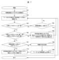
次に、本実施例における把持物2の挿入手順を図6(a)から図6(f)及び図7を用いて説明する。
Next, the procedure for inserting the
図6の(a)から図6の(f)は、把持物2を穴62に挿入するための挿入手順を示し、図7は、その挿入手順のフローチャートである。
Figures 6(a) to 6(f) show the insertion procedure for inserting the
該図に示すように、本実施例では、まず周知の画像認識による穴検出方法により、穴62の中心位置が大まかに検出される(ステップ701)。次に、把持物2を、反力検出部7によって検出された反力Fzが既定の閾値を超えるまで(ステップ703)、ワーク61の座標系Owの+Z方向に移動させる(ステップ702、図6(a))。これは、ワーク61(図6(b))における把持物2との接触を示している。反力検出部7によって検出された反力Fzが既定の閾値に達していない場合、移動距離Dzがチェックされる(ステップ704)。
As shown in the figure, in this embodiment, the center position of the
移動距離Dzが既定の移動距離Dzの閾値よりも長い場合、穴62内への挿入が可能なため、制御は終了する(図6(e))。それ以外の場合は、反力Fzが閾値を超えるまでチェックを続ける。反力Fzが閾値を超えると、Fyが閾値を超えたかがチェックされる(ステップ705)。Fyが閾値を超えない場合、それは、図6(b)に示されるように、把持物2がテーパ63内に入っていないことを示し、Fyが閾値を超えたのであれば、図6(d)に示すように、把持物2がテーパ63内に入っていることを示す。
If the travel distance Dz is longer than the default travel distance Dz threshold, insertion into the
図6(b)の状況では、把持物2は、Owのz軸における既定の初期位置Pzに引き戻され、次いで、Owのy方向に既定の移動量Dxyで移動される(図6(c))。その後、ステップ702に戻る。図6(d)の状況では、把持物2もPzで後退するが、Fy及びFxを検出して計算される穴62の中心位置の方向に移動量Dxyで移動する(ステップ710)。
In the situation of FIG. 6(b), the
ただし、ステップ709の前に、移動距離Dzを前回の移動距離Dzと比較して、把持物2が穴62に近づいているかどうかを確認する(ステップ707)。
However, before
移動距離Dzが前の移動距離Dzよりも大きい場合、把持物2が穴62に近づいていることを示し、ステップ710を続けることができる。それ以外の場合は、把持物2が穴62を通過したことを示す。そのため、進行方向が反転し(ステップ708)、移動量Dxyが減少し、ステップ710に進む。これにより、移動量Dxyをより細かくでき、穴62を発見することができる。
If the travel distance Dz is greater than the previous travel distance Dz, this indicates that the
上述した把持物挿入方法では、移動距離演算手段65により穴62の軸方向の穴62から離れた初期位置Pzから把持物2をワーク61に接触した位置までの移動距離Dzを演算し、移動距離演算手段65で演算した移動距離Dzにより、穴62への接近有無の判断及び/又は穴62に近づいていることの認識、穴62から離れていることの判定を穴近接度判定手段66で行い、穴近接度判定手段66の判定により、穴62の探索のための進行移動量を進行移動量調整手段67で調整している。
In the above-mentioned gripped object insertion method, the movement distance calculation means 65 calculates the movement distance Dz from the initial position Pz away from the
このような本実施例によれば、ワーク61の穴62にテーパ63が形成されていても、高い摩擦係数を有するワーク61の表面に形成された穴62を迅速に発見し、その穴62に短時間で把持物2を挿入できる効果がある。
According to this embodiment, even if a
なお、本発明は上記した実施例に限定されるものではなく、様々な変形例が含まれている。例えば、上記した実施例は本発明を分かりやすく説明するために詳細に説明したものであり、必ずしも説明した全ての構成を備えるものに限定されるものではない。また、ある実施例の構成の一部を他の実施例の構成に置き換えることが可能であり、また、ある実施例の構成に他の実施例の構成を加えることも可能である。また、各実施例の構成の一部について、他の構成の追加・削除・置換をすることが可能である。 The present invention is not limited to the above-mentioned embodiments, but includes various modified examples. For example, the above-mentioned embodiments have been described in detail to clearly explain the present invention, and are not necessarily limited to those having all of the configurations described. It is also possible to replace part of the configuration of one embodiment with the configuration of another embodiment, and it is also possible to add the configuration of another embodiment to the configuration of one embodiment. It is also possible to add, delete, or replace part of the configuration of each embodiment with other configurations.
1、1A…把持物挿入装置、2…把持物、3、61…ワーク、4、62…穴、5…把持部、6…ロボット、7…反力検出部、8…穴の中心位置、9…制御装置、10…制御部、11…演算部、21、42、44…把持物の側面と穴の縁との接触点、22、23…把持物の底面と穴の縁との接触点、41、43…探索移動パス、63…テーパ、64…ワーク座標系のz軸移動の初期位置、65…移動距離演算手段、66…穴近接度判定手段、67…進行移動量調整手段、501~514…実施例1の作業フローのステップ、701~710…実施例2の作業フローのステップ。 1, 1A...Grasp object insertion device, 2...Grasp object, 3, 61...Workpiece, 4, 62...Hole, 5...Grasp unit, 6...Robot, 7...Reaction force detection unit, 8...Center position of hole, 9...Control device, 10...Control unit, 11...Calculation unit, 21, 42, 44...Contact point between side of gripped object and edge of hole, 22, 23...Contact point between bottom surface of gripped object and edge of hole, 41, 43...Search movement path, 63...Taper, 64...Initial position of z-axis movement in work coordinate system, 65...Movement distance calculation means, 66...Hole proximity determination means, 67...Progress movement amount adjustment means, 501-514...Steps of workflow in Example 1, 701-710...Steps of workflow in Example 2.
Claims (16)
前記把持物駆動部を制御する制御部と、前記把持物が前記挿入対象物から受ける反力を検出する反力検出部と、前記反力検出部が検出した信号に基づいて前記把持物が前記穴の中心に向かう方向を演算する演算部と、を備え、
前記演算部は、前記反力検出部で検出された前記反力が予め定められた閾値を超えた際に、前記反力検出部で検出された前記反力の向きが前記穴の中心に向かう方向を演算し、前記制御部は、前記演算部で演算した結果に基づき、前記把持物を前記穴に挿入するように前記把持物駆動部を制御することを特徴とする把持物挿入装置。 A gripped object insertion device in which a gripped object drive unit scans a gripped object while pressing it against an insertion object, searches for a hole having a circular cross section formed in the insertion object, and the gripped object is inserted into the hole by the gripped object drive unit,
A control unit that controls the object drive unit, a reaction force detection unit that detects a reaction force that the object receives from the insertion target, and a calculation unit that calculates a direction in which the object moves toward the center of the hole based on a signal detected by the reaction force detection unit,
The calculation unit calculates the direction in which the reaction force detected by the reaction force detection unit faces the center of the hole when the reaction force detected by the reaction force detection unit exceeds a predetermined threshold value, and the control unit controls the object drive unit to insert the object into the hole based on the result of the calculation by the calculation unit.
前記制御部は、前記把持物を前記挿入対象物の表面に対してθ角度傾けた状態で、前記挿入対象物の表面を走査するように前記把持物駆動部を制御することを特徴とする把持物挿入装置。 The object insertion device according to claim 1,
The control unit controls the object drive unit to scan the surface of the object to be inserted while tilting the object at an angle of θ with respect to the surface of the object to be inserted.
前記把持物を前記挿入対象物の表面に対してθ角度傾けた状態で走査し、前記反力検出部で検出された前記反力が予め定められた閾値を超えた後に、前記把持物の底部が前記穴の形成方向となるように、前記把持物と前記穴の接触点を中心に前記把持物を回転させることを特徴とする把持物挿入装置。 The object insertion device according to claim 2,
A gripped object insertion device characterized in that the gripped object is scanned while tilted at an angle of θ with respect to the surface of the object to be inserted, and after the reaction force detected by the reaction force detection unit exceeds a predetermined threshold, the gripped object is rotated around the contact point between the gripped object and the hole so that the bottom of the gripped object is in the direction in which the hole is formed.
前記把持物の底部を前記穴の形成方向に向くように前記把持物を回転させた後に、前記穴の形成方向にさらに前記把持物を押し付け、前記把持物を前記穴の縁の3点に接触させることを特徴とする把持物挿入装置。 The object insertion device according to claim 3,
A gripped object insertion device characterized in that after rotating the gripped object so that the bottom of the gripped object faces the direction in which the hole is formed, the gripped object is further pressed in the direction in which the hole is formed, and the gripped object is brought into contact with three points on the edge of the hole.
前記穴の縁と前記把持物の3点の接触点と、前記穴と前記把持物の寸法との座標系により、前記穴の中心位置を求めることを特徴とする把持物挿入装置。 The object insertion device according to claim 4,
A gripped object insertion device, characterized in that the center position of the hole is determined using a coordinate system of three contact points between the edge of the hole and the gripped object, and the dimensions of the hole and the gripped object.
前記穴の入り口がテーパ状に形成されており、前記入り口がテーパ状に形成された前記穴の軸方向に平行な状態で前記把持物を前記挿入対象物に押し付け、
前記制御部は、前記反力検出部で検出された前記反力が予め定められた閾値以内の場合は、前記挿入対象物を押し付ける位置を変更するように前記把持物駆動部を制御することを特徴とする把持物挿入装置。 The object insertion device according to claim 1,
The hole has an entrance formed in a tapered shape, and the object is pressed against the object to be inserted in a state parallel to an axial direction of the hole having the entrance formed in a tapered shape;
The control unit controls the object drive unit to change the position against which the object to be inserted is pressed when the reaction force detected by the reaction force detection unit is within a predetermined threshold value.
前記穴の探索方向に前記把持物を移動する前に前記穴の軸方向の前記穴から離れた初期位置に前記把持物を引き込み、前記穴の探索方向の次のステップに前記把持物を移動してから前記把持物を前記挿入対象物の方向に押し付けることを特徴とする把持物挿入装置。 The object insertion device according to claim 6,
A gripped object insertion device characterized in that before moving the gripped object in the search direction of the hole, the gripped object is pulled to an initial position away from the hole in the axial direction of the hole, and then the gripped object is moved to the next step in the search direction of the hole and then pressed toward the insertion object.
前記初期位置から前記把持物を前記挿入対象物に接触した位置までの移動距離を演算する移動距離演算手段と、
前記移動距離演算手段で演算した移動距離により、前記穴への接近有無の判断及び/又は前記穴に近づいていることの認識、前記穴から離れていることの判定を行う穴近接度判定手段と、
前記穴近接度判定手段の判定により、前記穴の探索のための進行移動量を調整する進行移動量調整手段と、を更に備えていることを特徴とする把持物挿入装置。 The object insertion device according to claim 7,
a movement distance calculation means for calculating a movement distance of the gripped object from the initial position to a position where the gripped object comes into contact with the insertion target;
a hole proximity determination means for determining whether the robot is approaching the hole and/or recognizing that the robot is approaching the hole and determining that the robot is away from the hole based on the movement distance calculated by the movement distance calculation means;
a travel distance adjustment means for adjusting a travel distance for searching for the hole based on a determination made by the hole proximity determination means.
前記挿入対象物はワーク、前記把持物駆動部はロボット及びロボットハンド、前記反力検出部は力覚センサであり、
前記演算部は、前記力覚センサで検出された反力が予め定められた閾値を超えた際に、前記力覚センサで検出された前記反力の向きが前記ワークに形成された前記把持物が前記穴の中心に向かう方向を演算し、前記制御部は、前記演算部で演算した結果に基づき、前記把持物を前記穴に挿入するように前記ロボット及びロボットハンドを制御することを特徴とする把持物挿入装置。 The object insertion device according to any one of claims 1 to 8,
the insertion object is a workpiece, the gripping object driving unit is a robot and a robot hand, and the reaction force detection unit is a force sensor,
The calculation unit calculates the direction in which the reaction force detected by the force sensor moves toward the center of the hole formed on the workpiece when the reaction force detected by the force sensor exceeds a predetermined threshold, and the control unit controls the robot and robot hand to insert the object into the hole based on the result of the calculation by the calculation unit.
前記把持物が前記挿入対象物から受ける反力を反力検出部で検出し、前記反力検出部で検出された前記反力が予め定められた閾値を超えた際に、前記反力検出部で検出された前記反力の向きが、前記把持物が前記穴の中心に向かう方向を演算部で演算し、前記演算部で演算した結果に基づき、前記把持物を前記穴に挿入するように制御部で前記把持物駆動部を制御することを特徴とする把持物挿入方法。 A method for inserting an object, comprising: scanning an object held by a gripping object driving unit while pressing the object against an insertion object; searching for a hole having a circular cross section formed in the insertion object; and inserting the object into the hole by the gripping object driving unit,
A method for inserting an object to be held, comprising the steps of: detecting a reaction force that the object to be held receives from the object to be inserted using a reaction force detection unit; when the reaction force detected by the reaction force detection unit exceeds a predetermined threshold value, calculating by a calculation unit the direction of the reaction force detected by the reaction force detection unit, which is the direction in which the object to be held faces the center of the hole; and controlling by a control unit the object to be held drive unit so as to insert the object into the hole based on the result of the calculation by the calculation unit.
前記把持物を前記挿入対象物の表面に対してθ角度傾けた状態で、前記挿入対象物の表面を走査するように前記制御部で前記把持物駆動部を制御することを特徴とする把持物挿入方法。 The method for inserting an object according to claim 10,
A method for inserting an object to be held, characterized in that the control unit controls the object to be held drive unit to scan the surface of the object to be inserted while the object to be held is tilted at an angle of θ with respect to the surface of the object to be inserted.
前記把持物を前記挿入対象物の表面に対してθ角度傾けた状態で走査し、前記反力検出部で検出された前記反力が予め定められた閾値を超えた後に、前記把持物の底部が前記穴の形成方向となるように、前記把持物と前記穴の接触点を中心に前記把持物を回転させることを特徴とする把持物挿入方法。 The method for inserting an object according to claim 11,
A method for inserting an object, comprising: scanning the object while tilted at an angle of θ with respect to the surface of the object to be inserted; and rotating the object around the contact point between the object and the hole so that the bottom of the object is in the direction in which the hole is to be formed after the reaction force detected by the reaction force detection unit exceeds a predetermined threshold.
前記把持物の底部を前記穴の形成方向に向くように前記把持物を回転させた後に、前記穴の形成方向にさらに前記把持物を押し付け、前記把持物を前記穴の縁の3点に接触させ、前記穴の縁と前記把持物の3点の接触点と、前記穴と前記把持物の寸法との座標系により、前記穴の中心位置を求めることを特徴とする把持物挿入方法。 The method for inserting an object according to claim 12,
A method for inserting a gripped object, comprising: rotating the gripped object so that the bottom of the gripped object faces the direction in which the hole is formed; then, pressing the gripped object further in the direction in which the hole is formed, bringing the gripped object into contact with three points on the edge of the hole; and determining the center position of the hole using a coordinate system of the three contact points between the edge of the hole and the gripped object and the dimensions of the hole and the gripped object.
前記穴の入り口がテーパ状に形成されており、前記入り口がテーパ状に形成された前記穴の軸方向に平行な状態で前記把持物を前記挿入対象物に押し付け、
前記反力検出部で検出された前記反力が予め定められた閾値以内の場合は、前記挿入対象物を押し付ける位置を変更するように制御部で前記把持物駆動部を制御することを特徴とする把持物挿入方法。 The method for inserting an object according to claim 10,
The hole has an entrance formed in a tapered shape, and the object is pressed against the object to be inserted in a state parallel to the axial direction of the hole having the entrance formed in a tapered shape;
A method for inserting an object to be held, characterized in that when the reaction force detected by the reaction force detection unit is within a predetermined threshold value, a control unit controls the object to be held drive unit to change the position against which the object to be inserted is pressed.
前記穴の探索方向に前記把持物を移動する前に前記穴の軸方向の前記穴から離れた初期位置に前記把持物を引き込み、前記穴の探索方向の次のステップに前記把持物を移動してから前記把持物を前記挿入対象物の方向に押し付けることを特徴とする把持物挿入方法。 The method for inserting an object according to claim 14,
A method for inserting an object to be gripped, characterized in that before moving the object to be gripped in the search direction of the hole, the object is pulled to an initial position away from the hole in the axial direction of the hole, and then the object is moved to the next step in the search direction of the hole and then pressed toward the object to be inserted.
前記挿入対象物はワーク、前記把持物駆動部はロボット及びロボットハンド、前記反力検出部は力覚センサであり、
前記把持物が前記ワークから受ける反力を検出する前記力覚センサで検出した信号に基づいて前記演算部により、前記力覚センサで検出された前記反力が予め定められた閾値を超えた際に、前記力覚センサで検出された前記反力の向きが、前記把持物が前記穴の中心に向かう方向を演算し、前記演算部で演算した結果に基づき、前記把持物を前記穴に挿入するように制御部で前記ロボット及びロボットハンドを制御することを特徴とする把持物挿入方法。 The method for inserting an object according to any one of claims 10 to 15,
the insertion object is a workpiece, the gripping object driving unit is a robot and a robot hand, and the reaction force detection unit is a force sensor,
A method for inserting an object to be grasped, characterized in that, based on a signal detected by the force sensor which detects the reaction force received by the workpiece by the calculation unit, when the reaction force detected by the force sensor exceeds a predetermined threshold value, the calculation unit calculates the direction of the reaction force detected by the force sensor to be the direction in which the object to be grasped faces the center of the hole, and, based on the result of the calculation by the calculation unit, a control unit controls the robot and robot hand to insert the object to the hole.
Priority Applications (2)
| Application Number | Priority Date | Filing Date | Title |
|---|---|---|---|
| JP2020161904A JP7580997B2 (en) | 2020-09-28 | 2020-09-28 | Apparatus and method for inserting object |
| CN202110993459.6A CN114310978B (en) | 2020-09-28 | 2021-08-27 | Gripper insertion device and method |
Applications Claiming Priority (1)
| Application Number | Priority Date | Filing Date | Title |
|---|---|---|---|
| JP2020161904A JP7580997B2 (en) | 2020-09-28 | 2020-09-28 | Apparatus and method for inserting object |
Publications (2)
| Publication Number | Publication Date |
|---|---|
| JP2022054725A JP2022054725A (en) | 2022-04-07 |
| JP7580997B2 true JP7580997B2 (en) | 2024-11-12 |
Family
ID=80997610
Family Applications (1)
| Application Number | Title | Priority Date | Filing Date |
|---|---|---|---|
| JP2020161904A Active JP7580997B2 (en) | 2020-09-28 | 2020-09-28 | Apparatus and method for inserting object |
Country Status (2)
| Country | Link |
|---|---|
| JP (1) | JP7580997B2 (en) |
| CN (1) | CN114310978B (en) |
Citations (3)
| Publication number | Priority date | Publication date | Assignee | Title |
|---|---|---|---|---|
| JP2008221387A (en) | 2007-03-12 | 2008-09-25 | Ihi Corp | Assembling method and device |
| JP2013107175A (en) | 2011-11-22 | 2013-06-06 | Canon Inc | Assembly robot |
| JP2014155994A (en) | 2013-02-18 | 2014-08-28 | Seiko Epson Corp | Robot and robot control device |
Family Cites Families (11)
| Publication number | Priority date | Publication date | Assignee | Title |
|---|---|---|---|---|
| JPS61208514A (en) * | 1985-03-13 | 1986-09-16 | Amada Co Ltd | Control method of manipulator |
| JPH05108108A (en) * | 1991-05-10 | 1993-04-30 | Nok Corp | Compliance control method and controller |
| JP2009061550A (en) * | 2007-09-06 | 2009-03-26 | Yaskawa Electric Corp | Method and apparatus for controlling assembly robot |
| JP2010099784A (en) * | 2008-10-24 | 2010-05-06 | Honda Motor Co Ltd | Pin fitting method and pin pulling out method |
| EP2896487A1 (en) * | 2012-09-04 | 2015-07-22 | Kabushiki Kaisha Yaskawa Denki | Method for adjusting robot control parameters, robot system, and robot control device |
| JP2015160292A (en) * | 2014-02-28 | 2015-09-07 | セイコーエプソン株式会社 | Robot control apparatus, robot, and robot control method |
| JP6192599B2 (en) * | 2014-06-19 | 2017-09-06 | 三菱電機株式会社 | Robot control apparatus and control method |
| JP6460690B2 (en) * | 2014-09-16 | 2019-01-30 | キヤノン株式会社 | Robot apparatus, robot control method, program, and recording medium |
| JP2017196705A (en) * | 2016-04-28 | 2017-11-02 | セイコーエプソン株式会社 | Robot and robot system |
| JP2019160973A (en) * | 2018-03-12 | 2019-09-19 | オムロン株式会社 | Component insertion device, component insertion method, and program |
| CN110076780B (en) * | 2019-05-30 | 2021-04-30 | 中国科学院自动化研究所 | Robot assembly method and system based on vision and force feedback pose adjustment |
-
2020
- 2020-09-28 JP JP2020161904A patent/JP7580997B2/en active Active
-
2021
- 2021-08-27 CN CN202110993459.6A patent/CN114310978B/en active Active
Patent Citations (3)
| Publication number | Priority date | Publication date | Assignee | Title |
|---|---|---|---|---|
| JP2008221387A (en) | 2007-03-12 | 2008-09-25 | Ihi Corp | Assembling method and device |
| JP2013107175A (en) | 2011-11-22 | 2013-06-06 | Canon Inc | Assembly robot |
| JP2014155994A (en) | 2013-02-18 | 2014-08-28 | Seiko Epson Corp | Robot and robot control device |
Also Published As
| Publication number | Publication date |
|---|---|
| CN114310978A (en) | 2022-04-12 |
| JP2022054725A (en) | 2022-04-07 |
| CN114310978B (en) | 2024-02-02 |
Similar Documents
| Publication | Publication Date | Title |
|---|---|---|
| JP2710850B2 (en) | Work holding device, work and its storage case | |
| JP4098761B2 (en) | Finishing method | |
| US10562182B2 (en) | Robot, robot system, control device, and control method | |
| JP5229253B2 (en) | Robot system, robot apparatus and workpiece picking method | |
| US20080181485A1 (en) | System and method of identifying objects | |
| US7918036B2 (en) | Surface shape measuring apparatus and surface shape measuring method | |
| JP5071362B2 (en) | Assembly robot control method and assembly robot | |
| US20160229062A1 (en) | Workpiece taking out robot system having conversion-calculation function of position and orientation, and workpiece taking out method | |
| CN109422137B (en) | Clamp for spool | |
| JP2019126895A (en) | Robot control device and robot system | |
| US12036069B2 (en) | Ultrasonic diagnosis system | |
| KR20210029691A (en) | Wafer pre-aligner and method of pre-aligning wafer | |
| US8112177B2 (en) | Wafer position teaching method and teaching tool | |
| US9677876B2 (en) | Non-destructive and optical measurement automation system for web thickness of microdrills and method thereof | |
| JP7580997B2 (en) | Apparatus and method for inserting object | |
| US12005539B2 (en) | Self-detecting apparatus for workpiece-origin, mobile machine tool having the same, and method for self-detecting workpiece-origin of mobile machine tool using the mobile machine | |
| CN112297002A (en) | Robot control system for performing multipoint fitting | |
| CN111179221B (en) | Method, equipment and storage medium for detecting welding groove | |
| CN112388264A (en) | Hole searching method and hole searching device | |
| US20250039524A1 (en) | Multi-task device comprising a camera and a single spindle for placing the camera in a focussing position | |
| JP3151790B2 (en) | Method and apparatus for detecting center position of weld groove / bead | |
| JP3375242B2 (en) | Robot object recognition method and apparatus | |
| JP3382787B2 (en) | Apparatus and method for detecting welding position | |
| JPH10118976A (en) | Image capturing position setting method and setting device | |
| JP2802187B2 (en) | Deburring method and removing device for steel cut section |
Legal Events
| Date | Code | Title | Description |
|---|---|---|---|
| A621 | Written request for application examination |
Free format text: JAPANESE INTERMEDIATE CODE: A621 Effective date: 20230215 |
|
| A977 | Report on retrieval |
Free format text: JAPANESE INTERMEDIATE CODE: A971007 Effective date: 20231019 |
|
| A131 | Notification of reasons for refusal |
Free format text: JAPANESE INTERMEDIATE CODE: A131 Effective date: 20231205 |
|
| A601 | Written request for extension of time |
Free format text: JAPANESE INTERMEDIATE CODE: A601 Effective date: 20240131 |
|
| A521 | Request for written amendment filed |
Free format text: JAPANESE INTERMEDIATE CODE: A523 Effective date: 20240216 |
|
| A131 | Notification of reasons for refusal |
Free format text: JAPANESE INTERMEDIATE CODE: A131 Effective date: 20240521 |
|
| A521 | Request for written amendment filed |
Free format text: JAPANESE INTERMEDIATE CODE: A523 Effective date: 20240716 |
|
| TRDD | Decision of grant or rejection written | ||
| A01 | Written decision to grant a patent or to grant a registration (utility model) |
Free format text: JAPANESE INTERMEDIATE CODE: A01 Effective date: 20241022 |
|
| A61 | First payment of annual fees (during grant procedure) |
Free format text: JAPANESE INTERMEDIATE CODE: A61 Effective date: 20241030 |
|
| R150 | Certificate of patent or registration of utility model |
Ref document number: 7580997 Country of ref document: JP Free format text: JAPANESE INTERMEDIATE CODE: R150 |