JP7580901B2 - Power transmission - Google Patents
Power transmission Download PDFInfo
- Publication number
- JP7580901B2 JP7580901B2 JP2024509233A JP2024509233A JP7580901B2 JP 7580901 B2 JP7580901 B2 JP 7580901B2 JP 2024509233 A JP2024509233 A JP 2024509233A JP 2024509233 A JP2024509233 A JP 2024509233A JP 7580901 B2 JP7580901 B2 JP 7580901B2
- Authority
- JP
- Japan
- Prior art keywords
- motor
- boss portion
- boss
- control valve
- flange portion
- Prior art date
- Legal status (The legal status is an assumption and is not a legal conclusion. Google has not performed a legal analysis and makes no representation as to the accuracy of the status listed.)
- Active
Links
Images


Classifications
-
- F—MECHANICAL ENGINEERING; LIGHTING; HEATING; WEAPONS; BLASTING
- F16—ENGINEERING ELEMENTS AND UNITS; GENERAL MEASURES FOR PRODUCING AND MAINTAINING EFFECTIVE FUNCTIONING OF MACHINES OR INSTALLATIONS; THERMAL INSULATION IN GENERAL
- F16H—GEARING
- F16H57/00—General details of gearing
- F16H57/04—Features relating to lubrication or cooling or heating
- F16H57/0434—Features relating to lubrication or cooling or heating relating to lubrication supply, e.g. pumps; Pressure control
- F16H57/0441—Arrangements of pumps
-
- F—MECHANICAL ENGINEERING; LIGHTING; HEATING; WEAPONS; BLASTING
- F04—POSITIVE - DISPLACEMENT MACHINES FOR LIQUIDS; PUMPS FOR LIQUIDS OR ELASTIC FLUIDS
- F04B—POSITIVE-DISPLACEMENT MACHINES FOR LIQUIDS; PUMPS
- F04B53/00—Component parts, details or accessories not provided for in, or of interest apart from, groups F04B1/00 - F04B23/00 or F04B39/00 - F04B47/00
-
- F—MECHANICAL ENGINEERING; LIGHTING; HEATING; WEAPONS; BLASTING
- F16—ENGINEERING ELEMENTS AND UNITS; GENERAL MEASURES FOR PRODUCING AND MAINTAINING EFFECTIVE FUNCTIONING OF MACHINES OR INSTALLATIONS; THERMAL INSULATION IN GENERAL
- F16H—GEARING
- F16H57/00—General details of gearing
- F16H57/04—Features relating to lubrication or cooling or heating
- F16H57/0434—Features relating to lubrication or cooling or heating relating to lubrication supply, e.g. pumps; Pressure control
- F16H57/0436—Pumps
-
- F—MECHANICAL ENGINEERING; LIGHTING; HEATING; WEAPONS; BLASTING
- F16—ENGINEERING ELEMENTS AND UNITS; GENERAL MEASURES FOR PRODUCING AND MAINTAINING EFFECTIVE FUNCTIONING OF MACHINES OR INSTALLATIONS; THERMAL INSULATION IN GENERAL
- F16H—GEARING
- F16H57/00—General details of gearing
- F16H57/02—Gearboxes; Mounting gearing therein
- F16H2057/02008—Gearboxes; Mounting gearing therein characterised by specific dividing lines or planes of the gear case
-
- F—MECHANICAL ENGINEERING; LIGHTING; HEATING; WEAPONS; BLASTING
- F16—ENGINEERING ELEMENTS AND UNITS; GENERAL MEASURES FOR PRODUCING AND MAINTAINING EFFECTIVE FUNCTIONING OF MACHINES OR INSTALLATIONS; THERMAL INSULATION IN GENERAL
- F16H—GEARING
- F16H57/00—General details of gearing
- F16H57/02—Gearboxes; Mounting gearing therein
- F16H2057/02039—Gearboxes for particular applications
- F16H2057/02043—Gearboxes for particular applications for vehicle transmissions
-
- F—MECHANICAL ENGINEERING; LIGHTING; HEATING; WEAPONS; BLASTING
- F16—ENGINEERING ELEMENTS AND UNITS; GENERAL MEASURES FOR PRODUCING AND MAINTAINING EFFECTIVE FUNCTIONING OF MACHINES OR INSTALLATIONS; THERMAL INSULATION IN GENERAL
- F16H—GEARING
- F16H57/00—General details of gearing
- F16H57/02—Gearboxes; Mounting gearing therein
- F16H57/031—Gearboxes; Mounting gearing therein characterised by covers or lids for gearboxes
-
- F—MECHANICAL ENGINEERING; LIGHTING; HEATING; WEAPONS; BLASTING
- F16—ENGINEERING ELEMENTS AND UNITS; GENERAL MEASURES FOR PRODUCING AND MAINTAINING EFFECTIVE FUNCTIONING OF MACHINES OR INSTALLATIONS; THERMAL INSULATION IN GENERAL
- F16H—GEARING
- F16H61/00—Control functions within control units of change-speed- or reversing-gearings for conveying rotary motion ; Control of exclusively fluid gearing, friction gearing, gearings with endless flexible members or other particular types of gearing
- F16H61/0021—Generation or control of line pressure
- F16H61/0025—Supply of control fluid; Pumps therefor
Landscapes
- Engineering & Computer Science (AREA)
- General Engineering & Computer Science (AREA)
- Mechanical Engineering (AREA)
- General Details Of Gearings (AREA)
- Details Of Reciprocating Pumps (AREA)
- Control Of Transmission Device (AREA)
Description
本発明は、動力伝達装置に関する。 The present invention relates to a power transmission device.
特許文献1には、油圧制御装置が鉛直方向に沿う起立姿勢で配置された車両用駆動装置が開示されている。
この車両用駆動装置では、駆動伝達機構を収容するケース内の側部で、油圧制御装置が縦置き配置(起立姿勢で配置)されている。そして、油圧制御装置にオイルを供給するための電動ポンプが、ケース内の下部で、水平線方向に沿わせた向きで設けられている。
水平線方向から見て油圧制御装置は、駆動伝達機構と電動ポンプに重なる位置関係で設けられている。
In this vehicle drive system, the hydraulic control device is disposed vertically (upright) on the side of a case that houses the drive transmission mechanism, and an electric pump for supplying oil to the hydraulic control device is provided in the lower part of the case, oriented along the horizontal line.
When viewed from the horizontal direction, the hydraulic control device is provided in a positional relationship where it overlaps with the drive transmission mechanism and the electric pump.
水平線方向から見てケースでは、当該ケースの側部に開口部が設けられている。車両用駆動装置の組み立て時には、開口部を上側に向けてケースを配置した後、油圧制御装置は、上方から開口部内に設置される。一方、電動ポンプは、上側からケース内に挿入される。When viewed from the horizontal direction, the case has an opening on its side. When assembling the vehicle drive device, the case is placed with the opening facing upward, and then the hydraulic control device is installed in the opening from above. Meanwhile, the electric pump is inserted into the case from above.
ここで、油圧制御装置と電動ポンプを、ケースに対して同じ方向から組み付けるようにすると、車両用駆動装置の組み立て時の作業時間の短縮が期待できる。
かかる場合、油圧制御装置を収容する開口部内で、電動ポンプを、油圧制御装置に並べて縦置きすることが考えられる。
Here, if the hydraulic control device and the electric pump are assembled in the same direction relative to the case, it is expected that the work time required for assembling the vehicle drive device will be reduced.
In such a case, it may be possible to vertically dispose the electric pump next to the hydraulic control device within the opening that houses the hydraulic control device.
電動ポンプを、油圧制御装置(コントロールバルブ)の横に縦置きする場合、治具で把持した状態の電動ポンプを、開口部内の所定位置に配置する必要がある。
しかし、電動ポンプを治具で把持した際に、電動ポンプが安定して支持されていないと、電動ポンプを所定の位置に配置し難くなることがある。
そこで、動力伝達装置が備える電動ポンプの支持安定性の向上が求められている。
When the electric pump is placed vertically next to the hydraulic control device (control valve), the electric pump, while being held by a jig, needs to be placed at a predetermined position within the opening.
However, if the electric pump is not stably supported when it is held by a jig, it may be difficult to place the electric pump in a predetermined position.
Therefore, there is a demand for improving the support stability of the electric pump provided in the power transmission device.
本発明のある態様は、
動力伝達機構を収容するケースと、
前記動力伝達機構に供給する油圧を制御するコントロールバルブと、
前記コントロールバルブにオイルを供給する電動ポンプと、を有する動力伝達装置であって、
前記ケースは、
前記動力伝達機構を収容する第1室と、
水平線方向で前記第1室に隣接配置された第2室と、を有し、
前記コントロールバルブは、前記第2室内で、複数の調圧弁を上下方向に並べる向きで縦置きされており、
前記電動ポンプは、前記第2室内で、モータの回転軸を前記上下方向に沿わせた向きで設けられており、
前記コントロールバルブと前記電動ポンプは、前記動力伝達機構の回転軸方向で並んでおり、
前記電動ポンプは、
治具の第1アームが係止される第1フランジ部と、
前記治具の第2アームにより支持される被支持部と、を有しており、
前記被支持部は、前記モータの回転軸に直交する断面の基本形状が円形を成しており、
前記第1フランジ部は、前記被支持部の外周から延出している、動力伝達装置。
One aspect of the present invention is
a case that houses a power transmission mechanism;
a control valve for controlling hydraulic pressure supplied to the power transmission mechanism;
an electric pump for supplying oil to the control valve,
The case is
a first chamber that accommodates the power transmission mechanism;
A second chamber disposed adjacent to the first chamber in a horizontal direction,
The control valve is vertically disposed in the second chamber such that a plurality of pressure regulating valves are aligned vertically,
The electric pump is provided in the second chamber with a rotation shaft of a motor aligned along the up-down direction,
the control valve and the electric pump are aligned in a direction of a rotation axis of the power transmission mechanism,
The electric pump is
a first flange portion to which a first arm of the jig is engaged;
a supported portion supported by the second arm of the jig,
the supported portion has a cross section perpendicular to a rotation shaft of the motor that is basically circular,
The first flange portion extends from an outer periphery of the supported portion.
本発明のある態様によれば、動力伝達装置が備える電動ポンプの支持安定性が向上する。 According to one aspect of the present invention, the support stability of the electric pump provided in the power transmission device is improved.
始めに、本明細書における用語の定義を説明する。
動力伝達装置は、少なくとも動力伝達機構を有する装置であり、動力伝達機構は、例えば、歯車機構と差動歯車機構と減速機構の少なくともひとつである。
以下の実施形態では、動力伝達装置1がエンジンの出力回転を伝達する機能を有する場合を例示するが、動力伝達装置1は、エンジンとモータ(回転電機)のうちの少なくとも一方の出力回転を伝達するものであれば良い。
First, the definitions of terms used in this specification will be explained.
The power transmission device is a device that has at least a power transmission mechanism, and the power transmission mechanism is, for example, at least one of a gear mechanism, a differential gear mechanism, and a reduction mechanism.
In the following embodiment, an example is given in which the
「所定方向視においてオーバーラップする」とは、所定方向に複数の要素が並んでいることを意味し、「所定方向にオーバーラップする」と記載する場合と同義である。「所定方向」は、たとえば、軸方向、径方向、重力方向、車両前後方向等である。
図面上において複数の要素(部品、部分等)が所定方向に並んでいることが図示されている場合は、明細書の説明において、所定方向視においてオーバーラップしていることを説明した文章があるとみなして良い。
"Overlapping when viewed in a predetermined direction" means that a plurality of elements are arranged in a predetermined direction, and is synonymous with "overlapping in a predetermined direction." The "predetermined direction" is, for example, an axial direction, a radial direction, a gravitational direction, a front-rear direction of a vehicle, etc.
When a drawing shows multiple elements (parts, portions, etc.) arranged in a specified direction, it may be assumed that the description in the specification contains text explaining that they overlap when viewed in the specified direction.
「所定方向視においてオーバーラップしていない」、「所定方向視においてオフセットしている」とは、所定方向に複数の要素が並んでいないことを意味し、「所定方向にオーバーラップしていない」、「所定方向にオフセットしている」と記載する場合と同義である。「所定方向」は、たとえば、軸方向、径方向、重力方向、車両前後方向(車両前進方向、車両後進方向)等である。
図面上において複数の要素(部品、部分等)が所定方向に並んでいないことが図示されている場合は、明細書の説明において、所定方向視においてオーバーラップしていないことを説明した文章があるとみなして良い。
"Not overlapping when viewed in a predetermined direction" and "offset when viewed in a predetermined direction" mean that multiple elements are not lined up in a predetermined direction, and are synonymous with "not overlapping in a predetermined direction" and "offset in a predetermined direction." Examples of the "predetermined direction" include the axial direction, radial direction, gravity direction, and vehicle longitudinal direction (vehicle forward direction, vehicle backward direction).
When a drawing shows that multiple elements (parts, portions, etc.) are not lined up in a specified direction, it may be assumed that the description in the specification contains a sentence explaining that they do not overlap when viewed in the specified direction.
「所定方向視において、第1要素(部品、部分等)は第2要素(部品、部分等)と第3要素(部品、部分等)との間に位置する」とは、所定方向から観察した場合において、第1要素が第2要素と第3要素との間にあることが観察できることを意味する。「所定方向」とは、軸方向、径方向、重力方向、車両走行方向(車両前進方向、車両後進方向)等である。
例えば、第2要素と第1要素と第3要素とが、この順で軸方向に沿って並んでいる場合は、径方向視において、第1要素は第2要素と第3要素との間に位置しているといえる。図面上において、所定方向視において第1要素が第2要素と第3要素との間にあることが図示されている場合は、明細書の説明において所定方向視において第1要素が第2要素と第3要素との間にあることを説明した文章があるとみなして良い。
"When viewed from a predetermined direction, a first element (part, section, etc.) is located between a second element (part, section, etc.) and a third element (part, section, etc.)" means that when observed from a predetermined direction, it can be observed that the first element is between the second element and the third element. The "predetermined direction" refers to an axial direction, a radial direction, a gravitational direction, a vehicle running direction (vehicle forward direction, vehicle backward direction), etc.
For example, when the second element, the first element, and the third element are arranged in this order along the axial direction, it can be said that the first element is located between the second element and the third element when viewed in the radial direction. When the drawing shows that the first element is located between the second element and the third element when viewed in a specific direction, it may be considered that the description in the specification contains a sentence explaining that the first element is located between the second element and the third element when viewed in the specific direction.
軸方向視において、2つの要素(部品、部分等)がオーバーラップするとき、2つの要素は同軸である。
「軸方向」とは、動力伝達装置を構成する部品の回転軸の軸方向を意味する。「径方向」とは、動力伝達装置を構成する部品の回転軸に直交する方向を意味する。部品は、例えば、モータ、歯車機構、差動歯車機構等である。
When two elements (parts, portions, etc.) overlap in an axial view, the two elements are coaxial.
"Axial direction" refers to the axial direction of the rotation shaft of a component constituting the power transmission device. "Radial direction" refers to the direction perpendicular to the rotation shaft of a component constituting the power transmission device. The component is, for example, a motor, a gear mechanism, a differential gear mechanism, etc.
コントロールバルブの「縦置き」とは、バルブボディの間にセパレートプレートを挟み込んだ基本構成を持つコントロールバルブの場合、コントロールバルブのバルブボディが、動力伝達装置の車両への設置状態を基準とした水平線方向で積層されていることを意味する。ここでいう、「水平線方向」とは、厳密な意味での水平線方向を意味するものではなく、積層方向が水平線に対して傾いている場合も含む。 "Vertical placement" of a control valve means that, in the case of a control valve having a basic configuration in which a separator plate is sandwiched between valve bodies, the valve bodies of the control valve are stacked in a horizontal direction based on the installation state of the power transmission device on the vehicle. In this case, "horizontal direction" does not mean horizontal in the strict sense, but also includes cases where the stacking direction is inclined relative to the horizontal.
さらに、コントロールバルブの「縦置き」とは、コントロールバルブ内の複数の調圧弁(弁体)を、動力伝達装置の車両への設置状態を基準とした鉛直線VL方向(重力方向)に並べた向きで、コントロールバルブが配置されていることを意味する。
「複数の調圧弁を鉛直線VL方向に並べる」とは、コントロールバルブ内の調圧弁が、鉛直線VL方向に位置をずらして配置されていることを意味する。
Furthermore, "vertically mounted" of the control valve means that the control valve is arranged such that multiple pressure regulating valves (valve bodies) within the control valve are aligned in the direction of a vertical line VL (direction of gravity) based on the installation state of the power transmission device on the vehicle.
"Aligning a plurality of pressure regulating valves in the direction of the vertical line VL" means that the pressure regulating valves in the control valve are arranged at staggered positions in the direction of the vertical line VL.
この場合において、複数の調圧弁が、鉛直線VL方向に一列に厳密に並んでいる必要はない。
例えば、複数のバルブボディを積層してコントロールバルブが形成されている場合には、縦置きされたコントロールバルブにおいては、複数の調圧弁が、バルブボディの積層方向に位置をずらしつつ、鉛直線VL方向に並んでいても良い。
In this case, the pressure regulating valves do not need to be strictly aligned in a row in the direction of the vertical line VL.
For example, in the case where a control valve is formed by stacking multiple valve bodies, in a vertically oriented control valve, multiple pressure regulating valves may be aligned in the direction of the vertical line VL while being shifted in the stacking direction of the valve bodies.
さらに、調圧弁が備える弁体の軸方向(進退移動方向)から見たときに、複数の調圧弁が、鉛直線VL方向に間隔をあけて並んでいる必要はない。
調圧弁が備える弁体の軸方向(進退移動方向)から見たときに、複数の調圧弁が、鉛直線VL方向で隣接している必要もない。
Furthermore, when viewed from the axial direction (the direction of forward and backward movement) of the valve disc of the pressure regulating valve, the multiple pressure regulating valves do not need to be arranged at intervals in the vertical line VL direction.
When viewed in the axial direction (the direction of forward and backward movement) of the valve disc included in the pressure regulating valve, multiple pressure regulating valves do not need to be adjacent to each other in the direction of the vertical line VL.
よって、例えば、鉛直線VL方向に並んだ調圧弁が、バルブボディの積層方向(水平線方向)に位置をずらして配置されている場合には、積層方向から見たときに、鉛直線VL方向で隣接する調圧弁が、一部重なる位置関係で設けられている場合も含む。 Therefore, for example, when pressure regulating valves arranged in the vertical line VL direction are arranged with their positions shifted in the stacking direction (horizontal direction) of the valve body, this also includes cases where adjacent pressure regulating valves in the vertical line VL direction are arranged in a positional relationship where they partially overlap when viewed from the stacking direction.
さらに、コントロールバルブが「縦置き」されている場合には、コントロールバルブ内の複数の調圧弁が、当該調圧弁が備える弁体(スプール弁)の移動方向を水平線方向に沿わせる向きで配置されていることを意味する。
この場合における弁体(スプール弁)の移動方向は、厳密な意味の水平線方向に限定されるものではない。この場合における弁体(スプール弁)の移動方向は、動力伝達装置の回転軸Xに沿う方向である。この場合において、回転軸X方向と、弁体(スプール弁)の摺動方向が同じになる。
Furthermore, when a control valve is "vertically mounted," this means that multiple pressure regulating valves within the control valve are arranged in such a way that the movement direction of the valve body (spool valve) of the pressure regulating valve is aligned along the horizontal line.
In this case, the moving direction of the valve body (spool valve) is not limited to the horizontal direction in the strict sense. The moving direction of the valve body (spool valve) in this case is the direction along the rotation axis X of the power transmission device. In this case, the direction of the rotation axis X and the sliding direction of the valve body (spool valve) are the same.
以下、本発明の実施形態を説明する。
図1は、動力伝達装置1の概略構成を説明する模式図である。
図1に示すように、動力伝達装置1のハウジングHSは、ケース6と、第1カバー7と、第2カバー8と、第3カバー9とから構成される。
ハウジングHSの内部には、トルクコンバータ、前後進切替機構、バリエータ、減速機構、差動装置などの動力伝達機構と、コントロールバルブCVや電動オイルポンプEOPなどが収容されている。
Hereinafter, an embodiment of the present invention will be described.
FIG. 1 is a schematic diagram illustrating a general configuration of a
As shown in FIG. 1 , a housing HS of the
The housing HS accommodates power transmission mechanisms such as a torque converter, a forward/reverse switching mechanism, a variator, a reduction gear mechanism, and a differential gear, as well as a control valve CV and an electric oil pump EOP.
ここで、ケース6と第2カバー8の間に形成される内部空間が、前後進切替機構と、減速機構と、差動装置とを収容する第1室S1となる。ケース6に付設された収容部68と第3カバー9との間に形成される内部空間が、コントロールバルブCVと電動オイルポンプEOPを収容する第2室S2となる。ケース6と第1カバー7との間に形成される内部空間が、バリエータを収容する第3室S3となる。Here, the internal space formed between the
車両Vに搭載された動力伝達装置1では、エンジンENG(駆動源)の出力回転が、動力伝達機構を介して、左右の駆動軸55A、55Bから、駆動輪WH、WHに伝達される。In the
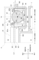
図2は、ハウジングHSを車両前方側から見た図である。この図2では、車両前方側から見た収容部68を、ハウジングHSの他の構成要素(ケース6、第1カバー7、第2カバー8)と共に模式的に示している。また、紙面手前側に位置する接合部683の領域に交差したハッチングを付して示している。また、コントロールバルブCVの外観を模式的に示している。
Figure 2 is a view of the housing HS as seen from the front of the vehicle. In this Figure 2, the
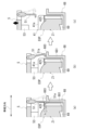
図3は、図2におけるA-A線に沿ってコントロールバルブCVと電動オイルポンプEOPを切断した断面を模式的に示した図である。
図3では、モータ部42の内部の図示を省略して断面を簡略的に示すと共に、コントロールバルブCVと第3カバー9を仮想線で示している。
図4は、図2におけるB-B線に沿ってコントロールバルブCVと電動オイルポンプEOPを切断した断面を模式的に示した図である。
図4では、モータ部42の内のモータMの位置を破線で略的に示すと共に、コントロールバルブCVと治具5を仮想線で示している。
FIG. 3 is a schematic cross-sectional view of the control valve CV and the electric oil pump EOP taken along line AA in FIG.
3, the inside of the
FIG. 4 is a schematic cross-sectional view of the control valve CV and the electric oil pump EOP taken along line BB in FIG.
In FIG. 4, the position of the motor M in the
図2に示すように、ケース6では、車両前方側の側面に、収容部68が付設されている。
収容部68は、開口を車両前方側に向けて設けられている。収容部68の紙面奥側の壁部682は、ハウジングHS内の動力伝達機構の回転軸Xに沿う向きで設けられている。回転軸Xの径方向から見て収容部68は、ケース6の周壁部61の領域から、第1カバー7の側方まで及ぶ回転軸X方向(図中、左右方向)の範囲を持って形成されている。
As shown in FIG. 2, the
The
収容部68の壁部682は、第2カバー8側の略半分の領域が、ケース6側の周壁部61と一体になっている。第2カバー8とは反対側の略半分の領域は、周壁部61の延長上で、第1カバー7の外周との間に隙間を開けて設けられている。Approximately half of the
図2に示すように、車両前方側から見て収容部68は、壁部682と、壁部682の外周を全周に亘って囲む周壁部681を有している。周壁部681の紙面手前側の端面は、第3カバー9との接合部683となっている。
図1および図3に示すように、接合部683には、第3カバー9側の接合部911が全周に亘って接合される。収容部68と第3カバー9は、互いの接合部683、911同士を接合した状態で、図示しないボルトで連結される。
2, when viewed from the front side of the vehicle, the
1 and 3, a
周壁部681の内側は、コントロールバルブCVと電動オイルポンプEOPを収容する第2室S2となっている。
図3に示すようにコントロールバルブCVは、バルブボディ921、921の間にセパレートプレート920を挟み込んだ基本構成を有している。コントロールバルブCVの内部には、油圧制御回路(図示せず)が形成されている。油圧制御回路には、制御装置(図示せず)からの指令に基づいて駆動するソレノイドや、ソレノイドで発生させた信号圧などで作動する調圧弁(スプール弁SP)が設けられている。
The inside of the
3, the control valve CV has a basic structure in which a
図2に示すように、第2室S2内では、コントロールバルブCVが、バルブボディ921、921の積層方向を車両前後方向(紙面手前奥方向)に沿わせた向きで、縦置きされている。
第2室S2では、コントロールバルブCVが、以下の条件を満たすように、縦置きされている。(a)コントロールバルブCV内の複数のスプール弁SPが、動力伝達装置1の車両Vへの設置状態を基準とした鉛直線VL方向(上下方向)に並ぶ、(b)スプール弁SPの進退移動方向Xpが水平線方向(図2における左右方向)に沿う向きとなる。
As shown in FIG. 2, in the second chamber S2, the control valve CV is disposed vertically with the stacking direction of the
In the second chamber S2, the control valve CV is vertically oriented so as to satisfy the following conditions: (a) the multiple spool valves SP in the control valve CV are aligned along a vertical line VL (up-down direction) based on the installation state of the
これにより、スプール弁SPの進退移動が阻害されないようにしつつ、コントロールバルブCVが第2室S2内で縦置きされる。よって、第2室S2が車両前後方向に大型化しないようにされている。This allows the control valve CV to be positioned vertically within the second chamber S2 while not impeding the forward and backward movement of the spool valve SP. This prevents the second chamber S2 from becoming larger in the fore-and-aft direction of the vehicle.
図2に示すように、車両前方側から見てコントロールバルブCVは、略矩形形状のバルブボディ921に切欠部923を設けた略L字形状を成している。切欠部923は、電動オイルポンプEOPとの干渉を避けるために設けられている。
車両前方側から見て電動オイルポンプEOPは、第2カバー8側(図中、左側)の一部が切欠部923に収容されている。
そのため、鉛直線VL方向から見ると、電動オイルポンプEOPの一部が、コントロールバルブCVと重なる位置関係で設けられている。
2, when viewed from the front side of the vehicle, the control valve CV has a generally L-shape with a
When viewed from the front side of the vehicle, a portion of the electric oil pump EOP on the
Therefore, when viewed from the direction of the vertical line VL, the electric oil pump EOP is provided in a positional relationship such that a portion of the electric oil pump EOP overlaps with the control valve CV.
図2に示すように、第2室S2内では、コントロールバルブCVと電動オイルポンプEOPとが、動力伝達機構の回転軸X方向(図2における左右方向)に並んでいる。
車両前方側から見てコントロールバルブCVは、ケース6と重なる位置関係で設けられている。車両前方側から見て電動オイルポンプEOPは、第1カバー7と重なる位置関係で設けられている。
As shown in FIG. 2, in the second chamber S2, the control valve CV and the electric oil pump EOP are arranged side by side in the direction of the rotation axis X of the power transmission mechanism (the left-right direction in FIG. 2).
When viewed from the front side of the vehicle, the control valve CV is provided in a positional relationship overlapping with the
図2に示すように電動オイルポンプEOPは、制御部41と、モータ部42と、ポンプ部43が、モータMの回転軸Z1方向で直列に並んだ基本構成を有する。
車両前方側から見て、電動オイルポンプEOPは、回転軸Z1を、動力伝達機構の回転軸Xに直交させた向きで設けられている。この状態において、電動オイルポンプEOPは、ポンプ部43を第2室S2内の下部側に、制御部41を第2室S2内の上部側に、それぞれ位置させる向きで縦置きされている。
As shown in FIG. 2, the electric oil pump EOP has a basic configuration in which a
When viewed from the front side of the vehicle, the electric oil pump EOP is provided with the rotation axis Z1 oriented perpendicular to the rotation axis X of the power transmission mechanism. In this state, the electric oil pump EOP is vertically oriented with the
図2に示すように、収容部68の壁部682では、車両前方側から見たときに第1カバー7と重なる領域に凹部69が設けられている。凹部69は、電動オイルポンプEOPを収容可能な鉛直線VL方向の高さH69の範囲に形成されている。
図3に示すように、凹部69は、壁部682を第1カバー7側(図中、下側)に窪ませて形成される。凹部69の車幅方向の幅W69は、電動オイルポンプEOPの制御部41の幅W41よりも僅かに大きくなっている(W69>W41)。
2, a
3, the
凹部69の車両前後方向の深さD69は、後記するフランジ部425が、収容部68の接合部683よりも車両前方側に位置すると共に、モータの回転軸Z1が、壁部682よりも車両前方側に位置するように設定されている。The depth D69 of the
本実施形態では、電動オイルポンプEOPの一部を凹部69内に収容することで、電動オイルポンプEOP(制御部41)の車両前方側の側縁41aと、コントロールバルブCV(バルブボディ921)の車両前方側の側縁921aとが、略面一となる位置に配置されるようにしている。これにより、第2室S2が車両前方側に大型化しないようにしている。In this embodiment, a portion of the electric oil pump EOP is housed in the
図5は、電動オイルポンプEOPの正面図である。図5は、第2室S2に配置された電動オイルポンプEOPを車両前方側から見た状態を模式的に示している。
図6は、電動オイルポンプEOPの一部を断面で示した側面図である。なお、図6は、図5におけるA-A線に沿って電動オイルポンプEOPを切断した断面を模式的に示している。
なお、以下の説明においては、電動オイルポンプEOPの各構成要素の位置関係を、必要に応じて、動力伝達装置1の車両Vへの設置状態を基準とした方向を用いて説明する。
Fig. 5 is a front view of the electric oil pump EOP, which is disposed in the second chamber S2, as viewed from the front side of the vehicle.
Fig. 6 is a side view showing a cross section of a part of the electric oil pump EOP, which is taken along the line AA in Fig. 5.
In the following description, the positional relationship of each component of the electric oil pump EOP will be described using directions based on the installation state of the
図3に示すように、電動オイルポンプEOPの制御部41は、回転軸Z1方向から見て略矩形形状を成している。図5に示すように、回転軸Z1の径方向から見て制御部41は、回転軸Z1方向に厚みH41を有している。制御部41の紙面手前側の側縁41aは、後記する治具5の当接部53が当接する平坦面となっている(図6参照)。
図6に示すように、制御部41の側縁41aは、後記するフランジ部425の係止面425bに対して、略平行な平坦面である。図6では、側縁41aと、係止面425bは、回転軸Z1に対して平行である。
なお、図5において交差したハッチングを付した領域R41が、当接部53が当接する領域である。この領域は、後記するモータMの回転軸Z1を、回転軸Z1の直交方向(図5における左右方向)に横切る範囲に設定されている。
As shown in Fig. 3, the
6, a
5, a region R41 indicated by cross-hatching is a region where the
制御部41の内部には、モータの駆動用の制御基板(図示せず)が収容されている。制御部41では、モータ部42とは反対側(図中、上側)の面に、電力供給線との接続部410が付設されている。A control board (not shown) for driving the motor is housed inside the
モータ部42の内部には、ロータコアMRと、ロータコアMRの外周を囲むステータコアMSが収容される。そのため、モータ部42は、回転軸Z1に直交する断面の基本形状が円形を成している(図3参照)。The
ここで、本明細書における用語「基本形状」とは、モータ部42が持つ基本的な形状や、モータ部42としての機能を確保するために必要な基本的な形状を意味する。
例えば、図4に示すように、モータMのロータコアMRは、回転軸Z1に直交する断面の外形が円形である。モータMのステータコアMSは、ロータコアMRの外周を全周に亘って囲むことができる形状を持つ。よって、モータMのステータコアMSもまた、回転軸Z1に直交する断面の外径が円形である。そうすると、モータMを内部に収容するために、モータ部42が持つ必要な断面形状は円形となる。
Here, the term “basic shape” in this specification means the basic shape of the
For example, as shown in Fig. 4, the rotor core MR of the motor M has a circular outer shape in a cross section perpendicular to the rotation axis Z1. The stator core MS of the motor M has a shape that can surround the entire outer periphery of the rotor core MR. Therefore, the stator core MS of the motor M also has a circular outer diameter in a cross section perpendicular to the rotation axis Z1. Therefore, in order to accommodate the motor M inside, the cross-sectional shape that the
図4の場合には、後記するフランジ部425が存在するため、図4に示すモータ部42の断面形状は円形ではない。しかし、フランジ部425は、モータMを内部に収容するために、モータ部42が持つ必要な断面形状とは関係が無い。よって、図4では、モータ部42の断面の基本形状は、円形であるといえる。In the case of Figure 4, the cross-sectional shape of the
同様に、図3の場合には、後記するフランジ部425、426が存在するため、図3に示すモータ部42の断面形状は円形ではない。しかし、フランジ部425、426は、モータMを内部に収容するために、モータ部42が持つ必要な断面形状とは関係が無い。よって、図3では、モータ部42の断面の基本形状は、円形であるといえる。Similarly, in the case of Figure 3, the cross-sectional shape of the
本実施形態では、後記する治具5の第2アーム52により、モータ部42の外周が支持される。そのため、「被支持部におけるモータの回転軸に直交する断面の形状」とは、モータ部42における第2アーム52により支持される領域の断面形状、少なくとも第2アーム52により支持される側の断面形状(図4における直線Lmよりも左側の領域の断面形状)を意味する。よって、「断面の基本形状が円形を成している」とは、図4の場合には、基本形状が円形、または円弧形状であることを意味する。In this embodiment, the outer periphery of the
図5に示すように、車両前方側から見てモータ部42では、制御部41との境界部に、ボス部421、423が設けられている。さらに、ポンプ部43との境界部にもボス部422、424が設けられている。As shown in Figure 5, when viewed from the front of the vehicle, the
図6に示すようにボス部421、422は、電動オイルポンプEOPの組付け方向(図6では、車両前後方向)に直線状に延びている。ボス部421、422は、当該ボス部421、422の先端421b、422bが、収容部68の凹部69内で、底壁部691に当接する長さL42で形成されている。
ボス部421、422には、ボルトの挿通孔421a、422aが設けられている。
As shown in Fig. 6, the
The
図6において紙面奥側の隠れた位置にあるボス部423、424もまた、ボス部421、422と同様の構成を有している。これらボス部423、424にも、ボルトの挿通孔423a、424aが設けられている(図5参照)。6, the
電動オイルポンプEOPは、挿通孔421a~424aを貫通したボルト(図示せず)により、収容部68の底壁部691に固定される。
回転軸Z1の径方向(図5における車両前方側)から見て、ボス部421、422と、ボス部423、424は、回転軸Z1を間に挟んで対称となる位置関係で設けられている。
電動オイルポンプEOPを第2室S2内に設置した状態では、ボス部423、424が、ボス部421、422よりもコントロールバルブCVに近い側に位置する。
The electric oil pump EOP is fixed to the
When viewed from the radial direction of the rotation axis Z1 (the front side of the vehicle in FIG. 5), the
When the electric oil pump EOP is installed in the second chamber S2, the
図5および図6に示すように、回転軸Z1の一方側では、モータ部42の外周に、フランジ部425が設けられている。
フランジ部425は、ボス部421とボス部422の間に位置すると共に、ボス部421とボス部422とに跨がって設けられた板状の部位である。
As shown in FIGS. 5 and 6, a
The
図3に示すように、フランジ部425は、直線Ln1に沿って、直線Lmから離れる方向(コントロールバルブCVから離れる方向)に延びている。ここで、直線Lmは、電動オイルポンプEOPの組付け方向に沿うと共に、モータMの回転軸Z1を通る直線である。直線Ln1は、直線Lmに直交すると共に、車幅方向に延びる直線である。直線Ln1は、制御部41の側縁41a、41bに対して平行な直線である。なお、直線Ln1は、直線Ln2に対して平行である。直線Ln2は、断面視におけるモータ部42の中心(回転軸Z1)を通ると共に、底壁部691に沿って、車幅方向に延びる直線である。
As shown in FIG. 3, the
図3に示すように、回転軸Z1方向から見てフランジ部425の先端425aは、制御部41の側縁41cよりも僅かに内側(直線Lm側)に位置している。
電動オイルポンプEOPを凹部69に収容すると、フランジ部425は、周壁部681側の接合部683よりも第3カバー9側(図中、上側)に配置される。この状態においてフランジ部425は、接合部683から高さh分だけ離れて位置している。
フランジ部425の接合部683側の下面は、後記する治具5の爪部51a(図4参照)が係止される係止面425bとなっている。係止面425bは、制御部41の側縁41aに対して平行である。
As shown in FIG. 3, a
When the electric oil pump EOP is housed in the
The lower surface of the
モータ部42では、直線Lmから見てフランジ部425とは反対側(コントロールバルブCV側)にも、フランジ部426が設けられている。フランジ部426もまた、モータ部42の外周に設けられた板状の部位である。
フランジ部426は、直線Ln1に沿って、直線Lmから離れる方向に延びている。回転軸Z1方向から見てフランジ部426の先端426aは、制御部41の側縁41dよりも内側(直線Lm側)に位置している。
The
The
電動オイルポンプEOPを凹部69に収容すると、フランジ部426は、壁部682よりも第3カバー9側(図中、上側)に配置される。この状態においてフランジ部426は、壁部682から高さh'分だけ離れて位置している。When the electric oil pump EOP is accommodated in the
図5に示すように、フランジ部426は、ボス部424からボス部423側に向けて、回転軸Z1に沿って延びている。フランジ部426の先端426cは、ボス部423との間に隙間427を空けて対向している。この隙間427は、後記する治具5の第2アーム52が通過可能な幅W427で形成されている。そのため、フランジ部426とボス部423との間の隙間427は、後記する治具5の第2アーム52が通過可能な隙間である。5, the
電動オイルポンプEOPは、第2室S2内の凹部69に設置する際に、専用の治具5を用いて把持される。
図4に示すように、電動オイルポンプEOPでは、制御部41の側縁41aと、フランジ部425と、モータ部42の外周42aとが、治具5による把持に関与可能な部位となっている。
When the electric oil pump EOP is installed in the
As shown in FIG. 4 , in the electric oil pump EOP, the
治具5は、フランジ部425に係止される爪部51aを持つ第1アーム51と、モータ部42の外周42aを支持する支持領域521を持つ第2アーム52と、制御部41の側縁41aに当接する当接部53と、を有している。
第2アーム52の先端52a側は、モータ部42の外周42aの支持領域521となっている。この支持領域521は、モータ部42の外周に沿う弧状を成している。
The
The
ここで、治具5により電動オイルポンプEOPを把持した状態を基準とすると、支持領域521は、直線Lpを、回転軸Z1周りの周方向に横切る範囲に設けられている。
ここで、直線Lpは、モータ部42における第1アーム51の爪部51aによる支持点と、回転軸Z1とを結ぶ直線であり、モータ部42の直径線に相当する。
Here, when the state in which the electric oil pump EOP is gripped by the
Here, the straight line Lp is a straight line connecting the support point of the
第2アーム52の先端52aは、治具5により電動オイルポンプEOPを把持する際と、把持を解消する際に、モータ部42の外周42aを摺動する。
そのため、モータ部42の外周42aのうち、少なくとも第2アーム52の先端52aが摺動する領域の表面は、断面視において、回転軸Z1を中心とする円弧状に形成されている(図4における太線で示した領域)。
The
Therefore, the surface of at least the area of the
第1アーム51と第2アーム52は、共通の基部50で軸線Zb、Za回りに回動可能に支持されている。第1アーム51と第2アーム52は、図示しないアクチュエータにより、軸線Zb、Za回りに回動可能である。
軸線Zb、Za方向から見ると、第1アーム51と第2アーム52の間に、当接部53が位置している。
図6に示すように、治具5において、第1アーム51と、第2アーム52、当接部53は、モータの回転軸Z1方向に位置をずらして設けられている。
The
When viewed from the direction of the axes Zb and Za, the
As shown in FIG. 6, in the
以下、治具5を用いた電動オイルポンプEOPの凹部69内への設置を説明する。
図7は、治具5を用いた電動オイルポンプEOPの凹部69内への設置を説明する図である。
図8は、電動オイルポンプEOPを凹部69内に設置した後の第1アーム51の変位を説明する図である。
図9は、電動オイルポンプEOPを凹部69内に設置した後の第2アーム52の変位を説明する図である。
The installation of the electric oil pump EOP in the
FIG. 7 is a diagram for explaining the installation of the electric oil pump EOP in the
FIG. 8 is a diagram for explaining the displacement of the
FIG. 9 is a diagram for explaining the displacement of the
始めに、電動オイルポンプEOPを治具5で把持すると、図4に示すように、第1アーム51の爪部51aは、電動オイルポンプEOPのフランジ部425に係止される。
爪部51aは、第1アーム51の下端から第2アーム52側に突出している。爪部51aの上面52bは、フランジ部425の係止面425b(図3参照)に接触可能な平坦面である。
第1アーム51の爪部51aは、フランジ部425の係止面425bに、面接触した状態で係止される。図5に示すように、フランジ部425において交差したハッチングを付した領域R425の紙面裏側の係止面425bが、第1アーム51の爪部51aで支持される。
第2アーム52の支持領域521は、モータ部42の外周42aを支持する(図4参照)。当接部53が、制御部41の側縁41aに当接する(図4参照)。
この状態においてモータ部42の外周42aのうち、図5において交差したハッチングを付した領域R427の紙面奥側に位置する外周42aが、第2アーム52の支持領域521で支持される。当接部53は、制御部41の領域R41(図5において交差したハッチングを付した領域)に当接する。
First, when the electric oil pump EOP is gripped by the
The
The
The
In this state, the
この状態で、治具5を持ち挙げると、電動オイルポンプEOPには、第1アーム51の爪部51aによる係止点から、電動オイルポンプEOPを回転させる方向(図4における反時計CCW回り方向)のモーメントが作用する。
このモーメントは、図5に示す電動オイルポンプEOPを回転軸Z1回りに回転させる方向に作用する。ここで、治具5の当接部53が、制御部41の側縁41aの領域R41に当接している。この領域R41は、回転軸Z1の一方側に位置するフランジ部425側から、他方側に位置するフランジ部426側に向けて、回転軸Z1を横切る範囲である。図5では、フランジ部425に爪部51aからの操作力が作用する。しかし、治具5の当接部53が、回転軸Z1よりもフランジ部425側まで及ぶ領域R41に当接している。そのため、モータ部42の回転軸Z1回りの回転が、制御部41に当接する当接部53により規制される。そのため、電動オイルポンプEOPの回転が、当接部53により規制される。
In this state, when the
This moment acts in a direction to rotate the electric oil pump EOP shown in FIG. 5 around the rotation axis Z1. Here, the
この状態おいて、治具5をさらに持ち上げると、電動オイルポンプEOPには、第1アーム51から離れる方向(図4における左方向)に荷重が作用する。
ここで、第2アーム52の支持領域521が、第1アーム51の爪部51aによる係止点とは反対側で、モータ部42の外周42aを支持している。そのため、電動オイルポンプEOPの第1アーム51から離れる方向への移動が、支持領域521により規制される。
In this state, when the
Here, the
さらに、図5に示すように第2アーム52は、フランジ部426とボス部423との間の隙間427内に位置している。そのため、治具5と電動オイルポンプEOPとの回転軸Z1方向での相対移動も規制される。
よって、治具5に把持された電動オイルポンプEOPは、大きくガタつくこと無く、第2アーム52との相対移動が規制される。
5, the
Therefore, the electric oil pump EOP held by the
治具5で把持された電動オイルポンプEOPを、収容部68内(第2室S2内)に設置する際には、図7に示すように、ケース6は、収容部68の開口を上方に向けた状態で保持される。この状態でコントロールバルブCVを設置した後、治具5で把持された電動オイルポンプEOPを上方から下方に向けて移動させて凹部69内に設置する。When the electric oil pump EOP held by the
凹部69内への電動オイルポンプEOPの設置が完了すると、第1アーム51の爪部51aは、収容部68(接合部683)と、フランジ部425との間に配置される(図8の(a)参照)。具体的には、収容部68とフランジ部425との間に高さh分の隙間が存在するため、この高さh分の隙間に爪部51aが位置することになる。
この状態で、図示しないアクチュエータにより第1アーム51を変位させて爪部51aをフランジ部425から離間させる。そうすると、爪部51aの外側に接合部683が位置していないので、爪部51aは、接合部683と干渉することなく、フランジ部425から離間する。これにより、爪部51aによるフランジ部425の支持を解消できる(図8の(b)参照)。
When the installation of the electric oil pump EOP in the
In this state, the
そして、治具5を電動オイルポンプEOPから離れる方向(図中、上方向)に移動させると、当接部53が、制御部41の側縁41aから離れることになる。
Then, when the
治具5を電動オイルポンプEOPから離れる方向(図中、上方向)に移動させると、第2アーム52の先端52aが、モータ部42の外周42aを摺動しながら、上方に向けて変位する(図9の(a)、(b)参照)。
これに伴い、第2アーム52は、回転軸Z1から離れる方向(コントロールバルブCVに近づく方向)に変位することになる。
先端52aが直線Ln2と交差する位置に達した時点が、第2アーム52がコントロールバルブCVに最も近づくことになる。
本実施形態では、先端52aが直線Ln2と交差する位置に達した時点で、第2アーム52が制御部41の側縁41dよりも外側に到達しないように、モータ部42と制御部41との位置関係が設定されている。
When the
Accordingly, the
When the
In this embodiment, the positional relationship between the
ここで、制御部41の側縁41dは、凹部69のコントロールバルブCV側の側縁69aに近接して配置されている。そのため、制御部41の側縁41dは、側縁69a側に位置するコントロールバルブCVにも近接して配置されている。
上記のとおり、第2アーム52の先端52aが直線Ln2と交差する位置に達した時点で、第2アーム52が制御部41の側縁41dよりも外側に到達しないので、第2アーム52は、凹部69を超えて壁部682の領域まで到達しない。
Here, the
As described above, when the
これにより、治具5による電動オイルポンプEOPの把持を解消して、治具5を電動オイルポンプEOPから離す方向(図中、上方向)に移動させる際に、コントロールバルブCV側に変位する第2アーム52が、壁部682に設置されたコントロールバルブCVに干渉しないようになっている。As a result, when the
このように、コントロールバルブCV側に位置する第2アーム52は、回転軸Z1方向から見て電動オイルポンプEOP(制御部41)よりも外方まで変位しないので(図9の(b)参照)、電動オイルポンプEOPとコントロールバルブCVを近づけて配置できる。In this way, the
さらに、コントロールバルブCVとは反対側位置する第1アーム51は、図8に示すように、回転軸Z1方向から見て電動オイルポンプEOP(制御部41)側のフランジ部425と、収容部68の接合部683との間の隙間に、爪部51aを位置させているので、爪部51aをフランジ部425から離れる方向(図中、右方向)に変位させても、爪部51aが収容部68側の周壁部681(接合部683)に干渉しない。これにより、電動オイルポンプEOPを凹部69の周壁部681に近接して配置することができる。8, the
よって、第2室S2(凹部69)内に電動オイルポンプEOPを設置するに当たり、第2室S2を車幅方向に大きく広げる必要が無い。Therefore, when installing the electric oil pump EOP in the second chamber S2 (recess 69), there is no need to significantly expand the second chamber S2 in the vehicle width direction.
なお、実施形態では、フランジ部425が、ボス部421とボス部422とに跨がって設けられている場合を例示した(図5参照)。フランジ部425を、ボス部421とボス部422の何れにも接続させずに設けても良い。
また、フランジ部425を、ボス部421とボス部422の少なくとも一方にのみ接続させて設けても良い。この場合、治具5の第1アーム51の爪部51aが、ボス部422寄りの位置に係止される場合には、フランジ部425をボス部422に接続する。治具5の第1アーム51の爪部51aが、ボス部421寄りの位置に係止される場合には、フランジ部425をボス部421に接続する。
すなわち、治具5の第1アーム51の爪部51aが係止される位置に応じて、フランジ部425が接続するボス部を変更することで、フランジ部425の剛性強度を確保できる。
In the embodiment, the
Furthermore, the
That is, by changing the boss portion to which the
また、実施形態では、フランジ部426が、ボス部424にのみ接続している場合を例示した。フランジ部426を、ボス部424と接続させずに、ボス部423とボス部424の間に位置させても良い。フランジ部426は、第2アーム52の回転軸Z1方向の変位を規制する。そのため、フランジ部425を、第2アーム52が通過可能な隙間427を確保しつつ、ボス部423、424の間に位置させることでも、第2アーム52の回転軸Z1方向の変位を規制できる。
また、フランジ部426を、ボス部423、424の両方に接続し、モータ部42における治具5の第2アーム52で支持される領域に応じて、フランジ部426に設ける隙間427の位置を、回転軸Z1方向で変更しても良い。
Also, in the embodiment, the case where the
In addition, the
また、実施形態では、回転軸Z1方向から見て、第2アーム52をコントロールバルブCV側に配置した場合を例示した。コントロールバルブCVと電動オイルポンプEOPとの間に空間的な余裕がある場合には、第1アーム51の方をコントロールバルブCV側に配置しても良い。In the embodiment, the
以上の通り、本実施形態にかかる動力伝達装置1は、以下の構成を有する。
(1)動力伝達装置1は、
動力伝達機構を収容するハウジングHS(ケース)と、
動力伝達機構に供給する油圧を制御するコントロールバルブCVと、
コントロールバルブにオイルを供給する電動オイルポンプEOP(電動ポンプ)と、を有する。
ハウジングHSは、
動力伝達機構を収容する第1室S1と、
水平線HL方向で第1室S1に隣接配置された第2室S2と、を有する。
コントロールバルブCVは、第2室S2内で、複数の調圧弁を鉛直線VL方向(上下方向)に並べる向きで縦置きされている。
電動オイルポンプEOPは、第2室S2内で、モータMの回転軸Z1を鉛直線VL方向(上下方向)に沿わせた向きで設けられている。
コントロールバルブCVと電動オイルポンプEOPは、動力伝達装置1の回転軸X方向で並んでいる。
電動オイルポンプEOPは、
治具5の第1アーム51が係止されるフランジ部425(第1フランジ部)と、
治具5の第2アーム52により支持されるモータ部42(被支持部)と、を有している。
モータ部42は、モータMの回転軸Z1に直交する断面の基本形状が円形を成している。
フランジ部425は、モータ部42の外周42aから延出している。
As described above, the
(1) The
A housing HS (case) that houses the power transmission mechanism;
A control valve CV that controls a hydraulic pressure supplied to the power transmission mechanism;
and an electric oil pump EOP (electric pump) that supplies oil to the control valve.
Housing HS is
a first chamber S1 that accommodates a power transmission mechanism;
and a second chamber S2 disposed adjacent to the first chamber S1 in the direction of the horizontal line HL.
The control valve CV is disposed vertically in the second chamber S2 such that a plurality of pressure regulating valves are aligned in the direction of a vertical line VL (up-down direction).
The electric oil pump EOP is provided in the second chamber S2 with the rotation axis Z1 of the motor M oriented along the vertical line VL (up-down direction).
The control valve CV and the electric oil pump EOP are aligned in the direction of the rotation axis X of the
The electric oil pump EOP is
a flange portion 425 (first flange portion) to which the
and a motor portion 42 (supported portion) supported by a
The
The
電動オイルポンプEOPのモータ部42を、治具5の第2アーム52で支持しただけでは、電動オイルポンプEOPは、モータの回転軸Z1回りの回転が許容された状態となる。
電動オイルポンプEOPが、モータ部42の外周42aから延出するフランジ部425を有することで、電動オイルポンプEOPを治具5で把持する際に、第1アーム51の爪部51aをフランジ部425に係止させることで、電動オイルポンプEOPの回転を規制できる。
これにより、治具5を用いて電動オイルポンプEOPを第2室S2に設置する際に、治具5における電動オイルポンプEOPの支持安定性が向上するので、第2室S2内の限られた空間に、電動オイルポンプEOPを位置精度良く配置できる。
If the
Since the electric oil pump EOP has a
This improves the support stability of the electric oil pump EOP in the
(2)フランジ部425は、モータ部42におけるコントロールバルブCVとは反対側の領域から、コントロールバルブCVから離れる方向に延びている。
(2) The
電動オイルポンプEOPを治具5で把持するためには、第1アーム51が変位する空間を、フランジ部425の延出方向の外側に確保する必要がある。
フランジ部425がコントロールバルブCV側に設けられている場合には、電動オイルポンプEOPを治具5で把持するために、コントロールバルブCVと電動オイルポンプEOPとの間に、第1アーム51が変位するための空間を確保する必要がある。
フランジ部425がコントロールバルブCVとは反対側に設けられていると、電動オイルポンプEOPをコントロールバルブCVに近づけて配置できる。これにより、電動オイルポンプEOPを治具5で把持するために必要な空間を確保するために、第2室S2を大型化させる必要が無いので、ハウジングHSの大型化を抑制できる。
In order to grip the electric oil pump EOP with the
When the
If the
(3)第2室S2は、
コントロールバルブCVと電動オイルポンプEOPの外周を囲む周壁部681と、
周壁部681に接合されて、周壁部681の開口を塞ぐ第3カバー9(カバー部)と、
第1室S1と第2室S2とを区画する壁部682(区画壁)と、で囲まれた空間である。
周壁部681の開口方向に沿う断面視において、フランジ部425は、周壁部681よりも第3カバー9側に位置している。
(3) The second chamber S2 is
A
a third cover 9 (cover portion) joined to the
The space is surrounded by a wall portion 682 (partition wall) that partitions the first chamber S1 and the second chamber S2.
In a cross-sectional view along the opening direction of the
このように構成すると、周壁部681の開口方向から見てフランジ部425を、周壁部681に近づけて配置しても、フランジ部425の延出方向の外側に、第1アーム51が変位する空間を確保できる。
これにより、電動オイルポンプEOPを治具5で把持するために必要な空間を確保するために、第2室S2を大型化させる必要が無いので、ハウジングHSの大型化を抑制できる。
With this configuration, even if the
As a result, there is no need to increase the size of the second chamber S2 in order to ensure the space necessary to grip the electric oil pump EOP with the
(4)電動オイルポンプEOPでは、ボス部421(第1ボス部)とボス部422(第2ボス部)が、モータMの回転軸Z1方向に間隔をあけて設けられている。
フランジ部425部は、ボス部421とボス部422の間に位置している。
(4) In the electric oil pump EOP, the boss portion 421 (first boss portion) and the boss portion 422 (second boss portion) are provided at an interval in the direction of the rotation axis Z1 of the motor M.
The
電動オイルポンプEOPでは、モータMの回転軸Z1の径方向外側であって、ボス部421とボス部422との間に、利用されない空間が存在する。この利用されていない空間を利用して、フランジ部425を設けることで、電動オイルポンプEOPが回転軸Z1の径方向に大型化することを好適に防止できる。In the electric oil pump EOP, there is an unused space between the
(5)フランジ部425は、ボス部422に接続されている。
(5) The
フランジ部425には、治具5の第1アーム51の爪部51aが係止される。そのため、電動オイルポンプEOPを治具5で把持して持ち上げる際に、フランジ部425に荷重が作用する。
フランジ部425がボス部422に接続されていることで、フランジ部425の剛性強度が、フランジ部425がボス部422に接続されていない場合に比べて高くなる。よって、電動オイルポンプEOPを治具5で把持して持ち上げる際の電動オイルポンプEOPの支持安定性が向上する。
特に、第1アーム51の爪部51aが、フランジ部425におけるボス部422寄りの位置を支持する場合には、電動オイルポンプEOPの支持に関わる部分の剛性を局所的に高めることができるので、電動オイルポンプEOPの支持安定性が向上する。
The
By connecting the
In particular, when the
(6)フランジ部425は、ボス部421とボス部422とに跨がって設けられている。
(6)
フランジ部425には、治具5の第1アーム51の爪部51aが係止される。そのため、電動オイルポンプEOPを治具5で把持して持ち上げる際に、フランジ部425に荷重が作用する。
フランジ部425がボス部421とボス部422とに跨がって設けられていることで、フランジ部425の剛性強度が、接続されていない場合に比べて高くなる。よって、電動オイルポンプEOPを治具5で把持して持ち上げる際の電動オイルポンプEOPの支持安定性が向上する。
The
By providing the
(7)電動オイルポンプEOPでは、ボス部423(第3ボス部)とボス部424(第4ボス部)が、モータの回転軸Z1方向に間隔をあけて設けられている。
ボス部423とボス部424は、モータの回転軸Z1を挟んでボス部421およびボス部422とは反対側に位置している。
ボス部423とボス部424の間に、フランジ部426(第2フランジ部)が設けられている。
フランジ部426は、モータMの回転軸Z1方向でボス部422と同じ側に位置するボス部424から、モータMの回転軸Z1方向でボス部421と同じ側に位置するボス部423に向けて、回転軸Z1に沿って延びている。
フランジ部426では、ボス部423側の先端426cと、ボス部423との間に隙間427が設けられている。
隙間427は、モータMの回転軸Z1方向の幅W427が、治具5の第2アーム52が通過可能な幅である。
(7) In the electric oil pump EOP, the boss portion 423 (third boss portion) and the boss portion 424 (fourth boss portion) are provided at an interval in the direction of the rotation axis Z1 of the motor.
The
A flange portion 426 (second flange portion) is provided between the
The
In the
The
このように構成すると、ボス部423とフランジ部426との間に隙間427が形成される。この隙間427に第2アーム52を挿入して、モータ部42を第2アーム52で支持できる。
ボス部423とフランジ部426が、モータの回転軸Z1方向への第2アーム52の変位を規制するので、電動オイルポンプEOPの支持安定性が向上する。
さらに、第1アーム51による支持位置と、第2アーム52による支持位置とを、モータの回転軸Z1方向にずらすことができるので、電動オイルポンプEOPの支持安定性が向上する。
With this configuration, a
The
Furthermore, since the support position by the
(8)電動オイルポンプEOPは、
治具5の当接部53が当接する被当接部となる側縁41aを有している。
側縁41aは、モータの回転軸Z1方向から見て、モータの回転軸Z1を通る直線Ln2に対して平行な平坦面である。当接部53の平坦面と、フランジ部425の係合面(係止面425b)は、ほぼ平行に形成されている。
(8) Electric oil pump EOP:
The
The
電動オイルポンプEOPを治具5で把持する際には、第1アーム51をフランジ部425に係止させると共に、第2アーム52の支持領域521で、モータ部42の外周42aを支持させる。
この際に、治具5側の当接部53が、電動オイルポンプEOP側の被当接部である側縁41aに当接することで、電動オイルポンプEOPの回転を確実に規制できる。さらに、当接部53の平坦面と、フランジ部425の係合面は、ほぼ平行に形成されているため、電動オイルポンプEOPにモーメントが発生しにくくなり、回転方向の動きが生じにくくなる。これにより、治具5における電動オイルポンプEOPの支持安定性が向上するので、第2室S2内の限られた空間に、電動オイルポンプEOPを位置精度良く配置できる。
When the electric oil pump EOP is held by the
At this time, the abutting
前記した実施形態では、動力伝達装置1がエンジンENGの回転を駆動輪WH、WHに伝達する場合を例示したが、動力伝達装置1は、エンジンENGとモータ(回転電機)のうちの少なくとも一方の回転を駆動輪WH、WHに伝達するものであっても良い。例えば、1モータ、2クラッチ式(エンジンENGと動力伝達装置の間にモータが配置され、エンジンENGとモータの間に第1のクラッチが配置され、動力伝達装置1内に第2のクラッチが配置された形式)の動力伝達装置であっても良い。
また、前記した実施形態では、動力伝達装置1が変速機能を有している場合を例示したが、動力伝達機構は変速機能を持たず、単に減速する(増速であってもよい)ものであっても良い。動力伝達装置が変速機能を有しておらず、動力伝達装置が、モータの回転を減速して駆動輪WH、WHに伝達する構成である場合には、モータの冷却用のオイルOLと、減速機構の潤滑用のオイルOLを供給するための油圧制御回路を、電動オイルポンプEOP共に、第2室S2に配置することになる。また、前記した実施形態では、動力伝達装置1のコントロールユニットがコントロールバルブCVを備えた場合を例示したが、動力伝達装置1が、変速機構をも持たず、また、駆動源がエンジンENGではなく、モータ(回転電機)の場合にあっては、モータを駆動制御するインバータ等を備えたコントロールユニットであっても良い。
In the above embodiment, the
In the above embodiment, the
以上、本願発明の実施形態を説明したが、本願発明は、これら実施形態に示した態様のみに限定されるものではない。発明の技術的な思想の範囲内で、適宜変更可能である。 Although the embodiments of the present invention have been described above, the present invention is not limited to the aspects shown in these embodiments. Modifications can be made as appropriate within the scope of the technical concept of the invention.
1 動力伝達装置
41 制御部
41a 側縁(被当接部)
42 モータ部(被支持部)
42a 表面(外周)
421 ボス部(第1ボス部)
422 ボス部(第2ボス部)
423 ボス部(第3ボス部)
424 ボス部(第4ボス部)
425 フランジ部(第1フランジ部)
426 フランジ部(第2フランジ部)
427 隙間
5 治具
51 第1アーム
51a 爪部
52 第2アーム
53 当接部
681 周壁部
682 底壁部(区画壁)
9 第3カバー(カバー部)
CV コントロールバルブ
EOP 電動オイルポンプ(電動ポンプ)
HS ハウジング(ケース)
S1 第1室
S2 第2室
M モータ
X、Z1 回転軸
1
42 Motor section (supported section)
42a Surface (Outer Circumference)
421 boss portion (first boss portion)
422 boss portion (second boss portion)
423 Boss part (third boss part)
424 boss part (fourth boss part)
425 Flange portion (first flange portion)
426 Flange portion (second flange portion)
427
9 Third cover (cover part)
CV Control valve EOP Electric oil pump (electric pump)
HS Housing (Case)
S1 First chamber S2 Second chamber M Motor X, Z1 Rotating shaft
Claims (9)
前記動力伝達機構に供給する油圧を制御するコントロールバルブと、
前記コントロールバルブにオイルを供給する電動ポンプと、を有する動力伝達装置であって、
前記ケースは、
前記動力伝達機構を収容する第1室と、
水平線方向で前記第1室に隣接配置された第2室と、を有し、
前記コントロールバルブは、前記第2室内で、複数の調圧弁を上下方向に並べる向きで縦置きされており、
前記電動ポンプは、前記第2室内で、モータの回転軸を前記上下方向に沿わせた向きで設けられており、
前記コントロールバルブと前記電動ポンプは、前記動力伝達機構の回転軸方向で並んでおり、
前記電動ポンプは、
治具の第1アームが係止される第1フランジ部と、
前記治具の第2アームにより支持される被支持部と、を有しており、
前記被支持部は、前記モータの回転軸に直交する断面の基本形状が円形を成しており、
前記第1フランジ部は、前記被支持部の外周から延出している、動力伝達装置。 a case that houses a power transmission mechanism;
a control valve for controlling hydraulic pressure supplied to the power transmission mechanism;
an electric pump for supplying oil to the control valve,
The case is
a first chamber that accommodates the power transmission mechanism;
A second chamber disposed adjacent to the first chamber in a horizontal direction,
The control valve is vertically disposed in the second chamber such that a plurality of pressure regulating valves are aligned vertically,
The electric pump is provided in the second chamber with a rotation shaft of a motor aligned along the up-down direction,
the control valve and the electric pump are aligned in a direction of a rotation axis of the power transmission mechanism,
The electric pump is
a first flange portion to which a first arm of the jig is engaged;
a supported portion supported by the second arm of the jig,
the supported portion has a cross section perpendicular to a rotation shaft of the motor that is basically circular,
The first flange portion extends from an outer periphery of the supported portion.
前記第1フランジ部は、前記被支持部における前記コントロールバルブとは反対側の領域から、前記コントロールバルブから離れる方向に延びている、動力伝達装置。 In claim 1,
A power transmission device, wherein the first flange portion extends from a region of the supported portion opposite the control valve in a direction away from the control valve.
前記第2室は、
前記コントロールバルブと前記電動ポンプとの外周を囲む周壁部と、
前記周壁部に接合されて、前記周壁部の開口を塞ぐカバー部と、
前記第1室と前記第2室とを区画する区画壁と、で囲まれた空間であり、
前記周壁部の開口方向に沿う断面視において、前記第1フランジ部は、前記周壁部よりも前記カバー部側に位置している、動力伝達装置。 In claim 2,
The second chamber is
a peripheral wall portion surrounding an outer periphery of the control valve and the electric pump;
a cover portion joined to the peripheral wall portion to close an opening of the peripheral wall portion;
a partition wall that partitions the first chamber and the second chamber; and
In a cross-sectional view along an opening direction of the peripheral wall portion, the first flange portion is located closer to the cover portion than the peripheral wall portion.
前記電動ポンプでは、第1ボス部と第2ボス部が、前記モータの前記回転軸方向に間隔をあけて設けられており、
前記第1フランジ部は、前記第1ボス部と前記第2ボス部の間に位置している、動力伝達装置。 In claim 2 ,
In the electric pump, a first boss portion and a second boss portion are provided at an interval in the direction of the rotation shaft of the motor,
The first flange portion is located between the first boss portion and the second boss portion.
前記第1フランジ部は、前記第2ボス部に接続されている、動力伝達装置。 In claim 4,
The first flange portion is connected to the second boss portion.
前記第1フランジ部は、前記第1ボス部と前記第2ボス部とに跨がって設けられている、動力伝達装置。 In claim 4,
The first flange portion is provided across the first boss portion and the second boss portion.
前記電動ポンプでは、第3ボス部と第4ボス部が、前記モータの前記回転軸方向に間隔をあけて設けられており、
前記第3ボス部と前記第4ボス部は、前記モータの回転軸を挟んで
前記第1ボス部および前記第2ボス部とは反対側に位置しており、
前記第3ボス部と前記第4ボス部の間に、第2フランジ部が設けられており、
前記第2フランジ部は、前記モータの回転軸方向で前記第2ボス部側に位置する前記第4ボス部から、前記第1ボス部側に位置する前記第3ボス部に向けて延びており、
前記第2フランジ部と前記第3ボス部との間に、隙間が設けられている、動力伝達装置。 In any one of claims 4 to 6,
In the electric pump, a third boss portion and a fourth boss portion are provided at an interval in the direction of the rotation shaft of the motor,
the third boss portion and the fourth boss portion are located on the opposite side to the first boss portion and the second boss portion across the rotation shaft of the motor,
a second flange portion is provided between the third boss portion and the fourth boss portion,
the second flange portion extends from the fourth boss portion located on the second boss portion side in a rotation shaft direction of the motor toward the third boss portion located on the first boss portion side,
a gap is provided between the second flange portion and the third boss portion.
前記電動ポンプは、
前記治具の当接部が当接する被当接部を有しており、
前記被当接部は、前記モータの回転軸方向から見て、前記モータの回転軸を通る直線に対して平行な平坦面である、動力伝達装置。 In any one of claims 1 to 6 ,
The electric pump is
The jig has a contacted portion that contacts the contact portion of the jig,
A power transmission device, wherein the abutment portion is a flat surface parallel to a line passing through the rotation shaft of the motor when viewed in the direction of the rotation shaft of the motor.
前記電動ポンプは、The electric pump is
前記治具の当接部が当接する被当接部を有しており、The jig has a contacted portion that contacts the contact portion of the jig,
前記被当接部は、前記モータの回転軸方向から見て、前記モータの回転軸を通る直線に対して平行な平坦面である、動力伝達装置。A power transmission device, wherein the abutment portion is a flat surface parallel to a line passing through the rotation shaft of the motor when viewed in the direction of the rotation shaft of the motor.
Applications Claiming Priority (3)
| Application Number | Priority Date | Filing Date | Title |
|---|---|---|---|
| JP2022047614 | 2022-03-23 | ||
| JP2022047614 | 2022-03-23 | ||
| PCT/JP2023/011617 WO2023182454A1 (en) | 2022-03-23 | 2023-03-23 | Power transmission device |
Publications (3)
| Publication Number | Publication Date |
|---|---|
| JPWO2023182454A1 JPWO2023182454A1 (en) | 2023-09-28 |
| JP7580901B2 true JP7580901B2 (en) | 2024-11-12 |
| JPWO2023182454A5 JPWO2023182454A5 (en) | 2024-11-21 |
Family
ID=88101674
Family Applications (1)
| Application Number | Title | Priority Date | Filing Date |
|---|---|---|---|
| JP2024509233A Active JP7580901B2 (en) | 2022-03-23 | 2023-03-23 | Power transmission |
Country Status (4)
| Country | Link |
|---|---|
| US (1) | US20250198499A1 (en) |
| JP (1) | JP7580901B2 (en) |
| CN (1) | CN118984914A (en) |
| WO (1) | WO2023182454A1 (en) |
Families Citing this family (1)
| Publication number | Priority date | Publication date | Assignee | Title |
|---|---|---|---|---|
| JP7621724B2 (en) * | 2022-03-23 | 2025-01-27 | ジヤトコ株式会社 | Power transmission |
Citations (2)
| Publication number | Priority date | Publication date | Assignee | Title |
|---|---|---|---|---|
| JP2015045401A (en) | 2013-08-29 | 2015-03-12 | アイシン・エィ・ダブリュ株式会社 | Vehicle drive unit |
| JP2019173943A (en) | 2018-03-29 | 2019-10-10 | アイシン・エィ・ダブリュ株式会社 | Vehicle driving device |
Family Cites Families (6)
| Publication number | Priority date | Publication date | Assignee | Title |
|---|---|---|---|---|
| US8556577B2 (en) * | 2010-07-21 | 2013-10-15 | Hamilton Sundstrand Corporation | Lube pump retention method |
| WO2012112778A2 (en) * | 2011-02-17 | 2012-08-23 | Allison Transmission, Inc. | Hydraulic system and method for a hybrid vehicle |
| US10780853B2 (en) * | 2012-10-01 | 2020-09-22 | Allison Transmission, Inc. | External lube system for a transmission |
| CN105518346B (en) * | 2013-09-30 | 2017-11-14 | 爱信艾达株式会社 | drive unit for vehicle |
| JP6124811B2 (en) * | 2014-01-17 | 2017-05-10 | アイシン・エィ・ダブリュ株式会社 | Vehicle drive device |
| US11679657B1 (en) * | 2022-05-23 | 2023-06-20 | Arvinmeritor Technology, Llc | Electric drive unit and drive axle system |
-
2023
- 2023-03-23 WO PCT/JP2023/011617 patent/WO2023182454A1/en not_active Ceased
- 2023-03-23 CN CN202380028301.2A patent/CN118984914A/en active Pending
- 2023-03-23 US US18/846,971 patent/US20250198499A1/en active Pending
- 2023-03-23 JP JP2024509233A patent/JP7580901B2/en active Active
Patent Citations (2)
| Publication number | Priority date | Publication date | Assignee | Title |
|---|---|---|---|---|
| JP2015045401A (en) | 2013-08-29 | 2015-03-12 | アイシン・エィ・ダブリュ株式会社 | Vehicle drive unit |
| JP2019173943A (en) | 2018-03-29 | 2019-10-10 | アイシン・エィ・ダブリュ株式会社 | Vehicle driving device |
Also Published As
| Publication number | Publication date |
|---|---|
| JPWO2023182454A1 (en) | 2023-09-28 |
| US20250198499A1 (en) | 2025-06-19 |
| WO2023182454A1 (en) | 2023-09-28 |
| CN118984914A (en) | 2024-11-19 |
Similar Documents
| Publication | Publication Date | Title |
|---|---|---|
| JP5707656B2 (en) | Vehicle drive device | |
| JP5862502B2 (en) | Vehicle drive device | |
| JP2013155810A (en) | Vehicle drive device | |
| JP7580901B2 (en) | Power transmission | |
| WO2015041274A1 (en) | Vehicle drive device | |
| JP7584879B2 (en) | Power transmission | |
| JP7592377B2 (en) | Power transmission | |
| JP7584877B2 (en) | Power transmission | |
| JP7580900B2 (en) | Power transmission | |
| JP7596055B2 (en) | Power transmission | |
| JP7604087B2 (en) | Power transmission | |
| JP7621724B2 (en) | Power transmission | |
| JP2012240556A (en) | Driving force transmission device for hybrid vehicle | |
| JP2021094884A (en) | Vehicle drive device | |
| US12504065B2 (en) | Power transmission device | |
| JP2021110381A (en) | Vehicular transmission | |
| JP7628386B2 (en) | Inhibitor Switch | |
| EP4611229A1 (en) | Vehicle drive system | |
| JP7443771B2 (en) | transmission | |
| JP2020100263A (en) | Hybrid vehicle drive | |
| JP2019173942A (en) | Vehicle driving device | |
| JP2023154845A (en) | power transmission device | |
| CN118830177A (en) | Device | |
| JP2021110379A (en) | Vehicular transmission | |
| KR20130117473A (en) | Structure for supporting input shaft of transmission for electric vehicle |
Legal Events
| Date | Code | Title | Description |
|---|---|---|---|
| A521 | Request for written amendment filed |
Free format text: JAPANESE INTERMEDIATE CODE: A523 Effective date: 20240921 |
|
| A621 | Written request for application examination |
Free format text: JAPANESE INTERMEDIATE CODE: A621 Effective date: 20240921 |
|
| A871 | Explanation of circumstances concerning accelerated examination |
Free format text: JAPANESE INTERMEDIATE CODE: A871 Effective date: 20240921 |
|
| A521 | Request for written amendment filed |
Free format text: JAPANESE INTERMEDIATE CODE: A821 Effective date: 20240924 |
|
| TRDD | Decision of grant or rejection written | ||
| A01 | Written decision to grant a patent or to grant a registration (utility model) |
Free format text: JAPANESE INTERMEDIATE CODE: A01 Effective date: 20241029 |
|
| A61 | First payment of annual fees (during grant procedure) |
Free format text: JAPANESE INTERMEDIATE CODE: A61 Effective date: 20241029 |
|
| R150 | Certificate of patent or registration of utility model |
Ref document number: 7580901 Country of ref document: JP Free format text: JAPANESE INTERMEDIATE CODE: R150 |