JP7577832B2 - Wet disc brakes with external oil supply - Google Patents
Wet disc brakes with external oil supply Download PDFInfo
- Publication number
- JP7577832B2 JP7577832B2 JP2023509731A JP2023509731A JP7577832B2 JP 7577832 B2 JP7577832 B2 JP 7577832B2 JP 2023509731 A JP2023509731 A JP 2023509731A JP 2023509731 A JP2023509731 A JP 2023509731A JP 7577832 B2 JP7577832 B2 JP 7577832B2
- Authority
- JP
- Japan
- Prior art keywords
- groove
- disc brake
- friction
- grooves
- wet disc
- Prior art date
- Legal status (The legal status is an assumption and is not a legal conclusion. Google has not performed a legal analysis and makes no representation as to the accuracy of the status listed.)
- Active
Links
Images


Classifications
-
- F—MECHANICAL ENGINEERING; LIGHTING; HEATING; WEAPONS; BLASTING
- F16—ENGINEERING ELEMENTS AND UNITS; GENERAL MEASURES FOR PRODUCING AND MAINTAINING EFFECTIVE FUNCTIONING OF MACHINES OR INSTALLATIONS; THERMAL INSULATION IN GENERAL
- F16D—COUPLINGS FOR TRANSMITTING ROTATION; CLUTCHES; BRAKES
- F16D65/00—Parts or details
- F16D65/78—Features relating to cooling
- F16D65/84—Features relating to cooling for disc brakes
- F16D65/853—Features relating to cooling for disc brakes with closed cooling system
-
- F—MECHANICAL ENGINEERING; LIGHTING; HEATING; WEAPONS; BLASTING
- F16—ENGINEERING ELEMENTS AND UNITS; GENERAL MEASURES FOR PRODUCING AND MAINTAINING EFFECTIVE FUNCTIONING OF MACHINES OR INSTALLATIONS; THERMAL INSULATION IN GENERAL
- F16D—COUPLINGS FOR TRANSMITTING ROTATION; CLUTCHES; BRAKES
- F16D65/00—Parts or details
- F16D65/02—Braking members; Mounting thereof
- F16D65/12—Discs; Drums for disc brakes
- F16D65/128—Discs; Drums for disc brakes characterised by means for cooling
-
- F—MECHANICAL ENGINEERING; LIGHTING; HEATING; WEAPONS; BLASTING
- F16—ENGINEERING ELEMENTS AND UNITS; GENERAL MEASURES FOR PRODUCING AND MAINTAINING EFFECTIVE FUNCTIONING OF MACHINES OR INSTALLATIONS; THERMAL INSULATION IN GENERAL
- F16D—COUPLINGS FOR TRANSMITTING ROTATION; CLUTCHES; BRAKES
- F16D65/00—Parts or details
- F16D65/02—Braking members; Mounting thereof
- F16D65/12—Discs; Drums for disc brakes
- F16D65/127—Discs; Drums for disc brakes characterised by properties of the disc surface; Discs lined with friction material
-
- F—MECHANICAL ENGINEERING; LIGHTING; HEATING; WEAPONS; BLASTING
- F16—ENGINEERING ELEMENTS AND UNITS; GENERAL MEASURES FOR PRODUCING AND MAINTAINING EFFECTIVE FUNCTIONING OF MACHINES OR INSTALLATIONS; THERMAL INSULATION IN GENERAL
- F16D—COUPLINGS FOR TRANSMITTING ROTATION; CLUTCHES; BRAKES
- F16D13/00—Friction clutches
- F16D13/58—Details
- F16D13/60—Clutching elements
- F16D13/64—Clutch-plates; Clutch-lamellae
- F16D13/648—Clutch-plates; Clutch-lamellae for clutches with multiple lamellae
-
- F—MECHANICAL ENGINEERING; LIGHTING; HEATING; WEAPONS; BLASTING
- F16—ENGINEERING ELEMENTS AND UNITS; GENERAL MEASURES FOR PRODUCING AND MAINTAINING EFFECTIVE FUNCTIONING OF MACHINES OR INSTALLATIONS; THERMAL INSULATION IN GENERAL
- F16D—COUPLINGS FOR TRANSMITTING ROTATION; CLUTCHES; BRAKES
- F16D13/00—Friction clutches
- F16D13/58—Details
- F16D13/74—Features relating to lubrication
-
- F—MECHANICAL ENGINEERING; LIGHTING; HEATING; WEAPONS; BLASTING
- F16—ENGINEERING ELEMENTS AND UNITS; GENERAL MEASURES FOR PRODUCING AND MAINTAINING EFFECTIVE FUNCTIONING OF MACHINES OR INSTALLATIONS; THERMAL INSULATION IN GENERAL
- F16D—COUPLINGS FOR TRANSMITTING ROTATION; CLUTCHES; BRAKES
- F16D65/00—Parts or details
- F16D65/02—Braking members; Mounting thereof
- F16D2065/13—Parts or details of discs or drums
- F16D2065/1304—Structure
- F16D2065/1324—Structure carrying friction elements
-
- F—MECHANICAL ENGINEERING; LIGHTING; HEATING; WEAPONS; BLASTING
- F16—ENGINEERING ELEMENTS AND UNITS; GENERAL MEASURES FOR PRODUCING AND MAINTAINING EFFECTIVE FUNCTIONING OF MACHINES OR INSTALLATIONS; THERMAL INSULATION IN GENERAL
- F16D—COUPLINGS FOR TRANSMITTING ROTATION; CLUTCHES; BRAKES
- F16D65/00—Parts or details
- F16D65/02—Braking members; Mounting thereof
- F16D2065/13—Parts or details of discs or drums
- F16D2065/1304—Structure
- F16D2065/1328—Structure internal cavities, e.g. cooling channels
-
- F—MECHANICAL ENGINEERING; LIGHTING; HEATING; WEAPONS; BLASTING
- F16—ENGINEERING ELEMENTS AND UNITS; GENERAL MEASURES FOR PRODUCING AND MAINTAINING EFFECTIVE FUNCTIONING OF MACHINES OR INSTALLATIONS; THERMAL INSULATION IN GENERAL
- F16D—COUPLINGS FOR TRANSMITTING ROTATION; CLUTCHES; BRAKES
- F16D55/00—Brakes with substantially-radial braking surfaces pressed together in axial direction, e.g. disc brakes
- F16D55/24—Brakes with substantially-radial braking surfaces pressed together in axial direction, e.g. disc brakes with a plurality of axially-movable discs, lamellae, or pads, pressed from one side towards an axially-located member
- F16D55/26—Brakes with substantially-radial braking surfaces pressed together in axial direction, e.g. disc brakes with a plurality of axially-movable discs, lamellae, or pads, pressed from one side towards an axially-located member without self-tightening action
- F16D55/36—Brakes with a plurality of rotating discs all lying side by side
Landscapes
- Engineering & Computer Science (AREA)
- General Engineering & Computer Science (AREA)
- Mechanical Engineering (AREA)
- Braking Arrangements (AREA)
- Mechanical Operated Clutches (AREA)
Description
本発明は、請求項1のプリアンブルの特徴を有する、外部オイル供給を伴う湿式ディスクブレーキに関する。 The present invention relates to a wet disc brake with external oil supply having the features of the preamble of claim 1.
本発明の適用範囲は、ハイブリッドモジュール内の湿式ディスクブレーキ、DHT及びシフト可能なE-Axle、並びに、始動、シフト、及び分離要素としての低損失ディスクブレーキである。 The scope of application of this invention is wet disc brakes in hybrid modules, DHT and shiftable E-Axles, and low loss disc brakes as starting, shifting and isolation elements.
湿式ディスククラッチ及びブレーキは、従来のパワーシフトトランスミッションにおいて、高負荷ドライブトレインにおける革新的なハイブリッドモジュールにおいて、又はシフト可能なE-Axleにおいて広く使用されており、それらは、高性能の高負荷構成要素を表している。自動車用途におけるドライブトレインのCO2排出量の削減と効率の改善に対する要求は、非常に重要である。シフト要素における負荷非依存の損失を低減することに加えて、熱負荷及び好適な冷却が考慮されなければならない。摩擦ディスクの溝パターンは、摩擦特性、熱管理及び効率の間のトレードオフにおいて中心的な役割を果たす。 Wet disc clutches and brakes are widely used in conventional powershift transmissions, in innovative hybrid modules in heavy duty drivetrains or in shiftable E-Axles, where they represent high performance heavy duty components. The demand for reduced CO2 emissions and improved efficiency of drivetrains in automotive applications is of great importance. In addition to reducing the load independent losses in the shifting elements, thermal loads and suitable cooling must be taken into account. The groove pattern of the friction discs plays a central role in the trade-off between friction properties, thermal management and efficiency.
先行技術(図1)
独国実用新案第202015009048(U1)号及び米国特許第8474590(B2)号は、摩擦面に溝を備える湿式摩擦部品を示している。
Prior Art (Figure 1)
German Utility Model No. 202015009048 (U1) and US Pat. No. 8,474,590 (B2) show wet friction components with grooves in the friction surface.
欠点:特に、ディスクブレーキ及び外部オイル供給(図2参照)の場合には、(内部オイル供給のための)試行された及び試験された溝パターンを使用することができない。 Disadvantages: especially in the case of disc brakes and external oil supply (see Figure 2), the tried and tested groove patterns (for internal oil supply) cannot be used.
本発明の目的は、したがって、好適な溝パターンによる外部オイル供給を伴うディスクブレーキにおける、対流冷却/冷却効果を改善し、抗力損失を最小化することである。 The object of the present invention is therefore to improve the convection/cooling effect and minimize drag losses in disc brakes with external oil supply through a preferred groove pattern.
この目的は、請求項1に記載の特徴を有する、外部オイル供給を伴う湿式ディスクブレーキによって達成される。 This object is achieved by a wet disc brake with external oil supply having the features of claim 1.
外部オイル供給を伴う本発明による湿式ディスクブレーキは、このように、摩擦面が、円周の周囲に延びるジグザグ形状若しくは波状の溝、又は円周の周囲に接線方向に延びる溝を有することを提供する。 A wet disc brake according to the invention with an external oil supply thus provides that the friction surface has zigzag or wavy grooves extending around the circumference or grooves extending tangentially around the circumference.
外部オイル供給を伴うディスクブレーキの場合には、そのような溝パターンは、冷却効果を改善し、かつ抗力損失を低減する。 In the case of disc brakes with external oil supply, such a groove pattern improves cooling and reduces drag losses.
上記の目的は、摩擦面の外部オイル供給を伴う湿式ディスクブレーキにおいて、摩擦面が円周を有し、摩擦面が、円周の周囲に延びるジグザグ形状若しくは波状の溝、又は円周の周囲に接線方向に延びる溝を有することによって達成される。摩擦面は、有利には、摩擦ディスク上に設けられ、摩擦ディスクは、好ましくは、2つの対向する側部の各々上に対応する摩擦面を有する。摩擦面は、例えば、パッドとも称される摩擦ライニング片を使用して表される。摩擦ライニング片又は摩擦ライニングパッドは、例えば、キャリアプレートに接着された、キャリア要素に取り付けられている。摩擦ライニング片の形状及び配置は、摩擦面に所定の溝パターンの溝を作り出す。円周方向溝に加えて、溝パターンは、冷却媒体及び/又は潤滑媒体、特にオイルが、外側から円周方向溝に流入する際に通る更なる溝を備える。 The above object is achieved in a wet disc brake with an external oil supply of the friction surface by the friction surface having a circumference and having zigzag or wavy grooves extending around the circumference or grooves extending tangentially around the circumference. The friction surface is advantageously provided on a friction disc, which preferably has a corresponding friction surface on each of two opposite sides. The friction surface is represented, for example, using friction lining pieces, also called pads. The friction lining pieces or friction lining pads are attached to a carrier element, for example glued to a carrier plate. The shape and arrangement of the friction lining pieces create a predetermined groove pattern of grooves on the friction surface. In addition to the circumferential grooves, the groove pattern comprises further grooves through which a cooling medium and/or a lubricating medium, in particular oil, flows from the outside into the circumferential grooves.
湿式ディスクブレーキの好ましい例示的な実施形態は、流入溝であって、それを通ってオイルが外側から周方向溝に流入する、流入溝が、各々、摩擦面に対して径方向に外側に拡幅部を有することを特徴とする。拡幅部は、特に、ディスクブレーキの閉鎖時に、外部からのオイル供給を改善する。この文脈において、拡幅部とは、特に、それぞれの流入溝が外側に径方向に拡幅していることを意味する。周方向で見て、流入溝は、径方向に外側に、径方向に内側よりも大きな幅を有している。径方向に内側から径方向に外側の流入溝の幅が増大することは、好ましくは、連続的に、例えば、次々に行われる。拡幅部は、流入溝の径方向の延在部全体にわたって設けることができる。ただし、流入溝の径方向外側領域のみに拡幅部を設けることも可能である。 A preferred exemplary embodiment of the wet disc brake is characterized in that the inlet grooves, through which the oil flows from the outside into the circumferential groove, each have a widening radially outward with respect to the friction surface. The widening improves the oil supply from the outside, in particular when the disc brake is closed. In this context, widening means in particular that the respective inlet groove is widened radially outward. Viewed in the circumferential direction, the inlet groove has a greater width radially outward than radially inward. The increase in the width of the inlet groove from the radially inner to the radially outer preferably takes place continuously, for example one after the other. The widening can be provided over the entire radial extension of the inlet groove. However, it is also possible to provide the widening only in the radially outer region of the inlet groove.
湿式ディスクブレーキの別の好ましい例示的な実施形態は、摩擦ライニング片であって、周方向溝を径方向に外側に画定し、かつ流入溝を周方向に画定する、摩擦ライニング片が、流入溝のディフューザ状の拡幅部を形成するために、台形状であることを特徴とする。これにより、流入溝を通した周方向溝へのオイルの供給が効果的に改善される。 Another preferred exemplary embodiment of the wet disc brake is characterized in that the friction lining piece, which defines the circumferential groove radially outward and defines the inlet groove circumferentially, is trapezoidal in shape in order to form a diffuser-like widening of the inlet groove. This effectively improves the supply of oil to the circumferential groove through the inlet groove.
湿式ディスクブレーキの別の好ましい例示的な実施形態は、摩擦ライニング片であって、周方向溝を径方向に外側に画定し、かつ流入溝を周方向に画定する、摩擦ライニング片が、流入溝の漏斗状の拡幅部を径方向に外側に形成するために、周方向に互いに向かい合うベベル又は面取り部を有することを特徴とする。特許請求される湿式ディスクブレーキは、漏斗状の拡幅部を備える流入溝だけを含む均一な溝パターンを作り出すように、バベル又は面取り部を備える摩擦ライニング片だけを有することができる。ただし、バベル又は面取り部を備える摩擦ライニング片は、異なる形状の流入溝を備える溝パターンを作り出すために、台形の摩擦ライニング片又は異なる形状の摩擦ライニング片と組み合わせることもできる。 Another preferred exemplary embodiment of the wet disc brake is characterized in that the friction lining pieces, which radially outwardly define the circumferential grooves and which circumferentially define the inlet grooves, have bevels or chamfers facing each other in the circumferential direction in order to form a funnel-shaped widening of the inlet grooves radially outward. The claimed wet disc brake can have only friction lining pieces with bevels or chamfers to create a uniform groove pattern that includes only inlet grooves with funnel-shaped widening. However, friction lining pieces with bevels or chamfers can also be combined with trapezoidal friction lining pieces or friction lining pieces of different shapes in order to create groove patterns with inlet grooves of different shapes.
湿式ディスクブレーキの更なる好ましい例示的な実施形態は、流入溝が、摩擦面に対して径方向に外側に、周方向溝の溝幅よりも少なくとも30パーセント大きい溝幅を有することを特徴とする。それぞれの溝のその長さに対して横方向の寸法は、溝幅と称される。そのため、流入溝の溝幅は、周方向溝の溝幅に対して本質的に垂直に延びている。流入口の著しく大きな溝幅は、外側から周方向溝内へのオイル供給を更に改善する。 A further preferred exemplary embodiment of the wet disc brake is characterized in that the inlet grooves have a groove width radially outwardly with respect to the friction surface that is at least 30 percent greater than the groove width of the circumferential grooves. The dimension of each groove transverse to its length is referred to as the groove width. The groove width of the inlet grooves thus extends essentially perpendicular to the groove width of the circumferential grooves. The significantly larger groove width of the inlet further improves the oil supply from the outside into the circumferential grooves.
湿式ディスクブレーキの別の好ましい例示的な実施形態は、周方向溝が、摩擦面に対して径方向に内側で閉鎖されていることを特徴とする。これは、周方向溝から径方向に内向きに延びる溝がないことを意味する。これは、例えば、閉じた内側リングとして設計された摩擦ライニング片によって達成することができる。 Another preferred exemplary embodiment of the wet disc brake is characterized in that the circumferential groove is closed radially inwardly with respect to the friction surface. This means that there are no grooves extending radially inwardly from the circumferential groove. This can be achieved, for example, by a friction lining piece designed as a closed inner ring.
湿式ディスクブレーキの更なる好ましい例示的な実施形態は、周方向溝が、摩擦面に対して径方向に内側に、2つの流入溝の間にブラインド溝を有することを特徴とする。ブラインド溝は、好ましくは、それぞれ外側の摩擦ライニング片の径方向の内側又は下方に配置されている。冷却オイルは、ブラインド溝によって、摩擦面にわたって良好に分配される。更に、ブラインド溝は、対流熱伝達のための隣接するスチールディスクとの接触領域の面積を増加させる。更に、周方向溝の内径における材料の割合を低減させることができる。これにより、動作中に均一な表面圧力分布が得られる。 A further preferred exemplary embodiment of the wet disc brake is characterized in that the circumferential groove has a blind groove between the two inlet grooves radially inward with respect to the friction surface. The blind groove is preferably arranged radially inward or below the respective outer friction lining piece. The cooling oil is well distributed over the friction surface by the blind groove. Furthermore, the blind groove increases the area of the contact area with the adjacent steel disc for convective heat transfer. Furthermore, the proportion of material on the inner diameter of the circumferential groove can be reduced. This results in a uniform surface pressure distribution during operation.
湿式ディスクブレーキの更なる好ましい例示的な実施形態は、ブラインド溝が、矩形の形状を有することを特徴とする。これらのブラインド溝は、製造技術に関して簡単かつ安価に製造することができる。 A further preferred exemplary embodiment of the wet disc brake is characterized in that the blind grooves have a rectangular shape. These blind grooves can be produced simply and cheaply in terms of manufacturing technology.
湿式ディスクブレーキの別の好ましい例示的な実施形態は、ブラインド溝が、半円の形状を有することを特徴とする。その結果、周方向溝を径方向に内側に画定する摩擦ライニング片の寿命を、有利には、延長することができる。 Another preferred exemplary embodiment of the wet disc brake is characterized in that the blind groove has a semicircular shape. As a result, the service life of the friction lining pieces that radially inwardly define the circumferential groove can be advantageously extended.
湿式ディスクブレーキの別の好ましい例示的な実施形態は、ブラインド溝が、ほぼV字形であることを特徴とする。摩擦面のブラインド溝は、全て同じ設計とすることができる。ただし、設計に応じて、1つの摩擦面において互いに異なる形状のブラインド溝を組み合わせることも有利であり得る。 Another preferred exemplary embodiment of the wet disc brake is characterized in that the blind grooves are approximately V-shaped. The blind grooves of a friction surface can all be of the same design. However, depending on the design, it can also be advantageous to combine blind grooves of different shapes in one friction surface.
湿式ディスクブレーキの更なる好ましい例示的な実施形態は、摩擦面が、円周方向溝に加えて、円周の周囲に延びる、少なくとも1つの更なるジグザグ形状若しくは波状の溝、及び/又は円周の周囲に接線方向に延びる、少なくとも1つの更なる溝を有することを特徴とする。これにより、外部オイル供給を伴う湿式ディスクブレーキにおける冷却効果を更に改善させることができる。 A further preferred exemplary embodiment of the wet disc brake is characterized in that the friction surface has, in addition to the circumferential grooves, at least one further zigzag or wavy groove extending around the circumference and/or at least one further groove extending tangentially around the circumference. This allows the cooling effect in wet disc brakes with an external oil supply to be further improved.
本発明の更なる利点及び有利な構成は、以下の図面及びそれらの記載の主題である。 Further advantages and advantageous configurations of the present invention are the subject of the following drawings and their description.
様々な既知の溝パターン62~69が、図1の平面図に示されている。溝のない摩擦面が装備された摩擦ディスクに、符号61が付されている。摩擦ディスクは、ディスクキャリア(図示せず)内に摩擦ディスクを懸架するために、径方向に内側に内側歯部を有する。 Various known groove patterns 62-69 are shown in plan view in FIG. 1. A friction disc equipped with a non-grooved friction surface is indicated at 61. The friction disc has internal teeth radially inward for suspending the friction disc within a disc carrier (not shown).
溝パターン62は、径方向の溝を備える。溝パターン63は、クロススロットを備える。溝パターン64は、群をなして配置された平行な溝を備える。溝パターン65は、交差して配置されたブラインド溝を備える。溝パターン66は、スパイラル溝を備える。溝パターン67は、交差溝を備える。溝パターン68は、サンバースト溝を備える。溝パターン69は、圧力解放孔を伴う環状溝を備える。
溝パターンは、シフト要素が閉鎖されているときでも、オイルフローでディスクを冷却するために使用される。更に、溝は、オイルフィルムを切断し、それによって摩擦係数を安定させる役割を果たす。このようにして、シフト時に所望の摩擦特性が生じる。シフト要素が開放されているとき、抗力トルクを、溝によって影響を受け、低減させることができる。 The groove pattern is used to allow the oil flow to cool the disc even when the shifting elements are closed. Furthermore, the grooves serve to cut the oil film and thereby stabilize the coefficient of friction. In this way, the desired friction characteristics are produced when shifting. When the shifting elements are open, the drag torque can be influenced and reduced by the grooves.
図2a及び図2bでは、湿式ディスクブレーキ20が、異なる視野で概略的に示されている。図2aは、湿式ディスククラッチ又はディスクブレーキの様々な潤滑システム21、22及び23を示している。潤滑システム21~23は、用途に応じて、湿式ディスククラッチ及びブレーキ用に異なるように実装することができる。
In Fig. 2a and Fig. 2b, a
一般に、摩擦システムの冷却オイルは、矢印24及び二重矢印25によって示されているように、能動的に、例えば、ダブルクラッチの場合には圧力オイル供給によって、又は受動的に、例えば、有段自動変速機のシフト要素においては変速機内の受動的なオイル分配によって、内部から供給される。変速機の設計に応じて、摩擦システムはまた、23で示唆されるように、オイル浴内で動作することができる。有段自動変速機、ハイブリッド変速機又はE-Axleで使用されるようなディスクブレーキの特別な場合には、22で矢印26によって示されているように、外部からの能動的なオイル供給が有用であり得る。
Generally, the cooling oil for the friction system is supplied internally, actively, e.g. by pressure oil supply in the case of double clutches, as indicated by arrow 24 and double arrow 25, or passively, e.g. by passive oil distribution in the transmission for shift elements of stepped automatic transmissions. Depending on the design of the transmission, the friction system can also operate in an oil bath, as suggested at 23. In the special case of disc brakes, such as those used in stepped automatic transmissions, hybrid transmissions or E-Axles, an external active oil supply can be useful, as indicated at 22 by
図2bの矢印は、湿式ディスクブレーキ20の内側ディスクキャリア27が速度ωで回転することを示している。合計4枚の摩擦ディスク28のうちの1枚が、内部ディスクキャリア27内に懸架されている。摩擦ディスク28は、対応する内部歯部により、内側ディスクキャリア27と回転不能に接続されている。
The arrow in Figure 2b shows that the
摩擦ディスク28は各々、2つのスチールディスク29の間に軸方向に配置されており、これらのスチールディスク29は、湿式ディスクブレーキ20の外部ディスクキャリア30に回動不能に接続されている。矢印ri及びraは、湿式ディスクブレーキ20が閉鎖時の、スチールディスク29と摩擦ディスク28との間の円環ディスク状摩擦面の内側半径及び外側半径を示している。図2bの矢印hは、ディスクブレーキ20が開放時に、スチールディスク29が摩擦ディスク28から軸方向に離間していることを示している。「軸」という用語は、湿式ディスククラッチ20の回転軸33を指す。
Each
ディスクブレーキは、一般的に、遊星歯車変速機において負荷下でシフトするための内部シフト要素として使用される。湿式ディスクブレーキ20は、図2a及び図2bに示されるように、自動変速機、DHT変速機、及び/又はマルチスピードE-Axleに使用される。
Disc brakes are commonly used as internal shift elements for shifting under load in planetary gear transmissions.
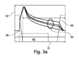
図3bは、摩擦ディスク28の平面図で湿式ディスクブレーキ20を示している。円26において、矢印は、閉鎖状態のディスクブレーキ20を冷却するための外部からのオイル供給を示している。円36において、目的は、シフトイベント後に摩擦システムの完全で均一で効果的な対流冷却を可能にするために、冷却オイルフローを摩擦リングの円周に沿って導くための好適な溝パターンであることが示されている。冷却オイルの出口は、円37によって示されている。冷却オイルフローは、可能な限り、摩擦システムの最も低いポイントで流出するべきである。冷却オイルの早期流出は、オイル流入ポイントにおける内径で、及び/又は円周に沿って外径で阻止されるか、又は最小限に抑えられるべきである。
Figure 3b shows the
摩擦ディスク28は、摩擦面34及び内側歯部35を装備している。所望の溝パターンが、摩擦面34に設けられている。
The
x軸31及びy軸32を備えるデカルト座標図が、図3aに示されている。好適な時間単位の時間が、x軸31にプロットされている。y軸32には、温度又は回転速度が、各場合における好適な単位でプロットされている。矩形40では、ディスクブレーキは閉鎖されている。矩形40の右側では、ディスクブレーキが開放されている。38は、ディスクブレーキの閉鎖時の速度低下を例示している。39は、ディスクブレーキの開放時の速度上昇を例示している。楕円44では、不均一な冷却オイル分布に起因して、ディスクブレーキの円周上に不均一な温度分布を見ることができる。ブレーキが閉鎖されると、ディスクブレーキのディスクパック内の摩擦ディスクとスチールディスクとが互いに押し付けられる。
3a shows a Cartesian coordinate diagram with an
x軸41及びy軸42を備えるデカルト座標図が、図4aに示されている。速度差は、好適な速度単位でx軸41上にプロットされている。抗力トルクは、好適な単位でy軸42上にプロットされている。曲線43は、異なる断面45、46、及び47における抗力トルク曲線を示している。ポイント71までの線状推移70である。最大値72の後、抗力トルクの推移には低下73がある。点線は、相対運動、特に、抗力トルクの新たな増加をもたらすディスクのウォブリング運動を示す。
A Cartesian coordinate diagram with an
摩擦ディスク28とスチールディスク29との間のオイルのシア流が、図4bに示されている。吸気の低速へのシフト50が、図4cに示されている。好適な溝パターンは、ブレーキのオイル排出を改善し、ひいては、抗力損失を改善することが意図される。
The shear flow of oil between the
図4dの円48は、ディスクブレーキ20が開放されているときのオイル供給が、すなわち、有利には、好適な溝パターンによって、可能な限り低減又は最小化されるべきであることを示す。円49では、オイル排出が、矢印で示されている。ディスクブレーキ20が開放されているとき、迅速なオイル排出/スピンフリーが望ましい。ディスクの分離及びオイル排出の両方を溝パターンによって補助することができる。
図5~図9は各々、異なる溝パターンの流入溝1、11及び周方向溝2、12を備える摩擦ディスク28の断面を示している。図5a、図5b、図5c、図6a、図6c、図7、図8a、図8b、図8c、図9a、図9b、図9cの溝パターンは、閉鎖された内側リング3を取り囲んでいる。すなわち、これらの例示的な実施形態では、周方向溝2、12は、径方向に内側で閉鎖されている。
Figures 5-9 each show a cross section of a
流入溝1は、各々の場合に、2つの摩擦ライニング片51、52によって画成されている。摩擦ライニング片51、52は、台形状である。外側の摩擦ライニング片51、52の台形の形状は、パッドとも称され、流入溝1がディフューザでのように、内側から外側に向かって開放していることを意味する。流入溝の例示される幅は、ディスクブレーキが閉鎖状態であるときに、外部からのオイル供給を容易にする。図5a~図5c、及び図6a~図6d、並びに図7では、周方向溝2は、接線方向に延びている。接線方向溝2は、冷却オイルを摩擦システムの円周にわたって分配するために中央に配置されている。閉鎖された内側リング3は、冷却オイルが摩擦接触部から流出することを阻止する。
The inlet groove 1 is in each case bounded by two
図5aでは、閉鎖された内側リング3は、矩形のブラインド溝4を装備している。矩形のブラインド溝4は、外側のパッド列51、52の下方に配置されていて、冷却オイルの良好な分配をもたらすとともに、冷却オイルとスチールディスクとの間の対流熱伝達のための接触表面を拡大する。同時に、内径上の材料の割合を低減させることができる。これにより、均一な表面圧力分布が得られる。
In Fig. 5a, the closed
図5bでは、内側リング3がV字形のブラインド溝5を装備することができることが示されている。図5cでは、閉鎖された内側リング3が三日月形又は半円形のブラインド溝6を装備することができることも示されている。
In Fig. 5b it is shown that the
図6aでは、図5a~図5cの例示的な実施形態と比較して、ブラインド溝7の数及び位置が変化している。2つ以上の矩形のブラインド溝7は各々、摩擦ライニング片51、52のうちの一方の下に配置されている。更に、ブラインド溝7は、外側パッド52の下で中央に配置される代わりに、オフセットして配置される。
In Fig. 6a, the number and location of the
内側リング3の径方向溝8が、図6bに示されている。径方向溝8によって、内側リング3はもはや閉鎖されておらず、中断されているか又はセグメント化されている。内側リング3の小さなセグメント化、例えば、6つ又は8つのセグメント化によって、製造時の材料の無駄を低減することができる。
The radial grooves 8 of the
図6cでは、径方向溝9が、内側リング3内に示されており、図6bよりも幅が広い。径方向溝9は、摩擦ライニング片52の下方又は径方向に内側に配置されている。
In FIG. 6c, the radial groove 9 is shown in the
図6dでは、10は、摩擦ライニング片51、52には、縁部に付加的な面取り部又はベベル10a、10bが設けられていることを示している。
In FIG. 6d, 10 shows that the
図7は、互い違いに配置された台形の外側パッド又は摩擦ライニング片51、52及び53、54の複数の列を備える溝パターンを示している。これにより、周方向溝2に加えて、更なる周方向溝55が得られる。
Figure 7 shows a groove pattern with multiple rows of staggered trapezoidal outer pads or
図8a~図8c及び図9a~図9cは、互いに向かい合っている面取り部又はベベル15、16を装備した外部パッド又は摩擦ライニング片56、57を備える溝パターンを示している。これにより、流入溝11において外側への漏斗状の開口部が得られる。更に、摩擦ライニング片56、57及び閉鎖された内側リング3は、周方向溝12に湾曲したジグザグ形状が得られるように設計され、配置されている。これにより、円周を通る冷却オイルフローがより良好になる。接触パターンも改善され、摩耗が少なくなる。開放状態にある矩形のブラインド溝4内のオイルリザーバと組み合わせて、摩擦ディスクの回転時に、冷却オイルが外部に浸透し、潤滑ギャップ内に圧力上昇を生じさせる。キャリアシートに波形がない場合、これは、改善された分離挙動をもたらすことができる。これにより、抗力トルクを効果的に低減することができる。
8a-8c and 9a-9c show a groove pattern with outer pads or
図8bでは、摩擦ライニングパッド57には、図8の尖った設計とは対照的に、平坦部13が設けられている。平坦部30は、図8aのポイントと同様に、摩擦ライニング片57の中心に径方向に配置されている。
In Fig. 8b, the
図8cでは、摩擦ライニング片56及び57には、互いに向かい合う丸み付けされた輪郭17、18が設けられており、流入溝11の拡幅部を径方向に外側に示している。
In FIG. 8c, the
図9aでは、図8aとは対照的に、摩擦ライニング片56、57には各々、型押しされた径方向溝74が設けられている。これは、オイルリザーバからオイルが排出されるか、又はブラインド溝4から自由に回転されることに役立つ。径方向溝74の数は、摩擦ライニング片56、57の数とは異なっていてよい。型押しされた径方向溝74の溝深さ及び溝幅は、ブラインド溝4よりも小さい。
In FIG. 9a, in contrast to FIG. 8a, the
図9bでは、摩擦ライニング片56、57は各々、径方向溝75によってセグメント化されている。その他の点では、図9bは図8bと同じである。
In FIG. 9b, the
閉鎖された内側リング3は、図9cにおいて、径方向溝76によってセグメント化されている。その他の点では、内側リング3は図8bの内側リングと同じである。図9cおける摩擦ライニング片56、57は、図8aにおける摩擦ライニング片56、57と同じである。
The closed
図9dでは、摩擦ライニング片56は、摩擦ライニング片77と交互に配置されている。摩擦ライニング片77は、ベベル78、79を備える矩形の形状を有している。
In FIG. 9d, the
周方向溝12における冷却オイル分布は、図10aにおいて矢印58によって示されている。冷却オイルフローは、閉鎖されたか又は僅かにセグメント化された内側リング3及び湾曲した接線方向溝12によって摩擦システム内に保持することができる。流出及び流入を最小限に抑えることができる。図10aは、ディスクブレーキが閉鎖されているときの概略的な冷却オイルフローを示している。
The cooling oil distribution in the
図10bでは、矢印59及び60は、開放状態における概略的なオイル排出及び分離挙動を示している。ブラインド溝4は、潤滑くさび効果をもたらす。開放状態にあるブラインド溝4内のオイルリザーバは、摩擦ディスクの回転とともに外方に押し、潤滑ギャップ内の圧力の増大を生じさせる。クラッチ又はブレーキが開放されているときのディスクの最適な分布は、抗力トルクの低減をもたらす。更に、クラッチは、作動されるときに穏やかに閉鎖することができる。矢印60は、流入溝11を通る径方向に外側へのオイルフローを示している。
In FIG. 10b,
閉鎖(回転なし)時の冷却(図3、図10):
溝パターンの設計は、低いフロー抵抗によって外部からの冷却オイル供給を容易にし、目標とされたオイルフローは、一方では摩擦システムからの冷却オイルの早期の流出を最小化し、他方では摩擦システムの円周にわたって均一な冷却を可能にする(対流冷却の改善)。これにより、シフト要素の熱経済性を改善し、冷却時間を短縮することができる。
Cooling when closed (no rotation) (Fig. 3, Fig. 10):
The groove pattern design facilitates an external cooling oil supply due to its low flow resistance, and the targeted oil flow on the one hand minimizes premature drainage of the cooling oil from the friction system and on the other hand allows for uniform cooling over the circumference of the friction system (improved convection cooling), which improves the thermal economy of the shift elements and shortens the cooling times.
開放時の抗力損失(図4、図10):
吸気/分離挙動の相互関係及び抗力損失に対するそれらの影響を考慮することによって、(潤滑間隙内の圧力レベル/分布に影響を及ぼす)溝パターンの設計は、抗力損失を最小限にすることができる。同時に、変速機の内部からの摩擦システムの追加の受動オイル供給が低減される。これは、ハイブリッドモジュール、DTH及びE-Axleのための始動、シフト及び分離要素としての低損失ディスクブレーキの目標を支持する。
Drag loss at opening (Fig. 4, Fig. 10):
By considering the interrelationships of intake/separation behavior and their impact on drag losses, the design of the groove pattern (which affects the pressure level/distribution in the lubricated gap) can minimize drag losses. At the same time, the additional passive oil supply of the friction system from inside the transmission is reduced. This supports the goal of low-loss disc brakes as starting, shifting and separation elements for hybrid modules, DTH and E-Axles.
溝パターン変形形態1(図5、図6、図7):
外部台形パッド、溝1は内側から外側に開放している(ディフューザ)。広い溝チャネルは、ブレーキが閉鎖されているときの外部からのオイル供給を容易にする。接線溝2が、摩擦システムの円周に冷却オイルを分配するために中央に配置されている。閉鎖された内側リング3は、冷却オイルが摩擦接触部から流出することを阻止する。矩形のブラインド溝4は、外側パッド列の下に配置され、冷却オイルのより良好な分布をもたらし、対流熱伝達(冷却オイル/スチールディスク)のための接触表面を拡大する。同時に、内径上の材料の割合を低減させることができる(均一な表面圧力分布)。
Groove pattern variant 1 (FIGS. 5, 6, 7):
External trapezoidal pads, grooves 1 open from inside to outside (diffuser). Wide groove channels facilitate oil supply from outside when the brake is closed.
溝パターン変形形態2(図8、図9):
面取り又は外部への開口溝を備える外部パッド(11漏斗形状)。円周の周囲のより良好な冷却オイルフローのための、接線溝の代わりの湾曲したジグザグ溝12。接触パターンも改善されている(摩耗が少ない)。冷却オイルは、摩擦ディスクの回転時に開放状態にあるブラインド溝内のオイルリザーバと協働して、外側に向かって押圧され、潤滑ギャップ内の圧力上昇を生じさせる。キャリアプレートに波形がない場合、これは、ディスクの改善された分離挙動(抗力トルクの低減)をもたらすことができる。
Groove pattern variant 2 (FIGS. 8 and 9):
External pads (11 funnel shape) with chamfers or grooves opening to the outside.
1 流入溝
2 円周方向溝
3 閉鎖された内側リング
4 ブラインド溝
5 ブラインド溝
6 ブラインド溝
7 ブラインド溝
8 溝(径方向)
9 溝(径方向)
10a、b ベベル、面取り
11 流入溝
12 円周方向溝
13 平坦部
15 ベベル、面取り
16 ベベル、面取り
17 丸み
18 丸み
19 角部
20 ディスクブレーキ
21 潤滑システム
22 潤滑システム
23 潤滑システム
24 矢印
25 二重矢印
26 矢印(外部オイル供給)
27 内側ディスクキャリア
28 摩擦ディスク
29 スチールディスク
30 外側ディスクキャリア
31 x軸
32 y軸
33 回転軸
34 摩擦面
35 内側歯部
36 円
37 円
38 速度低下
39 速度上昇
40 矩形
41 x軸
42 y軸
43 曲線
44 温度分布
45 断面
46 断面
47 断面
48 円
49 円
50 シフト
51 摩擦ライニング片
52 摩擦ライニング片
53 摩擦ライニング片
54 摩擦ライニング片
55 円周方向溝
56 摩擦ライニング片
57 摩擦ライニング片
58 矢印
59 矢印
60 矢印
61 溝パターン
62 溝パターン
63 溝パターン
64 溝パターン
65 溝パターン
66 溝パターン
67 溝パターン
68 溝パターン
69 溝パターン
70 線状推移
71 ポイント
72 最大
73 低下
74 径方向溝
75 径方向溝
76 径方向溝
77 摩擦ライニング片
78 ベベル
79 ベベル
1
9 Groove (radial direction)
10a, b bevel,
27
Claims (9)
前記周方向溝(2、12)が、前記摩擦面(34)に対して径方向に内側で閉鎖されていることを特徴とする、湿式ディスクブレーキ。 A wet disc brake (20) with an external oil supply (26) of a friction surface (34), said friction surface (34) having a circumference, said friction surface (34) having a circumferential groove (2, 12) extending around said circumference, said circumferential groove (2, 12) being a groove (12) of zigzag or wave shape or a groove (2) extending tangentially around said circumference, and an inlet groove (1, 11) through which oil flows from the outside into said circumferential groove (2, 12) ,
A wet disc brake, characterized in that said circumferential grooves (2, 12) are closed radially inwardly with respect to said friction surface (34) .
Applications Claiming Priority (3)
| Application Number | Priority Date | Filing Date | Title |
|---|---|---|---|
| DE102020121310 | 2020-08-13 | ||
| DE102020121310.7 | 2020-08-13 | ||
| PCT/DE2021/100670 WO2022033631A1 (en) | 2020-08-13 | 2021-08-04 | Wet disc brake with external oiling |
Publications (2)
| Publication Number | Publication Date |
|---|---|
| JP2023538311A JP2023538311A (en) | 2023-09-07 |
| JP7577832B2 true JP7577832B2 (en) | 2024-11-05 |
Family
ID=77300715
Family Applications (1)
| Application Number | Title | Priority Date | Filing Date |
|---|---|---|---|
| JP2023509731A Active JP7577832B2 (en) | 2020-08-13 | 2021-08-04 | Wet disc brakes with external oil supply |
Country Status (5)
| Country | Link |
|---|---|
| US (1) | US20240218910A1 (en) |
| JP (1) | JP7577832B2 (en) |
| CN (1) | CN116057295A (en) |
| DE (1) | DE102020127423A1 (en) |
| WO (1) | WO2022033631A1 (en) |
Families Citing this family (2)
| Publication number | Priority date | Publication date | Assignee | Title |
|---|---|---|---|---|
| JP7826342B2 (en) * | 2021-06-07 | 2026-03-09 | シェフラー テクノロジーズ アー・ゲー ウント コー. カー・ゲー | Friction plate having a groove pattern formed by a friction lining pad |
| DE102024127922A1 (en) | 2024-09-26 | 2026-03-26 | Schaeffler Technologies AG & Co. KG | Multi-plate brake or multi-plate clutch with external lubrication |
Citations (5)
| Publication number | Priority date | Publication date | Assignee | Title |
|---|---|---|---|---|
| JP2010535996A (en) | 2007-08-15 | 2010-11-25 | ボーグワーナー・インコーポレーテッド | Friction part with zigzag or wavy circumferential grooves on the friction surface |
| WO2011033861A1 (en) | 2009-09-15 | 2011-03-24 | アイシン化工株式会社 | Segment type friction part |
| DE202015009048U1 (en) | 2015-11-09 | 2016-08-03 | Zf Friedrichshafen Ag | Slat for a non-positive switching element |
| JP2018522176A (en) | 2015-07-30 | 2018-08-09 | シェフラー テクノロジーズ アー・ゲー ウント コー. カー・ゲーSchaeffler Technologies AG & Co. KG | Friction member |
| JP2019078351A (en) | 2017-10-25 | 2019-05-23 | アイシン化工株式会社 | Wet friction material |
Family Cites Families (10)
| Publication number | Priority date | Publication date | Assignee | Title |
|---|---|---|---|---|
| JPS61175326A (en) | 1985-01-31 | 1986-08-07 | Kawasaki Heavy Ind Ltd | Wet type multiple disc and multiple stage clutch |
| US5094331A (en) | 1988-03-18 | 1992-03-10 | Honda Giken Kogyo Kabushiki Kaisha | Wet-type multiplate clutch |
| JPH0352429U (en) * | 1989-09-27 | 1991-05-21 | ||
| JP3623527B2 (en) | 1993-12-24 | 2005-02-23 | Nskワーナー株式会社 | Torque converter with lock-up mechanism |
| DE10008167A1 (en) * | 2000-02-23 | 2001-08-30 | Zahnradfabrik Friedrichshafen | Friction clutch |
| AU2006220071A1 (en) * | 2005-03-03 | 2006-09-08 | Knorr-Bremse Systeme Fur Nutzfahrzeuge Gmbh | Brake-disc, in particular for a vehicle |
| JP2007132362A (en) * | 2005-11-08 | 2007-05-31 | Nsk Warner Kk | Friction plate and wet multi-disk clutch with friction plate |
| DE102008002556A1 (en) | 2008-06-20 | 2009-12-24 | Zf Friedrichshafen Ag | Clutch plate, in particular for a wet-running multi-plate clutch or a lock-up clutch of a hydrodynamic coupling device |
| JP2010185557A (en) | 2009-02-13 | 2010-08-26 | Toyota Motor Corp | Wet friction engagement device of automatic transmission for vehicle |
| JP6709742B2 (en) * | 2017-01-27 | 2020-06-17 | 株式会社ダイナックス | Friction plate |
-
2020
- 2020-10-19 DE DE102020127423.8A patent/DE102020127423A1/en active Pending
-
2021
- 2021-08-04 US US18/020,657 patent/US20240218910A1/en active Pending
- 2021-08-04 WO PCT/DE2021/100670 patent/WO2022033631A1/en not_active Ceased
- 2021-08-04 CN CN202180057248.XA patent/CN116057295A/en active Pending
- 2021-08-04 JP JP2023509731A patent/JP7577832B2/en active Active
Patent Citations (6)
| Publication number | Priority date | Publication date | Assignee | Title |
|---|---|---|---|---|
| JP2010535996A (en) | 2007-08-15 | 2010-11-25 | ボーグワーナー・インコーポレーテッド | Friction part with zigzag or wavy circumferential grooves on the friction surface |
| WO2011033861A1 (en) | 2009-09-15 | 2011-03-24 | アイシン化工株式会社 | Segment type friction part |
| JP2018522176A (en) | 2015-07-30 | 2018-08-09 | シェフラー テクノロジーズ アー・ゲー ウント コー. カー・ゲーSchaeffler Technologies AG & Co. KG | Friction member |
| DE202015009048U1 (en) | 2015-11-09 | 2016-08-03 | Zf Friedrichshafen Ag | Slat for a non-positive switching element |
| JP2018536809A (en) | 2015-11-09 | 2018-12-13 | ツェットエフ、フリードリッヒスハーフェン、アクチエンゲゼルシャフトZf Friedrichshafen Ag | Plate for friction-coupled shift element |
| JP2019078351A (en) | 2017-10-25 | 2019-05-23 | アイシン化工株式会社 | Wet friction material |
Also Published As
| Publication number | Publication date |
|---|---|
| CN116057295A (en) | 2023-05-02 |
| US20240218910A1 (en) | 2024-07-04 |
| WO2022033631A1 (en) | 2022-02-17 |
| DE102020127423A1 (en) | 2022-02-17 |
| JP2023538311A (en) | 2023-09-07 |
Similar Documents
| Publication | Publication Date | Title |
|---|---|---|
| CN101743408B (en) | Frictional part with a zig-zag or undulating circumferential groove in the frictional surface | |
| JP4663642B2 (en) | Plate with friction lining | |
| US8113330B2 (en) | Friction disk for a wet-running clutch for a motor vehicle | |
| JP3715215B2 (en) | Wet friction plate | |
| JP7577832B2 (en) | Wet disc brakes with external oil supply | |
| JP2018522176A (en) | Friction member | |
| EP1416183A2 (en) | A rotor with surface having a plurality of identations formed therein | |
| JP2019510934A (en) | Friction parts | |
| JP2001187927A (en) | Annular friction clutch facing for multiple disc clutch | |
| CN111836975A (en) | friction parts | |
| JP7073263B2 (en) | Friction parts | |
| CN111386405A (en) | Friction member | |
| JP2006132581A (en) | Segment type friction material | |
| JP7826342B2 (en) | Friction plate having a groove pattern formed by a friction lining pad | |
| JP7681121B2 (en) | Friction plate having groove pattern formed by friction lining pad | |
| KR20180053243A (en) | Friction lining multi-plate for a multi-plate clutch or a multi-plate brake of a motor vehicle | |
| CN116529498A (en) | Wet type multi-plate clutch | |
| JP7676552B2 (en) | Friction disc having groove pattern formed by friction lining pad | |
| JP7717813B2 (en) | Friction disc having a groove pattern formed by a friction lining pad | |
| CN117396682A (en) | Friction plate with groove pattern formed by means of friction pads | |
| CN116724179A (en) | Friction plate with groove pattern formed by means of friction pad | |
| KR100645999B1 (en) | Annular friction-clutch facing for a multi-disk clutch | |
| CN120092140A (en) | Groove pattern for friction plate | |
| US20240183407A1 (en) | Friction part for a frictionally working device |
Legal Events
| Date | Code | Title | Description |
|---|---|---|---|
| A621 | Written request for application examination |
Free format text: JAPANESE INTERMEDIATE CODE: A621 Effective date: 20230210 |
|
| A977 | Report on retrieval |
Free format text: JAPANESE INTERMEDIATE CODE: A971007 Effective date: 20240328 |
|
| A131 | Notification of reasons for refusal |
Free format text: JAPANESE INTERMEDIATE CODE: A131 Effective date: 20240409 |
|
| A521 | Request for written amendment filed |
Free format text: JAPANESE INTERMEDIATE CODE: A523 Effective date: 20240625 |
|
| TRDD | Decision of grant or rejection written | ||
| A01 | Written decision to grant a patent or to grant a registration (utility model) |
Free format text: JAPANESE INTERMEDIATE CODE: A01 Effective date: 20240924 |
|
| A61 | First payment of annual fees (during grant procedure) |
Free format text: JAPANESE INTERMEDIATE CODE: A61 Effective date: 20241023 |
|
| R150 | Certificate of patent or registration of utility model |
Ref document number: 7577832 Country of ref document: JP Free format text: JAPANESE INTERMEDIATE CODE: R150 |