JP2018536809A - Plate for friction-coupled shift element - Google Patents
Plate for friction-coupled shift element Download PDFInfo
- Publication number
- JP2018536809A JP2018536809A JP2018523449A JP2018523449A JP2018536809A JP 2018536809 A JP2018536809 A JP 2018536809A JP 2018523449 A JP2018523449 A JP 2018523449A JP 2018523449 A JP2018523449 A JP 2018523449A JP 2018536809 A JP2018536809 A JP 2018536809A
- Authority
- JP
- Japan
- Prior art keywords
- groove
- plate
- deflection point
- shift element
- friction
- Prior art date
- Legal status (The legal status is an assumption and is not a legal conclusion. Google has not performed a legal analysis and makes no representation as to the accuracy of the status listed.)
- Pending
Links
Images


Classifications
-
- F—MECHANICAL ENGINEERING; LIGHTING; HEATING; WEAPONS; BLASTING
- F16—ENGINEERING ELEMENTS AND UNITS; GENERAL MEASURES FOR PRODUCING AND MAINTAINING EFFECTIVE FUNCTIONING OF MACHINES OR INSTALLATIONS; THERMAL INSULATION IN GENERAL
- F16D—COUPLINGS FOR TRANSMITTING ROTATION; CLUTCHES; BRAKES
- F16D13/00—Friction clutches
- F16D13/58—Details
- F16D13/60—Clutching elements
- F16D13/64—Clutch-plates; Clutch-lamellae
- F16D13/648—Clutch-plates; Clutch-lamellae for clutches with multiple lamellae
-
- F—MECHANICAL ENGINEERING; LIGHTING; HEATING; WEAPONS; BLASTING
- F16—ENGINEERING ELEMENTS AND UNITS; GENERAL MEASURES FOR PRODUCING AND MAINTAINING EFFECTIVE FUNCTIONING OF MACHINES OR INSTALLATIONS; THERMAL INSULATION IN GENERAL
- F16D—COUPLINGS FOR TRANSMITTING ROTATION; CLUTCHES; BRAKES
- F16D13/00—Friction clutches
- F16D13/58—Details
- F16D13/72—Features relating to cooling
-
- F—MECHANICAL ENGINEERING; LIGHTING; HEATING; WEAPONS; BLASTING
- F16—ENGINEERING ELEMENTS AND UNITS; GENERAL MEASURES FOR PRODUCING AND MAINTAINING EFFECTIVE FUNCTIONING OF MACHINES OR INSTALLATIONS; THERMAL INSULATION IN GENERAL
- F16D—COUPLINGS FOR TRANSMITTING ROTATION; CLUTCHES; BRAKES
- F16D13/00—Friction clutches
- F16D13/58—Details
- F16D13/74—Features relating to lubrication
-
- F—MECHANICAL ENGINEERING; LIGHTING; HEATING; WEAPONS; BLASTING
- F16—ENGINEERING ELEMENTS AND UNITS; GENERAL MEASURES FOR PRODUCING AND MAINTAINING EFFECTIVE FUNCTIONING OF MACHINES OR INSTALLATIONS; THERMAL INSULATION IN GENERAL
- F16D—COUPLINGS FOR TRANSMITTING ROTATION; CLUTCHES; BRAKES
- F16D25/00—Fluid-actuated clutches
- F16D25/12—Details not specific to one of the before-mentioned types
- F16D25/123—Details not specific to one of the before-mentioned types in view of cooling and lubrication
-
- F—MECHANICAL ENGINEERING; LIGHTING; HEATING; WEAPONS; BLASTING
- F16—ENGINEERING ELEMENTS AND UNITS; GENERAL MEASURES FOR PRODUCING AND MAINTAINING EFFECTIVE FUNCTIONING OF MACHINES OR INSTALLATIONS; THERMAL INSULATION IN GENERAL
- F16D—COUPLINGS FOR TRANSMITTING ROTATION; CLUTCHES; BRAKES
- F16D65/00—Parts or details
- F16D65/02—Braking members; Mounting thereof
- F16D2065/13—Parts or details of discs or drums
- F16D2065/1304—Structure
- F16D2065/1312—Structure circumferentially segmented
-
- F—MECHANICAL ENGINEERING; LIGHTING; HEATING; WEAPONS; BLASTING
- F16—ENGINEERING ELEMENTS AND UNITS; GENERAL MEASURES FOR PRODUCING AND MAINTAINING EFFECTIVE FUNCTIONING OF MACHINES OR INSTALLATIONS; THERMAL INSULATION IN GENERAL
- F16D—COUPLINGS FOR TRANSMITTING ROTATION; CLUTCHES; BRAKES
- F16D69/00—Friction linings; Attachment thereof; Selection of coacting friction substances or surfaces
- F16D2069/004—Profiled friction surfaces, e.g. grooves, dimples
-
- F—MECHANICAL ENGINEERING; LIGHTING; HEATING; WEAPONS; BLASTING
- F16—ENGINEERING ELEMENTS AND UNITS; GENERAL MEASURES FOR PRODUCING AND MAINTAINING EFFECTIVE FUNCTIONING OF MACHINES OR INSTALLATIONS; THERMAL INSULATION IN GENERAL
- F16D—COUPLINGS FOR TRANSMITTING ROTATION; CLUTCHES; BRAKES
- F16D25/00—Fluid-actuated clutches
- F16D25/06—Fluid-actuated clutches in which the fluid actuates a piston incorporated in, i.e. rotating with the clutch
- F16D25/062—Fluid-actuated clutches in which the fluid actuates a piston incorporated in, i.e. rotating with the clutch the clutch having friction surfaces
- F16D25/063—Fluid-actuated clutches in which the fluid actuates a piston incorporated in, i.e. rotating with the clutch the clutch having friction surfaces with clutch members exclusively moving axially
- F16D25/0635—Fluid-actuated clutches in which the fluid actuates a piston incorporated in, i.e. rotating with the clutch the clutch having friction surfaces with clutch members exclusively moving axially with flat friction surfaces, e.g. discs
- F16D25/0638—Fluid-actuated clutches in which the fluid actuates a piston incorporated in, i.e. rotating with the clutch the clutch having friction surfaces with clutch members exclusively moving axially with flat friction surfaces, e.g. discs with more than two discs, e.g. multiple lamellae
-
- F—MECHANICAL ENGINEERING; LIGHTING; HEATING; WEAPONS; BLASTING
- F16—ENGINEERING ELEMENTS AND UNITS; GENERAL MEASURES FOR PRODUCING AND MAINTAINING EFFECTIVE FUNCTIONING OF MACHINES OR INSTALLATIONS; THERMAL INSULATION IN GENERAL
- F16D—COUPLINGS FOR TRANSMITTING ROTATION; CLUTCHES; BRAKES
- F16D65/00—Parts or details
- F16D65/02—Braking members; Mounting thereof
- F16D65/12—Discs; Drums for disc brakes
- F16D65/127—Discs; Drums for disc brakes characterised by properties of the disc surface; Discs lined with friction material
-
- F—MECHANICAL ENGINEERING; LIGHTING; HEATING; WEAPONS; BLASTING
- F16—ENGINEERING ELEMENTS AND UNITS; GENERAL MEASURES FOR PRODUCING AND MAINTAINING EFFECTIVE FUNCTIONING OF MACHINES OR INSTALLATIONS; THERMAL INSULATION IN GENERAL
- F16D—COUPLINGS FOR TRANSMITTING ROTATION; CLUTCHES; BRAKES
- F16D65/00—Parts or details
- F16D65/02—Braking members; Mounting thereof
- F16D65/12—Discs; Drums for disc brakes
- F16D65/128—Discs; Drums for disc brakes characterised by means for cooling
Landscapes
- Engineering & Computer Science (AREA)
- General Engineering & Computer Science (AREA)
- Mechanical Engineering (AREA)
- Mechanical Operated Clutches (AREA)
- Braking Arrangements (AREA)
Abstract
摩擦結合型シフト要素用のプレート(1)は、内縁(21)及び外縁(22)を有する環状の摩擦面を備える。摩擦面には、周方向の第1溝(31)、複数の第2溝(32)、及び複数の第3溝(33)が備えられている。第1溝(31)は、半径方向内側の偏向点(41)と半径方向外側の偏向点(42)との間をジグザグに又は波状に延在する。第2溝(32)は内縁(21)から半径方向内側の偏向点(41)まで延在する。第3溝(33)は外縁(22)から周方向の第1溝(31)に延在し、かつ合流点(43)において周方向の第1溝(31)に通じる。第3溝(33)は合流点(43)から実質的に半径方向で外縁(22)に向けて配向されている。第2溝(32)における、少なくとも半径方向内側の偏向点(41)に通じる部分の配向と、プレート(1)の回転中心点(44)と第2溝(32)の各々に割り当てられた偏向点(41)との間の線とが、35度と75度の間の角度(46a)をなす。
【選択図】図1The plate (1) for the friction-coupled shift element comprises an annular friction surface having an inner edge (21) and an outer edge (22). The friction surface includes a circumferential first groove (31), a plurality of second grooves (32), and a plurality of third grooves (33). The first groove (31) extends in a zigzag or wavy manner between the radially inner deflection point (41) and the radially outer deflection point (42). The second groove (32) extends from the inner edge (21) to the radially inner deflection point (41). The third groove (33) extends from the outer edge (22) to the circumferential first groove (31), and communicates with the circumferential first groove (31) at the junction (43). The third groove (33) is oriented substantially radially from the junction (43) toward the outer edge (22). In the second groove (32), at least the orientation of the portion leading to the radially inner deflection point (41) and the deflection assigned to each of the rotation center point (44) and the second groove (32) of the plate (1). The line between the point (41) forms an angle (46a) between 35 and 75 degrees.
[Selection] Figure 1
Description
本発明は、摩擦結合型シフト要素用のプレートに関する。本発明は更に、そうしたプレートを備えた摩擦結合型シフト要素、及びそうした摩擦結合型シフト要素を備えた自動車用の変速機に関する。 The present invention relates to a plate for a friction-coupled shift element. The invention further relates to a friction-coupled shift element comprising such a plate and to a motor vehicle transmission comprising such a friction-coupled shift element.
国際出願特許公開第2009/021569号は、摩擦係合式に作動する装置用の摩擦部に関する。摩擦部は、内縁及び外縁を有する環状の摩擦面を備える。摩擦面には、半径方向内側の偏向点と半径方向外側の偏向点との間をジグザグに又は波状に延在する周方向の第1溝、内縁から内側の偏向点まで延在する複数の第2溝、及び外縁から実質的に半径方向で周方向の第1溝に延在し、かつ合流点において周方向の第1溝に通じる複数の第3溝が設けられている。この場合第2溝は、摩擦部の放射状の線に沿って延在する。 WO 2009/021569 relates to a friction part for a device that operates in a frictional engagement manner. The friction portion includes an annular friction surface having an inner edge and an outer edge. The friction surface includes a first circumferential groove extending in a zigzag or wave shape between a radially inner deflection point and a radially outer deflection point, and a plurality of first grooves extending from the inner edge to the inner deflection point. There are provided two grooves and a plurality of third grooves extending from the outer edge to the first circumferential groove substantially in the radial direction and leading to the first circumferential groove at the junction. In this case, the second groove extends along a radial line of the friction part.
摩擦結合型シフト要素つまり多板クラッチ又は多板ブレーキの構成部分として、そうした回転する摩擦部に対して、冷却油が半径方向外側から第3溝に対して供給される。そのため油は、第3溝から周方向の第1溝に流入する。油の大部分は、遠心力により、第3溝を経て再度噴出され、第2溝には浸透しない。これにより、冷却効果は摩擦面の半径に亘って不均一に分布する。そのため、半径方向でより外側の摩擦面の領域は、半径方向でより内側の摩擦面の領域よりも、著しく良好に冷却される。こうした状態は、望ましくない。 As a component of a friction coupling type shift element, that is, a multi-plate clutch or a multi-plate brake, cooling oil is supplied to the third groove from the outside in the radial direction with respect to the rotating friction portion. Therefore, oil flows from the third groove into the first groove in the circumferential direction. Most of the oil is ejected again through the third groove by centrifugal force and does not penetrate into the second groove. As a result, the cooling effect is unevenly distributed over the radius of the friction surface. Thus, the radially outer friction surface region cools significantly better than the radially inner friction surface region. Such a situation is undesirable.
従って、本発明の課題は、半径方向外側から冷却油が供給される際に、摩擦面の半径方向でより内側の領域における冷却を改善可能な、プレート用の溝パターンを提供することである。 Accordingly, an object of the present invention is to provide a groove pattern for a plate that can improve cooling in a region on the inner side in the radial direction of the friction surface when the cooling oil is supplied from the outer side in the radial direction.
この課題は、請求項1に記載の特徴により解決される。有利な実施形態は、従属請求項、明細書の記載、及び図面から明らかとなる。
This problem is solved by the features of
本発明によれば、従来技術において既知の溝パターンが以下のように変更される。すなわち、第2溝における、少なくとも半径方向内側の偏向点に通じる部分の配向と、プレートの回転中心点と第2溝の各々に割り当てられた偏向点との間の線とが、35度と75度の間の角度、好適には45度と65度の間の角度をなす。換言すると第2溝は、従来技術と比較して、この場合もはや半径方向で走るのではなく、半径方向に対して斜めに走る。プレートがその軸周りで回転すると、周方向の第1溝を通って流れる冷却液が、第1溝に沿って走る。ここで、第2溝が斜めに配置されているために、内側の偏向点において流れが分配される。その際、冷却液の一部は、更に周方向の第1溝に沿って流れる。また残りの部分は、第2溝に流れる。これにより、従来技術と比較して、摩擦面の半径方向の内側領域の冷却が改善される。 According to the present invention, the groove pattern known in the prior art is modified as follows. That is, the orientation of the portion of the second groove that leads to at least the radially inner deflection point and the line between the rotation center point of the plate and the deflection point assigned to each of the second grooves are 35 degrees and 75 degrees. An angle between degrees, preferably between 45 and 65 degrees. In other words, the second groove no longer runs in the radial direction in this case compared to the prior art, but runs diagonally with respect to the radial direction. As the plate rotates about its axis, the coolant flowing through the circumferential first groove runs along the first groove. Here, since the second groove is disposed obliquely, the flow is distributed at the inner deflection point. At that time, a part of the cooling liquid further flows along the first circumferential groove. The remaining part flows into the second groove. This improves the cooling of the radially inner region of the friction surface compared to the prior art.
好適には、第2溝は直線で構成されている。これにより、第2溝を通る冷却液の流れ損失が僅かとなる。そのため、摩擦面の半径方向で内側領域の冷却効果が、更に改善される。 Preferably, the second groove is constituted by a straight line. Thereby, the flow loss of the coolant passing through the second groove is small. Therefore, the cooling effect of the inner region in the radial direction of the friction surface is further improved.
好適には第2溝は、半径方向内側の偏向点から、各々対をなして摩擦面の内縁に向かって延在する。これにより、摩擦面の半径方向で内側領域の冷却効果を、プレートの回転方向とは無関係に、改善することが達成できる。 Preferably, the second groove extends in pairs from the radially inner deflection point toward the inner edge of the friction surface. Thereby, the cooling effect of the inner region in the radial direction of the friction surface can be improved irrespective of the rotation direction of the plate.
第2溝の対をなす構成において、好適には、溝の対の各溝は、プレートの回転中心点と溝の対に割り当てられた偏向点との間の線に対して、同一の角度をなす。これにより、プレートの回転方向とは無関係に、均一な冷却効果が達成される。 In the second groove pair configuration, preferably each groove of the groove pair is at the same angle with respect to the line between the center of rotation of the plate and the deflection point assigned to the groove pair. Eggplant. This achieves a uniform cooling effect regardless of the direction of plate rotation.
第3溝は、実質的に半径方向で、プレートの外縁から周方向の第1溝への合流点まで延在する。「実質的に」との用語は、プレートの半径方向から最大で10度、好適には最大で5度逸れる第3溝の配向、と理解される。この逸脱は、両方向に、すなわちプラス10度又はマイナス10度で発生できる。半径方向からの逸脱には、第3溝の、いずれもが該当しない、全てが該当する、又は一部のみが該当することができる。このように、第3溝が実質的には半径方向に配向されることで、プレートの外縁から周方向の第1溝まで、しかもプレートの回転方向とは無関係に、油の浸透が促進される。 The third groove extends substantially radially and extends from the outer edge of the plate to the junction of the circumferential first grooves. The term “substantially” is understood to be the orientation of the third groove that deviates at most 10 degrees, preferably at most 5 degrees from the radial direction of the plate. This deviation can occur in both directions, ie plus 10 degrees or minus 10 degrees. Deviations from the radial direction may correspond to all of the third groove, none of them, or all of them. In this manner, the third groove is oriented substantially in the radial direction, so that oil permeation is promoted from the outer edge of the plate to the first groove in the circumferential direction, regardless of the direction of rotation of the plate. .
第3溝の配向が半径方向から逸れている場合、相互に隣接する第3溝の配向の逸脱は、正反対であることが好適である。第3溝の配向の逸脱が、例えばプラス5度である場合、従って、この第3溝に対して直に隣接する第3溝の配向の逸脱は、マイナス5度である。これにより、溝パターンを対称的に構成可能である。そのため、プレートを取り付ける際に、取り付け位置を考慮する必要がない。 When the orientation of the third grooves deviates from the radial direction, the deviation of the orientation of the third grooves adjacent to each other is preferably opposite. If the deviation in the orientation of the third groove is, for example, plus 5 degrees, the deviation in the orientation of the third groove immediately adjacent to the third groove is therefore minus 5 degrees. Thereby, a groove pattern can be constituted symmetrically. Therefore, it is not necessary to consider the attachment position when attaching the plate.
好適には、プレートはライニング付きプレートとして構成されている。ライニング付きプレートは、通常、環状の鋼製体を備える。鋼製体の正面側には、ライニング体が取り付けられている。ライニング体において、鋼製体から反対側を向く表面は、プレートの摩擦面を構成する。プレートの溝は、ライニング体の溝により、又はライニング体の間の凹部により、構成されることができる。この場合、本発明による溝の構成は、4つの異なる種類のライニング体形状のみを制限するものである。従って、従来技術と比較して溝パターンがより複雑であるにもかかわらず、労力を増大させずにプレートを製造可能である。 Preferably, the plate is configured as a lining plate. The lining plate usually comprises an annular steel body. A lining body is attached to the front side of the steel body. In the lining body, the surface facing away from the steel body constitutes the friction surface of the plate. The grooves in the plate can be constituted by grooves in the lining bodies or by recesses between the lining bodies. In this case, the configuration of the groove according to the invention limits only four different types of lining body shapes. Therefore, it is possible to manufacture a plate without increasing labor, despite the more complicated groove pattern compared to the prior art.
好適には、第3溝の合流点は、周方向の第1溝の偏向点の間に配置されている。これに対して代替的に、合流点は、第1溝の半径方向でより外側の偏向点と一致することができる。更なる有利な変更実施形態により、第3溝の合流点は、第1溝の半径方向でより内側の偏向点と一致する、つまり合同とすることができる。これにより、第3溝から第2溝への流れを改善可能である。 Preferably, the confluence point of the third groove is arranged between the deflection points of the first groove in the circumferential direction. Alternatively, the junction can coincide with a deflection point that is more outward in the radial direction of the first groove. According to a further advantageous variant embodiment, the confluence of the third groove can coincide with the inner deflection point in the radial direction of the first groove, ie congruent. Thereby, the flow from the third groove to the second groove can be improved.
好適には、周方向の第1溝、第2溝、及び第3溝の幅は、同一である。代替的な実施形態によれば、第2溝の幅は、周方向の第1溝の幅よりも大きい。これにより、第2溝の流れ抵抗が、周方向の第1溝の流れ抵抗と比較して低減される。そのため、半径方向外側からプレートの内縁に向かう油の浸透が促進される。 Preferably, the first groove, the second groove, and the third groove in the circumferential direction have the same width. According to an alternative embodiment, the width of the second groove is greater than the width of the first groove in the circumferential direction. Thereby, the flow resistance of the second groove is reduced as compared with the flow resistance of the first groove in the circumferential direction. Therefore, the penetration of oil from the radially outer side toward the inner edge of the plate is promoted.
本発明によるプレートは、例えば多板クラッチ又は多板ブレーキである、摩擦結合型シフト要素の構成部分とすることができる。この場合、複数のアウタプレート及び複数のインナプレートは、軸方向に交互に相前後して配置されている。アウタプレートは、回転不能かつ軸方向に移動可能な状態で、アウタプレートキャリアと結合されている。インナプレートは、回転不能かつ軸方向に移動可能な状態で、インナプレートキャリアと結合されている。本発明によるプレートは、インナプレート又はアウタプレートを構成する。この場合摩擦結合型シフト要素は、半径方向外側から本発明によるプレートの外縁に向けて流体を供給するよう構成された、装置を備える。このように構成された摩擦結合型シフト要素は、自動車用の変速機の構成部分とすることができる。この場合、摩擦結合型シフト要素は、自動車のドライブトレインにおける始動要素として作用する。そうした始動要素により、自動車の駆動源と駆動輪との間のスリップ状態が、始動プロセスの間に可能となる。この場合、例えば上り坂及び積載された自動車用トレーラー等である、特に高負荷の始動プロセスの際に、始動要素に高いエネルギを入力可能である。摩擦型シフト要素は、冷却効果が改善され摩擦面の半径に亘って均一であるために、特に始動要素としての使用に適している。 The plate according to the invention can be a component of a friction-coupled shift element, for example a multi-plate clutch or a multi-plate brake. In this case, the plurality of outer plates and the plurality of inner plates are alternately arranged in the axial direction. The outer plate is coupled to the outer plate carrier in a state in which it cannot rotate and is movable in the axial direction. The inner plate is coupled to the inner plate carrier in a state in which it cannot rotate and is movable in the axial direction. The plate according to the invention constitutes an inner plate or an outer plate. In this case, the friction-coupled shift element comprises a device configured to supply fluid from the radially outer side towards the outer edge of the plate according to the invention. The friction coupling type shift element configured as described above can be used as a component part of a transmission for an automobile. In this case, the friction coupling type shift element acts as a starting element in the drive train of the automobile. Such a starting element allows a slip condition between the driving source of the motor vehicle and the drive wheels during the starting process. In this case, high energy can be input to the starting element, especially during a high load starting process, such as for example uphill and loaded car trailers. The friction-type shift element is particularly suitable for use as a starting element because it has an improved cooling effect and is uniform over the radius of the friction surface.
本発明の実施形態は、以下に添付の図面を参照して詳述される。 Embodiments of the present invention are described in detail below with reference to the accompanying drawings.
図1は、プレート1の回転中心点44周りに配置された、プレート1の正面図である。プレート1は環状の摩擦面を備える。環状の摩擦面は、内縁21及び外縁22を備える。摩擦面には、対称的な溝パターンが備えられている。溝パターンは、周方向の第1溝31、複数の第2溝32、及び複数の第3溝33からなる。第1溝31は、半径方向内側の偏向点41と半径方向外側の偏向点42との間をジグザグ又は波状に、プレート1の周方向に延在する。第2溝32は、各々対をなして、内縁21から半径方向内側の偏向点41まで延在する。第3溝33は、外縁22から周方向の第1溝31に延在し、及び半径方向で配向されている。第3溝33の、周方向の第1溝31への合流点43は、偏向点41、42の間に存在する。
FIG. 1 is a front view of the
図2において、図1に示された正面図の拡大部分図が示される。第2溝32は、実質的に直線で構成されている。各第2溝32の線45に対する角度46a、46bは、35度と75度の間である。角度46a、46bは、図示の実施形態において約55度である。線45は、回転中心点44と、溝32に割り当てられた偏向点41との間で延在する。第1溝31の幅31t、第2溝32の幅32t、及び第3溝33の幅33tは、同一である。
In FIG. 2, an enlarged partial view of the front view shown in FIG. 1 is shown. The 2nd groove |
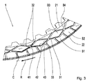
図3は、プレート1の等角図の部分図である。この部分図において、本発明による作動を良好に認識可能である。冷却油流Cは、外縁22から第3溝33に流入する。プレート1が所与の回転方向Rに回転する際、冷却油流Cは、プレート1に対して、周方向の第1溝31を通って回転方向Rの反対方向に流れる。遠心力のために、冷却油流Cの一部は、周方向に続く第3溝33において再度流出する。一方、冷却油流Cの残りの部分は、周方向の第1溝31を通り更に流れる。冷却油流Cは、今度は、内側の偏向点41のうちの1つを流れる。第2溝32が本発明により配向されているために、冷却油流Cは、第1溝31と、偏向点41から回転方向Rと反対に配向された第2溝32との間で分配される。プレート1の回転方向Rが常に同一である場合、従って、各偏向点32から内縁21に向かう単一の溝32で十分である。その場合、これらの溝32は回転方向Rと反対に配向されている。回転方向Rとは無関係に、プレート1の冷却機能が改良されるべきである場合、従って好適には、実施形態に示されるように、第2溝32は対で構成される。
FIG. 3 is a partial view of an isometric view of the
さらに図3においては、プレート1がライニング付きプレートであることを良好に認識可能である。溝31、32、33は、ライニング体の間の凹部により構成されている。プレート1は、この場合、ちょうど4つの異なる種類のライニング体形状B1、B2、B3、B4を備える。
Furthermore, in FIG. 3, it can be recognized well that the
図4は、本発明によるプレート1の第2実施形態の正面図を示す。プレート1は、実質的に図1に示された実施形態に対応する。菱形のライニング体は、この場合、半径方向で更に外側に配置された。これにより第3溝33が、今度は、周方向の第1溝よりも大きな幅を備える。
FIG. 4 shows a front view of a second embodiment of the
図5は、第2実施形態によるプレート1の詳細図を示す。図5において、第2溝32の幅32tが、周方向の第1溝31の、ここではより小さい幅31tと比較して、より大きくされた幅32tであることを良好に認識可能である。第3溝33の幅33tは、不変である。
FIG. 5 shows a detailed view of the
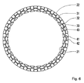
図6は、本発明によるプレート1の溝パターンを示す。溝パターンは、実質的に図4に示された第2実施形態の溝パターンに対応する。第3溝33の配向のみが変更された。そのため第3溝33は、プレート1の半径方向から5度逸れている。相互に隣接する第3溝33の逸脱は、この場合正反対に配向されている。そのため、対称的な溝パターンが発生する。
FIG. 6 shows the groove pattern of the
図7は同様に、第3溝33の配向がプレート1の半径方向から逸れる、本発明によるプレート1の溝パターンを示す。相互に隣接する第3溝33の逸脱は、再度、正反対に配向されている。そのため、対称的な溝パターンが発生する。図6に示された溝パターンと比較して、配向角度が変更された。そのため、内側の偏向点41に割り当てられたライニング体は、図6の実施形態におけるよりも幅広である。
FIG. 7 likewise shows the groove pattern of the
図8は、第3溝33の配向がプレート1の半径方向から逸れる、本発明によるプレート1の溝パターンを示す。配向角度は、図6による溝パターンに対応するが、プレート1の半径方向から10度の角度を備える。
FIG. 8 shows a groove pattern of the
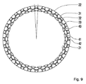
図9は同様に、第3溝33の配向がプレート1の半径方向から逸れる、本発明によるプレート1の溝パターンを示す。配向角度は、図7による溝パターンに対応するが、プレート1の半径方向から10度の角度を備える。
FIG. 9 likewise shows the groove pattern of the
図10は、摩擦結合型シフト要素Kの断面図を示す。摩擦結合型シフト要素Kにおいて、本発明によるプレート1が、インナプレートとして構成されている。摩擦結合型シフト要素Kは、例示的にブレーキとして作用する。インナプレートは、軸方向に相前後し、かつアウタプレートと交互に配置されている。アウタプレートは、スチールプレートとして構成されている。摩擦結合型シフト要素Kは、例えば冷却油である流体を供給する装置を備える。流体は、半径方向外側から、プレートパッケージに供給される。これによりインナプレート1に対して、半径方向外側から流体を供給可能である。
FIG. 10 shows a cross-sectional view of the friction coupling type shift element K. FIG. In the friction coupling type shift element K, the
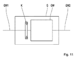
図11は、自動車用の変速機Gの概略図である。変速機Gは、入力軸GW1、出力軸GW2、及び変速部GWを備える。入力軸GW1は、例えば車両の内燃機関である、変速機外部の駆動ユニットへのインターフェイスとしての役割を果たす。出力軸GW2は、車両の車軸変速装置へのインターフェイスとしての役割を果たす。車軸変速装置を介して、出力軸GW2に作用する動力が、車両の駆動輪に分配される。変速部GWは、入力軸GW1と出力軸GW2との間で種々の変速比を実現するよう調整されている。入力軸GW1と変速部GWとの間に、摩擦結合型シフト要素Kが配置されている。摩擦結合型シフト要素Kにより、入力軸GW1と出力軸GW2との間のスリップ状態を、例えば自動車の始動プロセスの際に実現可能である。摩擦結合型シフト要素Kは、変速部GWの構成部分とすることもできる。 FIG. 11 is a schematic view of a transmission G for automobiles. The transmission G includes an input shaft GW1, an output shaft GW2, and a transmission unit GW. The input shaft GW1 serves as an interface to a drive unit outside the transmission, for example, an internal combustion engine of a vehicle. The output shaft GW2 serves as an interface to the vehicle axle transmission. The power acting on the output shaft GW2 is distributed to the drive wheels of the vehicle via the axle transmission. The transmission unit GW is adjusted to achieve various speed ratios between the input shaft GW1 and the output shaft GW2. A friction coupling type shift element K is disposed between the input shaft GW1 and the transmission unit GW. With the friction coupling type shift element K, a slip state between the input shaft GW1 and the output shaft GW2 can be realized, for example, during the start process of the automobile. The frictional coupling type shift element K can also be a constituent part of the transmission unit GW.
1 プレート
21 内縁
22 外縁
31 第1溝
31t 第1溝の幅
32 第2溝
32t 第2溝の幅
33 第3溝
33t 第3溝の幅
41 半径方向内側の偏向点
42 半径方向外側の偏向点
43 合流点
44 回転中心点
45 線
46a/b 角度
R 回転方向
C 冷却油流
B1 ライニング体形状
B2 ライニング体形状
B3 ライニング体形状
B4 ライニング体形状
K 摩擦結合型シフト要素
G 変速機
GW1 入力軸
GW2 出力軸
GW 変速部
1
Claims (14)
前記第1溝(31)は、半径方向内側の偏向点(41)と半径方向外側の偏向点(42)との間をジグザグに又は波状に延在し、
前記第2溝(32)は前記内縁(21)から前記半径方向内側の偏向点(41)まで延在し、
前記第3溝(33)は前記外縁(22)から前記周方向の第1溝(31)に延在し、かつ合流点(43)において前記周方向の第1溝(31)に通じ、
前記第3溝(33)は前記合流点(43)から実質的に半径方向で前記外縁(22)に向けて配向され、
前記第2溝(32)における、少なくとも前記半径方向内側の偏向点(41)に通じる部分の配向と、前記プレート(1)の回転中心点(44)と前記第2溝(32)の各々に割り当てられた前記偏向点(41)との間の線(45)とが、35度と75度の間の角度(46a)をなすことを特徴とする、
プレート(1)。 A plate (1) for a friction coupling type shift element, comprising an annular friction surface having an inner edge (21) and an outer edge (22), wherein the friction surface has a first circumferential groove (31), a plurality of The second groove (32) and a plurality of third grooves (33) are provided. In the plate (1),
The first groove (31) extends in a zigzag or wave shape between a radially inner deflection point (41) and a radially outer deflection point (42),
The second groove (32) extends from the inner edge (21) to the radially inner deflection point (41),
The third groove (33) extends from the outer edge (22) to the circumferential first groove (31) and communicates with the circumferential first groove (31) at the junction (43),
The third groove (33) is oriented substantially radially from the junction (43) toward the outer edge (22);
In the second groove (32), at least the orientation of the portion leading to the radially inner deflection point (41), the rotation center point (44) of the plate (1), and the second groove (32), respectively. The line (45) between the assigned deflection point (41) makes an angle (46a) between 35 and 75 degrees,
Plate (1).
14. A transmission (G) for an automobile comprising the friction coupling type shift element (K) according to claim 13, wherein the friction coupling type shift element (K) acts as a starting element for the automobile. A transmission (G).
Applications Claiming Priority (3)
| Application Number | Priority Date | Filing Date | Title |
|---|---|---|---|
| DE102015221932.1 | 2015-11-09 | ||
| DE102015221932.1A DE102015221932A1 (en) | 2015-11-09 | 2015-11-09 | Slat for a non-positive switching element |
| PCT/EP2016/067478 WO2017080689A1 (en) | 2015-11-09 | 2016-07-22 | Lamella for a frictional shift element |
Publications (1)
| Publication Number | Publication Date |
|---|---|
| JP2018536809A true JP2018536809A (en) | 2018-12-13 |
Family
ID=56511573
Family Applications (1)
| Application Number | Title | Priority Date | Filing Date |
|---|---|---|---|
| JP2018523449A Pending JP2018536809A (en) | 2015-11-09 | 2016-07-22 | Plate for friction-coupled shift element |
Country Status (6)
| Country | Link |
|---|---|
| US (1) | US20180328415A1 (en) |
| EP (1) | EP3374652B1 (en) |
| JP (1) | JP2018536809A (en) |
| CN (1) | CN108350954B (en) |
| DE (2) | DE102015221932A1 (en) |
| WO (1) | WO2017080689A1 (en) |
Cited By (1)
| Publication number | Priority date | Publication date | Assignee | Title |
|---|---|---|---|---|
| JP2021517224A (en) * | 2018-04-05 | 2021-07-15 | シェフラー テクノロジーズ アー・ゲー ウント コー. カー・ゲーSchaeffler Technologies AG & Co. KG | Friction parts |
Families Citing this family (13)
| Publication number | Priority date | Publication date | Assignee | Title |
|---|---|---|---|---|
| US8561283B1 (en) | 2007-10-29 | 2013-10-22 | Prestolite Performance, Llc | Method to provide a universal bellhousing between an engine and transmission of a vehicle |
| US9482308B2 (en) | 2011-01-26 | 2016-11-01 | Accel Performance Group Llc | Automotive flywheel with fins to increase airflow through clutch, method of making same, and heat management method |
| US20120186936A1 (en) | 2011-01-26 | 2012-07-26 | Prestolite Performance Llc. | Clutch assembly cover, method of making same, and optional heat management |
| US10502306B1 (en) | 2016-04-25 | 2019-12-10 | Accel Performance Group Llc | Bellhousing alignment device and method |
| AT519131B1 (en) * | 2016-09-12 | 2018-04-15 | Miba Frictec Gmbh | friction plate |
| DE102016014724A1 (en) * | 2016-12-09 | 2018-06-14 | Daimler Ag | Multi-plate clutch for a motor vehicle |
| JP6376671B1 (en) * | 2017-04-04 | 2018-08-22 | 株式会社エフ・シー・シー | Clutch friction plate and clutch device |
| WO2019120370A1 (en) * | 2017-12-18 | 2019-06-27 | Schaeffler Technologies AG & Co. KG | Friction part |
| DE102018003829A1 (en) * | 2018-05-11 | 2019-11-14 | Borgwarner Inc. | Friction plate and frictional device working with such a friction plate |
| DE102018003830A1 (en) * | 2018-05-11 | 2019-11-14 | Borgwarner Inc. | Friction part for a friction-operated device |
| DE102020127423A1 (en) | 2020-08-13 | 2022-02-17 | Schaeffler Technologies AG & Co. KG | Wet multi-disc brake with external oiling |
| WO2022258100A1 (en) | 2021-06-07 | 2022-12-15 | Schaeffler Technologies AG & Co. KG | Friction plate having a groove pattern formed by means of friction lining pads |
| DE102021120275B4 (en) | 2021-06-07 | 2023-06-01 | Schaeffler Technologies AG & Co. KG | Groove pattern for friction systems with external oiling |
Citations (6)
| Publication number | Priority date | Publication date | Assignee | Title |
|---|---|---|---|---|
| JPH0229331U (en) * | 1988-08-15 | 1990-02-26 | ||
| JPH0352429U (en) * | 1989-09-27 | 1991-05-21 | ||
| US5799763A (en) * | 1995-10-04 | 1998-09-01 | Fichtel & Sachs Ag | Lock-up clutch of a hydrodynamic torque converter |
| WO2013182266A2 (en) * | 2012-06-06 | 2013-12-12 | Becorit Gmbh | Modular brake lining system and brake lining |
| DE102013226393A1 (en) * | 2013-01-17 | 2014-07-17 | Schaeffler Technologies Gmbh & Co. Kg | Friction disc for clutch device of powertrain of vehicle, has fluid channels whose portion with respect to portion of friction lining element varies relatively little or constant within the peripheral region |
| JP2014231852A (en) * | 2013-05-28 | 2014-12-11 | アイシン化工株式会社 | Wet type friction material |
Family Cites Families (18)
| Publication number | Priority date | Publication date | Assignee | Title |
|---|---|---|---|---|
| US2828840A (en) * | 1955-04-28 | 1958-04-01 | Gen Motors Corp | Liquid cooled friction brake |
| US3202253A (en) * | 1961-12-04 | 1965-08-24 | Clark Equipment Co | Clutch cooling means |
| US3249189A (en) * | 1963-09-12 | 1966-05-03 | Gen Motors Corp | Transmission clutch control and pump drive mechanism |
| US3476228A (en) * | 1968-05-21 | 1969-11-04 | Gen Motors Corp | Torque transmitter |
| JPS5753880Y2 (en) * | 1978-07-14 | 1982-11-22 | ||
| JP2004132501A (en) * | 2002-10-11 | 2004-04-30 | Nsk Warner Kk | Multiple disc clutch device |
| DE10342271B4 (en) * | 2003-09-12 | 2014-07-10 | Zf Friedrichshafen Ag | Friction lining plate |
| US20070000747A1 (en) * | 2005-06-28 | 2007-01-04 | Tomoyuki Miyazaki | Wet clutch friction plate and multiple disc friction clutch apparatus |
| JP2007170494A (en) * | 2005-12-20 | 2007-07-05 | Nsk Warner Kk | Friction plate and wet multiple disk clutch with the same |
| JP2008304009A (en) * | 2007-06-08 | 2008-12-18 | Nsk Warner Kk | Wet type friction plate |
| JP5292401B2 (en) | 2007-08-15 | 2013-09-18 | ボーグワーナー インコーポレーテッド | Friction part with zigzag or wavy circumferential grooves on the friction surface |
| EP2463131B1 (en) * | 2009-08-07 | 2013-11-13 | Mitsubishi Heavy Industries, Ltd. | Vehicle air conditioning system |
| DE102012014804A1 (en) * | 2012-07-26 | 2014-01-30 | Borgwarner Inc. | Friction element for frictionally acting device e.g. disc brake, has flow connection that is formed between both grooves and between inner and outer edges of friction surface and grooves respectively |
| DE102012014811A1 (en) * | 2012-07-26 | 2014-01-30 | Borgwarner Inc. | Friction element e.g. friction plate for e.g. multi-plate clutch, has outer periphery grooves provided between outer edge of friction surface and outer rotating groove, such that inlet point is opened from outer edge to rotating groove |
| DE102013011677A1 (en) * | 2013-07-11 | 2015-01-15 | Borgwarner Inc. | Friction part for a friction-operated device |
| US9022183B2 (en) * | 2013-07-26 | 2015-05-05 | Deere And Company | Self-centering wet clutch or brake plate |
| US20150354649A1 (en) * | 2014-06-10 | 2015-12-10 | Deere & Company | Friction disk cooling grooves |
| DE102015214469A1 (en) * | 2015-07-30 | 2017-02-02 | Schaeffler Technologies AG & Co. KG | scuffing |
-
2015
- 2015-11-09 DE DE102015221932.1A patent/DE102015221932A1/en not_active Withdrawn
- 2015-11-09 DE DE202015009048.6U patent/DE202015009048U1/en not_active Expired - Lifetime
-
2016
- 2016-07-22 WO PCT/EP2016/067478 patent/WO2017080689A1/en active Application Filing
- 2016-07-22 EP EP16741935.7A patent/EP3374652B1/en active Active
- 2016-07-22 CN CN201680065295.8A patent/CN108350954B/en active Active
- 2016-07-22 JP JP2018523449A patent/JP2018536809A/en active Pending
- 2016-07-22 US US15/774,422 patent/US20180328415A1/en not_active Abandoned
Patent Citations (6)
| Publication number | Priority date | Publication date | Assignee | Title |
|---|---|---|---|---|
| JPH0229331U (en) * | 1988-08-15 | 1990-02-26 | ||
| JPH0352429U (en) * | 1989-09-27 | 1991-05-21 | ||
| US5799763A (en) * | 1995-10-04 | 1998-09-01 | Fichtel & Sachs Ag | Lock-up clutch of a hydrodynamic torque converter |
| WO2013182266A2 (en) * | 2012-06-06 | 2013-12-12 | Becorit Gmbh | Modular brake lining system and brake lining |
| DE102013226393A1 (en) * | 2013-01-17 | 2014-07-17 | Schaeffler Technologies Gmbh & Co. Kg | Friction disc for clutch device of powertrain of vehicle, has fluid channels whose portion with respect to portion of friction lining element varies relatively little or constant within the peripheral region |
| JP2014231852A (en) * | 2013-05-28 | 2014-12-11 | アイシン化工株式会社 | Wet type friction material |
Cited By (1)
| Publication number | Priority date | Publication date | Assignee | Title |
|---|---|---|---|---|
| JP2021517224A (en) * | 2018-04-05 | 2021-07-15 | シェフラー テクノロジーズ アー・ゲー ウント コー. カー・ゲーSchaeffler Technologies AG & Co. KG | Friction parts |
Also Published As
| Publication number | Publication date |
|---|---|
| DE202015009048U1 (en) | 2016-08-03 |
| US20180328415A1 (en) | 2018-11-15 |
| CN108350954A (en) | 2018-07-31 |
| DE102015221932A1 (en) | 2017-05-11 |
| CN108350954B (en) | 2019-12-31 |
| EP3374652A1 (en) | 2018-09-19 |
| EP3374652B1 (en) | 2020-07-15 |
| WO2017080689A1 (en) | 2017-05-18 |
Similar Documents
| Publication | Publication Date | Title |
|---|---|---|
| JP2018536809A (en) | Plate for friction-coupled shift element | |
| EP1763448B1 (en) | Planet transmission and drive device comprising the planet transmission | |
| KR20120030077A (en) | Gear set arrangement of a planetary transmission | |
| KR20180040685A (en) | Clutch device for hybrid drive system | |
| JP6468176B2 (en) | Vehicle power transmission device | |
| JP2006083984A (en) | Clutch device of automatic transmission | |
| US11679658B2 (en) | Electric drive device for a motor vehicle | |
| KR20180040684A (en) | Clutch device for hybrid drive system | |
| JP6380361B2 (en) | Vehicle power transmission device | |
| JP6341216B2 (en) | Vehicle power transmission device | |
| SE523111C2 (en) | Device for driving a wheel of a vehicle | |
| US10125867B2 (en) | Device to actuate shifting elements of a transmission | |
| WO2004078509A1 (en) | Device for driving a vehicle wheel | |
| JP2017105371A (en) | Power transmission of vehicle | |
| CN104100659B (en) | Clutch with pressure ring having bayonet connection | |
| JP4438192B2 (en) | One-way clutch support structure | |
| US11345232B2 (en) | Wheel hub arrangement for a driving wheel of a vehicle | |
| US20160178022A1 (en) | Clover Leaf Hub | |
| JP6467268B2 (en) | Planetary gear mechanism | |
| JP2017110741A (en) | Power transmission device for vehicle | |
| KR101651758B1 (en) | Transmission for vehicle | |
| JP2017110740A (en) | Power transmission device for vehicle | |
| JP6493239B2 (en) | Vehicle power transmission device | |
| JP6634811B2 (en) | Vehicle power transmission | |
| JP6705345B2 (en) | Vehicle power transmission device support structure |
Legal Events
| Date | Code | Title | Description |
|---|---|---|---|
| A529 | Written submission of copy of amendment under article 34 pct |
Free format text: JAPANESE INTERMEDIATE CODE: A529 Effective date: 20180612 |
|
| A621 | Written request for application examination |
Free format text: JAPANESE INTERMEDIATE CODE: A621 Effective date: 20190411 |
|
| A131 | Notification of reasons for refusal |
Free format text: JAPANESE INTERMEDIATE CODE: A131 Effective date: 20200317 |
|
| A02 | Decision of refusal |
Free format text: JAPANESE INTERMEDIATE CODE: A02 Effective date: 20201013 |