JP7577636B2 - 気密端子および同気密端子の製造方法 - Google Patents
気密端子および同気密端子の製造方法 Download PDFInfo
- Publication number
- JP7577636B2 JP7577636B2 JP2021157319A JP2021157319A JP7577636B2 JP 7577636 B2 JP7577636 B2 JP 7577636B2 JP 2021157319 A JP2021157319 A JP 2021157319A JP 2021157319 A JP2021157319 A JP 2021157319A JP 7577636 B2 JP7577636 B2 JP 7577636B2
- Authority
- JP
- Japan
- Prior art keywords
- sealing
- insulating
- resistant
- outer ring
- airtight terminal
- Prior art date
- Legal status (The legal status is an assumption and is not a legal conclusion. Google has not performed a legal analysis and makes no representation as to the accuracy of the status listed.)
- Active
Links
- 238000000034 method Methods 0.000 title claims description 26
- 238000004519 manufacturing process Methods 0.000 title claims description 15
- 229910052751 metal Inorganic materials 0.000 claims description 121
- 239000002184 metal Substances 0.000 claims description 121
- 238000007789 sealing Methods 0.000 claims description 113
- 239000011810 insulating material Substances 0.000 claims description 57
- 239000000463 material Substances 0.000 claims description 37
- 229920001971 elastomer Polymers 0.000 claims description 34
- 239000003507 refrigerant Substances 0.000 claims description 32
- 239000003921 oil Substances 0.000 claims description 30
- 238000003780 insertion Methods 0.000 claims description 24
- 230000037431 insertion Effects 0.000 claims description 24
- 239000004033 plastic Substances 0.000 claims description 22
- 229920003023 plastic Polymers 0.000 claims description 22
- 239000012790 adhesive layer Substances 0.000 claims description 19
- 239000000853 adhesive Substances 0.000 claims description 18
- 230000001070 adhesive effect Effects 0.000 claims description 18
- 230000008569 process Effects 0.000 claims description 15
- 238000007747 plating Methods 0.000 claims description 10
- 239000003566 sealing material Substances 0.000 claims description 10
- 238000000576 coating method Methods 0.000 claims description 9
- 239000011248 coating agent Substances 0.000 claims description 8
- 239000013013 elastic material Substances 0.000 claims description 6
- 230000002093 peripheral effect Effects 0.000 claims description 5
- 239000010410 layer Substances 0.000 claims description 4
- 239000011521 glass Substances 0.000 description 13
- 238000000465 moulding Methods 0.000 description 11
- 229920002943 EPDM rubber Polymers 0.000 description 10
- 239000004734 Polyphenylene sulfide Substances 0.000 description 10
- 229920000069 polyphenylene sulfide Polymers 0.000 description 10
- 229910045601 alloy Inorganic materials 0.000 description 6
- 239000000956 alloy Substances 0.000 description 6
- 229910000975 Carbon steel Inorganic materials 0.000 description 5
- CDBYLPFSWZWCQE-UHFFFAOYSA-L Sodium Carbonate Chemical compound [Na+].[Na+].[O-]C([O-])=O CDBYLPFSWZWCQE-UHFFFAOYSA-L 0.000 description 5
- 229910052788 barium Inorganic materials 0.000 description 5
- DSAJWYNOEDNPEQ-UHFFFAOYSA-N barium atom Chemical compound [Ba] DSAJWYNOEDNPEQ-UHFFFAOYSA-N 0.000 description 5
- 239000010962 carbon steel Substances 0.000 description 5
- 239000004696 Poly ether ether ketone Substances 0.000 description 4
- 229920006332 epoxy adhesive Polymers 0.000 description 4
- 229920001707 polybutylene terephthalate Polymers 0.000 description 4
- 229920002530 polyetherether ketone Polymers 0.000 description 4
- 229910017060 Fe Cr Inorganic materials 0.000 description 3
- 229910002544 Fe-Cr Inorganic materials 0.000 description 3
- 229910001030 Iron–nickel alloy Inorganic materials 0.000 description 3
- UPHIPHFJVNKLMR-UHFFFAOYSA-N chromium iron Chemical compound [Cr].[Fe] UPHIPHFJVNKLMR-UHFFFAOYSA-N 0.000 description 3
- 230000006835 compression Effects 0.000 description 3
- 238000007906 compression Methods 0.000 description 3
- 229920001973 fluoroelastomer Polymers 0.000 description 3
- 239000010687 lubricating oil Substances 0.000 description 3
- 229920001515 polyalkylene glycol Polymers 0.000 description 3
- 229920005989 resin Polymers 0.000 description 3
- 239000011347 resin Substances 0.000 description 3
- 229920000459 Nitrile rubber Polymers 0.000 description 2
- 230000000903 blocking effect Effects 0.000 description 2
- 238000010292 electrical insulation Methods 0.000 description 2
- 229920006351 engineering plastic Polymers 0.000 description 2
- 230000003993 interaction Effects 0.000 description 2
- 230000000149 penetrating effect Effects 0.000 description 2
- -1 polybutylene terephthalate Polymers 0.000 description 2
- 239000000565 sealant Substances 0.000 description 2
- 229910000838 Al alloy Inorganic materials 0.000 description 1
- 229910000881 Cu alloy Inorganic materials 0.000 description 1
- 238000004378 air conditioning Methods 0.000 description 1
- 230000008859 change Effects 0.000 description 1
- 238000010586 diagram Methods 0.000 description 1
- 230000000694 effects Effects 0.000 description 1
- 239000003822 epoxy resin Substances 0.000 description 1
- 230000007246 mechanism Effects 0.000 description 1
- 239000007769 metal material Substances 0.000 description 1
- 230000004048 modification Effects 0.000 description 1
- 238000012986 modification Methods 0.000 description 1
- 229920000647 polyepoxide Polymers 0.000 description 1
- 239000000843 powder Substances 0.000 description 1
- 239000005394 sealing glass Substances 0.000 description 1
Images


Landscapes
- Manufacturing Of Electrical Connectors (AREA)
- Connections Arranged To Contact A Plurality Of Conductors (AREA)
Description
Claims (21)
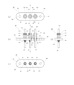
- 少なくとも1個の封着孔を有する金属外環と、
前記金属外環の前記封着孔に挿通したリードと、
前記金属外環と前記リードとを気密に封着する絶縁材と、
前記リードに挿着されて少なくとも端部を前記絶縁材ないし前記金属外環と接着層を介して気密に接着したプラスチック製の絶縁筒と
を備え、
前記絶縁筒は、外周壁に周回溝を1つ以上有し、前記周回溝内に弾性材からなるシール材を有した気密端子。 - 前記絶縁筒は、耐熱性かつ耐油/耐冷媒性を有するプラスチック材からなる請求項1に記載の気密端子。
- 前記シール材は、耐熱性かつ耐油/耐冷媒性を有するゴム材からなる請求項1または請求項2に記載の気密端子。
- 複数の封着孔を有する金属外環と、
前記金属外環の前記複数の封着孔の各々に挿通した複数のリードと、
前記金属外環と前記リードとをそれぞれ気密に封着する複数の絶縁材と、
前記複数のリードの各々に個別に挿着されて、少なくとも端部を前記複数の絶縁材の各々と接着層を介して気密に接着したプラスチック製またはゴム製の複数の絶縁筒と、
を備えた気密端子。 - 前記絶縁筒は、ゴム材からなり、同絶縁筒の外径を周回する突起を1つ以上有した、請求項4記載の気密端子。
- 前記絶縁筒は、耐熱性かつ耐油/耐冷媒性を有するゴム材からなる請求項4または5に記載の気密端子。
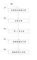
- 先ず封着部品仮組工程において、用意した封着治具の所定位置に封着孔を有した金属外環を配置し、前記封着孔内にリードを挿通するための挿着孔を設けた絶縁材のタブレットを載置し、さらに前記挿着孔にリードを貫通挿着させて置き、この状態を保ったまま前記封着治具上に気密端子の前記金属外環と前記絶縁材と前記リードとからなる封着部品を仮組し、
次に封着工程において、所定の封着条件に雰囲気および温度調整した封着炉中に前記封着部品を載せた前記封着治具を通炉させて、前記絶縁材で前記金属外環に前記リードを絶縁封着させた気密端子を得て、
封着後の気密端子は、必要に応じてめっき工程において、所望の金属表面にめっき層を施し、
封着後の前記気密端子は、さらに接着剤塗布工程において、前記絶縁材ないし前記金属外環の所定表面に接着剤を塗布し、
絶縁筒取付工程において、予め用意していたプラスチック製の絶縁筒を前記リードに挿着して、前記絶縁筒を前記接着剤の塗布面に合わさるように押し当て、同接着剤を硬化させて前記絶縁筒を前記気密端子に接着し、
前記絶縁筒取付工程の前又は後に、前記絶縁筒の外周壁に設けた周回溝にシール材を取り付ける、
ことを特徴とする気密端子の製造方法。 - 前記接着剤の塗布面をリードの一部に拡張した請求項7に記載の気密端子の製造方法。
- 前記絶縁筒は、耐熱性かつ耐油/耐冷媒性を有するプラスチック材からなる請求項7または請求項8に記載の気密端子の製造方法。
- 前記シール材は、耐熱性かつ耐油/耐冷媒性を有するゴム材からなる請求項7ないし請求項9の何れか1つに記載の気密端子の製造方法。
- 先ず封着部品仮組工程において、用意した封着治具の所定位置に複数の封着孔を有した金属外環を配置し、前記複数の封着孔の各々の中に、リードを挿通するための挿着孔を設けた絶縁材のタブレットをそれぞれ載置し、さらに前記挿着孔に複数のリードをそれぞれ貫通挿着させて置き、この状態を保ったまま前記封着治具上に気密端子の前記金属外環と前記絶縁材と前記リードとからなる封着部品を仮組し、
次に封着工程において、所定の封着条件に雰囲気および温度調整した封着炉中に前記封着部品を載せた前記封着治具を通炉させて、前記絶縁材で前記金属外環に前記リードを絶縁封着させた気密端子を得て、
封着後の気密端子は、必要に応じてめっき工程において、所望の金属表面にめっき層を施し、
封着後の前記気密端子は、さらに接着剤塗布工程において、前記絶縁材の所定表面に接着剤を塗布し、
絶縁筒取付工程において、予め用意していたプラスチック製またはゴム製の複数の絶縁筒を前記複数のリードの各々に個別に挿着して、前記絶縁筒を前記接着剤の塗布面に合わさるように押し当て、同接着剤を硬化させて前記複数の絶縁筒を少なくとも端部において前記絶縁材に接着する、
ことを特徴とする気密端子の製造方法。 - 前記絶縁筒は、ゴム材からなり、同絶縁筒の外径を周回する突起を1つ以上有した、請求項11記載の気密端子の製造方法。
- 前記絶縁筒は、耐熱性かつ耐油/耐冷媒性を有するゴム材からなる請求項11または12に記載の気密端子の製造方法。
- 電気装置を収めた容器体と、
前記容器体に設けられ前記容器体を貫通する挿着孔を閉塞して気密に固着された気密端子と、
容器体の内部に配置された気密端子に水密に電気接続した前記電気装置の配線ブロックと、を備え、
前記気密端子は、
封着孔を有する金属外環と、
前記金属外環の封着孔に挿通したリードと、
前記金属外環と前記リードとを気密に封着した絶縁材と、
前記リードに挿着されて少なくとも端部を前記絶縁材ないし前記金属外環と接着層を介して気密に接着したプラスチック製の絶縁筒と、
を有し、
前記絶縁筒は、外周壁に周回溝を1つ以上有し、前記周回溝内に弾性材からなるシール材を装着した気密容器。 - 前記絶縁筒は、耐熱性かつ耐油/耐冷媒性を有するプラスチック材からなる請求項14に記載の気密容器。
- 前記シール材は、耐熱性かつ耐油/耐冷媒性を有するゴム材からなる請求項14または請求項15に記載の気密容器。
- 電気装置を収めた容器体と、
前記容器体に設けられ前記容器体を貫通する挿着孔を閉塞して気密に固着された気密端子と、
容器体の内部に配置された気密端子に水密に電気接続した前記電気装置の配線ブロックと、
を備え、
前記気密端子は、
複数の封着孔を有する金属外環と、
前記金属外環の前記複数の封着孔の各々に挿通した複数のリードと、
前記金属外環と前記複数のリードとをそれぞれ気密に封着した複数の絶縁材と、
前記複数のリードの各々に個別に挿着されて、少なくとも端部を前記複数の絶縁材の各々と接着層を介して気密に接着したプラスチック製またはゴム製の複数の絶縁筒と、
を備えた、気密容器。 - 前記絶縁筒は、ゴム材からなり、同絶縁筒の外径を周回する突起を1つ以上有した、請求項17記載の気密容器。
- 前記絶縁筒は、耐熱性かつ耐油/耐冷媒性を有するゴム材からなる請求項17または18に記載の気密容器。
- 単一の封着孔を有する金属外環と、
前記金属外環の前記封着孔に挿通した単一のリードと、
前記金属外環と前記リードとをそれぞれ気密に封着する単一の絶縁材と、
前記リードに挿着されて、少なくとも端部を前記絶縁材と接着層を介して個別に気密に接着したプラスチック製またはゴム製の単一の絶縁筒と、
を備えた気密端子。 - 電気装置を収めた容器体と、
前記容器体に設けられ前記容器体を貫通する挿着孔を閉塞して気密に固着された気密端子と、
容器体の内部に配置された気密端子に水密に電気接続した前記電気装置の配線ブロックと、
を備え、
前記気密端子は、
単一の封着孔を有する金属外環と、
前記金属外環の前記封着孔に挿通した単一のリードと、
前記金属外環と前記リードとをそれぞれ気密に封着する単一の絶縁材と、
前記リードに挿着されて、少なくとも端部を前記絶縁材と接着層を介して個別に気密に接着したプラスチック製またはゴム製の単一の絶縁筒と、
を備えた気密容器。
Priority Applications (5)
| Application Number | Priority Date | Filing Date | Title |
|---|---|---|---|
| CN202280006040.XA CN116114126A (zh) | 2021-06-11 | 2022-01-19 | 气密端子及该气密端子的制造方法 |
| US18/041,268 US20230335941A1 (en) | 2021-06-11 | 2022-01-19 | Hermetic terminal and manufacturing method of same |
| KR1020237003951A KR102795694B1 (ko) | 2021-06-11 | 2022-01-19 | 기밀 단자 및 기밀 단자의 제조 방법 |
| PCT/JP2022/001681 WO2022259597A1 (ja) | 2021-06-11 | 2022-01-19 | 気密端子および同気密端子の製造方法 |
| DE112022000077.5T DE112022000077T5 (de) | 2021-06-11 | 2022-01-19 | Hermetischer anschluss und herstellungsverfahren dafür |
Applications Claiming Priority (2)
| Application Number | Priority Date | Filing Date | Title |
|---|---|---|---|
| JP2021097765 | 2021-06-11 | ||
| JP2021097765 | 2021-06-11 |
Publications (2)
| Publication Number | Publication Date |
|---|---|
| JP2022189682A JP2022189682A (ja) | 2022-12-22 |
| JP7577636B2 true JP7577636B2 (ja) | 2024-11-05 |
Family
ID=84532822
Family Applications (1)
| Application Number | Title | Priority Date | Filing Date |
|---|---|---|---|
| JP2021157319A Active JP7577636B2 (ja) | 2021-06-11 | 2021-09-28 | 気密端子および同気密端子の製造方法 |
Country Status (1)
| Country | Link |
|---|---|
| JP (1) | JP7577636B2 (ja) |
Citations (4)
| Publication number | Priority date | Publication date | Assignee | Title |
|---|---|---|---|---|
| WO2010117000A1 (ja) | 2009-04-08 | 2010-10-14 | エヌイーシー ショット コンポーネンツ株式会社 | 高耐圧気密端子およびその製造方法 |
| JP2013148037A (ja) | 2012-01-20 | 2013-08-01 | Sanden Corp | 電動圧縮機 |
| JP2015528631A (ja) | 2012-08-10 | 2015-09-28 | エマソン エレクトリック コー. | ピン分離用構造体を有するハーメチック端子 |
| WO2020171048A1 (ja) | 2019-02-19 | 2020-08-27 | ショット日本株式会社 | 気密端子および耐圧容器 |
Family Cites Families (3)
| Publication number | Priority date | Publication date | Assignee | Title |
|---|---|---|---|---|
| JPS5351490A (en) * | 1976-10-21 | 1978-05-10 | Nec Home Electronics Ltd | Sealing jig for air-proof terminal |
| JPS58155684A (ja) * | 1982-03-11 | 1983-09-16 | 日本電気ホームエレクトロニクス株式会社 | 気密端子の製造方法 |
| US4984973A (en) * | 1990-03-21 | 1991-01-15 | Tecumseh Products Company | Hermetic motor compressor unit having a hermetic terminal with electrically insulating anti-tracking cap |
-
2021
- 2021-09-28 JP JP2021157319A patent/JP7577636B2/ja active Active
Patent Citations (4)
| Publication number | Priority date | Publication date | Assignee | Title |
|---|---|---|---|---|
| WO2010117000A1 (ja) | 2009-04-08 | 2010-10-14 | エヌイーシー ショット コンポーネンツ株式会社 | 高耐圧気密端子およびその製造方法 |
| JP2013148037A (ja) | 2012-01-20 | 2013-08-01 | Sanden Corp | 電動圧縮機 |
| JP2015528631A (ja) | 2012-08-10 | 2015-09-28 | エマソン エレクトリック コー. | ピン分離用構造体を有するハーメチック端子 |
| WO2020171048A1 (ja) | 2019-02-19 | 2020-08-27 | ショット日本株式会社 | 気密端子および耐圧容器 |
Also Published As
| Publication number | Publication date |
|---|---|
| JP2022189682A (ja) | 2022-12-22 |
Similar Documents
| Publication | Publication Date | Title |
|---|---|---|
| KR102795694B1 (ko) | 기밀 단자 및 기밀 단자의 제조 방법 | |
| JP4983714B2 (ja) | 電動圧縮機 | |
| US6700253B1 (en) | Motor and production method of motor | |
| CN112204819B (zh) | 气密端子 | |
| KR20210046805A (ko) | 기밀 단자 및 내압 용기 | |
| US10170957B2 (en) | Controlling device integrated rotating electric machine | |
| JP7577636B2 (ja) | 気密端子および同気密端子の製造方法 | |
| US12035498B2 (en) | Airtight terminal | |
| CN107769477A (zh) | 一种汽车上使用的无刷电机 | |
| US20140332263A1 (en) | Waterproof main terminal | |
| JP4562699B2 (ja) | 電動圧縮機 | |
| JP7132195B2 (ja) | 気密端子 | |
| WO2018105603A1 (en) | Compressor for an air-conditioning installation of a motor vehicle equipped with a cover having improved sealing | |
| JP2003114080A (ja) | 熱電変換装置およびその製造方法 | |
| CN212563822U (zh) | 一种散热水泵 | |
| CN111835105B (zh) | 定子组件及电机 | |
| CN214412456U (zh) | 面密封结构及驱动电机 | |
| CN223348027U (zh) | 电气馈通组件及包括其的电动压缩机 | |
| CN218849850U (zh) | 接线端子、压缩机、空调设备和车辆 | |
| JP3280571B2 (ja) | 車輌用灯具の回路装置 | |
| CN223157101U (zh) | 网关装置及暖通设备、电梯 | |
| CN212839038U (zh) | 一种汽车空调压缩机线圈总成 | |
| KR101759337B1 (ko) | 밀폐형 압축기 단자의 제조방법 | |
| CN220085057U (zh) | 一种雷达、雷达安装结构以及一种车辆 | |
| CN212163004U (zh) | 电子水泵及其引线密封结构 |
Legal Events
| Date | Code | Title | Description |
|---|---|---|---|
| A521 | Request for written amendment filed |
Free format text: JAPANESE INTERMEDIATE CODE: A523 Effective date: 20220729 |
|
| A521 | Request for written amendment filed |
Free format text: JAPANESE INTERMEDIATE CODE: A821 Effective date: 20220802 |
|
| A621 | Written request for application examination |
Free format text: JAPANESE INTERMEDIATE CODE: A621 Effective date: 20230131 |
|
| A131 | Notification of reasons for refusal |
Free format text: JAPANESE INTERMEDIATE CODE: A131 Effective date: 20230927 |
|
| RD03 | Notification of appointment of power of attorney |
Free format text: JAPANESE INTERMEDIATE CODE: A7423 Effective date: 20231010 |
|
| A711 | Notification of change in applicant |
Free format text: JAPANESE INTERMEDIATE CODE: A711 Effective date: 20231106 |
|
| A601 | Written request for extension of time |
Free format text: JAPANESE INTERMEDIATE CODE: A601 Effective date: 20231108 |
|
| A601 | Written request for extension of time |
Free format text: JAPANESE INTERMEDIATE CODE: A601 Effective date: 20240126 |
|
| A521 | Request for written amendment filed |
Free format text: JAPANESE INTERMEDIATE CODE: A523 Effective date: 20240207 |
|
| A131 | Notification of reasons for refusal |
Free format text: JAPANESE INTERMEDIATE CODE: A131 Effective date: 20240319 |
|
| A521 | Request for written amendment filed |
Free format text: JAPANESE INTERMEDIATE CODE: A523 Effective date: 20240613 |
|
| TRDD | Decision of grant or rejection written | ||
| A01 | Written decision to grant a patent or to grant a registration (utility model) |
Free format text: JAPANESE INTERMEDIATE CODE: A01 Effective date: 20240924 |
|
| A61 | First payment of annual fees (during grant procedure) |
Free format text: JAPANESE INTERMEDIATE CODE: A61 Effective date: 20241023 |
|
| R150 | Certificate of patent or registration of utility model |
Ref document number: 7577636 Country of ref document: JP Free format text: JAPANESE INTERMEDIATE CODE: R150 |