JP7576331B2 - Gaming Machines - Google Patents
Gaming Machines Download PDFInfo
- Publication number
- JP7576331B2 JP7576331B2 JP2021187942A JP2021187942A JP7576331B2 JP 7576331 B2 JP7576331 B2 JP 7576331B2 JP 2021187942 A JP2021187942 A JP 2021187942A JP 2021187942 A JP2021187942 A JP 2021187942A JP 7576331 B2 JP7576331 B2 JP 7576331B2
- Authority
- JP
- Japan
- Prior art keywords
- state
- game
- gaming machine
- mode
- player
- Prior art date
- Legal status (The legal status is an assumption and is not a legal conclusion. Google has not performed a legal analysis and makes no representation as to the accuracy of the status listed.)
- Active
Links
- 230000004044 response Effects 0.000 claims description 41
- 238000000034 method Methods 0.000 description 833
- 230000008569 process Effects 0.000 description 740
- 239000000872 buffer Substances 0.000 description 667
- 230000005540 biological transmission Effects 0.000 description 497
- 238000004891 communication Methods 0.000 description 487
- 230000007704 transition Effects 0.000 description 413
- 238000012545 processing Methods 0.000 description 322
- 230000000694 effects Effects 0.000 description 308
- 238000003860 storage Methods 0.000 description 266
- 230000002349 favourable effect Effects 0.000 description 224
- 238000010586 diagram Methods 0.000 description 158
- 238000007726 management method Methods 0.000 description 152
- 238000001514 detection method Methods 0.000 description 106
- 230000006870 function Effects 0.000 description 96
- 230000003287 optical effect Effects 0.000 description 75
- 238000012360 testing method Methods 0.000 description 74
- 230000007246 mechanism Effects 0.000 description 72
- 230000008901 benefit Effects 0.000 description 70
- 230000008859 change Effects 0.000 description 70
- 241000167854 Bourreria succulenta Species 0.000 description 68
- 235000019693 cherries Nutrition 0.000 description 68
- 241000219109 Citrullus Species 0.000 description 65
- 235000012828 Citrullus lanatus var citroides Nutrition 0.000 description 65
- 230000001360 synchronised effect Effects 0.000 description 60
- 238000006243 chemical reaction Methods 0.000 description 55
- 230000005856 abnormality Effects 0.000 description 54
- 238000012544 monitoring process Methods 0.000 description 53
- 230000001276 controlling effect Effects 0.000 description 51
- 238000013500 data storage Methods 0.000 description 50
- 230000002093 peripheral effect Effects 0.000 description 50
- 238000003825 pressing Methods 0.000 description 48
- 238000003780 insertion Methods 0.000 description 45
- 230000037431 insertion Effects 0.000 description 45
- 238000004904 shortening Methods 0.000 description 44
- 230000005284 excitation Effects 0.000 description 38
- 239000013307 optical fiber Substances 0.000 description 37
- 238000012546 transfer Methods 0.000 description 36
- 238000001994 activation Methods 0.000 description 32
- 230000004913 activation Effects 0.000 description 31
- 230000002829 reductive effect Effects 0.000 description 31
- 238000004519 manufacturing process Methods 0.000 description 29
- 238000009987 spinning Methods 0.000 description 27
- 230000007423 decrease Effects 0.000 description 26
- 239000011159 matrix material Substances 0.000 description 26
- 230000001186 cumulative effect Effects 0.000 description 24
- 208000001613 Gambling Diseases 0.000 description 22
- 230000009977 dual effect Effects 0.000 description 19
- 101100495769 Caenorhabditis elegans che-1 gene Proteins 0.000 description 15
- 238000012790 confirmation Methods 0.000 description 15
- 238000013461 design Methods 0.000 description 14
- 238000010304 firing Methods 0.000 description 14
- 239000004973 liquid crystal related substance Substances 0.000 description 14
- 101001125858 Homo sapiens Peptidase inhibitor 15 Proteins 0.000 description 13
- 102100029323 Peptidase inhibitor 15 Human genes 0.000 description 13
- 238000004364 calculation method Methods 0.000 description 13
- 230000000737 periodic effect Effects 0.000 description 13
- 230000001174 ascending effect Effects 0.000 description 10
- 230000000717 retained effect Effects 0.000 description 10
- 238000012986 modification Methods 0.000 description 9
- 230000004048 modification Effects 0.000 description 9
- 239000011347 resin Substances 0.000 description 9
- 229920005989 resin Polymers 0.000 description 9
- 230000003068 static effect Effects 0.000 description 9
- 230000003247 decreasing effect Effects 0.000 description 8
- 230000009471 action Effects 0.000 description 7
- 230000004397 blinking Effects 0.000 description 7
- 238000002788 crimping Methods 0.000 description 6
- 238000010147 laser engraving Methods 0.000 description 6
- 238000002360 preparation method Methods 0.000 description 6
- 230000001737 promoting effect Effects 0.000 description 6
- 238000007789 sealing Methods 0.000 description 6
- 238000011161 development Methods 0.000 description 5
- 238000005286 illumination Methods 0.000 description 5
- 230000001795 light effect Effects 0.000 description 5
- 239000000463 material Substances 0.000 description 5
- 230000002265 prevention Effects 0.000 description 5
- 239000008186 active pharmaceutical agent Substances 0.000 description 4
- 230000033228 biological regulation Effects 0.000 description 4
- PZTQVMXMKVTIRC-UHFFFAOYSA-L chembl2028348 Chemical compound [Ca+2].[O-]S(=O)(=O)C1=CC(C)=CC=C1N=NC1=C(O)C(C([O-])=O)=CC2=CC=CC=C12 PZTQVMXMKVTIRC-UHFFFAOYSA-L 0.000 description 4
- 239000012141 concentrate Substances 0.000 description 4
- 230000001976 improved effect Effects 0.000 description 4
- 238000005259 measurement Methods 0.000 description 4
- 230000009467 reduction Effects 0.000 description 4
- 101000971351 Homo sapiens KRR1 small subunit processome component homolog Proteins 0.000 description 3
- 102100021559 KRR1 small subunit processome component homolog Human genes 0.000 description 3
- 230000002776 aggregation Effects 0.000 description 3
- 238000004220 aggregation Methods 0.000 description 3
- 238000005516 engineering process Methods 0.000 description 3
- 230000000670 limiting effect Effects 0.000 description 3
- 229910052751 metal Inorganic materials 0.000 description 3
- 239000002184 metal Substances 0.000 description 3
- 238000011017 operating method Methods 0.000 description 3
- 230000001151 other effect Effects 0.000 description 3
- 239000002243 precursor Substances 0.000 description 3
- 238000007639 printing Methods 0.000 description 3
- 238000011084 recovery Methods 0.000 description 3
- 230000002441 reversible effect Effects 0.000 description 3
- 238000005070 sampling Methods 0.000 description 3
- 239000000758 substrate Substances 0.000 description 3
- 230000000007 visual effect Effects 0.000 description 3
- 206010012335 Dependence Diseases 0.000 description 2
- 101000979629 Homo sapiens Nucleoside diphosphate kinase A Proteins 0.000 description 2
- 102100023252 Nucleoside diphosphate kinase A Human genes 0.000 description 2
- 238000009825 accumulation Methods 0.000 description 2
- 230000003213 activating effect Effects 0.000 description 2
- 230000004888 barrier function Effects 0.000 description 2
- 230000000052 comparative effect Effects 0.000 description 2
- 125000004122 cyclic group Chemical group 0.000 description 2
- 238000009795 derivation Methods 0.000 description 2
- 239000000284 extract Substances 0.000 description 2
- 238000009432 framing Methods 0.000 description 2
- 239000011521 glass Substances 0.000 description 2
- YAFQFNOUYXZVPZ-UHFFFAOYSA-N liproxstatin-1 Chemical compound ClC1=CC=CC(CNC=2C3(CCNCC3)NC3=CC=CC=C3N=2)=C1 YAFQFNOUYXZVPZ-UHFFFAOYSA-N 0.000 description 2
- 230000007257 malfunction Effects 0.000 description 2
- 230000000873 masking effect Effects 0.000 description 2
- 230000008450 motivation Effects 0.000 description 2
- 238000005192 partition Methods 0.000 description 2
- 230000000704 physical effect Effects 0.000 description 2
- 230000001105 regulatory effect Effects 0.000 description 2
- 238000009877 rendering Methods 0.000 description 2
- 239000004576 sand Substances 0.000 description 2
- 230000001960 triggered effect Effects 0.000 description 2
- 108010078791 Carrier Proteins Proteins 0.000 description 1
- 101000742310 Homo sapiens Rab15 effector protein Proteins 0.000 description 1
- 244000035744 Hura crepitans Species 0.000 description 1
- WHXSMMKQMYFTQS-UHFFFAOYSA-N Lithium Chemical compound [Li] WHXSMMKQMYFTQS-UHFFFAOYSA-N 0.000 description 1
- HBBGRARXTFLTSG-UHFFFAOYSA-N Lithium ion Chemical compound [Li+] HBBGRARXTFLTSG-UHFFFAOYSA-N 0.000 description 1
- 102100038203 Rab15 effector protein Human genes 0.000 description 1
- 230000001133 acceleration Effects 0.000 description 1
- NIXOWILDQLNWCW-UHFFFAOYSA-N acrylic acid group Chemical group C(C=C)(=O)O NIXOWILDQLNWCW-UHFFFAOYSA-N 0.000 description 1
- 238000013459 approach Methods 0.000 description 1
- 230000002844 continuous effect Effects 0.000 description 1
- 238000007796 conventional method Methods 0.000 description 1
- 238000005520 cutting process Methods 0.000 description 1
- 238000013523 data management Methods 0.000 description 1
- 238000000151 deposition Methods 0.000 description 1
- 238000007599 discharging Methods 0.000 description 1
- 238000011038 discontinuous diafiltration by volume reduction Methods 0.000 description 1
- 238000005401 electroluminescence Methods 0.000 description 1
- 230000008451 emotion Effects 0.000 description 1
- 238000009434 installation Methods 0.000 description 1
- 230000010354 integration Effects 0.000 description 1
- 230000001678 irradiating effect Effects 0.000 description 1
- 230000001788 irregular Effects 0.000 description 1
- 229910052744 lithium Inorganic materials 0.000 description 1
- 229910001416 lithium ion Inorganic materials 0.000 description 1
- 238000013507 mapping Methods 0.000 description 1
- 239000003550 marker Substances 0.000 description 1
- 230000001681 protective effect Effects 0.000 description 1
- 230000008707 rearrangement Effects 0.000 description 1
- 239000011435 rock Substances 0.000 description 1
- 230000011664 signaling Effects 0.000 description 1
- 230000000391 smoking effect Effects 0.000 description 1
- 239000007787 solid Substances 0.000 description 1
- 230000005236 sound signal Effects 0.000 description 1
- 238000003756 stirring Methods 0.000 description 1
- 239000012780 transparent material Substances 0.000 description 1
- 239000002699 waste material Substances 0.000 description 1
- 239000002023 wood Substances 0.000 description 1
Images


Classifications
-
- Y—GENERAL TAGGING OF NEW TECHNOLOGICAL DEVELOPMENTS; GENERAL TAGGING OF CROSS-SECTIONAL TECHNOLOGIES SPANNING OVER SEVERAL SECTIONS OF THE IPC; TECHNICAL SUBJECTS COVERED BY FORMER USPC CROSS-REFERENCE ART COLLECTIONS [XRACs] AND DIGESTS
- Y02—TECHNOLOGIES OR APPLICATIONS FOR MITIGATION OR ADAPTATION AGAINST CLIMATE CHANGE
- Y02B—CLIMATE CHANGE MITIGATION TECHNOLOGIES RELATED TO BUILDINGS, e.g. HOUSING, HOUSE APPLIANCES OR RELATED END-USER APPLICATIONS
- Y02B20/00—Energy efficient lighting technologies, e.g. halogen lamps or gas discharge lamps
- Y02B20/40—Control techniques providing energy savings, e.g. smart controller or presence detection
Landscapes
- Slot Machines And Peripheral Devices (AREA)
Description
本発明は、パチスロ機やパチンコ機等の遊技機に関する。 The present invention relates to gaming machines such as pachislot machines and pachinko machines.
従来からガイドメニュー画面を表示装置に表示させて、左右キーなどの入力部を操作することで音量や光量を所望の量に設定することが可能な遊技機が知られている(例えば、特許文献1参照)。特許文献1に記載されたような遊技機によれば、遊技者が好みの音量や光量などの演出環境を設定できるというメリットがある。
Conventionally, there has been known a gaming machine that allows a player to set the volume and light intensity to a desired level by displaying a guide menu screen on a display device and operating an input unit such as a left or right key (see, for example, Patent Document 1). The gaming machine described in
ところで、特許文献1に記載されているような演出環境を設定できる遊技機では、演出環境の設定に関して遊技者の利便性を高めることが望まれている。Incidentally, in a gaming machine capable of setting a presentation environment as described in
本発明は、このような点に鑑みてなされたものであり、演出環境の設定に関して遊技者の利便性を高めることを目的とする。 The present invention has been made in consideration of these points, and aims to increase convenience for players in setting the presentation environment .
上記目的を達成するために、本実施形態に係る遊技機によれば、以下のような構成の遊技機を提供することができる。 To achieve the above objective, the gaming machine according to this embodiment can provide a gaming machine having the following configuration:
出音可能な出音手段と、(例えば、スピーカ35a,35b)と、
前記出音手段を制御する演出制御手段(例えば、副制御回路200)と、
遊技者による操作に応じて前記出音手段における音量を設定可能な音量設定手段(例えば、音量を設定するサブCPU201)と、
所定のログイン操作(例えば、遊技者の端末を利用し、遊技者に演出表示部上に表示される二次元コードを読み取らせる)を行うことで、ログイン状態(例えば、ユニメモのログイン状態)を設定可能なログイン手段(例えば、「ユニメモ」のログインを行うサブCPU201)と、
所定のログアウト操作(例えば、遊技者の端末を利用し、遊技者に演出表示部上に表示される二次元コードを読み取らせる)を行うことで、前記ログイン状態を終了可能なログアウト手段(例えば、「ユニメモ」のログアウトを行うサブCPU201)と、
を備え、
すでに前記ログイン状態である状況においても新たなログイン操作を行うことで新たなログインが可能であり、
前記新たなログイン操作を行うと、これまでのデータが失われる旨を表示し、その後、新たなログインをするか否かの操作が可能となるものであり、
前記ログイン状態において遊技者が初期音量と異なる所定の音量を設定した状態で、前記所定のログアウト操作が行われた場合、前記ログイン状態の終了後においても前記所定の音量が維持される
ことを特徴とする遊技機。
A sound output means capable of outputting sound (e.g.,
A performance control means (e.g., a sub-control circuit 200) for controlling the sound output means;
A volume setting means (e.g., a
A login means (e.g., a
A logout means (e.g., a
Equipped with
Even if the user is already logged in, the user can log in again by performing a new login operation.
A message is displayed to inform the user that the new login operation will result in the loss of all data, and the user is then given the option to decide whether or not to log in again.
A gaming machine characterized in that, when a player sets a predetermined volume different from an initial volume in the logged-in state and performs the specified logout operation, the predetermined volume is maintained even after the logged-in state ends .
上記構成によれば、演出環境の設定に関して遊技者の利便性を高めることができる。 According to the above configuration, it is possible to increase the convenience for the player in setting the presentation environment.
以下、図面を参照して、本実施形態に係る遊技機について説明する。なお、本実施形態では、遊技機としてパチスロ機を例に挙げて説明する。 The gaming machine according to this embodiment will be described below with reference to the drawings. Note that in this embodiment, a pachislot machine will be used as an example of the gaming machine.
[1.パチスロ機の構造]
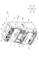
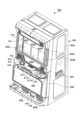
まず、図1及び図2を参照して、パチスロ機1の構造について説明する。なお、図1は、パチスロ機1の外部構造を示す図であり、図2は、パチスロ機1の内部構造を示す図である。また、説明の便宜上、以下の外部構造の説明において、内部構造の一部を説明する場合があり、内部構造の説明において、外部構造の一部を説明する場合がある。
[1. Structure of a Pachislot Machine]
First, the structure of the
[1-1.外部構造]
[1-1-1.筐体]
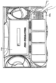
パチスロ機1は、矩形箱状の筐体2により構成されている。また、筐体2は、遊技機本体として前面側に矩形状の開口を有する金属製のキャビネットGと、キャビネットGの前面上部に配置された上ドア機構UDと、キャビネットGの前面下部に配置された下ドア機構DDとを有している。
[1-1. External structure]
[1-1-1. Housing]
The
キャビネットGは、中間支持板G1と、左右一対の側面壁G2と、背面壁G3と、上面壁G4と、底面壁G5とを有している。なお、図1及び図2においては、背面壁G3及び底面壁G5の図示を省略している。また、キャビネットGの上面壁G4には、左右方向に所定の間隔を空けて、上下方向に貫通する2つの開口G4aが形成されている。そして、この2つの開口G4aそれぞれを塞ぐように木製の板部材G4bが上面壁G4に取付けられている。 The cabinet G has an intermediate support plate G1, a pair of left and right side walls G2, a rear wall G3, a top wall G4, and a bottom wall G5. Note that the rear wall G3 and bottom wall G5 are not shown in Figures 1 and 2. The top wall G4 of the cabinet G has two openings G4a that penetrate in the vertical direction and are spaced a certain distance apart in the horizontal direction. Wooden plate members G4b are attached to the top wall G4 so as to close each of the two openings G4a.
なお、板部材G4bは、パチスロ機1を遊技店に設置する際に遊技島(不図示)に固定するために用いられるが、このような固定の方法が確保される限り、金属材や樹脂材で構成することもできるし、上面壁G4と一体に形成することもできる。また、キャビネットGについて一定の強度が確保される限り、各構成部材の一部又は全部を木材や樹脂材で構成することもできる。
The plate member G4b is used to secure the
また、キャビネットGは、その内部において、中間支持板G1を挟んで上側に、前方に開口する上側開口部G101が形成されており、中間支持板G1を挟んで下側に、前方に開口する下側開口部G102が形成されている。すなわち、キャビネットG内は、中間支持板G1を挟んで上部空間と下部空間とに仕切られており、中間支持板G1は、キャビネットG内を上部空間と下部空間とに仕切る仕切板として機能している。上部空間は、キャビネットG内の上ドア機構UDの後側となる空間であり、後述のメイン表示装置210等が収容される。また、下部空間は、キャビネットG内の下ドア機構DDの後側となる空間であり、後述のリールユニットRUや主制御基板71等が収容される。
Inside the cabinet G, an upper opening G101 that opens forward is formed on the upper side across the intermediate support plate G1, and a lower opening G102 that opens forward is formed on the lower side across the intermediate support plate G1. That is, the inside of the cabinet G is divided into an upper space and a lower space across the intermediate support plate G1, which functions as a partition plate that divides the inside of the cabinet G into the upper space and the lower space. The upper space is the space behind the upper door mechanism UD in the cabinet G, and contains the
なお、キャビネットGは、必ずしも中間支持板G1を含んで構成されていなくともよい。すなわち、キャビネットG内において各装置等が適切に収容される限り、上部空間と下部空間を仕切らない構成としてもよい。また、キャビネットGは、単に「箱体」や「本体」と称することもできるし、上ドア機構UD及び下ドア機構DDを支持、あるいは固定する枠体として機能するため、「本体枠」、「支持体」、「支持枠」、あるいは「固定枠」等と称することもできる。 The cabinet G does not necessarily have to include the intermediate support plate G1. In other words, as long as each device etc. can be appropriately accommodated within the cabinet G, the cabinet G may not have a partition between the upper and lower spaces. The cabinet G may simply be referred to as a "box" or "main body", or, since it functions as a frame that supports or fixes the upper door mechanism UD and the lower door mechanism DD, it may also be referred to as a "main body frame", "support body", "support frame", "fixing frame", etc.
[1-1-2.前面扉]
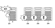
上ドア機構UD及び下ドア機構DDは、キャビネットGの開口の形状及び大きさに対応するように形成され、キャビネットGにおける開口の上部空間及び下部空間を閉塞可能に設けられている。すなわち、上ドア機構UD及び下ドア機構DDは、パチスロ機1の前面側に設けられた前面扉(フロントドア)として機能している。
[1-1-2. Front door]
The upper door mechanism UD and the lower door mechanism DD are formed to correspond to the shape and size of the opening of the cabinet G, and are provided so as to be able to close the upper and lower spaces of the opening in the cabinet G. In other words, the upper door mechanism UD and the lower door mechanism DD function as a front door provided on the front side of the
また、上ドア機構UD及び下ドア機構DDのそれぞれは、例えば、左側の側面壁G2に設けられたヒンジ等の開閉機構(不図示)によって、キャビネットGに対して開閉自在に取付けられている。なお、上ドア機構UD及び下ドア機構DDのいずれか一方については上述の開閉機構によって開閉自在とし、他方については一方のドア機構が開放状態となったときにのみ着脱可能となるように構成することもできる。 The upper door mechanism UD and the lower door mechanism DD are each attached to the cabinet G so as to be freely opened and closed, for example, by an opening and closing mechanism (not shown) such as a hinge provided on the left side wall G2. Note that it is also possible to configure either the upper door mechanism UD or the lower door mechanism DD to be openable and closable by the above-mentioned opening and closing mechanism, while the other can be attached and detached only when one of the door mechanisms is in the open state.
上ドア機構UDは、その中央部に設けられた演出表示窓UD1と、演出表示窓UD1の上部に設けられた上部ランプ23とを有している。演出表示窓UD1は、例えば、樹脂製の透明パネルとして構成され、その背面側に設けられた後述のメイン表示装置210を構成するスクリーン装置Cに表示された演出画像を視認可能としている。なお、本実施形態では、演出表示窓UD1を介して演出表示を行うメイン表示装置210を、メイン演出表示部21として説明する場合がある。
The upper door mechanism UD has a performance display window UD1 provided in the center, and an
下ドア機構DDは、その上部の略中央部に設けられたメイン表示窓4と、メイン表示窓4の背面側であって、キャビネットGの内部側に取付けられたリールユニットRUとを有している。
The lower door mechanism DD has a
リールユニットRUは、3個のリール3L(左リール),3C(中リール),3R(右リール)を主体に構成されている。各リール3L,3C,3Rは、例えば、円筒状に形成されたリール本体と、リール本体の周面に装着された透光性のリール帯から構成され、リール帯には、複数(例えば、20個)の図柄がリールの回転方向に沿って所定の間隔を空けて描かれている。また、各リール3L,3C,3Rは、それぞれが縦方向に一定の速度で回転できるように並列状態(横一列)に配設される。メイン表示窓4は、例えば、樹脂製の透明パネルとして構成され、各リール3L,3C,3Rの周面上の図柄について少なくとも一部(例えば、3個)を視認可能としている。また、各リール3L,3C,3Rの内部には、少なくともメイン表示窓4から図柄が視認される位置に光源(後述のランプ・LED類に含まれるリールランプ)が設けられ、少なくとも各リール3L,3C,3Rが回転中であるときにはこれらを内部から一定の輝度で照明することで、図柄の視認性を確保している。
The reel unit RU is mainly composed of three reels: 3L (left reel), 3C (middle reel), and 3R (right reel). Each
また、下ドア機構DDは、メイン表示窓4の左側に設けられたサブ演出表示部22と、メイン表示窓4の右側に設けられた演出用ボタン10bとを有している。サブ演出表示部22は、後述のサブ表示装置220に表示された演出画像を表示する。なお、サブ演出表示部22をタッチパネルとして構成し、演出表示を行う機能のみならず、演出用ボタンの1つとして機能させることもできる。演出用ボタン10bは、遊技者の演出用の操作(演出操作)を受付ける操作部である。
The lower door mechanism DD also has a
また、下ドア機構DDは、メイン表示窓4の下方に形成された略水平面の台座部において、左側に設けられたMAXベットボタン6a,1ベットボタン6b,精算ボタン9と、略中央部に設けられた演出用ボタン10aと、右側に設けられたメダル投入口5とを有している。
The lower door mechanism DD has a roughly horizontal base formed below the
MAXベットボタン6a及び1ベットボタン6bは、パチスロ機1の内部に預けられている(クレジットされている)メダルを使用するための遊技者の遊技操作(ベット操作。「投入操作」や「掛け操作」等と称することもできる)を受付ける操作部である。MAXベットボタン6aが操作された場合、現在のベット数が最大ベット数(例えば、3枚)未満であり、クレジットされているメダルがその差分以上ある場合には、最大ベット数のメダルがベットされる。一方、クレジットされているメダルがその差分以上ない場合には、メダルはベットされない。また、1ベットボタン6bが操作された場合、現在のベット数が最大ベット数未満であり、クレジットされているメダルが1枚以上ある場合には、1枚のメダルがベットされる。
The
精算ボタン9は、クレジットされているメダルを返却(精算)するための遊技者の遊技操作(精算操作)を受付ける操作部である。なお、クレジットされているメダルがない状態で精算ボタン9が操作された場合、投入され、あるいは払出されるメダルに関し、クレジット可能数(例えば、50枚)の範囲内において、当該メダルをクレジットするクレジットモード(Cモード)と、当該メダルをクレジットしないペイモード(Pモード)とのいずれかのモードを選択可能とするための遊技者の遊技操作(C/Pモード選択操作)を受付可能としてもよい。すなわち、精算ボタン9をいわゆるC/Pボタンとして機能させることもできる。演出用ボタン10aは、遊技者の演出用の操作(演出操作)を受付ける操作部である。
The
メダル投入口5は、遊技者によって外部からパチスロ機1に投入されるメダルを受入れる。受入れたメダルは、後述のセレクタ31によって検出されるとともに、適正なメダルであるか否かが判定される。受入れた1枚のメダルが適正なものでない場合、受入れたメダルが後述のメダル払出口11から返却される。また、受入れた1枚のメダルが適正なものである場合、現在のベット数が最大ベット数未満である場合には、1枚のメダルがベットされる。現在のベット数が最大ベット数であり、クレジットされているメダルがクレジット可能数に到達していない場合には、1枚のメダルがクレジットされる。一方、クレジットされているメダルがクレジット可能数に到達している場合には、受入れたメダルが後述のメダル払出口11から返却される。
The
また、下ドア機構DDは、メイン表示窓4と上述の台座部との間に設けられた情報表示装置14を有している。情報表示装置14は、複数のランプ(LED)や7セグメントLEDを含んで構成され、その点灯態様により遊技に関する情報を表示する。
The lower door mechanism DD also has an
また、下ドア機構DDは、上述の台座部の下方において、左側に設けられたスタートレバー7と、略中央部に設けられた3個のストップボタン8L,8C,8Rと、右側に設けられた施錠機構15とを有している。スタートレバー7は、所定の角度範囲で傾動自在に取付けられ、遊技を開始させるための遊技者の遊技操作(開始操作)を受付ける操作部である。各ストップボタン8L,8C,8Rは、各リール3L,3C,3Rに対応して設けられ、それぞれの回転を停止させるための遊技者の遊技操作(停止操作)を受付ける操作部である。
The lower door mechanism DD has a
施錠機構15は、例えば、キーシリンダー錠から構成され、下ドア機構DDが閉鎖状態であるとき、遊技店側の管理者(例えば、遊技店の店員等。以下同じ)が鍵穴にドアキー(不図示)を挿入した状態で右に回すと解錠し、下ドア機構DDが開放状態となる。なお、施錠機構15には、ドア機構の開閉を管理する機能のみならず、リセットスイッチとしての機能をもたせてもよい。例えば、遊技店側の管理者が鍵穴にドアキーを挿入した状態で左に回した場合には、後述のリセットスイッチ53と同様のリセット操作を検出可能としてもよい。また、本実施形態では、下ドア機構DDが開放状態となったとき、これに連動して上ドア機構UDも開放状態となるように構成することもできるし、上ドア機構UDに対応する施錠機構を別途設けるようにし、それぞれ独立して開閉を管理可能とすることもできる。
The
また、下ドア機構DDは、その下部の中央部に設けられた腰部パネル13と、腰部パネル13の下方に設けられたメダル受皿12と、メダル受皿12の上方に設けられたメダル払出口11と、メダル払出口11の左右に設けられた透音孔24a,24bとを有している。
The lower door mechanism DD also has a
腰部パネル13は、例えば、機種の名称を表すロゴやモチーフを表すキャラクタ等の機種情報が描かれた装飾パネルと、この装飾パネルを背面側から照明するための光源(後述のランプ・LED類に含まれる腰部ランプ)から構成される。メダル受皿12は、メダル払出口11から払出されたメダルを貯留する。メダル払出口11は、パチスロ機1の内部から払出される(あるいは返却される)メダルを外部に排出する。なお、メダル払出口11から排出されるメダルは、後述のホッパー装置32から払出されたものと、後述のセレクタ31からキャンセルシュート(不図示)を通って返却されたものとがある。透音孔24a,24bは、それぞれの背面側であって、キャビネットGの内部側に取付けられたスピーカ35a,35b(スピーカ35aは図2において符号省略)から出力される効果音やBGM等の音声をパチスロ機1の前面側に向かって透過する。
The
なお、本実施形態では、キャビネットG内が上部空間と下部空間とに仕切られていることに対応して上ドア機構UD及び下ドア機構DDを設けることとしているが、キャビネットGにおける開口を適切に開閉可能とする限り、単一のドア機構として構成することもできるし、3つ以上のドア機構として構成することもできる。また、前後方向に二重に構成されたドア機構(例えば、外扉と内扉等)として構成することもできる。また、上ドア機構UD及び下ドア機構DDは、単に「扉」や「ドア」と称することもできるし、キャビネットGにおける開口を開閉可能とする部材として機能するため、「開閉部材」、「扉部材」、あるいは「ドア部材」等と称することもできる。 In this embodiment, the upper door mechanism UD and the lower door mechanism DD are provided in response to the interior of the cabinet G being divided into an upper space and a lower space, but as long as the opening in the cabinet G can be opened and closed appropriately, they can be configured as a single door mechanism or as three or more door mechanisms. They can also be configured as a double door mechanism in the front-to-rear direction (for example, an outer door and an inner door). The upper door mechanism UD and the lower door mechanism DD can be simply referred to as "doors" or "doors," or can be referred to as "opening and closing members," "door members," or "door members" because they function as members that can open and close the opening in the cabinet G.
[1-1-3.変動表示部]
上述のとおり、パチスロ機1は、各リール3L,3C,3R及びメイン表示窓4を備える。各リール3L,3C,3Rは、スタートレバー7が操作されると(遊技者によって開始操作が行われると)、後述のステッピングモータ51L,51C,51Rが駆動制御されることにより回転を開始する。これにより、メイン表示窓4に表示される図柄が変動表示される。また、各リール3L,3C,3Rは、各ストップボタン8L,8C,8Rが操作されると(遊技者によって停止操作が行われると)、後述のステッピングモータ51L,51C,51Rが駆動制御されることによりそれぞれの回転を停止する。これにより、メイン表示窓4に表示される図柄が停止表示される。
[1-1-3. Variable display section]
As described above, the
すなわち、各リール3L,3C,3R及びメイン表示窓4は、複数の図柄を複数列に変動表示(及び停止表示)可能な変動表示部(手段)、あるいは複数の図柄を変動表示(及び停止表示)可能な複数の変動表示部(手段)を構成する。なお、変動表示部(手段)は、「図柄表示部(手段)」や「可変表示部(手段)」等と称することもできる。また、図柄は、「絵柄」や「柄」等と称することもできるし、遊技者が視認により識別可能な情報であればよいことから、その意味において「識別情報」等と称することもできる。
In other words, each of the
また、メイン表示窓4は、各リール3L,3C,3Rの回転が停止されたとき、それぞれについて連続して配置された3個の図柄がその枠内に表示されるように構成されている。すなわち、メイン表示窓4は、各列において上段、中段及び下段の各領域にそれぞれ1個の図柄(合計で3個)を表示する(メイン表示窓4の枠内には、3行×3列の態様で図柄が表示される)。なお、メイン表示窓4は、「図柄表示領域」や「窓部」等と称されることがある。
The
また、メイン表示窓4には、有効ラインが定義される。有効ラインは、遊技者の停止操作に応じて全ての列の図柄が停止表示されたときに、規定された図柄の組合せが表示されたか否かを判定するためのラインである。その意味において、有効ラインは、「入賞ライン」や「判定ライン」等と称することもできる。また、有効ラインは、各列の各領域のいずれかを結ぶラインとして構成される。すなわち、メイン表示窓4が3行×3列の態様で図柄を表示するように構成される場合、最大27通りの有効ラインを定義することが可能である。もっとも、実際には、そのうちの一又は複数通りのラインを有効ラインとして定義し、他のラインは有効ラインではない無効ラインとして定義することができる。
In addition, a winning line is defined in the
なお、例えば、リール3Lの中段領域、リール3Cの中段領域、及びリール3Rの中段領域を結ぶラインは「センターライン」、リール3Lの上段領域、リール3Cの上段領域、及びリール3Rの上段領域を結ぶラインは「トップライン」、リール3Lの下段領域、リール3Cの下段領域、及びリール3Rの下段領域を結ぶラインは「ボトムライン」、リール3Lの下段領域、リール3Cの中段領域、及びリール3Rの上段領域を結ぶラインは「クロスアップライン」、リール3Lの上段領域、リール3Cの中段領域、及びリール3Rの下段領域を結ぶラインは「クロスダウンライン」等と称され、これらは各列の各領域を一直線で結ぶラインであることから、これらのうちの一又は複数通りのラインが有効ラインとして定義されることが多い。もっとも、上述のとおり、各列の各領域を折れ線で結ぶ、いわゆる変則ラインを有効ラインとして定義することもできる。
For example, the line connecting the middle area of
また、有効ラインが有効化されるためには、遊技者の開始操作に先立って、今回の遊技に必要な分の(遊技開始可能枚数分の)メダルがベットされている必要があるが、有効化される有効ライン数は、ベット数にかかわらず同じであってもよいし、ベット数に応じて変動してもよい。例えば、上述の「センターライン」、「トップライン」、及び「ボトムライン」の3通りのラインが有効ラインとして定義されているとした場合、前者の場合には、ベット数が1~3のいずれであっても「センターライン」、「トップライン」、及び「ボトムライン」が有効化されるようにする。一方、後者の場合には、ベット数が1であれば「センターライン」のみが有効化され、ベット数が2であれば「センターライン」及び「トップライン」が有効化され、ベット数が3(最大ベット数)であれば「センターライン」、「トップライン」、及び「ボトムライン」が有効化されるようにする。 In order for the active lines to be activated, the player must bet the number of medals required for the current game (the number of medals that can be used to start the game) before starting the game. The number of active lines that are activated may be the same regardless of the number of bets, or may vary depending on the number of bets. For example, if the above-mentioned three lines, the "center line", "top line", and "bottom line", are defined as active lines, in the former case, the "center line", "top line", and "bottom line" are activated regardless of the number of bets, from 1 to 3. On the other hand, in the latter case, if the number of bets is 1, only the "center line" is activated, if the number of bets is 2, the "center line" and "top line" are activated, and if the number of bets is 3 (the maximum number of bets), the "center line", "top line", and "bottom line" are activated.
なお、本実施形態では、変動表示部が、3個のリール3L,3C,3Rと、各列において3個ずつの図柄を表示可能とするメイン表示窓4とを有することで、3行×3列の態様で図柄を表示するものとしていたが、変動表示部における図柄表示態様はこれに限られない。例えば、リール数を1個、2個、あるいは4個以上とし、また、例えば、各列における図柄の表示数を1個、2個、あるいは4個以上とすることで上述の態様とは異なる態様で図柄を表示することもできる。また、この場合、定義可能な有効ライン数も適宜増減する。
In this embodiment, the variable display unit has three
また、本実施形態では、変動表示部が、各リール3L,3C,3Rを回転させることによって図柄を変動表示するものとしていたが、変動表示部の構成はこれに限られない。例えば、後述のメイン表示装置210やサブ表示装置220と同様の画像表示装置を用いた構成としてもよいし、その他の表示装置(例えば、有機ELや7セグメントLED等)を用いた構成としてもよい。また、例えば、その他の物理的装置(例えば、ベルト等)を用いた構成としてもよい。また、変動表示部の配置や大きさ等は適宜変更可能である。
In addition, in this embodiment, the variable display unit displays the patterns by rotating each of the
また、本実施形態では、変動表示部が、後述の主制御回路100によって制御される、遊技に直接関連するメイン側表示部として機能とするものとしていたが、これとともに、後述の副制御回路200によって制御される、遊技に直接関連しない演出に関連するサブ側表示部としての変動表示部を設けるようにしてもよい。なお、サブ側表示部は、例えば、メイン表示装置210やサブ表示装置220を用いた構成とすることができる。すなわち、遊技者の開始操作(あるいは、その他開始条件の成立)に応じて図柄を変動表示させ、遊技者の停止操作(あるいは、その他停止条件の成立)に応じて図柄を停止表示させる変動表示部として、メイン側表示部のみならず、サブ側表示部を設けるようにしてもよい。なお、この場合、遊技者が変動表示部について遊技に直接関連するものであるか否かを識別可能とするため、メイン側表示部の近傍には、「回胴」ないし「メインリール」といった文字が表示された識別表示を付しておき、当該変動表示部がメイン側表示部であることを識別可能とすればよい。なお、このような識別表示は、メイン表示装置210やサブ表示装置220において表示されるようにしてもよい。
In addition, in this embodiment, the variable display unit functions as a main display unit directly related to the game, controlled by the
[1-1-4.メダル投入口]
上述のとおり、パチスロ機1は、遊技者によって外部からパチスロ機1に投入されるメダルを受け入れるメダル投入口5を備える。なお、メダル投入口5及び後述のセレクタ31は、MAXベットボタン6aや1ベットボタン6bと同様に、1回の遊技に必要なメダル数をベットする機能を有することから、このような投入動作は、例えば、ベット操作と換言することもできる。したがって、メダル投入口5は、遊技者のベット操作を検出可能なベット操作検出部(手段)であるともいえる。なお、メダル投入口の形状、配置及び大きさ等は適宜変更可能である。また、パチスロ機1が、後述のメダルレス遊技機として構成される場合には、必ずしも必須の構成とはならない。
[1-1-4. Medal slot]
As described above, the
なお、本実施形態では、遊技に使用し、あるいは遊技結果に応じて付与される遊技価値として、遊技媒体としてのメダルを用いることを一例として説明しているが、このように用いられる遊技価値はこれに限られない。例えば、コイン、遊技球、遊技用のポイントデータ又はトークン等を用いることもできる。また、遊技価値は、単に「価値」、あるいは「遊技用価値」等と称することもできる。 In this embodiment, the use of medals as gaming media is described as an example of gaming value that is used in games or awarded according to game results, but the gaming value used in this manner is not limited to this. For example, coins, gaming balls, gaming point data or tokens, etc. can also be used. Furthermore, gaming value can also be simply referred to as "value" or "game value", etc.
[1-1-5.操作部]
パチスロ機1は、遊技者が操作可能な操作部として、例えば、以下に示す各操作部を備える。なお、以下に示す各操作部はあくまで一例であって、これらとは異なる操作部を備える構成としてもよいし、これらのうち必ずしも必須のものでない操作部については、これを備えない構成としてもよい。
[1-1-5. Operation section]
The
[1-1-5-1.ベットボタン]
上述のとおり、パチスロ機1は、その内部に預けられている(クレジットされている)メダルを使用するための遊技者のベット操作を受付けるMAXベットボタン6a及び1ベットボタン6bを備える。また、このようなベット操作は、後述のベットスイッチ6Sによって検出される。したがって、MAXベットボタン6a及び1ベットボタン6b、並びにベットスイッチ6Sは、遊技者のベット操作を検出可能なベット操作検出部(手段)を構成する。なお、ベットボタンは、あくまで遊技者のベット操作を検出可能であればよく、その形状、配置及び大きさ等は適宜変更可能である。また、本実施形態では、MAXベットボタン6a及び1ベットボタン6bを設けているが、1ベットボタン6bを設けることなくMAXベットボタン6aのみを設けるようにしてもよい。また、2枚のメダルがベットされる2ベットボタンを別途設けるようにしてもよい。
[1-1-5-1. Bet button]
As described above, the
[1-1-5-2.スタートレバー]
上述のとおり、パチスロ機1は、遊技を開始させるための遊技者の開始操作を受付けるスタートレバー7を備える。また、このような開始操作は、後述のスタートスイッチ7Sによって検出される。したがって、スタートレバー7及びスタートスイッチ7Sは、遊技者の開始操作を検出可能な開始操作検出部(手段)を構成する。なお、スタートレバーは、あくまで遊技者の開始操作を検出可能であればよく、その形状、配置及び大きさ等は適宜変更可能である。
[1-1-5-2. Start lever]
As described above, the
[1-1-5-3.ストップボタン]
上述のとおり、パチスロ機1は、各リール3L,3C,3Rに対応して設けられ、それぞれの回転を停止させるための遊技者の停止操作を受付ける各ストップボタン8L,8C,8Rを備える。また、このような開始操作は、後述のストップスイッチ8Sによって検出される。したがって、各ストップボタン8L,8C,8R及びストップスイッチ8Sは、遊技者の停止操作を検出可能な停止操作検出部(手段)を構成する。なお、ストップボタンは、あくまで遊技者の停止操作を検出可能であればよく、その形状、配置及び大きさ等は適宜変更可能である。
[1-1-5-3. Stop button]
As described above, the
[1-1-5-4.精算ボタン]
上述のとおり、パチスロ機1は、クレジットされているメダルを返却(精算)するための遊技者の精算操作(返却操作)を受付ける精算ボタン9を備える。また、このような精算操作は、後述の精算スイッチ9Sによって検出される。したがって、精算ボタン9及び精算スイッチ9Sは、遊技者の精算操作を検出可能な精算操作検出部(手段)を構成する。なお、精算ボタンは、あくまで遊技者の精算操作を検出可能であればよく、その形状、配置及び大きさ等は適宜変更可能である。
[1-1-5-4. Settlement button]
As described above, the
[1-1-5-5.演出用ボタン]
上述のとおり、パチスロ機1は、遊技者の演出操作を受付ける演出用ボタン10a,10bを備える。なお、このような演出操作は、それぞれの演出用ボタンに対応して設けられた検出スイッチ(不図示)によって検出される。したがって、演出用ボタン10a,10b及び当該検出スイッチは、遊技者の演出操作を検出可能な演出操作検出部(手段)を構成する。なお、演出用ボタンは、あくまで遊技者の演出操作を検出可能であればよく、その形状、配置及び大きさ等は適宜変更可能である。また、本実施形態では、2個の演出用ボタン10a,10bを設けているが、これらのいずれも設けることなく構成することもできるし、これらのうちいずれかのみを設けるように構成することもできる。また、3個以上の演出用ボタンを設けるように構成することもできる。
[1-1-5-5. Performance buttons]
As described above, the
なお、演出用ボタンの主な用途としては、特定の演出(例えば、後述の操作連動演出)実行時に演出態様を変化させること、後述のユーザーメニューにおいて選択・決定操作を行うこと等である。したがって、用途に応じた演出用ボタンを設けるように構成することもできる。例えば、前者の用途では演出用ボタン10a,10bが使用されるものとし、後者の用途では上述のタッチパネルを使用するように構成することもできる。なお、後者の用途で用いるために、別の演出用ボタンとして、選択・決定操作を受付可能なジョグダイヤルや十字キー等を設けるように構成することもできる。
The main uses of the performance buttons are to change the performance mode when a specific performance (for example, an operation-linked performance described below) is executed, and to perform selection and confirmation operations in a user menu described below. Therefore, it is possible to configure the system so that performance buttons are provided according to the purpose. For example, the
[1-1-6.メダル払出口]
上述のとおり、パチスロ機1は、パチスロ機1の内部から払出される(あるいは返却される)メダルを外部に排出するメダル払出口11を備える。なお、入賞が発生してメダルを払出す場合、メダル払出口11は、後述のホッパー装置32から払出されたメダルを遊技者に付与するものであることから、遊技者に特典を付与する特典付与手段の一部であるともいえる。また、メダル払出口の形状、配置及び大きさ等は適宜変更可能である。また、パチスロ機1が、後述のメダルレス遊技機として構成される場合には、必ずしも必須の構成とはならない。
[1-1-6. Medal payout outlet]
As described above, the
[1-1-7.メダル受皿]
上述のとおり、パチスロ機1は、メダル払出口11から払出されたメダルを貯留するメダル受皿12を備える。すなわち、メダル受皿12は、付与された遊技価値を貯留可能な貯留部(手段)を構成する。なお、メダル受皿の形状、配置及び大きさ等は適宜変更可能である。また、パチスロ機1が、後述のメダルレス遊技機として構成される場合には、必ずしも必須の構成とはならない。
[1-1-7. Medal tray]
As described above, the
[1-1-8.腰部パネル]
上述のとおり、パチスロ機1は、例えば、機種情報が描かれた装飾パネルと、この装飾パネルを背面側から照明するための腰部ランプから構成される腰部パネル13を備える。なお、腰部パネル13は、基本的にはそのパチスロ機1がどういった機種であるかを遊技者にわかりやすく示すものであるが、例えば、腰部ランプの点灯態様により、あるいは、腰部パネル13そのものを画像表示装置等で構成することにより演出を実行可能な演出実行手段の1つとして構成することもできる。
[1-1-8. Waist panel]
As described above, the
[1-1-9.情報表示部]
上述のとおり、パチスロ機1は、その点灯態様により遊技に関する情報を表示する情報表示装置14を備える。すなわち、情報表示装置14は、遊技に関する情報を表示可能な情報表示部(手段)を構成する。
[1-1-9. Information display]
As described above, the
情報表示装置14は、例えば、インサートランプと、スタートランプと、リプレイランプと、ベット数ランプと、クレジットランプと、払出数ランプと、指示モニタと、リミットランプ等を含んで構成される。
The
インサートランプは、点灯することでメダルの投入が可能であることを表示する。スタートランプは、点灯することでスタートレバー7の操作にともなって遊技の開始が可能であることを表示する。リプレイランプは、点灯することで再遊技の作動によりメダルが自動投入されたことを表示する。ベット数ランプは、点灯することでベットされたメダル数を表示する。クレジットランプは、その点灯態様によりクレジットされているメダル数を表示する。払出数ランプは、その点灯態様により遊技結果に応じて払出されたメダル数(払出数)を表示する。
The insert lamp lights up to indicate that medals can be inserted. The start lamp lights up to indicate that play can be started by operating the
また、指示モニタは、報知ランプ(停止操作表示部)と、区間ランプ(状態表示部)と、を含んで構成される。報知ランプは、遊技者に対して停止操作の情報が報知される状況下(例えば、AT状態)において、報知する停止操作の情報と一義的に対応する態様で点灯することで、停止操作の情報を表示する。なお、「報知する停止操作の情報と一義的に対応する態様」とは、例えば、押し順(本実施形態では、これを「打順」として説明する場合がある)「1st(第1停止操作をリール3Lに対して行うこと)」を報知する場合には指示モニタに数値「1」を表示し、押し順「2nd(第1停止操作をリール3Cに対して行うこと)」を報知する場合には指示モニタに数値「2」を表示し、押し順「3rd(第1停止操作をリール3Rに対して行うこと)」を報知する場合には指示モニタに数値「3」を表示する等の態様のことである。なお、報知ランプは、クレジットランプや払出数ランプとは必ずしも別に設けられていなくともよい。例えば、クレジットランプ又は払出数ランプのいずれかを用いて、停止操作の情報を表示してもよい。
The instruction monitor is also configured to include a notification lamp (stop operation display section) and a section lamp (state display section). The notification lamp displays information on the stop operation by lighting in a manner that uniquely corresponds to the information on the stop operation to be notified in a situation where the information on the stop operation is notified to the player (for example, in an AT state). Note that the "manner that uniquely corresponds to the information on the stop operation to be notified" refers to, for example, a manner in which the number "1" is displayed on the instruction monitor when notifying the push order (which may be described as the "hitting order" in this embodiment) "1st (performing the first stop operation on
このように、本実施形態では、遊技者に対して停止操作の情報が報知される状況下においては、後述の副制御回路200によって制御されるサブ側報知手段(例えば、メイン演出表示部21)のみならず、後述の主制御回路100によって制御されるメイン側報知手段としての指示モニタにおいても停止操作の情報が報知される。なお、メイン側報知手段における報知の態様と、サブ側報知手段における報知の態様とは、互いに異なる態様であってもよい。すなわち、メイン側報知手段では、報知する停止操作の情報と一義的に対応する態様で報知すればよく、必ずしも、停止操作の情報を直接的に報知する必要はない。例えば、押し順「1st」を報知する場合、指示モニタにおいて数値「1」が表示されたとしても、遊技者によっては報知内容を特定できない可能性もある。一方、サブ側報知手段では、停止操作の情報を直接的に報知すればよい。例えば、押し順「1st」を報知する場合、メイン演出表示部21では、リール3Lに対して第1停止操作を行わせるための指示情報を直接的に報知すればよい。
In this way, in this embodiment, in a situation where information on a stop operation is notified to a player, not only the sub-side notification means (for example, the main performance display unit 21) controlled by the
また、区間ランプは、点灯することで現在の状態が後述の有利区間中であることを表示する。区間ランプは、例えば、後述の非有利区間から有利区間に移行するとき、当該有利区間の遊技が開始されるまでの任意のタイミングで点灯し、当該有利区間が終了して非有利区間に移行するとき、当該非有利区間の遊技が開始されるまでの任意のタイミングで消灯する。なお、区間ランプの点灯タイミングはこれに限られない。例えば、非有利区間又は有利区間における後述の演出区間(通常有利区間)から最初に有利区間における後述の増加区間(AT状態)に移行するとき、当該増加区間の遊技が開始されるまでの任意のタイミングで点灯するものとしてもよい。すなわち、区間ランプは、演出区間であるか増加区間であるかを問わず有利区間中であることを報せるものであってもよいし、少なくとも最初の増加区間の開始からこれを含めた有利区間が終了するまでの期間を報せるものであってもよい。 In addition, the section lamp, when lit, indicates that the current state is in the advantageous section, described below. For example, when transitioning from a non-advantageous section to an advantageous section, described below, the section lamp lights up at any timing before play in the advantageous section begins, and when the advantageous section ends and transitions to a non-advantageous section, it goes out at any timing before play in the non-advantageous section begins. Note that the timing of lighting the section lamp is not limited to this. For example, when transitioning from a performance section (normal advantageous section) described below in a non-advantageous section or advantageous section to an increase section (AT state) described below in an advantageous section for the first time, the section lamp may light up at any timing before play in the increase section begins. In other words, the section lamp may indicate that the section is in an advantageous section regardless of whether it is a performance section or an increase section, or may indicate at least the period from the start of the first increase section to the end of the advantageous section, including this.
また、リミットランプは、その点灯態様により後述のリミット処理が実行されたこと、あるいはその可能性を表示する。例えば、リミット処理が実行された場合に点灯することで遊技者に有利な状態(例えば、AT状態)がリミット処理の実行によって強制的に終了されたことを報せる。また、例えば、リミット処理の実行が近い場合に点滅することで当該有利な状態がリミット処理の実行によって強制的に終了される可能性が高いことを報せる。なお、これら以外にも点灯、点滅又は消灯の契機を設けることで、リミット処理に関するその他の情報を適宜報せることもできる。 The limit lamp also indicates, depending on the lighting state, whether or not a limit process described below has been executed. For example, by lighting up when a limit process has been executed, it notifies the player that a favorable state (e.g., AT state) has been forcibly ended by the execution of the limit process. Also, by flashing when the execution of the limit process is imminent, it notifies the player that there is a high possibility that the favorable state will be forcibly ended by the execution of the limit process. In addition to these, by providing triggers for lighting, flashing, or going off, it is also possible to appropriately notify other information regarding the limit process.
[1-1-10.演出表示部]
上述のとおり、パチスロ機1は、演出画像を表示するメイン演出表示部21及びサブ演出表示部22を備える。メイン演出表示部21及びサブ演出表示部22は、演出表示を行うことが可能な演出表示部(手段)を構成する。また、遊技者に対し視覚的な観点での演出を実行可能な演出実行手段の1つとして構成される。
[1-1-10. Performance display]
As described above, the
メイン演出表示部21は、演出表示窓UD1を介して演出表示を行うメイン表示装置210を含んで構成される。また、メイン表示装置210は、キャビネットG内の中間支持板G1上に交換可能に載置された表示ユニットAと、画像表示用の照射光を出射する照射ユニットBと、照射ユニットBからの照射光が照射されることにより画像を出現させるスクリーン装置Cとを有するいわゆるプロジェクションマッピング装置として構成される。なお、本実施形態では、メイン表示装置210をこのように構成することで、高度で、かつ迫力のある演出表示を可能としているが、メイン表示装置210の構成はこれに限られない。すなわち、遊技者に対し視覚的な観点での演出を実行可能であればよく、液晶表示装置や有機EL等の画像表示装置や7セグメントLED等の表示装置として構成することもできるし、サブリール等の変動表示装置やドット表示装置として構成することもできる。また、このような観点より、その形状、配置及び大きさ等も適宜変更可能である。また、パチスロ機1が、例えば、いわゆる出目によって楽しませることを主体とする遊技性である等の場合には、メイン演出表示部21を設けないように構成することもできる(サブ演出表示部22も同様)。
The
サブ演出表示部22は、サブ表示装置220を含んで構成される。また、サブ表示装置220は、液晶表示装置として構成される。なお、サブ表示装置220もメイン表示装置210と同様に、他の画像表示装置や表示装置として構成することができるし、変動表示装置やドット表示装置として構成することもできる。また、このような観点より、その形状、配置及び大きさ等も適宜変更可能である。また、メイン演出表示部21は、大画面で構成されていることから、押し順の報知や当り報知、あるいは連続演出等といった今回の遊技と密接に関連する演出を主として表示し、サブ演出表示部22は、小画面で構成されていることから、遊技履歴等といった今回の遊技とはそこまで密接に関連しない演出を主として表示するといったように、目的に応じて表示内容を分けて表示することが可能である。また、本実施形態では、メイン演出表示部21及びサブ演出表示部22の2個の演出表示部を設けるように構成しているが、これらのいずれも設けることなく構成することもできるし、これらのうちいずれかのみを設けるように構成することもできる。また、3個以上の演出表示部を設けるように構成することもできる。
The
[1-1-11.ランプ]
上述のとおり、パチスロ機1は、一例として挙げた上部ランプ23のように、その発光態様(点灯、点滅、あるいは消灯のみならず、フルカラーLEDとして構成される場合にはその輝度や発光色を含む)によって演出を行うことが可能な一又は複数のランプ(発光手段)を備える。また、このような発光手段は、遊技者に対し視覚的な観点での演出を実行可能な演出実行手段の1つとして構成される。なお、このような観点より、その数、形状、配置及び大きさ等も適宜変更可能である。
[1-1-11. Lamp]
As described above, the
なお、後述のランプ・LED類に含まれるその他のランプとしては、例えば、上ドア機構UDの両側端面や下ドア機構DDの両側端面に設けられたサイドランプや各操作部内に設けられた操作部ランプ等を挙げることができる。なお、後者は、それぞれの操作部が操作可能であるか否かを遊技者に報せる機能を含むことから、このような機能を発揮させる場合には演出内容に応じて発光態様を変動させず、一義的な発光態様によって発光するように制御することができる。 Other lamps included in the lamps and LEDs described below include, for example, side lamps provided on both end faces of the upper door mechanism UD and the lower door mechanism DD, and operation unit lamps provided within each operation unit. The latter include a function to inform the player whether or not each operation unit can be operated, so when this function is exercised, the light emission pattern does not change depending on the performance content, but can be controlled to emit light in a unique light emission pattern.
[1-1-12.スピーカ]
上述のとおり、パチスロ機1は、効果音やBGM等の音声を出力するスピーカ35a,35bを備える。スピーカ35a,35bは、音声の出力によって演出を行うことが可能な音声出力手段を構成する。また、遊技者に対し聴覚的な観点での演出を実行可能な演出実行手段の1つとして構成される。なお、このような観点より、その数、形状、配置及び大きさ等も適宜変更可能である。
[1-1-12. Speaker]
As described above, the
[1-1-13.その他演出装置]
なお、パチスロ機1では、上述の各種演出装置(演出実行手段)以外の演出装置を設けることもできる。例えば、いわゆる役物といった可動演出装置、振動により演出を行う振動演出装置、あるいは空気を噴射することで演出を行うエアー演出装置等の演出装置を設け、演出を実行することも可能である。すなわち、遊技者の五感(視覚、聴覚、触覚、味覚、嗅覚)のいずれかに訴えかけることができる(遊技者に演出が実行されていることを認識可能とさせる)演出を実行可能な演出装置であれば、それらのうちいずれを用いることもできる。したがって、本実施形態において「演出を実行する」とは、特段の説明がない限り、上述の各種演出装置(演出実行手段)のうち、一又は複数の演出装置のいずれの演出装置を用いて演出を実行してもよいこと示している。
[1-1-13. Other production devices]
In addition, in the
[1-2.内部構造]
[1-2-1.セレクタ]
セレクタ31(図2において符号省略)は、メダル投入口5から投入されたメダルの流下路であって、下ドア機構DDの背面側に設けられている。セレクタ31は、例えば、後述のメダルセンサ31Sと、振分装置とを有している。
[1-2. Internal structure]
[1-2-1. Selector]
The selector 31 (reference numeral omitted in FIG. 2) is a passage through which medals inserted through the
メダルセンサ31Sは、メダル投入口5から投入されたメダルを検出するとともに、検出されたメダルが適切なメダルであるか否かを判定する。振分装置は、メダルセンサ31Sにより、検出されたメダルが適切なメダルであると判定された場合であって、メダルの受入れが可能な状態である場合、当該メダルが後述のホッパー装置32側に案内されるように駆動制御される。なお、この場合、ベット数あるいはクレジット数が1加算される。一方、振分装置は、メダルセンサ31Sにより、検出されたメダルが適切なメダルでないと判定された場合、及びメダルの受入れが可能な状態でない場合、当該メダルがキャンセルシュートを通ってメダル払出口11から返却されるように駆動制御される。メダルセンサ31Sによるメダルの検出に異常が発生した場合にはセレクタエラーが発生する。なお、この場合、異常の発生要因(例えば、メダル詰まり)を解消した上で、リセット操作が行われると当該エラー状態が解除される。
The
すなわち、セレクタ31は、投入された遊技媒体を検出可能な遊技媒体検出部(手段)を構成する。また、セレクタ31は、投入された遊技媒体が適正であるか否かを判定可能な判定手段を構成する。また、セレクタ31は、投入された遊技媒体が適正である場合には内部に貯留する一方、投入された遊技媒体が適正でない場合には外部に排出する振分手段を構成する。また、セレクタ31の構成、配置及び大きさ等は適宜変更可能である。また、パチスロ機1が、後述のメダルレス遊技機として構成される場合には、必ずしも必須の構成とはならない。
In other words, the
[1-2-2.ホッパー装置]
ホッパー装置32は、キャビネットG内の下部空間に設けられている。ホッパー装置32は、例えば、メダル投入口5から投入され、セレクタ31によって案内されたメダルを貯留するバケット部と、バケット部の底部に設けられ、バケット部に貯留されたメダルを撹拌するとともに、1枚ずつ排出部に案内するディスク部と、ディスク部によって案内されたメダルを1枚ずつ排出する排出部と、排出部から排出されたメダルをカウントするカウントセンサとを有している。
[1-2-2. Hopper device]
The
バケット部は、一定数のメダルを貯留可能に構成される。一定数を超えたメダルは、上面側に設けられた案内通路を通って後述のメダル補助収納庫33に案内される。なお、バケット部に貯留されたメダルが空となった場合にはホッパーエンプティエラーが発生する。なお、この場合、メダルを補充した上で、リセット操作が行われると当該エラー状態が解除される。 The bucket is configured to be able to store a certain number of medals. Any medals exceeding this number are guided through a guide passage provided on the top side to the auxiliary medal storage 33 (described below). If the medals stored in the bucket become empty, a hopper empty error occurs. In this case, the error state will be cleared if medals are refilled and a reset operation is performed.
ディスク部は、中心から放射状にメダル形状のくり抜き部が複数形成され、駆動信号にしたがって中心軸が回転駆動されることで、くり抜き部に嵌ったメダルを1枚ずつ排出部に案内する。なお、ディスク部が回転することでバケット部に貯留されたメダルが撹拌される。また、ディスク部の回転に異常が発生した場合にはホッパージャムエラーが発生する。なお、この場合、異常の発生要因(例えば、メダル詰まり)を解消した上で、リセット操作が行われると当該エラー状態が解除される。 The disk unit has multiple medal-shaped cutouts formed radially from the center, and the central shaft is rotated in response to a drive signal to guide medals that fit into the cutouts one by one to the discharge unit. The medals stored in the bucket unit are stirred up as the disk unit rotates. If an abnormality occurs in the rotation of the disk unit, a hopper jam error occurs. In this case, the error state is cleared by performing a reset operation after eliminating the cause of the abnormality (for example, a medal jam).
カウントセンサは、排出部から排出されたメダルを検出するとともに、その枚数をカウントする。例えば、1枚のメダルを払出す場合、ディスク部が回転を開始し、続いてカウントセンサが1枚のメダルの払出をカウントしたことに応じてディスク部の回転が停止する。このようにして、適正枚数のメダルが払出されるようにしている。 The count sensor detects medals discharged from the discharge section and counts the number of medals. For example, when one medal is to be paid out, the disk section starts to rotate, and then the disk section stops rotating when the count sensor counts that one medal has been paid out. In this way, the correct number of medals is paid out.
すなわち、ホッパー装置32は、遊技媒体を払出可能な遊技媒体払出部(手段)を構成する。また、上述のとおり、遊技者に特典を付与する特典付与手段の一部であるともいえる。また、ホッパー装置32の構成、配置及び大きさ等は適宜変更可能である。また、パチスロ機1が、後述のメダルレス遊技機として構成される場合には、必ずしも必須の構成とはならない。
In other words, the
[1-2-3.メダル補助収納庫]
メダル補助収納庫33は、キャビネットG内の下部空間に設けられている。メダル補助収納庫33は、例えば、ホッパー装置32のバケット部から案内されたメダルを収納する収納部と、収納部の近傍に設けられ、収納部に収納されたメダルの容量を検出するメダル補助収納庫スイッチ33Sとを有している。
[1-2-3. Auxiliary Medal Storage]
The
収納部は、一定数のメダルを収納可能に構成される。メダル補助収納庫スイッチ33Sにより、当該一定数以上のメダルが収納されたと判定された場合にはメダル補助収納庫エラーが発生する。なお、この場合、収納部に収納されたメダルを少なくとも一定数未満に減らした上で、リセット操作が行われると当該エラー状態が解除される。
The storage section is configured to be able to store a certain number of medals. If the auxiliary
すなわち、メダル補助収納庫33は、余剰の遊技媒体を貯留可能な余剰遊技媒体貯留部(手段)を構成する。なお、メダル補助収納庫33の構成、配置及び大きさ等は適宜変更可能である。また、パチスロ機1が、後述のメダルレス遊技機として構成される場合には、必ずしも必須の構成とはならない。
In other words, the
[1-2-4.電源装置]
電源装置34は、キャビネットG内の下部空間に設けられている。電源装置34は、例えば、電源基板34aと、電源スイッチ34bとを有しており、電源スイッチ34bがオンされることに応じてパチスロ機1に電力を供給する。なお、電源装置34は、家庭用電気製品等と同じく電源ケーブル(不図示)から供給された交流電圧100Vの電力を各部で必要な直流電圧の電力に変換して、変換した電力を各部へ供給する。すなわち、電源装置34は、必要な電力を遊技機に供給可能な電源部(手段)を構成する。なお、電源装置34の構成、配置及び大きさ等は適宜変更可能である。
[1-2-4. Power supply]
The
なお、本実施形態では、後述の設定用鍵型スイッチ52やリセットスイッチ53が主制御基板71(より詳細には後述の主制御基板ケース上)に設けられるように構成しているが、これらのスイッチを電源装置34に設けるように構成することもできる。
In this embodiment, the setting
[1-2-5.基板]
パチスロ機1は、各種制御に必要な基板として、例えば、以下に示す各基板を備える。なお、以下に示す各基板はあくまで一例であって、これらとは異なる基板を備える構成としてもよいし、これらのうち必ずしも必須のものでない基板については、これを備えない構成としてもよい。
[1-2-5. Substrate]
The
[1-2-5-1.主制御基板]
主制御基板71は、キャビネットG内において、リールユニットRUの背面側に取付けられている。なお、主制御基板71は、遊技に関する制御を行う遊技制御基板であり、その状態が視認可能となるように透明(あるいは略透明)に構成された樹脂製の主制御基板ケース(不図示)内に収容されている。主制御基板71の電気的構成については後述する。
[1-2-5-1. Main control board]
The
なお、主制御基板71の仕様には種々の制約があり、基本的に各種電子部品がDIP実装されて構成されるものとなっているが、各種電子部品の一部又は全部についてSMT実装(表面実装)されて構成されるものとしてもよい。また、この場合、テスターやオシロスコープを用いて動作確認を行うためのテストポイントを設けるようにしてもよい。また、各種電子部品の一部又は全部について6平方mmを超えない小さい電子部品を使用してもよい。また、主制御基板71の基板面を多層化して構成してもよい。
The specifications of the
[1-2-5-2.副制御基板]
副制御基板72は、キャビネットG内において、中間支持板G1の裏面側に取付けられている。なお、副制御基板72は、演出に関する制御を行う演出制御基板であり、樹脂製の副制御基板ケース(不図示)内に収容されている。なお、副制御基板ケースは、主制御基板ケースと同様に透明(あるいは略透明)に構成された樹脂製のケースとして構成することもできるし、不透明(あるいは略不透明)に構成された他の材料を用いたケースとして構成することもできる。副制御基板72の電気的構成については後述する。
[1-2-5-2. Sub-control board]
The
[1-2-5-3.その他基板]
(主中継基板)
主中継基板73(図2において符号省略)は、キャビネットG内の特定位置(例えば、下ドア機構DDの背面側)に取付けられており、主中継基板73に接続された各種デバイス等と主制御基板71との間、及び主制御基板71と副制御基板72との間を中継するための中間制御基板である。なお、主中継基板73は、制御効率や配線効率の便宜から主制御基板71とは別の基板として構成されたものであるため、特段の支障がなければ主中継基板73の機能を全て主制御基板71にもたせ、主中継基板73を設けない構成とすることもできる。また、このような観点より、主中継基板73をさらに複数の中継基板に分割し、制御効率や配線効率の向上を図るようにしてもよい。すなわち、主中継基板として複数の基板を設けるようにしてもよい。
[1-2-5-3. Other substrates]
(Main relay board)
The main relay board 73 (reference numeral omitted in FIG. 2) is attached to a specific position (for example, the rear side of the lower door mechanism DD) in the cabinet G, and is an intermediate control board for relaying between the
(副中継基板)
副中継基板74は、キャビネットG内の特定位置(例えば、下ドア機構DDの背面側)に取付けられており、副中継基板74に接続された各種デバイス等と副制御基板72との間、及び主制御基板71と副制御基板72との間を中継するための中間制御基板である。なお、副中継基板74は、制御効率や配線効率の便宜から副制御基板72とは別の基板として構成されたものであるため、特段の支障がなければ副中継基板74の機能を全て副制御基板72にもたせ、副中継基板74を設けない構成とすることもできる。また、このような観点より、副中継基板74をさらに複数の中継基板に分割し、制御効率や配線効率の向上を図るようにしてもよい。すなわち、副中継基板として複数の基板を設けるようにしてもよい。
(Sub-relay board)
The
(外部集中端子板)
外部集中端子板55は、キャビネットG内の特定位置(例えば、下部空間の奥側)に取付けられており、例えば、メダル投入信号、メダル払出信号、外部信号1~4及びセキュリティ信号等の信号をパチスロ機1の外部へ出力する。なお、外部信号1~4は、その出力開始条件及び出力終了条件を適宜設定可能であり、その遊技性に応じてパチスロ機1の内部状態(例えば、ボーナス状態やAT状態)の遷移を外部に報せることを可能としている。そして、外部集中端子板55は、通常、外部のデータ表示機やホールコンピュータに接続されることから、これらの機器においても、パチスロ機1におけるメダルの投入・払出状況やエラーの発生状況のみならず、そのような内部状態の遷移状況が認識可能となっている。
(External common terminal board)
The external centralized
(試験機用インターフェースボード)
試験機用第1インターフェースボード301及び試験機用第2インターフェースボード302は、ともにパチスロ機1の検定試験(試射試験)において、遊技に関する各種信号を試験機に出力する際に用いられる中継基板である(なお、販売用のリリース製品としてのパチスロ機1にはこれらの中継基板は搭載されていないので、販売用の主制御基板71には、試験機用第1インターフェースボード301及び試験機用第2インターフェースボード302に接続するために必要な各種電子部品もまた実装されていない)。例えば、遊技に係る主要な動作(例えば、内部抽籤、リール停止制御等)を制御するための試験信号は、試験機用第1インターフェースボード301を介して出力され、また、主制御基板71で決定された押し順ナビに係る試験信号等は、試験機用第2インターフェースボード302を介して出力される。
(Test machine interface board)
The
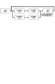
[2.パチスロ機の電気的構成]
続いて、図3を参照して、パチスロ機1の電気的構成について説明する。なお、図3は、パチスロ機1の電気的構成を示すブロック図である。
[2. Electrical configuration of the pachislot machine]
Next, the electrical configuration of the
上述のとおり、パチスロ機1は、主制御基板71と、副制御基板72と、主中継基板73と、副中継基板74とを有している。主制御基板71と主中継基板73、主中継基板73と副中継基板74、及び副中継基板74と副制御基板72は、それぞれ電気的に接続されている。また、主制御基板71と副制御基板72は、主中継基板73及び副中継基板74を介して、主制御基板71から副制御基板72に対して一方向のシリアル通信が可能となるように電気的に接続されている。
As described above, the
主制御基板71には、遊技に関する制御を行う遊技制御部としての主制御回路100が実装されている。主制御回路100は、例えば、メインCPU101、メインROM102、メインRAM103、クロックパルス発生回路(不図示)、乱数回路(不図示)等を含んで構成される。メインROM102には、メインCPU101により実行される各種制御プログラム、各種データテーブル、副制御回路200に対して各種制御指令(コマンド)を送信するためのデータ等が記憶される。メインRAM103には、制御プログラムの実行により決定された内部当籤役等の各種データを格納する格納領域が設けられる。クロックパルス発生回路は、メインCPU101作動用のクロックパルス信号を生成する。乱数回路は、予め定められた範囲の乱数(例えば、0~65535又は0~255等)を発生させる。メインCPU101は、生成されたクロックパルス信号に基づいて各種制御プログラムを実行する。また、発生された乱数の中から必要に応じて一又は複数の値を乱数値として抽出する。このようにして、遊技動作全般に係る制御を行う。
The
副制御基板72には、演出に関する制御を行う演出制御部としての副制御回路200が実装されている。副制御回路200は、例えば、サブCPU201、サブRAM203等を含んで構成される。また、副制御基板72には、ロムカートリッジ基板202が接続されている。ロムカートリッジ基板202には、サブCPU201により実行される各種制御プログラム、各種データテーブル、各種演出データ(例えば、メイン表示装置210に係る映像データや駆動データ、サブ表示装置220に係る映像データ、ランプ・LED群に係るランプデータ、スピーカ群に係るサウンドデータ等)等が記憶される。サブRAM203には、制御プログラムの実行により決定された演出内容や各種演出データを登録する格納領域や、主制御基板71から送信される各種制御指令(コマンド)に係るデータを格納する格納領域等が設けられる。なお、演出に係る演出用乱数値については、予め定められた範囲の乱数(例えば、0~32767等)の中から、サブCPU201内で発生及び抽出が行われるようにしてもよいし、主制御回路100と同様に乱数回路を設けることでその発生及び抽出が行われるようにしてもよい。また、ロムカートリッジ基板202ではなく、副制御回路200内にサブROMが含まれるようにし、各種制御プログラム等はサブROMに記憶されるように構成してもよい。また、ロムカートリッジ基板202に各種演出データを記憶させ、副制御回路200内のサブROMに各種制御プログラム及び各種データテーブルを記憶させるように構成してもよい。また、副制御回路200には、GPU等の画像専用のマイクロプロセッサ(例えば、「VDP」とも称される)が含まれるようにし、これによってメイン表示装置210やサブ表示装置220で表示される映像を生成(編集)するように構成してもよい。
The
主制御基板71には、ステッピングモータ51L,51C,51R、設定用鍵型スイッチ52、リセットスイッチ53、役比モニタ装置54、外部集中端子板55、ホッパー装置32、メダル補助収納庫スイッチ33S、電源装置34が電気的に接続されている。また、主制御基板71には、主中継基板73を介して、ドア開閉監視スイッチ56、メダルセンサ31S、ベットスイッチ6S、スタートスイッチ7S、ストップスイッチ8S、精算スイッチ9S、情報表示装置14が電気的に接続されている。なお、仮に試験機用第1インターフェースボード301及び試験機用第2インターフェースボード302が搭載される場合には、例えば、主中継基板73を介して主制御基板71に電気的に接続される。
The stepping
なお、外部集中端子板55、ホッパー装置32、メダル補助収納庫スイッチ33S、電源装置34、メダルセンサ31S、ベットスイッチ6S、スタートスイッチ7S、ストップスイッチ8S、精算スイッチ9S、情報表示装置14、試験機用第1インターフェースボード301及び試験機用第2インターフェースボード302についてはすでに説明したため、ここでの説明は省略する。
Note that the external centralized
各ステッピングモータ51L,51C,51Rは、それぞれ所定の減速比をもったギアを介して各リール3L,3C,3Rに接続され、その駆動により各リール3L,3C,3Rを回転及び停止させる。なお、各ステッピングモータ51L,51C,51Rに対して1回のパルスが出力されるごとに、各リール3L,3C,3Rが一定の角度で回転することから、メインCPU101は、各ステッピングモータ51L,51C,51Rに対してパルスを出力した回数をカウントし、このカウント結果に基づいて各リール3L,3C,3Rの図柄位置を管理する。また、各リール3L,3C,3Rには、このような管理を行うための初期位置を定めるリールインデックス(不図示)と、リールインデックスの位置を検出するためのインデックスセンサ(不図示)が設けられる。
Each stepping
設定用鍵型スイッチ52は、パチスロ機1の設定値(例えば、6段階の設定1~設定6)を変更するとき(設定変更)、もしくは、パチスロ機1の設定を確認するとき(設定確認)に使用される。ここで、設定値は、遊技に関する遊技者の有利さの度合いを示すものであり、通常は、設定値が低いほど(例えば、設定1に近いほど)遊技者の有利さの度合いが相対的に低くなり、設定値が高いほど(例えば、設定6に近いほど)遊技者の有利さの度合いが相対的に高くなる。設定用鍵型スイッチ52は、例えば、遊技店側の管理者が鍵穴に設定キー(不図示)を挿入して初期位置から左に回すとオン状態となり、左に回した状態から初期位置に戻すとオフ状態となる。なお、パチスロ機1の電源がオフ状態のとき、設定用鍵型スイッチ52をオン状態としてから電源をオン状態とすると設定変更が可能な状態となり、パチスロ機1の電源がオン状態のままで設定用鍵型スイッチ52をオン状態とすると設定確認が可能な状態となる。
The setting
リセットスイッチ53は、遊技店側の管理者によるリセット操作を検出可能としている。リセット操作は、各種のエラー状態を解除するための操作である。また、リセットスイッチ53は、設定変更が可能な状態において、遊技店側の管理者による設定値決定操作を検出可能としている。なお、設定変更が可能な状態においてリセットスイッチ53が操作されると、操作される度に設定値が順次1ずつ増加する(設定6まで到達すると次は設定1に戻る)。このようにして、設定値決定操作が行えるようになっている。また、このように決定された設定値は、その後スタートレバー7が1回操作されると確定する。すなわち、スタートスイッチ7Sは、遊技店側の管理者による設定値確定操作を検出可能としている。このように、設定変更を行う場合には、設定用鍵型スイッチ52をオン状態とし、リセットスイッチ53を操作して設定値を選択し、スタートレバー7を操作して選択した設定値を確定させた後、設定用鍵型スイッチ52をオフ状態とするといった設定変更操作が必要となっている。なお、これは、設定変更操作の一例であり、他の操作によって設定変更を行い得るように構成することもできる。また、設定変更や設定確認に際しては、例えば、上述のクレジットランプあるいは払出数ランプにおいて現在の設定値が表示されるものすればよい。
The
役比モニタ装置54は、例えば、4桁の7セグメントLEDにより構成され、主制御基板ケースの内部に設けられる。役比モニタ装置54は、メインCPU101によって集計・算出された遊技に関する各種割合情報を順次表示する。これらの割合情報は、遊技店の管理者がパチスロ機1に不正改造がないかを確認する際等に使用される。なお、役比モニタ装置54は、主制御基板71上に実装されるようにしてもよいし、主制御基板71に接続された他の基板(例えば、割合表示基板)上に実装されるようにしてもよい。また、キャビネットG内であれば、他の場所に設けられるようにしてもよい。例えば、主制御基板ケース上に設けられるようにしてもよい。また、役比モニタ装置54における表示を開始させ、あるいはその内容を切替えるための管理スイッチをキャビネットG内に設けるようにし、これが操作された場合に上述の各種割合情報が表示されるようにしてもよい。また、このような管理スイッチを使用することを前提として、例えば、情報表示装置14を役比モニタ装置54と兼用して用いる構成としてもよい。また、電源投入直後又は電源投入から所定時間(例えば、10秒程度。主制御回路100及び副制御回路200の立ち上げに要する時間を考慮したバッファとなる時間)の経過後に、役比モニタ装置54の4桁の7セグメントLEDが正常に機能していることを確認可能とするため、例えば、「8.8.」といったようなテストパターン(全てのセグ及びデシマルのLEDが点灯するパターン)で所定期間点灯(ないし点滅)させる構成とすることが望ましい。
The role
役比モニタ装置54では、例えば、上位2桁にはその割合情報の種類が表示され、下位2桁にはその割合情報を示す値(%)が表示される。ここで、役比モニタ装置54に表示される各種割合情報には、例えば、累計の特定区間割合情報、直近6000ゲーム間の連続役物割合情報及び役物割合情報、累計の連続役物割合情報及び役物割合情報等がある。
In the role
特定区間割合情報とは、対象の遊技数(例えば、「累計」であれば175000ゲーム。「直近6000ゲーム」であれば6000ゲーム。以下同じ)の遊技区間のうち、遊技者に有利な停止操作の情報の報知が行われていた遊技区間(例えば、AT状態)の遊技数(あるいは、単に有利区間中の遊技数であってもよい)の割合を示す情報である。また、連続役物割合情報とは、対象の遊技数の遊技区間において払出されたメダル数のうち、第一種特別役物(RB)の作動中(第一種特別役物に係る役物連続作動装置(BB)が作動している状態における第一種特別役物(RB)の作動中を含む)に払出されたメダル数の割合を示す情報である。また、役物割合情報は、対象の遊技数の遊技区間において払出されたメダル数のうち、第一種特別役物(RB)、第二種特別役物(CB)、及び普通役物(SB)の作動中に払出されたメダル数の割合を示す情報であり、ここでの第一種特別役物(RB)の作動中とは、第一種特別役物に係る役物連続作動装置(BB)が作動している状態における第一種特別役物(RB)の作動中を含む概念であり、また、第二種特別役物(CB)の作動中とは、第二種特別役物に係る役物連続作動装置(MB)が作動している状態における第二種特別役物(CB)の作動中を含む概念である。 The specific section ratio information is information that indicates the ratio of the number of plays in a play section (for example, AT state) in which information on a stop operation advantageous to the player was notified (or it may simply be the number of plays in an advantageous section) among the play sections of the target number of plays (for example, 175,000 games for "cumulative", 6,000 games for "last 6,000 games", the same below). In addition, the continuous feature ratio information is information that indicates the ratio of the number of medals paid out during the operation of the first type special feature (RB) (including the operation of the first type special feature (RB) when the feature continuous operation device (BB) related to the first type special feature is in operation) among the number of medals paid out in the play section of the target number of plays. In addition, the feature ratio information is information that indicates the ratio of the number of medals paid out during the operation of the first type special feature (RB), the second type special feature (CB), and the normal feature (SB) to the number of medals paid out in the play section of the target number of plays. Here, the operation of the first type special feature (RB) includes the operation of the first type special feature (RB) in a state in which the feature continuous operation device (BB) related to the first type special feature is in operation, and the operation of the second type special feature (CB) includes the operation of the second type special feature (CB) in a state in which the feature continuous operation device (MB) related to the second type special feature is in operation.
なお、遊技者に有利な停止操作の情報の報知が行われていた遊技区間(例えば、AT状態)を役物の作動中、あるいは役物連続作動装置の作動中としてとらえ、それぞれの割合情報において集計・算出の対象とすることもできる。すなわち、役比モニタ装置54は、必要な割合情報を適切に表示するものであればよく、表示可能な各種割合情報はこれらに限定されない。また、例えば、第一種特別役物(RB)が搭載されていない機種において連続役物割合情報を表示する場合、あるいは有利区間機能(AT機能)が搭載されていない機種において特定区間割合情報を表示する場合等、該当する数値情報(対応情報)が存在しない機種においては、当該項目の表示時に、4桁の7セグメントLEDのうちの数値情報(割合を示す%情報)を表示する下2桁の7セグメントLEDにおいて、例えば、「- -」といったように、中央の縦棒2本を点灯表示させる等の非対応情報用識別表示を行うことで、対応情報が存在しない機種である点を確認者が一目で認識可能とすることが望ましい。
In addition, the game section (for example, AT state) in which the information on the stop operation advantageous to the player was notified can be regarded as the operation of the role or the operation of the role continuous operation device, and can be the subject of aggregation and calculation in the respective ratio information. In other words, the role
ドア開閉監視スイッチ56は、例えば、下ドア機構DDの開閉側(右側)に設けられる。なお、下ドア機構DDの背面側に設けられるように構成してもよいし、キャビネットG側に設けられるように構成してもよい。また、上ドア機構UDにも同様のドア開閉監視スイッチが設けられるように構成してもよい。ドア開閉監視スイッチ56は、下ドア機構DDが開放状態となったときにオン状態となり、閉鎖状態となったときにオフ状態となることで、下ドア機構DDの開閉を監視する。なお、ドア開閉監視スイッチ56がオン状態となるとドア開放エラーが発生する。この場合、下ドア機構DDを閉鎖状態とすると当該エラー状態が解除される。
The door open/
副制御基板72には、ロムカートリッジ基板202、メイン表示装置210、サブ表示装置220が電気的に接続されている。また、副制御基板72には、副中継基板74を介して、24hドア監視ユニット61、演出用ボタン10a,10b等の演出用ボタン群、上部ランプ23等のランプ・LED類、スピーカ35a,35b等のスピーカ群が電気的に接続されている。
The
なお、ロムカートリッジ基板202、メイン表示装置210、サブ表示装置220、演出用ボタン群、ランプ・LED類及びスピーカ群についてはすでに説明したため、ここでの説明は省略する。
Note that the
24hドア監視ユニット61は、ドア開閉監視スイッチ56と同様に、例えば、下ドア機構DDの開閉側(右側)に設けられる。なお、下ドア機構DDの開閉を監視するという機能を有する点においてはドア開閉監視スイッチ56と同じであるが、このような監視を副制御回路200側でも行い得るようにすることで、さらに下ドア機構DDの開閉履歴を一定期間保存することができるようにしている。なお、この開閉履歴は、後述のホールメニューから確認することができる。したがって、例えば、営業時間外であって、遊技店の管理者が退出した後に開放履歴があった場合や、営業時間内において長時間にわたって開放された開閉履歴があった場合には、これにより不正行為が行われた可能性が高いことを認識できるようになっている。
The 24-hour
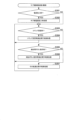
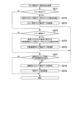
[3.パチスロ機の機能フロー]
続いて、図4を参照して、パチスロ機1の機能フローについて説明する。なお、図4は、パチスロ機1の機能フローを説明するための図である。
[3. Functional flow of the Pachislot machine]
Next, a functional flow of the
遊技者によりパチスロ機1にメダルが投入され(ベット操作が行われ)、スタートレバー7が操作される(開始操作が行われる)と、予め定められた範囲(例えば、0~65535)の乱数から1つの乱数値(本実施形態では、これを「内部抽籤用乱数値」として説明する場合がある)が抽出される。 When a player inserts a medal into the slot machine 1 (a bet operation is performed) and operates the start lever 7 (a start operation is performed), a random number (in this embodiment, this may be described as an "internal lottery random number") is extracted from a predetermined range of random numbers (for example, 0 to 65535).
内部抽籤手段(後述の内部抽籤処理を行うメインCPU101)は、抽出された乱数値に基づいて抽籤を行い、内部当籤役を決定する。内部当籤役の決定により、有効ライン上に表示されることが許可される図柄の組合せが事前に決定される。なお、図柄の組合せの種別としては、メダルの払い出し、再遊技(リプレイ)の作動、ボーナスの作動等といった特典が遊技者に与えられる「入賞」に係るものと、それ以外のいわゆる「はずれ」に係るものとが設けられる。なお、メダルの払い出しに係る役を「小役」と称し、再遊技(リプレイ)の作動に係る役を「リプレイ役」と称し、ボーナス(ボーナス状態)の作動に係る役を「ボーナス役」と称する。また、内部当籤し得る役(すなわち、成立が許可される図柄の組合せ)は、単に「役」と称されることがある。また、内部当籤役は、「当籤役」、「事前決定結果」、あるいは「導出許容条件」等と称されることがある。また、内部抽籤手段は、「役決定手段」、「当籤役決定手段」、「事前決定手段」、あるいは「導出許容条件決定手段」等と称されることがある。
The internal lottery means (
また、スタートレバー7が操作される(開始操作が行われる)と、複数のリールの回転が行われる。その後、遊技者によりリール(各リール3L,3C,3R)に対応するストップボタン(各ストップボタン8L,8C,8R)が操作される(停止操作が行われる)と、リール停止制御手段(後述のリール停止制御処理を行うメインCPU101)は、内部当籤役とストップボタンが押されたタイミング(あるいはその押し順を含む)とに基づいて、該当するリールの回転を停止する制御を行う。なお、開始操作を行うための操作手段は、スタートレバー7のようにレバー形状をしたものに限られず、遊技者が開始操作を行うことが可能であれば、どのような操作手段であってもよい。また、停止操作を行うための操作手段は、各ストップボタン8L,8C,8Rのようにボタン形状をしたものに限られず、遊技者が停止操作を行うことが可能であれば、どのような操作手段であってもよい。
When the
パチスロ機1では、基本的に、ストップボタンが押されたときから規定時間(190msec)内に、該当するリールの回転を停止する制御が行われる。本実施形態では、この規定時間内にリールの回転にともなって移動する図柄の数を「滑り駒数」という。そして、本実施形態では、規定期間が190msecである場合には、滑り駒数の最大数(最大滑り駒数)を図柄4個分に定める。
In the
リール停止制御手段は、入賞に係る図柄の組合せの表示を許可する内部当籤役が決定されているときは、通常、190msec(図柄4駒分)の規定時間内に、その図柄の組合せが有効ライン上に極力表示されるようにリールの回転を停止させる。また、リール停止制御手段は、規定時間を利用して、内部当籤役によってその表示が許可されていない図柄の組合せが有効ライン上に表示されないようにリールの回転を停止させる。なお、リールの回転が停止したときに表示された図柄は、「停止表示」、あるいは「表示結果」等と称されることがある。また、リールの回転が停止したときに図柄が表示されることは、「停止表示の導出」、あるいは「表示結果の導出」等と称されることがある。 When an internal winning combination that allows the display of a winning symbol combination has been determined, the reel stop control means stops the rotation of the reels within a specified time of usually 190 msec (four symbols) so that the symbol combination is displayed on the winning line as much as possible. The reel stop control means also uses the specified time to stop the rotation of the reels so that symbol combinations that are not permitted to be displayed by the internal winning combination are not displayed on the winning line. The symbols displayed when the reels stop spinning are sometimes referred to as "stop display" or "display result". The display of symbols when the reels stop spinning is sometimes referred to as "deriving the stop display" or "deriving the display result".
また、リール停止制御手段は、リールが回転してから、予め定められた自動停止時間が経過した場合には、遊技者が停止操作を行っていない場合でも、自動的に各リールを停止させる自動停止制御を行うようにしてもよい。この場合には、遊技者の停止操作を介さずにリールが停止することとなるため、いずれかの内部当籤役が決定されている場合であっても、いずれの入賞に係る図柄の組合せも有効ラインに沿って表示されていないようにリールの回転を停止させることが望ましい。 The reel stop control means may also be configured to perform automatic stop control to automatically stop each reel when a predetermined automatic stop time has elapsed since the reels started spinning, even if the player has not performed a stop operation. In this case, since the reels will stop without the player's stopping operation, it is desirable to stop the spinning of the reels so that no winning symbol combinations are displayed along the pay line, even if any internal winning combination has been determined.
このようにして、複数のリールの回転が全て停止されると、入賞判定手段(後述の入賞作動判定処理を行うメインCPU101)は、有効ライン上に表示された図柄の組合せが、入賞に係るもの(あるいは、その他予め定められたもの)であるか否かの判定を行う。
すなわち、入賞に係る図柄の組合せ(あるいは、その他予め定められた図柄の組合せ)が成立したか否かの判定を行う。そして、表示された図柄の組合せが、入賞判定手段により入賞に係るもの(あるいは、その他予め定められたもの)である(すなわち、入賞に係る図柄の組合せ(あるいは、その他予め定められた図柄の組合せ)が成立した)と判定されると、メダルの払い出し等の特典が遊技者に与えられ、あるいは、それを契機として各種の制御が行われる。パチスロ機1では、一例として、以上のような一連の流れで1回の遊技(単位遊技)として行われる。
In this way, when all of the rotations of the multiple reels are stopped, the winning determination means (
That is, a determination is made as to whether or not a winning symbol combination (or other predetermined symbol combination) has been achieved. Then, when the winning determination means determines that the displayed symbol combination is a winning symbol (or other predetermined one) (i.e., a winning symbol combination (or other predetermined symbol combination) has been achieved), a bonus such as a payout of medals is given to the player, or various controls are carried out in response to this. In the
なお、入賞判定手段は、有効ライン上に表示された図柄の組合せが、単に予め定められた複数の図柄の組合せのうちのいずれかの図柄の組合せに該当するか否かを判定するものであってもよいし、内部抽籤手段によって決定された内部当籤役に係る図柄の組合せに該当するか否かを判定するものであってもよい。すなわち、前者では、内部当籤役と切り離して、入賞に係る図柄の組合せであるか否かを判定するものであってもよい。この場合、リール停止制御手段によって適切に停止制御が行われる限り、誤入賞の発生の防止は十分に担保され得ることから、誤入賞検知に係る制御負担を低減させることが可能となる。一方、後者では、入賞に係る図柄の組合せが、入賞が許可されていた図柄の組合せであるか否かも判定可能とすることで、リールの不具合等により誤入賞が発生した場合に、その誤入賞を検知することができるため、セキュリティ性を向上させることが可能となる。 The winning determination means may determine whether the combination of symbols displayed on the pay line corresponds to any of a plurality of combinations of symbols that have been determined in advance, or may determine whether the combination corresponds to a combination of symbols related to an internal lottery role determined by the internal lottery means. In other words, in the former case, it may determine whether the combination of symbols related to a winning role is separate from the internal lottery role. In this case, as long as the reel stop control means appropriately controls the reels to stop, the prevention of erroneous winning can be sufficiently guaranteed, and the control burden related to erroneous winning detection can be reduced. On the other hand, in the latter case, by determining whether the combination of symbols related to a winning role is a combination of symbols that was permitted to win, if an erroneous winning occurs due to a reel malfunction, the erroneous winning can be detected, and security can be improved.
また、パチスロでは、前述した一連の遊技動作の流れの中で、表示装置(例えば、メイン表示装置210やサブ表示装置220等)による映像の表示、各種ランプ(例えば、上部ランプ23等)による光の出力、スピーカ(例えば、スピーカ35a,35b等)による音の出力、或いは、これらの組合せを利用して様々な演出が行われる。すなわち、これらは演出を実行する演出実行手段である。なお、演出実行手段により実行される演出の内容は、主制御回路100側(メイン側)で決定される場合もあれば、副制御回路200側(サブ側)で決定される場合もある。すなわち、これらはそのいずれもが演出内容決定手段となり得る。
In addition, in pachislots, during the sequence of game operations described above, various effects are produced using the display devices (e.g.,
例えば、スタートレバー7が操作される(開始操作が行われる)と、内部抽籤用乱数値とは別に、演出用乱数値が抽出される。演出用乱数値が抽出されると、演出内容決定手段は、内部当籤役に対応付けられた複数種類の演出内容の中から今回実行する演出を抽籤によって(あるいは予め定められた決定条件にしたがって)決定する。
For example, when the
次いで、演出内容決定手段により演出内容が決定されると、演出実行手段は、リールの回転開始時、各リールの回転停止時、入賞の有無の判定時等の各契機に連動させて対応する演出を実行する。このように、パチスロ機1では、例えば、内部当籤役に対応付けられた演出内容を実行することによって、決定された内部当籤役(狙うべき図柄の組合せや操作すべき押し順等と換言することもできる)を知る機会又は予想する機会が遊技者に提供され、遊技者の興味の向上を図ることができる。
Next, when the presentation content is determined by the presentation content determination means, the presentation execution means executes the corresponding presentation in conjunction with each trigger, such as when the reels start to spin, when each reel stops spinning, and when it is determined whether or not a prize has been won. In this way, in the
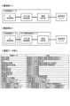
[4.パチスロ機の遊技性に関する基本仕様]
続いて、パチスロ機1の遊技性に関する基本仕様について説明する。
[4. Basic specifications regarding the playability of Pachislot machines]
Next, the basic specifications regarding the playability of the
[4-1.図柄配置]
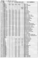
上述のとおり、パチスロ機1では、複数の図柄が変動表示及び停止表示されることで遊技が行われる仕様となっている。したがって、主制御回路100は、各リール3L,3C,3Rにおいて、どの図柄がどの位置に配置されているかを把握可能に構成されている必要がある。このため、メインROM102には、少なくとも各リール3L,3C,3Rそれぞれの各図柄位置にある図柄の種類を識別するためのデータが記憶されている。なお、このような目的が達成される限り、そのデータ構成は種々の構成を採用することができるが、本実施形態では、その一例として後述の図柄配置テーブル(図9参照)を用いている。
[4-1. Design arrangement]
As described above, the
図柄配置テーブルには、各リール3L,3C,3Rそれぞれの回転方向における各図柄位置を示す図柄位置データ(例えば、「0」~「19」)が規定されている。また、各図柄位置データに対して図柄の種類を特定するためのデータ(例えば、図柄コード)が対応付けられている。また、図柄配置テーブルでは、リールインデックスが検出されたときにメイン表示窓4の枠内における各リールの中段領域に位置する図柄の位置を「0」と規定している。なお、各列の図柄数、図柄の種類数、あるいは最大滑り駒数等は適宜変更して規定可能である。
The symbol arrangement table specifies symbol position data (e.g., "0" to "19") indicating the position of each symbol in the rotation direction of each of the
[4-2.図柄組合せ]
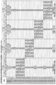
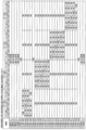
上述のとおり、パチスロ機1では、表示された図柄の組合せが遊技結果に影響を与える仕様となっている。すなわち、パチスロ機1は、表示された図柄の組合せに応じて、各種特典を付与したり、現在の状態から相対的に有利な状態に移行させたり、現在の状態から相対的に不利な状態に移行させたりすることを可能としている。したがって、主制御回路100は、このような図柄の組合せについて把握可能に構成されている必要がある。このため、メインROM102には、このような図柄の組合せを特定するためのデータが規定されている。なお、このような目的が達成される限り、そのデータ構成は種々の構成を採用することができるが、本実施形態では、その一例として後述の図柄組合せテーブル(図11~図14参照)を用いている。
[4-2. Design Combinations]
As described above, the
図柄組合せテーブルには、有効ライン上に表示され得る図柄の組合せのうちで予め定められた複数の図柄の組合せの種類を示すデータ(例えば、「表示役」あるいは「入賞作動フラグ」)が規定されている。なお、それぞれの図柄の組合せを構成する図柄は、例えば、上述の図柄コード等を用いて特定することができる。また、各図柄の組合せに対して特典等の種類を示すデータ(例えば、「払出等」)が対応付けられている。また、図柄組合せテーブルは、基本的に後述の当籤フラグ格納領域、入賞作動フラグ格納領域、及び図柄コード格納領域(図17参照)と対応するデータ構成となっている。なお、図柄の組合せの種類数、あるいは特典の付与内容等は適宜変更して規定可能である。 The symbol combination table specifies data (e.g., "display role" or "win activation flag") indicating the type of combination of multiple predefined symbols among the symbol combinations that can be displayed on the winning line. The symbols that make up each symbol combination can be specified, for example, using the symbol code described above. Each symbol combination is also associated with data indicating the type of bonus (e.g., "payout, etc."). The symbol combination table basically has a data structure that corresponds to the winning flag storage area, the winning activation flag storage area, and the symbol code storage area (see FIG. 17), which will be described later. The number of types of symbol combinations, the contents of the bonus, etc., can be changed and specified as appropriate.
[4-3.内部当籤役]
上述のとおり、パチスロ機1では、いずれの図柄の組合せが表示されることが許可されるか(事前に決定されるか)が遊技結果に影響を与える仕様となっている。すなわち、パチスロ機1は、遊技者の停止操作に先立って(事前に)、内部当籤役(すなわち、表示され得る図柄の組合せの種類(あるいは、付与され得る特典の種類))を決定することを可能としている。したがって、主制御回路100は、このような内部当籤役について把握可能に構成されている必要がある。このため、メインROM102には、このような内部当籤役を特定するためのデータが規定されている。なお、このような目的が達成される限り、そのデータ構成は種々の構成を採用することができるが、本実施形態では、その一例として後述の内部抽籤テーブル(図10参照)を用いている。
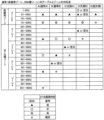
[4-3. Internal lottery]
As described above, the
内部抽籤テーブルには、予め定められた複数の内部当籤役の種類を示すデータ(例えば、「No.」あるいは「当籤番号」)と、各遊技状態において各内部当籤役が決定される抽籤値とが規定される。なお、抽籤値は、設定された設定値によっても変動する場合がある。また、各内部当籤役に対して表示が許可される(対応する)図柄の組合せの種類が対応付けられている。なお、パチスロ機1では、1つの内部当籤役に対して複数の図柄の組合せを対応付けることを可能としており、このような内部当籤役が決定された場合、いずれの図柄の組合せが表示されるかは停止制御によって決定されるものとなっている。
The internal lottery table specifies data indicating the types of multiple predefined internal winning roles (for example, "No." or "winning number") and lottery values that determine each internal winning role in each game state. The lottery values may vary depending on the set value that is set. Each internal winning role is also associated with a type of (corresponding) pattern combination that is permitted to be displayed. Note that in the
ここで、例えば、本実施形態の後述の内部抽籤処理(図26参照。より詳細には、S64の内部当籤役決定処理)では、まず、乱数回路によって予め定められた数値の範囲(例えば、0~65535)から抽出された乱数値を、各内部当籤役に対応して規定された抽籤値で順次加算更新する。次いで、抽籤結果(抽籤値+乱数値)が65535を超えたか否か(抽籤結果がオーバーフローしたか否か)の判定を行う。そして、所定の内部当籤役において、当該判定の結果が65535を超えた場合、当該内部当籤役に当籤させる(当該内部当籤役を決定する)。もっとも、全ての内部当籤役について当該判定を行っても65535を超えるものがなかった場合、今回の遊技における内部当籤役は「はずれ」となる。なお、これはあくまで内部抽籤処理の一例であり、抽籤値(当籤確率)に応じて適切な抽籤が行われる限り、その抽籤処理の手法は種々の手法を採用することができる。例えば、抽出された乱数値を、各内部当籤役に対応して規定された抽籤値で順次減算更新し、次いで、減算結果(抽籤結果)が0を下回ったか否か(抽籤結果がアンダーフローしたか否か)を判定して、内部当籤役を決定してもよい。 Here, for example, in the internal lottery process of this embodiment described later (see FIG. 26; more specifically, the internal winning combination determination process of S64), first, a random number value extracted from a predetermined numerical range (e.g., 0 to 65535) by a random number circuit is sequentially added and updated with a lottery value specified corresponding to each internal winning combination. Next, a determination is made as to whether or not the lottery result (lottery value + random number value) exceeds 65535 (whether or not the lottery result has overflowed). Then, for a given internal winning combination, if the result of this determination exceeds 65535, the internal winning combination is made to win (the internal winning combination is determined). However, if none of the internal winning combinations exceeds 65535 even after this determination has been made for all internal winning combinations, the internal winning combination for this game will be a "lose". Note that this is merely one example of the internal lottery process, and various methods can be used for the lottery process as long as an appropriate lottery is performed according to the lottery value (winning probability). For example, the extracted random number value may be sequentially subtracted and updated by the lottery value specified for each internal winning combination, and then the internal winning combination may be determined by determining whether the subtraction result (lottery result) is below 0 (whether the lottery result has underflowed).
このように、内部抽籤テーブルにおいては、規定されている抽籤値の数値が大きい内部当籤役ほど決定される確率(当籤確率)が高くなる。なお、各内部当籤役の当籤確率は、「各当籤番号に規定された抽籤値/抽出される可能性のある全ての乱数値の個数(乱数分母:65536)」によって表すことができる。 In this way, in the internal lottery table, the larger the lottery value specified for an internal winning role, the higher the probability of it being determined (winning probability). The winning probability of each internal winning role can be expressed as "lottery value specified for each winning number / number of all random number values that can be drawn (random number denominator: 65536)".
[4-4.停止制御]
上述のとおり、パチスロ機1では、内部当籤役の決定によって表示されることが許可された図柄の組合せのうち、遊技者の停止操作によって最終的にいずれの図柄の組合せを表示させるかが遊技結果に影響を与える仕様となっている。すなわち、パチスロ機1は、決定された内部当籤役の種類のみならず、遊技者の停止操作タイミングや押し順(「停止操作態様」や「停止操作手順」とも称される)によって最終的に表示される図柄の組合せの種類を変動させる(決定する)制御(停止制御)を行うことを可能としている。したがって、主制御回路100は、各内部当籤役に対して、遊技者の停止操作態様に応じてどのような態様で停止制御を行うかを把握可能に構成されている必要がある。このため、メインROM102には、このような停止制御の態様を特定するためのデータが規定されている。なお、このような目的が達成される限り、そのデータ構成は種々の構成を採用することができるが、本実施形態では、その一例として停止テーブルや引込優先順位テーブル(不図示)等を用いている。
[4-4. Stop control]
As described above, the
停止テーブルには、各リール3L,3C,3Rの各図柄位置データに対して、図柄の移動量を示すデータ(例えば、「滑り駒数」)が規定されている。例えば、所定の内部当籤役が決定された遊技において所定の停止テーブルが選択されたとする。次いで、回転中のリール3Lに対して停止操作が行われたとする。このとき、停止開始位置(停止操作が行われたときのリール3Lの中段領域の図柄位置データ)が「0」であったとする。そして、所定の停止テーブルにおいて、図柄位置データ「0」に規定された滑り駒数が「4」であったとする。そうすると、主制御回路100は、4図柄分移動した図柄位置(図柄位置データ「4」の位置)でリール3Lを停止させる(停止予定位置が「4」となる)ように制御を行う。このように、停止テーブルには、停止させる位置を直接的に決定することを可能とするデータ(滑り駒数)が規定されている。なお、このようなデータ構成もあくまで一例である。また、このような停止テーブルを用いて停止制御を行うことは、一般的に「テーブル制御」と称される。
In the stop table, data indicating the movement amount of the pattern (for example, "number of sliding pieces") is specified for each pattern position data of each
引込優先順位テーブルには、表示されることが許可された図柄の組合せが複数ある場合に、いずれの図柄の組合せを優先的に表示させるか(引込むか)を示すデータ(例えば、「引込優先順位」)が規定されている。例えば、所定の内部当籤役が決定された遊技において所定の引込優先順位テーブルが選択されたとする。ここで、所定の内部当籤役は、図柄組合せAと図柄組合せBの表示を許可するものとし、所定の引込優先順位テーブルは、図柄組合せAよりも図柄組合せBを優先的に表示させるように引込優先順位が規定されているものとする。次いで、回転中のリール3Lに対して停止操作が行われたとする。このとき、停止開始位置が「0」であったとする。
The attraction priority table specifies data (e.g., "attraction priority order") indicating which symbol combination is to be preferentially displayed (attracted) when there are multiple symbol combinations permitted to be displayed. For example, assume that a specified attraction priority order table is selected in a game in which a specified internal winning combination is determined. Here, the specified internal winning combination permits the display of symbol combination A and symbol combination B, and the specified attraction priority order table specifies attraction priorities such that symbol combination B is preferentially displayed over symbol combination A. Next, assume that a stop operation is performed on
そうすると、主制御回路100は、停止開始位置を含めた最大滑り駒数(例えば、「4」)の範囲内の各図柄位置について、図柄組合せAを構成する図柄と図柄組合せBを構成する図柄があるかどうかを検索する。双方の図柄がなければ、予め定められたルール(例えば、より近い位置で停止させる、より遠い位置で停止させる等)にしたがって停止させる位置を決定する。図柄組合せAを構成する図柄のみがあれば、当該図柄に対応する位置で停止させることを決定する。図柄組合せBを構成する図柄のみがあれば、当該図柄に対応する位置で停止させることを決定する。双方の図柄があれば、図柄組合せAよりも図柄組合せBを優先的に表示させるのであるから、図柄組合せBを構成する図柄に対応する位置で停止させることを決定する。なお、引込優先順位は、選択された引込優先順位テーブルにしたがって、対象となるリールの回転中に全図柄位置について格納されるようにしてもよいし、対象となるリールに対して停止操作が行われたときに、停止開始位置を含めた最大滑り駒数の範囲内の各図柄位置について格納されるようにしてもよい。また、このようなデータ構成もあくまで一例である。また、このような引込優先順位テーブルを用いて停止制御を行うことは、一般的に「コントロール制御」と称される。
Then, the
なお、本実施形態では、「テーブル制御」のみを行うことによって停止制御を実行する構成とすることもできるし、「コントロール制御」のみを行うことによって停止制御を実行する構成とすることもできる。あるいは、まず「テーブル制御」を行うことによって停止させる位置を仮決定し、次に「コントロール制御」を行うことによってより適切な停止位置があるかを検索し、検索結果によっては停止させる位置を変更することを可能とする停止制御を実行する構成とすることもできる。 In this embodiment, the stop control can be configured to be executed by performing only "table control" or by performing only "control control". Alternatively, the stop control can be configured to first tentatively determine the stopping position by performing "table control", then search for a more appropriate stopping position by performing "control control", and then change the stopping position depending on the search results.
このように、パチスロ機1では、最終的に有効ライン上に表示される図柄の組合せがどの図柄の組合せとなるかは、例えば、以下の3つの要素に基づいて決定される。
In this way, in the
第1の要素は、決定された内部当籤役(内部抽籤処理の抽籤結果)である。例えば、内部抽籤処理の結果が「はずれ」であった場合、いずれかのリプレイ役に係る図柄の組合せ、小役に係る図柄の組合せ又はボーナス役に係る図柄の組合せが最終的に有効ライン上に表示されることはない。なお、「はずれ」は、内部当籤役の1つであると捉えることもできるし、内部当籤役が決定されなかった抽籤結果であると捉えることもできる。 The first element is the determined internal winning role (lottery result of the internal lottery process). For example, if the result of the internal lottery process is a "miss," then none of the combinations of symbols related to any replay role, combinations of symbols related to minor roles, or combinations of symbols related to bonus roles will ultimately be displayed on the pay line. Note that a "miss" can be considered to be one of the internal winning roles, or it can be considered to be a lottery result in which no internal winning role has been determined.
第2の要素は、遊技者の停止操作タイミング(遊技者がいずれかのストップボタンを操作したときの図柄の位置(押下位置))である。例えば、本実施形態においては、最大滑り駒数として図柄4個分が定められているため、内部抽籤処理の結果、いずれかの内部当籤役に当籤していたとしても、表示が許可されている図柄の組合せを構成する図柄が有効ライン(複数ある場合には各有効ライン)に対して図柄4個分を超えて配置されていた場合には、遊技者の停止操作タイミングによっては当該図柄の組合せが表示されない場合がある。これをいわゆる「取りこぼし」という。 The second element is the timing of the player's stop operation (the position of the symbols (pressed position) when the player operates one of the stop buttons). For example, in this embodiment, the maximum number of sliding pieces is set to four symbols, so even if one of the internal winning roles is won as a result of the internal lottery process, if the symbols that make up a combination of symbols that are allowed to be displayed are positioned on an active line (or on each active line if there are multiple active lines) for more than four symbols, the combination of symbols may not be displayed depending on the timing of the player's stop operation. This is known as a "miss."
第3の要素は、遊技者の押し順(遊技者がストップボタンを操作した順番)である。例えば、本実施形態においては、複数の図柄の組合せが対応付けられた内部当籤役が決定される場合があり、この場合には、遊技者の押し順に応じて最終的に有効ライン上に表示される図柄の組合せが変動する場合がある。なお、このような内部当籤役を「押し順役」といい、それがリプレイ役の場合には「押し順リプレイ」と称されることがあり、小役の場合には「押し順小役」と称されることがある。 The third element is the player's push order (the order in which the player operates the stop button). For example, in this embodiment, an internal winning role associated with a combination of multiple symbols may be determined, and in this case, the combination of symbols that is ultimately displayed on the winning line may vary depending on the player's push order. Such an internal winning role is called a "push order role", and if it is a replay role, it may be called a "push order replay", and if it is a minor role, it may be called a "push order minor role".
[4-5.遊技状態]
パチスロ機1では、遊技者の有利度合いを変動させるため、あるいは企図した遊技性とするために、遊技を行う状態として種々の遊技状態を設けることが可能となっている。以下、その遊技状態の一例について説明する。
[4-5. Game Status]
In the
[4-5-1.ボーナス状態]
パチスロ機1では、ボーナス役に当籤し、当該ボーナス役に係る図柄の組合せが有効ライン上に表示された場合に、ボーナス状態に移行させる(ボーナス状態を作動させる)ことが可能となっている。なお、このようなボーナス状態を設けないように構成することもできる。また、複数種類のボーナス役を設けることで、複数のボーナス状態を設けるように構成することもできる。ボーナス役に当籤すると、当該ボーナス役に係る図柄の組合せが有効ライン上に表示されるまで複数回の遊技にわたって当該ボーナス役が内部当籤役として持越された状態(持越状態)が発生する。このようなボーナス役は「持越役」と称されることがある。また、このような持越状態は「(ボーナス)フラグ間」や「(ボーナス)内部中」等と称されることがある。
[4-5-1. Bonus state]
In the
ボーナス状態は、ボーナス状態が作動していない状態(非ボーナス状態)に対して小役の抽籤態様(当籤確率やその内容、あるいは停止制御の態様等も含む。以下同じ)を変動させることが可能な状態となっている(リプレイ役の抽籤態様を変動させることが可能な状態ともなっているため、ボーナス状態を後述のRT状態の一態様として捉えることもできる)。したがって、このような抽籤態様が遊技者に相対的に有利な抽籤態様となる場合には、ボーナス状態は非ボーナス状態よりも有利な遊技状態となる。一方、このような抽籤態様が遊技者に相対的に不利な抽籤態様となる場合には、ボーナス状態は非ボーナス状態よりも不利な遊技状態となる。 The bonus state is a state in which it is possible to vary the lottery mode of the minor role (including the probability of winning and its contents, or the mode of stop control, etc.; the same applies below) compared to a state in which the bonus state is not activated (non-bonus state) (since it is also a state in which it is possible to vary the lottery mode of the replay role, the bonus state can also be considered as one mode of the RT state described below). Therefore, if such a lottery mode is a lottery mode that is relatively advantageous to the player, the bonus state is a more advantageous gaming state than the non-bonus state. On the other hand, if such a lottery mode is a lottery mode that is relatively disadvantageous to the player, the bonus state is a less advantageous gaming state than the non-bonus state.
ボーナス役としては、例えば、第一種特別役物(RB)、第一種特別役物に係る役物連続作動装置(BB)、第二種特別役物(CB)(ただし持越役ではない)、第二種特別役物に係る役物連続作動装置(MB)、及び普通役物(SB)(ただし持越役ではない)等を挙げることができる。また、例えば、各ボーナス役に対応するボーナス状態は以下のように構成される。RB状態は、予め定められた任意の入賞回数(例えば、上限は8回)又は予め定められた任意の遊技回数(例えば、上限は12回)の遊技が行われた場合に終了する遊技状態として構成される。BB状態は、予め定められた任意の払出数(例えば、上限は285枚)を超えるメダルの払出があった場合に終了する遊技状態として構成される。 Examples of bonus roles include a first type special role (RB), a role continuous operation device (BB) related to a first type special role, a second type special role (CB) (but not a carryover role), a role continuous operation device (MB) related to a second type special role, and a normal role (SB) (but not a carryover role). For example, the bonus state corresponding to each bonus role is configured as follows. The RB state is configured as a game state that ends when a predetermined arbitrary number of winnings (e.g., the upper limit is 8 times) or a predetermined arbitrary number of games (e.g., the upper limit is 12 times) have been played. The BB state is configured as a game state that ends when a predetermined arbitrary number of payouts (e.g., the upper limit is 285 coins) has been paid out.
CB状態は、1回の遊技が行われた場合に終了する遊技状態として構成される。MB状態は、予め定められた任意の払出数(例えば、上限は153枚)を超えるメダルの払出があった場合、あるいはMB状態中にRBやSBに当籤した場合に終了する遊技状態として構成される。SB状態は、1回の遊技が行われた場合に終了する遊技状態として構成される。 The CB state is configured as a game state that ends when one game has been played. The MB state is configured as a game state that ends when more than a predetermined number of medals have been paid out (for example, the upper limit is 153 medals) or when RB or SB is won during the MB state. The SB state is configured as a game state that ends when one game has been played.
なお、ボーナス状態の作動条件は、ボーナス役に係る図柄の組合せが有効ライン上に表示されたことのみに限られない。例えば、第一種特別役物に係る役物連続作動装置(BB)の作動中においては、第一種特別役物に係る役物連続作動装置(BB)の作動開始時、第一種特別役物の作動中ではない場合の遊技開始時、あるいは第一種特別役物の作動終了時等において自動的に第一種特別役物(RB)を作動させるように構成することもできる。すなわち、RBに係る図柄の組合せを規定することなく、BBの作動中は常にRBの作動中となるように制御することもできる。ここで、BB作動中のRBは「JAC」等と称されることがあり、このように自動的にBB作動中のRBが作動する仕様は「オートJAC」等と称されることがある。また、BBの作動中においては、規定されたRBに係る図柄の組合せが有効ライン上に表示されたことをもってRBの作動中となるように制御することもできる。このように対応する図柄の組合せの表示に基づいてRBが作動する仕様は「マニュアルJAC」等と称されることがある。また、第二種特別役物に係る役物連続作動装置(MB)と、第二種特別役物(CB)との関係も同様である。すなわち、CBに係る図柄の組合せを規定することなく、MBの作動中は常にCBの作動中となるように制御することもできるし、MBの作動中においては、規定されたCBに係る図柄の組合せが有効ライン上に表示されたことをもってCBの作動中となるように制御することもできる。 The condition for the bonus state to be activated is not limited to the display of a combination of symbols related to the bonus role on the pay line. For example, during the operation of the consecutive activation device (BB) related to the first type special role, the first type special role (RB) can be automatically activated when the consecutive activation device (BB) related to the first type special role starts to operate, when the game starts when the first type special role is not in operation, or when the operation of the first type special role ends. In other words, it is possible to control the RB to be in operation at all times during the operation of the BB without specifying the combination of symbols related to the RB. Here, the RB during the operation of the BB is sometimes called "JAC" and the like, and the specification in which the RB automatically operates during the operation of the BB is sometimes called "auto JAC". Also, during the operation of the BB, it is possible to control the RB to be in operation when the combination of symbols related to the specified RB is displayed on the pay line. The specification in which the RB operates based on the display of the corresponding combination of symbols in this way is sometimes called "manual JAC". The same applies to the relationship between the special feature continuous operation device (MB) for the second type special feature and the second type special feature (CB). In other words, it is possible to control the CB to be in operation at all times while the MB is in operation without specifying the combination of symbols related to the CB, and it is also possible to control the CB to be in operation when the specified combination of symbols related to the CB is displayed on the winning line while the MB is in operation.
[4-5-2.RT状態]
パチスロ機1では、予め定められた移行条件が成立した場合に、RT状態に移行させる(RT状態を作動させる)ことが可能となっている。なお、このようなRT状態を設けないように構成することもできる。また、複数のRT状態を設けるように構成することもできる。RT状態は、RT状態が作動していない状態(非RT状態)に対してリプレイ役の抽籤態様を変動させることが可能な状態となっている。したがって、このような抽籤態様が遊技者に相対的に有利な抽籤態様となる場合には、RT状態は非RT状態よりも有利な遊技状態となる。一方、このような抽籤態様が遊技者に相対的に不利な抽籤態様となる場合には、RT状態は非RT状態よりも不利な遊技状態となる。また、複数のRT状態を設ける場合、当該複数のRT状態間についても同様である。なお、この場合、リプレイ役の抽籤態様(特に、当籤確率)が遊技者に相対的に有利なRT状態は「高RT状態」や「高確率再遊技状態」等と称され、リプレイ役の抽籤態様(特に、当籤確率)が遊技者に相対的に不利なRT状態は「低RT状態」や「低確率再遊技状態」等と称されることがある。
[4-5-2. RT state]
In the
RT状態は、例えば、以下のいずれの移行条件の成立によって移行させることができる。また、複数のRT状態を設ける場合、当該複数のRT状態間についても同様である。
(1)RB、BB又はMBに当籤したとき
(2)RB、BB又はMBに係る図柄の組合せが表示されたとき
(3)RB状態、BB状態又はMB状態が終了したとき
(4)RB、BB又はMBに当籤しておらず(持越されておらず)、RB状態、BB状態又はMB状態中でもない場合において、特定の図柄の組合せが表示されたとき
(5)(3)又は(4)の移行条件成立後に予め定められた回数の遊技が行われたとき
The RT state can be transitioned, for example, when any of the following transition conditions are satisfied. In addition, when multiple RT states are provided, the same applies to transitions between the multiple RT states.
(1) When RB, BB or MB is won; (2) When a combination of symbols related to RB, BB or MB is displayed; (3) When the RB state, BB state or MB state ends; (4) When a specific combination of symbols is displayed when RB, BB or MB has not been won (not carried over) and the player is not in the RB state, BB state or MB state; (5) When a predetermined number of plays have been played after the transition condition of (3) or (4) is met.
[4-5-3.AT状態]
パチスロ機1では、予め定められた移行条件が成立した場合に、AT状態に移行させる(AT状態を作動させる)ことが可能となっている。なお、このようなAT状態を設けないように構成することもできる。また、複数のAT状態を設けるように構成することもできる。AT状態は、例えば、上述の押し順役に当籤したときに、遊技者に有利な停止操作の情報が報知されることにより、AT状態が作動していない状態(非AT状態)よりも有利な状態として構成される遊技状態である。
[4-5-3. AT state]
In the
なお、複数のAT状態を設ける場合、それぞれのAT状態の遊技期間(当該期間の延長(あるいは「上乗せ」ともいう。以下同じ)を可能とする場合には延長のされやすさ等を含む)、停止操作の情報が報知される報知対象役の種類、あるいは停止操作の情報の報知が発生する発生確率等をそれぞれ異なるものとすることで、遊技者の有利度合いを変動させることができる。また、AT状態の移行条件及び終了条件は、遊技性に応じて適宜設定可能である(ただし後述のリミット処理の実行による終了を除く)。また、AT状態は、あたかも上述のボーナス状態と同様に扱われる場合があり、この場合には「疑似ボーナス状態」等と称されることがある。 When multiple AT states are provided, the degree of advantage to the player can be varied by making the play period for each AT state (including the ease of extension if the period can be extended (or "topped up"; the same applies below)), the type of role for which information on a stop operation is notified, or the occurrence probability of notification of information on a stop operation different from each other. In addition, the transition conditions and end conditions for the AT state can be set appropriately according to the gameplay (excluding end due to execution of the limit process described below). In addition, the AT state may be treated as if it were the bonus state described above, in which case it may be called a "pseudo bonus state", etc.
また、AT状態の遊技期間は、当該期間が適切に管理される限り、ゲーム数(遊技回数)によって管理されるようにしてもよく(ゲーム数管理)、所定ゲーム数を1セットとし、セット数によって管理されるようにしてもよい(セット数管理)。また、AT状態中の払出数や純増数(差枚数)によって管理されるようにしてもよい(払出数管理、差枚数管理)。また、AT状態においてメダルの払出に影響を与える報知(例えば、押し順小役当籤時の押し順ナビ)を行った回数(ナビ回数)によって管理されるようにしてもよい(ナビ回数管理)。また、AT状態が延長される場合も同様である。また、AT状態に移行したときに付与される遊技期間と、AT状態が延長されるときに付与される遊技期間とは異なる管理手法によって管理されるようにしてもよい。また、複数のAT状態を設ける場合、同じ管理手法によって管理されるようにしてもよく、異なる管理手法によって管理されるようにしてもよい。 In addition, the play period of the AT state may be managed by the number of games (play count) as long as the period is appropriately managed (game count management), or may be managed by the number of sets with a predetermined number of games as one set (set count management). It may also be managed by the number of payouts or net increase (difference in number of coins) during the AT state (payout number management, difference in number of coins management). It may also be managed by the number of notifications (number of navigations) that affect the payout of medals in the AT state (for example, push order navigation when a push order minor role is won) (navigation count management). The same applies when the AT state is extended. The play period granted when transitioning to the AT state and the play period granted when the AT state is extended may be managed by different management methods. In addition, when multiple AT states are provided, they may be managed by the same management method or different management methods.
[4-5-4.ART状態]
パチスロ機1では、予め定められた移行条件が成立した場合に、上述の高RT状態とAT状態を組合せたART状態に移行させる(ART状態を作動させる)ことが可能となっている。すなわち、ART状態とは、高RT状態において行われるAT状態を意味するものであるから、RT状態として少なくとも低RT状態と高RT状態とを設け、高RT状態に移行させる(あるいは低RT状態に移行することが回避される)制御が行われる点でAT状態と相違するものの、基本的な制御はAT状態と同様である(遊技者に有利な停止操作の情報が報知される結果として高RT状態に移行する(あるいは低RT状態に移行することが回避される)ものであれば、AT状態と同義であるともいえる)。なお、ART状態の移行条件が成立した場合、まずAT状態に移行し、その後高RT状態に移行することでART状態に移行するものであってもよいし、高RT状態及びAT状態に同時(あるいは略同時)に移行することでART状態に移行するものであってもよい。
[4-5-4. ART state]
In the
[4-5-5.その他遊技状態]
なお、パチスロ機1では、上述の各種遊技状態以外の遊技状態を設けることもできる。例えば、後述の有利区間中の各モード(図5及び図6参照)であるが、これらも遊技者が遊技を行う状態であって、疑似ボーナス状態としてのAT状態に移行するか否かの有利度合いを変動させ得るものであることから、これらを遊技状態として捉えることができる。また、同様の観点より、例えば、ボーナス状態に移行するか否かの有利度合いを変動させ得る遊技状態を設けることができる。例えば、ボーナス役に当籤している(持越されている)場合に、停止制御によってボーナス役に係る図柄の組合せが表示されやすい遊技状態と、これよりも当該ボーナス役に係る図柄の組合せが相対的に表示されにくい遊技状態とを設けることで、遊技者の有利度合いを変動させ得るように構成することもできる。また、例えば、ボーナス役が所定の確率で当籤する(当籤しやすい)遊技状態と、当該ボーナス役が当該所定の確率よりも低い確率で当籤する(相対的に当籤しにくい)遊技状態とを設けることで、遊技者の有利度合いを変動させ得るように構成することもできる。
[4-5-5. Other game states]
In addition, the
また、AT状態に移行するか否か(AT状態において当該AT状態の遊技期間を延長するか否かも含み得る。以下同じ)の有利度合いを変動させ得る手法としては、以下のような手法を採用することもできる。例えば、内部当籤役として「特定役」が決定され得るようにする。当該特定役は、遊技者の停止操作態様(停止操作タイミングであってもよいし、押し順であってもよいし、これらの組合せであってもよい)に応じて付与されるメダル数が変動するものとする(例えば、停止操作態様が適切(正解)であれば8枚の払出、不適切(不正解)であれば1枚の払出又は払出なし)。 In addition, the following methods can be adopted as a method for varying the degree of advantage of whether or not to transition to the AT state (which may also include whether or not to extend the play period of the AT state while in the AT state; the same applies below). For example, a "special role" can be determined as an internal winning role. The number of medals awarded for the special role varies depending on the player's stop operation mode (which may be the timing of the stop operation, the order of pressing the buttons, or a combination of these) (for example, if the stop operation mode is appropriate (correct), eight medals are paid out, and if it is inappropriate (incorrect), one medal or none is paid out).
そして、特定の遊技状態において当該特定役に当籤した場合、8枚の払出があった場合には今回の遊技においてAT状態に移行するか否かの有利度合いを有利なものに変動させるか否かの決定(直接AT状態に移行させるか否か、あるいは直接当該AT状態の遊技期間を延長するか否かの決定も含み得る。以下「有利決定」として説明する)を行わない。一方、8枚の払出がなかった場合には今回の遊技において当該有利決定を行う。あるいは、上述の特定の遊技状態において当該特定役に当籤した場合、8枚の払出があった場合には今回の遊技において当該有利決定を行う。一方、8枚の払出がなかった場合には今回の遊技において当該有利決定を行わない。 If the specific combination is won in a specific game state, and eight coins are paid out, then no decision is made as to whether or not to change the degree of advantage of transitioning to an AT state in the current game to a more favorable one (this may also include a decision as to whether or not to transition directly to the AT state, or whether or not to directly extend the game period of the AT state; hereafter referred to as "advantage decision"). On the other hand, if eight coins are not paid out, then that advantage decision is made in the current game. Alternatively, if the specific combination is won in the above-mentioned specific game state, and eight coins are paid out, then that advantage decision is made in the current game. On the other hand, if eight coins are not paid out, then that advantage decision is not made in the current game.
このように、遊技者が特定の遊技方法で遊技を行った場合に、その遊技結果として今回の遊技において有利決定が行われる場合と、当該有利決定が行わない(有利決定が行われることが制限される)場合とがあるように構成することもできる。なお、今回の遊技と次回の遊技で遊技者が替わる場合もあり、このような制限が次回の遊技以降も継続する場合には、(次の)遊技者が著しい不利益を被るおそれがあることから、このような制限は今回の遊技限りとし、次回の遊技以降には継続しないものとすることが望ましい。また、このような制限は「ペナルティ」と称されることがある。 In this way, when a player plays using a specific game method, it is possible to configure the system so that, as a result of the game, an advantageous decision is made in the current game, or the advantageous decision is not made (the advantageous decision is restricted). Note that the player may change between the current game and the next game, and if such restrictions continue into the next game and beyond, there is a risk that the (next) player may suffer a significant disadvantage. Therefore, it is desirable that such restrictions only apply to the current game and not continue into the next game and beyond. Such restrictions are also sometimes referred to as "penalties."
[4-6.遊技区間]
パチスロ機1では、射幸性が過度に高くなってしまうことを抑制するために、上述の遊技状態とは異なる概念で遊技を行う状態として種々の遊技区間を設けることが可能となっている。以下、その遊技区間の一例について説明する。なお、遊技区間は、大別すると非有利区間と有利区間から構成される。
[4-6. Playing area]
In the
(非有利区間)
非有利区間は、遊技者に有利な停止操作態様の報知が可能でない遊技期間として構成され、以下の要件を備える。なお、以下の要件はあくまで一例であり、少なくともいずれかの要件について緩和ないし厳格化される場合には、それにともなって適宜変更可能である。
(Non-advantageous section)
The non-advantageous section is configured as a game period during which it is not possible to notify the player of a stop operation mode advantageous to the player, and has the following requirements. Note that the following requirements are merely examples, and if at least one of the requirements is relaxed or tightened, the requirements can be appropriately changed accordingly.
(1)遊技者に対して有利な停止操作態様の報知(例えば、押し順ナビ等)を行うことはできない。したがって、上述のAT状態やART状態に制御することはできない。
(2)設定値が変更(設定変更)された場合、あるいは後述の「RAM異常」等の初期化条件が成立した場合、初期状態として非有利区間が設定される。
(3)有利区間において後述のリミット処理が実行された場合(すなわち、有利区間中の遊技の進行にともなって更新される所定値(例えば、後述の有利区間ゲーム数カウンタや有利区間払出数カウンタの値)が規定値(例えば、1500ゲームや2400枚)となった場合)、初期状態として非有利区間が設定される。なお、当該所定値を参照し、当該所定値が規定値となる前であっても特定の更新値となっている場合にはそれを条件として非有利区間が設定されるようにしてもよい。また、有利区間中に所定終了条件が成立して終了決定された場合(例えば、有利区間終了抽籤が行われるように構成した場合であって、これに当籤した場合等)にはそれを条件として非有利区間が設定されるようにしてもよい。
(4)非有利区間では、有利区間に関する処理(例えば、有利区間に移行させるか否かの判定処理等)は、決定された内部当籤役を参照した処理のみが可能であって、導出された結果表示(図柄の組合せ)や非有利区間(あるいは移行前の有利区間)中のゲーム数等の内部当籤役以外の各種パラメータを参照した処理を行うことはできない。なお、いずれの内部当籤役が決定されたかは、当籤番号等の直接的に内部当籤役を示すデータを参照することもできるし、内部当籤役のデータから生成あるいは変換されたサブフラグ(複数の役を1つの判定対象データとしたもの)等の間接的に内部当籤役を示すデータを参照することもできる。
(5)非有利区間は基本的に1の状態であり、非有利区間内で複数の状態を設定することはできない。例えば、有利区間終了後の非有利区間を非有利区間A、設定変更後の非有利区間を非有利区間Bというように異なる状態として設定することはできない。
(1) It is not possible to inform the player of advantageous stop operation modes (for example, push order navigation, etc.). Therefore, it is not possible to control to the above-mentioned AT state or ART state.
(2) When the setting value is changed (settings are changed), or when an initialization condition such as a "RAM abnormality" described below is met, a non-advantageous zone is set as the initial state.
(3) When the limit process described below is executed in the favorable zone (i.e., when a predetermined value (e.g., the value of the favorable zone game number counter or favorable zone payout counter described below) that is updated as play progresses during the favorable zone becomes a specified value (e.g., 1,500 games or 2,400 coins)), a non-favorable zone is set as the initial state. Note that the predetermined value may be referenced, and if the predetermined value becomes a specific updated value even before it becomes a specified value, a non-favorable zone may be set using that as a condition. Also, when a predetermined termination condition is met during the favorable zone and the zone is determined to end (e.g., when a lottery for the end of the favorable zone is held and the lottery is won), a non-favorable zone may be set using that as a condition.
(4) In a non-advantageous zone, processing related to the advantageous zone (for example, processing to determine whether or not to transition to an advantageous zone) can only be performed by referring to the determined internal winning role, and processing cannot be performed by referring to various parameters other than the internal winning role, such as the derived result display (combination of symbols) and the number of games in the non-advantageous zone (or the advantageous zone before transition). Note that which internal winning role has been determined can be determined by referring to data that directly indicates the internal winning role, such as a winning number, or by referring to data that indirectly indicates the internal winning role, such as a sub-flag (where multiple roles are treated as one determination target data) generated or converted from the data of the internal winning role.
(5) The non-advantageous zone is basically in
(有利区間)
有利区間は、遊技者に有利な停止操作態様の報知が可能である遊技期間として構成され、以下の要件を備える。なお、以下の要件はあくまで一例であり、少なくともいずれかの要件について緩和ないし厳格化される場合には、それにともなって適宜変更可能である。
(Advantageous Zone)
The advantageous section is configured as a game period during which the player can be notified of advantageous stop operation modes, and has the following requirements. Note that the following requirements are merely examples, and if at least one of the requirements is relaxed or tightened, the requirements can be appropriately changed accordingly.
(1)遊技者に対して有利な停止操作態様の報知(例えば、押し順ナビ等)を行うことができる。したがって、上述のAT状態やART状態に制御することができる。
(2)設定値が変更(設定変更)された場合、あるいは後述の「RAM異常」等の初期化条件が成立した場合、その初期状態として有利区間を設定することはできない。
(3)有利区間において後述のリミット処理が実行された場合、当該有利区間を終了させる必要がある。
(4)有利区間では、有利区間に関する処理(例えば、有利区間中に遊技状態(モード)を移行させるか否か、あるいは特定の遊技状態(モード)を延長させるか否かの判定処理等)は、決定された内部当籤役を参照した処理のみならず、導出された結果表示(図柄の組合せ)や有利区間中のゲーム数等の内部当籤役以外の各種パラメータを参照した処理を行うことができる。なお、参照可能な各種パラメータの他の例としては、例えば、上述の各種パラメータに応じて付与可能なポイント等の特典情報、ボーナス状態の種類、RT状態の種類、いずれかのリールの停止操作タイミング、あるいは押し順等を挙げることができる。
(5)有利区間内で複数の状態を設定することができる。例えば、遊技者にとって不利な通常状態、AT状態へ移行しやすいCZ状態、あるいは報知にしたがって停止操作を行った場合にメダル増加の期待値がプラスとなるAT状態等の状態を設定可能である。また、例えば、通常状態においてCZ状態移行が決定されたことに応じ、実際にCZ状態に移行するまでの待機状態として設定され、CZ状態への移行が示唆される前兆演出が行われ得るCZ前兆状態、あるいは通常状態若しくはCZ状態においてAT状態移行が決定されたことに応じ、実際にAT状態に移行するまでの待機状態として設定され、AT状態への移行が示唆される前兆演出が行われ得るAT前兆状態等の状態も遊技性に応じて設定可能である。
(6)非有利区間及び有利区間のいずれの区間であるかを報知可能な区間ランプ(状態表示部)の点灯により、有利区間中であることを報知することができる(区間ランプが消灯していれば非有利区間中であることを報知することができる)。なお、区間ランプの点灯開始タイミングについては、上述のとおり、ある程度任意のタイミングに設定することが可能である。基本的に非有利区間から有利区間に移行したときに点灯を開始し、非有利区間に移行するまで点灯を継続するものとしてもよいし、非有利区間から有利区間に移行した(有利区間が開始された)が、移行した有利区間が通常状態であれば点灯を開始せず、最初にAT状態となったときから点灯を開始するものとしてもよい。なお、移行した有利区間がAT状態であれば、そのときから点灯を開始すればよい。
(1) It is possible to inform the player of advantageous stop operation modes (for example, push order navigation, etc.). Therefore, it is possible to control to the above-mentioned AT state or ART state.
(2) If the setting value is changed (settings are changed), or if an initialization condition such as a "RAM abnormality" described below is met, it is not possible to set the advantageous zone as the initial state.
(3) If the limit processing described below is executed in a favorable zone, the favorable zone must be terminated.
(4) In the advantageous zone, processing related to the advantageous zone (for example, processing to determine whether or not to shift the game state (mode) during the advantageous zone, or whether or not to extend a specific game state (mode)) can be performed not only by referring to the determined internal winning combination, but also by referring to various parameters other than the internal winning combination, such as the derived result display (combination of symbols) and the number of games played during the advantageous zone. Other examples of the various parameters that can be referred to include, for example, bonus information such as points that can be awarded according to the various parameters described above, the type of bonus state, the type of RT state, the timing of the stop operation of any of the reels, or the push order.
(5) A plurality of states can be set within the advantageous zone. For example, a normal state that is disadvantageous to the player, a CZ state that is easy to transition to an AT state, or an AT state in which the expected value of medal increase is positive when a stop operation is performed according to the notification can be set. In addition, for example, a CZ premonition state that is set as a standby state until the actual transition to the CZ state in response to a decision to transition to the CZ state in the normal state, and a premonition performance that suggests the transition to the CZ state can be performed, or an AT premonition state that is set as a standby state until the actual transition to the AT state in response to a decision to transition to the AT state in the normal state or the CZ state, and a premonition performance that suggests the transition to the AT state can be performed, can also be set according to the gameplay.
(6) The fact that the vehicle is in a favorable zone can be notified by lighting up the zone lamp (status display unit) that can notify whether the zone is a non-favorable zone or a favorable zone (if the zone lamp is off, it can notify that the vehicle is in a non-favorable zone). As described above, the timing at which the zone lamp starts to light can be set to any timing. Basically, the zone lamp may start to light up when the vehicle moves from a non-favorable zone to a favorable zone and continue to light up until the vehicle moves to the non-favorable zone, or the zone lamp may not start to light up when the vehicle moves from a non-favorable zone to a favorable zone (the favorable zone has started) and the favorable zone to which the vehicle has moved is in a normal state, and may start to light up when the vehicle first enters the AT state. If the favorable zone to which the vehicle has moved is in the AT state, the light may start to light up from that point on.
[4-7.リミッタ]
パチスロ機1では、有利区間が長く継続し過ぎることに起因して射幸性が過度に高くなってしまうことを抑制するために、有利区間が連続して継続する期間について上限(制限)を設けることが可能となっている。このような上限は「リミッタ」と称される。また、本実施形態では、このようなリミッタにより有利区間を終了することを、リミット処理の実行、あるいはリミッタの作動として説明している。以下、そのリミッタの一例について説明する。
[4-7. Limiter]
In the
(ゲーム数リミッタ)
ゲーム数リミッタは、有利区間中のゲーム数(遊技回数)が「1500」回となったときにリミット処理が実行されるリミッタとして構成されている。例えば、後述の有利区間ゲーム数カウンタは、有利区間が開始されたときからカウントを開始し、1回の遊技が消化される度に1ずつカウントを加算していく。そして、有利区間ゲーム数カウンタの値が規定値(例えば、「1500」以上)となったことに基づいて(例えば、AT状態の遊技期間が残存する場合であっても)有利区間を強制的に終了させ、非有利区間に移行させる。なお、ゲーム数リミッタが作動するゲーム数は、上限である「1500」回以下のゲーム数であれば任意のゲーム数を設定可能である。また、このようなゲーム数リミッタの要件について緩和ないし厳格化される場合には、それにともなって適宜変更可能である。また、有利区間中のゲーム数に応じて段階的に射幸性を抑制していくものであってもよい。
(Game number limiter)
The game number limiter is configured as a limiter that executes a limit process when the number of games (number of plays) in the advantageous zone reaches "1500". For example, the advantageous zone game number counter described later starts counting when the advantageous zone starts, and increments the count by one each time one play is played. Then, based on the value of the advantageous zone game number counter reaching a specified value (for example, "1500" or more), the advantageous zone is forcibly ended (for example, even if the play period of the AT state remains) and a transition is made to a non-advantageous zone. Note that the number of games that activates the game number limiter can be set to any number of games as long as it is equal to or less than the upper limit of "1500". In addition, when the requirements for such a game number limiter are relaxed or tightened, it can be appropriately changed accordingly. In addition, it may be a type that gradually suppresses gambling according to the number of games in the advantageous zone.
(払出数リミッタ)
払出数リミッタは、有利区間中のメダルの払出数が「2400」枚となったときにリミット処理が実行されるリミッタとして構成されている。例えば、後述の有利区間払出数カウンタは、有利区間が開始されたときからカウントを開始し、メダルの払出がある度に対応する枚数分(より詳細には、払出数からベット数を減じた純増数分)カウントを加算していく。そして、有利区間払出数カウンタの値が規定値(例えば、「2400」以上)となったことに基づいて(例えば、AT状態の遊技期間が残存する場合であっても)有利区間を強制的に終了させ、非有利区間に移行させる。なお、払出数リミッタが作動する払出数は、上限である「2400」枚以下の払出数であれば任意の払出数を設定可能である。また、このような払出数リミッタの要件について緩和ないし厳格化される場合には、それにともなって適宜変更可能である。また、有利区間中のメダルの払出数に応じて段階的に射幸性を抑制していくものであってもよい。
(Payout limiter)
The payout number limiter is configured as a limiter that executes a limit process when the number of medals paid out during the favorable zone reaches "2400". For example, the favorable zone payout number counter described later starts counting when the favorable zone starts, and adds the corresponding number of medals each time a medal is paid out (more specifically, the net increase obtained by subtracting the number of bets from the number of payouts). Then, based on the value of the favorable zone payout number counter reaching a specified value (for example, "2400" or more), the favorable zone is forcibly ended (for example, even if the game period in the AT state remains), and the zone is shifted to a non-favorable zone. Note that the payout number at which the payout number limiter operates can be set to any payout number as long as it is equal to or less than the upper limit of "2400". In addition, when the requirements for such a payout number limiter are relaxed or tightened, it can be appropriately changed accordingly. In addition, it may be a type that gradually suppresses gambling according to the number of medals paid out during the favorable zone.
また、例えば、後述の有利区間払出数カウンタは、有利区間の開始時から最もメダル数の絶対値が減った地点を最下点(起点)として、直近の最下点からのプラス分をカウントする(すなわち、払出がなかった場合にはカウントを減算していく等)ように構成してもよい。すなわち、払出数リミッタは、有利区間中においてメダルが増加することとなったとき(例えば、AT状態が開始されたとき)から最大「2400」枚のメダルの払出があったときにリミット処理が実行されるリミッタとして構成することもできる。また、例えば、後述の有利区間払出数カウンタは、上述の純増数ではなく、単に実払出数(すなわち、払出数からベット数を減じないもの)をカウントするものであってもよい。 Also, for example, the advantageous zone payout number counter described below may be configured to count the positive amount from the most recent lowest point, with the point where the absolute value of the number of medals has decreased the most since the start of the advantageous zone as the lowest point (starting point) (i.e., the count is subtracted if there is no payout). In other words, the payout number limiter may be configured as a limiter that executes a limit process when a maximum of "2400" medals have been paid out since the medals increase during the advantageous zone (for example, when the AT state begins). Also, for example, the advantageous zone payout number counter described below may simply count the actual payout number (i.e., the number of medals paid out without subtracting the number of bets from the number of medals), rather than the net increase mentioned above.
なお、パチスロ機1は、ゲーム数リミッタのみを用いて有利区間のリミット処理を実行してもよく、払出数リミッタのみを用いて有利区間のリミット処理を実行してもよく、ゲーム数リミッタと払出数リミッタの双方を用いて有利区間のリミット処理を実行してもよい。なお、双方のリミッタを用いる場合、有利区間が開始してから何れか一方のリミッタの作動条件を満たした場合に、有利区間を終了させることが望ましい。
The
また、リミッタの種類も、上述のゲーム数リミッタ及び払出数リミッタのみに限られない。例えば、AT状態中の押し順小役のナビ回数(すなわち、メダルの払出に係る役について遊技者に有利な停止操作の情報が報知された回数)が所定回数(例えば、「400」回)となったときにリミット処理が実行されるナビ回数リミッタを設けるようにしてもよい。すなわち、射幸性を適切に抑制することができる限り、遊技に関する各種の条件を用いてリミット処理を実行することが可能である。 The types of limiters are not limited to the game count limiter and payout number limiter described above. For example, a navigation count limiter may be provided that executes limit processing when the number of times push order minor roles are navigated during the AT state (i.e., the number of times information on stop operations advantageous to the player is notified for roles related to the payout of medals) reaches a predetermined number (e.g., "400" times). In other words, as long as gambling can be appropriately suppressed, it is possible to execute limit processing using various conditions related to the game.
[4-8.外部信号]
上述のとおり、パチスロ機1では、複数種類の外部信号を外部に出力可能な仕様となっている。例えば、ボーナス状態が開始されたことに基づいて外部信号1をオン状態とし、ボーナス状態が終了されたことに基づいて当該外部信号1をオフ状態とすれば、外部のデータ表示機においてもこれに連動したボーナス状態中演出を行うことができる。また、例えば、BB状態が開始されたことに基づいて外部信号1をオン状態とし、BB状態が終了されたことに基づいて当該外部信号1をオフ状態とし、MB状態が開始されたことに基づいて外部信号2をオン状態とし、MB状態が終了されたことに基づいて当該外部信号2をオフ状態とすれば、外部のデータ表示機においても上述のボーナス状態中演出を行うのみならず、ボーナス回数をその種類別にカウントすることができる。
[4-8. External Signals]
As described above, the
また、例えば、AT状態が開始されたことに基づいて外部信号1をオン状態とし、AT状態が終了されたことに基づいて当該外部信号1をオフ状態とすれば、外部のデータ表示機においてもこれに連動したAT状態中演出を行うことができる。また、例えば、所定のAT状態が開始されたことに基づいて外部信号1をオン状態とし、所定のAT状態が終了されたことに基づいて当該外部信号1をオフ状態とし、特定のAT状態が開始されたことに基づいて外部信号2をオン状態とし、特定のAT状態が終了されたことに基づいて当該外部信号2をオフ状態とすれば、外部のデータ表示機においても上述のAT状態中演出を行うのみならず、AT回数をその種類別にカウントすることができる。
Also, for example, if
また、例えば、AT状態をセット数管理のAT状態として構成し、最初の1セット目のAT状態が開始されたことに基づいて外部信号1をオン状態とし、2セット目以降は当該セットが開始される度に外部信号2をオン状態とすれば、外部のデータ表示機においてもAT状態の初当り回数と、AT状態の延長回数とをカウントすることができる。なお、各外部信号についてオン状態とするタイミングとオフ状態とするタイミングは適宜設定可能である。すなわち、外部のデータ表示機やホールコンピュータ等によって状況が適切に認識される限り、各外部信号の出力態様は適宜設定可能である。例えば、オフ状態からオン状態となって再度オフ状態なるまでの期間は、所定時間、1回の遊技の間、状態が変化するまで等の種々の条件を採用することができる。
For example, if the AT state is configured as an AT state managed by the number of sets, and
[4-9.コマンド]
上述のとおり、パチスロ機1では、複数種類のコマンドを主制御回路100から副制御回路200に送信可能な仕様となっている。なお、パチスロ機1では、主制御回路100と副制御回路200とが相互に通信を行うことはできず、主制御回路100から副制御回路200の一方向にのみ通信を行うことが要件となっている。したがって、主制御回路100は、パチスロ機1における状態の変化等を報せるための情報(コマンド)を適時副制御回路200に送信する必要がある。以下にこのようなコマンドの一例について説明する。
[4-9. Commands]
As described above, the
主制御回路100は、副制御回路200に対し、例えば、設定変更操作が行われたときには初期化コマンドを送信する。初期化コマンドは、設定値や遊技状態等を特定するパラメータを含んで構成される。また、例えば、ベット操作が行われたときにはメダル投入コマンドを送信する。メダル投入コマンドは、ベット数等を特定するためのパラメータを含んで構成される。また、例えば、開始操作が行われたときにはスタートコマンドを送信する。スタートコマンドは、内部当籤役や遊技状態等を特定するパラメータを含んで構成される。また、例えば、ロック演出が行われるときにはロックコマンドを送信する。ロックコマンドは、ロック演出の内容等を特定するパラメータを含んで構成される。また、例えば、各リール3L,3C,3Rの回転が開始するときにはリール回転開始コマンドを送信する。リール回転開始コマンドは、リールの回転が開始されたこと等を特定するパラメータを含んで構成される。
The
また、例えば、停止操作が行われたときにはリール停止コマンドを送信する。リール停止コマンドは、停止されるリールや当該リールが停止される位置等を特定するパラメータを含んで構成される。また、例えば、全てのリールが停止され、表示役(入賞作動フラグ)が確定したときには入賞作動コマンドを送信する。入賞作動コマンドは、表示役の種類や付与される特典の内容等を特定するパラメータを含んで構成される。また、例えば、有利区間を開始するときには有利区間開始コマンドを送信する。有利区間開始コマンドは、有利区間を開始することやモード(遊技状態)等を特定するパラメータを含んで構成される。また、例えば、有利区間を終了するときには有利区間終了コマンドを送信する。有利区間終了コマンドは、有利区間を終了することやその終了要因等を特定するパラメータを含んで構成される。また、例えば、精算操作が行われたときには精算コマンドを送信する。精算コマンドは、返却数等を特定するためのパラメータを含んで構成される。なお、これらはあくまで一例であり、これら以外のコマンドを必要に応じて送信することもできるし、これらのうち不要なコマンドについては送信しないようにすることもできる。 Also, for example, when a stop operation is performed, a reel stop command is sent. The reel stop command is configured to include parameters that specify the reel to be stopped and the position where the reel is stopped. Also, for example, when all reels are stopped and the displayed role (winning activation flag) is confirmed, a winning activation command is sent. The winning activation command is configured to include parameters that specify the type of displayed role and the content of the bonus to be granted. Also, for example, when a favorable zone is started, a favorable zone start command is sent. The favorable zone start command is configured to include parameters that specify the start of the favorable zone and the mode (game state), etc. Also, for example, when a favorable zone is ended, a favorable zone end command is sent. The favorable zone end command is configured to include parameters that specify the end of the favorable zone and the cause of the end. Also, for example, when a settlement operation is performed, a settlement command is sent. The settlement command is configured to include parameters for specifying the number of returns, etc. Note that these are merely examples, and commands other than these can be sent as necessary, and unnecessary commands among these can be not sent.
[4-10.演出]
上述のとおり、パチスロ機1では、遊技の興趣を高めるため、有益な情報を遊技者に報せるため、あるいは企図した遊技性とするために、種々の演出を種々の演出装置を用いて実行することが可能となっている。以下、そのような演出の一例について説明する。
[4-10. Direction]
As described above, in the
[4-10-1.メイン側演出]
パチスロ機1では、主制御回路100側(メイン側)の制御により、例えば、以下のような演出を行い得る。なお、上述のとおり、パチスロ機1では、指示モニタによって停止操作の情報の報知を行うことを可能としているが、これも広義の意味において演出に含まれる。
[4-10-1. Main side production]
In the
(ロック演出)
パチスロ機1では、予め定められた実行条件が成立した場合に、遊技の進行を所定期間停止させる(遊技者の遊技操作を所定期間無効にする)演出を行い得る。このような演出は、「ロック演出(あるいは単に「ロック」)」と称される他、「フリーズ演出(あるいは単に「フリーズ」)」等とも称される。なお、このようなロック演出が行われないように構成することもできるし、複数種類のロック演出を行い得るように構成することもできる。
(Rock performance)
In the
また、無効とする対象の遊技操作は、例えば、開始操作であってもよいし、停止操作であってもよいし、他の操作であってもよい。例えば、開始操作が所定期間無効にされる場合には、全ての停止操作が行われた後の所定期間において遊技の進行が停止される。また、例えば、停止操作が所定期間無効にされる場合には、開始操作が行われた後の所定期間において遊技の進行が停止される。また、複数種類のロック演出を設ける場合には、ロック演出ごとに、遊技の進行が停止される期間(遊技者の遊技操作を無効にする期間)や無効とする遊技操作の種類等が設定されるようにすればよい。 The gaming operation to be invalidated may be, for example, a start operation, a stop operation, or another operation. For example, if a start operation is invalidated for a specified period of time, the progress of the game is stopped for a specified period of time after all stop operations have been performed. For example, if a stop operation is invalidated for a specified period of time, the progress of the game is stopped for a specified period of time after a start operation has been performed. If multiple types of lock effects are provided, the period during which the game progress is stopped (the period during which the player's gaming operation is invalidated) and the type of gaming operation to be invalidated may be set for each lock effect.
(リール演出)
パチスロ機1では、予め定められた実行条件が成立した場合に、上述のロック演出の実行中において各リール3L,3C,3Rの演出表示態様(変動表示態様のみならず、停止表示態様との組合せを含む)による演出を行い得る。このような演出は、「リール演出」と称される他、「図柄演出」等とも称される。なお、このようなリール演出が行われないように構成することもできるし、複数種類のリール演出を行い得るように構成することもできる。また、「ロック演出を行う(実行する)」という場合には、これに加えてリール演出が行われる場合と行われない場合のいずれもが含まれるものとする。
(Reel production)
In the
リール演出は、要するに、遊技者の遊技操作を無効とした期間中において、遊技者の遊技操作によらずして各リール3L,3C,3Rを回転させたり、停止(仮停止)させたりすることで演出を行うものである。したがって、回転速度や最大滑り駒数等を考慮することなく、このような演出動作を行わせる動作パターンを設定することができる。また、動作パターンを複数設定すれば、複数種類のリール演出を設けることができる。また、複数種類のリール演出と複数種類のロック演出との組合せによって、さらに多岐にわたる演出パターンを設定することができる。なお、リール演出に用いられるのは、各リール3L,3C,3Rのうちの任意の1個のみでもよいし、任意の2個であってもよいし、3個全てであってもよい。
In short, the reel effects are produced by spinning or stopping (temporarily stopping) each of the
(疑似遊技)
パチスロ機1では、予め定められた実行条件が成立した場合に、上述のロック演出の実行中において疑似的な遊技を行わせる演出を行い得る。このような演出は、「疑似遊技」と称される。なお、このような疑似遊技が行われないように構成することもできるし、複数種類の疑似遊技を行い得るように構成することもできる。また、「ロック演出を行う(実行する)」という場合には、これに加えて疑似遊技が行われる場合と行われない場合のいずれもが含まれる。
(Pseudo-game)
In the
疑似遊技は、要するに、遊技者の遊技操作を無効とした期間中において、遊技者の遊技操作を疑似的に受付け、これによって各リール3L,3C,3Rを回転させたり、停止(仮停止)させたりすることで演出を行うものである。すなわち、上述のリール演出について、さらに遊技者の遊技操作を介在させて演出を行うものである。なお、例えば、MAXベットボタン6a、1ベットボタン6b、スタートレバー7、各ストップボタン8L,8C,8R、及び精算ボタン9等は、基本的に遊技操作に使用されること目的として設けられるものであることから、これ以外の目的で使用されることは本来的には望ましくない。しかしながら、疑似遊技においては、実際の遊技中であると遊技者が誤認しないための措置がなされることを前提として、これらの操作を受付けることを可能としている。
In short, pseudo-games accept the player's game operations in a simulated manner during a period in which the player's game operations are invalid, and perform effects by spinning or stopping (temporarily stopping) the
ここで、疑似遊技の流れについて、一例を挙げて説明する。疑似遊技は、例えば、以下のような流れで行われる。
(1)遊技者の実際の開始操作(ここで実行条件が成立して疑似遊技開始)
(2)疑似的に各リールが回転(疑似遊技中)
(3)疑似的に停止操作を受付け、これによって各リールが仮停止(疑似遊技中)
(4)ランダム遅延処理を経てから実際に各リールが回転開始(疑似遊技が終了して実際の遊技開始)
Here, the flow of the pseudo game will be described with an example. The pseudo game is carried out, for example, in the following manner.
(1) The player's actual start operation (when the execution conditions are met, the pseudo game begins)
(2) Each reel rotates in a simulated manner (during simulated play)
(3) Accepts a pseudo-stop operation, which temporarily stops each reel (during pseudo play)
(4) After a random delay process, the reels actually start spinning (the simulated game ends and the actual game begins).
なお、ランダム遅延処理とは、例えば、上述の(3)の状況で特定の図柄が並んで表示された状態となり、そのまま上述の(4)の状況で各リールが通常回転を開始すると、遊技者が特定の図柄を目印として停止操作しやすくなってしまう(いわゆる「目押し」の補助となってしまう)場合があることから、これを是正するために各リールそれぞれに対してランダムに遅延期間を発生させてから回転を開始させるための処理である(このような遅延期間は「再配置期間」とも称される)。また、上述の(3)及び(4)の状況で各リールが仮停止している場合には、完全に停止していると誤認されないように、各ステッピングモータの励磁制御における位相信号は必ず所定時間(例えば、500ms)未満としてリールを順方向と逆方向とに交互に変化させるようにすることが望ましい。 The random delay process is a process that randomly generates a delay period for each reel before starting its rotation (such a delay period is also called a "rearrangement period") to correct the situation where, for example, if certain symbols are displayed in a line in the above situation (3) and the reels start to rotate normally in the above situation (4), the player may be more likely to use the certain symbols as a marker to stop the reels (this may be an aid to the so-called "eye-pressing" technique). In addition, when the reels are temporarily stopped in the above situations (3) and (4), it is desirable to ensure that the phase signal in the excitation control of each stepping motor is always less than a predetermined time (e.g., 500 ms) so that the reels are alternately changed between forward and reverse directions, so that they are not mistaken for being completely stopped.
上述の措置の1つとしては、例えば、上述の(3)の状況で任意の図柄の組合せが仮停止した場合(3個目のリールが仮停止して全てのリールが仮停止した場合)、上述の(4)の状況でランダム遅延処理が開始されるまでの間、各リールを上下に微振動させる(揺動させる)ことが挙げられる。なお、位相信号が上述の所定時間未満で変化するものである限り、1個目のリールが仮停止したとき、2個目のリールが仮停止したときには、このような揺動は行われないようにしてもよい。 One of the measures mentioned above is, for example, to slightly vibrate (swing) each reel up and down when any combination of symbols is temporarily stopped in the above-mentioned situation (3) (when the third reel is temporarily stopped and then all reels are temporarily stopped) until the random delay process is started in the above-mentioned situation (4). Note that, as long as the phase signal changes within the above-mentioned predetermined time, such swinging may not be performed when the first reel is temporarily stopped and when the second reel is temporarily stopped.
また、上述の措置の1つとしては、例えば、疑似遊技中であることを報せるための疑似遊技ランプを設け、上述の(1)の状況で疑似遊技が開始されてから、上述の(4)の状況でランダム遅延処理が開始されるまでの間、当該疑似遊技ランプを点灯させることが挙げられる。なお、疑似遊技ランプは、遊技者の遊技操作を受付ける操作部よりも上方、かつ遊技中に視認可能な位置に設置されることが望ましい。また、疑似遊技ランプは、他の用途に使用しない独立したランプであり、当該疑似遊技ランプの表示部全体は単色の縁で覆われていることが望ましい。また、疑似遊技ランプは、当該疑似遊技ランプの説明部分を含めた表示範囲が一定の表面積(例えば、1辺が10mmを超え、かつ表面積が642平方mmを超えること等)を有することが望ましい。また、疑似遊技ランプの説明部分は、当該疑似遊技ランプが疑似遊技中であることを報せるためのランプであることが認識できる記載(例えば、「FREEPLAY」、「疑似遊技演出中」、あるいは「リール自動演出中」等の記載)であることが望ましく、また、このような記載部分は、表面積の1/3以上を占めることが望ましい。なお、疑似遊技ランプを制御するのは、主制御回路100であってもよいし、副制御回路200であってもよい。
As one of the above-mentioned measures, for example, a pseudo game lamp is provided to notify the player that a pseudo game is being played, and the pseudo game lamp is turned on from when the pseudo game starts in the above-mentioned (1) situation until the random delay process starts in the above-mentioned (4) situation. The pseudo game lamp is preferably installed above the operation unit that accepts the player's game operation and in a position that is visible during play. The pseudo game lamp is preferably an independent lamp that is not used for other purposes, and the entire display unit of the pseudo game lamp is preferably covered with a monochromatic border. The pseudo game lamp is preferably such that the display range, including the explanatory portion of the pseudo game lamp, has a certain surface area (for example, one side is more than 10 mm and the surface area is more than 642 square mm, etc.). In addition, it is preferable that the description of the pseudo game lamp is written so that it can be recognized that the pseudo game lamp is a lamp to notify that a pseudo game is in progress (for example, "FREE PLAY", "pseudo game performance in progress", or "automatic reel performance in progress"), and it is preferable that such description occupies at least 1/3 of the surface area. Note that the pseudo game lamp may be controlled by the
また、上述の措置の1つとしては、例えば、疑似遊技中であることを報せるための疑似遊技中表示を、上述の(1)の状況で疑似遊技が開始されてから、上述の(4)の状況でランダム遅延処理が開始されるまでの間、メイン表示装置210又はサブ表示装置220(あるいはその双方)で行うことが挙げられる。なお、疑似遊技中表示は、遊技者の遊技操作を受付ける操作部よりも上方、かつ遊技中に視認可能な位置に表示されることが望ましい(本実施形態では、メイン表示装置210及びサブ表示装置220のいずれもが操作部よりも上方となっているため、いずれを使用してもよい)。また、疑似遊技中表示は、その説明部分を含めた表示範囲が一定の表面積(例えば、1辺が10mmを超えること、表示画面が7インチ未満である場合には表面積が642平方mmを超えること、表示画面が7インチ以上である場合には表面積が画面全体の8.2%以上となること等)を有することが望ましい。また、疑似遊技中表示の説明部分は、当該疑似遊技中表示が疑似遊技中であることを報せるための表示であることが認識できる記載(例えば、「FREEPLAY」、「疑似遊技演出中」、あるいは「リール自動演出中」等の記載)であることが望ましく、また、隠蔽等されることなく遊技者が読み取れる大きさであることが望ましい。
As one of the above-mentioned measures, for example, a pseudo-game display to inform the player that a pseudo-game is being played may be displayed on the
また、例えば、疑似遊技中(例えば、上述の(1)の状況で疑似遊技が開始されてから、上述の(4)の状況でランダム遅延処理が開始されるまでの間)は、指示モニタにおいて停止操作の情報が報知されないように構成する(当該遊技で指示モニタに停止操作の情報を表示する必要がある場合には、ランダム遅延処理が開始されるタイミングで表示を開始する)ことが望ましい。このようにすれば、疑似遊技中において実際の遊技中であると遊技者が誤認してしまうことをさらに抑制することができる。なお、上述のいずれかの措置がなされていれば、疑似遊技中において、サブ側の演出装置(例えば、メイン表示装置210やサブ表示装置220)では停止操作の情報が報知されるようにしてもよい。また、同様に、疑似遊技中において、サブ側の演出装置では疑似遊技の遊技結果にしたがった(疑似的な遊技操作に連動した)演出が行われるようにしてもよい。
Also, for example, during the pseudo game (for example, from the start of the pseudo game in the above-mentioned situation (1) to the start of the random delay processing in the above-mentioned situation (4)), it is desirable to configure so that information on the stop operation is not notified on the instruction monitor (if it is necessary to display information on the stop operation on the instruction monitor in the game, the display is started at the timing when the random delay processing is started). In this way, it is possible to further prevent the player from misunderstanding that an actual game is being played during the pseudo game. Note that, if any of the above measures are taken, during the pseudo game, information on the stop operation may be notified on the sub-side presentation device (for example, the
また、実際の遊技では、試験機用第1インターフェースボード301を介して遊技者の遊技操作、あるいは当該遊技操作が可能な状態となったことに対応する試験信号が出力されるが、疑似遊技中は、遊技者の疑似的な遊技操作あるいは当該疑似的な遊技操作が可能な状態となったことに対応する試験信号は出力されない。したがって、疑似遊技中は、試験機側で疑似遊技中であることを認識可能とするための試験信号(疑似遊技信号)が出力されるようにしてもよい。なお、試験機用第1インターフェースボード301は、主制御基板71から疑似遊技信号を受信した場合、疑似遊技進行制御用の信号を主制御基板71に出力することで、主制御基板71側で疑似遊技が進行されるようにしてもよい(すなわち、試験機用第1インターフェースボード301に疑似遊技進行機能をもたせてもよい)。また、試験機用第1インターフェースボード301にこのような疑似遊技進行機能をもたせる場合、当該機能のオン・オフを切替え可能な切替スイッチを設けるようにしてもよい。これにより、パチスロ機1の検定試験(試射試験)において、疑似遊技の演出内容を確認するか否かを任意に設定することが可能となる。
In addition, in an actual game, a test signal corresponding to the player's game operation or the state in which the game operation is possible is output through the
[4-10-2.サブ側演出]
パチスロ機1では、副制御回路200側(サブ側)の制御により、例えば、以下のような演出を行い得る。なお、上述のとおり、パチスロ機1では、メイン表示装置210等によって停止操作の情報の報知を行うことを可能としているが、これも広義の意味において演出に含まれる。
[4-10-2. Sub-side production]
In the
(通常演出)
パチスロ機1では、予め定められた実行条件が成立した場合に、今回の遊技において完結する(すなわち、1ゲームで終了する)演出を行い得る。このような演出は、「通常演出」と称される他、「単発演出」等とも称される。なお、このような通常演出が行われないように構成することもできるし、複数種類の通常演出を行い得るように構成することもできる。
(Normal performance)
In the
(連続演出)
パチスロ機1では、予め定められた実行条件が成立した場合に、複数回の遊技にわたって連続する(すなわち、複数ゲームの間継続する)演出を行い得る。このような演出は、「連読演出」と称される他、「継続演出」等とも称される。なお、このような連続演出が行われないように構成することもできるし、複数種類の連続演出を行い得るように構成することもできる。
(Continuous performance)
In the
(操作連動演出)
パチスロ機1では、予め定められた実行条件が成立した場合に、遊技者の演出操作に応じて演出内容を変化させることが可能な演出を行い得る。このような演出は、「操作連動演出」と称される他、「ボタン演出」等とも称される。なお、このような操作連動演出が行われないように構成することもできるし、複数種類の操作連動演出を行い得るように構成することもできる。また、操作連動演出は、通常演出として構成することもできるし、連続演出として構成することもできる。また、演出操作は、演出用ボタン群に対する操作のみならず、各種遊技操作を含むものとすることができる。
(Operation-linked effects)
In the
なお、上述の各種演出は、種々の用途に用いることができる。例えば、設定値、内部当籤役、遊技状態、遊技区間、特典の付与内容、特典が付与されるまでの期間等の示唆ないし報知を行うために用いることができる。また、これらの有利度合いの示唆ないし報知を行うために用いることができる。また、これらの用途もあくまで一例である。 The various effects described above can be used for various purposes. For example, they can be used to suggest or notify the set value, internal lottery role, game status, game section, bonus content, and the period until the bonus is granted. They can also be used to suggest or notify the degree of advantage in these areas. These uses are merely examples.
(その他演出)
パチスロ機1では、上述の各種演出以外の演出を行うこともできる。例えば、上述の用途以外に用いられるものとして、遊技者又は遊技店に対する各種の報知(例えば、のめり込み防止報知や忘れ物防止報知、エラー状態報知、デモ状態報知等)も広義の意味において演出に含まれる。なお、のめり込み防止報知は、例えば、有利区間が終了したときに、その旨を示す警告等が報知されるものとすることができる。また、忘れ物防止報知は、例えば、有利区間が終了したときや精算操作が行われたときに、その旨を示す警告等が報知されるものとすることができる。また、エラー状態報知は、エラーが発生してから解消されるまで、その旨を示す警告等が報知されるものとすることができる。また、デモ状態報知は、遊技されていない期間が所定期間となったときや精算操作が行われたときに、空き台であること等が報知されるものとすることができる。
(Other performances)
In the
[5.第1の遊技機]
続いて、図5~図22を参照して、パチスロ機1の遊技性に関する仕様の一具体例について、これを「第1の遊技機」として説明する。なお、本実施形態において第1の遊技機として説明する各種の仕様や機能等については、その一部又は全部を、本実施形態において他の遊技機として説明するものに適用可能であり、また、本実施形態において他の遊技機として説明する各種の仕様や機能等については、その一部又は全部を、本実施形態において第1の遊技機として説明するものに適用可能である。すなわち、これらを適宜組合せたものを本実施形態に係る発明とすることができる。
[5. First gaming machine]
Next, referring to Figures 5 to 22, a specific example of the specifications related to the playability of the
まず、第1の遊技機では、有効ラインが、上述の「センターライン」の1ラインのみと定義される。また、第1の遊技機では、遊技状態として、非ボーナス状態と、ボーナス状態とが設けられる。また、非ボーナス状態は、後述の「F_2BB」(2枚ベット状態でのみ当籤可能なボーナス役。以下、単に「2BB」として説明する場合がある)が持越されている2BBフラグ間と、後述の「F_3BB」(3枚ベット状態でのみ当籤可能なボーナス役。以下、単に「3BB」として説明する場合がある)が持越されている3BBフラグ間と、いずれのボーナス役も当籤していない(持越されていない)非フラグ間とを含んで構成される。また、ボーナス状態は、2BBに係る図柄の組合せが表示されたことに応じて移行する2BB状態と、3BBに係る図柄の組合せが表示されたことに応じて移行する3BB状態とを含んで構成される。 First, in the first gaming machine, the active line is defined as only one line, the "center line" mentioned above. In addition, in the first gaming machine, a non-bonus state and a bonus state are provided as gaming states. In addition, the non-bonus state includes a 2BB flag interval in which the "F_2BB" (a bonus role that can only be won in the two-coin bet state. Hereinafter, it may be simply referred to as "2BB") described below is carried over, a 3BB flag interval in which the "F_3BB" (a bonus role that can only be won in the three-coin bet state. Hereinafter, it may be simply referred to as "3BB") described below is carried over, and a non-flag interval in which no bonus role has been won (not carried over). In addition, the bonus state includes a 2BB state to which a transition occurs in response to the display of a combination of symbols related to 2BB, and a 3BB state to which a transition occurs in response to the display of a combination of symbols related to 3BB.
また、第1の遊技機では、2枚のメダルをベットした状態(2枚ベット状態)と、3枚のメダルをベットした状態(3枚ベット状態)とで遊技を行うことが可能となっている。なお、「ベット」とは、遊技に供するため、遊技者が2枚又は3枚のメダルをメダル投入口5に対して投入すること、遊技者がMAXベットボタン6a又は1ベットボタン6bを操作してクレジットから2枚又は3枚分のメダルを掛けること、及びリプレイ役の入賞によって自動的に2枚又は3枚分のメダルが掛けられることのいずれもが含まれる。
The first gaming machine allows players to play with two medals bet (two-bet state) and three medals bet (three-bet state). Note that "betting" includes the player inserting two or three medals into the
[5-1.第1の遊技機の遊技性]
続いて、図5~図8を参照して、第1の遊技機における遊技の流れについて説明する。なお、図5は、第1の遊技機における非有利区間及び有利区間における遊技状態の遷移フローの一例を示す図であり、図6は、第1の遊技機における各モードの一例を説明するための図であり、図7及び図8は、第1の遊技機における各種テーブルの一例を示す図である。
[5-1. Gaming Characteristics of the First Gaming Machine]
Next, the flow of the game in the first gaming machine will be described with reference to Figures 5 to 8. Note that Figure 5 is a diagram showing an example of a transition flow of the game state in the non-advantageous zone and the advantageous zone in the first gaming machine, Figure 6 is a diagram for explaining an example of each mode in the first gaming machine, and Figures 7 and 8 are diagrams showing an example of various tables in the first gaming machine.
図5に示すように、第1の遊技機では、遊技者が遊技を行う状態として、非有利区間及び有利区間に大別され、有利区間には、さらに演出区間(有利区間・通常遊技)及び増加区間(有利区間・疑似ボーナス)が設けられる。非有利区間は、遊技者にとって有利な停止操作の情報が報知されない遊技状態(非AT状態)であり、遊技者にとって不利な遊技状態である。演出区間は、遊技者にとって有利な停止操作の情報が報知されない遊技状態(非AT状態)であり、遊技者にとって不利な遊技状態である点は非有利区間と同様であるが、後述するように、モード移行が行われる点において非有利区間とは異なる。 As shown in FIG. 5, in the first gaming machine, the states in which the player plays are broadly divided into non-advantageous zones and advantageous zones, and the advantageous zones are further divided into presentation zones (advantageous zones, normal play) and increase zones (advantageous zones, pseudo bonus). The non-advantageous zones are game states (non-AT states) in which information on stop operations that are advantageous to the player is not notified, and are game states that are disadvantageous to the player. The presentation zones are game states (non-AT states) in which information on stop operations that are advantageous to the player is not notified, and are game states that are disadvantageous to the player, similar to the non-advantageous zones, but differ from the non-advantageous zones in that mode transitions are performed, as described below.
すなわち、非有利区間は、有利区間での遊技が終了したとき、設定変更操作が行われたとき、その他の初期化条件が成立したとき、あるいは工場出荷時等の場合に制御される初期状態としての制御状態であり、演出区間は、モード移行等によって増加区間移行(付与)の期待度を変動可能とし、遊技者が通常遊技を行う通常状態としての制御状態である。 In other words, the non-advantageous zone is the control state in the initial state that is controlled when play in the advantageous zone ends, when a setting change operation is performed, when other initialization conditions are met, or when the machine is shipped from the factory, etc., and the performance zone is the control state in the normal state in which the player plays normally, making it possible to vary the expectation of a transition to an increased zone (award) by mode transitions, etc.
一方、増加区間は、遊技者にとって有利な停止操作の情報が報知される遊技状態(AT状態)であり、遊技者にとって有利な遊技状態である。すなわち、増加区間は、遊技者がメダルを増加させることができる有利状態としての制御状態である。なお、演出区間と増加区間とはともに有利区間であり、これらの区間を相互に移行することで一連の有利区間として構成されるものである。 On the other hand, the increase section is a game state (AT state) in which information about a stop operation that is advantageous to the player is notified, and is an advantageous game state for the player. In other words, the increase section is a control state that is an advantageous state in which the player can increase the number of medals. Note that both the performance section and the increase section are advantageous sections, and by transitioning between these sections, a series of advantageous sections are formed.
なお、第1の遊技機では、図7の(a)に示すように、非有利区間において、内部当籤役(後述の図10参照)に応じた二次情報(サブフラグ)としての非有利区間サブフラグが決定される。なお、サブフラグは、主制御回路100による遊技性に関する各種抽籤(有利区間に関連する各種処理)において、同様の役割(抽籤対象役であるか否かやその当籤確率等)を担う内部当籤役をグループ化して同じ情報を割り当てることで、そのグループを識別可能とするための情報である。これにより、内部当籤役ごとに各種データテーブルを設ける必要がなくなることから、データ量を圧縮することができ、メインROM102の容量の圧迫を回避することができる。非有利区間では、この非有利区間サブフラグを用いた抽籤が行われる。
In the first gaming machine, as shown in FIG. 7(a), in the non-advantageous zone, a non-advantageous zone sub-flag is determined as secondary information (sub-flag) corresponding to the internal winning role (see FIG. 10 described later). The sub-flag is information for grouping internal winning roles that play similar roles (whether or not they are lottery-eligible roles and their winning probability, etc.) in various lotteries related to playability by the main control circuit 100 (various processes related to the advantageous zone) and assigning the same information to the group, making it possible to identify the group. This eliminates the need to provide various data tables for each internal winning role, making it possible to compress the amount of data and avoid straining the capacity of the
非有利区間サブフラグ「リプベル」は、内部当籤役が「F_リプレイA」(No.「3」)、「F_リプレイB」(No.「4」)、及び「F_ベル123A1」~「F_ベル321B2」(No.「10」~No.「33」)のいずれかであるときに決定される。非有利区間サブフラグ「弱チェ」は、内部当籤役が「F_チェリー」(No.「5」)であるときに決定される。非有利区間サブフラグ「スイカ」は、内部当籤役が「F_スイカ」(No.「9」)であるときに決定される。非有利区間サブフラグ「確定役」は、内部当籤役が「F_確定チェリー」(No.「6」)及び「F_リーチ目」(No.「8」)のいずれかであるときに決定される。非有利区間サブフラグ「中チェ」は、内部当籤役が「F_中段チェリー」(No.「7」)であるときに決定される。なお、非有利区間においても、有利区間と同様に、当籤時サブフラグと入賞時サブフラグが決定され得るように構成することもできる。また、これらの対応関係も上述のものに限られない。 The non-advantageous zone sub-flag "Rip Bell" is determined when the internal winning role is any of "F_Replay A" (No. "3"), "F_Replay B" (No. "4"), and "F_Bell 123A1" to "F_Bell 321B2" (No. "10" to "33"). The non-advantageous zone sub-flag "Weak Cherry" is determined when the internal winning role is "F_Cherry" (No. "5"). The non-advantageous zone sub-flag "Watermelon" is determined when the internal winning role is "F_Watermelon" (No. "9"). The non-advantageous zone sub-flag "Determined Role" is determined when the internal winning role is any of "F_Determined Cherry" (No. "6") and "F_Reach Eye" (No. "8"). The non-advantageous zone sub-flag "middle cherry" is determined when the internal winning role is "F_middle Cherry" (No. "7"). Note that the non-advantageous zone can also be configured so that the winning sub-flag and the winning sub-flag can be determined, just like the advantageous zone. Furthermore, the correspondence between these is not limited to the above.
また、第1の遊技機では、図7の(a)に示すように、有利区間において、内部当籤役(後述の図10参照)に応じた二次情報(サブフラグ)としての有利区間当籤時サブフラグが決定される。さらに、有利区間においては、表示された図柄の組合せに応じた二次情報(サブフラグ)としての有利区間入賞時サブフラグが決定される。有利区間では、これらの有利区間当籤時サブフラグ及び有利区間入賞時サブフラグを用いた抽籤が行われる。 In addition, in the first gaming machine, as shown in FIG. 7(a), in the advantageous zone, a sub-flag at the time of winning the advantageous zone is determined as secondary information (sub-flag) corresponding to the internal winning role (see FIG. 10 described below). Furthermore, in the advantageous zone, a sub-flag at the time of winning the advantageous zone is determined as secondary information (sub-flag) corresponding to the combination of symbols displayed. In the advantageous zone, a lottery is held using these sub-flags at the time of winning the advantageous zone and the sub-flag at the time of winning the advantageous zone.
有利区間当籤時サブフラグ「ベル」は、内部当籤役が「F_ベル123A1」~「F_ベル321B2」(No.「10」~No.「33」)のいずれかであるときに決定される。有利区間当籤時サブフラグ「弱チェ」は、内部当籤役が「F_チェリー」(No.「5」)であるときに決定される。有利区間当籤時サブフラグ「スイカ」は、内部当籤役が「F_スイカ」(No.「9」)であるときに決定される。有利区間当籤時サブフラグ「確定役」は、内部当籤役が「F_確定チェリー」(No.「6」)及び「F_リーチ目」(No.「8」)のいずれかであるときに決定される。有利区間当籤時サブフラグ「中チェ」は、内部当籤役が「F_中段チェリー」(No.「7」)であるときに決定される。 The sub-flag "Bell" when the advantageous zone is won is determined when the internal winning role is any of "F_Bell 123A1" to "F_Bell 321B2" (No. "10" to No. "33"). The sub-flag "Weak Cherry" when the advantageous zone is won is determined when the internal winning role is "F_Cherry" (No. "5"). The sub-flag "Watermelon" when the advantageous zone is won is determined when the internal winning role is "F_Watermelon" (No. "9"). The sub-flag "Definite Role" when the advantageous zone is won is determined when the internal winning role is any of "F_Definite Cherry" (No. "6") and "F_Reach Eye" (No. "8"). When the advantageous zone is won, the sub-flag "Middle Cherry" is determined when the internal winning role is "F_Middle Cherry" (No. "7").
有利区間入賞時サブフラグ「通リプ1」は、内部当籤役が「F_リプレイA」(No.「3」)及び「F_リプレイB」(No.「4」)のいずれかであるとき、「右上がりリプ」の図柄の組合せが表示された場合(すなわち、入賞役が「右上がりリプ」である場合)に決定される。有利区間入賞時サブフラグ「通リプ2」は、内部当籤役が「F_リプレイA」(No.「3」)及び「F_リプレイB」(No.「4」)のいずれかであるとき、「平行リプ」の図柄の組合せが表示された場合(すなわち、入賞役が「平行リプ」である場合)に決定される。
The sub-flag "Tsu-
ここで、第1の遊技機では、後述するように、内部当籤役が「F_リプレイA」(No.「3」)であるとき、3BBフラグ間では、「右上がりリプ」の図柄の組合せが表示され、2BBフラグ間及び非フラグ間では、「平行リプ」の図柄の組合せが表示されるようになっている。 Here, in the first gaming machine, as described below, when the internal winning combination is "F_Replay A" (No. "3"), a "Right-Rising Replay" symbol combination is displayed between 3BB flags, and a "Parallel Replay" symbol combination is displayed between 2BB flags and non-flags.
すなわち、内部当籤役が「F_リプレイA」(No.「3」)であるとき、3BBフラグ間では有利区間入賞時サブフラグとして「通リプ1」が決定され、2BBフラグ間及び非フラグ間では有利区間入賞時サブフラグとして「通リプ2」が決定されるようになっている。そして、第1の遊技機では、このように有利区間入賞時サブフラグが異なる場合、後述する各種抽籤(例えば、図7の(c)に示す疑似ボーナス移行抽籤テーブルを用いた疑似ボーナス移行抽籤や図8(f)に示すモード移行抽籤テーブルを用いたモード移行抽籤)における有利度合いを変動させるようにしている。
In other words, when the internal winning combination is "F_Replay A" (No. "3"), "
なお、第1の遊技機では、例えば、3BBフラグ間であるか、あるいは2BBフラグ間であるかに応じて、有利区間入賞時サブフラグが変動する役として「F_リプレイA」(No.「3」)を例に挙げて説明しているが、有利区間入賞時サブフラグが変動する態様はこれに限られない。例えば、後述するように、内部当籤役が「F_ベル123B1」(No.「12」)であるとき、3BBフラグ間である場合と、2BBフラグ間である場合とで停止制御を異ならせることにしているので、このような役に当籤した場合、メダルの払出数を変動させず(あるいは変動させるようにしてもよい)、表示される図柄の組合せが異なるようにし、これによって異なる有利区間入賞時サブフラグが決定されるようにしてもよい。そして、有利区間入賞時サブフラグが異なることに応じて、後述する各種抽籤における有利度合いを変動させるようにすればよい。 In the first gaming machine, for example, "F_Replay A" (No. "3") is used as an example of a role in which the sub-flag changes when the player enters a favorable zone depending on whether the sub-flag is between 3BB flags or between 2BB flags. However, the manner in which the sub-flag changes when the player enters a favorable zone is not limited to this. For example, as described below, when the internal winning role is "F_Bell 123B1" (No. "12"), the stop control is different between the 3BB flag and the 2BB flag. Therefore, when such a role is won, the number of medals paid out may not change (or may change), but the combination of the displayed symbols may be different, and a different sub-flag may be determined when the player enters a favorable zone. Then, the degree of advantage in the various lotteries described below may be changed depending on the difference in the sub-flag when the player enters a favorable zone.
また、例えば、後述するように、内部当籤役が「F_スイカ」(No.「9」)であるとき、いずれのフラグ間(非フラグ間)であるかにかかわらず、押下位置(停止操作タイミング)が適切であれば「スイカ」の図柄の組合せが表示され、押下位置が適切でなければ取りこぼしが発生して「スイカこぼし」の図柄の組合せが表示されるようにしているので、このような役に当籤した場合、取りこぼしが発生することなく入賞させることができた場合と、取りこぼしが発生した場合とで異なる有利区間入賞時サブフラグが決定されるようにしてもよい。そして、有利区間入賞時サブフラグが異なることに応じて、後述する各種抽籤における有利度合いを変動させるようにすればよい。 Also, for example, as described below, when the internal winning role is "F_watermelon" (No. "9"), regardless of which flag interval (non-flag interval) it is, if the pressing position (stop operation timing) is appropriate, the "watermelon" symbol combination is displayed, and if the pressing position is not appropriate, a miss occurs and the "watermelon spill" symbol combination is displayed. Therefore, when such a role is won, different sub-flags for winning the advantageous zone may be determined depending on whether a win is achieved without a miss or whether a miss occurs. Then, the degree of advantage in the various lotteries described below may be changed depending on whether the sub-flag for winning the advantageous zone is different.
また、例えば、内部当籤役が「F_リプレイA」(No.「3」)であるとき、3BBフラグ間では、停止操作が特定の態様(この特定の態様は、例えば、停止操作が予め定義された打順(正解押し順)で行われる態様、押下位置(停止操作のタイミング)が適切である態様、及びこれらの組合せの態様、いずれの態様であってもよい)で行われた場合には「平行リプ」の図柄の組合せが表示され、特定の態様で行われなかった場合には「右上がりリプ」の図柄の組合せが表示されるようにし、これにより異なる有利区間入賞時サブフラグが決定されるようにしてもよい。そして、有利区間入賞時サブフラグが異なることに応じて、後述する各種抽籤における有利度合いを変動させるようにすればよい。 Also, for example, when the internal winning role is "F_Replay A" (No. "3"), if the stopping operation is performed in a specific manner (this specific manner may be, for example, a manner in which the stopping operation is performed in a predefined hitting order (correct pressing order), a manner in which the pressing position (timing of the stopping operation) is appropriate, or a manner in which a combination of these is performed) between the 3BB flags, a combination of symbols of "parallel replay" is displayed, and if the stopping operation is not performed in the specific manner, a combination of symbols of "right-up replay" is displayed, and different sub-flags for when the player enters the advantageous zone may be determined based on this. Then, the degree of advantage in the various lotteries described below may be varied depending on the different sub-flags for when the player enters the advantageous zone.
すなわち、第1の遊技機では、特定役に関し、ベット数、遊技状態、停止操作の態様、あるいはこれらのうちいずれかの組合せによって、最終的な停止表示態様が異なる場合があることを可能とし、異なった停止表示態様に応じて異なる二次情報を決定可能とし、それによって有利度合いを変動可能とする態様全てを適用することができる。 In other words, the first gaming machine allows the final stop display mode for a specific combination to differ depending on the number of bets, the game state, the mode of the stop operation, or any combination of these, and allows different secondary information to be determined according to different stop display modes, thereby applying all the modes that allow the degree of advantage to be changed.
第1の遊技機の遊技性の説明に戻る。非有利区間では、遊技毎に、有利区間移行抽籤が行われる。具体的には、図7の(b)に示す有利区間移行抽籤テーブルが参照され、内部当籤役が決定され、当該内部当籤役に応じて非有利区間サブフラグが決定された以降の当該遊技中の所定のタイミングで、非遊技区間サブフラグに応じて、移行先モード等が決定される。なお、この決定に際しては、有利区間に移行した際のモードの種別のみが決定される場合(図5中、「有利区間開始」)と、当該モードの種別のみならず疑似ボーナスに移行することも決定される場合(図5中、「有利区間開始+疑似ボーナス開始」)とがある。もっとも、非有利区間においては、疑似ボーナスに移行することが決定されない仕様とすることもできる。 Returning to the description of the playability of the first gaming machine, in the non-advantageous zone, a lottery for transition to the advantageous zone is held for each game. Specifically, the advantageous zone transition lottery table shown in FIG. 7(b) is referenced, an internal winning combination is determined, and at a predetermined timing during the game after the non-advantageous zone sub-flag is determined according to the internal winning combination, the transition mode, etc. is determined according to the non-play zone sub-flag. Note that, when making this determination, there are cases where only the type of mode when transitioning to the advantageous zone is determined (in FIG. 5, "Advantageous Zone Start"), and cases where not only the type of mode but also a transition to a pseudo bonus is determined (in FIG. 5, "Advantageous Zone Start + Pseudo Bonus Start"). However, it is also possible to configure the specification so that a transition to a pseudo bonus is not determined in the non-advantageous zone.
ここで、図6を参照して、第1の遊技機における各モードについて説明する。第1の遊技機において、モードは、演出区間(通常遊技)における増加区間(疑似ボーナス)移行(付与)の期待度を変動させるための制御情報(遊技状態や制御状態と言い換えてもよい)であり、演出区間(通常遊技)においては、このモードにしたがって、疑似ボーナス移行の有無が決定されたり、有利区間を維持させたり、有利区間を終了させて非有利区間に移行させることが決定されたりするようになっている。 Now, referring to FIG. 6, the various modes in the first gaming machine will be described. In the first gaming machine, the mode is control information (which may also be referred to as the game state or control state) for varying the expectation of a transition (award) to an increase zone (pseudo bonus) in the presentation zone (normal play), and in the presentation zone (normal play), it is according to this mode that a decision is made as to whether or not a transition to a pseudo bonus will occur, whether an advantageous zone will be maintained, or whether the advantageous zone will end and a transition to a non-advantageous zone will be made.
スタートモードは、非有利区間から有利区間(演出区間)に移行するときに滞在しやすく、相対的に不利なモードとなっており、疑似ボーナスに移行する期待度は相対的に低く(後述の図7の(c)参照)、また、より有利なモードに移行する期待度も相対的に低い(後述の図8の(f)参照)。なお、図示は省略しているが、スタートモードでは、天井ゲーム数が「965ゲーム」に設定される。天井ゲーム数は、疑似ボーナスに移行しない期間が一定期間となったとき、強制的に疑似ボーナスに移行させるために用いられる。それゆえ、天井ゲーム数が少ないほど遊技者に有利であり、天井ゲーム数が多いほど遊技者に不利となる。 The start mode is a relatively disadvantageous mode in which a player is likely to stay when transitioning from a non-advantageous zone to an advantageous zone (performance zone), and the expectation of transitioning to a pseudo bonus is relatively low (see FIG. 7(c) below), and the expectation of transitioning to a more advantageous mode is also relatively low (see FIG. 8(f) below). Although not shown in the figure, in the start mode, the ceiling game number is set to "965 games." The ceiling game number is used to forcibly transition to a pseudo bonus when a certain period of time has elapsed without transitioning to a pseudo bonus. Therefore, the smaller the ceiling game number, the more advantageous it is for the player, and the higher the ceiling game number, the more disadvantageous it is for the player.
通常Aモードは、遊技者が遊技を行う上で最も滞在しやすく、相対的に不利なモードとなっており、疑似ボーナスに移行する期待度は相対的に低く(後述の図7の(c)参照)、また、より有利なモードに移行する期待度も相対的に低い(後述の図8の(f)参照)。なお、通常Aモードでは、天井ゲーム数が「965ゲーム」に設定される。また、図6中、「疑似ボーナス後約999G」とあるのは、疑似ボーナス終了後に、後述の終了Aモード又は終了Bモードに移行し、当該モードにて疑似ボーナスに移行することなく32ゲームの遊技が行われ、一度非有利区間に移行した後、非有利区間から有利区間に移行する際にこの通常Aモードが選択された場合、見かけ上の天井ゲーム数は、「965ゲーム」+終了Aモード又は終了Bモードでの遊技期間「32ゲーム」+非有利区間から有利区間に移行するのに要したゲーム数となるため、これを表現したものである。以下、通常Bモード、天国準備モード、チャンスモードにおいても同様である。 The normal A mode is the mode in which players are most likely to stay when playing, and is a relatively disadvantageous mode, so the expectation of transitioning to a pseudo bonus is relatively low (see FIG. 7 (c) described below), and the expectation of transitioning to a more advantageous mode is also relatively low (see FIG. 8 (f) described below). In the normal A mode, the ceiling game number is set to "965 games". In addition, in FIG. 6, "approximately 999G after pseudo bonus" means that after the pseudo bonus ends, the game transitions to the end A mode or end B mode described below, and 32 games are played in that mode without transitioning to a pseudo bonus, and after transitioning to a non-advantageous zone once, if the normal A mode is selected when transitioning from the non-advantageous zone to the advantageous zone, the apparent ceiling game number is "965 games" + the play period "32 games" in the end A mode or end B mode + the number of games required to transition from the non-advantageous zone to the advantageous zone, so this is expressed. The same applies to the normal B mode, the heaven preparation mode, and the chance mode.
通常Bモードは、遊技者が遊技を行う上で比較的滞在しやすく、相対的に不利なモードではあるが、通常Aモードよりは有利なモードとなっており、疑似ボーナスに移行する期待度は相対的に低く(後述の図7の(c)参照)、また、より有利なモードに移行する期待度も相対的に低い(後述の図8の(f)参照)。なお、通常Bモードでは、天井ゲーム数が「965ゲーム」に設定される。 Normal B mode is a mode in which players tend to stay relatively longer while playing, and although it is a relatively disadvantageous mode, it is more advantageous than normal A mode, and the expectation of transitioning to a pseudo bonus is relatively low (see FIG. 7(c) below), and the expectation of transitioning to a more advantageous mode is also relatively low (see FIG. 8(f) below). In normal B mode, the ceiling number of games is set to "965 games."
天国準備モードは、疑似ボーナスに移行する期待度は相対的に低い(後述の図7の(c)参照)ものの、天井ゲーム数は「466ゲーム」に設定され、また、疑似ボーナスに移行した場合、その終了後は天国モードに移行することが確定するため(後述の図8の(f)参照)、その意味において相対的に有利なモードとなっている。 In the Heaven Preparation Mode, the likelihood of transitioning to a pseudo bonus is relatively low (see Figure 7 (c) below), but the ceiling number of games is set at 466 games, and if a transition is made to a pseudo bonus, it is guaranteed that the mode will transition to Heaven Mode after the end of the pseudo bonus (see Figure 8 (f) below), making it a relatively advantageous mode in that sense.
チャンスモードは、疑似ボーナスに移行する期待度は相対的に高く(後述の図7の(c)参照)、天井ゲーム数は「222ゲーム」に設定されているため、その意味において相対的に有利なモードとなっている。もっとも、天国モードに移行する期待度は高いものとはなっていない(後述の図8の(f)参照)。 In Chance mode, the expectation of moving to the pseudo bonus is relatively high (see Figure 7 (c) below), and the ceiling number of games is set to "222 games," so in that sense it is a relatively advantageous mode. However, the expectation of moving to Heaven mode is not high (see Figure 8 (f) below).
終了Aモードは、疑似ボーナスに移行した場合、その終了後に天国モード(天国準備モードを含む)に移行しない場合に滞在しやすく、相対的に不利なモードとなっており、疑似ボーナスに移行する期待度は最も低く(後述の図7の(c)参照)、また、より有利なモードに移行する期待度も相対的に低い(後述の図8の(f)参照)。当該終了Aモードでは、疑似ボーナス終了後に疑似ボーナスに移行することなく32ゲームの遊技が行われると、有利区間そのものが終了し、非有利区間に移行する。 End A mode is a relatively unfavorable mode in which players are likely to remain if they transition to a pseudo bonus and do not transition to heaven mode (including heaven preparation mode) after the pseudo bonus ends, and the expected probability of transitioning to a pseudo bonus is the lowest (see FIG. 7(c) below), and the expected probability of transitioning to a more favorable mode is also relatively low (see FIG. 8(f) below). In End A mode, if 32 games are played without transitioning to a pseudo bonus after the pseudo bonus ends, the favorable zone itself ends and a transition occurs to a non-favorable zone.
終了Bモードは、疑似ボーナスに移行した場合、その終了後に天国モード(天国準備モードを含む)に移行しない場合に滞在しやすく、相対的に不利なモードではあるが、終了Aモードよりは有利なモードとなっており、疑似ボーナスに移行する期待度は相対的に低く(後述の図7の(c)参照)、また、より有利なモードに移行する期待度も相対的に低い(後述の図8の(f)参照)。当該終了Bモードでは、終了Aモードと同様、疑似ボーナス終了後に疑似ボーナスに移行することなく32ゲームの遊技が行われると、有利区間そのものが終了し、非有利区間に移行する。なお、終了Aモード及び終了Bモードは、「終了モード」と総称することもできる。 End B mode is a relatively unfavorable mode in which players are likely to stay if they transition to a pseudo bonus and do not transition to heaven mode (including heaven preparation mode) after the pseudo bonus ends, but it is more favorable than end A mode, and the expectation of transitioning to a pseudo bonus is relatively low (see FIG. 7(c) below), and the expectation of transitioning to a more favorable mode is also relatively low (see FIG. 8(f) below). In end B mode, like end A mode, if 32 games are played after the pseudo bonus ends without transitioning to a pseudo bonus, the favorable zone itself ends and the player transitions to a non-favorable zone. End A mode and end B mode can also be collectively referred to as "end modes".
保障モードは、天国Cモードが終了した場合に滞在するモードであり、疑似ボーナスに移行する期待度は相対的に高く(後述の図7の(c)参照)、天井ゲーム数は「32ゲーム」に設定されているため、その意味において相対的に有利なモードとなっている。もっとも、天国モードに移行する期待度は高いものとはなっていない(後述の図8の(f)参照)。すなわち、天国Cモードが終了したとき、それによる興趣の低下を防止するため、一定期間は相対的に有利な状態を維持(保障)しようするモードとして位置付けられる。 The guaranteed mode is the mode in which you stay when Heaven C mode ends, and since the expectation of moving to a pseudo bonus is relatively high (see FIG. 7(c) below), and the ceiling number of games is set to "32 games," in that sense it is a relatively advantageous mode. However, the expectation of moving to Heaven mode is not high (see FIG. 8(f) below). In other words, in order to prevent a drop in interest when Heaven C mode ends, the guaranteed mode is positioned as one that aims to maintain (guarantee) a relatively advantageous state for a certain period of time.
天国Aモードは、疑似ボーナスが連荘する(AT状態が、AT状態中に延長(上乗せ)の決定が行われることによって継続する仕様の場合には、当該延長(上乗せ)することも含み得る。以下同じ)ことが期待できるモードであり、疑似ボーナスに移行する期待度は相対的に高く(後述の図7の(c)参照)、天井ゲーム数は「32ゲーム」に設定され、また、天井モードが維持される確率(天国モードループ率)が中程度に設定された相対的に有利なモードとなっている。なお、図6においては図示を省略しているが、例えば、この天井モードループ率には設定差を設けるようにすることもできる。例えば、設定値が奇数(1,3,5)であるとき、天井モードループ率が75%程度となり、設定値が偶数(2,4,6)であるとき、天井モードループ率が67%程度となるように抽籤値を設定することもできるし、単に設定値が高いほど天井モードループ率も高くなるように抽籤値を設定することもできる。後述の天国Bモード及び天国Cモードにおいても同様であり、天井モードループ率に設定差を設けることもできる。 Heaven A mode is a mode in which pseudo bonuses can be expected to be consecutive (if the AT state is continued by a decision to extend (add on) during the AT state, this may also include the extension (add on). The same applies below), and the expectation of transitioning to a pseudo bonus is relatively high (see FIG. 7(c) described below). The ceiling number of games is set to "32 games". In addition, it is a relatively advantageous mode in which the probability of maintaining the ceiling mode (heaven mode loop rate) is set to a moderate level. Although not shown in FIG. 6, for example, it is possible to set a difference in the ceiling mode loop rate. For example, when the set value is an odd number (1, 3, 5), the lottery value can be set so that the ceiling mode loop rate is about 75% and when the set value is an even number (2, 4, 6), the ceiling mode loop rate is about 67%. Alternatively, the lottery value can be set so that the higher the set value, the higher the ceiling mode loop rate. The same applies to Heaven B mode and Heaven C mode, which will be described later, and it is also possible to set different ceiling mode loop rates.
天国Bモードは、疑似ボーナスが連荘することが期待できるモードであり、疑似ボーナスに移行する期待度は相対的に高く(後述の図7の(c)参照)、天井ゲーム数は「32ゲーム」に設定され、また、天井モードが維持される確率(天国モードループ率)が高く設定された相対的に有利なモードとなっている。すなわち、天井モードループ率の点で、天国Aモードよりもさらに有利なモードとなっている。 Heaven B mode is a mode in which pseudo bonuses can be expected to appear consecutively, the expectation of transitioning to a pseudo bonus is relatively high (see FIG. 7(c) below), the ceiling number of games is set to "32 games", and the probability of maintaining the ceiling mode (heaven mode loop rate) is set high, making it a relatively advantageous mode. In other words, in terms of the ceiling mode loop rate, it is an even more advantageous mode than Heaven A mode.
天国Cモードは、疑似ボーナスが連荘することが期待できるモードであり、疑似ボーナスに移行する期待度は相対的に高く(後述の図7の(c)参照)、天井ゲーム数は「32ゲーム」に設定され、また、天井モードが維持される確率(天国モードループ率)がかなり高く設定された相対的に有利なモードとなっている。すなわち、天井モードループ率の点で、天国Aモード及び天国Bモードよりもさらに有利なモードとなっている。なお、天国Aモード、天国Bモード、及び天国Cモードは、「天国モード」と総称することができる。 Heaven C mode is a mode in which pseudo bonuses can be expected to appear consecutively, the expectation of transitioning to a pseudo bonus is relatively high (see FIG. 7(c) below), the ceiling number of games is set to "32 games", and the probability of maintaining the ceiling mode (heaven mode loop rate) is set quite high, making it a relatively advantageous mode. In other words, in terms of the ceiling mode loop rate, it is a more advantageous mode than Heaven A mode and Heaven B mode. Heaven A mode, Heaven B mode, and Heaven C mode can be collectively referred to as "heaven mode".
なお、上述の各モードは、あくまでも一例を示すものであり、モードの構成はこれに限られない。上述の各モード以外のモードを設定することもできるし、上述の各モードのうち一部のモードを設定しないようにすることもできる。 Note that the above modes are merely examples, and the mode configuration is not limited to these. Modes other than the above modes can be set, and some of the above modes can be chosen not to be set.
また、ここまで、非有利区間は有利区間に比べて相対的に有利度が低い状態として説明したが、非有利区間と有利区間との関係はこのような態様に限定されない。例えば、非有利区間である場合のほうが、有利区間において少なくとも1つ以上のモードが設定されている場合よりも増加区間への移行割合が高かったり、増加区間への移行に要する平均ゲーム数が短くしたりする等の仕様、あるいは非有利区間が最も増加区間にしやすい仕様とすることもできる。このようにすることで、設定変更後等の非有利区間であることが確定する状態においても遊技を行うインセンティブが生まれるため、開店時からでも遊技を開始する動機づけとなる。また、疑似ボーナス終了後32ゲームを経過したときに区間ランプの点灯が終了した場合であっても、最も不利な状態となることが確定しないため、このようなときでも遊技が継続される動機づけとなる。また、ここまで、演出区間は遊技者にとって有利な停止操作の情報が報知されない遊技状態であるとして説明したが、増加区間と比べて不利な態様(例えば、報知の頻度を下げたり、報知の対象となる役を変更したりする等)であれば、停止操作の情報が報知される遊技状態とすることもできる。 Up to this point, the non-advantageous zone has been described as being in a state where the degree of advantage is relatively low compared to the advantageous zone, but the relationship between the non-advantageous zone and the advantageous zone is not limited to this. For example, the non-advantageous zone may have a higher transition rate to the increasing zone than the advantageous zone when at least one mode is set, or the average number of games required to transition to the increasing zone may be shorter, or the non-advantageous zone may be the zone that is most likely to become the increasing zone. By doing this, an incentive to play is created even in a state where it is confirmed that the zone is a non-advantageous zone after a setting change, etc., so that it is a motivation to start playing even from the time the store opens. Even if the zone lamp stops lighting when 32 games have passed after the end of the pseudo bonus, it is not confirmed that the zone is in the most disadvantageous state, so that it is a motivation to continue playing even in such a case. Up to this point, the performance zone has been described as a game state in which information on a stop operation that is advantageous to the player is not notified, but if it is in a state that is disadvantageous compared to the increasing zone (for example, by lowering the frequency of notification or changing the role that is the subject of notification), it can also be a game state in which information on a stop operation is notified.
第1の遊技機の遊技性の説明に戻る。演出区間(通常遊技)では、まず、遊技毎に、有利区間当籤時サブフラグを参照して、疑似ボーナス移行抽籤(当籤時)が行われる。具体的には、図7の(c)に示す疑似ボーナス移行抽籤テーブルが参照され、内部当籤役が決定され、当該内部当籤役に応じて有利区間当籤時サブフラグが決定された以降の当該遊技中の所定のタイミングで、有利区間当籤時サブフラグに応じて、疑似ボーナスに移行させるか否かが決定される。なお、図7の(c)中、「非当籤」は、疑似ボーナスに移行させないことを意味し、「当籤(今回遊技)」は、今回の遊技から疑似ボーナスに移行させることを意味し、「当籤(次回遊技)」は、次回の遊技から疑似ボーナスに移行させることを意味する。 Returning to the description of the playability of the first gaming machine, in the presentation section (normal play), first, for each play, a pseudo bonus transition lottery (at the time of winning) is performed by referring to the sub-flag at the time of winning the advantageous section. Specifically, the pseudo bonus transition lottery table shown in FIG. 7(c) is referred to, an internal winning role is determined, and at a predetermined timing during the play after the sub-flag at the time of winning the advantageous section is determined according to the internal winning role, it is determined whether or not to transition to a pseudo bonus according to the sub-flag at the time of winning the advantageous section. In FIG. 7(c), "non-winning" means that there is no transition to a pseudo bonus, "winning (current play)" means that there is a transition to a pseudo bonus from the current play, and "winning (next play)" means that there is a transition to a pseudo bonus from the next play.
なお、第1の遊技機では、「当籤(今回遊技)」が決定された場合には今回遊技の開始時に、「当籤(次回遊技)」が決定された場合には次回遊技の開始時に、遊技操作(停止操作)が一定期間無効とされるとともに、当該無効期間において、メイン表示窓4に「赤7」図柄が揃って表示されるリール演出(「赤7揃い」演出)が行われた後、疑似ボーナスが開始され、「赤7揃い」演出が行われた遊技で、停止操作の情報を報知する必要がある場合には、少なくとも当該無効期間が終了して遊技操作(停止操作)が有効となるとき(それ以前でもよいが、上述のランダム遅延処理が開始されるよりも前のタイミングではないとき)に、停止操作の情報の報知が行われるようになっている。 In the first gaming machine, if a "winning lottery (current game)" is determined, game operations (stop operations) are invalidated for a certain period of time at the start of the current game, and if a "winning lottery (next game)" is determined, at the start of the next game. During this invalid period, a reel effect in which "red 7" symbols are displayed in the main display window 4 (a "red 7s aligned" effect) is performed, and then a pseudo bonus is started. In a game in which a "red 7s aligned" effect is performed, if it is necessary to notify information about the stop operation, the information about the stop operation is notified at least when the invalid period ends and game operations (stop operations) become enabled (it may be before that, but not before the above-mentioned random delay process is started).
演出区間(通常遊技)において、疑似ボーナス移行抽籤(当籤時)の結果、疑似ボーナスに移行させることが決定された場合、モード移行抽籤(当籤時)が行われる。具体的には、図8の(f)に示すモード移行抽籤テーブルが参照され、現在のモード及び有利区間当籤時サブフラグに応じて、移行先モードが決定される。なお、この移行先モードは、疑似ボーナス中を含めたモードであってもよいし、疑似ボーナス終了後のモードであってもよい。また、疑似ボーナス移行抽籤(当籤時)の結果、疑似ボーナスに移行させることが決定され、モード移行抽籤(当籤時)が行われた場合、後述の疑似ボーナス移行抽籤(入賞時)、モード移行抽籤(入賞時)、及びモード移行抽籤(天井時)は行われない。 If the pseudo bonus transition lottery (when drawn) in the performance section (normal play) determines that a transition to a pseudo bonus will occur, a mode transition lottery (when drawn) is held. Specifically, the mode transition lottery table shown in FIG. 8(f) is referenced, and the transition mode is determined according to the current mode and the sub-flag when the advantageous section is drawn. Note that this transition mode may be a mode including the pseudo bonus, or may be a mode after the pseudo bonus ends. Also, if the pseudo bonus transition lottery (when drawn) determines that a transition to a pseudo bonus will occur and a mode transition lottery (when drawn) is held, the pseudo bonus transition lottery (when winning), mode transition lottery (when winning), and mode transition lottery (when reaching the ceiling) described below are not held.
演出区間(通常遊技)において、疑似ボーナス移行抽籤(当籤時)の結果、疑似ボーナスに移行させることが決定されなかった場合、遊技ごとに(より詳細には、「F_リプレイA」又は「F_リプレイB」に当籤した遊技において)、有利区間入賞時サブフラグを参照して、疑似ボーナス移行抽籤(入賞時)が行われる。具体的には、図7の(c)に示す疑似ボーナス移行抽籤テーブルが参照され、入賞役が決定され、当該入賞役に応じて有利区間入賞時サブフラグが決定された以降の当該遊技中(次回遊技開始前)の所定のタイミングで、有利区間入賞時サブフラグに応じて、疑似ボーナスに移行させるか否かが決定される。 If the pseudo bonus transition lottery (when drawn) does not determine a transition to a pseudo bonus in the presentation section (normal play), then for each play (more specifically, in a play in which "F_Replay A" or "F_Replay B" is drawn), a pseudo bonus transition lottery (when a win occurs) is held by referring to the sub-flag when entering the favorable zone. Specifically, the pseudo bonus transition lottery table shown in FIG. 7(c) is referenced to determine the winning combination, and at a predetermined timing during the play (before the start of the next play) after the sub-flag when entering the favorable zone is determined according to the winning combination, it is determined whether or not to transition to a pseudo bonus according to the sub-flag when entering the favorable zone.
なお、図7の(c)に示す疑似ボーナス移行抽籤テーブルでは、有利区間入賞時サブフラグとして「通リプ1」が決定された場合よりも、有利区間入賞時サブフラグとして「通リプ2」が決定された場合のほうが、疑似ボーナスに移行させることが決定される割合が高くなっている。もっとも、「通リプ2」を「通リプ1」よりも優遇させる態様はこれに限られない。例えば、有利区間入賞時サブフラグとして「通リプ2」が決定された場合には、所定確率で疑似ボーナスに移行させることが決定され得るが、有利区間入賞時サブフラグとして「通リプ1」が決定された場合には、疑似ボーナスに移行させることが決定され得ないようにしてもよい。
In the pseudo bonus transition lottery table shown in FIG. 7(c), the probability of deciding to transition to a pseudo bonus is higher when "
演出区間(通常遊技)において、疑似ボーナス移行抽籤(入賞時)の結果、疑似ボーナスに移行させることが決定された場合、モード移行抽籤(入賞時)が行われる。具体的には、図8の(f)に示すモード移行抽籤テーブルが参照され、現在のモード及び有利区間入賞時サブフラグに応じて、移行先モードが決定される。なお、この移行先モードは、疑似ボーナス中を含めたモードであってもよいし、疑似ボーナス終了後のモードであってもよい。また、疑似ボーナス移行抽籤(入賞時)の結果、疑似ボーナスに移行させることが決定され、モード移行抽籤(入賞時)が行われた場合、後述のモード移行抽籤(天井時)は行われない。 If the pseudo bonus transition lottery (when winning) in the performance section (normal play) determines that a transition to a pseudo bonus will occur, a mode transition lottery (when winning) is held. Specifically, the mode transition lottery table shown in FIG. 8(f) is referenced, and the transition mode is determined according to the current mode and the sub-flag when winning the advantageous section. Note that this transition mode may be a mode including the mode during the pseudo bonus, or may be a mode after the pseudo bonus ends. Also, if the pseudo bonus transition lottery (when winning) determines that a transition to a pseudo bonus will occur and a mode transition lottery (when winning) is held, the mode transition lottery (when ceiling) described below is not held.
なお、図8の(f)に示すモード移行抽籤テーブルでは、有利区間入賞時サブフラグとして「通リプ1」が決定された場合よりも、有利区間入賞時サブフラグとして「通リプ2」が決定された場合のほうが、遊技者に相対的に有利なモードに移行させることが決定される割合が高くなっている。もっとも、「通リプ2」を「通リプ1」よりも優遇させる態様はこれに限られない。例えば、有利区間入賞時サブフラグとして「通リプ2」が決定された場合には、所定確率で遊技者に相対的に有利なモードに移行させることが決定され得るが、有利区間入賞時サブフラグとして「通リプ1」が決定された場合には、遊技者に相対的に有利なモードに移行させることが決定され得ないようにしてもよい。
In the mode transition lottery table shown in FIG. 8(f), the probability of deciding to transition to a mode that is relatively advantageous to the player is higher when "Tsū-
演出区間(通常遊技)において、疑似ボーナス移行抽籤(入賞時)の結果、疑似ボーナスに移行させることが決定されなかった場合、天井ゲーム数を更新し(加算方式でも減算方式でもよい)、天井ゲーム数が現在のモードに対応付けられた(あるいは、有利区間移行時等において予め決定された)天井ゲーム数に達した場合には、疑似ボーナスに移行させることが決定される。この場合、必ず「当籤(今回遊技)」が決定されるようにすることもできるし、必ず「当籤(次回遊技)」が決定されるようにすることもできる。また、抽籤によりこれらのいずれが決定されるようにすることもできる。 If the pseudo bonus transition lottery (when a prize is won) does not determine a transition to a pseudo bonus in the presentation section (normal play), the ceiling game number is updated (this can be by addition or subtraction), and if the ceiling game number reaches the ceiling game number associated with the current mode (or determined in advance when transitioning to a favorable section, etc.), a transition to a pseudo bonus is determined. In this case, it is possible to always determine a "winning lottery (current play)" or to always determine a "winning lottery (next play)." It is also possible to have either of these be determined by lottery.
演出区間(通常遊技)において、天井ゲーム数の到達により、疑似ボーナスに移行させることが決定された場合、モード移行抽籤(天井時)が行われる。具体的には、図8の(f)に示すモード移行抽籤テーブルが参照され、現在のモードに応じて、移行先モードが決定される。なお、この移行先モードは、疑似ボーナス中を含めたモードであってもよいし、疑似ボーナス終了後のモードであってもよい。 When the ceiling number of games is reached during the presentation section (normal play) and it is decided to transition to a pseudo bonus, a mode transition lottery (at the ceiling) is held. Specifically, the mode transition lottery table shown in FIG. 8 (f) is referenced, and the mode to transition to is determined according to the current mode. This mode to transition to may be a mode including the mode during the pseudo bonus, or may be a mode after the pseudo bonus ends.
なお、疑似ボーナス移行抽籤(当籤時)及び疑似ボーナス移行抽籤(入賞時)に係る処理は、サブフラグの種類が異なるだけで、あとは同一の処理内容であることから、同一の抽籤テーブルや制御フローを用いて制御することができる。また、モード移行抽籤(当籤時)及びモード移行抽籤(入賞時)に係る処理は、サブフラグの種類が異なるだけで、あとは同一の処理内容であることから、同一の抽籤テーブルや制御フローを用いて制御することができる。 The processing related to the pseudo bonus transition lottery (when a prize is won) and the pseudo bonus transition lottery (when a prize is won) differs only in the type of sub-flag, and the rest of the processing is the same, so they can be controlled using the same lottery table and control flow.The processing related to the mode transition lottery (when a prize is won) and the mode transition lottery (when a prize is won) differs only in the type of sub-flag, and the rest of the processing is the same, so they can be controlled using the same lottery table and control flow.
また、仮に、疑似ボーナスの当籤の種類として「当籤(今回遊技)」を設けないのであれば、有利区間入賞時サブフラグが決定されるタイミングでは、有利区間当籤時サブフラグも決定済みであり、また、天井ゲーム数も更新済みとすることができるため、疑似ボーナス移行抽籤(当籤時)、疑似ボーナス移行抽籤(入賞時)及び天井到達時の疑似ボーナス移行処理を1回の処理でまとめて行うこともできる。また、同様に、モード移行抽籤(当籤時)、モード移行抽籤(入賞時)及びモード移行抽籤(天井時)を1回の処理でまとめて行うこともできる。 Also, if "Winning lottery (played this time)" is not set as a type of pseudo bonus winning lottery, then at the time the sub-flag for winning the advantageous zone is determined, the sub-flag for winning the advantageous zone has already been determined, and the ceiling game number can also be updated, so the pseudo bonus transition lottery (when winning), the pseudo bonus transition lottery (when winning), and the pseudo bonus transition processing when the ceiling is reached can be performed together in a single process. Similarly, the mode transition lottery (when winning), the mode transition lottery (when winning), and the mode transition lottery (when the ceiling is reached) can also be performed together in a single process.
第1の遊技機の遊技性の説明に戻る。上述のとおり、演出区間(通常遊技)において、疑似ボーナスに移行させることが決定され、疑似ボーナスが開始された場合(図5中、「疑似ボーナス開始」)、増加区間(疑似ボーナス)に移行する。また、上述のとおり、演出区間(通常遊技)において、終了Aモード又は終了Bモードに制御され、疑似ボーナスに移行することなく32ゲームの遊技が消化された場合(図5中、「有利区間終了(終了A・B経由)」)、非有利区間に移行する。また、後述の図16に示すリミット処理の条件が成立した場合には、有利区間は強制的に終了されることになり(図5中、「有利区間終了(リミット処理)」)、その結果、非有利区間に移行する。 Returning to the explanation of the playability of the first gaming machine, as described above, when a decision is made to transition to a pseudo bonus in the presentation section (normal play) and the pseudo bonus starts (in FIG. 5, "pseudo bonus start"), the game transitions to the increase section (pseudo bonus). Also, as described above, when the presentation section (normal play) is controlled to end A mode or end B mode and 32 games are played without transitioning to a pseudo bonus (in FIG. 5, "end of advantageous section (via ends A and B)"), the game transitions to a non-advantageous section. Also, when the conditions for the limit processing shown in FIG. 16 described below are met, the advantageous section is forcibly ended (in FIG. 5, "end of advantageous section (limit processing)"), resulting in a transition to a non-advantageous section.
増加区間(疑似ボーナス)では、当該疑似ボーナスが開始されるときに、天井短縮抽籤が行われる。具体的には、図8の(e)に示す天井短縮抽籤テーブルが参照され、現在のモードに応じて、当該疑似ボーナス終了後の天井ゲーム数を短縮するか否かが決定される。なお、図8の(e)中、「非当籤」は、天井ゲーム数を短縮させないことを意味し、「当籤(天井ゲーム数=0更新)」は、当該疑似ボーナス終了後、モードにかかわらず、セットされる天井ゲーム数を「0」とする(短縮させる)ことを意味する。なお、天井短縮抽籤は、疑似ボーナスが開始されるときのみならず、疑似ボーナス中は毎遊技行われるようにすることもできる。 In the increase section (pseudo bonus), a ceiling shortening lottery is held when the pseudo bonus starts. Specifically, the ceiling shortening lottery table shown in FIG. 8(e) is referenced, and it is determined whether or not to shorten the ceiling number of games after the pseudo bonus ends depending on the current mode. In FIG. 8(e), "non-winning" means that the ceiling number of games will not be shortened, and "winning (updated ceiling number of games = 0)" means that the ceiling number of games set will be set to "0" (shortened) after the pseudo bonus ends, regardless of the mode. The ceiling shortening lottery can be held not only when the pseudo bonus starts, but also every time the pseudo bonus is played.
天井短縮抽籤の結果、天井ゲーム数を短縮させないことが決定された場合、疑似ボーナスが終了したときに、後述の1G連ストックも保有していない場合には、現在のモードに応じて天井ゲーム数がセットされ(終了モードの場合には、32ゲーム経過後に有利区間が終了する(これにともなってクリアされる)ためセットされないが、ここで天井ゲーム数が仮セットされるようにしてもよい)、疑似ボーナスが終了し(図5中、「疑似ボーナス終了」)、演出区間(通常遊技)に移行する。一方、天井短縮抽籤の結果、天井ゲーム数を短縮させることが決定された場合、疑似ボーナスが終了したときに、天井ゲーム数として「0ゲーム」がセットされる。これにより、疑似ボーナス終了後の次回遊技から再度疑似ボーナスが開始されることとなる。なお、この場合、天井ゲーム数の到達により疑似ボーナスが開始されたことになるため、上述のモード移行抽籤(天井時)が行われる。 If the result of the ceiling shortening lottery is that the ceiling game number will not be shortened, and if the player does not have a 1G consecutive stock (described below) when the pseudo bonus ends, the ceiling game number will be set according to the current mode (in the end mode, the advantageous zone ends after 32 games (and is cleared accordingly), so the ceiling game number is not set, but the ceiling game number may be provisionally set here), the pseudo bonus ends (in FIG. 5, "pseudo bonus end"), and the performance zone (normal play) begins. On the other hand, if the result of the ceiling shortening lottery is that the ceiling game number will be shortened, the ceiling game number will be set to "0 games" when the pseudo bonus ends. This means that the pseudo bonus will start again from the next play after the pseudo bonus ends. In this case, the pseudo bonus will start when the ceiling game number is reached, so the mode transition lottery (at ceiling) described above will be performed.
増加区間(疑似ボーナス)では、遊技ごとに(より詳細には、有利区間当籤時サブフラグとして「確定役」又は「中チェ」が決定された遊技において)、モード移行抽籤(当籤時)が行われる。具体的には、図8の(f)に示すモード移行抽籤テーブルが参照され、現在のモード及び有利区間当籤時サブフラグに応じて、移行先モードが決定される。なお、上記以外の有利区間当籤時サブフラグが決定された場合にも、移行先モードが決定されるようにしてもよいが、この場合、原則として現在のモードよりも相対的に不利なモードが移行先モードとして決定されないようにするため、図8の(f)に示すモード移行抽籤テーブルとは抽籤値が異なる別のモード移行抽籤テーブルが参照されるようにしてもよい。 In the increase section (pseudo bonus), a mode transition lottery (when drawn) is held for each game (more specifically, in a game in which the sub-flag when the advantageous section is drawn is determined to be "guaranteed role" or "medium chain"). Specifically, the mode transition lottery table shown in FIG. 8(f) is referenced, and the transition mode is determined according to the current mode and the sub-flag when the advantageous section is drawn. Note that the transition mode may also be determined when a sub-flag when the advantageous section is drawn other than the above. In this case, however, in order to prevent a mode that is relatively less favorable than the current mode from being determined as the transition mode, a different mode transition lottery table with a different lottery value from the mode transition lottery table shown in FIG. 8(f) may be referenced.
増加区間(疑似ボーナス)では、遊技ごとに(より詳細には、「F_リプレイA」又は「F_リプレイB」に当籤した遊技において)、モード移行抽籤(入賞時)が行われる。具体的には、図8の(f)に示すモード移行抽籤テーブルが参照され、現在のモード及び有利区間入賞時サブフラグに応じて、移行先モードが決定される。なお、この場合、上記と同様、原則として現在のモードよりも相対的に不利なモードが移行先モードとして決定されないようにするため、図8の(f)に示すモード移行抽籤テーブルとは抽籤値が異なる別のモード移行抽籤テーブルが参照されるようにしてもよい。 In the increase zone (pseudo bonus), a mode transition lottery (when a win is won) is held for each game (more specifically, in a game in which "F_Replay A" or "F_Replay B" is won). Specifically, the mode transition lottery table shown in FIG. 8(f) is referenced, and the destination mode is determined according to the current mode and the sub-flag when entering the favorable zone. In this case, as with the above, in order to prevent a mode that is relatively less favorable than the current mode from being determined as the destination mode, a different mode transition lottery table with a different lottery value from the mode transition lottery table shown in FIG. 8(f) may be referenced.
増加区間(疑似ボーナス)では、遊技ごとに、1G連抽籤が行われる。具体的には、図7の(d)に示す1G連抽籤テーブルが参照され、現在のモード及び有利区間当籤時サブフラグ又は有利区間入賞時サブフラグに応じて、1G連を発生させるか否かが決定される。なお、図7の(d)中、「非当籤」は、1G連を発生させないことを意味し、「当籤(1G連+1)」は、1G連を発生させる権利(1G連ストック)が1個付与される(1G連ストックカウンタが1加算される)ことを意味する。なお、1G連ストックは、1G連ストックカウンタによって複数個(最大255個)ストック(貯留)されることが可能となっている。したがって、1回の疑似ボーナス中に複数個の1G連ストックが付与される場合もある。また、1回の1G連抽籤で、複数個の1G連ストックが付与され得るように、1G連抽籤テーブルを構成することもできる。 In the increase section (pseudo bonus), a 1G consecutive draw is performed for each game. Specifically, the 1G consecutive draw table shown in FIG. 7(d) is referenced, and whether or not a 1G consecutive draw will occur is determined according to the current mode and the sub-flag when the advantageous section is drawn or the sub-flag when the advantageous section is won. In FIG. 7(d), "non-win" means that a 1G consecutive draw will not occur, and "win (1G consecutive + 1)" means that one right to generate a 1G consecutive draw (1G consecutive stock) is granted (the 1G consecutive stock counter is incremented by 1). Note that multiple 1G consecutive stocks (up to 255) can be stocked (accumulated) by the 1G consecutive stock counter. Therefore, multiple 1G consecutive stocks may be granted during one pseudo bonus. The 1G consecutive draw table can also be configured so that multiple 1G consecutive stocks can be granted in one 1G consecutive draw.
疑似ボーナスが終了したときに、1G連ストックカウンタの値が1以上である場合(すなわち、1G連ストックを保有している場合)には、1G連ストックが1つ消化され(1G連ストックカウンタが1減算され)、疑似ボーナス終了後の次回遊技から再度疑似ボーナスが開始されることとなる。なお、この場合、1G連ストックという権利に応じた疑似ボーナスの開始となるため、上述のモード移行抽籤は行われない。一方、疑似ボーナスが終了したときに、1G連ストックカウンタの値が1以上でない場合(すなわち、1G連ストックを保有していない場合)、上述の天井短縮抽籤にも当籤していない場合には、現在のモードに応じて天井ゲーム数がセットされ(終了モードの場合には、32ゲーム経過後に有利区間が終了する(これにともなってクリアされる)ためセットされないが、ここで天井ゲーム数が仮セットされるようにしてもよい)、疑似ボーナスが終了し(図5中、「疑似ボーナス終了」)、演出区間(通常遊技)に移行する。 When the pseudo bonus ends, if the value of the 1G consecutive stock counter is 1 or more (i.e., if you have 1G consecutive stock), one 1G consecutive stock is consumed (the 1G consecutive stock counter is decremented by 1), and the pseudo bonus will start again from the next game after the pseudo bonus ends. In this case, since the pseudo bonus starts according to the right of 1G consecutive stock, the above-mentioned mode transition lottery is not held. On the other hand, when the pseudo bonus ends, if the value of the 1G consecutive stock counter is not 1 or more (i.e., if you do not have 1G consecutive stock), and if you have not won the above-mentioned ceiling shortening lottery, the ceiling game number is set according to the current mode (in the end mode, the advantageous period ends after 32 games (and is cleared accordingly), so it is not set, but the ceiling game number may be provisionally set here), the pseudo bonus ends (in FIG. 5, "pseudo bonus end"), and the game moves to the performance period (normal game).
なお、天井短縮抽籤に当籤し、1G連ストックも保有している場合、天井短縮抽籤の結果が優先され、天井短縮に応じた疑似ボーナスが実行された後、1G連ストックに応じた疑似ボーナスが実行されるようにしてもよいし、1G連ストックが優先され、1G連ストックに応じた疑似ボーナスが実行された後、天井短縮に応じた疑似ボーナスが実行されるようにしてもよい。後者の場合、天井短縮があることを持越せる情報を別途記憶しておけばよい。 In addition, if a player wins the ceiling shortening lottery and also has 1G consecutive stocks, the result of the ceiling shortening lottery may be prioritized and a pseudo bonus corresponding to the ceiling shortening may be executed after the pseudo bonus corresponding to the 1G consecutive stocks, or the 1G consecutive stocks may be prioritized and a pseudo bonus corresponding to the 1G consecutive stocks may be executed after the pseudo bonus corresponding to the ceiling shortening. In the latter case, information that allows the existence of a ceiling shortening to be carried over may be stored separately.
第1の遊技機では、増加区間(疑似ボーナス)の構成として、「55ゲーム」間継続し、最大275枚獲得可能としたものを一例として挙げているが、疑似ボーナスの構成はこれに限られない。例えば、当該疑似ボーナスを「疑似BB(ビッグボーナス)」として構成し、他に「22ゲーム」間継続し、最大110枚獲得可能とした疑似ボーナスである「疑似RB(レギュラーボーナス)」を搭載するようにしてもよい。この場合、上述の疑似ボーナス移行抽籤、天井到達時、1G連抽籤において、疑似ボーナスに移行させること(権利を付与すること)が決定される際には、その種類(例えば、「疑似BB」とするのか、「疑似RB」とするのか)が所定確率(例えば、50%ずつ)で決定されるようにすればよい。なお、「疑似RB」は、「疑似BB」との間で価値が異なる(より詳細には、「疑似BB」よりも価値が低い)ものとすればよいため、例えば、継続ゲーム数は「疑似BB」と同じであるが、ベルナビ率(停止操作の情報が報知される報知確率)を低いものとすることで、最大獲得可能枚数に差をつけ、価値が異なるようにすることもできる。また、「疑似RB」を開始させる際には、メイン表示窓4に「BAR」図柄が揃って表示されるリール演出、あるいは「赤7-赤7-BAR」が表示されるリール演出が行われるようにすればよい。さらに、増加区間は疑似ボーナスとして構成されるものに限られない。例えば、継続する遊技数(遊技期間)を変化させることが可能なAT状態やART状態として構成することもできる。
In the first gaming machine, the configuration of the increase section (pseudo bonus) is given as an example in which it continues for "55 games" and a maximum of 275 coins can be won, but the configuration of the pseudo bonus is not limited to this. For example, the pseudo bonus may be configured as a "pseudo BB (big bonus)" and a "pseudo RB (regular bonus)" that continues for "22 games" and allows a maximum of 110 coins to be won may be installed. In this case, when it is decided to transition to a pseudo bonus (to grant the right) in the pseudo bonus transition lottery, when the ceiling is reached, and in the 1G consecutive lottery, the type (e.g., whether to make it a "pseudo BB" or a "pseudo RB") may be decided with a predetermined probability (e.g., 50% each). In addition, the "pseudo RB" may have a different value from the "pseudo BB" (more specifically, a lower value than the "pseudo BB"). For example, the number of continuing games may be the same as the "pseudo BB", but the maximum number of coins that can be won may be different by lowering the Bernavi rate (probability of announcing information on a stop operation). When the "pseudo RB" is started, a reel effect may be performed in which the "BAR" symbols are aligned in the
また、疑似ボーナス中に、後述の図16に示すリミット処理の実行条件が成立した場合には、有利区間は強制的に終了されることになり(図5中、「リミット処理による有利区間終了」)、その結果、非有利区間に移行する。 In addition, if the conditions for executing the limit processing shown in FIG. 16 described below are met during the pseudo bonus, the advantageous zone will be forcibly ended ("End of advantageous zone due to limit processing" in FIG. 5), resulting in a transition to a non-advantageous zone.
なお、第1の遊技機において、上述の遊技の流れは、基本的に3枚ベット状態で遊技が行われることを前提としたものである。したがって、2枚ベット状態で遊技が行われる場合には、例えば、図7の(a)~(d)、図8の(e)及び(f)等を用いた各種抽籤は行われず、また、天井ゲーム数も更新されない。また、疑似ボーナス中に2枚ベット状態で遊技が行われた場合、2枚ベット状態ではメダルが増加しないように構成されていることから、疑似ボーナス中が増加区間とはならない。すなわち、第1の遊技機では、2枚ベット状態で遊技を行うと基本的に遊技者は不利となるように構成されている。 In the first gaming machine, the above-mentioned game flow is based on the premise that the game is basically played with three coins bet. Therefore, when playing with two coins bet, for example, various lotteries using (a)-(d) in FIG. 7 and (e) and (f) in FIG. 8 are not conducted, and the ceiling number of games is not updated. In addition, when playing with two coins bet during a pseudo bonus, the pseudo bonus is not an increase period because the machine is configured so that medals do not increase when two coins are bet. In other words, the first gaming machine is basically configured so that the player is at a disadvantage when playing with two coins bet.
ここで、2枚ベット状態で遊技が行われる場合には、有利区間(AT)に関する抽籤(例えば、図7の(a)~(d)、図8の(e)及び(f)等を用いた各種抽籤)や処理(例えば、天井ゲーム数の更新等)は行われないものの、上述のゲーム数リミッタ用の有利区間ゲーム数カウンタや、上述の払出数リミッタ用の有利区間払出数カウンタの更新は行われるものとすることが望ましい。これらのリミッタは、有利区間の滞在ゲーム数や獲得枚数の上限を制限することで射幸性を適切に抑制する機能を有するものであることから、仮に、2枚ベット状態ではこれらのカウンタが更新されないものとすると、2枚ベット状態での遊技が介在することで設定された有利区間の滞在ゲーム数や獲得枚数の上限を超えてしまう場合が生じ、その結果適切に射幸性を抑制できない場合が生じ得るためである。
それゆえ、リミッタ用のカウンタは、ベット数不問で毎ゲーム更新可能に構成されることが望ましい。
Here, when playing in the two-coin bet state, no lottery (e.g., various lotteries using (a)-(d) of FIG. 7, (e) and (f) of FIG. 8, etc.) or processing (e.g., updating of the ceiling game number, etc.) is performed for the advantageous zone (AT), but it is desirable to update the advantageous zone game number counter for the game number limiter described above and the advantageous zone payout number counter for the payout number limiter described above. These limiters have the function of appropriately suppressing gambling by restricting the number of games stayed in the advantageous zone and the upper limit of the number of coins won. If these counters were not updated in the two-coin bet state, there would be cases where the upper limit of the number of games stayed in the advantageous zone or the number of coins won would be exceeded due to play in the two-coin bet state, and as a result, gambling would not be appropriately suppressed.
Therefore, it is desirable that the limiter counter be configured so that it can be updated every game regardless of the number of bets.
また、第1の遊技機において、上述の遊技の流れは、基本的に非ボーナス状態で遊技が行われることを前提としたものである。したがって、ボーナス状態(2BB状態及び3BB状態)で遊技が行われる場合には、例えば、図7の(a)~(d)、図8の(e)及び(f)等を用いた各種抽籤は行われず、また、天井ゲーム数も更新されない。また、疑似ボーナス中にボーナス状態となった場合、ボーナス状態は非ボーナス状態(より詳細には非ボーナス状態の3枚ベット状態)よりもメダルの増加期待値が低い状態として構成されていることから、疑似ボーナス中が増加区間とはならない場合もある。すなわち、第1の遊技機では、ボーナス状態で遊技を行うと遊技者は不利となる場合があるように構成されている。 In addition, in the first gaming machine, the above-mentioned game flow is basically premised on the premise that the game is played in a non-bonus state. Therefore, when the game is played in a bonus state (2BB state and 3BB state), for example, various lotteries using (a) to (d) in FIG. 7, (e) and (f) in FIG. 8, etc. are not conducted, and the ceiling number of games is not updated. In addition, when the bonus state is entered during a pseudo bonus, the bonus state is configured as a state in which the expected increase in medals is lower than in a non-bonus state (more specifically, a non-bonus state with 3 medals bet), so the pseudo bonus may not be an increase period. In other words, the first gaming machine is configured so that playing in a bonus state may put the player at a disadvantage.
それゆえ、第1の遊技機では、2BBフラグ間の3枚ベット状態で遊技を行うことが推奨される構成となっている(本実施形態では、2BBフラグ間の3枚ベット状態を「推奨遊技状態」として説明し、その他の状態を「非推奨遊技状態」として説明する場合がある)。すなわち、第1の遊技機では、2BBは2枚ベット状態でのみ当籤するボーナス役であり、2BBフラグ間において2BBに係る図柄の組合せは2枚ベット状態でのみ入賞し、3枚ベット状態では入賞しない構成となっている。また、3BBは3枚ベット状態でのみ当籤するボーナス役であり、3BBフラグ間において3BBに係る図柄の組合せは3枚ベット状態でのみ入賞し、2枚ベット状態では入賞しない構成となっている。また、2BBフラグ間では3BBが当籤する場合はなく、3BBフラグ間では2BBが当籤する場合はない構成となっている。 Therefore, the first gaming machine is configured to recommend playing in the 3-coin bet state between 2BB flags (in this embodiment, the 3-coin bet state between 2BB flags may be described as the "recommended gaming state", and other states may be described as the "non-recommended gaming state"). That is, in the first gaming machine, 2BB is a bonus role that can only be won in the 2-coin bet state, and the combination of symbols related to 2BB between 2BB flags only wins in the 2-coin bet state, and does not win in the 3-coin bet state. Also, 3BB is a bonus role that can only be won in the 3-coin bet state, and the combination of symbols related to 3BB between 3BB flags only wins in the 3-coin bet state, and does not win in the 2-coin bet state. Also, 3BB does not win between 2BB flags, and 2BB does not win between 3BB flags.
そして、第1の遊技機では、これらの構成を用いて、例えば、非フラグ間の2枚ベット状態で2BBを当籤させて(2BBを入賞させず)2BBフラグ間とした後、3枚ベット状態で遊技を行えば、ボーナス役を入賞させるか否かを気にすることなく、上述の推奨遊技状態で遊技を行うことが可能となっている。 The first gaming machine uses these configurations to, for example, win 2BB (without winning 2BB) in a 2-coin bet state with no flags, resulting in a 2BB flag, and then play in a 3-coin bet state, making it possible to play in the recommended game state described above without worrying about winning a bonus role.
上述のとおり、第1の遊技機では、疑似ボーナス中において、天井短縮抽籤が行われる。ここで、図8の(e)に示す天井短縮抽籤テーブルをみると、現在のモードが、保障モード、天国Aモード、天国Bモード、及び天国Cモードのいずかのモードであるとき、1/8(32/256)の確率で天井短縮抽籤に当籤する一方、その他のモードであるときには天井短縮抽籤に当籤しないようになっている。すなわち、天井ゲーム数が「32ゲーム」であるモードの場合には、その「32ゲーム」が「0ゲーム」に短縮される場合があり、天井ゲーム数がそれよりも多いモードの場合には、天井ゲーム数が短縮される場合がないようになっている。 As described above, in the first gaming machine, a ceiling shortening lottery is held during the pseudo bonus. Looking at the ceiling shortening lottery table shown in FIG. 8(e), when the current mode is either the guaranteed mode, the heaven A mode, the heaven B mode, or the heaven C mode, there is a probability of 1/8 (32/256) of winning the ceiling shortening lottery, whereas in other modes, there is no winning the ceiling shortening lottery. In other words, in a mode where the ceiling game count is "32 games," the "32 games" may be shortened to "0 games," and in a mode where the ceiling game count is greater than that, the ceiling game count is never shortened.
なお、天井ゲーム数が「32ゲーム」よりも多いモードの場合であっても、天井ゲーム数が「32ゲーム」であるモードの場合よりも低い確率(例えば、1/64)で、天井ゲーム数が短縮されることが決定されるようにしてもよい。 Even in the case of a mode in which the ceiling number of games is greater than "32 games," it may be determined that the ceiling number of games will be shortened with a lower probability (e.g., 1/64) than in the case of a mode in which the ceiling number of games is "32 games."
また、天井ゲーム数を短縮する態様も上述のものに限られない。例えば、「32ゲーム」をそれより少ない所定ゲーム(0~31ゲーム)に短縮すれば、同様の作用効果を発揮できることから、天井短縮抽籤に当籤したときに短縮するゲーム数がさらに決定されるようにしてもよいし、天井短縮抽籤において、何ゲーム分短縮するのかを予め決定するようにしてもよい。 Furthermore, the manner in which the ceiling number of games is shortened is not limited to the above. For example, the same effect can be achieved by shortening "32 games" to a fewer number of games (0-31 games). Therefore, the number of games to be shortened when the ceiling shortening lottery is won may be determined, or the number of games to be shortened in the ceiling shortening lottery may be determined in advance.
また、天井短縮抽籤が行われる契機も上述のものに限られない。例えば、疑似ボーナス中には、遊技ごとに天井短縮抽籤が行われるようにしてもよい。また、有利区間(通常遊技)において、現在のモードが、保障モード、天国Aモード、天国Bモード、及び天国Cモードのいずかのモードであるときには、遊技ごとに天井短縮抽籤が行われるようにしてもよい。これらの場合には、有利区間当籤時サブフラグや有利区間入賞時サブフラグが参照されて、天井短縮抽籤に当籤するか否かが決定されるようにすればよい。 The trigger for the ceiling shortening lottery is not limited to the above. For example, during a pseudo bonus, the ceiling shortening lottery may be performed for each game. Also, in the advantageous zone (normal play), when the current mode is any of the guaranteed mode, heaven A mode, heaven B mode, and heaven C mode, the ceiling shortening lottery may be performed for each game. In these cases, the advantageous zone winning sub-flag and advantageous zone winning sub-flag are referenced to determine whether or not to win the ceiling shortening lottery.
また、上述のとおり、第1の遊技機では、疑似ボーナス中において、1G連抽籤が行われる。ここで、図7の(d)に示す1G連抽籤テーブルをみると、現在のモードがいずれのモードであっても、1G連ストックが付与される場合があるようになっている。すなわち、天井ゲーム数が「32ゲーム」であるモードであるか否かにかかわらず、疑似ボーナスを継続させるための権利が付与可能となっている。 As mentioned above, in the first gaming machine, a 1G consecutive lottery is held during the pseudo bonus. Looking at the 1G consecutive lottery table shown in FIG. 7(d), it can be seen that a 1G consecutive stock may be awarded regardless of the current mode. In other words, the right to continue the pseudo bonus can be awarded regardless of whether the mode has a ceiling game count of "32 games" or not.
なお、当該権利を付与する態様は上述のものに限られない。例えば、天井ゲーム数が「32ゲーム」であるモードであるときには、天井短縮抽籤が行われることを考慮して1G連抽籤が行われないようにし、天井ゲーム数が「32ゲーム」よりも多いモードであるときに1G連抽籤が行われるようにすることで、遊技の射幸性が過度に高くなってしまうことを抑制してもよい。 The manner in which the right is granted is not limited to the above. For example, in a mode in which the ceiling number of games is "32 games," a 1G consecutive lottery may not be conducted in consideration of the fact that a ceiling shortening lottery will be conducted, and in a mode in which the ceiling number of games is greater than "32 games," a 1G consecutive lottery may be conducted, thereby preventing the game from becoming excessively gambling-oriented.
また、1G連抽籤が行われる契機も上述のものに限られない。例えば、疑似ボーナス以外の有利区間(演出区間)においても、1G連抽籤が行われるようにし、その結果ストックされた1G連ストックは、次の疑似ボーナスにおいて消化されるようにしてもよい。 The trigger for the 1G consecutive lottery is not limited to the above. For example, the 1G consecutive lottery may be performed in favorable zones (performance zones) other than the pseudo bonus, and the 1G consecutive stocks accumulated as a result may be consumed in the next pseudo bonus.
なお、図5~図8においては図示を省略しているが、第1の遊技機では、疑似ボーナスの開始時、あるいは疑似ボーナス中において、現在のモードが天国モードであるとき、有利な状態であることを示唆するための特別ボーナス中演出が所定確率で実行されるようになっている。したがって、特別ボーナス中演出が実行された場合、天井短縮抽籤が実行されることを期待させることができる。また、この特別ボーナス中演出は、天井短縮抽籤に当籤したときには100%の確率で実行されるようにしてもよい。このようにすれば、例えば、疑似ボーナスの開始時に特別ボーナス中演出が実行された場合、少なくとも天国モードに滞在していることが示唆され、さらに天井短縮抽籤にも当籤したかもしれないとの期待感を抱かせることができる。また、この特別ボーナス中演出は、疑似ボーナス中に1G連抽籤に当籤したときにも、所定確率であるいは100%の確率で実行されるようにしてもよい。このようにすれば、(1)天国モードのみ、(2)天国モード+天井短縮当籤、(3)天国モード+1G連当籤、(4)天国モード+天井短縮当籤+1G連当籤、(5)1G連当籤のみ、等の様々な可能性を示唆することでき、遊技の興趣を向上させることができる。 Although not shown in Figures 5 to 8, in the first gaming machine, when the pseudo bonus starts or during the pseudo bonus, a special bonus performance is executed with a predetermined probability to suggest that the current mode is the heaven mode and that the player is in an advantageous state. Therefore, when the special bonus performance is executed, the player can expect that the ceiling shortening lottery will be executed. In addition, this special bonus performance may be executed with a probability of 100% when the ceiling shortening lottery is won. In this way, for example, when the special bonus performance is executed at the start of the pseudo bonus, it is suggested that the player is at least in the heaven mode, and the player can be made to have a sense of expectation that the ceiling shortening lottery may also be won. In addition, this special bonus performance may be executed with a predetermined probability or 100% probability when the 1G consecutive lottery is won during the pseudo bonus. In this way, various possibilities can be suggested, such as (1) Heaven mode only, (2) Heaven mode + ceiling shortening lottery, (3) Heaven mode + 1G consecutive lottery, (4) Heaven mode + ceiling shortening lottery + 1G consecutive lottery, (5) 1G consecutive lottery only, etc., which can increase the interest of the game.
このように、第1の遊技機では、有利状態(例えば、疑似ボーナス)が終了してから所定期間(例えば、32ゲーム)内に再度有利状態に制御されることが確定している場合(例えば、天国モードの場合)、その期間をさらに短縮できる場合があることから、一連の有利区間の遊技期間が制限される場合(例えば、リミット処理が実行される場合)であっても、遊技者がなるべく有利度合いの高い状態で遊技を行えるようにして遊技の興趣の低下を防止することができる。 In this way, in the first gaming machine, if it is determined that the advantageous state (e.g., pseudo bonus) will be controlled back to an advantageous state within a predetermined period (e.g., 32 games) after the end of the advantageous state (e.g., in the case of heaven mode), that period may be further shortened, so that even if the playing period of a series of advantageous zones is limited (e.g., when limit processing is executed), it is possible to prevent a decline in the interest of the game by allowing the player to play in as advantageous a state as possible.
また、第1の遊技機では、有利状態が終了してから所定期間内に再度有利状態に制御されることが確定していない場合(例えば、終了モードの場合)であっても、権利(例えば、1G連ストック)の付与によって再度有利状態が開始される場合があることから、遊技者の期待感を高めて遊技の興趣を向上させることができる。 In addition, in the first gaming machine, even if it is not certain that the advantageous state will be controlled again within a predetermined period after the advantageous state ends (for example, in the case of end mode), the advantageous state may be restarted by granting a right (for example, 1G consecutive stock), which can heighten the player's expectations and increase the enjoyment of the game.
また、図5~図8においては図示を省略しているが、第1の遊技機では、有利区間当籤時サブフラグとして「確定役」が決定された場合(すなわち、「F_確定チェリー」又は「F_リーチ目」が内部当籤役として決定された場合)であって、上述のモード移行抽籤の結果、天国Cモードに移行することが決定された場合には、1/2の確率(この確率は任意である)で特別ロック演出が実行可能となっている。なお、遊技者は、有利区間当籤時サブフラグ「中チェ」が決定された場合(すなわち、「F_中段チェリー」が内部当籤役として決定された場合)にも、有利区間当籤時サブフラグとして「確定役」が決定された場合と同様の恩恵を受けることができることから、有利区間当籤時サブフラグ「中チェ」が決定された場合には、有利区間当籤時サブフラグとして「確定役」が決定された場合と同様に、特別ロック演出を実行可能としてもよい。 Although not shown in Figures 5 to 8, in the first gaming machine, when the sub-flag "Determined Role" is determined as the sub-flag when the advantageous zone is won (i.e., when "F_Determined Cherry" or "F_Reach Eye" is determined as the internal winning role), and when the result of the mode transition lottery described above is that the mode transition to Heaven C mode is decided, a special lock effect can be executed with a probability of 1/2 (this probability is arbitrary). Note that, even when the sub-flag "Middle Cherry" is determined as the sub-flag when the advantageous zone is won (i.e., when "F_Middle Cherry" is determined as the internal winning role), the player can receive the same benefit as when the sub-flag "Determined Role" is determined as the sub-flag when the advantageous zone is won, so when the sub-flag "Middle Cherry" is determined as the sub-flag when the advantageous zone is won, a special lock effect may be executed in the same way as when the sub-flag "Determined Role" is determined as the sub-flag when the advantageous zone is won.
ここで、「確定役」は、疑似ボーナス移行も確定する役であることから(図7の(c)参照)、遊技者は特別ロック演出が実行されると、疑似ボーナス移行及び天国Cモード移行があったことが認識できるようになっており、遊技者にとって非常に興趣が高まるようになっている。特別ロック演出は、例えば、遊技開始時に約20秒間にわたって遊技操作(停止操作)が無効とされる演出として構成される。なお、この間には、各リールが振動したり、逆回転したりする特別リール演出が行われるようにしてもよいし、メイン演出表示部21において、通常は表示されない特別映像等が表示されるようにしてもよい。また、通常は出力されない特別楽曲が出力されるようにしてもよい。むろん、これらの組合せによって演出を行うこともできる。また、遊技操作は無効とされないが、遊技者が次の遊技操作を行うまで、これらの演出が行われるようにすることもできる(すなわち、演出を最後まで実行させるか、あるいは中途でキャンセルして遊技を進行させるかの決定を遊技者に委ねることもできる)。
Here, since the "fixed combination" is a combination that also determines the transition to the pseudo bonus (see FIG. 7(c)), when the special lock effect is executed, the player can recognize that the transition to the pseudo bonus and the transition to the Heaven C mode have occurred, which is very interesting for the player. The special lock effect is configured as an effect in which the game operation (stop operation) is invalid for about 20 seconds at the start of the game, for example. During this time, a special reel effect may be performed in which each reel vibrates or rotates in reverse, or a special video that is not normally displayed may be displayed on the main
ただし、第1の遊技機では、後述の図16に示すように、例えば、天国Cモードに滞在していたとしても、リミット処理の実行によって有利区間が強制的に終了される場合があることから、上述の特別ロック演出を何度も実行することが望ましくない場合もある。 However, in the first gaming machine, as shown in FIG. 16 described below, even if the player is in Heaven C mode, the advantageous zone may be forcibly terminated by the execution of the limit process, so it may not be desirable to execute the above-mentioned special lock effect multiple times.
そこで、第1の遊技機では、同じ一連の有利区間内では、特別ロック演出は一度しか実行されないようになっている。具体的には、一連の有利区間内において、最初に特別ロック演出を実行することが決定された場合には特別ロック演出が実行されるが、それ以降同じ一連の有利区間内では、同じ条件が成立した場合であっても特別ロック演出が実行されないように制御する。なお、手法としては、一度特別ロック演出が実行された場合、その旨を示す情報を格納しておき、それ以降同じ一連の有利区間内において当該情報が格納されている場合には、そもそも特別ロック演出を実行するか否かの決定が行われないようにしてもよいし、当該決定は行われるが、当該情報が格納されている場合にはその決定結果が実行することを示すものであっても、実行しないことを示すものに書き換えるようにしてもよい。そして、格納された当該情報は、有利区間が終了するときにクリアされるようにすればよい。 Therefore, in the first gaming machine, the special lock effect is executed only once within the same series of advantageous zones. Specifically, when it is decided to execute the special lock effect for the first time within a series of advantageous zones, the special lock effect is executed, but thereafter, even if the same conditions are met within the same series of advantageous zones, the special lock effect is controlled not to be executed. As a method, when the special lock effect is executed once, information indicating that is stored, and when the information is stored within the same series of advantageous zones thereafter, the decision on whether or not to execute the special lock effect may not be made in the first place, or the decision may be made, but when the information is stored, even if the decision result indicates execution, it may be rewritten to indicate no execution. Then, the stored information may be cleared when the advantageous zone ends.
なお、特別ロック演出の実行が制限される態様は上述のものに限られない。例えば、特別ロック演出の実行が制限される上限の回数を「1回」ではなく、「2回」や「3回」として定めてもよい。すなわち、特別ロック演出の実行は制限されるが、その上限は複数回として定めてもよい。これは、特別ロック演出1回あたりの出玉の期待値に応じて適宜設定することができる。 The manner in which the execution of the special lock effect is restricted is not limited to the above. For example, the upper limit on the number of times the special lock effect can be executed may be set to "two times" or "three times" rather than "one time." In other words, the execution of the special lock effect is restricted, but the upper limit may be set to multiple times. This can be set appropriately depending on the expected number of balls per special lock effect.
また、特別ロック演出が実行されるか否かの決定が行われる条件も上述のものに限られない。すなわち、上記では、「確定役」の当籤を契機として、モード移行が行われ、当該モードが天国Cモードであったことを条件として、特別ロック演出が実行されるか否かの決定を行うようにしているが、例えば、「確定役」の当籤以外の契機によっても天国Cモードに移行する場合があることから(図8の(f)参照)、これらの場合にも特別ロック演出が実行されるか否かの決定が行われるものとし、所定確率(「確定役」の当籤を契機とする場合と同じ確率であってもよいし、異なる確率であってもよい)で特別ロック演出が実行されることが決定されるようにしてもよい。 The conditions for determining whether or not to execute the special lock effect are not limited to those described above. In other words, in the above, a mode transition is triggered by the winning of a "fixed role", and a determination is made as to whether or not to execute the special lock effect on the condition that the mode is Heaven C mode. However, since there may be cases where a transition to Heaven C mode is caused by factors other than the winning of a "fixed role" (see (f) in FIG. 8), a determination may be made as to whether or not to execute the special lock effect in these cases as well, and it may be determined that the special lock effect is executed with a predetermined probability (which may be the same probability as when the winning of a "fixed role" is the trigger, or may be a different probability).
また、例えば、「確定役」の当籤を契機として、まず、特別ロック演出が実行されるか否かの決定が行われるものとし、特別ロック演出が実行されることが決定された場合に、天国Cモードに移行させるようにしてもよい。すなわち、天国Cモードに移行することが決定されたことに応じて特別ロック演出が実行されるようにしてもよいし、特別ロック演出が実行されることが決定されたことに応じて天国Cモードに移行させるようにしてもよい。 For example, when a "guaranteed role" is won, a decision may first be made as to whether or not a special lock effect will be executed, and if it is decided that a special lock effect will be executed, a transition to Heaven C mode may occur. In other words, the special lock effect may be executed in response to a decision to transition to Heaven C mode, or a transition to Heaven C mode may be initiated in response to a decision to execute a special lock effect.
また、例えば、特別ロック演出が実行されるか否かの決定が行われる条件として、有利区間中の遊技の進行度合いを採用してもよい。例えば、後述の有利区間ゲーム数カウンタないし制御用ゲーム数カウンタの値が「750」未満であるとき、あるいは後述の有利区間払出数カウンタないし制御用払出数カウンタの値が「1201」未満であるときには、上記のように特別ロック演出が実行されるか否かの決定が行われ、後述の有利区間ゲーム数カウンタないし制御用ゲーム数カウンタの値が「750」以上となったとき、あるいは後述の有利区間払出数カウンタないし制御用払出数カウンタの値が「1201」以上となったときには、以降同じ一連の有利区間においては、特別ロック演出が実行されるか否かの決定が行われないようにすることもできる。 In addition, for example, the degree of progress of the game in the advantageous zone may be used as a condition for determining whether or not to execute the special lock effect. For example, when the value of the advantageous zone game number counter or the control game number counter described below is less than "750", or when the value of the advantageous zone payout number counter or the control payout number counter described below is less than "1201", a determination as to whether or not to execute the special lock effect is made as described above, and when the value of the advantageous zone game number counter or the control game number counter described below becomes "750" or more, or when the value of the advantageous zone payout number counter or the control payout number counter described below becomes "1201" or more, it is possible to prevent the determination of whether or not to execute the special lock effect from being made in the same series of advantageous zones thereafter.
このように、第1の遊技機では、一連の有利区間の遊技期間が一定期間に制限される(後述の図16参照)。そして、同じ一連の有利区間内においては、遊技者にとって有利度合いの高い制御情報(例えば、天国Cモード)が複数回設定される場合であっても、その都度特別演出(例えば、特別ロック演出)が行われることがないように制御される。したがって、遊技の射幸性が過度に高くなってしまうことを抑制しつつも、遊技の興趣の低下を防止することができる。 In this way, in the first gaming machine, the play period of a series of advantageous zones is limited to a fixed period (see FIG. 16 described below). Furthermore, even if control information that is highly advantageous to the player (e.g., Heaven C mode) is set multiple times within the same series of advantageous zones, control is performed so that special effects (e.g., special lock effects) are not performed each time. Therefore, it is possible to prevent a decline in interest in the game while preventing the game from becoming excessively gambling-like.
また、第1の遊技機では、一連の有利区間内においては、特定役(例えば、「確定役」)の当籤を契機として、有利状態(例えば、疑似ボーナス)に制御されることが確定するとともに、遊技者にとって有利度合いの高い制御情報(例えば、天国Cモード)が設定される場合がある。そして、同じ一連の有利区間内においては、このような場合が複数回発生する場合であっても、その都度特別演出(例えば、特別ロック演出)が行われることがないように制御される。したがって、遊技の射幸性が過度に高くなってしまうことを抑制しつつも、遊技の興趣の低下を防止することができる。 In addition, in the first gaming machine, within a series of advantageous zones, the winning of a specific role (e.g., a "fixed role") may trigger control to a favorable state (e.g., a pseudo bonus), and control information that is highly favorable to the player (e.g., Heaven C mode) may be set. Even if such an event occurs multiple times within the same series of advantageous zones, control is performed so that a special effect (e.g., a special lock effect) is not performed each time. This makes it possible to prevent a decline in interest in the game while preventing the game from becoming excessively gambling-like.
また、第1の遊技機では、決定された内部当籤役に応じた二次情報(例えば、有利区間当籤時サブフラグ)を決定可能であるとともに、表示される図柄の組合せに応じた二次情報(例えば、有利区間入賞時サブフラグ)を決定可能とし、それぞれ決定された二次情報に応じて、遊技者の停止操作に関する情報が報知される有利状態(例えば、疑似ボーナス)を付与するか否かを決定可能としている。 The first gaming machine is also capable of determining secondary information (e.g., a sub-flag when a favorable zone is won) according to the determined internal winning role, and is also capable of determining secondary information (e.g., a sub-flag when a favorable zone is entered) according to the combination of symbols displayed, and is capable of determining whether or not to grant a favorable state (e.g., a pseudo bonus) in which information regarding the player's stopping operation is notified, according to the secondary information determined for each.
このように、第1の遊技機では、内部当籤役が決定された際のみならず、図柄の組合せが表示された際にも有利状態の付与に関する期待感を与えることができるため、有利状態の付与に関する遊技性を多様化することができる。 In this way, the first gaming machine can provide a sense of expectation regarding the award of an advantageous state not only when an internal winning combination is determined, but also when a combination of symbols is displayed, thereby diversifying the gameplay regarding the award of an advantageous state.
また、第1の遊技機では、決定された内部当籤役に対応する情報と、表示された図柄の組合せに対応する情報と、をともに共通の二次情報として管理しているため、有利状態の付与に関する制御負荷や情報量が増大してしまうことを抑制することができる。 In addition, in the first gaming machine, both the information corresponding to the determined internal winning combination and the information corresponding to the displayed symbol combination are managed as common secondary information, so that it is possible to suppress an increase in the control load and amount of information related to the granting of an advantageous state.
また、第1の遊技機では、ベットされた遊技価値が第1の量(例えば、3枚)である場合、第1特別役(例えば3BB)を当籤可能とする一方、第2特別役(例えば、2BB)を当籤可能としない。また、ベットされた遊技価値が第2の量(例えば、2枚)である場合、第2特別役を当籤可能とする一方、第1特別役を当籤可能としない。また、特定役(例えば、「F_リプレイA」)に当籤した場合、第1特別許可状態(例えば3BBフラグ間)であれば所定図柄の組合せ(例えば、「右上がりリプ」)を表示させ、第2特別許可状態(例えば2BBフラグ間)であれば特定図柄の組合せ(例えば、「平行リプ」)を表示させることを可能としている(後述の図15参照)。 In addition, in the first gaming machine, when the gaming value bet is a first amount (e.g., 3 coins), the first special role (e.g., 3BB) can be won, but the second special role (e.g., 2BB) cannot be won. In addition, when the gaming value bet is a second amount (e.g., 2 coins), the second special role can be won, but the first special role cannot be won. In addition, when a specific role (e.g., "F_Replay A") is won, if the first special permission state (e.g., between 3BB flags) is selected, a combination of predetermined patterns (e.g., "Right-up replay") is displayed, and if the second special permission state (e.g., between 2BB flags) is selected, a combination of specific patterns (e.g., "Parallel replay") is displayed (see FIG. 15 described below).
そして、第1の遊技機では、所定図柄の組合せが表示された場合と、特定図柄の組合せが表示された場合と、で異なる二次情報を決定可能としている。すなわち、第1の遊技機では、いずれの特別許可状態となっているかに応じて、同じ特定役が決定された場合であっても有利状態の付与に関する決定内容を変動させることができるため、有利状態の付与に関する制御負荷や情報量が増大してしまうことを抑制しつつ、その遊技性をさらに多様化することができる。 The first gaming machine is capable of determining different secondary information when a combination of predetermined symbols is displayed and when a combination of specific symbols is displayed. In other words, the first gaming machine can vary the content of the determination regarding the granting of an advantageous state depending on which special permission state is in effect, even when the same specific role is determined, and therefore can further diversify the gameplay while preventing an increase in the control load and amount of information regarding the granting of an advantageous state.
また、第1の遊技機では、少なくとも特定役に当籤した場合であって特定図柄の組合せが表示された場合に、有利状態を付与するか否かを決定可能とする。 In addition, in the first gaming machine, it is possible to determine whether or not to grant an advantageous state at least when a specific combination of symbols is displayed when a specific winning combination is won.
ここで、第1の遊技機では、所定図柄の組合せと特定図柄の組合せとは、ともに再遊技に係る図柄の組合せであることから、いずれが表示された場合であっても再遊技の作動という同じ特典が付与されることとなる。 Here, in the first gaming machine, since the combination of the predetermined symbols and the combination of the specific symbols are both combinations of symbols related to replay, the same privilege of activating replay is awarded regardless of which one is displayed.
なお、同じ特典を付与する態様は上述のものに限られない。例えば、特定役を遊技価値の付与に係る特定小役として構成する。そして、特定小役に当籤した場合、例えば、第1特別許可状態であれば、1枚(この値は任意であり、ベットされた遊技価値以下の他の値であってもよいし、ベットされた遊技価値を超える値であってもよい)の遊技価値が付与される所定図柄の組合せ(「右上がりリプ」に相当する遊技価値の付与に係る図柄の組合せ)を表示させ、第2特別許可状態であれば、所定図柄の組合せが表示された場合と同数の遊技価値が付与される特定図柄の組合せ(「平行リプ」に相当する遊技価値の付与に係る図柄の組合せ)を表示させるようにしてもよい。 The manner in which the same benefit is awarded is not limited to the above. For example, the specific role is configured as a specific minor role related to the award of game value. Then, when the specific minor role is won, for example, in the first special permission state, a combination of predetermined patterns (a combination of patterns related to the award of game value equivalent to a "right-up lip") that awards a game value of one coin (this value is arbitrary and may be another value less than the bet game value, or may be a value exceeding the bet game value) is displayed, and in the second special permission state, a combination of specific patterns (a combination of patterns related to the award of game value equivalent to a "parallel lip") that awards the same number of game values as when the combination of predetermined patterns is displayed is displayed.
また、所定図柄の組合せと特定図柄の組合せとをともに「はずれ」の図柄の組合せ(もっとも、有利状態を付与するか否かを決定可能とするため、純粋な「はずれ」の場合とは異なる図柄の組合せであることは識別可能な図柄の組合せとする)として構成するようにしてもよい。この場合であっても、価値が同じである点にかわりはない。 In addition, both the combination of the predetermined symbols and the combination of the specific symbols may be configured as "miss" symbol combinations (however, in order to be able to determine whether or not to grant an advantageous state, it is necessary to make it possible to distinguish that the combination of symbols is different from the case of a pure "miss"). Even in this case, the value remains the same.
このように、第1の遊技機では、いずれの特別許可状態となっているかに応じて、同じ特定役が決定された場合であっても有利状態の付与に関する決定内容を変動させることができるため、有利状態の付与に関する制御負荷や情報量が増大してしまうことを抑制しつつ、その遊技性を多様化することができる。また、特定役が決定された遊技では、いずれの特別許可状態となっていても同じ特典が付与されることから、遊技性を変動させる場合であっても、遊技者が直接的な不利益を被ってしまうこと防止することができる。 In this way, in the first gaming machine, the decision content regarding the granting of an advantageous state can be varied depending on which special permission state is in place, even when the same specific role is determined, so that the gameplay can be diversified while suppressing an increase in the control load and amount of information regarding the granting of an advantageous state. Furthermore, in a game in which a specific role has been determined, the same benefit is granted regardless of which special permission state is in place, so that even when the gameplay is varied, it is possible to prevent the player from suffering a direct disadvantage.
また、第1の遊技機では、特定役に当籤した場合、第2特別許可状態である場合に、特定の態様で停止操作が行われるときには特定図柄の組合せを表示させることを可能とし、特定の態様で停止操作が行われないときには特定図柄の組合せを表示させることを可能しないように構成してもよい。 In addition, in the first gaming machine, when a specific combination is won and the second special permission state is in effect, it may be configured so that it is possible to display a combination of specific symbols when a stop operation is performed in a specific manner, and not possible to display a combination of specific symbols when a stop operation is not performed in the specific manner.
そして、少なくとも特定役に当籤した場合であって特定図柄の組合せが表示された場合に、有利状態を付与するか否かを決定可能としてもよい。特定役が内部当籤役として決定された場合、特定図柄の組合せが表示されたときと、特定図柄の組合せが表示されなかったときとで有利状態の付与に関する有利度を異ならせることを可能としてもよい。 In addition, it may be possible to determine whether or not to grant an advantageous state at least when a specific combination of symbols is displayed when a specific role is won. When a specific role is determined as an internal winning role, it may be possible to make the degree of advantage regarding the granting of an advantageous state different between when a specific combination of symbols is displayed and when a specific combination of symbols is not displayed.
また、特定役に当籤した場合、第1特別許可状態である場合には、停止操作態様にかかわらず所定図柄の組合せを表示させ、第2特別許可状態である場合に、特定の態様で停止操作が行われるときには特定図柄の組合せを表示させ、特定の態様で停止操作が行われないときには所定図柄の組合せを表示させるようにしてもよい。 In addition, when a specific combination is won, if the first special permission state is established, a combination of specific symbols may be displayed regardless of the stop operation mode, and if the second special permission state is established, a combination of specific symbols may be displayed when the stop operation is performed in a specific mode, and a combination of specific symbols may be displayed when the stop operation is not performed in a specific mode.
この場合、特定役は、少なくとも1つのリールにおいて、停止操作のタイミングが適切である場合(本実施形態では、これを「押下位置○」や「押下位置正解」等として説明する場合がある)に特定図柄の組合せが表示され、停止操作のタイミングが適切でない場合(本実施形態では、これを「押下位置×」や「押下位置不正解」等として説明する場合がある)に所定図柄の組合せが表示されるものとして構成することができる。これにより、遊技者の停止操作(のタイミング)に起因して有利状態の付与に関する有利度を変動させることができるため、遊技者はより遊技に集中することとなり、遊技の興趣を向上させることができる。 In this case, the specific combination can be configured so that, on at least one reel, a specific symbol combination is displayed when the timing of the stopping operation is appropriate (in this embodiment, this may be described as "press position O" or "correct press position", etc.), and a predetermined symbol combination is displayed when the timing of the stopping operation is inappropriate (in this embodiment, this may be described as "press position X" or "incorrect press position", etc.). This allows the degree of advantage regarding the granting of an advantageous state to vary depending on the player's stopping operation (the timing), which allows the player to concentrate more on the game and increases the enjoyment of the game.
また、上述のとおり、特定役は特定小役として構成することも可能であり、この場合、少なくとも1つのリールにおいて、停止操作のタイミングが適切である場合(押下位置○の場合)に特定図柄の組合せが表示されて所定数の遊技価値が付与され、停止操作のタイミングが適切でない場合(押下位置×の場合)に所定図柄の組合せが表示されて特定数の遊技価値が付与されるものとして構成することができる。なお、この場合、所定数は特定数と同じ(すなわち、同じ特典)としてもよい。また、所定数のほうが特定数よりも多い遊技価値が付与されるものとしてもよい。また、所定数のほうが特定数よりも少ない遊技価値が付与されるものとしてもよい。また、特定図柄の組合せ及び所定図柄の組合せの少なくともいずれかを取りこぼしが発生したときの図柄の組合せとしてもよい。すなわち、所定数及び特定数のいずれかを「0」に設定するようにしてもよい。これにより、遊技者の停止操作(のタイミング)に起因して有利状態の付与に関する有利度を変動させることができるのみならず、直接的な特典の内容も変動させることができるため、遊技者はより遊技に集中することとなり、また遊技性をさらに多様化させることができ、遊技の興趣を向上させることができる。 As described above, the specific role can also be configured as a specific minor role. In this case, when the timing of the stop operation is appropriate (when the pressing position is ○), a specific combination of symbols is displayed and a specific number of game values is awarded on at least one reel, and when the timing of the stop operation is not appropriate (when the pressing position is ×), a specific combination of symbols is displayed and a specific number of game values is awarded. In this case, the specific number may be the same as the specific number (i.e., the same benefit). Also, the specific number may be awarded with a game value that is greater than the specific number. Also, the specific number may be awarded with a game value that is less than the specific number. Also, at least one of the specific combination of symbols and the specific combination of symbols may be the combination of symbols when a miss occurs. In other words, either the specific number or the specific number may be set to "0". This not only makes it possible to vary the degree of advantage in terms of granting an advantageous state based on the player's stopping operation (or the timing of that operation), but also makes it possible to vary the direct content of the bonus, allowing the player to concentrate more on the game, and further diversifying the gameplay, thereby increasing the interest of the game.
また、特定役が1種類であると、停止操作のタイミングが適切となるタイミングも限定されてしまうため、停止操作のタイミングが適切となるタイミングが異なる複数の特定役を設けることが望ましい。例えば、1つのリールにおいて、停止操作のタイミングが第1のタイミングであるとき、適切な停止操作となって特定図柄の組合せが表示され、第1のタイミング以外のタイミングであるとき、適切な停止操作とならずに特定図柄の組合せは表示されない第1特定役と、停止操作のタイミングが第1のタイミングとは異なる第2のタイミングであるとき、適切な停止操作となって特定図柄の組合せが表示され、第2のタイミング以外のタイミングであるとき、適切な停止操作とならずに特定図柄の組合せは表示されない第2特定役と、停止操作のタイミングが第1のタイミング及び第2のタイミングとは異なる第3のタイミングであるとき、適切な停止操作となって特定図柄の組合せが表示され、第3のタイミング以外のタイミングであるとき、適切な停止操作とならずに特定図柄の組合せは表示されない第3特定役と、が設けられ、これらが同じ当籤確率で当籤するようにすればよい。 Also, if there is only one type of specific role, the timing for the appropriate timing of the stop operation is also limited, so it is desirable to provide multiple specific roles with different appropriate timings for the stop operation. For example, on one reel, a first specific role is provided in which, when the timing of the stop operation is a first timing, the appropriate stop operation is performed and a combination of specific symbols is displayed, and when the timing is other than the first timing, the appropriate stop operation is not performed and the combination of specific symbols is not displayed; a second specific role is provided in which, when the timing of the stop operation is a second timing different from the first timing, the appropriate stop operation is performed and the combination of specific symbols is displayed, and when the timing is other than the second timing, the appropriate stop operation is not performed and the combination of specific symbols is not displayed; and a third specific role is provided in which, when the timing of the stop operation is a third timing different from the first timing and the second timing, the appropriate stop operation is performed and the combination of specific symbols is displayed, and when the timing is other than the third timing, the appropriate stop operation is not performed and the combination of specific symbols is not displayed, and these roles are set to win with the same probability of winning.
また、この場合、特定役は、打順が適切である場合(正解押し順の場合)に特定図柄の組合せが表示され、打順が適切でない場合(不正解押し順の場合)に所定図柄の組合せが表示されるものとして構成することができる。これにより、遊技者の停止操作(の手順)に起因して有利状態の付与に関する有利度を変動させることができるため、遊技者はより遊技に集中することとなり、遊技の興趣を向上させることができる。 In this case, the special role can be configured so that a combination of specific symbols is displayed when the batting order is appropriate (when the button press order is correct), and a combination of predetermined symbols is displayed when the batting order is inappropriate (when the button press order is incorrect). This allows the degree of advantage in terms of the granting of an advantageous state to vary depending on the player's stopping operation (procedure), allowing the player to concentrate more on the game, and increasing the player's interest in the game.
また、特定役は、上述のとおり特定小役として構成することも可能であり、この場合、打順が適切である場合(正解押し順の場合)に特定図柄の組合せが表示されて所定数の遊技価値が付与され、打順が適切でない場合(不正解押し順の場合)に所定図柄の組合せが表示されて特定数の遊技価値が付与されるものとして構成することができる。なお、この場合、所定数は特定数と同じ(すなわち、同じ特典)としてもよい。また、所定数のほうが特定数よりも多い遊技価値が付与されるものとしてもよい。また、所定数のほうが特定数よりも少ない遊技価値が付与されるものとしてもよい。また、特定図柄の組合せ及び所定図柄の組合せの少なくともいずれかを、取りこぼしが発生したときの図柄の組合せとしてもよい。すなわち、所定数及び特定数のいずれかを「0」に設定するようにしてもよい。これにより、遊技者の停止操作(の手順)に起因して有利状態の付与に関する有利度を変動させることができるのみならず、直接的な特典の内容も変動させることができるため、遊技者はより遊技に集中することとなり、また遊技性をさらに多様化させることができ、遊技の興趣を向上させることができる。 The specific role can also be configured as a specific minor role as described above. In this case, when the batting order is appropriate (when the button press is correct), a specific combination of symbols is displayed and a specific number of game values is awarded, and when the batting order is not appropriate (when the button press is incorrect), a specific combination of symbols is displayed and a specific number of game values is awarded. In this case, the specific number may be the same as the specific number (i.e., the same benefit). The specific number may be awarded with a game value that is greater than the specific number. The specific number may be awarded with a game value that is less than the specific number. At least one of the specific combination of symbols and the specific combination of symbols may be the combination of symbols when a miss occurs. In other words, either the specific number or the specific number may be set to "0". This not only makes it possible to vary the degree of advantage in terms of the granting of an advantageous state based on the player's stopping operation (procedure), but also makes it possible to vary the direct content of the bonus, allowing the player to concentrate more on the game, and further diversifying the gameplay, thereby increasing the interest of the game.
また、特定役が1種類であると、適切となる打順も限定されてしまうため、適切となる打順が異なる複数の特定役を設けることが望ましい。例えば、左第1停止であるとき、適切な停止操作となって特定図柄の組合せが表示され、中・右第1停止であるとき、適切な停止操作とならずに特定図柄の組合せは表示されない第1特定役と、中第1停止であるとき、適切な停止操作となって特定図柄の組合せが表示され、左・右第1停止であるとき、適切な停止操作とならずに特定図柄の組合せは表示されない第2特定役と、右第1停止であるとき、適切な停止操作となって特定図柄の組合せが表示され、左・中第1停止であるとき、適切な停止操作とならずに特定図柄の組合せは表示されない第3特定役とが設けられ、これらが同じ当籤確率で当籤するようにすればよい。 Also, if there is only one type of specific role, the appropriate batting order is also limited, so it is desirable to provide multiple specific roles with different appropriate batting orders. For example, a first specific role is provided in which, when the first stop is on the left, an appropriate stop operation is performed and a combination of specific symbols is displayed, and when the first stop is on the center or right, an appropriate stop operation is not performed and a combination of specific symbols is not displayed; a second specific role is provided in which, when the first stop is on the center, an appropriate stop operation is performed and a combination of specific symbols is displayed, and when the first stop is on the left or right, an appropriate stop operation is not performed and a combination of specific symbols is not displayed; and a third specific role is provided in which, when the first stop is on the right, an appropriate stop operation is performed and a combination of specific symbols is displayed, and when the first stop is on the left or center, an appropriate stop operation is not performed and a combination of specific symbols is not displayed, and these roles are set to win with the same probability of winning.
ここまで、特定役に当籤した単位遊技において、停止操作態様(停止操作のタイミングや打順のうち、少なくとも一方又は両方)に起因して、非有利区間における有利区間への移行判定処理や、有利区間における有利状態の付与に関する判定処理(疑似ボーナス移行抽籤やモード移行抽籤、その他有利区間における遊技状況の有利度を変化させるための処理を含む)を変化させることを述べたが、このような変化のうち、遊技者に相対的に不利となる(結果的に不利となる場合がある)変化は上述のペナルティと捉えることができる。したがって、そのような変化が発生した場合には、注意喚起をするための任意の演出(警告報知)を発生可能な構成としてもよい。 So far, we have mentioned that in a unit game in which a specific combination has been won, the process of determining whether a non-advantageous zone will transition to an advantageous zone and the process of determining whether an advantageous state will be granted in an advantageous zone (including pseudo bonus transition lotteries, mode transition lotteries, and other processes for changing the degree of advantage of the game situation in an advantageous zone) change due to the stop operation mode (at least one or both of the timing of the stop operation and the batting order). However, among such changes, any change that is relatively disadvantageous to the player (which may ultimately result in an disadvantage) can be considered as the above-mentioned penalty. Therefore, when such a change occurs, the configuration may be such that any presentation (warning notification) can be generated to call the player's attention.
また、第1の遊技機では、特定役に当籤した場合、所定図柄の組合せが表示された場合よりも、特定図柄の組合せが表示された場合のほうが、有利状態が付与される可能性が高くなっている。すなわち、3枚ベットすることを前提とすれば、第2特別許可状態(例えば、2BBフラグ間)は、第1特別許可状態(例えば、3BBフラグ間)よりも有利状態の付与が優遇される状態である。 In addition, in the first gaming machine, when a specific combination is won, the possibility of an advantageous state being awarded is higher when a combination of specific symbols is displayed than when a combination of predetermined symbols is displayed. In other words, assuming that three coins are bet, the second special permission state (e.g., between 2BB flags) is a state in which the award of an advantageous state is favored more than the first special permission state (e.g., between 3BB flags).
また、第1の遊技機では、所定役(例えば、後述の「押し順ベルB」)に当籤した場合、第1特別許可状態であれば打順不問で付与図柄の組合せ(例えば、8枚の払出となる図柄の組合せ)が表示される一方、第2特別許可状態であれば、打順が予め定義された正解押し順であった場合には付与図柄の組合せが表示されるが、打順が予め定義された正解押し順でなかった場合には付与図柄の組合せは表示されず、遊技価値が付与されない取りこぼしとなるか、又は付与図柄の組合せが表示された場合よりも少ない量の遊技価値しか付与されない図柄の組合せ(例えば、1枚の払出となる図柄の組合せ)が表示されるように構成されている。すなわち、有利状態の作動を考慮しなければ、第1特別許可状態は、第2特別許可状態よりも遊技価値の付与が優遇される状態である。 In addition, in the first gaming machine, when a predetermined role (for example, the "push order bell B" described below) is won, if the first special permission state is selected, the combination of symbols to be awarded (for example, a combination of symbols that will pay out 8 coins) is displayed regardless of the batting order, while if the second special permission state is selected, if the batting order is the predefined correct push order, the combination of symbols to be awarded is displayed, but if the batting order is not the predefined correct push order, the combination of symbols to be awarded is not displayed, resulting in a miss where no game value is awarded, or a combination of symbols to which less game value is awarded than when the combination of symbols to be awarded is displayed (for example, a combination of symbols that will pay out 1 coin) is displayed. In other words, if the operation of the advantageous state is not taken into consideration, the first special permission state is a state in which the award of game value is favored more than the second special permission state.
すなわち、遊技者が、非推奨遊技状態であっても3BBフラグ間の3枚ベット状態で遊技を行えば、有利状態の付与確率は優遇されないものの、有利状態が作動していないときの遊技価値の付与確率は優遇されるため、有利状態が作動しているときと作動していないときとの傾斜値の差が相対的に少ない状態で遊技を進めることができる。このように、遊技者が急激に遊技価値を増加させることができる可能性は少なくなるものの、遊技者の遊技価値が減りにくいといった状態は、例えば、「安定状態」と定義することができる。 In other words, if a player plays in a 3-coin bet state between 3BB flags even in a non-recommended gaming state, the probability of obtaining an advantageous state is not favored, but the probability of obtaining a gaming value when an advantageous state is not activated is favored, so the player can play in a state where the difference in the slope value between when an advantageous state is activated and when it is not activated is relatively small. In this way, a state in which the player's gaming value is unlikely to decrease, although the possibility of the player being able to suddenly increase the gaming value, is reduced, can be defined as, for example, a "stable state."
一方、遊技者が、推奨遊技状態で遊技を行えば、有利状態の付与確率は優遇されるものの、有利状態が作動していないときの遊技価値の付与確率は優遇されないため、有利状態が作動しているときと作動していないときとの傾斜値の差が相対的に多い状態で遊技を進めることができる。このように、遊技者が急激に遊技価値を増加させることができる可能性は高くなるものの、遊技者の遊技価値が減りやすいといった状態は、例えば、「荒波状態」と定義することができる。 On the other hand, if a player plays in the recommended game state, the probability of obtaining an advantageous state is favored, but the probability of obtaining game value when the advantageous state is not activated is not favored, so the player can play in a state where the difference in the slope value between when the advantageous state is activated and when it is not activated is relatively large. In this way, a state in which the player is more likely to be able to rapidly increase his or her game value, but in which the player's game value is likely to decrease, can be defined as, for example, a "rough sea state."
ここで、安定状態と荒波状態の2つの状態を創出する手法は上述のものに限られない。例えば、「安定状態」では、上述の疑似ボーナス移行抽籤において、疑似ボーナスの移行確率を「荒波状態」よりも高める一方、上述のモード移行抽籤において、天国モードの移行確率を「荒波状態」よりも低める。また、「荒波状態」では、上述の疑似ボーナス移行抽籤において、疑似ボーナスの移行確率を「安定状態」よりも低める一方、上述のモード移行抽籤において、天国モードの移行確率を「安定状態」よりも高める。このようにすれば、「安定状態」では、疑似ボーナスに初当りしやすいが、連荘しにくいという状態を創出でき、「荒波状態」では、疑似ボーナスに初当りしにくいが、連荘しやすいという状態を創出できる。なお、所定役の停止制御については、上述のとおり、2BBフラグ間と3BBフラグ間とで変動するものとしてもよいし、これとは異なる(すなわち、3BBフラグ間で優遇しない)ものとしてもよい。 Here, the method of creating the two states, the stable state and the rough sea state, is not limited to the above. For example, in the "stable state", the transition probability of the pseudo bonus is increased in the pseudo bonus transition lottery described above compared to the "rough sea state", while the transition probability of the heaven mode is decreased in the mode transition lottery described above compared to the "rough sea state". Also, in the "rough sea state", the transition probability of the pseudo bonus is decreased in the pseudo bonus transition lottery described above compared to the "stable state", while the transition probability of the heaven mode is increased in the mode transition lottery described above compared to the "stable state". In this way, in the "stable state", a state can be created in which it is easy to hit the pseudo bonus for the first time, but difficult to win consecutive wins, and in the "rough sea state", a state can be created in which it is difficult to hit the pseudo bonus for the first time, but easy to win consecutive wins. As described above, the stop control of the predetermined role may vary between the 2BB flag and the 3BB flag, or may be different from this (i.e., not favoring the 3BB flag).
[5-2.第1の遊技機の図柄配置構成]
続いて、図9を参照して、第1の遊技機の図柄配置構成について説明する。図9は、第1の遊技機の図柄配置テーブルの一例を示す図である。図9に示すように、第1の遊技機では、「赤7」、「BAR」、「リプレイ」、「ベル」、「スイカ」、「チェリー」、「赤ブランク」、「黄ブランク」、「白ブランク1」及び「白ブランク2」の10種類の図柄が、各リール3L,3C,3Rそれぞれにおいて図9に示す位置に配置されている。また、図柄コード表に示すように、各図柄には図柄コード1~10が割り当てられている。
[5-2. Symbol Arrangement Configuration of First Gaming Machine]
Next, the symbol arrangement configuration of the first gaming machine will be described with reference to Fig. 9. Fig. 9 is a diagram showing an example of a symbol arrangement table of the first gaming machine. As shown in Fig. 9, in the first gaming machine, ten types of symbols, "red 7", "BAR", "replay", "bell", "watermelon", "cherry", "red blank", "yellow blank", "white blank 1" and "white blank 2", are arranged in the positions shown in Fig. 9 on each of the
[5-3.第1の遊技機の内部当籤役構成]
続いて、図10~図15を参照して、第1の遊技機の内部当籤役構成について説明する。図10は、第1の遊技機の内部抽籤テーブルの一例を示す図である。また、図11~図14は、第1の遊技機の図柄組合せテーブルの一例を示す図である。また、図15は、第1の遊技機の内部当籤役と停止操作態様と表示役等との対応関係の一例を示す図である。
すなわち、以下では、第1の遊技機において抽籤される内部当籤役の種類や、それぞれの内部当籤役に当籤した場合に停止操作態様(すなわち、打順や停止操作タイミング等)に応じていずれの図柄の組合せ(表示役、入賞役、停止表示態様、表示結果等と換言することもできる)が表示されるのか等について説明する。
[5-3. Internal lottery winning combination configuration of the first gaming machine]
Next, the internal winning combination configuration of the first gaming machine will be described with reference to Fig. 10 to Fig. 15. Fig. 10 is a diagram showing an example of an internal lottery table of the first gaming machine. Figs. 11 to 14 are diagrams showing an example of a symbol combination table of the first gaming machine. Fig. 15 is a diagram showing an example of a correspondence relationship between the internal winning combination, the stop operation mode, and the display combination, etc. of the first gaming machine.
In other words, the following will explain the types of internal winning roles drawn in the first gaming machine, and which combinations of patterns (which can also be referred to as display roles, winning roles, stop display modes, display results, etc.) are displayed depending on the stop operation mode (i.e., the hitting order, the timing of the stop operation, etc.) when each internal winning role is won.
まず、第1の遊技機では、後述の内部抽籤処理(図26参照)において、図10に示す各内部当籤役が、図10に示す確率(抽籤値/確率分母:65536)で当籤する。なお、それぞれの内部当籤役に当籤した場合に表示が許可される図柄の組合せは、図10中、「対応する図柄組合せ」に示したとおりである。また、図11~図14中、「BB」はボーナス役に係る図柄の組合せを示し、「REP」は、リプレイ役に係る図柄の組合せを示し、「FRU」は、小役に係る図柄の組合せを示している。 First, in the first gaming machine, in the internal lottery process (see FIG. 26) described below, each internal winning combination shown in FIG. 10 is won with the probability shown in FIG. 10 (lottery value/probability denominator: 65536). The symbol combinations permitted to be displayed when each internal winning combination is won are as shown in "Corresponding symbol combinations" in FIG. 10. Also, in FIGS. 11 to 14, "BB" indicates a symbol combination related to a bonus role, "REP" indicates a symbol combination related to a replay role, and "FRU" indicates a symbol combination related to a minor role.
「F_2BB」は、非ボーナス状態(より詳細には、非フラグ間)において、2枚ベット状態で遊技が行われた場合に内部当籤役として決定可能である一方、3枚ベット状態で遊技が行われた場合には内部当籤役として決定されないように構成されている。2枚ベット状態で、「F_2BB」が当籤した遊技、あるいは2BBフラグ間で「はずれ」となった遊技において、各リールについて押下位置○であれば「BB01」が表示され、2BB状態(2BBに基づくボーナス状態)に移行する。一方、2BBフラグ間であっても3枚ベット状態では「BB01」が表示される場合はない。 "F_2BB" can be determined as an internal winning role when playing in a non-bonus state (more specifically, between non-flags) with 2 bets, but is configured not to be determined as an internal winning role when playing in a 3 bet state. In a game in which "F_2BB" wins in a 2 bet state, or in a game in which it is a "lose" between 2BB flags, if the pressed position for each reel is ○, "BB01" is displayed and the state transitions to 2BB state (bonus state based on 2BB). On the other hand, in a 3 bet state, even between 2BB flags, "BB01" is not displayed.
「F_3BB」は、非ボーナス状態(より詳細には、非フラグ間)において、3枚ベット状態で遊技が行われた場合に内部当籤役として決定可能である一方、2枚ベット状態で遊技が行われた場合には内部当籤役として決定されないように構成されている。3枚ベット状態で、「F_3BB」が当籤した遊技、あるいは3BBフラグ間で「はずれ」となった遊技において、各リールについて押下位置○であれば「BB02」が表示され、3BB状態(3BBに基づくボーナス状態)に移行する。一方、3BBフラグ間であっても2枚ベット状態では「BB02」が表示される場合はない。 "F_3BB" can be determined as an internal winning role when a game is played in a non-bonus state (more specifically, between non-flags) with three bets, but is configured not to be determined as an internal winning role when a game is played in a two bet state. In a game in which "F_3BB" wins in a three bet state, or in a game in which a "lose" occurs between 3BB flags, if the pressed position is ○ for each reel, "BB02" is displayed and the game transitions to the 3BB state (bonus state based on 3BB). On the other hand, in a two bet state, even between 3BB flags, "BB02" will not be displayed.
なお、2BB状態及び3BB状態では、図10中、「ボーナス状態」の列の抽籤値が参照され、内部当籤役が決定される(遊技開始可能枚数は3枚ベットのみ)。2BB状態及び3BB状態中は、常に第一種特別役物であるRBが作動している状態(RB状態)に制御される。なお、RB状態は、作動してから2回の入賞が発生又は2回の遊技が行われた場合に一旦終了して再び作動するといった制御が繰り返される。また、第1の遊技機において、2BB状態の終了条件は、2BB状態において1枚を超えるメダルが払出されたことと規定されており、3BB状態の終了条件は、3BB状態において176枚を超えるメダルが払出されたことと規定されている。 In the 2BB and 3BB states, the lottery value in the "bonus state" column in FIG. 10 is referenced to determine the internal winning combination (only three coins can be bet to start playing). In the 2BB and 3BB states, the RB, which is a first-class special combination, is always in operation (RB state). The RB state is repeatedly controlled to end once and then activate again if two wins occur or two games are played after it is activated. In the first gaming machine, the end condition for the 2BB state is stipulated as more than one medal being paid out in the 2BB state, and the end condition for the 3BB state is stipulated as more than 176 medals being paid out in the 3BB state.
ここで、2BB状態又は3BB状態が終了したときには、特殊モード移行処理が行われる。例えば、ボーナス状態に移行したとき(ボーナス状態中は、モード移行が行われないため、ボーナス状態が終了したときと同義)のモード、すなわち、現在のモードが「スタートモード」であれば、移行先のモードは「スタートモード」となる。また、現在のモードが「通常Aモード」「通常Bモード」「天国準備モード」「チャンスモード」のいずれかであれば、移行先のモードは「通常Aモード」となる。また、現在のモードが「終了Aモード」「終了Bモード」のいずれかであれば、移行先のモードは「終了Aモード」となる。また、現在のモードが「保障モード」「天国Aモード」「天国Bモード」「天国Cモード」のいずれかであれば、移行先のモードは「保障モード」となる。 Here, when the 2BB state or 3BB state ends, a special mode transition process is performed. For example, if the mode when transitioning to the bonus state (same as when the bonus state ends, since no mode transitions occur during the bonus state), i.e. the current mode, is "start mode", the mode to transition to will be "start mode". Also, if the current mode is either "normal A mode", "normal B mode", "heaven preparation mode", or "chance mode", the mode to transition to will be "normal A mode". Also, if the current mode is either "end A mode" or "end B mode", the mode to transition to will be "end A mode". Also, if the current mode is either "guaranteed mode", "heaven A mode", "heaven B mode", or "heaven C mode", the mode to transition to will be "guaranteed mode".
「F_リプレイA」は、非ボーナス状態において、ベット数にかかわらず内部当籤役として決定可能に構成されている。内部当籤役として決定された場合、非フラグ間及び2BBフラグ間では、停止操作態様にかかわらず「REP64」~「REP72」のいずれか(これらは、「リプレイ」図柄を下段一直線、あるいは中段一直線に表示させるものであることから、これらを「平行リプ」と総称することができる。また、「REP64」~「REP71」は、「下段リプ」と総称することができ、「REP72」は、「中段リプ」と称することができる)が表示され、再遊技が付与される。一方、3BBフラグ間では、停止操作態様にかかわらず「REP73」(これは、「リプレイ」図柄を右上がりに表示させるものであることから、これを「右上がりリプ」と称することができる)が表示され、再遊技が付与される。 "F_Replay A" is configured to be determined as an internal winning combination regardless of the number of bets in a non-bonus state. When determined as an internal winning combination, between non-flags and 2BB flags, regardless of the stopping operation mode, any of "REP64" to "REP72" (these are collectively called "parallel reps" because they display the "replay" symbols in a straight line in the lower row or in the middle row. Also, "REP64" to "REP71" can be collectively called "lower row reps" and "REP72" can be called "middle row reps") is displayed, and a replay is awarded. On the other hand, between 3BB flags, regardless of the stopping operation mode, "REP73" (this is a replay symbol that displays the "replay" symbols in a straight line in the upper right direction, so it can be called a "right-up reps") is displayed, and a replay is awarded.
「F_リプレイB」は、非ボーナス状態において、ベット数にかかわらず内部当籤役として決定可能に構成されている。なお、3枚ベット状態では内部当籤役として決定可能であるが、2枚ベット状態では内部当籤役として決定されないように構成することもできる。内部当籤役として決定された場合、いずれの状態であっても停止操作態様にかかわらず「平行リプ」が表示され、再遊技が付与される。 "F_Replay B" is configured to be determined as an internal winning role regardless of the number of bets in a non-bonus state. Note that while it can be determined as an internal winning role in a three-coin bet state, it can also be configured not to be determined as an internal winning role in a two-coin bet state. If it is determined as an internal winning role, a "parallel replay" is displayed regardless of the stop operation mode in either state, and a replay is granted.
「F_チェリー」は、非ボーナス状態において、ベット数にかかわらず内部当籤役として決定可能に構成されている。なお、3枚ベット状態では内部当籤役として決定可能であるが、2枚ベット状態では内部当籤役として決定されないように構成することもできる。内部当籤役として決定された場合、2枚ベット状態では停止操作態様にかかわらず「中段リプ」が表示され、再遊技が付与される。3枚ベット状態では、少なくとも左リール3Lについて押下位置○であれば「REP28」、「REP60」~「REP63」のいずれか(これらは、左リール3Lにおいて「チェリー」図柄を下段に表示させるものであることから、これらを「チェリーリプ」と総称することができる)が表示され、再遊技が付与される。一方、押下位置×であれば、その他リプ(例えば、「REP57」~「REP59」)が表示され、再遊技が付与される。
In a non-bonus state, "F_Cherry" is configured to be determined as an internal winning role regardless of the number of bets. It can be configured so that it can be determined as an internal winning role in a three-coin bet state, but not determined as an internal winning role in a two-coin bet state. If it is determined as an internal winning role, a "middle row replay" is displayed in a two-coin bet state regardless of the stop operation mode, and a replay is awarded. In a three-coin bet state, if the push position is ○ on at least the
「F_確定チェリー」は、非ボーナス状態において、ベット数にかかわらず内部当籤役として決定可能に構成されている。なお、3枚ベット状態では内部当籤役として決定可能であるが、2枚ベット状態では内部当籤役として決定されないように構成することもできる。内部当籤役として決定された場合、2枚ベット状態では停止操作態様にかかわらず「中段リプ」が表示され、再遊技が付与される。3枚ベット状態では、押し順が「打順1」~「打順4」のいずれかである場合、少なくとも左リール3Lについて押下位置○であれば「REP42」~「REP56」のいずれか(これらは、左リール3Lにおいて「チェリー」図柄を下段に表示させるものであって、例えば、「REP42」のように、他のリールにおいて遊技者が期待を高めることができる図柄も表示されることから、これらを「確定チェリーリプ」と総称することができる)が表示され、再遊技が付与される。一方、押下位置×であれば、その他リプ(例えば、上述の「チェリーリプ」や「REP29」~「REP41」)が表示され、再遊技が付与される。また、押し順が「打順5」及び「打順6」のいずれかである場合、停止操作態様にかかわらず「中段リプ」が表示され、再遊技が付与される。
"F_Definite Cherry" is configured to be determined as an internal winning role regardless of the number of bets in a non-bonus state. It can be determined as an internal winning role in a three-coin bet state, but can be configured not to be determined as an internal winning role in a two-coin bet state. If it is determined as an internal winning role, a "middle row replay" is displayed in a two-coin bet state regardless of the stop operation mode, and a replay is awarded. In a three-coin bet state, if the push order is any of "
「F_中段チェリー」は、非ボーナス状態において、ベット数にかかわらず内部当籤役として決定可能に構成されている。なお、3枚ベット状態では内部当籤役として決定可能であるが、2枚ベット状態では内部当籤役として決定されないように構成することもできる。内部当籤役として決定された場合、2枚ベット状態では停止操作態様にかかわらず「中段リプ」が表示され、再遊技が付与される。3枚ベット状態では、押し順が「打順1」~「打順4」のいずれかである場合、少なくとも左リール3Lについて押下位置○であれば「REP15」~「REP19」のいずれか(これらは、左リール3Lにおいて「チェリー」図柄を中段に表示させるものであることから、これらを「中段チェリーリプ」と総称することができる)が表示され、再遊技が付与される。一方、押下位置×であれば、その他リプ(例えば、「REP20」~「REP27」)が表示され、再遊技が付与される。また、押し順が「打順5」及び「打順6」のいずれかである場合、停止操作態様にかかわらず「中段リプ」が表示され、再遊技が付与される。
In the non-bonus state, "F_middle cherry" is configured to be determined as an internal winning role regardless of the number of bets. It can be configured so that it can be determined as an internal winning role in the three-coin bet state, but not determined as an internal winning role in the two-coin bet state. If it is determined as an internal winning role, in the two-coin bet state, a "middle lip" is displayed regardless of the stop operation mode, and a replay is awarded. In the three-coin bet state, if the push order is any of "
「F_リーチ目」は、非ボーナス状態において、ベット数にかかわらず内部当籤役として決定可能に構成されている。なお、3枚ベット状態では内部当籤役として決定可能であるが、2枚ベット状態では内部当籤役として決定されないように構成することもできる。内部当籤役として決定された場合、2枚ベット状態では停止操作態様にかかわらず「中段リプ」が表示され、再遊技が付与される。3枚ベット状態では、押し順が「打順1」~「打順4」のいずれかである場合、停止操作態様にかかわらず「REP01」~「REP14」のいずれか(これらは、慣習上、遊技者にとって有利な状態への移行を確定報知する(ないし示唆する)ことが可能な図柄の組合せとして構成されており、これらを「リーチ目リプ」を総称することができる)が表示され、再遊技が付与される。また、押し順が「打順5」及び「打順6」のいずれかである場合、停止操作態様にかかわらず「中段リプ」が表示され、再遊技が付与される。
In the non-bonus state, "F_Reach Eye" is configured to be determined as an internal winning role regardless of the number of bets. Note that while it can be determined as an internal winning role in the three-coin bet state, it can also be configured not to be determined as an internal winning role in the two-coin bet state. If it is determined as an internal winning role, in the two-coin bet state, a "middle lip" is displayed regardless of the stopping operation mode in the two-coin bet state, and a replay is awarded. In the three-coin bet state, if the push order is any of "
「F_スイカ」は、非ボーナス状態において、ベット数にかかわらず内部当籤役として決定可能に構成されている。内部当籤役として決定された場合、各リールについて押下位置○であれば、「FRU10」~「FRU12」のいずれか(これらは、「スイカ」図柄を並んで表示させるものであることから、これらを「スイカ」と総称することができる)が表示され、3枚ベット状態であれば3枚のメダルが払出され、2枚ベット状態であれば2枚のメダルが払出される。一方、押下位置×であれば、「FRU08」及び「FRU09」のいずれか(これらは、「スイカ」図柄を並んで表示されるものでないため、これらを「スイカこぼし」と総称することができる)が表示され、1枚のメダルが払出される。なお、押下位置×の場合、取りこぼしを発生させてメダルの払出が0枚となるように構成することもできる。 In a non-bonus state, "F_watermelon" is configured to be determined as an internal winning combination regardless of the number of bets. When determined as an internal winning combination, if the push position for each reel is ○, one of "FRU10" to "FRU12" (these are collectively called "watermelon" because they display "watermelon" symbols side by side) is displayed, and if three coins are bet, three medals are paid out, and if two coins are bet, two medals are paid out. On the other hand, if the push position is ×, one of "FRU08" and "FRU09" (these are collectively called "watermelon spill" because they do not display "watermelon" symbols side by side) is displayed, and one medal is paid out. Note that if the push position is ×, it can also be configured so that a spill occurs and zero medals are paid out.
「F_ベル123A1」、「F_ベル123A2」、「F_ベル132A1」、「F_ベル132A2」、「F_ベル213A1」、「F_ベル213A2」、「F_ベル231A1」、「F_ベル231A2」、「F_ベル312A1」、「F_ベル312A2」、「F_ベル321A1」、及び「F_ベル321A2」は、非ボーナス状態において、ベット数にかかわらず内部当籤役として決定可能に構成されている。なお、これらは、「押し順ベルA」と総称することができる。 "F_Bell 123A1", "F_Bell 123A2", "F_Bell 132A1", "F_Bell 132A2", "F_Bell 213A1", "F_Bell 213A2", "F_Bell 231A1", "F_Bell 231A2", "F_Bell 312A1", "F_Bell 312A2", "F_Bell 321A1", and "F_Bell 321A2" are configured to be determined as internal winning roles in a non-bonus state regardless of the number of bets. These can be collectively referred to as "Push Order Bell A".
図15に示すように、「押し順ベルA」は6択(「打順1」~「打順6」のうちいずれか1つの打順が正解押し順となっている)の押し順小役となっており、内部当籤役として決定された場合、対応する正解押し順で停止操作が行われた場合には、「右下がりベル」(「FRU03」)、「上段ベル」(「FRU01」及び「FRU02」)、「中段ベル」(「FRU04」)、「右上がりベル」(「FRU05」)、「小山ベル」(「FRU06」)、及び「下段ベル」(「FRU07」)のいずれかの「ベル」が表示され、3枚ベット状態であれば8枚のメダルが払出され、2枚ベット状態であれば2枚のメダルが払出される。一方、対応する正解押し順で停止操作が行われなかった場合には、第1停止操作が正解していれば、残りの停止操作において1/2の確率で押下位置○となり、押下位置○であれば当籤している「1枚役」(「FRU13」~「FRU116」)のうちいずれが表示され、1枚のメダルが払出される。一方、押下位置×であれば取りこぼしが発生してメダルは払出されない。また、第1停止操作が正解していなければ、残りの停止操作において1/8の確率で押下位置○となり、押下位置○であれば当籤している「1枚役」のうちいずれが表示され、1枚のメダルが払出される。一方、押下位置×であれば取りこぼしが発生してメダルは払出されない。
As shown in FIG. 15, "Push Order Bell A" is a push order minor role with six options (one of "
「F_ベル123B1」、「F_ベル123B2」、「F_ベル132B1」、「F_ベル132B2」、「F_ベル213B1」、「F_ベル213B2」、「F_ベル231B1」、「F_ベル231B2」、「F_ベル312B1」、「F_ベル312B2」、「F_ベル321B1」、及び「F_ベル321B2」は、非ボーナス状態において、ベット数にかかわらず内部当籤役として決定可能に構成されている。なお、これらは、「押し順ベルB」と総称することができる。 "F_Bell 123B1", "F_Bell 123B2", "F_Bell 132B1", "F_Bell 132B2", "F_Bell 213B1", "F_Bell 213B2", "F_Bell 231B1", "F_Bell 231B2", "F_Bell 312B1", "F_Bell 312B2", "F_Bell 321B1", and "F_Bell 321B2" are configured to be determined as internal winning roles in a non-bonus state regardless of the number of bets. These can be collectively referred to as "Push Order Bell B".
図15に示すように、「押し順ベルB」は、2枚ベット状態、及び3枚ベット状態の3BBフラグ間においては押し順小役となっていない。内部当籤役として決定された場合、停止操作態様にかかわらず上述のいずれかの「ベル」が表示され、3枚ベット状態であれば8枚のメダルが払出され、2枚ベット状態であれば2枚のメダルが払出される。 As shown in FIG. 15, "Push Order Bell B" is not a push order minor role between the 3BB flags in the 2-coin bet state and the 3-coin bet state. If it is determined as an internal winning role, one of the above-mentioned "bells" is displayed regardless of the stop operation mode, and 8 medals are paid out in the 3-coin bet state, and 2 medals are paid out in the 2-coin bet state.
また、図15に示すように、「押し順ベルB」は、3枚ベット状態の3BBフラグ間以外の状態(3枚ベット状態の非フラグ間、3枚ベット状態の2BBフラグ間)においては押し順小役となっており、内部当籤役として決定された場合、対応する正解押し順で停止操作が行われた場合には、上述のいずれかの「ベル」が表示され、8枚のメダルが払出される。一方、対応する正解押し順で停止操作が行われなかった場合には、第1停止操作が正解していれば、残りの停止操作において1/2の確率で押下位置○となり、押下位置○であれば当籤している「1枚役」のうちいずれが表示され、1枚のメダルが払出される。一方、押下位置×であれば取りこぼしが発生してメダルは払出されない。また、第1停止操作が正解していなければ、残りの停止操作において1/8の確率で押下位置○となり、押下位置○であれば当籤している「1枚役」のうちいずれが表示され、1枚のメダルが払出される。一方、押下位置×であれば取りこぼしが発生してメダルは払出されない。 Also, as shown in FIG. 15, the "Push Order Bell B" is a push order minor role in states other than between 3BB flags in the 3-coin bet state (between non-flags in the 3-coin bet state, between 2BB flags in the 3-coin bet state), and when it is determined as an internal winning role, if the stop operation is performed in the corresponding correct push order, one of the above-mentioned "bells" is displayed and 8 medals are paid out. On the other hand, if the stop operation is not performed in the corresponding correct push order, if the first stop operation is correct, the remaining stop operation will have a 1/2 probability of being a push position ○, and if the push position is ○, one of the winning "1-coin roles" will be displayed and one medal will be paid out. On the other hand, if the push position is ×, a miss will occur and no medal will be paid out. Also, if the first stop operation is incorrect, the remaining stop operation will have a 1/8 probability of being a push position ○, and if the push position is ○, one of the winning "1-coin roles" will be displayed and one medal will be paid out. On the other hand, if the pressed position is an X, a miss will occur and no medals will be paid out.
「F_RB役8枚」は、ボーナス状態において、内部当籤役として決定可能に構成されている。内部当籤役として決定された場合、停止操作態様にかかわらず上述のいずれかの「ベル」が表示され、8枚のメダルが払出される。 The "8 F_RB" is configured to be determined as an internal winning role in the bonus state. If it is determined as an internal winning role, one of the "bells" described above will be displayed regardless of the stopping operation mode, and 8 medals will be paid out.
「F_RB役1枚」は、ボーナス状態において、内部当籤役として決定可能に構成されている。内部当籤役として決定された場合、停止操作態様にかかわらず上述のいずれかの「1枚役」(より詳細には、「FRU117」~「FRU120」が追加されている)が表示され、1枚のメダルが払出される。
The "
なお、図10に示す内部抽籤テーブル、図11~図14に示す図柄組合せテーブル、及び図15に示す内部当籤役と停止操作態様と表示役等との対応関係はあくまで一例であり、これらに示した態様に限定されるものではない。 Note that the internal lottery table shown in FIG. 10, the symbol combination tables shown in FIG. 11 to FIG. 14, and the correspondence between the internal winning combinations, stop operation modes, and display combinations, etc. shown in FIG. 15 are merely examples, and are not limited to the modes shown here.
例えば、第1の遊技機では、純粋な「はずれ」のとき、「BB01」が表示可能な2ベット状態において、「BB01」を取りこぼして「はずれ」となったとき、「BB02」が表示可能な3ベット状態において、「BB02」を取りこぼして「はずれ」となったとき、2BBフラグ間において3ベット状態であることに起因して「はずれ」となったとき、3BBフラグ間において2ベット状態であることに起因して「はずれ」となったとき、「押し順小役」を取りこぼして「はずれ」となったとき等、様々な状態で「はずれ」が発生することがある。そこで、これらのうち一部又は全部の場合にそれぞれ「はずれ」として表示される図柄の組合せを異ならせるため、これら異なる図柄の組合せを図柄組合せテーブルにおいて予め規定しておき、決定された内部当籤役に応じてこれらも「対応する図柄の組合せ」として表示が許可されるようにすることで、状態等に応じて表示される「はずれ」に係る図柄の組合せを異ならせるようにすることもできる。 For example, in the first gaming machine, a "miss" may occur in various situations, such as when there is a pure "miss"; when in a 2-bet state where "BB01" can be displayed, "BB01" is missed and becomes a "miss"; when in a 3-bet state where "BB02" can be displayed, "miss" occurs when "BB02" is missed and becomes a "miss"; when there is a 3-bet state between 2BB flags; when there is a 2-bet state between 3BB flags; when there is a "miss" when "push order minor role" is missed and becomes a "miss". Therefore, in order to change the combination of symbols displayed as a "miss" in some or all of these cases, these different combinations of symbols are specified in advance in a symbol combination table, and these are also allowed to be displayed as "corresponding symbol combinations" depending on the determined internal winning role, so that the combination of symbols related to the "miss" displayed can be changed depending on the situation, etc.
[5-4.第1の遊技機のリミット処理構成]
続いて、図16を参照して、第1の遊技機のリミット処理構成について説明する。図16は、第1の遊技機における各リミット処理の一例を説明するための図である。図16に示すように、第1の遊技機では、通常リミット処理(ゲーム数)、通常リミット処理(払出数)、特殊リミット処理(ゲーム数)、特殊リミット処理(払出数)、準リミット処理(ゲーム数)、及び準リミット処理(払出数)の各リミット処理が実行されるようになっている。なお、これは、実行可能なリミット処理の一例であり、これらの各リミット処理以外のリミット処理が実行されるようにすることもできるし、これらの各リミット処理のうち一部のリミット処理は実行されないようにすることもできる。
[5-4. Limit processing configuration of the first gaming machine]
Next, the limit processing configuration of the first gaming machine will be described with reference to FIG. 16. FIG. 16 is a diagram for explaining an example of each limit processing in the first gaming machine. As shown in FIG. 16, in the first gaming machine, each limit processing of normal limit processing (number of games), normal limit processing (number of payouts), special limit processing (number of games), special limit processing (number of payouts), semi-limit processing (number of games), and semi-limit processing (number of payouts) is executed. Note that this is an example of executable limit processing, and limit processing other than each of these limit processings can be executed, or some of these limit processings can be prevented from being executed.
通常リミット処理(ゲーム数)は、有利区間ゲーム数カウンタの値が「1500」以上となったとき(すなわち、有利区間中の遊技が連続して1500回行われたとき)に実行される。なお、有利区間ゲーム数カウンタは、有利区間(演出区間を含む)が開始されたときから遊技回数の計数を開始し、有利区間が終了されたとき(当該リミット処理の作動による終了を含む)にその計数を終了してクリア(初期化)されるようになっている。また、有利区間ゲーム数カウンタは、ベット数が2枚及び3枚のいずれの場合にもその計数を行う。また、有利区間ゲーム数カウンタは、2BB状態及び3BB状態においてもその計数を行う。 Normal limit processing (number of games) is executed when the value of the advantageous zone game number counter reaches 1500 or more (i.e., when 1500 consecutive plays have been played during the advantageous zone). The advantageous zone game number counter starts counting the number of plays when the advantageous zone (including the presentation zone) starts, and ends and is cleared (initialized) when the advantageous zone ends (including the end due to the operation of the limit processing). The advantageous zone game number counter also counts when the number of bets is 2 or 3. The advantageous zone game number counter also counts in the 2BB and 3BB states.
通常リミット処理(ゲーム数)が実行される(作動する)と、演出区間中であるか、増加区間(疑似ボーナス)中であるかにかかわらず、有利区間を強制的に終了させ、非有利区間に移行させる。また、このとき、有利区間に関する情報(例えば、演出区間や増加区間に制御するための情報、現在のモードに係る情報、疑似ボーナスの遊技期間に係る情報、天井ゲーム数や天井短縮の有無に係る情報、1G連ストックカウンタの値等の当該有利区間中に得られた各種情報や当該有利区間を制御するために必要であった各種情報)も全てクリア(初期化)される。 When the normal limit process (number of games) is executed (activated), regardless of whether it is during the presentation period or the increase period (pseudo bonus), the advantageous period is forcibly ended and transitioned to a non-advantageous period. At this time, all information about the advantageous period (for example, information for controlling the presentation period or increase period, information about the current mode, information about the pseudo bonus play period, information about the ceiling game number and whether the ceiling has been shortened, the value of the 1G consecutive stock counter, and various information obtained during the advantageous period and various information required to control the advantageous period) is also cleared (initialized).
通常リミット処理(払出数)は、有利区間払出数カウンタの値が「2401」以上となったとき(すなわち、有利区間中に払出されたメダル数が2400枚を超えたとき)に実行される。なお、有利区間払出数カウンタは、有利区間(演出区間を含む)が開始されたときから払出されたメダル数(ここでは、例えば、「純増数(差枚数)」)の計数を開始し、有利区間が終了されたとき(当該リミット処理の作動による終了を含む)にその計数を終了してクリア(初期化)されるようになっている。また、有利区間払出数カウンタは、ベット数が2枚及び3枚いずれの場合にもその計数を行う。また、有利区間払出数カウンタは、2BB状態及び3BB状態においてもその計数を行う。また、有利区間払出数カウンタは、例えば、有利区間中に「はずれ」や「取りこぼし」が発生した際、実払出数(例えば、「-2枚」又は「-3枚」等)にしたがって適宜計数する値が減算される。したがって、有利区間が開始してからメダルが増加せず減少していった等の場合には、負の値となることもある(あるいは、負の値となる場合には常に「0」が維持されるように構成することもできる)。すなわち、有利区間払出数カウンタは、有利区間中の払出されたメダル数の最下点から定義された最高点(差枚数:2400枚)までを計数することが可能となっている。 Normal limit processing (number of payouts) is executed when the value of the favorable zone payout counter becomes "2401" or more (i.e., when the number of medals paid out during the favorable zone exceeds 2400). The favorable zone payout counter starts counting the number of medals paid out (here, for example, the "net increase (difference)") from the start of the favorable zone (including the performance zone), and ends the counting and is cleared (initialized) when the favorable zone ends (including the end due to the operation of the limit processing). The favorable zone payout counter also counts when the number of bets is 2 or 3. The favorable zone payout counter also counts in the 2BB state and the 3BB state. The favorable zone payout counter also subtracts a value that is appropriately counted according to the actual payout number (for example, "-2" or "-3", etc.) when a "miss" or "miss" occurs during the favorable zone. Therefore, if the number of medals does not increase but decreases after the start of the favorable zone, the value may become negative (or it may be configured to always remain "0" if the value becomes negative). In other words, the favorable zone payout number counter is capable of counting from the lowest point of the number of medals paid out during the favorable zone to the defined highest point (difference in number of medals: 2400 medals).
通常リミット処理(払出数)が実行される(作動する)と、演出区間中であるか、増加区間(疑似ボーナス)中であるかにかかわらず、有利区間を強制的に終了させ、非有利区間に移行させる。また、このとき、上述の有利区間に関する情報も全てクリア(初期化)される。 When the normal limit process (payout amount) is executed (activated), regardless of whether the player is in the performance period or the increase period (pseudo bonus), the advantageous period is forcibly ended and the player transitions to a non-advantageous period. At this time, all information related to the advantageous period mentioned above is also cleared (initialized).
特殊リミット処理(ゲーム数)は、制御用ゲーム数カウンタの値が「1445」以上となったとき(すなわち、有利区間中の遊技が連続して1445回行われたとき)に実行される。なお、制御用ゲーム数カウンタは、有利区間(演出区間を含む)が開始されたときから遊技回数の計数を開始し、有利区間が終了されたとき(当該リミット処理の作動による終了を含む)にその計数を終了してクリア(初期化)されるようになっている。また、制御用ゲーム数カウンタは、ベット数が3枚であるときにその計数を行い、ベット数が2枚であるときにはその計数を行わない。また、制御用ゲーム数カウンタは、非ボーナス状態であるときにその計数を行い、2BB状態及び3BB状態であるときにはその計数を行わない。もっとも、制御用ゲーム数カウンタを、有利区間ゲーム数カウンタと同様の構成とすることもできる。 The special limit process (number of games) is executed when the value of the control game number counter becomes "1445" or more (i.e., when 1445 consecutive plays have been played during the favorable zone). The control game number counter starts counting the number of plays when the favorable zone (including the presentation zone) starts, and ends and is cleared (initialized) when the favorable zone ends (including the end due to the operation of the limit process). The control game number counter counts when the number of bets is three coins, and does not count when the number of bets is two coins. The control game number counter counts when in a non-bonus state, and does not count when in a 2BB state or a 3BB state. However, the control game number counter can also be configured in the same way as the favorable zone game number counter.
特殊リミット処理(ゲーム数)が実行される(作動する)と、疑似ボーナス中であれば(すなわち、増加区間中であれば)、当該疑似ボーナスを途中で強制的に終了させることなく、疑似ボーナスが終了されたときにそれにしたがって有利区間を強制的に終了させ、非有利区間に移行させる。また、このとき、上述の有利区間に関する情報も全てクリア(初期化)される。 When the special limit process (number of games) is executed (activated), if the pseudo bonus is in progress (i.e., during an increase period), the pseudo bonus is not forcibly ended midway, but when the pseudo bonus ends, the advantageous period is forcibly ended accordingly and a transition is made to a non-advantageous period. At this time, all information related to the advantageous period described above is also cleared (initialized).
一方、疑似ボーナス中でなければ(すなわち、演出区間中であれば)、まず、疑似ボーナスに強制的に移行させる。すなわち、疑似ボーナス移行抽籤に当籤しなくとも、この特殊リミット処理(ゲーム数)の実行によって疑似ボーナスに移行させる。そして、移行させた疑似ボーナスが終了されたときにそれにしたがって有利区間を強制的に終了させ、非有利区間に移行させる。また、このとき、上述の有利区間に関する情報も全てクリア(初期化)される。 On the other hand, if the player is not in a pseudo bonus (i.e., during the presentation period), the game will first forcibly transition to the pseudo bonus. In other words, even if the pseudo bonus transition lottery is not won, the game will transition to the pseudo bonus by executing this special limit process (number of games). Then, when the pseudo bonus to which the player has transitioned ends, the advantageous period will be forcibly ended accordingly, and the game will transition to a non-advantageous period. At this time, all information regarding the advantageous period described above will also be cleared (initialized).
ここで、通常リミット処理(ゲーム数)が実行される(作動する)有利区間ゲーム数カウンタの値は「1500」であるのに対し、特殊リミット処理(ゲーム数)が実行される(作動する)制御用ゲーム数カウンタの値は「1445」である点に着目すると、第1の遊技機では、疑似ボーナス中の最大遊技数(継続可能期間)は「55ゲーム」となっていることから(図5参照)、この差は、疑似ボーナス中の遊技可能期間が考慮されたものとなっている。 Note here that the value of the advantageous zone game number counter where normal limit processing (number of games) is executed (activated) is "1500", while the value of the control game number counter where special limit processing (number of games) is executed (activated) is "1445". Since the maximum number of games played (continuation period) during a pseudo bonus is "55 games" in the first gaming machine (see Figure 5), this difference takes into account the playable period during a pseudo bonus.
すなわち、通常リミット処理(ゲーム数)は、遊技の射幸性が過度に高くなってしまう抑制するため、有利区間において予め定められた規制期間分の遊技が行われた場合に実行されるものであるが、例えば、疑似ボーナスが開始された直後やその途中にこの通常リミット処理(ゲーム数)が実行されてしまうと、遊技者は不信感や喪失感等を抱き、遊技の興趣を低下させてしまう場合がある。そこで、第1の遊技機では、通常リミット処理(ゲーム数)が実行される遊技よりも、増加区間1回あたりの継続可能期間(55ゲーム)分手前の遊技で特殊リミット処理(ゲーム数)を実行することで、疑似ボーナスが途中で終了して遊技者が不信感や喪失感等を抱いてしまうことを防止している。 In other words, the normal limit process (number of games) is executed when a predetermined restricted period of play has been played in the advantageous zone in order to prevent the gambling nature of the game from becoming too high. However, for example, if this normal limit process (number of games) is executed immediately after the pseudo bonus starts or during it, the player may feel distrust or a sense of loss, which may reduce interest in the game. Therefore, in the first gaming machine, the special limit process (number of games) is executed in a game that is one possible continuation period (55 games) per increased zone before the game in which the normal limit process (number of games) is executed, thereby preventing the pseudo bonus from ending prematurely and causing the player to feel distrust or a sense of loss.
なお、このような観点からは、特殊リミット処理(ゲーム数)が実行される(作動する)タイミングは上述のものに限られない。例えば、通常リミット処理(ゲーム数)が実行される遊技よりも、増加区間2回あたりの継続可能期間(55ゲーム×2セット=110ゲーム)分手前の遊技で特殊リミット処理(ゲーム数)が実行されるようにしてもよい。
また、例えば、若干の猶予期間を与えるために、通常リミット処理(ゲーム数)が実行される遊技よりも、増加区間1回あたりの継続可能期間(55ゲーム)+猶予期間(2ゲーム)分手前の遊技で特殊リミット処理(ゲーム数)が実行されるようにしてもよい。また、例えば、疑似ボーナスに移行する前に前兆状態を経由する等の仕様の場合であって、この前兆状態の最大遊技数が「4ゲーム」である場合、通常リミット処理(ゲーム数)が実行される遊技よりも、増加区間1回あたりの継続可能期間(55ゲーム)+最大前兆期間(4ゲーム)分手前の遊技で特殊リミット処理(ゲーム数)が実行されるようにしてもよい。すなわち、特殊リミット処理(ゲーム数)が実行される(作動する)タイミングは、通常リミット処理(ゲーム数)が実行されるタイミングよりも前のタイミングであればいずれのタイミングであってもよく、個別の遊技仕様等に応じて適宜設定可能であるものとする。
From this viewpoint, the timing at which the special limit process (number of games) is executed (operated) is not limited to the above. For example, the special limit process (number of games) may be executed in a game that is two increase intervals earlier than the game in which the normal limit process (number of games) is executed, by a possible continuation period (55 games x 2 sets = 110 games).
Also, for example, in order to provide a slight grace period, the special limit processing (number of games) may be executed in a game that is a continuation possible period (55 games) per increased section plus the grace period (2 games) before the game in which the normal limit processing (number of games) is executed. Also, for example, in the case of a specification in which a premonition state is passed through before a transition to a pseudo bonus, and the maximum number of games in this premonition state is "4 games", the special limit processing (number of games) may be executed in a game that is a continuation possible period (55 games) per increased section plus the maximum premonition period (4 games) before the game in which the normal limit processing (number of games) is executed. In other words, the timing at which the special limit processing (number of games) is executed (operated) may be any timing as long as it is a timing before the timing at which the normal limit processing (number of games) is executed, and may be set appropriately according to individual game specifications, etc.
特殊リミット処理(払出数)は、制御用払出数カウンタの値が「2126」以上となったとき(すなわち、有利区間中に払出されたメダル数が2125枚を超えたとき)に実行される。なお、制御用払出数カウンタは、有利区間(演出区間を含む)が開始されたときから払出されたメダル数(ここでは、例えば、「純増数(差枚数)」)の計数を開始し、有利区間が終了されたとき(当該リミット処理の作動による終了を含む)にその計数を終了してクリア(初期化)されるようになっている。また、制御用払出数カウンタは、ベット数が3枚であるときにその計数を行い、ベット数が2枚であるときにはその計数を行わない。また、制御用払出数カウンタは、非ボーナス状態であるときにその計数を行い、2BB状態及び3BB状態であるときにはその計数を行わない。 The special limit process (payout number) is executed when the value of the control payout number counter becomes "2126" or more (i.e., when the number of medals paid out during the favorable period exceeds 2125). The control payout number counter starts counting the number of medals paid out (here, for example, "net increase (difference in number of medals)") from the start of the favorable period (including the performance period), and ends the counting and is cleared (initialized) when the favorable period ends (including the end due to the operation of the limit process). The control payout number counter also counts when the number of bets is 3, and does not count when the number of bets is 2. The control payout number counter also counts when in a non-bonus state, and does not count when in a 2BB state or a 3BB state.
また、制御用払出数カウンタは、有利区間中に「はずれ」が発生した際、実払出数(例えば、「-3枚」等)にしたがって適宜計数する値が減算される。もっとも、制御用払出数カウンタは、有利区間中に「取りこぼし」発生した際(少なくとも、メダルの払出数の最大値から差分が発生した際)には、「取りこぼし」(あるいは、差分)が生じなかったものとして、メダルの払出数を計数する。具体的には、例えば、3枚ベットで「押し順ベルA」に当籤した遊技において、打順が適切である場合にはメダルの払出数(最大値)は「8枚」(差枚数としては「+5枚」)となる一方、打順が適切でない場合、押下位置が適切であればメダルの払出数は「1枚」(差枚数としては「-2枚」)となり、押下位置が適切でなければ取りこぼしが発生してメダルの払出数は「0枚」(差枚数としては「-3枚」)となるが、制御用払出数カウンタは、当該遊技においていずれの場合であっても、差枚数「+5枚」を計数する。 In addition, when a "miss" occurs during a favorable zone, the control payout counter subtracts an appropriate count value according to the actual number of medals paid out (for example, "-3 medals"). However, when a "miss" occurs during a favorable zone (at least when a difference occurs from the maximum number of medals paid out), the control payout counter counts the number of medals paid out as if no "miss" (or difference) occurred. Specifically, for example, in a game where you bet three coins and win "Push Order Bell A," if the stroke order is appropriate, the number of medals paid out (maximum) will be "8 medals" (the difference in number is "+5 medals"), but if the stroke order is not appropriate and the pressing position is appropriate, the number of medals paid out will be "1 medal" (the difference in number is "-2 medals"), and if the pressing position is not appropriate, a missed medal will occur and the number of medals paid out will be "0 medals" (the difference in number is "-3 medals"); however, the control payout counter will count the difference in number of medals as "+5 medals" in either case in that game.
また、例えば、2BB状態や3BB状態が作動する等して、有利区間払出数カウンタの値が制御用払出数カウンタの値よりも大きくなった場合には、制御用払出数カウンタの値は、有利区間払出数カウンタの値に補正される。なお、制御用払出数カウンタを、有利区間払出数カウンタと同様の構成とすることもできる。 In addition, for example, if the value of the advantageous zone payout number counter becomes greater than the value of the control payout number counter due to the activation of the 2BB state or 3BB state, the value of the control payout number counter is corrected to the value of the advantageous zone payout number counter. The control payout number counter can also be configured in the same way as the advantageous zone payout number counter.
特殊リミット処理(払出数)が実行される(作動する)と、疑似ボーナス中であれば(すなわち、増加区間中であれば)、当該疑似ボーナスを途中で強制的に終了させることなく、疑似ボーナスが終了されたときにそれにしたがって有利区間を強制的に終了させ、非有利区間に移行させる。また、このとき、上述の有利区間に関する情報も全てクリア(初期化)される。 When the special limit process (payout amount) is executed (activated), if the pseudo bonus is in progress (i.e., during an increase period), the pseudo bonus is not forcibly ended midway, but when the pseudo bonus ends, the advantageous period is forcibly ended accordingly and a transition is made to a non-advantageous period. At this time, all information related to the aforementioned advantageous period is also cleared (initialized).
一方、疑似ボーナス中でなければ(すなわち、演出区間中であれば)、まず、疑似ボーナスに強制的に移行させる。すなわち、疑似ボーナス移行抽籤に当籤しなくとも、この特殊リミット処理(払出数)の実行によって疑似ボーナスに移行させる。そして、移行させた疑似ボーナスが終了されたときにそれにしたがって有利区間を強制的に終了させ、非有利区間に移行させる。また、このとき、上述の有利区間に関する情報も全てクリア(初期化)される。 On the other hand, if the player is not in a pseudo bonus (i.e., during the presentation period), the game will first forcibly transition to the pseudo bonus. In other words, even if the pseudo bonus transition lottery is not won, the game will transition to the pseudo bonus by executing this special limit process (payout number). Then, when the pseudo bonus to which the game has been transitioned ends, the advantageous period will be forcibly ended accordingly, and the game will transition to a non-advantageous period. At this time, all information relating to the advantageous period described above will also be cleared (initialized).
ここで、通常リミット処理(払出数)が実行される(作動する)有利区間払出数カウンタの値は「2401」であるのに対し、特殊リミット処理(払出数)が実行される(作動する)制御用ゲーム数カウンタの値は「2126」である点に着目すると、第1の遊技機では、疑似ボーナス中の最大獲得枚数(付与可能遊技価値量)は「275枚」となっていることから(図5参照)、この差は、疑似ボーナス中の付与可能遊技価値量が考慮されたものとなっている。 Note that the value of the advantageous zone payout counter where normal limit processing (payout amount) is executed (activated) is "2401", while the value of the control game number counter where special limit processing (payout amount) is executed (activated) is "2126". Since the maximum number of coins that can be won during a pseudo bonus (amount of game value that can be awarded) in the first gaming machine is "275 coins" (see Figure 5), this difference takes into account the amount of game value that can be awarded during a pseudo bonus.
すなわち、通常リミット処理(払出数)は、遊技の射幸性が過度に高くなってしまう抑制するため、有利区間において予め定められた規制遊技価値量分の遊技価値が付与された場合に実行されるものであるが、例えば、疑似ボーナスが開始された直後やその途中にこの通常リミット処理(払出数)が実行されてしまうと、遊技者は不信感や喪失感を抱き、遊技の興趣が低下してしまう場合がある。そこで、第1の遊技機では、通常リミット処理(払出数)が実行される遊技価値量よりも、増加区間1回あたりの付与可能遊技価値量(275枚)分少ない遊技価値量が付与されたときに特殊リミット処理(払出数)を実行することで、疑似ボーナスが途中で終了して遊技者が不信感や喪失感を抱いてしまうことを防止している。 In other words, the normal limit process (payout number) is executed when a game value equivalent to a predetermined regulated game value amount is awarded in the advantageous zone in order to prevent the game from becoming too gambling-like. However, for example, if this normal limit process (payout number) is executed immediately after the start of a pseudo bonus or during it, the player may feel distrust or a sense of loss, and their interest in the game may decrease. Therefore, in the first gaming machine, the special limit process (payout number) is executed when a game value amount that is awarded is less than the game value amount at which the normal limit process (payout number) is executed by the amount of game value that can be awarded per increased zone (275 coins), thereby preventing the pseudo bonus from ending midway and causing the player to feel distrust or a sense of loss.
なお、このような観点からは、特殊リミット処理(払出数)が実行される(作動する)タイミングは上述のものに限られない。例えば、通常リミット処理(払出数)が実行される遊技価値量よりも、増加区間2回あたりの付与可能遊技価値量(275枚×2セット=550枚)分少ない遊技価値量が付与されたときに特殊リミット処理(払出数)が実行されるようにしてもよい。また、例えば、若干の猶予期間を与えるために、通常リミット処理(払出数)が実行される遊技価値量よりも、増加区間1回あたりの付与可能遊技価値量(275枚)+猶予期間に相当する遊技価値量(8枚)分少ない遊技価値量が付与されたときに特殊リミット処理(ゲーム数)が実行されるようにしてもよい。すなわち、特殊リミット処理(払出数)が実行される(作動する)タイミングは、通常リミット処理(払出数)が実行されるタイミングよりも前のタイミングであればいずれのタイミングであってもよく、個別の遊技仕様等に応じて適宜設定可能であるものとする。 From this perspective, the timing at which the special limit process (payout number) is executed (operated) is not limited to the above. For example, the special limit process (payout number) may be executed when a game value amount that is less than the game value amount at which the normal limit process (payout number) is executed is awarded by the amount of game value that can be awarded per two increase sections (275 pieces x 2 sets = 550 pieces). Also, for example, in order to provide a slight grace period, the special limit process (number of games) may be executed when a game value amount that is less than the game value amount at which the normal limit process (payout number) is executed is awarded by the amount of game value that can be awarded per one increase section (275 pieces) + the amount of game value equivalent to the grace period (8 pieces). In other words, the timing at which the special limit process (payout number) is executed (operated) may be any timing before the timing at which the normal limit process (payout number) is executed, and can be set appropriately according to individual game specifications, etc.
準リミット処理(ゲーム数)は、制御用ゲーム数カウンタの値に、1G連カウンタの値(天井短縮抽籤に当籤して「天井短縮あり」となっている場合にはさらに「1」を加算する)に「55」(すなわち、疑似ボーナスの継続可能期間)を乗じた値を加算し、加算結果が「1390」以上となったときに実行される。例えば、1G連カウンタの値が「1」であり、「天井短縮あり」となっている場合、後者の値は「55×2=110」となるから、制御用ゲーム数カウンタの値が「1280」となったときに準リミット処理(ゲーム数)が実行される(作動する)こととなる。 The semi-limit process (number of games) is executed when the value of the control game number counter is added to the value of the 1G consecutive counter (if the ceiling shortening lottery is won and the result is "ceiling shortening enabled", then "1" is added) multiplied by "55" (i.e., the duration for which the pseudo bonus can continue), and the result of the addition is "1390" or more. For example, if the value of the 1G consecutive counter is "1" and the result is "ceiling shortening enabled", then the latter value is "55 x 2 = 110", so the semi-limit process (number of games) is executed (activated) when the value of the control game number counter is "1280".
準リミット処理(払出数)は、制御用払出数カウンタの値に、1G連カウンタの値(天井短縮抽籤に当籤して「天井短縮あり」となっている場合にはさらに「1」を加算する)に「275」(すなわち、疑似ボーナスの付与可能遊技価値量)を乗じた値を加算し、加算結果が「1851」以上となったときに実行される。例えば、1G連カウンタの値が「1」であり、「天井短縮あり」となっている場合、後者の値は「275×2=550」となるから、制御用払出数カウンタの値が「1301」となったときに準リミット処理(払出数)が実行される(作動する)こととなる。なお、準リミット処理(ゲーム数)と準リミット処理(払出数)とは、ともに同じ内容の規制を行うものであるから、一方の作動条件が成立して作動した後は、もう一方の作動条件が成立したとしても重複して作動する必要ないものとなっている。 The semi-limit process (payout number) is executed when the value of the control payout number counter is added to the value of the 1G consecutive counter (if the ceiling shortening lottery is won and the ceiling shortening lottery is set to "with ceiling shortening", an additional "1" is added) multiplied by "275" (i.e., the amount of game value that can be awarded with the pseudo bonus), and the result of the addition is "1851" or more. For example, if the value of the 1G consecutive counter is "1" and the ceiling shortening lottery is set to "with ceiling shortening", the latter value is "275 x 2 = 550", so the semi-limit process (payout number) is executed (operated) when the value of the control payout number counter becomes "1301". Note that since the semi-limit process (number of games) and the semi-limit process (payout number) both perform the same restriction, once the operating condition of one is met and activated, there is no need to operate it redundantly even if the operating condition of the other is met.
準リミット処理(ゲーム数)、又は準備リミット処理(払出数)が実行される(作動する)と、以後の一連の有利区間において、疑似ボーナス中は、上述の1G連抽籤及び天井短縮抽籤が実行されなくなる。すなわち、増加区間における遊技期間の延長が抑制される。なお、増加区間における遊技期間の延長が抑制される手法はこれに限られない。例えば、上述の1G連抽籤において、1G連の当籤確率が通常よりも低くなるようにしてもよいし、上述の天井短縮抽籤において、天井短縮の当籤確率が通常よりも低くなるようにしてもよい。すなわち、上述の1G連抽籤及び天井短縮抽籤そのものは実行されるが、これらの抽籤に当籤しにくくなるようにしてもよい。また、例えば、準リミット処理(ゲーム数)の実行後の演出区間では、疑似ボーナス移行抽籤において当籤となる抽籤値を低くして、疑似ボーナスに移行しにくくしてもよい。あるいは、モード移行抽籤において遊技者に有利なモード移行が決定される抽籤値を低くして、疑似ボーナスが連荘しにくくしてもよい。 When the semi-limit process (number of games) or the preparation limit process (number of payouts) is executed (activated), the above-mentioned 1G consecutive lottery and ceiling shortening lottery are not executed during the pseudo bonus in the subsequent series of advantageous zones. In other words, the extension of the play period in the increase zone is suppressed. Note that the method of suppressing the extension of the play period in the increase zone is not limited to this. For example, in the above-mentioned 1G consecutive lottery, the winning probability of 1G consecutive may be made lower than normal, and in the above-mentioned ceiling shortening lottery, the winning probability of ceiling shortening may be made lower than normal. In other words, the above-mentioned 1G consecutive lottery and ceiling shortening lottery themselves are executed, but it may be made difficult to win these lotteries. Also, for example, in the performance zone after the execution of the semi-limit process (number of games), the lottery value that will be a winning lottery in the pseudo bonus transition lottery may be lowered to make it difficult to transition to the pseudo bonus. Alternatively, the lottery value that determines a mode transition that is advantageous to the player in the mode transition lottery may be lowered, making it more difficult for the pseudo bonus to be consecutive.
また、準リミット処理(ゲーム数)、又は準リミット処理(払出数)が実行される(作動する)と、以後の一連の有利区間において、演出区間中は、「確定役」(図7の(a)参照)の当籤時に特殊処理が行われるようになっている。以下、この特殊処理について、「確定役」が「F_確定チェリー」(以下、単に「確定チェリー」として説明する場合がある)である場合を例に挙げて説明する。 In addition, when the semi-limit process (number of games) or semi-limit process (number of payouts) is executed (activated), in the series of subsequent advantageous periods, during the presentation period, special processing is performed when a "fixed role" (see FIG. 7(a)) is drawn. Below, this special processing is explained using the example of the case where the "fixed role" is "F_fixed cherry" (hereinafter, sometimes simply referred to as "fixed cherry").
準リミット処理(ゲーム数)及び準リミット処理(払出数)のいずれも作動していないとき、演出区間中(増加区間中であってもよい)に「確定チェリー」が当籤すると、疑似ボーナス移行抽籤において「当籤(次回遊技)」が決定される(図7の(c)参照)。また、第1の遊技機では、左リール3Lの「チェリー」図柄が遊技者にとって期待度の高い図柄となっているので、停止操作の情報が報知されない遊技にあっては、遊技者は左第1停止で、かつ「チェリー」図柄を狙って(目安として「BAR」図柄を狙って)して停止操作を行うことが一般的な手順となっている。したがって、一般的な手順で遊技が行われる場合、「確定チェリー」当籤時には、まず、左第1停止で左リール3Lの下段に「チェリー」図柄が停止される。なお、準リミット処理(ゲーム数)及び準リミット処理(払出数)のいずれも作動していないとき、「確定チェリー」が当籤した場合には、左第1停止(「打順1」及び「打順2」)をすべき旨の報知が行われるようにしてもよい。また、「当籤(次回遊技)」は、次回遊技から疑似ボーナスが開始されるものに限られず、次回遊技以降の遊技から疑似ボーナスが開始されるものであってもよい。
When neither the semi-limit process (number of games) nor the semi-limit process (number of payouts) is in operation, if a "Definite Cherry" is drawn during the presentation period (or during the increase period), a "Winning Lottery (Next Play)" is determined in the pseudo-bonus transition lottery (see FIG. 7(c)). In addition, in the first gaming machine, the "Cherry" symbol on the
ここで、技量のある遊技者は、さらに「弱チェ」であるか「確定チェリー」であるかを判別するために、例えば、中リール3C及び右リール3Rにおいても「BAR」図柄を狙って停止操作を行う。その結果、各リールの中段に「BAR」図柄が揃い、「確定チェリー」に当籤したことが認識できる(例えば、図11中、「REP42」参照)。一方、技量のない遊技者は、例えば、中リール3C及び右リール3Rにおいて「BAR」図柄を狙って停止操作を行わない、あるいは行えないことにより、停止表示態様からは「弱チェ」であるか「確定チェリー」であるかを判別できない場合がある(例えば、図11中、「REP28」参照)。
Here, a skilled player will perform a stopping operation, for example, aiming for the "BAR" symbol on the
なお、第1の遊技機では、準リミット処理(ゲーム数)及び準リミット処理(払出数)のいずれも作動していないとき、「確定チェリー」に当籤した場合であって、「確定チェリーリプ」の図柄の組合せが表示された場合、特別入賞音が出力されるようになっている。また、「確定チェリー」に当籤した場合であって、「確定チェリーリプ」の図柄の組合せは表示されなかったが、「チェリーリプ」の図柄の組合せが表示された場合にも、特別入賞音が出力されるようになっている。なお、特別入賞音の出力は、100%の確率で行われるようにしてもよいし、所定確率(例えば、50%の確率)で行われるようにしてもよい。 In the first gaming machine, when neither the semi-limit process (number of games) nor the semi-limit process (number of payouts) is operating, if a "determined cherry" is won and the symbol combination of a "determined cherry replay" is displayed, a special winning sound is output. Also, if a "determined cherry" is won and the symbol combination of a "determined cherry replay" is not displayed, but the symbol combination of a "cherry replay" is displayed, a special winning sound is output. Note that the special winning sound may be output with a probability of 100% or with a predetermined probability (for example, a probability of 50%).
いずれにしても、準リミット処理(ゲーム数)及び準リミット処理(払出数)のいずれも作動していないとき、「確定チェリー」に当籤した場合には、次回遊技の開始時において「赤7揃い」演出が行われて疑似ボーナスが開始されることが報知され、疑似ボーナスが開始されることとなる。 In any case, if you win a "Confirmed Cherry" when neither the semi-limit process (number of games) nor the semi-limit process (number of payouts) is in operation, you will be notified that a pseudo bonus will begin when the next game starts with a "Red 7s lined up" effect, and the pseudo bonus will begin.
一方、準リミット処理(ゲーム数)及び準リミット処理(払出数)のいずれかが作動した後、演出区間中(増加区間中であってもよい)に「確定チェリー」が当籤すると、疑似ボーナス移行抽籤において一旦、「当籤(次回遊技)」は決定されるものの(図7の(c)参照)、特殊処理の実行により、この決定結果が「当籤(今回遊技)」に書き換えられる。そして、今回遊技の開始時において「赤7揃い」演出が行われて疑似ボーナスが開始されることが報知され、疑似ボーナスが開始されることとなる。 On the other hand, if a "confirmed cherry" is drawn during the presentation period (or during the increase period) after either the semi-limit process (number of games) or the semi-limit process (number of payouts) has been activated, the pseudo-bonus transition lottery will initially determine "winning lottery (next game)" (see FIG. 7(c)), but this determination result will be rewritten to "winning lottery (current game)" by executing a special process. Then, at the start of the current game, a "red 7s line up" presentation will be performed to announce that a pseudo-bonus will begin, and the pseudo-bonus will begin.
このとき、今回遊技においては、「確定チェリーリプ」の図柄の組合せ(「チェリーリプ」の図柄の組合せを含む)を表示させず、「中段リプ」の図柄の組合せを表示させるための停止操作の情報の報知(特殊報知)が行われる。例えば、第1の遊技機では、右第1停止(「打順5」及び「打順6」)をすべき旨の特殊報知が行われる(図15参照)。これにより、準リミット処理(ゲーム数)及び準リミット処理(払出数)のいずれも作動していないときには、「確定チェリーリプ」表示→次回遊技から疑似ボーナス開始といった遊技の流れであったものが、準リミット処理(ゲーム数)及び準リミット処理(払出数)のいずれかの作動後にあっては、今回遊技から疑似ボーナス開始→特殊報知にしたがって停止操作が行われることにより「中段リプ」表示という遊技の流れに変更される。なお、特殊報知は、メイン(主制御基板71)側の制御によって行われるようにしてもよいし、結果として疑似ボーナスに移行することにかわりなく遊技者が不利益を被らないという観点から、サブ(副制御基板72)側のみの制御によって行われるようにしてもよい。
At this time, in the current game, the symbol combination of "Determined Cherry Lip" (including the symbol combination of "Cherry Lip") is not displayed, and a notification (special notification) of information on the stop operation to display the symbol combination of "Middle Lip" is made. For example, in the first gaming machine, a special notification is made to the effect that the first right stop ("
なお、準リミット処理(ゲーム数)及び準リミット処理(払出数)のいずれかが作動した後、「確定チェリー」に当籤した場合であって、特殊報知が行われたにもかかわらず、「確定チェリーリプ」の図柄の組合せが表示された場合には、特別入賞音は出力さない。 In addition, if a "Definite Cherry" is drawn after either the semi-limit process (number of games) or the semi-limit process (number of payouts) has been activated, and the "Definite Cherry Rep" symbol combination is displayed despite a special notification, the special winning sound will not be output.
また、第1の遊技機では、「F_リプレイA」又は「F_リプレイB」が内部当籤役として決定された場合、基本的には停止操作の手順が報知されない。このため、停止操作の手順が報知されて「中段リプ」が表示されるのが上述の特殊報知が行われた場合のみであるとすると、このような状態が発生した場合には、いずれかの準リミット処理が作動したことを遊技者に明確に認識されてしまい、その結果遊技の興趣を低下させてしまう可能性もある。したがって、有利区間中においては、いずれかの準リミット処理が作動しているか否かにかかわらず(あるいは、いずれかの準リミット処理の作動後からであってもよい)、「F_リプレイA」又は「F_リプレイB」が内部当籤役として決定された場合に、所定確率で特殊報知と同様の報知が行われるようにしてもよい。このようにすれば、特殊報知が行われることに対して遊技者が不自然に感じてしまうこと防止することができる。また、「F_リプレイA」又は「F_リプレイB」が内部当籤役として決定された場合に特殊報知と同様の報知が行われるのは、疑似ボーナス移行抽籤に当籤した場合としてもよい。また、この場合、「F_リプレイA」又は「F_リプレイB」が内部当籤役として決定された場合の疑似ボーナス移行抽籤では、所定確率で「当籤(今回遊技)」が決定され得るようにしてもよい。 In addition, in the first gaming machine, when "F_Replay A" or "F_Replay B" is determined as the internal winning role, the procedure for the stop operation is not basically notified. For this reason, if the procedure for the stop operation is notified and the "middle replay" is displayed only when the above-mentioned special notification is performed, when such a state occurs, the player will clearly recognize that one of the semi-limit processes has been activated, which may result in a decrease in interest in the game. Therefore, during the advantageous zone, regardless of whether or not one of the semi-limit processes is activated (or even after the activation of one of the semi-limit processes), if "F_Replay A" or "F_Replay B" is determined as the internal winning role, a notification similar to the special notification may be made with a predetermined probability. In this way, it is possible to prevent the player from feeling that the special notification is unnatural. Also, when "F_Replay A" or "F_Replay B" is determined as the internal winning combination, a notification similar to the special notification may be made when the pseudo bonus transition lottery is won. Also, in this case, in the pseudo bonus transition lottery when "F_Replay A" or "F_Replay B" is determined as the internal winning combination, a "winning lottery (current game)" may be determined with a predetermined probability.
ここまで、通常リミット処理、特殊リミット処理、及び準リミット処理を作動させるため、「ゲーム数」及び「払出数」を用いて有利区間の遊技期間を監視することを例に挙げて説明したが、各リミット処理が実行される条件は上述のものに限られず、適宜変更可能であるものとする。例えば、各リミット処理が実行されるとした、有利区間ゲーム数カウンタの値、有利区間払出数カウンタの値、制御用ゲーム数カウンタの値、制御用払出数カウンタの値、並びに1G連カウンタの値及び天井短縮の有無(すなわち、準リミット処理を作動させるための変数)等は、遊技仕様や市場動向等に応じて適宜変更可能である。 So far, we have used the example of monitoring the play period in the favorable zone using the "number of games" and "number of payouts" to activate the normal limit process, special limit process, and semi-limit process, but the conditions for executing each limit process are not limited to those described above and can be changed as appropriate. For example, the value of the favorable zone game number counter, the value of the favorable zone payout counter, the value of the control game number counter, the value of the control payout counter, as well as the value of the 1G consecutive counter and the presence or absence of ceiling shortening (i.e., variables for activating the semi-limit process), etc., when each limit process is executed, can be changed as appropriate depending on the game specifications, market trends, etc.
また、有利区間の遊技期間を監視するための手法も上述のものに限られない。例えば、有利区間の遊技期間を監視するために「ナビ回数」を用いるとしたならば、上記と同様に、通常リミット処理(ナビ回数)や特殊リミット処理(ナビ回数)、あるいは準リミット処理(ナビ回数)が実行されるようにすることもできる。すなわち、有利区間の遊技期間を監視するために値を計数可能な要素(パラメータ)であればどのような要素も採用することができ、採用した要素に対して、通常リミット処理が実行される値と、特殊リミット処理が実行される値と、準リミット処理が実行される値と、を規定することで、上述のものと同様に、各リミット処理が実行されるものとすることができる。 Furthermore, the method for monitoring the play period of the advantageous zone is not limited to the above. For example, if the "number of navigations" is used to monitor the play period of the advantageous zone, normal limit processing (number of navigations), special limit processing (number of navigations), or semi-limit processing (number of navigations) can be executed in the same manner as described above. In other words, any element (parameter) whose value can be counted can be adopted to monitor the play period of the advantageous zone, and by specifying the value at which normal limit processing is executed, the value at which special limit processing is executed, and the value at which semi-limit processing is executed for the adopted element, each limit processing can be executed in the same manner as described above.
上述のとおり、第1の遊技機では、有利状態(例えば、疑似ボーナス)及び特定状態(例えば、演出区間)は一連の有利区間として制御され、この一連の有利区間における遊技期間が所定期間(例えば、有利区間ゲーム数カウンタの値が「1500」以上)となったとき、又はこの一連の有利区間において付与された遊技価値量が所定量(例えば、有利区間払出数カウンタの値が「2401」以上)となったときには、この一連の有利区間が強制的に終了されるが、この一連の有利区間における遊技期間が所定期間よりも短い特定期間(例えば、制御用ゲーム数カウンタの値が「1445」以上)となったとき、又はこの一連の有利区間において付与された遊技価値量が所定量よりも少ない特定量(例えば、制御用払出数カウンタの値が「2126」以上)となったときに、有利状態である場合には、特定状態に移行するときに、一連の有利区間を終了させるようにしている。 As described above, in the first gaming machine, the advantageous state (e.g., pseudo bonus) and the specific state (e.g., presentation zone) are controlled as a series of advantageous zones, and when the play period in the series of advantageous zones becomes a predetermined period (e.g., the value of the advantageous zone game number counter is "1500" or more), or when the amount of game value granted in the series of advantageous zones becomes a predetermined amount (e.g., the value of the advantageous zone payout number counter is "2401" or more), the series of advantageous zones are forcibly ended. However, when the play period in the series of advantageous zones becomes a specific period shorter than the predetermined period (e.g., the value of the control game number counter is "1445" or more), or when the amount of game value granted in the series of advantageous zones becomes a specific amount less than the predetermined amount (e.g., the value of the control payout number counter is "2126" or more), if the advantageous state exists, the series of advantageous zones are ended when transitioning to the specific state.
すなわち、第1の遊技機では、有利状態の途中で一連の有利区間が強制的に終了されることがなく、有利状態の終了にともなった自然な流れで一連の有利区間を一定期間内に終了させることを可能としている。これにより、射幸性が過度に高くなってしまうことを抑制しつつも、遊技者が不信感や喪失感等を抱くことを防止することができるので、遊技者の感情にも配慮することを可能としている。 In other words, in the first gaming machine, a series of advantageous periods is not forcibly ended in the middle of an advantageous state, but rather it is possible for a series of advantageous periods to end within a certain period in a natural flow that accompanies the end of an advantageous state. This makes it possible to prevent the player from feeling distrust or a sense of loss while suppressing excessive gambling, and therefore makes it possible to take into consideration the feelings of the player.
また、第1の遊技機では、有利状態(例えば、疑似ボーナス)及び特定状態(例えば、演出区間)は一連の有利区間として制御され、この一連の有利区間における遊技期間が所定期間(例えば、有利区間ゲーム数カウンタの値が「1500」以上)となったとき、又はこの一連の有利区間において付与された遊技価値量が所定量(例えば、有利区間払出数カウンタの値が「2401」以上)となったときには、この一連の有利区間が強制的に終了されるが、この一連の有利区間における遊技期間が所定期間よりも短い特定期間(例えば、制御用ゲーム数カウンタの値が「1445」以上)となったとき、又はこの一連の有利区間において付与された遊技価値量が所定量よりも少ない特定量(例えば、制御用払出数カウンタの値が「2126」以上)となったときに、有利状態でない場合には有利状態に移行させ、移行させた有利状態が終了して特定状態に移行するときに、一連の有利区間を終了させるようにしている。 In addition, in the first gaming machine, the advantageous state (e.g., pseudo bonus) and the specific state (e.g., presentation zone) are controlled as a series of advantageous zones, and when the play period in the series of advantageous zones becomes a predetermined period (e.g., the value of the advantageous zone game number counter is "1500" or more), or when the amount of game value granted in the series of advantageous zones becomes a predetermined amount (e.g., the value of the advantageous zone payout counter is "2401" or more), the series of advantageous zones is forcibly ended, but when the play period in the series of advantageous zones becomes a specific period shorter than the predetermined period (e.g., the value of the control game number counter is "1445" or more), or when the amount of game value granted in the series of advantageous zones becomes a specific amount less than the predetermined amount (e.g., the value of the control payout counter is "2126" or more), if the advantageous state is not in an advantageous state, the series of advantageous zones is transitioned to an advantageous state, and when the transitioned advantageous state ends and transitions to a specific state, the series of advantageous zones is terminated.
すなわち、第1の遊技機では、有利状態の途中で一連の有利区間が強制的に終了されることがなく、有利状態の終了にともなった自然な流れで一連の有利区間を一定期間内に終了させることを可能としている。また、このようにして一連の有利区間を終了させる際には、有利状態でなければ有利状態に移行させた上で終了させるようにしている。これにより、射幸性が過度に高くなってしまうことを抑制しつつも、遊技者が不信感や喪失感等を抱くことを防止することができるので、遊技者の感情にも配慮することを可能としている。 In other words, in the first gaming machine, a series of advantageous zones are not forcibly ended in the middle of an advantageous state, and it is possible to end a series of advantageous zones within a certain period of time in a natural flow that accompanies the end of an advantageous state. Furthermore, when ending a series of advantageous zones in this way, if the state is not advantageous, the system transitions to an advantageous state before ending the series. This makes it possible to prevent the player from feeling distrust or a sense of loss while suppressing excessive gambling, and therefore makes it possible to take into consideration the feelings of the player.
また、第1の遊技機では、特定期間又は特定量は、有利状態の継続可能期間(例えば、「55ゲーム」)又は付与可能遊技価値量(例えば、「275枚」)を考慮して設定されているため、遊技者の感情に配慮しつつも、遊技者に付与される遊技価値量が極端に規制されることを防止することができる。 In addition, in the first gaming machine, the specific period or specific amount is set taking into consideration the period during which the advantageous state can continue (e.g., "55 games") or the amount of gaming value that can be awarded (e.g., "275 coins"), so that it is possible to prevent the amount of gaming value awarded to the player from being excessively restricted while still taking into consideration the feelings of the player.
また、第1の遊技機では、有利状態は付与された権利(例えば、「1G連ストック」及び「天井短縮」)によって延長される場合があるが、一連の有利区間における遊技期間が、特定期間よりも短く、付与された権利数に応じて設定された特別期間となったとき(例えば、制御用ゲーム数カウンタの値が準リミット処理(ゲーム数)が実行される値となったとき)、又は一連の有利区間において付与された遊技価値量が、特定量よりも少なく、付与された権利数に応じて設定された特別量となったとき(例えば、制御用払出数カウンタの値が準リミット処理(払出数)が実行される値となったとき)には、以後の一連の有利区間において権利の付与が抑制されるようになっている。これにより、例えば、遊技者が消費しきれないほどの権利が付与され、このような状態で一連の有利区間が強制的に終了される結果、遊技者が不信感や喪失感等を抱いてしまうことを防止できるので、射幸性が過度に高くなってしまうことを抑制しつつも、遊技者の感情にも配慮することを可能としている。 In addition, in the first gaming machine, the advantageous state may be extended by the granted rights (for example, "1G consecutive stock" and "ceiling shortening"), but when the play period in a series of advantageous zones is shorter than the specific period and becomes a special period set according to the number of granted rights (for example, when the value of the control game number counter becomes a value at which the semi-limit process (number of games) is executed), or when the amount of game value granted in a series of advantageous zones is less than the specific amount and becomes a special amount set according to the number of granted rights (for example, when the value of the control payout number counter becomes a value at which the semi-limit process (payout number) is executed), the granting of rights is suppressed in the series of subsequent advantageous zones. This prevents, for example, a player from being granted more rights than he or she can consume, which would result in the series of advantageous zones being forcibly ended in such a state, causing the player to feel distrustful or have a sense of loss, and thus makes it possible to consider the player's feelings while suppressing excessive gambling.
また、第1の遊技機では、上述の「特定量」や「特別量」を計数する上では、例えば、遊技者の操作ミスや指示の無視等に起因して、本来付与されるはずであった遊技価値量と実際に付与された遊技価値量との間で差分が生じた場合であっても、この差分を考慮せず、本来付与されるはずであった遊技価値量を基準として計数が行われるようになっている。これにより、このような遊技者の行為によって一連の有利区間が必要以上に延長されてしまうことや、このような行為を行った遊技者と行っていない遊技者との間で不公平が生じてしまうことを防止することができるので、射幸性が過度に高くなってしまうことを抑制しつつも、遊技者の感情にも配慮することを可能としている。 In addition, in the first gaming machine, when counting the above-mentioned "specific amount" and "special amount," even if a difference occurs between the amount of game value that should have been awarded and the amount of game value that has actually been awarded due to, for example, a player's operating error or ignoring instructions, this difference is not taken into consideration, and the calculation is performed based on the amount of game value that should have been awarded. This makes it possible to prevent a series of advantageous zones from being unnecessarily extended due to such player actions, and to prevent unfairness from occurring between players who have performed such actions and players who have not, making it possible to take into consideration the feelings of the player while preventing excessive speculation.
また、第1の遊技機では、権利の付与が抑制されている状態(例えば、準リミット処理作動後の状態)において有利状態への移行が確定する確定役(例えば、「確定チェリー」)に当籤したときには、この確定役の当籤が明確に認識できる特別図柄の組合せ(例えば、「確定チェリーリプ」)を表示させないための特殊報知が行われるようになっている。これにより、例えば、確定役の当籤が無駄な当籤であった等といった感情を遊技者が抱いてしまうことを防止できる。すなわち、権利の付与が抑制されている状態では有利状態が開始された契機を遊技者に明確に認識させないようにすることで、射幸性が過度に高くなってしまうことを抑制しつつも、遊技者の感情にも配慮することを可能としている。なお、特殊報知を行うのはいずれの演出実行手段を用いてもよい。 In addition, in the first gaming machine, when a fixed combination (e.g., "fixed cherry") that confirms a transition to an advantageous state is won in a state in which the granting of rights is suppressed (e.g., a state after the semi-limit processing has been activated), a special notification is made to prevent the display of a special symbol combination (e.g., "fixed cherry replay") that clearly indicates the winning of this fixed combination. This makes it possible to prevent the player from feeling that the winning of the fixed combination was a wasted win, for example. In other words, by preventing the player from clearly recognizing the trigger that started the advantageous state in a state in which the granting of rights is suppressed, it is possible to prevent excessive gambling while also taking into consideration the player's feelings. Note that any presentation execution means may be used to make the special notification.
また、第1の遊技機では、特殊報知が行われる場合、本来次回遊技から開始されるはずであった有利状態を、今回遊技から開始するようにしている。これにより、遊技者に自然な流れで特殊報知にしたがった停止操作を行わせることができるので、このような特殊報知を行う場合であっても、遊技者が違和感等を抱いてしまうことを防止できる。 In addition, in the first gaming machine, when a special notification is made, the advantageous state that would have started from the next game is started from the current game. This allows the player to perform the stopping operation in accordance with the special notification in a natural flow, so that even when such a special notification is made, it is possible to prevent the player from feeling uncomfortable.
また、第1の遊技機では、権利の付与が抑制されていない状態で、確定役に当籤して特別図柄の組合せが表示された場合には特別報知(例えば、特別入賞音の出力)を行うことを可能とする一方、権利の付与が抑制されている状態で、確定役に当籤して特別図柄の組合せが表示された場合には特別報知を行うことを可能としないようになっている。これにより、例えば、確定役の当籤が無駄な当籤であった等といった感情を遊技者が抱いてしまうことを防止できる。すなわち、権利の付与が抑制されている状態では有利状態が開始された契機を遊技者に明確に認識させないようにすることで、射幸性が過度に高くなってしまうことを抑制しつつも、遊技者の感情にも配慮することを可能としている。なお、特別報知を行うのはいずれの演出実行手段を用いてもよい。 In addition, in the first gaming machine, when the granting of rights is not suppressed, if a fixed combination is won and a combination of special symbols is displayed, it is possible to issue a special notification (for example, output of a special winning sound), but when the granting of rights is suppressed, if a fixed combination is won and a combination of special symbols is displayed, it is not possible to issue a special notification. This makes it possible to prevent the player from feeling that the winning of the fixed combination was a wasted win, for example. In other words, by not allowing the player to clearly recognize the trigger that started the advantageous state when the granting of rights is suppressed, it is possible to prevent excessive gambling while also taking into consideration the player's feelings. Note that any performance execution means may be used to issue the special notification.
また、第1の遊技機では、確定役に当籤したか否か、特別図柄の組合せが表示されたか否か、及び特殊報知が行われたか否かに応じて、特別報知を行うか否かを決定するようにしている。これにより、特別報知が行われる状況をより適切に管理することができる。 In addition, in the first gaming machine, the decision as to whether or not to issue a special notification is made depending on whether or not a fixed combination has been drawn, whether or not a special symbol combination has been displayed, and whether or not a special notification has been issued. This allows for more appropriate management of the circumstances under which a special notification is issued.
また、第1の遊技機では、有利区間ゲーム数カウンタ及び有利区間払出数カウンタは、ベットされた遊技価値量にかかわらず計数を行う結果、3枚ベット状態のみならず2枚ベット状態においても、通常リミット処理(ゲーム数)及び通常リミット処理(払出数)が実行されることを可能としている。 In addition, in the first gaming machine, the advantageous zone game number counter and advantageous zone payout number counter count regardless of the amount of gaming value bet, making it possible to execute normal limit processing (number of games) and normal limit processing (number of payouts) not only in the three-coin bet state but also in the two-coin bet state.
また、第1の遊技機では、制御用ゲーム数カウンタ及び制御用払出数カウンタは、3枚ベット状態では計数を行うが、2枚ベット状態では計数を行わない。したがって、3枚ベット状態では、特殊リミット処理(ゲーム数)及び特殊リミット処理(払出数)が実行されることを可能としているが、2枚ベット状態では、特殊リミット処理(ゲーム数)及び特殊リミット処理(払出数)が実行されることを可能としていない。したがって、2枚ベット状態では、通常リミット処理(ゲーム数)又は通常リミット処理(払出数)の実行によって、疑似ボーナス中であっても一連の有利区間が強制的に終了してしまう場合がある。 In addition, in the first gaming machine, the control game number counter and the control payout number counter perform counting in the three-coin bet state, but do not perform counting in the two-coin bet state. Therefore, in the three-coin bet state, it is possible for the special limit process (number of games) and special limit process (number of payouts) to be executed, but in the two-coin bet state, it is not possible for the special limit process (number of games) and special limit process (number of payouts) to be executed. Therefore, in the two-coin bet state, the execution of the normal limit process (number of games) or normal limit process (number of payouts) may forcibly end a series of advantageous periods even during a pseudo bonus.
なお、第1の遊技機では、3枚ベット状態と2枚ベット状態とでは、例えば、小役の当籤確率、及びメダルの払出数が異なる結果(図10~図15参照)、3枚ベット状態で遊技を行う場合よりも2枚ベット状態で遊技を行う場合のほうが、遊技者に不利となっている。もっとも、このように、2枚ベット状態で遊技を行う場合のほうが遊技者に不利となる手法はこれに限られない。例えば、疑似ボーナス中に2枚ベット状態で遊技が行われた場合には、停止操作の手順が報知されないようすることで、遊技者に不利となるように構成してもよい。 In the first gaming machine, for example, the probability of winning the minor prize and the number of medals paid out differ between the three-coin bet state and the two-coin bet state (see Figures 10 to 15), so playing in the two-coin bet state is more disadvantageous to the player than playing in the three-coin bet state. However, the method of making playing in the two-coin bet state more disadvantageous to the player is not limited to this. For example, if playing in the two-coin bet state during a pseudo bonus is played, the stopping operation procedure may be notified, making it more disadvantageous to the player.
このように、第1の遊技機では、第1の量(例えば、「3枚」)の遊技価値がベットされて遊技が行われた場合には、有利状態の途中で一連の有利区間が強制的に終了されることがなく、有利状態の終了にともなった自然な流れで一連の有利区間を一定期間内に終了させることを可能としている。これにより、射幸性が過度に高くなってしまうことを抑制しつつも、遊技者が不信感や喪失感等を抱くことを防止することができるので、遊技者の感情にも配慮することを可能としている。一方、第2の量(例えば、「2枚」)の遊技価値がベットされて遊技が行われた場合には、有利状態の途中で一連の有利区間が強制的に終了される場合があることから、これによって遊技者に企図された遊技方法で遊技を行わなかったことを気付かせることができるので、遊技者に対して企図された遊技方法で遊技を行うことを促すことができる。 In this way, in the first gaming machine, when a first amount (e.g., "3 coins") of gaming value is bet and play is performed, a series of advantageous periods are not forcibly ended in the middle of an advantageous state, and it is possible to end a series of advantageous periods within a certain period in a natural flow accompanying the end of an advantageous state. This makes it possible to prevent the player from feeling distrust or a sense of loss while suppressing excessively high gambling tendency, and therefore makes it possible to take into consideration the emotions of the player. On the other hand, when a second amount (e.g., "2 coins") of gaming value is bet and play is performed, a series of advantageous periods may be forcibly ended in the middle of an advantageous state, which makes it possible to make the player realize that he/she has not played in the intended playing method, and therefore encourages the player to play in the intended playing method.
なお、一連の有利区間において、第1の量の遊技価値がベットされて遊技が行われる場合よりも、第2の量の遊技価値がベットされて遊技が行われる場合のほうが、遊技者にとって不利となっているので、このような注意喚起を可能にすることで、遊技者により有利な状態で遊技を行うべきであることも促すことができ、遊技者が企図しない遊技方法で遊技を行うことに起因して遊技の興趣が低下してしまうことを防止することができる。 In addition, since in a series of advantageous zones, when the second amount of game value is bet and play is performed, it is more disadvantageous for the player than when the first amount of game value is bet and play is performed, by making it possible to issue such a warning, it is possible to encourage the player to play in a more advantageous state, and it is possible to prevent a decrease in the interest of the game due to playing in a way that the player did not intend.
[5-5.第1の遊技機の格納領域構成]
続いて、図17~図22を参照して、第1の遊技機の格納領域構成について説明する。図17は、第1の遊技機の当籤フラグ格納領域、入賞作動フラグ格納領域、及び図柄コード格納領域の一例を示す図である。また、図18は、第1の遊技機の持越役格納領域の一例を示す図である。また、図19は、第1の遊技機の遊技状態フラグ格納領域の一例を示す図である。また、図20は、第1の遊技機のモードフラグ格納領域の一例を示す図である。また、図21は、第1の遊技機の作動ストップボタン格納領域の一例を示す図である。また、図22は、第1の遊技機の押下順序格納領域の一例を示す図である。
[5-5. Storage Area Configuration of First Gaming Machine]
Next, the configuration of the storage areas of the first gaming machine will be described with reference to Figs. 17 to 22. Fig. 17 is a diagram showing an example of a winning flag storage area, a winning activation flag storage area, and a symbol code storage area of the first gaming machine. Fig. 18 is a diagram showing an example of a carryover role storage area of the first gaming machine. Fig. 19 is a diagram showing an example of a game status flag storage area of the first gaming machine. Fig. 20 is a diagram showing an example of a mode flag storage area of the first gaming machine. Fig. 21 is a diagram showing an example of an activation stop button storage area of the first gaming machine. Fig. 22 is a diagram showing an example of a push order storage area of the first gaming machine.
(当籤フラグ格納領域、入賞作動フラグ格納領域、及び図柄コード格納領域)
まず、図17を参照して、当籤フラグ格納領域(内部当籤役格納領域)、入賞作動フラグ格納領域(表示役格納領域)、及び図柄コード格納領域の構成について説明する。なお、第1の遊技機では、当籤フラグ格納領域と、入賞作動フラグ格納領域と、図柄コード格納領域とが同じデータ構成となっている。
(Winning lottery flag storage area, winning activation flag storage area, and pattern code storage area)
First, the configurations of the winning flag storage area (internal winning combination storage area), the winning activation flag storage area (display combination storage area), and the symbol code storage area will be described with reference to Fig. 17. In the first gaming machine, the winning flag storage area, the winning activation flag storage area, and the symbol code storage area have the same data configuration.
上述の各格納領域は、それぞれ1バイトのデータにより表される格納領域1~26で構成される。なお、各格納領域に格納されるデータは、図17中の「データ」欄の1バイトデータのみであるが、図17では、説明の便宜上、各格納領域のビットに対応付けられた図柄組合せを示す「コンビネーション」(図17中では、リール3Lの図柄、リール3Cの図柄及びリール3Rの図柄の順で記載)及びその内容(図11~図14参照)も併せて記載する。
Each of the above storage areas is composed of
当籤フラグ格納領域に格納されるデータは、メインCPU101が、内部当籤役に対応する図柄の組合せの種類(すなわち、今回の遊技において表示されることが許可された図柄の組合せの種類)を識別可能とするために用いられる。例えば、今回の遊技において2BBに当籤した場合(持越されている場合)、格納領域1のビット0に「1」が格納される。
The data stored in the winning flag storage area is used to enable the
入賞作動フラグ格納領域に格納されるデータは、メインCPU101が、表示役に対応する図柄の組合せの種類(すなわち、今回の遊技において有効ライン上に表示された図柄の組合せの種類)を識別可能とするために用いられる。例えば、今回の遊技において2BBに係る図柄の組合せが有効ライン上に表示された場合、格納領域1のビット0に「1」が格納される。
The data stored in the winning activation flag storage area is used by the
図柄コード格納領域に格納されるデータは、メインCPU101が、少なくともいずれかのリールの回転中において、今回の遊技において未だ有効ライン上に表示可能となっている図柄の組合せの種類を識別可能とするために用いられる。例えば、今回の遊技において少なくともいずれかのリールが回転しているときに、2BBに係る図柄の組合せが有効ライン上に表示され得るものとなっている場合、格納領域1のビット0に「1」が格納される。
The data stored in the symbol code storage area is used by the
(持越役格納領域)
続いて、図18を参照して、持越役格納領域の構成について説明する。持越役格納領域は、1バイトのデータにより表される格納領域で構成される。
(Carryover role storage area)
Next, the configuration of the carryover combination storage area will be described with reference to Fig. 18. The carryover combination storage area is configured with a storage area represented by 1-byte data.
内部抽籤処理の結果、「F_2BB」(2BB)又は「F_3BB」(3BB)のボーナス役が内部当籤役として決定されたときには、これらのボーナス役は、持越役として持越役格納領域に格納される(対応するビットに「1」が格納される)。持越役格納領域に格納された持越役は、対応する図柄の組合せが有効ライン上に表示されるまでクリアされずに保持される。また、持越役格納領域に持越役が格納されている間、内部抽籤処理によって決定された内部当籤役(小役・リプレイ役)に加えて、持越役(ボーナス役)が当籤フラグ格納領域に格納される。 When the internal lottery process determines that the bonus role of "F_2BB" (2BB) or "F_3BB" (3BB) is the internal winning role, these bonus roles are stored in the carryover role storage area as carryover roles ("1" is stored in the corresponding bit). The carryover roles stored in the carryover role storage area are retained and not cleared until the corresponding symbol combination is displayed on the winning line. Also, while the carryover role is stored in the carryover role storage area, in addition to the internal winning roles (minor roles and replay roles) determined by the internal lottery process, the carryover role (bonus role) is stored in the winning flag storage area.
(遊技状態フラグ格納領域)
続いて、図19を参照して、遊技状態フラグ格納領域の構成について説明する。遊技状態フラグ格納領域は、1バイトのデータにより表される格納領域で構成される。例えば、現在の遊技状態が2BB状態である場合、格納領域のビット0に「1」が格納される。
(Game Status Flag Storage Area)
Next, the configuration of the game status flag storage area will be described with reference to Fig. 19. The game status flag storage area is configured as a storage area represented by 1 byte of data. For example, when the current game status is 2BB, "1" is stored in
なお、第1の遊技機では、RT状態が設けられていないので、図19に示す遊技状態フラグ格納領域にはRT状態の種類を示す領域は設けられていないが、例えば、RT状態が設けられている場合には、現在のRT状態に対応する格納領域のビットに「1」が格納される。なお、第1の遊技機では、有利区間中の遊技状態(モード)の種類を示すデータを別途後述のモードフラグ格納領域に格納するものとしているが、この遊技状態フラグ格納領域において格納して管理することもできる。また、非有利区間及び有利区間の遊技区間についても同様である。図示しない有利区間フラグ格納領域を設けて管理することもできるし、この遊技状態フラグ格納領域において格納して管理することもできる。また、AT状態やART状態等の遊技状態についても同様である。図示しないAT状態(ART状態)フラグ格納領域を設けて管理することもできるし、この遊技状態フラグ格納領域において格納して管理することもできる。 In the first gaming machine, since the RT state is not provided, the gaming state flag storage area shown in FIG. 19 does not have an area indicating the type of RT state. However, for example, when the RT state is provided, "1" is stored in the bit of the storage area corresponding to the current RT state. In the first gaming machine, data indicating the type of gaming state (mode) in the advantageous zone is stored in a mode flag storage area described later, but it can also be stored and managed in this gaming state flag storage area. The same applies to the gaming zones of the non-advantageous zone and the advantageous zone. It can be managed by providing an advantageous zone flag storage area (not shown), or it can be stored and managed in this gaming state flag storage area. The same applies to gaming states such as the AT state and the ART state. It can be managed by providing an AT state (ART state) flag storage area (not shown), or it can be managed by storing in this gaming state flag storage area.
(モードフラグ格納領域)
続いて、図20を参照して、モードフラグ格納領域の構成について説明する。モードフラグ格納領域は、それぞれ1バイトのデータにより表される格納領域1及び格納領域2で構成される。例えば、現在のモードがスタートモードである場合、格納領域1のビット0に「1」が格納される。また、例えば、現在のモードが天国Aモードである場合、格納領域2のビット0に「1」が格納される。なお、第1の遊技機では、疑似ボーナス状態もモードの1つとして管理している。
(Mode flag storage area)
Next, the configuration of the mode flag storage area will be described with reference to Fig. 20. The mode flag storage area is composed of
(作動ストップボタン格納領域)
次に、図21を参照して、作動ストップボタン格納領域の構成について説明する。作動ストップボタン格納領域は、1バイトのデータにより表される格納領域で構成される。なお、作動ストップボタン格納領域のビット0~2は、すでに操作されたストップボタンの種類(停止したリールの種類)を示すデータを格納し、ビット4~6は、未だ操作されていないストップボタンの種類(回転中のリールの種類)を示すデータを格納する。
(Operation stop button storage area)
Next, the configuration of the activated stop button storage area will be described with reference to Fig. 21. The activated stop button storage area is configured as a storage area represented by 1 byte of data.
例えば、ストップボタン8Lが今回押されたストップボタン、すなわち、作動ストップボタンである場合には、作動ストップボタン格納領域のビット0に「1」が格納される。また、例えば、ストップボタン8Lが未だ押されていないストップボタン、すなわち、有効ストップボタンである場合には、ビット4に「1」が格納される。メインCPU101は、作動ストップボタン格納領域に格納されているデータに基づいて、今回押されたストップボタンと未だ押されていないストップボタンとを識別する。
For example, if the
(押下順序格納領域)
次に、図22を参照して、押下順序格納領域の構成について説明する。押下順序格納領域は、1バイトのデータにより表される格納領域で構成される。なお、押下順序は、ストップボタンが押された順序、すなわち、押し順(打順)を示すものである。
(Pressing order storage area)
Next, the configuration of the pressing order storage area will be described with reference to Fig. 22. The pressing order storage area is configured as a storage area represented by 1-byte data. Note that the pressing order indicates the order in which the stop buttons were pressed, i.e., the pressing order (batting order).
例えば、全てのリールが回転中であるときには、押下順序格納領域のビット0~5に「1」が格納される。次いで、ストップボタン8Lが押されたときには(「左」第1停止であるから)、ビット0及び1には「1」が格納されたままとなるが、ビット2~5には「0」が格納されるようになる。次いで、ストップボタン8Cが押されたときには(「左」第1停止、「中」第2停止であることから)、ビット0には「1」が格納されたままとなるが、ビット1には「0」が格納されるようになる。メインCPU101は、押下順序格納領域に格納されているデータに基づいて、今回の遊技の押し順を識別する。
For example, when all reels are spinning, a "1" is stored in
[6.主制御回路による処理]
続いて、図23~図32を参照して、主制御回路100のメインCPU101が各プログラムを用いて実行する各種処理の内容について説明する。なお、以下に示す各種処理の説明では、第1の遊技機の仕様を用いてその処理内容の一具体例を説明する場合があるが、以下に示す各種処理の処理内容はこれに限定されるものではない。
[6. Processing by the main control circuit]
Next, the contents of various processes executed by the
[6-1.メイン処理]
まず、図23を参照して、主制御回路100のメインCPU101により実行されるメイン処理(主要動作処理)について説明する。なお、図23は、メイン処理の手順の一例を示すフローチャートである。また、図23においては、メイン処理の開始に先立って実行される電源投入時処理についても併せて示している。
[6-1. Main Processing]
First, the main processing (main operation processing) executed by the
まず、メインCPU101は、パチスロ機1に電力が供給されると(電源が投入されると)、電源投入時処理を行う(S1)。この処理では、電源投入時に必要な各種処理を行う。なお、電源投入時処理の詳細については後述する。
First, when power is supplied to the pachislot machine 1 (when the power is turned on), the
続いて、メインCPU101は、一遊技終了時の初期化処理を行う(S2)。この処理では、メインRAM103における指定格納領域のデータをクリアする。なお、ここでの指定格納領域は、例えば、当籤フラグ格納領域や入賞作動フラグ格納領域等の1回の単位遊技(ゲーム)ごとにデータの消去が必要な格納領域である。
Then, the
続いて、メインCPU101は、メダル受付・スタートチェック処理を行う(S3)。この処理では、例えば、メダルセンサ31S、ベットスイッチ6S、及びスタートスイッチ7S等の入力状態をチェックし、遊技開始時に必要な各種処理を行う。なお、メダル受付・スタートチェック処理の詳細については後述する。
Then, the
続いて、メインCPU101は、乱数値取得処理を行う(S4)。この処理では、内部抽籤用乱数値(例えば、0~65535の範囲)や遊技性に関する各種抽籤で用いられる演出用乱数値(その他抽籤用乱数値)(例えば、0~65535の範囲、あるいは0~255の範囲)等を抽出し、抽出した各種乱数値をメインRAM103に設けられた乱数値格納領域(不図示)に格納する。なお、各種乱数値の取得態様は上述のものに限られない。それぞれ予め定められた数値範囲(例えば、0~65535の範囲、0~32767の範囲、0~255の範囲、あるいは0~127の範囲等)から必要な個数の乱数値を適宜取得することができる。
Then, the
続いて、メインCPU101は、内部抽籤処理を行う(S5)。この処理では、現在の遊技状態等に応じた内部抽籤テーブルや内部抽籤用乱数値に基づいて内部当籤役を決定するために必要な各種処理を行う。なお、内部抽籤処理の詳細については後述する。
Then, the
続いて、メインCPU101は、遊技開始時状態制御処理を行う(S6)。この処理では、各種遊技状態について、遊技を開始するときに、(例えば、決定された内部当籤役等に基づいて)移行条件が成立する場合には成立した移行条件にしたがって遊技状態を移行させるため、あるいは現在の遊技状態の遊技期間を管理するために必要な各種処理を行う。なお、遊技開始時状態制御処理の詳細については後述する。
Then, the
続いて、メインCPU101は、スタートコマンド生成格納処理を行う(S7)。この処理では、副制御回路200に送信するスタートコマンドのデータを生成し、生成したデータをメインRAM103に設けられた通信データ格納領域(不図示)に格納する。なお、通信データ格納領域に格納されたデータは、後述の通信データ送信処理(図32のS204参照)において主制御回路100から副制御回路200に送信される。また、その他のコマンドのデータの生成、格納、及び送信手法も基本的に同様である。
Then, the
続いて、メインCPU101は、遊技開始時メイン側演出制御処理を行う(S8)。この処理では、遊技を開始するときに、主制御回路100側(メイン側)の制御による各種演出を行う場合、当該演出を行うために必要な各種処理を行う。例えば、遊技開始時にロック演出が行われる場合には当該ロック演出の実行を制御する。また、これが疑似遊技を含むものであれば当該疑似遊技の進行(あるいは疑似遊技に関する報知)を制御する。また、例えば、AT状態であって指示モニタによって停止操作の情報を報知する場合にはその報知態様を制御する。また、詳細は省略するが、ロック演出が行われる場合には、この処理においてロックコマンド生成格納処理が行われる。
Next, the
続いて、メインCPU101は、リール停止初期設定処理を行う(S9)。この処理では、内部当籤役や遊技状態等に基づいて、今回の遊技で使用する停止テーブルの種類や引込優先順位テーブルの種類等の停止制御に必要な各種情報を設定する。
Next, the
続いて、メインCPU101は、リール回転開始処理を行う(S10)。この処理では、全てのリールの回転開始を要求する。そして、全てのリールの回転開始が要求されると、後述のリール制御処理(図32のS203参照)により、各ステッピングモータ51L,51C,51Rの駆動が制御され、各リール3L,3C,3Rの回転が開始される。回転を開始した各リールは、その回転速度が一定速度に達するまで加速制御され、その後、当該一定速度が維持される。また、詳細は省略するが、この処理においてはリール回転開始コマンド生成格納処理が行われる。
Next, the
続いて、メインCPU101は、引込優先順位格納処理を行う(S11)。この処理では、回転中のリール(この場合は全てのリール)の各図柄(図柄位置)に対して、設定された内部当籤役と設定された引込優先順位テーブルとを参照して引込優先順位を示すデータを取得し、引込優先順位データ格納領域(不図示)に格納する。なお、図示は省略するが、この処理に先立って後述の図柄コード格納処理が行われる。
Next, the
続いて、メインCPU101は、リール停止制御処理を行う(S12)。この処理では、決定された内部当籤役(あるいはこれに応じて設定された各種停止制御に係る情報)と各ストップボタン8L,8C,8Rの停止操作態様と基づいて該当するリールの回転を停止させるために必要な各種処理を行う。なお、リール停止制御処理の詳細については後述する。
Then, the
続いて、メインCPU101は、入賞作動判定処理を行う(S13)。この処理では、有効ライン上に表示された図柄の組合せが、図柄組合せテーブルに規定されたいずれかの図柄の組合せであるか否かを判定する。例えば、入賞作動フラグ格納領域において「1」が格納されているビットがあるか否かを判定する。また、詳細は省略するが、この処理においては入賞作動コマンド生成格納処理が行われる。
Then, the
続いて、メインCPU101は、メダル払出・再遊技作動処理を行う(S14)。この処理では、上述の入賞作動判定処理において判定された図柄の組合せが、小役に係る図柄の組合せであればこれに対応するメダル数を払出し、リプレイ役に係る図柄の組合せであれば次回の遊技において再遊技を作動させるために必要な各種処理を行う。なお、例えば、上述の入賞作動判定処理において判定された図柄の組合せがリプレイ役に係る図柄の組合せである場合には、今回の遊技におけるベット数と同数の値を後述の自動投入メダルカウンタにセットする処理を行う。また、この処理では、払出すメダル数に応じたメダル払出信号を外部集中端子板55から出力する。
Next, the
続いて、メインCPU101は、遊技終了時状態制御処理を行う(S15)。この処理では、各種遊技状態について、遊技が終了するときに、(例えば、表示された図柄の組合せ等に基づいて)移行条件が成立する場合には成立した移行条件にしたがって遊技状態を移行させるため、あるいは現在の遊技状態の遊技期間を管理するために必要な各種処理を行う。なお、遊技終了時状態制御処理の詳細については後述する。
Then, the
続いて、メインCPU101は、遊技終了時メイン側演出制御処理を行う(S16)。この処理では、遊技が終了するときに、主制御回路100側(メイン側)の制御による各種演出を行う場合、当該演出を行うために必要な各種処理を行う。例えば、遊技終了時にロック演出が行われる場合には当該ロック演出の実行を制御する。また、これが疑似遊技を含むものであれば当該疑似遊技の進行(あるいは疑似遊技に関する報知)を制御する。また、詳細は省略するが、ロック演出が行われる場合には、この処理においてロックコマンド生成格納処理が行われる。
Next, the
このように、パチスロ機1では、上述のS2~S16の処理が行われることで1回の単位遊技が制御され、また、これらの処理が繰り返されることで遊技の進行が制御される。なお、必要に応じてこれらの処理以外の処理が適宜行われるように構成することもできるし、これらの処理のうち一部の処理については行われないように構成することもできる。すなわち、上述の各種処理はあくまで一例である。
In this way, in the
(電源投入時処理)
続いて、図24を参照して、上述のメイン処理のS1において行われる電源投入時処理について説明する。なお、図24は、電源投入時処理の手順の一例を示すフローチャートである。
(Power-on processing)
Next, the power-on process performed in S1 of the above-mentioned main process will be described with reference to Fig. 24. Fig. 24 is a flow chart showing an example of the procedure of the power-on process.
まず、メインCPU101は、図示しない電源投入時の初期化処理を行った後、メインRAM103の書込みテストを行い、当該テストの結果、メインRAM103への書込みが正常に行われたか否かを判定する(S21)。すなわち、メインCPU101は、メインRAM103に異常が発生していないか否かを判定する。
First, the
メインCPU101は、メインRAM103への書込みが正常に行われたと判定した場合(S21がYES)、設定用鍵型スイッチ52がオン状態であるか否かを判定する(S22)。すなわち、メインCPU101は、設定変更が可能な状態であるか否かを判定する。
When the
メインCPU101は、設定用鍵型スイッチ52がオン状態であると判定した場合(S22がYES)、設定変更時の初期化処理を行う(S23)。この処理では、メインRAM103における指定格納領域のデータをクリアする。なお、ここでの指定格納領域は、例えば、持越役格納領域、遊技状態フラグ格納領域やモードフラグ格納領域等の設定変更時にデータの消去が必要な格納領域である。
When the
続いて、メインCPU101は、初期化コマンド生成格納処理を行う(S24)。この処理では、副制御回路200に送信する設定変更処理が開始されたことを示す初期化コマンドのデータを生成し、生成したデータを通信データ格納領域に格納する。
Then, the
続いて、メインCPU101は、設定変更処理を行う(S25)。この処理では、上述の設定値決定操作や設定値確定操作を受付けることにより、メインRAM103が初期化された後、新たな設定値がメインRAM103の設定値格納領域(不図示)に設定(格納)される。続いて、メインCPU101は、設定用鍵型スイッチ52がオフ状態となったか否かを判定する(S26)。すなわち、メインCPU101は、新たに設定値が設定された後、設定変更が可能な状態が終了したか否かを判定する。
Then, the
メインCPU101は、設定用鍵型スイッチ52がオフ状態となっていないと判定した場合(S26がNO)、設定用鍵型スイッチ52がオフ状態となるまで処理を待機する。一方、設定用鍵型スイッチ52がオフ状態となったと判定した場合(S26がYES)、初期化コマンド生成格納処理を行う(S27)。この処理では、副制御回路200に送信する設定変更処理が終了したことを示す初期化コマンドのデータを生成し、生成したデータを通信データ格納領域に格納する。そして、メインCPU101は、この処理の後、電源投入時処理を終了する。
If the
メインCPU101は、S22において、設定用鍵型スイッチ52がオン状態でないと判定した場合(S22がNO)、バックアップデータが正常であるか否かを判定する(S28)。すなわち、メインCPU101は、パチスロ機1への電力の供給が断たれたとき(電断時)にバックアップされた各種情報が正常であるか否かを判定する。
When the
メインCPU101は、バックアップデータが正常であると判定した場合(S28がYES)、遊技復帰処理を行う(S29)。この処理では、パチスロ機1を電断前の状態に復帰させる処理を行う。そして、メインCPU101は、この処理の後、電源投入時処理を終了する。
When the
メインCPU101は、S21において、メインRAM103への書込みが正常に行わなかったと判定した場合(S21がNO)、及びS28において、バックアップデータが正常でないと判定した場合(S28がNO)、電源投入時エラー処理を行う(S30)。なお、この電源投入時エラー処理によって発生したエラーは、上述のリセット操作によっては解消されず、新たに設定値が設定されたことに応じて解消するものとなっている。したがって、メインCPU101は、電源投入時エラー処理の後、一度パチスロ機1の電源がオフとなり、その後、新たに設定値が設定されるまで(上述のS22~S26の処理が行われるまで)通常の処理(図23のS2以降)に移行しない。
If the
(メダル受付・スタートチェック処理)
続いて、図25を参照して、上述のメイン処理のS3において行われるメダル受付・スタートチェック処理について説明する。なお、図25は、メダル受付・スタートチェック処理の手順の一例を示すフローチャートである。
(Medal reception and start check processing)
Next, the medal acceptance/start check process performed in S3 of the above-mentioned main process will be described with reference to Fig. 25. Fig. 25 is a flow chart showing an example of the procedure of the medal acceptance/start check process.
まず、メインCPU101は、自動投入メダルカウンタの値が「0」であるか否かを判定する(S41)。すなわち、メインCPU101は、前回の単位遊技でリプレイ役に入賞したか(再遊技が作動したか)否かを判定する。
First, the
メインCPU101は、自動投入メダルカウンタの値が「0」でないと判定した場合(S41がNO)、自動投入処理を行う(S42)。この処理では、前回の単位遊技で投入されたメダルと同数のメダルが自動投入される。また、詳細は省略するが、自動投入が行われる場合には、この処理においてメダル投入コマンド生成格納処理が行われる。また、この処理では、メダル投入信号を外部集中端子板55から出力する。
When the
メインCPU101は、S41において、自動投入メダルカウンタの値が「0」であると判定した場合(S41がYES)、及びS42の処理の後、メダル補助収納庫スイッチチェック処理を行う(S43)。この処理では、メダル補助収納庫スイッチ33Sがオン状態となっているか(すなわち、メダル補助収納庫33に一定数以上のメダルが収納されているか)否かを判定し、メダル補助収納庫スイッチ33Sがオン状態となっていると判定した場合にはメダル補助収納庫エラーを発生させる。この場合、当該エラーが解消されるまで処理が待機される。また、メダル補助収納庫スイッチ33Sがオン状態となっていないと判定した場合には、この処理を終了する。
When the
続いて、メインCPU101は、メダル投入状態チェック処理を行う(S44)。この処理では、現在のベット数やクレジット数のチェックを行うとともに、メダルの受付が禁止されているか、あるいはセレクタエラーが発生しているか等も判定し、メダルの受付が可能であれば、メダルの受付が可能な状態(ベット操作を受付可能な状態)とする(メダルの受付を許可する)。なお、セレクタエラーが発生している場合には、当該エラーが解消されるまで処理が待機される。
Next, the
続いて、メインCPU101は、メダルの受付が可能な状態であるか否かを判定する(S45)。メインCPU101は、メダルの受付が可能な状態であると判定した場合(S45がYES)、メダル投入チェック処理を行う(S46)。この処理では、メダルセンサ31Sの検出結果やベットスイッチ6Sの検出結果に基づいてベット数やクレジット数を更新する。また、詳細は省略するが、ベット操作が行われた場合には、この処理においてメダル投入コマンド生成格納処理が行われる。また、この処理では、メダル投入信号を外部集中端子板55から出力する。
Then, the
続いて、メインCPU101は、メダルの投入又はクレジットが可能な状態であるか否かを判定する(S47)。すなわち、メインCPU101は、ベット数が「3」枚であって、かつクレジット数も「50」枚となっていないか否かを判定する。メインCPU101は、メダルの投入又はクレジットが可能な状態でない(すなわち、ベット数が「3」枚であって、かつクレジット数も「50」枚となっている)と判定した場合(S49がNO)、メダルの受付を禁止する(S48)。すなわち、メインCPU101は、メダルの受付が可能でない状態(ベット操作を受付可能としない状態)とする。
Then, the
メインCPU101は、S45において、メダルの受付が可能な状態でないと判定した場合(S45がNO)、S47において、メダルの投入又はクレジットが可能な状態であると判定した場合(S47がYES)、及びS48の処理の後、投入枚数が遊技開始可能枚数であるか否かを判定する(S49)。なお、第1の遊技機の場合、この処理では、例えば、現在のベット数が「2」又は「3」枚であるか否かが判定される。
If the
メインCPU101は、投入枚数が遊技開始可能枚数であると判定した場合(S49がYES)、スタートスイッチ7Sがオン状態となったか否かを判定する(S50)。すなわち、メインCPU101は、遊技者によって開始操作が行われたか否かを判定する。
When the
メインCPU101は、スタートスイッチ7Sがオン状態となったと判定した場合(S50がYES)、メダルの受付を禁止する(S51)。そして、メインCPU101は、この処理の後、メダル受付・スタートチェック処理を終了する。
When the
メインCPU101は、S49において、投入枚数が遊技開始可能枚数でないと判定した場合(S49がNO)、及びS50において、スタートスイッチ7Sがオン状態となっていないと判定した場合(S50がNO)、処理をS44に戻す。
If the
(内部抽籤処理)
続いて、図26を参照して、上述のメイン処理のS5において行われる内部抽籤処理について説明する。なお、図26は、内部抽籤処理の手順の一例を示すフローチャートである。
(Internal lottery processing)
Next, the internal lottery process performed in S5 of the above-mentioned main process will be described with reference to Fig. 26. Note that Fig. 26 is a flowchart showing an example of the procedure of the internal lottery process.
まず、メインCPU101は、設定値・メダル投入枚数チェック処理を行う(S61)。この処理では、今回の単位遊技における設定値及びベット数のチェックを行う。続いて、メインCPU101は、設定値、ベット数及び遊技状態等に応じた内部抽籤テーブルをセットする(S62)。続いて、メインCPU101は、乱数値格納領域から内部抽籤用乱数値を取得する(S63)。すなわち、メインCPU101は、上述のメイン処理のS4で取得した内部抽籤用乱数値のデータを取得する。なお、この処理において、設定値が「1」~「6」以外又はベット数が「1」~「3」以外であると判定された場合には、メインCPU101は、重篤なエラーが発生したと判断し、上述の電源投入時エラー処理(図24のS30参照)を実行する。
First, the
続いて、メインCPU101は、内部当籤役決定処理を行う(S64)。この処理では、取得した内部抽籤用乱数値を、セットされた内部抽籤テーブルに規定された各内部当籤役の抽籤値を用いて順次更新(例えば、加算更新)し、更新結果が所定結果となったか(例えば、オーバーフローしたか)否かを判定する。所定結果となった場合にはその内部当籤役を今回の単位遊技の内部当籤役として決定する。なお、全ての内部当籤役について判定しても所定結果とならなかった場合には、今回の単位遊技の結果は「はずれ」となる(内部当籤役として「はずれ」が決定される)。
Then, the
続いて、メインCPU101は、内部当籤役が決定されたか否かを判定する(S65)。メインCPU101は、内部当籤役が決定されなかったと判定した場合(S65がNO)、処理をS64に戻す。すなわち、メインCPU101は、判定対象となる内部当籤役を順次更新し(内部抽籤用乱数値も順次更新し)、全ての内部当籤役について判定が行われるまで(あるいは、その中途で内部当籤役が決定されるまで)S64の処理を繰り返す。
Then, the
メインCPU101は、内部当籤役が決定されたと判定した場合(S65がYES)、決定された内部当籤役が持越非対象役であるか(すなわち、持越役であるボーナス役でなく、小役又はリプレイ役であるか)否かを判定する(S66)。メインCPU101は、決定された内部当籤役が持越非対象役であると判定した場合(S66がYES)、当籤フラグ格納領域を更新する(S67)。この処理では、S64の処理で決定された内部当籤役に基づいて当籤フラグ格納領域のデータを更新する。すなわち、メインCPU101は、当籤フラグ格納領域において、決定された内部当籤役に対応して表示が許可される図柄の組合せに対応するデータにビットに「1」を格納する。
When the
メインCPU101は、S66において、決定された内部当籤役が持越非対象役でないと判定した場合(S66がNO)、及びS67の処理の後、決定された内部当籤役が持越対象役であるか(すなわち、持越役であるボーナス役であるか)否かを判定する(S68)。
If the
メインCPU101は、決定された内部当籤役が持越対象役であると判定した場合(S68がYES)、持越役格納領域のデータが「0」であるか否かを判定する(S69)。すなわち、メインCPU101は、未だいずれのボーナス役も持越されていないか否かを判定する。メインCPU101は、持越役格納領域のデータが「0」であると判定した場合(S69がYES)、持越役格納領域を更新する(S70)。この処理では、S64の処理で決定された内部当籤役に基づいて持越役格納領域のデータを更新する。すなわち、メインCPU101は、持越役格納領域において、決定された内部当籤役に対応して表示が許可される図柄の組合せに対応するデータにビットに「1」を格納する。
When the
メインCPU101は、S68において、決定された内部当籤役が持越対象役でないと判定した場合(S68がNO)、S69において、持越役格納領域のデータが「0」でないと判定した場合(S69がNO)、及びS70の処理の後、再度、持越役格納領域のデータが「0」であるか否かを判定する(S71)。
If the
メインCPU101は、持越役格納領域のデータが「0」でないと判定した場合(S71がNO)、当籤フラグ格納領域を更新する(S72)。この処理では、持越役格納領域に格納されているデータを当籤フラグ格納領域のデータに反映させる。すなわち、メインCPU101は、ボーナス役が持越されている(あるいは今回の単位遊技で当籤した)場合、当籤フラグ格納領域において、当該ボーナス役に対応して表示が許可される図柄の組合せに対応するデータにビットに「1」を格納する。
When the
メインCPU101は、S71において、持越役格納領域のデータが「0」であると判定した場合(S71がYES)、及びS72の処理の後、サブフラグ等設定処理を行う(S73)。なお、第1の遊技機の場合、この処理では、例えば、内部当籤役に基づいて非有利区間サブフラグや有利区間当籤時サブフラグが設定される。なお、この処理では、例えば、AT状態であるとき、指示モニタによって報知される停止操作の情報に対応する情報等が設定されるようにしてもよい。そして、メインCPU101は、この処理の後、内部抽籤処理を終了する。
If the
(遊技開始時状態制御処理)
続いて、図27を参照して、上述のメイン処理のS6において行われる遊技開始時状態制御処理について説明する。なお、図27は、遊技開始時状態制御処理の手順の一例を示すフローチャートである。
(Game start state control process)
Next, the game start state control process performed in S6 of the above-mentioned main process will be described with reference to Fig. 27. Fig. 27 is a flow chart showing an example of the procedure of the game start state control process.
まず、メインCPU101は、遊技状態移行条件成立チェック処理を行う(S81)。この処理では、遊技を開始するときに、いずれかの遊技状態からいずれかの遊技状態に移行させるための移行条件が成立したか否かのチェックを行う。例えば、所定のボーナス役に当籤したことに基づいて所定のRT状態としてのフラグ間に移行させる場合、この処理において所定のボーナス役に当籤したか否かのチェックを行う。なお、第1の遊技機の場合、フラグ間はRT状態として(すなわち、遊技状態フラグ格納領域に格納される遊技状態として)構成されていないため、ここでのチェックは不要となる。また、例えば、特定の移行条件の成立から特定の遊技数の遊技を行ったことにより開始又は終了する特定のRT状態がある場合、この処理においてこの特定の遊技数を管理することもできる。
First, the
続いて、メインCPU101は、いずれかの遊技状態に移行させるための移行条件が成立したか否かを判定する(S82)。メインCPU101は、いずれかの遊技状態に移行させるための移行条件が成立したと判定した場合(S82がYES)、遊技状態フラグ格納領域を更新する(S83)。すなわち、メインCPU101は、成立した移行条件にしたがって遊技状態をセットする。続いて、メインCPU101は、セットされた遊技状態に応じた設定処理を行う(S84)。この処理では、遊技状態が移行したことに応じて、例えば、当該遊技状態の遊技期間を設定したり、内部抽籤処理以外の各種抽籤処理における抽籤値(抽籤テーブル)を設定したりする必要がある場合に、このような設定処理を適宜行う。
Then, the
メインCPU101は、S82において、いずれかの遊技状態に移行させるための移行条件が成立していないと判定した場合(S82がNO)、及びS84の処理の後、現在の遊技区間が非有利区間であるか否かを判定する(S85)。メインCPU101は、現在の遊技区間が非有利区間であると判定した場合(S85がYES)、有利区間開始条件成立チェック処理を行う(S86)。この処理では、遊技を開始するときに、非有利区間から有利区間に移行させるための移行条件(有利区間の開始条件)が成立したか否かのチェックを行う。なお、第1の遊技機の場合、この処理では、例えば、上述の有利区間移行抽籤を行い、この抽籤結果が有利区間を開始させるものであるか否かがチェックされる。
When the
続いて、メインCPU101は、有利区間の開始条件が成立したか否かを判定する(S87)。メインCPU101は、有利区間の開始条件が成立していないと判定した場合(S87がNO)、遊技開始時状態制御処理を終了する。また、メインCPU101は、有利区間の開始条件が成立したと判定した場合(S87がYES)、有利区間開始時の設定処理を行う(S88)。すなわち、メインCPU101は、有利区間を開始させる(セットする)。この処理では、有利区間が開始したことに応じて、例えば、各種リミット処理に係る各種カウンタ(図16参照)のカウントを開始する(すなわち、一連の有利区間の遊技期間の監視を開始する)等の設定処理を適宜行う。
Then, the
続いて、メインCPU101は、モードフラグ格納領域を更新する(S89)。すなわち、メインCPU101は、開始された有利区間中のモード(遊技状態)をセットする。なお、第1の遊技機の場合、この処理では、例えば、上述の有利区間移行抽籤の抽籤結果にしたがって決定された移行先モードがセットされる。
Then, the
続いて、メインCPU101は、セットされたモードに応じた設定処理を行う(S90)。この処理では、セットされたモードに応じて、当該モードの遊技期間(天井ゲーム数等も含む)を設定したり、内部抽籤処理以外の各種抽籤処理における抽籤値(抽籤テーブル)を設定したりする必要がある場合に、このような設定処理を適宜行う。なお、第1の遊技機の場合、この処理では、例えば、セットされた移行先モードにしたがい、疑似ボーナスに移行する場合にはその遊技期間として「55ゲーム」が設定され、終了モードに移行する場合にはその遊技期間として「32ゲーム」が設定され、それ以外のモードに移行する場合にはそれぞれに対応する天井ゲーム数が設定される。また、各種抽籤(図7及び図8等参照)における抽籤値(抽籤テーブル)が設定される。そして、メインCPU101は、この処理の後、遊技開始時状態制御処理を終了する。
Next, the
メインCPU101は、S85において、現在の遊技区間が非有利区間でない(すなわち、有利区間である)と判定した場合(S85がNO)、有利区間中遊技開始時処理を行う(S91)。なお、有利区間中遊技開始時処理の詳細については後述する。
When the
続いて、メインCPU101は、有利区間終了条件成立チェック処理を行う(S92)。この処理では、遊技を開始するときに、有利区間から非有利区間に移行させるための移行条件(有利区間の終了条件)が成立したか否かのチェックを行う。なお、第1の遊技機の場合、この処理では、例えば、有利区間中のゲーム数に基づいて各種リミット処理の作動条件を満たしたか(図16参照)、あるいは現在のモードが終了モードである場合において32ゲームが経過したか等がチェックされる。
Then, the
続いて、メインCPU101は、有利区間の終了条件が成立したか否かを判定する(S93)。メインCPU101は、有利区間の終了条件が成立したと判定した場合(S93がYES)、有利区間終了時の初期化処理を行う(S94)。すなわち、メインCPU101は、有利区間を終了させて非有利区間をセットする。この処理では、有利区間が終了したことに応じて、例えば、各種リミット処理に係る各種カウンタ(図16参照)、有利区間中のモード(遊技状態)、及び当該モードの遊技期間(天井ゲーム数等も含む)等に関する情報(すなわち、有利区間に関する情報)を全てクリアする初期化処理を行う。そして、メインCPU101は、この処理の後、遊技開始時状態制御処理を終了する。また、メインCPU101は、有利区間の終了条件が成立していないと判定した場合(S93がNO)、遊技開始時状態制御処理を終了する。
Next, the
(有利区間中遊技開始時処理)
続いて、図28を参照して、上述の遊技開始時状態制御処理のS91において行われる有利区間中遊技開始時処理について説明する。なお、図28は、有利区間中遊技開始時処理の手順の一例を示すフローチャートである。
(Processing at the start of play during advantageous period)
Next, the game start processing during the advantageous period performed in S91 of the game start state control processing described above will be described with reference to Fig. 28. Fig. 28 is a flow chart showing an example of the procedure of the game start processing during the advantageous period.
まず、メインCPU101は、各種カウンタ更新処理(遊技開始時)を行う(S101)。この処理では、例えば、有利区間中のゲーム数に基づいて各種リミット処理に係る各種カウンタ(図16参照)、有利区間中の各種モード(遊技状態)等の遊技期間を管理する各種カウンタ、あるいはその他有利度合いを管理する各種カウンタを所定の更新条件(例えば、1ゲームにつき1ずつ減算(加算)する等)にしたがって更新する。
First, the
続いて、メインCPU101は、特定モード(AT状態)中であるか否かを判定する(S102)。メインCPU101は、特定モード中であると判定した場合(S102がYES)、AT期間管理処理(遊技開始時)を行う(S103)。この処理では、例えば、遊技開始時において、AT状態の遊技期間の延長(例えば、ゲーム数延長やセット数上乗せ等)を可能とする場合に、このような延長の実行条件が成立するか否かを判定したり、この判定結果に基づいて当該遊技期間を延長したりする等の処理を行う(仮に、AT状態の遊技期間短縮を可能とする場合には当該短縮に関する処理を行う)。また、この処理では、延長されるか否かにかかわらずAT状態の遊技期間を管理してもよいし、AT状態の遊技期間は上述のS101の処理において管理し、この処理では延長に関する処理のみが行われるようにしてもよい。なお、第1の遊技機の場合、この処理では、例えば、有利区間当籤時サブフラグに基づいて上述の1G連抽籤が行われ、1G連抽籤が行われ、この抽籤結果にしたがって疑似ボーナスを延長させるための処理が行われる。
Next, the
続いて、メインCPU101は、ナビ設定処理を行う(S104)。この処理では、指示モニタによって報知される停止操作の情報に対応する情報やスタートコマンドに含ませる停止操作の情報に対応する情報等を設定する。なお、この処理では、ナビを発生させるか否かを決定可能としてもよい。すなわち、AT状態において報知対象役が当籤した場合に、必ずしもナビが発生しない場合があってもよく、この処理においてナビ発生の可否を所定条件(例えば、報知対象役の種類や予め定められたナビ発生確率)にしたがって決定するようにしてもよい。
Next, the
メインCPU101は、S102において、特定モード中でないと判定した場合(S102がNO)、及びS104の後、モード移行条件が成立したか否かを判定する(S105)。なお、第1の遊技機の場合、この処理では、例えば、有利区間当籤時サブフラグに基づく上述のモード移行抽籤の抽籤結果にしたがって移行先モードが決定されたか否かを判定する。
When the
メインCPU101は、モード移行条件が成立したと判定した場合(S105がYES)、モードフラグ格納領域を更新する(S106)。すなわち、メインCPU101は、移行した有利区間中のモード(遊技状態)をセットする。なお、第1の遊技機の場合、この処理では、例えば、有利区間当籤時サブフラグに基づく上述のモード移行抽籤の抽籤結果にしたがって決定された移行先モードがセットされる。
When the
続いて、メインCPU101は、セットされたモードに応じた設定処理を行う(S107)。この処理では、セットされたモードに応じて、当該モードの遊技期間(天井ゲーム数等も含む)を設定したり、内部抽籤処理以外の各種抽籤処理における抽籤値(抽籤テーブル)を設定したりする必要がある場合に、このような設定処理を適宜行う。なお、第1の遊技機の場合、この処理では、例えば、上述のS90の処理と同様の処理が行われる。そして、メインCPU101は、この処理の後、有利区間中遊技開始時処理を終了する。また、メインCPU101は、モード移行条件が成立していないと判定した場合(S105がNO)、有利区間中遊技開始時処理を終了する。
Then, the
なお、図27に示す遊技開始時状態制御処理と図30に示す遊技終了時状態制御処理、及び図28に示す有利区間中遊技開始時処理と図31に示す有利区間中遊技終了時処理は、基本的にほとんど同様の処理構成となっている。これは、遊技を開始するとき、又は遊技が終了するときのいずれで処理を行ってもよいもの(例えば、遊技状態やモードの移行等、決定された内部当籤役を参照する処理であるが、処理結果が今回の遊技が終了するまで(あるいは、次回の遊技が開始されるまで)に反映されればよい処理等)については、いずれか一方で行われればよいことを意味し、双方で同様の処理が重複して行われることを意味するものではない。したがって、このような処理については、遊技を開始するとき、又は遊技が終了するときのいずれで行われるようにしてもよい。 The state control process at the start of play shown in FIG. 27 and the state control process at the end of play shown in FIG. 30, as well as the process at the start of play during the favorable zone shown in FIG. 28 and the process at the end of play during the favorable zone shown in FIG. 31, are basically almost the same processing configuration. This means that for processes that may be performed either when play starts or when play ends (for example, processes that refer to a determined internal lottery role, such as a game state or mode transition, but the processing result only needs to be reflected by the time the current game ends (or the time the next game starts)), it is sufficient to perform either one, and does not mean that similar processes are performed in duplicate in both. Therefore, such processes may be performed either when play starts or when play ends.
これに対し、遊技を開始するときに処理が行われる必要があるもの(例えば、上述のナビ設定処理等)については、遊技を開始するときに行われるものとし、また、遊技が終了するときに処理が行われる必要があるもの(例えば、表示された図柄の組合せを参照する処理等)については、遊技が終了するときに行われるものとすればよい。また、例えば、遊技開始後であって遊技終了前の所定時期に処理が行われる必要があるもの、あるいは処理を行ったほうがよいもの(例えば、第1停止操作の停止操作態様を参照する処理等)については、そのときに行われるものとすればよい。 In contrast, processing that needs to be performed when game play begins (such as the navigation setting processing described above) may be performed when game play begins, and processing that needs to be performed when game play ends (such as processing that references the combination of displayed symbols) may be performed when game play ends. Also, for example, processing that needs to be performed at a specified time after game play begins and before game play ends, or processing where it is better to perform processing (such as processing that references the stop operation mode of the first stop operation) may be performed at that time.
(リール停止制御処理)
続いて、図29を参照して、上述のメイン処理のS12において行われるリール停止制御処理について説明する。なお、図29は、リール停止制御処理の手順の一例を示すフローチャートである。
(Reel stop control process)
Next, the reel stop control process performed in S12 of the above-mentioned main process will be described with reference to Fig. 29. Note that Fig. 29 is a flowchart showing an example of the procedure of the reel stop control process.
まず、メインCPU101は、全てのリールの回転速度が所定の一定速度(例えば、80回転/1分)に到達したか(すなわち、定速回転しているか)否かを判定する(S111)。メインCPU101は、全てのリールが定速回転していないと判定した場合(S111がNO)、全てのリールが定速回転するまで処理を待機する。一方、全てのリールが定速回転していると判定した場合(S111がYES)、各リールの停止を許可する(S112)。すなわち、メインCPU101は、各ストップボタンを有効化する。また、これにともなって作動ストップボタン格納領域が更新される(第1の遊技機の場合、例えば、作動ストップボタン格納領域のビット4~6に「1」が格納される)。
First, the
続いて、メインCPU101は、有効なストップボタンが操作されたか否かを判定する(S113)。メインCPU101は、有効なストップボタンが操作されていないと判定した場合(S113がNO)、有効なストップボタンが操作されるまで処理を待機する。なお、自動停止制御を行う場合には、この待機時間を計測し、計測結果が所定時間となったときに自動停止制御を行うように構成することができる。
Then, the
メインCPU101は、有効なストップボタンが操作されたと判定した場合(S113がYES)、作動ストップボタン格納領域及び押下順序格納領域を更新する(S114)。なお、第1の遊技機の場合、例えば、リール3Lに対して第1停止操作が行われた場合(ストップボタン8Lが押された場合)には、この処理では、作動ストップボタン格納領域のビット0に「1」が格納され、ビット4が「0」に更新される。また、押下順序格納領域のビット2~5が「0」に更新される。
When the
続いて、メインCPU101は、作動ストップボタンから制御対象リールを決定する(S115)。この処理では、例えば、ストップボタン8Lが押された場合、リール3Lを制御対象リールとして決定する。
Then, the
続いて、メインCPU101は、図柄カウンタから停止開始位置を格納する(S116)。図柄カウンタは、図柄位置データ(例えば、「0」~「19」)を把握するためのカウンタとして構成される。この処理では、例えば、ストップボタン8Lが押された場合、ストップボタン8Lが押されたときのリール3Lの中段領域の図柄位置データを停止開始位置として格納する。
Then, the
続いて、メインCPU101は、滑り駒数決定処理を行う(S117)。この処理では、例えば、上述の停止テーブルに規定された滑り駒数や上述の引込優先順位データ格納領域のデータ等を参照し、最も適切な滑り駒数(図柄の移動量)を決定する。
Then, the
続いて、メインCPU101は、停止開始位置及び滑り駒数から停止予定位置を格納する(S118)。この処理では、上述のS116の処理で格納された停止開始位置と、上述のS117の処理で決定された滑り駒数から最終的に図柄が停止する位置の図柄位置データを停止予定位置として格納する。
Then, the
続いて、メインCPU101は、リール停止コマンド生成格納処理を行う(S119)。この処理では、副制御回路200に送信するリール停止コマンドコマンドのデータを生成し、生成したデータをメインRAM103に設けられた通信データ格納領域に格納する。なお、リール停止コマンドは、停止予定位置のみならず、停止開始位置や滑り駒数が特定できるパラメータを含んで構成することができる。
Then, the
続いて、メインCPU101は、図柄コード格納処理を行う(S120)。この処理では、すでに停止予定位置が決定されたリールにおける停止予定位置の図柄の種類(図柄コード)も参照しながら、図柄コード格納領域を更新する。続いて、メインCPU101は、有効なストップボタンがあるか否かを判定する(S121)。すなわち、メインCPU101は、未だ回転中のリールがあるか(全てのリールに対して停止操作が行われていないか)否かを判定する。
Next, the
メインCPU101は、有効なストップボタンがあると判定した場合(S121がYES)、制御変更処理を行う(S122)。この処理では、ここまでの遊技者の停止操作態様に応じて、例えば、上述のリール停止初期設定処理で設定された停止テーブルや引込優先順位テーブル等の変更が必要である場合に、このような停止制御に必要な各種情報を再設定する。
When the
続いて、メインCPU101は、引込優先順位格納処理を行う(S123)。この処理では、回転中のリールの各図柄(図柄位置)に対して、すでに停止予定位置が決定されたリールにおける停止予定位置の図柄の種類も参照しながら、設定された内部当籤役と設定された引込優先順位テーブルとを参照して引込優先順位を示すデータを取得し、引込優先順位データ格納領域に格納する。そして、メインCPU101は、この処理の後、処理をS113に戻す。また、メインCPU101は、有効なストップボタンがないと判定した場合(S121がNO)、リール停止制御処理を終了する。
Then, the
(遊技終了時状態制御処理)
続いて、図30を参照して、上述のメイン処理のS15において行われる遊技終了時状態制御処理について説明する。なお、図30は、遊技終了時状態制御処理の手順の一例を示すフローチャートである。
(Game End State Control Processing)
Next, the game end state control process carried out in S15 of the above-mentioned main process will be described with reference to Fig. 30. Fig. 30 is a flow chart showing an example of the procedure of the game end state control process.
まず、メインCPU101は、遊技状態移行条件成立チェック処理を行う(S131)。この処理では、遊技が終了するときに、いずれかの遊技状態からいずれかの遊技状態に移行させるための移行条件が成立したか否かのチェックを行う。例えば、所定の図柄の組合せが表示されたことに基づいて所定のRT状態や所定のボーナス状態に移行させる場合、この処理において所定の図柄の組合せが表示されたか否かのチェックを行う。また、所定のRT状態や所定のボーナス状態である場合、この処理においてこれらの遊技状態の終了条件が成立したか否かのチェックを行う。なお、第1の遊技機の場合、この処理では、例えば、2BB又は3BBに係る図柄の組合せが表示されたか否かのチェックを行う。また、例えば、2BB状態又は3BB状態である場合、メダルの払出によってこれらの遊技状態の終了条件が成立したか否かのチェックを行う。
First, the
続いて、メインCPU101は、いずれかの遊技状態に移行させるための移行条件が成立したか否かを判定する(S132)。メインCPU101は、いずれかの遊技状態に移行させるための移行条件が成立したと判定した場合(S132がYES)、遊技状態フラグ格納領域を更新する(S133)。すなわち、メインCPU101は、成立した移行条件にしたがって遊技状態をセットする。なお、第1の遊技機の場合、この処理では、例えば、2BB又は3BBに係る図柄の組合せが表示された場合、遊技状態フラグ格納領域のビット0又はビット1に「1」を格納し、2BB状態又は3BB状態をセットする。また、例えば、2BB状態又は3BB状態である場合に、これらの遊技状態の終了条件が成立した場合には、遊技状態フラグ格納領域のビット0又はビット1を「0」に更新する。
Next, the
続いて、メインCPU101は、セットされた遊技状態に応じた設定処理を行う(S134)。この処理では、遊技状態が移行したことに応じて、例えば、当該遊技状態の遊技期間を設定したり、内部抽籤処理以外の各種抽籤処理における抽籤値(抽籤テーブル)を設定したりする必要がある場合に、このような設定処理を適宜行う。なお、第1の遊技機の場合、この処理では、例えば、2BB状態がセットされた場合であればその終了条件としての払出数に「1」を設定し、3BB状態がセットされた場合であればその終了条件としての払出数に「176」を設定する。
Then, the
メインCPU101は、S132において、いずれかの遊技状態に移行させるための移行条件が成立していないと判定した場合(S132がNO)、及びS134の処理の後、現在の遊技区間が非有利区間であるか否かを判定する(S135)。メインCPU101は、現在の遊技区間が非有利区間であると判定した場合(S135がYES)、有利区間開始条件成立チェック処理を行う(S136)。なお、上述のとおり、非有利区間では決定された内部当籤役を参照した処理のみが可能となっているため、この処理は上述のS86の処理(遊技開始時状態制御処理)と同様となる。
When the
続いて、メインCPU101は、有利区間の開始条件が成立したか否かを判定する(S137)。メインCPU101は、有利区間の開始条件が成立していないと判定した場合(S137がNO)、遊技終了時状態制御処理を終了する。また、メインCPU101は、有利区間の開始条件が成立したと判定した場合(S137がYES)、有利区間開始時の設定処理を行う(S138)。なお、上述のとおり、非有利区間では決定された内部当籤役を参照した処理のみが可能となっているため、この処理は上述のS88の処理(遊技開始時状態制御処理)と同様となる。
Then, the
続いて、メインCPU101は、モードフラグ格納領域を更新する(S139)。すなわち、メインCPU101は、開始された有利区間中のモード(遊技状態)をセットする。なお、上述のとおり、非有利区間では決定された内部当籤役を参照した処理のみが可能となっているため、この処理は上述のS89の処理(遊技開始時状態制御処理)と同様となる。
Then, the
続いて、メインCPU101は、セットされたモードに応じた設定処理を行う(S140)。この処理では、セットされたモードに応じて、当該モードの遊技期間(天井ゲーム数等も含む)を設定したり、内部抽籤処理以外の各種抽籤処理における抽籤値(抽籤テーブル)を設定したりする必要がある場合に、このような設定処理を適宜行う。なお、上述のとおり、非有利区間では決定された内部当籤役を参照した処理のみが可能となっているため、この処理は上述のS90の処理(遊技開始時状態制御処理)と同様となる。
Next, the
メインCPU101は、S135において、現在の遊技区間が非有利区間でない(すなわち、有利区間である)と判定した場合(S135がNO)、有利区間中遊技終了時処理を行う(S141)。なお、有利区間中遊技終了時処理の詳細については後述する。
When the
続いて、メインCPU101は、有利区間終了条件成立チェック処理を行う(S142)。この処理では、遊技が終了するときに、有利区間から非有利区間に移行させるための移行条件(有利区間の終了条件)が成立したか否かのチェックを行う。なお、第1の遊技機の場合、この処理では、例えば、有利区間中の払出数に基づいて各種リミット処理の作動条件を満たしたか(図16参照)、あるいは現在のモードが終了モードである場合において32ゲームが経過したか等がチェックされる。
Then, the
続いて、メインCPU101は、有利区間の終了条件が成立したか否かを判定する(S143)。メインCPU101は、有利区間の終了条件が成立したと判定した場合(S143がYES)、有利区間終了時の初期化処理を行う(S144)。すなわち、メインCPU101は、有利区間を終了させて非有利区間をセットする。この処理では、有利区間が終了したことに応じて、例えば、各種リミット処理に係る各種カウンタ(図16参照)、有利区間中のモード(遊技状態)、及び当該モードの遊技期間(天井ゲーム数等も含む)等に関する情報(すなわち、有利区間に関する情報)を全てクリアする初期化処理を行う。そして、メインCPU101は、この処理の後、遊技終了時状態制御処理を終了する。また、メインCPU101は、有利区間の終了条件が成立していないと判定した場合(S143がNO)、遊技終了時状態制御処理を終了する。
Next, the
(有利区間中遊技終了時処理)
続いて、図31を参照して、上述の遊技終了時状態制御処理のS141において行われる有利区間中遊技終了時処理について説明する。なお、図31は、有利区間中遊技終了時処理の手順の一例を示すフローチャートである。
(Processing at the end of play during advantageous period)
Next, the game end processing during the advantageous period performed in S141 of the game end state control processing described above will be described with reference to Fig. 31. Fig. 31 is a flow chart showing an example of the procedure of the game end processing during the advantageous period.
まず、メインCPU101は、各種カウンタ更新処理(遊技終了時)を行う(S151)。この処理では、例えば、有利区間中の払出数に基づいて各種リミット処理に係る各種カウンタ(図16参照)、有利区間中の各種モード(遊技状態)等の遊技期間を管理する各種カウンタ、あるいはその他有利度合いを管理する各種カウンタを所定の更新条件(例えば、払出数、所定の図柄の組合せの表示回数や停止操作態様等)にしたがって更新する。
First, the
続いて、メインCPU101は、特定モード(AT状態)中であるか否かを判定する(S152)。メインCPU101は、特定モード中であると判定した場合(S152がYES)、AT期間管理処理(遊技終了時)を行う(S153)。この処理では、例えば、遊技終了時において、AT状態の遊技期間の延長(例えば、ゲーム数延長やセット数上乗せ等)を可能とする場合に、このような延長の実行条件が成立するか否かを判定したり、この判定結果に基づいて当該遊技期間を延長したりする等の処理を行う(仮に、AT状態の遊技期間短縮を可能とする場合には当該短縮に関する処理を行う)。また、この処理では、延長されるか否かにかかわらずAT状態の遊技期間を管理してもよいし、AT状態の遊技期間は上述のS151の処理において管理し、この処理では延長に関する処理のみが行われるようにしてもよい。なお、第1の遊技機の場合、この処理では、例えば、有利区間入賞時サブフラグに基づいて上述の1G連抽籤が行われ、この抽籤結果にしたがって疑似ボーナスを延長させるための処理が行われる。
Next, the
メインCPU101は、特定モード中でないと判定した場合(S152がNO)、及びS153の後、モード移行条件が成立したか否かを判定する(S154)。なお、第1の遊技機の場合、この処理では、例えば、有利区間入賞時サブフラグに基づく上述のモード移行抽籤の抽籤結果にしたがって移行先モードが決定されたか否かを判定する。
When the
メインCPU101は、モード移行条件が成立したと判定した場合(S154がYES)、モードフラグ格納領域を更新する(S155)。すなわち、メインCPU101は、移行した有利区間中のモード(遊技状態)をセットする。なお、第1の遊技機の場合、この処理では、例えば、有利区間入賞時サブフラグに基づく上述のモード移行抽籤の抽籤結果にしたがって決定された移行先モードがセットされる。
When the
続いて、メインCPU101は、セットされたモードに応じた設定処理を行う(S156)。この処理では、セットされたモードに応じて、当該モードの遊技期間(天井ゲーム数等も含む)を設定したり、内部抽籤処理以外の各種抽籤処理における抽籤値(抽籤テーブル)を設定したりする必要がある場合に、このような設定処理を適宜行う。なお、第1の遊技機の場合、この処理では、例えば、上述のS140の処理と同様の処理が行われる。そして、メインCPU101は、この処理の後、有利区間中遊技終了時処理を終了する。また、メインCPU101は、モード移行条件が成立していないと判定した場合(S154がNO)、有利区間中遊技終了時処理を終了する。
Then, the
[6-2.定期割込処理]
まず、図32を参照して、主制御回路100のメインCPU101により実行される定期割込処理について説明する。なお、図32は、定期割込処理の手順の一例を示すフローチャートである。
[6-2. Periodic interrupt processing]
First, the periodic interrupt process executed by the
ここで、本実施形態では、定期割込処理の周期(1割込時間)を「1.1172ms」としている。もっとも、定期割込処理の周期はこれに限られない。例えば、これとは異なる周期で定期割込処理が実行されるようにしてもよいし、あるいは、これと同じ周期が設定されていても、一部又は全部の処理について実際に処理が行われる割込回数を「2」以上とすることにより、結果的にこれとは異なる周期で定期割込処理が実行されるようにしてもよい。 In this embodiment, the periodic interrupt processing cycle (one interrupt time) is set to "1.1172 ms". However, the periodic interrupt processing cycle is not limited to this. For example, the periodic interrupt processing may be executed at a different cycle, or even if the same cycle is set, the number of interrupts actually executed for some or all of the processing may be set to "2" or more, resulting in the periodic interrupt processing being executed at a different cycle.
まず、メインCPU101は、レジスタの退避処理を行う(S201)。続いて、メインCPU101は、入力ポートチェック処理を行う(S202)。この処理では、主制御基板71に接続された(主中継基板73を介して接続されたものを含む)各種センサやスイッチの入力状態(オン状態又はオフ状態)のチェックを行う。例えば、前回の割込時の入力状態と今回の割込時の入力状態とを比較し、入力状態に変化があったか否かのチェックを行い、入力状態に変化があった場合、メインRAM103の入力ポート格納領域0(不図示)にその変化を格納し、変化にかかわらない入力状態についてはそのままメインRAM103の入力ポート格納領域1(不図示)に格納する。
First, the
続いて、メインCPU101は、リール制御処理を行う(S203)。この処理では、各ステッピングモータ51L,51C,51Rの駆動を制御し、各リール3L,3C,3Rの回転及び停止を制御する。続いて、メインCPU101は、通信データ送信処理を行う(S204)。この処理では、通信データ格納領域に格納された各コマンドの各パラメータを副制御回路200に送信する。なお、この処理では、通信データ格納領域にコマンドデータが格納されていない場合、入力ポート格納領域0及び入力ポート格納領域1に格納されているデータを入力状態コマンドとして副制御回路200に送信する。
Then, the
なお、本実施形態では、各種コマンドデータが一旦通信データ格納領域に格納された後、定期割込処理において副制御回路200に送信する構成としているが、例えば、各種コマンドデータを通信データ格納領域に格納することなく、主制御回路100内に設けられた通信回路(不図示)に直接格納して副制御回路200に送信する構成としてもよい。また、本実施形態では、詳細な説明は省略しているが、各種コマンドデータがシリアル通信によって副制御回路200に送信される構成としているが、例えば、各種コマンドデータがパラレル通信によって副制御回路200に送信される構成としてもよい。
In this embodiment, the various command data is temporarily stored in the communication data storage area and then transmitted to the
続いて、メインCPU101は、7セグLED駆動処理を行う(S205)。この処理では、主制御基板71に接続された(主中継基板73を介して接続されたものを含む)、例えば、情報表示装置14等の表示内容を制御する。続いて、メインCPU101は、タイマ更新処理を行う(S206)。この処理では、主制御回路100で管理される各種タイマを更新する。
Then, the
続いて、メインCPU101は、エラー検知処理を行う(S207)。この処理では、上述のS202でチェックされた入力状態等に基づいて、各種エラー状態が発生しているか否かを検知する。続いて、メインCPU101は、ドア開閉チェック処理を行う(S208)。この処理では、例えば、ドア開閉監視スイッチ56の入力状態に基づいて、下ドア機構DD開閉状態のチェックを行う。なお、各種エラー状態が発生している場合、及びドア開閉監視スイッチ56の入力状態が開状態(オフ状態)の場合、外部集中端子板55からセキュリティ信号が出力される。
Then, the
続いて、メインCPU101は、レジスタの復帰処理を行う(S209)。そして、メインCPU101は、この処理の後、定期割込処理を終了する。
Then, the
[7.副制御回路による処理]
続いて、図33を参照して、副制御回路200のサブCPU201が各プログラムを用いて実行するサブ側制御処理の概要について説明する。図33は、サブ側制御処理の概要の一例を示すフローチャートである。
[7. Processing by the sub-control circuit]
Next, an overview of the sub-side control processing executed by the
なお、パチスロ機1では、不正行為や不正改造防止の観点より、主制御回路100側(主制御基板71及び主制御基板ケースを含む)には種々の制約が設けられているが、副制御回路200側(副制御基板72及び副制御基板ケースを含む)にはそれほどの制約は設けられていない。したがって、副制御基板72(及び副制御回路200)は、接続される演出装置の種類、その数、あるいはその演出装置によって行われる演出の種類等と、製造コスト等との兼ね合いに応じて種々の構成を用いることが可能となっている。図33において「概要」としているのはそのためである。
In addition, in the
まず、サブCPU201は、電源投入時にはメインCPU101と同様、電源投入時処理を行う(S301及びS302)。この処理では、電源投入時に異常が発生しているか否かを検知したり、サブRAM203に格納されているデータを初期化したり、また、後述の各種演出実行制御処理を行うために必要な各種タスクを起動させたりする等の処理が行われる。
First, when the power is turned on, the
また、サブCPU201は、主制御回路100から送信されたコマンドを受信した場合、コマンド受信時演出実行制御処理を行う(S303及びS304)。この処理では、例えば、初期化コマンドを受信した場合、受信した初期化コマンドのパラメータの情報を参照し、設定変更がされていればサブ側でも適宜初期化処理が実行され、設定変更されていなければサブ側でも電断前の状態に復帰させる処理が実行される。
When the
また、例えば、スタートコマンドを受信した場合、受信したスタートコマンドのパラメータの情報を参照し、非AT状態であれば、内部当籤役や遊技状態等を示唆ないし報知する演出の内容を(必要に応じて抽籤により)決定し、決定した内容の演出が実行されるように各種演出装置を制御する。また、AT状態であれば、これに加え、有利な停止操作態様を報知する演出の内容を決定し、決定した内容の演出が実行されるように各種演出装置を制御する。 For example, when a start command is received, the parameter information of the received start command is referenced, and if the state is not AT, the content of the presentation that suggests or notifies the internal winning combination or game state, etc. is determined (by lottery if necessary), and various presentation devices are controlled so that the presentation of the determined content is executed. Furthermore, if the state is AT, in addition to this, the content of the presentation that notifies the advantageous stop operation mode is determined, and various presentation devices are controlled so that the presentation of the determined content is executed.
また、例えば、ロックコマンドを受信した場合、受信したロックコマンドのパラメータの情報を参照し、ロック演出の内容と連動する演出の内容を決定し、決定した内容の演出が実行されるように各種演出装置を制御する。また、例えば、リール停止コマンドを受信した場合、受信したリール停止コマンドのパラメータの情報を参照し、停止開始位置や停止予定位置(あるいは、単に何番目の停止操作が行われたか等)と連動する演出の内容を決定し、決定した内容の演出が実行されるように各種演出装置を制御する。また、例えば、入賞作動コマンドを受信した場合、受信した入賞作動コマンドのパラメータの情報を参照し、特典が付与される場合に、付与される特典と連動する演出の内容を決定し、決定した内容の演出が実行されるように各種演出装置を制御する。 For example, when a lock command is received, the parameter information of the received lock command is referenced, the content of the effect linked to the content of the lock effect is determined, and various effect devices are controlled so that the effect of the determined content is executed.For example, when a reel stop command is received, the parameter information of the received reel stop command is referenced, the content of the effect linked to the stop start position or the planned stop position (or simply the number of stop operations performed, etc.) is determined, and various effect devices are controlled so that the effect of the determined content is executed.For example, when a winning activation command is received, the parameter information of the received winning activation command is referenced, and if a bonus is awarded, the content of the effect linked to the bonus to be awarded is determined, and various effect devices are controlled so that the effect of the determined content is executed.
また、サブCPU201は、副制御基板72に接続された(副中継基板74を介して接続されたものを含む)、例えば、演出用ボタン10a,10bが操作された場合、演出ボタン操作時演出実行制御処理を行う(S305及びS306)。この処理では、例えば、操作連動演出の実行中に、当該演出に沿った演出用ボタンが操作された場合、操作連動演出の内容が変化するように各種演出装置を制御する。また、例えば、非遊技中に、後述のユーザーメニュー呼出のために演出用ボタンが操作された場合、ユーザーメニューを表示するための制御を行う。また、ユーザーメニューの表示中に、選択・決定操作のために演出用ボタンが操作された場合、これらの操作にしたがった制御を行う。
The sub-CPU 201 also performs a process for controlling the execution of effects when
また、サブCPU201は、上述の契機以外の契機が成立した場合、その他演出実行制御処理を行う(S307)。この処理では、例えば、遊技に関する操作及びユーザーメニューに関する操作が行われていない非操作期間が所定期間(例えば、30秒程度)となった場合、デモ状態報知に係る演出の内容を決定し、決定した内容の演出が実行されるように各種演出装置を制御する。
In addition, when a trigger other than the above-mentioned trigger occurs, the
[8.パチスロ機のその他の機能]
上述のとおり、パチスロ機1は、遊技を制御する各種機能及び演出を制御する各種機能、並びにこれらの機能を実現するための各種構成を備えるものであるが、例えば、以下に示すようなその他の機能を備えることもできる。なお、以下では、遊技者側のその他の機能の一例と、遊技店側のその他の機能の一例について説明する。
[8. Other functions of Pachislot machines]
As described above, the
[8-1.遊技者側]
例えば、遊技者の演出操作によってユーザーメニューが表示され、当該ユーザーメニューにおいて所望のメニューが選択され、さらに、選択されたメニューについて適宜選択・決定操作が行われると、遊技者は各種情報を得たり、各種設定を行ったりすることが可能となっている。
[8-1. Player side]
For example, a user menu is displayed by the player's presentation operation, a desired menu is selected from the user menu, and then the player performs an appropriate selection and decision operation for the selected menu, enabling the player to obtain various information and make various settings.
例えば、「配列・配当表」が選択・決定された場合には、パチスロ機1における図柄配列と、規定された図柄組合せ及びその入賞時の配当(特典の内容)等を示す遊技情報が確認可能となる情報画面が演出表示部において表示される。
For example, when the "arrangement and payout table" is selected and confirmed, an information screen is displayed on the performance display section, which allows the player to check the pattern arrangement on the
また、例えば、「音量・光量調整」が選択・決定された場合には、パチスロ機1における各種表示装置の輝度、スピーカ群から出力される音の音量、あるいはランプ・LED群の光量等が設定可能となる設定画面が演出表示部において表示される。なお、このような設定時においては、より詳細な設定を可能とするため、あるいはより簡単に設定に係る操作の受付を可能とするため、遊技者の遊技操作を受付ける各種操作部を、当該設定に係る操作を受付ける操作部(すなわち、演出操作を受付ける操作部)の一部として使用することができるものとする。
For example, when "Volume/Light Adjustment" is selected and confirmed, a setting screen is displayed on the performance display unit, which allows the brightness of the various display devices in the
また、例えば、「カスタム」が選択・決定された場合には、パチスロ機1における演出態様(例えば、演出に用いられるキャラクタの種類(当該キャラクタ(表示態様)自体の種類、当該キャラクタに対応する音声の種類、あるいは当該キャラクタに係る衣装やアイテム(個別表示態様)の種類等も含む)、演出発生確率(演出発生時の期待度の種類等も含む)、あるいは示唆ないし報知の態様(演出実行タイミング等も含む)等)が設定可能となる設定画面が演出表示部において表示される。なお、このような設定時においては、より詳細な設定を可能とするため、あるいはより簡単に設定に係る操作の受付を可能とするため、遊技者の遊技操作を受付ける各種操作部を、当該設定に係る操作を受付ける操作部(すなわち、演出操作を受付ける操作部)の一部として使用することができるものとする。 For example, when "Custom" is selected and confirmed, a setting screen is displayed on the performance display unit, which allows the setting of the performance mode in the pachislot machine 1 (for example, the type of character used in the performance (including the type of the character (display mode) itself, the type of voice corresponding to the character, or the type of costume or item (individual display mode) related to the character, etc.), the probability of the performance occurring (including the type of expectation when the performance occurs, etc.), or the mode of suggestion or notification (including the timing of performance execution, etc.)). Note that when setting in this manner, in order to allow for more detailed settings or to make it easier to accept operations related to the settings, the various operation units that accept the player's game operations can be used as part of the operation unit that accepts operations related to the settings (i.e., the operation unit that accepts performance operations).
また、例えば、「ユニメモ」が選択・決定された場合には、遊技者の携帯端末(例えば、携帯電話やスマートフォン等)を利用した情報提供サービスを受けること可能となっている。このような情報提供サービスでは、例えば、遊技者がログイン操作して遊技を開始し(ログイン操作なしに遊技を開始させた場合でもよい)、遊技終了時にログアウト操作することで、遊技履歴情報(例えば、累計何ゲーム遊技したか、有利な遊技状態を何回発生させたか、最高獲得枚数は何枚かなど種々の遊技の結果に応じた情報)を確認、あるいは取得できる。 For example, when "UniMemo" is selected and confirmed, it becomes possible to receive an information provision service using the player's mobile terminal (e.g., a mobile phone, smartphone, etc.). With such an information provision service, for example, the player can log in to start playing (play can also be started without logging in), and when the game is over, log out to check or obtain game history information (e.g., information according to various game results, such as the total number of games played, the number of times an advantageous game state occurred, and the maximum number of coins won).
また、例えば、遊技履歴情報には、遊技の結果(開放条件の成立)に応じて、遊技中に表示可能となったキャラクタの種類や出力可能となった楽曲の種類を示す情報、遊技者の携帯端末上で表示可能となったキャラクタの種類や出力可能となった楽曲の種類を示す情報など、付帯する特典に関する情報も含まれる。 In addition, for example, the game history information also includes information regarding associated benefits, such as information indicating the type of character that can be displayed during play and the type of music that can be output depending on the game result (achievement of the unlocking conditions), and information indicating the type of character that can be displayed on the player's mobile terminal and the type of music that can be output.
なお、このような情報提供サービスにおけるログイン・ログアウトの手法は種々の手法を採用することができる。例えば、遊技者の端末を利用し、遊技者に演出表示部上に表示される二次元コードを読み取らせることでログイン・ログアウトが行われるようにしてもよいし、また、遊技者にパスワードを入力させ、あるいはパスワードを記憶させる(具体的には、例えば、遊技終了時のログアウト時には、二次元コードにかえて、4ケタ~10ケタ程度の文字列を次回入力用パスワードとして表示可能とし、それを遊技者が紙媒体でメモしたり、携帯端末で写真として撮影したり等によって取得可能とし、次回の遊技開始前のログイン時には、このようにして取得されたパスワードを入力可能とする)ことでログイン・ログアウトが行われるようにしてもよい。また、これらの手法を適宜組み合わせてログイン・ログアウトが行われるようにすることもできる。 Note that various methods can be used for logging in and out of such information provision services. For example, the player may use his/her terminal to read a two-dimensional code displayed on the display screen to log in and out, or the player may enter a password or memorize a password (specifically, for example, when logging out at the end of a game, instead of the two-dimensional code, a character string of about 4 to 10 digits can be displayed as a password to be entered next time, which the player can obtain by writing it down on paper or taking a photo of it with a mobile device, and when logging in before the start of the next game, the password obtained in this way can be entered). These methods can also be combined as appropriate to log in and out.
[8-2.遊技店側]
例えば、遊技店側の管理者の設定確認操作(設定変更操作、あるいは遊技店側の管理者によるその他の操作であってもよい)によってホールメニューが表示され、当該ホールメニューにおいて所望のメニューが選択され、さらに、選択されたメニューについて適宜選択・決定操作が行われると、遊技店側の管理者は各種情報を得たり、各種設定を行ったりすることが可能となっている。
[8-2. Amusement store side]
For example, a hall menu is displayed by a setting confirmation operation (which may be a setting change operation or other operation by the amusement facility's administrator) by the amusement facility's administrator, a desired menu is selected from the hall menu, and then an appropriate selection/determination operation is performed for the selected menu, allowing the amusement facility's administrator to obtain various information and make various settings.
例えば、「時刻設定」が選択・決定された場合には、パチスロ機1における日時等が設定可能となる設定画面が演出表示部において表示される。なお、日時は、例えば、上述のサブ側電源投入時処理(図33のS302参照)において自動的に更新されるように構成することもできる。
For example, when "Time Setting" is selected and confirmed, a setting screen that allows the date and time, etc. of the
また、例えば、「トータルメダル情報」が選択・決定された場合には、パチスロ機1における所定期間内(例えば、7営業日分の各営業日)の投入枚数及び払出枚数等を示す履歴情報が確認可能となる情報画面が演出表示部において表示される。なお、このようなメニューは、ユーザーメニューにおけるメニューとして構成することもできる。
For example, when "Total Medal Information" is selected and confirmed, an information screen is displayed on the performance display section, which allows the user to check historical information showing the number of coins inserted and paid out during a specified period (for example, each business day for seven business days) on the
また、例えば、「設定変更・確認履歴」が選択・決定された場合には、パチスロ機1における所定期間内(例えば、7営業日分の各営業日)の設定変更操作及び設定確認操作回数等を示す履歴情報が確認可能となる情報画面が演出表示部において表示される。また、例えば、「エラー情報履歴」が選択・決定された場合には、パチスロ機1における所定期間内(例えば、7営業日分の各営業日)のエラー発生日時やその内容等を示す履歴情報が確認可能となる情報画面が演出表示部において表示される。
For example, when "setting change/confirmation history" is selected and confirmed, an information screen is displayed on the display section, which allows the user to check history information showing the number of setting change operations and setting confirmation operations within a specified period (for example, each business day for seven business days) on the
また、例えば、「監視履歴」が選択・決定された場合には、パチスロ機1における所定期間内(例えば、7営業日分の各営業日)のドア開放日時やその期間等を示す履歴情報が確認可能となる情報画面が演出表示部において表示される。また、例えば、「警告設定」が選択・決定された場合には、パチスロ機1における各種警告報知の態様や頻度等が設定可能となる設定画面が演出表示部において表示される。
For example, when "Monitoring History" is selected and confirmed, an information screen is displayed on the display section, which allows the user to check historical information showing the date and time of door opening within a specified period (for example, each business day for seven business days) on the
また、例えば、「省電力モード設定」が選択・決定された場合には、パチスロ機1における省電力機能を作動させるか否か等が設定可能となる設定画面が演出表示部において表示される。なお、このようなメニューは、ユーザーメニューにおけるメニューとして構成することもできる。また、このような設定時においては、より詳細な設定を可能とするため、あるいはより簡単に設定に係る操作の受付を可能とするため、遊技者の遊技操作を受付ける各種操作部を、当該設定に係る操作を受付ける操作部(すなわち、演出操作を受付ける操作部)の一部として使用することができるものとする。
For example, when "power saving mode setting" is selected and confirmed, a setting screen is displayed on the effect display section, which allows the user to set whether or not to activate the power saving function of the
また、例えば、「打ち止め設定」が選択・決定された場合には、パチスロ機1における打ち止め機能を作動させるか否か等が設定可能となる設定画面が演出表示部において表示される。なお、打ち止め機能は、所定の作動条件が成立した場合に、遊技店の管理者の解除操作(例えば、リセット操作)がなされるまで遊技不能状態とする機能をいう。また、所定の作動条件は、例えば、有利区間が上述のリミット処理の実行によって強制的に終了したときに成立するようにしてもよいし、特定の状態(例えば、ボーナス状態や増加区間、あるいは有利区間(演出区間を含む)のいずれか)が終了したときに成立するようにしてもよい。また、打ち止め機能がオン状態に設定された場合、これに連動して後述の自動精算機能もオン状態に設定されるようにしてもよい。
For example, when "limit setting" is selected and confirmed, a setting screen is displayed on the display section, which allows the user to set whether or not to activate the limit function in the
また、例えば、「自動精算設定」が選択・決定された場合には、パチスロ機1における自動精算機能を作動させるか否か等が設定可能となる設定画面が演出表示部において表示される。なお、自動精算機能は、所定の作動条件が成立した場合に、自動的にクレジットが精算される(すなわち、クレジットされていた遊技価値全てが自動的に返却される)機能をいう。また、所定の作動条件は、例えば、有利区間が上述のリミット処理の実行によって強制的に終了したときに成立するようにしてもよいし、特定の状態(例えば、ボーナス状態や増加区間、あるいは有利区間(演出区間を含む)のいずれか)が終了したときに成立するようにしてもよい。また、自動精算機能がオン状態に設定された場合、これに連動して上述の打ち止め機能もオン状態に設定されるようにしてもよい。
For example, when "automatic settlement setting" is selected and confirmed, a setting screen is displayed on the effect display section, which allows the user to set whether or not to activate the automatic settlement function of the
なお、打ち止め機能や自動精算機能の設定時においては、より詳細な設定を可能とするため、あるいはより簡単に設定に係る操作の受付を可能とするため、遊技者の遊技操作を受付ける各種操作部を、当該設定に係る操作を受付ける操作部(すなわち、演出操作を受付ける操作部)の一部として使用することができるものとする。もっとも、この場合、いたずらに受付可能とする操作部を増加させることも望ましくないので、特定の操作部(例えば、ストップボタン)のみを当該設定に係る操作を受付ける操作部の一部として使用することができるものとしてもよい。 When setting the limit function or automatic settlement function, in order to allow for more detailed settings or to make it easier to accept settings-related operations, various operation units that accept the player's game operations can be used as part of the operation unit that accepts operations related to the settings (i.e., the operation unit that accepts presentation operations). However, in this case, since it is not desirable to unnecessarily increase the number of operation units that can accept operations, it is also possible to use only a specific operation unit (e.g., a stop button) as part of the operation unit that accepts operations related to the settings.
[9.拡張例]
ここまで、本実施形態に係る発明が適用可能な遊技機として、パチスロ機1を一例に挙げて説明したが、本実施形態に係る発明が適用可能な遊技機はこれに限定されない。例えば、いわゆる「パチンコ機」や「スロットマシン」等と称される遊技機にも適用可能であり、同様の作用効果が得られる。すなわち、本実施形態に係る発明は、遊技者の遊技動作(操作)に応じて遊技を行う(遊技制御を行う)ことが可能な遊技機であれば、その全てに適用することができる。また、パチスロ機1を含む遊技機について、その構成やその機能等も上述のものに限定されず、種々の変更・拡張が可能である。以下、あくまで一例であるが、このような拡張例について説明する。
[9. Extension Example]
Up to this point, the
(パチンコ機)
パチンコ機は、例えば、遊技球が転動流下可能な遊技領域を有する遊技盤、遊技領域を外部から視認可能としつつ保護する保護ガラスを含むガラスドア、遊技領域の所定領域に設けられる演出表示装置(遊技領域外に設けられるものであってもよい)、遊技球を払出す払出ユニット、及び、遊技や演出に関する各種制御を行う各種制御基板を含む基板ユニット等を有し、これらは枠体(単に「枠」等と称される場合もある)によって支持される。
(Pachinko machine)
A pachinko machine has, for example, a game board with a game area in which game balls can roll and flow down, a glass door including protective glass that protects the game area while making it visible from the outside, a performance display device provided in a specified area of the game area (which may be provided outside the game area), a payout unit that pays out game balls, and a board unit including various control boards that perform various controls related to the game and performance, and these are supported by a frame body (which may also be simply referred to as a "frame" or the like).
また、パチンコ機の前面側には、例えば、遊技者の操作手段の一つとしての発射ハンドル、遊技に供する遊技球を貯留可能な上皿、及び、払出された遊技球を貯留可能な下皿等が設けられている。なお、上述した演出用ボタンや可動演出装置が設けられているものも多い。また、遊技領域には、例えば、遊技球が通過可能な始動領域(「始動口」等と称される場合もある)や特定領域(「V入賞口」等と称される場合もある)、遊技球が入賞しやすい状態と入賞しにくい状態との間で変移可能な可変入賞装置(「大入賞口」等と称される場合もある)、及び、識別情報(「図柄」等と称される場合があり、「特別図柄」と「普通図柄」を含む)を可変表示可能な可変表示装置等が設けられる。 In addition, the front side of the pachinko machine is provided with, for example, a launch handle as one of the operation means for the player, an upper tray in which game balls to be used in the game can be stored, and a lower tray in which paid-out game balls can be stored. Many pachinko machines are also provided with the above-mentioned performance buttons and movable performance devices. In addition, the game area is provided with, for example, a starting area (sometimes called a "starting hole") or a specific area (sometimes called a "V winning hole") through which the game ball can pass, a variable winning device (sometimes called a "big winning hole") that can shift between a state in which it is easy for the game ball to win and a state in which it is difficult for the game ball to win, and a variable display device that can variably display identification information (sometimes called a "design" or the like, including "special designs" and "normal designs").
そして、パチンコ機では、遊技者は発射ハンドルを操作し、遊技球を遊技領域に発射することで遊技を行う。例えば、発射された遊技球が始動領域を通過すると、可変表示が開始される。また、このとき、現在の状態(例えば、当り確率が相対的に高い確変遊技状態であるか等)や始動領域の種類等に応じた確率で、遊技状態を移行させるか否か(例えば、遊技者に有利な大当り遊技状態や小当り遊技状態に移行させるか否か)が決定される(すなわち、遊技状態を移行させるか否かが抽籤(あるいは、判定)される)。その後、可変表示の停止条件(例えば、設定された変動時間が終了したこと)が成立すると、上記決定結果に応じた停止態様で可変表示が停止する。このとき、上記決定結果が遊技状態を移行させるもの(当り)であれば、停止される停止態様も当該当りに対応する表示結果となり、当該表示結果が表示されたことに応じて当該当りに対応する遊技状態に移行する。一方、上記決定結果が遊技状態を移行させないもの(はずれ)であれば、停止される停止態様もはずれに対応する表示結果となり、遊技状態は移行しない。なお、例えば、発射された遊技球が特定領域を通過すると(特定領域は、通常は遊技球の通過が困難な状態におかれていることが多い)、可変表示装置によらず、遊技状態を移行させることが決定される。 In a pachinko machine, a player operates a launch handle to launch a game ball into a game area to play. For example, when a launched game ball passes through a starting area, a variable display is started. At this time, whether or not to transition the game state (for example, whether or not to transition to a big win game state or a small win game state that is advantageous to the player) is determined based on a probability according to the current state (for example, whether or not the game state is in a certain probability game state with a relatively high probability of winning) and the type of starting area (that is, whether or not to transition the game state is determined by lottery (or judgment)). After that, when a stop condition for the variable display (for example, the set variable time has ended) is established, the variable display stops in a stop mode according to the above-mentioned determination result. At this time, if the above-mentioned determination result is one that transitions the game state (a hit), the stop mode that is stopped also becomes a display result corresponding to the hit, and the game state corresponding to the hit is transitioned in response to the display result being displayed. On the other hand, if the above decision result is one that does not change the game state (miss), the display result for the stop mode also corresponds to a miss, and the game state does not change. For example, when the launched game ball passes through a specific area (specific areas are usually placed in a state where it is difficult for the game ball to pass through), it is decided to change the game state regardless of the variable display device.
すなわち、パチスロ機1は、必要なメダルをベットし、遊技者が開始操作することを開始契機として遊技が開始されるのに対し、パチンコ機は、遊技者が必要な遊技球を発射ハンドルの操作によって発射し、例えば、これによって始動領域を遊技球が通過したことを開始契機として遊技が開始される点においては異なるものの、ともに遊技者の遊技動作によって遊技が開始される点においては共通する。また、パチスロ機1とパチンコ機とは、その開始契機が成立したときに、最終的に表示が許可される停止態様(換言すれば、付与される特典の内容)が決定される点において共通する。
In other words, in a
また、パチスロ機1は、基本的には遊技者の停止操作によって可変表示が停止されるのに対し、パチンコ機は、停止条件が成立したことによって(遊技者の停止操作によらずして)可変表示が停止される点においては異なるものの、ともに事前の決定結果にしたがって可変表示を停止させ、停止した停止態様に応じた特典を付与する点においては共通する。また、パチスロ機1とパチンコ機とは、遊技に関連する演出を実行可能な点において共通する。例えば、上記演出表示装置は、上述した演出表示部や情報表示部として機能する。また、パチンコ機においても、上述したランプ、スピーカ、あるいはその他演出装置等の演出実行手段を設け、これらによって演出を実行してもよいことはもちろんである。
Furthermore, the
なお、パチンコ機では、上記演出表示装置において、装飾図柄(これも「識別情報」等と称される場合がある)が変動表示されるものが多い。上述のとおり、本来の遊技結果は上記可変表示装置にて表示されるものであるが、上記可変表示装置は小型に構成され、また、その表示結果も複数個のLEDの点灯パターンで表示されるため、遊技者が遊技結果を認識し難くなっているものが多い。このため、パチンコ機では、上記可変表示装置の可変表示に連動するように、上記演出表示装置上で装飾図柄を変動表示(及び停止表示)させることで遊技を行うようにしたものが主流である。そして、このような装飾図柄の変動表示は、(演出上、開始契機が成立したときに一定期間遅延してから変動表示を開始したり、あるいは停止条件の成立前に仮停止したりする場合もあるが)基本的には上記可変表装置と同様、遊技の進行にしたがって識別情報を変動表示あるいは停止表示するものである(例えば、当りの場合には装飾図柄が特別停止態様(例えば、図柄揃い)で停止表示される一方、はずれの場合には装飾図柄が非特別停止態様(例えば、バラケ目)で停止表示される)ことから、これを上述した変動表示部の一態様であるとして、本実施形態に係る発明を適用することも可能である。 In many pachinko machines, the decorative symbols (which are sometimes also referred to as "identification information") are displayed in a variable manner on the performance display device. As mentioned above, the actual game results are displayed on the variable display device, but since the variable display device is small and the display results are shown as lighting patterns of multiple LEDs, it is often difficult for the player to recognize the game results. For this reason, the mainstream pachinko machines are designed to play by varying (and stopping) decorative symbols on the performance display device in conjunction with the variable display of the variable display device. And, the variable display of such decorative symbols (for presentation purposes, the variable display may start after a certain delay when the start trigger is established, or may temporarily stop before the stop condition is established) is basically the same as the variable table device described above, and displays the identification information variably or statically as the game progresses (for example, in the case of a win, the decorative symbols are displayed statically in a special stop mode (for example, matching symbols), while in the case of a loss, the decorative symbols are displayed statically in a non-special stop mode (for example, scattered symbols)). Therefore, it is possible to apply the invention according to this embodiment to this as one aspect of the variable display unit described above.
すなわち、本実施形態において、パチスロ機1の外部構造あるいは内部構造の構成として説明する各種事項は、パチスロ機1独特の性質があるもの(例えば、メダルを必須とし、遊技球には置き換えできないもの等)を除き、パチンコ機の外部構造あるいは内部構造の構成として適用することができる。
In other words, in this embodiment, the various items described as the configuration of the external structure or internal structure of the
また、パチンコ機においても、遊技に関する各種制御は、主制御基板に実装された遊技制御部としての主制御回路によって行われ(一部、払出に関する制御は、主制御基板に電気的に接続された払出制御基板に実装された払出制御回路によって行われる場合があるが、これを含む)、演出に関する各種制御は、副制御基板に実装された演出制御部としての副制御回路によって行われることから、パチスロ機1の電気的構成として説明する各種事項は、パチスロ機1独特の性質があるもの(例えば、停止操作に関するもの等)を除き、パチンコ機の電気的構成として適用することができる。
In pachinko machines, various controls related to the game are performed by a main control circuit acting as a game control unit implemented on a main control board (including some payout-related controls that may be performed by a payout control circuit implemented on a payout control board electrically connected to the main control board), and various controls related to the presentation are performed by a sub-control circuit acting as a presentation control unit implemented on a sub-control board. Therefore, the various items described as the electrical configuration of
また、パチスロ機1においては、上述のとおり、遊技者に相対的に有利な(あるいは、その構成内容によっては不利となる場合もあり得るが)遊技状態として、ボーナス状態、RT状態、AT状態、これらを組み合わせたART状態等を設けることが可能となっている。例えば、ボーナス状態では、小役の抽籤態様を非ボーナス状態よりも有利とすることで、メダルが付与されやすい(増加する)状態を一定期間継続させることを可能とし、RT状態では、リプレイ役の抽籤態様を非RT状態よりも有利とすることで、はずれが発生しにくい(結果として、メダルが減少しにくい)状態を一定期間継続させることを可能とし、AT状態では、有利な停止操作態様が報知されることで、メダルが付与されやすい(増加する)状態を一定期間継続させることを可能としている。
As described above, the
これに対し、パチンコ機においても、これらと同様の性質を有する各種遊技状態を設けることが可能となっている。例えば、大当り遊技状態や小当り遊技状態では、上記可変入賞装置について通常とは異なる制御が行われることで、遊技球が入賞しやすい状態に変移することを可能とし、これによって遊技球が付与されやすい(増加する)状態を一定期間継続させることを可能としている。また、例えば、時短遊技状態(「電サポ状態」等と称される場合がある)では、普通図柄について通常とは異なる制御が行われることで、始動領域を遊技球が通過しやすい状態とすることを可能とし、これによって上記可変表示装置による抽籤頻度を高めるとともに、遊技球が減少しにくい状態を一定期間継続させることを可能としている。また、例えば、確変遊技状態では、特別図柄について通常とは異なる制御が行われることで、上記可変表示装置による当籤確率が高まる(結果として、遊技球が増加しやすい)状態を一定期間継続させることを可能としている。 In contrast, pachinko machines can also provide various game states with similar characteristics. For example, in a big win game state or a small win game state, the variable winning device is controlled differently from the normal state, making it possible to transition to a state in which game balls are more likely to win, and thus making it possible to continue a state in which game balls are more likely to be awarded (increased) for a certain period of time. Also, for example, in a time-saving game state (sometimes called an "electric support state"), normal symbols are controlled differently from the normal state, making it possible to create a state in which game balls are more likely to pass through the starting area, thereby increasing the frequency of lottery draws by the variable display device and making it possible to continue a state in which game balls are less likely to decrease for a certain period of time. Also, for example, in a probability-variation game state, special symbols are controlled differently from the normal state, making it possible to continue a state in which the variable display device has a higher probability of winning (as a result, game balls are more likely to increase) for a certain period of time.
すなわち、本実施形態において、パチスロ機1の遊技性として、遊技状態の遷移(あるいは、移行)に関する制御の構成として説明する各種事項は、パチスロ機1独特の性質があるもの(例えば、遊技区間の移行をともなうもの等)を除き、パチンコ機の遊技状態の遷移(あるいは、移行)に関する制御の構成として適用することができる。また、パチスロ機1の遊技性として他に説明する各種事項についても同様である。
In other words, in this embodiment, the various matters described as the configuration of control related to the transition (or shift) of the game state as the playability of the
なお、時短遊技状態であるが、パチンコ機においても、非時短遊技状態(通常遊技状態)中の遊技回数が規定回数となったことに応じて、時短遊技状態に移行することが可能となっている。すなわち、パチンコ機においても、天井機能(有利状態(例えば、大当り遊技状態)に移行することなく不利状態(例えば、通常遊技状態)が所定期間(例えば、900ゲーム(回転))継続した場合に、ハマリ救済として有利状態(例えば、時短遊技状態)に移行させることができる機能)を搭載することができるため、パチスロ機1の天井機能に関する構成として説明する各種事項は、パチンコ機の天井機能に関する構成として適用することができる。
In addition, in pachinko machines, it is possible to switch to the time-saving game state when the number of plays in the non-time-saving game state (normal game state) reaches a specified number. In other words, pachinko machines can also be equipped with a ceiling function (a function that can switch to a favorable state (e.g., time-saving game state) as a relief from being stuck if an unfavorable state (e.g., normal game state) continues for a predetermined period (e.g., 900 games (spins)) without switching to a favorable state (e.g., jackpot game state)). Therefore, the various matters described as the configuration related to the ceiling function of
また、時短遊技状態であるが、パチンコ機においても、非時短遊技状態(通常遊技状態)中において、上記可変表示装置の停止態様が特定のはずれに対応する表示結果となった場合には、これを契機として時短遊技状態に移行することが可能となっている。すなわち、パチンコ機においても、特定の表示結果(特定の図柄の組合せ)の表示による(大当り遊技状態等への移行を契機としない)遊技状態の遷移(移行)が可能となっているため、例えば、パチスロ機1の特定の図柄の組合せの表示によるRT状態の遷移(移行)に関する構成として説明する各種事項は、パチンコ機の特定の表示結果の表示による時短遊技状態の遷移(移行)に関する構成として適用することができる。
In addition, in a pachinko machine, when the stop state of the variable display device during a non-time-saving game state (normal game state) becomes a display result corresponding to a specific miss, this can trigger a transition to a time-saving game state. In other words, a transition (not triggered by a transition to a jackpot game state, etc.) is possible in a pachinko machine as well, due to the display of a specific display result (specific combination of symbols). Therefore, for example, the various matters described as configurations related to a transition (transition) to an RT state due to the display of a specific combination of symbols in a
(メダルレス遊技機)
本実施形態のパチスロ機1では、遊技者のベット操作(すなわち、手持ちのメダルをメダル投入口5に対して投入してベットする操作、あるいは、クレジットされたメダルをMAXベットボタン6a又は1ベットボタン6bを操作してベットする操作)があることを開始条件の1つとして遊技を開始し、遊技が終了したときにメダルの払出がある場合には、ホッパー装置32を駆動させてメダル払出口11からメダルを払出し、あるいは、クレジットされる形態について説明したが、パチスロ機1の構成はこれに限られない。
(Medalless gaming machine)
In the
例えば、遊技者によって遊技に必要な遊技価値がベットされ、それに基づいて遊技が行われ、その遊技の結果に基づいて特典が付与(例えば、遊技価値が付与される)形態全てについて、本実施形態に係る発明を適用可能である。すなわち、遊技者の動作によって物理的にメダルが投入され(掛けられ)、メダルが払出される形態のみならず、パチスロ機1の内部で、遊技者が保有する遊技価値を電磁的に管理し(あるいは、電磁的でなくとも、少なくとも遊技者が遊技価値に直接接触できない態様で管理し)、メダルレスで遊技を可能とするものにも適用可能である。ここでは、このようなパチスロ機1を「メダルレス遊技機」と称する。なお、メダルレス遊技機は、「管理遊技機」や「封入式遊技機」等と称されることがある。
For example, the invention according to this embodiment can be applied to all forms in which a player bets the gaming value required for a game, plays the game based on that bet, and a bonus is awarded (e.g., gaming value is awarded) based on the results of the game. In other words, the invention can be applied not only to forms in which medals are physically inserted (bet) and medals are paid out by the player's actions, but also to those in which the gaming value held by the player is electromagnetically managed inside the pachislot machine 1 (or, even if not electromagnetically, at least managed in a manner in which the player cannot directly touch the gaming value), allowing for medal-free play. Here, such a
なお、遊技者が保有する遊技価値を電磁的に管理するのは、主制御回路100(主制御基板71)自体であってもよいし、主制御回路100(主制御基板71)に装着される(接続される)遊技価値管理装置(以下では、このような管理装置を「メダル数制御基板」として説明する場合がある)であってもよい。以下では、この遊技価値管理装置が設けられる一例を説明する。 The game value held by the player may be electromagnetically managed by the main control circuit 100 (main control board 71) itself, or by a game value management device (hereinafter, such a management device may be described as a "medal count control board") that is attached (connected) to the main control circuit 100 (main control board 71). An example of the installation of this game value management device is described below.
遊技価値管理装置は、少なくともROM及びRWM(あるいは、RAM)を備え、パチスロ機1に設けられる装置であって、通信装置(以下では、このような通信装置を「接続端子板」として説明する場合がある)を介して外部の遊技価値提供装置(以下では、このような遊技価値提供装置を「通信専用ユニット」として説明する場合がある)と双方向通信可能に接続される。遊技価値管理装置は、外部の遊技価値提供装置との間で必要な通信を行うことにより、遊技価値の貸出動作(すなわち、遊技者が遊技価値のベット操作を行う上で必要な遊技価値を提供する動作)、遊技価値の付与動作(すなわち、遊技価値の付与に係る役に入賞(当該役が成立)した等の場合に遊技者に対して付与に係る遊技価値を提供する動作)、及びこれらの動作によって提供された遊技価値を電磁的に記録する動作等を行い得るものとする。なお、遊技価値提供装置は、「遊技価値(遊技媒体)取扱装置」、「遊技価値(遊技媒体)貸出装置」あるいは「サンド」等と称されることがある
The game value management device is a device equipped with at least a ROM and a RWM (or a RAM) and installed in the
また、外部の遊技価値提供装置は、外部の出玉管理装置(出玉管理サーバ)に接続されており、遊技価値管理装置は、外部の出玉管理装置に対し、通信装置及び外部の遊技価値提供装置を介して出玉管理情報を送信可能に構成される。ここで、出玉管理情報は、外部の出玉管理装置が出玉の管理を可能とするために必要な各種の情報で構成される。なお、出玉管理情報の一例については後述する。また、外部の遊技価値提供装置と外部の出玉管理装置との間は、例えば、インターネット回線によって接続される。 The external gaming value providing device is also connected to an external ball dispensing management device (ball dispensing management server), and the gaming value management device is configured to be able to transmit ball dispensing management information to the external ball dispensing management device via a communication device and the external gaming value providing device. Here, the ball dispensing management information is composed of various pieces of information necessary to enable the external ball dispensing management device to manage dispensing balls. An example of ball dispensing management information will be described later. The external gaming value providing device and the external ball dispensing management device are connected, for example, by an internet line.
ここで、「出玉」とは、直接的には払出された遊技媒体数を意味するものであるが、本実施形態では、例えば、払出数からベット数を減じた差枚数(純増数)等の遊技者に対する特典の付与度合い(例えば、遊技者がどの程度プラスとなったか(遊技店がどの程度マイナスとなったか))、あるいは遊技者がどの程度マイナスとなったか(遊技店がどの程度プラスとなったか等)や、有利状態(例えば、ボーナス状態、AT状態、あるいは一連の有利区間等)の継続度合い、あるいはこれらの組合せによって想定される射幸性の程度等も含む概念となっている。 Here, "balls paid out" directly means the number of gaming media paid out, but in this embodiment, the concept also includes the degree of benefit given to the player, such as the difference in number of coins (net increase) obtained by subtracting the number of bets from the number of payouts (for example, how much the player gained (how much the gaming establishment lost)), or how much the player lost (how much the gaming establishment gained), the duration of an advantageous state (for example, a bonus state, an AT state, or a series of advantageous periods, etc.), or the degree of gambling assumed by a combination of these, etc.
また、例えば、パチスロ機1の前面側に、保有する遊技価値数を表示する保有遊技価値数表示装置(不図示)を設けることとし、遊技価値管理装置は、その遊技価値数の管理結果に基づいてこの保有遊技価値数表示装置に表示される遊技価値数を管理するようにしてもよい。すなわち、遊技価値管理装置は、遊技者が遊技の用に供することができる遊技価値の総数を電磁的方法により記録するのみならず、当該記録結果の表示を制御可能なものとして構成してもよい。なお、この場合、遊技価値管理装置は、遊技者が、記録された遊技価値数を示す信号を外部の遊技価値提供装置に対して自由に送信させることできる性能を有し、また、遊技者が直接操作する場合以外には記録された遊技価値数を減ずることができない性能を有し、また、記録された遊技価値数を示す信号は、通信装置を介してでなければ送信できない性能を有することが望ましい。
Also, for example, a retained game value number display device (not shown) that displays the number of retained game values may be provided on the front side of the
なお、遊技価値管理装置は、外部の遊技価値提供装置を用いて遊技者の遊技価値を電磁的に管理する機能のみならず、遊技者の物理的動作によってベットされる遊技価値数やパチスロ機1の物理的動作によって払出される遊技価値数を管理する機能を有していてもよい。すなわち、従来のパチスロ機1における実際のメダルの投入や払出の管理をも可能とするものであってもよい。このようにすれば、パチスロ機1を従来の手法によって制御することもできるし、上述のメダルレス遊技機のような手法によって制御することもできるため、パチスロ機1がいずれの仕様となった場合であっても共通の構成とすることができる。また、この場合、遊技価値管理装置が、上述のセレクタ31やホッパー装置32を直接的に制御する方式を採用することもできるし、これらが主制御回路100(主制御基板71)によって制御され、その制御結果が送信されることにより間接的に制御する方式を採用することもできる。
The gaming value management device may have not only a function of electromagnetically managing the gaming value of the player using an external gaming value providing device, but also a function of managing the number of gaming values bet by the physical action of the player and the number of gaming values paid out by the physical action of the
また、パチスロ機1には上記の他、遊技者が操作可能な貸出操作手段や返却(精算)操作手段等のメダルレス遊技機の動作に必要な各種操作手段が設けられるものとすればよい。また、遊技価値提供装置には、紙幣等の有価価値の投入口、記録媒体(例えばICカード)の挿入口、携帯端末から電子マネー等の入金を行うための非接触通信アンテナ等の各種装置に加え、遊技者が操作可能な貸出操作手段や返却操作手段等のメダルレス遊技機の動作に必要な各種操作手段が設けられるものとすればよい(いずれも不図示)。なお、挿入可能な記録媒体には、遊技店で当日発行される非会員記録媒体のみならず、遊技店の会員が保有する会員記録媒体も含まれる。非会員記録媒体に記録された遊技価値は当日限り有効となる(翌日以降は無効となる)が、会員記録媒体に記録された遊技価値は翌日以降も有効となる。
In addition to the above, the
この場合の遊技の流れの一例を説明する。例えば、まず、遊技者は遊技価値提供装置に対しいずれかの方法で有価価値を入金する。遊技価値提供装置は、遊技者のいずれかの貸出操作手段への操作に応じて、所定数の有価価値を減算し、減算した有価価値に対応する遊技価値をパチスロ機1に提供する。そして、遊技者は遊技を行い、さらに遊技価値が必要となった場合には上記操作を繰り返し行う。その後、遊技の結果によって所定数の遊技価値を獲得してから遊技を終了する際には、遊技者はいずれかの返却操作手段を操作する。遊技価値管理装置は、遊技者のいずれかの返却操作手段への操作に応じて、遊技価値提供装置に対し遊技価値数を送信する。遊技価値提供装置は、送信された遊技価値数を記録した記録媒体を排出する。遊技価値管理装置は、遊技価値数を送信したときに自身が記憶する遊技価値数をクリアする。遊技者は、排出された記録媒体を景品に交換するために景品交換所等に持っていくこともできるし、また、排出された記録媒体を他のパチスロ機1に対応する遊技価値提供装置に挿入することで、台移動して遊技を続けることもできる。また、排出された記録媒体が会員記録媒体であれば、翌日以降も有効であるため、ここで遊技をやめることもできる。
An example of the flow of the game in this case will be described below. For example, first, the player deposits a valuable amount into the game value providing device by any method. The game value providing device subtracts a predetermined amount of valuable amount in response to the player's operation on any of the lending operation means, and provides the game value corresponding to the subtracted valuable amount to the
なお、上記の一例では、遊技者の返却操作に応じて、遊技価値管理装置が遊技価値提供装置に対して全遊技価値数を送信するものとしていたが、遊技者の返却操作の態様により、遊技者が所望する遊技価値数のみを送信可能に構成してもよい。すなわち、遊技者が保有する遊技価値を分割できるようにしてもよい。また、遊技価値提供装置は、送信された遊技価値数を記録媒体に記録して排出するものとしていたが、上述の非接触通信アンテナ等を用いて遊技者の携帯端末にこれと同様の価値となる情報を送信してもよいし、また、同等の価値となるものを遊技者に提供するものである限り、例えば、現金又は現金等価物を排出するようにしてもよい。 In the above example, the game value management device transmits the total number of game values to the game value providing device in response to the player's return operation, but it may be configured to transmit only the number of game values desired by the player depending on the manner of the player's return operation. In other words, it may be possible to divide the game value held by the player. Also, the game value providing device records the transmitted number of game values on a recording medium and discharges it, but it may transmit information of a similar value to the player's mobile terminal using the above-mentioned non-contact communication antenna, etc., and may also discharge, for example, cash or a cash equivalent, as long as it provides the player with something of equivalent value.
また、パチスロ機1又は遊技価値提供装置において、遊技者が操作可能なロック操作手段を設け、このロック操作手段への操作に応じて、遊技価値管理装置と遊技価値提供装置との間で通信できない状態(ロック状態)に制御可能としてもよい。なお、この場合、パチスロ機1又は遊技価値提供装置において、例えば、暗証番号の設定(及び設定した暗証番号の入力)、ワンタイムパスワードの発行(及び発行したワンタイムパスワードの入力)、あるいは生体認証等の認証処理が行い得るようにし、当該認証処理の結果が正常である場合に当該ロック状態が解除されるように構成すればよい。
In addition, the
ここまで説明したメダルレス遊技機によれば、遊技媒体が物理的に遊技に供される場合と比べて、例えば、メダル投入口5やメダル払出口11等の一部の外部構造、あるいはセレクタ31やホッパー装置32等の一部の内部構造についてはこれを設ける必要がなくなることから、遊技機の原価や製造コストを削減することができるのみならず、遊技機の消費電力を減らすことができる。また、遊技機の内部にアクセスすることがより困難となることから、遊技機に対する不正行為を防止することができる。さらに、遊技者が遊技媒体に直接的に接触しないことから、遊技環境が改善し、騒音も減らすことができる。すなわち、遊技機をとりまく種々の環境を改善することができる遊技機を提供することが可能となる。
The medal-less gaming machine described so far, compared to when gaming media are physically provided for play, does not require some external structures such as the
(メダルレス遊技機の構成例)
続いて、図34を参照して、パチスロ機1をメダルレス遊技機として構成した場合の構成例について説明する。図34は、メダルレス遊技機の構成の一例を示す図である。なお、以下では、主として、メダル数制御基板(遊技価値管理装置)が設けられた場合の構成例について説明する。
(Example of configuration of medal-less gaming machine)
Next, a configuration example of the
上述のとおり、メダル数制御基板は、主制御基板71に接続され、遊技者が保有するメダル数(遊技価値数)を管理する。また、メダル数制御基板は、接続端子板(通信装置)を介して通信専用ユニット(遊技価値提供装置)に接続される。また、メダル数制御基板は、接続端子板及び通信専用ユニットを介し、出玉管理装置に対して出玉管理情報を送信する。また、メダル数制御基板には、メダル数制御回路(不図示)が搭載される。また、メダル数制御回路は、例えば、メダル数制御CPU(不図示)と、メダル数制御ROM(不図示)と、メダル数制御RWM(不図示)とを含んで構成される。
As described above, the medal count control board is connected to the
なお、出玉管理装置は、例えば、遊技機メーカが加入する組合(の情報センタ)が管理する出玉管理用のサーバであり、送信された出玉管理情報が出玉管理装置に蓄積されることで、各遊技機の射幸性が適切なものであるか否か(出玉性能)を監視可能にする目的で設けられるものである。 The ball output management device is, for example, a server for managing ball output managed by an association (information center) to which the gaming machine manufacturer belongs, and the transmitted ball output management information is stored in the ball output management device, which is provided for the purpose of making it possible to monitor whether the gambling characteristics of each gaming machine are appropriate (ball output performance).
したがって、このような観点より、メダル数制御基板及び接続端子板は、主制御基板71と同様にパチスロ機1において重要な機能を担うものであることから、不正行為や不正改造を防止できる態様でパチスロ機1の内部に設けられている必要がある。図34に示す構成例1及び構成例2は、そのような態様の一例を示している。
From this perspective, the medal count control board and the connection terminal board, like the
<構成例1>
図34に示す構成例1は、メダル数制御基板及び接続端子板が、主制御基板71と同様に、主制御基板ケース内に収容されていることを示している。ここで、主制御基板ケースには、通常、その開放(あるいは取り外し)を困難とするため、あるいは開放された痕跡(あるいは開放された回数)を認識できるようにするための種々の封印処理が施されている(例えば、かしめによる封印や封印シールの貼付、あるいはかしめを切断した記録を記載するかしめシールの貼付等)。
<Configuration Example 1>
Configuration example 1 shown in Fig. 34 shows that the medal count control board and the connection terminal board are housed in the main control board case, similar to the
したがって、メダル数制御基板及び接続端子板を主制御基板ケース内に収容すれば、主制御基板71と同様のセキュリティ効果を得ることができ、不正行為や不正改造を適切に防止できる。
Therefore, by housing the medal count control board and the connection terminal board inside the main control board case, the same security effect as the
<構成例2>
図34に示す構成例2は、メダル数制御基板及び接続端子板が、上述の構成例1とは異なり、主制御基板ケースとは別体に設けられたメダル数制御基板ケース内に収容されていることを示している。なお、メダル数制御基板ケースは、主制御基板ケースと同様に透明(あるいは略透明)に構成された樹脂製のケースとして構成されるものとし、その内部に収容されたメダル数制御基板及び接続端子板が、容易に視認可能な状態で収容されるものとする。
<Configuration Example 2>
Configuration example 2 shown in Fig. 34 shows that the medal count control board and the connection terminal board are housed in a medal count control board case provided separately from the main control board case, unlike the above-mentioned configuration example 1. Note that the medal count control board case is configured as a resin case that is transparent (or nearly transparent) like the main control board case, and the medal count control board and the connection terminal board housed therein are housed in a state where they can be easily seen.
ここで、構成例2のメダル数制御基板ケースでは、主制御基板ケースと同様の封印処理が施される構成とすることもできるし、少なくともその一部の封印処理のみが施される構成とすることもできる。例えば、メダル数制御基板ケースでは、主制御基板ケースと同様にかしめによる封印は行われるが、封印シールは貼付されないといった構成としてもよい。また、例えば、主制御基板ケースでは、予め定められたかしめシールを使用することが義務付けられるが、メダル数制御基板ケースでは、かしめシールとして任意のシールを使用することができるようにしてもよい。 Here, the medal count control board case of configuration example 2 can be configured to undergo the same sealing process as the main control board case, or can be configured to undergo at least a portion of the sealing process. For example, the medal count control board case can be configured to be sealed by crimping like the main control board case, but no sealing sticker is affixed. Also, for example, the main control board case may be required to use a predetermined crimp sticker, but the medal count control board case may be configured to allow the use of any sticker as the crimp sticker.
<蓄積データ例>
図34に示す蓄積データ例は、出玉管理装置に蓄積される各種データの一例を示している。すなわち、メダル数制御基板が、接続端子板及び通信専用ユニットを介して出玉管理装置に送信する出玉管理情報の一例を示している。なお、これはあくまで一例であり、図34に示す各種の情報のうち、その一部を送信しない構成とすることもできるし、図34に示す各種の情報以外の情報を送信する構成とすることもできる。
<Example of accumulated data>
The example of stored data shown in FIG. 34 shows an example of various data stored in the ball management device. That is, it shows an example of ball management information that the medal count control board transmits to the ball management device via the connection terminal board and the communication unit. Note that this is only an example, and it is possible to configure the device so that some of the various information shown in FIG. 34 is not transmitted, or to transmit information other than the various information shown in FIG. 34.
また、メダル数制御基板が通信専用ユニットに情報を送信するタイミングも任意であるし、通信専用ユニットが出玉管理装置に情報を送信するタイミングも任意である。出玉管理装置により、少なくとも一単位(例えば、遊技店の1営業日)ごとに各遊技機の出玉性能を監視可能とする態様であれば、いずれのタイミングで送信されるようにしてもよい。例えば、メダル数制御基板が通信専用ユニットに情報を送信するタイミングと、通信専用ユニットが出玉管理装置に情報を送信するタイミングとは異なるタイミングであってもよい。また、例えば、メダル数制御基板が通信専用ユニットに情報を送信するタイミングは、情報の種類に応じて異なるタイミングであってもよい。 The timing at which the medal count control board transmits information to the communication-only unit may also be arbitrary, and the timing at which the communication-only unit transmits information to the ball payout management device may also be arbitrary. As long as the ball payout management device is capable of monitoring the ball payout performance of each gaming machine at least for each unit (e.g., each business day of an amusement facility), the information may be transmitted at any timing. For example, the timing at which the medal count control board transmits information to the communication-only unit may be different from the timing at which the communication-only unit transmits information to the ball payout management device. Also, for example, the timing at which the medal count control board transmits information to the communication-only unit may differ depending on the type of information.
蓄積データ「総投入枚数」は、各遊技機の電源が投入されてからの一単位あたりの累積投入枚数である。例えば、メダル数制御基板は、再遊技の作動によってベットされたものを除き、遊技者のベット操作によってベットされた遊技価値数の情報を所定のタイミング(例えば、単位遊技ごと)で通信専用ユニットに送信し、通信専用ユニットは、当該情報の累計を所定のタイミング(例えば、遊技店の営業終了時点)で出玉管理装置に送信する。 The accumulated data "total number of coins inserted" is the cumulative number of coins inserted per unit since each gaming machine was powered on. For example, the medal count control board transmits information on the number of game values bet by the player's betting operation, excluding those bets made by the replay operation, to the communication-only unit at a predetermined timing (e.g., for each unit of play), and the communication-only unit transmits the cumulative total of that information to the ball-out management device at a predetermined timing (e.g., when the gaming establishment closes for business).
蓄積データ「総払出枚数」は、各遊技機の電源が投入されてからの一単位あたりの累積払出枚数である。例えば、メダル数制御基板は、再遊技の作動によって付与されたものを除き、遊技機の払出処理によって付与された遊技価値数の情報を所定のタイミング(例えば、単位遊技ごと)で通信専用ユニットに送信し、通信専用ユニットは、当該情報の累計を所定のタイミング(例えば、遊技店の営業終了時点)で出玉管理装置に送信する。 The accumulated data "total number of paid out coins" is the cumulative number of paid out coins per unit since each gaming machine was powered on. For example, the medal count control board transmits information on the number of game values granted by the payout process of the gaming machine, excluding those granted by the replay operation, to the communication-only unit at a predetermined timing (e.g., for each unit of play), and the communication-only unit transmits the cumulative total of that information to the ball payout management device at a predetermined timing (e.g., when the gaming establishment closes for business).
蓄積データ「MY」は、各遊技機の電源が投入されてからの一単位中に発生した最大差枚数(要するに、一単位中において最も遊技価値が増加した期間で得られた差枚数。これを「MY」と称する)である。例えば、メダル数制御基板は、このような最大差枚数を算出し、算出した情報を所定のタイミング(例えば、遊技店の営業終了時点)で通信専用ユニットに送信し、通信専用ユニットは、当該情報を所定のタイミング(例えば、遊技店の営業終了時点)で出玉管理装置に送信する。 The accumulated data "MY" is the maximum difference in number of coins that occurred during one unit after each gaming machine was powered on (in other words, the difference in number of coins obtained during the period in which the gaming value increased the most during one unit. This is referred to as "MY"). For example, the medal count control board calculates such a maximum difference in number of coins and transmits the calculated information to the communication-only unit at a predetermined timing (for example, when the gaming establishment closes for business), and the communication-only unit transmits the information to the ball-out management device at a predetermined timing (for example, when the gaming establishment closes for business).
蓄積データ「役物総払出枚数」は、各遊技機の電源が投入されてからの一単位あたりの累積払出枚数であって、かつ、各種役物の作動中に払出された累積払出枚数である。例えば、メダル数制御基板は、各種役物の作動中に遊技機の払出処理によって付与された遊技価値数の情報を所定のタイミング(例えば、各種役物の作動中の単位遊技ごと)で通信専用ユニットに送信し、通信専用ユニットは、当該情報の累計を所定のタイミング(例えば、遊技店の営業終了時点)で出玉管理装置に送信する。 The accumulated data "total number of payouts from game devices" is the cumulative number of payouts per unit since the power of each gaming machine was turned on, and is also the cumulative number of payouts while the various game devices are in operation. For example, the medal count control board transmits information on the number of game value awarded by the payout process of the gaming machine while the various game devices are in operation to the communication-only unit at a predetermined timing (for example, for each unit of play while the various game devices are in operation), and the communication-only unit transmits the cumulative total of that information to the ball-out management device at a predetermined timing (for example, at the closing time of the gaming establishment).
蓄積データ「連続役物総払出枚数」は、各遊技機の電源が投入されてからの一単位あたりの累積払出枚数であって、かつ、連続役物(RB。BB作動中のRBを含む)の作動中に払出された累積払出枚数である。例えば、メダル数制御基板は、連続役物の作動中に遊技機の払出処理によって付与された遊技価値数の情報を所定のタイミング(例えば、連続役物の作動中の単位遊技ごと)で通信専用ユニットに送信し、通信専用ユニットは、当該情報の累計を所定のタイミング(例えば、遊技店の営業終了時点)で出玉管理装置に送信する。 The accumulated data "total number of consecutive feature payouts" is the cumulative number of payouts per unit since each gaming machine was powered on, and is also the cumulative number of payouts paid out while the consecutive feature (RB, including RB when BB is in operation) is in operation. For example, the medal count control board transmits information on the number of game value awarded by the payout process of the gaming machine while the consecutive feature is in operation to the communication-only unit at a predetermined timing (for example, for each unit of play while the consecutive feature is in operation), and the communication-only unit transmits the cumulative total of that information to the ball payout management device at a predetermined timing (for example, at the end of business hours of the gaming establishment).
また、メダル数制御基板は、役比モニタ装置54に表示可能な各種の情報を所定のタイミング(例えば、役比モニタ装置54での算出時点)で通信専用ユニットに送信し、通信専用ユニットは、当該情報を所定のタイミング(例えば、メダル数制御基板からの送信時点)で出玉管理装置に送信する。なお、蓄積データ「役物比率」は、例えば、上述の役物割合情報に相当し、蓄積データ「連続役物比率」は、例えば、上述の連続役物割合情報に相当し、蓄積データ「有利区間比率」は、例えば、上述の特定区間割合情報に相当し、蓄積データ「指示込役物比率」は、例えば、AT状態中も集計・算出の対象とした上述の役物割合情報に相当し、蓄積データ「役物等状態比率」は、例えば、各種役物の作動中も集計・算出の対象とした上述の特定区間割合情報に相当するものである。
The medal count control board transmits various information that can be displayed on the role
蓄積データ「遊技回数」は、各遊技機の電源が投入されてからの一単位あたりの累積遊技回数である。例えば、メダル数制御基板は、遊技が行われた遊技数の情報を所定のタイミング(例えば、単位遊技ごと)で通信専用ユニットに送信し、通信専用ユニットは、当該情報の累計を所定のタイミング(例えば、遊技店の営業終了時点)で出玉管理装置に送信する。 The accumulated data "number of plays" is the cumulative number of plays per unit since each gaming machine was powered on. For example, the medal count control board transmits information on the number of plays played to the communication-only unit at a predetermined timing (e.g., for each unit of play), and the communication-only unit transmits the cumulative total of that information to the ball management device at a predetermined timing (e.g., when the gaming establishment closes for business).
蓄積データ「主制御チップID番号」は、各遊技機の主制御回路100の個体識別番号(「CPUID」ともいう。これを「チップID番号」と称する)である。例えば、メダル数制御基板は、通信専用ユニットに各種情報を送信する際、この個体識別番号を含む情報を送信し、通信専用ユニットは、出玉管理装置に各種情報を送信する際、送信されたこの個体識別番号を含む情報を送信する。
The stored data "main control chip ID number" is the individual identification number (also called "CPU ID", hereafter referred to as the "chip ID number") of the
蓄積データ「主制御チップメーカコード」は、各遊技機の主制御回路100のメインROM102の管理エリアに記録されたメーカコードである。例えば、メダル数制御基板は、通信専用ユニットに各種情報を送信する際、このメーカコードを含む情報を送信し、通信専用ユニットは、出玉管理装置に各種情報を送信する際、送信されたこのメーカコードを含む情報を送信する。
The stored data "main control chip manufacturer code" is a manufacturer code recorded in the management area of the
蓄積データ「主制御チップ製品コード」は、各遊技機の主制御回路100のメインROM102の管理エリアに記録された製品コードである。例えば、メダル数制御基板は、通信専用ユニットに各種情報を送信する際、この製品コードを含む情報を送信し、通信専用ユニットは、出玉管理装置に各種情報を送信する際、送信されたこの製品コードを含む情報を送信する。
The stored data "main control chip product code" is a product code recorded in the management area of the
蓄積データ「メダル数制御チップID番号」は、各遊技機のメダル数制御回路の個体識別番号である。例えば、メダル数制御基板は、通信専用ユニットに各種情報を送信する際、この個体識別番号を含む情報を送信し、通信専用ユニットは、出玉管理装置に各種情報を送信する際、送信されたこの個体識別番号を含む情報を送信する。なお、メダル数制御基板を設けることなく、主制御基板71によって各種情報が通信専用ユニットに送信されるように構成した場合、当該情報は「0」となる。
The stored data "medal count control chip ID number" is the individual identification number of the medal count control circuit of each gaming machine. For example, when the medal count control board sends various information to the communication-only unit, it sends information including this individual identification number, and when the communication-only unit sends various information to the ball management device, it sends information including the individual identification number that was sent. Note that if there is no medal count control board and the
蓄積データ「メダル数制御チップメーカコード」は、各遊技機のメダル数制御回路のメダル数制御ROMの管理エリアに記録されたメーカコードである。例えば、メダル数制御基板は、通信専用ユニットに各種情報を送信する際、このメーカコードを含む情報を送信し、通信専用ユニットは、出玉管理装置に各種情報を送信する際、送信されたこのメーカコードを含む情報を送信する。なお、メダル数制御基板を設けることなく、主制御基板71によって各種情報が通信専用ユニットに送信されるように構成した場合、当該情報は「0」となる。
The stored data "medal count control chip manufacturer code" is a manufacturer code recorded in the management area of the medal count control ROM of the medal count control circuit of each gaming machine. For example, when the medal count control board sends various information to the communication-only unit, it sends information including this manufacturer code, and when the communication-only unit sends various information to the ball management device, it sends information including the manufacturer code that was sent. Note that if there is no medal count control board and the
蓄積データ「メダル数制御チップ製品コード」は、各遊技機のメダル数制御回路のメダル数制御ROMの管理エリアに記録された製品コードである。例えば、メダル数制御基板は、通信専用ユニットに各種情報を送信する際、この製品コードを含む情報を送信し、通信専用ユニットは、出玉管理装置に各種情報を送信する際、送信されたこの製品コードを含む情報を送信する。なお、メダル数制御基板を設けることなく、主制御基板71によって各種情報が通信専用ユニットに送信されるように構成した場合、当該情報は「0」となる。
The accumulated data "medal count control chip product code" is a product code recorded in the management area of the medal count control ROM of the medal count control circuit of each gaming machine. For example, when the medal count control board sends various information to the communication-only unit, it sends information including this product code, and when the communication-only unit sends various information to the ball output management device, it sends information including the transmitted product code. Note that if there is no medal count control board and the
このように、出玉管理装置は、遊技機から送信された各種の情報(出玉管理情報)を蓄積可能としている。また、出玉管理情報には、遊技機の個体を識別可能な複数の個体識別情報(例えば、上述の「主制御チップID番号」~「メダル数制御チップ製品コード」)が含まれる。したがって、出玉管理装置は、これらの個体識別情報によって送信元の遊技機を特定することができるとともに、例えば、あるときから、「主制御チップID番号」と「メダル数制御チップID番号」との対応関係が異なるものとなった場合には、いずれかの制御基板が交換された可能性(すなわち、不正行為や不正改造が行われた可能性)を認識することができる。 In this way, the ball dispensing management device is capable of storing various information (ball dispensing management information) transmitted from gaming machines. The ball dispensing management information also includes multiple individual identification information (for example, the above-mentioned "main control chip ID number" to "medal count control chip product code") that can identify individual gaming machines. Therefore, the ball dispensing management device can identify the gaming machine that sent the information by these individual identification information, and if, for example, the correspondence between the "main control chip ID number" and the "medal count control chip ID number" changes from a certain point in time, it can recognize the possibility that one of the control boards has been replaced (i.e., the possibility that fraud or unauthorized modification has occurred).
また、出玉管理情報には、一単位あたりの出玉性能を識別可能な複数の出玉情報(例えば、上述の「総投入枚数」~「遊技回数」)が含まれる。したがって、出玉管理装置は、これらの出玉情報によって送信元の遊技機の射幸性が適切な範囲のものとなっているかを認識することができる。例えば、あるときから、「総払出枚数」や「指示込役物比率」が著しく高い値となった場合には、不正行為や不正改造が行われた可能性、あるいはそもそもの仕様設計に何らかの不備があった可能性等を認識することができる。 The ball output management information also includes multiple pieces of ball output information (for example, the above-mentioned "total number of coins inserted" to "number of games played") that can identify the ball output performance per unit. Therefore, the ball output management device can use these pieces of ball output information to determine whether the gambling nature of the gaming machine that sent the information is within an appropriate range. For example, if the "total number of coins paid out" or the "ratio of instructed features" suddenly becomes significantly high, it can determine whether there is a possibility that fraud or tampering has occurred, or that there was some kind of flaw in the original design specifications.
そして、出玉管理装置によって上述のような可能性が認識された場合には、遊技店あるいは遊技機メーカ等にその結果が知らされ、適切な対処が行われることが期待できる。すなわち、複数の管理遊技機と、管理遊技機から送信された出玉管理情報を出玉管理装置に送信する遊技価値提供装置(通信専用ユニット)と、送信された出玉管理情報に基づいて各管理遊技機の出玉性能を管理する出玉管理装置とを含む管理システムが構築されることで、管理下にある全ての管理遊技機を適切に管理することを可能としている。 If the ball output management device recognizes the above-mentioned possibility, it is expected that the result will be notified to the gaming facility or gaming machine manufacturer, etc., and appropriate measures will be taken. In other words, by constructing a management system that includes multiple managed gaming machines, a gaming value providing device (a communication-only unit) that transmits ball output management information transmitted from the managed gaming machines to the ball output management device, and a ball output management device that manages the ball output performance of each managed gaming machine based on the transmitted ball output management information, it becomes possible to appropriately manage all managed gaming machines under management.
<変形例1>
上述のとおり、メダルレス遊技機では、メダル数制御基板によって、遊技者の保有する遊技価値数が管理されるように構成することができる。したがって、このような管理状況、あるいはその他の情報を遊技店の管理者が把握できるように、メダル数制御基板には、メダル数モニタ装置(不図示)が設けられるようにしてもよい。
<
As described above, in a medalless gaming machine, the medal count control board can be configured to manage the number of game values owned by a player. Therefore, in order to allow the manager of the gaming facility to grasp such management status or other information, a medal count monitor device (not shown) may be provided on the medal count control board.
メダル数モニタ装置は、例えば、4桁の7セグメントLEDにより構成され、メダル数制御基板ケースの内部に設けられる。メダル数モニタ装置は、メダル数制御CPU(あるいは、メインCPU101であってもよい)によって集計・算出された遊技価値数に関する各種の情報(例えば、上述の出玉管理情報の一部又は全部)を順次表示する。なお、メダル数モニタ装置によって役比モニタ装置54の表示内容が全て表示されるのであれば、役比モニタ装置54を設けないようにしてもよい。あるいは、役比モニタ装置54をメダル数モニタ装置と兼用して用いる構成としてもよい。
The medal count monitor device is, for example, configured with a four-digit seven-segment LED, and is provided inside the medal count control board case. The medal count monitor device sequentially displays various information (for example, part or all of the above-mentioned ball payout management information) relating to the game value number tallied and calculated by the medal count control CPU (or it may be the main CPU 101). Note that if the display contents of the role
また、メダル数モニタ装置は、メダル数制御基板上に実装されるようにしてもよいし、メダル数制御基板に接続された他の基板(例えば、接続端子板)上に実装されるようにしてもよい。また、キャビネットG内であれば、他の場所に設けられるようにしてもよい。例えば、メダル数制御基板ケース上に設けられるようにしてもよい。また、メダル数モニタ装置における表示を開始させ、あるいはその内容を切替えるための管理スイッチをキャビネットG内に設けるようにし、これが操作された場合に各種の情報が表示されるようにしてもよい。また、このような管理スイッチを使用することを前提として、例えば、情報表示装置14をメダル数モニタ装置と兼用して用いる構成としてもよい。
The medal count monitor device may be mounted on the medal count control board, or on another board (e.g., a connection terminal board) connected to the medal count control board. It may also be provided in another location within the cabinet G. For example, it may be provided on the medal count control board case. A management switch for starting the display on the medal count monitor device or for switching its contents may be provided within the cabinet G, and various information may be displayed when this switch is operated. Assuming that such a management switch is used, for example, the
なお、メダル数モニタ装置は、自身に関連する各種エラー状態が発生したとき、発生したエラー状態の種類を表示するものとしてもよい。例えば、主制御基板71との通信エラーが発生した場合、接続端子板との通信エラーが発生した場合、遊技価値提供装置との通信エラーが発生した場合、あるいはメダル数制御RWMに異常が発生した場合等の場合には、これに対応する数値を表示するものとしてもよい。なお、この場合、表示された数値がいずれのエラー状態に対応するものであるかを遊技店の管理者が容易に認識可能とするため、メダル数制御基板ケース又はその近傍に、その対応関係を示す説明部(シールの貼付や印字等)を設けるようにすればよい。
The medal count monitor device may display the type of error state that has occurred when any of the various error states related to the device occur. For example, if a communication error occurs with the
<変形例2>
上述のとおり、メダルレス遊技機では、メダル数制御基板は接続端子板を介して外部に出玉管理情報を送信するように構成することができる。ここで、本実施形態では、外部に情報を送信するものとして他に外部集中端子板55が設けられている。したがって、接続端子板と外部集中端子板55とを、例えば、以下のように構成することができる。
<
As described above, in a medalless gaming machine, the medal count control board can be configured to transmit ball management information to the outside via the connection terminal board. Here, in this embodiment, an external centralized
例えば、接続端子板と外部集中端子板55とを共通の端子板として構成する。これにより、部品点数を削減することができるのみならず、外部に向けた配線も削減することができるため、セキュリティ効果を高めることができる。
For example, the connection terminal board and the external centralized
また、例えば、接続端子板と外部集中端子板55とを1つのユニットとして構成する。また、例えば、接続端子板と外部集中端子板55とを少なくともキャビネットG内において近傍に配置する。これにより、接続時の作業効率を高めることができる。また、配線の長さを一定のものとすることができ、また、配線箇所を限定することもできるため、セキュリティ効果を高めることができる。
For example, the connection terminal board and the external centralized
<変形例3>
上述のとおり、メダルレス遊技機では、出玉管理装置に対して出玉管理情報が送信されるように構成することができる。また、出玉管理装置では、送信された出玉管理情報によって各メダルレス遊技機の出玉性能を適切に管理することができる。したがって、このようにして出玉性能が適切に管理され得ることを前提として、上述のリミッタを設けないようにしてもよい。すなわち、一定の規制条件が成立したことに基づいて有利区間を強制的に終了させる機能を有しないものとしてもよい。
<
As described above, the medalless gaming machine can be configured to transmit ball-discharge management information to the ball-discharge management device. The ball-discharge management device can appropriately manage the ball-discharge performance of each medalless gaming machine by the transmitted ball-discharge management information. Therefore, on the premise that the ball-discharge performance can be appropriately managed in this manner, the above-mentioned limiter may not be provided. In other words, the device may not have a function of forcibly ending the advantageous zone based on the establishment of a certain regulation condition.
また、出玉性能を適切に管理する機能をメダル数制御基板にもたせるようにし、このようにして出玉性能が適切に管理され得ることを前提として、上述のリミッタを設けないようにしてもよい。すなわち、一定の規制条件が成立したことに基づいて有利区間を強制的に終了させる機能を有しないものとしてもよい。 In addition, the medal count control board may be provided with a function for appropriately managing the ball output performance, and on the assumption that the ball output performance can be appropriately managed in this way, the above-mentioned limiter may not be provided. In other words, it may not have the function for forcibly ending the advantageous zone based on the establishment of certain regulatory conditions.
例えば、メダル数制御基板が、出玉監視用RWM(上述のメダル数制御RWMであってもよいし、別のRWMであってもよい)を含んで構成されるようにする。出玉監視用RWMは、例えば、設定変更時には初期化されるが、有利区間終了時には初期化されないようにして出玉を監視する。そして、監視した出玉が一定の閾値を超えた場合には、例えば、有利区間自体は強制的に終了させないが、ナビ発生確率を低下させたり、AT状態が延長される確率を低下させたり、あるいはAT状態自体は終了させたりして出玉性能を低下させる制御を行い得るものとする。このようにしても、出玉性能を適切に管理することが可能となる。なお、この場合、このような制御結果を出玉管理情報として出玉管理装置に送信可能としてもよい。すなわち、メダル数制御基板と出玉管理装置との双方において、各メダルレス遊技機の出玉性能を管理し得る構成としてもよい。 For example, the medal count control board is configured to include a ball output monitoring RWM (which may be the medal count control RWM described above or a different RWM). The ball output monitoring RWM is initialized, for example, when the setting is changed, but is not initialized when the favorable zone ends, so as to monitor the ball output. When the monitored ball output exceeds a certain threshold, for example, the favorable zone itself is not forcibly ended, but the control may be performed to reduce the ball output performance by lowering the probability of navigation occurrence, lowering the probability that the AT state is extended, or ending the AT state itself. In this way, it is possible to appropriately manage the ball output performance. In this case, such control results may be transmitted to the ball output management device as ball output management information. In other words, the ball output performance of each medal-less gaming machine may be managed in both the medal count control board and the ball output management device.
(パチスロ機の主制御基板の構成例)
続いて、図35を参照して、パチスロ機1の主制御基板71の構成例について説明する。図35は、主制御基板71の構成の一例を示す図である。なお、以下では、主として、主制御基板71のリユース(再利用)の構成例について説明する。
(Example of the main control board configuration of a pachinko slot machine)
Next, a configuration example of the
上述のとおり、パチスロ機1では、主制御基板71の仕様には種々の制約があり、その1つとして、主制御基板71上には、製造業者名及び基板管理番号を印字することが必要となっている。製造業者名は、パチスロ機1を製造する遊技機メーカ名であり、管理番号は、主制御基板71の型式を特定するための番号である。
As mentioned above, there are various restrictions on the specifications of the
<構成例1>
図35に示す構成例1は、主制御基板71において、製造業者名及び基板管理番号を従来のように文字にて印字していることを示している。ここで、図35に示す構成例1では、まず、株式会社BBによって当該主制御基板71が搭載されたパチスロ機1(以下、「機種A」として説明する)が製造されたものとする。このとき、当初は、下段の製造業者名「株式会社BB」及び基板管理番号「BB-00-11-22」しか印字されていない。その後、機種Aが遊技店から撤去され、例えば、株式会社AAが当該主制御基板71をリユースして異なるパチスロ機1(以下、「機種B」として説明する)を製造しようとした場合、株式会社AAは、印字されていた下段の製造業者名及び基板管理番号をレーザー刻印で削除し、違うスペースに自社に係る製造番号及び基板管理番号(例えば、図35に示す構成例1の上段の製造業者名「株式会社AA」及び基板管理番号「AA-00-11-22」)を新たに印字しなければならない。
<Configuration Example 1>
Configuration example 1 shown in FIG. 35 shows that the manufacturer name and the board management number are printed in characters on the
そして、その後、機種Bが遊技店から撤去され、仮に、例えば、株式会社BBが当該主制御基板71をリユースして異なるパチスロ機1(以下、「機種C」として説明する)を製造しようとした場合、株式会社BBは、印字されていた上段の製造業者名及び基板管理番号をレーザー刻印で削除し、違うスペースに自社に係る製造番号及び基板管理番号を新たに印字しなければならないわけであるが、図35に示す構成例1ではもう空きスペースがないため、ハードウェア的にはまだ十分にリユースが可能であるにもかかわらず、上述のような制約のために当該主制御基板71をリユースできない場合があるという問題があった。
Then, if model B is subsequently removed from the gaming establishment, and, for example, BB Co., Ltd. were to reuse the
なお、これは、当初から複数の製造業者名及び基板管理番号を印字していた場合であっても同様である。例えば、株式会社AAと株式会社BBの双方に係る製造番号及び基板管理番号が予め印字されていたとしても、機種Aを製造する時点で株式会社AAに係る製造番号及び基板管理番号はレーザー刻印で削除されてしまうからである。よって、株式会社BBではリユースできる可能性はあるものの、株式会社AAではリユースできなくなってしまう。これに対し、以下の構成例2及び構成例3では上述のような問題を解消することが期待できる。すなわち、主制御基板71のような遊技の制御に用いる基板について、そのリユース性を高めることができる。
This is also true in cases where multiple manufacturer names and board control numbers have been printed on the machine from the beginning. For example, even if the serial numbers and board control numbers for both AA Co., Ltd. and BB Co., Ltd. are printed on the machine in advance, the serial numbers and board control numbers for AA Co., Ltd. are erased by laser engraving when Model A is manufactured. Therefore, while BB Co., Ltd. may be able to reuse the machine, AA Co., Ltd. will not be able to reuse it. In contrast, the following configuration examples 2 and 3 are expected to solve the above-mentioned problems. In other words, it is possible to increase the reusability of boards used to control games, such as the
<構成例2>
図35に示す構成例2は、製造業者名及び基板管理番号を含む符号を印刷することを示している。なお、図35に示す構成例2では、製造業者名及び基板管理番号を含む符号の一例として、二次元コードであるQRコード(登録商標)を用いているが、JANコード(バーコード)や他のコードを用いることができる。すなわち、符号(コード)は、確認者が何らかの手段(例えば、携帯端末等)によって一義的に製造業者名及び基板管理番号を特定可能な情報を含むものであれば、どのようなものであってもよい。
<Configuration Example 2>
Configuration example 2 shown in Fig. 35 shows that a code including the manufacturer's name and the board control number is printed. Note that in configuration example 2 shown in Fig. 35, a QR code (registered trademark), which is a two-dimensional code, is used as an example of the code including the manufacturer's name and the board control number, but a JAN code (bar code) or other code can be used. In other words, the code may be any code as long as it includes information that allows a checker to uniquely identify the manufacturer's name and the board control number by some means (for example, a mobile terminal, etc.).
図35に示す構成例2では、まず、株式会社BBによって機種Aが製造されたものとしたとき、右から1番目の符号が印刷される。右から1番目の符号には、株式会社BBに係る製造番号及び基板管理番号を特定可能な情報が含まれる。その後、機種Aが遊技店から撤去され、例えば、株式会社AAが機種Bを製造しようとしたとき、右から2番目の符号が印刷され、右から1番目の符号はレーザー刻印で削除される。右から2番目の符号には、株式会社AAに係る製造番号及び基板管理番号を特定可能な情報が含まれる。 In configuration example 2 shown in FIG. 35, first, when model A is assumed to have been manufactured by BB Co., Ltd., the first code from the right is printed. The first code from the right contains information that can identify the manufacturing number and board management number related to BB Co., Ltd. After that, when model A is removed from the gaming facility and, for example, AA Co., Ltd. attempts to manufacture model B, the second code from the right is printed and the first code from the right is erased by laser engraving. The second code from the right contains information that can identify the manufacturing number and board management number related to AA Co., Ltd.
その後、機種Bが遊技店から撤去され、例えば、株式会社BBが機種Cを製造しようとしたとき、右から3番目の符号が印刷され、右から2番目の符号はレーザー刻印で削除される。右から3番目の符号には、株式会社BBに係る製造番号及び基板管理番号を特定可能な情報が含まれる。その後、機種Cが遊技店から撤去され、例えば、株式会社AAが当該主制御基板71をリユースして異なるパチスロ機1を製造しようとしたときであっても、株式会社AAは、右から3番目の符号をレーザー刻印で削除し、右から4番目の符号を印刷し、右から4番目の符号には、株式会社AAに係る製造番号及び基板管理番号を特定可能な情報が含まれるようにすれば、さらに新たなパチスロ機1に当該主制御基板71をリユースすることが可能となる。
After that, when model B is removed from the gaming establishment and, for example, BB Co., Ltd. attempts to manufacture model C, the third code from the right is printed and the second code from the right is erased by laser engraving. The third code from the right contains information that can identify the manufacturing number and board management number of BB Co., Ltd. After that, even when model C is removed from the gaming establishment and, for example, AA Co., Ltd. attempts to reuse the
すなわち、図35に示す構成例2では、製造業者名及び基板管理番号を含む符号を印刷することで、主制御基板71の表面において、製造業者名及び基板管理番号の1個あたりの印字(印刷)スペースを節約することができるので、図35に示す構成例1と比べて、そのリユース性を高めることが可能となっている。
In other words, in configuration example 2 shown in FIG. 35, by printing a code including the manufacturer's name and board control number, it is possible to save the printing space for each manufacturer's name and board control number on the surface of the
<構成例3>
図35に示す構成例3は、上述の構成例2と同様に、製造業者名及び基板管理番号を含む符号を印刷することを示している。なお、図35に示す構成例3では、当初から複数(例えば、4個)の符号が印刷されている。例えば、株式会社AA分及び株式会社BB分がそれぞれ2個ずつ印刷されているものとする。また、主制御基板71の表面(あるいは、これに対応する主制御基板ケース上であってもよい)において、各符号に対応する箇所を、例えば、帯状部材等によってかしめることにより、符号を読み取り不可能な状態に固定することを可能としている。また、例えば、帯状部材等を切断することにより、固定を解除して符号を読み取り可能な状態とすることを可能としている。
<Configuration Example 3>
Configuration example 3 shown in FIG. 35 shows that a code including a manufacturer name and a board management number is printed, similarly to configuration example 2 described above. Note that in configuration example 3 shown in FIG. 35, multiple codes (for example, four) are printed from the beginning. For example, two codes are printed for each of AA Co., Ltd. and BB Co., Ltd. In addition, on the surface of the main control board 71 (or on the corresponding main control board case), the parts corresponding to each code are crimped with, for example, a strip-shaped member, etc., so that the codes can be fixed in an unreadable state. In addition, for example, by cutting the strip-shaped member, etc., the fixation can be released to make the codes readable.
図35に示す構成例3では、まず、株式会社BBによって機種Aが製造されたものとしたとき、右から1番目の符号のみが読み取り可能な状態とされ、右から2番目~4番目の符号は読み取り不可能な状態とされる。右から1番目の符号には、株式会社BBに係る製造番号及び基板管理番号を特定可能な情報が含まれる。その後、機種Aが遊技店から撤去され、例えば、株式会社AAが機種Bを製造しようとしたとき、右から2番目の符号のみが読み取り可能な状態とされ、右から1番目、3番目及び4番目の符号は読み取り不可能な状態とされる。右から2番目の符号には、株式会社AAに係る製造番号及び基板管理番号を特定可能な情報が含まれる。 In configuration example 3 shown in FIG. 35, first, when model A is manufactured by BB Co., Ltd., only the first code from the right is made readable, and the second to fourth codes from the right are made unreadable. The first code from the right contains information that can identify the manufacturing number and board management number related to BB Co., Ltd. After that, when model A is removed from the gaming facility and, for example, AA Co., Ltd. attempts to manufacture model B, only the second code from the right is made readable, and the first, third, and fourth codes from the right are made unreadable. The second code from the right contains information that can identify the manufacturing number and board management number related to AA Co., Ltd.
その後、機種Bが遊技店から撤去され、例えば、株式会社BBが機種Cを製造しようとしたとき、右から3番目の符号のみが読み取り可能な状態とされ、右から1番目、2番目及び4番目の符号は読み取り不可能な状態とされる。右から3番目の符号には、株式会社BBに係る製造番号及び基板管理番号を特定可能な情報が含まれる。その後、機種Cが遊技店から撤去され、例えば、株式会社AAが当該主制御基板71をリユースして異なるパチスロ機1を製造しようとしたときであっても、株式会社AAは、右から4番目の符号のみを読み取り可能な状態とし、右から1番目~3番目の符号を読み取り不可能な状態とすれば、さらに新たなパチスロ機1に当該主制御基板71をリユースすることが可能となる。
After that, when model B is removed from the gaming establishment and, for example, BB Co., Ltd. attempts to manufacture model C, only the third code from the right is made readable, and the first, second, and fourth codes from the right are made unreadable. The third code from the right contains information that can identify the manufacturing number and board management number of BB Co., Ltd. After that, when model C is removed from the gaming establishment and, for example, AA Co., Ltd. attempts to reuse the
また、図35に示す構成例3では、少なくとも1つの符号を読み取り可能な状態とし、それ以外の符号読み取り不可能な状態とすればよいのであるから、さらなるリユースも可能であり、また、より多くの遊技機メーカでリユースすることも可能である。なお、図35に示す構成例3においても、かしめ穴だけを設けておき、リユースの度にかしめ穴に対応する箇所に符号を印刷していくように構成することもできる。 In addition, in configuration example 3 shown in FIG. 35, since it is sufficient to make at least one code readable and the other codes unreadable, further reuse is possible, and it is also possible for the machine to be reused by more gaming machine manufacturers. Note that configuration example 3 shown in FIG. 35 can also be configured so that only crimping holes are provided, and the code is printed in the location corresponding to the crimping hole each time the machine is reused.
[10.第2の遊技機]
続いて、図36~図120を参照して、パチスロ機400の遊技性に関する仕様の他の一具体例について、これを「第2の遊技機」として説明する。なお、以下では、第2の遊技機は、3BET専用のパチスロ機であるとして説明する。すなわち、第2の遊技機においてスタートレバー7及びスタートスイッチ7Sは、3枚のメダルがベットされることで開始操作の検出が可能になる。
[10. Second gaming machine]
Next, referring to Figures 36 to 120, another specific example of the specifications regarding the playability of the
[パチスロ機の構造]
まず、図36を参照しながら、第2の遊技機であるパチスロ機400の構造について説明する。なお、図36は、パチスロ機400の外部構造を示す図である。
[Structure of a Pachislot Machine]
First, the structure of a
[筐体]
図36に示すパチスロ機400の筐体500は、遊技機本体として前面側に矩形状の開口を有する金属製のキャビネットGと、キャビネットGの前面上部に配置された上ドア機構UDと、キャビネットGの前面下部に配置された下ドア機構DD2とを有している。キャビネットGと上ドア機構UDは、上述のパチスロ機1(図1参照)と同じであるため、説明を省略する。
[Housing]
36 includes a metal cabinet G having a rectangular opening on the front side as the gaming machine main body, an upper door mechanism UD disposed at the upper front part of the cabinet G, and a lower door mechanism DD2 disposed at the lower front part of the cabinet G. The cabinet G and the upper door mechanism UD are the same as those in the above-mentioned pachislot machine 1 (see FIG. 1), and therefore a description thereof will be omitted.
下ドア機構DD2は、その上部の略中央部に設けられたメイン表示窓4と、メイン表示窓4の背面側であって、キャビネットGの内部側に取付けられたリールユニットRU2とを有している。
The lower door mechanism DD2 has a
リールユニットRU2は、4個のリール3A(第1リール),3B(第2リール),3C(第3リール),3D(第4リール)を主体に構成されている。各リール3A,3B,3C,3Dは、例えば、円筒状に形成されたリール本体と、リール本体の周面に装着された透光性のリール帯から構成され、リール帯には、複数(例えば、20個)の図柄がリールの回転方向に沿って所定の間隔を空けて描かれている。また、各リール3A,3B,3C,3Dは、それぞれが縦方向に一定の速度で回転できるように並列状態(横一列)に配設される。メイン表示窓4は、例えば、樹脂製の透明パネルとして構成され、各リール3A,3B,3C,3Dの周面上の図柄について少なくとも一部(例えば、3個)を視認可能としている。また、各リール3A,3B,3C,3Dの内部には、少なくともメイン表示窓4から図柄が視認される位置に光源(後述のランプ・LED類に含まれるリールランプ)が設けられ、少なくとも各リール3A,3B,3C,3Dが回転中であるときにはこれらを内部から一定の輝度で照明することで、図柄の視認性を確保している。
The reel unit RU2 is mainly composed of four
また、下ドア機構DDは、上述の台座部の下方において、略中央部に設けられた4個のストップボタン8A,8B,8C,8Dを有している。各ストップボタン8A,8B,8C,8Dは、各リール3A,3B,3C,3Dに対応して設けられ、それぞれの回転を停止させるための遊技者の遊技操作(停止操作)を受付ける操作部である。
The lower door mechanism DD also has four
サブ演出表示部22、演出用ボタン10b、MAXベットボタン6a、1ベットボタン6b、精算ボタン9、演出用ボタン10a、メダル投入口5、情報表示装置14、スタートレバー7、施錠機構15、腰部パネル13、メダル受皿12、メダル払出口11、及び透音孔24a,24bは、上述のパチスロ機1(図1参照)と同じであるため、説明を省略する。
The
なお、本実施形態では、キャビネットG内が上部空間と下部空間とに仕切られていることに対応して上ドア機構UD及び下ドア機構DD2を設けることとしているが、キャビネットGにおける開口を適切に開閉可能とする限り、単一のドア機構として構成することもできるし、3つ以上のドア機構として構成することもできる。また、前後方向に二重に構成されたドア機構(例えば、外扉と内扉等)として構成することもできる。また、上ドア機構UD及び下ドア機構DD2は、単に「扉」や「ドア」と称することもできるし、キャビネットGにおける開口を開閉可能とする部材として機能するため、「開閉部材」、「扉部材」、あるいは「ドア部材」等と称することもできる。 In this embodiment, the upper door mechanism UD and the lower door mechanism DD2 are provided in response to the interior of the cabinet G being divided into an upper space and a lower space, but as long as the opening in the cabinet G can be opened and closed appropriately, they can be configured as a single door mechanism or as three or more door mechanisms. They can also be configured as a double door mechanism in the front-to-rear direction (e.g., an outer door and an inner door, etc.). The upper door mechanism UD and the lower door mechanism DD2 can be simply referred to as "doors" or "doors," or can be referred to as "opening and closing members," "door members," or "door members," etc., since they function as members that allow the opening in the cabinet G to be opened and closed.
[変動表示部]
各リール3A,3B,3C,3Dは、スタートレバー7が操作されると(遊技者によって開始操作が行われると)、後述のステッピングモータ51A,51B,51C,51Dが駆動制御されることにより回転を開始する。これにより、メイン表示窓4に表示される図柄が変動表示される。また、各リール3A,3B,3C,3Dは、各ストップボタン8A,8B,8C,8Dが操作されると(遊技者によって停止操作が行われると)、後述のステッピングモータ51A,51B,51C,51Dが駆動制御されることによりそれぞれの回転を停止する。これにより、メイン表示窓4に表示される図柄が停止表示される。
[Change display section]
When the
すなわち、各リール3A,3B,3C,3D及びメイン表示窓4は、複数の図柄を複数列に変動表示(及び停止表示)可能な変動表示部(手段)、あるいは複数の図柄を変動表示(及び停止表示)可能な複数の変動表示部(手段)を構成する。なお、変動表示部(手段)は、「図柄表示部(手段)」や「可変表示部(手段)」等と称することもできる。また、図柄は、「絵柄」や「柄」等と称することもできるし、遊技者が視認により識別可能な情報であればよいことから、その意味において「識別情報」等と称することもできる。
In other words, each of the
また、メイン表示窓4は、各リール3A,3B,3C,3Dの回転が停止されたとき、それぞれについて連続して配置された3個の図柄がその枠内に表示されるように構成されている。すなわち、メイン表示窓4は、各列において上段、中段及び下段の各領域にそれぞれ1個の図柄(合計で3個)を表示する(メイン表示窓4の枠内には、3行×4列の態様で図柄が表示される)。なお、メイン表示窓4は、「図柄表示領域」や「窓部」等と称されることがある。
The
また、メイン表示窓4には、有効ラインが定義される。有効ラインは、遊技者の停止操作に応じて全ての列の図柄が停止表示されたときに、規定された図柄の組合せが表示されたか否かを判定するためのラインである。その意味において、有効ラインは、「入賞ライン」や「判定ライン」等と称することもできる。また、有効ラインは、各列の各領域のいずれかを結ぶラインとして構成される。すなわち、メイン表示窓4が3行×4列の態様で図柄を表示するように構成される場合、最大81通りの有効ラインを定義することが可能である。もっとも、実際には、そのうちの一又は複数通りのラインを有効ラインとして定義し、他のラインは有効ラインではない無効ラインとして定義することができる。第2の遊技機では、有効ラインが、第1リール3Aの中段領域、第2リール3Bの中段領域、第3リール3Cの中段領域、及び第4リール3Dの下段領域を結ぶライン(中-中-中-下)のみと定義される。
In addition, a winning line is defined in the
また、有効ラインが有効化されるためには、遊技者の開始操作に先立って、今回の遊技に必要な分の(遊技開始可能枚数分の)メダルがベットされている必要があるが、有効化される有効ライン数は、ベット数にかかわらず同じであってもよいし、ベット数に応じて変動してもよい。 In addition, in order for the active lines to be activated, the necessary number of medals for the current game (the number of medals that can be used to start the game) must be bet before the player starts the game. However, the number of active lines that are activated may be the same regardless of the number of bets, or may vary depending on the number of bets.
なお、本実施形態では、変動表示部が、4個のリール3A,3B,3C,3Dと、各列において3個ずつの図柄を表示可能とするメイン表示窓4とを有することで、3行×4列の態様で図柄を表示するものとしていたが、変動表示部における図柄表示態様はこれに限られない。例えば、リール数を1個、2個、3個、あるいは5個以上とし、また、例えば、各列における図柄の表示数を1個、2個、あるいは4個以上とすることで上述の態様とは異なる態様で図柄を表示することもできる。また、この場合、定義可能な有効ライン数も適宜増減する。
In this embodiment, the variable display unit has four
また、本実施形態では、変動表示部が、各リール3A,3B,3C,3Dを回転させることによって図柄を変動表示するものとしていたが、変動表示部の構成はこれに限られない。例えば、メイン表示装置210やサブ表示装置220と同様の画像表示装置を用いた構成としてもよいし、その他の表示装置(例えば、有機ELや7セグメントLED等)を用いた構成としてもよい。また、例えば、その他の物理的装置(例えば、ベルト等)を用いた構成としてもよい。また、変動表示部の配置や大きさ等は適宜変更可能である。
In addition, in this embodiment, the variable display unit displays the patterns by rotating each of the
また、本実施形態では、変動表示部が、後述の主制御回路100によって制御される、遊技に直接関連するメイン側表示部として機能とするものとしていたが、これとともに、後述の副制御回路200によって制御される、遊技に直接関連しない演出に関連するサブ側表示部としての変動表示部を設けるようにしてもよい。なお、サブ側表示部は、例えば、メイン表示装置210やサブ表示装置220を用いた構成とすることができる。すなわち、遊技者の開始操作(あるいは、その他開始条件の成立)に応じて図柄を変動表示させ、遊技者の停止操作(あるいは、その他停止条件の成立)に応じて図柄を停止表示させる変動表示部として、メイン側表示部のみならず、サブ側表示部を設けるようにしてもよい。なお、この場合、遊技者が変動表示部について遊技に直接関連するものであるか否かを識別可能とするため、メイン側表示部の近傍には、「回胴」ないし「メインリール」といった文字が表示された識別表示を付しておき、当該変動表示部がメイン側表示部であることを識別可能とすればよい。なお、このような識別表示は、メイン表示装置210やサブ表示装置220において表示されるようにしてもよい。
In addition, in this embodiment, the variable display unit functions as a main display unit directly related to the game, controlled by the
[ストップボタン]
上述のとおり、パチスロ機400は、各リール3A,3B,3C,3Dに対応して設けられ、それぞれの回転を停止させるための遊技者の停止操作を受付ける各ストップボタン8A,8B,8C,8Dを備える。また、このような開始操作は、後述のストップスイッチ8Sによって検出される。したがって、各ストップボタン8A,8B,8C,8D及びストップスイッチ8Sは、遊技者の停止操作を検出可能な停止操作検出部(手段)を構成する。なお、ストップボタンは、あくまで遊技者の停止操作を検出可能であればよく、その形状、配置及び大きさ等は適宜変更可能である。
[Stop button]
As described above, the
[パチスロ機の電気的構成]
続いて、図37を参照して、パチスロ機400の電気的構成について説明する。なお、図37は、パチスロ機400の電気的構成を示すブロック図である。
[Electrical configuration of a pachislot machine]
Next, the electrical configuration of the
上述のとおり、パチスロ機400は、主制御基板71と、副制御基板72と、主中継基板73と、副中継基板74とを有している。主制御基板71、副制御基板72、主中継基板73、及び副中継基板74は、上述のパチスロ機1(図1参照)と同じであるため、説明を省略する。
As described above, the
主制御基板71には、ステッピングモータ51A,51B,51C,51D、設定用鍵型スイッチ52、リセットスイッチ53、役比モニタ装置54、外部集中端子板55、ホッパー装置32、メダル補助収納庫スイッチ33S、電源装置34が電気的に接続されている。また、主制御基板71には、主中継基板73を介して、ドア開閉監視スイッチ56、メダルセンサ31S、ベットスイッチ6S、スタートスイッチ7S、ストップスイッチ8S、精算スイッチ9S、情報表示装置14が電気的に接続されている。なお、仮に試験機用第1インターフェースボード301及び試験機用第2インターフェースボード302が搭載される場合には、例えば、主中継基板73を介して主制御基板71に電気的に接続される。
The stepping
ステッピングモータ51A,51B,51C,51Dは、それぞれ所定の減速比をもったギアを介して各リール3A,3B,3C,3Dに接続され、その駆動により各リール3A,3B,3C,3Dを回転及び停止させる。なお、各ステッピングモータ51A,51B,51C,51Dに対して1回のパルスが出力されるごとに、各リール3A,3B,3C,3Dが一定の角度で回転することから、メインCPU101は、各ステッピングモータ51A,51B,51C,51Dに対してパルスを出力した回数をカウントし、このカウント結果に基づいて各リール3A,3B,3C,3Dの図柄位置を管理する。また、各リール3A,3B,3C,3Dには、このような管理を行うための初期位置を定めるリールインデックス(不図示)と、リールインデックスの位置を検出するためのインデックスセンサ(不図示)が設けられる。
The stepping
[第2の遊技機]
続いて、図38~図120を参照して、パチスロ機400の遊技性に関する仕様の一具体例について、これを「第2の遊技機」として説明する。なお、本実施形態において第2の遊技機として説明する各種の仕様や機能等については、その一部又は全部を、本実施形態において他の遊技機として説明するものに適用可能であり、また、本実施形態において他の遊技機として説明する各種の仕様や機能等については、その一部又は全部を、本実施形態において第1の遊技機として説明するものに適用可能である。すなわち、これらを適宜組合せたものを本実施形態に係る発明とすることができる。
[Second gaming machine]
Next, referring to Figures 38 to 120, a specific example of the specifications related to the playability of the
第2の遊技機では、遊技状態として、非ボーナス状態と、ボーナス状態とが設けられる。また、非ボーナス状態は、後述の「RB」(レギュラーボーナス)が持越されているRBフラグ間状態と、後述の「BB」(ビッグボーナス)が持越されているBBフラグ間状態と、いずれのボーナス役も当籤していない(持越されていない)非フラグ間とを含んで構成される。なお、非フラグ間は、一般状態とする。また、ボーナス状態は、「RB」に係る図柄の組合せが表示されたことに応じて移行するRB作動状態と、「BB」に係る図柄の組合せが表示されたことに応じて移行するBB作動状態とを含んで構成される。 In the second gaming machine, a non-bonus state and a bonus state are provided as gaming states. The non-bonus state includes an RB flag interval state in which an "RB" (regular bonus) described below is carried over, a BB flag interval state in which a "BB" (big bonus) described below is carried over, and a non-flag interval in which no bonus role has been won (not carried over). The non-flag interval is a general state. The bonus state includes an RB operating state which is entered in response to the display of a symbol combination related to "RB", and a BB operating state which is entered in response to the display of a symbol combination related to "BB".
また、第2の遊技機では、3枚のメダルをベットした状態(3枚ベット状態)で遊技を行うことが可能となっている。なお、「ベット」とは、遊技に供するため、遊技者が3枚のメダルをメダル投入口5に対して投入すること、遊技者がMAXベットボタン6a又は1ベットボタン6bを操作してクレジットから3枚分のメダルを掛けること、及びリプレイ役の入賞によって自動的に3枚分のメダルが掛けられることのいずれもが含まれる。
The second gaming machine also allows players to play with three medals bet (three-coin bet state). Note that "betting" includes the player inserting three medals into the
[RT状態の遷移]
続いて、図38を参照して、第2の遊技機におけるRT状態の遷移を説明する。図38は、第2の遊技機におけるRT状態の遷移を説明するための図である。
[RT State Transition]
Next, the transition of the RT state in the second gaming machine will be described with reference to Fig. 38. Fig. 38 is a diagram for explaining the transition of the RT state in the second gaming machine.
図38に示すように、第2の遊技機では、RT状態として、リプレイの内部当籤役の種別及びその当籤確率が互いに異なる、RT0状態~RT3状態の4種類の状態を設ける。設定変更操作による初期化が行われたとき、その他の初期化条件が成立したとき、あるいは工場出荷時等の場合に、RT状態は、RT0状態にセットされる。 As shown in FIG. 38, the second gaming machine has four RT states, RT0 to RT3, in which the type of internal winning role of the replay and its winning probability differ from each other. When initialization is performed by a setting change operation, when other initialization conditions are met, or when the machine is shipped from the factory, the RT state is set to the RT0 state.
第2の遊技機では、ボーナス役として、第一種特別役物(RB)と、第一種特別役物に係る役物連続作動装置(BB)とを設けている。RB作動状態は、予め定められた任意の入賞回数(例えば、上限は8回)又は予め定められた任意の遊技回数(例えば、上限は12回)の遊技が行われた場合に終了する遊技状態として構成される。BB作動状態は、予め定められた任意の払出数(例えば、上限は55枚)を超えるメダルの払出があった場合に終了する遊技状態として構成される。また、BB作動状態では、RBが自動的に作動するように構成され、BBの作動中は常にRBの作動中となるように制御される。なお、第2の遊技機では、BBとRBとを設けているが、RBのみを設けるようにしてもよい。 In the second gaming machine, a first type special role (RB) and a role continuous operation device (BB) related to the first type special role are provided as bonus roles. The RB operating state is configured as a gaming state that ends when a predetermined arbitrary number of winnings (e.g., the upper limit is 8 times) or a predetermined arbitrary number of games (e.g., the upper limit is 12 times) have been played. The BB operating state is configured as a gaming state that ends when more than a predetermined arbitrary number of payouts (e.g., the upper limit is 55 coins) have been paid out. In the BB operating state, the RB is configured to operate automatically, and is controlled so that the RB is always operating while the BB is operating. Although the second gaming machine is provided with a BB and a RB, it is also possible to provide only the RB.
RT0状態において、「RB」に当籤してRBフラグ間状態になると、RT状態は、RT0状態からRT2状態に移行する。RT2状態であって、後述の有利区間である場合は、「RB」に係る図柄の組合せの表示を回避する停止操作態様の報知(例えば、押し順ナビ等)をメイン表示装置210及び指示モニタで行う。また、RT0状態において、「BB」に当籤してBBフラグ間状態になると、RT0状態からRT2状態に移行する。BBフラグ間状態は、出玉(第1の遊技機において説明された「出玉」と同じ)に係る抽籤を行わない。一般状態において、「BB」に当籤した場合は、BBの作動及び終了、RBフラグ間状態に移行するまで、メイン表示装置210で準備中又は待機中等の表示を行い、RBフラグ間状態に移行すると、準備中又は待機中の表示を終了させる。
In the RT0 state, if "RB" is drawn and the state becomes the RB flag interval, the RT state transitions from the RT0 state to the RT2 state. In the RT2 state, if it is in the advantageous zone described below, the
「RB」に係る図柄の組合せが表示されてRB作動状態に移行すると、RT状態は、RT2状態からRT3状態に移行する。また、「BB」に係る図柄の組合せが表示されてBB作動状態に移行すると、RT状態は、RT2状態からRT3状態に移行する。 When a symbol combination related to "RB" is displayed and the RB operation state is entered, the RT state transitions from RT2 to RT3. Also, when a symbol combination related to "BB" is displayed and the BB operation state is entered, the RT state transitions from RT2 to RT3.
RB作動状態又はBB作動状態が終了すると、一般状態に移行し、RT状態は、RT2状態からRT1状態に移行する。その後、設定変更操作による初期化が行われる、又はその他の初期化条件が成立するまで、RT0状態に移行することは無い。すなわち、RT1状態において、「RB」に当籤してRBフラグ間状態になると、RT状態は、RT1状態からRT2状態に移行する。また、RT1状態において、「BB」に当籤してBBフラグ間状態になると、RT1状態からRT2状態に移行する。 When the RB operating state or BB operating state ends, it transitions to the general state, and the RT state transitions from the RT2 state to the RT1 state. After that, it will not transition to the RT0 state until initialization is performed by a setting change operation or other initialization conditions are met. In other words, in the RT1 state, if "RB" is won and the state is in the RB flag interval, the RT state transitions from the RT1 state to the RT2 state. Also, in the RT1 state, if "BB" is won and the state is in the BB flag interval, it transitions from the RT1 state to the RT2 state.
なお、設定変更操作による初期化は、遊技状態、及び、リセットスイッチ53のオン・オフ状態に応じて、指定格納領域の全てのデータをクリアするか、一部の遊技状態をクリアするかを決定するようにしてもよい。また、設定用鍵型スイッチ52及びリセットスイッチ53がオン状態で電源が立ち上げられた場合は、遊技状態にかかわらず全てのデータをクリアするようにしてもよい。また、設定用鍵型スイッチ52がオン状態、かつ、リセットスイッチ53がオフ状態で電源が立ち上げられた場合に、RBフラグ間状態であるとRB持ち越しフラグを初期化しないようにしてもよく、また、BBフラグ間状態であるとBB持ち越しフラグも含めて全てのデータをクリアするようにしてもよい。
In addition, the initialization by the setting change operation may determine whether to clear all data in the specified storage area or to clear only part of the game state, depending on the game state and the on/off state of the
[第2の遊技機の図柄配置構成]
続いて、図39を参照して、第2の遊技機の図柄配置構成について説明する。図39は、第2の遊技機の図柄配置テーブルの一例を示す図である。図40に示すように、第2の遊技機では、「赤7」、「BAR」、「リプレイ」、「ベル」、「巻物」、「チェリー」、「ブランク1」、「ブランク2」、「上シンボル」及び「下シンボル」の10種類の図柄が、各リール3A,3B,3C,3Dそれぞれにおいて図39に示す位置に配置されている。また、図柄コード表に示すように、各図柄には図柄コード1~10が割り当てられている。
[Pattern Arrangement Configuration of Second Gaming Machine]
Next, the symbol arrangement configuration of the second gaming machine will be described with reference to Fig. 39. Fig. 39 is a diagram showing an example of a symbol arrangement table of the second gaming machine. As shown in Fig. 40, in the second gaming machine, ten types of symbols, "
[第2の遊技機の内部当籤役構成]
続いて、図40~図49を参照して、第2の遊技機の内部当籤役構成について説明する。図40及び図41は、第2の遊技機の内部抽籤テーブルの一例を示す図である。また、図42及び図43は、第2の遊技機の図柄組合せテーブルの一例を示す図である。また、図44~図49は、第2の遊技機の内部当籤役と停止操作態様と表示役等との対応関係の一例を示す図である。すなわち、以下では、第2の遊技機において抽籤される内部当籤役の種類や、それぞれの内部当籤役に当籤した場合に停止操作態様(すなわち、打順や停止操作タイミング等)に応じていずれの図柄の組合せ(表示役、入賞役、停止表示態様、表示結果等と換言することもできる)が表示されるのか等について説明する。
[Internal lottery winning combination configuration of the second gaming machine]
Next, the internal winning combination configuration of the second gaming machine will be described with reference to Figs. 40 to 49. Figs. 40 and 41 are diagrams showing an example of the internal lottery table of the second gaming machine. Also, Figs. 42 and 43 are diagrams showing an example of the symbol combination table of the second gaming machine. Also, Figs. 44 to 49 are diagrams showing an example of the correspondence between the internal winning combination, the stop operation mode, and the display combination, etc. of the second gaming machine. That is, the following will explain the type of the internal winning combination drawn in the second gaming machine, and which combination of symbols (which can also be referred to as a display combination, a winning combination, a stop display mode, a display result, etc.) is displayed according to the stop operation mode (i.e., the hitting order, the stop operation timing, etc.) when each internal winning combination is won.
まず、第2の遊技機では、内部抽籤処理において、図40及び図41に示す各内部当籤役が、図40及び図41に示す確率(抽籤値/確率分母:65536)で当籤する。なお、それぞれの内部当籤役に当籤した場合に表示が許可される図柄の組合せは、図40及び図41中、「対応する図柄組合せ」に示したとおりである。また、図42及び図43中、「内容」に示す「RB」、「BB」はボーナス役に係る図柄の組合せを示し、「RP」は、リプレイ役に係る図柄の組合せを示し、「NM」は、小役に係る図柄の組合せを示している。 First, in the second gaming machine, in the internal lottery process, each internal winning role shown in FIG. 40 and FIG. 41 is won with the probability shown in FIG. 40 and FIG. 41 (lottery value/probability denominator: 65536). The symbol combinations permitted to be displayed when each internal winning role is won are as shown in "Corresponding symbol combinations" in FIG. 40 and FIG. 41. Also, in FIG. 42 and FIG. 43, "RB" and "BB" shown in "Contents" indicate symbol combinations related to bonus roles, "RP" indicates symbol combinations related to replay roles, and "NM" indicates symbol combinations related to minor roles.
「F_通常リプ1」は、非ボーナス状態(RT0、RT1、RB内部中(RBフラグ間状態)、BB内部中(BBフラグ間状態))において、内部当籤役として決定可能に構成されている。図44、図46、図48に示すように、「F_通常リプ1」が内部当籤役として決定された場合、第1停止操作が第1リール3A(リールA)であれば、「RP01」(CLリプ)又は「RP04」(XUリプ)が表示され、再遊技が付与される。また、第1停止操作が第2リール3B(リールB)、第3リール3C(リールC)、又は第4リール3D(リールD)であれば、「RP02」(TLリプ)、「RP03」(TLリプ)、[RP05](XDリプ)、「RP06」(XDリプ)のいずれかが表示され、再遊技が付与される。
"
「RP01」は、第1リール3A~第3リール3Cにおいて「リプレイ」図柄を中段一直線に表示させるものであることから「中段リプ(CLリプ)」と称することができる。また、「RP04」は、第1リール3A~第3リール3Cにおいて「リプレイ」図柄を右上がりに表示させるものであることから、これを「右上がりリプ(XUリプ)」と称することができる。「RP02」、「RP03」は、第1リール3A~第3リール3Cにおいて「リプレイ」図柄を上段一直線に表示させるものであることから、これを「上段リプ(TLリプ)」と総称することができる。[RP05]、「RP06」は、第1リール3A~第3リール3Cにおいて「リプレイ」図柄を右下がりに表示させるものであることから、これを「右下がりリプ(XDリプ)」と総称することができる。
"RP01" displays the "replay" symbols in a straight line in the middle row on the
「F_通常リプ2」は、非ボーナス状態において、内部当籤役として決定可能に構成されている。図44、図46、図48に示すように、「F_通常リプ2」が内部当籤役として決定された場合、第1停止操作がリールAであれば、「RP01」(CLリプ)が表示され、再遊技が付与される。また、第1停止操作がリールB、リールC、又はリールDであれば、「RP02」(TLリプ)、「RP03」(TLリプ)、[RP05](XDリプ)、「RP06」(XDリプ)のいずれかが表示され、再遊技が付与される。
"
「F_通常リプ3」は、非ボーナス状態において、内部当籤役として決定可能に構成されている。図44、図46、図48に示すように、「F_通常リプ3」が内部当籤役として決定された場合、第1停止操作がリールAであれば、「RP01」(CLリプ)が表示され、再遊技が付与される。また、第1停止操作がリールB、リールC、又はリールDであれば、「RP02」(TLリプ)、「RP03」(TLリプ)のいずれかが表示され、再遊技が付与される。
"
「F_RB中1枚」は、ボーナス状態(RB作動状態及びBB作動状態)において、内部当籤役として決定可能に構成されている。ボーナス状態である場合に、「F_RB中1枚」が内部当籤役として決定された場合、停止操作態様にかかわらず「NM30」~「NM80」のいずれかが表示され、1枚のメダルが払出される。 "1 in F_RB" is configured to be determined as an internal winning combination in the bonus state (RB operating state and BB operating state). In the bonus state, if "1 in F_RB" is determined as an internal winning combination, one of "NM30" to "NM80" is displayed regardless of the stop operation mode, and one medal is paid out.
「F_RB中ベル」は、ボーナス状態において、内部当籤役として決定可能に構成されている。ボーナス状態である場合に、「F_RB中ベル」が内部当籤役として決定された場合、停止操作態様にかかわらず「NM01」~「NM29」のいずれかが表示され、15枚のメダルが払出される。 The "F_RB Bell" is configured to be determined as an internal winning role in the bonus state. When the bonus state is active and the "F_RB Bell" is determined as an internal winning role, one of "NM01" to "NM29" is displayed regardless of the stop operation mode, and 15 medals are paid out.
「F_共通ベル」は、非ボーナス状態において、内部当籤役として決定可能に構成されている。図44、図46、図48に示すように、「F_共通ベル」が内部当籤役として決定された場合、停止操作態様にかかわらず「NM13」~「NM15」のいずれかが表示され、15枚のメダルが払出される。 The "F_Common Bell" is configured to be determined as an internal winning role in a non-bonus state. As shown in Figures 44, 46, and 48, when the "F_Common Bell" is determined as an internal winning role, one of "NM13" to "NM15" is displayed regardless of the stop operation mode, and 15 medals are paid out.
「F_打順ベル01」~「F_打順ベル24」は、非ボーナス状態において、内部当籤役として決定可能に構成されている。図44、図46、図48に示すように、「F_打順ベル01」~「F_打順ベル24」は、第1、第2、第3停止操作の選択で構成される24択(24個の打順のうちいずれか1つの打順が正解押し順となっている)の押し順小役となっており、内部当籤役として決定された場合、対応する正解押し順で停止操作が行われた場合には、「NM01」~「NM12」のいずれかが表示され、15枚のメダルが払出される。一方、対応する正解押し順で停止操作が行われなかった場合には、「NM30」~「NM58」のいずれかが表示され、1枚のメダルが払出される。例えば、「F_打順ベル01」が内部当籤役として決定された場合、第1停止操作がリールA、第2停止操作がリールB、第3停止操作がリールCであれば、正解押し順となり、「NM01」(C_12ベル)が表示され、15枚のメダルが払出される。一方、第1停止操作がリールA、第2停止操作がリールB、第3停止操作がリールCでなければ、「NM30」(S_打順ミス01)、「NM34」(S_打順ミス03)のいずれかが表示され、1枚のメダルが払出される。
"
「F_中段チェ1」は、非ボーナス状態において、内部当籤役として決定可能に構成されている。図44、図46、図48に示すように、「F_中段チェ1」が内部当籤役として決定された場合、第1停止操作がリールA又はリールDであれば、「NM17」(S_中段チェ1)、「NM18」(S_中段チェ2)のいずれかが表示され、15枚のメダルが払出される。第1停止操作がリールBであれば、「NM04」(C_21ベル)が表示され、15枚のメダルが払出される。また、第1停止操作がリールCであれば、「NM09」(C_34ベル)が表示され、15枚のメダルが払出される。
"
「F_中段チェ2」は、非ボーナス状態において、内部当籤役として決定可能に構成されている。図44、図46、図48に示すように、「F_中段チェ2」が内部当籤役として決定された場合、第1停止操作がリールA又はリールDであれば、「NM16」(S_確定役)、「NM17」(S_中段チェ1)、「NM18」(S_中段チェ2)のいずれかが表示され、15枚のメダルが払出される。第1停止操作がリールBであれば、「NM04」(C_21ベル)が表示され、15枚のメダルが払出される。また、第1停止操作がリールCであれば、「NM09」(C_34ベル)が表示され、15枚のメダルが払出される。
"
「F_弱チェ」は、RB内部中、BB内部中、又はボーナス状態において、内部当籤役として決定可能に構成されている。「F_弱チェ」が内部当籤役として決定された場合、停止操作態様にかかわらず「NM19」(C_弱チェA)、「NM20」(S_弱チェB)、「NM22」(S_強チェ2)、「NM47」(S_打順ミス11)、「NM55」(S_打順ミス19A)のいずれかが表示される。図45、図47に示すように、ボーナス状態又はRB内部中である場合に、第1停止操作がリールA、リールB、又はリールCであれば、19/20の確率で「NM20」(S_弱チェB)、「NM22」(S_強チェ2)、「NM47」(S_打順ミス11)、「NM55」(S_打順ミス19A)のいずれかが表示されて1枚のメダルが払い出され、1/20の確率で「NM19」(C_弱チェA)が表示されて2枚のメダルが払い出される。第1停止操作がリールDであれば、18/20の確率で「NM20」(S_弱チェB)、「NM22」(S_強チェ2)、「NM47」(S_打順ミス11)、「NM55」(S_打順ミス19A)のいずれかが表示されて1枚のメダルが払い出され、2/20の確率で「NM19」(C_弱チェA)が表示されて2枚のメダルが払い出される。なお、本実施形態では、押し順が第4リールD、第3リールC、第2リールB、第1リールAの順序であり、第4リールDに対する停止操作が下段にチェリーが表示される押下タイミングであった場合は、「NM19」(C_弱チェA)が表示されて2枚のメダルが払い出される。図49に示すように、BB内部中である場合は、停止操作態様にかかわらず1/2の確率で「NM20」(S_弱チェB)、「NM22」(S_強チェ2)、「NM47」(S_打順ミス11)、「NM55」(S_打順ミス19A)のいずれかが表示されて1枚のメダルが払い出され、1/2の確率で「NM19」(C_弱チェA)が表示されて2枚のメダルが払い出される。 "F_Weak Che" is configured to be determined as an internal winning role when inside RB, inside BB, or in a bonus state. When "F_Weak Che" is determined as an internal winning role, one of "NM19" (C_Weak Che A), "NM20" (S_Weak Che B), "NM22" (S_Strong Che 2), "NM47" (S_Mistake 11), or "NM55" (S_Mistake 19A) is displayed regardless of the stopping operation mode. As shown in Figures 45 and 47, when in the bonus state or inside RB, if the first stop operation is on reel A, reel B, or reel C, there is a 19/20 probability that either "NM20" (S_weak chain B), "NM22" (S_strong chain 2), "NM47" (S_mistake in batting order 11), or "NM55" (S_mistake in batting order 19A) will be displayed and one medal will be paid out, and there is a 1/20 probability that "NM19" (C_weak chain A) will be displayed and two medals will be paid out. If the first stop operation is reel D, there is an 18/20 probability that either "NM20" (S_weak che B), "NM22" (S_strong che 2), "NM47" (S_batting order mistake 11), or "NM55" (S_batting order mistake 19A) will be displayed and one medal will be paid out, and there is a 2/20 probability that "NM19" (C_weak che A) will be displayed and two medals will be paid out. In this embodiment, if the push order is the fourth reel D, the third reel C, the second reel B, and the first reel A, and the stop operation for the fourth reel D is a push timing that displays a cherry on the lower row, "NM19" (C_weak che A) will be displayed and two medals will be paid out. As shown in FIG. 49, when inside BB, regardless of the stopping operation mode, there is a 1/2 probability that either "NM20" (S_Weak Che B), "NM22" (S_Strong Che 2), "NM47" (S_Mistake in Batting Order 11), or "NM55" (S_Mistake in Batting Order 19A) will be displayed and one medal will be paid out, and there is a 1/2 probability that "NM19" (C_Weak Che A) will be displayed and two medals will be paid out.
「F_強チェ1」は、RB内部中、BB内部中、又はボーナス状態において、内部当籤役として決定可能に構成されている。図45、図47、図49に示すように、「F_強チェ1」が内部当籤役として決定された場合、第1停止操作がリールA又はリールDであれば、「NM21」(S_強チェ1)、「NM22」(S_強チェ2)、「NM23」(S_強チェ3)のいずれかが表示され、1枚のメダルが払出される。第1停止操作がリールB又はリールCであれば、「NM20」(S_弱チェB)、「NM30」(S_打順ミス01)、「NM47」(S_打順ミス11)のいずれかが表示され、1枚のメダルが払出される。 "F_StrongChe1" is configured to be determined as an internal winning role when in RB, BB, or in a bonus state. As shown in FIG. 45, FIG. 47, and FIG. 49, when "F_StrongChe1" is determined as an internal winning role, if the first stopping operation is reel A or reel D, either "NM21" (S_StrongChe1), "NM22" (S_StrongChe2), or "NM23" (S_StrongChe3) is displayed and one medal is paid out. If the first stopping operation is reel B or reel C, either "NM20" (S_WeakCheB), "NM30" (S_Mistake01), or "NM47" (S_Mistake11) is displayed and one medal is paid out.
「F_強チェ2」は、RB内部中、BB内部中、又はボーナス状態において、内部当籤役として決定可能に構成されている。図45、図47、図49に示すように、「F_強チェ2」が内部当籤役として決定された場合、第1停止操作がリールA又はリールDであれば、「NM22」(S_強チェ2)が表示され、1枚のメダルが払出される。第1停止操作がリールB又はリールCであれば、「NM20」(S_弱チェB)、「NM30」(S_打順ミス01)、「NM47」(S_打順ミス11)のいずれかが表示され、1枚のメダルが払出される。
"
「F_弱スイカ1」は、RB内部中、BB内部中、又はボーナス状態において、内部当籤役として決定可能に構成されている。図45、図47、図49に示すように、「F_弱スイカ1」が内部当籤役として決定された場合、第1停止操作がリールA又はリールDであれば、「NM26」(C_BLスイカ1)、「NM28」(C_CLスイカ1)のいずれかが表示され、1枚のメダルが払出される。第1停止操作がリールB又はリールCであれば、「NM30」(S_打順ミス01)が表示され、1枚のメダルが払出される。
"
「F_弱スイカ2」は、RB内部中、BB内部中、又はボーナス状態において、内部当籤役として決定可能に構成されている。図45、図47、図49に示すように、「F_弱スイカ2」が内部当籤役として決定された場合、第1停止操作がリールA又はリールDであれば、「NM24」(C_XUスイカ1)、「NM28」(C_CLスイカ1)のいずれかが表示され、1枚のメダルが払出される。第1停止操作がリールB又はリールCであれば、「NM30」(S_打順ミス01)が表示され、1枚のメダルが払出される。
"
「F_強スイカ1」は、RB内部中、BB内部中、又はボーナス状態において、内部当籤役として決定可能に構成されている。図45、図47、図49に示すように、「F_強スイカ1」が内部当籤役として決定された場合、第1停止操作がリールA又はリールDであれば、「NM26」(C_BLスイカ1)、「NM27」(C_BLスイカ2)、「NM28」(C_CLスイカ1)、「NM29」(C_CLスイカ2)のいずれかが表示され、1枚のメダルが払出される。第1停止操作がリールB又はリールCであれば、「NM30」(S_打順ミス01)が表示され、1枚のメダルが払出される。
"
「F_強スイカ2」は、RB内部中、BB内部中、又はボーナス状態において、内部当籤役として決定可能に構成されている。図45、図47、図49に示すように、「F_強スイカ2」が内部当籤役として決定された場合、第1停止操作がリールA又はリールDであれば、「NM24」(C_XUスイカ1)、「NM25」(C_XUスイカ2)、「NM28」(C_CLスイカ1)、「NM29」(C_CLスイカ2)のいずれかが表示され、1枚のメダルが払出される。第1停止操作がリールB又はリールCであれば、「NM30」(S_打順ミス01)が表示され、1枚のメダルが払出される。
"
「F_RB1枚01」~「F_RB1枚12」は、RB内部中、又はBB内部中において、内部当籤役として決定可能に構成されている。図47に示すように、RB内部中である場合に、「F_RB1枚01」~「F_RB1枚12」は、第1停止操作の選択で構成される4択(4個の打順のうちいずれか1つの打順が正解押し順となっている)の押し順小役となっており、対応する正解押し順で停止操作が行われた場合には、「NM30」~「NM33」、「NM56」~「NM61」のいずれかが表示され、1枚のメダルが払出される。一方、対応する正解押し順で停止操作が行われなかった(不正解の押し順で停止操作が行われた)場合には、「RB」(C_RB)が表示される場合がある。例えば、「F_RB1枚01」が内部当籤役として決定された場合、第1停止操作がリールAであれば、正解押し順となり、「NM30」(S_打順ミス01)、「NM56」(C_打順ミス19B)、「NM59」(C_打順ミス20B)のいずれかが表示され、1枚のメダルが払出される。一方、第1停止操作がリールAでなければ、不正解の押し順となり、1/3の確率で「NM30」(S_打順ミス01)、「NM56」(C_打順ミス19B)、「NM59」(C_打順ミス20B)のいずれかが表示され、1枚のメダルが払出される。「NM30」、「NM56」、「NM59」のいずれも表示できなかった場合は、「RB」(C_RB)が表示される。 "F_RB101" to "F_RB112" are configured to be determined as an internal winning combination during RB or BB. As shown in FIG. 47, when in RB, "F_RB101" to "F_RB112" are push order minor combinations of four options (one of the four push orders is the correct push order) consisting of the selection of the first stop operation, and when the stop operation is performed in the corresponding correct push order, one of "NM30" to "NM33" and "NM56" to "NM61" is displayed and one medal is paid out. On the other hand, when the stop operation is not performed in the corresponding correct push order (the stop operation is performed in the incorrect push order), "RB" (C_RB) may be displayed. For example, when "F_RB101" is determined as the internal winning combination, if the first stop operation is reel A, the correct push order is reached, and either "NM30" (S_batting order error 01), "NM56" (C_batting order error 19B), or "NM59" (C_batting order error 20B) is displayed, and one medal is paid out. On the other hand, if the first stop operation is not reel A, the push order is incorrect, and there is a 1/3 probability that either "NM30" (S_batting order error 01), "NM56" (C_batting order error 19B), or "NM59" (C_batting order error 20B) is displayed, and one medal is paid out. If none of "NM30", "NM56", or "NM59" can be displayed, "RB" (C_RB) is displayed.
図49に示すように、BB内部中である場合に、「F_RB1枚01」~「F_RB1枚12」が内部当籤役として決定された場合は、停止操作態様にかかわらず「NM30」~「NM33」、「NM56」~「NM61」のいずれかが表示され、1枚のメダルが払出される。例えば、「F_RB1枚01」が内部当籤役として決定された場合は、「NM30」(S_打順ミス01)、「NM56」(C_打順ミス19B)、「NM59」(C_打順ミス20B)のいずれかが表示され、1枚のメダルが払出される。 As shown in FIG. 49, when inside BB, if "F_RB101" to "F_RB112" are determined as the internal winning combination, then regardless of the stop operation mode, one of "NM30" to "NM33" or "NM56" to "NM61" is displayed and one medal is paid out. For example, if "F_RB101" is determined as the internal winning combination, then one of "NM30" (S_batting order error 01), "NM56" (C_batting order error 19B), or "NM59" (C_batting order error 20B) is displayed and one medal is paid out.
「F_排他1枚1」は、RB内部中、又はBB内部中において、内部当籤役として決定可能に構成されている。図47、図49に示すように、「F_排他1枚1」が内部当籤役として決定された場合、停止操作態様にかかわらず、1/3の確率で「NM31」(C_打順ミス02A)、「NM37」(C_打順ミス06A)のいずれかが表示されて1枚のメダルが払出される。また、2/3の確率でいずれの表示役も表示されない。
"
「F_排他1枚2」は、RB内部中、又はBB内部中において、内部当籤役として決定可能に構成されている。図47、図49に示すように、「F_排他1枚2」が内部当籤役として決定された場合、停止操作態様にかかわらず、1/3の確率で「NM32」(C_打順ミス02B)、「NM38」(C_打順ミス06B)のいずれかが表示されて1枚のメダルが払出される。また、2/3の確率でいずれの表示役も表示されない。
"
「F_排他1枚3」は、RB内部中、又はBB内部中において、内部当籤役として決定可能に構成されている。図47、図49に示すように、「F_排他1枚3」が内部当籤役として決定された場合、停止操作態様にかかわらず、1/3の確率で「NM33」(C_打順ミス02C)、「NM39」(C_打順ミス06C)のいずれかが表示されて1枚のメダルが払出される。また、2/3の確率でいずれの表示役も表示されない。
"
「F_共通1枚A」は、RB内部中、BB内部中、又はボーナス状態において、内部当籤役として決定可能に構成されている。図45、図47、図49に示すように、「F_共通1枚A」が内部当籤役として決定された場合、停止操作態様にかかわらず、「NM31」(C_打順ミス02A)、「NM32」(C_打順ミス02B)、「NM33」(C_打順ミス02C)、「NM37」(C_打順ミス06A)、「NM38」(C_打順ミス06B)、「NM39」(C_打順ミス06C)のいずれかが表示されて1枚のメダルが払出される。 "F_Common 1 A" is configured to be determined as an internal winning role during RB, BB, or bonus state. As shown in Figures 45, 47, and 49, when "F_Common 1 A" is determined as an internal winning role, regardless of the stopping operation mode, one of "NM31" (C_Bat Order Mistake 02A), "NM32" (C_Bat Order Mistake 02B), "NM33" (C_Bat Order Mistake 02C), "NM37" (C_Bat Order Mistake 06A), "NM38" (C_Bat Order Mistake 06B), or "NM39" (C_Bat Order Mistake 06C) is displayed and one medal is paid out.
「F_共通1枚B」は、RB内部中、BB内部中、又はボーナス状態において、内部当籤役として決定可能に構成されている。図45、図47、図49に示すように、「F_共通1枚B」が内部当籤役として決定された場合、停止操作態様にかかわらず、「NM34」(S_打順ミス03)、「NM40」(C_打順ミス07A)、「NM41」(C_打順ミス07B)、「NM42」(C_打順ミス07C)のいずれかが表示されて1枚のメダルが払出される。 "F_1 Common B" is configured to be determined as an internal winning role when in RB, BB, or in a bonus state. As shown in Figures 45, 47, and 49, when "F_1 Common B" is determined as an internal winning role, regardless of the stopping operation mode, one of "NM34" (S_Mistake in Batting Order 03), "NM40" (C_Mistake in Batting Order 07A), "NM41" (C_Mistake in Batting Order 07B), or "NM42" (C_Mistake in Batting Order 07C) is displayed and one medal is paid out.
「F_打順BB01」~「F_打順BB10」は、RB内部中、BB内部中、又はボーナス状態において、内部当籤役として決定可能に構成されている。図45、図47に示すように、RB内部中又はボーナス状態である場合に、「F_打順BB01」~「F_打順BB10」が内部当籤役として決定された場合は、停止操作態様にかかわらず「NM40」、「NM41」、「NM44」、「NM45」、「NM62」~「NM80」のいずれかが表示され、1枚のメダルが払出される。例えば、「F_打順BB01」が内部当籤役として決定された場合は、「NM44」(C_打順ミス08B)、「NM45」(S_打順ミス09)、「NM62」(C_BBFLW)、「NM63」(C_BBK1A)、「NM64」(C_BBK1B)、「NM65」(C_BBK1C)「NM76」(C_BBK共通2)のいずれかが表示され、1枚のメダルが払出される。 "F_Batting Order BB01" to "F_Batting Order BB10" are configured to be determined as the internal winning combination when inside RB, inside BB, or in the bonus state. As shown in Figures 45 and 47, when inside RB or in the bonus state, if "F_Batting Order BB01" to "F_Batting Order BB10" are determined as the internal winning combination, regardless of the stopping operation mode, one of "NM40", "NM41", "NM44", "NM45", "NM62" to "NM80" is displayed, and one medal is paid out. For example, if "F_Batting Order BB01" is determined as the internal winning combination, one of the following will be displayed, and one medal will be paid out: "NM44" (C_Batting Order Missed 08B), "NM45" (S_Batting Order Missed 09), "NM62" (C_BBFLW), "NM63" (C_BBK1A), "NM64" (C_BBK1B), "NM65" (C_BBK1C), or "NM76" (C_BBK Common 2).
図49に示すように、BB内部中である場合に、「F_打順BB01」~「F_打順BB09」が内部当籤役として決定された場合は、第1、第2停止操作の選択で構成される12択(12個の打順のうちいずれか1つの打順が正解押し順となっている)の押し順BBとなっている。対応する正解押し順で停止操作が行われた場合には、3/4の確率で「BB」(C_BB)が表示され、1/4の確率で「NM41」、「NM44」、「NM45」、「NM63」~「NM72」、「MN75」~「MN80」のいずれかが表示される。一方、対応する正解押し順で停止操作が行われなかった場合には、1/4の確率で「NM41」、「NM44」、「NM45」、「NM63」~「NM72」、「MN75」~「MN80」のいずれかが表示され、3/4の確率でいずれの表示役も表示されない。例えば、「F_打順BB01」が内部当籤役として決定された場合、第1停止操作がリールA、第2停止操作がリールBであれば、正解押し順となり、3/4の確率で「BB」(C_BB)が表示され、1/4の確率で「NM44」、「NM45」、「NM62」~「NM65」、「MN76」のいずれかが表示される。一方、第1停止操作がリールA、第2停止操作がリールBでなければ、1/4の確率で「NM44」、「NM45」、「NM62」~「NM65」、「MN76」のいずれかが表示され、3/4の確率でいずれの表示役も表示されない。 As shown in FIG. 49, when inside BB, if "F_batting order BB01" to "F_batting order BB09" are determined as the internal winning combination, the push order BB is a 12-choice (one of the 12 batting orders is the correct push order) consisting of the selection of the first and second stop operations. If the stop operation is performed in the corresponding correct push order, there is a 3/4 probability that "BB" (C_BB) will be displayed, and a 1/4 probability that one of "NM41", "NM44", "NM45", "NM63" to "NM72", or "MN75" to "MN80" will be displayed. On the other hand, if the stop operation is not performed in the corresponding correct push order, there is a 1/4 probability that one of "NM41", "NM44", "NM45", "NM63" to "NM72", or "MN75" to "MN80" will be displayed, and a 3/4 probability that no display combination will be displayed. For example, if "F_batting order BB01" is determined as the internal winning combination, if the first stop operation is reel A and the second stop operation is reel B, it will be the correct push order, and there is a 3/4 probability that "BB" (C_BB) will be displayed, and a 1/4 probability that one of "NM44", "NM45", "NM62" to "NM65", or "MN76" will be displayed. On the other hand, if the first stop operation is not reel A and the second stop operation is not reel B, there is a 1/4 probability that one of "NM44", "NM45", "NM62" to "NM65", or "MN76" will be displayed, and a 3/4 probability that no display combination will be displayed.
図49に示すように、BB内部中である場合に、「F_打順BB10」が内部当籤役として決定された場合は、第1停止操作の選択で構成される4択(4個の打順のうちいずれか1つの打順が正解押し順となっている)の押し順BBとなっている。対応する正解押し順(第1停止操作がリールD)で停止操作が行われた場合には、9/16の確率で「BB」(C_BB)が表示され、7/16の確率で「NM40」、「NM62」、「NM73」、「MN74」のいずれかが表示される。一方、対応する正解押し順以外(第1停止操作がリールD以外)で停止操作が行われた場合には、1/4の確率で「NM44」、「NM45」、「NM62」~「NM65」、「MN76」のいずれかが表示され、3/4の確率でいずれの表示役も表示されない。 As shown in FIG. 49, when inside BB, if "F_batting order BB10" is determined as the internal winning role, the push order BB is a four-choice (one of the four batting orders is the correct push order) consisting of the selection of the first stop operation. If the stop operation is performed in the corresponding correct push order (the first stop operation is reel D), there is a 9/16 probability that "BB" (C_BB) will be displayed, and there is a 7/16 probability that one of "NM40", "NM62", "NM73", or "MN74" will be displayed. On the other hand, if the stop operation is performed in a push order other than the corresponding correct push order (the first stop operation is not reel D), there is a 1/4 probability that one of "NM44", "NM45", "NM62" to "NM65", or "MN76" will be displayed, and there is a 3/4 probability that none of the displayed roles will be displayed.
「RB+F_弱チェ」、「RB+F_強チェ1」、「RB+F_強チェ2」、「RB+F_弱スイカ1」、「RB+F_弱スイカ2」、「RB+F_強スイカ1」、「RB+F_強スイカ2」、「BB+F_RB1枚01」~「BB+F_RB1枚12」、「RB+F_排他1枚1」、「RB+F_排他1枚2」、「RB+F_排他1枚3」、「RB+F_共通1枚A」、「BB+F_共通1枚B」、「RB+F_打順BB01」~「RB+F_打順BB10」は、RT0状態、又はRT1状態において、内部当籤役として決定可能に構成されている。すなわち、一般状態(RT0状態、RT1状態)である場合に、「RB」は、「F_弱チェ」、「F_強チェ1」、「F_強チェ2」、「F_弱スイカ1」、「F_弱スイカ2」、「F_強スイカ1」、「F_強スイカ2」、「F_排他1枚1」、「F_排他1枚2」、「F_排他1枚3」、「F_共通1枚A」、「F_打順BB01」~「F_打順BB10」のいずれかと重複して当籤する。
"RB+F_Weak Che", "RB+
図45に示すように、「RB+F_弱チェ」、「RB+F_強チェ1」、「RB+F_強チェ2」、「RB+F_弱スイカ1」、「RB+F_弱スイカ2」、「RB+F_強スイカ1」、「RB+F_強スイカ2」、「RB+F_排他1枚1」、「RB+F_排他1枚2」、「RB+F_排他1枚3」、「RB+F_共通1枚A」、「RB+F_打順BB01」~「RB+F_打順BB10」の停止操作態様と表示役との対応関係は、図47に示す「F_弱チェ」、「F_強チェ1」、「F_強チェ2」、「F_弱スイカ1」、「F_弱スイカ2」、「F_強スイカ1」、「F_強スイカ2」、「F_排他1枚1」、「F_排他1枚2」、「F_排他1枚3」、「F_共通1枚A」、「F_打順BB01」~「F_打順BB10」の停止操作態様と表示役との対応関係と同じである。すなわち、一般状態(RT0状態、RT1状態)において、「RB」が、「F_弱チェ」、「F_強チェ1」、「F_強チェ2」、「F_弱スイカ1」、「F_弱スイカ2」、「F_強スイカ1」、「F_強スイカ2」、「F_排他1枚1」、「F_排他1枚2」、「F_排他1枚3」、「F_共通1枚A」、「F_打順BB01」~「F_打順BB10」のいずれかと重複して当籤した遊技では、停止操作態様にかかわらず、「RB」に係る図柄の組合せが表示されない(図45参照)。
As shown in Figure 45, "RB+F_Weak Che", "RB+
一方、RB内部中(RBフラグ間状態)において、「F_RB1枚01」~「F_RB1枚12」のいずれかが当籤した遊技では、「RB」に係る図柄の組合せが表示される場合がある(図47参照)。すなわち、RB内部中(RBフラグ間状態)において、「F_RB1枚01」~「F_RB1枚12」のいずれかが当籤した遊技では、正解押し順で停止操作が行われると、「RB」に関わる図柄の組合せは表示されず、1枚のメダルが払出される図柄の組合せが表示される。そして、正解押し順で停止操作が行われない場合は、1枚のメダルが払出される図柄の組合せが表示されない場合に、「RB」に関わる図柄の組合せが表示される。 On the other hand, in a game in which one of "F_RB101" to "F_RB112" is drawn while inside RB (RB flag state), a combination of symbols related to "RB" may be displayed (see FIG. 47). That is, in a game in which one of "F_RB101" to "F_RB112" is drawn while inside RB (RB flag state), if the stop operation is performed in the correct button press sequence, a combination of symbols related to "RB" is not displayed, and a combination of symbols that will pay out one medal is displayed. And, if the stop operation is not performed in the correct button press sequence, a combination of symbols related to "RB" is displayed when a combination of symbols that will pay out one medal is not displayed.
また、一般状態(RT0状態、RT1状態)である場合に、「BB」は、「F_RB1枚01」~「F_RB1枚12」、「F_共通1枚B」のいずれかと重複して当籤する。図45に示すように、「BB+F_RB1枚01」~「BB+F_RB1枚12」、「BB+F_共通1枚B」の停止操作態様と表示役との対応関係は、図47に示す「F_RB1枚01」~「F_RB1枚12」、「F_共通1枚B」の停止操作態様と表示役との対応関係と同じである。すなわち、一般状態(RT0状態、RT1状態)において、「BB」が、「F_RB1枚01」~「F_RB1枚12」、「F_共通1枚B」のいずれかと重複して当籤した遊技では、停止操作態様にかかわらず、「BB」に係る図柄の組合せが表示されない(図45参照)。
In addition, in the normal state (RT0 state, RT1 state), "BB" is drawn by overlapping with either "
一方、BB内部中(BBフラグ間状態)において、「F_打順BB01」~「F_打順BB10」のいずれかが当籤した遊技では、「BB」に係る図柄の組合せが表示される場合がある(図49参照)。すなわち、BB内部中において、「F_打順BB01」~「F_打順BB10」のいずれかが当籤した遊技では、正解押し順で停止操作が行われると、1枚のメダルが払出される図柄の組合せが表示されない場合に、「BB」に関わる図柄の組合せが表示される。そして、正解押し順で停止操作が行われない場合は、「BB」に関わる図柄の組合せは表示されず、1枚のメダルが払出される図柄の組合せが表示される場合がある。 On the other hand, when inside BB (between BB flags), in a game in which any of "F_batting order BB01" to "F_batting order BB10" is drawn, a combination of symbols related to "BB" may be displayed (see FIG. 49). That is, when inside BB, in a game in which any of "F_batting order BB01" to "F_batting order BB10" is drawn, if the stopping operation is performed in the correct button press sequence, a combination of symbols related to "BB" is displayed in the case where a combination of symbols that pays out one medal is not displayed. And, if the stopping operation is not performed in the correct button press sequence, a combination of symbols related to "BB" is not displayed, and a combination of symbols that pays out one medal may be displayed.
[第2の遊技機の遊技性]
続いて、図50を参照して、第2の遊技機における遊技の流れについて説明する。図50は、第2の遊技機における非有利区間及び有利区間における遊技状態の遷移フローの一例を示す図である。
[Gameplay of the second gaming machine]
Next, the flow of the game in the second gaming machine will be described with reference to Fig. 50. Fig. 50 is a diagram showing an example of a transition flow of the game state in the non-advantageous zone and the advantageous zone in the second gaming machine.
[遊技状態の遷移]
図50に示すように、第2の遊技機では、遊技者が遊技を行う状態として、非有利区間及び有利区間に大別され、有利区間には、さらに通常区間、疑似ボーナス区間、及び連チャンゾーン区間が設けられる。非有利区間は、遊技者にとって有利な停止操作の情報が報知されない遊技状態(非AT状態)であり、遊技者にとって不利な遊技状態である。非有利区間は、有利区間での遊技が終了したとき、設定変更操作が行われたとき、その他の初期化条件が成立したとき、あるいは工場出荷時等の場合に制御される初期状態としての制御状態である。
[Game state transition]
As shown in Fig. 50, in the second gaming machine, the states in which the player plays are broadly divided into non-advantageous and advantageous zones, and the advantageous zones are further divided into normal zones, pseudo bonus zones, and consecutive win zones. The non-advantageous zones are gaming states (non-AT states) in which information on stop operations advantageous to the player is not notified, and are gaming states that are disadvantageous to the player. The non-advantageous zones are control states that are set when play in an advantageous zone ends, when a setting change operation is performed, when other initialization conditions are met, or when the machine is shipped from the factory, as an initial state.
通常区間は、遊技者にとって有利な停止操作の情報が報知されない遊技状態(非AT状態)であり、遊技者にとって不利な遊技状態である点は非有利区間と同様であるが、後述するように、マップ種別の決定が行われる点において非有利区間とは異なる。通常区間は、マップ種別等によって疑似ボーナス区間移行(付与)の期待度を変動可能とし、遊技者が通常遊技を行う通常状態としての制御状態である。疑似ボーナス区間は、遊技者にとって有利な停止操作の情報が報知される遊技状態(AT状態)であり、遊技者にとって有利な遊技状態である。すなわち、疑似ボーナス区間は、遊技者がメダルを増加させることができる有利状態としての制御状態である。 The normal section is a game state (non-AT state) in which information on stop operations advantageous to the player is not notified, and is similar to the non-advantageous section in that it is a game state disadvantageous to the player, but differs from the non-advantageous section in that the map type is determined, as described below. The normal section is a control state in which the expectation of transition to the pseudo bonus section (awarding) can be varied depending on the map type, etc., and is the normal state in which the player plays the game normally. The pseudo bonus section is a game state (AT state) in which information on stop operations advantageous to the player is notified, and is a game state advantageous to the player. In other words, the pseudo bonus section is a control state in which it is an advantageous state in which the player can increase his/her medals.
また、連チャンゾーン区間は、遊技者にとって有利な停止操作の情報が報知されない遊技状態(非AT状態)であり、遊技者にとって不利な遊技状態である点は非有利区間と同様であるが、後述するように、マップ移行が行われる点において非有利区間とは異なる。連チャンゾーン区間は、マップ種別等によって疑似ボーナス区間移行(付与)の期待度を変動可能とし、遊技者が通常遊技を行う通常状態としての制御状態である。また、連チャンゾーン区間では、通常区間とは異なるマップ種別を決定可能であり、通常区間よりも疑似ボーナス区間移行(付与)の期待度が高い。 The consecutive win zone section is a game state (non-AT state) in which information on stop operations advantageous to the player is not notified, and is similar to a non-advantageous section in that it is an unfavorable game state to the player, but differs from a non-advantageous section in that a map transition occurs, as described below. The consecutive win zone section is a control state in which the expectation of a pseudo bonus zone transition (award) can be varied depending on the map type, etc., and is the normal state in which the player plays normal games. In the consecutive win zone section, a map type different from the normal section can be determined, and the expectation of a pseudo bonus zone transition (award) is higher than in the normal section.
非有利区間では、遊技毎に、有利区間移行条件が満たされたか否かが判断される。有利区間移行条件が満たされた場合は、非有利区間から有利区間に移行する。第2の遊技機において、有利区間移行条件は、所定の内部当籤役が決定されることである。そして、所定の内部当籤役は、「不当せん(RB・BB中のみ)」、「F_通常リプ2」、「F_通常リプ3」、「F_RB中1枚」、及び「F_RB中ベル」以外の役としている。なお、非有利区間から有利区間への移行は、RBフラグ間状態、BBフラグ間状態、RB作動状態、BB作動状態においても可能である。
In the non-advantageous zone, it is determined for each play whether the conditions for transition to the advantageous zone are met. If the conditions for transition to the advantageous zone are met, the zone transitions from the non-advantageous zone to the advantageous zone. In the second gaming machine, the condition for transition to the advantageous zone is that a predetermined internal winning role is determined. The predetermined internal winning role is a role other than "Unwinning (only during RB/BB)", "
また、非有利区間では、所定の内部当籤役が決定された場合に、疑似ボーナスの当籤・非当籤が決定される。この場合に決定可能な疑似ボーナスの種別は、「REGボーナス」、「BIGボーナス」、「超BIGボーナス」である。また、非有利区間において所定の内部当籤役が決定され、「REGボーナス」が決定された場合は、疑似ボーナスの種別を「BIGボーナス」に変更する。なお、非有利区間において所定の内部当籤役が決定され、「BIGボーナス」又は「超BIGボーナス」が決定された場合は、疑似ボーナスの種別を変更しない。しかし、非有利区間において所定の内部当籤役が決定され、「BIGボーナス」が決定された場合に、疑似ボーナスの種別を「超BIGボーナス」に変更したり、その他の特典を付与したりしてもよい。 In addition, in a non-advantageous zone, if a predetermined internal winning combination is determined, the winning or losing of the pseudo bonus is determined. The types of pseudo bonuses that can be determined in this case are "REG bonus", "BIG bonus", and "super BIG bonus". In addition, if a predetermined internal winning combination is determined in a non-advantageous zone and a "REG bonus" is determined, the type of pseudo bonus is changed to "BIG bonus". Note that, if a predetermined internal winning combination is determined in a non-advantageous zone and a "BIG bonus" or "super BIG bonus" is determined, the type of pseudo bonus is not changed. However, if a predetermined internal winning combination is determined in a non-advantageous zone and a "BIG bonus" is determined, the type of pseudo bonus may be changed to "super BIG bonus" or another benefit may be granted.
有利区間に移行したゲームの次のゲーム(以下、「有利区間移行の次ゲーム」とする。)には、後述するテーブル種別抽籤が行われ、そのときのRT状態に応じてテーブル種別が決定される。決定されたテーブル種別は、疑似ボーナスが決定されるまで基本的に変更されない。また、有利区間の通常区間及び連チャンゾーン区間では、テーブル種別に応じてマップ種別が決定され、決定されたマップ種別に応じて疑似ボーナスの当籤・非当籤が決定される。疑似ボーナスの当籤が決定された場合は、疑似ボーナス区間への移行が決定される。 In the game following the game that has transitioned to the advantageous zone (hereinafter referred to as the "next game after transition to the advantageous zone"), a table type lottery, described below, is held and the table type is determined according to the RT state at that time. The determined table type generally does not change until a pseudo bonus is determined. Also, in the normal zone and consecutive win zone zone of the advantageous zone, the map type is determined according to the table type, and whether or not the pseudo bonus will be won is determined according to the determined map type. If a pseudo bonus has been won, transition to the pseudo bonus zone is determined.
有利区間の1G目におけるRT状態がRT0状態である場合は、RT1~RT3状態である場合よりも、遊技者にとって有利なテーブル種別が決定され易い。遊技者にとって有利なテーブル種別は、疑似ボーナスの当籤に有利なマップ種別が決定され易い。したがって、有利区間の1G目におけるRT状態がRT0状態である場合は、RT1、RT2状態である場合よりも、疑似ボーナスに当籤する確率が高くなる。 When the RT state in the first game of the advantageous zone is the RT0 state, a table type that is advantageous to the player is more likely to be determined than when it is in the RT1 to RT3 state. A table type that is advantageous to the player is more likely to determine a map type that is advantageous for winning a pseudo bonus. Therefore, when the RT state in the first game of the advantageous zone is the RT0 state, the probability of winning a pseudo bonus is higher than when it is in the RT1 or RT2 state.
(通常区間)
非有利区間から直接疑似ボーナス区間に移行する場合を除き、有利区間移行時は、基本的に通常区間から開始される。通常区間には、高確率ゾーンと、BIG確ゾーンが設けられている。通常区間では、所定期間(約200G)毎に、マップ種別が決定される。また、通常区間では、マップ種別に応じて疑似ボーナスの当籤・非当籤が決定される。高確率ゾーンは、通常区間の1~200Gまでに設定されている。高確率ゾーンにおいて決定可能な疑似ボーナスの種別は、「REGボーナス」、「BIGボーナス」、「超BIGボーナス」である。高確率ゾーンは、BIG確ゾーンよりも疑似ボーナスが決定される期待度が高い。高確率ゾーンにおいて、疑似ボーナスが決定される際に、「REGボーナス」が決定される確率と、「BIGボーナス」が決定される確率は、ほぼ同じに設定されている。なお、本発明の係る遊技機としては、疑似ボーナスに当籤する際に「REGボーナス」が決定される確率と、「BIGボーナス」が決定される確率を異ならせてもよい。例えば、高確率ゾーンにおいて疑似ボーナスが決定されることが特定回連続し、疑似ボーナスの種別が全て「REGボーナス」であった場合に、「REGボーナス」が決定される確率よりも、「BIGボーナス」が決定される確率を高くしてもよい。
(Normal section)
Except for the case of directly moving from a non-advantageous zone to a pseudo bonus zone, the transition to the advantageous zone basically starts from the normal zone. The normal zone is provided with a high probability zone and a BIG certain zone. In the normal zone, a map type is determined every predetermined period (about 200G). In addition, in the normal zone, whether the pseudo bonus is won or not is determined according to the map type. The high probability zone is set from 1 to 200G in the normal zone. The types of pseudo bonuses that can be determined in the high probability zone are "REG bonus", "BIG bonus", and "super BIG bonus". The high probability zone has a higher expectation of determining a pseudo bonus than the BIG certain zone. In the high probability zone, when a pseudo bonus is determined, the probability of determining a "REG bonus" and the probability of determining a "BIG bonus" are set to be almost the same. Note that, in the gaming machine according to the present invention, the probability of determining a "REG bonus" and the probability of determining a "BIG bonus" when a pseudo bonus is won may be different from each other. For example, if pseudo bonuses are determined a certain number of times consecutively in a high probability zone and all of the pseudo bonuses are of the type "REG bonus," the probability of determining a "BIG bonus" may be made higher than the probability of determining a "REG bonus."
高確率ゾーンにおいて疑似ボーナスの種別が決定されると、前兆G(ゲーム)数が決定され、その前兆G数の最終ゲームにおいて、決定(付与)された疑似ボーナスの種別が報知される。以下、疑似ボーナスが決定された際に決定される前兆G数を本前兆G数とし、本前兆G数に到達するまでの遊技を本前兆中とする。高確率ゾーン中に「REGボーナス」が決定し、本前兆中にBIG確ゾーンに移行した場合は、決定していた「REGボーナス」を「BIGボーナス」に変更する。一方、高確率ゾーン中に「BIGボーナス」又は「超BIGボーナス」が決定し、本前兆G数の遊技を消化中にBIG確ゾーンに移行した場合は、決定した疑似ボーナスの種別を変更しない。 When the type of pseudo bonus is determined in the high probability zone, the number of premonition Gs (games) is determined, and the type of pseudo bonus determined (awarded) is announced in the final game of that number of premonition Gs. Hereinafter, the number of premonition Gs determined when the pseudo bonus is determined is referred to as the actual premonition Gs, and the play up until the actual premonition Gs is reached is referred to as the actual premonition period. If a "REG bonus" is determined during the high probability zone and the game transitions to the BIG certain zone during the actual premonition, the determined "REG bonus" is changed to a "BIG bonus." On the other hand, if a "BIG bonus" or "super BIG bonus" is determined during the high probability zone and the game transitions to the BIG certain zone while playing the actual premonition Gs, the determined type of pseudo bonus is not changed.
BIG確ゾーンは、通常区間の201G~天井まで設定されている。BIG確ゾーンの天井は、951G+前兆G数である。すなわち、有利区間の951Gにおいて「BIGボーナス」又は「超BIGボーナス」が決定し、そのときに決定された前兆G数の最終ゲームにおいて疑似ボーナスの決定(付与)、及び疑似ボーナスの種別が報知される。BIG確ゾーンにおいて決定可能な疑似ボーナスの種別は、「BIGボーナス」、「超BIGボーナス」である。すなわち、有利区間において200Gまでに疑似ボーナスに当籤しなかった場合は、その後に当籤する疑似ボーナスは、必ず「BIGボーナス」又は「超BIGボーナス」になる。 The BIG guaranteed zone is set from 201G in the normal zone up to the ceiling. The ceiling of the BIG guaranteed zone is 951G + the number of precursor Gs. In other words, a "BIG Bonus" or "Super BIG Bonus" is determined at 951G in the favorable zone, and in the final game of the number of precursor Gs determined at that time, the pseudo bonus is determined (awarded) and the type of pseudo bonus is announced. The types of pseudo bonus that can be determined in the BIG guaranteed zone are "BIG Bonus" and "Super BIG Bonus". In other words, if a pseudo bonus is not won by 200G in the favorable zone, the next pseudo bonus won will always be a "BIG Bonus" or "Super BIG Bonus".
通常区間では、フェイク前兆を決定可能である。フェイク前兆が決定された場合は、フェイク前兆G数が決定され、そのフェイク前兆G数の最終ゲームにおいて、疑似ボーナスの決定(付与)が行われないことを報知する。以下、フェイク前兆G数に到達するまでの遊技をフェイク前兆中とする。通常区間では、フェイク前兆中に、疑似ボーナスを決定可能である。フェイク前兆中に疑似ボーナスが決定(付与)されたとき、残りのフェイク前兆G数が所定数以上である場合は、前兆G数を変えずに、フェイク前兆を本前兆に書き換える。この場合は、決定されていた前兆G数の最終ゲームにおいて、決定(付与)された疑似ボーナスの種別を報知する。また、フェイク前兆中に疑似ボーナスが決定(付与)されたとき、残りのフェイク前兆G数が所定数未満である場合は、前兆G数を延長して、フェイク前兆を本前兆に書き換える。この場合は、延長された前兆G数の最終ゲームにおいて、決定(付与)された疑似ボーナスの種別を報知する。 In the normal section, a fake premonition can be determined. When a fake premonition is determined, the number of fake premonition Gs is determined, and it is notified that a pseudo bonus will not be determined (awarded) in the final game of that number of fake premonition Gs. Hereinafter, the game until the number of fake premonition Gs is reached is referred to as during the fake premonition. In the normal section, a pseudo bonus can be determined during the fake premonition. When a pseudo bonus is determined (awarded) during the fake premonition, if the remaining number of fake premonition Gs is equal to or greater than a predetermined number, the number of premonition Gs is not changed, and the fake premonition is rewritten to the main premonition. In this case, the type of pseudo bonus determined (awarded) in the final game of the determined number of premonition Gs is notified. Also, when a pseudo bonus is determined (awarded) during the fake premonition, if the remaining number of fake premonition Gs is less than a predetermined number, the number of premonition Gs is extended, and the fake premonition is rewritten to the main premonition. In this case, the type of pseudo bonus that has been determined (awarded) in the final game of the extended premonition G number will be announced.
(疑似ボーナス区間)
疑似ボーナス区間には、「REGボーナス」、「BIGボーナス」、「超BIGボーナス」が設けられている。「REGボーナス」は、決定(付与)された疑似ボーナスの種別を報知した次の遊技から開始される。「REGボーナス」の終了条件は、押し順小役当籤時の押し順ナビが第1規定数に達することである。本実施形態に係る「REGボーナス」は、約75枚のメダルを獲得することができる。「REGボーナス」が終了すると、疑似ボーナス区間及び有利区間が終了し、非有利区間に移行する。
(pseudo bonus section)
The pseudo bonus section includes a "REG bonus," a "BIG bonus," and a "super BIG bonus." The "REG bonus" starts from the next game after the type of pseudo bonus that has been decided (awarded) is announced. The end condition for the "REG bonus" is that the push order navigation reaches a first specified number when the push order minor prize is won. With the "REG bonus" of this embodiment, approximately 75 medals can be won. When the "REG bonus" ends, the pseudo bonus section and the advantageous section end, and a transition to a non-advantageous section occurs.
「BIGボーナス」は、決定(付与)された疑似ボーナスの種別を報知した次の遊技から開始される。「BIGボーナス」の終了条件は、押し順小役当籤時の押し順ナビが第2規定数に達することである。本実施形態に係る「BIGボーナス」は、約500枚のメダルを獲得することができる。「BIGボーナス」が終了すると、連チャンゾーン区間が開始される。また、「BIGボーナス」中は、「1G連」抽籤を行う。「1G連」抽籤に当籤した場合は、「BIGボーナス」がストックされる。「BIGボーナス」がストックされると、連チャンゾーン区間の1G目において、「BIGボーナス」の当選(付与)がメイン表示装置210等によって報知される。そして、次のゲームから「BIGボーナス」が開始される。「1G連」抽籤は、「強チェ」(「F_強チェ1」、「F_強チェ2」)当籤時に行われ、非当籤であったときは「打順ミス」に係る図柄の組合せが表示される押し順(打順ナビ)が表示され、「強チェ」に当籤したことが遊技者に分からないようする。一方、「強チェ」当籤時の「1G連」抽籤が当籤であったときは、押し順(打順ナビ)を表示しない。すなわち、「強チェ」当籤時の「1G連」抽籤に当籤した場合は、第1停止操作がリールA又はリールDであれば、「強チェ」に係る図柄の組合せ(NM21~NM23)が表示される。これにより、「1G連」抽籤に当籤したことを遊技者に示唆することができる。また、「1G連」抽籤は、「RB1枚」(「F_RB1枚01」~「F_RB1枚12」)当籤時に行われ、この場合は、当籤、非当籤にかかわらず、正解押し順(打順ナビ)を表示する。なお、既に「1G連」抽籤に当籤していて「BIGボーナス」がストックされているときは、「強チェ」又は「RB1枚」に当籤しても「1G連」抽籤を行わない。
The "BIG Bonus" starts from the next game after the type of pseudo bonus that has been decided (awarded) is announced. The end condition of the "BIG Bonus" is that the push order navigation reaches the second specified number when the push order minor role is won. The "BIG Bonus" according to this embodiment can win approximately 500 medals. When the "BIG Bonus" ends, the consecutive win zone section starts. In addition, during the "BIG Bonus", a "1G consecutive" lottery is held. If the "1G consecutive" lottery is won, the "BIG Bonus" is stocked. When the "BIG Bonus" is stocked, the winning (awarding) of the "BIG Bonus" is announced by the
「超BIGボーナス」は、疑似ボーナスの決定(付与)、及び疑似ボーナスの種別を報知した次の遊技から開始される。「超BIGボーナス」は、「BIGボーナス」の当籤と、さらに「BIGボーナス」のストックが決定されることである。すなわち、「超BIGボーナス」の決定(付与)がメイン表示装置210等によって報知されると、次の遊技から「BIGボーナス」が開始され、その「BIGボーナス」が終了すると、連チャンゾーン区間に移行する。そして、連チャンゾーン区間の1G目において、「BIGボーナス」の決定(付与)がメイン表示装置210等によって報知され、その次の遊技から「BIGボーナス」が開始される。したがって、本実施形態に係る「超BIGボーナス」は、約1000枚のメダルを獲得することができる。
The "Super BIG Bonus" begins with the next game after the pseudo bonus has been determined (awarded) and the type of pseudo bonus has been announced. The "Super BIG Bonus" is the winning of a "BIG Bonus" and the determination of the stock of "BIG Bonus". In other words, when the determination (awarding) of a "Super BIG Bonus" is announced by the
疑似ボーナス(AT)中に「RB」、「BB」が作動状態になった場合は、疑似ボーナスを一時中断して、特殊状態を開始する。特殊状態では、「RB」、「BB」の作動中において減ったメダルの枚数をカウントする。そして、「RB」、「BB」の作動の終了後に、ナビ(すなわち、メダルの払出に係る役について遊技者に有利な停止操作の情報を報知)を行うことにより、減った分のメダルを還元する。具体的には、「RB」、「BB」の作動中に減ったメダル枚数を12で割った値(余りは切り捨て)をナビ回数に設定する。また、特殊状態中は、メイン表示装置210等に「状態復帰中」を表示し、疑似ボーナスが一時中断されていることを遊技者に報知する。特殊状態は、設定したナビ回数のナビ(減った分のメダルの還元)が終了し、且つ、RB内部中(持越し中)である場合におけるゲームの停止操作が終了したときに終了し、これにより、疑似ボーナスに復帰する。
If "RB" or "BB" is activated during the pseudo bonus (AT), the pseudo bonus is temporarily suspended and a special state is started. In the special state, the number of medals that have been lost during the operation of "RB" or "BB" is counted. After the operation of "RB" or "BB" ends, the player is notified of information on the stop operation that is advantageous to the player regarding the role related to the payout of medals, and the lost medals are returned. Specifically, the number of navigations is set to the value obtained by dividing the number of medals lost during the operation of "RB" or "BB" by 12 (the remainder is rounded down). In addition, during the special state, "State Returning" is displayed on the
(連チャンゾーン区間)
連チャンゾーン区間は、「BIGボーナス」の終了後から最大100Gまでに設定されている。連チャンゾーン区間の1G目には、テーブル種別が決定され、テーブル種別に応じたマップ種別が決定される。連チャンゾーン区間のテーブル種別は、有利区間の残りの期間(遊技数)に応じて、或いは疑似ボーナスが決定されているか否かに応じて決定される。また、連チャンゾーン区間では、マップ種別に応じて疑似ボーナスの当籤・非当籤が決定される。
(Continuous win zone section)
The consecutive win zone section is set for a maximum of 100G from the end of the "BIG BONUS". In the first game of the consecutive win zone section, the table type is determined, and the map type is determined according to the table type. The table type of the consecutive win zone section is determined according to the remaining period (number of plays) of the advantageous zone, or whether or not a pseudo bonus has been determined. In the consecutive win zone section, whether or not the pseudo bonus will be won is determined according to the map type.
連チャンゾーン区間において決定可能な疑似ボーナスの種別は、「BIGボーナス」、「超BIGボーナス」である。すなわち、連チャンゾーンにおいて疑似ボーナスが決定された場合は、疑似ボーナス区間の終了後に連チャンゾーン区間に移行することが決定される。連チャンゾーン区間は、高確率ゾーン及びBIG確ゾーンよりも疑似ボーナスが決定される期待度が高い。なお、連チャンゾーン区間に移行する前に疑似ボーナスの当籤が決定されている場合は、連チャンゾーン区間において疑似ボーナスの当籤は決定されない。 The types of pseudo bonuses that can be determined in the consecutive win zone section are "BIG bonus" and "super BIG bonus." In other words, if a pseudo bonus is determined in the consecutive win zone, it is determined that there will be a transition to the consecutive win zone section after the pseudo bonus section ends. The consecutive win zone section has a higher chance of determining a pseudo bonus than the high probability zone and BIG guaranteed zone. Note that if a pseudo bonus has been determined before transitioning to the consecutive win zone section, the pseudo bonus will not be determined in the consecutive win zone section.
連チャンゾーン区間では、フェイク前兆を決定可能である。フェイク前兆が決定された場合は、フェイク前兆G数が決定され、そのフェイク前兆G数に亘るフェイク前兆演出が行われる。フェイク前兆演出では、最終ゲームにおいて、疑似ボーナスの決定(付与)が行われないことを報知する。フェイク前兆が終了すると、連チャンゾーン区間が終了し、有利区間が終了する。その結果、有利区間から非有利区間へ移行する。また、連チャンゾーン区間としては、開始と同時にフェイク前兆演出が開始されるもの(即前兆)がある。この場合は、フェイク前兆演出が終了しても、連チャンゾーン区間が終了せず、有利区間も終了しない。なお、本実施形態では、連チャンゾーン区間の終了条件を、フェイク前兆の終了としたが、本発明に係る連チャンゾーン区間の終了条件は、適宜設定することができる。例えば、連チャンゾーン区間に移行した際に、連チャンゾーン区間のゲーム数を決定するようにしてもよい。また、連チャンゾーン区間のゲーム数を予め定められた固定値にしてもよい。 In the consecutive win zone section, a fake premonition can be determined. When a fake premonition is determined, the number of fake premonition Gs is determined, and a fake premonition performance is performed for the number of fake premonition Gs. In the fake premonition performance, it is notified that a pseudo bonus will not be determined (awarded) in the final game. When the fake premonition ends, the consecutive win zone section ends and the advantageous section ends. As a result, the advantageous section transitions to a non-advantageous section. In addition, as a consecutive win zone section, there is a section in which a fake premonition performance starts at the same time as it starts (immediate premonition). In this case, even if the fake premonition performance ends, the consecutive win zone section does not end, and the advantageous section does not end either. In this embodiment, the end condition of the consecutive win zone section is the end of the fake premonition, but the end condition of the consecutive win zone section according to the present invention can be set appropriately. For example, when transitioning to the consecutive win zone section, the number of games in the consecutive win zone section may be determined. Also, the number of games in the consecutive win zone section may be set to a predetermined fixed value.
(有利区間上限処理)
第2の遊技機では、上述の第1の遊技機(図1参照)と同様に、リミット処理を実行する。リミット処理としては、上述のゲーム数リミッタ(1500ゲーム)及び払出数リミッタ(2400枚)を採用している。第2の遊技機では、通常区間において、有利区間中のメダルの払出数が第1特定数(例えば、「1400」)以上となったとき、或いは有利区間ゲーム数カウンタの値が第1特定値(例えば、「1350」)以上となった場合に、「超BIGボーナス」及び「1G連」の抽籤を行わない。すなわち、遊技者が「超BIGボーナス」や「1G連」の恩恵を十分に享受できずにないリミット処理が行われる可能性がある場合に、「超BIGボーナス」や「1G連」の当籤を決定しないようにすることができる。これにより、遊技者に不快感を抱かせないようにすることができる。また、通常区間において、有利区間ゲーム数カウンタの値が第2特定値(例えば、「1479」)以下、且つ有利区間中のメダルの払出数が第2特定数(例えば、「2200」)以上となった場合、又は有利区間ゲーム数カウンタの値が第2特定値になった場合に、「BIGボーナス」を決定(付与)し、「BIGボーナス」の決定(付与)をメイン表示装置210等によって報知する。
(Upper limit processing of favorable zone)
In the second gaming machine, the limit process is executed in the same manner as in the first gaming machine (see FIG. 1). The limit process employs the above-mentioned game number limiter (1500 games) and payout number limiter (2400 coins). In the second gaming machine, when the payout number of medals in the advantageous zone becomes equal to or exceeds a first specific number (e.g., "1400") in the normal zone, or when the value of the advantageous zone game number counter becomes equal to or exceeds a first specific value (e.g., "1350"), the lottery for the "super BIG bonus" and the "1G consecutive" is not executed. That is, when there is a possibility that the limit process is executed such that the player cannot fully enjoy the benefit of the "super BIG bonus" or the "1G consecutive", the lottery for the "super BIG bonus" or the "1G consecutive" can be prevented from being determined. This can prevent the player from feeling uncomfortable. In addition, during the normal period, if the value of the advantageous period game number counter is less than or equal to a second specific value (e.g., "1479") and the number of medals paid out during the advantageous period is greater than or equal to a second specific number (e.g., "2200"), or if the value of the advantageous period game number counter becomes the second specific value, a "BIG BONUS" is determined (awarded), and the determination (awarding) of the "BIG BONUS" is announced by the
疑似ボーナス区間において、有利区間中のメダルの払出数が払出数リミッタ(2400枚)を超えた場合、又は有利区間ゲーム数カウンタの値がゲーム数リミッタ(1500ゲーム)となった場合は、疑似ボーナス(有利区間)を終了し、メイン表示装置210等によって疑似ボーナス(有利区間)の終了を報知する。また、疑似ボーナス区間において、有利区間ゲーム数カウンタの値が第2特定値(例えば、「1479」)以下、且つ有利区間中のメダルの払出数が第2特定数(例えば、「2200」)以上となった場合、又は有利区間ゲーム数カウンタの値が第2特定値になった場合に、メイン表示装置210等によってエンディングを告知するエンディング演出が実行される。エンディング演出が行われた疑似ボーナスが終了すると、連チャンゾーン区間には移行せず、有利区間を終了する。なお、エンディング演出が行われた疑似ボーナス中に、有利区間中のメダルの払出数が払出数リミッタ(2400枚)を超えた場合、又は有利区間ゲーム数カウンタの値がゲーム数リミッタ(1500ゲーム)となった場合は、疑似ボーナスの途中であっても、疑似ボーナスを終了し、有利区間を終了する。また、疑似ボーナス(AT)、且つ「RB」、「BB」の作動中に有利区間の上限に達した場合は、次のゲームの開始操作が行われたときに、有利区間の終了をメイン表示装置210等によって報知する。
In the pseudo bonus period, if the number of medals paid out during the favorable period exceeds the payout number limiter (2400 medals), or if the value of the favorable period game number counter becomes the game number limiter (1500 games), the pseudo bonus (favorable period) ends, and the end of the pseudo bonus (favorable period) is announced by the
なお、第2の遊技機としては、ゲーム数リミッタのみを用いて有利区間のリミット処理を実行してもよく、払出数リミッタのみを用いて有利区間のリミット処理を実行してもよく、ゲーム数リミッタと払出数リミッタの双方を用いて有利区間のリミット処理を実行してもよい。なお、双方のリミッタを用いる場合、有利区間が開始してから何れか一方のリミッタの作動条件を満たした場合に、有利区間を終了させることが望ましい。 As for the second gaming machine, the advantageous zone limiting process may be executed using only the game count limiter, the advantageous zone limiting process may be executed using only the payout number limiter, or the advantageous zone limiting process may be executed using both the game count limiter and the payout number limiter. When both limiters are used, it is desirable to end the advantageous zone when the activation condition of either limiter is satisfied after the advantageous zone has started.
また、リミッタの種類も、上述のゲーム数リミッタ及び払出数リミッタのみに限られない。例えば、AT状態中の押し順小役のナビ回数(すなわち、メダルの払出に係る役について遊技者に有利な停止操作の情報が報知された回数)が所定回数(例えば、「400」回)となったときにリミット処理が実行されるナビ回数リミッタを設けるようにしてもよい。すなわち、射幸性を適切に抑制することができる限り、遊技に関する各種の条件を用いてリミット処理を実行することが可能である。 The types of limiters are not limited to the game count limiter and payout number limiter described above. For example, a navigation count limiter may be provided that executes limit processing when the number of times push order minor roles are navigated during the AT state (i.e., the number of times information on stop operations advantageous to the player is notified for roles related to the payout of medals) reaches a predetermined number (e.g., "400" times). In other words, as long as gambling can be appropriately suppressed, it is possible to execute limit processing using various conditions related to the game.
[高確率ゾーン・BIG確ゾーンのテーブル]
次に、図51及び図52を参照して、高確率ゾーン、及びBIG確ゾーンのテーブルについて説明する。図51は、第2の遊技機に係る高確率ゾーン、BIG確ゾーンのテーブル一覧表である。図52は、第2の遊技機に係る高確率ゾーン、BIG確ゾーンのテーブルとゾーンの対応表である。
[High Probability Zone/BIG Probability Zone Table]
Next, the tables of the high probability zone and the BIG certain zone will be described with reference to Fig. 51 and Fig. 52. Fig. 51 is a table list of the high probability zone and the BIG certain zone related to the second gaming machine. Fig. 52 is a table of the high probability zone and the BIG certain zone related to the second gaming machine and a correspondence table of the zones.
図51に示すように、高確率ゾーン、BIG確ゾーンのテーブル種別は、テーブルA~テーブルEである。上述したように、高確率ゾーン、BIG確ゾーンのテーブル種別は、有利区間移行の次ゲームで行われるテーブル種別抽籤によって決定される。テーブル種別が決定されると、疑似ボーナス(REGボーナス、BIGボーナス、超BIGボーナス)に当籤するまで基本的に変更されない。そして、テーブル種別に応じてMAP種別が決定される。MAP種別は、疑似ボーナスに当籤する期待度を左右する。 As shown in FIG. 51, the table types for the high probability zone and BIG guaranteed zone are Table A to Table E. As mentioned above, the table types for the high probability zone and BIG guaranteed zone are determined by a table type lottery held in the next game after the transition to the advantageous zone. Once the table type is determined, it will not generally be changed until a pseudo bonus (REG bonus, BIG bonus, super BIG bonus) is won. Then, the MAP type is determined according to the table type. The MAP type affects the likelihood of winning a pseudo bonus.
図51に示すように、テーブルAは、基本テーブルであり、テーブルB~テーブルEよりも決定され易いテーブル種別である。テーブルAが決定される場合は、疑似ボーナスが必ず決定されるまでの遊技数(天井)が最も多い。図52に示すように、テーブルAが決定された場合は、有利区間の51~100Gにおいて、疑似ボーナスが決定される期待度(以下、「AT当籤期待度」とする。)が「低」となる。AT当籤期待度は、「空白」、「低」、「中」、「高」、「確定」があり、AT当籤期待度「空白」が最も期待度が低く、「空白」、「低」、「中」、「高」、「確定」の順で期待度が高くなる。なお、AT当籤期待度「確定」の期間(ゾーン)は、疑似ボーナスが必ず決定される。テーブルAが決定された場合は、有利区間の951~1000Gにおいて、AT当籤期待度「確定」となり、必ず疑似ボーナスが決定される。また、テーブルAが決定された場合は、有利区間の151~200Gにおいて、AT当籤期待度「高」となり、有利区間の951~1000Gを除くその他の期間よりも、疑似ボーナスが決定される確率が高くなる。 As shown in FIG. 51, table A is a basic table, and is a table type that is more likely to be determined than tables B to E. When table A is determined, the number of plays (ceiling) until a pseudo bonus is determined is the largest. When table A is determined, the expectation of a pseudo bonus being determined (hereinafter referred to as "AT winning expectation") in the favorable zone of 51 to 100G is "low". The AT winning expectation can be "blank", "low", "medium", "high", or "confirmed". The AT winning expectation "blank" has the lowest expectation, and the expectation increases in the order of "blank", "low", "medium", "high", and "confirmed". In the period (zone) of the AT winning expectation "confirmed", a pseudo bonus is always determined. When table A is determined, the AT winning expectation is "confirmed" in the favorable zone of 951 to 1000G, and a pseudo bonus is always determined. Furthermore, if table A is selected, the AT winning probability will be "high" in the favorable zone of 151-200G, and the probability of a pseudo bonus being determined will be higher than in other periods except for the favorable zone of 951-1000G.
図51に示すように、テーブルBは、テーブルAよりも疑似ボーナスが決定される期待度が高いチャンステーブルAとされている。テーブルBが決定される場合は、テーブルAが決定される場合よりも、疑似ボーナスが必ず決定されるまでの遊技数(天井)が少ない。図52に示すように、テーブルBが決定された場合は、有利区間の751~800Gにおいて、AT当籤期待度「確定」となり、疑似ボーナスが必ず決定される。また、テーブルBが決定された場合は、有利区間の151~200Gにおいて、AT当籤期待度「高」となり、有利区間の751~800Gを除くその他の期間よりも、疑似ボーナスが決定される確率が高くなる。 As shown in FIG. 51, table B is considered to be chance table A with a higher probability of determining a pseudo bonus than table A. When table B is determined, the number of plays (ceiling) until a pseudo bonus is determined is smaller than when table A is determined. As shown in FIG. 52, when table B is determined, the AT winning probability is "guaranteed" in the favorable zone of 751-800G, and a pseudo bonus is always determined. Also, when table B is determined, the AT winning probability is "high" in the favorable zone of 151-200G, and the probability of a pseudo bonus being determined is higher than in other periods except for the favorable zone of 751-800G.
図51に示すように、テーブルCは、テーブルAよりも疑似ボーナスが決定される期待度が高いチャンステーブルBとされている。テーブルCが決定される場合は、テーブルBが決定される場合よりも、疑似ボーナスが必ず決定されるまでの遊技数(天井)が少ない。図52に示すように、テーブルCが決定された場合は、有利区間の551~600Gにおいて、AT当籤期待度「確定」となり、疑似ボーナスが必ず決定される。また、テーブルCが決定された場合は、有利区間の151~200Gにおいて、AT当籤期待度「高」となり、有利区間の551~600Gを除くその他の期間よりも、疑似ボーナスが決定される確率が高くなる。 As shown in FIG. 51, table C is a chance table B with a higher probability of determining a pseudo bonus than table A. When table C is determined, the number of plays (ceiling) until a pseudo bonus is determined is smaller than when table B is determined. As shown in FIG. 52, when table C is determined, the AT winning probability is "guaranteed" in the favorable zone of 551-600G, and a pseudo bonus is always determined. Also, when table C is determined, the AT winning probability is "high" in the favorable zone of 151-200G, and the probability of a pseudo bonus being determined is higher than in other periods except for the favorable zone of 551-600G.
図51に示すように、テーブルDは、テーブルAよりも疑似ボーナスが決定される期待度が高いチャンステーブルCとされている。テーブルDが決定される場合は、テーブルCが決定される場合よりも、疑似ボーナスが必ず決定されるまでの遊技数(天井)が少ない。図52に示すように、テーブルDが決定された場合は、有利区間の351~400Gにおいて、AT当籤期待度「確定」となり、疑似ボーナスが必ず決定される。また、テーブルDが決定された場合は、有利区間の151~200Gにおいて、AT当籤期待度「高」となり、有利区間の351~400Gを除くその他の期間よりも、疑似ボーナスが決定される確率が高くなる。 As shown in FIG. 51, table D is a chance table C with a higher probability of determining a pseudo bonus than table A. When table D is determined, the number of plays (ceiling) until a pseudo bonus is determined is smaller than when table C is determined. As shown in FIG. 52, when table D is determined, the AT winning probability is "guaranteed" in the favorable zone of 351-400G, and a pseudo bonus is always determined. Also, when table D is determined, the AT winning probability is "high" in the favorable zone of 151-200G, and the probability of a pseudo bonus being determined is higher than in other periods except for the favorable zone of 351-400G.
図51に示すように、テーブルEは、200ゲーム以内に疑似ボーナスが決定されるテーブルである。図52に示すように、テーブルEが決定された場合は、有利区間の151~200Gにおいて、AT当籤期待度「確定」となり、疑似ボーナスが必ず決定される。また、テーブルEが決定された場合は、有利区間の51~100Gにおいて、AT当籤期待度「低」となり、有利区間の151~200Gを除くその他の期間よりも、疑似ボーナスが決定される確率が高くなる。 As shown in FIG. 51, table E is a table in which a pseudo bonus is determined within 200 games. As shown in FIG. 52, when table E is determined, the AT winning expectation is "guaranteed" in the favorable zone of 151-200G, and a pseudo bonus is always determined. Also, when table E is determined, the AT winning expectation is "low" in the favorable zone of 51-100G, and the probability of a pseudo bonus being determined is higher than in other periods excluding the favorable zone of 151-200G.
有利区間移行の次ゲームにおいて、RT状態がRT0状態である場合は、テーブルAが決定されず、テーブルB~テーブルEが決定される。なお、決定されるテーブルはテーブルD又はテーブルEが決定されるようにしてもよく、また、テーブルEのみが決定されるようにしてもよい。一方、RT状態がRT1、RT2状態である場合は、テーブルAが決定され易い。したがって、RT状態がRT0状態である場合は、RT1、RT2状態である場合よりも、疑似ボーナスが決定される期待度が高い。 If the RT state is RT0 in the next game after the transition to the favorable zone, table A is not determined, and tables B to E are determined. The table determined may be table D or table E, or only table E may be determined. On the other hand, if the RT state is RT1 or RT2, table A is more likely to be determined. Therefore, when the RT state is RT0, there is a higher expectation of a pseudo bonus being determined than when the RT state is RT1 or RT2.
例えば、設定変更操作による初期化後の非有利区間において、「RB」に当籤し、且つ、当該ゲームで「RB」に係る図柄組合せが表示されなかった場合は、当該ゲームにおいてRB内部中(RBフラグ間状態)に移行するため、RT状態は、RT0状態からRT2状態に移行し、且つ、当該ゲームにおいて有利区間に移行する。したがって、有利区間移行の次ゲームにおいて、RT状態はRT2状態となるため、RT0状態に応じたテーブル種別抽籤は行われない。 For example, if "RB" is won in a non-favorable zone after initialization by a setting change operation, and a symbol combination related to "RB" is not displayed in that game, the game will transition to inside RB (RB flag state), so the RT state will transition from RT0 state to RT2 state, and the game will transition to a favorable zone. Therefore, in the game following the transition to the favorable zone, the RT state will be RT2 state, and a lottery for a table type according to the RT0 state will not be held.
一方、設定変更操作による初期化後の非有利区間において、「RB」や「BB」と重複当籤せず、且つ、有利区間に移行することが可能な内部当籤役に当籤した場合は、RT状態はRT0状態から変化せず、且つ、当該ゲームにおいて有利区間に移行する。その後、有利区間移行の次ゲームで、「RB」や「BB」に当籤した場合は、RT状態がRT0状態からRT2状態に移行するため、本来であればRT2状態に応じたテーブル種別抽籤が行われるところであるが、本実施形態では、有利区間に移行したゲームにおけるRT状態がRT0状態であったことを考慮して、RT0状態に応じたテーブル種別抽籤を行うようにしている。 On the other hand, in the non-favorable zone after initialization by the setting change operation, if you do not win "RB" or "BB" and you win an internal winning role that allows you to move to the favorable zone, the RT state will not change from the RT0 state and you will move to the favorable zone in that game. After that, if you win "RB" or "BB" in the next game after the favorable zone transition, the RT state will transition from the RT0 state to the RT2 state, so normally a table type lottery according to the RT2 state would be held, but in this embodiment, taking into account that the RT state in the game that transitioned to the favorable zone was the RT0 state, a table type lottery according to the RT0 state is held.
また、設定変更操作による初期化後の非有利区間において、「BB」に当籤し、且つ、当該ゲームで「BB」に係る図柄組合せが表示されなかった場合は、当該ゲームにおいてBB内部中(BBフラグ間状態)に移行し、且つ、当該ゲームにおいて有利区間に移行する。上述したように、BBフラグ間状態は、出玉に係る抽籤(例えば、AT抽籤(疑似ボーナス抽籤))を行わない。そのため、遊技者に不手際が無いにもかかわらず、遊技者にとって不利な状態になる。しかも、BBフラグ間状態(RT2状態)であるため、本来ならばRT0状態に応じたテーブル種別抽籤も受けられない。そこで、本実施形態では、BBフラグ間状態は、テーブル種別抽籤を行わず、BB作動状態に移行してからBB作動中に応じたテーブル種別抽籤を行う。BB作動中に応じたテーブル種別抽籤は、RT0状態に応じたテーブル種別抽籤と同じように、テーブルB~テーブルEが決定されるようにする。 In addition, if "BB" is drawn in the non-advantageous zone after initialization by the setting change operation and the symbol combination related to "BB" is not displayed in the game, the game transitions to the inside of BB (BB flag interval state) and the game transitions to the advantageous zone. As described above, in the BB flag interval state, a lottery related to the ball output (for example, AT lottery (pseudo bonus lottery)) is not conducted. Therefore, even if the player is not in the wrong, the state becomes disadvantageous to the player. Moreover, since it is the BB flag interval state (RT2 state), the table type lottery corresponding to the RT0 state cannot be received. Therefore, in this embodiment, the BB flag interval state does not conduct a table type lottery, and after transitioning to the BB operation state, a table type lottery corresponding to the BB operation is conducted. The table type lottery corresponding to the BB operation is determined to be table B to table E in the same way as the table type lottery corresponding to the RT0 state.
[連チャンゾーンのテーブル]
次に、図53を参照して、連チャンゾーンのテーブルについて説明する。図53は、第2の遊技機に係る連チャンゾーンのテーブル一覧表である。
[Continuous Win Zone Table]
Next, the consecutive win zone table will be described with reference to Fig. 53. Fig. 53 is a list of consecutive win zone tables for the second gaming machine.
図53に示すように、連チャンゾーンのテーブル種別は、テーブルF~テーブルIである。連チャンゾーンのテーブル種別は、「BIGボーナス」、「超BIGボーナス」、又は後述する「フリーズ」が決定された場合に、疑似ボーナスの種別、有利区間の残りの期間(遊技数)に応じて決定される。テーブルFは、疑似ボーナスの種別が「BIGボーナス」であり、有利区間の残りの期間(遊技数)が所定期間(例えば、500G)以上である場合に決定される。テーブルGは、疑似ボーナスの種別が「BIGボーナス」であり、有利区間の残りの期間(遊技数)が所定期間未満である場合に決定される。テーブルGが決定される場合は、連チャンゾーン区間において、「BIGボーナス」が決定されるまでの遊技数が最大100Gとなるマップ種別が決定されない。一方、テーブルFが決定される場合は、連チャンゾーン区間において、「BIGボーナス」が決定されるまでの遊技数が最大100Gとなるマップ種別が決定される。したがって、テーブルGが決定される場合は、テーブルFが決定される場合よりも、連チャンゾーン区間において、「BIGボーナス」が決定されるまでの遊技数が少なくなる(メダルが減少する期間が短くなる)。 As shown in FIG. 53, the table types of the consecutive win zone are Table F to Table I. The table type of the consecutive win zone is determined according to the type of pseudo bonus and the remaining period (number of plays) of the advantageous zone when "BIG BONUS", "Super BIG BONUS", or "Freeze" (described later) is determined. Table F is determined when the type of pseudo bonus is "BIG BONUS" and the remaining period (number of plays) of the advantageous zone is a predetermined period (for example, 500G) or more. Table G is determined when the type of pseudo bonus is "BIG BONUS" and the remaining period (number of plays) of the advantageous zone is less than a predetermined period. When Table G is determined, a map type in which the number of plays until the "BIG BONUS" is determined in the consecutive win zone section is not determined. On the other hand, when Table F is determined, a map type in which the number of plays until the "BIG BONUS" is determined in the consecutive win zone section is determined in which the number of plays until the "BIG BONUS" is determined in the consecutive win zone section is determined in which the number of plays until the "BIG BONUS" is determined in the maximum of 100G. Therefore, when table G is determined, the number of plays until the "BIG BONUS" is determined in the consecutive win zone section will be fewer (the period during which medals are reduced will be shorter) than when table F is determined.
テーブルHは、疑似ボーナスの種別が「フリーズ」である場合に決定される。「フリーズ」は、「超BIGボーナス」を決定すると共に、1G連に当籤する確率を高くする疑似ボーナスである。「フリーズ」は、確定役である「中段チェリー」(F_中段チェ1、F_中段チェ2)に当籤した場合、或いは、後述のAT種別抽籤で「フリーズ」に当籤した場合に決定される。「フリーズ」が決定された場合は、次のゲームにおいてロック演出が行われ、「超BIGボーナス」が決定(付与)されたことが報知される。テーブルIは、後述する特殊モードである場合に決定される。
Table H is determined when the type of pseudo bonus is "Freeze". "Freeze" is a pseudo bonus that determines the "Super BIG Bonus" and increases the probability of winning 1G consecutively. "Freeze" is determined when the fixed role "Middle Cherry" (
[テーブル種別抽籤テーブル]
次に、図54~図59を参照して、テーブル種別抽籤テーブルについて説明する。テーブル種別抽籤テーブルは、有利区間移行の次ゲームで行われるテーブル種別抽籤のために参照され、設定値ごとにテーブル種別の抽籤結果についての抽籤値の情報を規定する。なお、図54~図59に示す抽籤値の確率分母は、「256」である。
[Table type: lottery table]
Next, the table type lottery table will be described with reference to Figures 54 to 59. The table type lottery table is referred to for the table type lottery to be performed in the next game after the transition to the advantageous zone, and specifies the lottery value information for the lottery result of the table type for each setting value. The probability denominator of the lottery value shown in Figures 54 to 59 is "256".
図54は、有利区間移行の次ゲームにおいてRT状態がRT0状態である場合に参照されるテーブル種別抽籤テーブルである。図54に示すように、RT状態がRT0状態である場合は、テーブルAが当籤せず、テーブルBが当籤し易い。すなわち、有利区間移行の次ゲームにおいてRT状態がRT0状態である場合は、少なくとも有利区間の751~800Gで疑似ボーナス(AT)が決定されるテーブルに当籤し易い。なお、有利区間移行の次ゲームにおいてRT状態がRT0である場合に、テーブルEを決定するようにしてもよい。この場合、有利区間の151~200Gで疑似ボーナスが決定されるため、設定変更後の状態が、遊技者にとってより有利となる。 Figure 54 is a table type lottery table that is referenced when the RT state is RT0 in the game next after the transition to the favorable zone. As shown in Figure 54, when the RT state is RT0, table A does not win, and table B is likely to win. In other words, when the RT state is RT0 in the game next after the transition to the favorable zone, it is likely to win a table where the pseudo bonus (AT) is determined at least in the favorable zone of 751 to 800G. Note that table E may be determined when the RT state is RT0 in the game next after the transition to the favorable zone. In this case, since the pseudo bonus is determined in the favorable zone of 151 to 200G, the state after the setting change is more favorable for the player.
図55は、有利区間移行の次ゲームにおいてRT状態がRT0状態以外である場合に参照されるテーブル種別抽籤テーブルである。本実施形態では、RB作動状態(RT3状態)と、BB作動状態(RT3状態)に参照されるテーブル種別抽籤テーブルを設けている。そのため、RT状態がRT0状態以外である場合とは、実質的にRT1状態と、RT2状態のことである。図55に示すように、RT状態がRT0状態以外である場合は、テーブルAが当籤し易く、テーブルB~テーブルEは相対的に当籤し難い。すなわち、有利区間移行の次ゲームにおいてRT状態がRT0状態以外である場合は、少なくとも有利区間の951~1000Gで疑似ボーナス(AT)が決定されるテーブルに当籤し易い。 Figure 55 shows a table type lottery table that is referenced when the RT state is other than the RT0 state in the next game after the transition to the favorable zone. In this embodiment, a table type lottery table is provided that is referenced in the RB operating state (RT3 state) and the BB operating state (RT3 state). Therefore, when the RT state is other than the RT0 state, it essentially means the RT1 state and the RT2 state. As shown in Figure 55, when the RT state is other than the RT0 state, it is easy to win table A, and it is relatively difficult to win tables B to E. In other words, when the RT state is other than the RT0 state in the next game after the transition to the favorable zone, it is easy to win a table where a pseudo bonus (AT) is determined at least in the favorable zone from 951 to 1000G.
図56は、有利区間移行の次ゲームにおいてRB作動状態(RT3状態)である場合に参照されるテーブル種別抽籤テーブルである。RB作動状態(RT3状態)である場合は、設定値が高くなるにつれてテーブルCに当籤し易くなる。すなわち、有利区間移行の次ゲームにおいてRB作動状態(RT3状態)である場合は、設定値が高くなるにつれて、少なくとも有利区間の551~600Gで疑似ボーナス(AT)が決定されるテーブルに当籤し易くなる。 Figure 56 is a table type lottery table that is referenced when the RB is in operation (RT3 state) in the next game after the transition to the favorable zone. When the RB is in operation (RT3 state), the higher the set value, the easier it is to win table C. In other words, when the RB is in operation (RT3 state) in the next game after the transition to the favorable zone, the higher the set value, the easier it is to win a table where a pseudo bonus (AT) is determined at least in the favorable zone from 551 to 600G.
図57は、有利区間移行の次ゲームにおいてBB作動状態(RT3状態)である場合に参照されるテーブル種別抽籤テーブルである。BB作動状態(RT3状態)である場合は、テーブルAが当籤せず、比較的テーブルBが当籤し易い。また、設定値が高くなるにつれてテーブルCに当籤し易くなる。すなわち、有利区間移行の次ゲームにおいてRB作動状態(RT3状態)である場合は、少なくとも有利区間の751~800Gで疑似ボーナス(AT)が決定されるテーブルに比較的当籤し易く、設定値が高くなるにつれて、少なくとも有利区間の551~600Gで疑似ボーナス(AT)が決定されるテーブルに当籤し易くなる。 Figure 57 is a table type lottery table that is referenced when the BB is in operation (RT3 state) in the game next after the transition to the favorable zone. When the BB is in operation (RT3 state), table A does not win, and table B is relatively easy to win. Also, as the set value increases, it becomes easier to win table C. In other words, when the RB is in operation (RT3 state) in the game next after the transition to the favorable zone, it is relatively easy to win a table where the pseudo bonus (AT) is determined at least in the favorable zone of 751-800G, and as the set value increases, it becomes easier to win a table where the pseudo bonus (AT) is determined at least in the favorable zone of 551-600G.
[各ゾーンとMAP種別]
次に、図58及び図59を参照して、高確率ゾーン、BIG確ゾーン、及び連チャンゾーン区間のMAP種別について説明する。図58は、第2の遊技機に係るゾーンとMAPレベルの対応表である。図59は、第2の遊技機に係るMAPレベルと疑似ボーナスの当籤率の対応表である。
[Each zone and map type]
Next, the map types of the high probability zone, the BIG certain zone, and the consecutive win zone will be described with reference to Fig. 58 and Fig. 59. Fig. 58 is a correspondence table between the zone and the map level for the second gaming machine. Fig. 59 is a correspondence table between the map level and the winning rate of the pseudo bonus for the second gaming machine.
図58に示すように、高確率ゾーンのマップ種別は、高確_通常A、高確_通常B、高確_通常C、高確_天国である。高確率ゾーンのマップ種別は、有利区間移行の次ゲームで行われる通常マップ抽籤によって決定される。また、高確率ゾーンは、有利区間の1~200Gであり、4つのブロックに分けられている。高確率ゾーンの第1ブロックは1~50Gであり、第2ブロックは51~100Gであり、第3ブロックは101~150Gであり、第4ブロックは151G~200Gである。高確率ゾーンの各マップ種別は、ブロック毎にMAPレベルを規定している。例えば、高確率ゾーンのマップ種別として、高確_通常Aが決定される場合は、第1ブロックがMAPレベル0、第2ブロックがMAPレベル1、第3ブロックがMAPレベル0、第4ブロックがMAPレベル2となる。
As shown in FIG. 58, the map types of the high probability zone are High Probability_Normal A, High Probability_Normal B, High Probability_Normal C, and High Probability_Heaven. The map type of the high probability zone is determined by a normal map lottery held in the next game after the transition to the favorable zone. The high probability zone is 1 to 200G of the favorable zone and is divided into four blocks. The first block of the high probability zone is 1 to 50G, the second block is 51 to 100G, the third block is 101 to 150G, and the fourth block is 151G to 200G. Each map type of the high probability zone specifies a map level for each block. For example, if High Probability_Normal A is determined as the map type of the high probability zone, the first block will be
BIG確ゾーンのマップ種別は、BIG_通常A、BIG_通常B、BIG_通常C、BIG_天国である。BIG確ゾーンのマップ種別は、BIG確ゾーンにおいて200G毎に行われる通常マップ抽籤によって決定される。BIG確ゾーンは、有利区間の201~1000Gであり、200G毎に4つのブロックに分けられている。例えば、BIG確ゾーンの第1ブロックは、201~250G、401~450G、601~650G、801~850Gである。BIG確ゾーンのマップ種別は、第1ブロック(4つ)の1G目で行われる通常マップ抽籤によって決定される。BIG確ゾーンの各マップ種別は、ブロック毎にMAPレベルを規定している。例えば、BIG確ゾーンのマップ種別として、BIG_通常Aが決定される場合は、第1ブロックがMAPレベル0、第2ブロックがMAPレベル0、第3ブロックがMAPレベル0、第4ブロックがMAPレベル1となる。
The map types of the BIG Guaranteed Zone are BIG_Normal A, BIG_Normal B, BIG_Normal C, and BIG_Heaven. The map type of the BIG Guaranteed Zone is determined by a normal map lottery held every 200G in the BIG Guaranteed Zone. The BIG Guaranteed Zone is the favorable zone from 201 to 1000G, and is divided into four blocks of 200G each. For example, the first block of the BIG Guaranteed Zone is 201-250G, 401-450G, 601-650G, and 801-850G. The map type of the BIG Guaranteed Zone is determined by a normal map lottery held on the first G of the first block (of four). Each map type in the BIG Guaranteed Zone has a MAP level specified for each block. For example, if BIG_Normal A is determined as the map type for the BIG guaranteed zone, the first block will be
連チャンゾーン区間のマップ種別は、連_通常A、連_通常B、連_通常C、連_通常D、連_通常E、連_通常F、連_即弱前兆A、連_即弱前兆B、連_即弱前兆C、連_即強前兆A、連_強前兆B、連_強前兆C、連_特殊である。連チャンゾーン区間は、疑似ボーナス終了後から最大100Gであり、2つのブロックに分けられている。連チャンゾーン区間の第1ブロックは疑似ボーナス終了後の1~50Gであり、第2ブロックは疑似ボーナス終了後の51~100Gである。 The map types for the consecutive win zone are: Consecutive wins normal A, Consecutive wins normal B, Consecutive wins normal C, Consecutive wins normal D, Consecutive wins normal E, Consecutive wins normal F, Consecutive wins immediate weak premonition A, Consecutive wins immediate weak premonition B, Consecutive wins immediate weak premonition C, Consecutive wins immediate strong premonition A, Consecutive wins strong premonition B, Consecutive wins strong premonition C, Consecutive wins special. The consecutive win zone is a maximum of 100G from the end of the pseudo bonus, and is divided into two blocks. The first block of the consecutive win zone is 1-50G after the pseudo bonus ends, and the second block is 51-100G after the pseudo bonus ends.
連チャンゾーン区間のマップ種別は、第1ブロックの1G目で行われる連チャンゾーンマップ抽籤によって決定される。なお、連チャンゾーンマップ抽籤において参照されるテーブル種別は、連チャンゾーン区間に移行する前に行われていた「BIGボーナス」、「超BIGボーナス」、又は「フリーズ」が決定された場合に決定されている。連チャンゾーン区間の各マップ種別は、ブロック毎にMAPレベルを規定している。例えば、連チャンゾーン区間のマップ種別として、連_通常Aが決定される場合は、第1ブロックがMAPレベル0、第2ブロックがMAPレベル1となる。なお、連_特殊は、後述する特殊モードである場合に決定可能なマップ種別である。
The map type of the consecutive win zone section is determined by the consecutive win zone map lottery that is performed in the first game of the first block. The table type referenced in the consecutive win zone map lottery is determined when "BIG BONUS", "SUPER BIG BONUS", or "FREEZE" is determined, which was performed before moving to the consecutive win zone section. Each map type of the consecutive win zone section specifies a MAP level for each block. For example, if consecutive win zone section map type is determined to be consecutive_normal A, the first block will be
図59に示すように、第2の遊技に係るMAPレベルとしては、MAPレベル0~MAPレベル6が設けられている。MAPレベル0のブロックは、疑似ボーナス当籤率「低」となる。疑似ボーナス当籤率「低」は、疑似ボーナスが決定される期待値が最も低い。MAPレベル0のブロックでは、抽籤によって前兆(前兆は、本前兆、及びフェイク前兆を含む)を行うか否かが決定される。また、MAPレベル0のブロックでは、抽籤によって強制前兆G数抽籤を行うか否かが決定される。強制前兆G数抽籤が行われた場合は、強制前兆G数が決定され、決定された強制前兆G数のゲームが行われると、MAPレベルに応じたAT抽籤が行われる。
As shown in FIG. 59, the MAP levels for the second game are
MAPレベル1のブロックは、疑似ボーナス当籤率「通常」となる。疑似ボーナス当籤率「通常」は、疑似ボーナス当籤率「低」よりも疑似ボーナスが決定される期待値が高い。MAPレベル1のブロックでは、強制前兆G数抽籤が行われるため、必ず前兆が行われる。例えば、マップ種別がBIG_通常Aである場合は、第1~第3ブロックがMAPレベル0であり、第4ブロックがMAPレベル1である。そのため、マップ種別がBIG_通常Aである場合は、第4ブロックにおいて必ず前兆が行われる。
Blocks with
MAPレベル2のブロックは、疑似ボーナス当籤率「高」となる。疑似ボーナス当籤率「高」は、疑似ボーナス当籤率「通常」よりも疑似ボーナスが決定される期待値が高い。MAPレベル2のブロックでは、強制前兆G数抽籤が行われるため、必ず前兆が行われる。例えば、マップ種別が高確_通常A、高確_通常B、高確_通常Cである場合は、第4ブロックがMAPレベル2である。そのため、マップ種別が高確_通常A、高確_通常B、高確_通常Cである場合は、第4ブロックにおいて、疑似ボーナスが決定される期待値が高くなる。
Blocks of
MAPレベル3のブロックは、疑似ボーナス当籤率「確定」となる。疑似ボーナス当籤率「確定」は、疑似ボーナスの当籤が確定する。MAPレベル3のブロックでは、強制前兆G数抽籤が行われるため、必ず前兆が行われる。例えば、マップ種別が高確_天国、BIG_天国A、BIG_天国Bである場合は、第4ブロックがMAPレベル3である。そのため、マップ種別が高確_天国、BIG_天国A、BIG_天国Bである場合は、第4ブロックにおいて、疑似ボーナスの当籤が確定する。
Blocks of
MAPレベル4のブロックは、疑似ボーナス当籤率「高」となる。MAPレベル4のブロックでは、開始時に前兆が開始される。また、MAPレベル4のブロックでは、強制前兆G数抽籤が行われない。例えば、マップ種別が連_即弱前兆A、連_即弱前兆B、連_即強前兆A連_即強前兆Bである場合は、第1ブロックがMAPレベル4である。そのため、マップ種別が連_即弱前兆A、連_即弱前兆B、連_即強前兆A連_即強前兆Bである場合は、第1ブロックの開始時(「BIGボーナス」終了後)に前兆が開始され、疑似ボーナスが決定される期待値が高くなる。
MAPレベル5のブロックは、疑似ボーナス当籤率「確定」となる。MAPレベル5のブロックでは、開始時に疑似ボーナスに当籤し、本前兆が開始される。また、MAPレベル5のブロックでは、強制前兆G数抽籤が行われる。例えば、マップ種別が連_即弱前兆C、連_即強前兆Cである場合は、第1ブロックがMAPレベル5である。そのため、マップ種別が連_即弱前兆C、連_即強前兆Cである場合は、第1ブロックの開始時(「BIGボーナス」終了後)に本前兆が開始される。
In
MAPレベル6のブロックは、疑似ボーナス当籤率「激低」となる。疑似ボーナス当籤率「激低」は、疑似ボーナス当籤率「低」よりも疑似ボーナスが決定される期待値が低い。MAPレベル6のブロックでは、強制前兆G数抽籤が行われるため、必ず前兆が行われる。MAPレベル6は、マップ種別が連_特殊である場合の第2ブロックのみに規定されている。
[通常マップ抽籤テーブル]
次に、図60~図84を参照して、通常マップ抽籤テーブルについて説明する。本実施形態では、有利区間の1~200Gをゾーン0と称し、201~400Gをゾーン1と称する。また、有利区間の401~600Gをゾーン2と称し、601~800Gをゾーン3と称し、801~1000Gをゾーン4と称する。通常マップ抽籤テーブルは、有利区間におけるゾーン0~ゾーン4の1G目(200G毎)に行われる通常マップ抽籤のために参照され、設定値ごとにマップ種別の抽籤結果についての抽籤値の情報を規定する。なお、図60~図84に示す抽籤値の確率分母は、「256」である。
[Regular map lottery table]
Next, the normal map lottery table will be described with reference to Figures 60 to 84. In this embodiment, 1 to 200G of the advantageous zone is called
図60は、ゾーン0においてテーブル種別がテーブルAである場合に参照される通常マップ抽籤テーブルである。図61は、ゾーン0においてテーブル種別がテーブルBである場合に参照される通常マップ抽籤テーブルである。図62は、ゾーン0においてテーブル種別がテーブルCである場合に参照される通常マップ抽籤テーブルである。図63は、ゾーン0においてテーブル種別がテーブルDである場合に参照される通常マップ抽籤テーブルである。図64は、ゾーン0においてテーブル種別がテーブルEである場合に参照される通常マップ抽籤テーブルである。図60~図64に示すように、有利区間の1~200Gであるゾーン0では、テーブル種別がテーブルA、テーブルBである場合に、マップ種別として高確_通常Aが当籤する。また、テーブル種別がテーブルDである場合は、マップ種別として高確_通常Cが当籤可能であり、テーブルEである場合は、マップ種別として高確_天国が当籤する。
Figure 60 is a normal map lottery table that is referenced when the table type is table A in
図65は、ゾーン1においてテーブル種別がテーブルAである場合に参照される通常マップ抽籤テーブルである。図66は、ゾーン1においてテーブル種別がテーブルBである場合に参照される通常マップ抽籤テーブルである。図67は、ゾーン1においてテーブル種別がテーブルCである場合に参照される通常マップ抽籤テーブルである。図68は、ゾーン1においてテーブル種別がテーブルDである場合に参照される通常マップ抽籤テーブルである。図69は、ゾーン1においてテーブル種別がテーブルEである場合に参照される通常マップ抽籤テーブルである。図65~図69に示すように、有利区間の201~400Gであるゾーン1では、テーブル種別がテーブルA、テーブルEである場合に、マップ種別としてBIG_通常Aが当籤する。また、テーブルB、テーブルCである場合は、マップ種別としてBIG_通常A、BIG_通常Bが当籤可能であり、テーブルDである場合は、マップ種別としてBIG_天国A、BIG_天国Bが当籤可能である。
Figure 65 is a normal map lottery table referenced when the table type is Table A in
図70は、ゾーン2においてテーブル種別がテーブルAである場合に参照される通常マップ抽籤テーブルである。図71は、ゾーン2においてテーブル種別がテーブルBである場合に参照される通常マップ抽籤テーブルである。図72は、ゾーン2においてテーブル種別がテーブルCである場合に参照される通常マップ抽籤テーブルである。図73は、ゾーン2においてテーブル種別がテーブルDである場合に参照される通常マップ抽籤テーブルである。図74は、ゾーン2においてテーブル種別がテーブルEである場合に参照される通常マップ抽籤テーブルである。図70~図74に示すように、有利区間の401~600Gであるゾーン2では、テーブル種別がテーブルB、テーブルD、テーブルEである場合に、マップ種別としてBIG_通常Aが当籤する。また、テーブルAである場合は、マップ種別としてBIG_通常A、BIG_通常Bが当籤可能であり、テーブルCである場合は、マップ種別としてBIG_天国A、BIG_天国Bが当籤可能である。
Figure 70 is a normal map lottery table referenced when the table type is Table A in
図75は、ゾーン3においてテーブル種別がテーブルAである場合に参照される通常マップ抽籤テーブルである。図76は、ゾーン3においてテーブル種別がテーブルBである場合に参照される通常マップ抽籤テーブルである。図77は、ゾーン3においてテーブル種別がテーブルCである場合に参照される通常マップ抽籤テーブルである。図78は、ゾーン3においてテーブル種別がテーブルDである場合に参照される通常マップ抽籤テーブルである。図79は、ゾーン3においてテーブル種別がテーブルEである場合に参照される通常マップ抽籤テーブルである。図75~図79に示すように、有利区間の601~800Gであるゾーン3では、テーブル種別がテーブルA、テーブルC~テーブルEである場合に、マップ種別としてBIG_通常Aが当籤する。また、テーブルBである場合は、マップ種別としてBIG_天国A、BIG_天国Bが当籤可能である。
Figure 75 is a normal map lottery table that is referenced when the table type is Table A in
図80は、ゾーン4においてテーブル種別がテーブルAである場合に参照される通常マップ抽籤テーブルである。図81は、ゾーン4においてテーブル種別がテーブルBである場合に参照される通常マップ抽籤テーブルである。図82は、ゾーン4においてテーブル種別がテーブルCである場合に参照される通常マップ抽籤テーブルである。図83は、ゾーン4においてテーブル種別がテーブルDである場合に参照される通常マップ抽籤テーブルである。図84は、ゾーン4においてテーブル種別がテーブルEである場合に参照される通常マップ抽籤テーブルである。図80~図84に示すように、有利区間の801~1000Gであるゾーン4では、テーブル種別がテーブルAである場合に、マップ種別としてBIG_天国Aが当籤する。また、テーブルB~テーブルEである場合は、マップ種別としてマップ種別としてBIG_通常Aが当籤する。
Figure 80 is a normal map lottery table that is referenced when the table type is Table A in
[連チャンゾーンマップ抽籤テーブル]
次に、図85~図88を参照して、連チャンゾーンマップ抽籤テーブルについて説明する。連チャンゾーンマップ抽籤テーブルは、有利区間における連チャンゾーンの1G目に行われる連チャンゾーンマップ抽籤のために参照され、設定値ごとにマップ種別の抽籤結果についての抽籤値の情報を規定する。なお、図85~図88に示す抽籤値の確率分母は、「256」である。
[Continuous Zone Map Lottery Table]
Next, the consecutive win zone map lottery table will be described with reference to Figures 85 to 88. The consecutive win zone map lottery table is referenced for the consecutive win zone map lottery performed in the 1st game of the consecutive win zone in the advantageous area, and specifies the lottery value information for the lottery result of the map type for each set value. The probability denominator of the lottery value shown in Figures 85 to 88 is "256".
図85は、連チャンゾーンにおいてテーブル種別がテーブルFである場合に参照される連チャンゾーンマップ抽籤テーブルである。図86は、連チャンゾーンにおいてテーブル種別がテーブルGである場合に参照される連チャンゾーンマップ抽籤テーブルである。図87は、連チャンゾーンにおいてテーブル種別がテーブルHである場合に参照される連チャンゾーンマップ抽籤テーブルである。図88は、連チャンゾーンにおいてテーブル種別がテーブルIである場合に参照される連チャンゾーンマップ抽籤テーブルである。 Figure 85 is a consecutive win zone map lottery table referenced when the table type in the consecutive win zone is table F. Figure 86 is a consecutive win zone map lottery table referenced when the table type in the consecutive win zone is table G. Figure 87 is a consecutive win zone map lottery table referenced when the table type in the consecutive win zone is table H. Figure 88 is a consecutive win zone map lottery table referenced when the table type in the consecutive win zone is table I.
上述したように、テーブルFは、有利区間の残りの期間(遊技数)が所定期間以上である場合に決定される。そして、図85に示すように、連チャンゾーンにおいてテーブルFである場合は、マップ種別として、連_通常A、連_通常B、連_通常Cが当籤し易い。連_通常A、連_通常B、連_通常Cは、連チャンゾーン区間の第1ブロックより第2ブロックの方が疑似ボーナスに当籤する期待値が高い(図58参照)。一方、テーブルGは、有利区間の残りの期間(遊技数)が所定期間未満である場合に決定される。そして、図86に示すように、連チャンゾーンにおいてテーブルGである場合は、マップ種別として、連_通常D、連_通常E、連_通常Fが当籤し易い。連_通常D、連_通常E、連_通常Fは、連チャンゾーン区間の第2ブロックより第1ブロックの方が疑似ボーナスに当籤する期待値が高い(図58参照)。このように、有利区間の残りの期間(遊技数)が所定期間未満である場合は、テーブルGを決定することにより、テーブルFを決定する場合よりも比較的早く疑似ボーナスに当籤するようにしている。その結果、メダルが増加する疑似ボーナス区間と疑似ボーナス区間の間の連チャンゾーン区間(メダルが減少する区間)を短くすることができ、遊技者が抱く不満を解消することができる。 As described above, table F is determined when the remaining period (number of plays) of the advantageous zone is equal to or longer than a predetermined period. As shown in FIG. 85, when table F is used in the consecutive win zone, the map types consecutive_normal A, consecutive_normal B, and consecutive_normal C are more likely to be drawn. For consecutive_normal A, consecutive_normal B, and consecutive_normal C, the expected value of winning the pseudo bonus is higher in the second block of the consecutive win zone than in the first block (see FIG. 58). On the other hand, table G is determined when the remaining period (number of plays) of the advantageous zone is less than a predetermined period. As shown in FIG. 86, when table G is used in the consecutive win zone, the map types consecutive_normal D, consecutive_normal E, and consecutive_normal F are more likely to be drawn. For consecutive_normal D, consecutive_normal E, and consecutive_normal F, the expected value of winning the pseudo bonus is higher in the first block of the consecutive win zone than in the second block (see FIG. 58). In this way, when the remaining period (number of plays) of the advantageous period is less than the predetermined period, by determining table G, the pseudo bonus is won relatively sooner than when determining table F. As a result, the consecutive win zone period (period in which medals decrease) between the pseudo bonus period in which medals increase and the pseudo bonus period can be shortened, eliminating dissatisfaction felt by players.
上述したように、テーブルHは、疑似ボーナスの種別が「フリーズ」である場合に決定される。図87に示すように、連チャンゾーンにおいてテーブルHである場合は、マップ種別として、連_即強前兆B、連_即強前兆Cが当籤する。したがって、疑似ボーナスの種別が「フリーズ」である場合は、その後の連チャンゾーン区間のマップ種別として、連_即強前兆B、又は連_即強前兆Cが当籤する。また、テーブルIは、後述する特殊モードである場合に決定される。図88に示すように、連チャンゾーンにおいてテーブルIである場合は、マップ種別として、連_特殊が当籤する。したがって、特殊モードである場合は、連_特殊が当籤する。 As described above, table H is determined when the type of pseudo bonus is "freeze". As shown in FIG. 87, when table H is selected in the consecutive win zone, the map type is consecutive_instant strong premonition B or consecutive_instant strong premonition C. Therefore, when the type of pseudo bonus is "freeze", the map type for the subsequent consecutive win zone section is consecutive_instant strong premonition B or consecutive_instant strong premonition C. Furthermore, table I is determined when the special mode, which will be described later, is selected. As shown in FIG. 88, when table I is selected in the consecutive win zone, the map type is consecutive_special. Therefore, when the special mode is selected, consecutive_special is selected.
[AT抽籤(疑似ボーナス抽籤)]
続いて、第2の遊技機に係るAT抽籤について説明する。第2の遊技機では、強制前兆G数到達時AT抽籤と、通常AT抽籤と、ATポイント到達時AT抽籤の3つのAT抽籤が設けられている。また、第2の遊技機では、当籤役が「中段チェリー」である場合に、AT抽籤を行わずに疑似ボーナス(AT)の当籤を決定する。上述したように、「中段チェリー」は、確定役であり、上述の「F_中段チェ1」、「F_中段チェ2」に対応する。
[AT lottery (pseudo bonus lottery)]
Next, the AT lottery for the second gaming machine will be described. In the second gaming machine, there are three AT lotteries: the AT lottery when the forced premonition G number is reached, the normal AT lottery, and the AT lottery when the AT point is reached. In the second gaming machine, when the winning combination is "middle cherry", the winning combination of the pseudo bonus (AT) is determined without performing the AT lottery. "Cherry" is a confirmed role and corresponds to the above-mentioned "
(強制前兆G数到達時AT抽籤)
強制前兆G数到達時AT抽籤は、有利区間の高確率ゾーン、BIG確ゾーン、連チャンゾーン区間において実行可能である。第2の遊技機では、高確率ゾーン、BIG確ゾーン、連チャンゾーン区間における各ブロック(50G刻み)の1G目に強制前兆G数抽籤を行うか否かが決定される。MAPレベル0のブロックでは、MAPレベル0時強制前兆突入抽籤によって強制前兆G数抽籤を行うか否かが決定される。また、MAPレベル1~3、MAPレベル5、MAPレベル6のブロックでは、強制前兆G数抽籤を行うことが決定される。そして、MAPレベル4のブロックでは、強制前兆G数抽籤を行わないことが決定される。
(AT lottery when forced precursor G number is reached)
The forced premonition G number reaching AT lottery can be executed in the high probability zone, BIG certain zone, and consecutive win zone section of the advantageous zone. In the block of
強制前兆G数抽籤によって決定された強制前兆G数は、強制前兆ゲーム数カウンタにセットされる。強制前兆ゲーム数カウンタは、1ゲーム毎に1減算され、強制前兆ゲーム数カウンタの値が「0」になったゲームにおいて、強制前兆G数到達時AT抽籤が行われる。強制前兆G数到達時AT抽籤では、非当籤、フェイク当籤、本前兆当籤のいずれかが決定される。非当籤が決定された場合は、前兆は行われない。 The forced premonition G number determined by the forced premonition G number lottery is set in the forced premonition game number counter. The forced premonition game number counter is decremented by one for each game, and in a game in which the value of the forced premonition game number counter becomes "0", a forced premonition G number reaching AT lottery is held. In the forced premonition G number reaching AT lottery, either a non-winning lottery, a fake winning lottery, or a real premonition winning lottery is determined. If a non-winning lottery is determined, no premonition is held.
フェイク当籤が決定された場合は、フェイク前兆ゲーム数が決定され、決定されたフェイク前兆ゲーム数に亘ってフェイク前兆演出が行われる。フェイク前兆演出の最終ゲームでは、疑似ボーナス(AT)に当籤していないことがメイン表示装置210等によって報知される。また、フェイク前兆演出が行われるゲームでは、フェイク前兆中AT抽籤が行われる。フェイク前兆中AT抽籤では、フェイク当籤を本前兆当籤に変更するか否かが決定される。なお、フェイク当籤を本前兆当籤に変更する場合は、疑似ボーナス(AT)の種別として「BIGボーナス」が決定される。また、フェイク当籤を本前兆当籤に変更する場合は、残りのフェイク前兆ゲーム数を本前兆ゲーム数にするか、残りのフェイク前兆ゲーム数に適当なゲーム数を加算して本前兆ゲーム数にするか否かが決定される。そして、本前兆ゲーム数に亘って本前兆演出が行われる。
When a fake winning lottery is determined, the number of fake premonition games is determined, and the fake premonition performance is performed for the determined number of fake premonition games. In the final game of the fake premonition performance, the
本前兆当籤が決定された場合は、AT種別抽籤が行われる。AT種別抽籤では、「REGボーナス」、「BIGボーナス」、「超BIGボーナス」、「フリーズ」のいずれかが決定される。AT種別抽籤によって「REGボーナス」、「BIGボーナス」、「超BIGボーナス」が決定された場合は、本前兆ゲーム数が決定され、決定された本前兆ゲーム数に亘って本前兆演出が行われる。一方、AT種別抽籤によって「フリーズ」が決定された場合は、本前兆演出が行われず、次ゲームにおいて、「超BIGボーナス」に当籤したことがメイン表示装置210等により報知される。
If the actual premonition lottery is determined, an AT type lottery is held. In the AT type lottery, one of "REG Bonus", "BIG Bonus", "Super BIG Bonus", or "Freeze" is determined. If "REG Bonus", "BIG Bonus", or "Super BIG Bonus" is determined by the AT type lottery, the actual premonition game number is determined, and the actual premonition performance is performed for the determined actual premonition game number. On the other hand, if "Freeze" is determined by the AT type lottery, the actual premonition performance is not performed, and in the next game, the
本前兆演出が行われるゲームでは、本前兆中AT種別昇格抽籤が行われる。本前兆中AT種別昇格抽籤では、「REGボーナス」を「BIGボーナス」に昇格するか否か、又は「BIGボーナス」を「超BIGボーナス」に昇格するか否かが決定される。AT種別抽籤において「超BIGボーナス」が決定されている場合は、本前兆中AT種別昇格抽籤を行わない。本前兆演出の最終ゲームでは、当籤した(最終的に決定された)疑似ボーナス(AT)の種別が、メイン表示装置210等により報知される。
In the game in which this premonition performance is performed, a lottery for determining the AT type promotion during this premonition is held. In this lottery for determining the AT type promotion during this premonition, it is determined whether or not a "REG bonus" will be promoted to a "BIG bonus", or whether or not a "BIG bonus" will be promoted to a "super BIG bonus". If a "super BIG bonus" is determined in the AT type lottery, a lottery for determining the AT type promotion during this premonition is not held. In the final game of this premonition performance, the type of pseudo bonus (AT) that has been drawn (finally determined) is announced by the
(通常AT抽籤)
通常AT抽籤は、非有利区間と有利区間において行われる。非有利区間では、有利区間に移行可能な当籤役(「不当せん(RB・BB中のみ)」、「F_通常リプ2」、「F_通常リプ3」、「F_RB中1枚」、及び「F_RB中ベル」以外の役)が決定された場合に通常AT抽籤を行う。一方、有利区間では、非前兆中に通常AT抽籤を行う。通常AT抽籤では、非当籤、当籤のいずれかが決定される。通常AT抽籤により当籤が決定された場合の遊技の流れは、上述した本前兆当籤が決定された場合と同じである。一方、通常AT抽籤により非当籤が決定された場合は、疑似ボーナスに当籤せず、フェイク前兆突入抽籤が行われる。フェイク前兆突入抽籤では、非当籤、当籤のいずれかが決定される。フェイク前兆突入抽籤により非当籤が決定された場合は、フェイク前兆演出は行われない。フェイク前兆突入抽籤により当籤が決定された場合の遊技の流れは、上述したフェイク当籤が決定された場合と同じである。
(Normal AT lottery)
The normal AT lottery is conducted in the non-advantageous zone and the advantageous zone. In the non-advantageous zone, the normal AT lottery is conducted when a winning combination that can transition to the advantageous zone (a combination other than "unwinning (only during RB/BB)", "
(ATポイント到達時AT抽籤)
第2の遊技機では、有利区間、且つRB内部中において、「F_RB1枚01」~「F_RB1枚12」のいずれかが当籤した遊技では、「RB」に係る図柄の組合せの表示を回避する停止操作態様(正解押し順)が報知される。そして、回避する停止操作態様で停止操作が行われると、「F_RB1枚01」~「F_RB1枚12」に係る図柄の組合せが表示される。また、「F_RB1枚01」~「F_RB1枚12」のいずれかが当籤した場合は、ATポイントとして1ポイントが付与される。付与されたATポイントカウンタに加算される。そして、ATポイントカウンタの値が所定値(本実施形態では12ポイント)に達した場合に、ATポイント到達時AT抽籤を行う。詳しく説明すると、ATポイントカウンタの値が所定値に到達した次のゲーム以降において、連チャンゾーン区間ではなく、非前兆中であって、且つ「F_RB1枚01」~「F_RB1枚12」以外の内部当籤役が当籤した場合に、ATポイント到達時AT抽籤を行う。このとき、ATポイントカウンタの値が所定値より大きければ、ATポイントカウンタの値から所定値を減算し、残ったポイントは、持ち越される。ATポイント到達時AT抽籤では、非当籤、当籤のいずれかが決定される。ATポイント到達時AT抽籤により当籤が決定された場合の遊技の流れは、上述した本前兆当籤が決定された場合と同じである。一方、通常AT抽籤により非当籤が決定された場合は、疑似ボーナスに当籤せず、フェイク前兆ゲーム数が決定され、決定されたフェイク前兆ゲーム数に亘ってフェイク前兆演出が行われる。また、ATポイントカウンタは、非有利区間移行時にリセットされる。なお、「BIGボーナス」及び「超BIGボーナス」の当籤時又は終了時においてATポイントカウンタをリセットするようにしてもよい。
(AT lottery when AT points are reached)
In the second gaming machine, in the advantageous zone and within the RB, in a game in which any of "
[MAPレベル0時強制前兆突入抽籤テーブル]
次に、図89を参照して、MAPレベル0時強制前兆突入抽籤テーブルについて説明する。MAPレベル0時強制前兆突入抽籤テーブルは、高確率ゾーン、BIG確ゾーン、連チャンゾーン区間における各ブロック(50G刻み)の1G目がMAPレベル0である場合に行われるMAPレベル0時強制前兆突入抽籤のために参照され、設定値ごとに当籤・非当籤の抽籤結果についての抽籤値の情報を規定する。なお、図89に示す抽籤値の確率分母は、「256」である。
[
Next, referring to Fig. 89, the
[強制前兆ゲーム数抽籤テーブル]
次に、図90を参照して、強制前兆ゲーム数抽籤テーブルについて説明する。強制前兆ゲーム数抽籤テーブルは、高確率ゾーン、BIG確ゾーン、連チャンゾーン区間における各ブロック(50G刻み)の1G目で行う強制前兆ゲーム数抽籤のために参照され、設定値ごとに強制前兆ゲーム数の抽籤結果についての抽籤値の情報を規定する。なお、図90に示す抽籤値の確率分母は、「256」である。
[Forced Premonition Game Number Lottery Table]
Next, the forced premonition game number lottery table will be described with reference to Fig. 90. The forced premonition game number lottery table is referred to for the forced premonition game number lottery performed at the first game of each block (50G interval) in the high probability zone, BIG certainty zone, and consecutive win zone section, and specifies the lottery value information regarding the lottery result of the forced premonition game number for each set value. Note that the probability denominator of the lottery value shown in Fig. 90 is "256".
[強制前兆ゲーム数到達時AT抽籤テーブル]
次に、図91~図97を参照して、強制前兆ゲーム数到達時AT抽籤テーブルについて説明する。強制前兆ゲーム数到達時AT抽籤テーブルは、強制前兆ゲーム数カウンタの値が「0」になったゲームで行う強制前兆ゲーム数到達時AT抽籤のために参照され、設定値ごとに非当籤、フェイク当籤、本前兆当籤の抽籤結果についての抽籤値の情報を規定する。なお、図91~図97に示す抽籤値の確率分母は、「256」である。
[AT lottery table when the number of forced portent games is reached]
Next, the forced premonition game number reaching time AT lottery table will be described with reference to FIG. 91 to FIG. 97. The forced premonition game number reaching time AT lottery table is a table for determining whether or not the value of the forced premonition game number counter becomes "0". It is referred to for the AT lottery when the number of forced premonition games is reached in the game, and specifies the lottery value information for the lottery results of non-winning, fake winning, and real premonition winning for each set value. The probability denominator of the lottery value shown in 97 is “256”.
図91は、MAPレベル0である場合に参照される強制前兆ゲーム数到達時AT抽籤テーブルである。図91に示すように、MAPレベル0である場合の強制前兆ゲーム数到達時AT抽籤では、本前兆当籤が決定され易い。すなわち、MAPレベル0である場合にMAPレベル0時強制前兆突入抽籤により強制前兆ゲーム数抽籤が行われることが決定されると、本前兆当籤が決定され易い。図92は、MAPレベル1である場合に参照される強制前兆ゲーム数到達時AT抽籤テーブルである。MAPレベル1である場合の強制前兆ゲーム数到達時AT抽籤では、フェイク当籤が決定され易い。図93は、MAPレベル2である場合に参照される強制前兆ゲーム数到達時AT抽籤テーブルである。MAPレベル2である場合の強制前兆ゲーム数到達時AT抽籤では、MAPレベル1である場合よりも本前兆当籤が決定され易い。
Figure 91 is an AT lottery table when the forced premonition game number is reached that is referenced when the MAP level is 0. As shown in Figure 91, in the AT lottery when the forced premonition game number is reached when the MAP level is 0, a real premonition winning lottery is likely to be determined. In other words, when the MAP level is 0 and it is determined that a forced premonition game number lottery will be performed by the forced premonition entry lottery at
図94は、MAPレベル3である場合に参照される強制前兆ゲーム数到達時AT抽籤テーブルである。MAPレベル3である場合の強制前兆ゲーム数到達時AT抽籤では、本前兆当籤が決定される。したがって、図58に示すように、MAPレベル3が規定されているマップ種別が決定されると、必ず疑似ボーナス(AT)が当籤(確定)する。図95は、MAPレベル4である場合に参照される強制前兆ゲーム数到達時AT抽籤テーブルである。MAPレベル4である場合の強制前兆ゲーム数到達時AT抽籤では、非当籤が決定される。なお、MAPレベル4である場合は、強制前兆ゲーム数抽籤が行われないため、基本的に強制前兆ゲーム数到達時AT抽籤は行われない。
Figure 94 is a lottery table for the AT when the forced premonition game number is reached that is referenced when the MAP level is 3. When the AT lottery is performed when the forced premonition game number is reached when the MAP level is 3, a real premonition winning lottery is determined. Therefore, as shown in Figure 58, when a map type for which
図96は、MAPレベル5である場合に参照される強制前兆ゲーム数到達時AT抽籤テーブルである。MAPレベル5である場合の強制前兆ゲーム数到達時AT抽籤では、非当籤が決定される。図58に示すように、MAPレベル5が規定されているマップ種別が決定されると、必ず疑似ボーナス(AT)が当籤(確定)する。本実施形態では、MAPレベル5である場合の強制前兆ゲーム数到達時AT抽籤では、疑似ボーナスに当籤せず、通常AT抽籤において、疑似ボーナス(AT)に必ず当籤するように設定されている。図97は、MAPレベル6である場合に参照される強制前兆ゲーム数到達時AT抽籤テーブルである。MAPレベル6である場合の強制前兆ゲーム数到達時AT抽籤では、フェイク当籤が決定される。
Figure 96 is a lottery table for the AT when the forced premonition game number is reached that is referenced when the MAP level is 5. When the AT lottery when the forced premonition game number is reached when the MAP level is 5, a non-winning lottery is determined. As shown in Figure 58, when a map type for which
[通常AT抽籤テーブル]
次に、図98~図105を参照して、通常AT抽籤テーブルについて説明する。通常AT抽籤テーブルは、非前兆中のゲームで行う通常AT抽籤のために参照され、当籤役と、設定値ごとに当籤・非当籤の抽籤結果についての抽籤値の情報を規定する。なお、図98~図105に示す抽籤値の確率分母は、「256」である。また、図98以降に示す当籤役の「リプレイ」は、「F_通常リプ1」~「F_通常リプ3」に対応し、「RB1枚」は、「F_RB1枚01」~「F_RB1枚12」に対応する。「弱チェ」は、「F_弱チェ」に対応し、「弱スイカ」は、「F_弱スイカ1」、「F_弱スイカ2」に対応する。「強チェ」は、「F_強チェ1」、「F_強チェ2」に対応し、「強スイカ」は、「F_強スイカ1」、「F_強スイカ2」に対応する。
[Normal AT lottery table]
Next, the normal AT lottery table will be described with reference to Figures 98 to 105. The normal AT lottery table is referred to for the normal AT lottery performed in a game during a non-premonition, and the winning combination and the set value are The information on the lottery value for the winning/non-winning lottery results is specified in the table. The probability denominator of the lottery value shown in FIG. 98 to FIG. 105 is "256". "Replay" corresponds to "
図98は、テーブル種別無し(非有利区間)である場合に参照される通常AT抽籤テーブルである。テーブル種別無しである場合の通常AT抽籤では、例えば、当籤役が「強チェ」、であるとき、疑似ボーナス(AT)が決定される。図99は、MAPレベル0である場合に参照される通常AT抽籤テーブルである。MAPレベル0である場合の通常AT抽籤では、例えば、当籤役が「強チェ」であるとき、約1/10の確率で疑似ボーナス(AT)が決定される。図100は、MAPレベル1である場合に参照される通常AT抽籤テーブルである。MAPレベル1である場合の通常AT抽籤では、例えば、当籤役が「強チェ」であるとき、約1/3の確率で疑似ボーナス(AT)が決定される。図101は、MAPレベル2である場合に参照される通常AT抽籤テーブルである。MAPレベル2である場合の通常AT抽籤では、例えば、当籤役が「強チェ」であるとき、約3/4の確率で疑似ボーナス(AT)が決定される。 Figure 98 is a normal AT lottery table that is referenced when there is no table type (non-advantageous zone). In the normal AT lottery when there is no table type, for example, when the winning role is "strong che", a pseudo bonus (AT) is determined. Figure 99 is a normal AT lottery table that is referenced when the MAP level is 0. In the normal AT lottery when the MAP level is 0, for example, when the winning role is "strong che", a pseudo bonus (AT) is determined with a probability of about 1/10. Figure 100 is a normal AT lottery table that is referenced when the MAP level is 1. In the normal AT lottery when the MAP level is 1, for example, when the winning role is "strong che", a pseudo bonus (AT) is determined with a probability of about 1/3. Figure 101 is a normal AT lottery table that is referenced when the MAP level is 2. In the normal AT lottery when the MAP level is 2, for example, when the winning combination is "Strong Chain," there is about a 3/4 chance that a pseudo bonus (AT) will be determined.
図102は、MAPレベル3である場合に参照される通常AT抽籤テーブルである。MAPレベル3である場合の通常AT抽籤では、例えば、当籤役が「強チェ」であるとき、255/256の確率で疑似ボーナス(AT)が決定される。図103は、MAPレベル4である場合に参照される通常AT抽籤テーブルである。MAPレベル4である場合の通常AT抽籤では、例えば、当籤役が「弱チェ」、「弱スイカ」、「強チェ」、「強スイカ」のいずれであっても、疑似ボーナス(AT)が決定される。図104は、MAPレベル5である場合に参照される通常AT抽籤テーブルである。MAPレベル5である場合の通常AT抽籤では、いずれの当籤役であっても、疑似ボーナス(AT)が決定される。図105は、MAPレベル6である場合に参照される通常AT抽籤テーブルである。MAPレベル6である場合の通常AT抽籤では、例えば、当籤役が「強チェ」であるとき、2/256の確率で疑似ボーナス(AT)が決定される。 Figure 102 is a normal AT lottery table referenced when the MAP level is 3. In the normal AT lottery when the MAP level is 3, for example, when the winning role is "strong che", a pseudo bonus (AT) is determined with a probability of 255/256. Figure 103 is a normal AT lottery table referenced when the MAP level is 4. In the normal AT lottery when the MAP level is 4, for example, a pseudo bonus (AT) is determined regardless of whether the winning role is "weak che", "weak watermelon", "strong che", or "strong watermelon". Figure 104 is a normal AT lottery table referenced when the MAP level is 5. In the normal AT lottery when the MAP level is 5, a pseudo bonus (AT) is determined regardless of which winning role is selected. Figure 105 is a normal AT lottery table referenced when the MAP level is 6. In the normal AT lottery when the MAP level is 6, for example, when the winning combination is "Strong Che", the pseudo bonus (AT) is determined with a probability of 2/256.
[ATポイント到達時AT抽籤テーブル]
次に、図106を参照して、ATポイント到達時AT抽籤テーブルについて説明する。ATポイント到達時AT抽籤テーブルは、ATポイントカウンタの値が所定値(本実施形態では12ポイント)に達した際に行うATポイント到達時AT抽籤のために参照され、当籤役と、設定値ごとに当籤・非当籤の抽籤結果についての抽籤値の情報を規定する。なお、図106に示す抽籤値の確率分母は、「256」である。
[AT lottery table when AT point is reached]
Next, referring to Fig. 106, the AT lottery table when the AT point is reached will be described. The AT lottery table when the AT point is reached is referred to for the AT lottery when the value of the AT point counter reaches a predetermined value (12 points in this embodiment), and specifies the lottery value information for the winning combination and the lottery result of winning/not winning for each set value. The probability denominator of the lottery value shown in Fig. 106 is "256".
[フェイク前兆中AT抽籤テーブル]
次に、図107を参照して、フェイク前兆中AT抽籤テーブルについて説明する。フェイク前兆中AT抽籤テーブルは、フェイク前兆中(フェイク前兆演出中)のゲームで行うフェイク前兆中AT抽籤のために参照され、当籤役と、設定値ごとに当籤・非当籤の抽籤結果についての抽籤値の情報を規定する。なお、図107に示す抽籤値の確率分母は、「256」である。フェイク前兆中AT抽籤により疑似ボーナスの当籤が決定された場合は、AT種別抽籤を行わずに、疑似ボーナスの種別として「BIGボーナス」が決定される。
[Fake Premonition AT Lottery Table]
Next, referring to FIG. 107, the fake premonition AT lottery table will be described. The fake premonition AT lottery table is referred to for the fake premonition AT lottery performed in the game during the fake premonition (during the fake premonition performance), and specifies the lottery value information for the winning role and the lottery result of winning/not winning for each set value. Note that the probability denominator of the lottery value shown in FIG. 107 is "256". When the winning of the pseudo bonus is determined by the fake premonition AT lottery, the "BIG bonus" is determined as the type of the pseudo bonus without performing the AT type lottery.
[本前兆中AT種別昇格抽籤テーブル]
次に、図108及び図109を参照して、本前兆中AT種別昇格抽籤テーブルについて説明する。本前兆中AT種別昇格抽籤テーブルは、本前兆中(本前兆演出中)のゲームで行う本前兆中AT種別昇格抽籤のために参照され、当籤役と、設定値ごとに当籤・非当籤の抽籤結果についての抽籤値の情報を規定する。なお、図108及び図109に示す抽籤値の確率分母は、「256」である。
[AT type promotion lottery table during this premonition]
Next, referring to Fig. 108 and Fig. 109, the AT type promotion lottery table during this premonition will be described. The AT type promotion lottery table during this premonition is referred to for the AT type promotion lottery during this premonition (during this premonition performance) game, and specifies the lottery value information for the winning role and the lottery result of winning/not winning for each setting value. Note that the probability denominator of the lottery value shown in Fig. 108 and Fig. 109 is "256".
図108は、決定されている疑似ボーナスの種別が「REGボーナス」である場合に参照される本前兆中AT種別昇格抽籤テーブルである。図109は、決定されている疑似ボーナスの種別が「BIGボーナス」である場合に参照される本前兆中AT種別昇格抽籤テーブルである。図108及び図109に示すように、「BIGボーナス」から「超BIGボーナス」の昇格よりも、「REGボーナス」から「BIGボーナス」の昇格の方が決定され易い。 Figure 108 is a lottery table for determining the AT type promotion during this premonition that is referenced when the type of pseudo bonus that has been determined is "REG bonus." Figure 109 is a lottery table for determining the AT type promotion during this premonition that is referenced when the type of pseudo bonus that has been determined is "BIG bonus." As shown in Figures 108 and 109, promotion from "REG bonus" to "BIG bonus" is more likely to be determined than promotion from "BIG bonus" to "super BIG bonus."
[AT種別抽籤テーブル]
次に、図110~図114を参照して、AT種別抽籤テーブルについて説明する。AT種別抽籤テーブルは、各種AT抽籤により疑似ボーナス(AT)の当籤が決定された場合に行うAT種別抽籤のために参照され、設定値ごとに疑似ボーナスの種別の抽籤結果についての抽籤値の情報を規定する。なお、図110~図114に示す抽籤値の確率分母は、「256」である。
[AT type lottery table]
Next, the AT type lottery table will be described with reference to Figures 110 to 114. The AT type lottery table is referenced for the AT type lottery performed when the winning lottery for the pseudo bonus (AT) is determined by various AT lotteries, and specifies the lottery value information for the lottery result of the type of pseudo bonus for each setting value. The probability denominator of the lottery value shown in Figures 110 to 114 is "256".
図110は、連チャンゾーン区間である場合に参照されるAT種別抽籤テーブルである。図110に示すように、連チャンゾーン区間である場合は、疑似ボーナスの種別として「REGボーナス」は決定されず、「BIGボーナス」又は「超BIGボーナス」が決定される。図111は、有利区間の201G以降である場合に参照されるAT種別抽籤テーブルである。図111に示すように、連チャンゾーン区間である場合は、疑似ボーナスの種別として「REGボーナス」は決定されない。図112は、特殊ON時(特殊モード)である場合に参照されるAT種別抽籤テーブルである。図112に示すように、特殊ON時(特殊モード)である場合は、「超BIGボーナス」は決定されない。図113は、有利区間の1~100Gである場合に参照されるAT種別抽籤テーブルである。図114は、有利区間の101~200Gである場合に参照されるAT種別抽籤テーブルである。図113及び図114に示すように、有利区間の1~100Gである場合は、「REGボーナス」と「BIGボーナス」がほぼ同じ確率で決定される。 Figure 110 is an AT type lottery table that is referenced when the consecutive win zone is selected. As shown in Figure 110, when the consecutive win zone is selected, the pseudo bonus type is not determined as "REG bonus" but "BIG bonus" or "super BIG bonus". Figure 111 is an AT type lottery table that is referenced when the advantageous zone is 201G or later. As shown in Figure 111, when the consecutive win zone is selected, the pseudo bonus type is not determined as "REG bonus". Figure 112 is an AT type lottery table that is referenced when the special is ON (special mode). As shown in Figure 112, when the special is ON (special mode), the "super BIG bonus" is not determined. Figure 113 is an AT type lottery table that is referenced when the advantageous zone is 1 to 100G. Figure 114 is an AT type lottery table that is referenced when the advantageous zone is 101 to 200G. As shown in Figures 113 and 114, in the advantageous zone of 1 to 100G, the "REG BONUS" and "BIG BONUS" are determined with roughly equal probability.
[中段チェリー時AT種別抽籤テーブル]
次に、図115~図116を参照して、中段チェリー時AT種別抽籤テーブルについて説明する。中段チェリー時AT種別抽籤テーブルは、「中段チェリー」当籤により疑似ボーナス(AT)の当籤が決定された場合に行う中段チェリー時AT種別抽籤のために参照され、設定値ごとに疑似ボーナスの種別の抽籤結果についての抽籤値の情報を規定する。
なお、図115~図116に示す抽籤値の確率分母は、「256」である。
[AT type lottery table when middle row cherry appears]
Next, the middle cherry AT type lottery table will be described with reference to Figures 115 to 116. The middle cherry AT type lottery table is referenced for the middle cherry AT type lottery performed when the pseudo bonus (AT) is determined by the "middle cherry" lottery, and specifies the lottery value information for the lottery result of the pseudo bonus type for each setting value.
The probability denominator of the lottery values shown in Figures 115 and 116 is "256".
図115は、連チャンゾーン区間以外(通常)で「中段チェリー」に当籤した場合に参照される中段チェリー時AT種別抽籤テーブルである。図116は、連チャンゾーン区間で「中段チェリー」に当籤した場合に参照される中段チェリー時AT種別抽籤テーブルである。図115及び図116に示すように、中段チェリー時AT種別抽籤では、「REGボーナス」は当籤しない。また、連チャンゾーン区間以外(通常)で「中段チェリー」に当籤した場合は、「フリーズ」に当籤する可能性があるが、連チャンゾーン区間で「中段チェリー」に当籤した場合は、「フリーズ」には当籤しない。 Figure 115 is a middle cherry AT type lottery table that is referenced when a "middle cherry" is drawn outside the consecutive win zone area (normal). Figure 116 is a middle cherry AT type lottery table that is referenced when a "middle cherry" is drawn in the consecutive win zone area. As shown in Figures 115 and 116, in the middle cherry AT type lottery, a "REG bonus" is not drawn. Also, if a "middle cherry" is drawn outside the consecutive win zone area (normal), there is a possibility that a "freeze" will be drawn, but if a "middle cherry" is drawn in the consecutive win zone area, a "freeze" will not be drawn.
[安定状態(特殊モード)・荒波状態(非特殊モード)]
第2の遊技機では、有利区間の制御状態(遊技状態やモードや内部状態と言い換えてもよい)として、「安定状態」と「荒波状態」を設ける。「安定状態」は、上述した「特殊モードON」であり、遊技者が急激に遊技価値を増加させることができる可能性は少なくなるものの、遊技者の遊技価値が減りにくい。また、「荒波状態」は、「特殊モードOFF」であり、遊技者が急激に遊技価値を増加させることができる可能性は高くなるものの、遊技者の遊技価値が減りやすい。なお、第2の遊技機では、内部状態として「安定状態」と「荒波状態」を設けたが、内部状態の数は、2つに限定されるものではなく、3つ以上であってもよい。本発明に係る内部状態としては、例えば、「第1安定状態」、「第2安定状態」、「第1荒波状態」、及び「第2荒波状態」を設けてもよい。
[Stable condition (special mode) / Rough sea condition (non-special mode)]
In the second gaming machine, a "stable state" and a "rough sea state" are provided as control states (which may also be referred to as game states, modes, or internal states) of the advantageous zone. The "stable state" is the above-mentioned "special mode ON", and although the possibility that the player can suddenly increase the game value is reduced, the game value of the player is unlikely to decrease. The "rough sea state" is a "special mode OFF", and although the possibility that the player can suddenly increase the game value is increased, the game value of the player is likely to decrease. Note that, although the second gaming machine provides the "stable state" and the "rough sea state" as internal states, the number of internal states is not limited to two, and may be three or more. For example, a "first stable state", a "second stable state", a "first rough sea state", and a "second rough sea state" may be provided as internal states according to the present invention.
第2の遊技機では、第4ブロック(151G~200G)のフェイク前兆(演出)が開始されるゲームにおいて、特殊書き換え抽籤を行う。特殊書き換え抽籤では、特殊モードのON・OFFに応じてフェイク前兆を本前兆に書き換えるか否かを決定する。特殊書き換え抽籤時に「安定状態」(特殊モードON)である場合は、「荒波状態」(特殊モードOFF)である場合よりも、本前兆に書き換えられやすい。また、「安定状態」(特殊モードON)で通常AT抽籤を行う場合は、そのときのMAPレベルが「MAPレベル1」又は「MAPレベル2」であると、「MAPレベル6」の通常AT抽籤テーブルを参照する。また、「安定状態」(特殊モードON)である場合は、フェイク前兆中AT抽籤を行わない。また、「安定状態」(特殊モードON)である場合は、AT種別抽籤において「超BIGボーナス」及び「フリーズ」が当籤しない(図112参照)。また、「安定状態」(特殊モードON)である場合に疑似ボーナスの種別として「BIGボーナス」が決定された場合は、連チャンゾーン区間のテーブル種別として、「テーブルI」を決定する。また、「安定状態」(特殊モードON)である場合は、MAPレベル0において強制前兆G数抽籤を行わない。すなわち、MAPレベル0においてMAPレベル0時強制前兆突入抽籤(図89参照)を行わずに、強制前兆G数抽籤を行わないことを決定する。
In the second gaming machine, a special rewrite lottery is conducted in a game in which a fake premonition (performance) in the fourth block (151G to 200G) starts. In the special rewrite lottery, it is decided whether or not to rewrite a fake premonition to a real premonition depending on whether the special mode is ON or OFF. If the state is "stable" (special mode ON) at the time of the special rewrite lottery, it is more likely to be rewritten to a real premonition than if the state is "rough seas" (special mode OFF). In addition, when a normal AT lottery is conducted in a "stable state" (special mode ON), if the MAP level at that time is "
第2の遊技機では、有利区間への移行時に「安定状態」(特殊モードON)にする。そして、第2の遊技機では、有利区間の通常区間であり、且つ遊技状態がBB内部中以外であり、且つ非前兆中であり、且つ「F_弱チェ」に当籤した場合にチェリーナビ抽籤を行う。チェリーナビ抽籤では、特殊モードのON・OFFに応じてチェリーナビの当籤・非当籤を決定する。チェリーナビ抽籤時に「安定状態」(特殊モードON)である場合は、「荒波状態」(特殊モードOFF)である場合よりも、チェリーナビの当籤が決定されやすい。チェリーナビ抽籤によりチェリーナビの当籤が決定された場合は、指示モニタに停止操作の情報(例えば、「27」)を表示すると共に、通常とは異なる演出パターンを実行する。このとき、指示モニタに表示された停止操作の情報に対応する特定の停止操作態様(例えば、第4リールD、第3リールC、第2リールB、第1リールAの順序であり、第4リールDの下段にチェリーが表示される押下タイミング)であった場合に、「NM19」(C_弱チェA)が表示され、2枚のメダルが払い出される。一方、特定の停止操作態様が行われなかった場合は、「NM19」(C_弱チェA)が表示されず、1枚のメダルが払い出される図柄の組合せ(「NM20」(S_弱チェB))、又は取りこぼしの表示態様が表示される。第2の遊技機では、「NM19」(C_弱チェA)が表示され、2枚のメダルが払い出された場合に、「安定状態」(特殊モードON)を維持し、「NM19」(C_弱チェA)が表示されず、1枚のメダルが払い出される、又は、メダルが払い出されなかった場合は、「荒波状態」(特殊モードOFF)に切り替える。なお、第2の遊技機では、2枚のメダルが払い出されるか否かで、状態(モード)の遷移を決定しているが、枚数に限らず「NM19」(C_弱チェA)が表示されるか否かで、状態(モード)の遷移を決定するようにしてもよい。 In the second gaming machine, the "stable state" (special mode ON) is entered when the advantageous zone is entered. In the second gaming machine, if the advantageous zone is in a normal zone, the gaming state is not inside BB, there is no premonition, and "F_Weak Che" is drawn, a Cherry Navi lottery is held. In the Cherry Navi lottery, whether the Cherry Navi will win or not is determined depending on whether the special mode is ON or OFF. If the Cherry Navi lottery is in a "stable state" (special mode ON), it is more likely that the Cherry Navi will win than if the Cherry Navi is in a "rough seas state" (special mode OFF). If the Cherry Navi lottery determines that the Cherry Navi will win, information about the stop operation (e.g., "27") is displayed on the instruction monitor, and a different presentation pattern from the normal one is executed. At this time, if a specific stop operation mode corresponding to the information on the stop operation displayed on the instruction monitor (for example, the order of the fourth reel D, the third reel C, the second reel B, and the first reel A, and the pressing timing at which a cherry is displayed on the lower row of the fourth reel D) is reached, "NM19" (C_weak Che A) is displayed and two medals are paid out. On the other hand, if a specific stop operation mode is not performed, "NM19" (C_weak Che A) is not displayed, and a combination of symbols that pays out one medal ("NM20" (S_weak Che B)) or a display mode of a missed win is displayed. In the second gaming machine, when "NM19" (C_weak Che A) is displayed and two medals are paid out, the "stable state" (special mode ON) is maintained, and when "NM19" (C_weak Che A) is not displayed and one medal is paid out, or when no medal is paid out, the "rough sea state" (special mode OFF) is displayed. In the second gaming machine, the state (mode) transition is determined by whether or not two medals are paid out, but the state (mode) transition may also be determined by whether or not "NM19" (C_Weak Chain A) is displayed, regardless of the number of medals.
このように、「安定状態」(特殊モードON)では、「超BIGボーナス」や「フリーズ」に当籤不可能であるが、チェリーナビの当籤が決定されやすいことにより、「F_弱チェ」に当籤した場合に2枚のメダルを獲得することが可能になる。そのため、「安定状態」(特殊モードON)では、遊技者が急激に遊技価値を増加させることができる可能性は少なくなるものの、遊技者の遊技価値が減りにくい。一方、「荒波状態」(特殊モードOFF)では、「超BIGボーナス」や「フリーズ」に当籤可能であるが、チェリーナビの当籤が決定されにくいことにより、「F_弱チェ」に当籤した場合に2枚のメダルを獲得することが難しい。そのため、「荒波状態」(特殊モードOFF)では、遊技者が急激に遊技価値を増加させることができる可能性は高くなるものの、遊技者の遊技価値が減りやすい。 In this way, in the "stable state" (special mode ON), it is impossible to win the "super BIG Bonus" or "freeze", but since it is easy to win the Cherry Navi, it is possible to win two medals if the "F_weak Che" is won. Therefore, in the "stable state" (special mode ON), the player is less likely to be able to suddenly increase his/her play value, but the player's play value is less likely to decrease. On the other hand, in the "rough seas state" (special mode OFF), it is possible to win the "super BIG Bonus" or "freeze", but since it is difficult to win the Cherry Navi, it is difficult to win two medals if the "F_weak Che" is won. Therefore, in the "rough seas state" (special mode OFF), it is more likely that the player can suddenly increase his/her play value, but the player's play value is more likely to decrease.
図117は、通常(チェリーナビ抽籤で非当籤時)の巻物演出の演出パターンを説明する図である。また、図118は、チェリーナビ抽籤に当籤した場合の巻物演出の演出パターンを説明する図である。図117に示すように、通常(チェリーナビ抽籤で非当籤時)の巻物演出の演出パターンが実行された場合は、メイン表示装置210の表示画面における左端に巻物が表示され、その後右端に向かって巻物を開くことにより、当籤役を示唆する表示が行われる。一方、図117に示すように、チェリーナビ抽籤に当籤時の巻物演出の演出パターンが実行された場合は、メイン表示装置210の表示画面における右端に巻物が表示され、その後左端に向かって巻物を開くことにより、当籤役を示唆する表示が行われる。これにより、メイン表示装置210を用いた演出によって特定の停止操作態様を示唆する。この示唆或いは指示モニタの表示に気が付いた遊技者が、「安定状態」(特殊モードON)を維持したければ、特定の停止操作態様を行って「NM19」(C_弱チェA)を表示させる。また、この示唆或いは指示モニタの表示に気が付いた遊技者が、「荒波状態」(特殊モードOFF)に切り替えたければ、特定の停止操作態様を行わずに「NM19」(C_弱チェA)を表示させない。また、特定の停止操作態様は、遊技者が通常行う停止操作態様とは異なることが好ましい。これにより、遊技者がメイン表示装置210の演出による示唆或いは指示モニタの表示に気が付かない場合は、「荒波状態」(特殊モードOFF)に切り替わるようにすることができる。
Figure 117 is a diagram explaining the presentation pattern of the scroll presentation in the normal case (when the Cherry Navi lottery is not a winning lottery). Also, Figure 118 is a diagram explaining the presentation pattern of the scroll presentation in the case of winning the Cherry Navi lottery. As shown in Figure 117, when the presentation pattern of the scroll presentation in the normal case (when the Cherry Navi lottery is not a winning lottery) is executed, a scroll is displayed at the left end of the display screen of the
なお、第2の遊技機としては、「F_弱チェ」に当籤した場合に、「NM19」(C_弱チェA)を表示させて2枚のメダルが払い出されると、次の遊技において「安定状態」(特殊モードON)に遷移する処理が行われるようにした。しかし、本発明の遊技機としては、さらにチェリーナビ抽籤で当籤することを、「安定状態」(特殊モードON)に遷移する処理を行う条件に加えてもよい。すなわち、チェリーナビ抽籤において当籤が決定された場合に、内部状態を移行可能にしてもよい。これにより、通常(チェリーナビ抽籤で非当籤時)の巻物演出の演出パターンが実行された場合に、特定の停止操作態様を行って「NM19」(C_弱チェA)を表示させても、「安定状態」(特殊モードON)に移行しないようにすることができる。その結果、「安定状態」(特殊モードON)へ移行させることが難しくなり、「安定状態」(特殊モードON)を希少なものにすることができる。 In the second gaming machine, when "F_weak Che" is won, "NM19" (C_weak Che A) is displayed and two medals are paid out, and the next game is transitioned to the "stable state" (special mode ON). However, in the gaming machine of the present invention, winning the Cherry Navi lottery may be added as a condition for transitioning to the "stable state" (special mode ON). In other words, when a winning lottery is determined in the Cherry Navi lottery, the internal state may be made transitionable. This makes it possible to prevent transition to the "stable state" (special mode ON) even if a specific stop operation mode is performed to display "NM19" (C_weak Che A) when a normal (non-winning Cherry Navi lottery) scroll performance pattern is executed. As a result, it becomes difficult to transition to the "stable state" (special mode ON), making the "stable state" (special mode ON) rare.
図119は、従来の状態(モード)遷移処理のタイミングと、第2の遊技機(本発明)の状態(モード)遷移処理のタイミングを説明するための簡略図である。例えば、図119に示す1G目のレバー時の処理において、「F_弱チェ」に当籤したとする。従来の1G目のリール全停止時の処理では、払出し枚数を検出し、「NM19」(C_弱チェA)が表示されて2枚のメダルが払い出されていれば、特殊モードに係るフラグをONにする。一方、「NM19」(C_弱チェA)が表示されず、2枚のメダルが払い出されていなければ、特殊モードに係るフラグをOFFにする(特殊モードOFF)。そして、2G目のレバー時処理では、特殊モードに係るフラグがONであるか否かを判別し、特殊モードに係るフラグがONである場合に「安定状態」(特殊モードON)への遷移処理が行われる。一方、特殊モードに係るフラグがOFFである場合は、「荒波状態」(特殊モードOFF)への遷移処理が行われる。 Figure 119 is a simplified diagram for explaining the timing of the conventional state (mode) transition process and the timing of the state (mode) transition process of the second gaming machine (the present invention). For example, in the process when the lever is pressed in the first game shown in Figure 119, assume that "F_weak chain" is won. In the conventional process when the reels are all stopped in the first game, the number of medals paid out is detected, and if "NM19" (C_weak chain A) is displayed and two medals are paid out, the flag related to the special mode is turned ON. On the other hand, if "NM19" (C_weak chain A) is not displayed and two medals are not paid out, the flag related to the special mode is turned OFF (special mode OFF). Then, in the process when the lever is pressed in the second game, it is determined whether the flag related to the special mode is ON or not, and if the flag related to the special mode is ON, the transition process to the "stable state" (special mode ON) is performed. On the other hand, if the flag related to the special mode is OFF, the transition process to the "rough seas state" (special mode OFF) is performed.
第2の遊技機における1G目のリール全停止時の処理では、特殊モードに係るフラグのON・OFFは行わない。そして、2G目のレバー時処理では、1G目(前回)の当籤役が「F_弱チェ」である場合に、払出し枚数を検出し、2枚のメダルが払い出されていれば、特殊モードに係るフラグをONにすると共に、「安定状態」(特殊モードON)への遷移処理を行う。一方、2枚のメダルが払い出されていなければ、特殊モードに係るフラグをOFFにすると共に、「荒波状態」(特殊モードOFF)への遷移処理を行う。これにより、判別処理を削減して、状態(モード)遷移処理の効率化を図ることができる。 In the second gaming machine, in the process when all the reels come to a halt in the first game, the flag related to the special mode is not turned ON or OFF. Then, in the process when the lever is pressed in the second game, if the winning combination in the first game (previous game) is "F_Weak Che", the number of medals paid out is detected, and if two medals have been paid out, the flag related to the special mode is turned ON and a transition process to a "stable state" (special mode ON) is performed. On the other hand, if two medals have not been paid out, the flag related to the special mode is turned OFF and a transition process to a "rough seas state" (special mode OFF) is performed. This reduces the discrimination process and makes it possible to make the state (mode) transition process more efficient.
また、第2の遊技機では、状態(モード)遷移処理の後に疑似ボーナス(AT)の抽籤を行うようにしている。例えば、「荒波状態」(特殊モードOFF)、かつ、「MAPレベル1」の場合に、チェリーナビ抽籤に当籤し、「NM19」(C_弱チェA)が表示され、2枚のメダルが払い出されたとする。次ゲームのレバー時の処理で「安定状態」(特殊モードON)への遷移が行われた後、疑似ボーナス(AT)の抽籤が行われる。上述したように、「安定状態」(特殊モードON)で通常AT抽籤を行う場合は、そのときのMAPレベルが「MAPレベル1」又は「MAPレベル2」であると、「MAPレベル6」の通常AT抽籤テーブルが参照される。したがって、現在のMAPレベルが「MAPレベル1」であるため、通常AT抽籤を行う場合は、「MAPレベル6」の通常AT抽籤テーブルを参照して疑似ボーナス(AT)の抽籤が行われる。なお、状態(モード)遷移処理の前に疑似ボーナス(AT)の抽籤を行うようにしてもよい。例えば、「荒波状態」(特殊モードOFF)、かつ、「MAPレベル1」の場合に、チェリーナビ抽籤に当籤し、「NM19」(C_弱チェA)が表示され、2枚のメダルが払い出されたとする。次ゲームのレバー時の処理で、通常AT抽籤を行う場合は、「MAPレベル1」の通常AT抽籤テーブルを参照して疑似ボーナス(AT)の抽籤が行われた後、「安定状態」(特殊モードON)への遷移が行われる。
In addition, in the second gaming machine, the pseudo bonus (AT) is drawn after the state (mode) transition process. For example, in the case of the "rough sea state" (special mode OFF) and "
なお、リール全停止時のメダルの払出し枚数を判別する処理を削減し、次レバー時の処理で払出し枚数を検出して処理を実行することは、状態遷移処理に限らず以下の変形例のような場合においても用いることが可能である。 In addition, eliminating the process of determining the number of medals paid out when the reels are all stopped and instead detecting the number of medals paid out during the next lever operation and executing the process can be used not only in state transition processing but also in the following modified examples.
(変形例1)
通常区間の非前兆中では、「F_弱チェ」に当籤したゲームの次ゲームにおいて、「F_弱チェ」に当籤したゲームで2枚のメダルが払い出されたか否かを検出し、通常AT抽籤テーブルを変更させる。「F_弱チェ」に当籤したゲームの次ゲームにおいて、「F_弱チェ」に当籤したゲームで2枚のメダルが払い出されたことを検出した場合、MAPレベルが「MAPレベル5」以外である場合は、「MAPレベル5」の通常AT抽籤テーブルを参照して通常AT抽籤が行われ、また、MAPレベルが「MAPレベル5」である場合は、変更されずに「MAPレベル5」の通常AT抽籤テーブルを参照して通常AT抽籤が行われる。なお、「MAPレベル5」に限らず、「MAPレベル3」や「MAPレベル4」の通常AT抽籤テーブルを参照して通常AT抽籤が行われるようにしてもよい。また、「F_弱チェ」に当籤したゲームの次ゲームにおいて、「F_弱チェ」に当籤したゲームで2枚のメダルが払い出されていなかったことを検出した場合、「MAPレベル6」の通常AT抽籤テーブルを参照して通常AT抽籤が行われる。
(Variation 1)
During the non-premonition of the normal section, in the next game after the game in which "F_weak Che" was won, it is detected whether or not two medals were paid out in the game in which "F_weak Che" was won, and the normal AT lottery table is changed. If it is detected that two medals were paid out in the game in which "F_weak Che" was won in the next game after the game in which "F_weak Che" was won, if the MAP level is other than "
なお、「F_弱チェ」に当籤したゲームの次ゲームにおいて、「F_弱チェ」に当籤したゲームで2枚又は1枚のメダルが払い出されたことを検出した場合、「MAPレベル5」の通常AT抽籤テーブルを参照して通常AT抽籤が行われ、「F_弱チェ」に当籤したゲームでメダルの払い出しが無かった(取りこぼした)ことを検出した場合、「MAPレベル6」の通常AT抽籤テーブルを参照して通常AT抽籤が行われるようにしてもよい。
In addition, in the game following the game in which "F_Weak Che" was won, if it is detected that two or one medals were paid out in the game in which "F_Weak Che" was won, a normal AT lottery may be performed by referring to the normal AT lottery table for "
(変形例2)
「F_弱チェ」に当籤したゲームの次ゲームにおいて、「F_弱チェ」に当籤したゲームで2枚のメダルが払い出されたか否かを検出し、疑似ボーナス(AT)に当籤しているかを煽る煽り演出を実行するか否かを決定する。「F_弱チェ」に当籤したゲームの次ゲームにおいて、「F_弱チェ」に当籤したゲームで2枚のメダルが払い出されたことを検出した場合、メイン表示装置210で煽り演出を実行する。また、「F_弱チェ」に当籤したゲームの次ゲームにおいて、「F_弱チェ」に当籤したゲームで2枚のメダルが払い出されていなかったことを検出した場合、メイン表示装置210で煽り演出を実行しない。
(Variation 2)
In the game following the game in which "F_weak Che" was won, it is detected whether or not two medals were paid out in the game in which "F_weak Che" was won, and it is determined whether or not to execute a promotional effect to provoke whether or not the pseudo bonus (AT) was won. If it is detected in the game following the game in which "F_weak Che" was won that two medals were paid out in the game in which "F_weak Che" was won, a promotional effect is executed on the
なお、「F_弱チェ」に当籤したゲームの次ゲームにおいて、「F_弱チェ」に当籤したゲームで2枚又は1枚のメダルが払い出されたことを検出した場合、メイン表示装置210で煽り演出を実行し、「F_弱チェ」に当籤したゲームでメダルの払い出しが無かった(取りこぼした)ことを検出した場合、メイン表示装置210で煽り演出を実行しないようにしてもよい。
In addition, in the game following the game in which "F_Weak Che" was won, if it is detected that two or one medals were paid out in the game in which "F_Weak Che" was won, a promotional effect is executed on the
また、煽り演出は、メイン表示装置210による演出に限らず、スピーカ35a,35bや上部ランプ23等による演出であってもよい。例えば、「F_弱チェ」に当籤したゲームの次ゲームにおいて、「F_弱チェ」に当籤したゲームで2枚のメダルが払い出されたことを検出した場合、通常スタート音とは異なる特殊スタート音を実行し、「F_弱チェ」に当籤したゲームで2枚のメダルが払い出されていなかったことを検出した場合、通常スタート音を実行するようにしてもよい。
The promotional effects are not limited to effects by the
なお、「F_弱チェ」に当籤したゲームの次ゲームにおいて、「F_弱チェ」に当籤したゲームで2枚又は1枚のメダルが払い出されたことを検出した場合、特殊スタート音を実行し、「F_弱チェ」に当籤したゲームでメダルの払い出しが無かった(取りこぼした)ことを検出した場合、通常スタート音を実行するようにしてもよい。 In addition, in the game following the game in which "F_weak Che" was won, if it is detected that two or one medals were paid out in the game in which "F_weak Che" was won, a special start sound may be executed, and if it is detected that no medals were paid out (missed out) in the game in which "F_weak Che" was won, a normal start sound may be executed.
(変形例3)
「BIGボーナス」中において、1G連に当籤する確率は内部当籤役に応じて異なり、「強チェ」(「F_強チェ1」又は「F_強チェ2」)に当籤した場合は64/256、「RB1枚」(「F_RB1枚01」~「F_RB1枚12」)に当籤した場合は1/256、その他の内部当籤役に当籤した場合は0/256の確率で1G連に当籤する。
(Variation 3)
During the "BIG Bonus," the probability of winning 1G consecutively varies depending on the internal winning role; if you win a "Strong Che"("
「F_弱チェ」に当籤したゲームの次ゲームにおいて、「F_弱チェ」に当籤したゲームで2枚のメダルが払い出されたか否かを検出し、1G連に当籤する確率を変更する。「F_弱チェ」に当籤したゲームの次ゲームにおいて、「F_弱チェ」に当籤したゲームで2枚のメダルが払い出されたことを検出した場合、内部当籤役に関わらず1G連に当籤する確率を128/256に変更する。なお、内部当籤役に関わらず1G連に当籤する確率を256/256に変更するようにしてもよい。また、「F_弱チェ」に当籤したゲームの次ゲームにおいて、「F_弱チェ」に当籤したゲームで2枚のメダルが払い出されていなかったことを検出した場合、内部当籤役に関わらず1G連に当籤する確率を0/256に変更する。なお、「F_弱チェ」に当籤したゲームの次ゲームにおいて、「F_弱チェ」に当籤したゲームで2枚のメダルが払い出されていなかったことを検出した場合、1G連に当籤する確率を変更しないようにしてもよい。 In the game following the game in which "F_weak Che" was won, it is detected whether or not two medals were paid out in the game in which "F_weak Che" was won, and the probability of winning 1G consecutive is changed. In the game following the game in which "F_weak Che" was won, if it is detected that two medals were paid out in the game in which "F_weak Che" was won, the probability of winning 1G consecutive is changed to 128/256 regardless of the internal winning role. Note that the probability of winning 1G consecutive may be changed to 256/256 regardless of the internal winning role. Also, in the game following the game in which "F_weak Che" was won, if it is detected that two medals were not paid out in the game in which "F_weak Che" was won, the probability of winning 1G consecutive is changed to 0/256 regardless of the internal winning role. In addition, in the game following the game in which "F_Weak Che" was won, if it is detected that two medals were not paid out in the game in which "F_Weak Che" was won, the probability of winning 1G consecutively may not be changed.
なお、「F_弱チェ」に当籤したゲームの次ゲームにおいて、「F_弱チェ」に当籤したゲームで2枚又は1枚のメダルが払い出されたことを検出した場合、内部当籤役に関わらず1G連に当籤する確率を128/256に変更し、「F_弱チェ」に当籤したゲームでメダルの払い出しが無かった(取りこぼした)ことを検出した場合、内部当籤役に関わらず1G連に当籤する確率を0/256に変更するようにしてもよい。なお、「F_弱チェ」に当籤したゲームでメダルの払い出しが無かった(取りこぼした)ことを検出した場合、1G連に当籤する確率を変更しないようにしてもよい。 Note that, in the game following a game in which "F_weak Che" was won, if it is detected that 2 or 1 medals were paid out in the game in which "F_weak Che" was won, the probability of winning a 1G streak may be changed to 128/256 regardless of the internal winning role, and if it is detected that no medals were paid out (a miss) in the game in which "F_weak Che" was won, the probability of winning a 1G streak may be changed to 0/256 regardless of the internal winning role.Note that, if it is detected that no medals were paid out (a miss) in the game in which "F_weak Che" was won, the probability of winning a 1G streak may not be changed.
[特殊書き換え抽籤テーブル]
次に、図120~図121を参照して、特殊書き換え抽籤テーブルについて説明する。特殊書き換え抽籤テーブルは、第4ブロック(151G~200G)のフェイク前兆(演出)が開始されるゲームにおいて行う特殊書き換え抽籤のために参照され、設定値ごとに当籤・非当籤の抽籤結果についての抽籤値の情報を規定する。なお、図120~図121に示す抽籤値の確率分母は、「256」である。
[Special rewrite lottery table]
Next, the special rewrite lottery table will be described with reference to Figures 120 to 121. The special rewrite lottery table is referred to for the special rewrite lottery performed in the game in which the fake premonition (performance) of the fourth block (151G to 200G) starts, and specifies the lottery value information for the lottery results of winning and non-winning for each set value. The probability denominator of the lottery value shown in Figures 120 to 121 is "256".
図120は、特殊モードOFFである場合に参照される特殊書き換え抽籤テーブルである。図120に示すように、特殊モードOFFである場合は、特殊書き換え抽籤の当籤がほぼ決定されない。したがって、特殊モードOFFである場合は、第4ブロックにおいてフェイク前兆(演出)が行われても、特殊書き換え抽籤による本前兆への書き換えが行われにくい。なお、特殊モードOFFである場合は、フェイク前兆中AT抽籤が行われる。なお、特殊モードOFFである場合、特殊書き換え抽籤に当籤する確率は設定値に関わらず1/256となっているが、設定値に関わらず0/256となるようにしてもよい。また、設定値に応じて特殊書き換え抽籤に当籤する確率を変更するようにしてもよい。図121は、特殊モードONである場合に参照される特殊書き換え抽籤テーブルである。図121に示すように、特殊モードONである場合は、特殊書き換え抽籤の当籤がほぼ決定される。したがって、特殊モードONである場合は、第4ブロックにおいてフェイク前兆(演出)が行われると、特殊書き換え抽籤による本前兆への書き換えが行われやすい。なお、特殊モードOFFである場合は、フェイク前兆中AT抽籤は行われない。なお、特殊モードONである場合、特殊書き換え抽籤に非当籤となる確率は設定値に関わらず1/256となっているが、設定値に関わらず0/256となるようにしてもよい。また、設定値に応じて特殊書き換え抽籤に当籤する(非当籤となる)確率を変更するようにしてもよい。 Figure 120 is a special rewrite lottery table that is referred to when the special mode is OFF. As shown in Figure 120, when the special mode is OFF, the winning lottery for the special rewrite lottery is almost not determined. Therefore, when the special mode is OFF, even if a fake premonition (performance) is performed in the fourth block, it is difficult to rewrite to the real premonition by the special rewrite lottery. In addition, when the special mode is OFF, the AT lottery is performed during the fake premonition. In addition, when the special mode is OFF, the probability of winning the special rewrite lottery is 1/256 regardless of the set value, but it may be 0/256 regardless of the set value. In addition, the probability of winning the special rewrite lottery may be changed according to the set value. Figure 121 is a special rewrite lottery table that is referred to when the special mode is ON. As shown in Figure 121, when the special mode is ON, the winning lottery for the special rewrite lottery is almost determined. Therefore, when the special mode is ON, if a fake premonition (performance) is performed in the fourth block, it is likely that the premonition will be rewritten to the real premonition by the special rewrite lottery. Note that, when the special mode is OFF, the AT lottery is not performed during the fake premonition. Note that, when the special mode is ON, the probability of not winning the special rewrite lottery is 1/256 regardless of the set value, but it may be set to 0/256 regardless of the set value. Also, the probability of winning (not winning) the special rewrite lottery may be changed depending on the set value.
[チェリーナビ抽籤テーブル]
次に、図122~図123を参照して、チェリーナビ抽籤テーブルについて説明する。チェリーナビ抽籤テーブルは、有利区間の通常区間であり、且つ遊技状態がBB内部中以外であり、且つ非前兆中であり、且つ「F_弱チェ」に当籤した場合に行うチェリーナビ抽籤のために参照され、設定値ごとに当籤・非当籤の抽籤結果についての抽籤値の情報を規定する。なお、図122~図123に示す抽籤値の確率分母は、「256」である。
[CherryNavi lottery table]
Next, the Cherry Navi lottery table will be described with reference to Figures 122 to 123. The Cherry Navi lottery table is referenced for the Cherry Navi lottery when the game is in the normal zone of the advantageous zone, the game state is not in BB, the game is not in a premonition, and the "F_weak Che" is won, and specifies the lottery value information for the lottery results of winning and losing for each setting value. The probability denominator of the lottery value shown in Figures 122 to 123 is "256".
図122は、特殊モードOFFである場合に参照されるチェリーナビ抽籤テーブルである。図122に示すように、特殊モードOFFである場合は、チェリーナビ抽籤の当籤がほぼ決定されない。したがって、特殊モードOFFである場合は、指示モニタに停止操作の情報が表示されにくく、また、特定の停止操作態様を示唆する演出(図118参照)が行われにくい。なお、特殊モードOFFである場合、チェリーナビ抽籤に当籤する確率は設定値に関わらず1/256となっているが、設定値に関わらず0/256となるようにしてもよい。また、設定値に応じてチェリーナビ抽籤に当籤する確率を変更するようにしてもよい。図123は、特殊モードONである場合に参照されるチェリーナビ抽籤テーブルである。図123に示すように、特殊モードONである場合は、チェリーナビ抽籤の当籤がほぼ決定される。したがって、特殊モードONである場合は、指示モニタに停止操作の情報が表示されやすく、また、特定の停止操作態様を示唆する演出(図118参照)が行われやすい。なお、特殊モードONである場合、チェリーナビ抽籤に非当籤となる確率は設定値に関わらず1/256となっているが、設定値に関わらず0/256となるようにしてもよい。また、設定値に応じてチェリーナビ抽籤に当籤する(非当籤となる)確率を変更するようにしてもよい。 Figure 122 is a Cherry Navi lottery table that is referred to when the special mode is OFF. As shown in Figure 122, when the special mode is OFF, the winning lottery for the Cherry Navi lottery is almost not determined. Therefore, when the special mode is OFF, the information of the stop operation is less likely to be displayed on the instruction monitor, and the performance (see Figure 118) that suggests a specific stop operation mode is less likely to be performed. When the special mode is OFF, the probability of winning the Cherry Navi lottery is 1/256 regardless of the setting value, but it may be 0/256 regardless of the setting value. Also, the probability of winning the Cherry Navi lottery may be changed depending on the setting value. Figure 123 is a Cherry Navi lottery table that is referred to when the special mode is ON. As shown in Figure 123, when the special mode is ON, the winning lottery for the Cherry Navi lottery is almost determined. Therefore, when the special mode is ON, information about the stop operation is more likely to be displayed on the instruction monitor, and a performance suggesting a specific stop operation mode (see FIG. 118) is more likely to be performed. When the special mode is ON, the probability of not winning the Cherry Navi lottery is 1/256 regardless of the set value, but it may be set to 0/256 regardless of the set value. Also, the probability of winning (or not winning) the Cherry Navi lottery may be changed depending on the set value.
[有利区間移行時のテーブル決定]
上述したように、第2の遊技機では、有利区間移行の次ゲームにおいて、通常区間に用いるテーブル種別を決定する。そして、テーブル種別に応じてマップ種別を決定する。また、マップ種別は各ブロックにおけるMAPレベルを規定しており、通常区間におけるAT(疑似ボーナス)抽籤では、MAPレベルと当籤役に応じて当籤・非当籤が決定される。したがって、有利区間移行の次ゲームにおいてテーブル種別を決定することは、その後のAT(疑似ボーナス)抽籤に影響する。
[Table selection when moving to favorable zone]
As described above, in the second gaming machine, the table type to be used in the normal zone is determined in the next game after the transition to the advantageous zone. Then, the map type is determined according to the table type. The map type also determines the MAP level in each block, and in the AT (pseudo bonus) lottery in the normal zone, winning or non-winning is determined according to the MAP level and the winning combination. Therefore, determining the table type in the next game after the transition to the advantageous zone affects the subsequent AT (pseudo bonus) lottery.
有利区間移行の次ゲームにおいて、通常区間に用いるテーブル種別を決定する際は、そのときのRT状態の種別が参照される。RT状態としては、RT0状態~RT3状態の4種類が設けられている(図38)。RT0状態は、設定変更操作による初期化が行われたときにセットされ、RT1状態は、ボーナス(RB、BB)の作動が終了した際に移行する。RT2状態は、ボーナス(RB、BB)内部中となった場合に移行し、RT3状態は、ボーナス(RB、BB)作動中となった場合に移行する。有利区間移行の次ゲームにおいて、RT状態がRT0状態である場合は、テーブルAが決定されず、テーブルB~テーブルEが決定される。テーブルAが決定されている場合の通常区間は、テーブルB~テーブルEが決定されている場合の通常区間よりも、疑似ボーナスが決定される期待度が低い。したがって、テーブルAが決定されないこと(テーブルB~テーブルEが決定されること)は、遊技者にとっての特典となる。なお、RB1状態やRB2状態では、テーブルAが決定される可能性があり、かつ、テーブルAが決定される確率が、テーブルB~テーブルEが決定される確率よりも高い。 When determining the table type to be used in the normal zone in the next game after the transition to the favorable zone, the type of RT state at that time is referenced. There are four types of RT states, RT0 state to RT3 state (Figure 38). The RT0 state is set when initialization is performed by a setting change operation, and the RT1 state is transitioned to when the operation of a bonus (RB, BB) ends. The RT2 state is transitioned when a bonus (RB, BB) is inside, and the RT3 state is transitioned to when a bonus (RB, BB) is in operation. In the next game after the transition to the favorable zone, if the RT state is the RT0 state, table A is not determined, and tables B to E are determined. In the normal zone when table A is determined, the expectation of a pseudo bonus being determined is lower than in the normal zone when tables B to E are determined. Therefore, not determining table A (determining tables B to E) is a privilege for the player. In addition, in RB1 and RB2 states, there is a possibility that table A will be determined, and the probability that table A will be determined is higher than the probability that tables B to E will be determined.
このように、第2の遊技機では、ボーナス(RB、BB)に当籤する前に(RT0状態で)非有利区間から有利区間へ移行させることができると、テーブルAよりも有利な抽籤が受けられるテーブルB~テーブルEが決定される。一方、ボーナス(RB、BB)の作動が終了した場合は、RT1状態へ移行される。したがって、有利区間の終了直前に意図的にボーナス(RB、BB)を入賞及び作動させても、RT状態をRT0状態に移行させることはできない。その結果、意図的に遊技状態を遷移させることにより特典(有利な抽籤)が受けられるようにすることを防ぐことができる。なお、本発明に係る特典は、有利な抽籤を受けることに限定されず、例えば、所定の状態(例えば、AT当籤の期待値が高くなるCZ(チャンスゾーン))へ移行すること、AT(疑似ボーナス)のゲーム数の増加すること等、適宜設定することができる。 In this way, in the second gaming machine, if the non-advantageous zone can be shifted to the advantageous zone before the bonus (RB, BB) is won (in RT0 state), tables B to E that offer a more advantageous lottery than table A are determined. On the other hand, when the operation of the bonus (RB, BB) ends, the state is shifted to RT1. Therefore, even if the bonus (RB, BB) is intentionally won and activated just before the end of the advantageous zone, the RT state cannot be shifted to the RT0 state. As a result, it is possible to prevent the player from intentionally shifting the gaming state to receive a special benefit (advantageous lottery). Note that the special benefit according to the present invention is not limited to receiving an advantageous lottery, and can be set appropriately, for example, by shifting to a predetermined state (for example, a CZ (chance zone) where the expected value of winning the AT is high), or by increasing the number of games in the AT (pseudo bonus).
第2の遊技機では、「RB」は、「F_弱チェ」、「F_強チェ1」、「F_強チェ2」、「F_弱スイカ1」、「F_弱スイカ2」、「F_強スイカ1」、「F_強スイカ2」、「F_打順BB01」~「F_打順BB10」のいずれかと重複して当籤する。この場合は、停止操作態様にかかわらず、「F_弱チェ」、「F_強チェ1」、「F_強チェ2」、「F_弱スイカ1」、「F_弱スイカ2」、「F_強スイカ1」、「F_強スイカ2」、「F_打順BB01」~「F_打順BB10」に係る図柄組合せが表示され、「RB」に係る図柄の組合せが表示されない(図45参照)。これにより、「RB」の入賞を容易に回避させることができる。
In the second gaming machine, "RB" is drawn in combination with any of "F_Weak Che", "
第2の遊技機では、RB内部中に、「F_RB1枚01」~「F_RB1枚12」が当籤した場合は、正解押し順で停止操作が行われると、「F_RB1枚01」~「F_RB1枚12」に係る図柄組合せが表示される(図47参照)。一方、正解押し順で停止操作が行われない場合は、停止操作のタイミングによって「RB」に係る図柄組合せが表示される場合がある。そこで、第2の遊技機では、RB内部中、且つ有利区間中に「F_RB1枚01」~「F_RB1枚12」が当籤した場合に、正解押し順をメイン表示装置210等によって報知する。これにより、RB内部中(持越し中)を維持することができる。
In the second gaming machine, if "
第2の遊技機では、有利区間移行の次ゲームにおけるRT状態がRT0状態である場合に、設定値に関わらずにテーブル種別を決定する(図54参照)。これにより、RT0状態である場合は、設定値に左右されずに、テーブルB~テーブルEを決定することができ、特典の付与が被平等にならないようにすることができる。また、第2の遊技機では、有利区間移行の次ゲームにおけるRT状態がRT0状態以外(RT1状態、RT2状態)である場合は、設定値に応じてテーブル種別を決定する(図55参照)。これにより、RT0状態以外(RT1状態、RT2状態)である場合は、テーブルA~テーブルEが決定される確率を設定値に応じて異ならせることができ、決定されたテーブル種別を遊技状態から予想しにくくすることができる。 In the second gaming machine, if the RT state in the game following the transition to the advantageous zone is an RT0 state, the table type is determined regardless of the set value (see FIG. 54). This allows tables B to E to be determined without being influenced by the set value in the RT0 state, and prevents unfair awarding of benefits. Also, in the second gaming machine, if the RT state in the game following the transition to the advantageous zone is other than the RT0 state (RT1 state, RT2 state), the table type is determined according to the set value (see FIG. 55). This allows the probability of tables A to E being determined to differ depending on the set value in the game following the transition to the advantageous zone (RT1 state, RT2 state), and makes it difficult to predict the determined table type from the game state.
[払出枚数を参照する処理]
第2の遊技では、「F_弱チェ」に当籤したゲームにおいて、リール3A~3Dが全て停止したとき、特殊モードに係るフラグのON・OFFは行わない。そして、「F_弱チェ」に当籤したゲームの次のゲームにおいて、前のゲームで2枚のメダルが払い出されているか否かを判別し、2枚のメダルが払い出されていれば、特殊モードに係るフラグをONにすると共に、「安定状態」(特殊モードON)への遷移処理を行う。一方、2枚のメダルが払い出されていなければ、特殊モードに係るフラグをOFFにすると共に、「荒波状態」(特殊モードOFF)への遷移処理を行う。これにより、従来は行われる特殊モードに係るフラグがONであるか否かの判断処理を削減し、「F_弱チェ」に当籤したゲームにおける判断処理を削減することができる。その結果、状態(モード)遷移処理の効率化を図ることができる。
[Processing to refer to the number of copies dispensed]
In the second game, when all the
「F_弱チェ」に当籤した場合は、特定の停止操作態様(例えば、第4リールD、第3リールC、第2リールB、第1リールAの順序であり、第4リールDの下段にチェリーが表示される押下タイミング)であった場合に、「NM19」(C_弱チェA)が表示され、2枚のメダルが払い出される。また、特定の停止操作態様が行われなかった場合は、「NM20」(S_弱チェB)が表示されて1枚のメダルが払い出される、又は取りこぼしの表示態様が表示される。これにより、停止操作態様によって遷移する状態(モード)を選択することができる。また、停止操作態様に応じてメダルの減りやすさを異ならせることができる。また、第2の遊技機では、特定の停止操作態様が行われなかった場合に、「NM20」(S_弱チェB)を表示可能である。そのため、表示態様が「NM19」(C_弱チェA)であるか、「NM20」(S_弱チェB)であるかを確認することにより、状態(モード)遷移先を遊技者に認識させることができる。 When "F_Weak Che" is won, if a specific stop operation mode (for example, the order of the fourth reel D, the third reel C, the second reel B, and the first reel A, and the pressing timing when a cherry is displayed on the lower row of the fourth reel D) is met, "NM19" (C_Weak Che A) is displayed and two medals are paid out. Also, if a specific stop operation mode is not performed, "NM20" (S_Weak Che B) is displayed and one medal is paid out, or a display mode of missed wins is displayed. This allows the state (mode) to be transitioned to to be selected depending on the stop operation mode. Also, the ease of medal loss can be made different depending on the stop operation mode. Also, in the second gaming machine, if a specific stop operation mode is not performed, "NM20" (S_Weak Che B) can be displayed. Therefore, by checking whether the display mode is "NM19" (C_Weak Che A) or "NM20" (S_Weak Che B), the player can be made aware of the state (mode) transition destination.
第2の遊技機では、「安定状態」(特殊モードON)への遷移処理を行った場合は、MAPレベル6の通常AT抽籤テーブルを参照し、疑似ボーナス当籤率「激低」となる。したがって、「安定状態」(特殊モードON)、「荒波状態」(特殊モードOFF)への遷移処理を行うことにより、AT(疑似ボーナス)への移行抽籤の確率を異ならせることができ、AT(疑似ボーナス)への移行抽籤を多様なものにすることができる。また、第2の遊技機では、チェリーナビ抽籤によりチェリーナビの当籤が決定された場合は、指示モニタに停止操作の情報(例えば、「27」)を表示する。これにより、「F_弱チェ」に当籤したことを指示モニタの表示を用いて示唆することができる。また、第2の遊技機では、チェリーナビ抽籤によりチェリーナビの当籤が決定された場合は、巻物演出の演出態様(演出パターン)を通常とは異なる演出態様にする。これにより、「F_弱チェ」に当籤したことを、巻物演出の通常とは異なる演出態様で示唆することができる。
In the second gaming machine, when the transition process to the "stable state" (special mode ON) is performed, the normal AT lottery table for
第2の遊技機では、「安定状態」(特殊モードON)においてチェリーナビ抽籤によりチェリーナビの当籤が決定される確率は、「荒波状態」(特殊モードOFF)においてチェリーナビ抽籤によりチェリーナビの当籤が決定される確率よりも高い(図122、図123参照)。これにより、「安定状態」(特殊モードON)である場合には、「F_弱チェ」が決定されたことの示唆が行われやすくなり、「安定状態」(特殊モードON)を維持することが容易になる。一方、「荒波状態」(特殊モードOFF)である場合には、「F_弱チェ」が決定されたことの示唆が行われにくくなり、「荒波状態」(特殊モードOFF)から「安定状態」(特殊モードON)への移行が難しくなる。また、第2の遊技機では、「荒波状態」(特殊モードOFF)が「安定状態」(特殊モードON)よりも、疑似ボーナス(AT)への移行抽籤が優遇される。これにより、「荒波状態」(特殊モードOFF)を、メダルを増加させることができる可能性は高くなるものの、遊技者のメダルが減りやすい状態にすることができる。 In the second gaming machine, the probability that the Cherry Navi winning lottery is determined by the Cherry Navi lottery in the "stable state" (special mode ON) is higher than the probability that the Cherry Navi winning lottery is determined by the Cherry Navi lottery in the "rough seas state" (special mode OFF) (see Figures 122 and 123). As a result, in the "stable state" (special mode ON), it is easier to suggest that "F_weak Che" has been determined, making it easier to maintain the "stable state" (special mode ON). On the other hand, in the "rough seas state" (special mode OFF), it is harder to suggest that "F_weak Che" has been determined, making it more difficult to transition from the "rough seas state" (special mode OFF) to the "stable state" (special mode ON). Also, in the second gaming machine, the transition lottery to the pseudo bonus (AT) is favored in the "rough seas state" (special mode OFF) than in the "stable state" (special mode ON). This makes the "rough seas state" (special mode OFF) a state in which the player is more likely to lose medals, although it increases the chances of winning more medals.
第2の遊技機における「安定状態」(特殊モードON)への遷移処理は、本発明に係る第1処理に対応し、「荒波状態」(特殊モードOFF)への遷移処理は、本発明に係る第2処理に対応する。しかし、本発明に係る第1処理及び第2処理は、「安定状態」及び「荒波状態」への遷移処理に限定されない。本発明に係る第1処理及び第2処理は、遊技に関する制御を行うメイン処理であれば、適宜設定することができ、例えば、内部状態を移行させるための抽籤処理、出玉に係る抽籤処理(AT抽籤等)、遊技に関するポイントを付与する処理、管理情報(例えば、テーブルA~テーブルE)や有利度情報(例えば、マップ種別)を変更する処理であってもよい。また、第2の遊技機では、「F_弱チェ」に当籤したゲームにおいて2枚のメダルが払い出された場合と2枚のメダルが払い出されなかった場合の両方において、それぞれ処理を行うようにした。しかし、本発明の遊技機としては、一方の判断結果の場合に遊技に関する制御を行うメイン処理を行い、他方の判断結果の場合に遊技に関する制御を行うメイン処理を行わないようにしてもよい。 The transition process to the "stable state" (special mode ON) in the second gaming machine corresponds to the first process according to the present invention, and the transition process to the "rough seas state" (special mode OFF) corresponds to the second process according to the present invention. However, the first and second processes according to the present invention are not limited to the transition process to the "stable state" and the "rough seas state". The first and second processes according to the present invention can be set appropriately as long as they are main processes that perform control related to the game, and may be, for example, a lottery process for shifting the internal state, a lottery process related to the ball payout (AT lottery, etc.), a process for granting points related to the game, or a process for changing management information (e.g., tables A to E) or advantage information (e.g., map type). In addition, in the second gaming machine, a process is performed in both the case where two medals are paid out in a game in which "F_weak chain" is won and the case where two medals are not paid out. However, the gaming machine of the present invention may perform main processing to control the game when one of the judgment results is met, and may not perform main processing to control the game when the other judgment result is met.
[有利区間の残りゲーム数とテーブル決定]
第2の遊技機では、連チャンゾーン区間で用いるテーブルFは、有利区間の残りの期間(遊技数)が所定期間以上である場合に決定される。一方、テーブルGは、有利区間の残りの期間(遊技数)が所定期間未満である場合に決定される。図85及び図86に示すように、連チャンゾーンマップ抽籤では、例えば、「連_通常D」と、「連_通常D」よりも疑似ボーナス(AT)への移行期待度が高い「連_通常F」とが当籤可能である。そして、連チャンゾーン区間においてテーブルGが決定されている場合は、テーブルFが決定されている場合よりも、「連_通常F」が決定されやすい。したがって、テーブルGが決定されている場合は、テーブルFが決定されている場合よりも早く疑似ボーナスに当籤(移行)しやすい。そして、有利区間の残りの期間(遊技数)が所定期間未満である場合は、テーブルGを決定することにより、テーブルFを決定する場合よりも比較的早く疑似ボーナスに当籤するようにしている。その結果、メダルが増加する疑似ボーナス区間と疑似ボーナス区間の間の連チャンゾーン区間(メダルが減少する区間)を短くすることができ、遊技者が抱く不満を解消することができる。
[Number of remaining games in the favorable zone and table determination]
In the second gaming machine, the table F used in the consecutive win zone section is determined when the remaining period (number of games) of the advantageous section is equal to or longer than a predetermined period. On the other hand, the table G is determined when the remaining period (number of games) of the advantageous section is less than a predetermined period. As shown in FIG. 85 and FIG. 86, in the consecutive win zone map lottery, for example, "Consecutive_Normal D" and "Consecutive_Normal F" which has a higher expected probability of transition to a pseudo bonus (AT) than "Consecutive_Normal D" can be drawn. When the table G is determined in the consecutive win zone section, the "Consecutive_Normal F" is more likely to be determined than when the table F is determined. Therefore, when the table G is determined, it is easier to win (transition) to the pseudo bonus earlier than when the table F is determined. When the remaining period (number of games) of the advantageous section is less than a predetermined period, the table G is determined to draw the pseudo bonus relatively earlier than when the table F is determined. As a result, the consecutive win zone section (section in which medals decrease) between pseudo bonus sections in which medals increase can be shortened, thereby eliminating the dissatisfaction felt by players.
第2の遊技機では、疑似ボーナスの種別として「BIGボーナス」、「超BIGボーナス」、「フリーズ」が決定された場合に、疑似ボーナス区間の終了後に開始される連チャンゾーン区間において用いるテーブルの種別を決定する。これにより、連チャンゾーン区間が開始される前に連チャンゾーン区間で用いるテーブルの種別が決定される。その結果、連チャンゾーン区間の最初のゲームから管理情報を用いることができる。また、第2の遊技機では、連チャンソーン区間において、テーブル種別に応じてマップ種別を決定する。マップ種別は、各ブロックにおけるMAPレベルを規定している。そして、連チャンソーン区間におけるAT(疑似ボーナス)抽籤では、MAPレベルと当籤役に応じて当籤・非当籤が決定される。これにより、連チャンソーン区間における疑似ボーナス(AT)への移行抽籤を多様なものにすることができる。また、第2の遊技機では、マップ種別に応じて疑似ボーナス(AT)への移行期待度が異なるため、移行期待度を多様にして遊技の興趣を向上させることができる。 In the second gaming machine, when the type of pseudo bonus is determined to be "BIG BONUS", "Super BIG BONUS", or "Freeze", the type of table to be used in the consecutive win zone section that starts after the pseudo bonus section ends is determined. As a result, the type of table to be used in the consecutive win zone section is determined before the consecutive win zone section starts. As a result, the management information can be used from the first game in the consecutive win zone section. In addition, in the second gaming machine, the map type is determined according to the table type in the consecutive win zone section. The map type specifies the MAP level in each block. Then, in the AT (pseudo bonus) lottery in the consecutive win zone section, winning/non-winning is determined according to the MAP level and the winning role. This makes it possible to diversify the transition lottery to the pseudo bonus (AT) in the consecutive win zone section. In addition, in the second gaming machine, the transition expectation to the pseudo bonus (AT) differs depending on the map type, so that the transition expectation can be diversified to increase the interest of the game.
第2の遊技機では、疑似ボーナス(AT)への移行期待度が高いマップ種別(例えば、「連_通常F」)が決定される確率が、設定値に応じて異なる。これにより、設定値に応じて疑似ボーナス(AT)への移行期待度を異ならせることができ、遊技の興趣を向上させることができる。 In the second gaming machine, the probability of determining a map type (e.g., "Ren_Normal F") with a high expectation of transitioning to a pseudo bonus (AT) varies depending on the set value. This allows the expectation of transitioning to a pseudo bonus (AT) to vary depending on the set value, making the game more interesting.
[付記1]
従来の遊技機において、非有利区間と有利区間とを設定し、有利区間においてAT状態に設定可能であり、所定の終了条件が満たされることで、有利区間から非有利区間へと移行させる遊技機が知られている(例えば、特開2017-185099号公報参照)。
[Appendix 1]
In conventional gaming machines, a non-favorable zone and a favorable zone are set, and an AT state can be set in the favorable zone, and when a specific termination condition is satisfied, the gaming machine transitions from the favorable zone to the non-favorable zone is known (for example, see JP 2017-185099 A).
このような遊技機には、非有利区間から有利区間へと移行する際に、遊技状態がボーナス内部中か一般中かで有利な抽籤が受けられるか否かが決定されるようなものがある。例えば、設定変更時にボーナスフラグを初期化し、ボーナスに当籤する前に非有利区間から有利区間へ移行させることができると有利な抽籤が受けられるようにする。しかしながら、有利区間の終了直前に意図的にボーナスを入賞させ、ボーナスを消化して遊技状態を一般中にしてから、有利区間へ移行させることで、設定変更時以外においても有利な抽籤が受けられてしまうという問題が生じる。 Some of these gaming machines determine whether or not a favorable lottery can be received when transitioning from a non-favorable zone to a favorable zone, depending on whether the gaming state is in a bonus zone or in a general zone. For example, if the bonus flag is initialized when the settings are changed and the player can transition from the non-favorable zone to the favorable zone before winning a bonus, the player can receive a favorable lottery. However, this creates the problem that a favorable lottery can be received even when the settings are not changed, by intentionally winning a bonus just before the end of the favorable zone, using up the bonus and transitioning to the general gaming state, and then transitioning to the favorable zone.
本発明は、このような点に鑑みてなされたものであり、有利区間終了直前に意図的にボーナスを入賞させて有利な抽籤(特典)が受けられるようにすることを防ぐ遊技機を提供することを目的とする。 The present invention was made in consideration of these points, and aims to provide a gaming machine that prevents players from intentionally winning a bonus just before the end of a favorable zone in order to receive a favorable lottery (privilege).
予め定められた確率で内部当籤役を決定する内部当籤役決定手段(例えば、内部抽籤処理を行うメインCPU101)と、
複数の表示列によって構成され、遊技に必要な図柄を変動表示する変動表示手段(例えば、リール8A~8D)と、
遊技者による停止操作の検出を行う停止操作検出手段(例えば、ストップスイッチ8S)と、
前記内部当籤役決定手段の決定結果と前記停止操作検出手段による停止操作の検出とに基づいて、前記図柄の変動表示を停止させる停止制御手段(例えば、リール停止制御処理を行うメインCPU101)と、
遊技者に有利な停止操作態様を報知可能な報知手段(例えば、メイン表示装置210)と、
前記報知手段による停止操作態様の報知が可能でない非有利区間と、前記報知手段による停止操作態様の報知が可能な有利区間との区間の遷移を制御する区間制御手段(例えば、遊技状態の遷移を行うメインCPU101)と、を備え、
前記内部当籤役決定手段は、持ち越し可能な特別役(例えば、RB)を決定可能であり、
遊技状態の種別として、前記特別役を持ち越していない第1状態(例えば、RT0状態)と、前記特別役を持ち越している第2状態(例えば、RT2状態)と、前記特別役に係る図柄組合せの導出により開始される特別遊技後に移行される第3状態(例えば、RT1状態)とを有し、
前記非有利区間から前記有利区間への移行が決定された場合に、前記遊技状態の種別に応じて特典(例えば、テーブルAを決定しないこと)を付与するか否かを決定する特典決定手段(例えば、テーブル種別抽籤テーブル(RT0中)を参照してテーブル種別抽籤を行うメインCPU101)をさらに備える
ことを特徴とする遊技機。
このような遊技機によれば、有利区間の終了直前に意図的に特別役(「RB」)を入賞させて遊技状態を遷移させることにより特典(有利な抽籤)が受けられるようにすることを防ぐことができる。また、特定の遊技状態で非有利区間から有利区間への移行が決定された場合に、遊技者に対して特典が付与される状態にすることができる。
An internal winning combination determining means (e.g., the
A variable display means (e.g.,
A stop operation detection means (e.g., a
A stop control means (for example, a
A notification means (e.g., a main display device 210) capable of notifying a player of a stop operation mode advantageous to the player;
A zone control means (e.g., a
The internal winning combination determining means is capable of determining a carryover special combination (e.g., RB),
As types of game states, there are a first state (for example, RT0 state) in which the special role is not carried over, a second state (for example, RT2 state) in which the special role is carried over, and a third state (for example, RT1 state) to which a transition is made after a special game that is started by deriving a symbol combination related to the special role,
The gaming machine further comprises a benefit determination means (e.g., a
According to such a gaming machine, it is possible to prevent a player from receiving a special prize (a favorable lottery) by intentionally winning a special combination ("RB") just before the end of the favorable zone and transitioning the gaming state. Also, when a transition from a non-favorable zone to a favorable zone is determined in a specific gaming state, a state can be created in which a bonus is given to the player.
前記非有利区間から前記有利区間への移行が決定された場合に、前記遊技状態が前記第1状態である場合は、前記遊技状態が前記第3状態である場合よりも、前記特典を付与される割合が高い
ことを特徴とする上記の遊技機。
このような遊技機によれば、有利区間の終了直前に意図的に特別役(「RB」)を入賞させて遊技状態を第3状態に遷移させても、第1状態よりも特典(有利な抽籤)が受けられる割合が低くなる。したがって、有利区間の終了直前に意図的に遊技状態を遷移させることにより特典(有利な抽籤)が受けられる割合を第1状態である場合よりも高くすることができない。また、第1状態で非有利区間から有利区間への移行が決定された場合に、遊技者に対して特典が付与される割合を第3状態よりも高くすることができる。
The above gaming machine is characterized in that when a transition from the non-advantageous zone to the advantageous zone is determined and the gaming state is the first state, the probability of the bonus being granted is higher than when the gaming state is the third state.
According to such a gaming machine, even if a special role ("RB") is intentionally won just before the end of the advantageous zone to transition the gaming state to the third state, the probability of receiving a special prize (a favorable lottery) is lower than in the first state. Therefore, intentionally transitioning the gaming state just before the end of the advantageous zone cannot increase the probability of receiving a special prize (a favorable lottery) compared to the first state. Also, when a transition from a non-advantageous zone to an advantageous zone is determined in the first state, the probability of a special prize being awarded to a player can be made higher than in the third state.
前記特別役は、特定役(例えば、「F_打順BB01」~「F_打順BB10」)と重複して当籤可能である
ことを特徴とする上記の遊技機。
このような遊技機によれば、特別役が当籤した遊技において、特定役に係る図柄組合せを表示させることが可能になり、容易に特別役を持ち越している第2状態にすることができる。
The above gaming machine is characterized in that the special combination can be won in combination with a specific combination (for example, "F_batting order BB01" to "F_batting order BB10").
According to such a gaming machine, in a game in which a special role is won, it is possible to display a symbol combination related to a specific role, and it is possible to easily enter the second state in which the special role is carried over.
所定の遊技情報(例えば、指定格納領域のデータ)を初期化可能な初期化手段(例えば、設定用鍵型スイッチ52及びリセットスイッチ53)を備え、
前記遊技状態は、前記初期化手段により前記所定の遊技情報が初期化されるまで前記第1状態に移行されない
ことを特徴とする上記の遊技機。
このような遊技機によれば、所定の遊技情報が初期化された場合に、遊技者に対して特典が付与される状態にすることを可能にすることができる。そのため、特典の付与が頻繁に行われないようにすることができ、特典の価値を高めることができる。
The device has an initialization means (e.g., a
The gaming machine according to any one of the above, characterized in that the gaming state is not shifted to the first state until the predetermined gaming information is initialized by the initialization means.
According to such a gaming machine, when the predetermined game information is initialized, it is possible to make the state in which a bonus is awarded to the player. Therefore, it is possible to prevent the bonus from being awarded too frequently, and to increase the value of the bonus.
遊技者にとって有利な有利状態(例えば、疑似ボーナス(AT))に移行させるか否かの決定を管理する複数の管理情報(例えば、テーブルA~テーブルE)を有する
ことを特徴とする上記の遊技機。
このような遊技機によれば、有利状態へ移行する難易度を多様なものにすることができる。
The gaming machine is characterized by having a plurality of pieces of management information (e.g., Tables A to E) that manage the decision of whether or not to transition to an advantageous state (e.g., a pseudo bonus (AT)) that is advantageous to the player.
With such a gaming machine, the degree of difficulty for transitioning to an advantageous state can be varied.
前記複数の管理情報から1つの管理情報を決定する管理情報決定手段(例えば、テーブル種別抽籤を行うメインCPU101)を備え、
前記管理情報決定手段は、前記非有利区間から前記有利区間へ移行した次の遊技の開始操作が行われた場合に、前記遊技状態の種別を参照して前記管理情報の種別を決定する
ことを特徴とする上記の遊技機。
このような遊技機によれば、管理情報の種別を決定することを、特典を付与するか否かを決定することに対応させることができる。
A management information determination means (for example, a
The above-mentioned gaming machine is characterized in that the management information determination means determines the type of management information by referring to the type of game state when a start operation for the next game is performed after transitioning from the non-advantageous zone to the advantageous zone.
According to such a gaming machine, the determination of the type of management information can be made to correspond to the determination of whether or not to grant a bonus.
前記特典は、前記有利状態への移行期待度が低い所定管理情報(例えば、テーブルA)が選択されないことである
ことを特徴とする上記の遊技機。
このような遊技機によれば、非有利区間から有利区間への移行が決定された場合の遊技状態の種別に応じて、有利状態への移行期待度を異ならせることができ、遊技の興趣を高めることができる。
The above gaming machine, characterized in that the benefit is that predetermined management information (e.g., table A) with a low expectation of transition to the advantageous state is not selected.
With such a gaming machine, the expected probability of transitioning to a favorable state can be varied depending on the type of gaming state when a transition from a non-favorable zone to a favorable zone is decided, thereby increasing the interest in the game.
前記管理情報の種別が決定された場合に、前記有利状態に移行させるか否かの決定に関わる有利度情報(例えば、マップ種別)を決定する有利度情報決定手段(例えば、通常マップ抽籤を行うメインCPU101)を備える
ことを特徴とする上記の遊技機。
このような遊技機によれば、有利状態への移行期待度を多様にすることができる。
The above-mentioned gaming machine is characterized in that it is equipped with an advantage information determination means (e.g., a
With such a gaming machine, it is possible to diversify the expectation of transition to an advantageous state.
前記管理情報決定手段は、前記第1状態において、前記有利区間への移行が決定された場合は、遊技に関する遊技者の有利さの度合いを示す設定値に関わらず前記管理情報の種別を決定する
ことを特徴とする上記の遊技機。
このような遊技機によれば、第1状態である場合には、設定値に左右されずに、特典の付与に対応する管理情報の種別を決定することができる。
The above-mentioned gaming machine is characterized in that, when a transition to the advantageous zone is determined in the first state, the management information determination means determines the type of management information regardless of a set value indicating the player's degree of advantage in the game.
According to such a gaming machine, when in the first state, the type of management information corresponding to the award of a benefit can be determined without being influenced by the set value.
前記管理情報決定手段は、前記第2状態又は前記第3状態において、前記有利区間への移行が決定された場合は、遊技に関する遊技者の有利さの度合いを示す設定値に応じて前記管理情報の種別を決定する
ことを特徴とする上記の遊技機。
このような遊技機によれば、第2状態又は第3状態である場合には、各管理情報が決定される確率を設定値に応じて異ならせることができ、決定された管理情報の種別を遊技状態から予想することを難しくすることができる。
The above-mentioned gaming machine is characterized in that, when a transition to the advantageous zone is determined in the second state or the third state, the management information determination means determines the type of management information in accordance with a set value indicating the degree of advantage the player has in the game.
With such a gaming machine, when the game is in the second or third state, the probability that each piece of management information will be determined can be made to vary depending on a set value, making it difficult to predict the type of management information that has been determined from the game state.
[付記2]
従来の遊技機において、内部当籤役として決定された役に係る図柄組合せを表示させるように、或いは決定された役に係る図柄組合せの表示を取りこぼすことが無いように、遊技者にとって有利な情報を報知するAT機能を備えたものが知られている(例えば、特開2016-104425号公報参照)。
[Appendix 2]
Among conventional gaming machines, there are known ones equipped with an AT function that notifies a player of information advantageous to the player so as to display a symbol combination related to a role determined as an internal winning role, or to ensure that the display of a symbol combination related to a determined role is not missed (for example, see JP 2016-104425 A).
このような遊技機では、遊技の興趣を高めるため、例えば、有利状態(AT(assist time)状態)の付与や遷移などに関する遊技性をより多様化しようとする工夫がなされている。しかし、遊技性を多様化することにより、遊技性が複雑化することがある。その結果、遊技に関する制御を行うメイン処理に負担がかかるといった問題が生じる。 In these gaming machines, in order to increase the interest of the game, efforts are made to diversify the gameplay, for example, by providing advantageous states (AT (assist time) states) and transitions. However, diversifying the gameplay can make it more complicated. As a result, problems arise such as a burden being placed on the main processing that controls the gameplay.
本発明は、このような点に鑑みてなされたものであり、遊技に関する制御を行うメイン処理を効率化することを目的とする。 The present invention was made in consideration of these points, and aims to improve the efficiency of the main processing that controls the game.
予め定められた確率で内部当籤役を決定する内部当籤役決定手段(例えば、内部抽籤処理を行うメインCPU101)と、
複数の表示列によって構成され、遊技に必要な図柄を変動表示する変動表示手段(例えば、リール8A~8D)と、
遊技者による停止操作の検出を行う停止操作検出手段(例えば、ストップスイッチ8S)と、
前記内部当籤役決定手段の決定結果と前記停止操作検出手段による停止操作の検出とに基づいて、前記図柄の変動表示を停止させる停止制御手段(例えば、リール停止制御処理を行うメインCPU101)と、を備え、
前記内部当籤役決定手段は、特定の停止操作態様(例えば、第4リールD、第3リールC、第2リールB、第1リールAの順序であり、第4リールDの下段にチェリーが表示される押下タイミング)で停止操作が行われると、特定の表示態様(例えば、「NM19」(C_弱チェA))を導出可能な特定役(例えば、「F_弱チェ」)を決定可能であり、
前記特定の表示態様が導出された場合は、特定量(例えば、2枚)の遊技価値(例えば、メダル)が付与され、
前記特定役が決定された遊技の次の遊技の開始操作が行われた場合に、前記特定役が決定された遊技において前記特定量の遊技価値が付与されたか否かに応じて異なる処理(例えば、「安定状態」(特殊モードON)への遷移処理と、「荒波状態」(特殊モードOFF)への遷移処理)を実行する
ことを特徴とする遊技機。
このような遊技機によれば、特定役が決定された遊技の次の遊技において、特定役が決定された遊技において付与された遊技価値の量に基づく判断処理を行うため、特定役が決定された遊技における判断処理を削減することができる。その結果、遊技に関する制御を行うメイン処理を効率化することができる。
An internal winning combination determining means (e.g., the
A variable display means (e.g.,
A stop operation detection means (e.g., a
a stop control means (for example, a
The internal winning combination determining means is capable of determining a specific combination (e.g., “F_weak che”) that can lead to a specific display mode (e.g., “NM19” (C_weak che A)) when a stopping operation is performed in a specific stopping operation mode (e.g., the order of the fourth reel D, the third reel C, the second reel B, and the first reel A, and a pressing timing that displays a cherry on the lower row of the fourth reel D),
When the specific display mode is derived, a specific amount (e.g., 2 coins) of game value (e.g., medals) is awarded,
When a start operation for a game following the game in which the specific role has been determined is performed, a different process (e.g., a transition process to a "stable state" (special mode ON) and a transition process to a "rough seas state" (special mode OFF)) is executed depending on whether or not the specific amount of game value has been awarded in the game in which the specific role has been determined.
According to such a gaming machine, in the game following the game in which the specific combination is determined, a judgment process is performed based on the amount of game value awarded in the game in which the specific combination is determined, so that the judgment process in the game in which the specific combination is determined can be reduced. As a result, the main process that controls the game can be made more efficient.
前記特定役が決定された遊技において前記特定の停止操作態様で停止操作が行われなかった場合は、前記特定量以上の遊技価値は付与されない
ことを特徴とする上記の遊技機。
このような遊技機によれば、特定の停止操作態様で停止操作が行われる場合と、特定の停止操作態様で停止操作が行われない場合とで遊技価値の減りやすさを異ならせることができる。
The gaming machine as described above, characterized in that if a stop operation is not performed in the specific stop operation mode in a game in which the specific combination is determined, no game value greater than the specific amount is awarded.
According to such a gaming machine, it is possible to make the ease with which the gaming value decreases different between a case in which a stop operation is performed in a specific stop operation mode and a case in which a stop operation is not performed in a specific stop operation mode.
前記特定役が決定された遊技の次の遊技の開始操作が行われたときに、前記特定役が決定された遊技において前記特定量の遊技価値が付与されている場合は第1処理(例えば、「安定状態」(特殊モードON)への遷移処理)を実行し、前記特定役が決定された遊技において前記特定量の遊技価値が付与されていない場合は第2処理(例えば、「荒波状態」(特殊モードOFF)への遷移処理)を実行する
ことを特徴とする上記の遊技機。
このような遊技機によれば、特定役が決定された遊技において付与された遊技価値が特定量であるか否かに基づいて、第1処理と第2処理のいずれを行うかを決定することができる。
The gaming machine as described above is characterized in that, when a start operation for a game following a game in which the specific role has been determined is performed, if the specific amount of game value has been awarded in the game in which the specific role has been determined, a first process (e.g., a transition process to a "stable state" (special mode ON)) is executed, and if the specific amount of game value has not been awarded in the game in which the specific role has been determined, a second process (e.g., a transition process to a "rough seas state" (special mode OFF)) is executed.
According to such a gaming machine, it is possible to determine whether the first process or the second process will be performed based on whether the game value awarded in a game in which a specific role has been determined is a specific amount.
第1状態(例えば、「安定状態」)及び第2状態(例えば、「荒波状態」)を含む複数の内部状態を有し、
前記第1処理は、前記第1状態への移行処理、及び有利状態への移行が決定される割合を変化させる処理であり、
前記第2処理は、前記第2状態への移行処理である
ことを特徴とする上記の遊技機。
このような遊技機によれば、特定役が決定された遊技において特定量の遊技価値が付与されている場合に、有利状態への移行が決定される割合を変化させることができ、有利状態への移行決定を多様なものにすることができる。また、特定の停止操作態様を行うか否かを選択することにより、内部状態の移行先を選択することができ、遊技の興趣を高めることができる。
a plurality of internal states including a first state (e.g., a "stable state") and a second state (e.g., a "rough sea state");
The first process is a process of transitioning to the first state and a process of changing a ratio at which a transition to an advantageous state is determined,
The gaming machine as described above, wherein the second process is a transition process to the second state.
According to such a gaming machine, when a specific amount of game value is awarded in a game in which a specific combination is determined, the ratio at which a transition to an advantageous state is determined can be changed, and the determination of a transition to an advantageous state can be diversified. Also, by selecting whether or not to perform a specific stop operation mode, the transition destination of the internal state can be selected, and the interest of the game can be increased.
前記特定の停止操作態様が行われなかった場合は、所定の表示態様(例えば、「NM20」(S_弱チェB))を導出可能である
ことを特徴とする上記の遊技機。
このような遊技機によれば、特定の停止操作態様であるか、所定の表示態様であるかを確認することにより、その後に行われる処理がいずれであるかを遊技者に認識させることができる。
The gaming machine as described above is characterized in that, if the specific stop operation mode is not performed, a predetermined display mode (for example, "NM20" (S_Weak Che B)) can be derived.
According to such a gaming machine, by checking whether a specific stop operation mode or a specified display mode is displayed, the player can recognize which processing will be performed next.
停止操作態様の情報を表示可能な表示手段(例えば、指示モニタ)と、
前記特定役が決定された場合に、所定の決定(例えば、チェリーナビ抽籤に当籤)を行う所定決定手段(例えば、チェリーナビ抽籤を行うメインCPU101)と、を備え、
前記表示手段は、前記所定の決定が行われた場合に、停止操作態様の情報を表示可能である
ことを特徴とする上記の遊技機。
このような遊技機によれば、所定の情報を表示することにより、特定役が決定されたことを示唆することができる。
A display means (e.g., an indication monitor) capable of displaying information on the stop operation mode;
A predetermined determination means (e.g., a
The display means is capable of displaying information on a stop operation mode when the predetermined decision is made.
According to such a gaming machine, it is possible to indicate that a specific combination has been determined by displaying predetermined information.
演出を実行可能な演出実行手段(例えば、メイン表示装置210)を備え、
前記演出実行手段は、
前記特定役が決定された場合に、所定の演出(例えば、巻物演出)を実行可能であり、
前記所定の決定が行われたか否かに応じて前記所定の演出の態様を異ならせる
ことを特徴とする上記の遊技機。
このような遊技機によれば、所定の演出の態様により、特定役が決定されたことを示唆することができる。
A performance execution means (e.g., a main display device 210) capable of executing a performance is provided,
The performance execution means includes:
When the specific combination is determined, a predetermined effect (for example, a scroll effect) can be executed.
The gaming machine as described above, characterized in that the manner of the predetermined presentation is changed depending on whether or not the predetermined decision has been made.
According to such a gaming machine, it is possible to indicate that a specific combination has been determined by a predetermined presentation mode.
前記所定の決定が行われた場合に、前記内部状態を移行可能である
ことを特徴とする上記の遊技機。
このような遊技機によれば、内部状態の移行を難しくすることができ、内部状態の移行を希少なものにすることができる。
The gaming machine as described above, characterized in that the internal state can be transitioned when the predetermined decision is made.
According to such a gaming machine, it is possible to make the transition of the internal state difficult, and therefore possible to make the transition of the internal state rare.
前記所定の決定が行われる割合は、前記内部状態に応じて異なる
ことを特徴とする上記の遊技機。
このような遊技機によれば、内部状態に応じて内部状態を移行しやすくしたり、内部状態を移行しにくくしたりすることができる。
The gaming machine as described above, characterized in that the rate at which the predetermined decision is made varies depending on the internal state.
According to such a gaming machine, it is possible to make the transition of the internal state easier or more difficult depending on the internal state.
前記第1状態において前記所定の決定が行われる割合は、前記第2状態において前記所定の決定が行われる割合よりも高い
ことを特徴とする上記の遊技機。
このような遊技機によれば、第1状態である場合には、特定役が決定されたことの示唆が行われやすくなる。したがって、特定役が決定された遊技において特定量の遊技価値が付与されている場合に第1状態への移行処理を行う場合は、第1状態を維持することを容易にすることができる。また、第2状態である場合には、特定役が決定されたことの示唆が行われにくくなる。したがって、特定量の遊技価値が付与されていない場合に第2状態への移行処理を行う場合は、第2状態から第1状態への移行を難しくすることができる。
The gaming machine as described above, characterized in that the rate at which the predetermined decision is made in the first state is higher than the rate at which the predetermined decision is made in the second state.
According to such a gaming machine, when the gaming machine is in the first state, it is easy to give a hint that a specific role has been determined. Therefore, when a transition process to the first state is performed when a specific amount of game value has been awarded in a game in which a specific role has been determined, it is possible to easily maintain the first state. Also, when the gaming machine is in the second state, it is difficult to give a hint that a specific role has been determined. Therefore, when a transition process to the second state is performed when a specific amount of game value has not been awarded, it is possible to make it difficult to transition from the second state to the first state.
前記第2状態は、前記第1状態よりも有利状態(例えば、疑似ボーナス(AT))への移行が決定されやすい
ことを特徴とする上記の遊技機。
このような遊技機によれば、第2状態を、遊技価値を増加させることができる可能性は高くなるものの、遊技者の遊技価値が減りやすい状態にすることができる。
The gaming machine described above is characterized in that the second state is more likely to result in a transition to an advantageous state (e.g., a pseudo bonus (AT)) than the first state.
According to such a gaming machine, the second state can be made a state in which the possibility of increasing the gaming value is high, but in which the gaming value of the player is likely to decrease.
[付記3]
従来の遊技機において、非有利区間と有利区間とを設定し、有利区間においてAT状態に設定可能であり、所定の終了条件が満たされることで、有利区間から非有利区間へと移行させるものが知られている(例えば、特開2017-185099号公報参照)。
[Appendix 3]
In conventional gaming machines, non-favorable zones and favorable zones are set, and an AT state can be set in the favorable zone, and when a specific termination condition is met, the game transitions from the favorable zone to the non-favorable zone (for example, see JP 2017-185099 A).
このような遊技の有利区間において、停止操作の押し順を報知(ナビ)することにより遊技価値の増加が期待できる増加区間(疑似ボーナス)と、停止操作の押し順を報知(ナビ)しないことにより遊技価値が減少する減少区間とを繰り返すゲーム性が知られている。また、有利区間の終了条件の1つとしては、例えば、1500G(ゲーム)のリミッタがある。上記のようなゲーム性である場合、有利区間の消化G数が1500Gに近づくにつれて、減少区間を消化することが遊技者にとって不満となり、遊技の興趣の低下につながるおそれがある。 In such advantageous zones, a game is known in which the game alternates between an increase zone (pseudo bonus) where the game value is expected to increase by being informed (navigated) of the correct order to press the stop buttons, and a decrease zone where the game value decreases by not being informed (navigated) of the correct order to press the stop buttons. In addition, one of the conditions for ending an advantageous zone is, for example, a limit of 1500G (games). In the case of a game such as the one described above, as the number of Gs consumed in the advantageous zone approaches 1500G, the consumption of the decrease zone may become frustrating for the player, which may lead to a decrease in interest in the game.
本発明は、このような点に鑑みてなされたものであり、有利区間に関して遊技者が抱く不満を解消することが可能な遊技機を提供することを目的とする。 The present invention was made in consideration of these points, and aims to provide a gaming machine that can eliminate the dissatisfaction players have with advantageous zones.
予め定められた確率で内部当籤役を決定する内部当籤役決定手段(例えば、内部抽籤処理を行うメインCPU101)と、
複数の表示列によって構成され、遊技に必要な図柄を変動表示する変動表示手段(例えば、リール8A~8D)と、
遊技者による停止操作の検出を行う停止操作検出手段(例えば、ストップスイッチ8S)と、
前記内部当籤役決定手段の決定結果と前記停止操作検出手段による停止操作の検出とに基づいて、前記図柄の変動表示を停止させる停止制御手段(例えば、リール停止制御処理を行うメインCPU101)と、
遊技者に有利な停止操作態様を報知可能な報知手段(例えば、メイン表示装置210)と、
前記報知手段による停止操作態様の報知が可能でない非有利区間と、前記報知手段による停止操作態様の報知が可能な有利区間との区間の遷移を制御する区間制御手段(例えば、遊技状態の遷移を行うメインCPU101)と、を備え、
前記有利区間において、前記停止操作態様の報知により遊技価値を増加させることが可能な有利状態(例えば、疑似ボーナスの「BIGボーナス」)と、前記有利状態の終了後に移行し、前記停止操作態様の報知により遊技価値を増加させることが可能でない所定状態(例えば、連チャンソーン区間)と、を有し、
所定管理情報(例えば、テーブルF)と、前記所定管理情報よりも有利な特定管理情報(例えば、テーブルG)と、を少なくとも含む複数の管理情報(例えば、テーブルF~テーブルI)から前記所定状態で用いる1つの前記管理情報を決定する管理情報決定手段(例えば、テーブル種別抽籤を行うメインCPU101)をさらに備え、
前記特定管理情報が決定されている場合に前記有利状態へ移行するまでに要する遊技回数は、前記所定管理情報が決定されている場合に前記有利状態へ移行するまでに要する遊技回数よりも短くなり、
前記管理情報決定手段は、所定の条件(例えば、有利区間中の残りゲーム数が所定期間未満)を満たす場合に前記特定管理情報を決定する
ことを特徴とする遊技機。
このような遊技機によれば、所定の条件を満たした場合に、遊技価値を増加させることが可能でない所定状態を短くすることができる。その結果、所定の条件を満たすか否かにより、所定状態が行われる期間を異ならせることができ、遊技の興趣を高めることができる。
An internal winning combination determining means (e.g., the
A variable display means (e.g.,
A stop operation detection means (e.g., a
A stop control means (for example, a
A notification means (e.g., a main display device 210) capable of notifying a player of a stop operation mode advantageous to the player;
A zone control means (e.g., a
In the advantageous section, there is a advantageous state in which the game value can be increased by the notification of the stop operation mode (for example, a pseudo bonus "BIG BONUS"), and a predetermined state to which the advantageous state is shifted after the end of the advantageous state and in which the game value cannot be increased by the notification of the stop operation mode (for example, a consecutive chance zone section),
The game device further includes a control information determination means (e.g., a
the number of games required to transition to the advantageous state when the specific management information has been determined is shorter than the number of games required to transition to the advantageous state when the predetermined management information has been determined;
A gaming machine characterized in that the management information determination means determines the specific management information when a predetermined condition (e.g., the number of remaining games in the advantageous zone is less than a predetermined period) is satisfied.
According to such a gaming machine, when a predetermined condition is satisfied, the predetermined state in which it is not possible to increase the gaming value can be shortened. As a result, the period during which the predetermined state is performed can be varied depending on whether or not the predetermined condition is satisfied, thereby increasing the interest of the game.
前記有利区間は、当該有利区間中のゲーム数が規定数(例えば、1500)となった場合に終了し、
前記所定の条件は、前記有利区間中の残りゲーム数が閾値未満(例えば、500G未満)のときに前記有利状態への移行が決定されることである
ことを特徴とする上記の遊技機。
このような遊技機によれば、有利区間が残り少なくなった場合に、遊技価値を増加させることが可能でない所定状態を短くすることができる。その結果、有利状態を享受できる期間が短くならないようにすることができ、遊技者が抱く不満を解消することができる。
The advantageous period ends when the number of games in the advantageous period reaches a specified number (for example, 1,500).
The above-mentioned gaming machine is characterized in that the specified condition is that a transition to the advantageous state is determined when the number of remaining games in the advantageous zone is less than a threshold value (e.g., less than 500G).
According to such a gaming machine, when the advantageous zone is running low, the predetermined state in which it is not possible to increase the gaming value can be shortened. As a result, the period during which the advantageous state can be enjoyed can be prevented from being shortened, and dissatisfaction felt by the player can be eliminated.
前記有利状態は、少なくとも第1有利状態(例えば、「BIGボーナス」)と第2有利状態(例えば、「REGボーナス」)とを有し、
前記所定状態は、少なくとも第1所定状態(例えば、高確率ゾーン)と第2所定状態(例えば、連チャンソーン区間)とを有し、
前記区間制御手段は、前記第1所定状態において前記第2有利状態に移行した場合、または、特定期間(例えば、100G)に達するまでに前記第2所定状態において前記第1有利状態への移行が決定されなかった場合に前記有利区間から前記非有利区間へ移行させる
ことを特徴とする上記の遊技機。
このような遊技機によれば、所定の条件を満たした場合に、特定期間に達するまでに第1有利状態への移行が決定されやすくすることができる。
The advantageous state includes at least a first advantageous state (e.g., a "BIG BONUS") and a second advantageous state (e.g., a "REG BONUS");
The predetermined state includes at least a first predetermined state (e.g., a high probability zone) and a second predetermined state (e.g., a consecutive chance zone section),
The above-mentioned gaming machine is characterized in that the zone control means transitions from the advantageous zone to the non-advantageous zone when a transition to the second advantageous state occurs in the first specified state, or when a transition to the first advantageous state is not determined in the second specified state by the time a specific period (e.g., 100G) is reached.
With such a gaming machine, if a predetermined condition is satisfied, it is possible to easily determine a transition to the first advantageous state before a specific period of time is reached.
前記所定管理情報と前記特定管理情報は、前記第2所定状態において用いられる
ことを特徴とする上記に記載の遊技機。
このような遊技機によれば、所定の条件を満たした場合に、第2所定状態から第1有利状態へ移行するまでに要する遊技回数を短くすることができる。これにより、有利区間の残りのゲーム数が少なくても、有利状態を享受する期間を確保することができる。
The gaming machine described above, wherein the predetermined management information and the specific management information are used in the second predetermined state.
According to such a gaming machine, when a predetermined condition is satisfied, the number of games required to transition from the second predetermined state to the first advantageous state can be shortened. This makes it possible to secure a period during which the advantageous state can be enjoyed even if the number of games remaining in the advantageous zone is small.
前記第1所定状態は、前記非有利区間から前記有利区間に移行した場合に開始され、
前記第2所定状態は、前記第1有利状態の終了後に開始される
ことを特徴とする上記の遊技機。
このような遊技機によれば、所定の条件を満たした場合に、遊技価値が増加する第1有利状態間に行われる第2所定状態を短くすることができ、遊技者が抱く不満を解消することができる。
The first predetermined state is initiated when the vehicle moves from the non-favorable zone to the favorable zone,
The gaming machine described above, characterized in that the second predetermined state is initiated after the end of the first advantageous state.
With such a gaming machine, when a predetermined condition is satisfied, the second predetermined state that occurs between the first advantageous states in which the gaming value increases can be shortened, thereby eliminating the dissatisfaction felt by the player.
前記管理情報決定手段は、前記第1有利状態への移行が決定された場合に、当該第1有利状態の終了後の前記第2所定状態における前記管理情報の種別を決定する
ことを特徴とする上記の遊技機。
このような遊技機によれば、第2所定状態が開始される前に、管理情報の種別が決定されているため、第2所定状態の最初の遊技から管理情報を用いることができる。
The above-mentioned gaming machine is characterized in that the management information determination means determines the type of management information in the second specified state after the end of the first advantageous state when a transition to the first advantageous state is determined.
According to such a gaming machine, the type of management information is determined before the second predetermined state is started, so that the management information can be used from the first game in the second predetermined state.
前記所定状態において、前記有利状態に移行させるか否かの決定に関わる複数の有利度情報(例えば、マップ種別)を有し、
前記管理情報に応じて複数の有利度情報から1つの有利度情報を決定する有利度情報決定手段(例えば、連チャンゾーンマップ抽籤を行うメインCPU101)を備える
ことを特徴とする上記の遊技機。
このような遊技機によれば、所定状態における有利状態への移行抽籤を多様なものにすることができる。
A plurality of pieces of advantage degree information (e.g., map types) related to a decision of whether or not to transition to the advantageous state in the predetermined state,
The gaming machine is characterized by being equipped with an advantage information determination means (e.g., a
According to such a gaming machine, it is possible to diversify the lottery for transitioning to an advantageous state in a predetermined state.
前記有利度情報の種別に応じて前記有利状態への移行期待度が異なる
ことを特徴とする上記の遊技機。
このような遊技機によれば、所定状態における有利状態への移行期待度を多様にすることができ、遊技の興趣を向上させることができる。
The gaming machine described above is characterized in that the expected probability of transitioning to the advantageous state varies depending on the type of advantageous information.
According to such a gaming machine, it is possible to diversify the expectation of transition from a predetermined state to an advantageous state, thereby making the game more entertaining.
前記複数の有利度情報は、所定有利度情報(例えば、連_通常D)と、前記所定有利度情報よりも前記有利状態への移行期待度が高い特定有利度情報(例えば、連_通常F)とを有し、
前記特定管理情報が決定されている場合は、前記所定管理情報が決定されている場合よりも前記特定有利度情報が決定されやすい
ことを特徴とする上記の遊技機。
このような遊技機によれば、所定の条件を満たした場合に、特定有利度情報が決定されやすくすることができ、所定の条件を満たしていない場合よりも有利状態への移行期待度を高めることができる。
The plurality of pieces of advantage information include predetermined advantage information (e.g., consecutive_normal D) and specific advantage information (e.g., consecutive_normal F) having a higher expected degree of transition to the advantageous state than the predetermined advantage information,
The above gaming machine is characterized in that when the specific management information has been determined, the specific advantage information is more likely to be determined than when the predetermined management information has been determined.
With such a gaming machine, specific advantage information can be more easily determined when specified conditions are met, and the expectation of transitioning to an advantageous state can be increased compared to when the specified conditions are not met.
前記有利状態への移行期待度が高い有利度情報が決定される確率は、設定値に応じて異なる
ことを特徴とする上記の遊技機。
このような遊技機によれば、設定値に応じて有利状態への移行期待度を異ならせることができ、遊技の興趣を向上させることができる。
The gaming machine described above is characterized in that the probability of determining advantageous information with a high expectation of transition to the advantageous state varies depending on a set value.
According to such a gaming machine, the expectation of transition to an advantageous state can be varied depending on the set value, thereby making the game more interesting.
[11.第3の遊技機]
続いて、図124~図145を参照して、パチスロ機の制御系の他の一具体例について、これを「第3の遊技機」として説明する。なお、本実施形態において第3の遊技機として説明する制御系の構成については、その一部又は全部を、本実施形態において他の遊技機として説明するものに適用可能であり、また、本実施形態において他の遊技機として説明する制御系の構成については、その一部又は全部を、本実施形態において第3の遊技機として説明するものに適用可能である。すなわち、これらを適宜組合せたものを本実施形態に係る発明とすることができる。
[11. Third gaming machine]
Next, referring to Figures 124 to 145, another specific example of the control system of a pachinko slot machine will be described as a "third gaming machine". Note that the configuration of the control system described as the third gaming machine in this embodiment can be applied in part or in whole to the other gaming machines described in this embodiment, and the configuration of the control system described as the other gaming machines in this embodiment can be applied in part or in whole to the third gaming machine described in this embodiment. In other words, an appropriate combination of these can be the invention according to this embodiment.
[11-1.パチスロ機の制御系の構成]
まず、図124を参照して、第3の遊技機(パチスロ機)が備える制御系の構成について説明する。図124は、第3の遊技機(パチスロ機)の制御系の構成を示すブロック図である。なお、図124に示す第3の遊技機の制御系内の構成部において、上記図3及び図37でそれぞれ説明した第1及び第2の遊技機の制御系内の構成部と同じ構成部には同じ符号を付し、その構成部の説明を省略する。
[11-1. Configuration of the control system of a pachislot machine]
First, the configuration of the control system of the third gaming machine (slot machine) will be described with reference to Fig. 124. Fig. 124 is a block diagram showing the configuration of the control system of the third gaming machine (slot machine). In addition, in the components in the control system of the third gaming machine shown in Fig. 124, the same components as those in the control systems of the first and second gaming machines described in Fig. 3 and Fig. 37, respectively, are given the same reference numerals, and the description of those components will be omitted.
第3の遊技機(パチスロ機)は、図124に示すように、主制御部600と、副制御部620と、主制御部600に制御信号線(図124中の実線矢印)により接続された複数の周辺装置と、を含む。
As shown in FIG. 124, the third gaming machine (pachinko slot machine) includes a
主制御部600は、遊技の進行を制御する構成部であり、主制御基板601と、回胴装置基板602(中継基板)と、ドア中継基板603(中継基板)とを有する。なお、これらの各基板の内部構成については、後で詳述する。
The
主制御基板601、回胴装置基板602及びドア中継基板603間は、光ファイバーケーブル(図124中の二重線矢印)で接続される。具体的には、主制御基板601に設けられた光通信出力用コネクタAが、光ファイバーケーブルを介して回胴装置基板602に設けられた光通信入力用コネクタDに接続され、回胴装置基板602に設けられた光通信出力用コネクタEが、光ファイバーケーブルを介してドア中継基板603に設けられた光通信入力用コネクタFに接続され、ドア中継基板603に設けられた光通信出力用コネクタGが、光ファイバーケーブルを介して主制御基板601に設けられた光通信入力用コネクタBに接続される。
The
そして、主制御基板601、回胴装置基板602及びドア中継基板603間での通信は、一方向通信とし、主制御基板601から送信されたデータは、回胴装置基板602及びドア中継基板603の順に伝送され、最後には、ドア中継基板603から主制御基板601に伝送される。すなわち、主制御基板601から送信されたデータは、回胴装置基板602及びドア中継基板603をこの順で巡回して、主制御基板601に戻る。また、各基板間におけるデータの通信は、同期シリアル通信であり、後述のメインCPU(後述の図131参照)で行われる定期割込処理の周期(1割込時間:1.1172ms)以下の間隔で実施される。
The communication between the
なお、第3の遊技機では、主制御基板601、回胴装置基板602及びドア中継基板603間を光ファイバーケーブルで接続する例を説明するが、本発明はこれに限定されず、例えば、接続可能な通信ケーブル(ハーネス)を用いて、これらの3つの基板間を接続してもよい。また、第3の遊技機では、上述のように、伝送データが、主制御基板601から回胴装置基板602及びドア中継基板603をこの順で巡回して、主制御基板601に戻る例を説明するが、本発明はこれに限定されず、伝送データが、主制御基板601からドア中継基板603及び回胴装置基板602をこの順で巡回して、主制御基板601に戻るような構成にしてもよい。この場合には、図124に示すブロック図において、主制御基板601、回胴装置基板602及びドア中継基板603間を接続する二重線矢印の方向(光ファイバーケーブルを介する通信方向)が逆になるように、光ファイバーケーブルの各基板への接続態様を適宜変更する。
In the third gaming machine, an example is described in which the
副制御部620は、主制御部600からの指令に応じて図示しない各種演出装置(例えば、表示装置、スピーカ、ランプ、役物等)を制御する構成部であり、サブ中継基板621と、サブ制御基板622と、VDP基板623とを有する。なお、副制御部620の内部構成については、後で詳述する。
The sub-controller 620 is a component that controls various performance devices (not shown) (e.g., display devices, speakers, lamps, props, etc.) in response to commands from the
第3の遊技機では、主制御基板601に設けられた光通信出力用コネクタCが、光ファイバーケーブル(図124中の二重線矢印)を介してサブ中継基板621に設けられた光通信入力用コネクタHに接続され、主制御部600と副制御部620との間の通信は、主制御部600から副制御部620への一方向通信である。また、主制御部600及び副制御部620間におけるデータの通信は、非同期シリアル通信である。なお、第3の遊技機では、主制御部600及び副制御部620間を光ファイバーケーブルで接続する例を説明するが、本発明はこれに限定されず、例えば、接続可能な通信ケーブルを用いて、主制御部600及び副制御部620間を接続してもよい。
In the third gaming machine, the optical communication output connector C provided on the
複数の周辺装置には、主制御部600に接続される、ホッパー装置32(メダル補助収納庫33を含む)、設定用鍵型スイッチ52、外部集中端子板55が含まれる。また、複数の周辺装置には、回胴装置基板602に接続される、左リール3L(第1回胴)、中リール3C(第2回胴)、右リール3R(第3回胴)が含まれる。さらに、複数の周辺装置には、ドア中継基板603に接続される、情報表示装置14(LED状態表示装置)、メダルセンサ31S(メダルセレクタ)、ストップスイッチ8S(停止スイッチ基板)、精算スイッチ9S(精算ボタン9)、スタートスイッチ7S(スタートレバー7)、エラー解除スイッチ57(リセットスイッチ53)、ドア開閉監視スイッチ56が含まれる。
The multiple peripheral devices include a hopper device 32 (including an auxiliary medal storage 33), a setting
第3の遊技機では、図124に示すように、主制御基板601、回胴装置基板602、ドア中継基板603及びサブ中継基板621には、それぞれ、第1HB-LSI(Hybrid‐Large Scale Integration)611、第2HB-LSI612、第3HB-LSI613及び第4HB-LSI614が実装される。各HB-LSIは、通信機能、データのポート入出力機能、乱数発生機能、LED駆動機能等の複数種の機能を備えるLSI(ASIC:Application Specific Integrated Circuit(特定用途向け集積回路))である。
In the third gaming machine, as shown in FIG. 124, a first HB-LSI (Hybrid-Large Scale Integration) 611, a second HB-
そして、第3の遊技機では、第1HB-LSI611、第2HB-LSI612、第3HB-LSI613及び第4HB-LSI614として、同じ構成(仕様)のHB-LSIを使用する。なお、本発明はこれに限定されず、例えば、実装される基板の種別に応じて、基板毎に異なる構成(仕様)のHB-LSIを使用してもよい。
The third gaming machine uses HB-LSIs with the same configuration (specifications) as the first HB-
第3の遊技機では、上述した主制御基板601、回胴装置基板602及びドア中継基板603間の通信態様から、主制御基板601に設けられた第1HB-LSI611はマスター設定され、第2HB-LSI612及び第3HB-LSI613はスレーブ設定される。また、第3の遊技機では、主制御部600と副制御部620との間の通信は、主制御部600から副制御部620への一方向通信であるので、サブ中継基板621に設けられた第4HB-LSI614もスレーブ設定される。なお、第3の遊技機で用いられるHB-LSIの内部構成については、後で詳述する。
In the third gaming machine, due to the communication mode between the
また、第3の遊技機では、主制御部600(主制御基板601)は、試射試験用の制御信号線(図124中の破線矢印)により、パチスロ機の検定試験(試射試験)に用いられる試験機用第1インターフェースボード301(中継基板)に接続される。さらに、主制御部600(主制御基板601)は、試験機用第1インターフェースボード301とは別個に、試験内容に応じて、試験機用第2インターフェースボード302、又は、試験機用第3インターフェースボード303に接続される。試験機用第2インターフェースボード302は最大出玉試験用の中継基板であり、試験機用第3インターフェースボード303は最小出玉試験用の中継基板であり、この両基板が、同時に主制御部600に接続されることは無い。なお、いずれの試験内容においても、試験機用第1インターフェースボード301は、主制御部600に接続される。
In the third gaming machine, the main control unit 600 (main control board 601) is connected to the first interface board 301 (relay board) for the test machine used in the certification test (test firing test) of the pachislot machine by a control signal line for the test firing test (dashed arrow in FIG. 124). Furthermore, the main control unit 600 (main control board 601) is connected to the
なお、第3の遊技機の制御系は、メダルレス遊技機にも適用可能であり、第3の遊技機がメダルレス遊技機である場合には、メダル数制御基板650が中継基板として設けられ、メダル数制御基板650は、制御信号線(図124中の一点鎖線矢印)により主制御部600の主制御基板601に接続される。メダル数制御基板650の構成及び主制御部600との接続態様(図124中の一点鎖線矢印)は、上記第1の遊技機(図34参照)で説明したメダル数制御基板(遊技価値管理装置)のそれらと同様である。
The control system of the third gaming machine can also be applied to a medal-less gaming machine. When the third gaming machine is a medal-less gaming machine, a medal
また、第3の遊技機がメダルレス遊技機である場合には、メダルセレクタ及びホッパー装置32(メダル補助収納庫33を含む)は、設けられない、又は、設けられていても主制御部600に接続されない。さらに、第3の遊技機がメダルレス遊技機である場合には、図124には示さないが、メダル数制御基板650は、「サンド」と称される遊技価値提供装置に接続される。この場合、遊技価値提供装置を制御するためのメダル数制御用のマイクロプロセッサ(不図示)を、メダル数制御基板650に設けてもよいし、主制御基板601に設けてもよい。後者の場合、主制御基板601は、遊技制御用のマイクロプロセッサ610及びメダル数制御用のマイクロプロセッサの両方が実装されたメダルレス遊技機専用の主制御基板となる。
In addition, if the third gaming machine is a medal-less gaming machine, the medal selector and hopper device 32 (including the medal auxiliary storage 33) are not provided, or even if provided, are not connected to the
[11-2.情報表示装置の構成]
次に、図125及び図126を参照しながら、第3の遊技機で用いられる情報表示装置14の具体的な構成例について説明する。図125は、遊技機が通常(メダルレスでない)の遊技機である場合に用いられる情報表示装置14の一構成例を示す図である。図126は、遊技機がメダルレス遊技機である場合に用いられる情報表示装置14の一構成例を示す図である。
[11-2. Configuration of information display device]
Next, a specific configuration example of the
(通常の遊技機で用いられる情報表示装置)
通常の遊技機で用いられる情報表示装置14には、図125Aに示すように、遊技の動作状態を示す各種ランプ(状態表示ランプ)として、「INSERT」ランプ、「START」ランプ、「REPLAY」ランプ、並びに、「1BET」、「2BET」及び「3BET」と表記されたベット数表示用ランプが設けられる。各状態表示用ランプは、1つのLED(Light Emitting Diode)で構成される。
(Information display device used in normal gaming machines)
As shown in Fig. 125A, the
「INSERT」ランプは、メダル投入が可能であるときに点灯するランプであり、「START」ランプは、遊技開始可能となったときに点灯するランプであり、「REPLAY」ランプは、前回の単位遊技でリプレイ役が入賞したことにより再遊技可能である場合に点灯するランプである。また、「1BET」、「2BET」及び「3BET」ランプは、遊技価値(遊技媒体又は貯留)のベット数(遊技価値の投入又はMAXベットボタン6a及び1ベットボタン6bの押下による賭け数)に応じて点灯するランプである。
The "INSERT" lamp is turned on when it is possible to insert a medal, the "START" lamp is turned on when it is possible to start playing, and the "REPLAY" lamp is turned on when a replay is possible due to a replay winning in the previous unit game. The "1 BET", "2 BET" and "3 BET" lamps are turned on according to the number of bets (number of bets by inserting game value or pressing the
また、通常の遊技機で用いられる情報表示装置14には、7桁の7セグメントLED(以下、「7セグLED」と称する)が設けられる。なお、各7セグLEDは、図125Bに示す態様で配列された7つのセグメントa~gのLEDで構成される。
In addition, the
7桁の7セグLEDのうち、図中の左側(「CREDIT」表記上)の2桁の7セグLEDで構成されるランプは、パチスロ機の内部に預けられている遊技価値の貯留数(クレジット数)などの情報を遊技者に対してデジタル表示(報知)するためのクレジット表示ランプである。 Of the seven-digit seven-segment LEDs, the lamp consisting of two digit seven-segment LEDs on the left side of the figure (above the "CREDIT" marking) is a credit display lamp that digitally displays (notifies) the player of information such as the amount of accumulated gaming value (number of credits) stored inside the pachislot machine.
7桁の7セグLEDのうち、図中の右側(「PAY」表記上)の2桁の7セグLEDで構成されるランプは、遊技価値の払出数(付与数)の情報を遊技者に対してデジタル表示(報知)するための払出表示ランプである。なお、払出表示ランプを構成する2桁の7セグLEDは、エラー発生及びエラー種別の情報を遊技者に対してデジタル表示(報知)するためのエラー表示ランプとしても用いられる。 Of the seven-digit seven-segment LEDs, the lamp consisting of the two-digit seven-segment LED on the right side of the figure (above the "PAY" marking) is a payout indicator lamp that digitally displays (informs) the player of the amount of game value paid out (amount awarded). The two-digit seven-segment LED that constitutes the payout indicator lamp is also used as an error indicator lamp that digitally displays (informs) the player of the occurrence of an error and the type of error.
また、7桁の7セグLEDのうち、中央の3桁の7セグLEDで構成されるランプは、決定された内部当籤役に応じた図柄組合せを有効ラインに沿って表示するために必要な停止操作の情報を報知するための指示モニタである。この指示モニタでは、報知する停止操作の情報と一義的に対応する態様で、3桁の7セグLEDを点灯、点滅又は消灯することにより、遊技者に対して必要な停止操作の情報を報知する。 Of the seven-digit seven-segment LEDs, the lamp consisting of the central three-digit seven-segment LED is an instruction monitor for notifying the player of the necessary stopping operation information in order to display the symbol combination according to the determined internal winning combination along the winning line. This instruction monitor notifies the player of the necessary stopping operation information by turning on, blinking or turning off the three-digit seven-segment LED in a manner that uniquely corresponds to the notified stopping operation information.
なお、指示モニタ(3桁の7セグLED)での停止操作の情報の表示態様は任意であるが、例えば、3桁の7セグLEDのうち、図125A上で、最も左側(3桁目)に位置する7セグLEDで表示される情報を左リール3Lの停止操作に関する情報とし、中央(2桁目)に位置する7セグLEDで表示される情報を中リール3Cの停止操作に関する情報とし、最も右側(1桁目)に位置する7セグLEDで表示される情報を右リール3Rの停止操作に関する情報としてもよい。
The manner in which the information on the stopping operation is displayed on the instruction monitor (three-digit seven-segment LED) is arbitrary, but for example, among the three-digit seven-segment LEDs, the information displayed on the 7-segment LED located at the leftmost position (third digit) in FIG. 125A may be information related to the stopping operation of the
具体的には、リールの停止順序が中リール3C、右リール3R及び左リール3Lである場合、指示モニタ(3桁の7セグLED)の中央(2桁目)に位置する7セグLEDにおいて、第1停止対象となる中リール3Cの停止操作(ストップボタン8Cの押下示唆)に関する情報として「1」を表示し、右側(1桁目)に位置する7セグLEDにおいて、第2停止対象となる右リール3Rの停止操作(ストップボタン8Rの押下示唆)に関する情報として「2」を表示し、左側(3桁目)に位置する7セグLEDにおいて、第3停止対象となる左リール3Lの停止操作(ストップボタン8Lの押下示唆)に関する情報として「3」を表示する。
Specifically, if the reel stopping order is
また、例えば、指示モニタ(3桁の7セグLED)の中央(2桁目)に位置する7セグLEDのみを使用して、左リール3L、中リール3C及び右リール3Rの停止操作に関する情報を表示してもよい。具体的には、中央(2桁目)に位置する7セグLEDにおいて、例えば、「1」と表示した場合には、その情報を左リール3Lに対する停止操作(ストップボタン8Lの押下示唆)に関する情報とし、「2」と表示した場合には、その情報を中リール3Cに対する停止操作(ストップボタン8Cの押下示唆)に関する情報とし、「3」と表示した場合には、その情報を右リール3Rに対する停止操作(ストップボタン8Rの押下示唆)に関する情報とする。
In addition, for example, information regarding the stop operation of the
(メダルレス遊技機で用いられる情報表示装置)
メダルレス遊技機で用いられる情報表示装置14は、図126に示すように、状態表示モニタ14aと、指示モニタ14bとを有する。なお、第3の遊技機では、状態表示モニタ14a及び指示モニタ14bは、遊技機の台座部上において、それぞれ別体として配置される。
(Information display device used in medal-less gaming machine)
The
状態表示モニタ14aには、遊技の動作状態を示す状態表示ランプとして、「START」ランプ、「REPLAY」ランプ、「1BET」ランプ、「2BET」ランプ及び「3BET」ランプが設けられる。なお、各ランプは一つのLED(セグメント)で構成される。さらに、状態表示モニタ14aには、遊技価値の貯留数(クレジット数)などの情報を遊技者に対してデジタル表示(報知)するための5桁の7セグLEDが設けられる。なお、遊技価値の払出数(付与数)は、クレジット数に加算され、加算結果が5桁の7セグLEDに表示される。
The
指示モニタ14bは、3桁の7セグLEDで構成され、決定された内部当籤役に応じた図柄組合せを有効ラインに沿って表示するために必要な停止操作の情報を報知する。なお、指示モニタ14bの構成は、上述した通常の遊技機で用いられる指示モニタの構成と同様であり、指示モニタ14bを構成する各桁の7セグLEDの構成も、通常の遊技機のそれ(図125A参照)と同様である。
The
[11-3.HB-LSIの構成]
次に、第3の遊技機で用いられるHB-LSI(第1HB-LSI611~第4HB-LSI614)の構成例について説明する。なお、上述のように、第3の遊技機で用いられる第1HB-LSI611~第4HB-LSI614は、互いに同じ構成のLSIであるので、ここでは、説明の便宜上、これらのHB-LSIをHB-LSI700と記す。
[11-3. Configuration of HB-LSI]
Next, a configuration example of the HB-LSI (first HB-
図127は、HB-LSI700の内部構成を示すブロック図である。HB-LSI700(入出力通信手段)は、図127に示すように、シリアルバス通信回路701(第1通信部)と、非同期シリアル通信回路702(第2通信部)と、LED駆動回路703(表示駆動部)と、7セグ用キャラクタデータ記憶部704と、PIO(Parallel Input/Output)回路705(信号入出力部)と、コントローラ706と、外部バスインターフェース707(以下では、「外部バスI/F」と称する)と、乱数発生回路708(乱数発生部)と、を有する。そして、HB-LSI700を構成するこれらの各部は内部バス709を介して互いに接続されている。
Figure 127 is a block diagram showing the internal configuration of the HB-LSI 700. As shown in Figure 127, the HB-LSI 700 (input/output communication means) has a serial bus communication circuit 701 (first communication unit), an asynchronous serial communication circuit 702 (second communication unit), an LED drive circuit 703 (display drive unit), a 7-segment character
(シリアルバス通信回路)
シリアルバス通信回路701は、シリアルバス通信回路701が実装された基板と外部の基板との間において同期式のシリアルバス通信を行う際に、データの通信(送受信)動作を制御する回路である。第3の遊技機では、同期式の通信方式として、クロック同期式による2線式(I2C準拠)のシリアル通信方式を採用するが、クロック同期式による3線式(SPI準拠)のシリアル通信方式を採用してもよい。
(Serial bus communication circuit)
The serial
シリアルバス通信回路701は、HB-LSI700の「OP_I」端子(入力端子)及び「OP_O」端子(出力端子)に接続される。「OP_I」端子(入力端子)は、HB-LSI700が実装された基板において同期シリアル通信で使用される光通信入力用コネクタに接続可能であり、「OP_O」端子(出力端子)は、当該基板において同期シリアル通信で使用される光通信出力用コネクタに接続可能である(後述の図131~図133参照)。例えば、HB-LSI700が主制御基板601に実装された第1HB-LSI611(マスター)である場合には、第1HB-LSI611のシリアルバス通信回路701の「OP_I」端子は、主制御基板601の光通信入力用コネクタBに接続され、「OP_O」端子は、主制御基板601の光通信出力用コネクタAに接続される(後述の図131参照)。
The serial
(非同期シリアル通信回路)
非同期シリアル通信回路702(UART:Universal Asynchronous Receiver Transmitter)は、非同期シリアル通信回路702が実装された基板と外部の基板との間において非同期式のシリアル通信を行う際に、データの通信(送受信)動作を制御する回路である。具体的には、非同期シリアル通信回路702は、主に、調歩同期方式により、シリアル信号をパラレル信号に変換する処理、及び、その逆方向の信号変換処理を行う。また、第3の遊技機では、非同期シリアル通信回路702は、固定長データの送受信だけでなく、可変長データの送受信にも対応可能である。なお、非同期シリアル通信回路702の内部構成及び各種機能については、後で詳述する。
(Asynchronous serial communication circuit)
The asynchronous serial communication circuit 702 (UART: Universal Asynchronous Receiver Transmitter) is a circuit that controls data communication (transmission and reception) operations when asynchronous serial communication is performed between a board on which the asynchronous
非同期シリアル通信回路702は、HB-LSI700の「O_RX」端子(受信端子)及び「O_TX」端子(送信端子)に接続される。「O_RX」端子(受信端子)は、HB-LSI700が実装された基板において非同期シリアル通信で使用される光通信入力用コネクタに接続可能であり、「O_TX」端子(送信端子)は、当該基板において非同期シリアル通信で使用される光通信出力用コネクタに接続可能である(後述の図131及び図134参照)。
The asynchronous
なお、第3の遊技機では、上述のように、主制御部600(主制御基板601)と副制御部620(サブ中継基板621)との間で、非同期シリアル通信を行うので、非同期シリアル通信回路702は、主制御基板601に実装された第1HB-LSI611(マスター)、及び、サブ中継基板621に実装された第4HB-LSI614(スレーブ)において使用される。それゆえ、第1HB-LSI611(マスター)の非同期シリアル通信回路702は、第1HB-LSI611の「O_TX」端子を介して主制御基板601の光通信出力用コネクタC(後述の図131参照)に接続される。また、第4HB-LSI614(スレーブ)の非同期シリアル通信回路702は、第4HB-LSI614の「O_RX」端子を介して、サブ中継基板621の光通信入力用コネクタHに接続される(後述の図134参照)。
In the third gaming machine, as described above, asynchronous serial communication is performed between the main control unit 600 (main control board 601) and the sub-control unit 620 (sub-relay board 621), so the asynchronous
(LED駆動回路、7セグ用キャラクタデータ記憶部)
LED駆動回路703は、外部に設けられたLED装置(7セグLED、1つのLEDで構成されたランプを含む)を制御するためのLEDドライバ回路である。なお、第3の遊技機では、ドア中継基板603に実装された第3HB-LSI613のLED駆動回路703が、ドア中継基板603に接続された情報表示装置14に設けられた7セグLEDや状態表示ランプの表示動作を制御する際に使用される。
(LED driving circuit, 7-segment character data storage unit)
The
LED駆動回路703は、HB-LSI700の「POa」~「POg」端子及び「AS0」~「AS15」端子に接続され、これらの端子は、制御対象となる外部のLED装置(第3の遊技機では、情報表示装置14)に接続される。具体的には、「POa」~「POg」端子は、LED装置(情報表示装置14)に含まれる各7セグLEDを構成するセグメントa~セグメントg(図125B参照)のカソード、及び、各状態表示ランプ(図125A及び図126参照)のカソードに接続され、「AS0」~「AS15」端子は、各LEDのアノードに接続される(カソードコモン接続方式)。そして、「POa」~「POg」端子には、7セグLEDで実際に表示する情報(数字や文字)の態様に対応するデータ(キャラクタデータ)や、各状態表示ランプのオン/オフデータがセットされ、「AS0」~「AS15」端子には、制御対象となる外部の7セグLED装置をダイナミック制御方式で制御する際のアノード選択用の制御信号がセットされる。なお、「POa」~「POg」端子及び「AS0」~「AS15」端子を介する、第3HB-LSI613のLED駆動回路703と情報表示装置14との接続態様は、遊技機がメダルレス遊技機であるか否かに応じて変化するが、その接続態様については後で詳述する。
The
7セグ用キャラクタデータ記憶部704は、HB-LSI700がシリアルバス通信回路701を介して取得した表示データを、7セグLEDで実際に表示される情報(数字や文字)の態様、すなわち、各7セグLEDを構成するセグメントa~セグメントgの点灯/消灯態様に対応するキャラクタデータに変換するためのデータが記憶される。具体的には、シリアルバス通信回路701を介して取得した表示データ(例えば、後述の図144中の「7セグ表示データ」等)と、7セグLEDでの実際の表示態様に対応するキャラクタデータとの対応関係が7セグ用キャラクタデータ記憶部704に格納されている。
The 7-segment character
なお、第3の遊技機では、HB-LSI700において、シリアルバス通信回路701を介して取得された2バイトの表示データを、2桁の7セグLED表示用のキャラクタデータに変換する。それゆえ、7セグ用キャラクタデータ記憶部704内には、取得された2バイトの表示データと、2桁の7セグLED表示用のキャラクタデータとの対応関係を規定したデータテーブル(不図示:以下、「対応データテーブル」と称する)が格納されている。
In the third gaming machine, the HB-LSI 700 converts the 2-byte display data acquired via the serial
例えば、シリアルバス通信回路701を介して取得する2バイトの表示データ「0AH」と、2桁の7セグLEDで「10」という数字を表示するためのキャラクタデータとが対応付けられて対応データテーブルに格納されているものとする。この場合、HB-LSI700(シリアルバス通信回路701)において7セグLED表示用の2バイトの表示データとして「0AH」を受信すれば、HB-LSI700では、対応データテーブルに基づいて、この2バイトの表示データを、2桁の7セグLEDで「10」という数字を表示させるためのキャラクタデータに変換する。
For example, the two-byte display data "0AH" obtained via the serial
また、例えば、シリアルバス通信回路701を介して取得する2バイトの表示データ「75H」と、2桁の7セグLEDで「EE」という文字を表示するためのキャラクタデータとが対応付けられて対応データテーブルに格納されているものとする。この場合、HB-LSI700(シリアルバス通信回路701)において7セグLED表示用の2バイトの表示データとして「75H」を受信すれば、HB-LSI700では、対応データテーブルに基づいて、この2バイトの表示データを、2桁の7セグLEDで「EE」という文字を表示させるためのキャラクタデータに変換する。
For example, the two-byte display data "75H" acquired via the serial
また、例えば、シリアルバス通信回路701を介して取得する2バイトの表示データ「01H」と、2桁の7セグLEDで「 1」(1桁目が「1」、2桁目が「ブランク」)という文字を表示するためのキャラクタデータとが対応付けられて対応データテーブルに格納されているものとする。この場合、HB-LSI700(シリアルバス通信回路701)において7セグLED表示用の2バイトの表示データとして「01H」を受信すれば、HB-LSI700では、対応データテーブルに基づいて、この2バイトの表示データを、2桁の7セグLEDで「 1」という文字を表示させるためのキャラクタデータに変換する。
For example, the two-byte display data "01H" obtained via the serial
また、図127には示さないが、HB-LSI700には、シリアルバス通信回路701を介して取得する2バイトの表示データ(後述の図144中の「7セグ表示データ」、「状態表示データ」)を格納するための複数のセグレジスタが設けられる。具体的には、5つの2バイト長の第1セグレジスタ0~4と、3つの2バイト長の第2セグレジスタ0~2とが、HB-LSI700に設けられる。各セグレジスタでは、最大2桁分の7セグLEDの表示データを格納可能である。
Although not shown in FIG. 127, the HB-LSI 700 is provided with multiple segment registers for storing 2-byte display data ("7-segment display data" and "status display data" in FIG. 144 described below) acquired via the serial
第1セグレジスタ0~4は、主に、通常の遊技機用の2バイトの表示データが格納されるセグレジスタであり、第2セグレジスタ0~2は、メダルレス遊技機用の2バイトの表示データが格納されるセグレジスタである。すなわち、第3の遊技機では、HB-LSI700は、通常の遊技機用の情報表示装置14(図125参照)だけでなく、メダルレス遊技機用の情報表示装置14(図126参照)にも対応可能な構成となっている。なお、後述するように、第1セグレジスタ2及び3には、情報表示装置14に含まれる指示モニタの点灯/消灯を制御するための表示データがセットされ、第1セグレジスタ4には、情報表示装置14に含まれる各状態表示ランプ(LED)の点灯/消灯を制御するための表示データがセットされるので、第1セグレジスタ2~4は、通常の遊技機及びメダルレス遊技機の両方において兼用される。
The first segment registers 0 to 4 are segment registers in which 2-byte display data for normal gaming machines is mainly stored, and the second segment registers 0 to 2 are segment registers in which 2-byte display data for medalless gaming machines is stored. That is, in the third gaming machine, the HB-LSI 700 is configured to be compatible with not only the
ここで、第3の遊技機で実行される7セグLED用キャラクタデータへの変換動作から7セグLED用キャラクタデータのセット動作までの流れを簡単に説明する。第3の遊技機では、まず、HB-LSI700(第3HB-LSI613)のシリアルバス通信回路701を介して取得した7セグLED用の表示データ(2バイト)は、第1セグレジスタ又は第2セグレジスタにセットされる。この際、遊技機が通常の遊技機である場合には、シリアルバス通信回路701を介して取得した7セグLED用の表示データ(2バイト)は、第1セグレジスタ0~3のいずれかにセットされる。一方、遊技機がメダルレス遊技機である場合には、シリアルバス通信回路701を介して取得した7セグLED用の表示データ(2バイト)は、第1セグレジスタ2~3及び第2セグレジスタ0~2のいずれかにセットされる。
Here, the flow from the conversion operation to the character data for the 7-segment LED executed in the third gaming machine to the setting operation of the character data for the 7-segment LED will be briefly explained. In the third gaming machine, first, the display data (2 bytes) for the 7-segment LED acquired via the serial
次いで、コントローラ706の制御により、7セグ用キャラクタデータ記憶部704に格納された対応テーブルデータに基づいて、第1セグレジスタ又は第2セグレジスタにセットされた表示データが、7セグLEDで実際に表示される情報(数字や文字)に対応するキャラクタデータに変換される。そして、変換されたキャラクタデータが、LED駆動回路703を介してHB-LSI700(第3HB-LSI613)の「POa」~「POg」端子にセットされる。なお、この際、HB-LSI700の「AS0」~「AS15」端子には、現時点における7セグLEDのダイナミック制御状態に対応するアノード選択用の制御信号がセットされる。
Next, under the control of the
(PIO回路)
PIO回路705は、HB-LSI700の「PI0」~「PI15」端子(入力端子)、「PO0」~「PO15」端子(出力端子)及び「S0」~「S2」端子(アドレス設定用の入力端子)に接続され、これらの端子を介して信号(情報)の入力及び出力を行うポート入出力回路である。
(PIO circuit)
The
「PI0」~「PI15」端子は、外部装置、スイッチ、基板等の周辺装置(入力周辺装置)からPIO回路705に信号が入力される際に使用される端子であり、「PO0」~「PO15」端子は、PIO回路705から外部装置、基板等の周辺装置(出力周辺装置)に信号を出力する際に使用される端子である。
The "PI0" to "PI15" terminals are used when signals are input to the
また、「S0」~「S2」端子には、5V電源又はGND(グランド)に接続される。「S0」端子は、HB-LSI700が主制御部600(メイン側)のLSIであるか、副制御部620(サブ側)のLSIであるかを設定するための端子(メイン・サブ切り替え端子)であり、メイン側のHB-LSI700の「S0」端子に5V電源及びGNDの一方を接続(メイン設定)した場合には、サブ側のHB-LSI700の「S0」端子には5V電源及びGNDの他方が接続(サブ設定)される。また、「S1」及び「S2」端子は、HB-LSI700のアドレス設定用端子であり、「S1」に設定された5V電源又はGNDと、「S2」端子に設定された5V電源又はGNDとの組み合わせによりアドレス設定が行われる。 The "S0" to "S2" terminals are connected to a 5V power supply or GND (ground). The "S0" terminal is a terminal (main/sub switching terminal) for setting whether the HB-LSI 700 is an LSI for the main control unit 600 (main side) or the sub-control unit 620 (sub side). When either the 5V power supply or GND is connected to the "S0" terminal of the HB-LSI 700 on the main side (main setting), the other of the 5V power supply and GND is connected to the "S0" terminal of the HB-LSI 700 on the sub side (sub setting). The "S1" and "S2" terminals are terminals for setting the address of the HB-LSI 700, and the address is set by combining the 5V power supply or GND set to "S1" with the 5V power supply or GND set to the "S2" terminal.
スレーブ設定されたHB-LSI700において、マスター設定されたHB-LSI700からシリアルバス通信回路701で受信したデータを周辺装置に出力する場合には、PIO回路705は、シリアルバス通信回路701で受信したデータをポート出力データとして「PO0」~「PO15」端子にセットして出力する。また、スレーブ設定されたHB-LSI700において、周辺装置から「PI0」~「PI15」端子を介して入力されたデータをマスター設定されたHB-LSI700に送信する場合には、PIO回路705は、「PI0」~「PI15」端子を介して入力されたデータ(ポート入力データ)をシリアルバス通信回路701の送信データとしてセットする。
When the slave HB-LSI 700 outputs data received by the serial
なお、第3の遊技機では、マイクロプロセッサ610のメインCPUと、マスター設定されたHB-LSI700(第1HB-LSI611)との間は、HB-LSI700に内蔵の外部バスI/F707、後述のバス606(データバス、アドレスバス等を含む)及びメインCPUに内蔵の外部バスI/Fを介して接続されている。それゆえ、メインCPUは、HB-LSI700内の「PI0」~「PI15」端子及び「PO0」~「PO15」端子に対してデータのポート入出力を行うことが可能である。すなわち、メインCPUは、HB-LSI700をPIO回路として使用することが可能である。
In the third gaming machine, the main CPU of the
(コントローラ)
コントローラ706は、HB-LSI700が内蔵する各回路の動作(機能)を制御するための制御装置である。
(controller)
The
(外部バスI/F)
外部バスI/F707は、データバス、アドレスバス等を含み、ホスト側の装置(メインCPU、サブCPU)と、バスを介して、データの入出力制御を行うための回路である。外部バスI/F707は、HB-LSI700に設けられた「D0」~「D7」端子及び「A0」~「A15」端子に接続される。「D0」~「D7」端子は、外部の装置等と外部バスI/F707を介してデータの入出力を行う際に使用される端子であり、「A0」~「A15」端子は、外部の装置等と外部バスI/F707を介してアドレスデータの入出力を行う際に使用される端子である。
(External bus I/F)
The external bus I/
なお、ここでは、外部バスI/F707において、データの入出力に使用する端子(データバスの端子)の数を8個(8ビット分の入出力端子)とする例を説明したが、本発明はこれに限定されず、例えば、データの入出力に使用する端子(データバスの端子)の数を16個(16ビット分の入出力端子)としてもよい。また、ここでは、外部バスI/F707において、アドレスデータの入出力に使用する端子(アドレスバスの端子)の数を16個(16ビット分の入出力端子)とする例を説明したが、本発明はこれに限定されず、例えば、アドレスの入出力に使用する端子(データバスの端子)の数を32個(32ビット分の入出力端子)としてもよい。
Here, an example has been described in which the number of terminals (data bus terminals) used for data input and output in the external bus I/
(乱数発生回路)
乱数発生回路708は、16ビットの乱数値を発生させるための回路である。第3の遊技機では、乱数発生回路708が使用されるHB-LSI700は、主制御基板601に実装された第1HB-LSI611であり、第1HB-LSI611の乱数発生回路708では、内部当籤役の抽籤で使用される乱数値を発生させる。なお、乱数発生回路708の内部構成及び動作内容については、後で詳述する。
(Random number generator)
The random
(HB-LSIの特徴のまとめ)
従来の遊技機のメイン側の各基板では、乱数発生回路、PIO回路、及び、マスター・スレーブ間のシリアルバス通信回路を備えるASIC(マスター)、PIO回路、マスター・スレーブ間のシリアルバス通信回路、及び、LED駆動回路を備えるASIC(スレーブ)、並び、メイン・サブ間の非同期シリアル通信回路(暗号化通信回路)を備えるASIC(セキュリティLSI)がそれぞれ別個に設けられている。それに対して、第3の遊技機のメイン側の各基板では、上述のように、乱数発生回路708、PIO回路705、マスター・スレーブ間のシリアルバス通信回路701、LED駆動回路703、及び、メイン・サブ間の非同期シリアル通信回路702(可変長データに対応可能)を、一つのHB-LSI700内に搭載する。
(Summary of HB-LSI features)
In each main board of the conventional gaming machine, an ASIC (master) having a random number generating circuit, a PIO circuit, and a serial bus communication circuit between the master and slave, an ASIC (slave) having a PIO circuit, a serial bus communication circuit between the master and slave, and an LED driving circuit, and an ASIC (security LSI) having an asynchronous serial communication circuit (encrypted communication circuit) between the main and sub are separately provided. In contrast, in each main board of the third gaming machine, as described above, a random
すなわち、第3の遊技機のメイン側の各基板では、HB-LSI700の構成は、従来の3種類のASICを一つにまとめた構成となる。また、第3の遊技機では、HB-LSI700のマスター及びスレーブの設定切り替えは、PIO回路705の「S0」~「S2」端子に入力される信号(電圧)の組み合わせ(電圧の印加態様)により行われる。
That is, on each main board of the third gaming machine, the HB-LSI 700 is configured to combine three conventional types of ASIC into one. Also, in the third gaming machine, the master and slave settings of the HB-LSI 700 are switched by a combination (voltage application pattern) of signals (voltages) input to the "S0" to "S2" terminals of the
[11-3-1.非同期シリアル通信回路の内部構成]
第3の遊技機では、上述のように、HB-LSI700が内蔵する非同期シリアル通信回路702は、メイン・サブ間の通信(通信速度:230400bps~460800bps)で使用される通信回路である。それゆえ、非同期シリアル通信回路702は、主制御基板601に実装された第1HB-LSI611(マスター)、及び、サブ中継基板621に実装された第4HB-LSI614(スレーブ)において使用される。
[11-3-1. Internal configuration of asynchronous serial communication circuit]
In the third gaming machine, as described above, the asynchronous
なお、主制御部600から副制御部620に、非同期シリアル通信で送信されるデータ(コマンドデータ)は、遊技の状況に関する各種データ(後述の図137中の「d1」~「dn」:以下、「遊技制御データ」と称する)と、送信データのスタートを示すデータ(後述の図137中の「STX(Start of Text)」:以下、「スタートデータ」と称する)と、送信データのエンドを示すデータ(後述の図137中の「ETX(End of Text)」:以下、「エンドデータ」と称する)と、遊技制御データの転送に伴い発生する異常を検出するための誤り検出符号データ(後述の図137中の「CRC(Cyclic Redundancy Check:巡回冗長検査)16」)と、で構成される。
The data (command data) transmitted from the
また、第3の遊技機では、送信データ(コマンドデータ)の生成において、遊技制御データに対してDLE(Data Link Escape)制御を行う機能(データ変換機能)が設けられている。遊技制御データが、スタートデータ(7EH)又はエンドデータ(7FH)と同じである場合には、遊技制御データにDLE制御(変換)が適用され、変換前の遊技制御データは、DLE制御されたことを示すデータ(7DH:以下、「DLEデータ」と称する)と変換後の遊技制御データとの組み合わせで置き換えられる。また、第3の遊技機では、遊技制御データがDLEデータ(7DH)である場合にも、遊技制御データに対してDLE制御(変換)が行われる。なお、コマンドデータの構成及びDLE制御の内容については、後で詳述する。 The third gaming machine is also provided with a function (data conversion function) for performing DLE (Data Link Escape) control on the gaming control data when generating transmission data (command data). If the gaming control data is the same as the start data (7EH) or end data (7FH), DLE control (conversion) is applied to the gaming control data, and the gaming control data before conversion is replaced with a combination of data indicating that it has been DLE controlled (7DH: hereinafter referred to as "DLE data") and the converted gaming control data. In the third gaming machine, even if the gaming control data is DLE data (7DH), DLE control (conversion) is performed on the gaming control data. The configuration of the command data and the contents of the DLE control will be described in detail later.
図128は、非同期シリアル通信回路702の内部構成を示すブロック図である。非同期シリアル通信回路702は、図128に示すように、第1データセットレジスタ711(第1レジスタ)と、第2データセットレジスタ712(第2レジスタ)と、データリードレジスタ713と、ステータス監視回路714と、ボーレート生成回路715と、オプション付与/チェック回路716と、CRC16生成/チェック回路717と、送信データバッファ718(データバッファ)と、送信シフトレジスタ719と、受信シフトレジスタ720と、受信データバッファ721と、を有する。
Fig. 128 is a block diagram showing the internal configuration of the asynchronous
(第1データセットレジスタ、第2データセットレジスタ、データリードレジスタ)
第1データセットレジスタ711は、外部に送信する遊技制御データを格納(セット)し、格納した遊技制御データを送信データバッファ718に出力して書き込むレジスタである。第1データセットレジスタ711には、送信する1パケットの遊技制御データ群に含まれる複数の遊技制御データのうち、最初に送信される遊技制御データ(以下、「最初の遊技制御データ」と称する)から最後に送信される遊技制御データ(以下、「最後の遊技制御データ」と称す)の一つ前に送信される遊技制御データまでの各遊技制御データが順次格納される。なお、第1データセットレジスタ711への遊技制御データのセット処理は、ホスト(第3の遊技機ではメインCPU)により制御される。
(First data set register, second data set register, data read register)
The first
第2データセットレジスタ712もまた、第1データセットレジスタ711と同様に、外部に送信する遊技制御データを格納し、格納したデータを送信データバッファ718に出力して書き込むレジスタである。第2データセットレジスタ712には、送信する1パケットの遊技制御データ群に含まれる最後の遊技制御データが格納される。なお、第2データセットレジスタ712への遊技制御データのセット処理は、ホスト(第3の遊技機ではメインCPU)により制御される。
The second
また、第3の遊技機では、第2データセットレジスタ712に最後の遊技制御データが格納されたことにより1パケットの遊技制御データ群の書き込み完了が判断される。それゆえ、第2データセットレジスタ712による遊技制御データの格納及び送信データバッファ718への書き込みにより、送信されるコマンドデータ(遊技制御データ+スタートデータ+エンドデータ+誤り検出符号データ)のデータ長が確定する。なお、第3の遊技機では、非同期シリアル通信回路702で送受信される1パケットの遊技制御データ群のデータ長を可変長とすることができ、その最大データ長は32バイトである。
In addition, in the third gaming machine, the writing of one packet of game control data is determined to be complete when the last game control data is stored in the second
なお、第3の遊技機では、送信データバッファ718へ書き込まれる1パケットのデータサイズを格納(カウント)する送信パケットデータカウンタ(不図示)が、送信データバッファ718に書き込まれたパケット数分、設けられる。そして、送信パケットデータカウンタは、第2データセットレジスタ712により最後の遊技制御データが送信データバッファ718に書き込まれた時点で、第1データセットレジスタ711により送信データバッファ718に遊技制御データが書き込まれた回数(バイト数)に第2データセットレジスタ712により送信データバッファ718に遊技制御データが書き込まれた回数(1回)を加算した回数がセットされる。また、この際、次に送信する1パケットの送信データで使用される送信パケットデータカウンタが初期化(「0」がセット)される。例えば、送信データバッファ718に5パケット分の遊技制御データが書き込まれている場合、5つ目の送信パケットデータカウンタに1パケットのデータサイズがセットされると、6つ目の送信パケットデータカウンタが初期化される。
In the third gaming machine, a transmission packet data counter (not shown) that stores (counts) the data size of one packet written to the
そして、送信パケットデータカウンタの値は、対応する1パケットの送信データ内の1バイトの遊技制御データが送信される度に、1減算(更新)される。なお、送信データバッファ718に書き込まれた遊技制御データがDLE制御対象のデータである場合には、DLEデータの送信時には送信パケットデータカウンタの値は減算されず、DLE制御(変換)後の遊技制御データの送信時に送信パケットデータカウンタの値は1減算される。
The value of the transmission packet data counter is decremented (updated) by 1 each
第3の遊技機では、遊技制御データ群の最小サイズを2バイトとする例を説明し、また、例えば、5バイトの遊技制御データ群を、送信データバッファ718に書き込む場合、1バイト目~4バイト目の遊技制御データを第1データセットレジスタ711にセットして送信データバッファ718へ書き込み、5バイト目の遊技制御データを第2データセットレジスタ712にセットして送信データバッファ718に書き込む構成例を説明するが、本発明はこれに限定されない。例えば、遊技制御データ群の最小サイズを1バイトとしてもよく、この場合には、1バイトの遊技制御データ群を送信データバッファ718に書き込む際、第1データセットレジスタ711を使用することなく、第2データセットレジスタ712に遊技制御データをセットして、送信データバッファ718に書き込む構成になる。
In the third gaming machine, an example is described in which the minimum size of the gaming control data group is 2 bytes, and also, for example, when a 5-byte gaming control data group is written to the
データリードレジスタ713は、外部から受信した遊技制御データを受信データバッファ721から読み出して格納(セット)するレジスタである。なお、データリードレジスタ713にセットされた受信データは、ホスト(第3の遊技機ではサブCPU615)により読み出される。
The data read
(ステータス監視回路)
ステータス監視回路714は、非同期シリアル通信回路702での通信状態を監視する回路である。具体的には、ステータス監視回路714は、送信データバッファ718、受信データバッファ721等の状態を監視する。例えば、受信データバッファ721から受信データが全て読み込まれるとステータス監視回路714により監視される受信データの有/無の監視結果は無しになる。
(Status monitoring circuit)
The
ステータス監視回路714には、送信状態(送信動作)に関する各種情報が格納される1バイト長のステータスレジスタTと、受信状態(受信動作)に関する各種情報が格納される1バイト長のステータスレジスタRとが設けられる。ステータスレジスタTは、送信データバッファ718の状態に関する各種情報をビット毎に格納し、ステータスレジスタRは、受信データバッファ721の状態に関する各種情報をビット毎に格納する。
The
図129A及び図129Bは、それぞれ、ステータスレジスタT及びステータスレジスタRの構成を示す図である。ステータスレジスタTには、図129Aに示すように、送信状態に関する情報として、「バッファレディ」と称する情報がビット0にセットされ、「バッファエンプティ1」と称する情報がビット1にセットされ、「バッファエンプティ2」と称する情報がビット2にセットされ、「バッファフル」と称する情報がビット3にセットされ、「転送エラー」と称する情報がビット4にセットされ、「アクセスプロテクト」と称する情報がビット5にセットされ、そして、「アクティブ」と称する情報がビット6にセットされる。なお、ステータスレジスタTのビット7は未使用である。
Figures 129A and 129B are diagrams showing the configurations of status register T and status register R, respectively. As shown in Figure 129A, in status register T, as information relating to the transmission state, information called "buffer ready" is set in
なお、第3の遊技機では、ステータスレジスタTに格納される送信状態に関する各種情報の確認(読み出し)及び設定(書き込み)は、送信動作のホストとなるメインCPUにより実行可能である。ただし、メインCPUは、ステータスレジスタT内のビット0~ビット4に対しては確認(読み出し)のみを行うことができるが(図129A中の「R/-」表記参照)、ビット5~ビット6に対しては確認(読み出し)及び設定(書き込み)の両方を行うことができる(図129A中の「R/W」表記参照)。
In addition, in the third gaming machine, the main CPU, which acts as the host of the transmission operation, can check (read) and set (write) various pieces of information related to the transmission status stored in the status register T. However, while the main CPU can only check (read)
ステータスレジスタT内の「バッファレディ」(ビット0)には、送信データバッファ718へのデータの転送(書き込み)受付状態の情報が格納される。受付不可の場合には、「0」(オフ)が「バッファレディ」(ビット0)にセットされ、受付可の場合には、「1」(オン)が「バッファレディ」(ビット0)にセットされる。
In the "Buffer Ready" (bit 0) in the status register T, information on the acceptance status of data transfer (writing) to the
ステータスレジスタT内の「バッファエンプティ1」(ビット1)には、送信データバッファ718の状態(空状態であるか否か)の情報が格納される。送信データバッファ718に1パケット(又は1バイト)以上のデータがある場合には、「0」(オフ)が「バッファエンプティ1」(ビット1)にセットされ、送信データバッファ718に1パケット(又は1バイト)のデータもない場合には、「1」(オン)が「バッファエンプティ1」(ビット1)にセットされる。
In "Buffer Empty 1" (bit 1) in status register T, information on the state of the transmit data buffer 718 (whether it is empty or not) is stored. If the transmit
ステータスレジスタT内の「バッファエンプティ2」(ビット2)には、送信データバッファ718の状態(空状態が一定時間(送信周期=8ms)以上経過したか否か)の情報が格納される。送信データバッファ718に空きが無い、又は、送信データバッファ718が空き状態になってから一定時間経過していない場合には、「0」(オフ)が「バッファエンプティ2」(ビット2)にセットされ、送信データバッファ718が空き状態になってから一定時間経過している場合には、「1」(オン)が「バッファエンプティ2」(ビット2)にセットされる。なお、ステータスレジスタT内の「バッファエンプティ2」(ビット2)を「1」(オン)にセットする条件は、前回、送信データバッファ718に格納された情報を送信してから一定時間(送信周期=8ms)以上経過し、且つ、送信データバッファ718の空き容量が1パケットの最大バイト数(32バイト)以上である、としてもよい。
In the status register T, "Buffer empty 2" (bit 2) stores information on the state of the transmission data buffer 718 (whether the empty state has lasted a certain time (transmission cycle = 8 ms) or more). If there is no free space in the
ステータスレジスタT内の「バッファフル」(ビット3)には、送信データバッファ718に1パケット以上の空きが無いか否かの情報が格納される。送信データバッファ718に1パケット以上の空きがある場合には、「0」(オフ)が「バッファフル」(ビット3)にセットされ、送信データバッファ718に1パケット以上の空きが無い(空きが1パケット未満である)場合には、「1」(オン)が「バッファフル」(ビット3)にセットされる。
In the "Buffer Full" (bit 3) in the status register T, information is stored as to whether or not there is at least one packet free in the transmit
なお、「バッファフル」(ビット3)に「1」(オン)がセットされる条件は、次のような各種条件がある。
(1)送信データバッファ718の空き容量が1パケットの最大バイト数(32バイト)未満である場合
(2)送信データバッファ718の空き容量が所定数(16バイト)未満である場合
(3)送信データバッファ718が256バイト分のデータが書き込まれた状態
(4)送信データバッファ718の空き容量が1パケットの最小バイト数(2バイト)未満である場合
The "buffer full" (bit 3) is set to "1" (ON) in accordance with the following various conditions.
(1) The free space in the
第3の遊技機では、条件(1)がバッファフル(ビット3)に「1」(オン)がセットされる条件になるが、ステータス情報として、条件(1)~(4)に対して個々にビットを割り当ててもよい。例えば、ステータスレジスタT以外にステータスレジスタT2を設け、条件(1)をステータスレジスタT2のビット0に割り当て、条件(2)をビット1に割り当て、条件(3)をビット2に割り当て、条件(4)をビット3に割り当ててもよい。この場合、条件(1)~(4)のいずれかの条件が成立した場合、ステータスレジスタTの「バッファフル」(ビット3)に「1」(オン)がセットされ、続いて、ステータスレジスタT2内において、発生した条件(1)~(4)に対応するビットに「1」(オン)がセットされる。このような構成を採用した場合、例えば、メインCPUは、ステータスレジスタT内の「バッファフル」(ビット3)に「1」(オン)がセットされていても、送信したい遊技制御データのサイズが2バイトであれば、ステータスレジスタT2内のビット0(条件1)~2(条件3)に「1」(オン)がセットされていても、ビット3(条件4)が「0」(オフ)であれば、送信データバッファ718に遊技制御データを書き込むことができる。
In the third gaming machine, condition (1) is the condition for setting "1" (on) to buffer full (bit 3), but bits may be assigned individually to conditions (1) to (4) as status information. For example, a status register T2 may be provided in addition to status register T, and condition (1) may be assigned to
ステータスレジスタT内の「転送エラー」(ビット4)には、送信データバッファ718へのデータの転送(書き込み)でエラーの発生状態である(転送異常がある)か否かの情報が格納される。転送異常が無い場合には、「0」(オフ)が「転送エラー」(ビット4)にセットされ、転送異常がある場合には、「1」(オン)が「転送エラー」(ビット4)にセットされる。なお、送信データバッファ718に異常がある状態で、遊技制御データの書き込みを行えば、転送異常が発生し、「転送エラー」(ビット4)に「1」(オン)がセットされる。また、送信データバッファ718に異常が無くても、ステータスレジスタT内の「アクセスプロテクト」(ビット5)に「1」(オン)がセットされた状態で、遊技制御データの書き込みを行った場合にも「転送エラー」(ビット4)に「1」(オン)がセットされる。
In the "Transfer Error" (bit 4) in the status register T, information is stored as to whether or not an error has occurred (there is a transfer abnormality) in the transfer (writing) of data to the
ステータスレジスタT内の「アクセスプロテクト」(ビット5)には、送信データバッファ718へのアクセス制限の情報が、ホスト(第3の遊技機ではメインCPU)により設定(Write)される。アクセス不可の場合には、「アクセスプロテクト」(ビット5)に「0」(オフ)が設定され、アクセス可の場合には、「アクセスプロテクト」(ビット5)に「1」(オン)が設定される。なお、送信データバッファ718へのアクセス可/不可をホスト(メインCPU)が確認(Read)する場合には、ステータスレジスタT内の「アクセスプロテクト」(ビット5)の情報が、ホスト(第3の遊技機ではメインCPU)により読み出される。
Information on access restrictions to the
また、ステータスレジスタT内の「アクティブ」(ビット6)には、送信データバッファ718への送信の有効(送信解除)/無効(送信禁止)の情報が、ホスト(第3の遊技機ではメインCPU)により設定(Write)される。送信禁止の場合には、「アクティブ」(ビット6)に「0」(オフ)が設定され、送信解除の場合には、「アクティブ」(ビット6)に「1」(オン)が設定される。なお、送信データバッファ718への送信の有効/無効をホスト(メインCPU)が確認(Read)する場合には、ステータスレジスタT内の「アクティブ」(ビット6)の情報が、ホスト(第3の遊技機ではメインCPU)により読み出される。また、メインCPUは、電源投入(電断復帰)時に、一定時間(サブCPU615の起動に要する時間)、ステータスレジスタT内の「アクティブ」(ビット6)を「0」(オフ)に設定し、主制御部600の状態を電断発生前の状態に戻す直前に、「アクティブ」(ビット6)を「1」(オン)に設定して、サブCPU615の起動の安定化を図る。
In addition, information on whether transmission to the
ステータスレジスタRには、図129Bに示すように、受信状態に関する情報として、「バッファレディ」と称する情報がビット0にセットされ、「バッファエンプティ」と称する情報がビット1にセットされ、「バッファフル」と称する情報がビット2にセットされ、「転送エラー」と称する情報がビット3にセットされ、「受信エラー」と称する情報がビット4にセットされ、「アクセスプロテクト」と称する情報がビット5にセットされ、そして、「アクティブ」と称する情報がビット6にセットされる。なお、ステータスレジスタRのビット7は未使用である。
As shown in FIG. 129B, in the status register R, as information relating to the reception status, information called "buffer ready" is set in
なお、第3の遊技機では、ステータスレジスタRに格納される受信状態に関する各種情報の確認(読み出し)及び設定(書き込み)は、受信動作のホストとなるサブCPU615により実行可能である。ただし、サブCPU615は、ステータスレジスタR内のビット0~ビット4に対しては確認(読み出し)のみを行うことができるが(図129B中の「R/-」表記参照)、ビット5~ビット6に対しては確認(読み出し)及び設定(書き込み)の両方を行うことができる(図129B中の「R/W」表記参照)。
In the third gaming machine, the confirmation (reading) and setting (writing) of various information related to the reception status stored in the status register R can be performed by the
ステータスレジスタR内の「バッファレディ」(ビット0)には、受信データバッファ721へのデータの転送(書き込み)受付状態の情報が格納される。受付不可の場合には、「0」(オフ)が「バッファレディ」(ビット0)にセットされ、受付可の場合には、「1」(オン)が「バッファレディ」(ビット0)にセットされる。
In the "Buffer Ready" (bit 0) in the status register R, information on the acceptance status of data transfer (writing) to the receive
ステータスレジスタR内の「バッファエンプティ」(ビット1)には、受信データバッファ721の状態(空状態であるか否か)の情報が格納される。受信データバッファ721に1パケット(又は1バイト)以上のデータがある場合には、「0」(オフ)が「バッファエンプティ」(ビット1)にセットされ、受信データバッファ721に1パケット(又は1バイト)のデータもない場合には、「1」(オン)が「バッファエンプティ」(ビット1)にセットされる。
In the "Buffer Empty" (bit 1) in the status register R, information on the state of the receive data buffer 721 (whether it is empty or not) is stored. If the receive
ステータスレジスタR内の「バッファフル」(ビット2)には、受信データバッファ721に1パケット以上の空きが無いか否かの情報が格納される。受信データバッファ721に1パケット以上の空きがある場合には、「0」(オフ)が「バッファフル」(ビット2)にセットされ、受信データバッファ721に1パケット以上の空きが無い(空きが1パケット未満である)場合には、「1」(オン)が「バッファフル」(ビット2)にセットされる。
In the "Buffer Full" (bit 2) in the status register R, information is stored as to whether or not there is at least one packet of free space in the receive
ステータスレジスタR内の「転送エラー」(ビット3)には、受信データバッファ721へのデータの転送(書き込み)でエラーの発生状態である(転送異常がある)か否かの情報が格納される。転送異常が無い場合には、「0」(オフ)が「転送エラー」(ビット3)にセットされ、転送異常がある場合には、「1」(オン)が「転送エラー」(ビット3)にセットされる。
In the "Transfer Error" (bit 3) in the status register R, information is stored as to whether or not an error has occurred (there is a transfer abnormality) in the transfer (writing) of data to the receive
ステータスレジスタR内の「受信エラー」(ビット4)には、受信時のエラー発生状態である(受信異常がある)か否かの情報が格納される。受信異常が無い場合には、「0」(オフ)が「受信エラー」(ビット4)にセットされ、受信異常がある場合には、「1」(オン)が「受信エラー」(ビット4)にセットされる。「受信エラー」(ビット4)には、例えば、1バイトのデータを受信する度に発生し得るパリティエラー、フレーミングエラー、オーバーランエラー、及び、1パケット分のデータを受信した後にCRC16チェック回路により検出され得るCRCエラー等の受信異常があり、これらの受信異常のうちのいずれか一つが発生した場合に、「受信エラー」(ビット4)に「1」(オン)がセットされる。なお、1パケット分の受信データ(遊技制御データ)の全てにパリティエラー、フレーミングエラー、オーバーランエラーが無ければ、CRC16チェック回路による誤り検出符号データ(CRC)のチェック処理が行われる。 The "reception error" (bit 4) in the status register R stores information on whether an error occurred during reception (there is a reception abnormality). If there is no reception abnormality, "0" (off) is set to "reception error" (bit 4), and if there is a reception abnormality, "1" (on) is set to "reception error" (bit 4). For example, "reception error" (bit 4) includes reception abnormalities such as parity errors, framing errors, and overrun errors that may occur every time one byte of data is received, and CRC errors that may be detected by the CRC16 check circuit after one packet of data is received. If any one of these reception abnormalities occurs, "reception error" (bit 4) is set to "1" (on). If there are no parity errors, framing errors, or overrun errors in all of the received data (game control data) for one packet, the CRC16 check circuit checks the error detection code data (CRC).
ステータスレジスタR内の「アクセスプロテクト」(ビット5)には、受信データバッファ721へのアクセス制限の情報が、ホスト(第3の遊技機ではサブCPU615)により設定(Write)される。アクセス不可の場合には、「アクセスプロテクト」(ビット5)に「0」(オフ)が設定され、アクセス可の場合には、「アクセスプロテクト」(ビット5)に「1」(オン)が設定される。なお、受信データバッファ721へのアクセス可/不可をホスト(サブCPU615)が確認(Read)する場合には、ステータスレジスタR内の「アクセスプロテクト」(ビット5)の情報が、ホスト(第3の遊技機ではサブCPU615)により読み出される。
Information on access restrictions to the received
また、ステータスレジスタR内の「アクティブ」(ビット6)には、受信データバッファ721への受信の有効(受信解除)/無効(受信禁止)の情報が、ホスト(第3の遊技機ではサブCPU615)により設定(Write)される。受信禁止の場合には、「アクティブ」(ビット6)に「0」(オフ)が設定され、受信解除の場合には、「アクティブ」(ビット6)に「1」(オン)が設定される。なお、受信データバッファ721への送信の有効/無効をホスト(サブCPU615)が確認(Read)する場合には、ステータスレジスタR内の「アクティブ」(ビット6)の情報が、ホスト(第3の遊技機ではサブCPU615)により読み出される。
In addition, the host (sub-CPU 615 in the third gaming machine) sets (writes) information about whether reception to the received
なお、ホスト(第3の遊技機ではサブCPU615)がステータスレジスタR内の「アクティブ」(ビット6)に「0」(オフ)を設定すると、「O_RX」端子でホストからの伝送データを受信しても、当該受信データは受信シフトレジスタ720にセットされない、又は、当該受信データが受信シフトレジスタ720にセットされても、当該受信データが受信データバッファ721に書き込まれることはない。さらに、この場合には、オプションチェック回路も作動しない。
When the host (sub-CPU 615 in the third gaming machine) sets "active" (bit 6) in the status register R to "0" (off), even if transmission data is received from the host at the "O_RX" terminal, the received data is not set in the receive
また、第3の遊技機では、図128には示さないが、非同期シリアル通信回路702内に、1バイトの送信データの数をカウントするための送信データカウンタと、1バイトの受信データの数をカウントするための受信データカウンタとが設けられている。
In addition, in the third gaming machine, although not shown in FIG. 128, a transmission data counter for counting the number of 1-byte transmission data and a reception data counter for counting the number of 1-byte reception data are provided in the asynchronous
送信データカウンタは、送信データバッファ718に1バイトのデータが書き込まれる度に1加算され、1バイトのデータが送信(送信シフトレジスタ719にデータをセット、又は、送信シフトレジスタ719からデータを送信)される度に1減算される。ホストとなるメインCPUは、送信データカウンタの値を参照して送信データバッファ718の使用状況を把握し、送信データバッファ718のオーバーフロー発生の有無を判断することができる。なお、送信データバッファ718から読み出された送信データは、読み出された(送信シフトレジスタ719にセットされた)時点で、送信データバッファ718から消去される。
The transmit data counter is incremented by one each time one byte of data is written to the transmit
受信データカウンタは、1バイト単位でデータを受信(受信シフトレジスタ720にデータをセット、又は、受信シフトレジスタ720でデータを受信)し、当該1バイトのデータを受信データバッファ721に書き込む度に1加算され、データリードレジスタ713を介して受信データバッファ721から1バイト単位でデータを読み出す度に1減算される。ホストとなるサブCPU615は、受信データカウンタを参照して受信データバッファ721に受信データが有るか否かを把握して、受信データの有無を判断することができる。なお、受信データバッファ721から読み出された受信データは、読み出された時点で、受信データバッファ721から消去される。
The receive data counter is incremented by one each time data is received in byte units (data is set in the receive
送信データカウンタは、ステータスレジスタT(図129A)のビット1(B1)~ビット3(B3)に「1」(オン)、又は、「0」(オフ)をセットするためにも使用され、受信データカウンタは、ステータスレジスタR(図129B)のビット1(B1),ビット2(B2)に「1」(オン)、又は、「0」(オフ)をセットするためにも使用される。 The transmit data counter is also used to set bits 1 (B1) through 3 (B3) of the status register T (Fig. 129A) to "1" (on) or "0" (off), and the receive data counter is also used to set bits 1 (B1) and 2 (B2) of the status register R (Fig. 129B) to "1" (on) or "0" (off).
(ボーレート生成回路)
ボーレート生成回路715は、HB-LSI700に供給されるクロック信号(CLK)を分周し、分周したクロック信号から送信用及び受信用のボーレートを生成する。また、ボーレート生成回路715には、生成された送信用ボーレートがセット(格納)されるボーレート設定レジスタT、及び、生成された受信用ボーレートがセットされるボーレート設定レジスタRが設けられている。そして、ボーレート設定レジスタTにセットされた送信用ボーレートは、送信シフトレジスタ719に供給され、ボーレート設定レジスタRにセットされた受信用ボーレートは、受信シフトレジスタ720に供給される。
(Baud rate generation circuit)
The baud
(オプション付与/チェック回路)
オプション付与/チェック回路716は、オプション付与回路及びオプションチェック回路を有する。
(Options/Check circuit)
The option giving/
オプション付与回路は、非同期シリアル通信回路702から送信する1パケットの遊技制御データ群に対して、スタートデータ(STX)、エンドデータ(ETX)を付与する。また、オプション付与回路は、遊技制御データに応じてDLE制御(変換)を施して変換後の遊技制御データを生成するとともに、変換後の遊技制御データに対してDLEデータ(7DH)を付与する。さらに、オプション付与回路は、送信する1パケットの遊技制御データ群に対して、後述のCRC16生成回路が生成した誤り検出符号データ(CRC16)を付与する。
The option adding circuit adds start data (STX) and end data (ETX) to one packet of game control data group transmitted from the asynchronous
オプションチェック回路は、非同期シリアル通信回路702で受信したデータからスタートデータ(STX)、エンドデータ(ETX)をチェック(判別)する処理を行う。また、オプションチェック回路は、非同期シリアル通信回路702で受信した遊技制御データがDLEデータ(7DH)であるか否かのチェック処理を行い、そのチェック処理でDLEデータ(7DH)を検出した場合には、DLEデータの次に受信した遊技制御データ(DLE制御(変換)された遊技制御データ)を元の遊技制御データに復元する。さらに、オプションチェック回路は、非同期シリアル通信回路702で受信したデータから誤り検出符号データ(CRC16)を検出した場合には、後述のCRC16チェック回路に対して誤り検出符号データ(CRC16)の照合(誤り判定)処理をリクエストする。
The option check circuit checks (determines) start data (STX) and end data (ETX) from the data received by the asynchronous
(CRC16生成/チェック回路)
CRC16生成/チェック回路717は、CRC16生成回路及びCRC16チェック回路を有する。
(CRC16 generation/check circuit)
The CRC16 generation/
CRC16生成回路は、送信する1パケットの遊技制御データ群(送信データバッファ718に書き込まれた遊技制御データ群)を用いて、2バイトの誤り検出符号データ(CRC16:誤り検出用データ)を生成(算出)する。第3の遊技機では、後述するように、遊技制御データ群にDLE制御の対象となる遊技制御データが含まれる場合、送信データバッファ718には、DLE制御(変換)前の遊技制御データは書き込まれるが、DLE制御(変換)後の遊技制御データは書き込まれない。それゆえ、第3の遊技機では、誤り検出符号データ(CRC16)は、遊技制御データ群にDLE制御の対象となる遊技制御データが含まれる場合であってもDLE制御(変換)される前の遊技制御データ群を用いて生成される。
The CRC16 generation circuit generates (calculates) two bytes of error detection code data (CRC16: data for error detection) using the game control data group of one packet to be transmitted (the game control data group written to the transmission data buffer 718). In the third gaming machine, as described below, when the game control data group includes game control data that is subject to DLE control, the game control data before DLE control (conversion) is written to the
なお、本発明はこれに限定されず、遊技制御データ群にDLE制御の対象となる遊技制御データが含まれる場合に非同期シリアル通信回路702から実際に送信される1パケットの遊技制御データ群(DLE制御(変換)後の遊技制御データ及びDLEデータ(7DH)を含む遊技制御データ群:後述の図140B参照)を用いて誤り検出符号データ(CRC16)を生成してもよい。また、送信する1パケットの遊技制御データ群だけでなく、スタートデータ(STX)及びエンドデータ(ETX)を含めて誤り検出符号データ(CRC16)を生成してもよい。
Note that the present invention is not limited to this, and error detection code data (CRC16) may be generated using one packet of game control data actually transmitted from the asynchronous
CRC16チェック回路は、受信した1パケットの遊技制御データ群(受信データバッファ721に書き込まれた遊技制御データ)を用いて2バイトの誤り検出符号データ(CRC16)を生成し、当該生成した誤り検出符号データを、受信した2バイトの誤り検出符号データと照合し、照合結果から受信異常の有無をセットする。CRC16チェック回路は、受信異常(CRCエラー)を検出した場合にはステータスレジスタR内の「受信エラー」(ビット4)に「1」をセットする。また、CRC16チェック回路は、受信異常を検出しなかった場合であっても、既に、ステータスレジスタR内の「受信エラー」(ビット4)に「1」がセットされていれば、ビット4の「1」を保持する。
The CRC16 check circuit generates two bytes of error detection code data (CRC16) using one received packet of game control data (game control data written to the received data buffer 721), compares the generated error detection code data with the received two bytes of error detection code data, and sets whether or not there was a reception abnormality based on the comparison result. If the CRC16 check circuit detects a reception abnormality (CRC error), it sets "reception error" (bit 4) in the status register R to "1". Even if the CRC16 check circuit does not detect a reception abnormality, if "reception error" (bit 4) in the status register R has already been set to "1", it will retain the "1" in
なお、第3の遊技機では、データ通信(転送)に伴い発生する異常のチェック方式としてCRC(巡回冗長検査)を用いる例を説明するが、本発明はこれに限定されず、遊技制御データ群の通信異常を検出可能なチェック方式であれば任意の方式を採用可能である。例えば、通信異常のチェック方式として、例えば、サム値を用いてもよいし、CRCとサム値とを併用する方式を用いてもよい。 In the third gaming machine, an example is described in which a CRC (cyclic redundancy check) is used as a method for checking for abnormalities that occur during data communication (transfer), but the present invention is not limited to this, and any checking method that can detect communication abnormalities in a group of gaming control data can be used. For example, a sum value may be used as a method for checking for communication abnormalities, or a method that uses a combination of a CRC and a sum value may be used.
(送信データバッファ、送信シフトレジスタ、受信シフトレジスタ、受信データバッファ)
送信データバッファ718は、ホスト(第3の遊技機ではメインCPU)により第1データセットレジスタ711及び第2データセットレジスタ712を介して書き込まれた遊技制御データを格納する。第3の遊技機では、送信データバッファ718の容量は256バイトとする。なお、上述した送信データカウンタの値は、送信データバッファ718に1バイトの遊技制御データが書き込まれる度に1加算される。
(Transmit data buffer, transmit shift register, receive shift register, receive data buffer)
The
なお、送信データバッファ718には、送信する1パケットの遊技制御データ群に付与されるスタートデータ(STX)、エンドデータ(ETX)、誤り検出符号データ(CRC16)は格納されない。また、第3の遊技機では、送信データバッファ718には、DLE制御(変換)前の遊技制御データは格納されるが、DLEデータ及びDLE制御(変換)後の遊技制御データは格納されない。送信データバッファ718に格納されたDLE制御対象の遊技制御データは、当該遊技制御データの送信時にオプション付与回路によりDLE制御が施され、生成されたDLEデータ及びDLE制御(変換)後の遊技制御データは、送信シフトレジスタ719に直接セットされる。また、スタートデータ(STX)、エンドデータ(ETX)、誤り検出符号データ(CRC16)も同様に送信データバッファ718には格納されず、オプション付与回路により送信シフトレジスタ719にセットされる。
The
送信シフトレジスタ719は、1バイト長のシフトレジスタで構成される。送信シフトレジスタ719には、非同期シリアル通信回路702により外部に送信するデータがセットされる。そして、送信シフトレジスタ719にセットされたデータは、非同期シリアル通信回路702が接続されたHB-LSI700の「O_TX」端子(送信端子)を介して外部に送信される。
The transmit
受信シフトレジスタ720は、1バイト長のシフトレジスタで構成される。受信シフトレジスタ720には、非同期シリアル通信回路702が接続されたHB-LSI700の「O_RX」端子(受信端子)を介して受信したデータがセットされる。
The receive
受信データバッファ721は、受信シフトレジスタ720により書き込まれた遊技制御データを格納する。第3の遊技機では、受信データバッファ721の容量は256バイトとする。
The received
なお、受信データバッファ721には、受信する1パケットの遊技制御データ群に付与されたスタートデータ(STX)、エンドデータ(ETX)、誤り検出符号データ(CRC16)は格納されない。また、第3の遊技機では、受信データバッファ721には、受信したDLEデータ及びDLE制御(変換)後の遊技制御データは格納されない。受信シフトレジスタ720にセットされた受信データがDLEデータである場合には、当該DLEデータの次の受信データ(遊技制御データ)をDLE制御(変換)前の遊技制御データに復元し、当該復元された遊技制御データが受信データバッファ721に格納される。
The received
なお、第3の遊技機では、受信データバッファ721へ書き込まれる1パケットのデータサイズを格納(カウント)する受信パケットデータカウンタ(不図示)が、受信データバッファ721に書き込まれたパケット数分、設けられる。例えば、受信データバッファ721に3パケット分の遊技制御データが書き込まれた場合には、3つの受信パケットデータカウンタが設けられる。そして、受信パケットデータカウンタでは、スタートデータ(STX)を受信したタイミングを契機としてカウントが開始(受信パケットデータカウンタに「0」がセット)され、受信シフトレジスタ720にエンドデータ(ETX)がセットされた時点で、遊技制御データが書き込まれた回数(バイト数)が受信データバッファ721にセットされる。なお、上述の送信データカウンタ、受信データカウンタ、複数の送信パケットデータカウンタ及び複数の受信パケットデータカウンタは、HB-LSI700内のRAM(不図示)、又は、非同期シリアル通信回路702のRAM(不図示)に設けられている。
In the third gaming machine, a reception packet data counter (not shown) that stores (counts) the data size of one packet written to the
(非同期シリアル通信回路での送信動作)
ここで、非同期シリアル通信回路702で行われるデータの送信動作について説明する。第3の遊技機では、メインCPU(マイクロプロセッサ610)に内蔵の非同期シリアル通信回路(SCU)を使用せずに、主制御部600に内蔵のHB-LSI700(第1HB-LSI611)を用いて、主制御部600から副制御部620に遊技制御データ(コマンドデータ)を送信する。
(Transmission operation in asynchronous serial communication circuit)
Here, a data transmission operation performed by the asynchronous
非同期シリアル通信回路702からデータを外部に送信する場合、送信データバッファ718にセットされた遊技制御データ群(1パケット分の遊技制御データ)に対して、オプション付与回路によりスタートデータ(STX)、エンドデータ(ETX)、誤り検出符号データ(CRC16)を付与すると共に、必要に応じて遊技制御データ群の一部の遊技制御データに対してDLE制御を行う。そして、その後、送信データを順次、送信シフトレジスタ719にセットして、外部(第3の遊技機では副制御部620)にデータが送信される。
When data is transmitted from the asynchronous
具体的には、まず、送信開始時に、送信データバッファ718に格納された最初の遊技制御データを送信する前に、オプション付与回路が、スタートデータ(STX)を送信シフトレジスタ719にセットして送信する。次いで、オプション付与回路が、CRC16生成回路が生成した誤り検出符号データ(CRC16)を送信シフトレジスタ719にセットして送信する。
Specifically, first, at the start of transmission, before transmitting the first game control data stored in the
次いで、送信データバッファ718に格納された最初の遊技制御データから順次(送信順序に従って)、遊技制御データを送信シフトレジスタ719にセットして送信する。この際、送信データバッファ718の遊技制御データが、DLEデータ(7DH)、スタートデータ(7EH)及びエンドデータ(7FH)のいずれかである場合には、オプション付与回路は、当該遊技制御データに対してDLE制御(変換)を行い、DLEデータを送信シフトレジスタ719にセットして送信し、その後、DLE制御(変換)後の遊技制御データを送信シフトレジスタ719にセットして送信する。
Then, starting from the first game control data stored in the
そして、送信データバッファ718に最後の遊技制御データが格納され(対応する送信パケットデータカウンタの値が「1」から「0」になり)、当該最後の遊技制御データが送信シフトレジスタ719にセットされて送信された後、オプション付与回路が、エンドデータ(ETX)を送信シフトレジスタ719にセットして送信する。
Then, the last game control data is stored in the transmission data buffer 718 (the value of the corresponding transmission packet data counter changes from "1" to "0"), and the last game control data is set in the
また、送信データバッファ718に1パケット以上の遊技制御データ群が格納されていれる場合には、8ms間隔で、上述した送信動作で、送信データバッファ718に格納された順に1パケット単位で遊技制御データ群(コマンドデータ)が送信される。
In addition, if one or more packets of game control data are stored in the
(非同期シリアル通信回路での受信動作)
次に、非同期シリアル通信回路702で行われるデータの受信動作について説明する。非同期シリアル通信回路702でデータを受信する場合、受信シフトレジスタ720にセットされた受信データに対してデータ種別のチェック処理(判別処理)が行われる。このチェック処理で、受信データが遊技制御データであれば、当該遊技制御データが受信データバッファ721に書き込まれる(受信データカウンタ及び受信パケットデータカウンタの値が1加算される)が、受信データがスタートデータ(STX)、エンドデータ(ETX)及び誤り検出符号データ(CRC16)である場合には、これらのデータは受信データバッファ721に書き込まれない。また、この際、受信シフトレジスタ720にセットされた受信データがDLE制御された遊技制御データであれば、復元された遊技制御データが受信データバッファ721に書き込まれる。
(Receiving operation in asynchronous serial communication circuit)
Next, the data receiving operation performed by the asynchronous
具体的には、まず、受信開始時に、最初に受信シフトレジスタ720(1バイト受信)にセットされた受信データに対して、オプションチェック回路が、スタートデータ(STX)であるか否かを確認し、スタートデータ(STX)であれば、その次に受信シフトレジスタ720にセットされた2バイト分の受信データをCRC16チェック回路が誤り検出符号データ(CRC16)として取得する。
Specifically, when reception starts, the option check circuit first checks whether the received data set in the receive shift register 720 (1 byte received) is start data (STX), and if it is start data (STX), the CRC16 check circuit obtains the next 2 bytes of received data set in the receive
次いで、誤り検出符号データ(CRC16)の受信時以降に受信シフトレジスタ720にセットされた受信データが、順次、遊技制御データとして受信データバッファ721に書き込まれる。この際、受信シフトレジスタ720にセットされた受信データがDLEデータ(7DH)である場合には、オプションチェック回路が、その次に受信シフトレジスタ720にセットされた受信データに対してDLEの復元処理を行い、復元された遊技制御データを受信データバッファ721に書き込む。
Next, the received data set in the receiving
そして、オプションチェック回路が、受信シフトレジスタ720にセットされた受信データがエンドデータ(ETX)であることを検出すると、CRC16チェック回路は、受信データバッファ721に格納された遊技制御データ群からCRC16生成回路を使用して誤り検出符号データ(CRC16)を生成し、当該生成した誤り検出符号データ(CRC16)と、受信シフトレジスタ720を介して取得した誤り検出符号データ(CRC16)とを照合する。
Then, when the option check circuit detects that the received data set in the receiving
次いで、生成した誤り検出符号データ(CRC16)と、受信した誤り検出符号データ(CRC16)との照合結果が正常であれば、スタートデータ(STX)の受信を開始契機としてカウントされた受信データバッファ721への遊技制御データの書き込み回数(バイト数)を1パケットのサイズとし、当該サイズを対応する受信パケットデータカウンタにセットする。一方、照合結果が正常でなければ、受信データバッファ721に書き込まれた遊技制御データを破棄し、ステータスレジスタR(図129B参照)のビット4(「受信エラー」)に「1」(オン)をセットする。
Next, if the comparison result between the generated error detection code data (CRC16) and the received error detection code data (CRC16) is normal, the number of times (number of bytes) game control data is written to the received
[11-3-2.乱数発生回路の内部構成]
次に、HB-LSI700に設けられた乱数発生回路708の内部構成について説明する。図130は、乱数発生回路708の内部構成を示すブロック図である。
[11-3-2. Internal configuration of random number generating circuit]
Next, a description will be given of the internal configuration of the random
乱数発生回路708は、図130に示すように、4つの16ビット乱数発生回路(第1乱数発生回路731、第2乱数発生回路732、第3乱数発生回路733、第4乱数発生回路734)と、乱数回路選択回路735と、乱数レジスタ736と、乱数ラッチレジスタ737と、乱数監視回路738(乱数監視部)とを有する。
As shown in FIG. 130, the random
第1乱数発生回路731、第2乱数発生回路732、第3乱数発生回路733及び第4乱数発生回路734はいずれも、16ビットの乱数値を発生させる回路である。各乱数発生回路は、HB-LSI700に外部から供給されるクロック信号(CLK)により動作し、当該クロック信号の周期で乱数値を発生させる。なお、ここでは、1つのHB-LSI700(乱数発生回路708)内に4つの16ビット乱数発生回路(第1乱数発生回路731~第4乱数発生回路734)を設ける例を説明するが、本発明はこれに限定されない。例えば、HB-LSI700の実装スペース等に応じて、1つのHB-LSI700(乱数発生回路708)内に、2個、8個、16個等の偶数個の16ビット乱数発生回路を設けてもよい。
The first random
乱数回路選択回路735は、4つの16ビット乱数発生回路(第1乱数発生回路731~第4乱数発生回路734)から1つの16ビット乱数発生回路を選択する回路である。また、乱数回路選択回路735は、4つの16ビット乱数発生回路(第1乱数発生回路731~第4乱数発生回路734)及び乱数レジスタ736に接続され、選択した16ビット乱数発生回路で発生した16ビットの乱数値を乱数レジスタ736にセットする。
The random number
乱数回路選択回路735は、HB-LSI700に外部から供給されるクロック信号(CLK)により動作し、当該クロック信号の周期で、4つの16ビット乱数発生回路(第1乱数発生回路731~第4乱数発生回路734)の選択切り替え動作を行う。なお、図130には示さないが、乱数回路選択回路735内には、選択切り替え動作で参照される選択カウンタが設けられ、選択カウンタの値は、外部から供給されるクロック信号(CLK)により、0~65535の範囲内で更新される。そして、乱数回路選択回路735は、クロック信号により更新される選択カウンタの値に基づいて、4つの16ビット乱数発生回路から1つの16ビット乱数発生回路を選択する。
The random number
乱数レジスタ736は、16ビット長のレジスタであり、乱数回路選択回路735により選択された1つの16ビット乱数発生回路で発生した16ビットの乱数値を格納する。
The
乱数ラッチレジスタ737は、乱数レジスタ736の値をラッチする。乱数のラッチは、乱数ラッチレジスタ737に割り当てられたメインRAM(後述の図131参照)内のアドレスの領域に乱数値を書き込むことにより、又は、乱数レジスタ736に割り当てられたメインRAM内のアドレスを読み込むことにより、乱数レジスタ736の値がラッチされ、乱数レジスタ736から乱数値が取得される。また、乱数ラッチレジスタ737に割り当てられたメインRAM内のアドレスの領域に乱数値を書き込むことによりラッチが解除される。なお、第3の遊技機では、第1HB-LSI611の乱数発生回路708でラッチされた乱数値(乱数レジスタ736の値)がメインCPUで取得(図23のS4等で取得)され、この乱数値は、内部当籤役の抽籤(図26のS64等)で使用される。
The random
乱数監視回路738は、乱数発生回路708の動作状態を監視する。具体的には、乱数監視回路738は、4つの16ビット乱数発生回路(第1乱数発生回路731~第4乱数発生回路734)及び乱数回路選択回路735に接続され、4つの16ビット乱数発生回路の発生状態、4つの16ビット乱数発生回路に供給されるクロック信号(CLK)の状態、乱数回路選択回路735の選択状態、及び、乱数回路選択回路735に供給されるクロック信号の状態(周波数)を監視する。
The random
乱数監視回路738には、乱数ステータスレジスタが設けられ、乱数ステータスレジスタの各ビットには、各監視情報がステータスとして格納される。なお、第3の遊技機では、メインCPUは、第1HB-LSI611内の乱数ステータスレジスタに格納された情報を、乱数ステータスレジスタに対して割り当てたメインRAMのアドレスから読み込むことができ、これにより、乱数発生回路708の動作状態を把握することができる。
The random
乱数監視回路738は、4つの16ビット乱数発生回路(第1乱数発生回路731~第4乱数発生回路734)及び乱数回路選択回路735に供給するクロック信号(CLK)を発生させるクロック発生回路(不図示)とは別のクロック発生回路で発生させたクロック信号により動作する。
The random
これは、乱数監視回路738のクロック信号の供給元が、4つの16ビット乱数発生回路及び乱数回路選択回路735のクロック信号の供給元と同じである場合には、4つの16ビット乱数発生回路及び乱数回路選択回路735でクロック異常が発生してクロック発生回路が停止すると、乱数監視回路738の動作も停止することになるので、このような不具合を生じさせないようにするためである。それゆえ、乱数監視回路738に供給するクロック信号の周期(周波数)は、4つの16ビット乱数発生回路及び乱数回路選択回路735に供給するクロック信号の周期(周波数)より長く(低く)してもよい。例えば、4つの16ビット乱数発生回路及び乱数回路選択回路735に供給するクロック信号の周波数を約9MHzとした場合には、乱数監視回路738に供給するクロック信号の周波数を約3MHzとすることができる。また、クロック発生回路は乱数発生回路708内に設けてもよいし、外部からクロック信号を供給する構成にしてもよい。
This is to prevent such a malfunction from occurring, because if the clock signal source of the random
なお、乱数発生回路708で発生する異常の種別としては、次のようなものが挙げられる。
(1)16ビット乱数発生回路から発生する乱数値が一定時間以上の間、更新されない場合(回路異常)
(2)常時、クロック信号(CLK)をカウントし、一定時間以上カウントを更新できない場合(クロック周波数の異常)
(3)常時、クロック信号(CLK)をカウントし、クロック信号のカウントの更新が、一定の閾値(特定周期)以上の長い時間を要して更新される場合(クロック信号周波数の低下)
The types of abnormalities that may occur in the random
(1) If the random value generated by the 16-bit random number generator is not updated for a certain period of time (circuit abnormality)
(2) The clock signal (CLK) is constantly counted, and the count cannot be updated for a certain period of time (clock frequency error)
(3) A clock signal (CLK) is constantly counted, and the count of the clock signal takes a long time, equal to or longer than a certain threshold (specific period), to be updated (a decrease in the clock signal frequency).
乱数発生回路708において上記異常が発生したときには、乱数ステータスレジスタ内の異常ビット及び異常履歴ビットがオン状態(「1」)にセットされる。また、ホスト(第3の遊技機ではメインCPU)は、「回路異常」又は「クロック周波数の異常」が発生した場合、重篤なエラーに対応する処理(払出表示ランプでエラー情報「88」又は「rr」を表示)を行い、全ての遊技動作を停止し、電源がオフするまで待機する。一方、ホスト(第3の遊技機ではメインCPU)は、「クロック信号周波数の低下」が発生した場合、クロック信号周波数が正常に戻るまで待機し、周波数が正常に戻れば、遊技動作を再開する。なお、乱数監視回路738は、「クロック信号周波数の低下」が発生した場合において、周波数が正常に戻れば、乱数ステータスレジスタ内の異常ビットはオフ状態(「0」)に戻るが、異常履歴ビットのオン状態は、電断まで保持される。具体的には、ホスト(第3の遊技機ではメインCPU)は、一定周期(例えば、メインCPUで行われる定期割込処理の周期(1.1172ms))、又は、単位遊技の開始時点或いは終了時点で、乱数ステータスレジスタの各ビットの情報を参照し、上述した乱数発生回路708の異常発生時の処理を行う。なお、本発明はこれに限定されず、例えば、乱数発生回路708が正常な状態に戻るまで、マイクロプロセッサ610に内蔵された乱数発生回路(不図示)から内部当籤役の抽籤処理で使用する乱数値を取得するようにしてもよい。
When the above-mentioned abnormality occurs in the random
[11-4.主制御基板の構成]
次に、主制御基板601の内部構成について説明する。図131は、主制御基板601の内部構成、並びに、主制御基板601と外部の基板及び周辺装置との接続関係を示す図である。
[11-4. Configuration of main control board]
Next, there will be described the internal configuration of the
主制御基板601は、図131に示すように、マイクロプロセッサ610と、第1HB-LSI611と、役比モニタ装置54(4桁の7セグLED)と、試射試験回路605と、これらの各部を互い接続するバス606とを有する。
As shown in FIG. 131, the
また、主制御基板601には、外部の基板に対して光ファイバーケーブルを用いて接続可能にする光通信出力用コネクタA、光通信入力用コネクタB及び光通信出力用コネクタCが設けられる。なお、光通信出力用コネクタA及び光通信出力用コネクタCは、電気信号を光信号に変換して出力する電光変換コネクタであり、光通信入力用コネクタBは、光信号を電気信号に変換して出力する光電変換コネクタである。
The
マイクロプロセッサ610(遊技制御手段)は、従来の遊技機で使用されているセキュリティ機能付きマイクロプロセッサである。それゆえ、ここでは、マイクロプロセッサ610の内部構成については詳述しないが、マイクロプロセッサ610の内部には、メインCPU(演算処理部)、メインROM(第1記憶部)、メインRAM(第2記憶部)、外部バスI/F、クロック回路、リセットコントローラ、演算回路、乱数回路、パラレルポート、割込みコントローラ、タイマ回路、複数の非同期シリアル通信回路、及び、これらの各部を互いに接続する信号バス等が設けられている。
The microprocessor 610 (game control means) is a microprocessor with a security function that is used in conventional gaming machines. Therefore, the internal configuration of the
試射試験回路605は、パチスロ機の検定試験(試射試験)に使用される回路である。なお、試射試験回路605の電子部品は、申請用(検定試験用)の主制御基板601には実装されるが、リリース用(製品版)の主制御基板601には、実装されない。しかしながら、申請用及びリリース用の主制御基板601は互いに同じ基板が用いられるので、リリース用(製品版)の主制御基板601には、試射試験回路605の電子部品の実装パターンは残る。
The test
なお、役比モニタ装置54は、4桁の7セグLEDで構成され、主制御基板601に実装されている。役比モニタ装置54の構成は、図3で説明したものと同じ構成であり、役比モニタ装置54で表示される内容も図34の<蓄積データ例>で説明したものと同じ内容であるので、ここでは、これらの説明を省略する。また、第1HB-LSI611の構成は、図127で説明したHB-LSI700のそれと同じであるので、ここでは、その構成の説明を省略する。
The role
次に、主制御基板601に実装される構成部間、及び、各構成部と外部の基板及び周辺装置との接続関係について説明する。
Next, we will explain the connections between the components implemented on the
(マイクロプロセッサの接続態様)
マイクロプロセッサ610と第1HB-LSI611との間では、両者が内蔵する外部バスI/F間がアドレスバス及びデータバスを含むバス606により接続され、双方向にデータの入出力が行われる。役比モニタ装置54及び試射試験回路605は、バス606を介して、マイクロプロセッサ610に接続され、マイクロプロセッサ610は、役比モニタ装置54及び試射試験回路605にデータを出力可能である。また、試射試験回路605は、制御信号線を介して、パチスロ機の検定試験(試射試験)に用いられる試験機用第1インターフェースボード301(中継基板)に接続され、試射試験回路605と試験機用第1インターフェースボード301との間では互いにデータの出力が可能である。
(Connection of Microprocessor)
Between the
マイクロプロセッサ610に内蔵の所定の非同期シリアル通信回路(不図示)に接続されたマイクロプロセッサ610の「SCU(Serial Communication Unit)2_T」端子(送信用端子)は、試験内容に応じて、試験機用第2インターフェースボード302、又は、試験機用第3インターフェースボード303に制御信号線を介して接続される。そして、マイクロプロセッサ610と、試験機用第2インターフェースボード302、又は、試験機用第3インターフェースボード303との間では、非同期シリアル通信により、マイクロプロセッサ610(所定の非同期シリアル通信回路)から試験機用第2インターフェースボード302、又は、試験機用第3インターフェースボード303に、一方向にデータが送信される。
The "SCU (Serial Communication Unit) 2_T" terminal (transmission terminal) of the
また、第3の遊技機がメダルレス遊技機である場合には、マイクロプロセッサ610に内蔵の特定の非同期シリアル通信回路(不図示)に接続されたマイクロプロセッサ610の「SCU0_T」端子(送信用端子)及び「SCU0_R」端子(受信用端子)が、制御信号線を介して、メダル数制御基板650に接続される。そして、マイクロプロセッサ610(特定の非同期シリアル通信回路)と、メダル数制御基板650との間では、非同期シリアル通信により、双方向にデータの送受信が行われる。なお、主制御基板601とメダル数制御基板650とを近接して配置する場合や、両基板をBtoB(Board to Board)コネクタで接続する場合には、両基板間において、両基板に内蔵の外部I/F、及び、バス(アドレスバス、データバスを含む)を介して、メモリマップドIO方式によりデータの入出力を行うことができる。
In addition, when the third gaming machine is a medal-less gaming machine, the "SCU0_T" terminal (transmission terminal) and the "SCU0_R" terminal (reception terminal) of the
(第1HB-LSIの「PO0」~「PO6」端子)
第1HB-LSI611に内蔵のPIO回路705に接続された第1HB-LSI611の「PO0」~「PO6」端子(出力端子)は、制御信号線を介して、外部集中端子板55に接続される。なお、第1HB-LSI611と外部集中端子板55との間は、実際には、7本の制御信号線で並列に接続されているが、図131では説明を簡略化して、7本の制御信号線を1本の太線矢印で示す。
("PO0" to "PO6" terminals of the first HB-LSI)
The "PO0" to "PO6" terminals (output terminals) of the first HB-
第1HB-LSI611に内蔵のPIO回路705と外部集中端子板55との間では、PIO回路705から外部集中端子板55に、一方向にデータが出力される。なお、第1HB-LSI611の「PO0」~「PO6」端子のそれぞれから出力される各信号は、次の通りである。
Between the
「PO0」端子から出力される信号は、メダル投入信号であり、ベット操作(MAXベットボタン6aに対する操作、1ベットボタン6bに対する操作及びメダル投入操作)に応じて一定時間オン状態になる。なお、ベット操作が1ベットボタン6bに対する操作又はメダル1枚の投入操作であれば、その操作毎に、一定時間オン状態となるパルス信号が「PO0」端子から出力される。一方、ベット操作がMAXベットボタン6aに対する操作である場合には、当該操作により新規にベットされる遊技価値数分のパルス信号が「PO0」端子から出力される。例えば、ベット数「0」の状態でMAXベットボタン6aの操作により遊技価値数「3」が新規にベットされた(賭けられた)場合には、3つのパルス信号が所定間隔で「PO0」端子から出力され、例えば、ベット数「1」の状態でMAXベットボタン6aの操作により遊技価値数「2」が新規にベットされた場合には、2つのパルス信号が所定間隔で「PO0」端子から出力され、また、例えば、ベット数「2」の状態でMAXベットボタン6aの操作により遊技価値数「1」が新規にベットされた場合には、1つのパルス信号が「PO0」端子から出力される。
The signal output from the "PO0" terminal is a medal insertion signal, which is turned on for a certain period of time in response to a betting operation (operation of the
「PO1」端子から出力される信号は、メダル払出信号であり、クレジットアップ動作(クレジット数の加算動作)及びメダル払出動作に応じて出力される信号である。具体的には、クレジットアップ動作(クレジット数の加算動作)及びメダル払出動作が行われると、一定時間オン状態になるパルス信号が、払出数(クレジットアップ数)の回数分、「PO1」端子から出力される。 The signal output from the "PO1" terminal is a medal payout signal, and is a signal that is output in response to a credit-up operation (an operation of adding the number of credits) and a medal payout operation. Specifically, when a credit-up operation (an operation of adding the number of credits) and a medal payout operation are performed, a pulse signal that is in an ON state for a certain period of time is output from the "PO1" terminal the number of times equal to the number of payouts (number of credits up).
「PO2」端子から出力される信号は、外部信号1(RB、BB及びRTのいずれかの遊技状態を示す信号)であり、遊技機の遊技(出玉)仕様に応じて、信号が変化する。「PO3」端子から出力される信号は、外部信号2(RB、BB及びRTのいずれかの遊技状態を示す信号)であり、遊技機の遊技(出玉)仕様に応じて、信号が変化する。「PO4」端子から出力される信号は、外部信号3(RB、BB及びRTのいずれかの遊技状態を示す信号)であり、遊技機の遊技(出玉)仕様に応じて、信号が変化する。 The signal output from the "PO2" terminal is external signal 1 (a signal indicating one of the game states RB, BB, or RT), and the signal changes depending on the game (ball output) specifications of the gaming machine. The signal output from the "PO3" terminal is external signal 2 (a signal indicating one of the game states RB, BB, or RT), and the signal changes depending on the game (ball output) specifications of the gaming machine. The signal output from the "PO4" terminal is external signal 3 (a signal indicating one of the game states RB, BB, or RT), and the signal changes depending on the game (ball output) specifications of the gaming machine.
なお、「PO2」端子、「PO3」端子及び「PO4」端子からそれぞれ出力される外部信号1、外部信号2及び外部信号3が示す遊技状態の種別は互いに異なる。すなわち、「PO2」端子、「PO3」端子及び「PO4」端子のうち、1つの所定の出力端子をRBの遊技状態を示す信号の出力端子に設定すると、残りの2つの出力端子のうち、一方の出力端子はBBの遊技状態を示す信号の出力端子に設定され、他方の出力端子はRTの遊技状態を示す信号の出力端子に設定されることがある。また、遊技機の遊技(出玉)仕様に応じて、「PO2」端子、「PO3」端子及び「PO4」端子のいずれか1つの出力端子又はいずれか2つの出力端子が遊技状態を示す信号の出力端子に設定されることもある。
The types of game states indicated by the
「PO5」端子から出力される信号は、外部信号4(セキュリティ信号又はドアオープン信号)である。「PO5」端子がセキュリティ信号の出力端子であるときには、主制御部600のメインCPUがエラーを検出した場合に外部信号4がオフからオンに変化し、「PO5」端子がドアオープン信号の出力端子であるときには、ドア開閉監視スイッチ56の状態に応じて外部信号4がオン(開)又はオフ(閉)になる。「PO6」端子から出力される信号は、外部信号5(セキュリティ信号又はドアオープン信号)である。「PO6」端子がセキュリティ信号の出力端子であるときには、主制御部600のメインCPUがエラーを検出した場合に外部信号5がオフからオンに変化し、「PO6」端子がドアオープン信号の出力端子であるときには、ドア開閉監視スイッチ56の状態に応じて外部信号5がオン(開)又はオフ(閉)になる。
The signal output from the "PO5" terminal is an external signal 4 (security signal or door open signal). When the "PO5" terminal is an output terminal for a security signal, the
なお、「PO5」端子及び「PO6」端子からそれぞれ出力される外部信号4及び外部信号5が示す信号の種別は互いに異なる。すなわち、「PO5」端子及び「PO6」端子のうち、一方の出力端子はセキュリティ信号の出力端子に設定され、他方の出力端子はドアオープン信号の出力端子に設定される。また、ドアオープン信号がセキュリティ信号に含まれる仕様では、「PO5」端子及び「PO6」端子の一方が使用され、他方が未使用になる。そして、この構成では、主制御部600のメインCPUがエラーを検出した場合及びドア開閉監視スイッチ56のドア開(オン)状態を検出した場合に、「PO5」端子及び「PO6」端子の一方から出力される外部信号がオン状態になる。
The types of signals indicated by the
(第1HB-LSIの「PI0」~「PI2」端子)
第1HB-LSI611に内蔵のPIO回路705に接続された第1HB-LSI611の「PI0」端子(入力端子)は、制御信号線を介して、ホッパー装置32に設けられたカウントセンサ(不図示)に接続される。なお、カウントセンサは、ホッパー装置32から排出されたメダルをカウントするためのセンサである。第1HB-LSI611に内蔵のPIO回路705に接続された第1HB-LSI611の「PI1」端子(入力端子)は、制御信号線を介して、ホッパー装置32の傍に設けられたメダル補助収納庫33のメダル補助収納庫スイッチ33S(図3参照)に接続される。
("PI0" to "PI2" terminals of the first HB-LSI)
The "PI0" terminal (input terminal) of the first HB-
第1HB-LSI611に内蔵のPIO回路705とホッパー装置32との間では、ホッパー装置32からPIO回路705に、一方向にデータが出力される。具体的には、第1HB-LSI611の「PI0」端子に、ホッパー装置32内のカウントセンサでカウントされたカウント数のデータが入力され、第1HB-LSI611の「PI1」端子に、メダル補助収納庫スイッチ33Sで検出された信号が入力される。
Between the
第1HB-LSI611に内蔵のPIO回路705に接続された第1HB-LSI611の「PI2」端子(入力端子)は、制御信号線を介して、設定用鍵型スイッチ52に接続される。第1HB-LSI611に内蔵のPIO回路705と設定用鍵型スイッチ52との間では、設定用鍵型スイッチ52からPIO回路705に、一方向にデータが出力される。具体的には、第1HB-LSI611の「PI2」端子に、設定用鍵型スイッチ52の状態(オン又はオフ)を示す信号が入力される。
The "PI2" terminal (input terminal) of the first HB-
なお、第1HB-LSI611の「PO0」端子~「PO6」端子及び「PI0」端子~「PI2」端子を使用したデータのポート入出力は、メインCPUにより、バス606(アドレスバス及びデータバス)を介してメモリマップドIO方式で実行制御することができる。
In addition, the port input and output of data using the "PO0" to "PO6" terminals and the "PI0" to "PI2" terminals of the first HB-
(第1HB-LSIの「S0」~「S2」端子)
第1HB-LSI611に内蔵のPIO回路705に接続された第1HB-LSI611の「S0」端子(メイン・サブ切り替え端子)は、5V電源に接続され(オン設定され)、これにより、第1HB-LSI611がメイン設定される。第1HB-LSI611に内蔵のPIO回路705に接続された第1HB-LSI611の「S1」端子及び「S2」端子は、5V電源に接続され(オン設定され)、これにより、第1HB-LSI611のアドレス設定(マスター設定)が行われる。なお、「S1」端子及び「S2」端子に対するマスター設定の接続態様は、設計者等により任意に決定することができ、他の接続態様(例えば、全て接地する態様等)でマスター設定を行ってもよい。
("S0" to "S2" terminals of the first HB-LSI)
The "S0" terminal (main/sub switching terminal) of the first HB-
(第1HB-LSIの「OP_O」、「OP_I」端子)
第1HB-LSI611に内蔵のシリアルバス通信回路701に接続された第1HB-LSI611の「OP_O」端子(送信用端子)は、主制御基板601の光通信出力用コネクタAに制御信号線を介して接続され、光通信出力用コネクタAは、光ファイバーケーブルを介して回胴装置基板602の光通信入力用コネクタDに接続される。すなわち、第1HB-LSI611に内蔵のシリアルバス通信回路701は、第1HB-LSI611の光通信出力用コネクタA及び光ファイバーケーブルを介して回胴装置基板602に接続される。そして、主制御基板601及び回胴装置基板602間では、主制御基板601内の第1HB-LSI611の「OP_O」端子から回胴装置基板602に、同期シリアル通信により、後述の伝送データ(後述の図144参照)が一方向に送信される。
(First HB-LSI "OP_O", "OP_I" terminals)
The "OP_O" terminal (transmission terminal) of the first HB-
第1HB-LSI611に内蔵のシリアルバス通信回路701に接続された第1HB-LSI611の「OP_I」端子(受信用端子)は、主制御基板601の光通信入力用コネクタBに制御信号線を介して接続され、光通信入力用コネクタBは、光ファイバーケーブルを介してドア中継基板603の光通信出力用コネクタGに接続される。すなわち、第1HB-LSI611に内蔵のシリアルバス通信回路701は、第1HB-LSI611の光通信入力用コネクタB及び光ファイバーケーブルを介してドア中継基板603に接続される。そして、主制御基板601及びドア中継基板603間では、ドア中継基板603から主制御基板601内の第1HB-LSI611の「OP_I」端子に、同期シリアル通信により、後述の伝送データ(後述の図144参照)が一方向に送信される。
The "OP_I" terminal (receiving terminal) of the first HB-
(第1HB-LSIの「O_TX」端子)
第1HB-LSI611に内蔵の非同期シリアル通信回路702に接続された第1HB-LSI611の「O_TX」端子(送信用端子)は、主制御基板601の光通信出力用コネクタCに制御信号線を介して接続され、光通信出力用コネクタCは、光ファイバーケーブルを介してサブ中継基板621の光通信入力用コネクタHに接続される。すなわち、第1HB-LSI611に内蔵の非同期シリアル通信回路702は、第1HB-LSI611の光通信出力用コネクタC及び光ファイバーケーブルを介してサブ中継基板621に接続される。そして、主制御基板601及びサブ中継基板621間では、主制御基板601内の第1HB-LSI611の「O_TX」端子からサブ中継基板621に、非同期シリアル通信により、後述のコマンドデータ(後述の図137参照)が一方向に送信される。
(The "O_TX" terminal of the first HB-LSI)
The "O_TX" terminal (transmission terminal) of the first HB-
[11-5.回胴装置基板の構成]
次に、回胴装置基板602の内部構成について説明する。図132は、回胴装置基板602の内部構成、並びに、回胴装置基板602と外部の基板及び周辺装置との接続関係を示す図である。
[11-5. Configuration of reel device board]
Next, a description will be given of the internal configuration of the
回胴装置基板602は、図132に示すように、第2HB-LSI612を有する。なお、第2HB-LSI612の構成は、図127で説明したHB-LSI700のそれと同じであるので、ここでは、その構成の説明を省略する。
As shown in FIG. 132, the
また、回胴装置基板602には、外部の基板に対して光ファイバーケーブルを用いて接続可能にする光通信入力用コネクタD及び光通信出力用コネクタEが設けられる。なお、光通信入力用コネクタDは、光信号を電気信号に変換して出力する光電変換コネクタであり、光通信出力用コネクタEは、電気信号を光信号に変換して出力する電光変換コネクタである。
The
さらに、回胴装置基板602には、左リール3L駆動用のドライバIC741、中リール3C駆動用のドライバIC742及び右リール3R駆動用のドライバIC743が設けられる。なお、本発明はこれに限定されず、各ドライバICが対応するリールの回胴基板(不図示:回胴装置基板602の外部に設けられる)に設けられていてもよい。
Furthermore, the
(第2HB-LSIの「OP_I」、「OP_O」端子)
第2HB-LSI612に内蔵のシリアルバス通信回路701に接続された第2HB-LSI612の「OP_I」端子(受信用端子)は、回胴装置基板602の光通信入力用コネクタDに制御信号線を介して接続され、光通信入力用コネクタDは、光ファイバーケーブルを介して主制御基板601の光通信出力用コネクタAに接続される。すなわち、第2HB-LSI612に内蔵のシリアルバス通信回路701は、回胴装置基板602の光通信入力用コネクタD及び光ファイバーケーブルを介して主制御基板601に接続される。そして、回胴装置基板602及び主制御基板601間では、主制御基板601から回胴装置基板602内の第2HB-LSI612の「OP_I」端子に、同期シリアル通信により、後述の伝送データ(後述の図144参照)が一方向に送信される。
("OP_I" and "OP_O" terminals of the second HB-LSI)
The "OP_I" terminal (receiving terminal) of the second HB-
第2HB-LSI612に内蔵のシリアルバス通信回路701に接続された第2HB-LSI612の「OP_O」端子(送信用端子)は、回胴装置基板602の光通信出力用コネクタEに制御信号線を介して接続され、光通信出力用コネクタEは、光ファイバーケーブルを介してドア中継基板603の光通信入力用コネクタFに接続される。すなわち、第2HB-LSI612に内蔵のシリアルバス通信回路701は、回胴装置基板602の光通信出力用コネクタE及び光ファイバーケーブルを介してドア中継基板603に接続される。そして、回胴装置基板602及びドア中継基板603間では、回胴装置基板602内の第2HB-LSI612の「OP_O」端子からドア中継基板603に、同期シリアル通信により、後述の伝送データ(後述の図144参照)が一方向に送信される。
The "OP_O" terminal (transmission terminal) of the second HB-
(第2HB-LSIの「PO0」~「PO6」端子)
第2HB-LSI612に内蔵のPIO回路705に接続された第2HB-LSI612の「PO0」端子(出力端子)は、制御信号線を介して、ホッパー装置32(メダル補助収納庫33を含む)に接続される。回胴装置基板602とホッパー装置32との間では、第2HB-LSI612の「PO0」端子からホッパー装置32に、一方向にデータが出力される。
("PO0" to "PO6" terminals of the second HB-LSI)
The "PO0" terminal (output terminal) of the second HB-
第2HB-LSI612内のPIO回路705からホッパー装置32に出力されるデータ(信号)は、ホッパー装置32からメダルの払出しを行うために設けられたモータ(不図示)を駆動させるための駆動信号である。この駆動信号のオン/オフ制御は、主制御基板601内のメインCPUにより行われる。具体的には、メインCPUは、メダルを1枚払出す制御を行うと駆動信号をオン状態にし、ホッパー装置32内のカウントセンサ(不図示)でメダルをカウントしたことを検知すると駆動信号をオフ状態にする。そして、メインCPUは、この駆動信号のオン/オフ制御をメダルの払出数分繰り返す。なお、メインCPUは、遊技価値の払出数分、この駆動信号のオン/オフ制御を繰り返すのではなく、最初のメダルを払出す制御を行う時に、この駆動信号をオン状態にし、最後のメダルを払出す制御を行う時にホッパー装置32内のカウントセンサ(不図示)がメダルをカウントしたことを検知して駆動信号をオフ状態してもよい。
The data (signal) output from the
また、図132では、ホッパー装置32から主制御基板601に2本の制御信号線が接続されているが、一方の制御信号線は、ホッパー装置32内のカウントセンサ(不図示)と主制御基板601内のPIO回路705とを接続する制御信号線であり、他方の制御信号線は、ホッパー装置32の傍に配置されたメダル補助収納庫33のメダル補助収納庫スイッチ33S(図3参照)と主制御基板601内のPIO回路705とを接続する制御信号線である。
In addition, in FIG. 132, two control signal lines are connected from the
第2HB-LSI612に内蔵のPIO回路705に接続された第2HB-LSI612の「PO1」端子及び「PO2」(出力端子)は、制御信号線を介して、左リール3L駆動用のドライバIC741に接続され、ドライバIC741は、制御信号線を介して、左リール3L(第1回胴)に接続される。すなわち、第2HB-LSI612に内蔵のPIO回路705は、ドライバIC741を介して左リール3Lに接続される。
The "PO1" terminal and "PO2" (output terminal) of the second HB-
第2HB-LSI612に内蔵のPIO回路705と左リール3L駆動用のドライバIC741との間では、第2HB-LSI612の「PO1」及び「PO2」端子からドライバIC741に、一方向にデータが出力され、ドライバIC741と左リール3Lとの間では、ドライバIC741から左リール3Lに、一方向にデータが出力される。
Between the
第2HB-LSI612のPIO回路705から「PO1」端子を介してドライバIC741に出力されるデータ(信号)は、左リール3Lのステッピングモータ51Lを駆動するためのA相の励磁信号であり、「PO2」端子を介してドライバIC741に出力されるデータ(信号)は、左リール3Lのステッピングモータ51Lを駆動するためのB相の励磁信号である。左リール3L駆動用のドライバIC741は、入力されたA相の励磁信号からAバー相(反転相)の励磁信号を生成し、A相の励磁信号及びAバー相の励磁信号を左リール3Lに出力する。また、左リール3L駆動用のドライバIC741は、入力されたB相の励磁信号からBバー相(反転相)の励磁信号を生成し、B相の励磁信号及びBバー相の励磁信号を左リール3Lに出力する。なお、図132では説明の便宜上、ドライバIC741と左リール3Lとの間では、2本の制御信号線(太線矢印)のみを記載しているが、実際には、A相、Aバー相、B相及びBバー相の各励磁信号が並列で左リール3Lに入力されるので、ドライバIC741と左リール3Lとの間では、4本の制御信号線が設けられている。
The data (signal) output from the
第2HB-LSI612に内蔵のPIO回路705に接続された第2HB-LSI612の「PO3」端子及び「PO4」(出力端子)は、制御信号線を介して、中リール3C駆動用のドライバIC742に接続され、ドライバIC742は、制御信号線を介して、中リール3C(第2回胴)に接続される。すなわち、第2HB-LSI612に内蔵のPIO回路705は、ドライバIC742を介して中リール3Cに接続される。
The "PO3" and "PO4" (output terminals) of the second HB-
第2HB-LSI612に内蔵のPIO回路705と中リール3C駆動用のドライバIC742との間では、第2HB-LSI612の「PO3」及び「PO4」端子からドライバIC742に、一方向にデータが出力され、ドライバIC742と中リール3Cとの間では、ドライバIC742から中リール3Cに、一方向にデータが出力される。
Between the
第2HB-LSI612のPIO回路705から「PO3」端子を介してドライバIC742に出力されるデータ(信号)は、中リール3Cのステッピングモータ51Cを駆動するためのA相の励磁信号であり、「PO4」端子を介してドライバIC742に出力されるデータ(信号)は、中リール3Cのステッピングモータ51Cを駆動するためのB相の励磁信号である。中リール3C駆動用のドライバIC742は、入力されたA相の励磁信号からAバー相(反転相)の励磁信号を生成し、A相の励磁信号及びAバー相の励磁信号を中リール3Cに出力する。また、中リール3C駆動用のドライバIC742は、入力されたB相の励磁信号からBバー相(反転相)の励磁信号を生成し、B相の励磁信号及びBバー相の励磁信号を中リール3Cに出力する。なお、図132では説明の便宜上、ドライバIC742と中リール3Cとの間では、2本の制御信号線(太線矢印)のみを記載しているが、実際には、A相、Aバー相、B相及びBバー相の各励磁信号が並列で中リール3Cに入力されるので、ドライバIC742と中リール3Cとの間では、4本の制御信号線が設けられている。
The data (signal) output from the
第2HB-LSI612に内蔵のPIO回路705に接続された第2HB-LSI612の「PO5」端子及び「PO6」(出力端子)は、制御信号線を介して、右リール3R駆動用のドライバIC743に接続され、ドライバIC743は、制御信号線を介して、右リール3R(第3回胴)に接続される。すなわち、第2HB-LSI612に内蔵のPIO回路705は、ドライバIC743を介して右リール3Rに接続される。
The "PO5" terminal and "PO6" (output terminal) of the second HB-
第2HB-LSI612に内蔵のPIO回路705と右リール3R駆動用のドライバIC743との間では、第2HB-LSI612の「PO5」及び「PO6」端子からドライバIC743に、一方向にデータが出力され、ドライバIC743と右リール3Rとの間では、ドライバIC743から右リール3Rへ、一方向にデータが出力される。
Between the
第2HB-LSI612のPIO回路705から「PO5」端子を介してドライバIC743に出力されるデータ(信号)は、右リール3Rのステッピングモータ51Rを駆動するためのA相の励磁信号であり、「PO6」端子を介してドライバIC743に出力されるデータ(信号)は、右リール3Rのステッピングモータ51Rを駆動するためのB相の励磁信号である。右リール3R駆動用のドライバIC743は、入力されたA相の励磁信号からAバー相(反転相)の励磁信号を生成し、A相の励磁信号及びAバー相の励磁信号を右リール3Rに出力する。また、右リール3R駆動用のドライバIC743は、入力されたB相の励磁信号からBバー相(反転相)の励磁信号を生成し、B相の励磁信号及びBバー相の励磁信号を右リール3Rに出力する。なお、図132では説明の便宜上、ドライバIC743と右リール3Rとの間では、2本の制御信号線(太線矢印)のみを記載しているが、実際には、A相、Aバー相、B相及びBバー相の各励磁信号が並列で右リール3Rに入力されるので、ドライバIC743と右リール3Rとの間では、4本の制御信号線が設けられている。
The data (signal) output from the
なお、第3の遊技機では、リールを駆動するステッピングモータ51L,51C,51Rは、2相励磁式のステッピングモータ、又は、1・2相励磁式のステッピングモータで構成される。ステッピングモータ51L,51C,51Rとして2相励磁式のステッピングモータを採用した場合、リールの軸にギアを設け、モータ動力を、ギアを介して伝達し、リールの回転・停止を行う。また、ステッピングモータ51L,51C,51Rとして1・2相励磁式のステッピングモータを採用した場合、リールの軸に直接モータを接続してリールの回転・停止を行う。
In the third gaming machine, the stepping
(第2HB-LSIの「PI0」~「PI2」端子)
第2HB-LSI612に内蔵のPIO回路705に接続された第2HB-LSI612の「PI0」端子(入力端子)は、制御信号線を介して、左リール3Lのインデックスセンサ(不図示)に接続される。第2HB-LSI612に内蔵のPIO回路705と左リール3Lとの間では、左リール3Lのインデックスセンサから第2HB-LSI612の「PI0」端子に、一方向にデータが出力される。具体的には、第2HB-LSI612の「PI0」端子に、左リール3Lのインデックスセンサの検知信号(オン/オフ信号)が入力される。
("PI0" to "PI2" terminals of the second HB-LSI)
The "PI0" terminal (input terminal) of the second HB-
第2HB-LSI612に内蔵のPIO回路705に接続された第2HB-LSI612の「PI1」端子(入力端子)は、制御信号線を介して、中リール3Cのインデックスセンサ(不図示)に接続される。第2HB-LSI612に内蔵のPIO回路705と中リール3Cとの間では、中リール3Cのインデックスセンサから第2HB-LSI612の「PI1」端子に、一方向にデータが出力される。具体的には、第2HB-LSI612の「PI1」端子に、中リール3Cのインデックスセンサの検知信号(オン/オフ信号)が入力される。
The "PI1" terminal (input terminal) of the second HB-
第2HB-LSI612に内蔵のPIO回路705に接続された第2HB-LSI612の「PI2」端子(入力端子)は、制御信号線を介して、右リール3Rのインデックスセンサ(不図示)に接続される。第2HB-LSI612に内蔵のPIO回路705と右リール3Rとの間では、右リール3Rのインデックスセンサから第2HB-LSI612の「PI2」端子に、一方向にデータが出力される。具体的には、第2HB-LSI612の「PI2」端子に、右リール3Rのインデックスセンサの検知信号(オン/オフ信号)が入力される。
The "PI2" terminal (input terminal) of the second HB-
なお、各リールに設けられたインデックスセンサの検知片(不図示)は、リールの内周部に配置される。インデックスセンサの検知片の種類としては、片タイプとプレートタイプとがある。片タイプでは、小さな検知片(幅:5mm~10mm)がリールの内周部に形成され、その検出片を検出したときだけインデックスセンサの検知信号がオン状態になる。一方、プレートタイプでは、略扇形状の検知片がリールの内周部に形成される。この場合には、リールが1周する区間において、検知片が形成されている区間(90°~180°の範囲内の区間)では、インデックスセンサの検知信号がオン状態になり、残りの区間(360°-(検知片が形成されている区間))では、インデックスセンサの検知信号がオフ状態になる。 The detection piece (not shown) of the index sensor provided on each reel is placed on the inner circumference of the reel. There are two types of detection pieces for index sensors: one-piece type and plate type. In the one-piece type, a small detection piece (width: 5 mm to 10 mm) is formed on the inner circumference of the reel, and the detection signal of the index sensor turns on only when the detection piece is detected. On the other hand, in the plate type, a detection piece having a roughly fan shape is formed on the inner circumference of the reel. In this case, in the section where the detection piece is formed in the section where the reel rotates once (the section within the range of 90° to 180°), the detection signal of the index sensor turns on, and in the remaining section (360° - (the section where the detection piece is formed)), the detection signal of the index sensor turns off.
(第2HB-LSIの「S0」~「S2」端子)
第2HB-LSI612に内蔵のPIO回路705に接続された第2HB-LSI612の「S0」端子(メイン・サブ切り替え端子)は、5V電源に接続され(オン設定され)、これにより、第2HB-LSI612がメイン設定される。第2HB-LSI612に内蔵のPIO回路705に接続された第2HB-LSI612の「S1」端子及び「S2」端子は、接地(GNDに接続)され(オフ設定され)、これにより、第2HB-LSI612のアドレス設定(スレーブ設定)が行われる。
("S0" to "S2" terminals of the second HB-LSI)
The "S0" terminal (main/sub switching terminal) of the second HB-
[11-6.ドア中継基板の構成]
次に、ドア中継基板603の内部構成について説明する。図133は、ドア中継基板603の内部構成、並びに、ドア中継基板603と外部の基板及び周辺装置との接続関係を示す図である。
[11-6. Configuration of door relay board]
Next, a description will be given of the internal structure of the
ドア中継基板603は、図133に示すように、第3HB-LSI613を有する。なお、第3HB-LSI613の構成は、図127で説明したHB-LSI700のそれと同じであるので、ここでは、その構成の説明を省略する。
As shown in FIG. 133, the
また、ドア中継基板603には、外部の基板に対して光ファイバーケーブルを用いて接続可能にする光通信入力用コネクタF及び光通信出力用コネクタGが設けられる。なお、光通信入力用コネクタFは、光信号を電気信号に変換して出力する光電変換コネクタであり、光通信出力用コネクタGは、電気信号を光信号に変換して出力する電光変換コネクタである。
The
(第3HB-LSIの「OP_I」、「OP_O」端子)
第3HB-LSI613に内蔵のシリアルバス通信回路701に接続された第3HB-LSI613の「OP_I」端子(受信用端子)は、ドア中継基板603の光通信入力用コネクタFに制御信号線を介して接続され、光通信入力用コネクタFは、光ファイバーケーブルを介して回胴装置基板602の光通信出力用コネクタEに接続される。すなわち、第3HB-LSI613に内蔵のシリアルバス通信回路701は、第3HB-LSI613の光通信入力用コネクタF及び光ファイバーケーブルを介して回胴装置基板602に接続される。そして、ドア中継基板603及び回胴装置基板602間では、回胴装置基板602からドア中継基板603内の第3HB-LSI613の「OP_I」端子に、同期シリアル通信により、後述の伝送データ(後述の図144参照)が一方向に送信される。
(The "OP_I" and "OP_O" terminals of the third HB-LSI)
The "OP_I" terminal (receiving terminal) of the third HB-
第3HB-LSI613に内蔵のシリアルバス通信回路701に接続された第3HB-LSI613の「OP_O」端子(送信用端子)は、ドア中継基板603の光通信出力用コネクタGに制御信号線を介して接続され、光通信出力用コネクタGは、光ファイバーケーブルを介して主制御基板601の光通信入力用コネクタBに接続される。すなわち、第3HB-LSI613に内蔵のシリアルバス通信回路701は、光通信出力用コネクタG及び光ファイバーケーブルを介して主制御基板601に接続される。そして、ドア中継基板603及び主制御基板601間では、ドア中継基板603内の第3HB-LSI613の「OP_O」端子から主制御基板601に、同期シリアル通信により、後述の伝送データ(後述の図144参照)が一方向に送信される。
The "OP_O" terminal (transmission terminal) of the third HB-
(第3HB-LSIの「POa」~「POg」端子)
第3HB-LSI613に内蔵のLED駆動回路703に接続された第3HB-LSI613の「POa」~「POg」端子(出力端子)は、制御信号線を介して、情報表示装置14に接続される。なお、第3HB-LSI613の「POa」~「POg」端子と情報表示装置14との間は、実際には7本の制御信号線が並列に接続されているが、図133では簡略化して7本の制御信号線を1本の太線矢印で示す。
(3rd HB-LSI "POa" to "POg" terminals)
The "POa" to "POg" terminals (output terminals) of the third HB-
第3HB-LSI613に内蔵のLED駆動回路703に接続された第3HB-LSI613の「POa」~「POg」端子から出力されるデータ(信号)は、情報表示装置14内の各7セグLEDを構成する7つのセグメントa~g(図125B参照)の点灯/消灯(オン/オフ)を制御するための7セグメント制御信号である。具体的には、第3HB-LSI613の「POa」~「POg」端子から7セグLEDを構成する7つのセグメントa~gのLEDのそれぞれのカソードに7セグメント制御信号が出力される。
The data (signals) output from the "POa" to "POg" terminals of the third HB-
また、第3HB-LSI613の「POa」~「POg」端子から出力されるデータ(信号)は、情報表示装置14内の各状態表示ランプ(図125A及び図126参照)の点灯/消灯(オン/オフ)を制御するためのLED制御信号である。なお、情報表示装置14内の各状態表示ランプでは、「INSERT」ランプのカソードに「POa」端子が接続され、「START」ランプのカソードに「POb」端子が接続され、「REPLAY」ランプのカソードに「POc」端子が接続され、「1BET」ランプのカソードに「POd」端子が接続され、「2BET」ランプのカソードに「POe」端子が接続され、「3BET」ランプのカソードに「POf」端子(図125A参照)が接続されている。
The data (signals) output from the "POa" to "POg" terminals of the third HB-
(第3HB-LSIの「AS0」~「AS15」端子)
第3HB-LSI613に内蔵のLED駆動回路703に接続された第3HB-LSI613の「AS0」~「AS15」端子(出力端子)は、制御信号線を介して、情報表示装置14に接続される。なお、第3HB-LSI613の「AS0」~「AS15」端子と情報表示装置14との間は、実際には16本の制御信号線が並列に接続されているが、図133では簡略化して16本の制御信号線を1本の太線矢印で示す。
(Terminals "AS0" to "AS15" of the 3rd HB-LSI)
The "AS0" to "AS15" terminals (output terminals) of the third HB-
第3HB-LSI613に内蔵のLED駆動回路703に接続された第3HB-LSI613の「AS0」~「AS15」端子から出力されるデータ(信号)は、主に、情報表示装置14内に設けられた各種7セグLEDをダイナミック制御するためのアノード選択用の制御信号である。また、第3HB-LSI613の「AS0」~「AS15」端子から出力されるデータ(信号)の出力態様は、遊技機の種別(通常の遊技機であるか、メダルレス遊技機であるか)に応じて異なる。「AS0」~「AS15」端子のそれぞれ出力される制御信号の出力態様は、次の通りである。
The data (signals) output from the "AS0" to "AS15" terminals of the third HB-
まず、遊技機が通常の遊技機である場合について説明する。この場合、「AS0」端子から出力されるアノード選択用の制御信号は、情報表示装置14内のクレジット表示ランプ(2桁の7セグLED:図125A参照)の2桁目(10の位)の7セグLEDのアノードに出力される。「AS1」端子から出力されるアノード選択用の制御信号は、情報表示装置14内のクレジット表示ランプの1桁目(1の位)の7セグLEDのアノードに出力される。
First, we will explain the case where the gaming machine is a normal gaming machine. In this case, the control signal for anode selection output from the "AS0" terminal is output to the anode of the 7-segment LED in the second digit (tens digit) of the credit display lamp (two-digit 7-segment LED: see FIG. 125A) in the
遊技機が通常の遊技機である場合、「AS2」端子から出力されるアノード選択用の制御信号は、情報表示装置14内の払出表示ランプ(2桁の7セグLED:図125A参照)の2桁目(10の位)の7セグLEDのアノードに出力される。「AS3」端子から出力されるアノード選択用の制御信号は、情報表示装置14内の払出表示ランプの1桁目(1の位)の7セグLEDのアノードに出力される。
When the gaming machine is a normal gaming machine, the anode selection control signal output from the "AS2" terminal is output to the anode of the 7-segment LED in the second digit (tens digit) of the payout indicator lamp (2-digit 7-segment LED: see FIG. 125A) in the
遊技機が通常の遊技機である場合、「AS4」端子から出力されるアノード選択用の制御信号は、情報表示装置14内の指示モニタ(3桁の7セグLED:図125A参照)の3桁目(図125A上で左側)の7セグLEDのアノードに出力される。「AS5」端子から出力されるアノード選択用の制御信号は、情報表示装置14内の指示モニタの2桁目(図125A上で中央)の7セグLEDのアノードに出力される。「AS6」端子から出力されるアノード選択用の制御信号は、情報表示装置14内の指示モニタの1桁目(図125A上で右側)の7セグLEDのアノードに出力される。
When the gaming machine is a normal gaming machine, the anode selection control signal output from the "AS4" terminal is output to the anode of the 3rd digit (left side in FIG. 125A) 7-segment LED of the indication monitor (3-digit 7-segment LED: see FIG. 125A) in the
なお、「AS4」端子~「AS6」端子は、遊技機がメダルレス遊技機である場合にも同様に使用され、「AS4」端子~「AS6」端子から指示モニタ14b(図126参照)にアノード選択用の制御信号が出力される。すなわち、「AS4」端子~「AS6」端子は、通常の遊技機及びメダルレス遊技機の両方の指示モニタにおいて兼用される。
The "AS4" to "AS6" terminals are also used when the gaming machine is a medal-less gaming machine, and a control signal for anode selection is output from the "AS4" to "AS6" terminals to the
また、遊技機が通常の遊技機である場合、「AS7」端子から出力される制御信号は、情報表示装置14内の各状態表示ランプ(「INSERT」、「START」、「REPLAY」、「1BET」、「2BET」、「3BET」ランプ:図125A参照)のアノードに出力される。そして、遊技機が通常の遊技機である場合、「AS8」端子~「AS15」端子は、未使用となる。
Furthermore, if the gaming machine is a normal gaming machine, the control signal output from the "AS7" terminal is output to the anode of each status display lamp ("INSERT", "START", "REPLAY", "1 BET", "2 BET", "3 BET" lamps: see FIG. 125A) in the
なお、「AS7」端子は、遊技機がメダルレス遊技機である場合にも使用され、「AS7」端子から情報表示装置14内の各状態表示ランプ(「START」、「REPLAY」、「1BET」、「2BET」、「3BET」ランプ:図126参照)のアノードに制御信号が出力される。すなわち、「AS7」端子は、通常の遊技機及びメダルレス遊技機の両方の状態表示ランプにおいて兼用される。
The "AS7" terminal is also used when the gaming machine is a medal-less gaming machine, and a control signal is output from the "AS7" terminal to the anode of each status display lamp ("START", "REPLAY", "1 BET", "2 BET", "3 BET" lamps: see FIG. 126) in the
次に、遊技機がメダルレス遊技機である場合について説明する。この場合、「AS8」端子から出力されるアノード選択用の制御信号は、情報表示装置14(状態表示モニタ14a)内の5桁の7セグLED(図126参照)のうちの1桁目(1の位:図126上で最も右側に位置する7セグLED)の7セグLEDのアノードに出力される。「AS9」端子から出力されるアノード選択用の制御信号は、情報表示装置14内の5桁の7セグLEDのうちの2桁目(10の位)の7セグLEDのアノードに出力される。「AS10」端子から出力されるアノード選択用の制御信号は、情報表示装置14内の5桁の7セグLEDのうちの3桁目(100の位)の7セグLEDのアノードに出力される。「AS11」端子から出力されるアノード選択用の制御信号は、情報表示装置14内の5桁の7セグLEDのうちの4桁目(1000の位)の7セグLEDのアノードに出力される。また、「AS12」端子から出力されるアノード選択用の制御信号は、情報表示装置14内の5桁の7セグLEDのうちの5桁目(10000の位:図126上で最も左側に位置する7セグLED)の7セグLEDのアノードに出力される。
Next, a case where the gaming machine is a medal-less gaming machine will be described. In this case, the control signal for anode selection output from the "AS8" terminal is output to the anode of the 7-segment LED of the first digit (the 1's digit: the 7-segment LED located at the rightmost position in FIG. 126) of the 5-digit 7-segment LED (see FIG. 126) in the information display device 14 (
また、遊技機がメダルレス遊技機である場合、上述のように、情報表示装置14内の指示モニタ14bの3桁の7セグLED(図126参照)のアノード選択用の制御信号は、「AS4」端子~「AS6」端子から出力され、情報表示装置14内の各状態表示ランプ(「START」、「REPLAY」、「1BET」、「2BET」、「3BET」ランプ:図126参照)の制御信号は、「AS7」端子から出力される。
Also, if the gaming machine is a medal-less gaming machine, as described above, the control signals for anode selection of the 3-digit 7-segment LED (see FIG. 126) of the
そして、遊技機がメダルレス遊技機である場合、「AS0」端子~「AS3」端子、「AS13」端子~「AS15」端子は、未使用となる。なお、遊技機がメダルレス遊技機である場合、「AS13」端子から各状態表示ランプ(「START」、「REPLAY」、「1BET」、「2BET」、「3BET」ランプ)に制御信号を出力してもよく、この場合には、「AS7」端子は、未使用となる。 If the gaming machine is a medal-less gaming machine, the "AS0" to "AS3" terminals and the "AS13" to "AS15" terminals are unused. Note that if the gaming machine is a medal-less gaming machine, a control signal may be output from the "AS13" terminal to each status indicator lamp (the "START", "REPLAY", "1 BET", "2 BET", and "3 BET" lamps), in which case the "AS7" terminal is unused.
(第3HB-LSIの「PO0」、「PI0」~「PI7」端子)
第3HB-LSI613に内蔵のPIO回路705に接続された第3HB-LSI613の「PO0」端子(出力端子)及び「PI0」端子(入力端子)は、制御信号線を介して、メダルセンサ31S(メダルセレクタ)に接続される。ドア中継基板603内の第3HB-LSI613とメダルセンサ31S(メダルセレクタ)との間では、双方向にデータの入出力が行われる。
(The "PO0", "PI0" to "PI7" terminals of the third HB-LSI)
The "PO0" terminal (output terminal) and the "PI0" terminal (input terminal) of the third HB-
第3HB-LSI613の「PO0」端子からメダルセンサ31Sに出力される信号は、メダルセレクタ内に設けられた、メダルを受付可又は不可にするメダルプレッシャをオン/オフ制御するためのソレノイドの制御信号である。一方、メダルセンサ31S(メダルセレクタ)から第3HB-LSI613の「PI0」端子に入力される信号は、メダルセンサ31Sで検出された信号である。
The signal output from the "PO0" terminal of the third HB-
第3HB-LSI613に内蔵のPIO回路705に接続された第3HB-LSI613の「PI1」端子、「PI2」端子及び「PI3」端子の各入力端子は、制御信号線を介して、ストップスイッチ8S(停止スイッチ基板)に接続される。ドア中継基板603内の第3HB-LSI613とストップスイッチ8S(停止スイッチ基板)との間では、ストップスイッチ8Sから第3HB-LSI613に、一方向にデータが出力される。具体的には、第3HB-LSI613の「PI1」端子に、ストップボタン8Lに対応するストップスイッチ8Sで検出された信号が入力され、第3HB-LSI613の「PI2」端子に、ストップボタン8Cに対応するストップスイッチ8Sで検出された信号が入力され、第3HB-LSI613の「PI3」端子に、ストップボタン8Rに対応するストップスイッチ8Sで検出された信号が入力される。
The "PI1" terminal, "PI2" terminal, and "PI3" terminal of the third HB-
第3HB-LSI613に内蔵のPIO回路705に接続された第3HB-LSI613の「PI4」端子(入力端子)は、制御信号線を介して、精算スイッチ9S(精算ボタン9)に接続される。ドア中継基板603内の第3HB-LSI613と精算スイッチ9S(精算ボタン9)との間では、精算スイッチ9Sから第3HB-LSI613に、一方向にデータが出力される。具体的には、第3HB-LSI613の「PI4」端子に、精算スイッチ9Sで検出された信号が入力される。
The "PI4" terminal (input terminal) of the third HB-
第3HB-LSI613に内蔵のPIO回路705に接続された第3HB-LSI613の「PI5」端子(入力端子)は、制御信号線を介して、スタートスイッチ7S(スタートレバー7)に接続される。ドア中継基板603内の第3HB-LSI613とスタートスイッチ7S(スタートレバー7)との間では、スタートスイッチ7Sから第3HB-LSI613に、一方向にデータが出力される。具体的には、第3HB-LSI613の「PI5」端子に、スタートスイッチ7Sで検出された信号が入力される。
The "PI5" terminal (input terminal) of the third HB-
第3HB-LSI613に内蔵のPIO回路705に接続された第3HB-LSI613の「PI6」端子(入力端子)は、制御信号線を介して、エラー解除スイッチ57に接続される。ドア中継基板603内の第3HB-LSI613とエラー解除スイッチ57との間では、エラー解除スイッチ57から第3HB-LSI613に、一方向にデータが出力される。具体的には、第3HB-LSI613の「PI6」端子に、エラー解除スイッチ57で検出された信号が入力される。
The "PI6" terminal (input terminal) of the third HB-
なお、エラー解除スイッチ57は、メインCPUが検出した実際に発生中のエラーを解除するためのスイッチではなく、店舗の係員等が発生中のエラーの要因(遊技機内でのメダル詰まり、ホッパー装置32内の払出メダル用のメダル切れ等)を解消した後に押下されるスイッチであり、メインCPUは、エラー解除スイッチ57の押下(オン状態)を検出すると、メインRAM内のエラーフラグ(不図示)をクリアし、エラー検出前の処理に戻る。したがって、発生中のエラー要因を解消することなく、エラー解除スイッチ57を押下(オン状態)すると、一旦、エラーは解除されるが、メインCPUにより、即座にエラーが検出されることになる。
The error reset
第3HB-LSI613に内蔵のPIO回路705に接続された第3HB-LSI613の「PI7」端子(入力端子)は、制御信号線を介して、ドア開閉監視スイッチ56に接続される。ドア中継基板603内の第3HB-LSI613とドア開閉監視スイッチ56との間では、ドア開閉監視スイッチ56から第3HB-LSI613に、一方向にデータが出力される。具体的には、第3HB-LSI613の「PI7」端子に、ドア開閉監視スイッチ56で検出された信号が入力される。
The "PI7" terminal (input terminal) of the third HB-
(第3HB-LSIの「S0」~「S2」端子)
第3HB-LSI613に内蔵のPIO回路705に接続された第3HB-LSI613の「S0」端子(メイン・サブ切り替え端子)は、5V電源に接続され(オン設定され)、これにより、第3HB-LSI613がメイン設定される。第3HB-LSI613に内蔵のPIO回路705に接続された第3HB-LSI613の「S1」端子は、5V電源に接続され(オン設定され)、「S2」端子は、接地され(オフ設定され)、これにより、第3HB-LSI613のアドレス設定(スレーブ設定)が行われる。
(Terminals "S0" to "S2" of the third HB-LSI)
The "S0" terminal (main/sub switching terminal) of the third HB-
[11-7.副制御部の構成]
次に、副制御部620の内部構成について説明する。図134は、副制御部620の内部構成、並びに、副制御部620と外部の基板及び周辺装置との接続関係を示す図である。
[11-7. Configuration of sub-control unit]
Next, we will explain the internal configuration of the sub-controller 620. Fig. 134 is a diagram showing the internal configuration of the sub-controller 620 and the connection relationship between the sub-controller 620 and external boards and peripheral devices.
副制御部620は、図134に示すように、サブ中継基板621と、サブ制御基板622と、VDP(Video Display Processor)基板623と、を有する。サブ中継基板621及びサブ制御基板622間、並びに、サブ制御基板622及びVDP基板623間は、それぞれBtoB接続されている。なお、サブ制御基板622とVDP基板623とは、同じケースに収納されている。また、図134には示さないが、サブCPU615が実行する制御プログラムが記憶されているサブROM(不図示)は、サブ中継基板621にBtoB接続されている。
As shown in FIG. 134, the sub-controller 620 has a
サブ中継基板621は、第4HB-LSI614を有する。なお、第4HB-LSI614の構成は、図127で説明したHB-LSI700のそれと同じであるので、ここでは、その構成の説明を省略する。また、サブ中継基板621には、主制御基板601に対して光ファイバーケーブルを用いて接続可能にする光通信入力用コネクタHが設けられる。なお、光通信入力用コネクタHは、光信号を電気信号に変換して出力する光電変換コネクタである。
The
サブ制御基板622は、主制御部600(主制御基板601)から送信されたコマンドデータに応じて各種演出動作を制御するサブCPU615と、サブCPU615が実行する演出制御において作業領域として使用されるサブRAM(不図示)と、を有する。なお、図134には示さないが、サブCPU615には、複数の非同期シリアル通信回路(UART)が内蔵されている。
The
また、VDP基板623(画像制御基板)は、VDP616を有する。VDP616は、VDP基板623にBtoB接続されたLVDS(Low Voltage Differential Signaling)変換基板(不図示)を介して、メイン表示装置210及びサブ表示装置220(タッチパネル付き)に接続される。VDP616とメイン表示装置210及びサブ表示装置220との間では、VDP616からメイン表示装置210及びサブ表示装置220に、一方向にデータが出力される。具体的には、VDP616は、メイン表示装置210及び/又はサブ表示装置220での演出内容に応じた画像データを作成し、作成した画像データをメイン表示装置210及び/又はサブ表示装置220に出力して表示させる。
The VDP board 623 (image control board) also has a
(第4HB-LSIの「O_RX」、「O_TX」端子)
第4HB-LSI614に内蔵の非同期シリアル通信回路702に接続された第4HB-LSI614の「O_RX」端子(受信用端子)は、サブ中継基板621の光通信入力用コネクタHに制御信号線を介して接続され、光通信入力用コネクタHは、光ファイバーケーブルを介して主制御基板601の光通信出力用コネクタCに接続される。すなわち、第4HB-LSI614に内蔵のシリアルバス通信回路701は、第4HB-LSI614の光通信入力用コネクタH及び光ファイバーケーブルを介して主制御基板601に接続される。そして、サブ中継基板621及び主制御基板601間では、主制御基板601からサブ中継基板621内の第4HB-LSI614の「O_RX」端子に、非同期シリアル通信により、後述のコマンドデータ(後述の図137参照)が一方向に送信される。
(4th HB-LSI "O_RX" and "O_TX" terminals)
The "O_RX" terminal (receiving terminal) of the fourth HB-
第4HB-LSI614に内蔵の非同期シリアル通信回路702に接続された第4HB-LSI614の「O_TX」端子(送信用端子)は、制御信号線を介して、サブCPU615(サブ制御基板622)に内蔵の所定の非同期シリアル通信回路に接続されたサブCPU615の「UART_R0」端子(受信用端子)に接続される。第4HB-LSI614及びサブCPU615間では、第4HB-LSI614に内蔵の非同期シリアル通信回路702で受信した後述のコマンドデータ(後述の図137参照)が、第4HB-LSI614の「O_TX」端子からサブCPU615の「UART_R0」端子に、非同期シリアル通信により一方向に送信される。具体的には、第4HB-LSI614は、まず、主制御基板601からの送信データを第4HB-LSI614の「O_RX」端子を介して読み込み、次いで、当該送信データに含まれる遊技制御データを受信データバッファ721(図128参照)に順次書き込み、次いで、受信データバッファ721に書き込まれた遊技制御データを送信データバッファ718(図128参照)に順次書き込むことで、第4HB-LSI614の「O_TX」端子からサブCPU615の「UART_R0」端子に主制御基板601からの送信データを送ることができる。
The "O_TX" terminal (transmitting terminal) of the 4th HB-
すなわち、第3の遊技機では、後述のコマンドデータは、主制御基板601から光ファイバーケーブルを介してサブ中継基板621の第4HB-LSI614に送信され、第4HB-LSI614の光通信入力用コネクタHで光電変換されたコマンドデータは、第4HB-LSI614に内蔵の非同期シリアル通信回路702を介してサブCPU615で受信される。
That is, in the third gaming machine, the command data described below is transmitted from the
なお、本発明はこれに限定されず、サブCPU615は、主制御基板601からのコマンドデータを、第4HB-LSI614及びサブCPU615間を接続するローカルバス(バス624等)を介して、第4HB-LSI614から取得する構成にしてもよい。この場合、第4HB-LSI614の「O_TX」端子を、サブCPU615の「UART_R0」端子に接続する必要はない。また、サブ中継基板621の光通信入力用コネクタHを、制御信号線により、直接、サブCPU615の「UART_R0」端子に接続してもよい。この場合、光通信入力用コネクタHと第4HB-LSI614の「O_RX」端子との間を制御信号線で接続する必要はなく、第4HB-LSI614の「O_TX」端子を、制御信号線でサブCPU615の「UART_R0」端子に接続する必要もない。
Note that the present invention is not limited to this, and the sub-CPU 615 may be configured to obtain command data from the
(第4HB-LSIの「PI0」~「PI6」端子)
第4HB-LSI614に内蔵のPIO回路705に接続された第4HB-LSI614の「PI0」端子(入力端子)は、制御信号線を介して、演出内容に応じて遊技者に操作されるPUSHボタン631(図3中の演出用ボタン10b)に接続される。サブ中継基板621内の第4HB-LSI614とPUSHボタン631との間では、PUSHボタン631から第4HB-LSI614に、一方向にデータが出力される。具体的には、第4HB-LSI614の「PI0」端子に、PUSHボタン631に対して実行された遊技者の操作に関する信号が入力される。
(4th HB-LSI "PI0" to "PI6" terminals)
The "PI0" terminal (input terminal) of the fourth HB-
第4HB-LSI614に内蔵のPIO回路705に接続された第4HB-LSI614の「PI1」端子(入力端子)は、制御信号線を介して、演出内容に応じて遊技者に操作されるチャンスボタン632(図3中の演出用ボタン10a)に接続される。サブ中継基板621内の第4HB-LSI614とチャンスボタン632との間では、チャンスボタン632から第4HB-LSI614に、一方向にデータが出力される。具体的には、第4HB-LSI614の「PI1」端子に、チャンスボタン632に対して実行された遊技者の操作に関する信号が入力される。
The "PI1" terminal (input terminal) of the fourth HB-
第4HB-LSI614に内蔵のPIO回路705に接続された第4HB-LSI614の「PI2」~「PI6」端子(入力端子)は、制御信号線を介して、演出内容に応じて遊技者に操作可能なPUSHボタン631及びチャンスボタン632以外の各種操作手段に対応して設けられた各種操作スイッチ633(例えば、十字キー(「↑」、「↓」、「→」、「←」)、エンターキー等)に接続される。サブ中継基板621内の第4HB-LSI614と各種操作スイッチ633との間では、各種操作スイッチ633から第4HB-LSI614に、一方向にデータが出力される。具体的には、第4HB-LSI614の「PI2」~「PI6」端子に、PUSHボタン631及びチャンスボタン632以外の各種操作手段に対して実行された遊技者の操作に関する信号が入力される。
The "PI2" to "PI6" terminals (input terminals) of the fourth HB-
(第4HB-LSIの「S0」~「S2」端子)
第4HB-LSI614に内蔵のPIO回路705に接続された第4HB-LSI614の「S0」端子(メイン・サブ切り替え端子)は、接地され(オフ設定され)、これにより、第4HB-LSI614がサブ設定される。また、第4HB-LSI614の「S1」及び「S2」端子をオープンコレクタ状態にした場合には、ノイズが入る可能性があるので、第3の遊技機では、「S1」及び「S2」端子は接地される。
(4th HB-LSI "S0" to "S2" terminals)
The "S0" terminal (main/sub switching terminal) of the fourth HB-
(サブCPUと外部との接続形態)
サブ制御基板622内のサブCPU615は、バス624(データバス、アドレスバス等を含む)により、サブ中継基板621内の第4HB-LSI614に接続される。具体的には、サブCPU615に内蔵の外部バスI/F(不図示)と、第4HB-LSI614に内蔵の外部バスI/F707とがバス624(ローカルバス)を介して接続される。そして、第4HB-LSI614及びサブCPU615間では、バス624を介して双方向にデータが入出力される。例えば、第4HB-LSI614の「PI0」~「PI6」端子に入力された各種信号は、バス624を介してサブCPU615に入力される。それゆえ、サブCPU615は、第4HB-LSI614を通信回路としてだけでなく、外部接続回路(IC)としても使用することができる。
(Connection between the sub-CPU and the outside)
The sub-CPU 615 in the
図134には示さないが、サブ中継基板621にBtoB接続されたサブROM(不図示)は、ローカルバスではなく、mSATA(mini Serial ATA)によりサブCPU615に接続される。なお、第3の遊技機では、サブROMをサブ中継基板621に配置する構成例を説明するが、本発明はこれに限定されず、サブROMをmSATAでサブ制御基板622に直接接続してもよい。
Although not shown in FIG. 134, the sub ROM (not shown) connected to the
また、図134には示さないが、第4HB-LSI614に内蔵のPIO回路705に接続された第4HB-LSI614の「PO」端子(出力端子)に、可動役物を駆動するために実装されたドライバICを介してモータ、ソレノイド等を接続すれば、サブCPU615は、第4HB-LSI614を介して可動役物の動作(可動役物による演出)を制御することができる。
Although not shown in FIG. 134, if a motor, solenoid, etc. is connected to the "PO" terminal (output terminal) of the 4th HB-
サブCPU615は、PCI Express625により、VDP基板623内のVDP616に接続され、サブCPU615及びVDP616間では、PCI Express625を介して双方向にデータの入出力が可能である。
The
サブCPU615に内蔵のタッチパネル用の非同期シリアル通信回路に接続されたサブCPU615の「UART_T1」端子(送信用端子)及び「UART_R1」端子(受信用端子)は、サブ表示装置220内に設けられたタッチパネルに接続される。サブCPU615及びサブ表示装置220のタッチパネル間では、非同期シリアル通信により、双方向にデータの送受信が行われ、遊技者のタッチパネルに対する操作情報をサブCPU615に送信し、サブCPU615は、タッチパネルへ設定情報等を送信する。
The "UART_T1" terminal (transmission terminal) and "UART_R1" terminal (reception terminal) of the sub-CPU 615, which are connected to an asynchronous serial communication circuit for a touch panel built into the sub-CPU 615, are connected to a touch panel provided in the
なお、メイン表示装置210がプロジェクタである場合には、サブCPU615に内蔵のタッチパネル用の非同期シリアル通信回路とは別の非同期シリアル通信回路を、メイン表示装置210と接続し、両者間において双方向通信を行う。そして、この場合には、サブCPU615は、プロジェクタの制御コマンドをメイン表示装置210に送信し、メイン表示装置210は送信されたプロジェクタの制御コマンドに対する返信情報をサブCPU615に送信する。
When the
また、メイン表示装置210がプロジェクタである場合には、サブCPU615に内蔵のタッチパネル用の非同期シリアル通信回路と、メイン表示装置210(プロジェクタ)及びサブ表示装置220(タッチパネル)との間に別途、中継基板を設け、サブCPU615と、メイン表示装置210及びサブ表示装置220との間で、サブCPU615内の一つの非同期シリアル通信回路を使用して双方向通信するような構成にしてもよい。具体的には、中継基板において、サブCPU615内の一つの非同期シリアル通信回路とプロジェクタとの間を接続する形態と、一つの非同期シリアル通信回路とタッチパネルとの間を接続する形態とを切り替える構成にしてもよい。
In addition, when the
[11-8.メイン・サブ間でのデータ送信態様]
次に、主制御部600及び副制御部620間において送信されるデータ(コマンドデータ)の送信態様、コマンドデータの構成等について説明する。
[11-8. Data transmission mode between main and sub]
Next, the transmission mode of data (command data) transmitted between the
[11-8-1.メイン・サブ間でのデータ送信周期]
図135は、第3の遊技機の主制御部600及び副制御部620間で行われるコマンドデータの送信態様(タイムチャート)を示す図である。
[11-8-1. Data transmission cycle between main and sub]
FIG. 135 is a diagram showing a mode (time chart) of transmission of command data between the
図135には、非同期シリアル通信により、スタートコマンド、リールの回転開始コマンド、無操作コマンド、無操作コマンド、…という順で、コマンドデータが送信される例を示す。なお、図135中の「スタート」、「回転開始」、「無操作」と表記されている期間は、それぞれ、スタートコマンド、回転開始コマンド、無操作コマンドの送信期間である。また、図135中の各コマンドデータの送信期間の上部に記載されている「Data=**」は、コマンドデータに含まれる遊技制御データ群のデータ長(バイト数)を示す。例えば、スタートコマンドの「Data=6」という記載は、遊技制御データ群のデータ長が6バイトであること、すなわち、スタートコマンドに6個の遊技制御データ(通信パラメータ)が含まれることを示す。また、図135中の記載では、コマンドの送信終了から次回のコマンド送信開始までの期間に対して「サブの処理時間」と記載しているが、これは、副制御部620がコマンドを受信してから処理を行える時間であり、コマンドに対応する演出制御処理そのものの時間ではない。
Figure 135 shows an example in which command data is transmitted in the following order by asynchronous serial communication: start command, reel spin start command, no operation command, no operation command, ... Note that the periods marked "start", "spin start", and "no operation" in Figure 135 are the transmission periods of the start command, spin start command, and no operation command, respectively. Also, "Data = **" written above each command data transmission period in Figure 135 indicates the data length (number of bytes) of the game control data group included in the command data. For example, the description "Data = 6" for a start command indicates that the data length of the game control data group is 6 bytes, that is, that the start command includes 6 game control data (communication parameters). Also, in the description in Figure 135, the period from the end of command transmission to the start of the next command transmission is described as "sub processing time", but this is the time during which the
第3の遊技機では、図135に示すように、主制御部600から副制御部620へのコマンドデータの送信開始から次のコマンドデータの送信開始までの間隔(送信周期)は、約8msである。なお、コマンドデータの送信周期は、この例に限定されず、例えば、遊技機の仕様、制御系の性能等に応じて適宜設定可能である。ただし、第3の遊技機では、後述するように、主制御部600から副制御部620に送信されるコマンドデータのデータ長を可変長とすることができるので、コマンドデータの送信周期は、コマンドデータに含まれる遊技制御データ群(1パケット)のサイズを最大(32バイト)にしても、図135中の「サブの処理時間」を十分に確保できる値に設定される。
As shown in FIG. 135, in the third gaming machine, the interval (transmission period) from the start of transmission of command data from the
なお、第3の遊技機における主制御部600及び副制御部620間でのコマンドデータの送信態様は、図135に示す例に限定されない。例えば、コマンドデータの送信終了から次のコマンドデータの送信開始までの間隔を、約8msにする構成にしてもよい。図136は、そのような例(変形例)における主制御部600及び副制御部620間でのコマンドデータの送信態様(タイムチャート)を示す図である。図136には、図135に示す例と同様に、コマンドデータが、スタートコマンド、リールの回転開始コマンド、無操作コマンド、無操作コマンド、…という順で送信される例を示す。
The manner in which command data is transmitted between the
図136に示すコマンドデータの送信態様では、コマンドデータの送信終了から次のコマンドデータの送信開始までの間隔が約8msで一定となるが、コマンドデータの送信開始から次のコマンドデータの送信開始までの間隔は、先に送信されるコマンドデータのデータ長(コマンドデータの種別)に応じて変化し得る。なお、コマンドデータのデータ長が固定長である場合には、図136に示す例においても、コマンドデータの送信開始から次のコマンドデータの送信開始までの間隔は一定となる。 In the command data transmission mode shown in FIG. 136, the interval from the end of command data transmission to the start of next command data transmission is constant at approximately 8 ms, but the interval from the start of command data transmission to the start of next command data transmission can vary depending on the data length (type of command data) of the command data transmitted first. Note that if the data length of the command data is fixed, even in the example shown in FIG. 136, the interval from the start of command data transmission to the start of next command data transmission will be constant.
[11-8-2.メイン・サブ間の送信データの構成]
次に、主制御部600から副制御部620に、非同期シリアル通信により送信されるデータ(コマンドデータ)の構成について説明する。図137は、第3の遊技機において、主制御部600から副制御部620に送信されるコマンドデータ(非同期シリアル通信データ)の構成を示す図である。
[11-8-2. Configuration of data transmitted between main and sub]
Next, a description will be given of the structure of data (command data) transmitted by asynchronous serial communication from the
主制御部600から副制御部620に送信されるコマンドデータは、その先頭側から、スタートデータ(STX)、誤り検出符号データ(CRC16)、遊技制御データ群(「d0」~「dn」)及びエンドデータ(ETX)がこの順で配置されて構成される。なお、誤り検出符号データ(CRC16)は、遊技制御データ群(「d0」~「dn」)とエンドデータ(ETX)との間に配置してもよく、また、エンドデータ(ETX)の後に配置してもよい。
The command data sent from the
スタートデータ(STX)は1バイトであり、誤り検出符号データ(CRC16)は2バイトであり、遊技制御データ群(「d0」~「dn」)のデータ長は2バイト~32バイトであり、エンドデータ(ETX)は1バイトである。それゆえ、第3の遊技機において、主制御部600から副制御部620に送信される1つのコマンドデータの最大データ長は、後述のDLE制御が行われない場合、36バイトとなり、最小データ長は6バイトとなる。また、遊技制御データ群のデータ長が32バイトであり、32バイトの全ての遊技制御データに対して後述のDLE制御が行われた場合には、2つのコマンドデータの最大データ長は68バイトとなる。
The start data (STX) is 1 byte, the error detection code data (CRC16) is 2 bytes, the data length of the game control data group ("d0" to "dn") is 2 to 32 bytes, and the end data (ETX) is 1 byte. Therefore, in the third gaming machine, the maximum data length of one command data sent from the
複数の遊技制御データからなる遊技制御データ群(「d0」~「dn」)には、遊技制御データ(通信パラメータ)として、コマンド種別を示す情報(コマンドID)、コマンド送信時における遊技状況及び遊技進行に関する各種情報等が含まれる。遊技制御データ群(「d0」~「dn」)に含まれる遊技状況及び遊技進行に関する各種情報(通信パラメータ)としては、例えば、内部当籤役に関する情報、RT状態(遊技状態)、出玉状態、ナビデータ等が挙げられるが、遊技制御データ群に含まれる情報の種別はコマンド種別に応じて変化する。それゆえ、遊技制御データ群に含まれる情報(通信パラメータ)の内容や数は、コマンド種別に応じて変化し、遊技制御データ群のデータ長は、コマンド種別に応じて変化する。 A gaming control data group ("d0" to "dn") consisting of multiple gaming control data includes, as gaming control data (communication parameters), information indicating the command type (command ID), various information related to the gaming situation and progress at the time of command transmission, etc. Examples of various information (communication parameters) related to the gaming situation and progress included in the gaming control data group ("d0" to "dn") include information related to internal lottery winning combinations, RT state (gaming state), ball payout state, navigation data, etc., but the type of information included in the gaming control data group changes depending on the command type. Therefore, the content and number of information (communication parameters) included in the gaming control data group changes depending on the command type, and the data length of the gaming control data group changes depending on the command type.
[11-8-3.DLE制御]
第3の遊技機では、遊技制御データ群(「d0」~「dn」)に、DLEデータ(DLE)、スタートデータ(STX)及びエンドデータ(ETX)のいずれかと同じ値の遊技制御データが含まれる場合には、主制御基板601に実装された第1HB-LSI611内のオプション付与回路(図128参照)により、当該遊技制御データに対してDLE制御(変換)が行われ、DLE制御(変換)後の遊技制御データがDLEデータとともに副制御部620に送信される。そして、副制御部620側では、DLEデータを受信すると、サブ中継基板621に実装された第4HB-LSI614内のオプションチェック回路(図128参照)により、受信したDLE制御(変換)後の遊技制御データを元の遊技制御データに復元する。
[11-8-3. DLE Control]
In the third gaming machine, when the gaming control data group ("d0" to "dn") includes gaming control data having the same value as any of the DLE data (DLE), start data (STX), and end data (ETX), the option adding circuit (see FIG. 128) in the first HB-
図138は、DLE変換前の遊技制御データと、DLE変換後の遊技制御データ(送信データ)と、DLE変換時に使用される制御式と、DLE復元時に使用される制御式との対応関係を示す表である。 Figure 138 is a table showing the correspondence between game control data before DLE conversion, game control data after DLE conversion (transmission data), the control formula used during DLE conversion, and the control formula used during DLE restoration.
第3の遊技機では、図138に示すように、スタートデータ(STX)及びエンドデータ(ETX)はそれぞれ「7EH」及び「7FH」に設定されており、DLEデータ(DLE)は「7DH」に設定されている。なお、DLEデータ、スタートデータ及びエンドデータの値は、この例の値に限定されず、任意の値に設定可能である。以下、図138を参照しながら、DLE制御(変換)対象となる遊技制御データの送受信動作、並びに、その際、当該遊技制御データに対して行われるDLE制御の内容を具体的に説明する。 As shown in FIG. 138, in the third gaming machine, the start data (STX) and end data (ETX) are set to "7EH" and "7FH", respectively, and the DLE data (DLE) is set to "7DH". Note that the values of the DLE data, start data, and end data are not limited to the values in this example, and can be set to any value. Below, with reference to FIG. 138, the sending and receiving operation of the gaming control data that is the subject of DLE control (conversion), and the contents of the DLE control performed on the gaming control data at that time will be specifically explained.
(遊技制御データが「7DH」である場合)
例えば、送信する遊技制御データが、DLEデータ(DLE)と同じデータ「7DH」である場合、データ送信時には、主制御部600側において、「20H」と「7DH」との排他的論理和(xor)の演算が行われ、その演算結果である「5DH」がDLE変換後の遊技制御データとなる。そして、この場合には、「7DH」(DLEデータ)及び「5DH」(DLE変換後の遊技制御データ)がこの順で副制御部620に送信される。
(When the game control data is "7DH")
For example, if the game control data to be transmitted is the same data "7DH" as the DLE data (DLE), the
一方、副制御部620側では、「7DH」(DLEデータ)を受信すると、その次に受信される「5DH」(DLE変換後の遊技制御データ)と、「20H」との排他的論理和(xor)の演算が行われ、その演算結果は「7DH」となり、元の遊技制御データが復元される。 On the other hand, on the sub-controller 620 side, when "7DH" (DLE data) is received, an exclusive OR (xor) is performed between the next received "5DH" (game control data after DLE conversion) and "20H", and the result of this operation becomes "7DH", restoring the original game control data.
(遊技制御データが「7EH」である場合)
例えば、送信する遊技制御データが、スタートデータ(STX)と同じデータ「7EH」である場合、データ送信時には、主制御部600側において、「20H」と「7EH」との排他的論理和(xor)の演算が行われ、その演算結果である「5EH」がDLE変換後の遊技制御データとなる。そして、この場合には、「7DH」(DLEデータ)及び「5EH」(DLE変換後の遊技制御データ)がこの順で副制御部620に送信される。
(When the game control data is "7EH")
For example, if the game control data to be transmitted is the same data "7EH" as the start data (STX), then at the time of data transmission, the
一方、副制御部620側では、「7DH」(DLEデータ)を受信すると、その次に受信される「5EH」(DLE変換後の遊技制御データ)と、「20H」との排他的論理和(xor)の演算が行われ、その演算結果は「7EH」となり、元の遊技制御データが復元される。 On the other hand, on the sub-controller 620 side, when "7DH" (DLE data) is received, an exclusive OR (xor) is performed between the next received "5EH" (game control data after DLE conversion) and "20H", and the result of this operation becomes "7EH", restoring the original game control data.
(遊技制御データが「7FH」である場合)
また、例えば、送信する遊技制御データが、エンドデータ(ETX)と同じデータ「7FH」である場合、データ送信時には、主制御部600側において、「20H」と「7FH」との排他的論理和(xor)の演算が行われ、その演算結果である「5FH」がDLE変換後の遊技制御データとなる。そして、この場合には、「7DH」(DLEデータ)及び「5FH」(DLE変換後の遊技制御データ)がこの順で副制御部620に送信される。
(When the game control data is "7FH")
Also, for example, if the game control data to be transmitted is the same data "7FH" as the end data (ETX), when the data is transmitted, the
一方、副制御部620側では、「7DH」(DLEデータ)を受信すると、その次に受信される「5FH」(DLE変換後の遊技制御データ)と、「20H」との排他的論理和(xor)の演算が行われ、その演算結果は「7FH」となり、元の遊技制御データが復元される。 On the other hand, on the sub-controller 620 side, when "7DH" (DLE data) is received, an exclusive OR (xor) is performed between the next received "5FH" (game control data after DLE conversion) and "20H", and the result of this operation becomes "7FH", restoring the original game control data.
(DLE制御が行われない場合のコマンドデータの構成例)
図139は、遊技制御データに対してDLE制御(変換)が行われない場合に、主制御部600から副制御部620に送信されるコマンドデータの構成例を示す図である。
(Example of command data configuration when DLE control is not performed)
FIG. 139 is a diagram showing an example of the configuration of command data sent from the
図139に示すコマンドデータの例では、送信する遊技制御データが6個であり、その遊技制御データ群(「d0」~「d5」)には、スタートデータ(STX)、エンドデータ(ETX)及びDLEデータ(DLE)のいずれかと同じになるデータ(「7DH」、「7EH」及び「7FH」のいずれか)が含まれない。それゆえ、このような遊技制御データ群に対しては、データ送信時に、DLE制御が行われないので、送信される遊技制御データ群のデータ長は6バイトになり、コマンドデータのデータ長は10バイトになる。 In the example of command data shown in FIG. 139, there are six pieces of game control data to be sent, and the game control data group ("d0" to "d5") does not contain data that is the same as the start data (STX), end data (ETX), or DLE data (DLE) (any of "7DH", "7EH", and "7FH"). Therefore, for such game control data groups, no DLE control is performed when the data is sent, so the data length of the game control data group sent is 6 bytes, and the data length of the command data is 10 bytes.
(DLE制御が行われる場合のコマンドデータの構成例)
図140は、遊技制御データに対してDLE制御(変換)が行われる場合に、主制御部600から副制御部620に送信されるコマンドデータの構成例を説明するための図である。図140Aは、送信する遊技制御データ群(DLE変換前)の構成例を示す図であり、図140Bは、図140Aに示す遊技制御データ群に対してDLE制御(変換)を行った後のコマンドデータの構成例を示す図である。なお、図140に示す例では、図139に示す例と同様に、送信する遊技制御データが6個である場合を説明する。
(Example of command data configuration when DLE control is performed)
FIG. 140 is a diagram for explaining a configuration example of command data transmitted from the
この例では、図140Aに示すように、送信する遊技制御データ群内の先頭から4バイト目の遊技制御データ「d3」の値が、DLEデータ(DLE)と同じ「7DH」となる。この場合、送信データバッファ718に書き込まれた遊技制御データ「d3」を送信する前に、DLE制御(変換)により、遊技制御データ「d3」の値「7DH」を「5DH」に変換する。そして、この場合には、DLEデータ(7DH)を送信した後、DLE変換後の遊技制御データ(「5DH」)が送信される。
In this example, as shown in FIG. 140A, the value of the game control data "d3" in the fourth byte from the beginning of the game control data group to be transmitted is "7DH", the same as the DLE data (DLE). In this case, before transmitting the game control data "d3" written to the
その結果、図140Bに示すコマンドデータ内では、DLEデータ(「7DH」)及びDLE変換後の遊技制御データ(「5DH」)がそれぞれ、遊技制御データ群内の先頭から4バイト目の遊技制御データ「d3」及び5バイト目の遊技制御データ「d4」にセットされた構成となる。また、この際、図140Aに示すDLE変換前の遊技制御データ群内の先頭から5バイト目の遊技制御データ「d4」及び6バイト目の遊技制御データ「d5」もそれぞれ1バイト後方にずれて、遊技制御データ群内の6バイト目の遊技制御データ「d5」及び7バイト目の遊技制御データ「d6」にそれぞれセットされた構成となる。 As a result, in the command data shown in FIG. 140B, the DLE data ("7DH") and the game control data after DLE conversion ("5DH") are respectively set to the game control data "d3" in the fourth byte from the beginning and the game control data "d4" in the fifth byte from the beginning in the game control data group. At this time, the game control data "d4" in the fifth byte from the beginning and the game control data "d5" in the sixth byte from the beginning in the game control data group before DLE conversion shown in FIG. 140A are also shifted backward by one byte, and are respectively set to the game control data "d5" in the sixth byte and the game control data "d6" in the game control data group.
それゆえ、図140Bに示す例では、コマンドデータ内における遊技制御データ群のデータ長が、DLE変換前の遊技制御データ群のデータ長より1バイト長くなるので、コマンドデータ全体のデータ長も1バイト長くなる。なお、図140Bに示すコマンドデータの送信動作では、4バイト目のDLEデータ(「7DH」)及び5バイト目のDLE変換後の遊技制御データ(「5DH」)の送信時に、これらのデータは、送信データバッファ718に書き込まれず、DLE制御(変換)後に直接、送信シフトレジスタ719にセットされて送信される。
Therefore, in the example shown in FIG. 140B, the data length of the game control data group in the command data is one byte longer than the data length of the game control data group before DLE conversion, so the data length of the entire command data is also one byte longer. Note that in the command data transmission operation shown in FIG. 140B, when transmitting the fourth byte of DLE data ("7DH") and the fifth byte of game control data after DLE conversion ("5DH"), these data are not written to the
[11-8-4.メイン・サブ間の送信データの格納処理例]
次に、主制御部600から副制御部620に、非同期シリアル通信により送信されるデータ(コマンドデータ)に含まれる遊技制御データ群の生成格納処理について説明する。なお、ここでは、説明を簡略化するため、送信する1パケットの遊技制御データ群には、DLE制御の対象となる遊技制御データが含まれないものとする。また、以下に説明する遊技制御データ群の生成格納処理は、主制御基板601に実装されたマイクロプロセッサ610のメインCPUにより実行制御される。
[11-8-4. Example of storage process for data transmitted between main and sub]
Next, the process of generating and storing the game control data group included in the data (command data) transmitted from the
(従来の遊技機における遊技制御データ群の生成格納処理例)
まず、第3の遊技機で行われる遊技制御データ群の生成格納処理を説明する前に、その特徴をより明確にするため、従来の遊技機(HB-LSIを備えない遊技機)で行われる遊技制御データ群の生成格納処理について説明する。
(Example of generation and storage process of game control data group in conventional gaming machine)
First, before explaining the process of generating and storing a group of game control data performed in the third gaming machine, in order to clarify its characteristics, we will explain the process of generating and storing a group of game control data performed in a conventional gaming machine (a gaming machine that does not have an HB-LSI).
また、ここでは、第3の遊技機で行われる遊技制御データ群の生成格納処理の特徴をより明確にするため、副制御部620に送信される送信データに含まれる遊技制御データ群のデータ長を7バイトの固定長とする例、すなわち、送信する遊技制御データの個数を7個とする例を説明する。さらに、ここでは、遊技制御データ群の先頭に配置される遊技制御データにはコマンド種別を示すデータ(コマンドID)がセットされ、最後に配置される遊技制御データには遊技状態に関するデータがセットされ、先頭から2番目~6番目に配置される遊技制御データ(後述の通信パラメータ1~5)には遊技状況及び遊技進行に関する各種データがセットされるものとする。
In addition, in order to clarify the characteristics of the generation and storage process of the game control data group performed in the third game machine, an example will be described in which the data length of the game control data group included in the transmission data sent to the
なお、従来の遊技機(HB-LSIを備えない遊技機)では、メインCPUが有するアキュームレータA(以下、「Aレジスタ」と称する)、汎用レジスタB(以下、「Bレジスタ」と称する)、汎用レジスタC(以下、「Cレジスタ」と称する)、汎用レジスタD(以下、「Dレジスタ」と称する)、汎用レジスタE(以下、「Eレジスタ」と称する)、汎用レジスタH(以下、「Hレジスタ」と称する)及び汎用レジスタL(以下、「Lレジスタ」と称する)、並びに、メインRAM内に設けられた通信データ格納領域を使用して遊技制御データ群の生成格納処理が行われる。なお、各レジスタのデータ長は1バイトである。 In conventional gaming machines (gaming machines without an HB-LSI), game control data groups are generated and stored using the accumulator A (hereinafter referred to as the "A register"), general-purpose register B (hereinafter referred to as the "B register"), general-purpose register C (hereinafter referred to as the "C register"), general-purpose register D (hereinafter referred to as the "D register"), general-purpose register E (hereinafter referred to as the "E register"), general-purpose register H (hereinafter referred to as the "H register"), and general-purpose register L (hereinafter referred to as the "L register") of the main CPU, as well as a communication data storage area provided in the main RAM. The data length of each register is 1 byte.
図141は、従来の遊技機の主制御部で実行される遊技制御データ群の生成格納処理(通信データ格納処理)の手順を示すフローチャートである。 Figure 141 is a flowchart showing the steps of the process for generating and storing a group of game control data (communication data storage process) executed by the main control unit of a conventional gaming machine.
まず、メインCPUは、メインRAM内に設けられた通信データ格納領域に空きがあるか否かを判別する(S401)。S401において、メインCPUが、通信データ格納領域に空きがないと判別した場合(S401がNO判定である場合)、メインCPUは、遊技制御データ群の生成格納処理(通信データ格納処理)を終了する。 First, the main CPU determines whether or not there is free space in the communication data storage area provided in the main RAM (S401). In S401, if the main CPU determines that there is no free space in the communication data storage area (if S401 returns NO), the main CPU ends the process of generating and storing the game control data group (communication data storage process).
一方、S401において、メインCPUが、通信データ格納領域に空きがあると判別した場合(S401がYES判定である場合)、メインCPUは、Aレジスタにセットされたコマンド種別を示すコマンドID(遊技制御データ「d0」)を、メインRAMの通信データ一時領域(不図示)にセット(格納)する(S402)。 On the other hand, if the main CPU determines in S401 that there is free space in the communication data storage area (if S401 returns a YES judgment), the main CPU sets (stores) the command ID (game control data "d0") indicating the command type set in the A register in the temporary communication data area (not shown) of the main RAM (S402).
次いで、メインCPUは、Bレジスタにセットされた遊技状況に関する通信パラメータ1(遊技制御データ「d1」)を、メインRAMの通信データ一時領域(不図示)にセット(格納)する(S403)。次いで、メインCPUは、Cレジスタにセットされた遊技状況に関する通信パラメータ2(遊技制御データ「d2」)を、通信データ一時領域にセットする(S404)。次いで、メインCPUは、Dレジスタにセットされた遊技状況に関する通信パラメータ3(遊技制御データ「d3」)を、通信データ一時領域にセットする(S405)。次いで、メインCPUは、Eレジスタにセットされた遊技状況に関する通信パラメータ4(遊技制御データ「d4」)を、通信データ一時領域にセットする(S406)。次いで、メインCPUは、Hレジスタにセットされた遊技状況に関する通信パラメータ5(遊技制御データ「d5」)を、通信データ一時領域にセットする(S407)。次いで、メインCPUは、Lレジスタにセットされた遊技状態に関するデータ(遊技制御データ「d6」)を、通信データ一時領域にセットする(S408)。 Next, the main CPU sets (stores) the communication parameter 1 (game control data "d1") related to the game status set in the B register in the communication data temporary area (not shown) of the main RAM (S403). Next, the main CPU sets the communication parameter 2 (game control data "d2") related to the game status set in the C register in the communication data temporary area (S404). Next, the main CPU sets the communication parameter 3 (game control data "d3") related to the game status set in the D register in the communication data temporary area (S405). Next, the main CPU sets the communication parameter 4 (game control data "d4") related to the game status set in the E register in the communication data temporary area (S406). Next, the main CPU sets the communication parameter 5 (game control data "d5") related to the game status set in the H register in the communication data temporary area (S407). Next, the main CPU sets the game status data (game control data "d6") set in the L register in the temporary communication data area (S408).
次いで、メインCPUは、メインRAMの通信データ一時領域にセットされたデータをメインRAM内に設けられた通信データ格納領域にセットする(S409)。次いで、メインCPUは、送信するコマンドデータのサム値(BCC)を、Aレジスタ、Bレジスタ、Cレジスタ、Dレジスタ、Eレジスタ、Hレジスタ及びLレジスタにセットされたデータを用いて生成し、当該サム値を通信データ格納領域にセットする(S410)。そして、S410の処理後、メインCPUは、遊技制御データ群の生成格納処理(通信データ格納処理)を終了する。 The main CPU then sets the data set in the temporary communication data area of the main RAM in a communication data storage area provided within the main RAM (S409). The main CPU then generates a sum value (BCC) of the command data to be sent using the data set in the A register, B register, C register, D register, E register, H register, and L register, and sets the sum value in the communication data storage area (S410). After processing S410, the main CPU then ends the process of generating and storing the game control data group (communication data storage process).
(第3の遊技機における遊技制御データ群の生成格納処理の実施例1)
次に、図141で説明した遊技制御データ群の生成格納処理で生成した遊技制御データ群と同じ遊技制御データ群を第3の遊技機で生成する場合の遊技制御データ群の生成格納処理の実施例1を説明する。図142は、第3の遊技機の主制御部600で実行される遊技制御データ群の生成格納処理(通信データ格納処理)の実施例1の手順を示すフローチャートである。なお、実施例1では、主制御基板601に実装されたマイクロプロセッサ610のメインCPUが、主制御基板601に実装された第1HB-LSI611内の第1データセットレジスタ711、第2データセットレジスタ712及び送信データバッファ718を使用して、遊技制御データ群の生成格納処理を行う。
(Example 1 of generating and storing game control data group in the third gaming machine)
Next, a first embodiment of the process for generating and storing game control data will be described in the case where the same game control data group as the game control data group generated by the process for generating and storing game control data group described in Fig. 141 is generated by a third game machine. Fig. 142 is a flow chart showing the procedure of the first embodiment of the process for generating and storing game control data group (communication data storage process) executed by the
まず、メインCPUは、第1HB-LSI611内の送信データバッファ718に空きがあるか否かを判別する(S411)。この処理では、メインCPUは、第1HB-LSI611内のステータス監視回路714に設けられたステータスレジスタT(図129A参照)に格納された情報を参照して、送信データバッファ718に空きがあるか否かを判別する。S411において、メインCPUが、送信データバッファ718に空きがないと判別した場合(S411がNO判定である場合)、メインCPUは、遊技制御データ群の生成格納処理(通信データ格納処理)を終了する。
First, the main CPU determines whether there is free space in the
一方、S411において、メインCPUが、送信データバッファ718に空きがあると判別した場合(S411がYES判定である場合)、メインCPUは、コマンド種別を示すコマンドID(遊技制御データ「d0」)を、第1データセットレジスタ711にセットする(S412)。また、この処理により、第1データセットレジスタ711にセットされたコマンドIDが送信データバッファ718に書き込まれる。
On the other hand, if the main CPU determines in S411 that there is free space in the transmission data buffer 718 (if S411 is judged as YES), the main CPU sets a command ID (game control data "d0") indicating the command type in the first data set register 711 (S412). This process also causes the command ID set in the first data set register 711 to be written to the
なお、S411において、メインCPUにより送信データバッファ718に空きがあると判別される場合は、ステータスレジスタT(図129A参照)のビット0(B0)がオン(「1」)で、且つ、ビット1(B1)がオン(「1」)又はビット2(B2)がオン(「1」)である場合に該当する。さらに、S411において、メインCPUにより送信データバッファ718に空きがあると判別される条件に、ステータスレジスタTのビット5(B5)がオン(「1」)及び/又はビット6(B6)がオン(「1」)の条件を加えてもよい。
In S411, the main CPU determines that there is free space in the
次いで、メインCPUは、遊技状況に関する通信パラメータ1(遊技制御データ「d1」)を、第1データセットレジスタ711にセットする(S413)。また、この処理により、第1データセットレジスタ711にセットされた通信パラメータ1が送信データバッファ718に書き込まれる。この際、送信データバッファ718内において、通信パラメータ1は、コマンドIDが格納されたアドレスの次のアドレスに書き込まれる。
Then, the main CPU sets communication parameter 1 (game control data "d1") relating to the game status in the first data set register 711 (S413). This process also causes
次いで、メインCPUは、遊技状況に関する通信パラメータ2(遊技制御データ「d2」)を、第1データセットレジスタ711にセットする(S414)。また、この処理により、第1データセットレジスタ711にセットされた通信パラメータ2が送信データバッファ718に書き込まれる。この際、送信データバッファ718内において、通信パラメータ2は、通信パラメータ1が格納されたアドレスの次のアドレスに書き込まれる。
Then, the main CPU sets communication parameter 2 (game control data "d2") relating to the game status in the first data set register 711 (S414). This process also causes
次いで、メインCPUは、遊技状況に関する通信パラメータ3(遊技制御データ「d3」)を、第1データセットレジスタ711にセットする(S415)。また、この処理により、第1データセットレジスタ711にセットされた通信パラメータ3が送信データバッファ718に書き込まれる。この際、送信データバッファ718内において、通信パラメータ3は、通信パラメータ2が格納されたアドレスの次のアドレスに書き込まれる。
Then, the main CPU sets communication parameter 3 (game control data "d3") related to the game status in the first data set register 711 (S415). This process also causes
次いで、メインCPUは、遊技状況に関する通信パラメータ4(遊技制御データ「d4」)を、第1データセットレジスタ711にセットする(S416)。また、この処理により、第1データセットレジスタ711にセットされた通信パラメータ4が送信データバッファ718に書き込まれる。この際、送信データバッファ718内において、通信パラメータ4は、通信パラメータ3が格納されたアドレスの次のアドレスに書き込まれる。
Then, the main CPU sets communication parameter 4 (game control data "d4") relating to the game status in the first data set register 711 (S416). This process also causes
次いで、メインCPUは、遊技状況に関する通信パラメータ5(遊技制御データ「d5」)を、第1データセットレジスタ711にセットする(S417)。また、この処理により、第1データセットレジスタ711にセットされた通信パラメータ5が送信データバッファ718に書き込まれる。この際、送信データバッファ718内において、通信パラメータ5は、通信パラメータ4が格納されたアドレスの次のアドレスに書き込まれる。
Then, the main CPU sets communication parameter 5 (game control data "d5") relating to the game status in the first data set register 711 (S417). This process also causes
次いで、メインCPUは、遊技状態に関するデータ(遊技制御データ「d6」)を、第2データセットレジスタ712にセットする(S418)。また、この処理により、第2データセットレジスタ712にセットされた遊技状態に関するデータが送信データバッファ718に書き込まれる。この際、送信データバッファ718内において、遊技状態に関するデータは、通信パラメータ5が格納されたアドレスの次のアドレスに書き込まれる。
Then, the main CPU sets data relating to the game status (game control data "d6") in the second data set register 712 (S418). This process also causes the data relating to the game status set in the second data set register 712 to be written to the
なお、第3の遊技機では、上述のように、第2データセットレジスタ712には、送信する1パケットの遊技制御データ群の最後の遊技制御データが格納され、これにより1パケットの遊技制御データ群の書き込み完了が判断される。それゆえ、メインCPUは、S418の処理において第2データセットレジスタ712に遊技制御データがセットされることにより、1パケット分の遊技制御データ群の送信データバッファ718への書き込みが完了したと判断する。そして、S418の処理後、メインCPUは、遊技制御データ群の生成格納処理(通信データ格納処理)を終了する。
In the third gaming machine, as described above, the second data set register 712 stores the last game control data of one packet of game control data to be transmitted, and this determines that writing of one packet of game control data is complete. Therefore, when game control data is set in the second data set register 712 in the process of S418, the main CPU determines that writing of one packet of game control data to the
なお、上述した遊技制御データ群の生成格納処理(通信データ格納処理)では、メインCPUは、各遊技制御データを第1データセットレジスタ711又は第2データセットレジスタ712にセットして、送信データバッファ718に書き込む度に、ステータスレジスタT(図129A参照)のビット4(B4)がオン(「1」)にセットされているか否か(転送エラーが有るか否か)をチェックし、ステータスレジスタTのビット4(B4)がオンであれば、遊技制御データを送信データバッファ718に書き込む処理を中断してもよい。
In the process of generating and storing the game control data group (communication data storage process) described above, the main CPU sets each piece of game control data in the first data set register 711 or the second
(第3の遊技機における遊技制御データ群の生成格納処理の実施例2)
図142の実施例1では、遊技制御データ群のデータ長を固定長とする場合に適用可能な遊技制御データ群の生成格納処理を説明したが、第3の遊技機では、上述のように、遊技制御データ群のデータ長を可変長とすることができる。ここでは、遊技制御データ群のデータ長が固定長である場合だけでなく、遊技制御データ群のデータ長が可変長である場合にも適用可能な遊技制御データ群の生成格納処理(実施例2)を説明する。
(Example 2 of generating and storing game control data group in the third gaming machine)
In the first embodiment of Fig. 142, the generating and storing process of the game control data group applicable when the data length of the game control data group is fixed length is described, but in the third gaming machine, the data length of the game control data group can be variable length as described above. Here, the generating and storing process of the game control data group (second embodiment) applicable not only when the data length of the game control data group is fixed length but also when the data length of the game control data group is variable length is described.
図143は、第3の遊技機の主制御部600で実行される遊技制御データ群の生成格納処理(通信データ格納処理)の実施例2の手順を示すフローチャートである。なお、実施例2では、メインCPUは、主制御基板601に実装された第1HB-LSI611内の第1データセットレジスタ711、第2データセットレジスタ712及び送信データバッファ718だけでなく、メインRAM、メインCPUが有するAレジスタ、Bレジスタ、並びに、Hレジスタ及びLレジスタを組み合わせて構成されたHLペアレジスタ(データ長は2バイト)を使用して、遊技制御データ群の生成格納処理を行う。また、実施例2では、コマンド種別(コマンドID)に応じて送信される各種遊技制御データ(遊技状況に関する通信パラメータ)が、コマンド種別(コマンドID)毎に、メインRAM内の所定領域(以下、「送信対象格納領域」と称する)において、まとめて(アドレス上連続して)格納されているものとする。例えば、スタートスイッチ7Sのオン状態を契機として送信されるスタートコマンドに対応する送信対象格納領域には、遊技制御データとして、メインRAMの内部当籤役、ロック(リール)演出の種類、フリーズ演出の種類(フリーズする時間)、RT状態、及び、遊技状態がまとめて格納される。
Figure 143 is a flow chart showing the procedure of the second embodiment of the process for generating and storing game control data (communication data storage process) executed by the
まず、メインCPUは、第1HB-LSI611内の送信データバッファ718に空きがあるか否かを判別する(S421)。この処理では、メインCPUは、第1HB-LSI611内のステータス監視回路714に設けられたステータスレジスタT(図129A参照)に格納された情報を参照して、送信データバッファ718に空きがあるか否かを判別する。S421において、メインCPUが、送信データバッファ718に空きがないと判別した場合(S421がNO判定である場合)、メインCPUは、遊技制御データ群の生成格納処理(通信データ格納処理)を終了する。
First, the main CPU determines whether there is free space in the
一方、S421において、メインCPUが、送信データバッファ718に空きがあると判別した場合(S421がYES判定である場合)、メインCPUは、コマンドID(遊技制御データ「d0」)を、第1データセットレジスタ711にセットする(S422)。また、この処理により、第1データセットレジスタ711にセットされたコマンドIDが送信データバッファ718に書き込まれる。
On the other hand, in S421, if the main CPU determines that there is free space in the transmission data buffer 718 (if S421 returns a YES judgment), the main CPU sets the command ID (game control data "d0") in the first data set register 711 (S422). In addition, this process causes the command ID set in the first data set register 711 to be written to the
次いで、メインCPUは、送信する残りの遊技制御データの数(以下、「送信数」と称する)をBレジスタにセットする(S423)。なお、S423の処理でセットされる送信数は、送信する1パケットの遊技制御データ群に含まれる遊技制御データの個数「n」を1減算(コマンド種別(コマンドID)のデータ分を減算)した値となる。例えば、送信する1パケットの遊技制御データ群に含まれる遊技制御データの個数が「7」である場合には、S423の処理で、Bレジスタに送信数として「6」がセットされる。 The main CPU then sets the number of remaining game control data to be transmitted (hereinafter referred to as the "transmission count") in the B register (S423). The transmission count set in S423 is the number of game control data "n" contained in the game control data group of one packet to be transmitted minus 1 (subtracting the amount of command type (command ID) data). For example, if the number of game control data contained in the game control data group of one packet to be transmitted is "7", the transmission count is set to "6" in the B register in S423.
次いで、メインCPUは、処理対象のコマンド種別(コマンドID)に対応するメインRAM内の送信対象格納領域のアドレス(先頭アドレス)を、HLペアレジスタに、セットする(S424)。 Next, the main CPU sets the address (first address) of the transmission target storage area in the main RAM that corresponds to the command type (command ID) to be processed in the HL pair register (S424).
次いで、メインCPUは、現時点でHLペアレジスタにセットされている送信対象格納領域のアドレス(先頭アドレス又は更新後のアドレス)に格納されている通信パラメータ(遊技制御データ)を、第1データセットレジスタ711にセットする(S425)。また、この処理により、第1データセットレジスタ711にセットされた通信パラメータ(遊技制御データ)が送信データバッファ718に書き込まれる。この際、通信パラメータ(遊技制御データ)は、送信データバッファ718内において、前回の第1データセットレジスタ711への通信パラメータのセット処理(S422又はS425)で送信データバッファ718に書き込まれた通信パラメータ(遊技制御データ)のアドレスの次のアドレスに書き込まれる。なお、S425の処理後に、メインCPUは、ステータスレジスタT(図129A参照)を読み込み、ビット4(B4)がオン(「1」)であれば、処理を中断し、遊技制御データ群の生成格納処理(通信データ格納処理)を終了するようにしてもよい。
Next, the main CPU sets the communication parameters (game control data) stored in the address (first address or updated address) of the transmission target storage area currently set in the HL pair register to the first data set register 711 (S425). This process also causes the communication parameters (game control data) set in the first data set register 711 to be written to the
次いで、メインCPUは、HLペアレジスタの値を1加算する(S426)。この処理により、通信パラメータ(遊技制御データ)の読み出し対象となる送信対象格納領域内のアドレスが更新される。次いで、メインCPUは、Bレジスタの値を1減算する(S427)。この処理により、送信数(残りの遊技制御データの数)が更新される。 The main CPU then adds 1 to the value of the HL pair register (S426). This process updates the address in the transmission target storage area from which the communication parameters (game control data) are read. The main CPU then subtracts 1 from the value of the B register (S427). This process updates the number of transmissions (the number of remaining game control data).
次いで、メインCPUは、Bレジスタの値(送信数)が「1」であるか否かを判別する(S428)。 Next, the main CPU determines whether the value of the B register (number of transmissions) is "1" (S428).
S428において、メインCPUが、Bレジスタの値(送信数)が「1」でないと判別した場合(S428がNO判定である場合)、メインCPUは、処理をS425に戻し、S425~S428の処理を繰り返す。 If the main CPU determines in S428 that the value of the B register (number of transmissions) is not "1" (if S428 returns a NO verdict), the main CPU returns the process to S425 and repeats the processes of S425 to S428.
一方、S428において、メインCPUが、Bレジスタの値(送信数)が「1」であると判別した場合(S428がYES判定である場合)、メインCPUは、現時点でHLペアレジスタにセットされている送信対象格納領域内の最後のアドレスに格納されている通信パラメータ(遊技状態に関する情報:遊技制御データ「dn」)を、第2データセットレジスタ712にセットする(S429)。また、この処理により、第2データセットレジスタ712にセットされた通信パラメータ(遊技制御データ「dn」)が送信データバッファ718に書き込まれる。この際、通信パラメータ(遊技制御データ「dn」)は、送信データバッファ718内において、前回の第1データセットレジスタ711への通信パラメータのセット処理(S425)で送信データバッファ718に書き込まれた通信パラメータ(遊技制御データ「dn-1」)のアドレスの次のアドレスに書き込まれる。なお、メインCPUは、S429で第2データセットレジスタ712にセットされたことで、1パケット分の遊技制御データ群の書き込みが完了したと判断する。そして、S429の処理後、メインCPUは、遊技制御データ群の生成格納処理(通信データ格納処理)を終了する。
On the other hand, if the main CPU determines in S428 that the value of the B register (the number of transmissions) is "1" (if S428 is a YES judgment), the main CPU sets the communication parameters (information on the game state: game control data "dn") stored in the last address in the transmission target storage area currently set in the HL pair register to the second data set register 712 (S429). This process also causes the communication parameters (game control data "dn") set in the second data set register 712 to be written to the
非同期シリアル通信回路702では、S429の処理で第2データセットレジスタ712に通信パラメータがセットされ、セットされた通信パラメータが送信データバッファ718に書き込まれることで、1パケット分の遊技制御データ群の書き込みが完了する。そして、これにより、1パケット分のデータ長が確定し、確定したデータ長が対応するパケットの送信パケットカウンタにセットされる。
In the asynchronous
[11-9.同期シリアル通信でのデータ伝送]
次に、主制御部600内において、主制御基板601、回胴装置基板602及びドア中継基板603間で行われるデータの同期シリアル通信について説明する。
[11-9. Data transmission in synchronous serial communication]
Next, the synchronous serial communication of data carried out within the
[11-9-1.同期シリアル通信で伝送されるデータの構成例1]
(伝送データの全体構成)
図144は、主制御基板601、回胴装置基板602及びドア中継基板603間において、同期シリアル通信により伝送されるデータの構成例1を示す図である。なお、図144では、説明の便宜上、伝送データにセットされる周辺装置に対する入出力データについては、伝送されるデータの値(図中の「値」)だけでなく、各データの種別を示す名称(図中の「スレーブ1(第2HB-LSI)出力データ」等)、伝送データの送信元及び最終的な受信先となるマスター(第1HB-LSI611)内における各データの格納エリア(RAMやレジスタ)のアドレス(図中の「FED0H」等)、並びに、各データが入出力さるポート(図中の「PO0」等)も記載されている。
[11-9-1. Configuration example 1 of data transmitted in synchronous serial communication]
(Overall configuration of transmission data)
Figure 144 is a diagram showing a configuration example 1 of data transmitted by synchronous serial communication between the
また、図144では、説明の便宜上、伝送データにセットされる情報表示装置14の表示データについては、表示データの値(図中の「値」:「00H~FFH」)だけでなく、各表示データの種別を示す名称(図中の「7セグ表示データ1-1」等)、表示データの送信元及び最終的な受信先となるマスター(第1HB-LSI611)内における各表示データの格納エリア(RAMやレジスタ)のアドレス(図中の「FED4H」等)、並びに、各表示データで表示される7セグLED及びランプの種別(図中の「クレジット表示用2桁7セグ」等)も記載されている。
In addition, in FIG. 144, for ease of explanation, the display data of the
さらに、図144では、説明の便宜上、伝送データに含まれる各1バイトのデータにおいて、図面上の右側に位置するビットほど、上位側のビットとする。そえゆれ、例えば、「スレーブ1(第2HB-LSI)出力データ」内の先頭側の1バイトのデータでは、最も左側に位置するビット(出力ポート「PO0」に対応するビット)が最下位ビット(LSB)になり、最も右側に位置するビット(出力ポート「PO7」に対応するビット)が最上位ビット(MSB)になる。 Furthermore, in FIG. 144, for ease of explanation, in each byte of data contained in the transmission data, the further to the right on the drawing the bit is, the more significant the bit. Therefore, for example, in the first byte of data in "Slave 1 (second HB-LSI) output data", the bit on the leftmost side (the bit corresponding to output port "PO0") is the least significant bit (LSB), and the bit on the rightmost side (the bit corresponding to output port "PO7") is the most significant bit (MSB).
構成例1の伝送データは、図144に示すように、その先頭側から、「スレーブ1(第2HB-LSI)出力データ」~「スレーブ4(予備)出力データ」と称する各2バイトのデータ、「7セグ表示データ1-1」~「7セグ表示データ1-4(兼用)」と称する各1バイトのデータ、「状態表示データ(兼用)」と称する1バイトのデータ、「7セグ表示データ2-1」~「7セグ表示データ2-3」と称する各1バイトのデータ、「スレーブ1(第2HB-LSI)入力データ」~「スレーブ4(予備)入力データ」と称する各2バイトのデータ、及び、「CRC16」と称する2バイトのデータがこの順で配置されて構成される。すなわち、構成例1では、1つの伝送データ内のデータ部分のサイズ(データ長)は、26バイトとなる。なお、実際の伝送データは、使用する同期シリアルバス通信の通信仕様に応じたデータフォーマットで構成され、当該データフォーマットの伝送データが、マスター・スレーブ間、及び、スレーブ・スレーブ間で送受信されるが、ここでは、その通信仕様の説明は省略する。 As shown in Fig. 144, the transmission data of configuration example 1 is composed of, from the beginning, 2-byte data each called "Slave 1 (second HB-LSI) output data" to "Slave 4 (spare) output data", 1-byte data each called "7-segment display data 1-1" to "7-segment display data 1-4 (shared)", 1-byte data called "Status display data (shared)", 1-byte data each called "7-segment display data 2-1" to "7-segment display data 2-3", 2-byte data each called "Slave 1 (second HB-LSI) input data" to "Slave 4 (spare) input data", and 2-byte data called "CRC16", in that order. That is, in configuration example 1, the size (data length) of the data portion in one transmission data is 26 bytes. The actual transmission data is formatted according to the communication specifications of the synchronous serial bus communication used, and the transmission data in this data format is sent and received between the master and slave, and between slaves, but an explanation of the communication specifications is omitted here.
また、第3の遊技機では、メインCPU及びマスター(第1HB-LSI611)間において、主制御基板601に設けられたマイクロプロセッサ610のメインCPUが、各スレーブに出力するデータを伝送データに書き込む際、及び、伝送データから各スレーブで入力されたデータを読み込む際に、図144に記載されているマスター内におけるデータの格納エリア(RAMやレジスタ)のアドレスを指定することにより、メモリマップドIO方式でデータの入出力が行われる。以下、伝送データ内にセットされる各種データの内容を説明する。
In addition, in the third gaming machine, when the main CPU of the
(スレーブ1(第2HB-LSI)出力データ~スレーブ4(予備)出力データ)
「スレーブ1(第2HB-LSI)出力データ」にセットされるデータは、回胴装置基板602に実装された第2HB-LSI612(PIO回路705)の「PO0」~「PO15」端子に出力(セット)されるデータである。すなわち、「スレーブ1(第2HB-LSI)出力データ」には、回胴装置基板602(PIO回路705)に接続されたホッパー装置32、各リール等(図132参照)の周辺装置に出力されるデータ(制御信号)がセットされる。
(Slave 1 (second HB-LSI) output data to slave 4 (spare) output data)
The data set in "slave 1 (second HB-LSI) output data" is data output (set) to the "PO0" to "PO15" terminals of the second HB-LSI 612 (PIO circuit 705) mounted on the
「スレーブ2(第3HB-LSI)出力データ」にセットされるデータは、ドア中継基板603に実装された第3HB-LSI613(PIO回路705)の「PO0」~「PO15」端子に出力(セット)されるデータである。すなわち、「スレーブ2(第3HB-LSI)出力データ」には、ドア中継基板603(PIO回路705)に接続されたメダルセンサ31S、ストップスイッチ8S等(図133参照)の周辺装置に出力されるデータ(制御信号)がセットされる。
The data set in "Slave 2 (3rd HB-LSI) output data" is the data output (set) to the "PO0" to "PO15" terminals of the 3rd HB-LSI 613 (PIO circuit 705) mounted on the
なお、第3の遊技機では、「スレーブ3」及び「スレーブ4」に対応するHB-LSIは設けられていないので、2バイトの「スレーブ3(予備)出力データ」及び「スレーブ4(予備)出力データ」は未使用であり、これらの出力データには任意のデータをセットすることができる。第3の遊技機では、機能の拡張等により主制御部600内にさらにスレーブ設定されるHB-LSIが設けられた場合にも適用可能となるように、伝送データ内に、2バイトの「スレーブ3(予備)出力データ」及び「スレーブ4(予備)出力データ」が設けられている。それゆえ、主制御部600内にスレーブ設定されたHB-LSIを2個しか設けない場合には、伝送データに、「スレーブ3(予備)出力データ」及び「スレーブ4(予備)出力データ」を設けない構成にしてもよい。
In the third gaming machine, since there is no HB-LSI corresponding to "
「スレーブ1(第2HB-LSI)出力データ」~「スレーブ4(予備)出力データ」のセット処理は、伝送データの送信時に、主制御基板601(第1HB-LSI611)で行われる。 The process of setting "Slave 1 (second HB-LSI) output data" through "Slave 4 (backup) output data" is performed by the main control board 601 (first HB-LSI 611) when the transmission data is sent.
(7セグ表示データ1-1、7セグ表示データ1-2)
「7セグ表示データ1-1」及び「7セグ表示データ1-2」にセットされた各1バイトの表示データは、ドア中継基板603に実装された第3HB-LSI613に出力(セット)されるデータであり、遊技機が通常の遊技機(メダルレスでない遊技機)である場合に使用される表示データである。
(7-segment display data 1-1, 7-segment display data 1-2)
Each byte of display data set in "7-segment display data 1-1" and "7-segment display data 1-2" is data that is output (set) to the third HB-
「7セグ表示データ1-1」にセットされる表示データは、情報表示装置14内のクレジット表示ランプ(2桁の7セグLED:図125A参照)の点灯/消灯制御用の表示データである。すなわち、「7セグ表示データ1-1」にセットされる表示データは、第3HB-LSI613(LED駆動回路703)の「AS0」端子及び「AS1」端子で点灯/消灯制御される7セグLED用の表示データである。なお、遊技機がメダルレス遊技機である場合、「7セグ表示データ1-1」は使用されないので、「7セグ表示データ1-1」には任意のデータをセットすることができる。
The display data set in "7-segment display data 1-1" is display data for controlling the on/off of the credit display lamp (two-digit 7-segment LED: see FIG. 125A) in the
「7セグ表示データ1-2」にセットされる表示データは、情報表示装置14内の払出表示ランプ(2桁の7セグLED:図125A参照)の点灯/消灯制御用の表示データである。すなわち、「7セグ表示データ1-2」にセットされる表示データは、第3HB-LSI613(LED駆動回路703)の「AS2」端子及び「AS3」端子で点灯/消灯制御される7セグLED用の表示データである。なお、遊技機がメダルレス遊技機である場合、「7セグ表示データ1-2」は使用されないので、「7セグ表示データ1-2」には任意のデータをセットすることができる。
The display data set in "7-segment display data 1-2" is display data for controlling the on/off of the payout indicator lamp (two-digit 7-segment LED: see FIG. 125A) in the
「7セグ表示データ1-1」及び「7セグ表示データ1-2」のセット処理は、伝送データの送信時に、主制御基板601(第1HB-LSI611)で行われる。 The process of setting "7-segment display data 1-1" and "7-segment display data 1-2" is performed on the main control board 601 (first HB-LSI 611) when the transmission data is sent.
(7セグ表示データ1-3(兼用)、7セグ表示データ1-4(兼用))
「7セグ表示データ1-3(兼用)」及び「7セグ表示データ1-4(兼用)」にセットされる各1バイトの表示データは、ドア中継基板603に実装された第3HB-LSI613に出力(セット)されるデータであり、遊技機が通常の遊技機及びメダルレス遊技機にいずれであっても使用(兼用)される表示データである。
(7-segment display data 1-3 (shared), 7-segment display data 1-4 (shared))
Each byte of display data set in "7-segment display data 1-3 (dual use)" and "7-segment display data 1-4 (dual use)" is data that is output (set) to the third HB-
「7セグ表示データ1-3(兼用)」にセットされる表示データは、情報表示装置14内の指示モニタ(3桁の7セグLED:図125A及び図126)の3桁目(図中の左側の7セグLED:左リール3Lに対応)及び2桁目(図中の中央の7セグLED:中リール3Cに対応)の7セグLEDの点灯/消灯制御用の表示データである。すなわち、「7セグ表示データ1-3(兼用)」にセットされる表示データは、第3HB-LSI613(LED駆動回路703)の「AS4」端子及び「AS5」端子で点灯/消灯制御される7セグLED用の表示データである。
The display data set in "7-segment display data 1-3 (combined)" is display data for controlling the turning on/off of the 3rd digit (7-segment LED on the left side in the figures: corresponding to the
「7セグ表示データ1-4(兼用)」にセットされる表示データは、情報表示装置14内の指示モニタ(3桁の7セグLED:図125A及び図126)の1桁目(図中の右側の7セグLED:右リール3Rに対応)の7セグLEDの点灯/消灯制御用の表示データである。すなわち、「7セグ表示データ1-4(兼用)」にセットされる表示データは、第3HB-LSI613(LED駆動回路703)の「AS6」端子で点灯/消灯制御される7セグLED用の表示データである。なお、構成例1では、「7セグ表示データ1-4(兼用)」中の下位側4ビットに、指示モニタの1桁目の7セグLED用の表示データがセットされ、上位側4ビットは未使用となる(任意のデータをセットすることができる)。
The display data set in "7-segment display data 1-4 (shared)" is the display data for controlling the turning on/off of the 7-segment LED in the first digit (the 7-segment LED on the right side in the figure: corresponding to the
「7セグ表示データ1-3(兼用)」及び「7セグ表示データ1-4(兼用)」のセット処理は、伝送データの送信時に、主制御基板601(第1HB-LSI611)で行われる。 The process of setting "7-segment display data 1-3 (dual use)" and "7-segment display data 1-4 (dual use)" is performed by the main control board 601 (first HB-LSI 611) when the transmission data is sent.
(状態表示データ(兼用))
「状態表示データ(兼用)」にセットされる1バイトの表示データは、ドア中継基板603に実装された第3HB-LSI613に出力(セット)されるデータであり、遊技機が通常の遊技機及びメダルレス遊技機にいずれであっても使用(兼用)される表示データである。「状態表示データ(兼用)」にセットされる1バイトの表示データは、情報表示装置14内に設けられた状態表示用の各種LED(図125A及び図126中の各種状態表示ランプ)の点灯/消灯制御用の表示データである。すなわち、「状態表示データ(兼用)」にセットされる表示データは、第3HB-LSI613(LED駆動回路703)の「AS7」端子で点灯/消灯制御される状態表示ランプ用の表示データである。
(Status display data (shared))
The 1-byte display data set in the "status display data (dual use)" is data output (set) to the third HB-
「状態表示データ(兼用)」中の最下位ビットから6ビット目までの各ビットには、それぞれ、「INSERT」ランプ、「START」ランプ、「REPLAY」ランプ、「1BET」ランプ、「2BET」ランプ及び「3BET」ランプの点灯/消灯制御用の表示データ(0(オフ)/1(オン)データ)がセットされる。なお、「状態表示データ(兼用)」中の7ビット目及び8ビット目は、未使用であり、これらのビットには任意のデータをセットすることができる。また、遊技機がメダルレス遊技機である場合には、「状態表示データ(兼用)」中の最下位ビットは未使用となる。 In the "status display data (combined)", display data (0 (off)/1 (on) data) for controlling the on/off of the "INSERT" lamp, "START" lamp, "REPLAY" lamp, "1 BET" lamp, "2 BET" lamp, and "3 BET" lamp is set in each of the least significant bit to the sixth bit. The seventh and eighth bits in the "status display data (combined)" are unused, and any data can be set in these bits. In addition, if the gaming machine is a medal-less gaming machine, the least significant bit in the "status display data (combined)" is unused.
「状態表示データ(兼用)」のセット処理は、伝送データの送信時に、主制御基板601(第1HB-LSI611)で行われる。 The setting process of the "status display data (dual purpose)" is performed by the main control board 601 (first HB-LSI 611) when the transmission data is sent.
(7セグ表示データ2-1~7セグ表示データ2-3)
「7セグ表示データ2-1」~「7セグ表示データ2-3」にセットされる各1バイトの表示データは、ドア中継基板603に実装された第3HB-LSI613に出力(セット)されるデータであり、遊技機がメダルレス遊技機である場合に使用される表示データである。なお、遊技機がメダルレス遊技機でない場合、「7セグ表示データ2-1」~「7セグ表示データ2-3」は使用されないので、「7セグ表示データ2-1」~「7セグ表示データ2-3」には任意のデータをセットすることができる。
(7-segment display data 2-1 to 7-segment display data 2-3)
Each byte of display data set in "7-segment display data 2-1" to "7-segment display data 2-3" is data that is output (set) to the third HB-
「7セグ表示データ2-1」にセットされる表示データは、情報表示装置14の状態表示モニタ14a内に設けられた5桁の7セグLED(図126参照)の1桁目(1の位:図中において最も右側に位置する7セグLED)及び2桁目(10の位)の7セグLEDの点灯/消灯制御用の表示データである。すなわち、「7セグ表示データ2-1」にセットされる表示データは、第3HB-LSI613(LED駆動回路703)の「AS8」端子及び「AS9」端子で点灯/消灯制御される7セグLED用の表示データである。
The display data set in "7-segment display data 2-1" is display data for controlling the turning on/off of the first digit (the ones digit: the 7-segment LED located at the rightmost position in the figure) and the second digit (the tens digit) of the 5-digit 7-segment LED (see FIG. 126) provided in the
「7セグ表示データ2-2」にセットされる表示データは、情報表示装置14の状態表示モニタ14a内に設けられた5桁の7セグLED(図126参照)の3桁目(100の位)及び4桁目(1000の位)の7セグLEDの点灯/消灯制御用の表示データである。すなわち、「7セグ表示データ2-2」にセットされる表示データは、第3HB-LSI613(LED駆動回路703)の「AS10」端子及び「AS11」端子で点灯/消灯制御される7セグLED用の表示データである。
The display data set in "7-segment display data 2-2" is display data for controlling the turning on/off of the third digit (hundreds digit) and fourth digit (thousands digit) of the five-digit 7-segment LED (see FIG. 126) provided in the
「7セグ表示データ2-3」にセットされる表示データは、情報表示装置14の状態表示モニタ14a内に設けられた5桁の7セグLED(図126参照)の5桁目(10000の位:図中において最も左側に位置する7セグLED)の7セグLEDの点灯/消灯制御用の表示データである。すなわち、「7セグ表示データ2-3」にセットされる表示データは、第3HB-LSI613(LED駆動回路703)の「AS12」端子で点灯/消灯制御される7セグLED用の表示データである。なお、構成例1では、「7セグ表示データ2-3」中の下位側4ビットに、5桁目の7セグLEDの表示データがセットされ、上位側4ビットの表示データは未使用となる(任意のデータをセットすることができる)。
The display data set in "7-segment display data 2-3" is display data for controlling the turning on/off of the 5th digit (10,000's digit: the 7-segment LED located at the leftmost position in the figure) of the 5-digit 7-segment LED (see FIG. 126) provided in the
「7セグ表示データ2-1」~「7セグ表示データ2-3」のセット処理は、伝送データの送信時に、主制御基板601(第1HB-LSI611)で行われる。 The process of setting "7-segment display data 2-1" to "7-segment display data 2-3" is performed by the main control board 601 (first HB-LSI 611) when the transmission data is sent.
なお、本実施形態では、情報表示装置14をドア中継基板603に実装された第3HB-LSI613に接続する例を説明したが、本発明はこれに限定されない。例えば、情報表示装置14を回胴装置基板602に実装された第2HB-LSI612に接続してもよく、この場合にも、本実施形態と同様に、上述した情報表示装置14の表示処理を適用することができる。
In this embodiment, an example has been described in which the
(スレーブ1(第2HB-LSI)入力データ~スレーブ4(予備)入力データ)
「スレーブ1(第2HB-LSI)入力データ」にセットされるデータは、回胴装置基板602に実装された第2HB-LSI612(PIO回路705)の「PI0」~「PI15」端子に入力されるデータである。すなわち、「スレーブ1(第2HB-LSI)入力データ」には、回胴装置基板602(PIO回路705)に接続された各リール等(図132参照)の周辺装置から入力されるデータ(検出信号)がセットされる。なお、「スレーブ1(第2HB-LSI)入力データ」のセット処理は、伝送データが回胴装置基板602で受信された後、伝送データをドア中継基板603に送信するまでの間に、回胴装置基板602(第2HB-LSI612)で行われる。
(Slave 1 (second HB-LSI) input data to slave 4 (spare) input data)
The data set in the "slave 1 (second HB-LSI) input data" is data input to the "PI0" to "PI15" terminals of the second HB-LSI 612 (PIO circuit 705) mounted on the
「スレーブ2(第3HB-LSI)入力データ」にセットされる表示データは、ドア中継基板603に実装された第3HB-LSI613(PIO回路705)の「PI0」~「PI15」端子に入力されるデータである。すなわち、「スレーブ2(第3HB-LSI)入力データ」には、ドア中継基板603(PIO回路705)に接続されたメダルセンサ31S、ストップスイッチ8S等(図133参照)の周辺装置から入力されるデータ(検出信号)がセットされる。なお、「スレーブ2(第3HB-LSI)入力データ」のセット処理は、伝送データがドア中継基板603で受信された後、伝送データを主制御基板601に送信するまでの間に、ドア中継基板603(第3HB-LSI613)で行われる。
The display data set in "Slave 2 (3rd HB-LSI) input data" is data input to the "PI0" to "PI15" terminals of the 3rd HB-LSI 613 (PIO circuit 705) mounted on the
また、第3の遊技機では、上述のように、「スレーブ3」及び「スレーブ4」に対応するHB-LSIは設けられていないので、2バイトの「スレーブ3(予備)入力データ」及び「スレーブ4(予備)入力データ」は未使用であり(伝送途中にも更新されない)、これらの入力データには任意のデータをセットすることができる。第3の遊技機では、機能の拡張等により主制御部600内にさらにスレーブ設定されるHB-LSIが設けられた場合にも適用可能となるように、伝送データ内に、2バイトの「スレーブ3(予備)入力データ」及び「スレーブ4(予備)入力データ」が設けられている。それゆえ、主制御部600内にスレーブ設定されたHB-LSIを2個しか設けない場合には、伝送データに、「スレーブ3(予備)入力データ」及び「スレーブ4(予備)入力データ」を設けない構成にしてもよい。
In addition, as described above, the third gaming machine does not have HB-LSIs corresponding to "
(CRC16)
「CRC16」にセットされるデータは、データ通信に伴い発生する異常を検出するための2バイトの誤り検出符号データである。「CRC16」にセットされるデータは、伝送データを受信したHB-LSI700において読み出され、データ通信エラーの発生の有無の判定に使用される。
(CRC16)
The data set in "CRC16" is 2-byte error detection code data for detecting abnormalities that occur during data communication. The data set in "CRC16" is read by the HB-LSI 700 that receives the transmission data, and is used to determine whether or not a data communication error has occurred.
また、各基板のHB-LSI700は、伝送データを送信する際に、当該送信時点において伝送データにセットされた「CRC16」以外のデータに基づいてシリアルバス通信回路701内のCRC生成回路(不図示)を用いて誤り検出符号データを算出し、その算出結果を「CRC16」にセットする。それゆえ、回胴装置基板602からドア中継基板603に伝送データを送信する際には、誤り検出符号データの算出に使用される「スレーブ1(第2HB-LSI)入力データ」は、回胴装置基板602で更新された「スレーブ1(第2HB-LSI)入力データ」となる。また、ドア中継基板603から主制御基板601に伝送データを送信する際には、誤り検出符号データの算出に使用される「スレーブ1(第2HB-LSI)入力データ」及び「スレーブ2(第3HB-LSI)入力データ」は、それぞれ、回胴装置基板602で更新された「スレーブ1(第2HB-LSI)入力データ」及びドア中継基板603で更新された「スレーブ2(第3HB-LSI)入力データ」となる。
Furthermore, when the HB-LSI 700 of each board transmits transmission data, it calculates error detection code data using a CRC generation circuit (not shown) in the serial
なお、各基板のHB-LSI700で伝送データを受信した際に、「CRC16」にセットされた誤り検出符号データに誤りがあるか否かのチェックは、シリアルバス通信回路701内のCRCチェック回路(不図示)により行われるが、チェック結果に誤りがあると判別された場合には、各基板のHB-LSI700は、受信した伝送データを破棄する。
When the HB-LSI 700 on each board receives transmission data, a CRC check circuit (not shown) in the serial
上述のように、主制御部600内の基板間で伝送されるデータの構成例1では、伝送データの構成(フォーマット)を、遊技機が通常の遊技機であってもメダルレス遊技機であっても対応可能となる構成例を説明したが、本発明はこれに限定されない。例えば、遊技機が通常の遊技機である場合には、図144に示す伝送データの構成において、メダルレス遊技機専用の表示データ(「7セグ表示データ2-1」~「7セグ表示データ2-3」)を除いた構成にしてもよい。また、例えば、遊技機がメダルレス遊技機である場合には、図144に示す伝送データの構成において、通常の遊技機専用の表示データ(「7セグ表示データ1-1」~「7セグ表示データ1-2」)を除いた構成にしてもよい。
As described above, in the first configuration example of data transmitted between boards in the
[11-9-2.同期シリアル通信でのデータ伝送動作例1]
次に、主制御部600内における構成例1(図144)の伝送データの伝送動作例1を説明する。なお、伝送データの伝送動作例1において、同期シリアル通信は、メインCPUで行われる定期割込処理の周期(1割込時間:1.1172ms)以下の間隔で実施され、コントローラ706により実行制御される。また、以下に説明する伝送データの伝送動作例1では、主制御基板601(第1HB-LSI611:マスター)で生成された伝送データのサイズ(26バイト)は送信途中で変化せず、送信途中で伝送エラーも発生しない場合を説明する。
[11-9-2. Data transmission operation example 1 in synchronous serial communication]
Next, a description will be given of a transmission operation example 1 of the transmission data of the configuration example 1 (FIG. 144) in the
まず、マスター設定された第1HB-LSI611において、各スレーブ(回胴装置基板602及びドア中継基板603)の出力ポートから出力する各種出力データ、及び、情報表示装置14の各種表示データを伝送データにセットする。具体的には、メインCPUは、第1HB-LSI611において、メモリマップドIO方式により、図144に示す伝送データ中の「スレーブ1(第2HB-LSI)出力データ」、「スレーブ2(第3HB-LSI)出力データ」、「7セグ表示データ1-1」~「7セグ表示データ1-4(兼用)」、「状態表示データ(兼用)」及び「7セグ表示データ2-1」~「7セグ表示データ2-3」にそれぞれ対応するアドレスにデータをセットする。
First, in the first HB-
この際、「7セグ表示データ1-1」~「7セグ表示データ1-4(兼用)」が、第1HB-LSI611内に設けられた第1セグレジスタ0~3(不図示)にそれぞれセットされ、「状態表示データ(兼用)」が、第1HB-LSI611内に設けられた第1セグレジスタ4(不図示)にセットされる。また、この際、「7セグ表示データ2-1」~「7セグ表示データ2-3」が、第1HB-LSI611内に設けられた第2セグレジスタ0~2(不図示)にそれぞれセットされる。
At this time, "7-segment display data 1-1" to "7-segment display data 1-4 (shared)" are set in first segment registers 0 to 3 (not shown) provided in the first HB-
なお、第1HB-LSI611からの伝送データの送信時には、「スレーブ3(予備)出力データ」、「スレーブ4(予備)出力データ」、「スレーブ1(第2HB-LSI)入力データ」、「スレーブ2(第3HB-LSI)入力データ」、「スレーブ3(予備)及びデータ」及び「スレーブ4(予備)入力データ」に対しては、データのセット処理を行わない。それゆえ、主制御基板601(第1HB-LSI611)からのデータ送信開始時の伝送データでは、「スレーブ3(予備)出力データ」、「スレーブ4(予備)出力データ」、「スレーブ1(第2HB-LSI)入力データ」、「スレーブ2(第3HB-LSI)入力データ」、「スレーブ3(予備)及びデータ」及び「スレーブ4(予備)入力データ」は、その時点で格納されているデータとなる。
When transmitting data from the first HB-
次いで、第1HB-LSI611でセットされた各種データを用いて2バイトの誤り検出符号データ(CRC16)が算出され、算出結果が伝送データ内の「CRC16」にセットされる。そして、主制御基板601(第1HB-LSI611)において、上述した伝送データのセット処理(伝送データの生成処理)が終了すると、当該生成された伝送データが、第1HB-LSI611(シリアルバス通信回路701)から、光ファイバーケーブルを介して、回胴装置基板602(第2HB-LSI612)に送信される。
Next, the various data set in the first HB-
次いで、回胴装置基板602の第2HB-LSI612(シリアルバス通信回路701)で、主制御基板601からの伝送データが受信されると、第2HB-LSI612において、伝送データに含まれる「スレーブ1(第2HB-LSI)出力データ」(2バイト)が、第2HB-LSI612の「PO0」~「PO15」端子(PIO回路705の出力端子)にセットされる。また、この際、第2HB-LSI612において、「PI0」~「PI15」端子(PIO回路705の入力端子)を介して読み込まれた各種周辺装置(リール等)の検出データが、伝送データ内の「スレーブ1(第2HB-LSI)入力データ」にセットされる。
Next, when the second HB-LSI 612 (serial bus communication circuit 701) of the
次いで、第2HB-LSI612において、この時点で伝送データにセットされている各種データを用いて誤り検出符号データ(CRC16)が算出され、算出結果が伝送データ内の「CRC16」にセットされる。これにより、伝送データ内の「CRC16」が更新される。そして、第2HB-LSI612での上記処理が終了した後、「スレーブ1(第2HB-LSI)入力データ」に新たなデータがセットされた伝送データが、回胴装置基板602の第2HB-LSI612(シリアルバス通信回路701)から、光ファイバーケーブルを介して、ドア中継基板603(第3HB-LSI613)に送信される。
Then, in the second HB-
次いで、ドア中継基板603の第3HB-LSI613(シリアルバス通信回路701)で、回胴装置基板602からの伝送データが受信されると、第3HB-LSI613において、伝送データに含まれる「スレーブ2(第3HB-LSI)出力データ」(2バイト)が、第3HB-LSI613の「PO0」~「PO15」端子(PIO回路705の出力端子)にセットされる。また、この際、第3HB-LSI613において、「PI0」~「PI15」端子(PIO回路705の入力端子)を介して読み込まれた各種周辺装置(各種センサ、各種スイッチ等)の検出データが伝送データ内の「スレーブ2(第3HB-LSI)入力データ」にセットされる。
Next, when the third HB-LSI 613 (serial bus communication circuit 701) of the
さらに、第3HB-LSI613(シリアルバス通信回路701)で伝送データが受信されると、第3HB-LSI613において、コントローラ706の制御により、伝送データに含まれる各種7セグ表示データ及び状態表示データが、受信された順に、読み込まれる。次いで、読み込まれた各7セグ表示データ(1バイト)は、第3HB-LSI613において、コントローラ706の制御により、それぞれキャラクタデータに変換され、変換後の表示データがLED駆動回路703に入力される。また、読み込まれた状態表示データ(1バイト)も、LED駆動回路703に入力される。
Furthermore, when the third HB-LSI 613 (serial bus communication circuit 701) receives transmission data, the various 7-segment display data and status display data contained in the transmission data are read in the order they were received under the control of the
なお、第3HB-LSI613で読み込まれる7セグ表示データの種別は、遊技機の種別に応じて異なる。具体的には、遊技機が通常の遊技機である場合には、伝送データに含まれる各種7セグ表示データのうち、「7セグ表示データ1-1」~「7セグ表示データ1-4(兼用)」が読み込まれ、遊技機がメダルレス遊技機である場合には、「7セグ表示データ1-3(兼用)」、「7セグ表示データ1-4(兼用)」及び「7セグ表示データ2-1」~「7セグ表示データ2-3」が読み込まれる。また、伝送データに含まれる「状態表示データ(兼用)」は、遊技機の種別に関係なく、第3HB-LSI613で読み込まれる。
The type of 7-segment display data read by the third HB-
次いで、第3HB-LSI613において、この時点で伝送データにセットされている各種データを用いて誤り検出符号データ(CRC16)が算出され、算出結果が伝送データ内の「CRC16」にセットされる。これにより、伝送データ内の「CRC16」が更新される。そして、第3HB-LSI613での上記処理が終了した後、「スレーブ2(第3HB-LSI)入力データ」に新たなデータがセットされた伝送データが、ドア中継基板603の第3HB-LSI613(シリアルバス通信回路701)から、光ファイバーケーブルを介して、主制御基板601(第1HB-LSI611)に送信される。
Then, in the third HB-
次いで、主制御基板601の第1HB-LSI611(シリアルバス通信回路701)で、ドア中継基板603からの伝送データが受信されると、メインCPUにおいて、第1HB-LSI611からバス606(データバス及びアドレスバスを含む)を介して、伝送データ内の「スレーブ1(第2HB-LSI)入力データ」及び「スレーブ2(第3HB-LSI)入力データ」にセットされたデータが読み出される(取得される)。これにより、メインCPUは、外部の周辺装置(ホッパー装置、リール、各種センサ、各種スイッチ等)の状態を把握することができる。また、第1HB-LSI611で伝送データが受信された際に、メインCPUが、伝送データ内の「スレーブ1(第2HB-LSI)出力データ」及び「スレーブ2(第3HB-LSI)出力データ」にセットされたデータを読み出すことで、正常に、第2HB-LSI612及び第3HB-LSI613の出力ポートPO0~PO15から制御信号が出力されたか否かを確認することができる。
Next, when the first HB-LSI 611 (serial bus communication circuit 701) of the
[11-9-3.同期シリアル通信で伝送されるデータの構成例2]
主制御部600内の基板間で伝送されるデータの構成及びその伝送態様は、上述した構成例1及び伝送動作例1の態様に限定されない。例えば、マスター設定の第1HB-LSI611と、スレーブ設定の第2HB-LSI612及び第3HB-LSI613との間におけるデータの伝送を、スレーブ毎に別個に行う構成にしてもよい。この場合、送信先のHB-LSI700のアドレスを指定して、送信先毎に伝送データの送受信が行われる。なお、構成例2においても、伝送データの伝送方向は、主制御基板601から回胴装置基板602及びドア中継基板603を巡回して主制御基板601に戻る方向とする。
[11-9-3. Example 2 of the structure of data transmitted in synchronous serial communication]
The configuration of data transmitted between boards in the
図145は、主制御基板601、回胴装置基板602及びドア中継基板603間において、同期シリアル通信により伝送されるデータの構成例2を示す図である。図145Aは、主制御基板601から回胴装置基板602又はドア中継基板603に同期シリアル通信により送信されるデータ(以下、「マスター送信データ」と称する)の構成を示す図であり、図145Bは、回胴装置基板602又はドア中継基板603から主制御基板601に同期シリアル通信により送信されるデータ(以下、「スレーブ送信データ」と称する)の構成を示す図である。
Figure 145 is a diagram showing a second example of the configuration of data transmitted by synchronous serial communication between the
なお、図145においても、図144と同様に説明の便宜上、伝送データにセットされる周辺装置に対する入出力データについては、伝送されるデータの値(図中の「値」)だけでなく、各データの種別を示す名称(図中の「出力データ」、「入力データ」)、伝送データの送信元及び最終的な受信先となるマスター(第1HB-LSI611)内における各データの格納エリア(RAMやレジスタ)のアドレス(図中の「FE**H」、「FE##H」、「FE$$H」、「FE&&H」)及び各データが入出力されるポート(図中の「PO0」等)も記載されている。 In addition, in FIG. 145, as in FIG. 144, for the sake of convenience, the input/output data for peripheral devices set in the transmission data is shown not only with the value of the data to be transmitted ("Value" in the figure), but also with the name indicating the type of each data ("Output Data", "Input Data" in the figure), the address of the storage area (RAM or register) of each data within the master (first HB-LSI 611) that is the source and final recipient of the transmission data ("FE**H", "FE##H", "FE$$H", "FE&&H" in the figure), and the port through which each data is input/output ("PO0" in the figure, etc.).
図145Aにおいて、2バイトの出力データの各格納エリアのアドレスを示す「FE**H」及び「FE##H」は、出力データの送信先のスレーブの種別毎に応じて異なる。例えば、送信先となるスレーブが第2HB-LSI612(スレーブ1)である場合には、「FE**H」及び「FE##H」は、それぞれ「FED0H」及び「FED1H」となり、送信先となるスレーブが第3HB-LSI613(スレーブ2)である場合には、「FE**H」及び「FE##H」は、それぞれ「FED2H」及び「FED3H」となる(図144参照)。 In FIG. 145A, "FE**H" and "FE##H", which indicate the addresses of the storage areas of the 2-byte output data, differ depending on the type of slave to which the output data is sent. For example, if the destination slave is the second HB-LSI 612 (slave 1), "FE**H" and "FE##H" become "FED0H" and "FED1H", respectively, and if the destination slave is the third HB-LSI 613 (slave 2), "FE**H" and "FE##H" become "FED2H" and "FED3H", respectively (see FIG. 144).
また、図145Bにおいて、2バイトの入力データの各格納エリアのアドレスを示す「FE$$H」及び「FE&&H」は、入力データの送信元のスレーブの種別毎に応じて異なる。例えば、送信元となるスレーブが第2HB-LSI612(スレーブ1)である場合には、「FE$$H」及び「FE&&H」は、それぞれ「FEF0H」及び「FEF1H」となり、送信元となるスレーブが第3HB-LSI613(スレーブ2)である場合には、「FE$$H」及び「FE&&H」は、それぞれ「FEF2H」及び「FEF3H」となる(図144参照)。 In addition, in FIG. 145B, "FE$$H" and "FE&&H", which indicate the addresses of each storage area of the 2-byte input data, differ depending on the type of slave that transmits the input data. For example, if the source slave is the second HB-LSI 612 (slave 1), "FE$$H" and "FE&&H" are "FEF0H" and "FEF1H", respectively, and if the source slave is the third HB-LSI 613 (slave 2), "FE$$H" and "FE&&H" are "FEF2H" and "FEF3H", respectively (see FIG. 144).
また、図145では、説明の便宜上、伝送データにセットされる情報表示装置14の表示データについては、表示データの値(図中の「値」:「00H~FFH」)だけでなく、各表示データの種別を示す名称(図中の「7セグ表示データ1-1」等)、表示データの送信元及び最終的な受信先となるマスター(第1HB-LSI611)内における各表示データの格納エリア(RAMやレジスタ)のアドレス(図中の「FED4H」等)及び各表示データで表示される7セグLED及びランプの種別(図中の「クレジット表示用2桁7セグ」等)も記載されている。
In addition, in FIG. 145, for ease of explanation, the display data of the
(マスター送信データ)
マスター送信データは、図145Aに示すように、その先頭側から、「送信先アドレスデータ」と称する1バイトのデータ、「送信元アドレスデータ」と称する1バイトのデータ、「出力データ」と称する2バイトのデータ、「7セグ表示データ1-1」~「7セグ表示データ1-4(兼用)」と称する各1バイトのデータ、「状態表示データ(兼用)」と称する1バイトのデータ、「7セグ表示データ2-1」~「7セグ表示データ2-3」と称する各1バイトのデータ、及び、「CRC16」と称する2バイトのデータがこの順で配置されて構成される。すなわち、構成例2では、主制御基板601(マスター)から回胴装置基板602(スレーブ1)又はドア中継基板603(スレーブ2)に送信される1つのマスター送信データ内のデータ部分のサイズ(データ長)は、14バイトとなる。
(Master transmission data)
As shown in FIG. 145A, the master transmission data is configured by arranging, from the top, 1 byte of data called "destination address data", 1 byte of data called "source address data", 2 byte of data called "output data", 1 byte of data called "7-segment display data 1-1" to "7-segment display data 1-4 (combined)", 1 byte of data called "status display data (combined)", 1 byte of data called "7-segment display data 2-1" to "7-segment display data 2-3", and 2 byte of data called "CRC16" in this order. That is, in the configuration example 2, the size (data length) of the data portion in one master transmission data transmitted from the main control board 601 (master) to the reel device board 602 (slave 1) or the door relay board 603 (slave 2) is 14 bytes.
なお、構成例2では、図145Aに示すように、送信先となるスレーブが情報表示装置14に接続されていない第2HB-LSI612(スレーブ1)である場合にも、情報表示装置14の表示データをマスター送信データに含ませているが、この理由は次の通りである。マスター送信データを受信したHB-LSI700では、スレーブの種別に関係なく、自身に内蔵されたLED駆動回路703に情報表示装置14に接続されているか否かを判断することができない。それゆえ、ここでは、送信先がスレーブ1及びスレーブ2のいずれであっても、同じフォーマットのマスター送信データで両スレーブに対応可能とするため、情報表示装置14の表示データを、送信先のスレーブの種別に関係なく、共通データとしてマスター送信データに含ませている。なお、本発明はこれに限定されず、スレーブ1用のマスター送信データとスレーブ2用のマスター送信データとをそれぞれ別個のフォーマットで構成してもよく、この場合には、スレーブ1用のマスター送信データに、情報表示装置14の表示データを含めなくてもよい。
In the second configuration example, as shown in FIG. 145A, even when the destination slave is the second HB-LSI 612 (slave 1) that is not connected to the
また、構成例2では、予備の出力データ(図144中の「スレーブ3(予備)出力データ」、「スレーブ4(予備)出力データ」)がマスター送信データに含まれない例を説明するが、本発明はこれに限定されない。機能の拡張等のため、主制御部600内にスレーブ設定されるHB-LSIが増えた場合にも適用可能となるように、予備の出力データがマスター送信データに含まれていてもよい。
In addition, in configuration example 2, an example is described in which the spare output data ("Slave 3 (spare) output data" and "Slave 4 (spare) output data" in FIG. 144) are not included in the master transmission data, but the present invention is not limited to this. The spare output data may be included in the master transmission data so that it can be applied even when the number of HB-LSIs set as slaves in the
(送信先アドレスデータ、送信元アドレスデータ)
マスター送信データ中の「送信先アドレスデータ」及び「送信元アドレスデータ」には、各HB-LSI700(PIO回路705)の「S0」~「S2」端子に対する電圧の印加態様(3ビットのデータに対応)により設定されたアドレス(「00H」~「07H」)がセットされる。
(Destination address data, source address data)
The "destination address data" and "source address data" in the master transmission data are set to addresses ("00H" to "07H") that are determined by the voltage application mode (corresponding to 3-bit data) to the "S0" to "S2" terminals of each HB-LSI 700 (PIO circuit 705).
具体的には、マスターとなる第1HB-LSI611では、「S0」~「S2」端子に5Vが印加されているので(図131参照)、第1HB-LSI611のアドレスデータは「07H」(=「111B」)となる。スレーブ1となる第2HB-LSI612では、「S0」端子に5Vが印加され、「S1」及び「S2」端子は接地されているので(図132参照)、第2HB-LSI612のアドレスデータは「04H」(=「100B」)となる。また、スレーブ2となる第3HB-LSI613では、「S0」及び「S1」端子に5Vが印加され、「S2」端子は接地されているので(図133参照)、第3HB-LSI613のアドレスデータは「06H」(=「110B」)となる。
Specifically, in the first HB-
それゆえ、主制御基板601(マスター)から回胴装置基板602(スレーブ1)にマスター送信データを送信する場合には、マスター送信データ中の「送信先アドレスデータ」には「04H」がセットされ、「送信元アドレスデータ」には「07H」がセットされる。一方、主制御基板601(マスター)からドア中継基板603(スレーブ)にマスター送信データを送信する場合には、マスター送信データ中の「送信先アドレスデータ」には「06H」がセットされ、「送信元アドレスデータ」には「07H」がセットされる。 Therefore, when master transmission data is sent from the main control board 601 (master) to the reel device board 602 (slave 1), the "destination address data" in the master transmission data is set to "04H" and the "source address data" is set to "07H". On the other hand, when master transmission data is sent from the main control board 601 (master) to the door relay board 603 (slave), the "destination address data" in the master transmission data is set to "06H" and the "source address data" is set to "07H".
(出力データ)
マスター送信データ中の「出力データ」には、送信先となるスレーブの種別に対応した出力データがセットされる。
(Output data)
In the "output data" field of the master transmission data, output data corresponding to the type of the slave to which the data is to be transmitted is set.
例えば、主制御基板601(マスター)から回胴装置基板602(スレーブ1)にマスター送信データを送信する場合には、マスター送信データ中の「出力データ」には、図144に示す構成例1の伝送データ内の「スレーブ1(第2HB-LSI)出力データ」と同様のデータがセットされる。一方、主制御基板601(マスター)からドア中継基板603(スレーブ2)にマスター送信データを送信する場合には、マスター送信データ中の「出力データ」には、図144に示す構成例1の伝送データ内の「スレーブ2(第3HB-LSI)出力データ」と同様のデータがセットされる。 For example, when master transmission data is sent from the main control board 601 (master) to the reel device board 602 (slave 1), the "output data" in the master transmission data is set to the same data as the "slave 1 (second HB-LSI) output data" in the transmission data of configuration example 1 shown in FIG. 144. On the other hand, when master transmission data is sent from the main control board 601 (master) to the door relay board 603 (slave 2), the "output data" in the master transmission data is set to the same data as the "slave 2 (third HB-LSI) output data" in the transmission data of configuration example 1 shown in FIG. 144.
(7セグ表示データ1-1~7セグ表示データ1-4(兼用))
マスター送信データ中の「7セグ表示データ1-1」~「7セグ表示データ1-4(兼用)」には、それぞれ、例えば、図144に示す構成例1の伝送データ内の「7セグ表示データ1-1」~「7セグ表示データ1-4(兼用)」と同様のデータがセットされる。
(7-segment display data 1-1 to 7-segment display data 1-4 (shared))
The "7-segment display data 1-1" to "7-segment display data 1-4 (shared)" in the master transmission data are set with data similar to the "7-segment display data 1-1" to "7-segment display data 1-4 (shared)" in the transmission data of configuration example 1 shown in FIG. 144, for example.
すなわち、マスター送信データ中の「7セグ表示データ1-1」及び「7セグ表示データ1-2」には、遊技機が通常の遊技機である場合に使用される情報表示装置14(図125A参照)内のクレジット表示ランプ(2桁の7セグLED)及び払出表示ランプ(2桁の7セグLED)の表示データがセットされる。また、マスター送信データ中の「7セグ表示データ1-3(兼用)」及び「7セグ表示データ1-4(兼用)」には、遊技機の種別に関係なく、情報表示装置14(図125及び図126参照)内の指示モニタの表示データがセットされる。 In other words, the display data for the credit indicator lamp (two-digit seven-segment LED) and payout indicator lamp (two-digit seven-segment LED) in the information display device 14 (see FIG. 125A) used when the gaming machine is a normal gaming machine is set in "7-segment display data 1-1" and "7-segment display data 1-2" in the master transmission data. Also, the display data for the indication monitor in the information display device 14 (see FIG. 125 and FIG. 126) is set in "7-segment display data 1-3 (dual-purpose)" and "7-segment display data 1-4 (dual-purpose)" in the master transmission data, regardless of the type of gaming machine.
(状態表示データ(兼用))
マスター送信データ中の「状態表示データ(兼用)」には、例えば、図144に示す構成例1の伝送データ内の「状態表示データ(兼用)」と同様のデータがセットされる。すなわち、マスター送信データ中の「状態表示データ(兼用)」には、遊技機の種別に関係なく、情報表示装置14(図125及び図126参照)内の各種状態表示ランプの表示データがセットされる。なお、遊技機がメダルレス遊技機である場合には、「状態表示データ(兼用)」中の最下位ビットは未使用となる。
(Status display data (shared))
In the "status display data (shared)" in the master transmission data, for example, data similar to the "status display data (shared)" in the transmission data of configuration example 1 shown in Fig. 144 is set. In other words, the display data of various status display lamps in the information display device 14 (see Figs. 125 and 126) is set in the "status display data (shared)" in the master transmission data, regardless of the type of gaming machine. Note that if the gaming machine is a medal-less gaming machine, the lowest bit in the "status display data (shared)" is unused.
(7セグ表示データ2-1~7セグ表示データ2-3)
マスター送信データ中の「7セグ表示データ2-1」~「7セグ表示データ2-3」には、それぞれ、例えば、図144に示す構成例1の伝送データ内の「7セグ表示データ2-1」~「7セグ表示データ2-3」と同様のデータがセットされる。すなわち、マスター送信データ中の「7セグ表示データ2-1」~「7セグ表示データ2-3」には、遊技機がメダルレス遊技機である場合に使用される情報表示装置14(図126参照)内の5桁の7セグLEDの表示データがセットされる。
(7-segment display data 2-1 to 7-segment display data 2-3)
In the "7-segment display data 2-1" to "7-segment display data 2-3" in the master transmission data, data similar to, for example, the "7-segment display data 2-1" to "7-segment display data 2-3" in the transmission data of configuration example 1 shown in Fig. 144 is set. That is, in the "7-segment display data 2-1" to "7-segment display data 2-3" in the master transmission data, display data of a 5-digit 7-segment LED in the information display device 14 (see Fig. 126) used when the gaming machine is a medal-less gaming machine is set.
(CRC16)
マスター送信データ中の「CRC16」には、「出力データ」、「7セグ表示データ1-1」~「7セグ表示データ1-4(兼用)」、「状態表示データ(兼用)」及び「7セグ表示データ2-1」~「7セグ表示データ2-3」を用いて算出された2バイトの誤り検出符号データがセットされる。
(CRC16)
The "CRC16" in the master transmission data is set to 2 bytes of error detection code data calculated using the "output data,""7-segment display data 1-1" to "7-segment display data 1-4 (shared),""status display data (shared)," and "7-segment display data 2-1" to "7-segment display data 2-3."
上述のように、主制御部600内の基板間で伝送されるデータの構成例2では、マスター送信データの構成(フォーマット)を、遊技機が通常の遊技機であってもメダルレス遊技機であっても対応可能となる構成例を説明したが、本発明はこれに限定されない。例えば、遊技機が通常の遊技機である場合には、図145に示す伝送データの構成において、メダルレス遊技機専用の表示データ(「7セグ表示データ2-1」~「7セグ表示データ2-3」)を除いた構成にしてもよい。また、例えば、遊技機がメダルレス遊技機である場合には、図145に示す伝送データの構成において、通常の遊技機専用の表示データ(「7セグ表示データ1-1」~「7セグ表示データ1-2」)を除いた構成にしてもよい。
As described above, in the second configuration example of data transmitted between boards in the
(スレーブ送信データ)
スレーブ送信データは、図145Bに示すように、その先頭側から、1バイトの「送信先アドレスデータ」、1バイトの「送信元アドレスデータ」、「入力データ」と称する2バイトのデータ、及び、2バイトの「CRC16」がこの順で配置されて構成される。すなわち、構成例2では、回胴装置基板602(スレーブ1)又はドア中継基板603(スレーブ2)から主制御基板601(マスター)に送信される1つのスレーブ送信データ内のデータ部分のサイズ(データ長)は、6バイトとなる。
(slave transmit data)
As shown in Fig. 145B, the slave transmission data is configured by arranging, from the beginning, one byte of "destination address data", one byte of "source address data", two bytes of data called "input data", and two bytes of "CRC16" in this order. That is, in the configuration example 2, the size (data length) of the data portion in one slave transmission data transmitted from the reel device board 602 (slave 1) or the door relay board 603 (slave 2) to the main control board 601 (master) is 6 bytes.
なお、構成例2では、スレーブ送信データには、予備の入力データ(図144中の「スレーブ3(予備)入力データ」、「スレーブ4(予備)入力データ」)が含まれない例を説明するが、本発明はこれに限定されない。機能の拡張等のため、主制御部600内にスレーブ設定されるHB-LSIが増えた場合にも適用可能となるように、予備の入力データがスレーブ送信データに含まれていてもよい。
In configuration example 2, an example is described in which the slave transmission data does not include spare input data ("Slave 3 (spare) input data" and "Slave 4 (spare) input data" in FIG. 144), but the present invention is not limited to this. Spare input data may be included in the slave transmission data so that it can be applied even when the number of HB-LSIs set as slaves in the
(送信先アドレスデータ、送信元アドレスデータ)
スレーブ送信データ中の「送信先アドレスデータ」には、送信先となるマスター(第1HB-LSI611)のアドレスデータがセットされる。具体的には、主制御基板601(マスター)のアドレス「07H」が、スレーブ送信データ中の「送信先アドレスデータ」にセットされる。
(Destination address data, source address data)
The address data of the destination master (first HB-LSI 611) is set in the "destination address data" in the slave transmission data. Specifically, the address "07H" of the main control board 601 (master) is set in the "destination address data" in the slave transmission data.
スレーブ送信データ中の「送信元アドレスデータ」には、送信元となるスレーブ(HB-LSI)のアドレスデータがセットされる。具体的には、回胴装置基板602(スレーブ1)から主制御基板601(マスター)にスレーブ送信データを送信する場合には、第2HB-LSI612のアドレスデータ「04H」が、「送信元アドレスデータ」にセットされる。一方、ドア中継基板603(スレーブ2)から主制御基板601(マスター)にスレーブ送信データを送信する場合には、第3HB-LSI613のアドレスデータ「06H」が、「送信元アドレスデータ」にセットされる。
The address data of the slave (HB-LSI) that is the sender is set in the "sender address data" in the slave transmission data. Specifically, when slave transmission data is sent from the reel device board 602 (slave 1) to the main control board 601 (master), the address data "04H" of the second HB-
(入力データ)
スレーブ送信データ中の「入力データ」には、送信元となるスレーブの種別に対応した入力データがセットされる。
(Input data)
In the "input data" field in the slave transmission data, input data corresponding to the type of the slave that is the transmission source is set.
回胴装置基板602(スレーブ1)から主制御基板601(マスター)にスレーブ送信データを送信する場合には、伝送データ中の「入力データ」には、例えば、図144に示す構成例1の伝送データ内の「スレーブ1(第2HB-LSI)入力データ」と同様のデータがセットされる。すなわち、この場合には、第2HB-LSI612において、「PI0」~「PI15」端子(PIO回路705の入力端子)を介して読み込まれる各種周辺装置(リール等)の検出データが、スレーブ送信データ中の「入力データ」にセットされる。
When slave transmission data is sent from the reel device board 602 (slave 1) to the main control board 601 (master), the "input data" in the transmission data is set to data similar to the "slave 1 (second HB-LSI) input data" in the transmission data of configuration example 1 shown in FIG. 144. That is, in this case, in the second HB-
一方、ドア中継基板603(スレーブ2)から主制御基板601(マスター)にスレーブ送信データを送信する場合には、伝送データ中の「入力データ」には、例えば、図144に示す構成例1の伝送データ内の「スレーブ2(第3HB-LSI)入力データ」と同様のデータがセットされる。すなわち、この場合には、第3HB-LSI613において、「PI0」~「PI15」端子(PIO回路705の入力端子)を介して読み込まれる各種周辺装置(各種センサ、各種スイッチ等)の検出データが、スレーブ送信データ中の「入力データ」にセットされる。
On the other hand, when slave transmission data is sent from the door relay board 603 (slave 2) to the main control board 601 (master), the "input data" in the transmission data is set to data similar to the "slave 2 (third HB-LSI) input data" in the transmission data of configuration example 1 shown in FIG. 144. That is, in this case, in the third HB-
(CRC16)
スレーブ送信データ中の「CRC16」には、「入力データ」を用いて算出された2バイトの誤り検出符号データがセットされる。
(CRC16)
In the "CRC16" field in the slave transmission data, 2-byte error detection code data calculated using the "input data" is set.
[11-9-4.同期シリアル通信でのデータ伝送動作例2]
次に、主制御部600内における構成例2(図145)の伝送データの伝送動作例2を説明する。なお、伝送データの伝送動作例2において、同期シリアル通信は、メインCPUで行われる定期割込処理の周期(1割込時間:1.1172ms)以下の間隔で実施され、コントローラ706により実行制御される。また、以下に説明する伝送データの伝送動作例2では、伝送データの送信途中で伝送エラーが発生しない場合を説明する。
[11-9-4. Data transmission operation example 2 in synchronous serial communication]
Next, a second example of a transmission operation of the transmission data of the configuration example 2 (FIG. 145) in the
また、伝送データの伝送動作例2では、送信先がスレーブ1である場合に行うマスター送信データの送信動作、及び、送信先がスレーブ2である場合に行うマスター送信データの送信動作は連続して行われるものとする。なお、この際、前者のデータ送信動作及び後者のデータ送信動作の順序は任意とする。また、本発明はこれに限定されず、前者のデータ送信動作と後者のデータ送信動作とを連続して行わずに、それぞれ独立して定期的(定期割込処理の周期以下の間隔)に実行する構成にしてもよい。
In addition, in transmission operation example 2 of transmission data, the master transmission data transmission operation performed when the destination is
また、伝送データの伝送動作例2では、スレーブ1からマスターへのスレーブ送信データの送信動作は、スレーブ1がマスター送信データを受信した場合に開始し、スレーブ2からマスターへのスレーブ送信データの送信動作は、スレーブ2がマスター送信データを受信した場合に開始するものとする。なお、本発明はこれに限定されず、各スレーブでのスレーブ送信データの送信動作は、マスター送信データの受信契機とは関係なく、独立して定期的(定期割込処理の周期以下の間隔)に行われるようにしてもよい。
In addition, in transmission operation example 2 of transmission data, the operation of transmitting slave transmission data from
(マスター送信データの送信先がスレーブ1である場合のデータ伝送動作)
まず、主制御基板601(マスター)から回胴装置基板602(スレーブ1)にマスター送信データを送信する場合のデータ伝送動作について説明する。
(Data transmission operation when master transmission data is destined for slave 1)
First, the data transmission operation when transmitting master transmission data from the main control board 601 (master) to the reel device board 602 (slave 1) will be described.
まず、主制御基板601(第1HB-LSI611)において、スレーブ1(第2HB-LSI612)のアドレス(04H)が、マスター送信データ内の「送信先アドレス」にセットされ、マスター(第1HB-LSI611)のアドレス(07H)が、「送信元アドレス」にセットされる。 First, in the main control board 601 (first HB-LSI 611), the address (04H) of slave 1 (second HB-LSI 612) is set as the "destination address" in the master transmission data, and the address (07H) of the master (first HB-LSI 611) is set as the "source address".
次いで、主制御基板601(第1HB-LSI611)において、メモリマップドIO方式により、スレーブ1(第2HB-LSI612)の出力ポートから出力するデータが、マスター送信データ内の「出力データ」にセットされ、情報表示装置14の表示データが、マスター送信データ内の「7セグ表示データ1-1」~「7セグ表示データ1-4(兼用)」、「状態表示データ(兼用)」及び「7セグ表示データ2-1」~「7セグ表示データ2-3」にセットされる。
Next, in the main control board 601 (first HB-LSI 611), the data to be output from the output port of slave 1 (second HB-LSI 612) is set to "output data" in the master transmission data using the memory-mapped IO method, and the display data of the
この際、「7セグ表示データ1-1」~「7セグ表示データ1-4(兼用)」が、第1HB-LSI611内に設けられた第1セグレジスタ0~3(不図示)にそれぞれセットされ、「状態表示データ(兼用)」が、第1HB-LSI611内に設けられた第1セグレジスタ4(不図示)にセットされる。また、この際、「7セグ表示データ2-1」~「7セグ表示データ2-3」が、第1HB-LSI611内に設けられた第2セグレジスタ0~2(不図示)にそれぞれセットされる。なお、回胴装置基板602(スレーブ1)には情報表示装置14が接続されていないので、情報表示装置14の表示データには任意のデータをセットすることができる。
At this time, "7-segment display data 1-1" to "7-segment display data 1-4 (shared)" are set in the first segment registers 0 to 3 (not shown) provided in the first HB-
次いで、第1HB-LSI611でセットされた各種データを用いて2バイトの誤り検出符号データ(CRC16)が算出され、算出結果がマスター送信データ内の「CRC16」にセットされる。そして、主制御基板601(第1HB-LSI611)において、上述したマスター送信データのセット処理(マスター送信データの生成処理)が終了すると、当該生成されたマスター送信データが、第1HB-LSI611(シリアルバス通信回路701)から、光ファイバーケーブルを介して、回胴装置基板602(第2HB-LSI612)に送信される。
Next, the various data set in the first HB-
次いで、回胴装置基板602の第2HB-LSI612(シリアルバス通信回路701)で、マスター送信データが受信されると、第2HB-LSI612において、マスター送信データに含まれる「送信先アドレス」のデータが読み込まれ、自身のアドレス(04H)であるか否かの判定処理が行われる。そして、「送信先アドレス」のデータが自身のアドレスである場合には、マスター送信データに含まれる「出力データ」が読み込まれ、「送信先アドレス」のデータが自身のアドレスでない場合には、第2HB-LSI612で「出力データ」が読み込まれずに、マスター送信データは、ドア中継基板603に転送される。
Next, when the master transmission data is received by the second HB-LSI 612 (serial bus communication circuit 701) of the
今、説明している動作例では、「送信先アドレス」のデータは、自身(第2HB-LSI612)のアドレスとなるので、第2HB-LSI612において、マスター送信データに含まれる「出力データ」が読み込まれ、当該「出力データ」が第2HB-LSI612の「PO0」~「PO15」端子(PIO回路705の出力端子)にセットされる。
In the example operation just described, the data in the "destination address" is the address of the second HB-
なお、この際、マスター送信データに含まれる表示データも、一応、第2HB-LSI612内のLED駆動回路703に読み込まれるが、第2HB-LSI612には情報表示装置14が接続されていないので、LED駆動回路703での制御は空制御となる。
At this time, the display data included in the master transmission data is also read into the
また、スレーブ1宛てのマスター送信データを受信した第2HB-LSI612では、マスター(第1HB-LSI611)のアドレス(07H)が、スレーブ送信データ内の「送信先アドレス」にセットされ、自身のアドレス(04H)が、「送信元アドレス」にセットされる。次いで、第2HB-LSI612において、「PI0」~「PI15」端子(PIO回路705の入力端子)を介して読み込まれた各種周辺装置(リール等)の検出データが、スレーブ送信データ内の「入力データ」にセットされる。
In addition, in the second HB-
次いで、第2HB-LSI612において、スレーブ送信データにセットされた各種データを用いて誤り検出符号データ(CRC16)が算出され、算出結果がスレーブ送信データ内の「CRC16」にセットされる。そして、スレーブ送信データのセット処理(伝送データの生成処理)が終了すると、当該生成されたスレーブ送信データが、回胴装置基板602(第2HB-LSI612)から、光ファイバーケーブルを介して、ドア中継基板603(第3HB-LSI613)に送信される。
Then, in the second HB-
次いで、ドア中継基板603の第3HB-LSI613(シリアルバス通信回路701)で、回胴装置基板602からのスレーブ送信データが受信されると、第3HB-LSI613において、スレーブ送信データに含まれる「送信先アドレス」のデータが読み込まれ、自身のアドレス(06H)であるか否かの判定処理が行われる。今、説明している動作例では、「送信先アドレス」のデータは、自身(第3HB-LSI613)のアドレスではないので、第3HB-LSI613で当該スレーブ送信データに含まれる「入力データ」は読み込まれずに、当該スレーブ送信データは主制御基板601に転送される。
Next, when the slave transmission data from the
次いで、ドア中継基板603から転送されたスレーブ送信データが、主制御基板601の第1HB-LSI611(シリアルバス通信回路701)で受信されると、第1HB-LSI611において、スレーブ送信データに含まれる「送信先アドレス」のデータが読み込まれ、自身のアドレス(07H)であるか否かの判定処理が行われる。今、説明している動作例では、「送信先アドレス」のデータは、自身(第1HB-LSI611)のアドレスであるので、第1HB-LSI611において、当該スレーブ送信データに含まれる「入力データ」(各種周辺装置(リール等)の検出データ)が読み込まれる。
Next, when the slave transmission data transferred from the
そして、メインCPUでは、第1HB-LSI611からバス606(データバス及びアドレスバスを含む)を介して、読み込まれた「入力データ」(各種周辺装置(リール等)の検出データ)が取得される。これにより、メインCPUは、回胴装置基板602に接続された各種周辺装置(リール等)の状態を把握することができる。
Then, the main CPU acquires the "input data" (detection data of various peripheral devices (reels, etc.)) read from the first HB-
(マスター送信データの送信先がスレーブ2である場合の通信動作)
次に、主制御基板601(マスター)からドア中継基板603(スレーブ2)にマスター送信データを送信する場合のデータ伝送動作について説明する。
(Communication operation when master transmission data is destined for slave 2)
Next, a data transmission operation when master transmission data is transmitted from the main control board 601 (master) to the door relay board 603 (slave 2) will be described.
まず、主制御基板601(第1HB-LSI611)において、スレーブ2(第3HB-LSI613)のアドレス(06H)が、マスター送信データ内の「送信先アドレス」にセットされ、マスター(第1HB-LSI611)のアドレス(07H)が、「送信元アドレス」にセットされる。 First, in the main control board 601 (first HB-LSI 611), the address (06H) of slave 2 (third HB-LSI 613) is set as the "destination address" in the master transmission data, and the address (07H) of the master (first HB-LSI 611) is set as the "source address".
次いで、主制御基板601(第1HB-LSI611)において、メモリマップドIO方式により、スレーブ2(第3HB-LSI613)の出力ポートから出力するデータが、マスター送信データ内の「出力データ」にセットされ、情報表示装置14の表示データが、マスター送信データ内の「7セグ表示データ1-1」~「7セグ表示データ1-4(兼用)」、「状態表示データ(兼用)」及び「7セグ表示データ2-1」~「7セグ表示データ2-3」にセットされる。
Next, in the main control board 601 (first HB-LSI 611), the data to be output from the output port of slave 2 (third HB-LSI 613) is set to "output data" in the master transmission data using the memory-mapped IO method, and the display data of the
次いで、第1HB-LSI611でセットされた各種データを用いて2バイトの誤り検出符号データ(CRC16)が算出され、算出結果がマスター送信データ内の「CRC16」にセットされる。そして、主制御基板601(第1HB-LSI611)において、上述したマスター送信データのセット処理(マスター送信データの生成処理)が終了すると、当該生成されたマスター送信データが、第1HB-LSI611(シリアルバス通信回路701)から、光ファイバーケーブルを介して、回胴装置基板602(第2HB-LSI612)に送信される。
Next, the various data set in the first HB-
次いで、回胴装置基板602の第2HB-LSI612(シリアルバス通信回路701)で、マスター送信データが受信されると、第2HB-LSI612において、マスター送信データに含まれる「送信先アドレス」のデータが読み込まれ、自身のアドレス(04H)であるか否かの判定処理が行われる。今、説明している動作例では、「送信先アドレス」のデータは、自身(第2HB-LSI612)のアドレスではないので、第2HB-LSI612では、当該マスター送信データに含まれる「出力データ」が読み込まれず、当該マスター送信データはドア中継基板603に送信(転送)される。
Next, when the master transmission data is received by the second HB-LSI 612 (serial bus communication circuit 701) of the
次いで、回胴装置基板602から送信(転送)されたマスター送信データが、ドア中継基板603の第3HB-LSI613(シリアルバス通信回路701)で受信されると、第3HB-LSI613において、マスター送信データに含まれる「送信先アドレス」のデータが読み込まれ、自身のアドレス(06H)であるか否かの判定処理が行われる。
Next, when the master transmission data transmitted (transferred) from the
今、説明している動作例では、「送信先アドレス」のデータは、自身(第3HB-LSI613)のアドレスであるので、第3HB-LSI613において、当該マスター送信データに含まれる「出力データ」が読み込まれ、当該「出力データ」が第3HB-LSI613の「PO0」~「PO15」端子(PIO回路705の出力端子)にセットされる。
In the example operation just described, the data in the "destination address" is the address of the third HB-
また、この際、第3HB-LSI613において、当該マスター送信データに含まれる各種表示データが読み込まれ、各種表示データが第3HB-LSI613内のLED駆動回路703に入力される。そして、第3の遊技機では、第3HB-LSI613に情報表示装置14が接続されているので、入力された各種表示データに基づいて情報表示装置14の表示動作が制御される。なお、この際、第3HB-LSI613で読み込まれる表示データの種別は、遊技機の種別に応じて異なる。具体的には、遊技機が通常の遊技機である場合には、マスター送信データに含まれる各種表示データのうち、「7セグ表示データ1-1」~「7セグ表示データ1-4(兼用)」及び「状態表示データ(兼用)」が読み込まれ、遊技機がメダルレス遊技機である場合には、「7セグ表示データ1-3(兼用)」、「7セグ表示データ1-4(兼用)」、「状態表示データ(兼用)」及び「7セグ表示データ2-1」~「7セグ表示データ2-3」が読み込まれる。
At this time, the third HB-
また、スレーブ2宛てのマスター送信データを受信した第3HB-LSI613では、マスター(第1HB-LSI611)のアドレス(07H)が、スレーブ送信データ内の「送信先アドレス」にセットされ、自身のアドレス(06H)が、「送信元アドレス」にセットされる。次いで、第3HB-LSI613において、「PI0」~「PI15」端子(PIO回路705の入力端子)を介して読み込まれた各種周辺装置(各種センサ、各種スイッチ等)の検出データが、スレーブ送信データ内の「入力データ」にセットされる。
In addition, in the third HB-
次いで、第3HB-LSI613において、スレーブ送信データにセットされた各種データを用いて誤り検出符号データ(CRC16)が算出され、算出結果がスレーブ送信データ内の「CRC16」にセットされる。そして、スレーブ送信データのセット処理(伝送データの生成処理)が終了すると、当該生成されたスレーブ送信データが、ドア中継基板603(第3HB-LSI613)から、光ファイバーケーブルを介して、主制御基板601(第1HB-LSI611)に送信される。
Then, in the third HB-
次いで、ドア中継基板603から送信されたスレーブ送信データが、主制御基板601の第1HB-LSI611(シリアルバス通信回路701)で受信されると、第1HB-LSI611において、スレーブ送信データに含まれる「送信先アドレス」のデータが読み込まれ、自身のアドレス(07H)であるか否かの判定処理が行われる。今、説明している動作例では、「送信先アドレス」のデータは、自身(第1HB-LSI611)のアドレスであるので、第1HB-LSI611において、当該スレーブ送信データに含まれる「入力データ」(各種周辺装置(各種センサ、各種スイッチ等)の検出データ)が読み込まれる。
Next, when the slave transmission data transmitted from the
そして、メインCPUでは、第1HB-LSI611からバス606(データバス及びアドレスバスを含む)を介して、読み込まれた「入力データ」(各種周辺装置(各種センサ、各種スイッチ等)の検出データ)が取得される。これにより、メインCPUは、ドア中継基板603に接続された各種周辺装置(各種センサ、各種スイッチ等)の状態を把握することができる。
Then, the main CPU acquires the "input data" (detection data of various peripheral devices (various sensors, various switches, etc.)) read from the first HB-
[11-10.第3の遊技機で得られる各種効果]
第3の遊技機では、上述のように、主制御部600内において、各中継基板に入出力ポートを設け、その入出力ポートに外部の周辺装置(リール、各種スイッチ、各種センサ等の入出力機器)が接続され、主制御基板601と各中継基板との間を通信ケーブルで接続する。それゆえ、第3の遊技機では、主制御基板601に設けられる外部の周辺装置との接続ポート(入出力ポート)の数を減らすことができ、これにより、主制御基板601のサイズを小さくすることができる。
[11-10. Various Effects Obtained with the Third Gaming Machine]
In the third gaming machine, as described above, an input/output port is provided on each relay board in the
また、第3の遊技機では、主制御基板601と各中継基板との間を通信ケーブルで接続する。それゆえ、第3の遊技機では、主制御基板601と各中継基板との間を接続するハーネスを少なくすることができる。
In addition, in the third gaming machine, the
また、第3の遊技機では、各中継基板の入出力ポートに外部の周辺装置が接続される。それゆえ、第3の遊技機では、外部の周辺装置と、それが接続される入出力ポートとの間を繋ぐ配線ケーブルの長さを短くすることができる。 In addition, in the third gaming machine, external peripheral devices are connected to the input/output ports of each relay board. Therefore, in the third gaming machine, the length of the wiring cable connecting the external peripheral device and the input/output port to which it is connected can be shortened.
また、図141で説明したように、従来の遊技機(例えば、特開2018-027130号公報等参照)では、主制御側のRAM(メインRAM)を使用して、生成したコマンドデータを保存する必要がある。さらに、遊技機特有の制限として、主制御装置のメインRAMで使用できる容量は規則により小容量に制限されている。それゆえ、従来の遊技機のようにメインRAMを使用してコマンドデータを保存する構成では、他の処理で使用するためのメインRAMの容量が圧迫される。 As described in FIG. 141, in conventional gaming machines (see, for example, JP 2018-027130 A, etc.), it is necessary to use the RAM (main RAM) on the main control side to store the generated command data. Furthermore, as a restriction specific to gaming machines, the capacity that can be used by the main RAM of the main control device is limited to a small capacity by regulations. Therefore, in a configuration in which the main RAM is used to store command data as in conventional gaming machines, the capacity of the main RAM for use in other processes is strained.
それに対して、第3の遊技機では、上述のように、主制御部600から副制御部620にデータを送信(非同期シリアル通信)する場合、主制御基板601に実装された第1HB-LSI611内のデータバッファ(送信データバッファ718)に、生成したコマンドデータを保存し(図142、図142参照)、その後、コマンドデータを送信する。すなわち、第3の遊技機では、主制御基板601に実装されたマイクロプロセッサ(メインRAM)の外部に、通信に使用されるデータバッファ(送信データの格納領域)が設けられる。それゆえ、第3の遊技機では、マイクロプロセッサ内のメインRAMで、副制御部620に送信されるデータの記憶領域(格納領域)を確保する必要が無くなり、その分の領域を遊技性の処理で使用する作業領域に割り当てることができる。その結果、第3の遊技機では、遊技機特有の制限により発生する、メインRAMの容量の圧迫を軽減することができる。
In contrast, in the third gaming machine, as described above, when data is transmitted (asynchronous serial communication) from the
また、従来の一般的な遊技機の構成では、PIO回路用のIC(Integrated Circuit)を主制御基板に必要数実装し、主制御基板が、リール、スイッチ等と直接的又は間接的(中継基板経由)に接続される。それに対して、上述した第3の遊技機の構成では、主制御基板601に設けられた1つのHB-LSI700(第1HB-LSI611)により、リール、スイッチ等と直接的又は間接的に接続されるので、従来の一般的な遊技機に比べて、構成が簡易になるとともに、コストを低減することもできる。
In addition, in the configuration of conventional general gaming machines, the required number of ICs (Integrated Circuits) for the PIO circuit are mounted on the main control board, and the main control board is directly or indirectly (via a relay board) connected to the reels, switches, etc. In contrast, in the configuration of the third gaming machine described above, a single HB-LSI 700 (first HB-LSI 611) provided on the
また、従来の遊技機のメイン側の各基板では、上述のように、乱数発生回路、PIO回路及びマスター・スレーブ間のシリアルバス通信回路を備えるASIC(マスター)、PIO回路、マスター・スレーブ間のシリアルバス通信回路及びLED駆動回路を備えるASIC(スレーブ)、並び、メイン・サブ間の非同期シリアル通信回路(暗号化通信回路)を備えるASIC(セキュリティLSI)がそれぞれ別個に設けられているが、第3の遊技機のメイン側の各基板に実装されたHB-LSI700の構成は、この従来の3種類のASICを一つにまとめた構成となる。それゆえ、第3の遊技機では、従来の一般的な遊技機に比べて、構成をより一層簡易にすることができるとともに、コストもより一層低減することができる。また、第3の遊技機では各基板に実装したHB-LSI700をすべて同じ構成(仕様)としたので、コストをさらに低減することができる。 In addition, as described above, each main board of the conventional gaming machine is provided with an ASIC (master) having a random number generating circuit, a PIO circuit, and a serial bus communication circuit between the master and slave, an ASIC (slave) having a PIO circuit, a serial bus communication circuit between the master and slave, and an LED driving circuit, and an ASIC (security LSI) having an asynchronous serial communication circuit (encrypted communication circuit) between the main and sub. However, the HB-LSI 700 mounted on each main board of the third gaming machine has a configuration in which these three conventional types of ASICs are integrated into one. Therefore, in the third gaming machine, the configuration can be made even simpler than in conventional general gaming machines, and the cost can be further reduced. In addition, in the third gaming machine, the HB-LSI 700 mounted on each board has the same configuration (specifications), so the cost can be further reduced.
さらに、従来、主制御部内の基板間において、マスター・スレーブ間で同期シリアル通信を行う場合、2バイトのデータ毎に1つの誤り検出符号データ(CRC)を付加する技術が提案されているが、第3の遊技機では、上述のように、1パケットの遊技制御データ群毎に1つの誤り検出符号データ(CRC16)が付加される。それゆえ、第3の遊技機では、上記従来に技術に比べて、マスター・スレーブ間の同期シリアル通信で送受信される伝送データの容量を低減することができる。 Furthermore, in the past, when synchronous serial communication is performed between master and slave boards in the main control unit, a technology has been proposed in which one error detection code data (CRC) is added to every two bytes of data. However, in the third gaming machine, as described above, one error detection code data (CRC16) is added to each packet of gaming control data. Therefore, in the third gaming machine, the amount of transmission data sent and received in synchronous serial communication between master and slave can be reduced compared to the above-mentioned conventional technology.
[11-11.付記]
従来の遊技機において、主制御装置のCPU(Central Processing Unit)に、入出力ポートや基礎乱数器などを、内部バスを介して接続したものが提案されている(例えば、特開2009-268481号公報参照)。
[11-11. Supplementary notes]
In a conventional gaming machine, input/output ports, a basic random number generator, and the like are connected to a CPU (Central Processing Unit) of a main control device via an internal bus (see, for example, JP 2009-268481 A).
しかしながら、例えば、特開2009-268481号公報に開示の遊技機では、主制御装置に入出力ポートが設けられているので、主制御装置に、例えば、スタートレバー等の入力機器、及び、リール等の出力機器を配線ケーブル(例えば、ハーネスで接続可能なフラットケーブルと呼ばれるもの)を介して接続する必要がある。それゆえ、従来の遊技機の構成では、基板に接続する配線ケーブルの数が多くなり、主制御装置の基板のサイズが大きくなるという問題があった。また、従来の遊技機の構成では、主制御装置の基板と周辺機器との間の配線ケーブルも長くなるという問題もあった。 However, for example, in the gaming machine disclosed in JP 2009-268481 A, the main control device is provided with an input/output port, so that it is necessary to connect input devices such as a start lever and output devices such as reels to the main control device via wiring cables (for example, what are called flat cables that can be connected with a harness). Therefore, with the configuration of conventional gaming machines, there is a problem that the number of wiring cables connected to the board is large, and the size of the main control device board becomes large. In addition, with the configuration of conventional gaming machines, there is also a problem that the wiring cables between the main control device board and the peripheral devices are also long.
本発明は、このような点に鑑みてなされたものであり、主制御部の基板サイズを小さくするとともに、主制御部及び周辺機器間を接続する配線ケーブルの長さも短くすることが可能な遊技機を提供することを目的とする。 The present invention was made in consideration of these points, and aims to provide an amusement machine that can reduce the size of the main control unit board and the length of the wiring cable connecting the main control unit and peripheral devices.
上記目的を達成するために、本実施形態に係る遊技機によれば、以下のような構成の遊技機を提供することができる。 To achieve the above objective, the gaming machine according to this embodiment can provide a gaming machine having the following configuration:
遊技の進行を制御する主制御部(例えば、主制御部600)と、
前記主制御部からの指令に応じて演出装置を制御する副制御部(例えば、副制御部620)と、
前記主制御部に接続され、前記主制御部との間で信号の入力及び/又は出力が可能な複数の周辺装置と、を備え、
前記主制御部は、少なくとも主制御基板と、複数の中継基板(例えば、回胴装置基板602、ドア中継基板603)とを有し、
前記主制御基板及び複数の前記中継基板のそれぞれには、前記信号の入出力を行う信号入出力部(例えば、PIO回路705)と、第1の通信方式で外部と通信可能な第1通信部(例えば、シリアルバス通信回路701)と、第2の通信方式で外部と通信可能な第2通信部(例えば、非同期シリアル通信回路702)とを内蔵する入出力通信手段(例えば、HB-LSI700)が実装され、
前記複数の周辺装置のそれぞれは、前記入出力通信手段の前記信号入出力部に接続可能であり、
前記主制御基板及び前記中継基板との間では、前記主制御基板の前記入出力通信手段に内蔵の前記第1通信部と、前記中継基板の前記入出力通信手段に内蔵の前記第1通信部とを接続して通信を行うことが可能である
ことを特徴とする遊技機。
A main control unit (e.g., a main control unit 600) that controls the progress of the game;
A sub-controller (e.g., sub-controller 620) that controls the performance device in response to a command from the main controller;
a plurality of peripheral devices connected to the main control unit and capable of inputting and/or outputting signals between the main control unit and the peripheral devices;
The main control unit has at least a main control board and a plurality of relay boards (e.g., a
Each of the main control board and the multiple relay boards is equipped with an input/output communication means (e.g., HB-LSI 700) that incorporates a signal input/output unit (e.g., PIO circuit 705) that inputs and outputs the signal, a first communication unit (e.g., serial bus communication circuit 701) that can communicate with the outside using a first communication method, and a second communication unit (e.g., asynchronous serial communication circuit 702) that can communicate with the outside using a second communication method;
Each of the plurality of peripheral devices is connectable to the signal input/output unit of the input/output communication means;
A gaming machine characterized in that communication can be performed between the main control board and the relay board by connecting the first communication unit built into the input/output communication means of the main control board and the first communication unit built into the input/output communication means of the relay board.
前記本発明の遊技機では、前記複数の周辺装置には、遊技価値の貯留数を含む情報を表示可能な情報表示装置が含まれ、
前記入出力通信手段には、前記情報表示装置での前記情報の表示動作を実行可能な表示駆動部(例えば、LED駆動回路703)と、所定周期で乱数値を更新可能な乱数発生部(例えば、乱数発生回路708)とがさらに内蔵されているようにしてもよい。
In the gaming machine of the present invention, the plurality of peripheral devices include an information display device capable of displaying information including a number of accumulated gaming values,
The input/output communication means may further include a display drive unit (e.g., an LED drive circuit 703) capable of executing the display operation of the information on the information display device, and a random number generation unit (e.g., a random number generation circuit 708) capable of updating a random number value at a predetermined period.
前記本発明の遊技機では、前記第1の通信方式は、同期シリアル通信方式であり、前記第2の通信方式は、非同期シリアル通信方式であり、
前記主制御基板の前記入出力通信手段に内蔵の前記第2通信部と、前記副制御部とを接続して通信を行うことが可能であるようにしてもよい。
In the gaming machine of the present invention, the first communication method is a synchronous serial communication method, and the second communication method is an asynchronous serial communication method,
The second communication unit built into the input/output communication means of the main control board may be connected to the sub-control unit to enable communication therebetween.
前記本発明の遊技機では、前記入出力通信手段に内蔵の前記信号入出力部には、当該入出力通信手段のアドレス設定用の複数の入力端子(例えば、「S0」~「S2」端子)が設けられ、
前記入出力通信手段のアドレスは、前記アドレス設定用の複数の入力端子に対する電圧値の印加態様により設定されるようにしてもよい。
In the gaming machine of the present invention, the signal input/output unit built into the input/output communication means is provided with a plurality of input terminals (e.g., "S0" to "S2" terminals) for setting addresses of the input/output communication means,
The address of the input/output communication means may be set by the manner in which voltage values are applied to the plurality of input terminals for address setting.
また、前記本発明の遊技機では、前記第2通信部は、送信データがセットされる第1レジスタ(例えば、第1データセットレジスタ711)及び第2レジスタ(例えば、第2データセットレジスタ712)と、前記第1レジスタ及び前記第2レジスタから送信データが書き込まれるデータバッファ(例えば、送信データバッファ718)とを有し、
1回の送信動作で送信される複数の送信データからなる送信データ群を送信する場合、当該送信データ群に含まれる複数の送信データのうち、最後に送信される送信データ以外の送信データは、前記第1レジスタにセットされた後、前記データバッファに書き込まれ、前記最後に送信される送信データは、前記第2レジスタにセットされた後、前記データバッファに書き込まれ、前記最後に送信される送信データが前記データバッファに書き込まれた後、前記データバッファに書き込まれた前記送信データ群が外部に送信されるようにしてもよい。
In the gaming machine of the present invention, the second communication unit has a first register (e.g., a first data set register 711) and a second register (e.g., a second data set register 712) in which transmission data is set, and a data buffer (e.g., a transmission data buffer 718) in which the transmission data is written from the first register and the second register,
When transmitting a transmission data group consisting of multiple transmission data transmitted in one transmission operation, the transmission data other than the last transmission data among the multiple transmission data included in the transmission data group may be set in the first register and then written to the data buffer, the last transmission data to be transmitted may be set in the second register and then written to the data buffer, and after the last transmission data to be transmitted is written to the data buffer, the transmission data group written to the data buffer may be transmitted to the outside.
また、前記本発明の遊技機では、前記遊技機は、メダルレス遊技機であり、
前記情報表示装置は、前記情報を表示可能な5桁の7セグメントLEDを有するようにしてもよい。
In addition, in the gaming machine of the present invention, the gaming machine is a medal-less gaming machine,
The information display device may include a five-digit seven-segment LED capable of displaying the information.
また、前記本発明の遊技機では、前記乱数発生部は、前記乱数値の更新周期である前記所定周期を監視する乱数監視部(例えば、乱数監視回路738)を有し、
前記乱数監視部は、前記乱数値が前記更新周期より長い特定周期以上の期間で更新された場合には異常(例えば、「クロック信号周波数の低下」)が発生したと判断するようにしてもよい。
In the gaming machine of the present invention, the random number generating unit has a random number monitoring unit (e.g., a random number monitoring circuit 738) that monitors the predetermined period, which is an update period of the random number value,
The random number monitoring unit may be configured to determine that an abnormality (e.g., a "decrease in clock signal frequency") has occurred if the random number value is updated for a period equal to or longer than a specific period that is longer than the update period.
前記本発明の遊技機では、前記乱数監視部は、前記異常が発生した場合にはその旨を示す第1のステータス情報、及び、異常履歴を示す第2のステータス情報をセットし、その後、前記異常が解消された場合には、前記第1のステータス情報をクリアするが、前記第2のステータス情報をクリアせずに電源断まで保持するようにしてもよい。 In the gaming machine of the present invention, the random number monitoring unit sets first status information indicating the occurrence of an abnormality and second status information indicating the abnormality history when the abnormality occurs, and then clears the first status information when the abnormality is resolved, but may also be configured to retain the second status information without clearing it until the power is turned off.
また、前記本発明の遊技機では、前記第1通信部は、1回の送信動作で送信する送信データ群に対して1つの誤り検出用データ(例えば、「CRC16」)を付加するようにしてもよい。 In addition, in the gaming machine of the present invention, the first communication unit may add one piece of error detection data (e.g., "CRC16") to the transmission data group transmitted in one transmission operation.
さらに、前記本発明の遊技機では、前記主制御基板には、遊技動作を制御するための演算処理を行う演算処理部(例えば、メインCPU)と、前記演算処理部による前記演算処理の実行に必要な情報が記憶された第1記憶部(例えば、メインROM)と、前記演算処理部による前記演算処理の実行に必要な情報が記憶される第2記憶部(例えば、メインRAM)とを内蔵する遊技制御手段(例えば、マイクロプロセッサ610)が、前記入出力通信手段とは別個に実装されるようにしてもよい。 Furthermore, in the gaming machine of the present invention, the main control board may be implemented with a gaming control means (e.g., microprocessor 610) that incorporates an arithmetic processing unit (e.g., a main CPU) that performs arithmetic processing to control gaming operations, a first memory unit (e.g., a main ROM) that stores information necessary for the arithmetic processing to be executed by the arithmetic processing unit, and a second memory unit (e.g., a main RAM) that stores information necessary for the arithmetic processing to be executed by the arithmetic processing unit, separately from the input/output communication means.
上記構成の本発明の遊技機によれば、主制御部の基板サイズを小さくするとともに、主制御部及び周辺機器間を接続する配線ケーブルの長さも短くすることができる。 The gaming machine of the present invention with the above configuration can reduce the size of the main control circuit board and the length of the wiring cable connecting the main control unit and the peripheral devices.
[12.第4の遊技機]
続いて、図146~図170を参照して、パチスロ機の他の一具体例(一実施形態)について、これを「第4の遊技機」として説明する。なお、本実施形態において第4の遊技機として説明する構成については、その一部又は全部を、本実施形態において他の遊技機として説明するものに適用可能であり、また、本実施形態において他の遊技機として説明する構成については、その一部又は全部を、本実施形態において第4の遊技機として説明するものに適用可能である。すなわち、これらを適宜組合せたものを本実施形態に係る発明とすることができる。
[12. Fourth gaming machine]
Next, referring to Figures 146 to 170, another specific example (one embodiment) of a pachislot machine will be described as a "fourth gaming machine". Note that, with respect to the configuration described as the fourth gaming machine in this embodiment, a part or all of it can be applied to the other gaming machines described in this embodiment, and, further, with respect to the configuration described as the other gaming machines in this embodiment, a part or all of it can be applied to the fourth gaming machine described in this embodiment. In other words, an appropriate combination of these can be the invention according to this embodiment.
[12-1.外観構造]
まず、図146及び図147を参照して、第4の遊技機としてのパチスロ機901の構造について説明する。図146は、パチスロ機901の外部構造を示す斜視図である。図147は、パチスロ機901のフロントパネル910を外した状態のパチスロ機901の正面図である。
[12-1. External structure]
First, the structure of a
パチスロ機901は、図146に示すように、外装体902を備える。外装体902は、リールや回路基板等を収容するキャビネット902aと、キャビネット902aに対して開閉可能に取り付けられるフロントドア902bとを有する。
As shown in FIG. 146, the
キャビネット902aの両側面には、把手907が設けられている(図146では一方の側面の把手907のみを示す)。この把手907は、パチスロ機901を運搬するときに、運搬者が手を掛ける凹部である。
キャビネット902aの内部には、3つのリール903L,903C,903Rが横並びに設けられている。以下、各リール903L,903C,903Rを、それぞれ左リール903L、中リール903C、右リール903Rともいう。各リール903L,903C,903Rは、円筒状に形成されたリール本体と、リール本体の周面に装着された透光性のシート材と、リール本体の内側からシート材の背面に光を照射するリールバックライト(リール用光源)とを有する。シート材の表面には、複数(例えば21個)の図柄が周方向に沿って所定の間隔をあけて描かれている。なお、複数の図柄のうち、赤7図柄(不図示)の一部分は半透明で構成されている。また、リールバックライト(後述の第8ランプ群1018)は、後述の副制御回路942によって制御されて点灯及び消灯する。
Inside the
フロントドア902bは、ドア本体909と、フロントパネル910と、発光表示装置911とを備える。ドア本体909は、ヒンジ(不図示)を用いてキャビネット902aに開閉可能に取り付けられている。ヒンジは、パチスロ機901の前方からドア本体909を見た場合に、ドア本体909における左側の端部に設けられている。
The
発光表示装置911は、図146に示すように、ドア本体909の上部に設けられている。この発光表示装置911は、マトリクス状に配置された複数の光源部によって構成されたドットマトリクス部1019(図147参照)と、フロントパネル910のドットマトリクス部1019に対向して設けられたカバー部材とを有する。
The light-emitting
ドットマトリクス部1019は、複数の光源部内において任意の箇所の光源部を点灯(点滅)させることで、フロントパネル910に施されたデザインの任意の箇所(パチスロ機901では花火の絵柄)を背面から照明する。これにより、フロントパネル910に施されたデザインの任意の箇所を発光させる演出が行われる。
The
発光表示装置911の下方には、3つのリール903L,903C,903Rに描かれた図柄を表示する表示窓904L,904C,904Rが設けられている。以下、各表示窓904L,904C,904Rを、それぞれ左表示窓904L、中表示窓904C、右表示窓904Rともいう。
Below the light-
表示窓904L,904C,904Rは、例えばアクリル板等の透明な部材で形成されている。この表示窓904L,904C,904Rは、正面(遊技者側)から見て、3つのリール903L,903C,903Rの配置領域と重畳する位置に設けられ、かつ、3つのリール903L,903C,903Rより手前(遊技者側)に位置するように設けられる。したがって、遊技者は、表示窓904L,904C,904Rを介して、表示窓904L,904C,904Rの背後に設けられた3つのリール903L,903C,903Rを視認することができる。
The
パチスロ機901では、表示窓904L,904C,904Rは、その背後に設けられた対応するリール903L,903C,903Rの回転が停止したとき、各リール903L,903C,903Rに描かれた複数種類の図柄のうち、連続して配置された3つの図柄を表示できる大きさに設定されている。すなわち、表示窓904L,904C,904Rの枠内には、リール毎に上段、中段及び下段の各領域が設けられ、各領域に1個の図柄が表示される。
In the
フロントパネル910は、ドア本体909の上部に取り付けられている。このフロントパネル910は、上表示部1001と、リール照明部1002と、リールサイド演出表示部1003A,1003Bと、エッジ演出表示部1004A,1004Bと、リール下表示部1005と、特定情報表示部1006A,1006Bとを有する。
The
上表示部1001は、発光表示装置911の上方に配置され、リール照明部1002は、リール903L,903C,903Rと発光表示装置911との間に配置されている。リールサイド演出表示部1003Aは、左リール903Lの左側に配置され、リールサイド演出表示部1003Bは、右リール903Rの右側に配置されている。エッジ演出表示部1004Aは、リールサイド演出表示部1003Aの左側に配置され、エッジ演出表示部1004Bは、リールサイド演出表示部1003Bの右側に配置されている。リール下表示部1005は、リール903L,903C,903Rの下方に配置されている。特定情報表示部1006A,1006Bは、上表示部1001の上方に配置されている。
The
上表示部1001、リール照明部1002、リールサイド演出表示部1003A,1003B、エッジ演出表示部1004A,1004B、リール下表示部1005及び特定情報表示部1006A,1006Bは、ドア本体909に設けられた後述の各種ランプ群(第1ランプ群1011~第7ランプ群1017,特殊ランプ群1120)を覆っている。そして、上表示部1001,リール照明部1002,リールサイド演出表示部1003A,1003B,エッジ演出表示部1004A,1004B,リール下表示部1005,特定情報表示部1006A,1006Bは、後述の各種ランプ群(第1ランプ群1011~第7ランプ群1017,特殊ランプ群1120)からの光が照射されて発光する。
The
例えば、リールサイド演出表示部1003Aには、上下方向に並ぶ3つのBET発光部が設けられている。3つのBET発光部での点灯数は、1回の遊技に使用するメダル(遊技価値)の数を示す。パチスロ機901では、1回の遊技に使用するメダルの数を1~3に設定している。例えば、1回の遊技に使用するメダルの数を「1」にした場合には、1つのBET発光部(例えば一番下に位置するBET発光部)が点灯し、その他のBET発光部(真ん中及び一番上に位置するBET発光部)が消灯する。
For example, the reel side
ドア本体909の中央には、図146に示すように、台座部912が形成されている。この台座部912には、遊技者の操作対象となる各種装置(メダル投入口913、MAXベットボタン914、1ベットボタン915、スタートレバー916、ストップボタン917L,917C,917R)が設けられている。
As shown in FIG. 146, a
メダル投入口913は、遊技者によって外部からパチスロ機901に投下されるメダルを受け入れるために設けられる。メダル投入口913から受け入れられたメダルは、予め設定された枚数(例えば3枚)を上限として1回の遊技に使用され、予め設定された枚数を超えた分は、パチスロ機901の内部に預けることができる(いわゆるクレジット機能)。
The
MAXベットボタン914及び1ベットボタン915は、パチスロ機901の内部に預けられているメダル(遊技価値)から1回の遊技に使用する枚数を決定するために設けられる。台座部912の下方には、図147に示すように、精算ボタン921が設けられる。精算ボタン921は、パチスロ機901の内部に預けられているメダルを外部に引き出す(排出する)ために設けられる。
The
スタートレバー916は、全てのリール(903L,903C,903R)の回転を開始するために設けられる。ストップボタン917L,917C,917Rは、それぞれ、左リール903L、中リール903C、右リール903Rに対応づけて設けられ、各ストップボタンは対応するリールの回転を停止するために設けられる。以下、ストップボタン917L,917C,917Rを、それぞれ左ストップボタン917L、中ストップボタン917C、右ストップボタン917Rともいう。
The
また、台座部912には、7セグメントLED(Light Emitting Diode)からなる7セグ表示器906(上記第1の遊技機における「情報表示装置14」)が設けられている。この7セグ表示器906は、特典として遊技者に対して払い出すメダル(遊技価値)の枚数(払出数)、パチスロ機901の内部に預けられているメダルの枚数(クレジット数(貯留数))、遊技を行うためのメダルの投入枚数(BET数)等の情報をデジタル表示する。
The
ドア本体909の下部には、図146に示すように、メダル払出口918、メダル受皿919、スピーカ920L,920R等が設けられている。メダル払出口918は、後述のメダル払出装置933の駆動により排出されるメダルを外部に導く。メダル受皿919は、メダル払出口918から排出されたメダルを貯める。また、スピーカ920L,920Rは、演出内容に対応する効果音や楽曲等の音を出力する。
As shown in FIG. 146, a
また、ドア本体909には、図147に示すように、腰部パネル表示部1006が設けられている。腰部パネル表示部1006は、スピーカ920L,920Rの上方に配置されている。腰部パネル表示部1006は、ドア本体909に設けられた後述の光源部(No.53のポート番号に係る光源部)を覆っている。そして、腰部パネル表示部1006は、その光源部(No.53のポート番号に係る光源部)からの光が照射されて発光する。
As shown in FIG. 147, the
[12-2.各種ランプ群]
図148は、パチスロ機901において、上述した各種表示部に光を照射する複数の光源部に対して設けられたポートの配置態様を示す図(LED配置ポート図)である。なお、以下に説明する各種ランプ群は、本発明に係る発光手段の一具体例を示すものである。
[12-2. Various lamps]
148 is a diagram (LED arrangement port diagram) showing the arrangement of ports provided for a plurality of light source units that irradiate light to the various display units described above in a
ドア本体909には、図148に示すように、No.0~No.337、No.400及びNo.401のポート番号の光源部(トータルで340ポートの光源部)が設けられている。各ポート番号の光源部には、発光体として少なくとも1つのLEDが配置されている。具体的には、単色(白色又は橙色)で発光するポート番号の光源部には、1つのLEDが配置され、フルカラー発光(多色発光)可能なポート番号の光源部(フルカラーLED)には、3つのLED(赤色発光LED、緑色発光LED及び青色発光LED)、又は、3つのLED素子(赤色発光素子、緑色発光素子及び青色発光素子)が組み合わされた1つのLEDが配置される。フルカラーLEDをスタティック制御する場合、3つのLED素子(バッファ)で1つのLEDが構成されるので、3つのLED素子の発光態様の組み合わせにより、フルカラーLEDの輝度と発光色が決定される。なお、フルカラーLEDは、本発明に係る多色発光手段の一具体例を示すものである。また、本実施形態では、各光源部にLED素子を配置する例(LEDで構成する例)を説明するが、本発明はこれに限定されず、各光源部には、例えば、有機エレクトロルミネッセンス等の他の発光体を配置してもよい。
As shown in FIG. 148, the
No.0~No.30のポート番号に係る31個の光源部は、第1ランプ群1011を構成する。そして、第1ランプ群1011は、上表示部1001(図147参照)に光を照射する。なお、第1ランプ群1011での発光態様はフルカラー発光であるので、第1ランプ群1011内の各光源部(各ポート)には、3つのLED(赤色発光LED、緑色発光LED及び青色発光LED)が設けられる。
The 31 light source units associated with port numbers No. 0 to No. 30 constitute the
No.49~No.52のポート番号に係る4個の光源部は、第2ランプ群1012を構成する。そして、第2ランプ群1012は、リール照明部1002(図147参照)に光を照射する。なお、第2ランプ群1012での発光態様はフルカラー発光であるので、第2ランプ群1012内の各光源部(各ポート)には、3つのLED(赤色発光LED、緑色発光LED及び青色発光LED)が設けられる。
The four light source units associated with port numbers No. 49 to No. 52 constitute the
No.66~No.70のポート番号に係る5個の光源部は、第3ランプ群1013を構成し、No.71~No.75のポート番号に係る5個の光源部は、第4ランプ群1014を構成する。そして、第3ランプ群1013は、リールサイド演出表示部1003A(図147参照)に光を照射し、第4ランプ群1014は、リールサイド演出表示部1003B(図147参照)に光を照射する。なお、第3ランプ群1013内のNo.68~No.70のポート番号の3つの光源部は、それぞれ上述した3つのBET発光部に対向して配置され、各光源部が点灯することにより対応するBET発光部を発光させる。また、第3ランプ群1013及び第4ランプ群1014での発光態様はフルカラー発光であるので、第3ランプ群1013及び第4ランプ群1014内の各光源部(各ポート)には、3つのLED(赤色発光LED、緑色発光LED及び青色発光LED)が設けられる。
The five light source units associated with port numbers No. 66 to No. 70 constitute the
No.54~No.59のポート番号に係る6個の光源部は、第5ランプ群1015を構成し、No.60~No.65のポート番号に係る6個の光源部は、第6ランプ群1016を構成する。そして、第5ランプ群1015は、エッジ演出表示部1004A(図147参照)に光を照射し、第6ランプ群1016は、エッジ演出表示部1004B(図147参照)に光を照射する。なお、第5ランプ群1015及び第6ランプ群1016での発光態様はフルカラー発光であるので、第5ランプ群1015及び第6ランプ群1016内の各光源部(各ポート)には、3つのLED(赤色発光LED、緑色発光LED及び青色発光LED)が設けられる。
The six light source units associated with port numbers No. 54 to No. 59 constitute the
No.108~No.156のポート番号に係る49個の光源部は、第7ランプ群1017を構成する。第7ランプ群1017は、7桁(7個)の7セグメントLEDを有し、リール下表示部1005(図147参照)に光を照射する。なお、第7ランプ群1017に含まれる各7セグメントLEDは、本発明に係るセグメント発光手段の一具体例を示すものである。
The 49 light source units associated with port numbers No. 108 to No. 156 constitute the
第7ランプ群1017内のNo.108~No.121のポート番号に係る14個の光源部は、2桁の7セグメントLEDを構成し、例えば、パチスロ機901の内部に預けられているメダル(遊技価値)の数である貯留数を表示する。第7ランプ群1017内のNo.122~No.142のポート番号に係る21個の光源部は、3桁の7セグメントLEDを構成し、例えば、ボーナス中のメダルの獲得数を表示する。また、第7ランプ群1017内のNo.143~No.156のポート番号に係る14個の光源部は、2桁の7セグメントLEDを構成し、例えば、メダルの払出数を表示する。なお、第7ランプ群1017での発光態様は単色発光であるので、第7ランプ群1017内の各光源部(各ポート)には、1つのLEDが設けられる。
The 14 light source units associated with port numbers No. 108 to No. 121 in the
No.31~No.48及びNo.76~No.93のポート番号に係る36個の光源部は、第8ランプ群1018を構成する。
The 36 light source units corresponding to port numbers No. 31 to No. 48 and No. 76 to No. 93 constitute the
第8ランプ群1018内のNo.31~No.36のポート番号に係る6個の光源部は、左リール903Lのリール用光源(リールバックライト)として機能する。第8ランプ群1018内のNo.37~No.42のポート番号に係る6個の光源部は、中リール903Cのリール用光源(リールバックライト)として機能する。また、第8ランプ群1018内のNo.43~No.48のポート番号に係る6個の光源部は、右リール903Rのリール用光源(リールバックライト)として機能する。なお、第8ランプ群1018での発光態様はフルカラー発光であるので、第8ランプ群1018内の各光源部(各ポート)には、3つのLED(赤色発光LED、緑色発光LED及び青色発光LED)が設けられる。
The six light source units associated with port numbers No. 31 to No. 36 in the
No.161~No.337のポート番号に係る177個の光源部は、ドットマトリクス部1019を構成する。そして、ドットマトリクス部1019は、発光表示装置911(図146参照)の光源として機能する。なお、ドットマトリクス部1019での発光態様は単色発光であるので、ドットマトリクス部1019内の各光源部(各ポート)には、1つのLEDが設けられる。
The 177 light source sections corresponding to port numbers No. 161 to No. 337 constitute the
なお、本実施形態のドットマトリクス部1019では単色発光のLEDを使用しているが、ドットマトリクス部1019を構成する単色発光のLED群のうち、全てのLED、又は、必要数分のLEDをフルカラー発光のLEDで構成して、ドットマトリクス部1019での演出効果を高めてもよい。この場合、ドットマトリクス部1019では、フルカラー発光のLEDで構成する数に応じて、フルカラー発光のLEDで使用するポート番号(ポート数)には、単色発光の場合に比べて、3倍の数のポート番号が必要になる。
In this embodiment, the
No.400及びNo.401のポート番号に係る2個の光源部1120a,1120bは、特殊ランプ群1120を構成する。各光源部1120a,1120bは、それぞれ特定情報表示部1006A,1006B(図147参照)の下方から各特定情報表示部1006A,1006Bに光を照射する。光源部1120a,1120b(特殊ランプ群1120)のそれぞれでの発光態様はフルカラー発光であるので、光源部1120a,1120bのそれぞれ(各ポート)には、3つのLED(赤色発光LED、緑色発光LED及び青色発光LED)が設けられる。なお、光源部1120a,1120bを構成する各LEDは、例えば、周波数が110Hzであり、デューティ比が50%のスタティック点灯により点滅するように制御される。
The two
光源部1120a,1120bは、パチスロ機901の状態に応じた色で点灯させるために設けられたランプ群である。具体的には、光源部1120aの発光色と光源部1120bの発光色との組合せがパチスロ機901の状態と対応するように、光源部1120a,1120bが、後述のサブCPU981a(後述の図151参照)により発光制御される。
The
このような構成の光源部1120a,1120bを設けた場合、例えば、CMOSイメージセンサなどのカメラを有するデータ表示機(不図示)をパチスロ機901の上方の島設備に設け、データ表示機のカメラに特定情報表示部1006A,1006Bを撮影させることにより、データ表示機にパチスロ機901の状態を認識させることができる。そして、パチスロ機901の状態を認識することにより、データ表示機は、遊技データの表示、演出の実行、管理サーバ(不図示)に対するパチスロ機901に関する情報の送信などを行うことができるようなる。
When
No.53のポート番号に係る光源部は、腰部パネル表示部1006(図147参照)に光を照射する。No.157のポート番号に係る光源部は、MAXベットボタン914に光を照射する。No.158のポート番号に係る光源部は、左ストップボタン917Lに光を照射する。No.159のポート番号に係る光源部は、中ストップボタン917Cに光を照射する。また、No.160のポート番号に係る光源部は、右ストップボタン917Rに光を照射する。
The light source unit associated with port number No. 53 emits light onto the lower back panel display unit 1006 (see FIG. 147). The light source unit associated with port number No. 157 emits light onto the
[12-3.内部構造]
次に、パチスロ機901の内部構造を、図149を参照しながら説明する。図149は、パチスロ機901の内部構造を示す斜視図である。
[12-3. Internal structure]
Next, the internal structure of the
キャビネット902aは、正面側の一面が開口された略直方体状の部材により形成されている。このキャビネット902a内の上部には、後述の主制御回路941(後述の図150参照)を構成する主基板931が設けられている。主制御回路941は、内部当籤役の決定、各リールの回転及び停止、入賞の有無の判定等の、パチスロ機901における遊技の主な動作及び該動作間の流れを制御する回路である。なお、主制御回路941の具体的な構成は後述する。
The
キャビネット902a内の中央部には、3つのリール(左リール903L、中リール903C及び右リール903R)が設けられている。なお、図149には示さないが、各リールは、所定の減速比を有する歯車を介して対応する後述のステッピングモータ(後述の図150中のステッピングモータ961L,961C,961Rのいずれか)に接続される。
Three reels (left
キャビネット902a内の下部には、多量のメダルを収容可能であり、かつ、それらを1枚ずつ排出可能な構造を有するメダル払出装置933(以下、ホッパー933という)が設けられている。
A medal payout device 933 (hereafter referred to as hopper 933) is provided at the bottom of
キャビネット902a内における、ホッパー933の一方の側部(図149に示す例では右側)には、ホッパー933から溢れたメダルを収容するメダル補助庫937が設けられている。また、キャビネット902a内における、ホッパー933の他方の側部(図149に示す例では左側)には、パチスロ機901が有する各装置に対して必要な電力を供給する電源装置934が設けられている。
In the
フロントドア902bの裏面側(表示画面側とは反対側の部分)における上部には、後述の副制御回路942(後述の図150及び図151参照)を構成する副基板932が設けられている。副制御回路942は、映像の表示等による演出の実行を制御する回路である。なお、副制御回路942の具体的な構成は後述する。
A sub-substrate 932 that constitutes a sub-control circuit 942 (see Figures 150 and 151) described below is provided at the top of the back side of the
さらに、フロントドア902bの裏面側における略中央部には、セレクタ935が設けられている。セレクタ935は、メダル投入口913(図146参照)を介して外部から投入されたメダルの材質や形状等が適正である否かを選別する装置であり、適正であると判定したメダルをホッパー933に案内する。また、図149には示さないが、セレクタ935内においてメダルが通過する経路上には、適正なメダルが通過したことを検出するメダルセンサ935S(後述の図150参照)が設けられている。
Furthermore, a
[12-4.パチスロ機の電気的構成]
次に、パチスロ機901が備える回路の構成について、図150及び図151を参照して説明する。図150は、パチスロ機901が備える回路全体のブロック構成図である。図151は、副制御回路942の内部構成を示すブロック構成図である。
[12-4. Electrical configuration of the pachislot machine]
Next, the configuration of the circuitry included in the
パチスロ機901は、図150に示すように、主制御回路941、副制御回路942、及び、これらの回路と電気的に接続される周辺装置(アクチュエータ)を備える。
As shown in FIG. 150, the
[12-4-1.主制御回路]
主制御回路941は、主に、回路基板(主基板931)上に設置されたマイクロコンピュータ950により構成される。それ以外の構成要素として、主制御回路941は、クロックパルス発生回路954、分周器955、乱数発生器956、サンプリング回路957、表示部駆動回路964、ホッパー駆動回路965、及び、払出完了信号回路966を含む。
[12-4-1. Main control circuit]
The
マイクロコンピュータ950は、メインCPU951、メインROM(Read Only Memory)952、メインRAM(Random Access Memory)953、及び、各種内蔵回路(不図示)により構成されるいわゆるワンチップマイクロコンピュータである。
The
メインROM952には、メインCPU951により実行される各種処理の制御プログラム、内部抽籤テーブル等のデータテーブル、副制御回路942に対して各種制御指令(コマンド)を送信するためのデータ等が記憶されている。メインRAM953には、制御プログラムの実行により決定された内部当籤役等の各種データを格納する格納領域が設けられている。
The
メインCPU951には、クロックパルス発生回路954、分周器955、乱数発生器956及びサンプリング回路957が接続されている。クロックパルス発生回路954及び分周器955は、クロックパルスを発生する。なお、メインCPU951は、発生されたクロックパルスに基づいて、制御プログラムを実行する。また、乱数発生器956は、予め定められた範囲の乱数(例えば、0~65535)を発生する。そして、サンプリング回路957は、発生された乱数の中から1つの値を抽出する。
The
マイクロコンピュータ950の入力ポートには、各種スイッチ及びセンサ等が接続される。メインCPU951は、各種スイッチ等からの入力信号を受けて、ステッピングモータ961L,961C,961R等の周辺装置の動作を制御する。
Various switches and sensors are connected to the input ports of the
ストップスイッチ917Sは、左ストップボタン917L、中ストップボタン917C、右ストップボタン917Rのそれぞれが遊技者により押されたこと(停止操作)を検出する。なお、ストップスイッチ917Sは、本発明に係る停止操作検出手段の一具体例を示すものである。スタートスイッチ916Sは、スタートレバー916が遊技者により操作されたこと(開始操作)を検出する。なお、スタートスイッチ916Sは、本発明に係る開始操作検出手段の一具体例を示すものである。精算スイッチ914Sは、精算ボタン921が遊技者により押されたことを検出する。
The
メダルセンサ935Sは、メダル投入口913に投入されたメダルがセレクタ935内を通過したことを検出する。なお、メダルセンサ935Sは、本発明に係る投入操作検出手段の一具体例を示すものである。また、ベットスイッチ912Sは、ベットボタン(MAXベットボタン914又は1ベットボタン915)が遊技者により押されたことを検出する。
The
また、マイクロコンピュータ950により動作が制御される周辺装置としては、3つのステッピングモータ961L,961C,961R、7セグ表示器906及びホッパー933がある。また、マイクロコンピュータ950の出力ポートには、各周辺装置の動作を制御するための駆動回路が接続される。
The peripheral devices whose operation is controlled by the
モータ駆動回路962は、左リール903L、中リール903C、右リール903Rに対応してそれぞれ設けられた3つのステッピングモータ961L,961C,961Rの駆動を制御する。リール位置検出回路963は、センサ発光部とセンサ受光部とを有する光センサにより、リールが一回転したことを示すリールインデックスをリール毎に検出する。
The
3つのステッピングモータ961L,961C,961Rのそれぞれは、その運動量がパルスの出力数に比例し、回転軸を指定された角度で停止させることが可能な構成を有する。また、各ステッピングモータの駆動力は、所定の減速比を有する歯車を介して、対応するリールに伝達される。そして、各ステッピングモータに対して1回のパルスが出力されるごとに、対応するリールは一定の角度で回転する。なお、3つのリール903L,903C,903R及び3つのステッピングモータ961L,961C,961Rは、本発明に係る変動表示手段の一具体例を示すものである。
Each of the three stepping motors 961L, 961C, and 961R has a structure in which its momentum is proportional to the number of pulses output, and the rotation shaft can be stopped at a specified angle. The driving force of each stepping motor is transmitted to the corresponding reel via gears having a predetermined reduction ratio. Each time a pulse is output to each stepping motor, the corresponding reel rotates at a fixed angle. The three
メインCPU951は、各リールのリールインデックスを検出してから対応するステッピングモータに対してパルスが出力された回数をカウントすることによって、各リールの回転角度(具体的には、リールが図柄何個分だけ回転したか)を管理する。
The
ここで、各リールの回転角度の管理を具体的に説明する。各ステッピングモータに対して出力されたパルスの数は、メインRAM953に設けられたパルスカウンタ(不図示)によって計数される。そして、図柄1個分の回転に必要な所定回数(例えば16回)のパルスの出力がパルスカウンタで計数されるごとに、メインRAM953に設けられた図柄カウンタ(不図示)の値に、「1」が加算される。なお、図柄カウンタは、リール毎に設けられる。そして、図柄カウンタの値は、リール位置検出回路963によってリールインデックスが検出されるとクリアされる。
Here, the management of the rotation angle of each reel will be specifically explained. The number of pulses output to each stepping motor is counted by a pulse counter (not shown) provided in the
すなわち、パチスロ機901では、図柄カウンタの値を管理することにより、リールインデックスが検出されてから図柄何個分の回転動作が行われたのかを管理する。それゆえ、各リールの各図柄の位置は、リールインデックスが検出される位置を基準として検出される。
In other words, the
なお、表示部駆動回路964は、7セグ表示器906の動作を制御する。ホッパー駆動回路965は、ホッパー933の動作を制御する。払出完了信号回路966は、ホッパー933に設けられたメダル検出部933Sが行うメダルの検出を管理し、ホッパー933から外部に排出されたメダルが所定の払出枚数に達したか否かをチェックする。また、主制御回路941には、外部端子板918Sが接続されている。主制御回路941は、外部端子板918Sを介してホールコンピュータ又は呼出装置1000に接続されている。
The display
[12-4-2.副制御回路]
副制御回路942は、図151に示すように、主制御回路941と電気的に接続され、主制御回路941から送信されるコマンドに基づいて演出内容の決定や実行等の処理を行う。副制御回路942は、サブ用マイクロプロセッサ981、サブROM982、サブRAM983、発振回路984、バックアップRAM985、RTC(Real-Time Clock)986、及び、バッテリ987を有する。また、副制御回路942は、副制御回路942に接続されているスピーカ群(スピーカ920L,920R)を駆動するためのサウンドIC(Integrated Circuit)988を有する。
[12-4-2. Sub-control circuit]
151, the
さらに、副制御回路942は、副制御回路942に接続されている各種ランプ群(第1ランプ群1011~第8ランプ群1018、ドットマトリクス部1019、特殊ランプ群1120)を駆動するための複数のLEDドライバIC(後述のLEDドライバIC1021~LEDドライバIC1030)を有する。なお、LEDドライバICは、本発明に係る発光駆動手段の一具体例を示すものである。本実施形態のパチスロ機901では、副制御回路942に実装可能なLEDドライバICの個数は最大32個であり、そのうち、24個のLEDドライバICを副制御回路942に実装する。なお、図151上では、今回、ダミーとして使用し、実際に実装されていない3個のLEDドライバICについては破線で示す。
Furthermore, the
サブ用マイクロプロセッサ981は、サブCPU981a、内蔵RAM981b及び同期シリアル通信回路981cを有する。なお、サブ用マイクロプロセッサ981は、本発明に係る制御手段の一具体例を示すものである。
The sub-microprocessor 981 has a sub-CPU 981a, an internal RAM 981b, and a synchronous
サブCPU981aは、主制御回路941から送信されたコマンドに応じて、サブROM982に記憶されている制御プログラムに従い、演出実行時に、音、光の出力制御を行う。
The
内蔵RAM981bは、各種ランプ群に含まれる各LEDを発光駆動(点灯/点滅/消灯)するための発光駆動データ(発光データ)が格納されるバッファ領域(以下、「ランプバッファ」と称す)を有する。また、内蔵RAM981bは、同期シリアル通信回路981cに直結して構成されている。それゆえ、内蔵RAM981b内のランプバッファに発光駆動データがセット(格納、記憶)されると、発光駆動データを含む後述のランプデータが、ランプバッファから直接、同期シリアル通信回路981cを介して、複数のLEDドライバICからなるLEDドライバIC群に送信される。すなわち、内蔵RAM981b内に設けられたランプバッファは、後述のランプデータの通信バッファとしても動作する。ランプバッファの構成、及び、ランプバッファに格納される発光駆動データの構成については、後述の図155及び図156を参照して詳述する。なお、ランプバッファは、本発明に係るデータ記憶手段の一具体例を示すものである。
The built-in RAM 981b has a buffer area (hereinafter referred to as the "lamp buffer") in which light emission drive data (light emission data) for driving (lighting/flashing/extinguishing) each LED included in the various lamp groups is stored. The built-in RAM 981b is also directly connected to the synchronous
同期シリアル通信回路981cは、複数のLEDドライバICからなるLEDドライバIC群に後述のランプデータを送信するための通信回路である。同期シリアル通信回路981cには、図示しない同期シリアルドライバ(API:Application Program Interface)が設けられ、同期シリアル通信回路981cから複数のLEDドライバICのそれぞれに、同期式のシリアルバス通信で後述のランプデータが送信される。なお、本実施形態では、同期式の通信方式として、クロック同期式による2線式(I2C準拠:データ線・クロック線)のシリアル通信方式を採用するが、クロック同期式による3線式(SPI準拠:データ線・クロック線・セレクト線)のシリアル通信方式を採用してもよい。なお、同期シリアル通信回路981cは、本発明に係る発光データ送信手段の一具体例を示すものである。
The synchronous
また、同期シリアル通信回路981cの回路構成によっては、同期シリアル通信回路981cが内蔵バッファ(通信バッファ)を有する場合があり、この場合には、当該内蔵バッファを、各種ランプ群の発光駆動データを格納するためのランプバッファとして使用してもよい。このような構成の同期シリアル通信回路981cを使用しても、サブCPU981aは、ランプバッファに発光駆動データをセット(格納、記憶)することができる。
Depending on the circuit configuration of the synchronous
サブROM982は、基本的には、プログラム記憶領域及びデータ記憶領域を有する。サブROM982のプログラム記憶領域には、サブCPU981aが実行する各種制御プログラムが記憶される。なお、プログラム記憶領域に格納される制御プログラムには、例えば、主制御回路941との通信を制御するための主基板通信タスク、演出用乱数値を抽出して演出内容(演出データ)の決定及び登録を行うための演出登録タスク、決定した演出内容に基づいて各種ランプ群(ドットマトリクス部1019を含む)による光の出力を制御するためのランプ制御タスク、スピーカ920L,920Rによる音の出力を制御するためのサウンド制御タスク等のプログラムが含まれる。また、サブROM982のデータ記憶領域には、例えば、各種データテーブルを記憶する記憶領域、各種演出内容を構成する演出データを記憶する記憶領域、BGMや効果音に関するサウンド演出データを記憶する記憶領域、光の点消灯のパターンに関するランプ演出データを記憶する記憶領域等の各種記憶領域が含まれる。
The sub-ROM 982 basically has a program storage area and a data storage area. The program storage area of the sub-ROM 982 stores various control programs executed by the
サブRAM983は、サブROM982よりもアクセス速度が高い書き換え可能な記憶装置で構成され、例えば、DRAM(Dynamic Random Access Memory)、又は、SRAM(Static Random Access Memory)で構成することができる。サブRAM983は、決定された演出内容や演出データが登録される格納領域や、主制御回路941から送信される遊技状態や内部当籤役等の各種データが格納される演出状態格納領域などを有する。
The
発振回路984は、サブCPU981aを動作させるための所定周波数、例えば、22MHzのクロックを生成(発振)するための回路(クロック生成回路)である。
The
バックアップRAM985は、電源が不要でかつ書き換え可能な不揮発性メモリで構成され、例えば、FRAM(Ferroelectric Random Access Memory)(登録商標)で構成することができる。なお、バックアップRAM985は、例えば、SRAMで構成することも可能であるが、この場合には、RTC986に電源を供給するバッテリ987がSRAMにも接続される。
The
また、バックアップRAM985には、RTC986が計測する日時を記憶する日時記憶領域と、副制御回路942の遊技状態に関する情報及び演出に関する情報が記憶される遊技情報領域と、エラー情報履歴を格納する格納領域と、ホールメニューで設定するパチスロ機901の各種設定を格納する格納領域と、を有する。なお、バックアップRAM985の遊技情報領域には、任意のタイミング(例えば、副制御回路942への電源供給が断たれた時(電断発生時)、スタートコマンドを受信した時など)で、サブRAM983の演出状態格納領域に格納された各種データがコピーされる。また、バックアップRAM985の遊技情報領域に格納された各種データは、電源投入処理(後述の図162参照)の直後に、サブRAM983の演出状態格納領域にコピーされる。パチスロ機901では、バックアップRAM985の遊技情報領域に格納された各種データをサブRAM983の演出状態格納領域にコピーすることで、電源投入前に実行されていた遊技の演出を再開することが可能になる。
The
RTC986は、パチスロ機901の電源がオン状態であれば、副制御回路942に搭載された電子部品と同様に、電源基板(不図示)から供給される電力で動作して、日時を計時する。一方、パチスロ機901の電源がオフ状態であれば、バッテリ987から供給される電力によって動作して、日時を計時する。また、RTC986は、サブCPU981aとI2C(Inter-Integrated Circuit)によって接続され、サブCPU981aからの要求に応じて計測した日時を表す日時データをサブCPU981aに送信する。なお、バッテリ987は、例えば、コイン形リチウム電池などの一次電池や、リチウムイオン二次電池などによって構成される。
When the power supply of the
サウンドIC988は、スピーカ920L,920Rに接続される。サウンドIC988は、サブCPU981aとシリアルバス通信で接続され、サブCPU981aから送信されたサウンドデータにしたがってBGM等の音声(「ステレオ」又は「モノラル」)信号をスピーカ920L,920Rから出力させる。具体的には、サウンドIC988は、デジタルアンプで構成される。サウンドIC988は、サブCPU981aから受信したサウンドデータを、後述の電源投入処理中の初期化処理(後述の図162中のS501参照)で設定されたボリュームと、サブRAM983に格納されたボリュームとに応じて音声信号に変換(及び「増幅」)する。
The
[12-4-3.LEDドライバIC群]
副制御回路942は、図151に示すように、24個のLEDドライバICからなるLEDドライバIC群を有する。なお、本実施形態では、24個のLEDドライバICは、互いに同じ構成を有する。しかしながら、本発明はこれに限定されず、24個のLEDドライバICの少なくとも一部に、異なる構成(例えば、出力ポート数、階調等が異なる構成)のLEDドライバICが含まれていてもよい。また、図151において、各LEDドライバICに付与されている「ADR:**」は、各LEDドライバICに割り当てられたアドレス(10進数)を示す。例えば、LEDドライバIC1027に付与されている「ADR:23」は、LEDドライバIC1027のアドレスが10進数で「23」(2進数では「10111B」、16進数では「17H」)であることを示す。
[12-4-3. LED driver ICs]
As shown in FIG. 151, the
副制御回路942には、第1ランプ群1011に接続され、第1ランプ群1011を駆動するための4個のLEDドライバIC1021a~1021dが設けられる。副制御回路942には、第2ランプ群1012に接続され、第2ランプ群1012を駆動するための1個のLEDドライバIC1022が設けられる。副制御回路942には、第3ランプ群1013に接続され、第3ランプ群1013を駆動するための1個のLEDドライバIC1023が設けられる。副制御回路942には、第4ランプ群1014に接続され、第4ランプ群1014を駆動するための1個のLEDドライバIC1024が設けられる。
The
副制御回路942には、第5ランプ群1015に接続され、第5ランプ群1015を駆動するための1個のLEDドライバIC1025が設けられる。副制御回路942には、第6ランプ群1016に接続され、第6ランプ群1016を駆動するための1個のLEDドライバIC1026が設けられる。副制御回路942には、第7ランプ群1017に接続され、第7ランプ群1017を駆動するための1個のLEDドライバIC1027が設けられる。副制御回路942には、第8ランプ群1018に接続され、第8ランプ群1018を駆動するための5個のLEDドライバIC1028a~1028eが設けられる。
The
副制御回路942には、ドットマトリクス部1019に接続され、ドットマトリクス部1019を駆動するための8個のLEDドライバIC1029a~1029hが設けられる。また、副制御回路942には、特殊ランプ群1120に接続され、特殊ランプ群1120を駆動するための1個のLEDドライバIC1030が設けられる。
The
各LEDドライバICは、サブ用マイクロプロセッサ981内の同期シリアル通信回路981cとシリアルバス通信によって接続される。また、各LEDドライバICは、他のLEDドライバICに対してデータの送受信が可能に接続される。なお、各LEDドライバICは、64階調又は127階調のLEDドライバICで構成される。
Each LED driver IC is connected to the synchronous
本実施形態では、サブ用マイクロプロセッサ981(同期シリアル通信回路981c)からLEDドライバIC群(LEDドライバIC1021~1030)に、各ランプ群をそれぞれ発光駆動するための各発光駆動データを送信する際、LEDドライバIC単位で、LEDドライバICのアドレスデータとそれに対応する発光駆動データとを1組にしたデータ(データセット)を、LEDドライバIC群全体で一つにまとめた送信データ(以下、「ランプデータ」という:後述の図155及び図156参照)を、LEDドライバIC群に送信する。この際、送信されたランプデータは、24個のLEDドライバIC(LEDドライバIC群)内において所定の順序で巡回するように送信されるが、LEDドライバIC群内におけるランプデータの送信順序は任意に設定することができる。
In this embodiment, when the sub microprocessor 981 (synchronous
そして、LEDドライバIC群に送信されたランプデータを受信した各LEDドライバICは、ランプデータの中から自身のアドレスに対応付けられた発光駆動データを取得する。具体的には、各LEDドライバICは、自身が備える後述のアドレス設定用端子(後述の図152に記載の「AD0」端子~「AD4」端子)の設定(ON/OFF)と、ランプデータに含まれるアドレスデータとを比較し、比較結果が一致である場合に、当該アドレスデータに対応する(付加された)24バイト分に相当する発光駆動データをランプデータから取得する。なお、後述するように、ランプデータに含まれる1ポート番号単位の発光駆動データの有効ビットは、1バイト(8ビット)ではなく、6ビットのデータであるので、各LEDドライバICに実際に送信されるデータ量は24バイトでない。それゆえ、ここでは、「24バイト分に相当する発光駆動データ」と表現している。 Then, each LED driver IC that receives the lamp data sent to the LED driver IC group acquires the light emission drive data associated with its own address from the lamp data. Specifically, each LED driver IC compares the setting (ON/OFF) of its own address setting terminal (terminal "AD0" to "AD4" shown in FIG. 152 described later) with the address data included in the lamp data, and if the comparison results in a match, acquires the light emission drive data equivalent to 24 bytes corresponding to (added to) the address data from the lamp data. Note that, as described later, the effective bits of the light emission drive data per port number included in the lamp data are 6 bits of data, not 1 byte (8 bits), so the amount of data actually transmitted to each LED driver IC is not 24 bytes. Therefore, it is expressed here as "light emission drive data equivalent to 24 bytes."
また、ランプデータの送信態様は、本実施形態の上記態様に限定されず、例えば、LEDドライバICのアドレスデータとそれに対応する発光駆動データとを1組にしたデータ(データセット)を、対応するLEDドライバIC毎に別個に送信してもよい。この場合にも、当該データの送信順序を任意に設定することができる。また、この場合、例えば、発光駆動データが変化したデータセットだけを対応するLEDドライバICに送信するような構成にしてもよい。この場合には、発光駆動データの送信時間を短縮することができる。 The manner in which the lamp data is transmitted is not limited to the manner described above in this embodiment, and for example, data (data set) consisting of a set of address data for an LED driver IC and the corresponding light emission drive data may be transmitted separately to each corresponding LED driver IC. In this case, the transmission order of the data can be set arbitrarily. In this case, for example, only the data set in which the light emission drive data has changed may be transmitted to the corresponding LED driver IC. In this case, the transmission time of the light emission drive data can be shortened.
サブ用マイクロプロセッサ981(同期シリアル通信回路981c)から送信されたランプデータは、24個のLEDドライバICの間(LEDドライバIC群内)において所定の順序で送信される。この際、ランプデータを受信した各LEDドライバICは、ランプデータの中から自身のアドレスに対応付けられた発光駆動データを取得する。なお、LEDドライバIC群内におけるランプデータの送信順序は任意に設定することができる。
The lamp data sent from the sub microprocessor 981 (synchronous
[12-4-4.第7ランプ群とLEDドライバICとの接続態様]
本実施形態では、第1ランプ群1011~第8ランプ群1018、ドットマトリクス部1019及び特殊ランプ群1120のうち、第7ランプ群1017以外のランプ群はスタティック制御により駆動されるが、第7ランプ群1017はダイナミック制御により駆動される。
[12-4-4. Connection between the seventh lamp group and the LED driver IC]
In this embodiment, among the
図152は、第7ランプ群1017と、それを駆動するLEDドライバIC1027との接続関係を示す図である。なお、以下では、図152に示すように、第7ランプ群1017を構成する7桁(7個)の7セグメントLED(以下、「7セグLED」と称す)のうち、メダルの貯留数を表示する2桁の7セグLEDを「第1セグ」及び「第2セグ」と称し、ボーナス中のメダルの獲得数を表示する3桁の7セグLEDを「第3セグ」~「第5セグ」と称し、メダルの払出数を表示する2桁の7セグLEDを「第6セグ」及び「第7セグ」と称する。
Figure 152 is a diagram showing the connection relationship between the
また、第3セグ~第5セグ(3桁の7セグLED)は、ボーナス中以外の遊技状態において、主制御回路941から内部当籤役に応じた押し順情報(左ストップボタン917L、中ストップボタン917C及び右ストップボタン917Rの押下順序)が送信された場合(上述した第1の遊技機における「AT状態」、「ART状態」)に、内部当籤役の押し順情報を表示してもよい。この場合、内部当籤役の押し順情報に応じて第3セグ~第5セグのいずれかを表示する、又は、第4セグに内部当籤役の押し順情報に応じた押し順コードを表示する。
In addition, the third to fifth segments (three-digit seven-segment LED) may display the push order information of the internal winning role when the
例えば、内部当籤役の押し順情報に応じて第3セグ~第5セグのいずれかを表示する場合、スタートコマンド受信時において、第1停止が中ストップボタン917Cであれば、第4セグに数字「1」(後述の図165中のS532、S533で決定する情報)を表示する。また、リール停止コマンド受信時において、第2停止が左ストップボタン917Lであれば、第3セグに数字「2」(後述の図165中のS535で決定する情報)を表示し、第3停止が右ストップボタン917Rであれば、第5セグに数字「3」(後述の図165中のS535で決定する情報)を表示する。
For example, when displaying one of the third to fifth segments according to the push order information for the internal winning role, if the first stop is the
一方、例えば、第4セグに内部当籤役の押し順情報に応じた押し順コードを表示する場合、スタートコマンド受信時において、第1停止が右ストップボタン917Rであれば、第4セグに文字「R」を模したコード(後述の図165中のS532、S533で決定する情報)を表示する。また、リール停止コマンド受信時において、第2停止が中ストップボタン917Cであれば、第4セグに文字「C」を模したコード(後述の図165中のS535で決定する情報)を表示し、第3停止が左ストップボタン917Lであれば、第4セグに文字「L」を模したコード(後述の図165中のS535で決定する情報)を表示する。
On the other hand, for example, when the fourth segment displays a push order code according to the push order information of the internal winning role, if the first stop is the
また、第6セグ及び第7セグ(2桁の7セグLED)は、主制御回路941、及び/又は、副制御回路942がエラーの発生を検知した場合、メダルの払出数を表示する代わりに、エラーコード(上記第1の遊技機のエラー状態に対応するエラーコード、並びに、図167中のS573で登録されたランプ演出データ(表示用データ))を表示する。なお、第6セグ及び第7セグではなく、第1セグ及び第2セグ(2桁の7セグLED)でエラーコードを表示する構成にしてもよい。
In addition, when the
(7セグLED)
第1セグ~第7セグは互いに同じ構成を有する。第1セグ~第7セグの各7セグLEDは、図152に示すように、7つのセグメントA~G(LED素子)で構成され、7つのセグメントA~Gの発光態様により数字や文字(アルファベット)を表示する。
(7-segment LED)
The first to seventh segments have the same configuration. As shown in Fig. 152, each of the first to seventh segment 7-segment LEDs is made up of seven segments A to G (LED elements), and numbers and letters (alphabet) are displayed depending on the light emission state of the seven segments A to G.
7セグLEDは、1つのアノード端子と、7つのカソード端子a~カソード端子gとを有する。なお、本実施形態で使用可能な7セグLEDの構成は、図152に示す例に限定されない。例えば、7セグLEDを構成するセグメントとして、7つのセグメントA~Gだけでなく、ドットセグメントと称されるセグメントを有する7セグLEDを使用してもよい。図153は、ドットセグメントを有する7セグLEDの構成図である。ドットセグメントHは、通常、図153上(7セグLEDの表示面上)において、7セグLED内の右下角部付近に設けられる。そして、ドットセグメントHを有する7セグLEDでは、セグメントA~Gに対してそれぞれ設けられた7つのカソード端子a~カソード端子gに加えて、ドットセグメントに対応する1つのカソード端子hが設けられる。 The 7-segment LED has one anode terminal and seven cathode terminals a to g. The configuration of the 7-segment LED that can be used in this embodiment is not limited to the example shown in FIG. 152. For example, a 7-segment LED having a segment called a dot segment, in addition to the seven segments A to G, may be used as the segments that make up the 7-segment LED. FIG. 153 is a configuration diagram of a 7-segment LED having a dot segment. The dot segment H is usually provided near the lower right corner of the 7-segment LED in FIG. 153 (on the display surface of the 7-segment LED). In a 7-segment LED having a dot segment H, in addition to the seven cathode terminals a to g provided for the segments A to G, one cathode terminal h corresponding to the dot segment is provided.
(LEDドライバICの構成)
LEDドライバIC1027は、図152に示すように、4個の通信用端子である「CLK_IN」端子、「CLK_OUT」端子、「DATA_IN」端子及び「DATA_OUT」端子を有する。「CLK_IN」端子及び「CLK_OUT」端子には、I2C準拠のシリアル通信方式におけるクロック線が接続され、「DATA_IN」端子及び「DATA_OUT」端子には、I2C準拠のシリアル通信方式におけるデータ線が接続される。なお、LEDドライバIC1027以外の他のLEDドライバICも、図152に示すLEDドライバIC1027の構成と同様の構成を有する。
(Configuration of LED driver IC)
As shown in Fig. 152, the
「CLK_IN」端子は、「DATA_IN」端子に入力されるシリアルデータの同期を取るための同期用クロック信号の入力(受信)端子である。「CLK_IN」端子には、サブ用マイクロプロセッサ981(同期シリアル通信回路981c)の図示しない同期用クロック信号の出力(送信)端子、又は、他のLEDドライバICの「CLK_OUT」端子から出力(送信)された同期用クロック信号が入力される。
The "CLK_IN" terminal is an input (receiving) terminal for a synchronization clock signal for synchronizing the serial data input to the "DATA_IN" terminal. The "CLK_IN" terminal receives a synchronization clock signal output (transmitting) terminal (not shown) of the sub microprocessor 981 (synchronous
例えば、ランプデータの送信順序において最初にLEDドライバIC1027にランプデータが送信される場合には、LEDドライバIC1027の「CLK_IN」端子には、サブ用マイクロプロセッサ981(同期シリアル通信回路981c)の同期用クロック信号の出力端子から出力された同期用クロック信号が入力される。一方、例えば、ランプデータの送信順序において2番目以降の順序でLEDドライバIC1027にランプデータが送信される場合には、LEDドライバIC1027の「CLK_IN」端子には、LEDドライバIC1027より1つ前のランプデータの送信先となる他のLEDドライバICの「CLK_OUT」端子から出力された同期用クロック信号が入力される。
For example, when lamp data is transmitted to the
「CLK_OUT」端子は、同期用クロック信号の出力(送信)端子である。「CLK_OUT」端子は、LEDドライバIC1027の「CLK_IN」端子に入力された同期用クロック信号をそのまま、他のLEDドライバICの「CLK_IN」端子又はアース(以下、「GND」と称す)に出力(送信)する(スルーする)。
The "CLK_OUT" terminal is an output (transmission) terminal for the synchronization clock signal. The "CLK_OUT" terminal outputs (transmits) (passes through) the synchronization clock signal input to the "CLK_IN" terminal of the
例えば、ランプデータの送信順序において最後にLEDドライバIC1027にランプデータが送信される場合には、LEDドライバIC1027の「CLK_OUT」端子からGNDに同期用クロック信号が出力(送信)される。一方、例えば、ランプデータの送信順序において最後以外の順番でLEDドライバIC1027にランプデータが送信される場合には、LEDドライバIC1027の「CLK_OUT」端子から次のランプデータの送信先となる他のLEDドライバICの「CLK_IN」端子に同期用クロック信号が出力(送信)される。
For example, if lamp data is sent to the
「DATA_IN」端子は、ランプデータ(シリアルデータ)の入力(受信)端子である。「DATA_IN」端子には、サブ用マイクロプロセッサ981(同期シリアル通信回路981c)の図示しないシリアルデータの出力(送信)端子、又は、他のLEDドライバICの「DATA_OUT」端子から出力(送信)されたランプデータが入力される。
The "DATA_IN" terminal is an input (receiving) terminal for lamp data (serial data). The "DATA_IN" terminal receives lamp data output (transmitted) from a serial data output (transmitting) terminal (not shown) of the sub microprocessor 981 (synchronous
例えば、ランプデータの送信順序において最初にLEDドライバIC1027にランプデータが送信される場合には、LEDドライバIC1027の「DATA_IN」端子には、サブ用マイクロプロセッサ981(同期シリアル通信回路981c)のシリアルデータの出力端子から出力されたランプデータが入力される。一方、例えば、ランプデータの送信順序において2番目以降の順序でLEDドライバIC1027にランプデータが送信される場合には、LEDドライバIC1027の「DATA_IN」端子には、LEDドライバIC1027より1つ前のランプデータの送信先となる他のLEDドライバICの「DATA_OUT」端子から出力されたランプデータが入力される。
For example, when lamp data is transmitted to the
「DATA_OUT」端子は、ランプデータ(シリアルデータ)の出力(送信)端子である。「DATA_OUT」端子は、LEDドライバIC1027の「DATA_IN」端子に入力されたランプデータをそのまま、他のLEDドライバICの「DATA_IN」端子又はGNDに出力(送信)する(スルーする)。
The "DATA_OUT" terminal is an output (transmission) terminal for lamp data (serial data). The "DATA_OUT" terminal outputs (transmits) (passes through) the lamp data input to the "DATA_IN" terminal of the
例えば、ランプデータの送信順序において最後にLEDドライバIC1027にランプデータが送信される場合には、LEDドライバIC1027の「DATA_OUT」端子からGNDにランプデータが出力(送信)される。一方、例えば、ランプデータの送信順序において最後以外の順番でLEDドライバIC1027にランプデータが送信される場合には、LEDドライバIC1027の「DATA_OUT」端子から次のランプデータの送信先となる他のLEDドライバICの「DATA_IN」端子にランプデータが出力(送信)される。
For example, if lamp data is sent to the
なお、本実施形態におけるLEDドライバIC群内でのランプデータの送信態様(送信経路)では、複数のLEDドライバICがサブ用マイクロプロセッサ981に対して直列態様で接続された構成となるが、本発明はこれに限定されない。図151に示すサブ用マイクロプロセッサ981と各種LEDドライバICとの接続態様から明らかなように、例えば、ランプデータの送信態様において、全てのLEDドライバICがサブ用マイクロプロセッサ981に対して並列態様で接続された構成にすることもできる。この場合、全てのLEDドライバICの「CLK_OUT」端子及び「DATA_OUT」端子はGNDに接続され、全てのLEDドライバICは、同期用クロック信号及びランプデータをGNDに出力(送信)する(スルーする)。
In the embodiment, the transmission mode (transmission path) of lamp data within the LED driver IC group is a configuration in which multiple LED driver ICs are connected in series to the
また、本実施形態では、副制御回路942上にLEDドライバICが設けられているが、例えば、サブ用マイクロプロセッサ981とLEDドライバICとの間に、中継専用のLEDドライバIC(MasterIC)を設け、LEDドライバIC1021~LEDドライバIC1030をそれぞれ各ランプ群に対応するLED基板上に配置してもよい。この場合、ランプ群及び副制御回路942を含むパチスロ機901の内部構造(図149参照)に応じて、複数のLEDドライバIC間を直列接続、及び/又は、並列接続する。例えば、副制御回路942上に設けられた中継専用のLEDドライバIC(MasterIC)と、LEDドライバIC1021a、LEDドライバIC1022~LEDドライバIC1027、LEDドライバIC1028a、LEDドライバIC1029a及びLEDドライバIC1030との間は並列接続され、LEDドライバIC1021a~LEDドライバIC1021dの間、LEDドライバIC1028a~LEDドライバIC1028eの間、及び、LEDドライバIC1029a~LEDドライバIC1029hの間は、それぞれ、直列接続される。
In addition, in this embodiment, the LED driver IC is provided on the
また、LEDドライバIC1027は、図152に示すように、5個のアドレス設定用端子である「AD0」端子~「AD4」端子を有する。各アドレス設定用端子は、5V電源(ON=1)又はGND(OFF=0)に接続され、5個のアドレス設定用端子の接続態様(ON/OFF態様:5ビットの値(2進数))により、LEDドライバICのアドレスが設定される。
Also, as shown in FIG. 152, the
例えば、LEDドライバIC1027では、「AD0」端子~「AD2」端子及び「AD4」端子が5V電源に接続され、「AD3」端子がGNDに接続されるので、この接続態様に対応する5ビットの値は「10111B」(2進数)となる。すなわち、LEDドライバIC1027のアドレスとして、16進数では「17H」、10進数では「23」が設定される。なお、LEDドライバICのアドレスを示す5ビットの値において、0ビット~4ビットの値(0/1)は、それぞれ「AD0」端子~「AD4」端子のOFF/ON態様に対応する。また、「AD0」端子~「AD4」端子の「AD」は「Address」を意味し、「AD0」端子~「AD4」端子は、入力ポートである。
For example, in the
さらに、LEDドライバIC1027は、図152に示すように、24個の出力端子である「P0」端子~「P23」端子を有する。各出力端子は、例えば、対応する7セグLEDのアノード端子又はカソード端子、GND等に適宜接続される。なお、「P0」端子~「P23」端子の「P」は「Port(ポート)」を意味し、「P0」端子~「P23」端子は、出力ポートである。
Furthermore, as shown in FIG. 152, the
LEDドライバIC1027の「P0」端子~「P6」端子は、図152に示すように、第1セグ~第7セグのアノード端子にそれぞれ接続される。LEDドライバIC1027の「P0」端子~「P6」端子からは、後述のアノード選択データ「A0」~「A6」(7バイトの発光駆動データ)に対応する駆動信号が、それぞれ出力され、第1セグ~第7セグのアノード端子にそれぞれ入力される。
As shown in FIG. 152, the "P0" to "P6" terminals of the
LEDドライバIC1027の「P8」端子~「P14」端子は、図152に示すように、各7セグLED(第1セグ~第7セグのそれぞれ)のカソード端子a~カソード端子gにそれぞれ接続される。なお、図152では説明を簡略化するため図示しないが、各7セグLED(第1セグ~第7セグのそれぞれ)のカソード端子a~カソード端子gは、LEDドライバIC1027の「P8」端子~「P14」端子に対して並列接続される。
The "P8" to "P14" terminals of the
LEDドライバIC1027の「P8」端子~「P14」端子からは、後述のセグメントデータ「C0」~「C6」(7バイトの発光駆動データ)に対応する駆動信号が、それぞれ出力され、各7セグLED(第1セグ~第7セグのそれぞれ)のカソード端子a~カソード端子gにそれぞれ入力される。なお、本実施形態の構成では、第7ランプ群1017の発光動作をダイナミック制御するので、第7ランプ群1017を構成する全ての7セグLEDに対して、後述のセグメントデータ(カソード出力データ)が入力されるが、後述のアノード選択データにより選択されている7セグLEDにおいてのみ、セグメントデータが反映されて点灯し、その他の7セグLEDは点灯しない。
Drive signals corresponding to the segment data "C0" to "C6" (7 bytes of light emission drive data) described below are output from the "P8" to "P14" terminals of the
また、LEDドライバIC1027の「P7」端子、「P15」端子~「P23」端子は、図152に示すように、GNDに接続される。すなわち、LEDドライバIC1027では、「P7」端子、「P15」端子~「P23」端子は使用されない。ただし、第7ランプ群1017を構成する全ての7セグメントLEDを、図153に示すドットセグメントHを有する7セグLEDで構成した場合には、LEDドライバIC1027の「P7」端子、「P15」端子~「P23」端子のうちいずれか一つの出力端子(例えば、「P15」端子)が、各7セグLEDのカソード端子hに接続される。この場合、後述のセグメントデータ「C7」(8ビット(1バイト)の発光駆動データ)にドットセグメントHを駆動するための発光駆動データがセットされる。
Also, the "P7" terminal and the "P15" to "P23" terminals of the
なお、図152には示さないが、各LEDドライバICには、出力設定端子が設けられている。各LEDドライバICは、出力設定端子の状態(High/Low)に応じて、出力端子の出力を定電流出力とシンク出力とのいずれかに設定することができる。すなわち、各LEDドライバICでは、その出力態様を、LEDの接続状態に応じて、定電流出力及びシンク出力の一方に設定することができる。 Although not shown in FIG. 152, each LED driver IC is provided with an output setting terminal. Depending on the state (High/Low) of the output setting terminal, each LED driver IC can set the output of the output terminal to either a constant current output or a sink output. In other words, each LED driver IC can set its output mode to either a constant current output or a sink output depending on the connection state of the LED.
また、各LEDドライバICは、各出力端子(チャネル)に対応する、出力端子(「P0」端子~「P23」端子)の個数分の6ビットのレジスタと、各6ビットのレジスタに対応する、出力端子の個数分のPWM回路(不図示)とを内蔵し、レジスタに設定された値に応じたデューティ比の駆動信号をPWM回路が生成し、生成した駆動信号(PWM信号)を各出力端子(チャネル)に対して63μs周期で出力する。例えば、レジスタの値が「63」である場合には、LEDドライバICから該当する出力端子(チャネル)にデューティ比が100%(すなわち、パルス幅が63μs)の駆動信号が出力され、該当出力端子(チャネル)に接続されたLEDは、最も高い輝度(100%)で発光する。一方、レジスタの値が「0」である場合には、LEDドライバICから該当出力端子(チャネル)にデューティ比が0%(すなわち、パルス幅が0)の駆動信号が出力され、該当出力端子(チャネル)に接続されたLEDが消灯する。 Each LED driver IC also has built-in 6-bit registers for the number of output terminals ("P0" terminal to "P23" terminal) corresponding to each output terminal (channel), and PWM circuits (not shown) for the number of output terminals corresponding to each 6-bit register. The PWM circuit generates a drive signal with a duty ratio according to the value set in the register, and outputs the generated drive signal (PWM signal) to each output terminal (channel) with a period of 63 μs. For example, when the register value is "63", the LED driver IC outputs a drive signal with a duty ratio of 100% (i.e., a pulse width of 63 μs) to the corresponding output terminal (channel), and the LED connected to the corresponding output terminal (channel) emits light with the highest brightness (100%). On the other hand, when the register value is "0", the LED driver IC outputs a drive signal with a duty ratio of 0% (i.e., a pulse width of 0) to the corresponding output terminal (channel), and the LED connected to the corresponding output terminal (channel) is turned off.
(比較例)
ここで、図152に示す第7ランプ群1017をダイナミック制御する場合の第7ランプ群1017とLEDドライバICとの接続態様の特徴を明確にするため、図154に、第7ランプ群1017をスタティック制御する場合の第7ランプ群1017とLEDドライバICとの接続態様を示す。図154に示すLEDドライバICは、本実施形態で使用するLEDドライバICと同様に24個の出力端子(図154中の「P0」端子~「P23」端子)を有するものとする。
Comparative Example
Here, in order to clarify the characteristics of the connection between the
7桁(7個)の7セグLED(第1セグ~第7セグ)をスタティック制御で駆動する場合、各7セグLEDのアノード端子は、5V電源に接続される。また、この場合、LEDドライバICのカソード接続用の出力端子は、7セグLED毎に別個に接続される。 When driving seven digits (seven pieces) of seven-segment LEDs (first segment to seventh segment) with static control, the anode terminal of each seven-segment LED is connected to a 5V power supply. In this case, the output terminal for connecting the cathode of the LED driver IC is connected separately for each seven-segment LED.
図154に示す例では、LEDドライバICの「P0」端子~「P6」端子は、第1セグのカソード端子1-a~カソード端子1-gのそれぞれに接続され、LEDドライバICの「P8」端子~「P14」端子は、第2セグのカソード端子2-a~カソード端子2-gのそれぞれに接続され、LEDドライバICの「P16」端子~「P22」端子は、第3セグのカソード端子3-a~カソード端子3-gのそれぞれに接続される。しかしながら、この場合には、図154から明らかなように、1個のLEDドライバICで7桁の7セグLED(第1セグ~第7セグ)を全て制御することはできない。7桁の7セグLEDをスタティック制御で駆動するためには、出力端子が49個必要となるので、24個の出力端子を有するLEDドライバICを3個用意する必要がある。 In the example shown in FIG. 154, the "P0" to "P6" terminals of the LED driver IC are connected to the cathode terminals 1-a to 1-g of the first segment, the "P8" to "P14" terminals of the LED driver IC are connected to the cathode terminals 2-a to 2-g of the second segment, and the "P16" to "P22" terminals of the LED driver IC are connected to the cathode terminals 3-a to 3-g of the third segment. However, as is clear from FIG. 154, in this case, one LED driver IC cannot control all 7-digit 7-segment LEDs (1st segment to 7th segment). In order to drive 7-digit 7-segment LEDs with static control, 49 output terminals are required, so three LED driver ICs with 24 output terminals are required.
それに対して、本実施形態のパチスロ機901のように、7桁(7個)の7セグLEDで構成される第7ランプ群1017をダイナミック制御した場合には、図152に示すように、24個の出力端子を有するLEDドライバICを1個用意すればよい。それゆえ、本実施形態のパチスロ機901のように、7桁(7個)の7セグLEDで構成される第7ランプ群1017をダイナミック制御した場合には、副制御回路942に実装するLEDドライバICの個数を減らすことができ、パチスロ機901の価格や開発コストを低減することができる。
In contrast, when the
[12-5.ランプバッファ及びランプデータ]
(ランプバッファの全体構成)
図155及び図156は、内蔵RAM981bに設けられたランプバッファの構成を示す図である。図155及び図156では、ランプバッファを構成する1バイトのバッファ領域毎に割り当てられた光源部の種別(ポート番号)と、各LEDドライバICのアドレスとの関係を示す。また、図155及び図156には、説明の便宜上、各LEDドライバICのアドレスと、各LEDドライバICにより駆動制御されるランプ群の種別との対応関係も示す。なお、図156中の「ランプ群」欄に記載の「ダミーランプ」に対応するバッファ領域は、今回、副制御回路942に実装されていないLEDドライバIC(図151に記載の破線「ドライバIC(ADR:24-26)」)に対応して設けられたバッファ領域である。
[12-5. Ramp Buffer and Ramp Data]
(Overall configuration of the ramp buffer)
155 and 156 are diagrams showing the configuration of the lamp buffer provided in the built-in RAM 981b. In FIG. 155 and 156, the relationship between the type of light source unit (port number) assigned to each 1-byte buffer area constituting the lamp buffer and the address of each LED driver IC is shown. In addition, for convenience of explanation, FIG. 155 and 156 also show the correspondence between the address of each LED driver IC and the type of lamp group driven and controlled by each LED driver IC. Note that the buffer area corresponding to the "dummy lamp" described in the "lamp group" column in FIG. 156 is a buffer area provided corresponding to the LED driver IC (the dashed line "driver IC (ADR: 24-26)" described in FIG. 151) that is not mounted in the
また、図155及び図156中の「ドライバアドレス」欄に記載の「ADR:0」~「ADR:23」は、副制御回路942に実装されている24個のLEDドライバICに対して割り当てられたアドレス値(0~23(10進数))であり、「ADR:24」~「ADR:26」は、今回、副制御回路942に実装されていない3個のLEDドライバIC(ダミー)に対して割り当てられたアドレス値である。なお、アドレス値は、上述のように、LEDドライバICに設けられた5個のアドレス設定用端子(図152に記載の「AD0」端子~「AD4」端子)の接続(ON/OFF)設定に対応する。また、「ドライバアドレス」欄に「スタティック」と記載されているアドレスは、当該アドレスに対応するLEDドライバICがサブCPU981aによりスタティック制御されることを意味し、「ダイナミック」と記載されているアドレスは、当該アドレスに対応するLEDドライバICがサブCPU981aによりダイナミック制御されることを意味し、「ダミー」と記載されているアドレスは、当該アドレスに対応するLEDドライバICが、今回、副制御回路942に実装されていないLEDドライバICであることを示す。
In addition, "ADR:0" to "ADR:23" listed in the "Driver Address" column in Figures 155 and 156 are address values (0 to 23 (decimal)) assigned to the 24 LED driver ICs implemented in the
さらに、図155及び図156中の「各ポート番号(各光源部)に対するランプバッファの割り当て態様」欄に示すランプバッファの構成では、光源部のポート番号を示す数字が1つ記載された1マス(例えば、図155中の「161」等が記載された1マス)が、1バイトのバッファ領域(以下、「ランプバッファ単位領域」と称す)に対応する。また、図155及び図156において、未使用のランプバッファ単位領域には「-」と記載している。なお、ランプバッファ単位領域には、後述するように、輝度(0%~100%)に対応するPWM(Pulse Wide Modulation)値(駆動パルスのデューティ比)が発光駆動データとしてセット(格納、記憶)される。 Furthermore, in the lamp buffer configuration shown in the "Lamp buffer allocation mode for each port number (each light source unit)" column in Figures 155 and 156, one square in which a number indicating the port number of the light source unit is written (for example, one square in which "161" is written in Figure 155) corresponds to a one-byte buffer area (hereinafter referred to as a "lamp buffer unit area"). Also, in Figures 155 and 156, unused lamp buffer unit areas are written with "-". Note that, as described below, in the lamp buffer unit area, a PWM (Pulse Wide Modulation) value (duty ratio of the drive pulse) corresponding to brightness (0% to 100%) is set (stored, memorized) as light emission drive data.
また、図155及び図156中の各ランプバッファ単位領域に記載の光源部のポート番号の横に付記されている文字「(R)」、「(G)」、「(B)」はそれぞれ、当該ポート番号の光源部を構成する赤色発光LED、緑色発光LED、青色発光LEDを示す。例えば、ランプバッファ内の第1ランプ群1011に割り当てられたバッファ領域において、「0(R)」と記載されているランプバッファ単位領域は、第1ランプ群1011内のNo.0のポート番号に係る赤色発光LEDに対して割り当てられたバッファ領域であり、「0(G)」と記載されているランプバッファ単位領域は、第1ランプ群1011内のNo.0のポート番号に係る緑色発光LEDに対して割り当てられたバッファ領域であり、「0(B)」と記載されているランプバッファ単位領域は、第1ランプ群1011内のNo.0のポート番号に係る青色発光LEDに対して割り当てられたバッファ領域である。それゆえ、第1ランプ群1011~第6ランプ群1016、第8ランプ群1018及び特殊ランプ群1120のように、各ポート番号の光源部が3つのLED(フルカラーLED)で構成されるランプ群では、各光源部(各ポート番号)に対して3バイトのバッファ領域が割り当てられる。
In addition, the letters "(R)", "(G)", and "(B)" written next to the port number of the light source unit described in each lamp buffer unit area in Figures 155 and 156 respectively indicate the red light emitting LED, green light emitting LED, and blue light emitting LED that constitute the light source unit of the port number. For example, in the buffer area assigned to the
一方、ドットマトリクス部1019のように各ポート番号の光源部が1つのLED(単色発光LED)で構成されるランプ群では、図155及び図156に示すように、ランプバッファ単位領域には割り当てられた光源部のポート番号の数字のみを記載している。例えば、ランプバッファ内のドットマトリクス部1019に割り当てられたバッファ領域において、「161」と記載されているランプバッファ単位領域は、ドットマトリクス部1019内のNo.161のポート番号に係るLEDに対して割り当てられたバッファ領域である。
On the other hand, in a lamp group in which the light source section for each port number is composed of one LED (monochromatic LED) like the
なお、図155及び図156では、第7ランプ群1017のランプバッファ単位領域の表記は他のランプ群に対する表記と異なり、第7ランプ群1017に割り当てられた各ランプバッファ単位領域にポート番号を記載しないが、これは、第7ランプ群1017がダイナミック制御で駆動され、制御対象の7セグLED、すなわち、制御対象となる光源部のポート番号が時間とともに変化するためである。第7ランプ群1017に割り当てられたバッファ領域の構成については、後で詳述する。
Note that in Figures 155 and 156, the notation of the lamp buffer unit area for the
そして、図155及び図156に示すランプバッファ内では、図155中の「0(R)」と記載されたランプバッファ単位領域が先頭に配置され、それに続いて、「0(G)」,「0(B)」,…,「2(R)」,「2(G)」,「2(B)」,…,「5(R)」,「5(G)」,…,「5(R)」,「5(G)」,…,「7(B)」,「8(R)」,…,「10(G)」,「10(B)」,…,「155」,「156」の順で、各ランプバッファ単位領域が、アドレス上、配置される。 In the ramp buffer shown in Figures 155 and 156, the ramp buffer unit area marked "0(R)" in Figure 155 is placed at the beginning, followed by the ramp buffer unit areas in the following order in terms of addresses: "0(G)", "0(B)", ..., "2(R)", "2(G)", "2(B)", ..., "5(R)", "5(G)", ..., "5(R)", "5(G)", ..., "7(B)", "8(R)", ..., "10(G)", "10(B)", ..., "155", "156".
本実施形態のパチスロ機901では、各LEDドライバICの出力ポート数が24個(図152参照)であるので、図155及び図156に示すように、ランプバッファ内において、1個のLEDドライバICのアドレスに対して24バイトのバッファ領域が設けられている(割り当てられている)。なお、本実施形態では、出力ポート数が12個のLEDドライバICも使用可能であるが、この場合には、ランプバッファ内において、1個のLEDドライバICのアドレスに対して12バイトのバッファ領域が設けられる(割り当てられる)。
In the
また、本実施形態のパチスロ機901では、24個のLEDドライバICが副制御回路942に実装されているが、上述のように、副制御回路942に実装可能なLEDドライバICの個数は最大で27個であり、内蔵RAM981bに設けられたランプバッファも、27個分のLEDドライバICに対応可能なサイズのバッファ領域が設けられている。すなわち、ランプバッファには、今回実装されていない3個分のLEDドライバICのアドレス「24」~「26」に割り当てられた72バイト分のバッファ領域が含まれており、内蔵RAM981bに設けられたランプバッファのサイズは、トータルで648バイト(24バイト×27個)となる。
In addition, in the
図155及び図156中において、アドレス(ADR)「0」~「3」が割り当てられた4個のLEDドライバICは、第1ランプ群1011を駆動するための4個のLEDドライバIC1021a~1021dにそれぞれ対応する。アドレス(ADR)「4」~「11」が割り当てられた8個のLEDドライバICは、ドットマトリクス部1019を駆動するための8個のLEDドライバIC1029a~1029hにそれぞれ対応する。アドレス(ADR)「12」、「13」、「14」、「15」及び「16」が割り当てられたLEDドライバICは、それぞれ、第2ランプ群1012を駆動するためのLEDドライバIC1022、第3ランプ群1013を駆動するためのLEDドライバIC1023、第4ランプ群1014を駆動するためのLEDドライバIC1024、第5ランプ群1015を駆動するためのLEDドライバIC1025、及び、第6ランプ群1016を駆動するためのLEDドライバIC1026に対応する。
In Figures 155 and 156, the four LED driver ICs assigned addresses (ADR) "0" to "3" correspond to the four
また、図155及び図156中において、アドレス(ADR)「17」~「21」が割り当てられた5個のLEDドライバICは、第8ランプ群1018を駆動するための5個のLEDドライバIC1028a~1028eにそれぞれ対応する。アドレス(ADR)「22」が割り当てられたLEDドライバICは、特殊ランプ群1120を駆動するためのLEDドライバIC1030に対応する。そして、アドレス(ADR)「23」が割り当てられたLEDドライバICは、第7ランプ群1017を駆動するためのLEDドライバIC1027に対応する。なお、アドレス(ADR)「24」~「26」は、今回、副制御回路942に実装されていない3個のLEDドライバICに対して割り当て可能なアドレスである。
In addition, in Figures 155 and 156, the five LED driver ICs assigned addresses (ADR) "17" to "21" correspond to the five LED driver ICs 1028a to 1028e for driving the
(スタティック制御される各ランプ群に割り当てられたバッファ領域の構成)
本実施形態では、図155及び図156に示すように、ランプバッファ内において、アドレス(ADR)「0」~「3」の4個のLEDドライバICに対して割り当てられたバッファ領域(ランプバッファ内の先頭(1バイト目)~96バイト目の領域)には、第1ランプ群1011を駆動するための発光駆動データが格納される。具体的には、第1ランプ群1011用のバッファ領域内の1バイト目~93バイト目の各ランプバッファ単位領域に、それぞれ、No.0~No.30のポート番号(図148参照)に係る31個の光源部を駆動するための発光色(赤色、緑色、青色)毎の発光駆動データが、先頭側からポート番号の小さい順に格納される。なお、第1ランプ群1011用のバッファ領域内の93バイト目から当該バッファ領域の最後までの各ランプバッファ単位領域は、未使用領域となる。なお、多色発光の光源部(フルカラーLED)で構成されるランプ群(例えば、第1ランプ群1011等)のバッファ領域は、本発明に係る第1記憶領域の一具体例を示すものである。
(Configuration of Buffer Areas Allocated to Each Lamp Group Subject to Statically Control)
In this embodiment, as shown in FIG. 155 and FIG. 156, in the lamp buffer, the light emission drive data for driving the
ランプバッファ内において、アドレス(ADR)「4」~「11」の8個のLEDドライバICに対して割り当てられたバッファ領域(ランプバッファ内の97バイト目~288バイト目の領域)には、ドットマトリクス部1019を駆動するための発光駆動データが格納される。具体的には、ドットマトリクス部1019用のバッファ領域内の先頭(1バイト目)~177バイト目の各ランプバッファ単位領域に、それぞれ、No.161~No.337のポート番号(図148参照)に係る177個の光源部を駆動するための発光駆動データが、先頭側からポート番号の小さい順に格納される。なお、ドットマトリクス部1019用のバッファ領域内の178バイト目から当該バッファ領域の最後までの各ランプバッファ単位領域は、未使用領域となる。
In the lamp buffer, the buffer area (the area from the 97th byte to the 288th byte in the lamp buffer) allocated to the eight LED driver ICs with addresses (ADR) "4" to "11" stores light emission drive data for driving the
ランプバッファ内において、アドレス(ADR)「12」の1個のLEDドライバICに対して割り当てられたバッファ領域(ランプバッファ内の289バイト目~312バイト目の領域)には、第2ランプ群1012を駆動するための発光駆動データが格納される。具体的には、第2ランプ群1012用のバッファ領域内の先頭(1バイト目)~12バイト目の各ランプバッファ単位領域に、それぞれ、No.49~No.52のポート番号(図148参照)に係る4個の光源部を駆動するための発光色(赤色、緑色、青色)毎の発光駆動データが、先頭側からポート番号の小さい順に格納される。なお、第2ランプ群1012用のバッファ領域内の13バイト目から当該バッファ領域の最後までの各ランプバッファ単位領域は、未使用領域となる。
In the lamp buffer, the buffer area (the area from
ランプバッファ内において、アドレス(ADR)「13」の1個のLEDドライバICに対して割り当てられたバッファ領域(ランプバッファ内の313バイト目~336バイト目の領域)は、第3ランプ群1013を駆動するための発光駆動データが格納される。具体的には、第3ランプ群1013用のバッファ領域内の先頭(1バイト目)~15バイト目の各ランプバッファ単位領域に、それぞれ、No.66~No.70のポート番号(図148参照)に係る5個の光源部を駆動するための発光色(赤色、緑色、青色)毎の発光駆動データが、先頭側からポート番号の小さい順に格納される。なお、第3ランプ群1013用のバッファ領域内の16バイト目から当該バッファ領域の最後までの各ランプバッファ単位領域は、未使用領域となる。
In the lamp buffer, the buffer area (the area from 313th byte to 336th byte in the lamp buffer) allocated to one LED driver IC with address (ADR) "13" stores light emission drive data for driving the
ランプバッファ内において、アドレス(ADR)「14」の1個のLEDドライバICに対して割り当てられたバッファ領域(ランプバッファ内の337バイト目~360バイト目の領域)には、第4ランプ群1014を駆動するための発光駆動データが格納される。具体的には、第4ランプ群1014用のバッファ領域内の先頭(1バイト目)~15バイト目の各ランプバッファ単位領域に、それぞれ、No.71~No.75のポート番号(図148参照)に係る5個の光源部を駆動するための発光色(赤色、緑色、青色)毎の発光駆動データが、先頭側からポート番号の小さい順に格納される。なお、第4ランプ群1014用のバッファ領域内の16バイト目から当該バッファ領域の最後までの各ランプバッファ単位領域は、未使用領域となる。
In the lamp buffer, the buffer area (the area from 337th byte to 360th byte in the lamp buffer) allocated to one LED driver IC with address (ADR) "14" stores light emission drive data for driving the
ランプバッファ内において、アドレス(ADR)「15」の1個のLEDドライバICに対して割り当てられたバッファ領域(ランプバッファ内の361バイト目~384バイト目の領域)には、第5ランプ群1015を駆動するための発光駆動データが格納される。具体的には、第5ランプ群1015用のバッファ領域内の先頭(1バイト目)~18バイト目の各ランプバッファ単位領域に、それぞれ、No.54~No.59のポート番号(図148参照)に係る6個の光源部を駆動するための発光色(赤色、緑色、青色)毎の発光駆動データが、先頭側からポート番号の小さい順に格納される。なお、第5ランプ群1015用のバッファ領域内の19バイト目から当該バッファ領域の最後までの各ランプバッファ単位領域は、未使用領域となる。
In the lamp buffer, the buffer area (the area from 361st byte to 384th byte in the lamp buffer) allocated to one LED driver IC with address (ADR) "15" stores light emission drive data for driving the
ランプバッファ内において、アドレス(ADR)「16」の1個のLEDドライバICに対して割り当てられたバッファ領域(ランプバッファ内の385バイト目~408バイト目の領域)には、第6ランプ群1016を駆動するための発光駆動データが格納される。具体的には、第6ランプ群1016用のバッファ領域内の先頭(1バイト目)~18バイト目の各ランプバッファ単位領域に、それぞれ、No.60~No.65のポート番号(図148参照)に係る6個の光源部を駆動するための発光色(赤色、緑色、青色)毎の発光駆動データが、先頭側からポート番号の小さい順に格納される。なお、第6ランプ群1016用のバッファ領域内の19バイト目から当該バッファ領域の最後までの各ランプバッファ単位領域は、未使用領域となる。
In the lamp buffer, the buffer area (the area from 385th byte to 408th byte in the lamp buffer) assigned to one LED driver IC with address (ADR) "16" stores light emission drive data for driving the
ランプバッファ内において、アドレス(ADR)「17」~「21」の5個のLEDドライバICに対して割り当てられたバッファ領域(ランプバッファ内の409バイト目~528バイト目の領域)には、第8ランプ群1018を駆動するための発光駆動データが格納される。具体的には、第8ランプ群1018用のバッファ領域内の先頭(1バイト目)~108バイト目の各ランプバッファ単位領域に、それぞれ、No.31~No.48及びNo.76~No.93のポート番号(図148参照)に係る36個の光源部を駆動するための発光色(赤色、緑色、青色)毎の発光駆動データが、先頭側からポート番号の小さい順に格納される。なお、第8ランプ群1018用のバッファ領域内の109バイト目から当該バッファ領域の最後までの各ランプバッファ単位領域は、未使用領域となる。
In the lamp buffer, the buffer area (409th to 528th bytes in the lamp buffer) allocated to the five LED driver ICs with addresses (ADR) "17" to "21" stores light emission drive data for driving the
ランプバッファ内において、アドレス(ADR)「22」の1個のLEDドライバICに対して割り当てられたバッファ領域(ランプバッファ内の529バイト目~552バイト目の領域)には、特殊ランプ群1120を駆動するための発光駆動データが格納される。具体的には、特殊ランプ群1120用のバッファ領域内の先頭(1バイト目)~6バイト目の各ランプバッファ単位領域に、それぞれ、No.400及びNo.401のポート番号(図148参照)に係る2個の光源部を駆動するための発光色(赤色、緑色、青色)毎の発光駆動データが、先頭側からポート番号の小さい順に格納される。なお、特殊ランプ群1120用のバッファ領域内の7バイト目から当該バッファ領域の最後までの各ランプバッファ単位領域は、未使用領域となる。
In the lamp buffer, the buffer area (the area from byte 529 to byte 552 in the lamp buffer) assigned to one LED driver IC with address (ADR) "22" stores light emission drive data for driving the
(ダイナミック制御される第7ランプ群に割り当てられたバッファ領域の構成)
本実施形態では、図156に示すように、ランプバッファ内において、アドレス(ADR)「23」の1個のLEDドライバICに対して割り当てられたバッファ領域(ランプバッファ内の553バイト目~576バイト目の領域)には、第7ランプ群1017、すなわち、第1セグ~第7セグ(No.108~No.156のポート番号(図148及び図152参照)に係る49個の光源部)を駆動するための発光駆動データが格納される。
(Configuration of Buffer Area Allocated to Dynamically Controlled Seventh Lamp Group)
In this embodiment, as shown in FIG. 156, in the lamp buffer, a buffer area (the area from byte 553 to byte 576 in the lamp buffer) allocated to one LED driver IC with address (ADR) "23" stores light emission drive data for driving the
第7ランプ群1017用のバッファ領域内の先頭(1バイト目)~7バイト目の各ランプバッファ単位領域には、それぞれ、発光駆動データとして、第1セグ~第7セグの各アノード端子に出力される発光駆動データ「A0」~「A6」(以下、「アノード選択データ」と称す)が格納される。なお、本実施形態では、第7ランプ群1017が7桁の7セグLED(第1セグ~第7セグ)で構成されるので、第7ランプ群1017用のバッファ領域内の8バイト目のランプバッファ単位領域(「A7」と記載されているランプバッファ単位領域)は、未使用領域となる。
Each of the lamp buffer unit areas from the beginning (first byte) to the seventh byte in the buffer area for the
アノード選択データ「A0」~「A6」がそれぞれ格納される7つのランプバッファ単位領域のうち、ダイナミック制御中に選択されている7セグLEDに対応するランプバッファ単位領域には、アノードをON状態にするための発光駆動データが格納され、その他(非選択)の7セグLEDに対応するランプバッファ単位領域にはアノードをOFF状態にするための発光駆動データが格納される(後述の図157参照)。なお、アノード選択データ「A0」~「A6」が格納されるバッファ領域(アノードエリア)は、本発明に係る第2記憶領域の一具体例を示すものである。 Of the seven lamp buffer unit areas in which the anode selection data "A0" to "A6" are respectively stored, the lamp buffer unit area corresponding to the 7-segment LED selected during dynamic control stores light emission drive data for turning the anode ON, while the lamp buffer unit areas corresponding to the other (non-selected) 7-segment LEDs store light emission drive data for turning the anode OFF (see FIG. 157 described below). The buffer area (anode area) in which the anode selection data "A0" to "A6" are stored shows one specific example of the second memory area according to the present invention.
また、第7ランプ群1017用のバッファ領域内の9バイト目~15バイト目の各ランプバッファ単位領域には、それぞれ、ダイナミック制御中に選択されている7セグLED(第1セグ~第7セグのいずれか)のセグメントAのカソード端子a~セグメントGのカソード端子gに出力される発光駆動データ「C0(a)」~「C6(g)」(以下、「セグメントデータ」と称す)が格納される。なお、セグメントデータ「C0(a)」~「C6(g)」が格納されるバッファ領域(カソードエリア)は、本発明に係る第3記憶領域の一具体例を示すものである。
In addition, the 9th to 15th byte lamp buffer unit areas in the buffer area for the
なお、本実施形態では、第1セグ~第7セグの各7セグLEDにはドットセグメントHが設けられていないので、第7ランプ群1017用のバッファ領域内の16バイト目のランプバッファ単位領域(「C7」と記載されているランプバッファ単位領域)は、未使用領域となる。しかしながら、各7セグLEDにドットセグメントHが設けられている場合(図153参照)には、第7ランプ群1017用のバッファ領域内の16バイト目のランプバッファ単位領域には、ドットセグメントHのカソード端子hに出力される発光駆動データ「C7」がセグメントデータとして格納される。
In this embodiment, since the 1st to 7th 7-segment LEDs are not provided with a dot segment H, the 16th byte lamp buffer unit area (the lamp buffer unit area marked "C7") in the buffer area for the
そして、本実施形態では、第1セグ~第7セグ(第7ランプ群1017)をダイナミック制御するので、第7ランプ群1017用のバッファ領域内に格納されるアノード選択データ「A0」~「A6」、及び、セグメントデータ「C0(a)」~「C6(g)」は、ダイナミック制御中において、選択対象となる7セグLED(第1セグ~第7セグのいずれか)が切り替わる度に変化する。具体的には、第7ランプ群1017用のバッファ領域内に格納されるアノード選択データ「A0」~「A6」は、ランプデータが送信される度(約2.3msec毎)に更新され、アノード選択データが更新される度に、第7ランプ群1017用のバッファ領域内に格納さるセグメントデータも更新される。なお、セグメントデータの更新時には、第7ランプ群1017用のバッファ領域内にセットされているアノード選択データに応じて、後述のダミーランプ用のバッファ領域から選択対象となるセグメントデータが読み出されて、第7ランプ群1017用のバッファ領域にセット(格納、記憶)される。
In this embodiment, the first to seventh segments (seventh lamp group 1017) are dynamically controlled, so the anode selection data "A0" to "A6" and segment data "C0(a)" to "C6(g)" stored in the buffer area for the
また、本実施形態では、第7ランプ群1017用のバッファ領域内の17バイト目から当該バッファ領域の最後までの各ランプバッファ単位領域は、未使用領域とするが、第7ランプ群1017を構成する7セグLEDの数をさらに増やす場合には、この未使用領域が利用される。すなわち、第7ランプ群1017用のバッファ領域内の17バイト目から当該バッファ領域の最後までの未使用領域は、第7ランプ群1017を構成する7セグメントLEDの数を増やす場合に備えて設けられた発光駆動データの予備領域としても作用する。
In addition, in this embodiment, each lamp buffer unit area from the 17th byte to the end of the buffer area for the
(ダミーランプ用のバッファ領域の構成)
本実施形態では、図156に示すように、ランプバッファ内において、アドレス(ADR)「24」~「26」の3個の未実装のLEDドライバICに対して割り当てられたバッファ領域(ランプバッファ内の577バイト目~648バイト目の領域:以下、「ダミーランプ用のバッファ領域」と称す)には、第7ランプ群1017を構成する全て(7個)の7セグLEDのセグメントA~セグメントG(No.108~No.156のポート番号(図148参照)に係る49個の光源部)の各カソード端子に出力される発光駆動データが格納される。なお、ダミーランプ用のバッファ領域は、本発明に係る第4記憶領域の一具体例を示すものである。
(Configuration of Buffer Area for Dummy Lamp)
In this embodiment, as shown in Fig. 156, in the lamp buffer, the buffer area (the area from 577th byte to 648th byte in the lamp buffer: hereinafter referred to as the "buffer area for dummy lamps") allocated to the three unmounted LED driver ICs with addresses (ADR) "24" to "26" stores light emission drive data output to each cathode terminal of segments A to G (49 light source units corresponding to port numbers No. 108 to No. 156 (see Fig. 148)) of all (7) 7-segment LEDs constituting the
ダミーランプ用のバッファ領域内の先頭(1バイト目)~7バイト目の各ランプバッファ単位領域には、それぞれ、第1セグ(図152参照)のセグメントAのカソード端子a~セグメントGのカソード端子g(No.108~No.114のポート番号(図148参照)に係る7個の光源部)に出力される発光駆動データが格納される。そして、第7ランプ群1017のダイナミック制御中に第1セグが選択されている場合には、ダミーランプ用のバッファ領域内の1バイト目~7バイト目の各ランプバッファ単位領域に格納されている発光駆動データが、セグメントデータ「C0(a)」~「C6(g)」として読み出され、第7ランプ群1017用のバッファ領域内の9バイト目~15バイト目(カソードエリア)の各ランプバッファ単位領域にそれぞれセットされる。なお、ダミーランプ用のバッファ領域内の8バイト目のランプバッファ単位領域は、未使用領域となる。
Emission drive data to be output to the cathode terminal a of segment A of the first segment (see FIG. 152) through the cathode terminal g of segment G (seven light source units associated with port numbers No. 108 through No. 114 (see FIG. 148)) is stored in the first (first byte) through seventh byte lamp buffer unit areas in the buffer area for the dummy lamps. When the first segment is selected during dynamic control of the
ダミーランプ用のバッファ領域内の9バイト目~15バイト目の各ランプバッファ単位領域には、それぞれ、第2セグ(図152参照)のセグメントAのカソード端子a~セグメントGのカソード端子g(No.115~No.121のポート番号(図148参照)に係る7個の光源部)に出力される発光駆動データが格納される。そして、第7ランプ群1017のダイナミック制御中に第2セグが選択されている場合には、ダミーランプ用のバッファ領域内の9バイト目~15バイト目の各ランプバッファ単位領域に格納されている発光駆動データが、セグメントデータ「C0(a)」~「C6(g)」として読み出され、第7ランプ群1017用のバッファ領域内の9バイト目~15バイト目(カソードエリア)の各ランプバッファ単位領域にそれぞれセットされる。なお、ダミーランプ用のバッファ領域内の16バイト目のランプバッファ単位領域は、未使用領域となる。
Each lamp buffer unit area from the 9th byte to the 15th byte in the buffer area for the dummy lamp stores light emission drive data output to the cathode terminal a of segment A of the second segment (see FIG. 152) to the cathode terminal g of segment G (seven light source units associated with port numbers No. 115 to No. 121 (see FIG. 148)). When the second segment is selected during dynamic control of the
ダミーランプ用のバッファ領域内の17バイト目~23バイト目の各ランプバッファ単位領域には、それぞれ、第3セグ(図152参照)のセグメントAのカソード端子a~セグメントGのカソード端子g(No.122~No.128のポート番号(図148参照)に係る7個の光源部)に出力される発光駆動データが格納される。そして、第7ランプ群1017のダイナミック制御中に第3セグが選択されている場合には、ダミーランプ用のバッファ領域内の17バイト目~23バイト目の各ランプバッファ単位領域に格納されている発光駆動データが、セグメントデータ「C0(a)」~「C6(g)」として読み出され、第7ランプ群1017用のバッファ領域内の9バイト目~15バイト目(カソードエリア)の各ランプバッファ単位領域にそれぞれセットされる。なお、ダミーランプ用のバッファ領域内の24バイト目のランプバッファ単位領域は、未使用領域となる。
Each lamp buffer unit area from the 17th byte to the 23rd byte in the buffer area for the dummy lamp stores light emission drive data output to the cathode terminal a of segment A of the 3rd segment (see FIG. 152) to the cathode terminal g of segment G (seven light source units associated with port numbers No. 122 to No. 128 (see FIG. 148)). When the 3rd segment is selected during dynamic control of the
ダミーランプ用のバッファ領域内の25バイト目~31バイト目の各ランプバッファ単位領域には、それぞれ、第4セグ(図152参照)のセグメントAのカソード端子a~セグメントGのカソード端子g(No.129~No.135のポート番号(図148参照)に係る7個の光源部)に出力される発光駆動データが格納される。そして、第7ランプ群1017のダイナミック制御中に第4セグが選択されている場合には、ダミーランプ用のバッファ領域内の25バイト目~31バイト目の各ランプバッファ単位領域に格納されている発光駆動データが、セグメントデータ「C0(a)」~「C6(g)」として読み出され、第7ランプ群1017用のバッファ領域内の9バイト目~15バイト目(カソードエリア)の各ランプバッファ単位領域にそれぞれセットされる。なお、ダミーランプ用のバッファ領域内の32バイト目のランプバッファ単位領域は、未使用領域となる。
Each lamp buffer unit area from the 25th byte to the 31st byte in the buffer area for the dummy lamp stores light emission drive data output to the cathode terminal a of segment A of the 4th segment (see FIG. 152) to the cathode terminal g of segment G (seven light source units associated with port numbers No. 129 to No. 135 (see FIG. 148)). When the 4th segment is selected during dynamic control of the
ダミーランプ用のバッファ領域内の33バイト目~39バイト目の各ランプバッファ単位領域には、それぞれ、第5セグ(図152参照)のセグメントAのカソード端子a~セグメントGのカソード端子g(No.136~No.142のポート番号(図148参照)に係る7個の光源部)に出力される発光駆動データが格納される。そして、第7ランプ群1017のダイナミック制御中に第5セグが選択されている場合には、ダミーランプ用のバッファ領域内の33バイト目~39バイト目の各ランプバッファ単位領域に格納されている発光駆動データが、セグメントデータ「C0(a)」~「C6(g)」として読み出され、第7ランプ群1017用のバッファ領域内の9バイト目~15バイト目(カソードエリア)の各ランプバッファ単位領域にそれぞれセットされる。なお、ダミーランプ用のバッファ領域内の40バイト目のランプバッファ単位領域は、未使用領域となる。
Each lamp buffer unit area from 33rd byte to 39th byte in the buffer area for the dummy lamp stores light emission drive data output to the cathode terminal a of segment A of the 5th segment (see FIG. 152) to the cathode terminal g of segment G (seven light source units associated with port numbers No. 136 to No. 142 (see FIG. 148)). When the 5th segment is selected during dynamic control of the
ダミーランプ用のバッファ領域内の41バイト目~47バイト目の各ランプバッファ単位領域には、それぞれ、第6セグ(図152参照)のセグメントAのカソード端子a~セグメントGのカソード端子g(No.143~No.149のポート番号(図148参照)に係る7個の光源部)に出力される発光駆動データが格納される。そして、第7ランプ群1017のダイナミック制御中に第6セグが選択されている場合には、ダミーランプ用のバッファ領域内の41バイト目~47バイト目の各ランプバッファ単位領域に格納されている発光駆データが、セグメントデータ「C0(a)」~「C6(g)」として読み出され、第7ランプ群1017用のバッファ領域内の9バイト目~15バイト目(カソードエリア)の各ランプバッファ単位領域にそれぞれセットされる。なお、ダミーランプ用のバッファ領域内の48バイト目のランプバッファ単位領域は、未使用領域となる。
Each lamp buffer unit area from 41st byte to 47th byte in the buffer area for the dummy lamp stores light emission drive data output to the cathode terminal a of segment A of the 6th segment (see FIG. 152) to the cathode terminal g of segment G (seven light source units associated with port numbers No. 143 to No. 149 (see FIG. 148)). When the 6th segment is selected during dynamic control of the
また、ダミーランプ用のバッファ領域内の49バイト目~55バイト目の各ランプバッファ単位領域には、それぞれ、第7セグ(図152参照)のセグメントAのカソード端子a~セグメントGのカソード端子g(No.150~No.156のポート番号(図148参照)に係る7個の光源部)に出力される発光駆動データが格納される。そして、第7ランプ群1017のダイナミック制御中に第7セグが選択されている場合には、ダミーランプ用のバッファ領域内の49バイト目~55バイト目の各ランプバッファ単位領域に格納されている発光駆動データが、セグメントデータ「C0(a)」~「C6(g)」として読み出され、第7ランプ群1017用のバッファ領域内の9バイト目~15バイト目(カソードエリア)の各ランプバッファ単位領域にそれぞれセットされる。なお、ダミーランプ用のバッファ領域内の56バイト目から当該バッファ領域の最後までの範囲の各ランプバッファ単位領域は、未使用領域となる。
In addition, the 49th to 55th byte lamp buffer unit areas in the buffer area for the dummy lamps store light emission drive data output to the cathode terminal a of segment A of the 7th segment (see FIG. 152) through the cathode terminal g of segment G (seven light source units associated with port numbers No. 150 to No. 156 (see FIG. 148)). When the 7th segment is selected during dynamic control of the
(ダミーランプ用のバッファ領域の変形例)
本実施形態では、上述のように、未実装のLEDドライバICのアドレスに割り当てられたダミーランプ用のバッファ領域をランプバッファ(内蔵RAM981b)内に設け、ダミーランプ用のバッファ領域に、第7ランプ群1017を構成する全ての7セグLED(No.108~No.156のポート番号(図148参照)に係る49個の光源部)のカソード端子に出力する発光駆動データ(セグメントデータ)を格納する例を説明したが、本発明はこれに限定されない。
(Modification of the buffer area for the dummy lamp)
In the present embodiment, as described above, an example has been described in which a buffer area for dummy lamps assigned to the address of an unmounted LED driver IC is provided in the lamp buffer (built-in RAM 981b), and light emission drive data (segment data) to be output to the cathode terminals of all 7-segment LEDs (49 light source units corresponding to port numbers No. 108 to No. 156 (see FIG. 148)) that make up the
例えば、内蔵RAM981b内のランプバッファ以外のバッファ領域や、サブRAM983内に、ダミーランプ用のバッファ領域を別途設け、ランプバッファとは別に設けられたダミーランプ用のバッファ領域に、第7ランプ群1017を構成する全ての7セグLEDのカソード端子に出力する発光駆動データ(セグメントデータ)を格納してもよい。この場合には、ランプデータの送信時には、ランプバッファとは別に設けられたダミーランプ用のバッファ領域から選択対象の7セグLED(第1セグ~第7セグのいずれか)のセグメントデータが読み出され、当該セグメントデータが、第7ランプ群1017用のバッファ領域内の9バイト目~15バイト目(カソードエリア)のランプバッファ単位領域に格納される。
For example, a buffer area for dummy lamps may be provided in a buffer area other than the lamp buffer in the built-in RAM 981b or in the
[12-6.ダイナミック制御中の発光駆動データのセット態様]
図157A~図157Gは、第7ランプ群1017(7桁の7セグLED)のダイナミック制御中において、第7ランプ群1017用のバッファ領域(LEDドライバICのアドレス「23」に割り当てられたバッファ領域)内に格納されるアノード選択データ「A0」~「A6」、及び、セグメントデータ「C0(a)」~「C6(g)」のセット態様を示す。
[12-6. Setting of light emission drive data during dynamic control]
Figures 157A to 157G show the setting manner of the anode selection data "A0" to "A6" and the segment data "C0(a)" to "C6(g)" stored in the buffer area for the seventh lamp group 1017 (the buffer area assigned to address "23" of the LED driver IC) during dynamic control of the seventh lamp group 1017 (7-digit 7-segment LED).
図157Aは、ダイナミック制御中に第1セグ(1桁目の7セグLED)が選択されている場合、すなわち、No.108~No.114のポート番号(図148参照)に係る7個の光源部が制御中である場合において、第7ランプ群1017用のバッファ領域内に格納されるアノード選択データ「A0」~「A6」、及び、セグメントデータ「C0(a)」~「C6(g)」のセット態様を示す。
Figure 157A shows the setting of the anode selection data "A0" to "A6" and the segment data "C0(a)" to "C6(g)" stored in the buffer area for the
第1セグが選択されている場合、第7ランプ群1017用のバッファ領域内の先頭(1バイト目)~7バイト目(アノードエリア)のランプバッファ単位領域のうち、第1セグのアノード端子に対応する先頭(1バイト目)のランプバッファ単位領域には、ON状態のアノード選択データ「A0」が格納される。一方、第2セグ~第7セグのアノード端子に対応する第7ランプ群1017用のバッファ領域内の2バイト目~7バイト目のランプバッファ単位領域には、OFF状態のアノード選択データ「A1」~「A6」がそれぞれ格納される。
When the first segment is selected, the first (first byte) lamp buffer unit area corresponding to the anode terminal of the first segment among the lamp buffer unit areas from the beginning (first byte) to the seventh byte (anode area) in the buffer area for the
また、第1セグが選択されている場合、第7ランプ群1017用のバッファ領域内の9バイト目~15バイト目(カソードエリア)のランプバッファ単位領域には、第1セグのセグメントAのカソード端子a~セグメントGのカソード端子g(No.108~No.114のポート番号に係る7個の光源部)に出力されるセグメントデータ「C0(a)」~「C6(g)」がそれぞれ格納される。
When the first segment is selected, the lamp buffer unit area of the 9th to 15th bytes (cathode area) in the buffer area for the
図157Bは、ダイナミック制御中に第2セグ(2桁目の7セグLED)が選択されている場合、すなわち、No.115~No.121のポート番号(図148参照)に係る7個の光源部が制御中である場合において、第7ランプ群1017用のバッファ領域内に格納されるアノード選択データ「A0」~「A6」、及び、セグメントデータ「C0(a)」~「C6(g)」のセット態様を示す。
Figure 157B shows the setting of the anode selection data "A0" to "A6" and the segment data "C0(a)" to "C6(g)" stored in the buffer area for the
第2セグが選択されている場合、第7ランプ群1017用のバッファ領域内の先頭(1バイト目)~7バイト目(アノードエリア)のランプバッファ単位領域のうち、第2セグのアノード端子に対応する2バイト目のランプバッファ単位領域には、ON状態のアノード選択データ「A1」が格納される。一方、第1セグ,第3セグ~第7セグのアノード端子に対応する第7ランプ群1017用のバッファ領域内の1バイト目,3バイト目~7バイト目のランプバッファ単位領域には、OFF状態のアノード選択データ「A0」,「A2」~「A6」がそれぞれ格納される。
When the second segment is selected, among the lamp buffer unit areas from the beginning (first byte) to the seventh byte (anode area) in the buffer area for the
また、第2セグが選択されている場合、第7ランプ群1017用のバッファ領域内の9バイト目~15バイト目(カソードエリア)のランプバッファ単位領域には、第2セグのセグメントAのカソード端子a~セグメントGのカソード端子g(No.115~No.121のポート番号に係る7個の光源部)に出力されるセグメントデータ「C0(a)」~「C6(g)」がそれぞれ格納される。
When the second segment is selected, the lamp buffer unit area of the 9th to 15th bytes (cathode area) in the buffer area for the
図157Cは、ダイナミック制御中に第3セグ(3桁目の7セグLED)が選択されている場合、すなわち、No.122~No.128のポート番号(図148参照)に係る7個の光源部が制御中である場合において、第7ランプ群1017用のバッファ領域内に格納されるアノード選択データ「A0」~「A6」、及び、セグメントデータ「C0(a)」~「C6(g)」のセット態様を示す。
Figure 157C shows the setting of the anode selection data "A0" to "A6" and the segment data "C0(a)" to "C6(g)" stored in the buffer area for the
第3セグが選択されている場合、第7ランプ群1017用のバッファ領域内の先頭(1バイト目)~7バイト目(アノードエリア)のランプバッファ単位領域のうち、第3セグのアノード端子に対応する第7ランプ群1017用のバッファ領域内の3バイト目のランプバッファ単位領域には、ON状態のアノード選択データ「A2」が格納される。一方、第1セグ,第2セグ,第4セグ~第7セグのアノード端子に対応する第7ランプ群1017用のバッファ領域内の1バイト目,2バイト目,4バイト目~7バイト目のランプバッファ単位領域には、OFF状態のアノード選択データ「A0」,「A1」,「A3」~「A6」がそれぞれ格納される。
When the third segment is selected, among the lamp buffer unit areas from the beginning (first byte) to the seventh byte (anode area) in the buffer area for the
また、第3セグが選択されている場合、第7ランプ群1017用のバッファ領域内の9バイト目~15バイト目(カソードエリア)のランプバッファ単位領域には、第3セグのセグメントAのカソード端子a~セグメントGのカソード端子g(No.122~No.128のポート番号に係る7個の光源部)に出力されるセグメントデータ「C0(a)」~「C6(g)」がそれぞれ格納される。
In addition, when the third segment is selected, the lamp buffer unit area of the 9th to 15th bytes (cathode area) in the buffer area for the
図157Dは、ダイナミック制御中に第4セグ(4桁目の7セグLED)が選択されている場合、すなわち、No.129~No.135のポート番号(図148参照)に係る7個の光源部が制御中である場合において、第7ランプ群1017用のバッファ領域内に格納されるアノード選択データ「A0」~「A6」、及び、セグメントデータ「C0(a)」~「C6(g)」のセット態様を示す。
Figure 157D shows the setting of the anode selection data "A0" to "A6" and the segment data "C0(a)" to "C6(g)" stored in the buffer area for the
第4セグが選択されている場合、第7ランプ群1017用のバッファ領域内の先頭(1バイト目)~7バイト目(アノードエリア)のランプバッファ単位領域のうち、第4セグのアノード端子に対応する第7ランプ群1017用のバッファ領域内の4バイト目のランプバッファ単位領域には、ON状態のアノード選択データ「A3」が格納される。一方、第1セグ~第3セグ,第5セグ~第7セグのアノード端子に対応する第7ランプ群1017用のバッファ領域内の1バイト目~3バイト目,5バイト目~7バイト目のランプバッファ単位領域には、OFF状態のアノード選択データ「A0」~「A2」,「A4」~「A6」がそれぞれ格納される。
When the fourth segment is selected, the lamp buffer unit area from the beginning (first byte) to the seventh byte (anode area) in the buffer area for the
また、第4セグが選択されている場合、第7ランプ群1017用のバッファ領域内の9バイト目~15バイト目(カソードエリア)のランプバッファ単位領域には、第4セグのセグメントAのカソード端子a~セグメントGのカソード端子g(No.129~No.135のポート番号に係る7個の光源部)に出力されるセグメントデータ「C0(a)」~「C6(g)」がそれぞれ格納される。
In addition, when the fourth segment is selected, the lamp buffer unit area of the 9th to 15th bytes (cathode area) in the buffer area for the
図157Eは、ダイナミック制御中に第5セグ(5桁目の7セグLED)が選択されている場合、すなわち、No.136~No.142のポート番号(図148参照)に係る7個の光源部が制御中である場合において、第7ランプ群1017用のバッファ領域内に格納されるアノード選択データ「A0」~「A6」、及び、セグメントデータ「C0(a)」~「C6(g)」のセット態様を示す。
Figure 157E shows the setting of the anode selection data "A0" to "A6" and the segment data "C0(a)" to "C6(g)" stored in the buffer area for the
第5セグが選択されている場合、第7ランプ群1017用のバッファ領域内の先頭(1バイト目)~7バイト目(アノードエリア)のランプバッファ単位領域のうち、第5セグのアノード端子に対応する第7ランプ群1017用のバッファ領域内の5バイト目のランプバッファ単位領域には、ON状態のアノード選択データ「A4」が格納される。一方、第1セグ~第4セグ,第6セグ,第7セグのアノード端子に対応する第7ランプ群1017用のバッファ領域内の1バイト目~4バイト目,6バイト目,7バイト目のランプバッファ単位領域には、OFF状態のアノード選択データ「A0」~「A3」,「A5」,「A6」がそれぞれ格納される。
When the 5th segment is selected, among the lamp buffer unit areas from the beginning (1st byte) to the 7th byte (anode area) in the buffer area for the
また、第5セグが選択されている場合、第7ランプ群1017用のバッファ領域内の9バイト目~15バイト目(カソードエリア)のランプバッファ単位領域には、第5セグのセグメントAのカソード端子a~セグメントGのカソード端子g(No.136~No.142のポート番号に係る7個の光源部)に出力されるセグメントデータ「C0(a)」~「C6(g)」がそれぞれ格納される。
In addition, when the 5th segment is selected, the lamp buffer unit area of the 9th to 15th bytes (cathode area) in the buffer area for the
図157Fは、ダイナミック制御中に第6セグ(6桁目の7セグLED)が選択されている場合、すなわち、No.143~No.149のポート番号(図148参照)に係る7個の光源部が制御中である場合において、第7ランプ群1017用のバッファ領域内に格納されるアノード選択データ「A0」~「A6」、及び、セグメントデータ「C0(a)」~「C6(g)」のセット態様を示す。
Figure 157F shows the setting of the anode selection data "A0" to "A6" and the segment data "C0(a)" to "C6(g)" stored in the buffer area for the
第6セグが選択されている場合、第7ランプ群1017用のバッファ領域内の先頭(1バイト目)~7バイト目(アノードエリア)のランプバッファ単位領域のうち、第6セグのアノード端子に対応する第7ランプ群1017用のバッファ領域内の6バイト目のランプバッファ単位領域には、ON状態のアノード選択データ「A5」が格納される。一方、第1セグ~第5セグ,第7セグのアノード端子に対応する第7ランプ群1017用のバッファ領域内の1バイト目~5バイト目,7バイト目のランプバッファ単位領域には、OFF状態のアノード選択データ「A0」~「A4」,「A6」がそれぞれ格納される。
When the 6th segment is selected, among the lamp buffer unit areas from the beginning (1st byte) to the 7th byte (anode area) in the buffer area for the
また、第6セグが選択されている場合、第7ランプ群1017用のバッファ領域内の9バイト目~15バイト目(カソードエリア)のランプバッファ単位領域には、第6セグのセグメントAのカソード端子a~セグメントGのカソード端子g(No.143~No.149のポート番号に係る7個の光源部)に出力されるセグメントデータ「C0(a)」~「C6(g)」がそれぞれ格納される。
In addition, when the 6th segment is selected, the lamp buffer unit area of the 9th to 15th bytes (cathode area) in the buffer area for the
図157Gは、ダイナミック制御中に第7セグ(7桁目の7セグLED)が選択されている場合、すなわち、No.150~No.156のポート番号(図148参照)に係る7個の光源部が制御中である場合において、第7ランプ群1017用のバッファ領域内に格納されるアノード選択データ「A0」~「A6」、及び、セグメントデータ「C0(a)」~「C6(g)」のセット態様を示す。
Figure 157G shows the setting of the anode selection data "A0" to "A6" and the segment data "C0(a)" to "C6(g)" stored in the buffer area for the
第7セグが選択されている場合、第7ランプ群1017用のバッファ領域内の先頭(1バイト目)~7バイト目(アノードエリア)のランプバッファ単位領域のうち、第7セグのアノード端子に対応する第7ランプ群1017用のバッファ領域内の7バイト目のランプバッファ単位領域には、ON状態のアノード選択データ「A6」が格納される。一方、第1セグ~第6セグのアノード端子に対応する第7ランプ群1017用のバッファ領域内の1バイト目~6バイト目のランプバッファ単位領域には、OFF状態のアノード選択データ「A0」~「A5」がそれぞれ格納される。
When the seventh segment is selected, among the lamp buffer unit areas from the beginning (first byte) to the seventh byte (anode area) in the buffer area for the
また、第7セグが選択されている場合、第7ランプ群1017用のバッファ領域内の9バイト目~15バイト目(カソードエリア)のランプバッファ単位領域には、第7セグのセグメントAのカソード端子a~セグメントGのカソード端子g(No.150~No.156のポート番号に係る7個の光源部)に出力されるセグメントデータ「C0(a)」~「C6(g)」がそれぞれ格納される。
In addition, when the 7th segment is selected, the lamp buffer unit area of the 9th to 15th bytes (cathode area) in the buffer area for the
第7ランプ群1017のダイナミック制御中において、図157A~図157Gで示した、第7ランプ群1017用のバッファ領域でのアノード選択データ及びセグメントデータの格納態様の切り替え動作は、約2.3msecの一定周期でサブCPU981aにより実行される後述の割込み制御処理(後述の図168参照)で行われる。すなわち、第7ランプ群1017用のバッファ領域内に格納されたアノード選択データ及びセグメントデータの切り替え動作(ダイナミック制御)は、約2.3msecの一定周期で実行される。
During dynamic control of the
また、第7ランプ群1017用のバッファ領域内におけるアノード選択データ及びセグメントデータのセット態様の切り替え動作の順序は、例えば、第1セグ(図157Aの状態)→第2セグ(図157Bの状態)→第3セグ(図157Cの状態)→第4セグ(図157Dの状態)→第5セグ(図157Eの状態)→第6セグ(図157Fの状態)→第7セグ(図157Gの状態)→第1セグ(図157Aの状態)→…の順にすることができる。
The order of switching the set state of the anode selection data and segment data in the buffer area for the
[12-7.ランプバッファ単位領域の構成]
図158A~図158Dは、図155及び図156に示すランプバッファを構成するランプバッファ単位領域(1バイト単位のバッファ領域)に格納される発光駆動データの構成を示す図である。図158Aは、64階調のLEDドライバICを使用した場合において、アノード選択データ以外の発光駆動データが格納されるランプバッファ単位領域の構成を示す図である。図158Bは、64階調のLEDドライバICを使用した場合において、発光駆動データとしてアノード選択データが格納されるランプバッファ単位領域の構成を示す図である。図158Cは、128階調のLEDドライバICを使用した場合において、アノード選択データ以外の発光駆動データが格納されるランプバッファ単位領域の構成を示す図である。また、図158Dは、128階調のLEDドライバICを使用した場合において、発光駆動データとしてアノード選択データが格納されるランプバッファ単位領域の構成を示す図である。
[12-7. Configuration of Ramp Buffer Unit Area]
158A to 158D are diagrams showing the configuration of light emission drive data stored in a lamp buffer unit area (a buffer area in 1-byte units) constituting the lamp buffer shown in FIG. 155 and FIG. 156. FIG. 158A is a diagram showing the configuration of a lamp buffer unit area in which light emission drive data other than anode selection data is stored when a 64-gradation LED driver IC is used. FIG. 158B is a diagram showing the configuration of a lamp buffer unit area in which anode selection data is stored as light emission drive data when a 64-gradation LED driver IC is used. FIG. 158C is a diagram showing the configuration of a lamp buffer unit area in which light emission drive data other than anode selection data is stored when a 128-gradation LED driver IC is used. Also, FIG. 158D is a diagram showing the configuration of a lamp buffer unit area in which anode selection data is stored as light emission drive data when a 128-gradation LED driver IC is used.
なお、各ランプバッファ単位領域には、輝度(0%~100%)に対応するPWM値が発光駆動データとしてセットされる。すなわち、各ポート番号の光源部に出力される駆動パルスのON期間/OFF期間比(デューティ比)が発光駆動データとしてセットされる。ここで、図159に、64階調のLEDドライバICを使用した場合における輝度とPWM値との対応表を示す。なお、128階調のLEDドライバICを使用した場合における輝度とPWM値との対応表についてはその図示を省略する。 In addition, a PWM value corresponding to the brightness (0% to 100%) is set as the light emission drive data in each lamp buffer unit area. In other words, the ON period/OFF period ratio (duty ratio) of the drive pulse output to the light source unit of each port number is set as the light emission drive data. Here, FIG. 159 shows a correspondence table between brightness and PWM values when a 64-level LED driver IC is used. Note that the correspondence table between brightness and PWM values when a 128-level LED driver IC is used is not shown.
64階調のLEDドライバICを使用した場合には、図159に示すように、接続されたランプ(LED)の輝度(0%~100%)を64段階で調整することができる。そして、64階調のLEDドライバICを使用した場合において、各ランプバッファ単位領域に発光駆動データをセットする際には、図159に示す輝度とPWM値との対応表に従って、セットすべき輝度に対応するPWM値(「0」~「63」のいずれか)が発光駆動データとしてセットされる。また、128階調のLEDドライバICを使用した場合には、接続されたランプ(LED)の輝度(0%~100%)を128段階で調整することができる。そして、128階調のLEDドライバICを使用した場合において、各ランプバッファ単位領域に発光駆動データをセットする際には、セットすべき輝度に対応するPWM値(「0」~「127」のいずれか)が発光駆動データとしてセットされる。 When a 64-gradation LED driver IC is used, the brightness (0% to 100%) of the connected lamp (LED) can be adjusted in 64 steps, as shown in FIG. 159. When a 64-gradation LED driver IC is used, when setting light emission drive data in each lamp buffer unit area, the PWM value (any of "0" to "63") corresponding to the brightness to be set is set as the light emission drive data according to the brightness and PWM value correspondence table shown in FIG. 159. When a 128-gradation LED driver IC is used, the brightness (0% to 100%) of the connected lamp (LED) can be adjusted in 128 steps. When a 128-gradation LED driver IC is used, when setting light emission drive data in each lamp buffer unit area, the PWM value (any of "0" to "127") corresponding to the brightness to be set is set as the light emission drive data.
64階調のLEDドライバICを使用した場合、アノード選択データ以外の発光駆動データが格納されるランプバッファ単位領域では、図158Aに示すように、ビット0(「D0」)からビット5(「D5」)までの6ビット(有効ビット)を使用して、「0(000000B)」~「63(111111B)」の範囲内でPWM値(輝度0%~100%)がセットされ、ビット6(「D6」)及びビット7(「D7」)は未使用となる。なお、アノード選択データ以外の発光駆動データが格納されるランプバッファ単位領域は、第1ランプ群1011~第6ランプ群1016、第8ランプ群1018、ドットマトリクス部1019及び特殊ランプ群1120に割り当てられたバッファ領域内、並びに、第7ランプ群1017内のセグメントデータが格納されるバッファ領域(カソードエリア)内のランプバッファ単位領域に対応する。
When a 64-level LED driver IC is used, in the lamp buffer unit area in which light emission drive data other than anode selection data is stored, as shown in FIG. 158A, the PWM value (
また、64階調のLEDドライバICを使用した場合、第7ランプ群1017のアノード選択データが格納されるランプバッファ単位領域では、図158Bに示すように、ビット0(「D0」)からビット5(「D5」)までの6ビット(有効ビット)を使用して、「0(000000B)」又は「63(111111B)」のPWM値(輝度0%又は100%)がセットされ、ビット6(「D6」)及びビット7(「D7」)は未使用となる。すなわち、第7ランプ群1017のアノード選択データが格納されるランプバッファ単位領域には、ON又はOFFの2値データが格納され、PWM値「63」が、図157に記載の、ON状態のアノード選択データに対応し、PWM値「0」が、OFF状態のアノード選択データに対応する。ただし、ON状態のアノード選択データとしては、PWM値「63」に限定されず、例えば、7セグLEDの点灯状態のチラツキ(点滅)が目立たない程度であれば、「0」以外の任意のPWM値を採用することができる。
In addition, when a 64-level LED driver IC is used, in the lamp buffer unit area in which the anode selection data of the
128階調のLEDドライバICを使用した場合、アノード選択データ以外の発光駆動データが格納されるランプバッファ単位領域では、図158Cに示すように、ビット0(「D0」)からビット6(「D6」)までの7ビット(有効ビット)を使用して、「0(0000000B)」~「128(1111111B)」の範囲内でPWM値(輝度0%~100%)がセットされ、ビット7(「D7」)は未使用となる。また、128階調のLEDドライバICを使用した場合、第7ランプ群1017のアノード選択データが格納されるランプバッファ単位領域では、図158Dに示すように、ビット0(「D0」)からビット6(「D6」)までの7ビット(有効ビット)を使用して、「0(0000000B)」又は「128(1111111B)」のPWM値(輝度0%又は100%)がセットされ、ビット7(「D7」)は未使用となる。なお、128階調のLEDドライバICを使用した場合、PWM値「128」が、図157に記載の、ON状態のアノード選択データに対応し、PWM値「0」が、OFF状態のアノード選択データに対応する。
When a 128-gradation LED driver IC is used, in the lamp buffer unit area where the light emission drive data other than the anode selection data is stored, as shown in FIG. 158C, the 7 bits (valid bits) from bit 0 ("D0") to bit 6 ("D6") are used to set a PWM value (
[12-8.発光駆動データの輝度調整]
本実施形態のパチスロ機901では、上述のように、ランプバッファを構成するランプバッファ単位領域(1バイト領域)には、発光駆動データとして輝度(0%~100%)に対応するPWM値(「0」~「63」又は「0」~「127」)が格納される。そして、各ランプ群の点灯制御において、輝度調整を必要とする場合には、ランプバッファ単位領域に格納されているPWM値が調整(変更)される。
[12-8. Luminance Adjustment of Light Emission Drive Data]
In the
ここでは、図160A~160Dを参照して、第7ランプ群1017内の7セグLEDを構成する7個のセグメントA~セグメントGのカソード端子(カソード端子a~カソード端子g:図152参照)に出力されるセグメントデータを調整(変更)することにより、7セグLEDの輝度調整を行う例を説明する。なお、本実施形態では、輝度調整される7セグLED(ダイナミック制御中に選択されている7セグLED)のアノード端子に出力されるON状態のアノード選択データ(発光駆動データ)には、輝度100%に対応するPWM値「63」がセットされ、輝度調整されない7セグLED(ダイナミック制御中に選択されていない7セグLED)のアノード端子に出力されるOFF状態のアノード選択データには、輝度0%に対応するPWM値「0」(OFF状態のデータ)がセットされる。
Here, referring to Figs. 160A to 160D, an example of adjusting the brightness of a 7-segment LED by adjusting (changing) the segment data output to the cathode terminals (cathode terminal a to cathode terminal g: see Fig. 152) of the seven segments A to G that make up the 7-segment LED in the
図160Aは、ダイナミック制御中に選択されている所定の7セグLEDにおいて数字「0」を輝度100%で点灯させる場合(輝度調整を行わない場合)に、当該所定の7セグLEDを構成する7個のセグメントA~セグメントGのカソード端子(カソード端子a~カソード端子g)に出力するセグメントデータの構成例である。この場合には、所定の7セグLEDを構成するセグメントD以外のセグメントのカソード端子に、輝度100%に対応するPWM値「63」のセグメントデータ(発光駆動データ)を出力する必要がある。それゆえ、この場合には、第7ランプ群1017用のバッファ領域内の9バイト目~15バイト目(カソードエリア)のランプバッファ単位領域のうち、9バイト目~11バイト目,13バイト目~15バイト目の各ランプバッファ単位領域には、セグメントデータ(「C0(a)」~「C2(c)」,「C4(e)」~「C6(g)」)として、PWM値「63」がセットされ、12バイト目のランプバッファ単位領域には、セグメントデータ「C3(d)」として、PWM値「0」がセットされる。
Figure 160A shows an example of the configuration of segment data to be output to the cathode terminals (cathode terminal a to cathode terminal g) of the seven segments A to G that make up a specific 7-segment LED when the number "0" is illuminated at 100% brightness in a specific 7-segment LED selected during dynamic control (when brightness adjustment is not performed). In this case, it is necessary to output segment data (light emission drive data) with a PWM value of "63", which corresponds to 100% brightness, to the cathode terminals of the segments other than segment D that make up the specific 7-segment LED. Therefore, in this case, of the lamp buffer unit areas from the 9th byte to the 15th byte (cathode area) in the buffer area for the
図160Bは、ダイナミック制御中に選択されている所定の7セグLEDにおいて数字「2」を輝度100%で点灯させる場合(輝度調整を行わない場合)に、当該所定の7セグLEDを構成する7個のセグメントA~セグメントGのカソード端子(カソード端子a~カソード端子g)に出力するセグメントデータの構成例である。この場合には、所定の7セグLEDを構成するセグメントB,F以外のセグメントのカソード端子に、輝度100%に対応するPWM値「63」のセグメントデータ(発光駆動データ)を出力する必要がある。それゆえ、この場合には、第7ランプ群1017用のバッファ領域内の9バイト目~15バイト目(カソードエリア)のランプバッファ単位領域のうち、9バイト目,11バイト目~13バイト目,15バイト目の各ランプバッファ単位領域には、セグメントデータ(「C0(a)」,「C2(c)」~「C4(e)」,「C6(g)」)として、PWM値「63」がセットされ、10バイト目,14バイト目の各ランプバッファ単位領域には、セグメントデータ(「C1(b)」,「C5(f)」)として、PWM値「0」がセットされる。
Figure 160B shows an example of the segment data configuration to be output to the cathode terminals (cathode terminal a to cathode terminal g) of the seven segments A to G that make up a specific 7-segment LED when the number "2" is illuminated at 100% brightness in a specific 7-segment LED selected during dynamic control (when brightness adjustment is not performed). In this case, it is necessary to output segment data (light emission drive data) with a PWM value of "63" corresponding to 100% brightness to the cathode terminals of the segments other than segments B and F that make up the specific 7-segment LED. Therefore, in this case, of the lamp buffer unit areas from the 9th byte to the 15th byte (cathode area) in the buffer area for the
図160Cは、ダイナミック制御中に選択されている所定の7セグLEDにおいて数字「0」を輝度80%で点灯させる場合(輝度調整を行う場合)に、当該所定の7セグLEDを構成する7個のセグメントA~セグメントGのカソード端子(カソード端子a~カソード端子g)に出力するセグメントデータの構成例である。この場合には、所定の7セグLEDを構成するセグメントD以外のセグメントのカソード端子に、輝度80%に対応するPWM値「50」のセグメントデータ(発光駆動データ)を出力する必要がある。それゆえ、この場合には、第7ランプ群1017用のバッファ領域内の9バイト目~15バイト目(カソードエリア)のランプバッファ単位領域のうち、9バイト目~11バイト目,13バイト目~15バイト目の各ランプバッファ単位領域には、セグメントデータ(「C0(a)」~「C2(c)」,「C4(e)」~「C6(g)」)として、PWM値「50」がセットされ、12バイト目のランプバッファ単位領域には、セグメントデータ「C3(d)」として、PWM値「0」がセットされる。
Figure 160C shows an example of the configuration of segment data to be output to the cathode terminals (cathode terminal a to cathode terminal g) of the seven segments A to G that make up a specific 7-segment LED when the number "0" is illuminated at 80% brightness in a specific 7-segment LED selected during dynamic control (when brightness adjustment is performed). In this case, it is necessary to output segment data (light emission drive data) with a PWM value of "50" corresponding to a brightness of 80% to the cathode terminals of the segments other than segment D that make up the specific 7-segment LED. Therefore, in this case, of the lamp buffer unit areas from the 9th byte to the 15th byte (cathode area) in the buffer area for the
また、図160Dは、ダイナミック制御中に選択されている所定の7セグLEDにおいて数字「2」を輝度80%で点灯させる場合(輝度調整を行う場合)に、当該所定の7セグLEDを構成する7個のセグメントA~セグメントGのカソード端子(カソード端子a~カソード端子g)に出力するセグメントデータの構成例である。この場合には、所定の7セグLEDを構成するセグメントB,F以外のセグメントのカソード端子に、輝度80%に対応するPWM値「50」のセグメントデータ(発光駆動データ)を出力する必要がある。それゆえ、この場合には、第7ランプ群1017用のバッファ領域内の9バイト目~15バイト目(カソードエリア)のランプバッファ単位領域のうち、9バイト目,11バイト目~13バイト目,15バイト目の各ランプバッファ単位領域には、セグメントデータ(「C0(a)」,「C2(c)」~「C4(e)」,「C6(g)」)として、PWM値「50」がセットされ、10バイト目,14バイト目の各ランプバッファ単位領域には、セグメントデータ(「C1(b)」,「C5(f)」)として、PWM値「0」がセットされる。
Figure 160D shows an example of the configuration of segment data to be output to the cathode terminals (cathode terminal a to cathode terminal g) of the seven segments A to G that make up a specific 7-segment LED when the number "2" is illuminated at 80% brightness in a specific 7-segment LED selected during dynamic control (when brightness adjustment is performed). In this case, it is necessary to output segment data (light emission drive data) with a PWM value of "50" corresponding to a brightness of 80% to the cathode terminals of the segments other than segments B and F that make up the specific 7-segment LED. Therefore, in this case, of the lamp buffer unit areas from the 9th byte to the 15th byte (cathode area) in the buffer area for the
(輝度調整の変形例)
第7ランプ群1017(7桁の7セグメントLED)を構成する7個のセグLEDの輝度調整では、アノード端子に出力するアノード選択データ(発光駆動データ)を調整(変更)してもよい。LEDドライバICから7セグLEDのアノード端子に出力されるアノード選択データは、上述のようにON状態のデータ又はOFF状態のデータであるので、アノード端子に対する輝度調整では、選択されている7セグLEDのアノード端子に出力されるON状態のデータ(PWM値)が調整(変更)される。
(Modification of Brightness Adjustment)
In adjusting the brightness of the seven-segment LEDs constituting the seventh lamp group 1017 (seven-digit seven-segment LED), the anode selection data (light emission drive data) output to the anode terminal may be adjusted (changed). Since the anode selection data output from the LED driver IC to the anode terminal of the seven-segment LED is ON state data or OFF state data as described above, in adjusting the brightness of the anode terminal, the ON state data (PWM value) output to the anode terminal of the selected seven-segment LED is adjusted (changed).
アノード端子に入力されるON状態のアノード選択データ(PWM値)を「63」未満(輝度100%未満)に設定し、当該PWM値に対応したデューティ比(ON期間/OFF期間比)の駆動パルスがアノード端子に入力されると、デューティ比に応じてアノード端子がON/OFFする。この場合、駆動パルスのON期間では7セグLEDは発光するが、OFF期間では7セグLEDは発光しない。すなわち、駆動パルスのパルス期間に対して7セグLEDの発光期間が短くなり、その結果、輝度が低下し、その低下した輝度は、ON状態のアノード選択データ(PWM値)のデューティ比(ON期間/OFF期間比)に対応した値となる。 When the anode selection data (PWM value) for the ON state input to the anode terminal is set to less than "63" (less than 100% brightness) and a drive pulse with a duty ratio (ON period/OFF period ratio) corresponding to that PWM value is input to the anode terminal, the anode terminal turns ON/OFF according to the duty ratio. In this case, the 7-segment LED emits light during the ON period of the drive pulse, but does not emit light during the OFF period. In other words, the light emission period of the 7-segment LED becomes shorter than the pulse period of the drive pulse, resulting in a decrease in brightness, and the decreased brightness becomes a value corresponding to the duty ratio (ON period/OFF period ratio) of the anode selection data (PWM value) for the ON state.
図161A~161Cは、ダイナミック制御中に約2.3msecの周期毎(後述の割込み制御処理の実行毎)に選択される(切り替えられる)7セグLEDのアノード端子に出力されるアノード選択データの構成例を示す図である。なお、図161A~161Cに示す例では、ダイナミック制御で選択されている7セグLEDにおいて発光(点灯)対象となるセグメントのカソード端子には、セグメントデータとして輝度100%に対応するPWM値「63」が出力されるものとする。 Figures 161A to 161C are diagrams showing an example of the configuration of anode selection data output to the anode terminal of a 7-segment LED that is selected (switched) at approximately 2.3 msec intervals (each time the interrupt control process described below is executed) during dynamic control. In the example shown in Figures 161A to 161C, a PWM value of "63" corresponding to 100% brightness is output as segment data to the cathode terminal of the segment to be illuminated (turned on) in the 7-segment LED selected by dynamic control.
図161Aは、ダイナミック制御中に第7ランプ群1017を構成する7個の7セグLED(第1セグ~第7セグ)のうち、選択されている7セグLEDを輝度100%で点灯させる場合(輝度調整を行わない場合)に、第1セグ~第7セグの各アノード端子に出力されるアノード選択データの構成例である。
Figure 161A shows an example of the configuration of anode selection data that is output to each anode terminal of the 1st segment to the 7th segment when a selected 7-segment LED of the seven 7-segment LEDs (1st segment to 7th segment) that make up the
例えば、ダイナミック制御中に第1セグ(1桁目の7セグLED)が選択されており、第1セグを輝度100%で発光させる場合には、図161Aに示すように、第7ランプ群1017用のバッファ領域内の1バイト目~7バイト目(アノードエリア)のランプバッファ単位領域のうち、第1セグのアノード端子に対応する1バイト目のランプバッファ単位領域に、アノード選択データ「A0」として、輝度100%に対応するPWM値「63」(ON状態)がセットされる。また、この場合、第2セグ~第7セグのアノード端子に対応する2バイト目~7バイト目のランプバッファ単位領域には、アノード選択データ「A1」~「A6」として、PWM値「0」(OFF状態)がそれぞれセットされる。
For example, when the first segment (first digit 7-segment LED) is selected during dynamic control and the first segment is to be illuminated at 100% brightness, as shown in FIG. 161A, among the lamp buffer unit areas from
例えば、ダイナミック制御中に第2セグ(2桁目の7セグLED)が選択されており、第2セグを輝度100%で発光させる場合には、図161Aに示すように、第7ランプ群1017用のバッファ領域内の1バイト目~7バイト目(アノードエリア)のランプバッファ単位領域のうち、第2セグのアノード端子に対応する2バイト目のランプバッファ単位領域に、アノード選択データ「A1」として、輝度100%に対応するPWM値「63」(ON状態)がセットされる。また、この場合、第1セグ,第3セグ~第7セグのアノード端子に対応する1バイト目,3バイト目~7バイト目のランプバッファ単位領域には、アノード選択データ「A0」,「A2」~「A6」として、PWM値「0」(OFF状態)がそれぞれセットされる。
For example, when the second segment (the second digit 7-segment LED) is selected during dynamic control and the second segment is to be illuminated at 100% brightness, as shown in FIG. 161A, among the lamp buffer unit areas of the first byte to the seventh byte (anode area) in the buffer area for the
例えば、ダイナミック制御中に第3セグ(3桁目の7セグLED)が選択されており、第3セグを輝度100%で発光させる場合には、図161Aに示すように、第7ランプ群1017用のバッファ領域内の1バイト目~7バイト目(アノードエリア)のランプバッファ単位領域のうち、第3セグのアノード端子に対応する3バイト目のランプバッファ単位領域に、アノード選択データ「A2」として、輝度100%に対応するPWM値「63」(ON状態)がセットされる。また、この場合、第1セグ,第2セグ,第4セグ~第7セグのアノード端子に対応する1バイト目,2バイト目,4バイト目~7バイト目のランプバッファ単位領域には、アノード選択データ「A0」,「A1」,「A3」~「A6」として、PWM値「0」(OFF状態)がそれぞれセットされる。
For example, when the third segment (the third digit 7-segment LED) is selected during dynamic control and the third segment is to be illuminated at 100% brightness, as shown in FIG. 161A, among the lamp buffer unit areas of the first byte to the seventh byte (anode area) in the buffer area for the
例えば、ダイナミック制御中に第4セグ(4桁目の7セグLED)が選択されており、第4セグを輝度100%で発光させる場合には、図161Aに示すように、第7ランプ群1017用のバッファ領域内の1バイト目~7バイト目(アノードエリア)のランプバッファ単位領域のうち、第4セグのアノード端子に対応する4バイト目のランプバッファ単位領域に、アノード選択データ「A3」として、輝度100%に対応するPWM値「63」(ON状態)がセットされる。また、この場合、第1セグ~第3セグ,第5セグ~第7セグのアノード端子に対応する1バイト目~3バイト目,5バイト目~7バイト目のランプバッファ単位領域には、アノード選択データ「A0」~「A2」,「A4」~「A6」として、PWM値「0」(OFF状態)がそれぞれセットされる。
For example, when the fourth segment (fourth digit seven-segment LED) is selected during dynamic control and the fourth segment is to be illuminated at 100% brightness, as shown in FIG. 161A, among the lamp buffer unit areas of the first byte to the seventh byte (anode area) in the buffer area for the
例えば、ダイナミック制御中に第5セグ(5桁目の7セグLED)が選択されており、第5セグを輝度100%で発光させる場合には、図161Aに示すように、第7ランプ群1017用のバッファ領域内の1バイト目~7バイト目(アノードエリア)のランプバッファ単位領域のうち、第5セグのアノード端子に対応する5バイト目のランプバッファ単位領域に、アノード選択データ「A4」として、輝度100%に対応するPWM値「63」(ON状態)がセットされる。また、この場合、第1セグ~第4セグ,第6セグ,第7セグのアノード端子に対応する1バイト目~4バイト目,6バイト目,7バイト目のランプバッファ単位領域には、アノード選択データ「A0」~「A3」,「A5」,「A6」として、PWM値「0」(OFF状態)がそれぞれセットされる。
For example, when the 5th segment (5th digit 7-segment LED) is selected during dynamic control and the 5th segment is to be illuminated at 100% brightness, as shown in FIG. 161A, among the lamp buffer unit areas of the 1st byte to the 7th byte (anode area) in the buffer area for the
例えば、ダイナミック制御中に第6セグ(6桁目の7セグLED)が選択されており、第6セグを輝度100%で発光させる場合には、図161Aに示すように、第7ランプ群1017用のバッファ領域内の1バイト目~7バイト目(アノードエリア)のランプバッファ単位領域のうち、第6セグのアノード端子に対応する6バイト目のランプバッファ単位領域に、アノード選択データ「A5」として、輝度100%に対応するPWM値「63」(ON状態)がセットされる。また、この場合、第1セグ~第5セグ,第7セグのアノード端子に対応する1バイト目~5バイト目,7バイト目のランプバッファ単位領域には、アノード選択データ「A0」~「A4」,「A6」として、PWM値「0」(OFF状態)がそれぞれセットされる。
For example, when the 6th segment (sixth digit 7-segment LED) is selected during dynamic control and the 6th segment is to be illuminated at 100% brightness, as shown in FIG. 161A, among the lamp buffer unit areas of the 1st byte to the 7th byte (anode area) in the buffer area for the
また、例えば、ダイナミック制御中に第7セグ(7桁目の7セグLED)が選択されており、第7セグを輝度100%で発光させる場合には、図161Aに示すように、第7ランプ群1017用のバッファ領域内の1バイト目~7バイト目(アノードエリア)のランプバッファ単位領域のうち、第7セグのアノード端子に対応する7バイト目のランプバッファ単位領域に、アノード選択データ「A6」として、輝度100%に対応するPWM値「63」(ON状態)がセットされる。また、この場合、第1セグ~第6セグのアノード端子に対応する1バイト目~6バイト目のランプバッファ単位領域には、アノード選択データ「A0」~「A5」として、PWM値「0」(OFF状態)がそれぞれセットされる。
For example, when the 7th segment (7th digit 7-segment LED) is selected during dynamic control and the 7th segment is to be illuminated at 100% brightness, as shown in FIG. 161A, among the lamp buffer unit areas from 1st byte to 7th byte (anode area) in the buffer area for the
図161Bは、ダイナミック制御中に第7ランプ群1017を構成する7個の7セグLED(第1セグ~第7セグ)のうち、選択されている7セグLEDを輝度約50%で点灯させる場合(輝度調整を行う場合)に、第1セグ~第7セグの各アノード端子に出力されるアノード選択データの構成例である。
Figure 161B shows an example of the configuration of anode selection data that is output to each anode terminal of the 1st segment to the 7th segment when a selected 7-segment LED of the seven 7-segment LEDs (1st segment to 7th segment) that make up the
例えば、ダイナミック制御中に第1セグ(1桁目の7セグLED)が選択されており、第1セグを輝度約50%で発光させる場合には、図161Bに示すように、第7ランプ群1017用のバッファ領域内の1バイト目~7バイト目(アノードエリア)のランプバッファ単位領域のうち、第1セグのアノード端子に対応する1バイト目のランプバッファ単位領域に、アノード選択データ「A0」として、輝度約50%に対応するPWM値「31」(ON状態)がセットされる。また、この場合、第2セグ~第7セグのアノード端子に対応する2バイト目~7バイト目のランプバッファ単位領域には、アノード選択データ「A1」~「A6」として、PWM値「0」(OFF状態)がそれぞれセットされる。
For example, when the first segment (first digit 7-segment LED) is selected during dynamic control and the first segment is to be illuminated at approximately 50% brightness, as shown in FIG. 161B, among the lamp buffer unit areas from
例えば、ダイナミック制御中に第2セグ(2桁目の7セグLED)が選択されており、第2セグを輝度約50%で発光させる場合には、図161Bに示すように、第7ランプ群1017用のバッファ領域内の1バイト目~7バイト目(アノードエリア)のランプバッファ単位領域のうち、第2セグのアノード端子に対応する2バイト目のランプバッファ単位領域に、アノード選択データ「A1」として、輝度約50%に対応するPWM値「31」(ON状態)がセットされる。また、この場合、第1セグ,第3セグ~第7セグのアノード端子に対応する1バイト目,3バイト目~7バイト目のランプバッファ単位領域には、アノード選択データ「A0」,「A2」~「A6」として、PWM値「0」(OFF状態)がそれぞれセットされる。
For example, when the second segment (the second digit 7-segment LED) is selected during dynamic control and the second segment is to be illuminated at approximately 50% brightness, as shown in FIG. 161B, among the lamp buffer unit areas of the first byte to the seventh byte (anode area) in the buffer area for the
例えば、ダイナミック制御中に第3セグ(3桁目の7セグLED)が選択されており、第3セグを輝度約50%で発光させる場合には、図161Bに示すように、第7ランプ群1017用のバッファ領域内の1バイト目~7バイト目(アノードエリア)のランプバッファ単位領域のうち、第3セグのアノード端子に対応する3バイト目のランプバッファ単位領域に、アノード選択データ「A2」として、輝度約50%に対応するPWM値「31」(ON状態)がセットされる。また、この場合、第1セグ,第2セグ,第4セグ~第7セグのアノード端子に対応する1バイト目,2バイト目,4バイト目~7バイト目のランプバッファ単位領域には、アノード選択データ「A0」,「A1」,「A3」~「A6」として、PWM値「0」(OFF状態)がそれぞれセットされる。
For example, when the third segment (third digit 7-segment LED) is selected during dynamic control and the third segment is to be illuminated at approximately 50% brightness, as shown in FIG. 161B, among the lamp buffer unit areas of the first byte to the seventh byte (anode area) in the buffer area for the
例えば、ダイナミック制御中に第4セグ(4桁目の7セグLED)が選択されており、第4セグを輝度約50%で発光させる場合には、図161Bに示すように、第7ランプ群1017用のバッファ領域内の1バイト目~7バイト目(アノードエリア)のランプバッファ単位領域のうち、第4セグのアノード端子に対応する4バイト目のランプバッファ単位領域に、アノード選択データ「A3」として、輝度約50%に対応するPWM値「31」(ON状態)がセットされる。また、この場合、第1セグ~第3セグ,第5セグ~第7セグのアノード端子に対応する1バイト目~3バイト目,5バイト目~7バイト目のランプバッファ単位領域には、アノード選択データ「A0」~「A2」,「A4」~「A6」として、PWM値「0」(OFF状態)がそれぞれセットされる。
For example, when the fourth segment (fourth digit seven-segment LED) is selected during dynamic control and the fourth segment is to be illuminated at approximately 50% brightness, as shown in FIG. 161B, among the lamp buffer unit areas of the first byte to the seventh byte (anode area) in the buffer area for the
例えば、ダイナミック制御中に第5セグ(5桁目の7セグLED)が選択されており、第5セグを輝度約50%で発光させる場合には、図161Bに示すように、第7ランプ群1017用のバッファ領域内の1バイト目~7バイト目(アノードエリア)のランプバッファ単位領域のうち、第5セグのアノード端子に対応する5バイト目のランプバッファ単位領域に、アノード選択データ「A4」として、輝度約50%に対応するPWM値「31」(ON状態)がセットされる。また、この場合、第1セグ~第4セグ,第6セグ,第7セグのアノード端子に対応する1バイト目~4バイト目,6バイト目,7バイト目のランプバッファ単位領域には、アノード選択データ「A0」~「A3」,「A5」,「A6」として、PWM値「0」(OFF状態)がそれぞれセットされる。
For example, when the 5th segment (5th digit 7-segment LED) is selected during dynamic control and the 5th segment is to be illuminated at approximately 50% brightness, as shown in FIG. 161B, among the lamp buffer unit areas of the 1st byte to the 7th byte (anode area) in the buffer area for the
例えば、ダイナミック制御中に第6セグ(6桁目の7セグLED)が選択されており、第6セグを輝度約50%で発光させる場合には、図161Bに示すように、第7ランプ群1017用のバッファ領域内の1バイト目~7バイト目(アノードエリア)のランプバッファ単位領域のうち、第6セグのアノード端子に対応する6バイト目のランプバッファ単位領域に、アノード選択データ「A5」として、輝度約50%に対応するPWM値「31」(ON状態)がセットされる。また、この場合、第1セグ~第5セグ,第7セグのアノード端子に対応する1バイト目~5バイト目,7バイト目のランプバッファ単位領域には、アノード選択データ「A0」~「A4」,「A6」として、PWM値「0」(OFF状態)がそれぞれセットされる。
For example, when the 6th segment (sixth digit 7-segment LED) is selected during dynamic control and the 6th segment is to be illuminated at approximately 50% brightness, as shown in FIG. 161B, among the lamp buffer unit areas from 1st byte to 7th byte (anode area) in the buffer area for the
また、例えば、ダイナミック制御中に第7セグ(7桁目の7セグLED)が選択されており、第7セグを輝度約50%で発光させる場合には、図161Bに示すように、第7ランプ群1017用のバッファ領域内の1バイト目~7バイト目(アノードエリア)のランプバッファ単位領域のうち、第7セグのアノード端子に対応する7バイト目のランプバッファ単位領域に、アノード選択データ「A6」として、輝度約50%に対応するPWM値「31」(ON状態)がセットされる。また、この場合、第1セグ~第6セグのアノード端子に対応する1バイト目~6バイト目のランプバッファ単位領域には、アノード選択データ「A0」~「A5」として、PWM値「0」(OFF状態)がそれぞれセットされる。
For example, when the 7th segment (7th digit 7-segment LED) is selected during dynamic control and the 7th segment is to be illuminated at approximately 50% brightness, as shown in FIG. 161B, among the lamp buffer unit areas from 1st byte to 7th byte (anode area) in the buffer area for the
図161Cは、ダイナミック制御中に第7ランプ群1017を構成する7個の7セグLED(第1セグ~第7セグ)のうち、選択されている7セグLEDを輝度25%で点灯させる場合(輝度調整を行う場合)に、第1セグ~第7セグの各アノード端子に出力されるアノード選択データの構成例である。
Figure 161C shows an example of the configuration of anode selection data that is output to each anode terminal of the 1st to 7th segment LEDs when a selected 7-segment LED is turned on at a brightness of 25% (when brightness adjustment is performed) among the seven 7-segment LEDs (1st to 7th segment) that make up the
例えば、ダイナミック制御中に第1セグ(1桁目の7セグLED)が選択されており、第1セグを輝度25%で発光させる場合には、図161Cに示すように、第7ランプ群1017用のバッファ領域内の1バイト目~7バイト目(アノードエリア)のランプバッファ単位領域のうち、第1セグのアノード端子に対応する1バイト目のランプバッファ単位領域に、アノード選択データ「A0」として、輝度25%に対応するPWM値「16」(ON状態)がセットされる。また、この場合、第2セグ~第7セグのアノード端子に対応する2バイト目~7バイト目のランプバッファ単位領域には、アノード選択データ「A1」~「A6」として、PWM値「0」(OFF状態)がそれぞれセットされる。
For example, when the first segment (first digit 7-segment LED) is selected during dynamic control and the first segment is to be illuminated at 25% brightness, as shown in FIG. 161C, among the lamp buffer unit areas from
例えば、ダイナミック制御中に第2セグ(2桁目の7セグLED)が選択されており、第2セグを輝度25%で発光させる場合には、図161Cに示すように、第7ランプ群1017用のバッファ領域内の1バイト目~7バイト目(アノードエリア)のランプバッファ単位領域のうち、第2セグのアノード端子に対応する2バイト目のランプバッファ単位領域に、アノード選択データ「A1」として、輝度25%に対応するPWM値「16」(ON状態)がセットされる。また、この場合、第1セグ,第3セグ~第7セグのアノード端子に対応する1バイト目,3バイト目~7バイト目のランプバッファ単位領域には、アノード選択データ「A0」,「A2」~「A6」として、PWM値「0」(OFF状態)がそれぞれセットされる。
For example, when the second segment (the second digit 7-segment LED) is selected during dynamic control and the second segment is to be illuminated at 25% brightness, as shown in FIG. 161C, among the lamp buffer unit areas of the first byte to the seventh byte (anode area) in the buffer area for the
例えば、ダイナミック制御中に第3セグ(3桁目の7セグLED)が選択されており、第3セグを輝度25%で発光させる場合には、図161Cに示すように、第7ランプ群1017用のバッファ領域内の1バイト目~7バイト目(アノードエリア)のランプバッファ単位領域のうち、第3セグのアノード端子に対応する3バイト目のランプバッファ単位領域に、アノード選択データ「A2」として、輝度25%に対応するPWM値「16」(ON状態)がセットされる。また、この場合、第1セグ,第2セグ,第4セグ~第7セグのアノード端子に対応する1バイト目,2バイト目,4バイト目~7バイト目のランプバッファ単位領域には、アノード選択データ「A0」,「A1」,「A3」~「A6」として、PWM値「0」(OFF状態)がそれぞれセットされる。
For example, when the third segment (the third digit seven-segment LED) is selected during dynamic control and the third segment is to be illuminated at 25% brightness, as shown in FIG. 161C, among the lamp buffer unit areas of the first byte to the seventh byte (anode area) in the buffer area for the
例えば、ダイナミック制御中に第4セグ(4桁目の7セグLED)が選択されており、第4セグを輝度25%で発光させる場合には、図161Cに示すように、第7ランプ群1017用のバッファ領域内の1バイト目~7バイト目(アノードエリア)のランプバッファ単位領域のうち、第4セグのアノード端子に対応する4バイト目のランプバッファ単位領域に、アノード選択データ「A3」として、輝度25%に対応するPWM値「16」(ON状態)がセットされる。また、この場合、第1セグ~第3セグ,第5セグ~第7セグのアノード端子に対応する1バイト目~3バイト目,5バイト目~7バイト目のランプバッファ単位領域には、アノード選択データ「A0」~「A2」,「A4」~「A6」として、PWM値「0」(OFF状態)がそれぞれセットされる。
For example, when the fourth segment (fourth digit seven-segment LED) is selected during dynamic control and the fourth segment is to be illuminated at 25% brightness, as shown in FIG. 161C, among the lamp buffer unit areas of the first byte to the seventh byte (anode area) in the buffer area for the
例えば、ダイナミック制御中に第5セグ(5桁目の7セグLED)が選択されており、第5セグを輝度25%で発光させる場合には、図161Cに示すように、第7ランプ群1017用のバッファ領域内の1バイト目~7バイト目(アノードエリア)のランプバッファ単位領域のうち、第5セグのアノード端子に対応する5バイト目のランプバッファ単位領域に、アノード選択データ「A4」として、輝度25%に対応するPWM値「16」(ON状態)がセットされる。また、この場合、第1セグ~第4セグ,第6セグ,第7セグのアノード端子に対応する1バイト目~4バイト目,6バイト目,7バイト目のランプバッファ単位領域には、アノード選択データ「A0」~「A3」,「A5」,「A6」として、PWM値「0」(OFF状態)がそれぞれセットされる。
For example, when the 5th segment (5th digit 7-segment LED) is selected during dynamic control and the 5th segment is to be illuminated at 25% brightness, as shown in FIG. 161C, among the lamp buffer unit areas of the 1st byte to the 7th byte (anode area) in the buffer area for the
例えば、ダイナミック制御中に第6セグ(6桁目の7セグLED)が選択されており、第6セグを輝度25%で発光させる場合には、図161Cに示すように、第7ランプ群1017用のバッファ領域内の1バイト目~7バイト目(アノードエリア)のランプバッファ単位領域のうち、第6セグのアノード端子に対応する6バイト目のランプバッファ単位領域に、アノード選択データ「A5」として、輝度25%に対応するPWM値「16」(ON状態)がセットされる。また、この場合、第1セグ~第5セグ,第7セグのアノード端子に対応する1バイト目~5バイト目,7バイト目のランプバッファ単位領域には、アノード選択データ「A0」~「A4」,「A6」として、PWM値「0」(OFF状態)がそれぞれセットされる。
For example, when the 6th segment (sixth digit 7-segment LED) is selected during dynamic control and the 6th segment is to be illuminated at 25% brightness, as shown in FIG. 161C, among the lamp buffer unit areas from 1st byte to 7th byte (anode area) in the buffer area for the
また、例えば、ダイナミック制御中に第7セグ(7桁目の7セグLED)が選択されており、第7セグを輝度25%で発光させる場合には、図161Cに示すように、第7ランプ群1017用のバッファ領域内の1バイト目~7バイト目(アノードエリア)のランプバッファ単位領域のうち、第7セグのアノード端子に対応する7バイト目のランプバッファ単位領域に、アノード選択データ「A6」として、輝度25%に対応するPWM値「16」(ON状態)がセットされる。また、この場合、第1セグ~第6セグのアノード端子に対応する1バイト目~6バイト目のランプバッファ単位領域には、アノード選択データ「A0」~「A5」として、PWM値「0」(OFF状態)がそれぞれセットされる。
For example, when the 7th segment (7th digit 7-segment LED) is selected during dynamic control and the 7th segment is to be illuminated at 25% brightness, as shown in FIG. 161C, among the lamp buffer unit areas from 1st byte to 7th byte (anode area) in the buffer area for the
[12-9.ランプデータの送信動作の概要]
次に、本実施形態のパチスロ機901におけるランプデータの送信動作の概要を説明する。
[12-9. Overview of Lamp Data Transmission Operation]
Next, an overview of the lamp data transmission operation in the
まず、図155及び図156に示すランプバッファに、各種ランプ群を駆動するための各種発光駆動データ(上述のセグメントデータ及びアノード選択データを含む)がセットされる。次いで、副制御回路942のサブCPU981aにより、後述の割込み制御処理(後述の図168参照)内のLEDドライバIC転送処理(後述のS615)が実行されると、同期シリアル通信回路981cの同期シリアルドライバ(API)は、同期シリアル通信の送信フォーマットに応じたランプデータ(送信データ)を生成し、当該ランプデータを、各種ランプ群を駆動するためのLEDドライバIC群(LEDドライバIC1021~LEDドライバIC1030)に送信する。
First, various light emission drive data (including the above-mentioned segment data and anode selection data) for driving various lamp groups is set in the lamp buffer shown in Figures 155 and 156. Next, when the sub-CPU 981a of the
同期シリアル通信回路981cからLEDドライバIC群に送信されるランプデータには、各LEDドライバICのドライバアドレス、及び、ランプバッファに格納された発光駆動データが含まれる。そして、ランプデータ内では、ドライバアドレス毎に、当該ドライバアドレスに割り当てられたランプバッファ内の24バイトのバッファ領域(24個のランプバッファ単位領域)に格納された発光駆動データ群が付加されている。
The lamp data sent from the synchronous
また、ランプデータには、未実装の3個分のLEDドライバICに割り当てられたドライバアドレス(図155及び図156中のADR「24」~「26」)、及び、当該ドライバアドレスに割り当てられたランプバッファ内のバッファ領域(ダミーランプ用のバッファ領域)に格納された発光駆動データも含まれる。すなわち、本実施形態では、同期シリアル通信回路981cからLEDドライバIC群には、ランプバッファに格納された全ての発光駆動データが送信される。
The lamp data also includes the driver addresses (ADR "24" to "26" in Figures 155 and 156) assigned to the three unmounted LED driver ICs, and the light emission drive data stored in the buffer area (buffer area for dummy lamps) in the lamp buffer assigned to those driver addresses. That is, in this embodiment, all of the light emission drive data stored in the lamp buffer is sent from the synchronous
同期シリアル通信回路981cから送信されたランプデータは、LEDドライバIC群(LEDドライバIC1021~LEDドライバIC1030)内において所定の順序で送信される。なお、この際、実際にLEDドライバIC群に送信される発光駆動データは、有効ビット(本実施形態では6ビット:図158A及び図158B参照)分のデータのみとなる。次いで、ランプデータの送信経路において、ランプデータを受信したLEDドライバICは、ランプデータに含まれる自身のドライバアドレスに付加された24バイトの発光駆動データ群を取得する。そして、LEDドライバICは、当該取得した発光駆動データ群に基づいて、接続された(対応する)ランプ群内の所定のポート番号の光源部(LED)に駆動信号(PWM信号)を出力して、ランプ群の発光制御(点灯/点滅/消灯)を行う。
The lamp data transmitted from the synchronous
また、LEDドライバIC群(LEDドライバIC1021~LEDドライバIC1030)内において、ランプデータが、最後の送信先となるLEDドライバICに送信され、当該LEDドライバICでランプデータから対応する発光駆動データ群が取得されると、その後、当該LEDドライバICは、ランプデータを、サブ用マイクロプロセッサ981(同期シリアル通信回路981c)に戻さずに、GNDに出力(破棄)する。なお、本実施形態では、ランプデータに、ダミーランプ用のバッファ領域に格納された発光駆動データも含まれるが、当該ダミーランプ用のバッファ領域に割り当てられたドライバアドレスのLEDドライバICは副制御回路942に実装されていないので、ダミーランプ用のバッファ領域に格納された発光駆動データに対しては空制御となる。
In addition, within the LED driver IC group (LED driver IC 1021 to LED driver IC 1030), the lamp data is sent to the LED driver IC that is the final destination, and when the LED driver IC acquires the corresponding light emission drive data group from the lamp data, the LED driver IC outputs (discards) the lamp data to GND without returning it to the sub microprocessor 981 (synchronous
[12-10.副制御回路の動作説明]
次に、図162~図170を参照して、副制御回路942のサブCPU981aが、プログラムを用いて実行する各種処理(タスク)の内容について説明する。
[12-10. Operation of the Sub-Control Circuit]
Next, with reference to Figures 162 to 170, the contents of various processes (tasks) that the sub-CPU 981a of the
[12-10-1.電源投入処理]
まず、図162を参照して、電源投入時に実行されるサブCPU981a(副制御回路942)の電源投入処理について説明する。図162は、サブCPU981a(副制御回路942)で実行される電源投入処理の手順を示すフローチャートである。
[12-10-1. Power-on process]
First, the power-on process of the sub-CPU 981a (sub-control circuit 942) executed when the power is turned on will be described with reference to Fig. 162. Fig. 162 is a flow chart showing the procedure of the power-on process executed by the
まず、サブCPU981aは、初期化処理を実行する(S501)。この処理では、サブCPU981aは、サブRAM983等のエラーチェックに加えて、各種ドライバの初期化処理を行う。
First, the
各種ドライバの初期化処理では、例えば、サウンドIC988、及び、サウンドIC988にアクセスするためのサウンドドライバ(デバイスドライバ、ソフトウェア)がリセットされ、その後、サウンドIC988の初期設定が実行される。また、各種ドライバの初期化処理では、例えば、LEDドライバIC1021~LEDドライバIC1030、及び、これらのLEDドライバICにアクセスするためのランプ用のドライバ(同期シリアル通信回路981cの同期シリアルドライバ(デバイスドライバ)、ソフトウェア(API))がリセットされ、その後、LEDドライバIC1021~LEDドライバIC1030の初期設定が実行される。これらの初期化処理により、サウンドIC988及びLEDドライバIC1021~LEDドライバIC1030が使用可能になる。
In the initialization process for the various drivers, for example, the
また、各種ドライバの初期化処理では、図示しないサウンドバッファ管理領域及びサウンドバッファも初期化(「解放」又は「クリア」)される。各種ドライバの初期化処理では、後述の割込み制御処理(図168参照)においてランプバッファに格納される各種発光駆動データ(輝度値)も初期化(クリア)される。さらに、S501の初期化処理では、各種タスクも初期化される。例えば、コマンド受信割込同期のタスクグループである主基板通信タスク(後述の図163参照)、並びに、タイマ割込同期のタスクグループであるサウンド制御タスク(不図示)及びランプ制御タスク(後述の図166参照)等が初期化される。 In addition, in the initialization process of various drivers, the sound buffer management area and sound buffer (not shown) are also initialized ("released" or "cleared"). In the initialization process of various drivers, various light emission drive data (brightness values) stored in the lamp buffer in the interrupt control process (see FIG. 168) described below are also initialized (cleared). Furthermore, in the initialization process of S501, various tasks are also initialized. For example, the main board communication task (see FIG. 163 described below), which is a task group synchronized with the command reception interrupt, and the sound control task (not shown) and lamp control task (see FIG. 166 described below), which are task groups synchronized with the timer interrupt, are initialized.
次いで、サブCPU981aは、ランプ制御タスクを起動する(S502)。ランプ制御タスクでは、サブCPU981aは、2ms毎に送信されるタイマ割込イベントメッセージが受信されるのを待ち、タイマ割込イベントメッセージを受信したことに応じて、上述した各種ランプ群の光源部及び他の各種光源部(LED)の点灯状態(点灯/点滅/消灯等)を制御する。
Next, the
次いで、サブCPU981aは、サウンド制御タスクを起動する(S503)。サウンド制御タスクでは、サブCPU981aは、ランプ制御タスクと同様に、スピーカ920L、920Rなどの各種スピーカの出音状態を制御する。
Next, the
次いで、サブCPU981aは、主基板通信タスクを起動する(S504)。主基板通信タスクでは、サブCPU981aは、主制御回路941から送信されるコマンドを受信し、受信したコマンドに対して解析を行い、解析したコマンドに基づいて演出を決定(抽籤)する。
Next, the
次いで、サブCPU981aは、RTC986から日時データを取得し、サブRAM983に割り当てられた(設けられた)日時格納領域(不図示)に格納する(S505)。
Next, the
次いで、サブCPU981aは、サブCPU981aに設けられたクロックカウンタ(不図示)からカウント値を取得し、当該クロック値(クロックカウント)をサブRAM983に格納する(S506)。なお、クロックカウンタは、サブCPU981aに内蔵され発振回路984(図151参照)が発振する所定周波数のクロックをカウントするためのカウンタ回路である。そして、S506の処理後、サブCPU981aは、電源投入処理を終了する。
Next, the
[12-10-2.主基板通信タスク]
次に、図163を参照して、サブCPU981aにより行われる主基板通信タスクについて説明する。図163は、サブCPU981aで実行される主基板通信タスクの手順を示すフローチャートである。
[12-10-2. Main Board Communication Task]
Next, the main board communication task performed by the
まず、サブCPU981aは、主制御回路941から送信されたコマンドの受信チェック処理を行う(S511)。次いで、サブCPU981aは、受信チェック処理の結果に基づいて受信したコマンドが有効であるか否かを判別する(S512)。
First, the
S512の判別処理において、サブCPU981aは、例えば、受信したコマンドのデータ長が8バイトであるという第1条件、受信したコマンドがスタートコマンド、リール停止コマンド、表示コマンド、払出終了コマンド、ボーナス開始コマンド、ボーナス終了コマンド及び無操作コマンドなどの予め登録されたコマンドであるという第2条件、並びに、受信したコマンドの8バイト目に格納されたサム値が正しいという第3条件の3つの条件が成立した場合に、受信チェック処理の結果として、受信したコマンドが有効であると判別し、いずれかの条件が成立しなかった場合には、受信チェック処理の結果として、受信したコマンドが有効でないと判別する。
In the determination process of S512, if the following three conditions are met, for example: a first condition that the data length of the received command is 8 bytes; a second condition that the received command is a pre-registered command such as a start command, a reel stop command, a display command, a payout end command, a bonus start command, a bonus end command, or a no operation command; and a third condition that the sum value stored in the 8th byte of the received command is correct, the
S512において、サブCPU981aが、受信したコマンドが有効でないと判別したとき(S512がNo判定の場合)、サブCPU981aは、処理をS511に戻し、S511以降の処理を繰り返す。
When the
一方、S512において、サブCPU981aが、受信したコマンドが有効であると判別したとき(S512がYes判定の場合)、サブCPU981aは、受信したコマンドに基づいて、メッセージキューにメッセージを格納する(S513)。なお、メッセージキューとは、他のタスクに情報を渡すための仕組みである。そして、S513の処理後、サブCPU981aは、処理をS511に戻し、S511以降の処理を繰り返す。
On the other hand, when the sub-CPU 981a determines in S512 that the received command is valid (if S512 is judged as Yes), the
[12-10-3.演出登録タスク]
次に、図164を参照して、サブCPU981aにより行われる演出登録タスクについて説明する。図164は、サブCPU981aで実行される演出登録タスクの手順を示すフローチャートである。
[12-10-3. Performance registration task]
Next, the effect registration task performed by the
まず、サブCPU981aは、メッセージキューからメッセージを取り出す(S521)。なお、メッセージキューのメッセージは、主基板通信タスク(図163参照)により、サブCPU981aが受信したコマンドに基づいてメッセージキューに格納されたメッセージである。
First, the
次いで、サブCPU981aは、メッセージキューにメッセージが有るか否かを判別する(S522)。S522において、サブCPU981aが、メッセージキューにメッセージが無いと判別したとき(S522がNo判定の場合)、サブCPU981aは、後述のS526の処理を行う。
Then, the
一方、S522において、サブCPU981aが、メッセージキューにメッセージが有ると判別したとき(S522がYes判定の場合)、サブCPU981aは、メッセージから遊技情報を複写する(S523)。この処理では、例えば、遊技情報内のパラメータによって特定される、受信したコマンドの種別(上記第1の遊技機の「4-9.コマンド」参照)、内部当籤役、回転が停止したリールの種別、表示役、遊技状態フラグ等の各種データがサブRAM983に設けられた所定の格納領域(不図示)に複写される。
On the other hand, when the sub-CPU 981a determines in S522 that there is a message in the message queue (if S522 is judged as Yes), the
次いで、サブCPU981aは、演出内容決定処理を行う(S524)。この処理では、サブCPU981aは、S523でサブRAM983に複写された各種データと受信したコマンドの種別に応じて、演出内容の決定や演出データの登録等を行う。なお、演出内容決定処理の詳細については、後述の図165を参照しながら後で説明する。
Next, the
次いで、サブCPU981aは、特殊ランプデータ編集処理を行う(S525)。この処理では、サブCPU981aは、特殊ランプ群1120の点灯パターンテーブル(不図示)を参照し、S523でサブRAM983に複写された各種データと受信したコマンドの種別とに応じたパターン番号(点灯パターン)を決定する。
Next, the
S525の処理後、又は、S522がNo判定の場合、サブCPU981aは、サウンド演出データの登録を行う(S526)。次いで、サブCPU981aは、ランプ演出データの登録を行う(S527)。なお、これらの登録処理は、S524の演出内容決定処理において登録された演出データに基づいて行われる。また、本実施形態のパチスロ機901では、サブCPU981aは、サウンド演出データのリクエスト番号が決定されていた場合に限りサウンド演出データのリクエスト番号をサブRAM983の登録領域に記憶することでサウンド演出データを登録する。また、サブCPU981aは、ランプ演出データのリクエスト番号が決定されていた場合に限りランプ演出データのリクエスト番号をサブRAM983の登録領域に記憶することでランプ演出データを登録する。そして、S527の処理後、サブCPU981aは、処理をS521に戻し、S521以降の処理を繰り返す。
After the process of S525, or if S522 is judged as No, the
[12-10-4.演出内容決定処理]
次に、図165を参照して、演出登録タスクのフローチャート(図164参照)中のS524で行われる演出内容決定処理について説明する。図165は、サブCPU981aで実行される演出内容決定処理の手順を示すフローチャートである。
[12-10-4. Presentation content determination process]
Next, the effect content determination process performed at S524 in the flowchart of the effect registration task (see FIG. 164) will be described with reference to Fig. 165. Fig. 165 is a flowchart showing the procedure of the effect content determination process executed by the
まず、サブCPU981aは、スタートコマンド受信時であるか否かを判別する(S531)。
First, the
S531において、サブCPU981aが、スタートコマンド受信時であると判別したとき(S531がYes判定の場合)、サブCPU981aは、スタートコマンド受信時処理を行う(S532)。この処理では、サブCPU981aは、演出用乱数値を抽出し、内部当籤役等に基づいて演出番号を抽籤により決定して登録する。ここで、演出番号は、今回実行する演出内容を指定するデータである。
When the
次いで、サブCPU981aは、登録されている演出番号に応じて、スタート時の演出データを登録(選択)する(S533)。演出データは、サウンド演出データ及びランプ演出データを指定するデータである。それゆえ、演出データが登録されると、対応するランプ演出データ等が決定され、各種ランプ群による点灯等の演出が実行される。そして、S533の処理後、サブCPU981aは、演出内容決定処理を終了し、処理を、演出登録タスク(図164参照)中のS525の処理に戻す。
Then, the
なお、第3セグ~第5セグに内部当籤役に応じた押し順情報を表示する場合、S532及びS533の処理において、第1停止のための押し順情報の表示用データが決定される。 When displaying push order information according to the internal winning combination in the third to fifth segments, the display data for the push order information for the first stop is determined in the processing of S532 and S533.
一方、S531において、サブCPU981aが、スタートコマンド受信時でないと判別したとき(S531がNo判定の場合)、サブCPU981aは、リール停止コマンド受信時であるか否かを判別する(S534)。
On the other hand, when the sub-CPU 981a determines in S531 that a start command has not been received (if S531 returns No), the
S534において、サブCPU981aが、リール停止コマンド受信時であると判別したとき(S534がYes判定の場合)、サブCPU981aは、登録されている演出番号及び作動ストップボタンの種別に応じて、停止時の演出データを選択する(S535)。そして、S535の処理後、サブCPU981aは、演出内容決定処理を終了し、処理を、演出登録タスク(図164参照)中のS525の処理に戻す。
When the
なお、第3セグ~第5セグに内部当籤役に応じた押し順情報を表示する場合、S535の処理において、第2停止及び第3停止のための押し順情報の表示用データが決定される。 When displaying push order information according to the internal winning combination in the third to fifth segments, the display data for the push order information for the second and third stops is determined in the processing of S535.
一方、S534において、サブCPU981aが、リール停止コマンド受信時でないと判別したとき(S534がNo判定の場合)、サブCPU981aは、表示コマンド受信時であるか否かを判別する(S536)。
On the other hand, when the sub-CPU 981a determines in S534 that a reel stop command has not been received (if S534 returns No), the
S536において、サブCPU981aが、表示コマンド受信時であると判別したとき(S536がYes判定の場合)、サブCPU981aは、表示コマンド受信時処理を行う(S537)。この処理では、サブCPU981aは、表示役等に基づいて演出番号を抽籤により決定して登録する。ここで、演出番号は、今回実行する演出内容を指定するデータである。そして、S537の処理後、サブCPU981aは、演出内容決定処理を終了し、処理を、演出登録タスク(図164参照)中のS525の処理に戻す。
When the
なお、第3セグ~第5セグに内部当籤役に応じた押し順情報が表示されている場合、S537の処理において、第3セグ~第5セグのいずれかに表示されている情報(表示)を消去(消灯)させるための表示用データも生成される。 In addition, if push order information corresponding to the internal winning combination is displayed in the third to fifth segments, display data is also generated in the processing of S537 to erase (turn off) the information (display) displayed in any of the third to fifth segments.
一方、S536において、表示コマンド受信時でないと判別したとき(S536がNo判定の場合)、サブCPU981aは、払出終了コマンド受信時であるか否かを判別する(S538)。S538において、サブCPU981aは、払出終了コマンド受信時であると判別したとき(S538がYes判定の場合)、サブCPU981aは、払出終了コマンド受信時処理を行う(S539)。そして、S539の処理後、サブCPU981aは、演出内容決定処理を終了し、処理を、演出登録タスク(図164参照)中のS525の処理に戻す。
On the other hand, when it is determined in S536 that the display command has not been received (if S536 is a No judgment), the
なお、第3セグ~第5セグにボーナス中のメダルの獲得数が表示されている場合、S539の処理において、メダルの獲得数から第3セグ~第5セグに更新後の獲得数を表示するための表示用データが生成される。また、第6セグ及び第7セグに払出数を表示するための表示用データもS539の処理において生成される。 When the number of medals won during the bonus is displayed in the third to fifth segments, display data is generated in the process of S539 to display the updated number of medals won in the third to fifth segments from the number of medals won. Display data is also generated in the process of S539 to display the number of payouts in the sixth and seventh segments.
一方、S538において、サブCPU981aが、払出終了コマンド受信時でないと判別したとき(S538がNo判定の場合)、サブCPU981aは、ボーナス開始コマンド受信時であるか否かを判別する(S540)。
On the other hand, when the sub-CPU 981a determines in S538 that the payout end command has not been received (if S538 returns No), the
S540において、サブCPU981aが、ボーナス開始コマンド受信時であると判別したとき(S540がYes判定の場合)、サブCPU981aは、ボーナス開始コマンド受信時処理を行う(S541)。この処理では、サブCPU981aは、ボーナス開始用の演出データを登録する。そして、S541の処理後、サブCPU981aは、演出内容決定処理を終了し、処理を、演出登録タスク(図164参照)中のS525の処理に戻す。
When the
なお、第3セグ~第5セグにボーナス中のメダルの獲得数を表示する場合、S541の処理において、第3セグ~第5セグで初期表示(例えば、「 0」:第3セグ及び第4セグを消灯し、第5セグに数字「0」を表示)を行うための情報が生成される。 When the number of medals won during the bonus is displayed in the third to fifth segments, information is generated in the processing of S541 to perform the initial display in the third to fifth segments (for example, "0": the third and fourth segments are turned off and the number "0" is displayed in the fifth segment).
一方、S540において、サブCPU981aが、ボーナス開始コマンド受信時でないと判別したとき(S540がNo判定の場合)、サブCPU981aは、ボーナス終了コマンド受信時であるか否かを判別する(S542)。
On the other hand, when the sub-CPU 981a determines in S540 that the bonus start command has not been received (if S540 returns No), the
S542において、サブCPU981aが、ボーナス終了コマンド受信時であると判別したとき(S542がYes判定の場合)、サブCPU981aは、ボーナス終了コマンド受信時処理を行う(S543)。この処理では、サブCPU981aは、ボーナス終了用の演出データを登録する。そして、S543の処理後、サブCPU981aは、演出内容決定処理を終了し、処理を、演出登録タスク(図164参照)中のS525の処理に戻す。
When the
なお、S543の処理では、第3セグ~第5セグに表示中のボーナス中のメダルの獲得数を消去するため、第3セグ~第5セグの表示を消去するための情報が生成される(実際に消灯されるタイミングはメダル投入の直後、又は、MAXベットボタン914或いは1ベットボタン915の押下の直後である)。
In addition, in the process of S543, in order to erase the number of medals won during the bonus displayed in the third to fifth segments, information is generated to erase the display in the third to fifth segments (the display is actually turned off immediately after inserting a medal or immediately after pressing the
一方、S542において、サブCPU981aが、ボーナス終了コマンド受信時でないと判別したとき(S542がNo判定の場合)、サブCPU981aは、無操作コマンド受信時であるか否かを判別する(S544)。
On the other hand, when the sub-CPU 981a determines in S542 that a bonus end command has not been received (if S542 returns No), the
S544において、サブCPU981aが、無操作コマンド受信時でないと判別したとき(S544がNo判定の場合)、サブCPU981aは、演出内容決定処理を終了し、処理を、演出登録タスク(図164参照)中のS525の処理に戻す。
When the
一方、S544において、サブCPU981aが、無操作コマンド受信時であると判別したとき(S544がYes判定の場合)、サブCPU981aは、無操作コマンド受信時処理を行う(S545)。そして、S545の処理後、サブCPU981aは、演出内容決定処理を終了し、処理を、演出登録タスク(図164参照)中のS525の処理に戻す。
On the other hand, when the sub-CPU 981a determines in S544 that a no-operation command has been received (if S544 returns Yes), the
なお、図165では省略されているが、演出内容決定処理では、メダル投入コマンドを受信した場合の処理、及び、初期化コマンドを受信した場合の処理もあり、両コマンドの受信時の処理等は、上記第1の遊技機で説明した内容に準ずる。また、メダル投入コマンドを受信した場合には、メダル貯留数を第1セグ及び第2セグ(2桁の7セグLED)に表示するための情報が生成される。 Although omitted from FIG. 165, the presentation content determination process also includes processing when a medal insertion command is received and processing when an initialization command is received, and the processing when both commands are received conforms to the contents described for the first gaming machine above. Also, when a medal insertion command is received, information is generated to display the number of medals stored on the first and second segments (two-digit seven-segment LEDs).
[12-10-5.ランプ制御タスク]
次に、図166を参照して、サブCPU981aにより行われるランプ制御タスクについて説明する。図166は、サブCPU981aで実行されるランプ制御タスクの手順を示すフローチャートである。なお、ランプ制御タスクでは、後述するように、ランプ制御データ(発光駆動データ)の生成処理が行われるので、サブCPU981aにより行われるランプ制御タスクは、本発明に係る発光データ生成手段の一具体例を示すものである。
[12-10-5. Lamp control task]
Next, the lamp control task performed by the
まず、サブCPU981aは、ランプ演出データ読み込み処理を実行する(S551)。この処理では、サブCPU981aは、演出登録タスク(図164参照)中のランプ演出データの登録処理で登録されたランプ演出データをサブRAM983に読み込む。なお、ランプ演出データ読み込み処理の詳細については、後述の図167を参照しながら後で説明する。
First, the
次いで、サブCPU981aは、ランプ・サウンド同期処理を実行する(S552)。次いで、サブCPU981aは、ランプ再生開始処理を実行する(S553)。
Next, the
次いで、サブCPU981aは、ランプ演出データの再生中であるか否かを判別する(S554)。この処理では、サブCPU981aは、サブRAM983に設けられた再生状態管理格納領域(不図示)内のエントリパーツ番号格納領域(不図示)の値に基づいて、ランプ演出データの再生中であるか否かを判別する。
Next, the
具体的には、ランプ演出データの再生中である場合には、再生状態管理格納領域内のエントリパーツ番号格納領域に再生中のパーツデータを識別するためのパーツ番号が格納されている。一方、ランプ演出データの再生中でない場合には、再生状態管理格納領域内のエントリパーツ番号格納領域に特定値(例えば、「0」)が格納されている。それゆえ、S554において、サブCPU981aは、エントリパーツ番号格納領域の値が特定値でなければ、ランプ演出データの再生中であると判断し、エントリパーツ番号格納領域の値が特定値であれば、ランプ演出データの再生中でないと判断する。
Specifically, when lamp performance data is being played back, a part number for identifying the part data being played back is stored in the entry parts number storage area in the playback status management storage area. On the other hand, when lamp performance data is not being played back, a specific value (e.g., "0") is stored in the entry parts number storage area in the playback status management storage area. Therefore, in S554, if the value in the entry parts number storage area is not the specific value, the
S554において、サブCPU981aが、ランプ演出データの再生中でないと判別したとき(S554がNo判定の場合)、サブCPU981aは、処理をS551に戻し、S551以降の処理を繰り返す。一方、S554において、サブCPU981aが、ランプ演出データの再生中であると判別したとき(S554がYes判定の場合)、サブCPU981aは、ランプ演出データにおける再生中のパーツデータの属性データを取得する(S555)。
When the
次いで、サブCPU981aは、再生中のパーツデータの再生位置における輝度パターンがエンドブロック(例えば、「-1」)であるか否かを判別する(S556)。S556において、サブCPU981aが、再生中のパーツデータの再生位置における輝度パターンがエンドブロックであると判別したとき(S556がYes判定の場合)、サブCPU981aは、後述のS559の処理を行う。
Then, the
一方、S556において、サブCPU981aが、再生中のパーツデータの再生位置における輝度パターンがエンドブロックでないと判別したとき(S556がNo判定の場合)、サブCPU981aは、再生中のパーツデータの再生位置における輝度パターンから、ランプ制御データ生成処理を行う(S557)。
On the other hand, in S556, when the sub-CPU 981a determines that the brightness pattern at the playback position of the part data being played is not an end block (if S556 returns No), the
S557の処理では、サブCPU981aは、取得した輝度パターンに基づいて、図155及び図156のランプバッファの各ランプバッファ単位領域に格納されるランプ制御データ(発光駆動データ)を生成する。本実施形態では、上述のように、ランプ制御データ(発光駆動データ)は、輝度に対応するPWM値(図158参照)で表される。具体的には、使用するLEDドライバICの階調が64階調である場合には、輝度(0%~100%)に対して、ランプ制御データは6ビットのPWM値(0~63)で表され、使用するLEDドライバICの階調が128階調である場合には、輝度(0%~100%)に対して、ランプ制御データは7ビットのPWM値(0~127)で表される。なお、本実施形態では、輝度パターンの輝度を8ビット(0~255)で表してもよい。この場合、7ビットや6ビットの輝度に対応するLEDドライバICを使用した場合であっても、輝度を変換する処理を変更するだけで、輝度パターンを転用可能となる。すなわち、LEDドライバICの種類が異なってもランプ演出データを流用することが可能となる。
In the process of S557, the
また、S557の処理では、主に、演出の内容に係るランプ制御データ(発光駆動データ)が生成される。具体的には、副制御回路942に接続された第1ランプ群1011~第6ランプ群1016及びドットマトリクス部1019を駆動制御するためのランプ制御データが生成される。なお、副制御回路942に接続された第7ランプ群1017、第8ランプ群1018及び特殊ランプ群1120を駆動制御するためのランプ制御データ(発光駆動データ)は、サブCPU981aにより実行される後述の割込み制御処理(後述の図168参照)で生成される。
In addition, in the process of S557, lamp control data (light emission drive data) related to the content of the performance is mainly generated. Specifically, lamp control data is generated for driving and controlling the
S557の処理後、サブCPU981aは、ランプ制御データ生成処理(S557)で生成したランプ制御データ(発光駆動データ)をランプバッファ(図155及び図156参照)に登録(セット、格納)する(S558)。S558の処理によりランプバッファに登録されたランプ制御データ(発光駆動データ)は、後述の割込み制御処理(後述の図168参照)中のLEDドライバIC転送処理(後述のS615)によりLEDドライバIC群に送信される。そして、S558の処理後、サブCPU981aは、処理をS551に戻し、S551以降の処理を繰り返す。
After processing S557, the
ここで、再度、S556の処理に戻って、S556がYes判定の場合、サブCPU981aは、再生中のパーツデータの次のパーツデータがあるか否かを判別する(S559)。この処理では、サブCPU981aは、再生状態管理格納領域(不図示)内のエントリパーツ番号格納領域の値とパーツ番号格納領域の値とに基づいて、再生中のパーツデータの次のパーツデータがあるか否かを判別する。
Now, returning to the process of S556 again, if S556 is judged as Yes, the
S559において、サブCPU981aが、再生中のパーツデータの次のパーツデータがあると判別したとき(S559がYes判定の場合)、サブCPU981aは、再生位置を次のパーツデータに移動させる(S560)。この処理では、サブCPU981aは、再生状態管理格納領域(不図示)内のエントリパーツ番号格納領域の値を、次のパーツ番号格納領域の値に更新する。この処理により、再生位置が次のパーツデータに移動する。そして、S560の処理後、サブCPU981aは、処理をS551に戻し、S551以降の処理を繰り返す。
When the
一方、S559において、サブCPU981aが、再生中のパーツデータの次のパーツデータがないと判別したとき(S559がNo判定の場合)、サブCPU981aは、S555で取得した再生中のパーツデータの属性データが連続再生であるか否かを判別する(S561)。
On the other hand, in S559, when the sub-CPU 981a determines that there is no part data following the part data being played back (if S559 returns No), the
S561において、サブCPU981aが、再生中のパーツデータの属性データが連続再生であると判別したとき(S561がYes判定の場合)、サブCPU981aは、属性検索頭出処理を実行する(S562)。この処理では、サブCPU981aは、サブRAM983に設けられた再生状態管理格納領域(不図示)に記憶された内容に基づいて、サブRAM983に設けられた連続再生/ループ再生設定領域(不図示)に属性データが連続再生であることを示す値が格納されていれば、ランプ演出データの識別情報の先頭から属性データが連続再生であるパーツデータを検索し、検出したパーツデータの先頭に再生位置を移動させる。そして、S562の処理後、サブCPU981aは、処理をS551に戻し、S551以降の処理を繰り返す。
When the
一方、S561において、サブCPU981aが、再生中のパーツデータの属性データが連続再生でないと判別したとき(S561がNo判定の場合)、サブCPU981aは、S555で取得した再生中のパーツデータの属性データがループ再生(繰り返し再生)であるか否かを判別する(S563)。S563において、サブCPU981aが、再生中のパーツデータの属性データがループ再生でないと判別したとき(S563がNo判定の場合)、サブCPU981aは、処理をS551に戻し、S551以降の処理を繰り返す。
On the other hand, in S561, when the sub-CPU 981a determines that the attribute data of the part data being played is not continuous playback (if S561 is a No judgement), the
一方、S563において、サブCPU981aが、再生中のパーツデータの属性データがループ再生であると判別したとき(S563がYes判定の場合)、サブCPU981aは、パーツ内頭出処理を実行する(S564)。この処理では、サブCPU981aは、再生中のパーツデータの先頭に再生位置を移動させる。なお、パーツ内頭出処理では、例えば、属性データがループ再生であるパーツデータが、「0」~「9」まで昇順に変化するようなデータであれば、当該パーツデータの「9」のデータの再生後には、パーツデータの先頭である「0」に頭出しされ、「0」~「9」までのデータが繰り返して再生される(リピート機能が作動する)。そして、S564の処理後、サブCPU981aは、処理をS551に戻し、S551以降の処理を繰り返す。
On the other hand, when the sub-CPU 981a determines in S563 that the attribute data of the part data being played is loop playback (if S563 is judged as Yes), the
[12-10-6.ランプ演出データ読み込み処理]
次に、図167を参照して、ランプ制御タスクのフローチャート(図166参照)中のS551で行われるランプ演出データ読み込み処理について説明する。図167は、サブCPU981aで実行されるランプ演出データ読み込み処理の手順を示すフローチャートである。
[12-10-6. Lamp performance data reading process]
Next, the lamp effect data reading process performed in S551 in the flowchart of the lamp control task (see FIG. 166) will be described with reference to Fig. 167. Fig. 167 is a flowchart showing the procedure of the lamp effect data reading process executed by the
まず、サブCPU981aは、パチスロ機901のエラーが検出されたか否かを判別する(S571)。この処理では、サブCPU981aは、メインCPU951から送信されたエラーコマンドに含まれる情報に基づいて、パチスロ機901のエラー(エラー発生又はエラー中)が検出されたか否かを判別する。なお、パチスロ機901のエラーとしては、ホッパー933(図149参照)が空になったことを表すホッパーエンプティエラー、メダル補助庫937(図149参照)に収容されたメダルが規定量に達したことを表す投入メダル補助収納庫満杯エラーなどがある。
First, the
S571において、サブCPU981aが、パチスロ機901のエラーが検出されたと判別したとき(S571がYes判定の場合)、サブCPU981aは、ランプ演出データが再生中であれば、再生中のランプ演出データ(表示用データ)のリクエスト番号をサブRAM983に保存する(S572)。次いで、サブCPU981aは、エラー用のランプ演出データを登録する(S573)。そして、S573の処理後、サブCPU981aは、後述のS578の処理を実行する。
In S571, when the sub-CPU 981a determines that an error has been detected in the slot machine 901 (if S571 is judged as Yes), if lamp performance data is being played, the
なお、S571の判定結果がYes判定となる条件は、主制御回路941、及び/又は、副制御回路942がエラー発生を検知した場合であり、具体的には、主制御回路941のエラーは、上記第1の遊技機のエラー状態に準じ、副制御回路942のエラーは、LEDドライバIC、サウンドIC988、RTC986、及び/又は、バックアップRAM985の動作状態のチェック処理(不図示)により、動作状態に異常を検出した場合である。また、S573の処理でエラー用のランプ演出データが登録された場合、ランプ演出データに応じたエラーコードが第7ランプ群1017の第6セグ及び第7セグで表示される。この際、エラーが主制御回路941で検知されたエラーである場合には、第6セグ及び第7セグで表示されるエラーコードと同じエラーコードが、情報表示装置14で表示される。一方、エラーが副制御回路942で検知されたエラーである場合には、第6セグ及び第7セグではエラーコードが表示されるが、情報表示装置14ではエラーコードは表示されない。したがって、パチスロ機901に異常が発生した場合、第7ランプ群1017の第6セグ及び第7セグ、並びに、情報表示装置14でエラーコードが表示されていれば、主制御回路941が検知した異常であると判断でき、第6セグ及び第7セグだけでエラーコードが表示されていれば、副制御回路942が検知した異常であると判断できるため、異常の原因を特定することが容易になる。
The condition for the judgment result of S571 to be a Yes judgment is when the
一方、S571において、サブCPU981aが、パチスロ機901のエラーが検出されなかったと判別したとき(S571がNo判定の場合)、サブCPU981aは、パチスロ機901のエラーが解除されたか否かを判別する(S574)。
On the other hand, when the sub-CPU 981a determines in S571 that no error has been detected in the slot machine 901 (if S571 returns No), the
S574において、サブCPU981aが、パチスロ機901のエラーが解除(主制御回路941及び副制御回路942で発生中の異常(エラー)が無くなったとき)されたと判別したとき(S574がYes判定の場合)、サブCPU981aは、S572で保存されたリクエスト番号に対応する中断復帰用ランプ演出データのリクエスト番号を特定する(S575)。次いで、サブCPU981aは、S575で特定したリクエスト番号の中断復帰用ランプ演出データを登録する(S576)。そして、S576の処理後、サブCPU981aは、後述のS578の処理を実行する。なお、S576の処理では、第7ランプ群1017の第6セグ及び第7セグに表示されているエラーコードを消去し、エラー発生前に第6セグ及び第7セグに表示されていた表示用データを表示させるための処理が行われる。
In S574, when the sub-CPU 981a determines that the error in the
一方、S574において、サブCPU981aが、パチスロ機901のエラーが解除されていないと判別したとき(S574がNo判定の場合)、サブCPU981aは、演出登録タスクのS527(図164参照)で登録されたランプ演出データが更新されたか否かを判断する(S577)。S577において、サブCPU981aが、ランプ演出データが更新されていないと判別したとき(S577がNo判定の場合)、サブCPU981aは、ランプ演出データ読み込み処理を終了し、処理を、ランプ制御タスク(図166参照)中のS552の処理に戻す。
On the other hand, in S574, when the sub-CPU 981a determines that the error in the
一方、S577において、サブCPU981aが、ランプ演出データが更新されていると判別したとき(S577がYes判定の場合)、S573の処理後、又は、S576の処理後、サブCPU981aは、S573、S576又は演出登録タスクのS527で登録されたランプ演出データを取得する(S578)。次いで、サブCPU981aは、再生データ生成処理を行う(S579)。この処理では、サブCPU981aは、S578で取得したランプ演出データに基づいて、サブRAM983に再生状態管理格納領域(不図示)を生成する。そして、S573の処理後、サブCPU981aは、ランプ演出データ読み込み処理を終了し、処理を、ランプ制御タスク(図166参照)中のS552の処理に戻す。
On the other hand, in S577, when the sub-CPU 981a determines that the lamp performance data has been updated (if S577 is judged as Yes), after processing S573 or S576, the
なお、上述したランプ演出データ読み込み処理では、S577の判定処理において、演出登録タスクのS527(図164参照)で登録されたランプ演出データが更新されたか否を判別しているが、新たにランプ演出データが登録された場合にも、サブCPU981aは、ランプ演出データが更新されたと判断する。また、本実施形態のパチスロ機901において、ランプ演出データの再生を終了させる場合には、サブCPU981aは、演出登録タスク中のS527の処理でブランクのランプ演出データを登録する。ブランクのランプ演出データが登録された場合には、サブCPU981aは、エントリパーツ番号格納領域(不図示)に特定値(例えば、「0」)が設定され、パーツ番号格納領域を含まない再生状態管理格納領域をS579の処理で生成する。
In the lamp performance data reading process described above, the judgment process of S577 determines whether the lamp performance data registered in S527 (see FIG. 164) of the performance registration task has been updated, but even if new lamp performance data is registered, the
[12-10-7.割込み制御処理]
次に、図168を参照して、サブCPU981aにより行われる割込み制御処理について説明する。図168は、サブCPU981aで実行される割込み制御処理の手順を示すフローチャートである。なお、本実施形態では、図168に示す割込み制御処理を、440fps、すなわち、約2.3msecの一定周期で実行するが、本発明はこれに限定されず、例えば、約4msecの一定周期で実行してもよい。本実施形態では、後述するように、割込み制御処理において、ランプ制御データ(発光駆動データ)の生成処理が行われるので、サブCPU981aにより行われる割込み制御処理は、本発明に係る発光データ生成手段の一具体例を示すものである。
[12-10-7. Interrupt control processing]
Next, the interrupt control process performed by the
まず、サブCPU981aは、エラー発生又はエラー中であるか否かを判別する(S601)。なお、「エラー発生又はエラー中」の条件は、主制御回路941、及び/又は、副制御回路942がエラーの発生を検知した場合であり、具体的には、主制御回路941のエラーは、上記第1の遊技機のエラー状態に準じ、副制御回路942のエラーは、LEDドライバIC、サウンドIC988、RTC986、及び/又は、バックアップRAM985の動作状態のチェック処理(不図示)により、動作状態に異常を検出した場合である。
First, the
S601において、サブCPU981aが、エラー発生又はエラー中であると判別したとき(S601がYes判定の場合)、サブCPU981aは、エラー種別に応じた、特殊ランプ群1120(図148参照)の各光源部のエラー用点灯パターンを生成する(S602)。この処理では、サブCPU981aは、No.400のポート番号に係る光源部1120a(以下、「特殊LED1」と称す)、及び、No.401のポート番号に係る光源部1120b(以下、「特殊LED2」と称す)の点灯パターンとして、エラー種別に応じた点灯パターンを生成する。そして、S602の処理後、サブCPU981aは、後述のS606の処理を行う。
When the
なお、特殊ランプ群1120(図148参照)の各光源部のエラー用点灯パターンで表す意味は、第6及び第7セグで表示するエラーコードにより表す意味と同じである。 The meaning represented by the error lighting pattern of each light source unit of the special lamp group 1120 (see FIG. 148) is the same as the meaning represented by the error code displayed in the 6th and 7th segments.
一方、S601において、サブCPU981aが、エラー発生又はエラー中でないと判別したとき(S601がNo判定の場合)、サブCPU981aは、特殊発光状態であるか否かを判別する(S603)。なお、ここでいう、「特殊発光状態」とは、特殊ランプ群1120の点灯パターンテーブル(不図示)を参照して、特殊LED1,2の点灯パターンを決定する状態であり、例えば、電源が投入され、所定の初期化処理が実行された直後の状態等である。
On the other hand, when the sub-CPU 981a determines in S601 that an error has occurred or is not in error (if S601 returns No), the
S603において、サブCPU981aが、特殊発光状態であると判別したとき(S603がYes判定の場合)、サブCPU981aは、特殊発光状態における特殊LED1,2の点灯パターンを生成する(S604)。この処理では、サブCPU981aは、特殊ランプ群1120の点灯パターンテーブル(不図示)に基づいて、特殊発光状態における特殊LED1,2の時系列で変化する点灯パターンを生成する。そして、S604の処理後、サブCPU981aは、後述のS606の処理を行う。
When the
一方、S603において、サブCPU981aが、特殊発光状態でないと判別したとき(S603がNo判定の場合)、サブCPU981aは、特殊ランプ群1120の点灯パターンテーブル(不図示)を参照し、演出登録タスク(図164参照)の特殊ランプデータ編集処理(S525)で決定したパターン番号に応じた特殊LED1,2の点灯パターンを生成する(S605)。そして、S605の処理後、サブCPU981aは、後述のS606の処理を行う。
On the other hand, when the sub-CPU 981a determines in S603 that the special light emission state is not in progress (if S603 returns No), the
S602、S604又はS605の処理後、サブCPU981aは、生成された特殊LED1,2の点灯パターンに応じて、特殊LED1,2のRGB点灯用輝度に対応するPWM値(発光駆動データ)を生成する(S606)。
After processing S602, S604, or S605, the
次いで、サブCPU981aは、特殊LED1,2の消灯タイミングであるか否かを判別する(S607)。なお、本実施形態のパチスロ機901では、特殊LED1,2は、9.12msecにわたって点灯し、その後、9.12msecにわたって消灯する。9.12msec毎に特殊LED1,2の点灯・消灯を繰り返す目的は、データ表示機のカメラで特殊LED1,2を撮影する際に、遊技店(ホール)内の照明(主に、蛍光灯)が発するノイズ(フリッカ、東日本は50Hz、西日本は60Hz)の影響を低減するためである。
Then, the
S607において、サブCPU981aが、特殊LED1,2の消灯タイミングでないと判別したとき(S607がNo判定の場合)、サブCPU981aは、後述のS609の処理を行う。一方、S607において、サブCPU981aが、特殊LED1,2の消灯タイミングであると判別したとき(S607がYes判定の場合)、サブCPU981aは、特殊LED1,2のRGB消灯用輝度に対応するPWM値(発光駆動データ)を生成する(S608)。
In S607, when the sub-CPU 981a determines that it is not time to turn off the
S608の処理後、又は、S607がNo判定の場合、サブCPU981aは、バックランプ演出中であるか否かを判別する(S609)。
After processing S608, or if S607 is judged as No, the
バックランプ演出において、サブCPU981aは、通常時に点灯させているリールのバックライトに対して、入賞時のラインマスク処理を行い、入賞ラインに対応しないバックライト用LED(図148中の第8ランプ群1018(リールバックライト))の輝度を通常時よりも低い輝度(例えば、0)に低下させる。あるいは、バックランプ演出において、サブCPU981aは、入賞ラインに対応するバックライト用LEDを点滅するように輝度に対応するPWM値を生成する。なお、入賞ラインには、実際の有効ラインと見かけ上の有効ライン(疑似有効ライン)が存在する。その場合、実際の有効ラインではなく、見かけ上の有効ラインに対して入賞時のラインマスク処理を行ってもよい。
In the back lamp performance, the
S609において、サブCPU981aが、バックランプ演出中でないと判別したとき(S609がNo判定の場合)、サブCPU981aは、後述のS611の処理を行う。一方、S609において、サブCPU981aが、バックランプ演出中であると判別したとき(S609がYes判定の場合)、サブCPU981aは、ランプバッファ内のリールバックライト(図148中の第8ランプ群1018参照)のエリア(バッファ領域)を指定し、ラインマスクの処理対象となるバックランプ用LEDの輝度(RGB)に対応するPWM値(発光駆動データ)の書き換えを行う(S610)。
When the
S610の処理後、又は、S609がNo判定の場合、サブCPU981aは、ランプバッファ内の特殊LED1,2(特殊ランプ群1120)のバッファ領域を指定し、輝度(RGB)に対応するPWM値(発光駆動データ)を当該バッファ領域にセットする(S611)。なお、特殊LED1,2のバッファ領域にランプ制御データ(発光駆動データ)としてセットされる輝度(RGB)に対応するPWM値は、S606で生成したRGB点灯用輝度に対応するPWM値、又は、S608で生成したRGB消灯用輝度に対応するPWM値の何れか一方である。
After processing S610, or if S609 is judged as No, the
次いで、サブCPU981aは、7セグデータ生成処理を行う(S612)。この処理では、サブCPU981aは、第7ランプ群1017を構成する7桁の7セグLED(第1セグ~第7セグ)で表示する表示用データ(数字及び/又は文字の表示データ)に対応するセグメントデータを生成する。なお、7セグデータ生成処理の詳細については、後述の図169を参照しながら後で説明する。
Next, the
次いで、サブCPU981aは、7セグデータ登録処理を行う(S613)。この処理では、サブCPU981aは、第7ランプ群1017のダイナミック制御で選択された7セグLEDランプに対応するセグメントデータ(発光駆動データ)を、ランプバッファ内の第7ランプ群1017用のバッファ領域内のカソードエリアにセットする(書き込む)。具体的には、サブCPU981aは、図156中に示す第7ランプ群1017用のバッファ領域内の9バイト目~15バイト目(カソードエリア)のランプバッファ単位領域にセグメントデータ「C0(a)」~「C6(g)」をそれぞれセットする。なお、7セグデータ登録処理の詳細については、後述の図170を参照しながら後で説明する。
Then, the
次いで、サブCPU981aは、メモリバリアを実行する(S614)。メモリバリアは、ランプバッファへの各種ランプ制御データ(発光駆動データ)の登録(セット、書き込み)が完了する前に、他のタスクや次回の割込み制御処理によってランプバッファが書き換えられてしまうことを防止するために行われる。
Then, the
次いで、サブCPU981aは、LEDドライバIC転送処理(API)を実行する(S615)。この処理では、サブCPU981aは、同期シリアル通信の送信フォーマットに応じたランプデータを生成し、ランプデータをLEDドライバIC群に送信する。
Next, the
また、S615の処理では、サブCPU981aは、ランプデータの送信後、ランプバッファ内の第7ランプ群1017用のバッファ領域のアノードエリアにセットされているアノード選択データ(発光駆動データ)を更新する。具体的には、サブCPU981aは、図156中に示す第7ランプ群1017用のバッファ領域内の1バイト目~7バイト目(アノードエリア)のランプバッファ単位領域に格納されているアノード選択データ「A0」~「A6」を更新する。例えば、現在の割込み制御処理で選択されている第7ランプ群1017内の7セグLEDが第1セグであり、次回の割込み制御処理で選択される第7ランプ群1017内の7セグLEDが第2セグである場合には、ランプデータの送信処理を行った後、第1セグに対応するアノード選択データ「A0」のみがON状態であるデータ(図157A参照)が、第2セグに対応するアノード選択データ「A1」のみがON状態であるデータ(図157B参照)に更新(書き換え)られる。すなわち、S615の処理では、ランプデータの送信後、選択対象となる7セグLED(アノード)の切り替え処理も行われる。そして、S615の処理後、サブCPU981aは、割込み制御処理を終了する。
In addition, in the process of S615, after transmitting the lamp data, the
[12-10-8.7セグデータ生成処理]
次に、図169を参照して、割込み制御処理のフローチャート(図168参照)中のS612で行われる7セグデータ生成処理について説明する。図169は、サブCPU981aで実行される7セグデータ生成処理の手順を示すフローチャートである。
[12-10-8. 7-segment data generation process]
Next, the 7-segment data generation process performed in S612 of the flowchart of the interrupt control process (see FIG. 168) will be described with reference to Fig. 169. Fig. 169 is a flowchart showing the procedure of the 7-segment data generation process executed by the
まず、サブCPU981aは、演出登録タスクのS524(図164参照)及びランプ制御タスクのS551(図166参照)で登録されたランプ演出データに基づいて、サブRAM983から第7ランプ群1017に含まれる7桁の7セグLED(第1セグ~第7セグ:図152参照)で表示する表示用データを取得する(S621)。なお、S621で取得する表示用データは、各桁の7セグLEDで実際に表示する情報(数字や文字)の態様に対応するデータ(キャラクタデータ)である。また、S621で取得する表示用データを、各桁の7セグLEDで実際に表示するキャラクタデータではなく、キャラクタデータを取得するためのインデックスデータとし、インデックスデータからキャラクタデータを取得するようにしてもよい。
First, the
次いで、サブCPU981aは、S621で取得した7桁の7セグLED(第1セグ~第7セグ)のそれぞれの表示用データを、セグメントデータ(図160A参照)に変換する(S622)。なお、S622の処理では、各7セグLEDのセグメントA~セグメントGのうち、点灯させるセグメントには、輝度100%に対応するPWM値「63」がセグメントデータ(発光駆動データ)としてセットされ、点灯させないセグメントには、輝度0%に対応するPWM値「0」がセグメントデータ(発光駆動データ)としてセットされる。
Then, the
次いで、サブCPU981aは、S622の変換処理で取得した7桁の7セグLED(第1セグ~第7セグ)のそれぞれのセグメントデータ(No.108~No.156のポート番号(図148参照)に係る49個の光源部に出力される発光駆動データ)を、ランプバッファ内のダミーランプ用のバッファ領域(図156参照)に記憶(登録、セット)する(S623)。
Next, the
次いで、サブCPU981aは、輝度(PWM値)調整処理を行う(S624)。なお、この処理では、サブCPU981aは、第1セグ~第7セグの輝度を100%以外の所定輝度値に調整する旨の指示情報が設定されている場合に、点灯対象のセグメントのセグメントデータを所定輝度値に対応するPWM値に変更する。しかし、輝度調整の指示情報に調整有りが設定されていない場合には、サブCPU981aは、輝度(PWM値)の調整処理を行わない。そして、S624の処理後、サブCPU981aは、7セグデータ生成処理を終了し、処理を、割込み制御処理(図168参照)中のS613の処理に戻す。
Then, the
なお、輝度調整の調整パターンとしては、第1セグ~第7セグを全て一律に調整するパターン(第1調整パターン)、第1セグ~第7セグのそれぞれに対して個別に調整するパターン(第2調整パターン)、並びに、第1セグ及び第2セグと、第3セグ~第5セグと、第6セグ及び第7セグとの3つのグループ単位で調整するパターン(第3調整パターン)が設けられている。 The brightness adjustment patterns include a pattern (first adjustment pattern) in which the first to seventh segments are all adjusted uniformly, a pattern (second adjustment pattern) in which the first to seventh segments are each adjusted individually, and a pattern (third adjustment pattern) in which adjustment is made in three groups: the first and second segments, the third to fifth segments, and the sixth and seventh segments.
第1調整パターンで輝度調整を行う場合、指示情報には、輝度調整の有無を示す情報と、一律で調整するための1つの輝度値(目標輝度値)とが設定される。第2調整パターンで輝度調整を行う場合、指示情報には、輝度調整の有無を示す情報と、第1セグ~第7セグのそれぞれを調整するための7つの輝度値(目標輝度値)とが設定される。そして、第3調整パターンで輝度調整を行う場合、指示情報には、輝度調整の有無を示す情報と、第1セグ及び第2セグを調整するための1つの輝度値(目標輝度値)と、第3セグ~第5セグを調整するための1つの輝度値(目標輝度値)と、第6セグ及び第7セグを調整するための1つの輝度値(目標輝度値)とが設定される。また、輝度調整の指示情報は、サブROM982、サブRAM983、及び、バックアップRAM985のいずれかの記憶媒体内の所定領域に記憶される。
When performing brightness adjustment using the first adjustment pattern, the instruction information includes information indicating whether or not brightness adjustment is performed, and one brightness value (target brightness value) for uniform adjustment. When performing brightness adjustment using the second adjustment pattern, the instruction information includes information indicating whether or not brightness adjustment is performed, and seven brightness values (target brightness values) for adjusting each of the first segment to the seventh segment. When performing brightness adjustment using the third adjustment pattern, the instruction information includes information indicating whether or not brightness adjustment is performed, one brightness value (target brightness value) for adjusting the first segment and the second segment, one brightness value (target brightness value) for adjusting the third segment to the fifth segment, and one brightness value (target brightness value) for adjusting the sixth segment and the seventh segment. The instruction information for brightness adjustment is stored in a predetermined area in one of the storage media, the sub-ROM 982, the
さらに、輝度調整の対象を、7セグLED単位ではなく、各7セグLEDを構成するセグメント単位としてもよい。この場合には、第1セグ~第7セグからなる第7ランプ群1017に対してより詳細に輝度調整することができる。この場合、第7ランプ群1017用のバッファ領域内の9バイト目~15バイト目(カソードエリア)のランプバッファ単位領域にセットされるセグメントデータ「C0(a)」~「C6(g)」のそれぞれを個別に目標の輝度値(PWM値)に設定することにより、セグメント単位で輝度調整することができる。例えば、第1セグのセグメントA~C及びセグメントE~Gを輝度100%で点灯させ、第1セグのセグメントDを輝度約49%で点灯させることができる。この場合、輝度調整の調整パターンは上述した第2調整パターンとなるが、指示情報には、第1セグ~第7セグのそれぞれのセグメントA~セグメントGの輝度値(目標輝度値)を含ませることになる。
Furthermore, the target of brightness adjustment may be a segment unit constituting each 7-segment LED, rather than a 7-segment LED unit. In this case, the brightness of the
[12-10-9.7セグデータ登録処理]
次に、図170を参照して、割込み制御処理のフローチャート(図168参照)中のS613で行われる7セグデータ登録処理について説明する。図170は、サブCPU981aで実行される7セグデータ登録処理の手順を示すフローチャートである。
[12-10-9. 7-segment data registration process]
Next, the 7-segment data registration process performed in S613 of the flowchart of the interrupt control process (see FIG. 168) will be described with reference to Fig. 170. Fig. 170 is a flowchart showing the procedure of the 7-segment data registration process executed by the
まず、サブCPU981aは、ランプバッファの第7ランプ群1017用のバッファ領域(図156参照)内に格納されているアノード選択データ「A0」~「A6」を読み出す(S631)。
First, the
次いで、サブCPU981aは、S631で読み出したアノード選択データを参照して、ダイナミック制御される7桁の7セグLED(第1セグ~第7セグ)のうち、今回の割り込み処理で選択(点灯)対象となる7セグLEDを特定する(S632)。この処理では、サブCPU981aは、読み出したアノード選択データ「A0」~「A6」において、輝度100%に対応するPWM値「63」(ON状態)がセットされているランプバッファ単位領域(図157参照)を特定し、当該ランプバッファ単位領域に対応する7セグLEDを、今回の割り込み処理で選択対象となる7セグLEDとして特定する。
Then, the
次いで、サブCPU981aは、ランプバッファのダミーランプ用のバッファ領域(図156参照)から、S632で特定された選択対象の7セグLED(第1セグ~第7セグのいずれか)に出力するセグメントデータ(カソード出力データ)を読み出す(S633)。例えば、S632で特定された選択対象の7セグLEDが第1セグである場合には、サブCPU981aは、ダミーランプ用のバッファ領域内の1バイト目(先頭)~7バイト目のランプバッファ単位領域に格納されている発光駆動データ(No.108~No.114のポート番号)をセグメントデータとして読み出す。また、例えば、S632で特定された選択対象の7セグLEDが第3セグである場合には、サブCPU981aは、ダミーランプ用のバッファ領域内の17バイト目~23バイト目のランプバッファ単位領域に格納されている発光駆動データ(No.122~No.128のポート番号)をセグメントデータとして読み出す。
Next, the
次いで、サブCPU981aは、S633で読み出したセグメントデータ(カソード出力データ)を第7ランプ群1017用のバッファ領域に登録(記憶、セット)する(S634)。具体的には、サブCPU981aは、読み出したセグメントデータを第7ランプ群1017用のバッファ領域内の9バイト目~15バイト目(カソードエリア)のランプバッファ単位領域(図156参照)にセットする(書き込む)。そして、S634の処理後、サブCPU981aは、7セグデータ登録処理を終了し、処理を、割込み制御処理(図168参照)中のS614の処理に戻す。
Then, the
[12-11.第4の遊技機で得られる効果]
上記実施形態のパチスロ機901(第4の遊技機)では、上述のように、サブCPU981aにより駆動制御される各種ランプ群のうち、第7ランプ群1017を構成する7桁(7個)の7セグLEDを、スタティック制御でなく、ダイナミック制御で駆動する。この場合、第7ランプ群1017をスタティック制御する場合に比べて、副制御回路942に実装するLEDドライバICの個数を減らすことができ、パチスロ機901の価格や開発コストを低減することができる。
[12-11. Effects obtained with the fourth gaming machine]
In the slot machine 901 (fourth gaming machine) of the above embodiment, as described above, among the various lamp groups controlled by the
[12-12.付記]
従来の遊技機において、サブ制御基板の制御により、複数のセグメントを選択発光させて任意の数字や文字などを表示するセグメント表示装置を備えた遊技機が提案されている(例えば、特開2008-295655号公報参照)。特開2008-295655号公報に開示の遊技機では、サブ制御基板が画像制御基板にセグメント画像データを送信し、画像制御基板がセグメント画像を表示している。
[12-12. Notes]
In a conventional gaming machine, a gaming machine has been proposed that is equipped with a segment display device that selectively emits light from multiple segments to display any number, letter, etc., under the control of a sub-control board (see, for example, JP 2008-295655 A). In the gaming machine disclosed in JP 2008-295655 A, the sub-control board transmits segment image data to an image control board, and the image control board displays the segment image.
しかしながら、例えば、特開2008-295655号公報の遊技機では、良好な表示品質を維持しながら低コストでセグメントの大型化に対応することを目的としているが、近年、サブ制御基板側(サブ側)で複数のセグメントを表示制御する機能を備えた遊技機において、製造コスト及び開発コストの両方をさらに下げることが可能な技術が求められている。 However, for example, the gaming machine in JP 2008-295655 A aims to accommodate larger segments at low cost while maintaining good display quality, but in recent years, there has been a demand for technology that can further reduce both manufacturing and development costs for gaming machines equipped with the function of controlling the display of multiple segments on the sub-control board side (sub side).
本発明は、このような点に鑑みてなされたものであり、サブ側で複数のセグメントを表示制御する機能を備えた遊技機において、製造コスト及び開発コストの両方をさらに下げることを可能にすることを目的とする。 The present invention was made in consideration of these points, and aims to make it possible to further reduce both manufacturing and development costs in gaming machines equipped with the function of controlling the display of multiple segments on the sub side.
上記目的を達成するために、本実施形態に係る遊技機によれば、以下のような構成の遊技機を提供することができる。 To achieve the above objective, the gaming machine according to this embodiment can provide a gaming machine having the following configuration:
発光手段(例えば、各種ランプ群)と、
前記発光手段を駆動するための複数の発光駆動手段(例えば、LEDドライバIC群)と、
前記複数の発光駆動手段を駆動して前記発光手段の発光動作を制御する制御手段(例えば、サブ用マイクロプロセッサ981)と、を備え、
前記発光手段は、複数の多色発光手段(例えば、第1ランプ群1011等の光源部)及び複数のセグメント発光手段(例えば、第7ランプ群1017の第1セグ~第7セグ)を有し、
前記多色発光手段はカラー発光可能な発光素子で構成され、前記セグメント発光手段は複数のセグメント発光素子で構成され、
前記制御手段は、
前記発光駆動手段を制御するための発光データ(例えば、発光駆動データ)を生成する発光データ生成手段(例えば、割込み制御処理、ランプ制御タスク)と、
前記発光データ生成手段により生成された前記発光データを記憶するデータ記憶手段(例えば、ランプバッファ)と、を有する
ことを特徴とする遊技機。
Light emitting means (e.g., a group of various lamps);
A plurality of light emission driving means (e.g., a group of LED driver ICs) for driving the light emission means;
A control means (e.g., a sub-microprocessor 981) that drives the plurality of light emission drive means to control the light emission operation of the light emission means,
The light emitting means has a plurality of multi-color light emitting means (e.g., light source units such as the first lamp group 1011) and a plurality of segment light emitting means (e.g., the first segment to the seventh segment of the seventh lamp group 1017),
The multi-color light emitting means is composed of a light emitting element capable of emitting color light, and the segment light emitting means is composed of a plurality of segment light emitting elements,
The control means
A light emission data generating means (e.g., an interrupt control process, a lamp control task) that generates light emission data (e.g., light emission drive data) for controlling the light emission drive means;
and a data storage means (e.g., a lamp buffer) for storing the light emission data generated by the light emission data generation means.
前記本発明の遊技機では、前記制御手段は、前記複数の多色発光手段をスタティック制御で駆動し、前記複数のセグメント発光手段をダイナミック制御で駆動するようにしてもよい。 In the gaming machine of the present invention, the control means may drive the multiple multi-color light-emitting means with static control and drive the multiple segment light-emitting means with dynamic control.
前記本発明の遊技機では、前記データ記憶手段は、
前記複数の多色発光手段を駆動制御するための第1の発光データが記憶される第1記憶領域(例えば、第1ランプ群1011用のバッファ領域等)と、
前記複数のセグメント発光手段の中から一つのセグメント発光手段を選択するための選択情報が記憶される第2記憶領域(例えば、第7ランプ群1017内のアノードエリア)と、
選択された一つのセグメント発光手段を駆動制御するための第2の発光データが記憶される第3記憶領域(例えば、第7ランプ群1017内のカソードエリア)と、
前記複数のセグメント発光手段をそれぞれ駆動制御するための複数の前記第2の発光データが全て記憶される第4記憶領域(例えば、ダミーランプ用のバッファ領域等)と、を有するようにしてもよい。
In the gaming machine of the present invention, the data storage means
a first storage area (e.g., a buffer area for the
a second storage area (e.g., an anode area in the seventh lamp group 1017) in which selection information for selecting one segment light emitting means from the plurality of segment light emitting means is stored;
a third storage area (e.g., a cathode area in the seventh lamp group 1017) in which second light emission data for driving and controlling one selected segment light emitting means is stored;
and a fourth storage area (for example, a buffer area for a dummy lamp, etc.) in which all of the plurality of second light emission data for controlling the driving of each of the plurality of segment light emitting means are stored.
前記本発明の遊技機では、前記制御手段は、前記データ記憶手段に記憶された前記発光データを前記複数の発光駆動手段に送信する発光データ送信手段(例えば、同期シリアル通信回路981c)を有し、
前記発光データ送信手段により送信される前記発光データには、前記第1記憶領域に記憶された前記第1の発光データ、前記第2記憶領域に記憶された前記選択情報、前記第3記憶領域に記憶された前記第2の発光データ、及び、前記第4記憶領域に記憶された複数の前記第2の発光データが含まれるようにしてもよい。
In the gaming machine of the present invention, the control means has a light emission data transmission means (e.g., a synchronous
The light emission data transmitted by the light emission data transmitting means may include the first light emission data stored in the first memory area, the selection information stored in the second memory area, the second light emission data stored in the third memory area, and a plurality of the second light emission data stored in the fourth memory area.
前記本発明の遊技機では、前記データ記憶手段は、前記発光データ送信手段に含まれるようにしてもよい。 In the gaming machine of the present invention, the data storage means may be included in the light-emitting data transmission means.
前記本発明の遊技機では、前記制御手段は、前記発光データ送信手段による前記発光データの送信が行われた後に、前記第2記憶領域に記憶された前記選択情報を、前記複数のセグメント発光手段の中から次に選択するセグメント発光手段を特定する選択情報に更新するようにしてもよい。 In the gaming machine of the present invention, the control means may update the selection information stored in the second memory area to selection information specifying the next segment light-emitting means to be selected from among the plurality of segment light-emitting means after the light-emitting data transmission means transmits the light-emitting data.
前記本発明の遊技機では、前記制御手段は、選択された一つのセグメント発光手段を駆動制御するための前記第2の発光データを前記第3記憶領域にセットするときには、前記第4記憶領域に記憶された対応するセグメント発光手段の前記第2の発光データを読み出して、前記第3記憶領域にセットするようにしてもよい。 In the gaming machine of the present invention, when the control means sets the second light emission data for driving and controlling a selected one of the segment light emission means in the third memory area, the control means may read out the second light emission data of the corresponding segment light emission means stored in the fourth memory area and set it in the third memory area.
前記本発明の遊技機では、前記第1記憶領域に前記第1の発光データをセットする処理と、前記第3記憶領域に前記第2の発光データをセットする処理とは、互いに異なるタイミングで実行され、
前記第3記憶領域に前記第2の発光データをセットする処理は一定周期(例えば、サブCPU981aにより実行される割込み制御処理)で行われるようにしてもよい。
In the gaming machine of the present invention, the process of setting the first light emission data in the first memory area and the process of setting the second light emission data in the third memory area are executed at different times from each other,
The process of setting the second light emission data in the third storage area may be performed periodically (for example, as an interrupt control process executed by the sub-CPU 981a).
前記本発明の遊技機では、前記複数の発光駆動手段とは別の発光駆動手段をさらに設けることが可能であり、
前記データ記憶手段において、前記第1記憶領域、前記第2記憶領域及び前記第3記憶領域は、前記複数の発光駆動手段に対して割り当てられた記憶領域であり、前記第4記憶領域は、前記別の発光駆動手段に対して割り当てられた記憶領域であるようにしてもよい。
In the gaming machine of the present invention, it is possible to further provide a light emission driving means other than the plurality of light emission driving means,
In the data storage means, the first storage area, the second storage area and the third storage area may be storage areas assigned to the plurality of light-emitting drive means, and the fourth storage area may be a storage area assigned to the other light-emitting drive means.
前記本発明の遊技機では、前記複数の発光駆動手段は、互いに同じ構成を有するようにしてもよい。 In the gaming machine of the present invention, the multiple light emission driving means may have the same configuration.
上記構成の本発明の遊技機によれば、サブ側で複数のセグメントを表示制御する機能を備えた遊技機において、製造コスト及び開発コストの両方をさらに下げることができる。 The gaming machine of the present invention configured as described above can further reduce both manufacturing and development costs in a gaming machine equipped with the function of controlling the display of multiple segments on the sub side.
[13.第5の遊技機]
続いて、図171~図192を参照して、パチスロ機の他の一具体例(一実施形態)について、これを「第5の遊技機」として説明する。なお、本実施形態において第5の遊技機として説明する構成については、その一部又は全部を、本実施形態において他の遊技機として説明するものに適用可能であり、また、本実施形態において他の遊技機として説明する構成については、その一部又は全部を、本実施形態において第5の遊技機として説明するものに適用可能である。すなわち、これらを適宜組合せたものを本実施形態に係る発明とすることができる。
[13. Fifth gaming machine]
Next, referring to Figures 171 to 192, another specific example (one embodiment) of a pachislot machine will be described as a "fifth gaming machine". Note that, with respect to the configuration described as the fifth gaming machine in this embodiment, a part or all of it can be applied to the other gaming machines described in this embodiment, and, further, with respect to the configuration described as the other gaming machines in this embodiment, a part or all of it can be applied to the fifth gaming machine described in this embodiment. In other words, an appropriate combination of these can be the invention according to this embodiment.
[13-1.パチスロ機の副制御回路の構成]
まず、図171を参照して、第5の遊技機(パチスロ機)が備える副制御回路200の構成について説明する。図171は、第5の遊技機(パチスロ機)の副制御回路の構成を示すブロック図である。なお、図171に示す第5の遊技機の制御系内の構成において、上記図3及び図37でそれぞれ説明した第1及び第2の遊技機の制御系内の構成部と同じ構成部には同じ符号を付し、その構成部の説明を省略する。
[13-1. Configuration of the sub-control circuit of a pachinko slot machine]
First, the configuration of the
<副制御回路200>
図7は、本実施の形態におけるパチスロ10の副制御回路200の構成を示す。
<
FIG. 7 shows the configuration of the
副制御回路200は、主制御回路100と電気的に接続されており、主制御回路100から送信されるコマンドに基づいて演出内容の決定や実行等の処理を行う。副制御回路200は、基本的に、CPU201(以下、サブCPU201と称する。)、ROM204(以下、サブROM204と称する。)、RAM203(以下、サブRAM203と称する。)、レンダリングプロセッサ258、描画用RAM260、ドライバ262、DSP264(デジタルシグナルプロセッサ)、オーディオRAM266、中低音から高音用のアンプ270、ローパスフィルタ271、低音用のアンプ271等を含んで構成されている。
The
サブCPU201は、主制御回路100から送信されたコマンドに応じて、サブROM204に記憶されている制御プログラムに従い、映像、音、光の出力の制御を行う。また、第1操作方法、第2操作方法での操作信号に応じて、DSP264において音声制御タスクを行う音量が調整されることになる。第1操作方法は、ホール側で操作することができる手動操作手段によって行う操作方法であり、第2操作方法は、遊技者側が手動で操作することができる操作方法である。第1操作方法及び第2操作方法を用いた操作については、後述する。
The sub-CPU 201 controls the output of video, sound, and light in accordance with the control program stored in the sub-ROM 204 in response to commands sent from the
サブRAM203は、決定された演出内容や演出データを登録する格納領域や、主制御回路100から送信される内部当籤役等の各種データを格納する格納領域が設けられている。サブROM204は、基本的に、プログラム記憶領域とデータ記憶領域によって構成される。
The
プログラム記憶領域には、サブCPU201が実行する制御プログラムが記憶されている。例えば、制御プログラムには、主制御回路100との通信を制御するための主基板通信タスクや、演出用乱数値を抽出し、演出内容(演出データ)の決定及び登録を行うための演出登録タスク、決定した演出内容に基づいて表示装置210,220による映像の表示を制御する描画制御タスク、ランプ23による光の出力を制御するランプ制御タスク、スピーカ35a,35bによる音の出力を制御する音声制御タスク等が含まれる。
The program memory area stores control programs executed by the
データ記憶領域は、各種データテーブルを記憶する記憶領域、各演出内容を構成する演出データを記憶する記憶領域、映像の作成に関するアニメーションデータを記憶する記憶領域、BGMや効果音に関するサウンドデータを記憶する記憶領域、光の点消灯のパターンに関するランプデータを記憶する記憶領域等が含まれている。 The data storage area includes a storage area for storing various data tables, a storage area for storing performance data constituting each performance content, a storage area for storing animation data related to the creation of images, a storage area for storing sound data related to background music and sound effects, a storage area for storing lamp data related to light on/off patterns, etc.
また、副制御回路200には、その動作が制御される周辺装置として、表示装置210,220、スピーカ35a,35b、低音用のスピーカ及びランプ23が接続されている。
The
サブCPU201、レンダリングプロセッサ258、描画用RAM260(フレームバッファを含む)及びドライバ262は、演出内容により指定されたアニメーションデータに従って映像を作成し、作成した映像を表示装置210,220により表示する。
The sub-CPU 201,
また、サブCPU201、DSP264、オーディオRAM266、アンプ270、ローパスフィルタ271、低音用のアンプ272は、演出内容により指定されたサウンドデータに従ってBGM等の音をスピーカ35a,35b、低音用のスピーカにより出力する。また、サブCPU201は、演出内容により指定されたランプデータに従ってランプ23の点灯及び消灯を行う。
The sub-CPU 201,
<出音制御部>
音量調整部としては、DSP264と、アンプ270と、ローパスフィルタ271と、低音用のアンプ271とによって構成されており、音源部であるオーディオRAM266と合わせて出音制御部269が構成されている。
<Sound output control section>
The volume adjustment section is made up of a
[13-2.音量調整の操作方法]
次に、図172~図176を参照して、第5の遊技機(パチスロ機)に係る音量調整の第1操作方法及び第2操作方法について説明する。図172は、第5の遊技機(パチスロ機)のメニュー画面を示す概略図である。図173は、第5の遊技機(パチスロ機)の音量設定モードを示す概略図である。図174は、第5の遊技機(パチスロ機)のホール側による音量調整範囲の設定に関する設計仕様のイメージ図である。図175は、第5の遊技機(パチスロ機)の遊技者側による音量レベルの選択が可能な状態である画面を示す概略説明図である。図176は、第5の遊技機(パチスロ機)の遊技者側による音量レベル設定画面を示す概略説明図である。
[13-2. How to adjust the volume]
Next, the first and second operation methods of the volume adjustment related to the fifth gaming machine (slot machine) will be described with reference to Figs. 172 to 176. Fig. 172 is a schematic diagram showing a menu screen of the fifth gaming machine (slot machine). Fig. 173 is a schematic diagram showing a volume setting mode of the fifth gaming machine (slot machine). Fig. 174 is an image diagram of design specifications regarding the setting of the volume adjustment range by the hall side of the fifth gaming machine (slot machine). Fig. 175 is a schematic explanatory diagram showing a screen in which the player side of the fifth gaming machine (slot machine) can select the volume level. Fig. 176 is a schematic explanatory diagram showing a volume level setting screen by the player side of the fifth gaming machine (slot machine).
<第1操作方法>
本実施の形態では、図172に示す設定変更操作をメイン表示装置210に表示させるために、係員による通常操作とスピーカ35a,35bから出力する音量の調整操作とが行えるように構成されている。
<First operation method>
In this embodiment, in order to display the setting change operations shown in FIG. 172 on the
通常操作では、係員がフロントドア30を回転させてロック機構を解放し、図3に示す設定用鍵型スイッチ52をオンにすることで、メイン表示装置210の液晶表示領域210aに図172に示すホールメニュー画面が表示される。そして、係員が選択スイッチ(SELECTキー)222を7回押すことによって、選択状態として「時刻設定」の状態から「音量モード設定」の状態まで移動させることができる。そして、更に1回押すことによって「時刻設定」の状態に戻すことができる。
In normal operation, an attendant rotates the
「音量モード設定」の状態において、決定スイッチ(ENTERキー)223を押すことで、液晶表示領域210a上に図173に示す音量モード設定画面が表示される。この画面は、ホール側で操作することのできる画面であり、第5の遊技機(パチスロ機)における第1操作方法を操作することができる画面になっている。この画面において、選択スイッチ(SELECTキー)222を押すことで、「MODE1」→「ON」→「CANCEL」→「SET」→「MODE1」と切り換えて行くことができる。エンターキー(ENTERキー)で「ON」が選択されたときは、後述するように遊技者が、スピーカ35a,35bから出力する音量レベルの調整を行うことを許可した状態になる。
In the "volume mode setting" state, pressing the decision switch (ENTER key) 223 displays the volume mode setting screen shown in FIG. 173 on the liquid
また、例えば、「MODE1」が選択されている状態で、決定スイッチ(ENTERキー)223を押すことで、「MODE1」→「MODE2」→「MODE3」→「MODE1」と切り換えて行くことができる。キャンセルキー(CANCELキー)を押すことによって、この画面での設定内容を放棄して、図172で示したホールメニュー画面に戻ることができる。セットキー(SETキー)を押すことで、例えば、エンターキー(ENTERキー)で選択した「MODE1」の内容が決定して、図172で示すホールメニュー画面に戻ることになる。 For example, when "MODE1" is selected, pressing the decision switch (ENTER key) 223 will switch from "MODE1" to "MODE2" to "MODE3" to "MODE1". Pressing the cancel key (CANCEL key) will discard the settings on this screen and return to the hall menu screen shown in FIG. 172. Pressing the set key (SET key) will confirm the contents of "MODE1" selected with the enter key (ENTER key), and return to the hall menu screen shown in FIG. 172.
エンターキー(ENTERキー)で「MODE1」から「MODE3」のうちから一つのモードが選択される。「MODE1」が選択されたときには、図174(a)に示すモードIの音量調整範囲が選択される。「MODE2」が選択されたときには、図174(b)に示すモードIIの音量調整範囲が選択され、「MODE3」が選択されたときには、図174(c)に示すモードIIIの音量調整範囲が選択される。
One of the modes, "
図174(a)に示すモードIは、基本モードであって、遊技者が選択できる音量レベルの音量調整範囲を設定するものである。そして、ホール側によってモードIが設定されたときには、遊技者は基本モードでの音量調整範囲の中からボリューム値で示される1~7の中から自由に音量レベルを選択することが可能になる。また、ホール側は、基本モードでの音量調整範囲の中から一つの音量レベルを予め初期設定値として設定することができる。 Mode I shown in Figure 174 (a) is the basic mode, which sets the volume adjustment range of the volume levels that can be selected by the player. When Mode I is set by the hall, the player can freely select a volume level from 1 to 7, indicated by the volume value, within the volume adjustment range in the basic mode. The hall can also set one volume level from the volume adjustment range in the basic mode as the initial setting value in advance.
初期設定値を設定するには、スライドスイッチ228を「大」→「中」→「小」→「中」のようにスライドさせることで、設定することができる。図示例では、「小」が「1」の音量レベルに対応し、「中」が「4」の音量レベルに対応し、「大」が「7」の音量レベルに対応している。
スライドスイッチ228は、図171の副制御回路200の回路基板内に配置され、ホール側によって、スライドさせることにより、初期設定値を設定することができる。
To set the initial setting, the
The
上述したスライドスイッチ228と音量レベルとの対応関係は、例示であって本発明は上述した対応関係に限定されるものではない。そのため、例えば、「小」が「2」の音量レベルに対応し、「中」が「4」の音量レベルに対応し、「大」が「6」の音量レベルに対応するような関係に設定しておくこともできる。
The above-mentioned correspondence between the
図171における、DSP264からデジタルのアンプ270に送られるエンコードダデータが、初期設定値や後述する遊技者が選択した音量レベルに対応したボリューム値となるように加工されて、スピーカ35a,35bに供給されることになる。また、音量レベルが調整されたデータは、ローパスフィルタ271を通って低音用のアンプ271に供給されるが、ローパスフィルタ271を通っただけでは、低音部の音量レベルを調整することができないので、低音用のアンプ271に対しDSP264からの制御処理を行うことによって、低音用の音量調整を行うことができる。
In FIG. 171, the encoded data sent from the
図174(b)に示すモードIIは、規制対応モードであって、モードIにおける音量調整範囲よりもボリューム値の小さな領域側にシフトした音量調整範囲になっている。また、モードIIIは、モードIIよりも更に規制を強化した規制強化モードになっており、モードIIにおける音量調整範囲よりも更にボリューム値の小さな領域側にシフトした音量調整範囲になっている。 Mode II shown in FIG. 174(b) is a regulation-compliant mode, in which the volume adjustment range is shifted toward the region with smaller volume values than the volume adjustment range in mode I. Mode III is a stricter regulation mode with even stricter regulations than mode II, in which the volume adjustment range is shifted toward the region with even smaller volume values than the volume adjustment range in mode II.
モードIIでは、初期設定値として、スライドスイッチ228を「中」にして、音量レベルを「4」に設定した場合を示している。図174(c)に示すモードIIIでは、スライドスイッチ228を「小」にして、音量レベルを「1」に設定した場合を示している。
Mode II shows the case where the
モードII、モードIIIでは、特に、ホール側の要望に応じてスピーカ35a,35bから出力される音量レベルを、小さな音量レベルからある程度の高い音量レベルまで調整することができるので、よりきめ細かく適正なホール運営を行うことができる。
In Mode II and Mode III, the volume level output from
各モードI~モードIIIにおけるスライドスイッチ228と音量レベルとの関連付けは、設計段階では任意に設定することはできる。しかし、ホールメニュー画面におけるホール側の設定や後述する遊技者側での音量調整において、スライドスイッチ228と音量レベルとの関連付けを設定することはできない構成になっている。
The association between the
また、初期設定値を設定しておくことで、遊技機に電源を投入した時及びスライドスイッチ228の操作時には、スピーカ35a,35bから出力される音量は、初期設定値にすることができる。また、後述するように、遊技者が音量レベルを設定した遊技機が、遊技状態ではなくなったときには、ホール側で設定した初期設定値に戻すことができる。
Also, by setting an initial setting value, when the gaming machine is powered on and when the
このように、ホール側は、遊技者が行うことのできるスピーカ音量の調整範囲を制限しておくことができるので、適正なホール運営を行うことができるメリットを有している。また、遊技者側は、BGMの音量をある程度自分の好みに合った状態に、自由に設定することが可能となるので、快適な環境下で遊技を楽しむことが可能になっている。 In this way, the hall can limit the range of speaker volume adjustments that players can make, which has the advantage of allowing the hall to be operated appropriately. Also, players can freely set the volume of the background music to a level that suits their preferences to a certain extent, allowing them to enjoy playing in a comfortable environment.
「MODE1」から「MODE3」のうちから一つのモードが選択されて、音量調整範囲が設定された後に、図173に示すセットキー(SETキー)を押すことで、設定した音量調整範囲と初期設定値が決定し、図172で示すホールメニュー画面に戻ることになる。そして、各種の設定が終わった後に、図3に示す設定用鍵型スイッチ52をオフにすることで、液晶表示領域210aに図175に示す画面を表示させておくことができる。
After one of "MODE1" to "MODE3" is selected and the volume adjustment range is set, pressing the set key (SET key) shown in FIG. 173 will finalize the set volume adjustment range and initial setting value, and the display will return to the hall menu screen shown in FIG. 172. After the various settings are complete, the setting
上述の説明では、筐体内に設けたスライドスイッチ228を用いてホール側が音量調整範囲を設定した。しかし、音量調整範囲の設定は、筐体に設けたスライドスイッチやボリュームスイッチで行うことに限定されない。音量調整範囲の設定は、例えば、ホール側(店員)が表示させることが可能な設定用メニューを用いて行ってもよい。また、第5の遊技機(パチスロ機)としては、音量調整範囲の設定が無い遊技機であってもよい。
In the above explanation, the hall set the volume adjustment range using the
<第2操作方法>
図173において、ホール側で音量モードが設定され、更に、エンターキー(ENTERキー)で「ON」が選択されているときには、遊技者が、スピーカ35a,35bから出力する音量レベルの調整を行うことが可能な状態になっている。そして、各種の設定が終わって図172で示すホールメニュー画面に切り替わった後に、フロントドア30を回転させてロック機構を図3に示す設定用鍵型スイッチ52をオフにすることで、液晶表示領域210aには、図175に示す画面を表示させておくことができる。そして、フロントドア30を回転させてロック機構を施錠する。
<Second operation method>
In Fig. 173, when the volume mode is set by the hall and "ON" is selected by the enter key, the player can adjust the volume level output from the
図175に示す画面は、遊技者による遊技可能な画面である。この画面は、遊技者側で音量レベルを操作することのできる画面であり、本発明における第2操作手方法を操作するための画面になっている。 The screen shown in FIG. 175 is a screen on which the player can play. This screen allows the player to control the volume level, and is a screen for operating the second operating method of the present invention.
表示液晶表示領域210aの下部には、「中ボタンを長押しで音量調整ができます」旨の表示が現れている。図1に示すストップボタン8C(中ボタン)を長押しすると、例えば、5秒程度長押しすると、図176に示すように、「中ボタンを長押しで音量調整ができます」旨の表示の代わりに、音量レベルを変更できる画面に切り替わる。
At the bottom of the
このとき遊技者が選択できる音量レベルは7段階の音量レベルであり、ホール側が「MODE1」~「MODE3」のいずれかを選択して事前に設定した音量調整範囲内において、上述した「1」~「7」の音量レベルに対応した矩形形状のゲージが7段階で示されている。矩形形状のゲージは、音量レベルの大きさに応じて、大きな形状になるように表示されている。中央に示した数字「4」は、インジケータとして音量を示す数字であり、下側に示したゲージと連動している。
At this time, the player can select from seven volume levels, and within the volume adjustment range that is set in advance by the hall by selecting one of "
そして、ホール側で設定した初期設定値に対応したゲージに、例えば、緑色に着色された状態が表示された画面になっている。図示例では、初期設定値として、音量レベル「4」が設定された場合を示しており、音量レベル「4」までのゲージにハッチングを施している。 The screen then shows the gauges corresponding to the initial settings set by the hall, colored, for example, in green. In the example shown, a volume level of "4" is set as the initial setting, and the gauges up to volume level "4" are hatched.
図1に示すストップボタン8Rを押していくと、ホール側が事前に設定した音量調整範囲内において、遊技者が選択した音量レベルまでのゲージが順次着色されていく。ゲージが着色されていくのに連動して、中央に示した数字も「4」から増えた数字が表示されることになる。しかも、選択したゲージに対応した音量レベルの電子操作音が、選択されたゲージに連動しながら出力されることになる。
As the
そして、遊技者の選択によって最大音量に対応したゲージまで着色されたときには、中央に示した数字は「7」を表示し、電子操作音としては最大音量の音量レベルで出力されることになる。このように、ホール側が事前に設定した音量調整範囲内において、遊技者は自由に音量レベルが設定することができ、設定した音量レベルで演出効果音やBGM等をスピーカ35a,35bから出力させることができる。
When the gauge corresponding to the maximum volume is colored according to the player's selection, the number shown in the center will display "7" and the electronic operation sound will be output at the maximum volume level. In this way, the player can freely set the volume level within the volume adjustment range set in advance by the hall, and the performance sound effects and background music can be output from the
また、図1に示すストップボタン8Lを押していくと、ホール側が事前に設定した音量調整範囲内において音量を下げていくことができ、ゲージにおける着色された色も消えていくことになるとともに、中央に示した数字も小さな数の数字に変わって行くことになる。
In addition, by pressing the
ホール側が事前に設定した音量調整範囲外の音量レベルを、遊技者が選択したときには、例えば、最大音量レベルに達しているのにも関わらず、遊技者がストップボタン8Rを押し続けているときには、ゲージ全体を、例えば緑色とは異なる色である黄色等に着色して点滅させることができる。点滅回数としては、少なくとも1回以上点滅させることができる。また、事前に設定されている音量調整範囲外の音量レベルに設定されることもない。
When a player selects a volume level outside the volume adjustment range previously set by the hall, for example when the player continues to press the
遊技者による調整操作が行われていない状態が、例えば30秒以上経過した場合や、スタートボタン8C(中ボタン)が操作された場合、及び、スタートレバー7が操作された場合には、音量調整に対する遊技者の変更内容を反映させて終了させることができる。
If, for example, 30 seconds or more has elapsed without the player making any adjustments, if the
第1の判定条件として、投入枚数カウンタの値が0枚(ゼロ枚)で、かつ、クレジットカウンタの値が0枚(ゼロ枚)であるか否かを判断して、「YES」と判断されたときとして設定しておくことができる。第1の時間としては、例えば、30秒の経過時間を設定しておくことができる。
また、第2の判定条件として、メダル投入後もしくは、クレジットカウンタの値が1枚以上であって、スタートスイッチ7SがONになっていないか否かを判断して、「YES」と判断されたときとして設定しておくことができる。第2の時間としては、例えば、1時間の経過時間を設定しておくことができる。このような判定条件が満たされたときには、ホール側で設定した初期設定の音量レベルに戻すことができる。
The first judgment condition can be set as a time when the value of the inserted coin counter is 0 (zero coins) and the value of the credit counter is 0 (zero coins), and the judgment is "YES." The first time period can be set to, for example, an elapsed time of 30 seconds.
The second judgment condition can be set as the time when the
また、クレジットされている遊技媒体を返却する精算ボタン9が操作されたときにも、ホール側で設定した初期設定の音量レベルに戻すことができる。
上記精算ボタン9が操作されたときとしては、精算ボタン9が操作された時点として設定しておくことも、精算ボタン9が操作されてから予め定めた第3の時間が経過したときとして設定することができる。そして、第1の時間から第3の時間の長さとしては、例えば、第3の時間を第1の時間よりも短い時間に設定し、第2の時間を第1の時間よりも長い時間に設定しておくことができる。
尚、遊技の途中で、遊技者が音量レベルを変更したいときには、ストップボタン8Cを長押しすることによって、図176で示す画面に切り替えることができる。ストップボタン8R、8C、8Lを用いて、音量レベルを調整する構成について説明を行ったが、液晶表示領域210aにタッチパネル機能を持たせておき、ストップボタンでの操作に代えることもできる。また、音量調整用の操作ボタンを設け、音量調整用の操作ボタン用いて音量レベルを調整する構成であってもよい。
Also, when the
The time when the
If the player wishes to change the volume level during a game, he or she can switch to the screen shown in Fig. 176 by pressing and holding the
このように、所定の条件を満たしたときには、遊技者が設定した状態をキャンセルしてホール側が設定した初期設定値に戻すことができる。そして、スピーカ音量をホール側の管理下の下で、遊技者側にもある程度自由に選択させることができる。しかも、遊技機での遊技が行われていない場合には、予め設定した初期設定値に自動復帰させることができる。 In this way, when certain conditions are met, the state set by the player can be cancelled and the initial settings set by the hall can be restored. The speaker volume can then be selected by the player with a certain degree of freedom under the control of the hall. Furthermore, when no game is being played on the gaming machine, the volume can be automatically restored to the initial settings set in advance.
第5の遊技機(パチスロ機)では、設定した音量調整範囲と初期設定値及び遊技者による音量レベルの設定内容は、サブRAM203に保存されることになる。そして、電源がOFFされても消えずに保持されることになる。「MODE1」から「MODE3」のうちから一つのモードが選択されて、上述した設定が新たに行われた場合や遊技者が新たに音量レベルを設定し直した場合には、新たな設定内容がサブRAM203に上書き保存されることになる。
In the fifth gaming machine (pachinko/slot machine), the set volume adjustment range and initial settings, as well as the volume level settings made by the player, are saved in the
尚、遊技者が設定した音量レベルをホール側で設定した初期設定値に戻すまでの時間と条件を、上記において例記したが、上述した時間及び条件は例示であって、遊技機の設計において適宜変更することができる。また、時間の経過は、図171に示すサブCPU201に内蔵されている時計機能により計測することができる。 The above describes the time and conditions required for the volume level set by the player to be returned to the initial setting value set by the hall, but the above-mentioned time and conditions are merely examples and can be changed as appropriate in the design of the gaming machine. The passage of time can be measured by the clock function built into the sub-CPU 201 shown in FIG. 171.
<第2操作方法に関する他の設定画面>
次に、第2操作方法に関する他の設定画面について、図177及び図178を参照して説明する。
図177は、複数のカテゴリの音量を一括で設定する場合の操作方法を説明する図である。図178は、複数のカテゴリの音量を個別に設定する場合の操作方法を説明する図である。
<Other setting screens relating to the second operation method>
Next, another setting screen relating to the second operation method will be described with reference to FIGS. 177 and 178. FIG.
Fig. 177 is a diagram for explaining an operation method for setting the volumes of a plurality of categories collectively, and Fig. 178 is a diagram for explaining an operation method for setting the volumes of a plurality of categories individually.
第2操作方法に関する他の設定画面では、図177及び図178に示すように、全体音量メータ231と、複数のカテゴリ別音量メータ232~234が表示される。全体音量は、全てのカテゴリの統一した音量である。カテゴリの種別としては、例えば、「BGM」、「SE」、「VOICE」を挙げることができる。本実施形態では、カテゴリ別音量メータ232は、「BGM」の音量メータを示す。また、カテゴリ別音量メータ233は、「SE」の音量メータを示し、カテゴリ別音量メータ234は、「VOICE」の音量メータを示す。
As shown in Figures 177 and 178, another setting screen relating to the second operation method displays an
「BGM」は、いわゆるバックグラウンドミュージックであり、通常遊技状態、ART遊技状態等の各遊技状態の雰囲気をかもし出すために出力される音楽である。「SE」は、いわゆるサウンドエフェクトであり、演出に応じて出力される効果音である。「VOICE」は、例えば、遊技機の種別毎に対応付けられたキャラクタが発する音声である。 "BGM" is so-called background music, and is music that is output to create the atmosphere of each game state, such as the normal game state, the ART game state, etc. "SE" is so-called sound effect, and is sound effect that is output according to the performance. "VOICE" is, for example, the sound uttered by a character associated with each type of gaming machine.
各音量メータ231~234には、上述した「1」~「7」の音量レベルに対応した矩形形状のゲージが7段階で示されている。7つのゲージは、上下方向に所定の間隔を空けて並んでいる。全体音量メータ231は、全体音量の現在の音量レベルに対応したゲージまで着色される。各カテゴリ別音量メータ232~234は、各カテゴリの現在の音量レベルに対応したゲージまで着色される。音量レベルは、ゲージの着色が増えるほど大きくなる。なお、ゲージの数は、7つに限定されず、適宜設定することができる。
Each volume meter 231-234 shows a rectangular gauge with seven levels corresponding to the volume levels "1" to "7" mentioned above. The seven gauges are arranged vertically at a specified interval. The
図1に示すストップボタン8C(中ボタン)を長押しすると、例えば、5秒程度長押しすると、図177及び図178に示す音量設定画面が表示される。なお、音量調整キーを操作する。タッチパネルで音量調整アイコンが表示された部分にタッチするなどの操作で音量設定画面を表示させるものとしてもよい。音量設定画面を表示するための操作として前述の複数通りの操作のうちの全て又は2つ以上が可能なものとしてもよい。そして、遊技者は、設定したい音量メータを選択する。第5の遊技機(パチスロ機)では、演出用ボタン10a(図1参照)を押圧する度に選択する音量メータが切り替わる。
When the
全てのカテゴリの音量を一括して同じ音量レベルに設定する場合は、図177に示すように、全体音量メータ231を選択する。そして、ストップボタン8R(図1参照)を押す度に、全体音量メータ231のゲージが順次着色されていく。また、全体音量目メータ231のゲージが着色されていくのに連動して、カテゴリ別音量メータ232~234のゲージも着色されていく。一方、ストップボタン8L(図1参照)を押す度に、全体音量メータ231のゲージの着色が順次消えていく。また、全体音量目メータ231のゲージが消えていくのに連動して、カテゴリ別音量メータ232~234のゲージも消えていく。このように、全体音量メータ231を選択することにより、音量レベルの設定を迅速に行うことができる。なお、音量の上げ下げを行う操作は、ストップボタンではなく、音量調整キーやタッチパネルを用いて行ってもよい。例えば、タッチパネルを用いる場合は、図177で図示されるように7段階の音量を示す7つの四角形の音量アイコンのうち上から3番目の四角形にタッチした場合は、音量レベル5に設定される。ストップボタン等のボタンを用いる場合は、1段階ずつ上げ下げすることとなるが、タッチパネルを用いる場合は、希望の音量に1回の操作で変更できるメリットがある。
When the volume of all categories is to be set to the same volume level, the
各カテゴリの音量レベルを個別に設定する場合は、図178に示すように、設定したいカテゴリ別音量メータを選択する。このとき、全体音量メータ231は、待機状態になる。待機状態の全体音量メータ231は、待機状態の直前の音量レベルの表示で全体の色が半透明や薄い色に変更される。設定したいカテゴリ別音量メータを選択後、ストップボタン8Rを押す度に、選択したカテゴリ別音量メータのゲージが順次着色されていく。一方、ストップボタン8Lを押す度に、選択したカテゴリ別音量メータのゲージの着色が順次消えていく。このように、各カテゴリの音量レベルを個別に設定する場合は、例えば、「VOICE」の音量レベルをその他のカテゴリよりも大きくして、キャラクタの音声を際立たせるなど、遊技者の好みに合わせた音量レベルの調節を行うことができる。
また、ストップボタンではなく、音量調整キーやタッチパネルの操作により音量の上げ下げを行う操作を行ってもよい。例えば、タッチパネルを用いる場合は、図178のカテゴリ別音量メータ232~234のうち自分が調整したい項目にタッチすることで直感的に音量の調整を行うことができる。また、全体音量メータとカテゴリ別音量メータのいずれかを同時にタッチした場合は、どちらか一方を優先させる仕様としてもよいし、当該タッチ操作に基づいて音量設定値の変化がなされないものとしてもよい。複数のテゴリ別音量メータを同時にタッチした場合は、2点検出がハード的に可能なタッチパネルの場合は両方の操作を反映させてよいし、どちらか一方の操作のみを有効としてもよいし、両方の操作を無効として音量値を変化させないものとしてもよい。
なお、一旦、カテゴリ別音量メータ232~234で音量調整をした後の状態であっても、全体音量メータ231による全体音量調整を可能として、全体音量メータ231での音量調整操作(タッチやボタンなどで選択しての操作)が行われた場合は、その時点でのカテゴリ別音量メータの音量値情報を、全体音量による値に更新する。例えば、カテゴリ別音量メータによる調整を行って図178に示す音量レベル6・4・5の状態にした後に、全体音量メータ231でレベル5を指定する操作を行うことで、図177に示す音量レベル5・5・5の状態に変更できる。なお、音量キーをカテゴリの個数分用意するのはハード構成的にコストがかさむ。そこで、十字キーや演出ボタンなどで現在アクティブとなっている音量メータを示すカーソル(カーソルに代えて、アクティブとなっているメータやメータの周縁等を点滅させたり、他のメータより明るくしたりするなどアクティブであることを遊技者が認識しうる態様なら何でもよい)を移動させて、アクティブとなっているメータに対して音量キーの操作が有効となるものでもよい。
When the volume level of each category is set individually, the desired category volume meter is selected as shown in FIG. 178. At this time, the
Also, instead of the stop button, the operation of increasing or decreasing the volume may be performed by operating a volume adjustment key or a touch panel. For example, when a touch panel is used, the volume can be adjusted intuitively by touching an item that the user wants to adjust among the
In addition, even if the volume has been adjusted once using the
上記第2操作方法に関する他の設定画面では、全てのカテゴリの音量を一括して同じ音量レベルに設定するための全体音量メータ231を設けた。しかし、第5の遊技機(パチスロ機)では、全体音量メータ231を設けずに、複数のカテゴリ別音量メータ232~234のみを設けるものであってもよい。
In another setting screen relating to the second operation method, an
[13-3.パチスロの携帯端末連携機能]
以下、図179~図185を参照して第5の遊技機(パチスロ機)の携帯端末連携機能を例に説明する。
[13-3. Pachislot mobile device linking function]
Below, with reference to Figures 179 to 185, the mobile terminal linking function of the fifth gaming machine (pachinko slot machine) will be explained as an example.
第5の遊技機(パチスロ機)の携帯端末連携機能は、第5の遊技機(パチスロ機)と携帯端末とを連携させる機能である。第5の遊技機(パチスロ機)の携帯端末連携機能を使用すると、遊技者が行った遊技に関する詳細な情報を記録したり、所定の条件を満たすことにより第5の遊技機(パチスロ機)の遊技結果に影響を与えない機能をカスタマイズしたりすることができる。 The mobile terminal linking function of the fifth gaming machine (pachinko slot machine) is a function that links the fifth gaming machine (pachinko slot machine) with a mobile terminal. By using the mobile terminal linking function of the fifth gaming machine (pachinko slot machine), it is possible to record detailed information about the game played by the player, and customize functions that do not affect the game results of the fifth gaming machine (pachinko slot machine) by satisfying certain conditions.
所定の条件としては、例えば、特定の小役(内部当籤役)が連続で決定されることや、特定の演出が実行されたことなどを挙げることができる。また、第5の遊技機(パチスロ機)の遊技結果に影響を与えない機能をカスタマイズすることとしては、例えば、ART中や擬似ボーナス中に出力される音楽を特別な曲に変更したり、メイン表示装置210やサブ表示装置220に表示されるキャラクタの衣装を変更したりすることが挙げられる。
Examples of the specified conditions include the consecutive determination of a specific minor role (internal winning role) or the execution of a specific performance. Examples of customizing the functions that do not affect the game results of the fifth gaming machine (pachinko slot machine) include changing the music output during ART or pseudo bonus to a special song, or changing the costumes of the characters displayed on the
携帯端末連携機能を使用する場合は、まず、メイン表示装置210の液晶表示領域210a(以下、「メイン画面210a」とする)にガイド初期画像を表示させる。単位遊技が終了している状態で、例えば、演出用ボタン10a,10b(図1参照)に対する押圧操作を行うと、液晶表示領域210aにガイド初期画像が表示される。
When using the mobile terminal linking function, first, an initial guide image is displayed on the liquid
図179は、液晶表示領域210aにガイド初期画像が表示された状態を示す。なお、図179以降の図では、サブ表示装置220が遊技機本体2の左側に配置されている。サブ表示装置220の位置は、適宜設定できる。
ガイド初期画像は、「ユニメモ(登録商標)」という文字と、「好きなメニューを選んで下さい」という文字を含む。
Fig. 179 shows a state in which the guide initial image is displayed on the liquid
The initial guide image includes the words "UniMemo (registered trademark)" and "Please choose your preferred menu."
図179に示すように、メイン画面210aにガイド初期画像が表示される場合は、サブ表示装置220の液晶表示領域220a(以下、「サブ画面220a」とする)には、ガイドメニュー画面が表示される。ガイドメニュー画面には、複数のガイドメニューが表示される。ガイドメニューの項目は、「ユニメモを始める」と、「配列・配当」と、「機種サイト」と、「ゲームに戻る」とを含む。各ガイドメニューは、中央に項目名の文字列が配された矩形のボタン状に表示されている。
As shown in FIG. 179, when an initial guide image is displayed on the
ガイドメニューの「ユニメモを始める」を選択すると、メイン画面210aにユニメモ初期画像が表示される(図182参照)。また、「配列・配当」を選択すると、メイン画面210aに配列・配当初期画像が表示される(不図示)。そして、「機種サイト」を選択すると、メイン画面210aに機種サイト用登録コードが表示される。
When "Start UniMemo" is selected from the guide menu, the UniMemo initial image is displayed on the
「ゲームに戻る」を選択すると、メイン画面210aのガイド初期画像の表示と、サブ画面220aのガイドメニューの表示とが終了する。そして、メイン画面210a及びサブ画面220aには、遊技を行う際に表示する演出用の映像や、第5の遊技機(パチスロ機)が所定期間操作されなかった場合に表示する初期映像が表示される。また、ガイドメニューの項目の何れにもタッチせずに所定の時間が経過した場合も、メイン画面210a及びサブ画面220aには、遊技を行う際に表示する演出用の映像や、第5の遊技機(パチスロ機)が所定期間操作されなかった場合に表示する初期映像が表示される。
When "Return to game" is selected, the display of the guide initial image on the
ガイドメニュー画面表示時において、サブCPU201は、各ガイドメニューが遊技者によって選択されたことを、サブ画面220aに重なるタッチ入力部に触れている指がタッチ入力部から離れたときに検出するOFFエッジ実行を行う。また、サブCPU201は、タッチ入力部上の遊技者の指が触れている位置に対応するサブ画面220a上の位置に表示されているガイドメニューを他のガイドメニューのボタンと識別可能に表示させる。本実施形態では、サブCPU201は、対象のガイドメニューのボタンを、他のガイドメニューのボタンと識別可能に光らせて表示するハイライト表示を行う。なお、ハイライト表示に代えて、対象のガイドメニューのボタンを他のガイドメニューのボタンと識別可能なように拡大して表示してもよい。
When the guide menu screen is displayed, the
例えば、図180に示すように、遊技者が、タッチ入力部において、サブ画面220aのガイドメニューの「配列・配当」が表示されている位置に対応する位置(本実施形態ではガイドメニュー「配列・配当」に前後方向に対向する位置)に、指を触れると、サブCPU201は、ガイドメニューの「配列・配当」をハイライト表示、すなわちガイドメニューの「配列・配当」を光らせて表示する。この状態で、遊技者がタッチ入力部から指を離すと、サブCPU201は、遊技者によってガイドメニューの「配列・配当」が選択されたことを検出する。
For example, as shown in FIG. 180, when a player touches a position on the touch input section corresponding to the position where "Arrangement/Payout" of the guide menu on the sub-screen 220a is displayed (in this embodiment, the position facing the guide menu "Arrangement/Payout" in the front-to-back direction), the sub-CPU 201 highlights "Arrangement/Payout" of the guide menu, i.e., displays "Arrangement/Payout" of the guide menu by lighting it up. In this state, when the player releases his/her finger from the touch input section, the
ガイドメニューの「配列・配当」がハイライト表示されている状態で、遊技者がタッチ入力部から指を離すことなく、ガイドメニューの「配列・配当」が表示されている位置に対応する位置外に指を移動すると、サブCPU201は、ガイドメニューの「配列・配当」のハイライト表示を終了する。この場合、サブCPU201は、遊技者によってガイドメニューの「配列・配当」が選択されたことを検出しない。そして、図181に示すように、遊技者が、指をガイドメニューの「ユニメモを始める」が表示されている位置に対応する位置に移動させると、サブCPU201は、ガイドメニューの「ユニメモを始める」をハイライト表示する。そして、この状態で、遊技者がタッチ入力部から指を離すと、サブCPU201は、遊技者によってガイドメニューの「ユニメモを始める」が選択されたことを検出する。
すなわち、遊技者は、タッチ入力部から指を離さなければ、サブ画面220aにおいて、最初にタッチ入力部に触れた位置外に対応する(本実施形態では前後方向に対向する)位置に表示されているガイドメニューを選択することができる。
When "Arrangement/Payout" in the guide menu is highlighted, if the player moves his/her finger away from the position corresponding to the position where "Arrangement/Payout" in the guide menu is displayed without removing his/her finger from the touch input unit, the sub-CPU 201 ends the highlighting of "Arrangement/Payout" in the guide menu. In this case, the
In other words, as long as the player does not remove his/her finger from the touch input section, the player can select a guide menu that is displayed on the sub-screen 220a at a position that corresponds to outside the position where the player first touched the touch input section (in this embodiment, the position is opposite in the front-to-back direction).
サブ画面220aに上記のようなガイドメニュー画面が表示されているときのサブCPU201の具体的な動作について説明する。まず、サブCPU201は、遊技者がタッチ入力部に指を触れたこと、及び、遊技者の指が触れられている位置の位置座標(上述の操作XY座標データ)を検出する。次に、サブCPU201は、検出した位置座標に対応するサブ画面220a上の位置(本実施形態では、遊技者の指が触れられている位置に前後方向に対向する位置)にガイドメニューが表示されている場合は、そのガイドメニューのボタンをハイライト表示する。また、サブCPU201は、所定の周期、本実施形態では50msec毎に遊技者の指が触れられている位置の位置座標を取得する。そして、サブCPU201は、遊技者の指がタッチ入力部から離れたことを検出すると、最後に取得した位置座標を選択座標として決定し、サブ画面220a上の選択座標に対応する位置にガイドメニューが表示されている場合、そのガイドメニューが遊技者によって選択されたことを検出する。
The specific operation of the sub-CPU 201 when the above guide menu screen is displayed on the sub-screen 220a will be described. First, the
図182は、メイン画面210aにユニメモ初期画像が表示された状態を示す。
ユニメモ初期画像は、「ユニメモ」という文字と、「好きなキャラクタをカスタマイズしよう」という文字を含む。
FIG. 182 shows a state in which the UniMemo initial image is displayed on the
The initial Unimemo image includes the words "Unimemo" and "Customize your favorite character."
図182に示すように、メイン画面210aにユニメモ初期画像が表示される場合は、サブ画面220aにユニメモメニュー画面が表示される。ユニメモメニュー画面には複数のユニメモメニューが表示される。ユニメモメニューの項目は、「パスワード入力」と、「記録する」と、「記録して終了する」と、「会員登録」と、「ゲームに戻る」と、「戻る」を含む。各ユニメモメニューは、中央に項目名の文字列が配された矩形のボタン状に表示されている。ユニメモメニュー画面表示時において、サブCPU201は、上述と同様に、各ユニメモメニューが遊技者によって選択されたことを、タッチ入力部に触れている指がタッチ入力部から離れたときに検出する。
As shown in FIG. 182, when the UniMemo initial image is displayed on the
「パスワード入力」が選択されると、メイン画面210aにパスワード表示画像が表示される(図183参照)。
When "Enter Password" is selected, a password display image is displayed on the
図183は、メイン画面210aにパスワード表示画像が表示された状態を示す。
パスワード表示画像は、「パスワードを入力して下さい」という文字を含む。
FIG. 183 shows a state where a password display image is displayed on the
The password display image includes the text "Please enter your password."
図183に示すように、メイン画面210aにパスワード表示画像が表示される場合は、サブ画面220aにパスワード入力メニュー画面が表示される。パスワード入力メニュー画面には複数のパスワード入力メニューが表示される。パスワード入力メニューの項目は、「決定」と、「削除」と、「0」~「9」と、「A」~「F」と、「ゲームに戻る」と、「戻る」を含む。各パスワード入力メニューは、中央に項目名の文字列が配された矩形のボタン状に表示されている。
As shown in FIG. 183, when a password display image is displayed on the
パスワード入力メニューの「0」~「9」及び「A」~「F」が選択されると、選択された文字が入力され、パスワード表示画像に表示される。パスワード入力メニューの「決定」が選択されると、パスワード表示画像に表示された複数の文字を、入力するパスワードとして決定する。そして、パスワード入力メニューの「削除」が選択されると、最後に入力した文字がパスワード表示画像から削除される。 When "0" through "9" and "A" through "F" are selected in the password input menu, the selected character is entered and displayed in the password display image. When "Confirm" is selected in the password input menu, the multiple characters displayed in the password display image are confirmed as the password to be entered. And when "Delete" is selected in the password input menu, the last character entered is deleted from the password display image.
パスワード入力メニューの「ゲームに戻る」が選択されると、メイン画面210a及びサブ画面220aには、遊技を行う際に表示する演出用の映像や、第5の遊技機(パチスロ機)が所定期間操作されなかった場合に表示する初期映像が表示される。また、パスワード入力メニューの項目の何れも選択されずに所定の時間が経過した場合も、メイン画面210a及びサブ画面220aには、遊技を行う際に表示する演出用の映像や、第5の遊技機(パチスロ機)が所定期間操作されなかった場合に表示する初期映像が表示される。また、パスワード入力メニューの「戻る」が選択されると、メイン画面210aにユニメモ初期画像が表示され、サブ画面220aにユニメモメニューが表示される(図182参照)。
When "Return to game" is selected in the password input menu, the
パスワード入力メニュー画面表示時において、サブCPU201は、上述と同様に、各パスワードメニューが遊技者によって選択されたことを、タッチ入力部に触れている指がタッチ入力部から離れたときに検出する。例えば、図183に示すように、遊技者が、タッチ入力部において、パスワード入力メニューの「E」が表示されている位置に対応する(前後方向に対向する)位置に指を触れると、サブCPU201は、パスワード入力メニューの「E」をハイライト表示する。そして、図184に示すように、遊技者が、タッチ入力部上で、指をパスワード入力メニューの「F」が表示されている位置に対応する位置に移動させると、サブCPU201は、パスワード入力メニューの「E」のハイライト表示を終了し、パスワード入力メニューの「F」をハイライト表示する。この場合、サブCPU201は、遊技者によってパスワード入力メニューの「E」が選択されたことを検出しない。また、パスワード入力メニューの「F」がハイライト表示されている状態で、遊技者がタッチ入力部から指を離すと、サブCPU201は、遊技者によってパスワード入力メニューの「F」が選択されたことを検出する。そして、サブCPU201は、図185に示すように、パスワード表示画像に選択の検出に係る「F」を表示する。
When the password input menu screen is displayed, the
[13-4.タッチパネルの他の配置の例]
上述した本実施形態では、メイン画面210aとサブ画面220aとを設け、サブ画面220a上でタッチ操作が行い得るように、タッチセンサモジュールを用いたタッチ入力部(タッチパネル)を配置するように構成しているが、タッチ入力部(タッチパネル)の配置についてはこれに限られるものではない。例えば、サブ画面220a上のみならず、メイン画面210a上でもタッチ操作が行い得るように、メイン画面210aに対応する領域にタッチ入力部(タッチパネル)を配置するようにしてもよい。また、この場合、サブ画面220a上よりも広い領域で各種の入力操作を行えることから、サブ画面220aに対応する領域にはタッチ入力部(タッチパネル)を配置しないようにしてもよい。すなわち、メイン表示装置210において、通常演出などが表示される領域の全面において、タッチ操作の入力が可能となるように構成してもよい。
[13-4. Other examples of touch panel layout]
In the above-described embodiment, the
以下、図186~図189を参照して、タッチセンサモジュールを用いたタッチ入力部(タッチパネル)をメイン画面210aに対応する領域に配置する例について説明する。
Below, with reference to Figures 186 to 189, we will explain an example of placing a touch input unit (touch panel) using a touch sensor module in an area corresponding to the
図186及び図187は、本例における、メイン画面210aに表示されるパスワード表示画像(パスワード入力領域116)及びパスワード入力メニュー画面(キーボード表示領域117)を示す図であり、図186は、パスワードが全て入力されている状態を示し、図187は、パスワードの一部が入力されていない状態を示す。
Figures 186 and 187 show the password display image (password input area 116) and password input menu screen (keyboard display area 117) displayed on the
図186に示すように、メイン画面210a上には、パスワードとして入力された文字が表示されるとともに、タッチ操作が可能なパスワード入力領域116と、パスワード入力領域に入力される各種の文字や記号をタッチ操作によって指定可能なキーボード表示領域117と、遊技者の各種の意思操作を入力可能な意思操作入力領域118と、が表示されている。
As shown in FIG. 186, the
パスワード入力領域116は、12個の文字や記号が入力可能となっており、入力可能なパスワードの文字数(ケタ数)は、その情報量にかかわらず一定となっている。また、パスワード入力領域116は、向かって左側から右側に向かって順次パスワードが入力可能となっており、パスワードが入力される箇所にはそれぞれ、下線(バー)が表示されている。以下、パスワード入力領域116における最も左側の入力箇所をPA1、その右隣の入力箇所をPA2、さらにその右隣りの入力箇所をPA3、・・・最も右側の入力箇所をPA12として説明する。すなわち、PA1にはパスワードの1文字目が入力され、PA2にはパスワードの2文字目が入力され、PA3にはパスワードの3文字目が入力され、PA12にはパスワードの12文字目が入力される。
なお、パスワード入力領域116に入力可能なパスワードの文字数(ケタ数)は、その情報量や取得した日時などによって可変とすることもできる。また、パスワードに使用される文字や記号も図186に示したものに限られない。英数字やキャククタを示す象徴的な記号などを用いることもできる。すなわち、パスワード入力領域116に入力される対象は、何らかの識別情報であればよい。
The number of characters (digits) of the password that can be entered in the
キーボード表示領域117は、32個の文字や記号が表示可能となっており、遊技者がこれらの文字や記号に対応する領域をタッチすることにより、パスワード入力領域116に入力される文字や記号を順次指定することができるようになっている。なお、図186及び図187では図示を省略しているが、キーボード表示領域117においていずれかの文字や記号が指定された場合、その指定された文字や記号の対応箇所に、環状(あるいは、矢印状であってもよいし、パスワード入力領域116に表示されるものと同様に矩形上の枠であってもよい)のカーソルが表示され、どの文字や記号が指定されたかを認識できるようになっている。もっとも、その指定された文字や記号の対応箇所の表示態様を変更することで、どの文字や記号が指定されたかを認識できるようにしてもよい。
The
なお、このカーソルの表示は、例えば、メイン画面210a、あるいはサブ画面220aに表示され、十字キーのような移動選択操作を受け付けるための移動選択操作ボタン(不図示)への操作、あるいは演出用ボタン10a,10bへの操作にしたがって、パスワード入力領域116内のPA1~PA12の領域、キーボード表示領域117内の各文字や記号に対応する領域、及び意思操作入力領域118内の各入力領域を順次1箇所ずつ移動する。ここで、パスワード入力領域116内では、カーソルを移動させると、移動させた箇所がアクティブな状態となる。また、キーボード表示領域117、及び意思操作入力領域118において、移動させた先の各種の領域(ボタン)にカーソルが合っている状態で、例えば、メイン画面210a、あるいはサブ画面220aに表示され、決定操作を受け付けるための決定ボタン(不図示)への操作、あるいは演出用ボタン10a,10bへの操作が行われると、対応する文字や記号がパスワード表示領域116に入力され、また、後述する各種の意思操作が行われる。すなわち、本例では、タッチ操作によらずとも、パスワード入力領域116内の各領域をアクティブな状態とすることができ、キーボード表示領域117内の文字や記号を指定・入力でき、また、意思操作入力領域118内のボタンを指定・決定できる。
Note that this cursor is displayed, for example, on the
もっとも、このような移動選択操作ボタンや演出用ボタン10a,10bでの操作では、基本的にカーソルが1箇所ずつ順次移動するようになっているため、例えば、キーボード表示領域117内の「A」の文字に対応する領域にカーソルが合っている状態で、キーボード表示領域117内の「H」の文字に対応する領域を指定したい場合には、横方向への操作を7回分実行する必要が生じる。なお、例えば、キーボード表示領域117内の「A」の文字に対応する領域にカーソルが合っている状態で、パスワード入力領域116内の領域を指定したい場合には、縦方向の操作を1回分実行すれば移動することになるが、この場合には、一律に、未入力領域のうちで次の文字や記号が入力される箇所(すなわち、先頭の箇所)に移動する。また、例えば、パスワード入力領域116内のいずれかの領域にカーソルが合っている状態で、キーボード表示領域117内の領域を指定したい場合には、縦方向の操作を1回分実行すれば移動することになるが、この場合には、一律に、キーボード表示領域117内の「A」の文字に対応する領域に移動する。なお、これらは、タッチ操作を用いない場合の、カーソルの移動に関する規則性の一例である。
However, in the operation of the movement selection operation button and the
意思操作入力領域118は、実行した操作を1つ前の状態に戻す(例えば、パスワード入力画面の前の画面に表示を戻す)ための解除操作を入力可能な解除操作入力領域(図186及び図187中、「戻る」の表示箇所)と、入力したパスワードのうち1文字を削除するための削除操作を入力可能な削除操作入力領域(図186及び図187中、「一文字削除」の表示箇所)と、実行した操作を確定させる(例えば、入力したパスワードを確定させる)ための決定操作を入力可能な決定操作入力領域(図186及び図187中、「決定」の表示箇所)と、を含む。
The intention
ここで、決定操作入力領域は、パスワード入力領域116におけるPA1~PA12の全てにおいて、いずれかの文字や記号が入力されていないときには(すなわち、パスワードの一部が入力されていない状態では)、決定操作が入力可能な状態とはならず(図187中、図186の表示に対して白黒反転した「決定」の表示箇所参照)、パスワード入力領域116におけるPA1~PA12の全てにおいて、いずれかの文字や記号が入力されているときに(すなわち、パスワードが全て入力されている状態で)、決定操作が入力可能な状態となる(図186中、「決定」の表示箇所参照)ようになっている。 Here, the decision operation input area is not in a state where the decision operation can be input when no letters or symbols have been input in any of PA1 to PA12 in the password input area 116 (i.e., when no part of the password has been input) (see the display area of "Determine" in FIG. 187, which is inverted from the display in FIG. 186), but is in a state where the decision operation can be input when any letters or symbols have been input in any of PA1 to PA12 in the password input area 116 (i.e., when the entire password has been input) (see the display area of "Determine" in FIG. 186).
これにより、例えば、遊技者が入力すべき文字を一つ忘れてしまったなどの場合に、パスワードの入力内容に誤りがあることを遊技者にすぐに認識させることができるため、遊技者が困惑して無用の時間を消費してしまうことを防止し、パスワード入力に関する利便性を向上させることができる。 This allows the player to immediately recognize that there is an error in the password input, for example if the player forgets one character that should be input, preventing the player from becoming confused and wasting time, and improving the convenience of password input.
なお、図186及び図187において図示は省略しているが、削除操作入力領域は、パスワード入力領域116におけるPA1~PA12において、すでにいずれかの文字や記号が入力されている領域(入力済領域)のうちの最終の領域(すなわち、最も右側の領域)が選択されている場合のみ削除操作が入力可能な状態となり、その他の場合には削除操作が入力可能な状態とはならないようになっている。
Although not shown in Figures 186 and 187, the delete operation input area is in a state where a delete operation can be input only when the final area (i.e., the rightmost area) of the areas (input areas) in which any characters or symbols have already been input is selected among PA1 to PA12 in the
また、図186及び図187において図示は省略しているが、パスワード入力領域116のPA1~PA12のいずれかにおいて文字が入力されている場合、所定の期間(例えば、40秒)遊技者から何らの操作も行われないことによりメイン表示装置210上でデモンストレーション画面(待機画面)が表示される場合であっても、少なくとも次の遊技の開始操作が行われるまでは、その入力内容が保持されるようになっている。また、上述した解除操作入力領域に対して解除操作が行われたことによりガイドメニュー画面が1つ前の状態に戻った場合であっても、少なくとも次の遊技の開始操作が行われるまでは、その入力内容が保持されるようになっている。すなわち、パスワード表示画像の表示が中断される場合にも、次回の遊技が開始されるまではその入力内容が保持されるようになっている。
Although not shown in Figures 186 and 187, when characters are input in any of PA1 to PA12 of the
また、図186及び図187において図示は省略しているが、パスワード入力領域116のPA1~PA12のいずれかにおいて文字が入力されている場合、精算ボタン(不図示)が操作されたことによりメイン表示装置210上で直ちにデモンストレーション画面(待機画面)が表示される場合であっても、少なくとも次の遊技の開始操作が行われるまでは、その入力内容が保持されるようになっている。すなわち、パスワード表示画像の表示が強制的に終了される場合にも、次回の遊技が開始されるまではその入力内容が保持されるようになっている。
Although not shown in Figures 186 and 187, when characters are entered in any of PA1 to PA12 of the
また、図186及び図187では、文字が入力される領域(文字入力領域)として、パスワードが入力されるパスワード入力領域116を例に挙げて説明しているが、文字入力領域において入力される文字列は演出に関するパスワードに限られるものではない。例えば、上述したホールメニューにおける各種の情報(例えば、遊技店の店員が入力する遊技店の店名など)を入力する際に表示される文字入力領域(文字入力領域116)であってもよい。また、この際には、同様に、キーボード表示領域117や意思操作入力領域118が表示され、上述した、あるいは後述するパスワード入力領域116における各種の表示制御と同様の制御が行われるようにすればよい。すなわち、第5の遊技機(パチスロ機)は、遊技機に対して所定の情報に関する識別情報を入力可能な形態全てについて適用可能である。
In addition, in Fig. 186 and Fig. 187, the
図188、図189及び図190は、本例における、メイン画面210aに表示されるパスワード表示画像(パスワード入力領域116)の拡大図であり、その表示態様の遷移を説明する図である。
Figures 188, 189, and 190 are enlarged views of the password display image (password input area 116) displayed on the
まず、図188を参照して、遊技者がパスワード入力領域116にパスワードを順次入力していく場合の、表示態様の遷移について説明する。なお、図188においては、パスワード入力領域116のPA1に「A」、PA2に「B」、PA3に「C」、PA4に「D」、PA5に「E」、PA6に「F」が入力されており、PA7~PA12には文字や記号が入力されていない状態を示している。本実施形態では、パスワード入力領域116において、すでにパスワードが入力されている領域(すなわち、PA1~PA6)を入力済領域として説明し、未だパスワードが入力されていない領域(すなわち、PA7~PA12)を未入力領域として説明する場合がある。
First, referring to FIG. 188, the transition of the display mode when the player sequentially inputs a password into the
ここで、未入力領域のうちで次の文字や記号が入力される箇所(すなわち、先頭の箇所)の下線(バー)表示は、他の箇所の下線(バー)の表示と表示態様が異なるようになっている。例えば、図188に示すように、未入力領域で先頭となる箇所の下線(バー)表示は白抜きの表示となっており、入力済領域及び未入力領域で先頭以外の箇所の下線(バー)表示は黒色の表示となっている。なお、これは一例を示すものであり、未入力領域で先頭となる箇所の下線(バー)表示を点灯(あるいは点滅)させ、入力済領域及び未入力領域で先頭以外の箇所の下線(バー)表示は消灯(あるいは点滅に対して点灯のみ)させることもできる。すなわち、未入力領域で先頭となる箇所の表示態様と、入力済領域及び未入力領域で先頭以外の箇所との表示態様を異ならせることにより、未入力領域で先頭となる箇所を認識させやすくする態様全てを採用することができる。 Here, the underline (bar) display of the part where the next character or symbol is to be input (i.e., the first part) in the uninputted area is different from the underline (bar) display of other parts. For example, as shown in FIG. 188, the underline (bar) display of the first part in the uninputted area is displayed in white, and the underline (bar) display of parts other than the first part in the inputted area and the uninputted area is displayed in black. Note that this is only one example, and the underline (bar) display of the first part in the uninputted area can be lit (or blinking), and the underline (bar) display of parts other than the first part in the inputted area and the uninputted area can be turned off (or only lit instead of blinking). In other words, by making the display mode of the first part in the uninputted area different from the display mode of the parts other than the first part in the inputted area and the uninputted area, all the modes that make it easy to recognize the first part in the uninputted area can be adopted.
なお、図188の上段では、例えば、パスワード入力領域116のPA6に「F」の文字を入力した直後の状態を示しており、この場合、遊技者が最後にタッチ操作した(あるいは、上述した操作によりカーソルを移動させた)のはキーボード表示領域117の「F」に対応する領域であることから、このキーボード表示領域117の「F」に対応する領域にカーソルが移動している。すなわち、図188の上段では、上述した表示態様により、パスワード入力領域116のPA7が未入力領域で先頭となる箇所であることは示されているものの、パスワード入力領域116のPA7が、直ちに文字や記号を入力可能な状態(すなわち、アクティブな状態)とはなっていないことを示している。
The upper part of Fig. 188 shows the state immediately after the letter "F" is entered into PA6 of the
もっとも、後述するように、入力済領域の文字や記号を変更する操作が行われず、パスワード入力領域116において順次文字や記号が入力されていく限りにおいて、文字や記号が入力されると、自動的に未入力領域で先頭となる箇所がアクティブな状態となるように制御してもよい。
However, as described below, as long as no operation is performed to change the characters or symbols in the input area and characters and symbols are input sequentially in the
図188の上段に対して、図188の下段では、パスワード入力領域116のPA7が未入力領域で先頭となる箇所であり、かつアクティブな状態であることを示している。このとき、パスワード入力領域116のPA7では、白抜きの下線(バー)表示がなされるとともに、白抜きの枠線表示がなされている。なお、この白抜きの枠線表示は、上述したカーソルであるとともに、対応する箇所がアクティブな状態であることも示している。すなわち、未入力領域で先頭となる箇所において文字や記号を入力可能な状態である場合には、未入力領域で先頭となる箇所を示すのみならず、さらに表示態様を異ならせて、文字や記号を入力可能な状態であることを示している。なお、この場合も同様に、文字や記号を入力可能な状態を示す表示態様は、種々の態様を採用することができる。
In contrast to the upper part of FIG. 188, the lower part of FIG. 188 shows that PA7 in the
すなわち、本例では、未入力領域で先頭となる領域を示しつつ、直ちに文字や記号を入力可能な状態であるか否かによってその表示態様を異ならせるようにしている。これにより、パスワードの入力状態を遊技者にわかりやすく表示する工夫をなすことができ、パスワード入力に関する利便性を向上させることができる。 In other words, in this example, the first uninputted area is displayed, and its display mode differs depending on whether or not it is possible to immediately input characters or symbols. This allows the password input status to be displayed in an easy-to-understand way for the player, improving the convenience of password input.
なお、本例では、パスワード入力領域116の未入力領域で先頭となる箇所において、文字や記号を入力可能な状態(すなわち、アクティブな状態)をするためには、パスワード入力領域116における未入力領域のいずれかの領域に対してタッチ操作を行えばよいことになっている。具体的には、図187及び図188に示すように、パスワード入力領域116におけるPA1~PA6が入力済領域であり、パスワード入力領域116におけるPA7~PA12が未入力領域である場合、未入力領域で先頭となるPA7をアクティブな状態(すなわち、有効な状態)とするためには、PA7のみならず、PA8~PA12のいずれかの領域をタッチすれば、PA7が文字や記号を入力可能な状態に制御されるようになっている。
In this example, in order to make the first uninputted area of the
したがって、遊技者は、入力途中のパスワードを続きから入力しようとする場合、わざわざ未入力領域で先頭となる箇所までカーソルを移動させたり、未入力領域で先頭となる箇所に対して厳密なタッチ操作を行ったりすることなく、未入力領域をタッチ操作しさえすればすぐに入力を再開させることができる。 Therefore, when a player wishes to continue inputting a password that was left half-entered, the player can immediately resume input by simply touching the unentered area, without having to go to the trouble of moving the cursor to the first position in the unentered area or performing a precise touch operation at the first position in the unentered area.
これにより、パスワードの入力に関し、遊技者に煩わしさを感じさせにくくする工夫をなすことができ、パスワード入力に関する利便性を向上させることができる。 This allows for measures to be taken to make password entry less of a hassle for players, improving the convenience of password entry.
次に、図189及び図190を参照して、遊技者がパスワード入力領域116における入力済領域の文字や記号を変更する操作を行った場合の、表示態様の遷移について説明する。
Next, referring to Figures 189 and 190, we will explain the transition of the display mode when the player performs an operation to change the characters or symbols in the input area in the
本例では、パスワード入力領域116の入力済領域の文字や記号を変更したい場合、変更したい文字や記号が入力されているパスワード入力領域116の該当領域に対してタッチ操作を行うことで該当領域が指定され、あとは、この該当領域に入力される文字や記号を、キーボード表示領域117をタッチ操作して指定すればよいことになっている。具体的には、図189に示すように、パスワード入力領域116におけるPA3に入力した「C」の文字を変更したい場合、入力済領域のPA3に対応する領域をタッチすれば、PA3に新たな文字や記号を入力可能な状態に制御されるようになっている。一方、上述した操作によりカーソルを移動させて文字を変更する場合には、カーソルを該当領域に移動させるために必要な分、各方向への操作が必要となる。
In this example, if you want to change a character or symbol in an input area of the
なお、下線(バー)表示や枠線表示も、基本的には、図188に示すものと同様であり、変更したい文字や記号が入力されているパスワード入力領域116の該当領域(図189の例では、PA3)がタッチされると、白抜きの下線(バー)表示によって変更箇所が示されるとともに、白抜きの枠線(カーソル)表示によって文字や記号を入力可能な状態であることが示される。もっとも、入力される箇所を示す白抜きの下線(バー)表示は、あくまでも未入力領域で先頭となる箇所を示すものとして、パスワード入力領域116におけるPA7の箇所から移動せず、PA3の箇所には白抜きの枠線(カーソル)表示のみが表示されるようにしてもよい。
The underline (bar) and border displays are basically the same as those shown in FIG. 188, and when the relevant area (PA3 in the example of FIG. 189) of the
もっとも、パスワード入力領域116の入力済領域の文字や記号を変更したい場合であって、パスワード入力領域116の該当領域に対応しない領域に対してタッチ操作が行われた場合には、カーソルが移動しないようになっている。具体的には、例えば、図190に示すように、パスワード入力領域116における、PA1の左側のスペース(S1)や、入力済領域における各PA間のスペース(S2~S5・・・)に相当する領域に対してタッチ操作が行われた場合には、カーソルは移動することなく、入力済領域におけるいずれの領域もアクティブな状態とはならない。
However, if you wish to change the characters or symbols in an input area of the
遊技者は、厳密なタッチ操作を行わないこともあり、例えば、入力済領域のPA3に入力されている文字や記号を変更したいと考え、入力済領域のPA3に対応する領域周辺をタッチ操作した場合、PA2とPA3の間(S3)、あるいはPA3とPA4の間(S4)に対してタッチ操作してしまう場合もある。このとき、遊技機側では、遊技者がPA3に入力されている文字や記号を変更したいのか、PA2又はPA4に入力されている文字や記号を変更したいのかを判断することができず、仮に、勝手に判断してしまえば、誤って入力済領域のPA2、あるいはPA4がアクティブな状態となってしまう場合もあり、誤入力の要因ともなり得る。そこで、パスワード入力領域116の該当領域(例えば、図190中、PA1~PA5)に対応しない領域(例えば、図190中、S1~S5)に対してタッチ操作が行われた場合には、カーソルを移動せず、入力済領域におけるいずれの領域もアクティブな状態としないようにしている。
Sometimes the player does not perform the touch operation precisely. For example, if the player wants to change the characters or symbols input in PA3 of the input area and performs a touch operation around the area corresponding to PA3 of the input area, the player may end up performing a touch operation between PA2 and PA3 (S3) or between PA3 and PA4 (S4). In this case, the gaming machine cannot determine whether the player wants to change the characters or symbols input in PA3 or the characters or symbols input in PA2 or PA4. If the gaming machine makes an arbitrary judgment, PA2 or PA4 of the input area may be mistakenly activated, which may cause an erroneous input. Therefore, when a touch operation is performed on an area (e.g., S1 to S5 in FIG. 190) that does not correspond to the corresponding area (e.g., PA1 to PA5 in FIG. 190) of the
なお、入力済領域におけるS1~S5のうち、S1については、遊技者が入力済領域のPA1に入力されている文字や記号を変更したいと考えている可能性が高いことから、S1に対してタッチ操作が行われた場合には、PA1にカーソルを移動させ、PA1をアクティブな状態としてもよい。すなわち、パスワード入力領域116の該当領域に対応しない領域が、パスワード入力領域116の該当領域に対応する領域の間にない場合には、隣接するパスワード入力領域116の該当領域に対応する領域に、カーソルを移動させるようにしてもよい。
Of S1 to S5 in the input area, since there is a high possibility that the player wishes to change the characters or symbols input in PA1 of the input area for S1, when a touch operation is performed on S1, the cursor may be moved to PA1 and PA1 may be set to an active state. In other words, when an area that does not correspond to the relevant area in the
また、入力済領域におけるS1~S5のうち、他の領域よりもPA間の間隔が広いS5については、さらにPA4に属する領域と、PA5に属する領域と、PA4及びPA5のいずれにも属さない領域と、に分けて、PA4に属する領域に対してタッチ操作が行われた場合には、PA4にカーソルを移動させ、PA4をアクティブな状態とし、PA5に属する領域に対してタッチ操作が行われた場合には、PA5にカーソルを移動させ、PA5をアクティブな状態とし、PA4及びPA5のいずれにも属さない領域に対してタッチ操作が行われた場合には、カーソルを移動せず、PA4及びPA5のいずれの領域もアクティブな状態としないようにしてもよい。 Furthermore, among the input areas S1 to S5, S5, which has a wider interval between PAs than the other areas, may be further divided into an area belonging to PA4, an area belonging to PA5, and an area not belonging to either PA4 or PA5, and when a touch operation is performed on an area belonging to PA4, the cursor may be moved to PA4 and PA4 may be set to an active state, when a touch operation is performed on an area belonging to PA5, the cursor may be moved to PA5 and PA5 may be set to an active state, and when a touch operation is performed on an area not belonging to either PA4 or PA5, the cursor may not be moved and neither PA4 nor PA5 may be set to an active state.
このように、遊技者は、入力したパスワードの文字や記号を変更したい場合、変更したい文字や記号が表示された箇所をタッチして、文字や記号などを再入力しさえすれば、すぐに入力内容を変更することができる。 In this way, if a player wants to change the characters or symbols of the password they have entered, they can immediately change the input by simply touching the area where the character or symbol they want to change is displayed and re-entering the character or symbol.
これにより、例えば、パスワードの入力内容に誤りがあった場合など、入力内容を変更する必要性が生じた場合に、遊技者に煩わしさを感じさせにくくする工夫をなすことができ、パスワード入力に関する利便性を向上させることができる。 This makes it possible to reduce the inconvenience to the player when it becomes necessary to change the input, for example, when an incorrect password is entered, and improves the convenience of password input.
また、入力済領域において、遊技者によって文字や記号が入力されている領域に対応しない領域に対してタッチ操作が行われた場合には、カーソルが移動しないようになっているので、遊技者の意図に反した領域が指定されることを防止し、これにともなって誤入力を防止し、パスワード入力に関する利便性を向上させることができる。 In addition, if a touch operation is performed on an input area that does not correspond to an area where a character or symbol has been input by the player, the cursor will not move, preventing the player from specifying an area that is not intended by the player, thereby preventing erroneous input and improving the convenience of password input.
なお、本例では、パスワード入力領域116の入力済領域において、遊技者の操作対象となる該当領域(例えば、PA1~PA5)と、当該領域の間にある遊技者の操作対象とならない領域(例えば、S1~S5)と、が設けられる場合に、遊技者の操作対象とならない領域に対してタッチ操作が行われた場合には、例えば、カーソルを移動させないことで、当該タッチ操作に基づく制御が行われないようにしているが、このような法則に基づく制御は、種々の入力操作、選択操作、あるいは決定操作がなされるときにも行われるようにすればよい。例えば、キーボード表示領域117において、遊技者の操作対象となる文字や記号を選択するための該当領域の間にある遊技者の操作対象とならない領域(文字等と文字等の間)に対してタッチ操作が行われた場合には、カーソルを移動させず、また、いずれの文字等も選択されないようにすることができる。
In this example, in the input area of the
また、後述の図191を用いて説明するキャラクタのカスタマイズ画面においても同様であり、遊技者の操作対象となる該当領域(例えば、後述の各種の選択肢に対応する領域)の間にある遊技者の操作対象とならない領域(選択肢と選択肢の間)に対してタッチ操作が行われた場合には、遊技者の操作が反映されないようにすることができる。 The same is true for the character customization screen described below using Figure 191, where if a touch operation is performed on an area that is not the target of the player's operation (between options) that is between relevant areas that are the target of the player's operation (for example, areas corresponding to various options described below), the player's operation can be prevented from being reflected.
[13-5.携帯端末連携機能の使用によるデータ蓄積]
次に、図191~図193を参照して、第5の遊技機(パチスロ機)における上述した携帯端末連携機能の使用によるデータ蓄積の一例について説明する。図191は、第5の遊技機(パチスロ機)におけるキャラクタのカスタマイズ画面の例を示す図であり、図192は、第5の遊技機(パチスロ機)におけるキャラクタのカスタマイズに関する各種データを説明する図であり、図193は、第5の遊技機(パチスロ機)とサーバ200とのデータの受け渡しの概要について説明する図である。
[13-5. Data storage using mobile device linkage function]
Next, an example of data accumulation by using the above-mentioned mobile terminal link function in the fifth gaming machine (slot machine) will be described with reference to Fig. 191 to Fig. 193. Fig. 191 is a diagram showing an example of a character customization screen in the fifth gaming machine (slot machine), Fig. 192 is a diagram explaining various data related to character customization in the fifth gaming machine (slot machine), and Fig. 193 is a diagram explaining an overview of data transfer between the fifth gaming machine (slot machine) and the
上述したように、本実施形態の第5の遊技機(パチスロ機)では、携帯端末連携機能を使用することにより、すなわち、遊技者は自己の携帯端末を用い、第5の遊技機(パチスロ機)に対してログイン及びログアウトを行うことによって、これまでの遊技の結果に関連する遊技情報、遊技の進度に応じて適宜提供される遊技情報、遊技者の選択操作の結果を保存するための遊技情報など、各種の遊技情報(各種データ)を蓄積することが可能となっている。なお、後述のサーバ300と協働して各種の遊技情報(各種データ)を蓄積する手法については、図193を用いて後で説明する。
As described above, in the fifth gaming machine (pachinko slot machine) of this embodiment, by using the mobile terminal linking function, that is, by allowing a player to log in and out of the fifth gaming machine (pachinko slot machine) using his/her own mobile terminal, it becomes possible to accumulate various kinds of gaming information (various data), such as gaming information related to the results of games played so far, gaming information provided appropriately according to the progress of the game, and gaming information for saving the results of the player's selection operations. Note that a method for accumulating various kinds of gaming information (various data) in cooperation with the
まず、上述したユニメモメニューの項目(図182参照)が、メイン画面210aあるいはサブ画面220aに表示される場合、例えば、「カスタマイズ」という項目も表示されるものとし、この「カスタマイズ」メニューが選択されると、図191に示すようなキャラクタのカスタマイズ画面が表示される。
First, when the above-mentioned UniMemo menu items (see FIG. 182) are displayed on the
図191に示すように、キャラクタのカスタマイズ画面には、キャラクタを選択するためのキャラクタ選択ボタン(図191中、「キャラクタ」の枠内の「A」~「D」)が表示され、キャラクタが選択されると、選択されたキャラクタを示す画像が画面の左側に表示される。 As shown in FIG. 191, the character customization screen displays character selection buttons ("A" to "D" in the "Character" box in FIG. 191) for selecting a character, and when a character is selected, an image showing the selected character is displayed on the left side of the screen.
また、キャラクタ選択ボタンの下方には、選択したキャラクタの表示上の衣装(コスチューム)を選択するためのコスチューム選択ボタン(図191中、「コスチューム」の枠内の「A」~「D」)が表示され、コスチューム選択ボタンの下方には、選択したキャラクタの表示上の所有物(アイテム)を選択するためのアイテム選択ボタン(図191中、「アイテム」の枠内の「A」~「H」)が表示される。 In addition, below the character selection buttons are displayed costume selection buttons ("A" to "D" in the "Costume" box in Figure 191) for selecting the displayed outfit (costume) of the selected character, and below the costume selection buttons are displayed item selection buttons ("A" to "H" in the "Item" box in Figure 191) for selecting the displayed possessions (items) of the selected character.
本実施形態の第5の遊技機(パチスロ機)では、このカスタマイズ画面において、キャラクタが選択されるとともに、コスチュームやアイテムが選択されると、そのカスタマイズされたキャラクタが演出に用いられるようになっている。また、選択されたキャラクタの種類、選択されたコスチュームの種類、及び選択されたアイテムの種類は、遊技者の選択操作の結果を保存するための遊技情報の1つとして蓄積可能となっている。したがって、遊技者は、一度キャラクタをカスタマイズすれば、その後はログインするだけでそのカスタマイズされたキャラクタを復元することができる。 In the fifth gaming machine (pachinko slot machine) of this embodiment, when a character is selected on this customization screen, as well as a costume and an item, the customized character is used in the performance. In addition, the type of selected character, the type of selected costume, and the type of selected item can be stored as a piece of game information for saving the results of the player's selection operation. Therefore, once a player customizes a character, they can restore the customized character simply by logging in thereafter.
また、選択可能なキャラクタの中には、同一又は類似のモチーフやストーリー性を使用しながらその仕様が異なる、異なる機種間のパチスロ(例えば、一の機種を上述したパチスロ1aとし、他の機種を上述したパチスロ1bとする)で共通して用いられる共通キャラクタと、異なる機種間のパチスロで各々固有に用いられる固有キャラクタの双方のキャラクタが含まれる場合がある。 The selectable characters may include both common characters that are used in common across different pachislot models (for example, one model may be the above-mentioned pachislot 1a and the other model may be the above-mentioned pachislot 1b) that use the same or similar motifs or story elements but have different specifications, and unique characters that are used uniquely across different pachislot models.
また、選択可能なコスチュームの中には、共通キャラクタの表示をカスタマイズするための、上述した異なる機種間のパチスロで共通して用いられる共通コスチューム(共通キャラクタ用)と、上述した異なる機種間のパチスロで各々固有に用いられる固有コスチューム(共通キャラクタ用)が含まれる場合がある。また、固有キャラクタの表示をカスタマイズするための、上述した異なる機種間のパチスロで共通して用いられる共通コスチューム(固有キャラクタ用)と、上述した異なる機種間のパチスロで各々固有に用いられる固有コスチューム(固有キャラクタ用)が含まれる場合がある。 The selectable costumes may include a common costume (for common characters) used in common among the pachislots of the different models described above to customize the display of the common character, and a unique costume (for common characters) used uniquely among the pachislots of the different models described above.The selectable costumes may include a common costume (for unique characters) used in common among the pachislots of the different models described above to customize the display of the unique character, and a unique costume (for unique characters) used uniquely among the pachislots of the different models described above.
また、選択可能なアイテムの中には、共通キャラクタの表示をカスタマイズするための、上述した異なる機種間のパチスロで共通して用いられる共通アイテム(共通キャラクタ用)と、上述した異なる機種間のパチスロで各々固有に用いられる固有アイテム(共通キャラクタ用)が含まれる場合がある。また、固有キャラクタの表示をカスタマイズするための、上述した異なる機種間のパチスロで共通して用いられる共通アイテム(固有キャラクタ用)と、上述した異なる機種間のパチスロで各々固有に用いられる固有アイテム(固有キャラクタ用)が含まれる場合がある。 The selectable items may include common items (for common characters) used in common among the pachislots of the different models described above to customize the display of common characters, and unique items (for common characters) used uniquely among the pachislots of the different models described above.The selectable items may include common items (for unique characters) used in common among the pachislots of the different models described above to customize the display of unique characters, and unique items (for unique characters) used uniquely among the pachislots of the different models described above.
また、選択可能なコスチュームやアイテムの中には、当初は選択することができず、機種ごとに遊技の進度に応じて予め定められた開放条件を成立させることができた場合に、新たに選択可能となるものが含まれる場合がある。このように、開放条件が成立したことに応じて新たに選択可能となったコスチュームやアイテムの種類は、遊技の進度に応じて適宜提供される遊技情報の1つとして蓄積可能となっている。したがって、遊技者は、一度コスチュームやアイテムを選択可能な状態とすれば、その後はログインするだけでそのようなコスチュームやアイテムが選択可能な状態を復元することができる。なお、キャラクタについても、機種ごとに遊技の進度に応じて予め定められた開放条件を成立させることができた場合に、新たに選択可能となるものが含まれるようにしてもよい。 In addition, some selectable costumes and items may not be selectable initially, but may become newly selectable when predetermined unlocking conditions are met for each machine type according to the progress of the game. In this way, the types of costumes and items that become newly selectable when the unlocking conditions are met can be stored as one piece of game information that is provided as appropriate according to the progress of the game. Therefore, once a player has made a costume or item selectable, they can restore the state in which such costume or item is selectable by simply logging in thereafter. Note that characters may also include characters that become newly selectable when predetermined unlocking conditions are met for each machine type according to the progress of the game.
また、遊技の進度に応じた開放条件(遊技情報の提供条件)としては、種々の条件を種々の遊技情報の提供条件として定めることができる。例えば、携帯端末連携機能の使用回数(ログイン回数)が、1回、3回、5回となったこと、遊技を行った累計回数が、1000回、3000回、5000回となったこと、ボーナス遊技状態に移行させた累計回数が、10回、30回、50回となったこと、BB遊技状態に移行させた累計回数が、10回、30回、50回となったこと、MB遊技状態に移行させた累計回数が、10回、30回、50回となったこと、ボーナス役を単独で当籤させたこと(例えば、当籤番号「1」、「9」及び「18」の何れかに当籤したこと)、特定の演出(例えば、特殊演出)が行われたことなど、一の遊技情報に一の提供条件を対応付け、その提供条件が成立した場合に、対応する遊技情報が蓄積されるようにすればよい。 In addition, various conditions can be set as the conditions for opening (conditions for providing game information) according to the progress of the game as the conditions for providing various game information. For example, the number of times the mobile terminal link function has been used (number of logins) has reached 1, 3, and 5 times, the cumulative number of times the game has been played has reached 1,000, 3,000, and 5,000 times, the cumulative number of times the game has been switched to the bonus game state has reached 10, 30, and 50 times, the cumulative number of times the game has been switched to the BB game state has reached 10, 30, and 50 times, the cumulative number of times the game has been switched to the MB game state has reached 10, 30, and 50 times, a bonus role has been won alone (for example, winning any of the winning numbers "1," "9," and "18"), and a specific performance (for example, a special performance) has been performed. One provision condition can be associated with one piece of game information, and when the provision condition is established, the corresponding game information can be accumulated.
次に、図192を参照して、遊技の進度に応じて適宜提供される遊技情報の一例としてキャラクタのカスタマイズに関する各種データを挙げ、複数の異なる機種間における当該各種データの構成の異同について説明する。なお、図192においても、一の機種を上述したパチスロ1aとし、他の機種を上述したパチスロ1bとしている。 Next, referring to FIG. 192, various data related to character customization will be presented as an example of game information that is provided appropriately according to the progress of the game, and the differences in the configuration of the various data between multiple different models will be explained. Note that in FIG. 192, one model is the above-mentioned pachislot 1a, and the other model is the above-mentioned pachislot 1b.
図192に示すように、パチスロ1aにおいては、共通キャラクタを示すデータとして、「キャラクタA」及び「キャラクタB」に対応するデータ、固有キャラクタを示すデータとして、「キャラクタE」及び「キャラクタF」に対応するデータが、遊技情報として規定される。 As shown in FIG. 192, in the pachislot 1a, data corresponding to "character A" and "character B" as data indicating common characters, and data corresponding to "character E" and "character F" as data indicating unique characters are specified as game information.
また、パチスロ1aにおいては、共通コスチューム(共通キャラクタ用)を示すデータとして、「キャラクタA用:A」~「キャラクタA用:C」及び「キャラクタB用:A」~「キャラクタB用:C」に対応するデータ、固有コスチューム(共通キャラクタ用)を示すデータとして、「キャラクタA用:E」及び「キャラクタB用:E」に対応するデータ、固有コスチューム(固有キャラクタ用)を示すデータとして、「キャラクタE用:A」~「キャラクタE用:C」、「キャラクタE用:E」、「キャラクタF用:A」~「キャラクタF用:C」、及び「キャラクタF用:E」に対応するデータが、遊技情報として規定される。なお、例えば、「キャラクタE用:A」~「キャラクタE用:C」に対応するデータを、共通コスチューム(固有キャラクタ用)を示すデータとすることもできる。また、開放条件a~hは、各々任意の条件を定めることができる。 In addition, in the slot machine 1a, the game information specifies the following data: data for "Character A: A" to "Character A: C" and "Character B: A" to "Character B: C" as data indicating common costumes (for common characters); data for "Character A: E" and "Character B: E" as data indicating unique costumes (for common characters); and data for "Character E: A" to "Character E: C", "Character E: E", "Character F: A" to "Character F: C", and "Character F: E" as data indicating unique costumes (for unique characters). For example, the data for "Character E: A" to "Character E: C" can also be used as data indicating common costumes (for unique characters). Furthermore, any condition can be set for each of the release conditions a to h.
また、パチスロ1aにおいては、共通アイテム(共通キャラクタ用)及び/又は共通アイテム(固有キャラクタ用)を示すデータとして、「アイテムA」~「アイテムD」に対応するデータ、固有アイテム(共通キャラクタ用)及び/又は固有アイテム(固有キャラクタ用)を示すデータとして、「アイテムI」~「アイテムL」に対応するデータが、遊技情報として規定される。なお、開放条件1~8は、各々任意の条件を定めることができる。
In addition, in the Pachislot 1a, data corresponding to "Item A" through "Item D" as data indicating common items (for common characters) and/or common items (for unique characters) and data corresponding to "Item I" through "Item L" as data indicating unique items (for common characters) and/or unique items (for unique characters) are specified as game information. Note that any condition can be set for each of the
一方、図192に示すように、パチスロ1bにおいては、共通キャラクタを示すデータとして、「キャラクタA」及び「キャラクタB」に対応するデータ、固有キャラクタを示すデータとして、「キャラクタC」及び「キャラクタD」に対応するデータが、遊技情報として規定される。 On the other hand, as shown in FIG. 192, in Pachislot 1b, data corresponding to "Character A" and "Character B" as data indicating common characters, and data corresponding to "Character C" and "Character D" as data indicating unique characters are specified as game information.
また、パチスロ1bにおいては、共通コスチューム(共通キャラクタ用)を示すデータとして、「キャラクタA用:A」~「キャラクタA用:C」及び「キャラクタB用:A」~「キャラクタB用:C」に対応するデータ、固有コスチューム(共通キャラクタ用)を示すデータとして、「キャラクタA用:D」及び「キャラクタB用:D」に対応するデータ、固有コスチューム(固有キャラクタ用)を示すデータとして、「キャラクタC用:A」~「キャラクタC用:D」、及び「キャラクタD用:A」~「キャラクタD用:D」に対応するデータが、遊技情報として規定される。なお、例えば、「キャラクタC用:A」~「キャラクタC用:C」に対応するデータを、共通コスチューム(固有キャラクタ用)を示すデータとすることもできる。なお、開放条件a~hは、各々任意の条件を定めることができる。 In addition, in the slot machine 1b, the game information specifies data corresponding to "Character A: A" through "Character A: C" and "Character B: A" through "Character B: C" as data indicating common costumes (for common characters), data corresponding to "Character A: D" and "Character B: D" as data indicating unique costumes (for common characters), and data corresponding to "Character C: A" through "Character C: D" and "Character D: A" through "Character D: D" as data indicating unique costumes (for unique characters). For example, the data corresponding to "Character C: A" through "Character C: C" can also be used as data indicating common costumes (for unique characters). Each of the release conditions a through h can be set to any condition.
また、パチスロ1bにおいては、共通アイテム(共通キャラクタ用)及び/又は共通アイテム(固有キャラクタ用)を示すデータとして、「アイテムA」~「アイテムD」に対応するデータ、固有アイテム(共通キャラクタ用)及び/又は固有アイテム(固有キャラクタ用)を示すデータとして、「アイテムE」~「アイテムH」に対応するデータが、遊技情報として規定される。なお、開放条件1,2,5~10は、各々任意の条件を定めることができる。
In addition, in Pachislot 1b, data corresponding to "Item A" through "Item D" as data indicating common items (for common characters) and/or common items (for unique characters) and data corresponding to "Item E" through "Item H" as data indicating unique items (for common characters) and/or unique items (for unique characters) are specified as game information. Note that any condition can be set for each of the
ここで、「キャラクタA用:A」~「キャラクタA用:C」、「キャラクタB用:A」~「キャラクタB用:C」、及び「アイテムA」~「アイテムD」に対応するデータは、パチスロ1a及びパチスロ1bのいずれか一方において開放条件を満たした場合、他方において開放条件を満たしていない場合であっても、当該他方のパチスロにおいて開放条件が満たされたとされ、当該遊技情報が更新されて蓄積されるようになっている。 Here, when the unlocking conditions of the data corresponding to "Character A: A" through "Character A: C", "Character B: A" through "Character B: C", and "Item A" through "Item D" are met in either pachislot 1a or pachislot 1b, even if the unlocking conditions are not met in the other pachislot, the unlocking conditions are considered to be met in the other pachislot, and the game information is updated and stored.
また、パチスロ1aにおける「キャラクタA用:A」~「キャラクタA用:C」の開放条件とパチスロ1bにおける「キャラクタA用:A」~「キャラクタA用:C」の開放条件、パチスロ1aにおける「キャラクタB用:A」~「キャラクタB用:C」の開放条件とパチスロ1bにおける「キャラクタB用:A」~「キャラクタB用:C」の開放条件、パチスロ1aにおける「アイテムC」及び「アイテムD」の開放条件とパチスロ1bにおける「アイテムC」及び「アイテムD」の開放条件は、異なる条件となっている。すなわち、図192に示す共通データは、異なる開放条件を設定することが可能となっている。
もちろん、図192に示す個別データも、異なる開放条件を設定することが可能である。
In addition, the conditions for opening "Character A: A" to "Character A: C" in the slot machine 1a are different from those for "Character A: A" to "Character A: C" in the slot machine 1b, the conditions for opening "Character B: A" to "Character B: C" in the slot machine 1a are different from those for "Character B: A" to "Character B: C" in the slot machine 1b, and the conditions for opening "Item C" and "Item D" in the slot machine 1a are different from those for opening "Item C" and "Item D" in the slot machine 1b. In other words, the common data shown in FIG. 192 allows different opening conditions to be set.
Of course, it is possible to set different opening conditions for the individual data shown in FIG.
この場合、例えば、特定の共通データの開放条件として、パチスロ1aとして説明した機種においてはログイン回数を「1」回とし、パチスロ1bとして説明した機種においてはログイン回数を「5」回とするなど、同じ種類の開放条件のうちで、異なる達成度合いが規定された開放条件を設定することもできるし、パチスロ1aとして説明した機種においてはログイン回数を「1」回とし、パチスロ1bとして説明した機種においては遊技を行った累計回数を「1000」回とするなど、異なる種類の開放条件を設定することもできる。 In this case, for example, as the condition for unlocking specific common data, it is possible to set unlocking conditions with different degrees of achievement within the same type of unlocking condition, such as setting the number of logins to "1" in the model described as Pachislot 1a and the number of logins to "5" in the model described as Pachislot 1b, or it is possible to set different types of unlocking conditions, such as setting the number of logins to "1" in the model described as Pachislot 1a and the cumulative number of times played to "1000" in the model described as Pachislot 1b.
なお、共通データ及び個別データは、上述したように、キャラクタをカスタマイズするためのデータに限られない。例えば、遊技を行った累計回数(遊技回数)を共通データとし、ログイン回数を個別データとし、共通データである遊技を行った累計回数(遊技回数)が一定の値以上であり、かつ個別データであるログイン回数がパチスロ1aとして説明した機種及びパチスロ1bとして説明した機種の各々において一定の値以上であれば、各々の機種の遊技機における各種演出、例えば、画像演出(液晶表示装置11に映像を表示することによる演出)、音声演出(スピーカ35a,35bから演出音を出力することによる演出)、ランプ演出(上部ランプ23及びリールランプ等を点灯させることによる演出)、役物演出(役物による演出)などの演出のうち一部の演出を通常とは異なるように行ってもよい。具体的には、表示装置210,220の表示画面(例えば、メイン画面210a)の枠表示の表示態様を変更したり、上部ランプ23の点灯態様を変更したりすればよい。また、このような通常の演出実行時の演出態様を変更するのみならず、例えば、上述したガイドメニュー画面におけるメニュー画面の表示態様を変更するようにしてもよい。これらも一例であり、各種の共通データ及び個別データに応じて、演出を変更する全ての態様は本実施形態に適用可能である。
As described above, the common data and the individual data are not limited to data for customizing the character. For example, if the cumulative number of times the game has been played (number of times of play) is the common data, and the number of logins is the individual data, and the cumulative number of times the game has been played (number of times of play) is equal to or greater than a certain value, and the number of logins is equal to or greater than a certain value in each of the models described as Pachislot 1a and Pachislot 1b, then some of the various effects in each model of gaming machine, such as image effects (effects by displaying images on the liquid crystal display device 11), sound effects (effects by outputting sound effects from the
このように、遊技者毎の遊技の状況に応じた遊技情報に対応するデータを後述のサーバ300との間で受け渡し可能な第5の遊技機(パチスロ機)において、後述のサーバ300に蓄積可能な遊技情報には、例えば、パチスロ1aとして説明した機種又はパチスロ1bとして説明した機種の各々の機種における固有の情報である固有情報(例えば、図192に示す個別データ)と、パチスロ1aとして説明した機種及びパチスロ1bとして説明した機種の間で共通の情報である共通情報(例えば、図192に示す共通データ)と、を含ませることができる。
In this way, in the fifth gaming machine (pachinko slot machine) that can exchange data corresponding to gaming information according to the gaming situation of each player with the
これにより、例えば、これらの機種が同時期に遊技店に設置された場合には、遊技者は遊技情報の蓄積を楽しみつつ、遊技を行う機種を変更することができるため、遊技自体を飽きさせることなく、蓄積される遊技情報に対する興趣もさらに向上させることができる。また、例えば、これらの機種が異なる時期に遊技店に設置された場合には、先に設置された機種において蓄積された遊技情報が無駄となることがなく、後に設置された機種においても継続して遊技情報を蓄積することができるため、蓄積される遊技情報に対する興趣をさらに向上させることができるとともに、そのような関連性を有する遊技機のブランド力を高めることもできる。 As a result, for example, if these machines are installed in an amusement facility at the same time, the player can enjoy accumulating game information while changing the machine on which he plays, so that he does not get bored of the game itself and his interest in the accumulated game information can be further increased. Also, for example, if these machines are installed in an amusement facility at different times, the game information accumulated in the machine installed earlier will not go to waste, and game information can continue to be accumulated in the machine installed later, so that interest in the accumulated game information can be further increased and the brand power of the gaming machines having such an association can be enhanced.
また、本実施形態の第5の遊技機(パチスロ機)では、共通情報には、パチスロ1aとして説明した機種において行われる演出に用いられるキャラクタと、パチスロ1bとして説明した機種において行われる演出に用いられるキャラクタとの間で、共通して用いられるキャラクタに関連するキャラクタ関連情報を含ませることができ、このキャラクタ関連情報によってキャラクタの表示態様を変更することができるようになっている。これにより、複数の機種間にまたがった遊技の成果によって、演出内容を変化させることができるため、蓄積される遊技情報に対する興趣をさらに向上させることができる。 In addition, in the fifth gaming machine (pachinko slot machine) of this embodiment, the common information can include character-related information relating to characters used in common between the characters used in the presentation performed in the model described as pachinko slot 1a and the characters used in the presentation performed in the model described as pachinko slot 1b, and this character-related information can be used to change the display mode of the characters. This allows the presentation content to be changed depending on the results of games played across multiple models, further increasing interest in the accumulated game information.
また、本実施形態の第5の遊技機(パチスロ機)では、共通情報のうちの特定情報が後述のサーバ300に蓄積される条件は、パチスロ1aとして説明した機種とパチスロ1bとして説明した機種との間で、異なる条件とすることが可能となっている。これにより、蓄積される遊技情報を単に共通化するだけでなく、蓄積される条件に変化を与えることができるため、蓄積される遊技情報に対する興趣をさらに向上させることができる。
In addition, in the fifth gaming machine (pachinko slot machine) of this embodiment, the conditions under which specific information from the common information is stored in the
なお、図192では、共通データ及び個別データの一例として、キャラクタのカスタマイズに関連するデータを例に挙げて説明しているが、共通データ及び個別データはこれに限られるものではない。例えば、開放条件が遊技を行った累計回数に関するものであれば、当該遊技情報を共通データとし、開放条件がボーナス遊技状態に移行させた累計回数に関するものであれば、当該遊技情報を個別データとすることもできる。すなわち、一の機種の遊技機と他の機種の遊技機との間で共通化可能な遊技情報であれば、すべて共通データとして適用することができるものとする。 Note that in FIG. 192, data related to character customization is given as an example of common data and individual data, but common data and individual data are not limited to this. For example, if the release condition relates to the cumulative number of times a game has been played, the game information can be common data, and if the release condition relates to the cumulative number of times a game has been transitioned to a bonus game state, the game information can be individual data. In other words, any game information that can be shared between one model of gaming machine and another model of gaming machine can be applied as common data.
次に、図193を参照して、第5の遊技機(パチスロ機)とサーバ300とのデータの受け渡しについて説明する。なお、図示は省略するが、サーバ300は、例えば、遊技者の携帯端末との通信を制御するWEBサーバ、遊技者情報を管理する遊技者管理サーバ、機種別の遊技情報に対応するデータを管理するデータ管理サーバなどにより構成される。
Next, referring to FIG. 193, the transfer of data between the fifth gaming machine (pachinko slot machine) and the
まず、遊技者は、前回の遊技終了時に保存した遊技情報を復元したい場合(すなわち、蓄積された遊技情報に関し、前回の続きから遊技を行いたい場合)、自己の携帯端末のブラウザやアプリケーションなどを用いてサーバ300にアクセスする(遊技者アクセス)。
First, when a player wishes to restore the game information saved at the end of a previous game (i.e., when the player wishes to continue playing from where he left off with regard to the accumulated game information), the player accesses the
このとき、サーバ300は、アクセスされた際に取得した識別情報などによって遊技者を認証した後、遊技情報を復元するためのパスワードを発行し、当該パスワードが遊技者の携帯端末上に表示画面に表示されるためのデータを遊技者の携帯端末に送出する。なお、パスワードは、蓄積された遊技情報を第5の遊技機(パチスロ機)において復元するための復元情報の一例である。すなわち、第5の遊技機(パチスロ機)側で入力可能、あるいは読み取り可能な情報であれば、その他の情報を復元情報として送出することも可能である。
At this time, the
遊技者は、サーバ300から送出され、自己の携帯端末に表示されたパスワードを、上述したパスワード表示画像(パスワード入力領域116)において入力する(パスワード入力あり)。これにより、第5の遊技機(パチスロ機)では、遊技者のログインが完了するとともに、入力されたパスワードが示すデータに応じて、遊技情報を前回終了時のデータに復元する。
The player inputs the password sent from the
一方、その機種(共通データが設定されている他の機種を含む)で初めて遊技を行う遊技者である場合や、新たに遊技情報の蓄積の開始を希望する遊技者である場合には、パスワードは入力されず(パスワード入力なし)、遊技者によって上述したユニメモメニューの項目「記録する」などがタッチ操作されたことに基づいて、新規ログインがなされる。
なお、何らの操作もなされない場合には、ログインされず、遊技情報は更新されない。
On the other hand, if this is the first time that a player is playing on that model (including other models for which common data is set) or if the player wishes to start accumulating new game information, then no password is entered (no password entered), and a new login is made when the player touches an item such as "Record" in the UniMemo menu mentioned above.
If no operation is performed, the user is not logged in and the game information is not updated.
パスワードが入力されたことに基づいて遊技情報が復元されるとともにログインされた後、あるいは新規ログインされた後、遊技が開始されると(遊技開始)、その遊技の結果に応じて適宜、遊技情報(共通データ、個別データ、その他遊技結果データなどを含む)が更新されて記憶される。なお、ここで更新される遊技情報は、パスワード入力によって復元され得る特定情報のみならず、単に遊技の結果を示す一般情報などを含んでいてもよい。 After the game information is restored based on the password input and the user logs in or logs in for the first time, when the game begins (game start), the game information (including common data, individual data, and other game result data, etc.) is updated and stored as appropriate according to the game results. Note that the game information updated here may include not only specific information that can be restored by password input, but also general information that simply indicates the game results.
その後、遊技が終了されるとき(遊技終了)、遊技者によって上述したユニメモメニューの項目「記録して終了する」などがタッチ操作されたことに基づいて、ログアウトがなされる。そして、メイン表示装置210又はサブ表示装置220には、遊技情報を保存するための(すなわち、第5の遊技機(パチスロ機)側で記録された遊技情報をサーバ300に蓄積させるための)二次元コードが表示される。
After that, when the game ends (end of game), the player touches the item "Record and end" in the UniMemo menu described above, and is logged out. Then, a two-dimensional code for saving the game information (i.e., for storing the game information recorded on the fifth game machine (pachinko slot machine) in the server 300) is displayed on the
遊技者は、メイン表示装置210又はサブ表示装置220に表示された二次元コードを、自己の携帯端末で読み取り、その読み取った二次元コードに含まれるデータに基づいて、自己の携帯端末のブラウザやアプリケーションなどを用いてサーバ300にアクセスする(二次元コードに基づく遊技者アクセス)。なお、メイン表示装置210又はサブ表示装置220に表示されるのは、例えば、URLやパスワードであってもよい。すなわち、サーバ300にアクセス可能な情報であればよい。
The player reads the two-dimensional code displayed on the
このとき、サーバ300は、アクセスされた際に取得した第5の遊技機(パチスロ機)側で記憶された遊技情報を示すデータなどによって適宜、遊技情報(共通データ、個別データ、その他遊技結果データなどを含む)を更新して蓄積する。なお、ここで蓄積される遊技情報は、送出されるパスワードによって復元され得る特定情報のみであってもよい。
At this time, the
そして、サーバ300は、更新して蓄積する遊技情報に共通データが含まれる場合には、当該共通データによって遊技情報が更新され得る他の機種の遊技情報も更新して蓄積する。
When the gaming information that the
二次元コードが表示される画面には、二次元コードの表示を終了させるための終了ボタンが表示される。終了ボタンを選択した場合は、「再表示できないけど、終了してよろしい?」という確認文章が、二次元コード又は終了ボタンの近傍に表示される。これにより、誤操作で二次元コードの表示を終了させてしまうことを防止することができる。なお、二次元コードの再表示ができない旨の確認は、文章に限定されず、例えば、音声によって出力してもよく、また、音声と文章の両方を出力するようにしてもよい。 On the screen where the two-dimensional code is displayed, an end button for ending the display of the two-dimensional code is displayed. When the end button is selected, a confirmation message stating "It cannot be redisplayed, are you sure you want to end it?" is displayed near the two-dimensional code or the end button. This makes it possible to prevent the display of the two-dimensional code from being ended by mistake. Note that the confirmation that the two-dimensional code cannot be redisplayed is not limited to a message, and may be output by voice, for example, or both voice and text may be output.
本実施形態では、第5の遊技機(パチスロ機)とサーバ300との間に、遊技者の携帯端末を媒介させることで、第5の遊技機(パチスロ機)とサーバ300とのデータの受け渡しを可能とする構成ついて説明したが、第5の遊技機(パチスロ機)とサーバ300とのデータの受け渡しを可能とする構成はこれに限られるものではない。例えば、第5の遊技機(パチスロ機)が、サーバ300と直接データ通信を可能とするものである場合には、遊技者の携帯端末を媒介させることなく、直接遊技情報に関するデータの受け渡しを行うように構成してもよい。また、例えば、第5の遊技機(パチスロ機)が、サーバ300とはデータ通信不能であるが、他の遊技用装置(例えば、遊技に関する各種の情報を表示可能な遊技用表示装置、あるいは、遊技者が保有する遊技媒体に対応するデータを第5の遊技機(パチスロ機)との間で受け渡し可能とすることによって、第5の遊技機(パチスロ機)において物理的な遊技媒体の投入及び払出を行うことなく、電磁的に遊技媒体を管理することが可能な遊技媒体管理装置など)とはデータ通信可能である場合、このような他の遊技用装置を媒介させることで、第5の遊技機(パチスロ機)とサーバ300とのデータの受け渡しを行うように構成してもよい。要するに、第5の遊技機(パチスロ機)とサーバ300との間でデータの受け渡しを可能とする形態には、直接的にデータを受け渡す形態のみならず、間接的に(すなわち、他の機器を介して)データを受け渡す形態すべてが適用可能である。
In this embodiment, a configuration has been described that enables data transfer between the fifth gaming machine (pachinko slot machine) and the
すなわち、遊技機(例えば、第5の遊技機(パチスロ機))とサーバ装置(例えば、サーバ300)とを含む遊技システムとしては、遊技機(例えば、第5の遊技機(パチスロ機))とサーバ装置(例えば、サーバ300)とで構成される遊技システムとすることもできるし、遊技機(例えば、第5の遊技機(パチスロ機))とサーバ装置(例えば、サーバ300)と遊技者の携帯端末とで構成される遊技システムとすることもできるし、遊技機(例えば、第5の遊技機(パチスロ機))とサーバ装置(例えば、サーバ300)と他の遊技用装置とで構成される遊技システムとすることもできる。すなわち、本実施形態では、遊技システムとしての発明も構成することができる。 In other words, a gaming system including a gaming machine (e.g., the fifth gaming machine (slot machine)) and a server device (e.g., server 300) can be a gaming system configured with a gaming machine (e.g., the fifth gaming machine (slot machine)) and a server device (e.g., server 300), a gaming system configured with a gaming machine (e.g., the fifth gaming machine (slot machine)), a server device (e.g., server 300) and a player's mobile terminal, or a gaming system configured with a gaming machine (e.g., the fifth gaming machine (slot machine)), a server device (e.g., server 300) and other gaming devices. In other words, in this embodiment, the invention can also be configured as a gaming system.
なお、本実施形態では、操作者の指がタッチ入力部から離れた時点でサブCPU201が入力を検出するOFFエッジ実行を採用した。しかし、第5の遊技機としては、操作者の指がタッチ入力部に触れた時点でサブCPU201が入力を検出するONエッジ実行を採用することもできる。
In this embodiment, an OFF edge execution is used in which the
[13-6.第5の遊技機のその他の構成]
(演出環境の蓄積)
第5の遊技機(パチスロ機)では、演出環境を遊技者が設定することができる。演出環境としては、例えば、スピーカ35a,35bが出力される音量や、上部ランプ23等のランプから出射される光の量(光量)、表示装置210,220に表示させる言語の種類(例えば、日本語、英語、韓国語)、表示装置210,220に表示させる言語の書式(例えば、明朝、ゴシック)等を挙げることができる。演出環境の設定情報は、ユニメモのログアウトが実行される場合にサーバ300に蓄積する遊技情報に含まれる。
[13-6. Other configurations of the fifth gaming machine]
(Accumulation of production environment)
In the fifth gaming machine (pachinko slot machine), the player can set the presentation environment. Examples of the presentation environment include the volume of sound output from the
例えば、複数のカテゴリ別音量がそれぞれ設定されている場合は、それぞれのカテゴリ別音量の設定情報が遊技情報として蓄積される。そして、次に第5の遊技機(パチスロ機)に対してユニメモのログインが行われる場合は、蓄積されている複数のカテゴリ別音量の設定情報が含まれた遊技情報を取得するためのパスワードが発行される。これにより、ユニメモのログイン時に前回遊技したときの複数のカテゴリ別音量の設定が反映される。その結果、次にユニメモのログインを行った場合は、複数のカテゴリ別音量を所望の値に改めて設定する必要が無く、複数のカテゴリ別音量を容易に好みの音量に設定することができる。遊技を始める際の演出環境の設定に関して利便性を高めることができる。すなわち、二次元コードを読み取ることで演出環境の設定情報をサーバ300に蓄積し、次回の遊技を行う際にパスワード発行することで演出環境の設定情報を、遊技する遊技機において再現することが可能となる。その結果、遊技者の好みの演出環境の設定を容易に行うことができ、演出環境の設定に関して遊技者の利便性をを高めることができる。
For example, when multiple category-specific volumes are set, the setting information for each category volume is stored as game information. Then, when UniMemo logs in to the fifth gaming machine (pachinko slot machine) next time, a password is issued to obtain game information including the stored setting information for the multiple category-specific volumes. This reflects the settings for the multiple category-specific volumes from the previous game when UniMemo logs in. As a result, when UniMemo logs in next time, there is no need to set the multiple category-specific volumes to the desired values again, and the multiple category-specific volumes can be easily set to the desired volumes. This improves convenience in setting the presentation environment when starting a game. That is, by reading the two-dimensional code, the setting information for the presentation environment is stored in the
上述したように、サーバ300に蓄積される遊技情報には、遊技者が設定することができる演出の内容が含まれる。演出の内容としては、例えば、表示装置210,220に表示させるキャラクタの選択や、選択したキャラクタの表示上の衣装(コスチューム)の選択、選択したキャラクタの表示上の所有物(アイテム)の選択、いわゆるキャラカスタムや、押し順ナビを行う音声の選択等を挙げることができる。また、演出の内容としては、特定の演出が行われる頻度である演出頻度カスタムや、遊技者にとって有利な特典(パチスロ機におけるボーナスやATの当籤、ATにおけるゲーム数の上乗せ、ぱちんこ機における大当たり等)の付与が期待される演出の信頼度である信頼度カスタムを挙げることもできる。以下、このような演出の内容を、「演出カスタム」と称する。そして、このような演出の内容を設定することは、「演出内容設定」と言える。
As described above, the game information stored in the
演出カスタムは、ユニメモにログインしている状態(ログイン状態)だけでなく、ユニメモにログインしていない状態(非ログイン状態)であっても、設定可能にしてもよい。これにより、遊技者は、ログイン操作を行わなくても、好みのキャラクタやコスチュームで演出を楽しむことができる。ただし、好みのキャラクタやコスチューム等の演出カスタムの設定情報は、サーバ300に蓄積されない。なお、演出環境は、上述した遊技者による音量設定で説明したように、ログイン状態及び非ログイン状態に関わらず設定することができる。
Performance customization may be configurable not only when the player is logged in to UniMemo (logged-in state), but also when the player is not logged in to UniMemo (non-logged-in state). This allows the player to enjoy performances with their favorite characters and costumes without logging in. However, performance customization setting information such as favorite characters and costumes is not stored in the
(携帯端末による演出カスタム及び演出環境の設定)
サーバ300に蓄積された演出カスタム及び演出環境の設定は、携帯端末のアプリケーションから確認及び設定することができる。これにより、事前に携帯端末を用いて好みの演出カスタムや演出環境を設定することができる。第5の遊技機(パチスロ機)においてユニメモにログインする際は、携帯端末のアプリケーションにより設定した演出カスタム及び演出環境の情報が含まれた遊技情報を取得するためのパスワードが発行される。そして、パスワードを入力してユニメモにログインすると、アプリケーションにより設定した演出カスタム及び演出環境が反映された遊技機で遊技を行うことができる。
(Customizing the performance and setting the performance environment using a mobile device)
The settings of the performance customization and the performance environment stored in the
(演出カスタム及び演出環境の初期化)
本実施形態に係る遊技機は、遊技価値(例えば、メダル)の精算を行う精算処理が実行された場合に、デモンストレーション画面(待機画面)が表示される。なお。デモンストレーション画面(待機画面)の表示は、本発明に係る「デモ演出」に対応する。これにより、精算処理が行われると即座に待機画面が表示されるため、店内で台を探している遊技者は、空き台であるか否かが分かり易くなる。その結果、稼働を促進っせることができると共に、演出環境の設定に関して遊技者の利便性をを高めることができる。また、精算処理の実行後に待機画面が表示された場合は、スピーカからBGMが出音されない、又はスピーカから出音されるBGMの音量を抑制した状態(例えば、初期設定よりも小さい音量)にする。これにより、ホール全体の環境を静音化することができる。なお、ボタン操作など何らかの操作に対応する音は出音されるようにする。
第5の遊技機(パチスロ機)では、クレジットカウンタの値が0枚(ゼロ枚)であり、且つ、メイン表示装置210上でデモンストレーション画面(待機画面)が表示された場合に、演出カスタム及び演出環境を初期設定(デフォルト設定)に戻す。クレジットカウンタの値が0枚(ゼロ枚)である場合は、遊技を終了して精算された場合である可能性が高い。そのため、演出カスタム及び演出環境をすぐに初期設定(デフォルト設定)に戻すようにしている。これにより、前の遊技者が極端に大きな音量に設定していた場合であっても、そのあとに遊技する遊技者が大きな音量を聞いて不快に感じることがないようにすることができる。すなわち、に精算処理が実行されたときに、演出カスタム及び演出環境が初期設定に戻ることで、次の遊技者が快適に遊技することができる。
なお、クレジットカウンタの値が0枚(ゼロ枚)でない場合は、スタートスイッチ7SがONになっていない期間が所定期間に達した場合に待機画面が表示される。また、精算処理は、スタートスイッチ7SがONになっていない場合に実行可能である。したがって、精算処理が実行されて待機画面が表示される場合は、スタートスイッチ7SがONになっていない。
また、第5の遊技機(パチスロ機)では、電断復帰後の演出環境を初期設定(デフォルト設定)に戻す。なお、一定時間(例えば、3分間など)、遊技操作(ベット、レバーオン、停止操作、メダル投入、精算ボタン押下など)や演出用ボタン・タッチパネルなどの操作が行われていない場合に、待機画面を表示するものとしてもよい。この時間の計時タイマは、遊技終了時(最終停止操作に係るストップボタンのオフタイミング又はリール停止時、払出終了時、1ゲーム終了時フリーズの終了時などのいずれでもよい)から計時を開始する。また、計時中に何らかの操作が行われた場合は、タイマの時間値を初期化して再度計時を開始する。例えば、副制御回路により制御される操作が行われた場合は、タイマの時間値を初期化せず、主制御回路により制御される操作が行われた場合は、タイマの時間値を初期化してもよい。なお、再度の計時開始は、デモ移行条件を満たす場合のみとしてもよい。例えば、ベット後は待機画面へ移行しない仕様の場合は、ベット操作が行われ1枚以上のメダルがベットされた状態では当該タイマの計時は行われないものとしてもよい。
(Performance customization and performance environment initialization)
In the gaming machine according to the present embodiment, when a settlement process for settling game value (for example, medals) is executed, a demonstration screen (standby screen) is displayed. The display of the demonstration screen (standby screen) corresponds to the "demo performance" according to the present invention. As a result, since the standby screen is displayed immediately after the settlement process is executed, a player looking for a machine in the store can easily understand whether the machine is vacant or not. As a result, it is possible to promote operation and to improve the convenience of the player regarding the setting of the performance environment. In addition, when the standby screen is displayed after the settlement process is executed, BGM is not output from the speaker, or the volume of the BGM output from the speaker is suppressed (for example, the volume is lower than the initial setting). This makes it possible to make the environment of the entire hall quieter. In addition, sounds corresponding to some operation such as button operation are output.
In the fifth gaming machine (pachinko slot machine), when the credit counter value is 0 (zero) and a demonstration screen (standby screen) is displayed on the
If the credit counter value is not 0 (zero), the standby screen is displayed when the period during which the
In addition, in the fifth gaming machine (pachinko slot machine), the performance environment after power failure is restored to the initial setting (default setting). In addition, if no game operation (bet, lever on, stop operation, medal insertion, settlement button press, etc.) or operation of performance buttons/touch panel is performed for a certain period of time (for example, 3 minutes, etc.), the standby screen may be displayed. The timer for measuring this time starts measuring from the end of the game (either the off timing of the stop button related to the final stop operation or the time when the reel stops, the end of the payout, or the end of the freeze at the end of one game). In addition, if any operation is performed during the measurement, the time value of the timer is initialized and the measurement is started again. For example, if an operation controlled by the sub-control circuit is performed, the time value of the timer may not be initialized, and if an operation controlled by the main control circuit is performed, the time value of the timer may be initialized. In addition, the measurement may be started again only when the demo transition condition is satisfied. For example, in the case of a specification that does not transition to the standby screen after a bet, the timer may not be timed when a bet operation is performed and one or more medals are bet.
一方、ユニメモにログイン中(ログイン状態)の第5の遊技機(パチスロ機)は、演出カスタム及び演出環境が初期設定に戻らないように設定されている。すなわち、ユニメモにログイン中は、クレジットカウンタの値が0枚(ゼロ枚)であり、且つ、メイン表示装置210上でデモンストレーション画面(待機画面)が表示された場合であっても、設定した演出カスタム及び演出環境が維持される。これにより、意図しないタイミングで演出カスタム及び演出環境が初期設定に戻らないようにすることができ、演出カスタム及び演出環境のやり直しが必要になる状況を削減することができる。ユニメモにログイン中に、トイレや喫煙休憩等で短時間の離席をした場合に、音量などの演出環境が初期設定に戻ってしまうと不便である。そして、ユニメモにログイン中である場合は、遊技を続行する意思がある場合が多い。そのため、ユニメモにログイン中は、演出環境の設定を維持することで、再度好みの演出環境に設定する手間を省くことができる。また、第5の遊技機(パチスロ機)では、ユニメモのログアウト時又は電断時に、演出カスタム及び演出環境を初期設定に戻す。なお、ユニメモにログイン中(ログイン状態)の第5の遊技機(パチスロ機)では、設定変更が行われた場合に、演出カスタム及び演出環境を初期設定(デフォルト設定)に戻す。
On the other hand, the fifth gaming machine (slot machine) that is logged in to Unimemo (logged in state) is set so that the presentation customization and presentation environment do not return to the initial settings. That is, while logged in to Unimemo, even if the value of the credit counter is 0 (zero) and a demonstration screen (standby screen) is displayed on the
また、ユニメモにログインされていない状態(非ログイン状態)の第5の遊技機(パチスロ機)では、メイン表示装置210上でデモンストレーション画面(待機画面)が表示された場合に、演出カスタム及び演出環境を初期設定(デフォルト設定)に戻してもよい。すなわち、クレジットカウンタの値が0枚(ゼロ枚)でなくても、メイン表示装置210上でデモンストレーション画面(待機画面)が表示された場合に、演出カスタム及び演出環境を初期設定(デフォルト設定)に戻してもよい。この場合は、ユニメモにログインされている状態において、メイン表示装置210上でデモンストレーション画面(待機画面)が表示されても、演出カスタム及び演出環境が初期設定に戻らないようにする。
In addition, in a fifth gaming machine (pachinko slot machine) in a state where the user is not logged in to UniMemo (non-logged in state), the performance customization and performance environment may be returned to the initial settings (default settings) when a demonstration screen (standby screen) is displayed on the
なお、本発明に係る遊技機としては、ユニメモのログイン中において、クレジットに貯留されている遊技価値数を示すクレジットカウンタの値及び既にベットされた遊技価値数を示すベット数カウンタの値が0枚(ゼロ枚)であり、且つ、メイン表示装置210上でデモンストレーション画面(待機画面)が表示された場合に、演出カスタム及び演出環境を初期設定に戻す構成にしてもよい。この場合は、ユニメモのログアウトがなされないで遊技をやめてしまった場合であっても、演出カスタム及び演出環境を初期設定に戻す機会を増やすことができ、他人が設定した演出カスタム及び演出環境で遊技を始めることを抑制することができる。
The gaming machine according to the present invention may be configured to reset the presentation customization and presentation environment to the initial settings when the value of the credit counter indicating the number of gaming values stored in the credits and the value of the bet number counter indicating the number of gaming values already bet are 0 (zero) while logged in to UniMemo, and a demonstration screen (standby screen) is displayed on the
(遊技者による音量設定のON/OFF)
上述したように、ホール側の音量モード設定では、音量調整範囲を設定した。第5の遊技機(パチスロ機)では、音量調整範囲の設定の他に、遊技者による音量設定のON/OFFを設定することが可能である。遊技者による音量設定がONである場合は、遊技者が上述した複数のカテゴリ別音量等を設定することが可能である。一方、遊技者による音量設定がOFFである場合は、遊技者が上述した複数のカテゴリ別音量等を設定することができない。この場合は、遊技者側で音量レベルを操作することのできる画面を表示させても、音量レベルに対応したゲージの色を通常とは異なる色(例えば灰色)で表示して操作不能であることを表す。また、音量レベルに対応したゲージを表示しないことで、音量設定の操作が不能であること表してもよい。
なお、遊技者による音量設定がONである場合は、「音量調整キーで音量調整が可能です」、「タッチパネルで音量調整が可能です」といった音量調整が可能であることを示唆・報知する表示を行って遊技者が音量調整機能に気付きやすくすることが望ましい。これらの表示を行うタイミングは、以下のバリエーションが考えられる。
タイミング1:遊技の進行中の所定タイミング
例えば、当落報知演出など重要性の高い演出が行われてない通常演出の表示中などを挙げることができる。
タイミング2:遊技の待機中
例えば、1ゲームが終了してから、次遊技のベットやスタートレバー操作が行われるまでの期間を挙げることができる。この場合は、1ゲームの終了後、即座に表示してもよいし、頻繁にこの種の説明表示が出ると煩わしいので、1ゲームの終了から5秒程度など所定時間の間、遊技者の操作が行われない場合に表示させるものとしてもよい。
タイミング3:疑似遊技の実行中
例えば、定速回転前の加速中を利用したリールアクションによるリール変動をストップボタンで停止させる演出の最中や疑似遊技におけるリール仮停止中などを挙げることができる。
タイミング4:デモ画面の表示中
例えば、デモ画面の表示中以外に省電力モードが設定されており、デモ映像が流れずに待機中画面(黒背景の画像など消費電力の少ない画像)が表示されているときを挙げることができる
上記の音量調整が可能である旨の表示は、上述したような4つのタイミングのうち少なくとも1つ以上のタイミングで表示することが望ましい。なお、これらのタイミングは、あくまで例示であり、本実施形態に係る遊技機としては、これら以外のタイミングで音量調整が可能である旨の表示を行うものであってもよい。
上述したような4つのタイミングであっても、音量設定が無効である場合は、音量調整が可能であることを示唆・報知する表示を行わない。これにより、音量設定ができないのに、音量調整が可能であることを示唆・報知してしまうことを防ぐことができる。すなわち、音量調整が可能であることを示唆・報知する表示は、音量設定が有効である場合に行う。
第5の遊技機(パチスロ機)としては、エラー中を除くいずれのタイミングにおいても音量設定の操作を行うことができるようにしてもよい。この場合は、上記タイミング1、上記タイミング2、上記タイミング3、又は上記タイミング4のいずれのタイミングにおいても、音量調整が可能であることを示唆・報知する表示を行うことができる。
第5の遊技機(パチスロ機)としては、リールが回転中(パチンコの場合は変動中)である場合は、音量設定の操作を無効にしてもよい。この場合は、全リールが停止後に遊技操作を待っている状態や遊技終了から所定時間経過後は、音量設定を有効にする。上記タイミング1である場合は、リールが回転中であるならば、音量調整が可能であることを示唆・報知する表示を行わない。一方、上記タイミング1である場合に、リールが回転中でなければ、音量調整が可能であることを示唆・報知する表示を行なうことができる。また、上記タイミング2である場合は、リールが回転中でないため、音量調整が可能であることを示唆・報知する表示を行なうことができる。また、上記タイミング3である場合は、リールが回転中であるため、音量調整が可能であることを示唆・報知する表示を行わない。また、上記タイミング4は、リールが回転中でないため、音量調整が可能であることを示唆・報知する表示を行なうことができる。
第5の遊技機(パチスロ機)としては、演出用ボタン10a,10b等の演出用操作手段を押させる操作演出において操作待ちの状態では、音量設定の操作を有効にしてもよい。
上記タイミング1、上記タイミング2、上記タイミング3、又は上記タイミング4である場合に、当落報知演出など重要性の高い演出の操作待ちであれば、音量調整が可能であることを示唆・報知する表示を行わない。一方、上記タイミング1、上記タイミング2、上記タイミング3、又は上記タイミング4である場合に、当落報知演出など重要性の高い演出の操作待ちでなければ、音量調整が可能であることを示唆・報知する表示を行なうことができる。
第5の遊技機(パチスロ機)としては、操作演出において操作待ちの状態であっても、リールが回転中である場合は、音量設定の操作を無効にしてもよい。この場合は、全リールが停止後あるいは全リールが停止後から所定時間経過後であれば、音量設定の操作を有効にする。上記タイミング1である場合は、操作演出において操作待ちの状態であって、リールが回転中であるならば、音量調整が可能であることを示唆・報知する表示を行わない。一方、上記タイミング1である場合に、操作演出において操作待ちの状態であって、リールが回転中でなければ、音量調整が可能であることを示唆・報知する表示を行なうことができる。また、上記タイミング2又は上記タイミング4である場合は、リールが回転中でないため、操作演出において操作待ちの状態であるときに、音量調整が可能であることを示唆・報知する表示を行なうことができる。また、上記タイミング3である場合は、リールが回転中であるため、操作演出において操作待ちの状態であっても、音量調整が可能であることを示唆・報知する表示を行わない。
第5の遊技機(パチスロ機)としては、リールを用いた演出の1つである擬似遊技中は、リールが回転中であっても、音量設定の操作を有効にしてもよい。上記タイミング1である場合は、リールを用いた演出の1つである擬似遊技中であるときにも、音量調整が可能であることを示唆・報知する表示を行なうことができる。上記タイミング3である場合は、リールを用いた演出の1つである擬似遊技が行われるタイミングであるため、音量調整が可能であることを示唆・報知する表示を行なうことができる。上記タイミング2又は上記タイミング4は、リールを用いた演出の1つである擬似遊技が行われないタイミングである。
第5の遊技機(パチスロ機)としては、リールを用いた演出の1つである擬似遊技中は、音量設定の操作を無効にしてもよい。上記タイミング1である場合は、リールを用いた演出の1つである擬似遊技中でなければ、音量調整が可能であることを示唆・報知する表示を行なうことができる。上記タイミング3である場合は、リールを用いた演出の1つである擬似遊技が行われるタイミングであるため、音量調整が可能であることを示唆・報知する表示を行わない。上記タイミング2又は上記タイミング4は、リールを用いた演出の1つである擬似遊技が行われないタイミングである。
なお、量調整が可能であることを示唆・報知する表示は、メイン画面210aとサブ画面220aのどちらで行ってもよく、また、メイン画面210aとサブ画面220aの両方で行ってもよい。
(Volume setting ON/OFF by the player)
As described above, the volume adjustment range is set in the volume mode setting on the hall side. In the fifth gaming machine (pachinko slot machine), in addition to the setting of the volume adjustment range, the player can set the volume setting ON/OFF. When the volume setting by the player is ON, the player can set the above-mentioned multiple category-specific volumes, etc. On the other hand, when the volume setting by the player is OFF, the player cannot set the above-mentioned multiple category-specific volumes, etc. In this case, even if a screen is displayed on which the player can operate the volume level, the color of the gauge corresponding to the volume level is displayed in a different color (e.g., gray) from the normal color to indicate that the volume setting cannot be operated. Also, the gauge corresponding to the volume level may not be displayed to indicate that the volume setting cannot be operated.
When the volume setting by the player is ON, it is desirable to display a message suggesting or informing the player that the volume can be adjusted, such as "You can adjust the volume with the volume adjustment key" or "You can adjust the volume with the touch panel," so that the player can easily notice the volume adjustment function. The following variations are possible for the timing of displaying such messages.
Timing 1: A predetermined timing during the progress of a game. For example, the timing may be during the display of a normal effect when no important effect such as a win/loss notification effect is being performed.
Timing 2: During waiting for a game For example, the period from the end of one game to the betting or operation of the start lever for the next game can be mentioned. In this case, the information may be displayed immediately after the end of one game, or, since it is bothersome if this type of explanation display appears frequently, it may be displayed when the player does not perform any operation for a predetermined time, such as about 5 seconds, after the end of one game.
Timing 3: During execution of a pseudo game For example, during the performance in which the reel fluctuation caused by the reel action utilizing the acceleration before constant speed rotation is stopped by the stop button, or during the temporary stop of the reel in a pseudo game, etc. can be mentioned.
Timing 4: During display of demo screen For example, when the power saving mode is set other than during display of the demo screen, and the demo video is not being played and a standby screen (an image with low power consumption such as an image on a black background) is being displayed It is desirable to display the above indication that the volume adjustment is possible at at least one of the four timings described above. Note that these timings are merely examples, and the gaming machine according to this embodiment may display the indication that the volume adjustment is possible at timings other than these.
Even in the four timings described above, if the volume setting is invalid, no display is made to suggest or inform that the volume can be adjusted. This makes it possible to prevent a situation in which the volume cannot be set but the volume is suggested or informed that it can be adjusted. In other words, a display to suggest or inform that the volume can be adjusted is made only when the volume setting is valid.
The fifth gaming machine (pachinko/slot machine) may be configured so that the volume setting operation can be performed at any timing except during an error. In this case, a display suggesting or informing that the volume adjustment is possible can be displayed at any timing of the
As for the fifth gaming machine (pachinko slot machine), when the reels are rotating (when the reels are fluctuating in the case of pachinko), the operation of the volume setting may be invalidated. In this case, when all the reels are stopped and waiting for a gaming operation or when a predetermined time has elapsed since the end of the game, the volume setting is enabled. In the case of the
In the fifth gaming machine (pachinko slot machine), in a state waiting for an operation in which the operation means for presentation such as the
If the time is timing 1, 2, 3, or 4, and an operation for a highly important performance such as a winning/losing notification performance is awaited, a display suggesting/notifying that the volume can be adjusted is not made. On the other hand, if the time is timing 1, 2, 3, or 4, and an operation for a highly important performance such as a winning/losing notification performance is not awaited, a display suggesting/notifying that the volume can be adjusted can be made.
As a fifth gaming machine (pachinko slot machine), even if the operation presentation is in a state of waiting for operation, if the reels are rotating, the operation of the volume setting may be invalidated. In this case, if all reels have stopped or a predetermined time has elapsed since all reels stopped, the operation of the volume setting is enabled. In the case of the
As for the fifth gaming machine (pachinko slot machine), during a pseudo game, which is one of the effects using the reels, the operation of setting the volume may be enabled even when the reels are rotating. In the case of the
As for the fifth gaming machine (pachinko slot machine), the operation of the volume setting may be invalidated during a pseudo game, which is one of the effects using reels. In the case of the
The display suggesting/informing that the amount adjustment is possible may be displayed on either the
また、第5の遊技機(パチスロ機)では、遊技者による音量設定をONに設定するタイミングを、ユニメモにログインされたときにするか否かを設定可能である。すなわち、第5の遊技機(パチスロ機)では、ユンメモのログイン、非ログインに関わらず遊技者による音量設定をONに設定するか、ユニメモにログイン中にのみ遊技者による音量設定をONに設定するかを選択することができる。ユニメモにログイン中にのみ遊技者による音量設定をONに設定した場合は、非ログインで遊技者による音量設定が行えず、音量は初期設定が維持される。 In addition, in the fifth gaming machine (pachinko slot machine), it is possible to set whether or not the timing for setting the player's volume setting to ON is when the player logs in to UniMemo. In other words, in the fifth gaming machine (pachinko slot machine), it is possible to select whether the player's volume setting is set to ON regardless of whether the player is logged in to UniMemo or not, or whether the player's volume setting is set to ON only when the player is logged in to UniMemo. If the player's volume setting is set to ON only when the player is logged in to UniMemo, the player cannot set the volume when not logged in, and the volume will remain at the initial setting.
なお、ここでは、音量設定を例に挙げて説明したが、遊技者による光量設定のON/OFFを設定可能にしてもよい。すなわち、遊技者による演出環境設定のON/OFFを設定可能にしてもよい。また、遊技者による光量設定のON/OFFと、遊技者による音量設定のON/OFFと、を個別に設定できるようにしてもよく、演出環境設定として一括で設定可能できるようにしてもよい。 Note that, although volume settings have been used as an example here, it is also possible for the player to be able to set the light intensity setting to ON/OFF. In other words, it is also possible for the player to be able to set the presentation environment setting to ON/OFF. Also, it is also possible for the player to be able to set the light intensity setting to ON/OFF and the volume setting to ON/OFF separately, or to set them all together as a presentation environment setting.
(ログアウト時の設定状況集計)
第5の遊技機(パチスロ機)では、ユニメモからログアウトする際に第5の遊技機側で記録された遊技情報をサーバ300に蓄積させるための二次元コードが表示される。二次元コードに基づく遊技者アクセスが行われると、サーバ300は、アクセスされた際に取得した第5の遊技機(パチスロ機)側で記憶された遊技情報を示すデータなどによって適宜、遊技情報を更新して蓄積する。
(Settings summary at the time of logout)
In the fifth gaming machine (pachinko slot machine), when logging out from UniMemo, a two-dimensional code is displayed for storing the gaming information recorded on the fifth gaming machine in the
二次元コードを介してサーバ300にアクセスされた際に取得する遊技情報には、設定状況に関する情報が含まれる。設定状況に関する情報としては、例えば、遊技した際の第5の遊技機(パチスロ機)の設定値(例えば、6段階の設定1~設定6)、いわゆる「目押し」が必要なゲーム性における「目押し」の成功率、演出カスタムにおけるキャラクタの選択率(例えば、キャラクタA50%、キャラクタB30%、キャラクタC15%、キャラクタD5%など)、特典付与を報知する演出の種類(演出タイプ)を選択できるボーナスが搭載されている場合の演出タイプの選択率等を挙げることができる。
The game information acquired when the
(遊技者による音量設定の操作が有効なタイミング)
第5の遊技機(パチスロ機)としては、エラー中を除くいずれのタイミングにおいても音量設定の操作を行うことができるようにしてもよい。エラー中を除くいずれのタイミングには、デモンストレーション画面(待機画面)の表示中、遊技の進行中、遊技の待機中が含まれる。
また、リールが回転中(パチンコの場合は変動中)である場合は、音量設定の操作を無効にしてもよい。この場合は、全リールが停止後に遊技操作を待っている状態や遊技終了から所定時間経過後は、音量設定を有効にする。
また、演出用ボタン10a,10b等の演出用操作手段を押させる操作演出において操作待ちの状態では、音量設定の操作を有効にしてもよい。
また、操作演出において操作待ちの状態であっても、リールが回転中である場合は、音量設定の操作を無効にしてもよい。この場合は、全リールが停止後あるいは全リールが停止後から所定時間経過後であれば、音量設定の操作を有効にする。
また、リールを用いた演出の1つである擬似遊技中は、リールが回転中であっても、音量設定の操作を有効にしてもよい。
また、リールを用いた演出の1つである擬似遊技中は、音量設定の操作を無効にしてもよい。
(Timing when the player's volume setting operation is effective)
The fifth gaming machine (pachinko/slot machine) may be configured to allow the volume setting operation at any time except during an error, including when a demonstration screen (standby screen) is being displayed, when a game is in progress, and when the game is on standby.
Also, when the reels are rotating (or moving in the case of pachinko), the volume setting operation may be disabled. In this case, the volume setting is enabled when the game is waiting for a game operation after all reels have stopped or after a predetermined time has elapsed since the end of the game.
In addition, in an operation presentation in which a presentation operation means such as
In addition, even if the operation presentation is in a state of waiting for an operation, if the reels are spinning, the operation of setting the volume may be invalidated. In this case, the operation of setting the volume is valid after all the reels have stopped or after a predetermined time has elapsed since all the reels had stopped.
In addition, during simulated play, which is one of the effects using reels, the volume setting operation may be enabled even while the reels are spinning.
In addition, during simulated play, which is one of the effects using reels, the volume setting operation may be disabled.
(ログイン中の精算)
第5の遊技機(パチスロ機)では、ユニメモにログイン中に精算ボタン9(図1参照)を押して貯留メダルの精算を行うと、「ユニメモの取り忘れに注意してね!」という二次元コードの読み取り忘れを防止するための注意喚起報知が行われる。これにより、遊技をやめる際にユニメモのログアウトを忘れないようにすることができる。遊技をやめる際は、貯留メダルの精算、メダルを箱に移す、会員カードをサンドから取り出す、手荷物を取る等の作業が必要になり、ユニメモのログアウト(二次元コードの読み取り)を忘れやすい。したがって、二次元コードの読み取り忘れを防止するための注意喚起報知は効果的である。なお、貯留メダルの精算には、メダル受皿12(図1参照)への貯留メダルの払い出しと、メダルレス遊技機である場合のメダル情報の転送が含まれる。
(Settlement while logged in)
In the fifth gaming machine (pachinko/slot machine), when the settlement button 9 (see FIG. 1) is pressed to settle the stored medals while logged in to Unimemo, a warning message is issued to prevent the user from forgetting to read the two-dimensional code, saying, "Be careful not to forget to take out your Unimemo!" This makes it possible to prevent the user from forgetting to log out of Unimemo when quitting the game. When quitting the game, the user is required to settle the stored medals, move the medals to a box, take out the membership card from the sandbox, take out his/her baggage, and so on, and it is easy to forget to log out of Unimemo (to read the two-dimensional code). Therefore, a warning message to prevent the user from forgetting to read the two-dimensional code is effective. The settlement of the stored medals includes the payment of the stored medals to the medal tray 12 (see FIG. 1) and the transfer of medal information in the case of a medal-less gaming machine.
(貯留メダル精算時の効果音)
貯留メダルの精算を行う場合は、スピーカ35a,35bから効果音が出力される。貯留メダルの精算を行う場合の効果音は、音量設定による音量レベルではなく、所定の音量(例えば、音量調整範囲における中央値の音量よりも大きい音量)で出力される。これにより、遊技店の店員は、貯留メダルの精算が行われていることを認知し易くなる。その結果、離席中の遊技機に対して勝手に貯留メダルの精算を行い、メダルを持ち去るという不正行為を抑制することができる。
(Sound effect when collecting medals)
When the stored medals are settled, sound effects are output from the
また、貯留メダルの精算を行う場合の効果音は、音量設定による音量レベルで出力されるようにしてもよい。これにより、遊技者が音量設定において音量レベルを全体的に下げている場合に、貯留メダルの精算時においても大きな音が出力されないようにすることができる。その結果、貯留メダルの精算時に急に大きな音が出力されて遊技者が不快になることを防止できる。 The sound effects when the accumulated medals are settled may be output at a volume level determined by the volume setting. This makes it possible to prevent loud sounds from being output when the accumulated medals are settled if the player has lowered the overall volume level in the volume setting. As a result, it is possible to prevent the player from becoming uncomfortable due to a sudden loud sound being output when the accumulated medals are settled.
また、貯留メダルの精算を含むメダルの払い出し時には、メダル受皿12に設けられたLEDを発光させる発光演出が行われる。この発光演出は、光量設定による光量レベルではなく、所定の光量(例えば、光量調整範囲における中央値の光量よりも多い光量)で出力される。これにより、メダル(遊技価値)が付与されたことを分かり易くすることができる。なお、メダルの払い出しとしては、実際にメダルがメダル受皿12に払い出されるものだけでなく、小役入賞時にメダルが貯留されることも含まれる。
When medals are paid out, including when the accumulated medals are settled, a light-emitting effect is performed in which the LEDs installed in the
貯留メダルの精算を含むメダルの払い出し時に行われる発光演出は、光量設定による光量レベルで出力されるようにしてもよい。メダルの払い出し時に行われる発光演出のみ光量が多い場合は、他の発光演出の演出効果を低減させてしまうおそれがある。したがって、メダルの払い出し時に行われる発光演出を光量設定による光量レベルで出力することにより、他の発光演出の演出効果を低減させないようにすることができる。 The light effects that are performed when medals are paid out, including when accumulated medals are settled, may be output at a light intensity level determined by the light intensity setting. If the light intensity of only the light effects that are performed when medals are paid out is high, there is a risk that the effects of other light effects will be reduced. Therefore, by outputting the light effects that are performed when medals are paid out at a light intensity level determined by the light intensity setting, it is possible to prevent the effects of other light effects from being reduced.
(消灯演出中の光量設定)
第5の遊技機(パチスロ機)では、光量設定の対象となるランプ(例えば、上部ランプ23及びリールランプ等)を消灯させる消灯演出や、光量設定の対象となるランプを低輝度で発光させる低輝度演出を行う。第5の遊技機(パチスロ機)は、消灯演出時や低輝度演出時に、遊技者による光量設定を禁止する。これにより、光量設定を行うことで消灯演出や低輝度演出に気が付かない状況になることを防ぐことができる。また、消灯演出や低輝度演出が行われている時間を把握できなくなることを防ぐことができる。
なお、消灯演出や低輝度演出は、例えば、発生すれば特典(ぱちんこ遊技機での大当たり・確変・時短状態などへの移行や、回胴式遊技機での所定の当籤役の当籤やAT関連の特典)の付与期待度が上昇する、あるいは確定するものが挙げられる。なお、消灯演出や低輝度演出は、表示装置による画像演出やスピーカによる出音演出など他の演出の実行中に発生可能として、期待度などを示唆するものとすることができる。
(Light intensity setting during lights-out performance)
The fifth gaming machine (pachinko slot machine) performs a light-off effect in which lamps that are the subject of light intensity setting (e.g.,
In addition, the occurrence of the light-off effect or low brightness effect, for example, can be used to increase or confirm the expectation of the provision of a special benefit (such as a transition to a jackpot, a probability change, or a time-saving state in a pachinko game machine, or a winning combination or an AT-related special benefit in a reel-type game machine). In addition, the light-off effect and low brightness effect can be used to suggest the expectation level, as they can occur during the execution of other effects such as image effects by a display device or sound effects by a speaker.
(カスタマイズ画面の構成)
第5の遊技機(パチスロ機)は、メイン表示装置210にキャラクタのカスタマイズ画面(図191参照)を表示させる構成であった。そして、カスタマイズ画面には、キャラクタ選択ボタン、コスチューム選択ボタン、アイテム選択ボタン等の選択ボタンと、選択結果を表すキャラクタと、を表示させる。また、第5の遊技機(パチスロ機)は、サブ表示装置220を備えている。そこで、サブ表示装置220に各選択ボタンを表示し、メイン表示装置210に選択結果を表すキャラクタを表示させてもよい。これにより、選択結果を表すキャラクタを大きく表示することができ、遊技者が選択結果を容易に確認することができる。なお、各選択ボタンを表示するサブ表示装置220には、タッチ入力部が設けられているため、各選択ボタンを指で触れることにより、キャラクタ、コスチューム、アイテムを選択することができる。
(Customization screen configuration)
The fifth gaming machine (slot machine) is configured to display a character customization screen (see FIG. 191) on the
なお、本発明に係る遊技機としては、メイン表示装置210に各選択ボタンを表示し、サブ表示装置220に選択結果を表すキャラクタを表示させるようにしてもよい。例えば、遊技中にキャラクタをサブ表示装置220に表示させる演出を行う場合は、サブ表示装置220に選択結果を表すキャラクタを表示させることで、選択したキャラクタを演出時と同じ大きさで確認することができる。なお、各選択ボタンを表示するメイン表示装置210にタッチ入力部を設けてもよい。この場合は、メイン表示装置210に表示された各選択ボタンを指で触れることにより、キャラクタ、コスチューム、アイテムを選択することができる。
In addition, in the gaming machine according to the present invention, each selection button may be displayed on the
(ログインに関わるレベルの表示)
第5の遊技機(パチスロ機)では、ユニメモのログイン中における遊技の進行(消化ゲーム数、小役やボーナス等の当籤、AT当籤、予め定められたミッションの達成などの条件のいずれか又は複数の達成)に応じて、ユニメモレベルが上昇する構成となっている。ユニメモのログイン状態において、ユニメモレベルは、サブ表示装置220に表示される。また、ユニメモレベルが所定のレベルに達することは、遊技の進度に応じて予め定められた上述の開放条件に含まれる。ユニメモレベルが上限に達した場合は、ユニメモのメニュー画面において、「レベル転生」の項目が選択可能になる。「レベル転生」を選択すると、ユニメモレベルが初期レベル(例えば、「レベル1」)に戻り、サブ表示装置220のレベル表示の横に「転生1回目」が表示される。これにより、再度、ユニメモレベルを上げることが可能な状態にすることができる。
「転生1回目」は、一度ユニメモレベルが上限に達したこと旨を示す表示である。ユニメモレベルが上限に達した回数が増えると、「転生2回目」、「転生3回目」というように転生の回数が増える。
(Displays the level of login)
In the fifth gaming machine (slot machine), the UniMemo level increases according to the progress of the game during the login of the UniMemo (achievement of one or more of the conditions such as the number of games played, winning small roles or bonuses, winning AT, and accomplishing a predetermined mission). In the login state of the UniMemo, the UniMemo level is displayed on the
"1st reincarnation" is a display that indicates that the UniMemo level has reached the upper limit once. As the number of times the UniMemo level reaches the upper limit increases, the number of reincarnations increases, such as "2nd reincarnation,""3rdreincarnation," and so on.
(ログアウト後の音量設定維持)
第5の遊技機(パチスロ機)では、ユニメモがログアウトされると、クレジットに貯留されている遊技価値数を示すクレジットカウンタの値及び既にベットされた遊技価値数を示すベット数カウンタの値が0枚(ゼロ枚)であり、且つ、メイン表示装置210上でデモンストレーション画面(待機画面)が表示された場合に、演出カスタム及び演出環境を初期設定(デフォルト設定)に戻す。しかし、本発明に係る遊技機としては、ユニメモがログアウトされた後も、演出カスタム及び演出環境を維持してもよい。また、演出環境のみを維持してもよい。
(Volume settings are maintained after logging out)
In the fifth gaming machine (pachinko slot machine), when UniMemo logs out, if the value of the credit counter indicating the number of gaming values stored in the credits and the value of the bet number counter indicating the number of gaming values already bet are 0 (zero), and a demonstration screen (standby screen) is displayed on the
ここで、ユニメモのログアウト操作について説明する。
第5の遊技機(パチスロ機)におけるユニメモのログアウト操作は、以下の3つがある。
Here, the UniMemo logout operation will be explained.
There are three ways to log out of UniMemo on the fifth gaming machine (pachinko/slot machine):
1つ目のログアウト操作は、「ユニメモを終了する」という項目を選択して二次元コードを表示させて、その表示を終了させることである。「ユニメモを終了する」という項目は、サブ表示装置220に表示されたガイドメニューから選択することができる。また、厳密には、このログアウト操作によるログアウト完了のタイミングは、二次元コードの表示後に演出キー等を操作することで「二次元コードの表示を終了する」を選択し、表示を終了してよいか否かを確認する確認メッセージの表示に対して「はい」の選択肢を選んだときである。これにより、二次元コードの表示終了処理がなされて、ログアウト状態となる。なお、二次元コード表示中にメダルの投入やスタートレバーの操作により次ゲームが開始された場合にも当該二次元コードの表示は終了となる(あるいはメダル投入時点で二次元コードの表示を終了してもよい)が、この場合は、ログアウト処理は行われないことが望ましい。なぜなら、実質的に遊技を続行する意図がある状況なので、遊技者の意向を尊重するためである。
2つ目のログアウト操作は、ユニメモにログイン中に、新規にユニメモにログインすることである。新規にユニメモにログインするには、「パスワードの入力」という項目を選択してパスワードの入力を行う、又は「クイックスタート」という項目を選択してクイックスタートを選択する。「パスワードの入力」及び「クイックスタート」という項目は、サブ表示装置220に表示されたガイドメニューから選択することができる。ここで、「クイックスタート」とは、パスワード入力を必要としないログイン方法を意味する。前回までの遊技との累計での遊技データの蓄積や、ユニメモレベルの累積などを必要としない場合や、単純にパスワード入力が面倒な遊技者用の項目である。「クイックスタート」でも当該ログインからの遊技データは遊技機にて記録され、確認用二次元コードや終了時二次元コードにて読み取り可能となるため、単に今回の遊技の遊技データ(消化ゲーム数、ボーナス回数、AT回数、小役確率など)を知りたいがパスワード入力は面倒という遊技者には便利である。クイックスタートを選択すると、サーバ300に蓄積された演出カスタム及び演出環境等の遊技情報を反映させずにユニメモにログインすることができる。なお、ユニメモにログイン中に「クイックスタート」又は「パスワードの入力」という項目を選択した場合は、「ログイン中ですが、新規にログインを行いますか?保存しないデータは失われます」という注意文章と、「はい」及び「いいえ」の2つの選択ボタンがサブ表示装置220に表示される。ここで「はい」のボタンをタッチすると、クイックスタート又はパスワード入力が行えるようになる。一方、「いいえ」のボタンをタッチすると、サブ表示装置220の表示は、演出用の映像表示に戻る。
3つ目のログアウト操作は、ユニメモにログイン中に、「ログイン状態を終了する」という項目を選択することである。「ログイン状態を終了する」という項目は、サブ表示装置220に表示されたガイドメニューから選択することができる。なお、「ログイン状態を終了する」を選択した場合に、即座にログアウトが完了するものとしてもよいし、「ログイン状態を終了する」を選択した場合に、「ログアウトした場合に現在の遊技データが読み取りできなくなりますが、ログアウトしますか?」という注意表示を出力して、「はい」又は「いいえ」を選択する操作を遊技者に求めて、「はい」を選択したときにログアウトが完了するものとしてもよい。このようなログアウト確認を行うことで、誤操作によるログアウトを抑制することができる。
The first logout operation is to select the item "End UniMemo" to display the two-dimensional code and end the display. The item "End UniMemo" can be selected from the guide menu displayed on the
The second logout operation is to newly log in to UniMemo while logged in to UniMemo. To newly log in to UniMemo, select the item "Enter password" and enter a password, or select the item "Quick start" and select Quick start. The items "Enter password" and "Quick start" can be selected from the guide menu displayed on the
The third logout operation is to select the item "End login state" while logged in to UniMemo. The item "End login state" can be selected from the guide menu displayed on the
(ログイン中の電断復帰)
第5の遊技機(パチスロ機)では、電断した場合にユニメモのログイン状態が消去されない。したがって、電断前にユニメモのログイン状態であった場合は、電断復帰したときに、ユニメモのログイン状態で復帰する。なお、上述したように、電断復帰後は、演出環境を初期設定(デフォルト設定)に戻す。
(Power outage recovery while logged in)
In the fifth gaming machine (slot machine), the login status of UniMemo is not erased when the power is cut off. Therefore, if the login status of UniMemo was before the power cut, the login status of UniMemo is restored when the power is restored. As described above, after the power is restored, the performance environment is returned to the initial setting (default setting).
図177及び図178に示すような音量レベルを示す画像は、図180に示す液晶表示領域210aのようなメイン画面に表示してもよいし、図180に示す液晶表示領域220aのようなサブ画面に表示してもよい。また、音量調整メニューを開いた場合に現在実行中の演出表示を一旦中断して音量調整専用画面へ切り替えるものとしてもよいし、現在実行中の演出画面に重ねて手前側の画像レイヤーに表示するものとしてもよい。手前側のレイヤーに表示する場合は、画面の中央に大きく表示して音量を見やすくしてもよいし、画面の端などに小さくして演出画面の視認性を確保するものとしてもよい。
Images showing the volume level as shown in Figures 177 and 178 may be displayed on a main screen such as the liquid
本実施形態に係る遊技機は、音量調整メニューを開いた場合に、現時点で発生しているBGMを継続的に出音するものでもよいし、音量調整メニュー用のBGMを出音するものとしてもよい。調整メニュー用BGMを出音する仕様の場合は、BGMが発生していない状態(例えば、いわゆる通常遊技など)で音量調整したい場合もBGMの音量がどの程度か遊技者が認識しやすくなる。また、本実施形態に係る遊技機は、全体音量メータ231やカテゴリ別音量メータ232~234で音量レベルを変化させた際に、サンプル音を出音するものとしてもよい。全体音量を調整した場合は、「BGM」、「SE」、「VOICE」を同時に出音すると遊技者が分かりにくいので、代表例として「SE」又は「VOICE」を出音することが望ましい。カテゴリ別音量における「SE」の音量を調整した場合は、所定のSE(専用効果音でも良いし他演出の効果音を流用してもよい)を発生させ、「VOICE」の音量を調整した場合は、所定のボイスを発生させるものとするとよい。例えば、調整後の音量レベルが1である場合に「音量1です」、音量レベル2である場合に「音量2です」など音量レベルに応じたボイスを発生させると、カテゴリ別音量の設定が遊技者にとってより分かりやすくなる。また、本実施形態に係る遊技機は、調整後に決定アイコンにタッチする、所定の演出用ボタン、音量調整用ボタンなど操作するなど音量調整を完了させる操作を行うことで音量調整を確定するものとしてよい。この場合は、音量調整確定操作時に、音量調整が完了した旨の表示や効果音、「音量調整を完了しました」というボイスなどを発生させてもよい。
The gaming machine according to the present embodiment may be one that continuously outputs the currently occurring BGM when the volume adjustment menu is opened, or one that outputs BGM for the volume adjustment menu. In the case of specifications that output BGM for the adjustment menu, even when the player wants to adjust the volume when BGM is not being generated (for example, so-called normal play, etc.), it is easy for the player to recognize the volume of the BGM. In addition, the gaming machine according to the present embodiment may be one that outputs a sample sound when the volume level is changed with the
本実施形態に係る遊技機は、遊技者が所定の操作(遊技の進行に関する操作、もしくは、音量調整やユニメモログインなど遊技の進行に関しない操作)を行わずに、所定時間(例えば、30秒)が経過した場合に、メイン表示装置210上でデモンストレーション画面(待機画面)が表示される。そして、待機画面が表示された場合は、消音やミュートを行う。しかし、本実施形態に係る遊技機としては、遊技者が所定の操作(遊技の進行に関する操作、もしくは、音量調整やユニメモログインなど遊技の進行に関しない操作)を行わずに、所定時間(例えば、30秒)が経過した場合に、現在発生しているBGMの音量を自動的に低下させる音量低下機能を備えるものとしてもよい。この場合は、実行中の画像などの演出はそのままで音量が低下する。例えば、AT中やボーナス中などBGMが発生する状態で離席した場合に、そのままの音量でBGMが出力され続けると、周囲の遊技者にとって迷惑となりえる。BGMの音量を自動的に低下させる機能を備えることで、遊技が行われていない状態で自動的に音量が小さくなるため、遊技店全体の遊技機に関わる音量を低下させて、快適な環境になりやすくすることができる。なお、低下後の音量は、低下直前の音量の1/2や1/4にするなど一定の割合で音量を下げるものでもよいし、予め定められた低下時音量レベルとしてもよい。低下時音量レベルとしては、例えば、遊技者による調整で設定しうる最小音量である音量レベル1と同じ音量としてもよいし、音量レベル1よりも大きい所定音量、あるいは、音量レベル1よりも小さい所定音量又は無音とするために音量値を0とするミュートをかけてもよい。また、音量低下中にベット操作やスタートレバー操作などが行われて遊技を再開する所定操作の検出が行われた場合は、低下前の音量に復帰させることが望ましい。また、本実施形態に係る遊技機は、音量低下機能による音量低下が始まる時間(例えば、30秒)よりも長い時間(例えば、3分)が経過した場合に、待機画面(デモ画面)へ切り替わるようにしてもよい。そして、待機画面が表示された場合は、消音やミュートを行う、又は、音量低下中よりもさらに音量を小さくして出音を行うなどして、遊技されていない台の音量を段階的に低下させるものとしてもよい。
In the gaming machine according to this embodiment, if a predetermined time (e.g., 30 seconds) has elapsed without the player performing a predetermined operation (either an operation related to the game progress or an operation not related to the game progress such as volume adjustment or UniMemo login), a demonstration screen (standby screen) is displayed on the
本実施形態に係る遊技機は、電源投入後に、メイン表示装置210上でデモンストレーション画面(待機画面)を表示する。具体的には、電源が投入されると、まず、「電源立ち上げ中です」、「NOWLOADING」といった電源が投入されている旨を報知する画面を表示して、電源投入が終わった後に待機画面となる。なお、本実施形態に係る遊技機は、電源立ち上げ中であることを報知する表示を行わないようにしてもよい。電源投入後に待機画面を表示した場合は、BGMが出音されない(無音)。なお、電源投入後に待機画面を表示させる場合に、BGMの出音を低音量(例えば、初期設定の音量よりも小さい音量)で行ってもよい。この場合のBGMの出音は、遊技中に使用されるものであってもよく、また、待機画面用に予め設けたものであてもよい。また、本実施形態に係る遊技機としては、電源投入後に待機画面を表示させずに、遊技の待機中に表示される通常画面を表示してもよい。この場合は、BGM、SE、VOICE等が出音されない(無音)ようにしてもよく、遊技の待機中と同様のBGM等を出音させてもよい。
また、本実施形態に係る遊技機では、電源投入後に待機画面が表示された状態において、遊技の進行に関する操作(例えば、スタートレバー7の操作)が行われたとき、待機画面の表示(デモ演出)から通常画面の表示(遊技演出)に移行する。待機画面の表示から通常画面の表示に移行したときは、音量などの演出環境の設定が初期状態に戻るようにしてもよい。これにより、開店時に遊技する遊技者が演出環境について違和感を覚えないようにすることができる。仮に、開店時に閉店時の演出環境を引き継いでいると、開店直後は、各遊技機で演出環境(例えば、音量)がバラバラとなる。その結果、遊技者が違和感を覚えるおそれがある。したがって、電源投入時は初期状態の演出環境とすることで遊技者の違和感を低減することができる。
演出環境を制御するサブ制御回路には、データのバックアップ手段が設けられていない場合がある。この場合は、電源OFF時に演出環境の設定が消える。これにより、電源投入後に演出環境が初期状態に戻る。
演出環境を制御するサブ制御回路には、データのバックアップ手段が設けられている場合がある。この場合は、電源OFF時に演出環境の設定データを破棄する。又は、電源OFF時に出環境の設定データを維持するが、電源投入時に演出環境の設定データを初期化する処理を行う。これにより、電源投入後に演出環境が初期状態に戻る。
The gaming machine according to the present embodiment displays a demonstration screen (standby screen) on the
In addition, in the gaming machine according to the present embodiment, when an operation related to the progress of the game (for example, the operation of the start lever 7) is performed while the standby screen is displayed after the power is turned on, the display transitions from the standby screen display (demo presentation) to the normal screen display (game presentation). When the standby screen display transitions to the normal screen display, the settings of the presentation environment, such as the volume, may be returned to the initial state. This makes it possible to prevent players who play at the opening of the store from feeling uneasy about the presentation environment. If the presentation environment at the closing time is inherited at the opening of the store, the presentation environment (for example, the volume) of each gaming machine will be different immediately after the opening of the store. As a result, there is a risk that the player will feel uneasy. Therefore, by setting the presentation environment to the initial state when the power is turned on, the player's sense of uneasiness can be reduced.
The sub-control circuit that controls the performance environment may not be provided with a data backup means. In this case, the performance environment settings are erased when the power is turned off. As a result, the performance environment returns to its initial state when the power is turned on.
The sub-control circuit that controls the presentation environment may be provided with a data backup means. In this case, the setting data of the presentation environment is discarded when the power is turned off. Alternatively, the setting data of the output environment is maintained when the power is turned off, but the setting data of the presentation environment is initialized when the power is turned on. This allows the presentation environment to return to its initial state after the power is turned on.
また、本実施形態に係る遊技機は、デモンストレーション画面(待機画面)が表示されている場合に、音量調整や光量調整を行うことができる。この場合は、音量調整画面や光量調整画面を待機画面に重ねて表示してもよい。そして、音量調整や光量調整を終了すると、音量調整画面や光量調整画面を消して、待機画面のみが表示されるようにする。また、本実施形態に係る遊技機としては、待機画面が表示されているときに音量調整や光量調整を行う操作を行うと、待機画面を消して、音量調整画面や光量調整画面を表示するようにしてもよい。この場合は、音量調整や光量調整を終了すると、音量調整画面や光量調整画面を消して、待機画面に戻る。
また、待機画面が表示中に光量調整を行う場合のランプ類の態様は、待機画面中の態様、遊技が行われるときと同じ通常の態様、光量調整専用の態様にすることができる。これらランプ類の態様は、例えば、光量調整画面において選択可能にしてもよい。光量調整する際に、ランプ類の態様を待機画面中の態様のまま変更しない場合は、今現在の光量と調整後の光量を比較しやすいため、遊技者が所望の光量に調整しやすい。光量調整する際に、ランプ類の態様を通常の態様にする場合は、遊技が行われるときの光量を確認することができる。これにより、通常遊技に戻った際に遊技者が光量について違和感を覚えないようにすることができる。光量調整する際に、ランプ類の態様を光量調整専用の態様にする場合は、光量の変化を際立たせる態様にすることができ、光量の違いを遊技者に認識させやすくすることができる。
Furthermore, the gaming machine according to the present embodiment can adjust the volume and the light intensity when the demonstration screen (standby screen) is displayed. In this case, the volume adjustment screen and the light intensity adjustment screen may be displayed superimposed on the standby screen. Then, when the volume adjustment and the light intensity adjustment are completed, the volume adjustment screen and the light intensity adjustment screen are turned off, and only the standby screen is displayed. Furthermore, the gaming machine according to the present embodiment may turn off the standby screen and display the volume adjustment screen and the light intensity adjustment screen when an operation for adjusting the volume and the light intensity is performed while the standby screen is displayed. In this case, when the volume adjustment and the light intensity adjustment are completed, the volume adjustment screen and the light intensity adjustment screen are turned off, and the standby screen is displayed again.
In addition, the state of the lamps when adjusting the light intensity while the standby screen is displayed can be the state during the standby screen, the normal state the same as when a game is played, or a state dedicated to adjusting the light intensity. These states of the lamps may be selectable on the light intensity adjustment screen, for example. When adjusting the light intensity, if the state of the lamps is not changed from the state during the standby screen, it is easy to compare the current light intensity with the light intensity after adjustment, so that the player can easily adjust to the desired light intensity. When adjusting the light intensity, if the state of the lamps is set to the normal state, the player can check the light intensity when playing a game. This makes it possible to prevent the player from feeling uncomfortable about the light intensity when returning to normal play. When adjusting the light intensity, if the state of the lamps is set to the state dedicated to adjusting the light intensity, it is possible to set the state to one that emphasizes the change in the light intensity, making it easy for the player to recognize the difference in the light intensity.
また、本実施形態に係る遊技機において、音量調整画面や光量調整画面を表示しているときにエラーが発生した場合は、エラー報知画面を音量調整画面や光量調整画面の上に重ねて表示するようにしてもよい。この場合は、エラーが解消されると、エラー報知画面を消して、音量調整画面や光量調整画面、又は通常画面を表示する。また、音量調整画面や光量調整画面を表示しているときにエラーが発生した場合は、音量調整画面や光量調整画面を消して、エラー報知画面を表示してもよい。この場合は、エラーが解消されると、エラー報知画面を消して、待機画面又は通常画面を表示する。 In addition, in the gaming machine according to this embodiment, if an error occurs while the volume adjustment screen or light intensity adjustment screen is displayed, an error notification screen may be displayed superimposed on the volume adjustment screen or light intensity adjustment screen. In this case, once the error is resolved, the error notification screen is erased and the volume adjustment screen, light intensity adjustment screen, or normal screen is displayed. In addition, if an error occurs while the volume adjustment screen or light intensity adjustment screen is displayed, the volume adjustment screen or light intensity adjustment screen may be erased and an error notification screen is displayed. In this case, once the error is resolved, the error notification screen is erased and the standby screen or normal screen is displayed.
本実施形態に係る遊技機は、筐体内に音量調整用の物理スイッチ(上述の小・中・大などを設定可能なスライドスイッチやボリューム1~10などを回して操作するボリュームスイッチ)を備えていてもよい。この場合は、設定済みの音量をリセットして、物理スイッチによる音量設定をセットするようにしてもよい。また、物理スイッチによる音量設定を行っても、設定済みの音量を可能な限り反映させるようにしてもよい。例えば、音量レベル1~7までが存在する遊技機で、音量「中」で最大音量を音量レベル5として音量レベル1~5の範囲に音量調整範囲を限定する場合に、物理スイッチ操作前の音量レベルが4であった場合は、音量レベル4を維持するが、物理スイッチ操作前の音量レベルが6であった場合は、音量レベル5に変更されるようにしてもよい。
The gaming machine according to this embodiment may have a physical switch for adjusting the volume inside the cabinet (a slide switch that can set the above-mentioned low, medium, high, etc., or a volume switch that is operated by turning
[13-7.付記]
従来からガイドメニュー画面を表示装置に表示させて、左右キーなどの入力部を操作することで音量や光量を所望の量に設定することが可能な遊技機が知られている(例えば、特開2008-295551号公報参照)。特開2008-295551号公報に記載されたような遊技機によれば、遊技者が好みの音量や光量などの演出環境を設定できるというメリットがある。
[13-7. Supplementary notes]
Conventionally, there has been known a gaming machine that allows a player to set the volume and light intensity to a desired level by displaying a guide menu screen on a display device and operating an input unit such as a left or right key (see, for example, Japanese Patent Application Laid-Open No. 2008-295551). The gaming machine described in Japanese Patent Application Laid-Open No. 2008-295551 has the advantage that a player can set the presentation environment such as the volume and light intensity to his or her preference.
ところで、特開2008-295551号公報に記載されているような演出環境を設定できる遊技機では、演出環境の設定に関して遊技者の利便性を高めることが望まれている。
例えば、一度、遊技者自身の好みの演出環境(例えば、音量や光量)を見つけて設定したとしても、次回以降の遊技で同じ演出環境を再現するには、演出環境の設定情報(音量値や光量値)を遊技者が覚えておく必要がある。また、演出環境の設定情報を覚えておくことや、遊技を行う(始める)度に演出環境の設定を行うことは、面倒であるという問題があった。
Incidentally, in a gaming machine capable of setting a presentation environment as described in JP-A-2008-295551, it is desirable to improve convenience for players in setting the presentation environment.
For example, even if a player finds and sets a presentation environment (e.g., volume and light intensity) that he or she likes, in order to reproduce the same presentation environment in subsequent games, the player must remember the setting information of the presentation environment (volume value and light intensity value). Also, there is a problem in that it is troublesome to remember the setting information of the presentation environment and to set the presentation environment every time a game is played (started).
本発明は、このような点に鑑みてなされたものであり、演出環境の設定に関して遊技者の利便性を高めることを目的とする。 The present invention was made in consideration of these points, and aims to improve the convenience of players in setting the presentation environment.
上記目的を達成するために、本実施形態に係る遊技機によれば、以下のような構成の遊技機を提供することができる。 To achieve the above objective, the gaming machine according to this embodiment can provide a gaming machine having the following configuration:
遊技の演出を行う演出手段(例えば、スピーカ35a,35b、上部ランプ23、メイン表示装置210、サブ表示装置220等)と、
前記演出手段を制御する演出制御手段(例えば、副制御回路200)と、
遊技者による操作に応じて前記演出手段における演出環境(例えば、音量、光量等)を設定可能な演出環境設定手段(例えば、音量、光量等を設定するサブCPU201)と、を備える遊技機であって、
遊技価値(例えば、メダル)の精算を行う精算処理が実行された場合に、前記演出制御手段は、前記演出手段で行われる演出をデモ演出に移行させる
ことを特徴とする遊技機。
A presentation means for presenting the game (e.g.,
A performance control means (e.g., a sub-control circuit 200) for controlling the performance means;
A game machine including a presentation environment setting means (e.g., a sub-CPU 201 for setting the volume, the amount of light, etc.) capable of setting the presentation environment (e.g., the volume, the amount of light, etc.) in the presentation means in response to an operation by a player,
A gaming machine characterized in that, when a settlement process for settling game value (e.g., medals) is executed, the presentation control means shifts the presentation performed by the presentation means to a demo presentation.
上記構成の本発明の遊技機によれば、精算処理が行われると即座に待機画面が表示されるため、店内で台を探している遊技者は、空き台であるか否かを分かり易くなる。その結果、稼働の促進につながると共に、演出環境の設定に関して遊技者の利便性をを高めることができる。 With the gaming machine of the present invention configured as described above, the standby screen is displayed immediately after the settlement process is performed, making it easier for players searching for a machine in the store to know whether or not the machine is available. As a result, this leads to increased operation and increases the convenience of players in setting the presentation environment.
前記精算処理が実行された場合に、前記演出環境設定手段により設定された演出環境は、初期状態となる
ことを特徴とする上記の遊技機。
このような遊技機によれば、前の遊技者が極端な演出環境(例えば、大きな音量)に設定していた場合であっても、そのあとに遊技する遊技者が極端な演出環境を不快に感じることがないようにすることができる。
The gaming machine as described above, wherein when the settlement process is executed, the presentation environment set by the presentation environment setting means is reset to an initial state.
With such a gaming machine, even if the previous player has set an extreme presentation environment (e.g., loud volume), the player playing after him/her will not feel uncomfortable with the extreme presentation environment.
前記デモ演出の実行中は、BGMの出音が行われない、又はBGMの音量が抑制された静音状態である
ことを特徴とする上記の遊技機。
このような遊技機によれば、ホール全体の環境を静音化することができる。
The gaming machine as described above, wherein during the execution of the demo performance, no background music is played or the volume of the background music is suppressed to keep it quiet.
Such a gaming machine can make the environment of the entire hall quieter.
遊技の進行に関する操作(例えば、スタートレバー7の操作)が所定期間(例えば、3分)にわたって行われていないときに、遊技演出からデモ演出へと移行可能であり、
遊技の進行に関する操作が前記所定期間よりも短い特定期間(例えば、30秒や1分)にわたって行われていないときに、出音される音量が前記演出環境設定手段により設定された音量よりも低下する音量低下状態とすることが可能である
ことを特徴とする上記の遊技機。
このような遊技機によれば、一時的な離席が想定される場合に音量を抑制することができ、ホール全体の環境を静音化することができる。
When no operation related to the progress of the game (e.g., operation of the start lever 7) is performed for a predetermined period of time (e.g., 3 minutes), the game presentation can be shifted to the demo presentation.
The gaming machine described above is characterized in that when no operation related to the progress of the game is performed for a specific period of time shorter than the predetermined period (e.g., 30 seconds or 1 minute), the volume of the sound produced can be set to a reduced volume state in which the volume is lower than the volume set by the presentation environment setting means.
With such a gaming machine, the volume can be reduced when it is expected that players will leave their seats temporarily, making the environment in the entire hall quieter.
前記音量低下状態で遊技の進行に関する操作が行われた場合に、前記音量低下状態が終了し、前記演出環境設定により設定された音量で出音が行われる状態となる
ことを特徴とする上記の遊技機。
このような遊技機によれば、一時的に音量が低下する音量低下状態になったとしても、遊技操作を行うことですぐに元の音量(遊技者により設定された音量)に戻る。したがって、短い時間の離席後に遊技を再開した場合に、自分が設定した音量が維持されているので、演出環境の設定に関して遊技者の利便性をを高めることができる。
The gaming machine as described above is characterized in that when an operation related to the progress of the game is performed in the volume-reduced state, the volume-reduced state ends and the game enters a state in which sounds are output at the volume set by the presentation environment setting.
According to such a gaming machine, even if the volume is temporarily reduced, the original volume (volume set by the player) can be restored immediately by performing a game operation. Therefore, when the player resumes playing after being away from the seat for a short time, the volume set by the player is maintained, which increases the convenience of the player in setting the presentation environment.
前記演出手段は、電源投入後にデモ演出を実行可能であり、遊技の進行に関する操作が行われたときにデモ演出から遊技演出へと移行する
ことを特徴とする上記の遊技機。
このような遊技機によれば、開店時にデモ演出が実行される(例えば、機種の特徴的な映像や魅力的なゲーム性、キャラクタなどを紹介した映像が表示される)ため、開店直後に来た遊技者に遊技機をアピールすることができる。さらに、デモ演出中は、BGMの出音が行われないので、ホール内を静音化することができる。
The gaming machine as described above, wherein the presentation means is capable of executing a demo presentation after power is turned on, and transitions from the demo presentation to a game presentation when an operation related to the progress of a game is performed.
With such a gaming machine, a demo performance is performed when the store opens (for example, a video introducing the model's characteristic images, attractive gameplay, characters, etc. is displayed), so the gaming machine can be appealed to players who come in just after the store opens. Furthermore, since no background music is played during the demo performance, the inside of the hall can be kept quiet.
前記演出環境設定手段により前記演出環境の設定が可能な状況において、前記演出環境の設定が可能である旨の表示を行うことが可能であり、前記音量低下状態においても前記演出環境の設定が可能である旨の表示を行うことが可能である
ことを特徴とする上記の遊技機。
このような遊技機によれば、演出環境の設定が可能であることを遊技者に認識させやすくすることができる。
The gaming machine described above is characterized in that, when the presentation environment setting means is capable of setting the presentation environment, a display can be displayed indicating that the presentation environment can be set, and even when the volume is reduced, a display can be displayed indicating that the presentation environment can be set.
According to such a gaming machine, it is possible to make the player easily aware that the presentation environment can be set.
電源投入後は、前記演出環境の設定は初期状態となる
ことを特徴とする上記の遊技機。
このような遊技機によれば、開店時に遊技者が演出環境について違和感を覚えないようにすることができる。仮に開店時の演出環境が、閉店時の演出環境を引き継いでいると、開店直後は、各遊技機で演出環境(例えば、音量)がバラバラとなる。その結果、遊技者が違和感を覚えるおそれがある。したがって、電源投入時は初期状態の演出環境とすることで遊技者の違和感を低減することができる。
The gaming machine as described above is characterized in that, after the power is turned on, the settings of the presentation environment are initialized.
With such a gaming machine, it is possible to prevent players from feeling uncomfortable about the presentation environment when the store opens. If the presentation environment at the time of opening were to be inherited from the presentation environment at the time of closing, the presentation environments (e.g., volume) of the gaming machines would be different immediately after the store opens. As a result, players may feel uncomfortable. Therefore, by setting the presentation environment to the initial state when the power is turned on, it is possible to reduce the discomfort felt by players.
遊技者が操作不能な管理者用環境設定手段(例えば、筐体内に設けられた音量調整用の物理スイッチ)を備え、
前記演出環境設定手段により演出環境の設定が行われた状態で、前記管理者用環境設定手段により演出環境の設定が行われた場合は、前記管理者用環境設定手段により設定された演出環境の設定に更新される
ことを特徴とする上記の遊技機。
このような遊技機によれば、遊技者が設定した演出環境を無視して、一律にホール内の演出環境を調整したい場合に、各遊技機に設定された演出環境を気にする必要がない。その結果、ホール側による演出環境の調整の利便性を高めることができる。
The system is provided with an environment setting means for an administrator that cannot be operated by a player (for example, a physical switch for adjusting the volume provided in the cabinet),
The gaming machine as described above, characterized in that when the presentation environment has been set by the presentation environment setting means and the presentation environment is set by the administrator environment setting means, the presentation environment is updated to the setting set by the administrator environment setting means.
With such a gaming machine, when a player wants to ignore the presentation environment set by the player and adjust the presentation environment in the hall uniformly, there is no need to worry about the presentation environment set for each gaming machine. As a result, it is possible to improve the convenience of the hall side in adjusting the presentation environment.
遊技者による所定の操作時に、前記演出制御手段は、前記演出手段に携帯端末で読み取り可能な終了時二次元コード(例えば、遊技機側で記録された遊技情報をサーバ300に蓄積させるための二次元コード)を表示させることが可能であり、
前記終了時二次元コードには、前記演出環境の設定に関する情報が含まれ、
次回の遊技を開始する際に所定のログイン操作(例えば、パスワードの入力)を行うことで、前回の遊技終了時の前記演出環境の設定を再現することが可能である
ことを特徴とする上記の遊技機。
このような遊技機によれば、所定のログイン操作を行うことで、前回の遊技終了時の演出環境に設定することができ、遊技を始める際の演出環境の設定に関して利便性を高めることができる。
When a player performs a predetermined operation, the presentation control means can cause the presentation means to display a two-dimensional code at the end that can be read by a mobile terminal (for example, a two-dimensional code for storing game information recorded on the gaming machine in the server 300);
The two-dimensional code at the end includes information regarding the setting of the presentation environment,
The gaming machine described above is characterized in that, when starting the next game, a predetermined login operation (e.g., inputting a password) is performed, thereby making it possible to reproduce the settings of the presentation environment at the end of the previous game.
According to such a gaming machine, by performing a specified login operation, the presentation environment can be set to the one at the end of the previous game, thereby improving convenience in setting the presentation environment when starting a game.
1…パチスロ機、 3L,3C,3R…リール、 8L,8C,8R…ストップボタン、 23…上部ランプ、 35a,35b…スピーカ、 71…主制御基板、72…副制御基板、 100…主制御回路、 101…メインCPU、 200…副制御回路、 201…サブCPU、210…メイン表示装置、 220…サブ表示装置 1... Pachislot machine, 3L, 3C, 3R... Reels, 8L, 8C, 8R... Stop buttons, 23... Upper lamps, 35a, 35b... Speakers, 71... Main control board, 72... Sub-control board, 100... Main control circuit, 101... Main CPU, 200... Sub-control circuit, 201... Sub-CPU, 210... Main display device, 220... Sub-display device
Claims (1)
前記出音手段を制御する演出制御手段と、
遊技者による操作に応じて前記出音手段における音量を設定可能な音量設定手段と、
所定のログイン操作を行うことで、ログイン状態を設定可能なログイン手段と、
所定のログアウト操作を行うことで、前記ログイン状態を終了可能なログアウト手段と、
を備え、
すでに前記ログイン状態である状況においても新たなログイン操作を行うことで新たなログインが可能であり、
前記新たなログイン操作を行うと、これまでのデータが失われる旨を表示し、その後、新たなログインをするか否かの操作が可能となるものであり、
前記ログイン状態において遊技者が初期音量と異なる所定の音量を設定した状態で、前記所定のログアウト操作が行われた場合、前記ログイン状態の終了後においても前記所定の音量が維持される
ことを特徴とする遊技機。 A sound output means capable of outputting sound;
A performance control means for controlling the sound output means;
a volume setting means for setting the volume of the sound output means in response to an operation by a player;
A login means capable of setting a login state by performing a predetermined login operation;
a logout means for ending the login state by performing a predetermined logout operation;
Equipped with
Even if the user is already logged in, the user can log in again by performing a new login operation.
A message is displayed to inform the user that the new login operation will result in the loss of all data, and the user is then given the option to decide whether or not to log in again.
A gaming machine characterized in that, when a player sets a predetermined volume different from an initial volume in the logged-in state and performs the specified logout operation, the predetermined volume is maintained even after the logged-in state ends .
Priority Applications (1)
| Application Number | Priority Date | Filing Date | Title |
|---|---|---|---|
| JP2021187942A JP7576331B2 (en) | 2021-11-18 | 2021-11-18 | Gaming Machines |
Applications Claiming Priority (1)
| Application Number | Priority Date | Filing Date | Title |
|---|---|---|---|
| JP2021187942A JP7576331B2 (en) | 2021-11-18 | 2021-11-18 | Gaming Machines |
Publications (3)
| Publication Number | Publication Date |
|---|---|
| JP2023074808A JP2023074808A (en) | 2023-05-30 |
| JP2023074808A5 JP2023074808A5 (en) | 2024-08-15 |
| JP7576331B2 true JP7576331B2 (en) | 2024-10-31 |
Family
ID=86541175
Family Applications (1)
| Application Number | Title | Priority Date | Filing Date |
|---|---|---|---|
| JP2021187942A Active JP7576331B2 (en) | 2021-11-18 | 2021-11-18 | Gaming Machines |
Country Status (1)
| Country | Link |
|---|---|
| JP (1) | JP7576331B2 (en) |
Families Citing this family (1)
| Publication number | Priority date | Publication date | Assignee | Title |
|---|---|---|---|---|
| JP2024179481A (en) * | 2023-06-15 | 2024-12-26 | 株式会社ユニバーサルエンターテインメント | Gaming Machines |
Citations (2)
| Publication number | Priority date | Publication date | Assignee | Title |
|---|---|---|---|---|
| JP2015160068A (en) | 2014-02-28 | 2015-09-07 | ダイコク電機株式会社 | Game machine |
| JP7515181B2 (en) | 2021-11-18 | 2024-07-12 | 株式会社ユニバーサルエンターテインメント | Gaming Machines |
-
2021
- 2021-11-18 JP JP2021187942A patent/JP7576331B2/en active Active
Patent Citations (2)
| Publication number | Priority date | Publication date | Assignee | Title |
|---|---|---|---|---|
| JP2015160068A (en) | 2014-02-28 | 2015-09-07 | ダイコク電機株式会社 | Game machine |
| JP7515181B2 (en) | 2021-11-18 | 2024-07-12 | 株式会社ユニバーサルエンターテインメント | Gaming Machines |
Also Published As
| Publication number | Publication date |
|---|---|
| JP2023074808A (en) | 2023-05-30 |
Similar Documents
| Publication | Publication Date | Title |
|---|---|---|
| JP7515181B2 (en) | Gaming Machines | |
| JP2021142379A (en) | Game machine | |
| JP2025113301A (en) | gaming machines | |
| JP7576331B2 (en) | Gaming Machines | |
| JP7320276B2 (en) | game machine | |
| JP7634272B2 (en) | Gaming Machines | |
| JP7634270B2 (en) | Gaming Machines | |
| JP7634271B2 (en) | Gaming Machines | |
| JP7634273B2 (en) | Gaming Machines | |
| JP7320275B2 (en) | game machine | |
| JP2025105792A (en) | Gaming Machines | |
| JP2025105790A (en) | Gaming Machines | |
| JP2025105791A (en) | Gaming Machines | |
| JP2025105789A (en) | Gaming Machines | |
| JP7153954B1 (en) | game machine | |
| JP7153952B1 (en) | game machine | |
| JP7153956B1 (en) | game machine | |
| JP7153960B1 (en) | game machine | |
| JP7153957B1 (en) | game machine | |
| JP7153959B1 (en) | game machine | |
| JP7153955B1 (en) | game machine | |
| JP7153953B1 (en) | game machine | |
| JP7153958B1 (en) | game machine | |
| JP7153961B1 (en) | game machine | |
| JP7325119B2 (en) | game machine |
Legal Events
| Date | Code | Title | Description |
|---|---|---|---|
| A621 | Written request for application examination |
Free format text: JAPANESE INTERMEDIATE CODE: A621 Effective date: 20240313 |
|
| A521 | Request for written amendment filed |
Free format text: JAPANESE INTERMEDIATE CODE: A523 Effective date: 20240806 |
|
| TRDD | Decision of grant or rejection written | ||
| A01 | Written decision to grant a patent or to grant a registration (utility model) |
Free format text: JAPANESE INTERMEDIATE CODE: A01 Effective date: 20241001 |
|
| A61 | First payment of annual fees (during grant procedure) |
Free format text: JAPANESE INTERMEDIATE CODE: A61 Effective date: 20241011 |
|
| R150 | Certificate of patent or registration of utility model |
Ref document number: 7576331 Country of ref document: JP Free format text: JAPANESE INTERMEDIATE CODE: R150 |