JP7575853B2 - Light-emitting devices - Google Patents
Light-emitting devices Download PDFInfo
- Publication number
- JP7575853B2 JP7575853B2 JP2021559846A JP2021559846A JP7575853B2 JP 7575853 B2 JP7575853 B2 JP 7575853B2 JP 2021559846 A JP2021559846 A JP 2021559846A JP 2021559846 A JP2021559846 A JP 2021559846A JP 7575853 B2 JP7575853 B2 JP 7575853B2
- Authority
- JP
- Japan
- Prior art keywords
- light
- emitting device
- light guide
- light emitting
- incoupling
- Prior art date
- Legal status (The legal status is an assumption and is not a legal conclusion. Google has not performed a legal analysis and makes no representation as to the accuracy of the status listed.)
- Active
Links
Images


Classifications
-
- F—MECHANICAL ENGINEERING; LIGHTING; HEATING; WEAPONS; BLASTING
- F21—LIGHTING
- F21K—NON-ELECTRIC LIGHT SOURCES USING LUMINESCENCE; LIGHT SOURCES USING ELECTROCHEMILUMINESCENCE; LIGHT SOURCES USING CHARGES OF COMBUSTIBLE MATERIAL; LIGHT SOURCES USING SEMICONDUCTOR DEVICES AS LIGHT-GENERATING ELEMENTS; LIGHT SOURCES NOT OTHERWISE PROVIDED FOR
- F21K9/00—Light sources using semiconductor devices as light-generating elements, e.g. using light-emitting diodes [LED] or lasers
- F21K9/20—Light sources comprising attachment means
- F21K9/23—Retrofit light sources for lighting devices with a single fitting for each light source, e.g. for substitution of incandescent lamps with bayonet or threaded fittings
- F21K9/232—Retrofit light sources for lighting devices with a single fitting for each light source, e.g. for substitution of incandescent lamps with bayonet or threaded fittings specially adapted for generating an essentially omnidirectional light distribution, e.g. with a glass bulb
-
- F—MECHANICAL ENGINEERING; LIGHTING; HEATING; WEAPONS; BLASTING
- F21—LIGHTING
- F21K—NON-ELECTRIC LIGHT SOURCES USING LUMINESCENCE; LIGHT SOURCES USING ELECTROCHEMILUMINESCENCE; LIGHT SOURCES USING CHARGES OF COMBUSTIBLE MATERIAL; LIGHT SOURCES USING SEMICONDUCTOR DEVICES AS LIGHT-GENERATING ELEMENTS; LIGHT SOURCES NOT OTHERWISE PROVIDED FOR
- F21K9/00—Light sources using semiconductor devices as light-generating elements, e.g. using light-emitting diodes [LED] or lasers
- F21K9/60—Optical arrangements integrated in the light source, e.g. for improving the colour rendering index or the light extraction
- F21K9/61—Optical arrangements integrated in the light source, e.g. for improving the colour rendering index or the light extraction using light guides
-
- G—PHYSICS
- G02—OPTICS
- G02B—OPTICAL ELEMENTS, SYSTEMS OR APPARATUS
- G02B6/00—Light guides; Structural details of arrangements comprising light guides and other optical elements, e.g. couplings
- G02B6/0001—Light guides; Structural details of arrangements comprising light guides and other optical elements, e.g. couplings specially adapted for lighting devices or systems
- G02B6/0011—Light guides; Structural details of arrangements comprising light guides and other optical elements, e.g. couplings specially adapted for lighting devices or systems the light guides being planar or of plate-like form
- G02B6/0013—Means for improving the coupling-in of light from the light source into the light guide
- G02B6/0015—Means for improving the coupling-in of light from the light source into the light guide provided on the surface of the light guide or in the bulk of it
- G02B6/0016—Grooves, prisms, gratings, scattering particles or rough surfaces
-
- F—MECHANICAL ENGINEERING; LIGHTING; HEATING; WEAPONS; BLASTING
- F21—LIGHTING
- F21Y—INDEXING SCHEME ASSOCIATED WITH SUBCLASSES F21K, F21L, F21S and F21V, RELATING TO THE FORM OR THE KIND OF THE LIGHT SOURCES OR OF THE COLOUR OF THE LIGHT EMITTED
- F21Y2115/00—Light-generating elements of semiconductor light sources
- F21Y2115/10—Light-emitting diodes [LED]
Landscapes
- Engineering & Computer Science (AREA)
- Physics & Mathematics (AREA)
- Optics & Photonics (AREA)
- Microelectronics & Electronic Packaging (AREA)
- General Engineering & Computer Science (AREA)
- General Physics & Mathematics (AREA)
- Non-Portable Lighting Devices Or Systems Thereof (AREA)
- Planar Illumination Modules (AREA)
Description
本発明は、少なくとも1つの発光ダイオード(LED)フィラメントと、少なくとも1つの光ガイドとを備える発光デバイス(又は照明デバイス)に関し、この光ガイドは、少なくとも1つのLEDフィラメントがオフにされた(光を放出しない)ときに透明な外観を有し得る。 The present invention relates to a light emitting device (or illumination device) comprising at least one light emitting diode (LED) filament and at least one light guide, which may have a transparent appearance when the at least one LED filament is switched off (does not emit light).
LEDベースのランプなどの固体照明デバイスは、大部分の使用分野において白熱ランプを次第に置換してきている。白熱ランプ、蛍光ランプ、ガス放電ランプなどと比較して、固体ベース光源は、とりわけ、より長い動作寿命、消費電力の低減、より高い効果、より少ない発熱、環境に配慮した(すなわち、水銀を含まない)製品などの、数多くの利点をもたらし得る。LEDなどの固体照明デバイスは、例えば一般照明などの、広範な照明用途で用いられている。LEDは、例えば調光及び色設定に関して、比較的単純な放出光の制御を可能にし得るため、有利である。しかしながら、多くのユーザは依然として白熱ランプの外観を楽しんでいるが、依然としてLEDベースのランプ及び照明に切り替えることにより得られる恩恵を享受することを希望している。したがって、白熱電球の外観を有するレトロフィットランプを持つことがユーザによって評価される場合がある。この目的のため、ガラス電球に基づく白熱電球を生産するための利用可能なインフラストラクチャが用いられる場合があり、白熱灯フィラメントワイヤが、白色光を放出するLEDで置換される場合がある。これにより、白熱ランプ、照明器具、及び電球の外観に似たLEDランプ及び電球を作成する解決策が作成され、白熱ランプ、照明器具、及び電球のフィラメントワイヤはLED光源で置換される。 Solid-state lighting devices such as LED-based lamps are increasingly replacing incandescent lamps in most fields of use. Compared to incandescent lamps, fluorescent lamps, gas discharge lamps, etc., solid-state based light sources can provide numerous advantages, such as longer operating life, reduced power consumption, higher efficacy, less heat generation, and environmentally friendly (i.e., mercury-free) products, among others. Solid-state lighting devices such as LEDs are used in a wide range of lighting applications, such as general lighting. LEDs are advantageous because they can allow relatively simple control of emitted light, for example in terms of dimming and color settings. However, many users still enjoy the look of incandescent lamps, but still wish to enjoy the benefits that can be obtained by switching to LED-based lamps and lighting. Thus, users may value having a retrofit lamp with the look of an incandescent light bulb. For this purpose, the available infrastructure for producing incandescent light bulbs based on glass bulbs may be used, and the incandescent filament wire may be replaced with LEDs that emit white light. This creates a solution to create LED lamps and bulbs that resemble the appearance of incandescent lamps, fixtures, and bulbs, where the filament wire of the incandescent lamps, fixtures, and bulbs is replaced with an LED light source.
1つの概念として、キャリア上に構成され、場合によっては構成要素によって封止されるか又は被覆されて、様々な形状の、LEDフィラメントと呼ばれ得るフィラメントの外観を生むLEDが挙げられる。LEDフィラメントは、透明又は半透明の電球の内部に配置されてもよい。LEDフィラメントは、電気配線及び/又は電源を備えてもよいモジュールに接続されてもよい。 One concept includes LEDs configured on a carrier and possibly encapsulated or coated with components to produce the appearance of a filament, which may be called an LED filament, of various shapes. The LED filament may be placed inside a transparent or translucent light bulb. The LED filament may be connected to a module that may include electrical wiring and/or a power source.
上述の概念に従う又は上述の概念と同様の解決策は、多くの場合、LEDフィラメントが比較的低い強度を有する光を放出するように動作される場合に、白熱ランプの外観に似た意図された効果を生成することができる。しかしながら、LEDフィラメントによって放出される光の強度が増加すると、ランプによって放出される光が、観察者(代わりにユーザと呼ばれる場合がある)にとって不快なグレアを生成する場合がある。 Solutions following or similar to the above concepts can often produce an intended effect resembling the appearance of an incandescent lamp when the LED filament is operated to emit light having a relatively low intensity. However, as the intensity of the light emitted by the LED filament is increased, the light emitted by the lamp may produce a glare that is unpleasant to an observer (which may alternatively be referred to as a user).
上記の議論を考慮して、本発明の課題は、少なくとも1つのLEDフィラメントを含む発光デバイスであって、少なくとも1つのLEDフィラメントによって放出される光の強度が比較的高い場合に、観察者に対して、非常に制限された程度でグレアを生成する光を放出することができる、発光デバイスを提供することである。 In view of the above discussion, the object of the present invention is to provide a light emitting device comprising at least one LED filament, which is capable of emitting light that generates glare to a very limited extent for an observer when the intensity of the light emitted by the at least one LED filament is relatively high.
この課題及び他の課題のうちの少なくとも1つに対処するために、独立請求項に記載の発光デバイスが提供される。従属請求項によって、好ましい実施形態が定義される。 To address this and/or other objectives, a light emitting device is provided as set forth in the independent claims. Preferred embodiments are defined by the dependent claims.
本発明の第1の態様によれば、発光デバイスが提供される。発光デバイスは、透明光出射窓を備える。発光デバイスは、第1の光出力を透明光出射窓を通して1つ以上の光出力方向に沿って放出するように適合された1つの又は少なくとも1つのLEDフィラメントと、1つの又は少なくとも1つの光ガイドとを備える。光ガイドは、1つの又は少なくとも1つの光源によって放出された光を受光するように、及び光源によって放出された光を光ガイド内にカップリングするように構成された、1つの又は少なくとも1つのインカップリングフィーチャを備える。光源は、LEDフィラメントのうちの少なくとも1つ、若しくは発光デバイスに含まれる別個の光源を備えるか、又はそれから構成される。光ガイドは、インカップルされた光を光ガイド内で内部反射させるように適合された少なくとも1つの内部表面と、光ガイド内で内部反射された光の光ガイドからのアウトカップリングのために構成され、それにより第2の光出力を放出するように構成された少なくとも1つのアウトカップリングフィーチャと、を更に備える。第2の光出力は、1つ以上の光出力方向に沿って見たときに、第1の光出力に重畳される。 According to a first aspect of the present invention, a light emitting device is provided. The light emitting device comprises a transparent light exit window. The light emitting device comprises one or at least one LED filament adapted to emit a first light output through the transparent light exit window along one or more light output directions, and one or at least one light guide. The light guide comprises one or at least one incoupling feature configured to receive light emitted by the one or at least one light source and to couple the light emitted by the light source into the light guide. The light source comprises or consists of at least one of the LED filaments or a separate light source included in the light emitting device. The light guide further comprises at least one internal surface adapted to internally reflect the incoupled light within the light guide, and at least one outcoupling feature configured for outcoupling from the light guide of the light internally reflected within the light guide, thereby emitting a second light output. The second light output is superimposed on the first light output when viewed along one or more light output directions.
インカップリングフィーチャは代替として、インカップリング要素又はインカップリング表面と称されてもよく、アウトカップリングフィーチャは、アウトカップリング要素又はアウトカップリング表面と称されてもよい。 Incoupling features may alternatively be referred to as incoupling elements or incoupling surfaces, and outcoupling features may alternatively be referred to as outcoupling elements or outcoupling surfaces.
本発明の第1の態様に係る発光デバイスは、他のLEDフィラメントベースの発光デバイス、ランプ、又は照明器具と比較して、発光デバイスによって放出される光におけるいかなる不快なグレアも低減又は回避できることが理解されるであろう。発光デバイスは、LEDフィラメントによって放出される光とその直接的な周囲環境との間のコントラストを低減させ得る。LEDフィラメント及び/又は光源の動作を制御することにより、光ガイドからの光のアウトカップリングは、LEDフィラメントによって放出される光の光束とは異なる光束を有し得る。光ガイドによってアウトカップルされる光とLEDフィラメントによって放出される光との異なる光束は、発光デバイスによって放出された光からその周囲環境への、よりソフトな輝度の遷移をもたらすことができ、発光デバイスによって放出される光とその周囲環境との間における、観察者によって知覚されるようないかなる不快なグレア及び/又はコントラストも低減させることができる。LEDフィラメント及び光ガイドは、観察者によって単一の光源として知覚され得る(例えば、LEDフィラメントが光を放出し、光が光ガイドからアウトカップルされているとき)。光ガイドからアウトカップルされる光の光束が比較的高い場合の、発光デバイスの動作モードでは(異なる動作モードが、例えば、LEDフィラメント及び/又は光源の動作を制御することによって実現される場合)、光ガイドは、艶消し電球の外観を有し得る、又は艶消し電球の外観を有するものとして観察者によって知覚され得る。光ガイドの実装形態は、制御可能な拡散体と見なすことができる。 It will be appreciated that the light emitting device according to the first aspect of the present invention can reduce or avoid any unpleasant glare in the light emitted by the light emitting device compared to other LED filament-based light emitting devices, lamps or luminaires. The light emitting device can reduce the contrast between the light emitted by the LED filament and its immediate surroundings. By controlling the operation of the LED filament and/or the light source, the outcoupling of light from the light guide can have a different luminous flux than the luminous flux of the light emitted by the LED filament. The different luminous flux of the light outcoupled by the light guide and the light emitted by the LED filament can result in a softer luminance transition from the light emitted by the light emitting device to its surroundings, and can reduce any unpleasant glare and/or contrast as perceived by an observer between the light emitted by the light emitting device and its surroundings. The LED filament and the light guide can be perceived by an observer as a single light source (e.g. when the LED filament emits light and the light is outcoupled from the light guide). In modes of operation of the light emitting device where the luminous flux of light outcoupled from the light guide is relatively high (where different modes of operation are realized, for example, by controlling the operation of the LED filaments and/or the light source), the light guide may have, or may be perceived by an observer as having, the appearance of a frosted light bulb. Implementations of the light guide may be considered as a controllable diffuser.
透明光出射窓は、発光デバイスの他の部分が配置され得る空間を少なくとも部分的に画定してもよい。透明光出射窓は、LEDフィラメント及び/又は光ガイドを少なくとも部分的に包囲するように構成されてもよい。透明光出射窓は原則として、任意の形状、例えば、洋梨形状又は管形状を有してもよい。透明光出射窓は、例えば、ガラス及び/又はプラスチックで作製されてもよい。 The transparent light exit window may at least partially define a space in which other parts of the light emitting device may be arranged. The transparent light exit window may be configured to at least partially surround the LED filament and/or the light guide. The transparent light exit window may in principle have any shape, for example a pear or tubular shape. The transparent light exit window may be made, for example, of glass and/or plastic.
光ガイドは、例えば、プレート若しくはシートに従った形状、又はプレート若しくはシートに実質的に従った形状を有してもよい。しかしながら、光ガイドの他の形状が想到される。 The light guide may, for example, have a shape that conforms to a plate or sheet, or a shape that substantially conforms to a plate or sheet. However, other shapes of light guides are contemplated.
光ガイドは、少なくとも1つの光ガイドに光がインカップルされていないときに、例えば、観察者の肉眼と光ガイド(又は光ガイドのアウトカップリングフィーチャ)との間が少なくとも1メートルの距離において、アウトカップリングフィーチャが観察者の肉眼で視認できないように又は実質的に視認できないように(例えば、非常に限定された程度にしか視認できない又はほとんど知覚できないように)構成されてもよい。本出願との関連において、光ガイドが、観察者の肉眼でアウトカップリングフィーチャが視認できないように又は実質的に視認できないように構成されることにより、視覚障害がなく(例えば、近視を患っておらず)、かついかなる視覚補助もない観察者にとって、又は、視覚障害を有するが、眼鏡などの視力矯正用の視覚補助デバイスを備える観察者にとって(しかし、必ずしも、顕微鏡などの光学器具を使用する観察者は当てはまらない)、アウトカップリングフィーチャは、視認できない又は実質的に視認できないことを意味する。LEDフィラメントが装飾的理由のために使用される発光デバイスでは、LEDフィラメントによって生成されるいかなる不快なグレアも、LEDフィラメントによって放出される光の光束が十分に低く不快なグレアを何ら生じさせないモードでのみデバイスが動作するように、デバイスを制限し得る。アウトカップリングフィーチャが、観察者の肉眼で視認できないように光ガイドが構成されていることにより、発光デバイスは装飾的理由で使用されてもよく、それでも、LEDフィラメントによって放出される光の光束が、さもなければ不快なグレアを引き起こすであろうモードで動作可能であり得る。光ガイド要素のクリアな外観は、垂直に見たときに最も顕著であり得る。LEDフィラメントがオフモードにあるとき(光を放出していないとき)、光ガイドが発光デバイスのクリアな外観に及ぼす影響は最小限であり得る。少なくとも1つの光ガイドに光がインカップルされていないときに、観察者の肉眼で少なくとも1つのアウトカップリングフィーチャが視認できないか又は実質的に視認できないように光ガイドの構成を実装又は実現するために、例えば、光ガイドの1つ以上の表面上に、例えば塗料ドットの形態の、比較的小さいアウトカップリングフィーチャ(観察者の肉眼で知覚できない、又は(非常に)限定された程度で知覚できる)の微細な分布を有する光ガイドが用いられてもよい。代替として又は加えて、光ガイドは、充填剤粒子を含んでもよい内部屈折性充填剤粒子構造体と共に構成されてもよく、充填剤粒子の少なくとも一部は異なる屈折率を有してもよい。充填剤粒子は、充填剤粒子を取り囲む、光ガイドのホスト材料と称され得る光ガイド内の材料と比較して、異なる屈折率を有してもよい。例えば、ホスト材料は、例えば1.49又は約1.49の屈折率を有するポリ(メチルメタクリレート)(PMMA)を含んでもよく、充填剤粒子のうちの1つ以上は、例えば1.42又は約1.42の屈折率を有するシリコーンを含んでもよい。しかしながら、光が光ガイドにインカップルされていないときに、アウトカップリングフィーチャが観察者の肉眼で視認できない又は実質的に視認できないように、光ガイドの構成を実現する又は実装する他の方法も可能である。 The light guides may be configured such that, when light is not incoupled into at least one light guide, the outcoupling features are not visible or substantially not visible (e.g. only visible to a very limited extent or barely perceptible) to the naked eye of an observer, for example at a distance of at least one meter between the naked eye of the observer and the light guide (or the outcoupling features of the light guide). In the context of the present application, the light guide is configured such that the outcoupling features are not visible or substantially not visible to the naked eye of an observer, meaning that the outcoupling features are not visible or substantially not visible to an observer who is not visually impaired (e.g. does not suffer from myopia) and does not have any visual aids, or to an observer who is visually impaired but has a visual aid device for vision correction, such as glasses (but not necessarily to an observer using an optical instrument, such as a microscope). In light emitting devices where the LED filament is used for decorative reasons, any annoying glare generated by the LED filament may limit the device to operate only in modes where the luminous flux of light emitted by the LED filament is sufficiently low to not cause any annoying glare. By configuring the light guide such that the outcoupling features are not visible to the naked eye of an observer, the light emitting device may be used for decorative reasons and still be able to operate in modes where the luminous flux of light emitted by the LED filament would otherwise cause annoying glare. The clear appearance of the light guide element may be most noticeable when viewed vertically. When the LED filament is in the off mode (not emitting light), the light guide may have minimal impact on the clear appearance of the light emitting device. To implement or achieve a configuration of the light guide such that at least one outcoupling feature is not visible or substantially not visible to the naked eye of an observer when no light is incoupled into the at least one light guide, a light guide may be used that has a fine distribution of relatively small outcoupling features (not perceptible to the naked eye of an observer or perceptible to a (very) limited extent), e.g. in the form of paint dots, on one or more surfaces of the light guide. Alternatively or additionally, the light guide may be configured with an internal refractive filler particle structure that may include filler particles, at least some of which may have a different refractive index. The filler particles may have a different refractive index compared to a material within the light guide that surrounds the filler particles, which may be referred to as the host material of the light guide. For example, the host material may include poly(methyl methacrylate) (PMMA), e.g. having a refractive index of 1.49 or about 1.49, and one or more of the filler particles may include silicone, e.g. having a refractive index of 1.42 or about 1.42. However, other ways of achieving or implementing the configuration of the light guide are possible such that the outcoupling features are not visible or substantially not visible to the naked eye of an observer when light is not being incoupled into the light guide.
インカップリングフィーチャは、光ガイドの外側表面に一体的に構成された表面構造体、及び/又は光ガイドの外側表面上に構成された(例えば、取り付けられた、又は固定された)構造体を含んでもよい。光ガイドの外側表面に一体的に構成された表面構造体、及び/又は光ガイドの外側表面上に構成された構造体は、光のインカップリングのために構成されていてもよい。光ガイドの外側表面上に一体的に構成されてもよい表面構造体は、例えば、光のインカップリングのための1つ以上の縁部、窪み、及び/又は小平面(facet)を含んでもよく、又はこれらから構成されていてもよい。光ガイドの外側表面に一体的に構成されてもよい表面構造体は、例えば、光ガイド内における光の内部反射(例えば、内部全反射)のための、光ガイドの内側表面に垂直であり得る又は実質的に垂直であり得る、光ガイドの縁部表面を備えてもよく又はそれによって構成されていてもよい。同様に、光ガイドの外側表面上に構成されてもよい構造体は、例えば、1つ以上の縁部、窪み、及び/又は小平面、及び/又は1つ以上の塗料ドットを含んでもよく、又はこれらから構成されていてもよい。光ガイドの外側表面上に構成された構造体は、加えて、装飾的フィーチャを有してもよい。 The incoupling features may include surface structures integrally configured with the outer surface of the light guide and/or structures configured (e.g., attached or fixed) on the outer surface of the light guide. The surface structures integrally configured with the outer surface of the light guide and/or structures configured on the outer surface of the light guide may be configured for incoupling of light. The surface structures that may be integrally configured on the outer surface of the light guide may include or consist of, for example, one or more edges, indentations, and/or facets for incoupling of light. The surface structures that may be integrally configured on the outer surface of the light guide may comprise or consist of, for example, an edge surface of the light guide that may be perpendicular or substantially perpendicular to the inner surface of the light guide for internal reflection (e.g., total internal reflection) of light within the light guide. Similarly, the structures that may be configured on the outer surface of the light guide may include or consist of, for example, one or more edges, indentations, and/or facets, and/or one or more paint dots. The structures configured on the outer surface of the light guide may additionally have decorative features.
場合によっては、光ガイドの同じ要素が、光インカップリング機能及び光アウトカップリング機能の両方を提供してもよい。別の言い方をすれば、インカップリングフィーチャは、少なくともアウトカップリングフィーチャを備えるように構成されてもよく、又はその逆であってもよい。例えば、光ガイドの外側表面に一体的に構成されてもよい表面構造体はまた、例えば、光のアウトカップリングのために構成されてもよく、光のアウトカップリングのために構成された縁部、窪み、及び/又は小平面を備えてもよく、又はそれらから構成されていてもよい。 In some cases, the same element of the light guide may provide both light incoupling and light outcoupling functions. Stated differently, the incoupling features may be configured to comprise at least outcoupling features, or vice versa. For example, surface structures that may be integrally configured on the outer surface of the light guide may also be configured for light outcoupling, and may comprise or consist of edges, recesses, and/or facets configured for light outcoupling, for example.
アウトカップリングフィーチャは、アウトカップリングフィーチャを介した光のアウトカップリングが光ガイドの外側表面の全体に及ぶように、及び/又は光ガイドの外側表面の全体に及んで均等に広がるように構成されてもよい。アウトカップリングフィーチャは、観察者の肉眼で視認できない場合がある又は実質的に視認できない場合がある、微小な粒子及び/又は散乱性光ガイド材料の微細な分布を含んでもよい。光ガイドからアウトカップルされた光は、観察者にとって、光ガイドの外側表面にわたって均一に分布しているように見える場合がある。光ガイドからアウトカップルされる光の光束が所定の閾値を超えるような発光デバイスの動作モードでは(異なる動作モードが、例えば、LEDフィラメント及び/又は光源の動作を制御することによって実現される場合)、光ガイドは、艶消しの外観を有する場合がある。 The outcoupling features may be configured such that outcoupling of light through the outcoupling features spans the entire outer surface of the light guide and/or is evenly spread across the entire outer surface of the light guide. The outcoupling features may include a fine distribution of tiny particles and/or scattering light guide material that may not be visible or may be substantially invisible to the naked eye of an observer. To an observer, the light outcoupled from the light guide may appear to be uniformly distributed across the outer surface of the light guide. In modes of operation of the light emitting device where the luminous flux of light outcoupled from the light guide exceeds a predefined threshold (where different modes of operation are achieved, for example, by controlling the operation of the LED filaments and/or the light source), the light guide may have a matte appearance.
光ガイドは、LEDフィラメントを少なくとも部分的に包囲するように構成されてもよい。場合によっては、光ガイドは、LEDフィラメントを完全に包囲するように構成され得る。光が光ガイドからアウトカップルされると、LEDフィラメントによって生成されるいかなる不快なグレアも低減され得る。光ガイドからアウトカップルされる光の光束と、LEDフィラメントによって放出される光の光束との差は、観察者の肉眼で見たときに、よりソフトな輝度の遷移をもたらす場合があり、この効果は、1つのLEDフィラメントが少なくとも部分的に光ガイドによって包囲されているときに強化される場合がある。 The light guide may be configured to at least partially surround the LED filament. In some cases, the light guide may be configured to completely surround the LED filament. When light is outcoupled from the light guide, any objectionable glare produced by the LED filament may be reduced. The difference between the luminous flux of light outcoupled from the light guide and the luminous flux of light emitted by the LED filament may result in a softer brightness transition as seen by the naked eye of an observer, and this effect may be enhanced when one LED filament is at least partially surrounded by the light guide.
LEDフィラメントは、光ガイドの外側表面からある距離を置いて外側表面に沿って延在してもよい。LEDフィラメントは、例えば、光ガイドの外側表面と平行に延在してもよい。LEDフィラメントは、例えば、光ガイドの外側表面に対してある角度で構成されてもよく、又は傾斜していてもよい。少なくとも光ガイドの外側表面は、発光デバイスの長手方向軸線に平行又は実質的に平行な方向に延在してもよい。光ガイドは、LEDフィラメントよりも発光デバイスの長手方向軸線に近くてもよい。光ガイドの外側表面は、発光デバイスの長手方向軸線に関して中央に置かれてもよい。 The LED filament may extend along the outer surface of the light guide at a distance from the outer surface. The LED filament may extend, for example, parallel to the outer surface of the light guide. The LED filament may be, for example, configured at an angle or tilted to the outer surface of the light guide. At least the outer surface of the light guide may extend in a direction parallel or substantially parallel to the longitudinal axis of the light emitting device. The light guide may be closer to the longitudinal axis of the light emitting device than the LED filament. The outer surface of the light guide may be centered with respect to the longitudinal axis of the light emitting device.
光ガイドは、エンベロープとして、又は少なくとも部分的な光ガイド表面構造体として構成されてもよい。少なくとも部分的な光ガイド表面構造体又はエンベロープは、発光デバイスの他の部分が配置され得る空間を少なくとも部分的に画定してもよい。少なくとも部分的な光ガイド表面構造体又はエンベロープは原則として、任意の形状、例えば、洋梨形状又は管形状を有してもよい。エンベロープは、LEDフィラメントを少なくとも部分的に包囲するように構成されてもよい。光ガイドは、エンベロープの一部として、又は少なくとも部分的な光ガイド表面構造体として構成されてもよい。 The light guide may be configured as an envelope or as an at least partial light guide surface structure. The at least partial light guide surface structure or the envelope may at least partially define a space in which other parts of the light emitting device may be arranged. The at least partial light guide surface structure or the envelope may in principle have any shape, for example a pear shape or a tubular shape. The envelope may be configured to at least partially surround the LED filament. The light guide may be configured as a part of the envelope or as an at least partial light guide surface structure.
光源は、例えば、LEDフィラメントを備えてもよく、又はLEDフィラメントによって構成されてもよい。したがって、LEDフィラメントは、インカップリングフィーチャによって受光され得る光を放出するように構成されてもよい。したがって、インカップリングフィーチャは、LEDフィラメントによって放出される光のインカップリングのために構成されてもよい。光源及びインカップリングフィーチャの構成は、光ガイドの1つ以上の縁部、窪み、及び/又は小平面であり得るインカップリングフィーチャに向かって光源が光を放出するようなものであってもよい。 The light source may, for example, comprise or be constituted by an LED filament. The LED filament may thus be configured to emit light that may be received by the incoupling feature. The incoupling feature may thus be configured for incoupling of light emitted by the LED filament. The configuration of the light source and the incoupling feature may be such that the light source emits light towards the incoupling feature, which may be one or more edges, recesses, and/or facets of the light guide.
代替として又は加えて、発光デバイスは、補助LED光源を備えてもよい。光源は、補助LED光源を備えてもよく、又は補助LED光源によって構成されてもよい。その場合、インカップリングフィーチャは、LEDフィラメントによって放出される光のインカップリングのために構成されていても、されていなくてもよい。このインカップリングフィーチャは、補助LED光源によって放出された光のインカップリングのために構成されていてもよい。補助LED光源は、LEDフィラメントの動作から独立して動作してもよい。補助LED光源及びインカップリングフィーチャは、補助LED光源によって放出された光の全て又は実質的に全てが光ガイドにインカップルされるように構成されてもよい。光ガイドは、補助LED光源を覆うか又は包囲するように構成されてもよい。補助LED光源は、ある距離から、例えば1メートル又は2メートル又はそれを超える距離から、発光デバイスを見る観察者によって視認され得ないように発光デバイス内に構成されてもよい。 Alternatively or additionally, the light emitting device may comprise an auxiliary LED light source. The light source may comprise or be constituted by an auxiliary LED light source. In that case, the incoupling feature may or may not be configured for incoupling of light emitted by the LED filament. The incoupling feature may be configured for incoupling of light emitted by the auxiliary LED light source. The auxiliary LED light source may operate independently of the operation of the LED filament. The auxiliary LED light source and the incoupling feature may be configured such that all or substantially all of the light emitted by the auxiliary LED light source is incoupled to the light guide. The light guide may be configured to cover or surround the auxiliary LED light source. The auxiliary LED light source may be configured within the light emitting device such that it cannot be seen by an observer looking at the light emitting device from a distance, for example from a distance of 1 meter or 2 meters or more.
アウトカップリングフィーチャは、光ガイドの外側表面に一体的に構成された表面構造体、光ガイドの外側表面上に構成された構造体、又は光ガイド内の内部構造体、のうちの少なくとも1つを備えてもよい。光ガイドの外側表面に一体的に構成された表面構造体は、光のアウトカップリングのために構成されてもよい。光ガイドの外側表面体上に構成された構造体、及び光ガイド内の内部構造体は、光の屈折及び/又は光の内部全反射のために構成されてもよい。光ガイドの外側表面に一体的に構成された表面構造体は、1つ以上の縁部、窪み、小平面、及び/又は屈折性充填剤粒子構造体を含んでもよく、又はこれらから構成されてもよい。屈折性充填剤粒子構造体は、例えば、充填剤粒子を含んでもよく、充填剤粒子の少なくとも一部分が異なる屈折率を有してもよい。光ガイドの外側表面上に構成された構造体は、例えば、塗料、例えば塗料ドット、を含んでもよい。 The outcoupling features may comprise at least one of surface structures integrally configured on the outer surface of the light guide, structures configured on the outer surface of the light guide, or internal structures within the light guide. The surface structures integrally configured on the outer surface of the light guide may be configured for outcoupling of light. The structures configured on the outer surface of the light guide and the internal structures within the light guide may be configured for refraction of light and/or total internal reflection of light. The surface structures integrally configured on the outer surface of the light guide may include or consist of one or more edges, depressions, facets, and/or refractive filler particle structures. The refractive filler particle structures may include, for example, filler particles, at least a portion of which may have different refractive indices. The structures configured on the outer surface of the light guide may include, for example, paint, e.g., paint dots.
光源は、光ガイドからアウトカップルされる光が、LEDフィラメントによって放出される光の光束よりも低い光束を有するように、光ガイドへのインカップリングのための光を放出するように構成されてもよい。光ガイドからのアウトカップルされる光の光束と、LEDフィラメントによって放出される光の光束との差は、発光デバイスによって放出される光におけるいかなる不快なグレアも、及び/又はLEDフィラメントによって放出される光とその直接的な周囲環境との間のコントラストも低減させ得る。 The light source may be configured to emit light for incoupling into the light guide such that the light outcoupled from the light guide has a lower luminous flux than the luminous flux of the light emitted by the LED filament. The difference between the luminous flux of the light outcoupled from the light guide and the luminous flux of the light emitted by the LED filament may reduce any objectionable glare in the light emitted by the light emitting device and/or the contrast between the light emitted by the LED filament and its immediate surroundings.
光源は、LEDフィラメントによって放出された光の光束が所定値を超えたときに、光ガイドへのインカップリングのための光を放出するように構成されてもよい。所定値は、不快なグレアを引き起こしていると観察者によって知覚されるLEDフィラメントの光束の値に、又はそれを下回る値に設定されてもよい。LEDフィラメントによって放出された光の光束が所定値を超えたときの、光ガイドへの光のインカップリングが、光ガイドの透明な外観を実現することを容易にし得る。 The light source may be configured to emit light for incoupling into the light guide when the luminous flux of the light emitted by the LED filament exceeds a predetermined value. The predetermined value may be set at or below a value of the luminous flux of the LED filament that is perceived by an observer as causing unpleasant glare. Incoupling of light into the light guide when the luminous flux of the light emitted by the LED filament exceeds the predetermined value may facilitate achieving a transparent appearance of the light guide.
光源は、LEDフィラメントによって放出される光の光束が増加する場合に、光ガイドへのインカップリングのために放出されるその光の光束を増加させるように構成されてもよい。例えば、光源は、複数の光源を備えてもよく、光を放出するように追加光源が以前にオンにされていなかった場合は、光を放出するように追加光源をオンにすることにより、光ガイドへのインカップリングのために放出されるその光の光束を増加させるように構成されてもよい。 The light source may be configured to increase the luminous flux of the light emitted for incoupling into the light guide when the luminous flux of the light emitted by the LED filament increases. For example, the light source may comprise multiple light sources and may be configured to increase the luminous flux of the light emitted for incoupling into the light guide by turning on an additional light source to emit light if the additional light source was not previously turned on to emit light.
光ガイドによってアウトカップルされる光の流束は、光ガイド内への光のインカップリングのための、光ガイドの複数のインカップリングフィーチャを選択的に用いることにより適合されてもよい。光ガイド内への光のインカップリングのために用いられる、光ガイドのインカップリングフィーチャの数を増加させることにより、より多くの光を光ガイドにインカップルさせることができ、それに応じて、光ガイドによってアウトカップルされる光の流束を増加させることができる。 The flux of light outcoupled by the light guide may be adapted by selectively using a number of incoupling features of the light guide for incoupling light into the light guide. By increasing the number of incoupling features of the light guide used for incoupling light into the light guide, more light can be incoupled into the light guide and the flux of light outcoupled by the light guide can be increased accordingly.
光源は、LEDフィラメントによって放出された光の光束が所定値を超えたときに、インカップリングのために放出される光の光束がLEDフィラメントによって放出される光の光束よりも高くなるように、光ガイドへのインカップリングのための光を放出するように構成されてもよい。光源は、例えば、光ガイドからアウトカップルされる光の光束が、LEDフィラメントによって放出される光の光束に対して一定の比率となるように構成されてもよい。 The light source may be configured to emit light for incoupling into the light guide such that the luminous flux of light emitted for incoupling is higher than the luminous flux of light emitted by the LED filament when the luminous flux of light emitted by the LED filament exceeds a predetermined value. The light source may be configured, for example, such that the luminous flux of light outcoupled from the light guide is a constant ratio to the luminous flux of light emitted by the LED filament.
発光デバイスは、光源及び/又はLEDフィラメントの動作を制御するように構成され得る駆動ユニットを備えてもよい。駆動ユニットは、光源及び/又はLEDフィラメントに結合されてもよく、例えば、光源によって放出される光の光束及び/又はLEDフィラメントによって放出される光の光束を制御するように構成されてもよい。 The light emitting device may comprise a driving unit that may be configured to control the operation of the light source and/or the LED filament. The driving unit may be coupled to the light source and/or the LED filament and may be configured, for example, to control the luminous flux of light emitted by the light source and/or the luminous flux of light emitted by the LED filament.
本発明の第2の態様によれば、ランプ、照明器具、又は照明システムが提供される。ランプ、照明器具、又は照明システムは、本発明の第1の態様による発光デバイスを備える。 According to a second aspect of the present invention, there is provided a lamp, luminaire or lighting system comprising a light-emitting device according to the first aspect of the present invention.
LEDフィラメントは、複数のLEDを備えてもよい。光源は、例えば、1つ以上のLEDを備えてもよい。 The LED filament may comprise multiple LEDs. The light source may, for example, comprise one or more LEDs.
LEDフィラメント及び光源のLEDのそれぞれ又はいずれかは、無機LED及び/又は有機LED(OLED)を備えてもよい。場合により、LEDフィラメントは、LEDに加えて、別の又は他の種類の固体光エミッタなどの別の又は他の種類の光源を備え得る。また場合により、光源は、LEDの代わりに又はLEDに加えて、別の又は他の種類の固体光エミッタなどの、別の又は他の種類の光源を備え得る。固体光エミッタは、一般に、比較的安価であり、かつ比較的高い光学効率及び比較的長い寿命を有するため、比較的コスト効率が高い光源である。しかしながら、本出願の文脈では、用語「光源」とは、例えば両端間に電位差を印加するか又は電流を流すことによって作動されると、任意の領域又は領域の組み合わせの電磁スペクトル、例えば、可視領域、赤外領域、及び/又は紫外領域の放射線を放出することが可能な、実質的に任意のデバイス又は要素を意味するものと理解されたい。それゆえ、光源は、単色、準単色、多色、又は広帯域の、スペクトル放出特性を有し得る。光源の例としては、半導体、有機又はポリマー/高分子LED、紫色LED、青色LED、光励起蛍光体被覆LED、光励起ナノ結晶LED、又は当業者によって容易に理解されるであろう任意の他の同様のデバイスが挙げられる。更には、光源という用語は、本発明の1つ以上の実施形態によれば、特定の光源が内部に配置された又は構成された、ハウジング又はパッケージと組み合わされている、放射線を放出する特定の光源の組み合わせを意味し得る。例えば、光源という用語は、LEDパッケージと称され得る、ハウジング内に配置されているベアLEDダイを包含し得る。別の実施例によれば、光源は、プリント回路基板(PCB)などの基板に、サブマウントを介さずに直接取り付けられているLEDダイを備えてもよい、チップスケールパッケージ(Chip Scale Package;CSP)LEDを備えてもよい。 Each or any of the LED filaments and the LEDs of the light source may comprise inorganic LEDs and/or organic LEDs (OLEDs). In some cases, the LED filaments may comprise other or other types of light sources, such as other or other types of solid-state light emitters, in addition to LEDs. Also, in some cases, the light source may comprise other or other types of light sources, such as other or other types of solid-state light emitters, instead of or in addition to LEDs. Solid-state light emitters are generally relatively inexpensive and have relatively high optical efficiency and relatively long life, making them relatively cost-effective light sources. However, in the context of this application, the term "light source" should be understood to mean substantially any device or element capable of emitting radiation in any region or combination of regions of the electromagnetic spectrum, for example, in the visible, infrared, and/or ultraviolet regions, when activated, for example, by applying a potential difference across it or passing a current therethrough. Thus, a light source may have monochromatic, quasi-monochromatic, polychromatic, or broadband spectral emission characteristics. Examples of light sources include semiconductor, organic or polymer/polymer LEDs, violet LEDs, blue LEDs, photo-activated phosphor coated LEDs, photo-activated nanocrystal LEDs, or any other similar devices that would be readily understood by one of ordinary skill in the art. Furthermore, the term light source may refer to a combination of a particular radiation-emitting light source combined with a housing or package in which the particular light source is disposed or configured, according to one or more embodiments of the present invention. For example, the term light source may encompass a bare LED die disposed within a housing, which may be referred to as an LED package. According to another example, the light source may comprise a chip scale package (CSP) LED, which may comprise an LED die that is directly attached to a substrate, such as a printed circuit board (PCB), without a submount.
本発明の更なる目的及び利点が、例示的実施形態によって以下で説明される。本発明は、請求項に列挙される特徴の全ての可能な組み合わせに関するものである点に留意されたい。添付の請求項及び本明細書の説明を検討することにより、本発明の更なる特徴及び利点が明らかとなるであろう。当業者は、本明細書で説明される実施形態以外の実施形態を作り出すために、本発明の種々の特徴が組み合わせられることができる点を理解する。 Further objects and advantages of the present invention are described below by way of exemplary embodiments. It should be noted that the present invention relates to all possible combinations of the features recited in the claims. Further features and advantages of the present invention will become apparent upon studying the appended claims and the description herein. Those skilled in the art will appreciate that various features of the present invention can be combined to create embodiments other than those described herein.
本発明の例示的実施形態が、添付図面を参照して以下で説明される。
全ての図は、概略的であり、必ずしも縮尺通りではなく、全般的に、本発明の実施形態を明確化するために必要な部分のみを示しており、他の部分は、省略されるか又は単に示唆される場合がある。 All figures are schematic and not necessarily to scale and generally show only those parts necessary to clarify the embodiments of the invention; other parts may be omitted or merely suggested.
以下に、本発明の例示的実施形態が示されている添付図面を参照して、本発明が以降で説明される。しかしながら、本発明は、多くの異なる形態で具現化されてもよく、本明細書に記載の、本発明の実施形態に限定されるものとして解釈されるべきではなく、むしろ、本発明のこれらの実施形態は、本開示が、本発明の範囲を当業者に伝えるように、例として提供されている。図面では、別段の指定のない限り、同一の参照数字は、同じ又は同様の機能を有する、同じ又は同様の構成要素を示す。 The present invention will be described hereinafter with reference to the accompanying drawings in which exemplary embodiments of the present invention are shown. However, the present invention may be embodied in many different forms and should not be construed as being limited to the embodiments of the present invention set forth herein, but rather, these embodiments of the present invention are provided as examples so that the present disclosure will convey the scope of the present invention to those skilled in the art. In the drawings, unless otherwise specified, the same reference numerals indicate the same or similar components having the same or similar functions.
図1は、本発明の例示的実施形態による発光デバイス1の概略図である。発光デバイス1は、透明光出射窓10を備える。図1に示す実施形態によれば、発光デバイス1は、4つの発光ダイオード(LED)フィラメント2を備えるが、図1は、発光デバイス1の側面図であるため、図1ではLEDフィラメントのうちの2つのみが示されている。以下で更に説明する図2は、図1に示される発光デバイス1の断面図であり、4つのLEDフィラメント2の全てを示す。しかしながら、発光デバイス1内に、1つ、2つ、3つ、又は5つ以上などの任意の数のLEDフィラメントが存在し得ることを理解されたい。LEDフィラメント2は、第1の光出力を透明光出射窓を通して1つ以上の光出力方向に沿って放出するように適合されている。発光デバイス1は、光ガイド3を更に備える。図1に示される本発明の実施形態によれば、光ガイド3は、LEDフィラメント2を部分的に包囲している。光ガイド3は、少なくとも1つの光源によって放出された光を受光するように、及び少なくとも1つの光源によって放出された光の、光ガイド3内へのカップリングのために構成された、少なくとも1つのインカップリングフィーチャ(図1には図示せず;図3、図4、図6、図8、及び図9~図16を参照)を備える。少なくとも1つの光源は、LEDフィラメント2のうちの1つ以上及び/又は発光デバイス1に含まれる別個の光源を備えてもよい又はこれらから構成されてもよい。光ガイド3は、インカップルされた光を光ガイド3内で内部反射させるように適合された少なくとも1つの内部表面(図示せず;図2~図4、図6~図8、図10~図11、及び図15~図16を参照)と、光ガイド3内で内部反射された光の、光ガイド3からアウトカップリングのために構成されており、それにより1つ以上の光出力方向に沿って見たときに第1の光出力に重畳される第2の光出力を放出するように構成された少なくとも1つのアウトカップリングフィーチャ(図1には図示せず;図7、図12~図14、及び図16を参照)と、を備える。発光デバイス1は、光ガイドを1つだけ含むことに限定されず、発光デバイス1は、原則として任意の数の光ガイドを備え得ることに留意されたい。図1に示される実施形態によれば、少なくとも1つの光源は、8つの補助LED光源7を備える。図1は、発光デバイス1の側面図であるため、図1では補助LED光源7のうちの3つのみが示されていることに留意されたい。前述したように、以下で更に説明する図2は、図1に示す発光デバイス1の断面図であり、8つの補助LED光源7の全てを示す。更に、8つの補助LED光源7を含む構成は例示的であって、発光デバイス1は原則として、1つ、2つ、3つ、4つ、5つ、6つ、7つ、又は10個以上など、任意の数の補助LED光源7を備え得ることに留意されたい。発光デバイス1は、光ガイド3への光のインカップリングのための補助LED光源7を使用することに限定されない。代替として又は加えて、LEDフィラメント2によって放出される光は、少なくとも1つのインカップリングフィーチャによって光ガイド3にインカップルされてもよい。補助LED光源7は、駆動ユニット9上に取り付けられてもよい。駆動ユニット9は、補助LED光源7、LEDフィラメント2の各々の又はいずれかの動作を制御するように構成されてもよい。図示した実施形態によれば、LEDフィラメント2は、駆動ユニット9上に取り付けられる。しかしながら、実施例に係るLEDフィラメント2の取り付けに関して、発光デバイス1は、図1に示す実施形態に限定されないことを理解されたい。更に、図1に示される本発明の実施形態によれば、発光デバイス1はコネクタ11を備える。透明光出射窓10は、LEDフィラメント2及び光ガイド3を包囲してもよく、コネクタ11に接続されてもよい。駆動ユニット9は、コネクタ11に接続されてもよい。発光デバイス1は、コネクタ11を介してランプ又は照明器具ソケットに接続可能であってもよい。図1に示されるように、コネクタ11は、エジソンねじ込み口金を備えてもよい。代替として又は加えて、コネクタ11は、しかしながら、バヨネット取り付け具、又は当該技術分野において既知の、ランプ若しくは照明器具に好適な別のタイプの接続部を備え得る。
FIG. 1 is a schematic diagram of a light emitting device 1 according to an exemplary embodiment of the present invention. The light emitting device 1 comprises a transparent
図2は、本発明の例示的実施形態による、発光デバイス1の、発光デバイス1の長手方向軸線に垂直な断面の概略図である。図2は、図1に示される発光デバイス1の断面図である。発光デバイス1は、4つのLEDフィラメント2を備えてもよい。しかしながら、1つ、2つ、3つ、4つ、5つ、又はそれを超える数などの任意の数のLEDフィラメント2が存在し得ることが理解される。LEDフィラメント2は、第1の光出力を透明光出射窓10を通して1つ以上の光出力方向に沿って放出するように適合されている。発光デバイス1は、光ガイド3を更に備える。図2における構成は例示的であり、発光デバイス1は原則として、任意の数の光ガイド3を備え得ることに留意すべきである。更に、光ガイド3は、一実施例に係る図2に示される形状に限定されない。光ガイド3は、LEDフィラメント2を包囲してもよい。光ガイド3は、少なくとも1つの光源によって放出された光を受光するように、及び少なくとも1つの光源によって放出された光の光ガイド3へのインカップリングのために構成された少なくとも1つのインカップリングフィーチャ(図2には図示せず;図3、図4、図6、図8、及び図9~図16を参照)を備えてもよい。8つの補助LED光源7を備える少なくとも1つの光源が図2に示される。しかしながら、原則として、任意の数の補助LED光源7が存在し得る。補助LED光源7は、光ガイド3の下方に構成されてもよい。図2では、光ガイド3は、2つの内部表面5を備えるものとして示されている。しかしながら、光ガイド3は原則として、任意の数、例えば1つ、2つ、3つ、4つ以上の内部表面5を有してもよい。内部表面5は、インカップルされた光を光ガイド3内で内部反射させるように適合されてもよい。更に、光ガイド3は、アウトカップリングフィーチャ(図2には図示せず;図10~図16を参照)を備えてもよい。アウトカップリングフィーチャは、光ガイド3内で内部反射された光の光ガイド3からのアウトカップリングのために構成され、それにより1つ以上の光出力方向に沿って見たときに第1の光出力に重畳される第2の光出力を放出するように構成されてもよい。光ガイド3は、2つの外側表面8を更に備えてもよい。しかしながら、光ガイド3は、任意の数の外側表面8を有してもよい。光ガイド3は、図2に示される形状とは別の形状を有することができる。例えば、光ガイドは、小平面とすることができ、例えば八角形の断面形状を呈するように垂直な小平面を有することができる。各小平面は、光ガイドの別個の表面と考えることができる。発光デバイス1は、光ガイド3へのインカップリングのための光を放出するための少なくとも1つの光源として、補助LED光源7を使用することに限定されない。代替として又は加えて、LEDフィラメント2によって放出される光は、光ガイド3にインカップルされてもよい。透明光出射窓10は、LEDフィラメント2、光ガイド3、及び補助LED光源7を包囲してもよい。しかしながら、図2に示す透明光出射窓10の断面形状は例示的であり、断面形状は、実質的に、楕円、三角形、正方形、又は五角形に従う形状などの任意の形状であり得ることに留意されたい。
2 is a schematic diagram of a cross section of a light emitting device 1 perpendicular to the longitudinal axis of the light emitting device 1 according to an exemplary embodiment of the present invention. FIG. 2 is a cross section of the light emitting device 1 shown in FIG. 1. The light emitting device 1 may comprise four
図3は、本発明の例示的実施形態による、発光デバイス1の、発光デバイス1の長手方向軸線に垂直な断面の概略図である。図3に示される発光デバイス1は、図2に示される発光デバイス1と同様であり、図2及び図3における同一の参照数字は、同じ機能又は同様の機能を有する、同じ構成要素又は同様の構成要素を示す。図3における発光デバイス1は、2つのインカップリングフィーチャ4を備える光ガイド3を備える。しかしながら、光ガイド3は、任意の数のインカップリングフィーチャ4を有してもよいと理解されている。インカップリングフィーチャ4は、LEDフィラメント2によって放出された光の光ガイド3へのインカップリングのために構成されていてもよい。図3では、インカップリングフィーチャ4は、窪み及び/又は小平面として構成されているものとして示されている。発光デバイス1の光ガイド3は、インカップルされた光を光ガイド3内で内部反射させるように適合された2つの内部表面又は内側表面5と、2つの外側表面8とを備えるものとして、図3に示される。しかしながら、発光デバイス1の光ガイド3は原則として、任意の数の内部表面5と任意の数の外側表面8とを備え得ることに留意すべきである。図3は、LEDフィラメント2によって放出された光が、光ガイド3を通過し得ること、及び/又は、インカップリングフィーチャ4によって光ガイド3にインカップルされ得ることを示す。
3 is a schematic diagram of a light emitting device 1 according to an exemplary embodiment of the present invention, in a cross section perpendicular to the longitudinal axis of the light emitting device 1. The light emitting device 1 shown in FIG. 3 is similar to the light emitting device 1 shown in FIG. 2, and the same reference numerals in FIG. 2 and FIG. 3 indicate the same or similar components having the same or similar functions. The light emitting device 1 in FIG. 3 comprises a
図4は、本発明の例示的実施形態による、発光デバイス1の、発光デバイス1の長手方向軸線に垂直な断面の概略図である。図4に示される発光デバイス1は、図3に示される発光デバイス1と同様であり、図3及び図4における同一の参照数字は、同じ機能又は同様の機能を有する、同じ構成要素又は同様の構成要素を示す。図4は、2つの光ガイド3を備える発光デバイス1を示す。光ガイド3は、LEDフィラメント2を包囲してもよい。光ガイド3はそれぞれ、インカップルされた光を光ガイド3内で内部反射させるように適合された2つの内部表面又は内側表面5と、いくつかの外側表面8とを備えてもよい。光ガイド3のそれぞれは、原則として、任意の数の内部表面又は内側表面5、及び任意の数の外側表面8を有するように構成されてもよい。LEDフィラメント2及び光ガイド3は、LEDフィラメント2によって放出された光が、光ガイド3のインカップリングフィーチャ4によって光ガイド3にインカップルされるように構成されている。図4は、縁部として構成された4つのインカップリングフィーチャ4を示す。しかしながら、インカップリングフィーチャ4の他の構成が可能である。
4 is a schematic diagram of a light emitting device 1 according to an exemplary embodiment of the present invention, in a cross section perpendicular to the longitudinal axis of the light emitting device 1. The light emitting device 1 shown in FIG. 4 is similar to the light emitting device 1 shown in FIG. 3, and the same reference numbers in FIG. 3 and FIG. 4 indicate the same or similar components having the same or similar functions. FIG. 4 shows a light emitting device 1 comprising two light guides 3. The light guides 3 may surround an
図5は、本発明の例示的実施形態による発光デバイス1の概略図である。図5に示される発光デバイス1は、図1に示される発光デバイス1と同様であり、図1及び図5における同一の参照数字は、同じ機能又は同様の機能を有する、同じ構成要素又は同様の構成要素を示す。図5に示される発光デバイス1は、発光デバイス1の中央に配置され、発光デバイス1の長手方向軸線に沿って延在する光ガイド3を備える。LEDフィラメント2は、発光デバイス1の長手方向軸線からある距離を置いて長手方向軸に沿って延在してもよい。図1と比較すると、図5は、いかなる補助LED光源7又は駆動ユニット9も示していないが、図1に示されるような補助LED光源7及び/又は駆動ユニット9が、図5に示される発光デバイス1に含まれていてもよいことを理解されたい。図5では、LEDフィラメント2は、コネクタ11に接続されているものとして示されている。更に、図5に示される本発明の実施形態によれば、透明光出射窓10は、LEDフィラメント2及び光ガイド3を包囲してもよく、コネクタ11に接続されてもよい。
5 is a schematic diagram of a light emitting device 1 according to an exemplary embodiment of the present invention. The light emitting device 1 shown in FIG. 5 is similar to the light emitting device 1 shown in FIG. 1, and the same reference numerals in FIG. 1 and FIG. 5 indicate the same or similar components having the same or similar functions. The light emitting device 1 shown in FIG. 5 comprises a
図6は、本発明の例示的実施形態による、発光デバイス1の、発光デバイス1の長手方向軸線に垂直な断面の概略図である。図6に示される発光デバイス1は、図3に示される発光デバイス1と同様であり、図3及び図6における同一の参照数字は、同じ機能又は同様の機能を有する、同じ構成要素又は同様の構成要素を示す。図6は、光ガイド3と、4つのLEDフィラメント2と、透明光出射窓10とを備える発光デバイス1を示す。図6に示されるように、光ガイド3は、発光デバイス1の中央に配置されてもよく、発光デバイス1の長手方向軸線に沿って延在してもよい。4つのLEDフィラメント2は、発光デバイス1の中央に、及び光ガイド3からある距離を置いて配置されてもよい。光ガイド3は、LEDフィラメント2によって放出された光を受光してその光を光ガイド3にインカップルするためのインカップリングフィーチャ4として構成された2つの縁部を有するものとして示されている。任意の数のインカップリングフィーチャ4、内部表面又は内側表面5及び外側表面8を備えてもよい任意の数の光ガイド3、並びに図6に示される発光デバイス1に含まれる任意の数のLEDフィラメント2、が存在し得ることに留意すべきである。
6 is a schematic diagram of a cross section of a light emitting device 1 perpendicular to the longitudinal axis of the light emitting device 1 according to an exemplary embodiment of the present invention. The light emitting device 1 shown in FIG. 6 is similar to the light emitting device 1 shown in FIG. 3, and the same reference numerals in FIG. 3 and FIG. 6 indicate the same or similar components having the same or similar functions. FIG. 6 shows a light emitting device 1 comprising a
図7は、本発明の例示的実施形態による、発光デバイス1の、発光デバイス1の長手方向軸線に垂直な断面の概略図である。図7に示される発光デバイス1は、図2及び図6に示される発光デバイス1と同様であり、図2、図6、及び図7における同一の参照数字は、同じ機能又は同様の機能を有する、同じ構成要素又は同様の構成要素を示す。図7に示される発光デバイス1は、発光デバイス1の中央に配置された3つの光源7を備える。光源7は、補助LED光源7を備えてもよい。補助LED光源7は、光ガイド3へのインカップリングのための光を放出するように適合されてもよい。光ガイド3及び/又は補助LED光源7は、補助LED光源7によって放出された光が、光ガイド3の少なくとも1つのインカップリングフィーチャ(図7には図示せず;図3~図4、図6、図8、図10~図11、及び図16を参照)によって、光ガイド3にインカップルされ得るように構成されてもよく、例えば、少なくとも1つのインカップリングフィーチャが、図7に示される本発明の実施形態による光ガイド3の1つ以上の縁部として構成されてもよい。
7 is a schematic diagram of a cross section of a light emitting device 1 perpendicular to the longitudinal axis of the light emitting device 1 according to an exemplary embodiment of the present invention. The light emitting device 1 shown in FIG. 7 is similar to the light emitting device 1 shown in FIG. 2 and FIG. 6, and the same reference numbers in FIG. 2, FIG. 6, and FIG. 7 indicate the same or similar components having the same or similar functions. The light emitting device 1 shown in FIG. 7 comprises three
図8は、本発明の例示的実施形態による、発光デバイス1の、発光デバイス1の長手方向軸線に垂直な断面の概略図である。図8に示される発光デバイス1は、図6に示される発光デバイス1と同様であり、図6及び図8における同一の参照数字は、同じ機能又は同様の機能を有する、同じ構成要素又は同様の構成要素を示す。図8に示される光ガイド3は、十字架に類似した断面形状を有する。図8の光ガイド3の断面形状は例示的であり、光ガイド3は、任意の他の形状を有してもよいことに留意すべきである。図8における光ガイド3の断面図は、4つの外側表面8、8つの内部表面又は内側表面5、及び光ガイド3の少なくとも4つのインカップリングフィーチャ4を示す。インカップリングフィーチャ4は、光ガイド3の縁部として構成されてもよい。LEDフィラメント2及び/又は光ガイド3は、LEDフィラメント2によって放出された光が、インカップリングフィーチャ4によって光ガイド3にインカップルされ得るように構成されている。図8に示されるように、LEDフィラメント2は、光ガイド3のインカップリングフィーチャ4として機能し得る光ガイド3のそれぞれの縁部から、ある距離を置いて縁部に沿って延在してもよい。
8 is a schematic diagram of a cross section of a light emitting device 1 perpendicular to the longitudinal axis of the light emitting device 1 according to an exemplary embodiment of the present invention. The light emitting device 1 shown in FIG. 8 is similar to the light emitting device 1 shown in FIG. 6, and the same reference numerals in FIG. 6 and FIG. 8 indicate the same or similar components having the same or similar functions. The
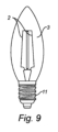
図9は、本発明の例示的実施形態による発光デバイス1の概略図である。図9に示される発光デバイス1は、図5に示される発光デバイス1と同様であり、図5及び図9における同一の参照数字は、同じ機能又は同様の機能を有する、同じ構成要素又は同様の構成要素を示す。図5に示される発光デバイス1とは対照的に、図9に示す発光デバイス1では、光ガイド3は、発光デバイス1の中央に配置されておらず、発光デバイス1の長手方向軸線に沿って延在しておらず、しかし、代わりに、図9に示される本発明の実施形態によれば、LEDフィラメント2を包囲し得る光出射窓又はエンベロープとして構成されている。図9に示される光ガイド3は、コネクタ11に接続されている。
9 is a schematic diagram of a light emitting device 1 according to an exemplary embodiment of the present invention. The light emitting device 1 shown in FIG. 9 is similar to the light emitting device 1 shown in FIG. 5, and the same reference numbers in FIG. 5 and FIG. 9 indicate the same or similar components having the same or similar functions. In contrast to the light emitting device 1 shown in FIG. 5, in the light emitting device 1 shown in FIG. 9, the
図10は、本発明の例示的実施形態による、発光デバイス1の、発光デバイス1の長手方向軸線に垂直な断面の概略図である。図10に示される発光デバイス1は、図9に示される発光デバイス1と同様であり、図9及び図10における同一の参照数字は、同じ機能又は同様の機能を有する、同じ構成要素又は同様の構成要素を示す。図10に示す発光デバイス1の光ガイド3は、エンベロープとして構成されている。図10に示される本発明の実施形態によれば、光ガイド3はLEDフィラメント2を包囲している。図10に示されるように、光ガイド3は、2つの内部表面又は内側表面5、及び2つの外側表面8を備えてもよい。図10における光ガイド3は、窪み及び/又は小平面として構成された8つのインカップリングフィーチャ4を有するものとして示されている。しかしながら、内部表面又は内側表面5、外側表面8、及びインカップリングフィーチャ4のそれぞれの数は例示的であり、光ガイド3は、内部内側表面5、外側表面8、及びインカップリングフィーチャ4を、それぞれ任意の数備えてもよいことに留意すべきである。図10に示される窪み及び/又は小平面の形態のインカップリングフィーチャ4は、光ガイド3の、発光デバイス1の長手方向軸線に最も近い外側表面8のうちの1つに構成されている。窪み及び/又は小平面は、代替として又は加えて、アウトカップリングフィーチャとして用いられ得る。
10 is a schematic diagram of a cross section of a light emitting device 1 perpendicular to the longitudinal axis of the light emitting device 1 according to an exemplary embodiment of the present invention. The light emitting device 1 shown in FIG. 10 is similar to the light emitting device 1 shown in FIG. 9, and the same reference numerals in FIG. 9 and FIG. 10 indicate the same or similar components having the same or similar functions. The
図11は、本発明の例示的実施形態による、発光デバイス1の、発光デバイス1の長手方向軸線に垂直な断面の概略図である。図11に示される発光デバイス1は、図10に示される発光デバイス1と同様であり、図10及び図11における同一の参照数字は、同じ機能又は同様の機能を有する、同じ構成要素又は同様の構成要素を示す。図11に示される本発明の実施形態によれば、光ガイド3の、発光デバイス1の長手方向軸線に最も近い外側表面8とは反対側の、光ガイド3の外側表面8に構成された小平面及び/又は縁部が存在する。小平面及び/又は縁部は、光ガイド3のインカップリングフィーチャ4及び/又はアウトカップリングフィーチャ6として用いられてもよい。図11では、図10のような、光ガイド3の、発光デバイス1の長手方向軸線に最も近い外側表面8のうちの1つに構成された窪み及び/又は小平面は示されていないが、窪み及び/又は小平面は、光ガイド3の、図11に示される発光デバイス1の長手方向軸線に最も近い外側表面8のうちの1つにも構成されてもよいことを理解されたい。
11 is a schematic diagram of a cross section of a light emitting device 1 perpendicular to the longitudinal axis of the light emitting device 1 according to an exemplary embodiment of the present invention. The light emitting device 1 shown in FIG. 11 is similar to the light emitting device 1 shown in FIG. 10, and the same reference numerals in FIG. 10 and FIG. 11 indicate the same or similar components having the same or similar functions. According to the embodiment of the present invention shown in FIG. 11, there are facets and/or edges configured on the
図12は、本発明の例示的実施形態による発光デバイス1の概略図である。図12に示される発光デバイス1は、図9に示される発光デバイス1と同様であり、図9及び図12における同一の参照数字は、同じ機能又は同様の機能を有する、同じ構成要素又は同様の構成要素を示す。図12に示される例示的実施形態によれば、光出射窓として、又はエンベロープとして構成された光ガイド3は、図12に示す本発明の実施形態によればLEDフィラメント2を包囲してもよく、インカップリングフィーチャ4として機能し得る装飾的フィーチャを有してもよい。場合によっては、インカップリングフィーチャ4はまた、光ガイド3のための光アウトカップリング機能を提供してもよい。図12では、装飾的フィーチャ又はインカップリングフィーチャ4は、発光デバイス1の光ガイド3の表面上に円周方向線の形状を有するものとして示されており、この円周方向線は、発光デバイス1の長手方向軸線に垂直な平面内にある。しかしながら、光ガイド3の装飾的フィーチャ又はインカップリングフィーチャ4は、任意の他の形状又は形態を有してもよいことが理解されるべきである。
12 is a schematic diagram of a light emitting device 1 according to an exemplary embodiment of the present invention. The light emitting device 1 shown in FIG. 12 is similar to the light emitting device 1 shown in FIG. 9, and the same reference numerals in FIG. 9 and FIG. 12 indicate the same or similar components having the same or similar functions. According to the exemplary embodiment shown in FIG. 12, the
図13は、本発明の例示的実施形態による発光デバイス1の概略図である。図13に示される発光デバイス1は、図12に示される発光デバイス1と同様であり、図12及び図13における同一の参照数字は、同じ機能又は同様の機能を有する、同じ構成要素又は同様の構成要素を示す。図13は、図12に示される形状とは異なる、光ガイド3の装飾的フィーチャ又はインカップリングフィーチャ4の形状を示す。図13では、装飾的フィーチャ又はインカップリングフィーチャ4は、発光デバイス1の光ガイド3の表面上の線又はその表面全体にわたる線として示される形状を有するものとして示されている。
13 is a schematic diagram of a light emitting device 1 according to an exemplary embodiment of the present invention. The light emitting device 1 shown in FIG. 13 is similar to the light emitting device 1 shown in FIG. 12, and the same reference numerals in FIG. 12 and FIG. 13 indicate the same or similar components having the same or similar functions. FIG. 13 shows a different shape of the decorative or
図14は、本発明の例示的実施形態による発光デバイス1の概略図である。図14に示される発光デバイス1は、図12及び13に示される発光デバイス1と同様であり、図12、図13、及び図14における同一の参照数字は、同じ機能又は同様の機能を有する、同じ構成要素又は同様の構成要素を示す。図14は、図12及び図13に示される形状とは異なる、光ガイド3の装飾的フィーチャ又はインカップリングフィーチャ4の形状を示す。図14では、装飾的フィーチャ又はインカップリングフィーチャ4は、発光デバイス1の光ガイド3の表面上にドット形状を有するものとして示されている。ドットは、例えば、塗料ドットであってもよい。
14 is a schematic diagram of a light emitting device 1 according to an exemplary embodiment of the present invention. The light emitting device 1 shown in FIG. 14 is similar to the light emitting device 1 shown in FIGS. 12 and 13, and the same reference numerals in FIGS. 12, 13, and 14 indicate the same or similar components having the same or similar functions. FIG. 14 shows a different shape of the decorative or
図15は、本発明の例示的実施形態による、発光デバイスの光ガイド3の一部又は一部分の断面の概略図である。図15及び図1~図14における同じ参照数字は、同じ機能又は同様の機能を有する、同じ構成要素又は同様の構成要素を示す。図15に示される本発明の実施形態によれば、光ガイド3は、光の光ガイド3へのインカップリングのために、光ガイドの外側表面8上に構成された構造体の形態のインカップリングフィーチャ4を備える。構造体は、例えば、外側表面8に取り付けられてもよく、例えば、塗料(例えば、1つ以上の塗料ドット)を含んでもよい。インカップリングフィーチャ4は、例えばドット(例えば、塗料ドット)などの微小な粒子の群、例えばアレイ、を備えてもよい。代替として又は加えて、インカップリングフィーチャ4は、表面粗さ及び/又は散乱性光ガイド材料を含み得る。インカップリングフィーチャ4は、観察者の肉眼で視認できないように構成されていてもよい。これは、前述したように、例えばドット(例えば、塗料ドット)などの微小な粒子の群、例えばアレイ、を備えるインカップリングフィーチャ4によって促進又は有効化されてもよい。図15に示されるように、インカップリングフィーチャ4は、光を光ガイド3にインカップルしてもよく、その後、光は光ガイド3内で、例えば内部全反射によって内部表面5上で内部反射されてもよい。図15における破線矢印は光を表す。
FIG. 15 is a schematic diagram of a cross section of a portion or part of a
図16は、本発明の例示的実施形態による、発光デバイスの一部又は一部分の光ガイド3の断面の概略図である。図16に示される光ガイド3は、図15に示される光ガイド3と同様であり、図15及び図16における同じ参照数字は、同じ機能又は同様の機能を有する、同じ構成要素又は同様の構成要素を示す。図16に示される本発明の実施形態によれば、光ガイド3は、光ガイド3の外側表面8に一体的に構成された表面構造体の形態のインカップリングフィーチャ4を備える。この構造体は、例えば、図16に示すような突出する小平面、及び/又は窪みを備えてもよい。代替として又は加えて、構造体は、光アウトカップリング機能を提供することができ、それゆえ、代替として又は加えて、光ガイド3のアウトカップリングフィーチャの一部若しくは一部分を構成するか又はその一部若しくは一部分であってもよい。
16 is a schematic diagram of a cross section of a
結論として、発光デバイスが提供される。発光デバイスは、透明光出射窓と、第1の光出力を透明光出射窓を通して1つ以上の光出力方向に沿って放出するように適合されたLEDフィラメントとを備える。発光デバイスは、光ガイドを備える。光ガイドは、光源によって放出された光を受光するように、かつ光源によって放出された光を光ガイド内にカップリングするように構成された、インカップリングフィーチャを備える。光源は、LEDフィラメントのうちの少なくとも1つ、又は発光デバイスに含まれる別個の光源を備えるか又はそれから構成される。光ガイドは、インカップルされた光を光ガイド内で内部反射させるように適合された少なくとも1つの内部表面と、光ガイド内で内部反射された光の、光ガイドからのアウトカップリングのために構成され、それにより1つ以上の光出力方向に沿って見たときに第1の光出力に重畳される第2の光出力を放出するように構成された、アウトカップリングフィーチャと、を備える。 In conclusion, a light emitting device is provided. The light emitting device comprises a transparent light exit window and an LED filament adapted to emit a first light output through the transparent light exit window along one or more light output directions. The light emitting device comprises a light guide. The light guide comprises an incoupling feature configured to receive light emitted by the light source and to couple the light emitted by the light source into the light guide. The light source comprises or consists of at least one of the LED filaments or a separate light source included in the light emitting device. The light guide comprises at least one internal surface adapted to internally reflect the incoupled light within the light guide, and an outcoupling feature configured for outcoupling from the light guide of the light internally reflected within the light guide, thereby emitting a second light output superimposed on the first light output when viewed along one or more light output directions.
本発明は、添付図面及び上記の説明において例示されているが、そのような例示は、説明的又は例示的なものであり、制限するものではないと見なされたく、本発明は、開示される実施形態に限定されるものではない。図面、本開示、及び添付の請求項の検討によって、開示される実施形態に対する他の変形形態が、当業者により理解されることができ、また、特許請求される発明を実施する際に実行されることができる。添付の請求項では、単語「備える(comprising)」は、他の要素又はステップを排除するものではなく、不定冠詞「1つの(a)」又は「1つの(an)」は、複数を排除するものではない。特定の手段が、互いに異なる従属請求項内に列挙されているという単なる事実は、これらの手段の組み合わせが、有利に使用され得ないことを示すものではない。請求項中のいかなる参照符号も、範囲を限定するものとして解釈されるべきではない。 While the invention has been illustrated in the accompanying drawings and in the above description, such illustrations are not to be considered as descriptive or exemplary and not restrictive, and the invention is not limited to the disclosed embodiments. Other variations to the disclosed embodiments can be understood by those skilled in the art, by study of the drawings, the disclosure, and the appended claims, and can be carried out in practicing the claimed invention. In the appended claims, the word "comprising" does not exclude other elements or steps, and the indefinite article "a" or "an" does not exclude a plurality. The mere fact that certain measures are recited in mutually different dependent claims does not indicate that a combination of these measures cannot be used to advantage. Any reference signs in the claims should not be interpreted as limiting the scope.
Claims (10)
透明光出射窓と;
第1の光出力を前記透明光出射窓を通して1つ以上の光出力方向に沿って放出するように適合された発光ダイオード(LED)フィラメントと;
光ガイドであって、
光源によって放出された光を受光するように、かつ前記光源によって放出された前記光を前記光ガイド内にカップリングするように構成された、インカップリングフィーチャであって、前記光源は、前記LEDフィラメントのうちの少なくとも1つ又は前記発光デバイスに含まれる別個の光源を備えるか又はそれから構成される、インカップリングフィーチャと、
インカップルされた前記光を前記光ガイド内で内部反射させるように適合された少なくとも1つの内部表面と、
前記光ガイド内で内部反射された光の、前記光ガイドからのアウトカップリングのために構成され、それにより前記1つ以上の光出力方向に沿って見たときに前記第1の光出力に重畳される第2の光出力を放出するように構成された、アウトカップリングフィーチャと、を備える光ガイドと;
を備える発光デバイスにおいて
前記発光デバイスは補助LED光源を更に備え、前記光源は前記補助LED光源を備え、前記インカップリングフィーチャは、前記補助LED光源によって放出された光のインカップリングのために構成されている、
前記光源は、
(1)前記LEDフィラメントによって放出された前記光の光束が所定値を超えたときに、前記光ガイドへのインカップリングのための光を放出するように構成されている、
(2)前記LEDフィラメントによって放出される前記光の光束が増加する場合に、前記光ガイドへのインカップリングのために放出される前記光の光束を増加させるように構成されている、及び
(3)前記LEDフィラメントによって放出された前記光の光束が所定値を超えたときに、インカップリングのために放出される前記光の光束が前記LEDフィラメントによって放出される前記光の光束よりも高くなるように、前記光ガイドへのインカップリングのための光を放出するように構成されている、
なる(1)~(3)の構成の少なくとも1つを備える、
発光デバイス。 1. A light emitting device, comprising:
A transparent light exit window;
a light emitting diode (LED) filament adapted to emit a first light output through the transparent light exit window along one or more light output directions;
1. A light guide comprising:
an incoupling feature configured to receive light emitted by a light source and to couple the light emitted by the light source into the light guide, the light source comprising or consisting of at least one of the LED filaments or a separate light source included in the light emitting device;
at least one internal surface adapted to internally reflect the incoupled light within the light guide;
an outcoupling feature configured for outcoupling from the light guide of light internally reflected within the light guide, thereby emitting a second light output superimposed on the first light output when viewed along the one or more light output directions;
In a light emitting device comprising:
the light emitting device further comprises an auxiliary LED light source, the light source comprising the auxiliary LED light source, and the incoupling feature is configured for incoupling of light emitted by the auxiliary LED light source.
The light source is
(1) configured to emit light for incoupling into the light guide when the luminous flux of the light emitted by the LED filament exceeds a predetermined value;
(2) configured to increase the luminous flux of the light emitted for incoupling into the light guide when the luminous flux of the light emitted by the LED filament increases ; and
(3) configured to emit light for incoupling into the light guide such that the luminous flux of the light emitted by the LED filament is higher than the luminous flux of the light emitted by the LED filament when the luminous flux of the light emitted by the LED filament exceeds a predetermined value;
The present invention has at least one of the following configurations (1) to (3) :
Light emitting device.
Applications Claiming Priority (3)
| Application Number | Priority Date | Filing Date | Title |
|---|---|---|---|
| EP19168162.6 | 2019-04-09 | ||
| EP19168162 | 2019-04-09 | ||
| PCT/EP2020/059037 WO2020207852A1 (en) | 2019-04-09 | 2020-03-31 | A light-emitting device |
Publications (3)
| Publication Number | Publication Date |
|---|---|
| JP2022526654A JP2022526654A (en) | 2022-05-25 |
| JPWO2020207852A5 JPWO2020207852A5 (en) | 2023-04-03 |
| JP7575853B2 true JP7575853B2 (en) | 2024-10-30 |
Family
ID=66290180
Family Applications (1)
| Application Number | Title | Priority Date | Filing Date |
|---|---|---|---|
| JP2021559846A Active JP7575853B2 (en) | 2019-04-09 | 2020-03-31 | Light-emitting devices |
Country Status (5)
| Country | Link |
|---|---|
| US (1) | US11519563B2 (en) |
| EP (1) | EP3953638A1 (en) |
| JP (1) | JP7575853B2 (en) |
| CN (1) | CN113661356B (en) |
| WO (1) | WO2020207852A1 (en) |
Families Citing this family (7)
| Publication number | Priority date | Publication date | Assignee | Title |
|---|---|---|---|---|
| CN117916638A (en) | 2021-09-06 | 2024-04-19 | 昕诺飞控股有限公司 | Light emitting device |
| EP4519600A1 (en) * | 2022-05-03 | 2025-03-12 | Signify Holding B.V. | Glare reduction for a lighting device |
| WO2023242116A1 (en) * | 2022-06-16 | 2023-12-21 | Signify Holding B.V. | Lighting arrangement with rod-shaped light guide element |
| USD1070131S1 (en) * | 2023-07-20 | 2025-04-08 | Sichuan Jamie Charming Technology Co., Ltd. | Light bulb |
| WO2025056359A1 (en) * | 2023-09-14 | 2025-03-20 | Signify Holding B.V. | Efficient (filament) bulb with an optical filter |
| WO2025180865A1 (en) | 2024-02-29 | 2025-09-04 | Signify Holding B.V. | Light emitting device |
| WO2025223989A1 (en) * | 2024-04-22 | 2025-10-30 | Signify Holding B.V. | Lighting device having improved optical efficiency |
Citations (2)
| Publication number | Priority date | Publication date | Assignee | Title |
|---|---|---|---|---|
| JP2013020874A (en) | 2011-07-13 | 2013-01-31 | Skg:Kk | Lighting device |
| WO2018041826A1 (en) | 2016-09-01 | 2018-03-08 | Philips Lighting Holding B.V. | A light emitting device |
Family Cites Families (15)
| Publication number | Priority date | Publication date | Assignee | Title |
|---|---|---|---|---|
| CN102913773B (en) | 2011-08-02 | 2016-05-04 | 欧司朗股份有限公司 | LED luminescence component and there is the LED remodeling lamp of this LED luminescence component |
| US9677738B2 (en) * | 2013-03-15 | 2017-06-13 | 1947796 Ontario Inc. | Optical device and system for solid-state lighting |
| US9267674B2 (en) | 2013-10-18 | 2016-02-23 | 3M Innovative Properties Company | Solid state light with enclosed light guide and integrated thermal guide |
| JP6139031B2 (en) * | 2013-11-05 | 2017-05-31 | フィリップス ライティング ホールディング ビー ヴィ | Light emitting device |
| RU2677687C2 (en) | 2014-03-13 | 2019-01-21 | Филипс Лайтинг Холдинг Б.В. | Filament for lighting device |
| CN204254304U (en) | 2014-09-24 | 2015-04-08 | 浙江承康机电制造有限公司 | A kind of LED |
| US9759389B2 (en) * | 2014-12-09 | 2017-09-12 | Cree, Inc. | LED based candelabra lamp |
| WO2016128509A1 (en) | 2015-02-12 | 2016-08-18 | Philips Lighting Holding B.V. | Lighting module and lighting device comprising the lighting module |
| US10172215B2 (en) * | 2015-03-13 | 2019-01-01 | Cree, Inc. | LED lamp with refracting optic element |
| CN106151934A (en) * | 2015-04-20 | 2016-11-23 | 葛兰菲照明有限公司 | Integrating illumination and the LED bulb of night-light function |
| US9689560B2 (en) | 2015-06-05 | 2017-06-27 | Chung Ping Lai | LED light bulb simultaneously using as nightlight |
| WO2017013141A1 (en) * | 2015-07-20 | 2017-01-26 | Philips Lighting Holding B.V. | Lighting device with light guide |
| WO2018202625A1 (en) * | 2017-05-02 | 2018-11-08 | Philips Lighting Holding B.V. | A lighting device and a luminaire |
| CN107339621B (en) | 2017-08-16 | 2023-06-16 | 常州市福兴电器有限公司 | LED lamp with light guide |
| CN108758371A (en) * | 2018-06-14 | 2018-11-06 | 漳州立达信光电子科技有限公司 | A kind of LED light of imitative decoration type tengsten lamp |
-
2020
- 2020-03-31 JP JP2021559846A patent/JP7575853B2/en active Active
- 2020-03-31 WO PCT/EP2020/059037 patent/WO2020207852A1/en not_active Ceased
- 2020-03-31 CN CN202080027424.0A patent/CN113661356B/en active Active
- 2020-03-31 EP EP20714616.8A patent/EP3953638A1/en active Pending
- 2020-03-31 US US17/599,693 patent/US11519563B2/en active Active
Patent Citations (2)
| Publication number | Priority date | Publication date | Assignee | Title |
|---|---|---|---|---|
| JP2013020874A (en) | 2011-07-13 | 2013-01-31 | Skg:Kk | Lighting device |
| WO2018041826A1 (en) | 2016-09-01 | 2018-03-08 | Philips Lighting Holding B.V. | A light emitting device |
Also Published As
| Publication number | Publication date |
|---|---|
| CN113661356B (en) | 2024-07-05 |
| EP3953638A1 (en) | 2022-02-16 |
| CN113661356A (en) | 2021-11-16 |
| US11519563B2 (en) | 2022-12-06 |
| WO2020207852A1 (en) | 2020-10-15 |
| JP2022526654A (en) | 2022-05-25 |
| US20220196213A1 (en) | 2022-06-23 |
Similar Documents
| Publication | Publication Date | Title |
|---|---|---|
| JP7575853B2 (en) | Light-emitting devices | |
| ES2712174T3 (en) | Lighting device | |
| JP5734204B2 (en) | Optical element and light source having the optical element | |
| JP5711147B2 (en) | Light source with LED, light guide and reflector | |
| JP5551714B2 (en) | Light source with LED, light guide and reflector | |
| CN109716013B (en) | light emitting device | |
| CN102654252B (en) | Lens and illumination device | |
| JP7080253B2 (en) | Lighting devices and lighting fixtures | |
| US20140254154A1 (en) | Light-emitting diode light bulb generating direct and decorative illumination | |
| CN103270363A (en) | Lighting device and method for manufacturing a lighting device | |
| JP7155117B2 (en) | Lighting device with UV LED | |
| JP2014500606A (en) | LED bulb with light scattering optical structure | |
| JP2022501796A (en) | Filament lamp | |
| JP6446202B2 (en) | Wide-angle diffusion optical system and illumination device using the same | |
| CN103975189A (en) | Side-emitting guidepipe technology on led lamp to make filament effect | |
| EP3105495A1 (en) | Lighting device | |
| CN106838650B (en) | LED lights | |
| CN204611662U (en) | Lighting device | |
| CN114502877A (en) | Lighting device | |
| EP2230440A2 (en) | Lighting apparatus comprising a plurality of LEDs and an optical element for diffusing the light and eliminating a ghost image of the point light sources | |
| CN106609919A (en) | Illuminating device | |
| JP2007180288A (en) | Light emitting device and lighting device | |
| WO2025252451A1 (en) | A led filament arrangement | |
| TWM555447U (en) | Tubular illuminator and bulb | |
| EP2662615A1 (en) | Bulb-type lamp and luminaire |
Legal Events
| Date | Code | Title | Description |
|---|---|---|---|
| A521 | Request for written amendment filed |
Free format text: JAPANESE INTERMEDIATE CODE: A523 Effective date: 20230324 |
|
| A621 | Written request for application examination |
Free format text: JAPANESE INTERMEDIATE CODE: A621 Effective date: 20230324 |
|
| A977 | Report on retrieval |
Free format text: JAPANESE INTERMEDIATE CODE: A971007 Effective date: 20240105 |
|
| A131 | Notification of reasons for refusal |
Free format text: JAPANESE INTERMEDIATE CODE: A131 Effective date: 20240118 |
|
| A601 | Written request for extension of time |
Free format text: JAPANESE INTERMEDIATE CODE: A601 Effective date: 20240416 |
|
| A521 | Request for written amendment filed |
Free format text: JAPANESE INTERMEDIATE CODE: A523 Effective date: 20240717 |
|
| TRDD | Decision of grant or rejection written | ||
| A01 | Written decision to grant a patent or to grant a registration (utility model) |
Free format text: JAPANESE INTERMEDIATE CODE: A01 Effective date: 20240924 |
|
| A61 | First payment of annual fees (during grant procedure) |
Free format text: JAPANESE INTERMEDIATE CODE: A61 Effective date: 20241017 |
|
| R150 | Certificate of patent or registration of utility model |
Ref document number: 7575853 Country of ref document: JP Free format text: JAPANESE INTERMEDIATE CODE: R150 |