JP7080253B2 - Lighting devices and lighting fixtures - Google Patents
Lighting devices and lighting fixtures Download PDFInfo
- Publication number
- JP7080253B2 JP7080253B2 JP2019560106A JP2019560106A JP7080253B2 JP 7080253 B2 JP7080253 B2 JP 7080253B2 JP 2019560106 A JP2019560106 A JP 2019560106A JP 2019560106 A JP2019560106 A JP 2019560106A JP 7080253 B2 JP7080253 B2 JP 7080253B2
- Authority
- JP
- Japan
- Prior art keywords
- light
- led filament
- lighting device
- guide
- optical guide
- Prior art date
- Legal status (The legal status is an assumption and is not a legal conclusion. Google has not performed a legal analysis and makes no representation as to the accuracy of the status listed.)
- Active
Links
Images


Classifications
-
- F—MECHANICAL ENGINEERING; LIGHTING; HEATING; WEAPONS; BLASTING
- F21—LIGHTING
- F21K—NON-ELECTRIC LIGHT SOURCES USING LUMINESCENCE; LIGHT SOURCES USING ELECTROCHEMILUMINESCENCE; LIGHT SOURCES USING CHARGES OF COMBUSTIBLE MATERIAL; LIGHT SOURCES USING SEMICONDUCTOR DEVICES AS LIGHT-GENERATING ELEMENTS; LIGHT SOURCES NOT OTHERWISE PROVIDED FOR
- F21K9/00—Light sources using semiconductor devices as light-generating elements, e.g. using light-emitting diodes [LED] or lasers
- F21K9/20—Light sources comprising attachment means
- F21K9/23—Retrofit light sources for lighting devices with a single fitting for each light source, e.g. for substitution of incandescent lamps with bayonet or threaded fittings
- F21K9/232—Retrofit light sources for lighting devices with a single fitting for each light source, e.g. for substitution of incandescent lamps with bayonet or threaded fittings specially adapted for generating an essentially omnidirectional light distribution, e.g. with a glass bulb
-
- F—MECHANICAL ENGINEERING; LIGHTING; HEATING; WEAPONS; BLASTING
- F21—LIGHTING
- F21K—NON-ELECTRIC LIGHT SOURCES USING LUMINESCENCE; LIGHT SOURCES USING ELECTROCHEMILUMINESCENCE; LIGHT SOURCES USING CHARGES OF COMBUSTIBLE MATERIAL; LIGHT SOURCES USING SEMICONDUCTOR DEVICES AS LIGHT-GENERATING ELEMENTS; LIGHT SOURCES NOT OTHERWISE PROVIDED FOR
- F21K9/00—Light sources using semiconductor devices as light-generating elements, e.g. using light-emitting diodes [LED] or lasers
- F21K9/60—Optical arrangements integrated in the light source, e.g. for improving the colour rendering index or the light extraction
- F21K9/61—Optical arrangements integrated in the light source, e.g. for improving the colour rendering index or the light extraction using light guides
-
- G—PHYSICS
- G02—OPTICS
- G02B—OPTICAL ELEMENTS, SYSTEMS OR APPARATUS
- G02B6/00—Light guides; Structural details of arrangements comprising light guides and other optical elements, e.g. couplings
- G02B6/0001—Light guides; Structural details of arrangements comprising light guides and other optical elements, e.g. couplings specially adapted for lighting devices or systems
- G02B6/0005—Light guides; Structural details of arrangements comprising light guides and other optical elements, e.g. couplings specially adapted for lighting devices or systems the light guides being of the fibre type
- G02B6/001—Light guides; Structural details of arrangements comprising light guides and other optical elements, e.g. couplings specially adapted for lighting devices or systems the light guides being of the fibre type the light being emitted along at least a portion of the lateral surface of the fibre
-
- F—MECHANICAL ENGINEERING; LIGHTING; HEATING; WEAPONS; BLASTING
- F21—LIGHTING
- F21Y—INDEXING SCHEME ASSOCIATED WITH SUBCLASSES F21K, F21L, F21S and F21V, RELATING TO THE FORM OR THE KIND OF THE LIGHT SOURCES OR OF THE COLOUR OF THE LIGHT EMITTED
- F21Y2113/00—Combination of light sources
- F21Y2113/20—Combination of light sources of different form
-
- F—MECHANICAL ENGINEERING; LIGHTING; HEATING; WEAPONS; BLASTING
- F21—LIGHTING
- F21Y—INDEXING SCHEME ASSOCIATED WITH SUBCLASSES F21K, F21L, F21S and F21V, RELATING TO THE FORM OR THE KIND OF THE LIGHT SOURCES OR OF THE COLOUR OF THE LIGHT EMITTED
- F21Y2115/00—Light-generating elements of semiconductor light sources
- F21Y2115/10—Light-emitting diodes [LED]
-
- G—PHYSICS
- G02—OPTICS
- G02B—OPTICAL ELEMENTS, SYSTEMS OR APPARATUS
- G02B6/00—Light guides; Structural details of arrangements comprising light guides and other optical elements, e.g. couplings
- G02B6/0001—Light guides; Structural details of arrangements comprising light guides and other optical elements, e.g. couplings specially adapted for lighting devices or systems
- G02B6/0011—Light guides; Structural details of arrangements comprising light guides and other optical elements, e.g. couplings specially adapted for lighting devices or systems the light guides being planar or of plate-like form
- G02B6/0033—Means for improving the coupling-out of light from the light guide
- G02B6/0035—Means for improving the coupling-out of light from the light guide provided on the surface of the light guide or in the bulk of it
Description
本発明は、照明器具に使用するための照明デバイス、及び当該照明デバイスを備える照明器具に関する。 The present invention relates to a lighting device for use in a lighting fixture and a lighting fixture including the lighting device.
白熱ランプは、LEDベースの照明ソリューションに急速に置き換えられている。しかしながら、白熱電球の外観を有するレトロフィットランプを持つことがユーザによって評価され望まれている。この目的で、単純に、ガラスをベースにした白熱ランプを製造するためのインフラストラクチャを利用し、フィラメントを白色光を発するLEDと置き換えることができる。発想の1つは、このような電球内に配置されるLEDフィラメントに基づいている。これらランプの外観は装飾性が高いので高く評価されている。 Incandescent lamps are rapidly being replaced by LED-based lighting solutions. However, it is appreciated and desired by users to have a retrofit lamp with the appearance of an incandescent light bulb. For this purpose, the filament can simply be replaced with an LED that emits white light, utilizing the infrastructure for manufacturing glass-based incandescent lamps. One of the ideas is based on LED filaments placed inside such bulbs. The appearance of these lamps is highly regarded because of their high decorativeness.
このようなLEDベースのソリューションの1つが米国特許出願公開第2012/0217862(A1)号から公知であり、プレート状の透光性ボードと、2列のLEDを形成するようにボード上に取り付けられた複数のLEDとを有するLEDモジュールを備える、電球形ランプが記載されている。LEDモジュールは、LEDを封止するための封止構成要素を更に備え、それにより、動作中にLEDの列がフィラメントの印象を与える。LEDモジュールは、LED用のライン、配線及び電源を更に備える。 One such LED-based solution is known from US Patent Application Publication No. 2012/0217862 (A1) and is mounted on a plate-like translucent board and on the board to form two rows of LEDs. A bulb-shaped lamp comprising an LED module having a plurality of LEDs is described. The LED module further comprises a sealing component for sealing the LED, whereby the row of LEDs gives the impression of a filament during operation. The LED module further comprises a line, wiring and power supply for the LED.
しかし、このような既知のソリューションに対しては、LEDフィラメントの強度が高いと、ランプの出力にグレアが強すぎる結果となる。 However, for such known solutions, high LED filament strength results in too much glare at the lamp output.
英国特許第2539190A号は、LED、LEDフィラメント、口金、駆動回路、及び光ガイド要素を含むLED電球を開示している。口金は、駆動回路及びLEDを収容するための中空キャビティを含む。口金は、電気用取付部品及び電球ホルダを有する。光ガイド要素は、光導電性材料で作製され、口金と結合され、LEDに隣接してLEDから光を導くための入射端を含む。LEDフィラメントは、光ガイド要素を取り囲み、光ガイド要素によって支持されている。 British Patent No. 2539190A discloses an LED bulb that includes an LED, an LED filament, a base, a drive circuit, and an optical guide element. The base includes a drive circuit and a hollow cavity for accommodating the LED. The base has electrical mounting parts and a light bulb holder. The optical guide element is made of a photoconductive material, coupled with a base, and includes an incident end adjacent to the LED to guide light from the LED. The LED filament surrounds the light guide element and is supported by the light guide element.
本発明の目的は、グレアの生成がより少ない発光デバイスを提供することである。 An object of the present invention is to provide a light emitting device that produces less glare.
本発明は、独立請求項1による照明デバイスを開示する。従属請求項によって、好ましい実施形態が定義される。 The present invention discloses a lighting device according to independent claim 1. Dependent claims define preferred embodiments.
本発明の第1の態様によれば、口金、少なくとも1つのLEDフィラメント、少なくとも1つの光ガイド、及び少なくとも部分的に光透過性のエンベロープを備える、照明器具で使用するための照明デバイスが提供される。口金は長手方向軸を有し、照明デバイスを照明器具の照明器具ソケットに接続する電気コネクタを備える。少なくとも1つのLEDフィラメントは、細長い本体を有する基材を備える。少なくとも1つのLEDフィラメントは、基材に機械的に結合された複数の光源を有する。複数の光源は、第1の空間光分布にて光を放出する。少なくとも1つの光ガイドは、細長い本体を有する。少なくとも1つの光ガイドは、少なくとも1つの光ガイドの少なくとも外周上に、少なくとも1つの光インカップリング部を備える。少なくとも1つの光インカップリング部は、光を少なくとも1つの光ガイドにインカップルさせる。少なくとも1つの光ガイドは、第2の空間光分布にて少なくとも1つの光ガイドから光をアウトカップルさせる複数の光アウトカップリング部を備える。少なくとも部分的に光透過性のエンベロープは、少なくとも1つのLEDフィラメント及び少なくとも1つの光ガイドを、少なくとも部分的に封入する。少なくとも1つの光ガイドは、少なくとも1つの光インカップリング部において少なくとも1つの光ガイドにインカップルされた光を、内部全反射を介して複数の光アウトカップリング部に導く。少なくとも1つのLEDフィラメントは、少なくとも1つの光ガイドの外部にある。 According to a first aspect of the invention, there is provided a lighting device for use in a luminaire, comprising a base, at least one LED filament, at least one light guide, and at least a partially light-transmitting envelope. Ru. The base has a longitudinal axis and includes an electrical connector that connects the luminaire to the luminaire socket of the luminaire. The at least one LED filament comprises a substrate having an elongated body. The at least one LED filament has a plurality of light sources mechanically coupled to the substrate. The plurality of light sources emit light in the first spatial light distribution. The at least one light guide has an elongated body. The at least one optical guide comprises at least one optical in-coupling portion on at least the outer periphery of the at least one optical guide. The at least one optical incoupling unit couples the light into at least one optical guide. The at least one optical guide comprises a plurality of optical out-coupling portions that outcouple the light from the at least one optical guide in the second spatial light distribution. The at least partially light-transmitting envelope encloses at least one LED filament and at least one light guide at least partially. The at least one optical guide guides the light coupled to the at least one optical guide in the at least one optical in-coupling section to the plurality of optical out-coupling sections via internal total internal reflection. The at least one LED filament is outside the at least one light guide.
少なくとも1つのLEDフィラメント及び少なくとも1つの光ガイドの両方を、少なくとも1つのLEDフィラメントが少なくとも1つの光ガイドの外部に位置するように設けることにより、少なくとも1つのLEDフィラメントランプの強度を増加させることによってのみ光のルーメン出力を増加させた場合に、より少ないグレアを生成する発光デバイスが提供される。この理由は、少なくとも1つの光ガイドがランプ内の発光面を増加させ、従って、少なくとも1つのLEDフィラメントの輝度を低下させることである。少なくとも1つのLEDフィラメントの輝度の低下により、グレアはより少なくなる。一実施形態では、提供される発光デバイスは、ランプのルーメン出力を増加させた場合にグレアを生成しないか、又は非常に限定された程度でのみグレアを生成する。 By increasing the intensity of the at least one LED filament lamp by providing both the at least one LED filament and the at least one light guide so that the at least one LED filament is located outside the at least one light guide. A light emitting device is provided that produces less glare when only the lumen output of light is increased. The reason for this is that at least one light guide increases the light emitting surface in the lamp and thus reduces the brightness of at least one LED filament. Glare is less due to the reduced brightness of at least one LED filament. In one embodiment, the provided light emitting device does not produce glare when the lumen output of the lamp is increased, or produces glare only to a very limited extent.
米国特許出願公開第2012/0217862(A1)号で提案されているソリューションは、ランプのルーメン出力を増加させた場合にグレアを減少させる発光デバイスを提供することができず、それにより少なくとも1つのLEDフィラメントの強度は増加することになる。この理由は、少なくとも1つのLEDフィラメントは小さい発光面を有し、少なくとも1つのLEDフィラメントの強度を増加させた場合に、より少ないグレアを生成しないことである。従って、米国特許出願公開第2012/0217862(A1)号で提案されているソリューションは、少なくとも1つのLEDフィラメントの強度を増加させた場合にグレアを生成する。 The solution proposed in US Patent Application Publication No. 2012/0217862 (A1) is unable to provide a light emitting device that reduces glare when increasing the lumen output of the lamp, thereby at least one LED. The strength of the filament will increase. The reason for this is that at least one LED filament has a small light emitting surface and does not produce less glare when the intensity of at least one LED filament is increased. Therefore, the solution proposed in US Patent Application Publication No. 2012/0217862 (A1) produces glare when the intensity of at least one LED filament is increased.
一実施形態では、少なくとも1つのLEDフィラメントは、少なくとも1つの光ガイドから物理的に分離されていてもよい。一実施形態では、少なくとも1つのLEDフィラメントは、少なくとも1つの光ガイドに対して非ゼロの距離に配置されていてもよい。一実施形態では、少なくとも1つのLEDフィラメントは、少なくとも1つの光ガイドに機械的及び光学的に結合されていてもよい。一実施形態では、第1の空間光分布は第2の空間光分布とは異なる。一実施形態では、第1の空間光分布は第2の空間光分布と部分的に重なり合う。例えば、光ガイドは360度の空間光分布を提供し、一方、LEDフィラメントは270度未満、例えば180度の空間光分布を提供する。得られる効果は、グレアが少ないことである。この理由は、より多くの光が異なる方向及び/又はより多くの方向に放出したことである。 In one embodiment, the at least one LED filament may be physically separated from at least one light guide. In one embodiment, the at least one LED filament may be located at a non-zero distance to at least one light guide. In one embodiment, the at least one LED filament may be mechanically and optically coupled to at least one optical guide. In one embodiment, the first spatial light distribution is different from the second spatial light distribution. In one embodiment, the first spatial light distribution partially overlaps the second spatial light distribution. For example, a light guide provides a spatial light distribution of 360 degrees, while an LED filament provides a spatial light distribution of less than 270 degrees, eg 180 degrees. The effect obtained is less glare. The reason for this is that more light is emitted in different directions and / or more directions.
一実施形態では、照明デバイスは、電気コネクタと複数の光源との間に電気的に接続されたドライバ回路を更に備える。ドライバは、照明器具の電気出力、すなわち、ドライバ用の電気入力を、光源の電気的特性に整合されたドライバの電気出力に変換する。典型的にドライバの電気入力は、主電圧等の高電圧の交流電流であり、ドライバ回路によって低電圧の直流電流に変換される。得られる効果は、照明デバイスを照明器具内に接続する間に、ドライバの電気出力に接触しても害が少なく、より安全なことである。この理由は、ドライバの典型的な出力は、それが身体を通過したときに多くの場合感知できない低電圧の直流である一方で、照明器具の典型的な出力はそれが身体を通過したときに不快であるか又は危険な高電圧の交流であることである。 In one embodiment, the lighting device further comprises a driver circuit electrically connected between the electrical connector and the plurality of light sources. The driver converts the electrical output of the luminaire, i.e. the electrical input for the driver, into the electrical output of the driver matched to the electrical characteristics of the light source. Typically, the electrical input of the driver is a high voltage alternating current such as the main voltage, which is converted into a low voltage direct current by the driver circuit. The effect obtained is that it is less harmful and safer to come into contact with the electrical output of the driver while connecting the lighting device inside the luminaire. The reason for this is that while the typical output of a driver is a low voltage direct current that is often undetectable when it passes through the body, the typical output of a luminaire is when it passes through the body. It is an unpleasant or dangerous high voltage alternating current.
一実施形態では、基材は、第1の伸長軸に沿った延長部を有する細長い本体を有する。少なくとも1つの光ガイドは、第2の伸長軸に沿った延長部を有する細長い本体を有する。第1の伸長軸の少なくとも一部は、第2の伸長軸の少なくとも一部に対して非平行である。得られる効果は、発光デバイスがより少ないグレアを生成することである。この理由は、第1の空間光分布と第2の空間光分布とが異なり得ることである。例えば、第1の空間光分布と第2の空間光分布とは、完全には重なり合っていなくてもよい。例えば、第1の空間光分布と第2の空間光分布とは重なり合っていてもよいが、例えば、第1の空間光分布は比較的狭く、一方で第2の空間光分布は比較的広いなどのように異なっている。得られる効果はまた、装飾照明の改善である。この理由は、少なくとも1つの光ガイドが、少なくとも1つのLEDフィラメントに対して異なる1つの角度で、又は異なる複数の角度で配置され得ることである。 In one embodiment, the substrate has an elongated body with an extension along the first extension axis. The at least one optical guide has an elongated body with an extension along a second extension axis. At least a portion of the first extension axis is non-parallel to at least a portion of the second extension axis. The effect obtained is that the light emitting device produces less glare. The reason for this is that the first spatial light distribution and the second spatial light distribution can be different. For example, the first spatial light distribution and the second spatial light distribution do not have to completely overlap. For example, the first spatial light distribution and the second spatial light distribution may overlap, but for example, the first spatial light distribution is relatively narrow, while the second spatial light distribution is relatively wide. It is different like. The effect obtained is also an improvement in novelty lighting. The reason for this is that at least one light guide can be placed at a different angle with respect to at least one LED filament, or at different angles.
一実施形態では、第1の伸長軸と第2の伸長軸との間の角度は10~80度の範囲にある。得られる効果は、発光デバイスがより少ないグレアを生成することである。この理由は、第1の空間光分布と第2の空間光分布とが異なり得ることである。例えば、第1の空間光分布と第2の空間光分布とは、完全には重なり合っていなくてもよい。得られる効果はまた、装飾照明の改善である。この理由は、少なくとも1つの光ガイドが、少なくとも1つのLEDフィラメントに対して異なる1つの角度で、又は異なる複数の角度で配置され得ることである。 In one embodiment, the angle between the first extension axis and the second extension axis is in the range of 10-80 degrees. The effect obtained is that the light emitting device produces less glare. The reason for this is that the first spatial light distribution and the second spatial light distribution can be different. For example, the first spatial light distribution and the second spatial light distribution do not have to completely overlap. The effect obtained is also an improvement in novelty lighting. The reason for this is that at least one light guide can be placed at a different angle with respect to at least one LED filament, or at different angles.
一実施形態では、第1の伸長軸と第2の伸長軸との間の角度は10~30度の範囲にある。得られる効果は、発光デバイスがより少ないグレアを生成することである。この理由は、第1の空間光分布と第2の空間光分布とが異なり得ることである。例えば、第1の空間光分布と第2の空間光分布とは、完全には重なり合っていなくてもよい。得られる効果はまた、装飾照明の改善である。この理由は、少なくとも1つの光ガイドが、少なくとも1つのLEDフィラメントに対して異なる1つの角度で、又は異なる複数の角度で配置され得ることである。 In one embodiment, the angle between the first extension axis and the second extension axis is in the range of 10-30 degrees. The effect obtained is that the light emitting device produces less glare. The reason for this is that the first spatial light distribution and the second spatial light distribution can be different. For example, the first spatial light distribution and the second spatial light distribution do not have to completely overlap. The effect obtained is also an improvement in novelty lighting. The reason for this is that at least one light guide can be placed at a different angle with respect to at least one LED filament, or at different angles.
複数の光源によって放出される光の少なくとも一部は、少なくとも1つの光ガイドにインカップルされる。得られる効果は、発光デバイスがより少ないグレアを生成することである。この理由は、少なくとも1つの光ガイドは、少なくとも1つの光インカップリング部において少なくとも1つの光ガイドにインカップルされた光を、内部全反射を介して複数の光アウトカップリング部に導くことである。少なくとも1つの光ガイドはランプ内の発光面を増加させ、従って、少なくとも1つのLEDフィラメントの輝度を低下させる。少なくとも1つのLEDフィラメントの輝度の低下により、グレアはより少なくなる。 At least a portion of the light emitted by the plurality of light sources is coupled to at least one light guide. The effect obtained is that the light emitting device produces less glare. The reason for this is that at least one optical guide guides the light coupled to at least one optical guide in at least one optical in-coupling section to a plurality of optical out-coupling sections via internal total internal reflection. be. The at least one light guide increases the light emitting surface in the lamp and thus reduces the brightness of the at least one LED filament. Glare is less due to the reduced brightness of at least one LED filament.
一実施形態では、少なくとも1つの光ガイドは、少なくとも1つのLEDフィラメントに機械的及び光学的に結合されている。得られる効果は、発光デバイスがより少ないグレアを生成することである。この理由は、複数の光源によって放出された光の、少なくとも1つの光ガイドへの光インカップリングが改善されることである。従って、少なくとも1つのLEDフィラメントによって放出される光の量は低減される。得られる効果はまた、装飾照明の改善である。この理由は、少なくとも1つの光ガイドと少なくとも1つのLEDフィラメントとの組み合わせが、白熱電球の単一フィラメントの外観を有することである。得られる効果はまた、少なくとも1つの光ガイドの機械的安定性の改善である。この理由は、少なくとも1つの光ガイドも、LEDフィラメントによって機械的に支持されることである。 In one embodiment, the at least one optical guide is mechanically and optically coupled to the at least one LED filament. The effect obtained is that the light emitting device produces less glare. The reason for this is that the optical incoupling of the light emitted by the plurality of light sources to at least one optical guide is improved. Therefore, the amount of light emitted by at least one LED filament is reduced. The effect obtained is also an improvement in novelty lighting. The reason for this is that the combination of at least one light guide and at least one LED filament has the appearance of a single filament in an incandescent bulb. The effect obtained is also an improvement in the mechanical stability of at least one optical guide. The reason for this is that at least one optical guide is also mechanically supported by the LED filament.
一実施形態では、照明デバイスは少なくとも1つの更なる光源を備える。少なくとも1つの更なる光源によって放出される光の少なくとも一部は、少なくとも1つの光ガイドにインカップルされる。得られる効果は、発光デバイスがより少ないグレアを生成することである。この理由は、少なくとも1つの光ガイドがランプ内の発光面を増加させ、従って、少なくとも1つのLEDフィラメントの輝度を低下させることである。一実施形態では、少なくとも1つの更なる光源は、例えば発光ダイオード(LED)又はレーザーダイオードなどの固体光源である。少なくとも1つの更なる光源は、更なる光源キャリア上に構成されていてもよい。少なくとも1つの更なる光源は、口金と機械的に接触していてもよい。更なる光源キャリアは、口金と機械的に接触していてもよい。 In one embodiment, the lighting device comprises at least one additional light source. At least a portion of the light emitted by at least one additional light source is coupled to at least one light guide. The effect obtained is that the light emitting device produces less glare. The reason for this is that at least one light guide increases the light emitting surface in the lamp and thus reduces the brightness of at least one LED filament. In one embodiment, the at least one additional light source is a solid light source such as, for example, a light emitting diode (LED) or a laser diode. At least one additional light source may be configured on the additional light source carrier. At least one additional light source may be in mechanical contact with the base. Further light source carriers may be in mechanical contact with the base.
一実施形態では、少なくとも1つの光ガイドの平均強度は、少なくとも1つのLEDフィラメントの平均強度の0.5倍から少なくとも1つのLEDフィラメントの平均強度の2倍の範囲にある。より好ましくは、少なくとも1つの光ガイドの平均強度は、少なくとも1つのLEDフィラメントの平均強度の0.7倍から少なくとも1つのLEDフィラメントの平均強度の1.4倍の範囲にある。最も好ましくは、少なくとも1つの光ガイドの平均強度は、少なくとも1つのLEDフィラメントの平均強度の0.8倍から少なくとも1つのLEDフィラメントの平均強度の1.2倍の範囲にある。得られる効果は、発光デバイスがより少ないグレアを生成することである。この理由は、これら条件下で、少なくとも1つのLEDフィラメントの輝度が更に低減されることである。得られる効果は、これが、白熱電球の外観、すなわち審美性をはるかに良好に模倣することである。この理由は、これら条件下で、少なくとも1つのLEDフィラメントの強度と少なくとも1つの光ガイドの強度とが概ね同じであることである。 In one embodiment, the average intensity of at least one light guide ranges from 0.5 times the average intensity of at least one LED filament to twice the average intensity of at least one LED filament. More preferably, the average intensity of at least one light guide ranges from 0.7 times the average intensity of at least one LED filament to 1.4 times the average intensity of at least one LED filament. Most preferably, the average intensity of at least one light guide ranges from 0.8 times the average intensity of at least one LED filament to 1.2 times the average intensity of at least one LED filament. The effect obtained is that the light emitting device produces less glare. The reason for this is that under these conditions, the brightness of at least one LED filament is further reduced. The effect obtained is that it much better mimics the appearance, or aesthetics, of an incandescent light bulb. The reason for this is that under these conditions, the intensity of at least one LED filament and the intensity of at least one light guide are approximately the same.
一実施形態では、少なくとも1つの光ガイドは長手方向軸に沿って配置され、少なくとも1つのLEDフィラメントは少なくとも1つの光ガイドに対して非ゼロの距離に配置される。得られる効果は、均質光の空間光分布の改善である。この理由は、少なくとも1つの光ガイドが発光デバイスの光学中心に配置されていることである。 In one embodiment, at least one light guide is placed along the longitudinal axis and at least one LED filament is placed at a non-zero distance to at least one light guide. The effect obtained is an improvement in the spatial light distribution of homogeneous light. The reason for this is that at least one light guide is located at the optical center of the light emitting device.
一実施形態では、少なくとも1つの光ガイドの平均直径は、少なくとも1つのLEDフィラメントの平均直径の0.5倍から少なくとも1つのLEDフィラメントの平均直径の2倍の範囲にある。より好ましくは、少なくとも1つの光ガイドの平均直径は、少なくとも1つのLEDフィラメントの平均直径の0.7倍から少なくとも1つのLEDフィラメントの平均直径の1.4倍の範囲にある。最も好ましくは、少なくとも1つの光ガイドの平均直径は、少なくとも1つのLEDフィラメントの平均直径の0.8倍から少なくとも1つのLEDフィラメントの平均直径の1.2倍の範囲にある。得られる効果は、これが、白熱電球の外観、すなわち審美性をはるかに良好に模倣することである。この理由は、少なくとも1つの光ガイドと少なくとも1つのLEDフィラメントが同じ寸法を有することである。一実施形態では、LEDフィラメントの幅は、好ましくは0.5~5mmの範囲、より好ましくは0.8~4mmの範囲、最も好ましくは1~3mmの範囲にある。 In one embodiment, the average diameter of at least one light guide ranges from 0.5 times the average diameter of at least one LED filament to twice the average diameter of at least one LED filament. More preferably, the average diameter of at least one light guide ranges from 0.7 times the average diameter of at least one LED filament to 1.4 times the average diameter of at least one LED filament. Most preferably, the average diameter of at least one light guide ranges from 0.8 times the average diameter of at least one LED filament to 1.2 times the average diameter of at least one LED filament. The effect obtained is that it much better mimics the appearance, or aesthetics, of an incandescent light bulb. The reason for this is that at least one light guide and at least one LED filament have the same dimensions. In one embodiment, the width of the LED filament is preferably in the range of 0.5 to 5 mm, more preferably in the range of 0.8 to 4 mm, and most preferably in the range of 1 to 3 mm.
一実施形態では、少なくとも1つの光ガイドの全長は、少なくとも1つの少なくとも1つのLEDフィラメントの全長の少なくとも2倍である。より好ましくは、少なくとも1つの光ガイドの全長は、少なくとも1つの少なくとも1つのLEDフィラメントの全長の少なくとも4倍である。より好ましくは、少なくとも1つの光ガイドの全長は、少なくとも1つの少なくとも1つのLEDフィラメントの全長の少なくとも5倍である。得られる効果は、発光デバイスがより少ないグレアを生成することである。この理由は、少なくとも1つの光ガイドがランプ内の発光面を更に増加させ、従って、少なくとも1つのLEDフィラメントの輝度を低下させることである。一実施形態では、LEDフィラメントの長さは、好ましくは1~10cmの範囲、より好ましくは2~8cmの範囲、最も好ましくは3~6cmの範囲にある。 In one embodiment, the overall length of at least one light guide is at least twice the overall length of at least one LED filament. More preferably, the total length of at least one optical guide is at least four times the total length of at least one LED filament. More preferably, the total length of at least one optical guide is at least five times the total length of at least one LED filament. The effect obtained is that the light emitting device produces less glare. The reason for this is that at least one light guide further increases the light emitting surface in the lamp and thus reduces the brightness of at least one LED filament. In one embodiment, the length of the LED filament is preferably in the range of 1-10 cm, more preferably in the range of 2-8 cm, and most preferably in the range of 3-6 cm.
一実施形態では、少なくとも1つの光ガイドの少なくとも第1の部分は、少なくとも1つのLEDフィラメントの第1の部分に機械的及び光学的に結合され、少なくとも1つの光ガイドの少なくとも第2の部分は、少なくとも1つのLEDフィラメントの第2の部分に機械的及び光学的に結合されている。得られる効果は、発光デバイスがより少ないグレアを生成することである。この理由は、複数の光源によって放出される光のより多くが、少なくとも1つの光ガイドにインカップルされることである。 In one embodiment, at least the first portion of the at least one optical guide is mechanically and optically coupled to the first portion of the at least one LED filament, and at least the second portion of the at least one optical guide is. , Mechanically and optically coupled to a second portion of at least one LED filament. The effect obtained is that the light emitting device produces less glare. The reason for this is that more of the light emitted by multiple light sources is coupled to at least one light guide.
一実施形態では、少なくとも1つの光ガイドの少なくとも第1の部分は、少なくとも1つのLEDフィラメントの第1の部分に機械的及び光学的に結合され、少なくとも1つの光ガイドの少なくとも第2の部分は、少なくとも1つのLEDフィラメントの第2の部分に機械的及び光学的に結合され、少なくとも1つの光ガイドの少なくとも第3の部分は、少なくとも1つのLEDフィラメントの第3の部分に機械的及び光学的に結合されている。得られる効果は、グレアが少ないことである。この理由は、複数の光源によって放出される光のより多くが、少なくとも1つの光ガイドにインカップルされることである。 In one embodiment, at least the first portion of the at least one optical guide is mechanically and optically coupled to the first portion of the at least one LED filament, and at least the second portion of the at least one optical guide is. Mechanically and optically coupled to a second portion of at least one LED filament, at least a third portion of the at least one optical guide is mechanically and optically coupled to a third portion of at least one LED filament. Is combined with. The effect obtained is less glare. The reason for this is that more of the light emitted by multiple light sources is coupled to at least one light guide.
一実施形態では、少なくとも1つの光ガイドの少なくとも第1の部分は、少なくとも1つのLEDフィラメントの第1の部分に機械的及び光学的に結合され、少なくとも1つの光ガイドの少なくとも第2の部分は、少なくとも1つのLEDフィラメントの第2の部分に機械的及び光学的に結合され、少なくとも1つの光ガイドの少なくとも第3の部分は、少なくとも1つのLEDフィラメントの第3の部分に機械的及び光学的に結合され、少なくとも1つの光ガイドの少なくとも第4の部分は、少なくとも1つのLEDフィラメントの第4の部分に機械的及び光学的に結合されている。得られる効果は、発光デバイスがより少ないグレアを生成することである。この理由は、複数の光源によって放出される光のより多くが、少なくとも1つの光ガイドにインカップルされることである。 In one embodiment, at least the first portion of the at least one optical guide is mechanically and optically coupled to the first portion of the at least one LED filament, and at least the second portion of the at least one optical guide is. Mechanically and optically coupled to a second portion of at least one LED filament, at least a third portion of the at least one optical guide is mechanically and optically coupled to a third portion of at least one LED filament. At least a fourth portion of the at least one optical guide is mechanically and optically coupled to a fourth portion of the at least one LED filament. The effect obtained is that the light emitting device produces less glare. The reason for this is that more of the light emitted by multiple light sources is coupled to at least one light guide.
一実施形態では、少なくとも1つの光ガイドは5つ以上の位置において、例えば、5、6、7、8、9、10、11又は12の位置において、少なくとも1つのLEDフィラメントに機械的及び光学的に結合されている。得られる効果は、発光デバイスがより少ないグレアを生成することである。この理由は、複数の光源によって放出される光のより多くが、少なくとも1つの光ガイドにインカップルされることである。 In one embodiment, at least one optical guide is mechanically and optically attached to at least one LED filament at five or more positions, eg, at positions 5, 6, 7, 8, 9, 10, 11 or 12. Is combined with. The effect obtained is that the light emitting device produces less glare. The reason for this is that more of the light emitted by multiple light sources is coupled to at least one light guide.
一実施形態では、少なくとも1つの光ガイドの少なくとも一部は、少なくとも1つのLEDフィラメントの周囲に巻かれている。得られる効果は、発光デバイスがより少ないグレアを生成することである。この理由は、複数の光源によって放出される光のより多くが、少なくとも1つの光ガイドにインカップルされることである。 In one embodiment, at least a portion of at least one light guide is wound around at least one LED filament. The effect obtained is that the light emitting device produces less glare. The reason for this is that more of the light emitted by multiple light sources is coupled to at least one light guide.
一実施形態では、照明デバイスは、複数の光源及び少なくとも1つの更なる光源に電気的に接続された制御ユニットを備える。制御装置は、複数の光源及び少なくとも1つの更なる光源から放出される光の量を別々に制御する。得られる効果は、照明デバイスが、より多様な色、色温度、及び強度を生成し得ることである。この理由は、複数の光源と少なくとも1つの更なる光源を別々に制御することができることによる。 In one embodiment, the lighting device comprises a plurality of light sources and a control unit electrically connected to at least one additional light source. The control device separately controls the amount of light emitted from the plurality of light sources and at least one additional light source. The effect obtained is that the lighting device can produce a wider variety of colors, color temperatures, and intensities. The reason for this is that multiple light sources and at least one additional light source can be controlled separately.
本発明は、独立請求項15による照明器具を開示する。 The present invention discloses a luminaire according to independent claim 15.
一実施形態では、照明器具は、当該照明デバイスを備える。 In one embodiment, the luminaire comprises the luminaire.
ここで、本発明の実施形態が、添付の概略図面を参照して例としてのみ説明され、図面中、対応する参照記号は、対応する部分を示す。
概略図面は必ずしも正しい縮尺ではない。 Schematic drawings are not always on the correct scale.
異なる図における、同じ機能を有する同じ特徴部は、同じ参照符号で言及されている。 The same features with the same function in different figures are referred to by the same reference numerals.
図1は、本発明の一実施形態による、照明デバイスのXY平面での断面図を概略的に示す。図1に示すように、照明デバイス100は、口金101、少なくとも1つのLEDフィラメント103、少なくとも1つの光ガイド107、及び少なくとも部分的に光透過性のエンベロープ110を備える。口金101は長手方向軸LAを有し、照明デバイス100を照明器具200の照明器具ソケット201に接続するための電気コネクタ102を備える。少なくとも部分的に光透過性のエンベロープ110は、少なくとも1つのLEDフィラメント103及び少なくとも1つの光ガイド107を、少なくとも部分的に封入する。少なくとも1つのLEDフィラメント103は、少なくとも1つの光ガイド107の外部にある。
FIG. 1 schematically shows a cross-sectional view of a lighting device in an XY plane according to an embodiment of the present invention. As shown in FIG. 1, the
図1に示すように、照明器具は、当該照明デバイス100を備えてもよい。
As shown in FIG. 1, the luminaire may include the
図1に示すように、照明デバイス100は、電気コネクタ102と複数の光源105との間に電気的に接続されたドライバ回路113を更に備える。
As shown in FIG. 1, the
図2a~図2cは、本発明の別の実施形態による、図1の照明デバイスのLEDフィラメントの、Z方向(図2a)、Y方向(図2b)、及びX方向(図2c)における、より詳細な図を概略的に示す。図2a~図2c図に示すように、LEDフィラメント103は、細長い本体を有する基材104と、基材104に機械的に結合された複数の光源105とを備える。複数の光源105は、第1の空間光分布にて光106を放出する。複数の光源105が、電気コネクタ112によって電気的に接続されていてもよい。
2a-2c show the LED filaments of the lighting device of FIG. 1 in the Z direction (FIG. 2a), the Y direction (FIG. 2b), and the X direction (FIG. 2c) according to another embodiment of the present invention. A detailed diagram is shown schematically. As shown in FIGS. 2a-2c, the
図3a~図3cは、本発明の別の実施形態による、図1の照明デバイスの光ガイドの、Z方向(図3a)、Y方向(図3b)、及びX方向(図3c)における、より詳細な図を概略的に示す。図3a~図3cに示すように、少なくとも1つの光ガイド107は細長い本体を有し、少なくとも1つの光インカップリング部108を少なくとも1つの光ガイド107の少なくとも外周上に備えて、光106を少なくとも1つの光ガイド107にインカップルさせる。少なくとも1つの光ガイド107は、第2の空間光分布にて少なくとも1つの光ガイド107から光106をアウトカップルさせる複数の光アウトカップリング部109を備える。少なくとも1つの光ガイド107は、少なくとも1つの光インカップリング部108において少なくとも1つの光ガイド107にインカップルされた光106を、内部全反射111を介して複数の光アウトカップリング部109に導くように構成されている。
3a-3c show the optical guides of the lighting device of FIG. 1 in the Z direction (FIG. 3a), the Y direction (FIG. 3b), and the X direction (FIG. 3c) according to another embodiment of the present invention. A detailed diagram is shown schematically. As shown in FIGS. 3a-3c, at least one
図4a~図4bは、本発明の別の実施形態による、LEDフィラメント103及び光ガイド107のXY平面での断面を概略的に示す。図4Aに示すように、基材103は細長い本体を有し、第1の伸長軸A1に沿った延長部を有し、少なくとも1つの光ガイド107は、第2の伸長軸A2に沿った延長部を有する細長い本体を有する。第1の伸長軸A1の少なくとも一部は、第2の伸長軸A2の少なくとも一部に対して非平行である。
4a-4b schematically show cross sections of the
図4Aに示すように、第1の伸長軸A1と第2の伸長軸A2との間の角度θは10~80度の範囲にある。 As shown in FIG. 4A, the angle θ between the first extension axis A1 and the second extension axis A2 is in the range of 10 to 80 degrees.
図4Bに示すように、第1の伸長軸A1と第2の伸長軸A2との間の角度θは10~30度の範囲にある。 As shown in FIG. 4B, the angle θ between the first extension axis A1 and the second extension axis A2 is in the range of 10 to 30 degrees.
図5は、本発明の別の実施形態による、LEDフィラメント103及び光ガイド107のXY平面での、より詳細な断面を概略的に示す。図5に示すように、複数の光源105によって放出される光106の少なくとも一部は、少なくとも1つの光ガイド107にインカップルされる。
FIG. 5 schematically shows a more detailed cross section of the
図6a~図6cは、本発明の別の実施形態による、LEDフィラメント103及び光ガイド107のXZ平面での、より詳細な断面を概略的に示す。図6Aに示すように、少なくとも1つの光ガイド107は、少なくとも1つのLEDフィラメント103に機械的及び光学的に結合されている。
6a-6c schematically show a more detailed cross section of the
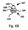
図6Bに示すように、少なくとも1つの光ガイド107は、少なくとも1つのLEDフィラメント103に機械的及び光学的に結合されている。LEDフィラメントは、例えばポリマー材料などの封入材116によって封入されてもよい。例えば、ポリマー材料はシリコーンであってもよい。得られる効果は、光学的結合の改善である。この理由は、シリコーンが、LEDフィラメント103の光ガイド107への機械的及び光学的結合を改善したことである。封入材116は、無機蛍光体、有機蛍光体、又は量子ドット若しくは量子ロッドなどのルミネッセント材料を含んでもよい。ルミネッセント材料は、例えば、封入材116中に分散されていてもよい。
As shown in FIG. 6B, at least one
図6Cに示すように、少なくとも1つの光ガイド107は、少なくとも1つのLEDフィラメント103に機械的及び光学的に結合されている。光ガイドは、例えば、封入材116によって部分的に取り囲まれていてもよい。
As shown in FIG. 6C, at least one
図7a~図7dは、本発明の別の実施形態による、LEDフィラメント103及び光ガイド107のXZ平面での、より詳細な断面を概略的に示す。図7Aに示すように、光ガイド107は、例えばTiO2、BaSO4、及び/若しくはAl2O3の粒子又は気泡などの散乱材料119を含んでもよい。得られる効果は、光106の光ガイド107へのインカップルの改善である。この理由は、光106が光ガイド107にインカップルされるように、光106が散乱材料119によってリダイレクトされるためである。
7a-7d schematically show a more detailed cross section of the
図7Bに示すように、光ガイド107は、例えば、TiO2、BaSO4、及び/又はAl2O3の粒子をベースにした材料などの、例えば拡散反射材料などのリフレクタ120を備えてもよい。得られる効果は、光106の光ガイド107へのインカップルの改善である。この理由は、光106が光ガイド107にインカップルされるように、光106がリフレクタ120によってリダイレクトされるためである。
As shown in FIG. 7B, the
図7Cに示すように、光ガイド107は、屈折構造121を備えてもよい。得られる効果は、光106の光ガイド107へのインカップルの改善である。この理由は、光106が光ガイド107にインカップルされるように、光106が屈折構造121によってリダイレクトされるためである。
As shown in FIG. 7C, the
図7Dに示すように、光ガイド107封入材116は、光ガイドによって部分的に取り囲まれ、屈折構造121を備えてもよい。得られる効果は、光106の光ガイド107へのインカップルの改善である。この理由は、光106が光ガイド107にインカップルされるように、光106が屈折構造121によってリダイレクトされるためである。
As shown in FIG. 7D, the
図7a~7図dは、機械的及び光学的に結合されたLEDフィラメント103及び光ガイド107の、より詳細な断面を概略的に示す。LEDフィラメント103及び光ガイド107はまた、互いにゼロとは異なる距離に配置されていてもよい。
7a-7d show schematically more detailed cross sections of the mechanically and optically coupled
図8は、本発明の別の実施形態による、LEDフィラメント103及び光ガイド107のXY平面での、より詳細な断面を概略的に示す。照明デバイス100は、少なくとも1つの更なる光源114を備える。少なくとも1つの更なる光源114によって放出される光106の少なくとも一部は、少なくとも1つの光ガイド107にインカップルされる。少なくとも1つの更なる光源は、更なる光源キャリア上に構成されていてもよい。
FIG. 8 schematically shows a more detailed cross section of the
図9a~図9dは、本発明の別の実施形態による、LEDフィラメント103及び光ガイド107のZ方向での、より詳細な図を概略的に示す。図9aに示すように、光ガイド107は第1の部分及び第2の部分を有する。LEDフィラメント103は第1の部分及び第2の部分を有する。光ガイド107の第1の部分は、LEDフィラメント103の第1の部分の周囲に巻かれている。光ガイド107の第2の部分は、LEDフィラメント103の周囲には巻かれておらず、装飾用の発光ループを提供する。
9a-9d schematically show a more detailed view of the
図9bに示すように、光ガイド107は第1の部分及び第2の部分を有する。第1のLEDフィラメント103'は第1の部分及び第2の部分を有する。第2のLEDフィラメント103"は、第1の部分及び第2の部分を有する。光ガイド107の第1の部分は、第1のLEDフィラメント103の第1の部分の周囲に巻かれている。光ガイド107の第2の部分は、第2のLEDフィラメント103"の第1の部分の周囲に巻かれている。光ガイド107は、第1のLEDフィラメント103'と第2のLEDフィラメント103"との間に装飾用の発光接続部を提供する。
As shown in FIG. 9b, the
図9cに示すように、光ガイド107は、第1のLEDフィラメント103'及び第2のLEDフィラメント103"の周囲に巻かれている。光ガイド107は、第1のLEDフィラメント103'と第2のLEDフィラメント103"との間に装飾用の発光接続部を提供する。そのような構成は、両方の種類のフィラメントを一体化した装飾的な照明効果を提供する。
As shown in FIG. 9c, the
図9dに示すように、光ガイド107は、第1のLEDフィラメント103'及び第2のLEDフィラメント103"の周囲に巻かれている。第1のLEDフィラメント103'は、第2のLEDフィラメント103"と非平行である。光ガイド107は、第1のLEDフィラメント103'と第2のLEDフィラメント103"との間に装飾用の発光接続部を提供する。そのような構成は、両方の種類のフィラメントを一体化した装飾的な照明効果を提供する。一実施形態では、複数のLEDフィラメント103が、複数の光ガイド107と組み合わされてもよい。例えば、2つのLEDフィラメント103が、2つの光ガイド107と組み合わされてもよい。例えば、図9Aに示す構成の2倍の構成が使用されてもよい。
As shown in FIG. 9d, the
一実施形態では、少なくとも1つの光ガイド107の少なくとも第1の部分は、少なくとも1つのLEDフィラメント103の第1の部分に機械的及び光学的に結合され、少なくとも1つの光ガイド107の少なくとも第2の部分は、少なくとも1つのLEDフィラメント103の第2の部分に機械的及び光学的に結合されている。
In one embodiment, at least the first portion of the at least one
一実施形態では、少なくとも1つの光ガイド107の平均強度は、少なくとも1つのLEDフィラメント103の平均強度の0.5倍から少なくとも1つのLEDフィラメント103の平均強度の2倍の範囲にある。このようにして、光ガイド107及びLEDフィラメント103は、ほぼ同じ外観を有する。
In one embodiment, the average intensity of at least one
図10は、本発明の一実施形態による、照明デバイス100のZ方向における図を概略的に示す。照明デバイスは、第1のLEDフィラメント103'、第2のLEDフィラメント103"、及び光ガイド107を備える。光ガイド107は、長手方向軸LAに沿って配置され、第1のLEDフィラメント103'及び第2のLEDフィラメント103"は、光ガイド107に対して非ゼロの距離に配置される。
FIG. 10 schematically shows a diagram of the
一実施形態では、少なくとも1つの光ガイド107の平均直径は、少なくとも1つのLEDフィラメント103の平均直径の0.5倍から少なくとも1つのLEDフィラメント103の平均直径の2倍の範囲にある。このようにして、光ガイド107及びLEDフィラメント103は、ほぼ同じ外観を有する。
In one embodiment, the average diameter of at least one
一実施形態では、少なくとも1つの光ガイド107の全長は、少なくとも1つの少なくとも1つのLEDフィラメント103の全長の少なくとも2倍である。
In one embodiment, the overall length of at least one
図11は、本発明の一実施形態による、光ガイド107のXY平面での断面図を概略的に示す。光ガイド107は、コア118及びクラッド117を備える。クラッド117は、コア118を少なくとも部分的に取り囲んでいる。クラッド118は、コア117よりも低い屈折率を有する。光106は、光ガイドを導波路として機能させる内部全反射111の現象によってコア117内に保持される。得られる効果は、光106がファイバの長さに沿って導かれ、複数の光アウトカップリング部109によって光ガイド107からアウトカップルされ得ることである。
FIG. 11 schematically shows a cross-sectional view of the
図12は、本発明の別の実施形態による照明デバイス100のブロック図を概略的に示す。照明デバイス100は、複数の光源105及び少なくとも1つの更なる光源114から放出される光108の量を別々に制御するための、複数の光源105及び少なくとも1つの更なる光源114に電気的に接続された制御ユニット115を備える。一実施形態では、制御ユニット115は、ユーザインタフェース、クロックモジュール、及び/又はセンサから受信した入力に基づいて、複数の光源105及び少なくとも1つの更なる光源114から放出される光108の量を制御してもよい。ユーザインタフェースは、例えば、タッチディスプレイであってもよい。センサは、例えば、光センサ及び/又は存在センサであってもよい。例えば、制御ユニット115は、周囲光の量に依存して、複数の光源105及び少なくとも1つの更なる光源114から放出される光108の量を別々に制御してもよい。例えば、センサが低い周囲光レベルを測定した場合、少なくとも1つの更なる光源114が、複数の光源105よりも相対的に多くの光を放出するように、制御ユニット115は、複数の光源105及び少なくとも1つの更なる光源114から放出される光108の量を別々に制御する。
FIG. 12 schematically shows a block diagram of a
複数の光源105及び/又は少なくとも1つの更なる光源114は、蛍光体変換発光ダイオード、直接放出発光ダイオード、蛍光体変換レーザーダイオード、及び直接放出レーザーダイオードからなる群から選択した。
The plurality of
照明デバイス100は、白色光を供給するように構成されていてもよい。本明細書での白色光という用語は、当業者には既知であり、約2.000K~20.000Kの相関色温度(correlated color temperature;CCT)を有する白色光に関する。一実施形態では、CCTは、2.500K~10.000Kである。通常、一般照明に関しては、CCTは、約2700K~6500Kの範囲である。好ましくは、本明細書での白色光という用語は、BBL(black body locus;黒体軌跡)から約15、10、又は5SDCM(standard deviation of color matching;等色標準偏差)以内のカラーポイントを有する白色光に関する。好ましくは、その用語は、少なくとも70~75の、一般照明に関しては少なくとも80~85の演色評価数(color rendering index;CRI)を有する、白色光に関する。
The
「実質的に全ての光(substantially all light)」、又は「実質的に成る(substantially consists)」などにおける、本明細書の「実質的に(substantially)」という用語は、当業者には理解されるであろう。用語「実質的に」はまた、「全体的に(entirely)」、「完全に(completely)」、「全て(all)」などを伴う実施形態も含み得る。それゆえ、実施形態では、(substantially)という形容詞はまた、削除される場合もある。適用可能な場合、用語「実質的に」はまた、95%以上、特に99%以上、更に特に99.5%以上などの、100%を含めた90%以上にも関連し得る。用語「備える(comprise)」は、用語「備える(comprise)」が「から成る(consists of)」を意味する実施形態もまた含む。用語「及び/又は」は、特に、その「及び/又は」の前後で言及された項目のうちの1つ以上に関連する。例えば、語句「項目1及び/又は項目2」、及び同様の語句は、項目1及び項目2のうちの1つ以上に関連し得る。用語「備える(comprising)」は、一実施形態では、「から成る(consisting of)」を指す場合もあるが、別の実施形態ではまた、「少なくとも定義されている種、及び任意選択的に1つ以上の他の種を包含する」も指す場合がある。 The term "substantially" herein is understood by those of skill in the art, such as "substantially all light" or "substantially consists". Will be. The term "substantially" may also include embodiments with "entirely", "completely", "all" and the like. Therefore, in embodiments, the adjective (substantially) may also be removed. Where applicable, the term "substantially" may also relate to 90% or more, including 100%, such as 95% or more, especially 99% or more, and even 99.5% or more. The term "comprise" also includes embodiments in which the term "comprise" means "consists of". The term "and / or" specifically relates to one or more of the items mentioned before and after the "and / or". For example, the phrase "item 1 and / or item 2", and similar terms may be associated with one or more of items 1 and 2. The term "comprising" may refer to "consisting of" in one embodiment, but also in another embodiment "at least a defined species, and optionally 1". It may also refer to "including one or more other species."
更には、明細書本文及び請求項での、第1、第2、第3などの用語は、類似の要素を区別するために使用されるものであり、必ずしも、連続的又は時系列的な順序を説明するために使用されるものではない。そのように使用される用語は、適切な状況下で交換可能であり、本明細書で説明される本発明の実施形態は、本明細書で説明又は図示されるもの以外の、他の順序での動作が可能である点を理解されたい。 Furthermore, terms such as first, second, and third in the text of the specification and claims are used to distinguish similar elements, and are not necessarily in continuous or chronological order. Is not used to explain. The terms so used are interchangeable under the appropriate circumstances and the embodiments of the invention described herein are in other order than those described or illustrated herein. Please understand that the operation of is possible.
本明細書のデバイスは、とりわけ、動作中について説明されている。当業者には明らかとなるように、本発明は、動作の方法又は動作中のデバイスに限定されるものではない。 The devices herein are described, among other things, in operation. As will be apparent to those skilled in the art, the present invention is not limited to the method of operation or the device in operation.
上述の実施形態は、本発明を限定するものではなく、むしろ例示するものであり、当業者は、添付の請求項の範囲から逸脱することなく、多くの代替的実施形態を設計することが可能となる点に留意されたい。請求項では、括弧内のいかなる参照符号も、その請求項を限定するものとして解釈されるべきではない。動詞「備える(to comprise)」及びその活用形の使用は、請求項に記述されたもの以外の要素又はステップが存在することを排除するものではない。要素に先行する冠詞「1つの(a)」又は「1つの(an)」は、複数のそのような要素が存在することを排除するものではない。本発明は、いくつかの個別要素を含むハードウェアによって、及び、好適にプログラムされたコンピュータによって実施されてもよい。いくつかの手段を列挙するデバイスの請求項では、これらの手段のうちのいくつかは、1つの同一のハードウェア物品によって具現化されてもよい。特定の手段が、互いに異なる従属請求項内に列挙されているという単なる事実は、これらの手段の組み合わせが、有利に使用され得ないことを示すものではない。 The embodiments described above are not limiting, but rather exemplary, the invention, allowing one of ordinary skill in the art to design many alternative embodiments without departing from the scope of the appended claims. Please note that In the claims, any reference code in parentheses should not be construed as limiting the claim. The use of the verb "to comprise" and its conjugations does not preclude the existence of elements or steps other than those described in the claims. The article "one (a)" or "one (an)" preceding an element does not preclude the existence of multiple such elements. The present invention may be carried out by hardware including several individual elements and by a suitablely programmed computer. In the device claim enumerating several means, some of these means may be embodied by one and the same hardware article. The mere fact that certain means are listed in different dependent claims does not indicate that a combination of these means cannot be used in an advantageous manner.
本発明は更に、明細書本文で説明される特徴及び/又は添付図面に示される特徴のうちの1つ以上を含む、デバイスに適用される。本発明は更に、明細書本文で説明される特徴及び/又は添付図面に示される特徴のうちの1つ以上を含む、方法又はプロセスに関する。 The invention further applies to devices comprising one or more of the features described in the text of the specification and / or the features shown in the accompanying drawings. The invention further relates to a method or process comprising one or more of the features described in the text of the specification and / or the features shown in the accompanying drawings.
本特許で論じられている様々な態様は、更なる利点をもたらすために組み合わされることも可能である。更には、当業者は、実施形態が組み合わされることが可能であり、また、3つ以上の実施形態が組み合わされることも可能である点を理解するであろう。更には、特徴のうちのいくつかは、1つ以上の分割出願のための基礎を形成し得るものである。 The various aspects discussed in this patent can also be combined to provide additional benefits. Furthermore, one of ordinary skill in the art will appreciate that embodiments can be combined and that three or more embodiments can be combined. Furthermore, some of the features can form the basis for one or more divisional applications.
Claims (15)
長手方向軸を有し、前記照明デバイスを前記照明器具の照明器具ソケットに接続するための電気コネクタを備える、口金と、
細長い本体を有する基材と、前記基材に機械的に結合され第1の空間光分布にて光を放出するように構成されている複数の光源とを備える、少なくとも1つのLEDフィラメントと、
細長い本体を有する少なくとも1つの光ガイドであって、前記少なくとも1つの光ガイドの少なくとも外周上にあって光を前記少なくとも1つの光ガイドにインカップルさせるための少なくとも1つの光インカップリング部と、第2の空間光分布にて前記少なくとも1つの光ガイドから光をアウトカップルさせるための複数の光アウトカップリング部と、を備える、少なくとも1つの光ガイドと、
前記少なくとも1つのLEDフィラメント及び前記少なくとも1つの光ガイドを、少なくとも部分的に封入する少なくとも部分的に光透過性のエンベロープと、を備え、
前記少なくとも1つの光ガイドは、前記少なくとも1つの光インカップリング部において前記少なくとも1つの光ガイドにインカップルされた前記光を、内部全反射を介して前記複数の光アウトカップリング部に導くように構成されており、
前記少なくとも1つのLEDフィラメントは、前記少なくとも1つの光ガイドの外部にあり、
前記複数の光源によって放出される前記光の少なくとも一部は、前記少なくとも1つの光ガイドにインカップルされ、
前記照明デバイスは、少なくとも1つの更なる光源を備え、前記少なくとも1つの更なる光源によって放出される前記光の少なくとも一部は、前記少なくとも1つの光ガイドにインカップルされる、
照明デバイス。 A lighting device for use in luminaires,
With a mouthpiece, which has a longitudinal axis and comprises an electrical connector for connecting the luminaire to the luminaire socket of the luminaire.
An at least one LED filament comprising a substrate having an elongated body and a plurality of light sources mechanically coupled to the substrate and configured to emit light in a first spatial light distribution.
An at least one optical in-coupling portion having an elongated body, which is on at least the outer periphery of the at least one optical guide and for incoupling light into the at least one optical guide. A plurality of optical guides comprising a plurality of optical out-coupling portions for outcoupled light from the at least one optical guide in a second spatial light distribution.
It comprises at least a partially light-transmitting envelope that at least partially encapsulates the at least one LED filament and the at least one light guide.
The at least one optical guide guides the light coupled to the at least one optical guide in the at least one optical in-coupling portion to the plurality of optical out-coupling portions via internal total internal reflection. Is configured in
The at least one LED filament is outside the at least one optical guide.
At least a portion of the light emitted by the plurality of light sources is coupled to the at least one light guide.
The lighting device comprises at least one additional light source, and at least a portion of the light emitted by the at least one additional light source is coupled to the at least one light guide.
Lighting device.
Applications Claiming Priority (3)
| Application Number | Priority Date | Filing Date | Title |
|---|---|---|---|
| EP17168998 | 2017-05-02 | ||
| EP17168998.7 | 2017-05-02 | ||
| PCT/EP2018/061039 WO2018202625A1 (en) | 2017-05-02 | 2018-04-30 | A lighting device and a luminaire |
Publications (3)
| Publication Number | Publication Date |
|---|---|
| JP2020518974A JP2020518974A (en) | 2020-06-25 |
| JP2020518974A5 JP2020518974A5 (en) | 2021-06-17 |
| JP7080253B2 true JP7080253B2 (en) | 2022-06-03 |
Family
ID=58668761
Family Applications (1)
| Application Number | Title | Priority Date | Filing Date |
|---|---|---|---|
| JP2019560106A Active JP7080253B2 (en) | 2017-05-02 | 2018-04-30 | Lighting devices and lighting fixtures |
Country Status (5)
| Country | Link |
|---|---|
| US (1) | US11015765B2 (en) |
| EP (1) | EP3619460B1 (en) |
| JP (1) | JP7080253B2 (en) |
| CN (1) | CN110573791B (en) |
| WO (1) | WO2018202625A1 (en) |
Families Citing this family (11)
| Publication number | Priority date | Publication date | Assignee | Title |
|---|---|---|---|---|
| CN113330245A (en) * | 2019-01-24 | 2021-08-31 | 昕诺飞控股有限公司 | LED filament device |
| US11353164B2 (en) * | 2019-02-28 | 2022-06-07 | Signify Holding B.V. | Filament lamp with reflector |
| WO2020207902A1 (en) * | 2019-04-11 | 2020-10-15 | Signify Holding B.V. | Solid state lamp |
| ES2935836T3 (en) | 2019-07-26 | 2023-03-10 | Signify Holding Bv | Arrangement of LED filaments |
| CN114423989A (en) | 2019-08-01 | 2022-04-29 | 昕诺飞控股有限公司 | Optical structure for producing decorative lighting effects |
| CN114556014A (en) | 2019-10-03 | 2022-05-27 | 昕诺飞控股有限公司 | LED filament lighting device |
| CN211578697U (en) * | 2020-01-15 | 2020-09-25 | 漳州立达信光电子科技有限公司 | Flexible filament lamp |
| CN115698582A (en) * | 2020-06-08 | 2023-02-03 | 昕诺飞控股有限公司 | Light emitting device with flashing effect |
| EP4182603B1 (en) * | 2020-07-16 | 2024-04-17 | Signify Holding B.V. | A light emitting device |
| US11873953B2 (en) | 2020-07-27 | 2024-01-16 | Signify Holding B.V. | Light emitting device |
| WO2023031314A1 (en) * | 2021-09-06 | 2023-03-09 | Signify Holding B.V. | A light emitting device |
Citations (5)
| Publication number | Priority date | Publication date | Assignee | Title |
|---|---|---|---|---|
| JP2012146738A (en) | 2011-01-07 | 2012-08-02 | Stanley Electric Co Ltd | Led module and led lamp |
| JP2014500605A (en) | 2010-12-22 | 2014-01-09 | コーニンクレッカ フィリップス エヌ ヴェ | LIGHTING DEVICE AND METHOD FOR MANUFACTURING LIGHTING DEVICE |
| JP2014110301A (en) | 2012-11-30 | 2014-06-12 | Panasonic Corp | Light-emitting device and illumination light source |
| JP2016066427A (en) | 2014-09-24 | 2016-04-28 | 東芝ライテック株式会社 | Light emission device and luminaire |
| US20160356461A1 (en) | 2015-06-05 | 2016-12-08 | Graphene Lighting Plc | LED light bulb simultaneously using as nightlight |
Family Cites Families (17)
| Publication number | Priority date | Publication date | Assignee | Title |
|---|---|---|---|---|
| CN100520152C (en) | 2004-09-29 | 2009-07-29 | 皇家飞利浦电子股份有限公司 | Lighting device |
| US8890401B2 (en) * | 2008-02-25 | 2014-11-18 | Illumination Machines, Llc | Solid-state luminescent filament lamps |
| EP2386044B1 (en) | 2009-01-09 | 2015-07-29 | Koninklijke Philips N.V. | Light source with leds, light guide and reflector |
| US8750671B1 (en) * | 2009-04-16 | 2014-06-10 | Fusion Optix, Inc | Light bulb with omnidirectional output |
| JP5073107B2 (en) | 2010-12-24 | 2012-11-14 | パナソニック株式会社 | Light bulb shaped lamp and lighting device |
| US9028120B2 (en) * | 2011-08-08 | 2015-05-12 | Quarkstar Llc | Illumination devices including multiple light emitting elements |
| KR20140097346A (en) * | 2011-12-14 | 2014-08-06 | 지이 라이팅 솔루션스, 엘엘씨 | Side-emitting guidepipe technology on led lamp to make filament effect |
| US9677738B2 (en) * | 2013-03-15 | 2017-06-13 | 1947796 Ontario Inc. | Optical device and system for solid-state lighting |
| CN103712105A (en) | 2013-12-26 | 2014-04-09 | 四川柏狮光电技术有限公司 | Full light distribution type LED bulb lamp with twisted-line-shaped lamp filaments distributed |
| WO2015124469A1 (en) * | 2014-02-24 | 2015-08-27 | Koninklijke Philips N.V. | Lamp assembly |
| CN105074321A (en) | 2014-03-13 | 2015-11-18 | 皇家飞利浦有限公司 | Filament for lighting device |
| DE102014213388A1 (en) | 2014-07-09 | 2016-01-14 | Osram Gmbh | Semiconductor lamp |
| CN204254304U (en) * | 2014-09-24 | 2015-04-08 | 浙江承康机电制造有限公司 | A kind of LED |
| CN107208849B (en) * | 2015-02-12 | 2020-05-01 | 飞利浦照明控股有限公司 | Lighting module and lighting device comprising same |
| CN106151934A (en) * | 2015-04-20 | 2016-11-23 | 葛兰菲照明有限公司 | Integrating illumination and the LED bulb of night-light function |
| GB2539190B (en) | 2015-06-05 | 2021-02-03 | Graphene Lighting Plc | An LED light bulb |
| CN205137115U (en) * | 2015-11-03 | 2016-04-06 | 厦门多彩光电子科技有限公司 | LED filament lamp |
-
2018
- 2018-04-30 US US16/610,378 patent/US11015765B2/en active Active
- 2018-04-30 WO PCT/EP2018/061039 patent/WO2018202625A1/en unknown
- 2018-04-30 CN CN201880028651.8A patent/CN110573791B/en active Active
- 2018-04-30 JP JP2019560106A patent/JP7080253B2/en active Active
- 2018-04-30 EP EP18719216.6A patent/EP3619460B1/en active Active
Patent Citations (5)
| Publication number | Priority date | Publication date | Assignee | Title |
|---|---|---|---|---|
| JP2014500605A (en) | 2010-12-22 | 2014-01-09 | コーニンクレッカ フィリップス エヌ ヴェ | LIGHTING DEVICE AND METHOD FOR MANUFACTURING LIGHTING DEVICE |
| JP2012146738A (en) | 2011-01-07 | 2012-08-02 | Stanley Electric Co Ltd | Led module and led lamp |
| JP2014110301A (en) | 2012-11-30 | 2014-06-12 | Panasonic Corp | Light-emitting device and illumination light source |
| JP2016066427A (en) | 2014-09-24 | 2016-04-28 | 東芝ライテック株式会社 | Light emission device and luminaire |
| US20160356461A1 (en) | 2015-06-05 | 2016-12-08 | Graphene Lighting Plc | LED light bulb simultaneously using as nightlight |
Also Published As
| Publication number | Publication date |
|---|---|
| US11015765B2 (en) | 2021-05-25 |
| CN110573791A (en) | 2019-12-13 |
| US20200141541A1 (en) | 2020-05-07 |
| WO2018202625A1 (en) | 2018-11-08 |
| EP3619460A1 (en) | 2020-03-11 |
| JP2020518974A (en) | 2020-06-25 |
| EP3619460B1 (en) | 2021-03-24 |
| CN110573791B (en) | 2022-03-04 |
Similar Documents
| Publication | Publication Date | Title |
|---|---|---|
| JP7080253B2 (en) | Lighting devices and lighting fixtures | |
| EP3775674B1 (en) | Led filament lamp of candle light appearance | |
| JP5711147B2 (en) | Light source with LED, light guide and reflector | |
| JP5734204B2 (en) | Optical element and light source having the optical element | |
| KR101839417B1 (en) | Light source with leds, light guide and reflector | |
| JP6936418B2 (en) | LED filament lamp | |
| CN109716013A (en) | Luminescent device | |
| CN114731748A (en) | LED filament and LED filament lamp | |
| US11719392B2 (en) | LED filament lamp that combines the advantages of LED lighting with the attractiveness and appeal of light emitted from a candle | |
| JP2013200963A (en) | Semiconductor light source, and lighting device | |
| US11519563B2 (en) | Light-emitting device | |
| JP6395033B2 (en) | Lighting device | |
| CN113330245A (en) | LED filament device | |
| US8882305B2 (en) | Bulb-type lamp and luminaire | |
| CN117916638A (en) | Light emitting device | |
| KR101043597B1 (en) | Light guide cap, and lamp including the same | |
| CN117561400A (en) | LED filament device |
Legal Events
| Date | Code | Title | Description |
|---|---|---|---|
| A521 | Request for written amendment filed |
Free format text: JAPANESE INTERMEDIATE CODE: A523 Effective date: 20210428 |
|
| A621 | Written request for application examination |
Free format text: JAPANESE INTERMEDIATE CODE: A621 Effective date: 20210428 |
|
| TRDD | Decision of grant or rejection written | ||
| A01 | Written decision to grant a patent or to grant a registration (utility model) |
Free format text: JAPANESE INTERMEDIATE CODE: A01 Effective date: 20220425 |
|
| A977 | Report on retrieval |
Free format text: JAPANESE INTERMEDIATE CODE: A971007 Effective date: 20220427 |
|
| A61 | First payment of annual fees (during grant procedure) |
Free format text: JAPANESE INTERMEDIATE CODE: A61 Effective date: 20220524 |
|
| R150 | Certificate of patent or registration of utility model |
Ref document number: 7080253 Country of ref document: JP Free format text: JAPANESE INTERMEDIATE CODE: R150 |