JP7570053B2 - 流体容器及び熱交換装置 - Google Patents
流体容器及び熱交換装置 Download PDFInfo
- Publication number
- JP7570053B2 JP7570053B2 JP2020086797A JP2020086797A JP7570053B2 JP 7570053 B2 JP7570053 B2 JP 7570053B2 JP 2020086797 A JP2020086797 A JP 2020086797A JP 2020086797 A JP2020086797 A JP 2020086797A JP 7570053 B2 JP7570053 B2 JP 7570053B2
- Authority
- JP
- Japan
- Prior art keywords
- fluid
- container body
- inclined portion
- heat exchange
- supply
- Prior art date
- Legal status (The legal status is an assumption and is not a legal conclusion. Google has not performed a legal analysis and makes no representation as to the accuracy of the status listed.)
- Active
Links
Images


Classifications
-
- F—MECHANICAL ENGINEERING; LIGHTING; HEATING; WEAPONS; BLASTING
- F28—HEAT EXCHANGE IN GENERAL
- F28C—HEAT-EXCHANGE APPARATUS, NOT PROVIDED FOR IN ANOTHER SUBCLASS, IN WHICH THE HEAT-EXCHANGE MEDIA COME INTO DIRECT CONTACT WITHOUT CHEMICAL INTERACTION
- F28C3/00—Other direct-contact heat-exchange apparatus
- F28C3/04—Other direct-contact heat-exchange apparatus the heat-exchange media both being liquids
-
- F—MECHANICAL ENGINEERING; LIGHTING; HEATING; WEAPONS; BLASTING
- F01—MACHINES OR ENGINES IN GENERAL; ENGINE PLANTS IN GENERAL; STEAM ENGINES
- F01K—STEAM ENGINE PLANTS; STEAM ACCUMULATORS; ENGINE PLANTS NOT OTHERWISE PROVIDED FOR; ENGINES USING SPECIAL WORKING FLUIDS OR CYCLES
- F01K3/00—Plants characterised by the use of steam or heat accumulators, or intermediate steam heaters, therein
- F01K3/18—Plants characterised by the use of steam or heat accumulators, or intermediate steam heaters, therein having heaters
- F01K3/185—Plants characterised by the use of steam or heat accumulators, or intermediate steam heaters, therein having heaters using waste heat from outside the plant
-
- F—MECHANICAL ENGINEERING; LIGHTING; HEATING; WEAPONS; BLASTING
- F22—STEAM GENERATION
- F22B—METHODS OF STEAM GENERATION; STEAM BOILERS
- F22B1/00—Methods of steam generation characterised by form of heating method
- F22B1/02—Methods of steam generation characterised by form of heating method by exploitation of the heat content of hot heat carriers
- F22B1/16—Methods of steam generation characterised by form of heating method by exploitation of the heat content of hot heat carriers the heat carrier being hot liquid or hot vapour, e.g. waste liquid, waste vapour
-
- F—MECHANICAL ENGINEERING; LIGHTING; HEATING; WEAPONS; BLASTING
- F24—HEATING; RANGES; VENTILATING
- F24T—GEOTHERMAL COLLECTORS; GEOTHERMAL SYSTEMS
- F24T10/00—Geothermal collectors
- F24T10/20—Geothermal collectors using underground water as working fluid; using working fluid injected directly into the ground, e.g. using injection wells and recovery wells
-
- F—MECHANICAL ENGINEERING; LIGHTING; HEATING; WEAPONS; BLASTING
- F24—HEATING; RANGES; VENTILATING
- F24T—GEOTHERMAL COLLECTORS; GEOTHERMAL SYSTEMS
- F24T50/00—Geothermal systems
-
- F—MECHANICAL ENGINEERING; LIGHTING; HEATING; WEAPONS; BLASTING
- F28—HEAT EXCHANGE IN GENERAL
- F28F—DETAILS OF HEAT-EXCHANGE AND HEAT-TRANSFER APPARATUS, OF GENERAL APPLICATION
- F28F13/00—Arrangements for modifying heat-transfer, e.g. increasing, decreasing
- F28F13/06—Arrangements for modifying heat-transfer, e.g. increasing, decreasing by affecting the pattern of flow of the heat-exchange media
-
- F—MECHANICAL ENGINEERING; LIGHTING; HEATING; WEAPONS; BLASTING
- F28—HEAT EXCHANGE IN GENERAL
- F28F—DETAILS OF HEAT-EXCHANGE AND HEAT-TRANSFER APPARATUS, OF GENERAL APPLICATION
- F28F19/00—Preventing the formation of deposits or corrosion, e.g. by using filters or scrapers
-
- F—MECHANICAL ENGINEERING; LIGHTING; HEATING; WEAPONS; BLASTING
- F28—HEAT EXCHANGE IN GENERAL
- F28F—DETAILS OF HEAT-EXCHANGE AND HEAT-TRANSFER APPARATUS, OF GENERAL APPLICATION
- F28F1/00—Tubular elements; Assemblies of tubular elements
- F28F1/10—Tubular elements and assemblies thereof with means for increasing heat-transfer area, e.g. with fins, with projections, with recesses
- F28F1/40—Tubular elements and assemblies thereof with means for increasing heat-transfer area, e.g. with fins, with projections, with recesses the means being only inside the tubular element
-
- F—MECHANICAL ENGINEERING; LIGHTING; HEATING; WEAPONS; BLASTING
- F28—HEAT EXCHANGE IN GENERAL
- F28F—DETAILS OF HEAT-EXCHANGE AND HEAT-TRANSFER APPARATUS, OF GENERAL APPLICATION
- F28F13/00—Arrangements for modifying heat-transfer, e.g. increasing, decreasing
- F28F13/06—Arrangements for modifying heat-transfer, e.g. increasing, decreasing by affecting the pattern of flow of the heat-exchange media
- F28F13/08—Arrangements for modifying heat-transfer, e.g. increasing, decreasing by affecting the pattern of flow of the heat-exchange media by varying the cross-section of the flow channels
-
- F—MECHANICAL ENGINEERING; LIGHTING; HEATING; WEAPONS; BLASTING
- F28—HEAT EXCHANGE IN GENERAL
- F28F—DETAILS OF HEAT-EXCHANGE AND HEAT-TRANSFER APPARATUS, OF GENERAL APPLICATION
- F28F3/00—Plate-like or laminated elements; Assemblies of plate-like or laminated elements
- F28F3/02—Elements or assemblies thereof with means for increasing heat-transfer area, e.g. with fins, with recesses, with corrugations
- F28F3/04—Elements or assemblies thereof with means for increasing heat-transfer area, e.g. with fins, with recesses, with corrugations the means being integral with the element
- F28F3/048—Elements or assemblies thereof with means for increasing heat-transfer area, e.g. with fins, with recesses, with corrugations the means being integral with the element in the form of ribs integral with the element or local variations in thickness of the element, e.g. grooves, microchannels
-
- F—MECHANICAL ENGINEERING; LIGHTING; HEATING; WEAPONS; BLASTING
- F28—HEAT EXCHANGE IN GENERAL
- F28F—DETAILS OF HEAT-EXCHANGE AND HEAT-TRANSFER APPARATUS, OF GENERAL APPLICATION
- F28F9/00—Casings; Header boxes; Auxiliary supports for elements; Auxiliary members within casings
- F28F9/24—Arrangements for promoting turbulent flow of heat-exchange media, e.g. by plates
-
- Y—GENERAL TAGGING OF NEW TECHNOLOGICAL DEVELOPMENTS; GENERAL TAGGING OF CROSS-SECTIONAL TECHNOLOGIES SPANNING OVER SEVERAL SECTIONS OF THE IPC; TECHNICAL SUBJECTS COVERED BY FORMER USPC CROSS-REFERENCE ART COLLECTIONS [XRACs] AND DIGESTS
- Y02—TECHNOLOGIES OR APPLICATIONS FOR MITIGATION OR ADAPTATION AGAINST CLIMATE CHANGE
- Y02E—REDUCTION OF GREENHOUSE GAS [GHG] EMISSIONS, RELATED TO ENERGY GENERATION, TRANSMISSION OR DISTRIBUTION
- Y02E10/00—Energy generation through renewable energy sources
- Y02E10/10—Geothermal energy
Landscapes
- Engineering & Computer Science (AREA)
- Mechanical Engineering (AREA)
- General Engineering & Computer Science (AREA)
- Life Sciences & Earth Sciences (AREA)
- Physics & Mathematics (AREA)
- Thermal Sciences (AREA)
- Sustainable Development (AREA)
- Sustainable Energy (AREA)
- Chemical & Material Sciences (AREA)
- Combustion & Propulsion (AREA)
- Hydrology & Water Resources (AREA)
- Heat-Exchange Devices With Radiators And Conduit Assemblies (AREA)
Description
こうした従来の直接接触式の熱交換器の一例として、特開平8-82490号公報に記載されるものがある。
しかしながら、こうした従来の熱交換器では、依然として、熱源となる液相流体を一時的に内部に収め、内壁面がこの液相流体と接触するシェル(外殻容器)を必要としており、熱源流体が地熱水等の腐食性やスケール析出性を有する液体(以下、腐食性液体等)である場合、これを入れる容器は、腐食による損傷リスクや頻繁なメンテナンスの必要性があるため、より耐食性のある高級金属の適用や容器内面に樹脂や高級金属によるライニングやコーティングの施工もしくは電気化学的な防食を講じる必要があり、やはり高コストとなってしまうという課題を有していた。
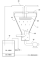
以下、本発明の第1の実施形態を図1ないし図4に基づいて説明する。本実施形態においては、地熱流体の熱をバイナリーサイクル方式で動力に変換して発電を行う地熱発電システムに用いられる熱交換装置の例について説明する。
また、前記発電機80は、公知の蒸気動力サイクルにおけるタービン等の膨張機72を駆動源とする発電に用いられるのと同様のものであり、詳細な説明を省略する。
測定部55は、第二流体排出部50で容器本体10から排出された後で、且つ蒸発器71に達する前の段階における第二の流体の電気伝導率を測定するものであり、この測定で得られた電気伝導率から、第二の流体中における第一の流体の混入度合いを取得可能としている。
第一の流体と第二の流体とは互いに溶け合わない性質を有するため、これら二つの液体は容器本体10内部で混ざり合わず、分離した状態を維持する。
こうして第二流体排出部50の排出経路を蒸発器71へ向かう中で、第二の流体は測定部55により電気伝導率を測定される。
本発明の第2の実施形態を図6及び図7に基づいて説明する。
前記各図において本実施形態に係る熱交換装置は、前記第1の実施形態同様、容器本体10と、第一流体供給部20と、第二流体供給部30と、第一流体排出部40と、第二流体排出部50とを備える一方、異なる点として、第二流体供給部30における第二の流体の容器本体10内部への供給方向をする構成を有するものである。なお、容器本体10、第一流体供給部20、第一流体排出部40、及び第二流体排出部50については、前記第1の実施形態と同様のものであり、詳細な説明を省略する。
また、前記熱交換装置1と共に地熱発電システム100をなす蒸気動力サイクル部70及び発電部80については、前記第1の実施形態と同様のものであり、説明を省略する。
そして、第二の流体は、傾斜部11の内側面上で螺旋状に流下することで、傾斜部11の内側面に沿う第二の流体の層を形成する。
第一の流体と第二の流体とは互いに溶け合わない性質を有するため、これら二つの液体は容器本体10内部で混ざり合わず、分離した状態を維持する。
そして、蒸気動力サイクル部70の蒸発器71では、第二の流体が作動流体と熱交換して、作動流体の温度を上昇させ、作動流体を蒸発させる。
10 容器本体
11 傾斜部
15 案内部
17 段部
18 蓋
20 第一流体供給部
30 第二流体供給部
35 供給手段
40 第一流体排出部
50 第二流体排出部
51 ポンプ
55 測定部
60 沈殿槽
70 蒸気動力サイクル部
71 蒸発器
72 膨張機
73 凝縮器
74 ポンプ
80 発電機
90 気液分離器
100 地熱発電システム
Claims (6)
- 内部の空間部分に流体を収容可能とされ、金属に対する腐食性及び/又はスケールの易析出性を有する第一の流体と当該第一の流体に対し比重大で且つ不溶である第二の流体とがそれぞれ流入出可能とされる容器本体と、
当該容器本体内部に対し前記第一の流体を外部から供給可能とする第一流体供給部と、
前記容器本体における前記第一の流体の供給位置より上側となる所定高さ位置で、前記第二の流体を容器本体の内側面に沿わせる状態で容器本体内部に供給する第二流体供給部と、
前記容器本体内部における前記第一の流体の供給位置より上側で且つ前記第二の流体の供給位置より下側の位置から前記第一の流体を外部に排出可能とする第一流体排出部と、
前記容器本体における前記第一の流体の供給位置より下側の所定部位から前記第二の流体を外部に排出する第二流体排出部とを備え、
前記容器本体の内側面のうち、少なくとも容器本体の内部で前記第一の流体の存在し得る高さ範囲が、上に向けて拡開状となるように傾けて形成される傾斜部とされ、
前記第二流体排出部が、第二の流体の排出経路に、当該排出経路内部を流れる第二の流体の電気伝導率を測定可能とする測定部を設けられ、
当該測定部が、前記容器本体から排出されて以降の所定段階における第二の流体の電気伝導率を測定し、
当該測定で得られた電気伝導率から、第二の流体中における第一の流体の混入度合いを取得し、当該混入度合いに基づいて前記容器本体における第一の流体と第二の流体の各流量の調整を行い、
前記第二の流体が、前記第二流体供給部により、前記容器本体内部の空間部分を取り囲むように容器本体内側面全周にわたって供給され、内側面に沿う流体の層を形成しつつ流下して、容器本体における第二の流体の排出位置に達することを
特徴とする流体容器。 - 前記請求項1に記載の流体容器において、
前記容器本体が、内側面の前記傾斜部を略円錐面状とされてなり、
前記第二流体供給部が、前記第二の流体を、前記容器本体の傾斜部における横断面の円周の接線方向に速度成分を有する供給方向として供給し、第二の流体が傾斜部を螺旋状に流下して、前記内側面に沿う流体の層を形成する状態を生じさせることを
特徴とする流体容器。 - 前記請求項2に記載の流体容器において、
前記容器本体が、内側面の前記傾斜部に、第二の流体の螺旋状の流れを案内する突条状の案内部を配設されることを
特徴とする流体容器。 - 前記請求項1ないし3のいずれかに記載の流体容器が、高温である熱源流体を前記第一の流体とされると共に、前記熱源流体と熱交換させる液相の熱媒体を前記第二の流体とされて、前記容器本体で第一の流体と第二の流体とを直接接触させて熱交換を行わせるものとされると共に、
前記第二流体供給部が、前記第二流体排出部により前記容器本体から排出されて外部に達し、他の熱交換対象媒体と熱交換した第二の流体をあらためて導入され、当該第二の流体を容器本体内部に供給して、第二の流体を循環使用可能とされることを
特徴とする熱交換装置。 - 前記請求項4に記載の熱交換装置において、
前記容器本体内部における第一の流体の存在する領域に対し、前記第二流体供給部によ
る供給分とは別に前記第二の流体を供給する供給手段が設けられ、
当該供給手段から前記第二の流体を第一の流体に撒布し、第一の流体中で第二の流体の液滴を沈降させ、第一の流体の存在する領域を通過した第二の流体の液滴を、前記第二流体供給部から供給された第二の流体に合流させることを
特徴とする熱交換装置。 - 前記請求項4又は5に記載の熱交換装置において、
前記容器本体内部から前記第一流体排出部で外部に取り出された第一の流体を導入可能とされる沈殿槽が設けられ、
当該沈殿槽が、第一の流体を所定量滞留状態として、前記容器本体で第一の流体中に混入した第二の流体を沈降させ、第一の流体から分離可能とすることを
特徴とする熱交換装置。
Priority Applications (4)
| Application Number | Priority Date | Filing Date | Title |
|---|---|---|---|
| JP2020086797A JP7570053B2 (ja) | 2020-05-18 | 2020-05-18 | 流体容器及び熱交換装置 |
| PCT/JP2021/018871 WO2021235456A1 (ja) | 2020-05-18 | 2021-05-18 | 流体容器及び熱交換装置 |
| US17/998,915 US20230213286A1 (en) | 2020-05-18 | 2021-05-18 | Fluid container and heat exchange apparatus |
| EP21809319.3A EP4155644A4 (en) | 2020-05-18 | 2021-05-18 | Fluid container and heat exchange device |
Applications Claiming Priority (1)
| Application Number | Priority Date | Filing Date | Title |
|---|---|---|---|
| JP2020086797A JP7570053B2 (ja) | 2020-05-18 | 2020-05-18 | 流体容器及び熱交換装置 |
Publications (2)
| Publication Number | Publication Date |
|---|---|
| JP2021181841A JP2021181841A (ja) | 2021-11-25 |
| JP7570053B2 true JP7570053B2 (ja) | 2024-10-21 |
Family
ID=78606391
Family Applications (1)
| Application Number | Title | Priority Date | Filing Date |
|---|---|---|---|
| JP2020086797A Active JP7570053B2 (ja) | 2020-05-18 | 2020-05-18 | 流体容器及び熱交換装置 |
Country Status (4)
| Country | Link |
|---|---|
| US (1) | US20230213286A1 (ja) |
| EP (1) | EP4155644A4 (ja) |
| JP (1) | JP7570053B2 (ja) |
| WO (1) | WO2021235456A1 (ja) |
Families Citing this family (1)
| Publication number | Priority date | Publication date | Assignee | Title |
|---|---|---|---|---|
| WO2024248057A1 (ja) * | 2023-05-29 | 2024-12-05 | 国立大学法人東京海洋大学 | 流路維持システムおよび流路維持方法 |
Citations (5)
| Publication number | Priority date | Publication date | Assignee | Title |
|---|---|---|---|---|
| WO2006029457A1 (en) | 2004-09-16 | 2006-03-23 | Rheem Australia Pty Limited | Drain back water heater |
| JP2012101194A (ja) | 2010-11-11 | 2012-05-31 | Kurita Water Ind Ltd | 薬注装置、循環冷却システム及び膜分離システム |
| JP2019109991A (ja) | 2017-12-15 | 2019-07-04 | 京セラ株式会社 | 燃料電池装置 |
| JP2019196854A (ja) | 2018-05-08 | 2019-11-14 | 国立大学法人東京海洋大学 | スケール対策が施された熱交換装置 |
| WO2020031667A1 (ja) | 2018-08-06 | 2020-02-13 | 三菱日立パワーシステムズ株式会社 | 酸電気伝導率の測定装置及び方法並びに蒸気タービンプラント |
Family Cites Families (18)
| Publication number | Priority date | Publication date | Assignee | Title |
|---|---|---|---|---|
| US3254048A (en) * | 1963-12-24 | 1966-05-31 | Ruhrchemie Ag | Process for separating at least two immiscible liquids by causing interpenetration and intermixing of liquids of different densities |
| US3409273A (en) * | 1967-11-17 | 1968-11-05 | American Colloid Co | Method and apparatus for blending pulverulent materials |
| JPS4830936B1 (ja) * | 1968-09-09 | 1973-09-25 | ||
| US3734160A (en) * | 1970-05-15 | 1973-05-22 | Hydro Chem & Mineral Corp | Flash evaporation using surface active agent and immiscible liquid |
| GB1363449A (en) * | 1970-10-12 | 1974-08-14 | Hydro Chem & Mineral Corp | Liquid-liquid heat exchange |
| JPS5125980B2 (ja) * | 1972-12-15 | 1976-08-03 | ||
| JPS5187847A (ja) * | 1975-01-30 | 1976-07-31 | Seiichi Awano | Netsukokansochi |
| JPS5226050A (en) * | 1975-08-22 | 1977-02-26 | Mitsubishi Heavy Ind Ltd | Opposed current heat-exchanger |
| JPS5852426Y2 (ja) * | 1978-04-17 | 1983-11-29 | 株式会社同和 | 直火式温水器における仕切壁の焼損防止装置 |
| JPS5918383A (ja) * | 1982-07-21 | 1984-01-30 | Hitachi Ltd | 直接液−液接触式熱交換器 |
| JPH0791866A (ja) * | 1993-09-21 | 1995-04-07 | Toshiba Corp | 熱交換器 |
| JPH07159059A (ja) * | 1993-12-01 | 1995-06-20 | Toshiba Corp | 熱交換装置 |
| JPH0882490A (ja) | 1994-09-12 | 1996-03-26 | Toshiba Keiso Kk | 熱交換器 |
| US6119458A (en) * | 1998-12-29 | 2000-09-19 | Harris; James Jeffrey | Immiscible, direct contact, floating bed enhanced, liquid/liquid heat transfer process |
| US9957208B2 (en) * | 2014-08-12 | 2018-05-01 | Basf Se | Process for preparing 1,3-butadiene from N-butenes by oxidative dehydrogenation |
| US20170108280A1 (en) * | 2015-10-20 | 2017-04-20 | James Jeffrey Harris | Moving film, direct contact, liquid to liquid heat transfer process |
| JP6729302B2 (ja) * | 2016-11-01 | 2020-07-22 | 住友金属鉱山株式会社 | 向流式直接加熱型熱交換器 |
| CN207585387U (zh) * | 2017-12-06 | 2018-07-06 | 葫芦岛中益能环保技术有限公司 | 供水调温罐 |
-
2020
- 2020-05-18 JP JP2020086797A patent/JP7570053B2/ja active Active
-
2021
- 2021-05-18 US US17/998,915 patent/US20230213286A1/en not_active Abandoned
- 2021-05-18 EP EP21809319.3A patent/EP4155644A4/en not_active Withdrawn
- 2021-05-18 WO PCT/JP2021/018871 patent/WO2021235456A1/ja not_active Ceased
Patent Citations (5)
| Publication number | Priority date | Publication date | Assignee | Title |
|---|---|---|---|---|
| WO2006029457A1 (en) | 2004-09-16 | 2006-03-23 | Rheem Australia Pty Limited | Drain back water heater |
| JP2012101194A (ja) | 2010-11-11 | 2012-05-31 | Kurita Water Ind Ltd | 薬注装置、循環冷却システム及び膜分離システム |
| JP2019109991A (ja) | 2017-12-15 | 2019-07-04 | 京セラ株式会社 | 燃料電池装置 |
| JP2019196854A (ja) | 2018-05-08 | 2019-11-14 | 国立大学法人東京海洋大学 | スケール対策が施された熱交換装置 |
| WO2020031667A1 (ja) | 2018-08-06 | 2020-02-13 | 三菱日立パワーシステムズ株式会社 | 酸電気伝導率の測定装置及び方法並びに蒸気タービンプラント |
Also Published As
| Publication number | Publication date |
|---|---|
| US20230213286A1 (en) | 2023-07-06 |
| EP4155644A4 (en) | 2024-06-19 |
| JP2021181841A (ja) | 2021-11-25 |
| WO2021235456A1 (ja) | 2021-11-25 |
| EP4155644A1 (en) | 2023-03-29 |
Similar Documents
| Publication | Publication Date | Title |
|---|---|---|
| US20110083619A1 (en) | Dual enhanced tube for vapor generator | |
| González-Gómez et al. | Thermo-economic optimization of molten salt steam generators | |
| CN102168848A (zh) | 一种直接产生蒸汽的高温混凝土储热器 | |
| JP7570053B2 (ja) | 流体容器及び熱交換装置 | |
| CN101976987A (zh) | 以热载体为热媒的工业余热半导体发电方法及装置 | |
| CN118749057A (zh) | 电和高温能存储装置 | |
| US5795446A (en) | Method and equipment for heat-of-vaporization transfer | |
| CN114743697A (zh) | 一种基于通海冷却无时限热管堆非能动余热排出系统 | |
| JP6249314B2 (ja) | 熱回収装置 | |
| RU2373461C1 (ru) | Система теплоснабжения | |
| CN103964399B (zh) | 一种硫磺回收热量利用装置及方法 | |
| CN103268808A (zh) | 一种浸渍式蒸发冷却变压器 | |
| RU2616431C2 (ru) | Парогенератор | |
| CN100493692C (zh) | 利用恒温换热装置进行强放热反应的方法 | |
| CN109154253A (zh) | 热电发电装置 | |
| Bangerth et al. | Process intensification in a spinning disk absorber for absorption heat pumps | |
| CN104712525A (zh) | 多管式气泡泵装置 | |
| González-Gómez et al. | Assessment of evaporators using solar salt as heat transfer fluid | |
| EP3798516B1 (en) | Arrangement and method for transferring heat | |
| CN103884007B (zh) | 多阀门调控锅炉给水系统 | |
| CN206656337U (zh) | 一种膜式蒸汽发生管 | |
| CN106051704A (zh) | 一种利用熔盐回收高温煤气余热的系统 | |
| JP2002333288A (ja) | 蒸気発生器 | |
| JP7750447B1 (ja) | 不凝縮ガス還元システム | |
| Kukulka et al. | Comparison of heat exchanger designs using Vipertex 1EHT enhanced heat transfer tubes |
Legal Events
| Date | Code | Title | Description |
|---|---|---|---|
| A621 | Written request for application examination |
Free format text: JAPANESE INTERMEDIATE CODE: A621 Effective date: 20230502 |
|
| A131 | Notification of reasons for refusal |
Free format text: JAPANESE INTERMEDIATE CODE: A131 Effective date: 20240416 |
|
| A601 | Written request for extension of time |
Free format text: JAPANESE INTERMEDIATE CODE: A601 Effective date: 20240617 |
|
| A521 | Request for written amendment filed |
Free format text: JAPANESE INTERMEDIATE CODE: A523 Effective date: 20240809 |
|
| TRDD | Decision of grant or rejection written | ||
| A01 | Written decision to grant a patent or to grant a registration (utility model) |
Free format text: JAPANESE INTERMEDIATE CODE: A01 Effective date: 20240903 |
|
| A61 | First payment of annual fees (during grant procedure) |
Free format text: JAPANESE INTERMEDIATE CODE: A61 Effective date: 20240927 |
|
| R150 | Certificate of patent or registration of utility model |
Ref document number: 7570053 Country of ref document: JP Free format text: JAPANESE INTERMEDIATE CODE: R150 |