JP7569112B2 - Gaming Machines - Google Patents
Gaming Machines Download PDFInfo
- Publication number
- JP7569112B2 JP7569112B2 JP2023070461A JP2023070461A JP7569112B2 JP 7569112 B2 JP7569112 B2 JP 7569112B2 JP 2023070461 A JP2023070461 A JP 2023070461A JP 2023070461 A JP2023070461 A JP 2023070461A JP 7569112 B2 JP7569112 B2 JP 7569112B2
- Authority
- JP
- Japan
- Prior art keywords
- gaming machine
- game
- unit
- machine according
- gaming
- Prior art date
- Legal status (The legal status is an assumption and is not a legal conclusion. Google has not performed a legal analysis and makes no representation as to the accuracy of the status listed.)
- Active
Links
- 238000004519 manufacturing process Methods 0.000 claims description 26
- 238000001514 detection method Methods 0.000 description 369
- 230000033001 locomotion Effects 0.000 description 344
- 238000007726 management method Methods 0.000 description 250
- 230000007246 mechanism Effects 0.000 description 230
- 238000000034 method Methods 0.000 description 223
- 230000008569 process Effects 0.000 description 212
- 230000000694 effects Effects 0.000 description 151
- 230000007423 decrease Effects 0.000 description 137
- 210000004709 eyebrow Anatomy 0.000 description 125
- 230000005540 biological transmission Effects 0.000 description 111
- 238000005034 decoration Methods 0.000 description 105
- 239000000758 substrate Substances 0.000 description 104
- 210000001747 pupil Anatomy 0.000 description 93
- 238000007789 sealing Methods 0.000 description 83
- 230000001105 regulatory effect Effects 0.000 description 80
- 238000012545 processing Methods 0.000 description 77
- 238000003860 storage Methods 0.000 description 77
- 238000011084 recovery Methods 0.000 description 68
- 239000004973 liquid crystal related substance Substances 0.000 description 67
- 238000011144 upstream manufacturing Methods 0.000 description 64
- 230000002093 peripheral effect Effects 0.000 description 50
- 230000004044 response Effects 0.000 description 49
- 238000004891 communication Methods 0.000 description 48
- 238000005286 illumination Methods 0.000 description 48
- 238000010586 diagram Methods 0.000 description 46
- 230000008859 change Effects 0.000 description 45
- 238000005498 polishing Methods 0.000 description 45
- 230000001276 controlling effect Effects 0.000 description 42
- 238000003780 insertion Methods 0.000 description 40
- 230000037431 insertion Effects 0.000 description 40
- 238000005096 rolling process Methods 0.000 description 30
- 230000007704 transition Effects 0.000 description 30
- 210000000078 claw Anatomy 0.000 description 29
- 238000010304 firing Methods 0.000 description 29
- 230000001965 increasing effect Effects 0.000 description 28
- 238000007664 blowing Methods 0.000 description 27
- 230000006698 induction Effects 0.000 description 27
- 230000006870 function Effects 0.000 description 26
- 230000001681 protective effect Effects 0.000 description 24
- 230000003287 optical effect Effects 0.000 description 23
- 230000002829 reductive effect Effects 0.000 description 22
- 238000005192 partition Methods 0.000 description 21
- 229920000098 polyolefin Polymers 0.000 description 21
- 238000012384 transportation and delivery Methods 0.000 description 21
- 210000000887 face Anatomy 0.000 description 19
- 238000006073 displacement reaction Methods 0.000 description 18
- 229920000573 polyethylene Polymers 0.000 description 17
- 238000009434 installation Methods 0.000 description 16
- 238000003825 pressing Methods 0.000 description 16
- 238000009423 ventilation Methods 0.000 description 15
- 238000005516 engineering process Methods 0.000 description 14
- 238000012544 monitoring process Methods 0.000 description 14
- 230000036544 posture Effects 0.000 description 14
- 238000007599 discharging Methods 0.000 description 13
- 239000004744 fabric Substances 0.000 description 12
- 239000011521 glass Substances 0.000 description 12
- 230000001678 irradiating effect Effects 0.000 description 12
- 239000007858 starting material Substances 0.000 description 11
- 230000000007 visual effect Effects 0.000 description 11
- 238000012790 confirmation Methods 0.000 description 10
- 238000013461 design Methods 0.000 description 10
- 238000009826 distribution Methods 0.000 description 10
- 238000001125 extrusion Methods 0.000 description 10
- 230000000717 retained effect Effects 0.000 description 10
- 230000002441 reversible effect Effects 0.000 description 10
- 238000005452 bending Methods 0.000 description 8
- 239000000463 material Substances 0.000 description 8
- 238000012986 modification Methods 0.000 description 8
- 230000004048 modification Effects 0.000 description 8
- 230000002159 abnormal effect Effects 0.000 description 7
- 230000000903 blocking effect Effects 0.000 description 7
- 230000001795 light effect Effects 0.000 description 7
- 230000009467 reduction Effects 0.000 description 7
- 230000004308 accommodation Effects 0.000 description 6
- 230000003247 decreasing effect Effects 0.000 description 6
- 239000000284 extract Substances 0.000 description 6
- 210000001508 eye Anatomy 0.000 description 6
- 238000012423 maintenance Methods 0.000 description 6
- 230000003014 reinforcing effect Effects 0.000 description 6
- 239000012780 transparent material Substances 0.000 description 6
- 239000002918 waste heat Substances 0.000 description 6
- 230000009471 action Effects 0.000 description 5
- 238000013459 approach Methods 0.000 description 5
- 230000008602 contraction Effects 0.000 description 5
- 230000007257 malfunction Effects 0.000 description 5
- 238000004458 analytical method Methods 0.000 description 4
- 239000003086 colorant Substances 0.000 description 4
- 230000005236 sound signal Effects 0.000 description 4
- 230000032258 transport Effects 0.000 description 4
- 230000006399 behavior Effects 0.000 description 3
- 238000004040 coloring Methods 0.000 description 3
- 230000006835 compression Effects 0.000 description 3
- 238000007906 compression Methods 0.000 description 3
- 230000001976 improved effect Effects 0.000 description 3
- 230000002452 interceptive effect Effects 0.000 description 3
- 230000000670 limiting effect Effects 0.000 description 3
- 230000036961 partial effect Effects 0.000 description 3
- 230000002265 prevention Effects 0.000 description 3
- 238000012546 transfer Methods 0.000 description 3
- 230000016776 visual perception Effects 0.000 description 3
- 241000219094 Vitaceae Species 0.000 description 2
- 230000005856 abnormality Effects 0.000 description 2
- 230000002411 adverse Effects 0.000 description 2
- 230000033228 biological regulation Effects 0.000 description 2
- 238000006243 chemical reaction Methods 0.000 description 2
- 238000005520 cutting process Methods 0.000 description 2
- 238000009792 diffusion process Methods 0.000 description 2
- 230000002708 enhancing effect Effects 0.000 description 2
- 230000002349 favourable effect Effects 0.000 description 2
- 235000021021 grapes Nutrition 0.000 description 2
- 230000011514 reflex Effects 0.000 description 2
- 238000009877 rendering Methods 0.000 description 2
- 238000010008 shearing Methods 0.000 description 2
- 230000008093 supporting effect Effects 0.000 description 2
- 230000003313 weakening effect Effects 0.000 description 2
- 239000004925 Acrylic resin Substances 0.000 description 1
- 229920000178 Acrylic resin Polymers 0.000 description 1
- 230000001174 ascending effect Effects 0.000 description 1
- 238000004140 cleaning Methods 0.000 description 1
- 239000004020 conductor Substances 0.000 description 1
- 238000013523 data management Methods 0.000 description 1
- 238000000151 deposition Methods 0.000 description 1
- 229910003460 diamond Inorganic materials 0.000 description 1
- 239000010432 diamond Substances 0.000 description 1
- 210000005069 ears Anatomy 0.000 description 1
- 238000010292 electrical insulation Methods 0.000 description 1
- 210000000744 eyelid Anatomy 0.000 description 1
- 210000003128 head Anatomy 0.000 description 1
- 230000001939 inductive effect Effects 0.000 description 1
- 238000005304 joining Methods 0.000 description 1
- 230000009191 jumping Effects 0.000 description 1
- 230000005389 magnetism Effects 0.000 description 1
- 238000000465 moulding Methods 0.000 description 1
- 239000012811 non-conductive material Substances 0.000 description 1
- 239000013307 optical fiber Substances 0.000 description 1
- 230000000737 periodic effect Effects 0.000 description 1
- 230000000704 physical effect Effects 0.000 description 1
- 230000001902 propagating effect Effects 0.000 description 1
- 230000001141 propulsive effect Effects 0.000 description 1
- 230000000630 rising effect Effects 0.000 description 1
- 239000011435 rock Substances 0.000 description 1
- 239000004576 sand Substances 0.000 description 1
- 239000007787 solid Substances 0.000 description 1
- 238000003892 spreading Methods 0.000 description 1
- 230000007480 spreading Effects 0.000 description 1
- 238000005728 strengthening Methods 0.000 description 1
- 238000002834 transmittance Methods 0.000 description 1
Images


Landscapes
- Pinball Game Machines (AREA)
Description
本発明は、例えばパチンコ機などの遊技機に関する。 The present invention relates to gaming machines, such as pachinko machines.
従来、例えばパチンコ機などの遊技機は公知となっている。例えば、特許文献1に記載の如くである。
Gaming machines such as pachinko machines have been publicly known for some time. For example, they are as described in
特許文献1には、回転動作を行うことで所定の可動演出を行う可動演出役物を備えた遊技機が開示されている。
このような遊技機において、遊技の興趣をさらに向上させることが望まれている。 It is desirable to further increase the entertainment value of such gaming machines.
本発明は、上述した課題に鑑みてなされたものであり、興趣を向上させることが可能な遊技機を提供することを目的とする。 The present invention was made in consideration of the above-mentioned problems, and aims to provide a gaming machine that can increase interest.
本発明に係る遊技機は、演出態様が実施可能な演出手段において、前記演出手段は、第1の可動体と第2の可動体と、前記第1の可動体の周辺を覆う装飾部と、を備え、前記第1の可動体が第1の位置、および第2の位置にある状態では前記第1の可動体と前記第2の可動体が作動可能であり、前記第1の可動体に対する前記第2の可動体の位置関係を変更することなく、前記第2の可動体の作動が許容された作動状態と作動が規制された非作動状態とを制御する作動制御手段を備え、前記第1の可動体が前記第1の位置にある状態で、前記第2の可動体を前記作動制御手段が前記作動状態とすることで第1の演出態様を実施可能にし、前記第1の可動体が前記第1の位置にある状態で、前記第2の可動体を前記作動制御手段が前記非作動状態とすることで前記第1の演出態様とは異なる第2の演出態様を実施可能にし、前記第1の可動体が前記第2の位置にある状態で、前記第2の可動体を前記作動制御手段が前記作動状態とすることで第3の演出態様を実施可能とし、前記第1の可動体は、部材を利用して前記第2の位置から前記第1の位置の方向に移動を行い、前記装飾部は、前記第1の演出態様と前記第3の演出態様において前記第1の可動体と同じタイミングで各演出態様を実行可能であることを特徴とする。 A gaming machine according to the present invention has a presentation means capable of implementing a presentation mode, the presentation means comprising a first movable body, a second movable body , and a decorative part covering the periphery of the first movable body, the first movable body and the second movable body being operable when the first movable body is in a first position and a second position, and an operation control means for controlling an operation state in which operation of the second movable body is permitted and a non-operation state in which operation is restricted without changing the positional relationship of the second movable body with respect to the first movable body, and the operation control means sets the second movable body to the operation state when the first movable body is in the first position, thereby implementing the first presentation mode. The present invention is characterized in that a performance mode can be implemented, a second performance mode different from the first performance mode can be implemented by causing the second movable body to be in the non-operated state when the first movable body is in the first position, and a third performance mode can be implemented by causing the second movable body to be in the operated state when the first movable body is in the second position, the first movable body moves from the second position to the first position by utilizing a member, and the decorative part is capable of executing each performance mode at the same timing as the first movable body in the first performance mode and the third performance mode .
本発明によれば、遊技機の興趣を向上させることができる。 The present invention can improve the entertainment value of gaming machines.
[遊技システムの概要]
本実施形態に係る遊技システムについて図を用いて説明する。図1は、本実施形態に係る遊技システムの全体構成を示す図である。図2は、本実施形態に係る遊技システムのデータの送受信について説明するためのブロック図である。
[Gaming System Overview]
The gaming system according to the present embodiment will be described with reference to the drawings. Fig. 1 is a diagram showing the overall configuration of the gaming system according to the present embodiment. Fig. 2 is a block diagram for explaining data transmission and reception of the gaming system according to the present embodiment.
図1および図2に示すように、本実施形態に係る遊技システム500は、遊技機11に対して遊技媒体管理装置20をデータ通信可能に接続された構成であり、遊技に用いられる遊技媒体の増減に関するデータ等を遊技機11および遊技媒体管理装置20間で送受信する。そして、遊技システム500において、遊技媒体の増減数の管理を、遊技を制御する遊技機11ではなく、遊技媒体管理装置20が実行する。
As shown in Figures 1 and 2, the
遊技システム500は、遊技機11と、遊技機11とデータの送受信が可能に接続された遊技媒体管理装置20とを有している。遊技機11と遊技媒体管理装置20とは、通信ケーブル39を介して接続されていて、これらの間でデータ通信が可能である。なお、通信ケーブル39には光ファイバを用い、光信号によってデータ通信が行われることとすればよい。
The
遊技機11は、いわゆるパチンコ機であり、遊技媒体として遊技球19を用いる。遊技機11は、発射装置118と、磨き装置122と、揚送装置133とを有している。発射装置118は、遊技機11の前面に設置された透過性を有する板状の保護ガラスによって覆われた遊技領域160の上方に位置し、遊技領域160に対して上方から遊技球19を発射する。これにより、遊技機11ではいわゆる戻り玉を回避することができる。戻り玉とは、遊技領域の下方に設けられた発射装置から発射された遊技球が上方に向かって通路を通って当該通路終端から遊技領域へと放出される構造の一般的な遊技機において生じる現象であり、通路を通って上方に向かった遊技球が通路終端から遊技領域に放出されず、通路を上方から下方に向かって通り、再び発射装置へと戻ってくる現象をいう。
The
磨き装置122は、遊技領域160を転動した後に遊技領域160から排出された遊技球19を磨く。揚送装置133は、磨き装置122により磨かれた遊技球19を上方へと搬送して、発射装置118へと導く。遊技球19は遊技機11の外部に排出されずに、遊技機11において一定数(例えば、50個)の遊技球19が一連の経路を循環するように構成されている。遊技球19が遊技機11の外部に排出されないため、遊技機11には外部に排出された遊技球19を一時的に保持するための上皿や下皿は設けられていない。ここで、一連の経路とは、具体的には、発射装置118、遊技領域160、磨き装置122、揚送装置133である。なお、発射装置118、磨き装置122および揚送装置133については、後に詳述する。
The
遊技機11では遊技球19が外部に排出されないことから、遊技者の手元に遊技球19が実際にあるわけではなく、遊技を行うことにより遊技球19が現実に増減するわけではない。遊技機11において、遊技者は遊技媒体管理装置20からの貸出により持ち球を得てから遊技を開始する。ここで、持ち球を得るとは、遊技者が、データ管理上、遊技媒体を得ることをいう。そして、発射装置118から遊技球19が発射されることにより持ち球が消費され、持ち球数が減少する。また、遊技球19が遊技領域160に設けられた各入賞口等を通過することにより、入賞口に応じて設定された条件に従った数だけ払出が行われ、持ち球数が増加する。さらに、遊技媒体管理装置20からの貸出によっても、持ち球数が増加する。
In the
なお、本明細書において、「遊技媒体の消費、貸出および払出」とは、持ち球の消費、貸出および払出が行われることを示す。また、「遊技媒体の増減」とは、消費、貸出および払出によって持ち球数が増減することを示す。また、「遊技媒体の増減数を検出する」とは、持ち球が増減する要因となる現象を検出することも含み、具体的な持ち球の増減数を検出することに限定されるわけではない。また、「遊技媒体の消費、貸出および払出に伴う遊技媒体の増減に関するデータ」とは遊技球19が発射されることによる持ち球の減少と、貸出および払出による持ち球の増加とに関するデータである。
In this specification, "consumption, lending, and payout of gaming media" refers to the consumption, lending, and payout of balls. Additionally, "increase or decrease in gaming media" refers to the increase or decrease in the number of balls held due to consumption, lending, and payout. Additionally, "detecting the increase or decrease in the number of gaming media" includes detecting phenomena that cause the increase or decrease in the number of balls held, and is not limited to detecting the specific increase or decrease in the number of balls held. Additionally, "data related to the increase or decrease in gaming media due to consumption, lending, and payout of gaming media" refers to data related to the decrease in the number of balls held due to the launch of
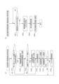
図2に示すように、遊技システム500において、遊技媒体管理装置20が遊技機11に対して、通信ケーブル39を介して光信号によるデータの送受信が可能であるように接続されている。遊技機11は、遊技者が保有する遊技媒体の増減数を検出する増減数検出手段としての増減数検出器1110(各入賞センサ1061および減算センサ1011)と、遊技機11を制御する制御手段である各種制御基板1099(主制御回路106、副制御回路107、および検知制御回路99)とを備える。増減数検出器1110は、遊技者が保有する遊技媒体の増減数すなわち持ち球の増減数を示す増減数検出信号を、遊技媒体管理装置20へ出力する。この際、増減数検出信号は、各種制御基板1099を介さずに遊技媒体管理装置20に入力される。遊技媒体管理装置20は、増減数検出器1110からの増減数検出信号に基づいて遊技者の持ち球数を管理する、管理装置制御部202を有している。本実施形態では、増減数検出信号は、遊技球19が各入賞センサ1061および減算センサ1011のいずれを通過したかを示す信号であり、遊技媒体管理装置20はこれに基づいて持ち球の増減数を決定する。なお、これに限定されず、例えば、各入賞センサ1061および減算センサ1011が、持ち球の具体的な増減数を示す増減数検出信号を遊技媒体管理装置20へ出力することとしてもよい。
As shown in FIG. 2, in the
このように、遊技媒体管理装置20は、持ち球数を管理している。例えば、遊技球19が各入賞口を通過した場合には、各入賞口における遊技球19の通過を検出する各入賞センサ1061から送信される増減数検出信号に基づき、遊技球19の払出個数を持ち球数に加算する。また、遊技球19が発射された場合には、これを検出する減算センサ1011から送信される増減数検出信号に基づき、持ち球数を減算する。遊技媒体管理装置20は、これら増減数検出信号に基づいて、持ち球数を管理する。そして、遊技媒体管理装置20は、現在の持ち球数に関するデータを遊技機11に送信する。また、遊技媒体管理装置20は、遊技機11で受け付けた遊技価値から持ち球への変換(球貸し)や、持ち球の計数(返却)の要求に基づく処理を実行する。
In this way, the gaming
ここで、「遊技価値」とは、貨幣・紙幣、プリペイド媒体、トークン、電子マネーおよびチケット等であり、遊技媒体管理装置20によって持ち球に変換することが可能であるものを示す。なお、本実施形態において、遊技媒体管理装置20は、いわゆるCRユニットであり、紙幣およびプリペイド媒体等を受付可能に構成されている。また、計数された持ち球は、遊技システム500が設置される遊技場などにおいて、景品交換等に用いることができる。
Here, "game value" refers to currency/paper money, prepaid media, tokens, electronic money, tickets, etc., which can be converted into balls by the game
遊技媒体管理装置20は、紙幣を挿入可能な紙幣挿入口21と、プリペイド媒体を挿入可能なプリペイド媒体挿入口22と、を有している。これにより、遊技媒体管理装置20は、外部から紙幣およびプリペイド媒体を受け付けることができ、遊技価値の管理を行うことができる。なお、図示していないが、遊技媒体管理装置20は遊技者を特定するための会員ID等の情報が記録された会員カードを挿入可能な挿入口も有していてもよく、会員カード挿入口をプリペイド媒体挿入口22と兼用させてもよい。なお、本実施形態では、遊技媒体管理装置20で受け付けた遊技価値を「残高」という。遊技媒体管理装置20は、残高に関するデータおよび貸出に関するデータに基づいて持ち球数を算出し、遊技機11に残高および持ち球数に関するデータを送信する。そして、遊技機11は残高および持ち球数についての表示を行う。また、遊技機11において遊技者が持ち球の計数(返却)操作を行った場合は、そのことを知らせる信号が遊技機11から遊技媒体管理装置20から送信される。
The gaming
上述したように、本実施形態では、増減数検出器1110から出力された増減数検出信号が、遊技媒体管理装置20に入力される際は、各種制御基板1099を介することがない。ただし、増減数検出器1110から出力された増減数検出信号が、各種制御基板1099以外の回路基板や装置等を介して遊技媒体管理装置20に入力されてもよい。例えば、遊技機11が各種信号を暗号化する暗号化回路を有し、当該暗号化回路が各種制御基板1099による遊技機11の制御とは独立して動作される場合、増減数検出信号が各種制御基板1099の暗号化回路において暗号化された後に遊技媒体管理装置20へ入力されてもよい。
As described above, in this embodiment, the increase/decrease detection signal output from the increase/
ここで、増減数検出器1110が出力する増減数検出信号は、遊技媒体の増減数を算出するための情報を含む信号であり、具体的には、各入賞センサ1061および減算センサ1011について遊技球19が通過したことを検出した際に出力される信号である。遊技媒体管理装置20の管理装置制御部202は、増減数検出器1110からの増減数検出信号に基づき持ち球数の管理を行う。
The increase/decrease detection signal output by the increase/
このように、遊技システム500において、増減数検出器1110から出力された増減数検出信号については、遊技機11の各種制御基板1099を介して、遊技媒体管理装置20へ入力されることがなく、持ち球数の管理は遊技媒体管理装置20が行う。したがって、遊技機11の各種制御基板1099において持ち球数の管理を行うことがなく、その分、各種制御基板1099の負荷が軽減される。したがって、遊技システム500において、遊技機11の各種制御基板1099の負荷を増加させることなく、持ち球数の管理を問題なく行うことができる。そのため、遊技機11における演出を制限する等、遊技機11の性能が低下することがない。
In this way, in the
また、遊技機11の主制御回路106は、後述の始動口161を遊技球19が通過したことに基づいて遊技者にとって有利な大当り遊技状態へ移行するか否かの大当り抽選を所定の抽選条件で行う大当り抽選部1064を有している。
The
[パチンコ遊技の概要]
ここで、遊技機11において実行されるパチンコ遊技の概要について図を用いて説明する。図3は、本実施形態に係る遊技機および遊技媒体管理装置の正面図である。
[Overview of Pachinko Games]
Here, an overview of the pachinko game executed in the
図3に示すように、遊技機11は、タッチパネル式である第1液晶表示装置102を有している。第1液晶表示装置102は、遊技機11の上部に位置している。第1液晶表示装置102は、遊技媒体管理装置20で管理する遊技価値から持ち球への変換(球貸し)や、持ち球の計数(返却)の要求を遊技機11において受け付け、持ち球の貸出に関するデータを遊技媒体管理装置20へ送信する。遊技機11の下方には、遊技球数表示装置1024および計数ボタン1025が設けられている。遊技球数表示装置1024は液晶表示装置であり、6桁までの持ち球が表示されるようになっている。計数ボタン1025は、入力に応じて持ち球の計数を行うための信号を遊技媒体管理装置20へ送信する。第1液晶表示装置102の右方向には、ハンドル1026が設けられている。本体191の上部の左右両側には、それぞれスピーカ1075が配設されている。
3, the
遊技球19が発射装置118から遊技領域160に発射されることで、管理された持ち球が消費される。そして、遊技領域160において遊技球19が各入賞口を通過することで、当該入賞口に設定される払い出しが行われ、持ち球数が加算される。各入賞口について、具体的に説明する。図3に示すように、遊技領域160の前面中央には、始動口161および大入賞口164が形成されている。また、遊技領域160の左右両側に、それぞれ2つ(合計4つ)の一般入賞口168が形成されている。始動口161の入口側には左右に開閉する一対の羽根部材163が設けられており、大入賞口164の入口側には開閉自在のシャッタ165が設けられている。各入賞センサ1061は、これら始動口161、大入賞口164、および一般入賞口168のそれぞれに設けられ、遊技球19が各入賞口を通過したことを検出することができるようになっている。なお、各入賞センサ1061のうちの1つである始動口入賞センサ1061aは、始動口161を遊技球19が通過したことを検出する入賞検出手段として機能する。このように、各入賞センサ1061には、始動口入賞センサ1061a、大入賞口164に設けられたセンサ、および一般入賞口168に設けられたセンサが含まれる。
When the
遊技球19が始動口161を通過した場合、所定の払出しが行われるとともに、大当り遊技状態へ移行するか否かの大当り抽選が大当り抽選部1064によって所定の抽選条件に基づき行われる。所定の抽選条件とは、例えば、ハズレになる確率や大当たりに当選する確率などの抽選処理に必要な条件である。この抽選条件は、所定の条件(例えば、大当り抽選の抽選結果)に基づき変動されるものであってもよい。遊技領域160の上部には、特別図柄表示装置169が設けられており、この大当り抽選に基づいて動作される。具体的に、特別図柄表示装置169は、7セグメント表示が可能な表示装置であり、大当り抽選毎に行われる特別図柄ゲームにおいて特別図柄(図示せず)の可変表示を行うものである。この特別図柄表示装置169における特別図柄は、一列の図柄列で構成されているが、この構成に限定されるものではなく、例えば、複数の図柄列で構成されていてもよい。
When the
この特別図柄は、数字や記号等からなる図柄であり、7セグメントの各セグメントを適宜組み合わせて表示させることができ、“0”から“9”の数字や、“-”の絵柄を用いることができる。特別図柄ゲームは、始動口161を遊技球19が通過したことを条件として開始され、特別図柄表示装置169において特別図柄が可変表示される。
The special symbols are made up of numbers and symbols, and can be displayed by appropriately combining each of the seven segments, and can include numbers from "0" to "9" and the symbol "-". The special symbol game starts when the
ここで、「可変表示」とは、変動可能に表示されることである。例えば、変動して表示される「変動表示」、停止して表示される「停止表示」等を可能とするものである。また、「可変表示」としては、特別図柄ゲームの結果として特別図柄が表示される「導出表示」を行うことができる。 Here, "variable display" means a display that can be changed. For example, it allows for a "variable display" that changes and is displayed, and a "stopped display" that is stopped and displayed. In addition, as a "variable display," it is possible to perform a "derived display" in which a special pattern is displayed as the result of a special pattern game.
この特別図柄表示装置169において、大当り抽選の抽選結果に応じた特別図柄の導出表示が行われ、導出表示された特別図柄が特定の表示態様(例えば、“0”から“9”のいずれかの数字が導出表示される態様、いわゆる「大当り表示態様」)になったことに基づいて、遊技状態を遊技者にとって有利な大当り遊技状態(特定遊技状態)に移行することとなる。この大当り遊技状態となった場合には、シャッタ165が開放状態に制御され、大入賞口164は遊技球19を受け入れ容易な開放状態となる。
In this special pattern display device 169, a special pattern is derived and displayed according to the result of the jackpot lottery, and when the derived and displayed special pattern becomes a specific display mode (for example, a mode in which any number from "0" to "9" is derived and displayed, the so-called "jackpot display mode"), the game state transitions to a jackpot game state (specific game state) that is advantageous to the player. When this jackpot game state is reached, the
このように、遊技球19が始動口161を通過した場合には、持ち球の加算が行われるとともに、大当り抽選部1064において遊技者にとって有利な大当り遊技状態へ移行するか否かの大当り抽選が行われる。すなわち、各入賞センサ1061に含まれる増減数検出手段としての始動口入賞センサ1061aは、持ち球の増減数を検出し、持ち球の増減数を示す増減数検出信号を遊技媒体管理装置20へ出力する。そして、入賞検出手段としての始動口入賞センサ1061aは、始動口161を遊技球19が通過したことを検出し、入賞検出信号を主制御回路106へ出力する。
In this way, when the
つまり、遊技機11は、遊技領域160に形成された、遊技球19が通過することができる始動口161と、始動口161を遊技球19が通過したことに基づいて、遊技者にとって有利な大当り遊技状態へ移行するか否かの大当り抽選を所定の抽選条件で行う大当り抽選部1064と、始動口161を遊技球19が通過したことを検出し、入賞検出信号を出力する始動口入賞センサ1061aと、を備え、入賞検出信号は、主制御回路106および遊技媒体管理装置20に入力される。
In other words, the
これにより、遊技者にとって有利な大当り遊技状態へ移行するか否かの大当り抽選を行うことを指示し、かつ、持ち球の払出を指示する入賞検出信号は、主制御回路106および遊技媒体管理装置20のいずれにも入力されることから、大当り抽選処理および遊技媒体の払出処理がいずれも遅延することなく、速やかに行われる。
As a result, the winning detection signal, which instructs the player to hold a jackpot lottery to determine whether or not to transition to a jackpot game state advantageous to the player, and instructs the payout of balls, is input to both the
[遊技システムの動作]
遊技システム500において、各入賞センサ1061または減算センサ1011で遊技球19を検出したことに起因する遊技機11および遊技媒体管理装置20の動作について、フローチャートを参照して具体的に説明する。図4は、本実施形態の増減数検出信号処理のフローチャートであって、図4(a)は、遊技機の増減数検出信号処理のフローチャートであり、図4(b)は、遊技媒体管理装置の増減数検出信号処理のフローチャートである。
[Operation of Gaming System]
In the
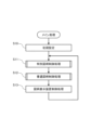
まず、図4(a)を参照して、遊技機11の増減数検出信号処理について説明する。遊技機11において、各入賞センサ1061または減算センサ1011によって遊技球19が検出されたか否かが判定される(S101)。各入賞センサ1061または減算センサ1011によって遊技球19が検出されない場合は(S101でNO)、後述のステップS103が実行される。一方、各入賞センサ1061によって遊技球19が検出された場合は(S101でYES)、増減数検出信号が遊技媒体管理装置20へ出力される(S102)。
First, referring to FIG. 4(a), the increase/decrease number detection signal processing of the
ステップS102では、各入賞センサ1061のうち始動口161に設けられたセンサ(始動口入賞センサ1061a)で遊技球19が検出された場合には、始動口161で遊技球19が検出されたことを示す増減数検出信号が始動口入賞センサ1061aから遊技媒体管理装置20へ出力される。また、各入賞センサ1061のうち大入賞口164に設けられたセンサで遊技球19が検出された場合には、大入賞口164で遊技球19が検出されたことを示す増減数検出信号が大入賞口164に設けられたセンサから遊技媒体管理装置20へ出力される。また、各入賞センサ1061のうち一般入賞口168に設けられたセンサで遊技球19が検出された場合には、一般入賞口168で遊技球19が検出されたことを示す増減数検出信号が一般入賞口168に設けられたセンサから遊技媒体管理装置20へ出力される。また、減算センサ1011で遊技球19が検出された場合には、減算センサ1011で遊技球19が検出されたことを示す増減数検出信号が減算センサ1011から遊技媒体管理装置20へ出力される。
In step S102, when the
そして、遊技球19が検出されたセンサが始動口入賞センサ1061aであるか否かが判定される(S103)。そして、遊技球19が検出されたセンサが始動口入賞センサ1061aでない場合は(S103でNO)、後述のステップS105が実行される。一方、遊技球19が検出されたセンサが始動口入賞センサ1061aである場合は(S103でYES)、始動口入賞センサ1061aから入賞検出信号が主制御回路106へ送信される(S104)。
Then, it is determined whether the sensor that detected the
そして、大当り抽選処理が行われる(S105)。大当り抽選処理は、主制御回路106の大当り抽選部1064によって所定の抽選条件に基づき行われる大当り遊技状態へ移行するか否かの大当り抽選を行う処理である。そして、特別図柄ゲーム処理が行われる(S106)。特別図柄ゲーム処理では、主制御回路106から送信されたコマンドデータ(大当り抽選の抽選結果を示す情報)に基づき、副制御回路107によって特別図柄表示装置169の特別図柄の可変表示が行われる。さらに、普通図柄ゲーム処理が行われる(S107)。
Then, a jackpot lottery process is performed (S105). The jackpot lottery process is a process in which the
そして、大当り抽選処理の結果が大当り(大当り遊技状態への移行)であるか否かが判定される(S108)。大当りでない場合は(S108でNO)、ステップS101が再実行される。一方、大当りである場合は(S108でYES)、シャッタ制御処理が行われる(S109)。シャッタ制御処理では、主制御回路106から送信されたコマンドデータ(大当り遊技状態への移行に当選したことを示す情報)に基づく検知制御回路99の制御によって、シャッタ165が開放状態にされた後、大当り遊技状態が完了した場合にシャッタ165が閉鎖状態にされる。
Then, it is determined whether the result of the jackpot lottery process is a jackpot (transition to a jackpot gaming state) or not (S108). If it is not a jackpot (NO in S108), step S101 is executed again. On the other hand, if it is a jackpot (YES in S108), shutter control processing is performed (S109). In the shutter control processing, the
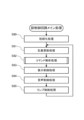
次に、図4(b)を参照して、遊技媒体管理装置20の増減数検出信号処理について説明する。遊技媒体管理装置20の管理装置制御部202において、増減数検出信号が受信されたか否かが判定される(S201)。増減数検出信号が受信されない場合は(S201でNO)、ステップS1が再実行される。一方、増減数検出信号が受信された場合は(S201でYES)、増減数検出信号の出力元が特定される(S202)。具体的に、増減数検出信号に基づいて、各入賞センサ1061および減算センサ1011のいずれから送信されたものであるかを特定する。
Next, referring to FIG. 4(b), the increase/decrease number detection signal processing of the gaming
そして、持ち球管理処理が行われる(S203)。具体的に、始動口161、大入賞口164、および一般入賞口168にはそれぞれ払い出される持ち球の増加数が予め設定されており、特定された入賞口に応じて持ち球数が加算される。また、減算センサ1011から出力される増減数検出信号は、遊技球19の発射が行われ持ち球が消費されたことを示す。そのため、この信号が出力された場合は、持ち球数が1減算される。そして、増減数検出信号に応じて更新された持ち球数が遊技機11へ送信される(S204)。遊技機11において持ち球数を受信した場合、表示されている持ち球の更新表示処理が行われる。持ち球数の更新表示については後述する。
Then, a ball management process is performed (S203). Specifically, the number of balls to be paid out is preset for each of the start opening 161, the
[遊技システムの電気的構成および動作]
遊技システムのネットワーク構成、電気的構成および動作について、図を用いて説明する。図5は、本実施形態に係る遊技システムのネットワーク構成を示す図である。図6は、本実施形態に係る遊技システムにおける遊技機および遊技媒体管理装置の電気的構成を示すブロック図である。
[Electrical configuration and operation of the gaming system]
The network configuration, electrical configuration and operation of the gaming system will be described with reference to the drawings. Fig. 5 is a diagram showing the network configuration of the gaming system according to this embodiment. Fig. 6 is a block diagram showing the electrical configuration of the gaming machines and the gaming media management device in the gaming system according to this embodiment.
図5に示すように、遊技機11が設置される遊技場等において、遊技機11および遊技媒体管理装置20を含む複数の遊技システム500が、パケット通信による光信号のデータ通信が可能に、ホールコンピュータ(遊技場管理装置)50と接続されている。また、表示装置(遊技用装置)40は、遊技機11および遊技媒体管理装置20に対応付けられている。図示していないが、情報表示装置49は遊技機11の上方等に設置され、遊技機11における入賞数等を示す入賞履歴等の遊技情報を表示する。なお、情報表示装置49と第1液晶表示装置102とを一体としてもよい。この遊技情報は、遊技機11から遊技媒体管理装置20を介して情報表示装置49へ送信される。遊技機11は、情報表示装置49と直接データ通信を行うことはできない。また、ホールコンピュータ50は、遊技媒体管理装置20および情報表示装置49のそれぞれとデータ通信可能に接続されている。しかし、遊技機11は、ホールコンピュータ50と直接データ通信を行うことはできない。
As shown in FIG. 5, in an amusement center or the like where the
遊技機11は、遊技機固有情報と、遊技情報等の遊技に関する情報およびその情報が送信された日時を示す日時情報を含む遊技機データと、を遊技媒体管理装置20へ送信する。ここで、遊技機固有情報とは、各遊技機11を識別するための識別情報であり、各遊技機11に固有の情報である。遊技機固有情報は、遊技機データとセットで遊技機11から遊技媒体管理装置20へ送信される。遊技機固有情報は、遊技機11が有するROM、RAM等の記憶手段に予め記憶されている。
The
遊技媒体管理装置20は、遊技機11から送信された遊技機固有情報および遊技機データを受信すると、遊技機データを情報表示装置49へ送信するとともに、遊技機固有情報および遊技機データをホールコンピュータ50へ送信する。遊技媒体管理装置20からホールコンピュータ50へ送信されたデータは、パケット通信による光信号として送信される。情報表示装置49は、遊技媒体管理装置20から遊技機データを受信した場合、表示装置固有情報(遊技用装置固有情報)と遊技機データとをホールコンピュータ50へ、パケット通信による光信号として送信する。ここで、表示装置固有情報とは、各情報表示装置49を識別するための識別情報であり、各情報表示装置49に固有の情報である。また、遊技媒体管理装置20および情報表示装置49は、電気信号を光信号に変換する信号変換器を有し、光信号をホールコンピュータ50に送信する。
When the gaming
ホールコンピュータ50は、信号を受信する受信部51と、受信部51が受信した遊技機データを集計して集計結果を表示する表示部52と、互いに対応付けられた遊技機11と情報表示装置49とを記憶している記憶部53と、受信部51で受信したデータを照合することにより、不正行為が行われていないか判断する照合部54とを有している。なお、ホールコンピュータ50は、いわゆるサーバであり、CPU、メモリ、各種入出力デバイス等を有する構成である。ホールコンピュータ50が有する上記各部は、ハードウェアとメモリ内のソフトウェアとが協働して構築されている。
The
受信部51は、光信号を電気信号に変換する信号変換器を有し、パケット通信による光信号を受信可能である。受信部51は、遊技システム500ごとに、遊技媒体管理装置20からの遊技機固有情報および遊技機データの信号をパケット通信により受信するとともに、情報表示装置49からの表示装置固有情報および遊技機データの信号をパケット通信により受信する。表示部52は、受信部51により受信された遊技機データに基づいて各遊技機の遊技に関するデータを集計し、集計結果を表示する。
The receiving
記憶部53は、互いに対応している遊技機11および情報表示装置49を記憶している。つまり、互いに対応している遊技機11と情報表示装置49とについて、それらの遊技機固有情報と表示装置固有情報とを対応付けて、予め記憶している。照合部54は、情報表示装置49から受信した表示装置固有情報と、遊技媒体管理装置20を介して遊技機11から受信した遊技機固有情報とを、記憶部53に記憶された内容と照合する。照合部54の照合の結果、遊技機固有情報と表示装置固有情報とが、記憶部53において対応付けられているものとは異なっていると判断した場合には、表示部52はその旨を表示する。この場合は、不正行為が行われたと判断される。
The
このように、ホールコンピュータ50は、データを受信する受信部51と、受信したデータを集計して表示する表示部52と、を備え、受信部51は、遊技機固有情報と、日時情報および遊技情報を含む遊技機データとを、情報表示装置49および遊技媒体管理装置20を介して遊技機11から信号変換器を通じてパケット通信による光信号により受信し、表示部52、受信した遊技機データに基づいて各遊技機11のデータを集計し表示する。
In this way, the
これにより、パケット通信は送信容量が大きいことから、各遊技機11は機種IDやメイン基板のシリアル番号等の遊技機固有の情報や対応する情報表示装置49に固有の情報を、ホールコンピュータ50に送信することができる。従来は遊技機と遊技機上部に備えられた表示装置との管理は、遊技機と表示装置の番号を予め紐付けて管理していた。それに対して本実施形態では、上記構成により、遊技媒体管理装置20および情報表示装置49から送信されるデータにより遊技機11および情報表示装置49を識別することにより、これらを管理できる。したがって、遊技機11を管理するホールコンピュータ50側で、予め、遊技機11を設置場所に関連付けてデータ設定しておく必要がない。また、遊技場内で遊技機の移動を行った際に、移動先の情報表示装置49の番号を新たに遊技機11に関連付けて再設定する必要もない。これにより、遊技場の管理者の負担を軽減することができる。
Because packet communication has a large transmission capacity, each
また、ホールコンピュータ50は、受信部51と、表示部52と、記憶部53と、表示部52と、を備え、受信部51は、ある遊技機11とは異なる他の複数の遊技機11それぞれからデータを受信可能に配されるとともに、自身の表示装置固有情報を送信可能な情報表示装置49からの信号を受信可能に構成され、記憶部53は、遊技機11と情報表示装置49とを対応付けて記憶し、照合部54は、情報表示装置49から受信した表示装置固有情報と、遊技機11から受信した遊技機固有情報とを記憶部に記憶された情報と照合し、表示部52は、照合部54による照合の結果、受信した表示装置固有情報と受信した遊技機固有情報とが対応付けられたものでないと判断したときにはその旨を表示する。
The
このような構成により、遊技機11と情報表示装置49とが対応付けられているか否かを、遊技機11から遊技媒体管理装置20を介して受信された遊技機固有情報と情報表示装置49から受信された表示装置固有情報とを予め記憶された情報と照合することで判定することができる。判定の結果、これらの情報が不一致である場合には、遊技機固有情報が正しくないと判断できる。それにより、遊技機11の制御基板等を不正に交換する等の不正行為が行われたか否かを検出することができる。このように簡素な構成で不正行為を検出可能である。なお、表示装置固有情報と遊技機固有情報とが対応付けられたものでないと照合部54で判断された場合には、遊技機11になんらかの不正行為が行われたのではなく、情報表示装置49になんらかの不正行為が行われた可能性も考えられるが、不正行為を行う者は、普通、不正出玉獲得を行うことから、情報表示装置49に不正行為が行われることはほとんどない。
With this configuration, it is possible to determine whether the
ここで、風俗営業等の規制及び業務の適正化等に関する法律によると、遊技機と外部装置とは電気的に接続することが認められていないと解釈できる。そこで、例えば、特開2008-173202号公報に開示されているように、従来の遊技機は、機械的に動作する電磁継電器を有する集中端子板を備え、この集中端子板と外部装置とが接続されていた。この従来の遊技機の集中端子板は、外部装置との信号の送受信を複数の信号ごとに設置された電磁継電器を用いて行っているため、大容量のデータを、簡単な構成により高速で簡単に送受信することが困難であった。しかし、本実施形態では、上述したように、遊技システム500と外部装置であるホールコンピュータ50とは、パケット通信による光信号のデータ通信が可能に接続されている。そのため、ホールコンピュータ50は、それぞれ大容量のデータである、遊技機固有情報および遊技機データの信号と、表示装置固有情報および遊技機データとを、遊技システム500ごとにパケット通信により一括して受信することができる。それにより、簡素な構成で不正行為を検出可能である。
Here, it can be interpreted that the Act on the Regulation of Amusement and Amusement Businesses and the Proper Management of Businesses does not permit the gaming machine and the external device to be electrically connected. Therefore, for example, as disclosed in JP 2008-173202 A, a conventional gaming machine is equipped with a central terminal board having a mechanically operated electromagnetic relay, and this central terminal board is connected to an external device. The central terminal board of this conventional gaming machine transmits and receives signals to and from the external device using electromagnetic relays installed for each of a plurality of signals, so it is difficult to transmit and receive large amounts of data at high speed and easily with a simple configuration. However, in this embodiment, as described above, the
図6に示すように、遊技機11は、検知制御回路99、表示装置制御基板103および遊技機接続基板201、主制御回路106および副制御回路107を有している。これらは、マイクロコンピュータを主要な構成部品として有している。マイクロコンピュータは、CPUおよび処理プログラム等が記憶される記憶部(RAM、ROM等)により構成される。
As shown in FIG. 6, the
また、遊技機11は電源供給用の電源108を有している。電源108は、遊技機11の各部に電力を供給する。なお、主制御回路106には検知制御回路99を経由して、電源108から電力が供給されている。また、表示装置制御基板103には副制御回路107を経由して、電源108から電力が供給されている。
The
表示装置制御基板103は第1液晶表示装置102と接続されている。表示装置制御基板103は、第1液晶表示装置102の表示を制御する。例えば、第1液晶表示装置102に送信される画像用の信号を第1液晶表示装置102においての表示に適するように変換する。例えば、表示装置制御基板103は画像のサイズが第1液晶表示装置102の画面のサイズに合うように画像用の信号を変換する。また、表示装置制御基板103は、第1液晶表示装置102の入力信号に応じて、遊技媒体管理装置20に指示を行う送信信号を生成する。
The display
主制御回路106は、各入賞センサ1061、磁石センサ1062および第2電波センサ1063と接続され、これらセンサからの信号を受信する。また、主制御回路106は、普通電動役物ソレノイド1064、大入賞口ソレノイド1065およびLED1066と接続され、これらの動作を制御する。
The
副制御回路107は、演出用ボタン1071および演出用センサ1072と接続され、これらからの信号を受信する。また、第2液晶表示装置1073、第1LED基板1074、スピーカ1075、第2LED基板1076、アクチュエータ1077が接続され、これらの動作を制御する。
The
検知制御回路99は、上述の各入賞センサ1061の他、第1電波センサ1001、第1開放センサ1002、第2開放センサ1003、遊技球ゼロセンサ1004、適正数センサ1005、アウト口センサ1006、ハンドルボリューム1007、停止スイッチ1008、タッチセンサ1009、発射装置入口センサ1010、減算センサ1011、揚送装置入口センサ1012、揚送モータセンサ基板1013、着脱ユニットセンサ1014、磨きモータセンサ1015および磨き装置入口センサ1016と接続され、これらからの信号を受信する。また、球送りソレノイド1017、発射ソレノイド1018、揚送モータ1019、着脱ユニットモータ1020および磨きモータ1021と接続され、これらの動作を制御する。
The
また、検知制御回路99は、計数スイッチ1023を有した表示基板1022と接続されている。表示基板1022は、遊技球数表示装置1024(図3参照)を制御する。
The
また、遊技機11は、第1接続部104および第2接続部105を有している。第1接続部104は、各入賞センサ1061および減算センサ1011に接続されている。各入賞センサ1061および減算センサ1011は、第1接続部104を介して、遊技媒体管理装置20の遊技機接続基板201に接続されている。第2接続部105は、表示装置制御基板103に接続されている。表示装置制御基板103は、第2接続部105介して、遊技媒体管理装置20の遊技機接続基板201に接続される。
The
第1接続部104は、各入賞センサ1061および減算センサ1011からの信号を光信号に変換する信号変換器を有しており、遊技媒体管理装置20に対して光通信方式による通信が可能である。ここで、上述の特開2008-173202号公報に開示されているように、従来の遊技機は、機械的に動作する電磁継電器を有する集中端子板を備え、この集中端子板と外部装置とが接続されていた。この従来の遊技機に対して、遊技システム500は、以下に示すように様々な有利な効果を奏する。
The
遊技システム500において、従来の遊技機における外部装置と端子板を接続する場合のように、これらの間に外部装置に対する信号の種別毎にそれぞれ電磁継電器を設ける必要がない。遊技システム500では、第1接続部104と遊技媒体管理装置20との間に信号変換器を1つ備えるだけでよく、コストの軽減を図ることができる。また、電磁継電器を用いたリレー回路では、その構造上、空きピンを設けることが困難であるが、光通信方式を用いる場合は、例えば受信側においても複数の空きピンを設けることが可能であり拡張性が高い。また、電磁継電器は電磁石により機械的に動作するものであるため故障が発生しやすいが、光通信方式では故障が少なく、電磁継電器を用いた場合よりも平均故障時間を低減し信頼性を向上させることができる。また、電磁継電器はノイズが発生しやすいが、光通信方式はノイズの影響を受けにくい。また、光通信方式の場合、電磁継電器を用いた場合よりも応答速度が速く、一度のパケットで大容量データを転送することもできる。一度のパケット通信で大容量のデータを送ることができるので、通信回数が減り、データ生成量が減少される。例えば、持ち球を15個増加させるという信号を送信する場合、電磁継電器を用いた方式では、1個の持ち球を増加させる信号を15回送信する必要がある。しかし、光通信方式では、15個の持ち球を増加させる信号を一括で送信できる。さらに、その他の信号(例えば、コマンド種別、通信日時などの日時データ、および、遊技機固有番号等)を同時に送信することも可能である。その結果、通信における送信側の制御および受信側の制御を、ともに簡素化することができる。それにより、各制御基板が有するCPUの小型化が可能となる。なお、各入賞センサ1061および減算センサ1011から光通信ケーブルを、遊技媒体管理装置20に直接接続してもよい。これにより、第1接続部104が不要となり、コストの軽減を図ることができる。
In the
したがって、遊技媒体管理装置20の管理装置制御部202は、遊技媒体管理装置20の遊技機接続基板201および遊技機11の第1接続部104を介して、遊技機11の各入賞センサ1061および減算センサ1011に接続される。そして、遊技媒体管理装置20の管理装置制御部202は、遊技媒体管理装置20の遊技機接続基板201および遊技機11の第2接続部105を介して、遊技機11の表示装置制御基板103に接続される。管理装置制御部202はCPUおよび処理プログラム等が記憶される記憶部(RAM、ROM等)により構成される。
Therefore, the management
以下、これらの構成の説明とともに遊技システム500について説明する。遊技機11の各入賞センサ1061は、各入賞口を通過する遊技球19を検出する。遊技媒体管理装置20の管理装置制御部202は、上述のように、各入賞センサ1061から出力される増減数検出信号に基づいて、各入賞に応じた球数を持ち球数に加算する。このように、遊技システム500は、入賞球を検出する機能を有している。
The
磁石センサ1062は、遊技機11における異常な磁気を検出する。これにより、磁石を利用して遊技球19を操作するといった不正行為を防止することができる。第2電波センサ1063は、遊技機11における異常な電波を検出する。これにより、遊技機11に対して電波を照射したり放電させたりすることにより、遊技機11の誤動作を誘発させるといった不正行為を防止することができる。
The
普通電動役物ソレノイド1064は、始動口161に設けられる羽根部材163を有した普通電動役物162(図3参照)に接続されており、主制御回路106から供給される駆動信号に応じて、羽根部材163が開放状態または閉鎖状態とする。また、大入賞口ソレノイド1065は、シャッタ165を有した大入賞口164に接続されており、主制御回路106から供給される駆動信号に応じて、シャッタ165を駆動させ、大入賞口164を開放状態または閉鎖状態とする。LED1066は、始動口161に遊技球が入球したことに基づいて大入賞口164を開放させるか否かの抽選結果である特別図柄表示装置、普通電動役物を開放するか否かの普通図柄表示装置、またはこれらの保留数である保留表示装置等の状態を表示するものであり、主制御回路106から供給される駆動信号に応じて点灯態様が変動する。
The normal
例えば、針金等を用いて大入賞口164のシャッタ165を強制的に開放状態とする不正行為を行ったとしても、シャッタ165を駆動させる駆動信号が供給されているか否かを検出することにより、不正が行われていることを検出することができ、不正行為を防止することができる。
For example, even if someone commits fraud by forcibly opening the
表示基板1022は、遊技者が有している持ち球数を表示する遊技球数表示装置1024を制御する。具体的には、図3に示すように、遊技機11の前面における下部には、遊技球数表示装置1024が設けられている。遊技球数表示装置1024は液晶表示装置であり、6桁までの持ち球数が表示されるようになっている。持ち球数は、上述したとおり、遊技媒体管理装置20によって管理されている。遊技が実行されることにより持ち球数は増減する。遊技媒体管理装置20は、各入賞センサ1061または減算センサ1011から送信される増減数検出信号に基づいて加算および減算を行い、持ち球数を管理している。そして、遊技媒体管理装置20は、持ち球数に関する信号を表示基板1022へと送信する。表示基板1022は、検知制御回路99から持ち球数の増減に関する信号を受信して、遊技球数表示装置1024に表示される持ち球数を更新する。また、表示基板1022は、持ち球数が0であった場合には、その旨を示す信号を検知制御回路99へ送信する。これにより、検知制御回路99は、遊技球19を発射してもよいか判定を行うことができる。なお、遊技機11の制御において必要であれば持ち球数が0以外であっても、持ち球数に関する信号を検知制御回路99に送信することとしてもよい。また、このような持ち球数に関する信号は、表示基板1022を介して検知制御回路99に送信されるのではなく、遊技媒体管理装置20から検知制御回路99へ直接送信されることとしてもよい。
The
上述のように、各入賞センサ1061で遊技球19が検出された場合、入賞ごとに設定される獲得遊技球数が持ち球数に加算される。つまり、増減数検出信号が遊技媒体管理装置20へ送信され、遊技媒体管理装置20では各入賞に応じた獲得遊技球数が現在の持ち球数に加算される。そして、遊技媒体管理装置20は、加算後の持ち球数に関するデータを表示基板1022に送信し、表示基板1022により遊技球数表示装置1024が表示される持ち球を更新する。
As described above, when each winning
減算センサ1011は、発射装置118における遊技球19の出口に設けられており、発射装置118から遊技球19が発射されること(発射球)を検出する。遊技媒体管理装置20は、減算センサ1011から送信される増減数検出信号を受信すると、現在の持ち球数を減算する。これにより、遊技媒体管理装置20により管理される持ち球数が更新される。遊技媒体管理装置20は、減算後の持ち球数に関するデータを検知制御回路99に送信する。そして、検知制御回路99から表示基板1022に持ち球数が送信されることにより、遊技球数表示装置1024の持ち球数の表示が更新される。なお、戻り玉が生じた場合は、実際には遊技球19が遊技領域160に発射されていないにも関わらず、減算センサ1011では遊技球19が発射されたと誤って検出をする可能性がある。しかし、上述したように、遊技機11は戻り玉を回避することができる構造であるため、遊技媒体管理装置20は持ち球数を正しく管理できる。
The
表示基板1022が有する計数スイッチ1023は、図3に示すように遊技球数表示装置1024の左側に配設される計数ボタン1025への入力を検出する。遊技者が計数ボタン1025を押下すると、計数スイッチ1023から検出信号が出力される。表示基板1022は計数スイッチ1023からの検出信号を受信すると、遊技球数表示装置1024に表示された持ち球数を徐々に減少させる。そして、同時に、遊技球数表示装置1024に表示された持ち球数の減少分に関してのデータが遊技媒体管理装置20に送信される。管理装置制御部202はこのデータに応じて、遊技球数表示装置1024に表示された持ち球数の減少分を、計数球数として遊技媒体管理装置20の表示装置(図示せず)に表示させる。つまり、持ち球を計数球に変換する。
The
また、計数ボタン1025の押下時間が長くなればなるほど、遊技球数表示装置1024に表示された持ち球数の減少速度が速くなるようにしてもよい。その場合は、持ち球数の減少速度に対応して、遊技媒体管理装置20に表示される計数球数の増加速度も速くなる。そして、持ち球数が所望の値となったところで、計数ボタン1025の押下操作を停止すれば、計数球への変換が停止する。これにより、遊技者は容易に、持ち球のうち所望の数の球を計数球に変換することができる。
The longer the
また、遊技者が第1液晶表示装置102における特定領域(後述の返却表示領域102b)を押下した後、10秒以内に計数ボタン1025を押下した場合には、遊技球数表示装置1024に表示された持ち球数がゼロになり、遊技球数表示装置1024に表示されていた持ち球数が計数球数に加算されて、遊技媒体管理装置20に表示されることとしてもよい。これにより、持ち球を一括で計数球数とすることができるため、すべての持ち球を計数する場合に、遊技者の操作が容易である。また、計数スイッチ1023を1回操作するだけですべての持ち球を一括で計数するようにしてもよい。また、第1液晶表示装置102において、計数球に変換する持ち球の数を設定できることとしてもよい。これにより、遊技者は任意の数の持ち球を容易に計数球に変換することができる。
In addition, if the player presses the
遊技球19は各入賞口を通過して磨き装置122に到達するか、各入賞口を通過せずに遊技領域160の下部に形成されたアウト口166を通過して磨き装置122に到達するかのいずれかである。したがって、各入賞センサ1061およびアウト口センサ1006の検出信号に基づいて、遊技領域160から磨き装置122へと到達して循環されるすべての遊技球19の個数(アウト球数)を検出することができる。なお、アウト球数を検出する際の各入賞センサ1061からの信号は、各入賞口を通過したか否かを示すものであり、持ち球の増減数を示すものではない。また、アウト球検出機能は、遊技媒体管理装置20が有していてもよい。その場合は、アウト口センサ1006は、遊技球19を検出した際に、当該検出信号を遊技媒体管理装置20へ送信することとすればよい。
The
また、遊技システム500は、エラー検出機能を有している。例えば、発射球の検出信号およびアウト球の検出信号により、遊技領域160に発射された遊技球19の個数と、遊技領域160から磨き装置122へ到達する遊技球19の個数とを比較することができる。すなわち、外部から遊技球19が遊技領域160内へ投入されるような不正行為を検出することができる。このように、遊技システム500は、遊技球数オーバーフローエラーを検出することができる。なお、遊技球数オーバーフローエラーは、遊技機11において、認識できる持ち球数を超えた場合に生じるエラーとしてもよい。例えば、持ち球数が、遊技球数表示装置1024に表示可能な6桁の持ち球を超えた場合に、遊技球数オーバーフローエラーが検出されることとしてもよい。
The
また、発射球の検出信号およびアウト球の検出信号により、遊技領域160に発射された遊技球19の個数と、遊技領域160から磨き装置122に到達する遊技球19の個数とを比較し、アウト球が検出され続ける一方で発射球が検出されない状態が生じた場合には、減算センサエラーを検出することができる。すなわち、遊技球19が発射装置118において球詰まりしていることを検出することができる。
In addition, the number of
また、発射球の検出信号およびアウト球の検出信号により、遊技領域160に発射された遊技球19の個数と、遊技領域160から磨き装置122に到達する遊技球19の個数とを比較し、発射球が検出され続ける一方で、発射球に応じたアウト球が検出されない状態が生じた場合には、入賞センサエラーを検出することができる。すなわち、遊技球19が各入賞口等において球詰まりしていることを検出することができる。
In addition, the number of
第1液晶表示装置102は、球貸に関する遊技者の入力を受け付けるための入力装置であると共に、遊技価値の残高を表示する表示装置として機能する。図3に示すように、遊技機11の上方には、第1液晶表示装置102が設けられている。第1液晶表示装置102の画面上には、再プレイ表示領域102a、返却表示領域102b、球貸表示領域102cおよび残高表示領域102dが形成されている。残高表示領域102dには、遊技媒体管理装置20において、外部から紙幣またはプリペイド媒体等の遊技価値を受け付けた場合に、その遊技価値のうち持ち球に変換可能である額が表示される。
The first liquid
再プレイ表示領域102a、返却表示領域102bおよび球貸表示領域102cは、遊技者の入力を受け付けるための入力用の領域である。第1液晶表示装置102が遊技者によるタッチ操作がなされた領域が球貸表示領域102cであることを検出したときは、表示装置制御基板103は、球貸を要求する送信信号を遊技媒体管理装置20に送信する。遊技媒体管理装置20では球貸要求に基づいて、残高を減算すると共に減算した分に対応する持ち球数を加算する貸出処理を行う。そして、更新された残高は、表示装置制御基板103を介して遊技媒体管理装置20から第1液晶表示装置102へ送信され、残高表示領域102dの残高表示が更新される。また、加算された持ち球数は、遊技媒体管理装置20から表示基板1022へ送信され、遊技球数表示装置1024の持ち球の表示が更新される。
The
また、遊技媒体管理装置20において残高がない状態(例えば、遊技媒体管理装置20にプリペイド媒体が挿入されていない場合等)では、球貸表示領域102cへの入力は無効となる。このような状態で、球貸表示領域102cにおける遊技者のタッチ操作を検出した場合には、不正加算エラーが検出される。なお、残高があり、持ち球への変換が可能な場合は、球貸表示領域102cが発光しているように表示し、残高がなく、持ち球への変換が不可能な場合は、球貸表示領域102cはやや暗めとなるように表示してもよい。
In addition, when there is no balance in the gaming media management device 20 (for example, when no prepaid media is inserted in the gaming media management device 20), input to the ball
また、第1液晶表示装置102が遊技者によるタッチ操作がなされた領域が返却表示領域102bであることを検出したときは、表示装置制御基板103は、遊技の終了を要求する送信信号を遊技媒体管理装置20に送信する。そして、遊技媒体管理装置20は、遊技の終了を指示するための送信信号を表示基板1022に対して送信する。また、返却表示領域102bがタッチ操作された後、10秒以内に遊技者が計数ボタン1025を押下した場合には、上述したように、持ち球数が一括で計数球数に変換されて遊技媒体管理装置20に表示される。
When the first liquid
なお、第1液晶表示装置102の再プレイ表示領域102aは、再プレイ貯玉がある場合にのみ入力の受け付けが有効となる。再プレイ貯玉とは、前日以前に遊戯した際の持ち球を持ち越すことをいう。再プレイ球の数等の持ち越した持ち球に関する情報は、例えば、遊技場以外の場所に設置された貯玉サーバに、遊技者を特定できる会員ID等の情報と対応付けて記憶されている。遊技者は、例えば、遊技中はこの会員カードを遊技媒体管理装置20に挿入しておくこととすればよい。遊技者が、会員カードを遊技媒体管理装置20に挿入した状態で再プレイ表示領域102aをタッチ操作することで、遊技媒体管理装置20は会員カードに記録された会員IDを読み取り、貯玉サーバより当該会員IDに対応付けられた、再プレイ球の数等の情報を入手する。遊技媒体管理装置20はこの情報に基づいて再プレイ球の数を持ち球数に加算する。
The
第1液晶表示装置102が遊技者によるタッチ操作がなされた領域が再プレイ表示領域102aであることを検出したときは、表示装置制御基板103において再プレイを要求する送信信号が遊技媒体管理装置20へ送信される。そして、遊技媒体管理装置20は、再プレイ球数の個数情報に基づいて増加された持ち球数の情報を表示基板1022に送信し、遊技球数表示装置1024の持ち球数の表示が更新される。そして、貯玉サーバに記憶された情報が更新される。
When the first liquid
また、図示していないが、第1液晶表示装置102には、画面切り替え領域が表示されていることとしてもよい。第1液晶表示装置102が遊技者によるタッチ操作がなされた領域が画面切り替え領域であることを検出したときは、第1液晶表示装置102に表示される内容が切り替えられることとしてもよい。例えば、上述した貸出動作の結果内容や返却動作の結果内容等の遊技媒体管理装置20からの情報と、副制御回路107から送信される演出用の画像等の情報とで、切り替えが行われることとしてもよい。
Although not shown, a screen switching area may be displayed on the first liquid
また、図示していないが、第1液晶表示装置102は、遊技媒体管理装置20に挿入された会員カードに記録された会員ID等のカード情報や遊技機11の遊技情報等を表示可能であることとしてもよい。これらのカード情報や遊技情報の表示は、第1液晶表示装置102のタッチ操作により、図3に示すような表示態様と切り替えが可能であることとしてもよい。
Although not shown, the first liquid
遊技機11は、電源が投入されると、主制御回路106に設けられたCPUの固有ID、検知制御回路99に設けられたCPUの固有ID、遊技機11に記憶された遊技機製造業者コード、上述の認証・通信制御回路300等の実現に用いられるセキュリティチップの製造業者コード、遊技機11の型式コードおよび遊技場の整合性を判定する。
When the power is turned on, the
第1開放センサ1002は、本体191において、ガラス枠が開放されていることを検出する。また、第2開放センサ1003は、本体191において、内枠が開放されていることを検出する。
The first
第1電波センサ1001は、遊技機11の本体191に対する異常な電波を検出する。
The first
また、遊技機11は、上記のようなエラーを検知した場合は、エラー報知を行う。エラー報知としては、エラーを検出する基板にもよるが、遊技の停止、遊技媒体管理装置20によるエラー情報の表示、スピーカ1075によるエラー情報の音声出力、本体演出用の第1LED基板1074や盤面演出用の第2LED基板1076に接続されるLEDの点灯、アクチュエータ1077の駆動およびタッチパネル式である第1液晶表示装置102におけるエラー情報の表示等とすればよい。
When the
遊技機11は、遊技媒体管理装置20に対して、遊技状態の情報を出力する。具体的には、遊技機11は、遊技媒体管理装置20に対して、アウト球数、入賞により得た持ち球数、入賞毎に出力される入賞種別(始動口、大当り、小当り、出玉大の大当り、出玉小の大当り、出玉中の大当り)、大当りかつ時短状態、確変状態、時短状態、不正検出に関するセキュリティ、ガラス枠開放状態、内枠開放状態、遊技機エラー時、に関する情報を出力する。
The
電源108は、単相交流100Vから遊技機11に必要な電源を生成する。本実施形態では、電源108は、検知制御回路99と、副制御回路107とに直接電力を供給する。そして、主制御回路106に検知制御回路99を介して電力を供給する。また、表示装置制御基板103には副制御回路107を介して電力を供給する。なお、電力の供給は上述の態様に限定されるわけではない。
The
また、電源108は、図示していないバックアップ電源を有している。そのため、電源がOFFにされても、主制御回路106および検知制御回路99のそれぞれのRAMに記憶された情報を保持することができる。なお、電源108には、図示していないクリアスイッチが設けられている。クリアスイッチを操作することにより、主制御回路106および検知制御回路99のそれぞれのRAMに記憶された情報を初期化することができる。
The
具体的には、主制御回路106のRAMにおいて保持される内容は、大当り状態(ラウンド回数含む)、高確率・時短状態、保留メモリ(特別図柄、普通図柄)の乱数値、エラー状態、検知制御回路99への未送信コマンドデータ、普通電動役物および特別電動役物、である。また、検知制御回路99のRAMにおいて保持される内容は、持ち球数、エラー状態、遊技媒体管理装置20への未送信コマンドデータ、遊技台情報、遊技情報および遊技媒体管理装置20に挿入された会員カードのカード情報等、である。
Specifically, the contents stored in the RAM of the
発射ソレノイド1018は、発射装置118に設けられ、検知制御回路99からの駆動制御信号に応じて遊技球19の発射を行うための動作を行う。発射ソレノイド1018を駆動するための駆動制御信号は、遊技者によってハンドル1026(図3参照)が操作されることにより出力される。タッチセンサ1009は、ハンドル1026の周縁に設けられており、遊技者がハンドル1026を握持した場合にはタッチセンサ1009にも触れることとなるような位置に配置されている。したがって、タッチセンサ1009からの検出信号により、遊技者がハンドル1026を握持しているか否かの検出を行うことができる(タッチ検出)。
The
ハンドル1026は、回転可能なように本体191に設置されている。また、ハンドル1026は、回転させた場合に、時計回りの反対方向へ付勢力が働くように設置されている。したがって、ハンドル1026を回転させて手を離すと、ハンドル1026は回転して元の位置に戻る。
The
ハンドル1026には、時計回り方向への回転角度に応じた検出信号を出力するハンドルボリューム1007が設けられている。このハンドルボリューム1007から出力される信号に応じて、発射装置118からの遊技球19の発射強度が変更される。
The
また、ハンドル1026には保持レバー1026aが設けられており、遊技者が保持レバー1026aを操作することで、ハンドル1026の回転位置が固定される。すなわち、ハンドル1026を回転させて、所望の位置で保持レバー1026aを操作することにより、ハンドル1026から手を離してもハンドル1026が回転することがなく、その位置で保持される。これにより、長時間にわたる遊技による疲労を軽減することができる。
The
さらに、図示していないが、ハンドル1026はスイング移動構造を有しており、ハンドル1026を上下左右にスイング移動させることができる。つまり、ハンドル1026は一般的には、本体191に対して略垂直方向に突出しているが、スイング移動構造を有することから、本体191に対してハンドル1026が傾斜するように配置することができる。これにより、遊技者はハンドル1026の操作において操作しやすいように、ハンドル1026を適度にスイング移動させることができる。
Furthermore, although not shown, the
また、停止スイッチ1008は、例えばハンドル1026の近傍に設けられている。検知制御回路99は停止スイッチ1008からの検出信号を受信した場合は、ハンドルボリューム1007から検出信号を受信している場合でも、発射ソレノイド1018の動作を停止させる。つまり、遊技者が停止スイッチ1008を操作している場合は、ハンドル1026が回転させられていても、発射装置118から遊技球19が発射されることはない。なお、ハンドル1026が回転させられていても、タッチセンサ1009からの検出信号が出力されていない場合すなわち遊技者がハンドル1026を握持していない場合、および、ハンドル1026の回転角度が小さすぎる場合には、発射装置118から遊技球19が発射されることはない。
The
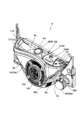
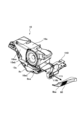
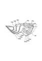
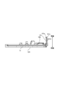
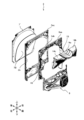
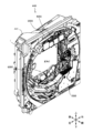
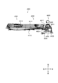
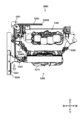
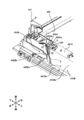
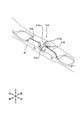
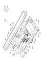
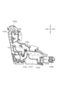
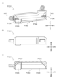
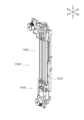
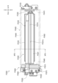
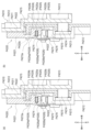
ここで、発射装置118について図を用いて説明する。図7は、本実施形態に係る遊技機の発射装置について説明するための図である。また、図8は、本実施形態に係る遊技機の発射装置の平面図である。
Here, the
図7に示すように、発射装置118は、発射ソレノイド1018、発射台1111、発射杵1112および支持軸1113を有している。発射杵1112はその上端部が支持軸1113に支持されており、支持軸1113を回転中心として回転可能に設置されている。発射ソレノイド1018は発射杵1112の近傍に配置されている。発射ソレノイド1018が検知制御回路99により駆動させられることにより、発射杵1112は発射ソレノイド1018に引き寄せられて、回転駆動する。発射杵1112が発射ソレノイド1018に引き寄せられることにより遊技球19を打撃し、遊技球19が発射装置118から斜め上方へと発射される。発射台1111は発射杵1112により打撃される遊技球19の待機位置である。遊技球19が発射台1111に配置された状態で、発射杵1112の反対側が発射方向であり、開放されている。
As shown in FIG. 7, the
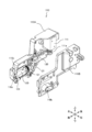
図8に示すように、発射装置118は、上述した部材以外に、球入口1114、発射装置入口センサ1010、球通路1115、球送りソレノイド1017および減算センサ1011を有している。遊技球19は、球送りソレノイド1017によって発射台1111へ送り出される。揚送装置133によって遊技機上部へ搬送された遊技球19は球入口1114に導かれる。さらに、球通路1115を通過し、待機位置にて待機する。球通路1115に設けられた発射装置入口センサ1010は、遊技球19が球通路1115を通過することにより検出信号を出力する。遊技者がハンドル1026を操作した場合は、検知制御回路99により球送りソレノイド1017が駆動させられ、図示していない球送り杵が発射台1111の方向(図8では下方向)へと、待機状態の遊技球19を押し出す。これにより、遊技球19が発射台1111へ移動する。また、待機位置から発射台1111への経路には減算センサ1011が設けられており、発射台1111へ移動する遊技球19を検出する。減算センサ1011によって、遊技球19が検出された場合には、持ち球数が1減算される。
As shown in FIG. 8, the
図3に示すように、遊技領域160において、始動口161や大入賞口164等の各入賞口、または、アウト口166を通過した遊技球19は、ガイド経路167を経由して磨き装置122に案内される。
As shown in FIG. 3, in the
ここで、磨き装置122について説明する。磨き装置122の詳細は図示していないが、磨き装置122は筐体と筐体に着脱自在な着脱ユニットとを有している。筐体には、ガイド経路167によって案内された遊技球19を筐体の内部へ導くための球入口が形成されている。球入口には、遊技球19が投入されたことを検出する磨き装置入口センサ1016が設けられている。筐体の前面側には、着脱ユニットを嵌め込むための嵌合凹部が形成されている。また、嵌合凹部の内側には、遊技球19の搬送経路となるガイド溝が形成されている。また、球入口とガイド溝との間には遊技球19を導くために入口案内経路が形成されている。また、ガイド溝の端部には、球出口が形成されている。ガイド溝には、ガイド溝に沿って遊技球19を導くためのらせん状のスクリューが設置されている。ガイド溝に導かれた遊技球19は、このスクリューが回転することによりガイド溝に沿って搬送され、球出口へと導かれる。
The
着脱ユニットは、遊技球19を磨くための布を有している。当該布の一部は着脱ユニットの外部に露呈しており残りは着脱ユニットの内部に設置されている。磨き装置122に設けられた着脱ユニットモータ1020が駆動することにより、この布は一定方向に送られ、外部に露呈される部分が変化する。つまり、着脱ユニットモータ1020が駆動することにより、露呈された布が着脱ユニット内部へと送られていき、それに伴って、着脱ユニット内部から布の新たな部分が外部に送られてくる。
The detachable unit has a cloth for polishing the
着脱ユニットを筐体の嵌合凹部に嵌め込むことにより、ガイド溝1204の開放された側に露呈された布が押し付けられる態様となる。つまり、スクリューが回転することにより遊技球19がガイド溝に沿って搬送されている際に、遊技球19が布に接触することとなる。なお、筐体には、着脱ユニットが嵌合凹部に嵌め込まれていることを検出する着脱ユニットセンサ1014が設けられている。磨き装置122は、さらに検知制御回路99によって制御される着脱ユニットモータ1020および磨きモータ1021を有する。
By fitting the detachable unit into the fitting recess of the housing, the cloth exposed on the open side of the guide groove 1204 is pressed against it. In other words, when the screw rotates and the
着脱ユニットが筐体の嵌合凹部に嵌め込まれている状態で、着脱ユニットモータ1020および磨きモータ1021が駆動する。これにより、布は移動し始め、スクリューは回転し始める。スクリューが回転することにより、遊技球19がガイド溝に沿って搬送される。この際に、布は、遊技球19の搬送方向とは逆方向に移動される。ガイド溝に沿って搬送される遊技球19は、遊技球19の搬送方向とは逆方向に移動される布と接触することにより、遊技球19が布により擦られて、遊技球19は磨かれる。このように、遊技球19は、布によって磨かれながらガイド溝を搬送され、球出口から排出されて、揚送装置133に導かれる。なお、着脱ユニットモータ1020および磨きモータ1021は、磨き装置入口センサ1016によって遊技球19が検出されたことを契機に駆動される。磨きモータセンサ1015は磨きモータ1021の駆動を検出する。これにより、磨きモータ1021が正常に回転駆動されているかを検出することができる。
With the detachable unit fitted into the fitting recess of the housing, the
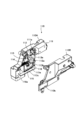
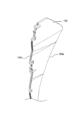
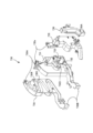
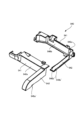
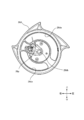
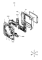
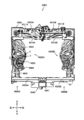
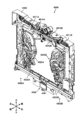
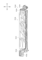
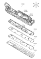
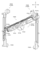
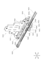
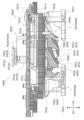
揚送装置について図を用いて説明する。図9は、本実施形態に係る遊技機の揚送装置について説明するための図である。図10は、本実施形態に係る遊技機の揚送装置の動作について説明するための図である。 The lifting device will be explained using the figures. Figure 9 is a diagram for explaining the lifting device of the gaming machine according to this embodiment. Figure 10 is a diagram for explaining the operation of the lifting device of the gaming machine according to this embodiment.
図9および図10に示すように、揚送装置133は、球入口1301、球出口1302、揚送部1303、スクリュー1304、揚送装置入口センサ1012および揚送モータ1019を有している。また、揚送装置133は、揚送モータセンサ基板1013を備えている。球入口1301には、磨き装置122によって搬送された遊技球19が導かれる。揚送装置入口センサ1012は、球入口1301に導入された遊技球19を検出する。揚送装置入口センサ1012による遊技球19の検出に応じて揚送モータ1019が駆動する。揚送部1303の内側に設けられたらせん状のスクリュー1304には、下部に設けられたギアを介して、揚送モータ1019からの動力が伝達される。球入口1301を通過した遊技球19は、さらに球通路(図示せず)を通過して、筒状の揚送部1303の下部に到達する。スクリュー1304は揚送モータ1019により回転しており、遊技球19はスクリュー1304により上方へ搬送される。揚送モータセンサ基板1013は、揚送モータ1019の駆動を検出する。これにより、揚送モータ1019が正常に回転駆動されているかを検出することができる。
9 and 10, the
スクリュー1304によって、揚送部1303の上部に到達した遊技球19は、揚送部1303の上側に設けられた球出口1302から排出され、球出口1302と連通された発射装置118の球入口1114に導かれる。そして、遊技球19は発射装置118に送られる。
The
また、遊技システム500は、遊技領域160における遊技球19の数を管理している。検知制御回路99に接続される適正数センサ1005は、遊技領域160内にある遊技球19の数が適正量か否かを検出する。遊技機11内に50個の遊技球19が循環しているとすると、例えば遊技領域160内に存在する遊技球が10個以下である場合を適正量とし、遊技領域160内に存在する遊技機11が10個を超えると検出信号を出力し、異常であることを知らせる。また、検知制御回路99に接続される遊技球ゼロセンサ1004は、遊技領域160内に遊技球19がない場合に検出信号を出力する。
The
検知制御回路99は、接続された各種センサ等に基づき、省電力状態へ移行する。例えば、タッチセンサ1009によって、所定の期間、遊技者がハンドル1026を握持していないことを検出した場合、省電力状態へ移行すればよい。例えば、副制御回路107に接続された各種演出デバイスをOFFとしてもよい。また、持ち球が0になった場合、プリペイド媒体が未挿入である場合、および現金が投入されていない場合等には、省電力状態へ移行することとしてもよい。このように、検知制御回路99は、遊技が行われているか否かを判定し、遊技機11を省電力状態に移行することができる。
The
電源108は、図示しないバックアップ電源を有している。これにより、夜間等に電源をOFFにした場合であっても、OFFにする直前のデータを保持することができる。また、このバックアップ電源により、例えば、第2開放センサ1003による内枠開放の検出を継続して実行させてもよい。これにより、夜間に不正行為を行われることも防止することができる。
The
なお、この場合は、内枠が開放された回数等の情報を記憶するものであってもよい。さらに、電源が投入された際に、内枠が開放された回数等の情報を、遊技機11の第1液晶表示装置102等に出力するものであってもよい。
In this case, the device may store information such as the number of times the inner frame has been opened. Furthermore, when the power is turned on, the device may output information such as the number of times the inner frame has been opened to the first liquid
[遊技機の動作]
以下に、遊技機11で実行される処理動作について図を用いて説明する。
[Operation of gaming machine]
The processing operations executed by the
[メイン処理]
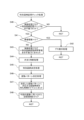
最初に、図11に示すように、主制御回路106におけるCPU(以下、メインCPU)は、RAMアクセス許可、バックアップ復帰処理、作業領域の初期化等の初期設定処理を実行する(S10)。そして、詳しくは図13を用いて後述するが、メインCPUは、特別図柄ゲームの進行、液晶表示装置、特別図柄表示装置に表示される特別図柄、装飾図柄に関する特別図柄制御処理を実行する(S11)。
[Main processing]
First, as shown in Fig. 11, the CPU in the main control circuit 106 (hereinafter, the main CPU) executes initial setting processing such as RAM access permission, backup recovery processing, and initialization of the work area (S10). Then, as will be described in detail later with reference to Fig. 13, the main CPU executes special symbol control processing related to the progress of the special symbol game, the special symbols displayed on the liquid crystal display device, and the decorative symbols (S11).
そして、詳しくは図16を用いて後述するが、メインCPUは、普通図柄ゲームの進行、普通図柄表示装置に表示される普通図柄に関する普通図柄制御処理を実行する(S12)。そして、メインCPUは、特別図柄制御処理、普通図柄制御処理の実行の結果にしたがって、特別図柄、普通図柄などの可変表示の表示制御を行う図柄表示装置制御処理を実行する(S13)。 Then, as will be described in more detail later with reference to FIG. 16, the main CPU executes a normal symbol control process for the progress of the normal symbol game and the normal symbols displayed on the normal symbol display device (S12).Then, the main CPU executes a symbol display device control process that controls the display of variable displays of special symbols, normal symbols, etc., according to the results of the execution of the special symbol control process and normal symbol control process (S13).
このように、メイン処理においては、初期設定処理が終了した後、特別図柄制御処理、普通図柄制御処理、図柄表示装置制御処理を繰り返し実行することとなる。 In this way, in the main processing, after the initial setting processing is completed, the special pattern control processing, normal pattern control processing, and pattern display device control processing are executed repeatedly.
[システムタイマ割込処理]
また、メインCPUは、メイン処理を実行している状態であっても、メイン処理を中断させ、システムタイマ割込処理を実行する場合がある。主制御回路106には、図示しないリセット用クロックパルス発生回路が設けられている。リセット用クロックパルス発生回路は、所定の周期(例えば2ミリ秒)毎にクロックパルスを発生するものである。メインCPUは、発生したクロックパルスに応じて、以下のシステムタイマ割込処理を実行する。このシステムタイマ割込処理について図12を用いて説明する。
[System timer interrupt processing]
Furthermore, even when the main CPU is executing the main processing, it may suspend the main processing and execute a system timer interrupt process. The
最初に、図12に示すように、メインCPUは、大当り判定用乱数カウンタ、大当り図柄決定用乱数カウンタ等の各カウント値を“1”増加するように乱数更新処理を実行する(S20)。そして、メインCPUは、始動口161等への遊技球19の入賞または通過を検知する入力検出処理を実行する(S21)。例えば、入力検出処理は、始動口入賞センサ1061aから入賞検出信号を受信したことにより実行される。そして、メインCPUは、主制御回路106および副制御回路107間等の制御基板間の同期をとるための待ち時間タイマ、大入賞口164の開放時間を計測するための大入賞口開放時間タイマ等、各種のタイマの更新処理を実行する(S22)。そして、各種の変数に基づいて駆動制御するための信号をソレノイド、モータ等に供給するために、出力処理を実行する(S23)。
First, as shown in FIG. 12, the main CPU executes a random number update process to increment each count value of the random number counter for jackpot determination, the random number counter for jackpot pattern determination, etc. by "1" (S20). Then, the main CPU executes an input detection process to detect the entry or passage of the
そして、メインCPUは、各種のコマンドを検知制御回路99や副制御回路107に供給するコマンド出力処理を実行する(S24)。この処理が終了した場合には、本サブルーチンを終了し、割込発生前のアドレスへ復帰し、メイン処理を実行させる。なお、各入賞口を遊技球19が通過することに基づいて行われる入賞による持ち球の加算は、上述の通り、遊技媒体管理装置20によって行われる。すなわち、始動口入賞センサ1061aを含む入賞センサ1061から、主制御回路106を介さず遊技媒体管理装置20へ増減数検出信号が送信され、遊技媒体管理装置20において払出処理が実行される。
Then, the main CPU executes a command output process to supply various commands to the
[特別図柄制御処理]
図11の特別図柄制御処理について図13を用いて説明する。なお、図13において、各処理の側方に記載された数値は、それら各処理に対応する制御状態フラグを示し、その制御状態フラグの数値に応じて、その数値に対応する一つのステップが実行され、特別図柄ゲームが進行することとなる。
[Special symbol control process]
The special symbol control process of Fig. 11 will be described with reference to Fig. 13. In Fig. 13, the numerical values written beside each process indicate the control status flags corresponding to each process, and one step corresponding to the numerical value is executed according to the numerical value of the control status flag, and the special symbol game progresses.
最初に、図13に示すように、メインCPUは、制御状態フラグをロードする処理を実行する(S30)。 First, as shown in FIG. 13, the main CPU executes a process to load the control status flag (S30).
なお、後述する各処理において、メインCPUは、制御状態フラグの値に基づいて、各ステップにおける各種の処理を実行するか否かを判断することとなる。この制御状態フラグは、特別図柄ゲームの遊技の状態を示すものであり、各処理のいずれかを実行可能にするものである。また、それに加えて、メインCPUは、各ステップに対して設定された待ち時間タイマ等に応じて決定される所定のタイミングで各ステップにおける処理を実行する。 In each process described below, the main CPU will determine whether or not to execute various processes in each step based on the value of the control status flag. This control status flag indicates the state of play in the special symbol game, and allows one of the processes to be executed. In addition, the main CPU will execute the process in each step at a predetermined timing determined according to a waiting time timer set for each step, etc.
なお、この所定のタイミングに至る前においては、各ステップにおける処理を実行することなく終了することとなり、他のサブルーチンを実行することとなる。もちろん、所定の周期でシステムタイマ割込処理も実行する。 Note that before this specified timing is reached, the process in each step will end without being executed, and another subroutine will be executed. Of course, system timer interrupt processing will also be executed at a specified cycle.
そして、メインCPUは、特別図柄記憶チェック処理を実行する(S31)。詳しくは図15を用いて後述するが、メインCPUは、制御状態フラグが特別図柄記憶チェックを示す値(00)である場合に、保留個数のチェックを行い、保留個数がある場合に、大当り判定、導出特別図柄、特別図柄の変動パターン等の決定を行う。また、メインCPUは、特別図柄変動時間管理を示す値(01)を制御状態フラグにセットし、今回の処理で決定された変動パターンに対応する変動時間を待ち時間タイマにセットする。つまり、今回決定された変動パターンに対応する変動時間を経過した後、後述する特別図柄変動時間管理処理を実行するように設定することとなる。 Then, the main CPU executes a special symbol memory check process (S31). Details will be described later with reference to FIG. 15, but when the control status flag is a value (00) indicating a special symbol memory check, the main CPU checks the number of reserved symbols, and when there are reserved symbols, it determines whether there is a jackpot, the derived special symbol, the change pattern of the special symbol, etc. The main CPU also sets the control status flag to a value (01) indicating special symbol change time management, and sets the change time corresponding to the change pattern determined in this process to the waiting time timer. In other words, the setting is such that the special symbol change time management process described later will be executed after the change time corresponding to the change pattern determined this time has elapsed.
一方、メインCPUは、保留個数がない場合には、デモ画面を表示するためのデモ表示処理を行う。 On the other hand, if there are no reserved items, the main CPU performs a demo display process to display a demo screen.
そして、メインCPUは、特別図柄変動時間管理処理を実行する(S32)。この処理において、メインCPUは、制御状態フラグが特別図柄変動時間管理を示す値(01)であり、変動時間が経過した場合に、特別図柄表示時間管理を示す値(02)を制御状態フラグにセットし、確定後待ち時間を待ち時間タイマにセットする。つまり、確定後待ち時間が経過した後、後述する特別図柄表示時間管理処理を実行するように設定することとなる。 Then, the main CPU executes a special symbol change time management process (S32). In this process, when the control status flag is a value (01) indicating special symbol change time management and the change time has elapsed, the main CPU sets the control status flag to a value (02) indicating special symbol display time management, and sets the post-determination waiting time in the waiting time timer. In other words, the main CPU is set to execute the special symbol display time management process described below after the post-determination waiting time has elapsed.
そして、メインCPUは、特別図柄表示時間管理処理を実行する(S33)。この処理において、メインCPUは、制御状態フラグが特別図柄表示時間管理を示す値(02)であり、確定後待ち時間が経過した場合に、大当りか否かを判断する。メインCPUは、大当りである場合に、大当り開始インターバル管理を示す値(03)を制御状態フラグにセットし、大当り開始インターバルに対応する時間を待ち時間タイマにセットする。つまり、大当り開始インターバルに対応する時間が経過した後、後述する大当り開始インターバル管理処理を実行するように設定することとなる。 Then, the main CPU executes a special symbol display time management process (S33). In this process, the main CPU determines whether or not a jackpot has occurred when the control status flag is a value (02) indicating special symbol display time management and the post-confirmation waiting time has elapsed. If a jackpot has occurred, the main CPU sets the control status flag to a value (03) indicating jackpot start interval management, and sets the waiting time timer to a time corresponding to the jackpot start interval. In other words, the process is set to execute the jackpot start interval management process described below after the time corresponding to the jackpot start interval has elapsed.
一方、メインCPUは、大当りではない場合に、特別図柄ゲーム終了を示す値(08)をセットする。つまり、後述する特別図柄ゲーム終了処理を実行するように設定することとなる。 On the other hand, if there is no jackpot, the main CPU sets a value (08) indicating the end of the special symbol game. In other words, it sets the device to execute the special symbol game end process described below.
そして、メインCPUは、大当りであると判別した場合には、大当り開始インターバル管理処理を実行する(S34)。この処理において、メインCPUは、制御状態フラグが大当り開始インターバル管理を示す値(03)であり、その大当り開始インターバルに対応する時間が経過した場合に、大入賞口164を開放させるために、主制御回路106のROMから読み出されたデータに基づいて、主制御回路106のRAMに位置付けられた変数を更新する。メインCPUは、大入賞口開放中を示す値(04)を制御状態フラグにセットするとともに、開放上限時間(例えば30秒)を大入賞口開放時間タイマにセットする。つまり、後述する大入賞口開放中処理を実行するように設定することとなる。
Then, if the main CPU determines that a jackpot has occurred, it executes a jackpot start interval management process (S34). In this process, the main CPU updates the variables located in the RAM of the
そして、メインCPUは、大入賞口開放中処理を実行する(S35)。この処理において、メインCPUは、制御状態フラグが大入賞口開放中を示す値(04)である場合に、大入賞口入賞カウンタが所定数以上であるという条件、開放上限時間を経過した(大入賞口開放時間タイマが“0”である)という条件のいずれかを満たす(所定の閉鎖条件が成立した)か否かを判断する。 Then, the main CPU executes the large prize opening open process (S35). In this process, when the control status flag is a value (04) indicating that the large prize opening is open, the main CPU determines whether or not either of the following conditions is met (predetermined closing conditions are met): the large prize opening prize counter is equal to or greater than a predetermined number, or the upper limit of opening time has elapsed (the large prize opening open time timer is "0").
メインCPUは、いずれかの条件を満たした場合に、大入賞口164を閉鎖させるために、メインRAMに位置付けられた変数を更新する。そして、メインCPUは、大入賞口内残留球監視を示す値(05)を制御状態フラグにセットする。メインCPUは、大入賞口内残留球監視時間を待ち時間タイマにセットする。つまり、大入賞口内残留球監視時間が経過した後、後述する大入賞口内残留球監視処理を実行するように設定することとなる。
When any of the conditions are met, the main CPU updates the variables located in the main RAM in order to close the
そして、メインCPUは、大入賞口内残留球監視処理を実行する(S36)。この処理において、メインCPUは、制御状態フラグが大入賞口内残留球監視を示す値(05)であり、大入賞口内残留球監視時間が経過した場合に、大入賞口開放回数カウンタが大入賞口開放回数最大値以上である(最終ラウンドである)という条件を満たすか否かを判断する。 Then, the main CPU executes a process for monitoring balls remaining in the large prize opening (S36). In this process, the main CPU determines whether or not the condition is met that the control status flag is a value (05) indicating monitoring of balls remaining in the large prize opening, and the large prize opening open count counter is equal to or greater than the maximum large prize opening open count value (it is the final round) when the large prize opening open count time has elapsed.
メインCPUは、この条件を満たした場合に、大当り終了インターバルを示す値(07)を制御状態フラグにセットし、大当り終了インターバルに対応する時間を待ち時間タイマにセットする。つまり、大当り終了インターバルに対応する時間が経過した後、後述する大当り終了インターバル処理の処理を実行するように設定することとなる。 When this condition is met, the main CPU sets the control status flag to a value (07) indicating the jackpot end interval, and sets the waiting time timer to a time corresponding to the jackpot end interval. In other words, the timer is set to execute the jackpot end interval processing described below after the time corresponding to the jackpot end interval has elapsed.
一方、メインCPUは、この条件を満たさない場合に、大入賞口再開放待ち時間管理を示す値(06)を制御状態フラグにセットする。また、メインCPUは、ラウンド間インターバルに対応する時間を待ち時間タイマにセットする。つまり、ラウンド間インターバルに対応する時間が経過した後、後述する大入賞口再開放前待ち時間管理処理を実行するように設定することとなる。 On the other hand, if this condition is not met, the main CPU sets the control status flag to a value (06) indicating the large prize opening reopening waiting time management. The main CPU also sets the waiting time timer to a time corresponding to the interval between rounds. In other words, the main CPU sets the waiting time timer to execute the large prize opening reopening waiting time management process described below after the time corresponding to the interval between rounds has elapsed.
そして、メインCPUは、大入賞口開放回数カウンタが大入賞口開放回数最大値以上ではないと判別した場合に、大入賞口再開放前待ち時間管理処理を実行する(S37)。この処理において、メインCPUは、制御状態フラグが大入賞口再開放待ち時間管理を示す値(06)であり、ラウンド間インターバルに対応する時間が経過した場合に、大入賞口開放回数カウンタを“1”増加するように記憶更新する。メインCPUは、大入賞口開放中を示す値(04)を制御状態フラグにセットする。メインCPUは、開放上限時間(例えば30秒)を大入賞口開放時間タイマにセットする。つまり、上述した大入賞口開放中処理を再度実行するように設定することとなる。 Then, when the main CPU determines that the large prize opening count counter is not equal to or greater than the maximum large prize opening count value, it executes a large prize opening reopening waiting time management process (S37). In this process, the main CPU updates and stores the large prize opening count counter so that it increases by "1" when the control status flag is a value (06) indicating large prize opening reopening waiting time management and the time corresponding to the inter-round interval has elapsed. The main CPU sets the control status flag to a value (04) indicating that the large prize opening is currently open. The main CPU sets the large prize opening opening time timer to an upper limit opening time (e.g., 30 seconds). In other words, it is set to execute the large prize opening open process described above again.
そして、メインCPUは、大入賞口開放回数カウンタが大入賞口開放回数最大値以上であると判別した場合に、大当り終了インターバル処理を実行する(S38)。この処理において、メインCPUは、制御状態フラグが大当り終了インターバルを示す値(07)であり、大当り終了インターバルに対応する時間が経過した場合に、特別図柄ゲーム終了を示す値(08)を制御状態フラグにセットする。つまり、後述する特別図柄ゲーム終了処理を実行するように設定することとなる。 Then, when the main CPU determines that the large prize opening count counter is equal to or greater than the maximum large prize opening count value, it executes the large prize opening end interval process (S38). In this process, when the control status flag is a value (07) indicating the large prize opening end interval and the time corresponding to the large prize opening end interval has elapsed, the main CPU sets the control status flag to a value (08) indicating the end of the special symbol game. In other words, the control status flag is set to execute the special symbol game end process described later.
そして、メインCPUは、大当り図柄が確変図柄である場合には、確変状態に移行させる制御を行うとともに、大当り図柄が非確変図柄である場合には、通常遊技状態に移行させる制御を行うこととなる。 The main CPU then controls the game to transition to a probability variable state if the jackpot symbol is a probability variable symbol, and controls the game to transition to a normal game state if the jackpot symbol is a non-probability variable symbol.
そして、メインCPUは、大当り遊技状態が終了した場合、または、はずれとなった場合には、特別図柄ゲーム終了処理を実行する(S39)。この処理において、メインCPUは、制御状態フラグが特別図柄ゲーム終了を示す値(08)である場合に、保留個数を示すデータ(始動記憶情報)を“1”減少するように記憶更新する。そして、メインCPUは、次回の変動表示を行うために、特別図柄記憶領域の更新を行う。メインCPUは、特別図柄記憶チェックを示す値(00)をセットする。つまり、上述した特別図柄記憶チェック処理を実行するように設定することとなる。この処理が終了した場合には、本サブルーチンを終了する。 Then, when the jackpot game state ends, or when a miss occurs, the main CPU executes a special symbol game end process (S39). In this process, when the control state flag is a value (08) indicating the end of the special symbol game, the main CPU updates the data indicating the reserved number (start memory information) to decrease it by "1". Then, the main CPU updates the special symbol memory area in order to perform the next variable display. The main CPU sets a value (00) indicating a special symbol memory check. In other words, it is set to execute the above-mentioned special symbol memory check process. When this process ends, this subroutine ends.
上述したように、制御状態フラグをセットすることにより、特別図柄ゲームが実行されることとなる。具体的には、メインCPUは、図14に示すように、大当り遊技状態ではない場合において、大当り判定の結果がハズレであるときには、制御状態フラグを“00”、“01”、“02”、“08”と順にセットすることにより、図13に示す特別図柄記憶チェック処理、特別図柄変動時間管理処理、特別図柄表示時間管理処理、特別図柄ゲーム終了処理の処理を所定のタイミングで実行することとなる。 As described above, by setting the control status flag, the special symbol game is executed. Specifically, as shown in FIG. 14, when the game is not in a jackpot game state and the result of the jackpot determination is a miss, the main CPU sets the control status flags to "00", "01", "02", and "08" in that order, thereby executing the special symbol memory check process, special symbol change time management process, special symbol display time management process, and special symbol game end process shown in FIG. 13 at predetermined timings.
また、メインCPUは、大当り遊技状態ではない場合において、大当り判定の結果が大当りであるときには、制御状態フラグを“00”、“01”、“02”、“03”と順にセットすることにより、図13に示す特別図柄記憶チェック処理、特別図柄変動時間管理処理、特別図柄表示時間管理処理、大当り開始インターバル管理処理の処理を所定のタイミングで実行し、大当り遊技状態への制御を実行することとなる。 In addition, when the game is not in a jackpot game state and the jackpot determination result indicates a jackpot, the main CPU sets the control state flags to "00", "01", "02", and "03" in that order, thereby executing the special symbol memory check process, special symbol change time management process, special symbol display time management process, and jackpot start interval management process shown in FIG. 13 at predetermined timings, thereby executing control to the jackpot game state.
更に、メインCPUは、大当り遊技状態への制御が実行された場合には、制御状態フラグを“04”、“05”、“06”と順にセットすることにより、図13に示す大入賞口開放中処理、大入賞口内残留球監視処理、大入賞口再開放前待ち時間管理処理の処理を所定のタイミングで実行し、大当り遊技を実行することとなる。 Furthermore, when control to the jackpot game state is executed, the main CPU sets the control state flag to "04", "05", and "06" in that order, thereby executing the processes shown in FIG. 13 during the opening of the large prize opening, the process of monitoring balls remaining in the large prize opening, and the process of managing the waiting time before the large prize opening is reopened at the specified timing, thereby executing the jackpot game.
なお、大当り遊技が実行されている場合において、大当り遊技状態の終了条件が成立した場合には、“04”、“05”、“07”、“08”と順にセットすることにより、図13に示す大入賞口開放中処理、大入賞口内残留球監視処理、大当り終了インターバル処理、特別図柄ゲーム終了処理の処理を所定のタイミングで実行し、大当り遊技状態を終了することとなる。 When a jackpot game is being played, if the conditions for ending the jackpot game state are met, the program will set "04", "05", "07", and "08" in that order, and the following processes will be executed at the specified timing: jackpot opening process, jackpot opening remaining ball monitoring process, jackpot end interval process, and special symbol game end process shown in FIG. 13, and the jackpot game state will end.
[特別図柄記憶チェック処理]
図13の特別図柄記憶チェック処理について図15を用いて説明する。
[Special symbol memory check process]
The special symbol memory check process of FIG. 13 will be described with reference to FIG.
最初に、図15に示すように、メインCPUは、制御状態フラグが特別図柄記憶チェックを示す値(00)であるか否かの判断を行う(S40)。メインCPUは、制御状態フラグが特別図柄記憶チェックを示す値であると判別した場合(S40でYES)には、保留個数が“0”であるか否かの判断を行う(S41)。一方、メインCPUは、制御状態フラグが特別図柄記憶チェックを示す値であるとは判別しなかった場合(S40でNO)には、本サブルーチンを終了する。 First, as shown in FIG. 15, the main CPU judges whether the control status flag is a value (00) indicating a special symbol memory check (S40). If the main CPU determines that the control status flag is a value indicating a special symbol memory check (YES in S40), it judges whether the number of reserved pieces is "0" (S41). On the other hand, if the main CPU does not determine that the control status flag is a value indicating a special symbol memory check (NO in S40), it ends this subroutine.
そして、メインCPUは、保留個数を示すデータが“0”であると判別した場合(S41でYES)には、デモ表示処理を実行する(S42)。この処理が終了した場合には、本サブルーチンを終了する。一方、メインCPUは、保留個数を示すデータが“0”であるとは判別しなかった場合(S41でNO)には、制御状態フラグとして特別図柄変動時間管理を示す値(01)をセットする処理を実行する(S43)。 If the main CPU determines that the data indicating the reserved number is "0" (YES in S41), it executes a demo display process (S42). When this process ends, it ends this subroutine. On the other hand, if the main CPU does not determine that the data indicating the reserved number is "0" (NO in S41), it executes a process to set the control status flag to a value (01) indicating special symbol variation time management (S43).
そして、メインCPUは、大当り判断処理を実行する(S44)。この処理において、メインCPUは、高確率フラグを読み出し、読み出した高確率フラグに基づいて、大当りの判定値(大当り判定値)の数が異なる複数の大当り判定テーブルから1つの大当り判定テーブルを選択する。 Then, the main CPU executes a jackpot determination process (S44). In this process, the main CPU reads out the high probability flag, and selects one jackpot determination table from among a plurality of jackpot determination tables having different numbers of jackpot determination values (jackpot determination values) based on the high probability flag that has been read out.
このように、高確率フラグが所定の値である場合、つまり遊技状態が確変状態である場合には、大当り遊技状態に移行する確率は、通常時よりも向上することとなる。そして、メインCPUは、始動入賞時に抽出された大当り判定用乱数値と、選択された大当り判定テーブルとを参照する。つまり、メインCPUは、遊技者に有利な大当り遊技状態とするか否かの判定を行うこととなる。 In this way, when the high probability flag is at a predetermined value, that is, when the game state is in a high probability state, the probability of transitioning to a jackpot game state is higher than normal. The main CPU then refers to the random number value for jackpot determination extracted at the time of the start winning and the selected jackpot determination table. In other words, the main CPU determines whether or not to enter a jackpot game state that is advantageous to the player.
そして、メインCPUは、特別図柄決定処理を実行する(S45)。この処理において、メインCPUは、始動入賞時に抽出された大当り図柄用乱数値を読み出し、その大当り図柄用乱数値と、上述した大当り判定の結果と、に基づいて、特別図柄を決定し、その特別図柄を示すデータを、主制御回路106が有するメインRAMの所定領域に記憶する。また、メインCPUは、特別図柄を特別の表示態様(大当り図柄が確変図柄となる表示態様)として決定する場合には、確変状態に移行させる制御を行うこととなる。
Then, the main CPU executes a special symbol determination process (S45). In this process, the main CPU reads the random number value for the jackpot symbol extracted at the time of the start winning, determines a special symbol based on the random number value for the jackpot symbol and the result of the jackpot determination described above, and stores data indicating the special symbol in a specified area of the main RAM of the
このように記憶された特別図柄を示すデータは、特別図柄表示装置に供給される。これによって、特別図柄表示装置に、特別図柄が導出表示されることとなる。また、このように記憶された特別図柄を示すデータは、主制御回路106のメインCPUから副制御回路107のCPUに導出図柄指定コマンドとして供給される。これによって、副制御回路107において、特別図柄に対応する装飾図柄が液晶表示装置に導出表示されることとなる。
The data representing the special symbol stored in this manner is supplied to the special symbol display device. This causes the special symbol to be derived and displayed on the special symbol display device. The data representing the special symbol stored in this manner is also supplied from the main CPU of the
そして、メインCPUは、変動パターン決定処理を実行する(S46)。この処理において、メインCPUは、演出条件選択用乱数値を抽出する。メインCPUは、上述したように決定された特別図柄に基づいて、変動パターンを決定するための変動パターン振分テーブルを選択する。そして、メインCPUは、演出条件選択用乱数カウンタから抽出した演出条件選択用乱数値と選択した変動パターン振分テーブルとに基づいて、変動パターンを決定し、メインRAMの所定領域に記憶する。メインCPUは、このような変動パターンを示すデータに基づいて、特別図柄の変動表示態様(特に、変動表示時間)を決定することとなる。 Then, the main CPU executes a variation pattern determination process (S46). In this process, the main CPU extracts a random number value for selecting performance conditions. Based on the special symbol determined as described above, the main CPU selects a variation pattern allocation table for determining a variation pattern. Then, the main CPU determines a variation pattern based on the random number value for selecting performance conditions extracted from the random number counter for selecting performance conditions and the selected variation pattern allocation table, and stores the pattern in a specified area of the main RAM. Based on the data indicating such a variation pattern, the main CPU determines the variation display mode (particularly, the variation display time) of the special symbol.
このように記憶された変動パターンを示すデータは、特別図柄表示装置に供給される。これによって、特別図柄表示装置に、特別図柄が決定した変動パターンで変動表示することとなる。また、このように記憶された変動パターンを示すデータは、主制御回路106のメインCPUから副制御回路107のCPUに変動パターン指定コマンドとして供給される。副制御回路107のCPUは、受信した変動パターン指定コマンドに応じた演出表示を実行することとなる。
The data indicating the variation pattern stored in this manner is supplied to the special pattern display device. As a result, the special pattern is displayed on the special pattern display device in a variation pattern that has been determined. The data indicating the variation pattern stored in this manner is also supplied from the main CPU of the
そして、メインCPUは、決定した変動パターンに対応する変動時間を待ち時間タイマにセットし(S47)、今回の変動表示に用いられた記憶領域をクリアする処理を実行する(S48)。この処理が終了した場合には、本サブルーチンを終了する。 Then, the main CPU sets the fluctuation time corresponding to the determined fluctuation pattern in the waiting time timer (S47), and executes a process to clear the memory area used for the current fluctuation display (S48). When this process is completed, this subroutine is terminated.
[普通図柄制御処理]
図11の普通図柄制御処理について図16を用いて説明する。なお、図16において、各処理の側方に記載された数値は、それらのステップに対応する普通図柄制御状態フラグを示し、その普通図柄制御状態フラグの数値に応じて、その数値に対応する一つのステップが実行され、普通図柄ゲームが進行することとなる。
[Normal symbol control process]
The normal symbol control process of Fig. 11 will be described with reference to Fig. 16. In Fig. 16, the numerical values written beside each process indicate the normal symbol control status flag corresponding to each step, and one step corresponding to the numerical value is executed according to the numerical value of the normal symbol control status flag, and the normal symbol game proceeds.
最初に、図16に示すように、普通図柄制御状態フラグをロードする処理を実行する(S50)。この処理において、メインCPUは、普通図柄制御状態フラグを読み出す。 First, as shown in FIG. 16, a process is executed to load the normal symbol control status flag (S50). In this process, the main CPU reads the normal symbol control status flag.
なお、後述する処理において、メインCPUは、普通図柄制御状態フラグの値に基づいて、各ステップにおける各種の処理を実行するか否かを判断することとなる。この普通図柄制御状態フラグは、普通図柄ゲームの遊技の状態を示すものであり、各処理のいずれかを実行可能にするものである。また、それに加えて、メインCPUは、各ステップに対して設定された待ち時間タイマ等に応じて決定される所定のタイミングで各ステップにおける処理を実行する。 In the process described below, the main CPU will determine whether or not to execute various processes in each step based on the value of the normal symbol control status flag. This normal symbol control status flag indicates the state of play in the normal symbol game, and allows one of the processes to be executed. In addition, the main CPU will execute the process in each step at a predetermined timing determined according to a waiting time timer set for each step, etc.
なお、この所定のタイミングに至る前においては、各ステップにおける処理を実行することなく終了することとなり、他のサブルーチンを実行することとなる。もちろん、所定の周期でシステムタイマ割込処理も実行する。 Note that before this specified timing is reached, the process in each step will end without being executed, and another subroutine will be executed. Of course, system timer interrupt processing will also be executed at a specified cycle.
そして、メインCPUは、普通図柄記憶チェック処理を実行する(S51)。この処理において、メインCPUは、普通図柄制御状態フラグが普通図柄記憶チェックを示す値(00)である場合に、普通図柄に関する保留個数のチェックを行い、保留個数がある場合に、当り判定等を行う。そして、メインCPUは、普通図柄変動時間管理を示す値(01)を普通図柄制御状態フラグにセットし、今回の処理で決定された変動時間を待ち時間タイマにセットする。つまり、今回決定された変動時間を経過した後、後述する普通図柄変動時間監視処理を実行するように設定するのである。 Then, the main CPU executes a normal symbol memory check process (S51). In this process, if the normal symbol control status flag is a value (00) indicating a normal symbol memory check, the main CPU checks the number of reserved normal symbols, and if there are reserved symbols, performs a win determination, etc. Then, the main CPU sets the normal symbol control status flag to a value (01) indicating normal symbol fluctuation time management, and sets the fluctuation time determined in this process to the waiting time timer. In other words, it sets the timer to execute the normal symbol fluctuation time monitoring process described below after the fluctuation time determined this time has elapsed.
そして、メインCPUは、普通図柄変動時間監視処理を実行する(S52)。この処理において、メインCPUは、普通図柄制御状態フラグが普通図柄変動時間管理を示す値(01)であり、変動時間が経過した場合に、普通図柄表示時間監視を示す値(02)を普通図柄制御状態フラグにセットし、確定後待ち時間(例えば0.5秒)を待ち時間タイマにセットする。つまり、確定後待ち時間が経過した後、後述する普通図柄表示時間監視処理を実行するように設定するのである。 Then, the main CPU executes a normal pattern change time monitoring process (S52). In this process, when the normal pattern control status flag is a value (01) indicating normal pattern change time management and the change time has elapsed, the main CPU sets the normal pattern control status flag to a value (02) indicating normal pattern display time monitoring, and sets the post-confirmation waiting time (e.g., 0.5 seconds) to the waiting time timer. In other words, the process is set to execute the normal pattern display time monitoring process described below after the post-confirmation waiting time has elapsed.
そして、メインCPUは、普通図柄表示時間監視処理を実行する(S53)。この処理において、メインCPUは、普通図柄制御状態フラグが普通図柄表示時間監視を示す値(02)であり、確定後待ち時間が経過した場合に、当りか否かを判断する。メインCPUは、当りである場合に、普通電動役物開放設定処理を実行し、普通電動役物開放を示す値(03)を普通図柄制御状態フラグにセットする。つまり、後述する普通電動役物開放処理を実行するように設定するのである。 Then, the main CPU executes a normal symbol display time monitoring process (S53). In this process, the main CPU judges whether or not a win has occurred when the normal symbol control status flag is a value (02) indicating normal symbol display time monitoring and the post-confirmation waiting time has elapsed. If a win has occurred, the main CPU executes a normal electric role release setting process and sets the normal symbol control status flag to a value (03) indicating the release of the normal electric role. In other words, it sets the normal electric role release process described below to be executed.
一方、メインCPUは、当りではない場合に、普通図柄ゲーム終了を示す値(04)をセットする。つまり、後述する普通図柄ゲーム終了処理を実行するように設定するのである。 On the other hand, if there is no win, the main CPU sets a value (04) indicating the end of the normal symbol game. In other words, it sets the device to execute the normal symbol game end process described below.
そして、メインCPUは、普通電動役物開放処理を実行する(S54)。この処理において、メインCPUは、普通図柄制御状態フラグが普通電動役物開放を示す値(03)である場合に、普通電動役物の開放中において所定数の始動入賞があったという条件、普通電動役物開放時間タイマが“0”であるという条件のいずれかを満たすか否かを判断する。 Then, the main CPU executes the normal electric role release process (S54). In this process, when the normal symbol control state flag is a value (03) indicating the normal electric role release, the main CPU determines whether or not either of the following conditions is met: a predetermined number of start winnings have occurred while the normal electric role is open, or the normal electric role release time timer is "0".
メインCPUは、いずれかの条件を満たした場合に、普通電動役物である羽根部材を閉鎖状態にさせるために、メインRAMに位置付けられた変数を更新する。メインCPUは、普通図柄ゲーム終了を示す値(04)を普通図柄制御状態フラグにセットする。つまり、後述する普通図柄ゲーム終了処理を実行するように設定するのである。 When any of the conditions are met, the main CPU updates the variables stored in the main RAM in order to close the vane member, which is the normal electric device. The main CPU sets the normal symbol control status flag to a value (04) indicating the end of the normal symbol game. In other words, it sets the flag to execute the normal symbol game end process, which will be described later.
そして、メインCPUは、普通図柄ゲーム終了処理を実行する(S55)。この処理において、メインCPUは、普通図柄制御状態フラグが普通図柄ゲーム終了を示す値(04)である場合に、普通図柄に関する保留個数を示すデータを“1”減少するように記憶更新する。メインCPUは、次回の普通図柄の変動表示を行うために、普通図柄記憶領域の更新を行う。メインCPUは、普通図柄記憶チェックを示す値(00)をセットする。つまり、上述した普通図柄制御状態フラグをロードする処理を実行するように設定するのである。この処理が終了した場合には、本サブルーチンを終了する。 Then, the main CPU executes a normal symbol game end process (S55). In this process, when the normal symbol control status flag is a value (04) indicating the end of the normal symbol game, the main CPU updates and stores the data indicating the reserved number of normal symbols to decrease by "1". The main CPU updates the normal symbol memory area to perform the next normal symbol variable display. The main CPU sets a value (00) indicating a normal symbol memory check. In other words, it sets the above-mentioned normal symbol control status flag to load the process. When this process ends, this subroutine ends.
[副制御回路メイン処理]
一方、副制御回路107は、副制御回路メイン処理を実行することとなる。この副制御回路メイン処理について図17を用いて説明する。なお、この副制御回路メイン処理は、電源が投入されたときに開始される処理である。
[Sub-control circuit main processing]
On the other hand, the
最初に、図17に示すように、副制御回路107のCPU(以下、サブCPUと称す)は、RAMアクセス許可、作業領域を初期化等の初期設定処理を実行する(S60)。そして、サブCPUは、ワークRAMの所定領域に位置付けられた各種の乱数カウンタの乱数値を更新する乱数更新処理を実行する(S61)。 First, as shown in FIG. 17, the CPU of the sub-control circuit 107 (hereinafter referred to as the sub-CPU) executes initial setting processing such as RAM access permission and work area initialization (S60). Then, the sub-CPU executes random number update processing to update the random number values of various random number counters located in a predetermined area of the work RAM (S61).
そして、詳しくは図18を用いて後述するが、サブCPUは、受信したコマンドを解析し、その解析したコマンドに応じたコマンド解析処理を実行する(S62)。そして、サブCPUは、遊技領域160内に設けられる第2液晶表示装置1073における画像の表示制御を行う表示制御処理を実行する(S63)。そして、サブCPUは、スピーカ1075から発生させる音の制御を行う音声制御処理(S64)、各種のランプの発光制御を行うランプ制御処理を実行する(S65)。この処理が終了した場合には、再度、乱数更新処理(S61)に処理を移す。
Then, as will be described in detail later with reference to FIG. 18, the sub CPU analyzes the received command and executes a command analysis process according to the analyzed command (S62). The sub CPU then executes a display control process for controlling the display of an image on the second liquid
このように、副制御回路メイン処理においては、初期設定処理が終了した後、乱数更新処理からランプ制御処理を繰り返し実行することとなる。 In this way, in the sub-control circuit main processing, after the initial setting processing is completed, the random number update processing and lamp control processing are repeatedly executed.
[コマンド解析処理]
図17のコマンド解析処理について図18を用いて説明する。
[Command analysis process]
The command analysis process in FIG. 17 will be described with reference to FIG.
最初に、図18に示すように、サブCPUは、コマンドバッファにコマンドが格納されているか否かによって、主制御回路106からの受信コマンドがあるか否かを判断する(S71)。この処理において、サブCPUは、受信コマンドがあると判別した場合には、ワークRAMの所定領域に位置付けられたコマンドバッファから、コマンドデータを読み出す(S72)。これ以降の処理については以下に詳しく説明する。一方、サブCPUは、受信コマンドがないと判別した場合(S71でNO)には、本サブルーチンを終了する。
First, as shown in FIG. 18, the sub CPU determines whether or not there is a received command from the
受信コマンドがあると判別した場合(S71でYES)には、サブCPUは、読み出したコマンドデータに基づいて、変動パターン指定コマンドを受信したか否かを判断する(S73)。サブCPUは、変動パターン指定コマンドを受信したと判別した場合(S73でYES)には、装飾図柄の変動パターン、背景画像を表示する画像演出パターンなど、各種の演出パターンを決定する演出パターン決定処理を実行する(S74)。なお、演出パターンの決定には、現在行われている演出の状況を検出する演出用センサ1072からの信号および遊技者が演出用ボタン1071を操作したことにより出力される信号も考慮される。この処理が終了した場合には、本サブルーチンを終了する。
When it is determined that a command has been received (YES in S71), the sub-CPU judges whether or not a variation pattern designation command has been received based on the read command data (S73). When it is determined that a variation pattern designation command has been received (YES in S73), the sub-CPU executes a presentation pattern determination process to determine various presentation patterns, such as a decorative pattern variation pattern and an image presentation pattern that displays a background image (S74). Note that the presentation pattern is determined taking into consideration a signal from the
一方、サブCPUは、変動パターン指定コマンドを受信していないと判別した場合(S73でNO)には、読み出したコマンドデータに基づいて、導出図柄指定コマンドを受信したか否かを判断する(S75)。サブCPUは、導出図柄指定コマンドを受信したと判別した場合(S75でYES)には、導出図柄指定コマンドに基づいて、導出表示させる装飾図柄を決定する導出装飾図柄決定処理を実行し(S76)、本サブルーチンを終了する。一方、サブCPUは、導出図柄指定コマンドを受信していないと判別した場合(S75でNO)には、受信コマンドに対応する演出制御データをセットし(S77)、本サブルーチンを終了する。 On the other hand, if the sub-CPU determines that it has not received a variation pattern designation command (NO in S73), it determines whether or not it has received a derived symbol designation command based on the read command data (S75). If the sub-CPU determines that it has received a derived symbol designation command (YES in S75), it executes a derived decorative symbol determination process that determines the decorative symbol to be derived and displayed based on the derived symbol designation command (S76), and ends this subroutine. On the other hand, if the sub-CPU determines that it has not received a derived symbol designation command (NO in S75), it sets the performance control data that corresponds to the received command (S77), and ends this subroutine.
[発射処理]
次に、遊技システム500において遊技球19を発射させたときの遊技機11の主な動作について、フローチャートを用いて説明する。図19は、本実施形態の発射処理のフローチャートである。図19に示すように、まず、遊技者によるハンドル1026への操作を検出したか否かが判定される(S301)。ハンドル1026が操作された場合、ハンドルボリューム1007から検知制御回路99へ検出信号が出力される。つまり、検知制御回路99がハンドルボリューム1007からの検出信号を受信したか否かで、遊技者によるハンドル1026への操作を検出したか否かが判定される。ハンドル1026への操作が検出されない場合は(S301でNO)、ステップS301が再実行される。一方、ハンドル1026への操作が検出された場合は(S301でYES)、持ち球数が0であるか否かが判定される。(S302)。ステップS302においては、表示基板1022から持ち球数が0である旨を示す信号を受信しているか否かで持ち球数の判定が行われる。持ち球数が0である場合は(S302でYES)、ステップS301が再実行される。つまり、持ち球数が0である場合には、球送りソレノイド1017によって遊技球19が発射台1111へ送られることがなく、遊技球19は発射装置118から発射されない。
[Fire Processing]
Next, the main operation of the
一方、持ち球数が0ではない場合は(S302でNO)、遊技球発射処理が行われる(S303)。遊技球発射処理では、球送りソレノイド1017(図6、図8参照)が動作されて遊技球19が発射台1111へ送られる。このときに減算センサ1011によって遊技球19が検出されることになる。そして、発射ソレノイド1018(図6、図7参照)が、ハンドルボリューム1007が検出したハンドル1026への操作に応じた強度で動作され、遊技球19が発射される。
On the other hand, if the number of balls held is not 0 (NO in S302), a game ball launch process is performed (S303). In the game ball launch process, the ball sending solenoid 1017 (see Figures 6 and 8) is operated to send the
そして、図4(a)を参照して説明した遊技機側増減数検出信号処理が実行される(S304)。具体的には、ステップS303において減算センサ1011が遊技球19を検出することを契機として、遊技機側増減数検出信号処理が実行される。その後、ステップS301が再実行される。
Then, the gaming machine side increment/decrement number detection signal processing described with reference to FIG. 4(a) is executed (S304). Specifically, the gaming machine side increment/decrement number detection signal processing is executed in response to the
以上、本発明の実施形態について説明したが、上述の実施形態は具体例を例示したに過ぎず、特に本発明を限定するものではなく、具体的構成などは適宜設計変更可能である。また、上述の作用および効果は、本発明から生じる最も好適な作用および効果を列挙したに過ぎず、本発明による作用および効果は、本実施形態に記載されたものに限定されるものではない。 Although the embodiments of the present invention have been described above, the above-mentioned embodiments are merely illustrative examples and do not limit the present invention, and the specific configurations and other aspects can be modified as appropriate. Furthermore, the above-mentioned actions and effects are merely a list of the most favorable actions and effects resulting from the present invention, and the actions and effects of the present invention are not limited to those described in the present embodiment.
例えば、本実施形態においては、複数の制御基板を備える構成としたが、例えば、これら複数の制御基板のすべてをワンボードに構成してもよい。 For example, in this embodiment, the configuration includes multiple control boards, but all of these multiple control boards may be configured on a single board.
なお、上述した実施形態においては、液晶表示装置付きのパチンコ遊技機を例に挙げたが、これに限らず、羽根モノ、ヒコーキモノと称されるパチンコ遊技機、権利モノと称されるパチンコ遊技機、その他別の態様であってもよい。 In the above-mentioned embodiment, a pachinko game machine with a liquid crystal display device is given as an example, but the invention is not limited to this, and may be a pachinko game machine called a "hanemono" or "hikokimono", a pachinko game machine called a "rights game machine", or other type of game machine.
以下、本発明の一実施形態に係る遊技機について、添付図面を参照しつつ説明する。なお、本発明に係る遊技機としては、封入式のパチンコ遊技機を含めパチンコ遊技機全般及びパチスロ遊技機全般を対象とするが、本実施形態ではそれぞれ図に示す形態のパチンコ遊技機を想定する。まず、本発明の第2実施形態に係る遊技機について以下に説明する。 The gaming machine according to one embodiment of the present invention will be described below with reference to the attached drawings. The gaming machine according to the present invention covers all pachinko gaming machines, including enclosed pachinko gaming machines, and all pachislot gaming machines, but this embodiment assumes the pachinko gaming machines shown in the figures. First, the gaming machine according to the second embodiment of the present invention will be described below.
「第2実施形態」
<遊技機の特徴的構成>
図20~図24に示すように、本実施形態に係るパチンコ遊技機は、表枠3に特徴的な構成要素を備えている。表枠3の構成要素としては、表枠ベース板を構成する右側ベース板3aa、左側ベース板3ab及び全体ベース板3acのほか、透明板ユニット7、皿ユニット8、トップ飾り14、右側装飾部材15、左側装飾部材16がある。皿ユニット8は、全体ベース板3acの下部に取り付けられる。トップ飾り14は、右側ベース板3aa及び左側ベース板3abの上部に取り付けられる。右側装飾部材15は、右側ベース板3aaの下部に取り付けられ、左側装飾部材16は、左側ベース板3abの下部に取り付けられる。以下に主たる特徴的な構成要素について図面を参照して説明する。
Second Embodiment
<Characteristic configuration of gaming machine>
As shown in Figures 20 to 24, the pachinko game machine according to this embodiment has characteristic components in the
<皿ユニット8について>
図25~図33に示すように、皿ユニット8は、上皿上部カバー8a、下皿カバー8b、アンダーカバー8c、支持部材8d、第1操作ユニット9A、第2操作ユニット9B、スピーカユニット10、送風機構110、発光ユニット12、上皿17、下皿18等を有する。上皿17は、支持部材8dの上部左寄りの位置に設けられ、第1操作ユニット9Aは、上皿17の右隣りとなる支持部材8dの上部中央の位置に設けられ、第2操作ユニット9Bは、第1操作ユニット9Aの右隣りとなる支持部材8dの上部右寄りの位置に設けられる。下皿18は、上皿17の下方となる支持部材8dの下部左寄りの位置に設けられ、スピーカユニット10は、下皿18の右隣りとなる支持部材8dの下部中央の位置に設けられ、送風機構110は、スピーカユニット10の右隣りとなる支持部材8dの下部右寄りの位置に設けられ、発光ユニット12は、送風機構110の右隣りで発射装置26の左隣りとなる支持部材8dの下部右寄りの位置に設けられる。第1操作ユニット9A、第2操作ユニット9B、スピーカユニット10、送風機構110、発光ユニット12、上皿17、及び下皿18は、第1操作ユニット9A及び第2操作ユニット9Bの後述する操作部材(操作ボタン)や上皿17及び下皿18の上面を露出させるように上皿上部カバー8a、下皿カバー8b、アンダーカバー8cにより覆われる。上皿上部カバー8a、下皿カバー8bの一部、アンダーカバー8cは、着脱自在となっている。
<About the
25 to 33, the
[上皿17及び下皿18]
上皿17は、遊技球を貯留可能な上皿本体17p等のほか、上皿本体17pに遊技球を払い出すための払出口170を有する。下皿18は、遊技球を貯留可能な下皿本体18p等のほか、下皿本体18pに遊技球を排出するための排出口180や、下皿本体18pの下方外部に遊技球を落下させるための球抜き部181を有する。
[
The
[第1操作ユニット9A]
第1操作ユニット9Aは、遊技者が操作可能な操作部材(操作ボタン)2000のほか、押下検出センサ2035(図示略)や電飾基板2183(図示略)等を有する。第1操作ユニット9Aの操作部材2000は、上皿上部カバー8aの中央に設けられた開口から露出し、操作部材2000の押圧操作面が円形状に形成されている。この操作部材2000は、後述する演出抽選テーブル(図41参照)から明らかなように、比較的使用頻度が高い操作演出用のボタンとして設けられている。押下検出センサ2035及び電飾基板2183は、専用の図示しないハーネス等の配線を介して後述するサブ制御基板33(図40参照)に接続されている。これにより、操作部材2000の押下操作に際しては、押下検出センサ2035による操作信号がサブ制御基板33に供給される。
[
The
[第2操作ユニット9B]
第2操作ユニット9Bは、球貸ボタン23や返却ボタン24とともに、遊技者が操作演出に際して操作するための押圧ボタン3000や遊技者が選択操作するための十字ボタン3100を共通基板3200に実装して構成されたものである。球貸ボタン23、返却ボタン24、押圧ボタン3000、及び十字ボタン3100は、それぞれに対応して共通基板3200に設けられた押下検出センサにより変位動作が検出される。共通基板3200は、図示しないハーネス等の配線を介して後述するサブ制御基板33やカードユニット装置CU(図40参照)に接続されている。これにより、球貸ボタン23や返却ボタン24の押下操作に際しては、共通基板3200から押下検出センサによる球貸操作信号や返却操作信号がカードユニット装置CUに供給される一方、押圧ボタン3000や十字ボタン3100の押下操作に際しては、共通基板3200から押下検出センサによる演出操作信号や選択操作信号がサブ制御基板33に供給される。このような第2操作ユニット9Bの押圧ボタン3000は、上皿上部カバー8aの右寄りの位置に設けられた開口から露出し、押圧ボタン3000の押圧操作面が四角形状に形成されている。この押圧ボタン3000は、後述する演出抽選テーブル(図41参照)から明らかなように、比較的使用頻度が低い操作演出用のボタンとして設けられている。ここで、十字ボタン3100と押圧ボタン3000とは、共に直線状の辺を備えた略四角形状で構成され、直線状の辺が互いに対向して配置されている。
[
The
[スピーカユニット10]
スピーカユニット10は、低音域の音を増幅するバスレフ型のものであり、スピーカ10c及びエンクロージャ10eを有する。スピーカ10cは、エンクロージャ10eの前面に設けられており、下皿カバー8bの前面中央部に設けられたスピーカカバー10kによってスピーカ10cの前部が覆われる。スピーカ10cの前部で発生した音は、スピーカカバー10kを通って遊技者に直接伝わる一方、スピーカ10cの後部で発生した音は、エンクロージャ10eの内部に一旦籠る。
[Speaker unit 10]
The
エンクロージャ10eは、スピーカ10cの後部から発生した音をその前部から発生した音と干渉させないように封じ込めるものであり、比較的大きな容積をもつように形成されている。図33に示すように、エンクロージャ10eの左上部10eaは、下皿18の右側上方まで迫り出すように形成されている。また、エンクロージャ10eの左上部10eaは、上皿本体17pの底部と接触するように配置される。さらに、エンクロージャ10eの左下部10ebは、下皿本体18pの右端部と接触するように配置される。
The
図35に示すように、エンクロージャ10eの右下端部には、内部に設けられた導管(図示略)へと通じる開口10ecが設けられている。このような導管及び開口10ecは、いわゆるヘルムホルツ共鳴の原理により、スピーカ10cの後部からエンクロージャ10eの内部に発せられた音を共振・増強しつつ外部へと伝播する。開口10ecから外部へと伝播する音は、スピーカ10cの前部から発せられた音と重なることにより、豊かで力強い低音として感じられる。また、スピーカ10cから音が発生する際には、その音の発生に連動して開口10ecから外部へと空気が流出する。スピーカ10cから音が発生していない状態では、開口10ecから外部へと空気が流出しない。
As shown in FIG. 35, an opening 10ec is provided at the lower right end of the
このようなスピーカユニット10によれば、エンクロージャ10eの左上部10eaが部分的に膨出した形状であるので、例えば直方体状のエンクロージャよりも容積を十分確保することができ、スピーカ10cから十分な音圧で迫力のある低音を発生させることができる。
With this type of
また、スピーカ10cから音を発生させる際には、それと同時にエンクロージャ10eの開口10ecから外部へと十分な風圧で風を送出することができる。
In addition, when sound is generated from the
さらに、スピーカ10cで音を発生させる際には、エンクロージャ10e全体が音圧に応じて振動するが、エンクロージャ10eの左上部10ea及び左下部10ebが上皿本体17p及び下皿本体18pの一部と接触しているので、その振動が上皿本体17pや下皿本体18p全体にも伝わる。これにより、上皿本体17pや下皿本体18pに多くの遊技球が貯留されている場合にあっても、払出口170や排出口180から出てくる遊技球の球詰まりを振動によって効果的に防ぐことができる。
Furthermore, when sound is generated by the
[送風機構110]
送風機構110は、エンクロージャ10eの開口10ecから送出される風の方向を切り替えるものであり、エンクロージャ10eの右側面に隣接して配置される。図36及び図38に示すように、送風機構110は、左右に2分割可能なカバー部材110A,110B、ソレノイド111、スライド部材112、リンク部材113、バネ114、開閉部材115、及び開閉検知センサ116を有する。ソレノイド111、スライド部材112、リンク部材113、バネ114、開閉部材115、及び開閉検知センサ116は、カバー部材110A,110Bの内部に収容される。
[Blower mechanism 110]
The
図38及び図39に示すように、カバー部材110Aには、エンクロージャ10eの開口10ecからまっすぐ向かう方面を開閉部材115が閉鎖・開放可能な空間部110aが設けられている。空間部110aの下方は、開閉部材115の閉鎖・開放に関係なく常に開放されており、アンダーカバー8cに設けられた通気口8caが位置する(図35参照)。図36及び図38に示すように、カバー部材110Bには、空間部110aと対向する位置に開口部110bが設けられている。開口部110bの右側には、下皿カバー8bの一部として着脱自在の右下側面カバー8baに設けられた送風口80が位置する(図31、図34、図35参照)。これにより、開閉部材115が空間部110aを閉鎖した状態の場合、開口10ecから送出された風は、開閉部材115に当って遮られ、開口部110bを抜けることなく空間部110aの下方へと導かれる。空間部110aの下方へと導かれた風は、アンダーカバー8cの通気口8caを通って外部へと送出される。一方、開閉部材115が空間部110aを開放した状態の場合、開口10ecから送出された風は、開閉部材115に遮られることなく概ねまっすぐ流れ、空間部110a及び開口部110bを抜けた後、右下側面カバー8baの送風口80を通って外部へと送出される。送風口80と概ねまっすぐ対向する位置には、発射装置26の発射ハンドル26bが配置されており、送風口80から出た風は、発射ハンドル26bを把持する遊技者の手に当たる。すなわち、開口10ecから空間部110a及び開口部110b並びに送風口80を経て発射ハンドル26bへと風が流れる流路は、概ねまっすぐ形成されるので、発射ハンドル26bを握る遊技者の手まで風圧をできる限り弱めることなく風を到達させることができ、遊技者に対して確実に風を感じさせることができる。また、開閉部材115の閉鎖・開放状態のいずれにしても、開口10ecから風と共に送出される音は、送風口80あるいは通気口8caのいずれかを通って外部に放出されるので、ヘルムホルツ共鳴による音響効果を低減させることなく重低音を十分体感させることができる。
As shown in Figures 38 and 39, the
図36~図39に示すように、ソレノイド111は、オン・オフ動作に連動して突出・退避可能なプランジャ111aを有する。プランジャ111aの先端部は、スライド部材112と連結されている。スライド部材112は、水平方向に沿って移動可能にカバー部材110Aに支持されている。スライド部材112には、垂直方向に沿って長く伸びるように長孔112aが形成されている。この長孔112aには、リンク部材113の連結部113aが移動自在に係止される。リンク部材113の基端部113bは、回転可能にカバー部材110Aに支持され、リンク部材113の先端部寄りの部位には、バネ114の一端が係止される。バネ114の他端は、カバー部材110Aの適部に係止されている。リンク部材113の先端部には、長孔113cが形成されている。この長孔113cには、開閉部材115に設けられた連結ピン115aが移動自在に係止される。開閉部材115は、空間部110aに留まる閉鎖位置と空間部110aからずれた開放位置との間を移動可能にカバー部材110Aに案内されている。開閉検知センサ116は、例えばタッチセンサあるいは近接センサにより構成され、開閉部材115が開放位置にあるとき、リンク部材113の一部が当接あるいは近接することにより、空間部110aが開放状態にあることを検知する。開閉部材115が閉鎖位置にあるとき、リンク部材113が開閉検知センサ116から離間することにより、空間部110aが閉鎖状態にあることを検知する。開閉検知センサ116は、サブ制御基板33と電気的に接続されている。
As shown in Figures 36 to 39, the
図36及び図37に示すように、ソレノイド111がオフ状態でプランジャ111aが突出位置にあるとき、スライド部材112が図中左寄りに位置し、リンク部材113の先端部側がバネ114によって引っ張られる結果、その先端部の長孔113cに連結ピン115aを介して連結された開閉部材115は、空間部110aの閉鎖位置に留まり、空間部110aを閉鎖状態とする。このとき、リンク部材113は、開閉検知センサ116から離間した位置にあるため、開閉検知センサ116からは、閉鎖状態を示す検知信号がサブ制御基板33に供給される。
As shown in Figures 36 and 37, when the
一方、図38及び図39に示すように、ソレノイド111がオン状態となると、プランジャ111aが突出位置から退避位置へと移動する。プランジャ111aが退避位置へと移動すると、スライド部材112が図中右側へと移動し、それに伴いリンク部材113の先端部側がバネ114の引っ張り力に抗して基端部113bを軸に反時計回りの方向に回動する。その結果、リンク部材113の長孔113cに連結ピン115aを介して連結された開閉部材115は、空間部110aから図中右側の退避した位置へと移動し、これにより空間部110aが開放状態となる。このとき、リンク部材113は、開閉検知センサ116と当接あるいは近接するため、開閉検知センサ116からは、開放状態を示す検知信号がサブ制御基板33に供給される。
On the other hand, as shown in Figures 38 and 39, when the
このような送風機構110によれば、開口10ecから送風口80を経て発射ハンドル26bへと至る風の流路が概ね直線状となり、この開口10ecと送風口80との間に位置する空間部110aが閉鎖・開放状態に制御され、空間部110aを閉鎖状態とした場合、開口10ecからの風の流れを空間部110aの下方に位置する通気口8caへと導くことができる一方、空間部110aを開放状態とした場合、開口10ecからの風の流れを空間部110aから開口部110bを通ってまっすぐ送風口80へと直線的に導くことができる。送風口80を出た風は、さらにまっすぐ直線的に発射ハンドル26bの方へと流れ、発射ハンドル26bを把持する遊技者の手に当たることとなる。これにより、重低音を聞く聴覚とともに皮膚感覚によって風を感じさせることができる。開口10ecからの風が通気口8caへと導かれる場合、通気口8ca付近に遊技者の手が添えられることはないため、例えば風を感じさせずに聴覚によって重低音のみを感じさせることができる。
According to such a
[発光ユニット12]
発光ユニット12は、発射ハンドル26bを把持する遊技者の手に照射光を当てるものであり、発射ハンドル26bの左斜め上方に配置される。発光ユニット12は、その詳細について図示説明を省略するが、発光手段としての複数のLED、複数のLEDを搭載した発光基板、複数のLEDからの光を所定方向に導くための導光板等を有して構成される。図32及び図33に示すように、発光ユニット12からの光が導かれる所定方向には、下皿カバー8bの一部として着脱自在の右上側面カバー8bbに設けられた照射窓81が設けられている。発光ユニット12からの光は、照射窓81を通って発射ハンドル26bの方に照射され、発射ハンドル26bを把持する遊技者の手にスポットライトとして映る。これにより、皮膚感覚に訴える風や聴覚に訴える重低音とは別に、照射光によっても視覚を刺激して感じさせることができる。
[Light-emitting unit 12]
The light-emitting
[遊技機の電気的構成]
次に、図40を用いて、本実施形態に係る遊技機の制御回路について説明する。なお、図40においては、「スイッチ」を「SW」と略記し、「ソレノイド」を「SOL」と略記する。
[Electrical configuration of gaming machine]
Next, the control circuit of the gaming machine according to this embodiment will be described with reference to Fig. 40. In Fig. 40, "switch" is abbreviated as "SW" and "solenoid" is abbreviated as "SOL".
図40に示すように、遊技機は、遊技の制御を行う主制御手段としての主制御基板28と、遊技の進行に応じた演出の制御を行う副制御手段としてのサブ制御基板33とを有する。
As shown in FIG. 40, the gaming machine has a
主制御基板28は、メインCPU280、読み出し専用メモリであるメインROM281、読み書き可能メモリであるメインRAM282、初期リセット回路283、I/Oポート284、コマンド送信手段としてのコマンド出カポート285、リセット用クロックパルス発生回路286、及び遊技情報出力回路287を備えている。主制御基板28は、各種のデバイス(機器やスイッチ等)と接続されている。
The
メインCPU280は、メインROM281及びメインRAM282と接続されており、メインROM281に記憶されたプログラムにしたがって、各種の処理を実行する機能を有する。
The
主制御基板28には、遊技盤1における第1始動口(図示略)の後方に配置された第1始動口スイッチ311が接続されている。第1始動口スイッチ311によって遊技球が検出されると、当り抽選が行われる。
The
主制御基板28には、遊技盤1における第2始動口(図示略)の後方に配置された第2始動口スイッチ312が接続されている。第2始動口スイッチ312によって遊技球が検出されると、当り抽選が行われる。
The
これらの第1始動口スイッチ311及び第2始動口スイッチ312は、第1始動口及び第2始動口に遊技球が入球したことを検出した場合に入賞したとして、所定の検出信号を主制御基板28に供給する。
When the first
主制御基板28には、遊技盤1における通過ゲート(図示略)の後方に配置された通過ゲートスイッチ314が接続されている。通過ゲートスイッチ314によって遊技球が検出された場合、通過ゲートに遊技球が入賞したとして、普通図柄抽選が行われる。この普通図柄抽選の結果は、遊技盤1に設けられた普通図柄表示部5Aにおいて表示される。なお、普通図柄表示部5Aにおいて特定の図柄が停止表示された場合には、普通図柄抽選の結果が当選であることを遊技者に把握させる演出画像が液晶表示装置4の画面上に表示されるようにしてもよい。
The
通過ゲートスイッチ314は、通過ゲートを遊技球が通過したことを検出した場合に入賞したとして、所定の検出信号を主制御基板28に供給する。これにより、通過ゲートスイッチ314は、第2始動口を開放する契機を与える。
When the passing
主制御基板28には、遊技盤1に設けられた一般入賞口(図示略)の後方に配置された一般入賞口スイッチ310が接続されている。一般入賞口スイッチ310によって遊技球が検出されると、払出装置35により予め設定されている数の賞球が行われる。
The
主制御基板28には、遊技盤1における第1大入賞口(図示略)の奥方に配置された第1大入賞口カウントスイッチ315が接続されている。第1大入賞口カウントスイッチ315は、第1大入賞口への遊技球の入賞数をカウントするためのものである。第1大入賞口カウントスイッチ315により遊技球の入賞が検出されると、払出装置35は、予め設定されている数の遊技球を賞球として払出口170又は排出口180を通じて上皿17又は下皿18に払い出しを行う。
The
主制御基板28には、遊技盤1における第2大入賞口(図示略)の奥方に配置された第2大入賞口カウントスイッチ316が接続されている。第2大入賞口カウントスイッチ316は、第2大入賞口への遊技球の入賞数をカウントするためのものである。第2大入賞口カウントスイッチ316により遊技球の入賞が検出されると、払出装置35は、予め設定されている数の遊技球を賞球として払出口170又は排出口180を介して上皿17又は下皿18に払い出しを行う。
The
これらの第1大入賞口カウントスイッチ315及び第2大入賞口カウントスイッチ316は、第1大入賞口及び第2大入賞口を遊技球が通過した場合に、所定の検出信号を主制御基板28に供給する。
These first large prize opening count switch 315 and second large prize
主制御基板28には、第2大入賞口の内部にある特定領域及び非特定領域(図示略)に配置された特定領域スイッチ317A及び非特定領域スイッチ317Bが接続されている。特定領域スイッチ317Aは、大当り遊技状態において特定領域を遊技球が通過したことを検出した場合にV入賞として、所定の検出信号を主制御基板28に供給する。非特定領域スイッチ317Bは、大当り遊技状態において非特定領域を遊技球が通過したことを検出した場合に非V入賞として、所定の検出信号を主制御基板28に供給する。
A
主制御基板28は、第1大入賞口を開閉する第1大入賞口シャッタ(図示略)を駆動する第1大入賞口ソレノイド315Aと、第2大入賞口を開閉する第2大入賞口シャッタ(図示略)を駆動する第2大入賞口ソレノイド316Aとを排他的に制御する。これにより、第1大入賞口シャッタは、第1大入賞口への遊技球の入賞が容易な開放状態(第1態様)と、遊技球の入賞が不可能又は困難な閉鎖状態(第2態様)とに変動するように駆動され、第1大入賞口が少なくとも閉鎖状態とされる状況において、第2大入賞口シャッタは、第2大入賞口への遊技球の入賞が可能な開放状態と、遊技球の入賞が不可能又は困難な閉鎖状態とに変動するように駆動される。このような第1大入賞口シャッタ及び第2大入賞口シャッタによる第1大入賞口及び第2大入賞口の開放駆動は、遊技盤1に設けられた第1特別図柄表示部5C又は第2特別図柄表示部5Dにおいて特別図柄が特定の停止表示態様となって、大当り遊技状態に移行された場合に行われる。
The
主制御基板28は、第2始動口に設けられた羽根部材(図示略)を開閉する羽根部材ソレノイド313を制御する。これにより、普通図柄表示部5Aにおいて所定の発光態様で普通図柄が停止表示されたときに、羽根部材が所定の時間、所定の回数だけ開放状態となり、第2始動口に遊技球を入りや易くなる。
The
例えば、本実施形態の普通図柄ゲームにおいて、時短遊技状態ではない遊技状態(非確変・非時短遊技状態)における普通図柄の当り確率は、1/256であり、羽根部材が開放されることはない。一方、高確率状態(時短遊技状態)における普通図柄の当り確率は、例えば255/256であり、これに当選した場合に、羽根部材が例えば1.3秒間、3回開放される。また、普通図柄ゲームにおいて当り図柄となる普通図柄の数は1個であり、第2始動口の開放時に上限となる入賞カウント数は10カウント(10個)である。 For example, in the normal symbol game of this embodiment, the probability of winning a normal symbol in a game state that is not a time-saving game state (non-variable/non-time-saving game state) is 1/256, and the wing member is not released. On the other hand, the probability of winning a normal symbol in a high probability state (time-saving game state) is, for example, 255/256, and if this is won, the wing member is released three times for, for example, 1.3 seconds. Also, the number of normal symbols that become a winning symbol in the normal symbol game is one, and the upper limit of the winning count when the second starting hole is opened is 10 counts (10 symbols).
主制御基板28は、第2大入賞口内の特定領域の変位部材(図示略)を開閉するように動作させる変位部材ソレノイド318を制御する。これにより、大当り遊技状態のラウンドゲームを実行中にある場合に、変位部材が所定の時間、所定の回数だけ開放状態となり、特定領域に対して遊技球が通過し易くなる。一方、大当り遊技状態であっても変位部材が閉鎖状態となる場合は、特定領域を遊技球が通過不可能又は困難となり、非特定領域を遊技球が通過し易くなる。
The
第1特別図柄保留表示部5Eは、第1特別図柄表示部5C又は第2特別図柄表示部5Dが変動表示しているときに、第1始動口スイッチ311によって遊技球が検出された場合、第1特別図柄表示部5C又は第2特別図柄表示部5Dにおいて変動表示中の第1特別図柄又は第2特別図柄が停止表示されるまで、第1始動口への遊技球の入賞に基づく第1特別図柄の変動表示の実行(開始)が保留される数、すなわち第1特別図柄に係る保留数を表示する。変動表示していた第1特別図柄又は第2特別図柄が停止表示された場合には、第1特別図柄に係る保留数として保留されていた第1特別図柄の変動表示が開始される。
When a game ball is detected by the first
第2特別図柄保留表示部5Fは、第1特別図柄表示部5C又は第2特別図柄表示部5Dが変動表示しているときに、第2始動口スイッチ312によって遊技球が検出された場合、第1特別図柄表示部5C又は第2特別図柄表示部5Dにおいて変動表示中の第1特別図柄又は第2特別図柄が停止表示されるまで、第2始動口への遊技球の入賞に基づく第2特別図柄の変動表示の実行(開始)が保留される数、すなわち第2特別図柄に係る保留数を表示する。変動表示していた第1特別図柄又は第2特別図柄が停止表示された場合には、第2特別図柄に係る保留数として保留されていた第2特別図柄の変動表示が開始される。
When a game ball is detected by the second
ここで、本実施形態のパチンコ遊技機において、第1特別図柄及び第2特別図柄の変動表示の優先順位は、第2特別図柄の方が第1特別図柄よりも優先するように設定されているが、第1始動口及び第2始動口への入賞順にしたがって、対応する第1特別図柄及び第2特別図柄を入賞順通りに変動表示させるようにしてもよい。 In the pachinko game machine of this embodiment, the priority order for the variable display of the first special symbol and the second special symbol is set so that the second special symbol takes precedence over the first special symbol, but the corresponding first special symbol and second special symbol may be displayed in the order of winning in the first start port and the second start port.
また、特別図柄の変動表示の実行が保留される保留数には、上限数が設定されており、本実施形態において、メインCPU280は、第1始動口及び第2始動口に遊技球が入賞して第1始動口スイッチ311及び第2始動口スイッチ312によって遊技球が検出されたときの第1特別図柄及び第2特別図柄の変動表示の保留数を、それぞれ最大で4個(すなわち、4検出回数)まで記憶させており、5個目以降は保留数として記憶させないようになっている。この際、特別図柄の変動表示の終了により保留数が減った時には、再び保留数が4個を上限として加算される。
In addition, an upper limit is set for the number of reserved special symbol variable display executions, and in this embodiment, the
第1特別図柄表示部5Cにおける第1特別図柄ゲームの保留数が例えば4個まで保留される場合、変動中の第1特別図柄表示部5Cに対応する特別図柄ゲームの情報は、メインRAM282の第1特別図柄始動記憶領域(0)に始動記憶として記憶され、以降、保留数が4個分の特別図柄ゲームの情報は、メインRAM282の第1特別図柄始動記憶領域(1)~(4)に始動記憶として順次記憶される。
When the number of reserved first special pattern games in the first special pattern display section 5C is increased to, for example, four, the information on the special pattern game corresponding to the changing first special pattern display section 5C is stored as a start memory in the first special pattern start memory area (0) of the
第2特別図柄表示部5Dにおける第2特別図柄ゲームについても同様に、第2特別図柄ゲームの保留数が例えば4個まで保留される場合、変動中の第2特別図柄表示部5Dに対応する第2特別図柄ゲームの情報は、メインRAM282の第2特別図柄始動記憶領域(0)に始動記憶として記憶され、以降、保留数が4個分の第2特別図柄ゲームの情報は、メインRAM282の第2特別図柄始動記憶領域(1)~(4)に始動記憶として順次記憶される。
Similarly, for the second special pattern game in the second special
したがって、第1始動口及び第2始動口への入賞に伴う特別図柄ゲームに係る遊技球の保留数は、合計で最大8個となり、第1特別図柄保留表示部5E及び第2特別図柄保留表示部5Fによる保留表示数もそれぞれ4個となる。 Therefore, the total number of reserved game balls for the special symbol game resulting from winning at the first and second starting holes will be a maximum of eight balls, and the number of reserved balls displayed by the first special symbol reserved display unit 5E and the second special symbol reserved display unit 5F will each be four balls.
第1大入賞口シャッタによる第1大入賞口の開放状態は、第1大入賞口カウントスイッチ315によるカウント値(遊技球の入賞数)が所定数(例えば、入賞数10個)となるか、あるいは予め規定された後述の開放時間を経過するといったいずれか一方の条件を満たすまで維持される。遊技球の入賞数が所定数となった場合、又は第1大入賞口シャッタの開放時間が経過した場合は、第1大入賞口シャッタが第1大入賞口を閉鎖するように駆動される。 The first large prize opening shutter keeps the first large prize opening open until one of two conditions is met: the count value (number of winning game balls) by the first large prize opening count switch 315 reaches a predetermined number (e.g., 10 winning balls) or the predetermined opening time described below has elapsed. When the number of winning game balls reaches the predetermined number or the opening time of the first large prize opening shutter has elapsed, the first large prize opening shutter is driven to close the first large prize opening.
第2大入賞口シャッタによる第2大入賞口の開放状態も同様に、第2大入賞口カウントスイッチ316によるカウント値(遊技球の入賞数)が所定数(例えば、入賞数10個)となるか、あるいは予め規定された後述の開放時間を経過するといったいずれか一方の条件を満たすまで維持される。遊技球の入賞数が所定数となった場合、又は第2大入賞口シャッタの開放時間が経過した場合は、第2大入賞口シャッタが第2大入賞口を閉鎖するように駆動される。
Similarly, the second large prize opening shutter keeps the second large prize opening open until one of two conditions is met: the count value (number of winning game balls) by the second large prize
大当り遊技状態では、予め設定された大入賞口開閉パターン(当り開閉パターン)に基づき、第1大入賞口及び第2大入賞口の開放状態と閉鎖状態とが繰り返される。大当り遊技状態において、第1大入賞口及び第2大入賞口のそれぞれが大入賞口開閉パターン(当り開閉パターン)に基づいて所定回数にわたり開放状態及び閉鎖状態となる遊技は、「ラウンドゲーム(ラウンド遊技)」という。ラウンドゲーム(ラウンド遊技)は、単にラウンドという場合もある。1回のラウンドゲームにより第1大入賞口又は第2大入賞口が閉鎖状態とされてから、次回のラウンドゲームとして第1大入賞口又は第2大入賞口が開放状態となるまでの状態については、「ラウンド間ゲーム」又は「ラウンド間インターバル」あるいは単に「インターバル」ともいう。1回のラウンドゲームにおいては、第1大入賞口及び第2大入賞口のそれぞれが複数回にわたり開放状態及び閉鎖状態となる場合がある。また、1回のラウンドゲームでは、第1大入賞口及び第2大入賞口の開閉状態が排他的に制御される。すなわち、1回のラウンドゲームにおいては、一方の大入賞口が所定回数繰り返し開放状態となる間、他方の大入賞口が継続して閉鎖状態とされる。 In the jackpot game state, the first and second large prize openings are repeatedly opened and closed based on a preset large prize opening opening pattern (win opening and closing pattern). In the jackpot game state, a game in which the first and second large prize openings are opened and closed a predetermined number of times based on the large prize opening opening and closing pattern (win opening and closing pattern) is called a "round game (round game)". A round game (round game) may also be simply called a round. The state from when the first or second large prize opening is closed in one round game to when the first or second large prize opening is opened in the next round game is also called an "inter-round game" or "inter-round interval" or simply an "interval". In one round game, each of the first and second large prize openings may be open and closed multiple times. In addition, in one round game, the open/closed states of the first and second large prize openings are exclusively controlled. That is, in one round game, while one large prize opening is repeatedly opened a predetermined number of times, the other large prize opening is continuously closed.
なお、本実施形態の遊技機には、大当り遊技状態とは異なる性質の遊技状態として、いわゆる小当り遊技状態が設けられている。小当り遊技状態は、大当り遊技状態とは異なりラウンドゲームという概念によって規定されず、本実施形態の小当り遊技状態では、第2大入賞口が所定回数繰り返し開放状態とされるように規定されている。もちろん、小当り遊技状態においては、任意あるいは特定の大入賞口を1回あるいは複数回数にわたり繰り返し開放状態となるように制御してもよい。この小当り遊技状態とは、特別図柄抽選による小当りの当選を契機に移行する遊技状態である。小当り遊技状態に移行する前とその終了後においては、基本的に遊技状態が変化しない。例えば、非確変遊技状態において小当り当選となって小当り遊技状態に移行した場合、この小当り遊技状態の終了後の遊技状態は、小当り遊技状態に移行する前の非確変遊技状態のままであり、確変遊技状態に移行することはない。同様に、確変遊技状態において小当り当選となって小当り遊技状態に移行した場合、この小当り遊技状態の終了後の遊技状態は、確変遊技状態のゲーム数が残存する限り、小当り遊技状態に移行する前の確変遊技状態のままであり、非確変遊技状態に移行することもない。 In addition, the gaming machine of this embodiment is provided with a so-called small win gaming state as a gaming state of a different nature from the big win gaming state. Unlike the big win gaming state, the small win gaming state is not defined by the concept of a round game, and in the small win gaming state of this embodiment, the second big prize winning port is defined to be repeatedly opened a predetermined number of times. Of course, in the small win gaming state, any or a specific big prize winning port may be controlled to be repeatedly opened once or multiple times. This small win gaming state is a gaming state that is transitioned to when a small win is won by a special pattern lottery. Before and after the transition to the small win gaming state, the gaming state does not basically change. For example, if a small win is won in a non-probability variable gaming state and the game state transitions to a small win gaming state, the gaming state after the end of this small win gaming state remains the non-probability variable gaming state before the transition to the small win gaming state, and does not transition to a probability variable gaming state. Similarly, if a small win occurs during a probability variable game state and the game state transitions to a small win game state, the game state after the small win game state ends will remain in the probability variable game state before the transition to the small win game state as long as there are games remaining in the probability variable game state, and will not transition to a non-probability variable game state.
ラウンドゲームは、1ラウンド、2ラウンドのようにラウンド数(回数)として計数される。1回のラウンドゲームにおいて、第1大入賞口又は第2大入賞口が所定回数開放状態となる前に、1ラウンドあたりの上限入賞数に到達した場合は、第1大入賞口及び第2大入賞口が閉鎖状態となり、残りの開放回数分について第1大入賞口及び第2大入賞口が開放状態とされることなく、当該ラウンドゲームが終了させられる。 A round game is counted as the number of rounds (number of times), such as 1 round, 2 rounds, etc. In one round game, if the upper limit number of winnings per round is reached before the first or second large prize opening is opened a predetermined number of times, the first and second large prize openings are closed, and the round game is ended without the first and second large prize openings being opened for the remaining number of times.
また、大当り遊技状態において第2大入賞口が開放状態となる特定のラウンドゲームでは、予め設定された作動パターン(変位部材作動パターン)に基づき、変位部材が制御される。これにより、特定領域は、大当り遊技状態の特定のラウンドゲームにおいて、開放状態及び閉鎖状態となる。すなわち、特定のラウンドゲームにおいては、特定領域を遊技球が通過してV入賞となる可能がある一方、特定のラウンドゲーム以外のラウンドゲームでは、仮に第2大入賞口に遊技球が入賞したとしても、特定領域を遊技球が通過不可能又は困難な状態となる。すなわち、大当り遊技状態の種類には、特定のラウンドゲームを含む大当り遊技状態と、特定のラウンドゲームを含まない大当り遊技状態とがある。 In addition, in a specific round game in which the second large prize opening is in an open state in a jackpot game state, the displacement member is controlled based on a preset operation pattern (displacement member operation pattern). As a result, the specific area is in an open state and a closed state in a specific round game in a jackpot game state. That is, in a specific round game, it is possible for a game ball to pass through the specific area and enter a V prize, whereas in round games other than the specific round game, even if the game ball enters the second large prize opening, it is impossible or difficult for the game ball to pass through the specific area. In other words, there are types of jackpot game states, including a specific round game and a jackpot game state not including a specific round game.
液晶表示装置4の画面上には、第1特別図柄表示部5C及び第2特別図柄表示部5Dにおいて表示される特別図柄と関連する演出画像が表示される。例えば、第1特別図柄表示部5C及び第2特別図柄表示部5Dで表示される特別図柄の変動表示中において、特定の場合を除いて、液晶表示装置4の画面上には、数字からなる図柄(装飾図柄)、例えば、「0」、「1」、「2」・・・「7」のような数字が3列変動表示される。
Displayed on the screen of the liquid
一方、第1特別図柄表示部5C及び第2特別図柄表示部5Dにおいて変動表示されていた特別図柄が停止表示されると、液晶表示装置4の画面上においても装飾図柄が停止表示される。
On the other hand, when the special symbols that were being displayed in a variable manner on the first special symbol display section 5C and the second special
また、第1特別図柄表示部5C及び第2特別図柄表示部5Dにおいて、変動、停止された特別図柄が特定の停止表示態様である場合には、「大当り」であることを遊技者に把握させる演出画像が液晶表示装置4の画面上に表示される。
In addition, when the special symbols that change and stop in the first special symbol display section 5C and the second special
具体的には、第1特別図柄表示部5C及び第2特別図柄表示部5Dのいずれか一方において特別図柄が、例えば「大当り」に対応する特定の表示態様で停止表示された場合には、液晶表示装置4の画面上に表示される演出用の装飾図柄の組み合わせが特定の表示態様(例えば、複数の図柄列のそれぞれに同一の図柄がすべて揃った状態で停止表示される態様)となり、さらに、大当り用の演出画像が液晶表示装置4の画面上に表示される。
Specifically, when a special pattern is displayed in a specific display mode corresponding to, for example, a "jackpot" in either the first special pattern display section 5C or the second special
このような主制御基板28のメインCPU280は、遊技領域1pにおける所定の領域(第1始動口、第2始動口)を遊技球が通過した場合に、遊技者に有利な特別遊技(大当り遊技状態)を実行するか否かを抽選可能な抽選手段を実現している。
The
メインROM281は、大当り抽選や図柄抽選等といった各種の処理をメインCPU280に実行させるためのプログラムや、各種テーブルを記憶している。
The
例えば、図41に示すように、メインROM281に記憶されたテーブルとしては、大当り抽選テーブルや図柄抽選テーブルがある。大当り抽選テーブルは、大当り抽選を乱数抽選により行う際に用いられ、例えば乱数範囲0~255のうち、0~254の乱数値が抽出されるとハズレで、255の乱数値が抽出されると大当りの当選となる旨を規定している。図柄抽選テーブルは、大当り当選の際、第1特別図柄(特図1)及び第2特別図柄(特図2)を乱数抽選により決定付けるために用いられる。このような図柄抽選テーブルは、例えば、第1特別図柄(特図1)に関し、乱数範囲0~99のうち、0~35の乱数値が抽出されると4R通常大当りに対応する4R通常図柄を決定し、36~65の乱数値が抽出されると16R通常大当りに対応する16R通常図柄を決定し、66~85の乱数値が抽出されると4R確変大当りに対応する4R確変図柄を決定し、86~99の乱数値が抽出されると16R確変大当りに対応する16R確変図柄を決定する旨を規定している。また、図柄抽選テーブルは、例えば、第2特別図柄(特図1)に関し、乱数範囲0~99のうち、0~33の乱数値が抽出されると4R確変大当りに対応する4R確変図柄を決定し、34~99の乱数値が抽出されると16R確変大当りに対応する16R確変図柄を決定する旨を規定している。
For example, as shown in Figure 41, tables stored in
メインRAM282は、メインCPU280の一時記憶領域として、種々のデータ(フラグ、カウンタ、タイマ、及び変数の値等)を記憶する機能を有する。メインCPU280の一時記憶領域としては、メインRAM282に代えて、他の読み書き可能な記憶媒体を用いることもできる。
The
初期リセット回路283は、電源投入時においてリセット信号を生成するものであり、メインCPU280に接続されている。
The
I/Oポート284は、各種のデバイスからの入力信号をメインCPU280に、メインCPU280からの出力信号を各種のデバイスに送信するものである。
The I/
コマンド出カポート285は、メインCPU280からの各種コマンドをサブ制御基板33に送信するものである。
The
リセット用クロックパルス発生回路286は、タイマ割込処理を実行するためのクロックパルスを所定の周期(たとえば2msec)毎に発生するものである。
The reset clock
遊技情報出力回路287は、外部接続されたホールコンピュータHPや外部情報表示装置EDに各種の情報を出力するためのものである。
The game
主制御基板28に接続される各種のデバイスには、第1大入賞口ソレノイド315A、第2大入賞口ソレノイド316A、羽根部材ソレノイド313、変位部材ソレノイド318、及び外部端子板320が含まれる。
The various devices connected to the
外部端子板320は、略して外端板と称され、ホール係員を呼び出す機能や大当り回数を表示するといった機能を有する外部情報表示装置ED、あるいはホールに設置された複数の遊技機を管理するホールコンピュータHP等の外部機器との間でデータ通信するためのものである。
The external
主制御基板28に接続される各種のスイッチには、一般入賞口スイッチ310、第1始動口スイッチ311、第2始動口スイッチ312、通過ゲートスイッチ314、第1大入賞口カウントスイッチ315、第2大入賞口カウントスイッチ316、特定領域スイッチ317A、非特定領域スイッチ317B、及びバックアップクリアスイッチ319が含まれる。
The various switches connected to the
バックアップクリアスイッチ319は、電断時等における主制御基板28及び後述する払出・発射制御基板34のバックアップデータを、ホール管理者の操作に応じてクリアするものである。
The backup clear switch 319 clears the backup data of the
また、主制御基板28には、払出・発射制御基板34を介して、発射装置26、払出装置35、及びカードユニット装置CUが接続されている。
The
主制御基板28は、払出・発射制御基板34に賞球制御コマンドを送信する。払出・発射制御基板34は、主として発射装置26及び払出装置35を制御するものであり、発射装置26、払出装置35、及びカードユニット装置CUが接続されている。
The
カードユニット装置CUは、遊技者の操作に応じて遊技球の貸し出しを要求する信号を出力する第2操作ユニット9Bと接続されており、この第2操作ユニット9Bとの間で信号を送受信可能である。
The card unit device CU is connected to a
払出・発射制御基板34は、主制御基板28から供給される賞球制御コマンドと、カードユニット装置CUから供給される貸し球制御信号とを受け取り、払出装置35に対して所定の信号を送信することにより、払出装置35に遊技球を払い出させる。払出装置35は、例えば、第1始動口又は第2始動口への入賞1個あたり賞球数として3個の遊技球を払い出し、一般入賞口や第1大入賞口又は第2大入賞口への入賞1個あたり賞球数として10個の遊技球を払い出す。
The payout/
払出・発射制御基板34は、発射装置26の発射ハンドル26bが遊技者によって把持され、かつ、時計回りの方向へ回動操作された場合に、その回動量に応じて発射ソレノイド(図示略)に電力を供給し、遊技球を遊技領域1pに向けて発射させる制御を行う。
When the
サブ制御基板33は、主制御基板28に接続されており、主制御基板28から各種のコマンドが供給されるように構成されている。
The
サブ制御基板33は、主制御基板28から供給される各種のコマンドに応じて、各種の制御、主として演出動作に係る制御を行うものであり、サブCPU330、プログラムROM331、ワークRAM332、コマンド入力ポート333、リアルタイムクロック(以下、「RTC:Real-Time Clock」という)334、表示制御回路335、音響制御回路336、発光制御回路337、及び演出装置制御回路338を有する。表示制御回路335には、液晶表示装置4が接続されている。音響制御回路336には、スピーカ10a,10b,10cが接続されている。発光制御回路337には、ランプや各種のLED(図40においては、まとめてランプ・LED260と表記)が接続されている。演出装置制御回路338は、各種の可動演出役物や可動部材の可動機構(図40においては、まとめて可動演出装置270と表記)が接続されている。
The
また、サブ制御基板33は、第1操作ユニット9Aと接続され、当該第1操作ユニット9Aに設けられたセンサ類(図示略)からの信号が入力可能とされる。例えば、操作部材(操作ボタン)2000が押下された状態を押下検出センサが検出すると、この押下検出センサからサブ制御基板33に操作部材2000の操作に応じた操作信号が入力される。サブ制御基板33はまた、第2操作ユニット9Bと接続され、当該第2操作ユニット9Bに設けられたセンサ類(図示略)からの信号が入力可能とされる。例えば、押圧ボタン3000が押下された状態を押下検出センサが検出すると、この押下検出センサからサブ制御基板33に押圧ボタン3000の操作に応じた操作信号が入力される。
The
サブCPU330は、プログラムROM331に記憶されたプログラムにしたがって、各種の処理、主として演出動作に係る処理を実行するものである。液晶表示装置4は、表示手段として機能する。特に、サブCPU330は、主制御基板28から供給される各種のコマンドにしたがって、サブ制御基板33全体の制御を行う。
The
プログラムROM331は、サブCPU330が主として各種演出を制御するためのプログラムや各種のテーブルを記憶している。
The
例えば、図41に示すように、プログラムROM331に記憶されたテーブルとしては、演出抽選テーブルがある。演出抽選テーブルは、例えば、スピーカユニット10及び送風機構110を用いた送風に係る演出(送風演出)、発光ユニット12を用いた光照射に係る演出(光照射演出)、操作部材2000あるいは押圧ボタン3000を用いた操作演出(第1操作演出、第2操作演出)といった各種演出の実行有無を決定するための演出抽選を乱数抽選により行う際に用いられる。なお、送風演出が実行される際は、それと同時にスピーカ10cを用いて低音を発生させる音響演出も実行される。第1操作演出は、第1操作ユニット9Aの操作部材2000を用いた演出であり、第2操作演出は、第2操作ユニット9Bの押圧ボタン3000を用いた演出である。
For example, as shown in FIG. 41, the table stored in the
具体的に、演出抽選テーブルは、大当り抽選によるハズレ、4R通常大当りの当選、16R通常大当りの当選、4R確変大当りの当選、16R確変大当りの当選といった場合に、送風演出、光照射演出、操作演出の各演出を実行させるか否かを乱数抽選(乱数範囲0~99による抽選)により決定するための抽籤値を規定している。 Specifically, the effect selection table specifies the lottery values to determine by random number selection (with a random number range of 0 to 99) whether or not to execute each of the air blowing effect, light irradiation effect, and operation effect in the case of a miss in the jackpot selection, a win of a 4R normal jackpot, a win of a 16R normal jackpot, a win of a 4R special jackpot, or a win of a 16R special jackpot.
このような演出抽選テーブルによれば、送風演出については、大当り抽選結果がハズレの場合、必ず0~99の乱数値が抽出されることで「演出なし」が決定され、4R通常大当りの場合、0~30の乱数値が抽出されると「演出なし」が決定される一方、31~99の乱数値が抽出されると「演出あり」が決定され、16R通常大当りの場合、0~95の乱数値が抽出されると「演出なし」が決定される一方、96~99の乱数値が抽出されると「演出あり」が決定され、4R確変大当りの場合、0~50の乱数値が抽出されると「演出なし」が決定される一方、51~99の乱数値が抽出されると「演出あり」が決定され、16R確変大当りの場合、0~50の乱数値が抽出されると「演出なし」が決定される一方、51~99の乱数値が抽出されると「演出あり」が決定される。 According to this effect selection table, for the air blowing effect, if the jackpot lottery result is a miss, a random number between 0 and 99 is always drawn to determine "no effect," and for a 4R normal jackpot, if a random number between 0 and 30 is drawn, "no effect" is determined, while if a random number between 31 and 99 is drawn, "effect" is determined. For a 16R normal jackpot, if a random number between 0 and 95 is drawn, "no effect" is determined, while if a random number between 96 and 99 is drawn, "effect" is determined. For a 4R special jackpot, if a random number between 0 and 50 is drawn, "no effect" is determined, while if a random number between 51 and 99 is drawn, "effect" is determined. For a 16R special jackpot, if a random number between 0 and 50 is drawn, "no effect" is determined, while if a random number between 51 and 99 is drawn, "effect" is determined.
光照射演出については、大当り抽選結果がハズレの場合、0~90の乱数値が抽出されると「演出なし」が決定される一方、91~99の乱数値が抽出されると「演出あり」が決定され、4R通常大当りの場合、0~90の乱数値が抽出されると「演出なし」が決定される一方、91~99の乱数値が抽出されると「演出あり」が決定され、16R通常大当りの場合、必ず0~99の乱数値が抽出されることで「演出あり」が決定され、4R確変大当りの場合、0~90の乱数値が抽出されると「演出なし」が決定される一方、91~99の乱数値が抽出されると「演出あり」が決定され、16R確変大当りの場合、必ず0~99の乱数値が抽出されることで「演出あり」が決定される。 For the light illumination effects, if the jackpot lottery result is a miss, a random number between 0 and 90 will determine "no effects", while a random number between 91 and 99 will determine "effects", and for a 4R normal jackpot, a random number between 0 and 90 will determine "no effects", while a random number between 91 and 99 will determine "effects", and for a 16R normal jackpot, a random number between 0 and 99 will always determine "effects", and for a 4R special jackpot, a random number between 0 and 90 will determine "no effects", while a random number between 91 and 99 will determine "effects", and for a 16R special jackpot, a random number between 0 and 99 will always determine "effects".
第1操作演出については、大当り抽選結果がハズレの場合、0~95の乱数値が抽出されると「演出なし」が決定される一方、96~99の乱数値が抽出されると「演出あり」が決定され、4R通常大当りの場合、0~50の乱数値が抽出されると「演出なし」が決定される一方、51~99の乱数値が抽出されると「演出あり」が決定され、16R通常大当りの場合、0~50の乱数値が抽出されると「演出なし」が決定される一方、51~99の乱数値が抽出されると「演出あり」が決定され、4R確変大当りの場合、0~85の乱数値が抽出されると「演出なし」が決定される一方、86~99の乱数値が抽出されると「演出あり」が決定され、16R確変大当りの場合、0~95の乱数値が抽出されると「演出なし」が決定される一方、96~99の乱数値が抽出されると「演出あり」が決定される。 For the first operation effect, if the jackpot lottery result is a miss, if a random number between 0 and 95 is drawn, "no effect" is determined, while if a random number between 96 and 99 is drawn, "effect" is determined; for a 4R normal jackpot, if a random number between 0 and 50 is drawn, "no effect" is determined, while if a random number between 51 and 99 is drawn, "effect" is determined; for a 16R normal jackpot, if a random number between 0 and 50 is drawn, "no effect" is determined, while if a random number between 51 and 99 is drawn, "effect" is determined; for a 4R special jackpot, if a random number between 0 and 85 is drawn, "no effect" is determined, while if a random number between 86 and 99 is drawn, "effect" is determined; for a 16R special jackpot, if a random number between 0 and 95 is drawn, "no effect" is determined, while if a random number between 96 and 99 is drawn, "effect" is determined.
第2操作演出については、大当り抽選結果がハズレの場合、必ず0~99の乱数値が抽出されることで「演出なし」が決定され、4R通常大当りの場合、0~97の乱数値が抽出されると「演出なし」が決定される一方、98~99の乱数値が抽出されると「演出あり」が決定され、16R通常大当りの場合、必ず0~99の乱数値が抽出されることで「演出なし」が決定され、4R確変大当りの場合、0~90の乱数値が抽出されると「演出なし」が決定される一方、91~99の乱数値が抽出されると「演出あり」が決定され、16R確変大当りの場合、0~60の乱数値が抽出されると「演出なし」が決定される一方、61~99の乱数値が抽出されると「演出あり」が決定される。 For the second operation effects, if the jackpot lottery result is a miss, a random number between 0 and 99 will always be drawn to determine "no effects", for a 4R normal jackpot, a random number between 0 and 97 will determine "no effects", while a random number between 98 and 99 will determine "effects", for a 16R normal jackpot, a random number between 0 and 99 will always be drawn to determine "no effects", for a 4R special jackpot, a random number between 0 and 90 will determine "no effects", while a random number between 91 and 99 will determine "effects", for a 16R special jackpot, a random number between 0 and 60 will determine "no effects", while a random number between 61 and 99 will determine "effects".
このような演出抽選テーブルによれば、送風演出、光照射演出、第1操作演出、第2操作演出といった演出が同時に発生する組み合わせパターンが、ハズレあるいは大当りの種類に応じて確率的に異なる。すなわち、発生する演出の組み合わせパターンに応じてハズレや大当りの種類について見当をつけやすくすることができる。 According to such a performance selection table, the combination patterns in which the performances such as the air blowing performance, the light irradiation performance, the first operation performance, and the second operation performance occur simultaneously differ probabilistically depending on the type of miss or big win. In other words, it is easier to guess the type of miss or big win depending on the combination pattern of the performances that occur.
また、操作演出についての規定内容からも明らかなように、第2操作ユニット9Bの押圧ボタン3000を用いた第2操作演出よりも、第1操作ユニット9Aの操作部材2000を用いた第1操作演出の方が出現頻度が高くなっている。すなわち、第1操作演出において用いられる操作部材2000よりも第2操作演出において用いられる押圧ボタン3000の方が使用頻度が低いので、押圧ボタン3000の近隣に配置される操作演出とは関係ない十字ボタン3100といったボタンの誤操作を未然に防ぐとともに、使用頻度の高い操作部材2000を独立した操作ユニットに備えることで配線や基板を簡易に専用設計することができる。
As is also clear from the regulations regarding the operation presentation, the first operation presentation using the
ワークRAM332は、サブCPU330の一時記憶領域として種々のデータ(フラグ、カウンタ、タイマ、及び変数の値等)を記憶するものである。
The
コマンド入力ポート333は、主制御基板28のメインCPU280から送信された各種コマンドを受信し、サブCPU330へと伝えるものである。
The
RTC334は、現在の日付を示す日付信号や現在の時刻を示す時刻信号をサブCPU330に入力する。RTC334は、通常、遊技機本体に電源が供給されているときには遊技機本体からの電源によって動作し、遊技機本体の電源が切られているときには、電源基板(図示略)に搭載されたバックアップ電源から供給される電源によって動作する。これにより、RTC334は、遊技機本体の電源が切られている場合であっても現在の日時を計時することができる。なお、RTCは、サブ制御基板上に設けた電池によって動作するようにしてもよい。また、RTCに代わるものとしては、バックアップRAMとしての機能を有するワークRAMに設けたカウンタを、所定時間ごと(例えば2ms毎)にカウントアップすることによって時間を計時する手段として用いてもよい。
The
表示制御回路335は、サブCPU330から供給されるデータに応じて、液晶表示装置4における表示制御を行うためのものであり、例えば画像データプロセッサ(VDP)と、各種の画像データを生成するためのデータが記憶されている画像データROMと、画像データを一時記憶するフレームバッファと、画像データを画像信号として変換するD/Aコンバータとから構成されている。なお、表示制御回路335の構成は、あくまでも一例であり、これに限定されるものではない。
The display control circuit 335 controls the display on the liquid
表示制御回路335は、サブCPU330から供給される画像表示命令に応じて、液晶表示装置4の画面上に表示させるための画像データを一時的にフレームバッファに格納する。画像データとしては、例えば装飾図柄画像データ、背景画像データ、各種演出用画像データ、各種不正報知画像データ等が含まれる。
The display control circuit 335 temporarily stores image data to be displayed on the screen of the liquid
また、表示制御回路335は、所定のタイミングで、フレームバッファに格納された画像データをD/Aコンバータ(図示略)に供給する。D/Aコンバータは、画像データを画像信号として変換し、所定のタイミングで、この画像信号を液晶表示装置4に供給する。液晶表示装置4の画面上には、D/Aコンバータからの画像信号に基づいて画像が表示される。
The display control circuit 335 also supplies the image data stored in the frame buffer to a D/A converter (not shown) at a predetermined timing. The D/A converter converts the image data into an image signal, and supplies this image signal to the liquid
音響制御回路336は、スピーカ10a,10b,10cから発生させる音楽や音声などのサウンドに関する制御を行うためのものであり、サウンド出力に関する制御を行う音源IC、各種のサウンドデータを記憶するサウンドデータROM、サウンド信号を増幅するための増幅器(AMP)を含んでいる。なお、音響制御回路336の構成も、あくまでも一例であり、これに限定されるものではない。
The audio control circuit 336 is for controlling sounds such as music and voice generated from the
音源ICは、スピーカ10a,10b,10cから発生させるサウンドの制御を行うものであり、サブCPU330から供給されるサウンド発生命令に応じて、サウンドデータROMに記憶されている複数のサウンドデータから一つのサウンドデータを選択することができる。
The sound source IC controls the sound generated from the
また、音源ICは、選択されたサウンドデータをサウンドデータROMから読み出し、サウンドデータを所定のサウンド信号に変換し、そのサウンド信号を増幅器に供給する。なお、この増幅器は、サウンド信号を増幅させ、スピーカ10a,10b,10cから音を発生させる。
The sound source IC also reads out the selected sound data from the sound data ROM, converts the sound data into a predetermined sound signal, and supplies the sound signal to the amplifier. The amplifier then amplifies the sound signal and generates sound from the
発光制御回路337は、装飾ランプ等を含むランプ・LED260の制御を行うためのものであり、発光制御信号を供給するためのドライブ回路、複数種類のランプ装飾パターンが記憶されている装飾データROM等から構成されている。なお、発光制御回路337の構成も、あくまでも一例であり、これに限定されるものではない。
The light emission control circuit 337 is for controlling the lamps/
演出装置制御回路338は、例えば、大当り遊技状態において可動演出役物等を作動させる等の演出動作を制御する。 The presentation device control circuit 338 controls presentation operations such as operating movable presentation devices during a jackpot game state.
<右側装飾部材15及び左側装飾部材16について>
右側装飾部材15及び左側装飾部材16は、互いに概ね左右対称の形状に形成されており、共に同様の部材を備えて構成される。以下の説明においては、便宜上、右側装飾部材15について説明する。
<Regarding the right side
The right
右側装飾部材15及び左側装飾部材16は、所定の遊技条件が成立した場合に光の演出を行うものである。図42~図47に示すように、右側装飾部材15は、支持部材150、発光基板(図示略)、外側導光部材151、内側導光部材152、及び装飾カバー153を有する。支持部材150、発光基板、外側導光部材151、及び内側導光部材152は、装飾カバー153により覆われる。装飾カバー153の主な前面部は、半透明あるいは透明で光透過性を有する。
The right
支持部材150及び発光基板は、右側ベース板3aaに取り付けられる。支持部材150の裏面側には、発光基板が配置される。支持部材150には、複数のスリット150aが形成されており、これら複数のスリット150aに臨むように発光基板に設けられた複数のLED(図示略)が位置する。支持部材150の前部には、複数のスリット150aに沿うように外側導光部材151及び内側導光部材152が取り付けられる。LEDは、光量の確保とコスト面とを考慮し、所定の間隔(例えば、20mmから30mmの間隔)で配置されている。
The
外側導光部材151及び内側導光部材152は、各々板状部材で構成され、外側導光部材151よりも内側導光部材152が大きくなるように形成されている。外側導光部材151及び内側導光部材152は、互いに左右に所定間隔離れるように位置する。これら外側導光部材151及び内側導光部材152は、大きさや配置が異なる以外は同様の構成からなるため、以下の説明においては、便宜上、内側導光部材152について説明する。
The outer
図43~図47に示すように、内側導光部材152は、光入射面となる入射後端面152aと、光出射面となる出射前端面152bとを有する。入射後端面152aは、支持部材150の複数のスリット150aに臨むように配置される。これにより、複数のLEDは、入射後端面152aの長手方向に沿って並ぶように位置する。出射前端面152bは、装飾カバー153の内面に沿うように配置され、全体的に湾曲状に形成されている。
As shown in Figures 43 to 47, the inner light-guiding
図44及び図45に示すように、入射後端面152aは、長手方向に沿って凹凸をなすように鋸歯状のレンズカットが形成されている。これにより、スリット150aを通って入射後端面152aに入射したLEDからの光は、内側導光部材152の内部を概ね長手方向に拡散しながら進む。出射前端面152bは、いわゆるダイヤカット状のレンズカットが形成されている。これにより、入射後端面152aから内側導光部材152の内部へと進行してきた光は、ある程度広がりをもって前方へと照射される。なお、内側導光部材152の出射前端面152bは、外側導光部材151の出射前端面よりも遊技者が位置する手前側に配置されている。
As shown in Figures 44 and 45, the rear
このような右側装飾部材15によれば、その内部を進行する光を側方に漏らすことなく出射前端面152bから効率よく拡散することができ、視覚を効果的に刺激するように光の演出を実行することができる。左側装飾部材16も、右側装飾部材15と同様の構成されていることから、右側装飾部材15による光の演出と同時に、あるいは右側装飾部材15による光の演出とは異なるタイミングで視覚を効果的に刺激するように光の演出を実行することができる。
With this right
<トップ飾り14について>
図23に示すように、トップ飾り14は、中央装飾ユニット14a、右側装飾ユニット14b、左側装飾ユニット14cを有する。右側装飾ユニット14b及び左側装飾ユニット14cは、互いに概ね左右対称の形状に形成されており、共に同様の部材を備えて構成される。以下の説明においては、便宜上、中央装飾ユニット14a及び右側装飾ユニット14bについて説明する。
<About
As shown in Figure 23, the
[中央装飾ユニット14a]
中央装飾ユニット14aは、例えば大当り開始時に発光することによって光の演出を行う正面視逆三角形状のものである。図48~図52に示すように、中央装飾ユニット14aは、本体カバー140、前面カバー141、上部カバー142、支持部材143、発光基板144、遮光部材145、複数の導光部材146a~146cを有する。支持部材143、発光基板144、遮光部材145、及び複数の導光部材146a~146cは、本体カバー140、前面カバー141、及び上部カバー142により覆われる。前面カバー141の前面部141aは、半透明あるいは透明で光透過性を有する。この前面部141aは、下部より上部に至るほど前方に位置するようなせり出す面であって、鉛直方向に対して傾斜した透光面をなすように配置される。
[Central
The central
本体カバー140の内側には、支持部材143が取り付けられる。支持部材143の前部には、発光基板144が取り付けられるとともに、発光基板144の前方に位置するように遮光部材145が取り付けられる。遮光部材145の下部には、複数の導光部材146a~146cが互いに所定間隔離れて取り付けられる。
A
発光基板144の前面下部には、複数の導光部材146a~146cに対応する複数のLED144aが設けられており、発光基板144の前面上部には、後述する遮光部材145の上部に設けられた複数の開口145cに対応する複数のLED144bが設けられている。
A number of
遮光部材145には、その上部と下部とを仕切るように隔壁145aが形成されている。遮光部材145の下部には、複数の導光部材146a~146cに対応するように複数のスリット145ba,145bb,145bcが形成されている。遮光部材145の上部には、後述する発光基板144のLED144bが露出するように複数の開口145cが形成されている。遮光部材145の隔壁145aの上面は、LED144bからの光を前方に向けて反射しやすい表面加工が施され、開口145cの周縁部も、LED144bからの光を前方に向けて反射しやすいように凹面状に形成されている。
A
複数の導光部材146a~146cは、各々板状部材で構成され、正面視略U字状あるいは略V字状に形成されている。複数の導光部材146a~146cは、下方より上方に位置するものほど小さくなるように形成されており、導光部材146aよりも導光部材146bの方が小さく、導光部材146bよりも導光部材146cの方が小さくなっている。複数の導光部材146a~146cは、互いに所定間隔離れるように位置する。
The multiple
図52に示すように、複数の導光部材146a~146cは、光入射面となる入射後端面146aa,146ba,146caと、光出射面となる出射前端面146ab,146bb,146cbとを有する。入射後端面146aa,146ba,146caは、遮光部材145のスリット145ba,145bb,145bcに臨むように配置される。出射前端面146ab,146bb,146cbは、鉛直方向に対して傾斜した前面カバー141の前面部141aに沿うように配置される。
As shown in FIG. 52, the multiple
入射後端面146aa,146ba,146caは、先述した右側装飾部材15の内側導光部材152の入射後端面152aと同様に、長手方向に沿って凹凸をなすように鋸歯状に形成されている。これにより、入射後端面146aa,146ba,146caに入射したLED144aからの光は、導光部材146a~146cの内部を概ね長手方向に拡散しながら進む。出射前端面146ab,146bb,146cbは、先述した右側装飾部材15の内側導光部材152の出射前端面15bと同様に、いわゆるダイヤカット状に形成されている。これにより、入射後端面146aa,146ba,146caから導光部材146a~146cの内部へと進行してきた光は、ある程度広がりをもって前方へと照射される。
The rear incident end faces 146aa, 146ba, 146ca are formed in a sawtooth shape with unevenness along the longitudinal direction, similar to the rear
このような中央装飾ユニット14aによれば、複数の導光部材146a~146cの出射前端面146ab,146bb,146cbから照射された光は、前面カバー141の前面部141aを通って外方に導かれるが、出射前端面146ab,146bb,146cbが前面部141aに対して比較的近くに位置し、この出射前端面146ab,146bb,146cbに沿って光強度が比較的強い細長い領域が形成されるので、前面カバー141の下部の領域においては、出射前端面146ab,146bb,146cbからの光が複数のライン状に見える。一方、前面カバー141の上部の領域においては、複数のLED144bからの光が遮光部材145の開口145cの周縁部等によって乱反射しつつ前面カバー141の前面部141aを通って外方に放射されるが、導光部材146a~146cの出射前端面146ab,146bb,146cbよりも前面部141aに対して遠い奥方から反射光として前面部141aへと導かれるので、前面カバー141の上部の領域においては、平均的に光が広がった広配光として見える。すなわち、遊技者の目線となる前面カバー141の斜め下方からは、上方からの万遍なくぼんやりとした光の中に下方においてライン状の光が立体的に浮かび上がるように見える。
With such a central
[右側装飾ユニット14b]
右側装飾ユニット14bは、例えば大当り開始時に音の発生や発光により演出を行うものである。図53~図58に示すように、右側装飾ユニット14bは、スピーカユニット10A、本体支持部材147A、本体カバー147B、前面カバー147C、発光基板148、導光部材149を有する。スピーカユニット10A及び発光基板148は、本体支持部材147Aの後部に取り付けられ、発光基板148は、スピーカユニット10Aの前部に取り付けられる。導光部材149は、本体支持部材147Aの前側内部に取り付けられ、前面カバー147Cによって覆われる。前面カバー147Cの前面147Caは、網目状に形成されており、隙間からスピーカ10bの振動面や導光部材149が視認可能とされる。
[Right side
The right
スピーカユニット10Aは、スピーカ10bの振動面(出音部)を前方に向けて露出させる開口(図示略)を有し、この開口の周縁部に沿うように発光基板148が取り付けられる。発光基板148には、スピーカ10bの周縁に沿って環状に並ぶように複数のLED148aが設けられている。
The
本体支持部材147Aには、スピーカ10bの振動面及び発光基板148の複数のLED148aを露出させて周縁に導光部材149を取り付け可能な開口部147Aaが形成されている。
The main
導光部材149は、スピーカ10bの振動面で発生した音を前方に導くための筒部149a、筒部149aの周縁後側にあって光入射面となる入射後端面149b、筒部149aの周縁前側にあって光出射面となる出射前端面149c、出射前端面149cの周縁から前方へと広がりつつ延出する突出部149dを有する。
The
筒部149aの後部には、スピーカ10bの振動面が配置され、振動面で発生した音は、筒部149aを通って前方へと導かれる。入射後端面1449bは、発光基板148のLED148aと対向するように配置される。入射後端面149bは、先述した右側装飾部材15の内側導光部材152の入射後端面152aと同様に、周方向に沿って凹凸をなすように鋸歯状に形成されている。これにより、入射後端面149bに入射したLED148aからの光は、筒部149aを概ね周方向に拡散しながら進む。
The vibration surface of the
出射前端面149cは、前面カバー147Cの前面147Caから所定距離後方に離れて位置する。この出射前端面149cも、入射後端面149bと同様に、周方向に沿って凹凸をなすように鋸歯状に形成されている。これにより、入射後端面149bから筒部149aへと進行してきた光は、正面から見て主として周方向に広がりつつリング状に見えるように前方へと照射される。
The exit
突出部149dは、左右両側の一部が部分的に前方へと延出するように形成されており、その先端が前面カバー147Cの前面147Caの裏側に当接するように配置される。なお、突出部149dは、前面147Caの裏側に接触させることなく近接するように配置してもよい。また、突出部149dに代えて出射前端面149cを前面147Caの裏側に当接するように配置したり、あるいは近接するように配置してもよい。
The
このような右側装飾ユニット14bによれば、スピーカ10bから発生する音に合わせてスピーカ10bの周りがリング状に光って見える演出を行うことができる。また、前面カバー147Cの前面147Caは、網目状に形成されているため、それだけでは外部からの衝撃や押圧によって破損しやすいが、導光部材149の突出部149dが当接することで補強支持された状態にあるため、外部からの衝撃や押圧による破損を効果的に防ぐことができる。すなわち、網目状(格子状)の前面カバー147Cは、導光部材149に沿ってスピーカ10bからの音が前面カバー147Cの裏面まで導かれるので、美観を損ねることなくスピーカ10bからの音を支障なく外方に伝えることができる。また、導光部材149が前面カバー147Cの支持部材としての機能を果たすため、前面カバー147Cの剛性を高めることができる。
With this right side
以上説明した第2実施形態に係る遊技機によれば、以下のような作用効果を得ることができる。 The gaming machine according to the second embodiment described above can provide the following effects:
スピーカユニット10やその周辺の構成によれば、スピーカ10cから音が出力されるのに伴いエンクロージャ10eの開口10ecから空気流が流出する。このとき、送風機構110の開閉部材115が空間部110aを開放した状態にあると、開口10ecからの空気流が送風口80へとまっすぐ向かう方向に導かれ、送風口80から発射ハンドル26bの方へと十分な風圧をもって風が流れる。その結果、遊技者は、発射ハンドル26bを把持する手に風を感じるとともに、スピーカ10cからの音も送風口80から風と共に出力される音とのヘルムホルツ共鳴によって重低音に感じることができる。
The
その一方、送風機構110の開閉部材115が空間部110aを閉鎖した状態にあり、開口10ecからの空気流が空間部110aの下方へと略直角に曲がって流れるような方向に導かれると、アンダーカバー8cの通気口8caから風が排出されることとなり、発射ハンドル26bへと風が導かれなくなる。これにより、遊技者は、発射ハンドル26bを把持する手に風を感じることなく、スピーカ10cからの音のみを通気口8caから風と共に出力される音とのヘルムホルツ共鳴によって重低音に感じることができる。
On the other hand, when the opening/closing
すなわち、スピーカユニット10の開口10ecから流出する風の方向を送風機構110により切り替えるだけで低音と風を感じさせたり、あるいは低音のみを感じさせることができるので、スピーカユニット10の小型化及び簡素化を図りつつ音と風による演出を臨機応変に行うことができる。
In other words, by simply switching the direction of the air flowing out of the opening 10ec of the
また、スピーカユニット10の開口10ecから出る風の方向を送風機構110により切り替えるだけで音と風を感じさせたり、あるいは音のみを感じさせることができ、着脱自在の右下側面カバー8baやアンダーカバー8cに送風口80や通気口8caを形成し、これらとスピーカユニット10との間に送風機構110配置するように各々個別に設計すればよいので、スピーカユニット10及びその周辺の構成について、製造コストや設計自由度、メンテナンス性に優れたものとすることができる。
In addition, by simply switching the direction of the air coming out of the opening 10ec of the
また、バスレフ型でエンクロージャ10eの容積が比較的大きいスピーカユニット10でも、上皿17や下皿18に貯留された遊技球を取り扱う遊技者の手の支障とならならないスペースに配置することができるので、スピーカユニット10の配置スペースを確保しつつスピーカ装置を効率よくレイアウトすることができる。
In addition, even if the
また、エンクロージャ10eの左上部10eaが上皿本体17pの底部に当接するとともに左下部10eb下皿本体18pに当接するので、上皿17pを支持するとともに、スピーカ10cの作動に応じてエンクロージャ10eからの振動が上皿17や下皿18に伝えられ、この振動により上皿17や下皿18における遊技球の詰まりを効果的に解消することができる。
In addition, the upper left part 10ea of the
また、押圧ボタン3000を用いた第2操作演出よりも操作部材2000を用いた第1操作演出の方が発生頻度が高くなるように設定されており、すなわち、使用頻度が高い操作部材2000が操作ユニット9Aに単独で設けられる一方、使用頻度が低い押圧ボタン3000が球貸ボタン23や返却ボタン24と兼用の共通基板3200に設けられるので、使用頻度に応じて使いやすい位置に操作部材2000及び押圧ボタン3000を各々配置して各基板への配線を簡素化することができ、ひいては製造コスト及び配置スペースの節減化を図ることができる。
In addition, the first operation presentation using the
また、使用頻度が高い操作部材2000が円形状として覚えられる一方、使用頻度が低い押圧ボタン3000が円形状とは異なる四角形状として覚えやすくなるので、使用頻度に応じて操作部材2000及び押圧ボタン3000を区別しやすい外形形状として設けることができ、ひいては複数の操作手段を使いやすくすることができる。また、四角形状の押圧ボタン3000と十字状の十字ボタン3100については、互いに直線部分となる一部の端部が対向するように隣接して配置されるので、狭いスペースにあってもこれらの複数のボタンを配置することができる。
In addition, the frequently used
また、16R通常大当りあるいは16R確変大当りといった遊技者にとって有利な遊技状態に移行する条件を満たす場合には、必ず光照射演出が実行され、それと同時に送風演出が実行される場合があるので、遊技者は、発射ハンドル26bを把持する手に視覚及び触覚のいずれかによって光照射演出あるいは送風演出が実行されていることを感知することができ、そのような演出を見逃すことなく有利な遊技状態に移行することを察知することができる。また、送風演出が実行される際は、スピーカ10cからの重低音による音響演出も同時に実行されることとなり、重低音による振動も感じさせることができる。
In addition, when the conditions for transitioning to a game state advantageous to the player, such as a 16R normal jackpot or a 16R special jackpot, are met, a light illumination effect is always executed, and at the same time, an air blowing effect may be executed, so the player can sense that a light illumination effect or an air blowing effect is being executed by either sight or touch in the hand holding the
また、例えば右側装飾部材15において、外側導光部材151及び内側導光部材152の入射後端面152aでは、鋸歯状のレンズカットによりLEDが並ぶ長手方向へと光を拡散しながら入射することにより、導光体内を光が効率よく進行する一方、外側導光部材151及び内側導光部材152の出射前端面152bでは、入射後端面152aから導光体内へと導かれた光をダイヤカット状のレンズカットにより外方へと効率よく散乱させることができるので、色ムラを解消して光を効率よく照射することができる。
For example, in the right
また、例えば右側装飾ユニット14bにおいて、前面カバー147Cの網目状の前面147Caの裏面に当接するように導光部材149の突出部149dが配置され、出射前端面149cが前面147Caから所定間隔離れつつ、スピーカ10bの振動面を遮らないようにその周縁に沿って環状に配置されるので、入射後端面149b側に位置するLED148aを前面カバー147Cの正面から見えなくすることができ、美観を損ねることなくスピーカ10bからの音を支障なく外方に放出することができる。
For example, in the right
また、例えば中央装飾ユニット14aにおいて、複数の導光部材146a~146cの出射前端面146ab,146bb,146cbは、LED144bが露出する遮光部材145の開口145cの周縁部よりも発光基板144から遠い距離にあり、前面カバー141の前面部141a付近に配置されるので、開口145cの周縁部で乱反射して前方へと導かれるLED144bの光と、導光部材146a~146cの体内を通って出射前端面146ab,146bb,146cbから照射されるLED144aの光とは、平均的に拡散したような光とライン状の光となり、これらの光の視認性に明瞭な差を生じせしめることができ、ひいては斬新な光の演出を実現することができる。
For example, in the central
なお、送風機構110の変形例としては、図59に示すようなものを適用してもよい。図59に示す送風機構110では、空間部110aの下方及び開口部110bを排他的に開閉可能な回動自在のシャッタ部材117が設けられる。図59(a)に示すように、シャッタ部材117は、図外の開口10ecからの風の流れを開口部110bへと導く場合は、水平姿勢をなすように位置する。このとき、空間部110aの下方へと完全に風が導かれなくなる。一方、図59(b)に示すように、シャッタ部材117は、図外の開口10ecからの風の流れを空間部110aの下方へと導く場合は、図59(a)に示す水平姿勢から回動して起立姿勢をなすように位置する。このとき、空間部110aの側方へとまっすぐ進もうとする風の流れが阻害され、空間部110aの下方へと略直角に曲がるように風が導かれる。このような送風機構110によれば、図外の送風口80へと風を導く際には、空間部110aの下方へと風を漏らさずに充分な風圧をもって送風口80へと風を導くことができる。
As a modified example of the
「第3実施形態」
図60~図103は、第3実施形態に係るパチンコ遊技機Yを説明する図である。
"Third embodiment"
60 to 103 are diagrams for explaining the pachinko game machine Y according to the third embodiment.
第3実施形態に係るパチンコ遊技機Yは、表枠3(図20参照)とは異なる構成の本体枠を有し、上下方向に配列された2台のプロジェクタユニットを備える。なお、第3実施形態に係るパチンコ遊技機Yは、矛盾の無い限り、第2実施形態のパチンコ遊技機の構成を備え、同様の作用効果を得ることができる。 The pachinko gaming machine Y according to the third embodiment has a main body frame with a different configuration from the front frame 3 (see FIG. 20), and is equipped with two projector units arranged in the vertical direction. Note that the pachinko gaming machine Y according to the third embodiment has the configuration of the pachinko gaming machine of the second embodiment, so long as there is no contradiction, and can obtain the same effects.
図60は、パチンコ遊技機Yの外観斜視図、図61は、パチンコ遊技機Yの分解斜視図である。パチンコ遊技機Yは、本体枠(外枠)2と、本体枠2に回動自在に軸支された本体ユニット400と、本体ユニット400の前面側に取り付けられた遊技盤1Aと、遊技盤1Aの前面側において本体ユニット400に取り付けられたガラスドア5と、を備える。
Figure 60 is an external perspective view of pachinko game machine Y, and Figure 61 is an exploded perspective view of pachinko game machine Y. Pachinko game machine Y comprises a main body frame (outer frame) 2, a
[本体及びガラスドア]
外枠としての本体枠2は、第3実施形態と同様の構成であり、本体ユニット400を、一方の側縁近傍において、上下方向に延びる回転軸としての本体枠ヒンジ2bを中心に回動可能に軸支する。ガラスドア5は、第3実施形態のガラスドア30と同様の構成であり、下部に、後述する皿ユニット900が設けられている。
[Main unit and glass door]
The
[本体枠]
図62は、本体ユニット400の分解斜視図である。本体ユニット400は、前面側に配置される取付枠410と、取付枠410の背面側に取り付けられ、遊技機構成部品を収容可能であるカバー部材430と、取付枠410とカバー部材430との間に設けられる取付ベース420と、を備える。
[Body frame]
62 is an exploded perspective view of the
[取付枠]
図63は、取付枠410の分解斜視図である。取付枠410は、1対の縦枠411と、1対の横枠412と、を有し、略長方形形状の外観を形成する。取付枠410は、貯留タンク415を有し、後述するプロジェクタユニットbによる照射光が投影されるスクリーン部b4及び遊技盤1A、発射装置26等が取り付けられている。また、取付枠410は、背面側において、遊技盤1Aのアウト口55(図61参照)に対応する位置に、後述する球検知ユニット800(図62参照)が設けられている。また、1対の縦枠411は、背面側にそれぞれ取付ベース420及びカバー部材430を別々に固定可能な固定部411a(図62参照)を有する。
[Mounting frame]
63 is an exploded perspective view of the mounting
1対の縦枠411の内側面には、遊技盤1Aを着脱自在に固定する遊技盤可動止め具413が、それぞれ取り付けられている。遊技盤可動止め具413は、縦枠411に沿って、上下方向の任意の位置で固定されている。遊技盤可動止め具413は、遊技盤1Aの側縁を、着脱自在に挟持する。このような遊技盤可動止め具413により、例えば、遊技盤1Aの下辺を、取付枠410の下部に配置されている溝等の係止部に係止させ、上辺の両端近傍を、遊技盤可動止め具413により挟持することで、遊技盤1Aを、取付枠410に固定することが可能となる。
A game board
また、1対の縦枠411の内側面には、スクリーン部b4を着脱自在に固定するスクリーン止め具414が、それぞれ取り付けられている。スクリーン止め具414は、縦枠411に沿って、上下方向の任意の位置で固定されている。取付枠410の背面には、遊技盤可動止め具413及びスクリーン止め具414を覆うようにカバー部材430が取り付けられている。なお、遊技盤可動止め具413やスクリーン止め具414は、縦枠411上を移動可能なように構成し、任意の位置で固定できるように構成してもよい。縦枠411に、遊技盤1A等の遊技部材や、スクリーン部b4等の演出装置を、固定する治具を、上下方向に移動可能に取り付けることで、遊技部材や演出装置の大きさや種類に応じて、治具種類や位置を変更することが可能となるので、遊技機の多様なレイアウトが可能となる。
Also, a
[遊技盤]
図64は、遊技盤1Aの上面図である。遊技盤1Aは、一般的な遊技盤1と同様の構成を備え、更に、以下の構成を有する。遊技盤1Aは、遊技領域1pを備え、遊技盤1Aの裏面側(背面側)に設けられた第1大入賞口ソレノイド53b等と、第1大入賞口ソレノイド53b等の配線部が接続される遊技盤中継基板101と、を有する。また、遊技盤1Aは、透過性を有する素材で形成され、背面側にスクリーンシートが貼付され、後述するプロジェクタユニットbから照射された投影光が投影されるスクリーンとしても機能する。
[Game board]
64 is a top view of the game board 1A. The game board 1A has the same configuration as a
遊技盤中継基板101は、裏面側(背面側)において、遊技盤1Aの遊技領域1pが形成された面に対して、略直角に背面側に延びる垂直ベース101Aに取り付けられることで、遊技盤1Aに対し、略直角に立設する。遊技盤中継基板101は、他の基板に電気的に接続するためのコネクタが接続されるコネクタ接続部101aが設けられている。
The game
また、遊技盤中継基板101は、後述する後述するカバー部材430の開口部432eを介して、カバー部材430の外部からコネクタ接続部101aに対する接続操作が可能な位置まで延設され、かつ、少なくとも遊技盤中継基板101の外側部分がカバー部材430で覆われている状態で、コネクタ接続部101aは、配線差込口101bが、後述するカバー部材430の開口部432eの方向に向くように配置されている。コネクタ接続部101aは、遊技盤コネクタ接続部の一例として機能し、後述する中継基板100(図70参照)の特定部品コネクタ接続部の一例である中継基板コネクタ接続部100a(図70参照)と配線部材(ケーブル)により接続される。
The game
図65は、遊技盤1Aの変形例の上面図である。図65では、遊技盤1Aの垂直ベース101Aが設けられた部分を拡大して示している。変形例の遊技盤中継基板101は、遊技盤1Aに対し、略直角に立設した状態から、遊技盤1Aと平行な状態となるように折り畳み可能である。詳細には、変形例の垂直ベース101Aは、遊技盤1Aに対し、略直角に立設したベース部材101Aaと、遊技盤1Aの遊技領域1pと並行して延びる回転軸となるヒンジ101Bにより回動自在に、ベース部材101Aaに連結され、遊技盤中継基板101が取り付けられた回動部材101Abと、を備える。また、変形例の垂直ベース101Aは、ベース部材101Aaと回動部材101Abとの接合面において、ベース部材101Aaと回動部材101Abとのいずれか一方に、突起101aが形成され、他方に、突起101aが挿入可能なボス穴101bが形成されている。回動部材101Abが遊技盤1Aに対し、略直角に立設され、突起101aがボス穴101bに挿入されることで、遊技盤中継基板101が、遊技盤1Aに対し、略直角に立設した状態で固定される。また、この状態から回動部材101Abが、ヒンジ101Bを中心に回動されることで、突起101aがボス穴101bから引き抜かれ、遊技盤中継基板101が、遊技盤1Aと平行な状態となるように折り畳まれる。
Figure 65 is a top view of a modified example of the game board 1A. Figure 65 shows an enlarged view of the portion of the game board 1A where the
[取付ベース]
図66は取付ベース420の斜視図、図67は取付ベース420の正面図、図68は本体ユニット400の断面図である。取付ベース420は、遊技に関連する制御を実行可能な遊技装置としてのプロジェクタユニットb及びミラー部材b3が取り付けられる。取付ベース420は、プロジェクタユニットbが取り付けられる遊技装置取付部421と、遊技装置取付部421の下に形成され、プロジェクタユニットbから照射された投影光が通過可能な投影光用孔422と、投影光用孔422の下に配置され、ミラー部材b3が取り付けられるミラー部材ベース423と、遊技盤1Aの遊技盤中継基板101(図65参照)が挿通する基板用孔424と、を有する。取付ベース420は、遊技装置取付部421、投影光用孔422及びミラー部材ベース423から成る構成を2つ有し、これらの構成が上下方向に配列されている。このような上の構成は、プロジェクタユニットbから照射された投影光を、スクリーン部b4の背面に投影する。また、下の構成は、プロジェクタユニットbから照射された投影光を、遊技盤1Aの背面に投影する。基板用孔424は、遊技盤1Aが取り付けられた取付枠410に、取付ベース420を取り付けた状態において、遊技盤中継基板101の背面側に配置され、遊技盤中継基板101(図65参照)が挿通する孔である。
[Mounting base]
Fig. 66 is a perspective view of the mounting
遊技装置取付部421は、背面側から前面側に向かって下り傾斜した板状体であり、背面側に、プロジェクタユニットbが、前面側斜め下方に向けて投影光を照射するように取り付けられる。投影光用孔422は、プロジェクタユニットbから照射された投影光を遮らない範囲で形成された孔である。ミラー部材ベース423は、背面側から前面側に向かって下り傾斜した板状体である。また、ミラー部材ベース423は、プロジェクタユニットbから照射された投影光を反射するのに必要な範囲で形成されている。具体的には、ミラー部材ベース423は、背面側から前面側に向かって下り傾斜しているため、上方に取り付けられたプロジェクタユニットbからの距離が、背面側から前面側に行くほど遠くなる。このため、プロジェクタユニットbから照射された投影光を反射するのに必要な範囲の幅は、前面側より背面側の方が狭くなる。すなわち、ミラー部材ベース423におけるプロジェクタユニットbから照射された投影光を反射するのに必要な範囲は、上面視で、背面側の辺の幅が、前面側の辺の幅より狭い台形形状となる。このため、ミラー部材ベース423は、図67に示すように、上面視で、背面側の辺の幅が、前面側の辺の幅より狭い台形形状に形成されている。
The game
また、このミラー部材ベース423の上面に取り付けられたミラー部材b3も、上面視で、背面側の辺の幅が、前面側の辺の幅より狭い台形形状に形成されている。また、ミラー部材ベース423は背面側から前面側に向かって下り傾斜しているので、図67に示すように、ミラー部材ベース423及びミラー部材b3は、正面視で、上方の辺の幅が、下方の辺の幅より狭い台形形状に形成されている。また、ミラー部材b3は、ミラー部材ベース423に、台形形状の4隅近傍にそれぞれ設けられた調整部材423aにより取り付けられている。調整部材423aは、例えば、ミラー部材ベース423とミラー部材b3とを締結する締結部材と、ミラー部材ベース423とミラー部材b3との間に配置された弾性部材とにより構成され、締結部材を緩めることでミラー部材ベース423とミラー部材b3とが離間し、締結部材を締めることでミラー部材ベース423とミラー部材b3とが近接する。このような調整部材423aにより、ミラミラー部材b3のミラー部材ベース423に対する取り付け角度を調整することで、プロジェクタユニットbから照射された投影光の、スクリーン部b4又は遊技盤1Aに投影される位置や角度を調整することができる。
The mirror member b3 attached to the upper surface of the
このような遊技装置取付部421にプロジェクタユニットbを取り付けることで、後述するプロジェクタ装置本体b2からの投影光を出射する投射レンズb2aが設けられたプロジェクタカバーb1の一方の端部側をパチンコ遊技機Y(図61参照)の前面側に、一方の端部側の反対の端部を背面側に配置し、かつ一方の端部側を反対の端部側より低くなるように設けることが可能となる。そして、プロジェクタユニットbは、カバー部材430に覆われる。これにより、投射レンズb2aから出射される投影光を遮らない位置であって、カバー部材430とプロジェクタカバーb1の下部とカバー部材430との間に所定の空間405が形成され、この所定の空間405に、後述するカバー部材430の凹部431aを配置し、この凹部431aに主制御基板70Aを収容することが可能となる。
By mounting the projector unit b to such a game
なお、取付ベース420には、プロジェクタユニットbに限らず、液晶表示装置等のその他の遊技装置を取付可能な形状に形成してもよい。すなわち、取付ベース420は、取付枠410とカバー部材430との間に形成された空間内に収容可能な範囲で、遊技装置の種類に応じて、形状を変更可能である。
The mounting
[プロジェクタユニット]
図68に示すように、プロジェクタユニットbは、投影光を生成可能な投影画像生成装置としてのプロジェクタ装置本体b2と、プロジェクタ装置本体b2を収容可能な収容ケースとしてのプロジェクタカバーb1と、プロジェクタ装置本体b2からの投影光を出射する照射部としての投射レンズb2aと、を含む。プロジェクタ装置本体b2は、副制御回路200(図103参照)に接続され、副制御回路200により、プロジェクタ制御回路90(図103参照)が制御され、光学機構(図示略)による投射光を、投射レンズb2aにより拡大して出射し、この照射光をミラー部材b3に反射させ、遊技盤1Aやスクリーン部b4の背面に向けて照射光を投影することにより、視覚的な演出として映像を表示する。このようなスクリーン部b4は、プロジェクタユニットbから照射される投影光を反射可能な反射部の一例として機能する。また、スクリーン部b4は、ミラー部材b3により反射される投影光により所定の画像を映し出すスクリーン部の一例として機能する。また、上述した空間405に対応する位置において、カバー部材430の一部が凹形状に形成されており、凹部内に主基板70Aを収容可能となっている。
[Projector unit]
As shown in FIG. 68, the projector unit b includes a projector device body b2 as a projection image generating device capable of generating projection light, a projector cover b1 as a storage case capable of storing the projector device body b2, and a projection lens b2a as an irradiation unit that emits the projection light from the projector device body b2. The projector device body b2 is connected to a sub-control circuit 200 (see FIG. 103), and the
図69は、プロジェクタユニットbから出射された投影光の光軸を説明する図である。これらの照射光は、図69に示すように、上部に設けられたプロジェクタユニットbの投射レンズb2aからの投影光L1が、点線で示すような投影範囲を形成しつつ、下方に向かって出射され、上部のミラー部材b3により、前面側斜め上方に向かって反射してスクリーン部b4の背面側に投影される。本実施形態の投射レンズb2aは、レンズ部材で構成され、またレンズ部材の上半分側(前面側)は遮光された状態となっており、レンズ部材の下半分側(背面側)から出射される投影光でもって投影画像を生成している。よって、投射レンズb2aから出射される投影光はレンズ部材の下半分側から広がるように形成される。同様に、下部に設けられたプロジェクタユニットbの投射レンズb2aからの投影光L2が、点線で示すような投影範囲を形成しつつ、下方に向かって出射され、下部のミラー部材b3により、前面側斜め上方に向かって反射して、遊技盤1Aの背面側に投影される。
このように、プロジェクタユニットbまたはミラ一部材b3を一定の設置角度にて配置し、それらの背後に生じるスペースにプロジェクタユニットbや基盤ケースなどを収容することで複数の遊技装置を配しつつも他の遊技機構成部品を効率よく配置でき、省スペース化を実現できる。
FIG. 69 is a diagram for explaining the optical axis of the projection light emitted from the projector unit b. As shown in FIG. 69, the projection light L1 from the projection lens b2a of the projector unit b provided at the top is emitted downward while forming a projection range as shown by the dotted line, and is reflected by the upper mirror member b3 toward the front side diagonally upward and projected on the rear side of the screen unit b4. The projection lens b2a of this embodiment is composed of a lens member, and the upper half side (front side) of the lens member is in a light-shielded state, and the projection image is generated by the projection light emitted from the lower half side (rear side) of the lens member. Therefore, the projection light emitted from the projection lens b2a is formed to spread from the lower half side of the lens member. Similarly, the projection light L2 from the projection lens b2a of the projector unit b provided at the bottom is emitted downward while forming a projection range as shown by the dotted line, and is reflected by the lower mirror member b3 toward the front side diagonally upward and projected on the rear side of the game board 1A.
In this way, by placing the projector unit b or the mirror member b3 at a fixed installation angle and storing the projector unit b and a base case in the space created behind them, it is possible to efficiently arrange other gaming machine components while arranging multiple gaming devices, thereby achieving space savings.
[カバー部材]
図70はカバー部材430の背面側から視た斜視図、図71はカバー部材430の前面側から視た斜視図である。図70に示すように、カバー部材430は、背面部431及び互いに対向する2つの側面432から形成され、取付ベース420(図68参照)との間に形成される空間の内部に、遊技機構成部品の少なくとも一部を収容可能である。また、カバー部材430は、最も背面側に設けられることにより、遊技盤の背面側に設けられ、電気部品を覆うカバー部材の一例として機能する。
[Cover member]
Fig. 70 is a perspective view of the
図70に示すように、背面部431の幅は、取付ベース420の幅よりも狭く形成されている。背面部431は、主制御基板70Aを収容可能な凹部431aと、凹部431aを覆う蓋部431bと、プロジェクタユニットb(図68参照)の廃熱口に対応する位置に形成された開口部431cと、払出制御基板123Aを収容可能な払出制御基板収容部431dと、を有する。また、図71に示すように、背面部431には、後述する第2誘導樋434の受入部434a(図75参照)が配置される第2誘導??用開口432fが形成されている。図68に示すように、凹部431a及び払出制御基板収容部431dは、カバー部材430の表面からパチンコ遊技機Y内部側に突出するように形成され、主制御基板70Aや払出制御基板123Aをカバー部材430の表面よりパチンコ遊技機Y背面側に突出しないように収容可能である。凹部431aは、カバー部材430が取付ベース420(図68参照)の背面側に取り付けられた状態で、プロジェクタカバーb1の下部に形成される所定の空間405に配置され、主制御基板70Aが収容され、蓋部431bで覆われる。主制御基板70Aは、例えば、中継基板100(図70参照)と配線部材(ケーブル)により接続される一般部品コネクタ接続部の一例である主制御基板コネクタ接続部70Aaを備える。主制御基板コネクタ接続部70Aaは、主制御基板70Aの側縁近傍に設けられ、凹部431aに蓋部431bを取り付けた状態でも、蓋部431bに覆われず、露出しており、配線部材(ケーブル)の着脱が可能に構成されている。これにより、背面部431の表面が略面一の状態となる。このように、カバー部材430は、背面部431及び少なくとも2つの側面部432から形成される空間の内部に、第1の遊技機構成部品の一例である主制御基板70Aを収容可能である。また、開口部431cは、2つのプロジェクタユニットbの廃熱口に対応する位置にそれぞれ形成されている。払出制御基板収容部431dは、取付ベース420の背面側に取り付けられた状態で、下のミラー部材ベース423の下部に形成された空間に配置される。また、凹部431aは、カバー部材430において、後述する球通路ユニット730(図77参照)の配置位置より中央寄りに配置されている。
As shown in Fig. 70, the width of the
図70に示すように、互いに対向する側面432は、互いの幅が、前面側から背面側にいくにつれて狭くなっている。側面432は、背面部431と隣接しない端部側に取付ベース420に装着可能な取付部433を備えるとともに、少なくとも1つの側面432が、取付部433が設けられた端部から背面部431と隣接する端部へ傾斜するように形成されている。傾斜した側面432には、特定収容部である側面第1凹部432aと、側面第1凹部432aを覆う側面第1蓋部432bと、一般収容部である側面第2凹部432cと、側面第2凹部432cを覆う側面第2蓋部432dと、側面第1凹部432aに形成された開口部432eと、を有する。また、凹部431a及び側面第2凹部432cは、少なくとも2つ以上の収容部より構成される一般収容部の一例であり、特定収容部の一例である側面第1凹部432aに隣接している。
As shown in FIG. 70, the width of the opposing side surfaces 432 narrows from the front side to the rear side. The
側面第1凹部432aは、カバー部材430の外側面に設けられ、背面部431の凹部431aや払出制御基板収容部431dと隣接する位置に形成され、特定の遊技機構成部品又は第2の遊技機構成部品としての中継基板100を収容可能である。側面第2凹部432cは、カバー部材430の外側面に設けられ、側面第1凹部432aに隣接する位置に形成され、その他の複数種類の遊技機構成部品としての副制御基板80A(サブ制御基板33に相当)を収容可能である。側面第1凹部432a及び側面第2凹部432cは、カバー部材430の表面からパチンコ遊技機Y内部側に突出するように形成され、中継基板100や副制御基板80Aをカバー部材430の表面よりパチンコ遊技機Y背面側に突出しないように収容可能である。中継基板100は、例えば、主制御基板70A(主制御基板28に相当)、副制御基板80A、遊技盤中継基板101(図64参照)等と配線部材(ケーブル)により接続される特定部品コネクタ接続部の一例である中継基板コネクタ接続部100aを備える。副制御基板80Aは、例えば、中継基板100等と配線部材(ケーブル)により接続される一般部品コネクタ接続部の一例である副制御基板コネクタ接続部80Aaを備える。すなわち、中継基板コネクタ接続部100aと、主制御基板コネクタ接続部70Aaや副制御基板コネクタ接続部80Aaと、は配線部材(ケーブル)により接続される。開口部432eは、背面部431及び2つの側面部432から形成される空間の内部に収容された遊技盤1Aの遊技盤中継基板101(図64参照)からの配線をカバー部材430の外側に設けられた中継基板100と接続可能なように設けられ、カバー部材430が取付枠410に取り付けられた状態で、遊技盤1Aの背面側から立設する遊技盤中継基板101に対応する位置に形成されている。このような開口部432eが形成された側面第1凹部432aは、側面部の外側面に設けられ、開口部を介して配線と接続される特定の遊技機構成部品を収容可能な特定収容部の一例として機能する。また、側面第2凹部432cは、カバー部材の外側の傾斜した側面部に、カバー部材の表面から遊技機内部側に突出するように形成され、第1の遊技機構成部品とは異なる第2の遊技機構成部品を収容可能な収容部の一例である。これにより、開口部432eから、遊技盤中継基板101のコネクタ接続部101aに接続したコネクタを介して、遊技盤中継基板101と、例えば、側面第1凹部432aに隣接する凹部431aに収容された主制御基板70Aと、を電気的に接続することが可能となる。このように、中継基板100が収容可能な側面第1凹部432aは、その他の基板が収容可能な凹部の中心に配置されている。
The
図72は、遊技盤中継基板101と、取付ベース420の基板用孔424及びカバー部材430の開口部432eとの位置関係を説明する図である。図72は、遊技盤中継基板101が取り付けられている部分の拡大斜視図であり、(a)は取付枠410の背面側に取付ベース420が取り付けられた状態を示し、(b)は更に取付ベース420の背面側にカバー部材430が取り付けられた状態を示している。図72(a)に示すように、遊技盤1A(図62参照)が取り付けられた取付枠410に、取付ベース420を取り付けた状態では、遊技盤中継基板101のコネクタ接続部101aが、取付ベース420基板用孔424から背面側に突出している。そして、図72(b)に示すように、図72(a)に示す状態から、更に取付ベース420の背面側にカバー部材430を取り付けることで、遊技盤中継基板101の側面がカバー部材430に覆われる。この状態において、コネクタ接続部101aの配線差込口101bは、カバー部材430の開口部432eの方向に向いている。なお、図72では、遊技盤中継基板101の全体をカバー部材430及び側面第2蓋部432dによって覆っているが、遊技盤中継基板101の一部分のみを覆うようにしてもよい。また、遊技盤中継基板101の外側面や内側面等1つの面のみを覆うようにしてもよい。いずれにせよ、遊技盤中継基板101に加わる外力の少なくとも一部を防ぐことができれば本発明の効果を奏することができる。なお、その場合、コネクタ接続部101aをカバー部材430に覆われていない部分に設けることが望ましい(例えば、遊技盤中継基板101の外側面をカバー部材430で覆うのであれば、遊技盤中継基板101の内側面にコネクタ接続部101aを設ける等)。
Figure 72 is a diagram explaining the positional relationship between the game
また、図72(a)に示すように、取付ベース420は、ビス等で構成される固定部材425により、取付枠410の背面の固定部411aにビス止めさる。その後、図72(b)に示すように、カバー部材430は、取付ベース420の背面側に配置され、取付部433で固定部材425を覆い、取付ベース420を貫通するビス等で構成される固定部材435により、取付枠410の背面の固定部411aにビス止めさる。よって、カバー部材430のビス止めを外した後でないと取付ベース420のビス止めを外すことができない。
As shown in FIG. 72(a), the mounting
図73は、パチンコ遊技機Yの上面図である。図73は、本体枠2から本体ユニット400を開いた状態(本体枠2の内側に本体ユニット400が配置された状態から、本体枠ヒンジ2bを中心に90度回動させた状態)を示している。カバー部材430は、本体枠ヒンジ2bに軸支された方と反対側の側面432が、回転軸としての本体枠ヒンジ2bを中心とし、本体枠2の内側側縁を通る仮想円VCの内側に形成され、少なくとも一部が仮想円に沿った形状に形成されている。
Figure 73 is a top view of the pachinko game machine Y. Figure 73 shows the state in which the
[樋の接続部分]
図74は、本体ユニット400の分解斜視図、図75及び図76は、第1誘導樋416及び第2誘導樋434の分解斜視図である。図75及び図76は、図74に示す第1誘導樋416及び第2誘導樋434のみを示した図である。図75は、取付枠410から視た図であり、図76は、カバー部材430から視た図である。図74に示すように、取付枠410には、図示しない貯留ユニットから供給された遊技球を貯留可能な貯留タンク415と、貯留タンク415から遊技球を下流に導く第1誘導樋416と、を有する。カバー部材430は、遊技球を払出可能な払出装置700と、払出装置700に遊技球を導く第2誘導樋434と、を有する。
[Gutter connection part]
74 is an exploded perspective view of the
第1誘導樋416と第2誘導樋434は、取付枠410にカバー部材430を装着した際に、一方の開口部に他方の開口部が挿入するように接続されることで遊技球が流下可能な状態となる。第1誘導樋416及び第2誘導樋434のいずれか一方(図75及び図76に示す例では第2誘導樋434)には、他方(図75及び図76に示す例では第1誘導樋416)の開口部の開口面積より広い開口面積にて形成された受入部434aが設けられている。受入部434aは、受入部434aに挿入される開口部を接続位置まで案内する接続位置案内手段としてのリブ434bを有する。リブ434bは、開口を中心とする放射方向に延び、受入部434aの外縁から内縁に向かって、側縁が下り傾斜している板状体であり、開口を囲むように、複数配置されている。第1誘導樋416及び第2誘導樋434のいずれか他方(図75及び図76に示す例では第1誘導樋416)には、開口の外縁に設けられ、リブ434bにより囲まれた部分の形状と略同一形状の外形で形成され、接続位置において、リブ434bと係合する係合手段としての係合部416aを有する。
When the
また、図62に示すように、取付枠410は、皿ユニット900の払出口901(図60参照)に遊技球を導く第3誘導樋418を有する。また、カバー部材430は、後述する払出装置700から遊技球を下流に導く第4誘導樋としての第4誘導樋(図78参照)を有する。
As shown in FIG. 62, the mounting
第3誘導樋418と第1誘導路730C及び第2誘導路730D(図79参照)は、取付枠410にカバー部材430を装着した際に、一方の開口部に他方の開口部が挿入するように接続されることで遊技球が流下可能な状態となる。第3誘導樋418と、第1誘導路730C及び第2誘導路730Dとのいずれか一方(図62に示す例では第3誘導樋418)には、受入部418aが設けられている。受入部418aは、受入部434aと同様に、複数のリブを有する。第1誘導路730C及び第2誘導路730Dの排出口730B(図78参照)は、第1誘導樋416と同様に、受入部418aの複数のリブと係合する係合部を有する。
When the
[払出装置]
図77は、払出装置700を示す全体斜視図、図78は、払出装置700に含まれる球通路ユニット730を示す斜視図である。払出装置700は、球供給路710、球送出機構720、及び球通路ユニット730を有して構成される。球供給路710は、上部に設けられた貯留タンク415(図74参照)から球送出機構720へと遊技球を導く配管部品である。球送出機構720は、入賞に応じた賞球数を計数しながら当該賞球数分の遊技球を繰り出すものである。球通路ユニット730は、カバー部材430(図74参照)の背面側の端部に配置され、球送出機構720から繰り出された遊技球を後述する皿ユニット900の払出口901へ導くためのものである。
[Dispensing device]
FIG. 77 is an overall perspective view showing the
球供給路710は、貯留タンク415(図74参照)から、互いに接続された第1誘導樋416及び第2誘導樋434(図76参照)を介して、球送出機構720へと遊技球を1つずつ自然に流下させることが可能に鉛直状に設けられている。球供給路710の下端出口(図示略)は、球送出機構720の上部入口(図示略)に連接される。
The
球送出機構720は、球供給路710から流下してきた遊技球を上部入口(図示略)から内部に導きつつ下部出口(図示略)から1つずつ繰り出し可能に構成されている。球送出機構720は、遊技球を1ずつ繰り出し可能な内部機構やこれを動作させるためのソレノイド、繰り出した遊技球を計数するためのカウントセンサ(図示略)を有する。球送出機構720は、入賞がないとき、遊技球を繰り出さないように内部機構及びソレノイドを非作動状態とする一方、入賞があると、当該入賞に応じた賞球数の遊技球を繰り出すまで内部機構及びソレノイドを作動状態としつつ遊技球をカウントセンサにより計数し、賞球数分の遊技球を繰り出すと、再び内部機構及びソレノイドを非作動状態とする。これにより、球送出機構720は、入賞時に賞球数分の遊技球を1つずつ繰り出すことができる。球送出機構720の下部出口は、球通路ユニット730の上部に設けられた導入口730Aに連接され、球送出機構720から繰り出された遊技球が1つずつ球通路ユニット730の導入口730Aへと流下する。なお、球送出機構720から繰り出された遊技球は、基本的に導入口730Aへと導かれるが、導入口730Aに隣接する後述の球抜き口730aへと導かれる場合がある。
The
球通路ユニット730は、球送出機構720から繰り出された多数の遊技球を数珠状に並べて通過させることが可能な誘導路を有し、この誘導路を通じて後述する皿ユニット900の払出口901へと遊技球を導くように構成されている。図79は、球通路ユニット730を示す分解斜視図、図80は、図79とは異なる向きで球通路ユニット730を示す分解斜視図である。球通路ユニット730は、通路隔壁部材731、満タン検知レバー732、満タン検知センサ733、第1カバー部材734、第2カバー部材735、及び球抜き部材736を有して構成される。球通路ユニット730の誘導路としては、パチンコ遊技機Yの正面側からみて通路隔壁部材731の左側部と第1カバー部材734との間に第1誘導路730Cが形成され、パチンコ遊技機Yの正面側からみて通路隔壁部材731の右側部と第2カバー部材735との間に第2誘導路730Dが形成される。第1誘導路730C及び第2誘導路730Dは、それぞれ多数の遊技球を並べることが可能な十分な経路長を有する。
The
通路隔壁部材731の左側部には、第1誘導路730Cの路側壁が前後に蛇行しつつ上部の導入口730Aから下部の排出口730Bへと延びるように形成されている。この通路隔壁部材731の左側部に形成された路側壁は、第1誘導路730Cの右半分を溝状に形成している(図80参照)。通路隔壁部材731の右側部には、第2誘導路730Dの路側壁が上部の導入口730Aから下部の排出口730Bへと延びるように形成されている。この通路隔壁部材731の右側部に形成された路側壁は、第2誘導路730Dの左半分を溝状に形成している(図79参照)。このような第2誘導路730Dは、第1誘導路730Cと隔壁を挟んで隣接している。すなわち、第1誘導路730Cと第2誘導路730Dとは、互いに並んで同方向に遊技球を導くように並設されている。
On the left side of the
一方、通路隔壁部材731の左側部に対向する第1カバー部材734の対向面にも、第1誘導路730Cの路側壁が前後に蛇行しつつ導入口730Aから排出口730Bへと延びるように形成されている。これら通路隔壁部材731の左側部と第1カバー部材734の対向面にある路側壁どうしが合わさることにより第1誘導路730Cが形成されるとともに、導入口730A及び排出口730Bが形成される。また、通路隔壁部材731の右側部に対向する第2カバー部材735の対向面にも、第2誘導路730Dの路側壁が排出口730Bへと延びるように形成されている。これら通路隔壁部材731の右側部と第2カバー部材735の対向面にある路側壁どうしが合わさることにより第2誘導路730Dが形成される。第1誘導路730Cは、横方向に比較的大きな第1の幅でもって形成される一方、第2誘導路730Dは、第1誘導路730Cの横幅(第1の幅)よりも横方向に小さい第2の幅でもって形成され、排出口730Bより上流側において第1誘導路730Cと合流するようになっている。また、排出口730Bは、横方向に第1誘導路730Cの横幅(第1の幅)と同じ第1の幅でもって形成される。なお、導入口730Aは、第1誘導路730Cのみに導通しており、基本的に球送出機構720から繰り出された遊技球は、導入口730Aへと入るようになっている。ただし、導入口730Aに隣接する部位には、通路隔壁部材731の右側部と第2カバー部材735とが合わされることによって球抜き部材736へと通じる球抜き口730aが形成される。これにより、第1誘導路730Cが詰まって導入口730Aに入りきれない遊技球は、球抜き口730aへと導かれる。第2誘導路730Dの下端部は、排出口730Bの近傍で第1誘導路730Cと合流するように形成されている。これにより、排出口730B付近における遊技球の詰まりが解消されると、第1誘導路730Cと第2誘導路730Dとに貯まった遊技球がまとまって一気に排出口730Bから排出される。
On the other hand, the roadside wall of the
図81は、球通路ユニット730の第1誘導路730Cを示す平面図、図82は、球通路ユニット730の第2誘導路730Dを示す平面図である。通路隔壁部材731の上部には、その右側部から左側部へと遊技球を案内するための貫通口731Aが形成されている。通路隔壁部材731の右側部において第1誘導路730Cの上部途中には、貫通口731Aへと遊技球を案内可能な分岐路730Eが形成されている。貫通口731Aの反対側は、第2誘導路730Dの上端部に連通している。これにより、第1誘導路730Cの遊技球が上部まで詰まって下方へと流れない状態になると、導入口730Aから第1誘導路730Cの上部へと流下してきた遊技球がこの第1誘導路730Cを??回して分岐路730Eへと導かれ、さらに分岐路730Eへと導かれてきた遊技球は、貫通口731Aを通って第2誘導路730Dの上端部へと導かれ、第1誘導路730Cのみならず第2誘導路730Dまでもが遊技球で満タン状態となるまで球通路ユニット730の内部に賞球として払い出される遊技球が一時的に貯留される。
Figure 81 is a plan view showing the
また、通路隔壁部材731の右側部においては、第2誘導路730Dの途中部分に先端部が突き出た姿勢で揺動可能な満タン検知レバー732と、満タン検知レバー732の先端部が突き出た姿勢から奥方に変位した状態を検知する満タン検知センサ733とが、設けられている。満タン検知レバー732は、第2誘導路730Dの略鉛直部分に設けられており、この部分まで詰まって流下できない遊技球に圧接されると、奥方に変位した状態となる。満タン検知センサ733は、奥方に変位した満タン検知レバー732が所定時間にわたり接した状態になると、第2誘導路730Dに遊技球が詰まって満タンになった状態と検知し、それに応じた信号を払出・発射制御回路123(図103参照)に出力する。これにより、第1誘導路730Cにおける遊技球の流下が停滞しても第2誘導路730Dが満タン状態となるまで球送出機構720の遊技球繰り出し動作を継続させることができる。
In addition, on the right side of the
さらに、パチンコ遊技機Yの正面側からみて第2カバー部材735の右側部には、球抜き部材736が付設される。球抜き部材736は、球抜き口730aから導かれてきた遊技球を下端口736Aから排出する。球抜き部材736の下端口736Aから排出された遊技球は、図外の球抜き管路へと導かれ、最終的にはパチンコ遊技機Yの外部に置かれたドル箱に放出される。
Furthermore, a
[球検知ユニット]
図83は、遊技盤1Aのアウト口55を示す斜視図、図84は、遊技盤1Aを取り外した状態でアウト口55の背後に位置する球検知ユニット800を示す斜視図である。図83に示すように、遊技盤1Aの遊技領域1pにおける中央下部には、入賞せずに流下してきた遊技球を背後に導くためのアウト口55が設けられている。図84に示すように、アウト口55の背後には、アウト口55から導かれてきた複数の遊技球を受けるとともに、アウト口55と対向する箇所に遊技球を集めてさらに背後へと遊技球を導くための開口801Aを有するアウト球受け部材801が設けられている。球検知ユニット800は、取付枠410において、アウト球受け部材801の開口801Aの直後に設けられている。
[Ball detection unit]
83 is a perspective view showing the
図85は、球検知ユニット800の全体を示す斜視図、図86は、球検知ユニット800を示す分解斜視図、図87は、図86とは異なる向きで球検知ユニット800を示す分解斜視図である。球検知ユニット800は、左側構成部材810、右側構成部材820、突片部材830、第1検知センサ840、第2検知センサ850を有して構成される。球検知ユニット800は、流入口としてのアウト口55を通過して排出される遊技球をアウト球として検知するためのものである。左側構成部材810には、第1検知センサ840が設けられ、右側構成部材820には、第2検知センサ850が設けられており、これらの第1検知センサ840及び第2検知センサ850と一体に突片部材830を中央に挟み込んだ状態で左側構成部材810と右側構成部材820とが接合される。第1検知センサ840及び第2検知センサ850は、複数の遊技球が流入可能な流入口と、流入口より下流において、流入した遊技球を検知可能な複数の検知手段の一例として機能する。
Figure 85 is an oblique view showing the entire
図88は、球検知ユニット800を構成する左側構成部材810の内部側面図、図89は、球検知ユニット800を構成する右側構成部材820の内部側面図、図90は、球検知ユニット800を構成する突片部材830の上面図である。左側構成部材810及び右側構成部材820は、概ね左右対称形に形成されており、それぞれ前面開口部810A,820A、導入空間部810B,820B、センサ配置部810C,820C、遊動空間部810D,820Dを有する。
Figure 88 is an internal side view of the
前面開口部810A,820Aは、互いに一体となってアウト球受け部材801の開口801Aの直ぐ背後に位置し、開口801Aを通過した遊技球を受け入れる受入口(流入口)を形成する。前面開口部810A,820Aは、それぞれ1個の遊技球が余裕をもって通過可能な開口面積を有する。これにより、一体となった受入口には、少なくとも2個の遊技球が同時に進入することができる。
The
導入空間部810B,820Bは、基本的にそれぞれ前面開口部810A,820Aからセンサ配置部810C,820Cへと遊技球を導く通路であり、それぞれ1個の遊技球が余裕をもって通過可能である。導入空間部810B,820Bの底面810Ba,820Baは、水平面より若干傾斜しており、奥側に進むほど下降するように形成されている。
The
センサ配置部810C,820Cは、それぞれ第1検知センサ840、第2検知センサ850が配置される箇所である。センサ配置部810C,820Cには、導入空間部810B,820Bの底面810Ba,820Baよりも第1検知センサ840、第2検知センサ850それぞれの前端が若干低位となるように配置される。第1検知センサ840、第2検知センサ850は、それぞれ前端から後端にいくほど上位となるように傾斜姿勢で配置される。第1検知センサ840、第2検知センサ850には、1個の遊技球が通過可能な通過孔が設けられており、この通過孔を遊技球が通過するとアウト球として検知され、下方に排出された後に収集される。これにより、導入空間部810B,820Bからセンサ配置部810C,820Cへと導かれてきた遊技球は、第1検知センサ840、第2検知センサ850の通過孔へと導かれやすくなっている。
The
遊動空間部810D,820Dは、アウト口55より下流において、センサ配置部810C,820Cより奥側上方に設けられ、センサ配置部810C,820Cよりも狭小な空間を形成している。遊動空間部810D,820Dは、互いに一体となった状態で概ね1個の遊技球が十分遊動し得るだけの広さを有する。遊動空間部810D,820Dの底面810Da,820Daは、水平面より若干傾斜しており、奥側に進むにつれて上昇(隆起)するように形成されている。底面810Da,820Daの前端は、第1検知センサ840、第2検知センサ850の後端よりも上位に位置するように形成されている。これにより、第1検知センサ840、第2検知センサ850を越えて奥方の遊動空間部810D,820Dへと1個の遊技球が導かれることがあり、この遊動空間部810D,820Dへと導かれた遊技球にあっても、第1検知センサ840、第2検知センサ850へと転落しやすくなっている。なお、遊動空間部810D,820Dは、互いに一体となった状態で2個以上の遊技球が遊動し得るだけの広さを有する部分としてもよい。
The
突片部材830は、センサ配置部810C,820C(第1検知センサ840,第2検知センサ850)のほか、導入空間部810B,820Bや遊動空間部810D,820Dを分け隔てるように設けられる。図88及び図89に示すように、突片部材830は、流入した遊技球の少なくとも一部が乗り上げ可能なように流入口となる前面開口部810A,820Aの底部から奥方へと延設するように配置され、前面開口部810A,820Aの底部から遊動空間部810D,820Dへと進むにつれて上昇(隆起)した傾斜状の上端830Aを有する。この上端830Aは、導入空間部810B,820Bや遊動空間部810D,820Dを完全に仕切ることなく、これらの底面810Ba,820Ba,810Da,820Daよりも若干上方に突出している。また、図90に示すように、突片部材830の上端830Aは、遊技球進入方向に沿って左右に波打つように形成されているとともに、流入した遊技球が乗り上げても滑りやすいように峰状に形成されている。これにより、センサ配置部810C,820Cの遊技球は、突片部材830の上端830Aを左右方向に越えて第1検知センサ840及び第2検知センサ850のいずれかに落下しやすい。また、センサ配置部810C,820Cより奥方の遊動空間部810D,820Dへと進んだ遊技球は、突片部材830の上端830Aに不安定に接した状態となり、第1検知センサ840及び第2検知センサ850のいずれかの方へと振り落とされる。
The protruding
[皿ユニット]
図91は、皿ユニット900が設けられたガラスドア5を示す全体斜視図、図92は、ガラスドア5の正面を示す全体正面図である。ガラスドア5の正面に向かって左下部には、皿ユニット900が設けられる。なお、本実施形態の遊技機においては、一つの皿ユニット900しか存在しないが、例えば上皿ユニットと下皿ユニットとを設け、いずれか一方を本実施形態の皿ユニット900として適用してもよい。皿ユニット900は、入賞に応じて払い出される遊技球を貯留し、貯留した遊技球を発射装置26へと順次誘導するとともに、遊技者の球抜き操作に応じて下方に配置したいわゆるドル箱(図示略)へと遊技球を排出可能とするものである。皿ユニット900の後方には、遊技球を払い出す払出口901が設けられ、この払出口901から複数の遊技球が皿ユニット900へと払い出される。払出口901の背後には、発射装置26からの遊技球を受けつつ払出口901へと送り出すための球送出受け部材902が設けられる(図93参照)。
[Dish unit]
FIG. 91 is an overall perspective view showing the
図93は、皿ユニット900の全体を示す拡大斜視図、図94は、皿ユニット900の分解斜視図、図95は、皿ユニット900の上面図、図96は、皿ユニット900の受け皿カバー部材930を取り外した状態の上面図である。皿ユニット900は、装飾カバー910、本体部920、受け皿カバー部材930、球抜き通路部材940、蓋開閉部950などを有して構成される。装飾カバー910は、本体部920の下部に配置される球抜き通路部材940などを覆うように皿ユニット900の前面及び側面に取り付けられる。図94に示すように、本体部920には、パチンコ遊技機Y内部の発射装置26へと複数の遊技球を順序よく列状に整列させる整列部920Aと、遊技者による蓋開閉部950の操作により、球抜き通路部材940へと遊技球を導くための第1開閉蓋920B及び第2開閉蓋953Bが設けられる。受け皿カバー部材930は、本体部920の上部に配置されるものであり、払出口901から払い出された遊技球を最初に受けて貯留するとともに、貯留した遊技球を下方の整列部920Aへと導くものである。受け皿カバー部材930には、本体部920の整列部920Aを上方から覆うカバー部930Aと、カバー部930Aの外側壁930Aaとの間に遊技球が通過し得る間隔をあけて周壁を形成する外周部930Bと、この外側壁930Aaと外周部930Bとの間に形成され、下方の整列部920Aへと遊技球を導く整流部930Cと、払出口901から払い出された複数の遊技球を滑り落とすことが可能なスロープ部930Dと、スロープ部930Dから滑り落ちてきた複数の遊技球を貯留しつつ整流部930Cへと流動させることが可能な貯留部930Eと、貯留部930Eの底面にあって第1開閉蓋920Bの上方に設けられる第1開口部930Fとが設けられる。なお、図93においては、払出口901の図示を省略している。図94においては、装飾カバー910の図示を省略している。
Figure 93 is an enlarged perspective view showing the
本体部920の整列部920Aは、皿ユニット900の後端側において払出口901(球送出受け部材902)が配置される側とは反対側の右寄りの箇所において左右にまっすぐ延びるように設けられる。整列部920Aは、複数の遊技球が一列に並んで流動するように、右側から左側へと下降傾斜しつつガイド片920Aaにより直線的な溝状に形成されている。すなわち、整列部920Aにおいて遊技球が整列する方向の上流側(整列方向上流側)は、払出口901から離間した整列部920Aの右端部に相当し、この整列部920Aの右端部にカバー部930Aの整流部930Cから遊技球が流下してくる。整列部920Aの整列下流側となる左端部には、内部の発射装置26へと遊技球を導くための導入口920Abが設けられ、整列部920Aの底面にあって第2開閉蓋953Bの上方に設けられる第2開口部930Gが設けられる。整列部920Aに並んだ遊技球は、1つずつ導入口920Abへと直線的に導かれる。このような整列部920Aは、右端部が一部露出しつつその余の部分が受け皿カバー部材930のカバー部930Aによって覆われる。また、本体部920において受け皿カバー部材930が配置される部分は、概ね受け皿カバー部材930の外周部930Bや整流部930C、スロープ部930Dや貯留部930E、第1開口部930Fと整合する形状に形成されている。また、整列部920Aの整流部930C側には、カバー部930Aが装着されなかった場合でも整列部920Aに整列している遊技球に流下してくる遊技球が乗り上げないような壁部920Acが設けられている。遊技者による第1蓋開閉部950Aの操作により、本体部920の第1開閉蓋920Bが開放されると、受け皿カバー部材930の貯留部930Eにある遊技球が第1開口部930Fを通じて下方へと排出される。排出された遊技球は、球抜き通路部材940を通じてドル箱の直上に位置する落下口940Aへと導かれ、落下口940Aからドル箱へと遊技球が排出される。一方、第1開閉蓋920Bが閉鎖状態にある場合、貯留部930Eの遊技球が第1開口部930Fから落下せずにそのままとどまり、整流部930Cへと導かれる。また、遊技者による第2蓋開閉部950Bの操作により、本体部920の第2開閉蓋953Bが開放されると、整列部920Aに並んだ遊技球が第2開口部930Gを通じて下方へと排出される。排出された遊技球は、球抜き通路部材940を通じてドル箱の直上に位置する落下口940Aへと導かれ、落下口940Aからドル箱へと遊技球が排出される。一方、第2開閉蓋953Bが閉鎖状態にある場合、整列部920Aに並んだ遊技球が第2開口部930Gから落下せずに導入口920Abから内部の発射装置26へと導かれる。
The
受け皿カバー部材930のカバー部930Aは、皿ユニット900の後端側において払出口901(球送出受け部材902)が配置される側とは反対側の右寄りの箇所に位置する。カバー部930Aの外側壁930Aaは、湾曲状に形成されており、整列部920Aの右端部と対応する部位に開口930Abが形成されている。また、外周部930Bは、外側壁930Aaとの間に整流部930Cを形成するように、外側壁930Aaに概ね沿うような湾曲状に形成されている。これにより、整流部930Cは、貯留部930Eの遊技球を開口930Abへと湾曲状に曲げつつ導くような通路として形成される。また、貯留部930Eの外壁部930Eaと整流部930Cの外周部930Bは、払出口901から放出された遊技球が接触しつつ転動して整流部930Cまで辿り着けるように連続した一つの面を形成している。これにより、貯留部930Eに遊技球が貯留されていない状態では、放出された遊技球が外壁部930Eaまで転動し、連続面(外壁部930Ea、外周部930B)にて方向を変えられつつ整流部930Cへと導かれる。ここで、遊技球を貯留部930Eの外部に排出可能な第1開口部930F及び遊技球を貯留可能な閉鎖状態と遊技球を外部へと排出可能な開放状態とに切替可能な第1開閉蓋920Bは、遊技球が連続面(外壁部930Ea、外周部930B)に接触しつつ転動可能なように、貯留部930Eの内部側(遊技盤1A側)に連続面から所定の間隔をあけて設けられている。この所定の間隔としては、少なくとも遊技球の直径以上の距離となることが望ましい。これは、払出口901から放出された遊技球が全て第1開口部930Fから外部へと排出されてしまうことを防止するためであり、例えば、貯留している遊技球が少ない場合、払出口901から放出された遊技球は、連続面(外壁部930Ea、外周部930B)に接触しながら転動し、第1開口部930Fに至ることなく第1開口部930Fから落下せずに整流部930Cへと導かれるので、仮に第1開閉蓋920Bが開放状態であっても、遊技球が第1開口部930Fからほとんど落下してしまって発射装置26へと供給される遊技球が途切れてしまうようなことがない。
The
整流部930Cは、貯留部930Eから開口930Abの方へと若干下降傾斜するように形成されている。また、整流部930Cは、外側壁930Aaと外周部930Bとにより開口930Abの方へと進むに従って徐々に幅狭くなるように形成されている。これにより、貯留部930Eにおいて乱雑に山積した遊技球は、整流部930Cによって徐々に曲がった列をなして開口930Abへと流れるようになる。また、払出口901から勢いよく払い出されることにより、スロープ部930D及び貯留部930Eを越えて整流部930Cにまで達する遊技球があっても、遊技球は、湾曲した外周部930Bの内面に当たることで推進力が弱められつつ整流部930Cを経て開口930Abへと導かれる。
The
図97は、本体部920、球抜き通路部材940及び蓋開閉部950を背面側から視た斜視図、図98は、図97に示す図の分解図である。本体部920の下には、蓋開閉部950が設けられ、蓋開閉部950の下には、球抜き通路部材940が設けられている。
Figure 97 is a perspective view of the
図99は、球抜き通路部材940の斜視図、図100は、図99中のAA’断面図、図101は、図99中のBB’断面図である。図99に示すように、球抜き通路部材940は、上面視で略L字形状に形成され、前面側から視て左右方向に延び、中空形状に形成され、内部を遊技球が流下する第1通路941と、第1通路941の下流側端部に接続され、第1通路941と直交する方向(前面背面方向)に延び、中空形状に形成され、内部を遊技球が流下し、下流側端部において下方が開放した落下口940Aが形成された第2通路942と、を備える。第1通路941及び第2通路942は、上流側から下流側に向かって、底面が下り傾斜して配置されることで、内部を遊技球が上流から下流に向かって流下する。
99 is a perspective view of the ball
第1通路941は、球抜き通路部材940内に遊技球を導くための第1受け口941a及び第2受け口941bを備える。第1受け口941aは、上流側端部において、本体部920の第1開口部930F(図98参照)及び第1蓋開閉部950Aの第1開閉蓋953A(図98参照)の下に形成され、上方が開放されている。第1受け口941aは、第1通路941の側面から突出し、湾曲して上方が開放されている。これにより、第1開口部930Fから落下した遊技球をスムーズに第1通路941の内部に導くことができる。第2受け口941bは、上流側端部と下流側端部との間において、本体部920の第2開口部930G(図98参照)及び第2蓋開閉部950Bの第2開閉蓋953B(図98参照)の下に形成され、上方が開放されている。第2受け口941bは、第1通路941の側面から突出し、湾曲して上方が開放されている。これにより、第2開口部930Gから落下した遊技球をスムーズに第1通路941の内部に導くことができる。
The
また、図100に示すように、第1通路941は、上流下流方向に延びる2つの側面の少なくとも一方の側面が、底面に向かって下り傾斜する傾斜壁941cを形成している。また、傾斜壁941cは、図101に示すように、中間から下流側端部に向かって、他方の側面側にせり出している。すなわち、傾斜壁941cは、底面に向かって下り傾斜しつつ、他方の側面側にせり出している。これにより、第1通路941内部の幅は、中間から下流側端部に向かって、また、底面に向かって、徐々に狭くなっている(例えば、遊技球2個分の幅から遊技球1個分の幅になっている)。これにより、例えば、第1通路941内に多量の遊技球が流入しても、遊技球を1列に整流して、第2通路942に流下させることが可能となる。また、第1通路941は、上流下流方向に延びる側面において、第1受け口941a(図99参照)と対面する部分に、第1受け口941aが設けられた側の側面側から他方の側面側に斜めに延びるガイド壁941dが形成されている。これにより、第1受け口941aから流入した遊技球をスムーズに第1通路941の内部に導くことができる。
As shown in FIG. 100, at least one of the two side surfaces of the
第2通路942は、第1通路941の接続部分において、外側のコーナーを形成するコーナー壁942aを備える。コーナー壁942aは、第1通路941の下流側端部から第2通路942の上流側端部に連なる部分であり、遊技球が流下する方向に膨出した湾曲形状に形成されている。
The
図102は、球抜き通路部材940の分解斜視図である。球抜き通路部材940は、第1部材940aと、第2部材940bと、が互いに組み合わされることで、内部を遊技球が流下可能な中空形状に形成される。第1部材940aは、第1通路941の天面、底面及び一方の側面と、第2通路942の天面及び2つの側面を構成する。第2部材940bは、第1通路941の他方の側面と、第2通路942のコーナー壁942a及び底面を構成する。第1部材940aには、第2通路942の2つの側面を構成する部分の下端に、それぞれ下端から斜め上方に向かって欠き込まれた欠き込み940a’が形成されている。第2部材940bには、第2通路942の底面を構成する部分の2つの側縁に、それぞれ斜め上方に向かって突出する突起940b’が形成されている。欠き込み940a’と突起940b’は、第1部材940a及び第2部材940bが互いに組み合わされるときに、互いに係合され、図101に示す状態となる。よって、第1部材940a及び第2部材940bをネジ止めしなくとも、2つの部材を組み合わせた状態に維持できる。
Figure 102 is an exploded perspective view of the ball
図98に示すように、蓋開閉部950は、本体部920の第1開口部930Fを開閉するための第1蓋開閉部950Aと、本体部920の第2開口部930Gを開閉するための第2蓋開閉部950Bと、を備える。第1蓋開閉部950Aは、本体部920の下に配置された基端から前面側に延び、先端が本体部920より前面方向に突出し、遊技者が操作可能な第1把持部951Aと、第1把持部951Aの基端側をスライド自在に保持する第1蓋開閉部本体952Aと、第1把持部951Aに固定され、第1蓋開閉部本体952Aにスライド自在に取り付けられ、第1開口部930Fを塞ぐ閉状態と、第1開口部930Fを開放する開状態とに変位可能な第1開閉蓋953Aと、を備える。これにより、遊技者は、第1把持部951Aをスライド移動させることで、第1開閉蓋953Aを開状態と開状態との間で変位させ、第1開口部930Fを開閉させることができる。第2蓋開閉部950Bは、本体部920の下に配置された基端から前面側に延び、先端が本体部920より前面方向に突出し、遊技者が操作可能な第2把持部951Bと、第2把持部951Bの基端側をスライド自在に保持する第2蓋開閉部本体952Bと、第2蓋開閉部本体952Bにスライド自在に取り付けられ、第2開口部930Gを塞ぐ閉状態と、第2開口部930Gを開放する開状態とに変位可能な第2開閉蓋953Bと、第2把持部951Bと第2開閉蓋953Bとに連結され、第2把持部951Bのスライド移動により、第2開閉蓋953Bを開状態と開状態との間で変位させるリンク部954と、を備える。これにより、遊技者は、第2把持部951Bをスライド移動させることで、第2開閉蓋953Bを開状態と開状態との間で変位させ、第2開口部930Gを開閉させることができる。
98, the lid opening/
[第3実施形態に係る遊技機の電気的構成]
図103は、本発明の第3実施形態に係る遊技機の回路構成を示すブロック図である。第3実施形態に係るパチンコ遊技機Yの電気的構成は、主制御回路70に第1検知センサ840及び第2検知センサ850が接続されている点と、払出・発射制御回路123に満タン検知センサ733が接続されている点と、副制御回路200に2つのプロジェクタ装置本体b2が接続されている点と、第3実施形態のパチンコ遊技機1と異なる。
[Electrical configuration of the gaming machine according to the third embodiment]
103 is a block diagram showing the circuit configuration of a gaming machine according to the third embodiment of the present invention. The electrical configuration of the pachinko gaming machine Y according to the third embodiment differs from the
第1検知センサ840及び第2検知センサ850は、アウト口55(図83参照)を通過した遊技球をそれぞれアウト球として検知し、所定の出力信号を主制御回路70に出力する。満タン検知センサ733は、奥方に変位した満タン検知レバー732(図82参照)が所定時間にわたり接した状態になると、第2誘導路730D(図82参照)に遊技球が詰まって満タンになった状態と検知し、所定の出力信号を払出・発射制御回路123に出力する。払出・発射制御回路123は、この所定の出力信号を受信した場合、賞球ケースユニット170による遊技球の払い出しを一旦停止する。また、満タン検知センサ733は、満タン検知レバー732が前面側に変位し、満タン検知センサ733から離間した状態になると、第2誘導路730Dに遊技球が詰まっていない状態と検知し、所定の出力信号を払出・発射制御回路123に出力する。払出・発射制御回路123は、この所定の出力信号を受信した場合、一旦停止していた賞球ケースユニット170による遊技球の払い出しを再開する。
The
副制御回路200は、第2実施形態のパチンコ遊技機と同様に、他の遊技装置等の演出動作に応じて、プロジェクタ制御回路90を制御し、2つのプロジェクタ装置本体b2をそれぞれ又は連動させて、照射光を投影させ、遊技盤1Aやスクリーン部b4の背面に向けて照射光を投影することにより、視覚的な演出として映像を表示する。
As with the pachinko game machine of the second embodiment, the
また、主制御回路70に接続されている各種センサ、各種装置、他の回路等の遊技機構成部品は、カバー部材430(図70参照)に収容されている中継基板100(図70参照)や、遊技盤1A(図64参照)の遊技盤中継基板101(図64参照)を介して、主制御回路70に接続されている。
In addition, the various sensors, devices, other circuits, and other components of the gaming machine connected to the
上記実施形態でのパチンコ遊技機では、貯留皿に貯留されている遊技球を遊技盤に発射し、入賞が発生した場合に払出装置から遊技球を貯留皿に払い出す構成であったが、これに限定されるものではない。 In the above embodiment of the pachinko game machine, game balls stored in a storage tray are shot onto the game board, and when a winning combination occurs, the game balls are paid out from the payout device onto the storage tray, but the invention is not limited to this.
例えば、遊技者によって遊技に必要な遊技球やメダルなどの遊技媒体が投入され、それに基づいて遊技が行われ、例えばパチスロ機やカジノマシンなど、その遊技の結果に基づいて特典が付与される形態全てについて、本発明を適用することができる。すなわち、物理的な遊技者の動作によって遊技媒体を使用し、遊技結果に応じて遊技媒体が払い出される形態のみならず、主制御回路(主制御基板)自体が、遊技者が保有する遊技媒体を電磁的に管理し、遊技媒体を遊技者が触れることなく遊技が可能とするものであってもよい。また、遊技者が保有する遊技媒体を電磁的に管理するのは、主制御回路(主制御基板)に装着され(接続され)、遊技媒体を管理する遊技媒体管理装置であってもよい。またその場合、遊技盤に発射される遊技球は遊技者が触れることのない封入式遊技機であることが望ましい。 For example, the present invention can be applied to all forms in which a player inserts gaming media such as gaming balls or medals required for a game, plays the game based on the inserted gaming media, and awards are given based on the results of the game, such as pachislot machines and casino machines. In other words, not only can gaming media be used by the physical actions of the player and paid out based on the game results, but the main control circuit (main control board) itself can electromagnetically manage the gaming media held by the player, allowing the player to play without touching the gaming media. In addition, the device that electromagnetically manages the gaming media held by the player can be a gaming media management device that is attached (connected) to the main control circuit (main control board) and manages the gaming media. In that case, it is preferable that the gaming balls that are shot onto the gaming board are an enclosed gaming machine that the player cannot touch.
遊技媒体管理装置は、ROM及びRWM(あるいは、RAM)を有して、遊技機に設けられる装置であって、図示しない外部の遊技媒体取扱装置と所定のインターフェイスを介して双方向通信可能に接続されるものであり、遊技媒体の貸出動作や遊技媒体の払出動作によって生じる遊技の用に供する遊技媒体を電磁的に記録する動作を行い得るものとすればよい。また、遊技媒体管理装置は、これら実際の遊技媒体数の管理のみならず、例えば、その遊技媒体数の管理結果に基づいて、パチンコ機1又は1Aの前面に、保有する遊技媒体数を表示する保有遊技媒体数表示装置(不図示)を設けることとし、この保有遊技媒体数表示装置に表示される遊技媒体数を管理するものであってもよい。すなわち、遊技媒体管理装置は、遊技者が遊技の用に供することができる遊技媒体の総数を電磁的方法により記録し、表示することができるものとすればよい。
The game media management device is a device that has a ROM and RWM (or RAM) and is installed in the game machine, is connected to an external game media handling device (not shown) via a specified interface for two-way communication, and can electromagnetically record the game media used for play that are generated by the game media lending operation and the game media dispensing operation. The game media management device can not only manage the actual number of game media, but also, for example, be provided with an owned game media number display device (not shown) on the front of the
また、この場合、遊技媒体管理装置は、遊技者が、記録された遊技媒体数を示す信号を、外部の遊技媒体取扱装置に対して自由に送信させることできる性能を有し、また、遊技者が直接操作する場合のほか、記録された遊技媒体数を減ずることができない性能を有し、また、外部の遊技媒体取扱装置との間に外部接続端子板(不図示)が設けられる場合には、その外部接続端子板を介してでなければ、遊技者が、記録された遊技媒体数を示す信号を送信できない性能を有することが望ましい。 In this case, the gaming media management device should have the capability to allow the player to freely transmit a signal indicating the number of recorded gaming media to an external gaming media handling device, and should also have the capability to prevent the number of recorded gaming media from being reduced except by direct operation by the player, and if an external connection terminal board (not shown) is provided between the device and the external gaming media handling device, it is desirable that the device should have the capability to prevent the player from transmitting a signal indicating the number of recorded gaming media except through the external connection terminal board.
遊技機には上記の他、遊技者が操作可能な貸出操作手段、返却(精算)操作手段、外部接続端子板が設けられ、遊技媒体取扱装置には紙幣等の有価価値の投入口、記録媒体(例えば、ICカード)の挿入口、携帯端末から電子マネー等の入金を行うための非接触通信アンテナ等、その他貸出操作手段、返却操作手段等の各種操作手段、遊技媒体取扱装置側外部接続端子板が設けられるようにしてもよい(いずれも不図示)。 In addition to the above, the gaming machine may be provided with a loan operation means, a return (settlement) operation means, and an external connection terminal board that can be operated by the player, and the gaming medium handling device may be provided with an insertion slot for valuables such as bills, an insertion slot for recording media (e.g., IC cards), a non-contact communication antenna for depositing electronic money from a mobile terminal, and various other operation means such as a loan operation means, a return operation means, and an external connection terminal board on the gaming medium handling device side (all not shown).
その際の遊技の流れとしては、例えば、遊技者が遊技媒体取扱装置に対しいずれかの方法で有価価値を入金し、上記いずれかの貸出操作手段の操作に基づいて所定数の有価価値を減算し、遊技媒体取扱装置から遊技媒体管理装置に対し減算した有価価値に対応する遊技媒体を増加させる。そして遊技者は遊技を行い、さらに遊技媒体が必要な場合には上記操作を繰り返し行う。その後、遊技の結果、所定数の遊技媒体を獲得し、遊技を終了する際には、いずれかの返却操作手段を操作することにより、遊技媒体管理装置から遊技媒体取扱装置に対し遊技媒体数を送信し、遊技媒体取扱装置はその遊技媒体数を記録した記録媒体を排出する。遊技媒体管理装置は遊技媒体数を送信したときに自身が記憶する遊技媒体数をクリアする。遊技者は排出された記録媒体を景品交換するために景品カウンター等に持っていくか、又は他の台で記録された遊技媒体に基づいて遊技を行うために遊技台を移動する。 In this case, the game flow is as follows: the player deposits a value into the game media handling device by any method, subtracts a predetermined amount of value by operating any of the above-mentioned lending operation means, and increases the game media corresponding to the subtracted value from the game media handling device to the game media management device. The player then plays the game, and repeats the above operation if more game media are required. After that, when the player acquires a predetermined number of game media as a result of playing and ends the game, the player operates any of the return operation means to transmit the number of game media from the game media management device to the game media handling device, and the game media handling device ejects a recording medium on which the number of game media is recorded. When the game media management device transmits the number of game media, it clears the number of game media stored in itself. The player then takes the ejected recording medium to a prize counter or the like to exchange it for a prize, or moves to another game machine to play based on the game media recorded on another machine.
このように、上述した遊技媒体管理装置を設けることにより、遊技媒体が物理的に遊技に供される場合と比べて、遊技機内部の払出装置等を減らすことができ、遊技機の原価及び製造コストを削減できるのみならず、遊技者が直接遊技媒体に接触しないようにすることもでき、遊技環境が改善し、騒音も減らすことができるとともに、装置を減らしたことにより遊技機の消費電力を減らすことにもなる。また、遊技媒体や遊技媒体の投入口や払出口を介した不正行為を防止することができる。すなわち、遊技機をとりまく種々の環境を改善することができる遊技機を提供することが可能となる。 In this way, by providing the gaming medium management device described above, it is possible to reduce the number of payout devices and the like inside the gaming machine compared to when gaming media are physically provided for play, which not only reduces the cost and manufacturing costs of the gaming machine, but also prevents players from directly touching the gaming media, improving the gaming environment and reducing noise, and by reducing the number of devices, it also reduces the power consumption of the gaming machine. It is also possible to prevent fraudulent activities via the gaming media and the gaming medium insertion and payout openings. In other words, it is possible to provide a gaming machine that can improve the various environments surrounding the gaming machine.
第3実施形態に係るパチンコ遊技機Yによれば、以下の作用効果を奏する。パチンコ遊技機Yによれば、プロジェクタユニットbを、前面側から背面側方向の投射レンズb2aから出射される投影光を遮らない位置において、傾斜させた状態で配置できるので、プロジェクタユニットbの前面側から背面側方向の設置スペースを抑えることができる。さらに、このように配置したプロジェクタユニットbの下部とカバー部材との間に形成された所定の空間405に、主制御基板70Aを収容できるので、所定の空間405を利用せずに、別の場所の主制御基板70Aを設けた場合に比べ、省スペース化が可能となる。したがって、裏機構を省スペース化することが可能な遊技機を提供できる。
The pachinko game machine Y according to the third embodiment has the following effects. With the pachinko game machine Y, the projector unit b can be placed in an inclined state at a position that does not block the projection light emitted from the projection lens b2a in the front-to-back direction, so that the installation space from the front to the back direction of the projector unit b can be reduced. Furthermore, the
また、プロジェクタユニットbを、投射レンズb2aを設けた一方の端部側をパチンコ遊技機Yの前面側に配置し、反対の端部を背面側に配置し、一方の端部側を反対の端部側より低くなるように設けたことで、プロジェクタユニットbからの廃熱を、パチンコ遊技機Yの裏機構内にこもらせることなく、斜め上方に逃がすことが可能となり、この廃熱が他の精密部品に悪影響を及ぼすことを防止可能となる。 In addition, by arranging one end of the projector unit b, where the projection lens b2a is located, on the front side of the pachinko game machine Y and the other end on the rear side, with one end lower than the other end, it is possible to release the waste heat from the projector unit b diagonally upwards without it being trapped inside the rear mechanism of the pachinko game machine Y, and it is possible to prevent this waste heat from adversely affecting other precision parts.
これにより、カバー部材430の凹部431aに、主制御基板70Aを収容できるので、主制御基板70Aをプロジェクタユニットbの下部の所定の空間405に納めつつ、プロジェクタユニットbの廃熱から主制御基板70Aを保護し、この廃熱による主制御基板70Aへの悪影響を防止することが可能となる。また、主制御基板70Aを、外側に配置されているカバー部材430に収容することで、構成部品のメンテナンスが容易になる。
This allows the
また、取付枠410とカバー部材430との間に設けられた取付ベース420に、プロジェクタユニットb及びミラー部材b3を取り付けることができるので、取付枠410の前方から飛び出すようにミラー部材b3を設ける必要がないので、パチンコ遊技機Yの美観を損ねることなく、照射光を適切に、スクリーンに投影することが可能な遊技機を提供できる。
In addition, since the projector unit b and the mirror member b3 can be attached to the mounting
また、取付ベース420の幅を、前面側から背面側にいくにつれて狭くし、カバー部材430の背面部431に主基板70Aを収容可能とし、カバー部材430の側面432に、主基板70Aとは異なる中継基板100を収容可能としたので、遊技機内部の限られたスペースを有効に利用することが可能となる。また、カバー部材430が、カバー部材430の表面からパチンコ遊技機Y内部側に突出するように形成され、主制御基板70Aをカバー部材430の表面よりパチンコ遊技機Y背面側に突出しないように収容可能な凹部431aを備えた。これにより、主制御基板70Aを、凹部431aに収容することで、取付ベース420とカバー部材430の表面との間において、パチンコ遊技機Y背面側に突出しないように設けることができるので、遊技機内部の限られたスペースを有効に利用することが可能となる。
In addition, the width of the mounting
また、前面側に配置される取付枠410に取り付けられた可動止め具により、遊技盤1Aを着脱自在に固定し、取付枠410の背面側に取付ベース420及びカバー部材430を取り付けたので、カバー部材430を外さないと、取付枠410に設けられた遊技盤可動止め具413へのアクセスを困難とすることで、不正行為を防止することができる。また、遊技盤1Aの背面側に設ける各種部品を、遊技盤1Aの背面側に設けられた取付ベース420やカバー部材430に、取り付けることができるので、例えば、各種部品を変えずに、遊技盤1Aだけ変更することも可能となり遊技機の設計が容易になる。また、遊技機の組み立てる際には、遊技盤1Aに関連する遊技盤可動止め具413を取付枠410の側面に、主制御基板70Aが収容されているカバー部材430を取付枠410の背面に取り付けるようにして、遊技盤1Aに関わる部材、主制御基板70A等の裏機構に関わる部材、というように、部材の大きなカテゴリ毎に取り付ける面を異なるように構成した。したがって、遊技機の設計変更や組み立て作業を容易にし、また組み立て作業における作業水を低減することが可能な遊技機を提供できる。
In addition, the game board 1A is removably fixed by a movable stopper attached to the mounting
また、取付枠410のどの面に、どの部材を取り付けるかを分けることで、取付枠410に取り付ける部材の配置関係(内周か背面か)にしたがって組み立てることで、組み立て作業における誤作業を防止できる。
In addition, by determining which parts are attached to which sides of the mounting
また、取付枠410と、主制御基板70Aを収容可能なカバー部材430との間に取付ベース420を設け、この取付ベース420にプロジェクタユニットbが取り付け、カバー部材に遊技装置を制御可能な制御基板を取り付け、取付枠410に、取付ベース420及びカバー部材430を別々に固定可能な固定部411aを備えることで、遊技装置の種類に応じて、取付ベース420の形状を変更可能とすることができる。よって、裏機構を覆う部材を、カバー部材430と取付ベース420との2つの部材で構成することで、共通した部材であるカバー部材430を使用しつつ、取付ベース420をパチンコ遊技機Yの演出特性に合わせた遊技装置の種類に応じた形状に変更することで、柔軟な機種開発を行うことが可能となる。したがって、裏機構を覆う部材の汎用性を向上可能な遊技機を提供できる。
In addition, a mounting
また、カバー部材430を外さないと、遊技装置が取り付けられた取付ベース420を操作できないので、いたずら等で外部から遊技装置を取り外されることを防止できる。
In addition, unless the
また、カバー部材430を取付枠410に取り付けることで、遊技機全体の剛性を向上することが可能となる。また、裏機構を覆う部材を、カバー部材430と取付ベース420との二重構造とすることで、さらに、遊技機全体の剛性を向上することが可能となる。
In addition, by attaching the
パチンコ遊技機Yによれば、カバー部材430の側面部432の少なくとも1つを傾斜させたので、奥行き寸法が同じ場合に、側面部432を傾斜させない場合に比べ、副制御基板80A等の遊技機構成部品の設置可能面積が大きくなるので、より多様な遊技機構成部品を取り付けることが可能となる。また、背面部431及び少なくとも2つの側面部432から形成される空間の内部に収容される主制御基板70Aとは別に、この傾斜した側面部432に、副制御基板80Aを収容可能としたので、副制御基板80Aを背面部431に集約した場合に比べ、副制御基板80Aがパチンコ遊技機Yの背面部431に突出するのを抑えることが可能となる。したがって、奥行き寸法を抑えることが可能な遊技機を提供できる。
According to the pachinko game machine Y, at least one of the
また、カバー部材430の背面部431に凹部431aを設けることで、カバー部材430の背面部431の折曲がり強度を高めることが可能となる。したがって、遊技機の背面側を覆うカバー部材の強度を向上可能な遊技機を提供できる。
In addition, by providing a
また、例えば、主制御基板70Aが背面部431から突出していた場合、パチンコ遊技機Yの移動時等において、この突出した部分に外力が加わり、破損する可能性が高くなる。本発明によれば、凹部431aに主制御基板70Aを収容し、背面部431の表面を略面一の状態とすることで、遊技機の移動時等において、遊技機構成部品に外力が加わり破損する可能性を低減できる。
For example, if the
また、カバー部材430の側面部432の少なくとも1つを傾斜させたので、奥行き寸法が同じ場合に、側面部432を傾斜させない場合に比べ、副制御基板80A等の遊技機構成部品の設置可能面積が大きくなるので、より多様な遊技機構成部品を取り付けることが可能となる。また、本体枠2に軸支された側と反対側の側面部432の少なくとも一部を、本体ユニット400の本体枠ヒンジ2bを中心とし、本体ユニット400の内側側縁を通る仮想円VCの内側に形成したので、本体枠2の内側を回動可能な範囲で、カバー部材430内部の空間をより広くし、より多くの遊技機構成部品を配置することが可能となる。したがって、奥行き寸法を抑えることが可能な遊技機を提供できる。
In addition, since at least one of the
また、カバー部材430の側面部432の少なくとも一部を仮想円VCに沿った形状に形成したので、本体枠2の内側を回動可能な範囲で、カバー部材430内部の空間を更に広くし、更に多くの遊技機構成部品を配置することが可能となる。
In addition, at least a portion of the
また、カバー部材430の側面部432の少なくとも1つを傾斜させたので、奥行き寸法が同じ場合に、側面部432を傾斜させない場合に比べ、副制御基板80A等の遊技機構成部品の設置可能面積が大きくなるので、より多様な遊技機構成部品を取り付けることが可能となる。また、カバー部材430において、開口部432eを、背面部431及び少なくとも2つの側面部432から形成される空間の内部に収容された遊技盤1Aの遊技盤中継基板101からの配線をカバー部材430の外側に設けられた中継基板100と接続可能なように設け、側面第1凹部432aに開口部432eを介して配線と接続される中継基板100を収容可能とし、この側面第1凹部432aに、主制御基板70Aや副制御基板80Aをそれぞれ収容可能な凹部431aや側面第2凹部432cを隣接させた。これにより、より多彩な主制御基板70Aを取り付けることが可能であっても、多様な遊技機構成部品を集約して配置可能となり、これらを接続するケーブルを短くすることが可能となる。よって、多様な遊技機構成部品の確認作業やケーブル等の取り回しが容易になる。したがって、遊技機の組み立て作業やメンテナンスを簡素にすることが可能な遊技機を提供できる。
In addition, since at least one of the
パチンコ遊技機Yによれば、仮に貯留皿の払出口が塞がれることなどにより、払出装置700の内部において球送出機構720から排出口730Bへと通じる第1誘導路730Cで賞球となる遊技球の流れが停滞して詰まりが生じても、この第1誘導路730Cの上部途中から分岐した分岐路730E及び貫通口731Aを通じて球送出機構720からの遊技球が第2誘導路730Dへと??回して導かれ、第2誘導路730Dが遊技球で満タン状態となっても、払出口(排出口730B)付近の閉塞状態が解消されると、第1誘導路730C及び第2誘導路730Dにおいて満タン状態となった多数の遊技球を直ちにまとめて排出口730Bから排出することができる。すなわち、払出装置700の内部における遊技球の球詰まりを第2誘導路730Dが満タン状態となるまで可及的に遅らせて防ぐことができる。
According to pachinko game machine Y, even if the flow of winning game balls stagnates and becomes clogged in the
また、払出装置700の内部に第1誘導路730C及び第2誘導路730Dが設けられるので、遊技者の手に誘導路内の遊技球が直接触れられるおそれもなく、外的な要因によって遊技球の球詰まりが発生してしまうことを防ぐことができる。
In addition, since the
また、カバー部材430において、球通路ユニット730と基板の収容部を一体的なユニットとして形成でき、また、カバー部材430の中央よりに制御基板を配置することで、配線回しに柔軟性を持たせることが可能となり、また、制御基板に不正が行われているかも確認しやすくなる。
In addition, the
また、第2誘導路730Dが満タン状態となって満タン検知レバー732及び満タン検知センサ733により遊技球の停滞が検知されるまでは、球送出機構720により入賞に応じた賞球としての遊技球を継続して繰り出すことができる。したがって、満タン状態となっても払い出し動作をすぐに中断させずに継続することができ、払出装置700の内部により多くの遊技球を貯留することができる。また、第1誘導路730Cと第2誘導路730Dとの横方向の幅を変えることで、第1誘導部と第2誘導部とにおける遊技球の貯留量や流量を変えることが可能となり、より適切な払い出し動作を行えるように調整することが可能となる。
In addition, until the
また、第2誘導路730Dは、第1誘導路730Cに平面的に重なるように併設されることにより、別途設けられる第2誘導路730Dの占有スペースを大きく拡張せずとも有効にスペースを確保して利用することができる。これにより、球通路ユニット730と共に払出装置700全体の小型化に貢献することができる。
In addition, the
また、第2誘導路730Dに満タン状態となって貯留された遊技球も排出口730Bへと合流するように導くことができる。これにより、第1誘導路730Cの遊技球もまとめて多数の遊技球を1箇所の排出口730Bから排出することができ、払出装置700の内部における遊技球の球詰まりを可及的かつ速やかに解消することができる。
In addition, game balls stored in the
パチンコ遊技機Yによれば、突片部材830が第1検知センサ840,第2検知センサ850を分け隔てつつも奥方の遊動空間部810D,820Dまで遊技球の進入を可能としており、遊動空間部810D,820Dの遊技球を突片部材830の上端830Aに接しながら底面810Da,820Daに沿って第1検知センサ840及び第2検知センサ850のいずれか一方に振り落とすことができるので、球検知ユニット800の内部において遊技球どうしで球噛みを生じることがなく、ひいてはアウト口55付近における遊技球の球詰まりを効果的に防ぐことができる。
In pachinko game machine Y, the protruding
また、突片部材830は、遊技球が進入する方向に沿って手前から奥方へと遊技球を左右に振り分けるように導くことができるので、遊技球どうしで球噛みを生じるおそれもなく、第1検知センサ840及び第2検知センサ850のいずれかへとスムーズに遊技球を導くことができる。
In addition, the protruding
また、突片部材830の上端830Aは、奥側にいくほど上昇(隆起)するように形成されているので、遊動空間部810D,820Dへの遊技球の進入を許容しつつも可及的に第1検知センサ840及び第2検知センサ850のいずれかへと徐々に遊技球を落下させやすくすることができるとともに、上端830Aの前側部分では、遊技球の進行方向を規制せずに第1検知センサ840及び第2検知センサ850のいずれにも誘導することができる。
The
また、突片部材830は、第1検知センサ840及び第2検知センサ850を分け隔てつつも完全にこれらを仕切ることなく、上端830Aが峰状になっているので、進入した遊技球を引っ掛かりなく第1検知センサ840及び第2検知センサ850のいずれかへとスムーズに誘導することができる。
In addition, the protruding
パチンコ遊技機Yによれば、遊技盤中継基板101を、遊技盤1Aに対し略直角に立設させたので、遊技盤1Aに面で取り付けた場合に比べ、遊技盤1Aの裏面側における遊技盤中継基板101の設置スペースを抑えことが可能となる。また、カバー部材430により第1大入賞口ソレノイド53bを覆うことで、第1大入賞口ソレノイド53bと遊技盤中継基板101との接続部分を保護することが可能となる。したがって、遊技盤の裏面側における基板の設置スペースを抑えつつ、基板を外部の衝撃から保護することが可能な遊技機を提供できる。
In pachinko game machine Y, the game
また、カバー部材430に、遊技盤中継基板101に対応する位置に開口を設け、遊技盤中継基板101を、この開口を介してカバー部材430の外部からコネクタ接続部101aに対する接続操作が可能な位置まで延設し、かつ、少なくとも遊技盤中継基板101の外側部分をカバー部材で覆った。このため、遊技盤中継基板101を外部の衝撃から保護しつつ、遊技盤中継基板101に接続されたコネクタをカバー部材430の外に引き出したり、カバー部材430を取り付けた状態で、遊技盤中継基板101にコネクタを着脱することが可能となるので、遊技機の組み立てや、メンテナンスの作業性を向上することが可能となる。
In addition, an opening is provided in the
また、遊技盤中継基板101を、遊技盤1Aに対し略直角に立設させたので、遊技盤1Aに面で取り付けた場合に比べ、遊技盤1Aの裏面側における遊技盤中継基板101の設置スペースを抑えことが可能となる。また、遊技盤中継基板101を遊技盤1Aと平行な状態となるように折り畳み可能とすることで、必要に応じて(例えば、遊技盤中継基板101を取り付けた遊技盤1Aを搬送したり、重ねて保管したりする場合等)、遊技盤中継基板101を折り畳めるので、遊技盤1Aから垂直に突出させたままの状態にしておく場合に比べ、遊技盤中継基板101に外力がかかる可能性が低くなり、遊技盤中継基板101が破損してしまうリスクを低減できる。したがって、遊技盤の裏面側における基板の設置スペースを抑えつつ、基板が損傷するリスクを低減することが可能な遊技機を提供できる。
In addition, since the game
また、カバー部材430に、遊技盤中継基板101に対応する位置に開口部432eを設け、遊技盤中継基板101が、この開口部432eを介してカバー部材430の外部からコネクタ接続部101aに対する接続操作が可能な位置まで延設し、かつ、少なくとも遊技盤中継基板101の外側部分をカバー部材430で覆った状態でコネクタ接続部101aの配線差込口101bが開口部432eの方向に向くように配置した。このため、遊技盤中継基板101を外部の衝撃から保護しつつ、遊技盤中継基板101に接続されたコネクタをカバー部材430の外に引き出したり、カバー部材430を取り付けた状態で、遊技盤中継基板101にコネクタを着脱することが可能となるので、遊技機の組み立てや、メンテナンスの作業性を向上することが可能となる。
In addition, an
また、カバー部材430の側面部432の少なくとも1つを傾斜させたので、奥行き寸法が同じ場合に、側面部432を傾斜させない場合に比べ、副制御基板80A等の遊技機構成部品の設置可能面積が大きくなるので、より多様な遊技機構成部品を取り付けることが可能となる。また、この傾斜した側面部432に、遊技機構成部品を収容可能としたので、遊技機構成部品を背面部431に集約した場合に比べ、遊技機構成部品が遊技機の背面部431に突出するのを抑えることが可能となる。また、傾斜した側面部432において、遊技盤中継基板101に対応する位置に開口部432eを設けることで、遊技盤1Aの裏面側における遊技盤中継基板101の設置スペースを抑えつつ、カバー部材430の側面部432における遊技機構成部品の設置可能面積をより大きくすることが可能となる。
In addition, since at least one of the
また、遊技盤中継基板101を、遊技盤1Aに対し略直角に立設させたので、遊技盤1Aに面で取り付けた場合に比べ、遊技盤1Aの裏面側における遊技盤中継基板101の設置スペースを抑えことが可能となる。また、カバー部材430により第1大入賞口ソレノイド53bを覆うことで、第1大入賞口ソレノイド53bと遊技盤中継基板101との接続部分を保護することが可能となる。したがって、遊技盤の裏面側における基板の設置スペースを抑えつつ、基板を外部の衝撃から保護することが可能な遊技機を提供できる。
In addition, because the game
また、中継基板100を収容可能な側面第1凹部432aに、主制御基板70A、副制御基板80Aをそれぞれ収容可能な側面第2凹部432c、凹部431aを隣接して配置し、かつ側面第1凹部432aには遊技盤1Aからの配線と接続可能な開口部432eを設けたので、遊技盤1Aに設けられた部品と側面第2凹部432cや凹部431aに収容された主制御基板70Aや副制御基板80Aのそれぞれとの配線長さを短くすることができる。よって、多様な遊技機構成部品の確認作業やケーブル等の取り回しが容易になる。
In addition, the
パチンコ遊技機Yによれば、パチンコ遊技機Yの組み立て作業において、取付枠410にカバー部材430を取り付ける場合、大まかな位置を合わせて重ねることで、取付枠410の第1誘導樋416及びカバー部材430の第2誘導樋434のいずれか他方の開口部が、一方の開口部の受入部434aのリブ434bに導かれ、一方の開口部に他方の開口部が挿入するように接続されることで遊技球が流下可能な状態となる。このように、取付枠410の第1誘導樋416及びカバー部材430の第2誘導樋434のいずれか一方の開口部と他方の開口部を、厳密に位置合わせしなくとも、大まかな位置を合わせ、重ねるだけで、一方の開口部に他方の開口部が挿入するように接続され、遊技球が流下可能な状態となるので、組み立ての作業効率を向上可能となる。したがって、組み立ての作業効率を向上可能な遊技機を提供できる。
According to the pachinko game machine Y, when the
また、パチンコ遊技機Yの組み立て作業において、取付枠410にカバー部材430を取り付ける場合、大まかな位置を合わせて重ねることで、取付枠410の第1誘導樋416及びカバー部材430の第2誘導樋434のいずれか他方の開口部が、一方の開口部の受入部434aのリブ434bに導かれ、他方の開口部が一方の開口部に挿入するように接続されることで遊技球が流下可能な状態となる。また、取付枠410の第3誘導樋418及びカバー部材430の第4誘導樋のいずれか一方の開口部が、一方の開口部の受入部434aのリブ434bに導かれ、他方の開口部が一方の開口部に挿入するように接続されることで遊技球が流下可能な状態となる。このように、取付枠410の第1誘導樋416及びカバー部材430の第2誘導樋434のいずれか一方の開口部と他方の開口部や、取付枠410の第3誘導樋418及びカバー部材430の第4誘導樋のいずれか一方の開口部と他方の開口部を、厳密に位置合わせしなくとも、大まかな位置を合わせ、重ねるだけで、一方の開口部に他方の開口部が挿入するように接続され、遊技球が流下可能な状態となるので、組み立ての作業効率を向上可能となる。さらに、第1誘導樋416及び第2誘導樋434と、第3誘導樋418及び第4誘導樋と、の2ヶ所の連結部分で、取付枠410にカバー部材430を取り付ける際の位置決めが可能となるので、大まかな位置を合わせで、より正確な位置決めが可能となる。したがって、組み立ての作業効率を向上可能な遊技機を提供できる。
In addition, when attaching the
また、パチンコ遊技機Yの組み立て作業において、取付枠410にカバー部材430を取り付ける場合、大まかな位置を合わせて重ねることで、取付枠410の第1誘導樋416及びカバー部材430の第2誘導樋434のいずれか他方の開口部が、一方の開口部の受入部のリブ434bに導かれ、他方の開口部が一方の開口部に挿入するように接続されることで遊技球が流下可能な状態となる。また、取付枠410の第3誘導樋418及びカバー部材430の第4誘導樋のいずれか一方の開口部が、一方の開口部の受入部のリブ434bに導かれ、他方の開口部が一方の開口部に挿入するように接続されることで遊技球が流下可能な状態となる。このように、取付枠410の第1誘導樋416及びカバー部材430の第2誘導樋434のいずれか一方の開口部と他方の開口部や、取付枠410の第3誘導樋418及びカバー部材430の第4誘導樋のいずれか一方の開口部と他方の開口部を、厳密に位置合わせしなくとも、大まかな位置を合わせ、重ねるだけで、一方の開口部に他方の開口部が挿入するように接続され、遊技球が流下可能な状態となるので、組み立ての作業効率を向上可能となる。さらに、第1誘導樋416及び第2誘導樋434と、第3誘導樋418及び第4誘導樋と、の2ヶ所の連結部分で、取付枠410にカバー部材430を取り付ける際の位置決めが可能となるので、大まかな位置を合わせで、より正確な位置決めが可能となる。したがって、組み立ての作業効率を向上可能な遊技機を提供できる。
In addition, when the
また、パチンコ遊技機Yの組み立て作業において、取付枠410にカバー部材430を取り付ける場合、大まかな位置を合わせて重ねる。このとき、互いの開口部の位置が多少ずれていても、カバー部材430を押し込むことで、他方の開口部は、一方の開口部のリブ434bの傾斜に導かれ、リブ434bの外縁から内縁側に移動し、内縁に囲まれた部分に嵌まり、一方の開口部に他方の開口部が挿入するように接続され、遊技球が流下可能な状態となる。このように、取付枠410の第1誘導樋416及びカバー部材430の第2誘導樋434のいずれか一方の開口部と他方の開口部を、厳密に位置合わせしなくとも、大まかな位置を合わせ、重ねるだけで、一方の開口部に他方の開口部が挿入するように接続され、遊技球が流下可能な状態となるので、組み立ての作業効率を向上可能となる。したがって、組み立ての作業効率を向上可能な遊技機を提供できる。
In addition, when attaching the
また、パチンコ遊技機Yの組み立て作業において、取付枠410にカバー部材430を取り付ける場合、大まかな位置を合わせて重ねることで、取付枠410の第1誘導樋416及びカバー部材430の第2誘導樋434のいずれか他方の開口部の係合部416aが、一方の開口部の受入部434aのリブ434bに導かれ、接続位置において、リブ434bにより囲まれた部分に嵌まり、一方の開口部に他方の開口部が挿入するように接続されることで遊技球が流下可能な状態となる。このように、取付枠410の第1誘導樋416及びカバー部材430の第2誘導樋434のいずれか一方の開口部と他方の開口部を、厳密に位置合わせしなくとも、大まかな位置を合わせ、重ねるだけで、一方の開口部に他方の開口部が挿入するように接続され、遊技球が流下可能な状態となるので、組み立ての作業効率を向上可能となる。したがって、組み立ての作業効率を向上可能な遊技機を提供できる。
In addition, when attaching the
また、他方の開口部を、一方の開口部のリブ434bで案内する場合、他方の開口部の開口の外縁が、リブ434bに当接するが、このとき、開口の外縁に力が加わり、開口を変形させてしまい、接続後に、遊技球の流下に支障をきたすおそれがある。本発明によれば、他方の開口部の開口の外縁に係合部416aを設けることで、係合部416aをリブ434bに当接させ、開口の外縁に加わる力を低減し、接続後に、遊技球の流下に支障をきたすことを防止可能となる。
In addition, when the other opening is guided by the
パチンコ遊技機Yによれば、払出口901から放出された遊技球は、外壁部930Eaに接触しつつこれに沿って転動し、さらに連続する湾曲状の外周部930Bに沿って転動しながら整列部920Aの整列方向上流側へと導かれ、整列部920Aにおいては、複数の遊技球が直線的な列をなすように整列して導入口920Abまで誘導される。その際、第1開口部930Fに設けられた第1開閉蓋953Aが開放状態にあっても、払出口901から放出された遊技球が第1開口部930Fに落下することなく外壁部930Eaから外周部930Bに沿って転動しつつ整流部930Cから整列部920Aへと導かれる。したがって、整流部930Cによって払出口901から整列部920Aに至るまでの経路長を比較的長く確保しつつも、第1開口部930Fから落下しないように、貯留部930Eの外壁部930Eaや整列部920Aの外周部930Bが第1開口部930Fから所定の間隔をあけて形成されるとともに、その外周部930Bが湾曲状に形成されているので、整流部930Cから整列部920Aへと円滑に落下・排出させることなく遊技球を導くことができる。
According to the pachinko game machine Y, the game balls released from the
また、払出口901から放出された遊技球は、直接整列部920Aに達することなく整流部930Cへと??回するように導かれ、その後、この整流部930Cから整列部920Aへと導かれ、整列部においてまっすぐ整列した状態で導入口920Abへと導かれる。これによっても、整流部930Cから整列部920Aへと円滑に球詰まりさせることなく遊技球を導くことができる。
In addition, the game balls released from the
また、整流部930Cと整列部920Aとは、カバー部930Aの外側と内側とに形成されるので、これによっても、払出口901から整列部920Aに至るまでの経路長を比較的長く確保し、皿ユニット900全体の幅寸法や設置スペースを抑えることができる。
In addition, the
また、整列部920Aに整列している遊技球に、更に放出された遊技球が乗り上げ、整列が乱れ球詰まりが発生したり、遊技球が皿ユニット900から飛び出したりすることを防止できる。
In addition, it is possible to prevent released game balls from riding on the game balls aligned in the
また、湾曲状の整流部930Cを形成することによっても、払出口901から整列部920Aに至るまでの経路長を比較的長く確保することができるので、皿ユニット900全体の幅寸法や設置スペースを抑えることができ、整流部930Cから整列部920Aへと円滑に遊技球を導くことができる。
なお、本実施形態においては、受け皿カバー部材930自体のカバー部930Aの外側壁930Aaと外周部930Bとの間に整流部930Cが形成されるが、単に整列部を覆うだけのカバー部材を設け、このカバー部材の外側と皿ユニット本体部の湾曲した内周部との間に整列部のほか、スロープ部や貯留部を設けるようにしてもよい。
In addition, by forming a
In this embodiment, a straightening
「第4実施形態」
次に、第4実施形態に係るパチンコ遊技機について図面を参照して説明する。なお、先述した第1~第3実施形態に係るものと同一又は類似の構成要素については、同一符号を付してその説明を省略する。図104~図154は、第4実施形態に係るパチンコ遊技機を説明するための図である。
"Fourth embodiment"
Next, a pachinko game machine according to a fourth embodiment will be described with reference to the drawings. Note that components that are the same as or similar to those in the first to third embodiments described above will be given the same reference numerals and their description will be omitted. Figures 104 to 154 are diagrams for explaining the pachinko game machine according to the fourth embodiment.
第4実施形態に係るパチンコ遊技機は、主として、主制御基板28を収容する基板ケース2800の組付け構造、当該基板ケース2800の基板ユニット34における取付構造、前面ドア(表枠)3の形状・構造、発射ハンドル26bの内部構造、送風機構110の可動構造に特徴を有する。これらの特徴的な構造について図面を参照して以下に順に説明する。
The pachinko gaming machine according to the fourth embodiment is characterized primarily by the assembly structure of the
[基板ケースの組付け構造]
図104及び図105は基板ユニット34の斜視図、図106は基板ユニット34の正面図、図107及び図108は基板ケース2800の斜視図、図109及び図110は基板ケース2800の分解斜視図、図111は基板ケース2800の正面図、図112は基板ケース2800の背面図、図113及び図114は基板ケース2800における上側部材2810の側面図、図115は上側部材2810の一部拡大側面図、図116は基板ケース2800における下側部材2820の内部正面図、図117は上側部材2810及び下側部材2820の組付け前の状態を示す斜視図、図118は上側部材2810及び下側部材2820の組付け後の状態を示す斜視図である。
[Board case assembly structure]
Figures 104 and 105 are oblique views of the
図104~図106に示すように、主制御基板28を収容する基板ケース2800は、サブ制御基板33を収容するサブ制御基板収容部材33aや中継基板32と共に基板ユニット34のベース部材340に取り付けられる。中継基板32は、ベース部材340の下側部分に取り付けられ、サブ制御基板収容部材33aは、中継基板32の左寄り上方に位置し、ベース部材340の左上側部分に取り付けられ、基板ケース2800は、中継基板32の右寄り上方に位置し、サブ制御基板収容部材33aに近接しつつベース部材340の右上側部分に取り付けられる。
104 to 106,
図107~図110に示すように、基板ケース2800は、主たる部材要素として、上側部材2810、下側部材2820、及びカバー部材2830を有する。上側部材2810、下側部材2820、及びカバー部材2830は、内部を視認可能な透明素材で形成される。図110に示すように、上側部材2810の裏面には、ネジ2840を介して主制御基板28が固定される。主制御基板28は、図示されないメインCPU280等の電子部品が実装された主面を上側部材2810の表面2810aに向けた姿勢で固定される。主制御基板28が裏面に固定された上側部材2810は、上下方向にスライドさせることで下側部材2820に組み付けられ、さらに上側部材2810と下側部材2820とは、互いに封止されることで一体化される。図109及び図110に示すように、カバー部材2830は、互いに封止された上側部材2810及び下側部材2820の上端部2811,2821を覆うように取り付けられる。
As shown in Figures 107 to 110, the
図111~図115に示すように、上側部材2810は、概ね上下方向を長手方向として蓋状に形成されており、上端部2811、端子露出部2812、封止部2813、周縁部2814を有する。
As shown in Figures 111 to 115, the
上端部2811と下側部材2820の上端部2821には、封印シール2830Aが貼着され、その上からシールストッパ2830Bが嵌め合わされ、さらにその上からカバー部材2830が被せられる(図109~図111参照)。
A
端子露出部2812は、主制御基板28に設けられた各種の接続端子28a~28cを露出させるための開口2812a~2812cを有する(図111参照)。主制御基板28の接続端子28a~28cは、端子露出部2812の開口2812a~2812cから外方に露出され、図示しない外部の端子と接続される。
The
封止部2813は、上側部材2810の左端部に一体形成されている。封止部2813は、下側部材2820の封止固定部2823とネジ2850等を介して結合・封止される(図109及び図110参照)。図111及び図112に示すように、封止部2813は、ネジ2850に対応する2つのネジ孔2813aを有し、複数のブリッジ2813bを介して上側部材2810の左端部に連接されている。このような封止部2813は、一つのネジ孔2813aにネジ2850を介して下側部材2820の封止固定部2823に結合される。ネジ2850が締結された封止部2813には、封止蓋2853が嵌め合わされる。その後、封止部2813の結合を解除する際には、複数のブリッジ2813bのうち、ネジ2850が残存する方のブリッジ2813bを切断して封止部2813の半分を分離・破壊し(図111参照)、封止固定部2823にネジ2850を残存させた状態で結合が解除される。残存するネジ2850は、封止固定部2823に取り残される。さらにその後、封止部2813は、半分破壊後に残った部分のネジ孔2813aにネジ2850を介して再び封止固定部2823に固定することができる。すなわち、上側部材2810は、封止部2813を介して2回まで下側部材2820と結合・封止することができる。
The sealing
周縁部2814は、上側部材2810の周縁から後方に延出するように形成されている。図112~図114に示すように、左右両側の周縁部2814には、複数の係合爪2814A,2814Bが形成されている。複数の係合爪2814A,2814Bのうち、封止部2813に最も近接する係合爪2814Bは、他の係合爪2814Aと一部異なる。以下においては、係合爪2814Bについて説明するが、他の係合爪2814Aについて係合爪2814Bと同様の部分については、特に断らない限りその説明を省略する。
The
図115に示すように、係合爪2814Bは、L字状に形成されており、基端部2814Ba、屈曲部2814Bb、先端部2814Bcを有する。さらに、係合爪2814Bは、他の係合爪2814Aと異なる点として切り欠き部2814Bdを有する。
As shown in FIG. 115, the
基端部2814Baは、周縁部2814から後方向に突出するように形成されている。屈曲部2814Bbは、基端部2814Baから先端部2814Bcへと直角に曲がってつながるように形成されている。先端部2814Bcは、屈曲部2814Bbから下方向に延びるように形成されている。特に係合爪2814Bにおいては、封止部2813の方へと延びるように形成されている。基端部2814Baから屈曲部2814Bbまでの部分は、相対的に太い幅である一方、屈曲部2814Bbから先端部2814Bcまでの部分は、相対的に細い幅になっている。これにより、基端部2814Baは、比較的堅牢であり、先端部2814Bcは、比較的脆弱である。切り欠き部2814Bdは、屈曲部2814Bbと先端部2814Bcとの間の細い幅の部分、より具体的には先端部2814Bcよりも屈曲部2814Bbの内側に近い部分に形成されている。このような切り欠き部2814Bdは、屈曲部2814Bbから先端部2814Bcまでの細い幅の部分に前後方向の力が加わると、その細い部分が欠損しやすくなるように設けられている。
The base end 2814Ba is formed to protrude rearward from the
図116に示すように、下側部材2820は、概ね上下方向を長手方向として上側部材2810と対応する形状に形成されており、上端部2821、封止固定部2823、周縁部2824を有するほか、後述する基板ユニット34のベース部材340に対して連結するための一対の軸部2825を有する。
As shown in FIG. 116, the
上端部2821は、上側部材2810の上端部2811と図示しないカシメピン等を用いて結合・封止される。結合・封止された上端部2811,2821は、封印シール2830Aが貼着され、その上からシールストッパ2830Bが嵌め合わされ、さらにその上からカバー部材2830が被せられる(図109~図111参照)。
The
封止固定部2823は、上側部材2810の封止部2813と対応するように下側部材2820の左端部に一体形成されている。封止固定部2823には、上側部材2810の封止部2813を結合・封止する際にネジ2850を固定するための封止カバー2851及び封止プレート2852が収容される(図109及び図110参照)。封止固定部2823は、封止部2813のネジ孔2813aを通じて封止カバー2851及び封止プレート2852にネジ2850が締結されることにより、封止部2813が固定される。
The
周縁部2824は、係合爪2814A,2814Bと対応する複数の箇所に係合孔2824Aを有する。係合孔2824Aは、係合爪2814A,2814Bの屈曲部2814Bbから先端部2814Bcまでの部分を挿入可能に上下方向に沿った長孔状に形成されている。このような係合孔2824Aに対して係合爪2814A,2814Bが当初挿入された状態では、図117に示すように、上側部材2810が下側部材2820に対して若干上方向にずれた姿勢で組み合う。その後、上側部材2810全体を下方向に沿ってスライドさせることにより、係合孔2824Aに対して係合爪2814A,2814Bが係合される。これにより、図118に示すように、上側部材2810は、係合爪2814A,2814Bを介して下側部材2820に完全に組み付けられる。こうして組み付けられ、封止部2813及び封止固定部2823等で封止された上側部材2810及び下側部材2820は、封止部2813付近を前後方向に無理にこじ開けようとすると、封止部2813に最も近い係合爪2814Bに対して前後方向に過度な力が作用することとなる。その結果、係合爪2814Bの切り欠き部2814Bdが形成された付近が欠損しやすくなる。
The
軸部2825は、基板ケース2800全体をベース部材340に対して回転可能に取り付けるための部分であり、下側部材2820の左端部に一体形成されている。軸部2825には、下方向に突出するように回転軸2825Aが形成されている。このような軸部2825を介して基板ケース2800がベース部材340に取り付けられるが、これについては後述する。
The
このような基板ケース2800の組付け構造によれば、互いに組み付けられた上側部材2810及び下側部材2820に対し、係合爪2814A,2814B及び係合孔2824Aをスライド係合させる際の上下方向に対して垂直な前後方向に外力を加えてこじ開けようとした場合には、係合爪2814Bの切り欠き部2814Bd付近が欠損しやすいので、不正な方法で基板ケース2800をこじ開けようとした場合にその痕跡として欠損した係合爪2814Bを確実に残すことができる。
With this assembly structure of the
また、係合爪2814Bは、屈曲部2814Bbから先端部2814Bcへと延びる細い部分に大きなせん断力が作用し、その部分の切り欠き部2814Bd付近が欠損しやすくなるので、不正な方法で基板ケースをこじ開けようとした場合にその痕跡として欠損した係合爪2814Bを確実に残すことができる。
In addition, a large shearing force acts on the thin portion of the
また、封止部2813及び封止固定部2823付近を無理にこじ開けようとした場合は、その封止部2813に最も近い係合爪2814Bの細い部分に大きなせん断力が作用し、切り欠き部2814Bd付近が欠損しやすくなるので、不正な方法で基板ケースをこじ開けようとした場合にその痕跡として欠損した係合爪2814Bを確実に残すことができる。
In addition, if an attempt is made to forcibly pry open the sealing
[基板ケースの基板ユニットにおける取付構造]
図119及び図120は、基板ユニット34における基板ケース2800の回転状態を示す斜視図、図121~図123は、基板ユニット34のベース部材340に対する基板ケース2800の取付状態を示す斜視図、図124~図126は、基板ユニット34のベース部材340に対する基板ケース2800の取付前の状態を示す分解斜視図、図127は、基板ユニット34における基板ケース2800の回転状態を示す斜視図、図128は、基板ユニット34のベース部材340に取り付けられる封止部材3410を示す分解斜視図、図129は、基板ユニット34における基板ケース2800の回転状態を示す上面図である。
[Mounting structure of board case in board unit]
Figures 119 and 120 are oblique views showing the rotated state of the
図119及び図120並びに図127に示すように、基板ケース2800は、基板ユニット34のベース部材340に対して回転可能に取り付けられる。具体的には、図125及び図126に示すように、ベース部材340においてサブ制御基板収容部材33aの配置箇所に近接する右側の箇所には、封止部材3410を固定・封止可能な封止固定部340Aと、基板ケース2800の軸部2825を軸支可能な一対の軸受部340B,340Cとが形成されている。上側の軸受部340Bは、封止固定部340Aの直下に設けられている。基板ケース2800は、軸部2825の回転軸2825Aを軸受部340B,340Cに対して上方から挿入されることでベース部材340に組み付けられる。また、図119及び図121に示すように、ベース部材340の右端部には、係合フック340aが設けられているとともに、基板ケース2800の右端部には、凹部2800aが設けられており、この凹部2800aに係合フック340aが係止されることで基板ケース2800がベース部材340に対して回転不能に配置される。さらに、軸部2825を介して基板ケース2800がベース部材340に組み付けられた後、封止部材3410が封止固定部340Aに固定される。この封止部材3410の下端部は、上側の軸受部340Bに挿入された軸部2825に近接あるいは当接する。これにより、封止部材3410は、軸受部340Bにおける軸部2825の上下方向の??動を規制し、軸部2825を回転可能としつつも軸受部340Bから抜けないようにストッパとしての役割を果たす。
119, 120 and 127, the
図128に示すように、封止部材3410は、ネジ3420に対応する2つのネジ孔3411を有する。2つのネジ孔3411の間には、封止部材3410を半壊しやすくするための縦溝3412が形成されている。一方、図126に示すように、封止固定部340Aには、封止部材3410を固定・封止する際にネジ3420を固定するための封止カバー3440及び封止プレート3450が収容される。封止固定部340Aには、封止部材3410のネジ孔3411を通じて封止カバー3440及び封止プレート3450にネジ3420が締結されることにより、封止部材3410が固定される。このような封止部材3410は、一つのネジ孔3411(具体的には上側のネジ孔3411)にネジ3420を介して封止固定部340Aに固定される。ネジ3420が締結された封止部材3410のネジ孔3411には、封止蓋3430が嵌め合わされる(図126参照)。その後、封止部材3410の固定を解除する際には、縦溝3412に沿って封止部材3410を切断して封止部材3410の上半分を分離・破壊し、封止固定部340Aにネジ3420を残存させた状態で固定が解除される。残存するネジ3420は、封止固定部340Aに取り残される。さらにその後、封止部材3410は、半分破壊後に残った下半分のネジ孔3411にネジ3420を介して再び封止固定部340Aに固定することができる。すなわち、封止部材3410は、2回まで封止固定部340Aに対して固定・封止することができる。また、封止部材3410は、上半分が破壊されても、その下半分の下端部に対して上側の軸受部340Bに挿入された軸部2825が近接あるいは当接するので、軸部2825の上下方向の??動を規制することができ、軸部2825が軸受部340Bから抜けないようにストッパとしての役割を果たすことができる。
As shown in FIG. 128, the sealing
図123に示すように、基板ケース2800がベース部材340に取り付けられ、封止部材3410が封止固定部340Aに固定された状態においては、上側の軸部2825が封止部材3410と軸受部340Bとの間において上下方向の移動が規制される。これにより、基板ケース2800は、基板ユニット34のベース部材340から取り外し不可とされる。一方、封止部材3410が封止固定部340Aに固定された状態を解除すれば、軸受部340Bから上方に軸部2825を抜き出し可能となり、基板ケース2800をベース部材340から取り外すことができる。
As shown in FIG. 123, when the
また、図127及び図129に示すように、基板ケース2800の凹部2800aに対して係合フック340aの係合状態を解除すると、基板ケース2800は、軸部2825を回転中心としつつベース部材340に対して回転した姿勢をとることができる。これにより、基板ケース2800の表側だけでなく裏側からも内部に収容された主制御基板28の状態を目視で確認することができる。
As shown in Figures 127 and 129, when the
このとき、図129に示すように、基板ケース2800をある程度の角度(例えば30度あるいは45度)まで回転させると、基板ケース2800の左端部が封止部材3410に当接する。これにより、基板ケース2800は、その左側に近接するサブ制御基板収容部材33aと干渉させずに裏側から内部を視認可能な回転姿勢まで回転させることができる。
At this time, as shown in FIG. 129, when the
このような基板ケース2800の基板ユニット34における取付構造によれば、基板ユニット34のベース部材340に対して封止部材3410で基板ケース2800の上下方向への移動を規制することができる一方、基板ケース2800を回転可能としつつもその回転角度を規制することができるので、基板ケース2800をベース部材340から取り外すことなくある程度の回転角度まで回転させた姿勢とし、基板ケース2800の背面側からケース内の主制御基板28を容易に確認することができる。
This mounting structure of the
また、基板ケース2800をサブ制御基板収容部材33aの方へと回転させても、基板ケース2800の左端部が封止部材3410に当接するまでの回転角度、すなわちサブ制御基板収容部材33aに当接しない回転角度まで基板ケース2800を回転させることができるので、基板ケース2800をサブ制御基板収容部材33aとは別にベース部材340から取り外すことなくある程度の回転角度まで回転させた姿勢とし、基板ケース2800の背面側からケース内の主制御基板28を容易に確認することができる。
In addition, even if the
[前面ドアの形状・構造]
図130は、前面ドア3を示す斜視図、図131は、前面ドア3を示す側面図、図132は、前面ドア3を示す分解斜視図、図133及び図134は、前面ドア3における透明板ユニット7’を示す分解斜視図、図135は、前面ドア3における透明板ユニット7’を示す正面図、図136は、前面ドア3における透明板ユニット7’を示す背面図、図137は、前面ドア3における透明板ユニット7’を示す側面図、図138及び図139は、前面ドア3の組み付け状態を示す分解斜視図である。なお、本実施形態においては、先述した第2実施形態の表枠3に相当するものを前面ドア3と称する。
[Front door shape and structure]
Fig. 130 is a perspective view showing the
図130~図132に示すように、本実施形態の前面ドア3は、図20等に示す第2実施形態の表枠3と異なる構成要素として、透明板ユニット7’を有する。右側ベース板3aa及び左側ベース板3abは、全体ベース板3acの前面に取り付けられる。全体ベース板3acには、開口部3hが形成されており、透明板ユニット7’は、主たる前面部分が開口部3hから前方に張り出すように全体ベース板3acの背面に取り付けられる。
As shown in Figures 130 to 132, the
図133及び図134に示すように、透明板ユニット7’は、背面側に位置ずる第1透明部材7A、前面側に位置する第2透明部材7B、及び装飾シート7Cを有する。第1透明部材7A及び第2透明部材7Bは、例えばアクリル樹脂といった透明性を有して成形容易な素材で形成される。装飾シート7Cは、透明あるいは半透明のシート素材で形成される。
As shown in Figures 133 and 134, the transparent plate unit 7' has a first
図134及び図136に示すように、第1透明部材7Aは、概ね平板状に形成されており、開口部7Aa、一対の凹部7Ab、一対の回転係止片7Acを有する。開口部7Aaは、遊技盤1の転動領域(遊技領域1p)以外となる中央領域(液晶表示装置4の表示領域4dを含む領域)を前方に露出させるように形成されている。すなわち、第1透明部材7Aは、転動領域(遊技領域1p)における遊技球の前方への移動を規制しつつ、転動する遊技球を前方から視認可能とする一方、例えば可動演出役物1321を開口部7Aaより前方に移動可能としている(図138及び図139参照)。一対の凹部7Abは、第1透明部材7Aの下端部に設けられており、一対の回転係止片7Acは、第1透明部材7Aの上端部に設けられている。第1透明部材7Aは、凹部7Abに第2透明部材7Bの後述する係合爪7Bdが掛けられた後、回転係止片7Acを回転させて第2透明部材7Bの上端部に係止させることにより第2透明部材7Bに組み付けられる。
134 and 136, the first
図133~図135及び図137に示すように、第2透明部材7Bは、主たる部分が前方に膨出するように形成されており、前面部7Ba、側面部7Bb、周縁部7Bc、一対の係合爪7Bd、一対の凸部7Beを有する。前面部7Ba及び側面部7Bbは、第2透明部材7Bの主たる部分として形成されている。
As shown in Figures 133 to 135 and 137, the second
図137に示すように、前面部7Baは、下部から上部へといくにつれて次第に前方に突き出るように傾斜面状に形成されている。このような前面部7Baの奥方には、第1透明部材7Aの開口部7Aaが配置される(図133、図134、及び図136参照)。これにより、前面部7Baは、遊技盤1と対向するように配置される(図138参照)。図137~図139に示すように、前面部7Baの上部は、その下部よりも遊技盤1との間に可動演出役物1321が動作可能な十分なスペースを形成している。図135及び図137に示すように、側面部7Bbは、前面部7Baの外周部から後方へと向かうにつれて若干外側に広がるように傾斜面状に形成されており、前面部7Baから周縁部7Bcへと連続するように形成されている。側面部7Bbは、前後方向に垂直な面内において弧を描くように前面部7Baの周囲に曲面状に形成されている。側面部7Bbには、装飾シート7Cが貼着される。図133及び図134に示すように、周縁部7Bcは、その裏面に対して第1透明部材7Aが当接させられる。図135及び図136に示すように、周縁部7Bcの下端部には、後方に突出するように係合爪7Bdが形成されているとともに、下方に突出するように凸部7Beが形成されている。第2透明部材7Bは、第1透明部材7Aの凹部7Abに係合爪7Bdが掛けられ、その後、周縁部7Bcの上端部に第1透明部材7Aの回転係止片7Acが係止されることにより、第1透明部材7Aと一体化される。図132に示すように、第1透明部材7A及び第2透明部材7Bが一体的に組み付けられた透明板ユニット7’は、全体ベース板3acの開口部hから前面部7Ba及び側面部7Bbが前方に突き出る姿勢で全体ベース板3acの裏面に凸部7Be等を介して組み付けられる。
As shown in FIG. 137, the front surface 7Ba is formed in an inclined plane so as to gradually protrude forward from the bottom to the top. The opening 7Aa of the first
遊技者は、透明板ユニット7’の前面部7Ba及び開口部7Aaを通して液晶表示装置4の表示領域4dや可動演出役物1321を視認することができる。また、図137~図139に示すように、可動演出役物1321は、前後方向に大きく動作可能であり、可動演出役物1321によるダイナミックな動きを遊技者に対して見せることができる。また、遊技者は、前面部7Baや側面部7Bbから第1透明部材7Aの開口部7Aaの外縁部分を通して転動領域(遊技領域1p)にて転動する遊技球を視認することができる。なお、第1透明部材7A及び第2透明部材7Bは、一体成形してもよい。
The player can see the
このような透明板ユニット7’を備えた前面ドア3によれば、第2透明部材7Bの前面部7Baにおいて前方にせり出した上部や前面部7Baと曲面状に連なって一体的に形成された側面部7Bbが前面ドア3の飾り部分として構成され、これら前面部7Baや側面部7Bbを通して境目なく電飾等が設けられた遊技盤1を視認することができるので、複数の部材を用いることなく前面ドア3を容易に組み付けることができるとともに、軽量化を図りつつ部品コストを抑えることができ、視覚的効果を高めることができる。
With a
[発射ハンドルの内部構造]
図140は、発射ハンドル26bを示す斜視図、図141及び図142は、発射ハンドル26bを示す分解斜視図、図143は、発射ハンドル26bを示す分解側面図、図144は、発射ハンドル26bにおけるハンドルグリップ26dを示す正面図、図145は、発射ハンドル26bにおけるハンドルグリップ26dを示す背面図、図146は、発射ハンドル26bにおけるベース部材26kを示す正面図、図147は、発射ハンドル26bにおけるベース部材26kを示す背面図である。
[Internal structure of the launch handle]
Figure 140 is an oblique view showing the
図141~図143に示すように、本実施形態の発射ハンドル26bは、図1等に示す第2実施形態の発射ハンドル26bと異なる構成要素として、ベース部材26kを有する。ベース部材26kは、非導電性の素材で形成されており、ハンドルキャップ26h及びハンドルグリップ26dの背面側に位置し、収容ケース26cの内部に収容される。
As shown in Figures 141 to 143, the
図141、図142、図144、及び図145に示すように、ハンドルグリップ26dは、2つの貫通部26daと、発射ボリューム26mから前方に突き出たハンドル軸26iを挿入・固定可能なボス部26dbとを有する。貫通部26daは、回転軸方向(前後方向)に貫通するとともに、円周方向(回転方向)に沿って半円弧状に形成されている。ハンドルグリップ26dの周縁部は、導電性を有する素材で形成され、遊技者の手がハンドルグリップ26dの周縁部に接触すると、タッチセンサ26pによって接触が検知される。タッチセンサ26pは、ハンドルグリップ26dの背面側に設けられている(図142及び図145参照)。
As shown in Figures 141, 142, 144, and 145, the
図142に示すように、収容ケース26cには、複数のネジ孔26caが設けられている。ハンドルキャップ26hには、収容ケース26cのネジ孔26caと対応する箇所にボス部26haが設けられている。ベース部材26kには、収容ケース26cのネジ孔26ca及びハンドルキャップ26hのボス部26haと対応する箇所にネジ孔kbが設けられている。ハンドルキャップ26h及びベース部材26kは、ネジ孔26caに挿通されたネジ26cbがボス部26ha及びネジ孔kbに螺着されることで収容ケース26cに固定される。一方、ハンドルグリップ26dは、ボス部26ha及びネジ孔kbに螺着されたネジ26cbが貫通部26daを貫通しつつも回転方向に相対移動可能である。これにより、ハンドルグリップ26dは、ハンドル軸26iを回転中心として回転可能である。
As shown in FIG. 142, the
図141、図142、図146、及び図147に示すように、ベース部材26kは、周縁部から外方に露出するように発射停止ボタン26eが設けられ、前面側に凹部26kaを有するとともに、背面側に発射停止スイッチ26g及び発射ボリューム26mが設けられる。ハンドルグリップ26dの背面側に設けられたタッチセンサ26pは、凹部26kaの内部空間に位置し、この内部空間においてハンドルグリップ26dと一体に回転可能である。発射停止ボタン26eは、押圧されると発射停止スイッチ26gによって押圧が検知される。発射ボリューム26mは、ハンドルグリップ26dの回動角度に応じて抵抗値を変化させ、その抵抗値に応じた電力を図示しない発射装置のソレノイドアクチュエータに供給する。このようなベース部材26kによれば、電子部品としての発射停止スイッチ26gや発射ボリューム26mがベース部材26kの背面側に設けられるので、ベース部材26kの前面側に配置される導電性のハンドルグリップ26dからの沿面距離が比較的大きく(図143に示す点線部参照)、ハンドルグリップ26d等との電気的絶縁が十分確保されることとなり、発射停止スイッチ26gや発射ボリューム26mの誤作動を効果的に防ぐことができる。また、ベース部材26kは、外装として傷や汚れがつきやすい収容ケース26cやハンドルキャップ26h、ハンドルグリップ26dとは異なり、収容ケース26cの内部に収容されるので、リサイクル品として有効に再利用することができる。
As shown in Figures 141, 142, 146, and 147, the
このような発射ハンドル26bによれば、発射ハンドル26bをリサイクル品として再利用する際には、収容ケース26cやハンドルキャップ26h、ハンドルグリップ26dを取り替えるだけで発射停止スイッチ26gや発射ボリューム26mが設けられたベース部材26kをそのまま再利用することができるので、リサイクル品として再利用する際に電子部品の取り外しといった煩雑な作業を要することなく、リサイクル性を高めることができる。
When reusing the
また、ベース部材26kの背面側に発射停止スイッチ26gや発射ボリューム26mが設けられているので、ベース部材26kの前面側に配置されたハンドルキャップ26hの導電性を有する周縁部までの沿面距離を大きく確保することができ、発射停止スイッチ26gや発射ボリューム26mの誤作動を有効に防ぐことができる。
In addition, since the firing
[送風機構の可動構造]
図148は、送風機構110を示す斜視図、図149は、送風機構110を示す分解斜視図、図150は、送風機構110の内部を示す内部平面図、図151は、送風機構110の動作を説明するための内部平面図、図152は、送風機構110の動作を説明するための左側面図、図153は、送風機構110の動作を説明するための内部平面図、図154は、送風機構110の動作を説明するための左側面図である。
[Moving structure of blower mechanism]
Figure 148 is an oblique view showing the
図149に示すように、本実施形態の送風機構110は、図36等に示す第2実施形態の送風機構110と異なる構成要素として、第1リンク部材120、第2リンク部材121、可変フラップ130を有する。また、カバー部材110A,110Bには、風を導くための楕円状の開口部110c,110bが形成されている。
As shown in FIG. 149, the
図149及び図153に示すように、カバー部材110Aには、先述したエンクロージャ10eの開口10ec(図35参照)からまっすぐ向かう方面に開口部110cが形成されており、開口部110cの内側に空間部110aが設けられている。空間部110aにおいては、可変フラップ130が傾斜姿勢・水平姿勢に変動可能である。空間部110aの下方は、可変フラップ130の傾斜姿勢・水平姿勢に関係なく常に開放されており、先述した通気口8caが位置する(図35参照)。図149に示すように、カバー部材110Bには、カバー部材110Aの開口部110cから左右方向にまっすぐ向かう方面に開口部110bが形成されている。
As shown in Figures 149 and 153, the
図151及び図153に示すように、ソレノイド111は、オン・オフ動作に連動して退避・突出可能なプランジャ111aを有し、プランジャ111aの先端部は、第1リンク部材120の基端部120aと連結されている。第1リンク部材120は、中間部120bが回転可能にカバー部材110Aに軸支されている。第1リンク部材120の先端部120cは、第2リンク部材121の基端部121aに連結されている。第2リンク部材121は、長穴状の開口121bを有し、この開口121bにカバー部材110Aの裏面に突設されたピン110dが相対的に遊動可能となるように配置される。これにより、第2リンク部材121は、ピン110dを介して上下動可能に支持される。第2リンク部材121の先端部121cは、可変フラップ130の一端部を左右移動可能としつつこの一端部に連結されている。図151に示すように、ソレノイド111のプランジャ111aが下方に突き出た状態では、第1リンク部材120を介して第2リンク部材121が相対的に上位に位置し、これに伴い可変フラップ130が上端部を持ち上げられた姿勢(傾斜姿勢)となる。一方、図153に示すように、ソレノイド111のプランジャ111aが退避した状態になると、第1リンク部材120を介して第2リンク部材121が相対的に下位に位置し、これに伴い可変フラップ130が上端部を引き下げられた姿勢(水平姿勢)となる。
As shown in FIG. 151 and FIG. 153, the
図149に示すように、可変フラップ130は、空間部110aにおいて下端部が回転軸131を介して回転可能に支持されており、通常時は上端部が下端部よりも開口部110cに近づくような傾斜姿勢に保たれる(図149において実線で示す姿勢)。一方、上述したようにソレノイド111のプランジャ111aが退避した状態になると、可変フラップ130は、空間部110aの下方を塞ぐような水平姿勢になる(図149において仮想線で示す姿勢)。図150に示すように、カバー部材110Bの内側部分において開口部110bの上縁付近には、弾力性を有する緩衝部材132が貼着されている。可変フラップ130が傾斜姿勢の状態では、風の流れが可変フラップ130を緩衝部材132の方方向へと押し出す力として作用し、可変フラップ130の上端部分が緩衝部材132に密接する。これにより、開口部110bと可変フラップ130との隙間から風が漏れることを効果的に防ぐことができる。開口部110bの右側には、先述した図32、図34、図35に示すような送風口80が位置する。
As shown in FIG. 149, the
可変フラップ130が傾斜姿勢の場合、開口10ec(図35参照)から送出された風は、可変フラップ130に当って遮られ、開口部110bを抜けることなく空間部110aの下方へと導かれる(図152参照)。空間部110aの下方へと導かれた風は、アンダーカバー8cの通気口8ca(図35参照)を通って外部へと送出される。一方、可変フラップ130が水平姿勢の場合、開口10ec(図35参照)から送出された風は、可変フラップ130に遮られることなく概ねまっすぐ流れ、空間部110aを通って開口部110bへとまっすぐ抜ける(図154参照)。開口部110bを抜けた風は、右下側面カバー8baの送風口80(図34、図35参照)を通って外部へと送出される。送風口80と概ねまっすぐ対向する位置には、発射装置26の発射ハンドル26bが配置されており、送風口80から出た風は、発射ハンドル26bを把持する遊技者の手に当たる。このように、通常時は発射ハンドル26bの方へと風が漏れることなく下方へと導かれる一方、演出音等に応じて発射ハンドル26bの方へと風を導く際には、開口10ecから空間部110a及び開口部110c,110b並びに送風口80へと至る風の流路が概ねまっすぐ形成されるので、発射ハンドル26bを握る遊技者の手まで風圧をできる限り弱めることなく風を到達させることができる。
When the
このような送風機構110によれば、スピーカ10cから音が出力されるのに伴いエンクロージャ10eの開口10ecから流出する空気流が、可変フラップ130の水平姿勢によって直線的に案内されると発射ハンドル26bの方へと導かれる一方、可変フラップ130の傾斜姿勢によって曲折して下方へと案内されると発射ハンドル26bの方へと導かれなくなるので、送風機構110の小型化を図りつつも発射ハンドル26bの方には抵抗なく十分な風量をもって空気流を導くことができ、スピーカユニット10の小型化及び簡素化を図ることができる。
With this type of
また、可変フラップ130が傾斜姿勢にあるときでも、可変フラップ130の上端部と相対する接触面との間から緩衝部材132によって空気流が漏れないようにすることができるので、発射ハンドル26bの方には抵抗なく十分な風量をもって空気流を導く一方、下方へと空気流を導く際には発射ハンドル26bの方に風が漏れないようにすることができる。
In addition, even when the
「第5実施形態」
次に、第5実施形態に係るパチンコ遊技機について図面を参照して説明する。なお、先述した第1~第4実施形態に係るものと同一又は類似の構成要素については、同一符号を付してその説明を省略する。図155~図199は、第5実施形態に係るパチンコ遊技機を説明するための図である。なお、図155~図199においては、便宜上、適宜部品の図示を省略している。
Fifth Embodiment
Next, a pachinko gaming machine according to the fifth embodiment will be described with reference to the drawings. Components that are the same as or similar to those in the first to fourth embodiments described above will be given the same reference numerals and their description will be omitted. Figures 155 to 199 are diagrams for explaining the pachinko gaming machine according to the fifth embodiment. For convenience, parts are omitted from the illustrations in Figures 155 to 199.
第5実施形態に係るパチンコ遊技機は、主として、本体サブユニット440における第1演出ユニット4000の動作及び構造、本体サブユニット440における第2演出ユニット5000の動作及び構造、遊技盤1の球通路構造に特徴を有する。これらの特徴的な構造について図面を参照して以下に順に説明する。
The pachinko gaming machine according to the fifth embodiment is mainly characterized by the operation and structure of the
[本体サブユニットの構造]
図155及び図156は、本体サブユニット440を示す斜視図、図157は、本体サブユニット440を示す正面図、図158及び図159は、本体サブユニット440を示す分解斜視図である。
[Structure of main body subunit]
155 and 156 are perspective views showing the
本実施形態の本体サブユニット440は、図示しない本体ユニット400の取付枠410(図62及び図63参照)に対して遊技盤1や液晶表示装置4等を一体的に装着するためのものである。図158及び図159に示すように、本体サブユニット440は、本体ケース441、遊技盤1、液晶表示装置4、第1演出ユニット4000、第2演出ユニット5000、及び装飾ユニット6000を有して構成される。
The
本体ケース441は、液晶表示装置4の表示領域4dを前方に露出させる開口部442を有し、矩形箱状に形成されている。本体ケース441の背面には、液晶表示装置4が表示領域4dを開口部442に対向させるように取り付けられる。本体ケース441の前面奥側の左右側部から下部には、第1演出ユニット4000が配置される。本体ケース441の前方内部における左右側部から下部には、第1演出ユニット4000が配置される。本体ケース441の前方内部における上部には、第2演出ユニット5000が取り付けられる。本体ケース441の前方内部における下部には、第1演出ユニット4000よりも前方に位置するように装飾ユニット6000が取り付けられる。本体ケース441の前面には、遊技盤1が取り付けられる。遊技盤1には、液晶表示装置4の表示領域4dを前方に露出させるための開口領域1dが形成されており、この開口領域1dの外周に遊技球が転動可能な遊技領域1pが形成される。開口領域1dは、液晶表示装置4の表示領域4dを前方に臨ませるだけでなく、表示領域4dと重なって出現した状態の第1演出ユニット4000や第2演出ユニット5000を遊技者に対して視認可能とする。このような開口領域1dは、第1演出ユニット4000等の出現を見ることが可能な視野面となる。装飾ユニット6000は、遊技盤1の透明な下部分を通して遊技者に視認可能となるように配置される。第1演出ユニット4000及び第2演出ユニット5000については後述する。また、遊技盤1に設けられた球通路カバー7000等についても後述する。
The
[第1演出ユニット]
図160は、第1演出ユニット4000を示す斜視図、図161は、第1演出ユニット4000を示す正面図、図162は、第1演出ユニット4000を示す背面図、図163は、第1演出ユニット4000を示す側面図、図164は、第1演出ユニット4000の一部を示す上面図、図165は、第1演出ユニット4000における下ユニット4100の動作を説明するための正面図、図166は、第1演出ユニット4000における下ユニット4100の動作を説明するための背面図、図167は、第1演出ユニット4000における左ユニット4200の動作を説明するための正面図、図168は、第1演出ユニット4000における左ユニット4200の動作を説明するための背面図、図169は、第1演出ユニット4000における左ユニット4200の動作を説明するための斜視図、図170は、第1演出ユニット4000における右ユニット4300の動作を説明するための正面図、図171は、第1演出ユニット4000における右ユニット4300の動作を説明するための背面図、図172は、第1演出ユニット4000における右ユニット4300の動作を説明するための側面図、図173は、第1演出ユニット4000における右ユニット4300の動作を説明するための斜視図、図174は、第1演出ユニット4000における直立ユニット4400の動作を説明するための正面図、図175は、第1演出ユニット4000における直立ユニット4400の動作を説明するための背面図、図176は、第1演出ユニット4000における直立ユニット4400の動作を説明するための側面図、図177は、第1演出ユニット4000における直立ユニット4400の動作を説明するための上面図、図178は、第1演出ユニット4000における直立ユニット4400の動作を説明するための斜視図である。
[First Production Unit]
160 is a perspective view showing the
図160~図164に示すように、第1演出ユニット4000は、下ユニット4100、左ユニット4200、右ユニット4300、及び直立ユニット4400を有して構成される。下ユニット4100は、第1演出ユニット4000の下方において上下方向に移動可能に設けられる。左ユニット4200は、第1演出ユニット4000の左側において開口領域1d(視野面)に垂直な水平軸周りに回転可能に設けられる。右ユニット4300は、第1演出ユニット4000の右側において開口領域1dに垂直な水平軸周りに回転可能に設けられる。直立ユニット4400は、右ユニット4300よりも前方に配置され、開口領域1dに沿う鉛直軸周りに反転可能に設けられる。
As shown in Figures 160 to 164, the
図161及び図162に示すように、下ユニット4100は、主として、下可動体4110、ベース部材4120、一対のリンク部材4130,4140、ラック部材4150、複数の歯車4160~4162、及びモータ4170を有して構成される。左ユニット4200は、主として、左可動体4210、ベース部材4220、アーム部材4230、複数の歯車4240~4242、及びモータ4250を有して構成される。右ユニット4300は、主として、右可動体4310、ベース部材4320、アーム部材4330、複数の歯車4340~4343、及びモータ4350を有して構成される。図160~図164に示すように、直立ユニット4400は、主として、直立可動体4410、ベース部材4420、複数の歯車4430~4433、及びモータ4440を有して構成される。
161 and 162, the
[下ユニット]
下ユニット4100において、下可動体4110は、遊技者から見えない開口領域1dより下方の退避位置から開口領域1dの下縁付近の出現位置へと上下方向にスライド移動可能な部材である。下可動体4110は、内部に発光手段を有しており、出現の際に発光する。下可動体4110の構造については後述する。図162及び図166に示すように、下可動体4110の裏面には、左右一対の支持部4111,4112が設けられており、ベース部材4120に形成された上下縦長状の案内溝4121,4122に支持部4111,4112が??動可能に支持されている。また、下可動体4110の下部は、リンク部材4130,4140の先端部4132、4142に当接しており、リンク部材4130,4140が所定方向に回転して先端部4132、4142が上方に移動すると、先端部4132、4142に持ち上げられるようにして下可動体4110が上方に移動して出現位置へと現れる。その逆に、リンク部材4130,4140が所定方向とは逆方向に回転して先端部4132、4142が下方に移動すると、先端部4132、4142に持ち下げられるようにして下可動体4110が下方に移動して退避位置へと戻る。
[Lower unit]
In the
図162、図165、及び図166に示すように、下ユニット4100において、ベース部材4120には、上記した案内溝4121,4122のほか、リンク部材4130,4140の先端部4132、4142を??動可能に案内するための円弧状の湾曲溝4123,4124が形成されている。リンク部材4130,4140の基端部には、ピニオン4131,4141が設けられており、これらのピニオン4131,4141が回転すると、リンク部材4130,4140の先端部4132、4142が湾曲溝4123,4124に沿って回転移動する。ベース部材4120の背後には、左右方向に移動可能にラック部材4150が配置されている。ラック部材4150には、上向きのラック4151と下向きのラック4152とが形成されている。上向きのラック4151は、左側のリンク部材4130のピニオン4131と噛合されており、下向きのラック4152は、右側のリンク部材4140のピニオン4141と噛合されている。
As shown in Figures 162, 165, and 166, in the
図166を参照して説明すると、図中右側のピニオン4131が図中で反時計回りに回転すると、リンク部材4130の先端部4132が下方から上方へと湾曲溝4123に沿って回転移動する。その際、ピニオン4131と噛合された上向きのラック4151が図中右方向へと転移することとなり、ラック部材4150全体も図中右方向へと移動する。すると、図中左側に配置された下向きのラック4152も図中右方向へと転移する。その結果、下向きのラック4152と噛合されたピニオン4141が図中で時計回りに回転し、リンク部材4140の先端部4142が下方から上方へと湾曲溝4124に沿って回転移動する。図中右側のピニオン4131を図中で時計回りに回転させた場合は、上記とは逆の挙動となる。これにより、一方のピニオン4131を回転させるだけで左右一対のリンク部材4130,4140を連動させ、それらの先端部4132,4142を同時に上下変位させることができ、ひいては下可動体4110を上下方向に容易にスライド移動させることができる。
With reference to FIG. 166, when the
リンク部材4130,4140、ラック部材4150、複数の歯車4160~4162、及びモータ4170は、下可動体4110を上下移動させるための駆動手段としてベース部材4120に設けられている。リンク部材4130のピニオン4131は、複数の歯車4160~4162を介してモータ4170の駆動力が伝えられ、モータ4170の回転方向に応じて正逆両方向に回転可能である。
The
[左ユニット]
左ユニット4200において、左可動体4210は、遊技者から見えない開口領域1dより左側の退避位置から開口領域1dに出現した下可動体4110の上端部左側に接する開口領域1dの左側の出現位置へと前後方向に沿う水平軸周りに回転可能な部材である。左可動体4210は、内部に発光手段を有しており、出現の際に発光する。左可動体4210の構造については、下可動体4110の構造と同様であるため省略する。図166及び図168に示すように、左可動体4210は、端部に支持部4211が設けられており、この支持部4211が同図において省略されたベース部材4220に回転可能に支持されている。支持部4211から離間した左可動体4210の端部には、アーム部材4230の一端が回動自在に連結されている。アーム部材4230の他端は、歯車4242の側部に回動自在に連結されている。
[Left unit]
In the
図168を参照して説明すると、歯車4242が図中で反時計回りに回転すると、アーム部材4230が左可動体4210の端部に回転モーメントを付与する。これにより、左可動体4210は、支持部4211を中心に下方に向けて回転し、下可動体4110の上端部左側と合体するように出現位置へと現れる。その逆に、歯車4242が図中で時計回りに回転すると、アーム部材4230が左可動体4210の端部に逆方向の回転モーメントを付与する。これにより、左可動体4210は、支持部4211を中心に上方に向けて回転し、下可動体4110の左側上端部から離れるように退避位置へと戻る。
Referring to FIG. 168, when the
アーム部材4230、複数の歯車4240~4242、及びモータ4250は、左可動体4210を回転移動させるための駆動手段としてベース部材4220に設けられている。アーム部材4230は、複数の歯車4240~4242を介してモータ4250の駆動力が伝えられ、モータ4250の回転方向に応じて正逆両方向に回転可能である。
The
[右ユニット]
右ユニット4300において、右可動体4310は、遊技者から見えない開口領域1dより右側の退避位置から開口領域1dに出現した下可動体4110の上端部右側に接する出現位置へと前後方向に沿う水平軸周りに回転可能な部材である。右可動体4310は、退避位置にある状態において、直立可動体4410の背後に位置する。右可動体4310は、内部に発光手段を備えておらず、出現の際には下可動体4110からの光を受けて自ら発光しているように見える。これについては、右可動体4310の構造とともに後述する。図168及び図171に示すように、右可動体4310は、図示省略するが、左可動体4210と同様に、端部に支持部が設けられており、この支持部が同図において省略されたベース部材4320に回転可能に支持されている。支持部から離間した右可動体4310の端部には、アーム部材4330の一端が回動自在に連結されている。アーム部材4330の他端は、歯車4343の側部に回動自在に連結されている。
[Right unit]
In the
図171を参照して説明すると、歯車4343が図中で時計回りに回転すると、アーム部材4330が右可動体4310の端部に回転モーメントを付与する。これにより、右可動体4310は、支持部を中心に下方に向けて回転し、下可動体4110の上端部右側と合体するように出現位置へと現れる。その逆に、歯車4343が図中で反時計回りに回転すると、アーム部材4330が右可動体4310の端部に逆方向の回転モーメントを付与する。これにより、右可動体4310は、支持部を中心に上方に向けて回転し、下可動体4110の右側上端部から離れるように退避位置へと戻る。
Referring to FIG. 171, when the
アーム部材4330、複数の歯車4340~4343、及びモータ4350は、右可動体4310を回転移動させるための駆動手段としてベース部材4320に設けられている。アーム部材4330は、複数の歯車4340~4343を介してモータ4350の駆動力が伝えられ、モータ4350の回転方向に応じて正逆両方向に回転可能である。
The
[直立ユニット]
直立ユニット4400において、直立可動体4410は、開口領域1dの右側に一部視認し得る状態に配置されている(図157参照)。直立可動体4410は、前面部4410Aと背面部4410Bとを有し、これらのうち背面部4410Bが下可動体4110、左可動体4210、及び右可動体4310と統一したモチーフのデザインで装飾が施されている。直立可動体4410は、背面部4410Bが裏向き状態となる退避位置から開口領域1dの右側に背面部4410Bの一部が見える出現位置へと上下方向に沿う鉛直軸(回転軸S)周りに回転可能な部材である。図172に示すように、直立可動体4410は、背面部4410Bが退避位置にある状態(裏向き状態)において、前面部4410Aが回転軸Sよりも前方に位置するように側面視略コ字状に形成されている。これにより、背面部4410Bが退避位置にある状態では、直立可動体4410の背後に大きな空間が形成され、この空間を退避スペースとして右可動体4310が退避される。図176に示すように、右可動体4310が出現位置へと回転移動すると、右可動体4310の退避スペースを占有しつつ背面部4410Bが反転可能となる。すなわち、直立可動体4410の背面部4410Bが退避位置から反転して出現位置にある状態(表向き状態)になる。直立可動体4410は、内部に発光手段を有しており、背面部4410Bが反転して表向き状態となった際に発光する。なお、直立ユニット4400の前方には、開口領域1dに露出することなく直立可動体4410と重ならない位置において上下方向に延びるように球回収通路部材9000が設けられる。
[Upright unit]
In the
図178に示すように、直立可動体4410は、縦長フレーム状のベース部材4420に回転可能に支持されている。図164に示すように、直立可動体4410の上部には、歯車4433が設けられており、この歯車4433に連動して直立可動体4410が回転軸S周りに回転する。
As shown in FIG. 178, the upright
図164、図170~図172、図174~図176を参照して説明すると、図170~図172に示すように、直立可動体4410の前面部4410Aが表向きの状態(背面部4410Bが裏向きの状態)において、歯車4443が図164で時計回りに回転すると、図174~図176に示すように、直立可動体4410が180度反転して前面部4410Aが裏向きの状態となる。すなわち、背面部4410Bが表向きの状態となって出現位置に現れる。その逆に、図174~図176に示すように、直立可動体4410の前面部4410Aが裏向きの状態(背面部4410Bが表向きの状態)において、歯車4443が図164で反時計回りに回転すると、直立可動体4410が逆向きに反転し、図170~図172に示すように、直立可動体4410の前面部4410Aが表向きの状態となり、背面部4410Bが裏向きの状態となって退避位置に戻る。
Explaining with reference to Figures 164, 170 to 172, and 174 to 176, as shown in Figures 170 to 172, when the gear 4443 rotates clockwise in Figure 164 with the
複数の歯車4440~4443、及びモータ4440は、直立可動体4410を回転軸S周りに反転させるための駆動手段としてベース部材4420に設けられている。直立可動体4410は、複数の歯車4440~4443を介してモータ4450の駆動力が伝えられ、モータ4450の回転方向に応じて正逆両方向に180度反転可能である。
The multiple gears 4440-4443 and the
[第1演出ユニットの動作]
次に、図165~図178を参照して第1演出ユニット4000の動作について説明する。
[Operation of the first production unit]
Next, the operation of the
まず、下可動体4110、左可動体4210、右可動体4310、及び直立可動体4410は、当初において退避位置にある状態とする。この状態から、図165~図166に示すように、下可動体4110が下方の退避位置から上方の出現位置へと移動する。すると、特に図示しないが、遊技盤1の開口領域1dの下縁に沿って下可動体4110が出現する。
First, the lower
次に、下可動体4110が出現位置にある状態において、図167~図169に示すように、左可動体4210が左側の退避位置から下方の出現位置へと回転移動する。これにより、左可動体4210は、下可動体4110の上端部左側に合体した状態となる。
Next, with the lower
次に、下可動体4110及び左可動体4210が出現位置にある状態において、図170~図173に示すように、右可動体4310が右側の退避位置から下方の出現位置へと回転移動する。これにより、右可動体4310は、下可動体4110の上端部左側から上端部中央にわたって合体した状態となる。
Next, with the lower
次に、最終的には、下可動体4110、左可動体4210、及び右可動体4310が出現位置にある状態において、図174~図178に示すように、直立可動体4310の背面部4410Bが裏向きとなった退避位置から表向きの出現位置へと反転する。これにより、直立可動体4310の背面部4410Bは、下可動体4110、左可動体4210、及び右可動体4310と一体になって統一したモチーフの立体的な装飾が施された演出物の全体像が完全に出現した状態となる。
Next, finally, with the lower
このような第1演出ユニット4000によれば、上下移動する下可動体4110、水平軸周りに回転移動する左可動体4210及び右可動体4310、並びに鉛直軸周りに反転する直立可動体4410を各々異なる動作態様によって遊技盤1の開口領域1dに順次出現させ、最終的に演出物の全体像を遊技者に視認させることができるので、動作態様が多様となり、多彩な演出効果として合体時のダイナミックさを高め、ひいては面白味や興趣を高めることができる。なお、下可動体4110、左可動体4210及び右可動体4310、並びに直立可動体4410の動作態様は、互いに異なっていればよく、上記した上下移動や水平軸周りの回転、鉛直軸周りの回転に限定されず、斜め方向や奥行き方向(前後方向)の動きでもよいことはいうまでもない。
According to such a
また、下可動体4110、左可動体4210、及び右可動体4310を遊技盤1の開口領域1dに出現させた後、部分的に前面部4410Aが見える直立可動体4410を反転させることで背面部4410Bを出現させることにより、連続的な異なる動作によって演出物の全体像を視認させることができるので、動作態様が多彩で連動性のある演出効果として面白味や興趣を高めることができる。なお、上記実施形態では、上下移動する下可動体4110、水平軸周りに回転移動する左可動体4210及び右可動体4310、並びに鉛直軸周りに反転する直立可動体4410でもって1つの構成物を形成したが、上記実施形態よりも可動体の数を少なくしてもよいし、多くしてもよいことは言うまでもない。例えば、可動体の数を少なくして、上下移動する可動体と、水平軸周りに回転移動する可動体と、鉛直軸周りに反転する可動体の3つの可動体で1つの構成物を構成してもよい。
In addition, after the lower
[第1演出ユニットの導光構造]
図179は、下可動体4110、左可動体4210、及び右可動体4310を示す斜視図、図180は、下可動体4110、左可動体4210、及び右可動体4310を示す分解斜視図、図181は、右可動体4310を示す分解斜視図、図182は、下可動体4110及び右可動体4310の一部を示す斜視図、図183は、下可動体4110、左可動体4210、及び右可動体4310を示す一部切り欠き側面図である。なお、第1演出ユニット4000においては、下可動体4110と右可動体4310との導光構造に特徴を有するため、これらの導光構造を主として説明する。
[Light guiding structure of the first production unit]
Fig. 179 is a perspective view showing the lower
図180に示すように、下可動体4110は、ベース板4113、発光基板4114、中間フレーム部材4115、複数の導光部材4116、前面装飾部材4117、及び上縁レンズ部材4118を有して構成される。左可動体4210は、上部装飾部材4212、前面装飾部材4213、及び上縁レンズ部材4214を有して構成される。右可動体4310は、上部装飾部材4311、支持部材4312、上縁レンズ部材4313、及び上縁装飾部材4314を有して構成される。
As shown in FIG. 180, the lower
下可動体4110において、ベース板4113の前面には、発光基板4114が取り付けられる。図183に示すように、発光基板4114の前面には、複数のLED4114Aが設けられており、LED4114Aの光が概ね前方に向けて照射される。発光基板4114の前面には、LED4114Aを前方に露出させるように中間フレーム部材4115が設けられる。中間フレーム部材4115の前面には、LED4114Aからの光を前方に導くように複数の導光部材4116が設けられる。導光部材4116は、LED4114Aからの光を前方だけでなく側方にも導く。また、中間フレーム部材4115の前面には、複数の導光部材4116を覆うように前面装飾部材4117が取り付けられる。前面装飾部材4117は、モチーフに応じたデザインで透光性を有する装飾レンズとして形成されている。図183に示すように、LED4114Aからの光は、導光部材4116を通って前面装飾部材4117へと導かれ、さらに前面装飾部材4117を透過して前方へと照射される。図182に示すように、前面装飾部材4117の上部中央には、右可動体4310が合体時に近接する後述の上縁レンズ部材4313を位置決めするための凹部4117Aが形成されている。また、中間フレーム部材4115の右上部分には、前面装飾部材4117の右上端部に近接するように上縁レンズ部材4118が取り付けられる。上縁レンズ部材4118は、モチーフに応じた横長波状のデザインで透光性を有する装飾レンズとして形成されている。特に図示しないが、LED4114Aからの光は、導光部材4116を通って上縁レンズ部材4118へと導かれ、さらに上縁レンズ部材4118を透過して前方へと照射される。なお、上縁レンズ部材4118は、後述する右可動体4310の上縁レンズ部材4313と同様の形状に形成されている。
In the lower
左可動体4210は、特に細部について図示しないが、下可動体4110と同様に発光基板や導光部材を内蔵しており、発光基板のLEDからの光が導光部材を通って前面装飾部材4213や上縁レンズ部材4214へと導かれ、これら前面装飾部材4213及び上縁レンズ部材4214を透過して前方へと照射される。
The left
右可動体4310は、下可動体4110や左可動体4210とは異なり、発光基板を備えておらず、下可動体4110のLED4114Aからの光を利用してあたかも自ら発光して見えるように構成されている。図180に示すように、右可動体4310において、上部装飾部材4311は、モチーフ(砲台及び甲板)に応じたデザインの装飾形状に形成されている。上部装飾部材4311の左前上端部には、支持部材4312が取り付けられる。支持部材4312の前面には、合体時に下可動体4110の上縁レンズ部材4118や左可動体4210の上縁レンズ部材4214と横方向に連続するように上縁レンズ部材4313が設けられている。上縁レンズ部材4313は、下可動体4110との合体時に凹部4117Aに対応する凸部(図示略)を有し、この凸部が凹部4117Aに嵌合することで下可動体4110の上端部中央に位置決めされる。上縁レンズ部材4313は、上縁レンズ部材4118等と統一したモチーフ(甲板の端部に設けられた手??)に基づく横長波状のデザインで透光性を有する装飾レンズとして形成されている。図183に示すように、上縁レンズ部材4313は、下方から上方へと前方にせり出すように屈曲状に形成されている。このような上縁レンズ部材4313は、合体時に下可動体4110のLED4114Aからの光を凹部4117Aに対応する凸部を含む下端部から受け、その光を内部において屈折・反射させつつ上縁レンズ部材4313において前方に突出した部分(手??部分)のみ前方へと光が照射するようになっている。ただし、下可動体4110が出現位置にあっても右可動体4310が退避位置にある状態では、下可動体4110のLED4114Aからの光が上縁レンズ部材4313に入射することはない。上縁レンズ部材4313の下部には、上縁装飾部材4314が取り付けられる。上縁装飾部材4314は、下可動体4110の前面装飾部材4117と統一したデザインの装飾形状に形成されている。
Unlike the lower
このような右可動体4310によれば、発光基板を備えずに下可動体4110と合体するように出現させても、下可動体4110のLED4114Aからの光を受け、この光が上縁レンズ部材4313を通って前方に照射されるので、発光演出による演出効果を高めつつも部品のコストダウンを図ることができる。
With this type of right
また、下可動体4110のLED4114Aからの光は、下可動体4110の上縁レンズ部材4118を通じて屈折・反射しつつ前方に照射されるだけでなく、右可動体4310の上縁レンズ部材4313によっても屈折・反射しつつ前方に照射されるので、同様の統一感のある発光演出を行い、そのような発光演出による発光効率を高めることができる。さらに、上縁レンズ部材4313は、合体時に下可動体4110の上縁レンズ部材4118や左可動体4210の上縁レンズ部材4214と横方向に連続するように設けられているので、それぞれの上縁レンズ部材の端部から入光してくる光によって光量が補填され、さらに鮮やかな発光を実現できる。
In addition, the light from the
なお、本実施形態においては、左可動体4210が下可動体4110と同様に発光基板を有して自ら発光するように構成されるが、左可動体4210を右可動体4310と同様に発光基板を備えないものとし、左可動体4210においても下可動体4110のLED4114Aからの光を受けて前方に導くように構成してもよい。
In this embodiment, the left
[第2演出ユニット]
図184は、第2演出ユニット5000を示す斜視図、図185は、第2演出ユニット5000を示す正面図、図186は、第2演出ユニット5000を示す上面図、図187は、第2演出ユニット5000を示す背面図、図188は、第2演出ユニット5000における上下動ユニット5200の動作を説明するための斜視図、図189は、第2演出ユニット5000における上下動ユニット5200の動作を説明するための正面図、図190は、第2演出ユニット5000における上下動ユニット5200の動作を説明するための背面図である。
[Second Production Unit]
Figure 184 is an oblique view showing the
図184~図187に示すように、第2演出ユニット5000は、揺動ユニット5100及び上下動ユニット5200を有して構成される。揺動ユニット5100は、第2演出ユニット5000の上方の所定位置において左右方向の水平軸周りに揺動可能に設けられている。揺動ユニット5100は、開口領域1dの上端側に視認し得る状態に配置されている(図157参照)。上下動ユニット5200は、第2演出ユニット5000の上方において揺動ユニット5100の背後となる遊技者から見えない退避位置から揺動ユニット5100の下方の出現位置へと移動可能に設けられる。本実施形態においては、上下動ユニット5200に主な特徴を有するため、以下においては、上下動ユニット5200について説明する。
As shown in Figures 184 to 187, the
[上下動ユニットの構造・動作]
図185~図187、図189、及び図190に示すように、上下動ユニット5200は、前面装飾部材5210、背面部材5211、連結支持部材5220、ガイド部材5230、ばね部材5240、滑車部材5241、左右一対のアーム部材5250,5251、歯車5260、モータ5270、揺動機構5280を有して構成される。なお、図185に示すように、ガイド部材5230、滑車部材5341、ばね部材5240の他端5240B等は、本体ケース441の内部面(図158参照)に固定されている。
[Structure and operation of the vertical movement unit]
185 to 187, 189, and 190, the
上下動ユニット5200において、前面装飾部材5210は、モチーフに応じたデザインで透光性を有する装飾レンズとして形成されており、背面部材5211に設けられた揺動機構5280を介して背面部材5211に支持されている(図187及び図190参照)。前面装飾部材5210の背面側には、図示しない発光基板や導光部材が設けられる。前面装飾部材5210及び背面部材5211は、互いに一体となって連結支持部材5220に支持されており、遊技者から見えない揺動ユニット5100の背後の退避位置から揺動ユニット5100より下方の出現位置へと上下方向に移動可能である。
In the
図187及び図190に示すように、連結支持部材5220は、背面部材5211を片持ち支持するように背面部材5211の片側部分(左側部分)に連結されている。連結支持部材5220の先端部5221は、??動部分としてガイド部材5230に沿って上下方向に移動可能に支持されている。ガイド部材5230は、本体ケース441に固定されている。ばね部材5240は、その一端5240Aが連結支持部材5220の適部に係止されるとともに、他端5240Bが本体ケース441の適部に係止される。ばね部材5240は、連結支持部材5220が下方から上方へと移動する際に弾性収縮力によって移動を補助する役割を果たす。ばね部材5240は、その中間部分の側部が本体ケース441に固定された滑車部材5241に当接することで略直角に曲げられており、一端5240Aから滑車部材5241に接するまでの部分がガイド部材5230によって移動案内される方向、すなわち概ね上下方向に沿うように配置される一方、滑車部材5241から他端5240Aまでの部分が概ね左右方向に沿うように配置される。これにより、ばね部材5240は、弾性限界が比較的大きくて長いものが用いられる。その結果、連結支持部材5220とともに前面装飾部材5210及び背面部材5211は、上下方向に移動するストロークが相当大きくなっている。
187 and 190, the connecting
図190に示すように、左右一対のアーム部材5250,5251は、それらの先端部が背面部材5211に設けられた案内溝5211A,5211Bに??動可能に連結されている。アーム部材5250,5251の基端部は、前後方向に沿う水平軸周りに回転可能に支持されている。一方のアーム部材5250の基端部は、図示しないリンク部材を介して歯車5260と連結されており、この歯車5260に連動してアーム部材5250が回転することにより背面部材5211と一体となって前面装飾部材5210が上下方向に移動する。アーム部材5250は、歯車5260を介してモータ5270の駆動力が伝えられ、モータ5270の回転方向に応じて正逆両方向に回転可能である。歯車5260やモータ5270は、ベース部材に取り付けられている。
As shown in FIG. 190, the left and right pair of
具体的には、図187に示すように、前面装飾部材5210及び背面部材5211が揺動ユニット5100背後の退避位置にある状態において、歯車5260が図187で反時計回りに回転すると、図190に示すように、アーム部材5250,5251が下方向に回転し、前面装飾部材5210及び背面部材5211が連結支持部材5220を介してガイド部材5230に案内されつつ下方の出現位置へと移動する。その際、ばね部材5240は、連結支持部材5220に対して下方に変位するほど上向きの弾性収縮力を強める。ただし、前面装飾部材5210及び背面部材5211が所定の出現位置にあって連結支持部材5220が最下位に位置しても、ばね部材5240のみの弾性収縮力によってはこれらを引き上げるほどの力が発生せず、あくまでも上方に移動する際の補助的な弾性収縮力が作用するにすぎない。そのため、図190に示す状態から図187に示す状態へとアーム部材5250,5251を介して前面装飾部材5210及び背面部材5211が上方へと移動させられる際には、これらを上方へと引き戻そうとする適度な弾性収縮力がばね部材5240によって補助的に付与される。このようなばね部材5240は、左右方向に沿う部分がガイド部材5230から離れて邪魔にならない上下動ユニット5200の上方の空きスペースに配置される。
Specifically, as shown in FIG. 187, when the front
このような上下動ユニット5200によれば、ばね部材5240の一端5240Aから滑車部材5241までの部分については、前面装飾部材5210及び背面部材5211を上下移動させる上下方向に伸長するように配置される一方、ばね部材5240の他端5240Bから滑車部材5241までの部分については、上下移動の方向とは異なる左右方向に伸長するように配置することができる。これにより、上下移動を補助するためのばね部材5240の長さに応じて上下動ユニット5200の移動ストロークをより大きくすることができる。
With this type of
また、上下動ユニット5200において、構成部品等に邪魔されない空きスペースにばね部材5240を曲げた姿勢で配置することができるので、比較的長いばね部材5240でも支障なく上下動ユニット5200に配置することができる。
In addition, in the
なお、本実施形態において、ばね部材5240は、滑車部材5241によって概ね上下方向に沿う部分と左右方向に沿う部分とに屈曲変形する姿勢で配置されるが、配置スペースによっては、滑車部材5241を介してばね部材5240を例えば上下方向から前後方向に屈曲変形する姿勢で配置するようにしてもよい。また、上記したばね部材5240以外にも、ゴム等の弾性部材を用いてもよく、伸縮して付勢力が生じる部材であれば本発明に適用できることはいうまでもない。
In this embodiment, the
[遊技盤]
図191は、遊技盤1を示す正面図、図192及び図193は、遊技盤1の要部を示す分解斜視図、図193は、遊技盤1の要部を示す分解斜視図、図194は、遊技盤1における球通路カバー7000を示す斜視図、図195は、遊技盤1における球通路カバー7000を示す背面図、図196は、遊技盤1における開閉ユニット8000を示す斜視図、図197は、遊技盤1における開閉ユニット8000の動作を説明するための斜視図、図198は、遊技盤1における開閉ユニット8000の動作を説明するための一部切り欠き斜視図、図199は、遊技盤1における開閉ユニット8000の動作を説明するための一部切り欠き上面図である。
[Game board]
Figure 191 is a front view of the
図157及び図191に示すように、遊技盤1は、球発射通路40、ステージ41、第1始動口42、第2始動口43、第2始動口43を開閉する開閉ユニット8000、通過ゲート44、第1大入賞口45、第1大入賞口45を開閉する第1大入賞口シャッタ45A、第2大入賞口46、第2大入賞口46を開閉する大入賞口シャッタ46A、複数の一般入賞口47、アウト口48、球通路カバー7000(図191において図示略)等を備える。なお、本実施形態のパチンコ遊技機では、第1始動口42、第2始動口43、通過ゲート44、第1大入賞口45、第2大入賞口46、及び一般入賞口47により遊技球が通過により入賞可能な入賞領域が形成される。図191は、球通路カバー7000を取り外した状態を示している。
157 and 191, the
球発射通路40は、遊技盤1に向かって左側から概ね中央上部へと延びるように配設され、一対の外レールと内レールとによって形成される。外レールは、遊技領域1p全体を囲むように配置されている。内レールは、外レールとともに遊技球を遊技盤1の上部に案内するためのものであり、遊技盤1の左側において外レールの内側に配設されている。
The
ステージ41は、遊技領域1pにおける遊技球の流化領域を振り分けるものであり、開口領域1dの下縁部に沿って配置されている。
The
図外の発射装置26によって発射された遊技球は、遊技盤1に打ち込まれた遊技釘(符号略)やステージ41等との衝突により、その進行方向を変えながら遊技盤1の下方に向かって流下する。この過程において、遊技球は、第1始動口42、第2始動口43、大入賞口46、一般入賞口47のいずれかに入賞することで回収され、また、入賞しなかった場合や、通過ゲート44を通過してその後入賞しなかった場合にアウト口48から排出されることで回収される。
The game balls launched by the launching device 26 (not shown) change direction as they collide with the game nails (symbol omitted) driven into the
第1始動口42及び第2始動口43は、遊技球が入賞(通過)することを条件に抽選の契機を与えるとともに、抽選の結果を図外の液晶表示装置4等に表示させる契機を与えるものである。
The
第1始動口42は、遊技盤1の中央で概ね下方位置に設けられている。第1始動口42に遊技球が入賞すると、予め設定されている数の遊技球が図外の上皿17又は下皿18に払い出される。第1始動口42への遊技球の入賞は、第1始動口スイッチ311(図40参照)により検出される。
The
第2始動口43は、遊技盤1の右側で第1始動口42より上方位置に設けられている。第2始動口43に遊技球が入賞すると、予め設定されている数の遊技球が図外の上皿17又は下皿18に払い出される。第2始動口43は、普通電動役物としての後述する開閉ユニット8000の動作により開閉される。第2始動口43への遊技球の入賞は、第2始動口スイッチ312(図40、図191、図192参照)により検出される。
The
通過ゲート44は、第2始動口43を開放する契機を与えるものである。通過ゲート44への遊技球の入賞は、通過ゲートスイッチ314(図40、図191、図192参照)により検出される。なお、この通過ゲート44に遊技球が入賞しても、賞球は発生しない。
The passing
第1大入賞口45は、遊技者に有利な遊技状態である当り遊技状態(大当り遊技状態など)のときに開放されるものである。第1大入賞口45は、遊技領域1pの右側上部に設けられている。
The first
第1大入賞口45には、これを開閉するための第1大入賞口シャッタ45Aが設けられている。第1大入賞口シャッタ45Aは、棒部材が前後方向に移動することで第1大入賞口45に遊技球を導く状態と、導かない状態とに切替可能となるように構成されている。このような第1大入賞口45は、遊技者に有利な遊技状態である大当り遊技状態のときに開放される。第1大入賞口シャッタ45Aは、第1大入賞口ソレノイド315A(図40参照)により開閉可能に駆動される。第1大入賞口45への遊技球の入賞は、第1大入賞口カウントスイッチ315(図40参照)により検出される。
The first
第2大入賞口46も、遊技者に有利な遊技状態である当り遊技状態(大当り遊技状態など)のときに開放されるものである。第2大入賞口46は、遊技領域1pの右側下部にあって、第1始動口42の右側上方で第2始動口43の概ね左側下方に設けられている。
The second
第2大入賞口46は、複数の遊技球が同時に入賞し得るように比較的左右方向の寸法が大きい開口からなる。第2大入賞口46は、第2大入賞口シャッタ46A及び後述する球通路カバー7000により形成される。第2大入賞口46は、遊技領域1pの右側下部に設けられている。第2大入賞口46は、第2大入賞口シャッタ46Aが開放状態にある時、遊技盤1の前面と球通路カバー7000との間に開放口として形成され、第2大入賞口シャッタ46Aが閉鎖状態にある時に閉鎖口となる。
The second
第2大入賞口シャッタ46Aは、第2大入賞口46を覆うように左右方向に沿う長手方向寸法が比較的大きい板状部材である。第2大入賞口シャッタ46Aの短手方向寸法は、遊技球の直径程度である。第2大入賞口シャッタ46Aは、遊技盤1の前後方向に突出・退避可能に設けられている。第2大入賞口シャッタ46Aは、遊技盤1の前方に突出した状態が第2大入賞口46を閉鎖する閉鎖状態となり、遊技盤1の後方へと退避した状態が第2大入賞口46を開放する開放状態となる。第2大入賞口シャッタ46Aの上面は、閉鎖状態において比較的緩やかな左下がり傾向の傾斜面になっている。第2大入賞口シャッタ46Aは、第2大入賞口ソレノイド316A(図40参照)により開閉可能に駆動される。第2大入賞口46への遊技球の入賞は、第2大入賞口カウントスイッチ316(図40、図191、図192参照)により検出される。
The second large
一般入賞口47は、遊技盤1の適宜位置に一つ以上設けられている。この一般入賞口47に遊技球が入賞すると、抽選が行われないものの、所定数の賞球が払い出される。一般入賞口47への遊技球の入賞は、一般入賞口スイッチ310(図40参照)により検出される。
One or more general winning
[球通路カバー]
図192~図195に示すように、球通路カバー7000は、通過ゲート44の付近から第2始動口43を経て第2大入賞口46へと遊技球を導く球通路T1~T5を形成するものであり、遊技領域1pの前面に所定の間隔をあけて対向するように取り付けられる。球通路カバー7000の前面は、透明な素材で形成されており、球通路T1~T5を通る遊技球を前方から視認可能となっている。球通路カバー7000の裏面には、複数のリブ7100,7110,7120,7130,7140、複数の凸部7200、第1減速部7300、及び第2減速部7310が形成されている。
[Ball passage cover]
As shown in Figures 192 to 195, the
図194及び図195に示すように、球通路カバー7000において、球通路T1は、通過ゲート44を通過した遊技球あるいは通過ゲート44から逸れた遊技球を下方へと落下するように導く縦長状の通路(縦通路)であり、遊技盤1の前面や開口領域1dの周縁壁とリブ7100により形成される。球通路T1の下方には、リブ7110が形成されている。球通路T1を通って落下してきた遊技球は、リブ7110において略水平状に形成された当接部7110Aに突き当たる。当接部7110Aの左側は、その先の第2始動口43へと遊技球を放出するように開放状の放出部7110Bが形成されている。また、当接部7110Aには、球通路T1を通って落下してきた遊技球を遊技領域1pの後面に向けて一旦跳ね返らせるように、遊技領域1pの後面に向けて傾斜した姿勢の第1減速部7300が形成され、跳ね返った遊技球は、遊技盤1の壁部によって転動を阻止され、転動速度が大幅に減速される。球通路T1を通って落下してきた遊技球は、第1減速部7300に当たることにより、直ぐに放出部7110Bの方へと跳ね返ることなく放出部7110Bへと向かう転動速度が低下させられる。これにより、球通路T1を経て放出部7110Bから放出された遊技球は、比較的緩慢な転動速度でゆっくりと第2始動口43へと向かう。なお、第1減速部7300は、当たった遊技球が遊技領域1pの前面に跳ね返るように形成してもよい。要するに、放出部7110B以外の方向に壁部が存在し、第1減速部7300に当たった遊技球がその壁部に転動を阻止されることで遊技球の転動速度が減速されればよい。
As shown in Figures 194 and 195, in the
次に、球通路カバー7000において、球通路T2は、後述する開閉ユニット8000が第2始動口43を閉状態としている場合に、放出部7110Bから放出された遊技球を第2始動口43の上から開閉ユニット8000の内部を通過させつつさらに左側へと導く若干左下がりの通路であり、主として開閉ユニット8000により形成される。この球通路T2については、開閉ユニット8000の説明とあわせて後述する。
Next, in the
次に、球通路カバー7000において、球通路T3は、球通路T2を通過してきた遊技球をさらにその左側で落下させる通路であり、遊技盤1の前面とリブ7120,7130により形成される。リブ7120は、第2始動口43の左側に近接している。リブ7130は、リブ7120より下方に形成されており、リブ7120と高低差のある段差部7130Aを有する。段差部7130Aのさらに左側には、第2大入賞口46が位置する。球通路T3を経て落下した遊技球は、リブ7130の段差部7130Aに突き当たる。この段差部7130Aにおいても、球通路T3を経て落下してきた遊技球を遊技領域1pの前面に向けて一旦跳ね返らせるように、遊技領域1pの前面に向けて傾斜した姿勢の第2減速部7310が形成されている。球通路T3を経て落下してきた遊技球は、第2減速部7310に当たることにより、直ぐに第2大入賞口46の方へと跳ね返ることなく第2大入賞口46へと向かう転動速度が低下させられる。これにより、球通路T3を経て第2大入賞口46へと向かう遊技球についても、比較的遅い転動速度で転動させることができる。また、球通路T3に沿う球通路カバー7000の裏面部分には、凸部7200が形成されている。球通路T3を通過する際の遊技球は、凸部7200に当たることによっても転動速度が低下させられる。したがって、第2大入賞口46へと向かう遊技球は、比較的遅い転動速度で第2大入賞口46へと誘導される。
Next, in the
次に、球通路カバー7000において、球通路T4は、第2大入賞口46を図外の第2大入賞口シャッタ46Aにより閉状態としている場合に、その第2大入賞口シャッタ46Aの上面に沿って遊技球をさらに左側へと導く若干左下がりの通路であり、第2大入賞口シャッタ46Aと球通路カバー7000の裏面により形成される。球通路T4に沿う球通路カバー7000の裏面部分にも、凸部7200が形成されている。これにより、球通路T4を通過する際の遊技球は、凸部7200に当たることによって転動速度が低下させられる。その結果、複数の遊技球が停滞しながら第2大入賞口シャッタ46A上を転動することとなり、その際に第2大入賞口シャッタ46Aが開状態となると、一度に複数の遊技球が第2大入賞口46から同時に落下することで多くの入賞球数が期待される。
Next, in the
次に、球通路T5は、球通路T4を通過してきた遊技球をさらにその左側で落下させる通路であり、遊技盤1の前面とリブ7140により形成される。リブ7140は、第2大入賞口46の左側に近接している。球通路T5を経て落下した遊技球は、主として図外のアウト口48へと導かれる。
Next, ball passage T5 is a passage that allows game balls that have passed through ball passage T4 to fall further to the left, and is formed by the front surface of the
[開閉ユニット]
図196~図199に示すように、開閉ユニット8000は、基本的な構成部品として、本体部材8100、後カバー部材8200、羽根部材8300、及び羽根部材ソレノイド313(図示略)を有して構成される。
[Opening and closing unit]
As shown in Figures 196 to 199, the opening/
本体部材8100及び後カバー部材8200の内部には、球通路T2がU字状に形成される(図198、図199参照)。本体部材8100の前面右側には、放出部7110B(図194、図195参照)から転動してきた遊技球を内部に誘導するための入口部8110が形成されているとともに、本体部材8100の前面左側には、内部において転動する遊技球を外部に誘導するための出口部8120が形成されている。本体部材8100の内部には、入口部8110及び出口部8120を仕切ってU字状の球通路T2を形成するための仕切り部8130が形成されている。
Inside the
後カバー部材8200は、本体部材8100の後部に取り付けられ、本体部材8100の仕切り部8130との間に遊技球が通過可能な内部空間を形成している。後カバー部材8200の内壁には、U字状の球通路T2に沿って転動する遊技球をスムーズに曲げるための凹湾曲部8210,8211が設けられている。
The
羽根部材8300は、第2始動口43から本体部材8100及び後カバー部材8200の内部にわたって球通路T2の底面を形成する可動部品である。羽根部材8300は、図示しない羽根部材ソレノイド313(図40参照)によって遊技盤1の前後方向に突出・退避するように駆動させられる。羽根部材8300は、前方に突出した状態において、第2始動口43を閉状態とする一方、後方に退避した状態において、第2始動口43を開状態とする。羽根部材8300は、第2始動口43を閉状態とする前側部分が右側から左側へと低位となるように段差状に形成されている。これにより、羽根部材8300が第2始動口43を閉状態とした場合には、後カバー部材8200の内部に遊技球をスムーズに流入させるための誘導湾曲部7115によって入口部8110から本体部材8100及び後カバー部材8200の内部に入ることで球通路T2に沿って導かれる。羽根部材8300が第2始動口43を閉状態あるいは開状態のいずれの場合にあっても、羽根部材8300の後側部分8320は、本体部材8100及び後カバー部材8200の内部において球通路T2の底面を形成している。この後側部分8320において、入口部8110の後方に続く部分から出口部8120の後方へと続く部分にかけては、球通路T2の進行方向に沿って低位となる傾斜状の連続面となっている。これにより、羽根部材8300が第2始動口43を閉状態としている場合には、入口部8110から出口部8120へと球通路T2に沿って複数の遊技球が比較的緩やかな速度でスムーズに導かれる。また、羽根部材8300が第2始動口43を開状態とした場合には、羽根部材8300の後側部分8320上に滞留している複数の遊技球が出口部8120からスムーズに排出され、第2始動口43の下方へと落下して入賞することとなる。第2始動口43への遊技球の入賞は、第2始動口スイッチ312(図40、図191、図192参照)により検出される。
The
図194及び図195に示すように、球通路T2に進入する直前の遊技球は、球通路T1を経て落下した後、第1減速部7300に当たることで直ぐに第2始動口43の方へと跳ね返ることなく、第2始動口43へと向かう転動速度が低下させられる。これにより、球通路T2に進入する直前で第2始動口43へと向かう遊技球は、比較的遅い転動速度で転動させることができる。その結果、複数の遊技球が球通路T2に沿って停滞しながら羽根部材8300上を転動することとなり、その際に羽根部材8300が開状態となると、一度に複数の遊技球が第2始動口43から同時に落下することで多くの入賞球数が期待される。
As shown in Figures 194 and 195, the game ball just before entering the ball passage T2 falls through the ball passage T1, and then hits the
このような遊技盤1によれば、縦通路となる球通路T1に沿って落下してきた遊技球が当接部7110Aに突き当たって放出部7110Bから左方向に放出される際に、第1減速部7300によって遊技球の進行速度が減速されつつ当該遊技球が左方向に位置する第1始動口43及び羽根部材8300へと案内され。さらに、第1始動口43及び羽根部材8300を経て段差部7130Aへと落下してきた遊技球は、第2減速部7310によって進行速度が減速されつつ第2大入賞口46及び第2大入賞口シャッタ46Aへと案内される。これにより、遊技球の跳ね返りを抑えてスムーズに遊技球を放出部7110Bから第1始動口43及び羽根部材8300を経て第2大入賞口46及び第2大入賞口シャッタ46Aへと導くことができ、連続する複数の入賞領域に対しても複数の遊技球を十分減速させて連続的に導くことができ、また、羽根部材8300や第2大入賞口シャッタ46Aの傾斜を緩くしても球通路T1から球通路T5までの通路全体の落下距離を十分に維持することができ、ひいては放出部7110B付近や第2始動口43及び第2大入賞口46の羽根部材8300上や及び第2大入賞口シャッタ46A上における遊技球の球噛みや球詰まりを防ぎつつ多くの入賞球数を期待させることができる。
With this type of
「第6実施形態」
次に、第6実施形態に係るパチンコ遊技機について図面を参照して説明する。なお、先述した第1~第5実施形態に係るものと同一又は類似の構成要素については、同一符号を付してその説明を省略する。図200~図260は、第6実施形態に係るパチンコ遊技機を説明するための図である。
Sixth Embodiment
Next, a pachinko game machine according to the sixth embodiment will be described with reference to the drawings. Note that components that are the same as or similar to those in the first to fifth embodiments described above will be given the same reference numerals and their description will be omitted. Figures 200 to 260 are diagrams for explaining the pachinko game machine according to the sixth embodiment.
第6実施形態に係るパチンコ遊技機は、主として、本体サブユニット440における第1演出ユニット4000の動作及び構造並びに発光態様、第1演出ユニット4000のベース部材4500の配線接続構造、本体ケース441の配線収容構造、透明板ユニット7’における導光板ユニット700’の構造及び発光動作に特徴を有する。これらの特徴的な構成について図面を参照して以下に順に説明する。
The pachinko gaming machine according to the sixth embodiment is characterized primarily by the operation, structure and light emission mode of the
[本体サブユニットの構成]
図200は、透明板ユニット7’を分解して本体サブユニット440を示す斜視図、図201は、透明板ユニット7’を略して本体サブユニット440を示す斜視図、図202は、遊技盤1を示す正面図、図203は、本体サブユニット440を示す分解斜視図である。
[Main body subunit configuration]
Figure 200 is an oblique view showing the
図200及び図203に示すように、本実施形態の本体サブユニット440は、透明板ユニット7’、本体ケース441、遊技盤1、液晶表示装置4、ロゴ装飾部材1000、上部装飾パネル1100、下部装飾部材1200、第1演出ユニット4000、第2演出ユニット5000、及び第3演出ユニット5000’を有して構成される。
As shown in Figures 200 and 203, the main body sub-unit 440 of this embodiment is composed of a transparent plate unit 7', a
透明板ユニット7’は、遊技盤1の前面全体を覆うように配置される。透明板ユニット7’は、図133~図136に示すものと概ね同様の構成を備えるほか、開口部7Aaに対応するように設けられた導光板ユニット700’(図200において図示略、図238、図239等参照)を備える。本体ケース441の内部奥方の上部には、第1演出ユニット4000が配置される。本体ケース441の内部奥方の下部には、第3演出ユニット5000’が配置される。本体ケース441の内部において第1演出ユニット4000の前方上部には、第2演出ユニット5000が配置される。本体ケース441の内部において第1演出ユニット4000の前方下部には、下部装飾部材1200が配置される。本体ケース441の内部において遊技盤1と第2演出ユニット5000との間には、上部装飾パネル1100が配置される。遊技盤1の開口領域1dの上部において上部装飾パネル1100の前方には、ロゴ装飾部材1000が配置される。上部装飾パネル1100及び下部装飾部材1200は、透過性素材で形成された遊技盤1を通して前方から視認可能である。一方、第1演出ユニット4000、第2演出ユニット5000、及び第3演出ユニット5000’は、夫々待機状態にある場合、上部装飾パネル1100及び下部装飾部材1200の背後に位置し、遊技盤1を通しても前方から視認することができない。第1演出ユニット4000、第2演出ユニット5000、及び第3演出ユニット5000’は、各々出現状態になると、液晶表示装置4の表示領域4dの前方にあって開口領域1dに出現した状態となり、遊技盤1の前方から視認可能となる。第1演出ユニット4000、第2演出ユニット5000、第3演出ユニット5000’、本体ケース441、及び導光板ユニット700’については後述する。また、遊技盤1に設けられたステージ41及び大入賞口ユニット450等についても後述する。
The transparent plate unit 7' is arranged to cover the entire front of the
[第1演出ユニット]
次に、第1演出ユニット4000の構成について、図204~図224を参照して説明する。図204~図212は、第1演出ユニット4000を示す図である。図213~図224は、左可動ユニット4600Aの駆動伝達機構4610Aを示す図である。なお、図204~図206は、第1演出ユニット4000の可動体が待機位置にある状態を示し、図207~図209は、第1演出ユニット4000の可動体が中間位置にある状態を示し、図210~図212は、第1演出ユニット4000の可動体が出現位置にある状態を示している。また、図213~図224は、基本的に駆動伝達機構4610Aが待機位置にある状態を示しているが、図219~図224は、待機位置から中間位置へと移動する直前の状態を示している。
[First Production Unit]
Next, the configuration of the
図204~図212に示すように、第1演出ユニット4000は、主なアセンブリパーツとして、ベース部材4500、左可動ユニット4600A、及び右可動ユニット4600Bを有して構成される。左可動ユニット4600A及び右可動ユニット4600Bは、互いに左右対称な動作を行うものであり、それぞれの可動体4620A、4620Bがベース部材4500の左右両端の待機位置から中央の出現位置へと移動し、その後、再び出現位置から待機位置へと移動可能である。なお、左可動ユニット4600A及び右可動ユニット4600Bは、互いに左右対称の動作を行うもので左右反対の動きを実現する以外は同様の構成であるため、以下の説明においては、左可動ユニット4600A及び右可動ユニット4600Bに対応する構成パーツを末尾の符号「A」及び「B」で分け、特に断らない限り左可動ユニット4600Aの構成について説明する。右可動ユニット4600Bの構成要素の一部については、図中において適宜符号を省略する。
As shown in Figures 204 to 212, the
ベース部材4500は、左可動ユニット4600A及び右可動ユニット4600Bを保持し、可動体4620A,4620Bを左右方向に沿って往復移動可能に支持するものである。ベース部材4500の上部には、左可動ユニット4600A及び右可動ユニット4600Bの可動体4620A,4620Bを懸架しつつ左右方向に案内するためのガイドロッド4510A,4510Bが設けられている。ベース部材4500の上部には、可動体4620A,4620Bの左右方向の移動に伴って上下方向の動作を発生させるためのカム溝4511A,4511Bが設けられている。図206等に示すように、カム溝4511A,4511Bは、概ね左右方向に延伸し、左右両端から中央へと進むに従って次第に低位となるように形成されている。ベース部材4500の下部には、可動体4620A,4620Bのそれぞれ下端部を支持しつつ左右方向に案内するためのガイドレール4520A,4520Bが設けられている。図210~図212によく示すように、ベース部材4500の内側下部には、可動体4620A、4620Bが中央から左右両端へと進むと可動体4620A,4620Bの一部に突き当たる突出部4530A,4530Bが設けられている。ベース部材4500の下部中央には、左可動ユニット4600A及び右可動ユニット4600Bの電子部品等と外部との電気的な接続を図るための配線接続部4540が設けられている。配線接続部4540は、遊技機の組み立て時に保護カバー4541で閉鎖される。配線接続部4540の構成については後述する。
The
左可動ユニット4600Aは、駆動伝達機構4610A及び可動体4620Aを有して構成される。駆動伝達機構4610Aは、主として可動体4620Aを主として左右方向に移動させる駆動力を発生・伝達するためのものであり、ベース部材4500の上部に設けられる。可動体4620Aは、駆動伝達機構4610Aの駆動力によりベース部材4500の左側で主として左右方向に移動するものである。また、可動体4620Aは、移動位置に応じて動作態様・発光態様が変化するものである。可動体4620Aの動作態様・発光態様については後述する。
The left
次に、駆動伝達機構4610Aについて、図213~図224を参照して説明する。図213によく示すように、駆動伝達機構4610Aは、駆動手段としてのモータ4611、駆動ギヤ4612、回転体4613、及びラック部材4614を有して構成される。
Next, the
モータ4611は、可動体4620Aを移動させる駆動力を発生するものであり、正逆両方向に回転制御される。駆動ギヤ4612は、モータ4611の駆動軸に回転可能に固定されている。
The
図215に示すように、回転体4613は、ピニオン4613a、押出片4613b、ロック片4613cを一体化して構成される。ピニオン4613aは、駆動ギヤ4612に常時噛み合わされ、駆動ギヤ4612の回転に伴って回転する。押出片4613bは、ピニオン4613aの一側面側にロック片4613cを介して固定され、ピニオン4613aと一体になって回転する。図216等に示すように、押出片4613bは、全体的な外径がピニオン4613aの外径よりも小さい一方、ピニオン4613aの外径よりも部分的に大きく外方に突き出た突出部4613baを有する。ロック片4613cは、ピニオン4613aの一側面に一体形成され、ピニオン4613aと一体になって回転する。図217に示すように、ロック片4613cは、正面視小判形状に形成されており、押出片4613bの外径より若干小さい外径を有する一対の湾曲部4613caと、これらの湾曲部4613caよりも小径となり、湾曲部4613caに直線状に連なる一対の直線部4613cbとを有する。
As shown in FIG. 215, the
図213に示すように、ラック部材4614は、その左端部が可動体4620A(ベース部材4630)の上部に固定されており、可動体4620Aと一体になって左右方向に移動する。図215に示すように、ラック部材4614は、ラック4614a、案内部4614b、及び壁部4614cを有して構成される。
As shown in FIG. 213, the left end of the
ラック4614aは、左右方向に沿って歯を形成したものであり、回転体4613のピニオン4613aと噛み合わされる。ただし、可動体4620Aが基本的に待機位置にある場合、ラック4614aは、ピニオン4613aと噛み合わない状態となる。このような駆動伝達機構4610Aの動作については後述する。
The
案内部4614bは、壁部4614cに対してラック4614aの反対側に形成されたものであり、主としてラック4614aよりも低い平坦面をなすようにラック4614aに平行して形成される。図216に示すように、案内部4614bの右端部には、回転体4613の押出片4613bの突出部4613baが入り込んで側壁部分に当接するように凹部4614baが形成されている。凹部4614baを含めて案内部4614bの底面は、押出片4613bの突出部4613baが回転しつつも接触しない程度に形成されている。可動体4620Aが基本的に待機位置にある場合、案内部4614bの凹部4614baには、押出片4613bの突出部4613baが入り込んだ状態となる。このような駆動伝達機構4610Aの動作については後述する。
The
壁部4614cは、ラック4614aと案内部4614bとを仕切るように形成されたものであり、主としてラック4614aよりも高い平坦面をなすようにラック4614aに平行して形成される。図213及び図217に示すように、壁部4614cの右端部には、回転体4613のロック片4613cの湾曲部4613caが摺接するように窪み部4614caが形成されている。窪み部4614caの内面は、ロック片4613cの湾曲部4613caが摺動しながら概ね接触可能である一方、ロック片4613cの直線部4613cbが接触することなく回転可能となるように形成されている(図220及び図223参照)。可動体4620Aが基本的に待機位置にある場合、壁部4614cの窪み部4614caには、その内面にちょうど添う姿勢でロック片4613cの湾曲部4613caが接触した状態となる。このような駆動伝達機構4610Aの動作については後述する。
The
図211及び図212によく示すように、可動体4620Aは、ベース部材4630、上可動部4640、中可動部4650、下可動部4660、連接部材4670、及び揺動部材4680を有して構成される。上可動部4640、中可動部4650、下可動部4660は、右可動ユニット4600Bの可動体4620Bと一体になって演出役物を構成するものである。
As shown clearly in Figures 211 and 212, the
図211及び図213等に示すように、ベース部材4630は、その上端部がラック部材4614と一体になってベース部材4500のガイドロッド4510Aに懸架されており、ガイドロッド4510Aに沿って左右方向に移動可能である。ベース部材4630の下端部は、ベース部材4500のガイドレール4520Aに案内された状態で左右方向に移動可能である。このようなベース部材4630は、基本的に上下動することなく左右方向に水平移動する。図212等に示すように、ベース部材4630には、連接部材4670を介して上可動部4640が揺動可能に支持されるとともに、揺動部材4680を介して中可動部4650及び下可動部4660が揺動可能に支持される。
211 and 213, the upper end of the
図209及び図212等に示すように、上可動部4640は、支点Xを軸として揺動可能にベース部材4630に支持されている。上可動部4640は、支点Xから所定距離の部位に案内ピン4640Aを有する。案内ピン4640Aは、ベース部材4630に形成された上下方向に対して傾斜状の第1案内溝4630A及び連接部材4670に形成されたくの字状の案内溝4670Aに挿通された状態で移動可能に係合されている。連接部材4670の上端部には、上側案内ピン4670Bが設けられており、この上側案内ピン4670Bがベース部材4500のカム溝4511Aに挿通された状態で移動可能に係合されている。連接部材4670は、上下方向に長手状の案内溝4670Cを有し、この案内溝4670Cにベース部材4630に設けられた一対の案内ピン4630Bが挿通された状態で係合されることにより、ベース部材4630に対して上下方向に移動可能に支持されている。連接部材4670の下端部は、バネ4671を介してベース部材4630に支持されており、このバネ4671の弾性力によって常に下向きに付勢されている。これにより、ベース部材4630の左右方向の移動に伴って連接部材4670が上下方向に変位し、連接部材4670の上下動に連動して第1案内溝4630Aを案内ピン4640Aが移動することにより、上可動部4640が支点X周りに揺動する。ベース部材4630の移動に連動する上可動部4640の揺動動作については後述する。
209 and 212, the upper
図209及び図212等に示すように、中可動部4650は、支点Yを軸として揺動可能にベース部材4630に支持されている。中可動部4650は、支点Yから所定距離の部位に案内ピン4650Aを有する。案内ピン4650Aは、ベース部材4630に形成された第2案内溝4630Cに挿通された状態で揺動部材4680の一端部に連結されている。揺動部材4680は、支点Yを軸として回転可能にベース部材4630に支持されている。揺動部材4680の支点Yから他端部に至るまでの中間部には、案内溝4680Aが形成されており、この案内溝4680Aに対して連接部材4670に設けられた下側案内ピン4670Dが挿通された状態で移動可能に係合されている。これにより、揺動部材4680は、ベース部材4630の左右方向の移動に伴う連接部材4670の上下動に連動して第2案内溝4630Cを案内ピン4650Aが移動することにより支点Y周りに揺動し、それに連動して中可動部4650も支点Y周りに揺動する。ベース部材4630の移動に連動する中可動部4650の揺動動作については後述する。
As shown in Figures 209 and 212, the middle
図209及び図212等に示すように、下可動部4660は、支点Zを軸として揺動可能にベース部材4630に支持されている。具体的に、下可動部4660は、支点Zとなる揺動部材4680の他端部に回転可能に軸支されている。支点Z(揺動部材4680の他端部)は、ベース部材4630に形成された弧状の第4案内溝4630Eに挿通された状態で移動可能に係合されている。下可動部4660は、支点Zから所定距離の部位に案内ピン4660Aを有する。案内ピン4660Aは、ベース部材4630に形成されたくの字状の第3案内溝4630Dに挿通された状態で移動可能に係合されている。図209及び図212に示すように、案内ピン4660Aは、揺動部材4680の他端部(支点Z)が支点Y周りに揺動する際、第3案内溝4630Dの下側部分に沿うことで支点Zと同心円状に支点Y周りに移動する。一方、図206に示すように、可動体4620Aが待機位置へと移動してくると、下可動部4660の背面適部に突出部4530Aが突き当たる状態となり、その結果、案内ピン4660Aは、第3案内溝4630Dの上側部分に進入し、揺動部材4680の他端部(支点Z)周りに移動することとなる。すなわち、下可動部4660は、可動体4620A(ベース部材4630)の左右移動に伴う上可動部4640や中可動部4650の一定の支点X,Y周りの揺動動作とは異なり、揺動中心となる支点Y,Zが左右移動の途中で切り替えられることで逆方向に揺動するような挙動を示す。このようなベース部材4630の移動に連動する下可動部4660の揺動動作については後述する。
As shown in Figures 209 and 212, the lower
[可動部の構成]
次に、特に上可動部4640に着目し、この上可動部4640の構成について、図225~図227を参照して説明する。図225~図227は、左可動ユニット4600Aの可動体4620Aを示している。なお、図225及び図226は、可動体4620Aが待機位置にある状態を示し、図227は、可動体4620Aが出現位置にある状態を示している。
[Configuration of moving parts]
Next, focusing in particular on the upper
図225に示すように、上可動部4640は、前面装飾カバー4641、前面レンズ4642、赤色レンズ4643、白色レンズ4644、可動ベース部材4645、導光板4646、及び発光基板4647を有して構成される。
As shown in FIG. 225, the upper
前面装飾カバー4641は、可動ベース部材4645の前面全体を覆うように可動ベース部材4645に装着される。前面装飾カバー4641は、可動ベース部材4645と一体になって支点X周りに揺動する。
The front
前面レンズ4642は、例えば光を透過可能な半透明の黒色に着色された黒色レンズであり、前面装飾カバー4641の前面に装着される。前面レンズ4642は、前面装飾カバー4641と一体になって支点X周りに変位する。
The
赤色レンズ4643は、例えば光を透過可能な赤色に着色されたレンズであり、前面レンズ4642の背後に対応するように可動ベース部材4645に取り付けられる。赤色レンズ4643は、前面レンズ4642との相対的な位置関係を一定に保ちつつ可動ベース部材4645と一体になって支点X周りに変位する。なお、特に図示しないが、赤色レンズ4643の中心部には、白色レンズ4644を装着するための貫通口が形成されている。
The
白色レンズ4644は、例えば光を透過可能な白色に着色されたレンズであり、前面レンズ4642の背後に対応するように赤色レンズ4643の中心部に装着される。白色レンズ4644も、赤色レンズ4643と同様に、前面レンズ4642との相対的な位置関係を一定に保ちつつ可動ベース部材4645と一体になって支点X周りに変位する。
The
可動ベース部材4645は、光を透過可能な部材であり、支点Xを軸として揺動可能にベース部材4630に支持され、支点Xから所定距離の部位に案内ピン4640Aを有する(図226、図227参照)。
The
導光板4646は、発光基板4647からの光を前方へと導くものであり、可動ベース部材4645の背後に概ね対応するようにベース部材4630に固定される。導光板4646は、ベース部材4630に固定されているため、ベース部材4630の左右方向の移動によっても支点X周りに変位することはない。
The
発光基板4647は、前面に複数のLED4647a,4647b,4647cを搭載した基板であり、導光板4646の背後に対応するようにベース部材4630に固定される。LED4647aは、前面装飾カバー4641において前面レンズ4642が設けられない領域全体を発光させるように導光板4646を通して光を照射する。LED4647bは、赤色レンズ4643に対応して例えば赤色光を照射するものであり、一例として本実施形態では4個設けられており、発光基板4647の前面に半円弧状に配列されている。以下の説明において、LED4647bは、特に「赤色LED4647b」という。LED4647cは、白色レンズ4644に対応して例えば白色光を照射するものであり、一例として本実施形態では1個設けられており、発光基板4647の前面において複数のLED4647bの中心に配置されている。以下の説明において、LED4647cは、特に「白色LED4647c」という。このような発光基板4647も、ベース部材4630に固定されているため、ベース部材4630の左右方向の移動によっても支点X周りに変位することはない。そのため、赤色レンズ4643及び白色レンズ4644の支点X周りの変位状態によっては、4個全ての赤色LED4647bが赤色レンズ4643に対応するように位置するとともに、1個の白色LED4647cが白色レンズ4644に対応するように位置する状態と(図227参照)、4個のうち1個の赤色LED4647bが白色レンズ4644に対応するように位置するとともに、1個の白色LED4647cと2個の赤色LED4647bとが赤色レンズ4643に対応するように位置する状態がある(図226参照)。赤色レンズ4643及び白色レンズ4644に対する赤色LED4647b及び白色LED4647cの対応位置関係に応じて前面レンズ4642の発光態様が変化する。このような上可動部4640の発光態様の変化については後述する。
The
なお、中可動部4650及び下可動部4660については、特に詳細な図示説明を省略するが、互いに異なる色の光を発するLEDやレンズを備えておらず、それ以外においては上可動部4640と同様の構成要素を有して構成される。また、右可動ユニット4600Bも、上記した左可動ユニット4600Aと同様の構成要素を有するが、特に詳細な図示説明を省略する。
The middle
[ベース部材の配線接続構造]
次に、ベース部材4500の配線接続構造について、図228~図233を参照して説明する。図228~図233は、ベース部材4500における配線接続部4540の構成を示している。
[Base member wiring connection structure]
Next, the wiring connection structure of the
図228に示すように、配線接続部4540は、保護カバー4541、ベース部4542、2つの接続端子部4543を備えた中継基板4544、及び接続端子部4543に付設された開閉蓋4545を有して構成される。
As shown in FIG. 228, the
図229及び図230に示すように、保護カバー4541は、配線接続部4540の前面とその周囲を覆うものである。保護カバー4541の上部には、いわゆるフレキシブルフラットケーブル(以下、「FFC」という)の先端を内部に案内するための開口部4541aが形成されている。保護カバー4541の背面には、中継基板4544の接続端子部4543に対応して位置するように凸部4541bが形成されている。このような保護カバー4541は、中継基板4544の前面を覆うように配線接続部4540のベース部4542に図示しないネジを介して取り付けられる。
As shown in Figures 229 and 230, the
中継基板4544は、第1演出ユニット4000の電子部品等と外部との電気的な接続を中継するためのものであり、電子部品等に接続されたFFCを接続するための接続端子部4543を有する。中継基板4544は、配線接続部4540のベース部4542に固定される。
The
接続端子部4543は、FFCの先端を電気的に接続する部分である。接続端子部4543の下端には、接続端子部4543にFFCの先端を挿入する際に起立した開状態となり、接続端子部4543にFFCの先端を接続する際に接続端子部4543との間にFFCを介在させた状態で閉状態となる開閉蓋4545が設けられている。このような接続端子部4543には、遊技機の組み立て時にFFCの先端が接続された後に開閉蓋4545が閉状態とされ、さらにそうした後に保護カバー4541がベース部4542に取り付けられる。
The
図231に示すように、遊技機の組み立て時において、保護カバー4541がベース部4542に取り付けられる前には、接続端子部4543にFFCを接続する前の状態にあり、開閉蓋4545が起立した開状態とされる。
As shown in FIG. 231, when assembling the gaming machine, before the
例えば、図232に示すように、接続端子部4543にFFCを接続することなく保護カバー4541をベース部4542に取り付けようとした場合には、起立した開状態の開閉蓋4545の端部に保護カバー4541の凸部4541bが当接する。これにより、FFCの接続を忘れたまま保護カバー4541を取り付けることができないようになっている。これにより、FFCの接続を完了せずに遊技機の組み立てを完成してしまうといった事態を防ぐことができる。
For example, as shown in FIG. 232, if an attempt is made to attach the
図233に示すように、接続端子部4543にFFCを接続した状態で保護カバー4541をベース部4542に取り付ける場合には、開閉蓋4545を閉状態としてこの開閉蓋4545と接続端子部4543との間にFFCの先端を挟んだ状態で確実に接続することができ、保護カバー4541の凸部4541bに対して開閉蓋4545の表面がほとんど接するか接しない状態で保護カバー4541をベース部4542に取り付けることができる。これにより、接続端子部4543に対してFFCを確実に接続した状態で保護カバー4541を取り付けることができ、FFCの接続を確実に完了した状態で遊技機の組み立てを完成することができる。
As shown in FIG. 233, when the
[本体ケースの配線収容構造]
次に、本体ケース441の配線収容構造について、図234~図237を参照して説明する。図234~図237は、本体ケース441の配線収容部443の構成を示している。
[Wiring accommodation structure of main body case]
Next, the wiring accommodation structure of the
図237に示すように、配線収容部443は、複数の配線を束ねた配線束Sをその先端に設けられたコネクタCと共に配線収容部443の外部から内部へとまとめて引き込むための部分である。図234に示すように、配線収容部443は、一例として本体ケース441の背面部441Aの左側部分から左側部441Bにかけて設けられている。なお、左側部441Bは、前後方向に概ね垂直状の面をなす第1壁部441Baと、第1壁部441Baに連続して屈曲形成され、左右方向に概ね垂直状の面をなす第2壁部441Bbとによって形成される。
As shown in FIG. 237, the
図235~図237に示すように、配線収容部443は、第1の開口領域443A及び第2の開口領域443Bを有して構成される。第1の開口領域443Aは、背面部441Aを貫通するように形成される。第2の開口領域443Bは、左側部441Bの第1壁部441Ba及び第2壁部441Bbを貫通し、第1の開口領域443Aに連続するように形成される。第2の開口領域443Bは、第1壁部441Baに形成された挿通部443Baと、第2壁部441Baに形成された連通部443Bbとを有する。
As shown in Figures 235 to 237, the
第1の開口領域443Aは、第2の開口領域443Bの連通部443Bbを介して挿通部443Baへと連続するように形成されている。第1の開口領域443Aには、連通部443Bbとの境目部分に凸部443Aaが形成されている。また、第1の開口領域443Aの内側には、第1の開口領域443Aを囲うように前後方向に沿う配線収容壁443Abが形成されている。凸部443Aaと配線収容壁443Abとの間には、配線束Sを押し入れることができる隙間Gが形成される。このような第1の開口領域443Aは、コネクタCを出し入れ不可能である一方、配線束Sをまとめて収容することが可能な開口部分となる。
The
第2の開口領域443Bの挿通部443Baは、コネクタCを出し入れ可能な程度の開口面積を有し、第1の開口領域443Aよりも広く形成される。第2の開口領域443Bの連通部443Bbは、挿通部443Baから第1の開口領域443Aへと連続するように前後方向に細長いスリット状の開口部分として形成される。これにより、挿通部443Baには、本体ケース441の背後から前方へとコネクタCと共に配線束Sを挿入することが可能であり、連通部443Bbには、コネクタCに続く配線束Sを内側へと押し入れることが可能となる。
The insertion portion 443Ba of the
配線収容部443において配線束Sを本体ケース441の背後から前方へと引き回す際には、次のような手順で作業を行う。
When routing the wiring bundle S from the rear to the front of the
図237の(1)に示すように、まず、配線束Sの先端に一体となったコネクタCを挿通部443Baに差し込む。次に、(2)に示すように、コネクタCに続く配線束Sをまとめて連通部443Bbに押し込む。その後、(3)に示すように、連通部443Bbに押し込んだ配線束Sをさらに凸部443Aaを越えて隙間Gから挿通部443Baへと押しやる。これにより、挿通部443Baの内側においては、配線収容壁443Abによって配線束Sがばらつくことなく纏まって収容・保持される。 As shown in FIG. 237(1), first, the connector C integrated with the tip of the wiring bundle S is inserted into the insertion portion 443Ba. Next, as shown in (2), the wiring bundle S following the connector C is pushed together into the communication portion 443Bb. After that, as shown in (3), the wiring bundle S pushed into the communication portion 443Bb is further pushed beyond the protrusion 443Aa and through the gap G into the insertion portion 443Ba. As a result, inside the insertion portion 443Ba, the wiring bundle S is accommodated and held together by the wiring accommodation wall 443Ab without scattering.
[導光板ユニットの構成]
次に、導光板ユニット700’の構成について、図238~図241を参照して説明する。図238~図240は、導光板ユニット700’の構成を示している。図241は、導光板ユニット700’の変形例を示している。
[Configuration of Light Guide Plate Unit]
Next, the configuration of the light guide plate unit 700' will be described with reference to Figures 238 to 241. Figures 238 to 240 show the configuration of the light guide plate unit 700'. Figure 241 shows a modified example of the light guide plate unit 700'.
図238及び図239に示すように、導光板ユニット700’は、透明パネル740、発光基板750、及び2つの傾斜レンズ760,770を有して構成される。
As shown in Figures 238 and 239, the light guide plate unit 700' is composed of a
透明パネル740は、全体が光を透過可能な面をなし、図239に示すように、部分的な表面加工により上端部740Aから導入された光を前方へと反射可能な発光領域741,742,743を有する。発光領域741は、透明パネル740の上端部740Aに対して概ね垂直に導入された光を最も強く前方に向けて反射するように形成されている。一方、発光領域742,743は、透明パネル740の上端部740Aに対して若干斜め方向に導入された光を最も強く前方に向けて反射するように形成されている。発光領域742と発光領域743とは、発光領域741の両側に配置され、互いに最も強く反射する光の導入方向が左右対称となるように形成されている。
The
発光基板750は、透明パネル740の上端部740Aに配置され、その上端部740Aから透明パネル740の内部へと光を入射させるように複数のLED751,752,753を有する。LED751は、透明パネル740の上端部740Aに沿うように配置されており、上端部740Aに対して概ね垂直に光を照射する。一方、LED752,753は、傾斜レンズ760,770を介して透明パネル740の上端部740Aに対して若干斜め方向に光を照射するように配置されている。
The light-emitting
傾斜レンズ760,770は、透明パネル740の上端部740Aにおいて、各々の光軸が発光領域742,743を通るように配置される。図240に示すように、傾斜レンズ760は、光入射面760Aが透明パネル740の上端部740Aに対して全体的に傾斜状であり、LED752に対応する部分が凸面状に形成される。傾斜レンズ760の光出射面760Bは、透明パネル740の上端部740Aに対して平行な平坦状に形成される。このような傾斜レンズ760は、LED752からの光を集光しつつ上端部740Aに対して斜め方向に光を出射する役割をはたす。傾斜レンズ770も同様である。このような導光板ユニット700’の発光動作については後述する。
The
[第2演出ユニットの構成・動作]
次に、第2演出ユニット5000の構成・動作について、図250~図255を参照して説明する。図250~図255は、第2演出ユニット5000の構成を示している。なお、図250~図252は、第2演出ユニット5000の構成要素が待機位置にある状態を示し、図253~図255は、第2演出ユニット5000の構成要素が出現位置にある状態を示している。
[Configuration and operation of the second production unit]
Next, the configuration and operation of the
図250~図255に示すように、第2演出ユニット5000は、主なアセンブリパーツとして、ベース部材5300、左右一対のガイド部5310A,5310B、中央前可動ユニット5320、左可動ユニット5330A、右可動ユニット5330B、中央後可動ユニット5340、及び左右一対の駆動機構5350A,5350Bを有して構成される。中央前可動ユニット5320の左右両側には、左可動ユニット5330A及び右可動ユニット5330Bが位置するように一体化されており、中央前可動ユニット5320の背後には、中央後可動ユニット5340が配置される。中央前可動ユニット5320、左可動ユニット5330A、右可動ユニット5330B、及び中央後可動ユニット5340は、上下方向に沿って待機位置から出現位置まで往復移動可能である。駆動機構5350A,5350Bは、駆動手段としてのモータ5351、駆動ギヤ5352、従動ギヤ5353、揺動アーム5354を有して構成される。なお、第2演出ユニット5000は、互いに左右対称の構成要素を有するが、主として上下方向の動きを実現するように構成されている。そのため、以下の説明においては、左側及び右側の構成パーツを末尾の符号「A」及び「B」で分け、特に断らない限り左側の構成要素について説明する。右側の構成要素については、図中において適宜符号を省略する。
As shown in Figures 250 to 255, the
ベース部材5300は、左可動ユニット5330A及び右可動ユニット5330Bを介して中央前可動ユニット5320を上下方向に沿って往復移動可能に支持するものである。
The
ガイド部5310A,5310Bは、ベース部材5300の左右両端部に設けられる。ガイド部5310A,5310Bには、上下方向に沿ってバネ5311が巻回されたガイドロッド5312と、ガイドロッド5312の上下方向所定位置に固定されたストッパ5313とが設けられる。ガイドロッド5312には、バネ5311によって常に下向きの弾性力が付勢された状態で左可動ユニット5330A及び右可動ユニット5330Bの支持部が上下方向に移動可能に支持される。左可動ユニット5330A及び右可動ユニット5330Bが待機位置にあるとき、これらの支持部の下端がストッパ5313に当接しない一方、左可動ユニット5330A及び右可動ユニット5330Bが所定の出現位置に達すると、これらの支持部の下端がストッパ5313に当接することでそれよりも下方に移動不可能となる。
The
中央前可動ユニット5320は、その左右両側に左可動ユニット5330A及び右可動ユニット5330Bが固定され、これらと一体になって上下方向に移動する。ただし、中央前可動ユニット5320と中央後可動ユニット5340とは、一体化されておらず、中央前可動ユニット5320は、所定の出現位置まで中央後可動ユニット5340に追従して移動する。中央後可動ユニット5340は、中央前可動ユニット5320が所定の出現位置に達した後にあっても、その所定の出現位置を通り越してさらに下方の最下限の出現位置まで移動する。
The central front
図252及び図255に示すように、左可動ユニット5330Aの背部には、上下方向に沿って延伸するようにカム溝5331が形成されている。カム溝5331には、中央後可動ユニット5340の背部に設けられた一対の案内ピン5341が挿通された状態で移動可能に係合されている。右可動ユニット5330Bも、左可動ユニット5330Aと同様の構成からなる。このような左可動ユニット5330A及び右可動ユニット5330Bは、中央後可動ユニット5340が待機位置から最下限の出現位置に達するまでの所定の中間位置まで移動するのに伴い、バネ5311の下向き弾性付勢力によって案内ピン5341がカム溝5331の上端に当接した状態のまま移動し、これらの支持部がストッパ5313に当接する所定の出現位置まで移動する。
As shown in Figures 252 and 255, a
図252及び図255に示すように、中央後可動ユニット5340の背部には、左右方向に沿って延伸するようにカム溝5342が形成されている。カム溝5342には、揺動アーム5354の先端部が移動可能に係合されている。このような揺動アーム5354の先端部が回転するのに伴い、カム溝5342を従節として中央後可動ユニット5340が待機位置から最下限の出現位置まで移動する。このとき、揺動アーム5354の先端部がカム溝5342の中間に位置し、中央後可動ユニット5340が待機位置から最下限の出現位置までの間の中間位置に達すると、左可動ユニット5330A及び右可動ユニット5330Bは、ストッパ5313に当接することでそれより下方に移動することなく所定の出現位置に達した状態となる。さらにその後、揺動アーム5354の先端部がカム溝5342の中間から移動すると、左可動ユニット5330A及び右可動ユニット5330Bが所定の出現位置に留まった状態のまま、案内ピン5341がカム溝5331の下方へと移動することで中央後可動ユニット5340が中間位置から最下限の出現位置へと移動する。すなわち、中央後可動ユニット5340が待機位置から中間位置へと移動するまでは、中央前可動ユニット5320が中央後可動ユニット5340の前面全体を覆い隠す状態で所定の出現位置まで移動し、中央前可動ユニット5320が所定の出現位置に止まった状態の後、中央前可動ユニット5320の背後から中央後可動ユニット5340がさらに最下限の出現位置へと現れるように移動する。出現位置から待機位置へと戻る際は、上記した動作とは逆の手順で中央前可動ユニット5320及び中央後可動ユニット5340が移動する。
252 and 255, a
モータ5351は、主として中央後可動ユニット5340を上下方向に移動させる駆動力を発生するものであり、正逆両方向に回転制御される。駆動ギヤ5352は、モータ5351の駆動軸に回転可能に固定されている。従動ギヤ5353は、駆動ギヤ5352に噛み合わされ、駆動ギヤ5352の回転に伴って回転する。このような従動ギヤ5353は、揺動アーム5354の基端部に固定されており、従動ギヤ5353の回転に伴って揺動アーム5354の先端部が回転する。
The
このような第2演出ユニット5000によれば、中央前可動ユニット5320と中央後可動ユニット5340との差動動作を簡単な仕組みによって実現することができ、斬新な演出を行うことができる。
With this type of
[第3演出ユニットの構成・動作]
次に、第3演出ユニット5000’の構成・動作について、図242~図249を参照して説明する。図242~図249は、第3演出ユニット5000’の構成を示している。なお、図242~図245は、第3演出ユニット5000’の構成要素が待機位置にある状態を示し、図246~図249は、第3演出ユニット5000’の構成要素が出現位置にある状態を示している。
[Configuration and operation of the third production unit]
Next, the configuration and operation of the third performance unit 5000' will be described with reference to Figures 242 to 249. Figures 242 to 249 show the configuration of the third performance unit 5000'. Note that Figures 242 to 245 show the state in which the components of the third performance unit 5000' are in the standby position, and Figures 246 to 249 show the state in which the components of the third performance unit 5000' are in the appearance position.
図242~図249に示すように、第3演出ユニット5000’は、主なアセンブリパーツとして、ベース部材5500、左前可動ユニット5510A、右前可動ユニット5510B、左後可動ユニット5520A、右後可動ユニット5520B、及び左右一対の駆動機構5530A,5530Bを有して構成される。左前可動ユニット5510A及び右前可動ユニット5510Bは、ベース部材5500の前面側に配置されており、左後可動ユニット5520A及び右後可動ユニット5520Bは、ベース部材5500の前面側にあって左前可動ユニット5510A及び右前可動ユニット5510Bの背後に配置される。左前可動ユニット5510A及び右前可動ユニット5510Bは、互いに左右に開いた待機位置の状態から、左後可動ユニット5520A及び右後可動ユニット5520Bと概ね一体になって起立した出現位置の状態まで変動可能である。駆動機構5530A,5530Bは、駆動手段としてのモータ5531、駆動ギヤ5352、従動ギヤ5353、従動カム5534を有して構成される。なお、第3演出ユニット5000’は、互いに左右対称の構成要素を有するが、互いに左右に開いた待機状態から起立した出現状態へと揺動する動きを実現するように構成されている。そのため、以下の説明においては、左側及び右側の構成パーツを末尾の符号「A」及び「B」で分け、特に断らない限り左側の構成要素について説明する。右側の構成要素については、図中において適宜符号を省略する。
As shown in Figures 242 to 249, the third performance unit 5000' is composed of the following main assembly parts: a
ベース部材5500は、回転軸5501A,5501Bを介して左前可動ユニット5510A及び右前可動ユニット5510Bを揺動可能に支持している。また、ベース部材5500には、左前可動ユニット5510A及び右前可動ユニット5510Bが出現状態となる直前に後述する揺動レバー5512の基端部に当接可能な突設ピン5500A,5500B(図242、図244、図248参照)が設けられている。
The
図244、図245、図248、及び図249に示すように、左前可動ユニット5510Aの基端部には、カム溝5511が形成されている。カム溝5511には、従動カム5534が挿通された状態で移動可能に係合されている。また、左前可動ユニット5510Aの背部には、突設ピン5500Aに当接可能な揺動レバー5512と、揺動レバー5512に連結されたリンク部材5513が支持されている。右前可動ユニット5510Bも、左前可動ユニット5510Aと同様の構成からなる。このような左前可動ユニット5510A及び右前可動ユニット5510Bは、従動カム5534の回転に伴い、回転軸5501A,5501Bを中心として揺動する。そうして待機位置から出現位置に達する直前には、揺動レバー5512の基端部に突設ピン5500A,5500Bが当接することにより、揺動レバー5512及びリンク部材5513の相対的な姿勢が変化する。
244, 245, 248, and 249, a
図244、図245、図248、及び図249に示すように、左後可動ユニット5520Aの基端部は、回転軸5521を介して回転可能に左前可動ユニット5510Aの背部に支持されている。回転軸5521には、図示しないトーションバネが巻回されており、このトーションバネの弾性力により左後可動ユニット5520Aが常に左側へと開く方向に付勢されている。一方、回転軸5521には、凸片5522が一体となって回転可能に設けられている(図248、図249参照)。左後可動ユニット5520Aが左前可動ユニット5510Aと共に待機位置にある場合、この凸片5522は、揺動レバー5512及びリンク部材5513の連結部に当接する。これにより、凸片5522が当接する位置よりも左後可動ユニット5520Aが左側に揺動することなく、左前可動ユニット5510Aの背後に隠れた状態となる。その一方、左前可動ユニット5510Aが出現位置に達する直前になると、揺動レバー5512の基端部に突設ピン5500Aが当接し、揺動レバー5512及びリンク部材5513の連結部が凸片5522の変位に支障がない姿勢に変化する。これにより、凸片5522によるストッパーの機能が解除され、左後可動ユニット5520Aは、左前可動ユニット5510Aの出現位置よりもさらに左側へと揺動し、左前可動ユニット5510Aの背後から現れるように移動する。右後可動ユニット5520Bも、左後可動ユニット5520Aと同様の構成からなる。出現位置から待機位置へと戻る際は、上記した動作とは逆の手順で左前可動ユニット5510A及び右前可動ユニット5510B、並びに左後可動ユニット5520A及び右後可動ユニット5520Bが揺動する。
244, 245, 248, and 249, the base end of the left rear
モータ5531は、主として左前可動ユニット5510Aを揺動させる駆動力を発生するものであり、正逆両方向に回転制御される。駆動ギヤ5532は、モータ5351の駆動軸に回転可能に固定されている。従動ギヤ5533は、駆動ギヤ5532に噛み合わされ、駆動ギヤ5532の回転に伴って回転する。従動カム5534は、従動ギヤ5533と一体になって回転し、カム溝5511に沿って移動する。
The
このような第3演出ユニット5000’によれば、左前可動ユニット5510A及び右前可動ユニット5510Bと左後可動ユニット5520A及び右後可動ユニット5520Bとの差動動作を簡単な仕組みによって実現することができ、斬新な演出を行うことができる。
With this third performance unit 5000', differential movement between the left front
[遊技盤のステージ]
次に、遊技盤1のステージ41について、図256及び図257を参照して説明する。図256及び図257は、ステージ41の構造を示している。
[Game board stage]
Next, the
第1始動口42の上方となるステージ41の中央部41Aには、周辺面よりも若干高く隆起した頂面41Aaが形成されており、さらにこの頂面41Aaから窪むように窪み部41Abが形成されている。窪み部41Abには、後方から前方へと延伸し、前端が凹状の開口をなすように凹溝41Acが形成されている。また、中央部41Aの左右両側におけるステージ41の前端部には、ステージ41上を転動する遊技球に当接可能で、ステージ41からの遊技球の落下を防ぐための壁部41Bが形成されている。
A top surface 41Aa is formed in the
窪み部41Abの上縁外径Wは、遊技球の直径よりも大きい寸法に形成されている。これにより、窪み部41Abには、ステージ41上を転動する遊技球が進入しやすい。また、凹溝41Acは、その幅寸法wが遊技球の直径よりも小さく、深さが遊技球の半径よりも小さくなるように形成されている。さらに、凹溝41Acは、後方から前方へと進むほど低位となるように前後方向にスロープ状に形成されている。これにより、窪み部41Abに進入してきた遊技球は、凹溝41Acの左右両側の上縁に当接しながら凹溝41Acに沿って前方へと転がり、中央部41Aの前端から下方へと落下しやすくなる。
The outer diameter W of the upper edge of the recessed portion 41Ab is larger than the diameter of the game ball. This makes it easier for the game ball rolling on the
このようなステージ41によれば、ステージ41上へと導かれてきた遊技球が中央部41Aから凹溝41Acに沿ってまっすぐ落下しやすくなり、ひいては第1始動口42に対して遊技球が入賞し易くなるので、ステージ41上における遊技球の動きに注目度や関心を高め、遊技の興趣を高めることができる。
With such a
[大入賞口ユニット]
次に、大入賞口ユニット450について、図258~図260を参照して説明する。図258は、大入賞口ユニット450の全体を示し、図259及び図260は、大入賞口ユニット450に含まれるシャッタ部材452を示している。
[Big prize entry unit]
Next, the special
図202に示すように、大入賞口ユニット450は、遊技盤1の第1大入賞口45を開閉するためのものであり、第1大入賞口45の背後において遊技盤1の背面に取り付けられる。図258に示すように、大入賞口ユニット450は、ユニット本体451及びシャッタ部材452を有して構成される。
As shown in FIG. 202, the large
図258に示すように、ユニット本体451は、前面開口を開閉可能なシャッタ部材452を有し、シャッタ部材452を第1大入賞口45の後方から前方へと臨ませるように第1大入賞口45の背後に取り付けられる。ユニット本体451には、特に図示しないが、シャッタ部材452を開閉動作させるためのソレノイドや前面開口から内部へと進入した遊技球を検知するためのセンサが設けられる。ユニット本体451の内部に進入した遊技球は、図示しない球通路を通って回収される。なお、本実施形態の第1大入賞口45に対しては、基本的に右側から遊技球が転動してくる。
As shown in FIG. 258, the
シャッタ部材452は、ユニット本体451の前面開口に対して前後方向に回転することで第1大入賞口45を開閉するものであり、ユニット本体451の前面下部に回転可能に軸支されている。シャッタ部材452は、図示しないソレノイドによって開閉動作する。シャッタ部材452は、開状態の場合、ユニット本体451の前面開口から内部に複数の遊技球を案内可能であり、閉状態の場合、ユニット本体451の前面開口を閉じた状態で内部に遊技球を案内不可となる。
The
図259及び図260に示すように、シャッタ部材452は、左右方向に沿って長手状の面をなす前面部452Aを有する。前面部452Aは、開状態の場合、遊技球が進入してくる右側において遊技球をユニット本体451の内部へと案内する右案内部452Aaと、右案内部452Aより左側において右案内部452Aaを通ってきた遊技球をユニット本体451の内部へと案内する左案内部452Abとを有する。右案内部452Aaは、全体の厚みが左案内部452Abの全体の厚みよりも薄くなるように形成されており、右端にいくほど薄くなるように形成されている。これにより、遊技球が進入してくるユニット本体451の前面開口の右半分領域と右案内部452Aaとの隙間が、その前面開口の左半分領域と左案内部452Abとの隙間よりも大きくなる。また、前面部452Aには、閉状態の場合、前面部452Aの外面に沿って転動する遊技球に当接可能な複数の凸部452Acが形成されている。シャッタ部材452が閉状態の場合、前面部452Aの凸部452Acに転動する遊技球が接触することにより、遊技球の転動速度が抑えられる。
259 and 260, the
このようなシャッタ部材452を備えた大入賞口ユニット450によれば、シャッタ部材452が開状態から閉状態へと変動する直前に、その右側から進入してくる遊技球があっても、ユニット本体451の前面開口の右半分領域と右案内部452Aaとの隙間が左側よりも大きいので、そのような隙間に遊技球を球噛みさせることなくユニット本体451の内部へとスムーズに遊技球を導くことができる。
With the large
[可動体の動作態様]
次に、第1演出ユニット4000の左側の可動体4620Aの動作態様について、図204~図212を参照して説明する。なお、右側の可動体4620Bの動作態様は、左側の可動体4620Aの動作態様と左右対称になるので、可動体4620Bの動作態様の説明については省略する。
[Operational mode of movable body]
Next, the operation mode of the
図204~図206に示すように、可動体4620Aが待機位置にある場合、上可動部4640、中可動部4650、及び下可動部4660は、各々に対応する支点X,Y,Zで揺動可能に支持された状態にある。図205に示すように、正面から見た場合、上可動部4640は、支点Xを中心として反時計方向の限度まで回り切った姿勢にあり、中可動部4650は、支点Yを中心として時計方向の限度まで回り切った姿勢にあり、下可動部4660は、支点Zを中心として反時計方向の限度まで回り切った姿勢にある。なお、下可動部4660は、背部の外縁部分に突出部4530Aが当接することで支点Z周りに回転した姿勢を保っている。
As shown in Figures 204 to 206, when the
次に、図207~図209に示すように、可動体4620Aが待機位置から中間位置まで移動した場合、連接部材4670が待機位置と同程度の高さ位置にあって上下方向にほとんど変位していないため、上可動部4640及び中可動部4650は、各々に対応する支点X,Yを中心として待機位置と概ね同じ姿勢を保っている。一方、下可動部4660は、突出部4530Aに当接する状態が解除され、案内ピン4660Aが第3案内溝4630Dの上側部分から屈曲部分まで移動することにより、支点Z周りに揺動した姿勢に変化する。具体的には、図208に示すように、正面から見た場合、下可動部4660は、第3案内溝4630Dの上側部分に沿うように支点Zを中心として時計方向に回転した姿勢となる。このとき、支点Z(揺動部材4680の他端部)は、揺動部材4680が待機位置と同程度の姿勢に保たれているため、上下方向にほとんど高さ位置が変化していない。
207 to 209, when the
次に、図210~図212に示すように、可動体4620Aが中間位置から出現位置まで移動した場合、連接部材4670が待機位置や中間位置よりも低位となり、それに応じて揺動部材4680が支点Y周りに揺動した姿勢になることから、上可動部4640及び中可動部4650は、各々に対応する支点X,Yを中心として揺動した姿勢に変化する。また、下可動部4660は、支点Z(揺動部材4680の他端部)の移動に追従するように変動する。具体的には、図211に示すように、正面から見た場合、上可動部4640は、支点Xを中心として時計方向に回った姿勢に変化し、中可動部4650は、支点Yを中心として反時計方向に回った姿勢に変化する。下可動部4660は、支点Zに追従しつつ支点Yを中心として反時計方向に回った姿勢に変化する。すなわち、下可動部4660は、待機位置から中間位置まで移動する際の回転中心(支点Z)及び回転方向(正面から見て時計回りの方向)が、中間位置から出現位置まで移動する際の回転中心(支点Y)及び回転方向(正面から見て反時計回りの方向)に変転するようになっている。
210 to 212, when the
なお、可動体4620Aが出現位置から中間位置を経て待機位置へと戻る際には、上述した流れとは逆の流れで上可動部4640、中可動部4650、及び下可動部4660の姿勢が変化することとなる。また、右側の可動体4620Bも同様の流れで姿勢が変化する。
When the
このような可動体4620A,4620Bを備えた第1演出ユニット4000によれば、可動体4620A,4620Bが待機位置から中間位置まで移動する際の姿勢変化や変化方向と、中間位置から出現位置まで移動する際の姿勢変化や変化方向とが異なるように切り替えられるので、可動体4620A,4620Bの多彩な動きを実現することができ、役物の演出効果として面白味や興趣を高めることができる。
The
[可動体の発光態様]
次に、可動体4620Aの発光態様について、図226及び図227を参照して説明する。
[Light Emitting Mode of Movable Body]
Next, the light emitting mode of
まず、図226に示すように、可動体4620Aが待機位置にある場合、赤色レンズ4643は、2個の赤色LED4647bとその間に位置する1個の白色LED4647cとに対応するように位置する。また、白色レンズ4644は、1個の赤色LED4647bのみに対応するように位置する。これにより、2個の赤色LED4647bから発せられた赤色光と1個の白色LED4647cから発せられた白色光とが混合しつつ赤色レンズ4643を透過するとともに、1個の赤色LED4647bから発せられた赤色光が白色レンズ4644を透過する。その結果、図示しない外側の前面レンズ4642を通して比較的低い明度や光量をもって赤色と白色とが混じった不鮮明なピンク色の発光態様が視認される。可動体4620Aが中間位置にある場合も、待機位置と同様に上可動部4640の姿勢に変化がないため、上述したものと同様の発光態様が視認される。
First, as shown in FIG. 226, when the
一方、図227に示すように、可動体4620Aが出現位置まで移動した場合、赤色レンズ4643は、4個全ての赤色LED4647bに対応するように位置する。また、白色レンズ4644は、1個の白色LED4647cのみに対応するように位置する。これにより、4個の赤色LED4647bから発せられた赤色光が同色の赤色レンズ4643を透過するとともに、1個の白色LED4647cから発せられた白色光も同色の白色レンズ4644を透過する。その結果、図示しない外側の前面レンズ4642を通して比較的高い明度や光量をもって赤色の中に白色がはっきりと鮮明に光って見えるような発光態様が視認される。
On the other hand, as shown in FIG. 227, when the
このような可動体4620Aの発光態様によれば、可動体4620Aの移動位置に応じて赤色レンズ4643及び白色レンズ4644に各々対応するLEDの色や個数を変化させ、前面レンズ4642を通して視認し得る発光態様を点灯制御することなく変化させることができるので、簡単な移動の仕組みだけで役物の演出効果として面白味や興趣を高めることができる。なお、本実施形態では、複数のLED又は複数のレンズともに互いに異なる色で構成しているが、LEDとレンズのうちいずれか一方を同色で構成してもよい。例えば、2個のLEDをともに白色で、2個のレンズを赤色と白色で構成したり、2個のLEDを赤色と白色で、2個のレンズをともに赤色で構成してもよい。
According to such a light emission mode of the
[駆動伝達機構の動作]
次に、駆動伝達機構4610Aの動作について、図216~図224を参照して説明する。なお、図216~図224は、可動体4620Aと一体になってラック部材4614が待機位置にある状態を示している。
[Operation of the drive transmission mechanism]
Next, the operation of the
まず、図216~図218に示すように、ラック部材4614が待機位置にあり、回転体4613の押出片4613bの突出部4613baがラック部材4614の凹部4614baに進入する直前の姿勢にあり、ロック片4613cの湾曲部4613caがラック部材4614の窪み部4614caに対してちょうど添う姿勢にある場合について考察する。この場合、ピニオン4613aがラック4614aと噛み合った状態にないものの、湾曲部4613caが窪み部4614caに添って接した状態にあるため、可動体4620Aと共にラック部材4614を左右方向に揺らすような外力などが生じても、ラック部材4614が左右方向に動くことはない。
First, as shown in Figures 216 to 218, consider the case where the
次に、図219~図221に示すように、ラック部材4614が待機位置にある状態において、このラック部材4614を右方向に移動させるように回転体4613が回転し始めた回転開始直後の場合について考察する。この場合、ラック部材4614が依然として待機位置に留まる一方、回転体4613の押出片4613bの突出部4613baがラック部材4614の凹部4614baに進入した姿勢となり、ロック片4613cの湾曲部4613caがラック部材4614の窪み部4614caから脱出する姿勢となる。また、この段階においても、ピニオン4613aがラック4614aと噛み合った状態になく、湾曲部4613caの一部が窪み部4614caに添って接した状態にあるため、ラック部材4614が左右方向に動くことはない。
Next, as shown in Figures 219 to 221, when the
さらに進んで、図222~図224に示すように、回転体4613が回転し始めてから概ね45度程度まで回転した場合について考察する。押出片4613bの突出部4613baが凹部4614baの右側壁に当接して押し出す状態となり、ロック片4613cの湾曲部4613caがラック部材4614の窪み部4614caから完全に離脱した姿勢となる。これにより、ピニオン4613aがラック4614aと噛み合った状態となり、ラック部材4614が右方向に移動し、待機位置から少し移動した待機位置直前の位置となる。なお、可動体4620Aと共にラック部材4614が待機位置へと戻るように左方向に移動する際には、上述した流れとは逆の流れで駆動伝達機構4610Aが動作することとなる。
Moving further, as shown in Figures 222 to 224, let us consider the case where the
このような駆動伝達機構4610Aを備えた第1演出ユニット4000は、その前面に導光板ユニット700’が設けられ、導光板ユニット700’を容易に取り外すことができないので、遊技機の移送に際してがたつき防止用に可動部品の周囲に緩衝材を詰め込んだり、駆動伝達機構4610Aに対して直接がたつき防止用のピン等を差し込んだりすることができない。一方、本実施形態の駆動伝達機構4610Aによれば、可動体4620Aと共にラック部材4614を待機位置に移動させておくだけで、ラック部材4614を左右方向にがたつかせることなく定位置に留めておくことができるので、遊技機の移送中にあっては、第1演出ユニット4000に含まれる可動部品を外力等による衝撃で想定外の位置へと移動させることなく、可動部品やその周辺部材の破損を確実に防ぐことができる。
The
[導光板ユニットの発光動作]
次に、導光板ユニット700’の発光動作について、図239及び図241を参照して説明する。
[Light emitting operation of light guide plate unit]
Next, the light emitting operation of the light guide plate unit 700' will be described with reference to FIGS. 239 and 241. FIG.
図239に示す導光板ユニット700’の場合、中央のLED751を点灯させると、中央の発光領域741がLED751からの光を受けて最も強く発光する一方、左右の発光領域742,743がLED751からの光を受けるものの入射角度が斜めになっているため、中央の発光領域741よりも弱く発光する。
In the case of the light guide plate unit 700' shown in FIG. 239, when the
また、図239に示す導光板ユニット700’の場合、例えば左側のLED752を点灯させると、左の発光領域742がLED752からの光を効率よく受けて最も強く発光する。左側のLED752は、傾斜レンズ760によって光の指向性が強められているので、中央の発光領域741には左側のLED752からの光がほとんど入射せず、中央の発光領域741がほとんど発光しない。右側のLED753を点灯させた場合も同様に、右の発光領域743が最も強く発光する一方、中央の発光領域741がほとんど発光しないこととなる。
In the case of the light guide plate unit 700' shown in FIG. 239, for example, when the
図241に示す導光板ユニット700’の変形例の場合、中央のLED751を点灯させると、下側の発光領域741がLED751からの光を受けて強く発光する一方、左右上側左右の発光領域742,743がLED751からの光を受けるものの入射角度が斜めになっているため、若干弱く発光する。
In the case of the modified light guide plate unit 700' shown in FIG. 241, when the
また、図241に示す導光板ユニット700’の変形例の場合、例えば左側のLED752を点灯させると、上側左の発光領域742がLED752からの光を効率よく受けて最も強く発光する。左側のLED752からの光は、下側左の発光領域741にも入射するが、下側左の発光領域741に対する入射角度が斜めになっており、また、上側左の発光領域742よりも遠い位置にあるため、下側左の発光領域741は、上側左の発光領域742よりも弱く発光するか、あるいはほとんど発光しない状態となる。右側のLED753を点灯させた場合も同様に、上側右の発光領域743が最も強く発光する一方、下側左の発光領域741が弱く発光するか、あるいはほとんど発光しない状態となる。なお、本実施形態では、それぞれのLEDから近い発光領域が一番強く発光するように表面加工を施しているが、LEDから近い場所に弱く発光する発光領域を設けてもよい。また、LEDの発光タイミングを、例えば左側から右側に順番に点灯、消灯を繰り返すことにより、発光領域が左側から右側に流れるような発光演出を行うことも可能である。また、本実施形態では、透明パネル740の上端部740Aを直線的に形成しているが、例えば透明パネル740の左端部のように、一定の角度をつけて形成したり、曲線にて形成してもよい。
In the case of the modified example of the light guide plate unit 700' shown in FIG. 241, for example, when the
このような導光板ユニット700’によれば、透明パネル740の一端部となる上端部740Aに複数のLED751,752,753や傾斜レンズ760,770を配置し、中央のLED751から照射した光によって一部の発光領域741を発光させる態様と、左右のLED752,753から照射した光によって他の発光領域742,743を発光させる態様とで発光態様を変化させることができるので、LEDの配置スペースや個数を抑えてコストを抑制しつつも多彩な発光演出を行うことができる。
With this type of light guide plate unit 700',
上述した第1~第6実施形態の各構成にあっては、それぞれ他の実施形態において本発明の範囲内で適宜援用したり変更したりして、任意の構成での組合せが可能である。 The configurations of the first to sixth embodiments described above can be combined in any configuration by appropriately incorporating or modifying them in other embodiments within the scope of the present invention.
なお、本発明は、上記実施形態に限定されるものではない。上記実施形態では、遊技機としてパチンコ遊技機を例に挙げ説明したが、本発明はこれに限定されない。上述した本発明の各種技術は、他の遊技機にも適用可能であり、例えば、弾球遊技機や封入式遊技機にも適用することができる。また、汎用的な技術については、上記に挙げた遊技機のほか、例えばゲーミングマシン、スロットマシン、あるいはパチスロ遊技機等といった各種遊技機にも適用することができる。 The present invention is not limited to the above embodiment. In the above embodiment, a pachinko gaming machine is used as an example of a gaming machine, but the present invention is not limited to this. The various technologies of the present invention described above can be applied to other gaming machines, such as pinball gaming machines and enclosed gaming machines. Furthermore, the general-purpose technologies can be applied to various gaming machines, such as gaming machines, slot machines, and pachislot gaming machines, in addition to the gaming machines listed above.
また、上記実施形態で示した数値や情報、構成要素などは、あくまでも一例にすぎず、本発明の範囲内において適宜変更することができるのはいうまでもない。 Furthermore, it goes without saying that the numerical values, information, components, etc. shown in the above embodiment are merely examples and can be modified as appropriate within the scope of the present invention.
以上の実施形態に基づき、本発明の概要を以下に列挙する。 Based on the above embodiment, the outline of the present invention is given below.
(付記1)
[背景技術]
この種の遊技機には、可動体を動作させるための駆動手段として、ラック及び回転体を備え、この回転体に設けられたピンを作動アームの連結部に当接させることで回転体の動きを阻止し、ひいては可動体の動作をロックさせるように構成されたものが提案されている(例えば、特開2001-340557号公報参照)。
(Appendix 1)
[Background Art]
For this type of gaming machine, a rack and a rotating body are provided as a driving means for operating the movable body, and a pin on the rotating body is abutted against the connecting portion of the operating arm to prevent the movement of the rotating body, thereby locking the operation of the movable body (see, for example, JP 2001-340557 A).
[発明の概要]
[発明が解決しようとする課題]
しかしながら、上記従来の遊技機では、可動体のロック時にあって作動アームの連結部にピンが当接した状態にあっては、外力などによって無理にロックが解除させられると、作動アームやこれを駆動するソレノイドの軸部が曲がってしまう可能性があり、可動体の動作に支障をきたすおそれがあった。
Summary of the Invention
[Problem to be solved by the invention]
However, in the conventional gaming machine described above, when the movable body is locked and the pin is in contact with the connecting part of the operating arm, if the lock is forcibly released by an external force, there is a possibility that the operating arm or the shaft of the solenoid that drives it will bend, which could cause a disruption in the operation of the movable body.
本発明は、上記の点に鑑みてなされたものであり、可動体のロック状態を無理に解除しようとしても、可動体を動作させる機構に支障をきたすことがないようにすることができる遊技機を提供することを目的とする。 The present invention was made in consideration of the above points, and aims to provide a gaming machine that can prevent interference with the mechanism that operates the movable body, even if an attempt is made to forcibly release the locked state of the movable body.
[課題を解決するための手段]
上記の目的を達成するために、本発明は、以下のような遊技機を提供する。
[Means for solving the problems]
In order to achieve the above object, the present invention provides a gaming machine as follows.
本発明に係る遊技機は、
可動体(例えば、可動体4620A)と、前記可動体を駆動するための駆動手段(モータ4611)と、前記駆動手段の駆動力を前記可動体に伝達する伝達機構(例えば、駆動伝達機構4610A)と、を備え、
前記可動体は、第1の位置(例えば、待機位置)から第2の位置(例えば、出現位置)へと移動可能であり、
前記伝達機構は、前記駆動手段の駆動力により回転可能な歯車(例えば、ピニオン4613a)を有する回転体(例えば、回転体4613)と、前記歯車と噛合可能なラック(例えば、ラック4614a)を有するラック部材(例えば、ラック部材4614)と、を有し、
前記可動体は、前記ラック部材が一体的に設けられ、前記歯車と前記ラックとが噛合した状態において、前記第1の位置から前記第2の位置に至るまでの移動経路上にある第3の位置(例えば、待機位置直前の位置)から前記第2の位置へと移動可能であり、
前記ラック部材は、前記ラックの一端側に凹部(例えば、凹部4614ba)及び窪み部(例えば、窪み部4614ca)を有し、
前記回転体は、前記歯車とともに回転しつつ前記ラック部材の前記凹部に入り込むことで前記可動体を前記第3の位置から前記第1の位置へと押し出し可能な押出片(例えば、押出片4613b)と、前記歯車とともに回転しつつ前記ラック部材の前記窪み部に摺接することで前記可動体を前記第1の位置に留止可能なロック片(例えば、ロック片4613c)と、を有し、
前記可動体が前記第1の位置にあるとき、前記歯車と前記ラックとが噛合しない状態で前記回転体が回転するのに応じて、前記ロック片が前記窪み部に対して摺接する留止状態と、前記ロック片が前記窪み部に対して摺接しない非留止状態とに切替可能であることを特徴とする。
The gaming machine according to the present invention comprises:
A movable body (e.g., a
The movable body is movable from a first position (e.g., a standby position) to a second position (e.g., an appearance position);
The transmission mechanism includes a rotating body (e.g., a rotating body 4613) having a gear (e.g., a
the movable body is integrally provided with the rack member, and is movable from a third position (e.g., a position immediately before a standby position) on a movement path from the first position to the second position in a state in which the gear and the rack are engaged with each other, to the second position,
The rack member has a recess (e.g., recess 4614ba) and a recess (e.g., recess 4614ca) on one end side of the rack,
The rotating body has a push-out piece (e.g., push-
When the movable body is in the first position, the locking piece is switchable between a retaining state in which it slides against the recessed portion and a non-retaining state in which it does not slide against the recessed portion as the rotating body rotates with the gear and the rack not meshing.
このような構成によれば、ラック部材の窪み部に回転体のロック片が摺接した状態で可動体が第1の位置において留止状態にある場合は、その留止状態を無理に解除しようとしても、窪み部に対してロック片が摺接するだけで回転体やラック部材に無理な力が作用しないので、可動体を動作させるための回転体やラック部材に支障をきたすことがないようにすることができる。 With this configuration, when the movable body is in a retained state in the first position with the locking piece of the rotating body sliding against the recessed portion of the rack member, even if you try to forcibly release the retained state, the locking piece simply slides against the recessed portion, and no undue force is applied to the rotating body or the rack member, so that the rotating body and the rack member that operate the movable body are not hindered.
[発明の効果]
本発明によれば、可動体のロック状態を無理に解除しようとしても、可動体を動作させる機構に支障をきたすことがないようにすることができる。
[Effects of the Invention]
According to the present invention, even if an attempt is made to forcibly release the locked state of the movable body, it is possible to prevent any hindrance to the mechanism that operates the movable body.
(付記1-1)
[背景技術]
この種の遊技機には、可動体を動作させるための駆動手段として、ラック及び回転体を備え、この回転体に設けられたピンを作動アームの連結部に当接させることで回転体の動きを阻止し、ひいては可動体の動作をロックさせるように構成されたものが提案されている(例えば、特開2001-340557号公報参照)。
(Appendix 1-1)
[Background Art]
For this type of gaming machine, a rack and a rotating body are provided as a driving means for operating the movable body, and a pin on the rotating body is abutted against the connecting portion of the operating arm to prevent the movement of the rotating body, thereby locking the operation of the movable body (see, for example, JP 2001-340557 A).
[発明の概要]
[発明が解決しようとする課題]
しかしながら、上記従来の遊技機では、可動体のロック時にあって作動アームの連結部にピンが当接した状態にあっては、外力などによって無理にロックが解除させられると、作動アームやこれを駆動するソレノイドの軸部が曲がってしまう可能性があり、可動体の動作に支障をきたすおそれがあった。
Summary of the Invention
[Problem to be solved by the invention]
However, in the conventional gaming machine described above, when the movable body is locked and the pin is in contact with the connecting part of the operating arm, if the lock is forcibly released by an external force, there is a possibility that the operating arm or the shaft of the solenoid that drives it will bend, which could cause a disruption in the operation of the movable body.
本発明は、上記の点に鑑みてなされたものであり、可動体のロック状態を無理に解除しようとしても、可動体を動作させる機構に支障をきたすことがないようにすることができる遊技機を提供することを目的とする。 The present invention was made in consideration of the above points, and aims to provide a gaming machine that can prevent interference with the mechanism that operates the movable body even if an attempt is made to forcibly release the locked state of the movable body.
[課題を解決するための手段]
上記の目的を達成するために、本発明は、以下のような遊技機を提供する。
[Means for solving the problems]
In order to achieve the above object, the present invention provides a gaming machine as follows.
本発明に係る遊技機は、
可動体(例えば、可動体4620A)と、前記可動体を駆動するための駆動手段(モータ4611)と、前記駆動手段の駆動力を前記可動体に伝達する伝達機構(例えば、駆動伝達機構4610A)と、を備え、
前記可動体は、第1の位置(例えば、待機位置)から第2の位置(例えば、出現位置)へと移動可能であり、
前記伝達機構は、前記駆動手段の駆動力により回転可能な歯車(例えば、ピニオン4613a)を有する回転体(例えば、回転体4613)と、前記歯車と噛合可能なラック(例えば、ラック4614a)を有するラック部材(例えば、ラック部材4614)と、を有し、
前記可動体は、前記ラック部材が一体的に設けられ、前記歯車と前記ラックとが噛合した状態において、前記第1の位置から前記第2の位置に至るまでの移動経路上にある第3の位置(例えば、待機位置直前の位置)から前記第2の位置へと移動可能であり、
前記ラック部材は、前記ラックの一端側に凹部(例えば、凹部4614ba)及び窪み部(例えば、窪み部4614ca)を有し、
前記回転体は、前記歯車とともに回転しつつ前記ラック部材の前記凹部に入り込むことで前記可動体を前記第3の位置から前記第1の位置へと押し出し可能な押出片(例えば、押出片4613b)と、前記歯車とともに回転しつつ前記ラック部材の前記窪み部に摺接することで前記可動体を前記第1の位置に留止可能なロック片(例えば、ロック片4613c)と、を有し、
前記可動体が前記第1の位置にあるとき、前記歯車と前記ラックとが噛合しない状態で前記回転体が回転するのに応じて、前記ロック片が前記窪み部に摺接しつつも前記押出片が前記凹部に入り込まない状態から、前記押出片が前記凹部に入り込んで前記ロック片が前記窪み部に摺接しない状態になると、前記可動体が前記第1の位置から前記第3の位置へと押し出されることを特徴とする。
The gaming machine according to the present invention comprises:
A movable body (e.g., a
The movable body is movable from a first position (e.g., a standby position) to a second position (e.g., an appearance position);
The transmission mechanism includes a rotating body (e.g., a rotating body 4613) having a gear (e.g., a
the movable body is integrally provided with the rack member, and is movable from a third position (e.g., a position immediately before a standby position) on a movement path from the first position to the second position in a state in which the gear and the rack are engaged with each other, to the second position,
The rack member has a recess (e.g., recess 4614ba) and a recess (e.g., recess 4614ca) on one end side of the rack,
The rotating body has a push-out piece (e.g., push-
When the movable body is in the first position, as the rotating body rotates with the gear and the rack not meshing, the movable body is pushed out from the first position to the third position when the state changes from one in which the locking piece is in sliding contact with the recessed portion but the extrusion piece does not enter the recessed portion to a state in which the extrusion piece enters the recessed portion and the locking piece is no longer in sliding contact with the recessed portion.
このような構成によれば、ラック部材の窪み部に回転体のロック片が摺接した状態で可動体が第1の位置において留止状態にある場合は、回転体の押出片もラック部材の凹部に入り込まずにラック部材を留止させた状態となり、その留止状態を無理に解除しようとしても、窪み部に対してロック片が摺接するだけで回転体やラック部材に無理な力が作用しないので、可動体を動作させるための回転体やラック部材に支障をきたすことがないようにすることができる。 With this configuration, when the movable body is in a retained state in the first position with the locking piece of the rotating body sliding against the recessed portion of the rack member, the pushing piece of the rotating body also does not enter the recessed portion of the rack member and retains the rack member, and even if you try to forcibly release the retained state, the locking piece simply slides against the recessed portion and no excessive force is applied to the rotating body or rack member, so it is possible to prevent interference with the rotating body or rack member that operate the movable body.
[発明の効果]
本発明によれば、可動体のロック状態を無理に解除しようとしても、可動体を動作させる機構に支障をきたすことがないようにすることができる。
[Effects of the Invention]
According to the present invention, even if an attempt is made to forcibly release the locked state of the movable body, it is possible to prevent any hindrance to the mechanism that operates the movable body.
(付記1-2)
[背景技術]
この種の遊技機には、可動体を動作させるための駆動手段として、ラック及び回転体を備え、この回転体に設けられたピンを作動アームの連結部に当接させることで回転体の動きを阻止し、ひいては可動体の動作をロックさせるように構成されたものが提案されている(例えば、特開2001-340557号公報参照)。
(Appendix 1-2)
[Background Art]
For this type of gaming machine, a rack and a rotating body are provided as a driving means for operating the movable body, and a pin on the rotating body is abutted against the connecting portion of the operating arm to prevent the movement of the rotating body, thereby locking the operation of the movable body (see, for example, JP 2001-340557 A).
[発明の概要]
[発明が解決しようとする課題]
しかしながら、上記従来の遊技機では、可動体のロック時にあって作動アームの連結部にピンが当接した状態にあっては、外力などによって無理にロックが解除させられると、作動アームやこれを駆動するソレノイドの軸部が曲がってしまう可能性があり、可動体の動作に支障をきたすおそれがあった。
Summary of the Invention
[Problem to be solved by the invention]
However, in the conventional gaming machine described above, when the movable body is locked and the pin is in contact with the connecting part of the operating arm, if the lock is forcibly released by an external force, there is a possibility that the operating arm or the shaft of the solenoid that drives it will bend, which could cause a disruption in the operation of the movable body.
本発明は、上記の点に鑑みてなされたものであり、可動体のロック状態を無理に解除しようとしても、可動体を動作させる機構に支障をきたすことがないようにすることができる遊技機を提供することを目的とする。 The present invention was made in consideration of the above points, and aims to provide a gaming machine that can prevent interference with the mechanism that operates the movable body, even if an attempt is made to forcibly release the locked state of the movable body.
[課題を解決するための手段]
上記の目的を達成するために、本発明は、以下のような遊技機を提供する。
[Means for solving the problems]
In order to achieve the above object, the present invention provides a gaming machine as follows.
本発明に係る遊技機は、
可動体(例えば、可動体4620A)と、前記可動体を駆動するための駆動手段(モータ4611)と、前記駆動手段の駆動力を前記可動体に伝達する伝達機構(例えば、駆動伝達機構4610A)と、を備え、
前記可動体は、第1の位置(例えば、待機位置)から第2の位置(例えば、出現位置)へと移動可能であり、
前記伝達機構は、前記駆動手段の駆動力により回転可能な歯車(例えば、ピニオン4613a)を有する回転体(例えば、回転体4613)と、前記歯車と噛合可能なラック(例えば、ラック4614a)を有するラック部材(例えば、ラック部材4614)と、を有し、
前記可動体は、前記ラック部材が一体的に設けられ、前記歯車と前記ラックとが噛合した状態において、前記第1の位置から前記第2の位置に至るまでの移動経路上にある第3の位置(例えば、待機位置直前の位置)から前記第2の位置へと移動可能であり、
前記ラック部材は、前記ラックの一端側に凹部(例えば、凹部4614ba)及び窪み部(例えば、窪み部4614ca)を有し、
前記回転体は、前記歯車とともに回転しつつ前記ラック部材の前記凹部に入り込むことで前記可動体を前記第3の位置から前記第1の位置へと押し出し可能な押出片(例えば、押出片4613b)と、前記歯車とともに回転しつつ前記ラック部材の前記窪み部に摺接することで前記可動体を前記第1の位置に留止可能なロック片(例えば、ロック片4613c)と、を有し、
前記可動体が前記第1の位置にあるとき、前記歯車と前記ラックとが噛合しない状態で前記回転体が回転し、前記ロック片が前記窪み部に摺接しつつも前記押出片が前記凹部に入り込まない回転角度から、前記押出片が前記凹部に入り込んで前記ロック片が前記窪み部に摺接しない回転角度に回転可能であることを特徴とする。
The gaming machine according to the present invention comprises:
A movable body (e.g., a
The movable body is movable from a first position (e.g., a standby position) to a second position (e.g., an appearance position);
The transmission mechanism includes a rotating body (e.g., a rotating body 4613) having a gear (e.g., a
the movable body is integrally provided with the rack member, and is movable from a third position (e.g., a position immediately before a standby position) on a movement path from the first position to the second position in a state in which the gear and the rack are engaged with each other, to the second position,
The rack member has a recess (e.g., recess 4614ba) and a recess (e.g., recess 4614ca) on one end side of the rack,
The rotating body has a push-out piece (e.g., push-
When the movable body is in the first position, the rotating body rotates with the gear and the rack not meshing, and is capable of rotating from a rotation angle at which the locking piece slides against the recessed portion but the extrusion piece does not enter the recessed portion to a rotation angle at which the extrusion piece enters the recessed portion and the locking piece does not slide against the recessed portion.
このような構成によれば、ラック部材の窪み部に回転体のロック片が摺接した状態で可動体が第1の位置において留止状態にある場合は、回転体の押出片もラック部材の凹部に入り込まない回転角度を保ってラック部材を留止させた状態となり、その留止状態を無理に解除しようとしても、窪み部に対してロック片が摺接するだけで回転体やラック部材に無理な力が作用しないので、可動体を動作させるための回転体やラック部材に支障をきたすことがないようにすることができる。 With this configuration, when the movable body is in a retained state at the first position with the locking piece of the rotating body sliding against the recessed portion of the rack member, the rack member is retained by maintaining a rotational angle at which the pushing piece of the rotating body does not enter the recessed portion of the rack member either, and even if you try to forcibly release the retained state, the locking piece simply slides against the recessed portion, and no undue force is applied to the rotating body or the rack member, so that the rotating body and the rack member that operate the movable body are not hindered.
[発明の効果]
本発明によれば、可動体のロック状態を無理に解除しようとしても、可動体を動作させる機構に支障をきたすことがないようにすることができる。
[Effects of the Invention]
According to the present invention, even if an attempt is made to forcibly release the locked state of the movable body, it is possible to prevent any hindrance to the mechanism that operates the movable body.
(付記2)
[背景技術]
この種の遊技機には、駆動源によって所定方向に移動可能なスライドバーに支持された前面可動演出役物と、前面可動演出役物の移動に連動して所定角度回転可能な複数の可動演出役物を備えたものが提案されている(例えば、特開2015-47429号公報参照)。
(Appendix 2)
[Background Art]
One type of gaming machine that has been proposed is one that includes a front movable prop supported on a slide bar that can be moved in a predetermined direction by a drive source, and a number of movable props that can rotate a predetermined angle in conjunction with the movement of the front movable prop (see, for example, JP 2015-47429 A).
[発明の概要]
[発明が解決しようとする課題]
しかしながら、上記従来の遊技機では、可動演出役物の移動に連動して複数の可動演出役物が一方向に回転するのみであり、役物の演出効果として面白味や興趣に欠けるという難点があった。
Summary of the Invention
[Problem to be solved by the invention]
However, in the above-mentioned conventional gaming machines, the multiple movable performance parts only rotate in one direction in conjunction with the movement of the movable performance parts, which has the drawback that the performance effect of the parts is lacking in excitement and interest.
本発明は、上記の点に鑑みてなされたものであり、役物の演出効果として面白味や興趣を高めることができる遊技機を提供することを目的とする。 The present invention was made in consideration of the above points, and aims to provide an amusement machine that can enhance the fun and excitement of the game through the presentation effects of the gadgets.
[課題を解決するための手段]
上記の目的を達成するために、本発明は、以下のような遊技機を提供する。
[Means for solving the problems]
In order to achieve the above object, the present invention provides a gaming machine as follows.
本発明に係る遊技機は、
可動体(例えば、4620A)と、前記可動体を駆動するための駆動手段(例えば、モータ4611)と、を備え、
前記可動体は、
前記駆動手段の駆動力により所定の移動方向(例えば、左右方向)に沿って第1の位置(例えば、待機位置)から第2の位置(例えば、中間位置)を経て第3の位置(例えば、出現位置)へと移動可能であり、
前記所定の移動方向に沿う移動に連動して動作する複数の動作部(例えば、上可動部4640、中可動部4650、下可動部4660)を有し、
前記複数の動作部のうち少なくとも一の動作部(例えば、下可動部4660)は、
前記可動体の前記第1の位置から前記第2の位置までの移動に連動し、前記所定の移動方向とは異なる第1の方向(例えば、支点Zを中心とした時計回りの方向)に動作するための第1の動作機構(例えば、第3案内溝4630D)と、
前記可動体の前記第2の位置から前記第3の位置までの移動に連動し、前記所定の移動方向及び前記第1の方向とは異なる第2の方向(例えば、支点Yを中心とした反時計回りの方向)に動作するための第2の動作機構(例えば、揺動部材4680)と、に連結されていることを特徴とする。
The gaming machine according to the present invention comprises:
A movable body (e.g., 4620A) and a driving means (e.g., a motor 4611) for driving the movable body,
The movable body is
the driving force of the driving means is movable along a predetermined moving direction (e.g., left-right direction) from a first position (e.g., a standby position) through a second position (e.g., an intermediate position) to a third position (e.g., an appearance position);
The movable member has a plurality of movable parts (e.g., an upper
At least one of the plurality of operating units (for example, the lower movable unit 4660)
a first operating mechanism (e.g., a
It is characterized in that it is connected to a second operating mechanism (e.g., a oscillating member 4680) for operating in a second direction (e.g., a counterclockwise direction centered on fulcrum Y) different from the predetermined moving direction and the first direction in conjunction with the movement of the movable body from the second position to the third position.
このような構成によれば、動作部について、可動体が第1の位置から第2の位置まで移動するまでは第1の方向に動作する一方、可動体が第第2の位置から第3の位置まで移動するまでは第1の方向から切り替わって第2の方向に動作するので、動作部の多彩な動きを実現することができ、役物の演出効果として面白味や興趣を高めることができる。 With this configuration, the moving part moves in a first direction until the movable body moves from the first position to the second position, and then switches from the first direction to the second direction until the movable body moves from the second position to the third position, so that a variety of movements can be realized for the moving part, and the entertainment value and interest of the prop can be enhanced as a production effect.
本発明の好ましい実施の形態は、
前記第1の動作機構は、前記複数の動作部のうち少なくとも一の動作部と前記可動体とは別に設けられた突出部(例えば、突出部4530A)とが当接した状態で、前記可動体が前記第1の位置から前記第2の位置まで移動することにより、前記複数の動作部のうち少なくとも一の動作部が前記第1の方向に動作することを特徴とする。
A preferred embodiment of the present invention comprises:
The first operating mechanism is characterized in that at least one of the multiple operating parts operates in the first direction by the movable body moving from the first position to the second position while at least one of the multiple operating parts is in contact with a protrusion (e.g.,
このような構成によれば、可動体が第1の位置から第2の位置まで移動する際に一の動作部を突出部に当接させるだけで第1の方向に動作させることができる。 With this configuration, when the movable body moves from the first position to the second position, it can be operated in the first direction simply by abutting one of the operating parts against the protrusion.
[発明の効果]
本発明によれば、役物の演出効果として面白味や興趣を高めることができる。
[Effects of the Invention]
According to the present invention, it is possible to enhance entertainment value and interest by using props as a production effect.
(付記2-1)
[背景技術]
この種の遊技機には、駆動源によって所定方向に移動可能なスライドバーに支持された前面可動演出役物と、前面可動演出役物の移動に連動して所定角度回転可能な複数の可動演出役物を備えたものが提案されている(例えば、特開2015-47429号公報参照)。
(Appendix 2-1)
[Background Art]
One type of gaming machine that has been proposed is one that includes a front movable prop supported on a slide bar that can be moved in a predetermined direction by a drive source, and a number of movable props that can rotate a predetermined angle in conjunction with the movement of the front movable prop (see, for example, JP 2015-47429 A).
[発明の概要]
[発明が解決しようとする課題]
しかしながら、上記従来の遊技機では、可動演出役物の移動に連動して複数の可動演出役物が一方向に回転するのみであり、役物の演出効果として面白味や興趣に欠けるという難点があった。
Summary of the Invention
[Problem to be solved by the invention]
However, in the above-mentioned conventional gaming machines, the multiple movable performance parts only rotate in one direction in conjunction with the movement of the movable performance parts, which has the drawback that the performance effect of the parts is lacking in excitement and interest.
本発明は、上記の点に鑑みてなされたものであり、役物の演出効果として面白味や興趣を高めることができる遊技機を提供することを目的とする。 The present invention was made in consideration of the above points, and aims to provide an amusement machine that can enhance the fun and excitement of the game through the presentation effects of the gadgets.
[課題を解決するための手段]
上記の目的を達成するために、本発明は、以下のような遊技機を提供する。
[Means for solving the problems]
In order to achieve the above object, the present invention provides a gaming machine as follows.
本発明に係る遊技機は、
可動体(例えば、4620A)と、前記可動体を駆動するための駆動手段(例えば、モータ4611)と、を備え、
前記可動体は、
前記駆動手段の駆動力により所定の移動方向(例えば、左右方向)に沿って第1の位置(例えば、待機位置)から第2の位置(例えば、中間位置)を経て第3の位置(例えば、出現位置)へと直線的に移動可能であり、
前記所定の移動方向に沿う移動に連動して動作する複数の動作部(例えば、上可動部4640、中可動部4650、下可動部4660)を有し、
前記複数の動作部のうち少なくとも一の動作部(例えば、下可動部4660)は、
前記可動体の前記第1の位置から前記第2の位置までの移動に伴って第1の支点(例えば、支点Z)を中心に揺動し、
前記可動体の前記第2の位置から前記第3の位置までの移動に伴って前記第1の支点とは異なる第2の支点(例えば、支点Y)を中心に揺動するように軸支されていることを特徴とする。
The gaming machine according to the present invention comprises:
A movable body (e.g., 4620A) and a driving means (e.g., a motor 4611) for driving the movable body,
The movable body is
the driving force of the driving means is capable of linearly moving from a first position (e.g., a standby position) through a second position (e.g., an intermediate position) to a third position (e.g., an appearance position) along a predetermined moving direction (e.g., a left-right direction);
The movable member has a plurality of movable parts (e.g., an upper
At least one of the plurality of operating units (for example, the lower movable unit 4660)
The movable body swings about a first fulcrum (e.g., fulcrum Z) as the movable body moves from the first position to the second position,
The movable body is characterized in that it is supported so as to swing about a second fulcrum (e.g., fulcrum Y) different from the first fulcrum as the movable body moves from the second position to the third position.
このような構成によれば、動作部について、可動体が第1の位置から第2の位置まで直線的に移動するまでは第1の支点を中心に揺動する一方、可動体が第第2の位置から第3の位置まで直線的に移動するまでは第1の支点から切り替わって第2の支点を中心に揺動するので、動作部の多彩な動きを実現することができ、役物の演出効果として面白味や興趣を高めることができる。 With this configuration, the moving part swings around the first fulcrum until the movable body moves linearly from the first position to the second position, and then switches from the first fulcrum to swing around the second fulcrum until the movable body moves linearly from the second position to the third position, so that a variety of movements can be realized for the moving part, and the entertainment value and interest of the prop can be enhanced as a production effect.
本発明の好ましい実施の形態は、
前記複数の動作部のうち少なくとも一の動作部は、前記可動体とは別に設けられた突出部(例えば、突出部4530A)に当接した状態で、前記可動体が前記第1の位置から前記第2の位置まで移動することにより、前記第1の支点を中心に揺動することを特徴とする。
A preferred embodiment of the present invention comprises:
At least one of the multiple operating parts is characterized in that it oscillates around the first fulcrum as the movable body moves from the first position to the second position while in contact with a protrusion (e.g.,
このような構成によれば、可動体が第1の位置から第2の位置まで移動する際に一の動作部を突出部に当接させるだけで第1の支点を中心に揺動させることができる。 With this configuration, when the movable body moves from the first position to the second position, it can be swung about the first fulcrum by simply abutting one of the operating parts against the protruding part.
[発明の効果]
本発明によれば、役物の演出効果として面白味や興趣を高めることができる。
[Effects of the Invention]
According to the present invention, it is possible to enhance entertainment value and interest by using props as a production effect.
(付記2-2)
[背景技術]
この種の遊技機には、駆動源によって所定方向に移動可能なスライドバーに支持された前面可動演出役物と、前面可動演出役物の移動に連動して所定角度回転可能な複数の可動演出役物を備えたものが提案されている(例えば、特開2015-47429号公報参照)。
(Appendix 2-2)
[Background Art]
One type of gaming machine that has been proposed is one that includes a front movable prop supported on a slide bar that can be moved in a predetermined direction by a drive source, and a number of movable props that can rotate a predetermined angle in conjunction with the movement of the front movable prop (see, for example, JP 2015-47429 A).
[発明の概要]
[発明が解決しようとする課題]
しかしながら、上記従来の遊技機では、可動演出役物の移動に連動して複数の可動演出役物が一方向に回転するのみであり、役物の演出効果として面白味や興趣に欠けるという難点があった。
Summary of the Invention
[Problem to be solved by the invention]
However, in the above-mentioned conventional gaming machines, the multiple movable performance parts only rotate in one direction in conjunction with the movement of the movable performance parts, which has the drawback that the performance effect of the parts is lacking in excitement and interest.
本発明は、上記の点に鑑みてなされたものであり、役物の演出効果として面白味や興趣を高めることができる遊技機を提供することを目的とする。 The present invention was made in consideration of the above points, and aims to provide an amusement machine that can enhance the fun and excitement of the game through the presentation effects of the gadgets.
[課題を解決するための手段]
上記の目的を達成するために、本発明は、以下のような遊技機を提供する。
[Means for solving the problems]
In order to achieve the above object, the present invention provides a gaming machine as follows.
本発明に係る遊技機は、
可動体(例えば、4620A)と、前記可動体を駆動するための駆動手段(例えば、モータ4611)と、を備え、
前記可動体は、
前記駆動手段の駆動力により所定の移動方向(例えば、左右方向)に沿って第1の位置(例えば、出現位置)から第2の位置(例えば、中間位置)を経て第3の位置(例えば、待機位置)へと直線的に移動可能であり、
前記所定の移動方向に沿う移動に連動して動作する複数の動作部(例えば、上可動部4640、中可動部4650、下可動部4660)と、
前記所定の移動方向に沿う移動に連動して揺動する揺動部材(例えば、揺動部材4680)と、を有し、
前記揺動部材は、前記可動体の前記第1の位置から前記第2の位置までの移動に従って第1の支点(例えば、支点Y)を中心に揺動するように軸支されており、
前記複数の動作部のうち少なくとも一の動作部(例えば、下可動部4660)は、
前記可動体が前記第1の位置から前記第2の位置まで移動する際に前記揺動部材と一体になって前記第1の支点を中心に揺動し、
前記可動体が前記第2の位置から前記第3の位置まで移動する際に前記第1の支点とは異なる第2の支点(例えば、支点Z)を中心に揺動するように前記揺動部材に軸支されていることを特徴とする。
The gaming machine according to the present invention comprises:
A movable body (e.g., 4620A) and a driving means (e.g., a motor 4611) for driving the movable body,
The movable body is
the driving force of the driving means is capable of linearly moving from a first position (e.g., an appearance position) through a second position (e.g., an intermediate position) to a third position (e.g., a standby position) along a predetermined moving direction (e.g., a left-right direction);
A plurality of operating parts (e.g., an upper
A swinging member (e.g., swinging member 4680) that swings in conjunction with the movement along the predetermined movement direction,
the swinging member is pivotally supported so as to swing about a first fulcrum (e.g., fulcrum Y) as the movable body moves from the first position to the second position,
At least one of the plurality of operating units (for example, the lower movable unit 4660)
When the movable body moves from the first position to the second position, the movable body swings integrally with the swinging member around the first fulcrum,
The movable body is supported by the oscillating member so as to oscillate about a second fulcrum (e.g., fulcrum Z) different from the first fulcrum when the movable body moves from the second position to the third position.
このような構成によれば、動作部について、可動体が第1の位置から第2の位置まで直線的に移動するまでは揺動部材と一体になって第1の支点を中心に揺動する一方、可動体が第第2の位置から第3の位置まで直線的に移動するまでは第1の支点から切り替わって揺動部材に軸支された第2の支点を中心に揺動するので、動作部の多彩な動きを実現することができ、役物の演出効果として面白味や興趣を高めることができる。 With this configuration, the moving part oscillates around a first fulcrum integral with the oscillating member until the movable body moves linearly from the first position to the second position, while the moving part switches from the first fulcrum and oscillates around a second fulcrum pivotally supported by the oscillating member until the movable body moves linearly from the second position to the third position, thereby enabling a variety of movements to be realized for the moving part, and enhancing the entertainment and interest of the prop's presentation effect.
本発明の好ましい実施の形態は、
前記複数の動作部のうち少なくとも一の動作部は、前記可動体とは別に設けられた突出部(例えば、突出部4530A)に当接した状態で、前記可動体が前記第2の位置から前記第3の位置まで移動することにより、前記第2の支点を中心に揺動することを特徴とする。
A preferred embodiment of the present invention comprises:
At least one of the multiple operating parts is characterized in that it oscillates around the second fulcrum as the movable body moves from the second position to the third position while in contact with a protrusion (e.g.,
このような構成によれば、可動体が第2の位置から第3の位置まで移動する際に一の動作部を突出部に当接させるだけで第2の支点を中心に揺動させることができる。 With this configuration, when the movable body moves from the second position to the third position, it can be swung about the second fulcrum by simply abutting one of the operating parts against the protruding part.
[発明の効果]
本発明によれば、役物の演出効果として面白味や興趣を高めることができる。
[Effects of the Invention]
According to the present invention, it is possible to enhance entertainment value and interest by using props as a production effect.
(付記3)
[背景技術]
この種の遊技機には、可動演出役物の内部に発光基板を備え、可動演出役物の前面として装飾カバーで発光基板を覆うように構成されたものが提案されている(例えば、特開2010-259550号公報参照)。
(Appendix 3)
[Background Art]
For this type of gaming machine, there has been proposed a configuration in which an illuminating board is provided inside the movable performance device, and the illuminating board is covered with a decorative cover on the front side of the movable performance device (see, for example, JP 2010-259550 A).
[発明の概要]
[発明が解決しようとする課題]
しかしながら、上記従来の遊技機では、可動演出役物が変動するものの、装飾カバーを通じて視認し得る発光態様に変化がないので、役物の演出効果として面白味や興趣に欠けるという難点があった。
Summary of the Invention
[Problem to be solved by the invention]
However, in the above-mentioned conventional gaming machines, although the movable performance props change, the light emission pattern visible through the decorative cover does not change, so there is a drawback in that the performance effect of the props lacks excitement and interest.
本発明は、上記の点に鑑みてなされたものであり、役物の演出効果として面白味や興趣を高めることができる遊技機を提供することを目的とする。 The present invention was made in consideration of the above points, and aims to provide an amusement machine that can enhance the fun and excitement of the game through the presentation effects of the gadgets.
[課題を解決するための手段]
上記の目的を達成するために、本発明は、以下のような遊技機を提供する。
[Means for solving the problems]
In order to achieve the above object, the present invention provides a gaming machine as follows.
本発明に係る遊技機は、
基板(例えば、発光基板4647)上に設けられた発光手段(例えば、LED4647a、赤色LED4647b、白色LED4647c)と、前記発光手段から照射された光が透過可能なレンズ部材(例えば、赤色レンズ4643、白色レンズ4644)と、前記レンズ部材を変位させるための変位手段(例えば、上可動部4640、連接部材4670)と、を備えた遊技機であって、
前記発光手段は、前記基板上の所定の位置に固定され、
前記変位手段は、前記レンズ部材について、前記発光手段から照射された光が前記レンズ部材を透過して第1の明度で発光する第1の位置(例えば、待機位置)と、前記発光手段から照射された光が前記レンズ部材を透過して前記第1の明度より明るい第2の明度で発光する第2の位置(例えば、出現位置)と、に変位可能であることを特徴とする。
The gaming machine according to the present invention comprises:
A gaming machine comprising: a light-emitting means (e.g.,
The light emitting means is fixed at a predetermined position on the substrate,
The displacement means is characterized in that it is capable of displacing the lens member between a first position (e.g., a standby position) where light irradiated from the light emitting means passes through the lens member and is emitted at a first brightness, and a second position (e.g., an appearance position) where light irradiated from the light emitting means passes through the lens member and is emitted at a second brightness brighter than the first brightness.
このような構成によれば、レンズ部材を第1の位置に変位させると、レンズ部材を通じて第1の明度で発光するような発光態様となる一方、レンズ部材を第1の位置から第2の位置に変位させると、レンズ部材を通じて第2の明度で発光するような発光態様となるので、レンズ部材の変位に応じて発光態様を変化させることができ、役物の演出効果として面白味や興趣を高めることができる。 With this configuration, when the lens member is displaced to a first position, light is emitted through the lens member at a first brightness, while when the lens member is displaced from the first position to a second position, light is emitted through the lens member at a second brightness. This allows the light emission mode to be changed according to the displacement of the lens member, and can enhance the entertainment value and interest of the props as a dramatic effect.
[発明の効果]
本発明によれば、役物の演出効果として面白味や興趣を高めることができる。
[Effects of the Invention]
According to the present invention, it is possible to enhance entertainment value and interest by using props as a production effect.
(付記3-1)
[背景技術]
この種の遊技機には、可動演出役物の内部に発光基板を備え、可動演出役物の前面として装飾カバーで発光基板を覆うように構成されたものが提案されている(例えば、特開2010-259550号公報参照)。
(Appendix 3-1)
[Background Art]
For this type of gaming machine, there has been proposed a configuration in which an illuminating board is provided inside the movable performance device, and the illuminating board is covered with a decorative cover on the front side of the movable performance device (see, for example, JP 2010-259550 A).
[発明の概要]
[発明が解決しようとする課題]
しかしながら、上記従来の遊技機では、可動演出役物が変動するものの、装飾カバーを通じて視認し得る発光態様に変化がないので、役物の演出効果として面白味や興趣に欠けるという難点があった。
Summary of the Invention
[Problem to be solved by the invention]
However, in the above-mentioned conventional gaming machines, although the movable performance props change, the light emission pattern visible through the decorative cover does not change, so there is a drawback in that the performance effect of the props lacks excitement and interest.
本発明は、上記の点に鑑みてなされたものであり、役物の演出効果として面白味や興趣を高めることができる遊技機を提供することを目的とする。 The present invention was made in consideration of the above points, and aims to provide an amusement machine that can enhance the fun and excitement of the game through the presentation effects of the gadgets.
[課題を解決するための手段]
上記の目的を達成するために、本発明は、以下のような遊技機を提供する。
[Means for solving the problems]
In order to achieve the above object, the present invention provides a gaming machine as follows.
本発明に係る遊技機は、
基板(例えば、発光基板4647)上に設けられた複数の発光手段(例えば、LED4647a、赤色LED4647b、白色LED4647c)と、前記複数の発光手段から照射された光が透過可能なレンズ部材(例えば、赤色レンズ4643、白色レンズ4644)と、前記レンズ部材を変位させるための変位手段(例えば、上可動部4640、連接部材4670)と、を備えた遊技機であって、
前記複数の発光手段は、第1の発光手段(例えば、白色LED4647c)と、前記第1の発光手段の周囲に配列された第2の発光手段(例えば、赤色LED4647b)と、を含み、
前記レンズ部材は、第1のレンズ部材(例えば、白色レンズ4644)と、前記第1のレンズ部材の周囲に配置された第2のレンズ部材(例えば、赤色レンズ4643)と、を含み、
前記第1の発光手段が照射する光の色と前記第2の発光手段が照射する光の色との組み合わせ、及び前記第1のレンズ部材に着色された色と前記第2のレンズ部材に着色された色との組み合わせのうち、少なくともいずれか一方の色の組み合わせが異なるように構成され、
前記変位手段は、前記第1の発光手段から照射された光が前記第2のレンズ部材を透過するとともに前記第2の発光手段から照射された光が前記第1のレンズ部材を透過することで発光する第1の位置(例えば、待機位置)と、前記第1の発光手段から照射された光が前記第1のレンズ部材を透過するとともに前記第2の発光手段から照射された光が前記第2のレンズ部材を透過することで発光する第2の位置(例えば、出現位置)と、に移動可能であることを特徴とする。
The gaming machine according to the present invention comprises:
A gaming machine comprising: a plurality of light-emitting means (e.g.,
The plurality of light emitting means include a first light emitting means (e.g., a
The lens member includes a first lens member (e.g., a white lens 4644) and a second lens member (e.g., a red lens 4643) disposed around the first lens member;
a combination of a color of light emitted by the first light-emitting means and a color of light emitted by the second light-emitting means, and a combination of a color of the first lens member and a color of the second lens member, at least one of the combinations of colors is different;
The displacement means is characterized in that it is movable between a first position (e.g., a standby position) where light irradiated from the first light-emitting means passes through the second lens member and emits light by passing through the first lens member, and a second position (e.g., an appearance position) where light irradiated from the first light-emitting means passes through the first lens member and light irradiated from the second light-emitting means passes through the second lens member to emit light.
このような構成によれば、第1のレンズ部材及び第2のレンズ部材を第1の位置に変位させると、第1の発光手段からの光が第2のレンズ部材を通じて発光しつつ第2の発光手段からの光が第1のレンズ部材を通じて発光するような発光態様となる一方、第1のレンズ部材及び第2のレンズ部材を第1の位置から第2の位置に変位させると、第1の発光手段からの光が第1のレンズ部材を通じて発光しつつ第2の発光手段からの光が第2のレンズ部材を通じて発光するような発光態様となるので、レンズ部材の変位に応じて発光態様を多様に変化させることができ、役物の演出効果として面白味や興趣を高めることができる。 With this configuration, when the first lens member and the second lens member are displaced to the first position, the light from the first light-emitting means is emitted through the second lens member while the light from the second light-emitting means is emitted through the first lens member, whereas when the first lens member and the second lens member are displaced from the first position to the second position, the light from the first light-emitting means is emitted through the first lens member while the light from the second light-emitting means is emitted through the second lens member. Therefore, the light-emitting mode can be varied in a variety of ways according to the displacement of the lens members, and the entertainment value and interest of the props can be enhanced as a production effect.
[発明の効果]
本発明によれば、役物の演出効果として面白味や興趣を高めることができる。
[Effects of the Invention]
According to the present invention, it is possible to enhance entertainment value and interest by using props as a production effect.
(付記3-2)
[背景技術]
この種の遊技機には、可動演出役物の内部に発光基板を備え、可動演出役物の前面として装飾カバーで発光基板を覆うように構成されたものが提案されている(例えば、特開2010-259550号公報参照)。
(Appendix 3-2)
[Background Art]
For this type of gaming machine, there has been proposed a configuration in which an illuminating board is provided inside the movable performance device, and the illuminating board is covered with a decorative cover on the front side of the movable performance device (see, for example, JP 2010-259550 A).
[発明の概要]
[発明が解決しようとする課題]
しかしながら、上記従来の遊技機では、可動演出役物が変動するものの、装飾カバーを通じて視認し得る発光態様に変化がないので、役物の演出効果として面白味や興趣に欠けるという難点があった。
Summary of the Invention
[Problem to be solved by the invention]
However, in the above-mentioned conventional gaming machines, although the movable performance props change, the light emission pattern visible through the decorative cover does not change, so there is a drawback in that the performance effect of the props lacks excitement and interest.
本発明は、上記の点に鑑みてなされたものであり、役物の演出効果として面白味や興趣を高めることができる遊技機を提供することを目的とする。 The present invention was made in consideration of the above points, and aims to provide an amusement machine that can enhance the fun and excitement of the game through the presentation effects of the gadgets.
[課題を解決するための手段]
上記の目的を達成するために、本発明は、以下のような遊技機を提供する。
[Means for solving the problems]
In order to achieve the above object, the present invention provides a gaming machine as follows.
本発明に係る遊技機は、
基板(例えば、発光基板4647)上に設けられた複数の発光手段(例えば、LED4647a、赤色LED4647b、白色LED4647c)と、前記複数の発光手段から照射された光が透過可能なレンズ部材(例えば、赤色レンズ4643、白色レンズ4644)と、前記レンズ部材を変位させるための変位手段(例えば、上可動部4640、連接部材4670)と、を備えた遊技機であって、
前記複数の発光手段は、
第1の発光手段(例えば、白色LED4647c)と、
前記第1の発光手段の周囲に配列された複数の第2の発光手段(例えば、赤色LED4647b)と、を含み、
前記レンズ部材は、
第1のレンズ部材(例えば、白色レンズ4644)と、
前記第1のレンズ部材の周囲に配置された第2のレンズ部材(例えば、赤色レンズ4643)と、を有し、
前記変位手段は、前記第1の発光手段が前記第2のレンズ部材に対応するとともに前記第2の発光手段が前記第1のレンズ部材に対応する第1の位置(例えば、待機位置)と、前記第1の発光手段が前記第1のレンズ部材に対応するとともに前記第2の発光手段が前
記第2のレンズ部材に対応する第2の位置(例えば、出現位置)と、に移動可能であり、
前記第1の位置よりも前記第2の位置の方が前記レンズ部材に対応する前記複数の発光手段の個数が多くなることを特徴とする。
The gaming machine according to the present invention comprises:
A gaming machine comprising: a plurality of light-emitting means (e.g.,
The plurality of light emitting means include
A first light emitting means (e.g., a
A plurality of second light emitting means (e.g.,
The lens member is
A first lens member (e.g., a white lens 4644); and
a second lens element (e.g., a red lens 4643) disposed about the first lens element;
the displacement means is movable between a first position (e.g., a standby position) where the first light-emitting means corresponds to the second lens member and the second light-emitting means corresponds to the first lens member, and a second position (e.g., an appearance position) where the first light-emitting means corresponds to the first lens member and the second light-emitting means corresponds to the second lens member;
The number of the plurality of light emitting means corresponding to the lens member is greater at the second position than at the first position.
このような構成によれば、第1のレンズ部材及び第2のレンズ部材を第1の位置に変位させると、第1の発光手段からの光が第2のレンズ部材を通じて発光しつつ第2の発光手段からの光が第1のレンズ部材を通じて発光するような発光態様となる一方、第1のレンズ部材及び第2のレンズ部材を第1の位置から第2の位置に変位させると、第1の発光手段からの光が第1のレンズ部材を通じて発光しつつ第2の発光手段からの光が第2のレンズ部材を通じて発光し、レンズ部材に対応する発光手段の個数も多くなるような発光態様となるので、レンズ部材の変位に応じて発光態様を多様に変化させることができ、役物の演出効果として面白味や興趣を高めることができる。 According to this configuration, when the first lens member and the second lens member are displaced to the first position, the light from the first light-emitting means is emitted through the second lens member while the light from the second light-emitting means is emitted through the first lens member, while when the first lens member and the second lens member are displaced from the first position to the second position, the light from the first light-emitting means is emitted through the first lens member while the light from the second light-emitting means is emitted through the second lens member, and the number of light-emitting means corresponding to the lens members is also increased. Therefore, the light-emitting mode can be varied in a variety of ways according to the displacement of the lens members, and the entertainment value and interest can be enhanced as a performance effect of the role-playing object.
[発明の効果]
本発明によれば、多彩な演出効果として面白味や興趣を高めることができる遊技機を提供することができる。
[Effects of the Invention]
According to the present invention, a gaming machine can be provided that can enhance entertainment value and interest through a variety of presentation effects.
(付記4)
[背景技術]
この種の遊技機に適用可能な配線接続構造としては、フレキシブルケーブルの先端部をコネクタ接続部の開口に挿入し、アクチュエータを開状態から閉状態へと回転させることにより、フレキシブルケーブルの先端部をコネクタ接続部に固定するように構成されたものが提案されている(例えば、特開2002-124330号公報参照)。
(Appendix 4)
[Background Art]
A wiring connection structure that can be applied to this type of gaming machine has been proposed, which is configured to insert the tip of a flexible cable into an opening in the connector connection portion and fix the tip of the flexible cable to the connector connection portion by rotating the actuator from an open state to a closed state (see, for example, JP 2002-124330 A).
[発明の概要]
[発明が解決しようとする課題]
しかしながら、上記従来の配線接続構造では、遊技機の組立作業に際してアクチュエータを閉状態とすることを忘れたまま気付かないことがあり、そうした場合にフレキシブルケーブルの先端部がコネクタ接続部から抜けた状態で組み立てられてしまうおそれがあった。
Summary of the Invention
[Problem to be solved by the invention]
However, with the conventional wiring connection structure described above, it is possible that the actuator may be forgotten to be in the closed position during assembly of the gaming machine and the person doing so may not realize it, in which case there is a risk that the machine may be assembled in a state in which the tip of the flexible cable is disconnected from the connector connection portion.
本発明は、上記の点に鑑みてなされたものであり、配線接続部に対して配線を確実に接続した状態で組み立てることができる遊技機を提供することを目的とする。 The present invention was made in consideration of the above points, and aims to provide an amusement machine that can be assembled with the wiring securely connected to the wiring connection part.
[課題を解決するための手段]
上記の目的を達成するために、本発明は、以下のような遊技機を提供する。
[Means for solving the problems]
In order to achieve the above object, the present invention provides a gaming machine as follows.
本発明に係る遊技機は、
配線(例えば、FFC)が接続される配線接続部(例えば、接続端子部4543)と、
前記配線が前記配線接続部に接続された状態で、前記配線を固定可能な配線固定手段(例えば、開閉蓋4545)と、
前記配線接続部及び前記配線固定手段を覆う保護カバー(例えば、保護カバー4541)と、
前記保護カバーを取付可能なベース部(例えば、ベース部4542)と、を有し、
前記配線固定手段は、前記配線接続部に対して前記配線の挿入が容易となる開放状態と、前記配線接続部に挿入された配線を固定する閉鎖状態と、に動作可能であり、
前記保護カバーは、前記ベース部に取り付けられた状態において、前記配線接続部及び前記配線固定手段を内側に収容可能であり、
前記保護カバーの内面には、前記配線固定手段が開放状態の場合、当該配線固定手段に当接可能で前記ベース部への取り付けを妨げるための取付阻止部(例えば、凸部4541b)が設けられていることを特徴とする。
The gaming machine according to the present invention comprises:
A wiring connection portion (e.g., a connection terminal portion 4543) to which a wiring (e.g., an FFC) is connected;
A wiring fixing means (e.g., an opening/closing cover 4545) capable of fixing the wiring in a state in which the wiring is connected to the wiring connection portion;
A protective cover (e.g., protective cover 4541) for covering the wiring connection portion and the wiring fixing means;
A base portion (e.g., base portion 4542) to which the protective cover can be attached,
the wiring fixing means is operable into an open state in which the wiring can be easily inserted into the wiring connection portion, and a closed state in which the wiring inserted into the wiring connection portion is fixed;
the protective cover is capable of housing the wiring connection portion and the wiring fixing means therein when attached to the base portion,
The inner surface of the protective cover is provided with an attachment prevention portion (e.g.,
このような構成によれば、ベース部に対して保護カバーを取り付ける際には、配線接続部に配線を挿入して配線固定手段を閉鎖状態として固定しておかなければ、取付阻止部が配線固定手段に当接することで保護カバーを取り付けることができないので、配線接続部に対して配線を確実に接続・固定した状態でベース部に保護カバーを取り付けることができる。 With this configuration, when attaching the protective cover to the base, unless the wiring is inserted into the wiring connection portion and the wiring fixing means is fixed in a closed state, the mounting prevention portion abuts against the wiring fixing means and the protective cover cannot be attached, so the protective cover can be attached to the base with the wiring securely connected and fixed to the wiring connection portion.
[発明の効果]
本発明によれば、配線接続部に対して配線を確実に接続した状態で組み立てることができる。
[Effects of the Invention]
According to the present invention, assembly can be performed in a state in which the wiring is securely connected to the wiring connection portion.
(付記5)
[背景技術]
この種の遊技機には、枠体(機構板)の取付ベース部に断面略L字状の配線カバーを設け、この配線カバーの内側に複数の配線を束ねた状態で収容可能な配線収容部を形成したものが提案されている(例えば、特開2007-282853号公報参照)。
(Appendix 5)
[Background Art]
For this type of gaming machine, it has been proposed to provide a wiring cover with an approximately L-shaped cross section on the mounting base of the frame body (mechanism plate), with a wiring storage section formed inside this wiring cover that can store multiple wires in a bundled state (see, for example, JP 2007-282853 A).
[発明の概要]
[発明が解決しようとする課題]
しかしながら、上記従来の遊技機では、配線収容部が枠体の一面側に形成されるのみであり、反対側の面に配線束を案内することができないので、電子部品が収容された枠体の内側から外側へと配線束を纏めて引き回すことができないという難点があった。
Summary of the Invention
[Problem to be solved by the invention]
However, in the above-mentioned conventional gaming machines, the wiring accommodating section is only formed on one side of the frame body, and the wiring bundle cannot be guided to the opposite side, which results in the drawback that the wiring bundle cannot be pulled together from the inside of the frame body in which the electronic components are housed to the outside.
本発明は、上記の点に鑑みてなされたものであり、電子部品が収容された内側から外側へと配線束を容易に纏めて引き回すことができる遊技機を提供することを目的とする。 The present invention was made in consideration of the above points, and aims to provide an amusement machine that allows wiring bundles to be easily bundled and routed from the inside where the electronic components are housed to the outside.
[課題を解決するための手段]
上記の目的を達成するために、本発明は、以下のような遊技機を提供する。
[Means for solving the problems]
In order to achieve the above object, the present invention provides a gaming machine as follows.
本発明に係る遊技機は、
電子部品を収容するための収容部材(例えば、本体ケース441)を備え、
前記収容部材は、
第1の壁部(例えば、背面部441A)と、
前記第1の壁部から立設するように形成される第2の壁部(例えば、左側部441B)と、を有し、
前記第1の壁部には、配線束を挿通するための第1の開口領域(例えば、第1の開口領域443A)が形成され、
前記第2の壁部には、前記配線束を挿通するための第2の開口領域(例えば、第2の開口領域443B)が形成され、
前記第2の開口領域は、
前記第1の開口領域より広い挿通部(例えば、挿通部443Ba)と、
前記挿通部に連続し、当該挿通部に挿通された前記配線束を前記第1の開口領域まで導引可能な連通部(例えば、連通部443Bb)と、を有し、
前記第1の開口領域の周囲には、前記配線束を纏めるための配線収容部(例えば、配線収容部443)が形成されていることを特徴とする。
The gaming machine according to the present invention comprises:
The electronic device includes a housing member (e.g., a main body case 441) for housing electronic components,
The housing member is
A first wall portion (e.g., a
A second wall portion (e.g., a
A first opening area (for example, a
A second opening area (e.g., a
The second opening region is
An insertion portion (for example, an insertion portion 443Ba) that is wider than the first opening area;
a communication portion (for example, a communication portion 443Bb) that is continuous with the insertion portion and can guide the wiring bundle that is inserted into the insertion portion to the first opening region,
A wiring housing portion (for example, wiring housing portion 443) for holding the wiring bundle is formed around the first opening region.
このような構成によれば、第2の開口領域の挿通部に配線束の先端を挿入して収容部材の一面側から反対面側へと配線束を案内した後、当該配線束を連通部に押し込んだ状態とし、さらに配線束を第1の開口領域から配線収容部へと纏めて収容しておくことができるので、電子部品が収容された収容部材の内側から外側へと配線束を容易に纏めて引き回すことができる。 With this configuration, the tip of the wiring bundle is inserted into the insertion portion of the second opening area to guide the wiring bundle from one side of the housing member to the opposite side, and then the wiring bundle is pushed into the communication portion, and the wiring bundle is then stored together in the wiring housing portion from the first opening area. This makes it possible to easily route the wiring bundle from the inside to the outside of the housing member in which the electronic component is housed.
[発明の効果]
本発明によれば、電子部品が収容された内側から外側へと配線束を容易に纏めて引き回すことができる。
[Effects of the Invention]
According to the present invention, the wiring bundle can be easily bundled and routed from the inside to the outside of the area where the electronic components are housed.
(付記5-1)
[背景技術]
この種の遊技機には、枠体(機構板)の取付ベース部に断面略L字状の配線カバーを設け、この配線カバーの内側に複数の配線を束ねた状態で収容可能な配線収容部を形成したものが提案されている(例えば、特開2007-282853号公報参照)。
(Appendix 5-1)
[Background Art]
For this type of gaming machine, it has been proposed to provide a wiring cover with an approximately L-shaped cross section on the mounting base of the frame body (mechanism plate), with a wiring storage section formed inside this wiring cover that can store multiple wires in a bundled state (see, for example, JP 2007-282853 A).
[発明の概要]
[発明が解決しようとする課題]
しかしながら、上記従来の遊技機では、配線収容部が枠体の一面側に形成されるのみであり、反対側の面に配線束を案内することができないので、電子部品が収容された枠体の内側から外側へと配線束を纏めて引き回すことができないという難点があった。
Summary of the Invention
[Problem to be solved by the invention]
However, in the above-mentioned conventional gaming machines, the wiring accommodating section is only formed on one side of the frame body, and the wiring bundle cannot be guided to the opposite side, which results in the drawback that the wiring bundle cannot be pulled together from the inside of the frame body in which the electronic components are housed to the outside.
本発明は、上記の点に鑑みてなされたものであり、電子部品が収容された内側から外側へと配線束を容易に纏めて引き回すことができる遊技機を提供することを目的とする。 The present invention was made in consideration of the above points, and aims to provide an amusement machine that allows wiring bundles to be easily bundled and routed from the inside where the electronic components are housed to the outside.
[課題を解決するための手段]
上記の目的を達成するために、本発明は、以下のような遊技機を提供する。
[Means for solving the problems]
In order to achieve the above object, the present invention provides a gaming machine as follows.
本発明に係る遊技機は、
電子部品を収容するための収容部材(例えば、本体ケース441)を備え、
前記収容部材は、
第1の壁部(例えば、背面部441A)と、
前記第1の壁部から連続して立設する第2の壁部(例えば、第2壁部441Bb)と、
前記第2の壁部から連続して屈曲する第3の壁部(例えば、第1壁部441Ba)と、
を有し、
前記第1の壁部には、配線束を挿通するための第1の開口領域(例えば、第1の開口領域443A)が形成され、
前記第3の壁部には、前記配線束を挿通するための第2の開口領域(例えば、挿通部443Ba)が形成され、
前記第2の壁部には、前記第1の開口領域及び前記第2の開口領域に連続し、当該第2の開口領域に挿通された前記配線束を前記第1の開口領域まで導引可能な連通部(例えば、連通部443Bb)が形成され、
前記連通部は、前記第1の開口領域及び前記第2の開口領域よりも狭幅に形成されていることを特徴とする。
The gaming machine according to the present invention comprises:
The electronic device includes a housing member (e.g., a main body case 441) for housing electronic components;
The housing member is
A first wall portion (e.g., a
a second wall portion (for example, a second wall portion 441Bb) standing continuously from the first wall portion;
a third wall portion (for example, a first wall portion 441Ba) bent continuously from the second wall portion;
having
A first opening area (for example, a
A second opening region (e.g., an insertion portion 443Ba) for inserting the wiring bundle is formed in the third wall portion,
The second wall portion has a communication portion (e.g., a communication portion 443Bb) that is continuous with the first opening region and the second opening region and can guide the wiring bundle inserted into the second opening region to the first opening region,
The communication portion is formed to have a width narrower than the first opening region and the second opening region.
このような構成によれば、第2の開口領域の挿通部に配線束の先端を挿入して収容部材の一面側から反対面側へと配線束を案内した後、当該配線束を連通部に押し込んだ状態とし、さらに配線束を連通部から第1の開口領域へと纏めて導引しておくことができるので、電子部品が収容された収容部材の内側から外側へと配線束を容易に纏めて引き回すことができる。 With this configuration, the tip of the wiring bundle is inserted into the insertion portion of the second opening area to guide the wiring bundle from one side of the housing member to the opposite side, and then the wiring bundle is pushed into the communication portion, and the wiring bundle is guided from the communication portion to the first opening area. This makes it possible to easily route the wiring bundle from the inside to the outside of the housing member in which the electronic components are housed.
[発明の効果]
本発明によれば、電子部品が収容された内側から外側へと配線束を容易に纏めて引き回すことができる。
[Effects of the Invention]
According to the present invention, the wiring bundle can be easily bundled and routed from the inside to the outside of the area where the electronic components are housed.
(付記6)
[背景技術]
この種の遊技機には、遊技盤の前方に導光板を配置し、この導光板の左端面と上端面とに光を入光可能な複数の発光手段(LED)を設け、左端面から入光した光と上端面から入光した光とで異なる発光態様の画像を表示するように構成されたものが提案されている(例えば、特開2016-59483号公報参照)。
(Appendix 6)
[Background Art]
This type of gaming machine has been proposed to have a light guide plate disposed in front of the gaming board, with multiple light emitting means (LEDs) that can admit light provided on the left and top end faces of the light guide plate, and configured to display images with different light emission patterns using the light entering from the left end face and the light entering from the top end face (see, for example, JP 2016-59483 A).
[発明の概要]
[発明が解決しようとする課題]
しかしながら、上記従来の遊技機では、発光手段の配置箇所が導光板の左端面及び上端面といった広範囲に及ぶので、発光手段の配置スペースや個数に応じてコストが増大してしまう難点があった。
Summary of the Invention
[Problem to be solved by the invention]
However, in the above-mentioned conventional gaming machines, the light-emitting means is arranged over a wide area such as the left end surface and the upper end surface of the light guide plate, which results in an increase in costs depending on the arrangement space and number of the light-emitting means.
本発明は、上記の点に鑑みてなされたものであり、発光手段の配置スペースや個数を抑えてコストを抑制しつつも多彩な発光演出を行うことができる遊技機を提供することを目的とする。 The present invention was made in consideration of the above points, and aims to provide a gaming machine that can provide a variety of light-emitting effects while reducing costs by reducing the space and number of light-emitting means.
[課題を解決するための手段]
上記の目的を達成するために、本発明は、以下のような遊技機を提供する。
[Means for solving the problems]
In order to achieve the above object, the present invention provides a gaming machine as follows.
本発明に係る遊技機は、
発光手段(例えば、LED751,752,753)と、
複数の反射領域(例えば、発光領域741,742,743)を有する導光板(例えば、透明パネル740)と、を備え、
前記発光手段は、前記導光板の周縁部(例えば、上端部740A)から前記導光板の内部に光を入光可能な位置に配置され、
前記周縁部の所定の辺に対して第1の方向(例えば、直角方向)から光を入光させる第1の発光手段(例えば、LED751)と、
前記周縁部の前記所定の辺に対して前記第1の方向とは異なる第2の方向(例えば、斜め方向)から光を入光させる第2の発光手段(例えば、LED752,753)と、を含み、
前記複数の反射領域は、前記周縁部から入光された光を遊技者が視認可能な正面側に反射可能に設けられ、
前記第2の発光手段から照射された光よりも前記第1の発光手段から照射された光を強く反射可能な第1の反射領域(例えば、発光領域741)と、
前記第1の発光手段から照射された光よりも前記第2の発光手段から照射された光を強く反射可能な第2の反射領域(例えば、発光領域742,743)と、を含むことを特徴とする。
The gaming machine according to the present invention comprises:
Light emitting means (e.g.,
a light guide plate (e.g., a transparent panel 740) having a plurality of reflective regions (e.g.,
the light emitting means is disposed at a position capable of introducing light into the light guiding plate from a peripheral portion (e.g., an
a first light emitting means (e.g., LED 751) that emits light from a first direction (e.g., a perpendicular direction) relative to a predetermined side of the peripheral portion;
a second light emitting means (e.g.,
the plurality of reflective areas are provided so as to be capable of reflecting light incident from the peripheral portion to a front side visible to a player,
a first reflection area (e.g., light emitting area 741) capable of reflecting light emitted from the first light emitting means more strongly than light emitted from the second light emitting means;
and a second reflective area (e.g.,
このような構成によれば、導光板の周縁部に複数の発光手段を配置し、第1の発光手段から照射した光によって第1の反射領域を発光させる態様と第2の発光手段から照射した光によって第2の反射領域を発光させる態様とで発光態様を変化させることができるので、発光手段の配置スペースや個数を抑えてコストを抑制しつつも多彩な発光演出を行うことができる。 With this configuration, multiple light-emitting means are arranged on the periphery of the light guide plate, and the light emission mode can be changed between a mode in which the first reflective area is illuminated by light irradiated from the first light-emitting means and a mode in which the second reflective area is illuminated by light irradiated from the second light-emitting means. This makes it possible to produce a variety of light-emitting effects while reducing the space and number of light-emitting means, thereby reducing costs.
[発明の効果]
本発明によれば、発光手段の配置スペースや個数を抑えてコストを抑制しつつも多彩な発光演出を行うことができる。
[Effects of the Invention]
According to the present invention, it is possible to reduce the space required for arranging the light-emitting means and the number of light-emitting means, thereby suppressing costs, while still providing a wide variety of light-emitting effects.
(付記6-1)
[背景技術]
この種の遊技機には、遊技盤の前方に導光板を配置し、この導光板の左端面と上端面とに光を入光可能な複数の発光手段(LED)を設け、左端面から入光した光と上端面から入光した光とで異なる発光態様の画像を表示するように構成されたものが提案されている(例えば、特開2016-59483号公報参照)。
(Appendix 6-1)
[Background Art]
This type of gaming machine has been proposed to have a light guide plate disposed in front of the gaming board, with multiple light emitting means (LEDs) that can admit light provided on the left and top end faces of the light guide plate, and configured to display images with different light emission patterns using the light entering from the left end face and the light entering from the top end face (see, for example, JP 2016-59483 A).
[発明の概要]
[発明が解決しようとする課題]
しかしながら、上記従来の遊技機では、発光手段の配置箇所が導光板の左端面及び上端面といった広範囲に及ぶので、発光手段の配置スペースや個数に応じてコストが増大してしまう難点があった。
Summary of the Invention
[Problem to be solved by the invention]
However, in the above-mentioned conventional gaming machines, the light-emitting means is arranged over a wide area such as the left end surface and the upper end surface of the light guide plate, which results in an increase in costs depending on the arrangement space and number of the light-emitting means.
本発明は、上記の点に鑑みてなされたものであり、発光手段の配置スペースや個数を抑えてコストを抑制しつつも多彩な発光演出を行うことができる遊技機を提供することを目的とする。 The present invention was made in consideration of the above points, and aims to provide a gaming machine that can provide a variety of light-emitting effects while reducing costs by reducing the space and number of light-emitting means.
[課題を解決するための手段]
上記の目的を達成するために、本発明は、以下のような遊技機を提供する。
[Means for solving the problems]
In order to achieve the above object, the present invention provides a gaming machine as follows.
本発明に係る遊技機は、
複数の発光手段(例えば、LED751,752,753)と、
前記複数の発光手段からの光を正面側に向けて反射可能な複数の反射領域(例えば、発光領域741,742,743)を有する導光板(例えば、透明パネル740)と、を備え、
前記複数の発光手段は、前記導光板の周縁部(例えば、上端部740A)から前記導光板の内部に光を入光可能な位置に配置され、
前記周縁部の所定の辺に対して第1の方向(例えば、直角方向)から光を入光させる第1の発光手段(例えば、LED751)と、
前記周縁部の前記所定の辺に対して前記第1の方向とは異なる第2の方向(例えば、斜め方向)に光を透過可能なレンズ部材(例えば、傾斜レンズ760,770)と、
前記レンズ部材を通して前記周縁部に対して光を入光させる第2の発光手段(例えば、LED752,753)と、を含み、
前記複数の反射領域は、
前記第2の発光手段から前記レンズ部材を透過して照射された光よりも前記第1の発光手段から照射された光を強く反射可能な第1の反射領域(例えば、発光領域741)と、
前記第1の発光手段から照射された光よりも前記第2の発光手段から前記レンズ部材を透過して照射された光を強く反射可能な第2の反射領域(例えば、発光領域742,743)と、を含むことを特徴とする。
The gaming machine according to the present invention comprises:
A plurality of light emitting means (e.g.,
a light guide plate (e.g., a transparent panel 740) having a plurality of reflection areas (e.g.,
the plurality of light emitting means are disposed at positions capable of introducing light into the light guiding plate from a peripheral portion (e.g., an
a first light emitting means (e.g., LED 751) that emits light from a first direction (e.g., a perpendicular direction) relative to a predetermined side of the peripheral portion;
a lens member (e.g.,
A second light emitting means (e.g.,
The plurality of reflective regions include
A first reflection region (e.g., light emitting region 741) capable of reflecting light emitted from the first light emitting means more strongly than light irradiated from the second light emitting means through the lens member;
and a second reflective area (e.g., light-emitting
このような構成によれば、導光板の周縁部に複数の発光手段を配置し、第1の発光手段から照射した光によって第1の反射領域を発光させる態様と第2の発光手段からレンズ部材を透過して照射した光によって第2の反射領域を発光させる態様とで発光態様を変化させることができるので、発光手段の配置スペースや個数を抑えてコストを抑制しつつも多彩な発光演出を行うことができる。 With this configuration, multiple light-emitting means are arranged around the periphery of the light guide plate, and the light emission mode can be changed between a mode in which the first reflective area is illuminated by light irradiated from the first light-emitting means and a mode in which the second reflective area is illuminated by light irradiated from the second light-emitting means through the lens member, thereby making it possible to produce a variety of light-emitting effects while reducing the space and number of light-emitting means, thereby reducing costs.
[発明の効果]
本発明によれば、発光手段の配置スペースや個数を抑えてコストを抑制しつつも多彩な発光演出を行うことができる。
[Effects of the Invention]
According to the present invention, it is possible to reduce the space required for arranging the light-emitting means and the number of light-emitting means, thereby suppressing costs, while still providing a wide variety of light-emitting effects.
(付記6-2)
[背景技術]
この種の遊技機には、遊技盤の前方に導光板を配置し、この導光板の左端面と上端面とに光を入光可能な複数の発光手段(LED)を設け、左端面から入光した光と上端面から入光した光とで異なる発光態様の画像を表示するように構成されたものが提案されている(例えば、特開2016-59483号公報参照)。
(Appendix 6-2)
[Background Art]
This type of gaming machine has been proposed to have a light guide plate disposed in front of the gaming board, with multiple light emitting means (LEDs) that can admit light provided on the left and top end faces of the light guide plate, and configured to display images with different light emission patterns using the light entering from the left end face and the light entering from the top end face (see, for example, JP 2016-59483 A).
[発明の概要]
[発明が解決しようとする課題]
しかしながら、上記従来の遊技機では、発光手段の配置箇所が導光板の左端面及び上端面といった広範囲に及ぶので、発光手段の配置スペースや個数に応じてコストが増大してしまう難点があった。
Summary of the Invention
[Problem to be solved by the invention]
However, in the conventional gaming machines described above, the light-emitting means is arranged over a wide area such as the left end surface and the upper end surface of the light guide plate, which results in an increase in costs depending on the arrangement space and number of the light-emitting means.
本発明は、上記の点に鑑みてなされたものであり、発光手段の配置スペースや個数を抑えてコストを抑制しつつも多彩な発光演出を行うことができる遊技機を提供することを目的とする。 The present invention was made in consideration of the above points, and aims to provide a gaming machine that can provide a variety of light-emitting effects while reducing costs by reducing the space and number of light-emitting means.
[課題を解決するための手段]
上記の目的を達成するために、本発明は、以下のような遊技機を提供する。
[Means for solving the problems]
In order to achieve the above object, the present invention provides a gaming machine as follows.
本発明に係る遊技機は、
複数の発光手段(例えば、LED751,752,753)と、
前記複数の発光手段からの光を正面側に向けて反射可能な複数の反射領域(例えば、発光領域741,742,743)を有する導光板(例えば、透明パネル740)と、を備え、
前記複数の発光手段は、前記導光板の周縁部(例えば、上端部740A)から前記導光板の内部に光を入光可能な位置に配置され、
前記周縁部の所定の辺に対して第1の方向(例えば、直角方向)から光を入光させる第1の発光手段(例えば、LED751)と、
前記周縁部の前記所定の辺に対して前記第1の方向とは異なる第2の方向(例えば、右斜め下向き)から光を入光させる第2の発光手段(例えば、LED752)と、
前記周縁部の前記所定の辺に対して前記第1の方向及び前記第2の方向とは異なる第3の方向(例えば、左斜め下向き)から光を入光させる第3の発光手段(例えば、LED753)と、を含み、
前記複数の反射領域は、
前記第2の発光手段及び前記第3の発光手段から照射された光よりも前記第1の発光手段から照射された光を強く反射可能な第1の反射領域(例えば、発光領域741)と、
前記第1の発光手段及び前記第3の発光手段から照射された光よりも前記第2の発光手段から照射された光を強く反射可能な第2の反射領域(例えば、発光領域742)と、
前記第1の発光手段及び前記第2の発光手段から照射された光よりも前記第3の発光手段から照射された光を強く反射可能な第3の反射領域(例えば、発光領域743)と、を含むことを特徴とする。
The gaming machine according to the present invention comprises:
A plurality of light emitting means (e.g.,
a light guide plate (e.g., a transparent panel 740) having a plurality of reflection areas (e.g.,
the plurality of light emitting means are disposed at positions capable of introducing light into the light guiding plate from a peripheral portion (e.g., an
a first light emitting means (e.g., LED 751) that emits light from a first direction (e.g., a perpendicular direction) relative to a predetermined side of the peripheral portion;
a second light-emitting means (e.g., LED 752) that emits light from a second direction (e.g., diagonally downward to the right) different from the first direction with respect to the predetermined side of the peripheral portion;
a third light-emitting means (e.g., an LED 753) that causes light to enter the predetermined side of the peripheral portion from a third direction (e.g., a downward diagonal left direction) different from the first direction and the second direction,
The plurality of reflective regions include
a first reflection region (e.g., light emitting region 741) capable of reflecting light irradiated from the first light emitting means more strongly than light irradiated from the second light emitting means and the third light emitting means;
a second reflection region (e.g., light emitting region 742) capable of reflecting light emitted from the second light emitting means more strongly than light emitted from the first light emitting means and the third light emitting means;
and a third reflective area (e.g., light-emitting area 743) capable of reflecting light irradiated from the third light-emitting means more strongly than light irradiated from the first light-emitting means and the second light-emitting means.
このような構成によれば、導光板の周縁部に複数の発光手段を配置し、第1の発光手段から照射した光によって第1の反射領域を発光させる態様と第2の発光手段から照射した光によって第2の反射領域を発光させる態様と第3の発光手段から照射した光によって第3の反射領域を発光させる態様とで発光態様を変化させることができるので、発光手段の配置スペースや個数を抑えてコストを抑制しつつも多彩な発光演出を行うことができる。 With this configuration, multiple light-emitting means are arranged on the periphery of the light guide plate, and the light emission mode can be changed between a mode in which the first reflective area is illuminated by light irradiated from the first light-emitting means, a mode in which the second reflective area is illuminated by light irradiated from the second light-emitting means, and a mode in which the third reflective area is illuminated by light irradiated from the third light-emitting means. This makes it possible to produce a variety of light-emitting effects while reducing the space and number of light-emitting means, thereby reducing costs.
[発明の効果]
本発明によれば、発光手段の配置スペースや個数を抑えてコストを抑制しつつも多彩な発光演出を行うことができる。
[Effects of the Invention]
According to the present invention, it is possible to reduce the space required for arranging the light-emitting means and the number of light-emitting means, thereby suppressing costs, while still providing a wide variety of light-emitting effects.
以下では、図261から図274を参照して、本発明の第7実施形態に係る遊技システム600について説明する。
Below, we will explain the
図261に示す遊技システム600が図2に示す第1実施形態に係る遊技システム500と異なる点は、遊技機11に代えて遊技機9000を具備する点である。遊技機9000は、増減数検出器1110に代えて増減数検出器9001を具備する。増減数検出器9001は、各入賞センサ1061、アウト球カウントセンサ9063、球送りカウントセンサ9075、上側ファール球カウントセンサ9103及び下側ファール球カウントセンサ9114を具備する。増減数検出器9001は、増減数検出信号を遊技媒体管理装置20へ出力する。遊技媒体管理装置20は増減数検出信号に基づいて持ち球の増減数を決定する。本実施形態では、増減数検出信号は、遊技球19が各入賞センサ1061、アウト球カウントセンサ9063、球送りカウントセンサ9075、上側ファール球カウントセンサ9103及び下側ファール球カウントセンサ9114のいずれかを通過したかを示す信号である。遊技媒体管理装置20は、各入賞センサ1061、球送りカウントセンサ9075、上側ファール球カウントセンサ9103及び下側ファール球カウントセンサ9114から出力された増減数検出信号や、それらを参照して生成された遊技情報に基づいて持ち球の増減数を決定する。不明球数については後述する。
The
図262に示すように、遊技機9000は、第1実施形態に係る遊技機11と同様に、検知制御回路99、表示装置制御基板103および遊技機接続基板201、主制御回路106および副制御回路107を有している。これらは、マイクロコンピュータを主要な構成部品として有している。マイクロコンピュータは、CPUおよび処理プログラム等が記憶される記憶部(RAM、ROM等)により構成される。
As shown in FIG. 262, the
検知制御回路99は、各入賞センサ1061の他、第1電波センサ1001、第1開放センサ1002、第2開放センサ1003、遊技球ゼロセンサ1004、ハンドルボリューム1007、停止スイッチ1008、タッチセンサ1009及び着脱ユニットセンサ1014と接続され、これらからの信号を受信する。また、検知制御回路99は、球送りソレノイド9074及び発射モーター9082と接続され、これらの動作を制御する。
The
また、遊技機9000は、第1接続部104および第2接続部105を有している。第1接続部104は、各入賞センサ1061、アウト球カウントセンサ9063、球送りカウントセンサ9075、上側ファール球カウントセンサ9103及び下側ファール球カウントセンサ9114に接続されている。前記各入賞センサ1061等は、第1接続部104を介して、遊技媒体管理装置20の遊技機接続基板201に接続されている。第2接続部105は、表示装置制御基板103に接続されている。表示装置制御基板103は、第2接続部105を介して、遊技媒体管理装置20の遊技機接続基板201に接続される。
The
次に、図263から図269を用いて、遊技機9000の具体的な構造について説明する。以下では、主として遊技機9000が遊技機11と異なる点(具体的には、遊技球19の循環経路に係る構造)について説明を行い、共通する部分については説明を省略する。なお、第1実施形態に係る遊技機11は、遊技中において遊技球19が遊技機11内を循環する筐体内循環式(完全封入式)であるのに対して、第7実施形態に係る遊技機9000は、遊技中においては遊技球19が島設備と遊技機9000とを循環する島循環式である。
Next, the specific structure of the
遊技機9000は、遊技盤9002、タンク9010、第一補給球通路9020、振分けユニット9030、第二補給球通路9040、球抜き通路9050、アウト球通路9060、球送り装置9070、発射装置9080、案内通路9090、上側ファール球通路9100、下側ファール球通路9110及び球排出部9120を具備する。
The
図263、図264及び図266に示す遊技盤9002は、遊技球19が転動流下可能な遊技領域160を有するものである。遊技盤9002は、本体枠ベース板(不図示)に着脱可能に設けられている。
The
図263、図264及び図266に示すタンク9010は、島設備(不図示)から供給される遊技球19を受け取る部分である。タンク9010は、上方が開口した器状に形成される。タンク9010は、遊技盤9002の上部の後方に設けられる。
The
図263、図264及び図266に示す第一補給球通路9020は、島設備から供給されタンク9010が受け取った遊技球19を下流側へ案内するものである。第一補給球通路9020の一端は、タンク9010に接続される。第一補給球通路9020は、遊技盤9002の後方において、タンク9010との接続部分(一端)から左方に延びた後、遊技盤9002の左端部近傍に沿って下方に延びるように形成される。
The first
図264及び図266に示す振分けユニット9030は、第一補給球通路9020を通過した遊技球19を、下流側の2つの通路(具体的には、後述する第二補給球通路9040及び球抜き通路9050)のいずれかに振り分けるものである。振分けユニット9030は、第一補給球通路9020の下端に接続される。振分けユニット9030は、遊技盤9002の左端部の後方に設けられる。振分けユニット9030は、切替板(不図示)を具備し、当該切替板が動作することにより、後述する第二補給球通路9040又は球抜き通路9050のいずれかに遊技球19を供給可能とする。
The
図263から図266に示す第二補給球通路9040は、振分けユニット9030によって振分けられた遊技球19を下流側(具体的には、後述する球送り装置9070)に供給するものである。第二補給球通路9040は、上流側補給樋9041、下流側補給樋9042及び接続部9043を具備する。
The second
図264から図266に示す上流側補給樋9041は、第二補給球通路9040の上流側の部分を構成するものである。上流側補給樋9041の一端は、振分けユニット9030の下端の左部に接続される。上流側補給樋9041は、振分けユニット9030との接続部分(一端)から適宜屈曲しながら遊技盤9002よりも下方まで延びた後、略右方に屈曲して、後述する発射装置9080の後方まで到達するように形成される(図264参照)。上流側補給樋9041は、その略右方に延びる部分が右方(下流側)に向かうにつれて上下方向の高さが低くなるように形成される。
The
下流側補給樋9042は、第二補給球通路9040の下流側の部分を構成するものである。下流側補給樋9042の一端は、上流側補給樋9041の下流側端部の近傍に位置するように形成される。下流側補給樋9042は、その一端から後述する球送り装置9070及び発射装置9080の右方において概ね前方に延びた後、球送り装置9070及び発射装置9080の前方において左方に屈曲するように形成される。これにより、下流側補給樋9042は、球送り装置9070及び発射装置9080を右方及び前方から取り囲むように形成される(図263及び図265参照)。下流側補給樋9042は、球送り装置9070の前部まで延伸し、その先端(他端)が後述する球送り装置9070に接続される。
The
図264から図266に示す接続部9043は、上流側補給樋9041と下流側補給樋9042とを接続するものである。接続部9043は、上流側補給樋9041と下流側補給樋9042との間に設けられる。
The
図264から図266に示す球抜き通路9050は、振分けユニット9030によって振分けられた遊技球19を、島設備に排出するものである。球抜き通路9050の一端は、振分けユニット9030の下端の右部に接続される。球抜き通路9050は、振分けユニット9030との接続部分(一端)から適宜屈曲しながら上流側補給樋9041(の前記略右方に延びる部分)よりも前方まで延びるように形成される(図264参照)。球抜き通路9050は、上流側補給樋9041の前方を略右方に延びて、その右端部が後述する上側ファール球通路9100(第一上流側ファール球樋9101)に接続される。
The
図263から図266に示すアウト球通路9060は、アウト口166を通過した遊技球19や各入賞口(不図示)を通過し遊技盤9002の裏面側を流下する遊技球19を集合させて下流側へ案内する部分である。アウト球通路9060は、アウト球受け部9061及びアウト球樋9062を具備する。また、アウト球通路9060には、アウト球カウントセンサ9063が設けられる。
The out
図264から図266に示すアウト球受け部9061は、アウト口166を通過した遊技球19や各入賞口を通過した遊技球19を受け取る部分である。アウト球受け部9061は、アウト口166の直ぐ後下方に設けられる(図264参照)。アウト球受け部9061は、上方が開口した器状に形成される。アウト球受け部9061の底面は、遊技機9000の左右中央側に向かうにつれて上下方向の高さが低くなるように形成される。アウト球受け部9061の底面の略左右中央には、開口部(不図示)が形成される。
The out
図264から図266に示すアウト球樋9062は、アウト球受け部9061で受け取った遊技球19を下流側へ案内する部分である。アウト球樋9062の一端(上端)は、アウト球受け部9061の前記開口部(不図示)に接続される。アウト球樋9062は、アウト球受け部9061の開口部との接続部分(一端)から、上流側補給樋9041よりも前方において左下方に延びた後、右下方に屈曲するように形成される。アウト球樋9062の他端(下端)は、後述する球排出部9120に接続される。
The out
図265に示すアウト球カウントセンサ9063は、アウト口166から流入してアウト球通路9060を通過した遊技球19や各入賞口を通過した遊技球19を検出するものである。アウト球カウントセンサ9063は、アウト球樋9062の中途部に設けられる。アウト球カウントセンサ9063は、アウト球樋9062のアウト球カウントセンサ9063が設けられた部分を通過した遊技球19を検出すると、増減数検出信号を遊技媒体管理装置20に送信する。
The out
図263及び図265から図269に示す球送り装置9070は、遊技球19を下流側(具体的には、後述する発射装置9080)に供給するものである。球送り装置9070は、球送り装置カバー9071、球送り装置ベース9072、球送りレバー9073、球送りソレノイド9074及び球送りカウントセンサ9075を具備する。
The
図267及び図268に示す球送り装置カバー9071は、球送り装置9070の前部を構成する部分である。なお、図269においては、球送り装置カバー9071の図示を省略している。球送り装置カバー9071には、球入口9071aが形成される。
The ball
球入口9071aは、島設備から補給される遊技球19の入口である。球入口9071aは、球送り装置カバー9071の中央部が貫通するように形成される。球入口9071aは、下流側補給樋9042の下流側端部と接続される(図265参照)。
The
図267から図269に示す球送り装置ベース9072は、球送り装置9070の主たる構造体を構成するものである。球送り装置ベース9072は、球送り装置カバー9071によって前方から覆われている。球送り装置ベース9072には、案内路9072a及び球出口9072bが形成される。
The ball
図267及び図269に示す案内路9072aは、球入口9071aから入ってきた遊技球19を下流側へ案内するものである。案内路9072aは、リブが前方に立ち上がることで形成される。案内路9072aは、正面視において球入口9071aと重複する位置に形成されることにより、球入口9071aに接続される。案内路9072aは、球入口9071aとの接続部分(一端)から左下方に延びるように形成される。また、案内路9072aには、球入口9071aから入ってきた遊技球19を左下方に案内する案内リブ9072cが形成されている(図269(b)参照)。
The
図268及び図269に示す球出口9072bは、案内路9072aによって案内された遊技球19の出口である。球出口9072bには、案内路9072aの他端(左端)が接続される。球出口9072bは、球送り装置ベース9072の後部が開口するように形成される。
The
図267及び図269に示す球送りレバー9073は、球出口9072bから遊技球19を排出するか否かを切り替えるものである。球送りレバー9073は、長手方向を略左右方向に向けて配置される。球送りレバー9073の左端部には、揺動軸9073aが設けられる。球送りレバー9073は、その右端部が揺動軸9073a回りに所定の範囲(揺動範囲)において上下に揺動可能に球送り装置ベース9072に支持される。また、球送りレバー9073には、当該球送りレバー9073の右端部が切り欠かれるように形成された切欠部9073bが形成されている。
The
図267及び図269に示す球送りソレノイド9074は、球送りレバー9073を回動させるものである。球送りソレノイド9074は、球送りレバー9073の上方に設けられる。球送りソレノイド9074に電力が供給(通電)されることにより、球送りソレノイド9074は、球送りレバー9073を吸引し正面視で反時計回りに回動させる。これにより、球送りレバー9073の右端部が前記揺動範囲において最も上方まで回動される。一方、球送りソレノイド9074への電力の供給が停止される(非通電となる)ことにより、球送りソレノイド9074は球送りレバー9073を吸引しなくなる。これにより、球送りレバー9073の右端部が前記揺動範囲において最も下方まで回動される(元の位置に戻る)。
The
球送りソレノイド9074に通電されていないときには、球送りレバー9073の右端は前記揺動範囲において最も下方に位置している。このときに案内路9072aを通過してきた遊技球19は、球送りレバー9073の右端部に当接することで、球出口9072bへの進入が防止される(図269(a)参照)。そして、球送りソレノイド9074に通電されると、球送りレバー9073の右端部は前記揺動範囲において最も上方まで回動される(正面視で反時計回りに回動される)。すると、遊技球19は、球送りレバー9073の切欠部9073b内に進入し、当該切欠部9073bに保持される。そして、球送りソレノイド9074が再び非通電となると、球送りレバー9073の右端は前記揺動範囲において最も下方まで回動される(正面視で時計回りに回動される)。これにより、切欠部9073bに保持された遊技球19は、球出口9072bと対向する位置に案内され、当該球出口9072bから排出される。このように、球送りレバー9073が1回揺動することにより、遊技球19が後述する発射装置9080に1球ずつ案内される。
When the
図268に示す球送りカウントセンサ9075は、球送り装置9070から発射装置9080に送られる遊技球19を検出するものである。球送りカウントセンサ9075は、球出口9072b付近に設けられる。球送りカウントセンサ9075は、球出口9072bを通過した遊技球19を検出すると、増減数検出信号を遊技媒体管理装置20に送信する。
The ball
図263から図268に示す発射装置9080は、遊技盤9002の遊技領域160に遊技球19を発射するものである。発射装置9080は、球送り装置9070から発射位置に供給された遊技球19を遊技領域160に発射する。発射装置9080は、発射杵9081及び発射モーター9082を具備する。
The
図267に示す発射杵9081は、遊技球19を発射するために弾く部分である。発射杵9081は、正面視略L字状に形成される。発射杵9081は、その延伸部が上端及び右端に位置するように配置される。発射杵9081の中途部には、揺動軸9081aが設けられる。発射杵9081は、その下端部が揺動軸9081a回りに左右に揺動可能に支持される。発射杵9081の下端が左方に(正面視時計回り方向に)回動することにより、遊技球19を打撃し、発射レール9083を転動して当該遊技球19が発射装置9080から斜め上方へと発射される。
The launching pestle 9081 shown in FIG. 267 is a part that is used to launch the
図267に示す発射モーター9082は、発射杵9081を揺動させるものである。発射モーター9082は、発射杵9081の後方に設けられる。発射モーター9082が駆動することにより、発射杵9081の下端を左方に(正面視時計回り方向に)回動させる。これにより、発射杵9081によって遊技球19を発射させる。
The
図263及び図265に示す案内通路9090は、発射装置9080から発射された遊技球19を遊技領域160に案内するものである。案内通路9090は、下側ガイドレール9091及び上側ガイドレール9092を具備する。
The
図263及び図265に示す下側ガイドレール9091は、案内通路9090の下部を構成する部分である。下側ガイドレール9091は、遊技球19が通過可能な斜面状に形成される。下側ガイドレール9091の一端(下端)は、発射装置9080の発射レール9083に接続される。下側ガイドレール9091は、その一端から左上方に延びて、遊技盤9002の直ぐ下方まで到達するように形成される。即ち発射装置9080によって発射された遊技球19は、発射レール9083上を転動した後に下側ガイドレール9091上を転動し、その後上側ガイドレール9092上を転動して遊技領域160に到達する。下側ガイドレール9091には、上回収口9091a及び下回収口9091bが設けられる。
The
図265に示す上回収口9091aは、発射装置9080により発射され、上側ガイドレール9092に到達したにもかかわらず、遊技領域160に到達しなかった遊技球19(以下、「ファール球」という)を回収するものである。上回収口9091aは、下側ガイドレール9091の斜面が開口するように形成される。上回収口9091aは、遊技球19(ファール球)が通過可能な大きさに形成される。上回収口9091aは、遊技盤9002よりも下方、かつ、球送り装置9070及び発射装置9080よりも上方に形成される。
The
図265に示す下回収口9091bは、発射装置9080により発射されたが、上側ガイドレール9092にまで到達しなかった遊技球19(ファール球)を回収するものである。下回収口9091bは、下側ガイドレール9091の斜面が開口するように形成される。下回収口9091bは、遊技球19(ファール球)が通過可能な大きさに形成される。下回収口9091bは、遊技盤9002よりも下方、かつ、球送り装置9070及び発射装置9080よりも上方に形成される。下回収口9091bは、上回収口9091aよりも下方に(発射装置9080に近い位置に)設けられる。
The
図263に示す上側ガイドレール9092は、案内通路9090の上部を構成する部分である。上側ガイドレール9092の一端(下端)は、遊技盤9002の下方において、下側ガイドレール9091の上端の近傍に位置するように形成される。上側ガイドレール9092は、その一端(下端)から遊技盤9002の遊技領域160の上端近傍まで延びるように形成される。上側ガイドレール9092は、遊技盤9002の遊技領域160に沿って略円弧状に延びるように形成される。
The
このように形成された案内通路9090によって、発射装置9080から発射された遊技球19を発射装置9080よりも上方に案内しつつ、当該案内通路9090(上側ガイドレール9092)の上側端部から遊技領域160に遊技球19を射出可能となる。
The
図263から図266に示す上側ファール球通路9100は、上回収口9091aにより回収された遊技球19(ファール球)を、下流側に誘導するものである。上側ファール球通路9100は、第一上流側ファール球樋9101及び第一下流側ファール球樋9102を具備する。また、上側ファール球通路9100には、上側ファール球カウントセンサ9103が設けられる。
The upper
図264から図266に示す第一上流側ファール球樋9101は、上側ファール球通路9100の上流側の部分を構成するものである。第一上流側ファール球樋9101の一端は、上回収口9091aに接続される。第一上流側ファール球樋9101は、その一端から適宜屈曲しながら後方に延びて、上流側補給樋9041(の前記略右方に延びる部分)のすぐ前方まで到達するように形成される。第一上流側ファール球樋9101の後端部には、球抜き通路9050の下流側端部が接続される(図264参照)。
The first upstream
図264から図266に示す第一下流側ファール球樋9102は、上側ファール球通路9100の下流側の部分を構成するものである。第一下流側ファール球樋9102の一端は、第一上流側ファール球樋9101の後端部(下流側端部)に接続される。第一下流側ファール球樋9102は、その一端から略右下方に延びて、アウト球樋9062の中途部に接続するように形成される。第一下流側ファール球樋9102の他端(右端)は、アウト球カウントセンサ9063よりも下流側でアウト球樋9062に接続される(図265参照)。
The first downstream
図265に示す上側ファール球カウントセンサ9103は、上回収口9091aにより回収され上側ファール球通路9100を通過する遊技球19(ファール球)を検出するものである。上側ファール球カウントセンサ9103は、上側ファール球通路9100(第一下流側ファール球樋9102)の中途部に設けられる。上側ファール球カウントセンサ9103は、上側ファール球通路9100を通過する遊技球19(ファール球)を検出すると、増減数検出信号を遊技媒体管理装置20に送信する。
The upper foul
図263から図266に示す下側ファール球通路9110は、下回収口9091bにより回収された遊技球19(ファール球)を、下流側に誘導するものである。下側ファール球通路9110は、第二上流側ファール球樋9111、第二下流側ファール球樋9112及び接続部9113を具備する。また、下側ファール球通路9110には、下側ファール球カウントセンサ9114が設けられる。
The lower
図265及び図266に示す第二上流側ファール球樋9111は、下側ファール球通路9110の上流側の部分を構成するものである。第二上流側ファール球樋9111の一端は、下回収口9091bに接続される。第二上流側ファール球樋9111は、その一端から左方に延びるように形成される。
The second upstream
図265及び図266に示す第二下流側ファール球樋9112は、下側ファール球通路9110の下流側の部分を構成するものである。第二下流側ファール球樋9112の一端は、第二上流側ファール球樋9111の左端(下流側端部)の近傍に位置するように形成される。第二下流側ファール球樋9112は、その一端から後方に延びた後、右方に屈曲するように形成される。第二下流側ファール球樋9112の他端(右端)は、アウト球樋9062の右端(下流側端部)の近傍まで延びるように形成される。
The second downstream
図265及び図266に示す接続部9113は、第二上流側ファール球樋9111と第二下流側ファール球樋9112とを接続するものである。接続部9113は、第二上流側ファール球樋9111と第二下流側ファール球樋9112との間に、遊技球19が通過可能に設けられる。
The
図265に示す下側ファール球カウントセンサ9114は、下回収口9091bにより回収され下側ファール球通路9110を通過する遊技球19(ファール球)を検出するものである。下側ファール球カウントセンサ9114は、下側ファール球通路9110(第二上流側ファール球樋9111)の中途部に設けられる。下側ファール球カウントセンサ9114は、下側ファール球通路9110を通過する遊技球19(ファール球)を検出すると、増減数検出信号を遊技媒体管理装置20に送信する。
The lower foul
図263から図266に示す球排出部9120は、遊技球19を遊技機9000の外部(島設備)に排出するためのものである。球排出部9120は、アウト球樋9062の下流側端部及び第二下流側ファール球樋9112の下流側端部と接続される(図266参照)。球排出部9120には、球排出口9121が形成される。
The
図266に示す球排出口9121は、遊技球19を島設備に排出するものである。球排出口9121は、球排出部9120が下方に開口するように形成される。このように球排出口9121が形成されることにより、アウト球通路9060を通過した遊技球19、及び下側ファール球通路9110を通過した遊技球19が当該球排出口9121から島設備に排出可能である。
The
次に、図270(a)を用いて、遊技機9000側の増減数検出信号処理について説明する。図270(a)に示す増減数検出信号処理が図4(a)に示す第1実施形態に係る増減数検出信号処理と異なる点は、ステップS101に代えてステップS311を行う点である。したがって、第1実施形態と同一のステップについては説明を省略する。
Next, the increase/decrease number detection signal processing on the
図270(a)に示すステップS311において、増減数検出器9001によって遊技球19が検出された否かが判定される。すなわち、ステップS311においては、各入賞センサ1061、アウト球カウントセンサ9063、球送りカウントセンサ9075、上側ファール球カウントセンサ9103又は下側ファール球カウントセンサ9114によって遊技球19が検出された否かが判定される。増減数検出器9001によって遊技球19が検出されない場合(ステップS311でNO)、ステップS103が実行される。一方、増減数検出器9001によって遊技球19が検出された場合(ステップS311でYES)、増減数検出信号が遊技媒体管理装置20へ出力される(ステップS102)。
In step S311 shown in FIG. 270(a), it is determined whether the
次に、図270(b)及び図271(a)を用いて、遊技媒体管理装置20側の第一増減数検出信号処理について説明する。
Next, the first increase/decrease number detection signal processing on the gaming
図270(b)に示すステップS321において、遊技媒体管理装置20の管理装置制御部202において、増減数検出信号が受信されたか否かが判定される。増減数検出信号が受信されない場合(ステップS321でNO)、ステップS321が再実行される。一方、増減数検出信号が受信された場合は(ステップS321でYES)、管理装置制御部202はステップS322に処理を移す。
In step S321 shown in FIG. 270(b), the management
ステップS322において、管理装置制御部202は、増減数検出信号の出力元を特定する。具体的には、管理装置制御部202は、増減数検出信号に基づいて、当該増減数検出信号が各入賞センサ1061、球送りカウントセンサ9075、上側ファール球カウントセンサ9103又は下側ファール球カウントセンサ9114のいずれから送信されたものであるかを特定する。この処理を終了した場合には、管理装置制御部202はステップS323に処理を移す。
In step S322, the management
ステップS323において、管理装置制御部202は、持ち球管理処理を行う。この処理において、図271(a)に示すように、持ち球数が加算又は減算される。具体的には、始動口161、大入賞口164、および一般入賞口168それぞれに持ち球の増加数(賞球数)が予め設定されており、特定された入賞口に応じた賞球数の分だけ持ち球数が加算される。球送りカウントセンサ9075から増減数検出信号が出力された場合は、持ち球数が1減算される。上側ファール球カウントセンサ9103又は下側ファール球カウントセンサ9114から増減数検出信号が出力された場合は、持ち球数が1加算される。また、遊技媒体の貸出操作が行われた場合は、貸出球数に応じて持ち球数が加算される。また、計数操作(遊技媒体の返却)が行われた場合は、持ち球数はクリアされ0とされる。この処理を終了した場合には、管理装置制御部202はステップS324に処理を移す。
In step S323, the management
ステップS324において、管理装置制御部202は、持ち球数を遊技機9000に送信する。管理装置制御部202は、この処理を終了した場合には、第一増減数検出信号処理ルーチンを終了する。
In step S324, the management
次に、図270(c)及び図271(b)を用いて、遊技媒体管理装置20側の第二増減数検出信号処理について説明する。
Next, the second increase/decrease number detection signal processing on the gaming
図270(c)に示すステップS325において、遊技媒体管理装置20の管理装置制御部202において、増減数検出信号が受信されたか否かが判定される。増減数検出信号が受信されない場合(ステップS325でNO)、ステップS325が再実行される。一方、増減数検出信号が受信された場合は(ステップS325でYES)、管理装置制御部202はステップS326に処理を移す。
In step S325 shown in FIG. 270(c), the management
ステップS326において、管理装置制御部202は、増減数検出信号の出力元を特定する。具体的には、管理装置制御部202は、増減数検出信号に基づいて、当該増減数検出信号がアウト球カウントセンサ9063、球送りカウントセンサ9075、上側ファール球カウントセンサ9103又は下側ファール球カウントセンサ9114のいずれから送信されたものであるかを特定する。この処理を終了した場合には、管理装置制御部202はステップS327に処理を移す。
In step S326, the management
ステップS327において、管理装置制御部202は、不明球管理処理を行う。ここで、「不明球」とは、球送り装置9070から発射装置9080に送られた後、存在が確認されない遊技球19のことをいう。この処理において、図271(b)に示すように、不明球数が加算又は減算される。具体的には、球送りカウントセンサ9075から増減数検出信号が出力された場合は、不明球数が1加算される。上側ファール球カウントセンサ9103又は下側ファール球カウントセンサ9114から増減数検出信号が出力された場合は、不明球数が1減算される。アウト球カウントセンサ9063から増減数検出信号が出力された場合(すなわち、アウト口166を通過した遊技球19及び各入賞口を通過した遊技球19が検出された場合)は、不明球数が1減算される。この処理を終了した場合には、管理装置制御部202はステップS328に処理を移す。
In step S327, the management
ステップS328において、管理装置制御部202は、不明球数を遊技機9000に送信する。この処理を終了した場合には、管理装置制御部202はステップS329に処理を移す。
In step S328, the management
ステップS329において、管理装置制御部202は、不明球報知処理を行う。不明球報知処理は、図272に示すフローチャートに従って行われる。
In step S329, the management
図272に示すステップ331において、管理装置制御部202は、不明球数がマイナス閾値より少ない(マイナス閾値を超えた)か否かを判定する。ここで、マイナス閾値は予め設定された負の値であり、任意の値とすることができる。
In
管理装置制御部202は、不明球数がマイナス閾値より少ないと判定した場合(ステップS331で「YES」)、ステップS333に処理を移す。一方、管理装置制御部202は、不明球数がマイナス閾値より少なくないと判定した場合(ステップS331で「NO」)、ステップS332に処理を移す。
If the management
なお、不明球数がマイナス閾値より少ない場合(ステップS331で「YES」)とは、球送りソレノイド9074で遊技球19が検出されていないにもかかわらず、アウト球カウントセンサ9063、上側ファール球カウントセンサ9103又は下側ファール球カウントセンサ9114で遊技球19が検出された場合であって、遊技システム600の外部から遊技球19が取り込まれたことを示している。すなわち、不明球数がマイナス閾値より少ない場合(ステップS331で「YES」)とは、不正入賞や不正な遊技の可能性があることを示している。
When the number of unknown balls is less than the negative threshold ("YES" in step S331), this means that although no
ステップ332において、管理装置制御部202は、不明球数がプラス閾値より多い(プラス閾値を超えた)か否かを判定する。ここで、プラス閾値は予め設定された正の値であり、任意の値とすることができる。
In
管理装置制御部202は、不明球数がプラス閾値より多いと判定した場合(ステップS332で「YES」)、ステップS333に処理を移す。一方、管理装置制御部202は、不明球数がプラス閾値より多くないと判定した場合(ステップS332で「NO」)、不明球報知処理ルーチンを終了する。
If the management
なお、不明球数がプラス閾値より多い場合(ステップS332で「YES」)とは、遊技領域160において遊技球19が数珠繋ぎになって詰まっている状態(所謂ブドウの発生)等の盤面異常状態の可能性があることを示している。
If the number of unknown balls is greater than the positive threshold ("YES" in step S332), this indicates that there is a possibility of an abnormal state on the board, such as a state in which
ステップS333において、管理装置制御部202は、不明球報知処理を行う。この処理において、管理装置制御部202は、マイナス閾値より少ないこと、又はプラス閾値より多いことを、例えば第1液晶表示装置102に表示させることにより、従業員等に報知する。この処理を終了した場合には、不明球報知処理ルーチンを終了する。
In step S333, the management
[発射処理]
次に、図273を用いて、発射処理について説明する。
[Fire Processing]
Next, the firing process will be described with reference to FIG.
遊技機9000における発射処理(図273参照)が第1実施形態に係る遊技機11における発射処理(図19参照)と異なる点は、ステップS302及びステップS304を行わない点である。すなわち、図270に示す発射処理においては、持ち球数が0であっても、ハンドル1026が操作されると発射杵9081が回動される。
The launch process in the gaming machine 9000 (see FIG. 273) differs from the launch process in the
[球送り処理]
次に、図274を用いて、球送り処理について説明する。
[Ball feeding process]
Next, the ball passing process will be explained using Figure 274.
図274に示すように、ステップS341において、メインCPUは、ハンドル1026の操作を検出したか否かを判定する。この処理において、メインCPUは、タッチセンサ1009からの検出信号を受信した場合に、ハンドル1026の操作を検出したと判定する。
As shown in FIG. 274, in step S341, the main CPU determines whether or not operation of the
メインCPUは、ハンドル1026の操作を検出したと判定した場合(ステップS341で「YES」)、ステップS342に処理を移す。一方、メインCPUは、ハンドル1026の操作を検出していないと判定した場合(ステップS341で「NO」)、球送り処理ルーチンを終了する。
If the main CPU determines that operation of the
ステップS342において、メインCPUは、持ち球数が0であるか否かを判定する。この処理において、メインCPUは、表示基板1022から持ち球数が0である旨を示す信号を受信しているか否かに基づいて、持ち球数が0であるか否かを判定する。
In step S342, the main CPU determines whether or not the number of balls held is 0. In this process, the main CPU determines whether or not the number of balls held is 0 based on whether or not a signal indicating that the number of balls held is 0 has been received from the
メインCPUは、持ち球数が0ではないと判定した場合(ステップS342で「NO」)、ステップS343に処理を移す。一方、メインCPUは、持ち球数が0であると判定した場合(ステップS342で「YES」)、球送り処理ルーチンを終了する。 If the main CPU determines that the number of balls held is not 0 ("NO" in step S342), it proceeds to step S343. On the other hand, if the main CPU determines that the number of balls held is 0 ("YES" in step S342), it ends the ball passing processing routine.
ステップS343において、メインCPUは、球送り装置作動処理を行う。この処理において、メインCPUは、球送りソレノイド9074に通電を行った後再び非通電とすることにより、球送りレバー9073を1回揺動させる。これにより、遊技球19は、球出口9072bから排出され、発射装置9080へと送られる。メインCPUは、この処理を終了した場合には、ステップS344に処理を移す。
In step S343, the main CPU performs a ball feeding device operation process. In this process, the main CPU energizes the
ステップS344において、メインCPUは、遊技機側増減数検出信号処理を行う。この処理において、メインCPUは、図270(a)に示す遊技機側増減数検出信号処理を行う。この処理を終了した場合には、球送り処理ルーチンを終了する。 In step S344, the main CPU performs the game machine side increment/decrement number detection signal processing. In this processing, the main CPU performs the game machine side increment/decrement number detection signal processing shown in FIG. 270(a). When this processing is completed, the ball forwarding processing routine is terminated.
次に、遊技機9000における遊技球19の流れを説明する。
Next, we will explain the flow of the
島設備(不図示)からタンク9010に遊技球19が供給される。タンク9010に供給された遊技球19は、第一補給球通路9020を通過し、振分けユニット9030に供給される。振分けユニット9030の切替板(不図示)の状態により、遊技球19は第二補給球通路9040又は球抜き通路9050のいずれかに供給される(図264参照)。以下、遊技球19が第二補給球通路9040に供給された場合について説明し、球抜き通路9050に供給された場合については後述する。
第二補給球通路9040に供給された遊技球19は、当該第二補給球通路9040を通過し、球送り装置9070の球入口9071aに供給される(図263及び図265参照)。球入口9071aに供給された遊技球19は、案内路9072aによって球出口9072bの近傍まで案内される。
The
このとき、球送りソレノイド9074が駆動していない場合(球送りレバー9073が図269(a)に示す位置にある場合)、遊技球19は球出口9072bから排出されない。したがって、遊技球19は、発射装置9080に供給されない。
At this time, if the
一方、ハンドル1026の操作があり(ステップS341でYES)、持ち球数が0でない場合(ステップS342でNO)、球送り装置作動処理(ステップS343)が行われる。球送り装置作動処理において球送りレバー9073が1回揺動することにより、遊技球19は球出口9072bから排出される。球送りカウントセンサ9075が球出口9072bを通過した遊技球19を検出することにより、持ち球数が1減算され、不明球数が1加算される。球出口9072bを通過した遊技球19は、発射装置9080に供給される。
On the other hand, if the
発射装置9080に送られた遊技球19は、ハンドルボリューム1007が検出したハンドル1026への操作に応じた強度で発射モーター9082が動作されることにより、案内通路9090によって案内されて遊技領域160に発射される(ステップS303)。
The
遊技領域160に発射された遊技球19が各入賞口を通過した場合、各入賞センサ1061が各入賞口を通過する遊技球19を検出することにより、入賞口に応じた賞球数の分だけ持ち球数が加算される。各入賞口を通過した遊技球19は、遊技盤9002の裏面側に設けられた樋(不図示)を通過して、アウト球通路9060に送られる。アウト球カウントセンサ9063がアウト球通路9060を通過する遊技球19を検出することにより、不明球数が1減算される。
When the
一方、遊技領域160に発射され、各入賞口を通過せずにアウト口166を通過した遊技球19は、アウト球通路9060に送られる。当該遊技球19は、アウト球通路9060を通過し、球排出口9121から島設備に排出される。この際、アウト球カウントセンサ9063がアウト球通路9060を通過する遊技球19を検出することにより、不明球数が1減算される。
On the other hand, a
一方、発射装置9080により発射されたにもかかわらず、遊技領域160に到達しなかった遊技球19(ファール球)は、上回収口9091a又は下回収口9091bによって回収される。
On the other hand, game balls 19 (foul balls) that were launched by the
上回収口9091aによって回収された遊技球19は、上側ファール球通路9100に送られる。当該遊技球19は、上側ファール球通路9100及び当該上側ファール球通路9100に接続されたアウト球通路9060を通過し、球排出口9121から島設備に排出される。この際、上側ファール球カウントセンサ9103が上側ファール球通路9100を通過する遊技球19を検出することにより、持ち球数が1加算され、不明球数が1減算される。
The
下回収口9091bによって回収された遊技球19は、下側ファール球通路9110に送られる。当該遊技球19は、下側ファール球通路9110及び当該下側ファール球通路9110に接続された球排出部9120を通過し、球排出口9121から島設備に排出される。この際、下側ファール球カウントセンサ9114が下側ファール球通路9110を通過する遊技球19を検出することにより、持ち球数が1加算され、不明球数が1減算される。
The
一方、振分けユニット9030によって遊技球19が球抜き通路9050に供給された場合、当該遊技球19は、球抜き通路9050を介して、当該球抜き通路9050に接続された上側ファール球通路9100に送られる。その後、遊技球19は、上側ファール球通路9100を介して、当該上側ファール球通路9100に接続されたアウト球樋9062に送られる。その後、遊技球19は、アウト球樋9062を介して、当該アウト球樋9062に接続された球排出部9120に送られ、球排出口9121から島設備に排出される。
On the other hand, when the
このように、遊技球19は島設備から供給され、遊技盤9002に発射された後、再び島設備に排出される。そして、持ち球数が管理されており、持ち球数に応じて計数(返却)の要求に基づく処理が実行される。よって、遊技球19は遊技機9000の外部に排出されるものの、遊技者が実際に遊技球19に触れることはない。したがって、例えば遊技球19が不正行為者により不正の遊技球に交換されることを防止し、不正防止を図ることができる。
In this way, the
さらに、本実施形態においては、不明球数が管理されている(図270(c)に示すステップS327)。そして、不明球数がマイナス閾値より少ない場合(図272に示すステップS331でYES)、又は不明球数がプラス閾値より多い場合(図272に示すステップS332でYES)、その旨が従業員等に報知される(図272に示すステップS333)。これにより、従業員等は、不明球数がマイナス閾値より少ない場合には、不正入賞や不正な遊技の可能性があることを把握することができる。また、従業員等は、不明球数がプラス閾値より多い場合には、ブドウ発生等の盤面異常状態の可能性があることを把握することができる。このように、不明球数を管理することにより、これらの不正や異常状態の発生の可能性を把握することができ、適切な対応を図ることができる。 Furthermore, in this embodiment, the number of unknown balls is managed (step S327 shown in FIG. 270(c)). Then, if the number of unknown balls is less than the negative threshold (YES in step S331 shown in FIG. 272), or if the number of unknown balls is more than the positive threshold (YES in step S332 shown in FIG. 272), the employee or the like is notified of this (step S333 shown in FIG. 272). This allows the employee or the like to know that there is a possibility of an illegal win or illegal play when the number of unknown balls is less than the negative threshold. In addition, the employee or the like can know that there is a possibility of an abnormal state on the board, such as the appearance of grapes, when the number of unknown balls is more than the positive threshold. In this way, by managing the number of unknown balls, it is possible to know the possibility of such illegality or abnormal states occurring, and to take appropriate measures.
また、本実施形態においては、ファール球の回収手段として2つの回収口(上回収口9091a及び下回収口9091b)が案内通路9090(下側ガイドレール9091)に上下に間隔をおいて設けられている。下側ガイドレール9091の上端付近まで到達した遊技球19や、上側ガイドレール9092まで到達したものの遊技領域160に到達しなかった遊技球19は、上回収口9091aによって回収することができる。
また、打ち出し強度が極端に弱くて上回収口9091aにも到達しない遊技球19は、発射位置に戻ってくる。このような遊技球19が複数発生し、下側ガイドレール9091の下端に数珠繋ぎとなって滞留した場合であっても、発射位置に近い位置に設けられた下回収口9091bによって当該遊技球19を案内通路9090から回収することができる。
In this embodiment, two recovery ports (
In addition,
また、本実施形態においては、遊技球数が1以上であるときにハンドル1026が操作された場合、球送りソレノイド9074(球送りレバー9073)及び発射杵9081が動作する。これにより、遊技球19が遊技領域160に発射される。一方、遊技球数が0であるときにハンドル1026が操作された場合、発射杵9081は動作するが球送りソレノイド9074(球送りレバー9073)は動作しない。これにより、遊技球19が発射装置9080に供給されない。
In addition, in this embodiment, if the
ここで、持ち球数が1であるときに、発射装置9080から遊技球19が発射されたにもかかわらず、下回収口9091bに到達しないほど打ち出し強度が弱かった場合、第1実施形態に係る遊技機11のように発射装置9080に使用球センサが設けられている(発射装置118における遊技球19の出口に減算センサ1011が設けられていると)と、持ち球数が1減算されて0となり、発射機能が停止される。このため、当該遊技球19が発射装置9080に戻ってきている(実際には遊技球19が存在する)にもかかわらず、当該遊技球19を発射することができない。
Here, when the number of balls held is 1, if a
一方、本実施形態においては、使用球センサ(球送りカウントセンサ9075)が球送り装置9070に設けられている。また、持ち球数が1であるときに、球送り装置9070から発射装置9080に遊技球19が送られると、球送りカウントセンサ9075の検出によって持ち球数が1減算され0になるが、発射装置9080の発射機能は停止されていない。このため、発射装置9080によって遊技球19を発射可能である。そして、発射装置9080から遊技球19が発射されたにもかかわらず、下回収口9091bに到達しないほど打ち出し強度が弱く再び発射装置9080に戻ってきた場合であっても、再び発射装置9080によって遊技球19を発射することができる。
On the other hand, in this embodiment, a used ball sensor (ball feed count sensor 9075) is provided in the
次に、図275及び図276を参照して、本発明の第8実施形態に係る遊技機9200について説明する。以下では、第8実施形態に係る遊技機9200のうち第7実施形態に係る遊技機9000と同一の構成については、同一の符号を付して説明を省略する。なお、第8実施形態に係る遊技機9200は、遊技中において遊技球19が遊技機9200内を循環する筐体内循環式(完全封入式)である。
Next, referring to Figures 275 and 276, a
遊技機9200は、遊技盤9002、アウト球通路9260、球送り装置9070、発射装置9080、案内通路9090、上側ファール球通路9300、下側ファール球通路9310、球磨き機9320、球排出通路9330及び球交換操作レバー9340を具備する。
The
図275及び図276に示すアウト球通路9260は、アウト口166を通過した遊技球19を下流側へ案内する部分である。アウト球通路9260が第7実施形態に係るアウト球通路9060と異なる点は、アウト球樋9062に代えて上流側アウト球樋9262、下流側アウト球樋9263及び接続部9264を具備する点である。
The out
上流側アウト球樋9262は、アウト球通路9260の上流側の部分を構成するものである。上流側アウト球樋9262の一端(上端)は、アウト球受け部9061の開口部(不図示)に接続される。上流側アウト球樋9262は、アウト球受け部9061の開口部との接続部分(一端)から、球送り装置9070及び発射装置9080よりも後方において、左下方に延びた後、右下方に屈曲するように形成される。上流側アウト球樋9262の中途部には、アウト球カウントセンサ9063が設けられる。
The upstream out-
下流側アウト球樋9263は、アウト球通路9260の下流側の部分を構成するものである。下流側アウト球樋9263の一端(上端)は、上流側アウト球樋9262の他端(右端)の近傍に位置するように形成される。下流側アウト球樋9263は、その一端から概ね前方に延びた後、左方に屈曲することで、球送り装置9070及び発射装置9080を取り囲むように形成される。下流側アウト球樋9263は、球送り装置9070の前部まで延伸し、その先端(他端)が球送り装置9070に接続される。なお、上記実施形態では、球送り装置9070に接続される樋は下流側アウト球樋9263のみであるが、上側ファール球通路9300、アウト球通路9460、補給球樋9441が下流側アウト球樋9263に合流せずにそれぞれ独立した樋で形成されて球送り装置9070に接続するように構成してもよい。
The downstream out-
接続部9264は、上流側アウト球樋9262と下流側アウト球樋9263とを、遊技球19が通過可能に接続するように設けられる。また、接続部9264には、第一下流側ファール球樋9102の右端(下流側端部)が接続される。
The
図275及び図276に示す上側ファール球通路9300は、上回収口9091aにより回収された遊技球19(ファール球)を、球送り装置9070に誘導するものである。
The upper
図275に示す上側ファール球カウントセンサ9103は、上回収口9091aにより回収され上側ファール球通路9300を通過する遊技球19(ファール球)を検知するものである。上側ファール球カウントセンサ9103は、上側ファール球通路9300を通過する遊技球19(ファール球)を検出すると、検出信号をメインCPUに送信する。
The upper foul
図275に示す下側ファール球通路9310は、下回収口9091bにより回収された遊技球19(ファール球)を、球送り装置9070に誘導するものである。下側ファール球通路9310が第7実施形態に係る下側ファール球通路9110と異なる点は、第二上流側ファール球樋9111に代えて第二上流側ファール球樋9311を具備し、第二下流側ファール球樋9112に代えて第二下流側ファール球樋9312を具備し、接続部9113に代えて接続部9313を具備する点である。
The lower
図275に示す第二上流側ファール球樋9311は、下側ファール球通路9310の上流側の部分を構成するものである。第二上流側ファール球樋9311の一端は、下回収口9091bに接続される。第二上流側ファール球樋9311は、その一端から左方に延びるように形成される。第二上流側ファール球樋9311の中途部には、下側ファール球カウントセンサ9114が設けられる。
The second upstream
図275に示す第二下流側ファール球樋9312は、下側ファール球通路9310の下流側の部分を構成するものである。第二下流側ファール球樋9312の一端は、第二上流側ファール球樋9311の左端(下流側端部)の近傍に位置するように形成される。第二下流側ファール球樋9312は、その一端から前方に延びた後、右方に屈曲することで、球送り装置9070及び発射装置9080を取り囲むように形成される。第二下流側ファール球樋9312及び下流側アウト球樋9263、球送り装置9070の前部まで延伸し、接続部9350に接続する。接続部9350は球送り装置9070に接続され、第二下流側ファール球樋9312及び下流側アウト球樋9263から流下してくる遊技球19を集合させて球送り装置9070に誘導する。
The second downstream
図275に示す接続部9313は、第二上流側ファール球樋9311と第二下流側ファール球樋9312とを接続するものである。接続部9313は、第二上流側ファール球樋9311と第二下流側ファール球樋9312との間に、遊技球19が通過可能に設けられる。
The
図275に示す下側ファール球カウントセンサ9114は、下回収口9091bにより回収され下側ファール球通路9310を通過する遊技球19(ファール球)を検知するものである。下側ファール球カウントセンサ9114は、下側ファール球通路9310を通過する遊技球19(ファール球)を検出すると、検出信号をメインCPUに送信する。
The lower foul
図275及び図276に示す球磨き機9320は、遊技球19を磨くものである。球磨き機9320は、下流側アウト球樋9263の中途部に設けられる。球磨き機9320は、球送り装置9070及び発射装置9080の右方に設けられる。
The ball polisher 9320 shown in Figures 275 and 276 polishes the
球排出通路9330は、球交換の際に遊技球19を遊技機9200の外部に排出するためのものである。球排出通路9330の一端は、接続部9264に接続される。これにより、球排出通路9330の一端は、アウト球カウントセンサ9063の下流側、かつ、球磨き機9320の上流側でアウト球通路9260(接続部9264)に接続される。球排出通路9330は、その一端から右方に延びた後、球磨き機9320よりも右方において前方に屈曲するように形成される。球排出通路9330には、球排出口9331が形成される。
The
図275に示す球排出口9331は、球排出通路9330を移動する遊技球19を遊技機9200の外部に排出するものである。球排出口9331は、球排出通路9330の他端(前端)が前方に開口するように形成される。このように球排出口9331が形成されることにより、球排出通路9330を通過した遊技球19が球排出口9331から外部に排出される。球排出口9331には、当該球排出口9331の開放と閉鎖を切り替え可能な排出口シャッタ(不図示)が設けられている。
The
球交換操作レバー9340は、アウト球通路9260(接続部9264)と球排出通路9330との接続部分において、下流側アウト球樋9263と球排出通路9330とのいずれかの流路に切り替えるものである。球交換操作レバー9340は、初期位置にあるときには、当該接続部分において下流側アウト球樋9263を開放し球排出通路9330を閉鎖している。これにより、遊技球19は下流側アウト球樋9263を流通することとなる。一方、球交換操作レバー9340は、操作されて初期位置から操作位置に移動されることにより、当該接続部分において下流側アウト球樋9263を閉鎖し球排出通路9330を開放する。これにより、遊技球19は球排出通路9330を流通することとなる。球交換操作レバー9340には、球交換操作レバー9340の操作を検出するセンサ(不図示)が設けられており、球交換操作レバー9340が初期位置から操作位置に移動すると(アウト球通路9260を閉鎖し球排出通路9330を開放すると)、当該センサからの検出信号がメインCPUに出力される。
The ball
[球交換処理]
次に、図277を用いて、球交換処理について説明する。図277に示す球交換処理は、球交換の際に遊技球19を遊技機9200の外部に排出する処理である。
[Ball replacement process]
Next, the ball exchange process will be described with reference to Fig. 277. The ball exchange process shown in Fig. 277 is a process for discharging the
図277に示すように、ステップS351において、メインCPUは、球交換操作レバー操作があったか否かを判定する。この処理において、メインCPUは、球交換操作レバー9340の操作を検出するセンサからの検出信号を受信した場合に、球交換操作レバー操作があった(球交換操作レバー9340が操作位置にある)と判定する。
As shown in FIG. 277, in step S351, the main CPU determines whether or not the ball exchange operation lever has been operated. In this process, when the main CPU receives a detection signal from a sensor that detects the operation of the ball
メインCPUは、球交換操作レバー操作があったと判定した場合(ステップS351で「YES」)、ステップS352に処理を移す。一方、メインCPUは、球交換操作レバー操作がなかったと判定した場合(ステップS351で「NO」)、球交換処理ルーチンを終了する。 If the main CPU determines that the ball exchange lever has been operated ("YES" in step S351), it proceeds to step S352. On the other hand, if the main CPU determines that the ball exchange lever has not been operated ("NO" in step S351), it ends the ball exchange processing routine.
ステップS352において、メインCPUは、排出口シャッタ開放処理を行う。この処理において、メインCPUは、球排出口9331に設けられた排出口シャッタ(不図示)を動作させ、球排出口9331を開放させる。メインCPUは、この処理を終了した場合には、ステップS353に処理を移す。
In step S352, the main CPU performs an outlet shutter opening process. In this process, the main CPU operates an outlet shutter (not shown) provided at the
ステップS353において、メインCPUは、自動球送り処理を行う。この処理において、メインCPUは、球送りソレノイド9074に通電を行った後再び非通電とすることにより、球送りレバー9073を1回揺動させる。これにより、遊技球19は、球出口9072bから排出され、発射装置9080へと送られる(図267参照)。この処理は、ハンドル1026が操作されていなくても自動的に行われる。メインCPUは、この処理を終了した場合には、ステップS354に処理を移す。
In step S353, the main CPU performs an automatic ball feeding process. In this process, the main CPU energizes the
ステップS354において、メインCPUは、自動ファール打ち処理を行う。この処理において、メインCPUは、発射装置9080から発射される遊技球19が遊技領域160に到達せず、かつ、上回収口9091aに到達するような強度で発射モーター9082を動作させる。これにより、発射装置9080から発射された遊技球19が、上回収口9091aによって回収される。なおこの処理は、ハンドル1026が操作されていなくても自動的に行われる。メインCPUは、この処理を終了した場合には、ステップS355に処理を移す。
In step S354, the main CPU performs an automatic foul shot process. In this process, the main CPU operates the
ステップS355において、メインCPUは、球送りカウントセンサ9075による検出があったか否かを判定する。この処理において、メインCPUは、球送りカウントセンサ9075からの検出信号を受信した場合に、球送りカウントセンサ9075による検出があったと判定する。一方、メインCPUは、球送りカウントセンサ9075からの検出信号を所定期間受信しなかった場合に、球送りカウントセンサ9075による検出がなかったと判定する。
In step S355, the main CPU determines whether or not there has been detection by the ball
メインCPUは、球送りカウントセンサ9075による検出があったと判定した場合(ステップS355で「YES」)、ステップS353に処理を戻す。一方、メインCPUは、球送りカウントセンサ9075による検出がなかったと判定した場合(ステップS355で「NO」)、ステップS356に処理を移す。 If the main CPU determines that there has been detection by the ball feed count sensor 9075 ("YES" in step S355), it returns the process to step S353. On the other hand, if the main CPU determines that there has been no detection by the ball feed count sensor 9075 ("NO" in step S355), it transfers the process to step S356.
ステップS356において、メインCPUは、排出完了報知処理を行う。この処理において、メインCPUは、遊技球19の排出が完了したことを、例えば第1液晶表示装置102に表示させることにより、従業員等に報知する。メインCPUは、この処理を終了した場合には、ステップS357に処理を移す。
In step S356, the main CPU performs a discharge completion notification process. In this process, the main CPU notifies an employee or the like that the discharge of the
ステップS357において、メインCPUは、球交換操作レバー9340が初期位置にあるか否かを判定する。この処理において、メインCPUは、球交換操作レバー9340の操作を検出するセンサからの検出信号を受信しなくなった場合に、球交換操作レバー9340が初期位置にあると判定する。
In step S357, the main CPU determines whether the ball
メインCPUは、球交換操作レバー9340が初期位置にないと判定した場合(ステップS357で「NO」)、再びステップS357に処理を移す。一方、メインCPUは、球交換操作レバー9340が初期位置にあると判定した場合(ステップS357で「YES」)、球交換処理ルーチンを終了する。
If the main CPU determines that the
次に、遊技機9200の遊技時における遊技球19の流れを説明する。
Next, we will explain the flow of the
遊技領域160に発射された遊技球19が各入賞口を通過した場合、各入賞センサ1061が各入賞口を通過する遊技球19を検出することにより、入賞口に応じた賞球数の分だけ持ち球数が加算される。各入賞口を通過した遊技球19は、遊技盤9002の裏面側に設けられた樋(不図示)を通過して、アウト球通路9260に送られる。アウト球カウントセンサ9063がアウト球通路9260を通過する遊技球19を検出することにより、不明球数が1減算される。
When the
一方、遊技領域160に発射され、各入賞口を通過せずにアウト口166を通過した遊技球19は、アウト球通路9260に送られる。アウト球通路9260に送られた遊技球19は、アウト球通路9260の中途部に設けられた球磨き機9320によって磨かれた後、球送り装置9070に送られる。
On the other hand,
球送り装置9070の球入口9071aに供給された遊技球19は、案内路9072aによって球出口9072bの近傍まで案内される。
The
このとき、球送りソレノイド9074が駆動していない場合(球送りレバー9073が図269に示す位置にある場合)、遊技球19は球出口9072bから排出されない。したがって、遊技球19は、発射装置9080に供給されない。
At this time, if the
一方、ハンドル1026の操作があり(ステップS311でYES)、持ち球数が0でない場合(ステップS312でNO)、球送り装置作動処理(ステップS313)が行われる。球送り装置作動処理において球送りレバー9073が1回揺動することにより、遊技球19は球出口9072bから排出される。球送りカウントセンサ9075が球出口9072bを通過した遊技球19を検出することにより、持ち球数が1減算され、不明球数が1加算される。球出口9072bを通過した遊技球19は、発射装置9080に供給される。
On the other hand, if the
発射装置9080に送られた遊技球19は、ハンドルボリューム1007が検出したハンドル1026への操作に応じた強度で発射モーター9082が動作されることにより、案内通路9090によって案内されて遊技領域160に発射される(ステップS303)。
The
遊技領域160に発射され、各入賞口を通過せずにアウト口166を通過した遊技球19は、再びアウト球通路9260に送られる。
A
一方、発射装置9080により発射されたにもかかわらず、遊技領域160に到達しなかった遊技球19(ファール球)は、上回収口9091a又は下回収口9091bによって回収される。
On the other hand, game balls 19 (foul balls) that were launched by the
上回収口9091aによって回収された遊技球19は、上側ファール球通路9300に送られる。当該遊技球19は、上側ファール球通路9300及び当該上側ファール球通路9300に接続されたアウト球通路9260を通過し、球磨き機9320を経由して再び球送り装置9070に送られる。この際、上側ファール球カウントセンサ9301が上側ファール球通路9300を通過する遊技球19を検出することにより、持ち球数が1加算され、不明球数が1減算される。
The
下回収口9091bによって回収された遊技球19は、下側ファール球通路9310に送られる。当該遊技球19は、下側ファール球通路9310を通過し、球磨き機9320を経由することなく再び球送り装置9070に送られる。この際、下側ファール球カウントセンサ9114が下側ファール球通路9310を通過する遊技球19を検出することにより、持ち球数が1加算され、不明球数が1減算される。
The
次に、遊技機9200の球交換(排出)時における遊技球19の流れを説明する。
Next, we will explain the flow of the
自動ファール打ち処理(ステップS354)が行われることにより、遊技領域160に到達しなかった遊技球19(ファール球)は、上回収口9091aによって回収される。
By performing the automatic foul shot process (step S354), game balls 19 (foul balls) that do not reach the
上回収口9091aによって回収された遊技球19は、上側ファール球通路9300に送られる。当該遊技球19は、上側ファール球通路9300及び当該上側ファール球通路9300に接続されたアウト球通路9260を流通する。そして、球交換操作レバー9340が操作位置にあることにより、当該遊技球19は、球排出通路9330に送られ、球排出口9331から外部に排出される。これにより、球交換を行うことができる。
The
以上の実施形態に基づき、本発明の概要を以下に列挙する。 Based on the above embodiment, the outline of the present invention is given below.
従来、遊技機の技術は公知となっている。例えば、特開2013-180080号公報に記載の如くである。 Conventionally, gaming machine technology has been publicly known. For example, it is as described in JP 2013-180080 A.
特開2013-180080号公報には、封入式の遊技機において、貸出操作に応じてカードの残高から所定の金額が減算されて所定の持球数が付与された後、発射球検出センサが検知されると持球数が1減算される処理、ファール球検出センサが検知されると持球数が1加算される処理、入賞球検出センサが検知されると所定数の持球数が加算される処理を行うとともに、現在の持球数を情報表示部に表示し、持球数が0になるまで遊技が可能な遊技機が開示されている。 JP Patent Publication 2013-180080 A discloses an enclosed gaming machine in which a predetermined amount is subtracted from the balance of a card in response to a loan operation, a predetermined number of balls is awarded, and then when a shot ball detection sensor is detected, the number of balls held is subtracted by one, when a foul ball detection sensor is detected, the number of balls held is increased by one, and when a winning ball detection sensor is detected, the number of balls held is increased by a predetermined number, the current number of balls held is displayed on an information display unit, and the machine allows play until the number of balls held reaches zero.
しかしながら、特開2013-180080号公報には、持球数が0のときに、どのように遊技を停止させるかの具体的な開示はない。例えば、保有する遊技媒体がなくなった場合に発射装置を停止することで遊技を停止する仕様だと、センサ類が検知するまでに複数の遊技媒体が発射されてしまうという問題や、発射球検出センサ(使用球センサ)を通過した後に遊技媒体が発射装置に戻ってきた場合次の発射が行えないという問題があった。 However, JP 2013-180080 A does not specifically disclose how to stop play when the number of balls held is zero. For example, if play were to be stopped by stopping the launching device when the player had run out of game media, there would be problems such as multiple game media being launched before the sensors could detect them, and if game media returned to the launching device after passing the launched ball detection sensor (used ball sensor), the next launch would not be possible.
本発明は、上述した課題に鑑みてなされたものであり、保有する遊技媒体数による遊技制御を確実に行うことができる遊技機を提供することを目的とする。 The present invention was made in consideration of the above-mentioned problems, and aims to provide a gaming machine that can reliably control gaming based on the number of gaming media held.
(2-1)
以上の如く、第8実施形態に係る遊技システム600は、
遊技球19(遊技媒体)が流下可能な遊技領域160を有する遊技盤9002と、
前記遊技領域160に遊技球19を発射可能な発射装置9080(発射手段)と、
前記発射装置9080に遊技球19を供給可能な球送り装置9070(供給手段)と、
前記発射装置9080及び前記球送り装置9070を制御可能な主制御回路106(遊技制御手段)と、
前記発射装置9080から発射された遊技球19を前記発射装置9080よりも上方に案内しつつ、上側端部から前記遊技領域160に遊技球19を射出可能な案内通路9090(案内手段)と、
前記遊技領域160を流下した遊技球19が流入可能な流入口(アウト口166、始動口161、大入賞口164、一般入賞口168)と、
前記流入口に流入した遊技球19を前記球送り装置9070に誘導可能なアウト球通路9260(誘導手段)と、
遊技者が保有する持ち球数(遊技媒体数)の増減数を検出する増減数検出器9001(増減数検出手段)と、
前記増減数検出器9001からの増減数検出信号(検出信号)に基づいて、遊技者が持ち球(遊技媒体)を保有しているか否かを判定可能な遊技媒体管理装置20(管理制御手段)と、
を備え、
前記主制御回路106は、前記遊技媒体管理装置20により遊技者が持ち球を保有していると判定される場合には、前記発射装置9080及び前記球送り装置9070の動作を可能とし、
前記遊技媒体管理装置20により遊技者が持ち球を保有していないと判定される場合には、前記発射装置9080の動作を可能とし、前記球送り装置9070の動作を不可能とするものである。
(2-1)
As described above, the
A
A launching device 9080 (launching means) capable of launching a
A ball feed device 9070 (supply means) capable of supplying
A main control circuit 106 (game control means) capable of controlling the
A guide passage 9090 (guide means) capable of guiding the
Inlets (
An out ball passage 9260 (guiding means) capable of guiding the
An increase/decrease detector 9001 (increase/decrease detection means) that detects an increase/decrease in the number of balls (number of game media) owned by a player;
A game media management device 20 (management control means) capable of determining whether or not a player has balls (game media) based on an increase/decrease detection signal (detection signal) from the increase/
Equipped with
When the game
When the game
また、遊技システム600においては、前記増減数検出器9001(増減数検出手段)は、遊技者が使用した遊技媒体数を検出する球送りカウントセンサ9075(使用遊技媒体検出手段)を含み、
前記球送りカウントセンサ9075は、前記球送り装置9070(供給手段)に設けられているものである。
In addition, in the
The ball feeding
また、第8実施形態に係る遊技機9200は、遊技機9200に備えられまたは遊技機9200の外部に設けられた管理制御手段の情報に応じて制御可能な遊技機9200であって、
遊技球19(遊技媒体)が流下可能な遊技領域160を有する遊技盤9002と、
前記遊技領域160に遊技球19を発射可能な発射装置9080(発射手段)と、
前記発射装置9080に遊技球19を供給可能な球送り装置9070(供給手段)と、
前記発射装置9080及び前記球送り装置9070を制御可能な主制御回路106(遊技制御手段)と、
前記発射装置9080から発射された遊技球19を前記発射装置9080よりも上方に案内しつつ、上側端部から前記遊技領域160に遊技球19を射出可能な案内通路9090(案内手段)と、
前記遊技領域160を流下した遊技球19が流入可能な流入口(アウト口166、始動口161、大入賞口164、一般入賞口168)と、
前記流入口に流入した遊技球19を前記球送り装置9070(供給手段)に誘導可能なアウト球通路9260(誘導手段)と、
遊技球19を検出可能な増減数検出器9001(検出手段)と、
を備え、
前記主制御回路106は、
前記管理制御手段により、前記増減数検出器9001からの検出信号に応じて更新された遊技者が保有する遊技媒体情報から遊技者が遊技球19を保有していると判定される場合には、前記発射装置9080及び前記球送り装置9070の動作を可能とし、
前記管理制御手段により、前記増減数検出器9001からの検出信号に応じて更新された遊技者が保有する遊技媒体情報から遊技者が遊技球19を保有していないと判定される場合には、前記発射装置9080の動作を可能とし、前記球送り装置9070の動作を不可能とするものである。
In addition, the
A
A launching device 9080 (launching means) capable of launching a
A ball feed device 9070 (supply means) capable of supplying
A main control circuit 106 (game control means) capable of controlling the
A guide passage 9090 (guide means) capable of guiding the
Inlets (
An out ball passage 9260 (guiding means) capable of guiding the
An increase/decrease detector 9001 (detection means) capable of detecting the
Equipped with
The
When the management control means determines that the player is in possession of a
When the management control means determines that the player does not have a
また、遊技機9200においては、前記増減数検出器9001(増減数検出手段)は、遊技者が使用した遊技媒体数を検出する球送りカウントセンサ9075(使用遊技媒体検出手段)を含み、
前記球送りカウントセンサ9075は、前記球送り装置9070(供給手段)に設けられているものである。
In addition, in the
The ball feeding
このような構成によれば、保有する持ち球数(遊技媒体数)による遊技制御を確実に行うことができる。 This configuration ensures that game control can be performed based on the number of balls (number of game media) held.
具体的には、仮に保有する持ち球数(遊技媒体数)が0になった場合に発射装置9080を停止することで遊技を停止する仕様であると、遊技球19の打ち出し強度が弱く使用球センサを通過した後に当該遊技球19が発射装置9080に戻ってくる場合がある。この場合、持ち球数(遊技媒体数)が0と認定され、発射装置9080の機能が停止されてしまう。このため、実際には遊技球19が存在するにもかかわらず、当該遊技球19を発射することができない。
これに対して、遊技機9200においては、持ち球数が0になった場合であっても発射装置9080の発射機能は失われない。よって、発射装置9080に戻ってきた遊技球19を再び発射させることができる。
Specifically, if the specifications were such that the game would stop by stopping the
In contrast, in the
(2-2)
また、第8実施形態に係る遊技システム600は、
遊技球19(遊技媒体)が流下可能な遊技領域160を有する遊技盤9002と、
前記遊技領域160に遊技球19を発射可能な発射装置9080(発射手段)と、
前記発射装置9080に遊技球19を供給可能な球送り装置9070(供給手段)と、
前記発射装置9080及び前記球送り装置9070を制御可能な主制御回路106(遊技制御手段)と、
前記発射装置9080から発射された遊技球19を前記発射装置9080よりも上方に案内しつつ、上側端部から前記遊技領域160に遊技球19を射出可能な案内通路9090(案内手段)と、
前記遊技領域160を流下した遊技球19が流入可能な流入口(アウト口166、始動口161、大入賞口164、一般入賞口168)と、
前記流入口に流入した遊技球19を前記球送り装置9070に誘導可能なアウト球通路9260(誘導手段)と、
遊技者が保有する持ち球数(遊技媒体数)の増減数を検出する増減数検出器9001(増減数検出手段)と、
前記増減数検出器9001からの増減数検出信号(検出信号)に基づいて、遊技者が持ち球(遊技媒体)を保有しているか否かを判定可能な遊技媒体管理装置20(管理制御手段)と、
を備え、
前記増減数検出器9001は、
前記球送り装置9070に設けられ、前記球送り装置9070から前記発射装置9080に供給される遊技球19を検出する球送りカウントセンサ9075(使用球検出手段)を有し、
前記主制御回路106は、前記遊技媒体管理装置20により遊技者が持ち球を保有していないと判定される場合には、前記発射装置9080の動作を可能とし、前記球送り装置9070の動作を不可能とするものである。
(2-2)
In addition, the
A
A launching device 9080 (launching means) capable of launching a
A ball feed device 9070 (supply means) capable of supplying
A main control circuit 106 (game control means) capable of controlling the
A guide passage 9090 (guide means) capable of guiding the
Inlets (
An out ball passage 9260 (guiding means) capable of guiding the
An increase/decrease detector 9001 (increase/decrease detection means) that detects an increase/decrease in the number of balls (number of game media) owned by a player;
A game media management device 20 (management control means) capable of determining whether or not a player has balls (game media) based on an increase/decrease detection signal (detection signal) from the increase/
Equipped with
The increase/
A ball feed count sensor 9075 (used ball detection means) is provided in the
When the game
また、第8実施形態に係る遊技機9200は、遊技機9200に備えられまたは遊技機9200の外部に設けられた管理制御手段の情報に応じて制御可能な遊技機9200であって、
遊技球19(遊技媒体)が流下可能な遊技領域160を有する遊技盤9002と、
前記遊技領域160に遊技球19(遊技媒体)を発射可能な発射装置9080(発射手段)と、
前記発射装置9080に遊技球19を供給可能な球送り装置9070(供給手段)と、
前記発射装置9080及び前記球送り装置9070を制御可能な主制御回路106(遊技制御手段)と、
前記発射装置9080から発射された遊技球19を前記発射装置9080よりも上方に案内しつつ、上側端部から前記遊技領域160に遊技球19を射出可能な案内通路9090(案内手段)と、
前記遊技領域160を流下した遊技球19が流入可能な流入口(アウト口166、始動口161、大入賞口164、一般入賞口168)と、
前記流入口に流入した遊技球19を前記球送り装置9070に誘導可能なアウト球通路9260(誘導手段)と、
遊技球19を検出可能な増減数検出器9001(検出手段)と、
を備え、
前記増減数検出器9001は、前記球送り装置9070に設けられ、前記球送り装置9070から前記発射装置9080に供給される遊技球19を検出する球送りカウントセンサ9075(使用球検出手段)を有し、
前記主制御回路106は、前記管理制御手段により、前記増減数検出器9001からの検出信号に応じて更新された遊技者が保有する遊技媒体情報から遊技者が遊技球19を保有していないと判定される場合には、前記発射装置9080の動作を可能とし、前記球送り装置9070の動作を不可能とするものである。
In addition, the
A
A launching device 9080 (launching means) capable of launching a game ball 19 (game medium) into the
A ball feed device 9070 (supply means) capable of supplying
A main control circuit 106 (game control means) capable of controlling the
A guide passage 9090 (guide means) capable of guiding the
Inlets (
An out ball passage 9260 (guiding means) capable of guiding the
An increase/decrease detector 9001 (detection means) capable of detecting the
Equipped with
The increase/
When the management control means determines that the player does not hold a
このような構成によれば、保有する持ち球数(遊技媒体数)による遊技制御を確実に行うことができる。 This configuration ensures that game control can be performed based on the number of balls (number of game media) held.
具体的には、仮に使用球検出手段が発射装置9080から発射される遊技球19を検出するように設けられた仕様であると、球送り装置9070から使用球検出手段までの距離が比較的遠いため、使用球検出手段による検出の前に複数の遊技球19が発射装置9080に送られ発射されてしまう可能性があった。
これに対して、遊技機9000においては、球送り装置9070の球出口9072b付近に使用球検出手段(球送りカウントセンサ9075)が設けられているため、使用球検出手段(球送りカウントセンサ9075)による検出の前に複数の遊技球19が発射装置9080に送られるのを防止することができ、ひいては複数の遊技球19が発射装置9080に送られ発射されてしまうのを防止することができる。
Specifically, if the used ball detection means were designed to detect
In contrast, in the
なお、本実施形態に係る遊技球19は、遊技球の実施の一形態である。
また、本実施形態に係る主制御回路106は、遊技制御手段の実施の一形態である。
また、本実施形態に係るアウト口166、始動口161、大入賞口164及び一般入賞口168は、流入口の実施の一形態である。
また、本実施形態に係る遊技媒体管理装置20は、管理制御手段の実施の一形態である。
また、本実施形態に係る増減数検出器1110は、増減数検出手段の実施の一形態である。
また、本実施形態に係る球送り装置9070は、供給手段の実施の一形態である。
また、本実施形態に係る発射装置9080は、発射手段の実施の一形態である。
また、本実施形態に係る案内通路9090は、案内手段の実施の一形態である。
また、本実施形態に係るアウト球通路9260は、誘導手段の実施の一形態である。
The
Moreover, the
In addition, the
Moreover, the game
The increase/
Furthermore, the
Furthermore, the
Moreover, the
Furthermore, the
以上、本発明の一実施形態を説明したが、本発明は上記構成に限定されるものではなく、特許請求の範囲に記載された発明の範囲内で種々の変更が可能である。 Although one embodiment of the present invention has been described above, the present invention is not limited to the above configuration, and various modifications are possible within the scope of the invention described in the claims.
例えば、第8実施形態においては、持ち球数及び不明球数の管理は、遊技媒体管理装置20によって管理するものとしたが、遊技機9200によって管理するものであってもよい。すなわち、遊技機9200が管理装置制御部202を具備してもよい。その場合、主制御回路106に管理制御手段の機能を持たせてもよいし、主制御回路106が設けられた基板とは別に設けられた基板に管理制御手段を備えてもよい。また、遊技機9200の外部から送信されてくる遊技媒体関連情報に基づいて主制御回路106が球送りソレノイド9074の動作を制御するようにしてもよい。
For example, in the eighth embodiment, the number of held balls and the number of unknown balls are managed by the gaming
また、入賞した遊技球19はアウト球カウントセンサ9063により検出されるものとしたが、入賞した遊技球19を検出するセンサを別途設けるようにしてもよい。
In addition, although the winning
また、第8実施形態においては、球排出口9331に設けられた排出口シャッタ(不図示)は、制御により動作するものとしたが(図277に示すステップS352)、球交換操作レバー9340により機械的に動作するものであってもよい。
In addition, in the eighth embodiment, the outlet shutter (not shown) provided at the
以上の実施形態に基づき、本発明の概要を以下に列挙する。 Based on the above embodiment, the outline of the present invention is given below.
従来、遊技機の技術は公知となっている。例えば、特開2013-180080号公報に記載の如くである。 Conventionally, gaming machine technology has been publicly known. For example, it is as described in JP 2013-180080 A.
特開2013-180080号公報には、球磨き装置を循環通路内に備えた封入式の遊技機において、貸出操作に応じてカードの残高から所定の金額が減算されて所定の持球数が付与された後、発射球検出センサが検知されると持球数が1減算される処理、ファール球検出センサが検知されると持球数が1加算される処理、入賞球検出センサが検知されると所定数の持球数が加算される処理を行うとともに、現在の持球数を情報表示部に表示し、持球数が0になるまで遊技が可能な遊技機が開示されている。 JP Patent Publication 2013-180080 A discloses an enclosed gaming machine with a ball polishing device in the circulation path, which subtracts a predetermined amount from the balance of a card in response to a loan operation, grants a predetermined number of balls, and then subtracts one from the number of balls held when a shot ball detection sensor is detected, adds one to the number of balls held when a foul ball detection sensor is detected, and adds a predetermined number of balls held when a winning ball detection sensor is detected; the current number of balls held is displayed on an information display, and the machine allows play until the number of balls held reaches zero.
しかしながら、特開2013-180080号公報には、遊技領域に到達しなかった遊技球(ファール球)をどのように回収するかの具体的な開示はない。遊技が適正に行われるためには、案内手段(ガイドレール)に複数の遊技球が滞留した場合、当該遊技球を素早く回収することが望まれる。 However, JP 2013-180080 A does not specifically disclose how to collect game balls that do not reach the play area (foul balls). In order for the game to be played properly, when multiple game balls become stuck on the guide means (guide rail), it is desirable to collect the game balls quickly.
本発明は、上述した課題に鑑みてなされたものであり、案内手段に遊技媒体が複数滞留しても案内手段から遊技媒体を素早く回収できる遊技機を提供することを目的とする。 The present invention was made in consideration of the above-mentioned problems, and aims to provide a gaming machine that can quickly collect gaming media from the guiding means even if multiple gaming media are stuck in the guiding means.
(4-1)
第8実施形態に係る遊技機9200は、
遊技球19(遊技媒体)が流下可能な遊技領域160を有する遊技盤9002と、
前記遊技領域160に遊技球19を発射可能な発射装置9080(発射手段)と、
前記発射装置9080に遊技球19を供給可能な球送り装置9070(供給手段)と、
前記発射装置9080から発射された遊技球19を前記発射装置9080よりも上方に案内しつつ、上側端部から前記遊技領域160に遊技球19を射出可能な案内通路9090(案内手段)と、
前記発射装置9080により発射された遊技球19であって、前記遊技領域160に到達しなかった遊技球19を回収する回収手段と、
前記遊技領域160を流下した遊技球19が流入可能な流入口(アウト口166、始動口161、大入賞口164、一般入賞口168)と、
前記回収手段により回収された遊技球19を前記球送り装置9070に誘導可能な上側ファール球通路9300及び下側ファール球通路9310(第1の誘導手段)と、
前記流入口に流入した遊技球19を前記球送り装置9070に誘導可能なアウト球通路9260(第2の誘導手段)と、を備え、
前記回収手段は、前記案内通路9090によって移動する遊技球19を回収可能な上回収口9091a(第1の回収口)と、前記上回収口9091aよりも下方に設けられ前記案内通路9090によって移動する遊技球19を回収可能な下回収口9091b(第2の回収口)とを有するものである。
(4-1)
The
A
A launching device 9080 (launching means) capable of launching a
A ball feed device 9070 (supply means) capable of supplying
A guide passage 9090 (guide means) capable of guiding the
A recovery means for recovering the
Inlets (
An upper
An out ball passage 9260 (second guide means) capable of guiding the
The recovery means has an
また、前記下側ファール球通路9310は、前記上回収口9091aに回収された遊技球19を前記球送り装置9070に供給可能であり、
前記下側ファール球通路9310には、前記下側ファール球通路9310を移動する遊技球19を遊技機9200の外部に排出可能な球排出口9331(排出口)が設けられているものである。
In addition, the lower
The lower
このような構成によれば、案内通路9090(案内手段)の上側端部付近まで到達した遊技球19(遊技媒体)は上回収口9091a(第1の回収口)によって回収され、発射装置9080の近傍に複数滞留してしまった遊技球19は下回収口9091b(第2の回収口)から回収されるので、案内通路9090に遊技球19が複数滞留しても案内通路9090から遊技球19を素早く回収できる。
With this configuration, game balls 19 (game media) that reach the vicinity of the upper end of the guide passage 9090 (guide means) are collected by the
以上の実施形態に基づき、本発明の概要を以下に列挙する。 Based on the above embodiment, the outline of the present invention is given below.
従来、遊技機の技術は公知となっている。例えば、特開2013-180080号公報に記載の如くである。 Conventionally, gaming machine technology has been publicly known. For example, it is as described in JP 2013-180080 A.
特開2013-180080号公報には、球磨き装置を循環通路内に備えた封入式の遊技機において、貸出操作に応じてカードの残高から所定の金額が減算されて所定の持球数が付与された後、発射球検出センサが検知されると持球数が1減算される処理、ファール球検出センサが検知されると持球数が1加算される処理、入賞球検出センサが検知されると所定数の持球数が加算される処理を行うとともに、現在の持球数を情報表示部に表示し、持球数が0になるまで遊技が可能な遊技機が開示されている。 JP Patent Publication 2013-180080 A discloses an enclosed gaming machine with a ball polishing device in the circulation path, which subtracts a predetermined amount from the balance of a card in response to a loan operation, grants a predetermined number of balls, and then subtracts one from the number of balls held when a shot ball detection sensor is detected, adds one to the number of balls held when a foul ball detection sensor is detected, and adds a predetermined number of balls held when a winning ball detection sensor is detected; the current number of balls held is displayed on an information display, and the machine allows play until the number of balls held reaches zero.
しかしながら、特開2013-180080号公報には、遊技領域に到達しなかった遊技球(ファール球)が、どのような経路で供給手段(球送り装置)に戻されるのかの具体的な開示はない。当該遊技球(ファール球)は、球磨き装置によって清掃されることが望ましく、かつ、供給手段に確実に誘導することが望まれる。 However, JP 2013-180080 A does not specifically disclose the route by which game balls (foul balls) that do not reach the play area are returned to the supply means (ball delivery device). It is desirable for such game balls (foul balls) to be cleaned by a ball polishing device, and for them to be reliably guided to the supply means.
本発明は、上述した課題に鑑みてなされたものであり、回収手段により回収された遊技媒体を、可能な限り清掃しつつ供給手段に確実に誘導することができる遊技機を提供することを目的とする。 The present invention was made in consideration of the above-mentioned problems, and aims to provide a gaming machine that can reliably guide gaming media collected by a collection means to a supply means while cleaning the media as much as possible.
(4-2)
第8実施形態に係る遊技機9200は、
遊技球19(遊技媒体)が流下可能な遊技領域160を有する遊技盤9002と、
前記遊技領域160に遊技球19を発射可能な発射装置9080(発射手段)と、
遊技に使用された遊技球19に付着した汚れを除去する球磨き機9320(球磨き手段)と、
前記発射装置9080に遊技球19を供給可能な球送り装置9070(供給手段)と、
前記発射装置9080から発射された遊技球19を前記発射装置9080よりも上方に案内しつつ、上側端部から前記遊技領域160に遊技球19を射出可能な案内通路9090(案内手段)と、
前記発射装置9080により発射された遊技球19であって、前記遊技領域160に到達しなかった遊技球19を回収する回収手段と、
前記遊技領域160を流下した遊技球19が流入可能な流入口(アウト口166、始動口161、大入賞口164、一般入賞口168)と、
前記回収手段により回収された遊技球19を前記球送り装置9070に誘導可能な上側ファール球通路9300及び下側ファール球通路9310(第1の誘導手段)と、
前記流入口に流入した遊技球19を前記球送り装置9070に誘導可能なアウト球通路9260(第2の誘導手段)と、を備え、
前記回収手段は、前記案内通路9090によって移動する遊技球19を回収可能な上回収口9091a(第1の回収口)と、前記上回収口9091aよりも下方に設けられ前記案内通路9090によって移動する遊技球19を回収可能な下回収口9091b(第2の回収口)とを有し、
前記上回収口9091a及び前記下回収口9091bは、前記球送り装置9070よりも上方に設けられ、
前記下回収口9091bに回収された遊技球19は、前記球磨き機9320を経由することなく前記球送り装置9070に送られ、
前記上回収口9091aに回収された遊技球19は、前記球磨き機9320を経由して前記球送り装置9070に送られるものである。
(4-2)
The
A
A launching device 9080 (launching means) capable of launching a
A ball polisher 9320 (ball polishing means) for removing dirt adhering to the
A ball feed device 9070 (supply means) capable of supplying
A guide passage 9090 (guide means) capable of guiding the
A recovery means for recovering the
Inlets (
An upper
An out ball passage 9260 (second guide means) capable of guiding the
The recovery means has an
The
The
The
このような構成によれば、球送り装置9070(供給手段)までの高低差が比較的大きい上回収口9091a(第1の回収口)により回収された遊技球19(遊技媒体)は球磨き機9320(球磨き手段)を経由させ、一方、球送り装置9070までの高低差が比較的小さい下回収口9091b(第2の回収口)により回収された遊技球19は球磨き機9320を経由させないことにより、回収手段(上回収口9091a又は下回収口9091b)により回収された遊技球19に付着した汚れを、可能な限り除去しつつ球送り装置9070に確実に誘導することができる。
According to this configuration, the game balls 19 (game media) collected by the
以上の実施形態に基づき、本発明の概要を以下に列挙する。 Based on the above embodiment, the outline of the present invention is given below.
従来、遊技機の技術は公知となっている。例えば、特開2013-180080号公報に記載の如くである。 Conventionally, gaming machine technology has been publicly known. For example, it is as described in JP 2013-180080 A.
特開2013-180080号公報には、球磨き装置を循環通路内に備えた封入式の遊技機において、貸出操作に応じてカードの残高から所定の金額が減算されて所定の持球数が付与された後、発射球検出センサが検知されると持球数が1減算される処理、ファール球検出センサが検知されると持球数が1加算される処理、入賞球検出センサが検知されると所定数の持球数が加算される処理を行うとともに、現在の持球数を情報表示部に表示し、持球数が0になるまで遊技が可能な遊技機が開示されている。 JP Patent Publication 2013-180080 A discloses an enclosed gaming machine with a ball polishing device in the circulation path, which subtracts a predetermined amount from the balance of a card in response to a loan operation, grants a predetermined number of balls, and then subtracts one from the number of balls held when a shot ball detection sensor is detected, adds one to the number of balls held when a foul ball detection sensor is detected, and adds a predetermined number of balls held when a winning ball detection sensor is detected; the current number of balls held is displayed on an information display, and the machine allows play until the number of balls held reaches zero.
しかしながら、特開2013-180080号公報には、遊技機内の遊技媒体(遊技球)を交換する方法についての具体的な開示はない。遊技媒体の交換作業は容易に実行できることが望ましい。 However, JP 2013-180080 A does not specifically disclose how to replace the gaming medium (gaming balls) inside the gaming machine. It is desirable for the task of replacing the gaming medium to be easy to carry out.
本発明は、上述した課題に鑑みてなされたものであり、遊技媒体の交換の作業性を向上させることができる遊技機を提供することを目的とする。 The present invention was made in consideration of the above-mentioned problems, and aims to provide a gaming machine that can improve the operability of replacing gaming media.
(5-2)
第8実施形態に係る遊技機9200は、
遊技球19(遊技媒体)が流下可能な遊技領域160を有する遊技盤9002と、
前記遊技領域160に遊技球19を発射可能な発射装置9080(発射手段)と、
前記発射装置9080に遊技球19を供給可能な球送り装置9070(供給手段)と、
前記発射装置9080及び前記球送り装置9070を制御可能な主制御回路106(遊技制御手段)と、
前記発射装置9080から発射された遊技球19を前記発射装置9080よりも上方に案内しつつ、上側端部から前記遊技領域160に遊技球19を射出可能な案内通路9090(案内手段)と、
前記発射装置9080により発射された遊技球19であって、前記遊技領域160に到達しなかった遊技球19を回収する上回収口9091a及び下回収口9091b(回収手段)と、
前記遊技領域160を流下した遊技球19が流入可能な流入口(アウト口166、始動口161、大入賞口164、一般入賞口168)と、
前記球送り装置9070に遊技球19を誘導する誘導手段と、
を備えた遊技機9200であって、
前記誘導手段は、
前記上回収口9091a及び下回収口9091bにより回収された遊技球19を誘導する上側ファール球通路9300及び下側ファール球通路9310(第1の誘導手段)と、
前記流入口に流入した遊技球19を誘導するアウト球通路9260(第2の誘導手段)と、を含み、
前記誘導手段には、前記誘導手段を移動する遊技球19を遊技機9200の外部に排出可能な排出手段(球排出通路9330及び球交換操作レバー9340)が設けられており、
前記主制御回路106は、所定の条件が満たされた場合に、発射される遊技球19が前記上回収口9091aにより回収されるように前記発射装置9080の動作を制御するものである。
(5-2)
The
A
A launching device 9080 (launching means) capable of launching a
A ball feed device 9070 (supply means) capable of supplying
A main control circuit 106 (game control means) capable of controlling the
A guide passage 9090 (guide means) capable of guiding the
An
Inlets (
A guide means for guiding the
A
The induction means is
An upper
An out ball passage 9260 (second guide means) for guiding the
The guiding means is provided with a discharge means (a
The
このような構成によれば、遊技球19(遊技媒体)の交換の作業性を向上させることができる。 This configuration improves the ease of replacing the game balls 19 (game media).
具体的には、球交換の際に球交換操作レバー9340を操作するだけで、自動的に自動ファール打ち処理(ステップS354)が行われる。これにより、球排出通路9330を介して遊技球19を自動的に遊技機9200の外部に排出することができる。なお、上記実施形態では、球交換操作レバー9340が操作されたことを条件に、自動球送り処理及び自動ファール打ちを行ったが、遊技媒体管理装置20に設けられた操作ボタンが操作されたことに応じて自動球送り処理及び自動ファール打ちを行ってもよい。また球交換操作レバー9340が操作された後、ハンドル1026が操作されたことを条件に球交換処理(排出)を行ってもよい。
Specifically, simply by operating the ball
(5-3)
また、第8実施形態に係る遊技機9200は、
遊技球19(遊技媒体)が流下可能な遊技領域160を有する遊技盤9002と、
前記遊技領域160に遊技球19を発射可能な発射装置9080(発射手段)と、
前記発射装置9080に遊技球19を供給可能な球送り装置9070(供給手段)と、
前記発射装置9080から発射された遊技球19を前記発射装置9080よりも上方に案内しつつ、上側端部から前記遊技領域160に遊技球19を射出可能な案内通路9090(案内手段)と、
前記発射装置9080により発射された遊技球19であって、前記遊技領域160に到達しなかった遊技球19を回収する上回収口9091a及び下回収口9091b(回収手段)と、
前記遊技領域160を流下した遊技球19が流入可能な流入口(アウト口166、始動口161、大入賞口164、一般入賞口168)と、
前記球送り装置9070に遊技球19を誘導する誘導手段と、
を備えた遊技機9200であって、
前記誘導手段は、
前記上回収口9091a及び下回収口9091bにより回収された遊技球19を誘導する上側ファール球通路9300及び下側ファール球通路9310(第1の誘導手段)と、
前記流入口に流入した遊技球19を誘導するアウト球通路9260(第2の誘導手段)と、を含み、
前記誘導手段には、前記誘導手段を移動する遊技球19を遊技機9200の外部に排出可能な球排出口9331(排出口)が設けられており、
前記球排出口9331は、前記遊技機9200の手前側に向けられているものである。
(5-3)
In addition, the
A
A launching device 9080 (launching means) capable of launching a
A ball feed device 9070 (supply means) capable of supplying
A guide passage 9090 (guide means) capable of guiding the
An
Inlets (
A guide means for guiding the
A
The induction means is
An upper
An out ball passage 9260 (second guide means) for guiding the
The guiding means is provided with a ball outlet 9331 (outlet) capable of discharging the
The
このような構成によれば、遊技球19(遊技媒体)の交換の作業性を向上させることができる。 This configuration improves the ease of replacing the game balls 19 (game media).
具体的には、球排出口9331が遊技機9200の手前側に向けられているため、球交換を行う作業者が、排出された遊技球19を受け取り易くすることができる。特に、遊技機の背面側に一定のスペースを有する通常の遊技機島設備ではなく、封入式遊技機等の島設備において遊技機の背面側にスペースを有さない場合や、壁際に遊技機を配置した場合は、排出口を遊技機背面側ではなく手前側に向けたほうが望ましいことは言うまでもない。
Specifically, because the
以上の実施形態に基づき、本発明の概要を以下に列挙する。 Based on the above embodiment, the outline of the present invention is given below.
従来、遊技機の技術は公知となっている。例えば、特開2013-180080号公報に記載の如くである。 Conventionally, gaming machine technology has been publicly known. For example, it is as described in JP 2013-180080 A.
特開2013-180080号公報には、球磨き装置を循環通路内に備えた封入式の遊技機において、貸出操作に応じてカードの残高から所定の金額が減算されて所定の持球数が付与された後、発射球検出センサが検知されると持球数が1減算される処理、ファール球検出センサが検知されると持球数が1加算される処理、入賞球検出センサが検知されると所定数の持球数が加算される処理を行うとともに、現在の持球数を情報表示部に表示し、持球数が0になるまで遊技が可能な遊技機が開示されている。 JP Patent Publication 2013-180080 A discloses an enclosed gaming machine with a ball polishing device in the circulation path, which subtracts a predetermined amount from the balance of a card in response to a loan operation, grants a predetermined number of balls, and then subtracts one from the number of balls held when a shot ball detection sensor is detected, adds one to the number of balls held when a foul ball detection sensor is detected, and adds a predetermined number of balls held when a winning ball detection sensor is detected; the current number of balls held is displayed on an information display, and the machine allows play until the number of balls held reaches zero.
しかしながら、特開2013-180080号公報には、遊技領域に到達しなかった遊技球(ファール球)が、どのような経路で供給手段(球送り装置)に戻されるのかの具体的な開示はない。当該遊技球(ファール球)は、簡易な構成で供給手段に戻されることが望まれる。 However, JP 2013-180080 A does not specifically disclose the route by which game balls (foul balls) that do not reach the play area are returned to the supply means (ball delivery device). It is desirable to return such game balls (foul balls) to the supply means using a simple configuration.
本発明は、上述した課題に鑑みてなされたものであり、遊技領域に到達しなかった遊技球(ファール球)を簡易な構成で供給手段に戻すことができる遊技機を提供することを目的とする。 The present invention was made in consideration of the above-mentioned problems, and aims to provide a gaming machine that can return gaming balls that do not reach the playing area (foul balls) to the supply means with a simple configuration.
(4-3)
第8実施形態に係る遊技機9200は、
遊技球19(遊技媒体)が流下可能な遊技領域160を有する遊技盤9002と、
前記遊技領域160に遊技球19を発射可能な発射装置9080(発射手段)と、
前記発射装置9080に遊技球19を供給可能な球送り装置9070(供給手段)と、
前記発射装置9080から発射された遊技球19を前記発射装置9080よりも上方に案内しつつ、上側端部から前記遊技領域160に遊技球19を射出可能な案内通路9090(案内手段)と、
前記発射装置9080により発射された遊技球19であって、前記遊技領域160に到達しなかった遊技球19を回収する回収手段と、
前記遊技領域160を流下した遊技球19が流入可能な流入口(アウト口166、始動口161、大入賞口164、一般入賞口168)と、
前記ファール球回収口により回収された遊技球19を前記球送り装置9070に誘導可能な第1の誘導手段と、
前記流入口に流入した遊技球19を前記球送り装置9070に誘導可能なアウト球通路9260(第2の誘導手段)と、を備え、
前記回収手段は、前記案内通路9090によって移動する遊技球19を回収可能な上回収口9091a(第1の回収口)と、前記上回収口9091aよりも下方に設けられ前記案内通路9090によって移動する遊技球19を回収可能な下回収口9091b(第2の回収口)とを有し、
前記第1の誘導手段は、前記上回収口9091aに回収された遊技球19を前記球送り装置9070に供給可能な上側ファール球通路9300(第1の樋)と、前記下回収口9091bに回収された遊技球19を前記球送り装置9070に供給可能な下側ファール球通路9310(第2の樋)と、を有し、
前記上側ファール球通路9300及び前記下側ファール球通路9310は互いに干渉しないように配置され、
前記上側ファール球通路9300の下流側端部と前記下側ファール球通路9310の下流側端部が接続する接続部9350を有し、
前記接続部9350から前記球送り装置9070に遊技球19が供給されるものである。
(4-3)
The
A
A launching device 9080 (launching means) capable of launching a
A ball feed device 9070 (supply means) capable of supplying
A guide passage 9090 (guide means) capable of guiding the
A recovery means for recovering the
Inlets (
A first guiding means capable of guiding the
An out ball passage 9260 (second guide means) capable of guiding the
The recovery means has an
The first guiding means has an upper foul ball passage 9300 (first gutter) capable of supplying the
The upper
A
The
また、前記上側ファール球通路9300及び前記下側ファール球通路9310は、前記発射装置9080及び前記球送り装置9070の周囲に設けられているものである。
The upper
このような構成によれば、遊技領域160に到達しなかった遊技球(ファール球)を簡易な構成で球送り装置9070(供給手段)に戻すことができる。
With this configuration, game balls (foul balls) that do not reach the
次に、図278から図280を参照して、本発明の第9実施形態に係る遊技機9400について説明する。以下では、第9実施形態に係る遊技機9400のうち第7実施形態に係る遊技機9000及び第8実施形態に係る遊技機9200と同一の構成については、同一の符号を付して説明を省略する。なお、第9実施形態に係る遊技機9400は、遊技中において遊技球19が遊技機9400内を循環し、球交換時においては遊技球19が島設備と遊技機9000とを循環するものである。すなわち、第9実施形態に係る遊技機9400は、筐体内循環式と島循環式とを併用するものである。
Next, referring to FIG. 278 to FIG. 280, a
遊技機9400は、遊技盤9002、タンク9010、第一補給球通路9020、賞球装置9430、第二補給球通路9440、球抜き通路9450、アウト球通路9460、球送り装置9070、発射装置9080、案内通路9090、上側ファール球通路9300、下側ファール球通路9310及び球交換操作レバー9540を具備する。
The
図279及び図280に示す賞球装置9430は、島設備から遊技球19を取込むものである。賞球装置9430は、第一補給球通路9020の下端に接続される。賞球装置9430の下端には、第二補給球通路9440及び後述する球抜き通路9450が接続され、賞球装置9430は、遊技球を第二補給球通路9440に流すか、球抜き通路9450に流すかを切り替え可能な切替装置を備える。遊技球を遊技機9400に補給したい場合は、賞球装置9430から排出される遊技球が第二補給球通路9440に流れるように切替装置を切り替えた後、賞球装置9430の近傍に設けられた補給ボタン(不図示)を1回押圧すると所定数(例えば10球)の遊技球19が第二補給球通路9440に供給される。なお、補給ボタンは、遊技機9400の前面側に設けてもよいし、遊技媒体管理装置20に設けてもよい。
The
第二補給球通路9440は、賞球装置9430から補給された遊技球19を下流側(具体的には、後述する球送り装置9070)に供給するものである。第二補給球通路9440は、補給球樋9441及び接続部9442を具備する。
The second
図279及び図280に示す補給球樋9441の一端は、賞球装置9430の下端の左部に接続される。補給球樋9441は、賞球装置9430との接続部分(一端)から適宜屈曲しながら遊技盤9002よりも下方まで延びた後、略右方に屈曲して、発射装置9080の後方まで到達するように形成される。補給球樋9441は、その略右方に延びる部分が右方(下流側)に向かうにつれて上下方向の高さが低くなるように形成される。
One end of the
接続部9442は、補給球樋9441とアウト球通路9460とを接続するものである。接続部9442は、補給球樋9441の右端(下流側端部)と下流側アウト球樋9263との間に設けられ、互いを接続するように形成される。これにより、接続部9442は、球排出口9464aよりも下流側でアウト球通路9460と接続される。
The
球抜き通路9450は、タンク9010に貯溜された遊技球19を、島設備に排出するためのものである。球抜き通路9450の一端は、賞球装置9430の下端の右部に接続される。球抜き通路9450は、賞球装置9430との接続部分(一端)から適宜屈曲しながら補給球樋9441(の前記略右方に延びる部分)よりも前方まで延びるように形成される(図279参照)。球抜き通路9450は、上流側補給樋9041の前方を略右方に延びて、その左端部が第一上流側ファール球樋9101に接続される。
The
アウト球通路9460は、アウト口166を通過した遊技球19を下流側へ案内する部分である。アウト球通路9460が第8実施形態に係るアウト球通路9260と異なる点は、接続部9264に代えて接続部9464を具備する点である。
The out
接続部9464は、上流側アウト球樋9262と下流側アウト球樋9263とを、遊技球19が通過可能に接続するように設けられる。また、接続部9464には、上流側アウト球樋9262の下流側端部とともに第一下流側ファール球樋9102の右端(下流側端部)が接続される(図278参照)。接続部9464には、球排出口9464aが形成される。
The
図280に示す球排出口9464aは、アウト球通路9460を移動する遊技球19を遊技機9400の島設備に排出するものである。球排出口9464aは、接続部9464の下端が下方に開口するように形成される。このように球排出口9464aが形成されることにより、アウト球通路9460、及びアウト球通路9460に接続された上側ファール球通路9300を通過した遊技球19が球排出口9464aから島設備に排出可能となる。
The
球交換操作レバー9540は、球排出口9261の開閉を切り替えるものである。球交換操作レバー9540は、初期位置にあるときには、球排出口9464aを閉鎖している。これにより、遊技球19は球排出口9464aから島設備に排出される。一方、球交換操作レバー9540は、操作されて初期位置から操作位置に移動されることにより、球排出口9464aを開放する。これにより、遊技球19は球排出口9464aから排出されることなく、球送り装置9070に送られる。球交換操作レバー9540には、球交換操作レバー9540の操作を検出するセンサ(不図示)が設けられており、球交換操作レバー9540が初期位置から操作位置に移動すると(球排出口9464aが開放されると)、当該センサからの検出信号がメインCPUに出力される。
The ball
次に、第9実施形態に係る遊技機9400の遊技時における遊技球19の流れは、第8実施形態に係る遊技機9200と同じであるため、説明を省略する。
Next, the flow of the
次に、遊技機9400の球交換(排出)時における遊技球19の流れを説明する。
Next, we will explain the flow of the
自動ファール打ち処理(図277に示すステップS354)が行われることにより、遊技領域160に到達しなかった遊技球19(ファール球)は、上回収口9091aによって回収される。
By performing the automatic foul shot process (step S354 shown in FIG. 277), the game ball 19 (foul ball) that does not reach the
上回収口9091aによって回収された遊技球19は、上側ファール球通路9300に送られる。当該遊技球19は、上側ファール球通路9300及び当該上側ファール球通路9300に接続されたアウト球通路9460を流通する。そして、球交換操作レバー9540が操作位置にあることにより、当該遊技球19は、球排出口9464aから島設備に排出される。
The
排出完了報知処理(図277に示すステップS356)が行われた後、作業者は、球交換操作レバー9540を初期位置に戻す。その後、賞球装置9430から一定球数の遊技球19を補給する。これにより、球交換が完了する。
After the discharge completion notification process (step S356 shown in FIG. 277) is performed, the operator returns the ball
このように遊技機9400においては、遊技球19を球排出口9464aから島設備に排出し、賞球装置9430から補給することで、球交換を行うことができる。このため、遊技機9400の外部で球磨きを行うことが可能となり、遊技機9400ごとにその内部に球磨き機を設けなくても、遊技球19に付着した汚れを除去することが可能となる。
In this way, in the
以上の実施形態に基づき、本発明の概要を以下に列挙する。 Based on the above embodiment, the outline of the present invention is given below.
従来、遊技機の技術は公知となっている。例えば、特開2013-180080号公報に記載の如くである。 Conventionally, gaming machine technology has been publicly known. For example, it is as described in JP 2013-180080 A.
特開2013-180080号公報には、球磨き装置を循環通路内に備えた封入式の遊技機において、貸出操作に応じてカードの残高から所定の金額が減算されて所定の持球数が付与された後、発射球検出センサが検知されると持球数が1減算される処理、ファール球検出センサが検知されると持球数が1加算される処理、入賞球検出センサが検知されると所定数の持球数が加算される処理を行うとともに、現在の持球数を情報表示部に表示し、持球数が0になるまで遊技が可能な遊技機が開示されている。 JP Patent Publication 2013-180080 A discloses an enclosed gaming machine with a ball polishing device in the circulation path, which subtracts a predetermined amount from the balance of a card in response to a loan operation, grants a predetermined number of balls, and then subtracts one from the number of balls held when a shot ball detection sensor is detected, adds one to the number of balls held when a foul ball detection sensor is detected, and adds a predetermined number of balls held when a winning ball detection sensor is detected; the current number of balls held is displayed on an information display, and the machine allows play until the number of balls held reaches zero.
しかしながら、特開2013-180080号公報に記載の技術においては、球磨き装置の球磨き部を定期的に交換しなければならず、また稼動の高い遊技機は球磨き装置の交換時期が早まり、稼動の悪い遊技機は交換時期が遅くなることから、交換タイミングを管理することが煩雑であるいう問題があった。 However, the technology described in JP 2013-180080 A required periodic replacement of the ball polishing section of the ball polishing device, and since the ball polishing device needed to be replaced earlier in gaming machines with high operating rates and later in gaming machines with low operating rates, there was a problem in that managing the replacement timing was cumbersome.
本発明は、上述した課題に鑑みてなされたものであり、コストの削減や装置交換の煩雑さを回避することができる遊技機を提供することを目的とする。 The present invention was made in consideration of the above-mentioned problems, and aims to provide an amusement machine that can reduce costs and avoid the hassle of replacing equipment.
(5-1)
以上の如く、第9実施形態に係る遊技機9400は、
遊技球19(遊技媒体)が流下可能な遊技領域160を有する遊技盤9002と、
前記遊技領域160に遊技球19を発射可能な発射装置9080(発射手段)と、
前記発射装置9080に遊技球19を供給可能な球送り装置9070(供給手段)と、
前記発射装置9080から発射された遊技球19を前記発射装置9080よりも上方に案内しつつ、上側端部から前記遊技領域160に遊技球19を射出可能な案内通路9090(案内手段)と、
前記発射装置9080により発射された遊技球19であって、前記遊技領域160に到達しなかった遊技球19を回収する上回収口9091a及び下回収口9091b(回収手段)と、
前記遊技領域160を流下した遊技球19が流入可能な流入口(アウト口166、始動口161、大入賞口164、一般入賞口168)と、
遊技機9400の外部から遊技球19を取込可能な賞球装置9430(取込部)と、
前記球送り装置9070に遊技球19を誘導する誘導手段と、
を備えた遊技機9400であって、
前記誘導手段は、
前記上回収口9091a及び下回収口9091bにより回収された遊技球19を誘導する上側ファール球通路9300及び下側ファール球通路9310(第1の誘導手段)と、
前記流入口に流入した遊技球19を誘導するアウト球通路9460(第2の誘導手段)と、
前記賞球装置9430から取り込まれた遊技球19を誘導する補給球樋9441(第3の誘導手段)と、を含むものである。
(5-1)
As described above, the
A
A launching device 9080 (launching means) capable of launching a
A ball feed device 9070 (supply means) capable of supplying
A guide passage 9090 (guide means) capable of guiding the
An
Inlets (
A prize ball device 9430 (taking-in unit) capable of taking in
A guide means for guiding the
A
The induction means is
An upper
An out ball passage 9460 (second guide means) for guiding the
and a supply ball trough 9441 (third guiding means) that guides the
このような構成によれば、遊技機9400に球磨き機9320(球磨き装置)を備える必要がないので、コストの削減や装置交換の煩雑さを回避することができる。
With this configuration, there is no need to equip the
また、前記誘導手段(アウト球通路9460)には、前記誘導手段(アウト球通路9460)を移動する遊技球19を遊技機9400の外部に排出可能な排出手段(球排出口9464a及び球交換操作レバー9540)が設けられているものである。
The guiding means (out ball passage 9460) is also provided with discharge means (
このような構成によれば、簡易な構成で、賞球装置9430から取り込まれた遊技球19を遊技機9400の外部に排出することができる。
With this configuration, the
以上の実施形態に基づき、本発明の概要を以下に列挙する。 Based on the above embodiment, the outline of the present invention is given below.
従来、遊技機の技術は公知となっている。例えば、特開2013-180080号公報に記載の如くである。 Conventionally, gaming machine technology has been publicly known. For example, it is as described in JP 2013-180080 A.
特開2013-180080号公報には、球磨き装置を循環通路内に備えた封入式の遊技機において、貸出操作に応じてカードの残高から所定の金額が減算されて所定の持球数が付与された後、発射球検出センサが検知されると持球数が1減算される処理、ファール球検出センサが検知されると持球数が1加算される処理、入賞球検出センサが検知されると所定数の持球数が加算される処理を行うとともに、現在の持球数を情報表示部に表示し、持球数が0になるまで遊技が可能な遊技機が開示されている。 JP Patent Publication 2013-180080 A discloses an enclosed gaming machine with a ball polishing device in the circulation path, which subtracts a predetermined amount from the balance of a card in response to a loan operation, grants a predetermined number of balls, and then subtracts one from the number of balls held when a shot ball detection sensor is detected, adds one to the number of balls held when a foul ball detection sensor is detected, and adds a predetermined number of balls held when a winning ball detection sensor is detected; the current number of balls held is displayed on an information display, and the machine allows play until the number of balls held reaches zero.
しかしながら、特開2013-180080号公報には、遊技機内の遊技媒体(遊技球)を交換する方法についての具体的な開示はない。遊技媒体を交換する際には、遊技媒体を遊技機の外部に取り出す(球抜きを行う)ための構成が必要となるが、その球抜きのための構成の配置スペースが問題となる。 However, JP 2013-180080 A does not specifically disclose a method for replacing the gaming medium (gaming balls) inside the gaming machine. When replacing the gaming medium, a structure is required for removing the gaming medium from the gaming machine (removing the balls), but the space required for the structure for removing the balls becomes an issue.
本発明は、上述した課題に鑑みてなされたものであり、球抜きのための構成の配置スペースを削減することができる遊技機を提供することを目的とする。 The present invention was made in consideration of the above-mentioned problems, and aims to provide an amusement machine that can reduce the space required for the ball removal mechanism.
(5-4)
第9実施形態に係る遊技機9400は、
遊技球19(遊技媒体)が流下可能な遊技領域160を有する遊技盤9002と、
前記遊技領域160に遊技球19を発射可能な発射装置9080(発射手段)と、
前記発射装置9080に遊技球19を供給可能な球送り装置9070(供給手段)と、
前記発射装置9080及び前記球送り装置9070を制御可能な主制御回路106(遊技制御手段)と、
前記発射装置9080から発射された遊技球19を前記発射装置9080よりも上方に案内しつつ、上側端部から前記遊技領域160に遊技球19を射出可能な案内通路9090(案内手段)と、
前記発射装置9080により発射された遊技球19であって、前記遊技領域160に到達しなかった遊技球19を回収する上回収口9091a及び下回収口9091b(回収手段)と、
前記遊技領域160を流下した遊技球19が流入可能な流入口(アウト口166、始動口161、大入賞口164、一般入賞口168)と、
遊技機9400の外部から遊技球19を取込可能な賞球装置9430(取込部)と、
前記球送り装置9070に遊技球19を誘導する誘導手段と、
を備えた遊技機9400であって、
前記誘導手段は、
前記上回収口9091a及び下回収口9091bにより回収された遊技球19を誘導する上側ファール球通路9300及び下側ファール球通路9310(第1の誘導手段)と、
前記流入口に流入した遊技球19を誘導するアウト球通路9460(第2の誘導手段)と、
前記賞球装置9430から取り込まれた遊技球19を誘導する第3の誘導手段(第二補給球通路9440及び球抜き通路9450)と、を含み、
前記誘導手段(アウト球通路9460)には、前記誘導手段(アウト球通路9460)を移動する遊技球19を遊技機9400の外部に排出可能な排出手段(球排出口9464a及び球交換操作レバー9540)が設けられており、
前記第3の誘導手段は、前記排出手段(球排出口9464a)よりも上流側で前記誘導手段を形成する球抜き通路9450(球抜き樋)を含むものである。
(5-4)
The
A
A launching device 9080 (launching means) capable of launching a
A ball feed device 9070 (supply means) capable of supplying
A main control circuit 106 (game control means) capable of controlling the
A guide passage 9090 (guide means) capable of guiding the
An
Inlets (
A prize ball device 9430 (taking-in unit) capable of taking in
A guide means for guiding the
A
The induction means is
An upper
An out ball passage 9460 (second guide means) for guiding the
A third guide means (a second
The guiding means (out ball passage 9460) is provided with a discharge means (
The third guiding means includes a ball removal passage 9450 (ball removal gutter) which forms the guiding means upstream of the discharge means (
このような構成によれば、球抜きのための部材の配置スペースを減少させることができる。 This configuration allows for a reduction in the space required for arranging the ball removal components.
以上、本発明の一実施形態を説明したが、本発明は上記構成に限定されるものではなく、特許請求の範囲に記載された発明の範囲内で種々の変更が可能である。例えば、以下の如く構成することができる。 Although one embodiment of the present invention has been described above, the present invention is not limited to the above configuration, and various modifications are possible within the scope of the invention described in the claims. For example, it can be configured as follows.
封入式の遊技機は、払出制御回路および操作手段(例えば、タッチパネル式である液晶表示装置であって、遊技機と別体又は一体的に備えられていてもよい)を有していても良いし、遊技媒体管理装置が操作手段(例えば、タッチパネル式である液晶表示装置であって、遊技媒体管理装置と別体又は一体的に備えられていてもよい)を有していても良い。払出制御回路は、遊技球が各入賞口等の通過を検出する各種センサに接続されている。払出制御回路は、持ち球数を管理している。例えば、遊技球が各入賞口を通過した場合には、そのことによる遊技球の払出個数を持ち球数に加算する。また、遊技球が発射されると持ち球数を減算する。払出制御回路は、遊技者の操作により、持ち球数に関するデータを遊技媒体管理装置へ送信する。また、上記の液晶表示装置(又はタッチパネルなど)は、その設置位置が特に限定されることはないが主に遊技機の下部に位置し、遊技媒体管理装置で管理する遊技価値から持ち球への変換(球貸し)や、持ち球数の計数(返却)の要求を受け付ける。そして、これらの要求を遊技媒体管理装置を介して払出制御回路に伝え、払出制御回路が現在の持ち球数に関するデータを遊技媒体管理装置に送信するように指示する。ここで、「遊技価値」とは、貨幣・紙幣、プリペイド媒体、トークン、電子マネーおよびチケット等であり、遊技媒体管理装置によって持ち球に変換することが可能であるものを示すがこれに限られるものではなく、遊技機における賞球や遊技者の持ち球数を示すデータなど、遊技媒体としての価値を示すものであればこれに限定されないものである。なお、本実施形態において、遊技媒体管理装置は、いわゆるCRユニットであり、紙幣およびプリペイド媒体等を受付可能に構成されている。また、計数された持ち球は、遊技システムが設置される遊技場などにおいて、景品交換等に用いることができる。 An enclosed gaming machine may have a payout control circuit and an operating means (for example, a touch panel type liquid crystal display device that may be provided separately or integrally with the gaming machine), or the gaming media management device may have an operating means (for example, a touch panel type liquid crystal display device that may be provided separately or integrally with the gaming media management device). The payout control circuit is connected to various sensors that detect the passage of gaming balls through each winning hole, etc. The payout control circuit manages the number of balls held. For example, when a gaming ball passes through each winning hole, the number of game balls paid out as a result is added to the number of balls held. Also, when a gaming ball is released, the number of balls held is subtracted. The payout control circuit transmits data regarding the number of balls held to the gaming media management device by operation of the player. The liquid crystal display device (or touch panel, etc.) is mainly located at the bottom of the gaming machine, although the location of the device is not particularly limited, and accepts requests to convert the game value managed by the gaming media management device into balls (ball lending) and to count the number of balls held (return). These requests are then transmitted to the payout control circuit via the gaming media management device, and the payout control circuit instructs the payout control circuit to send data on the current number of balls held to the gaming media management device. Here, "game value" refers to currency, paper money, prepaid media, tokens, electronic money, tickets, etc., and indicates anything that can be converted to balls by the gaming media management device, but is not limited to these, and may be anything that indicates value as a gaming medium, such as prize balls in a gaming machine or data indicating the number of balls held by a player. In this embodiment, the gaming media management device is a so-called CR unit, and is configured to be able to accept paper money, prepaid media, etc. In addition, the counted balls can be used for prize exchange, etc. in the amusement facility where the gaming system is installed.
また、封入式の遊技機は、バックアップ電源を有している。これにより、夜間等に電源をOFFにした場合であっても、OFFにする直前のデータを保持することができる。また、このバックアップ電源には、例えば、扉開放センサによる扉枠開放の検出を継続して実行させてもよい。これにより、夜間に不正行為が行われることも防止することができる。なお、この場合は、扉枠が開放された回数等の情報を記憶するものであってもよい。さらに、電源が投入された際に、扉枠が開放された回数等の情報を、遊技機の液晶表示装置等に出力するものであってもよい。 The enclosed gaming machine also has a backup power supply. This allows the data immediately prior to the power being turned off to be retained even if the power is turned off at night, etc. Furthermore, this backup power supply may, for example, be made to continuously detect the opening of the door frame using a door opening sensor. This also makes it possible to prevent fraudulent acts from being committed at night. In this case, the backup power supply may store information such as the number of times the door frame has been opened. Furthermore, when the power is turned on, information such as the number of times the door frame has been opened may be output to a liquid crystal display device or the like of the gaming machine.
遊技媒体管理装置は、遊技機接続基板を有している。遊技媒体管理装置は、遊技機接続基板を介して、遊技機とのデータ(送信信号)の送受信を行うように構成されている。送受信されるデータは、主制御回路に設けられたCPUの固有ID、払出制御回路に設けられたCPUの固有ID、遊技機に記憶された遊技機製造業者コード、セキュリティチップの製造業者コード、遊技機の型式コードなどの情報である。そして、遊技機および前記遊技媒体管理装置のいずれか一方を送信元とし他方を送信先として、送信元が送信信号を送信した際に、上記送信信号を受信した送信先が上記送信信号と同じ信号である確認用信号を上記送信元に送信し、上記送信元は、上記送信信号と上記確認用信号とを比較して、これらが同一か否かを判別するようにしている。 The gaming media management device has a gaming machine connection board. The gaming media management device is configured to transmit and receive data (transmission signals) to and from the gaming machine via the gaming machine connection board. The transmitted and received data is information such as the unique ID of the CPU provided in the main control circuit, the unique ID of the CPU provided in the payout control circuit, the gaming machine manufacturer code stored in the gaming machine, the security chip manufacturer code, and the gaming machine model code. Then, with either the gaming machine or the gaming media management device as the source and the other as the destination, when the source transmits a transmission signal, the destination that receives the transmission signal transmits a confirmation signal that is the same as the transmission signal to the source, and the source compares the transmission signal with the confirmation signal to determine whether they are the same or not.
このように、送信元において、送信先から送信された確認用信号を送信信号と比較して、これらが同一か否かを判別することにより、送信元から送信した信号が改ざんされることなく、送信元に送信されていることを確認することができる。これにより、遊技機と遊技媒体管理装置との間での送受信信号を改ざんする等の不正行為を抑制することができる。 In this way, the source of transmission can compare the confirmation signal sent from the destination with the transmission signal to determine whether they are identical, thereby confirming that the signal sent from the source of transmission has been sent to the source without being tampered with. This makes it possible to prevent fraudulent activities such as tampering with the transmitted and received signals between the gaming machine and the gaming media management device.
また、上記遊技システムにおいて、上記送信元は信号を変調する変調部を有し、該変調部により変調された信号を上記送信信号として送信し、上記送信先は上記変調部により変調された信号を復調する復調部を有することとしてもよい。 In addition, in the gaming system, the source may have a modulation unit that modulates a signal and transmits the signal modulated by the modulation unit as the transmission signal, and the destination may have a demodulation unit that demodulates the signal modulated by the modulation unit.
これにより、仮に、遊技機と遊技媒体管理装置との間での送受信信号を読み取られたとしても、この信号の解読は困難であり、遊技機と遊技媒体管理装置との間での送受信信号を改ざんする等の不正行為を抑制することができる。 As a result, even if the signals transmitted between the gaming machine and the gaming media management device are read, it is difficult to decipher these signals, and fraudulent activities such as tampering with the signals transmitted between the gaming machine and the gaming media management device can be prevented.
また、上記遊技システムにおいて、上記送信先は、上記送信元からの上記送信信号を受信した際に、上記送信信号を受信したことを示す信号である承認信号を、上記確認用信号とは別に上記送信元に送信することとしてもよい。 In addition, in the gaming system, when the destination receives the transmission signal from the source, the destination may transmit an acknowledgment signal, which is a signal indicating that the transmission signal has been received, to the source separately from the confirmation signal.
これにより、送信信号と確認用信号とを比較することにより、正規の信号の送受信が行われたことを確認するだけでなく、承認信号に基づいて正規の信号の送受信が行われたことを確認することができるので、不正行為の抑制をより強化することができる。 This allows not only to confirm that a legitimate signal has been sent and received by comparing the transmission signal with the confirmation signal, but also to confirm that a legitimate signal has been sent and received based on the approval signal, further strengthening the prevention of fraudulent activity.
特別図柄の変動に応じて実行される演出には「ノーマルリーチ」や、「ノーマルリーチ」に比べて大当りとなるときに選択される割合が高く、大当りとなる期待度が高い変動パターンの時に実行される「スーパーリーチ」の演出を備えていても良い。このとき、「スーパーリーチ」は、「ノーマルリーチ」に比べて変動時間が長い変動パターンであることが望ましい。なお、期待度とは、大当りや確変や時短に対する期待度等を含む概念である。具体的には、大当りに対する期待度(信頼度など)とは、各リーチ変動パターンが選択された場合に大当りとなる期待度(大当りとなる割合)であり、例えば、リーチ変動が100回行われた場合に70回大当りとなるのであれば、大当りに対する期待度が70%(大当りが出現する出現率(確率)が70%)となる。また、確変や時短に対する期待度とは、大当り等の終了後に確変状態(特図の高確率状態であり、普図の高確率又は普図の低確率)や時短状態(電サポ状態で普図の高確率状態であり、主に特図の低確率状態だが特図の高確率であってもよい)へ移行する期待度、各種の期待度が複合されたもののことを示すものであっても良い。 The effects executed in response to the variation of the special symbols may include "normal reach" and "super reach" effects that are selected more frequently when a jackpot occurs than the "normal reach" and are executed when the variation pattern has a high expectation of a jackpot. In this case, it is preferable that the "super reach" is a variation pattern with a longer variation time than the "normal reach". The expectation level is a concept that includes the expectation of a jackpot, a probability change, a time reduction, and the like. Specifically, the expectation level (reliability, etc.) of a jackpot is the expectation level (the proportion of jackpots) of a jackpot when each reach variation pattern is selected. For example, if a jackpot occurs 70 times out of 100 reach variations, the expectation level of a jackpot is 70% (the occurrence rate (probability) of a jackpot occurring is 70%). In addition, the expectation for a probability change or time reduction may refer to the expectation of transitioning to a probability change state (high probability state of special chart, high probability of normal chart or low probability of normal chart) or time reduction state (high probability state of normal chart in electric support state, mainly low probability state of special chart but may also be high probability of special chart) after the end of a jackpot, etc., or a combination of various expectations.
特別図柄の変動に応じて実行される演出には遊技状態や当りに対する期待度等の「示唆」を行う場合があるが、このとき「示唆」とは、例えば演出による表現等において間接的に又は直接的に当りとなることを文字や数値等で表現することを示してもよい。例えば、一般的にガセ演出と呼ばれるものや、虹色等の表現を介して当りであることが濃厚又は確実であることを遊技者に示すことも可能である。なお、遊技者に示す内容として当りであることを例として挙げたが、これに限られるものではなく、確変、時短、パチスロであればAT、RT、BB、RB等様々な情報を示すことが可能である。
なお、遊技者に対して情報を示すことを「報知」と呼称する場合もあるが、「報知」と表現した場合に「示唆」の意味合いを含んでいても良いし、「示唆」の意味合いに「報知」の意味を含むものであっても良い。
The effects executed in response to the variation of the special symbols may "indicate" the game state, the expectation of a win, etc., and in this case, "indication" may refer to, for example, indirectly or directly expressing a win in the expression of the effects, using letters, numbers, etc. For example, it is possible to indicate to the player that it is highly likely or certain that it will be a win through what is generally called a false effect, or through the expression of rainbow colors, etc. Note that, although the content to be indicated to the player is a win, it is not limited to this, and various information such as probability change, time reduction, and in the case of a pachislot, AT, RT, BB, RB, etc. can be indicated.
In addition, showing information to the player is sometimes referred to as an "alert," but when used as an "alert," it may also include the meaning of "suggestion," and the meaning of "suggestion" may also include the meaning of "alert."
また、遊技機に対応して設けられた遊技用装置として、計数機、サンド、ホールコンピュータ、POS、代表ランプ、データ公開機、データ表示機、封入式遊技機に併設されたユニットなどが存在するが、この場合の「対応」とは遊技機のデータを間接的に又は直接的に受信する場合以外にも、遊技場に設置されていることで結果的に遊技機に対応して設けられている場合も存在する。何れにしても、遊技機に関するデータや遊技者が遊技機で遊技を行った結果(例えば、持ち球や貯球等)を管理していれば遊技機との関係性があるため何れの遊技用装置も遊技機に対応して設けられていると考えられる。 In addition, gaming devices that correspond to gaming machines include counters, sand, hall computers, POS, representative lamps, data disclosure devices, data displays, and units attached to sealed gaming machines. In this case, "correspondence" does not only mean indirectly or directly receiving data from a gaming machine, but also means that the device is installed in an amusement facility and corresponds to the gaming machine as a result. In any case, if the device manages data related to the gaming machine or the results of a player's play on the gaming machine (for example, balls held or saved), there is a relationship with the gaming machine, and any gaming device can be considered to be installed in correspondence with the gaming machine.
(2)拡張性
大当り遊技状態はラウンド遊技を行うことが可能であり、一方で小当り遊技状態は基本的にはラウンド遊技を備えず、役物連続作動装置が作動しない大入賞口の開閉を行うことが可能であり、大当り遊技機終了後は遊技者にとって有利な遊技状態へ移行することが可能であるが、基本的には小当り遊技状態の終了後は小当り遊技状態へ移行される前よりも有利な遊技状態へ移行させないものである。
ただし、小当り遊技状態中に特定領域を備えた大入賞口が開放し、特定領域を遊技球が通過することで条件装置が作動し、役物連続作動装置が作動する場合には、小当り遊技状態の終了後に遊技者にとって有利な遊技状態である大当り遊技状態へ移行し、このとき、小当り遊技状態もラウンド数に数えられる場合があっても良い。
(2) Expandability: In the big win game state, it is possible to play in a round, while in the small win game state, it is basically not possible to play in a round, and it is possible to open and close the large prize opening without operating the continuous operation device of the reels. After the big win game ends, it is possible to transition to a game state that is more advantageous to the player, but basically, after the small win game state ends, the player does not transition to a game state that is more advantageous than before the transition to the small win game state.
However, if a large prize opening with a specific area is opened during a small win game state, and the condition device is activated when the game ball passes through the specific area, and the device for continuously operating the reels is activated, then after the small win game state ends, the game will transition to a large win game state, which is a game state that is advantageous to the player, and at this time, the small win game state may also be counted in the number of rounds.
(3)拡張性
本発明の遊技機では、ソフトウェア上において、ドア開放が設定変更の条件となるようにしてもよい。電源投入時に設定キーON+RWM(RAM)クリアスイッチONでさらにドア開放を監視(検知)して初めて設定変更が可能となる。設定値がセットされていない状態では性能表示モニタの4桁には全て「E」が表示される。なお、この際、所定音も発生するが、所定音だけでなく「RWM異常エラーです。」という音声を発生させても良い。設定変更時には、特定音が発生し(「設定変更中です。」という音声を発生させてもよい)、ランプも全点灯する。遊技機の裏面ではRWMクリアスイッチを押す度に設定値が変わり、設定キーを戻す(抜く)と通常の状態に戻る。鍵を回した状態で扉を開けて電源を入れると設定確認状態で裏面では設定値を確認することができ、画面では「設定変更中です。」という文言が表示される。
なお、ドア開放が設定変更の条件とならない場合には、電源投入時に設定キーON+RWM(RAM)クリアスイッチONで設定変更可能とし、電源投入時に設定キーON+RWM(RAM)クリアスイッチOFFで設定確認可能とし、その後、設定キーを抜くと遊技可能な状態となるよう制御可能である。
また、電源投入時に設定キーOFF+RWM(RAM)クリアスイッチONでラムクリアされ、電源投入時に設定キーOFF+RWM(RAM)クリアスイッチOFFで通常の電断復帰がおこなわれるように制御可能である。
(3) Extensibility In the gaming machine of the present invention, the door opening may be set as a condition for changing the settings in the software. When the power is turned on, the setting key is turned on and the RWM (RAM) clear switch is turned on, and the door opening is monitored (detected) before the settings can be changed. When the setting value is not set, all four digits of the performance display monitor are displayed as "E". At this time, a predetermined sound is generated, but in addition to the predetermined sound, a voice saying "RWM abnormal error" may be generated. When changing the settings, a specific sound is generated (a voice saying "settings are being changed" may be generated), and all the lamps are lit. On the back of the gaming machine, the setting value changes every time the RWM clear switch is pressed, and when the setting key is returned (removed), the machine returns to the normal state. When the door is opened and the power is turned on with the key turned, the setting value can be confirmed on the back in the setting confirmation state, and the screen displays the words "settings are being changed."
In addition, if opening the door is not a condition for changing the settings, the settings can be changed by turning the setting key ON and the RWM (RAM) clear switch ON when the power is turned on, and the settings can be confirmed by turning the setting key ON and the RWM (RAM) clear switch OFF when the power is turned on, and then the game can be controlled so that it is ready to play when the setting key is removed.
In addition, the RAM is cleared by turning the setting key OFF and the RWM (RAM) clear switch ON when the power is turned on, and normal power recovery is performed by turning the setting key OFF and the RWM (RAM) clear switch OFF when the power is turned on.
また、メンテナンスモードが搭載されていてもよい。メンテナンス履歴では、電源ONした時間、設定確認を行った時間、RWM(RAM)異常が発生した時間、設定に係るエラー等が記録される。この場合、例えば、最大200件程度のメンテナンス履歴を記録可能としてもよい。設定履歴では、設定変更及び設定確認の履歴と、設定値とを確認することができる。なお、この履歴は、設定キーが無ければ見ることができない構成となっている。 A maintenance mode may also be installed. The maintenance history records the time the power was turned on, the time the settings were checked, the time an RWM (RAM) abnormality occurred, errors related to settings, etc. In this case, for example, a maximum of about 200 maintenance history items may be recorded. In the setting history, the history of setting changes and setting checks, as well as the setting values, can be checked. Note that this history is configured so that it cannot be viewed without the setting key.
また、設定変更の表示は、サブ側の制御のみで行っても良いが、メイン側の制御により特図関連表示を全点灯にして表示してもよい。なお、設定変更の表示を特図関連表示を全点灯により行う場合、特別図柄の表示パターンでは、全点灯のパターンは設けられない。また、設定変更履歴は、例えば、最大100件程度まで記録可能であり、メンテナンスモードは、設定確認中にしか作動させることができない。また、履歴はホール(遊技場)では消去することができない。 The setting change may be displayed only by the control on the sub side, but may also be displayed by turning on all the special symbol related displays under the control of the main side. Note that when the setting change is displayed by turning on all the special symbol related displays, the display pattern for the special symbols does not include a fully lit pattern. For example, a maximum of about 100 setting change history items can be recorded, and the maintenance mode can only be activated while the settings are being confirmed. The history cannot be erased in the hall (amusement facility).
また、電源基板にはバックアップ機能が設けられているため、盤の切り替え時には、RWM異常となり、性能表示モニタもクリアされる。なお、設定値をセットする最後の確定時にはディレイは入らない。ディレイ中は設定変更状態になる。 The power supply board is also equipped with a backup function, so when the panel is switched over, an RWM error occurs and the performance display monitor is cleared. There is no delay when the final setting is confirmed. During the delay, the setting is changed.
(4)拡張性
パチンコ遊技機においては、前扉の開放制御を行う第1のセンサと、外枠(機枠など)から本体部(盤の保持枠)が移動(開放動作など)したことを検知する第2のセンサとが設けられている。
(4) Expandability: Pachinko gaming machines are provided with a first sensor that controls the opening of the front door, and a second sensor that detects the movement (e.g., opening operation) of the main body (the frame holding the board) from the outer frame (e.g., the machine frame).
第1のセンサにより開放検知されているときには設定変更を行えないようにし、第2のセンサにより開放検知されているときには設定変更を行えるようにしても良い。この場合、設定変更を行うために押下されるスイッチは、遊技機背面側にある基板等に設けられており、遊技場の作業員が本体部を動かして、遊技機前方(遊技機の外枠前方)から作業することが保証された状態で設定変更可能になる。なお、本発明はこれに限定されず、第1のセンサ及び第2のセンサの両方により開放検知されているときに設定変更を可能にする構成にしても良いし、第1のセンサにより開放検知されているときに設定変更を可能にする構成にしても良い。 It is also possible to prevent the setting from being changed when the first sensor detects that the machine is open, and to allow the setting to be changed when the second sensor detects that the machine is open. In this case, the switch that is pressed to change the setting is provided on a board or the like on the rear side of the gaming machine, and the setting can be changed while ensuring that an amusement center worker can work from the front of the gaming machine (the front of the outer frame of the gaming machine) by moving the main body. Note that the present invention is not limited to this, and it is also possible to configure the setting to be changed when the first sensor and the second sensor both detect that the machine is open, or to allow the setting to be changed when the first sensor detects that the machine is open.
なお、本明細書においては複数の実施形態について説明したが、各実施形態の構成は他の実施形態に適用可能である。例えば、第9実施形態において球排出口9464aは、接続部9464の下端が下方に開口するように形成される(すなわち、下側に向けられている)ものとしたが、第8実施形態に係る球排出口9331と同様に遊技機9400の手前側に向けられているものとしてもよい。
Note that, although multiple embodiments have been described in this specification, the configuration of each embodiment can be applied to other embodiments. For example, in the ninth embodiment, the
以下では、本発明の第10実施形態に係るパチンコ遊技機の遊技盤P1100について説明する。なお、先述した第1~第9実施形態に係るものと同一又は類似の構成要素については、同一名称や同一符号を付する等してその説明を省略する。 The following describes the game board P1100 of a pachinko game machine according to the tenth embodiment of the present invention. Note that components that are the same as or similar to those in the first to ninth embodiments described above are given the same names and symbols and descriptions thereof are omitted.
図281に示す遊技盤P1100は、透明板ユニットP1110、遊技領域P1120、球発射通路P1130、ワープ通路P1140、ステージP1150、一般入賞口ユニットP1160、上アタッカ部P1170、下アタッカ部P1180、アウト口P1190、上部可動演出役物P2000及び回転役物P3000等を具備する。 The game board P1100 shown in FIG. 281 comprises a transparent board unit P1110, a game area P1120, a ball launch passage P1130, a warp passage P1140, a stage P1150, a general winning port unit P1160, an upper attacker section P1170, a lower attacker section P1180, an outlet P1190, an upper movable performance device P2000, and a rotating device P3000.
図281に示す透明板ユニットP1110は、遊技盤P1100の前側に位置するように設けられる。透明板ユニットP1110は、図200等に示す透明板ユニット7’の変形例である。透明板ユニットP1110は、遊技盤P1100の中央に開口された開口領域1dの前方も含めて、遊技盤P1100の前側全体を覆うように形成される。透明板ユニットP1110には、開口領域1dの周囲に位置する台板P1111や、台板P1210(図286等参照)、図239等に示す導光板ユニット700’の変形例である導光板ユニットの導光板P1112(透明パネル)等が含まれる。導光板P1112は、開口領域1dの前方に配置され、複数のLEDから照射した光によって発光演出を行うことができる。
The transparent plate unit P1110 shown in FIG. 281 is provided so as to be positioned in front of the game board P1100. The transparent plate unit P1110 is a modified version of the transparent plate unit 7' shown in FIG. 200 and other figures. The transparent plate unit P1110 is formed so as to cover the entire front side of the game board P1100, including the front of the
図281、図284、図286等に示す遊技領域P1120は、遊技球が転動可能な領域である。遊技領域P1120は、透明板ユニットP1110の前面に形成される。遊技領域P1120は、開口領域1dの周囲を囲うように形成される。
The game area P1120 shown in Figures 281, 284, 286, etc. is an area in which the game ball can roll. The game area P1120 is formed on the front side of the transparent plate unit P1110. The game area P1120 is formed so as to surround the periphery of the
図281に示す球発射通路P1130は、図263等に示す発射装置9080から発射された遊技球を遊技領域P1120へと案内する通路である。球発射通路P1130は、外レールP1131及び内レールP1132により区画形成される。球発射通路P1130は、遊技領域P1120の左方に形成される。
The ball launching passage P1130 shown in FIG. 281 is a passage that guides game balls launched from the
図281に示すワープ通路P1140は、遊技球を後述するステージP1150へと導く通路である。ワープ通路P1140は、内部を遊技球が転動可能なトンネル状に形成される。ワープ通路P1140は、開口領域1dの左下縁部に沿うように形成される。ワープ通路P1140の上端部は、遊技領域P1120を臨むように開口される。ワープ通路P1140の下端部は、後述するステージP1150を臨むように開口される。
The warp passage P1140 shown in FIG. 281 is a passage that leads the game ball to the stage P1150 described later. The warp passage P1140 is formed in the shape of a tunnel through which the game ball can roll. The warp passage P1140 is formed along the lower left edge of the
図281に示すステージP1150は、遊技領域P1120における遊技球の流化領域を振り分けるものである。ステージP1150は、開口領域1dの下縁部に形成される。ステージP1150は、遊技球が左右方向に転動可能な上面を有する。ステージP1150の上面の左右中央部、左部及び右部は、下方へ凹むと共に前方に傾斜するように形成される。これによって、ステージP1150の上面を転動する遊技球は、左右中央部、左部及び右部のいずれかから下方(下側の遊技領域P1120)へと落下する。
The stage P1150 shown in FIG. 281 distributes the areas in which game balls flow in the game area P1120. The stage P1150 is formed on the lower edge of the
図281に示す一般入賞口ユニットP1160は、遊技球が入賞可能な後述する一般入賞口P1161aを有するものである。一般入賞口ユニットP1160は、遊技領域P1120の左下部(開口領域1dの左下方)に配置される。一般入賞口ユニットP1160の詳細については後述する。
The general winning opening unit P1160 shown in FIG. 281 has a general winning opening P1161a, which will be described later, through which game balls can enter. The general winning opening unit P1160 is located in the lower left corner of the game area P1120 (lower left corner of the
図281に示す上アタッカ部P1170は、遊技球が入賞可能な後述する第1大入賞口P1176等を有する部分である。上アタッカ部P1170は、遊技領域P1120の右上部(開口領域1dの右上方)に位置する。上アタッカ部P1170には、遊技領域P1120から前方へ立設される複数の壁部や、後述するカバーP1171から後方へ立設される複数の壁部等により、後述する遊技球の流路(流路P1172)が形成される。上アタッカ部P1170の詳細については後述する。
The upper attacker section P1170 shown in FIG. 281 is a section that has the first large winning hole P1176 (described later) through which the game ball can win. The upper attacker section P1170 is located in the upper right part of the game area P1120 (upper right above the
図281に示す下アタッカ部P1180は、遊技球が入賞可能な後述する第2大入賞口P1300や、第1始動口P1350、上第2始動口P1250、下第2始動口P1360等を有する部分である。下アタッカ部P1180は、遊技領域P1120の右下部(開口領域1dの右下方)に配置される。下アタッカ部P1180には、後述するカバーP1220から後方へ立設される複数の壁部等により、後述する遊技球の流路(流路P1230)が形成される。下アタッカ部P1180の詳細については後述する。
The lower attacker section P1180 shown in FIG. 281 is a section that includes the second large winning hole P1300, which will be described later, through which game balls can win, the first starting hole P1350, the upper second starting hole P1250, the lower second starting hole P1360, etc. The lower attacker section P1180 is located in the lower right part of the game area P1120 (the lower right part of the
図281に示すアウト口P1190は、いずれの入賞口や始動口にも入賞(入球)しなかった遊技球が最終的に流入する部分である。アウト口P1190は、遊技領域P1120の左右中央部における下端部に形成される。 The outlet P1190 shown in FIG. 281 is the part into which game balls that have not won (entered) any of the winning or starting holes ultimately flow. The outlet P1190 is formed at the bottom end in the center of the left and right of the game area P1120.
図281に示す上部可動演出役物P2000は、上下方向に移動可能な役物である。上部可動演出役物P2000は、後述する回転役物P3000の後方(背後)に配置される。上部可動演出役物P2000の動作は、図103に示した副制御回路200(より詳細には、演出動作制御回路89)により制御される。上部可動演出役物P2000の詳細については後述する。 The upper movable performance piece P2000 shown in FIG. 281 is a piece that can move in the vertical direction. The upper movable performance piece P2000 is positioned behind (behind) the rotating piece P3000 described below. The operation of the upper movable performance piece P2000 is controlled by the sub-control circuit 200 (more specifically, the performance operation control circuit 89) shown in FIG. 103. Details of the upper movable performance piece P2000 will be described later.
図281に示す回転役物P3000は、回転移動可能な役物である。回転役物P3000は、正面視で開口領域1dの上部に配置される。また、回転役物P3000は、上部可動演出役物P2000の前方に配置される。回転役物P3000の動作は、図103に示した副制御回路200(より詳細には、演出動作制御回路89)により制御される。回転役物P3000の詳細については後述する。
The rotating part P3000 shown in FIG. 281 is a part that can be rotated. The rotating part P3000 is positioned at the top of the
以下では、図282及び図283を用いて、一般入賞口ユニットP1160の詳細について説明する。 Below, details of the general prize winning port unit P1160 will be explained using Figures 282 and 283.
一般入賞口ユニットP1160は、本体部P1161、リフレクタP1162、左側発光基盤P1163及び右側発光基盤P1164を具備する。 The general prize winning unit P1160 comprises a main body P1161, a reflector P1162, a left light-emitting base P1163, and a right light-emitting base P1164.
本体部P1161は、正面視略扇状に形成される。本体部P1161は、透光性を有する(光を透過可能な)材料によって構成される。本体部P1161の前面には、当該本体部P1161を装飾するためのシール(不図示)が貼り付けられる。本体部P1161は、一般入賞口P1161aを具備する。 The main body P1161 is formed in a roughly fan-shape when viewed from the front. The main body P1161 is made of a material that is translucent (able to transmit light). A sticker (not shown) for decorating the main body P1161 is attached to the front of the main body P1161. The main body P1161 is equipped with a general prize opening P1161a.
一般入賞口P1161aは、遊技球が入球した場合に、抽選を行わずに所定数の賞球を払い出すためのものである。一般入賞口P1161aは、本体部P1161の上面における左右中央部が凹むことで形成される。 The general prize winning opening P1161a is for paying out a predetermined number of prize balls without holding a lottery when a game ball enters the opening. The general prize winning opening P1161a is formed by recessing the center of the left and right sides of the top surface of the main body P1161.
リフレクタP1162は、後述する発光部P1163a・P1164aからの光を前方へと導くためのものである。リフレクタP1162は、本体部P1161の後方に配置される。リフレクタP1162は、透光性を有さない(光を透過しない)材料によって構成される。リフレクタP1162は、透明板ユニットP1110を前後方向に貫通するように設けられる。リフレクタP1162は、左側導光部P1162a及び右側導光部P1162bを具備する。 The reflector P1162 is for guiding light forward from the light-emitting portions P1163a and P1164a (described later). The reflector P1162 is disposed behind the main body portion P1161. The reflector P1162 is made of a material that is not translucent (does not transmit light). The reflector P1162 is disposed so as to penetrate the transparent plate unit P1110 in the front-rear direction. The reflector P1162 includes a left light-guiding portion P1162a and a right light-guiding portion P1162b.
左側導光部P1162a及び右側導光部P1162bは、軸線方向を前後方向に向けた略筒状に形成される。左側導光部P1162aは、正面断面視において、一般入賞口P1161aの左方に配置される。右側導光部P1162bは、正面断面視において、一般入賞口P1161aの右方に配置される。 The left light guiding section P1162a and the right light guiding section P1162b are formed in a generally cylindrical shape with their axis oriented in the front-to-rear direction. The left light guiding section P1162a is positioned to the left of the general prize winning opening P1161a in a front cross-sectional view. The right light guiding section P1162b is positioned to the right of the general prize winning opening P1161a in a front cross-sectional view.
左側発光基盤P1163及び右側発光基盤P1164は、リフレクタP1162の後方において、光を発するためのものである。左側発光基盤P1163及び右側発光基盤P1164は、それぞれ発光部P1163a・P1164aを具備する。 The left light emitting board P1163 and the right light emitting board P1164 are for emitting light behind the reflector P1162. The left light emitting board P1163 and the right light emitting board P1164 each have light emitting portions P1163a and P1164a.
発光部P1163aは、前方(本体部P1161側)へ光を照射可能に左側発光基盤P1163に取り付けられる。発光部P1163aは、リフレクタP1162の左側導光部P1162aの後方に配置される。発光部P1163aは、正面断面視において、左側導光部P1162aの内側に配置される。発光部P1163aは、例えば、LED等によって構成される。 The light-emitting unit P1163a is attached to the left light-emitting base P1163 so that it can irradiate light forward (towards the main body unit P1161). The light-emitting unit P1163a is disposed behind the left light-guiding unit P1162a of the reflector P1162. The light-emitting unit P1163a is disposed inside the left light-guiding unit P1162a in a front cross-sectional view. The light-emitting unit P1163a is composed of, for example, an LED.
発光部P1164aは、前方(本体部P1161側)へ光を照射可能に右側発光基盤P1164に取り付けられる。発光部P1164aは、リフレクタP1162の右側導光部P1162bの後方に配置される。発光部P1164aは、正面断面視において、右側導光部P1162bの内側に配置される。発光部P1164aは、例えば、LED等によって構成される。 The light-emitting unit P1164a is attached to the right light-emitting base P1164 so that it can irradiate light forward (towards the main body P1161). The light-emitting unit P1164a is disposed behind the right light-guiding unit P1162b of the reflector P1162. The light-emitting unit P1164a is disposed inside the right light-guiding unit P1162b in a front cross-sectional view. The light-emitting unit P1164a is configured, for example, by an LED or the like.
このように構成される一般入賞口ユニットP1160は、所定のタイミングで発光部P1163a・P1164aから前方へ向けて光を照射する。当該光は、リフレクタP1162の左側導光部P1162a内及び右側導光部P1162b内を通過して本体部P1161内へ入射する。当該光は、本体部P1161内を前方へ進んで本体部P1161外へと出射する。これによって、本体部P1161を当該光によって発光させることができる。 The general prize winning port unit P1160 configured in this manner emits light forward from the light-emitting sections P1163a and P1164a at a predetermined timing. The light passes through the left light-guiding section P1162a and the right light-guiding section P1162b of the reflector P1162 and enters the main body section P1161. The light travels forward within the main body section P1161 and is emitted outside the main body section P1161. This allows the main body section P1161 to emit light using the light.
本実施形態においては、光を透過不能なリフレクタP1162を介して、発光部P1163a・P1164aから照射された光を本体部P1161内へと導くようにしている。これによれば、発光部P1163a・P1164aから照射された光が、本体部P1161内へと導かれる前に拡散してしまうのを抑制することができる。こうして、左右の発光部P1163a・P1164aにより、本体部P1161を狙い通りに発光させ易くすることができる。 In this embodiment, the light emitted from the light-emitting elements P1163a and P1164a is guided into the main body P1161 via the reflector P1162, which does not transmit light. This makes it possible to prevent the light emitted from the light-emitting elements P1163a and P1164a from diffusing before being guided into the main body P1161. In this way, the left and right light-emitting elements P1163a and P1164a make it easier to make the main body P1161 emit light as intended.
以下では、図281及び図284を用いて、上アタッカ部P1170の詳細について説明する。 Below, details of the upper attacker unit P1170 are explained using Figures 281 and 284.
図281及び図284に示す上アタッカ部P1170は、カバーP1171、流路P1172、迂回路入口P1173、迂回路出口P1174、迂回路P1175、第1大入賞口P1176及びシャッタP1177等を具備する。 The upper attacker section P1170 shown in Figures 281 and 284 includes a cover P1171, a flow path P1172, a bypass entrance P1173, a bypass exit P1174, a bypass P1175, a first large prize entrance P1176, and a shutter P1177.
図281に示すカバーP1171は、上アタッカ部P1170の前側に位置する略板状の部材である。カバーP1171は、後方へ立設される複数の壁部を有する。カバーP1171は、遊技領域P1120(台板P1111)から前方へ立設される複数の壁部等とにより、後述する流路P1172を形成する。 The cover P1171 shown in FIG. 281 is a generally plate-shaped member located in front of the upper attacker portion P1170. The cover P1171 has multiple wall portions erected toward the rear. The cover P1171 forms a flow path P1172 (described later) together with multiple wall portions erected toward the front from the play area P1120 (base plate P1111).
図284に示す流路P1172は、上アタッカ部P1170における遊技球の流路である。流路P1172は、遊技領域P1120に含まれる。流路P1172は、上アタッカ部P1170の上端部に形成された流路入口P1172aから、下端部に形成された流路出口P1172bまで、所定の経路を経由するよう、遊技球を案内可能に形成される。 The flow path P1172 shown in FIG. 284 is a flow path for game balls in the upper attacker section P1170. The flow path P1172 is included in the game area P1120. The flow path P1172 is formed so as to be able to guide the game balls from a flow path inlet P1172a formed at the upper end of the upper attacker section P1170 to a flow path outlet P1172b formed at the lower end via a predetermined route.
図284に示す迂回路入口P1173は、後述する迂回路P1175への遊技球の入口となる孔である。迂回路入口P1173は、台板P1111を前後方向に貫通するように形成される。迂回路入口P1173は、流路入口P1172aの真下方に形成される。迂回路入口P1173の上側を除く周囲には、壁部が形成される。 The detour entrance P1173 shown in FIG. 284 is a hole through which game balls enter the detour P1175 described below. The detour entrance P1173 is formed so as to penetrate the base plate P1111 in the front-to-rear direction. The detour entrance P1173 is formed directly below the flow path entrance P1172a. A wall is formed around the detour entrance P1173, except for the upper side.
図284に示す迂回路出口P1174は、後述する迂回路P1175からの遊技球の出口となる孔である。迂回路出口P1174は、台板P1111を前後方向に貫通するように形成される。迂回路出口P1174は、迂回路入口P1173の左下方に形成される。迂回路出口P1174の下方には、概ね上下方向に板面を向けた板状の壁部が形成される。 The detour exit P1174 shown in FIG. 284 is a hole through which the game balls exit from the detour P1175 described below. The detour exit P1174 is formed so as to penetrate the base plate P1111 in the front-to-rear direction. The detour exit P1174 is formed below and to the left of the detour entrance P1173. Below the detour exit P1174, a plate-shaped wall portion is formed with the plate surface facing generally in the vertical direction.
図284に示す迂回路P1175は、遊技球を遊技領域P1120の裏側へ迂回させるものである。迂回路P1175は、台板P1111の裏側に固定される所定の部材等により形成される。迂回路P1175は、遊技領域P1120の裏側を遊技球が流通するトンネル状に形成される。迂回路P1175は、正面視で略矩形状に形成され、右上左下となる姿勢で配置される。迂回路P1175の右端部は、迂回路入口P1173に接続される。迂回路P1175の左端部は、迂回路出口P1174に接続される。 The detour P1175 shown in FIG. 284 diverts game balls to the back side of the game area P1120. The detour P1175 is formed by a specified member or the like fixed to the back side of the base plate P1111. The detour P1175 is formed in a tunnel shape through which game balls flow on the back side of the game area P1120. The detour P1175 is formed in a roughly rectangular shape when viewed from the front, and is positioned in an upper right-lower left orientation. The right end of the detour P1175 is connected to the detour entrance P1173. The left end of the detour P1175 is connected to the detour exit P1174.
図281及び図284に示す第1大入賞口P1176は、遊技球が入賞(入球)することで、所定数の賞球を払い出すためのものである。第1大入賞口P1176は、複数の壁部等により上方が開放された正面視で略箱状に形成される。第1大入賞口P1176の上端部は、左右方向に比較的大きく開口されている。 The first large prize opening P1176 shown in Figures 281 and 284 is for paying out a predetermined number of prize balls when a game ball enters it. The first large prize opening P1176 is formed in a roughly box-like shape when viewed from the front, with the upper part open by multiple walls etc. The upper end of the first large prize opening P1176 has a relatively large opening in the left-right direction.
また、第1大入賞口P1176は、迂回路出口P1174の真下方に形成される。具体的には、第1大入賞口P1176の左上端部は、迂回路出口P1174よりも左方に位置する。第1大入賞口P1176の右上端部は、迂回路出口P1174よりも右方に位置する。第1大入賞口P1176の上下方向中途部には、第1大入賞口カウントスイッチP1176aが配置される。第1大入賞口P1176の下端部(第1大入賞口カウントスイッチP1176aの下方)には、透明板ユニットP1110を前後方向に貫通する回収口P1178が形成される。 The first large prize opening P1176 is formed directly below the detour exit P1174. Specifically, the upper left end of the first large prize opening P1176 is located to the left of the detour exit P1174. The upper right end of the first large prize opening P1176 is located to the right of the detour exit P1174. The first large prize opening count switch P1176a is located halfway up and down the first large prize opening P1176. A recovery opening P1178 that penetrates the transparent plate unit P1110 in the front-rear direction is formed at the lower end of the first large prize opening P1176 (below the first large prize opening count switch P1176a).
図284に示すシャッタP1177は、第1大入賞口P1176を開閉するものである。シャッタP1177は、板面を上下方向へ向けた略板状に形成される。シャッタP1177は、第1大入賞口P1176の上端部の開口を塞ぐように、長手方向を概ね左右方向へ向けて配置される。シャッタP1177は、図示しないソレノイドによって、遊技領域P1120よりも前方へ突出した状態と、遊技領域P1120よりも後方へ退避した状態と、に切り替え可能に構成される。シャッタP1177は、前方に突出した状態で、第1大入賞口P1176を閉状態とする。また、シャッタP1177は、後方に退避した状態で、第1大入賞口P1176を開状態とする。 The shutter P1177 shown in FIG. 284 opens and closes the first large prize opening P1176. The shutter P1177 is formed in a roughly plate-like shape with the plate surface facing up and down. The shutter P1177 is positioned with its longitudinal direction facing roughly left and right so as to close the opening at the upper end of the first large prize opening P1176. The shutter P1177 is configured to be switchable between a state in which it protrudes forward from the play area P1120 and a state in which it retracts rearward from the play area P1120 by a solenoid (not shown). When the shutter P1177 protrudes forward, it closes the first large prize opening P1176. When the shutter P1177 retracts rearward, it opens the first large prize opening P1176.
以下では、図281、図285から図295を用いて、下アタッカ部P1180の詳細について説明する。 Below, details of the lower attacker unit P1180 are explained using Figures 281, 285 to 295.
図281及び図285に示す下アタッカ部P1180は、台板P1210、カバーP1220、流路P1230、通過ゲートP1240、上第2始動口P1250、開閉ユニットP1260(羽根部材P1261)、上迂回路入口P1270、上迂回路出口P1280、上迂回路P1290、第2大入賞口P1300、下アタッカユニットP1310(シャッタP1311)、下迂回路入口P1320、下迂回路出口P1330、下迂回路P1340、第1始動口P1350及び下第2始動口P1360等を具備する。 The lower attacker section P1180 shown in Figures 281 and 285 includes a base plate P1210, a cover P1220, a flow path P1230, a passing gate P1240, an upper second starting port P1250, an opening/closing unit P1260 (blade member P1261), an upper bypass entrance P1270, an upper bypass exit P1280, an upper bypass P1290, a second large prize entrance P1300, a lower attacker unit P1310 (shutter P1311), a lower bypass entrance P1320, a lower bypass exit P1330, a lower bypass P1340, a first starting port P1350, and a lower second starting port P1360.
図285から図290に示す台板P1210は、下アタッカ部P1180のベースとなる板状の部材である。台板P1210は、板面を前後方向に向けて配置される。台板P1210は、正面視で略L字状に形成される。台板P1210は、透明板ユニットP1110の右下部に配置される。台板P1210には、後述する第1始動口P1350が形成される。また、台板P1210には、前後方向に貫通する複数の孔が形成される。前記複数の孔の一部には、後述する羽根部材P1261や、シャッタP1311、通過ゲートスイッチP1241等の部材が設けられる。また、前記複数の孔の(その他の)一部は、後述する上迂回路入口P1270等を構成する。 The base plate P1210 shown in Figures 285 to 290 is a plate-shaped member that serves as the base of the lower attacker section P1180. The base plate P1210 is arranged with its plate surface facing the front-to-rear direction. The base plate P1210 is formed in a roughly L-shape when viewed from the front. The base plate P1210 is arranged at the lower right of the transparent plate unit P1110. The base plate P1210 is formed with a first starting port P1350, which will be described later. In addition, the base plate P1210 is formed with a plurality of holes that penetrate in the front-to-rear direction. In some of the plurality of holes, members such as the blade member P1261, the shutter P1311, and the passing gate switch P1241, which will be described later, are provided. In addition, (the other) portion of the plurality of holes constitutes the upper bypass entrance P1270, which will be described later.
図281及び図285に示すカバーP1220は、下アタッカ部P1180の前側に位置する略板状の部材である。カバーP1220は、台板P1210に対応した形状に形成される。図291に示すように、カバーP1220は、後方へ立設される複数の壁部を有する。カバーP1220は、上記複数の壁部等により、後述する流路P1230を形成する。 The cover P1220 shown in Figures 281 and 285 is a generally plate-shaped member located in front of the lower attacker portion P1180. The cover P1220 is formed in a shape corresponding to the base plate P1210. As shown in Figure 291, the cover P1220 has multiple wall portions erected toward the rear. The cover P1220 forms a flow path P1230, which will be described later, with the multiple walls and the like.
図286に示す流路P1230は、下アタッカ部P1180における遊技球の流路である。流路P1230は、遊技領域P1120に含まれる。流路P1230は、下アタッカ部P1180の上端部に形成された流路入口P1231から概ね左下方へ向けて、所定の経路を経由するよう、遊技球を案内可能に形成される。 The flow path P1230 shown in FIG. 286 is a flow path for game balls in the lower attacker section P1180. The flow path P1230 is included in the game area P1120. The flow path P1230 is formed so as to be able to guide the game ball from a flow path inlet P1231 formed at the upper end of the lower attacker section P1180 generally downward and to the left, via a predetermined route.
また、流路P1230は、カバーP1220の壁部(壁部P1232)により、大きく2つの領域に区画される。壁部P1232は、左右方向中央部よりも左側において、下アタッカ部P1180を上下方向に亘るように形成される。すなわち、流路P1230は、正面視で壁部P1232を挟んで、右側の領域と左側の領域とに区画される。流路P1230の右側の領域から左側の領域へは、後述する下迂回路P1340を介して遊技球が移動可能に構成される。 The flow path P1230 is also roughly divided into two regions by a wall portion (wall portion P1232) of the cover P1220. The wall portion P1232 is formed to the left of the center in the left-right direction, and extends vertically across the lower attacker portion P1180. In other words, the flow path P1230 is divided into a right region and a left region on either side of the wall portion P1232 when viewed from the front. A game ball can move from the right region of the flow path P1230 to the left region via the lower detour path P1340, which will be described later.
図286、図291及び図292に示す通過ゲートP1240は、遊技球が通過することを条件に、普通図柄抽選の契機を与えるためのものである。通過ゲートP1240は、カバーP1220の壁部等により、遊技球が通過可能な通路状に形成される。図286に示すように、通過ゲートP1240は、流路入口P1231のすぐ下方に形成される。通過ゲートP1240のすぐ下方には、通過ゲートスイッチP1241が配置される。 The pass gate P1240 shown in Figures 286, 291, and 292 is intended to trigger a normal symbol lottery on the condition that a gaming ball passes through it. The pass gate P1240 is formed in the shape of a passage through which the gaming ball can pass by using the wall portion of the cover P1220 or the like. As shown in Figure 286, the pass gate P1240 is formed immediately below the flow path entrance P1231. A pass gate switch P1241 is located immediately below the pass gate P1240.
図281、図286、図291及び図292に示す上第2始動口P1250は、遊技球が入賞(入球)することを条件に、当り抽選の契機を与えるためのものである。上第2始動口P1250は、複数の壁部等により上方が開放された正面視で略箱状に形成される。上第2始動口P1250の上端部は、左右方向に比較的大きく開口されている。 The upper second starting hole P1250 shown in Figures 281, 286, 291, and 292 is intended to trigger a winning lottery on the condition that the game ball enters (enters). The upper second starting hole P1250 is formed in a roughly box-like shape when viewed from the front, with the upper part open by multiple walls, etc. The upper end of the upper second starting hole P1250 has a relatively large opening in the left-right direction.
また、上第2始動口P1250は、通過ゲートP1240の下方に形成される。上第2始動口P1250の上下方向中途部には、上第2始動口カウントスイッチP1251が配置される。上第2始動口P1250の下端部(上第2始動口カウントスイッチP1251の下方)には、台板P1210を前後方向に貫通する回収口P1252が形成される。 The upper second starting port P1250 is formed below the passing gate P1240. An upper second starting port count switch P1251 is disposed midway up and down the upper second starting port P1250. A recovery port P1252 is formed at the lower end of the upper second starting port P1250 (below the upper second starting port count switch P1251) and penetrates the base plate P1210 in the front-rear direction.
図289及び図290に示す開閉ユニットP1260は、羽根部材P1261を有すると共に、図示しないソレノイドによって羽根部材P1261を開閉動作可能に構成するものである。開閉ユニットP1260は、台板P1210の後面に固定される。 The opening/closing unit P1260 shown in Figures 289 and 290 has a blade member P1261 and is configured to be able to open and close the blade member P1261 using a solenoid (not shown). The opening/closing unit P1260 is fixed to the rear surface of the base plate P1210.
図286、図289、図291及び図292に示す羽根部材P1261は、上第2始動口P1250を開閉するものである。羽根部材P1261は、板面を上下方向へ向けた略板状に形成される。より詳細には、羽根部材P1261は、右方から左方にいくに従って下がる傾斜状に形成される。羽根部材P1261は、上第2始動口P1250の上端部の開口を塞ぐように、長手方向を概ね左右方向へ向けて配置される。羽根部材P1261は、開閉ユニットP1260に設けられたソレノイドによって、遊技領域P1120よりも前方へ突出した状態と、遊技領域P1120よりも後方へ退避した状態と、に切り替え可能に構成される。羽根部材P1261は、前方に突出した状態で、上第2始動口P1250を閉状態とする。また、羽根部材P1261は、後方に退避した状態で、上第2始動口P1250を開状態とする。 The blade member P1261 shown in Figures 286, 289, 291, and 292 opens and closes the upper second starting port P1250. The blade member P1261 is formed in a generally plate-like shape with the plate surface facing the up-down direction. More specifically, the blade member P1261 is formed in an inclined shape that slopes downward from right to left. The blade member P1261 is arranged with its longitudinal direction facing generally left-right so as to close the opening at the upper end of the upper second starting port P1250. The blade member P1261 is configured to be switchable between a state in which it protrudes forward from the play area P1120 and a state in which it retracts rearward from the play area P1120 by a solenoid provided in the opening/closing unit P1260. When the blade member P1261 protrudes forward, it closes the upper second starting port P1250. Additionally, the blade member P1261 is retracted rearward, leaving the upper second starting port P1250 in an open state.
図286から図289に示す上迂回路入口P1270は、後述する上迂回路P1290への遊技球の入口となる孔である。上迂回路入口P1270は、透明板ユニットP1110の台板P1210を前後方向に貫通するように形成される。図286に示すように、上迂回路入口P1270は、羽根部材P1261の右側部分のすぐ上方に形成される。 The upper bypass entrance P1270 shown in Figures 286 to 289 is a hole that serves as an entrance for game balls to the upper bypass P1290 described below. The upper bypass entrance P1270 is formed so as to penetrate the base plate P1210 of the transparent plate unit P1110 in the front-to-rear direction. As shown in Figure 286, the upper bypass entrance P1270 is formed immediately above the right-hand portion of the blade member P1261.
図286から図289に示す上迂回路出口P1280は、後述する上迂回路P1290からの遊技球の出口となる孔である。上迂回路出口P1280は、透明板ユニットP1110の台板P1210を前後方向に貫通するように形成される。図286に示すように、上迂回路出口P1280は、羽根部材P1261の左側部分のすぐ上方に形成される。 The upper bypass exit P1280 shown in Figures 286 to 289 is a hole that serves as an exit for the game ball from the upper bypass P1290 described below. The upper bypass exit P1280 is formed so as to penetrate the base plate P1210 of the transparent plate unit P1110 in the front-to-rear direction. As shown in Figure 286, the upper bypass exit P1280 is formed immediately above the left side portion of the blade member P1261.
なお、上迂回路入口P1270及び上迂回路出口P1280は、台板P1210において、一つの孔として形成される。そして、図286に示すように、カバーP1220の壁部等により正面視で右側と左側とに区画され、当該右側に区画された部分が上迂回路入口P1270として形成されている。また、当該左側に区画された部分が上迂回路出口P1280として形成されている。 The upper bypass entrance P1270 and the upper bypass exit P1280 are formed as a single hole in the base plate P1210. As shown in FIG. 286, the cover P1220 is partitioned into right and left sides when viewed from the front by a wall or the like, and the part partitioned on the right side is formed as the upper bypass entrance P1270. The part partitioned on the left side is formed as the upper bypass exit P1280.
図286及び図290に示す上迂回路P1290は、遊技球を遊技領域P1120の裏側へ迂回させるものである。上迂回路P1290は、台板P1210の裏側に固定される所定の部材により形成される。上迂回路P1290は、遊技領域P1120の裏側を遊技球が流通するトンネル状に形成される。上迂回路P1290は、正面視で略矩形状に形成され、右上左下となる姿勢で配置される。上迂回路P1290の右端部は、上迂回路入口P1270に接続される。上迂回路P1290の左端部は、上迂回路出口P1280に接続される。 The upper detour P1290 shown in Figures 286 and 290 diverts the game ball to the back side of the game area P1120. The upper detour P1290 is formed by a specified member fixed to the back side of the base plate P1210. The upper detour P1290 is formed in a tunnel shape through which the game ball flows on the back side of the game area P1120. The upper detour P1290 is formed in a roughly rectangular shape when viewed from the front, and is arranged in an upper right-lower left orientation. The right end of the upper detour P1290 is connected to the upper detour entrance P1270. The left end of the upper detour P1290 is connected to the upper detour exit P1280.
図281、図286、図291及び図292に示す第2大入賞口P1300は、遊技球が入賞(入球)することで、所定数の賞球を払い出すためのものである。第2大入賞口P1300は、複数の壁部等により上方が開放された正面視で略箱状に形成される。第2大入賞口P1300の上端部は、左右方向に比較的大きく開口されている。 The second large prize opening P1300 shown in Figures 281, 286, 291, and 292 is for paying out a predetermined number of prize balls when a game ball enters it. The second large prize opening P1300 is formed in a roughly box-like shape when viewed from the front, with the upper part open by multiple walls, etc. The upper end of the second large prize opening P1300 has a relatively large opening in the left-right direction.
また、第2大入賞口P1300は、上第2始動口P1250の左下方に形成される。第2大入賞口P1300は、上第2始動口P1250と離間した位置に形成される。第2大入賞口P1300の上下方向中途部には、第2大入賞口カウントスイッチP1301が配置される。第2大入賞口P1300の下端部(第2大入賞口カウントスイッチP1301の下方)には、台板P1210を前後方向に貫通する回収口P1302が形成される。 The second large prize opening P1300 is formed to the lower left of the upper second starting opening P1250. The second large prize opening P1300 is formed at a position spaced apart from the upper second starting opening P1250. The second large prize opening count switch P1301 is disposed midway up and down the second large prize opening P1300. A recovery opening P1302 is formed at the lower end of the second large prize opening P1300 (below the second large prize opening count switch P1301) which penetrates the base plate P1210 in the front-rear direction.
図290に示す下アタッカユニットP1310は、シャッタP1311を有すると共に、図示しないソレノイドによってシャッタP1311を開閉動作可能に構成するものである。下アタッカユニットP1310は、台板P1210の後面に固定される。 The lower attacker unit P1310 shown in FIG. 290 has a shutter P1311 and is configured so that the shutter P1311 can be opened and closed by a solenoid (not shown). The lower attacker unit P1310 is fixed to the rear surface of the base plate P1210.
図286、図289、図291及び図292に示すシャッタP1311は、第2大入賞口P1300を開閉するものである。シャッタP1311は、板面を上下方向へ向けた略板状に形成される。シャッタP1311は、第2大入賞口P1300の上端部の開口を塞ぐように、長手方向を概ね左右方向へ向けて配置される。シャッタP1311は、下アタッカユニットP1310に設けられたソレノイドによって、遊技領域P1120よりも前方へ突出した状態と、遊技領域P1120よりも後方へ退避した状態と、に切り替え可能に構成される。シャッタP1311は、前方に突出した状態で、第2大入賞口P1300を閉状態とする。また、シャッタP1311は、後方に退避した状態で、第2大入賞口P1300を開状態とする。 The shutter P1311 shown in Figures 286, 289, 291 and 292 opens and closes the second large prize opening P1300. The shutter P1311 is formed in a roughly plate-like shape with the plate surface facing up and down. The shutter P1311 is positioned with its longitudinal direction facing roughly left and right so as to close the opening at the upper end of the second large prize opening P1300. The shutter P1311 is configured to be switchable between a state in which it protrudes forward from the play area P1120 and a state in which it retracts rearward from the play area P1120 by a solenoid provided in the lower attacker unit P1310. When the shutter P1311 protrudes forward, it closes the second large prize opening P1300. Additionally, the shutter P1311 is retracted backwards, leaving the second large prize opening P1300 open.
図286から図289に示す下迂回路入口P1320は、後述する下迂回路P1340への遊技球の入口となる孔である。下迂回路入口P1320は、台板P1210を前後方向に貫通するように形成される。下迂回路入口P1320は、シャッタP1311の左下方に形成される。 The lower bypass entrance P1320 shown in Figures 286 to 289 is a hole that serves as an entrance for game balls to the lower bypass P1340 described later. The lower bypass entrance P1320 is formed so as to penetrate the base plate P1210 in the front-to-rear direction. The lower bypass entrance P1320 is formed to the lower left of the shutter P1311.
なお、下迂回路入口P1320の左方には、壁部P1232が形成される。すなわち、上述の如く通過ゲートP1240、上第2始動口P1250、開閉ユニットP1260(羽根部材P1261)、上迂回路入口P1270、上迂回路出口P1280、上迂回路P1290、第2大入賞口P1300、下アタッカユニットP1310(シャッタP1311)及び下迂回路入口P1320は、壁部P1232により区画された流路P1230の右側の領域に形成される。 A wall portion P1232 is formed to the left of the lower bypass entrance P1320. That is, as described above, the passing gate P1240, the upper second starting opening P1250, the opening/closing unit P1260 (blade member P1261), the upper bypass entrance P1270, the upper bypass exit P1280, the upper bypass P1290, the second large prize opening P1300, the lower attacker unit P1310 (shutter P1311), and the lower bypass entrance P1320 are formed in the area to the right of the flow path P1230 partitioned by the wall portion P1232.
図286から図289に示す下迂回路出口P1330は、後述する下迂回路P1340からの遊技球の出口となる孔である。下迂回路出口P1330は、台板P1210を前後方向に貫通するように形成される。下迂回路出口P1330は、台板P1210の左下部に形成される。下迂回路出口P1330は、上下方向位置が下迂回路入口P1320よりも下方に位置するように形成される。 The lower bypass exit P1330 shown in Figures 286 to 289 is a hole that serves as an exit for game balls from the lower bypass P1340 described below. The lower bypass exit P1330 is formed so as to penetrate the base plate P1210 in the front-to-rear direction. The lower bypass exit P1330 is formed in the lower left part of the base plate P1210. The lower bypass exit P1330 is formed so that its vertical position is lower than the lower bypass entrance P1320.
図286に示す下迂回路P1340は、遊技球を遊技領域P1120の裏側へ迂回させるものである。下迂回路P1340は、台板P1210の裏側に固定される所定の部材により形成される。後側案内部P1341の詳細については後述する。 The lower detour P1340 shown in FIG. 286 is for redirecting the game ball to the rear side of the game area P1120. The lower detour P1340 is formed by a specific member fixed to the rear side of the base plate P1210. Details of the rear guide portion P1341 will be described later.
図281、図286から図290に示す第1始動口P1350は、遊技球が入賞(入球)することを条件に、当り抽選の契機を与えるためのものである。第1始動口P1350は、台板P1210の左下部であって、下迂回路出口P1330の上方に形成される。第1始動口P1350は、上方が開口された略箱状に形成される。第1始動口P1350の後側は、台板P1210に形成された切欠部と接続される。第1始動口P1350には、図示しない第1始動口カウントスイッチが設けられる。 The first starting hole P1350 shown in Figures 281, 286 to 290 is intended to trigger a winning lottery on the condition that the game ball enters (goes in). The first starting hole P1350 is formed in the lower left part of the base plate P1210, above the lower detour exit P1330. The first starting hole P1350 is formed in a roughly box shape with an open top. The rear side of the first starting hole P1350 is connected to a cutout formed in the base plate P1210. A first starting hole count switch (not shown) is provided in the first starting hole P1350.
図281、図286、図291及び図292に示す下第2始動口P1360は、遊技球が入賞(入球)することを条件に、当り抽選の契機を与えるためのものである。下第2始動口P1360は、下迂回路出口P1330のすぐ下方に形成される。下第2始動口P1360は、上側が開放された略箱状に形成される。下第2始動口P1360の後側は、台板P1210を前後方向に貫通するように形成された孔と接続される。下第2始動口P1360には、図示しない下第2始動口カウントスイッチが設けられる。 The lower second starting port P1360 shown in Figures 281, 286, 291, and 292 is intended to trigger a winning lottery on the condition that the game ball enters (enters). The lower second starting port P1360 is formed immediately below the lower detour exit P1330. The lower second starting port P1360 is formed in a roughly box-like shape with an open upper side. The rear side of the lower second starting port P1360 is connected to a hole formed to penetrate the base plate P1210 in the front-to-rear direction. A lower second starting port count switch (not shown) is provided in the lower second starting port P1360.
こうして、下迂回路出口P1330、第1始動口P1350及び下第2始動口P1360は、壁部P1232により区画された流路P1230の左側の領域に形成される。より詳細には、下迂回路出口P1330、第1始動口P1350及び下第2始動口P1360は、壁部P1232から左方に離間した位置に形成される。なお、下迂回路出口P1330、第1始動口P1350及び下第2始動口P1360付近の部材の位置関係の詳細は後述する。 In this way, the lower bypass exit P1330, the first starting port P1350, and the lower second starting port P1360 are formed in the left region of the flow path P1230 partitioned by the wall portion P1232. More specifically, the lower bypass exit P1330, the first starting port P1350, and the lower second starting port P1360 are formed at a position spaced to the left of the wall portion P1232. The positional relationship of the components near the lower bypass exit P1330, the first starting port P1350, and the lower second starting port P1360 will be described in detail later.
また、下迂回路P1340は、遊技領域P1120の裏側で、壁部P1232を左右方向に跨ぐように、すなわち流路P1230の右側の領域と左側の領域とに亘るように形成される。以下では、図293から図295を用いて、下迂回路P1340の後側案内部P1341の詳細について説明する。 The lower detour P1340 is formed behind the play area P1120, straddling the wall P1232 in the left-right direction, i.e., spanning the right and left areas of the flow path P1230. Details of the rear guide P1341 of the lower detour P1340 are described below using Figures 293 to 295.
図293から図295に示す後側案内部P1341は、下迂回路P1340において下迂回路入口P1320から下迂回路出口P1330へと遊技球を案内する部材である。後側案内部P1341は、台板P1210の後面に固定される。後側案内部P1341は、長手状に形成される。後側案内部P1341は、正面視で長手方向を右上左下へ向けた若干傾斜した姿勢で配置される。後側案内部P1341は、前側が開口された略箱状に形成される。後側案内部P1341の底板P1343(下側面)の上面は、遊技球が転動可能に形成される。後側案内部P1341は、第一傾斜部P1344、第二傾斜部P1345、右側ガイド部P1346及び左側ガイド部P1347を具備する。 The rear guide portion P1341 shown in Figures 293 to 295 is a member that guides the game ball from the lower detour entrance P1320 to the lower detour exit P1330 in the lower detour P1340. The rear guide portion P1341 is fixed to the rear surface of the base plate P1210. The rear guide portion P1341 is formed in a longitudinal shape. The rear guide portion P1341 is arranged in a slightly inclined position with the longitudinal direction facing the upper right and lower left when viewed from the front. The rear guide portion P1341 is formed in a roughly box shape with the front side open. The upper surface of the bottom plate P1343 (lower surface) of the rear guide portion P1341 is formed so that the game ball can roll. The rear guide portion P1341 has a first inclined portion P1344, a second inclined portion P1345, a right guide portion P1346, and a left guide portion P1347.
第一傾斜部P1344は、底板P1343のうち上面が左下方に傾斜している部分である。第一傾斜部P1344は、底板P1343の右端部から左端部近傍に亘るように形成される。 The first inclined portion P1344 is a portion of the bottom plate P1343 whose upper surface is inclined downward and to the left. The first inclined portion P1344 is formed so as to extend from the right end of the bottom plate P1343 to near the left end.
第二傾斜部P1345は、底板P1343のうち上面が前下方に傾斜している部分である。第二傾斜部P1345は、底板P1343の左端部に形成される。第二傾斜部P1345は、第一傾斜部P1344の左方に当該第一傾斜部P1344と左右方向に連続するように形成される。第二傾斜部P1345と第一傾斜部P1344との接続部分には、上下方向に段差が設けられる。第二傾斜部P1345は、底板P1343の上面において他の部分と比べて最も高さが低くなるように形成される。第二傾斜部P1345の前端部は、第一傾斜部P1344の前端部よりも前方に突出するように形成される。 The second inclined portion P1345 is a portion of the bottom plate P1343 whose upper surface is inclined downward and forward. The second inclined portion P1345 is formed at the left end of the bottom plate P1343. The second inclined portion P1345 is formed to the left of the first inclined portion P1344 so as to be continuous with the first inclined portion P1344 in the left-right direction. A step is provided in the up-down direction at the connection portion between the second inclined portion P1345 and the first inclined portion P1344. The second inclined portion P1345 is formed so as to be the shortest in height compared to other portions on the upper surface of the bottom plate P1343. The front end of the second inclined portion P1345 is formed so as to protrude further forward than the front end of the first inclined portion P1344.
右側ガイド部P1346は、後側案内部P1341内において、遊技球を左下方へ向けて案内するための部分である。右側ガイド部P1346は、斜辺となる面を左前方に向けた平面視略直角三角形状に形成される。右側ガイド部P1346は、第一傾斜部P1344の右後端部に形成される。 The right guide portion P1346 is a portion for guiding the game ball toward the lower left within the rear guide portion P1341. The right guide portion P1346 is formed in a roughly right-angled triangular shape in a plan view with its hypotenuse facing toward the front left. The right guide portion P1346 is formed at the right rear end portion of the first inclined portion P1344.
左側ガイド部P1347は、後側案内部P1341内において、遊技球を前方へ向けて案内するための部分である。左側ガイド部P1347は、斜辺となる面を右前方に向けた平面視略直角三角形状に形成される。左側ガイド部P1347は、第二傾斜部P1345の左端部に形成される。 The left guide portion P1347 is a portion for guiding the game ball forward within the rear guide portion P1341. The left guide portion P1347 is formed in a roughly right-angled triangular shape in a plan view with its hypotenuse facing toward the right front. The left guide portion P1347 is formed at the left end of the second inclined portion P1345.
こうして、下迂回路P1340は、遊技領域P1120の裏側で、壁部P1232を左右方向に跨ぐように、すなわち流路P1230の右側の領域と左側の領域とに亘るように形成される。 In this way, the lower detour P1340 is formed behind the play area P1120, straddling the wall P1232 in the left-right direction, i.e., spanning the right and left areas of the flow path P1230.
以下では、図296を用いて、第1始動口P1350、下迂回路出口P1330及び下第2始動口P1360付近の部材の位置関係の詳細について説明する。なお以下では便宜上、第1始動口P1350、下迂回路出口P1330及び下第2始動口P1360を、「3つの口」と称する場合がある。 Below, the detailed positional relationship of the components near the first starting entrance P1350, the lower detour exit P1330, and the lower second starting entrance P1360 will be explained using FIG. 296. For convenience, the first starting entrance P1350, the lower detour exit P1330, and the lower second starting entrance P1360 may be referred to as the "three entrances" below.
図296に示すように、3つの口は、上下方向に略隙間無く連続するように配置される。具体的には、3つの口においては、第1始動口P1350、下迂回路出口P1330及び下第2始動口P1360が、上側から下側に順番に配置される。3つの口の上方には、ステージP1150、より詳細にはステージP1150の下方へ凹んだ左右中央部(以下では「ステージ中央部P1151」と称する)が配置される。 As shown in FIG. 296, the three openings are arranged so that they are continuous with almost no gaps in the vertical direction. Specifically, the three openings are the first starting opening P1350, the lower detour exit P1330, and the lower second starting opening P1360, which are arranged in order from top to bottom. Above the three openings is the stage P1150, or more specifically, the left-right central portion of the stage P1150 recessed downward (hereinafter referred to as the "stage central portion P1151").
また、3つの口は、下アタッカ部P1180の壁部P1232から左方に離間した位置に配置される。具体的には、3つの口は、壁部P1232から左方に、少なくとも遊技球の外径以上の幅をあけて配置される。3つの口と壁部P1232との間には、遊技領域P1120が形成される。また、3つの口と壁部P1232との間の、遊技領域P1120の後側には、下迂回路P1340(後側案内部P1341)が配置される。また、3つの口と下アタッカ部P1180との間の上方には、ステージP1150、より詳細にはステージP1150のうち、下方へ凹んだ右部(以下では「ステージ右部P1152」と称する)が配置される。 The three openings are arranged at a distance to the left of the wall P1232 of the lower attacker P1180. Specifically, the three openings are arranged to the left of the wall P1232 with a width at least equal to or greater than the outer diameter of the game ball. The game area P1120 is formed between the three openings and the wall P1232. A lower detour P1340 (rear guide P1341) is arranged behind the game area P1120 between the three openings and the wall P1232. A stage P1150, more specifically, a downwardly recessed right portion of the stage P1150 (hereinafter referred to as "stage right portion P1152") is arranged above and between the three openings and the lower attacker P1180.
また、3つの口は、一般入賞口ユニットP1160から右方に離間した位置に配置される。具体的には、3つの口は、一般入賞口ユニットP1160から右方に、少なくとも遊技球の外径以上の幅をあけて配置される。3つの口と一般入賞口ユニットP1160との間には、遊技領域P1120が形成される。また、3つの口と下アタッカ部P1180との間の上方には、ステージP1150、より詳細にはステージP1150のうち、下方へ凹んだ左部(以下では「ステージ左部P1153」と称する)が配置される。 The three openings are also positioned to the right of the general winning opening unit P1160. Specifically, the three openings are positioned to the right of the general winning opening unit P1160 with a gap of at least the outer diameter of a game ball. A game area P1120 is formed between the three openings and the general winning opening unit P1160. Also, above between the three openings and the lower attacker section P1180, a stage P1150 is positioned, more specifically, the downwardly recessed left portion of the stage P1150 (hereinafter referred to as "stage left portion P1153").
以下では、図297から図301を用いて、遊技における遊技球の主たる流れについて説明する。なお、図297から図301に示す黒太線(実線及び点線)の矢印は、遊技球の流れの一例を示している。また、図297に示す黒太線の点線の矢印は、ワープ通路P1140における遊技球の流れの一例を示している。また、図298から図301に示す黒太線の点線の矢印は、各種の迂回路における遊技球の流れ(遊技領域P1120の裏側における遊技球の流れ)の一例を示している。 Below, the main flow of game balls during gameplay will be explained using Figures 297 to 301. Note that the thick black arrows (solid and dotted) shown in Figures 297 to 301 show an example of the flow of game balls. Also, the thick black dotted arrows shown in Figure 297 show an example of the flow of game balls in the warp passage P1140. Also, the thick black dotted arrows shown in Figures 298 to 301 show an example of the flow of game balls in various detours (the flow of game balls on the back side of the game area P1120).
図297に示すように、図263等に示す発射装置9080から発射された遊技球は、球発射通路P1130により遊技領域P1120へ案内される。そして、打ち出された遊技球の勢いに応じて、開口領域1dよりも左側の領域、あるいは、開口領域1dよりも右側の領域を流れていく。なお便宜上、図示を省略しているが、遊技領域P1120には多数の遊技釘が設けられている。こうして、遊技領域P1120へと案内された遊技球は、繰り返し遊技釘に衝突して種々の方向へ跳ね返りながら、当該遊技領域P1120を落下していく。
As shown in FIG. 297, the game ball launched from the
遊技球が開口領域1dよりも左側の遊技領域P1120を落下する場合(いわゆる左打ちが行われた場合)、一部の遊技球は、ワープ通路P1140の内部に入り込み、当該ワープ通路P1140によりステージP1150へ案内される。ステージP1150へ案内された遊技球は、後述するように、ステージP1150の左右中央部、左部及び右部のいずれかから下方(下側の遊技領域P1120)へと落下する。
When a game ball falls in the game area P1120 to the left of the
また、遊技球が開口領域1dよりも右側の遊技領域P1120を落下する場合(いわゆる右打ちが行われた場合)、遊技球は、まず上アタッカ部P1170へ案内される。
In addition, when the game ball falls in the game area P1120 to the right of the
図298に示すように、上アタッカ部P1170へ案内された遊技球は、流路入口P1172aから上アタッカ部P1170の内部に流入する。そして、遊技球は、迂回路入口P1173から迂回路P1175へ案内され、当該迂回路P1175(すなわち、遊技領域P1120の裏側)を転動する。次に、迂回路P1175を転動した遊技球は、迂回路出口P1174から再び遊技領域P1120へ戻され、シャッタP1177を転動する。なおこの際、シャッタP1177が開状態になれば、遊技球は第1大入賞口P1176に入賞する。また、シャッタP1177を転動した遊技球は、下方へ落下し、流路出口P1172bから上アタッカ部P1170の外部へ排出される。そして、上アタッカ部P1170の外部へ排出された遊技球は、下アタッカ部P1180へ案内される。 As shown in FIG. 298, the game ball guided to the upper attacker section P1170 flows into the upper attacker section P1170 from the flow path entrance P1172a. The game ball is then guided from the detour entrance P1173 to the detour P1175, and rolls along the detour P1175 (i.e., the back side of the play area P1120). Next, the game ball that has rolled along the detour P1175 is returned to the play area P1120 again from the detour exit P1174, and rolls along the shutter P1177. At this time, if the shutter P1177 is opened, the game ball will enter the first large prize opening P1176. The game ball that has rolled along the shutter P1177 falls downward and is discharged to the outside of the upper attacker section P1170 from the flow path exit P1172b. The game balls discharged outside the upper attacker section P1170 are then guided to the lower attacker section P1180.
図299及び図300に示すように、下アタッカ部P1180へ案内された遊技球は、流路入口P1231から下アタッカ部P1180の内部へ流入する。そして、遊技球は、下アタッカ部P1180の内部を落下していき、上第2始動口P1250の箇所で2方向へ振り分けられる(黒太矢印R1a及びR1b参照)。そして、黒太矢印R1aに示す左方向に振り分けられた遊技球は、羽根部材P1261を転動する共に、途中で上迂回路入口P1270から上迂回路P1290へ案内され、当該上迂回路P1290(すなわち、遊技領域P1120の裏側)を転動する。そして、上迂回路P1290を転動した遊技球は、上迂回路出口P1280から再び遊技領域P1120へ戻され、羽根部材P1261を転動する。なおこの際、羽根部材P1261が開状態になれば、遊技球は上第2始動口P1250に入球する。 As shown in Figures 299 and 300, the game ball guided to the lower attacker section P1180 flows into the interior of the lower attacker section P1180 from the flow path entrance P1231. The game ball then falls inside the lower attacker section P1180 and is diverted in two directions at the upper second starting port P1250 (see thick black arrows R1a and R1b). The game ball diverted to the left, as indicated by thick black arrow R1a, rolls along the blade member P1261, and is guided from the upper bypass entrance P1270 to the upper bypass P1290, where it rolls (i.e., the back side of the game area P1120). Then, the game ball that has rolled along the upper detour P1290 is returned to the game area P1120 again from the upper detour exit P1280, and rolls along the blade member P1261. At this time, if the blade member P1261 is in an open state, the game ball enters the upper second starting opening P1250.
そして、羽根部材P1261を転動した遊技球は、落下していき、第2大入賞口P1300の箇所で2方向へ振り分けられる(黒太矢印R2a及びR2b参照)。そして、黒太矢印R2aに示す左方向に振り分けられた遊技球は、シャッタP1311を転動する。なおこの際、シャッタP1311が開状態になれば、遊技球は第2大入賞口P1300に入賞する。そして、シャッタP1311を転動した遊技球は、下迂回路入口P1320から下迂回路P1340(遊技盤P1100の背面方向)へ案内され、当該下迂回路P1340の後側案内部P1341(すなわち、遊技領域P1120の裏側)を転動する。そして、下迂回路P1340を転動した遊技球は、下迂回路出口P1330から再び遊技領域P1120側(遊技盤P1100の前面方向)へ戻される。 The game ball that rolls on the blade member P1261 then falls and is sorted in two directions at the second large prize opening P1300 (see thick black arrows R2a and R2b). The game ball sorted to the left, as indicated by thick black arrow R2a, rolls on the shutter P1311. If the shutter P1311 opens at this time, the game ball will enter the second large prize opening P1300. The game ball that rolls on the shutter P1311 is then guided from the lower detour entrance P1320 to the lower detour P1340 (towards the back of the game board P1100), and rolls on the rear guide portion P1341 of the lower detour P1340 (i.e., the back side of the game area P1120). Then, the game ball that rolled along the lower detour P1340 is returned again to the game area P1120 side (toward the front of the game board P1100) from the lower detour exit P1330.
上述の如く、下迂回路出口P1330のすぐ下方には、下第2始動口P1360が配置されている。したがって、図301に示すように、遊技球が下迂回路出口P1330から再び遊技領域P1120側へ戻された場合、黒太矢印R3に示すように、当該遊技球は下第2始動口P1360に容易に入球されることとなる。 As mentioned above, the lower second starting gate P1360 is located immediately below the lower detour exit P1330. Therefore, as shown in FIG. 301, when the game ball is returned from the lower detour exit P1330 to the game area P1120 side, the game ball can easily enter the lower second starting gate P1360, as shown by the thick black arrow R3.
なお、下迂回路出口P1330及び下第2始動口P1360には、右側の遊技領域P1120から流れてきた遊技球(すなわち、下アタッカ部P1180から下迂回路P1340を介して流れてきた遊技球)だけでなく、左側の遊技領域P1120から流れてきた遊技球も落下してくる。例えば、ステージP1150を転動した遊技球が落下してくる。 In addition, not only game balls that have flowed in from the right-hand game area P1120 (i.e., game balls that have flowed in from the lower attacker section P1180 via the lower detour P1340) but also game balls that have flowed in from the left-hand game area P1120 fall into the lower detour exit P1330 and the lower second starting gate P1360. For example, game balls that have rolled on the stage P1150 fall into these.
具体的には、図301に示すように、ステージP1150のステージ左部P1153から落下した遊技球は、黒太矢印R4に示すように、第1始動口P1350、下迂回路出口P1330及び下第2始動口P1360の左方を落下していく。また、ステージP1150のステージ右部P1152から落下した遊技球は、黒太矢印R5に示すように、第1始動口P1350、下迂回路出口P1330及び下第2始動口P1360の右方(すなわち、3つの口と壁部P1232との間の領域)を落下していく。 Specifically, as shown in FIG. 301, a game ball that falls from the stage left part P1153 of the stage P1150 falls to the left of the first starting gate P1350, the lower detour exit P1330, and the lower second starting gate P1360, as shown by the thick black arrow R4. Also, a game ball that falls from the stage right part P1152 of the stage P1150 falls to the right of the first starting gate P1350, the lower detour exit P1330, and the lower second starting gate P1360 (i.e., the area between the three gates and the wall part P1232), as shown by the thick black arrow R5.
また、ステージP1150のステージ中央部P1151から落下した遊技球は、黒太矢印R6に示すように、真下方に配置された第1始動口P1350へと落下していく。そして、当該落下した遊技球は、図示しない遊技釘の間をすり抜けることができれば、第1始動口P1350に入賞することとなる。 In addition, the game ball that falls from the stage center P1151 of the stage P1150 falls to the first starting hole P1350 located directly below, as shown by the thick black arrow R6. If the falling game ball can slip through the game nails (not shown), it will enter the first starting hole P1350.
また、また、ステージ中央部P1151から落下した遊技球であっても、例えば図示しない遊技釘に衝突した場合、例えば黒太矢印R6bに示すように左方へと弾かれ、前記3つの口(第1始動口P1350、下迂回路出口P1330及び下第2始動口P1360)と一般入賞口ユニットP1160との間の遊技領域P1120を落下していく。 In addition, even if a game ball falls from the center of the stage P1151, if it collides with a game pin (not shown), it will be bounced to the left, for example, as shown by the thick black arrow R6b, and will fall through the game area P1120 between the three ports (first starting port P1350, lower detour exit P1330, and lower second starting port P1360) and the general winning port unit P1160.
また、ステージ中央部P1151から落下した遊技球であっても、図示しない遊技釘に衝突した場合、例えば黒太矢印R6aに示すように右方へと弾かれ、前記3つの口(第1始動口P1350、下迂回路出口P1330及び下第2始動口P1360)と壁部P1232との間の遊技領域P1120を落下していく。 In addition, even if a game ball falls from the center of the stage P1151, if it collides with a game nail (not shown), it will be bounced to the right, for example as shown by the thick black arrow R6a, and will fall through the game area P1120 between the three openings (first starting opening P1350, lower detour exit P1330, and lower second starting opening P1360) and the wall P1232.
このように、前記3つの口と壁部P1232との間の遊技領域P1120においては、右打ちを行った場合の遊技球が右方から左方へと流れてくるにもかかわらず、当該遊技球が遊技領域P1120の裏側で下迂回路P1340を転動してくるため、上方から落下してくる遊技球(黒太矢印R5及びR6a参照)との衝突を防止することができる。すなわち、2つの方向(右方向及び下方向)に遊技球が転動する領域を正面視で重複させることができるため、遊技球の転動領域の省スペース化を図ることができ、例えば複数の入賞口を形成することができる等、遊技部品の配置スペースを確保し易くすることができる。
また、下迂回路出口P1330の左右にも遊技領域P1220を確保できるので、下迂回路出口P1330から排出してくる遊技球を一律に下第2始動口P1360へ導くのではなく、下第2始動口P1360へ入賞しないハズレ球を発生させることもでき、遊技性を高めることができる。
In this way, in the game area P1120 between the three openings and the wall portion P1232, even though the game ball flows from right to left when a right hit is performed, the game ball rolls on the lower detour P1340 on the back side of the game area P1120, so that it is possible to prevent collision with the game ball falling from above (see black thick arrows R5 and R6a). In other words, since the areas in which the game ball rolls in two directions (rightward and downward) can be overlapped in front view, it is possible to save space in the game ball rolling area, and it is possible to easily secure the arrangement space for game components, for example, by forming multiple winning openings.
In addition, since game areas P1220 can be secured on the left and right of the lower detour exit P1330, instead of guiding all game balls discharged from the lower detour exit P1330 to the lower second starting port P1360, it is possible to generate losing balls that do not enter the lower second starting port P1360, thereby improving playability.
以上の実施形態に基づき、本発明の概要を以下に列挙する。 Based on the above embodiment, the outline of the present invention is given below.
従来、遊技盤の右側に打ち出された遊技球を大入賞口へと導く誘導路を有する大入賞口ユニットを備えた遊技機が開示されている。例えば、特開2017-35176号公報に記載の如くである。 Conventionally, gaming machines have been disclosed that include a large prize opening unit with a guide path that guides gaming balls shot to the right side of the gaming board to the large prize opening. For example, as described in JP 2017-35176 A.
しかしながら、大入賞口は入賞領域を広く確保する必要があるために比較的大型に形成されることが多く、大入賞口の近傍に他の入賞口を形成しようとしても配置スペースが確保しにくい問題点があった。 However, because large prize openings need to have a large prize area, they are often made relatively large, and there is a problem that it is difficult to secure space to place other prize openings near the large prize opening.
本発明は、上記問題に鑑みてなされたものであり、入賞口の配置スペースを確保し易くすることができる遊技機を提供することを目的とする。 The present invention was made in consideration of the above problems, and aims to provide a gaming machine that makes it easier to secure space for placing winning slots.
以上の如く、第10実施形態に係る遊技機は、
前面側に遊技球が転動可能な遊技領域P1120を有する遊技盤P1100を備えた遊技機であって、
前記遊技盤P1100は、
前記遊技領域P1120に設けられた第1の入賞口(第1始動口P1350)と、
前記遊技盤の前面側に設けられ遊技球が転動可能な第1の球通路(例えば、上アタッカ部P1170の流路P1172や、下アタッカ部P1180の流路P1230)と、
前記第1の球通路の下流側に設けられ、遊技球を前記遊技盤P1100の背面方向に誘導する流入口(下迂回路入口P1320)と、
前記流入口(下迂回路入口P1320)から流入した遊技球が転動可能な第2の球通路(下迂回路P1340)と、
前記第2の球通路(下迂回路P1340)の下流側に設けられ、遊技球を前記遊技盤P1100の前面方向に誘導する排出口(下迂回路出口P1330)と、
前記遊技領域P1120に設けられ前記排出口(下迂回路出口P1330)の下方に設けられた第2の入賞口(下第2始動口P1360)と、を備え、
前記第2の入賞口(下第2始動口P1360)は、前記第1の入賞口(第1始動口P1350)の下方に設けられており、
前記第1の入賞口(第1始動口P1350)の左右には、前記第1の入賞口(第1始動口P1350)に流入しなかった遊技球が下方へ転動可能な遊技領域P1120が形成されており、
前記第1の入賞口(第1始動口P1350)の左右に形成された遊技領域P1120うち、少なくともいずれか一方の遊技領域は、前記第2の球通路(下迂回路P1340)の遊技盤前面側に形成されていることを特徴とする。
As described above, the gaming machine according to the tenth embodiment has the following features:
A gaming machine equipped with a gaming board P1100 having a gaming area P1120 on the front side in which a gaming ball can roll,
The game board P1100 is
A first winning hole (first starting hole P1350) provided in the game area P1120;
A first ball passage (for example, a flow path P1172 of the upper attacker portion P1170 or a flow path P1230 of the lower attacker portion P1180) that is provided on the front side of the game board and through which the game balls can roll;
An inlet (lower bypass inlet P1320) provided downstream of the first ball passage and guiding the game ball toward the back surface of the game board P1100;
A second ball passage (lower bypass P1340) through which the game balls flowing in from the inlet (lower bypass inlet P1320) can roll;
An outlet (lower bypass exit P1330) that is provided downstream of the second ball passage (lower bypass P1340) and guides the game ball toward the front of the game board P1100;
A second winning port (lower second starting port P1360) is provided in the game area P1120 and below the discharge port (lower bypass exit P1330),
The second winning hole (lower second starting hole P1360) is provided below the first winning hole (first starting hole P1350),
A game area P1120 is formed on the left and right of the first winning port (first starting port P1350) in which game balls that do not flow into the first winning port (first starting port P1350) can roll downward,
At least one of the game areas P1120 formed on the left and right of the first winning hole (first starting hole P1350) is characterized in that it is formed on the front side of the game board of the second ball passage (lower bypass P1340).
このような構成によれば、入賞口の配置スペースを確保し易くすることができる。 This configuration makes it easier to secure space for placing the prize slots.
以上、本発明の第一実施形態を説明したが、本発明は上記構成に限定されるものではなく、特許請求の範囲に記載された発明の範囲内で種々の変更が可能である。 The first embodiment of the present invention has been described above, but the present invention is not limited to the above configuration, and various modifications are possible within the scope of the invention described in the claims.
例えば、本実施系形態においては、「第1の入賞口」を第1始動口P1350とし、「第2の入賞口」を下第2始動口P1360としたが、これに限定するものではない。 For example, in this embodiment, the "first winning hole" is the first starting hole P1350 and the "second winning hole" is the lower second starting hole P1360, but this is not limited to this.
また、後側案内部P1341の構成は、本実施形態に係るものに限定されない。例えば後側案内部P1341は、正面視で湾曲や屈曲するような形状を有する等、種々の構成が想定される。 The configuration of the rear guide portion P1341 is not limited to that described in this embodiment. For example, the rear guide portion P1341 may have a variety of configurations, such as a shape that is curved or bent when viewed from the front.
以下では、図302から図321を用いて、上部可動演出役物P2000及び上部役物昇降機構P2300について説明する。 Below, we will use Figures 302 to 321 to explain the upper movable prop P2000 and the upper prop lifting mechanism P2300.
[上部可動演出役物P2000]
上部可動演出役物P2000は、移動することで演出を行うものである。具体的には、上部可動演出役物P2000は、後述する第一演出部P2110及び第二演出部P2120を用いて演出を行う。なお、詳細は後述するが、上部可動演出役物P2000は左右方向に延びる軸線回りに回動して演出を行うものであるが、以下では、瞳装飾体P2113の表面(第1の演出面)を前方に向けた状態を基準に説明を行う。
[Upper movable prop P2000]
The upper movable performance prop P2000 performs a performance by moving. Specifically, the upper movable performance prop P2000 performs a performance using a first performance part P2110 and a second performance part P2120 described later. Although the details will be described later, the upper movable performance prop P2000 performs a performance by rotating around an axis extending in the left-right direction, the following description will be based on the state in which the surface (first performance surface) of the eye decoration body P2113 faces forward.
上部可動演出役物P2000は、略直方体状に形成される。上部可動演出役物P2000は、長手方向を左右に向けて配置される。上部可動演出役物P2000は、主として第一演出部P2110、第二演出部P2120、被昇降部P2140及び駆動機構P2200を具備する。 The upper movable prop P2000 is formed in an approximately rectangular parallelepiped shape. The upper movable prop P2000 is arranged with its longitudinal direction facing left and right. The upper movable prop P2000 mainly comprises a first performance section P2110, a second performance section P2120, a liftable section P2140, and a drive mechanism P2200.
[第一演出部P2110]
図302から図304及び図308等に示す第一演出部P2110は、適宜の装飾が施されており、移動されることによって演出を行うものである。具体的には、第一演出部P2110は、人の左右両側の瞳及び眉を模した装飾が施されている。第一演出部P2110は、上部可動演出役物P2000の前面に設けられる。第一演出部P2110は、主として眉可動体P2111、可動体支持アームP2112、瞳装飾体P2113、役物電飾基板P2114、後部カバーP2115、アウターレンズP2116、拡散シートP2117、導光レンズP2118及びインナーレンズP2119を具備する。
[First production department P2110]
The first performance unit P2110 shown in FIG. 302 to FIG. 304 and FIG. 308 is appropriately decorated and performs a performance by moving. Specifically, the first performance unit P2110 is The first performance part P2110 is provided in front of the upper movable performance piece P2000. The first performance part P2110 is mainly composed of the eyebrow movable body P2111. It comprises a movable body support arm P2112, an eye decoration body P2113, a part illumination board P2114, a rear cover P2115, an outer lens P2116, a diffusion sheet P2117, a light-guiding lens P2118 and an inner lens P2119.
図302から図304及び図308に示す眉可動体P2111は、演出を行う際に可動する部分である。眉可動体P2111は、人の眉を模した形状に形成されている。眉可動体P2111は、第一演出部P2110の前部に左右一対設けられる。左側の眉可動体P2111は、長手方向が右下がりとなるように設けられる。右側の眉可動体P2111は、長手方向が左下がりとなるように設けられる。左右の眉可動体P2111は、互いに左右対称となるように設けられる。眉可動体P2111の後部には、眉軸部P2111aが設けられる(図304参照)。眉軸部P2111aは、軸線を前後方向に向けて、眉可動体P2111から後方に延びるように設けられる。 The eyebrow movable body P2111 shown in Figures 302 to 304 and 308 is a part that moves when performing a performance. The eyebrow movable body P2111 is formed in a shape that imitates a human eyebrow. A pair of eyebrow movable bodies P2111 are provided on the left and right in front of the first performance part P2110. The left eyebrow movable body P2111 is provided so that its longitudinal direction slopes downward to the right. The right eyebrow movable body P2111 is provided so that its longitudinal direction slopes downward to the left. The left and right eyebrow movable bodies P2111 are provided so that they are symmetrical to each other. An eyebrow shaft portion P2111a is provided at the rear of the eyebrow movable body P2111 (see Figure 304). The eyebrow shaft portion P2111a is provided so that its axis faces the front-to-rear direction and extends rearward from the eyebrow movable body P2111.
図304に示す可動体支持アームP2112は、眉可動体P2111を支持するものである。可動体支持アームP2112は、アーム状に形成される。可動体支持アームP2112は、眉可動体P2111の後方に左右一対設けられる。左側の可動体支持アームP2112は、長手方向が右下がりとなるように設けられる。右側の可動体支持アームP2112は、長手方向が左下がりとなるように設けられる。左右の可動体支持アームP2112は、互いに左右対称となるように設けられる。以下では左側の可動体支持アームP2112について説明を行い、右側の可動体支持アームP2112については説明を省略する。 The movable body support arm P2112 shown in FIG. 304 supports the eyebrow movable body P2111. The movable body support arm P2112 is formed in an arm shape. A pair of movable body support arms P2112 are provided on the left and right behind the eyebrow movable body P2111. The left movable body support arm P2112 is provided so that its longitudinal direction slopes downward to the right. The right movable body support arm P2112 is provided so that its longitudinal direction slopes downward to the left. The left and right movable body support arms P2112 are provided so that they are symmetrical to each other. Below, the left movable body support arm P2112 will be described, and a description of the right movable body support arm P2112 will be omitted.
可動体支持アームP2112の前面には、挿通孔(不図示)が形成されている。前記挿通孔は、可動体支持アームP2112の左端部近傍に設けられる。前記挿通孔には、眉可動体P2111の眉軸部P2111aが挿通される。 An insertion hole (not shown) is formed on the front surface of the movable body support arm P2112. The insertion hole is provided near the left end of the movable body support arm P2112. The eyebrow shaft portion P2111a of the eyebrow movable body P2111 is inserted into the insertion hole.
また、可動体支持アームP2112の後面には、アーム軸部P2112aが形成されている。アーム軸部P2112aは、可動体支持アームP2112の右端部近傍に設けられる。アーム軸部P2112aは、軸線を前後方向に向けて、可動体支持アームP2112の後面から後方に延びるように設けられている。アーム軸部P2112aは、後述する駆動機構P2200に支持されている。 An arm shaft P2112a is formed on the rear surface of the movable body support arm P2112. The arm shaft P2112a is provided near the right end of the movable body support arm P2112. The arm shaft P2112a is provided so as to extend rearward from the rear surface of the movable body support arm P2112 with its axis facing in the front-to-rear direction. The arm shaft P2112a is supported by the drive mechanism P2200, which will be described later.
このようにして、可動体支持アームP2112は、眉可動体P2111を眉軸部P2111a回りに回動可能に支持する。 In this way, the movable body support arm P2112 supports the eyebrow movable body P2111 so that it can rotate around the eyebrow axis portion P2111a.
図302から図304及び図308に示す瞳装飾体P2113は、第一演出部P2110の前面を構成する部分である。瞳装飾体P2113は、正面視略矩形状に形成される。瞳装飾体P2113は、長手方向を左右方向に向けて、眉可動体P2111の後方に設けられる。瞳装飾体P2113には、瞳貫通孔P2113aが形成される(図304参照)。瞳貫通孔P2113aは、正面視において人の瞳を模した形状に形成される。瞳貫通孔P2113aは左右一対形成され、左右の瞳貫通孔P2113aは互いに左右対称となるように形成される。瞳装飾体P2113の表面(前面)が、本発明に係る「第1の演出面」を構成する。 The pupil decoration body P2113 shown in Figures 302 to 304 and 308 is the part that constitutes the front surface of the first performance part P2110. The pupil decoration body P2113 is formed in a roughly rectangular shape when viewed from the front. The pupil decoration body P2113 is provided behind the eyebrow movable body P2111 with its longitudinal direction facing left and right. A pupil through hole P2113a is formed in the pupil decoration body P2113 (see Figure 304). The pupil through hole P2113a is formed in a shape that imitates a human pupil when viewed from the front. A pair of pupil through holes P2113a are formed on the left and right, and the left and right pupil through holes P2113a are formed so that they are symmetrical to each other. The surface (front surface) of the pupil decoration body P2113 constitutes the "first performance surface" according to the present invention.
図304に示す役物電飾基板P2114は、略矩形板状に形成される。役物電飾基板P2114は、その板面を前後に向けると共に、長手方向を左右に向けて設けられる。役物電飾基板P2114の前面には、当該役物電飾基板P2114の左右略全域に亘って複数のLED(不図示)が設けられる。当該LEDを発光させることで、役物電飾基板P2114の前方へと光を照射することができる。 The accessory illumination board P2114 shown in FIG. 304 is formed in a roughly rectangular plate shape. The accessory illumination board P2114 is arranged with its plate surface facing forward and backward, and its longitudinal direction facing left and right. On the front surface of the accessory illumination board P2114, multiple LEDs (not shown) are provided across roughly the entire left and right area of the accessory illumination board P2114. By emitting light from the LEDs, light can be irradiated forward of the accessory illumination board P2114.
図304に示す後部カバーP2115は、第一演出部P2110の後部を構成する部分である。後部カバーP2115は、正面視略矩形状に形成される。後部カバーP2115は、長手方向を左右方向に向けて役物電飾基板P2114の後方に設けられ、役物電飾基板P2114を支持する。 The rear cover P2115 shown in FIG. 304 is a part that constitutes the rear of the first performance section P2110. The rear cover P2115 is formed in a generally rectangular shape when viewed from the front. The rear cover P2115 is provided behind the prop illumination board P2114 with its longitudinal direction facing left and right, and supports the prop illumination board P2114.
瞳装飾体P2113と役物電飾基板P2114との間には、アウターレンズP2116、拡散シートP2117、導光レンズP2118及びインナーレンズP2119が、前から順に設けられる(図304参照)。これらアウターレンズP2116等は、瞳装飾体P2113の瞳貫通孔P2113aに対応する位置に、左右一対設けられる。これらアウターレンズP2116等が設けられることにより、役物電飾基板P2114の前記LEDから光を照射することで、瞳貫通孔P2113aが形成された部分を全体的に光らせることができる。 Between the pupil decoration body P2113 and the accessory illumination board P2114, an outer lens P2116, a diffusion sheet P2117, a light guide lens P2118, and an inner lens P2119 are arranged in this order from the front (see FIG. 304). These outer lenses P2116, etc. are arranged in pairs on the left and right at positions corresponding to the pupil through hole P2113a of the pupil decoration body P2113. By providing these outer lenses P2116, etc., the area where the pupil through hole P2113a is formed can be illuminated as a whole by irradiating light from the LED of the accessory illumination board P2114.
[第二演出部P2120]
図305及び図306に示す第二演出部P2120は、適宜の装飾が施されており、移動されることによって演出を行うものである。具体的には、第二演出部P2120は、人の左右片側の瞳及び眉を模した装飾が施されている。第二演出部P2120は、上部可動演出役物P2000の下面に設けられる。第二演出部P2120は、主として眉装飾体P2121、役物電飾基板P2122、導光レンズP2123、上部カバーP2124及び瞳可動体ユニットP2130を具備する。
[Second production department P2120]
The second performance unit P2120 shown in FIG. 305 and FIG. 306 is appropriately decorated and performs a performance by moving. The second performance part P2120 is provided on the underside of the upper movable performance prop P2000. The second performance part P2120 mainly comprises an eyebrow decoration P2121, a prop electric device, and a headlight. It comprises a decorative substrate P2122, a light-guiding lens P2123, an upper cover P2124, and a pupil movable unit P2130.
図305及び図306に示す眉装飾体P2121は、第二演出部P2120の下面を構成する部分である。眉装飾体P2121は、底面視略矩形状に形成される。眉装飾体P2121は、長手方向を左右方向に向けて、第二演出部P2120の下部に設けられる。眉装飾体P2121は、底面視において人の左右片側の眉を模した形状に形成される。眉装飾体P2121の表面(下面)が、本発明に係る「第2の演出面」を構成する。 The eyebrow decoration P2121 shown in Figures 305 and 306 is a part that constitutes the underside of the second performance part P2120. The eyebrow decoration P2121 is formed in a roughly rectangular shape when viewed from the bottom. The eyebrow decoration P2121 is provided at the bottom of the second performance part P2120 with its longitudinal direction facing left and right. The eyebrow decoration P2121 is formed in a shape that resembles one eyebrow on either the left or right side of a person when viewed from the bottom. The surface (lower surface) of the eyebrow decoration P2121 constitutes the "second performance surface" of the present invention.
図306に示す役物電飾基板P2122は、略矩形板状に形成される。役物電飾基板P2122は、その板面を上下に向けると共に、長手方向を左右に向けて設けられる。役物電飾基板P2122の下面には、当該役物電飾基板P2122の左右略全域に亘って複数のLED(不図示)が設けられる。当該LEDを発光させることで、眉装飾体P2121側へと光を照射することができる。 The accessory illumination board P2122 shown in FIG. 306 is formed in a substantially rectangular plate shape. The accessory illumination board P2122 is arranged with its plate surface facing up and down and its longitudinal direction facing left and right. On the underside of the accessory illumination board P2122, multiple LEDs (not shown) are provided across substantially the entire left and right area of the accessory illumination board P2122. By emitting light from the LEDs, light can be irradiated toward the eyebrow decoration P2121.
眉装飾体P2121と役物電飾基板P2122との間には、導光レンズP2123が設けられる(図306参照)。導光レンズP2123が設けられることにより、役物電飾基板P2122の前記LEDから光を照射することで、眉装飾体P2121を全体的に光らせることができる。 A light guide lens P2123 is provided between the eyebrow ornament P2121 and the accessory illumination board P2122 (see FIG. 306). By providing the light guide lens P2123, the eyebrow ornament P2121 can be illuminated as a whole by irradiating light from the LEDs on the accessory illumination board P2122.
図306に示す上部カバーP2124は、第二演出部P2120の上部を構成する部分である。上部カバーP2124は、底面視略矩形状に形成される。上部カバーP2124は、長手方向を左右方向に向けて役物電飾基板P2122の上方に設けられ、役物電飾基板P2122を支持する。 The upper cover P2124 shown in FIG. 306 is a part that constitutes the upper part of the second performance section P2120. The upper cover P2124 is formed in a generally rectangular shape when viewed from the bottom. The upper cover P2124 is provided above the accessory illumination board P2122 with its longitudinal direction facing left and right, and supports the accessory illumination board P2122.
図306及び図307に示す瞳可動体ユニットP2130は、演出を行う際に可動する部分である。瞳可動体ユニットP2130は、上部カバーP2124の上方に左右一対設けられる。瞳可動体ユニットP2130は、瞳可動体P2131、電飾基板P2132及び導光レンズP2133を具備する。なお、左右の瞳可動体ユニットP2130は、互いに概ね左右対称となるように形成される。このため、以下では、左側の瞳可動体ユニットP2130について説明を行い、右側の瞳可動体ユニットP2130については説明を省略する。 The pupil movable body unit P2130 shown in Figures 306 and 307 is a part that moves when performing a performance. The pupil movable body units P2130 are provided in pair on the left and right above the upper cover P2124. The pupil movable body unit P2130 comprises a pupil movable body P2131, an illumination board P2132, and a light guiding lens P2133. The left and right pupil movable body units P2130 are formed to be roughly symmetrical with each other. For this reason, the following will explain the left pupil movable body unit P2130, and will omit an explanation of the right pupil movable body unit P2130.
図306及び図307に示す瞳可動体P2131は、底面視において人の左右片側の瞳の一部(半部)を模した形状に形成されている。瞳可動体P2131は、瞳可動体ユニットP2130の最も下側に設けられる。 The pupil movable body P2131 shown in Figures 306 and 307 is formed in a shape that resembles a part (half) of one of the left or right pupils of a person when viewed from the bottom. The pupil movable body P2131 is provided at the very bottom of the pupil movable body unit P2130.
図307に示す電飾基板P2132は、略矩形板状に形成される。電飾基板P2132は、瞳可動体P2131の上方において、その板面を上下に向けて設けられる。電飾基板P2132の下面には、当該電飾基板P2132の左右略全域に亘って複数のLED(不図示)が設けられる。当該LEDを発光させることで、電飾基板P2132の下方へと光を照射することができる。 The illumination board P2132 shown in FIG. 307 is formed in a substantially rectangular plate shape. The illumination board P2132 is provided above the pupil movable body P2131 with its plate surface facing up and down. A plurality of LEDs (not shown) are provided on the underside of the illumination board P2132 across substantially the entire left and right area of the illumination board P2132. By emitting light from the LEDs, light can be irradiated downward from the illumination board P2132.
瞳可動体P2131と電飾基板P2132との間には、導光レンズP2133が設けられる(図307参照)。導光レンズP2133が設けられることにより、電飾基板P2132の前記LEDから光を照射することで、瞳可動体P2131を全体的に光らせることができる。 A light guide lens P2133 is provided between the pupil movable body P2131 and the illumination board P2132 (see FIG. 307). By providing the light guide lens P2133, the pupil movable body P2131 can be illuminated as a whole by irradiating it with light from the LED of the illumination board P2132.
瞳可動体P2131、電飾基板P2132及び導光レンズP2133は、互いに固定されてユニット化されている。なお、左側の瞳可動体ユニットP2130には、後述する左瞳カバーP2231も固定されている(図307参照)。また、右側の瞳可動体ユニットP2130には、後述する右瞳カバーP2232も固定されている(図307参照)。 The pupil movable body P2131, the illumination board P2132, and the light guide lens P2133 are fixed together to form a unit. The left pupil cover P2231, which will be described later, is also fixed to the left pupil movable body unit P2130 (see FIG. 307). The right pupil cover P2232, which will be described later, is also fixed to the right pupil movable body unit P2130 (see FIG. 307).
[被昇降部P2140]
図303、図305及び図308に示す被昇降部P2140は、後述する上部役物昇降機構P2300によって昇降される部分である。被昇降部P2140は、第一演出部P2110及び第二演出部P2120と、後述する上部役物昇降機構P2300との間に介在するように設けられる。被昇降部P2140は、主としてベース部材P2141、左取付軸部材P2142、右取付軸部材P2143、左取付ガイドP2144、右取付ガイドP2145、左キャリッジP2146及び右キャリッジP2147を具備する。
[Elevated part P2140]
The liftable part P2140 shown in Figures 303, 305 and 308 is a part that is lifted and lowered by the upper role lifting mechanism P2300 described later. The liftable part P2140 is connected to the first performance part P2110 and the second performance part P2120. The lifting part P2140 is mainly composed of a base member P2141, a left mounting shaft member P2142, a right mounting shaft member P2143, a left mounting guide P2144, a right mounting It includes a guide P2145, a left carriage P2146 and a right carriage P2147.
図303及び図308等に示すベース部材P2141は、被昇降部P2140の左右中央部を構成するものである。ベース部材P2141は、第一演出部P2110及び第二演出部P2120の後方において左右方向に延びて、その左右両端が前方に屈曲するように形成される。ベース部材P2141の左右幅は、第一演出部P2110及び第二演出部P2120と略同じとなるように形成される。 The base member P2141 shown in Figures 303 and 308 constitutes the left-right central portion of the ascending/descending portion P2140. The base member P2141 extends in the left-right direction behind the first performance portion P2110 and the second performance portion P2120, and is formed so that both its left and right ends are bent forward. The left-right width of the base member P2141 is formed to be approximately the same as the first performance portion P2110 and the second performance portion P2120.
図308及び図309に示す左取付軸部材P2142は、上部可動演出役物P2000の左側の回動軸(後述する挿通部材P2213)を取り付けるものである。左取付軸部材P2142は、ベース部材P2141の左端部に固定される。 The left mounting shaft member P2142 shown in Figures 308 and 309 is used to attach the left rotating shaft (the insertion member P2213 described later) of the upper movable prop P2000. The left mounting shaft member P2142 is fixed to the left end of the base member P2141.
図308及び図310に示す右取付軸部材P2143は、上部可動演出役物P2000の右側の回動軸(後述する回動軸P2143a)を取り付けるものである。右取付軸部材P2143は、ベース部材P2141の右端部に固定される。右取付軸部材P2143には、回動軸P2143aが設けられる。回動軸P2143aは、軸線を左右方向に向けて、右取付軸部材P2143から左方に延びるように設けられる。回動軸P2143aは、ベース部材P2141の右端部に設けられた貫通孔に挿通される。 The right mounting shaft member P2143 shown in Figures 308 and 310 is used to attach the right-side pivot shaft (the pivot shaft P2143a described below) of the upper movable prop P2000. The right mounting shaft member P2143 is fixed to the right end of the base member P2141. The right mounting shaft member P2143 is provided with a pivot shaft P2143a. The pivot shaft P2143a is provided so as to extend leftward from the right mounting shaft member P2143 with its axis facing left-right. The pivot shaft P2143a is inserted into a through hole provided in the right end of the base member P2141.
図308及び図309に示す左取付ガイドP2144は、後述する左キャリッジP2146を左取付軸部材P2142に取り付けるための部材である。左取付ガイドP2144は、左取付軸部材P2142の左側に固定される。左取付ガイドP2144には、軸孔P2144a及び長孔P2144bが形成される。 The left mounting guide P2144 shown in Figures 308 and 309 is a member for mounting the left carriage P2146, which will be described later, to the left mounting shaft member P2142. The left mounting guide P2144 is fixed to the left side of the left mounting shaft member P2142. The left mounting guide P2144 is formed with an axis hole P2144a and an elongated hole P2144b.
図309に示す軸孔P2144aは、左取付ガイドP2144の上端部近傍を前後方向に貫通するように形成される。 The shaft hole P2144a shown in FIG. 309 is formed to penetrate the vicinity of the upper end of the left mounting guide P2144 in the front-rear direction.
図309に示す長孔P2144bは、延伸方向を略左右方向に向けて、軸孔P2144aの下方に設けられる。長孔P2144bは、正面視において後述する第一ピンP2146aを中心とする円弧状に形成される。 The long hole P2144b shown in FIG. 309 is provided below the shaft hole P2144a with its extension direction facing approximately left-right. The long hole P2144b is formed in an arc shape centered on the first pin P2146a (described later) when viewed from the front.
図308及び図310に示す右取付ガイドP2145は、後述する右キャリッジP2147を右取付軸部材P2143に取り付けるための部材である。右取付ガイドP2145は、右取付軸部材P2143の右側に固定される。 The right mounting guide P2145 shown in Figures 308 and 310 is a member for mounting the right carriage P2147 (described later) to the right mounting shaft member P2143. The right mounting guide P2145 is fixed to the right side of the right mounting shaft member P2143.
図302、図303及び図308に示す左キャリッジP2146は、後述する上部役物昇降機構P2300(左側案内部P2310)に取り付けられる部分である。左キャリッジP2146は、左取付ガイドP2144に固定される。左キャリッジP2146は、左側案内部P2310に沿って上下に移動可能に形成される。左キャリッジP2146には、第一ピンP2146a及び第二ピンP2146bが設けられる。 The left carriage P2146 shown in Figures 302, 303 and 308 is the part that is attached to the upper part lifting mechanism P2300 (left guide portion P2310) described below. The left carriage P2146 is fixed to the left mounting guide P2144. The left carriage P2146 is formed so as to be movable up and down along the left guide portion P2310. The left carriage P2146 is provided with a first pin P2146a and a second pin P2146b.
第一ピンP2146a及び第二ピンP2146bはともに、左キャリッジP2146から前方に延びるように設けられる。第一ピンP2146aは第二ピンP2146bの上方に設けられる。第一ピンP2146aは軸孔P2144aに挿通され、第二ピンP2146bは長孔P2144bに挿通される(図309参照)。 The first pin P2146a and the second pin P2146b are both arranged to extend forward from the left carriage P2146. The first pin P2146a is arranged above the second pin P2146b. The first pin P2146a is inserted into the shaft hole P2144a, and the second pin P2146b is inserted into the long hole P2144b (see FIG. 309).
図302、図303及び図308に示す右キャリッジP2147は、後述する上部役物昇降機構P2300(右側案内部P2320)に取り付けられる部分である。右キャリッジP2147は、右取付ガイドP2145に固定される。右キャリッジP2147は、右側案内部P2320に沿って上下に移動可能に形成される。右キャリッジP2147には、押さえ部材P2147aが設けられている。 The right carriage P2147 shown in Figures 302, 303 and 308 is the part that is attached to the upper part lifting mechanism P2300 (right guide portion P2320) described below. The right carriage P2147 is fixed to the right mounting guide P2145. The right carriage P2147 is formed so as to be movable up and down along the right guide portion P2320. The right carriage P2147 is provided with a pressing member P2147a.
図308に示す押さえ部材P2147aは、右取付ガイドP2145の前方への移動を規制するものである。押さえ部材P2147aは、正面視略L字状に形成される。より詳細には、押さえ部材P2147aは、上下方向に延びる部分と、当該部分の下端から左方に延びる部分とにより構成される。押さえ部材P2147aは、右取付ガイドP2145の前方に設けられる。 The pressing member P2147a shown in FIG. 308 restricts the forward movement of the right mounting guide P2145. The pressing member P2147a is formed in a generally L-shape when viewed from the front. More specifically, the pressing member P2147a is composed of a portion that extends in the vertical direction and a portion that extends to the left from the lower end of that portion. The pressing member P2147a is provided in front of the right mounting guide P2145.
[駆動機構P2200]
駆動機構P2200は、第一演出部P2110及び第二演出部P2120を駆動させるものである。駆動機構P2200は、役物回転駆動部P2210、眉回転駆動部P2220及び瞳回転駆動部P2230を具備する。
[Drive mechanism P2200]
The drive mechanism P2200 drives the first production unit P2110 and the second production unit P2120. The drive mechanism P2200 includes a role rotation drive unit P2210, an eyebrow rotation drive unit P2220, and an eye pupil rotation drive unit P2230.
[役物回転駆動部P2210]
図312から図314に示す役物回転駆動部P2210は、上部可動演出役物P2000を回転駆動させるものである。役物回転駆動部P2210は、主として左軸穴部材P2211、回転ブッシュP2212、挿通部材P2213、伝達ギヤP2214、モータギヤP2215、回転駆動モータP2216及び右軸穴部材P2217を具備する。
[Feature rotation drive unit P2210]
The accessory rotation drive unit P2210 shown in Figures 312 to 314 rotates the upper movable performance accessory P2000. The accessory rotation drive unit P2210 mainly includes a left shaft hole member P2211, a rotating bush P2212, an insertion member P2213, a transmission gear P2214, a motor gear P2215, a rotation drive motor P2216, and a right shaft hole member P2217.
図312及び図313に示す左軸穴部材P2211は、板面を左右方向に向けた板状部P2211aを具備しており、板状部P2211aが左取付軸部材P2142の右方に位置するように設けられる(図313参照)。左軸穴部材P2211は、役物電飾基板P2122の左端に載置されるとともに、眉装飾体P2121に固定される。左軸穴部材P2211には、軸孔P2211b及びガイドP2211cが形成される。 The left shaft hole member P2211 shown in Figures 312 and 313 has a plate-shaped portion P2211a with its plate surface facing left and right, and is arranged so that the plate-shaped portion P2211a is located to the right of the left mounting shaft member P2142 (see Figure 313). The left shaft hole member P2211 is placed on the left end of the accessory illumination board P2122 and is fixed to the eyebrow ornament P2121. The left shaft hole member P2211 is formed with a shaft hole P2211b and a guide P2211c.
図313に示す軸孔P2211bは、板状部P2211aを貫通するように形成される。また、板状部P2211aの左方を向く面には、ガイドP2211cが形成される。ガイドP2211cは、板状部P2211aから左方に突出するように形成される。ガイドP2211cは、左側面視において軸孔P2211bと同心の円弧状に形成される。ガイドP2211cは、左側面視において軸孔P2211bの後上方において、左取付軸部材P2142の外周面に沿うように形成される。 The shaft hole P2211b shown in FIG. 313 is formed so as to penetrate the plate-shaped portion P2211a. In addition, a guide P2211c is formed on the surface facing left of the plate-shaped portion P2211a. The guide P2211c is formed so as to protrude leftward from the plate-shaped portion P2211a. The guide P2211c is formed in an arc shape concentric with the shaft hole P2211b in a left side view. The guide P2211c is formed to follow the outer peripheral surface of the left mounting shaft member P2142, above and rear of the shaft hole P2211b in a left side view.
図313に示す回転ブッシュP2212は、略円筒状に形成される。回転ブッシュP2212は、軸線を左右方向に向けて、軸孔P2211bに軸線回りに回動可能に設けられる。回転ブッシュP2212の内周面には、突起部(不図示)が形成される。回転ブッシュP2212は、その軸線が回動軸P2143aの軸線と一致するように設けられる。 The rotating bush P2212 shown in FIG. 313 is formed in a substantially cylindrical shape. The rotating bush P2212 is provided in the shaft hole P2211b so as to be rotatable about its axis, with its axis facing the left-right direction. A protrusion (not shown) is formed on the inner peripheral surface of the rotating bush P2212. The rotating bush P2212 is provided so that its axis coincides with the axis of the rotation shaft P2143a.
図312及び図313に示す挿通部材P2213は、略円柱状に形成され、軸線を左右方向に向けて回転ブッシュP2212の内周面に挿通される。挿通部材P2213の外周面には、溝部P2213aが形成される。溝部P2213aには、回転ブッシュP2212の前記突起部(不図示)が係合される。挿通部材P2213の左端部は、左取付軸部材P2142に固定される。 The insertion member P2213 shown in Figures 312 and 313 is formed in a generally cylindrical shape and is inserted into the inner peripheral surface of the rotating bush P2212 with its axis facing left-right. A groove portion P2213a is formed on the outer peripheral surface of the insertion member P2213. The protrusion portion (not shown) of the rotating bush P2212 engages with the groove portion P2213a. The left end portion of the insertion member P2213 is fixed to the left mounting shaft member P2142.
図312及び図314から図316に示す伝達ギヤP2214は、軸線を左右方向に向けて挿通部材P2213の右方に設けられ、当該挿通部材P2213に固定される。伝達ギヤP2214は、その軸線が回動軸P2143aと軸線が一致するように設けられる。 The transmission gear P2214 shown in Figures 312 and 314 to 316 is provided to the right of the insertion member P2213 with its axis facing left and right, and is fixed to the insertion member P2213. The transmission gear P2214 is provided so that its axis coincides with the axis of the rotation shaft P2143a.
図312、図314及び図315に示すモータギヤP2215は、伝達ギヤP2214に駆動力を伝達するものである。モータギヤP2215は、伝達ギヤP2214の後上方に軸線を左右方向に向けて設けられる。モータギヤP2215は、伝達ギヤP2214と噛み合うように設けられる。 The motor gear P2215 shown in Figures 312, 314, and 315 transmits driving force to the transmission gear P2214. The motor gear P2215 is provided above and rearward of the transmission gear P2214 with its axis pointing in the left-right direction. The motor gear P2215 is provided to mesh with the transmission gear P2214.
図312及び図314に示す回転駆動モータP2216は、モータギヤP2215を回転させるものである。回転駆動モータP2216は、出力軸P2216aを左方に向けてモータギヤP2215の右方に設けられる。出力軸P2216aの左端にはモータギヤP2215が固定される。回転駆動モータP2216は、図示せぬモータブラケットに支持される。前記モータブラケットは、役物電飾基板P2122に載置されるとともに、眉装飾体P2121に固定される。 The rotary drive motor P2216 shown in Figures 312 and 314 rotates the motor gear P2215. The rotary drive motor P2216 is provided to the right of the motor gear P2215 with the output shaft P2216a facing left. The motor gear P2215 is fixed to the left end of the output shaft P2216a. The rotary drive motor P2216 is supported by a motor bracket (not shown). The motor bracket is placed on the accessory illumination board P2122 and fixed to the eyebrow ornament P2121.
図311に示す右軸穴部材P2217は、右取付軸部材P2143の左方に位置するように設けられる。右軸穴部材P2217は、役物電飾基板P2122の右端に載置されるとともに、眉装飾体P2121に固定される。右軸穴部材P2217には、軸孔(不図示)が形成され、当該軸孔には右取付軸部材P2143の回動軸P2143aが挿通される。 The right shaft hole member P2217 shown in FIG. 311 is provided so as to be located to the left of the right mounting shaft member P2143. The right shaft hole member P2217 is placed on the right end of the accessory illumination board P2122 and is fixed to the eyebrow ornament P2121. A shaft hole (not shown) is formed in the right shaft hole member P2217, and the rotation shaft P2143a of the right mounting shaft member P2143 is inserted into the shaft hole.
このように役物回転駆動部P2210が構成されることにより、上部可動演出役物P2000を、回動軸P2143a回りに回動させることができる。以下、図312及び図314を参照して具体的に説明する。 By configuring the prop rotation drive unit P2210 in this manner, the upper movable prop P2000 can be rotated around the rotation axis P2143a. A detailed explanation will be given below with reference to Figures 312 and 314.
まず、回転駆動モータP2216を駆動させる。回転駆動モータP2216が駆動すると、モータギヤP2215が回転する。ここで、伝達ギヤP2214は挿通部材P2213を介して左取付軸部材P2142に固定されている。このため、伝達ギヤP2214と噛み合うモータギヤP2215が回転すると、回転駆動モータP2216ひいては上部可動演出役物P2000(の挿通部材P2213及び被昇降部P2140以外の部分)が、回動軸P2143a及び回転ブッシュP2212の軸線回りに回転する。 First, the rotary drive motor P2216 is driven. When the rotary drive motor P2216 is driven, the motor gear P2215 rotates. Here, the transmission gear P2214 is fixed to the left mounting shaft member P2142 via the insertion member P2213. Therefore, when the motor gear P2215 meshing with the transmission gear P2214 rotates, the rotary drive motor P2216 and thus the upper movable prop P2000 (parts other than the insertion member P2213 and the raised/lowered part P2140) rotate around the axis of the pivot shaft P2143a and the rotating bush P2212.
[眉回転駆動部P2220]
図312及び図314から図316に示す眉回転駆動部P2220は、眉可動体P2111を可動させるものである。眉回転駆動部P2220は、主として可動ラックP2221、アイドルギヤP2222、第一ベベルギヤP2223、第二ベベルギヤP2224、ベベルギヤシャフトP2225、シャフトギヤP2226、伝達ギヤP2214、モータギヤP2215及び回転駆動モータP2216を具備する。なお、伝達ギヤP2214、モータギヤP2215及び回転駆動モータP2216は、前述の如く役物回転駆動部P2210に属するものであるが、眉回転駆動部P2220にも属するものとする。
[Eyebrow rotation drive unit P2220]
The eyebrow rotation drive unit P2220 shown in Figure 312 and Figures 314 to 316 moves the eyebrow movable body P2111. The eyebrow rotation drive unit P2220 mainly includes a movable rack P2221, an idle gear P2222, a first bevel gear P2223, a second bevel gear P2224, a bevel gear shaft P2225, a shaft gear P2226, a transmission gear P2214, a motor gear P2215, and a rotation drive motor P2216. Note that the transmission gear P2214, the motor gear P2215, and the rotation drive motor P2216 belong to the accessory rotation drive unit P2210 as described above, but they also belong to the eyebrow rotation drive unit P2220.
図312、図314及び図315に示す可動ラックP2221は、瞳装飾体P2113の後方において、長手方向を左右方向に向けて設けられる。可動ラックP2221は、後部カバーP2115(図304参照)に、左右方向に移動可能に支持されている。可動ラックP2221には、長孔P2221a、案内孔P2221b、ギヤP2221c及び係合部P2221dが形成される。 The movable rack P2221 shown in Figures 312, 314 and 315 is provided at the rear of the eye ornament P2113 with its longitudinal direction facing left and right. The movable rack P2221 is supported by the rear cover P2115 (see Figure 304) so that it can move left and right. The movable rack P2221 is formed with a long hole P2221a, a guide hole P2221b, a gear P2221c and an engagement portion P2221d.
図315に示す長孔P2221aは、長手方向を左右方向に向けて、可動ラックP2221の左右端部近傍にそれぞれ形成される。長孔P2221aには、後部カバーP2115の突起部P2115aが挿通される。これにより、可動ラックP2221が後部カバーP2115に左右方向に移動可能に支持される。 The long holes P2221a shown in FIG. 315 are formed near the left and right ends of the movable rack P2221 with their longitudinal directions facing left and right. The protrusions P2115a of the rear cover P2115 are inserted into the long holes P2221a. This allows the movable rack P2221 to be supported on the rear cover P2115 so as to be movable left and right.
図315に示す案内孔P2221bは、可動体支持アームP2112を案内するものである。案内孔P2221bは、正面視において左方に延びた後、左上方に延び、さらに左方に延びるように形成される。案内孔P2221bは、左右一対形成される。案内孔P2221bには、可動体支持アームP2112が挿通される。 The guide hole P2221b shown in FIG. 315 guides the movable body support arm P2112. The guide hole P2221b is formed to extend to the left when viewed from the front, then to the upper left and further to the left. A pair of guide holes P2221b are formed on the left and right. The movable body support arm P2112 is inserted into the guide holes P2221b.
図315に示すギヤP2221cは、案内孔P2221bの左方において、可動ラックP2221の上端部に形成される。 The gear P2221c shown in FIG. 315 is formed at the upper end of the movable rack P2221, to the left of the guide hole P2221b.
図312に示す係合部P2221dは、後述する可動ラックP2234と係合する部分である。係合部P2221dは、可動ラックP2221の左右中途部から後方に突出するように形成される。 The engagement portion P2221d shown in FIG. 312 is a portion that engages with the movable rack P2234 described below. The engagement portion P2221d is formed so as to protrude rearward from the middle of the left and right sides of the movable rack P2221.
図312、図314及び図315に示すアイドルギヤP2222は、ギヤP2221cに駆動力を伝達するものである。アイドルギヤP2222は、軸線を前後方向に向けて、ギヤP2221cと噛み合うように設けられる。 The idle gear P2222 shown in Figures 312, 314, and 315 transmits driving force to the gear P2221c. The idle gear P2222 has its axis facing the front-rear direction and is arranged to mesh with the gear P2221c.
図312、図315及び図316に示す第一ベベルギヤP2223は、アイドルギヤP2222に駆動力を伝達するものである。第一ベベルギヤP2223は、軸線を前後方向に向けてアイドルギヤP2222の左上方に設けられる。第一ベベルギヤP2223は、アイドルギヤP2222と噛み合うように設けられる。 The first bevel gear P2223 shown in Figures 312, 315, and 316 transmits driving force to the idle gear P2222. The first bevel gear P2223 is provided to the upper left of the idle gear P2222 with its axis facing the front-rear direction. The first bevel gear P2223 is provided to mesh with the idle gear P2222.
図312及び図315に示す第二ベベルギヤP2224は、第一ベベルギヤP2223に駆動力を伝達するものである。第二ベベルギヤP2224は、軸線を左右方向に向けて第一ベベルギヤP2223の後方に設けられる。第二ベベルギヤP2224は、第一ベベルギヤP2223と噛み合うように設けられる。 The second bevel gear P2224 shown in Figures 312 and 315 transmits driving force to the first bevel gear P2223. The second bevel gear P2224 is provided behind the first bevel gear P2223 with its axis facing left and right. The second bevel gear P2224 is provided to mesh with the first bevel gear P2223.
図312、図314及び図315に示すベベルギヤシャフトP2225は、第二ベベルギヤP2224に駆動力を伝達するものである。ベベルギヤシャフトP2225は、延伸方向を左右方向に向けて設けられる。ベベルギヤシャフトP2225の右端部は、第二ベベルギヤP2224に固定される。 The bevel gear shaft P2225 shown in Figures 312, 314, and 315 transmits driving force to the second bevel gear P2224. The bevel gear shaft P2225 extends in the left-right direction. The right end of the bevel gear shaft P2225 is fixed to the second bevel gear P2224.
図312、図314及び図315に示すシャフトギヤP2226は、ベベルギヤシャフトP2225(第二ベベルギヤP2224)に駆動力を伝達するものである。シャフトギヤP2226は、軸線を左右方向に向けてベベルギヤシャフトP2225の左端に固定される。シャフトギヤP2226は、伝達ギヤP2214の上方において、当該伝達ギヤP2214と噛み合うように設けられる。 The shaft gear P2226 shown in Figures 312, 314, and 315 transmits driving force to the bevel gear shaft P2225 (second bevel gear P2224). The shaft gear P2226 is fixed to the left end of the bevel gear shaft P2225 with its axis facing left-right. The shaft gear P2226 is disposed above the transmission gear P2214 so as to mesh with the transmission gear P2214.
伝達ギヤP2214、モータギヤP2215及び回転駆動モータP2216については前述したので、ここでは説明を省略する。 The transmission gear P2214, motor gear P2215, and rotary drive motor P2216 have been described above, so a detailed explanation will be omitted here.
このように眉回転駆動部P2220が構成されることにより、眉可動体P2111を回動させることができる。以下、図312、図314及び図315を参照して具体的に説明する。 By configuring the eyebrow rotation drive unit P2220 in this way, the eyebrow movable body P2111 can be rotated. A specific explanation will be given below with reference to Figures 312, 314, and 315.
まず、回転駆動モータP2216を駆動させると、前述の如く、上部可動演出役物P2000(の挿通部材P2213及び被昇降部P2140以外の部分)が、回動軸P2143a及び回転ブッシュP2212の軸線回りに回転する。すると、シャフトギヤP2226が伝達ギヤP2214の外周に沿って移動することとなる。シャフトギヤP2226と伝達ギヤP2214とは互いに噛み合っているので、左取付軸部材P2142に固定された伝達ギヤP2214に対してシャフトギヤP2226が回転する。これによりベベルギヤシャフトP2225及び第二ベベルギヤP2224も回転する。すると、第二ベベルギヤP2224に噛み合う第一ベベルギヤP2223も回転し、第一ベベルギヤP2223に噛み合うアイドルギヤP2222も回転する。アイドルギヤP2222が回転することにより、当該アイドルギヤP2222と噛み合う可動ラックP2221は左右方向に移動する。これにより、可動体支持アームP2112及び当該可動体支持アームP2112に固定される眉可動体P2111が、案内孔P2221bに案内されて眉軸部P2111a回りに回転する。このようにして、上部可動演出役物P2000(の被昇降部P2140等以外の部分)の回転と同時に、眉可動体P2111も回転する。 First, when the rotary drive motor P2216 is driven, as described above, the upper movable prop P2000 (other than the insertion member P2213 and the raised/lowered portion P2140) rotates around the axis of the pivot shaft P2143a and the rotating bush P2212. This causes the shaft gear P2226 to move along the outer periphery of the transmission gear P2214. Since the shaft gear P2226 and the transmission gear P2214 are meshed with each other, the shaft gear P2226 rotates relative to the transmission gear P2214 fixed to the left mounting shaft member P2142. This causes the bevel gear shaft P2225 and the second bevel gear P2224 to also rotate. This causes the first bevel gear P2223 meshed with the second bevel gear P2224 to also rotate, and the idle gear P2222 meshed with the first bevel gear P2223 to also rotate. As the idle gear P2222 rotates, the movable rack P2221 that meshes with the idle gear P2222 moves left and right. As a result, the movable body support arm P2112 and the eyebrow movable body P2111 fixed to the movable body support arm P2112 are guided by the guide hole P2221b and rotate around the eyebrow axis P2111a. In this way, the eyebrow movable body P2111 also rotates at the same time as the upper movable prop P2000 (parts other than the raised and lowered part P2140, etc.) rotates.
[瞳回転駆動部P2230]
図307、図312及び図316に示す瞳回転駆動部P2230は、瞳可動体ユニットP2130を可動させるものである。瞳回転駆動部P2230は、主として左瞳カバーP2231、右瞳カバーP2232、可動ギヤP2233、可動ラックP2234、可動ラックP2221、アイドルギヤP2222、第一ベベルギヤP2223、第二ベベルギヤP2224、ベベルギヤシャフトP2225、シャフトギヤP2226、伝達ギヤP2214、モータギヤP2215及び回転駆動モータP2216を具備する。なお、伝達ギヤP2214、モータギヤP2215及び回転駆動モータP2216は、前述の如く役物回転駆動部P2210及び眉回転駆動部P2220に属するものであり、可動ラックP2221、アイドルギヤP2222、第一ベベルギヤP2223、第二ベベルギヤP2224、ベベルギヤシャフトP2225及びシャフトギヤP2226は、眉回転駆動部P2220に属するものであるが、瞳回転駆動部P2230にも属するものとする。
[Pupil rotation drive unit P2230]
The pupil rotation drive unit P2230 shown in Figures 307, 312, and 316 moves the pupil movable body unit P2130. The pupil rotation drive unit P2230 mainly includes a left pupil cover P2231, a right pupil cover P2232, a movable gear P2233, a movable rack P2234, a movable rack P2221, an idle gear P2222, a first bevel gear P2223, a second bevel gear P2224, a bevel gear shaft P2225, a shaft gear P2226, a transmission gear P2214, a motor gear P2215, and a rotation drive motor P2216. In addition, the transmission gear P2214, the motor gear P2215 and the rotary drive motor P2216 belong to the reel rotation drive unit P2210 and the eyebrow rotation drive unit P2220 as described above, and the movable rack P2221, the idle gear P2222, the first bevel gear P2223, the second bevel gear P2224, the bevel gear shaft P2225 and the shaft gear P2226 belong to the eyebrow rotation drive unit P2220 but also belong to the pupil rotation drive unit P2230.
図307、図312及び図316に示す左瞳カバーP2231は、左側の瞳可動体ユニットP2130を上方から覆うものである。左瞳カバーP2231には、左伝達ギヤP2231aが形成されている。 The left pupil cover P2231 shown in Figures 307, 312 and 316 covers the left pupil movable unit P2130 from above. A left transmission gear P2231a is formed on the left pupil cover P2231.
左伝達ギヤP2231aは、軸線を上下方向に向けて、左瞳カバーP2231の右後部に設けられる。 The left transmission gear P2231a is mounted on the right rear of the left pupil cover P2231 with its axis facing up and down.
右瞳カバーP2232は、右側の瞳可動体ユニットP2130を上方から覆うものである。右瞳カバーP2232には、第一右伝達ギヤP2232a及び第二右伝達ギヤP2232bが形成されている。 The right pupil cover P2232 covers the right pupil movable unit P2130 from above. The right pupil cover P2232 is formed with a first right transmission gear P2232a and a second right transmission gear P2232b.
第一右伝達ギヤP2232aは、軸線を上下方向に向けて、右瞳カバーP2232の左後部に設けられる。第一右伝達ギヤP2232aは、左伝達ギヤP2231aと噛み合うように設けられる。 The first right transmission gear P2232a is provided at the left rear of the right pupil cover P2232 with its axis facing up and down. The first right transmission gear P2232a is provided to mesh with the left transmission gear P2231a.
第二右伝達ギヤP2232bは、軸線を上下方向に向けて、第一右伝達ギヤP2232aの上方に設けられる。第二右伝達ギヤP2232bは、第一右伝達ギヤP2232aと一体化されている。 The second right transmission gear P2232b is provided above the first right transmission gear P2232a with its axis facing up and down. The second right transmission gear P2232b is integrated with the first right transmission gear P2232a.
図312及び図316に示す可動ギヤP2233は、軸線を上下方向に向けて、第二右伝達ギヤP2232bの前方に設けられる。可動ギヤP2233は、第二右伝達ギヤP2232bに噛み合うように設けられる。 The movable gear P2233 shown in Figures 312 and 316 is arranged in front of the second right transmission gear P2232b with its axis facing up and down. The movable gear P2233 is arranged to mesh with the second right transmission gear P2232b.
図312及び図316に示す可動ラックP2234は、可動ギヤP2233に駆動力を伝達するものである。可動ラックP2234は、平面視略矩形状に形成される。可動ラックP2234は、長手方向を左右方向に向けて、可動ギヤP2233の上方に設けられる。可動ラックP2234に形成された長孔には、可動ギヤP2233の突出部が挿通され、当該突出部において可動ギヤP2233と係合する。可動ラックP2234は、その前部において可動ラックP2221の係合部P2221dと係合する。 The movable rack P2234 shown in Figures 312 and 316 transmits driving force to the movable gear P2233. The movable rack P2234 is formed in a generally rectangular shape when viewed from above. The movable rack P2234 is provided above the movable gear P2233 with its longitudinal direction facing the left-right direction. A protruding portion of the movable gear P2233 is inserted into a long hole formed in the movable rack P2234, and engages with the movable gear P2233 at the protruding portion. The movable rack P2234 engages with the engagement portion P2221d of the movable rack P2221 at its front portion.
伝達ギヤP2214、モータギヤP2215及び回転駆動モータP2216については前述したので、ここでは説明を省略する。 The transmission gear P2214, motor gear P2215, and rotary drive motor P2216 have been described above, so a detailed explanation will be omitted here.
このように瞳回転駆動部P2230が構成されることにより、瞳可動体ユニットP2130を回動させることができる。以下、図312及び図316を参照して具体的に説明する。 By configuring the pupil rotation drive unit P2230 in this way, it is possible to rotate the pupil movable unit P2130. A specific explanation will be given below with reference to Figures 312 and 316.
まず、回転駆動モータP2216を駆動させると、前述の如く、上部可動演出役物P2000(の挿通部材P2213及び被昇降部P2140以外の部分)が、回動軸P2143a及び回転ブッシュP2212の軸線回りに回転する。すると、シャフトギヤP2226が伝達ギヤP2214の外周に沿って移動することとなる。シャフトギヤP2226と伝達ギヤP2214とは互いに噛み合っているので、左取付軸部材P2142に固定された伝達ギヤP2214に対してシャフトギヤP2226が回転する。これによりベベルギヤシャフトP2225及び第二ベベルギヤP2224も回転する。すると、第二ベベルギヤP2224に噛み合う第一ベベルギヤP2223も回転し、第一ベベルギヤP2223に噛み合うアイドルギヤP2222も回転する。アイドルギヤP2222が回転することにより、当該アイドルギヤP2222と噛み合う可動ラックP2221は左右方向に移動する。すると、可動ラックP2221と係合する可動ラックP2234も左右方向に移動し、可動ギヤP2233が回転する。すると、第二右伝達ギヤP2232b及び第一右伝達ギヤP2232aが回転し、第一右伝達ギヤP2232aと噛み合う左伝達ギヤP2231aも回転する。これにより、瞳可動体ユニットP2130が回転する。このようにして、上部可動演出役物P2000(の被昇降部P2140等以外の部分)の回転及び眉可動体P2111の回転と同時に、瞳可動体ユニットP2130も回転する。 First, when the rotary drive motor P2216 is driven, as described above, the upper movable prop P2000 (other than the insertion member P2213 and the raised/lowered portion P2140) rotates around the axis of the pivot shaft P2143a and the rotating bush P2212. This causes the shaft gear P2226 to move along the outer periphery of the transmission gear P2214. Since the shaft gear P2226 and the transmission gear P2214 are meshed with each other, the shaft gear P2226 rotates relative to the transmission gear P2214 fixed to the left mounting shaft member P2142. This causes the bevel gear shaft P2225 and the second bevel gear P2224 to also rotate. This causes the first bevel gear P2223 meshed with the second bevel gear P2224 to also rotate, and the idle gear P2222 meshed with the first bevel gear P2223 to also rotate. As the idle gear P2222 rotates, the movable rack P2221 that meshes with the idle gear P2222 moves left and right. Then, the movable rack P2234 that engages with the movable rack P2221 also moves left and right, and the movable gear P2233 rotates. Then, the second right transmission gear P2232b and the first right transmission gear P2232a rotate, and the left transmission gear P2231a that meshes with the first right transmission gear P2232a also rotates. This causes the pupil movable body unit P2130 to rotate. In this way, the pupil movable body unit P2130 also rotates at the same time as the upper movable prop P2000 (parts other than the raised and lowered part P2140, etc.) rotates and the eyebrow movable body P2111 rotates.
[上部役物昇降機構P2300]
図302及び図317から図321に示す上部役物昇降機構P2300は、上部可動演出役物P2000及び下部可動演出役物(不図示)を昇降駆動させるものである。上部役物昇降機構P2300は、主として左側案内部P2310、右側案内部P2320、左側駆動機構P2330及び右側駆動機構P2340を具備する。
[Upper part lifting mechanism P2300]
The upper part lifting mechanism P2300 shown in Figures 302 and 317 to 321 lifts and lowers the upper movable part P2000 and the lower movable part (not shown). The upper part lifting mechanism P2300 mainly includes a left guide portion P2310, a right guide portion P2320, a left drive mechanism P2330, and a right drive mechanism P2340.
図317に示す左側案内部P2310は、上部可動演出役物P2000及び下部可動演出役物(不図示)を上下に案内するものである。左側案内部P2310は、長手方向を上下に向けて、遊技盤P1100に設けられる。左側案内部P2310の右側面には、その下端部から上端部に亘って上下方向に延びる左側昇降シャフトP2311が形成される。左側昇降シャフトP2311は、左キャリッジP2146の内側に挿通されることにより、左キャリッジP2146(ひいては上部可動演出役物P2000)を上下に案内する。 The left guide part P2310 shown in FIG. 317 guides the upper movable prop P2000 and the lower movable prop (not shown) up and down. The left guide part P2310 is provided on the game board P1100 with its longitudinal direction facing up and down. A left lift shaft P2311 is formed on the right side of the left guide part P2310, extending up and down from its lower end to its upper end. The left lift shaft P2311 is inserted into the inside of the left carriage P2146, thereby guiding the left carriage P2146 (and thus the upper movable prop P2000) up and down.
図320に示す右側案内部P2320は、上部可動演出役物P2000及び下部可動演出役物(不図示)を上下に案内するものである。右側案内部P2320は、長手方向を上下に向けて、遊技盤P1100に設けられる。右側案内部P2320の左側面には、その下端部から上端部に亘って上下方向に延びる右側昇降シャフトP2321が形成される。右側昇降シャフトP2321は、右キャリッジP2147の内側に挿通されることにより、右キャリッジP2147(ひいては上部可動演出役物P2000)を上下に案内する。 The right-side guide P2320 shown in FIG. 320 guides the upper movable prop P2000 and the lower movable prop (not shown) up and down. The right-side guide P2320 is provided on the game board P1100 with its longitudinal direction facing up and down. A right-side lift shaft P2321 is formed on the left side of the right-side guide P2320, extending up and down from its lower end to its upper end. The right-side lift shaft P2321 is inserted into the inside of the right carriage P2147, thereby guiding the right carriage P2147 (and thus the upper movable prop P2000) up and down.
図317から図319に示す左側駆動機構P2330は、上部可動演出役物P2000を上下に昇降駆動するものである。左側駆動機構P2330は、主として上部プーリP2331、下部プーリP2332、ベルトP2333、伝達ギヤP2334及び昇降駆動モータP2335を具備する。 The left-side drive mechanism P2330 shown in Figures 317 to 319 drives the upper movable prop P2000 to move up and down. The left-side drive mechanism P2330 mainly comprises an upper pulley P2331, a lower pulley P2332, a belt P2333, a transmission gear P2334, and a lifting drive motor P2335.
図318に示す上部プーリP2331は、略円形板状に形成される部材である。上部プーリP2331は、左側案内部P2310の右面の上端部近傍に回動可能に支持される。 The upper pulley P2331 shown in FIG. 318 is a member formed in a substantially circular plate shape. The upper pulley P2331 is rotatably supported near the upper end of the right surface of the left guide portion P2310.
図319に示す下部プーリP2332は、略円形板状に形成される部材である。下部プーリP2332は、左側案内部P2310の右面の下端部近傍(上部プーリP2331の下方)に回動可能に支持される。下部プーリP2332には、ギヤP2332aが形成される。 The lower pulley P2332 shown in FIG. 319 is a member formed in a substantially circular plate shape. The lower pulley P2332 is rotatably supported near the lower end of the right surface of the left guide portion P2310 (below the upper pulley P2331). A gear P2332a is formed on the lower pulley P2332.
図318及び図319に示すベルトP2333は、上部可動演出役物P2000を支持するものである。ベルトP2333は、上部プーリP2331及び下部プーリP2332に巻回される。 The belt P2333 shown in Figures 318 and 319 supports the upper movable prop P2000. The belt P2333 is wound around the upper pulley P2331 and the lower pulley P2332.
図319に示す伝達ギヤP2334は、下部プーリP2332に駆動力を伝達するものである。伝達ギヤP2334は、下部プーリP2332に形成されたギヤP2332aと噛み合うように配置される。 The transmission gear P2334 shown in FIG. 319 transmits driving force to the lower pulley P2332. The transmission gear P2334 is positioned so as to mesh with the gear P2332a formed on the lower pulley P2332.
図319に示す昇降駆動モータP2335は、上部可動演出役物P2000を上下に昇降させるための駆動源である。昇降駆動モータP2335は、左側案内部P2310の右面の下端部近傍に設けられる。昇降駆動モータP2335の図示しない出力軸からの駆動力は、伝達ギヤP2334に伝達される。昇降駆動モータP2335の駆動力によって伝達ギヤP2334が回動すると、当該伝達ギヤP2334の回動に伴って下部プーリP2332が回動する。これによって、ベルトP2333が上部プーリP2331と下部プーリP2332の間を回動する。 The lifting drive motor P2335 shown in FIG. 319 is a drive source for raising and lowering the upper movable prop P2000 up and down. The lifting drive motor P2335 is provided near the lower end of the right surface of the left guide portion P2310. The drive force from the output shaft (not shown) of the lifting drive motor P2335 is transmitted to the transmission gear P2334. When the transmission gear P2334 rotates due to the drive force of the lifting drive motor P2335, the lower pulley P2332 rotates in conjunction with the rotation of the transmission gear P2334. This causes the belt P2333 to rotate between the upper pulley P2331 and the lower pulley P2332.
図320及び図321に示す右側駆動機構P2340は、上部可動演出役物P2000を上下に昇降駆動するものである。右側駆動機構P2340は、主として上部プーリ(不図示)、下部プーリP2342、ベルトP2343、伝達ギヤP2344及び昇降駆動モータP2345を具備する。なお、右側駆動機構P2340は、左側駆動機構P2330と略同様(略左右対称)に構成されているため、以下ではその構成を簡単に説明する。 The right-side drive mechanism P2340 shown in Figures 320 and 321 drives the upper movable prop P2000 to move up and down. The right-side drive mechanism P2340 mainly comprises an upper pulley (not shown), a lower pulley P2342, a belt P2343, a transmission gear P2344, and a lifting drive motor P2345. Note that the right-side drive mechanism P2340 is configured in a similar manner to the left-side drive mechanism P2330 (substantially symmetrical), so its configuration will be briefly described below.
上部プーリ(不図示)及び下部プーリP2342は、右側案内部P2320の左面に設けられる。上部プーリ(不図示)及び下部プーリP2342には、ベルトP2343が巻回される。下部プーリP2342には、伝達ギヤP2344を介して昇降駆動モータP2345の駆動力が伝達される。昇降駆動モータP2345の駆動力によって、ベルトP2343が回動する。 The upper pulley (not shown) and the lower pulley P2342 are provided on the left surface of the right guide portion P2320. A belt P2343 is wound around the upper pulley (not shown) and the lower pulley P2342. The driving force of the lift drive motor P2345 is transmitted to the lower pulley P2342 via a transmission gear P2344. The belt P2343 rotates due to the driving force of the lift drive motor P2345.
このように上部役物昇降機構P2300が構成されることにより、上部可動演出役物P2000を昇降及び傾動させることができる。具体的には、ベルトP2333及びベルトP2343が回動することにより、当該ベルトP2333に固定された左キャリッジP2146、及びベルトP2343に固定された右キャリッジP2147が昇降し、ひいては上部可動演出役物P2000を昇降及び傾動させることができる。 By configuring the upper prop lifting mechanism P2300 in this manner, the upper movable prop P2000 can be raised, lowered, and tilted. Specifically, by rotating the belts P2333 and P2343, the left carriage P2146 fixed to the belt P2333 and the right carriage P2147 fixed to the belt P2343 rise and fall, thereby raising, lowering, and tilting the upper movable prop P2000.
[演出時の上部可動演出役物P2000の動作]
以下、演出を行う際の上部可動演出役物P2000の動作について説明する。
[Operation of the upper movable performance prop P2000 during performance]
The operation of the upper movable prop P2000 when performing a performance will be described below.
上部可動演出役物P2000は、演出を行う前の状態(初期位置)においては、回転役物P3000の後方に位置しており、遊技者には視認されない(図281参照)。 The upper movable performance device P2000 is located behind the rotating device P3000 before the performance begins (initial position), and is not visible to the player (see Figure 281).
演出を行うに際し、まず、左側駆動機構P2330の昇降駆動モータP2335を駆動させて、ベルトP2333を回動させ、左キャリッジP2146を下降させる。同様に、右側駆動機構P2340の昇降駆動モータP2345を駆動させて、ベルトP2343を回動させ、右キャリッジP2147を下降させる。 When performing the performance, first, the lift drive motor P2335 of the left drive mechanism P2330 is driven to rotate the belt P2333 and lower the left carriage P2146. Similarly, the lift drive motor P2345 of the right drive mechanism P2340 is driven to rotate the belt P2343 and lower the right carriage P2147.
そうすることで、図322に示すように、上部可動演出役物P2000が、遊技者に視認可能な位置まで下降する。これにより、瞳装飾体P2113の表面(第1の演出面)が遊技者に視認容易な演出位置に移動する。このとき、眉可動体P2111の少なくとも一部は、正面視において瞳装飾体P2113の表面(第1の演出面)の端部より外側(上方)に突出している。 By doing so, as shown in FIG. 322, the upper movable performance device P2000 descends to a position visible to the player. This causes the surface (first performance surface) of the pupil decoration P2113 to move to a performance position that is easily visible to the player. At this time, at least a portion of the eyebrow movable body P2111 protrudes outward (upward) from the edge of the surface (first performance surface) of the pupil decoration P2113 when viewed from the front.
次に、回転駆動モータP2216を駆動させて、上部可動演出役物P2000(被昇降部P2140等以外の部分)を左側面視反時計回りに回転させる(図312等参照)。 Next, the rotation drive motor P2216 is driven to rotate the upper movable prop P2000 (parts other than the liftable part P2140, etc.) counterclockwise when viewed from the left side (see Figure 312, etc.).
そうすることで、図323に示すように、上部可動演出役物P2000の眉装飾体P2121が前方(正面)に向けられる。これにより、眉装飾体P2121の表面(第2の演出面)が遊技者に視認容易な演出位置に移動する。このとき、瞳装飾体P2113の表面(第1の演出面)は、上方に向けられ、すなわち遊技者に視認困難な待機位置に移動する。 By doing so, as shown in FIG. 323, the eyebrow decoration P2121 of the upper movable performance device P2000 is faced forward (front). This causes the surface (second performance surface) of the eyebrow decoration P2121 to move to a performance position that is easily visible to the player. At this time, the surface (first performance surface) of the pupil decoration P2113 is faced upward, that is, it moves to a waiting position that is difficult for the player to see.
このとき、回転駆動モータP2216が駆動することで、可動ラックP2221が移動し、可動ギヤP2233が回転する。これにより、瞳可動体ユニットP2130が回転する(図316等参照)。 At this time, the rotary drive motor P2216 is driven, causing the movable rack P2221 to move and the movable gear P2233 to rotate. This causes the pupil movable body unit P2130 to rotate (see FIG. 316, etc.).
すると、図323に示すように、左右の瞳可動体ユニットP2130(瞳可動体P2131)はそれぞれ、眉装飾体P2121の表面(第2の演出面)の端部の内側から外側(下方)に飛び出す。これにより、左右の瞳可動体ユニットP2130によって、正面視において左右片側の瞳を模した形状を構成する。 As a result, as shown in FIG. 323, the left and right pupil movable body units P2130 (pupil movable body P2131) each protrude from the inside to the outside (downward) of the edge of the surface (second performance surface) of the eyebrow accessory P2121. As a result, the left and right pupil movable body units P2130 form a shape that resembles one of the pupils on either the left or right side when viewed from the front.
このように上部可動演出役物P2000を回転させることにより、遊技者が視認する演出面は、瞳装飾体P2113の表面(第1の演出面)から眉装飾体P2121の表面(第2の演出面)に変更される。また、瞳可動体ユニットP2130が遊技者に視認可能に移動(回動)する。これにより、遊技者に対する興趣を向上させることができる。 By rotating the upper movable performance device P2000 in this manner, the performance surface that the player sees is changed from the surface of the pupil decoration P2113 (first performance surface) to the surface of the eyebrow decoration P2121 (second performance surface). In addition, the pupil movable unit P2130 moves (rotates) so as to be visible to the player. This can increase the interest of the player.
また、回転駆動モータP2216が駆動して可動ラックP2221が移動することで、可動体支持アームP2112及び当該可動体支持アームP2112に固定される眉可動体P2111が回転(瞳装飾体P2113の表面に対して平行に移動)する(図315等参照)。 In addition, when the rotary drive motor P2216 is driven to move the movable rack P2221, the movable body support arm P2112 and the eyebrow movable body P2111 fixed to the movable body support arm P2112 rotate (moving parallel to the surface of the pupil ornament P2113) (see Figure 315, etc.).
すると、図324に示すように、左右の眉可動体P2111は、平面視において瞳装飾体P2113の外周端部より内側に収まるように移動する。 Then, as shown in FIG. 324, the left and right eyebrow movable bodies P2111 move so that they are located inside the outer edge of the pupil ornament body P2113 in a plan view.
このように、上部可動演出役物P2000が回転する際、回転と同時に第一演出部P2110の眉可動体P2111が回動して内側に引っ込むので、上部可動演出役物P2000の後方に位置する液晶に眉可動体P2111が当ってしまうのを防止することができる。 In this way, when the upper movable prop P2000 rotates, the eyebrow movable body P2111 of the first prop P2110 rotates and retracts inward at the same time, preventing the eyebrow movable body P2111 from hitting the liquid crystal located behind the upper movable prop P2000.
また、回転駆動モータP2216を駆動させることにより、上部可動演出役物P2000(被昇降部P2140等以外の部分)を眉装飾体P2121の表面(第2の演出面)が遊技者に視認可能となるように回転させ、かつ、瞳可動体ユニットP2130を眉装飾体P2121から下方に飛び出すように移動させ、かつ、眉可動体P2111を瞳装飾体P2113の内側に収まるように移動させることができる。すなわち、1つの駆動源により、様々な動きを表現することができ、多様な演出を行うことができる。 In addition, by driving the rotary drive motor P2216, the upper movable performance piece P2000 (parts other than the raised and lowered part P2140, etc.) can be rotated so that the surface of the eyebrow decoration P2121 (second performance surface) becomes visible to the player, the pupil movable body unit P2130 can be moved so that it protrudes downward from the eyebrow decoration P2121, and the eyebrow movable body P2111 can be moved so that it fits inside the pupil decoration P2113. In other words, a variety of movements can be expressed using a single drive source, allowing for a variety of performances.
次に、図325及び図326に示すように、上部可動演出役物P2000を傾動させる。具体的には、右キャリッジP2147が上昇するように昇降駆動モータP2345を駆動させ、左キャリッジP2146が下降するように昇降駆動モータP2335を駆動させる。すると、上部可動演出役物P2000(被昇降部P2140等以外の部分)は、第一ピンP2146a(図309参照)回りに正面視反時計回りに回動する。この回動範囲は、第二ピンP2146bと長孔P2144bによって規制されており、上部可動演出役物P2000(被昇降部P2140等以外の部分)は、所定の角度まで傾動することとなる。なお、上部可動演出役物P2000を傾動させる際、右キャリッジP2147が上昇するように昇降駆動モータP2345のみを駆動させて、昇降駆動モータP2335を駆動させなくてもよい。 Next, as shown in Figures 325 and 326, the upper movable prop P2000 is tilted. Specifically, the lift drive motor P2345 is driven so that the right carriage P2147 rises, and the lift drive motor P2335 is driven so that the left carriage P2146 descends. Then, the upper movable prop P2000 (parts other than the lifted part P2140, etc.) rotates counterclockwise when viewed from the front around the first pin P2146a (see Figure 309). This rotation range is regulated by the second pin P2146b and the long hole P2144b, and the upper movable prop P2000 (parts other than the lifted part P2140, etc.) tilts to a predetermined angle. When tilting the upper movable prop P2000, it is possible to drive only the lift drive motor P2345 so that the right carriage P2147 rises, without driving the lift drive motor P2335.
ここで、導光板P1112は、部分的な表面加工により光を前方へと反射可能な発光領域P1112aを有している。発光領域P1112aは、瞳可動体ユニットP2130の周囲(眉装飾体P2121の周囲の少なくとも一部)に設けられている。発光領域P1112aは、正面視において左右片側の瞳及び眉を模した形状に形成されている(図326参照)。上部可動演出役物P2000が傾動した状態において、電飾基板P2132から前方の導光板P1112に光を照射することにより発光領域P1112aにおいて最も強く光が前方に反射されるため、遊技者に対して、より人の瞳及び眉を想起させるような面白みのある演出を行うことができる。 Here, the light guide plate P1112 has a light emitting area P1112a that can reflect light forward due to partial surface processing. The light emitting area P1112a is provided around the pupil movable body unit P2130 (at least a part of the periphery of the eyebrow decoration P2121). The light emitting area P1112a is formed in a shape that resembles an eyebrow and eyebrow on either the left or right side when viewed from the front (see Figure 326). When the upper movable performance device P2000 is tilted, light is irradiated from the illumination board P2132 to the forward light guide plate P1112, so that the light is most strongly reflected forward in the light emitting area P1112a, and an interesting performance that reminds the player more of a human eyebrow and eyebrow can be performed.
また、上部可動演出役物P2000が傾動することにより、眉装飾体P2121の長手方向の角度は、瞳装飾体P2113の表面(第1の演出面)が前方に向けられた状態(図322参照)の眉可動体P2111の長手方向の角度と概ね同じとなる。これにより、瞳装飾体P2113の表面(第1の演出面)が遊技者に視認可能な状態(第1の態様)と、眉装飾体P2121の表面(第2の演出面)が遊技者に視認可能な状態(第2の態様)との関連性を高めることができる。 In addition, by tilting the upper movable performance object P2000, the longitudinal angle of the eyebrow decoration P2121 becomes roughly the same as the longitudinal angle of the eyebrow movable body P2111 when the surface (first performance surface) of the pupil decoration P2113 is facing forward (see FIG. 322). This enhances the correlation between the state in which the surface (first performance surface) of the pupil decoration P2113 is visible to the player (first aspect) and the state in which the surface (second performance surface) of the eyebrow decoration P2121 is visible to the player (second aspect).
また、図326に示すように、上部可動演出役物P2000は右上りに傾動すると、上部可動演出役物P2000の右部に設けられた右取付ガイドP2145等は、左方に引っ張り出されることとなる。このとき、押さえ部材P2147aは、その下端から左方に延びるように形成されているので、右取付ガイドP2145が左方に引っ張り出されても、この左方に延びる部分によって右取付ガイドP2145を前方から押えることができる。よって、右取付ガイドP2145の前方への移動を規制することができる。 Also, as shown in FIG. 326, when the upper movable prop P2000 tilts upward and to the right, the right mounting guide P2145 and other parts provided on the right side of the upper movable prop P2000 are pulled to the left. At this time, the holding member P2147a is formed to extend to the left from its lower end, so that even if the right mounting guide P2145 is pulled to the left, this part extending to the left can hold down the right mounting guide P2145 from the front. Therefore, the forward movement of the right mounting guide P2145 can be restricted.
演出終了時には、これまで説明した動作と反対の動作をすることにより、上部可動演出役物P2000は、初期位置(図281参照)に戻る。その際、眉装飾体P2121の表面(第2の演出面)が下方を向く(遊技者に視認困難な待機位置に移動する)ように上部可動演出役物P2000が回転すると、左右の瞳可動体ユニットP2130は、眉装飾体P2121(第2の演出面)の裏面側において当該眉装飾体P2121の外周端部より内側に収まるように移動する。 At the end of the performance, the upper movable performance device P2000 returns to its initial position (see Figure 281) by performing the opposite operation to that described above. At that time, when the upper movable performance device P2000 rotates so that the surface (second performance surface) of the eyebrow decoration P2121 faces downward (moves to a waiting position that is difficult for the player to see), the left and right pupil movable body units P2130 move to fit inside the outer periphery of the eyebrow decoration P2121 on the back side of the eyebrow decoration P2121 (second performance surface).
このように、上部可動演出役物P2000が回転する際、回転と同時に瞳可動体ユニットP2130が回動して内側に引っ込むので、上部可動演出役物P2000の後方に位置する液晶に瞳可動体ユニットP2130が当ってしまうのを防止することができる。 In this way, when the upper movable prop P2000 rotates, the pupil movable body unit P2130 simultaneously rotates and retracts inward, preventing the pupil movable body unit P2130 from hitting the liquid crystal located behind the upper movable prop P2000.
以上の実施形態に基づき、本発明の概要を以下に列挙する。 Based on the above embodiment, the outline of the present invention is given below.
従来、演出装置を備える遊技機は公知となっている。例えば、特開2018-161333号公報に記載の如くである。 Gaming machines equipped with presentation devices have been publicly known in the past, as described in, for example, JP 2018-161333 A.
特開2018-161333号公報には、発光部を内蔵し複数の演出面を備えた演出回転体を有し、大当り中の演出や遊技情報等を複数の演出面に表示可能な遊技機が開示されている。 JP 2018-161333 A discloses a gaming machine that has a rotating device with multiple display surfaces that incorporate a light-emitting unit and can display the effects during a jackpot, game information, etc., on the multiple display surfaces.
しかし、演出面に表示される演出内容は同一の演出態様が繰り返し表示されるだけで面白みに欠ける問題があった。 However, there was a problem with this, as the presentation content displayed on the presentation screen was simply the same presentation format repeated over and over, making it uninteresting.
本発明は、上述した課題に鑑みてなされたものであり、演出内容の面白みを向上させることができる遊技機を提供することを目的とする。 The present invention was made in consideration of the above-mentioned problems, and aims to provide a gaming machine that can improve the entertainment value of the presentation content.
以上の如く、本実施形態に係る遊技機は、
第1の演出面(瞳装飾体P2113の表面)と、前記第1の演出面とは異なる演出面である第2の演出面(眉装飾体P2121の表面)とを含む複数の演出面を有する上部可動演出役物P2000(演出装置)を備えた遊技機であって、
遊技者に視認困難な待機位置と遊技者に視認容易な演出位置とに前記第1の演出面又は前記第2の演出面を移動制御可能な演出動作制御回路89(演出面制御手段)と、
前記第1の演出面に設けられた眉可動体P2111(可動体)と、
前記眉可動体P2111を移動制御可能な演出動作制御回路89(可動体制御手段)と、を備え、
前記演出動作制御回路89(可動体制御手段)は、
前記第1の演出面を前記待機位置から前記演出位置に移動制御する場合、前記待機位置において前記第1の演出面の端部より内側に収まっている前記眉可動体P2111の少なくとも一部を前記第1の演出面の端部の内側から外側に突出するように移動制御し、
前記第1の演出面を前記演出位置から前記待機位置に移動制御する場合、前記演出位置において前記第1の演出面の端部より外側に突出している前記眉可動体P2111の少なくとも一部を前記第1の演出面の端部より内側に収まるように移動制御するものである。
As described above, the gaming machine according to this embodiment has the following features:
A gaming machine having an upper movable performance device P2000 (performance device) having a plurality of performance surfaces including a first performance surface (a surface of an eyebrow decoration P2113) and a second performance surface (a surface of an eyebrow decoration P2121) which is a different performance surface from the first performance surface,
A presentation operation control circuit 89 (presentation surface control means) capable of controlling the movement of the first presentation surface or the second presentation surface between a waiting position that is difficult for a player to see and a presentation position that is easily visible to a player;
An eyebrow movable body P2111 (movable body) provided on the first performance surface;
A performance operation control circuit 89 (movable body control means) capable of controlling the movement of the eyebrow movable body P2111;
The performance operation control circuit 89 (movable body control means)
When controlling the movement of the first performance surface from the standby position to the performance position, at least a part of the eyebrow movable body P2111, which is located inside the end of the first performance surface at the standby position, is controlled to move so as to protrude from the inside of the end of the first performance surface to the outside,
When the first performance surface is controlled to move from the performance position to the standby position, at least a portion of the eyebrow movable body P2111, which protrudes outward from the end of the first performance surface at the performance position, is controlled to move inward from the end of the first performance surface.
このような構成によれば、演出内容の面白みを向上させることができる。さらには、演出面が待機位置に移動制御された際に、他の部材との干渉を防止することができる。 This configuration can improve the entertainment value of the presentation. Furthermore, when the presentation surface is controlled to move to the standby position, interference with other components can be prevented.
具体的には、上部可動演出役物P2000が第1の演出面が視認可能な状態から第2の演出面が視認可能な状態となるように回転する際、回転と同時に第一演出部P2110の眉可動体P2111が回動して瞳装飾体P2113の表面より内側に収まるので、上部可動演出役物P2000の後方に位置する液晶に眉可動体P2111が当ってしまうのを防止することができる。 Specifically, when the upper movable performance piece P2000 rotates from a state in which the first performance surface is visible to a state in which the second performance surface is visible, the eyebrow movable body P2111 of the first performance part P2110 rotates at the same time as the rotation and fits inside the surface of the pupil decoration body P2113, thereby preventing the eyebrow movable body P2111 from hitting the liquid crystal located behind the upper movable performance piece P2000.
以上の実施形態に基づき、本発明の概要を以下に列挙する。 Based on the above embodiment, the outline of the present invention is given below.
従来、演出装置を備える遊技機は公知となっている。例えば、特開2018-161333号公報に記載の如くである。 Gaming machines equipped with presentation devices have been publicly known in the past, as described in, for example, JP 2018-161333 A.
特開2018-161333号公報には、発光部を内蔵し複数の演出面を備えた演出回転体を有し、大当り中の演出や遊技情報等を複数の演出面に表示可能な遊技機が開示されている。 JP 2018-161333 A discloses a gaming machine that has a rotating device with multiple display surfaces that incorporate a light-emitting unit and can display the effects during a jackpot, game information, etc., on the multiple display surfaces.
しかし、演出面に表示される演出内容は同一の演出態様が繰り返し表示されるだけで面白みに欠ける問題があった。 However, there was a problem with this, as the presentation content displayed on the presentation screen was simply the same presentation format repeated over and over, making it uninteresting.
本発明は、上述した課題に鑑みてなされたものであり、演出内容の面白みを向上させることができる遊技機を提供することを目的とする。 The present invention was made in consideration of the above-mentioned problems, and aims to provide a gaming machine that can improve the entertainment value of the presentation content.
以上の如く、本実施形態に係る遊技機は、
第1の演出面(瞳装飾体P2113の表面)と、前記第1の演出面とは異なる演出面である第2の演出面(眉装飾体P2121の表面)とを含む複数の演出面を有する上部可動演出役物P2000(演出装置)を備えた遊技機であって、
遊技者に視認困難な待機位置と遊技者に視認容易な演出位置とに前記第1の演出面又は前記第2の演出面を移動制御可能な演出動作制御回路89(演出面制御手段)と、
前記第1の演出面に設けられた眉可動体P2111(可動体)と、
前記眉可動体P2111を移動制御可能な演出動作制御回路89(可動体制御手段)と、を備え、
前記演出動作制御回路89(可動体制御手段)は、
前記演出動作制御回路89(演出面制御手段)により前記第1の演出面が前記演出位置に移動制御される場合、前記眉可動体P2111を前記第1の演出面に対して平行に移動させることにより、前記待機位置において前記第1の演出面の端部より内側に収まっている前記眉可動体P2111の少なくとも一部を前記第1の演出面の端部の内側から外側に突出するように移動制御するものである。
即ち、遊技者に視認容易な演出位置に前記第1の演出面と前記第2の演出面とを切り替えて移動制御可能な演出動作制御回路89(演出面制御手段)を備えるものである。ここで演出面を切り替えるとは、第1の演出面が視認容易であり第2の演出面が視認困難な状態から、第1の演出面が視認困難であり第2の演出面が視認容易となるように可動体を移動制御することである。
As described above, the gaming machine according to this embodiment has the following features:
A gaming machine having an upper movable performance device P2000 (performance device) having a plurality of performance surfaces including a first performance surface (a surface of an eyebrow decoration P2113) and a second performance surface (a surface of an eyebrow decoration P2121) which is a different performance surface from the first performance surface,
A presentation operation control circuit 89 (presentation surface control means) capable of controlling the movement of the first presentation surface or the second presentation surface between a waiting position that is difficult for a player to see and a presentation position that is easily visible to a player;
An eyebrow movable body P2111 (movable body) provided on the first performance surface;
A performance operation control circuit 89 (movable body control means) capable of controlling the movement of the eyebrow movable body P2111;
The performance operation control circuit 89 (movable body control means)
When the first performance surface is controlled to move to the performance position by the performance operation control circuit 89 (performance surface control means), the eyebrow movable body P2111 is moved parallel to the first performance surface, thereby controlling the movement of at least a portion of the eyebrow movable body P2111, which is contained inside the edge of the first performance surface in the waiting position, so as to protrude from the inside to the outside of the edge of the first performance surface.
That is, the device is provided with a presentation operation control circuit 89 (presentation surface control means) capable of switching and controlling the movement of the first presentation surface and the second presentation surface to a presentation position that is easily visible to the player. Switching the presentation surface here means controlling the movement of the movable body so that the first presentation surface is difficult to see and the second presentation surface is difficult to see from a state in which the first presentation surface is easy to see and the second presentation surface is difficult to see and the second presentation surface is easy to see.
このような構成によれば、演出内容の面白みを向上させることができる。さらには、演出装置の前後方向幅が広がることなく演出を実行できる。 This configuration can improve the entertainment value of the performance content. Furthermore, the performance can be performed without increasing the front-to-rear width of the performance device.
具体的には、眉可動体P2111は、第1の演出面(瞳装飾体P2113の表面)に対して平行に移動するように形成されているので、眉可動体P2111の移動によって上部可動演出役物P2000の前後方向幅が広がることがなく、部材同士の干渉を抑制することができる。 Specifically, the eyebrow movable body P2111 is formed to move parallel to the first performance surface (the surface of the pupil ornament P2113), so that the movement of the eyebrow movable body P2111 does not increase the front-to-rear width of the upper movable performance object P2000, and interference between the components can be suppressed.
以上の実施形態に基づき、本発明の概要を以下に列挙する。 Based on the above embodiment, the outline of the present invention is given below.
従来、演出装置を備える遊技機は公知となっている。例えば、特開2018-161333号公報に記載の如くである。 Gaming machines equipped with presentation devices have been publicly known in the past, as described in, for example, JP 2018-161333 A.
特開2018-161333号公報には、発光部を内蔵し複数の演出面を備えた演出回転体を有し、大当り中の演出や遊技情報等を複数の演出面に表示可能な遊技機が開示されている。 JP 2018-161333 A discloses a gaming machine that has a rotating device with multiple display surfaces that incorporate a light-emitting unit and can display the effects during a jackpot, game information, etc., on the multiple display surfaces.
しかし、演出面に表示される演出内容は同一の演出態様が繰り返し表示されるだけで面白みに欠ける問題があった。 However, there was a problem with this, as the content displayed on the presentation screen was simply the same presentation format repeated over and over, making it uninteresting.
本発明は、上述した課題に鑑みてなされたものであり、演出内容の面白みを向上させることができる遊技機を提供することを目的とする。 The present invention was made in consideration of the above-mentioned problems, and aims to provide a gaming machine that can improve the entertainment value of the presentation content.
以上の如く、本実施形態に係る遊技機は、
第1の演出面(瞳装飾体P2113の表面)と、前記第1の演出面とは異なる演出面である第2の演出面(眉装飾体P2121の表面)とを含む複数の演出面を有する上部可動演出役物P2000(演出装置)を備えた遊技機であって、
遊技者に視認困難な待機位置と遊技者に視認容易な演出位置とに前記第1の演出面又は前記第2の演出面を移動制御可能な演出動作制御回路89(演出面制御手段)と、
前記第2の演出面に設けられた瞳可動体P2131(可動体)と、
前記瞳可動体P2131を移動制御可能な演出動作制御回路89(可動体制御手段)と、を備え、
前記演出動作制御回路89(可動体制御手段)は、
前記演出動作制御回路89(演出面制御手段)により前記第2の演出面が前記演出位置に移動制御される場合、前記瞳可動体P2131の少なくとも一部を前記第2の演出面の端部より外側に突出するように移動制御し、
前記演出動作制御回路89(演出面制御手段)により前記第2の演出面が前記待機位置に移動制御される場合、前記演出位置において前記第2の演出面の端部より外側に突出している前記瞳可動体P2131の少なくとも一部を前記第2の演出面の裏面側において当該第2の演出面の端部より内側に収まるように移動制御するものである。
As described above, the gaming machine according to this embodiment has the following features:
A gaming machine having an upper movable performance device P2000 (performance device) having a plurality of performance surfaces including a first performance surface (a surface of an eyebrow decoration P2113) and a second performance surface (a surface of an eyebrow decoration P2121) which is a different performance surface from the first performance surface,
A presentation operation control circuit 89 (presentation surface control means) capable of controlling the movement of the first presentation surface or the second presentation surface between a waiting position that is difficult for a player to see and a presentation position that is easily visible to a player;
A pupil movable body P2131 (movable body) provided on the second performance surface;
A performance operation control circuit 89 (movable body control means) capable of controlling the movement of the pupil movable body P2131;
The performance operation control circuit 89 (movable body control means)
When the second performance surface is controlled to move to the performance position by the performance operation control circuit 89 (performance surface control means), at least a part of the pupil movable body P2131 is controlled to move so as to protrude outward from the end of the second performance surface,
When the second performance surface is controlled to move to the waiting position by the performance operation control circuit 89 (performance surface control means), at least a portion of the pupil movable body P2131, which protrudes outward from the end of the second performance surface at the performance position, is controlled to move so as to be contained inward from the end of the second performance surface on the back side of the second performance surface.
このような構成によれば、演出内容の面白みを向上させることができる。さらには、演出面が待機位置に移動制御された際に、他の部材との干渉を防止することができる。 This configuration can improve the entertainment value of the presentation. Furthermore, when the presentation surface is controlled to move to the standby position, interference with other components can be prevented.
具体的には、瞳可動体P2131は、眉装飾体P2121と同じ面ではなく、眉装飾体P2121よりも上方に設けられている(図306参照)。よって、第2の演出面(眉装飾体P2121の表面)が遊技者に視認容易な状態においては、瞳可動体P2131は、眉装飾体P2121の裏面側(後方)に位置することとなる。よって、瞳可動体P2131を用いて奥行きのある演出を行うことができる。そして、第2の演出面(眉装飾体P2121の表面)が遊技者に視認困難な状態(眉装飾体P2121の表面が下方へ向けられた状態)においては、瞳可動体P2131は眉装飾体P2121の裏面側において眉装飾体P2121の外周端部より内側に収まるので、他の部材に対する干渉の防止を図ることができる。 Specifically, the pupil movable body P2131 is not on the same surface as the eyebrow decoration P2121, but is located above the eyebrow decoration P2121 (see FIG. 306). Therefore, when the second presentation surface (the surface of the eyebrow decoration P2121) is easily visible to the player, the pupil movable body P2131 is located on the back side (rear) of the eyebrow decoration P2121. Therefore, a presentation with depth can be created using the pupil movable body P2131. And, when the second presentation surface (the surface of the eyebrow decoration P2121) is difficult for the player to see (when the surface of the eyebrow decoration P2121 is facing downward), the pupil movable body P2131 is located on the back side of the eyebrow decoration P2121, inside the outer periphery of the eyebrow decoration P2121, so interference with other components can be prevented.
以上の実施形態に基づき、本発明の概要を以下に列挙する。 Based on the above embodiment, the outline of the present invention is given below.
従来、演出装置を備える遊技機は公知となっている。例えば、特開2018-161333号公報に記載の如くである。 Gaming machines equipped with presentation devices have been publicly known in the past, as described in, for example, JP 2018-161333 A.
特開2018-161333号公報には、発光部を内蔵し複数の演出面を備えた演出回転体を有し、大当り中の演出や遊技情報等を複数の演出面に表示可能な遊技機が開示されている。 JP 2018-161333 A discloses a gaming machine that has a rotating device with multiple display surfaces that incorporate a light-emitting unit and can display the effects during a jackpot, game information, etc., on the multiple display surfaces.
しかし、演出面に表示される演出内容は同一の演出態様が繰り返し表示されるだけで面白みに欠ける問題があった。 However, there was a problem with this, as the presentation content displayed on the presentation screen was simply the same presentation format repeated over and over, making it uninteresting.
本発明は、上述した課題に鑑みてなされたものであり、演出内容の面白みを向上させることができる遊技機を提供することを目的とする。 The present invention was made in consideration of the above-mentioned problems, and aims to provide a gaming machine that can improve the entertainment value of the presentation content.
以上の如く、本実施形態に係る遊技機は、
第1の演出面(瞳装飾体P2113の表面)と、前記第1の演出面とは異なる演出面である第2の演出面(眉装飾体P2121の表面)とを含む複数の演出面を有する上部可動演出役物P2000(演出装置)と、前記上部可動演出役物P2000の前面側に設けられた導光板P1112(表示手段)と、を備えた遊技機であって、
遊技者に視認容易な演出位置に前記第1の演出面又は前記第2の演出面を移動制御可能な演出動作制御回路89(演出面制御手段)を備え、
前記第1の演出面には、第1の態様の装飾部(人の左右両側の瞳及び眉を模した装飾)が含まれ、
前記第2の演出面には、前記第1の態様の一部に関連した第2の態様の装飾部(人の左右片側の瞳の一部及び眉を模した装飾)が含まれ、
前記導光板P1112(表示手段)は、前記第2の演出面の周囲の少なくとも一部に前記第1の態様の一部に関連した第3の態様の演出(人の左右片側の瞳の他部を模した発光領域P1112aを用いた演出)を表示するものである。
As described above, the gaming machine according to this embodiment has the following features:
A gaming machine comprising: an upper movable performance device P2000 (performance device) having a plurality of performance surfaces including a first performance surface (a surface of an eyebrow decoration P2113) and a second performance surface (a surface of an eyebrow decoration P2121) which is different from the first performance surface; and a light guide plate P1112 (display means) provided on the front side of the upper movable performance device P2000,
A presentation operation control circuit 89 (presentation surface control means) capable of controlling the movement of the first presentation surface or the second presentation surface to a presentation position that is easily visible to a player;
The first presentation surface includes a first aspect of the decorative portion (decoration resembling the eyes and eyebrows of a person on both the left and right sides),
The second presentation surface includes a second aspect of the decorative portion (a part of a pupil on one side of a person and a decoration resembling eyebrows) related to a part of the first aspect,
The light guide plate P1112 (display means) displays a third aspect of the presentation related to a part of the first aspect (a presentation using a light-emitting area P1112a that mimics the other part of a person's pupil on either the left or right side) on at least a portion of the periphery of the second presentation surface.
このような構成によれば、演出内容の面白みを向上させることができる。さらには、第1の演出面(瞳装飾体P2113の表面)で表示された演出と関連した演出を第2の演出面(眉装飾体P2121の表面)と表示手段(導光板P1112)とを用いて実行することで斬新な演出を実現できる。 This configuration can improve the entertainment value of the presentation. Furthermore, a novel presentation can be realized by executing a presentation related to the presentation displayed on the first presentation surface (the surface of the eyebrow decoration P2113) using the second presentation surface (the surface of the eyebrow decoration P2121) and the display means (light guide plate P1112).
以上の実施形態に基づき、本発明の概要を以下に列挙する。 Based on the above embodiment, the outline of the present invention is given below.
従来、演出装置を備える遊技機は公知となっている。例えば、特開2018-161333号公報に記載の如くである。 Gaming machines equipped with presentation devices have been publicly known in the past, as described in, for example, JP 2018-161333 A.
特開2018-161333号公報には、発光部を内蔵し複数の演出面を備えた演出回転体を有し、大当り中の演出や遊技情報等を複数の演出面に表示可能な遊技機が開示されている。 JP 2018-161333 A discloses a gaming machine that has a rotating device with multiple display surfaces that incorporate a light-emitting unit and can display the effects during a jackpot, game information, etc., on the multiple display surfaces.
しかし、演出面に表示される演出内容は同一の演出態様が繰り返し表示されるだけで面白みに欠ける問題があった。 However, there was a problem with this, as the presentation content displayed on the presentation screen was simply the same presentation format repeated over and over, making it uninteresting.
本発明は、上述した課題に鑑みてなされたものであり、演出内容の面白みを向上させることができる遊技機を提供することを目的とする。 The present invention was made in consideration of the above-mentioned problems, and aims to provide a gaming machine that can improve the entertainment value of the presentation content.
以上の如く、本実施形態に係る遊技機は、
第1の演出面(瞳装飾体P2113の表面)と、前記第1の演出面とは異なる演出面である第2の演出面(眉装飾体P2121の表面)とを含む複数の演出面を有する上部可動演出役物P2000(演出装置)を備えた遊技機であって、
遊技者に視認容易な演出位置に前記第1の演出面又は前記第2の演出面を移動制御可能な演出動作制御回路89(演出面制御手段)を備え、
前記第1の演出面には、第1の態様の装飾部が含まれ、
前記第2の演出面には、前記第1の態様の一部に関連した第2の態様の装飾部が含まれ、
前記第2の演出面が遊技者に視認容易な演出位置に移動制御されている場合、前記上部可動演出役物P2000を傾斜させる上部役物昇降機構P2300(傾斜手段)を備えるものである。
As described above, the gaming machine according to this embodiment has the following features:
A gaming machine having an upper movable performance device P2000 (performance device) having a plurality of performance surfaces including a first performance surface (a surface of an eyebrow decoration P2113) and a second performance surface (a surface of an eyebrow decoration P2121) which is a different performance surface from the first performance surface,
A presentation operation control circuit 89 (presentation surface control means) capable of controlling the movement of the first presentation surface or the second presentation surface to a presentation position that is easily visible to a player;
The first presentation surface includes a decorative portion of the first aspect,
The second presentation surface includes a decorative portion of a second aspect related to a part of the first aspect,
When the second presentation surface is controlled to move to a presentation position that is easily visible to the player, an upper part lifting mechanism P2300 (tilting means) is provided which tilts the upper movable presentation part P2000.
また、本実施形態に係る遊技機は、
前記演出装置を傾斜させても、前記第1の態様の一部と前記第2の態様との関連性が維持されるものである。
In addition, the gaming machine according to this embodiment has
Even when the effect device is tilted, the relationship between a part of the first aspect and the second aspect is maintained.
このような構成によれば、第1の演出面で表示された演出と関連した演出を第2の演出面と表示手段とを用いて実行することで斬新な演出を実現できる。 With this configuration, a novel presentation can be realized by using the second presentation surface and the display means to execute a presentation related to the presentation displayed on the first presentation surface.
具体的には、上部可動演出役物P2000が傾動することにより、眉装飾体P2121の長手方向の角度は、第1の演出面で表示された演出における眉可動体P2111の長手方向の角度と概ね同じとなる。これにより、瞳装飾体P2113の表面(第1の演出面)が遊技者に視認可能な状態(第1の態様)と、眉装飾体P2121の表面(第2の演出面)が遊技者に視認可能な状態(第2の態様)との関連性を高め、遊技者に対して面白みのある演出を行うことができる。 Specifically, by tilting the upper movable performance device P2000, the longitudinal angle of the eyebrow decoration P2121 becomes roughly the same as the longitudinal angle of the eyebrow movable body P2111 in the performance displayed on the first performance surface. This enhances the correlation between the state in which the surface of the pupil decoration P2113 (first performance surface) is visible to the player (first aspect) and the state in which the surface of the eyebrow decoration P2121 (second performance surface) is visible to the player (second aspect), making it possible to provide an interesting performance for the player.
以上の実施形態に基づき、本発明の概要を以下に列挙する。 Based on the above embodiment, the outline of the present invention is given below.
従来、演出装置を備える遊技機は公知となっている。例えば、特開2018-161333号公報に記載の如くである。 Gaming machines equipped with presentation devices have been publicly known in the past, as described in, for example, JP 2018-161333 A.
特開2018-161333号公報には、発光部を内蔵し複数の演出面を備えた演出回転体を有し、大当り中の演出や遊技情報等を複数の演出面に表示可能な遊技機が開示されている。 JP 2018-161333 A discloses a gaming machine that has a rotating device with multiple display surfaces that incorporate a light-emitting unit and can display the effects during a jackpot, game information, etc., on the multiple display surfaces.
しかし、演出面に表示される演出内容は同一の演出態様が繰り返し表示されるだけで面白みに欠ける問題があった。 However, there was a problem with this, as the presentation content displayed on the presentation screen was simply the same presentation format repeated over and over, making it uninteresting.
本発明は、上述した課題に鑑みてなされたものであり、演出内容の面白みを向上させることができる遊技機を提供することを目的とする。 The present invention was made in consideration of the above-mentioned problems, and aims to provide a gaming machine that can improve the entertainment value of the presentation content.
以上の如く、本実施形態に係る遊技機は、
第1の演出面(瞳装飾体P2113の表面)と、前記第1の演出面とは異なる演出面である第2の演出面(眉装飾体P2121の表面)とを含む複数の演出面を有する上部可動演出役物P2000(演出装置)を備えた遊技機であって、
遊技者に視認容易な演出位置に前記第1の演出面又は前記第2の演出面を移動制御可能な演出動作制御回路89(演出面制御手段)と、
前記第1の演出面に設けられた眉可動体P2111(可動体)と、を備え、
前記第1の演出面には、第1の態様の装飾部が含まれ、
前記第2の演出面には、前記第1の態様の一部に関連した第2の態様の装飾部が含まれ、
前記第1の態様においては、前記眉可動体P2111が一の方向に移動し、
前記第2の態様においては、前記第2の演出面が前記一の方向に移動するものである。
As described above, the gaming machine according to this embodiment has the following features:
A gaming machine having an upper movable performance device P2000 (performance device) having a plurality of performance surfaces including a first performance surface (a surface of an eyebrow decoration P2113) and a second performance surface (a surface of an eyebrow decoration P2121) which is a different performance surface from the first performance surface,
A presentation operation control circuit 89 (presentation surface control means) capable of controlling the movement of the first presentation surface or the second presentation surface to a presentation position that is easily visible to a player;
An eyebrow movable body P2111 (movable body) provided on the first performance surface;
The first presentation surface includes a decorative portion of the first aspect,
The second presentation surface includes a decorative portion of a second aspect related to a part of the first aspect,
In the first aspect, the eyebrow movable body P2111 moves in one direction,
In the second aspect, the second presentation surface moves in the one direction.
また、本実施形態に係る遊技機は、
前記第2の演出面が前記第一の方向に移動しても、前記第1の態様の一部と前記第2の態様との関連性が維持されるものである。
In addition, the gaming machine according to this embodiment has
Even when the second presentation surface moves in the first direction, the relationship between a part of the first aspect and the second aspect is maintained.
このような構成によれば、演出内容の面白みを向上させることができる。さらには、第1の演出面で表示された演出と関連した演出を第2の演出面と表示手段とを用いて実行することで斬新な演出を実現できる。 This configuration can improve the entertainment value of the presentation. Furthermore, a novel presentation can be realized by using the second presentation surface and the display means to execute a presentation related to the presentation displayed on the first presentation surface.
具体的には、瞳装飾体P2113の表面(第1の演出面)が遊技者に視認可能な状態(第1の態様)において右側の眉可動体P2111は右上りに傾動する方向に移動制御されている。そして、眉装飾体P2121の表面(第2の演出面)が遊技者に視認可能な状態(第2の態様)においては上部可動演出役物P2000は右上りに傾動する方向に移動制御される。すなわち、第1の態様における右側の眉可動体P2111と第2の態様における上部可動演出役物P2000とが略同一方向に移動制御されているため、第1の態様の演出と第2の演出との関連性をより高めることができる。 Specifically, when the surface (first performance surface) of the eyebrow decoration P2113 is visible to the player (first aspect), the right eyebrow movable body P2111 is controlled to move in a direction tilting upward and to the right. And when the surface (second performance surface) of the eyebrow decoration P2121 is visible to the player (second aspect), the upper movable performance piece P2000 is controlled to move in a direction tilting upward and to the right. In other words, because the right eyebrow movable body P2111 in the first aspect and the upper movable performance piece P2000 in the second aspect are controlled to move in approximately the same direction, the correlation between the performance of the first aspect and the second performance can be further enhanced.
以上、本発明の一実施形態を説明したが、本発明は上記構成に限定されるものではなく、特許請求の範囲に記載された発明の範囲内で種々の変更が可能である。 Although one embodiment of the present invention has been described above, the present invention is not limited to the above configuration, and various modifications are possible within the scope of the invention described in the claims.
例えば、本実施形態においては、第一演出部P2110及び第二演出部P2120は、人の瞳及び眉を模した装飾が施されているものとしたが、当該装飾は任意のものとすることができる。 For example, in this embodiment, the first performance unit P2110 and the second performance unit P2120 are decorated to resemble human eyes and eyebrows, but the decorations can be any decoration.
また、本実施形態においては、1つの駆動源(回転駆動モータP2216)により、上部可動演出役物P2000(被昇降部P2140等以外の部分)の回転と、瞳可動体ユニットP2130の移動と、眉可動体P2111の移動とを行うものとしたが、これらの各動作は別々の駆動源によって行われるものであってもよい。 In addition, in this embodiment, a single drive source (rotary drive motor P2216) is used to rotate the upper movable prop P2000 (parts other than the raised and lowered part P2140, etc.), move the pupil movable body unit P2130, and move the eyebrow movable body P2111, but each of these operations may be performed by a separate drive source.
また、本実施形態においては、眉可動体P2111は、図281に示す初期位置及び図322に示す演出位置のいずれにおいても、正面視において瞳装飾体P2113の外周端部から突出しているものとしたが、上述の如く上部可動演出役物P2000(被昇降部P2140等以外の部分)の回転のための駆動源と眉可動体P2111の移動のための駆動源とを別の駆動源とし、眉可動体P2111が初期位置(図281)においては瞳装飾体P2113の外周端部の内側に収まっており、演出位置(図322)まで移動したときに(移動するにつれて)瞳装飾体P2113の外周端部の内側から外側に突出するように移動するものとしてもよい。 In addition, in this embodiment, the eyebrow movable body P2111 protrudes from the outer peripheral end of the pupil decoration body P2113 when viewed from the front, both in the initial position shown in FIG. 281 and in the performance position shown in FIG. 322. However, as described above, the drive source for rotating the upper movable performance object P2000 (parts other than the raised and lowered part P2140, etc.) and the drive source for moving the eyebrow movable body P2111 may be separate drive sources, and the eyebrow movable body P2111 may be contained inside the outer peripheral end of the pupil decoration body P2113 in the initial position (FIG. 281), and move so as to protrude from the inside to the outside of the outer peripheral end of the pupil decoration body P2113 when (as) it moves to the performance position (FIG. 322).
このようにすることで、右側の眉可動体P2111が移動するのを遊技者が視認することとなる。ここで、瞳装飾体P2113の表面(第1の演出面)が遊技者に視認可能な状態(第1の態様)において右側の眉可動体P2111は右上りに傾動する方向に移動する。そして、眉装飾体P2121の表面(第2の演出面)が遊技者に視認可能な状態(第2の態様)においては上部可動演出役物P2000は右上りに傾動する方向に移動する。すなわち、第1の態様における右側の眉可動体P2111と第2の態様における上部可動演出役物P2000とが略同一方向に移動するのを遊技者が視認することとなるため、第1の態様の演出と第2の演出との関連性をより高めることができる。 By doing this, the player can see the right eyebrow movable body P2111 moving. Here, when the surface (first performance surface) of the eyelid decoration P2113 is visible to the player (first aspect), the right eyebrow movable body P2111 moves in a direction tilting upwards and to the right. And when the surface (second performance surface) of the eyebrow decoration P2121 is visible to the player (second aspect), the upper movable performance device P2000 moves in a direction tilting upwards and to the right. In other words, the player can see the right eyebrow movable body P2111 in the first aspect and the upper movable performance device P2000 in the second aspect moving in approximately the same direction, which can further enhance the correlation between the performance of the first aspect and the second performance.
以下では、図327から図343を用いて、回転役物P3000について説明する。 Below, we will explain the rotating device P3000 using Figures 327 to 343.
回転役物P3000は、後述する回転体P3400を回転させると共に、発光手段P3300を発光させることで、所定の演出を行うものである。回転役物P3000は、遊技盤P1100の上部に配置される。回転役物P3000は、主として左側支持部P3100、右側支持部P3200、発光手段P3300、回転体P3400、駆動手段P3500及び遮蔽手段P3600を具備する。 The rotating device P3000 rotates the rotating body P3400 (described below) and illuminates the light-emitting means P3300 to produce a specific effect. The rotating device P3000 is placed on top of the game board P1100. The rotating device P3000 mainly comprises a left support portion P3100, a right support portion P3200, light-emitting means P3300, a rotating body P3400, a driving means P3500, and a shielding means P3600.
図327から図329に示す左側支持部P3100は、遊技盤P1100に対して固定される部材である。左側支持部P3100は、板面を左右に向けた略板状に形成される。左側支持部P3100の後部は、ビス等により遊技盤P1100に対して固定される。 The left side support part P3100 shown in Figures 327 to 329 is a member that is fixed to the game board P1100. The left side support part P3100 is formed in a roughly plate-like shape with the board surface facing left and right. The rear part of the left side support part P3100 is fixed to the game board P1100 with screws or the like.
右側支持部P3200は、遊技盤P1100に対して固定される部材である。右側支持部P3200は、板面を左右に向けた略板状に形成される。右側支持部P3200は、左側支持部P3100との間に所定の間隔を空けて、左側支持部P3100の右方に配置される。右側支持部P3200の後部は、ビス等により遊技盤P1100に対して固定される。 The right side support part P3200 is a member fixed to the game board P1100. The right side support part P3200 is formed in a generally plate-like shape with the board surface facing left and right. The right side support part P3200 is positioned to the right of the left side support part P3100 with a predetermined distance between them. The rear part of the right side support part P3200 is fixed to the game board P1100 with screws or the like.
左側支持部P3100及び右側支持部P3200の間には、後述する回転体P3400等が配置される。左側支持部P3100及び右側支持部P3200によって、回転体P3400等が遊技盤P1100に対して固定される。 The rotating body P3400 (described later) and other components are arranged between the left support portion P3100 and the right support portion P3200. The rotating body P3400 and other components are fixed to the game board P1100 by the left support portion P3100 and the right support portion P3200.
図328から図332に示す発光手段P3300は、後述する回転体P3400の内側に光を照射することで、当該回転体P3400の外部方向に光を照射するものである。発光手段P3300は、主として支軸P3310、基板支持部P3320、基板P3330、発光部P3340及び回転支持部P3350を具備する。 The light emitting means P3300 shown in Figs. 328 to 332 irradiates light toward the inside of a rotating body P3400 (described later), thereby irradiating light toward the outside of the rotating body P3400. The light emitting means P3300 mainly comprises a support shaft P3310, a substrate support part P3320, a substrate P3330, a light emitting part P3340, and a rotation support part P3350.
図329、図331及び図332に示す支軸P3310は、後述する基板支持部P3320等を支持する部材である。支軸P3310は、略円柱状に形成される。支軸P3310は、長手方向を左右に向けて配置される。支軸P3310の左右両端部は、左側支持部P3100及び右側支持部P3200にそれぞれ支持される。支軸P3310は、左側支持部P3100及び右側支持部P3200に対して回転不能となるように固定される。 The support shaft P3310 shown in Figures 329, 331, and 332 is a member that supports the substrate support part P3320, which will be described later, and the like. The support shaft P3310 is formed in a substantially cylindrical shape. The support shaft P3310 is disposed with its longitudinal direction facing left and right. The left and right ends of the support shaft P3310 are supported by the left support part P3100 and the right support part P3200, respectively. The support shaft P3310 is fixed so as not to rotate relative to the left support part P3100 and the right support part P3200.
基板支持部P3320は、後述する基板P3330を支持する部材である。基板支持部P3320は、主として支持板部P3321及びボス部P3322を具備する。 The substrate support portion P3320 is a member that supports the substrate P3330, which will be described later. The substrate support portion P3320 mainly comprises a support plate portion P3321 and a boss portion P3322.
支持板部P3321は、板面を前後方向に向けた略板状に形成される部分である。支持板部P3321は、背面視において、長手方向を左右に向けた略矩形状に形成される。支持板部P3321には、凹部P3321aが形成される。 The support plate portion P3321 is a portion formed in a generally plate-like shape with the plate surface facing in the front-to-rear direction. When viewed from behind, the support plate portion P3321 is formed in a generally rectangular shape with the longitudinal direction facing left-to-right. A recess P3321a is formed in the support plate portion P3321.
凹部P3321aは、支持板部P3321の背面を前方に向かって凹ませるようにして形成された部分である。凹部P3321aは、支持板部P3321の上下中途部(上下略中央)に形成される。凹部P3321aは、支持板部P3321の左端から右端に亘って、当該支持板部P3321の長手方向(左右方向)に沿うように形成される。支持板部P3321の凹部P3321a内には、支軸P3310が嵌め込まれるように配置される。このようにして、支軸P3310によって、支持板部P3321(基板支持部P3320)が支持される。 The recess P3321a is a portion formed by recessing the back surface of the support plate portion P3321 toward the front. The recess P3321a is formed midway up and down (approximately in the center between the top and bottom) of the support plate portion P3321. The recess P3321a is formed from the left end to the right end of the support plate portion P3321 along the longitudinal direction (left-right direction) of the support plate portion P3321. The support shaft P3310 is positioned to be fitted into the recess P3321a of the support plate portion P3321. In this manner, the support plate portion P3321 (substrate support portion P3320) is supported by the support shaft P3310.
ボス部P3322は、支持板部P3321に後述する基板P3330を取り付けるための部分である。ボス部P3322は、略円柱状に形成される。ボス部P3322は、長手方向を前後に向けて配置される。ボス部P3322は、支持板部P3321の前面から前方に向かって突出するように形成される。ボス部P3322は、支持板部P3321に複数設けられる。 The boss portion P3322 is a portion for attaching the substrate P3330, which will be described later, to the support plate portion P3321. The boss portion P3322 is formed in a generally cylindrical shape. The boss portion P3322 is disposed with its longitudinal direction facing forward and backward. The boss portion P3322 is formed so as to protrude forward from the front surface of the support plate portion P3321. Multiple boss portions P3322 are provided on the support plate portion P3321.
図328から図332に示す基板P3330は、後述する発光部P3340が設けられる部材である。基板P3330は、板面を前後方向に向けた略板状に形成される。基板P3330は、正面視略矩形状に形成される。基板P3330の上下幅及び左右幅は、支持板部P3321の上下幅及び左右幅と略同一となるように形成される。基板P3330は、支持板部P3321の前方に配置される。基板P3330は、ビス等によりボス部P3322に固定される。これによって、基板P3330は基板支持部P3320に支持される。 The substrate P3330 shown in Figures 328 to 332 is a component on which the light-emitting portion P3340, described below, is provided. The substrate P3330 is formed in a generally plate-like shape with its plate surface facing in the front-to-rear direction. The substrate P3330 is formed in a generally rectangular shape when viewed from the front. The vertical and horizontal widths of the substrate P3330 are formed to be generally the same as the vertical and horizontal widths of the support plate portion P3321. The substrate P3330 is disposed in front of the support plate portion P3321. The substrate P3330 is fixed to the boss portion P3322 with screws or the like. As a result, the substrate P3330 is supported by the substrate support portion P3320.
発光部P3340は、発光可能な部材である。発光部P3340としては、例えば適宜の色に発光可能なLEDが用いられる。発光部P3340は、基板P3330の前面に設けられる。発光部P3340は、基板P3330の前面の略全域に複数設けられる。 The light-emitting portion P3340 is a component capable of emitting light. For example, an LED capable of emitting light of an appropriate color is used as the light-emitting portion P3340. The light-emitting portion P3340 is provided on the front surface of the substrate P3330. Multiple light-emitting portions P3340 are provided over substantially the entire front surface of the substrate P3330.
図328、図330及び図331に示す回転支持部P3350は、後述する回転体P3400を回転可能に支持する部分である。回転支持部P3350は、側面視円形状に形成される。回転支持部P3350は、基板支持部P3320及び基板P3330の左方に配置される。回転支持部P3350は、基板支持部P3320の左端部に固定される。回転支持部P3350の中心には、支軸P3310が相対回転不能となるように挿通される。 The rotational support part P3350 shown in Figures 328, 330, and 331 is a part that rotatably supports the rotating body P3400 described below. The rotational support part P3350 is formed in a circular shape when viewed from the side. The rotational support part P3350 is disposed to the left of the substrate support part P3320 and the substrate P3330. The rotational support part P3350 is fixed to the left end part of the substrate support part P3320. The support shaft P3310 is inserted through the center of the rotational support part P3350 so that it cannot rotate relative to the substrate.
図328、図329、図332、図333及び図334に示す回転体P3400は、複数(本実施形態では、2つ)の演出面を有し、回転可能なものである。回転体P3400は、主として第1の演出面P3410、第1のレンズ部材P3420、第2の演出面P3430、第2のレンズ部材P3440、第1の連結面P3450、第2の連結面P3460、左側面P3470及び右側面P3480を具備する。即ち、本実施形態では、第1の演出部の一例として第1の演出面P3410と、第2の演出部の一例として第2の演出面P3430を具備する。なお、演出部は、平面形状以外でもよく、凸凹に形成された演出部であったり、曲線形状に形成された演出部であってもよい。 The rotating body P3400 shown in Figures 328, 329, 332, 333 and 334 has multiple (two in this embodiment) presentation surfaces and is rotatable. The rotating body P3400 mainly comprises a first presentation surface P3410, a first lens member P3420, a second presentation surface P3430, a second lens member P3440, a first connecting surface P3450, a second connecting surface P3460, a left side surface P3470 and a right side surface P3480. That is, in this embodiment, the rotating body P3400 comprises a first presentation surface P3410 as an example of a first presentation section and a second presentation surface P3430 as an example of a second presentation section. Note that the presentation section may have a shape other than a flat shape, and may be a presentation section formed in an uneven shape or a presentation section formed in a curved shape.
なお、後述するように、回転体P3400は回転可能となるように設けられる。そこで以下では、図328、図329、図332、図333及び図334等に示すように、第1の演出面P3410が前方に向けられ、かつ第2の演出面P3430が後方に向けられた状態に基づいて、回転体P3400の構成を説明する。 As will be described later, the rotating body P3400 is provided so as to be rotatable. Below, the configuration of the rotating body P3400 will be described based on the state in which the first performance surface P3410 faces forward and the second performance surface P3430 faces backward, as shown in Figures 328, 329, 332, 333, and 334, etc.
図328、図329、図332及び図333に示す第1の演出面P3410は、適宜の装飾が施された部分である。第1の演出面P3410は、長手方向を左右に向けた略矩形板状に形成される。第1の演出面P3410は、板面を前後に向けて配置される。第1の演出面P3410の前面には、適宜の文字、図形、記号、着色等が装飾として施される。第1の演出面P3410には、光を透過させることが可能な部分(第1の透光部)が形成される。本実施形態においては、第1の演出面P3410全体が第1の透光部となるように形成されている。 The first performance surface P3410 shown in Figures 328, 329, 332 and 333 is a portion that is appropriately decorated. The first performance surface P3410 is formed in a roughly rectangular plate shape with its longitudinal direction facing left and right. The first performance surface P3410 is arranged with its plate surface facing front and back. The front surface of the first performance surface P3410 is decorated with appropriate letters, figures, symbols, coloring, etc. The first performance surface P3410 is formed with a portion that can transmit light (first light-transmitting portion). In this embodiment, the entire first performance surface P3410 is formed to be the first light-transmitting portion.
図329及び図332に示す第1のレンズ部材P3420は、第1の演出面P3410に照射される光を適宜案内(拡散等)させるための部材である。第1のレンズ部材P3420は、長手方向を左右に向けた略矩形板状に形成される。第1のレンズ部材P3420は、板面を前後に向けて配置される。第1のレンズ部材P3420は、第1の演出面P3410の後面に固定される。 The first lens member P3420 shown in Figures 329 and 332 is a member for appropriately guiding (diffusing, etc.) the light irradiated onto the first performance surface P3410. The first lens member P3420 is formed in a roughly rectangular plate shape with its longitudinal direction facing left and right. The first lens member P3420 is arranged with its plate surface facing forward and backward. The first lens member P3420 is fixed to the rear surface of the first performance surface P3410.
図328、図329、図332、図333及び図334に示す第2の演出面P3430は、適宜の装飾が施された部分である。第2の演出面P3430は、長手方向を左右に向けた略矩形板状に形成される。第2の演出面P3430は、板面を前後に向けて配置される。第2の演出面P3430は、第1の演出面P3410の後方に配置される。第2の演出面P3430の後面には、適宜の文字、図形、記号、着色等が装飾として施される。第2の演出面P3430には、第1の演出面P3410とは異なる装飾が施される。第2の演出面P3430には、光を透過させることが可能な部分(第2の透光部)が形成される。本実施形態においては、第2の演出面P3430全体が第2の透光部となるように形成されている。すなわち、第2の演出面P3430(第2の透光部)は、第1の演出面P3410(第1の透光部)と、形状、文字、図形、記号、着色等のいずれかが異なるように形成されている。 The second performance surface P3430 shown in Figures 328, 329, 332, 333 and 334 is a portion that is appropriately decorated. The second performance surface P3430 is formed in an approximately rectangular plate shape with the longitudinal direction facing left and right. The second performance surface P3430 is arranged with the plate surface facing front and back. The second performance surface P3430 is arranged behind the first performance surface P3410. The rear surface of the second performance surface P3430 is decorated with appropriate letters, figures, symbols, coloring, etc. The second performance surface P3430 is decorated differently from the first performance surface P3410. The second performance surface P3430 is formed with a portion that can transmit light (second light-transmitting portion). In this embodiment, the entire second performance surface P3430 is formed to be the second light-transmitting portion. That is, the second performance surface P3430 (second light-transmitting portion) is formed to differ from the first performance surface P3410 (first light-transmitting portion) in any of the following: shape, letters, figures, symbols, coloring, etc.
図328、図332、図333及び図334に示す第2のレンズ部材P3440は、第2の演出面P3430に照射される光を適宜案内(拡散等)させるための部材である。第2のレンズ部材P3440は、長手方向を左右に向けた略矩形板状に形成される。第2のレンズ部材P3440は、板面を前後に向けて配置される。第2のレンズ部材P3440は、第2の演出面P3430の前面に固定される。 The second lens member P3440 shown in Figures 328, 332, 333, and 334 is a member for appropriately guiding (diffusing, etc.) the light irradiated onto the second performance surface P3430. The second lens member P3440 is formed in a roughly rectangular plate shape with its longitudinal direction facing left and right. The second lens member P3440 is arranged with its plate surface facing forward and backward. The second lens member P3440 is fixed to the front surface of the second performance surface P3430.
図328、図329、図332、図333及び図334に示す第1の連結面P3450は、第1の演出面P3410と第2の演出面P3430を連結する部分である。第1の連結面P3450は、長手方向を左右に向けた略矩形板状に形成される。第1の連結面P3450は、板面を上下に向けて配置される。第1の連結面P3450の前端部は、第1の演出面P3410の上端部に固定される。第1の連結面P3450の後端部は、第2の演出面P3430の上端部に固定される。これによって第1の連結面P3450は、第1の演出面P3410と第2の演出面P3430の上端部同士を連結する。第1の連結面P3450の上面には、適宜の装飾が施される。本実施形態においては、第1の連結面P3450は、光が透過不能となるように形成されている。 The first connecting surface P3450 shown in Figures 328, 329, 332, 333 and 334 is a part that connects the first performance surface P3410 and the second performance surface P3430. The first connecting surface P3450 is formed in a roughly rectangular plate shape with its longitudinal direction facing left and right. The first connecting surface P3450 is arranged with the plate surface facing up and down. The front end of the first connecting surface P3450 is fixed to the upper end of the first performance surface P3410. The rear end of the first connecting surface P3450 is fixed to the upper end of the second performance surface P3430. In this way, the first connecting surface P3450 connects the upper ends of the first performance surface P3410 and the second performance surface P3430 to each other. The upper surface of the first connecting surface P3450 is appropriately decorated. In this embodiment, the first connecting surface P3450 is formed so that light cannot pass through it.
第2の連結面P3460は、第1の演出面P3410と第2の演出面P3430を連結する部分である。第2の連結面P3460は、長手方向を左右に向けた略矩形板状に形成される。第2の連結面P3460は、板面を上下に向けて配置される。第2の連結面P3460の前端部は、第1の演出面P3410の下端部に固定される。第2の連結面P3460の後端部は、第2の演出面P3430の下端部に固定される。これによって第2の連結面P3460は、第1の演出面P3410と第2の演出面P3430の下端部同士を連結する。第2の連結面P3460の下面には、適宜の装飾が施される。本実施形態においては、第2の連結面P3460は、光が透過不能となるように形成されている。 The second connecting surface P3460 is a portion that connects the first performance surface P3410 and the second performance surface P3430. The second connecting surface P3460 is formed in a substantially rectangular plate shape with the longitudinal direction facing left and right. The second connecting surface P3460 is arranged with the plate surface facing up and down. The front end of the second connecting surface P3460 is fixed to the lower end of the first performance surface P3410. The rear end of the second connecting surface P3460 is fixed to the lower end of the second performance surface P3430. In this way, the second connecting surface P3460 connects the lower ends of the first performance surface P3410 and the second performance surface P3430. The lower surface of the second connecting surface P3460 is appropriately decorated. In this embodiment, the second connecting surface P3460 is formed so that light cannot pass through it.
図328、図329、図333及び図334に示す左側面P3470は、回転体P3400の左側部を形成する部分である。左側面P3470は、板面を左右に向けた略矩形板状に形成される。左側面P3470は、第1の演出面P3410、第2の演出面P3430、第1の連結面P3450及び第2の連結面P3460の左端部に固定される。左側面P3470には、円形孔P3471が形成される。 The left side surface P3470 shown in Figures 328, 329, 333 and 334 is the part that forms the left side of the rotating body P3400. The left side surface P3470 is formed in a roughly rectangular plate shape with the plate surface facing left and right. The left side surface P3470 is fixed to the left ends of the first performance surface P3410, the second performance surface P3430, the first connecting surface P3450 and the second connecting surface P3460. A circular hole P3471 is formed in the left side surface P3470.
円形孔P3471は、左側面P3470を左右に貫通する孔である。円形孔P3471は、側面視円形状に形成される。 The circular hole P3471 is a hole that penetrates the left side surface P3470 from left to right. The circular hole P3471 is formed in a circular shape when viewed from the side.
右側面P3480は、回転体P3400の右側部を形成する部分である。右側面P3480は、板面を左右に向けた略矩形板状に形成される。右側面P3480は、第1の演出面P3410、第2の演出面P3430、第1の連結面P3450及び第2の連結面P3460の右端部に固定される。右側面P3480には、ギヤP3481が形成される。 The right side P3480 is the part that forms the right side of the rotating body P3400. The right side P3480 is formed in a roughly rectangular plate shape with the plate surface facing left and right. The right side P3480 is fixed to the right ends of the first performance surface P3410, the second performance surface P3430, the first connecting surface P3450, and the second connecting surface P3460. A gear P3481 is formed on the right side P3480.
ギヤP3481は、後述する駆動手段P3500からの駆動力が伝達されるものである。ギヤP3481は、軸線を左右に向けて、右側面P3480の右面に一体的に形成される。 The gear P3481 transmits the driving force from the driving means P3500, which will be described later. The gear P3481 is integrally formed on the right side of the right side surface P3480 with its axis facing left and right.
このように回転体P3400は、第1の演出面P3410、第2の演出面P3430、第1の連結面P3450、第2の連結面P3460、左側面P3470及び右側面P3480によって、6面を有する略直方体状に形成される。 In this way, the rotating body P3400 is formed into an approximately rectangular parallelepiped shape with six sides by the first performance surface P3410, the second performance surface P3430, the first connecting surface P3450, the second connecting surface P3460, the left side surface P3470, and the right side surface P3480.
図328、図329、図331及び図332に示すように、回転体P3400は、発光手段P3300の基板支持部P3320、基板P3330及び発光部P3340を収容する。図331に示すように、回転体P3400の左側面P3470(図333に示す円形孔P3471)には、発光手段P3300の回転支持部P3350が相対回転可能に挿通される。回転体P3400の右側面P3480(ギヤP3481の中心部分)には、発光手段P3300の支軸P3310が相対回転可能に挿通される。右側面P3480のギヤP3481は、後述する駆動手段P3500の収容部P3510内に挿入される。このように回転体P3400は、基板P3330等を収容すると共に、支軸P3310を中心として回転可能となるように配置される。 As shown in Figures 328, 329, 331 and 332, the rotating body P3400 houses the substrate support portion P3320, substrate P3330 and light emitting portion P3340 of the light emitting means P3300. As shown in Figure 331, the rotation support portion P3350 of the light emitting means P3300 is inserted into the left side surface P3470 (circular hole P3471 shown in Figure 333) of the rotating body P3400 so as to be capable of relative rotation. The support shaft P3310 of the light emitting means P3300 is inserted into the right side surface P3480 (central portion of the gear P3481) of the rotating body P3400 so as to be capable of relative rotation. The gear P3481 on the right side surface P3480 is inserted into the housing portion P3510 of the driving means P3500, which will be described later. In this way, the rotating body P3400 is arranged to accommodate the substrate P3330 and the like and to be rotatable around the support shaft P3310.
図328、図329及び図335に示す駆動手段P3500は、回転体P3400の回転を制御するものである。駆動手段P3500は、主として収容部P3510、モータP3520、駆動ギヤP3530、第1の検出ギヤP3540、第2の検出ギヤP3550、第1の検出センサP3560及び第2の検出センサP3570を具備する。 The driving means P3500 shown in Figures 328, 329 and 335 controls the rotation of the rotating body P3400. The driving means P3500 mainly includes a storage section P3510, a motor P3520, a driving gear P3530, a first detection gear P3540, a second detection gear P3550, a first detection sensor P3560 and a second detection sensor P3570.
収容部P3510は、後述する駆動ギヤP3530、第1の検出ギヤP3540及び第2の検出ギヤP3550を収容するものである。収容部P3510は、内部空間を有する箱状に形成される。収容部P3510は、右側支持部P3200に固定される。なお、図335においては、収容部P3510の内部(駆動ギヤP3530等)を示すために、収容部P3510の右部を開放した状態を示している。 The storage section P3510 stores the drive gear P3530, the first detection gear P3540, and the second detection gear P3550, which will be described later. The storage section P3510 is formed in a box shape with an internal space. The storage section P3510 is fixed to the right support section P3200. Note that in FIG. 335, the right side of the storage section P3510 is shown open to show the inside of the storage section P3510 (the drive gear P3530, etc.).
モータP3520は、回転体P3400を回転駆動させるための駆動力を発生するもの(駆動源)である。モータP3520は、収容部P3510の右側面に固定される。 The motor P3520 is a drive source that generates a driving force for rotating the rotating body P3400. The motor P3520 is fixed to the right side of the storage section P3510.
図335に示す駆動ギヤP3530は、モータP3520の駆動力により回転するものである。駆動ギヤP3530は、軸線を左右に向けて収容部P3510の内部に配置される。駆動ギヤP3530は、モータP3520の出力軸(不図示)に固定される。駆動ギヤP3530は、収容部P3510に挿入された回転体P3400のギヤP3481の後下方に配置される。駆動ギヤP3530は、ギヤP3481と歯合される。 The drive gear P3530 shown in FIG. 335 rotates due to the driving force of the motor P3520. The drive gear P3530 is arranged inside the storage section P3510 with its axis facing left and right. The drive gear P3530 is fixed to the output shaft (not shown) of the motor P3520. The drive gear P3530 is arranged rearward and below the gear P3481 of the rotating body P3400 inserted into the storage section P3510. The drive gear P3530 is engaged with the gear P3481.
第1の検出ギヤP3540は、回転体P3400の回転位置を検出するためのものである。第1の検出ギヤP3540は、軸線を左右に向けて収容部P3510の内部に配置される。第1の検出ギヤP3540は、ギヤP3481の後上方に配置される。第1の検出ギヤP3540は、ギヤP3481と歯合される。 The first detection gear P3540 is for detecting the rotational position of the rotating body P3400. The first detection gear P3540 is disposed inside the storage section P3510 with its axis facing left and right. The first detection gear P3540 is disposed above and rearward of the gear P3481. The first detection gear P3540 is meshed with the gear P3481.
第2の検出ギヤP3550は、回転体P3400の回転位置を検出するためのものである。第2の検出ギヤP3550は、軸線を左右に向けて収容部P3510の内部に配置される。第2の検出ギヤP3550は、ギヤP3481の前下方に配置される。第2の検出ギヤP3550は、ギヤP3481と歯合される。 The second detection gear P3550 is for detecting the rotational position of the rotating body P3400. The second detection gear P3550 is arranged inside the storage section P3510 with its axis facing left and right. The second detection gear P3550 is arranged in front and below the gear P3481. The second detection gear P3550 is meshed with the gear P3481.
図328及び図329に示す第1の検出センサP3560は、第1の検出ギヤP3540が所定の回転位置にあるか否かを検出するものである。第1の検出センサP3560は、収容部P3510の上部に固定される。第1の検出センサP3560の一部(検出部)は収容部P3510内に挿入され、第1の検出ギヤP3540が所定の回転位置にあるか否かを検出することができる。 The first detection sensor P3560 shown in Figures 328 and 329 detects whether the first detection gear P3540 is in a predetermined rotational position. The first detection sensor P3560 is fixed to the upper part of the storage section P3510. A part of the first detection sensor P3560 (detection section) is inserted into the storage section P3510 and can detect whether the first detection gear P3540 is in a predetermined rotational position.
図328に示す第2の検出センサP3570は、第2の検出ギヤP3550が所定の回転位置にあるか否かを検出するものである。第2の検出センサP3570は、収容部P3510の下部に固定される。第2の検出センサP3570の一部(検出部)は収容部P3510内に挿入され、第2の検出ギヤP3550が所定の回転位置にあるか否かを検出することができる。 The second detection sensor P3570 shown in FIG. 328 detects whether the second detection gear P3550 is in a predetermined rotational position. The second detection sensor P3570 is fixed to the lower part of the storage section P3510. A part of the second detection sensor P3570 (detection section) is inserted into the storage section P3510 and can detect whether the second detection gear P3550 is in a predetermined rotational position.
このように構成された駆動手段P3500において、モータP3520が駆動すると、当該モータP3520の駆動力は、駆動ギヤP3530を介して回転体P3400のギヤP3481に伝達される。これによって、回転体P3400は、発光手段P3300の支軸P3310を中心として回転する。 When the motor P3520 is driven in the driving means P3500 configured in this manner, the driving force of the motor P3520 is transmitted to the gear P3481 of the rotating body P3400 via the driving gear P3530. This causes the rotating body P3400 to rotate around the support shaft P3310 of the light emitting means P3300.
また、回転体P3400の回転に伴って、第1の検出ギヤP3540及び第2の検出ギヤP3550が回転する。第1の検出センサP3560及び第2の検出センサP3570によって、第1の検出ギヤP3540及び第2の検出ギヤP3550が所定の回転位置にあるか否かを検出することで、回転体P3400の回転位置を検出することができる。 In addition, the first detection gear P3540 and the second detection gear P3550 rotate in conjunction with the rotation of the rotating body P3400. The first detection sensor P3560 and the second detection sensor P3570 detect whether the first detection gear P3540 and the second detection gear P3550 are in a predetermined rotational position, thereby detecting the rotational position of the rotating body P3400.
具体的には、回転体P3400が第1の演出面P3410を正面(前方)に向けた状態、すなわち第1の演出面P3410が遊技者から視認可能な位置(以下、この位置を単に「演出位置」と称する)に位置するまで回転した状態において、第1の検出センサP3560は、第1の検出ギヤP3540が所定の回転位置にあることを検出する。すなわち、第1の検出センサP3560は、第1の演出面P3410が演出位置にあることを検出することができる。 Specifically, when the rotating body P3400 has rotated so that the first presentation surface P3410 faces forward (forward), i.e., the first presentation surface P3410 is in a position visible to the player (hereinafter, this position will be simply referred to as the "presentation position"), the first detection sensor P3560 detects that the first detection gear P3540 is in a predetermined rotational position. In other words, the first detection sensor P3560 can detect that the first presentation surface P3410 is in the presentation position.
また、回転体P3400が第2の演出面P3430を正面(前方)に向けた状態、すなわち第2の演出面P3430が演出位置に位置するまで回転した状態において、第2の検出センサP3570は、第2の検出ギヤP3550が所定の回転位置にあることを検出する。すなわち、第2の検出センサP3570は、第2の演出面P3430が演出位置にあることを検出することができる。 In addition, when the rotating body P3400 faces the second performance surface P3430 toward the front (forward), i.e., when the second performance surface P3430 has rotated to the point where it is positioned at the performance position, the second detection sensor P3570 detects that the second detection gear P3550 is in a predetermined rotational position. In other words, the second detection sensor P3570 can detect that the second performance surface P3430 is in the performance position.
このように、第1の検出センサP3560及び第2の検出センサP3570によって、第1の演出面P3410又は第2の演出面P3430のどちらかが演出位置に位置していることを検出することができる。当該検出に基づいてモータP3520を駆動又は停止させることで、第1の演出面P3410又は第2の演出面P3430のいずれか一方を任意に演出位置に回転移動させることができる。 In this way, the first detection sensor P3560 and the second detection sensor P3570 can detect that either the first performance surface P3410 or the second performance surface P3430 is located at the performance position. By driving or stopping the motor P3520 based on this detection, either the first performance surface P3410 or the second performance surface P3430 can be rotated and moved to the performance position as desired.
図332、及び図336から図339までに示す遮蔽手段P3600は、発光手段P3300から回転体P3400の内側面に照射される光の照射範囲を所定の範囲に制限するものである。遮蔽手段P3600は、主として発光手段側遮蔽手段P3610及び回転体側遮蔽手段P3620を具備する。 The shielding means P3600 shown in Figure 332 and Figures 336 to 339 limits the irradiation range of the light irradiated from the light emitting means P3300 to the inner surface of the rotating body P3400 to a predetermined range. The shielding means P3600 mainly comprises a light emitting means side shielding means P3610 and a rotating body side shielding means P3620.
図332、図336、図337及び図339に示す発光手段側遮蔽手段P3610は、発光手段P3300に固定される部材である。発光手段側遮蔽手段P3610は、主として左遮蔽部P3611、右遮蔽部P3612、上連結部P3613、下連結部P3614、左固定部P3615及び右固定部P3616を具備する。 The light-emitting means side shielding means P3610 shown in Figures 332, 336, 337 and 339 is a member fixed to the light-emitting means P3300. The light-emitting means side shielding means P3610 mainly comprises a left shielding portion P3611, a right shielding portion P3612, an upper connecting portion P3613, a lower connecting portion P3614, a left fixing portion P3615 and a right fixing portion P3616.
左遮蔽部P3611は、発光手段側遮蔽手段P3610の左部を形成する部分である。左遮蔽部P3611は、板面を左右に向けた略板状に形成される。左遮蔽部P3611の後端部の上下幅は、発光手段P3300の基板P3330の上下幅と略同一となるように形成される。左遮蔽部P3611の前端部は、後端部から前方に向かって膨出するような側面視円弧状に形成される。より具体的には、後述するように発光手段側遮蔽手段P3610が基板P3330に取り付けられた際に、左遮蔽部P3611の前端部は、側面視において支軸P3310を中心とする円弧状となるように形成される(図332参照)。左遮蔽部P3611は、正面視において適宜の形状に形成される。本実施形態に係る左遮蔽部P3611は、正面視において概ね上下に延びるように形成されると共に、上部に比べて下部が左方に位置するように、上下中途部に段差(屈曲部分)が形成されている。 The left shielding portion P3611 is a portion that forms the left part of the light-emitting means side shielding means P3610. The left shielding portion P3611 is formed in an approximately plate shape with the plate surface facing left and right. The vertical width of the rear end of the left shielding portion P3611 is formed to be approximately the same as the vertical width of the substrate P3330 of the light-emitting means P3300. The front end of the left shielding portion P3611 is formed in an arc shape in side view that bulges forward from the rear end. More specifically, when the light-emitting means side shielding means P3610 is attached to the substrate P3330 as described below, the front end of the left shielding portion P3611 is formed in an arc shape centered on the support shaft P3310 in side view (see FIG. 332). The left shielding portion P3611 is formed in an appropriate shape in front view. The left shielding portion P3611 according to this embodiment is formed so that it extends generally vertically when viewed from the front, and has a step (bent portion) formed midway between the top and bottom so that the lower portion is positioned to the left compared to the upper portion.
右遮蔽部P3612は、発光手段側遮蔽手段P3610の右部を形成する部分である。右遮蔽部P3612は、板面を左右に向けた略板状に形成される。右遮蔽部P3612は、左遮蔽部P3611の右方に配置される。右遮蔽部P3612は、側面視において左遮蔽部P3611と略同一形状となるように形成される。右遮蔽部P3612は、正面視において適宜の形状に形成される。本実施形態に係る右遮蔽部P3612は、正面視において上下中途部が上下両端部に比べて内側(左方)に位置するように、上下両端部から上下中途部に向かって左方に傾斜するように形成されている。 The right shielding portion P3612 is a portion that forms the right portion of the light-emitting means side shielding means P3610. The right shielding portion P3612 is formed in a generally plate-like shape with the plate surface facing left and right. The right shielding portion P3612 is disposed to the right of the left shielding portion P3611. The right shielding portion P3612 is formed to have generally the same shape as the left shielding portion P3611 in a side view. The right shielding portion P3612 is formed to have an appropriate shape in a front view. The right shielding portion P3612 according to this embodiment is formed to be inclined leftward from both the upper and lower ends toward the upper and lower midpoints so that the upper and lower midpoints are located inward (leftward) compared to both the upper and lower ends in a front view.
上連結部P3613は、左遮蔽部P3611と右遮蔽部P3612を連結する部分である。上連結部P3613は、長手方向を左右に向けた長手状に形成される。上連結部P3613の左右両端部は、左遮蔽部P3611及び右遮蔽部P3612の上端部にそれぞれ連結される。これによって上連結部P3613は、左遮蔽部P3611と右遮蔽部P3612の上端部同士を連結する。 The upper connecting portion P3613 is a portion that connects the left shielding portion P3611 and the right shielding portion P3612. The upper connecting portion P3613 is formed in a longitudinal shape with its longitudinal direction facing left and right. The left and right ends of the upper connecting portion P3613 are connected to the upper ends of the left shielding portion P3611 and the right shielding portion P3612, respectively. In this way, the upper connecting portion P3613 connects the upper ends of the left shielding portion P3611 and the right shielding portion P3612 to each other.
下連結部P3614は、左遮蔽部P3611と右遮蔽部P3612を連結する部分である。下連結部P3614は、長手方向を左右に向けた長手状に形成される。下連結部P3614の左右両端部は、左遮蔽部P3611及び右遮蔽部P3612の下端部にそれぞれ連結される。これによって下連結部P3614は、左遮蔽部P3611と右遮蔽部P3612の下端部同士を連結する。 The lower connecting portion P3614 is a portion that connects the left shielding portion P3611 and the right shielding portion P3612. The lower connecting portion P3614 is formed in a longitudinal shape with its longitudinal direction facing left and right. The left and right ends of the lower connecting portion P3614 are connected to the lower ends of the left shielding portion P3611 and the right shielding portion P3612, respectively. In this way, the lower connecting portion P3614 connects the lower ends of the left shielding portion P3611 and the right shielding portion P3612 to each other.
左固定部P3615は、基板P3330に対して固定される部分である。左固定部P3615は、長手方向を上下に向けた長手状に形成される。左固定部P3615の上下両端部は、上連結部P3613及び下連結部P3614の左部にそれぞれ連結される。 The left fixing part P3615 is a part that is fixed to the substrate P3330. The left fixing part P3615 is formed in a longitudinal shape with its longitudinal direction facing up and down. Both the upper and lower ends of the left fixing part P3615 are connected to the left parts of the upper connecting part P3613 and the lower connecting part P3614, respectively.
右固定部P3616は、基板P3330に対して固定される部分である。右固定部P3616は、長手方向を上下に向けた長手状に形成される。右固定部P3616の上下両端部は、上連結部P3613及び下連結部P3614の右部にそれぞれ連結される。 The right fixed part P3616 is a part that is fixed to the substrate P3330. The right fixed part P3616 is formed in a longitudinal shape with its longitudinal direction facing up and down. Both upper and lower ends of the right fixed part P3616 are connected to the right parts of the upper connecting part P3613 and the lower connecting part P3614, respectively.
図332及び図336に示すように、左固定部P3615及び右固定部P3616は、ビス等により基板P3330の前面に固定される。これによって、発光手段側遮蔽手段P3610が基板P3330の左右中央部に取り付けられる。この際、基板P3330に設けられた複数の発光部P3340のうち、基板P3330の左右中央部に配置された発光部P3340が、発光手段側遮蔽手段P3610の内側(正面視において、左遮蔽部P3611、右遮蔽部P3612、上連結部P3613及び下連結部P3614によって囲まれた範囲)に配置される。 As shown in Figures 332 and 336, the left fixing portion P3615 and the right fixing portion P3616 are fixed to the front surface of the substrate P3330 with screws or the like. This causes the light-emitting means side shielding means P3610 to be attached to the left-right central portion of the substrate P3330. At this time, of the multiple light-emitting portions P3340 provided on the substrate P3330, the light-emitting portion P3340 arranged in the left-right central portion of the substrate P3330 is arranged inside the light-emitting means side shielding means P3610 (the area surrounded by the left shielding portion P3611, right shielding portion P3612, upper connecting portion P3613, and lower connecting portion P3614 when viewed from the front).
図332、図336、図338及び図339に示す回転体側遮蔽手段P3620は、回転体P3400に固定される部材である。回転体側遮蔽手段P3620は、主として左遮蔽部P3621、右遮蔽部P3622、第1の連結部P3623及び第2の連結部P3624を具備する。 The rotor-side shielding means P3620 shown in Figures 332, 336, 338 and 339 is a member fixed to the rotor P3400. The rotor-side shielding means P3620 mainly comprises a left shielding portion P3621, a right shielding portion P3622, a first connecting portion P3623 and a second connecting portion P3624.
左遮蔽部P3621は、回転体側遮蔽手段P3620の左部を形成する部分である。左遮蔽部P3621は、板面を左右に向けた略板状に形成される。左遮蔽部P3621の後端部の上下幅は、第2のレンズ部材P3440の上下幅と略同一となるように形成される。左遮蔽部P3621は、正面視において適宜の形状に形成される。本実施形態に係る左遮蔽部P3621は、正面視において概ね上下に延びるように形成されると共に、下部に比べて上部が左方に位置するように、上下中途部に段差(屈曲部分)が形成されている。左遮蔽部P3621には、凹部P3621aが形成される。 The left shielding portion P3621 is a portion that forms the left part of the rotor side shielding means P3620. The left shielding portion P3621 is formed in a generally plate-like shape with the plate surface facing left and right. The vertical width of the rear end of the left shielding portion P3621 is formed to be approximately the same as the vertical width of the second lens member P3440. The left shielding portion P3621 is formed in an appropriate shape when viewed from the front. The left shielding portion P3621 according to this embodiment is formed to extend generally vertically when viewed from the front, and a step (bent portion) is formed in the middle between the top and bottom so that the upper part is located to the left compared to the lower part. A recess P3621a is formed in the left shielding portion P3621.
凹部P3621aは、左遮蔽部P3621の前端部を後方に向かって凹ませるようにして形成される。凹部P3621aは、左遮蔽部P3621の前端部の上下略中央部に形成される。凹部P3621aは、側面視略円弧状に形成される。より具体的には、後述するように回転体側遮蔽手段P3620が第2のレンズ部材P3440に取り付けられた際に、凹部P3621aは、側面視において支軸P3310を中心とする円弧状となるように形成される(図332参照)。また、凹部P3621aの半径は、発光手段側遮蔽手段P3610の左遮蔽部P3611の円弧状の半径と略同一となるように(厳密には、若干大きくなるように)形成される。 The recess P3621a is formed by recessing the front end of the left shielding portion P3621 toward the rear. The recess P3621a is formed in the approximately vertical center of the front end of the left shielding portion P3621. The recess P3621a is formed in an approximately arc shape in side view. More specifically, when the rotor side shielding means P3620 is attached to the second lens member P3440 as described below, the recess P3621a is formed in an arc shape centered on the support shaft P3310 in side view (see FIG. 332). In addition, the radius of the recess P3621a is formed to be approximately the same as (strictly speaking, slightly larger than) the radius of the arc shape of the left shielding portion P3611 of the light emitting means side shielding means P3610.
右遮蔽部P3622は、回転体側遮蔽手段P3620の右部を形成する部分である。右遮蔽部P3622は、板面を左右に向けた略板状に形成される。右遮蔽部P3622は、左遮蔽部P3621の右方に配置される。左遮蔽部P3621と右遮蔽部P3622の間隔(左右の間隔)は、発光手段側遮蔽手段P3610の左遮蔽部P3611と右遮蔽部P3612の間隔と略同一となるように形成される。右遮蔽部P3622は、側面視において左遮蔽部P3621と略同一形状となるように形成される。右遮蔽部P3622は、正面視において適宜の形状に形成される。本実施形態に係る右遮蔽部P3622は、正面視において上下中途部が上下両端部に比べて内側(左方)に位置するように、上下両端部から上下中途部に向かって左方に傾斜するように形成されている。右遮蔽部P3622には、凹部P3622aが形成される。 The right shielding portion P3622 is a portion that forms the right portion of the rotating body side shielding means P3620. The right shielding portion P3622 is formed in an approximately plate-like shape with the plate surface facing left and right. The right shielding portion P3622 is positioned to the right of the left shielding portion P3621. The distance (left-right distance) between the left shielding portion P3621 and the right shielding portion P3622 is formed to be approximately the same as the distance between the left shielding portion P3611 and the right shielding portion P3612 of the light-emitting means side shielding means P3610. The right shielding portion P3622 is formed to be approximately the same shape as the left shielding portion P3621 in a side view. The right shielding portion P3622 is formed to have an appropriate shape in a front view. The right shielding portion P3622 according to this embodiment is formed so that it slopes leftward from both the upper and lower ends toward the upper and lower midpoints, so that the upper and lower midpoints are located inward (leftward) compared to the upper and lower ends when viewed from the front. A recess P3622a is formed in the right shielding portion P3622.
凹部P3622aは、右遮蔽部P3622の前端部を後方に向かって凹ませるようにして形成される。凹部P3622aは、右遮蔽部P3622の前端部の上下略中央部に形成される。凹部P3622aは、側面視において、左遮蔽部P3621の凹部P3621aと略同一形状となるように形成される。 The recess P3622a is formed by recessing the front end of the right shielding portion P3622 toward the rear. The recess P3622a is formed in the approximate vertical center of the front end of the right shielding portion P3622. The recess P3622a is formed to have approximately the same shape as the recess P3621a of the left shielding portion P3621 in a side view.
第1の連結部P3623は、左遮蔽部P3621と右遮蔽部P3622を連結する部分である。第1の連結部P3623は、板面を上下に向けた略矩形板状に形成される。第1の連結部P3623の左右両端部は、左遮蔽部P3621及び右遮蔽部P3622の上端部にそれぞれ連結される。これによって第1の連結部P3623は、左遮蔽部P3621と右遮蔽部P3622の上端部同士を連結する。 The first connecting portion P3623 is a portion that connects the left shielding portion P3621 and the right shielding portion P3622. The first connecting portion P3623 is formed in a substantially rectangular plate shape with the plate surface facing up and down. The left and right ends of the first connecting portion P3623 are connected to the upper ends of the left shielding portion P3621 and the right shielding portion P3622, respectively. In this way, the first connecting portion P3623 connects the upper ends of the left shielding portion P3621 and the right shielding portion P3622 to each other.
第2の連結部P3624は、左遮蔽部P3621と右遮蔽部P3622を連結する部分である。第2の連結部P3624は、板面を上下に向けた略矩形板状に形成される。第2の連結部P3624の左右両端部は、左遮蔽部P3621及び右遮蔽部P3622の下端部にそれぞれ連結される。これによって第2の連結部P3624は、左遮蔽部P3621と右遮蔽部P3622の下端部同士を連結する。 The second connecting portion P3624 is a portion that connects the left shielding portion P3621 and the right shielding portion P3622. The second connecting portion P3624 is formed in a substantially rectangular plate shape with the plate surface facing up and down. The left and right ends of the second connecting portion P3624 are connected to the lower ends of the left shielding portion P3621 and the right shielding portion P3622, respectively. In this way, the second connecting portion P3624 connects the lower ends of the left shielding portion P3621 and the right shielding portion P3622 to each other.
図332及び図336に示すように、第1の連結部P3623及び第2の連結部P3624は、ビス等により第2のレンズ部材P3440の前面に固定される。これによって、回転体側遮蔽手段P3620が第2のレンズ部材P3440の左右中央部(左右方向において、発光手段側遮蔽手段P3610と同一位置)に取り付けられる。 As shown in Figures 332 and 336, the first connecting portion P3623 and the second connecting portion P3624 are fixed to the front surface of the second lens member P3440 with screws or the like. This causes the rotating body side shielding means P3620 to be attached to the left-right center of the second lens member P3440 (at the same position in the left-right direction as the light emitting means side shielding means P3610).
以下では、上述の如く構成された回転役物3000による演出態様について説明する。
The following describes the performance aspects of the
まず、図332及び図339に示すように、回転体P3400の演出面のうち、第1の演出面P3410が正面を向く位置(演出位置)に位置している場合について説明する。 First, as shown in Figures 332 and 339, we will explain the case where the first performance surface P3410 of the rotating body P3400 is located in a position (performance position) facing forward.
この場合、遊技者からは第1の演出面P3410が視認容易となっている。また、第2の演出面P3430は後方を向いているため、遊技者からは視認困難となっている。この際、第2の演出面P3430(第2のレンズ部材P3440)の内側に固定された回転体側遮蔽手段P3620は、発光手段P3300の基板P3330の後方に位置している。 In this case, the first presentation surface P3410 is easily visible to the player. Also, the second presentation surface P3430 faces backwards, making it difficult for the player to see. In this case, the rotating body side shielding means P3620 fixed to the inside of the second presentation surface P3430 (second lens member P3440) is located behind the substrate P3330 of the light emitting means P3300.
この状態では、基板P3330の前面に固定された発光手段側遮蔽手段P3610と、第2の演出面P3430の内側に固定された回転体側遮蔽手段P3620は、別々に分離された状態(以下、単に「分離状態」と称する)となる。分離状態では、発光手段側遮蔽手段P3610と回転体P3400の第1の演出面P3410との間には大きな隙間が形成されている。このため、基板P3330に設けられた複数の発光部P3340からの光は、発光手段側遮蔽手段P3610と回転体P3400の第1の演出面P3410との間の隙間を介して、回転体P3400の第1のレンズ部材P3420全域に照射される。当該第1のレンズ部材P3420を透過した光は、第1の演出面P3410の内側全域に照射される。これによって、図340に示すように、第1の演出面P3410全体から外部に略均一に光が照射され、第1の演出面P3410全体が、略均一に発光することになる。すなわちこの場合、第1の演出面P3410(第1の透光部)に応じて、発光手段P3300から第1の演出面P3410の内面側の全体(第1の照射範囲)に光が照射される。 In this state, the light-emitting means side shielding means P3610 fixed to the front surface of the substrate P3330 and the rotating body side shielding means P3620 fixed to the inside of the second performance surface P3430 are in a separate separated state (hereinafter simply referred to as the "separated state"). In the separated state, a large gap is formed between the light-emitting means side shielding means P3610 and the first performance surface P3410 of the rotating body P3400. Therefore, light from the multiple light-emitting units P3340 provided on the substrate P3330 is irradiated to the entire first lens member P3420 of the rotating body P3400 through the gap between the light-emitting means side shielding means P3610 and the first performance surface P3410 of the rotating body P3400. The light transmitted through the first lens member P3420 is irradiated to the entire inside of the first performance surface P3410. As a result, as shown in FIG. 340, light is emitted from the entire first performance surface P3410 to the outside in a substantially uniform manner, and the entire first performance surface P3410 emits light in a substantially uniform manner. In other words, in this case, light is emitted from the light-emitting means P3300 to the entire inner surface of the first performance surface P3410 (first illumination range) in accordance with the first performance surface P3410 (first light-transmitting section).
次に、図341及び図342に示すように、回転体P3400の演出面のうち、第2の演出面P3430が正面を向く位置(演出位置)に位置している場合について説明する。 Next, as shown in Figures 341 and 342, we will explain the case where the second performance surface P3430 of the rotating body P3400 is located in a position (performance position) facing forward.
この場合、遊技者からは第2の演出面P3430が視認容易となっている。また、第1の演出面P3410は後方を向いているため、遊技者からは視認困難となっている。この際、第2の演出面P3430(第2のレンズ部材P3440)の内側に固定された回転体側遮蔽手段P3620は、発光手段P3300の基板P3330の前方に位置している。 In this case, the second presentation surface P3430 is easily visible to the player. Also, since the first presentation surface P3410 faces backward, it is difficult for the player to see. In this case, the rotating body side shielding means P3620 fixed to the inside of the second presentation surface P3430 (second lens member P3440) is located in front of the substrate P3330 of the light emitting means P3300.
この状態では、基板P3330の前面に固定された発光手段側遮蔽手段P3610の前端が、第2の演出面P3430の内側に固定された回転体側遮蔽手段P3620の凹部(凹部P3621a及び凹部P3622a)に嵌り込むように位置している。このようにして、発光手段側遮蔽手段P3610と回転体側遮蔽手段P3620とによって、基板P3330から第2の演出面P3430まで延びる1つの筒状の部材が形成された状態(以下、単に「制限状態」と称する)となる。制限状態では、遮蔽手段P3600によって、基板P3330に設けられた複数の発光部P3340からの光の照射範囲が、所定の範囲に制限される。 In this state, the front end of the light-emitting means side shielding means P3610 fixed to the front surface of the substrate P3330 is positioned so as to fit into the recesses (recesses P3621a and P3622a) of the rotating body side shielding means P3620 fixed to the inside of the second performance surface P3430. In this way, the light-emitting means side shielding means P3610 and the rotating body side shielding means P3620 form a single cylindrical member extending from the substrate P3330 to the second performance surface P3430 (hereinafter simply referred to as the "restricted state"). In the restricted state, the irradiation range of light from the multiple light-emitting units P3340 provided on the substrate P3330 is restricted to a predetermined range by the shielding means P3600.
具体的には、複数の発光部P3340のうち、遮蔽手段P3600(発光手段側遮蔽手段P3610)の内側に配置された発光部P3340から照射された光は、当該遮蔽手段P3600の外側に出ることができない。このため、当該発光部P3340から照射された光は、第2の演出面P3430のうち、正面視で遮蔽手段P3600の内側に位置する範囲にのみ照射される(図343参照)。 Specifically, among the multiple light-emitting units P3340, light emitted from a light-emitting unit P3340 that is located inside the shielding means P3600 (light-emitting unit side shielding means P3610) cannot exit to the outside of the shielding means P3600. Therefore, the light emitted from the light-emitting unit P3340 is only irradiated to the area of the second performance surface P3430 that is located inside the shielding means P3600 when viewed from the front (see Figure 343).
一方、複数の発光部P3340のうち、遮蔽手段P3600(発光手段側遮蔽手段P3610)の外側に配置された発光部P3340から照射された光は、当該遮蔽手段P3600の内側に入ることができない。このため、当該発光部P3340から照射された光は、第2の演出面P3430のうち、正面視で遮蔽手段P3600の外側に位置する範囲にのみ照射される(図343参照)。 On the other hand, light emitted from a light-emitting unit P3340 that is located outside the shielding means P3600 (light-emitting unit side shielding means P3610) among the multiple light-emitting units P3340 cannot enter the inside of the shielding means P3600. Therefore, the light emitted from the light-emitting unit P3340 is only irradiated onto the range of the second performance surface P3430 that is located outside the shielding means P3600 when viewed from the front (see Figure 343).
このように、第2の演出面P3430が演出位置に移動制御されている場合、遮蔽手段P3600が制限状態となり、発光部P3340から第2の演出面P3430の内側に照射される光の照射範囲を所定の範囲(正面視において遮蔽手段P3600の内側に位置する範囲、又は外側に位置する範囲)に制限することができる。すなわち、第1の演出面P3410が演出位置に移動制御された場合の光の照射範囲(第1の照射範囲)と、第2の演出面P3430が演出位置に移動制御された場合の光の照射範囲(第2の照射範囲)と、を異ならせることができる。これによって、例えば、遮蔽手段P3600の内側の発光部P3340と外側の発光部P3340を異なる態様(例えば、異なる明るさ、色、タイミング等)で発光させることで、第2の演出面P3430を非均一に発光させることができる。 In this way, when the second performance surface P3430 is controlled to move to the performance position, the shielding means P3600 is in a restricted state, and the irradiation range of the light irradiated from the light emitting unit P3340 to the inside of the second performance surface P3430 can be restricted to a predetermined range (the range located inside the shielding means P3600 when viewed from the front, or the range located outside). In other words, the irradiation range of the light when the first performance surface P3410 is controlled to move to the performance position (first irradiation range) can be made different from the irradiation range of the light when the second performance surface P3430 is controlled to move to the performance position (second irradiation range). This makes it possible to, for example, make the second performance surface P3430 emit light non-uniformly by making the light emitting unit P3340 inside the shielding means P3600 and the light emitting unit P3340 outside emit light in different ways (for example, different brightness, color, timing, etc.).
特に本実施形態では、正面視における遮蔽手段P3600の形状を、第2の演出面P3430に施された装飾と対応する形状となるように形成することを想定している。これによって、発光手段P3300から照射される光の照射範囲(第2の照射範囲)を第2の演出面P3430(第2の透光部)に応じたものとし、第2の演出面P3430の装飾をより引き立てるように発光させることができる。例えば、第2の演出面P3430に施された文字と、遮蔽手段P3600と、が正面視において一致するように形成することで、当該文字をその他の装飾と異なる態様で発光させることができる。 In particular, in this embodiment, it is assumed that the shape of the shielding means P3600 when viewed from the front is formed to correspond to the shape of the decoration applied to the second performance surface P3430. This allows the irradiation range (second irradiation range) of the light irradiated from the light emitting means P3300 to correspond to the second performance surface P3430 (second light-transmitting section), and the decoration of the second performance surface P3430 can be illuminated to further highlight it. For example, by forming the characters applied to the second performance surface P3430 and the shielding means P3600 to match when viewed from the front, the characters can be illuminated in a manner different from the other decorations.
また本実施形態では、制限状態において、回転体側遮蔽手段P3620の後端部は、基板P3330よりも後方に位置している(図341参照)。これによって、基板P3330の前面に設けられた発光部P3340から照射された光が遮蔽手段P3600の後方から回り込む(遮蔽手段P3600の内側から外側へ、又は外側から内側へ照射される)のを効果的に抑制することができる。 In addition, in this embodiment, in the restricted state, the rear end of the rotor-side shielding means P3620 is located rearward of the substrate P3330 (see FIG. 341). This effectively prevents light irradiated from the light-emitting unit P3340 provided on the front surface of the substrate P3330 from going around the rear of the shielding means P3600 (irradiating from the inside to the outside of the shielding means P3600, or from the outside to the inside).
また本実施形態では、図341等に示すように、発光手段側遮蔽手段P3610を、支軸P3310(回転体P3400の回転中心)を中心とする円弧状に膨出する形状とすると共に、回転体側遮蔽手段P3620を、支軸P3310を中心とする円弧状に凹む形状としている。これによって、回転体P3400が回転する際の部材同士の干渉をなくしながらも、制限状態となった遮蔽手段P3600(発光手段側遮蔽手段P3610及び回転体側遮蔽手段P3620)の隙間を小さくすることができる。 In addition, in this embodiment, as shown in FIG. 341 etc., the light emitting means side shielding means P3610 is shaped to bulge in an arc centered on the support shaft P3310 (the center of rotation of the rotating body P3400), and the rotating body side shielding means P3620 is shaped to be recessed in an arc centered on the support shaft P3310. This makes it possible to reduce the gap between the shielding means P3600 (light emitting means side shielding means P3610 and rotating body side shielding means P3620) in the restricted state while eliminating interference between the members when the rotating body P3400 rotates.
すなわち、発光手段側遮蔽手段P3610及び回転体側遮蔽手段P3620に、回転体P3400の回転軌跡に沿う円弧状の部分を形成することで、当該発光手段側遮蔽手段P3610と回転体側遮蔽手段P3620との干渉を回避することができる。またこのように構成することで、発光手段側遮蔽手段P3610と回転体側遮蔽手段P3620とが対向する部分(円弧状に形成された部分)を近づけて隙間を小さくすることができ、光の遮蔽性を向上することができる。これによって、発光部P3340から照射された光が遮蔽手段P3600を超えて漏れ出すのを効果的に抑制することができる。 That is, by forming an arc-shaped portion in the light-emitting means side shielding means P3610 and the rotor side shielding means P3620 that follows the rotation trajectory of the rotor P3400, it is possible to avoid interference between the light-emitting means side shielding means P3610 and the rotor side shielding means P3620. Also, by configuring in this manner, it is possible to bring the opposing portions (arc-shaped portions) of the light-emitting means side shielding means P3610 and the rotor side shielding means P3620 closer together to reduce the gap, thereby improving the light shielding properties. This makes it possible to effectively prevent light irradiated from the light-emitting unit P3340 from leaking beyond the shielding means P3600.
このように、演出位置に移動制御されている演出面(第1の演出面P3410又は第2の演出面P3430)の種別によって、発光手段P3300による装飾面の発光態様を異ならせることができる。これによって、装飾面の種別に応じた異なる演出(発光演出)を行い、回転役物P3000による演出の興趣を向上させることができる。 In this way, the lighting state of the decorative surface by the light-emitting means P3300 can be made different depending on the type of performance surface (first performance surface P3410 or second performance surface P3430) that is controlled to move to the performance position. This allows different performances (light-emitting performances) to be performed according to the type of decorative surface, improving the interest of the performance by the rotating role object P3000.
以上の実施形態に基づき、本発明の概要を以下に列挙する。 Based on the above embodiment, the outline of the present invention is given below.
従来、演出装置を備える遊技機は公知となっている。例えば、特開2018-161333号公報に記載の如くである。 Gaming machines equipped with presentation devices have been publicly known in the past, as described in, for example, JP 2018-161333 A.
特開2018-161333号公報には、発光部を内蔵すると共に複数の演出面を備えた演出回転体を有し、大当り中の演出や遊技情報等を複数の演出面に表示可能な遊技機が開示されている。 JP 2018-161333 A discloses a gaming machine that has a rotating body with multiple presentation surfaces that incorporates a light-emitting unit and is capable of displaying the effects of a jackpot, game information, and the like, on the multiple presentation surfaces.
しかしながら、特許文献1に記載の遊技機では、演出面に表示される演出内容は同一の演出態様が繰り返し表示されるだけで面白みに欠ける問題があった。
However, the gaming machine described in
本発明は、上述した課題に鑑みてなされたものであり、興趣を向上させることが可能な遊技機を提供することを目的とする。 The present invention was made in consideration of the above-mentioned problems, and aims to provide a gaming machine that can increase interest.
以上の如く、本実施形態に係る遊技機は、
透光部を有し遊技者から視認可能な複数の演出面(演出部)から形成される回転体P3400を備えた遊技機であって、
前記回転体P3400の内部に設けられ、少なくとも一つの演出面の内面側に光を照射することで前記透光部を介して前記回転体P3400の外部方向に光を照射可能な発光手段P3300と、
前記発光手段P3300から演出面の内面側に照射される光の照射範囲を所定の範囲に制限する遮蔽手段P3600と、
前記回転体P3400を回転させ前記複数の演出面のうちいずれかの演出面を遊技者から視認容易な演出位置に移動制御する駆動手段P3500と、を備え、
前記複数の演出面は、
第1の演出面P3410と、
前記第1の演出面P3410とは別の演出面である第2の演出面P3430と、を含み、
前記回転体P3400は、前記遮蔽手段P3600により、前記第1の演出面P3410が前記演出位置に移動制御されている場合と、前記第2の演出面P3430が前記演出位置に移動制御されている場合とで、前記演出面の内面側に照射される光の照射範囲が異なることを特徴とするものである。
As described above, the gaming machine according to this embodiment has the following features:
A gaming machine equipped with a rotating body P3400 formed of a plurality of performance surfaces (performance sections) having a light-transmitting section and visible to a player,
A light emitting means P3300 is provided inside the rotating body P3400 and is capable of irradiating light toward the outside of the rotating body P3400 through the light transmitting portion by irradiating light to the inner side of at least one performance surface;
A shielding means P3600 for limiting the range of light emitted from the light emitting means P3300 to the inner surface of the performance surface to a predetermined range;
and a driving means P3500 for rotating the rotating body P3400 to move and control any one of the plurality of presentation surfaces to a presentation position that is easily visible to a player.
The plurality of presentation surfaces include:
A first performance surface P3410; and
A second performance surface P3430 which is a performance surface different from the first performance surface P3410,
The rotating body P3400 is characterized in that the irradiation range of light irradiated to the inner surface of the performance surface is different when the first performance surface P3410 is controlled to move to the performance position by the shielding means P3600 and when the second performance surface P3430 is controlled to move to the performance position.
また、本実施形態に係る遮蔽手段P3600は、
前記回転体P3400に設けられる回転体側遮蔽手段P3620と、
前記発光手段P3300に設けられる発光手段側遮蔽手段P3610と、
を含み、
前記遮蔽手段P3600は、
前記回転体P3400の回転に伴って前記回転体側遮蔽手段P3620が移動することにより、前記発光手段側遮蔽手段P3610と共に前記発光手段P3300から前記演出面(演出部)の内面側に照射される光の照射範囲を所定の範囲に制限可能であり、
前記第1の演出面P3410が前記演出位置に移動制御された場合、前記発光手段P3300から前記第1の演出面P3410の内面側に照射される光の照射範囲が第1の照射範囲となり、前記第2の演出面P3430が前記演出位置に移動制御された場合に、前記発光手段P3300から前記第2の演出面P3430の内面側に照射される光の照射範囲が前記第1の照射範囲とは異なる第2の照射範囲となることを特徴とするものである。
Moreover, the shielding means P3600 according to this embodiment is
A rotor-side shielding means P3620 provided on the rotor P3400;
A light-emitting means side shielding means P3610 provided in the light-emitting means P3300;
Including,
The shielding means P3600 is
The rotating body side shielding means P3620 moves with the rotation of the rotating body P3400, and together with the light emitting means side shielding means P3610, the irradiation range of the light irradiated from the light emitting means P3300 to the inner surface of the performance surface (performance section) can be limited to a predetermined range.
When the first performance surface P3410 is controlled to move to the performance position, the irradiation range of light irradiated from the light-emitting means P3300 to the inner side of the first performance surface P3410 becomes a first irradiation range, and when the second performance surface P3430 is controlled to move to the performance position, the irradiation range of light irradiated from the light-emitting means P3300 to the inner side of the second performance surface P3430 becomes a second irradiation range different from the first irradiation range.
このような構成によれば、遊技機の興趣を向上させることができる。 This configuration can increase the entertainment value of the gaming machine.
具体的には、第1の演出面P3410が演出位置に移動制御された場合と、第2の演出面P3430が演出位置に移動制御された場合とで、発光手段P3300による演出面の発光態様を異ならせることができる。すなわち、演出位置に移動制御されている演出面の種別によって、異なる発光演出が可能となり、ひいては遊技機の興趣を向上させることができる。 Specifically, the light emission mode of the presentation surface by the light emitting means P3300 can be made different when the first presentation surface P3410 is controlled to move to the presentation position and when the second presentation surface P3430 is controlled to move to the presentation position. In other words, different light emission presentations are possible depending on the type of presentation surface that is controlled to move to the presentation position, which can increase the entertainment value of the gaming machine.
以上の実施形態に基づき、本発明の概要を以下に列挙する。 Based on the above embodiment, the outline of the present invention is given below.
従来、演出装置を備える遊技機は公知となっている。例えば、特開2018-161333号公報に記載の如くである。 Gaming machines equipped with presentation devices have been publicly known in the past, as described in, for example, JP 2018-161333 A.
特開2018-161333号公報には、発光部を内蔵すると共に複数の演出面を備えた演出回転体を有し、大当り中の演出や遊技情報等を複数の演出面に表示可能な遊技機が開示されている。 JP 2018-161333 A discloses a gaming machine that has a rotating body with multiple presentation surfaces that incorporates a light-emitting unit and is capable of displaying the effects of a jackpot, game information, and the like, on the multiple presentation surfaces.
しかしながら、特許文献1に記載の遊技機では、演出面に表示される演出内容は同一の演出態様が繰り返し表示されるだけで面白みに欠ける問題があった。
However, the gaming machine described in
本発明は、上述した課題に鑑みてなされたものであり、興趣を向上させることが可能な遊技機を提供することを目的とする。 The present invention was made in consideration of the above-mentioned problems, and aims to provide a gaming machine that can increase interest.
以上の如く、本実施形態に係る遊技機は、
透光部を有し遊技者から視認可能な複数の演出部から形成される回転体を備えた遊技機であって、
前記回転体の内部に設けられ、少なくとも一つの演出部の内面側に光を照射することで前記透光部を介して前記回転体の外部方向に光を照射可能な発光手段と、
前記発光手段から演出部の内面側に照射される光の照射範囲を所定の範囲に制限する遮蔽手段と、
前記回転体を回転させ前記複数の演出部のうちいずれかの演出部を遊技者から視認容易な演出位置に移動制御する駆動手段と、を備え、
前記複数の演出面は、
第1の演出面P3410と、
前記第1の演出面P3410とは別の演出面である第2の演出面P3430と、を含み、
前記遮蔽手段P3600は、
前記回転体P3400に設けられる回転体側遮蔽手段P3620を含み、
前記回転体側遮蔽手段P3620は、
前記回転体P3400の回転に伴って移動することにより、前記第1の演出面P3410が前記演出位置に移動制御されている場合と、前記第2の演出面P3430が前記演出位置に移動制御されている場合とで、前記演出面の内面側に照射される光の照射範囲を異ならせることを特徴とするものである。
As described above, the gaming machine according to this embodiment has the following features:
A gaming machine having a rotating body formed of a plurality of performance parts having a light-transmitting part and visible to a player,
A light emitting means is provided inside the rotating body, and is capable of irradiating light toward the outside of the rotating body through the light transmitting portion by irradiating light to an inner surface side of at least one of the performance portions;
A shielding means for limiting the irradiation range of light irradiated from the light emitting means to the inner surface of the performance section to a predetermined range;
and a driving means for rotating the rotating body to move and control any one of the plurality of presentation units to a presentation position that is easily visible to a player.
The plurality of presentation surfaces include:
A first performance surface P3410; and
A second performance surface P3430 which is a performance surface different from the first performance surface P3410,
The shielding means P3600 is
The rotor P3400 includes a rotor-side shielding means P3620 provided in the rotor P3400,
The rotating body side shielding means P3620 is
By moving in conjunction with the rotation of the rotating body P3400, the irradiation range of light irradiated onto the inner side of the performance surface is made different when the first performance surface P3410 is controlled to move to the performance position and when the second performance surface P3430 is controlled to move to the performance position.
また、本実施形態に係る前記第1の演出面P3410は、
所定の形状で形成される第1の透光部を有し、
前記第2の演出面P3430は、
前記第1の透光部とは異なる形状で形成される第2の透光部を有し、
前記回転体側遮蔽手段P3620は、
前記回転体P3400の回転に伴って移動することにより、前記第1の演出面P3410が前記演出位置に移動制御されている場合は、前記発光手段P3300から照射される光の照射範囲が前記第1の透光部に応じた第1の照射範囲となることで前記第1の透光部が発光し、前記第2の演出面P3430が前記演出位置に移動制御されている場合は、前記発光手段P3300から照射される光の照射範囲が前記第2の透光部に応じた第2の照射範囲となることで前記第2の透光部が発光することを特徴とするものである。
In addition, the first rendering surface P3410 according to this embodiment is
A first light transmitting portion is formed in a predetermined shape,
The second performance surface P3430 is
a second light transmitting portion formed in a shape different from that of the first light transmitting portion;
The rotating body side shielding means P3620 is
When the first performance surface P3410 is controlled to move to the performance position by moving in conjunction with the rotation of the rotating body P3400, the irradiation range of the light irradiated from the light-emitting means P3300 becomes a first irradiation range corresponding to the first light-transmitting section, causing the first light-transmitting section to emit light, and when the second performance surface P3430 is controlled to move to the performance position, the irradiation range of the light irradiated from the light-emitting means P3300 becomes a second irradiation range corresponding to the second light-transmitting section, causing the second light-transmitting section to emit light.
このような構成によれば、遊技機の興趣を向上させることができる。 This configuration can increase the entertainment value of the gaming machine.
具体的には、第1の演出面P3410が演出位置に移動制御された場合と、第2の演出面P3430が演出位置に移動制御された場合とで、発光手段P3300による演出面の発光態様を異ならせることができる。すなわち、演出位置に移動制御されている演出面の種別によって、異なる発光演出が可能となり、ひいては遊技機の興趣を向上させることができる。 Specifically, the light emission mode of the presentation surface by the light emitting means P3300 can be made different when the first presentation surface P3410 is controlled to move to the presentation position and when the second presentation surface P3430 is controlled to move to the presentation position. In other words, different light emission presentations are possible depending on the type of presentation surface that is controlled to move to the presentation position, which can increase the entertainment value of the gaming machine.
以上の実施形態に基づき、本発明の概要を以下に列挙する。 Based on the above embodiment, the outline of the present invention is given below.
従来、演出装置を備える遊技機は公知となっている。例えば、特開2018-161333号公報に記載の如くである。 Gaming machines equipped with presentation devices have been publicly known in the past, as described in, for example, JP 2018-161333 A.
特開2018-161333号公報には、発光部を内蔵すると共に複数の演出面を備えた演出回転体を有し、大当り中の演出や遊技情報等を複数の演出面に表示可能な遊技機が開示されている。 JP 2018-161333 A discloses a gaming machine that has a rotating body with multiple presentation surfaces that incorporates a light-emitting unit and is capable of displaying the effects of a jackpot, game information, and the like, on the multiple presentation surfaces.
しかしながら、特許文献1に記載の遊技機では、演出面に表示される演出内容は同一の演出態様が繰り返し表示されるだけで面白みに欠ける問題があった。
However, the gaming machine described in
本発明は、上述した課題に鑑みてなされたものであり、興趣を向上させることが可能な遊技機を提供することを目的とする。 The present invention was made in consideration of the above-mentioned problems, and aims to provide a gaming machine that can increase interest.
以上の如く、本実施形態に係る遊技機は、
透光部を有し遊技者から視認可能な複数の演出部から形成される回転体を備えた遊技機であって、
前記回転体の内部に設けられ、少なくとも一つの演出部の内面側に光を照射することで前記透光部を介して前記回転体の外部方向に光を照射可能な発光手段と、
前記発光手段から演出部の内面側に照射される光の照射範囲を所定の範囲に制限する遮蔽手段と、
前記回転体を回転させ前記複数の演出部のうちいずれかの演出部を遊技者から視認容易な演出位置に移動制御する駆動手段と、を備え、
前記遮蔽手段P3600は、
前記回転体P3400に設けられる回転体側遮蔽手段P3620と、
前記発光手段P3300に設けられる発光手段側遮蔽手段P3610と、
を含み、
前記遮蔽手段P3600は、
前記回転体P3400の回転に伴って前記回転体側遮蔽手段P3620が移動することにより、前記発光手段側遮蔽手段P3610と共に前記発光手段P3300から前記演出面の内面側に照射される光の照射範囲を所定の範囲に制限する状態と、前記発光手段から前記演出面の内面側に照射される光の照射範囲を制限しない状態と、に切り替えられることを特徴とするものである。
As described above, the gaming machine according to this embodiment has the following features:
A gaming machine having a rotating body formed of a plurality of performance parts having a light-transmitting part and visible to a player,
A light emitting means is provided inside the rotating body, and is capable of irradiating light toward the outside of the rotating body through the light transmitting portion by irradiating light to an inner surface side of at least one of the performance portions;
A shielding means for limiting the irradiation range of light irradiated from the light emitting means to the inner surface of the performance section to a predetermined range;
and a driving means for rotating the rotating body to move and control any one of the plurality of presentation units to a presentation position that is easily visible to a player.
The shielding means P3600 is
A rotor-side shielding means P3620 provided on the rotor P3400;
A light emitting means side shielding means P3610 provided in the light emitting means P3300;
Including,
The shielding means P3600 is
The rotating body side shielding means P3620 moves in accordance with the rotation of the rotating body P3400, and together with the light-emitting means side shielding means P3610, it can be switched between a state in which the irradiation range of light irradiated from the light-emitting means P3300 to the inner surface of the performance surface is limited to a predetermined range, and a state in which the irradiation range of light irradiated from the light-emitting means to the inner surface of the performance surface is not limited.
このような構成によれば、遊技機の興趣を向上させることができる。 This configuration can increase the entertainment value of the gaming machine.
具体的には、第1の演出面P3410が演出位置に移動制御された場合と、第2の演出面P3430が演出位置に移動制御された場合とで、発光手段P3300による演出面の発光態様を異ならせることができる。すなわち、回転体P3400の回転に応じて、異なる発光演出が可能となり、ひいては遊技機の興趣を向上させることができる。 Specifically, the light emission mode of the presentation surface by the light emitting means P3300 can be made different when the first presentation surface P3410 is controlled to move to the presentation position and when the second presentation surface P3430 is controlled to move to the presentation position. In other words, different light emission presentations are possible depending on the rotation of the rotating body P3400, which can increase the entertainment value of the gaming machine.
以上、本発明の第一実施形態を説明したが、本発明は上記構成に限定されるものではなく、特許請求の範囲に記載された発明の範囲内で種々の変更が可能である。 The first embodiment of the present invention has been described above, but the present invention is not limited to the above configuration, and various modifications are possible within the scope of the invention described in the claims.
例えば、駆動手段P3500による回転体P3400の移動(回転)と、発光手段P3300による光の照射は、任意に制御することができる。両者のタイミングを適宜設定することで、種々の態様の演出を行うことができる。 For example, the movement (rotation) of the rotating body P3400 by the driving means P3500 and the light irradiation by the light emitting means P3300 can be controlled as desired. By appropriately setting the timing of both, various types of effects can be produced.
また、本実施形態では第1の演出面P3410及び第2の演出面P3430の全体が透光部となっている(全体的に光が透過可能である)例を示したが、第1の演出面P3410及び第2の演出面P3430の一部のみを透光部とする(一部のみ光を透過可能とする)ことも可能である。例えば、第1の演出面P3410を、表面に施される装飾に応じて、透光性を有する部材と、透光性を有さない部材と、を組み合わせて形成することも可能である。 In addition, in this embodiment, an example is shown in which the entire first performance surface P3410 and the second performance surface P3430 are translucent (light can pass through the entire surface), but it is also possible to make only a portion of the first performance surface P3410 and the second performance surface P3430 a translucent portion (light can pass through only a portion). For example, the first performance surface P3410 can be formed by combining a translucent material and a non-translucent material depending on the decoration applied to the surface.
また、遮蔽手段P3600として、回転体側遮蔽手段P3620のみを用いることも可能である。すなわち、発光手段側遮蔽手段P3610を省略することも可能である。この場合、第2の演出面P3430が演出位置に移動制御された場合、回転体側遮蔽手段P3620によって光の照射範囲が制限される。 It is also possible to use only the rotating body side shielding means P3620 as the shielding means P3600. In other words, it is also possible to omit the light emitting means side shielding means P3610. In this case, when the second performance surface P3430 is controlled to move to the performance position, the range of light irradiation is limited by the rotating body side shielding means P3620.
また、遮蔽手段P3600の構成(形状、大きさ等)は、上記実施形態に限るものではない。例えば、演出面に施された装飾に応じて適宜の形状、大きさ等とすることが可能である。 Furthermore, the configuration (shape, size, etc.) of the shielding means P3600 is not limited to the above embodiment. For example, it is possible to make it an appropriate shape, size, etc. depending on the decoration applied to the performance surface.
また、遮蔽手段P3600は、本実施形態の回転体側遮蔽手段P3620のように、必ずしも回転体P3400に設けられている必要はない。すなわち、遮蔽手段P3600は、回転体P3400の移動制御(回転)に応じて、光の照射範囲を制限する状態と、制限しない状態と、に切り替え可能なものであればよい。例えば、回転体P3400の移動制御に応じて、別途設けられた駆動手段によって(若しくは、駆動手段P3500の駆動力を用いて)、光の照射範囲を制限する位置と、制限しない位置と、に移動可能な部材を遮蔽手段P3600とすることも可能である。 Furthermore, the shielding means P3600 does not necessarily have to be provided on the rotating body P3400, like the rotating body side shielding means P3620 in this embodiment. In other words, the shielding means P3600 only needs to be switchable between a state in which the light irradiation range is restricted and a state in which it is not restricted, depending on the movement control (rotation) of the rotating body P3400. For example, the shielding means P3600 can be a member that can be moved by a separately provided driving means (or by using the driving force of the driving means P3500) between a position in which the light irradiation range is restricted and a position in which it is not restricted, depending on the movement control of the rotating body P3400.
以下では、図344から図364を用いて、演出装置P4000について説明する。 Below, we will explain the performance device P4000 using Figures 344 to 364.
図344に示す演出装置P4000は、適宜のタイミングで動作することで、遊技者に視覚的な印象(インパクト)を与えるものである。なお便宜上、演出装置P4000は、本発明の第10実施形態に係るパチンコ遊技機の別例の遊技盤P1100に設けられているものとする。 The presentation device P4000 shown in FIG. 344 operates at appropriate timing to give the player a visual impression (impact). For convenience, it is assumed that the presentation device P4000 is provided on a game board P1100 of another example of a pachinko gaming machine according to the tenth embodiment of the present invention.
演出装置P4000は、遊技盤P1100に設置される。演出装置P4000は、遊技盤P1100の開口領域1dにおいて遊技者が視認可能な位置で可動体P4300を移動制御することで、遊技者に視覚的な印象を与える。演出装置P4000は、移動制御機構P4010、可動体P4300及び補強カバーP4400を具備している。
The performance device P4000 is installed on the game board P1100. The performance device P4000 gives the player a visual impression by controlling the movement of the movable body P4300 at a position visible to the player in the
移動制御機構P4010は、可動体P4300を、遊技者から視認し難い位置である図344に示す待機位置と、遊技者から視認可能な位置である図358から図360までに示す演出位置と、に移動制御するものである。なお、可動体P4300の詳細な説明については後述する。 The movement control mechanism P4010 controls the movement of the movable body P4300 between the waiting position shown in FIG. 344, which is a position that is difficult for the player to see, and the performance positions shown in FIG. 358 to FIG. 360, which are positions that are visible to the player. A detailed explanation of the movable body P4300 will be given later.
本実施形態では、図344に示すように、待機位置を、遊技盤P1100の開口領域1dよりも下方(遊技盤P1100の下側部分と重複する位置)としている。また、図358から図360までに示すように、演出位置を開口領域1dにおける下側部分としている。移動制御機構P4010は、昇降移動制御機構P4100及び左右移動制御機構P4200を具備する。
In this embodiment, as shown in FIG. 344, the waiting position is below the
図344及び図345、図358に示す昇降移動制御機構P4100は、可動体P4300を上下方向に移動制御するものである。ここで、可動体P4300は、後述する左右移動制御機構P4200に設けられており、昇降移動制御機構P4100は、左右移動制御機構P4200を介して、可動体P4300を移動制御する。すなわち、昇降移動制御機構P4100は、直接的には、左右移動制御機構P4200を上下方向に移動制御する。なお、左右移動制御機構P4200の詳細な説明については後述する。 The lifting and lowering movement control mechanism P4100 shown in Figures 344, 345, and 358 controls the movement of the movable body P4300 in the vertical direction. Here, the movable body P4300 is provided in a left-right movement control mechanism P4200, which will be described later, and the lifting and lowering movement control mechanism P4100 controls the movement of the movable body P4300 via the left-right movement control mechanism P4200. In other words, the lifting and lowering movement control mechanism P4100 directly controls the movement of the left-right movement control mechanism P4200 in the vertical direction. A detailed explanation of the left-right movement control mechanism P4200 will be given later.
昇降移動制御機構P4100は、図344及び図358に示すように、待機位置と演出位置との間において左右移動制御機構P4200(可動体P4300)を移動制御する。なお、以下では、主として、可動体P4300を待機位置に位置させた状態を基準として、昇降移動制御機構P4100の構成について説明する。昇降移動制御機構P4100は、左側移動ユニットP4110及び右側移動ユニットP4160を具備する。 As shown in Figures 344 and 358, the lifting movement control mechanism P4100 controls the movement of the left/right movement control mechanism P4200 (movable body P4300) between the standby position and the performance position. Note that below, the configuration of the lifting movement control mechanism P4100 will be mainly explained based on the state in which the movable body P4300 is positioned at the standby position. The lifting movement control mechanism P4100 comprises a left movement unit P4110 and a right movement unit P4160.
左側移動ユニットP4110は、遊技盤P1100の左側において左右移動制御機構P4200を上下方向に移動させると共に、上下方向の移動をガイドするものである。左側移動ユニットP4110は、ベース部P4120、第1のモータP4130、第1の伝達部P4140及び昇降シャフトP4150を具備する。 The left side movement unit P4110 moves the left/right movement control mechanism P4200 up and down on the left side of the game board P1100, and also guides the up and down movement. The left side movement unit P4110 comprises a base part P4120, a first motor P4130, a first transmission part P4140, and a lifting shaft P4150.
ベース部P4120は、後述する第1のモータP4130、第1の伝達部P4140及び昇降シャフトP4150が設置されるものである。ベース部P4120は、遊技盤P1100の左側部分に固定される。ベース部P4120は、後方に向けて開口する略箱形状とされている。また、ベース部P4120は、正面視において上下方向に長尺な略矩形状とされている。 The base part P4120 is where the first motor P4130, the first transmission part P4140, and the lift shaft P4150, which will be described later, are installed. The base part P4120 is fixed to the left side part of the game board P1100. The base part P4120 is roughly box-shaped and opens toward the rear. In addition, the base part P4120 is roughly rectangular and elongated in the vertical direction when viewed from the front.
図344に示す第1のモータP4130は、左右移動制御機構P4200を上下方向に移動させるための駆動源である。第1のモータP4130は、ベース部P4120の上側部分に設置される。また、第1のモータP4130は、ベース部P4120の左側部分に設置される。第1のモータP4130は、図345に示すように、出力軸P4131が、ベース部P4120を前後に貫通して後方へと突出するように設けられる。 The first motor P4130 shown in FIG. 344 is a drive source for moving the left/right movement control mechanism P4200 in the up/down direction. The first motor P4130 is installed on the upper part of the base part P4120. The first motor P4130 is also installed on the left part of the base part P4120. As shown in FIG. 345, the output shaft P4131 of the first motor P4130 is disposed so as to penetrate the base part P4120 from front to rear and protrude rearward.
図345に示す第1の伝達部P4140は、第1のモータP4130で発生した駆動力を、左右移動制御機構P4200側へと伝達するものである。第1の伝達部P4140は、ベース部P4120の左側部分に設置される。第1の伝達部P4140は、出力ギヤP4141、第1のギヤP4142及び第2のギヤP4143を具備する。 The first transmission part P4140 shown in FIG. 345 transmits the driving force generated by the first motor P4130 to the left-right movement control mechanism P4200. The first transmission part P4140 is installed on the left side of the base part P4120. The first transmission part P4140 includes an output gear P4141, a first gear P4142, and a second gear P4143.
出力ギヤP4141は、第1のモータP4130の駆動力を取り出すものである。出力ギヤP4141は、第1のモータP4130の出力軸P4131の後端部に固定される。 The output gear P4141 extracts the driving force of the first motor P4130. The output gear P4141 is fixed to the rear end of the output shaft P4131 of the first motor P4130.
第1のギヤP4142は、出力ギヤP4141の略下方に配置され、出力ギヤP4141と歯合する。第1のギヤP4142は、ベース部P4120の後面において、前後方向に向く軸心回りに回転自在に軸支される。 The first gear P4142 is disposed substantially below the output gear P4141 and meshes with the output gear P4141. The first gear P4142 is supported on the rear surface of the base portion P4120 so as to be rotatable about an axis that faces in the front-rear direction.
第2のギヤP4143は、第1のギヤP4142の略下方に配置され、第1のギヤP4142と歯合する。第2のギヤP4143は、ベース部P4120の後面において、前後方向に向く軸心回りに回転自在に軸支される。 The second gear P4143 is disposed substantially below the first gear P4142 and meshes with the first gear P4142. The second gear P4143 is supported on the rear surface of the base portion P4120 so as to be rotatable about an axis that faces in the front-rear direction.
昇降シャフトP4150は、左右移動制御機構P4200の上下方向の移動をガイドするものである。昇降シャフトP4150は、上下方向に長尺な略円柱形状とされている。昇降シャフトP4150は、ベース部P4120の右側部分に設置される。また、昇降シャフトP4150は、ベース部P4120の後面から離間するように設置される。 The lift shaft P4150 guides the vertical movement of the left/right movement control mechanism P4200. The lift shaft P4150 has a generally cylindrical shape that is long in the vertical direction. The lift shaft P4150 is installed on the right side of the base part P4120. The lift shaft P4150 is also installed so as to be spaced apart from the rear surface of the base part P4120.
右側移動ユニットP4160は、遊技盤P1100の右側において、左右移動制御機構P4200の上下方向の移動をガイドするものである。右側移動ユニットP4160は、ベース部P4170及び昇降シャフトP4180を具備する。 The right-side movement unit P4160 guides the vertical movement of the left-right movement control mechanism P4200 on the right side of the game board P1100. The right-side movement unit P4160 includes a base portion P4170 and a lift shaft P4180.
ベース部P4170は、後述する昇降シャフトP4180が設置されるものである。ベース部P4170は、遊技盤P1100の右側部分に固定される。ベース部P4170は、後方に向けて開口する略箱形状とされている。また、ベース部P4170は、正面視において上下方向に長尺な略矩形状とされている。 The base part P4170 is where the lift shaft P4180, which will be described later, is installed. The base part P4170 is fixed to the right side of the game board P1100. The base part P4170 is roughly box-shaped and opens toward the rear. In addition, the base part P4170 is roughly rectangular and elongated in the vertical direction when viewed from the front.
昇降シャフトP4180は、左右移動制御機構P4200の上下方向の移動をガイドするものである。昇降シャフトP4180は、上下方向に長尺な略円柱形状とされている。昇降シャフトP4150は、ベース部P4170の左側部分に設置される。また、昇降シャフトP4180は、ベース部P4170の後面から離間するように設置される。 The lift shaft P4180 guides the vertical movement of the left/right movement control mechanism P4200. The lift shaft P4180 has a generally cylindrical shape that is long in the vertical direction. The lift shaft P4150 is installed on the left side of the base part P4170. In addition, the lift shaft P4180 is installed so as to be spaced apart from the rear surface of the base part P4170.
図344から図351、図358から図360までに示す左右移動制御機構P4200は、可動体P4300を支持すると共に、可動体P4300を左右方向に移動制御するものである。左右移動制御機構P4200は、図358から図360までに示すように、演出位置において、可動体P4300を移動制御する。また、左右移動制御機構P4200は、昇降移動制御機構P4100により、上下方向に移動制御される。左右移動制御機構P4200は、左側移動ユニットP4110と右側移動ユニットP4160との間に配置される。左右移動制御機構P4200は、ベース部P4210、カバー部P4220、連結部P4230、ラック部P4240、ガイド部P4250、第2のモータP4260及び第2の伝達部P4270を具備する。 The left-right movement control mechanism P4200 shown in Figures 344 to 351 and 358 to 360 supports the movable body P4300 and controls the movement of the movable body P4300 in the left-right direction. As shown in Figures 358 to 360, the left-right movement control mechanism P4200 controls the movement of the movable body P4300 at the performance position. In addition, the left-right movement control mechanism P4200 is controlled to move in the up-down direction by the elevation movement control mechanism P4100. The left-right movement control mechanism P4200 is disposed between the left movement unit P4110 and the right movement unit P4160. The left-right movement control mechanism P4200 includes a base portion P4210, a cover portion P4220, a connecting portion P4230, a rack portion P4240, a guide portion P4250, a second motor P4260, and a second transmission portion P4270.
図345、図347から図351までに示すベース部P4210は、後述する第2のモータP4260や第2の伝達部P4270が設置されるものである。ベース部P4210は、本体部P4211及び支持部P4219を具備する。 The base part P4210 shown in Figures 345, 347 to 351 is where the second motor P4260 and the second transmission part P4270, which will be described later, are installed. The base part P4210 includes a main body part P4211 and a support part P4219.
図348に示す本体部P4211は、ベース部P4210の大部分を構成するものである。本体部P4211は、後方に向けて開口する略箱形状とされている。また、本体部P4211は、正面視において左右方向に長尺な略矩形状とされている。本体部P4211は、前壁部P4212、上壁部P4215、下壁部P4216、左壁部P4217及び右壁部P4218を具備する。 The main body P4211 shown in FIG. 348 constitutes the majority of the base P4210. The main body P4211 is generally box-shaped and opens toward the rear. The main body P4211 is generally rectangular and elongated in the left-right direction when viewed from the front. The main body P4211 includes a front wall P4212, an upper wall P4215, a lower wall P4216, a left wall P4217, and a right wall P4218.
前壁部P4212は、本体部P4211の前側部分を構成するものである。前壁部P4212は、厚さ方向を前後方向に向けた略板形状とされている。前壁部P4212は、ガイド孔部P4213及び第1の付勢部受け部P4214を具備する。 The front wall portion P4212 constitutes the front portion of the main body portion P4211. The front wall portion P4212 is generally plate-shaped with its thickness direction facing the front-rear direction. The front wall portion P4212 has a guide hole portion P4213 and a first biasing portion receiving portion P4214.
図347及び図350に示すガイド孔部P4213は、可動体P4300の左右方向の移動をガイドするものである。ガイド孔部P4213は、前壁部P4212を前後に貫通するように形成される。ガイド孔部P4213は、前壁部P4212の上下方向略中央部分に形成される。ガイド孔部P4213は、左右方向に長尺な形状とされる。 The guide hole portion P4213 shown in Figures 347 and 350 guides the movement of the movable body P4300 in the left-right direction. The guide hole portion P4213 is formed so as to penetrate the front wall portion P4212 from front to back. The guide hole portion P4213 is formed in approximately the center of the front wall portion P4212 in the up-down direction. The guide hole portion P4213 has a shape that is elongated in the left-right direction.
図351に示す第1の付勢部受け部P4214は、後述する付勢部の付勢力を受けるものである。第1の付勢部受け部P4214は、前壁部P4212の右側部分において、後方へ突出するように設けられる。 The first biasing portion receiving portion P4214 shown in FIG. 351 receives the biasing force of the biasing portion described below. The first biasing portion receiving portion P4214 is provided so as to protrude rearward on the right side of the front wall portion P4212.
図348に示す上壁部P4215は、本体部P4211の上側部分を構成するものである。上壁部P4215は、前壁部P4212の上端部に設けられる。上壁部P4215は、厚さ方向を上下方向に向けた略板形状とされている。上壁部P4215は、切欠部P4215aを具備する。 The upper wall portion P4215 shown in FIG. 348 constitutes the upper portion of the main body portion P4211. The upper wall portion P4215 is provided at the upper end portion of the front wall portion P4212. The upper wall portion P4215 has a generally plate-like shape with its thickness direction facing the up-down direction. The upper wall portion P4215 has a notch portion P4215a.
切欠部P4215aは、上壁部P4215の後側部分を切り欠いたものである。切欠部P4215aは、上壁部P4215の左右方向中央部分に形成される。 The cutout portion P4215a is formed by cutting out the rear portion of the upper wall portion P4215. The cutout portion P4215a is formed in the center portion of the upper wall portion P4215 in the left-right direction.
下壁部P4216は、本体部P4211の下側部分を構成するものである。下壁部P4216は、前壁部P4212の下端部に設けられる。下壁部P4216は、厚さ方向を上下方向に向けた略板形状とされている。 The lower wall portion P4216 constitutes the lower portion of the main body portion P4211. The lower wall portion P4216 is provided at the lower end of the front wall portion P4212. The lower wall portion P4216 has a generally plate-like shape with its thickness oriented in the vertical direction.
左壁部P4217は、本体部P4211の左側部分を構成するものである。左壁部P4217は、前壁部P4212の左端部に設けられる。左壁部P4217は、厚さ方向を左右方向に向けた略板形状とされている。 The left wall portion P4217 constitutes the left portion of the main body portion P4211. The left wall portion P4217 is provided at the left end portion of the front wall portion P4212. The left wall portion P4217 has a generally plate-like shape with its thickness oriented in the left-right direction.
右壁部P4218は、本体部P4211の右側部分を構成するものである。右壁部P4218は、右壁部P4218の右端部に設けられる。右壁部P4218は、厚さ方向を左右方向に向けた略板形状とされている。 The right wall portion P4218 constitutes the right side of the main body portion P4211. The right wall portion P4218 is provided at the right end of the right wall portion P4218. The right wall portion P4218 has a generally plate-like shape with its thickness oriented in the left-right direction.
支持部P4219は、後述するガイド部P4250を支持するものである。支持部P4219は、本体部P4211の右端部から上方に延びるように形成される。 The support portion P4219 supports the guide portion P4250, which will be described later. The support portion P4219 is formed to extend upward from the right end portion of the main body portion P4211.
図345に示すカバー部P4220は、本体部P4211の開口を覆うものである。カバー部P4220は、厚さ方向を前後方向に向けた、左右方向に長尺な板形状とされる。カバー部P4220は、本体部P4211とによって、後述する第2の伝達部P4270を収容するハウジングを構成する。 The cover part P4220 shown in FIG. 345 covers the opening of the main body part P4211. The cover part P4220 has a plate shape that is long in the left-right direction and has its thickness oriented in the front-to-rear direction. The cover part P4220, together with the main body part P4211, constitutes a housing that accommodates the second transmission part P4270 described below.
連結部P4230は、カバー部P4220(ベース部P4210)と、後述するラック部P4240とを連結するものである。連結部P4230は、厚さ方向を前後方向に向けた板形状とされる。連結部P4230は、右側部分が、カバー部P4220の後面における左側端部に固定される。また、連結部P4230は、左側部分が、カバー部P4220の左側端部よりも左方に突出する。 The connecting portion P4230 connects the cover portion P4220 (base portion P4210) and the rack portion P4240 described below. The connecting portion P4230 is shaped like a plate with its thickness oriented in the front-to-rear direction. The right side of the connecting portion P4230 is fixed to the left end of the rear surface of the cover portion P4220. In addition, the left side of the connecting portion P4230 protrudes leftward beyond the left end of the cover portion P4220.
図345から図347までに示すラック部P4240は、第1の伝達部P4140が伝達する回転を、左右移動制御機構P4200の上下方向の移動に変換するものである。ラック部P4240は、連結部P4230の左側部分に固定される。ラック部P4240は、本体部P4241、ガイド孔部P4242及びラック歯部P4243を具備する。 The rack portion P4240 shown in Figures 345 to 347 converts the rotation transmitted by the first transmission portion P4140 into vertical movement of the left-right movement control mechanism P4200. The rack portion P4240 is fixed to the left side portion of the connecting portion P4230. The rack portion P4240 comprises a main body portion P4241, a guide hole portion P4242, and a rack tooth portion P4243.
図346及び図347に示す本体部P4241は、ラック部P4240の大部分を構成するものである。本体部P4241は、厚さ方向を前後方向に向けた板形状とされる。本体部P4241は、正面視において、上下方向に長尺な略矩形状とされる。本体部P4241は、下側部分が、連結部P4230の左側部分の前面に固定される。 The main body P4241 shown in Figures 346 and 347 constitutes the majority of the rack portion P4240. The main body P4241 has a plate shape with its thickness oriented in the front-to-rear direction. When viewed from the front, the main body P4241 has a generally rectangular shape that is elongated in the up-down direction. The lower portion of the main body P4241 is fixed to the front surface of the left side portion of the connecting portion P4230.
ガイド孔部P4242は、本体部P4241を上下方向に貫通する孔である。ガイド孔部P4242には、左側移動ユニットP4110の昇降シャフトP4150が挿通される。ガイド孔部P4242に昇降シャフトP4150が挿通されることで、左右移動制御機構P4200の左側部分において、左右移動制御機構P4200の上下方向の移動がガイドされる。 The guide hole portion P4242 is a hole that penetrates the main body portion P4241 in the vertical direction. The lift shaft P4150 of the left movement unit P4110 is inserted into the guide hole portion P4242. By inserting the lift shaft P4150 into the guide hole portion P4242, the vertical movement of the left-right movement control mechanism P4200 is guided in the left portion of the left-right movement control mechanism P4200.
ラック歯部P4243は、第1の伝達部P4140の第2のギヤP4143と歯合するものである。ラック歯部P4243は、本体部P4241の左端部に設けられる。ラック歯部P4243は、ガイド孔部P4242に昇降シャフトP4150が挿通された状態で第2のギヤP4143と歯合する。 The rack teeth portion P4243 meshes with the second gear P4143 of the first transmission portion P4140. The rack teeth portion P4243 is provided at the left end portion of the main body portion P4241. The rack teeth portion P4243 meshes with the second gear P4143 when the lift shaft P4150 is inserted through the guide hole portion P4242.
図346及び図347に示すガイド部P4250は、左右移動制御機構P4200の上下方向の移動をガイドするものである。ガイド部P4250は、支持部P4219の上端部に固定される。ガイド部P4250は、厚さ方向を前後方向に向けた板形状とされる。ガイド部P4250は、正面視において略矩形状とされる。ガイド部P4250は、ガイド孔部P4251を具備する。 The guide portion P4250 shown in Figures 346 and 347 guides the vertical movement of the left/right movement control mechanism P4200. The guide portion P4250 is fixed to the upper end of the support portion P4219. The guide portion P4250 has a plate shape with its thickness direction facing the front/rear direction. The guide portion P4250 has a substantially rectangular shape when viewed from the front. The guide portion P4250 has a guide hole portion P4251.
ガイド孔部P4251は、ガイド部P4250を上下方向に貫通する孔である。ガイド孔部P4251には、右側移動ユニットP4160の昇降シャフトP4180が挿通される。ガイド孔部P4251に昇降シャフトP4180が挿通されることで、左右移動制御機構P4200の右側部分において、左右移動制御機構P4200の上下方向の移動がガイドされる。 The guide hole portion P4251 is a hole that penetrates the guide portion P4250 in the vertical direction. The lift shaft P4180 of the right-side movement unit P4160 is inserted into the guide hole portion P4251. By inserting the lift shaft P4180 into the guide hole portion P4251, the vertical movement of the left-right movement control mechanism P4200 is guided on the right side of the left-right movement control mechanism P4200.
図346に示す第2のモータP4260は、可動体P4300を左右方向に移動させるための駆動源である。第2のモータP4260は、ベース部P4210(本体部P4211)の左側部分に設置される。第2のモータP4260は、図349に示すように、出力軸P4261が、ベース部P4210を前後に貫通して後方へと突出するように設けられる。 The second motor P4260 shown in FIG. 346 is a drive source for moving the movable body P4300 in the left-right direction. The second motor P4260 is installed on the left side of the base part P4210 (main body part P4211). As shown in FIG. 349, the second motor P4260 is arranged so that the output shaft P4261 penetrates the base part P4210 from front to rear and protrudes rearward.
図347から図351までに示す第2の伝達部P4270は、第2のモータP4260で発生した駆動力を、可動体P4300へと伝達するものである。第2の伝達部P4270は、出力ギヤP4271、第1のギヤP4272、第2のギヤP4273、ベルトP4274、テンションプーリP4275、張力付与部P4276、第1のプーリP4277及び第2のプーリP4278を具備する。 The second transmission part P4270 shown in Fig. 347 to Fig. 351 transmits the driving force generated by the second motor P4260 to the movable body P4300. The second transmission part P4270 includes an output gear P4271, a first gear P4272, a second gear P4273, a belt P4274, a tension pulley P4275, a tension applying part P4276, a first pulley P4277, and a second pulley P4278.
図347から図349までに示す出力ギヤP4271は、第2のモータP4260の駆動力を取り出すものである。出力ギヤP4271は、第2のモータP4260の出力軸P4261の後端部に固定される。 The output gear P4271 shown in Figures 347 to 349 extracts the driving force of the second motor P4260. The output gear P4271 is fixed to the rear end of the output shaft P4261 of the second motor P4260.
第1のギヤP4272は、出力ギヤP4271の略下方に配置され、出力ギヤP4271と歯合する。第1のギヤP4272は、前後方向に向く軸心回りに回転自在に軸支される。 The first gear P4272 is disposed substantially below the output gear P4271 and meshes with the output gear P4271. The first gear P4272 is supported so as to be freely rotatable about an axis that faces in the front-rear direction.
第2のギヤP4273は、第1のギヤP4272の略右方に配置され、第1のギヤP4272と歯合する。第2のギヤP4273は、前後方向に向く軸心回りに回転自在に軸支される。また、第2のギヤP4273には、後述するベルトP4274が巻回される。 The second gear P4273 is disposed approximately to the right of the first gear P4272 and meshes with the first gear P4272. The second gear P4273 is supported so as to be rotatable about an axis facing in the front-rear direction. In addition, a belt P4274 (described later) is wound around the second gear P4273.
図347から図351までに示すベルトP4274は、無端状に形成され、第2のギヤP4273と、後述するテンションプーリP4275と、に巻回されるものである。ベルトP4274は、前壁部P4212において、ガイド孔部P4213の上方に、左右方向に延びるように配置される。 The belt P4274 shown in Figures 347 to 351 is formed in an endless shape and is wound around the second gear P4273 and a tension pulley P4275 (described later). The belt P4274 is disposed in the front wall portion P4212, above the guide hole portion P4213, so as to extend in the left-right direction.
ベルトP4274は、第2のギヤP4273の回転に伴い回転する。ベルトP4274は、内周面(第2のギヤP4273に対向する面)の一部に、ラック状の歯部P4274aが形成されている。歯部P4274aは、第2のギヤP4273に歯合する。 The belt P4274 rotates in conjunction with the rotation of the second gear P4273. The belt P4274 has a rack-shaped tooth portion P4274a formed on part of its inner circumferential surface (the surface facing the second gear P4273). The tooth portion P4274a meshes with the second gear P4273.
図351に示すテンションプーリP4275は、ベルトP4274が巻回されるものである。テンションプーリP4275は、前壁部P4212の右側部分において、後述する張力付与部P4276を介して、前後方向に向く軸心回りに回転自在に軸支される。 The tension pulley P4275 shown in FIG. 351 is wound around the belt P4274. The tension pulley P4275 is supported on the right side of the front wall portion P4212 via a tension applying portion P4276 (described later) so as to be rotatable about an axis facing in the front-rear direction.
張力付与部P4276は、テンションプーリP4275を回転可能に支持すると共に、ベルトP4274に張力を付与するものである。張力付与部P4276は、前壁部P4212の右側部分に配置される。張力付与部P4276は、テンションプーリ支持部P4276a及び付勢部P4276dを具備する。 The tension applying part P4276 rotatably supports the tension pulley P4275 and applies tension to the belt P4274. The tension applying part P4276 is disposed on the right side of the front wall part P4212. The tension applying part P4276 includes a tension pulley support part P4276a and a biasing part P4276d.
テンションプーリ支持部P4276aは、テンションプーリP4275を回転可能に支持するものである。テンションプーリ支持部P4276aは、左右方向に移動可能に支持される。テンションプーリ支持部P4276aは、左側部分においてテンションプーリP4275を支持する構成とされている。また、テンションプーリ支持部P4276aは、孔部P4276b及び第2の付勢部受け部P4276cを具備する。 The tension pulley support part P4276a rotatably supports the tension pulley P4275. The tension pulley support part P4276a is supported so as to be movable in the left-right direction. The tension pulley support part P4276a is configured to support the tension pulley P4275 at its left side. The tension pulley support part P4276a also includes a hole part P4276b and a second biasing part receiving part P4276c.
孔部P4276bは、テンションプーリ支持部P4276aを前後に貫通する孔である。孔部P4276bは、テンションプーリ支持部P4276aの右側部分に形成される。孔部P4276bは、左右方向に長尺な長孔形状とされている。孔部P4276bには、前壁部P4212に形成された第1の付勢部受け部P4214が挿通される。 The hole P4276b is a hole that penetrates the tension pulley support part P4276a from front to rear. The hole P4276b is formed on the right side of the tension pulley support part P4276a. The hole P4276b has an elongated hole shape that is long in the left-right direction. The first biasing part receiving part P4214 formed on the front wall part P4212 is inserted into the hole P4276b.
第2の付勢部受け部P4276cは、後述する付勢部P4276dの付勢力を受けるものである。第2の付勢部受け部P4276cは、テンションプーリ支持部P4276aの右端部から、後方へ突出するように設けられる。 The second biasing member receiving portion P4276c receives the biasing force of the biasing member P4276d, which will be described later. The second biasing member receiving portion P4276c is provided so as to protrude rearward from the right end portion of the tension pulley support portion P4276a.
付勢部P4276dは、テンションプーリ支持部P4276aを右方に付勢するものである。付勢部P4276dによりテンションプーリ支持部P4276aを介してテンションプーリP4275を右方に付勢することで、ベルトP4274に一定の張力を付与することができる。付勢部P4276dは、第1の付勢部受け部P4214と、テンションプーリ支持部P4276aの第2の付勢部受け部P4276cと、の間に介在され、第1の付勢部受け部P4214及び第2の付勢部受け部P4276cを互いに離間させるように付勢する圧縮ばねを構成する。 The biasing portion P4276d biases the tension pulley support portion P4276a to the right. By biasing the tension pulley P4275 to the right via the tension pulley support portion P4276a using the biasing portion P4276d, a certain tension can be applied to the belt P4274. The biasing portion P4276d is interposed between the first biasing portion receiving portion P4214 and the second biasing portion receiving portion P4276c of the tension pulley support portion P4276a, and constitutes a compression spring that biases the first biasing portion receiving portion P4214 and the second biasing portion receiving portion P4276c so as to move them apart from each other.
図347、図349及び図350までに示す第1のプーリP4277は、第2のギヤP4273の略右方に配置される。第1のプーリP4277は、ベルトP4274の下方において、ベルトP4274の外周面に当接するように配置される。また、第1のプーリP4277は、上端部が第2のギヤP4273の下端部よりも上方に位置するように配置される。第1のプーリP4277は、前後方向に向く軸心回りに回転自在に軸支される。第1のプーリP4277は、ベルトP4274の回転に応じて回転する。 The first pulley P4277 shown in Figures 347, 349, and 350 is disposed approximately to the right of the second gear P4273. The first pulley P4277 is disposed below the belt P4274 so as to abut against the outer peripheral surface of the belt P4274. The first pulley P4277 is also disposed so that its upper end is located higher than the lower end of the second gear P4273. The first pulley P4277 is supported so as to be rotatable around an axis facing in the front-rear direction. The first pulley P4277 rotates in response to the rotation of the belt P4274.
図347、図350及び図351に示す第2のプーリP4278は、テンションプーリP4275の略左方に配置される。第2のプーリP4278は、ベルトP4274の下方において、ベルトP4274の外周面に当接するように配置される。第2のプーリP4278は、上端部がテンションプーリP4275の下端部よりも上方に位置するように配置される。また、第2のプーリP4278は、第1のプーリP4277と略同高さに配置される。第2のプーリP4278は、前後方向に向く軸心回りに回転自在に軸支される。第2のプーリP4278は、ベルトP4274の回転に応じて回転する。 The second pulley P4278 shown in Figures 347, 350, and 351 is disposed approximately to the left of the tension pulley P4275. The second pulley P4278 is disposed below the belt P4274 so as to abut against the outer circumferential surface of the belt P4274. The second pulley P4278 is disposed so that its upper end is located higher than the lower end of the tension pulley P4275. The second pulley P4278 is also disposed at approximately the same height as the first pulley P4277. The second pulley P4278 is supported so as to be rotatable around an axis facing in the front-rear direction. The second pulley P4278 rotates in response to the rotation of the belt P4274.
図346から図355までに示す可動体P4300は、昇降移動制御機構P4100及び左右移動制御機構P4200による移動制御により、上下方向及び左右方向に移動可能なものである。可動体P4300は、左右移動制御機構P4200に対して左右方向に移動可能に設置される。可動体P4300は、正面視において略三角形状とされている。また、可動体P4300は、戦闘機を模した形状とされている。可動体P4300は、ベース部P4310、係合部P4320、基板P4330及びカバー部P4340を具備する。 The movable body P4300 shown in Figures 346 to 355 is movable up and down and left and right by movement control by the lift movement control mechanism P4100 and the left and right movement control mechanism P4200. The movable body P4300 is installed so that it can move left and right relative to the left and right movement control mechanism P4200. The movable body P4300 has a roughly triangular shape when viewed from the front. The movable body P4300 is also shaped to resemble a fighter jet. The movable body P4300 comprises a base portion P4310, an engagement portion P4320, a substrate P4330, and a cover portion P4340.
図352に示すベース部P4310は、後述する基板P4330及びカバー部P4340を保持するものである。ベース部P4310は、左右移動制御機構P4200に設置される。ベース部P4310は、本体部P4311、ローラ収容部P4312及び被ガイド部P4313を具備する。 The base part P4310 shown in FIG. 352 holds the substrate P4330 and the cover part P4340, which will be described later. The base part P4310 is installed on the left-right movement control mechanism P4200. The base part P4310 includes a main body part P4311, a roller accommodating part P4312, and a guided part P4313.
本体部P4311は、ベース部P4310の大部分を構成するものである。本体部P4311は、厚さ方向を前後方向に向けた略板形状とされている。本体部P4311は、正面視において略三角形状とされている。 The main body portion P4311 constitutes the majority of the base portion P4310. The main body portion P4311 has a generally plate-like shape with its thickness oriented in the front-to-rear direction. The main body portion P4311 has a generally triangular shape when viewed from the front.
ローラ収容部P4312は、後述するローラP4322を収容するものである。ローラ収容部P4312は、本体部P4311の下側部分における左右方向両側に一対配置される。ローラ収容部P4312は、後方及び下方に向けて開口している。 The roller housing section P4312 houses the roller P4322 described below. A pair of roller housing sections P4312 are arranged on both the left and right sides of the lower part of the main body section P4311. The roller housing sections P4312 are open toward the rear and downward.
図350、図352、図354、図355までに示す被ガイド部P4313は、左右移動制御機構P4200のガイド孔部P4213によって左右方向にガイドされる部分である。被ガイド部P4313は、本体部P4311の下側部分における左右方向中央部分から、下方に延びるように設けられる。被ガイド部P4313は、厚さ方向を前後方向に向けた略板形状とされている。被ガイド部P4313は、突部P4314及び拡径部P4315を具備する。 The guided portion P4313 shown in Figures 350, 352, 354, and 355 is a portion that is guided in the left-right direction by the guide hole portion P4213 of the left-right movement control mechanism P4200. The guided portion P4313 is provided so as to extend downward from the left-right central portion of the lower portion of the main body portion P4311. The guided portion P4313 has a generally plate-like shape with its thickness direction facing the front-rear direction. The guided portion P4313 has a protrusion P4314 and an enlarged diameter portion P4315.
図354及び図355に示す突部P4314は、被ガイド部P4313の後面から後方に向けて突出するものである。突部P4314は、左右方向に間隔を空けて一対設けられる。突部P4314は、略円柱形状とされている。突部P4314は、ガイド孔部P4213に挿通される。 The protrusion P4314 shown in Figures 354 and 355 protrudes rearward from the rear surface of the guided portion P4313. A pair of protrusions P4314 are provided with a gap in the left-right direction. The protrusions P4314 are generally cylindrical in shape. The protrusions P4314 are inserted into the guide hole portions P4213.
拡径部P4315は、突部P4314の後端部に設けられるものである。拡径部P4315は、突部P4314よりも拡径した形状とされている。拡径部P4315の外径は、ガイド孔部P4213の上下寸法よりも大きく形成されている。 The enlarged diameter portion P4315 is provided at the rear end of the protrusion P4314. The enlarged diameter portion P4315 has a shape with a larger diameter than the protrusion P4314. The outer diameter of the enlarged diameter portion P4315 is formed to be larger than the vertical dimension of the guide hole portion P4213.
上述した突部P4314がガイド孔部P4213に挿通されることで、ガイド孔部P4213に沿って可動体P4300の左右方向の移動をガイドすることができる。また、上述した拡径部P4315が突部P4314の後端部に設けられることで、ガイド孔部P4213に対する突部P4314の抜けを防止することができる。 By inserting the above-mentioned protrusion P4314 into the guide hole P4213, the left-right movement of the movable body P4300 can be guided along the guide hole P4213. In addition, by providing the above-mentioned enlarged diameter portion P4315 at the rear end of the protrusion P4314, it is possible to prevent the protrusion P4314 from coming out of the guide hole P4213.
図352から図355までに示す係合部P4320は、ベース部P4310に固定されると共に、ベルトP4274に係合するものである。係合部P4320は、固定部P4321、ローラP4322及び係合ガイド部P4323を具備する。 The engagement portion P4320 shown in Figures 352 to 355 is fixed to the base portion P4310 and engages with the belt P4274. The engagement portion P4320 includes a fixed portion P4321, a roller P4322, and an engagement guide portion P4323.
固定部P4321は、ベース部P4310の後面に固定されるものである。固定部P4321は、左右方向に長尺な形状とされている。固定部P4321は、適宜の止具を介してベース部P4310に固定される。 The fixed part P4321 is fixed to the rear surface of the base part P4310. The fixed part P4321 is elongated in the left-right direction. The fixed part P4321 is fixed to the base part P4310 via an appropriate fastener.
図352及び図353に示すローラP4322は、固定部P4321に対して、前後方向に向く軸心回りに回転自在に軸支されるものである。ローラP4322は、円盤形状とされている。ローラP4322は、固定部P4321の前面における左右方向両端部にそれぞれ設けられる。ローラP4322は、固定部P4321がベース部P4310に固定された状態で、ローラ収容部P4312に収容される。また、ローラP4322は、図355に示すように、ベース部P4210(本体部P4211)の上壁部P4215の上面に接地する。 The roller P4322 shown in Figures 352 and 353 is supported on the fixed part P4321 so as to be rotatable about an axis facing in the front-rear direction. The roller P4322 is disk-shaped. The roller P4322 is provided on both left and right ends of the front surface of the fixed part P4321. The roller P4322 is accommodated in the roller accommodation part P4312 with the fixed part P4321 fixed to the base part P4310. The roller P4322 also comes into contact with the upper surface of the upper wall part P4215 of the base part P4210 (main body part P4211) as shown in Figure 355.
図352から図355に示す係合ガイド部P4323は、ベルトP4274に係合すると共に、可動体P4300の左右方向の移動をガイドするものである。係合ガイド部P4323は、固定部P4321の下面における左右方向中央部分に設けられる。係合ガイド部P4323は、ガイド部P4324、係合部P4325及び係合維持部P4326を具備する。 The engagement guide portion P4323 shown in Figures 352 to 355 engages with the belt P4274 and guides the left-right movement of the movable body P4300. The engagement guide portion P4323 is provided in the left-right central portion of the lower surface of the fixed portion P4321. The engagement guide portion P4323 includes a guide portion P4324, an engagement portion P4325, and an engagement maintaining portion P4326.
図353から図355までに示すガイド部P4324は、可動体P4300の左右方向の移動をガイドするものである。ガイド部P4324は、左右方向に長尺な形状とされている。ガイド部P4324の左右寸法は、固定部P4321の左右寸法よりも小さく形成されている。ガイド部P4324は、鉛直部P4324a及び水平部P4324bを具備する。 The guide portion P4324 shown in Figures 353 to 355 guides the movement of the movable body P4300 in the left-right direction. The guide portion P4324 is elongated in the left-right direction. The left-right dimension of the guide portion P4324 is smaller than the left-right dimension of the fixed portion P4321. The guide portion P4324 has a vertical portion P4324a and a horizontal portion P4324b.
図355に示す鉛直部P4324aは、固定部P4321の下面における後端部から、下方に突出する部分である。鉛直部P4324aは、厚さ方向を前後方向に向けた略板形状とされている。 The vertical portion P4324a shown in FIG. 355 is a portion that protrudes downward from the rear end of the lower surface of the fixed portion P4321. The vertical portion P4324a is generally plate-shaped with its thickness oriented in the front-to-rear direction.
水平部P4324bは、鉛直部P4324aの下端部から前方に突出する部分である。水平部P4324bは、厚さ方向を上下方向に向けた略板形状とされている。 The horizontal portion P4324b is a portion that protrudes forward from the lower end of the vertical portion P4324a. The horizontal portion P4324b is shaped like a plate with its thickness oriented in the up-down direction.
上述したガイド部P4324は、断面視(側面視)において略L字形状とされている。ガイド部P4324は、図355に示すように、水平部P4324bの上面が、ベース部P4210(本体部P4211)の上壁部P4215の下面に対向する。これにより、ガイド部P4324は、ローラP4322と共に上壁部P4215を挟むことで、可動体P4300の左右方向の移動をガイドすることができる。 The above-mentioned guide portion P4324 is substantially L-shaped in cross section (side view). As shown in FIG. 355, the upper surface of the horizontal portion P4324b of the guide portion P4324 faces the lower surface of the upper wall portion P4215 of the base portion P4210 (main body portion P4211). As a result, the guide portion P4324, together with the roller P4322, sandwiches the upper wall portion P4215, thereby being able to guide the left-right movement of the movable body P4300.
図354及び図355に示す係合部P4325は、ベルトP4274に係合するものである。係合部P4325は、ガイド部P4324の下面における左右方向中央部分に設けられる。係合部P4325は、鉛直部P4325a及び水平部P4325bを具備する。 The engagement portion P4325 shown in Figures 354 and 355 is for engaging with the belt P4274. The engagement portion P4325 is provided in the left-right central portion of the lower surface of the guide portion P4324. The engagement portion P4325 has a vertical portion P4325a and a horizontal portion P4325b.
図355に示す鉛直部P4325aは、ガイド部P4324の下面における前端部から、下方に突出する部分である。鉛直部P4325aは、厚さ方向を前後方向に向けた略板形状とされている。 The vertical portion P4325a shown in FIG. 355 is a portion that protrudes downward from the front end of the lower surface of the guide portion P4324. The vertical portion P4325a is generally plate-shaped with its thickness oriented in the front-to-rear direction.
水平部P4325bは、鉛直部P4325aの下端部から後方に突出する部分である。水平部P4325bは、厚さ方向を上下方向に向けた略板形状とされている。水平部P4325bの上面には、ベルトP4274の歯部P4274aに歯合する歯部P4325cが形成されている。 The horizontal portion P4325b is a portion that protrudes rearward from the lower end of the vertical portion P4325a. The horizontal portion P4325b is generally plate-shaped with its thickness oriented in the up-down direction. A tooth portion P4325c that meshes with the tooth portion P4274a of the belt P4274 is formed on the upper surface of the horizontal portion P4325b.
上述した係合部P4325は、断面視(側面視)において略L字形状とされている。係合部P4325は、図355に示すように、ガイド部P4324の下面と、水平部P4325bの上面と、によってベルトP4274を上下に挟み込むように保持する。また、この状態では、係合部P4325の歯部P4325cと、ベルトP4274の歯部P4274aと、が歯合する。これにより、係合部P4325をベルトP4274に係合させ、ベルトP4274の動作を可動体P4300に伝達することができる。 The above-mentioned engagement portion P4325 is substantially L-shaped in cross section (side view). As shown in FIG. 355, the engagement portion P4325 holds the belt P4274 by sandwiching it between the lower surface of the guide portion P4324 and the upper surface of the horizontal portion P4325b from above and below. In this state, the teeth P4325c of the engagement portion P4325 mesh with the teeth P4274a of the belt P4274. This allows the engagement portion P4325 to engage with the belt P4274, transmitting the movement of the belt P4274 to the movable body P4300.
図354及び図355に示す係合維持部P4326は、係合部P4325とベルトP4274との係合を維持するものである。係合維持部P4326は、ガイド部P4324の下面に設けられる。また、係合維持部P4326は、係合部P4325の左右方向両側に一対設けられる。係合維持部P4326は、鉛直部P4326a及び水平部P4326bを具備する。 The engagement maintaining portion P4326 shown in Figures 354 and 355 maintains the engagement between the engagement portion P4325 and the belt P4274. The engagement maintaining portion P4326 is provided on the lower surface of the guide portion P4324. A pair of engagement maintaining portions P4326 are provided on both the left and right sides of the engagement portion P4325. The engagement maintaining portion P4326 has a vertical portion P4326a and a horizontal portion P4326b.
図355に示す鉛直部P4326aは、ガイド部P4324の下面における後端部から、下方に突出する部分である。鉛直部P4326aは、厚さ方向を前後方向に向けた略板形状とされている。 The vertical portion P4326a shown in FIG. 355 is a portion that protrudes downward from the rear end of the lower surface of the guide portion P4324. The vertical portion P4326a is generally plate-shaped with its thickness oriented in the front-to-rear direction.
水平部P4326bは、鉛直部P4326aの下端部から前方に突出する部分である。水平部P4326bは、厚さ方向を上下方向に向けた略板形状とされている。 The horizontal portion P4326b is a portion that protrudes forward from the lower end of the vertical portion P4326a. The horizontal portion P4326b is generally plate-shaped with its thickness oriented in the up-down direction.
上述した係合維持部P4326は、断面視(側面視)において略L字形状とされている。係合維持部P4326は、図355に示すように、ガイド部P4324の下面と、水平部P4326bの上面と、によってベルトP4274を上下に挟み込むように保持する。また、係合維持部P4326の鉛直部P4326aによって、係合部P4325に係合されたベルトP4274の後方への移動を規制することができる。これにより、ベルトP4274が係合部P4325から外れることを抑制することができる。 The engagement maintaining portion P4326 described above is generally L-shaped in cross section (side view). As shown in FIG. 355, the engagement maintaining portion P4326 holds the belt P4274 by sandwiching it between the lower surface of the guide portion P4324 and the upper surface of the horizontal portion P4326b from above and below. In addition, the vertical portion P4326a of the engagement maintaining portion P4326 can restrict the rearward movement of the belt P4274 engaged with the engagement portion P4325. This can prevent the belt P4274 from coming off the engagement portion P4325.
図352に示す基板P4330は、適宜の電子部品(機能部品)が実装されるものである。基板P4330は、ベース部P4310の前面に固定される。基板P4330は、厚さ方向を前後方向に向けた略板形状とされている。基板P4330は、正面視において略三角形状とされている。基板P4330は、前面が、適宜の発光手段が実装される実装面とされている。 The substrate P4330 shown in FIG. 352 has appropriate electronic components (functional components) mounted thereon. The substrate P4330 is fixed to the front surface of the base portion P4310. The substrate P4330 has a generally plate-like shape with its thickness oriented in the front-to-rear direction. The substrate P4330 has a generally triangular shape when viewed from the front. The front surface of the substrate P4330 is the mounting surface on which appropriate light-emitting means is mounted.
カバー部P4340は、可動体P4300の正面視における外観を構成するものである。カバー部P4340は、ベース部P4310及び基板P4330を覆うように、ベース部P4310の前面に固定される。カバー部P4340は、本体部P4341、当接部P4342及び位置決め突部P4343を具備する。 The cover part P4340 constitutes the external appearance of the movable body P4300 when viewed from the front. The cover part P4340 is fixed to the front surface of the base part P4310 so as to cover the base part P4310 and the substrate P4330. The cover part P4340 comprises a main body part P4341, an abutment part P4342, and a positioning protrusion P4343.
本体部P4341は、カバー部P4340の大部分を構成するものである。本体部P4341は、後方に向けて開口する略箱形状とされている。また、本体部P4341は、正面視において略三角形状とされている。本体部P4341は、基板P4330に設けられた発光手段による光を透過可能な透過性部材によって形成されている。 The main body portion P4341 constitutes the majority of the cover portion P4340. The main body portion P4341 is generally box-shaped and opens toward the rear. The main body portion P4341 is also generally triangular in front view. The main body portion P4341 is formed from a transparent material that can transmit light from a light-emitting means provided on the substrate P4330.
当接部P4342は、本体部P4341の前面において前方に突出するものである。当接部P4342は、本体部P4341の下端部における左端部に配置される。当接部P4342は、図350に示すように、係合部P4320のガイド部P4324よりも左方に配置される。また、当接部P4342は、ガイド部P4324よりも下方に配置される。当接部P4342は、略円柱状とされている。 The abutment portion P4342 protrudes forward from the front surface of the main body portion P4341. The abutment portion P4342 is located at the left end of the lower end portion of the main body portion P4341. As shown in FIG. 350, the abutment portion P4342 is located to the left of the guide portion P4324 of the engagement portion P4320. The abutment portion P4342 is also located below the guide portion P4324. The abutment portion P4342 is approximately cylindrical.
位置決め突部P4343は、本体部P4341の下端部から下方に突出するものである。位置決め突部P4343は、本体部P4341の左右方向中央部分に設けられている。位置決め突部P4343は、正面視において、下方に向かうに従い左右寸法が小さくなる形状とされている。 The positioning protrusion P4343 protrudes downward from the lower end of the main body P4341. The positioning protrusion P4343 is provided in the left-right central portion of the main body P4341. When viewed from the front, the positioning protrusion P4343 has a shape in which the left-right dimension decreases as it goes downward.
図344、図356及び図357に示す補強カバーP4400は、左側移動ユニットP4110及び右側移動ユニットP4160を連結するものである。補強カバーP4400は、遊技盤P1100の後面における下側部分に配置される。また、補強カバーP4400は、可動体P4300よりも前方に配置される。補強カバーP4400は、本体部P4410、規制手段P4420及び切欠部P4430を具備する。 The reinforcing cover P4400 shown in Figures 344, 356 and 357 connects the left moving unit P4110 and the right moving unit P4160. The reinforcing cover P4400 is disposed in the lower portion of the rear surface of the game board P1100. The reinforcing cover P4400 is disposed forward of the movable body P4300. The reinforcing cover P4400 comprises a main body portion P4410, a regulating means P4420 and a cutout portion P4430.
本体部P4410は、補強カバーP4400の大部分を構成するものである。本体部P4410は、厚さ方向を前後方向に向けた板形状とされている。また、本体部P4410は、左右方向に長尺な形状とされている。本体部P4410は、左右方向両端部が左側移動ユニットP4110の下側部分及び右側移動ユニットP4160の下側部分に、適宜の止具を介してそれぞれ固定される。 The main body P4410 constitutes the majority of the reinforcing cover P4400. The main body P4410 is shaped like a plate with its thickness oriented in the front-to-rear direction. The main body P4410 is also elongated in the left-to-right direction. Both left-to-right ends of the main body P4410 are fixed to the lower part of the left moving unit P4110 and the lower part of the right moving unit P4160 via appropriate fasteners.
規制手段P4420は、所定の場合に、可動体P4300の当接部P4342と当接することで、可動体P4300の左右方行への移動を所定の移動範囲内に制限するものである。規制手段P4420は、左右方向に離間した一対の壁部を構成する。規制手段P4420は、本体部P4410の後面において後方に突出するように設けられる。また、規制手段P4420は、本体部P4410の左右方向中央部分よりも左方に配置される。また、規制手段P4420は、図344に示すように、遊技盤P1100の開口領域1dにおける左右方向中央部分よりも左方に位置する。規制手段P4420は、第1の壁部P4421、第2の壁部P4422及び第3の壁部P4423を具備する。
The restricting means P4420 restricts the movement of the movable body P4300 in the left and right directions within a predetermined range of movement by contacting the contact portion P4342 of the movable body P4300 in a predetermined case. The restricting means P4420 constitutes a pair of walls spaced apart in the left and right direction. The restricting means P4420 is provided so as to protrude rearward on the rear surface of the main body P4410. The restricting means P4420 is also disposed to the left of the left and right central portion of the main body P4410. The restricting means P4420 is also located to the left of the left and right central portion of the
第1の壁部P4421は、規制手段P4420の上側部分を構成するものである。第1の壁部P4421は、演出位置における可動体P4300の左右方向の移動を、左右の第1の壁部P4421の間の範囲である第1の範囲R1内に制限可能とする。第1の壁部P4421は、待機位置よりも演出位置寄りに形成される。 The first wall portion P4421 constitutes the upper portion of the regulating means P4420. The first wall portion P4421 can restrict the left-right movement of the movable body P4300 at the performance position to within a first range R1, which is the range between the left and right first wall portions P4421. The first wall portion P4421 is formed closer to the performance position than the standby position.
第1の壁部P4421は、上下方向に直線状に延びる形状とされる。第1の壁部P4421の上下寸法は、左右の第1の壁部P4421の間の距離よりも小さく形成される。すなわち、第1の範囲R1は、正面視において左右方向に長尺な形状とされている。また、第1の壁部P4421の上下寸法は、当接部P4342の正面視における外径よりも大きく形成されている。 The first wall portion P4421 is shaped to extend linearly in the vertical direction. The vertical dimension of the first wall portion P4421 is formed to be smaller than the distance between the left and right first wall portions P4421. In other words, the first range R1 is formed to be elongated in the horizontal direction in a front view. In addition, the vertical dimension of the first wall portion P4421 is formed to be larger than the outer diameter of the abutment portion P4342 in a front view.
第2の壁部P4422は、規制手段P4420の下側部分を構成するものである。第2の壁部P4422は、待機位置から規制手段P4420における上下方向略中央部分までの間を上下方向に移動する可動体P4300の左右方向の移動を、左右の第2の壁部P4422の間の範囲である第2の範囲R2内に制限可能とする。第2の壁部P4422は、演出位置よりも待機位置寄りに形成される。 The second wall portion P4422 constitutes the lower portion of the regulating means P4420. The second wall portion P4422 can restrict the left-right movement of the movable body P4300, which moves vertically between the standby position and approximately the vertical center of the regulating means P4420, to within a second range R2, which is the range between the left and right second wall portions P4422. The second wall portion P4422 is formed closer to the standby position than the performance position.
第2の壁部P4422は、上下方向に直線状に延びる形状とされる。左右の第2の壁部P4422の間の距離は、左右の第1の壁部P4421の間の距離よりも小さく形成される。すなわち、第2の範囲R2の左右方向の幅は、第1の範囲R1の左右方向の幅よりも小さく形成される。また、第2の壁部P4422上下寸法は、左右の第2の壁部P4422の間の距離よりも大きく形成される。すなわち、第2の範囲R2は、正面視において上下方向に長尺な形状とされている。また、左右の第2の壁部P4422の間の距離は、当接部P4342の正面視における外径よりも大きく形成されている。 The second wall portion P4422 is shaped to extend linearly in the vertical direction. The distance between the left and right second wall portions P4422 is smaller than the distance between the left and right first wall portions P4421. That is, the left-right width of the second range R2 is smaller than the left-right width of the first range R1. In addition, the vertical dimension of the second wall portion P4422 is larger than the distance between the left and right second wall portions P4422. That is, the second range R2 is shaped to be elongated in the vertical direction when viewed from the front. In addition, the distance between the left and right second wall portions P4422 is larger than the outer diameter of the abutment portion P4342 when viewed from the front.
第3の壁部P4423は、第1の壁部P4421と第2の壁部P4422との間の部分を構成するものである。第3の壁部P4423は、第1の範囲R1と第2の範囲R2との間を上下方向に移動する可動体P4300の左右方向の移動を、左右の第3の壁部P4423の間の範囲である第3の範囲R3内に制限可能とする。 The third wall portion P4423 constitutes the portion between the first wall portion P4421 and the second wall portion P4422. The third wall portion P4423 enables the left-right movement of the movable body P4300, which moves up and down between the first range R1 and the second range R2, to be limited to within a third range R3, which is the range between the left and right third wall portions P4423.
第3の壁部P4423は、第1の壁部P4421の下端部と第2の壁部P4422の上端部とに連続する。第3の壁部P4423は、左右の第3の壁部P4423の間の距離が下方に向かうに従い徐々に小さくなるように(第3の範囲R3の幅が狭くなるように)湾曲した形状とされる。また、第3の壁部P4423は、正面視において、第3の範囲R3の左右方向中央に向かって凸となる円弧形状とされる。また、第3の壁部P4423の内面と、第2の壁部P4422の内面と、は角が形成されないように連続している。また、第3の壁部P4423の上下寸法及び左右の第3の壁部P4423の間の距離は、当接部P4342の正面視における外径よりも大きく形成されている。 The third wall portion P4423 is continuous with the lower end of the first wall portion P4421 and the upper end of the second wall portion P4422. The third wall portion P4423 is curved so that the distance between the left and right third wall portions P4423 gradually decreases toward the bottom (so that the width of the third range R3 narrows). In addition, the third wall portion P4423 is arc-shaped so as to be convex toward the left-right center of the third range R3 in a front view. In addition, the inner surface of the third wall portion P4423 and the inner surface of the second wall portion P4422 are continuous so as not to form corners. In addition, the vertical dimension of the third wall portion P4423 and the distance between the left and right third wall portions P4423 are formed to be larger than the outer diameter of the abutment portion P4342 in a front view.
切欠部P4430は、本体部P4410の下端部において切欠状に形成された部分である。切欠部P4430は、本体部P4410の左右方向略中央部分に形成される。図344に示すように、切欠部P4430には、遊技球が入賞(通過)する始動口(第1始動口P1350)が配置される。 The cutout portion P4430 is a cutout-shaped portion formed at the lower end of the main body portion P4410. The cutout portion P4430 is formed in approximately the center of the main body portion P4410 in the left-right direction. As shown in FIG. 344, a starting hole (first starting hole P1350) through which the game ball enters (passes through) is located in the cutout portion P4430.
図344に示す第1始動口P1350は、遊技盤P1100の開口領域1dにおける左右方向略中央部分に位置する。また、遊技盤P1100の後面における第1始動口P1350の下方には、待機状態における可動体P4300の位置決め突部P4343を受け入れる位置決め凹部P4001が設けられる。位置決め凹部P4001によって位置決め突部P4343を受け入れることで、待機状態における可動体P4300の位置決めが可能となる。
The first starting opening P1350 shown in FIG. 344 is located in approximately the center in the left-right direction of the
以下では、上述の如く構成された演出装置P4000の移動制御について説明する。なお、以下では、待機位置とされた可動体P4300を演出位置で移動させる移動制御について説明する。 The following describes the movement control of the performance device P4000 configured as described above. Note that the following describes the movement control that moves the movable body P4300, which is in a standby position, to a performance position.
図344に示す待機位置においては、可動体P4300は、正面視において遊技盤P1100の開口領域1dよりも下方(遊技盤P1100の下側部分と重複する位置)に位置する。待機位置において、可動体P4300は、遊技盤P1100の背後に隠れ、遊技者から視認し難い位置となる。この状態では、図344及び図362(a)に示すように、可動体P4300の当接部P4342は、規制手段P4420における第2の範囲R2に位置する。
In the standby position shown in FIG. 344, the movable body P4300 is located below the
まず、昇降移動制御機構P4100による移動制御について説明する。第1のモータP4130を駆動させれば、図345に示す互いに歯合する出力ギヤP4141及び第1のギヤP4142を介して第2のギヤP4143が軸心回りに回転する。 First, the movement control by the lift movement control mechanism P4100 will be described. When the first motor P4130 is driven, the second gear P4143 rotates around its axis via the output gear P4141 and the first gear P4142, which are meshed with each other as shown in FIG. 345.
第2のギヤP4143の回転は、左右移動制御機構P4200のラック部P4240に伝達される。これにより、図358及び図362(b)に示すように、左右移動制御機構P4200を介して可動体P4300が上方へ移動する。 The rotation of the second gear P4143 is transmitted to the rack portion P4240 of the left-right movement control mechanism P4200. As a result, as shown in Figures 358 and 362 (b), the movable body P4300 moves upward via the left-right movement control mechanism P4200.
上述のように、可動体P4300を上方に移動制御する際には、可動体P4300の当接部P4342は、規制手段P4420における第2の範囲R2及び第3の範囲R3を上方に移動する。 As described above, when controlling the upward movement of the movable body P4300, the abutment portion P4342 of the movable body P4300 moves upward through the second range R2 and the third range R3 of the regulating means P4420.
上述のように移動制御したことで、可動体P4300は演出位置となる。演出位置において、可動体P4300は、開口領域1dにおける下側部分において、遊技者が視認可能な位置となる。また、図358に示す状態では、可動体P4300は、開口領域1dにおける左右方向略中央部分に位置する。
By controlling the movement as described above, the movable body P4300 is in the presentation position. In the presentation position, the movable body P4300 is in a position that is visible to the player in the lower part of the
次に、左右移動制御機構P4200による移動制御について説明する。第2のモータP4260を駆動させれば、図349に示す互いに歯合する出力ギヤP4271及び第1のギヤP4272を介して及び第2のギヤP4273が軸心回りに回転する。第2のギヤP4273の回転は、当該第2のギヤP4273及びテンションプーリP4275に巻回されたベルトP4274に伝達され、当該ベルトP4274が回転する。これにより、ベルトP4274に係合する可動体P4300が、例えば、図359及び図363(a)に示すように右方に移動制御される。
Next, the movement control by the left-right movement control mechanism P4200 will be described. When the second motor P4260 is driven, the second gear P4273 rotates around its axis via the output gear P4271 and the first gear P4272 which mesh with each other as shown in Fig. 349. The rotation of the second gear P4273 is transmitted to the belt P4274 wound around the second gear P4273 and the tension pulley P4275, causing the belt P4274 to rotate. As a result, the movable body P4300 engaged with the belt P4274 is controlled to move rightward, for example, as shown in Figs. 359 and 363(a).
また、上記第2のモータP4260を、上記した移動制御と逆回転となるように駆動させれば、可動体P4300は、図360及び図363(b)に示すように、左方に移動制御される。このように、演出位置においては、可動体P4300を左右方向に移動制御可能となる。 Furthermore, if the second motor P4260 is driven to rotate in the opposite direction to the movement control described above, the movable body P4300 is controlled to move to the left as shown in Figures 360 and 363(b). In this way, in the performance position, the movable body P4300 can be controlled to move in the left and right directions.
上述のように、演出位置における可動体P4300を左右方向に移動制御する際には、可動体P4300の当接部P4342は、規制手段P4420における第1の範囲R1を左右方向に移動する。なお、可動体P4300は、当接部P4342が左右の第1の壁部P4421に接触しないように左右方向に移動制御される。なお、規制手段P4420は、可動体P4300の上下方向の可動範囲全てにわたって、可動体P4300左右方向の移動が所定の範囲内となるように規制するように構成してもよい。例えば、可動体P4300が演出位置のどの場所に存在していたとしても、可動体P4300の左右方向への移動が第1の壁部P4421によって第1の範囲R1内に制限されるような形状に規制手段P4420を形成してもよい。また規制する範囲は可動体P4300が位置する場所によって異なる範囲となるようにしてもよい。 As described above, when controlling the movement of the movable body P4300 in the left-right direction at the performance position, the contact portion P4342 of the movable body P4300 moves left-right within the first range R1 of the regulating means P4420. The movable body P4300 is controlled to move left-right so that the contact portion P4342 does not come into contact with the first wall portion P4421 on the left and right. The regulating means P4420 may be configured to regulate the left-right movement of the movable body P4300 to be within a predetermined range throughout the entire vertical movable range of the movable body P4300. For example, the regulating means P4420 may be formed in a shape such that the left-right movement of the movable body P4300 is limited to within the first range R1 by the first wall portion P4421 regardless of where the movable body P4300 is located in the performance position. The regulating range may also be different depending on where the movable body P4300 is located.
次に、演出位置とされた可動体P4300を待機位置とする移動制御について説明する。なお、以下の例では、図360及び図363(b)に示すように、演出位置において左方に移動制御された可動体P4300を待機位置へ移動制御する。 Next, we will explain the movement control that sets the movable body P4300, which is set to the performance position, to the standby position. Note that in the following example, as shown in Figures 360 and 363 (b), the movable body P4300, which has been controlled to move leftward from the performance position, is controlled to move to the standby position.
本実施形態では、図361及び図364に示すように、演出位置とされた可動体P4300を待機位置とする際に、可動体P4300を斜め下方に移動させる構成としている。この際には、左右移動制御機構P4200による右方への移動制御と、昇降移動制御機構P4100による下方への移動制御と、を同時に行う。 In this embodiment, as shown in Figures 361 and 364, when the movable body P4300, which is set to the performance position, is set to the standby position, the movable body P4300 is moved diagonally downward. At this time, the rightward movement control by the left/right movement control mechanism P4200 and the downward movement control by the up/down movement control mechanism P4100 are performed simultaneously.
上述のように、可動体P4300を斜め下方に移動制御する際には、可動体P4300の当接部P4342は、規制手段P4420における第3の範囲R3を斜め下方に移動する。なお、可動体P4300は、当接部P4342が左右の第3の壁部P4423に接触しないように移動制御される。 As described above, when the movable body P4300 is controlled to move diagonally downward, the contact portion P4342 of the movable body P4300 moves diagonally downward within the third range R3 of the regulating means P4420. Note that the movable body P4300 is controlled to move so that the contact portion P4342 does not come into contact with the third wall portions P4423 on the left and right.
上述のように、可動体P4300を斜め下方に移動させることで、可動体P4300を開口領域1dの左右方向略中央部分に位置させることができる。次に、可動体P4300は、昇降移動制御機構P4100により、待機位置となるように下方に移動制御される。
As described above, by moving the movable body P4300 diagonally downward, the movable body P4300 can be positioned at approximately the center in the left-right direction of the
上述のように、可動体P4300を下方に移動制御する際には、可動体P4300の当接部P4342は、規制手段P4420における第2の範囲R2を下方に移動する。 As described above, when controlling the downward movement of the movable body P4300, the abutment portion P4342 of the movable body P4300 moves downward within the second range R2 of the regulating means P4420.
上述の如き演出装置P4000によれば、可動体P4300が左右方向に移動可能な範囲を、規制手段P4420を構成する左右の壁部(第1の壁部P4421、第2の壁部P4422及び第3の壁部P4423)の間の範囲(第1の範囲R1、第2の範囲R2及び第3の範囲R3)に制限することができる。これにより、遊技機に衝撃が加わったり可動体P4300に外力が加わった場合でも、規制手段P4420により、可動体P4300の左右方向の移動を所定の範囲内に制限することができ、可動体P4300が遊技盤P1100の他の部材に接触することを防止できる。 According to the performance device P4000 as described above, the range in which the movable body P4300 can move left and right can be limited to the range (first range R1, second range R2, and third range R3) between the left and right wall portions (first wall portion P4421, second wall portion P4422, and third wall portion P4423) that constitute the regulating means P4420. As a result, even if an impact is applied to the gaming machine or an external force is applied to the movable body P4300, the regulating means P4420 can limit the left and right movement of the movable body P4300 to within a predetermined range, and the movable body P4300 can be prevented from contacting other components of the gaming board P1100.
また、規制手段P4420における第1の範囲R1の幅よりも第2の範囲R2の幅を狭くしている。これにより、可動体P4300を待機位置に位置させた状態では、比較的狭い範囲内に可動体P4300の移動を規制することで、規制手段P4420の周囲において他の部材の配置スペースを確保することができると共に、演出位置では可動体P4300の左右方向へ移動可能な範囲を広くすることで、演出態様を多彩にできる。 In addition, the width of the second range R2 in the regulating means P4420 is narrower than the width of the first range R1. As a result, when the movable body P4300 is positioned in the standby position, the movement of the movable body P4300 is restricted within a relatively narrow range, making it possible to secure space for arranging other components around the regulating means P4420, and by widening the range in which the movable body P4300 can move left and right in the performance position, it is possible to provide a variety of performance patterns.
また、規制手段P4420第3の壁部P4423を曲面形状としているので、第3の壁部P4423の内面と第2の壁部P4422の内面とを角が形成されないように連続させることができる。これにより、可動体P4300が演出位置と待機位置との間を移動する際に、遊技機に衝撃が加わったり可動体P4300に外力が加わり、可動体P4300の当接部P4342が第3の壁部P4423と当接した場合に、当該可動体P4300の移動を第3の壁部P4423によりスムーズにガイドすることができる。また、本実施形態では、第3の壁部P4423を、第3の範囲R3の左右方向中央に向かって凸となる円弧形状としている。これにより、第3の壁部P4423の外側において、他の部材の配置スペースを比較的広く確保することができる。 In addition, since the third wall portion P4423 of the regulating means P4420 is curved, the inner surface of the third wall portion P4423 and the inner surface of the second wall portion P4422 can be continuous without forming a corner. As a result, when the movable body P4300 moves between the performance position and the standby position, if an impact is applied to the gaming machine or an external force is applied to the movable body P4300 and the abutment portion P4342 of the movable body P4300 abuts against the third wall portion P4423, the movement of the movable body P4300 can be smoothly guided by the third wall portion P4423. In addition, in this embodiment, the third wall portion P4423 is made into an arc shape that is convex toward the center in the left-right direction of the third range R3. As a result, a relatively large space for arranging other components can be secured outside the third wall portion P4423.
また、可動体P4300の当接部P4342は、当該可動体P4300のガイド部P4324と重ならない位置(ガイド部P4324よりも左右方向(左方側)にずれた位置)に配置されている。これにより、当接部P4342とガイド部P4324が重なって可動体P4300の厚みが増してしまい、前後方向(奥行方向)に余分な移動スペースが必要になるようなことがなくなり、そのスペースに他の部材を配置することができる。また、当接部P4342と規制手段P4420が当接したときの衝撃がガイド部P4324に直接加わることがなくなるので、ガイド部P4324が破損したり、ガイド部P4324とベルトP4274との係合に不具合が生じることを防止できる。 In addition, the abutment portion P4342 of the movable body P4300 is positioned so as not to overlap with the guide portion P4324 of the movable body P4300 (position shifted leftward (toward the left) of the guide portion P4324). This prevents the abutment portion P4342 and the guide portion P4324 from overlapping, increasing the thickness of the movable body P4300 and requiring extra movement space in the front-to-back direction (depth direction), and allows other components to be placed in that space. In addition, the impact caused when the abutment portion P4342 and the regulating means P4420 come into contact is not directly applied to the guide portion P4324, so it is possible to prevent the guide portion P4324 from being damaged or problems occurring in the engagement between the guide portion P4324 and the belt P4274.
以上の実施形態に基づき、本発明の概要を以下に列挙する。 Based on the above embodiment, the outline of the present invention is given below.
従来、移動可能に構成された役物(可動体)を備える遊技機の技術は公知となっている。例えば、特開2010-11934号公報に記載の如くである。 The technology for gaming machines equipped with movable parts (movable bodies) is well known. For example, see JP 2010-11934 A.
特開2010-11934号公報には、可動役物と、当該可動役物を収容可能な箱状の役物収容ケースと、を備え、可動役物を役物収容ケース内に収容可能な遊技機が開示されている。 JP 2010-11934 A discloses a gaming machine that includes a movable part and a box-shaped part storage case that can store the movable part, and that can store the movable part inside the part storage case.
しかしながら、このような遊技機においては、遊技機に衝撃が加わったり可動役物に外力が加わった場合などに、役物収容ケースや他の遊技部材等に接触して破損してしまう恐れがあった。 However, in such gaming machines, if the gaming machine is subjected to an impact or an external force is applied to the movable parts, there is a risk that they may come into contact with the part storage case or other gaming components and be damaged.
本発明は以上の如き状況に鑑みてなされたものであり、可動体が他の部材に接触することを防止することができる遊技機を提供することを目的とする。 The present invention was made in consideration of the above circumstances, and aims to provide an amusement machine that can prevent the movable body from coming into contact with other components.
以上の如く、本実施形態に係る遊技機は、
待機位置と演出位置とを移動可能な可動体P4300と、
前記可動体P4300を移動制御可能な移動制御機構P4010と、
前記可動体P4300の移動を規制する規制手段P4420と、
を備えた遊技機であって、
前記可動体P4300は、前記待機位置から前記演出位置への移動方向である上下方向(第1の方向)、及び、前記演出位置において前記上下方向とは異なる左右方向(第2の方向)、に移動可能であり、
前記可動体P4300は、前記規制手段P4420と当接可能な当接部P4342を有し、
前記規制手段P4420は、前記当接部P4342と当接することで、前記可動体P4300が前記左右方向へ移動することが可能な距離を所定の範囲内に制限するものであり、
前記所定の範囲は、前記可動体P4300が前記演出位置から前記待機位置に移動するのに伴って狭くなるものである。
As described above, the gaming machine according to this embodiment has the following features:
A movable body P4300 that can move between a standby position and a performance position;
A movement control mechanism P4010 capable of controlling the movement of the movable body P4300;
A regulating means P4420 for regulating the movement of the movable body P4300;
A gaming machine equipped with
The movable body P4300 is movable in an up-down direction (first direction), which is a moving direction from the standby position to the performance position, and in a left-right direction (second direction) different from the up-down direction at the performance position,
The movable body P4300 has a contact portion P4342 that can contact the regulating means P4420,
The regulating means P4420 comes into contact with the contact portion P4342 to limit the distance that the movable body P4300 can move in the left-right direction to within a predetermined range.
The specified range narrows as the movable body P4300 moves from the performance position to the standby position.
このような構成により、可動体P4300が他の部材に接触することを防止することができる。すなわち、遊技機に衝撃が加わったり可動体P4300に外力が加わった場合でも、規制手段P4420により、可動体P4300の左右方向の移動を所定の範囲内に制限することができ、可動体P4300が遊技盤P1100の他の部材に接触することを防止できる。 This configuration makes it possible to prevent the movable body P4300 from coming into contact with other components. In other words, even if an impact is applied to the gaming machine or an external force is applied to the movable body P4300, the regulating means P4420 can limit the left-right movement of the movable body P4300 within a predetermined range, thereby preventing the movable body P4300 from coming into contact with other components of the gaming board P1100.
また、規制手段P4420における第1の範囲R1の幅よりも第2の範囲R2の幅を狭くしている。これにより、可動体P4300を待機位置に位置させた状態では、比較的狭い範囲内に可動体P4300の移動を規制することで、規制手段P4420の周囲において他の部材の配置スペースを確保することができると共に、演出位置では可動体P4300の左右方向へ移動可能な範囲を広くすることで、演出態様を多彩にできる。 In addition, the width of the second range R2 in the regulating means P4420 is narrower than the width of the first range R1. As a result, when the movable body P4300 is positioned in the standby position, the movement of the movable body P4300 is restricted within a relatively narrow range, making it possible to secure space for arranging other components around the regulating means P4420, and by widening the range in which the movable body P4300 can move left and right in the performance position, it is possible to provide a variety of performance patterns.
以上の実施形態に基づき、本発明の概要を以下に列挙する。 Based on the above embodiment, the outline of the present invention is given below.
従来、移動可能に構成された役物(可動体)を備える遊技機の技術は公知となっている。例えば、特開2010-11934号公報に記載の如くである。 The technology for gaming machines equipped with movable parts (movable bodies) is well known. For example, see JP 2010-11934 A.
特開2010-11934号公報には、可動役物と、当該可動役物を収容可能な箱状の役物収容ケースと、を備え、可動役物を役物収容ケース内に収容可能な遊技機が開示されている。 JP 2010-11934 A discloses a gaming machine that includes a movable part and a box-shaped part storage case that can store the movable part, and that can store the movable part inside the part storage case.
しかしながら、このような遊技機においては、遊技機に衝撃が加わったり可動役物に外力が加わった場合などに、役物収容ケースや他の遊技部材等に接触して破損してしまう恐れがあった。 However, in such gaming machines, if the gaming machine is subjected to an impact or an external force is applied to the movable parts, there is a risk that they may come into contact with the part storage case or other gaming components and be damaged.
本発明は以上の如き状況に鑑みてなされたものであり、可動体が他の部材に接触することを防止することができる遊技機を提供することを目的とする。 The present invention was made in consideration of the above circumstances, and aims to provide an amusement machine that can prevent the movable body from coming into contact with other components.
以上の如く、本実施形態に係る遊技機は、
待機位置と演出位置とを移動可能な可動体P4300と、
前記可動体P4300を移動制御可能な移動制御機構P4010と、
前記可動体P4300の移動を規制する規制手段P4420と、
を備えた遊技機であって、
前記移動制御機構P4010は、
前記可動体P4300を上下方向に移動制御することにより、前記待機位置から前記演出位置に移動制御可能な昇降移動制御機構P4100(第1の移動制御手段)と、
前記可動体P4300を左右方向に移動制御可能な左右移動制御機構P4200(第2の移動制御手段)と、
を含み、
前記可動体P4300は、前記規制手段P4420と当接可能な当接部P4342を有し、
前記規制手段P4420は、前記当接部P4342と当接することで前記可動体P4300の左右方向の移動を制限可能であり、前記待機位置よりも前記演出位置寄りに形成され、前記可動体P4300の左右方向の移動を第1の範囲R1内に制限可能な第1の壁部P4421と、前記演出位置よりも前記待機位置寄りに形成され、前記可動体P4300の左右方向の移動を前記第1の範囲R1よりも左右方向の幅が小さい第2の範囲R2内に制限可能な第2の壁部P4422と、前記第1の壁部P4421と前記第2の壁部P4422とに連続する曲面を有する第3の壁部P4423と、を有するものである。
As described above, the gaming machine according to this embodiment has the following features:
A movable body P4300 that can move between a standby position and a performance position;
A movement control mechanism P4010 capable of controlling the movement of the movable body P4300;
A regulating means P4420 for regulating the movement of the movable body P4300;
A gaming machine equipped with
The movement control mechanism P4010 is
An elevation movement control mechanism P4100 (first movement control means) capable of controlling the movement of the movable body P4300 in the vertical direction from the standby position to the performance position;
A left-right movement control mechanism P4200 (second movement control means) capable of controlling the movement of the movable body P4300 in the left-right direction;
Including,
The movable body P4300 has a contact portion P4342 that can contact the regulating means P4420,
The regulating means P4420 is capable of restricting the left-right movement of the movable body P4300 by abutting against the abutment portion P4342, and has a first wall portion P4421 formed closer to the performance position than the waiting position and capable of restricting the left-right movement of the movable body P4300 to within a first range R1, a second wall portion P4422 formed closer to the waiting position than the performance position and capable of restricting the left-right movement of the movable body P4300 to within a second range R2 whose left-right width is smaller than the first range R1, and a third wall portion P4423 having a curved surface continuing from the first wall portion P4421 and the second wall portion P4422.
このような構成により、可動体P4300が他の部材に接触することを防止することができる。すなわち、遊技機に衝撃が加わったり可動体P4300に外力が加わった場合でも、規制手段P4420により、可動体P4300の左右方向の移動を所定の範囲内に制限することができ、可動体P4300が遊技盤P1100の他の部材に接触することを防止できる。 This configuration makes it possible to prevent the movable body P4300 from coming into contact with other components. In other words, even if an impact is applied to the gaming machine or an external force is applied to the movable body P4300, the regulating means P4420 can limit the left-right movement of the movable body P4300 within a predetermined range, thereby preventing the movable body P4300 from coming into contact with other components of the gaming board P1100.
また、第3の壁部P4423を曲面形状としたことで、第3の壁部P4423の内面と第2の壁部P4422の内面とを角が形成されないように連続させることができる。これにより、可動体P4300が演出位置と待機位置との間を移動する際に、遊技機に衝撃が加わったり可動体P4300に外力が加わり、可動体P4300の当接部P4342が第3の壁部P4423と当接した場合に、当該可動体P4300の移動を第3の壁部P4423によりスムーズにガイドすることができる。 In addition, by making the third wall portion P4423 curved, the inner surface of the third wall portion P4423 and the inner surface of the second wall portion P4422 can be continuous without forming corners. As a result, when the movable body P4300 moves between the performance position and the standby position, if an impact is applied to the gaming machine or an external force is applied to the movable body P4300 and the abutment portion P4342 of the movable body P4300 abuts against the third wall portion P4423, the movement of the movable body P4300 can be smoothly guided by the third wall portion P4423.
以上の実施形態に基づき、本発明の概要を以下に列挙する。 Based on the above embodiment, the outline of the present invention is given below.
従来、移動可能に構成された役物(可動体)を備える遊技機の技術は公知となっている。例えば、特開2010-11934号公報に記載の如くである。 The technology for gaming machines equipped with movable parts (movable bodies) is well known. For example, see JP 2010-11934 A.
特開2010-11934号公報には、可動役物と、当該可動役物を収容可能な箱状の役物収容ケースと、を備え、可動役物を役物収容ケース内に収容可能な遊技機が開示されている。 JP 2010-11934 A discloses a gaming machine that includes a movable part and a box-shaped part storage case that can store the movable part, and that can store the movable part inside the part storage case.
しかしながら、このような遊技機においては、遊技機に衝撃が加わったり可動役物に外力が加わった場合などに、役物収容ケースや他の遊技部材等に接触して破損してしまう恐れがあった。 However, in such gaming machines, if the gaming machine is subjected to an impact or an external force is applied to the movable parts, there is a risk that they may come into contact with the part storage case or other gaming components and be damaged.
本発明は以上の如き状況に鑑みてなされたものであり、可動体が他の部材に接触することを防止することができる遊技機を提供することを目的とする。 The present invention was made in consideration of the above circumstances, and aims to provide an amusement machine that can prevent the movable body from coming into contact with other components.
以上の如く、本実施形態に係る遊技機は、
待機位置と演出位置とを移動可能な可動体P4300と、
前記可動体P4300を移動制御可能な移動制御機構P4010と、
前記可動体P4300の移動を規制する規制手段P4420と、
を備えた遊技機であって、
前記移動制御機構P4010は、
前記可動体P4300を上下方向(第1の方向)に移動制御することにより、前記待機位置から前記演出位置に移動制御可能な昇降移動制御機構P4100(第1の移動制御手段)と、
前記可動体P4300を前記昇降移動制御機構P4100による移動制御の方向とは異なる左右方向(第2の方向)に移動制御可能な左右移動制御機構P4200(第2の移動制御手段)と、を含み、
前記可動体P4300は、前記規制手段P4420と当接可能な当接部P4342と、前記左右方向に案内されるためのガイド部P4324と、を有し、
前記規制手段P4420は、前記当接部P4342と当接することで、前記可動体P4300が前記左右方向へ移動することが可能な距離を所定の範囲内に制限するものであり、
前記当接部P4342は、前記可動体P4300において、前記ガイド部P4324と重ならない位置に設けられるものである。
As described above, the gaming machine according to this embodiment has the following features:
A movable body P4300 that can move between a standby position and a performance position;
A movement control mechanism P4010 capable of controlling the movement of the movable body P4300;
A regulating means P4420 for regulating the movement of the movable body P4300;
A gaming machine comprising:
The movement control mechanism P4010 is
An elevation movement control mechanism P4100 (first movement control means) capable of controlling the movement of the movable body P4300 in an up-down direction (first direction) to move the movable body P4300 from the standby position to the performance position;
a left-right movement control mechanism P4200 (second movement control means) capable of controlling the movement of the movable body P4300 in a left-right direction (second direction) different from the direction of movement control by the elevation movement control mechanism P4100,
The movable body P4300 has a contact portion P4342 that can come into contact with the regulating means P4420 and a guide portion P4324 for being guided in the left-right direction,
The regulating means P4420 comes into contact with the contact portion P4342 to limit the distance that the movable body P4300 can move in the left-right direction to within a predetermined range.
The contact portion P4342 is provided at a position on the movable body P4300 so as not to overlap with the guide portion P4324.
このような構成により、可動体P4300が他の部材に接触することを防止することができる。すなわち、遊技機に衝撃が加わったり可動体P4300に外力が加わった場合でも、規制手段P4420により、可動体P4300の左右方向の移動を所定の範囲内に制限することができ、可動体P4300が遊技盤P1100の他の部材に接触することを防止できる。 This configuration makes it possible to prevent the movable body P4300 from coming into contact with other components. In other words, even if an impact is applied to the gaming machine or an external force is applied to the movable body P4300, the regulating means P4420 can limit the left-right movement of the movable body P4300 within a predetermined range, thereby preventing the movable body P4300 from coming into contact with other components of the gaming board P1100.
また、可動体P4300が移動可能な範囲を確保可能であると共に、可動体P4300が待機位置に位置した状態で、ガイド部P4324よりも下方側の空間を有効に利用することができる。すなわち、当接部P4342及び規制手段P4420を、ガイド部P4324と重ならない位置(ガイド部P4324に対して左右方向にずれた位置)に設けたことで、奥行方向に不必要な移動スペースを設ける必要がなくなり、他の部材を配置することができる。 In addition, the range within which the movable body P4300 can move can be secured, and the space below the guide portion P4324 can be effectively utilized when the movable body P4300 is in the standby position. In other words, by providing the abutment portion P4342 and the regulating means P4420 at a position that does not overlap with the guide portion P4324 (a position offset in the left-right direction from the guide portion P4324), there is no need to provide unnecessary movement space in the depth direction, and other components can be arranged.
なお、昇降移動制御機構P4100は、第1の移動制御手段の一形態である。
また、左右移動制御機構P4200は、第2の移動制御手段の一形態である。
The lift movement control mechanism P4100 is one form of the first movement control means.
Moreover, the left/right movement control mechanism P4200 is one form of a second movement control means.
以上、本発明の第一実施形態を説明したが、本発明は上記構成に限定されるものではなく、特許請求の範囲に記載された発明の範囲内で種々の変更が可能である。 The first embodiment of the present invention has been described above, but the present invention is not limited to the above configuration, and various modifications are possible within the scope of the invention described in the claims.
例えば、昇降移動制御機構P4100による移動制御及び左右移動制御機構P4200による移動制御は、上述した態様に限られない。例えば、各移動制御の順番を適宜、入れ替えてもよい。 For example, the movement control by the lift movement control mechanism P4100 and the movement control by the left-right movement control mechanism P4200 are not limited to the above-mentioned aspects. For example, the order of each movement control may be changed as appropriate.
また、本実施形態では、可動体P4300を、上下方向及び左右方向に移動制御するものとしたが、このような態様に限られない。例えば、可動体P4300を斜め方向に移動制御可能なものとしてもよく、可動体P4300を移動制御する方向は、種々の方向を採用可能である。 In addition, in this embodiment, the movable body P4300 is controlled to move in the up-down and left-right directions, but this is not limited to this. For example, the movable body P4300 may be controlled to move in a diagonal direction, and various directions can be adopted as the direction in which the movable body P4300 is controlled to move.
また、本実施形態では、可動体P4300を戦闘機を模したものとしたが、可動体P4300の形状としてはこのような態様に限られず、種々の形状を採用可能である。 In addition, in this embodiment, the movable body P4300 is modeled after a fighter jet, but the shape of the movable body P4300 is not limited to this, and various shapes can be adopted.
以下では、本発明の第11実施形態に係るパチンコ遊技機の遊技盤P1100について説明する。なお、先述した第1~第10実施形態に係るものと同一又は類似の構成要素については、同一名称や同一符号を付する等してその説明を省略する。 The following describes the game board P1100 of a pachinko game machine according to the eleventh embodiment of the present invention. Note that components that are the same as or similar to those in the first to tenth embodiments described above are given the same names and symbols and descriptions thereof are omitted.
第11実施形態に係るパチンコ遊技機においては、上部可動演出役物P2000及び回転役物P3000とは異なる役物を有する点で、第10実施形態に係るパチンコ遊技機と大きく異なる。具体的には、第11実施形態に係るパチンコ遊技機は、役物として、可動演出役物P5000(下部役物装置P5100、右部役物装置P5200及び左上部役物装置P5300)及び演出装置P6000を具備する。 The pachinko gaming machine according to the 11th embodiment is significantly different from the pachinko gaming machine according to the 10th embodiment in that it has parts that are different from the upper movable performance part P2000 and the rotating part P3000. Specifically, the pachinko gaming machine according to the 11th embodiment is equipped with the movable performance part P5000 (lower part device P5100, right part device P5200, and upper left part device P5300) and the performance device P6000 as parts.
以下では、図365から図377を用いて、本実施形態に係る可動演出役物P5000について説明する。 Below, we will use Figures 365 to 377 to explain the movable prop P5000 related to this embodiment.
なお、図368においては、便宜上、役物装飾体P5111の図示を省略している。また、図370においては、便宜上、ベース部材P5130の図示を省略している。また、図374(及び後述する図378から図380)においては、便宜上、リンクアームP5120及びベース部材P5130の図示を省略している。また、図375から図377においては、便宜上、役物装飾体P5111の図示を省略している。 In addition, in Figure 368, for convenience, the reel decoration body P5111 is omitted. Also, in Figure 370, for convenience, the base member P5130 is omitted. Also, in Figure 374 (and Figures 378 to 380 described below), for convenience, the link arm P5120 and base member P5130 are omitted. Also, in Figures 375 to 377, for convenience, the reel decoration body P5111 is omitted.
図365に示す可動演出役物P5000は、上述の如く、下部役物装置P5100、右部役物装置P5200及び左上部役物装置P5300を具備する。 The movable prop P5000 shown in FIG. 365 is equipped with a lower prop device P5100, a right prop device P5200, and an upper left prop device P5300, as described above.
[下部役物装置P5100]
まず、下部役物装置P5100の構成について説明する。
[Lower role device P5100]
First, the configuration of the lower role device P5100 will be explained.
図365から図371に示す下部役物装置P5100は、適宜のタイミングで動作することで、遊技者に視覚的な印象(インパクト)を与えるものである。下部役物装置P5100は、遊技盤P1100の下部に長手方向を左右方向に向けて設けられる。下部役物装置P5100は、下部役物P5110、リンクアームP5120、ベース部材5130、クランクギヤP5140、モータギヤP5150、回転駆動モータP5160、カバー部材P5170及びビスP5180を具備する。なお、詳細は後述するが、下部役物装置P5100は、下部役物P5110が待機位置と演出位置とに変位可能に形成されるものであるが、以下では、下部役物P5110が待機位置にある状態を基準に説明を行う。 The lower role device P5100 shown in Figures 365 to 371 operates at an appropriate timing to give the player a visual impression (impact). The lower role device P5100 is provided at the bottom of the game board P1100 with its longitudinal direction facing left and right. The lower role device P5100 comprises a lower role P5110, a link arm P5120, a base member 5130, a crank gear P5140, a motor gear P5150, a rotary drive motor P5160, a cover member P5170, and a screw P5180. The lower role device P5100 is formed so that the lower role P5110 can be displaced between a standby position and a performance position, as will be described in detail later, but the following description will be based on the state in which the lower role P5110 is in the standby position.
図366から図373及び図375に示す下部役物P5110は、移動することで演出を行うものである。下部役物P5110は、役物装飾体P5111、役物電飾基板P5112、後部カバーP5113及び役物制御アームP5114を具備する。 The lower part P5110 shown in Figures 366 to 373 and 375 moves to create a performance. The lower part P5110 comprises a part decoration body P5111, a part illumination board P5112, a rear cover P5113 and a part control arm P5114.
図367及び図373等に示す役物装飾体P5111は、下部役物P5110の前部を構成するものであって、遊技者に視認される部分である。役物装飾体P5111は、光透過性の材料(レンズ)により構成される。役物装飾体P5111は、長手方向を略左右方向に向けて(より詳細には、やや右下がりとなるように)設けられる。役物装飾体P5111には、適宜の装飾が施されている。 The reel decoration P5111 shown in Figures 367 and 373 etc. constitutes the front part of the lower reel P5110 and is the part that is visible to the player. The reel decoration P5111 is made of a light-transmitting material (lens). The reel decoration P5111 is arranged with its longitudinal direction facing approximately left-right (more specifically, slightly downward to the right). The reel decoration P5111 is appropriately decorated.
図368及び図373に示す役物電飾基板P5112は、その板面を前後方向に向けると共に、長手方向がやや右下がりとなるように設けられる。役物電飾基板P5112は、役物装飾体P5111の後方に設けられる。役物電飾基板P5112の前面には、当該役物電飾基板P5112の略全域に亘って複数のLEDP5112aが設けられる。当該LEDP5112aを発光させることで、役物電飾基板P5112の前方へと光を照射することができる。役物電飾基板P5112のLEDP5112aから光を照射することで、役物装飾体P5111を全体的に光らせることができる。 The accessory illumination board P5112 shown in Figures 368 and 373 is arranged so that its plate surface faces in the front-to-back direction and its longitudinal direction slopes slightly downward to the right. The accessory illumination board P5112 is arranged behind the accessory decoration body P5111. A plurality of LEDs P5112a are arranged on the front of the accessory illumination board P5112 across almost the entire area of the accessory illumination board P5112. By emitting light from the LEDs P5112a of the accessory illumination board P5112, the accessory decoration body P5111 can be made to glow overall.
図368から図373及び図375に示す後部カバーP5113は、下部役物P5110の後部を構成する部分である。後部カバーP5113は、役物電飾基板P5112の後方に設けられ、役物電飾基板P5112を支持する。後部カバーP5113は、後部カバー本体P5113A、アーム部P5113B、第一ボス部P5113a、第二ボス部P5113b、第三ボス部P5113c及び第四ボス部P5113dを具備する。 The rear cover P5113 shown in Figures 368 to 373 and 375 is a part that constitutes the rear of the lower part P5110. The rear cover P5113 is provided behind the part illumination board P5112 and supports the part illumination board P5112. The rear cover P5113 comprises a rear cover main body P5113A, an arm portion P5113B, a first boss portion P5113a, a second boss portion P5113b, a third boss portion P5113c, and a fourth boss portion P5113d.
図373及び図375に示す後部カバー本体P5113Aは、後部カバーP5113の主たる構造体を構成するものである。後部カバー本体P5113Aは、長手方向を左右方向に向けて設けられる。 The rear cover body P5113A shown in Figures 373 and 375 constitutes the main structure of the rear cover P5113. The rear cover body P5113A is provided with its longitudinal direction facing the left-right direction.
図373及び図375に示すアーム部P5113Bは、後部カバー本体P5113Aの左右略中央から下方に延びるように形成される。 The arm portion P5113B shown in Figures 373 and 375 is formed to extend downward from approximately the center of the rear cover body P5113A.
図371から図373及び図375に示す第一ボス部P5113aは、後述するリンクアームP5120の第一長孔P5122及び後述するベース部材P5130の第一制御孔P5131に挿通されるものである。第一ボス部P5113aは、後部カバー本体P5113Aの左部から後方に突出するように形成される。第一ボス部P5113aは、軸線を前後方向に向けた円柱状に形成される。 The first boss portion P5113a shown in Figures 371 to 373 and 375 is inserted into a first long hole P5122 of the link arm P5120 described below and a first control hole P5131 of the base member P5130 described below. The first boss portion P5113a is formed so as to protrude rearward from the left portion of the rear cover main body P5113A. The first boss portion P5113a is formed in a cylindrical shape with its axis facing in the front-rear direction.
図371から図373及び図375に示す第二ボス部P5113bは、後述するベース部材P5130の第二制御孔P5132に挿通されるものである。第二ボス部P5113bは、アーム部P5113Bの上下中途部から後方に突出するように形成される。第二ボス部P5113bは、軸線を前後方向に向けた円柱状に形成される。第二ボス部P5113bは、第一ボス部P5113aの右下方に設けられる。 The second boss portion P5113b shown in Figures 371 to 373 and 375 is inserted into the second control hole P5132 of the base member P5130 described below. The second boss portion P5113b is formed so as to protrude rearward from the middle of the arm portion P5113B in the vertical direction. The second boss portion P5113b is formed in a cylindrical shape with its axis oriented in the front-rear direction. The second boss portion P5113b is provided to the lower right of the first boss portion P5113a.
図372、図373及び図375に示す第三ボス部P5113cは、後述する役物制御アームP5114の回動軸孔P5114aに挿通されるものである。第三ボス部P5113cは、後部カバー本体P5113Aの略中央部から後方に突出するように形成される。第三ボス部P5113cは、軸線を前後方向に向けた円柱状に形成される。第三ボス部P5113cは、第一ボス部P5113aよりも右方、かつ第二ボス部P5113bよりも上方に設けられる。 The third boss portion P5113c shown in Figures 372, 373, and 375 is inserted into the pivot hole P5114a of the role control arm P5114 described below. The third boss portion P5113c is formed so as to protrude rearward from approximately the center of the rear cover main body P5113A. The third boss portion P5113c is formed in a cylindrical shape with its axis facing in the front-to-rear direction. The third boss portion P5113c is located to the right of the first boss portion P5113a and above the second boss portion P5113b.
図372、図373及び図375に示す第四ボス部P5113dは、後述する役物制御アームP5114の制御孔P5114bに挿通されるものである。第四ボス部P5113dは、後部カバー本体P5113Aの右部から後方に突出するように形成される。第四ボス部P5113dは、軸線を前後方向に向けた円柱状に形成される。第四ボス部P5113dは、第三ボス部P5113c(及び第一ボス部P5113a)よりも右方かつ下方、かつ第二ボス部P5113bよりも上方に設けられる。 The fourth boss portion P5113d shown in Figures 372, 373, and 375 is inserted into the control hole P5114b of the role control arm P5114 described below. The fourth boss portion P5113d is formed so as to protrude rearward from the right portion of the rear cover main body P5113A. The fourth boss portion P5113d is formed in a cylindrical shape with its axis facing in the front-to-rear direction. The fourth boss portion P5113d is located to the right and below the third boss portion P5113c (and the first boss portion P5113a), and above the second boss portion P5113b.
図370から図373及び図375に示す役物制御アームP5114は、下部役物P5110をスムーズに移動させるためのものである。役物制御アームP5114は、後部カバーP5113の後方に設けられる。役物制御アームP5114は、回動軸孔P5114a、制御孔P5114b及びボス部P5114cを具備する。 The reel control arm P5114 shown in Figures 370 to 373 and 375 is for smoothly moving the lower reel P5110. The reel control arm P5114 is provided behind the rear cover P5113. The reel control arm P5114 has a pivot hole P5114a, a control hole P5114b, and a boss portion P5114c.
図372、図373及び図375に示す回動軸孔P5114aは、役物制御アームP5114の左部に設けられる。回動軸孔P5114aは、役物制御アームP5114を前後方向に貫通するように形成される。回動軸孔P5114aには、後部カバーP5113の第三ボス部P5113cが挿通される(図373参照)。 The pivot shaft hole P5114a shown in Figures 372, 373, and 375 is provided on the left side of the reel control arm P5114. The pivot shaft hole P5114a is formed so as to penetrate the reel control arm P5114 in the front-to-rear direction. The third boss portion P5113c of the rear cover P5113 is inserted into the pivot shaft hole P5114a (see Figure 373).
図372、図373及び図375に示す制御孔P5114bは、背面視において回動軸孔P5114aを中心とした円弧状(部分円環状)に形成される。制御孔P5114bは、役物制御アームP5114を前後方向に貫通するように形成される。制御孔P5114bは、回動軸孔P5114aの右方に設けられる。制御孔P5114bには、後部カバーP5113の第四ボス部P5113dが挿通される(図373及び図375参照)。 The control hole P5114b shown in Figures 372, 373, and 375 is formed in an arc shape (partial ring shape) centered on the pivot shaft hole P5114a when viewed from the rear. The control hole P5114b is formed so as to penetrate the role control arm P5114 in the front-to-rear direction. The control hole P5114b is provided to the right of the pivot shaft hole P5114a. The fourth boss portion P5113d of the rear cover P5113 is inserted into the control hole P5114b (see Figures 373 and 375).
図372、図373及び図375に示すボス部P5114cは、後述するベース部材P5130の第二制御孔P5132に挿通されるものである。ボス部P5114cは、役物制御アームP5114の右部から後方に突出するように形成される。ボス部P5114cは、回動軸孔P5114a及び制御孔P5114bよりも右方かつ下方に設けられる。 The boss portion P5114c shown in Figures 372, 373, and 375 is inserted into the second control hole P5132 of the base member P5130 described below. The boss portion P5114c is formed so as to protrude rearward from the right portion of the reel control arm P5114. The boss portion P5114c is provided to the right and below the pivot shaft hole P5114a and the control hole P5114b.
このようにして、役物制御アームP5114は、後部カバーP5113に対して、回動軸孔P5114aに挿入された第三ボス部P5113cの軸線を中心として回動可能に設けられる。 In this way, the reel control arm P5114 is rotatably mounted on the rear cover P5113 around the axis of the third boss portion P5113c inserted into the pivot hole P5114a.
図367、図368、図370から図372及び図375に示すリンクアームP5120は、下部役物P5110に駆動力を伝達するものである。リンクアームP5120は、長手方向を略上下方向に向けて設けられる。リンクアームP5120は、下部役物P5110の左部の後方に設けられる。リンクアームP5120は、回動軸P5121、第一長孔P5122及び第二長孔P5123を具備する。 The link arm P5120 shown in Figures 367, 368, 370 to 372, and 375 transmits driving force to the lower part P5110. The link arm P5120 is arranged with its longitudinal direction facing approximately vertically. The link arm P5120 is arranged behind the left part of the lower part P5110. The link arm P5120 has a rotation shaft P5121, a first long hole P5122, and a second long hole P5123.
図370から図372及び図375に示す回動軸P5121は、リンクアームP5120の回転中心となる部分である。回動軸P5121は、リンクアームP5120の下部から後方に突出するように形成される。回動軸P5121は、軸線を前後方向に向けた円柱状に形成される。回動軸P5121は、貫通孔P5121aを具備する。 The pivot shaft P5121 shown in Figures 370 to 372 and 375 is the center of rotation of the link arm P5120. The pivot shaft P5121 is formed so as to protrude rearward from the lower part of the link arm P5120. The pivot shaft P5121 is formed in a cylindrical shape with its axis facing the front-rear direction. The pivot shaft P5121 has a through hole P5121a.
図371及び図372に示す貫通孔P5121aは、後述するベース部材P5130に設けられたシャフトP5133が挿通されるものである。貫通孔P5121aは、回動軸P5121の中心にリンクアームP5120を前後方向に貫通するように形成される。 The through hole P5121a shown in Figures 371 and 372 is for inserting a shaft P5133 provided on the base member P5130 described later. The through hole P5121a is formed at the center of the rotation axis P5121 so as to penetrate the link arm P5120 in the front-rear direction.
図370から図372及び図375に示す第一長孔P5122は、リンクアームP5120の上部において上下に延びる長孔である。第一長孔P5122は、リンクアームP5120を前後方向に貫通するように形成される。第一長孔P5122には、後部カバーP5113の第一ボス部P5113aが挿入される(図371及び図375参照)。 The first long hole P5122 shown in Figures 370 to 372 and 375 is a long hole that extends vertically at the upper part of the link arm P5120. The first long hole P5122 is formed so as to penetrate the link arm P5120 in the front-rear direction. The first boss portion P5113a of the rear cover P5113 is inserted into the first long hole P5122 (see Figures 371 and 375).
図370から図372及び図375に示す第二長孔P5123は、後述するクランクギヤP5140のクランク部P5142が挿通されるものである。第二長孔P5123は、リンクアームP5120の下部において略上下に延びる長孔である。より詳細には、第二長孔P5123は、その上部が少し左方に傾くように形成される。第二長孔P5123は、リンクアームP5120を前後方向に貫通するように形成される。第二長孔P5123は、第一長孔P5122の下方に設けられる。 The second long hole P5123 shown in Figures 370 to 372 and 375 is for inserting the crank portion P5142 of the crank gear P5140 described later. The second long hole P5123 is a long hole that extends approximately vertically in the lower part of the link arm P5120. More specifically, the second long hole P5123 is formed so that its upper part is inclined slightly to the left. The second long hole P5123 is formed so as to penetrate the link arm P5120 in the front-rear direction. The second long hole P5123 is provided below the first long hole P5122.
図367から図369及び図371に示すベース部材P5130は、下部役物装置P5100の後部を構成するものである。ベース部材P5130は、長手方向を左右方向に向けて設けられる。ベース部材P5130は、第一制御孔P5131、第二制御孔P5132及びシャフトP5133を具備する。 The base member P5130 shown in Figures 367 to 369 and 371 constitutes the rear of the lower role device P5100. The base member P5130 is arranged with its longitudinal direction facing the left-right direction. The base member P5130 has a first control hole P5131, a second control hole P5132, and a shaft P5133.
図369及び図371及び図375に示す第一制御孔P5131は、ベース部材P5130の左右方向略中央に形成される長孔である。第一制御孔P5131は、長手方向(延伸方向)を略左右方向に向けた直線状に形成される。より詳細には、第一制御孔P5131は、やや右下がりとなるように形成される。第一制御孔P5131は、ベース部材P5130を前後に貫通するように形成される。第一制御孔P5131には、後部カバーP5113の第一ボス部P5113aが挿通される(図371及び図375参照)。 The first control hole P5131 shown in Figures 369, 371, and 375 is a long hole formed in approximately the center of the base member P5130 in the left-right direction. The first control hole P5131 is formed in a straight line with its longitudinal direction (extension direction) facing approximately left-right. More specifically, the first control hole P5131 is formed to slope slightly downward to the right. The first control hole P5131 is formed to penetrate the base member P5130 from front to rear. The first boss portion P5113a of the rear cover P5113 is inserted into the first control hole P5131 (see Figures 371 and 375).
図369及び図371及び図375に示す第二制御孔P5132は、背面視において左下がりの円弧状に形成される。第二制御孔P5132は、その右端(上端)が第一制御孔P5131よりも右方かつ上方に位置するように形成される。第二制御孔P5132は、その左端(下端)が第一制御孔P5131よりも下方に、かつ、左右方向において第一制御孔P5131の右端と左端の間に位置するように形成される。第二制御孔P5132には、後部カバーP5113の第二ボス部P5113bが挿通される。また、第二制御孔P5132には、役物制御アームP5114のボス部P5114cが挿通される(図369及び図375参照)。 The second control hole P5132 shown in Figures 369, 371, and 375 is formed in a circular arc shape slanting downward to the left when viewed from the rear. The second control hole P5132 is formed so that its right end (upper end) is located to the right and above the first control hole P5131. The second control hole P5132 is formed so that its left end (lower end) is located below the first control hole P5131 and between the right and left ends of the first control hole P5131 in the left-right direction. The second boss portion P5113b of the rear cover P5113 is inserted into the second control hole P5132. In addition, the boss portion P5114c of the role control arm P5114 is inserted into the second control hole P5132 (see Figures 369 and 375).
図368及び図371に示すシャフトP5133は、円柱状に形成される。シャフトP5133は、軸線を前後方向に向けて設けられる。シャフトP5133は、ベース部材P5130から前方に突出するようにベース部材P5130に嵌合される。シャフトP5133は、リンクアームP5120の回動軸P5121の貫通孔P5121aに挿通される(図371参照)。 The shaft P5133 shown in Figures 368 and 371 is formed in a cylindrical shape. The axis of the shaft P5133 is oriented in the front-rear direction. The shaft P5133 is fitted into the base member P5130 so as to protrude forward from the base member P5130. The shaft P5133 is inserted into the through hole P5121a of the rotation shaft P5121 of the link arm P5120 (see Figure 371).
このようにして、ベース部材P5130は、リンクアームP5120をシャフトP5133の軸線を中心として左右に揺動可能に支持する。 In this way, the base member P5130 supports the link arm P5120 so that it can swing left and right around the axis of the shaft P5133.
図368、図370から図372及び図375に示すクランクギヤP5140は、リンクアームP5120に駆動力を伝達するものである。クランクギヤP5140は、軸線を前後方向に向けて設けられる。クランクギヤP5140は、歯車部P5141及びクランク部P5142を具備する。 The crank gear P5140 shown in Figures 368, 370 to 372, and 375 transmits driving force to the link arm P5120. The crank gear P5140 is provided with its axis oriented in the front-to-rear direction. The crank gear P5140 includes a gear portion P5141 and a crank portion P5142.
図372及び図374に示す歯車部P5141は、後述するモータギヤP5150と噛み合う部分である。歯車部P5141は、略円柱状に形成されるとともに、その外周面に歯が設けられるように形成される。歯車部P5141は、軸線を前後方向に向けてクランクギヤP5140の右部に設けられる。歯車部P5141は、貫通孔P5141aを具備する。 The gear portion P5141 shown in Figures 372 and 374 is the part that meshes with the motor gear P5150 described below. The gear portion P5141 is formed in a roughly cylindrical shape, and is formed so that teeth are provided on its outer circumferential surface. The gear portion P5141 is provided on the right side of the crank gear P5140 with its axis facing in the front-to-rear direction. The gear portion P5141 has a through hole P5141a.
図374及び図375に示す貫通孔P5141aは、後述するカバー部材P5170の軸部P5173が挿通されるものである。貫通孔P5141aは、クランクギヤP5140の右部(歯車部P5141の中央)に設けられる。貫通孔P5141aは、歯車部P5141を前後に貫通するように形成される。 The through hole P5141a shown in Figures 374 and 375 is for inserting the shaft portion P5173 of the cover member P5170 described later. The through hole P5141a is provided on the right side of the crank gear P5140 (the center of the gear portion P5141). The through hole P5141a is formed so as to penetrate the gear portion P5141 from front to rear.
図375に示すクランク部P5142は、クランクギヤP5140の左部から後方に突出するように形成される。クランク部P5142は、貫通孔P5141aの左下方に設けられる。クランク部P5142は、リンクアームP5120の第二長孔P5123に挿通される。 The crank portion P5142 shown in FIG. 375 is formed so as to protrude rearward from the left portion of the crank gear P5140. The crank portion P5142 is provided on the lower left side of the through hole P5141a. The crank portion P5142 is inserted into the second long hole P5123 of the link arm P5120.
図370から図372及び図375に示すモータギヤP5150は、クランクギヤP5140に駆動力を伝達するものである。モータギヤP5150は、クランクギヤP5140の右下方に、軸線を前後方向に向けて設けられる。モータギヤP5150は、クランクギヤP5140の歯車部P5141と噛み合うように設けられる。 The motor gear P5150 shown in Figures 370 to 372 and 375 transmits driving force to the crank gear P5140. The motor gear P5150 is provided to the lower right of the crank gear P5140 with its axis facing in the front-to-rear direction. The motor gear P5150 is provided so as to mesh with the gear portion P5141 of the crank gear P5140.
図366から図368及び図371に示す回転駆動モータP5160は、モータギヤP5150を回転させるものである。回転駆動モータP5160は、出力軸P5161を後方に向けてモータギヤP5150の前方に設けられる。出力軸P5161の後端にはモータギヤP5150が固定される。回転駆動モータP5160は、後述するカバー部材P5170に固定される。 The rotary drive motor P5160 shown in Figures 366 to 368 and 371 rotates the motor gear P5150. The rotary drive motor P5160 is provided in front of the motor gear P5150 with the output shaft P5161 facing rearward. The motor gear P5150 is fixed to the rear end of the output shaft P5161. The rotary drive motor P5160 is fixed to a cover member P5170, which will be described later.
図366から図368、図370、図371及び図374に示すカバー部材P5170は、下部役物装置P5100の前部を構成するものである。カバー部材P5170は、長手方向を左右方向に向けて設けられる。カバー部材P5170は、ベース部材P5130の下部を前方から覆うように設けられ、当該ベース部材P5130に固定される。カバー部材P5170は、カバー本体P5171、軸受部P5172、軸部P5173、ビス孔P5174及びリブP5175を具備する。 The cover member P5170 shown in Figures 366 to 368, 370, 371 and 374 constitutes the front part of the lower role device P5100. The cover member P5170 is provided with its longitudinal direction facing the left-right direction. The cover member P5170 is provided so as to cover the lower part of the base member P5130 from the front, and is fixed to the base member P5130. The cover member P5170 comprises a cover body P5171, a bearing portion P5172, an axis portion P5173, a screw hole P5174 and a rib P5175.
図371及び図374に示すカバー本体P5171は、カバー部材P5170の主たる構造体を構成するものである。カバー本体P5171は、板面を前後方向に、かつ長手方向を左右方向に向けて設けられる。 The cover body P5171 shown in Figures 371 and 374 constitutes the main structure of the cover member P5170. The cover body P5171 is provided with its plate surface facing in the front-rear direction and its longitudinal direction facing in the left-right direction.
図371に示す軸受部P5172は、ベース部材P5130に設けられたシャフトP5133の軸受となるものである。軸受部P5172は、カバー本体P5171から後方に突出する円筒状に形成される。軸受部P5172はベース部材P5130に設けられたシャフトP5133と対応する位置に設けられ、軸受部P5172の内周面側にシャフトP5133が嵌合される。 The bearing portion P5172 shown in FIG. 371 serves as a bearing for the shaft P5133 provided on the base member P5130. The bearing portion P5172 is formed in a cylindrical shape that protrudes rearward from the cover main body P5171. The bearing portion P5172 is provided at a position corresponding to the shaft P5133 provided on the base member P5130, and the shaft P5133 is fitted onto the inner peripheral surface side of the bearing portion P5172.
図371及び図374に示す軸部P5173は、円柱状に形成される。軸部P5173は、軸線を前後方向に向けて設けられる。軸部P5173は、カバー本体P5171の内底面P5171a(図374参照)から後方に突出するように形成される。軸部P5173は、カバー本体P5171と一体成型されている。軸部P5173は、クランクギヤP5140の貫通孔P5141aに挿通される。このとき、クランクギヤP5140は、クランクギヤP5140の後面P5140aが軸部P5173の頂部(後端部)よりも前方に位置するようにして、軸部P5173に挿通される。 The shaft portion P5173 shown in Figures 371 and 374 is formed in a cylindrical shape. The shaft portion P5173 is provided with its axis facing the front-rear direction. The shaft portion P5173 is formed so as to protrude rearward from the inner bottom surface P5171a (see Figure 374) of the cover body P5171. The shaft portion P5173 is molded integrally with the cover body P5171. The shaft portion P5173 is inserted into the through hole P5141a of the crank gear P5140. At this time, the crank gear P5140 is inserted into the shaft portion P5173 so that the rear surface P5140a of the crank gear P5140 is positioned forward of the top (rear end) of the shaft portion P5173.
図374に示すビス孔P5174は、後述するビスP5180が挿入されるものである。ビス孔P5174は、軸部P5173の背面視中央部に形成される。ビス孔P5174の内周面には、めねじ部が形成される。ビス孔P5174は、軸部P5173の後端部から前方に延びるように形成される。ビス孔P5174の一部は、カバー本体P5171に形成される。より詳細には、ビス孔P5174は、軸部P5173の後端部から、カバー本体P5171の内底面P5171aよりも前方まで、かつ、カバー本体P5171の外底面P5171bよりも後方まで延びるように形成される。すなわち、ビス孔P5174は、軸部P5173からカバー本体P5171にわたって形成される。 The screw hole P5174 shown in FIG. 374 is for inserting a screw P5180, which will be described later. The screw hole P5174 is formed in the center of the shaft portion P5173 when viewed from the rear. An internal thread is formed on the inner peripheral surface of the screw hole P5174. The screw hole P5174 is formed so as to extend forward from the rear end of the shaft portion P5173. A part of the screw hole P5174 is formed in the cover main body P5171. More specifically, the screw hole P5174 is formed so as to extend from the rear end of the shaft portion P5173 forward of the inner bottom surface P5171a of the cover main body P5171 and rearward of the outer bottom surface P5171b of the cover main body P5171. That is, the screw hole P5174 is formed from the shaft portion P5173 to the cover main body P5171.
図371及び図374に示すリブP5175は、軸部P5173の周囲から後方に突出するように形成される。リブP5175は、背面視において軸部P5173の軸線を中心とした円環状に形成される。リブP5175の高さは、軸部P5173の高さよりも低くなるように形成される。リブP5175は、歯車部P5141の前面と当接可能に設けられる。 The rib P5175 shown in Figures 371 and 374 is formed so as to protrude rearward from the periphery of the shaft portion P5173. The rib P5175 is formed in an annular shape centered on the axis of the shaft portion P5173 when viewed from behind. The height of the rib P5175 is formed so as to be lower than the height of the shaft portion P5173. The rib P5175 is arranged so as to be able to abut against the front surface of the gear portion P5141.
図371及び図374に示すビスP5180は、クランクギヤP5140をカバー部材P5170に対し回動可能な状態で固定するものである。ビスP5180は、ビス軸部P5181及びビス頭部P5182を具備する。 The screw P5180 shown in Figures 371 and 374 is used to fix the crank gear P5140 to the cover member P5170 in a rotatable state. The screw P5180 has a screw shaft portion P5181 and a screw head portion P5182.
ビス軸部P5181の外周面には、おねじ部が形成される。ビス軸部P5181は、ビス孔P5174に挿入され、当該ビス孔P5174に螺合される。ビス軸部P5181は、ビス孔P5174と略同じ長さに形成される。 A male thread is formed on the outer peripheral surface of the screw shank P5181. The screw shank P5181 is inserted into the screw hole P5174 and screwed into the screw hole P5174. The screw shank P5181 is formed to be approximately the same length as the screw hole P5174.
これにより、ビス軸部P5181は、ビス孔P5174の内周面のうち軸部P5173に設けられる部分(後部及び前後中途部)、及びビス孔P5174の内周面のうちカバー本体P5171に設けられる部分(前部)の双方と当接する。すなわち、ビス軸部P5181(ビスP5180)は、軸部P5173及びカバー本体P5171の双方にまたがるように設けられる。また、ビス軸部P5181の先端(前端)は、ビス孔P5174の底面と当接する(図374参照)。 As a result, the screw shank P5181 abuts against both the portion of the inner circumferential surface of the screw hole P5174 that is provided on the shank P5173 (rear portion and midway portions between the front and rear) and the portion of the inner circumferential surface of the screw hole P5174 that is provided on the cover body P5171 (front portion). In other words, the screw shank P5181 (screw P5180) is provided so as to straddle both the shank P5173 and the cover body P5171. In addition, the tip (front end) of the screw shank P5181 abuts against the bottom surface of the screw hole P5174 (see FIG. 374).
ビス頭部P5182は、その径が軸部P5173の径よりも大きくなるように形成される。ビス頭部P5182は、軸部P5173の先端(後端)に当接するように設けられる。このとき、ビス頭部P5174aとクランクギヤP5140の後面P5140aとの間には隙間が設けられる。 The screw head P5182 is formed so that its diameter is larger than the diameter of the shaft portion P5173. The screw head P5182 is provided so as to abut against the tip (rear end) of the shaft portion P5173. At this time, a gap is provided between the screw head P5174a and the rear surface P5140a of the crank gear P5140.
このように形成されたカバー部材P5170及びビスP5180は、クランクギヤP5140を軸部P5173回りに回動可能に支持(固定)する。 The cover member P5170 and the screw P5180 thus formed support (fix) the crank gear P5140 so that it can rotate around the shaft portion P5173.
[右部役物装置P5200]
図365に示す右部役物装置P5200は、遊技盤P1100の右部に長手方向を上下方向に向けて設けられている。右部役物装置P5200の構成は、概ね下部役物装置P5100と同じであるので、説明を省略する。
[Right side role device P5200]
The right part role device P5200 shown in FIG. 365 is provided on the right part of the game board P1100 with its longitudinal direction facing the up-down direction. The configuration of the right part role device P5200 is generally the same as that of the lower part role device P5100, so the description will be omitted.
[左上部役物装置P5300]
図365に示す左上部役物装置P5300は、遊技盤P1100の左上部に長手方向を略上下方向に向けて設けられている。左上部役物装置P5300の構成は、概ね下部役物装置P5100と同じであるので、説明を省略する。
[Upper left role device P5300]
The upper left hand role device P5300 shown in FIG. 365 is provided in the upper left part of the game board P1100 with its longitudinal direction directed approximately vertically. The configuration of the upper left hand role device P5300 is generally the same as that of the lower hand role device P5100, so a description thereof will be omitted.
[演出時の下部役物装置P5100の動作]
以下、図375から図377を用いて、演出を行う際の下部役物装置P5100の動作について説明する。
[Operation of the lower role device P5100 during performance]
Below, using Figures 375 to 377, we will explain the operation of the lower role device P5100 when performing a performance.
下部役物装置P5100の下部役物P5110は、演出を行う前の状態(図375参照)と演出を行っている状態(図377参照)とに変位可能である。以下では、演出を行う前の状態(図375参照)の下部役物P5110、リンクアームP5120及びクランクギヤP5140の位置をそれぞれ、「役物待機位置」、「アーム待機位置」及び「ギヤ待機位置」と称する。また、演出を行っている状態(図377参照)の下部役物P5110、リンクアームP5120及びクランクギヤP5140の位置をそれぞれ、「役物演出位置」、「アーム演出位置」及び「ギヤ演出位置」と称する。 The lower reel P5110 of the lower reel device P5100 can be displaced between a state before a performance is performed (see FIG. 375) and a state when a performance is being performed (see FIG. 377). In the following, the positions of the lower reel P5110, link arm P5120, and crank gear P5140 in the state before a performance is performed (see FIG. 375) are respectively referred to as the "reel standby position," the "arm standby position," and the "gear standby position." In addition, the positions of the lower reel P5110, link arm P5120, and crank gear P5140 in the state when a performance is being performed (see FIG. 377) are respectively referred to as the "reel performance position," the "arm performance position," and the "gear performance position."
下部役物P5110は、図375に示す役物待機位置においては、その大部分が遊技盤P1100の後方に位置しており、一部のみしか遊技者には視認されない。 When the lower device P5110 is in the device standby position shown in FIG. 375, most of it is located behind the game board P1100, and only a portion of it is visible to the player.
演出を行うに際し、まず、回転駆動モータP5160(図371等参照)を駆動させる。これにより、回転駆動モータP5160の出力軸P5161に固定されたモータギヤP5150が回転する。すると、モータギヤP5150と噛み合うクランクギヤP5140(ギヤ待機位置にあるクランクギヤP5140)が、貫通孔P5141a(カバー部材P5170の軸部P5173)の軸線を中心として、背面視反時計回りに回転する。 When performing the performance, first the rotary drive motor P5160 (see FIG. 371, etc.) is driven. This rotates the motor gear P5150 fixed to the output shaft P5161 of the rotary drive motor P5160. Then, the crank gear P5140 (crank gear P5140 in the gear standby position) that meshes with the motor gear P5150 rotates counterclockwise when viewed from behind, centered on the axis of the through hole P5141a (shaft portion P5173 of the cover member P5170).
すると、クランクギヤP5140のクランク部P5142が、アーム待機位置にあるリンクアームP5120の第二長孔P5123の内側を略上方に移動する。クランク部P5142が第二長孔P5123の内周面を押圧することで、リンクアームP5120が回動軸P5121(ベース部材P5130に設けられたシャフトP5133)の軸線を中心として、背面視反時計回りに回転する(図376参照)。 Then, the crank portion P5142 of the crank gear P5140 moves substantially upward inside the second long hole P5123 of the link arm P5120 in the arm standby position. The crank portion P5142 presses against the inner peripheral surface of the second long hole P5123, causing the link arm P5120 to rotate counterclockwise in rear view around the axis of the pivot shaft P5121 (shaft P5133 provided on the base member P5130) (see FIG. 376).
すると、リンクアームP5120の第一長孔P5122に挿入された後部カバーP5113の第一ボス部P5113aが略右方に押圧される。このようにして、リンクアームP5120が回転駆動モータP5160の駆動力を下部役物P5110(後部カバーP5113)に伝達することにより、下部役物P5110の第一ボス部P5113aは、第一制御孔P5131の内側を当該第一制御孔P5131の延出方向に沿うように(右下方に)移動する。また、下部役物P5110の第二ボス部P5113bは、第二制御孔P5132の内側を当該第二制御孔P5132の延出方向に沿うように(右上方に)移動する。そうすることで、役物待機位置にあった下部役物P5110は、当該下部役物P5110の右部の高さが高くなるように傾きを変えながら右上方に移動する(図376参照)。 Then, the first boss portion P5113a of the rear cover P5113 inserted into the first long hole P5122 of the link arm P5120 is pressed approximately to the right. In this way, the link arm P5120 transmits the driving force of the rotary drive motor P5160 to the lower part P5110 (rear cover P5113), and the first boss portion P5113a of the lower part P5110 moves (to the lower right) along the inside of the first control hole P5131 in the extension direction of the first control hole P5131. In addition, the second boss portion P5113b of the lower part P5110 moves (to the upper right) along the inside of the second control hole P5132 in the extension direction of the second control hole P5132. By doing so, the lower part P5110, which was in the part standby position, moves to the upper right while changing its inclination so that the height of the right part of the lower part P5110 becomes higher (see Figure 376).
さらに下部役物P5110が傾きを変えながら右上方に移動すると、役物制御アームP5114は、回動軸孔P5114aに挿入された後部カバーP5113の第三ボス部P5113cの軸線を中心として、後部カバーP5113に対して背面視反時計回りに回転する。役物制御アームP5114が後部カバーP5113に対して回動することで、下部役物P5110のスムーズな移動が可能となる。後部カバーP5113に対する役物制御アームP5114の相対的な移動は、制御孔P5114b及び後部カバーP5113の第四ボス部P5113dによって規制される。 Furthermore, when the lower part P5110 moves to the upper right while changing its inclination, the part control arm P5114 rotates counterclockwise in rear view relative to the rear cover P5113, centering on the axis of the third boss portion P5113c of the rear cover P5113 inserted into the pivot hole P5114a. The part control arm P5114 rotates relative to the rear cover P5113, allowing for smooth movement of the lower part P5110. The relative movement of the part control arm P5114 with respect to the rear cover P5113 is regulated by the control hole P5114b and the fourth boss portion P5113d of the rear cover P5113.
このようにして、クランクギヤP5140が図377に示すギヤ演出位置に移動し、リンクアームP5120が図377に示すアーム演出位置に移動することにより、下部役物P5110を、図377に示す役物演出位置まで移動させることができる。下部役物P5110は、図377に示す役物演出位置においては、その大部分が遊技者に視認可能となる。 In this way, the crank gear P5140 moves to the gear performance position shown in FIG. 377, and the link arm P5120 moves to the arm performance position shown in FIG. 377, so that the lower part P5110 can be moved to the part performance position shown in FIG. 377. When the lower part P5110 is in the part performance position shown in FIG. 377, most of it is visible to the player.
演出を終了する際には、下部役物P5110、リンクアームP5120及びクランクギヤP5140はそれぞれ、待機位置(役物待機位置、アーム待機位置及びギヤ待機位置)から演出位置(役物演出位置、アーム演出位置及びギヤ演出位置)に移動する場合と反対の動作を行う。これにより、下部役物P5110は、図377に示す役物演出位置から図375に示す役物待機位置に移動する。 When the performance ends, the lower reel P5110, link arm P5120 and crank gear P5140 each perform the opposite operation to when moving from the standby positions (reel standby position, arm standby position and gear standby position) to the performance positions (reel performance position, arm performance position and gear performance position). As a result, the lower reel P5110 moves from the reel performance position shown in FIG. 377 to the reel standby position shown in FIG. 375.
以上のように、リンクアームP5120は、演出の実行及び終了のたびに、アーム待機位置(図375参照)とアーム演出位置(図377参照)との間を変位するため、カバー部材P5170の軸部P5173回りに何度も揺動を繰り返す。そうすると、リンクアームP5120の揺動により軸部P5173に大きな力が加わることとなる。 As described above, the link arm P5120 moves between the arm standby position (see FIG. 375) and the arm performance position (see FIG. 377) each time a performance is performed or ended, and so it repeatedly swings around the shaft P5173 of the cover member P5170. This causes a large force to be applied to the shaft P5173 due to the swinging of the link arm P5120.
ここで本実施形態においては、ビスP5180が軸部P5173とカバー本体P5171の双方と当接し(軸部P5173及びカバー本体P5171の双方にまたがるようにして)クランクギヤP5140を固定している。このため、軸部P5173の根元に加わる力をビスP5180によって受けることができる。したがって、軸部P5173に加わる力を分散することができ、ひいては軸部P5173が根元から折れてしまうのを防ぐことができる。なお、軸部P5173とカバー本体P5171を別部材で構成して両者を固着するように構成してもよい。また軸部P5173とカバー本体P5171は、それぞれ別の部材に固着するように構成してもよい。 In this embodiment, the screw P5180 abuts against both the shaft P5173 and the cover body P5171 (straddling both the shaft P5173 and the cover body P5171) to fix the crank gear P5140. Therefore, the force applied to the base of the shaft P5173 can be received by the screw P5180. This makes it possible to distribute the force applied to the shaft P5173, and thus to prevent the shaft P5173 from breaking at its base. Note that the shaft P5173 and the cover body P5171 may be configured to be separate members and fixed to each other. The shaft P5173 and the cover body P5171 may also be configured to be fixed to different members.
以上の実施形態に基づき、本発明の概要を以下に列挙する。 Based on the above embodiment, the outline of the present invention is given below.
従来、例えばパチンコ機などの遊技機の技術は公知となっている。例えば、特開2019-180975号公報に記載の如くである。 The technology for gaming machines such as pachinko machines has been publicly known for some time. For example, it is as described in JP 2019-180975 A.
特開2019-180975号公報には、所定部材に設けられた軸受部に可動体に設けられた軸部が挿入されることで、所定部材に対し可動体が回動可能な遊技機が開示されている。 JP 2019-180975 A discloses an amusement machine in which a shaft part provided on a movable body is inserted into a bearing part provided on a specified member, thereby allowing the movable body to rotate relative to the specified member.
このような遊技機において、遊技者に対する興趣をさらに向上させることが望まれている。 It is desirable to further increase the interest of players in such gaming machines.
本発明は、上述した課題に鑑みてなされたものであり、遊技者に対する興趣を向上させることができる遊技機を提供することを目的とする。 The present invention was made in consideration of the above-mentioned problems, and aims to provide a gaming machine that can increase the interest of players.
以上の如く、本実施形態に係る遊技機は、
クランクギヤP5140(可動体)と、
前記クランクギヤP5140を装着可能なカバー部材P5170(ベース部)と、
前記カバー部材P5170に設けられ前記クランクギヤP5140が取付可能な軸部P5173(受部)と、
前記クランクギヤP5140が前記カバー部材P5170に対し動作可能な状態で固定可能なビスP5180(固定手段)と、
を備えたものである。
As described above, the gaming machine according to this embodiment has the following features:
Crank gear P5140 (movable body),
A cover member P5170 (base portion) to which the crank gear P5140 can be attached;
a shaft portion P5173 (receiving portion) provided in the cover member P5170 and to which the crank gear P5140 can be attached;
a screw P5180 (fixing means) capable of fixing the crank gear P5140 to the cover member P5170 in an operable state;
It is equipped with the following:
このような構成によれば、遊技者に対する興趣を向上させることができる。
また本実施形態においては、クランクギヤP5140が軸部P5173に対して回動可能な状態で固定されている。そして、クランクギヤP5140が回動することにより下部役物P5110を遊技者に視認可能な位置(演出位置)に移動させることができる。したがって、演出内容の面白みを向上させることができる。
Such a configuration can enhance the interest of the player.
In this embodiment, the crank gear P5140 is fixed to the shaft P5173 in a rotatable state. The crank gear P5140 rotates to move the lower part P5110 to a position (performance position) visible to the player. This improves the entertainment value of the performance.
また、前記軸部P5173は、前記カバー部材P5170(カバー本体P5171)から立設される軸部P5173であり、
前記クランクギヤP5140は、前記軸部P5173に軸支され、
前記ビスP5180は、前記軸部P5173と前記カバー部材P5170の双方と当接し前記クランクギヤP5140を固定するものである。
In addition, the shaft portion P5173 is a shaft portion P5173 that stands upright from the cover member P5170 (the cover main body P5171),
The crank gear P5140 is journalled on the shaft portion P5173,
The screw P5180 comes into contact with both the shaft portion P5173 and the cover member P5170 to fix the crank gear P5140.
このような構成によれば、軸部P5173に加わる力を分散することで、軸部P5173の破損を抑制することができる。
また本実施形態においては、ビス軸部P5181は、ビス孔P5174の内周面のうち軸部P5173に設けられる部分、及びビス孔P5174の内周面のうちカバー本体P5171に設けられる部分の双方と当接する。これにより、軸部P5173に加わる力を分散することができ、ひいては軸部P5173が根元から折れてしまうのを防ぐことができる。
According to such a configuration, the force applied to the shaft portion P5173 can be dispersed, thereby preventing the shaft portion P5173 from being damaged.
Furthermore, in this embodiment, the screw shank P5181 abuts against both a portion of the inner circumferential surface of the screw hole P5174 that is provided on the shank P5173 and a portion of the inner circumferential surface of the screw hole P5174 that is provided on the cover body P5171. This makes it possible to distribute the force applied to the shank P5173 and, in turn, to prevent the shank P5173 from breaking at its base.
また、前記軸部P5173は、前記カバー部材P5170(カバー本体P5171)と一体成型されているものである。 The shaft portion P5173 is integrally molded with the cover member P5170 (cover body P5171).
このような構成によれば、部材点数の低減を図ることができる。
また本実施形態においては、ビス孔P5174が、軸部P5173からカバー部材P5170(カバー本体P5171)にわたって形成されている。したがって、軸部P5173がカバー部材P5170と一体成形されることにより、ビス孔P5174のうちカバー本体P5171側の部分と、ビス孔P5174のうち軸部P5173側の部分との位置ズレが生じるのが抑制され、ひいては軸部P5173の破損を抑制することができる。
With this configuration, the number of parts can be reduced.
Furthermore, in this embodiment, the screw holes P5174 are formed from the shaft portion P5173 to the cover member P5170 (cover main body P5171). Therefore, by integrally molding the shaft portion P5173 with the cover member P5170, misalignment between the portion of the screw hole P5174 on the cover main body P5171 side and the portion of the screw hole P5174 on the shaft portion P5173 side is suppressed, and thus damage to the shaft portion P5173 can be suppressed.
また、前記軸部P5173は、前記ビスP5180を挿入可能なビス孔P5174(孔部)を備え、
前記クランクギヤP5140は、前記ビスP5180が前記ビス孔P5174に挿入されることで前記カバー部材P5170に固定されるものである。
In addition, the shaft portion P5173 is provided with a screw hole P5174 (hole portion) into which the screw P5180 can be inserted,
The crank gear P5140 is fixed to the cover member P5170 by inserting the screw P5180 into the screw hole P5174.
このような構成によれば、クランクギヤP5140を容易にカバー部材P5170に固定することができる。
また本実施形態においては、ビス孔P5174が、軸部P5173からカバー部材P5170(カバー本体P5171)にわたって形成されている。このように形成されたビス孔P5174にビスP5180が挿入されることで、ビスP5180がビス孔P5174の内周面のうち軸部P5173に設けられる部分、及びビス孔P5174の内周面のうちカバー本体P5171に設けられる部分の双方と当接した状態でクランクギヤP5140を固定し易くすることができる。
According to this configuration, the crank gear P5140 can be easily fixed to the cover member P5170.
Furthermore, in this embodiment, the screw holes P5174 are formed from the shaft portion P5173 to the cover member P5170 (cover main body P5171). By inserting the screws P5180 into the screw holes P5174 thus formed, the crank gear P5140 can be easily fixed in place with the screws P5180 in contact with both a portion of the inner circumferential surface of the screw hole P5174 that is provided on the shaft portion P5173 and a portion of the inner circumferential surface of the screw hole P5174 that is provided on the cover main body P5171.
また、前記孔部は、ビス孔P5174であり、
前記ビスP5180は、前記ビス孔P5174に挿入されるビスであり、前記ビスP5180のビス頭部P5182によって前記クランクギヤP5140が固定されているものである。
Moreover, the hole is a screw hole P5174,
The screw P5180 is inserted into the screw hole P5174, and the crank gear P5140 is fixed by a screw head P5182 of the screw P5180.
このような構成によれば、ビスP5180のビス頭部P5182によってクランクギヤP5140を容易にカバー部材P5170に固定することができる。
また本実施形態においては、クランクギヤP5140は、クランクギヤP5140の後面P5140aが軸部P5173の頂部(後端部)よりも前方に位置するようにして、軸部P5173に挿通されている。したがって、ビス頭部P5182が軸部P5173の頂部(後端部)に当接することで、クランクギヤP5140を動作不能な状態ではなく、回動可能な状態で固定することができる。
また本実施形態においては、リブP5175が歯車部P5141の前面と当接可能に設けられている。したがって、ビス頭部P5182及びリブP5175により、クランクギヤP5140の前後方向の位置を規制することができる。またリブP5175によりクランクギヤP5140からの力を受けることで、軸部P5173に加わる力(負担)を低減させることができる。
According to this configuration, the crank gear P5140 can be easily fixed to the cover member P5170 by the screw head P5182 of the screw P5180.
In this embodiment, the crank gear P5140 is inserted into the shaft portion P5173 such that the rear surface P5140a of the crank gear P5140 is located forward of the top (rear end) of the shaft portion P5173. Therefore, by the screw head P5182 abutting against the top (rear end) of the shaft portion P5173, the crank gear P5140 can be fixed in a rotatable state rather than in an inoperable state.
In this embodiment, the rib P5175 is provided so as to be able to come into contact with the front surface of the gear portion P5141. Therefore, the screw head portion P5182 and the rib P5175 can regulate the position of the crank gear P5140 in the front-rear direction. Furthermore, the force from the crank gear P5140 is received by the rib P5175, so that the force (burden) applied to the shaft portion P5173 can be reduced.
また、前記ビス孔P5174は、前記軸部P5173から前記カバー部材P5170(カバー本体P5171)にわたって形成されているものである。 The screw holes P5174 are formed from the shaft portion P5173 to the cover member P5170 (cover body P5171).
このような構成によれば、ビスP5180をビス孔P5174に挿入することでビスP5180を軸部P5173とカバー本体P5171の双方と当接し易くさせることができる。
また本実施形態においては、ビス軸部P5181は、ビス孔P5174の内周面のうち軸部P5173に設けられる部分、及びビス孔P5174の内周面のうちカバー本体P5171に設けられる部分の双方に当接するとともに、当該ビス軸部P5181の先端(前端)がビス孔P5174の底面と当接するように設けられる。これにより、ビス孔P5174の空間部分を埋めることができ、軸部P5173に加わる力をビス軸部P5181の外周面及び底面の双方で受けることができる。したがって、軸部P5173の破損を抑制することができる。
According to this configuration, by inserting the screw P5180 into the screw hole P5174, the screw P5180 can be easily brought into contact with both the shaft portion P5173 and the cover main body P5171.
In this embodiment, the screw shank P5181 abuts against both the portion of the inner circumferential surface of the screw hole P5174 that is provided on the shank P5173 and the portion of the inner circumferential surface of the screw hole P5174 that is provided on the cover body P5171, and is provided so that the tip (front end) of the screw shank P5181 abuts against the bottom surface of the screw hole P5174. This makes it possible to fill the space in the screw hole P5174, and to support the force applied to the shank P5173 on both the outer circumferential surface and the bottom surface of the screw shank P5181. Therefore, damage to the shank P5173 can be suppressed.
また、前記クランクギヤP5140は、図375に示すギヤ待機位置(第1の位置)と図377に示すギヤ演出位置(第2の位置)とに動作可能なクランク部P5142(クランク部)が設けられた回転ギヤである。 The crank gear P5140 is a rotating gear provided with a crank portion P5142 (crank portion) that can move between the gear standby position (first position) shown in FIG. 375 and the gear performance position (second position) shown in FIG. 377.
このような構成によれば、クランクギヤP5140を動作させることで、クランク部P5142によって他の部材を動作させることができる。
また本実施形態においては、回転駆動モータP5160によってモータギヤP5150を回転させることにより、クランクギヤP5140をギヤ待機位置(第1の位置)とギヤ演出位置(第2の位置)とに変位させることができる。
According to this configuration, by operating the crank gear P5140, it is possible to operate other members via the crank portion P5142.
Furthermore, in this embodiment, by rotating the motor gear P5150 by the rotary drive motor P5160, the crank gear P5140 can be displaced between a gear standby position (first position) and a gear performance position (second position).
また、本実施形態に係る遊技機は、前記クランク部P5142に当接することで、図375に示すアーム待機位置(第3の位置)と図377に示すアーム演出位置(第4の位置)とに移動可能なリンクアームP5120(第2の可動体)を備えるものである。 The gaming machine according to this embodiment also includes a link arm P5120 (second movable body) that can be moved between the arm standby position (third position) shown in FIG. 375 and the arm performance position (fourth position) shown in FIG. 377 by contacting the crank portion P5142.
このような構成によれば、クランクギヤP5140を動作させることで、クランク部P5142によってリンクアームP5120を動作させることができる。
また本実施形態においては、クランクギヤP5140をギヤ待機位置(第1の位置)とギヤ演出位置(第2の位置)とに変位させることにより、リンクアームP5120をアーム待機位置(第3の位置)とアーム演出位置(第4の位置)とに変位させることができる。
According to this configuration, by operating the crank gear P5140, the link arm P5120 can be operated by the crank portion P5142.
In addition, in this embodiment, by displacing the crank gear P5140 between a gear standby position (first position) and a gear performance position (second position), the link arm P5120 can be displaced between an arm standby position (third position) and an arm performance position (fourth position).
また、前記リンクアームP5120は、当該リンクアームP5120と当接することで、当該リンクアームP5120の動作に応じて図375に示す役物待機位置(第5の位置)と図377に示す役物演出位置(第6の位置)とに動作可能な下部役物P5110(第3の可動体)を備えるものである。 The link arm P5120 also includes a lower part P5110 (third movable body) that can move between the part standby position (fifth position) shown in FIG. 375 and the part performance position (sixth position) shown in FIG. 377 in response to the movement of the link arm P5120 by abutting against the link arm P5120.
このような構成によれば、リンクアームP5120を動作させることにより、下部役物P5110を動作させることができる。
また本実施形態においては、ベース部材P5130の第一制御孔P5131は直線状に形成され、第二制御孔P5132は円弧状に形成されている。そして、下部役物P5110の第一ボス部P5113aは第一制御孔P5131に挿入され、第二ボス部P5113b及びボス部P5114cは第二制御孔P5132に挿入されている。このようにして直線状の孔と円弧状の孔によって下部役物P5110の動作が制御されることにより、下部役物P5110は傾きを変えながら遊技者に視認可能な位置へと移動する。したがって、演出の面白みを向上させることができる。
また本実施形態においては、下部役物P5110は後部カバーP5113に対して回動可能に設けられた役物制御アームP5114を備えており、後部カバーP5113(の第二ボス部P5113b)と役物制御アームP5114(のボス部P5114c)とによってベース部材P5130の第二制御孔P5132に支持されている。これにより、下部役物P5110を第二制御孔P5132に沿ってスムーズに移動させることが可能となる。また、下部役物P5110が第一制御孔P5131及び第二制御孔P5132に対して複数の箇所(第一ボス部P5113a、第二ボス部P5113b及びボス部P5114cの3点)で支持されることにより、下部役物P5110の姿勢の安定性を向上させることができる。
With this configuration, the lower part P5110 can be operated by operating the link arm P5120.
In this embodiment, the first control hole P5131 of the base member P5130 is formed in a straight line, and the second control hole P5132 is formed in an arc. The first boss P5113a of the lower part P5110 is inserted into the first control hole P5131, and the second boss P5113b and the boss P5114c are inserted into the second control hole P5132. In this way, the operation of the lower part P5110 is controlled by the straight hole and the arc hole, so that the lower part P5110 moves to a position visible to the player while changing its inclination. Therefore, the entertainment value of the presentation can be improved.
In this embodiment, the lower part P5110 is provided with a part control arm P5114 that is rotatably provided with respect to the rear cover P5113, and is supported by the rear cover P5113 (the second boss P5113b) and the part control arm P5114 (the boss P5114c) in the second control hole P5132 of the base member P5130. This allows the lower part P5110 to be moved smoothly along the second control hole P5132. In addition, the lower part P5110 is supported at multiple points (three points: the first boss P5113a, the second boss P5113b, and the boss P5114c) with respect to the first control hole P5131 and the second control hole P5132, thereby improving the stability of the posture of the lower part P5110.
また、前記リンクアームP5120は、揺動運動する揺動部材であるものである。 The link arm P5120 is a swinging member that swings.
このような構成によれば、クランクギヤP5140を動作させることで、クランク部P5142によってリンクアームP5120を揺動させることができる。
また本実施形態においては、リンクアームP5120は、アーム待機位置(図375参照)からアーム演出位置(図377参照)へと移動する際、役物待機位置(図375参照)にある下部役物P5110の側(背面視において当該下部役物P5110と概ね重複する位置)へと回動する。よって、リンクアームP5120の揺動のために新たなスペースを設ける必要がないため、省スペース化を図ることができる。
According to this configuration, by operating the crank gear P5140, the link arm P5120 can be swung by the crank portion P5142.
In this embodiment, when the link arm P5120 moves from the arm standby position (see FIG. 375) to the arm performance position (see FIG. 377), it rotates to the side of the lower part P5110 at the part standby position (see FIG. 375) (a position that roughly overlaps with the lower part P5110 when viewed from the rear). Therefore, there is no need to provide new space for the swinging of the link arm P5120, which allows for space saving.
以上、本発明の実施形態を説明したが、本発明は上記構成に限定されるものではなく、特許請求の範囲に記載された発明の範囲内で種々の変更が可能である。 Although an embodiment of the present invention has been described above, the present invention is not limited to the above configuration, and various modifications are possible within the scope of the invention described in the claims.
例えば、本実施形態においては、ビス軸部P5181の先端(前端)は、ビス孔P5174の底面と当接するものとしたが、ビス軸部P5181がビス孔P5174の内周面のうち軸部P5173に設けられる部分、及びビス孔P5174の内周面のうちカバー本体P5171に設けられる部分の双方と当接していれば(軸部P5173及びカバー本体P5171の双方にまたがるように設けられていれば)、図378に示すように、ビス孔P5174の底面と当接していなくてもよい。 For example, in this embodiment, the tip (front end) of the screw shank P5181 is in contact with the bottom surface of the screw hole P5174, but as long as the screw shank P5181 is in contact with both the portion of the inner surface of the screw hole P5174 that is provided on the shank P5173 and the portion of the inner surface of the screw hole P5174 that is provided on the cover body P5171 (as long as it is provided so as to straddle both the shank P5173 and the cover body P5171), it does not have to be in contact with the bottom surface of the screw hole P5174 as shown in FIG. 378.
また、本実施形態においては、カバー部材P5170の軸部P5173のビス孔P5174は、カバー本体P5171の内底面P5171aよりも前方まで、かつ、カバー本体P5171の外底面P5171bよりも後方まで延びるように形成されるものとしたが、図379に示すように、カバー本体P5171を貫通するように(カバー本体P5171の外底面P5171bまで延びるように)形成されるものとしてもよい。これにより、ビス孔P5174の加工を容易とすることができる。 In addition, in this embodiment, the screw holes P5174 of the shaft portion P5173 of the cover member P5170 are formed to extend forward of the inner bottom surface P5171a of the cover body P5171 and rearward of the outer bottom surface P5171b of the cover body P5171, but as shown in FIG. 379, they may be formed to penetrate the cover body P5171 (to extend to the outer bottom surface P5171b of the cover body P5171). This makes it easier to machine the screw holes P5174.
このとき、ビスP5180は、図379に示すように、カバー本体P5171の外底面P5171bよりも前方まで突き抜けるように設けられていてもよい。これにより、軸部P5173に加わる力をビスP5180で受け易くすることができる。或いは、ビス孔P5174がカバー本体P5171を貫通している場合であっても、ビスP5180は、図380に示すように、カバー本体P5171の内底面P5171aよりも前方まで、かつ、カバー本体P5171の外底面P5171bよりも後方まで延びるように設けられていてもよい。 In this case, the screw P5180 may be provided so as to penetrate forward of the outer bottom surface P5171b of the cover body P5171, as shown in FIG. 379. This makes it easier for the screw P5180 to receive the force applied to the shaft portion P5173. Alternatively, even if the screw hole P5174 penetrates the cover body P5171, the screw P5180 may be provided so as to extend forward of the inner bottom surface P5171a of the cover body P5171 and rearward of the outer bottom surface P5171b of the cover body P5171, as shown in FIG. 380.
以上の如く、本実施形態の別例においては、前記ビス孔P5174は、前記カバー部材P5170を貫通して設けられているものである。 As described above, in this alternative embodiment, the screw holes P5174 are provided through the cover member P5170.
このような構成によれば、ビス孔P5174の加工を容易とすることができる。
また図379に示す例においては、ビスP5180はカバー本体P5171の外底面P5171bよりも前方まで突き抜けるように設けられている。これにより、軸部P5173に加わる力をビスP5180で受け易くすることができ、ひいては軸部P5173の破損を抑制することができる。
With this configuration, the screw holes P5174 can be easily processed.
379, the screw P5180 is provided so as to penetrate further forward than the outer bottom surface P5171b of the cover main body P5171. This makes it possible for the screw P5180 to easily bear the force applied to the shaft portion P5173, thereby making it possible to suppress damage to the shaft portion P5173.
また、本実施形態においては、本発明に係る固定手段(ビスP5180)は、軸部(軸部P5173)に対して回動可能な状態で可動体(クランクギヤP5140)を固定するものとしたが、固定手段の固定対象である可動体は、回動可能なものに限定されず、任意の動作(例えば直線移動)が可能なものであってもよい。例えば、本発明に係る固定手段は、リンクアームP5120とクランクギヤP5140のクランク部P5142との固定に適用することも可能である。また、本発明に係る固定手段は、ベース部材P5130と下部役物P5110との固定に適用することも可能である。 In addition, in this embodiment, the fixing means (screw P5180) of the present invention is used to fix the movable body (crank gear P5140) in a rotatable state relative to the shaft portion (shaft portion P5173), but the movable body that is the object of the fixing means is not limited to being rotatable, and may be capable of any movement (for example, linear movement). For example, the fixing means of the present invention can also be applied to fixing the link arm P5120 and the crank portion P5142 of the crank gear P5140. The fixing means of the present invention can also be applied to fixing the base member P5130 and the lower part P5110.
[演出装置P6000]
以下では、図365、図381から図406までを用いて、本実施形態に係る演出装置P6000について説明する。
[Production device P6000]
Hereinafter, the rendering device P6000 according to this embodiment will be described with reference to Figures 365, 381 to 406.
なお、以降の説明で用いる図面(例えば図386等)においては、各部材の外郭を明確とするため、便宜上、当該部材に適宜色を付している場合がある。 In the drawings used in the following explanation (e.g., Figure 386, etc.), the components may be colored appropriately for the sake of clarity and to clarify their contours.
演出装置P6000は、適宜のタイミングで動作することで、遊技者に視覚的な印象(インパクト)を与えるものである。演出装置P6000は、図365に示すように、遊技盤P1100に設置される。より詳細には、演出装置P6000は、遊技盤P1100の開口領域1dの上方に設置される。演出装置P6000は、後述する開閉役物P6300及び装飾役物P6600を移動制御することで、遊技者に視覚的な印象を与える。演出装置P6000は、図381から図386までに示すように、ベース部P6100、開閉制御手段P6200、開閉役物P6300、弾丸制御手段P6400、弾丸役物P6500、装飾役物P6600及び固定装飾部P6700を具備する。
The performance device P6000 operates at an appropriate timing to give the player a visual impression (impact). The performance device P6000 is installed on the game board P1100 as shown in FIG. 365. More specifically, the performance device P6000 is installed above the
図381から図387までに示すベース部P6100は、開閉制御手段P6200、開閉役物P6300、弾丸制御手段P6400、弾丸役物P6500、装飾役物P6600及び固定装飾部P6700が設けられるものである。なお、開閉制御手段P6200、開閉役物P6300、弾丸制御手段P6400及び弾丸役物P6500の詳細な説明については後述する。ベース部P6100は、第1のベース部P6110、第2のベース部P6120及び第3のベース部P6130を具備する。 The base part P6100 shown in Figures 381 to 387 is provided with an opening/closing control means P6200, an opening/closing part P6300, a bullet control means P6400, a bullet part P6500, a decorative part P6600, and a fixed decorative part P6700. A detailed explanation of the opening/closing control means P6200, the opening/closing part P6300, the bullet control means P6400, and the bullet part P6500 will be given later. The base part P6100 comprises a first base part P6110, a second base part P6120, and a third base part P6130.
図383、図384、図386及び図387に示す第1のベース部P6110は、ベース部P6100の前部を構成するものである(図386参照)。また、第1のベース部P6110は、弾丸制御手段P6400の一部(後述する駆動伝達ギヤP6420及びガイドギヤP6430)や、開閉役物P6300(後述する右側ロゴ役物P6310及び左側ロゴ役物P6320)が設けられる(図384参照)。第1のベース部P6110は、後方に向けて開口する略箱形状とされている。第1のベース部P6110は、左右方向に長尺な形状とされている。第1のベース部P6110は、軸受開口部P6111、右側シャフト軸受部P6112及び左側シャフト軸受部P6113を具備する。 The first base part P6110 shown in Figures 383, 384, 386 and 387 constitutes the front part of the base part P6100 (see Figure 386). In addition, the first base part P6110 is provided with a part of the bullet control means P6400 (the drive transmission gear P6420 and the guide gear P6430 described later) and the opening and closing part P6300 (the right logo part P6310 and the left logo part P6320 described later) (see Figure 384). The first base part P6110 is approximately box-shaped and opens toward the rear. The first base part P6110 is elongated in the left-right direction. The first base part P6110 is provided with a bearing opening P6111, a right shaft bearing part P6112 and a left shaft bearing part P6113.
図387に示す軸受開口部P6111は、第1のベース部P6110を前後方向に貫通するものである。軸受開口部P6111は、第1のベース部P6110の左右方向略中央かつ上下方向略中央に位置する。軸受開口部P6111は、後述するガイドギヤP6430を前後方向に向く軸心回りに回転自在に軸支する。 The bearing opening P6111 shown in FIG. 387 penetrates the first base portion P6110 in the front-rear direction. The bearing opening P6111 is located approximately in the center of the first base portion P6110 in the left-right direction and approximately in the center of the up-down direction. The bearing opening P6111 supports the guide gear P6430 (described later) so that it can rotate freely around an axis facing in the front-rear direction.
図384に示す右側シャフト軸受部P6112は、第1のベース部P6110を前後方向に貫通するものである。右側シャフト軸受部P6112は、第1のベース部P6110の右側部分における上部に位置する。右側シャフト軸受部P6112は、後述する右側ロゴ役物P6310の右側クランクシャフトP6312(メインシャフトP6312a)を軸支する。 The right-side shaft bearing portion P6112 shown in FIG. 384 penetrates the first base portion P6110 in the front-rear direction. The right-side shaft bearing portion P6112 is located at the upper part of the right side portion of the first base portion P6110. The right-side shaft bearing portion P6112 supports the right-side crankshaft P6312 (main shaft P6312a) of the right-side logo character object P6310 described later.
左側シャフト軸受部P6113は、第1のベース部P6110を前後方向に貫通するものである。左側シャフト軸受部P6113は、第1のベース部P6110の左側部分における上部に位置する。左側シャフト軸受部P6113は、後述する左側ロゴ役物P6320の左側クランクシャフトP6322(メインシャフトP6322a)を軸支する。 The left shaft bearing portion P6113 penetrates the first base portion P6110 in the front-rear direction. The left shaft bearing portion P6113 is located at the upper part of the left side portion of the first base portion P6110. The left shaft bearing portion P6113 supports the left crankshaft P6322 (main shaft P6322a) of the left logo character object P6320 described below.
図383、図386及び図387に示す第2のベース部P6120は、第1のベース部P6110の後側を覆うと共に、弾丸役物P6500を収容するものである。第2のベース部P6120は、カバー部P6121及びホルダー部P6122を具備する。 The second base part P6120 shown in Figures 383, 386 and 387 covers the rear side of the first base part P6110 and houses the bullet role P6500. The second base part P6120 has a cover part P6121 and a holder part P6122.
カバー部P6121は、第1のベース部P6110の後側の開口を覆うものである。カバー部P6121は、厚さ方向を前後方向に向けた板形状とされている。カバー部P6121は、左右方向に長尺な形状とされている。カバー部P6121は、第1のベース部P6110の後部に固定される。 The cover part P6121 covers the opening on the rear side of the first base part P6110. The cover part P6121 has a plate shape with its thickness direction facing the front-to-rear direction. The cover part P6121 has a shape that is elongated in the left-to-right direction. The cover part P6121 is fixed to the rear of the first base part P6110.
ホルダー部P6122は、弾丸役物P6500を収容するものである。ホルダー部P6122は、前方に開口する有底略円筒形状とされている。ホルダー部P6122は、カバー部P6121から後方に突出するように形成される。ホルダー部P6122は、カバー部P6121の左右方向略中央かつ上下方向略中央に位置する。また、ホルダー部P6122は、背面視において、第1のベース部P6110の軸受開口部P6111と重複する位置とされる。ホルダー部P6122は、底部P6122a及び側部P6122cを具備する。 The holder part P6122 is for housing the bullet role object P6500. The holder part P6122 is generally cylindrical in shape with a bottom that opens forward. The holder part P6122 is formed so as to protrude rearward from the cover part P6121. The holder part P6122 is located approximately in the center of the cover part P6121 in the left-right direction and approximately in the center of the top-bottom direction. In addition, the holder part P6122 is located so as to overlap with the bearing opening part P6111 of the first base part P6110 when viewed from behind. The holder part P6122 has a bottom part P6122a and a side part P6122c.
図386及び図387に示す底部P6122aは、ホルダー部P6122の底壁を構成するものである。底部P6122aは、ホルダー部P6122の後端に位置する。底部P6122aは、軸受部P6122bを具備する。 The bottom portion P6122a shown in Figures 386 and 387 constitutes the bottom wall of the holder portion P6122. The bottom portion P6122a is located at the rear end of the holder portion P6122. The bottom portion P6122a is provided with a bearing portion P6122b.
軸受部P6122bは、弾丸役物P6500(後述する規制部P6530)を、前後方向に向く軸心回りに回転自在に軸支するものである。軸受部P6122bは、底部P6122aを前後方向に貫通する。 The bearing portion P6122b supports the bullet role P6500 (the restricting portion P6530 described later) so that it can rotate freely around an axis that faces in the front-to-rear direction. The bearing portion P6122b penetrates the bottom portion P6122a in the front-to-rear direction.
側部P6122cは、ホルダー部P6122の側壁を構成するものである。側部P6122cは、開口部P6122dを具備する。 The side portion P6122c constitutes the side wall of the holder portion P6122. The side portion P6122c has an opening P6122d.
開口部P6122dは、側部P6122cにおいて開口する部分である。開口部P6122dは、側部P6122cの上部及び下部を切り欠いた形状とされる。図例では、開口部P6122dを、底部P6122aの近傍に設けた例を示している。 The opening P6122d is an opening in the side portion P6122c. The opening P6122d is shaped by cutting out the upper and lower portions of the side portion P6122c. The example shown in the figure shows an example in which the opening P6122d is provided near the bottom portion P6122a.
図381から図387までに示す第3のベース部P6130は、開閉制御手段P6200が設けられるものである。第3のベース部P6130は、厚さ方向を前後方向に向けた板形状とされている。第3のベース部P6130は、第1のベース部P6110の後部に固定される。第3のベース部P6130は、第2のベース部P6120のカバー部P6121の後方に配置される(図386参照)。第3のベース部P6130は、開口部P6131、右側ガイドピン貫通孔P6132及び左側ガイドピン貫通孔P6133を具備する。 The third base part P6130 shown in Figures 381 to 387 is provided with an opening/closing control means P6200. The third base part P6130 has a plate shape with its thickness direction facing the front-to-rear direction. The third base part P6130 is fixed to the rear part of the first base part P6110. The third base part P6130 is disposed behind the cover part P6121 of the second base part P6120 (see Figure 386). The third base part P6130 has an opening P6131, a right guide pin through hole P6132, and a left guide pin through hole P6133.
図385及び図387に示す開口部P6131は、第3のベース部P6130を前後方向に貫通するものである。開口部P6131は、第3のベース部P6130の左右方向略中央かつ上下方向略中央に位置する。開口部P6131は、前方からホルダー部P6122が挿通される(図387参照)。また、開口部P6131は、後述するように、カバー部P6121においてホルダー部P6122の右方に設けられる前後センサP6450が挿通される。 The opening P6131 shown in Figures 385 and 387 penetrates the third base part P6130 in the front-rear direction. The opening P6131 is located approximately in the center of the third base part P6130 in the left-right direction and approximately in the center of the up-down direction. The holder part P6122 is inserted into the opening P6131 from the front (see Figure 387). In addition, as described below, the front-rear sensor P6450, which is provided to the right of the holder part P6122 in the cover part P6121, is inserted into the opening P6131.
右側ガイドピン貫通孔P6132は、第3のベース部P6130を前後方向に貫通するものである。右側ガイドピン貫通孔P6132は、第3のベース部P6130の右側部分における上部に位置する。右側ガイドピン貫通孔P6132は、背面視において右下方向へ傾斜する円弧形状の長孔とされている。右側ガイドピン貫通孔P6132は、後述する右側クランクシャフトP6312の右側クランクガイドピンP6312cが挿通される。右側ガイドピン貫通孔P6132は、右側クランクガイドピンP6312cの移動をガイドする。 The right guide pin through hole P6132 penetrates the third base portion P6130 in the front-rear direction. The right guide pin through hole P6132 is located at the upper part of the right side portion of the third base portion P6130. The right guide pin through hole P6132 is an elongated hole having an arc shape that inclines in the lower right direction when viewed from the rear. The right guide pin through hole P6132 is inserted with the right crank guide pin P6312c of the right crankshaft P6312, which will be described later. The right guide pin through hole P6132 guides the movement of the right crank guide pin P6312c.
左側ガイドピン貫通孔P6133は、第3のベース部P6130を前後方向に貫通するものである。左側ガイドピン貫通孔P6133は、第3のベース部P6130の左側部分における上部に位置する。左側ガイドピン貫通孔P6133は、背面視において右下方向へ傾斜する円弧形状の長孔とされている。左側ガイドピン貫通孔P6133は、後述する左側クランクシャフトP6322の左側クランクガイドピンP6322cが挿通される。左側ガイドピン貫通孔P6133は、左側クランクガイドピンP6322cの移動をガイドする。 The left guide pin through hole P6133 penetrates the third base portion P6130 in the front-rear direction. The left guide pin through hole P6133 is located at the upper part of the left side portion of the third base portion P6130. The left guide pin through hole P6133 is an elongated hole having an arc shape that inclines toward the lower right when viewed from the rear. The left guide pin through hole P6133 is inserted with the left crank guide pin P6322c of the left crankshaft P6322, which will be described later. The left guide pin through hole P6133 guides the movement of the left crank guide pin P6322c.
図383及び図385に示す開閉制御手段P6200は、開閉役物P6300を、図381及び図382に示す閉鎖位置と、図388及び図389に示す開放位置と、に移動制御するものである。また、開閉制御手段P6200は、後述する弾丸役物P6500(規制部P6530)の回転動作を規制する。なお、開閉役物P6300の詳細な説明については後述する。 The opening and closing control means P6200 shown in Figures 383 and 385 controls the movement of the opening and closing device P6300 between the closed position shown in Figures 381 and 382, and the open position shown in Figures 388 and 389. The opening and closing control means P6200 also regulates the rotational movement of the bullet device P6500 (regulating section P6530) described below. A detailed explanation of the opening and closing device P6300 will be given later.
開閉制御手段P6200は、演出装置制御回路338(制御手段)からの制御信号に応じて、開閉役物P6300を移動制御する。開閉制御手段P6200は、第1のモータP6210、出力ギヤP6220、ガイド部P6230、スライドラックP6240及びスライドセンサP6250を具備する。 The opening and closing control means P6200 controls the movement of the opening and closing prop P6300 in response to a control signal from the performance device control circuit 338 (control means). The opening and closing control means P6200 includes a first motor P6210, an output gear P6220, a guide section P6230, a slide rack P6240, and a slide sensor P6250.
図385に示す第1のモータP6210は、開閉役物P6300を開閉させるための駆動源である。第1のモータP6210は、第3のベース部P6130の前面の左側部分に設けられる。第1のモータP6210は、出力軸が、第3のベース部P6130を前後に貫通して後方へと突出するように設けられる。 The first motor P6210 shown in FIG. 385 is a drive source for opening and closing the opening/closing device P6300. The first motor P6210 is provided on the left side of the front surface of the third base portion P6130. The first motor P6210 is provided so that its output shaft passes through the third base portion P6130 from front to rear and protrudes rearward.
出力ギヤP6220は、第1のモータP6210の駆動力を取り出すものである。出力ギヤP6220は、第1のモータP6210の出力軸の後端部に固定される。出力ギヤP6220を介して伝達された駆動力により、スライドラックP6240が左右方向にスライドする。なお、スライドラックP6240の詳細な説明については後述する。 The output gear P6220 extracts the driving force of the first motor P6210. The output gear P6220 is fixed to the rear end of the output shaft of the first motor P6210. The driving force transmitted via the output gear P6220 causes the slide rack P6240 to slide left and right. A detailed description of the slide rack P6240 will be given later.
図385に示すガイド部P6230は、スライドラックP6240の左右方向のスライドをガイドするものである。ガイド部P6230は、右側ガイドピンP6231及び左側ガイドピンP6232を具備する。 The guide portion P6230 shown in FIG. 385 guides the left-right sliding of the slide rack P6240. The guide portion P6230 has a right guide pin P6231 and a left guide pin P6232.
右側ガイドピンP6231は、スライドラックP6240の右側部分をガイドするものである。右側ガイドピンP6231は、後述するスライドラックP6240の右側ガイド孔P6242に挿通される。右側ガイドピンP6231は、第3のベース部P6130の後面において後方に突出する。右側ガイドピンP6231は、軸心を前後方向に向けた略円柱形状とされる。右側ガイドピンP6231は、第3のベース部P6130の右側部分における上部に設けられる。右側ガイドピンP6231の後端部には、右側ガイド孔P6242からの脱落防止のためのワッシャが設けられている。 The right guide pin P6231 guides the right portion of the slide rack P6240. The right guide pin P6231 is inserted into a right guide hole P6242 of the slide rack P6240, which will be described later. The right guide pin P6231 protrudes rearward from the rear surface of the third base portion P6130. The right guide pin P6231 has a generally cylindrical shape with its axis facing in the front-to-rear direction. The right guide pin P6231 is provided at the upper part of the right portion of the third base portion P6130. A washer is provided at the rear end of the right guide pin P6231 to prevent it from falling out of the right guide hole P6242.
左側ガイドピンP6232は、スライドラックP6240の左側部分をガイドするものである。左側ガイドピンP6232は、後述するスライドラックP6240の左側ガイド孔P6243に挿通される。左側ガイドピンP6232は、第3のベース部P6130の後面において後方に突出する。左側ガイドピンP6232は、軸心を前後方向に向けた略円柱形状とされる。左側ガイドピンP6232は、第3のベース部P6130の左側部分における上下方向略中央に設けられる。左側ガイドピンP6232の後端部には、左側ガイド孔P6243からの脱落防止のためのワッシャが設けられている。 The left guide pin P6232 guides the left portion of the slide rack P6240. The left guide pin P6232 is inserted into a left guide hole P6243 of the slide rack P6240, which will be described later. The left guide pin P6232 protrudes rearward from the rear surface of the third base portion P6130. The left guide pin P6232 has a generally cylindrical shape with its axis facing the front-to-rear direction. The left guide pin P6232 is provided in approximately the center in the up-down direction of the left portion of the third base portion P6130. A washer is provided at the rear end of the left guide pin P6232 to prevent it from falling out of the left guide hole P6243.
図383、図385、図390及び図391に示すスライドラックP6240は、第3のベース部P6130に対して左右方向にスライドすることで、開閉役物P6300の移動と、弾丸役物P6500(規制部P6530)の回転動作の規制と、が可能なものである。スライドラックP6240は、図385に示すスライド方向左側に位置する閉鎖状態と、図390に示すスライド方向中途部に位置する開放/ロック状態と、図391に示すスライド方向右側に位置する開放/ロック解除状態と、にスライド可能である。なお、閉鎖状態、開放/ロック状態及び開放/ロック解除状態の詳細な説明については後述する。 The slide rack P6240 shown in Figures 383, 385, 390 and 391 can move the opening/closing part P6300 and regulate the rotational movement of the bullet part P6500 (regulating part P6530) by sliding left and right relative to the third base part P6130. The slide rack P6240 can slide between a closed state located on the left side of the sliding direction shown in Figure 385, an open/locked state located halfway in the sliding direction shown in Figure 390, and an open/unlocked state located on the right side of the sliding direction shown in Figure 391. A detailed explanation of the closed state, open/locked state and open/unlocked state will be given later.
スライドラックP6240は、厚さ方向を前後方向に向けた板形状とされている。スライドラックP6240は、第3のベース部P6130の後方に配置される。スライドラックP6240は、ラック歯部P6241、右側ガイド孔P6242、左側ガイド孔P6243、右側クランクガイド孔P6244、左側クランクガイド孔P6245、開口部P6246、ロック部P6247及び被検知部P6248を具備する。 The slide rack P6240 has a plate shape with its thickness oriented in the front-rear direction. The slide rack P6240 is disposed behind the third base portion P6130. The slide rack P6240 includes a rack tooth portion P6241, a right guide hole P6242, a left guide hole P6243, a right crank guide hole P6244, a left crank guide hole P6245, an opening P6246, a lock portion P6247, and a detectable portion P6248.
ラック歯部P6241は、出力ギヤP6220と歯合するものである。ラック歯部P6241は、スライドラックP6240の左側部分における下部に位置する。ラック歯部P6241に出力ギヤP6220が伝達する回転(駆動力)が伝達されることで、スライドラックP6240が左右方向に移動可能とされる。 The rack tooth portion P6241 meshes with the output gear P6220. The rack tooth portion P6241 is located at the bottom of the left side portion of the slide rack P6240. The rotation (driving force) transmitted by the output gear P6220 is transmitted to the rack tooth portion P6241, thereby allowing the slide rack P6240 to move left and right.
右側ガイド孔P6242は、右側ガイドピンP6231が挿通されるものである。右側ガイド孔P6242は、スライドラックP6240を前後方向に貫通する。右側ガイド孔P6242は、左右方向に長尺な長孔形状とされている。右側ガイド孔P6242の幅寸法(上下寸法)は、右側ガイドピンP6231のワッシャの外径よりも小さい。右側ガイド孔P6242は、スライドラックP6240の右側部分における上部に位置する。 The right guide hole P6242 is inserted through the right guide pin P6231. The right guide hole P6242 penetrates the slide rack P6240 in the front-to-rear direction. The right guide hole P6242 is an elongated hole that is long in the left-right direction. The width dimension (vertical dimension) of the right guide hole P6242 is smaller than the outer diameter of the washer of the right guide pin P6231. The right guide hole P6242 is located at the upper part of the right side portion of the slide rack P6240.
左側ガイド孔P6243は、左側ガイドピンP6232が挿通されるものである。左側ガイド孔P6243は、スライドラックP6240を前後方向に貫通する。左側ガイド孔P6243は、左右方向に長尺な長孔形状とされている。左側ガイド孔P6243の幅寸法(上下寸法)は、左側ガイドピンP6232のワッシャの外径よりも小さい。左側ガイド孔P6243は、スライドラックP6240の左側部分において、ラック歯部P6241の上方に位置する。 The left guide hole P6243 is inserted through the left guide pin P6232. The left guide hole P6243 penetrates the slide rack P6240 in the front-to-rear direction. The left guide hole P6243 has an elongated hole shape that is long in the left-right direction. The width dimension (vertical dimension) of the left guide hole P6243 is smaller than the outer diameter of the washer of the left guide pin P6232. The left guide hole P6243 is located above the rack tooth portion P6241 on the left side of the slide rack P6240.
右側クランクガイド孔P6244は、後述する右側クランクシャフトP6312の右側クランクガイドピンP6312cが挿通されるものである。右側クランクガイド孔P6244は、スライドラックP6240を前後方向に貫通する。 The right crank guide hole P6244 is for inserting the right crank guide pin P6312c of the right crankshaft P6312 (described later). The right crank guide hole P6244 penetrates the slide rack P6240 in the front-rear direction.
右側クランクガイド孔P6244は、背面視において略S字状に屈曲した長孔とされている。より詳細には、右側クランクガイド孔P6244は、右側部分が左右方向に延びる形状とされ、中央部分(傾斜部分)が斜め左下方に延びる形状とされ、左側部分が左右方向に延びる形状とされている。右側クランクガイド孔P6244は、スライドラックP6240の右側部分において、右側ガイド孔P6242の下方に位置する。 The right crank guide hole P6244 is an elongated hole that is bent in a roughly S-shape when viewed from the rear. More specifically, the right crank guide hole P6244 has a right portion that extends in the left-right direction, a central portion (inclined portion) that extends diagonally downward and to the left, and a left portion that extends in the left-right direction. The right crank guide hole P6244 is located below the right guide hole P6242 in the right portion of the slide rack P6240.
左側クランクガイド孔P6245は、後述する左側クランクシャフトP6322の左側クランクガイドピンP6322cが挿通されるものである。左側クランクガイド孔P6245は、スライドラックP6240を前後方向に貫通する。 The left crank guide hole P6245 is for inserting the left crank guide pin P6322c of the left crankshaft P6322, which will be described later. The left crank guide hole P6245 penetrates the slide rack P6240 in the front-rear direction.
左側クランクガイド孔P6245は、背面視において略S字状に屈曲した長孔とされている。より詳細には、左側クランクガイド孔P6245は、右側部分が左右方向に延びる形状とされ、中央部分(傾斜部分)が斜め左下方に延びる形状とされ、左側部分が左右方向に延びる形状とされている。左側クランクガイド孔P6245は、スライドラックP6240の左側部分において、左側ガイド孔P6243の上方に位置する。 The left crank guide hole P6245 is an elongated hole that is bent in a roughly S-shape when viewed from behind. More specifically, the right side of the left crank guide hole P6245 extends in the left-right direction, the central part (inclined part) extends diagonally downward and to the left, and the left side extends in the left-right direction. The left crank guide hole P6245 is located above the left guide hole P6243 in the left part of the slide rack P6240.
開口部P6246は、ホルダー部P6122及び後述する前後センサP6450が挿通されるものである。開口部P6246は、スライドラックP6240を前後方向に貫通する。開口部P6246は、左右方向に長尺な形状とされている。また、開口部P6246は、左右方向中途部が背面視において略円形状とされている。開口部P6246は、スライドラックP6240の左右方向略中央かつ上下方向略中央に位置する。 The opening P6246 is through which the holder portion P6122 and the front-rear sensor P6450, described later, are inserted. The opening P6246 penetrates the slide rack P6240 in the front-rear direction. The opening P6246 is elongated in the left-right direction. The middle portion of the opening P6246 in the left-right direction is approximately circular in rear view. The opening P6246 is located approximately in the left-right center and the up-down center of the slide rack P6240.
ロック部P6247は、弾丸役物P6500の動作の一部をロックするものである。なお、弾丸役物P6500の動作の詳細な説明については後述する。ロック部P6247は、スライドラックP6240の後面から後方に突出している。ロック部P6247は、背面視において左右に長尺な形状とされている。ロック部P6247は、開口部P6246を挟んで、上下に一対設けられている。ロック部P6247は、開口部P6246の左右方向略中央に位置する。 The locking portion P6247 locks part of the operation of the bullet role P6500. The operation of the bullet role P6500 will be described in detail later. The locking portion P6247 protrudes rearward from the rear surface of the slide rack P6240. The locking portion P6247 has a long shape in the left-right direction when viewed from behind. A pair of locking portions P6247 are provided above and below, sandwiching the opening P6246. The locking portion P6247 is located approximately in the center of the opening P6246 in the left-right direction.
図385に示す被検知部P6248は、後述するスライドセンサP6250により検知される部分である。被検知部P6248は、スライドラックP6240の下部において、下方に突出する。被検知部P6248は、厚さ方向を前後方向に向けた板形状とされている。被検知部P6248は、スライドラックP6240の左右方向中央に位置する。被検知部P6248は、第1の被検知部P6248a、第2の被検知部P6248b及び第3の被検知部P6248cを具備する。 The detected part P6248 shown in FIG. 385 is a part that is detected by the slide sensor P6250 described later. The detected part P6248 protrudes downward at the bottom of the slide rack P6240. The detected part P6248 has a plate shape with its thickness direction facing the front-to-rear direction. The detected part P6248 is located in the left-to-right center of the slide rack P6240. The detected part P6248 includes a first detected part P6248a, a second detected part P6248b, and a third detected part P6248c.
第1の被検知部P6248aは、被検知部P6248の右側部分を構成する。 The first detected part P6248a constitutes the right side part of the detected part P6248.
第2の被検知部P6248bは、被検知部P6248の左右方向中央部分を構成する。第2の被検知部P6248bの下端部は、第1の被検知部P6248aよりも上方に位置する。 The second detectable portion P6248b constitutes the left-right central portion of the detectable portion P6248. The lower end of the second detectable portion P6248b is located higher than the first detectable portion P6248a.
第3の被検知部P6248cは、被検知部P6248の左側部分を構成する。第3の被検知部P6248cの下端部は、第2の被検知部P6248bよりも上方に位置する。 The third detected part P6248c constitutes the left side of the detected part P6248. The lower end of the third detected part P6248c is located higher than the second detected part P6248b.
スライドセンサP6250は、被検知部P6248を検知可能なものである。スライドセンサP6250は、被検知部P6248の下方に設けられる。スライドセンサP6250は、第1のスライドセンサP6251、第2のスライドセンサP6252及び第3のスライドセンサP6253を具備する。 The slide sensor P6250 is capable of detecting the detected portion P6248. The slide sensor P6250 is provided below the detected portion P6248. The slide sensor P6250 includes a first slide sensor P6251, a second slide sensor P6252, and a third slide sensor P6253.
第1のスライドセンサP6251は、第1の被検知部P6248aを検知可能なものである。第1のスライドセンサP6251は、背面視において第1の被検知部P6248aと重複した場合に、第1の被検知部P6248aを検知する。第1のスライドセンサP6251は、図385に示す閉鎖状態のスライドラックP6240の第1の被検知部P6248aと重複する位置(検知可能な位置)に配置される。本実施形態では、第1のスライドセンサP6251を、閉鎖状態のスライドラックP6240の第1の被検知部P6248aの左端部と重複する位置に配置している。これにより、第1のスライドセンサP6251は、スライドラックP6240が閉鎖状態より右方にスライドすれば、第1の被検知部P6248aと重複しなくなる(検知不能となる)。 The first slide sensor P6251 is capable of detecting the first detectable portion P6248a. The first slide sensor P6251 detects the first detectable portion P6248a when overlapping the first detectable portion P6248a in rear view. The first slide sensor P6251 is arranged at a position overlapping the first detectable portion P6248a of the slide rack P6240 in the closed state shown in FIG. 385 (a detectable position). In this embodiment, the first slide sensor P6251 is arranged at a position overlapping the left end of the first detectable portion P6248a of the slide rack P6240 in the closed state. As a result, if the slide rack P6240 slides to the right from the closed state, the first slide sensor P6251 will no longer overlap the first detectable portion P6248a (will become undetectable).
第2のスライドセンサP6252は、第2の被検知部P6248bを検知可能なものである。第2のスライドセンサP6252は、背面視において第2の被検知部P6248bと重複した場合に、第2の被検知部P6248bを検知する。第2のスライドセンサP6252は、図385に示す閉鎖状態のスライドラックP6240の第2の被検知部P6248bと重複する位置(検知可能な位置)に配置される。また、第2のスライドセンサP6252は、閉鎖状態のスライドラックP6240が右方へとスライドし、図390に示す開放/ロック状態に到達した時点で、第2の被検知部P6248bと重複しなくなる位置(検知不能となる位置)に配置される。これにより、第2のスライドセンサP6252は、スライドラックP6240が閉鎖状態から開放/ロック状態となる直前まで第2の被検知部P6248bを検知可能となり、スライドラックP6240が開放/ロック状態となれば第2の被検知部P6248bを検知不能となる。 The second slide sensor P6252 is capable of detecting the second detectable portion P6248b. The second slide sensor P6252 detects the second detectable portion P6248b when it overlaps with the second detectable portion P6248b in rear view. The second slide sensor P6252 is disposed at a position overlapping with the second detectable portion P6248b of the slide rack P6240 in the closed state shown in FIG. 385 (detectable position). The second slide sensor P6252 is also disposed at a position where it does not overlap with the second detectable portion P6248b (undetectable position) when the slide rack P6240 in the closed state slides to the right and reaches the open/locked state shown in FIG. 390. This allows the second slide sensor P6252 to detect the second detectable portion P6248b until just before the slide rack P6240 changes from a closed state to an open/locked state, and once the slide rack P6240 is in the open/locked state, it becomes unable to detect the second detectable portion P6248b.
第3のスライドセンサP6253は、第3の被検知部P6248cを検知可能なものである。第3のスライドセンサP6253は、背面視において第3の被検知部P6248cと重複した場合に、第3の被検知部P6248cを検知する。第3のスライドセンサP6253は、図385に示す閉鎖状態及び図390に示す開放/ロック状態のスライドラックP6240の第3の被検知部P6248cと重複する位置(検知可能な位置)に配置される。また、第3のスライドセンサP6253は、開放/ロック解除状態のスライドラックP6240が右方へとスライドし、図391に示す開放/ロック解除状態に到達した時点で、第3の被検知部P6248cと重複しなくなる位置(検知不能となる位置)に配置される。これにより、第3のスライドセンサP6253は、スライドラックP6240が閉鎖状態から開放/ロック解除状態となる直前まで第3の被検知部P6248cを検知可能となり、スライドラックP6240が開放/ロック解除状態となれば第3の被検知部P6248cを検知不能となる。 The third slide sensor P6253 is capable of detecting the third detectable portion P6248c. The third slide sensor P6253 detects the third detectable portion P6248c when it overlaps with the third detectable portion P6248c in rear view. The third slide sensor P6253 is disposed at a position overlapping with the third detectable portion P6248c of the slide rack P6240 in the closed state shown in FIG. 385 and the open/locked state shown in FIG. 390 (detectable position). The third slide sensor P6253 is also disposed at a position where it does not overlap with the third detectable portion P6248c (undetectable position) when the slide rack P6240 in the open/unlocked state slides to the right and reaches the open/unlocked state shown in FIG. 391. This allows the third slide sensor P6253 to detect the third detectable portion P6248c until just before the slide rack P6240 changes from a closed state to an open/unlocked state, and once the slide rack P6240 is in the open/unlocked state, it becomes unable to detect the third detectable portion P6248c.
第1のスライドセンサP6251、第2のスライドセンサP6252及び第3のスライドセンサP6253は、例えばフォトセンサ等、被検知部P6248を検知可能な種々のセンサを採用可能である。 The first slide sensor P6251, the second slide sensor P6252, and the third slide sensor P6253 can be various sensors capable of detecting the detected portion P6248, such as a photosensor.
図381から図386に示す開閉役物P6300は、開閉制御手段P6200による移動制御により、閉鎖位置と開放位置とに移動可能なものである。開閉役物P6300は、右側ロゴ役物P6310及び左側ロゴ役物P6320を具備する。 The opening and closing device P6300 shown in Figures 381 to 386 can be moved between a closed position and an open position by movement control by the opening and closing control means P6200. The opening and closing device P6300 includes a right logo device P6310 and a left logo device P6320.
右側ロゴ役物P6310は、開閉役物P6300の右側部分を構成するものである。右側ロゴ役物P6310は、第1のベース部P6110の右側部分において、前後方向に向く軸回りに回動可能に連結される。右側ロゴ役物P6310は、右側役物本体P6311及び右側クランクシャフトP6312を具備する。 The right side logo prop P6310 constitutes the right side of the opening and closing prop P6300. The right side logo prop P6310 is connected to the right side of the first base part P6110 so as to be rotatable around an axis facing in the front-to-rear direction. The right side logo prop P6310 comprises a right side prop main body P6311 and a right side crankshaft P6312.
図386に示す右側役物本体P6311は、回動動作により遊技者に視覚的な印象を与えるものである。右側役物本体P6311は、厚さ方向を前後方向に向けた略板形状とされている。右側役物本体P6311の前面には、ロゴを模した模様が設けられている。 The right side role main body P6311 shown in FIG. 386 gives the player a visual impression by its rotational motion. The right side role main body P6311 is roughly plate-shaped with its thickness oriented in the front-to-rear direction. The front of the right side role main body P6311 has a pattern that resembles a logo.
図384に示す右側クランクシャフトP6312は、スライドラックP6240の左右方向の動作を右側役物本体P6311に伝達するものである。右側クランクシャフトP6312は、第1のベース部P6110に回動可能に軸支される。右側クランクシャフトP6312は、メインシャフトP6312a、アームP6312b及び右側クランクガイドピンP6312cを具備する。 The right crankshaft P6312 shown in FIG. 384 transmits the left-right movement of the slide rack P6240 to the right role body P6311. The right crankshaft P6312 is rotatably supported on the first base portion P6110. The right crankshaft P6312 includes a main shaft P6312a, an arm P6312b, and a right crank guide pin P6312c.
メインシャフトP6312aは、第1のベース部P6110の右側シャフト軸受部P6112に挿通されるものである。メインシャフトP6312aは、右側シャフト軸受部P6112に、前後方向に向く軸心回りに回転自在に軸支される。メインシャフトP6312aは、前端部が右側役物本体P6311に固定される。 The main shaft P6312a is inserted into the right shaft bearing portion P6112 of the first base portion P6110. The main shaft P6312a is supported by the right shaft bearing portion P6112 so as to be rotatable about an axis facing in the front-to-rear direction. The front end of the main shaft P6312a is fixed to the right role body P6311.
アームP6312bは、メインシャフトP6312aと、後述する右側クランクガイドピンP6312cと、を接続するものである。アームP6312bは、メインシャフトP6312aの後端部から、前後方向に直交する方向(図384においては左方向)に延びるように形成される。 The arm P6312b connects the main shaft P6312a to the right crank guide pin P6312c, which will be described later. The arm P6312b is formed to extend from the rear end of the main shaft P6312a in a direction perpendicular to the front-rear direction (leftward in FIG. 384).
右側クランクガイドピンP6312cは、図385に示すように、第3のベース部P6130の右側ガイドピン貫通孔P6132及びスライドラックP6240の右側クランクガイド孔P6244に挿通されるものである。右側クランクガイドピンP6312cは、アームP6312bの先端部(反メインシャフトP6312a側の端部)から後方に突出する。右側クランクガイドピンP6312cは、軸心を前後方向に向けた略円柱形状とされる。 As shown in FIG. 385, the right crank guide pin P6312c is inserted through the right guide pin through hole P6132 of the third base portion P6130 and the right crank guide hole P6244 of the slide rack P6240. The right crank guide pin P6312c protrudes rearward from the tip end of the arm P6312b (the end opposite the main shaft P6312a). The right crank guide pin P6312c is generally cylindrical in shape with its axis facing the front-rear direction.
右側クランクガイドピンP6312cの後端部には、右側クランクガイド孔P6244からの脱落防止のためのワッシャが設けられている。上記ワッシャの外径は、右側ガイドピン貫通孔P6132及び右側クランクガイド孔P6244の幅寸法(背面視において長手方向に直交する寸法)よりも大きい。 A washer is provided at the rear end of the right crank guide pin P6312c to prevent it from falling out of the right crank guide hole P6244. The outer diameter of the washer is larger than the width dimension (the dimension perpendicular to the longitudinal direction in rear view) of the right guide pin through hole P6132 and the right crank guide hole P6244.
左側ロゴ役物P6320は、開閉役物P6300の左側部分を構成するものである。左側ロゴ役物P6320は、第1のベース部P6110の左側部分において、前後方向に向く軸回りに回動可能に連結される。左側ロゴ役物P6320は、左側役物本体P6321及び左側クランクシャフトP6322を具備する。 The left logo prop P6320 constitutes the left side of the opening and closing prop P6300. The left logo prop P6320 is connected to the left side of the first base part P6110 so as to be rotatable around an axis facing in the front-to-rear direction. The left logo prop P6320 comprises a left prop main body P6321 and a left crankshaft P6322.
図386に示す左側役物本体P6321は、回動動作により遊技者に視覚的な印象を与えるものである。左側役物本体P6321は、厚さ方向を前後方向に向けた略板形状とされている。左側役物本体P6321の前面には、ロゴを模した模様が設けられている。 The left side reel body P6321 shown in FIG. 386 gives the player a visual impression by rotating. The left side reel body P6321 is roughly plate-shaped with its thickness facing the front-to-rear direction. The front of the left side reel body P6321 has a pattern that resembles a logo.
図384に示す左側クランクシャフトP6322は、スライドラックP6240の左右方向の動作を左側役物本体P6321に伝達するものである。左側クランクシャフトP6322は、第1のベース部P6110に回動可能に軸支される。左側クランクシャフトP6322は、メインシャフトP6322a、アームP6322b及び左側クランクガイドピンP6322cを具備する。 The left crankshaft P6322 shown in FIG. 384 transmits the left-right movement of the slide rack P6240 to the left role main body P6321. The left crankshaft P6322 is rotatably supported on the first base portion P6110. The left crankshaft P6322 includes a main shaft P6322a, an arm P6322b, and a left crank guide pin P6322c.
メインシャフトP6322aは、第1のベース部P6110の左側シャフト軸受部P6113に挿通されるものである。メインシャフトP6322aは、左側シャフト軸受部P6113に、前後方向に向く軸心回りに回転自在に軸支される。メインシャフトP6322aは、前端部が左側役物本体P6321に固定される。 The main shaft P6322a is inserted into the left shaft bearing portion P6113 of the first base portion P6110. The main shaft P6322a is supported by the left shaft bearing portion P6113 so as to be rotatable about an axis facing in the front-to-rear direction. The front end of the main shaft P6322a is fixed to the left role main body P6321.
アームP6322bは、メインシャフトP6322aと、後述する左側クランクガイドピンP6322cと、を接続するものである。アームP6322bは、メインシャフトP6322aの後端部から、前後方向に直交する方向(図384においては左方向)に延びるように形成される。 The arm P6322b connects the main shaft P6322a to the left crank guide pin P6322c, which will be described later. The arm P6322b is formed to extend from the rear end of the main shaft P6322a in a direction perpendicular to the front-rear direction (leftward in FIG. 384).
左側クランクガイドピンP6322cは、第3のベース部P6130の左側ガイドピン貫通孔P6133及びスライドラックP6240の左側クランクガイド孔P6245に挿通されるものである。左側クランクガイドピンP6322cは、アームP6322bの先端部(反メインシャフトP6322a側の端部)から後方に突出する。左側クランクガイドピンP6322cは、軸心を前後方向に向けた略円柱形状とされる。 The left crank guide pin P6322c is inserted through the left guide pin through hole P6133 of the third base portion P6130 and the left crank guide hole P6245 of the slide rack P6240. The left crank guide pin P6322c protrudes rearward from the tip of the arm P6322b (the end opposite the main shaft P6322a). The left crank guide pin P6322c is generally cylindrical in shape with its axis facing in the front-to-rear direction.
左側クランクガイドピンP6322cの後端部には、左側クランクガイド孔P6245からの脱落防止のためのワッシャが設けられている。上記ワッシャの外径は、左側ガイドピン貫通孔P6133及び左側クランクガイド孔P6245の幅寸法(背面視において長手方向に直交する寸法)よりも大きい。 A washer is provided at the rear end of the left crank guide pin P6322c to prevent it from falling out of the left crank guide hole P6245. The outer diameter of the washer is larger than the width dimension (the dimension perpendicular to the longitudinal direction in rear view) of the left guide pin through hole P6133 and the left crank guide hole P6245.
以下では、上述の如き開閉役物P6300の閉鎖位置及び開放位置について説明する。 The following describes the closed and open positions of the opening and closing device P6300 as described above.
閉鎖位置は、図381及び図382に示すように、右側ロゴ役物P6310及び左側ロゴ役物P6320が、第1のベース部P6110の前面における左右方向中央部(後述する弾丸役物P6500)を、遊技者から視認し難いように、正面視において覆う位置である。閉鎖位置においては、右側ロゴ役物P6310及び左側ロゴ役物P6320の前面のロゴが組み合わされて、特定の意味が生じるように連続するロゴ(文字)を表示する。 As shown in Figures 381 and 382, the closed position is a position in which the right logo device P6310 and the left logo device P6320 cover the left-right center of the front of the first base part P6110 (the bullet device P6500 described below) when viewed from the front, making it difficult for the player to see. In the closed position, the logos on the front of the right logo device P6310 and the left logo device P6320 combine to display consecutive logos (letters) that create a specific meaning.
開放位置は、図388及び図389に示すように、右側ロゴ役物P6310及び左側ロゴ役物P6320が、第1のベース部P6110の前面における左右方向中央部(弾丸制御手段P6400が位置する部分)を、遊技者から視認可能なように、正面視において露出する位置である。 As shown in Figures 388 and 389, the open position is a position in which the right logo device P6310 and the left logo device P6320 are exposed when viewed from the front so that the central portion in the left-right direction on the front surface of the first base portion P6110 (the portion where the bullet control means P6400 is located) is visible to the player.
右側ロゴ役物P6310及び左側ロゴ役物P6320は、開閉制御手段P6200のスライドラックP6240のスライドに伴い、メインシャフトP6312a及びメインシャフトP6322aの軸心回りに回動することで、閉鎖位置及び開放位置に移動する。 The right logo prop P6310 and the left logo prop P6320 move to the closed position and the open position by rotating around the axis of the main shaft P6312a and the main shaft P6322a as the slide rack P6240 of the opening/closing control means P6200 slides.
右側ロゴ役物P6310及び左側ロゴ役物P6320は、スライドラックP6240が閉鎖状態にあるときに閉鎖位置となる。また、右側ロゴ役物P6310及び左側ロゴ役物P6320は、スライドラックP6240が開放/ロック状態及び開放/ロック解除状態にあるときに開放位置となる。 The right logo reel P6310 and the left logo reel P6320 are in the closed position when the slide rack P6240 is in the closed state. The right logo reel P6310 and the left logo reel P6320 are in the open position when the slide rack P6240 is in the open/locked state and the open/unlocked state.
以下では、図385、図390及び図391を用いて、スライドラックP6240を閉鎖状態、開放/ロック状態及び開放/ロック解除状態とした演出装置P6000の状態についてそれぞれ説明する。 Below, using Figures 385, 390, and 391, we will explain the states of the performance device P6000 when the slide rack P6240 is in the closed state, open/locked state, and open/unlocked state, respectively.
図385に示す閉鎖状態において、スライドラックP6240はスライド方向左側に位置する。閉鎖状態においては、開閉役物P6300(右側ロゴ役物P6310及び左側ロゴ役物P6320)は、閉鎖位置とされる。 In the closed state shown in FIG. 385, the slide rack P6240 is located on the left side in the sliding direction. In the closed state, the opening and closing device P6300 (right logo device P6310 and left logo device P6320) is in the closed position.
閉鎖状態においては、右側ガイド孔P6242及び左側ガイド孔P6243の右端部に、右側ガイドピンP6231及び左側ガイドピンP6232が位置する。また、閉鎖状態においては、右側クランクガイド孔P6244及び左側クランクガイド孔P6245の右端部に、右側クランクガイドピンP6312c及び左側クランクガイドピンP6322cが位置する。 In the closed state, the right guide pin P6231 and the left guide pin P6232 are located at the right ends of the right guide hole P6242 and the left guide hole P6243. In addition, in the closed state, the right crank guide pin P6312c and the left crank guide pin P6322c are located at the right ends of the right crank guide hole P6244 and the left crank guide hole P6245.
また、閉鎖状態においては、被検知部P6248の第1の被検知部P6248a、第2の被検知部P6248b及び第3の被検知部P6248cのそれぞれが、スライドセンサP6250の第1のスライドセンサP6251、第2のスライドセンサP6252及び第3のスライドセンサP6253によって検知可能な位置に位置する。 In addition, in the closed state, the first detectable portion P6248a, the second detectable portion P6248b, and the third detectable portion P6248c of the detectable portion P6248 are located at positions that can be detected by the first slide sensor P6251, the second slide sensor P6252, and the third slide sensor P6253 of the slide sensor P6250.
図390に示す開放/ロック状態において、スライドラックP6240はスライド方向中途部に位置する。開放/ロック状態において、開閉役物P6300(右側ロゴ役物P6310及び左側ロゴ役物P6320)は開放位置となる。 In the open/locked state shown in FIG. 390, the slide rack P6240 is positioned midway in the sliding direction. In the open/locked state, the opening/closing prop P6300 (right logo prop P6310 and left logo prop P6320) is in the open position.
開放/ロック状態においては、右側ガイド孔P6242及び左側ガイド孔P6243の左右方向中途部に、右側ガイドピンP6231及び左側ガイドピンP6232が位置する。また、開放/ロック状態においては、右側クランクガイド孔P6244及び左側クランクガイド孔P6245の傾斜部分における左端部に、右側クランクガイドピンP6312c及び左側クランクガイドピンP6322cが位置する。 In the open/locked state, the right guide pin P6231 and the left guide pin P6232 are located in the left-right midpoint of the right guide hole P6242 and the left guide hole P6243. In addition, in the open/locked state, the right crank guide pin P6312c and the left crank guide pin P6322c are located at the left end of the inclined portion of the right crank guide hole P6244 and the left crank guide hole P6245.
また、開放/ロック状態においては、第1の被検知部P6248a及び第2の被検知部P6248bは、第1のスライドセンサP6251及び第2のスライドセンサP6252によって検知不能な位置に位置する。また、第3の被検知部P6248cは、第3のスライドセンサP6253によって検知可能な位置に位置する。 In addition, in the open/locked state, the first detectable part P6248a and the second detectable part P6248b are located in positions that cannot be detected by the first slide sensor P6251 and the second slide sensor P6252. Furthermore, the third detectable part P6248c is located in a position that can be detected by the third slide sensor P6253.
図391に示す開放/ロック解除状態において、スライドラックP6240はスライド方向右側に位置する。開放/ロック解除状態においては、開閉役物P6300(右側ロゴ役物P6310及び左側ロゴ役物P6320)は開放位置となる。 In the open/unlocked state shown in FIG. 391, the slide rack P6240 is located on the right side in the sliding direction. In the open/unlocked state, the opening/closing device P6300 (right logo device P6310 and left logo device P6320) is in the open position.
開放/ロック解除状態においては、右側ガイド孔P6242及び左側ガイド孔P6243の左端部に、右側ガイドピンP6231及び左側ガイドピンP6232が位置する。また、閉鎖状態においては、右側クランクガイド孔P6244及び左側クランクガイド孔P6245の左端部に、右側クランクガイドピンP6312c及び左側クランクガイドピンP6322cが位置する。 In the open/unlocked state, the right guide pin P6231 and the left guide pin P6232 are located at the left ends of the right guide hole P6242 and the left guide hole P6243. In the closed state, the right crank guide pin P6312c and the left crank guide pin P6322c are located at the left ends of the right crank guide hole P6244 and the left crank guide hole P6245.
また、開放/ロック解除状態においては、被検知部P6248の第1の被検知部P6248a、第2の被検知部P6248b及び第3の被検知部P6248cのそれぞれが、スライドセンサP6250の第1のスライドセンサP6251、第2のスライドセンサP6252及び第3のスライドセンサP6253によって検知不能な位置に位置する。 In addition, in the open/unlocked state, the first detectable portion P6248a, the second detectable portion P6248b, and the third detectable portion P6248c of the detectable portion P6248 are located in positions that cannot be detected by the first slide sensor P6251, the second slide sensor P6252, and the third slide sensor P6253 of the slide sensor P6250.
制御手段は、スライドセンサP6250による被検知部P6248の検知に関する情報を基に、スライドラックP6240の位置を判断することができる。 The control means can determine the position of the slide rack P6240 based on information regarding the detection of the detected portion P6248 by the slide sensor P6250.
図384、図387、図398から図400までに示す弾丸制御手段P6400は、弾丸役物P6500を、図386から図388までに示す待機位置と、図392及び図393に示すように待機位置から前方に移動した演出位置と、に移動させる動作を制御するものである。なお、弾丸役物P6500の詳細な説明については後述する。弾丸制御手段P6400は、演出装置制御回路338(制御手段)からの制御信号に応じて、弾丸役物P6500を移動制御する。弾丸制御手段P6400は、第2のモータP6410、駆動伝達ギヤP6420、ガイドギヤP6430、回動センサP6440及び前後センサP6450を具備する。 The bullet control means P6400 shown in Fig. 384, Fig. 387, Fig. 398 to Fig. 400 controls the movement of the bullet role P6500 to the standby position shown in Fig. 386 to Fig. 388 and to the performance position moved forward from the standby position as shown in Fig. 392 and Fig. 393. A detailed explanation of the bullet role P6500 will be given later. The bullet control means P6400 controls the movement of the bullet role P6500 in response to a control signal from the performance device control circuit 338 (control means). The bullet control means P6400 includes a second motor P6410, a drive transmission gear P6420, a guide gear P6430, a rotation sensor P6440, and a front-rear sensor P6450.
図384に示す第2のモータP6410は、弾丸役物P6500を動作させるための駆動源である。第2のモータP6410は、第2のベース部P6120(図384では図示省略)の右側部分に設けられる。第2のモータP6410は、出力軸が、第2のベース部P6120を前後に貫通して前方へと突出するように設けられる。 The second motor P6410 shown in FIG. 384 is a drive source for operating the bullet role P6500. The second motor P6410 is provided on the right side of the second base part P6120 (not shown in FIG. 384). The second motor P6410 is provided so that its output shaft penetrates the second base part P6120 from front to back and protrudes forward.
駆動伝達ギヤP6420は、第2のモータP6410の駆動力を取り出すと共に、当該駆動力を、後述するガイドギヤP6430へと伝達するものである。駆動伝達ギヤP6420は、出力ギヤP6421、第1のギヤP6422、第2のギヤP6423及び第3のギヤP6424を具備する。 The drive transmission gear P6420 extracts the drive force of the second motor P6410 and transmits the drive force to the guide gear P6430 described below. The drive transmission gear P6420 includes an output gear P6421, a first gear P6422, a second gear P6423, and a third gear P6424.
出力ギヤP6421は、第2のモータP6410の駆動力を取り出すものである。出力ギヤP6421は、第2のモータP6410の出力軸の前端部に固定される。 The output gear P6421 extracts the driving force of the second motor P6410. The output gear P6421 is fixed to the front end of the output shaft of the second motor P6410.
第1のギヤP6422は、出力ギヤP6421の略左方に配置され、出力ギヤP6421と歯合する。第1のギヤP6422は、第1のベース部P6110の後面において、前後方向に向く軸心回りに回転自在に軸支される。 The first gear P6422 is disposed approximately to the left of the output gear P6421 and meshes with the output gear P6421. The first gear P6422 is supported on the rear surface of the first base portion P6110 so as to be rotatable about an axis that faces in the front-rear direction.
第2のギヤP6423は、第1のギヤP6422の略左上方に配置され、第1のギヤP6422と歯合する。第2のギヤP6423は、第1のベース部P6110の後面において、前後方向に向く軸心回りに回転自在に軸支される。 The second gear P6423 is disposed approximately to the upper left of the first gear P6422 and meshes with the first gear P6422. The second gear P6423 is supported on the rear surface of the first base portion P6110 so as to be rotatable about an axis that faces in the front-rear direction.
第3のギヤP6424は、第2のギヤP6423の略左下方に配置され、第2のギヤP6423と歯合する。第3のギヤP6424は、第1のベース部P6110の後面において、前後方向に向く軸心回りに回転自在に軸支される。 The third gear P6424 is disposed approximately below and to the left of the second gear P6423 and meshes with the second gear P6423. The third gear P6424 is supported on the rear surface of the first base portion P6110 so as to be rotatable about an axis that faces in the front-rear direction.
図384、図387、図398から図400までに示すガイドギヤP6430は、駆動伝達ギヤP6420を介して伝達された駆動力を、弾丸役物P6500に伝達するものである。ガイドギヤP6430は、第1のベース部P6110の軸受開口部P6111に、前後方向に向く軸心回りに回転自在に軸支される。ガイドギヤP6430は、略円筒形状とされる。ガイドギヤP6430は、開口方向を前後方向に向けて配置される。ガイドギヤP6430の後方には、第2のベース部P6120のカバー部P6121が互いに摺動可能に設けられる(図387参照)。ガイドギヤP6430は、嵌合部P6431、ギヤ部P6432、突起部P6433及び被検知部P6434を具備する。 The guide gear P6430 shown in Figures 384, 387, 398 to 400 transmits the driving force transmitted through the drive transmission gear P6420 to the bullet role P6500. The guide gear P6430 is supported by the bearing opening P6111 of the first base part P6110 so as to be rotatable around an axis facing the front-rear direction. The guide gear P6430 has a substantially cylindrical shape. The guide gear P6430 is disposed with its opening facing the front-rear direction. Behind the guide gear P6430, the cover part P6121 of the second base part P6120 is provided so as to be slidable relative to each other (see Figure 387). The guide gear P6430 includes a fitting part P6431, a gear part P6432, a protrusion part P6433, and a detected part P6434.
図398から図400までに示す嵌合部P6431は、第1のベース部P6110の軸受開口部P6111に、前後方向に向く軸心回りに回転自在に嵌合されるものである(図387参照)。嵌合部P6431は、ガイドギヤP6430の前側部分を構成する。 The fitting portion P6431 shown in Figures 398 to 400 is fitted into the bearing opening P6111 of the first base portion P6110 so as to be rotatable around an axis facing in the front-rear direction (see Figure 387). The fitting portion P6431 constitutes the front portion of the guide gear P6430.
ギヤ部P6432は、第3のギヤP6424と歯合するものである。ギヤ部P6432は、ガイドギヤP6430の後側部分の外面に設けられる。 The gear portion P6432 meshes with the third gear P6424. The gear portion P6432 is provided on the outer surface of the rear portion of the guide gear P6430.
突起部P6433は、ガイドギヤP6430の内面において突出するものである。突起部P6433は、ガイドギヤP6430の内面において一対設けられる。突起部P6433は、嵌合部P6431の内面に設けられる。 The protrusions P6433 protrude from the inner surface of the guide gear P6430. A pair of protrusions P6433 are provided on the inner surface of the guide gear P6430. The protrusions P6433 are provided on the inner surface of the fitting portion P6431.
被検知部P6434は、後述する回動センサP6440に検知されるものである。被検知部P6434は、ガイドギヤP6430の外面において突出する。被検知部P6434は、厚さ方向を前後方向に向けた板形状とされている。被検知部P6434は、ガイドギヤP6430の後側部分の外面に設けられる。 The detected portion P6434 is detected by the rotation sensor P6440, which will be described later. The detected portion P6434 protrudes from the outer surface of the guide gear P6430. The detected portion P6434 has a plate shape with its thickness direction facing the front-to-rear direction. The detected portion P6434 is provided on the outer surface of the rear portion of the guide gear P6430.
図384に示す回動センサP6440は、被検知部P6434を検知するものである。回動センサP6440は、第1のベース部P6110の後面において、ガイドギヤP6430の左側に配置される。回動センサP6440は、弾丸役物P6500が後述するロック可能位置に位置する状態で、被検知部P6434を検知可能に配置される。回動センサP6440は、例えばフォトセンサ等、被検知部P6434を検知可能な種々のセンサを採用可能である。 The rotation sensor P6440 shown in FIG. 384 detects the detected portion P6434. The rotation sensor P6440 is disposed on the rear surface of the first base portion P6110, to the left of the guide gear P6430. The rotation sensor P6440 is disposed so as to be able to detect the detected portion P6434 when the bullet role object P6500 is positioned in the lockable position described below. The rotation sensor P6440 can be any of a variety of sensors capable of detecting the detected portion P6434, such as a photosensor.
図383に示す前後センサP6450は、後述する弾丸役物P6500の外側スパイラル部材P6510の位置を検知可能なものである。前後センサP6450は、後方への押圧を検知するレバー部(不図示)を有する。後述するように、弾丸役物P6500が後方へ移動すれば、当該レバー部が当該弾丸役物P6500(押圧部P6513a)に押圧され、前後センサP6450は、弾丸役物P6500が所定の前後位置(後述する待機位置)にあることを検知することができる。前後センサP6450は、第2のベース部P6120のカバー部P6121の後面において、ホルダー部P6122の右方に設けられる。 The front-rear sensor P6450 shown in FIG. 383 is capable of detecting the position of the outer spiral member P6510 of the bullet role P6500, which will be described later. The front-rear sensor P6450 has a lever portion (not shown) that detects rearward pressure. As will be described later, when the bullet role P6500 moves rearward, the lever portion is pressed by the bullet role P6500 (pressing portion P6513a), and the front-rear sensor P6450 can detect that the bullet role P6500 is in a predetermined front-rear position (a standby position, which will be described later). The front-rear sensor P6450 is provided to the right of the holder portion P6122 on the rear surface of the cover portion P6121 of the second base portion P6120.
図387、図394から図402までに示す弾丸役物P6500は、弾丸制御手段P6400による移動制御により、待機位置と演出位置とに移動可能なものである。弾丸役物P6500は、前後方向に長尺な形状とされている。弾丸役物P6500は、前後方向に移動する直進動作(前後動作)と、前後方向に向く軸心回りに回転する回転動作(回動動作)と、が可能とされている。弾丸役物P6500は、外側スパイラル部材P6510、内側スパイラル部材P6520、規制部P6530及び発光部P6540を具備する。 The bullet role P6500 shown in Figures 387, 394 to 402 can be moved between a standby position and a performance position by movement control by the bullet control means P6400. The bullet role P6500 has a long shape in the front-to-rear direction. The bullet role P6500 can move in a straight line in the front-to-rear direction (front-to-rear movement) and rotate around an axis facing in the front-to-rear direction (rotational movement). The bullet role P6500 comprises an outer spiral member P6510, an inner spiral member P6520, a regulating portion P6530, and a light-emitting portion P6540.
図398、図399、図401及び図402に示す外側スパイラル部材P6510は、弾丸役物P6500の外側部分を構成するものである。外側スパイラル部材P6510は、前後方向に長尺な形状とされている。外側スパイラル部材P6510は、中空形状とされている。外側スパイラル部材P6510は、外側胴部P6511、突起部P6512、後部P6513、弾丸部P6514及び第1のばねP6515を具備する。 The outer spiral member P6510 shown in Figures 398, 399, 401 and 402 constitutes the outer portion of the bullet role P6500. The outer spiral member P6510 is elongated in the front-to-rear direction. The outer spiral member P6510 is hollow. The outer spiral member P6510 comprises an outer body portion P6511, a protrusion portion P6512, a rear portion P6513, a bullet portion P6514 and a first spring P6515.
外側胴部P6511は、弾丸役物P6500の胴体部分を構成するものである。外側胴部P6511は、前後方向に開口する略円筒形状とされている。外側胴部P6511は、ガイドギヤP6430の内側に配置される。外側胴部P6511は、外側螺旋溝部P6511a及び前後溝部P6511bを具備する。 The outer body portion P6511 constitutes the body portion of the bullet role object P6500. The outer body portion P6511 has a generally cylindrical shape that opens in the front-to-rear direction. The outer body portion P6511 is disposed inside the guide gear P6430. The outer body portion P6511 has an outer spiral groove portion P6511a and a front-to-rear groove portion P6511b.
図399(a)、図401及び図402に示す外側螺旋溝部P6511aは、外側胴部P6511の外面に形成される螺旋状(スパイラル状)の溝である。外側螺旋溝部P6511aは、外側胴部P6511の外面において、前後方向の略全体に亘って形成される。本実施形態では、外側螺旋溝部P6511aを平行する2本の螺旋状の溝(二重螺旋状の溝)としている。また、本実施形態では、外側螺旋溝部P6511aを、外側胴部P6511の外面を概ね1周する長さとしている。外側螺旋溝部P6511aの長さ等の形状は、弾丸役物P6500の動作に応じて適宜設定される。外側螺旋溝部P6511aは、図399(a)に示すように、ガイドギヤP6430の一対の突起部P6433が係合される。 The outer spiral groove portion P6511a shown in Figures 399(a), 401, and 402 is a spiral groove formed on the outer surface of the outer body P6511. The outer spiral groove portion P6511a is formed on the outer surface of the outer body P6511 over almost the entire front-to-rear direction. In this embodiment, the outer spiral groove portion P6511a is two parallel spiral grooves (double spiral grooves). In addition, in this embodiment, the outer spiral groove portion P6511a has a length that approximately goes around the outer surface of the outer body P6511. The shape of the outer spiral groove portion P6511a, such as its length, is appropriately set according to the operation of the bullet role P6500. As shown in Figure 399(a), the outer spiral groove portion P6511a is engaged with a pair of protrusions P6433 of the guide gear P6430.
図401及び図402に示す前後溝部P6511bは、外側胴部P6511の外面に形成される直線状の溝である。前後溝部P6511bは、外側胴部P6511の外面において、当該外側胴部P6511の前端部から、前後方向途中部分に亘って形成される。前後溝部P6511bは、外側胴部P6511の外面において、一対設けられる。前後溝部P6511bは、当接面P6511cを有する。 The front-rear groove portion P6511b shown in Figures 401 and 402 is a linear groove formed on the outer surface of the outer body portion P6511. The front-rear groove portion P6511b is formed on the outer surface of the outer body portion P6511 from the front end portion of the outer body portion P6511 to the middle portion in the front-rear direction. The front-rear groove portion P6511b is provided in a pair on the outer surface of the outer body portion P6511. The front-rear groove portion P6511b has an abutment surface P6511c.
当接面P6511cは、前後溝部P6511bにおいて前方を向く面である。当接面P6511cは、前後溝部P6511bの後端部(終端部)を構成する。 The abutment surface P6511c is the surface facing forward in the front-rear groove portion P6511b. The abutment surface P6511c constitutes the rear end (terminal end) of the front-rear groove portion P6511b.
図399(b)及び図402に示す突起部P6512は、外側胴部P6511の内面において突出するものである。突起部P6512は、外側胴部P6511の内面において一対設けられる。突起部P6512は、外側胴部P6511の内面における後側部分に設けられる。 The protrusions P6512 shown in Figures 399(b) and 402 protrude from the inner surface of the outer body P6511. A pair of protrusions P6512 are provided on the inner surface of the outer body P6511. The protrusions P6512 are provided on the rear portion of the inner surface of the outer body P6511.
図401に示す後部P6513は、弾丸役物P6500の後側部分を構成するものである。後部P6513は、前後方向に開口する環状とされている。後部P6513は、外側胴部P6511の後端部に固定される。後部P6513は、押圧部P6513aを具備する。 The rear part P6513 shown in FIG. 401 constitutes the rear portion of the bullet role P6500. The rear part P6513 is annular and opens in the front-to-rear direction. The rear part P6513 is fixed to the rear end of the outer body part P6511. The rear part P6513 is equipped with a pressing part P6513a.
押圧部P6513aは、前後センサP6450のレバー部を押圧するものである。押圧部P6513aは、後方に向けて開口する凹形状とされている。押圧部P6513aは、後部P6513の右側部分に位置する。押圧部P6513aは、弾丸役物P6500が待機位置に位置する状態で前後センサP6450のレバー部を押圧する。 The pressing portion P6513a presses the lever portion of the front/rear sensor P6450. The pressing portion P6513a has a concave shape that opens toward the rear. The pressing portion P6513a is located on the right side of the rear portion P6513. The pressing portion P6513a presses the lever portion of the front/rear sensor P6450 when the bullet role object P6500 is in the standby position.
弾丸部P6514は、弾丸役物P6500の前側部分を構成するものである。弾丸部P6514は、光を透過可能な透過性部材によって形成されている。弾丸部P6514は、弾丸本体部P6514a及び鍔部P6514bを具備する。 The bullet portion P6514 constitutes the front portion of the bullet device P6500. The bullet portion P6514 is formed from a transparent material that allows light to pass through. The bullet portion P6514 comprises a bullet body portion P6514a and a flange portion P6514b.
弾丸本体部P6514aは、弾丸部P6514の大部分を構成するものである。弾丸本体部P6514aは、弾丸(弾頭)を模した形状とされている。具体的には、弾丸本体部P6514aは、後側部分が略円柱形状とされ、前側部分が前方へ向かうに従い尖った形状とされる。 The bullet body P6514a constitutes the majority of the bullet P6514. The bullet body P6514a is shaped to resemble a bullet (warhead). Specifically, the rear portion of the bullet body P6514a is roughly cylindrical, and the front portion is sharply pointed as it approaches the front.
鍔部P6514bは、弾丸部P6514の後側部分を構成するものである。鍔部P6514bは、弾丸本体部P6514aの後側部分よりも拡径した略円盤形状とされる。鍔部P6514bの外径は、外側胴部P6511の外径よりも大きい。鍔部P6514bは、外側胴部P6511の先端部に設けられる。 The flange portion P6514b constitutes the rear portion of the bullet portion P6514. The flange portion P6514b is generally disk-shaped with a larger diameter than the rear portion of the bullet body portion P6514a. The outer diameter of the flange portion P6514b is larger than the outer diameter of the outer barrel portion P6511. The flange portion P6514b is provided at the tip of the outer barrel portion P6511.
第1のばねP6515は、外側胴部P6511に嵌装されるばねである。第1のばねP6515は、圧縮コイルばねを構成する。第1のばねP6515の一端部(前端部)は、鍔部P6514bに当接する。 The first spring P6515 is a spring fitted into the outer body portion P6511. The first spring P6515 constitutes a compression coil spring. One end (front end) of the first spring P6515 abuts against the flange portion P6514b.
図399(b)、図401及び図402に示す内側スパイラル部材P6520は、外側スパイラル部材P6510の内部に収容可能なものである。内側スパイラル部材P6520は、略円柱形状とされる。内側スパイラル部材P6520は、中空形状とされている。内側スパイラル部材P6520の外径は、外側スパイラル部材P6510の外側胴部P6511の内径よりも小さい。内側スパイラル部材P6520は、内側螺旋溝部P6521を具備する。 The inner spiral member P6520 shown in Figures 399(b), 401, and 402 can be housed inside the outer spiral member P6510. The inner spiral member P6520 has a substantially cylindrical shape. The inner spiral member P6520 has a hollow shape. The outer diameter of the inner spiral member P6520 is smaller than the inner diameter of the outer body portion P6511 of the outer spiral member P6510. The inner spiral member P6520 has an inner spiral groove portion P6521.
内側螺旋溝部P6521は、内側スパイラル部材P6520の外面に形成される螺旋状(スパイラル状)の溝である。内側螺旋溝部P6521は、内側スパイラル部材P6520の外面において、前後方向の略全体に亘って形成される。内側螺旋溝部P6521は、外側螺旋溝部P6511aとは逆方向の螺旋とされる。本実施形態では、内側螺旋溝部P6521を平行する2本の螺旋状の溝(二重螺旋状の溝)としている。本実施形態では、内側螺旋溝部P6521を、内側スパイラル部材P6520の外面を概ね1周する長さとしている。内側螺旋溝部P6521の長さ等の形状は、弾丸役物P6500の動作に応じて適宜設定される。内側螺旋溝部P6521は、図399(b)に示すように、外側胴部P6511の一対の突起部P6512が係合される。 The inner spiral groove portion P6521 is a spiral groove formed on the outer surface of the inner spiral member P6520. The inner spiral groove portion P6521 is formed on the outer surface of the inner spiral member P6520 over almost the entire front-to-rear direction. The inner spiral groove portion P6521 is a spiral in the opposite direction to the outer spiral groove portion P6511a. In this embodiment, the inner spiral groove portion P6521 is two parallel spiral grooves (double spiral grooves). In this embodiment, the inner spiral groove portion P6521 has a length that approximately goes around the outer surface of the inner spiral member P6520. The shape of the inner spiral groove portion P6521, such as its length, is appropriately set according to the operation of the bullet role P6500. As shown in FIG. 399(b), the inner spiral groove portion P6521 engages with a pair of protrusions P6512 on the outer body portion P6511.
図385から図387まで、図401に示す規制部P6530は、第2のベース部P6120のホルダー部P6122に対して、弾丸役物P6500(内側スパイラル部材P6520)を回転自在に軸支すると共に、弾丸役物P6500(内側スパイラル部材P6520)の回転動作を規制可能なものである。規制部P6530は、厚さ方向を前後方向に向けた略板形状とされている。規制部P6530は、正面視において、円形の上部及び下部を切り欠いた形状とされる。規制部P6530は、内側スパイラル部材P6520の後端部に固定される。規制部P6530は、軸部P6531、規制片部P6532及び開口部P6533を具備する。 The regulating portion P6530 shown in Figures 385 to 387 and Figure 401 rotatably supports the bullet role P6500 (inner spiral member P6520) with respect to the holder portion P6122 of the second base portion P6120, and can regulate the rotational movement of the bullet role P6500 (inner spiral member P6520). The regulating portion P6530 has a generally plate-like shape with its thickness direction facing the front-rear direction. When viewed from the front, the regulating portion P6530 has a circular shape with the upper and lower portions cut out. The regulating portion P6530 is fixed to the rear end of the inner spiral member P6520. The regulating portion P6530 has an axis portion P6531, a regulating piece portion P6532, and an opening P6533.
軸部P6531は、第2のベース部P6120のホルダー部P6122に軸支される部分である(図387参照)。軸部P6531は、軸心を前後方向に向けた略円柱形状とされる。軸部P6531は、ホルダー部P6122の底部P6122aの軸受部P6122bに、前後方向に向く軸心回りに回転自在に軸支される。これにより、内側スパイラル部材P6520は、規制部P6530の軸部P6531を介して、第2のベース部P6120のホルダー部P6122に回転自在に軸支される。 The shaft portion P6531 is a portion that is axially supported by the holder portion P6122 of the second base portion P6120 (see FIG. 387). The shaft portion P6531 has a generally cylindrical shape with its axis facing in the front-to-rear direction. The shaft portion P6531 is axially supported by the bearing portion P6122b of the bottom portion P6122a of the holder portion P6122 so as to be freely rotatable about its axis facing in the front-to-rear direction. As a result, the inner spiral member P6520 is axially supported by the holder portion P6122 of the second base portion P6120 so as to be freely rotatable via the shaft portion P6531 of the regulating portion P6530.
規制片部P6532は、弾丸役物P6500の回転動作を規制可能な部分である。規制片部P6532は、規制部P6530の上端部及び下端部を構成する。規制片部P6532は、平坦面状とされている。図386及び図387に示すように、規制片部P6532は、ホルダー部P6122の側部P6122cの開口部P6122dを介して露出する。すなわち、規制片部P6532は、平面視(底面視)において、開口部P6122dと重複する。規制片部P6532が、一対のロック部P6247に当接することで、規制部P6530(内側スパイラル部材P6520)の回転が規制される。 The regulating piece P6532 is a part that can regulate the rotational movement of the bullet role P6500. The regulating piece P6532 constitutes the upper and lower ends of the regulating part P6530. The regulating piece P6532 is flat. As shown in Figures 386 and 387, the regulating piece P6532 is exposed through an opening P6122d in the side part P6122c of the holder part P6122. That is, the regulating piece P6532 overlaps with the opening P6122d in a plan view (bottom view). The regulating piece P6532 comes into contact with a pair of locking parts P6247, thereby regulating the rotation of the regulating part P6530 (the inner spiral member P6520).
図401に示す開口部P6533は、規制部P6530を前後方向に貫通するものである。図例では、開口部P6533を上下に長尺な形状としている。 The opening P6533 shown in FIG. 401 penetrates the restricting portion P6530 in the front-rear direction. In the illustrated example, the opening P6533 has a vertically elongated shape.
図401に示す発光部P6540は、弾丸部P6514を発光させるものである。発光部P6540は、第2のベース部P6120のホルダー部P6122の底部P6122aに設けられる。発光部P6540は、制御手段からの制御信号に応じて発光する。発光部P6540は、基板P6541及びインナーレンズP6542を具備する。 The light-emitting part P6540 shown in FIG. 401 causes the bullet part P6514 to emit light. The light-emitting part P6540 is provided on the bottom part P6122a of the holder part P6122 of the second base part P6120. The light-emitting part P6540 emits light in response to a control signal from the control means. The light-emitting part P6540 includes a substrate P6541 and an inner lens P6542.
基板P6541は、適宜の発光手段が実装されるものである。 The substrate P6541 is equipped with suitable light emitting means.
インナーレンズP6542は、発光手段の光を前方に導光するものである。図例では、インナーレンズP6542を、上下方向及び左右方向中央部が前方に突出する形状としている。インナーレンズP6542は、上記前方に突出する部分が、規制部P6530の開口部P6533に挿通される。 The inner lens P6542 guides the light from the light emitting means forward. In the illustrated example, the inner lens P6542 is shaped so that the central portion in the up-down and left-right directions protrudes forward. The forward protruding portion of the inner lens P6542 is inserted into the opening P6533 of the restricting portion P6530.
図394から図398まで、図400に示す装飾役物P6600は、弾丸役物P6500の動作に伴い、移動可能なものである。装飾役物P6600は、前後方向に2層の積層構造(独立した2部材(後述する第1の装飾役物P6610及び第2の装飾役物P6620)が、前後方向に視て少なくとも一部が互いに重複するように配置される構造)とされている。装飾役物P6600は、第1の装飾役物P6610及び第2の装飾役物P6620を具備する。 The decorative part P6600 shown in Figures 394 to 398 and 400 can move with the movement of the bullet part P6500. The decorative part P6600 has a two-layer laminated structure in the front-to-back direction (a structure in which two independent members (a first decorative part P6610 and a second decorative part P6620 described below) are arranged so that at least a portion of them overlap each other when viewed in the front-to-back direction). The decorative part P6600 includes a first decorative part P6610 and a second decorative part P6620.
第1の装飾役物P6610は、装飾役物P6600の前方側の層(1層目)を構成するものである。第1の装飾役物P6610は、外側スパイラル部材P6510の外側胴部P6511に嵌装される。第1の装飾役物P6610は、弾丸役物P6500の動作に伴い、前後動作及び回転動作が可能とされる。第1の装飾役物P6610は、第1の装飾ベース部P6611及び第1の装飾部P6612を具備する。 The first decorative part P6610 constitutes the front layer (first layer) of the decorative part P6600. The first decorative part P6610 is fitted into the outer body part P6511 of the outer spiral member P6510. The first decorative part P6610 is capable of moving back and forth and rotating in accordance with the movement of the bullet part P6500. The first decorative part P6610 comprises a first decorative base part P6611 and a first decorative part P6612.
図398及び図400(c)に示す第1の装飾ベース部P6611は、外側スパイラル部材P6510の外側胴部P6511に嵌装される。第1の装飾ベース部P6611は、厚さ方向を前後方向に向けた略板形状とされている。第1の装飾ベース部P6611は、正面視において略円形状とされている。第1の装飾ベース部P6611は、開口部P6611a、突起部P6611b、ばね受け部P6611c、シャフト部P6611d及び第2のばねP6611fを具備する。 The first decorative base part P6611 shown in Figures 398 and 400(c) is fitted to the outer body part P6511 of the outer spiral member P6510. The first decorative base part P6611 has a generally plate shape with its thickness direction facing the front-to-rear direction. The first decorative base part P6611 has a generally circular shape when viewed from the front. The first decorative base part P6611 has an opening P6611a, a protrusion part P6611b, a spring receiving part P6611c, a shaft part P6611d, and a second spring P6611f.
開口部P6611aは、第1の装飾ベース部P6611を前後方向に貫通するものである。開口部P6611aの内径は、外側スパイラル部材P6510の外側胴部P6511の外径よりも大きい。また、開口部P6611aの内径は、弾丸部P6514の鍔部P6514bの外径よりも小さい。開口部P6611aは、外側胴部P6511が挿通される。 The opening P6611a penetrates the first decorative base portion P6611 in the front-rear direction. The inner diameter of the opening P6611a is larger than the outer diameter of the outer body portion P6511 of the outer spiral member P6510. The inner diameter of the opening P6611a is also smaller than the outer diameter of the flange portion P6514b of the bullet portion P6514. The outer body portion P6511 is inserted into the opening P6611a.
突起部P6611bは、開口部P6611aの内面において突出するものである。突起部P6611bは、開口部P6611aの内面において一対設けられる。突起部P6611bは、外側スパイラル部材P6510(外側胴部P6511)の前後溝部P6511bに、当該前後溝部P6511b内を前後方向に相対的に移動可能に係合される(図403参照)。また、突起部P6611bは、前後溝部P6511bに、外側スパイラル部材P6510の周方向に相対的に移動不能に係合される。 The protrusions P6611b protrude from the inner surface of the opening P6611a. A pair of protrusions P6611b are provided on the inner surface of the opening P6611a. The protrusions P6611b are engaged with the front-rear grooves P6511b of the outer spiral member P6510 (outer body P6511) so as to be relatively movable in the front-rear direction within the front-rear grooves P6511b (see FIG. 403). In addition, the protrusions P6611b are engaged with the front-rear grooves P6511b so as not to be relatively movable in the circumferential direction of the outer spiral member P6510.
ばね受け部P6611cは、第1のばねP6515を受けるものである。ばね受け部P6611cは、第1の装飾ベース部P6611の前面において、後方に凹んだ形状とされる。ばね受け部P6611cは、開口部P6611aの周囲に設けられる。ばね受け部P6611cは、第1のばねP6515の他端部(後端部)が当接する。 The spring receiving portion P6611c receives the first spring P6515. The spring receiving portion P6611c is recessed toward the rear on the front surface of the first decorative base portion P6611. The spring receiving portion P6611c is provided around the opening P6611a. The other end (rear end) of the first spring P6515 abuts against the spring receiving portion P6611c.
シャフト部P6611dは、第1の装飾ベース部P6611の後方に突出するものである。シャフト部P6611dは、軸心を前後方向に向けた略円柱形状とされる。シャフト部P6611dは、第1の装飾ベース部P6611の外側部分において、周方向に互いに間隔を空けて複数(本実施形態においては3つ)設けられる。シャフト部P6611dの後端部には、他の部分よりも拡径する拡径部P6611eが設けられている。 The shaft portion P6611d protrudes rearward from the first decorative base portion P6611. The shaft portion P6611d has a generally cylindrical shape with its axis facing the front-to-rear direction. A plurality of shaft portions P6611d (three in this embodiment) are provided at intervals from each other in the circumferential direction on the outer portion of the first decorative base portion P6611. The rear end of the shaft portion P6611d is provided with an enlarged diameter portion P6611e that is larger in diameter than the other portions.
第2のばねP6611fは、シャフト部P6611dに嵌装されるばねである。第2のばねP6611fは、圧縮コイルばねを構成する。第2のばねP6611fの一端部(前端部)は、第1の装飾ベース部P6611の後面に当接する。 The second spring P6611f is a spring that is fitted onto the shaft portion P6611d. The second spring P6611f constitutes a compression coil spring. One end (front end) of the second spring P6611f abuts against the rear surface of the first decorative base portion P6611.
図394及び図396に示す第1の装飾部P6612は、第1の装飾役物P6610における装飾を構成するものである。第1の装飾部P6612は、弾丸部P6514を中心とした渦(螺旋)を模した形状とされる。第1の装飾部P6612は、第1の装飾ベース部P6611の前面に設けられる。第1の装飾部P6612は、第1の装飾ベース部P6611の外側部分において、周方向に互いに間隔を空けて複数設けられる。 The first decorative part P6612 shown in Figures 394 and 396 constitutes the decoration of the first decorative feature P6610. The first decorative part P6612 is shaped to resemble a vortex (spiral) centered on the bullet part P6514. The first decorative part P6612 is provided on the front surface of the first decorative base part P6611. A plurality of first decorative parts P6612 are provided at intervals from each other in the circumferential direction on the outer portion of the first decorative base part P6611.
第2の装飾役物P6620は、装飾役物P6600の後方側の層(2層目)を構成するものである。第2の装飾役物P6620は、外側スパイラル部材P6510の外側胴部P6511に嵌装される。第2の装飾役物P6620は、第1の装飾役物P6610の後方に配置される。第2の装飾役物P6620は、正面視において、少なくとも一部が第1の装飾役物P6610と重複するように配置される。第2の装飾役物P6620は、第1の装飾役物P6610の動作に伴い、前後動作及び回転動作が可能とされる。第2の装飾役物P6620は、第2の装飾ベース部P6621及び第2の装飾部P6622を具備する。 The second decorative part P6620 constitutes the rear layer (second layer) of the decorative part P6600. The second decorative part P6620 is fitted into the outer body P6511 of the outer spiral member P6510. The second decorative part P6620 is arranged behind the first decorative part P6610. The second decorative part P6620 is arranged so that at least a portion of it overlaps with the first decorative part P6610 when viewed from the front. The second decorative part P6620 is capable of forward and backward movement and rotational movement in accordance with the movement of the first decorative part P6610. The second decorative part P6620 comprises a second decorative base part P6621 and a second decorative part P6622.
図398及び図400(d)に示す第2の装飾ベース部P6621は、外側スパイラル部材P6510の外側胴部P6511に対して支持されると共に、第1の装飾ベース部P6611と連結されるものである。第2の装飾ベース部P6621は、厚さ方向を前後方向に向けた略板形状とされている。第2の装飾ベース部P6621は、正面視において略円形状とされている。第2の装飾ベース部P6621の外径は、第1の装飾ベース部P6611の外径よりも大きい。第2の装飾ベース部P6621は、開口部P6621a及びシャフト受け部P6621bを具備する。 The second decorative base part P6621 shown in Figures 398 and 400 (d) is supported by the outer body part P6511 of the outer spiral member P6510 and is connected to the first decorative base part P6611. The second decorative base part P6621 has a generally plate shape with its thickness direction facing the front-to-rear direction. The second decorative base part P6621 has a generally circular shape when viewed from the front. The outer diameter of the second decorative base part P6621 is larger than the outer diameter of the first decorative base part P6611. The second decorative base part P6621 has an opening P6621a and a shaft receiving part P6621b.
開口部P6621aは、第2の装飾ベース部P6621を前後方向に貫通するものである。開口部P6621aの内径は、外側スパイラル部材P6510の外側胴部P6511の外径よりも大きい。開口部P6621aは、外側胴部P6511が挿通される。 The opening P6621a penetrates the second decorative base portion P6621 in the front-rear direction. The inner diameter of the opening P6621a is larger than the outer diameter of the outer body portion P6511 of the outer spiral member P6510. The outer body portion P6511 is inserted into the opening P6621a.
シャフト受け部P6621bは、第2の装飾ベース部P6621を前後方向に貫通するものである。シャフト受け部P6621bは、シャフト部P6611d(拡径部P6611eを除く部分)が挿通される。シャフト受け部P6621bは、シャフト部P6611dに応じた数(本実施形態においては3つ)設けられる。シャフト受け部P6621bの内径は、拡径部P6611eの外径よりも小さい。 The shaft receiving portion P6621b penetrates the second decorative base portion P6621 in the front-rear direction. The shaft portion P6611d (excluding the enlarged diameter portion P6611e) is inserted into the shaft receiving portion P6621b. The number of shaft receiving portions P6621b (three in this embodiment) corresponds to the number of shaft portions P6611d. The inner diameter of the shaft receiving portion P6621b is smaller than the outer diameter of the enlarged diameter portion P6611e.
図403に示すように、第2の装飾ベース部P6621は、シャフト部P6611dを介して第1の装飾ベース部P6611と連結される。第2の装飾ベース部P6621の前面におけるシャフト受け部P6621bの周囲の部分は、第2のばねP6611fの他端部(後端部)が当接する。また、第2の装飾ベース部P6621の後面におけるシャフト受け部P6621bの周囲の部分は、拡径部P6611eに当接可能とされる。 As shown in FIG. 403, the second decorative base part P6621 is connected to the first decorative base part P6611 via the shaft part P6611d. The other end (rear end) of the second spring P6611f abuts against the portion around the shaft receiving part P6621b on the front surface of the second decorative base part P6621. In addition, the portion around the shaft receiving part P6621b on the rear surface of the second decorative base part P6621 can abut against the enlarged diameter part P6611e.
図394及び図396に示す第2の装飾部P6622は、第2の装飾役物P6620における装飾を構成するものである。第2の装飾部P6622は、弾丸部P6514を中心とした渦(螺旋)を模した形状とされる。第2の装飾部P6622は、第2の装飾ベース部P6621の前面に設けられる。第2の装飾部P6622は、第2の装飾ベース部P6621の外側部分において、周方向に互いに間隔を空けて複数設けられる。 The second decorative part P6622 shown in Figures 394 and 396 constitutes the decoration of the second decorative feature P6620. The second decorative part P6622 is shaped to resemble a vortex (spiral) centered on the bullet part P6514. The second decorative part P6622 is provided on the front surface of the second decorative base part P6621. The second decorative part P6622 is provided in multiple numbers at intervals from each other in the circumferential direction on the outer portion of the second decorative base part P6621.
図382に示す固定装飾部P6700は、ベース部P6100の前面に固定される装飾である。固定装飾部P6700は、弾丸部P6514を中心とした渦(螺旋)を模した形状とされる。固定装飾部P6700は、正面視において、第2の装飾部P6622の外側に配置される。固定装飾部P6700は、互いに間隔を空けて複数設けられる。 The fixed decorative part P6700 shown in FIG. 382 is a decoration fixed to the front surface of the base part P6100. The fixed decorative part P6700 is shaped to resemble a vortex (spiral) centered on the bullet part P6514. When viewed from the front, the fixed decorative part P6700 is positioned outside the second decorative part P6622. Multiple fixed decorative parts P6700 are provided at intervals from each other.
以下では、上述の如き弾丸役物P6500及び装飾役物P6600の待機位置及び演出位置での状態について説明する。 The following describes the state of the bullet role P6500 and decorative role P6600 in the standby position and performance position as described above.
待機位置は、図381から図383、図386、図387、図394及び図395までに示すように、弾丸役物P6500及び装飾役物P6600の前後方向に移動可能な範囲のうちの最も後方側の位置である。待機位置では、弾丸役物P6500及び装飾役物P6600は、右側ロゴ役物P6310(右側役物本体P6311)及び左側ロゴ役物P6320(左側役物本体P6321)よりも後方に位置する。待機位置においては、弾丸役物P6500の弾丸部P6514、第1の装飾役物P6610及び第2の装飾役物P6620が、互いに近接した状態となる。 As shown in Figures 381 to 383, 386, 387, 394 and 395, the standby position is the rearmost position within the range in which the bullet role P6500 and the decorative role P6600 can move in the forward and backward directions. In the standby position, the bullet role P6500 and the decorative role P6600 are located rearward of the right logo role P6310 (right role main body P6311) and the left logo role P6320 (left role main body P6321). In the standby position, the bullet part P6514 of the bullet role P6500, the first decorative role P6610 and the second decorative role P6620 are close to each other.
待機位置においては、開閉役物P6300が閉鎖位置とされれば、正面視において、弾丸役物P6500及び装飾役物P6600が開閉役物P6300に覆われて、遊技者から視認し難くなる。 When in the standby position, if the opening and closing device P6300 is in the closed position, the bullet device P6500 and the decorative device P6600 are covered by the opening and closing device P6300 when viewed from the front, making them difficult for the player to see.
なお、以下では、待機位置における弾丸役物P6500の位置を弾丸役物待機位置、待機位置における第1の装飾役物P6610の位置を第1の装飾役物待機位置、待機位置における第2の装飾役物P6620の位置を第2の装飾役物待機位置と称して説明する。 In the following, the position of the bullet role P6500 in the standby position will be referred to as the bullet role standby position, the position of the first decorative role P6610 in the standby position will be referred to as the first decorative role standby position, and the position of the second decorative role P6620 in the standby position will be referred to as the second decorative role standby position.
図387、図394及び図403(a)に示すように、弾丸役物P6500は、弾丸役物待機位置において、内側スパイラル部材P6520の略全体が、外側スパイラル部材P6510(外側胴部P6511)の内部に収容される。 As shown in Figures 387, 394, and 403(a), when the bullet role P6500 is in the bullet role standby position, substantially the entire inner spiral member P6520 is housed inside the outer spiral member P6510 (outer body portion P6511).
図387及び図403(a)に示すように、第1の装飾役物P6610は、第1のばねP6515の付勢力により後方へ押し付けられることで、第1の装飾役物待機位置に位置する。より詳細には、第1の装飾役物P6610は、第1のばねP6515を介して、弾丸部P6514の鍔部P6514bに押圧されることで、第1の装飾役物待機位置に位置する。この際、第1の装飾役物P6610(第1の装飾ベース部P6611)の後面が、第2の装飾役物P6620の第2の装飾ベース部P6621の前面に当接することで、第1の装飾役物P6610の後方へのさらなる移動が規制される。第1の装飾役物待機位置においては、第1のばねP6515は、ばね受け部P6611cに収容される。 As shown in Figure 387 and Figure 403 (a), the first decorative reel P6610 is pushed backward by the force of the first spring P6515, and is positioned at the first decorative reel standby position. More specifically, the first decorative reel P6610 is pressed against the brim P6514b of the bullet portion P6514 via the first spring P6515, and is positioned at the first decorative reel standby position. At this time, the rear surface of the first decorative reel P6610 (first decorative base portion P6611) abuts against the front surface of the second decorative base portion P6621 of the second decorative reel P6620, thereby restricting further movement of the first decorative reel P6610 backward. In the first decorative reel standby position, the first spring P6515 is accommodated in the spring receiving portion P6611c.
第2の装飾役物P6620は、第2のばねP6611fの付勢力により後方へ押し付けられることで、第2の装飾役物待機位置に位置する。より詳細には、第2の装飾役物P6620は、第2のばねP6611fを介して、第1の装飾ベース部P6611に押圧されることで、第2の装飾役物待機位置に位置する。この際、第2の装飾役物P6620の第2の装飾ベース部P6621の後面が、第1のベース部P6110の前面に当接することで、第2の装飾役物P6620の後方へのさらなる移動が規制される。 The second decorative reel P6620 is pushed backward by the force of the second spring P6611f, and is positioned in the second decorative reel standby position. More specifically, the second decorative reel P6620 is pushed against the first decorative base part P6611 via the second spring P6611f, and is positioned in the second decorative reel standby position. At this time, the rear surface of the second decorative base part P6621 of the second decorative reel P6620 abuts against the front surface of the first base part P6110, restricting further movement of the second decorative reel P6620 backward.
演出位置は、図392、図393、図396及び図397に示すように、弾丸役物P6500及び装飾役物P6600の前後方向に移動可能な範囲のうちの最も前方側の位置である。演出位置では、弾丸役物P6500の弾丸部P6514は、右側ロゴ役物P6310(右側役物本体P6311)及び左側ロゴ役物P6320(左側役物本体P6321)よりも前方に位置する。また、演出位置においては、弾丸役物P6500の弾丸部P6514、第1の装飾役物P6610及び第2の装飾役物P6620が、互いに離間した状態となる。 As shown in Figures 392, 393, 396 and 397, the performance position is the forward-most position within the range in which the bullet role P6500 and the decorative role P6600 can move in the forward and backward directions. In the performance position, the bullet part P6514 of the bullet role P6500 is located forward of the right logo role P6310 (right role main body P6311) and the left logo role P6320 (left role main body P6321). In addition, in the performance position, the bullet part P6514 of the bullet role P6500, the first decorative role P6610 and the second decorative role P6620 are spaced apart from each other.
演出位置においては、弾丸役物P6500及び装飾役物P6600が前方へ移動することで、遊技者に視覚的な印象(インパクト)を与えることができる。 At the performance position, the bullet device P6500 and the decorative device P6600 move forward, giving the player a visual impression (impact).
なお、本実施形態では、図386に示す待機位置では、第1の装飾役物P6610(第1の装飾部P6612)の前端部及び第2の装飾役物P6620(第2の装飾部P6622)の前端部は、概ね前後位置が一致する。また、待機位置では、第1の装飾役物P6610の前端部及び第2の装飾役物P6620の前端部は、固定装飾部P6700の前端部よりも後方に位置する。また、図392に示す演出位置では、第1の装飾役物P6610の前端部は、第2の装飾役物P6620の前端部よりも前方に位置し、第2の装飾役物P6620の前端部は、固定装飾部P6700の前端部よりも前方に位置する。これにより、第1の装飾役物P6610及び第2の装飾役物P6620が前方に大きく飛び出すような印象を遊技者に与えることができ、遊技の興趣を向上させることができる。 In this embodiment, in the standby position shown in FIG. 386, the front end of the first decorative reel P6610 (first decorative part P6612) and the front end of the second decorative reel P6620 (second decorative part P6622) are roughly aligned in the front-to-back positions. Also, in the standby position, the front end of the first decorative reel P6610 and the front end of the second decorative reel P6620 are located behind the front end of the fixed decorative part P6700. Also, in the performance position shown in FIG. 392, the front end of the first decorative reel P6610 is located forward of the front end of the second decorative reel P6620, and the front end of the second decorative reel P6620 is located forward of the front end of the fixed decorative part P6700. This gives the player the impression that the first decorative reel P6610 and the second decorative reel P6620 are jumping out far forward, which increases the interest of the game.
以下では、演出位置における弾丸役物P6500の位置を弾丸役物演出位置、演出位置における第1の装飾役物P6610の位置を第1の装飾役物演出位置、演出位置における第2の装飾役物P6620の位置を第2の装飾役物演出位置と称して説明する。 In the following, the position of the bullet reel P6500 at the performance position will be referred to as the bullet reel performance position, the position of the first decorative reel P6610 at the performance position will be referred to as the first decorative reel performance position, and the position of the second decorative reel P6620 at the performance position will be referred to as the second decorative reel performance position.
弾丸役物P6500は、図393及び図404(b)に示すように、弾丸役物演出位置において、内側スパイラル部材P6520の前側部分を除く部分が、外側スパイラル部材P6510(外側胴部P6511)の外部に位置する。 As shown in Figures 393 and 404 (b), when the bullet role P6500 is in the bullet role performance position, all parts except the front part of the inner spiral member P6520 are located outside the outer spiral member P6510 (outer body part P6511).
図404(b)に示すように、第1の装飾役物P6610は、内側スパイラル部材P6520に対して前方に移動すると共に、第1のばねP6515の付勢力により後方へ押し付けられることで、第1の装飾役物演出位置に位置する。より詳細には、第1の装飾役物P6610は、第1のばねP6515を介して、弾丸部P6514の鍔部P6514bに押圧されることで、第1の装飾役物演出位置に位置する。この際、第1の装飾役物P6610(第1の装飾ベース部P6611)の突起部P6611bが、外側スパイラル部材P6510(外側胴部P6511)の前後溝部P6511bの当接面P6511cに当接することで、第1の装飾役物P6610の後方へのさらなる移動が規制される。 As shown in FIG. 404(b), the first decorative reel P6610 moves forward relative to the inner spiral member P6520 and is pushed backward by the force of the first spring P6515, thereby being positioned at the first decorative reel performance position. More specifically, the first decorative reel P6610 is pressed against the flange P6514b of the bullet portion P6514 via the first spring P6515, thereby being positioned at the first decorative reel performance position. At this time, the protrusion P6611b of the first decorative reel P6610 (first decorative base portion P6611) abuts against the abutment surface P6511c of the front and rear groove portion P6511b of the outer spiral member P6510 (outer body portion P6511), thereby restricting further backward movement of the first decorative reel P6610.
第2の装飾役物P6620は、内側スパイラル部材P6520に対して前方に移動すると共に、第2のばねP6611fの付勢力により後方へ押し付けられることで、第2の装飾役物演出位置に位置する。より詳細には、第2の装飾役物P6620は、第2のばねP6611fを介して、第1の装飾ベース部P6611に押圧されることで、第2の装飾役物演出位置に位置する。この際、第2の装飾役物P6620の第2の装飾ベース部P6621の後面が、第1の装飾役物P6610のシャフト部P6611dの拡径部P6611eに当接することで、第2の装飾役物P6620の後方へのさらなる移動が規制される。 The second decorative reel P6620 moves forward relative to the inner spiral member P6520 and is pushed backward by the force of the second spring P6611f, thereby being positioned at the second decorative reel performance position. More specifically, the second decorative reel P6620 is pressed against the first decorative base part P6611 via the second spring P6611f, thereby being positioned at the second decorative reel performance position. At this time, the rear surface of the second decorative base part P6621 of the second decorative reel P6620 abuts against the enlarged diameter part P6611e of the shaft part P6611d of the first decorative reel P6610, thereby restricting further backward movement of the second decorative reel P6620.
以下では、上述の如く構成された演出装置P6000の動作について説明する。すなわち、開閉制御手段P6200の動作制御による開閉役物P6300の動作と、弾丸制御手段P6400の動作制御による弾丸役物P6500及び装飾役物P6600の動作と、について説明する。 The following describes the operation of the performance device P6000 configured as described above. That is, the operation of the opening and closing device P6300 controlled by the opening and closing control means P6200, and the operation of the bullet device P6500 and the decorative device P6600 controlled by the bullet control means P6400 will be described.
まず、閉鎖位置の開閉役物P6300を開放位置とすると共に、待機位置の弾丸役物P6500及び装飾役物P6600を演出位置に移動する動作を説明する。 First, we will explain the operation of moving the opening and closing role P6300 from the closed position to the open position, and moving the bullet role P6500 and decorative role P6600 from the standby position to the performance position.
閉鎖状態では、図385に示すように、弾丸役物P6500の規制部P6530は、一対のロック部P6247の間に位置する。この状態では、一対のロック部P6247に規制片部P6532が当接することで、規制部P6530の回転が規制される。これにより、内側スパイラル部材P6520の回転が規制される。 In the closed state, as shown in FIG. 385, the regulating portion P6530 of the bullet role P6500 is located between a pair of locking portions P6247. In this state, the regulating piece portion P6532 abuts against the pair of locking portions P6247, thereby regulating the rotation of the regulating portion P6530. This restricts the rotation of the inner spiral member P6520.
第1のモータP6210を駆動させれば、図385に示す出力ギヤP6220が回転する。これにより、出力ギヤP6220に歯合するラック歯部P6241を介して第1のモータP6210の駆動力が伝達され、スライドラックP6240が右方に移動する。上記第1のモータP6210の駆動は、制御手段の制御信号に応じて行われる。 When the first motor P6210 is driven, the output gear P6220 shown in FIG. 385 rotates. As a result, the driving force of the first motor P6210 is transmitted via the rack tooth portion P6241 that meshes with the output gear P6220, and the slide rack P6240 moves to the right. The first motor P6210 is driven in response to a control signal from the control means.
スライドラックP6240が右方に移動する際には、右側ロゴ役物P6310の右側クランクガイドピンP6312c及び左側ロゴ役物P6320の左側クランクガイドピンP6322cが、スライドラックP6240の右側クランクガイド孔P6244及び左側クランクガイド孔P6245に沿ってガイドされる。 When the slide rack P6240 moves to the right, the right crank guide pin P6312c of the right logo part P6310 and the left crank guide pin P6322c of the left logo part P6320 are guided along the right crank guide hole P6244 and the left crank guide hole P6245 of the slide rack P6240.
この際には、図385及び図390に示すように、右側クランクガイドピンP6312c及び左側クランクガイドピンP6322cは、右側クランクガイド孔P6244及び左側クランクガイド孔P6245の傾斜部分(斜め左下方に延びる部分)にガイドされて、下方に移動する。これに伴い、右側ロゴ役物P6310及び左側ロゴ役物P6320は、メインシャフトP6312a及びメインシャフトP6322aの軸心回りに、正面視反時計回りに回動する。 At this time, as shown in Figures 385 and 390, the right crank guide pin P6312c and the left crank guide pin P6322c are guided by the inclined portions (portions extending diagonally downward and to the left) of the right crank guide hole P6244 and the left crank guide hole P6245 and move downward. As a result, the right logo reel P6310 and the left logo reel P6320 rotate counterclockwise when viewed from the front around the axes of the main shafts P6312a and P6322a.
制御手段は、スライドラックP6240の右方への移動により、スライドラックP6240が図390に示す開放/ロック状態となれば、第1のモータP6210の駆動を停止する。この状態では、右側ロゴ役物P6310及び左側ロゴ役物P6320は、開放位置となり、弾丸役物P6500の前後動作が可能となる。 When the slide rack P6240 moves to the right and enters the open/locked state shown in FIG. 390, the control means stops driving the first motor P6210. In this state, the right logo device P6310 and the left logo device P6320 are in the open position, allowing the bullet device P6500 to move back and forth.
開放/ロック状態では、弾丸役物P6500の規制部P6530の一部分(右端部)は、一対のロック部P6247の間に位置する。この状態では、閉鎖位置の場合と同様、規制部P6530(内側スパイラル部材P6520)の回転が規制される。 In the open/locked state, a portion (the right end) of the regulating portion P6530 of the bullet role P6500 is positioned between a pair of locking portions P6247. In this state, as in the closed position, rotation of the regulating portion P6530 (the inner spiral member P6520) is restricted.
第2のモータP6410を駆動させれば、図384に示す出力ギヤP6421が回転する。出力ギヤP6421の回転は、第1のギヤP6422、第2のギヤP6423及び第3のギヤP6424を介して、ガイドギヤP6430に伝達される。上記第2のモータP6410の駆動は、制御手段の制御信号に応じて行われる。 When the second motor P6410 is driven, the output gear P6421 shown in FIG. 384 rotates. The rotation of the output gear P6421 is transmitted to the guide gear P6430 via the first gear P6422, the second gear P6423, and the third gear P6424. The second motor P6410 is driven in response to a control signal from the control means.
ここで、図399(a)に示すように、ガイドギヤP6430の突起部P6433は、外側スパイラル部材P6510の外側螺旋溝部P6511aに係合している。ガイドギヤP6430の回転は、突起部P6433が外側螺旋溝部P6511aを相対的に移動することにより、外側スパイラル部材P6510の直線動作に変換される。これにより、ガイドギヤP6430の回転に伴い外側スパイラル部材P6510が前方に移動する。 Here, as shown in FIG. 399(a), the protrusion P6433 of the guide gear P6430 engages with the outer spiral groove portion P6511a of the outer spiral member P6510. The rotation of the guide gear P6430 is converted into linear motion of the outer spiral member P6510 by the relative movement of the protrusion P6433 in the outer spiral groove portion P6511a. As a result, the outer spiral member P6510 moves forward in conjunction with the rotation of the guide gear P6430.
ここで、スライドラックP6240が開放/ロック状態である場合は、規制部P6530の回転が規制される。これにより、内側スパイラル部材P6520の回転が規制される。すなわち、内側スパイラル部材P6520が固定された状態で、外側スパイラル部材P6510が前方に移動する。 When the slide rack P6240 is in the open/locked state, the rotation of the regulating portion P6530 is regulated. This regulates the rotation of the inner spiral member P6520. In other words, with the inner spiral member P6520 fixed, the outer spiral member P6510 moves forward.
また、図399(b)に示すように、外側スパイラル部材P6510の突起部P6512は、内側スパイラル部材P6520の内側螺旋溝部P6521に係合している。これにより、外側スパイラル部材P6510は、前方への移動に伴い、内側螺旋溝部P6521にガイドされて、前後方向を向く回転軸回りに回転動作する。 Also, as shown in FIG. 399(b), the protrusion P6512 of the outer spiral member P6510 engages with the inner spiral groove P6521 of the inner spiral member P6520. As a result, as the outer spiral member P6510 moves forward, it is guided by the inner spiral groove P6521 and rotates around a rotation axis facing in the front-to-rear direction.
ここで、図403(a)に示すように、外側スパイラル部材P6510の前後溝部P6511bには、第1の装飾役物P6610(第1の装飾ベース部P6611)の突起部P6611bが周方向に相対的に移動不能に係合している。上記突起部P6611bを介して、第1の装飾役物P6610には、外側スパイラル部材P6510の回転が伝達される。 Here, as shown in FIG. 403(a), the protrusion P6611b of the first decorative feature P6610 (first decorative base part P6611) is engaged with the front and rear groove parts P6511b of the outer spiral member P6510 so as to be immovable relative to the circumferential direction. The rotation of the outer spiral member P6510 is transmitted to the first decorative feature P6610 via the protrusion P6611b.
また、第1の装飾役物P6610は、シャフト部P6611dを介して第2の装飾役物P6620(第2の装飾ベース部P6621)と連結されている。上記シャフト部P6611dを介して、第2の装飾役物P6620に、第1の装飾役物P6610の回転が伝達される。 The first decorative reel P6610 is also connected to the second decorative reel P6620 (second decorative base part P6621) via the shaft part P6611d. The rotation of the first decorative reel P6610 is transmitted to the second decorative reel P6620 via the shaft part P6611d.
以上から、第1の装飾役物P6610及び第2の装飾役物P6620は、外側スパイラル部材P6510の動作に応じて回転する。 As a result, the first decorative element P6610 and the second decorative element P6620 rotate in response to the operation of the outer spiral member P6510.
また、外側スパイラル部材P6510が前方へ移動すれば、図403(b)に示すように、第1のばねP6515及び第2のばねP6611fが伸長する。第1の装飾役物P6610は、第2のばねP6611fの伸長に伴い前方へ移動する。この際、第1の装飾役物P6610(第1の装飾ベース部P6611)の突起部P6611bは、前後溝部P6511b内を相対的に移動する。また、第1の装飾役物P6610が前方へ移動する際には、シャフト部P6611dは、第2の装飾役物P6620(第2の装飾ベース部P6621)のシャフト受け部P6621b内を前方へ相対的に移動する。 When the outer spiral member P6510 moves forward, the first spring P6515 and the second spring P6611f expand, as shown in FIG. 403(b). The first decorative part P6610 moves forward as the second spring P6611f expands. At this time, the protrusion P6611b of the first decorative part P6610 (first decorative base part P6611) moves relatively within the front and rear groove parts P6511b. When the first decorative part P6610 moves forward, the shaft part P6611d moves relatively forward within the shaft receiving part P6621b of the second decorative part P6620 (second decorative base part P6621).
外側スパイラル部材P6510が所定距離前方に移動すれば、図404(a)に示すように、前後溝部P6511bの当接面P6511cが、突起部P6611bに当接する。また、シャフト受け部P6621bの拡径部P6611eが、第2の装飾ベース部P6621に当接する。 When the outer spiral member P6510 moves forward a predetermined distance, the abutment surface P6511c of the front and rear groove portion P6511b abuts against the protrusion portion P6611b, as shown in FIG. 404(a). In addition, the enlarged diameter portion P6611e of the shaft receiving portion P6621b abuts against the second decorative base portion P6621.
この状態では、さらなる外側スパイラル部材P6510の前方への移動に伴い、突起部P6611bが当接面P6511cに押圧される。これにより、第1の装飾役物P6610に、外側スパイラル部材P6510の前方への動作が伝達され、第1の装飾役物P6610が前方へと移動する。また、この状態では、さらなる第1の装飾役物P6610の前方への移動に伴い、第2の装飾ベース部P6621が拡径部P6611eに押圧される。これにより、第2の装飾役物P6620に、第1の装飾役物P6610の前方への動作が伝達され、第2の装飾役物P6620が前方へと移動する。 In this state, as the outer spiral member P6510 moves further forward, the protrusion P6611b is pressed against the abutment surface P6511c. This transmits the forward movement of the outer spiral member P6510 to the first decorative reel P6610, causing the first decorative reel P6610 to move forward. Also, in this state, as the first decorative reel P6610 moves further forward, the second decorative base portion P6621 is pressed against the enlarged diameter portion P6611e. This transmits the forward movement of the first decorative reel P6610 to the second decorative reel P6620, causing the second decorative reel P6620 to move forward.
なお、上記説明では、便宜的に、第1のばねP6515及び第2のばねP6611fが概ね同じタイミングで伸長するような例を挙げたが、第1のばねP6515及び第2のばねP6611fが伸長するタイミングとしては、上記した例に限られない。上記各ばねが伸長するタイミングとしては、各ばねのばね定数等に応じて種々の態様を採用可能である。 In the above explanation, for convenience, an example is given in which the first spring P6515 and the second spring P6611f extend at approximately the same timing, but the timing at which the first spring P6515 and the second spring P6611f extend is not limited to the above example. Various modes can be adopted as the timing at which each of the above springs extends, depending on the spring constant of each spring, etc.
図404(b)に示すように、外側スパイラル部材P6510が、突起部P6512が内側螺旋溝部P6521の前端部に位置するまで前方へ移動すれば、弾丸役物P6500及び装飾役物P6600は演出位置となる。この状態では、弾丸役物P6500、第1の装飾役物P6610及び第2の装飾役物P6620は、それぞれ弾丸役物演出位置、第1の装飾役物演出位置及び第2の装飾役物演出位置に位置する。 As shown in FIG. 404(b), when the outer spiral member P6510 moves forward until the protrusion P6512 is positioned at the front end of the inner spiral groove P6521, the bullet role P6500 and the decorative role P6600 are in their performance positions. In this state, the bullet role P6500, the first decorative role P6610, and the second decorative role P6620 are respectively positioned at the bullet role performance position, the first decorative role performance position, and the second decorative role performance position.
図405に示すように、弾丸役物P6500の前後方向への移動距離L1は、第1の装飾役物P6610の前後方向への移動距離L2より大きい。また、第1の装飾役物P6610の前後方向への移動距離L2は、第2の装飾役物P6620の前後方向への移動距離L3より大きい。 As shown in FIG. 405, the distance L1 traveled in the forward/backward direction by the bullet role P6500 is greater than the distance L2 traveled in the forward/backward direction by the first decorative role P6610. Also, the distance L2 traveled in the forward/backward direction by the first decorative role P6610 is greater than the distance L3 traveled in the forward/backward direction by the second decorative role P6620.
上記構成としたことで、演出位置において、第1の装飾役物P6610及び第2の装飾役物P6620を前後方向に互いに離間させた立体的な演出が可能なり、遊技の興趣を向上させることができる。 The above configuration allows for a three-dimensional presentation in which the first decorative reel P6610 and the second decorative reel P6620 are spaced apart from each other in the front-to-back direction at the presentation position, improving the entertainment value of the game.
制御手段は、弾丸役物P6500を演出位置へ移動するように弾丸制御手段P6400の動作を制御した後、スライドラックP6240が開放/ロック解除状態となるように、再び第1のモータP6210を駆動させる。これにより、スライドラックP6240が右方へ移動する。 The control means controls the operation of the bullet control means P6400 so as to move the bullet device P6500 to the performance position, and then drives the first motor P6210 again so that the slide rack P6240 is in the open/unlocked state. This causes the slide rack P6240 to move to the right.
また、制御手段は、スライドラックP6240の右方への移動により、スライドラックP6240が開放/ロック解除状態となれば、第1のモータP6210の駆動を停止する。 In addition, when the slide rack P6240 moves to the right and enters an open/unlocked state, the control means stops driving the first motor P6210.
開放/ロック解除状態では、図391に示すように、弾丸役物P6500の規制部P6530は、ロック部P6247よりも左方に位置する。この状態では、規制部P6530のロック部P6247による回転の規制が解除される。これにより、内側スパイラル部材P6520の回転が許容される。 In the open/unlocked state, as shown in FIG. 391, the regulating portion P6530 of the bullet role P6500 is located to the left of the locking portion P6247. In this state, the restriction on rotation of the regulating portion P6530 by the locking portion P6247 is released. This allows the inner spiral member P6520 to rotate.
開放/ロック解除状態において、第2のモータP6410を駆動させれば、内側螺旋溝部P6521の前端部に位置する突起部P6512を介して、外側スパイラル部材P6510の回転が内側スパイラル部材P6520に伝達される。これにより、外側スパイラル部材P6510の回転に伴い内側スパイラル部材P6520が回転する。 When the second motor P6410 is driven in the open/unlocked state, the rotation of the outer spiral member P6510 is transmitted to the inner spiral member P6520 via the protrusion P6512 located at the front end of the inner spiral groove portion P6521. As a result, the inner spiral member P6520 rotates in conjunction with the rotation of the outer spiral member P6510.
上記構成としたことで、演出位置において、外側スパイラル部材P6510、第1の装飾役物P6610及び第2の装飾役物P6620を回転させることができる。すなわち、内側スパイラル部材P6520の回転を規制した状態では、外側スパイラル部材P6510の突起部P6512が内側螺旋溝部P6521の前端部に位置する演出位置においては、外側スパイラル部材P6510の更なる回転が不能となる。一方、内側スパイラル部材P6520の回転を許容すれば、外側スパイラル部材P6510の回転に伴い内側スパイラル部材P6520が回転することで、演出位置における外側スパイラル部材P6510、第1の装飾役物P6610及び第2の装飾役物P6620の回転動作が可能となる。 The above configuration allows the outer spiral member P6510, the first decorative character P6610, and the second decorative character P6620 to rotate in the performance position. In other words, when the rotation of the inner spiral member P6520 is restricted, the outer spiral member P6510 cannot rotate further in the performance position where the protrusion P6512 of the outer spiral member P6510 is located at the front end of the inner spiral groove portion P6521. On the other hand, if the rotation of the inner spiral member P6520 is permitted, the inner spiral member P6520 rotates in conjunction with the rotation of the outer spiral member P6510, allowing the outer spiral member P6510, the first decorative character P6610, and the second decorative character P6620 to rotate in the performance position.
次に、演出位置の弾丸役物P6500及び装飾役物P6600を待機位置に移動すると共に、開放位置の開閉役物P6300を閉鎖位置とする動作を説明する。 Next, we will explain how the bullet role P6500 and decorative role P6600 in the performance position are moved to the standby position, and the opening and closing role P6300 in the open position is moved to the closed position.
まず、制御手段は、弾丸役物P6500の回転位置がロック可能位置で停止するように、第2のモータP6410の駆動を停止する。ここで、ロック可能位置とは、図385及び図391に示すように、開放/ロック状態及び閉鎖状態のスライドラックP6240により、規制部P6530の回転が規制可能な弾丸役物P6500の回転位置である。ロック可能位置において、規制部P6530の上下の規制片部P6532の上面及び下面は、それぞれ上方及び下方を向く。弾丸役物P6500がロック可能位置となれば、回動センサP6440が被検知部P6434を検知する。これにより、制御手段は、弾丸役物P6500がロック可能位置となったことを検知することができる。 First, the control means stops driving the second motor P6410 so that the rotational position of the bullet role P6500 stops at the lockable position. Here, the lockable position is the rotational position of the bullet role P6500 where the rotation of the regulating part P6530 can be regulated by the slide rack P6240 in the open/locked state and the closed state, as shown in Figures 385 and 391. In the lockable position, the upper and lower surfaces of the upper and lower regulating pieces P6532 of the regulating part P6530 face upward and downward, respectively. When the bullet role P6500 reaches the lockable position, the rotation sensor P6440 detects the detected part P6434. This allows the control means to detect that the bullet role P6500 has reached the lockable position.
第1のモータP6210を、上述した移動制御と逆回転となるように駆動させれば、図391に示す出力ギヤP6220が逆回転する。これにより、スライドラックP6240が左方に移動する。 When the first motor P6210 is driven to rotate in the opposite direction to the movement control described above, the output gear P6220 shown in FIG. 391 rotates in the opposite direction. This causes the slide rack P6240 to move to the left.
制御手段は、スライドラックP6240の左方への移動により、スライドラックP6240が開放/ロック状態となれば、第1のモータP6210の駆動を停止する。 When the slide rack P6240 moves to the left and enters an open/locked state, the control means stops driving the first motor P6210.
開放/ロック解除状態において、第2のモータP6410を、上述した移動制御と逆回転となるように駆動させれば、ガイドギヤP6430の回転に伴い、外側スパイラル部材P6510が後方に移動する。 In the open/unlocked state, if the second motor P6410 is driven to rotate in the opposite direction to the movement control described above, the outer spiral member P6510 moves backward as the guide gear P6430 rotates.
ここで、開放/ロック解除状態では、図390に示すように、規制部P6530の回転が規制される。これにより、内側スパイラル部材P6520の回転が規制される。これにより、外側スパイラル部材P6510は、後方への移動に伴い、内側螺旋溝部P6521にガイドされて、前後方向を向く回転軸回りに回転動作する。 In the open/unlocked state, as shown in FIG. 390, the rotation of the regulating portion P6530 is regulated. This restricts the rotation of the inner spiral member P6520. As a result, as the outer spiral member P6510 moves rearward, it is guided by the inner spiral groove portion P6521 and rotates around a rotation axis facing in the front-to-rear direction.
この際、外側スパイラル部材P6510の回転に応じて、第1の装飾役物P6610及び第2の装飾役物P6620も回転する。 At this time, the first decorative element P6610 and the second decorative element P6620 also rotate in response to the rotation of the outer spiral member P6510.
外側スパイラル部材P6510が後方へ移動する際には、図406(a)に示すように、第1の装飾役物P6610は、収縮する第1のばねP6515を介して後方へ押圧される。これにより、第1の装飾役物P6610に、外側スパイラル部材P6510の後方への動作が伝達される。この際、第1の装飾役物P6610(第1の装飾ベース部P6611)の突起部P6611bは、前後溝部P6511b内を相対的に移動する。 When the outer spiral member P6510 moves rearward, as shown in FIG. 406(a), the first decorative feature P6610 is pressed rearward via the contracting first spring P6515. This transmits the rearward movement of the outer spiral member P6510 to the first decorative feature P6610. At this time, the protrusion P6611b of the first decorative feature P6610 (first decorative base portion P6611) moves relatively within the front and rear groove portions P6511b.
また、外側スパイラル部材P6510が後方へ移動する際には、第2の装飾役物P6620は、収縮する第2のばねP6611fを介して後方へ押圧される。これにより、第2の装飾役物P6620に、第1の装飾役物P6610の後方への動作が伝達される。この際、第1の装飾役物P6610のシャフト部P6611dは、第2の装飾役物P6620(第2の装飾ベース部P6621)のシャフト受け部P6621b内を後方へ相対的に移動する。 In addition, when the outer spiral member P6510 moves backward, the second decorative part P6620 is pressed backward via the contracting second spring P6611f. This transmits the backward movement of the first decorative part P6610 to the second decorative part P6620. At this time, the shaft part P6611d of the first decorative part P6610 moves relatively backward within the shaft receiving part P6621b of the second decorative part P6620 (second decorative base part P6621).
なお、上記説明では、便宜的に、第1のばねP6515及び第2のばねP6611fが概ね同じタイミングで収縮するような例を挙げたが、第1のばねP6515及び第2のばねP6611fが収縮するタイミングとしては、上記した例に限られない。上記各ばねが収縮するタイミングとしては、各ばねのばね定数等に応じて種々の態様を採用可能である。 In the above description, for convenience, an example is given in which the first spring P6515 and the second spring P6611f contract at approximately the same timing, but the timing at which the first spring P6515 and the second spring P6611f contract is not limited to the above example. Various modes can be adopted as the timing at which each of the above springs contracts, depending on the spring constant of each spring, etc.
外側スパイラル部材P6510が、突起部P6512が内側螺旋溝部P6521の後端部に位置するまで後方へ移動すれば、弾丸役物P6500及び装飾役物P6600は待機位置となる。この状態では、弾丸役物P6500、第1の装飾役物P6610及び第2の装飾役物P6620は、それぞれ弾丸役物待機位置、第1の装飾役物待機位置及び第2の装飾役物待機位置に位置する。 When the outer spiral member P6510 moves backward until the protrusion P6512 is positioned at the rear end of the inner spiral groove P6521, the bullet role P6500 and the decorative role P6600 are in their standby positions. In this state, the bullet role P6500, the first decorative role P6610, and the second decorative role P6620 are respectively positioned at the bullet role standby position, the first decorative role standby position, and the second decorative role standby position.
弾丸役物P6500が待機位置となれば、前後センサP6450のレバー部が、押圧部P6513aにより押圧される。これにより、制御手段は、弾丸役物P6500が待機位置となったことを検知することができる。 When the bullet role P6500 is in the standby position, the lever portion of the front and rear sensor P6450 is pressed by the pressing portion P6513a. This allows the control means to detect that the bullet role P6500 has reached the standby position.
制御手段は、弾丸役物P6500が待機位置となれば、第2のモータP6410の駆動を停止する。また、制御手段は、第1のモータP6210を駆動させ、スライドラックP6240を左方に移動させる。 When the bullet role P6500 reaches the standby position, the control means stops driving the second motor P6410. The control means also drives the first motor P6210 to move the slide rack P6240 to the left.
この際には、右側クランクガイドピンP6312c及び左側クランクガイドピンP6322cは、右側クランクガイド孔P6244及び左側クランクガイド孔P6245の傾斜部分(斜め左下方に延びる部分)にガイドされて、上方に移動する。これに伴い、右側ロゴ役物P6310及び左側ロゴ役物P6320は、メインシャフトP6312a及びメインシャフトP6322aの軸心回りに、正面視時計回りに回動する。 At this time, the right crank guide pin P6312c and the left crank guide pin P6322c are guided by the inclined portions (portions extending diagonally downward and to the left) of the right crank guide hole P6244 and the left crank guide hole P6245 and move upward. As a result, the right logo reel P6310 and the left logo reel P6320 rotate clockwise when viewed from the front around the axes of the main shaft P6312a and the main shaft P6322a.
制御手段は、スライドラックP6240の左方への移動により、スライドラックP6240が閉鎖状態となれば、第1のモータP6210の駆動を停止する。この状態では、右側ロゴ役物P6310及び左側ロゴ役物P6320は、閉鎖位置となる。 When the slide rack P6240 moves to the left and enters a closed state, the control means stops driving the first motor P6210. In this state, the right logo reel P6310 and the left logo reel P6320 are in the closed position.
上述の如き演出装置P6000によれば、演出態様を多彩にし、遊技の興趣を向上させることができる。すなわち、弾丸役物P6500及び装飾役物P6600を、直進動作及び回転動作の複数の動作態様で動作させることができる。 The presentation device P6000 described above can diversify presentation modes and increase the interest of the game. In other words, the bullet role P6500 and the decorative role P6600 can be operated in multiple motion modes, including linear motion and rotational motion.
また、本実施形態に係る弾丸制御手段P6400は、単一のモータ(第2のモータP6410)の駆動力で、弾丸役物P6500の直進動作及び回転動作を可能としている。これにより、機構の簡素化を図ることができる。また、弾丸役物P6500の動作に伴って、装飾役物P6600(第1の装飾役物P6610及び第2の装飾役物P6620)を動作させる構成としているので、更なる機構の簡素化を図ることができる。 The bullet control means P6400 according to this embodiment also enables the bullet part P6500 to move in a straight line and rotate with the driving force of a single motor (second motor P6410). This allows for simplification of the mechanism. In addition, the decorative part P6600 (first decorative part P6610 and second decorative part P6620) are operated in conjunction with the movement of the bullet part P6500, allowing for further simplification of the mechanism.
また、本実施形態に係る弾丸制御手段P6400は、内側スパイラル部材P6520の回転を規制する状態(開放/ロック状態)と回転を許容する状態(開放/ロック解除状態)とに切り替え可能としている。これにより、内側スパイラル部材P6520の回転を規制して、外側スパイラル部材P6510を前後方向に移動させながら回転させる動作と、外側スパイラル部材P6510を前後方向に移動させずに回転させる動作と、が可能となる。 The bullet control means P6400 according to this embodiment can be switched between a state in which the rotation of the inner spiral member P6520 is restricted (open/locked state) and a state in which the rotation is permitted (open/unlocked state). This allows for an operation in which the rotation of the inner spiral member P6520 is restricted and the outer spiral member P6510 is rotated while moving in the forward/backward direction, and an operation in which the outer spiral member P6510 is rotated without moving in the forward/backward direction.
以上の実施形態に基づき、本発明の概要を以下に列挙する。 Based on the above embodiment, the outline of the present invention is given below.
従来、例えばパチンコ機などの遊技機は公知となっている。例えば、特開2016-59498号公報に記載の如くである。 Gaming machines such as pachinko machines have been publicly known for some time. For example, they are described in JP 2016-59498 A.
特開2016-59498号公報には、回転動作を行うことで所定の可動演出を行う可動演出役物を備えた遊技機が開示されている。 JP 2016-59498 A discloses a gaming machine equipped with a movable performance device that performs a predetermined moving performance by rotating.
このような遊技機において、遊技の興趣をさらに向上させることが望まれている。 It is desirable to further increase the entertainment value of such gaming machines.
本発明は、上述した課題に鑑みてなされたものであり、遊技の興趣を向上させることができる遊技機を提供することを目的とする。 The present invention was made in consideration of the above-mentioned problems, and aims to provide a gaming machine that can increase the enjoyment of gaming.
以上の如く、本実施形態に係る遊技機は、
第1の可動体(弾丸役物P6500)と第2の可動体(第1の装飾役物P6610)とを備え、
前記第1の可動体(弾丸役物P6500)は、第1の位置(弾丸役物待機位置)から第2の位置(弾丸役物演出位置)へ動作可能であり、
前記第2の可動体(第1の装飾役物P6610)は、前記第1の可動体(弾丸役物P6500)の動作に伴い前記第1の可動体(弾丸役物P6500)に当接されることで動作することを特徴とするものである。
As described above, the gaming machine according to this embodiment has the following features:
The first movable body (the bullet role P6500) and the second movable body (the first decorative role P6610) are provided.
The first movable body (bullet role P6500) is movable from a first position (bullet role standby position) to a second position (bullet role performance position),
The second movable body (first decorative part P6610) is characterized in that it moves by being abutted against the first movable body (bullet part P6500) as the first movable body (bullet part P6500) moves.
このような構成により、演出態様を多彩にし、遊技の興趣を向上させることができる。 This configuration allows for a variety of presentation styles and increases the entertainment value of the game.
また、本実施形態に係る遊技機は、
前記第2の可動体(第1の装飾役物P6610)の動作に伴って動作する第3の可動体(第2の装飾役物P6620)を備え、
前記第2の可動体(第1の装飾役物P6610)と前記第3の可動体(第2の装飾役物P6620)とは動作距離が異なることを特徴とするものである。
In addition, the gaming machine according to this embodiment has
The third movable body (second decorative part P6620) is provided, which moves in accordance with the movement of the second movable body (first decorative part P6610),
The second movable body (first decorative character P6610) and the third movable body (second decorative character P6620) are characterized in that their operating distances are different.
このような構成により、演出態様をより多彩にすることができる。 This configuration allows for a greater variety of presentation options.
また、前記第2の可動体(第1の装飾役物P6610)は、
前記第1の可動体(弾丸役物P6500)が前記第1の位置(弾丸役物待機位置)から前記第2の位置(弾丸役物演出位置)に動作する場合は前記第1の可動体(弾丸役物P6500)の第1の部位(当接面P6511c)に当接することで動作し、
前記第1の可動体(弾丸役物P6500)が前記第2の位置(弾丸役物演出位置)から前記第1の位置(弾丸役物待機位置)に動作する場合は前記第1の可動体(弾丸役物P6500)の第2の部位(第1のばねP6515)に当接することで動作することを特徴とするものである。
In addition, the second movable body (first decorative object P6610) is
When the first movable body (bullet role P6500) moves from the first position (bullet role standby position) to the second position (bullet role performance position), it moves by abutting against the first portion (abutment surface P6511c) of the first movable body (bullet role P6500),
When the first movable body (bullet role P6500) moves from the second position (bullet role performance position) to the first position (bullet role waiting position), it moves by abutting against a second part (first spring P6515) of the first movable body (bullet role P6500).
このような構成により、第1の可動体(弾丸役物P6500)の動作を利用して第2の可動体(第1の装飾役物P6610)を動作させることができる。 With this configuration, the movement of the first movable body (bullet role P6500) can be used to operate the second movable body (first decorative role P6610).
また、前記第1の可動体(弾丸役物P6500)は、
前記第1の位置(弾丸役物待機位置)から前記第2の位置(弾丸役物演出位置)に動作する際に、異なる複数の動作態様(直進動作と回転動作)で動作可能であることを特徴とするものである。
In addition, the first movable body (bullet role P6500) is,
It is characterized in that when moving from the first position (bullet role waiting position) to the second position (bullet role performance position), it can operate in a number of different operating modes (straight-line operation and rotational operation).
このような構成により、演出態様をより多彩にすることができる。 This configuration allows for a greater variety of presentation options.
また、本実施形態に係る遊技機は、
前記第2の可動体(第1の装飾役物P6610)の動作に伴って動作する第3の可動体(第2の装飾役物P6620)を備え、
前記第3の可動体(第2の装飾役物P6620)は、
前記第2の可動体(第1の装飾役物P6610)の前記第1の可動体(弾丸役物P6500)との位置関係に応じて付勢手段(第1のばねP6515及び第2のばねP6613f)の付勢力により第3の位置(第2の装飾役物待機位置)にあり、前記第1の可動体(弾丸役物P6500)が前記第1の位置(弾丸役物待機位置)から前記第2の位置(弾丸役物演出位置)に動作するのに伴い前記第3の位置(第2の装飾役物待機位置)から第4の位置(第2の装飾役物演出位置)に動作することを特徴とするものである。
In addition, the gaming machine according to this embodiment has
The third movable body (second decorative part P6620) is provided, which moves in accordance with the movement of the second movable body (first decorative part P6610),
The third movable body (the second decorative object P6620) is
The second movable body (first decorative feature P6610) is in a third position (second decorative feature waiting position) due to the force of a spring means (first spring P6515 and second spring P6613f) depending on the positional relationship of the second movable body (first decorative feature P6610) with the first movable body (bullet feature P6500), and moves from the third position (second decorative feature waiting position) to a fourth position (second decorative feature performance position) as the first movable body (bullet feature P6500) moves from the first position (bullet feature waiting position) to the second position (bullet feature performance position).
このような構成により、第1の可動体(弾丸役物P6500)の動作を利用して第3の可動体(第2の装飾役物P6620)を動作させることができる。 With this configuration, the movement of the first movable body (bullet role P6500) can be used to operate the third movable body (second decorative role P6620).
また、前記第2の可動体(第1の装飾役物P6610)は、
前記第3の位置(第2の装飾役物待機位置)から前記第4の位置(第2の装飾役物演出位置)に動作する際に、異なる複数の動作態様(前後動作と回転動作)で動作可能であることを特徴とするものである。
In addition, the second movable body (first decorative object P6610) is
It is characterized in that when moving from the third position (second decorative prop waiting position) to the fourth position (second decorative prop performance position), it can operate in a number of different operating modes (forward and backward movement and rotational movement).
このような構成により、演出態様をより多彩にすることができる。 This configuration allows for a greater variety of presentation options.
また、本実施形態に係る遊技機は、
前記第2の可動体(第1の装飾役物P6610)の動作に伴って動作する第3の可動体(第2の装飾役物P6620)を備え、
前記第3の可動体(第2の装飾役物P6620)は、
前記第2の可動体(第1の装飾役物P6610)が前記第3の位置(第2の装飾役物待機位置)から前記第4の位置(第2の装飾役物演出位置)に動作する際に、異なる複数の動作態様(前後動作と回転動作)で動作可能であることを特徴とするものである。
In addition, the gaming machine according to this embodiment has
The third movable body (second decorative part P6620) is provided, which moves in accordance with the movement of the second movable body (first decorative part P6610),
The third movable body (the second decorative object P6620) is
The second movable body (first decorative reel P6610) is characterized in that it can operate in a number of different operating modes (forward/backward operation and rotational operation) when moving from the third position (second decorative reel waiting position) to the fourth position (second decorative reel performance position).
このような構成により、演出態様をより多彩にすることができる。 This configuration allows for a greater variety of presentation options.
また、本実施形態に係る遊技機は、
前記第2の可動体(第1の装飾役物P6610)の動作に伴って動作する第3の可動体(第2の装飾役物P6620)を備え、
前記第2の可動体(第1の装飾役物P6610)と前記第3の可動体(第2の装飾役物P6620)とは、積層構造となっていることを特徴とするものである。
In addition, the gaming machine according to this embodiment has
The third movable body (second decorative part P6620) is provided, which moves in accordance with the movement of the second movable body (first decorative part P6610),
The second movable body (first decorative piece P6610) and the third movable body (second decorative piece P6620) are characterized in that they have a laminated structure.
このような構成により、演出態様をより多彩にすることができる。 This configuration allows for a greater variety of presentation options.
また、前記第1の可動体(弾丸役物P6500)は、
前記第1の位置(弾丸役物待機位置)から前記第2の位置(弾丸役物演出位置)に動作する際に、異なる複数の動作態様で動作可能であり、
前記複数の動作態様は、少なくとも直進動作を含むことを特徴とするものである。
In addition, the first movable body (bullet role P6500) is,
When moving from the first position (bullet role standby position) to the second position (bullet role performance position), it can operate in a plurality of different operating modes,
The plurality of motion patterns includes at least a straight forward motion.
このような構成により、演出態様をより多彩にすることができる。 This configuration allows for a greater variety of presentation options.
また、前記第1の可動体(弾丸役物P6500)は、
前記第1の位置(弾丸役物待機位置)から前記第2の位置(弾丸役物演出位置)に動作する際に、異なる複数の動作態様で動作可能であり、
前記複数の動作態様は、直進動作と回転動作であることを特徴とするものである。
In addition, the first movable body (bullet role P6500) is,
When moving from the first position (bullet role standby position) to the second position (bullet role performance position), it can operate in a plurality of different operating modes,
The plurality of motion patterns are characterized by a linear motion and a rotational motion.
このような構成により、演出態様をより多彩にすることができる。 This configuration allows for a greater variety of presentation options.
また、前記第1の可動体(弾丸役物P6500)は、前記第2の位置(弾丸役物演出位置)に位置する場合、回転動作を行うが直進動作(前後動作)は行わないことを特徴とするものである。 The first movable body (bullet role P6500) is characterized in that when it is located at the second position (bullet role performance position), it performs a rotational movement but does not perform a linear movement (forward and backward movement).
このような構成により、演出態様をより多彩にすることができる。 This configuration allows for a greater variety of presentation options.
また、本実施形態に係る遊技機は、
前記第1の可動体(弾丸役物P6500)の外面にはスパイラル状の第1の溝部(外側螺旋溝部P6511a)が設けられ、
前記第1の溝部(外側螺旋溝部P6511a)が、前記第1の可動体(弾丸役物P6500)の外側に設けられたガイドギヤP6430の第1の突起部(突起部P6433)と当接して前記ガイドギヤP6430へ駆動手段(第2のモータP6410)からの回転駆動力が伝達されることで前記第1の可動体(弾丸役物P6500)が直進動作することを特徴とするものである。
In addition, the gaming machine according to this embodiment has
A spiral first groove portion (outer spiral groove portion P6511a) is provided on the outer surface of the first movable body (bullet role P6500),
The first groove portion (outer spiral groove portion P6511a) abuts against a first protrusion portion (protrusion portion P6433) of a guide gear P6430 provided on the outside of the first movable body (bullet role P6500), and a rotational driving force from a driving means (second motor P6410) is transmitted to the guide gear P6430, thereby causing the first movable body (bullet role P6500) to move in a straight line.
このような構成により、駆動手段の回転駆動力を用いた多彩な演出が可能となる。 This configuration allows for a variety of effects to be created using the rotational driving force of the drive means.
また、本実施形態に係る遊技機は、
前記第1の可動体(弾丸役物P6500)の内部に収容されると共に、外面にはスパイラル状の第2の溝部(内側螺旋溝部P6521)が設けられた内部スパイラル部材(内側スパイラル部材P6520)を備え、
前記第1の可動体(弾丸役物P6500)の内面には第2の突起部(突起部P6512)が設けられ、
前記第2の突起部(突起部P6512)が前記第2の溝部(内側螺旋溝部P6521)に当接した状態での前記第1の可動体(弾丸役物P6500)の直進動作に伴って、当該第1の可動体(弾丸役物P6500)が回転動作することを特徴とするものである。
In addition, the gaming machine according to this embodiment has
The first movable body (bullet role P6500) is accommodated inside the first movable body, and the inner spiral member (inner spiral member P6520) is provided with a spiral-shaped second groove portion (inner spiral groove portion P6521) on the outer surface.
A second protrusion (protrusion P6512) is provided on the inner surface of the first movable body (bullet role P6500),
The first movable body (bullet role P6500) rotates in response to the straight-line movement of the first movable body (bullet role P6500) with the second protrusion portion (protrusion portion P6512) in contact with the second groove portion (inner spiral groove portion P6521).
このような構成により、駆動手段(第2のモータP6410)の回転駆動力を用いたより多彩な演出が可能となる。 This configuration allows for a wider variety of effects to be produced using the rotational driving force of the drive means (second motor P6410).
なお、弾丸役物P6500は、第1の可動体の一形態である。
また、外側螺旋溝部P6511aは、第1の溝部の一形態である。
また、第1のばねP6515は、付勢手段の一形態である。
また、内側スパイラル部材P6520は、内部スパイラル部材の一形態である。
また、内側螺旋溝部P6521は、第2の溝部の一形態である。
また、第1の装飾役物P6610は、第2の可動体の一形態である。
また、第2のばねP6613fは、付勢手段の一形態である。
また、第2の装飾役物P6620は、第3の可動体の一形態である。
The bullet role P6500 is one form of the first movable body.
Moreover, the outer spiral groove portion P6511a is one form of the first groove portion.
Additionally, the first spring P6515 is a form of biasing means.
Additionally, the inner spiral member P6520 is one form of an internal spiral member.
Moreover, the inner spiral groove portion P6521 is one form of the second groove portion.
In addition, the first decorative object P6610 is one form of the second movable body.
Moreover, the second spring P6613f is one form of biasing means.
In addition, the second decorative object P6620 is one form of the third movable body.
以上の実施形態に基づき、本発明の概要を以下に列挙する。 Based on the above embodiment, the outline of the present invention is given below.
従来、例えばパチンコ機などの遊技機は公知となっている。例えば、特開2016-59498号公報に記載の如くである。 Gaming machines such as pachinko machines have been publicly known for some time. For example, they are described in JP 2016-59498 A.
特開2016-59498号公報には、回転動作を行うことで所定の可動演出を行う可動演出役物を備えた遊技機が開示されている。 JP 2016-59498 A discloses a gaming machine equipped with a movable performance device that performs a predetermined moving performance by rotating.
このような遊技機において、遊技の興趣をさらに向上させることが望まれている。 It is desirable to further increase the entertainment value of such gaming machines.
本発明は、上述した課題に鑑みてなされたものであり、遊技の興趣を向上させることができる遊技機を提供することを目的とする。 The present invention was made in consideration of the above-mentioned problems, and aims to provide a gaming machine that can increase the enjoyment of gaming.
以上の如く、本実施形態に係る遊技機は、
第1の可動体(外側スパイラル部材P6510)と第2の可動体(内側スパイラル部材P6520)とを備え、
前記第1の可動体(外側スパイラル部材P6510)が第1の位置(待機位置)と第2の位置(演出位置)との間にある状態では前記第1の可動体(外側スパイラル部材P6510)が動作可能かつ前記第2の可動体(内側スパイラル部材P6520)が動作不能であり、
前記第1の可動体(外側スパイラル部材P6510)が前記第2の位置(演出位置)にある状態では前記第1の可動体(外側スパイラル部材P6510)と前記第2の可動体(内側スパイラル部材P6520)とが共に動作可能であることを特徴とするものである。
As described above, the gaming machine according to this embodiment has the following features:
The rotor includes a first movable body (outer spiral member P6510) and a second movable body (inner spiral member P6520),
When the first movable body (outer spiral member P6510) is between a first position (standby position) and a second position (performance position), the first movable body (outer spiral member P6510) is operable and the second movable body (inner spiral member P6520) is inoperable;
The feature is that when the first movable body (outer spiral member P6510) is in the second position (performance position), the first movable body (outer spiral member P6510) and the second movable body (inner spiral member P6520) are both operable.
このような構成により、演出態様を多彩にし、遊技の興趣を向上させることができる。 This configuration allows for a variety of presentation styles and increases the entertainment value of the game.
また、本実施形態に係る遊技機は、
前記第2の可動体(内側スパイラル部材P6520)の動作をロックするロック手段(スライドラックP6240)を備え、
前記第1の可動体(外側スパイラル部材P6510)が前記第1の位置(待機位置)から前記第2の位置(演出位置)までの間にある状態で、前記ロック手段(スライドラックP6240)が第3の位置(開放/ロック状態)にあると前記第1の可動体(外側スパイラル部材P6510)が動作可能かつ前記第2の可動体(内側スパイラル部材P6520)が動作不能となり、
前記第1の可動体(外側スパイラル部材P6510)が前記第2の位置(演出位置)にある状態で、前記ロック手段が第4の位置(開放/ロック解除状態)にあると前記第1の可動体(外側スパイラル部材P6510)と前記第2の可動体(内側スパイラル部材P6520)とが共に動作可能となることを特徴とするものである。
In addition, the gaming machine according to this embodiment has
A locking means (slide rack P6240) for locking the operation of the second movable body (the inner spiral member P6520) is provided,
When the first movable body (outer spiral member P6510) is between the first position (standby position) and the second position (performance position) and the locking means (slide rack P6240) is in the third position (open/locked state), the first movable body (outer spiral member P6510) becomes operable and the second movable body (inner spiral member P6520) becomes inoperable,
The feature of this invention is that when the first movable body (outer spiral member P6510) is in the second position (performance position) and the locking means is in the fourth position (open/unlocked state), both the first movable body (outer spiral member P6510) and the second movable body (inner spiral member P6520) become operable.
このような構成により、ロック手段(スライドラックP6240)を用いた第2の可動体(内側スパイラル部材P6520)の動作の切り替えが可能となる。 This configuration makes it possible to switch the operation of the second movable body (inner spiral member P6520) using the locking means (slide rack P6240).
また、前記第1の可動体(外側スパイラル部材P6510)は、
第1の動作(回転動作)と、前記第1の動作とは異なる第2の動作(直進動作)と、を実行可能であることを特徴とするものである。
In addition, the first movable body (outer spiral member P6510) is
The robot is characterized in that it is capable of executing a first motion (rotational motion) and a second motion (linear motion) different from the first motion.
このような構成により、演出態様をより多彩にすることができる。 This configuration allows for a greater variety of presentation options.
また、本実施形態に係る遊技機は、
前記第2の可動体(内側スパイラル部材P6520)は前記第1の動作(回転動作)を実行可能であり、
前記第2の可動体(内側スパイラル部材P6520)には前記第1の動作(回転動作)を規制する規制部材(規制部P6530)が設けられ、
前記ロック手段(スライドラックP6240)は前記第3の位置(開放/ロック状態)において前記規制部材(規制部P6530)と当接することで前記第2の可動体(内側スパイラル部材P6520)の前記第1の動作(回転動作)をロックすることを特徴とするものである。
In addition, the gaming machine according to this embodiment has
The second movable body (the inner spiral member P6520) is capable of performing the first motion (rotation motion),
The second movable body (the inner spiral member P6520) is provided with a regulating member (a regulating portion P6530) that regulates the first motion (the rotational motion),
The locking means (slide rack P6240) is characterized in that it locks the first operation (rotational operation) of the second movable body (inner spiral member P6520) by abutting against the regulating member (regulating portion P6530) in the third position (open/locked state).
このような構成により、演出態様をより多彩にすることができる。 This configuration allows for a greater variety of presentation options.
また、本実施形態に係る遊技機は、
前記ロック手段(スライドラックP6240)が前記第2の可動体(内側スパイラル部材P6520)の前記第1の動作(回転動作)をロックした状態で、前記第1の可動体(外側スパイラル部材P6510)は前記第2の動作(直進動作)が可能であることを特徴とするものである。
In addition, the gaming machine according to this embodiment has
The locking means (slide rack P6240) is characterized in that when the first movement (rotational movement) of the second movable body (inner spiral member P6520) is locked, the first movable body (outer spiral member P6510) is capable of the second movement (linear movement).
このような構成により、演出態様をより多彩にすることができる。 This configuration allows for a greater variety of presentation options.
また、本実施形態に係る遊技機は、
前記第1の動作は回転動作であり、前記第2の動作は直進動作であることを特徴とするものである。
In addition, the gaming machine according to this embodiment has
The first motion is a rotational motion, and the second motion is a linear motion.
このような構成により、演出態様をより多彩にすることができる。 This configuration allows for a greater variety of presentation options.
また、本実施形態に係る遊技機は、
前記第1の可動体(外側スパイラル部材P6510)にはスパイラル状の第1の溝部(外側螺旋溝部P6511a)が設けられ、
前記第1の溝部(外側螺旋溝部P6511a)に当接した状態で、駆動手段(第2のモータP6410)からの回転駆動力を伝達し前記第1の可動体(外側スパイラル部材P6510)を直進動作させるガイドギヤP6430を備えることを特徴とするものである。
In addition, the gaming machine according to this embodiment has
The first movable body (outer spiral member P6510) is provided with a spiral first groove portion (outer spiral groove portion P6511a),
It is characterized by having a guide gear P6430 that, when in contact with the first groove portion (outer spiral groove portion P6511a), transmits a rotational driving force from a driving means (second motor P6410) and moves the first movable body (outer spiral member P6510) in a straight line.
このような構成により、駆動手段(第2のモータP6410)の回転駆動力を用いた多彩な演出が可能となる。 This configuration makes it possible to create a variety of effects using the rotational driving force of the driving means (second motor P6410).
また、本実施形態に係る遊技機は、
前記第1の可動体(外側スパイラル部材P6510)には、突起部P6611bが設けられ、
前記第2の可動体(内側スパイラル部材P6520)にはスパイラル状の第2の溝部(内側螺旋溝部P6521)が設けられ、
前記突起部P6611bと前記第2の溝部(内側螺旋溝部P6521)とが当接した状態で、前記第2の可動体(内側スパイラル部材P6520)に対し前記第1の可動体(外側スパイラル部材P6510)が直進動作することで当該第1の可動体(外側スパイラル部材P6510)が回転動作可能であることを特徴とするものである。
In addition, the gaming machine according to this embodiment has
The first movable body (outer spiral member P6510) is provided with a protrusion P6611b,
The second movable body (the inner spiral member P6520) is provided with a spiral second groove portion (the inner spiral groove portion P6521),
The feature of this embodiment is that when the protrusion portion P6611b and the second groove portion (inner spiral groove portion P6521) are in contact with each other, the first movable body (outer spiral member P6510) moves in a straight line relative to the second movable body (inner spiral member P6520), thereby enabling the first movable body (outer spiral member P6510) to rotate.
このような構成により、演出態様をより多彩にすることができる。 This configuration allows for a greater variety of presentation options.
また、前記第2の可動体(内側スパイラル部材P6520)は、前記第1の可動体(外側スパイラル部材P6510)が前記第1の位置(待機位置)にある状態で当該第1の可動体(外側スパイラル部材P6510)の内部に収容され、前記第1の可動体(外側スパイラル部材P6510)が前記第2の位置(演出位置)にある状態で当該第1の可動体(外側スパイラル部材P6510)の外部に位置することを特徴とするものである。 The second movable body (inner spiral member P6520) is housed inside the first movable body (outer spiral member P6510) when the first movable body (outer spiral member P6510) is in the first position (standby position), and is located outside the first movable body (outer spiral member P6510) when the first movable body (outer spiral member P6510) is in the second position (performance position).
このような構成により、第1の位置(待機位置)においてコンパクト化を図ることができる。 This configuration allows for compact size in the first position (standby position).
また、本実施形態に係る遊技機は、
前記ロック手段(スライドラックP6240)の動作に伴って動作する第3の可動体(開閉役物P6300)を備えることを特徴とするものである。
In addition, the gaming machine according to this embodiment has
It is characterized by having a third movable body (opening/closing part P6300) that operates in conjunction with the operation of the locking means (slide rack P6240).
このような構成により、演出態様をより多彩にすることができる。 This configuration allows for a greater variety of presentation options.
また、本実施形態に係る遊技機は、
前記第1の可動体(外側スパイラル部材P6510)が前記第1の位置(待機位置)から前記第2の位置(演出位置)へ動作するのに伴って動作する第4の可動体(装飾役物P6600)を備えることを特徴とするものである。
In addition, the gaming machine according to this embodiment has
It is characterized in that it has a fourth movable body (decorative object P6600) that moves as the first movable body (outer spiral member P6510) moves from the first position (standby position) to the second position (performance position).
このような構成により、演出態様をより多彩にすることができる。 This configuration allows for a greater variety of presentation options.
また、前記第1の可動体(外側スパイラル部材P6510)は、
第1の動作(回転動作)と、前記第1の動作とは異なる第2の動作(直進動作)と、を実行可能であり、
前記第4の可動体(装飾役物P6600)は、前記第1の動作及び前記第2の動作を実行可能であることを特徴とするものである。
In addition, the first movable body (outer spiral member P6510) is
The robot is capable of executing a first motion (rotational motion) and a second motion (linear motion) different from the first motion,
The fourth movable body (decorative object P6600) is characterized in that it is capable of executing the first action and the second action.
このような構成により、演出態様をより多彩にすることができる。 This configuration allows for a greater variety of presentation options.
また、前記第4の可動体(装飾役物P6600)は、
前記第1の可動体(外側スパイラル部材P6510)の第前記1の位置(待機位置)から前記第2の位置(演出位置)への動作に伴い前記第1の可動体(外側スパイラル部材P6510)に当接されることで動作し、
前記第1の可動体(外側スパイラル部材P6510)との位置関係に応じて付勢手段(第1のばねP6515及び第2のばねP6613f)の付勢力により前記第1の位置(待機位置)へと付勢されることを特徴とするものである。
In addition, the fourth movable body (decorative accessory P6600) is
The first movable body (outer spiral member P6510) moves from the first position (standby position) to the second position (performance position) by being brought into contact with the first movable body (outer spiral member P6510),
It is characterized in that it is urged toward the first position (standby position) by the urging force of a urging means (first spring P6515 and second spring P6613f) depending on its positional relationship with the first movable body (outer spiral member P6510).
このような構成により、第1の可動体(外側スパイラル部材P6510)の動作を利用して第4の可動体(装飾役物P6600)を動作させることができる。 With this configuration, the fourth movable body (decorative element P6600) can be operated by utilizing the movement of the first movable body (outer spiral member P6510).
なお、外側スパイラル部材P6510は、第1の可動体の一形態である。
また、外側螺旋溝部P6511aは、第1の溝部の一形態である。
また、第1のばねP6515は、付勢手段の一形態である。
また、内側スパイラル部材P6520は、第2の可動体の一形態である。
また、内側螺旋溝部P6521は、第2の溝部の一形態である。
また、規制部P6530は、規制部材の一形態である。
また、スライドラックP6240は、ロック手段の一形態である。
また、開閉役物P6300は、第3の可動体の一形態である。
また、装飾役物P6600は、第4の可動体の一形態である。
また、第2のばねP6613fは、付勢手段の一形態である。
It should be noted that the outer spiral member P6510 is one form of the first movable body.
Moreover, the outer spiral groove portion P6511a is one form of the first groove portion.
Additionally, the first spring P6515 is a form of biasing means.
Additionally, the inner spiral member P6520 is one form of the second movable body.
Moreover, the inner spiral groove portion P6521 is one form of the second groove portion.
The restricting portion P6530 is one form of a restricting member.
The slide rack P6240 is also a form of locking means.
In addition, the opening and closing part P6300 is one form of the third movable body.
In addition, the decorative object P6600 is one form of the fourth movable body.
Moreover, the second spring P6613f is one form of biasing means.
以上、本発明の第一実施形態を説明したが、本発明は上記構成に限定されるものではなく、特許請求の範囲に記載された発明の範囲内で種々の変更が可能である。 The first embodiment of the present invention has been described above, but the present invention is not limited to the above configuration, and various modifications are possible within the scope of the invention described in the claims.
例えば、本実施形態では、弾丸役物P6500及び装飾役物P6600を待機位置から演出位置に移動させる際に、第1の装飾役物P6610は、まず第2のばねP6611fの伸長に伴い前方へ移動し、外側スパイラル部材P6510が所定距離前方に移動すれば、突起部P6611bが当接面P6511cに押圧されることにより前方へ移動する構成としたが、このような態様に限られない。例えば、第1の装飾役物P6610を、待機位置から演出位置までの全体に亘って、突起部P6611bが当接面P6511cに押圧されることにより前方へ移動する構成としてもよい。 For example, in this embodiment, when the bullet role P6500 and the decorative role P6600 are moved from the standby position to the performance position, the first decorative role P6610 first moves forward as the second spring P6611f expands, and when the outer spiral member P6510 moves forward a predetermined distance, the protrusion P6611b is pressed against the abutment surface P6511c, causing it to move forward, but this is not limited to the above configuration. For example, the first decorative role P6610 may be configured to move forward over the entire length from the standby position to the performance position by the protrusion P6611b being pressed against the abutment surface P6511c.
また、本実施形態では、待機位置において、装飾役物P6600(第1の装飾役物P6610及び第2の装飾役物P6620)を、第1のばねP6515及び第2のばねP6611fを介して、後方へ押し付ける構成としたが、このような態様に限られない。例えば、待機位置において、弾丸役物P6500により、付勢部材を介さずに直接的に第1の装飾役物P6610を後方へ押し付ける構成としてもよい。また、待機位置において、第1の装飾役物P6610により、直接的に第2の装飾役物P6620を後方へ押し付ける構成としてもよい。 In addition, in this embodiment, the decorative part P6600 (the first decorative part P6610 and the second decorative part P6620) is configured to be pushed backwards via the first spring P6515 and the second spring P6611f in the standby position, but this is not limited to this configuration. For example, in the standby position, the bullet part P6500 may be configured to push the first decorative part P6610 backwards directly without using a biasing member. In addition, in the standby position, the first decorative part P6610 may be configured to push the second decorative part P6620 backwards directly.
また、本実施形態では、弾丸役物P6500の直進動作を、前後方向の動作としたが、このような態様に限られない。弾丸役物P6500の直進動作としては種々の方向を採用可能である。 In addition, in this embodiment, the linear movement of the bullet role P6500 is a movement in the forward and backward directions, but this is not limited to this. Various directions can be adopted for the linear movement of the bullet role P6500.
また、本実施形態では、第1の可動体を弾丸を模したものとしたが、第1の可動体の形状としてはこのような態様に限られず、種々の形状を採用可能である。 In addition, in this embodiment, the first movable body is modeled after a bullet, but the shape of the first movable body is not limited to this, and various shapes can be adopted.
また、本実施形態では、装飾役物P6600を渦を模したものとしたが、装飾役物P6600の形状としてはこのような態様に限られず、種々の形状を採用可能である。 In addition, in this embodiment, the decorative element P6600 is modeled after a vortex, but the shape of the decorative element P6600 is not limited to this form and various shapes can be adopted.
P6000 演出装置
P6240 スライドラック(ロック手段)
P6300 開閉役物P6300(第3の可動体)
P6410 第2のモータ(駆動手段)
P6430 ガイドギヤ
P6433 突起部
P6510 外側スパイラル部材(第1の可動体)
P6511a 外側螺旋溝部(第1の溝部)
P6512 突起部
P6515 第1のばね(付勢部材)
P6520 内側スパイラル部材(第2の可動体)
P6521 内側螺旋溝部(第2の溝部)
P6530 規制部(規制部材)
P6600 装飾役物(第4の可動体)
P6613f 第2のばね
P6000 Performance device P6240 Slide rack (locking means)
P6300 Opening and closing part P6300 (third movable body)
P6410 Second motor (drive means)
P6430 Guide gear P6433 Projection portion P6510 Outer spiral member (first movable body)
P6511a Outer spiral groove (first groove)
P6512 Protrusion P6515 First spring (biasing member)
P6520 Inner spiral member (second movable body)
P6521 Inner spiral groove (second groove)
P6530 Restriction part (restriction member)
P6600 Decorative accessory (fourth movable body)
P6613f Second Spring
Claims (1)
前記演出手段は、
第1の可動体と第2の可動体と、
前記第1の可動体の周辺を覆う装飾部と、
を備え、
前記第1の可動体が第1の位置、および第2の位置にある状態では前記第1の可動体と前記第2の可動体が作動可能であり、
前記第1の可動体に対する前記第2の可動体の位置関係を変更することなく、前記第2の可動体の作動が許容された作動状態と作動が規制された非作動状態とを制御する作動制御手段を備え、
前記第1の可動体が前記第1の位置にある状態で、前記第2の可動体を前記作動制御手段が前記作動状態とすることで第1の演出態様を実施可能にし、
前記第1の可動体が前記第1の位置にある状態で、前記第2の可動体を前記作動制御手段が前記非作動状態とすることで前記第1の演出態様とは異なる第2の演出態様を実施可能にし、
前記第1の可動体が前記第2の位置にある状態で、前記第2の可動体を前記作動制御手段が前記作動状態とすることで第3の演出態様を実施可能とし、
前記第1の可動体は、
部材を利用して前記第2の位置から前記第1の位置の方向に移動を行い、
前記装飾部は、前記第1の演出態様と前記第3の演出態様において前記第1の可動体と同じタイミングで各演出態様を実行可能である
ことを特徴とする遊技機。 In a production means capable of implementing a production mode,
The production means is
A first movable body and a second movable body ,
A decorative part that covers the periphery of the first movable body;
Equipped with
When the first movable body is in a first position and when the second movable body is in a second position, the first movable body and the second movable body are operable,
an operation control means for controlling an operation state in which the operation of the second movable body is permitted and a non-operation state in which the operation is restricted, without changing a positional relationship of the second movable body with respect to the first movable body;
When the first movable body is in the first position, the operation control means sets the second movable body to the operation state, thereby enabling a first performance mode to be implemented;
When the first movable body is in the first position, the operation control means sets the second movable body to the inoperative state, thereby enabling a second performance mode different from the first performance mode to be implemented;
When the first movable body is in the second position, the operation control means sets the second movable body to the operation state, thereby enabling a third performance mode to be implemented;
The first movable body is
utilizing a member to move from the second position toward the first position ;
The decorative part is capable of executing each of the first and third performance modes at the same timing as the first movable body in the first and third performance modes.
A gaming machine characterized by:
Priority Applications (1)
| Application Number | Priority Date | Filing Date | Title |
|---|---|---|---|
| JP2023070461A JP7569112B2 (en) | 2020-01-09 | 2023-04-21 | Gaming Machines |
Applications Claiming Priority (2)
| Application Number | Priority Date | Filing Date | Title |
|---|---|---|---|
| JP2020001934A JP2021108884A (en) | 2020-01-09 | 2020-01-09 | Game machine |
| JP2023070461A JP7569112B2 (en) | 2020-01-09 | 2023-04-21 | Gaming Machines |
Related Parent Applications (1)
| Application Number | Title | Priority Date | Filing Date |
|---|---|---|---|
| JP2020001934A Division JP2021108884A (en) | 2020-01-09 | 2020-01-09 | Game machine |
Publications (2)
| Publication Number | Publication Date |
|---|---|
| JP2023083515A JP2023083515A (en) | 2023-06-15 |
| JP7569112B2 true JP7569112B2 (en) | 2024-10-17 |
Family
ID=77058401
Family Applications (2)
| Application Number | Title | Priority Date | Filing Date |
|---|---|---|---|
| JP2020001934A Pending JP2021108884A (en) | 2020-01-09 | 2020-01-09 | Game machine |
| JP2023070461A Active JP7569112B2 (en) | 2020-01-09 | 2023-04-21 | Gaming Machines |
Family Applications Before (1)
| Application Number | Title | Priority Date | Filing Date |
|---|---|---|---|
| JP2020001934A Pending JP2021108884A (en) | 2020-01-09 | 2020-01-09 | Game machine |
Country Status (1)
| Country | Link |
|---|---|
| JP (2) | JP2021108884A (en) |
Citations (12)
| Publication number | Priority date | Publication date | Assignee | Title |
|---|---|---|---|---|
| JP2004283326A (en) | 2003-03-20 | 2004-10-14 | Taiyo Elec Co Ltd | Moving body drive mechanism and gaming machine |
| JP2008200304A (en) | 2007-02-21 | 2008-09-04 | Daito Giken:Kk | Game table |
| JP2012115305A (en) | 2010-11-29 | 2012-06-21 | Kyoraku Sangyo Kk | Pachinko game machine |
| JP2012228414A (en) | 2011-04-27 | 2012-11-22 | Kyoraku Sangyo Kk | Pachinko game machine |
| JP2013056060A (en) | 2011-09-08 | 2013-03-28 | Sankyo Co Ltd | Game machine |
| JP2014236805A (en) | 2013-06-06 | 2014-12-18 | オムロン株式会社 | Drive control device |
| JP2015167750A (en) | 2014-03-07 | 2015-09-28 | 株式会社三共 | Game machine |
| JP2015181570A (en) | 2014-03-20 | 2015-10-22 | 株式会社三共 | Game machine |
| JP2018139832A (en) | 2017-02-28 | 2018-09-13 | 株式会社サンセイアールアンドディ | Game machine |
| JP6967091B2 (en) | 2020-01-09 | 2021-11-17 | 株式会社ユニバーサルエンターテインメント | Pachinko machine |
| JP7154617B2 (en) | 2020-01-09 | 2022-10-18 | 株式会社ユニバーサルエンターテインメント | game machine |
| JP7154618B2 (en) | 2020-01-09 | 2022-10-18 | 株式会社ユニバーサルエンターテインメント | game machine |
-
2020
- 2020-01-09 JP JP2020001934A patent/JP2021108884A/en active Pending
-
2023
- 2023-04-21 JP JP2023070461A patent/JP7569112B2/en active Active
Patent Citations (12)
| Publication number | Priority date | Publication date | Assignee | Title |
|---|---|---|---|---|
| JP2004283326A (en) | 2003-03-20 | 2004-10-14 | Taiyo Elec Co Ltd | Moving body drive mechanism and gaming machine |
| JP2008200304A (en) | 2007-02-21 | 2008-09-04 | Daito Giken:Kk | Game table |
| JP2012115305A (en) | 2010-11-29 | 2012-06-21 | Kyoraku Sangyo Kk | Pachinko game machine |
| JP2012228414A (en) | 2011-04-27 | 2012-11-22 | Kyoraku Sangyo Kk | Pachinko game machine |
| JP2013056060A (en) | 2011-09-08 | 2013-03-28 | Sankyo Co Ltd | Game machine |
| JP2014236805A (en) | 2013-06-06 | 2014-12-18 | オムロン株式会社 | Drive control device |
| JP2015167750A (en) | 2014-03-07 | 2015-09-28 | 株式会社三共 | Game machine |
| JP2015181570A (en) | 2014-03-20 | 2015-10-22 | 株式会社三共 | Game machine |
| JP2018139832A (en) | 2017-02-28 | 2018-09-13 | 株式会社サンセイアールアンドディ | Game machine |
| JP6967091B2 (en) | 2020-01-09 | 2021-11-17 | 株式会社ユニバーサルエンターテインメント | Pachinko machine |
| JP7154617B2 (en) | 2020-01-09 | 2022-10-18 | 株式会社ユニバーサルエンターテインメント | game machine |
| JP7154618B2 (en) | 2020-01-09 | 2022-10-18 | 株式会社ユニバーサルエンターテインメント | game machine |
Also Published As
| Publication number | Publication date |
|---|---|
| JP2023083515A (en) | 2023-06-15 |
| JP2021108884A (en) | 2021-08-02 |
Similar Documents
| Publication | Publication Date | Title |
|---|---|---|
| JP7154618B2 (en) | game machine | |
| JP7569112B2 (en) | Gaming Machines | |
| JP7569111B2 (en) | Gaming Machines | |
| JP7569113B2 (en) | Gaming Machines | |
| JP7637433B2 (en) | Gaming Machines | |
| JP7492786B2 (en) | Gaming Machines | |
| JP7789416B2 (en) | gaming machines | |
| JP7789415B2 (en) | gaming machines | |
| JP7779552B2 (en) | gaming machines | |
| JP7779551B2 (en) | gaming machines | |
| JP7560183B2 (en) | Gaming Machines | |
| JP7426153B2 (en) | gaming machine | |
| JP7313687B2 (en) | game machine | |
| JP7313688B2 (en) | game machine | |
| JP7313686B2 (en) | game machine | |
| JP7046108B2 (en) | Pachinko machine | |
| JP7213545B2 (en) | game machine | |
| JP7202670B2 (en) | game machine | |
| JP7202669B2 (en) | game machine | |
| JP7291390B2 (en) | game machine | |
| JP7202652B2 (en) | game machine | |
| JP7202654B2 (en) | game machine | |
| JP7149598B2 (en) | game machine | |
| JP7202653B2 (en) | game machine | |
| JP7123875B2 (en) | game machine |
Legal Events
| Date | Code | Title | Description |
|---|---|---|---|
| A621 | Written request for application examination |
Free format text: JAPANESE INTERMEDIATE CODE: A621 Effective date: 20230421 |
|
| A131 | Notification of reasons for refusal |
Free format text: JAPANESE INTERMEDIATE CODE: A131 Effective date: 20231205 |
|
| A521 | Request for written amendment filed |
Free format text: JAPANESE INTERMEDIATE CODE: A523 Effective date: 20240201 |
|
| A131 | Notification of reasons for refusal |
Free format text: JAPANESE INTERMEDIATE CODE: A131 Effective date: 20240521 |
|
| A521 | Request for written amendment filed |
Free format text: JAPANESE INTERMEDIATE CODE: A523 Effective date: 20240716 |
|
| TRDD | Decision of grant or rejection written | ||
| A01 | Written decision to grant a patent or to grant a registration (utility model) |
Free format text: JAPANESE INTERMEDIATE CODE: A01 Effective date: 20240924 |
|
| A61 | First payment of annual fees (during grant procedure) |
Free format text: JAPANESE INTERMEDIATE CODE: A61 Effective date: 20240927 |
|
| R150 | Certificate of patent or registration of utility model |
Ref document number: 7569112 Country of ref document: JP Free format text: JAPANESE INTERMEDIATE CODE: R150 |