JP7561908B2 - Stretch blow molded pipettes and systems and methods for molding stretch blow molded pipettes - Patents.com - Google Patents
Stretch blow molded pipettes and systems and methods for molding stretch blow molded pipettes - Patents.com Download PDFInfo
- Publication number
- JP7561908B2 JP7561908B2 JP2023048029A JP2023048029A JP7561908B2 JP 7561908 B2 JP7561908 B2 JP 7561908B2 JP 2023048029 A JP2023048029 A JP 2023048029A JP 2023048029 A JP2023048029 A JP 2023048029A JP 7561908 B2 JP7561908 B2 JP 7561908B2
- Authority
- JP
- Japan
- Prior art keywords
- preform
- pipette
- region
- tubular body
- stretch blow
- Prior art date
- Legal status (The legal status is an assumption and is not a legal conclusion. Google has not performed a legal analysis and makes no representation as to the accuracy of the status listed.)
- Active
Links
Images


Classifications
-
- B—PERFORMING OPERATIONS; TRANSPORTING
- B01—PHYSICAL OR CHEMICAL PROCESSES OR APPARATUS IN GENERAL
- B01L—CHEMICAL OR PHYSICAL LABORATORY APPARATUS FOR GENERAL USE
- B01L3/00—Containers or dishes for laboratory use, e.g. laboratory glassware; Droppers
- B01L3/02—Burettes; Pipettes
- B01L3/021—Pipettes, i.e. with only one conduit for withdrawing and redistributing liquids
-
- B—PERFORMING OPERATIONS; TRANSPORTING
- B29—WORKING OF PLASTICS; WORKING OF SUBSTANCES IN A PLASTIC STATE IN GENERAL
- B29C—SHAPING OR JOINING OF PLASTICS; SHAPING OF MATERIAL IN A PLASTIC STATE, NOT OTHERWISE PROVIDED FOR; AFTER-TREATMENT OF THE SHAPED PRODUCTS, e.g. REPAIRING
- B29C49/00—Blow-moulding, i.e. blowing a preform or parison to a desired shape within a mould; Apparatus therefor
- B29C49/02—Combined blow-moulding and manufacture of the preform or the parison
- B29C49/06—Injection blow-moulding
-
- B—PERFORMING OPERATIONS; TRANSPORTING
- B01—PHYSICAL OR CHEMICAL PROCESSES OR APPARATUS IN GENERAL
- B01L—CHEMICAL OR PHYSICAL LABORATORY APPARATUS FOR GENERAL USE
- B01L2200/00—Solutions for specific problems relating to chemical or physical laboratory apparatus
- B01L2200/12—Specific details about manufacturing devices
-
- B—PERFORMING OPERATIONS; TRANSPORTING
- B01—PHYSICAL OR CHEMICAL PROCESSES OR APPARATUS IN GENERAL
- B01L—CHEMICAL OR PHYSICAL LABORATORY APPARATUS FOR GENERAL USE
- B01L2300/00—Additional constructional details
- B01L2300/02—Identification, exchange or storage of information
- B01L2300/025—Displaying results or values with integrated means
- B01L2300/028—Graduation
-
- B—PERFORMING OPERATIONS; TRANSPORTING
- B01—PHYSICAL OR CHEMICAL PROCESSES OR APPARATUS IN GENERAL
- B01L—CHEMICAL OR PHYSICAL LABORATORY APPARATUS FOR GENERAL USE
- B01L2300/00—Additional constructional details
- B01L2300/08—Geometry, shape and general structure
- B01L2300/0848—Specific forms of parts of containers
- B01L2300/0858—Side walls
-
- B—PERFORMING OPERATIONS; TRANSPORTING
- B29—WORKING OF PLASTICS; WORKING OF SUBSTANCES IN A PLASTIC STATE IN GENERAL
- B29C—SHAPING OR JOINING OF PLASTICS; SHAPING OF MATERIAL IN A PLASTIC STATE, NOT OTHERWISE PROVIDED FOR; AFTER-TREATMENT OF THE SHAPED PRODUCTS, e.g. REPAIRING
- B29C49/00—Blow-moulding, i.e. blowing a preform or parison to a desired shape within a mould; Apparatus therefor
- B29C49/02—Combined blow-moulding and manufacture of the preform or the parison
- B29C2049/023—Combined blow-moulding and manufacture of the preform or the parison using inherent heat of the preform, i.e. 1 step blow moulding
-
- B—PERFORMING OPERATIONS; TRANSPORTING
- B29—WORKING OF PLASTICS; WORKING OF SUBSTANCES IN A PLASTIC STATE IN GENERAL
- B29C—SHAPING OR JOINING OF PLASTICS; SHAPING OF MATERIAL IN A PLASTIC STATE, NOT OTHERWISE PROVIDED FOR; AFTER-TREATMENT OF THE SHAPED PRODUCTS, e.g. REPAIRING
- B29C2949/00—Indexing scheme relating to blow-moulding
- B29C2949/07—Preforms or parisons characterised by their configuration
- B29C2949/0715—Preforms or parisons characterised by their configuration the preform having one end closed
Landscapes
- Health & Medical Sciences (AREA)
- Clinical Laboratory Science (AREA)
- Chemical & Material Sciences (AREA)
- Chemical Kinetics & Catalysis (AREA)
- Engineering & Computer Science (AREA)
- Manufacturing & Machinery (AREA)
- Mechanical Engineering (AREA)
- Blow-Moulding Or Thermoforming Of Plastics Or The Like (AREA)
- Devices For Use In Laboratory Experiments (AREA)
Description
本出願は、2017年11月30日に出願された米国仮出願第62/592,928号の米国特許法第120条による優先権の利益を主張し、その内容は、参照によりその全体が本明細書に組み込まれる。 This application claims the benefit of priority under 35 U.S.C. §120 of U.S. Provisional Application No. 62/592,928, filed November 30, 2017, the contents of which are incorporated herein by reference in their entirety.
本開示は、概して、一体型測定ピペットならびに例えば延伸ブロー成形によって一体型測定ピペットを成形するためのシステムおよび方法に関する。 The present disclosure generally relates to integrated measuring pipettes and systems and methods for molding integrated measuring pipettes, for example by stretch blow molding.
ピペットは、通常は両端部に開口を有しかつ測定された量の液体を排出するように設計された公知の管状の装置である。ピペットは、液体の正確な測定および排出が要求される多くの産業、特に医学的および実験室試験および分析分野で広く使用されてきた。測定ピペットは、一般的に、一方のテーパした端部を備える直線的なガラスまたはプラスチックチューブを構成しており、同一のピペットによって様々な量の液体を測定することができるように小さく区分けして目盛付けされている。測定ピペットは、モールピペット(先端付近においてテーパが開始する前に終了した目盛線を有する)および血清学ピペット(先端付近のテーパした領域まで続く目盛線を有する)を含み、両方とも開口した先端および開口した吸口を有する。 A pipette is a well-known tubular device that usually has openings at both ends and is designed to dispense measured amounts of liquid. Pipettes have been widely used in many industries, especially in the medical and laboratory testing and analysis fields, where accurate measurement and dispensing of liquids is required. Measuring pipettes generally consist of straight glass or plastic tubes with one tapered end and are graduated in small sections so that different amounts of liquid can be measured with the same pipette. Measuring pipettes include Mohr pipettes (with graduation lines that end before the taper begins near the tip) and serological pipettes (with graduation lines that continue into the tapered area near the tip), both of which have an open tip and an open mouthpiece.
(i)予め作製された吸口および先端構成部材を中空チューブに溶接する、(ii)厚いチューブを再加熱した後、大気中でチューブを下方へ引き出し、ピペットの一端または両端をトリミングして、先端および吸口を成形する、(iii)真空成形およびブロー成形を含む、差圧を加えることによる成形、を含む、ピペットを製造するための多くの異なる方法が存在する。これらの各方法は、以下に詳述するように、コスト、品質、性能および/または処理ステップに関するトレードオフを伴う。 There are many different methods for manufacturing pipettes, including (i) welding prefabricated tip and nozzle components to a hollow tube, (ii) reheating a thick tube and then drawing the tube down in air and trimming one or both ends of the pipette to form the tip and nozzle, and (iii) molding by applying a pressure differential, including vacuum forming and blow molding. Each of these methods involves tradeoffs in cost, quality, performance and/or processing steps, as detailed below.
上で概説した方法(i)にしたがって、予め作製された吸口および先端構成部材を中空チューブに溶接すると、溶接継目が形成され、これは、得られたピペット内に望ましくない残留物または粒子を生じることがあり、また、突出部または隆起部を生じることもある。突出部または隆起部は、ピペット内に流体および汚染物質を蓄積させることがある。図1Aは、吸口領域12と先端領域16との間に配置された管状本体領域14を含み、中空内部18を有する、溶接ピペット10の概略的な側断面図である。溶接接合部13,15は、吸口12、管状本体14および先端領域16のそれぞれの対の間に設けられ、超音波溶接によって製作することができる。先端領域16は、隣接する溶接接合部15と先端開口17との間で幅がテーパ状になっている。任意で、吸口領域12は、管状本体領域14の対応する寸法よりも小さい内径寸法および外径寸法を有し、吸口領域12は、隣接する溶接接合部13と吸口開口11との間に配置されたフィルタ19をさらに含む。図示のように、吸口12、管状本体14および先端領域16の壁厚は、実質的に同じであってよい。溶接ピペットの典型的な壁厚の下限は約0.6mmであり、吸口12、管状本体14、先端領域16の間に溶接接合部13,15を製造することができる。
Welding the prefabricated tip and tip components to the hollow tube according to method (i) outlined above creates a weld seam that may result in undesirable residue or particles in the resulting pipette and may also result in protrusions or ridges that may allow fluid and contaminants to accumulate within the pipette. FIG. 1A is a schematic side cross-sectional view of a
図1Bは、図1Aによる溶接ピペットを製造する方法20のステップを概説するフローチャートである。第1のステップ21は、管状本体を成形するために使用されるチューブを押し出し、冷却し、かつ切断することを含む。第2のステップ22は、仕掛品(「WIP」)のチューブをハンドリング(例えば輸送および保管)することを含む。第3のステップ23は、溶接の準備としてWIPのチューブを向かい合わせることを含む。第4のステップ24は、第1のステップ21で製造されたチューブとの嵌合に適するピペット吸口を成形することを含む。第5のステップ25は、WIPのピペット吸口をハンドリングすることを含む。第6のステップ26は、第1のステップ21で製造されたチューブとの嵌合に適するピペット先端を成形することを含む。第7のステップ27は、WIPのピペット先端をハンドリングすることを含む。第8および第9のステップ28,29は、それぞれ、吸口を向かい合ったチューブの一方の端部に溶接すること、および先端を向かい合ったチューブの他方の端部に溶接することを含む。第10のステップ30は、溶接ピペットの外面に目盛を印刷することを含み、第11のステップ31は、ピペット吸口にフィルタを挿入することを含む。図1Bを観察すると明らかであるように、方法20は多数の処理ステップを含む。
FIG. 1B is a flow chart outlining steps of a
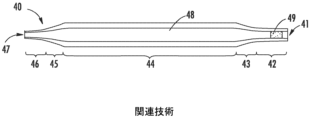
厚いチューブを再熱した後、ピペットの一端または両端を引き出してトリミングし、上で概説した方法(ii)にしたがって先端と吸口を成形することには、先端および吸口の開口の大きなばらつき、先端、本体および吸口領域間の形状移行のばらつき、ならびに全体的な品質のばらつきが伴う。加えて、先端領域および吸口領域の壁厚は初期のチューブの厚さによって決定されるため、得られたピペットの本体部分が必要以上に大幅に厚い壁厚を有することがあり、材料コストが過度に高くなりうる。図2Aは、吸口領域42と先端領域46との間に配置された管状本体領域44を含み、中空内部48を有する、引き出しピペット40の概略的な側断面図である。移行領域43,45は、吸口42、管状本体44、および先端領域46のそれぞれの対の間に設けられる。管状本体領域44は、吸口領域42および先端領域46の壁厚よりも大きな壁厚を有する。各移行領域43,45は、管状本体領域44からの距離が増大するにつれてテーパ状となる可変壁厚を有する。先端開口47が先端領域46の端部に設けられる。吸口領域42は、隣接する移行領域43と吸口開口41との間に配置されたフィルタ49を含む。引き出しプロセスにおける固有のばらつきにより、先端領域46、吸口領域42および移行領域43,45の位置および寸法は、ピペットごとに異なりうる。
Reheating the thick tubing, then drawing and trimming one or both ends of the pipette and shaping the tip and mouth according to method (ii) outlined above, involves large variations in tip and mouth openings, variations in the shape transition between the tip, body and mouth regions, and variations in overall quality. In addition, because the wall thickness of the tip and mouth regions is determined by the initial tubing thickness, the body portion of the resulting pipette may have a wall thickness that is significantly thicker than necessary, which may result in excessive material costs. Figure 2A is a schematic side cross-sectional view of a
図2Bは、図2Aによる引き出しピペットを製造する方法50のステップを概説するフローチャートである。第1のステップ51は、本体前駆体として使用される厚いチューブを押し出し、冷却し、かつ切断することを含む。第2のステップ52は、WIPのチューブをハンドリング(例えば輸送および保管)することを含む。第3のステップ53は、加熱および引き出しステップの準備としてWIPのチューブを向かい合わせることを含む。第4のステップ54は、チューブを加熱し、先端領域を引き出すことを含む。第5のステップ55は、(第4のステップ54から冷却が行われていない場合)チューブを加熱し、吸口領域を引き出して、引き出しピペットを成形することを含む。第6のステップ56は、引き出しピペットの外面に目盛を印刷することを含み、第7のステップ57は、ピペット吸口にフィルタを挿入することを含む。図2Bを観察すると明らかであるように、方法50は多数の処理ステップを含む。
2B is a flow chart outlining the steps of a
上で概説した方法(iii)にしたがって差圧を加えることによって成形すると、溶接継目のない高品質のピペットを製作できるが、こうした方法では、一般的に、管状ピペット本体の外面に沿って、長手方向に離隔して突出した周方向リング形状またはリブ(すなわち、ガス抜き通路内への軟化した材料の進入によって生じる当たり確認特徴)が形成され、このようなリング形状の当たり確認特徴は、本体の外側に印刷される目盛線の明瞭さおよび読み取りやすさを分かりにくくする傾向がある。(上で概説した方法(iii)による)差圧を加えることによる成形によって製作可能な例示的なピペット60を図3に示しており、これは、コーニング社へ譲渡された“Unitary Serological Pipette and Methods of Producing the Same”なるタイトルの特許文献1の第1図と実質的に同じである。入口領域62、本体領域64および先端領域66のそれぞれは、空間を囲む湾曲した内面71を有し、かつ対応する直径(すなわち、入口直径72、本体直径74および先端直径76)を有する。ピペット60は、長手方向軸線に沿って整列された入口73および先端75を有し、さらに入口73付近にフィルタ79を有する。任意で、ピペット60は、入口領域62と本体領域64との間の入口‐本体移行領域63、ならびに本体領域64と先端領域66との間の本体‐先端移行領域65を有しうる。ピペット60が溶接接合部(例えば、先端領域66、本体領域64および吸口領域62の間)を形成することなく連続材料で成形される場合、実質的に平滑な内面69を移行領域63,65に設けることができ、これにより、流体および/または粒子材料の残留の可能性が低減される。ピペット60は、ピペット60内の空間78に包まれた液体の体積を示すために(少なくとも)本体領域64の外面68に沿って印刷(またはインプリント)された一連の目盛付けされた体積マーク77を有してもよい。ピペット60は、特定の体積(例えば、1mL(1cm3)、2mL(2cm3)、5mL(5cm3)、10mL(10cm3)、25mL(25cm3)、50mL(50cm3)、100mL(100cm3)、または別の所望の体積)の液体を保持するようにサイズ決めされていてよい。任意で、本体領域64の直径74は、入口領域62の直径72または先端領域66の直径76のいずれよりも大きくてよい。ピペット60は、あらゆる適切な材料、例えばガラスまたはポリマー(例えばポリスチレン、ポリエチレンまたはポリプロピレン)から製造可能である。
Although forming by differential pressure according to method (iii) outlined above can produce high quality pipettes without welded seams, such methods typically result in the formation of longitudinally spaced, protruding circumferential rings or ribs (i.e., impact features caused by the ingress of softened material into the vent passages) along the exterior surface of the tubular pipette body, which tend to obscure the clarity and readability of the graduation lines printed on the exterior of the body. An exemplary pipette 60 that can be produced by forming by differential pressure (according to method (iii) outlined above) is shown in FIG. 3, which is substantially the same as FIG. 1 of U.S. Patent No. 5,399,333, entitled "Unitary Serological Pipette and Methods of Producing the Same," assigned to Corning Incorporated. Each of the
差圧を加えながら成形することによるピペット60の製造は、加熱されたパリソン(例えば、一般的には均一な中空円筒体の形状のチューブまたはプリフォーム)を型内に供給し、パリソンの内部と外部との間に差圧を生じさせ、パリソンを膨張させ、型のキャビティに合致させることを含んでもよい。当該差圧は、パリソンの内部に加圧ガス(例えば、0.05~1.5MPaの圧縮空気)を供給することによって、または型のキャビティを画定した面に沿って大気圧未満の条件(例えば0.01~0.09MPaの圧力における真空条件としても知られる)を生じさせることによって形成されてもよい。いずれのケースも、加熱されたパリソンの膨張を可能にするため、パリソンの外部とキャビティとの間のガスが逃げられるように、型の表面における通路の存在を必要とする。一般的に、成形作業中のガス逃がし通路として機能する周方向チャネルが、型の湾曲面(例えば対応する型半部)に形成される。湾曲した内面に沿って、位置合わせされた横方向の凹みチャネルセグメントを画定する型半部を使用してピペットを製造した後、得られたピペットは、管状ピペット本体の外面に沿って長手方向に離隔して突出した周方向リング(すなわち周方向当たり確認特徴)を示す。当該周方向当たり確認特徴は、望ましくないことに、目盛付けされた体積マークの印刷を妨げることがあり、また、使用者が目盛付けされた体積マークを使用して流体体積を迅速かつ正確に読み取ることを誤らせる可能性がある。膨張した材料(ここではピペットとして構成されている)が十分に冷却された後、型が開放され、ピペットが排出されて、型は別の加熱されたパリソンを受容してプロセスを繰り返すことができる。 The production of the pipette 60 by molding under differential pressure may involve feeding a heated parison (e.g., a tube or preform, typically in the shape of a uniform hollow cylinder) into a mold and creating a pressure differential between the interior and exterior of the parison to expand it and conform to the mold cavity. The pressure differential may be created by feeding a pressurized gas (e.g., compressed air at 0.05-1.5 MPa) into the interior of the parison or by creating subatmospheric conditions (also known as vacuum conditions, e.g., at pressures of 0.01-0.09 MPa) along the surfaces defining the mold cavity. In either case, to allow the expansion of the heated parison, the presence of passages in the mold surface to allow the escape of gas between the exterior of the parison and the cavity is required. Typically, circumferential channels are formed in the curved surfaces of the mold (e.g., in the corresponding mold halves) to serve as gas escape passages during the molding operation. After fabricating a pipette using mold halves that define aligned lateral recessed channel segments along their curved inner surfaces, the resulting pipette exhibits circumferential rings (i.e., circumferential contact features) that protrude longitudinally spaced apart along the outer surface of the tubular pipette body. Such circumferential contact features may undesirably interfere with the printing of graduated volume marks and may mislead a user from using the graduated volume marks to quickly and accurately read the fluid volume. After the expanded material (now configured as a pipette) has sufficiently cooled, the mold is opened, the pipette is ejected, and the mold can receive another heated parison to repeat the process.
以上のことを考えると、上記の欠点を有さないピペット、およびピペットを製造するための改良されたシステムおよび方法が必要となる。 In view of the above, there is a need for a pipette that does not have the above-mentioned drawbacks, and for an improved system and method for manufacturing the pipette.
延伸ブロー成形によって成形された一体型測定ピペット(例えば血清学ピペット)、ならびに延伸ブロー成形によって一体型測定ピペットを成形するためのシステムおよび方法が、本明細書において提供される。延伸ブロー成形は、既製プリフォームの延伸と、型キャビティ内で延伸されたプリフォームのブローとを含む。プリフォームは、材料を所望の場所に分配するようにプロファイル可能であり、ピペットの正確な本体厚さをもたらす。延伸ブロー成形ピペットは、先端領域と吸口領域との間の管状本体を含む。先端領域は、管状本体の壁厚よりも大きい平均壁厚を有し、ピペットには、管状本体と先端領域との間、および管状本体と吸口領域との間の溶接ピペットに存在するような接合部(例えば溶接接合部)がない。延伸ブロー成形ピペットは、熱可塑性材料、例えば二軸配向熱可塑性材料を含むことができる。延伸ブロー成形法は、(例えば成形により)プリフォームを製造すること、プリフォームを軟化温度まで加熱すること、加熱されたプリフォームの少なくとも一部分を延伸し、これにより細長くすること、細長いプリフォームに型キャビティ内で加圧流体(例えば、ガス、例えば空気)をブローして、加熱されたプリフォームを膨張させて成形面と接触させ、ピペット形状にし、ブローされた細長いプリフォームを冷却すること、を含むことができる。特定の実施形態では、プリフォームが型キャビティの外側にある間に延伸を行い、続いて、延伸プリフォームの周りの(型キャビティを画定する)型半部を閉鎖してもよい。特定の実施形態では、プリフォームは、コアピンがプリフォーム型キャビティ内で回転している間に成形することによって製造可能であり、ポリマー鎖が半径方向に配向される。延伸ブロー成形ピペットを製造するシステムは、プリフォーム型キャビティを画定する第1の型と、中空プリフォームの成形中に(プリフォーム型キャビティ内に配置可能な)コアピンと第1の型との相対回転を実現するように構成された回転駆動ユニットとを含むことができる。システムは、プリフォームの内部で延伸ロッドを運動させて細長いプリフォームを成形するように構成された延伸ロッド駆動ユニットと、加圧流体が細長いプリフォームの内部に供給されたときに細長いプリフォームの膨張を抑制するための成形面およびブロー成形キャビティを画定する第2の型とをさらに含んでもよい。 Provided herein are integral metering pipettes (e.g., serological pipettes) molded by stretch blow molding, as well as systems and methods for molding integral metering pipettes by stretch blow molding. Stretch blow molding involves stretching a pre-made preform and blowing the stretched preform into a mold cavity. The preform can be profiled to dispense material at a desired location, resulting in a precise body thickness for the pipette. The stretch blow molded pipette includes a tubular body between a tip region and a mouth region. The tip region has an average wall thickness greater than the wall thickness of the tubular body, and the pipette is free of joints (e.g., welded joints) as exist in welded pipettes between the tubular body and the tip region and between the tubular body and the mouth region. The stretch blow molded pipette can include a thermoplastic material, such as a biaxially oriented thermoplastic material. The stretch blow molding process can include producing a preform (e.g., by molding), heating the preform to a softening temperature, stretching and thereby elongating at least a portion of the heated preform, blowing a pressurized fluid (e.g., gas, e.g., air) into the elongated preform in a mold cavity to expand the heated preform into contact with a molding surface and into a pipette shape, and cooling the blown elongated preform. In certain embodiments, the stretching can be performed while the preform is outside the mold cavity, followed by closing the mold halves (which define the mold cavity) around the stretched preform. In certain embodiments, the preform can be produced by molding while a core pin rotates in the preform mold cavity, resulting in a radial orientation of the polymer chains. A system for producing a stretch blow molding pipette can include a first mold defining a preform mold cavity and a rotational drive unit configured to effect relative rotation between the core pin (which can be positioned in the preform mold cavity) and the first mold during molding of the hollow preform. The system may further include a stretch rod drive unit configured to move the stretch rod within the preform to shape the elongated preform, and a second mold defining a molding surface and a blow molding cavity for constraining expansion of the elongated preform when pressurized fluid is supplied to the interior of the elongated preform.
本開示の特定の態様によれば、先端領域と吸口領域との間に配置された管状本体を含む延伸ブロー成形ピペットが提供される。先端領域は、管状本体の壁厚よりも大きい平均壁厚を有し、延伸ブロー成形ピペットには、(i)管状本体と先端領域との間、および(ii)管状本体と吸口領域との間に接合部がない。 According to certain aspects of the present disclosure, a stretch blow molded pipette is provided that includes a tubular body disposed between a tip region and a mouth region. The tip region has an average wall thickness that is greater than the wall thickness of the tubular body, and the stretch blow molded pipette is free of joints (i) between the tubular body and the tip region and (ii) between the tubular body and the mouth region.
本開示の追加の態様によれば、先端領域と吸口領域との間に配置された管状本体を含むピペットを製造する方法が提供される。この方法は、中空管状形状を有するプリフォームを製造(成形)するステップを含む。この方法は、プリフォームをプリフォームの材料の軟化温度内に加熱する追加のステップを含む。この方法は、加熱されたプリフォームの少なくとも一部分を延伸して細長いプリフォームを成形するさらなるステップを含む。この方法は、加熱されたプリフォームの内部に加圧流体を適用することにより、型キャビティ内で細長いプリフォームの少なくとも一部分をブローし、加熱されたプリフォームを膨張して成形面と接触させるさらなるステップを含む。さらなる方法のステップは、ブローされた細長いプリフォームを冷却することを含む。 According to an additional aspect of the present disclosure, there is provided a method of manufacturing a pipette including a tubular body disposed between a tip region and a mouth region. The method includes the step of manufacturing (molding) a preform having a hollow tubular shape. The method includes the additional step of heating the preform to within a softening temperature of a material of the preform. The method includes the further step of stretching at least a portion of the heated preform to form an elongated preform. The method includes the further step of blowing at least a portion of the elongated preform in a mold cavity by applying a pressurized fluid to an interior of the heated preform to expand the heated preform into contact with a molding surface. A further method step includes cooling the blown elongated preform.
本開示の追加の態様によれば、延伸ブロー成形プロセスによって先端領域と吸口領域との間に配置された管状本体を含むピペットを製造するシステムが提供される。システムは、内部に中空プリフォームを成形できるように構成されたプリフォーム型キャビティを画定する第1の型を含む。システムは、中空プリフォームの内部で位置決め可能であり、かつ中空プリフォームの内部で延伸ロッドを運動させて細長いプリフォームを成形するように構成された延伸ロッド駆動ユニットと連結された延伸ロッドを含むプリフォーム延伸装置をさらに含む。システムは、第2の型であって、加圧流体が細長いプリフォームの内部に供給されて細長いプリフォームを半径方向に膨張し、第2の型の成形面に接触させる間、細長いプリフォームの少なくとも一部分を包含するように構成されたブロー成形キャビティを画定する第2の型をさらに含む。 According to an additional aspect of the present disclosure, a system is provided for manufacturing a pipette including a tubular body disposed between a tip region and a mouth region by a stretch blow molding process. The system includes a first mold defining a preform mold cavity configured to mold a hollow preform therein. The system further includes a preform stretching device including a stretch rod positionable within the hollow preform and coupled to a stretch rod drive unit configured to move the stretch rod within the hollow preform to mold an elongated preform. The system further includes a second mold defining a blow molding cavity configured to contain at least a portion of the elongated preform while a pressurized fluid is supplied to the interior of the elongated preform to radially expand the elongated preform into contact with a molding surface of the second mold.
本開示の主題のさらなる特徴および利点は、以下の詳細な説明に記載され、その一部は、その説明から当業者に容易に明らかになるか、または以下の詳細な説明、特許請求の範囲、および添付図面を含む本明細書に記載された本開示の主題を実施することによって認識されるであろう。 Additional features and advantages of the subject matter of the present disclosure will be set forth in the detailed description which follows, and in part will be readily apparent to those skilled in the art from that description, or will be learned by practicing the subject matter of the present disclosure as described herein, including in the following detailed description, the claims, and the accompanying drawings.
上述した一般的な説明および以下の詳細な説明の両方が、本開示の主題の実施形態を提示しており、主張されている本開示の主題の性質および特性を理解するための概要またはフレームワークを提供することを意図していることが理解されるであろう。添付図面は、本開示の主題のさらなる理解を提供するために含まれ、本明細書に組み込まれ、その一部を構成する。図面は、本開示の主題の様々な実施形態を示し、説明とともに、本開示の主題の原理および動作を説明するのに役立つ。 It will be understood that both the foregoing general description and the following detailed description present embodiments of the presently disclosed subject matter and are intended to provide an overview or framework for understanding the nature and character of the claimed subject matter. The accompanying drawings are included to provide a further understanding of the presently disclosed subject matter and are incorporated in and constitute a part of this specification. The drawings illustrate various embodiments of the presently disclosed subject matter and, together with the description, serve to explain the principles and operation of the presently disclosed subject matter.
以下は、添付図面の図の説明である。図は必ずしも縮尺通りではなく、特定の機能および特定のビューは、明確性または簡潔性のために、縮尺の点で強調してまたは概略的に示したところがある。
本開示は、一体型測定ピペット(例えば血清学ピペット)、および延伸ブロー成形によって一体型測定ピペットを成形するための方法および装置に関する。延伸ブロー成形は、既製プリフォームの延伸と、型キャビティ内で延伸されたプリフォームのブローとを含む。プリフォームは、材料を所望の場所に分配するようにプロファイル可能であり、ピペットの正確な本体厚さをもたらす。プリフォームを既製(例えば成形)することで、先端領域および吸口領域を延伸の前に成形することができ、これにより、得られたピペットにおいてこれらの領域を正確かつ再現可能に成形することができ、さらに、これらの領域が管状本体に対して増加した厚さを有することができる。既製された先端領域および吸口領域を備えたプリフォームを使用することで、引き出しピペットまたは溶接ピペットに通常必要とされる切断が不要となる。 The present disclosure relates to integrated metering pipettes (e.g., serological pipettes) and methods and apparatus for molding integrated metering pipettes by stretch blow molding. Stretch blow molding involves stretching a pre-made preform and blowing the stretched preform into a mold cavity. The preform can be profiled to distribute material in a desired location, resulting in a precise body thickness for the pipette. Pre-fabricating (e.g., molding) the preform allows the tip and mouth regions to be shaped prior to stretching, allowing these regions to be precisely and reproducibly shaped in the resulting pipette and to have an increased thickness relative to the tubular body. Using a pre-form with pre-fabricated tip and mouth regions eliminates the cutting typically required for puller or welded pipettes.
延伸ブロー成形法を使用して、二軸配向ポリマー材料のピペットを製作することができる。二軸配向の理解を可能にするために、ポリマー配向原理への簡単なイントロダクションを以下に示す。 Stretch blow molding techniques can be used to fabricate pipettes of biaxially oriented polymeric material. To enable understanding of biaxial orientation, a brief introduction to polymer orientation principles is provided below.
機械的荷重に耐えるためのポリマーの能力は、共有結合の強度および分子間力に依存する。非晶質系において、機械的荷重のほとんどは、ファンデルワールス相互作用および鎖間のランダムなコイルからみ合いによって担持される。しかしながら、ポリマー鎖の実質的な部分を耐荷方向において整列させる(すなわち配向させる)ことができるならば、荷重のより大きな部分を主鎖共有結合へ伝達することができる。非晶質系では鎖配向のみが生じるのに対し、半結晶性ポリマーでは鎖および結晶領域の両者を整列させることができる。非晶質系および半結晶系の両者において、ポリマー鎖の配向により、配向方向の強度が増大する。一軸配向された材料は、一般的に、ポリマー鎖配向に対して垂直方向において低い強度を有する。 The ability of a polymer to withstand mechanical loads depends on the strength of the covalent bonds and the intermolecular forces. In amorphous systems, most of the mechanical load is carried by van der Waals interactions and random coil entanglements between the chains. However, if a substantial portion of the polymer chains can be aligned (i.e. oriented) in the load-bearing direction, a larger portion of the load can be transferred to the backbone covalent bonds. In amorphous systems, only chain orientation occurs, whereas in semicrystalline polymers both the chains and the crystalline regions can be aligned. In both amorphous and semicrystalline systems, polymer chain orientation increases the strength in the direction of orientation. Uniaxially oriented materials generally have lower strength in the direction perpendicular to the polymer chain orientation.
ポリマー鎖は、これらのポリマー鎖を、溶融したまたはほぼ溶融した状態において延伸ひずみ(流れ)に曝すことによって配向される。ポリマー材料の二軸配向は、高温において2つの方向(例えば、半径方向および長さ方向)に材料をひずませ、材料をひずませながら冷却することによって達成することができる。配向されていないまたは一軸配向されたポリマーと比較して、二軸配向は、機械的および光学的特性が高められた、厚さが減じられたフィルム、容器および物体の製作を可能にする。 Polymer chains are oriented by subjecting them to elongational strain (flow) in the molten or near-molten state. Biaxial orientation of a polymeric material can be achieved by straining the material in two directions (e.g., radial and longitudinal) at elevated temperatures and cooling the material under strain. Compared to unoriented or uniaxially oriented polymers, biaxial orientation allows for the fabrication of films, containers and objects of reduced thickness with enhanced mechanical and optical properties.
二軸配向は、ホットプリフォームの寸法を膨張することにより延伸ブロー成形し、これにより(例えばブローによって)半径方向に、かつ(例えば延伸によって)長手軸方向にひずませることにより得ることができる。プリフォームと完成したピペットとの相対寸法によっては、ブローに起因する半径方向の膨張の度合いが、延伸ブロー成形ピペットにおいてポリマー鎖の半径方向の配向性に顕著な度合いを付与するには十分でないことがある。この状況に対処するために、特定の実施形態では、ポリマー鎖の半径方向配向は、プリフォーム成形プロセス中にプリフォーム材料を半径方向で剪断するために、プリフォームの成形材料と接触しているスピニングコアの使用によって強化することができる。プリフォーム内のポリマー鎖の初期の半径方向の配向は、軸方向の延伸中に得られる軸方向の配向によって増強されると、完成したピペット中にポリマー鎖の二軸配向を生じさせる。 Biaxial orientation can be achieved by stretch blow molding a hot preform by expanding its dimensions, thereby straining it radially (e.g., by blowing) and longitudinally (e.g., by stretching). Depending on the relative dimensions of the preform and the finished pipette, the degree of radial expansion resulting from blowing may not be sufficient to impart a significant degree of radial orientation of the polymer chains in the stretch blow molded pipette. To address this situation, in certain embodiments, the radial orientation of the polymer chains can be enhanced by the use of a spinning core in contact with the molding material of the preform to radially shear the preform material during the preform molding process. The initial radial orientation of the polymer chains in the preform, when augmented by the axial orientation achieved during axial stretching, results in biaxial orientation of the polymer chains in the finished pipette.
特定の実施形態では、プリフォームおよび得られたピペット(管状本体領域、先端領域、および吸口領域を含む)は、二軸配向されうる熱可塑性材料を含むことができる。特定の実施形態では、熱可塑性材料は、結晶性ポリスチレン、ポリ(スチレン-ブタジエン-スチレン)、ポリエチレンテレフタレート、ポリプロピレン、これらのポリマーのいずれか2種以上のコポリマー、および/またはこれらのポリマーのいずれか1種以上のリサイクルストリームを含んでいてもよい。 In certain embodiments, the preform and resulting pipette (including the tubular body region, the tip region, and the mouth region) may comprise a thermoplastic material that may be biaxially oriented. In certain embodiments, the thermoplastic material may comprise crystal polystyrene, poly(styrene-butadiene-styrene), polyethylene terephthalate, polypropylene, copolymers of any two or more of these polymers, and/or recycled streams of any one or more of these polymers.
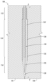
図4Aは、本開示の一実施形態による、延伸ブロー成形によって製造されたピペット80を示す。ピペット80は、吸口領域82と先端領域86との間に配置された管状本体領域84を含み、中空内部90を有する。吸口領域82と管状本体領域84との間に第1の急峻な移行領域83が設けられ、管状本体領域84と先端領域86との間に第2の急峻な移行領域85が設けられる。ただし、こうした移行領域83、85は、溶接接合部の存在なしに、連続的に均一な材料を構成する。先端領域86の外径は、先端開口87に近づくにつれて幅がテーパ状となる。ただし、先端領域86は、任意で、実質的に一定の内径を有するボア88を含む。先端領域86のこうした特徴部は、プリフォーム成形作業中に製造することができる。特定の実施形態では、先端領域86は、一定でない内径を有しうる。任意で、吸口領域82は、管状本体領域84の対応する寸法よりも小さい内径寸法および外径寸法を有し、吸口領域82は、開口した吸口端部81と管状本体領域84との間の内部に配置されたフィルタ89をさらに含む。管状本体領域84は、外面に沿って印刷(またはインプリント)された目盛付けされた体積マーク91をさらに含み、中空内部90に包含される液体の体積を示す。図示のように、先端領域86の平均壁厚は、管状本体領域84の壁厚よりも大きく、吸口領域82は、管状本体領域84の壁厚よりも大きい平均壁厚を有する。加えて、ピペット80の最大壁厚の領域は、先端領域86内にあり、かつ/または先端領域86と管状本体領域84との間の移行部85にある。
4A illustrates a
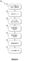
図4Bは、図4Aによる延伸ブロー成形ピペットを製造する方法94のステップを概説するフローチャートである。第1のステップ95は、プリフォームを製造(例えば成形)し、これをプリフォーム延伸装置または機械に搬送することを含む。特定の実施形態では、プリフォームの成形は、内部での中空プリフォームの成形を可能とするように構成されたプリフォーム型キャビティを画定する第1の型での射出成形または圧縮成形を含みうる。任意で、第1の型は、プリフォーム型キャビティ内にコアピンを受容するように構成可能であり、回転駆動ユニットを利用して、第1の型内での中空プリフォームの成形中にコアピンと第1の型との相対回転を実現可能である。こうした回転は、第1の型が静止している間のコアピンの回転を含むことができ、またはコアピンが静止している間の第1の型の回転を含むことができる。プリフォームの成形を完了するために、プリフォームが冷却される。第2のステップ96は、プリフォームの延伸およびブローの準備として、プリフォームをプリフォーム材料の軟化温度まで加熱することを含む。特定の実施形態では、少なくとも1つの赤外線加熱要素を使用して、プリフォームを加熱することができる。第3のステップ97は、ブロープロセス中にピペットの外面にマークを付与するために、ブロー作業の前に成形面にインクを付着させること、またはプリフォームのブローに使用する型キャビティにラベルを挿入することを含みうる。第4のステップ98は、プリフォームを延伸して細長いプリフォームを成形し、細長いプリフォームをブローして少なくともその一部分の半径方向の膨張を促進し、延伸かつブローされた材料を冷却してピペットを成形し、ピペットを型のブロー成形キャビティから(例えば、嵌合した型半部を分離することにより)取り外すことを含む。第5のステップ99は、得られたピペットの吸口領域への(例えばフィルタ差し込み機構を使用した)フィルタの挿入を含む。その後、ピペットは、さらなる処理のために滅菌ステーションおよび/または包装ステーションに搬送されてもよい。特定の実施形態では、延伸ブロー作製ステップは、無菌(例えばクリーンルーム)環境で実行されてもよく、これにより、製造ステップが完了した後の滅菌の必要性を回避することができる。
4B is a flow chart outlining steps of a
特定の実施形態では、超音波励起をプリフォームの成形中に射出スクリューおよび/または型キャビティに適用して、プリフォーム内のポリマー鎖のランダム配向の実現を促進することができ、これにより、スピニングコアの必要性を排除することができる。 In certain embodiments, ultrasonic excitation can be applied to the injection screw and/or mold cavity during molding of the preform to help achieve random orientation of the polymer chains within the preform, thereby eliminating the need for a spinning core.
特定の実施形態では、中空プリフォームの少なくとも一部分の内部で位置決め可能な延伸ロッドを使用して、プリフォームの延伸を実現し、細長いプリフォームを成形することができる。延伸ロッドは、プリフォームの内部で延伸ロッドを(例えば並進によって)運動させるように構成された延伸ロッド駆動ユニットと連結されていてよい。特定の実施形態では、延伸ロッドは、先端領域とピペットの管状本体との間の移行領域の内部テーパと一致する形状を有するテーパした領域を含む。特定の実施形態では、チャックまたはクランプを使用して、プリフォームの内部で延伸ロッドが運動して細長いプリフォームを成形する間、プリフォームの吸口端部を固定することができる。特定の実施形態では、プリフォーム延伸作業は、ブロー成形キャビティを有する型の外で(例えば、第2の型の開口セクションに近接するプリフォーム延伸装置を用いて)実行可能であり、その結果、プリフォームの延伸後、細長いプリフォームは、(例えば、細長いプリフォームの周りの型キャビティ半部を閉鎖することにより)ブロー成形キャビティに移送可能であり、その後、細長いプリフォームの半径方向の膨張を行うことができる。 In certain embodiments, a stretch rod positionable within at least a portion of the hollow preform can be used to achieve stretching of the preform to form an elongated preform. The stretch rod can be coupled to a stretch rod drive unit configured to move the stretch rod (e.g., by translation) within the preform. In certain embodiments, the stretch rod includes a tapered region having a shape that matches the internal taper of the transition region between the tip region and the tubular body of the pipette. In certain embodiments, a chuck or clamp can be used to secure the mouth end of the preform during movement of the stretch rod within the preform to form the elongated preform. In certain embodiments, the preform stretching operation can be performed outside of the mold having the blow molding cavity (e.g., with a preform stretching device proximate the open section of the second mold), so that after stretching the preform, the elongated preform can be transferred to the blow molding cavity (e.g., by closing the mold cavity halves around the elongated preform) and then radial expansion of the elongated preform can take place.
図5Aは、型キャビティ104に配置された回転可能なコアピン106を有するプリフォーム型100を示しており、回転可能なコアピン106に連結された回転駆動ユニット108を伴う。プリフォーム型100は、プリフォームの製造後のプリフォームの取り出しを可能にするために、分離可能半部101、102から形成することができる。型キャビティ104は、それぞれ異なる寸法を有する吸口キャビティ部分104A、管状本体キャビティ部分104B、および先端キャビティ部分104Cを含む。回転可能なコアピン106は、先端キャビティ部分104C内に配置されたテーパ状端部分107を含みうる。図示のように、管状本体キャビティ部分104Bは、型キャビティ104の最長部分を含み、吸口キャビティ部分104Aおよび管状本体キャビティ部分104Bは、異なるが一定の外径を有し(吸口キャビティ部分104Aは、型キャビティ104の最小外径を有する)、先端キャビティ部分104Cは、可変外径を有する。プリフォーム型100の使用時、分離可能半部101、102は閉鎖可能であり、溶融熱可塑性材料を型キャビティ104に供給(例えば注入)することができ、コアピン106は、熱可塑性材料が型キャビティ104内で冷却および固化する間、回転駆動ユニット108の作業によって回転可能である。その後、型100の分離可能半部101、102を互いに分離させ、プリフォームを下方向に引っ張ることによってプリフォームをコアピン106から取り外し、加熱ステーションに搬送することができる。
5A shows a
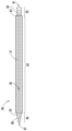
図5Bは、図5Aに示すプリフォーム型100および回転可能なコアピン106により製作可能なプリフォーム110の側面図である。プリフォーム110は、吸口前駆体部分112と先端前駆体部分116との間に配置された管状本体前駆体部分114を含み、吸口端部111と先端端部117との間に延在する中空内部118を全て取り囲んでいる。
Figure 5B is a side view of a
プリフォーム110の製造後、プリフォーム110をプリフォーム材料の軟化温度まで加熱して、ピペットの成形のためにプリフォーム110を延伸かつブローする準備をすることができる。特定の実施形態では、こうした加熱は、プリフォーム110を赤外線加熱装置の中またはそれに近接して配置することによって実現することができる。図5Cは、赤外線加熱要素119A、119Bを含む赤外線加熱装置内に配置された図5Bのプリフォーム110を示し、プリフォーム110へ赤外放射を当てることを示している。
After the
図5Dは、プリフォーム延伸装置120の概略的な側断面図であり、細長いプリフォーム110’の内部118’内の延伸ロッド122の並進による延伸作業を受けた後の(例えば、まだ加熱状態にある)細長いプリフォーム110’を示す。延伸ロッド122は、任意で、コア123およびクラッド124を含み、テーパ状端部125を含む。任意で、コア123は、クラッド124の内部のねじ状面に沿って回転して、延伸ロッド122の並進を生じさせるように配置されてもよい。特定の実施形態では、テーパ状端部125は、細長いプリフォーム110’の先端部分116’の内部テーパに対応しており、かつ/または先端部分116’と管状本体部分114’との間の移行領域の内部テーパに対応する形状を有し、これにより、細長いプリフォーム110’の内部へのブローのための差し込みが可能となる。細長いプリフォーム110’は、管状本体部分114’および吸口部分112’をさらに含む。延伸ロッド122の並進は、延伸ロッド駆動ユニット128によって促される。チャックまたはクランプ126は、延伸作業中に延伸ロッド122が並進するときに吸口部分112’を固定するために設けられる。
5D is a schematic cross-sectional side view of a
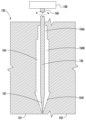
図5Eは、型130のブロー成形キャビティ134内に配置された図5Dの加熱された細長いプリフォーム110’(吸口部分112’、管状本体部分114’および先端部分116’を含む)ならびに延伸ロッド122の概略的な側断面図である。型130は、成形面135を画定する分離可能な第1および第2の型半部131、132から構成される。凸状の受容特徴部139をブロー成形キャビティ134の底部に設けることができ、細長いプリフォーム110’の内部を閉鎖するのに役立つ。図示のように、加熱された細長いプリフォーム110’は、ブロー前の状態にあり、その内部に(例えば、延伸ロッド122を通じて)加圧流体を供給して、細長いプリフォーム110’を半径方向に膨張し、型130の成形面135に接触させることを含む。ブロー作業が完了した後、型半部131、132を分離して得られたピペットを延伸ロッド122から取り外すことにより、型130を開放することができる。
5E is a schematic cross-sectional side view of the heated elongated preform 110' (including the mouth portion 112', the tubular body portion 114' and the tip portion 116') of FIG. 5D positioned within the
図5Fは、図5A~図5Eに示すプリフォームおよび装置を使用して、延伸およびブロー作業、および型130からのピペット140の取り出しに続いて取得可能な、延伸ブロー成形ピペット140の概略的な断面図である。ピペット140は、吸口領域142と先端領域146との間に配置された管状本体領域144を含み、中空内部150を有する。吸口領域142と管状本体領域144との間に第1の急峻な移行領域143が設けられ、管状本体領域144と先端領域146との間に第2の急峻な移行領域145が設けられる。ただし、こうした移行領域143、145は、溶接接合部の存在なしに、連続的に均一な材料を構成する。先端領域146の外径および内部ボア148の両方は、先端開口147に近づくにつれてテーパ状になる幅を有する。図示のように、先端領域146は、管状本体領域144の壁厚を超える平均壁厚を有し、吸口領域142は、管状本体領域144の外径よりも小さい外径を有する。吸口領域142は、開口した吸口端部141と管状本体領域144との間に内部に配置されたフィルタ149をさらに含む。吸口領域142は、管状本体領域144と同じ内径を有するものとして示されているが、特定の実施形態では、吸口領域142は、管状本体領域144の内径よりも小さい内径を有してもよい。
5F is a schematic cross-sectional view of a stretch blow molded
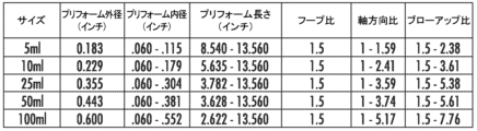
図6~図9は、複数の異なる体積の延伸ブロー成形ピペットを製作するのに有用な、計算されたプリフォーム外径、プリフォーム内径、プリフォーム長さ、フープ比、軸方向比およびブローアップ比の値の範囲を提供する表を構成したものである。直径および長さの値はインチ単位である。フープ比は、対応するプリフォームの管状本体領域の外径に対する延伸ブロー成形ピペットの管状本体領域の外径の比である。軸方向比は、対応するプリフォームの長さに対する延伸ブロー成形ピペットの長さの比である。ブローアップ比は、フープ比と軸方向比の積である。 FIGS. 6-9 constitute a table providing a range of calculated preform outer diameter, preform inner diameter, preform length, hoop ratio, axial ratio and blow-up ratio values useful for producing stretch blow molding pipettes of a number of different volumes. Diameter and length values are in inches. Hoop ratio is the ratio of the outer diameter of the tubular body region of the stretch blow molding pipette to the outer diameter of the tubular body region of the corresponding preform. Axial ratio is the ratio of the length of the stretch blow molding pipette to the length of the corresponding preform. Blow-up ratio is the product of hoop ratio and axial ratio.
図6は、プリフォーム製造ステップ中にスピニングコアピンを使用せずに、コーニング社(Corning, New York, 米国)から市販入手可能なCostar(登録商標)溶接ピペットと一致する管状本体の壁厚寸法を有する、4つの異なる体積の延伸ブロー成形ピペットを製作するのに有用な値の範囲を提供する表である。最大外径は、ピペット材料の二軸配向を実現するためにプリフォーム成形中にスピニングコアを使用する必要なく、ブローの際の半径方向でのポリマー鎖の配向が可能となるように計算されている。 Figure 6 is a table providing a range of values useful for fabricating stretch blow molded pipettes of four different volumes with tubular body wall thickness dimensions consistent with Costar® welded pipettes commercially available from Corning, New York, USA, without the use of spinning core pins during the preform fabrication step. The maximum outer diameters are calculated to allow for radial polymer chain orientation during blowing without the need to use a spinning core during preform molding to achieve biaxial orientation of the pipette material.
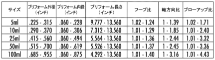
図7は、プリフォーム製造ステップ中にスピニングコアピンを使用せずに、従来のCostar(登録商標)溶接ピペットよりも50%少ない材料を使用して、5つの異なる体積のピペットを製作するのに有用な値の範囲を提供する表である。図6の場合と同様に、最大外径は、ピペット材料の二軸配向を実現するためにプリフォーム成形中にスピニングコアを使用する必要なく、ブローの際の半径方向でのポリマー鎖の配向が可能となるように計算されている。図6と比較すると、図7のフープ比、軸方向比およびブローアップ比の範囲が拡大されていることから明らかなように、図7では、より少ない材料しか要しないピペットを延伸ブロー成形することで、プリフォームの成形のための設計範囲が拡がる可能性があることが示されている。 Figure 7 is a table providing a range of values useful for fabricating pipettes of five different volumes using 50% less material than conventional Costar® welded pipettes without the use of spinning core pins during the preform fabrication step. As in Figure 6, the maximum outer diameter is calculated to allow for radial polymer chain orientation during blowing without the need to use a spinning core during preform molding to achieve biaxial orientation of the pipette material. Figure 7 shows that stretch blow molding pipettes that require less material may expand the design range for molding the preform, as evidenced by the expanded range of hoop, axial, and blow-up ratios in Figure 7 compared to Figure 6.
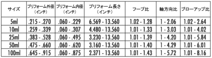
図8は、プリフォーム製造ステップ中のスピニングコアピンの使用を含め、従来のCostar(登録商標)溶接ピペットと一致する管状本体の壁厚寸法を有する、5つの異なる体積の延伸ブロー成形ピペットを製作するのに有用な値の範囲を提供する表である。図8と図6を比較すると、図8のブローアップ比の範囲が膨張されていることから明らかなように、スピニングコアを使用することで、より大きな寸法範囲の成形プリフォームが可能になることがわかる。 Figure 8 is a table providing a range of values useful for producing stretch blow molded pipettes of five different volumes, including the use of spinning core pins during the preform fabrication step, with tubular body wall thickness dimensions consistent with conventional Costar® welded pipettes. Comparing Figure 8 with Figure 6, it can be seen that the use of spinning cores allows for a larger range of molded preform dimensions, as evidenced by the expanded range of blow-up ratios in Figure 8.
図9は、プリフォーム製造ステップ中のスピニングコアピンの使用を含め、従来のCostar(登録商標)溶接ピペットよりも50%少ない材料を使用して、5つの異なる体積のピペットを製作するのに有用な値の範囲を提供する表である。図9と図7および図8を比較すると、スピニングコアを、より少ない材料を必要とするピペットの延伸ブロー成形と組み合わせて使用することで、図7および8と比較して図9のフープ比、軸方向比、およびブローアップ比の範囲が膨張されていることから明らかなように、これらの状況のいずれか1つよりもさらに大きな寸法範囲の成形プリフォームが可能になることがわかる。 Figure 9 is a table providing a range of values useful for producing pipettes of five different volumes using 50% less material than conventional Costar® welded pipettes, including the use of spinning core pins during the preform fabrication step. Comparing Figure 9 to Figures 7 and 8, it can be seen that the use of spinning cores in combination with stretch blow molding of pipettes requiring less material allows for an even larger range of molded preforms than either of these situations, as evidenced by the expanded range of hoop, axial, and blow-up ratios in Figure 9 compared to Figures 7 and 8.
本開示の態様(1)は、延伸ブロー成形ピペットに関する。延伸ブロー成形ピペットは、先端領域と吸口領域との間に配置された管状本体を含み、先端領域が、管状本体の壁厚よりも大きい平均壁厚を有し、延伸ブロー成形ピペットには、(i)管状本体と先端領域との間、および(ii)管状本体と吸口領域との間に接合部がない。 Aspect (1) of the present disclosure relates to a stretch blow molded pipette. The stretch blow molded pipette includes a tubular body disposed between a tip region and a mouth region, the tip region having an average wall thickness greater than the wall thickness of the tubular body, and the stretch blow molded pipette is free of joints (i) between the tubular body and the tip region and (ii) between the tubular body and the mouth region.
本開示の態様(2)は、先端領域が、実質的に一定の内径を有する開口を含む、態様(1)記載の延伸ブロー成形ピペットに関する。 Aspect (2) of the present disclosure relates to a stretch blow molded pipette according to aspect (1), in which the tip region includes an opening having a substantially constant inner diameter.
本開示の態様(3)は、吸口領域が、管状本体の壁厚よりも大きい平均壁厚を有し、態様(1)または(2)記載の延伸ブロー成形ピペットに関する。 Aspect (3) of the present disclosure relates to a stretch blow molded pipette as described in aspect (1) or (2), in which the mouth region has an average wall thickness greater than the wall thickness of the tubular body.
本開示の態様(4)は、以下の特徴(i)または(ii)、すなわち(i)吸口領域が管状本体の内径よりも小さい内径を有すること、または(ii)吸口領域が管状本体の外径よりも小さい外径を有すること、のうち少なくとも1つの特徴を含む、態様(1)から(3)までのいずれか1つ記載の延伸ブロー成形ピペットに関する。 Aspect (4) of the present disclosure relates to a stretch blow molded pipette according to any one of aspects (1) to (3), comprising at least one of the following features (i) or (ii): (i) the mouth region has an inner diameter smaller than the inner diameter of the tubular body, or (ii) the mouth region has an outer diameter smaller than the outer diameter of the tubular body.
本開示の態様(5)は、管状本体、先端領域、および吸口領域が、熱可塑性材料を含む、態様(1)から(4)までのいずれか1つ記載の延伸ブロー成形ピペットに関する。 Aspect (5) of the present disclosure relates to a stretch blow molded pipette according to any one of aspects (1) to (4), in which the tubular body, tip region, and mouth region comprise a thermoplastic material.
本開示の態様(6)は、管状本体が、二軸配向熱可塑性材料を含む、態様(1)から(5)までのいずれか1つ記載の延伸ブロー成形ピペットに関する。 Aspect (6) of the present disclosure relates to a stretch blow molded pipette according to any one of aspects (1) to (5), wherein the tubular body comprises a biaxially oriented thermoplastic material.
本開示の態様(7)は、管状本体、先端領域、および吸口領域が、結晶性ポリスチレン、ポリ(スチレン-ブタジエン-スチレン)、ポリエチレンテレフタレート、ポリプロピレン、これらのポリマーのいずれか2種以上のコポリマー、またはこれらのポリマーのいずれか1種以上のリサイクルストリームを含む、態様(5)または(6)記載の延伸ブロー成形ピペットに関する。 Aspect (7) of the present disclosure relates to a stretch blow molded pipette according to aspect (5) or (6), in which the tubular body, tip region, and mouth region comprise crystalline polystyrene, poly(styrene-butadiene-styrene), polyethylene terephthalate, polypropylene, a copolymer of any two or more of these polymers, or a recycled stream of any one or more of these polymers.
本開示の態様(8)は、管状本体が、0.25mm~0.6mmの範囲の壁厚を有する、態様(1)から(7)までのいずれか1つ記載の延伸ブロー成形ピペットに関する。 Aspect (8) of the present disclosure relates to a stretch blow molded pipette according to any one of aspects (1) to (7), wherein the tubular body has a wall thickness in the range of 0.25 mm to 0.6 mm.
本開示の態様(9)は、先端領域が、実質的に一定の内径を有し、かつ管状本体に近づくにつれ増大する外径を有する、態様(1)から(8)までのいずれか1つ記載の延伸ブロー成形ピペットに関する。 Aspect (9) of the present disclosure relates to a stretch blow molded pipette according to any one of aspects (1) to (8), in which the tip region has a substantially constant inner diameter and an outer diameter that increases as it approaches the tubular body.
本開示の態様(10)は、先端領域が、一定でない内径を有する、態様(1)から(8)までのいずれか1つ記載の延伸ブロー成形ピペットに関する。 Aspect (10) of the present disclosure relates to a stretch blow molded pipette according to any one of aspects (1) to (8), in which the tip region has a non-constant inner diameter.
本開示の態様(11)は、延伸ブロー成形ピペットの最大壁厚の領域が、先端領域と管状本体との間の移行部において、または移行部に近接して、先端領域内にある、態様(1)から(10)までのいずれか1つ記載の延伸ブロー成形ピペットに関する。 Aspect (11) of the present disclosure relates to a stretch blow molded pipette according to any one of aspects (1) to (10), wherein the region of maximum wall thickness of the stretch blow molded pipette is within the tip region at or adjacent to the transition between the tip region and the tubular body.
本開示の態様(12)は、先端領域と吸口領域との間に配置された管状本体を含むピペットを製造する方法に関する。方法は、中空管状形状を有するプリフォームを製造するステップと、プリフォームをプリフォームの材料の軟化温度内に加熱するステップと、加熱されたプリフォームの少なくとも一部分を延伸して細長いプリフォームを成形するステップと、加熱されたプリフォームの内部に加圧流体を適用することにより、型キャビティ内で細長いプリフォームの少なくとも一部分をブローし、加熱されたプリフォームを膨張して成形面と接触させ、ピペット形状にするステップと、ブローされた細長いプリフォームを冷却するステップと、を含む。 Aspect (12) of the present disclosure relates to a method of making a pipette including a tubular body disposed between a tip region and a mouth region. The method includes the steps of making a preform having a hollow tubular shape, heating the preform to within a softening temperature of a material of the preform, stretching at least a portion of the heated preform to form an elongated preform, blowing at least a portion of the elongated preform in a mold cavity by applying a pressurized fluid to an interior of the heated preform to expand the heated preform into contact with a molding surface and into a pipette shape, and cooling the blown elongated preform.
本開示の態様(13)は、加熱されたプリフォームの少なくとも一部分を延伸して細長いプリフォームを成形するステップが、加熱されたプリフォームが型キャビティの外側にある間に実行される、態様(12)記載の方法に関する。 Aspect (13) of the present disclosure relates to the method of aspect (12), in which the step of stretching at least a portion of the heated preform to form an elongated preform is performed while the heated preform is outside the mold cavity.
本開示の態様(14)は、プリフォームを製造するステップが、成形可能材料を溶融状態でプリフォーム型のキャビティに供給するステップと、(i)プリフォームのキャビティ内にあり、かつ成形可能材料と接触しているコアピンと(ii)プリフォーム型との相対回転を実現することによって成形可能材料を処理するステップと、成形可能材料を固体状態に冷却するステップと、を含む、態様(12)または(13)記載の方法に関する。 Aspect (14) of the present disclosure relates to a method according to aspect (12) or (13), in which the step of producing a preform includes the steps of: supplying a moldable material in a molten state to a cavity of a preform mold; manipulating the moldable material by achieving relative rotation between (i) a core pin in the cavity of the preform and in contact with the moldable material and (ii) the preform mold; and cooling the moldable material to a solid state.
本開示の態様(15)は、加熱されたプリフォームの少なくとも一部分を延伸するステップの前に、プリフォームの吸口端部を固定することをさらに含む、態様(12)から(14)までのいずれか1つ記載の方法に関する。 Aspect (15) of the present disclosure relates to the method of any one of aspects (12) to (14), further comprising clamping the mouth end of the preform prior to the step of stretching at least a portion of the heated preform.
本開示の態様(16)は、加熱されたプリフォームの少なくとも一部分を延伸するステップが、ピペットの先端領域と管状本体との間の移行領域の内部テーパと一致する形状を有するテーパした領域を含む延伸ロッドを利用する、態様(12)から(15)までのいずれか1つ記載の方法に関する。 Aspect (16) of the present disclosure relates to the method of any one of aspects (12) to (15), wherein the step of stretching at least a portion of the heated preform utilizes a stretch rod that includes a tapered region having a shape that matches the internal taper of the transition region between the tip region and the tubular body of the pipette.
本開示の態様(17)は、細長いプリフォームの少なくとも一部分をブローするステップの前に、以下のステップ(a)または(b)、すなわち(i)成形面上にインクを付着させるステップ、または(ii)型キャビティにラベルを挿入するステップのうちの1つをさらに含む、態様(12)から(16)までのいずれか1つ記載の方法に関する。 Aspect (17) of the present disclosure relates to the method of any one of aspects (12) to (16), further comprising one of the following steps (a) or (b) prior to the step of blowing at least a portion of the elongated preform: (i) depositing an ink on the molding surface; or (ii) inserting a label into the mold cavity.
本開示の態様(18)は、プリフォームをプリフォームの材料の軟化温度内に加熱するステップが、プリフォームに赤外線を当てることを含む、態様(12)から(17)までのいずれか1つ記載の方法に関する。 Aspect (18) of the present disclosure relates to the method of any one of aspects (12) to (17), wherein the step of heating the preform to within the softening temperature of the material of the preform includes applying infrared radiation to the preform.
本開示の態様(19)は、延伸ブロー成形プロセスによって先端領域と吸口領域との間に配置された管状本体を含むピペットを製造するシステムに関する。システムは、内部に中空プリフォームを成形できるように構成されたプリフォーム型キャビティを画定する第1の型と、延伸ロッドを含むプリフォーム延伸装置であって、延伸ロッドが、中空プリフォームの内部で位置決め可能であり、かつ中空プリフォームの内部で延伸ロッドを運動させて細長いプリフォームを成形するように構成された延伸ロッド駆動ユニットに連結されている、プリフォーム延伸装置と、第2の型であって、加圧流体が細長いプリフォームの内部に供給されて細長いプリフォームを半径方向に膨張し、第2の型の成形面に接触させる間、細長いプリフォームの少なくとも一部分を包含するように構成されたブロー成形キャビティを画定する第2の型と、を含む。 Aspect (19) of the present disclosure relates to a system for manufacturing a pipette including a tubular body disposed between a tip region and a mouth region by a stretch blow molding process. The system includes a first mold defining a preform mold cavity configured to mold a hollow preform therein, a preform stretching apparatus including a stretch rod positionable within the hollow preform and coupled to a stretch rod drive unit configured to move the stretch rod within the hollow preform to mold an elongated preform, and a second mold defining a blow molding cavity configured to contain at least a portion of the elongated preform while a pressurized fluid is supplied to the interior of the elongated preform to radially expand the elongated preform into contact with a molding surface of the second mold.
本開示の態様(20)は、第1の型が、プリフォーム型キャビティ内にコアピンを受容するように構成され、システムが、第1の型内での中空プリフォームの成形中にコアピンと第1の型との相対回転を実現するように構成された回転駆動ユニットをさらに含む、態様(19)記載のシステムに関する。 Aspect (20) of the present disclosure relates to the system of aspect (19), wherein the first mold is configured to receive a core pin within the preform mold cavity, and the system further includes a rotational drive unit configured to effect relative rotation between the core pin and the first mold during molding of the hollow preform in the first mold.
本開示の態様(21)は、プリフォームがブロー成形キャビティの外側にある間に、プリフォームの内部で延伸ロッドが運動して細長いプリフォームを成形することを可能にするように構成されている、態様(19)または(20)記載のシステムに関する。 Aspect (21) of the present disclosure relates to a system as described in aspect (19) or (20) configured to allow movement of the stretch rod within the preform to mold the elongated preform while the preform is outside the blow molding cavity.
本開示の態様(22)は、中空プリフォームの内部で延伸ロッドが運動して細長いプリフォームを成形する前に、プリフォームをプリフォームの材料の軟化温度まで加熱するように構成された赤外線加熱要素をさらに含む、態様(19)から(21)までのいずれか1つ記載のシステムに関する。 Aspect (22) of the present disclosure relates to the system of any one of aspects (19) to (21), further comprising an infrared heating element configured to heat the preform to a softening temperature of the material of the preform prior to movement of the stretch rod within the hollow preform to form the elongated preform.
本開示の態様(23)は、中空プリフォームの内部で延伸ロッドが運動して細長いプリフォームを成形する間、プリフォームの吸口端部を固定するように構成されたチャックまたはクランプをさらに含む、態様(19)から(22)までのいずれか1つ記載のシステムに関する。 Aspect (23) of the present disclosure relates to the system of any one of aspects (19) to (22), further comprising a chuck or clamp configured to secure the mouth end of the preform during movement of the stretch rod within the hollow preform to form an elongated preform.
本開示の態様(24)は、延伸ロッドが、(i)先端領域の内部テーパ、または(ii)ピペットの先端領域と管状本体との間の移行領域の内部テーパのうちの少なくとも1つと一致する形状を有するテーパした領域を含む、態様(19)から(23)までのいずれか1つ記載のシステムに関する。 Aspect (24) of the present disclosure relates to the system of any one of aspects (19) to (23), wherein the stretch rod includes a tapered region having a shape that matches at least one of (i) an internal taper of the tip region, or (ii) an internal taper of the transition region between the tip region and the tubular body of the pipette.
本開示のさらなる態様では、本明細書において開示した任意の2つ以上の態様、実施形態または特徴が、さらなる利点のために組み合わせ可能であることが特に企図される。 In a further aspect of the present disclosure, it is specifically contemplated that any two or more aspects, embodiments, or features disclosed herein may be combined for additional advantage.
本明細書で使用される単数形「或る(a,an)」および「前記(the)」は、文脈が他の場合を明確に指示しない限り、複数の指示対象を含む。したがって、例えば、或る「ノッチ」への言及は、文脈が他の場合を明確に示さない限り、こうした「ノッチ」を2つ以上有する例を含む。 As used herein, the singular forms "a," "an," and "the" include plural referents unless the context clearly dictates otherwise. Thus, for example, reference to a "notch" includes instances having two or more such "notches" unless the context clearly dictates otherwise.
「含む(includeまたはincludes)」なる語は、包括であってこれに限定されるものでないが、包含的かつ非排他的であることを意味する。 The words "include" and "includes" are meant to be inclusive and non-exclusive, but not limited to.
「任意の」または「任意で」とは、その後で説明する事象、状況または構成部材が発生してもまたは発生しなくてもよいことを意味し、当該説明には、事象、状況または構成部材が発生する場合と発生しない場合とが含まれる。 "Optional" or "optionally" means that the subsequently described event, circumstance, or component may or may not occur, and the description includes cases where the event, circumstance, or component occurs and cases where it does not occur.
本明細書では、範囲は、1つの特定の「おおよそ」の値から、かつ/または別の特定の「おおよそ」の値までとして表現することができる。こうした範囲が表現される場合、例には、1つの特定の値から、かつ/または他の特定の値までが含まれる。同様に、先行詞「約」を使用することにより、値が近似値として表現される場合、特定の値が別の態様を形成することが理解されるであろう。各範囲の端点は、他の端点との関連においても、他の端点から独立しても重要であることがさらに理解されるであろう。 Ranges can be expressed herein as from "approximately" one particular value and/or to "approximately" another particular value. When such a range is expressed, examples include from the one particular value and/or to the other particular value. Similarly, when values are expressed as approximations, by use of the antecedent "about," it will be understood that the particular value forms another aspect. It will be further understood that the endpoints of each of the ranges are significant both in relation to the other endpoint and independently of the other endpoint.
特に明記しない限り、本明細書に記載の方法はいずれも、そのステップを特定の順序で実行する必要があるとの解釈を意図したものではまったくない。したがって、方法の請求項が、そのステップに従うべき順序を実際に述べていない場合、またはステップが特定の順序に限定されることが特許請求の範囲または明細書に特に明記されていない場合、いかなる特定の順序が推論されることもまったく意図していない。任意の1つの請求項で列挙した単一もしくは複数の特徴または態様は、任意の1つもしくは複数の請求項で列挙した他の特徴または態様と組み合わせ可能であり、または並べ替え可能である。 Unless otherwise expressly stated, no method described herein is intended to be construed as requiring that its steps be performed in any particular order. Thus, unless a method claim actually recites the order in which its steps should be followed, or unless the claim or specification specifically states that the steps are limited to a particular order, no particular order is intended to be inferred. Any single or multiple features or aspects recited in any claim may be combined or permuted with any other features or aspects recited in any claim or claims.
また、本明細書での列挙は、特定の方式で機能するように「構成」または「適合化」されている構成部材を指すことに注意されたい。この点において、こうした構成部材は、特定の特性を構成し、または特定の方式で機能するように「構成」または「適合化」されており、こうした列挙は、意図している使用の列挙とは対照的に、構造的な列挙である。より具体的には、本明細書において、構成部材が「構成」または「適合化」されているという方式への言及は、構成部材の既存の物理的状態を示しており、それ自体で、構成部材の構造的特性の明確な列挙として解釈されるべきである。 Also, note that enumerations herein refer to components that are "configured" or "adapted" to function in a particular manner. In this regard, such components are "configured" or "adapted" to assume certain properties or function in a particular manner, and such enumerations are structural enumerations, as opposed to enumerations of intended uses. More specifically, references herein to the manner in which a component is "configured" or "adapted" refer to the existing physical state of the component, and as such should be construed as an explicit enumeration of the structural characteristics of the component.
特定の実施形態の様々な特徴、要素またはステップは、「含む」なる移行句を使用して開示されうるが、「から成る」または「から実質的に成る」なる移行句を使用して説明可能であるものを含む代替の実施形態が示唆されることを理解されたい。 Although various features, elements, or steps of particular embodiments may be disclosed using the transition phrase "comprising," it should be understood that alternative embodiments are suggested, including those that may be described using the transition phrases "consisting of" or "consisting essentially of."
本開示の精神および範囲から逸脱することなく、本発明の技術に対して様々な修正および変更を行えることは、当業者には明らかであろう。本発明の技術の精神および実体を組み込んだ開示の実施形態の修正、組み合わせ、部分組み合わせおよび変形は当業者に想到可能であり、本発明の技術は、添付の特許請求の範囲およびその等価物の範囲内の全てを含むものと解釈されるべきである。 It will be apparent to those skilled in the art that various modifications and variations can be made to the technology of the present invention without departing from the spirit and scope of the present disclosure. Modifications, combinations, subcombinations, and variations of the disclosed embodiments incorporating the spirit and substance of the technology of the present invention are conceivable to those skilled in the art, and the technology of the present invention should be construed as including all within the scope of the appended claims and their equivalents.
以下、本発明の好ましい実施形態を項分け記載する。 The following describes preferred embodiments of the present invention.
実施形態1
延伸ブロー成形ピペットであって、
先端領域と吸口領域との間に配置された管状本体を含み、
前記先端領域が、前記管状本体の壁厚よりも大きい平均壁厚を有し、前記延伸ブロー成形ピペットには、(i)前記管状本体と前記先端領域との間、および(ii)前記管状本体と前記吸口領域との間に接合部がない、
延伸ブロー成形ピペット。
1. A stretch blow molded pipette comprising:
a tubular body disposed between a tip region and a mouth region;
the tip region has an average wall thickness greater than a wall thickness of the tubular body, and the stretch blow molded pipette is free of joints (i) between the tubular body and the tip region, and (ii) between the tubular body and the mouth region.
Stretch blow molding pipette.
実施形態2
前記先端領域が、実質的に一定の内径を有する開口を含む、実施形態1記載の延伸ブロー成形ピペット。
2. The stretch blow molded pipette of
実施形態3
前記吸口領域が、前記管状本体の前記壁厚よりも大きい平均壁厚を有する、実施形態1または2記載の延伸ブロー成形ピペット。
EMBODIMENT 3
3. The stretch blow molded pipette of
実施形態4
(i)前記吸口領域が、以下の特徴(i)または(ii)、すなわち前記管状本体の内径よりも小さい内径を有すること、または(ii)前記吸口領域が、前記管状本体の外径よりも小さい外径を有すること、のうち少なくとも1つの特徴を含む、実施形態1から3までのいずれか1つ記載の延伸ブロー成形ピペット。
EMBODIMENT 4
4. The stretch blow molded pipette of any one of
実施形態5
前記管状本体、前記先端領域、および前記吸口領域が、熱可塑性材料を含む、実施形態1から4までのいずれか1つ記載の延伸ブロー成形ピペット。
EMBODIMENT 5
5. The stretch blow molded pipette of any one of the preceding claims, wherein the tubular body, the tip region, and the mouth region comprise a thermoplastic material.
実施形態6
前記管状本体が、二軸配向熱可塑性材料を含む、実施形態1から5までのいずれか1つ記載の延伸ブロー成形ピペット。
EMBODIMENT 6
6. The stretch blow molded pipette of any one of the preceding claims, wherein the tubular body comprises a biaxially oriented thermoplastic material.
実施形態7
前記管状本体、前記先端領域、および前記吸口領域が、結晶性ポリスチレン、ポリ(スチレン-ブタジエン-スチレン)、ポリエチレンテレフタレート、ポリプロピレン、これらのポリマーのいずれか2種以上のコポリマー、またはこれらのポリマーのいずれか1種以上のリサイクルストリームを含む、実施形態5または6記載の延伸ブロー成形ピペット。
EMBODIMENT 7
7. The stretch blow molded pipette of claim 5 or 6, wherein the tubular body, the tip region, and the mouth region comprise crystal polystyrene, poly(styrene-butadiene-styrene), polyethylene terephthalate, polypropylene, copolymers of any two or more of these polymers, or recycled streams of any one or more of these polymers.
実施形態8
前記管状本体が、0.25mm~0.6mmの範囲の壁厚を有する、実施形態1から7までのいずれか1つ記載の延伸ブロー成形ピペット。
EMBODIMENT 8
8. The stretch blow molded pipette of any one of the preceding embodiments, wherein the tubular body has a wall thickness in the range of 0.25 mm to 0.6 mm.
実施形態9
前記先端領域が、実質的に一定の内径を有し、かつ前記管状本体に近づくにつれ増大する外径を有する、実施形態1から8までのいずれか1つ記載の延伸ブロー成形ピペット。
EMBODIMENT 9
9. The stretch blow molded pipette of any one of the preceding claims, wherein the tip region has a substantially constant inner diameter and an outer diameter that increases as it approaches the tubular body.
実施形態10
前記先端領域が、一定でない内径を有する、実施形態1から8までのいずれか1つ記載の延伸ブロー成形ピペット。
9. The stretch blow molded pipette of any one of the preceding claims, wherein the tip region has a non-constant inner diameter.
実施形態11
前記延伸ブロー成形ピペットの最大壁厚の領域が、前記先端領域と前記管状本体との間の移行部において、または移行部に近接して、前記先端領域内にある、実施形態1から10までのいずれか1つ記載の延伸ブロー成形ピペット。
EMBODIMENT 11
11. The stretch blow molded pipette of any one of
実施形態12
先端領域と吸口領域との間に配置された管状本体を含むピペットを製造する方法であって、前記方法が、
中空管状形状を有するプリフォームを製造するステップと、
前記プリフォームを当該プリフォームの材料の軟化温度内まで加熱するステップと、
前記加熱されたプリフォームの少なくとも一部分を延伸して細長いプリフォームを成形するステップと、
前記加熱されたプリフォームの内部に加圧流体を適用することにより、型キャビティ内で前記細長いプリフォームの少なくとも一部分をブローし、前記加熱されたプリフォームを膨張させて成形面と接触させ、ピペット形状にするステップと、
ブローされた前記細長いプリフォームを冷却するステップと、
を含む、方法。
1. A method of manufacturing a pipette including a tubular body disposed between a tip region and a mouth region, the method comprising:
Producing a preform having a hollow tubular shape;
heating the preform to within the softening temperature of the material of the preform;
stretching at least a portion of the heated preform to form an elongated preform;
blowing at least a portion of the elongated preform within a mold cavity by applying a pressurized fluid to an interior of the heated preform to expand the heated preform into contact with a molding surface and into a pipette shape;
cooling the blown elongated preform;
A method comprising:
実施形態13
前記加熱されたプリフォームの少なくとも一部分を延伸して細長いプリフォームを成形する前記ステップは、前記加熱されたプリフォームが前記型キャビティの外側にある間に実行される、実施形態12記載の方法。
13. The method of
実施形態14
前記プリフォームを製造する前記ステップが、
成形可能材料を溶融状態でプリフォーム型のキャビティに供給するステップと、
(i)前記プリフォームの前記キャビティ内にあり、かつ前記成形可能材料と接触しているコアピンと(ii)前記プリフォーム型との相対回転を実現することによって前記成形可能材料を処理するステップと、
前記成形可能材料を固体状態に冷却するステップと、
を含む、実施形態12または13記載の方法。
The step of manufacturing the preform further comprises:
providing a moldable material in a molten state into a cavity of a preform mold;
manipulating the moldable material by providing relative rotation between (i) a core pin in the cavity of the preform and in contact with the moldable material, and (ii) the preform mold;
cooling the moldable material to a solid state;
14. The method of
実施形態15
前記加熱されたプリフォームの少なくとも一部分を延伸する前記ステップの前に、前記プリフォームの吸口端部を固定することをさらに含む、実施形態12から14までのいずれか1つ記載の方法。
15. The method of any one of
実施形態16
前記加熱されたプリフォームの少なくとも一部分を延伸する前記ステップが、前記ピペットの前記先端領域と前記管状本体との間の移行領域の内部テーパと一致する形状を有するテーパした領域を含む延伸ロッドを利用する、実施形態12から15までのいずれか1つ記載の方法。
16. The method of any one of
実施形態17
前記細長いプリフォームの少なくとも一部分をブローする前記ステップの前に、以下のステップ(a)または(b)、すなわち(i)前記成形面上にインクを付着させるステップ、または(ii)前記型キャビティにラベルを挿入するステップのうちの1つをさらに含む、実施形態12から16までのいずれか1つ記載の方法。
EMBODIMENT 17
17. The method of any one of
実施形態18
前記プリフォームを当該プリフォームの材料の軟化温度内まで加熱する前記ステップが、前記プリフォームに赤外放射を当てることを含む、実施形態12から17までのいずれか1つ記載の方法。
18. The method of any one of
実施形態19
延伸ブロー成形プロセスによって先端領域と吸口領域との間に配置された管状本体を含むピペットを製造するシステムであって、前記システムが、
内部に中空プリフォームを成形できるように構成されたプリフォーム型キャビティを画定する第1の型と、
延伸ロッドを含むプリフォーム延伸装置であって、前記延伸ロッドが、前記中空プリフォームの内部で位置決め可能であり、かつ前記中空プリフォームの内部で前記延伸ロッドを運動させて細長いプリフォームを成形するように構成された延伸ロッド駆動ユニットに連結されている、プリフォーム延伸装置と、
第2の型であって、加圧流体が前記細長いプリフォームの内部に供給されて前記細長いプリフォームを半径方向に膨張させ、前記第2の型の成形面に接触させる間、前記細長いプリフォームの少なくとも一部分を包含するように構成されたブロー成形キャビティを画定する第2の型と、
を含む、システム。
1. A system for manufacturing a pipette including a tubular body disposed between a tip region and a mouth region by a stretch blow molding process, the system comprising:
a first mold defining a preform mold cavity configured to mold a hollow preform therein;
a preform stretching apparatus including a stretch rod positionable within the hollow preform and coupled to a stretch rod drive unit configured to move the stretch rod within the hollow preform to form an elongated preform;
a second mold defining a blow molding cavity configured to contain at least a portion of the elongated preform while a pressurized fluid is supplied to an interior of the elongated preform to radially expand the elongated preform into contact with a molding surface of the second mold;
Including, the system.
実施形態20
前記第1の型が、前記プリフォーム型キャビティ内にコアピンを受容するように構成されており、前記システムが、前記第1の型内での前記中空プリフォームの成形中に前記コアピンと前記第1の型との相対回転を実現するように構成された回転駆動ユニットをさらに含む、実施形態19記載のシステム。
20. The system of
実施形態21
前記プリフォームが前記ブロー成形キャビティの外側にある間に、前記プリフォームの内部で前記延伸ロッドが運動して前記細長いプリフォームを成形可能にするように構成されている、実施形態19または20記載のシステム。
21. The system of
実施形態22
前記中空プリフォームの内部で前記延伸ロッドが運動して前記細長いプリフォームを成形する前に、前記プリフォームを当該プリフォームの材料の軟化温度まで加熱するように構成された赤外線加熱要素をさらに含む、実施形態19から21までのいずれか1つ記載のシステム。
22. The system of any one of
実施形態23
前記中空プリフォームの内部で前記延伸ロッドが運動して前記細長いプリフォームを成形する間、前記プリフォームの吸口端部を固定するように構成されたチャックまたはクランプをさらに含む、実施形態19から22までのいずれか1つ記載のシステム。
23. The system of any one of
実施形態24
前記延伸ロッドが、(i)前記先端領域の内部テーパ、または(ii)前記ピペットの前記先端領域と前記管状本体との間の移行領域の内部テーパのうちの少なくとも1つと一致する形状を有するテーパした領域を含む、実施形態19から23までのいずれか1つ記載のシステム。
実施形態2-1
延伸ブロー成形ピペットであって、先端領域と吸口領域との間に配置された管状本体を含み、前記先端領域が、前記管状本体の壁厚よりも大きい平均壁厚を有し、前記延伸ブロー成形ピペットには、(i)前記管状本体と前記先端領域との間、および(ii)前記管状本体と前記吸口領域との間に接合部がない、延伸ブロー成形ピペット。
実施形態2-2
前記先端領域が、実質的に一定の内径を有する開口を含む、実施形態2-1記載の延伸ブロー成形ピペット。
実施形態2-3
前記吸口領域が、前記管状本体の前記壁厚よりも大きい平均壁厚を有する、実施形態2-1又は2-2記載の延伸ブロー成形ピペット。
実施形態2-4
以下の特徴(i)または(ii)、すなわち(i)前記吸口領域が前記管状本体の内径よりも小さい内径を有すること、または(ii)前記吸口領域が前記管状本体の外径よりも小さい外径を有すること、のうち少なくとも1つの特徴を含む、実施形態2-1から2-3までのいずれか1つ記載の延伸ブロー成形ピペット。
実施形態2-5
前記管状本体、前記先端領域、および前記吸口領域が、熱可塑性材料を含む、実施形態2-1から2-4までのいずれか1つ記載の延伸ブロー成形ピペット。
実施形態2-6
前記管状本体が、0.25mm~0.6mmの範囲の壁厚を有する、実施形態2-1から2-5までのいずれか1つ記載の延伸ブロー成形ピペット。
実施形態2-7
前記先端領域が、実質的に一定の内径を有し、かつ前記管状本体に近づくにつれ増大する外径を有する、実施形態2-1から2-6までのいずれか1つ記載の延伸ブロー成形ピペット。
実施形態2-8
先端領域と吸口領域との間に配置された管状本体を含むピペットを製造する方法であって、前記方法が、中空管状形状を有するプリフォームを製造するステップと、前記プリフォームを当該プリフォームの材料の軟化温度内まで加熱するステップと、前記加熱されたプリフォームの少なくとも一部分を延伸して細長いプリフォームを成形するステップと、前記加熱されたプリフォームの内部に加圧流体を適用することにより、型キャビティ内で前記細長いプリフォームの少なくとも一部分をブローし、前記加熱されたプリフォームを膨張させて成形面と接触させ、ピペット形状にするステップと、ブローされた前記細長いプリフォームを冷却するステップと、
を含む、方法。
実施形態2-9
前記加熱されたプリフォームの少なくとも一部分を延伸して細長いプリフォームを成形する前記ステップは、前記加熱されたプリフォームが前記型キャビティの外側にある間に実行される、実施形態2-8記載の方法。
実施形態2-10
前記プリフォームを製造する前記ステップが、成形可能材料を溶融状態でプリフォーム型のキャビティに供給するステップと、(i)前記プリフォームの前記キャビティ内にあり、かつ前記成形可能材料と接触しているコアピンと(ii)前記プリフォーム型との相対回転を実現することによって、前記成形可能材料を処理するステップと、前記成形可能材料を固体状態に冷却するステップと、を含む、実施形態2-8または2-9記載の方法。
実施形態2-11
前記細長いプリフォームの少なくとも一部分をブローする前記ステップの前に、以下のステップ(a)または(b)、すなわち(i)前記成形面上にインクを付着させるステップ、または(ii)前記型キャビティにラベルを挿入するステップのうちの1つをさらに含む、実施形態2-8から2-10までのいずれか1つ記載の方法。
実施形態2-12
前記プリフォームを当該プリフォームの材料の軟化温度内まで加熱する前記ステップが、前記プリフォームに赤外放射を当てることを含む、実施形態2-8から2-11までのいずれか1つ記載の方法。
実施形態2-13
延伸ブロー成形プロセスによって先端領域と吸口領域との間に配置された管状本体を含むピペットを製造するシステムであって、前記システムが、内部に中空プリフォームを成形できるように構成されたプリフォーム型キャビティを画定する第1の型と、延伸ロッドを含むプリフォーム延伸装置であって、前記延伸ロッドが、前記中空プリフォームの内部で位置決め可能であり、かつ前記中空プリフォームの内部で前記延伸ロッドを運動させて細長いプリフォームを成形するように構成された延伸ロッド駆動ユニットに連結されている、プリフォーム延伸装置と、第2の型であって、加圧流体が前記細長いプリフォームの内部に供給されて前記細長いプリフォームを半径方向に膨張させ、前記第2の型の成形面に接触させる間、前記細長いプリフォームの少なくとも一部分を包含するように構成されたブロー成形キャビティを画定する第2の型と、を含む、システム。
実施形態2-14
前記第1の型が、前記プリフォーム型キャビティ内にコアピンを受容するように構成されており、前記システムが、前記第1の型内での前記中空プリフォームの成形中に前記コアピンと前記第1の型との相対回転を実現するように構成された回転駆動ユニットをさらに含む、実施形態2-13記載のシステム。
実施形態2-15
前記プリフォームが前記ブロー成形キャビティの外側にある間に、前記プリフォームの内部で前記延伸ロッドが運動して前記細長いプリフォームを成形可能にするように構成されている、実施形態2-13または2-14記載のシステム。
24. The system of any one of
Embodiment 2-1
1. A stretch blow molded pipette comprising a tubular body disposed between a tip region and a mouth region, the tip region having an average wall thickness greater than a wall thickness of the tubular body, the stretch blow molded pipette being free of joints (i) between the tubular body and the tip region and (ii) between the tubular body and the mouth region.
Embodiment 2-2
Stretch blow molded pipette according to embodiment 2-1, wherein the tip region includes an opening having a substantially constant inner diameter.
Embodiment 2-3
The stretch blow molded pipette of embodiment 2-1 or 2-2, wherein the mouth region has an average wall thickness greater than the wall thickness of the tubular body.
Embodiment 2-4
The stretch blow molded pipette of any one of embodiments 2-1 to 2-3, comprising at least one of the following features (i) or (ii): (i) the mouth region has an inner diameter smaller than the inner diameter of the tubular body, or (ii) the mouth region has an outer diameter smaller than the outer diameter of the tubular body.
Embodiment 2-5
5. The stretch blow molded pipette of any one of embodiments 2-1 to 2-4, wherein the tubular body, the tip region, and the mouth region comprise a thermoplastic material.
Embodiment 2-6
6. The stretch blow molded pipette of any one of embodiments 2-1 to 2-5, wherein the tubular body has a wall thickness in the range of 0.25 mm to 0.6 mm.
Embodiment 2-7
7. The stretch blow molded pipette of any one of embodiments 2-1 to 2-6, wherein the tip region has a substantially constant inner diameter and an outer diameter that increases as it approaches the tubular body.
Embodiment 2-8
1. A method of manufacturing a pipette including a tubular body disposed between a tip region and a mouth region, the method comprising the steps of: manufacturing a preform having a hollow tubular shape; heating the preform to within a softening temperature of a material of the preform; stretching at least a portion of the heated preform to form an elongated preform; blowing at least a portion of the elongated preform in a mold cavity by applying a pressurized fluid to an interior of the heated preform to expand the heated preform into contact with a molding surface and into a pipette shape; and cooling the blown elongated preform.
A method comprising:
Embodiment 2-9
The method of any of embodiments 2-8, wherein the step of stretching at least a portion of the heated preform to form an elongated preform is performed while the heated preform is outside of the mold cavity .
Embodiment 2-10
The method of any one of embodiments 2-8 and 2-9, wherein the step of manufacturing the preform includes the steps of: supplying a moldable material in a molten state into a cavity of a preform mold; manipulating the moldable material by achieving relative rotation between (i) a core pin that is in the cavity of the preform and in contact with the moldable material and (ii) the preform mold; and cooling the moldable material to a solid state.
Embodiment 2-11
The method of any one of embodiments 2-8 to 2-10, further comprising one of the following steps (a) or (b) prior to the step of blowing at least a portion of the elongated preform: (i) depositing ink on the molding surface; or (ii) inserting a label into the mold cavity.
Embodiment 2-12
The method of any one of embodiments 2-8 to 2-11, wherein the step of heating the preform to within the softening temperature of a material of the preform includes subjecting the preform to infrared radiation.
Embodiment 2-13
1. A system for manufacturing a pipette comprising a tubular body disposed between a tip region and a mouth region by a stretch blow molding process, the system comprising: a first mold defining a preform mold cavity configured to mold a hollow preform therein; a preform stretching apparatus including a stretch rod positionable within the hollow preform and coupled to a stretch rod drive unit configured to move the stretch rod within the hollow preform to mold an elongated preform; and a second mold defining a blow molding cavity configured to contain at least a portion of the elongated preform while a pressurized fluid is supplied to an interior of the elongated preform to radially expand the elongated preform into contact with a molding surface of the second mold.
Embodiment 2-14
The system of any one of embodiments 2-13, wherein the first mold is configured to receive a core pin within the preform mold cavity, and the system further includes a rotational drive unit configured to achieve relative rotation between the core pin and the first mold during molding of the hollow preform within the first mold.
Embodiment 2-15
The system of any one of claims 2-13 and 2-14, wherein the stretch rod is configured to move within the preform to enable molding of the elongated preform while the preform is outside the blow mold cavity.
Claims (11)
先端領域と吸口領域との間に配置された管状本体を含み、
前記先端領域が、前記管状本体の壁厚よりも大きい平均壁厚を有し、前記延伸ブロー成形ピペットには、(i)前記管状本体と前記先端領域との間、および(ii)前記管状本体と前記吸口領域との間に接合部がなく、
前記先端領域が、一定の内径を有し、かつ前記管状本体に近づくにつれ増大する外径を有する、
延伸ブロー成形ピペット。 1. A stretch blow molded pipette comprising:
a tubular body disposed between a tip region and a mouth region;
the tip region has an average wall thickness greater than a wall thickness of the tubular body, and the stretch blow molded pipette is free of joints (i) between the tubular body and the tip region, and (ii) between the tubular body and the mouth region;
the distal end region having a constant inner diameter and an outer diameter that increases as it approaches the tubular body;
Stretch blow molding pipette.
Applications Claiming Priority (4)
| Application Number | Priority Date | Filing Date | Title |
|---|---|---|---|
| US201762592928P | 2017-11-30 | 2017-11-30 | |
| US62/592,928 | 2017-11-30 | ||
| JP2020529352A JP7252958B2 (en) | 2017-11-30 | 2018-11-28 | Stretch blow molded pipettes and systems and methods for molding stretch blow molded pipettes |
| PCT/US2018/062904 WO2019108690A1 (en) | 2017-11-30 | 2018-11-28 | Stretch blow molded pipette, and system and method for forming same |
Related Parent Applications (1)
| Application Number | Title | Priority Date | Filing Date |
|---|---|---|---|
| JP2020529352A Division JP7252958B2 (en) | 2017-11-30 | 2018-11-28 | Stretch blow molded pipettes and systems and methods for molding stretch blow molded pipettes |
Publications (2)
| Publication Number | Publication Date |
|---|---|
| JP2023085377A JP2023085377A (en) | 2023-06-20 |
| JP7561908B2 true JP7561908B2 (en) | 2024-10-04 |
Family
ID=64746648
Family Applications (2)
| Application Number | Title | Priority Date | Filing Date |
|---|---|---|---|
| JP2020529352A Active JP7252958B2 (en) | 2017-11-30 | 2018-11-28 | Stretch blow molded pipettes and systems and methods for molding stretch blow molded pipettes |
| JP2023048029A Active JP7561908B2 (en) | 2017-11-30 | 2023-03-24 | Stretch blow molded pipettes and systems and methods for molding stretch blow molded pipettes - Patents.com |
Family Applications Before (1)
| Application Number | Title | Priority Date | Filing Date |
|---|---|---|---|
| JP2020529352A Active JP7252958B2 (en) | 2017-11-30 | 2018-11-28 | Stretch blow molded pipettes and systems and methods for molding stretch blow molded pipettes |
Country Status (5)
| Country | Link |
|---|---|
| US (2) | US11986817B2 (en) |
| EP (1) | EP3717128A1 (en) |
| JP (2) | JP7252958B2 (en) |
| CN (1) | CN111432931B (en) |
| WO (1) | WO2019108690A1 (en) |
Families Citing this family (4)
| Publication number | Priority date | Publication date | Assignee | Title |
|---|---|---|---|---|
| WO2019108693A1 (en) * | 2017-11-30 | 2019-06-06 | Corning Incorporated | Biaxially oriented thermoplastic pipette, and method and apparatus for forming same |
| US11583847B2 (en) * | 2017-11-30 | 2023-02-21 | Corning Incorporated | Pipette with encapsulated or integral filter, and method and apparatus for forming same |
| CN116887919A (en) * | 2021-02-26 | 2023-10-13 | 康宁股份有限公司 | Thin pipettes with increased mechanical properties |
| CN115816762A (en) * | 2021-11-30 | 2023-03-21 | 苏州新大陆精密科技股份有限公司 | A kind of universal pipette and its manufacturing mold and manufacturing method |
Citations (2)
| Publication number | Priority date | Publication date | Assignee | Title |
|---|---|---|---|---|
| WO2011105267A1 (en) | 2010-02-25 | 2011-09-01 | テルモ株式会社 | Balloon manufacturing method |
| WO2017091540A1 (en) | 2015-11-25 | 2017-06-01 | Corning Incorporated | Unitary serological pipette and methods of producing the same |
Family Cites Families (28)
| Publication number | Priority date | Publication date | Assignee | Title |
|---|---|---|---|---|
| US3084592A (en) * | 1959-11-20 | 1963-04-09 | Willard L Scott | Pipette construction |
| USRE31555E (en) | 1973-04-30 | 1984-04-17 | Beral Enterprises, Inc. | Pipette |
| GB1446914A (en) * | 1973-08-24 | 1976-08-18 | Monsanto Co | Container forming process |
| JPS51135593A (en) * | 1976-05-06 | 1976-11-24 | Kisaku Sano | Plastic squirt manufacturing process |
| US4242300A (en) * | 1978-12-12 | 1980-12-30 | Valyi Emery I | Method for processing parisons |
| JPS59120427A (en) * | 1982-12-28 | 1984-07-12 | Katashi Aoki | 2-layer preform molding apparatus for injection drawing blow molding machine |
| JPH0615196B2 (en) * | 1986-06-30 | 1994-03-02 | 大下産業株式会社 | Method for manufacturing container having extremely small diameter portion |
| US5125278A (en) * | 1990-10-18 | 1992-06-30 | V-Tech, Inc. | Volumetric pipette |
| JP2555298B2 (en) * | 1990-11-10 | 1996-11-20 | テルモ株式会社 | CATHETER BALLOON, CATHETER BALLOON MANUFACTURING METHOD, AND BALLOON CATHETER |
| CN2083205U (en) * | 1990-12-05 | 1991-08-21 | 邹永平 | Portable oil suction pipe |
| US5571583A (en) * | 1995-04-26 | 1996-11-05 | Becton, Dickinson And Company | Injection spin molding process and articles made therewith |
| CN1143562A (en) * | 1995-05-29 | 1997-02-26 | 宇部兴产株式会社 | Blow molding method and blow molding machine |
| DE19742559C2 (en) * | 1997-09-26 | 1999-08-05 | Gaplast Gmbh | Container with a pump |
| EP0955084B1 (en) * | 1998-04-27 | 2006-07-26 | Corning Incorporated | Method of depositing an array of biological samples using a redrawn capillary reservoir |
| JP2006168355A (en) | 2004-11-18 | 2006-06-29 | Yupo Corp | In-mold molded body with label and label for in-mold |
| CA2636500A1 (en) | 2006-01-23 | 2007-07-26 | Yoshio Oyama | An ampoule usable as a syringe and a syringe unit comprising the ampoule |
| US20090019955A1 (en) * | 2007-04-24 | 2009-01-22 | Porex Corporation | Disposable Pipette and Methods for Making and Using the Same |
| JP5567310B2 (en) | 2009-10-08 | 2014-08-06 | 株式会社フロンティア | Blow molding method for flat containers |
| US20130104324A1 (en) | 2010-07-07 | 2013-05-02 | Unicep Packaging, Inc. | Disposable applicator assembly |
| CN102583972B (en) * | 2010-11-30 | 2015-10-21 | Hoya株式会社 | Glass prefabricated member through precision impact molding manufacture method and Optical element manufacturing method |
| CN102847566B (en) * | 2012-08-23 | 2015-05-20 | 浙江硕华医用塑料有限公司 | Pasteur pipette semi-finished product |
| US10343156B2 (en) * | 2013-03-15 | 2019-07-09 | Nalge Nunc International Corporation | Tapered pipette |
| EP3064448B1 (en) * | 2013-10-31 | 2020-03-11 | Daizo Corporation | Two fluid discharge container |
| JP6266326B2 (en) * | 2013-12-06 | 2018-01-24 | 株式会社ケーヒン | Casting die apparatus and casting method |
| CH710701A1 (en) * | 2015-02-06 | 2016-08-15 | Alpla Werke Alwin Lehner Gmbh & Co Kg | Preform for the production of a plastic container, production of the preform and produced from the preform plastic container and its production. |
| US20160318014A1 (en) * | 2015-05-01 | 2016-11-03 | Molecular Bioproducts, Inc. | Thin walled pipette tip |
| FR3046023B1 (en) * | 2015-12-23 | 2017-12-22 | Pellenc Sa | ANTICIPATING ELECTRIC MOWER AND METHOD FOR CONTROLLING SUCH MOWER. |
| WO2019049115A2 (en) * | 2017-09-08 | 2019-03-14 | Zeus Industrial Products, Inc. | Polymeric tubes with controlled orientation |
-
2018
- 2018-11-28 EP EP18822558.5A patent/EP3717128A1/en active Pending
- 2018-11-28 US US16/767,324 patent/US11986817B2/en active Active
- 2018-11-28 JP JP2020529352A patent/JP7252958B2/en active Active
- 2018-11-28 CN CN201880077867.3A patent/CN111432931B/en active Active
- 2018-11-28 WO PCT/US2018/062904 patent/WO2019108690A1/en not_active Ceased
-
2023
- 2023-03-24 JP JP2023048029A patent/JP7561908B2/en active Active
-
2024
- 2024-04-18 US US18/639,408 patent/US20240261777A1/en active Pending
Patent Citations (2)
| Publication number | Priority date | Publication date | Assignee | Title |
|---|---|---|---|---|
| WO2011105267A1 (en) | 2010-02-25 | 2011-09-01 | テルモ株式会社 | Balloon manufacturing method |
| WO2017091540A1 (en) | 2015-11-25 | 2017-06-01 | Corning Incorporated | Unitary serological pipette and methods of producing the same |
Also Published As
| Publication number | Publication date |
|---|---|
| JP7252958B2 (en) | 2023-04-05 |
| EP3717128A1 (en) | 2020-10-07 |
| US20240261777A1 (en) | 2024-08-08 |
| JP2021504196A (en) | 2021-02-15 |
| CN111432931B (en) | 2022-04-26 |
| US11986817B2 (en) | 2024-05-21 |
| WO2019108690A1 (en) | 2019-06-06 |
| JP2023085377A (en) | 2023-06-20 |
| CN111432931A (en) | 2020-07-17 |
| US20210001325A1 (en) | 2021-01-07 |
Similar Documents
| Publication | Publication Date | Title |
|---|---|---|
| JP7561908B2 (en) | Stretch blow molded pipettes and systems and methods for molding stretch blow molded pipettes - Patents.com | |
| CN212045943U (en) | Perforated blowing nozzles for directional blowing | |
| AU2011316513B2 (en) | Blow nozzle to control liquid flow with pre-stretch rod assembly | |
| SE423981B (en) | PROCEDURE AND DEVICE FOR THE ESTABLISHMENT OF ORIENTED MATERIAL PARTS IN THE PREPARATION OF TERMOPLASTIC MATERIAL | |
| JP7023227B2 (en) | Integrated serum pipette and its manufacturing method | |
| SE448967B (en) | SET AND DEVICE FOR MANUFACTURING THERMOPLASTIC CONTAINERS | |
| CN107206659B (en) | Preforms and containers for biaxial stretch blow molding | |
| EP1541475A1 (en) | Blow molded product | |
| CN113453869B (en) | Method for manufacturing eccentric container and mold for temperature adjustment | |
| WO2005042230A1 (en) | Integral handle pet container system | |
| US20240123439A1 (en) | Thin pipettes having increased mechanical performance | |
| JP2023145536A (en) | Method and apparatus for forming pipettes and pipettes with encapsulated or integrated filters | |
| WO2022220274A1 (en) | Double-walled resin container and method for producing same | |
| US20020130445A1 (en) | Thermoplastic articles made from extrusion blow molded pre-forms | |
| CA3222208A1 (en) | Two-step hdpe preform and container with high axial stretch ratio | |
| CN115702074B (en) | Method for forming a container with a suspension device | |
| JP5086847B2 (en) | Manufacturing method of resin tubular parts | |
| CN216832152U (en) | Stretching rod and device for inflating preforms | |
| AU2004284953A1 (en) | Integral handle PET container system | |
| JPH10338219A (en) | Container made of propylene polymer excelling in impact resistance and its manufacture |
Legal Events
| Date | Code | Title | Description |
|---|---|---|---|
| A521 | Request for written amendment filed |
Free format text: JAPANESE INTERMEDIATE CODE: A523 Effective date: 20230424 |
|
| A621 | Written request for application examination |
Free format text: JAPANESE INTERMEDIATE CODE: A621 Effective date: 20230424 |
|
| A977 | Report on retrieval |
Free format text: JAPANESE INTERMEDIATE CODE: A971007 Effective date: 20240315 |
|
| A131 | Notification of reasons for refusal |
Free format text: JAPANESE INTERMEDIATE CODE: A131 Effective date: 20240321 |
|
| A521 | Request for written amendment filed |
Free format text: JAPANESE INTERMEDIATE CODE: A523 Effective date: 20240620 |
|
| A131 | Notification of reasons for refusal |
Free format text: JAPANESE INTERMEDIATE CODE: A131 Effective date: 20240731 |
|
| A521 | Request for written amendment filed |
Free format text: JAPANESE INTERMEDIATE CODE: A523 Effective date: 20240808 |
|
| TRDD | Decision of grant or rejection written | ||
| A01 | Written decision to grant a patent or to grant a registration (utility model) |
Free format text: JAPANESE INTERMEDIATE CODE: A01 Effective date: 20240828 |
|
| A61 | First payment of annual fees (during grant procedure) |
Free format text: JAPANESE INTERMEDIATE CODE: A61 Effective date: 20240924 |
|
| R150 | Certificate of patent or registration of utility model |
Ref document number: 7561908 Country of ref document: JP Free format text: JAPANESE INTERMEDIATE CODE: R150 |