JP7561593B2 - Yoke integrated shaft - Google Patents

Yoke integrated shaft Download PDF

Info

Publication number
JP7561593B2
JP7561593B2 JP2020203829A JP2020203829A JP7561593B2 JP 7561593 B2 JP7561593 B2 JP 7561593B2 JP 2020203829 A JP2020203829 A JP 2020203829A JP 2020203829 A JP2020203829 A JP 2020203829A JP 7561593 B2 JP7561593 B2 JP 7561593B2
Authority
JP
Japan
Prior art keywords
shaft
yoke
base
welded portion
welded
Prior art date
Legal status (The legal status is an assumption and is not a legal conclusion. Google has not performed a legal analysis and makes no representation as to the accuracy of the status listed.)
Active
Application number
JP2020203829A
Other languages
Japanese (ja)
Other versions
JP2022091180A (en
Inventor
誠一 森山
康男 小池
Current Assignee (The listed assignees may be inaccurate. Google has not performed a legal analysis and makes no representation or warranty as to the accuracy of the list.)
NSK Ltd
Original Assignee
NSK Ltd
Priority date (The priority date is an assumption and is not a legal conclusion. Google has not performed a legal analysis and makes no representation as to the accuracy of the date listed.)
Filing date
Publication date
Application filed by NSK Ltd filed Critical NSK Ltd
Priority to JP2020203829A priority Critical patent/JP7561593B2/en
Publication of JP2022091180A publication Critical patent/JP2022091180A/en
Application granted granted Critical
Publication of JP7561593B2 publication Critical patent/JP7561593B2/en
Active legal-status Critical Current
Anticipated expiration legal-status Critical

Links

Images

Landscapes

  • Steering Controls (AREA)

Description

本発明は、ヨーク一体型シャフトに関する。 The present invention relates to a yoke-integrated shaft.

車両は、運転者によるステアリングホイールの操作を車輪に伝えるため、ステアリング装置を備える。ステアリング装置は、一端がステアリングホイールと連結されるステアリングシャフトと、一端がステアリングシャフトの他端と連結する中間シャフトと、一端が中間シャフトの他端と連結されるピニオンシャフトと、を備える。 The vehicle is equipped with a steering device to transmit the driver's operation of the steering wheel to the wheels. The steering device includes a steering shaft, one end of which is connected to the steering wheel, an intermediate shaft, one end of which is connected to the other end of the steering shaft, and a pinion shaft, one end of which is connected to the other end of the intermediate shaft.

下記特許文献1に示すように、中間シャフトは、筒状のアウタチューブと、インナシャフトと、を備える。インナシャフトは、アウタチューブに収容され、アウタチューブに摺動自在に支持されている。これにより、中間シャフトは、伸縮して走行中の振動を吸収する。又は、車両がキャブチルトされた場合(運転席が前方に持ち上げられた場合)、中間シャフトは伸長する。 As shown in the following Patent Document 1, the intermediate shaft includes a cylindrical outer tube and an inner shaft. The inner shaft is housed in the outer tube and is supported by the outer tube so that it can slide freely. This allows the intermediate shaft to expand and contract to absorb vibrations while driving. Alternatively, when the vehicle is cab tilted (when the driver's seat is lifted forward), the intermediate shaft extends.

下記特許文献1に示すように、ステアリング装置では、ステアリングシャフトと中間シャフトを繋いだり、中間シャフトとピニオンシャフトを繋いだりするための継手として、ユニバーサルジョイントが用いられる。ユニバーサルジョイントのヨークは、インナシャフトの一端に溶接され、インナシャフトとヨークとが一体化している。以下、インナシャフトとヨークとが一体化したものをヨーク一体型シャフトと呼ぶ。また、溶接によりインナシャフトとヨークとを接合する部位を溶接部という。 As shown in Patent Document 1 below, in a steering device, a universal joint is used as a joint for connecting the steering shaft to the intermediate shaft and for connecting the intermediate shaft to the pinion shaft. The yoke of the universal joint is welded to one end of the inner shaft, and the inner shaft and the yoke are integrated. Hereinafter, the inner shaft and the yoke integrated are referred to as a yoke-integrated shaft. In addition, the part where the inner shaft and the yoke are joined by welding is referred to as a welded part.

特開2014-105773号公報JP 2014-105773 A

ところで、ヨークは、一対のアームと、一対のアームを支持する環状の基部と、を備える。また、インナシャフトは、ヨークの基部の貫通孔に挿入される嵌合部と、一対のアームと反対方向に延出する軸部と、を備える。特許文献1では、溶接は、基部に対し、軸部が延在している方向から行われていた。そして、軸部の外周面のうち基部寄りの部分には、スパッタや溶接ビードが発生していた。このため、アウタチューブは、軸部のうち基部寄りの部分を収容できなかった。つまり、特許文献1の軸部は、スライド可能なスライド有効長が短く、改善が求められていた。 The yoke includes a pair of arms and an annular base that supports the pair of arms. The inner shaft includes a fitting portion that is inserted into a through hole in the base of the yoke, and an axle that extends in the opposite direction to the pair of arms. In Patent Document 1, welding is performed from the direction in which the axle extends relative to the base. Spatter and weld beads are generated on the outer peripheral surface of the axle near the base. For this reason, the outer tube cannot accommodate the portion of the axle near the base. In other words, the axle in Patent Document 1 has a short effective sliding length, and improvement is required.

本開示は、上記の課題に鑑みてなされたものであって、軸部のスライド有効長を長くすることができるヨーク一体型シャフトを提供することを目的とする。 The present disclosure was made in consideration of the above problems, and aims to provide a yoke-integrated shaft that can increase the effective sliding length of the shaft portion.

上記の目的を達成するため、本開示の一態様に係るヨーク一体型シャフトは、一端が第1方向を指し、他端が第2方向を指すシャフトと、前記シャフトの一端と溶接されるヨークと、溶接により生成される溶接部と、を備える。前記ヨークは、前記シャフトの軸と平行な軸方向に貫通する貫通孔を有する環状体の基部と、前記基部から前記第1方向に突出する一対のアームと、を備える。前記シャフトは、前記シャフトの一端に位置し、前記基部の貫通孔に挿入される嵌合部と、前記嵌合部から前記第2方向に延び、アウタチューブに摺動自在に支持される軸部と、を有する。前記溶接部の前記第1方向の表面が露出している。 In order to achieve the above object, a yoke-integrated shaft according to one aspect of the present disclosure comprises a shaft having one end pointing in a first direction and the other end pointing in a second direction, a yoke welded to one end of the shaft, and a welded portion created by welding. The yoke comprises an annular base having a through hole penetrating in an axial direction parallel to the axis of the shaft, and a pair of arms protruding from the base in the first direction. The shaft has a fitting portion located at one end of the shaft and inserted into the through hole of the base, and an axial portion extending from the fitting portion in the second direction and supported slidably by an outer tube. The surface of the welded portion in the first direction is exposed.

本開示のヨーク一体型シャフトは、溶接部の第1方向の表面が露出し、シャフトと基部との溶接は第1方向から行われている。このため、スパッタや溶接ビードは、基部を介して溶接部と反対側に位置する軸部に生成されない。よって、軸部の外周面は、平滑性が確保され、軸部の全長をアウタチューブに収容できる。以上から、軸部のスライド有効長が長くなる。 In the yoke-integrated shaft of the present disclosure, the surface of the welded portion in the first direction is exposed, and welding between the shaft and the base is performed from the first direction. As a result, spatter and weld beads are not generated on the shaft portion located on the opposite side of the base from the welded portion. As a result, the outer peripheral surface of the shaft portion is kept smooth, and the entire length of the shaft portion can be accommodated in the outer tube. As a result, the effective sliding length of the shaft portion is increased.

また、上記のヨーク一体型シャフトの望ましい態様として、前記溶接部は、第1溶接部と、前記第1溶接部に対し、前記軸を中心に点対称に配置された第2溶接部と、を有する。 In addition, as a desirable aspect of the above-mentioned yoke-integrated shaft, the welded portion has a first welded portion and a second welded portion that is arranged point-symmetrically with respect to the first welded portion around the axis.

シャフトとヨークとの間で伝達されるトルクが第1溶接部と第2溶接部とにバランスよく振り分けられ、溶接部の耐久性が向上する。 The torque transmitted between the shaft and the yoke is distributed in a balanced manner between the first welded portion and the second welded portion, improving the durability of the welded portion.

また、上記のヨーク一体型シャフトの望ましい態様として、前記軸方向から視て、前記軸と前記アームの周方向の両端部とを結ぶ一対の仮想線の間の領域は、アーム内側領域である。前記軸方向から視て、前記第1溶接部と前記第2溶接部とは、前記アーム内側領域と重なっていない。 In addition, as a desirable aspect of the above-mentioned yoke-integrated shaft, when viewed from the axial direction, the region between a pair of imaginary lines connecting the shaft and both circumferential ends of the arm is the arm inner region. When viewed from the axial direction, the first welded portion and the second welded portion do not overlap with the arm inner region.

溶接作業は、基部の径方向外側に配置されたトーチを径方向内側に移動し、基部の溶接個所にトーチを対向させて行う。また、第1溶接部及び第2溶接部は、径方向外側にアームが存在していない。よって、溶接個所(第1溶接部及び第2溶接部)は、トーチの移動が容易な個所に位置し、溶接作業が容易となる。 Welding is performed by moving a torch located radially outside the base radially inward, and facing the weld point on the base. Furthermore, no arm is present radially outside the first weld point and the second weld point. Therefore, the weld points (first weld point and second weld point) are located in a place where the torch can be easily moved, making the welding work easy.

また、上記のヨーク一体型シャフトの望ましい態様として、前記基部は、前記第1方向を向く第1面を有する。前記嵌合部は、前記基部の前記第1面よりも前記第1方向に突出している。前記嵌合部は、カシメにより径方向外側に変形して成るカシメ部を有している。前記カシメ部は、前記基部の前記第1面に当接している。前記軸方向から視て、前記カシメ部は、前記アーム内側領域と重なっている。 As a preferred embodiment of the above-mentioned yoke-integrated shaft, the base has a first surface facing the first direction. The fitting portion protrudes in the first direction beyond the first surface of the base. The fitting portion has a crimped portion that is deformed radially outward by crimping. The crimped portion abuts against the first surface of the base. When viewed from the axial direction, the crimped portion overlaps with the arm inner region.

これによれば、仮に溶接部が破損しても、カシメ部がヨークの第1面に当接し、シャフトがヨークから離脱しない。また、カシメ部は、トーチが進入し難い範囲に設けられている。よって、溶接し難い領域を有効に活用しつつ、シャフトがヨークから離脱することを防止している。 With this, even if the welded portion is damaged, the crimped portion abuts against the first surface of the yoke, and the shaft does not come off the yoke. The crimped portion is also located in an area that is difficult for the torch to enter. This makes effective use of the difficult-to-weld area while preventing the shaft from coming off the yoke.

また、上記のヨーク一体型シャフトの望ましい態様として、前記軸部は、外周面を覆う樹脂製のコーティング層を有する。 In addition, a desirable aspect of the above-mentioned yoke-integrated shaft is that the shaft portion has a resin coating layer covering the outer circumferential surface.

軸部は、アウタチューブに対する摺動性が高くなる。また、溶接が基部の第1方向から行われ、コーティング層にスパッタが付着しない。よって、コーティング層の溶融を回避できる。 The shaft portion has high sliding properties against the outer tube. In addition, welding is performed from the first direction of the base, so spatter does not adhere to the coating layer. This prevents the coating layer from melting.

本開示のヨーク一体型シャフトによれば、軸部のスライド有効長が長くなり、短縮時の中間シャフトの長さを短くすることができる。 The yoke-integrated shaft disclosed herein increases the effective sliding length of the shaft portion, allowing the length of the intermediate shaft to be shortened when shortened.

図1は、実施形態1のステアリング装置の模式図である。FIG. 1 is a schematic diagram of a steering device according to a first embodiment. 図2は、実施形態1のステアリング装置の斜視図である。FIG. 2 is a perspective view of the steering device of the first embodiment. 図3は、実施形態1のヨーク一体型シャフトを外周面の方から視た全体図である。FIG. 3 is an overall view of the yoke-integrated shaft of the first embodiment as viewed from the outer circumferential surface side. 図4は、実施形態1のインナシャフトとヨークとを組み合わせる前の分解斜視図である。FIG. 4 is an exploded perspective view of the inner shaft and the yoke according to the first embodiment before they are combined together. 図5は、実施形態1のインナシャフトを抽出して第1方向から視た図である。FIG. 5 is a view of the inner shaft of the first embodiment viewed from a first direction. 図6は、実施形態1のヨーク一体型シャフトを第1方向から視た図である。FIG. 6 is a view of the yoke-integrated shaft of the first embodiment as viewed from a first direction. 図7は、図3のVII-VII線の矢視断面図である。7 is a cross-sectional view taken along line VII-VII in FIG. 図8は、図6のVIII-VIII線の矢視断面図である。FIG. 8 is a cross-sectional view taken along line VIII-VIII in FIG. 図9は、図6のIX-IX線の矢視断面図である。FIG. 9 is a cross-sectional view taken along line IX-IX in FIG. 図10は、図6のX-X線の矢視断面図である。FIG. 10 is a cross-sectional view taken along line XX in FIG. 図11は、変形例1のヨーク一体型シャフトを第1方向から視た図である。FIG. 11 is a view of the yoke-integrated shaft of the first modification example as viewed from a first direction. 図12は、変形例2のインナシャフトとヨークとを組み合わせる前の分解斜視図である。FIG. 12 is an exploded perspective view of the inner shaft and the yoke of the second modification before they are combined together. 図13は、変形例3のインナシャフトとヨークとを組み合わせる前の分解斜視図である。FIG. 13 is an exploded perspective view of the inner shaft and the yoke of the third modified example before they are combined together. 図14は、変形例4のインナシャフトとヨークとを組み合わせる前の分解斜視図である。FIG. 14 is an exploded perspective view of the inner shaft and the yoke of the fourth modified example before they are combined together. 図15は、変形例4のヨーク一体型シャフトを第1方向から視た図である。FIG. 15 is a view of the yoke-integrated shaft of the fourth modification example as viewed from a first direction. 図16は、変形例5のヨーク一体型シャフトを第1方向から視た図である。FIG. 16 is a view of the yoke-integrated shaft of the fifth modification example as viewed from a first direction. 図17は、変形例6のインナシャフトとヨークとを組み合わせる前の分解斜視図である。FIG. 17 is an exploded perspective view of the inner shaft and the yoke of the sixth modified example before they are combined together. 図18は、変形例6のヨーク一体型シャフトを第1方向から視た図である。FIG. 18 is a view of the yoke-integrated shaft of the sixth modification example as viewed from a first direction.

以下、本発明につき図面を参照しつつ詳細に説明する。なお、下記の発明を実施するための形態(以下、実施形態という)により本発明が限定されるものではない。また、下記実施形態における構成要素には、当業者が容易に想定できるもの、実質的に同一のもの、いわゆる均等の範囲のものが含まれる。さらに、下記実施形態で開示した構成要素は適宜組み合わせることが可能である。 The present invention will be described in detail below with reference to the drawings. Note that the present invention is not limited to the following modes for carrying out the invention (hereinafter, referred to as embodiments). Furthermore, the components in the following embodiments include those that a person skilled in the art can easily imagine, those that are substantially the same, and those that are within the so-called equivalent range. Furthermore, the components disclosed in the following embodiments can be combined as appropriate.

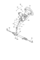
図1は、実施形態1のステアリング装置の模式図である。図2は、実施形態1のステアリング装置の斜視図である。ステアリング装置80の基本的な構造について、図1、図2を参照しながら説明する。ステアリング装置80は、操作者から付与される操作力(操舵トルク)が伝達する順に、ステアリングホイール81、ステアリングシャフト82、操舵力アシスト機構83、第1ユニバーサルジョイント84、中間シャフト85、及び第2ユニバーサルジョイント86を備える。 Figure 1 is a schematic diagram of a steering device of the first embodiment. Figure 2 is a perspective view of the steering device of the first embodiment. The basic structure of the steering device 80 will be described with reference to Figures 1 and 2. The steering device 80 includes a steering wheel 81, a steering shaft 82, a steering force assist mechanism 83, a first universal joint 84, an intermediate shaft 85, and a second universal joint 86, in the order in which the operating force (steering torque) applied by the operator is transmitted.

操舵力アシスト機構83は、ECU(Electronic Control Unit)90と、減速装置92と、電動モータ93と、トルクセンサ94と、図示しないトーションバーと、を備える。ECU90には、イグニッションスイッチ98がオンの状態で、電源装置99(例えば車載のバッテリ)から電力が供給される。なお、本実施形態のヨーク一体型シャフト4は、操舵力アシスト機構83を備えたステアリング装置80(電動パワーステアリング装置)に適用した例を挙げているが、本開示のヨーク一体型シャフトは、操舵力アシスト機構83を備えていないステアリング装置に適用してもよい。 The steering force assist mechanism 83 includes an ECU (Electronic Control Unit) 90, a reduction gear 92, an electric motor 93, a torque sensor 94, and a torsion bar (not shown). When an ignition switch 98 is on, the ECU 90 is supplied with power from a power supply device 99 (e.g., an on-board battery). Note that, although the yoke-integrated shaft 4 of this embodiment is applied to a steering device 80 (electric power steering device) equipped with a steering force assist mechanism 83, the yoke-integrated shaft of the present disclosure may also be applied to a steering device that does not have a steering force assist mechanism 83.

ステアリングシャフト82は、入力軸82aと、出力軸82bと、を備える。入力軸82aの一方の端部は、ステアリングホイール81と連結している。また、入力軸82aの他方の端部は、操舵力アシスト機構83のトーションバー(不図示)を介して、出力軸82bの一方の端部と連結している。操舵トルクにより入力軸82aが回転すると、トーションバーが捻じれ、入力軸82aと出力軸82bとの回転に角度差が生じる。 The steering shaft 82 includes an input shaft 82a and an output shaft 82b. One end of the input shaft 82a is connected to the steering wheel 81. The other end of the input shaft 82a is connected to one end of the output shaft 82b via a torsion bar (not shown) of the steering force assist mechanism 83. When the input shaft 82a rotates due to steering torque, the torsion bar twists, causing an angular difference in the rotation of the input shaft 82a and the output shaft 82b.

トルクセンサ94は、入力軸82aと出力軸82bとの角度差を検出し、その結果をECU90に送信する。ECU90は、車両の車速センサ95から車両の走行速度を取得する。ECU90は、入力軸82aと出力軸82bとの角度差と、車両の走行速度とに基づいて、電動モータ93を駆動させる。減速装置92は、電動モータ93の出力軸に連結する図示しないウォームと、出力軸82bと連結する図示しないウォームホイールと、を備える。よって、電動モータ93が駆動すると、減速装置92を介して出力軸82bに操舵補助トルクが付与され、入力軸82aと出力軸82bとの回転に角度差がなくなる。 The torque sensor 94 detects the angular difference between the input shaft 82a and the output shaft 82b and transmits the result to the ECU 90. The ECU 90 acquires the traveling speed of the vehicle from the vehicle speed sensor 95 of the vehicle. The ECU 90 drives the electric motor 93 based on the angular difference between the input shaft 82a and the output shaft 82b and the traveling speed of the vehicle. The reduction gear 92 includes a worm (not shown) connected to the output shaft of the electric motor 93 and a worm wheel (not shown) connected to the output shaft 82b. Therefore, when the electric motor 93 is driven, a steering assist torque is applied to the output shaft 82b via the reduction gear 92, and the angular difference in the rotation of the input shaft 82a and the output shaft 82b disappears.

図2に示すように、出力軸82bの他方の端部は、第1ユニバーサルジョイント84を介して、中間シャフト85の一方の端部と連結している。中間シャフト85の他方の端部は、第2ユニバーサルジョイント86を介して、ピニオンシャフト87の一方の端部と連結している。ピニオンシャフト87の他方の端部は、ピニオン88aを備える。ピニオン88aは、ラック88bと噛み合っている。ステアリングギヤ88は、ピニオン88aに伝達された回転運動をラック88bで直進運動に変換する。ラック88bは、タイロッド89に連結される。ラック88bが移動することで車輪の角度が変化する。 As shown in FIG. 2, the other end of the output shaft 82b is connected to one end of the intermediate shaft 85 via a first universal joint 84. The other end of the intermediate shaft 85 is connected to one end of the pinion shaft 87 via a second universal joint 86. The other end of the pinion shaft 87 is provided with a pinion 88a. The pinion 88a meshes with a rack 88b. The steering gear 88 converts the rotational motion transmitted to the pinion 88a into linear motion by the rack 88b. The rack 88b is connected to a tie rod 89. The angle of the wheels changes as the rack 88b moves.

中間シャフト85は、第1ユニバーサルジョイント84と接合されるインナシャフト1と、第1ユニバーサルジョイント84と接合されるアウタチューブ2と、を備える。インナシャフト85aは、アウタチューブ85bに摺動自在に支持されている。よって、中間シャフト85は、車両の振動により長さ方向に伸縮し、車体に歪を吸収する(図2の矢印A1参照)。また、キャブチルトにより運転席が前方に持ち上がった場合(図2の矢印A2参照)、中間シャフト85は、長さ方向に短縮する。次に、インナシャフト1と第1ユニバーサルジョイント84のヨーク3とを接合してなるヨーク一体型シャフト4について説明する。なお、本実施形態において、インナシャフト1が入力軸となっており、アウタチューブ2が出力軸となっているが、本開示のヨーク一体型シャフトは、出力軸のインナシャフトに適用してもよい。 The intermediate shaft 85 includes an inner shaft 1 joined to the first universal joint 84 and an outer tube 2 joined to the first universal joint 84. The inner shaft 85a is supported by the outer tube 85b so as to be freely slidable. Therefore, the intermediate shaft 85 expands and contracts in the length direction due to vibration of the vehicle, absorbing distortion in the vehicle body (see arrow A1 in FIG. 2). In addition, when the driver's seat is raised forward by the cab tilt (see arrow A2 in FIG. 2), the intermediate shaft 85 shortens in the length direction. Next, a yoke-integrated shaft 4 formed by joining the inner shaft 1 and the yoke 3 of the first universal joint 84 will be described. In this embodiment, the inner shaft 1 is the input shaft and the outer tube 2 is the output shaft, but the yoke-integrated shaft of the present disclosure may be applied to the inner shaft of an output shaft.

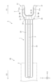
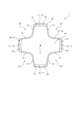
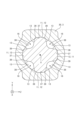
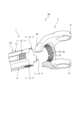
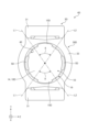
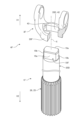
図3は、実施形態1のヨーク一体型シャフトを外周面の方から視た全体図である。図4は、実施形態1のインナシャフトとヨークとを組み合わせる前の分解斜視図である。図5は、実施形態1のインナシャフトを抽出して第1方向から視た図である。図6は、実施形態1のヨーク一体型シャフトを第1方向から視た図である。図7は、図3のVII-VII線の矢視断面図である。図8は、図6のVIII-VIII線の矢視断面図である。図9は、図6のIX-IX線の矢視断面図である。図10は、図6のX-X線の矢視断面図である。 Figure 3 is an overall view of the yoke-integrated shaft of embodiment 1 as viewed from the outer circumferential surface. Figure 4 is an exploded perspective view of the inner shaft of embodiment 1 before it is combined with the yoke. Figure 5 is a view of the inner shaft of embodiment 1 as viewed from a first direction. Figure 6 is a view of the yoke-integrated shaft of embodiment 1 as viewed from a first direction. Figure 7 is a cross-sectional view taken along line VII-VII in Figure 3. Figure 8 is a cross-sectional view taken along line VIII-VIII in Figure 6. Figure 9 is a cross-sectional view taken along line IX-IX in Figure 6. Figure 10 is a cross-sectional view taken along line X-X in Figure 6.

図3に示すように、ヨーク一体型シャフト4は、インナシャフト1とヨーク3を溶接により接合して成る。よって、ヨーク一体型シャフト4は、インナシャフト1と、ヨーク3と、溶接部5(図6、図8を参照)と、を備える。インナシャフト1及びヨーク3は、機械構造用炭素鋼(Carbon Steel for Machine Structural Use)で製造されている。以下、インナシャフト1の軸Xと平行な方向を軸方向と呼ぶ。インナシャフト1の軸方向の中央部から視てヨーク3が配置される方向を第1方向X1と呼び、ヨーク3が配置されていない方向を第2方向X2と呼ぶ。 As shown in FIG. 3, the yoke-integrated shaft 4 is formed by joining the inner shaft 1 and the yoke 3 by welding. Thus, the yoke-integrated shaft 4 includes the inner shaft 1, the yoke 3, and the welded portion 5 (see FIG. 6 and FIG. 8). The inner shaft 1 and the yoke 3 are manufactured from carbon steel for machine structural use. Hereinafter, the direction parallel to the axis X of the inner shaft 1 is referred to as the axial direction. When viewed from the center of the axial direction of the inner shaft 1, the direction in which the yoke 3 is arranged is referred to as the first direction X1, and the direction in which the yoke 3 is not arranged is referred to as the second direction X2.

インナシャフト1は、ヨーク3の基部30に嵌合される嵌合部10と、基部30から第2方向X2に延在する軸部20と、を備える。図4に示すように、インナシャフト1は、軸Xと直交する方向に切った断面が十字形状となっている。よって、嵌合部10は、軸Xを中心に径方向外側に突出する4つの第1突起11を備える。また、軸部20は、第1突起11と軸方向に連続する4つの第2突起21を備える。 The inner shaft 1 has a fitting portion 10 that fits into the base portion 30 of the yoke 3, and a shaft portion 20 that extends from the base portion 30 in the second direction X2. As shown in FIG. 4, the inner shaft 1 has a cross-shaped cross section cut in a direction perpendicular to the axis X. Thus, the fitting portion 10 has four first protrusions 11 that protrude radially outward from the axis X. In addition, the shaft portion 20 has four second protrusions 21 that are continuous with the first protrusions 11 in the axial direction.

図5に示すように、第1突起11は、径方向外側を向く外向面12と、周方向を向く一対の13、13を備える。第1突起11の周面13は、径方向内端が隣り合う第1突起11の周面13と連続している。第2突起21は、第1突起11よりも径方向外側への突出量が大きい。よって、インナシャフト1は、嵌合部10と軸部20との境界で第1方向X1を向く突き当て面22を有している。また、軸部20において周方向に隣り合う第2突起21の間は、軸方向に延在する空間となっている。つまり、軸部20は、第2突起21の間で軸方向に延在する4つの開放部23を備えている。 As shown in FIG. 5, the first protrusion 11 has an outward surface 12 facing radially outward and a pair of protrusions 13, 13 facing in the circumferential direction. The peripheral surface 13 of the first protrusion 11 is continuous with the peripheral surface 13 of the first protrusion 11 whose radial inner end is adjacent. The second protrusion 21 protrudes radially outward to a greater extent than the first protrusion 11. Thus, the inner shaft 1 has an abutment surface 22 facing the first direction X1 at the boundary between the fitting portion 10 and the shaft portion 20. In addition, the space between the second protrusions 21 adjacent in the circumferential direction in the shaft portion 20 is an axially extending space. In other words, the shaft portion 20 has four openings 23 extending in the axial direction between the second protrusions 21.

図3に示すように、軸部20は、アウタチューブ2に収容され、アウタチューブ2に摺動自在に支持される。よって、軸部20がアウタチューブ2に収容される軸方向の長さが増加すると、中間シャフト85が短縮する。軸部20は、アウタチューブ2との摺動性を確保するため、軸部20の外周面を被覆する樹脂製のコーティング層25を有している。このコーティング層25は、インナシャフト1とヨーク3とを溶接する前からインナシャフト1を被覆している。 As shown in FIG. 3, the shaft portion 20 is housed in the outer tube 2 and is supported by the outer tube 2 so as to be freely slidable. Therefore, when the axial length of the shaft portion 20 housed in the outer tube 2 increases, the intermediate shaft 85 shortens. To ensure slidability with the outer tube 2, the shaft portion 20 has a resin coating layer 25 that covers the outer circumferential surface of the shaft portion 20. This coating layer 25 covers the inner shaft 1 even before the inner shaft 1 and the yoke 3 are welded together.

図4に示すように、ヨーク3は、基部30と、基部30から第1方向X1に突出する一対のアーム31、31を備える。基部30は、環状体であり、貫通孔32を備える。また、基部30は、第1方向X1を向く第1面33と、第2方向X2を向く第2面34と、貫通孔32を囲む内周面35と、を備える。 As shown in FIG. 4, the yoke 3 includes a base 30 and a pair of arms 31, 31 that protrude from the base 30 in a first direction X1. The base 30 is annular and includes a through hole 32. The base 30 also includes a first surface 33 facing the first direction X1, a second surface 34 facing the second direction X2, and an inner circumferential surface 35 that surrounds the through hole 32.

一対のアーム31、31は、基部30の第1面33に設けられている。アーム31は、軸Xを中心に径方向に貫通する円形状の円形孔31aを有する。円形孔31aには、第1ユニバーサルジョイント84の図示しない十字軸が挿入される。以下、円形孔31aの中心線Oと平行な方向を第3方向Yと呼ぶ。また、軸方向と第3方向Yとのそれぞれに直交する方向を第4方向Zと呼ぶ。また、軸Xから径方向に延び、アーム31の周方向の両端31b、31cに接する仮想線L1、L2に挟まれる領域をアーム内側領域8と呼ぶ。 The pair of arms 31, 31 are provided on the first surface 33 of the base 30. The arm 31 has a circular hole 31a that is circular and penetrates radially around the axis X. A cross shaft (not shown) of the first universal joint 84 is inserted into the circular hole 31a. Hereinafter, the direction parallel to the center line O of the circular hole 31a is referred to as the third direction Y. The direction perpendicular to both the axial direction and the third direction Y is referred to as the fourth direction Z. The region between imaginary lines L1, L2 that extend radially from the axis X and are tangent to both circumferential ends 31b, 31c of the arm 31 is referred to as the arm inner region 8.

貫通孔32は、基部30の中央部を軸方向に貫通している。また、貫通孔32には、基部30の第2面34の方から、インナシャフト1の嵌合部10が挿入されている(図4の矢印A3参照)。これにより、インナシャフト1の嵌合部10は、基部30の内周面35に嵌合している(図7参照)。 The through hole 32 passes through the center of the base 30 in the axial direction. The fitting portion 10 of the inner shaft 1 is inserted into the through hole 32 from the second surface 34 of the base 30 (see arrow A3 in FIG. 4). As a result, the fitting portion 10 of the inner shaft 1 fits into the inner peripheral surface 35 of the base 30 (see FIG. 7).

なお、図8に示すように、貫通孔32にインナシャフト1が挿入された時、インナシャフト1の突き当て面22が第2面34に突き当てられている。よって、ヨーク3に対し、インナシャフト1の軸方向の位置決めが容易となっている。また、嵌合部10の軸方向の長さは、基部30の軸方向の長さよりも長い。よって、嵌合部10の第1方向X1の端面14は、基部30の第1面33よりも第1方向X1に位置している(図8の第1面33に沿って引いた仮想線Hを参照)。 As shown in FIG. 8, when the inner shaft 1 is inserted into the through hole 32, the abutment surface 22 of the inner shaft 1 abuts against the second surface 34. This makes it easy to position the inner shaft 1 in the axial direction relative to the yoke 3. The axial length of the fitting portion 10 is longer than the axial length of the base portion 30. Therefore, the end surface 14 of the fitting portion 10 in the first direction X1 is located further in the first direction X1 than the first surface 33 of the base portion 30 (see the imaginary line H drawn along the first surface 33 in FIG. 8).

図7に示すように、内周面35は、90度間隔で配置された円弧状の4つの当接面37と、当接面37の間に介在する円弧状の4つの非当接面38と、当接面37と非当接面38との境界で径方向に延在する8つの段差面39と、を備える。 As shown in FIG. 7, the inner peripheral surface 35 has four arc-shaped abutment surfaces 37 arranged at 90 degree intervals, four arc-shaped non-abutment surfaces 38 interposed between the abutment surfaces 37, and eight step surfaces 39 extending radially at the boundaries between the abutment surfaces 37 and the non-abutment surfaces 38.

当接面37は、第1突起11の外向面12と径方向に対向している。当接面37の内径は、第1突起11の外向面12の外径よりも僅かに小さい。よって、第1突起11は、当接面37に圧入されており、ヨーク3からインナシャフト1が脱落し難い。なお、嵌合部10の圧入により基部30に応力が作用するが、嵌合部10の全周でなく、第1突起11の外向面12の部分だけが圧入されている。よって、基部30に作用する応力は小さく、耐久強度が高い。 The abutment surface 37 faces the outward surface 12 of the first protrusion 11 in the radial direction. The inner diameter of the abutment surface 37 is slightly smaller than the outer diameter of the outward surface 12 of the first protrusion 11. Therefore, the first protrusion 11 is pressed into the abutment surface 37, and the inner shaft 1 is unlikely to fall off from the yoke 3. Note that, although stress acts on the base 30 due to the press-fitting of the fitting portion 10, only the outward surface 12 of the first protrusion 11 is pressed in, not the entire circumference of the fitting portion 10. Therefore, the stress acting on the base 30 is small, and durability is high.

当接面37の周方向の長さは、外向面12の周方向の長さと同じとなっている。よって、当接面37に対して周方向の両側にある段差面39は、第1突起11における一対の周面13の径方向外側の端部と当接している。これにより、仮に溶接部5が破損しても、インナシャフト1とヨーク3とは、相対回転することなく、確実にトルクが伝達される。 The circumferential length of the abutment surface 37 is the same as the circumferential length of the outward surface 12. Therefore, the step surfaces 39 on both sides of the abutment surface 37 in the circumferential direction abut against the radially outer ends of the pair of peripheral surfaces 13 of the first protrusion 11. As a result, even if the welded portion 5 is damaged, the inner shaft 1 and the yoke 3 do not rotate relative to each other, and torque is reliably transmitted.

非当接面38は、当接面37よりも内径が小さい。非当接面38は、周方向に隣り合う2つの周面13、13の間を周方向に延在している。よって、非当接面38と、非当接面38を周方向から挟む2つの周面13、13と、の間には、軸方向に延在する連通穴16が設けられている。そして、連通穴16は、基部30の第1方向X1の空間と第2方向X2の空間を連通している(図10参照)。 The non-contact surface 38 has a smaller inner diameter than the contact surface 37. The non-contact surface 38 extends circumferentially between two circumferential surfaces 13, 13 that are adjacent in the circumferential direction. Therefore, a communication hole 16 extending in the axial direction is provided between the non-contact surface 38 and the two circumferential surfaces 13, 13 that sandwich the non-contact surface 38 in the circumferential direction. The communication hole 16 communicates the space in the first direction X1 of the base 30 with the space in the second direction X2 (see FIG. 10).

内周面35において、2つの当接面37は、軸Xから視て第3方向Yに配置されている。他の2つの当接面37は、軸Xから視て第4方向Zに配置されている。よって、図6に示すように、4つの第1突起11のうち、2つの第1突起11は、軸Xから視て第3方向Yに配置される。残り2つの第1突起11は、軸方向から視て第4方向Zに配置される。以下、4つの第1突起11のうち、軸Xから視て第3方向Yに配置されるものをアーム側第1突起11aと呼び、軸Xから視て第4方向Zに配置されるものを開放側第1突起11bと呼ぶ。 On the inner peripheral surface 35, two abutment surfaces 37 are disposed in the third direction Y as viewed from the axis X. The other two abutment surfaces 37 are disposed in the fourth direction Z as viewed from the axis X. Thus, as shown in FIG. 6, of the four first protrusions 11, two first protrusions 11 are disposed in the third direction Y as viewed from the axis X. The remaining two first protrusions 11 are disposed in the fourth direction Z as viewed from the axial direction. Hereinafter, of the four first protrusions 11, the one disposed in the third direction Y as viewed from the axis X will be referred to as the arm-side first protrusion 11a, and the one disposed in the fourth direction Z as viewed from the axis X will be referred to as the open-side first protrusion 11b.

図6に示すように、第1面33は、内周面35との境界に、第2方向X2に窪む環状の内縁部36を有している。インナシャフト1の端面14には、溶接部5と、カシメ部15と、が設けられている。 As shown in FIG. 6, the first surface 33 has an annular inner edge portion 36 recessed in the second direction X2 at the boundary with the inner peripheral surface 35. The end surface 14 of the inner shaft 1 is provided with a welded portion 5 and a crimped portion 15.

図8に示すように、溶接部5は、基部30の当接面37と、開放側第1突起11bの外向面12と、の突合せ面のうち、第1方向X1寄りの部分を接合している。よって、溶接部5の第1方向X1の表面は、基部30の第1面33とインナシャフト1の端面14との間から露出している。この溶接部5は、第1面33の内縁部36と、開放側第1突起11bの端面14の外縁部と、の境界に対し、第1方向X1から熱を加えることで生成される。つまり、本実施形態の溶接部5は、インナシャフト1と基部30とを、基部30の第1方向X1から溶接して生成されている。そして、この溶接部5により、インナシャフト1とヨーク3とが強固に結合している。 8, the welded portion 5 joins the portion of the butt surface between the abutment surface 37 of the base 30 and the outward surface 12 of the first projection 11b closer to the first direction X1. Therefore, the surface of the welded portion 5 in the first direction X1 is exposed between the first surface 33 of the base 30 and the end surface 14 of the inner shaft 1. The welded portion 5 is generated by applying heat from the first direction X1 to the boundary between the inner edge portion 36 of the first surface 33 and the outer edge portion of the end surface 14 of the first projection 11b. In other words, the welded portion 5 in this embodiment is generated by welding the inner shaft 1 and the base 30 from the first direction X1 of the base 30. The welded portion 5 firmly bonds the inner shaft 1 and the yoke 3.

溶接部5は、第1溶接部6と、第2溶接部7と、を備える。第1溶接部6と第2溶接部7とは、第1方向X1から視ると、それぞれ内縁部36に沿って円弧状を成している。第1溶接部6と第2溶接部7は、軸Xを中心に相反する方向に突出する2つの開放側第1突起11bと、基部30と、を接合している。つまり、第1溶接部6と、第2溶接部7とは、互いに軸Xを中心に点対称に配置されている。また、第1溶接部6と第2溶接部7は、アーム内側領域8に対し周方向にずれて配置され、アーム内側領域8と重なっていない。 The welded portion 5 includes a first welded portion 6 and a second welded portion 7. When viewed from the first direction X1, the first welded portion 6 and the second welded portion 7 each form an arc shape along the inner edge portion 36. The first welded portion 6 and the second welded portion 7 join two open side first protrusions 11b that protrude in opposite directions about the axis X to the base portion 30. In other words, the first welded portion 6 and the second welded portion 7 are arranged point symmetrically with respect to each other about the axis X. In addition, the first welded portion 6 and the second welded portion 7 are arranged circumferentially offset from the arm inner region 8 and do not overlap with the arm inner region 8.

図9に示すように、カシメ部15は、嵌合部10の第1方向X1の端部のうち、基部30の第1面33よりも第1方向X1に突出している部分(図8の仮想線Hよりも第1方向X1に配置される部位)をカシメることで生成されている。カシメ部15は、第1面33の内縁部36と接触している。よって、仮に2つの溶接部5が破損しても、インナシャフト1はヨーク3から離脱しない。図6に示すように、2つのカシメ部15は、アーム内側領域8と重なっている。 As shown in FIG. 9, the crimped portion 15 is generated by crimping a portion of the end of the fitting portion 10 in the first direction X1 that protrudes in the first direction X1 beyond the first surface 33 of the base portion 30 (a portion located in the first direction X1 beyond the imaginary line H in FIG. 8). The crimped portion 15 is in contact with the inner edge portion 36 of the first surface 33. Therefore, even if the two welded portions 5 are damaged, the inner shaft 1 will not come off the yoke 3. As shown in FIG. 6, the two crimped portions 15 overlap the arm inner region 8.

次に実施形態1のヨーク一体型シャフト4の効果を説明する。溶接部5は、基部30の第1面33の方に設けられている。このため、溶接時に発生するスパッタや溶接ビードは、基部30を介して溶接部5と反対側に位置する軸部20に生成されない。このため、軸部20の外周面の平滑性が確保され、軸部20の全長をアウタチューブ2に収容できるようになる。よって、軸部20のスライド有効長が長くなり、短縮時の中間シャフト85の長さが短くなる。 Next, the effect of the yoke-integrated shaft 4 of the first embodiment will be described. The welded portion 5 is provided on the first surface 33 of the base portion 30. Therefore, spatters and weld beads generated during welding are not generated on the shaft portion 20 located on the opposite side of the base portion 30 from the welded portion 5. This ensures smoothness of the outer peripheral surface of the shaft portion 20, and the entire length of the shaft portion 20 can be accommodated in the outer tube 2. This increases the effective sliding length of the shaft portion 20, and shortens the length of the intermediate shaft 85 when shortened.

また、溶接部5は、基部30の第1面33の方に設けられているため、スパッタがコーティング層25に付着し難い。よって、コーティング層25の溶融を抑制できる。 In addition, since the welded portion 5 is provided on the first surface 33 of the base portion 30, spatter is less likely to adhere to the coating layer 25. This makes it possible to suppress melting of the coating layer 25.

また、図6に示すように、第1溶接部6と第2溶接部7は、アーム内側領域8と重なっていない。ここで、基部30の当接面37と、開放側第1突起11bの外向面12と、の溶接作業は、軸方向から視て、第1面33の径方向外側に配置されたトーチを径方向内側に移動させ、第1面33と軸方向に対向させる(図6の矢印A4参照)。次に、当接面37と外向面12との境界に熱を加えつつ、トーチを周方向に移動させる(図6の矢印A5参照)。次に、溶接が完了したら、トーチを径方向外側に移動させる(図6の矢印A6参照)。以上から、トーチの移動経路(図6の矢印A4、A5、A6参照)上にアームが存在していないため、トーチがアーム31と接触しない。また、トーチが周方向に移動する経路(矢印A5参照)の径方向外側にアーム31が存在しないため、トーチから引き出されている配線がアーム31と接触しない。よって、第1溶接部6、第2溶接部7は、溶接作業がしやすい箇所に設けられており、ヨーク一体型シャフト4の生産効率が向上する。 Also, as shown in FIG. 6, the first welded portion 6 and the second welded portion 7 do not overlap with the arm inner region 8. Here, the welding work between the abutment surface 37 of the base 30 and the outward surface 12 of the open-side first protrusion 11b is performed by moving the torch arranged radially outside the first surface 33 inward in the radial direction when viewed from the axial direction, and facing the first surface 33 in the axial direction (see arrow A4 in FIG. 6). Next, the torch is moved in the circumferential direction while applying heat to the boundary between the abutment surface 37 and the outward surface 12 (see arrow A5 in FIG. 6). Next, when welding is completed, the torch is moved radially outward (see arrow A6 in FIG. 6). From the above, since the arm is not present on the movement path of the torch (see arrows A4, A5, and A6 in FIG. 6), the torch does not come into contact with the arm 31. In addition, because the arm 31 is not present radially outside the path along which the torch moves in the circumferential direction (see arrow A5), the wiring drawn from the torch does not come into contact with the arm 31. Therefore, the first welded portion 6 and the second welded portion 7 are provided in locations where welding work is easy to perform, improving the production efficiency of the yoke-integrated shaft 4.

一方で、2つのカシメ部15は、アーム内側領域8と重なっており、溶接し難い箇所に設けられている。よって、溶接し難い領域を有効に活用しつつ、インナシャフト1がヨーク3から離脱することを防止している。 On the other hand, the two crimped portions 15 overlap the arm inner region 8 and are provided in locations that are difficult to weld. This effectively utilizes the difficult-to-weld areas while preventing the inner shaft 1 from coming off the yoke 3.

また、第1溶接部6と、第2溶接部7とは、互いに軸Xを中心に点対称に配置されている。このため、一対のアーム31、31から基部30に伝達されるトルクは、第1溶接部6と第2溶接部7とに均等に作用して、インナシャフト1の嵌合部10に伝達される。よって、トルクが第1溶接部6と第2溶接部7とにバランスよく振り分けられ、溶接部5の耐久性が向上する。 The first welded portion 6 and the second welded portion 7 are arranged point-symmetrically with respect to each other around the axis X. Therefore, the torque transmitted from the pair of arms 31, 31 to the base portion 30 acts evenly on the first welded portion 6 and the second welded portion 7, and is transmitted to the fitting portion 10 of the inner shaft 1. Therefore, the torque is distributed in a well-balanced manner between the first welded portion 6 and the second welded portion 7, improving the durability of the welded portion 5.

図10に示すように、連通穴16の第1方向X1の第1開口部16aは、閉塞されていない。よって、連通穴16は、基部30の第1面33側の空間と連続している。連通穴16の第2方向X2の第2開口部16bは、軸部20の開放部23と連続している。よって、連通穴16は、基部30の第2面34側の空間と連続している。以上から、溶接により溶接部5を生成する際、溶接個所に供給されたシールドガスは、溶接個所に当たった後、連通穴16に流入する。その後、図10の矢印A7に示すように、シールドガスは、連通穴16を第2方向X2に流れ、軸部20の開放部23から排出される。よって、溶接個所に供給されたシールドガスは、基部30の第1面33やインナシャフト1の端面14に滞留することなく流れる。そして、溶接個所の近傍にある酸素等もシールドガスに連れられて流れる。このため、溶接欠陥の発生が抑えられる。 As shown in FIG. 10, the first opening 16a of the communication hole 16 in the first direction X1 is not blocked. Therefore, the communication hole 16 is continuous with the space on the first surface 33 side of the base 30. The second opening 16b of the communication hole 16 in the second direction X2 is continuous with the open portion 23 of the shaft portion 20. Therefore, the communication hole 16 is continuous with the space on the second surface 34 side of the base 30. From the above, when the welded portion 5 is generated by welding, the shielding gas supplied to the welded portion flows into the communication hole 16 after hitting the welded portion. Then, as shown by the arrow A7 in FIG. 10, the shielding gas flows through the communication hole 16 in the second direction X2 and is discharged from the open portion 23 of the shaft portion 20. Therefore, the shielding gas supplied to the welded portion flows without stagnation on the first surface 33 of the base 30 or the end surface 14 of the inner shaft 1. And, oxygen and the like in the vicinity of the welded portion also flows along with the shielding gas. This helps prevent welding defects from occurring.

以上、実施形態1のヨーク一体型シャフト4は、一端が第1方向X1を指し、他端が第2方向X2を指すシャフト(インナシャフト1)と、シャフト(インナシャフト1)の一端と溶接されるヨーク3と、溶接により生成される溶接部5と、を備える。ヨーク3は、シャフト(インナシャフト1)の軸Xと平行な軸方向に貫通する貫通孔32を有する環状体の基部30と、基部30から第1方向X1に突出する一対のアーム31、31と、を備える。シャフト(インナシャフト1)は、シャフト(インナシャフト1)の一端に位置し、基部30の貫通孔32に挿入される嵌合部10と、嵌合部10から第2方向X2に延び、アウタチューブ2に摺動自在に支持される軸部20と、を有する。前記溶接部の前記第1方向の表面が露出している溶接部5は、嵌合部10と基部30とを、基部30の第1方向X1から溶接して成る。 As described above, the yoke-integrated shaft 4 of the first embodiment includes a shaft (inner shaft 1) having one end pointing in the first direction X1 and the other end pointing in the second direction X2, a yoke 3 welded to one end of the shaft (inner shaft 1), and a welded portion 5 created by welding. The yoke 3 includes an annular base 30 having a through hole 32 penetrating in an axial direction parallel to the axis X of the shaft (inner shaft 1), and a pair of arms 31, 31 protruding from the base 30 in the first direction X1. The shaft (inner shaft 1) includes a fitting portion 10 located at one end of the shaft (inner shaft 1) and inserted into the through hole 32 of the base 30, and an axial portion 20 extending from the fitting portion 10 in the second direction X2 and supported slidably by the outer tube 2. The welded portion 5, in which the surface of the welded portion in the first direction is exposed, is formed by welding the fitting portion 10 and the base portion 30 from the first direction X1 of the base portion 30.

これによれば、溶接時に発生するスパッタや溶接ビードは、軸部20に生成されず、軸部20の全長をアウタチューブ2に収容できる。以上から、軸部20のスライド有効長が長くなり、短縮時の中間シャフト85の長さを短くすることができる。 As a result, spatter and weld beads that occur during welding are not generated on the shaft portion 20, and the entire length of the shaft portion 20 can be accommodated in the outer tube 2. As a result, the effective sliding length of the shaft portion 20 is increased, and the length of the intermediate shaft 85 when shortened can be shortened.

また、実施形態1のヨーク一体型シャフト4において、溶接部5は、第1溶接部6と、第1溶接部6に対し、軸Xを中心に点対称に配置された第2溶接部7と、を有する。 In addition, in the yoke-integrated shaft 4 of embodiment 1, the welded portion 5 has a first welded portion 6 and a second welded portion 7 that is arranged point-symmetrically with respect to the first welded portion 6 around the axis X.

これによれば、シャフト(インナシャフト1)とヨーク3との間で伝達されるトルクが第1溶接部6と第2溶接部7とにバランスよく振り分けられ、溶接部5の耐久性が向上する。 As a result, the torque transmitted between the shaft (inner shaft 1) and the yoke 3 is distributed in a well-balanced manner between the first welded portion 6 and the second welded portion 7, improving the durability of the welded portion 5.

また、実施形態1のヨーク一体型シャフト4において、軸方向から視て、軸Xとアーム31の周方向の両端31b、31cとを結ぶ一対の仮想線L1、L2の間の領域は、アーム内側領域8である。軸方向から視て、第1溶接部6と第2溶接部7とは、アーム内側領域8と重なっていない。 In addition, in the yoke-integrated shaft 4 of embodiment 1, the region between a pair of imaginary lines L1, L2 connecting the axis X and both circumferential ends 31b, 31c of the arm 31 is the arm inner region 8 when viewed from the axial direction. The first welded portion 6 and the second welded portion 7 do not overlap with the arm inner region 8 when viewed from the axial direction.

これによれば、トーチ及びトーチに接続する配線がアーム31に接触しないため、溶接作業が容易となり、ヨーク一体型シャフト4の生産効率が向上する。 As a result, the torch and the wiring connected to the torch do not come into contact with the arm 31, making the welding work easier and improving the production efficiency of the yoke-integrated shaft 4.

また、実施形態1のヨーク一体型シャフト4において、基部30は、第1方向X1を向く第1面33を有する。嵌合部10は、基部30の第1面33よりも第1方向X1に突出している。嵌合部10は、カシメにより径方向外側に変形して成るカシメ部15を有する。カシメ部15は、基部30の第1面33に当接する。カシメ部15は、軸方向から視て、アーム内側領域8と重なっている。 In the yoke-integrated shaft 4 of the first embodiment, the base 30 has a first surface 33 facing the first direction X1. The fitting portion 10 protrudes in the first direction X1 beyond the first surface 33 of the base 30. The fitting portion 10 has a crimped portion 15 that is deformed radially outward by crimping. The crimped portion 15 abuts against the first surface 33 of the base 30. The crimped portion 15 overlaps with the arm inner region 8 when viewed from the axial direction.

これによれば、溶接し難い領域を有効に活用しつつ、シャフト(インナシャフト1)がヨーク3から離脱することを防止している。 This effectively utilizes areas that are difficult to weld while preventing the shaft (inner shaft 1) from coming off the yoke 3.

また、実施形態1のヨーク一体型シャフト4において、軸部20は、外周面を覆う樹脂製のコーティング層25を有する。 In addition, in the yoke-integrated shaft 4 of embodiment 1, the shaft portion 20 has a resin coating layer 25 that covers the outer circumferential surface.

これにより、軸部20は、アウタチューブ2との摺動性が高くなる。また、溶接が基部の第1方向X1から行われているため、コーティング層25にスパッタが付着しない。よって、コーティング層25の溶融が回避される。 This improves the sliding properties of the shaft portion 20 with respect to the outer tube 2. In addition, because welding is performed from the first direction X1 of the base, spatter does not adhere to the coating layer 25. This prevents the coating layer 25 from melting.

次に、実施形態1のヨーク一体型シャフト4の変形例を説明する。なお、以下の説明においては、上述した実施形態1で説明したものと同じ構成要素には同一の符号を付して重複する説明は省略する。 Next, a modified example of the yoke-integrated shaft 4 of the first embodiment will be described. In the following description, the same components as those described in the first embodiment above will be assigned the same reference numerals, and duplicate descriptions will be omitted.

(変形例1)
図11は、変形例1のヨーク一体型シャフトを第1方向から視た図である。図11に示すように、変形例1のヨーク一体型シャフト4Aは、カシメ部15に代えて溶接部5が設けられている点で、実施形態1のヨーク一体型シャフト4と相違する。この変形例1によれば、4つの溶接部5を備え、インナシャフト1とヨーク3との接合強度が非常に高い。
(Variation 1)
Fig. 11 is a view of the yoke-integrated shaft of Modification 1 as viewed from a first direction. As shown in Fig. 11, the yoke-integrated shaft 4A of Modification 1 differs from the yoke-integrated shaft 4 of Embodiment 1 in that welded portions 5 are provided instead of the crimped portions 15. According to Modification 1, four welded portions 5 are provided, and the joining strength between the inner shaft 1 and the yoke 3 is very high.

なお、変形例1で示すように、本開示のヨーク一体型シャフトは、カシメ部15は必須の構成ではない。また、カシメ部15を備えていない場合、インナシャフト1の端面14は、基部30の第1面33よりも第1方向X1に突出させなくてもよい。言い換えると、インナシャフト1の端面14は、基部30の第1面33に対して面一であったり、又は基部30の第1面33よりも第2方向X2に位置していたりしてもよい。 As shown in Modification 1, the crimped portion 15 is not an essential component of the yoke-integrated shaft of the present disclosure. Furthermore, if the crimped portion 15 is not provided, the end face 14 of the inner shaft 1 does not need to protrude in the first direction X1 beyond the first surface 33 of the base 30. In other words, the end face 14 of the inner shaft 1 may be flush with the first surface 33 of the base 30, or may be located in the second direction X2 beyond the first surface 33 of the base 30.

(変形例2)
図12は、変形例2のインナシャフトとヨークとを組み合わせる前の分解斜視図である。図12に示すように、変形例2のヨーク一体型シャフト4Bは、インナシャフト1の第1突起11の外向面12が雄セレーション部17を有している点で、実施形態1のヨーク一体型シャフト4と相違する。また、変形例2のヨーク一体型シャフト4Bは、ヨーク3の内周面35が雌セレーション部40を有している点で、実施形態1のヨーク一体型シャフト4と相違する。
(Variation 2)
Fig. 12 is an exploded perspective view of the inner shaft and yoke of Modification 2 before they are combined. As shown in Fig. 12, the yoke-integrated shaft 4B of Modification 2 differs from the yoke-integrated shaft 4 of Embodiment 1 in that the outward surface 12 of the first projection 11 of the inner shaft 1 has a male serration portion 17. The yoke-integrated shaft 4B of Modification 2 also differs from the yoke-integrated shaft 4 of Embodiment 1 in that the inner peripheral surface 35 of the yoke 3 has a female serration portion 40.

雌セレーション部40は、内周面35の全周に亘って設けられている。そして、嵌合部10は、基部30の貫通孔32に挿入され、外向面12の雄セレーション部17は、当接面37の雌セレーション部40とセレーション嵌合している。よって、溶接部5(図8参照)が破損しても、インナシャフト1とヨーク3とは、相対回転することなく、確実にトルクが伝達される。 The female serration portion 40 is provided around the entire circumference of the inner peripheral surface 35. The mating portion 10 is inserted into the through hole 32 of the base portion 30, and the male serration portion 17 of the outward surface 12 is serrated and mated with the female serration portion 40 of the abutment surface 37. Therefore, even if the welded portion 5 (see FIG. 8) is damaged, the inner shaft 1 and the yoke 3 do not rotate relative to each other, and torque is reliably transmitted.

(変形例3)
図13は、変形例3のインナシャフトとヨークとを組み合わせる前の分解斜視図である。変形例3のヨーク一体型シャフト4Cは、インナシャフト1の第1突起11と第2突起21との突出量が同じとなっている点で、実施形態1のヨーク一体型シャフト4と相違する。つまり、インナシャフト1は、突き当て面22(図8参照)を有していない。また、変形例3のヨーク一体型シャフト4Cは、ヨーク3の内周面35が円形となっている点で、実施形態1のヨーク一体型シャフト4と相違する。そして、嵌合部10は、基部30の貫通孔32に挿入され、外向面12は、基部30の内周面35に圧入され、嵌合している。
(Variation 3)
13 is an exploded perspective view of the inner shaft and the yoke of the third modification before being assembled. The yoke-integrated shaft 4C of the third modification differs from the yoke-integrated shaft 4 of the first embodiment in that the first protrusion 11 and the second protrusion 21 of the inner shaft 1 have the same protrusion amount. In other words, the inner shaft 1 does not have an abutment surface 22 (see FIG. 8). The yoke-integrated shaft 4C of the third modification also differs from the yoke-integrated shaft 4 of the first embodiment in that the inner circumferential surface 35 of the yoke 3 is circular. The fitting portion 10 is inserted into the through hole 32 of the base 30, and the outward surface 12 is press-fitted into the inner circumferential surface 35 of the base 30 to be fitted thereto.

(変形例4)
図14は、変形例4のインナシャフトとヨークとを組み合わせる前の分解斜視図である。図15は、変形例4のヨーク一体型シャフトを第1方向から視た図である。図14に示すように、変形例4のヨーク一体型シャフト4Dは、インナシャフト1に代えてインナシャフト1Dを用いている点で、実施形態1のヨーク一体型シャフト4と相違する。なお、変形例4のヨーク一体型シャフト4Dのヨーク3Dは、基部30の内周面35に雌セレーション部40が設けられた変形例2のヨーク3と同じである。
(Variation 4)
Fig. 14 is an exploded perspective view of the inner shaft and the yoke of the fourth modification before they are combined. Fig. 15 is a view of the yoke-integrated shaft of the fourth modification as viewed from a first direction. As shown in Fig. 14, the yoke-integrated shaft 4D of the fourth modification differs from the yoke-integrated shaft 4 of the first embodiment in that an inner shaft 1D is used instead of the inner shaft 1. The yoke 3D of the yoke-integrated shaft 4D of the fourth modification is the same as the yoke 3 of the second modification in which the female serration portion 40 is provided on the inner peripheral surface 35 of the base portion 30.

インナシャフト1Dは、外形が円形状で軸方向に延在している。よって、嵌合部10D及び軸部20Dも円形となっている。軸部20は、第2方向X2の端部に雄セレーション部26が設けられている。雄セレーション部26は、アウタチューブ2(図4参照)の雌セレーション(不図示)に嵌合している。これにより、軸部20は、アウタチューブ2に対し、軸方向に摺動自在に支持され、かつ確実にトルクを伝達できるようになっている。また、コーティング層25は、軸部20Dのうち雄セレーション部26のみを被覆している。 The inner shaft 1D has a circular outer shape and extends in the axial direction. Therefore, the mating portion 10D and the shaft portion 20D are also circular. The shaft portion 20 has a male serration portion 26 at the end in the second direction X2. The male serration portion 26 is mated with a female serration (not shown) of the outer tube 2 (see FIG. 4). This allows the shaft portion 20 to be supported axially slidably relative to the outer tube 2 and ensures that torque can be transmitted reliably. The coating layer 25 covers only the male serration portion 26 of the shaft portion 20D.

嵌合部10は、全周に亘って雄セレーション部18を有している。図15に示すように、雄セレーション部18の全周が雌セレーション部40にセレーション嵌合している。このため、溶接部5が破損しても、インナシャフト1Dとヨーク3Dとは、相対回転することなく、確実にトルクが伝達される。また、変形例2に示すヨーク一体型シャフト1Bよりも、トルクを伝達する確実性が高い。 The mating portion 10 has a male serration portion 18 around its entire circumference. As shown in FIG. 15, the entire circumference of the male serration portion 18 is serrated mated with the female serration portion 40. Therefore, even if the welded portion 5 is damaged, the inner shaft 1D and the yoke 3D do not rotate relative to each other, and torque is transmitted reliably. In addition, torque is transmitted more reliably than with the yoke-integrated shaft 1B shown in variant example 2.

図15に示すように、ヨーク一体型シャフト4Dは、溶接部5Dとカシメ部15Dとを備える。溶接部5Dは、基部30の第1面33の方に設けられており、スパッタや溶接ビードが軸部20Dに生成されないようになっている。溶接部5Dは、第1溶接部6Dと、第2溶接部7Dと、を備える。第1溶接部6Dと第2溶接部7Dとは、軸Xから第4方向Zに配置されており、アーム内側領域8と重なっていない。よって、第1溶接部6Dと、第2溶接部7Dは、溶接作業がしやすい箇所に設けられている。また、カシメ部15は、2つ設けられており、軸Xから第3方向Yに配置されており、アーム内側領域8と重なっている。よって、溶接し難い領域を有効に活用しつつ、インナシャフト1Dがヨーク3Dから離脱することを防止している。 As shown in FIG. 15, the yoke-integrated shaft 4D includes a welded portion 5D and a crimped portion 15D. The welded portion 5D is provided on the first surface 33 of the base portion 30 so that spatters and weld beads are not generated on the shaft portion 20D. The welded portion 5D includes a first welded portion 6D and a second welded portion 7D. The first welded portion 6D and the second welded portion 7D are arranged in the fourth direction Z from the axis X and do not overlap with the arm inner region 8. Therefore, the first welded portion 6D and the second welded portion 7D are provided in a place where welding work is easy. In addition, two crimped portions 15 are provided, which are arranged in the third direction Y from the axis X and overlap with the arm inner region 8. Therefore, the inner shaft 1D is prevented from coming off the yoke 3D while effectively utilizing the region that is difficult to weld.

(変形例5)
図16は、変形例5のヨーク一体型シャフトを第1方向から視た図である。図16に示すように、変形例5のヨーク一体型シャフト4Eは、環状の溶接部5Eを備える点で、変形例4のヨーク一体型シャフト4Dと相違する。溶接部5Eは、雄セレーション部18と雌セレーション部40とを基部30Dの第1方向X1から全周溶接して成る。変形例5のヨーク一体型シャフト4Eであっても、スパッタや溶接ビードが軸部20Dに生成されず、軸部20Dのスライド有効長を長くすることができる。
(Variation 5)
Fig. 16 is a view of the yoke-integrated shaft of the fifth modification seen from the first direction. As shown in Fig. 16, the yoke-integrated shaft 4E of the fifth modification differs from the yoke-integrated shaft 4D of the fourth modification in that it includes an annular welded portion 5E. The welded portion 5E is formed by welding the male serration portion 18 and the female serration portion 40 all around from the first direction X1 of the base portion 30D. Even with the yoke-integrated shaft 4E of the fifth modification, spatters and weld beads are not generated on the shaft portion 20D, and the effective sliding length of the shaft portion 20D can be increased.

(変形例6)
図17は、変形例6のインナシャフトとヨークとを組み合わせる前の分解斜視図である。図18は、変形例6のヨーク一体型シャフトを第1方向から視た図である。図17に示すように、変形例6のヨーク一体型シャフト4Fは、軸部10Fの断面形状を変更している点が変形例4のヨーク一体型シャフト4Dと相違する。また、変形例6のヨーク一体型シャフト4Fは、基部30Fの内周面35Fの形状を変更している点で、変形例4のヨーク一体型シャフト4Dと相違する。
(Variation 6)
Fig. 17 is an exploded perspective view of the inner shaft and the yoke of the sixth modification before they are combined. Fig. 18 is a view of the yoke-integrated shaft of the sixth modification as viewed from a first direction. As shown in Fig. 17, the yoke-integrated shaft 4F of the sixth modification differs from the yoke-integrated shaft 4D of the fourth modification in that the cross-sectional shape of the shaft portion 10F is changed. The yoke-integrated shaft 4F of the sixth modification also differs from the yoke-integrated shaft 4D of the fourth modification in that the shape of the inner peripheral surface 35F of the base portion 30F is changed.

インナシャフト1Fの軸部10Fは、2つの平面19aと、2つの平面19aと連続する2つの円弧面19bと、を備える。図18に示すように、平面19aは、軸方向と、第3方向Yと、に延在している。また、2つの平面19a、19aは、第4方向Zに離隔している。円弧面19bは、軸Xを中心とする円弧状の面である。また、基部30Fの内周面35Fは、平面19aと対向する2つの第1対向面42と、円弧面39aと対向する2つの第2対向面43と、を備えている。第1対向面42は、平面状を成し、全面が平面19aと当接している。また、第2対向面43は、円弧面19bに沿って延在し、全面が円弧面19bと当接している。このため、溶接部5Fが破損しても、インナシャフト1Fとヨーク3Fとは、相対回転することなく、確実にトルクが伝達される。 The shaft portion 10F of the inner shaft 1F has two flat surfaces 19a and two arc surfaces 19b continuous with the two flat surfaces 19a. As shown in FIG. 18, the flat surfaces 19a extend in the axial direction and the third direction Y. The two flat surfaces 19a, 19a are spaced apart in the fourth direction Z. The arc surface 19b is an arc surface centered on the axis X. The inner peripheral surface 35F of the base portion 30F has two first opposing surfaces 42 facing the flat surfaces 19a and two second opposing surfaces 43 facing the arc surface 39a. The first opposing surfaces 42 are flat and are in contact with the flat surfaces 19a on the entire surface. The second opposing surfaces 43 extend along the arc surface 19b and are in contact with the arc surface 19b on the entire surface. Therefore, even if the welded portion 5F is damaged, the inner shaft 1F and the yoke 3F do not rotate relative to each other, and torque is transmitted reliably.

インナシャフト1Fは、溶接部5Fとカシメ部15Fとを備える。溶接部5Fは、基部30の第1面33の方に設けられている。よって、スパッタや溶接ビードが軸部20Dに生成されない。溶接部5Fは、第1溶接部6Fと、第2溶接部7Fと、を備える。第1溶接部6Fと第2溶接部7Fとは、軸Xから第4方向Zに配置されており、アーム内側領域8と重なっていない。よって、第1溶接部6Dと、第2溶接部7Dは、溶接作業がしやすい箇所に設けられている。また、カシメ部15Fは、2つ設けられており、軸Xから第3方向Yに配置されており、アーム内側領域8と重なっている。よって、溶接し難い領域を有効に活用しつつ、インナシャフト1Fがヨーク3Fから離脱することを防止している。 The inner shaft 1F includes a welded portion 5F and a crimped portion 15F. The welded portion 5F is provided on the first surface 33 of the base portion 30. Therefore, spatters and weld beads are not generated on the shaft portion 20D. The welded portion 5F includes a first welded portion 6F and a second welded portion 7F. The first welded portion 6F and the second welded portion 7F are arranged in the fourth direction Z from the axis X and do not overlap with the arm inner region 8. Therefore, the first welded portion 6D and the second welded portion 7D are provided in a place where welding work is easy. In addition, two crimped portions 15F are provided, and are arranged in the third direction Y from the axis X and overlap with the arm inner region 8. Therefore, the inner shaft 1F is prevented from coming off the yoke 3F while effectively utilizing the area that is difficult to weld.

以上、実施形態1と、変形例1から変形例6とについて説明したが、本開示のヨーク一体型シャフトは、実施形態及び変形例に示した例に限定されない。例えば、実施形態及び変形例では、ヨーク一体型シャフトのシャフトとして、中間シャフト85のインナシャフト1に適用しているが、本開示のヨーク一体型シャフトは、他のシャフトに適用してもよい。 Although the first embodiment and the first to sixth variations have been described above, the yoke-integrated shaft of the present disclosure is not limited to the examples shown in the embodiments and variations. For example, in the embodiments and variations, the yoke-integrated shaft is applied to the inner shaft 1 of the intermediate shaft 85 as the shaft of the yoke-integrated shaft, but the yoke-integrated shaft of the present disclosure may be applied to other shafts.

1、1D、1F インナシャフト(シャフト)
2 アウタチューブ
3 ヨーク
4、4A、4B、4C、4D、4E、4F ヨーク一体型シャフト
5、5D、5E、5F 溶接部
6、6D、6F 第1溶接部
7、7D、7F 第2溶接部
8 アーム内側領域
10、10F嵌合部
11 第1突起
11a アーム側第1突起
11b 開放側第1突起
12 外向面
13 周面
15、15D カシメ部
16 連通穴
16a 第1開口部
16b 第2開口部
17 雄セレーション部
19a 平面
19b 円弧面
20 軸部
21 第2突起
23 開放部
25 コーティング層
30 基部
31 アーム
32 貫通孔
33 第1面
34 第2面
35、35F 内周面
37 当接面
38 非当接面
39 段差面
40 雌セレーション部
42 第1対向面
43 第2対向面
80 ステアリング装置
84 第1ユニバーサルジョイント
85 中間シャフト
86 第2ユニバーサルジョイント
1, 1D, 1F Inner shaft (shaft)
Description of the Reference Signs 2 Outer tube 3 Yoke 4, 4A, 4B, 4C, 4D, 4E, 4F Yoke-integrated shaft 5, 5D, 5E, 5F Welded portion 6, 6D, 6F First welded portion 7, 7D, 7F Second welded portion 8 Arm inner region 10, 10F fitting portion 11 First projection 11a Arm-side first projection 11b Opening-side first projection 12 Outer surface 13 Circumferential surface 15, 15D Crimped portion 16 Communication hole 16a First opening 16b Second opening 17 Male serration portion 19a Flat surface 19b Arc surface 20 Shaft portion 21 Second projection 23 Open portion 25 Coating layer 30 Base portion 31 Arm 32 Through hole 33 First surface 34 Second surface 35, 35F Inner circumferential surface 37 Contact surface 38 Non-contact surface 39 Step surface 40 Female serration portion 42 First opposing surface 43 Second opposing surface 80 Steering device 84 First universal joint 85 Intermediate shaft 86 Second universal joint

Claims (3)

一端が第1方向を指し、他端が第2方向を指すシャフトと、
前記シャフトの前記一端と溶接されるヨークと、
前記シャフトと前記ヨークとを溶接して生成される溶接部と、
を備え、
前記ヨークは、
前記シャフトの軸と平行な軸方向に貫通する貫通孔を有する環状体の基部と、
前記基部から前記第1方向に突出する一対のアームと、
を備え、
前記シャフトは、
前記シャフトの前記一端に位置し、前記基部の前記貫通孔に挿入される嵌合部と、
前記嵌合部から前記第2方向に延び、アウタチューブに摺動自在に支持される軸部と、
を有し、
前記溶接部の前記第1方向の表面が露出し
前記アームの内周側の領域であり、かつ前記軸方向から視て前記軸から径方向に延びて前記アームの周方向の両端に接する一対の仮想線に挟まれる領域を、アーム内側領域とし、
前記軸方向から視て、前記溶接部は、前記アーム内側領域と重ならず、
前記溶接部は、
第1溶接部と、
前記第1溶接部に対し、前記軸を中心に点対称に配置された第2溶接部と、
を有している
ヨーク一体型シャフト。
a shaft having one end pointing in a first direction and another end pointing in a second direction;
a yoke welded to the one end of the shaft;
a welded portion formed by welding the shaft and the yoke;
Equipped with
The yoke is
a base portion of an annular body having a through hole extending in an axial direction parallel to the axis of the shaft;
A pair of arms protruding from the base in the first direction;
Equipped with
The shaft is
a fitting portion located at the one end of the shaft and inserted into the through hole of the base portion;
a shaft portion extending in the second direction from the fitting portion and supported slidably by the outer tube;
having
The surface of the weld in the first direction is exposed ,
an arm inner region is an area on the inner circumferential side of the arm, and is sandwiched between a pair of imaginary lines extending radially from the axis and contacting both ends of the arm in the circumferential direction when viewed from the axial direction;
When viewed in the axial direction, the welded portion does not overlap with the arm inner region,
The welded portion is
A first weld;
A second welded portion is arranged point symmetrically with respect to the first welded portion about the axis;
Possesses
Yoke integrated shaft.
前記基部は、前記第1方向を向く第1面を有し、
前記嵌合部は、前記基部の前記第1面よりも前記第1方向に突出しており、
前記嵌合部は、カシメにより径方向外側に変形して成るカシメ部を有し、
前記カシメ部は、前記基部の前記第1面に当接し、
前記軸方向から視て、前記カシメ部は、前記アーム内側領域と重なっている
請求項に記載のヨーク一体型シャフト。
The base portion has a first surface facing the first direction,
the fitting portion protrudes in the first direction beyond the first surface of the base portion,
The fitting portion has a crimped portion that is deformed radially outward by crimping,
The crimping portion abuts against the first surface of the base portion,
The yoke-integrated shaft according to claim 1 , wherein the crimped portion overlaps with the arm inner region when viewed in the axial direction.
前記軸部は、外周面を覆う樹脂製のコーティング層を有する
請求項1又は請求項2に記載のヨーク一体型シャフト。
The yoke-integrated shaft according to claim 1 or 2 , wherein the shaft portion has a resin coating layer covering an outer circumferential surface thereof.
JP2020203829A 2020-12-09 2020-12-09 Yoke integrated shaft Active JP7561593B2 (en)

Priority Applications (1)

Application Number Priority Date Filing Date Title
JP2020203829A JP7561593B2 (en) 2020-12-09 2020-12-09 Yoke integrated shaft

Applications Claiming Priority (1)

Application Number Priority Date Filing Date Title
JP2020203829A JP7561593B2 (en) 2020-12-09 2020-12-09 Yoke integrated shaft

Publications (2)

Publication Number Publication Date
JP2022091180A JP2022091180A (en) 2022-06-21
JP7561593B2 true JP7561593B2 (en) 2024-10-04

Family

ID=82067256

Family Applications (1)

Application Number Title Priority Date Filing Date
JP2020203829A Active JP7561593B2 (en) 2020-12-09 2020-12-09 Yoke integrated shaft

Country Status (1)

Country Link
JP (1) JP7561593B2 (en)

Citations (2)

* Cited by examiner, † Cited by third party
Publication number Priority date Publication date Assignee Title
JP2008196650A (en) 2007-02-15 2008-08-28 Nsk Ltd Universal joint, steering device using the same, and electric power steering device
JP2015137679A (en) 2014-01-21 2015-07-30 株式会社ジェイテクト Process of manufacturing telescopic shaft

Patent Citations (2)

* Cited by examiner, † Cited by third party
Publication number Priority date Publication date Assignee Title
JP2008196650A (en) 2007-02-15 2008-08-28 Nsk Ltd Universal joint, steering device using the same, and electric power steering device
JP2015137679A (en) 2014-01-21 2015-07-30 株式会社ジェイテクト Process of manufacturing telescopic shaft

Also Published As

Publication number Publication date
JP2022091180A (en) 2022-06-21

Similar Documents

Publication Publication Date Title
JP2014105773A (en) Connecting structure for shaft and universal joint yoke, connecting method and intermediate shaft
JP4962037B2 (en) Universal joint, steering device using the same, and electric power steering device
JP2015051765A (en) Rack and pinion type steering gear unit
JP5123025B2 (en) Universal joint yoke, universal joint and vehicle steering device
JP7561593B2 (en) Yoke integrated shaft
JP5359813B2 (en) Vehicle differential switching device
JP5321655B2 (en) Torque transmission device for steering device
JP7544585B2 (en) Yoke integrated shaft
JP2018167780A (en) Rack shaft and electric power steering device
JP7561594B2 (en) Yoke integrated shaft
JP7587974B2 (en) Yoke integrated shaft
JP7734968B2 (en) Steering gear
JP2018016128A (en) Telescopic shaft
JP2008272818A (en) Friction welding structure and axle housing
JP7119841B2 (en) Telescopic shaft with stopper
JP7162573B2 (en) stabilizer
JP7673529B2 (en) Method for joining metal components
JP4844885B2 (en) Cylinder device and manufacturing method thereof
JPH0972348A (en) Universal joint
JP7003836B2 (en) Cushioning joint and steering device
JP7180169B2 (en) Joint
JP7779742B2 (en) Thin-walled cylindrical sleeve and torque sensor
JP7447713B2 (en) Connection structure, yoke and intermediate shaft
JP2022068107A (en) Worm reducer and manufacturing method of the same
JP2025143082A (en) Electric power steering device

Legal Events

Date Code Title Description
A621 Written request for application examination

Free format text: JAPANESE INTERMEDIATE CODE: A621

Effective date: 20231011

A977 Report on retrieval

Free format text: JAPANESE INTERMEDIATE CODE: A971007

Effective date: 20240517

A131 Notification of reasons for refusal

Free format text: JAPANESE INTERMEDIATE CODE: A131

Effective date: 20240604

A521 Request for written amendment filed

Free format text: JAPANESE INTERMEDIATE CODE: A523

Effective date: 20240731

TRDD Decision of grant or rejection written
A01 Written decision to grant a patent or to grant a registration (utility model)

Free format text: JAPANESE INTERMEDIATE CODE: A01

Effective date: 20240903

A61 First payment of annual fees (during grant procedure)

Free format text: JAPANESE INTERMEDIATE CODE: A61

Effective date: 20240924

R150 Certificate of patent or registration of utility model

Ref document number: 7561593

Country of ref document: JP

Free format text: JAPANESE INTERMEDIATE CODE: R150