JP7561550B2 - Train on-time arrival support device - Google Patents
Train on-time arrival support device Download PDFInfo
- Publication number
- JP7561550B2 JP7561550B2 JP2020152677A JP2020152677A JP7561550B2 JP 7561550 B2 JP7561550 B2 JP 7561550B2 JP 2020152677 A JP2020152677 A JP 2020152677A JP 2020152677 A JP2020152677 A JP 2020152677A JP 7561550 B2 JP7561550 B2 JP 7561550B2
- Authority
- JP
- Japan
- Prior art keywords
- deceleration pattern
- train
- deceleration
- stop
- time
- Prior art date
- Legal status (The legal status is an assumption and is not a legal conclusion. Google has not performed a legal analysis and makes no representation as to the accuracy of the status listed.)
- Active
Links
Images


Landscapes
- Train Traffic Observation, Control, And Security (AREA)
- Electric Propulsion And Braking For Vehicles (AREA)
Description
本発明は、列車定時到着支援装置に関する。 The present invention relates to a train arrival time support device.
一部の鉄道路線では自動運転が実施されている。自動運転では、運行ダイヤに合わせて計画走行パターンを作成し、その計画走行パターンに列車を追従させて運行する。計画走行パターンは、気象条件や乗車率等、追従精度に影響を与える外乱要因を一意に仮定して作成される。そのため、実走行時の外乱要因が仮定から大きく外れていると、計画走行パターンへの追従精度が悪くなり、計画走行パターン通りに列車を運行できず、定時性を維持することが困難となる。 Automatic driving is being implemented on some railway lines. In automatic driving, a planned running pattern is created according to the train schedule, and the train follows this planned running pattern. The planned running pattern is created by uniquely assuming disturbance factors that affect the accuracy of the running pattern, such as weather conditions and passenger occupancy rates. Therefore, if the disturbance factors during actual running deviate significantly from the assumptions, the accuracy of following the planned running pattern deteriorates, the train cannot be operated according to the planned running pattern, and it becomes difficult to maintain punctuality.
特許文献1には、列車の定時運転を行うための技術が開示されている。具体的には、特許文献1には、車両前方の停止位置(次駅)に車両を減速停止させる運転パターンに定速走行区間を挿入し、計画到着時刻と最速到着時刻との時間差である余裕時分に基づいて定速走行区間の長さを増減させる車両運転支援装置が開示されている。
特許文献1に開示された技術では、運転パターンに対する定速走行区間の挿入と、定速走行区間の長さの増減により、定時で次駅に到着できるように列車を制御する。そのため、特許文献1に開示された技術を用いた場合、定時性を維持することは可能であるが、減速、定速走行、減速を繰り返すことになるので、加加速度が大きく変化し、乗り心地の悪化が懸念される。
The technology disclosed in
そこで、本発明は、乗り心地を損なうことなく定時性を維持可能な列車定時到着支援装置を提供することを目的とする。 Therefore, the present invention aims to provide a train arrival support device that can maintain punctuality without compromising ride comfort.
上記の課題を解決するために、代表的な本発明の列車定時到着支援装置の一つは、所定の減速度に従って停止目標位置に列車を停止させる固定減速パターンと、前記所定の減速度よりも大きな減速度に従って前記停止目標位置より前記列車に近い側に前記列車を停止させる調整減速パターンとから、前記停止目標位置までの各位置で速度が高い方の減速パターンを優先して組み合わせて駅停車減速パターンを生成する減速パターン生成部と、前記減速パターン生成部から出力された前記駅停車減速パターンに追従して前記列車を制御する列車制御部とを備え、前記減速パターン生成部は、前記固定減速パターンと、現時点における前記列車の走行位置及び速度を起点とする前記調整減速パターンとから、前記現時点以降の前記駅停車減速パターンを生成し、当該駅停車減速パターンに追従して前記列車が前記現時点の走行位置から前記停止目標位置に停止するまでの予測走行時分を算出し、当該予測走行時分と前記停止目標位置に対する到着目標時分までに残された残走行時分とが所定の定時到着条件を満たすか否かを判定し、前記定時到着条件を満たす場合には、生成した前記駅停車減速パターンを前記列車制御部へ出力するものである。 In order to solve the above problem, one representative train arrival support device of the present invention includes a deceleration pattern generation unit that generates a station stop deceleration pattern by combining a deceleration pattern with a higher speed at each position up to the stop target position from a fixed deceleration pattern that stops the train at a stop target position according to a predetermined deceleration and an adjusted deceleration pattern that stops the train on a side closer to the train than the stop target position according to a deceleration greater than the predetermined deceleration, and a train control unit that controls the train by following the station stop deceleration pattern output from the deceleration pattern generation unit, The turn generation unit generates the station stop deceleration pattern from the current time point onwards from the fixed deceleration pattern and the adjusted deceleration pattern based on the current running position and speed of the train, calculates a predicted running time for the train from the current running position until it stops at the target stop position by following the station stop deceleration pattern, determines whether the predicted running time and the remaining running time until the target arrival time for the target stop position satisfy specified on-time arrival conditions, and if the on-time arrival conditions are satisfied, outputs the generated station stop deceleration pattern to the train control unit .
本発明によれば、減速パターン生成部が、残走行時分に応じて調整減速パターンの基準位置を決定するので、列車が停止目標位置(次駅)に到着するときの駅到着時分を調整することが可能である。そして、駅到着時分の調整に際して基準位置の変更が列車の走行に与える影響は、減速度の大きな調整減速パターンから減速度の小さな固定減速パターンに切り替わるタイミングが変化するだけである。そのため、加加速度の変化が低減され、乗り心地の悪化を防止することができる。したがって、乗り心地を損なうことなく定時性を維持して列車を制御することができる。 According to the present invention, the deceleration pattern generation unit determines the reference position of the adjusted deceleration pattern according to the remaining running time, so it is possible to adjust the station arrival time when the train arrives at the target stop position (next station). The only effect that a change in the reference position has on the running of the train when adjusting the station arrival time is a change in the timing of switching from an adjusted deceleration pattern with large deceleration to a fixed deceleration pattern with small deceleration. This reduces changes in jerk and prevents a deterioration in ride comfort. Therefore, the train can be controlled while maintaining punctuality without compromising ride comfort.
上記以外の課題、構成及び効果は、以下の発明を実施するための形態における説明により明らかにされる。 Other issues, configurations, and advantages will become clearer in the description of the embodiments of the invention below.
以下、図面を参照して、本発明の実施の形態に係る列車定時到着支援装置について説明する。各図に図示されている列車定時到着支援装置は、プロセッサ、記憶媒体又はプログラムのいずれか又はそれらを組み合わせて構成される機器である。例えば、プロセッサは、記憶媒体に記憶されているプログラムを読み出して各種機能を実現する。 The on-time train arrival support device according to an embodiment of the present invention will be described below with reference to the drawings. The on-time train arrival support device shown in each drawing is a device configured with a processor, a storage medium, or a program, or a combination of these. For example, the processor reads out a program stored in the storage medium to realize various functions.
(実施例1)
[列車定時到着支援装置1の構成]
図1は、実施例1に係る列車定時到着支援装置1の概略構成図である。列車定時到着支援装置1は、列車に搭載されており、その列車が停止目標位置に対して定時に到着するように走行支援を行う装置である。停止目標位置は、列車が走行中の路線に設けられた次駅であり、列車の速度を0とする位置である。
Example 1
[Configuration of train arrival support device 1]
1 is a schematic diagram of a train on-time
列車定時到着支援装置1は、列車情報管理部101、減速パターン生成部102、ノッチ決定部103、制駆動部104、及び、シミュレーションデータベース105を備える。
The train on-time
列車情報管理部101は、列車に取り付けられたセンサ類等の出力値に基づいて、走行中の列車における走行位置及び速度を計算し、位置速度情報111として減速パターン生成部102とノッチ決定部103へ出力する。
The train
シミュレーションデータベース105は、線路の勾配、曲線、トンネル、鉄橋、停止目標位置等を含む路線条件情報と、列車の重量、引張力、制動力、走行抵抗式等を含む列車仕様情報とが記憶されたデータベースである。シミュレーションデータベース105は、路線条件情報及び列車仕様情報を、列車の速度を走行シミュレーションで計算するために必要なシミュレーション条件115として、減速パターン生成部102へ出力する。なお、シミュレーション条件115は、上記の情報の一部でもよいし、より精度の高い走行シミュレーションを実現するために上記の情報以外のパラメータをさらに含むものでもよい。
The
減速パターン生成部102は、位置速度情報111と、シミュレーション条件115とを入力し、停止目標位置に列車を停止させる駅停車減速パターン112を生成し、その生成した駅停車減速パターン112をノッチ決定部103へ出力する。なお、減速パターン生成部102の詳細は後述する。
The deceleration
ノッチ決定部103は、位置速度情報111と、駅停車減速パターン112とを入力し、制駆動部104へ出力するノッチを計算し、自動減速ノッチ113として制駆動部104へ出力する。なお、ノッチ決定部103は、駅停車減速パターン112に追従して列車を制御する列車制御部として構成されていればよく、任意の構成を採用することができる。例えば、ノッチ決定部103は、駅停車減速パターン112に追従するように比例制御によってブレーキノッチを決定する構成でもよいし、駅停車減速パターン112を生成するために規定された減速度やその減速度を実現するために選択されるブレーキノッチをフィードフォワード的に出力する構成でもよい。
The
制駆動部104は、自動減速ノッチ113を入力し、列車の速度を制御する。制駆動部104は、列車の速度を制御する速度制御部として構成されていればよく、任意の構成を採用することができる。例えば、制駆動部104は、交流モータとインバータ装置の組合せで構成されたものでもよいし、直流モータと半導体、抵抗等の組合せで構成されたものでもよいし、磁力を制御することで速度を調節する機構で構成されたものでもよい。
The control/
[減速パターン生成部102の詳細な構成及び動作]
減速パターン生成部102は、減速度が異なる複数の減速パターンとして、固定減速パターンと、少なくとも1つの調整減速パターンとから停止目標位置までの各位置で速度が高い方の減速パターンを優先して組み合わせて、駅停車減速パターン112を生成する。
[Detailed configuration and operation of the deceleration pattern generation unit 102]
The deceleration
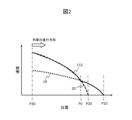
図2は、固定減速パターン10、調整減速パターン20及び駅停車減速パターン112の関係を示す図である。以下の説明(実施例1並びに後述する実施例2及び実施例3)では、調整減速パターンが1つである場合について説明する。
Figure 2 is a diagram showing the relationship between the
固定減速パターン10は、所定の減速度に従って停止目標位置P10に列車を停止させるように定められた減速パターンである。
Fixed
調整減速パターン20は、固定減速パターン10における所定の減速度よりも大きな減速度に従って基準位置P20に列車を停止させるように定められた減速パターンである。基準位置P20は、減速パターン生成部102により動的に変更可能な任意の位置である。調整減速パターン20の減速度は、上記のように、固定減速パターン10の減速度よりも大きく設定されるが、非常ブレーキによる最大減速度よりも小さく設定されるのが好ましい。
The adjusted
減速パターン生成部102は、列車が駅停車減速パターン112の生成を開始する位置として予め定められた減速パターン生成位置P30を通過したときに、固定減速パターン10と調整減速パターン20とから駅停車減速パターン112を生成する。そして、減速パターン生成部102は、停止目標位置P10に対する到着目標時分までに残された残走行時分に応じて基準位置P20を決定する。
When the train passes a deceleration pattern generation position P30, which is a predetermined position for starting the generation of the station
ここで、到着目標時分は、列車が停止目標位置P10である次駅に到着する際の目標となる時刻であり、運行ダイヤにて定められている。残走行時分は、基準時刻(例えば、現在時刻)から列車が到着目標時分通りに到着するまでに残された時間であり、基準時刻と到着目標時分との差分で計算される。 The target arrival time is the target time for the train to arrive at the next station, which is the target stopping position P10, and is determined by the train schedule. The remaining running time is the time remaining from a reference time (e.g., the current time) until the train arrives at the target arrival time, and is calculated as the difference between the reference time and the target arrival time.
その際、減速パターン生成部102は、図2に示すように、列車の走行位置である減速パターン生成位置P30と停止目標位置P10との間において、固定減速パターン10と調整減速パターン20とが交点Paで交差するように、基準位置P20を決定する。したがって、駅停車減速パターン112は、図2の実線で示すように、交点Paよりも停止目標位置P10側の固定減速パターン10と、交点Paよりも減速パターン生成位置P30側の調整減速パターン20とを組み合わせたものとして生成される。
At that time, the deceleration
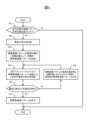
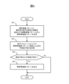
図3は、実施例1に係る減速パターン生成部102による駅停車減速パターン112の生成処理を示すフローチャートである。図3に示す生成処理は、減速パターン生成部102により列車の制御周期ごとに繰り返し実行される。
Figure 3 is a flowchart showing the process of generating the station
ステップ301では、現時点の走行位置が、減速パターン生成位置P30を超えて停止目標位置P10に近づいたか否かを判定する。その結果、「Yes」の場合はステップ302へ進み、「No」の場合は処理を終了する。
In
ステップ302では、現在時刻と停止目標位置P10に対する到着目標時分とに基づいて残走行時分を計算し、ステップ303へ進む。
In
ステップ303では、初期の駅停車減速パターン112を生成し、ステップ304へ進む。
In
ステップ303で生成される初期の駅停車減速パターン112は、固定減速パターン10と、予め設定された初期位置を基準位置P20とする調整減速パターン20とを組み合わせたものである。基準位置P20の初期位置は、固定減速パターン10と調整減速パターン20とが交差する交点Paが停止目標位置P10と減速パターン生成位置P30との間に入るような初期範囲内に設定される必要がある。このような初期範囲から初期位置が減速パターン生成位置P30側に外れた場合には、どの位置においても調整減速パターン20の速度が固定減速パターン10の速度よりも低くなるため、基準位置P20の変更により駅到着時分を調整できなくなるからである。
The initial station
ステップ304では、ステップ303で生成された初期の駅停車減速パターン112(又は後述するステップ306で生成された変更後の駅停車減速パターン112)に追従して列車を減速させたときの走行シミュレーションを実施する。そして、現時点の走行位置(減速パターン生成位置P30)から停止目標位置P10に停止するまでの予測走行時分を計算し、ステップ305へ進む。
In
ステップ305では、ステップ304で計算した予測走行時分と、ステップ302で計算した残走行時分とを比較し、所定の定時到着条件として、予測走行時分が残走行時分以下であるか否かを判定する。その結果、「No」の場合はステップ306へ進み、「Yes」の場合はステップ307へ進む。
In
ステップ306では、基準位置P20を停止目標位置P10に近づけるように変更し、変更後の駅停車減速パターン112を生成し、ステップ304へ戻る。
In
ステップ306で生成される変更後の駅停車減速パターン112は、固定減速パターン10と、停止目標位置P10に近づけるように変更された基準位置P20に列車を停止させる調整減速パターン20とを組み合わせたものである。なお、基準位置P20を変更する際の変更方法としては、例えば、予め設定された一定の距離分近づけてもよいし、停止目標位置P10に近づくたびに近づける距離を長くしたり短くしたりしてもよいし、予測走行時分と残走行時分との差分値に比例して近づける距離を長くしたりしてもよい。
The changed station
ステップ307では、ステップ305で予測走行時分が残走行時分以下であると判定された場合、ステップ303又はステップ306で駅停車減速パターン112を生成したときの基準位置P20を最終的な基準位置P20として決定し、そのときの駅停車減速パターン112をノッチ決定部103へ出力し、処理を終了する。
In
なお、図3に示す生成処理は、ステップ307にて駅停車減速パターン112がノッチ決定部103に出力されるまで繰り返し実行され、駅停車減速パターン112が出力された後は、列車が次駅(停止目標位置P10)を通過するまで停止されるようにしてもよい。
The generation process shown in FIG. 3 may be repeatedly executed until the station
また、ステップ301では、列車が減速パターン生成位置P30を通過したことを条件としたが、例えば、走行中であることを条件としてもよいし、他の条件を採用してもよい。
In addition, in
さらに、ステップ306では、基準位置P20を停止目標位置P10に近づけるように変更したが、基準位置P20の初期位置を停止目標位置P10として、基準位置P20を停止目標位置P10から遠ざけるように変更してもよい。また、計画ランカーブ作成時の前提となる位置を基準位置P20の初期位置としてもよいし、過去の走行実績で最も多く採用された位置を基準位置P20の初期位置としてもよい。その場合には、遅着が見込まれる場合は、基準位置P20を停止目標位置P10に近づけるように変更し、早着が見込まれる場合は、基準位置P20を停止目標位置P10から遠ざけるように変更してもよい。
Furthermore, in
また、ステップ305では、所定の定時到着条件として、予測走行時分に対して上限値(残走行時分)を設定して遅着を防止するものであるが、予測走行時分に対して下限値をさらに設定して過度な早着を防止するようにしてもよい。例えば、所定の定時到着条件は、予測走行時分が残走行時分以下であり、かつ、残走行時分から所定の早着限界時分を減算した値以上であるか否かを判定するものでもよい。下限値の設定は、基準位置P20を停止目標位置P10から遠ざけるように変更する場合に特に有用である。
In addition, in
したがって、減速パターン生成部102は、列車がステップ303で生成された駅停車減速パターン112に追従して停止目標位置P10に停止するまでの予測走行時分を算出し、当該予測走行時分と残走行時分とが所定の定時到着条件を満たすか否かを判定する判定処理(ステップ304、305)に応じて基準位置P20を決定し、駅停車減速パターン112をノッチ決定部103へ出力する(ステップ307)。
Therefore, the deceleration
そして、減速パターン生成部102は、その判定処理の結果、所定の定時到着条件を満たさないと判定した場合、基準位置P20を変更して変更後の駅停車減速パターン112を生成し(ステップ306)、当該変更後の駅停車減速パターン112に基づく上記と同様の判定処理(ステップ304、305)に応じて基準位置P20を決定し、駅停車減速パターン112をノッチ決定部103へ出力する(ステップ307)。
If the deceleration
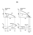
図4は、実施例1に係る減速パターン生成部102による駅停車減速パターン112の生成例を示す図である。
Figure 4 is a diagram showing an example of the generation of a station
グラフ401は、列車が減速パターン生成位置P30を通過したときに、予め設定された初期位置を基準位置P20Aとして、ステップ303で生成された初期の駅停車減速パターン112Aを示す。
グラフ402は、グラフ401で示す初期の駅停車減速パターン112Aに基づいて走行シミュレーション(ステップ304)を実施したときの結果として、現時点の走行位置(減速パターン生成位置P30)から停止目標位置P10に停止するまでの予測走行時分を示す。グラフ402では、停止目標位置P10にて予測走行時分が残走行時分を上回るため、遅着の発生が見込まれる。
グラフ403は、ステップ306で生成された変更後の駅停車減速パターン112Bを示す。ここでの変更後の駅停車減速パターン112は、ステップ305にて予測走行時分が残走行時分以下であると判定されるまで基準位置P20を停止目標位置P10に近づけるように変更したものである。
グラフ404は、変更後の駅停車減速パターン112Bに基づいて走行シミュレーション(ステップ304)を実施したときの結果として、現時点の走行位置(減速パターン生成位置P30)から停止目標位置P10に停止するまでの予測走行時分を示す。グラフ404では、基準位置P20Bが停止目標位置P10に近づけられているため、固定減速パターン10よりも減速度が大きな調整減速パターン20に沿って列車が走行する時間が長くなり、遅着が解消されている。
以上のように、本実施例によれば、減速パターン生成部102が、残走行時分に応じて調整減速パターン20の基準位置P20を決定するので、列車が停止目標位置P10に到着するときの駅到着時分を調整することが可能である。駅到着時分の調整に際して基準位置P20の変更が列車の走行に与える影響は、減速度の大きな調整減速パターン20から減速度の小さな固定減速パターン10に切り替わるタイミングが変化するだけである。そのため、加加速度の変化が低減され、乗り心地の悪化を防止することができる。したがって、乗り心地を損なうことなく定時性を維持して列車を制御することができる。
As described above, according to this embodiment, the deceleration
(実施例2)
[列車定時到着支援装置1の構成]
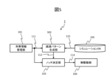
図5は、実施例2に係る列車定時到着支援装置1の概略構成図である。列車定時到着支援装置1は、列車情報管理部101、減速パターン生成部502、ノッチ決定部103、制駆動部104、及び、シミュレーションデータベース105を備える。減速パターン生成部502以外の各部は、実施例1に係る列車定時到着支援装置1と同様に構成されているため、説明を省略する。
Example 2
[Configuration of train arrival support device 1]
5 is a schematic diagram of the on-time train
減速パターン生成部502は、走行位置及び速度で構成される位置速度情報111と、シミュレーション条件115とを入力し、残走行時分に応じて駅停車減速パターン112を生成し、ノッチ決定部103へ出力する。
The deceleration
[減速パターン生成部502の詳細な構成及び動作]
図6は、実施例2に係る減速パターン生成部502による駅停車減速パターン112の生成処理を示すフローチャートである。図6に示す生成処理は、減速パターン生成部502により列車の制御周期ごとに繰り返し実行される。
[Detailed configuration and operation of the deceleration pattern generation unit 502]
Fig. 6 is a flowchart showing a process of generating the station
ステップ601では、固定減速パターン10と、現時点における走行位置及び速度を起点とする調整減速パターン20とから停止目標位置P10までの各位置で速度が高い方の減速パターンを優先して組み合わせて、現時点以降の駅停車減速パターン112を生成し、ステップ602へ進む。このとき、調整減速パターン20は、現時点の走行位置及び速度を起点とするため、調整減速パターン20において速度0となる位置を基準位置P20とみなすことができる。
In
ステップ602では、ステップ601で生成された駅停車減速パターン112に追従して列車を減速させたときの走行シミュレーションを実施する。そして、現時点の走行位置から停止目標位置P10に停止するまでの予測走行時分を計算し、ステップ603へ進む。
In
ステップ603では、ステップ602で計算した予測走行時分と、残走行時分とを比較し、所定の定時到着条件として、予測走行時分が残走行時分以下であるか否かを判定する。その結果、「Yes」の場合はステップ604へ進み、「No」の場合は処理を終了する。
In
ステップ604では、ステップ601で生成された駅停車減速パターン112をノッチ決定部103へ出力し、処理を終了する。なお、ステップ603で「No」と判定された場合は遅着が見込まれるため、現時点ではステップ604に進まずに、上記のように、処理を終了する。そして、次回以降の制御周期の到来時点において、ステップ603で「Yes」と判定される場合にステップ604へ進み、その到来時点を現時点としてステップ601で生成された現時点以降の駅停車減速パターン112がノッチ決定部103へ出力されることになる。
In
なお、図6に示す生成処理は、ステップ604にて駅停車減速パターン112がノッチ決定部103に出力されるまで繰り返し実行され、駅停車減速パターン112が出力された後は、列車が次駅(停止目標位置P10)を通過するまで停止されるようにしてもよい。
The generation process shown in FIG. 6 may be repeatedly executed until the station
したがって、減速パターン生成部502は、固定減速パターン10と、現時点における列車の走行位置及び速度を起点とする調整減速パターン20とから現時点以降の駅停車減速パターン112を生成し(ステップ601)、当該駅停車減速パターン112に基づく当該現時点の判定処理(ステップ602、603)に応じて基準位置P20を決定し、駅停車減速パターン112をノッチ決定部103へ出力する(ステップ604)。ここでの判定処理に応じて基準位置P20を決定することとは、列車が現時点以降の駅停車減速パターン112に追従して停止目標位置P10に停止するまでの予測走行時分と残走行時分とが所定の定時到着条件を満たすときに、現時点の走行位置及び速度を起点とする調整減速パターン20において速度0となる位置を、基準位置P20に決定することに相当する。
Therefore, the deceleration
そして、減速パターン生成部502は、列車の制御周期の到来時点を現時点として、上記と同様の判定処理(ステップ602、603)を制御周期ごとに実行して基準位置P20を決定し、駅停車減速パターン112をノッチ決定部103へ出力する(ステップ604)。
Then, the deceleration
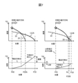
図7は、実施例2に係る減速パターン生成部502による駅停車減速パターン112の生成例を示す図である。
Figure 7 is a diagram showing an example of the generation of the station
グラフ701は、列車の制御周期が到来した所定の時点において、ステップ601で生成された駅停車減速パターン112Aを示す。
グラフ702は、グラフ701で示す駅停車減速パターン112Aに基づいて走行シミュレーション(ステップ602)を実施したときの結果を示す。グラフ701、702の時点では、列車の走行位置P40が停止目標位置P10から離れている。そのため、グラフ702に示すように、列車がグラフ701で示す駅停車減速パターン112Aに追従して減速した場合、停止目標位置P10にて予測走行時分が残走行時分を上回るため(ステップ603で「No」)、遅着の発生が見込まれる。
グラフ703は、グラフ701の時点から所定回数の制御周期(例えば、10秒相当)が経過した時点において、ステップ601で生成された駅停車減速パターン112Bを示す。
グラフ704は、グラフ703で示す駅停車減速パターン112Bに基づいて走行シミュレーション(ステップ602)を実施したときの結果を示す。グラフ703、704の時点では、列車の走行位置P41が停止目標位置P10に近づいている。そのため、グラフ704に示すように、列車がグラフ703で示す駅停車減速パターン112に追従して減速した場合、予測走行時分が残走行時分以下と判定される(ステップ603で「Yes」)。そのため、グラフ703、704の時点の調整減速パターン20において速度0となる位置を基準位置P20Bとして決定し、グラフ703で示す駅停車減速パターン112Bがノッチ決定部103へ出力される(ステップ604)ので、定時性を維持することが可能となる。
以上のように、本実施例によれば、制御周期の各時点(到来時点)において減速パターン生成部502が走行シミュレーションを実施する回数を1回に減らすことが可能である。そのため、駅停車減速パターン112を生成するための計算負荷を低減することができるとともに、実施例1と同様に、乗り心地を損なうことなく定時性を維持して列車を制御することができる。
As described above, according to this embodiment, it is possible to reduce the number of times that the deceleration
(実施例3)
[列車定時到着支援装置1の構成]
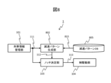
図8は、実施例3に係る列車定時到着支援装置1の概略構成図である。列車定時到着支援装置1は、列車情報管理部101、減速パターン生成部802、ノッチ決定部103、制駆動部104、及び、減速パターンデータベース805を備える。減速パターン生成部802及び減速パターンデータベース805以外の各部は、実施例1に係る列車定時到着支援装置1と同様に構成されているため、説明を省略する。
Example 3
[Configuration of train on-time arrival support device 1]
8 is a schematic configuration diagram of the train on-time
減速パターン生成部802は、位置速度情報111と、減速パターンデータベース情報815とを入力し、残走行時分に応じて駅停車減速パターン112を生成し、ノッチ決定部103へ出力する。なお、減速パターン生成部802の詳細は後述する。
The deceleration
減速パターンデータベース805は、記憶部で構成されており、減速パターンデータベース情報815を減速パターン生成部802へ出力する。減速パターンデータベース805は、例えば、走行シミュレーションを事前に実施し、走行シミュレーションにより計算された計算結果により作成されたものである。
The
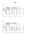
図9は、減速パターンデータベース情報815の一例を示すデータ構成図である。減速パターンデータベース情報815は、調整減速パターン基準位置テーブル901と、駅停車減速パターン速度テーブル902とから構成される。
Figure 9 is a data structure diagram showing an example of deceleration
調整減速パターン基準位置テーブル901は、列車が減速パターン生成位置P30を通過する時点での速度(行方向に対応)及び残走行時分(列方向に対応)の各組み合わせから調整減速パターン20の基準位置P20が設定されたテーブルである。調整減速パターン基準位置テーブル901には、基準位置P20を特定するデータとして、停止目標位置P10から基準位置P20までの距離が格納されている。
The adjusted deceleration pattern reference position table 901 is a table in which the reference position P20 of the adjusted
駅停車減速パターン速度テーブル902は、基準位置P20(行方向に対応)ごとに、各走行位置(列方向に対応)に応じた速度が設定されたテーブルである。調整減速パターン20の基準位置P20が、例えば、「10m」であるときの駅停車減速パターン速度テーブル902の1列分のデータを参照すると、その一列分のデータは、固定減速パターン10と、基準位置P20が「10m」であるときの調整減速パターン20とを組み合わせることによって生成された駅停車減速パターン112における各走行位置の速度を示す。
The station stop deceleration pattern speed table 902 is a table in which a speed corresponding to each running position (corresponding to the column direction) is set for each reference position P20 (corresponding to the row direction). When referring to one column of data in the station stop deceleration pattern speed table 902 when the reference position P20 of the adjusted
[減速パターン生成部802の詳細な構成及び動作]
図10は、実施例3に係る減速パターン生成部802による駅停車減速パターン112の生成処理を示すフローチャートである。
[Detailed configuration and operation of the deceleration pattern generation unit 802]
FIG. 10 is a flowchart illustrating a process of generating the station
ステップ1001では、現時点の走行位置が、減速パターン生成位置P30を超えて停止目標位置P10に近づいたか否かを判定する。その結果、「Yes」の場合はステップ1002へ進み、「No」の場合は処理を終了する。
In
ステップ1002では、減速パターン生成位置P30を通過した時点(現時点)における列車の速度を取得し、ステップ1003へ進む。
In
ステップ1003では、現在時刻と停止目標位置P10に対する到着目標時分とに基づいて残走行時分を計算し、ステップ1004へ進む。
In
ステップ1004では、ステップ1002で取得した速度と、ステップ1003で計算した残走行時分との組み合わせに応じて調整減速パターン基準位置テーブル901を参照することによって基準位置P20を決定し、ステップ1005へ進む。
In
ステップ1005では、ステップ1004で決定した基準位置P20に応じて駅停車減速パターン速度テーブル902を参照することによって駅停車減速パターン112を生成し、ステップ1006へ進む。
In
ステップ1006では、ステップ1005で生成された駅停車減速パターン112をノッチ決定部103へ出力し、処理を終了する。
In
なお、図10に示す生成処理は、ステップ1006にて駅停車減速パターン112がノッチ決定部103に出力されるまで繰り返し実行され、駅停車減速パターン112が出力された後は、列車が次駅(停止目標位置P10)を通過するまで停止されるようにしてもよい。
The generation process shown in FIG. 10 may be repeatedly executed until the station
以上のように、本実施例によれば、減速パターン生成部1102が走行シミュレーションを実施することなく、駅停車減速パターン112を生成することが可能である。そのため、駅停車減速パターン112を生成するための計算負荷を低減することができるとともに、実施例1と同様に、乗り心地を損なうことなく定時性を維持して列車を制御することができる。
As described above, according to this embodiment, the deceleration
なお、本実施例では、基準位置P20の決定と、駅停車減速パターン112の生成の両方とも、減速パターンデータベース情報815を参照することで実施したが、どちらか一方は、シミュレーションで実施するようにしてもよい。例えば、基準位置P20の決定は、調整減速パターン基準位置テーブル901を参照して実施するが、駅停車減速パターン112の生成は、シミュレーションで実施してもよい。また、基準位置P20の決定は、シミュレーションで実施するが、駅停車減速パターン112の生成は、駅停車減速パターン速度テーブル902を参照して実施してもよい。
In this embodiment, both the determination of the reference position P20 and the generation of the stop-
(実施例4)
[列車定時到着支援装置1の構成]
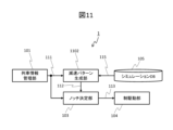
図11は、実施例4に係る列車定時到着支援装置1の概略構成図である。列車定時到着支援装置1は、列車情報管理部101、減速パターン生成部1102、ノッチ決定部103、制駆動部104、及び、シミュレーションデータベース105を備える。減速パターン生成部1102以外の各部は、実施例1に係る列車定時到着支援装置1と同様に構成されているため、説明を省略する。
Example 4
[Configuration of train arrival support device 1]
11 is a schematic configuration diagram of the train on-time
減速パターン生成部1102は、位置速度情報111と、シミュレーション条件115とを入力し、残走行時分に応じて駅停車減速パターン112を生成し、ノッチ決定部103へ出力する。
The deceleration
[減速パターン生成部1102の詳細な構成及び動作]
減速パターン生成部1102は、減速度が異なる複数の減速パターンとして、固定減速パターン10と、複数の調整減速パターン(図12に例示する調整減速パターン21、22)とから停止目標位置P10までの各位置において速度が高い方の減速パターンを優先して組み合わせて、駅停車減速パターン112を生成する。
[Detailed configuration and operation of the deceleration pattern generation unit 1102]
The deceleration
図12は、固定減速パターン10、2つの調整減速パターン21、22及び駅停車減速パターン112の関係を示す図である。以下の説明では、調整減速パターンが2つである場合について説明する。なお、固定減速パターン10は、実施例1と同様であるため、説明を省略する。
Figure 12 is a diagram showing the relationship between the fixed
調整減速パターンは、第1の調整減速パターン21と、第2の調整減速パターン22とからなる。第1の調整減速パターン21は、固定減速パターン10の減速度よりも大きな減速度に従って第1の基準位置P21に列車を停止させるように定められた減速パターンである。第2の調整減速パターン22は、第1の調整減速パターン21よりも大きな減速度に従って第2の基準位置P22に列車を停止させるように定められた減速パターンである。第1の基準位置P21及び第2の基準位置P22は、減速パターン生成部1102により動的に変更可能な任意の位置である。
The adjusted deceleration pattern consists of a first adjusted deceleration pattern 21 and a second adjusted
減速パターン生成部1102は、減速度が異なる複数の調整減速パターンを列車側から減速度の高い順に組み合わせる場合、減速度の高い第2の調整減速パターン22の第2の基準位置P22を、減速度の低い第1の調整減速パターン21の第1の基準位置P21よりも停止目標位置P10から遠い位置に決定する。そして、減速パターン生成部1102は、その決定した第1の基準位置P21及び第2の基準位置P22に列車を停止させるようにそれぞれ定められた第1の調整減速パターン21及び第2の調整減速パターン22と、固定減速パターン10とから駅停車減速パターン112を生成する。これにより、列車が駅停車減速パターン112に追従して減速したときに、減速度が徐々に低くなるように切り替わるので、加加速度の変化が低減される。
When combining multiple adjusted deceleration patterns with different decelerations from the train side in descending order of deceleration, the deceleration
その際、減速パターン生成部1102は、図12に示すように、列車の走行位置と停止目標位置P10との間において、固定減速パターン10と第1の調整減速パターン21とが交点Paで交差するとともに、第1の調整減速パターン21と第2の調整減速パターン22とが交点Pbで交差するように、第1の基準位置P21及び第2の基準位置P22を決定する。したがって、駅停車減速パターン112は、交点Paよりも停止目標位置P10側の固定減速パターン10と、交点Paと交点Pbの間の第1の調整減速パターン21と、交点Pbよりも減速パターン生成位置P30側の第2の調整減速パターン22とを組み合わせたものとして生成される。
In this case, the deceleration
図13は、実施例4に係る減速パターン生成部1102による駅停車減速パターン112の生成処理を示すフローチャートである。図13に示す生成処理は、減速パターン生成部1102により列車の制御周期ごとに繰り返し実行される。
Figure 13 is a flowchart showing the process of generating the station
ステップ1301では、列車が固定減速パターン10、第1の調整減速パターン21、第2の調整減速パターン22のいずれにも追従していない状態であるか否かを判定する。その結果、「Yes」の場合はステップ1302へ進み、「No」の場合はステップ1306へ進む。
In
ステップ1302では、固定減速パターン10と、予め設定された初期位置を第1の基準位置P21とする第1の調整減速パターン21と、現時点における走行位置及び速度を起点とする第2の調整減速パターン22とから現時点以降の駅停車減速パターン112を生成し、ステップ1303へ進む。このとき、第2の調整減速パターン22は、現時点の走行位置及び速度を起点とするため、第2の調整減速パターン22において速度0となる位置を第2の基準位置P22とみなすことができる。
In
ステップ1303では、ステップ1302で生成された駅停車減速パターン112に追従して列車を減速させたときの走行シミュレーションを実施し、現時点の走行位置から停止目標位置P10に停止するまでの予測走行時分を計算し、ステップ1304へ進む。
In
ステップ1304では、ステップ1303(又は後述するステップ1308)で計算した予測走行時分と、残走行時分とを比較し、所定の定時到着条件として、予測走行時分が残走行時分以下であるか否かを判定する。その結果、「Yes」の場合はステップ1305へ進み、「No」の場合は処理を終了する。
In
ステップ1305では、ステップ1302(又は後述するステップ1307)で生成された駅停車減速パターン112をノッチ決定部103へ出力し、処理を終了する。
In
ステップ1306では、列車が第2の調整減速パターン22に追従している状態であるか否かを判定する。その結果、「Yes」の場合はステップ1307へ進み、「No」の場合は固定減速パターン10又は第1の調整減速パターン21のいずれかに追従している状態であり、駅停車減速パターン112の生成は必要ないため、処理を終了する。
In
ステップ1307では、固定減速パターン10と、現時点の走行位置及び速度を起点とする第1の調整減速パターン21とから現時点以降の駅停車減速パターン112を生成し、ステップ1308へ進む。このとき、第1の調整減速パターン21は、現時点の走行位置及び速度を起点とするため、第1の調整減速パターン21において速度0となる位置を第1の基準位置P21とみなすことができる。
In
ステップ1308では、ステップ1307で生成された駅停車減速パターン112に追従して列車を減速させたときの走行シミュレーションを実施し、現時点の走行位置から停止目標位置P10に停止するまでの予測走行時分を計算し、ステップ1304へ進む。ステップ1304以降の処理は上記と同様のため、説明を省略する。
In
なお、図13に示す生成処理は、ステップ1307で生成された駅停車減速パターン112がステップ1305にてノッチ決定部103に出力されるまで繰り返し実行され、駅停車減速パターン112が出力された後は、列車が次駅(停止目標位置P10)を通過するまで停止されるようにしてもよい。
The generation process shown in FIG. 13 may be repeatedly executed until the station
したがって、減速パターン生成部1102は、列車が現時点でいずれの調整減速パターンにも追従していないとき(ステップ1301で「Yes」)、減速度の最も高い第2の調整減速パターン22の第2の基準位置P22を決定すべく、現時点における走行位置及び速度を起点とする第2の調整減速パターン22に基づき現時点以降の駅停車減速パターン112を生成する(ステップ1302)。そして、減速パターン生成部1102は、当該駅停車減速パターン112に基づく判定処理(ステップ1303、1304)に応じて第2の基準位置P22を決定し、駅停車減速パターン112をノッチ決定部103へ出力する(ステップ1305)。
Therefore, when the train is not currently following any of the adjusted deceleration patterns (step 1301: "Yes"), the deceleration
また、減速パターン生成部1102は、列車が現時点でいずれかの調整減速パターンとして、例えば、第2の調整減速パターン22に追従しているとき、当該第2の調整減速パターン22の次に減速度の高い第1の調整減速パターン21の第1の基準位置P21を決定すべく、現時点における走行位置及び速度を起点とする第1の調整減速パターン21に基づき現時点以降の駅停車減速パターン112を生成する(ステップ1307)。そして、減速パターン生成部1102は、当該駅停車減速パターン112に基づく判定処理(ステップ1308、1304)に応じて第1の基準位置P21を決定し、駅停車減速パターン112をノッチ決定部103へ出力する(ステップ1305)。
Furthermore, when the train is currently following any of the adjusted deceleration patterns, for example, the second adjusted
以上のように、本実施例によれば、外乱等の影響によって駅停車減速パターン112への追従性が悪い状況であっても、減速度が異なる複数の調整減速パターンを用いることにより停止目標位置P10に近づきながら駅到着時分を複数回調整することが可能である。その際、減速度は徐々に低くなるように切り替わるので、加加速度の変化が低減される。したがって、実施例1と同様に、乗り心地を損なうことなく定時性を維持して列車を制御することができる。
As described above, according to this embodiment, even in a situation where the train is poorly able to follow the station
また、本実施例によれば、制御周期の各時点(到来時点)において減速パターン生成部1102が走行シミュレーションを実施する回数を1回に減らすことが可能である。そのため、実施例2と同様に、駅停車減速パターン112を生成するための計算負荷を低減することができる。
In addition, according to this embodiment, it is possible to reduce the number of times that the deceleration
(補足事項)
以上、本発明の実施の形態について説明したが、本発明は、上記の実施の形態に限定されるものではなく、本発明の要旨を逸脱しない範囲において種々の変形が可能である。例えば、本発明は、上記の実施の形態で説明した全ての構成を備えるものに限定されず、その構成の一部を削除したものも含まれる。また、特定の実施例に係る構成の一部を、他の実施例に係る構成に追加又は置換することが可能である。
(Additional Information)
Although the embodiment of the present invention has been described above, the present invention is not limited to the above embodiment, and various modifications are possible within the scope of the gist of the present invention. For example, the present invention is not limited to those having all the configurations described in the above embodiment, and includes those in which some of the configurations are deleted. In addition, it is possible to add or replace some of the configurations of a specific embodiment with the configurations of other embodiments.
例えば、各実施例では、列車定時到着支援装置が列車に搭載された構成とした。これに対し、列車定時到着支援装置は、地上に設置された構成でもよく、その場合には、列車定時到着支援装置が、減速パターン生成部により生成された駅停車減速パターンを列車に送信するようにすればよい。 For example, in each embodiment, the train on-time arrival support device is configured to be mounted on the train. In contrast, the train on-time arrival support device may be configured to be installed on the ground, in which case the train on-time arrival support device may transmit the station stop deceleration pattern generated by the deceleration pattern generation unit to the train.
また、各実施例では、減速パターン生成部が、固定減速パターンと調整減速パターンとを組み合わせた駅停車減速パターンをノッチ決定部へ出力する構成とした。これに対し、減速パターン生成部が、固定減速パターンと調整減速パターンとの両方をノッチ決定部へ出力し、ノッチ決定部で固定減速パターン及び調整減速パターンのうち速度の高い方に追従するよう制御する構成としてもよい。 In addition, in each embodiment, the deceleration pattern generation unit is configured to output a station-stop deceleration pattern that combines a fixed deceleration pattern and an adjusted deceleration pattern to the notch determination unit. In contrast, the deceleration pattern generation unit may be configured to output both the fixed deceleration pattern and the adjusted deceleration pattern to the notch determination unit, and the notch determination unit may be configured to control the notch determination unit to follow the fixed deceleration pattern or the adjusted deceleration pattern, whichever has the higher speed.
また、各実施例では、減速パターン生成部が、残走行時分に応じて調整減速パターンの基準位置を決定(変更)する構成とした。これに対し、減速パターン生成部は、基準位置だけでなく、残走行時分に応じて調整減速パターンの減速度を決定(変更)する構成としてもよい。 In addition, in each embodiment, the deceleration pattern generation unit is configured to determine (change) the reference position of the adjusted deceleration pattern depending on the remaining travel time. In contrast, the deceleration pattern generation unit may be configured to determine (change) the deceleration of the adjusted deceleration pattern depending on the remaining travel time, not just the reference position.
また、第1乃至第3実施例では、減速パターン生成部は、固定減速パターンと、1つの調整減速パターンとを組み合わせて駅停車減速パターンを生成する例を中心に説明した。これに対し、第1乃至第3実施例において、減速パターン生成部は、固定減速パターンと、減速度の異なる複数の調整減速パターンとを組み合わせて駅停車減速パターンを生成してもよい。その際、減速パターン生成部は、減速度の高い方の調整減速パターンの基準位置を、減速度の低い方の調整減速パターンの基準位置よりも停止目標位置から遠い位置に決定するようにすればよい。 In the first to third embodiments, the deceleration pattern generation unit has been described mainly as combining a fixed deceleration pattern with one adjusted deceleration pattern to generate a station stop deceleration pattern. In contrast to this, in the first to third embodiments, the deceleration pattern generation unit may combine a fixed deceleration pattern with multiple adjusted deceleration patterns with different deceleration rates to generate a station stop deceleration pattern. In this case, the deceleration pattern generation unit may determine the reference position of the adjusted deceleration pattern with the higher deceleration rate to be farther from the stop target position than the reference position of the adjusted deceleration pattern with the lower deceleration rate.
また、第4実施例では、減速パターン生成部は、固定減速パターン10と、減速度の異なる2つの調整減速パターンとを組み合わせて駅停車減速パターンを生成する例を中心に説明した。これに対し、第4実施例において、駅停車減速パターンが、固定減速パターンと、減速度の異なる3つ以上の調整減速パターンとを組み合わせて駅停車減速パターンを生成してもよい。
In the fourth embodiment, the deceleration pattern generation unit mainly describes an example in which the station stop deceleration pattern is generated by combining the fixed
1…列車定時到着支援装置
101…列車情報管理部
102、502、802、1102…減速パターン生成部
103…ノッチ決定部(列車制御部)
104…制駆動部
105…シミュレーションデータベース
805…減速パターンデータベース(記憶部)
1... Train on-time
104: Braking/driving unit 105: Simulation database 805: Deceleration pattern database (storage unit)
Claims (4)
前記減速パターン生成部から出力された前記駅停車減速パターンに追従して前記列車を制御する列車制御部と
を備え、
前記減速パターン生成部は、
前記固定減速パターンと、現時点における前記列車の走行位置及び速度を起点とする前記調整減速パターンとから、前記現時点以降の前記駅停車減速パターンを生成し、当該駅停車減速パターンに追従して前記列車が前記現時点の走行位置から前記停止目標位置に停止するまでの予測走行時分を算出し、当該予測走行時分と前記停止目標位置に対する到着目標時分までに残された残走行時分とが所定の定時到着条件を満たすか否かを判定し、前記定時到着条件を満たす場合には、生成した前記駅停車減速パターンを前記列車制御部へ出力する
ことを特徴とする列車定時到着支援装置。 a deceleration pattern generation unit that generates a station stop deceleration pattern by combining, with priority given to a deceleration pattern with a higher speed at each position up to the stop target position, a fixed deceleration pattern that stops the train at a stop target position according to a predetermined deceleration and an adjusted deceleration pattern that stops the train at a reference position closer to the train than the stop target position according to a deceleration greater than the predetermined deceleration;
a train control unit that controls the train in accordance with the station stop deceleration pattern output from the deceleration pattern generation unit,
The deceleration pattern generation unit
The station stop deceleration pattern from the current time onwards is generated from the fixed deceleration pattern and the adjusted deceleration pattern which is based on the current running position and speed of the train, a predicted running time for the train to stop at the target stop position is calculated in accordance with the station stop deceleration pattern, and a determination is made as to whether or not the predicted running time and a remaining running time remaining until the target arrival time for the target stop position satisfy a predetermined on-time arrival condition, and if the on-time arrival condition is satisfied, the generated station stop deceleration pattern is output to the train control unit.
A train arrival time support device characterized by the above.
前記減速パターン生成部は、
前記調整減速パターンとして、前記減速度が異なる複数の前記調整減速パターンを組み合わせる場合、
前記列車が現時点で前記複数の調整減速パターンのいずれにも追従していないときには、前記固定減速パターンと、当該現時点における前記列車の走行位置及び速度を起点とし前記減速度の最も高い前記調整減速パターンと、当該調整減速パターンの次に前記減速度が順に高く前記基準位置が順に前記停止目標位置に近い前記調整減速パターンとから、当該現時点以降の前記駅停車減速パターンを生成し、
前記列車が現時点で前記複数の調整減速パターンのいずれかに追従しているときには、前記固定減速パターンと、当該現時点における前記列車の走行位置及び速度を起点とし当該追従している調整減速パターンに対して前記減速度が次に高く前記基準位置が前記停止目標位置により近い前記調整減速パターンとから、当該現時点以降の前記駅停車減速パターンを生成する
ことを特徴とする列車定時到着支援装置。 2. The train arrival support device according to claim 1,
The deceleration pattern generation unit
In a case where a plurality of adjusted deceleration patterns each having a different deceleration rate are combined as the adjusted deceleration pattern,
When the train is not currently following any of the plurality of adjusted deceleration patterns, a station stop deceleration pattern for the current time onward is generated from the fixed deceleration pattern, the adjusted deceleration pattern having the highest deceleration rate based on the running position and speed of the train at the current time, and the adjusted deceleration pattern having the next highest deceleration rate after the adjusted deceleration pattern and having the reference position that is sequentially closer to the stop target position,
When the train is currently following any of the plurality of adjusted deceleration patterns, the station stop deceleration pattern from the current time onward is generated from the fixed deceleration pattern and the adjusted deceleration pattern which has the second highest deceleration rate and the reference position closest to the stop target position with respect to the adjusted deceleration pattern being followed, starting from the running position and speed of the train at the current time.
A train arrival time support device characterized by the above.
前記減速パターン生成部は、
前記列車の制御周期の到来時点を前記現時点として、前記駅停車減速パターンに基づき前記判定をする処理を前記制御周期ごとに実行する
ことを特徴とする列車定時到着支援装置。 The train arrival support device according to claim 1 or 2,
The deceleration pattern generation unit
The present time is set to the time when the control period of the train arrives, and the process of making the determination based on the station stop deceleration pattern is executed for each control period.
A train arrival time support device characterized by the above.
前記減速パターン生成部から出力された前記駅停車減速パターンに追従して前記列車を制御する列車制御部と、
前記停止目標位置よりも前記列車側に位置する減速パターン生成位置を前記列車が通過した時点での当該列車の速度と前記停止目標位置に対する到着目標時分までに残された残走行時分との各組み合わせから前記基準位置が設定された第1のテーブルおよび前記基準位置ごとに前記列車の走行位置に応じて前記列車の速度が設定された第2のテーブルを記憶する記憶部と
を備え、
前記減速パターン生成部は、
前記列車が前記減速パターン生成位置を通過した時点における前記列車の速度と前記残走行時分とに応じて前記第1のテーブルを参照して前記基準位置を取得し、取得した当該基準位置に基づいて前記第2のテーブルを参照して前記列車の走行位置に応じた前記列車の速度を取得して前記駅停車減速パターンを生成する
ことを特徴とする列車定時到着支援装置。 a deceleration pattern generation unit that generates a station stop deceleration pattern by combining, with priority given to a deceleration pattern with a higher speed at each position up to the stop target position, a fixed deceleration pattern that stops the train at a stop target position according to a predetermined deceleration and an adjusted deceleration pattern that stops the train at a reference position closer to the train than the stop target position according to a deceleration greater than the predetermined deceleration;
a train control unit that controls the train in accordance with the station stop deceleration pattern output from the deceleration pattern generation unit;
a storage unit that stores a first table in which the reference position is set based on each combination of the speed of the train at the time when the train passes a deceleration pattern generation position that is located on the train side of the stop target position and a remaining running time remaining until the arrival target time for the stop target position, and a second table in which the speed of the train is set according to the running position of the train for each of the reference positions;
Equipped with
The deceleration pattern generation unit
The first table is referenced to acquire the reference position according to the speed of the train at the time when the train passed the deceleration pattern generation position and the remaining running time, and the second table is referenced based on the acquired reference position to acquire the speed of the train according to the running position of the train, thereby generating the station stop deceleration pattern.
A train arrival time support device characterized by the above.
Priority Applications (1)
| Application Number | Priority Date | Filing Date | Title |
|---|---|---|---|
| JP2020152677A JP7561550B2 (en) | 2020-09-11 | 2020-09-11 | Train on-time arrival support device |
Applications Claiming Priority (1)
| Application Number | Priority Date | Filing Date | Title |
|---|---|---|---|
| JP2020152677A JP7561550B2 (en) | 2020-09-11 | 2020-09-11 | Train on-time arrival support device |
Publications (2)
| Publication Number | Publication Date |
|---|---|
| JP2022046993A JP2022046993A (en) | 2022-03-24 |
| JP7561550B2 true JP7561550B2 (en) | 2024-10-04 |
Family
ID=80780109
Family Applications (1)
| Application Number | Title | Priority Date | Filing Date |
|---|---|---|---|
| JP2020152677A Active JP7561550B2 (en) | 2020-09-11 | 2020-09-11 | Train on-time arrival support device |
Country Status (1)
| Country | Link |
|---|---|
| JP (1) | JP7561550B2 (en) |
Citations (4)
| Publication number | Priority date | Publication date | Assignee | Title |
|---|---|---|---|---|
| JP2005280542A (en) | 2004-03-30 | 2005-10-13 | Nippon Signal Co Ltd:The | ATC / O equipment |
| JP2006006030A (en) | 2004-06-17 | 2006-01-05 | Toshiba Corp | Driving pattern creation device, vehicle speed control device, and vehicle driving support device. |
| JP2011087364A (en) | 2009-10-14 | 2011-04-28 | Hitachi Ltd | Automatic train drive unit and constant position stop device |
| JP2017063556A (en) | 2015-09-25 | 2017-03-30 | 株式会社日立製作所 | Travel pattern creation device, automatic train operation system with travel pattern creation device and automatic train operation device, and drive support system with travel pattern creation device and operation support device |
Family Cites Families (1)
| Publication number | Priority date | Publication date | Assignee | Title |
|---|---|---|---|---|
| JP2690220B2 (en) * | 1991-02-28 | 1997-12-10 | 三菱電機株式会社 | Train fixed position stop control device |
-
2020
- 2020-09-11 JP JP2020152677A patent/JP7561550B2/en active Active
Patent Citations (4)
| Publication number | Priority date | Publication date | Assignee | Title |
|---|---|---|---|---|
| JP2005280542A (en) | 2004-03-30 | 2005-10-13 | Nippon Signal Co Ltd:The | ATC / O equipment |
| JP2006006030A (en) | 2004-06-17 | 2006-01-05 | Toshiba Corp | Driving pattern creation device, vehicle speed control device, and vehicle driving support device. |
| JP2011087364A (en) | 2009-10-14 | 2011-04-28 | Hitachi Ltd | Automatic train drive unit and constant position stop device |
| JP2017063556A (en) | 2015-09-25 | 2017-03-30 | 株式会社日立製作所 | Travel pattern creation device, automatic train operation system with travel pattern creation device and automatic train operation device, and drive support system with travel pattern creation device and operation support device |
Also Published As
| Publication number | Publication date |
|---|---|
| JP2022046993A (en) | 2022-03-24 |
Similar Documents
| Publication | Publication Date | Title |
|---|---|---|
| US9205851B2 (en) | Speed profile creation device and automatic train operation apparatus | |
| US8374739B2 (en) | Train control device having a target speed calculation function | |
| CN109070765B (en) | Train control device, method and computer-readable recording medium | |
| US5440489A (en) | Regulating a railway vehicle | |
| EP1210240B1 (en) | Method and device for assisting a driver of a vehicle | |
| CN113320576B (en) | Parking control method, device and storage medium for virtual marshalling train formation | |
| JP2011205738A (en) | Automatic train operating device | |
| CN114802362B (en) | Train energy-saving operation method and device controlled by time division | |
| JP2011121417A (en) | Travel control system, control program, and recording medium | |
| JP5805051B2 (en) | Train automatic control device | |
| JP5150448B2 (en) | Train control device | |
| JPH06284519A (en) | Train travelling controller | |
| JP7561550B2 (en) | Train on-time arrival support device | |
| JPH0976914A (en) | Train running operation control method and device | |
| CN118220286A (en) | Method, device, train and storage medium for adjusting train section running time | |
| JP7433933B2 (en) | Train control device and train control method | |
| CN112124363A (en) | Control method for accurate train stop, ATO, VOBC and train | |
| JP6712959B2 (en) | Travel control device, travel control method, and travel control system | |
| JPH0799708A (en) | Train automatic operation device | |
| KR20220126207A (en) | Train control apparatus and control method | |
| CN117465436B (en) | Vehicle cruise control method and system | |
| JP2006074876A (en) | Vehicle fixed position stop automatic control device | |
| CN119271920B (en) | A method for planning the target speed curve during the train's entry and stopping phase at the station. | |
| JP7786193B2 (en) | Control device | |
| JP7466494B2 (en) | Train control system and train control device |
Legal Events
| Date | Code | Title | Description |
|---|---|---|---|
| A621 | Written request for application examination |
Free format text: JAPANESE INTERMEDIATE CODE: A621 Effective date: 20230303 |
|
| A977 | Report on retrieval |
Free format text: JAPANESE INTERMEDIATE CODE: A971007 Effective date: 20230929 |
|
| A131 | Notification of reasons for refusal |
Free format text: JAPANESE INTERMEDIATE CODE: A131 Effective date: 20231003 |
|
| A521 | Request for written amendment filed |
Free format text: JAPANESE INTERMEDIATE CODE: A523 Effective date: 20231130 |
|
| A131 | Notification of reasons for refusal |
Free format text: JAPANESE INTERMEDIATE CODE: A131 Effective date: 20240305 |
|
| A601 | Written request for extension of time |
Free format text: JAPANESE INTERMEDIATE CODE: A601 Effective date: 20240507 |
|
| A521 | Request for written amendment filed |
Free format text: JAPANESE INTERMEDIATE CODE: A523 Effective date: 20240626 |
|
| TRDD | Decision of grant or rejection written | ||
| A01 | Written decision to grant a patent or to grant a registration (utility model) |
Free format text: JAPANESE INTERMEDIATE CODE: A01 Effective date: 20240903 |
|
| A61 | First payment of annual fees (during grant procedure) |
Free format text: JAPANESE INTERMEDIATE CODE: A61 Effective date: 20240924 |
|
| R150 | Certificate of patent or registration of utility model |
Ref document number: 7561550 Country of ref document: JP Free format text: JAPANESE INTERMEDIATE CODE: R150 |