JP7557560B2 - Photographing system and image fusion method - Google Patents
Photographing system and image fusion method Download PDFInfo
- Publication number
- JP7557560B2 JP7557560B2 JP2023022643A JP2023022643A JP7557560B2 JP 7557560 B2 JP7557560 B2 JP 7557560B2 JP 2023022643 A JP2023022643 A JP 2023022643A JP 2023022643 A JP2023022643 A JP 2023022643A JP 7557560 B2 JP7557560 B2 JP 7557560B2
- Authority
- JP
- Japan
- Prior art keywords
- objects
- sub
- images
- image
- scene
- Prior art date
- Legal status (The legal status is an assumption and is not a legal conclusion. Google has not performed a legal analysis and makes no representation as to the accuracy of the status listed.)
- Active
Links
Images


Classifications
-
- G—PHYSICS
- G06—COMPUTING OR CALCULATING; COUNTING
- G06T—IMAGE DATA PROCESSING OR GENERATION, IN GENERAL
- G06T5/00—Image enhancement or restoration
- G06T5/50—Image enhancement or restoration using two or more images, e.g. averaging or subtraction
-
- G—PHYSICS
- G06—COMPUTING OR CALCULATING; COUNTING
- G06T—IMAGE DATA PROCESSING OR GENERATION, IN GENERAL
- G06T3/00—Geometric image transformations in the plane of the image
- G06T3/40—Scaling of whole images or parts thereof, e.g. expanding or contracting
- G06T3/4038—Image mosaicing, e.g. composing plane images from plane sub-images
-
- G—PHYSICS
- G06—COMPUTING OR CALCULATING; COUNTING
- G06T—IMAGE DATA PROCESSING OR GENERATION, IN GENERAL
- G06T2207/00—Indexing scheme for image analysis or image enhancement
- G06T2207/20—Special algorithmic details
- G06T2207/20016—Hierarchical, coarse-to-fine, multiscale or multiresolution image processing; Pyramid transform
-
- G—PHYSICS
- G06—COMPUTING OR CALCULATING; COUNTING
- G06T—IMAGE DATA PROCESSING OR GENERATION, IN GENERAL
- G06T2207/00—Indexing scheme for image analysis or image enhancement
- G06T2207/20—Special algorithmic details
- G06T2207/20048—Transform domain processing
- G06T2207/20064—Wavelet transform [DWT]
-
- G—PHYSICS
- G06—COMPUTING OR CALCULATING; COUNTING
- G06T—IMAGE DATA PROCESSING OR GENERATION, IN GENERAL
- G06T2207/00—Indexing scheme for image analysis or image enhancement
- G06T2207/20—Special algorithmic details
- G06T2207/20212—Image combination
- G06T2207/20221—Image fusion; Image merging
-
- G—PHYSICS
- G06—COMPUTING OR CALCULATING; COUNTING
- G06V—IMAGE OR VIDEO RECOGNITION OR UNDERSTANDING
- G06V10/00—Arrangements for image or video recognition or understanding
- G06V10/10—Image acquisition
- G06V10/16—Image acquisition using multiple overlapping images; Image stitching
-
- H—ELECTRICITY
- H04—ELECTRIC COMMUNICATION TECHNIQUE
- H04N—PICTORIAL COMMUNICATION, e.g. TELEVISION
- H04N23/00—Cameras or camera modules comprising electronic image sensors; Control thereof
- H04N23/90—Arrangement of cameras or camera modules, e.g. multiple cameras in TV studios or sports stadiums
Landscapes
- Physics & Mathematics (AREA)
- General Physics & Mathematics (AREA)
- Engineering & Computer Science (AREA)
- Theoretical Computer Science (AREA)
- Studio Devices (AREA)
- Image Processing (AREA)
- Image Analysis (AREA)
- Two-Way Televisions, Distribution Of Moving Picture Or The Like (AREA)
- Lining Or Joining Of Plastics Or The Like (AREA)
Description
本発明は、撮影システムに関するものであり、特に、撮影システムおよび画像融合方法に関するものである。 The present invention relates to an imaging system, and more particularly to an imaging system and an image fusion method.
一般的に、撮影システムは、通常、複数のカメラを有する。情景を撮影するために、異なるカメラが異なる部分の情景を別々に撮像することができる。そのため、撮像した画像を1つに接合または融合さえすれば、より完成した情景画像を取得することができる。 Generally, a photography system usually has multiple cameras. To capture a scene, different cameras can capture different parts of the scene separately. Then, all that is needed is to splice or fuse the captured images together to obtain a more complete scene image.
しかしながら、情景には異なるオブジェクトが存在する可能性がある。異なるカメラが同じオブジェクトを撮影した時、撮像された画像は、角度や画質が異なる問題が生じる可能性があるため、画像の接合や融合が困難になり、画質を下げる結果となる。 However, there may be different objects in the scene. When different cameras capture the same object, the captured images may have different angles and quality issues, making it difficult to stitch or fuse the images, resulting in poor image quality.
本発明は、接合または融合した画像の画質をより高めることのできる撮影システムおよび画像融合方法に関するものである。 The present invention relates to an imaging system and an image fusion method that can improve the image quality of a joined or fused image.
本発明の1つの実施形態は、複数のカメラおよびコントローラを含む撮影システムを提供する。カメラは、情景を撮影して、複数のサブ画像を生成するよう構成される。コントローラは、カメラに信号接続され、サブ画像を取得する。コントローラは、サブ画像を分析して、情景に含まれる複数のオブジェクトを取得する。コントローラが各オブジェクトのパレート集合(Pareto set)を確立した後、コントローラは、各オブジェクトのパレート集合に基づいてオブジェクトを接合し、サブ画像の融合後の画像を生成する。 One embodiment of the present invention provides an imaging system including multiple cameras and a controller. The cameras are configured to capture a scene and generate multiple sub-images. The controller is signal-coupled to the cameras to capture the sub-images. The controller analyzes the sub-images to capture multiple objects included in the scene. After the controller establishes a Pareto set for each object, the controller joins the objects based on the Pareto set for each object to generate a fused image of the sub-images.
本発明の1つの実施形態は、以下のステップを含む画像融合方法を提供する。複数のカメラの各光学パラメータに基づいて最適化された光学パラメータを計算する。カメラを使用して情景を撮影し、複数のサブ画像を取得する。サブ画像を分析して、情景に含まれる複数のオブジェクトを取得する。各オブジェクトのパレート集合を確立する。各オブジェクトのパレート集合に基づいてオブジェクトを接合し、サブ画像の融合後の画像を生成する。 One embodiment of the present invention provides an image fusion method that includes the following steps: Calculate optimized optical parameters based on the optical parameters of a plurality of cameras; Use the cameras to capture a scene and obtain a plurality of sub-images; Analyze the sub-images to obtain a plurality of objects contained in the scene; Establish a Pareto set for each object; Join the objects based on the Pareto set for each object to generate a fused image of the sub-images.
以上のように、本発明の1つの実施形態に基づく撮影システムおよび画像融合方法は、コントローラが各オブジェクトのパレート集合を確立した後にオブジェクトを接合し、サブ画像の融合後の画像を生成する。したがって、接合および融合のプロセスにおいて、画質の悪い部分が排除されるため、サブ画像の融合後の画像は、より優れた画質を有する。 As described above, the imaging system and image fusion method according to one embodiment of the present invention joins the objects after the controller establishes the Pareto sets for each object, and generates an image after the sub-images are fused. Therefore, the image after the sub-images are fused has better image quality because parts with poor image quality are eliminated in the joining and fusion process.
添付図面は、本発明の原理がさらに理解されるために含まれており、本明細書に組み込まれ、且つその一部を構成するものである。図面は、本発明の実施形態を例示しており、説明とともに、本発明の原理を説明する役割を果たしている。 The accompanying drawings are included to provide a further understanding of the principles of the invention, and are incorporated in and constitute a part of this specification. The drawings illustrate embodiments of the invention and, together with the description, serve to explain the principles of the invention.
図1は、本発明の1つの実施形態に係る情景を撮影する撮影システムの概略図である。まず、図1を参照すると、本発明の1つの実施形態は、撮影システム10および画像融合方法を提供する。1つの実施形態において、撮影システム10は、複数のカメラ100A、100B、100C、100D、100E、100F、およびコントローラ200を含む。カメラの数は、単なる例であるため、本発明はこれに限定されない。
FIG. 1 is a schematic diagram of a photography system for photographing a scene according to one embodiment of the present invention. First, referring to FIG. 1, one embodiment of the present invention provides a
1つの実施形態において、カメラ100A、100B、100C、100D、100E、および100Fは、相補型金属酸化膜半導体(complementary metal-oxide semiconductor, CMOS)のフォトセンサまたは電荷結合素子(charge coupled device, CCD)のフォトセンサであってもよいが、本発明はこれに限定されない。カメラ100A、100B、100C、100D、100E、および100Fを使用して、情景Sを撮影し、複数のサブ画像(例えば、図4に示したサブ画像SI)を生成する。つまり、各カメラ100A、100B、100C、100D、100E、100Fが情景Sを撮像して、サブ画像を生成する。
In one embodiment,
1つの実施形態において、コントローラ200は、例えば、中央処理装置(central processing unit, CPU)、マイクロプロセッサ(microprocessor)、デジタル信号プロセッサ(digital signal processor, DSP)、プログラマブルコントローラ(programmable controller)、プログラマブル論理デバイス(programmable logic device, PLD)、または他の類似するデバイス、あるいはこれらのデバイスの組み合わせを含むが、本発明はこれに限定されない。また、1つの実施形態において、コントローラ200の様々な機能は、複数のプログラムコードとして実施されてもよい。これらのプログラムコードは、メモリユニットに保存され、プログラムコードは、コントローラ200によって実行される。あるいは、1つの実施形態において、コントローラ200の機能は、1つまたは複数の回路として実施されてもよい。本発明は、コントローラ200の機能がソフトウェアによって実施されるか、ハードウェアによって実施されるかを限定しない。
In one embodiment, the
また、1つの実施形態において、1つの実施形態において、コントローラ200は、スマートフォン、モバイルデバイス、コンピュータ、ノート型パソコン、サーバー、AIサーバー、またはクラウドサーバー内に配置されてもよい。別の実施形態において、コントローラ200は、カメラ100A、100B、100C、100D、100E、100F内に直接配置されてもよい。しかしながら、本発明は、コントローラ200が配置される位置を限定しない。
Also, in one embodiment, the
1つの実施形態において、コントローラ200は、カメラ100A、100B、100C、100D、100E、および100Fに信号接続され、サブ画像を取得する。コントローラ200は、サブ画像を分析して、情景Sに含まれる複数のオブジェクトBG、O1、O2を取得する。そのうち、オブジェクトBG、O1、O2は、オブジェクトの種類に応じて、花、人、車(例えば、レクリエーション用車両、スポーツカー、オープンカー、SUV等)、背景(例えば、道、空、建物等)に分割することができる。例えば、図1のオブジェクトO1またはO2は、花、人、または車であってもよく、オブジェクトBGは、背景であってもよい。カメラ100A、100B、および100Cは、例えば、オブジェクトBGおよびO1を撮影することができ、カメラ100D、100E、および100Fは、例えば、オブジェクトBGおよびO2を撮影することができる。そのため、カメラ100A、100B、100C、100D、100E、および100Fによって撮像されたサブ画像を融合または接合した後、情景Sの完全な画像を生成することができる。
In one embodiment, the
しかしながら、オブジェクトBG、O1、およびO2に対して各カメラ100A、100B、100C、100D、100E、および100Fが撮像した画像は、画質が異なる可能性がある。例えば、図1において、実線矢印は、比較的高画質であることを示し、破線矢印は、比較的低画質であることを示す。つまり、オブジェクトO1に対してカメラ100Aおよび100Bが撮像したサブ画像は、比較的高画質であるが、オブジェクトO1に対してカメラ100Cが撮像したサブ画像は、比較的低画質である。同様に、オブジェクトO2に対してカメラ100Dおよび100Eが撮像したサブ画像は、比較的高画質であるが、オブジェクトO2に対してカメラ100Fが撮像したサブ画像は、比較的低画質である。カメラ100A、100B、および100Cが撮像したサブ画像中の全てのオブジェクトO1が融合された場合、またはカメラ100D、100E、および100Fが撮像したサブ画像中の全てのオブジェクトO2が融合された場合には、画質の高い情景Sの完全な画像を取得することができない。そのため、1つの実施形態において、コントローラ200が各オブジェクトBG、O1、O2のパレート集合を確立した後、例えば、パレート最適解の集合をパレート集合と呼ぶが、コントローラ200は、オブジェクトBG、O1、O2のパレート集合に基づいてオブジェクトBG、O1、O2を接合し、サブ画像の融合後の画像を生成する。与えられた関数の解を考慮すると、複数の解が存在する可能性があり、これらの解のいくつかは、他よりも優れている可能性がある。そのため、パレート最適解を満たす解の集合をパレート集合と呼ぶ。
However, the images captured by
図2は、本発明の1つの実施形態に係る画像融合方法のフローチャートである。図1および図2を参照すると、本発明の1つの実施形態は、以下のステップを含む画像融合方法を提供する。ステップS100において、複数のカメラ100A、100B、100C、100D、100E、および100Fの各光学パラメータに基づいて最適な光学パラメータを計算する。ステップS200において、カメラ100A、100B、100C、100D、100E、および100Fを使用して情景Sを撮影し、複数のサブ画像を取得する。ステップS300において、サブ画像を分析して、情景に含まれる複数のオブジェクトBG、O1、O2を取得する。ステップS400において、各オブジェクトBG、O1、O2のパレート集合を確立する。ステップS500において、オブジェクトBG、O1、O2のパレート集合に基づいてオブジェクトBG、O1、O2を接合し、サブ画像の融合後の画像を生成する。
Figure 2 is a flow chart of an image fusion method according to one embodiment of the present invention. With reference to Figures 1 and 2, one embodiment of the present invention provides an image fusion method including the following steps: In step S100, optimal optical parameters are calculated based on the optical parameters of the
1つの実施形態において、各カメラ100A、100B、100C、100D、100E、および100Fの光学パラメータは、口径、焦点距離、感度、ホワイドバランス、または解析度を含む。1つの実施形態において、光学パラメータは、さらに、フルウェルキャパシティ(full well capacity, FWC)、飽和容量(saturation capacity)、絶対感度閾値(absolute sensitivity threshold, AST)、テンポラルダークノイズ(temporal dark noise)、ダイナミックレンジ(dynamic range)、量子効率(quantum efficiency, QE)、最大信号対雑音比(maximum signal-to-noise ratio, SNRmax)、Kファクター(K-factor)等を含む。
In one embodiment, the optical parameters of each
以下、本発明の1つの実施形態に基づく撮影システム10および画像融合方法によってサブ画像の融合後の画像を生成するプロセスについて詳しく説明する。
The following provides a detailed description of the process of generating an image after fusing sub-images using an
図3は、図2におけるサブ画像を分析して情景に含まれるオブジェクトを取得するステップのフローチャートである。図4は、サブ画像を分析することによってサブ画像に含まれるオブジェクトを取得する時の概略図である。図2、図3、および図4を参照すると、1つの実施形態において、上述したステップS300は、以下のステップを含む。ステップS320において、パノプティックセグメンテーションアルゴリズム(panoptic segmentation algorithm)を使用して、サブ画像SIを分析する。パノプティックセグメンテーションアルゴリズムは、インスタンス(instance)およびセマンティック(semantic)セグメンテーションの両方からの予測を一般的な統一された出力に結合し、各サブ画像SIに含まれるオブジェクトBB1、BS1、C1、C2、C3、C4、H1、H2、H3、H4、H5、H6、H7、およびH8およびそれらの境界を取得するイメージセグメンテーションである。ステップS340において、情景Sに含まれるオブジェクトBB1、BS1、C1、C2、C3、C4、H1、H2、H3、H4、H5、H6、H7、およびH8のオブジェクトタイプに基づいてオブジェクトBB1、BS1、C1、C2、C3、C4、H1、H2、H3、H4、H5、H6、H7、およびH8に番号を付ける。 3 is a flow chart of the steps of analyzing the sub-images in FIG. 2 to obtain objects contained in the scene. FIG. 4 is a schematic diagram of obtaining objects contained in the sub-images by analyzing the sub-images. With reference to FIG. 2, FIG. 3, and FIG. 4, in one embodiment, the above-mentioned step S300 includes the following steps: In step S320, a panoptic segmentation algorithm is used to analyze the sub-images SI. The panoptic segmentation algorithm is an image segmentation that combines predictions from both instance and semantic segmentation into a common unified output to obtain objects BB1, BS1, C1, C2, C3, C4, H1, H2, H3, H4, H5, H6, H7, and H8 contained in each sub-image SI and their boundaries. In step S340, objects BB1, BS1, C1, C2, C3, C4, H1, H2, H3, H4, H5, H6, H7, and H8 are numbered based on the object types of the objects BB1, BS1, C1, C2, C3, C4, H1, H2, H3, H4, H5, H6, H7, and H8 contained in the scene S.
例えば、図4は、情景Sを撮影することによってカメラ100A、100B、100C、100D、100E、および100Fのうちの1つによって得られたサブ画像SIを示したものである。コントローラ200は、パノプティックセグメンテーションアルゴリズムを使用してサブ画像SIを分析した後、オブジェクトBB1、BS1、C1、C2、C3、C4、H1、H2、H3、H4、H5、H6、H7、およびH8を取得することができる。オブジェクトC1、C2、C3、およびC4は、車である。そのため、コントローラ200は、例えば、参照番号car#1、car#2、car#3、およびcar#4をそれぞれオブジェクトC1、C2、C3、およびC4に割り当てることができる。オブジェクトH1、H2、H3、H4、H5、H6、H7、およびH8は、人である。そのため、コントローラ200は、例えば、参照番号person#1、person#2、person#3、person#4、person#5、person#6、person#7、およびperson#8をそれぞれオブジェクトH1、H2、H3、H4、H5、H6、H7、およびH8に割り当てることができる。さらに、オブジェクトBB1およびBS1は、背景であるが、オブジェクトBB1は、建物の背景であり、オブジェクトBS1は、空の背景である。そのため、コントローラ200は、例えば、参照番号building#1およびsky#1をオブジェクトBB1およびBS1に割り当てることができる。
For example, FIG. 4 shows a sub-image SI obtained by one of the
図5は、図2における各オブジェクトのパレート集合を確立するステップのフローチャートである。図2および図5を参照すると、1つの実施形態において、各オブジェクトBB1、BS1、C1、C2、C3、C4、H1、H2、H3、H4、H5、H6、H7、およびH8は、少なくとも1つのサブオブジェクトを含み、各サブオブジェクトは、各オブジェクトBB1、BS1、C1、C2、C3、C4、H1、H2、H3、H4、H5、H6、H7、およびH8がサブ画像SIのうちの1つに出現する画像範囲である。例えば、撮影システム10におけるカメラ100A、100B、100C、100D、100E、100Fのうちのいくつかによって、オブジェクトC1を撮像することができる。つまり、全てのカメラでオブジェクトC1を撮像しなくてもよい。そのため、サブオブジェクトは、オブジェクトC1を撮像するこれらのカメラの各サブ画像内の画像範囲であり、オブジェクトC1は、これらのサブオブジェクトを含む。図1を例に挙げると、オブジェクトO1は、カメラ100A、100B、および100Cによって撮影されるため、オブジェクトO1は、3つのサブオブジェクトを含み、オブジェクトO2は、カメラ100D、100E、および100Fによって撮影されるため、オブジェクトO1は、3つのサブオブジェクトを含む。
Figure 5 is a flow chart of the steps of establishing a Pareto set for each object in Figure 2. With reference to Figures 2 and 5, in one embodiment, each object BB1, BS1, C1, C2, C3, C4, H1, H2, H3, H4, H5, H6, H7, and H8 includes at least one sub-object, and each sub-object is an image area in which each object BB1, BS1, C1, C2, C3, C4, H1, H2, H3, H4, H5, H6, H7, and H8 appears in one of the sub-images SI. For example, object C1 can be captured by some of the
1つの実施形態において、上述したステップS400は、以下のステップを含む。ステップS420において、情景Sの各オブジェクトBB1、BS1、C1、C2、C3、C4、H1、H2、H3、H4、H5、H6、H7、およびH8において、異なるサブ画像SI中の各オブジェクトBB1、BS1、C1、C2、C3、C4、H1、H2、H3、H4、H5、H6、H7、およびH8に含まれる全てのサブオブジェクトに対応する画像フィードバックパラメータを収集する。各画像フィードバックパラメータは、画質指標(image quality indicator, IQI)および撮像位置指標(imaging position indicator, IPI)を含む。ステップS440において、画像フィードバックパラメータおよび少なくとも1つのサブオブジェクトに対応する最適化された光学パラメータに基づいて、多目的シミュレーテッドアニーリングアルゴリズム(multi-objective simulated annealing algorithm)を使用して各オブジェクトBB1、BS1、C1、C2、C3、C4、H1、H2、H3、H4、H5、H6、H7、およびH8のパレート集合を確立する。多目的シミュレーテッドアニーリングアルゴリズムは、与えられた関数の大域的最適解(global optimum)を近似する確率的技法である。 In one embodiment, the above-mentioned step S400 includes the following steps: In step S420, for each object BB1, BS1, C1, C2, C3, C4, H1, H2, H3, H4, H5, H6, H7, and H8 of the scene S, collect image feedback parameters corresponding to all sub-objects included in each object BB1, BS1, C1, C2, C3, C4, H1, H2, H3, H4, H5, H6, H7, and H8 in different sub-images SI. Each image feedback parameter includes an image quality indicator (IQI) and an imaging position indicator (IPI). In step S440, based on the image feedback parameters and the optimized optical parameters corresponding to at least one sub-object, a Pareto set is established for each of the objects BB1, BS1, C1, C2, C3, C4, H1, H2, H3, H4, H5, H6, H7, and H8 using a multi-objective simulated annealing algorithm. The multi-objective simulated annealing algorithm is a probabilistic technique that approximates the global optimum of a given function.
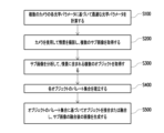
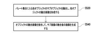
図6は、図2におけるオブジェクトのパレート集合に基づいてオブジェクトを融合または接合し、サブ画像の融合後の画像を生成するステップのフローチャートである。図2および図6を参照すると、1つの実施形態において、上述したステップS500は、以下のステップを含む。ステップS520において、各オブジェクトBB1、BS1、C1、C2、C3、C4、H1、H2、H3、H4、H5、H6、H7、およびH8においてパレート集合に入るサブオブジェクトを融合し、各オブジェクトBB1、BS1、C1、C2、C3、C4、H1、H2、H3、H4、H5、H6、H7、およびH8の融合画像を形成する。ステップS540において、各オブジェクトBB1、BS1、C1、C2、C3、C4、H1、H2、H3、H4、H5、H6、H7、およびH8の融合画像を接合し、サブ画像SIの融合後の画像を生成する。 Figure 6 is a flow chart of the steps of fusing or joining objects based on the Pareto set of objects in Figure 2 to generate a fused image of sub-images. With reference to Figures 2 and 6, in one embodiment, the above-mentioned step S500 includes the following steps: In step S520, the sub-objects that fall into the Pareto set in each object BB1, BS1, C1, C2, C3, C4, H1, H2, H3, H4, H5, H6, H7, and H8 are merged to form a fused image of each object BB1, BS1, C1, C2, C3, C4, H1, H2, H3, H4, H5, H6, H7, and H8. In step S540, the fused images of each object BB1, BS1, C1, C2, C3, C4, H1, H2, H3, H4, H5, H6, H7, and H8 are joined to generate a fused image of sub-image SI.
図1を例に挙げると、オブジェクトO1のサブオブジェクトにおいて、カメラ100Cに対応するサブオブジェクトは、例えば、ピント外れやその他の理由により、画質指標および撮像位置指標が比較的悪い。そのため、コントローラ200は、好ましくは、カメラ100Aおよび100Bに対応する2つのサブオブジェクトのみを融合する。つまり、オブジェクトO1のサブオブジェクトのうち、カメラ100Aおよび100Bに対応する2つのサブオブジェクトがパレート集合に入る。同様に、オブジェクトO2のサブオブジェクトにおいて、カメラ100Fに対応するサブオブジェクトは、例えば、ピント外れやその他の理由により、画質指標および撮像位置指標が比較的悪い。そのため、コントローラ200は、好ましくは、カメラ100Dおよび100Eに対応する2つのサブオブジェクトのみを融合する。つまり、オブジェクトO2のサブオブジェクトのうち、カメラ100Dおよび100Eに対応する2つのサブオブジェクトがパレート集合に入る。画質指標または撮像位置指標の値が低ければ低いほど、高画質であることを示し、反対に、画質指標または撮像位置指標の値が高ければ高いほど、低画質であることを示す。
1 as an example, in the sub-objects of object O1, the sub-object corresponding to
図7は、図6におけるパレート集合に入る各オブジェクト中のサブオブジェクトを融合して、各オブジェクトの融合後の画像を形成するステップのフローチャートである。図6および図7を参照すると、1つの実施形態において、上述したステップS520は、以下のステップを含む。ステップS522において、非剛性アライメントアルゴリズム(non-rigid alignment algorithm)を使用し、パレート集合に入るサブオブジェクトに基づいてアライメント基準を確立する。非剛性アライメントアルゴリズムは、非剛性オブジェクト間で位置合わせを行う画像アライメントアルゴリズムである。ステップS524において、各オブジェクトBB1、BS1、C1、C2、C3、C4、H1、H2、H3、H4、H5、H6、H7、およびH8のオブジェクトタイプに基づいて融合方法を選択する。ステップS526において、アライメント基準および融合方法に基づいて各オブジェクトBB1、BS1、C1、C2、C3、C4、H1、H2、H3、H4、H5、H6、H7、およびH8中のパレート集合に入るサブオブジェクトを融合する。 7 is a flowchart of the steps of fusing sub-objects in each object in the Pareto set in FIG. 6 to form a fused image of each object. With reference to FIG. 6 and FIG. 7, in one embodiment, the above-mentioned step S520 includes the following steps: In step S522, a non-rigid alignment algorithm is used to establish an alignment criterion based on the sub-objects in the Pareto set. The non-rigid alignment algorithm is an image alignment algorithm that performs registration between non-rigid objects. In step S524, a fusing method is selected based on the object type of each object BB1, BS1, C1, C2, C3, C4, H1, H2, H3, H4, H5, H6, H7, and H8. In step S526, sub-objects that fall into the Pareto set in each of objects BB1, BS1, C1, C2, C3, C4, H1, H2, H3, H4, H5, H6, H7, and H8 are merged based on the alignment criteria and merging method.
図1を例に挙げると、カメラ100A、100B、100C、100D、100E、100Fは、異なる角度または異なる位置でそれぞれ情景Sを撮影することができる。そのため、コントローラ200は、非剛性アライメントアルゴリズムを使用して、異なるサブオブジェクト間のアライメント基準を確立し、オブジェクトO1およびO2のオブジェクトタイプに基づいて、カメラ100Aおよび100Bに対応する2つのサブオブジェクトを融合してオブジェクトO1の融合画像を形成し、カメラ100Dおよび100Eに対応する2つのサブオブジェクトを融合してオブジェクトO2の融合画像を形成する。
Taking FIG. 1 as an example,
1つの実施形態において、上述した融合方法は、離散ウェーブレット変換(discrete wavelet transform)、均一有理フィルタバンク(uniform rational filter bank)、またはラプラシアンピラミッド(Laplacian pyramid)を含む。 In one embodiment, the fusion method described above includes a discrete wavelet transform, a uniform rational filter bank, or a Laplacian pyramid.
以上のように、本発明の1つの実施形態に基づく撮影システムおよび画像融合方法は、カメラを使用して情景を撮影し、サブ画像を取得した後、コントローラを使用してサブ画像を分析し、情景に含まれるオブジェクトを取得する。コントローラが各オブジェクトのパレート集合を確立した後にオブジェクトを接合し、サブ画像の融合後の画像を生成する。接合および融合のプロセスにおいて画質の悪い部分が排除されるため、サブ画像の融合後の画像は、より優れた画質を有する。また、カメラは、白黒カメラまたはカラーカメラに限定されないため、コントローラは、白黒画像におけるグレーレベルの画素を使用して、カラー画像における画素のカラー値の変更に役立てることができ、それにより、画質を向上させることができる。コントローラは、また、白黒カメラを使用して、より高い画像解析度を提供することができるため、それにより、画像解析度を上げることができる。 As described above, the photographing system and image fusion method according to one embodiment of the present invention photographs a scene using a camera to obtain sub-images, and then analyzes the sub-images using a controller to obtain objects contained in the scene. After the controller establishes a Pareto set for each object, the objects are joined to generate an image after the sub-images are fused. Since poor image quality is eliminated in the joining and fusion process, the image after the sub-images are fused has better image quality. Also, since the camera is not limited to a black-and-white camera or a color camera, the controller can use gray level pixels in the black-and-white image to help change the color value of pixels in the color image, thereby improving image quality. The controller can also use a black-and-white camera to provide a higher image resolution, thereby increasing the image resolution.
また、コントローラは、非剛性アライメントアルゴリズムを使用して、サブオブジェクトの位置合わせを行い、オブジェクトのオブジェクトタイプに基づいて融合方法を選択するため、本発明の実施形態に基づく撮影システムおよび画像融合方法は、カメラを様々な情景の処理が可能な汎用カメラに変換することもできる。 In addition, because the controller uses a non-rigid alignment algorithm to align sub-objects and select a fusion method based on the object type of the object, the imaging system and image fusion method according to embodiments of the present invention can also transform the camera into a generic camera capable of processing a variety of scenes.
以上のごとく、この発明を実施形態により開示したが、もとより、この発明を限定するためのものではなく、当業者であれば容易に理解できるように、この発明の技術思想の範囲内において、適当な変更ならびに修正が当然なされうるものであるから、その特許権保護の範囲は、特許請求の範囲および、それと均等な領域を基準として定めなければならない。 As described above, this invention has been disclosed through embodiments, but of course, this is not intended to limit the invention. As a person skilled in the art can easily understand, appropriate changes and modifications can be made within the scope of the technical concept of this invention, and therefore the scope of patent protection must be determined based on the scope of the claims and equivalent areas.
本発明の撮影システムおよび画像融合方法は、複数のカメラを有する撮影システムおよび複数の画像の画像融合に応用することができる。 The imaging system and image fusion method of the present invention can be applied to imaging systems with multiple cameras and image fusion of multiple images.
100A、100B、100C、100D、100E、100F カメラ
200 コントローラ
BB1、BG、BS1、C1、C2、C3、C4、H1、H2、H3、H4、H5、H 6、H7、H8、O1、O2 オブジェクト
S 情景
SI サブ画像
S100、S200、S300、S320、S340、S400、S420、S440、S500、S520、S540、S522、S524、S526 ステップ
100A, 100B, 100C, 100D, 100E,
Claims (5)
前記カメラに信号接続され、前記サブ画像を取得するコントローラと、
を含み、
前記コントローラが、前記サブ画像を分析して、前記情景に含まれる複数のオブジェクトを取得するとともに、
前記コントローラが、各前記オブジェクトのパレート集合を確立し、各前記オブジェクトの前記パレート集合に基づいて前記オブジェクトを接合し、前記サブ画像の融合後の画像を生成し、
各前記オブジェクトが、サブオブジェクトを含み、前記サブオブジェクトが、各前記オブジェクトが前記サブ画像のうちの1つに出現する画像範囲であり、
前記コントローラが、前記カメラの各光学パラメータに基づいて最適化された光学パラメータを計算し、
前記コントローラが、前記情景の各前記オブジェクトから異なるサブ画像中の各前記オブジェクトに含まれる全ての前記サブオブジェクトに対応する画像フィードバックパラメータを収集するとともに、前記画像フィードバックパラメータおよび前記サブオブジェクトに対応する前記最適化された光学パラメータに基づいて、多目的シミュレーテッドアニーリングアルゴリズムを使用して各前記オブジェクトの前記パレート集合を確立する撮影システム。 A plurality of cameras for capturing an image of a scene and generating a plurality of sub-images;
a controller signally connected to the camera for acquiring the sub-image;
Including,
the controller analyzes the sub-image to obtain a plurality of objects contained in the scene;
the controller establishing a Pareto set for each of the objects, joining the objects based on the Pareto set for each of the objects, and generating a fused image of the sub-images ;
each said object includes sub-objects, said sub-objects being image regions within which each said object appears in one of said sub-images;
the controller calculates optimized optical parameters based on each optical parameter of the camera;
The imaging system, wherein the controller collects image feedback parameters corresponding to all the sub-objects included in each of the objects in the scene in different sub-images, and establishes the Pareto set for each of the objects using a multi-objective simulated annealing algorithm based on the image feedback parameters and the optimized optical parameters corresponding to the sub-objects .
前記カメラを使用して情景を撮影し、複数のサブ画像を取得するステップと、
前記サブ画像を分析して、前記情景に含まれる複数のオブジェクトを取得するステップと、
各前記オブジェクトのパレート集合を確立するステップと、
各前記オブジェクトの前記パレート集合に基づいて前記オブジェクトを接合し、前記サブ画像の融合後の画像を生成するステップと、
を含み、
各前記オブジェクトが、サブオブジェクトを含み、前記サブオブジェクトが、各前記オブジェクトが前記サブ画像のうちの1つに出現する画像範囲であり、各前記オブジェクトのパレート集合を確立するステップが、
前記情景の各前記オブジェクトから異なるサブ画像中の各前記オブジェクトに含まれる全ての前記サブオブジェクトに対応する画像フィードバックパラメータを収集することと、
前記画像フィードバックパラメータおよび前記サブオブジェクトに対応する前記最適化された光学パラメータに基づいて、多目的シミュレーテッドアニーリングアルゴリズムを使用して各前記オブジェクトの前記パレート集合を確立することと、を含む画像融合方法。
calculating optimized optical parameters based on the optical parameters of the plurality of cameras;
using the camera to capture a scene to obtain a number of sub-images;
analyzing the sub-images to obtain a plurality of objects contained in the scene;
establishing a Pareto set for each of said objects;
joining the objects based on the Pareto sets of each of the objects to generate a fused image of the sub-images;
Including,
each said object includes sub-objects, said sub-objects being image ranges in which each said object appears in one of said sub-images, and the step of establishing a Pareto set for each said object comprises:
collecting image feedback parameters corresponding to all the sub-objects contained in each of the objects in the scene in different sub-images from each of the objects;
establishing the Pareto set for each of the objects using a multi-objective simulated annealing algorithm based on the image feedback parameters and the optimized optical parameters corresponding to the sub-objects .
Applications Claiming Priority (2)
| Application Number | Priority Date | Filing Date | Title |
|---|---|---|---|
| TW111131061 | 2022-08-18 | ||
| TW111131061A TWI819752B (en) | 2022-08-18 | 2022-08-18 | Photographing system and method of image fusion |
Publications (2)
| Publication Number | Publication Date |
|---|---|
| JP2024028090A JP2024028090A (en) | 2024-03-01 |
| JP7557560B2 true JP7557560B2 (en) | 2024-09-27 |
Family
ID=84568798
Family Applications (1)
| Application Number | Title | Priority Date | Filing Date |
|---|---|---|---|
| JP2023022643A Active JP7557560B2 (en) | 2022-08-18 | 2023-02-16 | Photographing system and image fusion method |
Country Status (5)
| Country | Link |
|---|---|
| US (1) | US20240062339A1 (en) |
| EP (1) | EP4325428B1 (en) |
| JP (1) | JP7557560B2 (en) |
| CN (1) | CN117676301A (en) |
| TW (1) | TWI819752B (en) |
Families Citing this family (1)
| Publication number | Priority date | Publication date | Assignee | Title |
|---|---|---|---|---|
| CN118429784B (en) * | 2024-07-02 | 2024-10-01 | 深圳市华方信息产业有限公司 | Collaborative image processing method, device, equipment and storage medium |
Citations (1)
| Publication number | Priority date | Publication date | Assignee | Title |
|---|---|---|---|---|
| US20220237813A1 (en) | 2021-01-28 | 2022-07-28 | Qualcomm Incorporated | Image fusion for scenes with objects at multiple depths |
Family Cites Families (7)
| Publication number | Priority date | Publication date | Assignee | Title |
|---|---|---|---|---|
| US8411938B2 (en) * | 2007-11-29 | 2013-04-02 | Sri International | Multi-scale multi-camera adaptive fusion with contrast normalization |
| WO2017079657A1 (en) * | 2015-11-04 | 2017-05-11 | Intel Corporation | Use of temporal motion vectors for 3d reconstruction |
| US20190122082A1 (en) * | 2017-10-23 | 2019-04-25 | Motionloft, Inc. | Intelligent content displays |
| US11676284B2 (en) * | 2019-03-22 | 2023-06-13 | Nvidia Corporation | Shape fusion for image analysis |
| US11210769B2 (en) * | 2019-05-03 | 2021-12-28 | Amazon Technologies, Inc. | Video enhancement using a recurrent image date of a neural network |
| US20210027439A1 (en) * | 2019-07-22 | 2021-01-28 | Qualcomm Incorporated | Orientation adjustment of objects in images |
| CN112995467A (en) * | 2021-02-05 | 2021-06-18 | 深圳传音控股股份有限公司 | Image processing method, mobile terminal and storage medium |
-
2022
- 2022-08-18 TW TW111131061A patent/TWI819752B/en active
- 2022-09-09 CN CN202211103415.2A patent/CN117676301A/en active Pending
- 2022-11-23 US US17/992,943 patent/US20240062339A1/en active Pending
- 2022-12-22 EP EP22215780.2A patent/EP4325428B1/en active Active
-
2023
- 2023-02-16 JP JP2023022643A patent/JP7557560B2/en active Active
Patent Citations (1)
| Publication number | Priority date | Publication date | Assignee | Title |
|---|---|---|---|---|
| US20220237813A1 (en) | 2021-01-28 | 2022-07-28 | Qualcomm Incorporated | Image fusion for scenes with objects at multiple depths |
Also Published As
| Publication number | Publication date |
|---|---|
| JP2024028090A (en) | 2024-03-01 |
| TWI819752B (en) | 2023-10-21 |
| EP4325428B1 (en) | 2025-08-13 |
| US20240062339A1 (en) | 2024-02-22 |
| CN117676301A (en) | 2024-03-08 |
| EP4325428A1 (en) | 2024-02-21 |
| EP4325428C0 (en) | 2025-08-13 |
| TW202410683A (en) | 2024-03-01 |
Similar Documents
| Publication | Publication Date | Title |
|---|---|---|
| TWI899424B (en) | Method, device, and non-transitory computer-readable medium for image fusion for scenes with objects at multiple depths | |
| US9883125B2 (en) | Imaging systems and methods for generating motion-compensated high-dynamic-range images | |
| US10009540B2 (en) | Image processing device, image capturing device, and image processing method for setting a combination parameter for combining a plurality of image data | |
| JP2020039130A (en) | Imaging device | |
| CN101690160B (en) | Method, system and apparatus for motion detection using autofocus statistics | |
| CN107205109A (en) | Electronic device with multiple camera modules and control method thereof | |
| WO2017170716A1 (en) | Image pickup device, image processing device, and electronic apparatus | |
| US11593958B2 (en) | Imaging device, distance measurement method, distance measurement program, and recording medium | |
| CN104243804B (en) | Picture pick-up device, image processing equipment and its control method | |
| JP7557560B2 (en) | Photographing system and image fusion method | |
| JPWO2017057492A1 (en) | Imaging apparatus and image processing apparatus | |
| CN115314697A (en) | Image processing apparatus and method, image pickup apparatus, control method therefor, and storage medium | |
| WO2007043325A1 (en) | Image processing system and image processing program | |
| JP5332493B2 (en) | Camera, image sharing server, and image sharing program | |
| JP5359930B2 (en) | Imaging apparatus, display method, and program | |
| JP6900577B2 (en) | Image processing equipment and programs | |
| JP7191680B2 (en) | Image processing device and imaging device | |
| WO2017170717A1 (en) | Image pickup device, focusing device, and electronic apparatus | |
| JP2017182668A (en) | Data processing apparatus, imaging apparatus, and data processing method | |
| CN114202488A (en) | Image fusion method and device | |
| JP2024176038A (en) | Signal processing device and signal processing method | |
| JP2016095229A (en) | Parallax value deriving device, moving body, robot, parallax value production method, and program | |
| JP2018050231A (en) | Imaging apparatus, imaging method and imaging control program | |
| WO2017170719A1 (en) | Image pickup device and electronic apparatus | |
| CN102387301A (en) | Imaging apparatus and imaging method |
Legal Events
| Date | Code | Title | Description |
|---|---|---|---|
| A621 | Written request for application examination |
Free format text: JAPANESE INTERMEDIATE CODE: A621 Effective date: 20230216 |
|
| A131 | Notification of reasons for refusal |
Free format text: JAPANESE INTERMEDIATE CODE: A131 Effective date: 20240501 |
|
| A521 | Request for written amendment filed |
Free format text: JAPANESE INTERMEDIATE CODE: A523 Effective date: 20240705 |
|
| TRDD | Decision of grant or rejection written | ||
| A01 | Written decision to grant a patent or to grant a registration (utility model) |
Free format text: JAPANESE INTERMEDIATE CODE: A01 Effective date: 20240903 |
|
| A61 | First payment of annual fees (during grant procedure) |
Free format text: JAPANESE INTERMEDIATE CODE: A61 Effective date: 20240913 |
|
| R150 | Certificate of patent or registration of utility model |
Ref document number: 7557560 Country of ref document: JP Free format text: JAPANESE INTERMEDIATE CODE: R150 |