JP7557504B2 - Polarizing plate and image display device using the same - Google Patents
Polarizing plate and image display device using the same Download PDFInfo
- Publication number
- JP7557504B2 JP7557504B2 JP2022129979A JP2022129979A JP7557504B2 JP 7557504 B2 JP7557504 B2 JP 7557504B2 JP 2022129979 A JP2022129979 A JP 2022129979A JP 2022129979 A JP2022129979 A JP 2022129979A JP 7557504 B2 JP7557504 B2 JP 7557504B2
- Authority
- JP
- Japan
- Prior art keywords
- layer
- polarizer
- polarizing plate
- refractive index
- absorption axis
- Prior art date
- Legal status (The legal status is an assumption and is not a legal conclusion. Google has not performed a legal analysis and makes no representation as to the accuracy of the status listed.)
- Active
Links
Images


Classifications
-
- G—PHYSICS
- G02—OPTICS
- G02B—OPTICAL ELEMENTS, SYSTEMS OR APPARATUS
- G02B5/00—Optical elements other than lenses
- G02B5/30—Polarising elements
- G02B5/3025—Polarisers, i.e. arrangements capable of producing a definite output polarisation state from an unpolarised input state
- G02B5/3033—Polarisers, i.e. arrangements capable of producing a definite output polarisation state from an unpolarised input state in the form of a thin sheet or foil, e.g. Polaroid
- G02B5/3041—Polarisers, i.e. arrangements capable of producing a definite output polarisation state from an unpolarised input state in the form of a thin sheet or foil, e.g. Polaroid comprising multiple thin layers, e.g. multilayer stacks
- G02B5/305—Polarisers, i.e. arrangements capable of producing a definite output polarisation state from an unpolarised input state in the form of a thin sheet or foil, e.g. Polaroid comprising multiple thin layers, e.g. multilayer stacks including organic materials, e.g. polymeric layers
-
- G—PHYSICS
- G02—OPTICS
- G02B—OPTICAL ELEMENTS, SYSTEMS OR APPARATUS
- G02B5/00—Optical elements other than lenses
- G02B5/30—Polarising elements
-
- B—PERFORMING OPERATIONS; TRANSPORTING
- B32—LAYERED PRODUCTS
- B32B—LAYERED PRODUCTS, i.e. PRODUCTS BUILT-UP OF STRATA OF FLAT OR NON-FLAT, e.g. CELLULAR OR HONEYCOMB, FORM
- B32B17/00—Layered products essentially comprising sheet glass, or glass, slag, or like fibres
- B32B17/06—Layered products essentially comprising sheet glass, or glass, slag, or like fibres comprising glass as the main or only constituent of a layer, next to another layer of a specific material
- B32B17/10—Layered products essentially comprising sheet glass, or glass, slag, or like fibres comprising glass as the main or only constituent of a layer, next to another layer of a specific material of synthetic resin
- B32B17/10005—Layered products essentially comprising sheet glass, or glass, slag, or like fibres comprising glass as the main or only constituent of a layer, next to another layer of a specific material of synthetic resin laminated safety glass or glazing
- B32B17/1055—Layered products essentially comprising sheet glass, or glass, slag, or like fibres comprising glass as the main or only constituent of a layer, next to another layer of a specific material of synthetic resin laminated safety glass or glazing characterized by the resin layer, i.e. interlayer
- B32B17/10752—Layered products essentially comprising sheet glass, or glass, slag, or like fibres comprising glass as the main or only constituent of a layer, next to another layer of a specific material of synthetic resin laminated safety glass or glazing characterized by the resin layer, i.e. interlayer containing polycarbonate
-
- B—PERFORMING OPERATIONS; TRANSPORTING
- B32—LAYERED PRODUCTS
- B32B—LAYERED PRODUCTS, i.e. PRODUCTS BUILT-UP OF STRATA OF FLAT OR NON-FLAT, e.g. CELLULAR OR HONEYCOMB, FORM
- B32B7/00—Layered products characterised by the relation between layers; Layered products characterised by the relative orientation of features between layers, or by the relative values of a measurable parameter between layers, i.e. products comprising layers having different physical, chemical or physicochemical properties; Layered products characterised by the interconnection of layers
- B32B7/02—Physical, chemical or physicochemical properties
- B32B7/023—Optical properties
-
- B—PERFORMING OPERATIONS; TRANSPORTING
- B32—LAYERED PRODUCTS
- B32B—LAYERED PRODUCTS, i.e. PRODUCTS BUILT-UP OF STRATA OF FLAT OR NON-FLAT, e.g. CELLULAR OR HONEYCOMB, FORM
- B32B7/00—Layered products characterised by the relation between layers; Layered products characterised by the relative orientation of features between layers, or by the relative values of a measurable parameter between layers, i.e. products comprising layers having different physical, chemical or physicochemical properties; Layered products characterised by the interconnection of layers
- B32B7/04—Interconnection of layers
- B32B7/12—Interconnection of layers using interposed adhesives or interposed materials with bonding properties
-
- G—PHYSICS
- G02—OPTICS
- G02B—OPTICAL ELEMENTS, SYSTEMS OR APPARATUS
- G02B1/00—Optical elements characterised by the material of which they are made; Optical coatings for optical elements
- G02B1/10—Optical coatings produced by application to, or surface treatment of, optical elements
- G02B1/14—Protective coatings, e.g. hard coatings
-
- G—PHYSICS
- G02—OPTICS
- G02F—OPTICAL DEVICES OR ARRANGEMENTS FOR THE CONTROL OF LIGHT BY MODIFICATION OF THE OPTICAL PROPERTIES OF THE MEDIA OF THE ELEMENTS INVOLVED THEREIN; NON-LINEAR OPTICS; FREQUENCY-CHANGING OF LIGHT; OPTICAL LOGIC ELEMENTS; OPTICAL ANALOGUE/DIGITAL CONVERTERS
- G02F1/00—Devices or arrangements for the control of the intensity, colour, phase, polarisation or direction of light arriving from an independent light source, e.g. switching, gating or modulating; Non-linear optics
- G02F1/01—Devices or arrangements for the control of the intensity, colour, phase, polarisation or direction of light arriving from an independent light source, e.g. switching, gating or modulating; Non-linear optics for the control of the intensity, phase, polarisation or colour
- G02F1/13—Devices or arrangements for the control of the intensity, colour, phase, polarisation or direction of light arriving from an independent light source, e.g. switching, gating or modulating; Non-linear optics for the control of the intensity, phase, polarisation or colour based on liquid crystals, e.g. single liquid crystal display cells
- G02F1/133—Constructional arrangements; Operation of liquid crystal cells; Circuit arrangements
- G02F1/1333—Constructional arrangements; Manufacturing methods
- G02F1/1335—Structural association of cells with optical devices, e.g. polarisers or reflectors
- G02F1/133528—Polarisers
Landscapes
- Physics & Mathematics (AREA)
- General Physics & Mathematics (AREA)
- Optics & Photonics (AREA)
- Nonlinear Science (AREA)
- Mathematical Physics (AREA)
- Chemical & Material Sciences (AREA)
- Crystallography & Structural Chemistry (AREA)
- Polarising Elements (AREA)
- Liquid Crystal (AREA)
- Electroluminescent Light Sources (AREA)
Description
本発明は、偏光板および該偏光板を用いた画像表示装置に関する。 The present invention relates to a polarizing plate and an image display device using the polarizing plate.
近年、液晶表示装置およびエレクトロルミネセンス(EL)表示装置(例えば、有機EL表示装置、無機EL表示装置)に代表される画像表示装置が急速に普及している。画像表示装置には、代表的には偏光板が用いられている。しかし、偏光板の構成によっては、反射色相が赤味を帯びてしまい、画像表示装置の表示性能に悪影響を与える場合がある。 In recent years, image display devices such as liquid crystal display devices and electroluminescence (EL) display devices (e.g., organic EL display devices, inorganic EL display devices) have rapidly become widespread. Polarizing plates are typically used in image display devices. However, depending on the configuration of the polarizing plate, the reflected hue may become reddish, which may adversely affect the display performance of the image display device.
本発明は上記従来の課題を解決するためになされたものであり、その主たる目的は、長波長の光に対する反射異方性が大きい偏光子を用いるにもかかわらず、赤味が抑制された偏光板を提供することにある。 The present invention has been made to solve the above-mentioned problems of the conventional art, and its main objective is to provide a polarizing plate in which redness is suppressed despite the use of a polarizer with large reflection anisotropy for light of long wavelengths.
[1]本発明の実施形態による偏光板は、偏光子と、該偏光子に接着剤層を介して積層された保護層と、を有し、上記偏光子の吸収軸方向の屈折率n1Aと上記接着剤層の屈折率n2との差の絶対値は0.20以下である。
[2]上記[1]において、波長700nmにおける偏光子の吸収軸方向の反射率RPAと吸収軸に直交する方向の反射率RPTとの差は0.40%以下である。
[3]上記[1]または[2]において、上記保護層の面内位相差Re(550)は20nm以下である。
[4]上記[1]から[3]のいずれかにおいて、上記保護層はポリカーボネート系樹脂フィルムで構成されている。
[5]上記[1]から[4]のいずれかにおいて、上記偏光板は、上記接着剤層と上記保護層との間に下塗り層をさらに有する。
[6]上記[5]において、上記偏光子の吸収軸方向の屈折率n1Aと上記下塗り層の屈折率n4との差の絶対値は0.20以下である。
[7]上記[1]から[6]のいずれかにおいて、上記偏光板は、上記偏光子の上記保護層と反対側に、円偏光機能または楕円偏光機能を有する位相差層をさらに有する。
[8]本発明の別の局面によれば、画像表示装置が提供される。画像表示装置は、上記[1]から[6]のいずれかの偏光板を備える。
[9]画像表示装置は、上記[7]の偏光板を備えていてもよい。
[1] A polarizing plate according to an embodiment of the present invention has a polarizer and a protective layer laminated to the polarizer via an adhesive layer, and an absolute value of a difference between a refractive index n1A of the polarizer in an absorption axis direction and a refractive index n2 of the adhesive layer is 0.20 or less.
[2] In the above [1], the difference between the reflectance R PA in the absorption axis direction of the polarizer and the reflectance R PT in the direction perpendicular to the absorption axis at a wavelength of 700 nm is 0.40% or less.
[3] In the above [1] or [2], the protective layer has an in-plane retardation Re(550) of 20 nm or less.
[4] In any one of the above [1] to [3], the protective layer is made of a polycarbonate-based resin film.
[5] In any one of the above [1] to [4], the polarizing plate further has an undercoat layer between the adhesive layer and the protective layer.
[6] In the above [5], the absolute value of the difference between the refractive index n1A of the polarizer in the absorption axis direction and the refractive index n4 of the undercoat layer is 0.20 or less.
[7] In any one of the above [1] to [6], the polarizing plate further has a retardation layer having a circular polarization function or an elliptically polarizing function on the opposite side of the polarizer to the protective layer.
[8] According to another aspect of the present invention, there is provided an image display device comprising the polarizing plate according to any one of [1] to [6] above.
[9] An image display device may include the polarizing plate according to [7] above.
本発明の実施形態によれば、長波長の光に対する反射異方性が大きい偏光子を用いるにもかかわらず、赤味が抑制された偏光板を実現することができる。 According to an embodiment of the present invention, a polarizing plate with suppressed redness can be realized, even though a polarizer with large reflection anisotropy for long wavelength light is used.
以下、本発明の代表的な実施形態について説明するが、本発明はこれらの実施形態には限定されない。 Representative embodiments of the present invention are described below, but the present invention is not limited to these embodiments.
(用語および記号の定義)
本明細書における用語および記号の定義は下記の通りである。
(1)屈折率(nx、ny、nz)
「nx」は面内の屈折率が最大になる方向(すなわち、遅相軸方向)の屈折率であり、「ny」は面内で遅相軸と直交する方向(すなわち、進相軸方向)の屈折率であり、「nz」は厚み方向の屈折率である。
(2)面内位相差(Re)
「Re(λ)」は、23℃における波長λnmの光で測定したフィルムの面内位相差である。例えば、「Re(550)」は、23℃における波長550nmの光で測定したフィルムの面内位相差である。Re(λ)は、フィルムの厚みをd(nm)としたとき、式:Re=(nx-ny)×dによって求められる。
(3)厚み方向の位相差(Rth)
「Rth(λ)」は、23℃における波長λnmの光で測定したフィルムの厚み方向の位相差である。例えば、「Rth(550)」は、23℃における波長550nmの光で測定したフィルムの厚み方向の位相差である。Rth(λ)は、フィルムの厚みをd(nm)としたとき、式:Rth=(nx-nz)×dによって求められる。
(4)Nz係数
Nz係数は、Nz=Rth/Reによって求められる。
(5)角度
本明細書において角度に言及するときは、特に明記しない限り、当該角度は時計回りおよび反時計回りの両方の方向の角度を包含する。
(Definition of terms and symbols)
The definitions of terms and symbols used in this specification are as follows.
(1) Refractive index (nx, ny, nz)
"nx" is the refractive index in the direction in which the in-plane refractive index is maximum (i.e., the slow axis direction), "ny" is the refractive index in the direction perpendicular to the slow axis in the plane (i.e., the fast axis direction), and "nz" is the refractive index in the thickness direction.
(2) In-plane phase difference (Re)
"Re(λ)" is the in-plane retardation of a film measured with light having a wavelength of λ nm at 23° C. For example, "Re(550)" is the in-plane retardation of a film measured with light having a wavelength of 550 nm at 23° C. Re(λ) is calculated by the formula: Re=(nx-ny)×d, where d (nm) is the thickness of the film.
(3) Retardation in the thickness direction (Rth)
"Rth(λ)" is the retardation in the thickness direction of the film measured with light having a wavelength of λ nm at 23° C. For example, "Rth(550)" is the retardation in the thickness direction of the film measured with light having a wavelength of 550 nm at 23° C. Rth(λ) is calculated by the formula: Rth=(nx-nz)×d, where d (nm) is the thickness of the film.
(4) Nz Coefficient The Nz coefficient is calculated by Nz=Rth/Re.
(5) Angles When angles are referred to in this specification, unless otherwise specified, the angles include angles in both clockwise and counterclockwise directions.
A.偏光板の全体構成
図1は、本発明の1つの実施形態による偏光板の概略断面図である。図示例の偏光板100は、偏光子10と、偏光子10に接着剤層20を介して積層された保護層30と、を有する。本発明の実施形態においては、偏光子の吸収軸方向の屈折率n1Aと接着剤層の屈折率n2との差の絶対値は、代表的には0.20以下であり、好ましくは0.18以下であり、より好ましくは0.15以下であり、さらに好ましくは0.12以下であり、特に好ましくは0.07以下である。当該差の絶対値は小さいほど好ましく、望ましくはゼロである。このような構成であれば、長波長の光に対する反射異方性が大きい偏光子を用いても、赤味が抑制された偏光板を実現することができる。なお、偏光子の吸収軸方向の屈折率n1Aは、代表的には、接着剤層の屈折率n2より大きい。また、偏光子の吸収軸に直交する方向の屈折率n1Tと接着剤層の屈折率n2との差の絶対値は、多くの場合、それほど大きくない。当該差の絶対値は、例えば0.01~0.10であり得、また例えば0.02~0.09であり得、また例えば0.04~0.06であり得る。その結果、偏光子の吸収軸方向の屈折率n1Aと接着剤層の屈折率n2との差の絶対値を制御することにより、本発明の実施形態による効果を顕著なものとすることができる。
A. Overall configuration of polarizing plate FIG. 1 is a schematic cross-sectional view of a polarizing plate according to one embodiment of the present invention. The polarizing
本発明の実施形態においては、偏光板は、代表的には、波長700nmにおける偏光子の吸収軸方向の反射率RPAが、偏光子の吸収軸に直交する方向の反射率RPTより大きい。さらに、RPAとRPTとの差は、好ましくは0.40%以下であり、より好ましくは0.39%以下であり、さらに好ましくは0.35%以下であり、特に好ましくは0.30%以下であり、とりわけ好ましくは0.25%以下であり、最も好ましくは0.15%以下である。RPAとRPTとの差は、例えば0.03%以上であり、また例えば0.05%以上である。このような構成であれば、長波長の光(例えば、波長650nm以上の光)に対する反射異方性が大きい偏光子(後述)を用いるにもかかわらず、赤味が抑制された偏光板を実現することができる。 In the embodiment of the present invention, the polarizing plate is typically such that the reflectance R PA in the absorption axis direction of the polarizer at a wavelength of 700 nm is greater than the reflectance R PT in the direction perpendicular to the absorption axis of the polarizer. Furthermore, the difference between R PA and R PT is preferably 0.40% or less, more preferably 0.39% or less, even more preferably 0.35% or less, particularly preferably 0.30% or less, particularly preferably 0.25% or less, and most preferably 0.15% or less. The difference between R PA and R PT is, for example, 0.03% or more, or, for example, 0.05% or more. With this configuration, a polarizing plate with suppressed redness can be realized despite the use of a polarizer (described later) with large reflection anisotropy for long-wavelength light (for example, light with a wavelength of 650 nm or more).
図2は、本発明の別の実施形態による偏光板の概略断面図である。図示例の偏光板101は、接着剤層20と保護層30との間に下塗り層40をさらに有する。本実施形態においては、偏光子の吸収軸方向の屈折率n1Aと下塗り層の屈折率n4との差の絶対値は、好ましくは0.20以下であり、より好ましくは0.18以下であり、さらに好ましくは0.15以下であり、特に好ましくは0.12以下であり、とりわけ好ましくは0.07以下である。当該差の絶対値は小さいほど好ましく、望ましくはゼロである。このような構成であれば、長波長の光に対する反射異方性が大きい偏光子を用いても、赤味が抑制された偏光板を実現することができる。この場合、偏光子の吸収軸方向の屈折率n1Aと下塗り層の屈折率n4との差の絶対値を制御すればよく、偏光子の吸収軸方向の屈折率n1Aと接着剤層の屈折率n2との差の絶対値を制御する必要はない。その結果、接着剤層の選択の自由度が格段に大きくなる。なお、上記した接着剤層の屈折率n2との関係と同様に、偏光子の吸収軸方向の屈折率n1Aは、代表的には、下塗り層の屈折率n4より大きい。また、偏光子の吸収軸に直交する方向の屈折率n1Tと下塗り層の屈折率n4との差の絶対値は、多くの場合、それほど大きくない。当該差の絶対値は、例えば0.01~0.10であり得、また例えば0.02~0.09であり得、また例えば0.04~0.06であり得る。その結果、偏光子の吸収軸方向の屈折率n1Aと下塗り層の屈折率n4との差の絶対値を制御することにより、本発明の実施形態による効果を顕著なものとすることができる。
FIG. 2 is a schematic cross-sectional view of a polarizing plate according to another embodiment of the present invention. The polarizing
本発明の実施形態による偏光板は、必要に応じて、偏光子10の保護層30と反対側に、円偏光機能または楕円偏光機能を有する位相差層(図示せず)をさらに有していてもよい。このような構成であれば、優れた反射防止特性を有する偏光板(位相差層付偏光板)を得ることができる。1つの実施形態においては、位相差層は、樹脂フィルムの延伸フィルムで構成されている。この場合、位相差層は代表的には単一層である。別の実施形態においては、位相差層は、液晶化合物の配向固化層(以下、液晶配向固化層と称する場合がある)である。この場合、位相差層は、単一層であってもよく、第1液晶配向固化層と第2液晶配向固化層との2層構造を有していてもよい。
The polarizing plate according to the embodiment of the present invention may further have a retardation layer (not shown) having a circular polarization function or an elliptical polarization function on the side opposite to the
1つの実施形態においては、偏光板(位相差層付偏光板)は、位相差層の偏光子と反対側に別の位相差層をさらに有していてもよい。別の位相差層は、代表的には、屈折率特性がnz>nx=nyの関係を示す、いわゆるポジティブCプレートである。このような別の位相差層を設けることにより、斜め方向の反射を良好に防止することができ、反射防止機能の広視野角化が可能となる。 In one embodiment, the polarizing plate (polarizing plate with retardation layer) may further have another retardation layer on the opposite side of the retardation layer to the polarizer. The other retardation layer is typically a so-called positive C plate whose refractive index characteristics show the relationship nz>nx=ny. By providing such another retardation layer, it is possible to effectively prevent reflections in oblique directions, and it is possible to widen the viewing angle of the anti-reflection function.
偏光板が画像表示装置の視認側に配置される場合、保護層30は、代表的にはその視認側に配置される。したがって、保護層30には、必要に応じて、表面処理が施されていてもよい。表面処理としては、例えば、ハードコート処理、反射防止処理、スティッキング防止処理、アンチグレア処理が挙げられる。本発明の実施形態においては、ハードコート処理(ハードコート層の形成)が好ましい。ハードコート層については後述する。ハードコート処理と他の表面処理とが組み合わせて施されていてもよい。さらに/あるいは、保護層30には、必要に応じて、偏光サングラスを介して視認する場合の視認性を改善する処理(代表的には、(楕)円偏光機能を付与すること、超高位相差を付与すること)が施されていてもよい。このような処理を施すことにより、偏光サングラス等の偏光レンズを介して表示画面を視認した場合でも、優れた視認性を実現することができる。したがって、偏光板は、屋外で用いられ得る画像表示装置にも好適に適用され得る。
When the polarizing plate is disposed on the viewing side of the image display device, the
本発明の実施形態による偏光板は、必要に応じて、偏光子10の保護層30と反対側(位相差層が設けられる場合には、偏光子と位相差層との間)に別の保護層(図示せず)をさらに有していてもよい。
The polarizing plate according to the embodiment of the present invention may further have another protective layer (not shown) on the opposite side of the
実用的には、本発明の実施形態による偏光板は、保護層30と反対側の最外層として粘着剤層(図示せず)を有し、画像表示セルに貼り付け可能とされている。この場合、粘着剤層の表面には、偏光板が使用に供されるまで、はく離ライナーが仮着されていることが好ましい。はく離ライナーを仮着することにより、粘着剤層を保護するとともに、偏光板のロール形成が可能となる。
For practical purposes, the polarizing plate according to the embodiment of the present invention has an adhesive layer (not shown) as the outermost layer on the side opposite the
以下、偏光板の構成要素について説明する。 The components of a polarizing plate are explained below.
B.偏光子
偏光子10としては、任意の適切な偏光子が採用され得る。例えば、偏光子を形成する樹脂フィルムは、単層の樹脂フィルムであってもよく、二層以上の積層体であってもよい。
B. Polarizer Any appropriate polarizer may be adopted as the
単層の樹脂フィルムから構成される偏光子の具体例としては、ポリビニルアルコール(PVA)系フィルム、部分ホルマール化PVA系フィルム、エチレン・酢酸ビニル共重合体系部分ケン化フィルム等の親水性高分子フィルムに、ヨウ素や二色性染料等の二色性物質による染色処理および延伸処理が施されたもの、PVAの脱水処理物やポリ塩化ビニルの脱塩酸処理物等ポリエン系配向フィルム等が挙げられる。好ましくは、光学特性に優れることから、PVA系フィルムをヨウ素で染色し一軸延伸して得られた偏光子が用いられる。 Specific examples of polarizers made of a single-layer resin film include hydrophilic polymer films such as polyvinyl alcohol (PVA)-based films, partially formalized PVA-based films, and partially saponified ethylene-vinyl acetate copolymer films that have been dyed with iodine or a dichroic substance such as a dichroic dye and stretched, and polyene-based oriented films such as dehydrated PVA and dehydrochlorinated polyvinyl chloride. Preferably, a polarizer obtained by dyeing a PVA-based film with iodine and uniaxially stretching it is used because of its excellent optical properties.
上記ヨウ素による染色は、例えば、PVA系フィルムをヨウ素水溶液に浸漬することにより行われる。上記一軸延伸の延伸倍率は、好ましくは3~7倍である。延伸は、染色処理後に行ってもよいし、染色しながら行ってもよい。また、延伸してから染色してもよい。必要に応じて、PVA系フィルムに、膨潤処理、架橋処理、洗浄処理、乾燥処理等が施される。例えば、染色の前にPVA系フィルムを水に浸漬して水洗することで、PVA系フィルム表面の汚れやブロッキング防止剤を洗浄することができるだけでなく、PVA系フィルムを膨潤させて染色ムラなどを防止することができる。 The dyeing with iodine is carried out, for example, by immersing the PVA-based film in an aqueous iodine solution. The stretching ratio of the uniaxial stretching is preferably 3 to 7 times. The stretching may be carried out after the dyeing process or while dyeing. Alternatively, the film may be stretched and then dyed. If necessary, the PVA-based film may be subjected to a swelling process, a crosslinking process, a washing process, a drying process, or the like. For example, by immersing the PVA-based film in water and washing it before dyeing, it is possible to wash off dirt and anti-blocking agents on the surface of the PVA-based film, and also to swell the PVA-based film and prevent uneven dyeing.
積層体を用いて得られる偏光子の具体例としては、樹脂基材と当該樹脂基材に積層されたPVA系樹脂層(PVA系樹脂フィルム)との積層体、あるいは、樹脂基材と当該樹脂基材に塗布形成されたPVA系樹脂層との積層体を用いて得られる偏光子が挙げられる。樹脂基材と当該樹脂基材に塗布形成されたPVA系樹脂層との積層体を用いて得られる偏光子は、例えば、PVA系樹脂溶液を樹脂基材に塗布し、乾燥させて樹脂基材上にPVA系樹脂層を形成して、樹脂基材とPVA系樹脂層との積層体を得ること;当該積層体を延伸および染色してPVA系樹脂層を偏光子とすること;により作製され得る。本実施形態においては、好ましくは、樹脂基材の片側に、ハロゲン化物とポリビニルアルコール系樹脂とを含むポリビニルアルコール系樹脂層を形成する。延伸は、代表的には積層体をホウ酸水溶液中に浸漬させて延伸することを含む。さらに、延伸は、必要に応じて、ホウ酸水溶液中での延伸の前に積層体を高温(例えば、95℃以上)で空中延伸することをさらに含み得る。加えて、本実施形態においては、好ましくは、積層体は、長手方向に搬送しながら加熱することにより幅方向に2%以上収縮させる乾燥収縮処理に供される。代表的には、本実施形態の製造方法は、積層体に、空中補助延伸処理と染色処理と水中延伸処理と乾燥収縮処理とをこの順に施すことを含む。補助延伸を導入することにより、熱可塑性樹脂上にPVAを塗布する場合でも、PVAの結晶性を高めることが可能となり、高い光学特性を達成することが可能となる。また、同時にPVAの配向性を事前に高めることで、後の染色工程や延伸工程で水に浸漬された時に、PVAの配向性の低下や溶解などの問題を防止することができ、高い光学特性を達成することが可能になる。さらに、PVA系樹脂層を液体に浸漬した場合において、PVA系樹脂層がハロゲン化物を含まない場合に比べて、ポリビニルアルコール分子の配向の乱れ、および配向性の低下が抑制され得る。これにより、染色処理および水中延伸処理など、積層体を液体に浸漬して行う処理工程を経て得られる偏光子の光学特性は向上し得る。さらに、乾燥収縮処理により積層体を幅方向に収縮させることにより、光学特性を向上させることができる。得られた樹脂基材/偏光子の積層体はそのまま用いてもよく(すなわち、樹脂基材を偏光子の保護層としてもよく)、樹脂基材/偏光子の積層体から樹脂基材を剥離した剥離面に、もしくは、剥離面とは反対側の面に目的に応じた任意の適切な保護層を積層して用いてもよい。このような偏光子の製造方法の詳細は、例えば特開2012-73580号公報、特許第6470455号に記載されている。これらの公報は、その全体の記載が本明細書に参考として援用される。 Specific examples of polarizers obtained using a laminate include a laminate of a resin substrate and a PVA-based resin layer (PVA-based resin film) laminated on the resin substrate, or a polarizer obtained using a laminate of a resin substrate and a PVA-based resin layer coated on the resin substrate. A polarizer obtained using a laminate of a resin substrate and a PVA-based resin layer coated on the resin substrate can be produced, for example, by applying a PVA-based resin solution to a resin substrate and drying the substrate to form a PVA-based resin layer on the resin substrate to obtain a laminate of the resin substrate and the PVA-based resin layer; stretching and dyeing the laminate to make the PVA-based resin layer into a polarizer. In this embodiment, a polyvinyl alcohol-based resin layer containing a halide and a polyvinyl alcohol-based resin is preferably formed on one side of the resin substrate. Stretching typically involves immersing the laminate in an aqueous boric acid solution and stretching it. Furthermore, the stretching may further include air-stretching the laminate at a high temperature (e.g., 95°C or higher) before stretching in the boric acid aqueous solution, as necessary. In addition, in this embodiment, the laminate is preferably subjected to a drying shrinkage treatment in which the laminate is heated while being conveyed in the longitudinal direction, thereby shrinking the laminate by 2% or more in the width direction. Typically, the manufacturing method of this embodiment includes subjecting the laminate to an air-assisted stretching treatment, a dyeing treatment, an underwater stretching treatment, and a drying shrinkage treatment in this order. By introducing the auxiliary stretching, it is possible to increase the crystallinity of PVA even when PVA is applied onto a thermoplastic resin, and it is possible to achieve high optical properties. At the same time, by increasing the orientation of PVA in advance, problems such as a decrease in the orientation of PVA or dissolution can be prevented when the PVA is immersed in water in the subsequent dyeing step or stretching step, and it is possible to achieve high optical properties. Furthermore, when the PVA-based resin layer is immersed in a liquid, the disorder of the orientation of polyvinyl alcohol molecules and the decrease in orientation can be suppressed compared to when the PVA-based resin layer does not contain a halide. This can improve the optical properties of the polarizer obtained by immersing the laminate in a liquid in a treatment process such as a dyeing process and an underwater stretching process. Furthermore, the optical properties can be improved by shrinking the laminate in the width direction by a drying shrinkage process. The obtained resin substrate/polarizer laminate may be used as it is (i.e., the resin substrate may be used as a protective layer for the polarizer), or any suitable protective layer may be laminated on the peeled surface obtained by peeling the resin substrate from the resin substrate/polarizer laminate, or on the surface opposite to the peeled surface. Details of the manufacturing method of such a polarizer are described in, for example, JP 2012-73580 A and JP 6470455 A. The entire disclosures of these publications are incorporated herein by reference.
偏光子の厚みは、好ましくは10μm以下であり、より好ましくは1μm~8μmであり、さらに好ましくは3μm~7μmである。このような非常に薄い偏光子は、長波長の光に対する反射異方性が大きい、より詳細には、吸収軸方向の反射率が吸収軸と直交する方向の反射率に比べて大きいという傾向がある。したがって、このような非常に薄い偏光子を有する偏光板において、本発明の実施形態による効果が顕著である。 The thickness of the polarizer is preferably 10 μm or less, more preferably 1 μm to 8 μm, and even more preferably 3 μm to 7 μm. Such very thin polarizers tend to have a large reflection anisotropy for long wavelength light, more specifically, the reflectance in the absorption axis direction tends to be larger than the reflectance in the direction perpendicular to the absorption axis. Therefore, the effects of the embodiments of the present invention are remarkable in polarizing plates having such very thin polarizers.
偏光子は、好ましくは、波長380nm~780nmのいずれかの波長で吸収二色性を示す。偏光子の単体透過率は、好ましくは41.0%~46.0%であり、より好ましくは42.5%~45.0%である。偏光子の偏光度は、好ましくは98.0%以上であり、より好ましくは99.0%以上であり、さらに好ましくは99.9%以上であり、特に好ましくは99.95%以上である。本発明の実施形態によれば、単体透過率が上記のような範囲であっても、偏光度をこのような範囲に維持することができる。 The polarizer preferably exhibits absorption dichroism at any wavelength between 380 nm and 780 nm. The single transmittance of the polarizer is preferably 41.0% to 46.0%, and more preferably 42.5% to 45.0%. The degree of polarization of the polarizer is preferably 98.0% or more, more preferably 99.0% or more, even more preferably 99.9% or more, and particularly preferably 99.95% or more. According to an embodiment of the present invention, even if the single transmittance is in the above range, the degree of polarization can be maintained within such a range.
偏光子のヨウ素濃度は、例えば3重量%~10重量%であり、より好ましくは4重量%~8重量%であり、さらに好ましくは5重量%~7重量%である。このようなヨウ素濃度を有する偏光子は、ヨウ素と偏光板の構成要素に含まれる物質との相互作用が大きくなり、長波長の光に対する反射異方性が大きい、より詳細には、吸収軸方向の反射率が吸収軸と直交する方向の反射率に比べて大きいという傾向がある。したがって、このようなヨウ素濃度の偏光子を有する偏光板において、本発明の実施形態による効果が顕著である。なお、本明細書において「ヨウ素濃度」とは、偏光子に含まれるすべてのヨウ素の量を意味する。より具体的には、偏光子中においてヨウ素はI-、I2、I3 -等の形態で存在するところ、本明細書におけるヨウ素濃度は、これらの形態をすべて包含したヨウ素の濃度を意味する。ヨウ素濃度は、例えば、蛍光X線分析による蛍光X線強度とフィルム(偏光子)厚みとから算出され得る。 The iodine concentration of the polarizer is, for example, 3% by weight to 10% by weight, more preferably 4% by weight to 8% by weight, and even more preferably 5% by weight to 7% by weight. A polarizer having such an iodine concentration has a tendency that the interaction between iodine and a substance contained in a constituent element of the polarizing plate is large, and the reflection anisotropy for light of a long wavelength is large, more specifically, the reflectance in the absorption axis direction is larger than the reflectance in the direction perpendicular to the absorption axis. Therefore, the effect of the embodiment of the present invention is remarkable in a polarizing plate having a polarizer with such an iodine concentration. In this specification, the "iodine concentration" means the amount of all iodine contained in the polarizer. More specifically, iodine exists in the polarizer in the form of I - , I 2 , I 3 - , etc., and the iodine concentration in this specification means the concentration of iodine including all of these forms. The iodine concentration can be calculated, for example, from the fluorescent X-ray intensity by fluorescent X-ray analysis and the film (polarizer) thickness.
偏光子の吸収軸方向の屈折率n1Aと吸収軸に直交する方向の屈折率n1Tとの差(n1A-n1T)は、例えば0.15~0.20であり、また例えば0.18~0.20である。このような屈折率特性を有する偏光子は、長波長の光に対する反射異方性が大きい、より詳細には、吸収軸方向の反射率が吸収軸と直交する方向の反射率に比べて大きいという傾向がある。したがって、このような屈折率特性の偏光子を有する偏光板において、本発明の実施形態による効果が顕著である。 The difference (n 1A -n 1T ) between the refractive index n 1A in the absorption axis direction of the polarizer and the refractive index n 1T in the direction perpendicular to the absorption axis is, for example, 0.15 to 0.20, and also, for example, 0.18 to 0.20. A polarizer having such refractive index characteristics has a large reflection anisotropy for light with a long wavelength, and more specifically, the reflectance in the absorption axis direction tends to be larger than the reflectance in the direction perpendicular to the absorption axis. Therefore, the effects of the embodiments of the present invention are remarkable in a polarizing plate having a polarizer with such refractive index characteristics.
偏光子の波長700nmにおける吸収軸方向の反射率RSAは、代表的には、偏光子の吸収軸に直交する方向の反射率RSTより大きい。さらに、RSAとRSTとの差は、好ましくは0.5%以上であり、より好ましくは1.0%以上であり、さらに好ましくは2.0%以上である。RSAとRSTとの差は、例えば2.5%以下であり得る。本発明の実施形態によれば、このような反射異方性が大きい偏光子を用いるにもかかわらず、赤味が抑制された偏光板を実現することができる。 The reflectance RSA in the absorption axis direction of the polarizer at a wavelength of 700 nm is typically greater than the reflectance RST in the direction perpendicular to the absorption axis of the polarizer. Furthermore, the difference between RSA and RST is preferably 0.5% or more, more preferably 1.0% or more, and even more preferably 2.0% or more. The difference between RSA and RST may be, for example, 2.5% or less. According to an embodiment of the present invention, a polarizing plate with suppressed redness can be realized despite the use of such a polarizer with large reflection anisotropy.
C.保護層
保護層の面内位相差Re(550)は、好ましくは20nm以下であり、より好ましくは15nm以下であり、さらに好ましくは10nm以下であり、特に好ましくは8nm以下であり、とりわけ好ましくは5nm以下である。保護層の面内位相差Re(550)の下限は、例えば0nmであり得る。このような構成であれば、本発明の実施形態の偏光板を適用した画像表示装置を、偏光サングラスを介して視認した場合に、視認性の低下(例えば、画面が真っ暗に見える)を抑制することができる。
C. Protective layer The in-plane retardation Re(550) of the protective layer is preferably 20 nm or less, more preferably 15 nm or less, even more preferably 10 nm or less, particularly preferably 8 nm or less, and particularly preferably 5 nm or less. The lower limit of the in-plane retardation Re(550) of the protective layer can be, for example, 0 nm. With this configuration, when the image display device to which the polarizing plate of the embodiment of the present invention is applied is viewed through polarized sunglasses, the decrease in visibility (for example, the screen appears completely dark) can be suppressed.
保護層は、位相差値が測定光の波長に応じて大きくなる逆分散波長特性を示してもよく、位相差値が測定光の波長に応じて小さくなる正の波長分散特性を示してもよく、位相差値が測定光の波長によってもほとんど変化しないフラットな波長分散特性を示してもよい。1つの実施形態においては、保護層は、フラットな波長分散特性を示す。この場合、保護層のRe(450)/Re(550)は、好ましくは0.95~1.05であり、より好ましくは0.98~1.02である。 The protective layer may exhibit an inverse wavelength dispersion characteristic in which the phase difference value increases according to the wavelength of the measurement light, may exhibit a positive wavelength dispersion characteristic in which the phase difference value decreases according to the wavelength of the measurement light, or may exhibit a flat wavelength dispersion characteristic in which the phase difference value changes very little depending on the wavelength of the measurement light. In one embodiment, the protective layer exhibits a flat wavelength dispersion characteristic. In this case, the Re(450)/Re(550) of the protective layer is preferably 0.95 to 1.05, and more preferably 0.98 to 1.02.
保護層30は、上記のような特性を満足し得る限りにおいて、任意の適切な樹脂フィルムで構成され得る。保護層を構成する樹脂としては、例えば、ポリカーボネート系樹脂、環状オレフィン系樹脂、セルロース系樹脂、ポリエステル系樹脂、ポリビニルアルコール系樹脂、ポリアミド系樹脂、ポリイミド系樹脂、ポリエーテル系樹脂、ポリスチレン系樹脂、アクリル系樹脂、ポリエステルカーボネート系樹脂が挙げられる。これらの中でも、ポリカーボネート系樹脂およびポリエステルカーボネート系樹脂が好適に用いられ得る。これらの樹脂はレーザー加工が可能であるので、例えば偏光板を異形加工する場合に非常に有利である。なお、本明細書においては、ポリカーボネート系樹脂およびポリエステルカーボネート樹脂をまとめてポリカーボネート系樹脂と称する場合がある。
The
上記ポリカーボネート系樹脂としては、本発明の効果が得られる限りにおいて、任意の適切なポリカーボネート系樹脂を用いることができる。好ましくは、ポリカーボネート系樹脂は、フルオレン系ジヒドロキシ化合物に由来する構造単位と、イソソルビド系ジヒドロキシ化合物に由来する構造単位と、脂環式ジオール、脂環式ジメタノール、ジ、トリまたはポリエチレングリコール、ならびに、アルキレングリコールまたはスピログリコールからなる群から選択される少なくとも1つのジヒドロキシ化合物に由来する構造単位と、を含む。好ましくは、ポリカーボネート系樹脂は、フルオレン系ジヒドロキシ化合物に由来する構造単位と、イソソルビド系ジヒドロキシ化合物に由来する構造単位と、脂環式ジメタノールに由来する構造単位ならびに/あるいはジ、トリまたはポリエチレングリコールに由来する構造単位と、を含み;さらに好ましくは、フルオレン系ジヒドロキシ化合物に由来する構造単位と、イソソルビド系ジヒドロキシ化合物に由来する構造単位と、ジ、トリまたはポリエチレングリコールに由来する構造単位と、を含む。ポリカーボネート系樹脂は、必要に応じてその他のジヒドロキシ化合物に由来する構造単位を含んでいてもよい。なお、ポリカーボネート系樹脂の詳細は、例えば、特開2014-10291号公報、特開2014-26266号公報、特開2015-212816号公報、特開2015-212817号公報、特開2015-212818号公報に記載されており、これらの公報の記載は本明細書に参考として援用される。 As the polycarbonate-based resin, any suitable polycarbonate-based resin can be used as long as the effects of the present invention can be obtained. Preferably, the polycarbonate-based resin contains a structural unit derived from a fluorene-based dihydroxy compound, a structural unit derived from an isosorbide-based dihydroxy compound, and a structural unit derived from at least one dihydroxy compound selected from the group consisting of alicyclic diol, alicyclic dimethanol, di-, tri- or polyethylene glycol, and alkylene glycol or spiro glycol. Preferably, the polycarbonate-based resin contains a structural unit derived from a fluorene-based dihydroxy compound, a structural unit derived from an isosorbide-based dihydroxy compound, a structural unit derived from an alicyclic dimethanol and/or a structural unit derived from a di-, tri- or polyethylene glycol; more preferably, it contains a structural unit derived from a fluorene-based dihydroxy compound, a structural unit derived from an isosorbide-based dihydroxy compound, and a structural unit derived from a di-, tri- or polyethylene glycol. The polycarbonate-based resin may contain a structural unit derived from another dihydroxy compound as necessary. Details of polycarbonate-based resins are described, for example, in JP 2014-10291 A, JP 2014-26266 A, JP 2015-212816 A, JP 2015-212817 A, and JP 2015-212818 A, and the descriptions in these publications are incorporated herein by reference.
1つの実施形態においては、下記一般式(1)で表されるジヒドロキシ化合物に由来する単位構造を含むポリカーボネート系樹脂が用いられ得る。
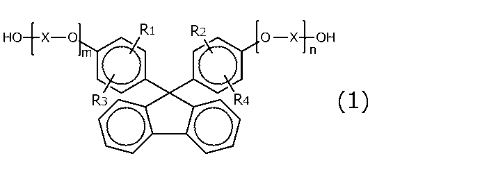
一般式(1)で表されるジヒドロキシ化合物の具体例としては、9,9-ビス(4-ヒドロキシフェニル)フルオレン、9,9-ビス(4-ヒドロキシ-3-メチルフェニル)フルオレン、9,9-ビス(4-ヒドロキシ-3-エチルフェニル)フルオレン、9,9-ビス(4-ヒドロキシ-3-n-プロピルフェニル)フルオレン、9,9-ビス(4-ヒドロキシ-3-イソプロピルフェニル)フルオレン、9,9-ビス(4-ヒドロキシ-3-n-ブチルフェニル)フルオレン、9,9-ビス(4-ヒドロキシ-3-sec-ブチルフェニル)フルオレン、9,9-ビス(4-ヒドロキシ-3-tert-ブチルフェニル)フルオレン、9,9-ビス(4-ヒドロキシ-3-シクロヘキシルフェニル)フルオレン、9,9-ビス(4-ヒドロキシ-3-フェニルフェニル)フルオレン、9,9-ビス(4-(2-ヒドロキシエトキシ)フェニル)フルオレン、9,9-ビス(4-(2-ヒドロキシエトキシ)-3-メチルフェニル)フルオレン、9,9-ビス(4-(2-ヒドロキシエトキシ)-3-イソプロピルフェニル)フルオレン、9,9-ビス(4-(2-ヒドロキシエトキシ)-3-イソブチルフェニル)フルオレン、9,9-ビス(4-(2-ヒドロキシエトキシ)-3-tert-ブチルフェニル)フルオレン、9,9-ビス(4-(2-ヒドロキシエトキシ)-3-シクロヘキシルフェニル)フルオレン、9,9-ビス(4-(2-ヒドロキシエトキシ)-3-フェニルフェニル)フルオレン、9,9-ビス(4-(2-ヒドロキシエトキシ)-3,5-ジメチルフェニル)フルオレン、9,9-ビス(4-(2-ヒドロキシエトキシ)-3-tert-ブチル-6-メチルフェニル)フルオレン、9,9-ビス(4-(3-ヒドロキシ-2,2-ジメチルプロポキシ)フェニル)フルオレン等が挙げられる。 Specific examples of dihydroxy compounds represented by general formula (1) include 9,9-bis(4-hydroxyphenyl)fluorene, 9,9-bis(4-hydroxy-3-methylphenyl)fluorene, 9,9-bis(4-hydroxy-3-ethylphenyl)fluorene, 9,9-bis(4-hydroxy-3-n-propylphenyl)fluorene, 9,9-bis(4-hydroxy-3-isopropylphenyl)fluorene, 9,9-bis(4-hydroxy-3-n-butylphenyl)fluorene, 9,9-bis(4-hydroxy-3-sec-butylphenyl)fluorene, 9,9-bis(4-hydroxy-3-tert-butylphenyl)fluorene, 9,9-bis(4-hydroxy-3-cyclohexylphenyl)fluorene, 9,9-bis(4-hydroxy-3-phenylphenyl)fluorene, 9,9-bis(4-(2-hydroxyethoxy)phenyl)fluorene, 9, 9-bis(4-(2-hydroxyethoxy)-3-methylphenyl)fluorene, 9,9-bis(4-(2-hydroxyethoxy)-3-isopropylphenyl)fluorene, 9,9-bis(4-(2-hydroxyethoxy)-3-isobutylphenyl)fluorene, 9,9-bis(4-(2-hydroxyethoxy)-3-tert-butylphenyl)fluorene, 9,9-bis(4-(2-hydroxyethoxy)-3-cyclohexyl 9,9-bis(4-(2-hydroxyethoxy)-3-phenylphenyl)fluorene, 9,9-bis(4-(2-hydroxyethoxy)-3,5-dimethylphenyl)fluorene, 9,9-bis(4-(2-hydroxyethoxy)-3-tert-butyl-6-methylphenyl)fluorene, 9,9-bis(4-(3-hydroxy-2,2-dimethylpropoxy)phenyl)fluorene, etc.
上記ポリカーボネート系樹脂は、上記ジヒドロキシ化合物に由来する構造単位の他に、イソソルビド、イソマンニド、イソイデット、スピログリコール、ジオキサングリコール、ジエチレングリコール(DEG)、トリエチレングリコール(TEG)、ポリエチレングリコール(PEG)、ビスフェノール類などのジヒドロキシ化合物に由来する構造単位を含んでいてもよい。 In addition to the structural units derived from the dihydroxy compounds, the polycarbonate resin may also contain structural units derived from dihydroxy compounds such as isosorbide, isomannide, isoidet, spiroglycol, dioxane glycol, diethylene glycol (DEG), triethylene glycol (TEG), polyethylene glycol (PEG), and bisphenols.
ジヒドロキシ化合物に由来する構造単位を含むポリカーボネート系樹脂の詳細は、例えば、特許5204200号、特開2012-67300号公報、特許第3325560号、WO2014/061677号等に記載されている。当該特許文献の記載は、本明細書に参考として援用される。 Details of polycarbonate resins containing structural units derived from dihydroxy compounds are described, for example, in Japanese Patent No. 5204200, JP 2012-67300 A, Japanese Patent No. 3325560, and WO 2014/061677. The descriptions in these patent documents are incorporated herein by reference.
1つの実施形態においては、オリゴフルオレン構造単位を含むポリカーボネート系樹脂が用いられ得る。オリゴフルオレン構造単位を含むポリカーボネート系樹脂としては、例えば、下記一般式(2)で表される構造単位および/または下記一般式(3)で表される構造単位を含む樹脂が挙げられる。

1つの実施形態においては、オリゴフルオレン構造単位に含まれるフルオレン環は、R8~R13の全てが水素原子である構成を有するか、あるいは、R8及び/又はR13がハロゲン原子、アシル基、ニトロ基、シアノ基、及びスルホ基からなる群から選ばれるいずれかであり、かつ、R9~R12が水素原子である構成を有する。 In one embodiment, the fluorene ring contained in the oligofluorene structural unit has a configuration in which all of R 8 to R 13 are hydrogen atoms, or R 8 and/or R 13 are any one selected from the group consisting of a halogen atom, an acyl group, a nitro group, a cyano group, and a sulfo group, and R 9 to R 12 are hydrogen atoms.
オリゴフルオレン構造単位を含むポリカーボネート系樹脂の詳細は、例えば、特開2015-212816号公報に記載されている。当該公報の記載は、本明細書に参考として援用される。 Details of polycarbonate-based resins containing oligofluorene structural units are described, for example, in JP 2015-212816 A. The disclosure of this publication is incorporated herein by reference.
保護層の厚みは、好ましくは15μm~60μmであり、より好ましくは25μm~45μmである。 The thickness of the protective layer is preferably 15 μm to 60 μm, and more preferably 25 μm to 45 μm.
D.ハードコート層
ハードコート層は、本発明の実施形態による効果が得られる限りにおいて、任意の適切な材料で構成され得る。ハードコート層は、例えば、任意の適切な熱硬化性樹脂または活性エネルギー線(例えば、紫外線、可視光線、電子線)硬化型樹脂の硬化層である。紫外線硬化型樹脂が好ましい。簡便な操作および高効率でハードコート層を形成することができるからである。紫外線硬化型樹脂の具体例としては、ポリエステル系、(メタ)アクリル系、ウレタン系、アミド系、シリコーン系、エポキシ系、不飽和ポリエステル系の紫外線硬化型樹脂が挙げられる。(メタ)アクリル系紫外線硬化型樹脂は、ウレタン(メタ)アクリレート、ポリエステル(メタ)アクリレート、エポキシ(メタ)アクリレートを包含する。紫外線硬化型樹脂には、紫外線硬化型のモノマー、オリゴマー、ポリマーが含まれ得る。好ましい紫外線硬化型樹脂としては、紫外線重合性の官能基を好ましくは2個以上、より好ましくは3~6個有するアクリル系のモノマー成分またはオリゴマー成分を含む樹脂組成物が挙げられる。代表的には、紫外線硬化型樹脂には、光重合開始剤が配合されている。
D. Hard Coat Layer The hard coat layer may be made of any suitable material as long as the effect of the embodiment of the present invention can be obtained. The hard coat layer is, for example, a cured layer of any suitable thermosetting resin or active energy ray (e.g., ultraviolet light, visible light, electron beam) curable resin. UV curable resin is preferred. This is because the hard coat layer can be formed with simple operation and high efficiency. Specific examples of UV curable resins include polyester-based, (meth)acrylic-based, urethane-based, amide-based, silicone-based, epoxy-based, and unsaturated polyester-based UV curable resins. (Meth)acrylic UV curable resins include urethane (meth)acrylate, polyester (meth)acrylate, and epoxy (meth)acrylate. UV curable resins may include UV curable monomers, oligomers, and polymers. Preferred UV curable resins include resin compositions containing acrylic monomers or oligomers having preferably two or more, more preferably 3 to 6, UV polymerizable functional groups. Typically, a photopolymerization initiator is blended into the UV curable resin.
ハードコート層は、好ましくはH以上、より好ましくは2H以上、さらに好ましくは3H以上の鉛筆硬度を有する。一方、ハードコート層の鉛筆硬度は、好ましくは6H以下であり、より好ましくは5H以下である。ハードコート層の鉛筆硬度がこのような範囲であれば、偏光板を画像表示装置に適用した場合に、優れた表面保護性能を付与することができる。鉛筆硬度は、JIS K 5400の「鉛筆硬度試験」に基づいて測定され得る。 The hard coat layer preferably has a pencil hardness of H or more, more preferably 2H or more, and even more preferably 3H or more. On the other hand, the pencil hardness of the hard coat layer is preferably 6H or less, and more preferably 5H or less. If the pencil hardness of the hard coat layer is in this range, excellent surface protection performance can be imparted when the polarizing plate is applied to an image display device. The pencil hardness can be measured based on the "Pencil Hardness Test" of JIS K 5400.
ハードコート層の厚みは、好ましくは5μm以下であり、より好ましくは0.5μm~4μmであり、さらに好ましくは1μm~3.5μmである。ハードコート層の厚みがこのような範囲であれば、優れた耐擦傷性を実現し得る。 The thickness of the hard coat layer is preferably 5 μm or less, more preferably 0.5 μm to 4 μm, and even more preferably 1 μm to 3.5 μm. If the thickness of the hard coat layer is in this range, excellent scratch resistance can be achieved.
ハードコート層は、任意の適切な方法により形成され得る。ハードコート層は、好ましくは、保護層上にハードコート層形成用樹脂組成物を塗工し、乾燥させ、乾燥した塗工膜に紫外線を照射して硬化させることにより形成され得る。 The hard coat layer can be formed by any suitable method. The hard coat layer can be preferably formed by coating a resin composition for forming a hard coat layer on the protective layer, drying the composition, and curing the dried coating film by irradiating it with ultraviolet light.
ハードコート層の詳細は、例えば、特開2011-237789号公報、特開2016-224443号公報に記載されている。これらの公報の記載は、本明細書に参考として援用される。 Details of the hard coat layer are described, for example, in JP 2011-237789 A and JP 2016-224443 A. The descriptions in these publications are incorporated herein by reference.
E.接着剤層
E-1.下塗り層を設けない場合
接着剤層の屈折率n2は、好ましくは1.50~1.70であり、より好ましくは1.60~1.70である。接着剤層の屈折率がこのような範囲であれば、偏光子の吸収軸方向の屈折率n1Aと接着剤層の屈折率n2との差の絶対値を上記所望の範囲とすることができる。
E. Adhesive Layer E-1. When an Undercoat Layer is Not Provided The refractive index n2 of the adhesive layer is preferably 1.50 to 1.70, and more preferably 1.60 to 1.70. When the refractive index of the adhesive layer is in this range, the absolute value of the difference between the refractive index n1A in the absorption axis direction of the polarizer and the refractive index n2 of the adhesive layer can be set to the desired range.
接着剤層を構成する接着剤としては、上記のような高い屈折率を有する任意の適切な接着剤を用いることができる。このような高い屈折率を有する接着剤は、任意の適切な接着剤に屈折率調整剤(例えば、酸化チタン)を配合することにより調製され得る。 As the adhesive constituting the adhesive layer, any suitable adhesive having a high refractive index as described above can be used. Such an adhesive having a high refractive index can be prepared by blending any suitable adhesive with a refractive index adjuster (e.g., titanium oxide).
E-2.下塗り層を設ける場合
下塗り層を設ける場合には下塗り層の屈折率n4を制御することにより、本発明の実施形態による効果が得られ得る。したがって、接着剤層の屈折率n2を精密に制御する必要はない。言い換えれば、接着剤層を構成する接着剤として、目的に応じた適切な特性を有する接着剤を用いることができる。
E-2. When an undercoat layer is provided When an undercoat layer is provided, the effect of the embodiment of the present invention can be obtained by controlling the refractive index n4 of the undercoat layer. Therefore, it is not necessary to precisely control the refractive index n2 of the adhesive layer. In other words, an adhesive having appropriate properties according to the purpose can be used as the adhesive constituting the adhesive layer.
接着剤層は、例えば、活性エネルギー線硬化型接着剤で構成され得る。活性エネルギー線硬化型接着剤としては、例えば、紫外線硬化型接着剤、電子線硬化型接着剤が挙げられる。また、硬化メカニズムの観点からは、活性エネルギー線硬化型接着剤としては、例えば、ラジカル硬化型、カチオン硬化型、アニオン硬化型、ラジカル硬化型とカチオン硬化型とのハイブリッドが挙げられる。代表的には、ラジカル硬化型の紫外線硬化型接着剤が用いられ得る。汎用性に優れ、および、特性(構成)の調整が容易だからである。 The adhesive layer may be made of, for example, an active energy ray curable adhesive. Examples of active energy ray curable adhesives include ultraviolet ray curable adhesives and electron beam curable adhesives. From the viewpoint of the curing mechanism, examples of active energy ray curable adhesives include radical curable adhesives, cationic curable adhesives, anionic curable adhesives, and hybrids of radical curable adhesives and cationic curable adhesives. Typically, a radical curable ultraviolet ray curable adhesive may be used. This is because it is highly versatile and the properties (composition) can be easily adjusted.
活性エネルギー線硬化型接着剤は、代表的には、単官能成分と多官能成分(硬化成分)と光重合開始剤とを含有する。単官能成分および多官能成分はそれぞれ、代表的には、ラジカル重合性化合物である。好ましい単官能成分としては、例えば、(メタ)アクリル酸の高級アルキルエステルおよびその変性体が挙げられる。具体例としては、イソステアリルアクリレート、ラウリルアクリレート、アクリロイルモルホリン、不飽和脂肪酸ヒドロキシアルキルエステル修飾ε-カプロラクトンが挙げられる。好ましい多官能成分としては、例えば、(メタ)アクリレート基、(メタ)アクリルアミド基などの官能基を2つ以上有するモノマーおよび/またはオリゴマーが挙げられる。具体例としては、ポリエチレングリコールジアクリレート、トリメチルプロパントリアクリレート、グリセリントリアクリレートが挙げられる。上記以外の単官能成分または多官能成分の具体例としては、トリプロピレングリコールジアクリレート、1,9-ノナンジオールジアクリレート、トリシクロデカンジメタノールジアクリレート、フェノキシジエチレングリコールアクリレート、環状トリメチロールプロパンフォルマルアクリレート、ジオキサングリコールジアクリレート、EO変性ジグリセリンテトラアクリレート、γ-ブチロラクトンアクリレート、N-メチルピロリドン、ヒドロキシエチルアクリルアミド、N-メチロールアクリルアミド、N-メトキシメチルアクリルアミド、N-エトキシメチルアクリルアミド、9-ビニルカルバゾールが挙げられる。1つの実施形態においては、単官能成分または多官能成分は、環構造を有する。具体例としては、アクリロイルモルホリン、γ-ブチロラクトンアクリレート、不飽和脂肪酸ヒドロキシアルキルエステル修飾ε-カプロラクトン、N-メチルピロリドン、9-ビニルカルバゾールが挙げられる。単官能成分または多官能成分はそれぞれ、単独で用いてもよく2種以上を併用してもよい。 The active energy ray curable adhesive typically contains a monofunctional component, a polyfunctional component (curing component), and a photopolymerization initiator. The monofunctional component and the polyfunctional component are typically radical polymerizable compounds. Preferred monofunctional components include, for example, higher alkyl esters of (meth)acrylic acid and modified products thereof. Specific examples include isostearyl acrylate, lauryl acrylate, acryloyl morpholine, and unsaturated fatty acid hydroxyalkyl ester modified ε-caprolactone. Preferred polyfunctional components include, for example, monomers and/or oligomers having two or more functional groups such as (meth)acrylate groups and (meth)acrylamide groups. Specific examples include polyethylene glycol diacrylate, trimethylpropane triacrylate, and glycerin triacrylate. Specific examples of monofunctional or polyfunctional components other than those mentioned above include tripropylene glycol diacrylate, 1,9-nonanediol diacrylate, tricyclodecane dimethanol diacrylate, phenoxydiethylene glycol acrylate, cyclic trimethylolpropane formal acrylate, dioxane glycol diacrylate, EO-modified diglycerin tetraacrylate, γ-butyrolactone acrylate, N-methylpyrrolidone, hydroxyethyl acrylamide, N-methylol acrylamide, N-methoxymethyl acrylamide, N-ethoxymethyl acrylamide, and 9-vinyl carbazole. In one embodiment, the monofunctional or polyfunctional component has a ring structure. Specific examples include acryloyl morpholine, γ-butyrolactone acrylate, unsaturated fatty acid hydroxyalkyl ester-modified ε-caprolactone, N-methylpyrrolidone, and 9-vinyl carbazole. The monofunctional or polyfunctional components may be used alone or in combination of two or more.
上記のような活性エネルギー線硬化型接着剤で構成された接着剤層の屈折率n2は、例えば1.45~1.49であり得る。 The refractive index n2 of the adhesive layer made of the above-mentioned active energy ray-curable adhesive may be, for example, 1.45 to 1.49.
接着剤層の厚みは、下塗り層の有無にかかわらず、好ましくは0.1μm~3.0μmであり、より好ましくは0.5μm~2.0μmである。 The thickness of the adhesive layer, whether or not a primer layer is present, is preferably 0.1 μm to 3.0 μm, and more preferably 0.5 μm to 2.0 μm.
F.下塗り層
下塗り層は、代表的には、水系樹脂の塗布膜の固化層である。水系樹脂の好ましい具体例としては、ウレタン系樹脂が挙げられる。したがって、下塗り層は、好ましくは、ウレタン系樹脂を含む水系分散体(下塗り剤)の塗布膜の固化層であり得る。水系は、溶剤系に比べて環境面に優れ、作業性にも優れ得る。
F. Undercoat layer The undercoat layer is typically a solidified layer of a coating film of a water-based resin. A preferred example of the water-based resin is a urethane-based resin. Therefore, the undercoat layer can preferably be a solidified layer of a coating film of a water-based dispersion (undercoat agent) containing a urethane-based resin. A water-based system is more environmentally friendly than a solvent-based system, and can also be excellent in workability.
ウレタン系樹脂は、代表的には、ポリオールとポリイソシアネートとを反応させることにより得られる。ポリオールとしては、分子中にヒドロキシル基を2個以上有するものであれば特に限定されず、任意の適切なポリオールを採用し得る。具体例としては、ポリアクリルポリオール、ポリエステルポリオール、ポリエーテルポリオールが挙げられる。これらは単独で、または2種以上を組み合わせて用い得る。 Urethane resins are typically obtained by reacting a polyol with a polyisocyanate. There are no particular limitations on the polyol, so long as it has two or more hydroxyl groups in the molecule, and any appropriate polyol can be used. Specific examples include polyacrylic polyol, polyester polyol, and polyether polyol. These can be used alone or in combination of two or more types.
ポリイソシアネートとしては、例えば、テトラメチレンジイソシアネート、ドデカメチレンジイソシアネート、1,4-ブタンジイソシアネート、ヘキサメチレンジイソシアネート、2,2,4-トリメチルヘキサメチレンジイソシアネート、2,4,4-トリメチルヘキサメチレンジイソシアネート、リジンジイソシアネート、2-メチルペンタン-1,5-ジイソシアネート、3-メチルペンタン-1,5-ジイソシアネート等の脂肪族ジイソシアネート;イソホロンジイソシアネート、水添キシリレンジイソシアネート、4,4′-シクロヘキシルメタンジイソシアネート、1,4-シクロヘキサンジイソシアネート、メチルシクロヘキシレンジイソシアネート、1,3-ビス(イソシアネートメチル)シクロヘキサン等の脂環族ジイソシアネート;トリレンジイソシアネート、2,2′-ジフェニルメタンジイソシアネート、2,4′-ジフェニルメタンジイソシアネート、4,4′-ジフェニルメタンジイソシアネート、4,4′-ジフェニルジメチルメタンジイソシアネート、4,4′-ジベンジルジイソシアネート、1,5-ナフチレンジイソシアネート、キシリレンジイソシアネート、1,3-フェニレンジイソシアネート、1,4-フェニレンジイソシアネート等の芳香族ジイソシアネート;ジアルキルジフェニルメタンジイソシアネート、テトラアルキルジフェニルメタンジイソシアネート、α,α,α,α-テトラメチルキシリレンジイソシアネート等の芳香脂肪族ジイソシアネート等が挙げられる。これらは単独で、または2種以上を組み合わせて用い得る。 Examples of polyisocyanates include aliphatic diisocyanates such as tetramethylene diisocyanate, dodecamethylene diisocyanate, 1,4-butane diisocyanate, hexamethylene diisocyanate, 2,2,4-trimethylhexamethylene diisocyanate, 2,4,4-trimethylhexamethylene diisocyanate, lysine diisocyanate, 2-methylpentane-1,5-diisocyanate, and 3-methylpentane-1,5-diisocyanate; isophorone diisocyanate, hydrogenated xylylene diisocyanate, 4,4'-cyclohexylmethane diisocyanate, 1,4-cyclohexane diisocyanate, methylcyclohexylene diisocyanate, and 1,3-bis(isocyanate methyl) cyclohexane diisocyanate. Examples of the diisocyanates include alicyclic diisocyanates such as cyclohexane; aromatic diisocyanates such as tolylene diisocyanate, 2,2'-diphenylmethane diisocyanate, 2,4'-diphenylmethane diisocyanate, 4,4'-diphenylmethane diisocyanate, 4,4'-diphenyldimethylmethane diisocyanate, 4,4'-dibenzyl diisocyanate, 1,5-naphthylene diisocyanate, xylylene diisocyanate, 1,3-phenylene diisocyanate, and 1,4-phenylene diisocyanate; and aromatic aliphatic diisocyanates such as dialkyldiphenylmethane diisocyanate, tetraalkyldiphenylmethane diisocyanate, and α,α,α,α-tetramethylxylylene diisocyanate. These may be used alone or in combination of two or more.
ウレタン系樹脂は、好ましくは、カルボキシル基を有する。カルボキシル基を有することにより、偏光子との密着性(特に、高温・高湿下における)に優れた下塗り層が得られ得る。カルボキシル基を有するウレタン系樹脂は、例えば、上記ポリオールと上記ポリイソシアネートとに加え、遊離カルボキシル基を有する鎖長剤を反応させることにより得られる。遊離カルボキシル基を有する鎖長剤としては、例えば、ジヒドロキシカルボン酸、ジヒドロキシスクシン酸が挙げられる。ジヒドロキシカルボン酸は、例えば、ジメチロールアルカン酸(例えば、ジメチロール酢酸、ジメチロールブタン酸、ジメチロールプロピオン酸、ジメチロール酪酸、ジメチロールペンタン酸)等のジアルキロールアルカン酸が挙げられる。これらは単独で、または2種以上を組み合わせて用い得る。 The urethane resin preferably has a carboxyl group. By having a carboxyl group, an undercoat layer having excellent adhesion to a polarizer (particularly under high temperature and high humidity) can be obtained. The urethane resin having a carboxyl group can be obtained, for example, by reacting the above-mentioned polyol and the above-mentioned polyisocyanate with a chain lengthening agent having a free carboxyl group. Examples of the chain lengthening agent having a free carboxyl group include dihydroxycarboxylic acid and dihydroxysuccinic acid. Examples of the dihydroxycarboxylic acid include dialkylolalkanoic acids such as dimethylolalkanoic acids (e.g., dimethylolacetic acid, dimethylolbutanoic acid, dimethylolpropionic acid, dimethylolbutyric acid, and dimethylolpentanoic acid). These can be used alone or in combination of two or more.
ウレタン系樹脂の数平均分子量は、好ましくは5000~600000であり、さらに好ましくは10000~400000である。ウレタン系樹脂の酸価は、好ましくは10以上であり、さらに好ましくは10~50であり、特に好ましくは20~45である。酸価がこのような範囲内であれば、偏光子との密着性がより優れ得る。 The number average molecular weight of the urethane resin is preferably 5,000 to 600,000, and more preferably 10,000 to 400,000. The acid value of the urethane resin is preferably 10 or more, more preferably 10 to 50, and particularly preferably 20 to 45. If the acid value is within this range, the adhesion to the polarizer can be superior.
下塗り剤は、好ましくは、架橋剤を含む。架橋剤としては、任意の適切な架橋剤を採用し得る。具体的には、ウレタン系樹脂がカルボキシル基を有する場合、架橋剤としては、好ましくは、カルボキシル基と反応し得る基を有するポリマーが挙げられる。カルボキシル基と反応し得る基としては、例えば、有機アミノ基、オキサゾリン基、エポキシ基、カルボジイミド基が挙げられる。好ましくは、架橋剤は、オキサゾリン基を有する。オキサゾリン基を有する架橋剤は、ウレタン系樹脂と混合したときの室温でのポットライフが長く、加熱することによって架橋反応が進行するため、作業性が良好である。 The undercoat agent preferably contains a crosslinking agent. Any suitable crosslinking agent may be used as the crosslinking agent. Specifically, when the urethane resin has a carboxyl group, the crosslinking agent is preferably a polymer having a group capable of reacting with the carboxyl group. Examples of the group capable of reacting with the carboxyl group include an organic amino group, an oxazoline group, an epoxy group, and a carbodiimide group. Preferably, the crosslinking agent has an oxazoline group. A crosslinking agent having an oxazoline group has a long pot life at room temperature when mixed with a urethane resin, and the crosslinking reaction proceeds by heating, so that the workability is good.
下塗り剤は、好ましくは微粒子を含まない。このような構成であれば、位相差ムラが小さい下塗り層を実現することができる。その結果、保護層の面内位相差が小さいことによる効果との相乗的な効果により、長波長の光に対する反射異方性が大きい偏光子を用いても、赤味が顕著に抑制された偏光板を実現することができる。下塗り剤は、必要に応じてレベリング剤を含み得る。レベリングを含むことにより、塗布膜の平滑性をさらに高めることができ、結果として、厚みバラツキの小さい下塗り層を形成することができる。レベリング剤としては、例えば、イソプロピルアルコール(IPA)、エチレングリコール、プロピレングリコールが挙げられる。下塗り剤中のレベリング剤の含有量は、例えば1.0重量%~3.5重量%であり得る。 The undercoat agent preferably does not contain fine particles. With this configuration, it is possible to realize an undercoat layer with small phase difference unevenness. As a result, due to the synergistic effect with the effect of the small in-plane phase difference of the protective layer, it is possible to realize a polarizing plate with significantly suppressed redness even when a polarizer with large reflection anisotropy for long wavelength light is used. The undercoat agent may contain a leveling agent as necessary. By including a leveling agent, the smoothness of the coating film can be further improved, and as a result, an undercoat layer with small thickness variation can be formed. Examples of leveling agents include isopropyl alcohol (IPA), ethylene glycol, and propylene glycol. The content of the leveling agent in the undercoat agent may be, for example, 1.0% by weight to 3.5% by weight.
下塗り剤は、好ましくは屈折率調整剤を含む。屈折率調整剤としては、代表的には高屈折率材料が挙げられる。高屈折率材料としては、例えば酸化チタンが挙げられる。屈折率調整剤の種類(したがって、屈折率)および配合量を調整することにより、所望の屈折率を有する下塗り層を形成し得る下塗り剤を得ることができる。 The undercoat preferably contains a refractive index adjuster. A representative example of the refractive index adjuster is a high refractive index material. An example of a high refractive index material is titanium oxide. By adjusting the type (and therefore the refractive index) and amount of the refractive index adjuster, it is possible to obtain an undercoat that can form an undercoat layer having the desired refractive index.
下塗り剤は、任意の適切な添加剤をさらに含み得る。添加剤としては、例えば、ブロッキング防止剤、分散安定剤、揺変剤、酸化防止剤、紫外線吸収剤、消泡剤、増粘剤、分散剤、界面活性剤、触媒、フィラー、滑剤、帯電防止剤が挙げられる。添加剤の種類、数、組み合わせ、配合量等は、目的に応じて適切に設定され得る。 The undercoat agent may further contain any suitable additives. Examples of additives include antiblocking agents, dispersion stabilizers, thixotropic agents, antioxidants, UV absorbers, defoamers, thickeners, dispersants, surfactants, catalysts, fillers, lubricants, and antistatic agents. The type, number, combination, and amount of additives may be appropriately set according to the purpose.
ウレタン系樹脂および下塗り剤の詳細については、例えば特開2010-055062号公報、特開2021-047235号公報に記載されている。当該公報の記載は、本明細書に参考として援用される。 Details of the urethane resin and the undercoat agent are described, for example, in JP 2010-055062 A and JP 2021-047235 A. The disclosures in these publications are incorporated herein by reference.
下塗り層の厚みは、好ましくは150nm~600nmであり、より好ましくは200nm~500nmであり、さらに好ましくは250nm~400nmである。このような構成であれば、保護層に下塗り層を形成する際の破断が抑制され得る。 The thickness of the undercoat layer is preferably 150 nm to 600 nm, more preferably 200 nm to 500 nm, and even more preferably 250 nm to 400 nm. With this configuration, breakage during the formation of the undercoat layer on the protective layer can be suppressed.
下塗り層の屈折率n4は、好ましくは1.50~1.70であり、より好ましくは1.60~1.70である。下塗り層の屈折率がこのような範囲であれば、偏光子の吸収軸方向の屈折率n1Aと下塗り層の屈折率n4との差の絶対値を上記所望の範囲とすることができる。 The refractive index n4 of the undercoat layer is preferably 1.50 to 1.70, and more preferably 1.60 to 1.70. When the refractive index of the undercoat layer is in this range, the absolute value of the difference between the refractive index n1A in the absorption axis direction of the polarizer and the refractive index n4 of the undercoat layer can be set to the desired range.
G.位相差層
位相差層は、上記のとおり、代表的には円偏光機能または楕円偏光機能を有する。さらに、上記のとおり、位相差層は、樹脂フィルムの延伸フィルムで構成されていてもよく、液晶配向固化層であってもよい。
G. Retardation layer As described above, the retardation layer typically has a circular polarization function or an elliptical polarization function. Furthermore, as described above, the retardation layer may be composed of a stretched film of a resin film, or may be a liquid crystal alignment solidified layer.
G-1.樹脂フィルムの延伸フィルム
位相差層が樹脂フィルムの延伸フィルムで構成されている場合、位相差層は代表的には単一層であり、いわゆるλ/4板として機能し得る。この場合、位相差層のRe(550)は、好ましくは100nm~200nmであり、より好ましくは110nm~180nmであり、さらに好ましくは120nm~160nmであり、特に好ましくは130nm~150nmである。位相差層は、好ましくはRe(450)<Re(550)の関係を満たし、好ましくはRe(550)<Re(650)の関係をさらに満たす。すなわち、位相差層は、位相差値が測定光の波長に応じて大きくなる逆分散の波長依存性を示す。位相差層のRe(450)/Re(550)は、例えば0.5を超えて1.0未満であり、好ましくは0.7~0.95であり、より好ましくは0.75~0.92であり、さらに好ましくは0.8~0.9である。Re(650)/Re(550)は、好ましくは1.0以上1.15未満であり、より好ましくは1.03~1.1である。さらに、位相差層の遅相軸と偏光子の吸収軸とのなす角度は、好ましくは40°~50°であり、より好ましくは42°~48°であり、さらに好ましくは44°~46°であり、特に好ましくは約45°である。
G-1. Stretched film of resin film When the retardation layer is composed of a stretched film of a resin film, the retardation layer is typically a single layer and can function as a so-called λ/4 plate. In this case, the Re(550) of the retardation layer is preferably 100 nm to 200 nm, more preferably 110 nm to 180 nm, even more preferably 120 nm to 160 nm, and particularly preferably 130 nm to 150 nm. The retardation layer preferably satisfies the relationship of Re(450)<Re(550), and preferably further satisfies the relationship of Re(550)<Re(650). That is, the retardation layer shows the wavelength dependency of reverse dispersion in which the retardation value increases according to the wavelength of the measurement light. The Re(450)/Re(550) of the retardation layer is, for example, more than 0.5 and less than 1.0, preferably 0.7 to 0.95, more preferably 0.75 to 0.92, and even more preferably 0.8 to 0.9. Re(650)/Re(550) is preferably 1.0 or more and less than 1.15, more preferably 1.03 to 1.1. Furthermore, the angle between the slow axis of the retardation layer and the absorption axis of the polarizer is preferably 40° to 50°, more preferably 42° to 48°, even more preferably 44° to 46°, and particularly preferably about 45°.
位相差層は、上記のように面内位相差を有するので、nx>nyの関係を有する。位相差層は、nx>nyの関係を有する限り、任意の適切な屈折率特性を示す。位相差層の屈折率特性は、代表的にはnx>ny≧nzの関係を示す。なお、ここで「ny=nz」はnyとnzが完全に等しい場合だけではなく、実質的に等しい場合を包含する。したがって、本発明の効果を損なわない範囲で、ny<nzとなる場合があり得る。位相差層のNz係数は、好ましくは0.9~2.0であり、より好ましくは0.9~1.5であり、さらに好ましくは0.9~1.2である。 Since the retardation layer has an in-plane retardation as described above, it has a relationship of nx>ny. The retardation layer exhibits any appropriate refractive index characteristics as long as it has the relationship of nx>ny. The refractive index characteristics of the retardation layer typically exhibit the relationship of nx>ny≧nz. Note that "ny=nz" here includes not only the case where ny and nz are completely equal, but also the case where they are substantially equal. Therefore, there may be cases where ny<nz as long as the effect of the present invention is not impaired. The Nz coefficient of the retardation layer is preferably 0.9 to 2.0, more preferably 0.9 to 1.5, and even more preferably 0.9 to 1.2.
位相差層の厚みは、λ/4板として最も適切に機能し得るように設定され得る。言い換えれば、厚みは、所望の面内位相差が得られるように設定され得る。具体的には、厚みは、好ましくは15μm~60μmであり、さらに好ましくは20μm~55μmであり、最も好ましくは25μm~50μmである。 The thickness of the retardation layer can be set so that it functions most appropriately as a λ/4 plate. In other words, the thickness can be set so that a desired in-plane retardation is obtained. Specifically, the thickness is preferably 15 μm to 60 μm, more preferably 20 μm to 55 μm, and most preferably 25 μm to 50 μm.
位相差層は、上記のような特性を満足し得る限りにおいて、任意の適切な材料で構成され得る。位相差層は、代表的には、カーボネート結合およびエステル結合からなる群から選択される少なくとも1つの結合基を含む樹脂を含有する。言い換えれば、位相差層は、ポリカーボネート系樹脂、ポリエステル系樹脂またはポリエステルカーボネート系樹脂を含有する。1つの実施形態においては、位相差層は、保護層に関して上記C項で説明した材料を用い、上記特性を満足するよう適切に処理(例えば、延伸処理)されたフィルムで構成され得る。1つの実施形態においては、位相差層は、ポリカーボネート系樹脂とアクリル系樹脂とのブレンドを含むフィルムで構成されていてもよい。アクリル系樹脂は、好ましくは、メタクリル酸メチル由来の構造単位を主たる構造単位として含む。位相差層におけるアクリル系樹脂の含有量は、例えば0.5質量%~2.0質量%であり得る。 The retardation layer may be made of any suitable material as long as it satisfies the above-mentioned characteristics. The retardation layer typically contains a resin containing at least one bond group selected from the group consisting of carbonate bonds and ester bonds. In other words, the retardation layer contains a polycarbonate-based resin, a polyester-based resin, or a polyestercarbonate-based resin. In one embodiment, the retardation layer may be made of a film that is appropriately treated (e.g., stretched) using the material described in section C above regarding the protective layer to satisfy the above-mentioned characteristics. In one embodiment, the retardation layer may be made of a film containing a blend of a polycarbonate-based resin and an acrylic-based resin. The acrylic-based resin preferably contains a structural unit derived from methyl methacrylate as a main structural unit. The content of the acrylic-based resin in the retardation layer may be, for example, 0.5% by mass to 2.0% by mass.
G-2.液晶配向固化層
位相差層が液晶配向固化層であれば、偏光板(位相差層付偏光板)の顕著な薄型化を図ることができる。この場合、上記のとおり、位相差層は単一層であってもよく、第1液晶配向固化層と第2液晶配向固化層との2層構造を有していてもよい。本明細書において「配向固化層」とは、液晶化合物が層内で所定の方向に配向し、その配向状態が固定されている層をいう。なお、「配向固化層」は、液晶モノマーを硬化させて得られる配向硬化層を包含する概念である。位相差層においては、代表的には、棒状の液晶化合物が位相差層の遅相軸方向に並んだ状態で配向している(ホモジニアス配向)。
G-2. Liquid crystal alignment solidified layer If the retardation layer is a liquid crystal alignment solidified layer, the polarizing plate (polarizing plate with retardation layer) can be significantly thinned. In this case, as described above, the retardation layer may be a single layer, or may have a two-layer structure of a first liquid crystal alignment solidified layer and a second liquid crystal alignment solidified layer. In this specification, the "alignment solidified layer" refers to a layer in which liquid crystal compounds are aligned in a predetermined direction within the layer and the alignment state is fixed. The "alignment solidified layer" is a concept that includes an alignment hardened layer obtained by hardening a liquid crystal monomer. In the retardation layer, typically, rod-shaped liquid crystal compounds are aligned in the slow axis direction of the retardation layer (homogeneous alignment).
G-2-1.単一層
液晶配向固化層が単一層である場合の特性は、厚み以外は樹脂フィルムの延伸フィルムに関してG-1項で説明したとおりである。液晶配向固化層が単一層である場合の厚みは、例えば1.0μm~5.0μmであり得、また例えば1.0μm~3.0μmであり得る。
G-2-1. Single layer When the liquid crystal alignment solidified layer is a single layer, the characteristics are as described in G-1 for the stretched film of the resin film, except for the thickness. When the liquid crystal alignment solidified layer is a single layer, the thickness can be, for example, 1.0 μm to 5.0 μm, or, for example, 1.0 μm to 3.0 μm.
本実施形態の位相差層を構成する液晶化合物の具体例は、例えば、特開2006-163343号公報、特開2006-178389号公報、国際公開第2018/123551号公報に記載されている。これらの公報の記載は本明細書に参考として援用される。 Specific examples of the liquid crystal compound constituting the retardation layer of this embodiment are described in, for example, JP 2006-163343 A, JP 2006-178389 A, and WO 2018/123551 A. The descriptions in these publications are incorporated herein by reference.
G-2-2.第1液晶配向固化層と第2液晶配向固化層との2層構造
位相差層が偏光子側から第1液晶配向固化層と第2液晶配向固化層との2層構造を有する場合、第1液晶配向固化層は、代表的にはλ/2板として機能し得、第2液晶配向固化層は、代表的にはλ/4板として機能し得る。具体的には、第1液晶配向固化層のRe(550)は好ましくは200nm~300nmであり、より好ましくは230nm~290nmであり、さらに好ましくは250nm~280nmであり;第2液晶配向固化層のRe(550)は、樹脂フィルムの延伸フィルムに関してG-1項で説明したとおりである。第1液晶配向固化層の厚みは、λ/2板の所望の面内位相差が得られるよう調整され得る。具体的には、その厚みは例えば2.0μm~4.0μmであり得る。第2液晶配向固化層の厚みは、λ/4板の所望の面内位相差が得られるよう調整され得る。具体的には、その厚みは例えば1.0μm~2.5μmであり得る。本実施形態においては、第1液晶配向固化層の遅相軸と偏光子の吸収軸とのなす角度は、好ましくは10°~20°であり、より好ましくは12°~18°であり、さらに好ましくは14°~16°であり;第2液晶配向固化層の遅相軸と偏光子の吸収軸とのなす角度は、好ましくは70°~80°であり、より好ましくは72°~78°であり、さらに好ましくは74°~76°である。なお、第1液晶配向固化層および第2液晶配向固化層の配置順序は逆であってもよく、第1液晶配向固化層の遅相軸と偏光子の吸収軸とのなす角度および第2液晶配向固化層の遅相軸と偏光子の吸収軸とのなす角度は逆であってもよい。第1液晶配向固化層および第2液晶配向固化層は、位相差値が測定光の波長に応じて大きくなる逆分散波長特性を示してもよく、位相差値が測定光の波長に応じて小さくなる正の波長分散特性を示してもよく、位相差値が測定光の波長によってもほとんど変化しないフラットな波長分散特性を示してもよい。
G-2-2. Two-layer structure of first liquid crystal alignment solidified layer and second liquid crystal alignment solidified layer When the retardation layer has a two-layer structure of a first liquid crystal alignment solidified layer and a second liquid crystal alignment solidified layer from the polarizer side, the first liquid crystal alignment solidified layer can typically function as a λ/2 plate, and the second liquid crystal alignment solidified layer can typically function as a λ/4 plate. Specifically, the Re(550) of the first liquid crystal alignment solidified layer is preferably 200 nm to 300 nm, more preferably 230 nm to 290 nm, and even more preferably 250 nm to 280 nm; the Re(550) of the second liquid crystal alignment solidified layer is as described in section G-1 regarding the stretched film of the resin film. The thickness of the first liquid crystal alignment solidified layer can be adjusted so that the desired in-plane retardation of the λ/2 plate is obtained. Specifically, the thickness can be, for example, 2.0 μm to 4.0 μm. The thickness of the second liquid crystal alignment solidified layer can be adjusted so as to obtain a desired in-plane retardation of the λ/4 plate. Specifically, the thickness can be, for example, 1.0 μm to 2.5 μm. In this embodiment, the angle between the slow axis of the first liquid crystal alignment solidified layer and the absorption axis of the polarizer is preferably 10° to 20°, more preferably 12° to 18°, and even more preferably 14° to 16°; the angle between the slow axis of the second liquid crystal alignment solidified layer and the absorption axis of the polarizer is preferably 70° to 80°, more preferably 72° to 78°, and even more preferably 74° to 76°. The arrangement order of the first liquid crystal alignment solidified layer and the second liquid crystal alignment solidified layer may be reversed, and the angle between the slow axis of the first liquid crystal alignment solidified layer and the absorption axis of the polarizer and the angle between the slow axis of the second liquid crystal alignment solidified layer and the absorption axis of the polarizer may be reversed. The first liquid crystal alignment solidified layer and the second liquid crystal alignment solidified layer may exhibit an inverse dispersion wavelength characteristic in which the retardation value increases depending on the wavelength of the measurement light, may exhibit a positive wavelength dispersion characteristic in which the retardation value decreases depending on the wavelength of the measurement light, or may exhibit a flat wavelength dispersion characteristic in which the retardation value changes very little depending on the wavelength of the measurement light.
本実施形態の位相差層は、例えば、任意の適切な液晶モノマーを含む組成物を用いて形成される。液晶モノマーとしては、例えば、特表2002-533742(WO00/37585)、EP358208(US5211877)、EP66137(US4388453)、WO93/22397、EP0261712、DE19504224、DE4408171、およびGB2280445等に記載の重合性メソゲン化合物等が使用できる。このような重合性メソゲン化合物の具体例としては、例えば、BASF社の商品名LC242、Merck社の商品名E7、Wacker-Chem社の商品名LC-Sillicon-CC3767が挙げられる。液晶モノマーとしては、例えばネマチック性液晶モノマーが好ましい。 The retardation layer of this embodiment is formed, for example, using a composition containing any suitable liquid crystal monomer. As the liquid crystal monomer, for example, polymerizable mesogen compounds described in JP-A-2002-533742 (WO00/37585), EP358208 (US5211877), EP66137 (US4388453), WO93/22397, EP0261712, DE19504224, DE4408171, GB2280445, etc. can be used. Specific examples of such polymerizable mesogen compounds include BASF's product name LC242, Merck's product name E7, and Wacker-Chem's product name LC-Sillicon-CC3767. As the liquid crystal monomer, for example, a nematic liquid crystal monomer is preferable.
H.画像表示装置
上記A項~G項に記載の偏光板は、画像表示装置に適用され得る。したがって、本発明の実施形態は、そのような偏光板を用いた画像表示装置も包含する。画像表示装置の代表例としては、液晶表示装置、有機EL表示装置が挙げられる。本発明の実施形態による画像表示装置は、代表的には、その視認側に上記A項~G項に記載の偏光板を備える。偏光板は、保護層30が視認側となるようにして配置される。
H. Image display device The polarizing plate described in the above items A to G can be applied to an image display device. Therefore, the embodiment of the present invention also includes an image display device using such a polarizing plate. Representative examples of image display devices include liquid crystal display devices and organic EL display devices. The image display device according to the embodiment of the present invention typically includes the polarizing plate described in the above items A to G on the viewing side. The polarizing plate is disposed so that the
以下、実施例によって本発明を具体的に説明するが、本発明はこれら実施例によって限定されるものではない。実施例における評価項目および測定方法は以下のとおりである。 The present invention will be specifically described below with reference to examples, but the present invention is not limited to these examples. The evaluation items and measurement methods in the examples are as follows.
(1)屈折率
接着剤層の屈折率については、接着剤層を構成する接着剤で単一膜のサンプルを作製し、当該サンプルの屈折率を、多波長アッベ屈折率計(アタゴ社製)を用いて測定した。
偏光子の吸収軸方向の屈折率n1Aおよび吸収軸に直交する方向の屈折率n1Tは、以下のように測定および算出した。実施例および比較例で得られた樹脂基材/偏光子の構成を有する偏光板から、粘着剤層が設けられた黒板の粘着剤層表面に偏光子を転写し、試験サンプルを得た。この試験サンプルを用いて、偏光子単体の吸収軸方向の反射率RSAおよび吸収軸に直交する方向の反射率RSTを、分光光度計(日立製作所社製、U-4100)を用いて測定した。RSAは、分光光度計の光源からの直線偏光の振動方向と吸収軸方向とを平行としたときの反射率であり;RSTは、分光光度計の光源からの直線偏光の振動方向と吸収軸方向とを直交としたときの反射率である。式(I)および(II)を用いてRSAおよびRSTからn1Aおよびn1Tを算出した。なお、測定波長は700nmであった。
RSA=(1-n1A)2/(1+n1A)2 ・・・(I)
RST=(1-n1T)2/(1+n1T)2 ・・・(II)
(1) Refractive Index Regarding the refractive index of the adhesive layer, a single film sample was prepared from the adhesive constituting the adhesive layer, and the refractive index of the sample was measured using a multi-wavelength Abbe refractometer (manufactured by Atago Co., Ltd.).
The refractive index n 1A in the absorption axis direction of the polarizer and the refractive index n 1T in the direction perpendicular to the absorption axis were measured and calculated as follows. From the polarizing plate having the resin substrate/polarizer configuration obtained in the Examples and Comparative Examples, the polarizer was transferred to the surface of the adhesive layer of a blackboard on which an adhesive layer was provided, to obtain a test sample. Using this test sample, the reflectance RSA in the absorption axis direction of the polarizer alone and the reflectance RST in the direction perpendicular to the absorption axis were measured using a spectrophotometer (U-4100, manufactured by Hitachi, Ltd.). RSA is the reflectance when the vibration direction of the linearly polarized light from the light source of the spectrophotometer is parallel to the absorption axis direction; RST is the reflectance when the vibration direction of the linearly polarized light from the light source of the spectrophotometer is perpendicular to the absorption axis direction. n 1A and n 1T were calculated from RSA and RST using formulas (I) and (II). The measurement wavelength was 700 nm.
R SA = (1-n 1A ) 2 / (1+n 1A ) 2 ...(I)
R ST = (1-n 1T ) 2 / (1+n 1T ) 2 ...(II)
(2)面内位相差Re(550)
実施例および比較例で用いた保護層を構成する樹脂フィルムについて、Axoscan(Axometrics社製)を用いて測定した。
(2) In-plane phase difference Re (550)
The resin films constituting the protective layers used in the examples and comparative examples were measured using an Axoscan (manufactured by Axometrics).
(3)反射率
実施例および比較例で得られた偏光板を、アクリル系粘着剤を介して黒板に貼り合わせて測定サンプルとした。測定サンプルの偏光子の吸収軸方向の反射率RPAおよび吸収軸に直交する方向の反射率RPTを、上記(1)と同様にして、分光光度計(日立製作所社製、U-4100)を用いて測定した。
(3) Reflectance The polarizing plates obtained in the Examples and Comparative Examples were attached to a blackboard via an acrylic adhesive to prepare measurement samples. The reflectance R PA in the absorption axis direction of the polarizer of the measurement sample and the reflectance R PT in the direction perpendicular to the absorption axis were measured using a spectrophotometer (U-4100, manufactured by Hitachi, Ltd.) in the same manner as in (1) above.
(4)反射色相
上記(3)と同様にして作成した測定サンプルについて、分光測色計・色彩色差計(コニカミノルタ社製、CM-26d)を用いて測定した。
(4) Reflection Hue A measurement sample prepared in the same manner as in (3) above was measured using a spectrophotometer/colorimeter (CM-26d, manufactured by Konica Minolta).
(5)赤味
上記(3)と同様にして作成した測定サンプルについて、色味を目視により確認し、以下の基準で評価した。
良好:赤味は認識されなかった
不良:赤味が認識された
(5) Redness The color of the measurement sample prepared in the same manner as in (3) above was visually observed and evaluated according to the following criteria.
Good: No redness was recognized. Bad: Redness was recognized.
[製造例1:偏光板の作製]
熱可塑性樹脂基材として、長尺状で、Tg約75℃である、非晶質のイソフタル共重合ポリエチレンテレフタレートフィルム(厚み:100μm)を用い、樹脂基材の片面に、コロナ処理を施した。
ポリビニルアルコール(重合度4200、ケン化度99.2モル%)およびアセトアセチル変性PVA(日本合成化学工業社製、商品名「ゴーセファイマー」)を9:1で混合したPVA系樹脂100重量部に、ヨウ化カリウム13重量部を添加したものを水に溶かし、PVA水溶液(塗布液)を調製した。
樹脂基材のコロナ処理面に、上記PVA水溶液を塗布して60℃で乾燥することにより、厚み13μmのPVA系樹脂層を形成し、積層体を作製した。
得られた積層体を、130℃のオーブン内で縦方向(長手方向)に2.4倍に一軸延伸した(空中補助延伸処理)。
次いで、積層体を、液温40℃の不溶化浴(水100重量部に対して、ホウ酸を4重量部配合して得られたホウ酸水溶液)に30秒間浸漬させた(不溶化処理)。
次いで、液温30℃の染色浴(水100重量部に対して、ヨウ素とヨウ化カリウムを1:7の重量比で配合して得られたヨウ素水溶液)に、最終的に得られる偏光子の単体透過率(Ts)が所望の値となるように濃度を調整しながら60秒間浸漬させた(染色処理)。
次いで、液温40℃の架橋浴(水100重量部に対して、ヨウ化カリウムを3重量部配合し、ホウ酸を5重量部配合して得られたホウ酸水溶液)に30秒間浸漬させた(架橋処理)。
その後、積層体を、液温70℃のホウ酸水溶液(ホウ酸濃度4重量%、ヨウ化カリウム濃度5重量%)に浸漬させながら、周速の異なるロール間で縦方向(長手方向)に総延伸倍率が5.5倍となるように一軸延伸を行った(水中延伸処理)。
その後、積層体を液温20℃の洗浄浴(水100重量部に対して、ヨウ化カリウムを4重量部配合して得られた水溶液)に浸漬させた(洗浄処理)。
その後、約90℃に保たれたオーブン中で乾燥しながら、表面温度が約75℃に保たれたSUS製の加熱ロールに接触させた(乾燥収縮処理)。
このようにして、樹脂基材上に厚み約5μmの偏光子を形成し、樹脂基材/偏光子の構成を有する偏光板を得た。偏光子の単体透過率Tsは42.6%および偏光度Pは99.99%であった。また、この偏光子の吸収軸方向の屈折率n1Aは1.70であり、吸収軸に直交する方向の屈折率n1Tは1.52であった。さらに、偏光子の波長700nmにおける吸収軸方向の反射率RSAは6.7%であり、吸収軸に直交する方向の反射率RSTは4.3%であり、RSAとRSTとの差は2.4%であった。
[Production Example 1: Preparation of Polarizing Plate]
As a thermoplastic resin substrate, a long amorphous isophthalic copolymerized polyethylene terephthalate film (thickness: 100 μm) having a Tg of about 75° C. was used, and one side of the resin substrate was subjected to a corona treatment.
A PVA aqueous solution (coating solution) was prepared by adding 13 parts by weight of potassium iodide to 100 parts by weight of a PVA-based resin prepared by mixing polyvinyl alcohol (polymerization degree 4,200, saponification degree 99.2 mol%) and acetoacetyl-modified PVA (manufactured by Nippon Synthetic Chemical Industry Co., Ltd., product name "GOHSEFFIMER") in a ratio of 9:1. The resulting mixture was dissolved in water.
The above PVA aqueous solution was applied to the corona-treated surface of a resin substrate and dried at 60° C. to form a PVA-based resin layer having a thickness of 13 μm, thereby producing a laminate.
The obtained laminate was uniaxially stretched 2.4 times in the machine direction (longitudinal direction) in an oven at 130° C. (auxiliary in-air stretching treatment).
Next, the laminate was immersed in an insolubilizing bath (a boric acid aqueous solution obtained by mixing 4 parts by weight of boric acid with 100 parts by weight of water) at a liquid temperature of 40° C. for 30 seconds (insolubilizing treatment).
Next, the film was immersed in a dye bath (an aqueous iodine solution obtained by mixing iodine and potassium iodide in a weight ratio of 1:7 with 100 parts by weight of water) having a liquid temperature of 30° C. for 60 seconds while adjusting the concentration so that the single transmittance (Ts) of the finally obtained polarizer would have a desired value (dyeing treatment).
Next, the plate was immersed in a crosslinking bath (a boric acid aqueous solution obtained by mixing 3 parts by weight of potassium iodide and 5 parts by weight of boric acid with 100 parts by weight of water) at a liquid temperature of 40° C. for 30 seconds (crosslinking treatment).
Thereafter, the laminate was immersed in an aqueous boric acid solution (boric acid concentration: 4 wt %, potassium iodide concentration: 5 wt %) at a liquid temperature of 70° C., and uniaxially stretched in the longitudinal direction (longitudinal direction) between rolls with different peripheral speeds to a total stretch ratio of 5.5 times (underwater stretching treatment).
Thereafter, the laminate was immersed in a cleaning bath (an aqueous solution obtained by mixing 4 parts by weight of potassium iodide with 100 parts by weight of water) at a liquid temperature of 20° C. (cleaning treatment).
Thereafter, the film was dried in an oven maintained at about 90° C., while being brought into contact with a SUS heated roll whose surface temperature was maintained at about 75° C. (drying shrinkage treatment).
In this way, a polarizer with a thickness of about 5 μm was formed on the resin substrate, and a polarizing plate having a resin substrate/polarizer configuration was obtained. The single transmittance Ts of the polarizer was 42.6% and the polarization degree P was 99.99%. In addition, the refractive index n 1A of this polarizer in the absorption axis direction was 1.70, and the refractive index n 1T in the direction perpendicular to the absorption axis was 1.52. Furthermore, the reflectance RSA of the polarizer in the absorption axis direction at a wavelength of 700 nm was 6.7%, the reflectance RST in the direction perpendicular to the absorption axis was 4.3%, and the difference between RSA and RST was 2.4%.
[製造例2:保護層を構成する樹脂フィルムの作製]
撹拌翼および100℃に制御された還流冷却器を具備した縦型反応器2器からなるバッチ重合装置を用いて重合を行った。ビス[9-(2-フェノキシカルボニルエチル)フルオレン-9-イル]メタン(化合物3)29.60質量部(0.046mol)、ISB 29.21質量部(0.200mol)、SPG 42.28質量部(0.139mol)、DPC 63.77質量部(0.298mol)及び触媒として酢酸カルシウム1水和物1.19×10⁻²質量部(6.78×10⁻⁵mol)を仕込んだ。反応器内を減圧窒素置換した後、熱媒で加温を行い、内温が100℃になった時点で撹拌を開始した。昇温開始40分後に内温を220℃に到達させ、この温度を保持するように制御すると同時に減圧を開始し、220℃に到達してから90分で13.3kPaにした。重合反応とともに副生するフェノール蒸気を100℃の還流冷却器に導き、フェノール蒸気中に若干量含まれるモノマー成分を反応器に戻し、凝縮しないフェノール蒸気は45℃の凝縮器に導いて回収した。第1反応器に窒素を導入して一旦大気圧まで復圧させた後、第1反応器内のオリゴマー化された反応液を第2反応器に移した。次いで、第2反応器内の昇温および減圧を開始して、50分で内温240℃、圧力0.2kPaにした。その後、所定の攪拌動力となるまで重合を進行させた。所定動力に到達した時点で反応器に窒素を導入して復圧し、生成したポリエステルカーボネートを水中に押し出し、ストランドをカッティングしてペレットを得た。
得られたポリカーボネート樹脂を80℃で5時間真空乾燥をした後、単軸押出機(東芝機械社製、シリンダー設定温度:250℃)、Tダイ(幅300mm、設定温度:250℃)、チルロール(設定温度:120~130℃)および巻取機を備えたフィルム製膜装置を用いて、厚み13μmのポリカーボネート系樹脂フィルムを作製した。得られたポリカーボネート系樹脂フィルムの面内位相差Re(550)は1nmであった。最後に、ポリカーボネート系樹脂フィルムの一方の表面にハードコート層(厚み2μm)を形成した。
[Production Example 2: Preparation of resin film constituting protective layer]
Polymerization was carried out using a batch polymerization apparatus consisting of two vertical reactors equipped with stirring blades and a reflux condenser controlled at 100°C. 29.60 parts by mass (0.046 mol) of bis[9-(2-phenoxycarbonylethyl)fluoren-9-yl]methane (compound 3), 29.21 parts by mass (0.200 mol), 42.28 parts by mass (0.139 mol) of SPG, 63.77 parts by mass (0.298 mol) of DPC, and 1.19 x 10 -2 parts by mass (6.78 x 10 -5 mol) of calcium acetate monohydrate as a catalyst were charged. After the inside of the reactor was replaced with nitrogen under reduced pressure, it was heated with a heat medium, and stirring was started when the inside temperature reached 100°C. The internal temperature was allowed to reach 220°
The obtained polycarbonate resin was vacuum-dried at 80°C for 5 hours, and then a polycarbonate-based resin film having a thickness of 13 μm was produced using a film-forming device equipped with a single-screw extruder (manufactured by Toshiba Machine Co., Ltd., cylinder set temperature: 250°C), a T-die (width 300 mm, set temperature: 250°C), a chill roll (set temperature: 120 to 130°C) and a winder. The in-plane retardation Re (550) of the obtained polycarbonate-based resin film was 1 nm. Finally, a hard coat layer (thickness 2 μm) was formed on one surface of the polycarbonate-based resin film.
[製造例3-1:接着剤層を構成する接着剤の調製]
不飽和脂肪酸ヒドロキシアルキルエステル修飾ε-カプロラクトン(ダイセル社製、プラクセルFA1DDM)61.5質量部、アクリロイルモルホリン(KJケミカルズ社製、ACMO)30.8重量部、ポリエチレングリコールジアクリレート(共栄社化学社製、ライトアクリレート9EG-A)7.7重量部、アクリル系オリゴマー(東亞合成社製、ARUFON UP-1190)15.3重量部、および、ラジカル重合開始剤7.0重量部を混合して、紫外線硬化型接着剤Aを調製した。接着剤Aの硬化後の屈折率は1.49であった。
[Production Example 3-1: Preparation of Adhesive Constituting Adhesive Layer]
An ultraviolet-curable adhesive A was prepared by mixing 61.5 parts by mass of unsaturated fatty acid hydroxyalkyl ester-modified ε-caprolactone (manufactured by Daicel Corporation, Plaxel FA1DDM), 30.8 parts by weight of acryloylmorpholine (manufactured by KJ Chemicals, ACMO), 7.7 parts by weight of polyethylene glycol diacrylate (manufactured by Kyoeisha Chemical Co., Ltd., Light Acrylate 9EG-A), 15.3 parts by weight of an acrylic oligomer (manufactured by Toagosei Co., Ltd., ARUFON UP-1190), and 7.0 parts by weight of a radical polymerization initiator. The refractive index of adhesive A after curing was 1.49.
[製造例3-2:接着剤層を構成する接着剤の調製]
紫外線硬化型接着剤Aに屈折率調整剤(酸化チタン、堺化学工業社製「A-190」)を用いて、硬化後の屈折率が1.53となる紫外線硬化型接着剤Bを調製した。
[Production Example 3-2: Preparation of Adhesive Constituting Adhesive Layer]
A refractive index adjuster (titanium oxide, "A-190" manufactured by Sakai Chemical Industry Co., Ltd.) was added to the ultraviolet-curable adhesive A to prepare an ultraviolet-curable adhesive B having a refractive index of 1.53 after curing.
[製造例3-3:接着剤層を構成する接着剤の調製]
紫外線硬化型接着剤Aに屈折率調整剤(酸化チタン、堺化学工業社製「A-190」)を用いて、硬化後の屈折率が1.60となる紫外線硬化型接着剤Cを調製した。
[Production Example 3-3: Preparation of Adhesive Constituting Adhesive Layer]
A refractive index adjuster (titanium oxide, "A-190" manufactured by Sakai Chemical Industry Co., Ltd.) was added to the ultraviolet-curable adhesive A to prepare an ultraviolet-curable adhesive C having a refractive index of 1.60 after curing.
[製造例4-1:下塗り層を構成する下塗り剤の調製]
ポリエステルウレタン(第一工業製薬製、商品名:スーパーフレックス210、固形分:33%)16.8重量部、架橋剤(オキサゾリン含有ポリマー、日本触媒製、商品名:エポクロスWS-700、固形分:25%)4.2重量部、および1重量%のアンモニア水2.0重量部を混合し、純水およびイソプロピルアルコール(IPA、レベリング剤)を加えて固形分濃度を1重量%に、IPA濃度を2.5重量%に調整し、下塗り剤Xを調製した。下塗り剤Xから形成される下塗り層の屈折率は1.51であった。
[Production Example 4-1: Preparation of undercoat agent constituting undercoat layer]
Undercoat agent X was prepared by mixing 16.8 parts by weight of polyester urethane (manufactured by Daiichi Kogyo Seiyaku, product name: Superflex 210, solids content: 33%), 4.2 parts by weight of a crosslinker (oxazoline-containing polymer, manufactured by Nippon Shokubai, product name: Epocross WS-700, solids content: 25%), and 2.0 parts by weight of 1 wt% ammonia water, and adding pure water and isopropyl alcohol (IPA, leveling agent) to adjust the solids concentration to 1 wt% and the IPA concentration to 2.5 wt%. The refractive index of the undercoat layer formed from undercoat agent X was 1.51.
[製造例4-2:下塗り層を構成する下塗り剤の調製]
下塗り剤Xに屈折率調整剤(酸化チタン、堺化学工業社製「A-190」)を用いて、得られる下塗り層の屈折率が1.60となる下塗り剤Yを調製した。
[Production Example 4-2: Preparation of undercoat agent constituting undercoat layer]
A refractive index adjuster (titanium oxide, "A-190" manufactured by Sakai Chemical Industry Co., Ltd.) was used in Primer X to prepare Primer Y, which would give a refractive index of the resulting primer layer of 1.60.
[製造例4-3:下塗り層を構成する下塗り剤の調製]
下塗り剤Xに屈折率調整剤(酸化チタン、堺化学工業社製「A-190」)を用いて、得られる下塗り層の屈折率が1.70となる下塗り剤Zを調製した。
[Production Example 4-3: Preparation of undercoat agent constituting undercoat layer]
A refractive index adjuster (titanium oxide, "A-190" manufactured by Sakai Chemical Industry Co., Ltd.) was used in Primer X to prepare Primer Z, which would give a refractive index of the resulting primer layer of 1.70.
[実施例1]
製造例2で得られたポリカーボネート系樹脂フィルムのハードコート(HC)層が形成されていない表面に製造例4-1の下塗り剤Xを塗布および乾燥して下塗り層を形成し、HC層/ポリカーボネート系樹脂フィルム/下塗り層の積層体を得た。製造例3-1の接着剤A(硬化後の厚み1μm)を介して、製造例1で得られた樹脂基材/偏光子の積層体の偏光子側に、積層体の下塗り層を貼り合わせた。最後に、樹脂基材を剥離除去し、HC層/ポリカーボネート系樹脂フィルム(保護層)/下塗り層/接着剤層/偏光子の構成を有する偏光板を得た。得られた偏光板を上記(3)~(5)の評価に供した。結果を表1に示す。
[Example 1]
The undercoat agent X of Production Example 4-1 was applied to the surface of the polycarbonate-based resin film obtained in Production Example 2 on which the hard coat (HC) layer was not formed, and dried to form an undercoat layer, thereby obtaining a laminate of HC layer/polycarbonate-based resin film/undercoat layer. The undercoat layer of the laminate was attached to the polarizer side of the laminate of the resin substrate/polarizer obtained in Production Example 1 via the adhesive A of Production Example 3-1 (thickness after curing: 1 μm). Finally, the resin substrate was peeled off and removed to obtain a polarizing plate having a configuration of HC layer/polycarbonate-based resin film (protective layer)/undercoat layer/adhesive layer/polarizer. The obtained polarizing plate was subjected to the above evaluations (3) to (5). The results are shown in Table 1.
[実施例2~5、比較例1~2]
接着剤層および下塗り層を表1に示すように組み合わせたこと以外は実施例1と同様にして偏光板を作製した。得られた偏光板を実施例1と同様の評価に供した。結果を表1に示す。
[Examples 2 to 5, Comparative Examples 1 to 2]
A polarizing plate was produced in the same manner as in Example 1, except that the adhesive layer and the undercoat layer were combined as shown in Table 1. The obtained polarizing plate was subjected to the same evaluation as in Example 1. The results are shown in Table 1.
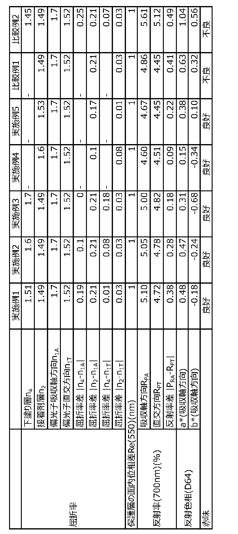
[評価]
表1から明らかなように、本発明の実施例によれば、長波長の光に対する反射異方性が大きい偏光子を用いるにもかかわらず、赤味が抑制された偏光板を実現することができる。
[evaluation]
As is clear from Table 1, according to the examples of the present invention, a polarizing plate in which redness is suppressed can be realized despite the use of a polarizer having large reflection anisotropy for light with long wavelengths.
本発明の実施形態による偏光板は画像表示装置(代表的には、液晶表示装置、有機EL表示装置)に好適に用いられ得る。 The polarizing plate according to the embodiment of the present invention can be suitably used in image display devices (typically, liquid crystal display devices and organic EL display devices).
10 偏光子
20 接着剤層
30 保護層
40 下塗り層
100 偏光板
101 偏光板
REFERENCE SIGNS
Claims (9)
該偏光子の吸収軸方向の屈折率n1Aと該接着剤層の屈折率n2との差の絶対値が0.20以下であり、
該偏光子の波長700nmにおける吸収軸方向の反射率RSAと吸収軸に直交する方向の反射率RSTとの差が0.5%以上であり、
該偏光板の波長700nmにおける偏光子の吸収軸方向の反射率RPAと吸収軸に直交する方向の反射率RPTとの差が0.40%以下である、
偏光板。 A polarizing plate having a polarizer made of a polyvinyl alcohol-based resin film containing iodine and a protective layer laminated on the polarizer via an adhesive layer,
an absolute value of a difference between a refractive index n1A of the polarizer in the absorption axis direction and a refractive index n2 of the adhesive layer is 0.20 or less;
the difference between the reflectance R SA in the absorption axis direction and the reflectance R ST in the direction perpendicular to the absorption axis at a wavelength of 700 nm of the polarizer is 0.5% or more;
The difference between the reflectance R PA in the absorption axis direction of the polarizer of the polarizing plate at a wavelength of 700 nm and the reflectance R PT in the direction perpendicular to the absorption axis is 0.40% or less.
Polarizing plate.
該偏光子の吸収軸方向の屈折率n1Aと該下塗り層の屈折率n4との差の絶対値が0.20以下であり、
該偏光子の波長700nmにおける吸収軸方向の反射率RSAと吸収軸に直交する方向の反射率RSTとの差が0.5%以上であり、
該偏光板の波長700nmにおける偏光子の吸収軸方向の反射率RPAと吸収軸に直交する方向の反射率RPTとの差が0.40%以下である、
偏光板。 A polarizing plate including a polarizer made of a polyvinyl alcohol-based resin film containing iodine, a protective layer laminated on the polarizer via an adhesive layer, and an undercoat layer provided between the adhesive layer and the protective layer,
an absolute value of a difference between a refractive index n1A of the polarizer in the absorption axis direction and a refractive index n4 of the undercoat layer is 0.20 or less;
the difference between the reflectance R SA in the absorption axis direction and the reflectance R ST in the direction perpendicular to the absorption axis at a wavelength of 700 nm of the polarizer is 0.5% or more;
The difference between the reflectance R PA in the absorption axis direction of the polarizer of the polarizing plate at a wavelength of 700 nm and the reflectance R PT in the direction perpendicular to the absorption axis is 0.40% or less.
Polarizing plate.
An image display device comprising the polarizing plate according to claim 7 .
Priority Applications (4)
| Application Number | Priority Date | Filing Date | Title |
|---|---|---|---|
| JP2022129979A JP7557504B2 (en) | 2022-08-17 | 2022-08-17 | Polarizing plate and image display device using the same |
| TW112120532A TWI859902B (en) | 2022-08-17 | 2023-06-01 | Polarizing plate and image display device using the same |
| KR1020230093746A KR20240024738A (en) | 2022-08-17 | 2023-07-19 | Polarizing plate, and image display device using said polarizing plate |
| CN202310922675.0A CN117590509A (en) | 2022-08-17 | 2023-07-26 | Polarizing plate and image display device using the polarizing plate |
Applications Claiming Priority (1)
| Application Number | Priority Date | Filing Date | Title |
|---|---|---|---|
| JP2022129979A JP7557504B2 (en) | 2022-08-17 | 2022-08-17 | Polarizing plate and image display device using the same |
Publications (2)
| Publication Number | Publication Date |
|---|---|
| JP2024027295A JP2024027295A (en) | 2024-03-01 |
| JP7557504B2 true JP7557504B2 (en) | 2024-09-27 |
Family
ID=89910371
Family Applications (1)
| Application Number | Title | Priority Date | Filing Date |
|---|---|---|---|
| JP2022129979A Active JP7557504B2 (en) | 2022-08-17 | 2022-08-17 | Polarizing plate and image display device using the same |
Country Status (4)
| Country | Link |
|---|---|
| JP (1) | JP7557504B2 (en) |
| KR (1) | KR20240024738A (en) |
| CN (1) | CN117590509A (en) |
| TW (1) | TWI859902B (en) |
Citations (4)
| Publication number | Priority date | Publication date | Assignee | Title |
|---|---|---|---|---|
| JP2018151603A (en) | 2017-03-15 | 2018-09-27 | 日東電工株式会社 | Polarizer |
| JP2019107830A (en) | 2017-12-19 | 2019-07-04 | 日立化成株式会社 | Manufacturing method of decorative glass member |
| WO2019151334A1 (en) | 2018-01-30 | 2019-08-08 | 富士フイルム株式会社 | Polarization plate, circular polarization plate, and display device |
| JP2020086237A (en) | 2018-11-28 | 2020-06-04 | 日東電工株式会社 | Polarizing plate with surface protection film |
Family Cites Families (7)
| Publication number | Priority date | Publication date | Assignee | Title |
|---|---|---|---|---|
| JP5834880B2 (en) | 2011-12-19 | 2015-12-24 | コニカミノルタ株式会社 | Polarizing plate and liquid crystal display device using the same |
| JP5615987B2 (en) * | 2013-02-07 | 2014-10-29 | 日東電工株式会社 | Optical laminate having polarizing film |
| WO2018225741A1 (en) * | 2017-06-07 | 2018-12-13 | 日東電工株式会社 | Optical member, image display device, and method for manufacturing optical member |
| JP2019204083A (en) | 2018-05-21 | 2019-11-28 | 大日本印刷株式会社 | Optical laminate, display panel, and display device |
| KR102855217B1 (en) * | 2019-02-12 | 2025-09-05 | 닛토덴코 가부시키가이샤 | Polarizing plate, its manufacturing method, and image display device using the polarizing plate |
| JP2021039275A (en) * | 2019-09-04 | 2021-03-11 | 日東電工株式会社 | Laminated optical film and image display device |
| KR20220094552A (en) * | 2020-12-29 | 2022-07-06 | 동우 화인켐 주식회사 | Polarizing laminate and image display device including the same |
-
2022
- 2022-08-17 JP JP2022129979A patent/JP7557504B2/en active Active
-
2023
- 2023-06-01 TW TW112120532A patent/TWI859902B/en active
- 2023-07-19 KR KR1020230093746A patent/KR20240024738A/en active Pending
- 2023-07-26 CN CN202310922675.0A patent/CN117590509A/en active Pending
Patent Citations (4)
| Publication number | Priority date | Publication date | Assignee | Title |
|---|---|---|---|---|
| JP2018151603A (en) | 2017-03-15 | 2018-09-27 | 日東電工株式会社 | Polarizer |
| JP2019107830A (en) | 2017-12-19 | 2019-07-04 | 日立化成株式会社 | Manufacturing method of decorative glass member |
| WO2019151334A1 (en) | 2018-01-30 | 2019-08-08 | 富士フイルム株式会社 | Polarization plate, circular polarization plate, and display device |
| JP2020086237A (en) | 2018-11-28 | 2020-06-04 | 日東電工株式会社 | Polarizing plate with surface protection film |
Also Published As
| Publication number | Publication date |
|---|---|
| JP2024027295A (en) | 2024-03-01 |
| CN117590509A (en) | 2024-02-23 |
| TWI859902B (en) | 2024-10-21 |
| TW202409677A (en) | 2024-03-01 |
| KR20240024738A (en) | 2024-02-26 |
Similar Documents
| Publication | Publication Date | Title |
|---|---|---|
| TWI533036B (en) | Polarizer having protection films in two sides and optical device comprising the same | |
| JP6681934B2 (en) | Polarizing plate and organic EL panel | |
| JP2017049574A (en) | Optical laminate | |
| JP2024045312A (en) | Circularly polarizing plate with antireflection layer and image display device using the circularly polarizing plate with antireflection layer | |
| JP2025061550A (en) | Polarizing plate with phase difference layer and image display device | |
| JP2022095799A (en) | Optical laminate | |
| JP2023118963A (en) | Retardation film with easy-adhesion layer, polarizing plate with retardation layer, and method for producing retardation film with easy-adhesion layer | |
| WO2022244301A1 (en) | Circular polarizing plate and image display device using same | |
| JP7557504B2 (en) | Polarizing plate and image display device using the same | |
| JP7848793B2 (en) | Polarizing plate protective film | |
| TWI770876B (en) | Polarizing plate and organic electroluminescence display device | |
| TWI826911B (en) | Polarizing plates and display devices | |
| JP7592662B2 (en) | Polarizing plate with phase difference layer and image display device | |
| JP2025022188A (en) | Polarizing plate with phase difference layer and image display device having said polarizing plate with phase difference layer | |
| TW202345432A (en) | Optical laminate with surface protection films and method for manufacturing display system | |
| WO2023042518A1 (en) | Optical layered body | |
| JP2023038184A (en) | Manufacturing method of retardation film with easy adhesion layer, retardation film with easy adhesion layer and polarizer with retardation film | |
| JP2025182580A (en) | Optical laminate and image display device | |
| TW202402524A (en) | Optical laminate equipped with surface protection film, and production method therefor | |
| WO2025057648A1 (en) | Optical laminate and display system | |
| JP2026030369A (en) | Optical laminate set | |
| JP2025042572A (en) | Optical laminate and display system | |
| KR20240147951A (en) | Optical laminate and image display device comprising the optical laminate | |
| JP2024126533A (en) | Optical laminate | |
| JP2024126446A (en) | Polarizing plate with surface protection film |
Legal Events
| Date | Code | Title | Description |
|---|---|---|---|
| A621 | Written request for application examination |
Free format text: JAPANESE INTERMEDIATE CODE: A621 Effective date: 20230615 |
|
| A131 | Notification of reasons for refusal |
Free format text: JAPANESE INTERMEDIATE CODE: A131 Effective date: 20231128 |
|
| A521 | Request for written amendment filed |
Free format text: JAPANESE INTERMEDIATE CODE: A523 Effective date: 20240122 |
|
| A131 | Notification of reasons for refusal |
Free format text: JAPANESE INTERMEDIATE CODE: A131 Effective date: 20240507 |
|
| A521 | Request for written amendment filed |
Free format text: JAPANESE INTERMEDIATE CODE: A523 Effective date: 20240628 |
|
| TRDD | Decision of grant or rejection written | ||
| A01 | Written decision to grant a patent or to grant a registration (utility model) |
Free format text: JAPANESE INTERMEDIATE CODE: A01 Effective date: 20240910 |
|
| A61 | First payment of annual fees (during grant procedure) |
Free format text: JAPANESE INTERMEDIATE CODE: A61 Effective date: 20240913 |
|
| R150 | Certificate of patent or registration of utility model |
Ref document number: 7557504 Country of ref document: JP Free format text: JAPANESE INTERMEDIATE CODE: R150 |