JP7552182B2 - Image forming apparatus, control method, and program - Google Patents
Image forming apparatus, control method, and program Download PDFInfo
- Publication number
- JP7552182B2 JP7552182B2 JP2020155738A JP2020155738A JP7552182B2 JP 7552182 B2 JP7552182 B2 JP 7552182B2 JP 2020155738 A JP2020155738 A JP 2020155738A JP 2020155738 A JP2020155738 A JP 2020155738A JP 7552182 B2 JP7552182 B2 JP 7552182B2
- Authority
- JP
- Japan
- Prior art keywords
- stain
- area
- dirt
- acceptable
- detection unit
- Prior art date
- Legal status (The legal status is an assumption and is not a legal conclusion. Google has not performed a legal analysis and makes no representation as to the accuracy of the status listed.)
- Active
Links
Images


Landscapes
- Ink Jet (AREA)
- Accessory Devices And Overall Control Thereof (AREA)
- Facsimiles In General (AREA)
Description
本発明は、画像形成装置、制御方法、およびプログラムに関する。 The present invention relates to an image forming apparatus, a control method, and a program.
下記特許文献1には、理想的な状態が明確になっている搬送ローラの搬送面の汚れを光学読取機構にて検出する技術が開示されている。
The following
しかしながら、特許文献1の技術では、搬送面の理想的な状態(すなわち、汚れの発生していない状態)を事前に認識することなく、当該搬送面の汚れを検出することはできない。
However, the technology in
上述した課題を解決するために、一実施形態に係る画像形成装置は、記録媒体を搬送する搬送手段と、搬送手段の搬送面を光学的に読み取ることによって、搬送面の読み取り画像を生成する光学読み取り手段と、読み取り画像に基づいて搬送面における汚れの発生領域を検出する汚れ検出部と、汚れ検出部によって検出された汚れの発生領域が許容できるものであるか否かを、ユーザに確認する確認部とを備え、汚れ検出部は、確認部によって汚れの発生領域が許容できるものであることが確認された場合、当該汚れの発生領域を、汚れを許容する許容領域として設定する。 In order to solve the above-mentioned problems, an image forming apparatus according to one embodiment includes a transport means for transporting a recording medium, an optical reading means for optically reading the transport surface of the transport means to generate a read image of the transport surface, a dirt detection unit for detecting an area where dirt has occurred on the transport surface based on the read image, and a confirmation unit for confirming with a user whether or not the dirt area detected by the dirt detection unit is acceptable, and when the confirmation unit confirms that the dirt area is acceptable, the dirt detection unit sets the dirt area as an acceptable area in which dirt is acceptable.
一実施形態によれば、搬送面の理想的な状態を事前に認識することなく、当該搬送面の汚れを検出することができる。 According to one embodiment, it is possible to detect contamination of the transport surface without knowing in advance the ideal state of the transport surface.
以下、図面を参照して、本発明の一実施形態について説明する。 One embodiment of the present invention will be described below with reference to the drawings.
(画像形成装置200の全体構成)
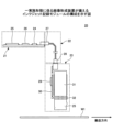
図1は、一実施形態に係る画像形成装置200の全体構成を示す図である。図1に示す画像形成装置200は、オンデマンド方式のライン走査型インクジェット記録装置である。
(Overall configuration of image forming apparatus 200)
Fig. 1 is a diagram showing the overall configuration of an
図1に示すように、一実施形態に係る画像形成装置200は、画像形成部210、給紙部220、レジスト調整部230、乾燥部240、記録媒体反転部250、および排紙部290を備える。
As shown in FIG. 1, an
給紙部220は、給紙スタック221に積載された記録媒体W1を、エアー分離部222によって1枚ずつピックアップし、レジスト調整部230へ送出する。
The
レジスト調整部230は、給紙部220から送出された記録媒体W1に対し、レジストローラ対231によって、傾きの補正を行う。そして、レジスト調整部230は、傾きの補正が行われた後の記録媒体W1を、画像形成部210へ送出する。
The
画像形成部210は、レジスト調整部230から送出された記録媒体W1の先端を、円筒形状のドラム10(「搬送手段」の一例)の表面に設けられた記録媒体グリッパ11によって挟んだ状態で、ドラム10が回転することにより、当該記録媒体W1を、ヘッドモジュール28K~28Pの各々に対向する位置へ搬送する。画像形成部210では、円筒形状のドラム10表面に沿って、インクジェット方式によりインクを吐出する記録ヘッドユニットであるヘッドモジュール28K~28Pが、所定のインク色を充填した状態で放射状に角度をもって配置されている。画像形成部210は、ヘッドモジュール28K~28Pの各々が、ドラム10の表面に保持された記録媒体W1の表面に対して、インク(液体)を吐出することにより、記録媒体W1の表面に画像を形成する。そして、画像形成部210は、画像が形成された後の記録媒体W1を、乾燥部240へ送出する。
In the
乾燥部240は、乾燥ユニット241の下側を記録媒体W1が通過することにより、記録媒体W1を乾燥させる。そして、乾燥部240は、乾燥された後の記録媒体W1を、排紙部290へ送出する。但し、乾燥部240は、両面印刷の場合には、乾燥された後の記録媒体W1を、記録媒体反転部250へ送出する。
The
記録媒体反転部250は、乾燥部240から送出された記録媒体W1を、記録媒体反転機構251によって反転し、反転搬送部252によって、画像形成部210へ送出する。画像形成部210の内部に設けられたレジストローラ253は、記録媒体反転部250から送出された記録媒体W1の傾きを補正し、ドラム10へ搬送する。
The recording
排紙部290は、乾燥部240から送出された複数の記録媒体W1が、互いに揃えられた状態で積載される。
The
(インクジェット記録モジュール20の構成)
一実施形態に係る画像形成装置200(画像形成部210)が備えるインクジェット記録モジュール20の構成を示す図である。
(Configuration of the Inkjet Recording Module 20)
1 is a diagram showing a configuration of an
図2に示すように、インクジェット記録モジュール20は、駆動制御基板21、ケーブル22、およびインクジェット記録ヘッド23を備える。
As shown in FIG. 2, the
駆動制御基板21は、駆動制御部25、駆動波形生成部26、および記憶手段24が搭載されている。
The
ケーブル22は、駆動制御基板21に接続される駆動制御基板コネクタ27と、インクジェット記録ヘッド23に接続されるヘッド側コネクタ28とを有する。ケーブル22は、駆動制御基板21と、インクジェット記録ヘッド23との間で、アナログ信号およびデジタル信号を伝送する。
The
インクジェット記録ヘッド23は、残留振動検知モジュール29、ヘッド基板30、ヘッド内インクタンク31、ヘッド駆動IC基板32、および剛性プレート33を有する。なお、本実施形態の画像形成装置200は、オンデマンド方式のライン走査型インクジェット記録装置であるため、インクジェット記録モジュール20では、複数のインクジェット記録ヘッド23が、記録媒体W1の搬送方向と直交する方向(すなわち、記録媒体W1の幅方向)に並べて設けられている。但し、本発明は、ライン走査型インクジェット記録装置への適用に限らず、その他の方式を用いた記録装置(例えば、インクジェット記録ヘッドが、主走査方向に移動しながら、記録媒体の表面に画像を形成するシリアル走査型プリンタ)にも適用可能である。
The
(汚れ検出構成)
図3は、一実施形態に係る画像形成装置200(画像形成部210)が備える汚れ検出構成を示す図である。
(Dirt detection configuration)
FIG. 3 is a diagram showing a stain detection configuration provided in the image forming apparatus 200 (image forming unit 210) according to an embodiment.
図3に示すように、一実施形態に係る画像形成装置200(画像形成部210)は、ドラム10の搬送面10Aと対向して、スキャナ40が設けられている。スキャナ40は、「光学読み取り手段」の一例であり、ドラム10の搬送面10Aを光学的に読み取ることによって、搬送面10Aの読み取り画像を生成する。
As shown in FIG. 3, an image forming apparatus 200 (image forming unit 210) according to one embodiment is provided with a
図3(b)に示すように、スキャナ40は、主走査方向(図中X軸方向)に関しては、搬送面10Aの全域を覆うことで、搬送面10Aの全域を読み取り対象領域としてカバーし、すなわち、汚れ検出が可能である。また、スキャナ40は、ドラム10を回転させながら、光学的な読み取りを行うことによって、副走査方向(図中Y軸方向)においても、搬送面10Aの全域を読み取り対象領域としてカバーし、すなわち、汚れ検出が可能である。
As shown in FIG. 3B, the
なお、本実施形態では、スキャナ40として、画像濃度を読み取るために画像形成装置200(画像形成部210)に搭載されているものを用いている。但し、これに限らず、スキャナ40として、汚れ検出専用のものを別途設けるようにしてもよい。
In this embodiment, the
このような汚れ検出構成を有する画像形成装置200は、例えば、予め取得しておいた搬送面10Aの理想的な状態(すなわち、汚れが生じていない状態)の画像と、スキャナ40によって生成された搬送面10Aの画像とを比較することにより、搬送面10Aにおける汚れ発生領域を検出することができる。
The
但し、汚れ発生領域を許容できるか否かは、ユーザや印刷ジョブにより異なる可能性がある。例えば、搬送面10Aに僅かに汚れ発生領域が生じている場合であっても、ユーザや印刷ジョブによっては、この汚れ発生領域を許容できると判断できる場合がある。それにも関わらず、従来技術では、この汚れ発生領域を一律に許容できないものと判断し、所定の汚れ対応処理(例えば、汚れの通知、装置の停止、等)を不必要に行ってしまう虞がある。そこで、本実施形態の画像形成装置200は、搬送面10Aに生じている汚れ発生領域を許容できるか否かをユーザに確認することで、検出する必要がない汚れの発生領域のために、所定の汚れ対応処理(例えば、汚れの通知、装置の停止、搬送面10Aの清掃、等)を行ってしまうことを防ぐことができる。
However, whether or not a dirty area is acceptable may vary depending on the user and the print job. For example, even if a dirty area occurs slightly on the
(搬送面10Aにおける許容領域の一例)
図4は、一実施形態に係るドラム10の搬送面10Aにおける許容領域の一例を示す図である。図4に示す例では、搬送面10Aにおいて、主走査方向の中央に、記録媒体W1が通過する領域が発生しており、記録媒体W1が通過する領域の左右両方の外側に、記録媒体W1が通過しない領域が発生している。画像形成装置200は、この記録媒体W1が通過しない領域を、自動認識するとともに、汚れを許容する「許容領域」と判定し、当該「許容領域」を記憶部523に設定することができる。記録媒体W1が通過しない領域に汚れが発生した場合であっても、当該汚れが記録媒体W1に付着する可能性は低く、当該汚れを無視できるからである。
(An example of an allowable area on the conveying
4 is a diagram showing an example of an allowable area on the conveying
このように、一実施形態に係る画像形成装置200は、記録媒体W1への影響を及ぼさない「許容領域」の汚れを無視することで、装置のダウンタイム時間を軽減することができる。
In this way, the
なお、ドラム10の搬送面10Aには、記録媒体を吸引するための吸引機構(例えば吸引穴)が設けられている場合がある。そこで、「許容領域」を適切に設定するためには、吸引機構と汚れとを適切に判別しなければならない。但し、一実施形態に係る画像形成装置200は、搬送面10Aの読み取り画像をユーザに呈示して、汚れ発生領域を「許容領域」とするか否かをユーザに判断させるため、吸引機構と汚れとを適切に判別するロジックを予め用意しておく必要が無く、且つ、吸引機構を有する領域が「許容領域」として記憶部523に誤って設定されてしまうことを抑制することができる。
The
(画像形成装置200の機能構成)
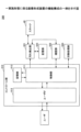
図5は、一実施形態に係る画像形成装置200の機能構成の一例を示す図である。図5に示すように、画像形成装置200は、スキャナ40、コントロール部510、印刷処理部520、汚れ検出部521、確認部522、および記憶部523を備える。
(Functional configuration of image forming apparatus 200)
5 is a diagram showing an example of a functional configuration of the
汚れ検出部521は、スキャナ40に対し、搬送面10Aの読み取り画像の生成を指示する。そして、汚れ検出部521は、スキャナ40によって生成された搬送面10Aの読み取り画像に基づいて、搬送面10Aにおける汚れの発生領域を検出する。
The
確認部522は、汚れ検出部521によって検出された搬送面10Aにおける汚れの発生領域の汚れが許容できるものであるか否かを、コントロール部510(制御部511およびユーザIF512)を介して、ユーザに確認する。
The
汚れ検出部521は、確認部522によって搬送面10Aにおける汚れの発生領域の汚れが許容できるものであることが確認された場合、当該汚れの発生領域を、汚れを許容する「許容領域」として、記憶部523に設定する。
When the
汚れ検出部521は、「許容領域」が記憶部523に設定された場合、以降、当該「許容領域」を、汚れの発生領域として検出しないようにすることができる。これにより、汚れ検出部521は、検出する必要がない汚れのために、所定の汚れ対応処理(例えば、汚れの通知、装置の停止、搬送面10Aの清掃、等)を行ってしまうことを防ぐことができる。
When an "acceptable area" is set in the
なお、画像形成装置200は、所定の条件を満たす領域(例えば、図4に例示するように、記録媒体W1が通過しない領域)を「許容領域」と判定し、当該「許容領域」を記憶部523に設定してもよい。
In addition, the
なお、上記した画像形成装置200の各機能は、コンピュータが画像形成装置200用のプログラムを実行することによって実現することが可能である。また、上記した画像形成装置200の各機能は、一又は複数の処理回路によって実現することが可能である。ここで、本明細書における「処理回路」とは、電子回路により実装されるプロセッサのようにソフトウェアによって各機能を実行するようプログラミングされたプロセッサや、上記した画像形成装置200の各機能を実行するよう設計されたASIC(Application Specific Integrated Circuit)、DSP(digital signal processor)、FPGA(field programmable gate array)や従来の回路モジュール等のデバイスを含むものとする。
The functions of the
(画像形成装置200による処理の手順)
図6は、一実施形態に係る画像形成装置200による処理の手順の一例を示すフローチャートである。
(Processing Procedure by Image Forming Apparatus 200)
FIG. 6 is a flowchart showing an example of a processing procedure by the
まず、汚れ検出部521が、スキャナ40によって生成された読み取り画像に基づいて、搬送面10Aにおける汚れの発生領域を検出する(ステップS601)。
First, the
次に、汚れ検出部521が、ステップS601で検出された汚れの発生領域が、記憶部523に設定されている「許容領域」の範囲内であるか否かを判断する(ステップS602)。
Next, the
ステップS602において、「許容領域」の範囲内であると判断された場合(ステップS602:Yes)、画像形成装置200は、図6に示す一連の処理を終了する。
If it is determined in step S602 that the pixel value is within the "allowable range" (step S602: Yes), the
一方、ステップS602において、「許容領域」の範囲内ではないと判断された場合(ステップS602:No)、確認部522が、ステップS601で検出された汚れの発生領域の汚れが許容できるものであるか否かを、コントロール部510(制御部511およびユーザIF512)を介して、ユーザに確認する(ステップS603)。
On the other hand, if it is determined in step S602 that the dirt is not within the "acceptable area" (step S602: No), the
そして、汚れ検出部521が、ステップS603の確認処理の結果が「許容できる」であるか否かを判断する(ステップS604)。
Then, the
ステップS604において、「許容できる」ではないと判断された場合(ステップS604:No)、汚れ検出部521が、所定の汚れ対応処理(例えば、ユーザへの汚れの通知、ユーザへの搬送面10Aの清掃要求、清掃装置の停止、搬送面10Aの清掃、等)を実行する(ステップS605)。そして、画像形成装置200は、図6に示す一連の処理を終了する。
If it is determined in step S604 that the detected dirt is not "acceptable" (step S604: No), the
一方、ステップS604において、「許容できる」であると判断された場合(ステップS604:Yes)、汚れ検出部521が、ステップS601で検出された汚れの発生領域を、「許容領域」として記憶部523に設定する(ステップS606)。そして、画像形成装置200は、図6に示す一連の処理を終了する。
On the other hand, if it is determined in step S604 that the stain is "acceptable" (step S604: Yes), the
なお、汚れ検出部521は、「許容領域」に該当しない汚れの発生領域が検出された場合、所定の汚れ対応処理として、ユーザに搬送面10Aの清掃要求を行うようにしてもよく、ユーザにインクジェット記録ヘッド23の清掃要求を行うようにしてもよい。これにより、一実施形態に係る画像形成装置200は、搬送面10Aまたはインクジェット記録ヘッド23の汚れを直ちに除去するように、ユーザに促すことができる。
When the
例えば、画像形成装置200は、図6に示す一連の処理を、定期的に実施してもよい。これにより、画像形成装置200は、定期的に、搬送面10Aの最新の状態に応じて、「許容領域」を適切に設定することができる。
For example, the
また、例えば、画像形成装置200は、図6に示す一連の処理を、所定のイベントが発生したタイミングで実施してもよい。これにより、画像形成装置200は、所定のイベント(例えば、搬送路の変更、等)が発生する毎に、搬送面10Aの最新の状態に応じて、「許容領域」を適切に設定することができる。
Also, for example, the
また、例えば、画像形成装置200は、図6に示す一連の処理を、印刷ジョブ毎に実施してもよい。これにより、画像形成装置200は、印刷ジョブ毎に、搬送面10Aの最新の状態と、印刷ジョブの品質要求とに応じて、「許容領域」を適切に設定することができる。
Also, for example, the
また、例えば、画像形成装置200は、印刷ジョブの設定情報に基づいて、自動的に「許容領域」を設定してもよい。例えば、画像形成装置200は、印刷ジョブの設定情報に含まれている用紙サイズに基づいて、搬送面10Aにおける、その用紙サイズの記録媒体W1が通過しない領域を、「許容領域」として自動的に設定してもよい。
Also, for example, the
(ユーザに呈示される読み取り画像の一例)
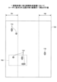
図7は、一実施形態に係る画像形成装置200において、ユーザに呈示される読み取り画像の一例を示す図である。図7に示す読み取り画像700は、スキャナ40によって生成され、確認部522によってユーザに呈示される読み取り画像の一例である。
(An example of a scanned image presented to a user)
7 is a diagram showing an example of a scanned image presented to a user in the
図7に示すように、確認部522は、読み取り画像700において、主走査方向における左右両方の外側の記録媒体W1が通過しない領域(図4参照)を、推奨許容領域701,702としてユーザに呈示してもよい。推奨許容領域701,702は、ユーザに対して、「許容領域」として指定することを推奨する領域である。これにより、一実施形態に係る画像形成装置200は、ユーザが、推奨許容領域701,702を参考にして、「許容領域」を指定できるようになるため、ユーザによる「許容領域」の指定を、容易且つ適切に行わせることができる。もし、推奨許容領域701,702が、ユーザによって「許容領域」に指定された場合、以降、汚れ検出部521は、推奨許容領域701,702に発生している汚れ710(図7参照)を許容することができる。
As shown in FIG. 7, the
また、図7に示すように、確認部522は、読み取り画像700において、既存許容領域703をユーザに呈示してもよい。既存許容領域703は、既にユーザによって汚れ710を許容する「許容領域」として指定されている領域である。これにより、一実施形態に係る画像形成装置200は、ユーザが、呈示された既存許容領域703を参考にして、当該既存許容領域703を「許容領域」として二重に指定してしまうことを防止することができる。なお、汚れ検出部521は、ユーザに呈示された既存許容領域703を、改めて、ユーザが「許容領域」として指定できるようにしてもよい。
As shown in FIG. 7, the
(汚れ検出部521による汚れ発生領域を検出する方法の一例(第1例))
図8は、一実施形態に係る画像形成装置200において、汚れ検出部521による汚れ発生領域を検出する方法の一例(第1例)を説明するための図である。図8に示す読み取り画像800は、スキャナ40によって生成される読み取り画像の一例である。
(First Example of a Method for Detecting a Dirt Occurrence Area by the Dirt Detection Unit 521)
8 is a diagram for explaining an example (first example) of a method for detecting a dirt occurrence region by the
例えば、汚れ検出部521は、図8に示すように、スキャナ40によって生成された読み取り画像800を、複数の領域に分割する。そして、汚れ検出部521は、読み取り画像800の複数の領域の各々について、汚れを表す画素の画素数を算出する。例えば、図8に示す例では、汚れ検出部521は、汚れ801が発生している汚れ発生領域800Aについて、汚れ801を表す画素の画素数を算出する。さらに、汚れ検出部521は、算出された汚れ801を表す画素の画素数と、ユーザによる汚れ発生領域800Aを許容するか否かの判断結果とに応じて、許容可能画素数を決定する。
For example, as shown in FIG. 8, the
例えば、汚れ検出部521は、汚れ801を表す画素の画素数が「1000」であり、ユーザによって汚れ発生領域800Aを許容すると判断され、さらに、許容可能画素数を算出するための重み付け係数を「1.1」とする場合、許容可能画素数を「1100」に決定する。
For example, if the number of pixels representing the
このように、汚れ検出部521は、許容可能画素数を決定した場合、以降、読み取り画像800を構成する複数の領域のうち、許容可能画素数未満の汚れが発生している領域を、汚れ発生領域として検出しないようにしてもよい。
In this way, when the
なお、許容可能画素数を算出するための重み付け係数として、複数種類の重み付け係数が利用可能であってもよい。例えば、許容可能画素数を算出するための重み付け係数として、高検出モードでは「1.1」が用いられ、高生産モードでは「1.3」が用いられてもよい。 Note that multiple types of weighting coefficients may be used as the weighting coefficient for calculating the allowable number of pixels. For example, a weighting coefficient of "1.1" may be used in the high detection mode and a weighting coefficient of "1.3" may be used in the high production mode for calculating the allowable number of pixels.
(汚れ検出部521による汚れ発生領域を検出する方法の一例(第2例))
図9は、一実施形態に係る画像形成装置200において、汚れ検出部521による汚れ発生領域を検出する方法の一例(第2例)を説明するための図である。図9に示す読み取り画像900は、スキャナ40によって生成される読み取り画像の一例である。
(Second Example of Method for Detecting Dirt Occurrence Area by Dirt Detection Unit 521)
9 is a diagram for explaining an example (second example) of a method for detecting a dirt occurrence region by the
例えば、汚れ検出部521は、図9に示すように、スキャナ40によって生成された読み取り画像900を、複数の領域に分割する。そして、汚れ検出部521は、読み取り画像900の複数の領域の各々について、搬送面10Aの地肌とは異なるRGB値(詳しくは、図10参照)を有する画素の画素数を算出する。
For example, as shown in FIG. 9, the
例えば、図9に示す領域900A-1は、汚れが発生していないときの領域900Aの状態を表しており、複数の吸引孔902(画素数=600)が含まれているため、汚れ検出部521は、搬送面10Aの地肌とは異なるRGB値を有する画素の画素数として、「600」を算出する。
For example, the
汚れ検出部521は、汚れが発生していないときの、搬送面10Aの地肌とは異なるRGB値を有する画素の画素数「600」を基準とすることにより、読み取り画像900の複数の領域の各々について、汚れ発生領域であるか否かを判断することができる。
The
例えば、図9に示す領域900A-2は、複数の汚れ901が発生していないときの領域900Aの状態を表しており、複数の吸引孔902(画素数=600)に加えて、複数の汚れ901(画素数=600)が含まれているため、汚れ検出部521は、搬送面10Aの地肌とは異なるRGB値を有する画素の画素数として、「1200」を算出する。このため、汚れ検出部521は、領域900A-2を、汚れ発生領域と判断することができる。
For example, the
(搬送面10Aの地肌とは異なるRGB値の一例)
図10は、一実施形態に係る画像形成装置200において、汚れ検出部521による汚れ発生領域を検出する際に用いられる、搬送面10Aの地肌とは異なるRGB値の一例を示す図である。
(An example of RGB values different from the background of the
FIG. 10 is a diagram showing an example of RGB values different from the background of the
図10に示すように、一実施形態に係る画像形成装置200においては、搬送面10Aの地肌とは異なるRGB値として、搬送面10Aの地肌をRGBの範囲R1が、予め設定されている。
As shown in FIG. 10, in the
例えば、搬送面10Aの地肌のRGB値(スキャナ40による検出値)の基準値が、220(R),205(G),220(B)である場合において、±20%を地肌の許容範囲とする場合、以下のように、地肌を表すRGB値の基準範囲が設定される。
For example, if the reference values for the RGB values (detection values by the scanner 40) of the background on the
R:176~255
G:164~246
B:176~255
R: 176-255
G: 164-246
B: 176-255
そして、汚れ検出部521は、上記地肌を表すRGB値の基準範囲から逸脱する画素を、搬送面10Aの地肌とは異なるRGB値を有する画素(すなわち、吸引孔または汚れを表す画素)として判断する。
The
なお、汚れ検出部521は、上記した地肌のRGB値の各基準値として、地肌が撮像されている読み取り画像から最も多く検出された画素値を用いてもよい。また、汚れ検出部521は、上記した地肌のRGB値の各基準値として、記憶部523に予め記憶されているものを用いてもよい。
In addition, the
また、汚れ検出部521は、上記した地肌を表すRGB値の基準範囲を、適切なタイミング(例えば、定期的、搬送路が変更されたタイミング、等)で、スキャナ40によって検出することにより、変更してもよい。これにより、一実施形態に係る画像形成装置200は、搬送面10Aの地肌の最新の色味に応じて、汚れおよび吸引孔の判断を適切に行うことができる。
The
以上説明したように、一実施形態に係る画像形成装置200は、記録媒体を搬送するドラム10と、ドラム10の搬送面10Aを光学的に読み取ることによって、搬送面10Aの読み取り画像を生成するスキャナ40と、スキャナ40によって生成された読み取り画像に基づいて、搬送面10Aにおける汚れの発生領域を検出する汚れ検出部521と、汚れ検出部521によって検出された汚れの発生領域が許容できるものであるか否かをユーザに確認する確認部522とを備え、汚れ検出部521は、確認部522によって汚れの発生領域が許容できるものであることが確認された場合、当該汚れの発生領域を、汚れを許容する許容領域として設定する。
As described above, the
これにより、一実施形態に係る画像形成装置200は、搬送面10Aの理想的な状態を事前に認識することなく、当該搬送面10Aの汚れを検出することができる。
As a result, the
以上、本発明の好ましい実施形態について詳述したが、本発明はこれらの実施形態に限定されるものではなく、特許請求の範囲に記載された本発明の要旨の範囲内において、種々の変形又は変更が可能である。 Although the preferred embodiments of the present invention have been described in detail above, the present invention is not limited to these embodiments, and various modifications and variations are possible within the scope of the gist of the present invention as described in the claims.
10 ドラム
10A 搬送面
20 インクジェット記録モジュール
40 スキャナ
200 画像形成装置
210 画像形成部
220 給紙部
230 レジスト調整部
240 乾燥部
250 記録媒体反転部
290 排紙部
510 コントロール部
520 印刷処理部
521 汚れ検出部
522 確認部
523 記憶部
700,800,900 読み取り画像
W1 記録媒体
REFERENCE SIGNS
Claims (19)
前記搬送手段の搬送面を光学的に読み取ることによって、前記搬送面の読み取り画像を生成する光学読み取り手段と、
前記読み取り画像に基づいて前記搬送面における汚れの発生領域を検出する汚れ検出部と、
前記汚れ検出部によって検出された前記汚れの発生領域が許容できるものであるか否かをユーザに確認する確認部と
を備え、
前記汚れ検出部は、
前記確認部によって前記汚れの発生領域が許容できるものであることが確認された場合、当該汚れの発生領域を、汚れを許容する許容領域として設定し、
前記汚れ検出部によって設定された前記許容領域を記憶する記憶部を備え、
前記汚れ検出部は、検出された前記汚れの発生領域が、前記記憶部に記憶されている前記許容領域の範囲内である場合、当該汚れの発生領域の汚れを許容する
ことを特徴とする画像形成装置。 A conveying means for conveying a recording medium;
an optical reading means for optically reading a conveying surface of the conveying means to generate a read image of the conveying surface;
a stain detection unit that detects a stain occurrence area on the conveying surface based on the read image;
a confirmation unit that confirms with a user whether or not the stain occurrence area detected by the stain detection unit is acceptable,
The dirt detection unit is
When the confirmation unit confirms that the dirt occurrence region is acceptable, the dirt occurrence region is set as an acceptable region in which dirt is acceptable ;
a storage unit that stores the allowable range set by the dirt detection unit,
The stain detection unit allows stains in the stain occurrence area when the detected stain occurrence area is within the range of the allowable area stored in the storage unit.
1. An image forming apparatus comprising:
前記搬送手段の搬送面を光学的に読み取ることによって、前記搬送面の読み取り画像を生成する光学読み取り手段と、an optical reading means for optically reading a conveying surface of the conveying means to generate a read image of the conveying surface;
前記読み取り画像を複数の領域に分割し、当該複数の領域の各々について、汚れを表す画素の画素数に基づいて、汚れの発生領域とするか否かを判断することで前記搬送面における前記汚れの発生領域を検出する汚れ検出部と、a stain detection unit that detects a stain occurrence area on the conveying surface by dividing the read image into a plurality of areas and determining whether each of the plurality of areas is a stain occurrence area based on a pixel count of pixels representing stains;
前記汚れ検出部によって検出された前記汚れの発生領域が許容できるものであるか否かをユーザに確認する確認部とa confirmation unit that confirms with a user whether or not the stain occurrence area detected by the stain detection unit is acceptable;
を備え、Equipped with
前記汚れ検出部は、The dirt detection unit is
前記確認部によって前記汚れの発生領域が許容できるものであることが確認された場合、当該汚れの発生領域を、汚れを許容する許容領域として設定するWhen the confirmation unit confirms that the stain occurrence area is acceptable, the stain occurrence area is set as an acceptable area in which stains are acceptable.
ことを特徴とする画像形成装置。1. An image forming apparatus comprising:
前記複数の領域の各々について、ユーザによる過去の判断結果に基づく許容可能画素数を基準として、前記汚れの発生領域とするか否かを判断する
ことを特徴とする請求項2に記載の画像形成装置。 The dirt detection unit is
3. The image forming apparatus according to claim 2 , wherein for each of the plurality of regions, it is determined whether or not the region is to be the region where the stain has occurred, based on an allowable number of pixels based on a result of a previous determination made by a user.
前記複数の領域の各々について、ユーザによる過去の判断結果と所定の重み付け係数とに基づく許容可能画素数を基準として、前記汚れの発生領域とするか否かを判断する
ことを特徴とする請求項2に記載の画像形成装置。 The dirt detection unit is
The image forming apparatus according to claim 2 , further comprising: a step of determining whether or not each of the plurality of regions is to be a region where dirt has occurred, based on an allowable number of pixels based on a user's past judgment results and a predetermined weighting coefficient.
前記複数の領域の各々について、前記搬送面の地肌を表す画素とは異なる画素の画素数に基づいて、前記汚れの発生領域とするか否かを判断する
ことを特徴とする請求項2に記載の画像形成装置。 The dirt detection unit is
The image forming apparatus according to claim 2 , wherein for each of the plurality of regions, it is determined whether or not the region is to be a region where the stain has occurred based on the number of pixels different from pixels representing the surface of the transport surface.
前記搬送面の地肌を表す画素の基準値として、前記読み取り画像から最も多く検出された画素値を用いる
ことを特徴とする請求項5に記載の画像形成装置。 The dirt detection unit is
6. The image forming apparatus according to claim 5 , wherein a pixel value detected most frequently from the read image is used as a reference value for a pixel representing a background of the transport surface.
をさらに備えることを特徴とする請求項5に記載の画像形成装置。 The image forming apparatus according to claim 5 , further comprising a storage unit that stores in advance a reference value of a pixel representing a background of the transport surface.
前記汚れ検出部によって検出された前記汚れの発生領域が許容できるものであるか否かをユーザに確認する際に、前記読み取り画像を呈示するとともに、前記読み取り画像において、前記許容領域に設定することを推奨する推奨領域を、前記ユーザに呈示する
ことを特徴とする請求項1から7のいずれか一項に記載の画像形成装置。 The confirmation unit is
The image forming apparatus according to any one of claims 1 to 7, characterized in that, when confirming with a user whether the area of dirt occurrence detected by the dirt detection unit is acceptable or not, the scanned image is presented, and a recommended area in the scanned image that is recommended to be set as the acceptable area is presented to the user.
前記汚れ検出部によって検出された前記汚れの発生領域が許容できるものであるか否かをユーザに確認する際に、前記読み取り画像を呈示するとともに、前記読み取り画像において、既に設定されている前記許容領域を、前記ユーザに呈示する
ことを特徴とする請求項1から8のいずれか一項に記載の画像形成装置。 The confirmation unit is
9. The image forming apparatus according to claim 1, wherein, when a user is to confirm whether the area of dirt occurrence detected by the dirt detection unit is acceptable or not , the scanned image is presented to the user, and the acceptable area that has already been set in the scanned image is presented to the user.
前記確認部が、前記汚れの発生領域が許容できるものであるか否かを前記ユーザに確認し、
前記汚れ検出部が、前記確認部によって前記汚れの発生領域が許容できるものであることが確認された場合、当該汚れの発生領域を、前記許容領域として設定する
ことを特徴とする請求項1から9のいずれか一項に記載の画像形成装置。 Regularly,
the confirmation unit confirms with the user whether or not the stain occurrence area is acceptable;
10. The image forming apparatus according to claim 1 , wherein the stain detection unit sets the stain occurrence area as the acceptable area when the confirmation unit confirms that the stain occurrence area is acceptable.
前記確認部が、前記汚れの発生領域が許容できるものであるか否かを前記ユーザに確認し、
前記汚れ検出部が、前記確認部によって前記汚れの発生領域が許容できるものであることが確認された場合、当該汚れの発生領域を、前記許容領域として設定する
ことを特徴とする請求項1から10のいずれか一項に記載の画像形成装置。 Each time the conveying surface is changed,
the confirmation unit confirms with the user whether or not the stain occurrence area is acceptable;
11. The image forming apparatus according to claim 1, wherein the stain detection unit sets the stain occurrence area as the acceptable area when the confirmation unit confirms that the stain occurrence area is acceptable.
前記確認部が、前記汚れの発生領域が許容できるものであるか否かを前記ユーザに確認し、
前記汚れ検出部が、前記確認部によって前記汚れの発生領域が許容できるものであることが確認された場合、当該汚れの発生領域を、前記許容領域として設定する
ことを特徴とする請求項1から11のいずれか一項に記載の画像形成装置。 For each print job,
the confirmation unit confirms with the user whether or not the stain occurrence area is acceptable;
12. The image forming apparatus according to claim 1 , wherein the stain detection unit sets the stain occurrence area as the acceptable area when the confirmation unit confirms that the stain occurrence area is acceptable.
印刷ジョブの設定情報に基づいて、前記許容領域を自動的に設定する
ことを特徴とする請求項1から12のいずれか一項に記載の画像形成装置。 The dirt detection unit is
13. The image forming apparatus according to claim 1, wherein the allowable range is automatically set based on setting information of a print job.
前記許容領域に該当しない前記汚れの発生領域が検出された場合、前記ユーザに対する前記搬送面の清掃要求を行う
ことを特徴とする請求項1から13のいずれか一項に記載の画像形成装置。 The dirt detection unit is
14 . The image forming apparatus according to claim 1 , wherein, when a stain occurrence area that does not fall within the allowable area is detected, a request for cleaning the transport surface is issued to the user.
前記許容領域に該当しない前記汚れの発生領域が検出された場合、前記ユーザに対するインクジェット記録ヘッドの清掃要求を行う
ことを特徴とする請求項1から14のいずれか一項に記載の画像形成装置。 The dirt detection unit is
15. The image forming apparatus according to claim 1, wherein, when a stain occurrence area that does not fall within the allowable area is detected, a request for cleaning the inkjet recording head is issued to the user.
前記搬送手段の搬送面を光学的に読み取ることによって、前記搬送面の読み取り画像を生成する光学読み取り手段と
を備えた画像形成装置の制御方法であって、
前記読み取り画像に基づいて前記搬送面における汚れの発生領域を検出する汚れ検出工程と、
前記汚れ検出工程において検出された前記汚れの発生領域が許容できるものであるか否かをユーザに確認する確認工程と、
前記確認工程において前記汚れの発生領域が許容できるものであることが確認された場合、当該汚れの発生領域を、汚れを許容する許容領域として設定する設定工程と、
前記設定工程において設定された前記許容領域を記憶する記憶工程と、
前記汚れ検出工程において検出された前記汚れの発生領域が、前記記憶工程で記憶されている前記許容領域の範囲内である場合、当該汚れの発生領域を許容する許容工程と
を含むことを特徴とする制御方法。 A conveying means for conveying a recording medium;
an optical reading unit that optically reads a transport surface of the transport unit to generate a read image of the transport surface,
a stain detection step of detecting a stain occurrence area on the conveying surface based on the read image;
a confirmation step of confirming with a user whether or not the stain occurrence area detected in the stain detection step is acceptable;
a setting step of setting the dirt generation area as an allowable area in which dirt is allowed when the dirt generation area is confirmed to be an allowable area in the confirmation step ;
a storage step of storing the allowable range set in the setting step;
an acceptance step of accepting the stain occurrence area when the stain occurrence area detected in the stain detection step is within the range of the acceptance area stored in the storage step;
A control method comprising:
前記搬送手段の搬送面を光学的に読み取ることによって、前記搬送面の読み取り画像を生成する光学読み取り手段とan optical reading means for optically reading a conveying surface of the conveying means to generate a read image of the conveying surface;
を備えた画像形成装置の制御方法であって、A method for controlling an image forming apparatus comprising:
前記読み取り画像を複数の領域に分割し、当該複数の領域の各々について、汚れを表す画素の画素数に基づいて、汚れの発生領域とするか否かを判断することで前記搬送面における汚れの発生領域を検出する汚れ検出工程と、a stain detection step of detecting a stain occurrence area on the conveying surface by dividing the read image into a plurality of areas and determining whether or not each of the plurality of areas is a stain occurrence area based on the number of pixels representing stains;
前記汚れ検出工程において検出された前記汚れの発生領域が許容できるものであるか否かをユーザに確認する確認工程と、a confirmation step of confirming with a user whether or not the stain occurrence area detected in the stain detection step is acceptable;
前記確認工程において前記汚れの発生領域が許容できるものであることが確認された場合、当該汚れの発生領域を、汚れを許容する許容領域として設定する設定工程とa setting step of setting the dirt occurrence area as an allowable area in which dirt is allowed when the dirt occurrence area is confirmed to be an allowable area in the confirmation step;
を含むことを特徴とする制御方法。A control method comprising:
前記搬送手段の搬送面を光学的に読み取ることによって、前記搬送面の読み取り画像を生成する光学読み取り手段と
を備えた画像形成装置用のプログラムであって、
コンピュータを、
前記読み取り画像に基づいて前記搬送面における汚れの発生領域を検出する汚れ検出部、および、
前記汚れ検出部によって検出された前記汚れの発生領域が許容できるものであるか否かをユーザに確認する確認部
として機能させ、
前記汚れ検出部に、
前記確認部によって前記汚れの発生領域が許容できるものであることが確認された場合、当該汚れの発生領域を、汚れを許容する許容領域として設定させ、
前記汚れ検出部によって設定された前記許容領域を記憶する記憶部として機能させ、
前記汚れ検出部は、検出された前記汚れの発生領域が、前記記憶部に記憶されている前記許容領域の範囲内である場合、当該汚れの発生領域を許容する
ことを特徴とするプログラム。 A conveying means for conveying a recording medium;
an optical reading unit that optically reads a transport surface of the transport unit to generate a read image of the transport surface,
Computer,
a stain detection unit that detects a stain occurrence area on the conveying surface based on the read image; and
a confirmation unit that confirms with a user whether or not the stain occurrence area detected by the stain detection unit is acceptable;
The dirt detection unit,
When the confirmation unit confirms that the dirt occurrence region is acceptable, the dirt occurrence region is set as an acceptable region in which dirt is acceptable ;
a storage unit that stores the allowable range set by the dirt detection unit;
The stain detection unit accepts the stain occurrence area when the detected stain occurrence area is within the range of the allowable area stored in the storage unit.
A program characterized by:
前記搬送手段の搬送面を光学的に読み取ることによって、前記搬送面の読み取り画像を生成する光学読み取り手段とan optical reading means for optically reading a conveying surface of the conveying means to generate a read image of the conveying surface;
を備えた画像形成装置用のプログラムであって、A program for an image forming apparatus comprising:
コンピュータを、Computer,
前記読み取り画像を複数の領域に分割し、当該複数の領域の各々について、汚れを表す画素の画素数に基づいて、汚れの発生領域とするか否かを判断することで前記搬送面における汚れの発生領域を検出する汚れ検出部、および、a stain detection unit that detects a stain occurrence area on the conveying surface by dividing the read image into a plurality of areas and determining whether each of the plurality of areas is a stain occurrence area based on the number of pixels representing stains; and
前記汚れ検出部によって検出された前記汚れの発生領域が許容できるものであるか否かをユーザに確認する確認部a confirmation unit that confirms with a user whether or not the stain occurrence area detected by the stain detection unit is acceptable
として機能させ、Function as a
前記汚れ検出部に、The dirt detection unit,
前記確認部によって前記汚れの発生領域が許容できるものであることが確認された場合、当該汚れの発生領域を、汚れを許容する許容領域として設定させるWhen the confirmation unit confirms that the stain occurrence region is acceptable, the stain occurrence region is set as an acceptable region in which stains are acceptable.
ことを特徴とするプログラム。A program characterized by:
Priority Applications (1)
| Application Number | Priority Date | Filing Date | Title |
|---|---|---|---|
| JP2020155738A JP7552182B2 (en) | 2020-09-16 | 2020-09-16 | Image forming apparatus, control method, and program |
Applications Claiming Priority (1)
| Application Number | Priority Date | Filing Date | Title |
|---|---|---|---|
| JP2020155738A JP7552182B2 (en) | 2020-09-16 | 2020-09-16 | Image forming apparatus, control method, and program |
Publications (2)
| Publication Number | Publication Date |
|---|---|
| JP2022049505A JP2022049505A (en) | 2022-03-29 |
| JP7552182B2 true JP7552182B2 (en) | 2024-09-18 |
Family
ID=80853902
Family Applications (1)
| Application Number | Title | Priority Date | Filing Date |
|---|---|---|---|
| JP2020155738A Active JP7552182B2 (en) | 2020-09-16 | 2020-09-16 | Image forming apparatus, control method, and program |
Country Status (1)
| Country | Link |
|---|---|
| JP (1) | JP7552182B2 (en) |
Citations (9)
| Publication number | Priority date | Publication date | Assignee | Title |
|---|---|---|---|---|
| JP2000198566A (en) | 1999-01-06 | 2000-07-18 | Canon Inc | Sheet suction conveyance device and recording device |
| JP2003304377A (en) | 2002-04-08 | 2003-10-24 | Canon Inc | Image reading device and image forming device |
| JP2003312090A (en) | 2002-04-24 | 2003-11-06 | Canon Inc | Inkjet recording device |
| JP2004159240A (en) | 2002-11-08 | 2004-06-03 | Konica Minolta Holdings Inc | Image recorder provided with automatic document feeder |
| JP2006187990A (en) | 2005-01-07 | 2006-07-20 | Canon Inc | Inkjet recording device |
| JP2007293069A (en) | 2006-04-26 | 2007-11-08 | Fuji Xerox Co Ltd | Image forming apparatus and image forming method |
| JP2008297069A (en) | 2007-05-31 | 2008-12-11 | Brother Ind Ltd | Belt conveying device and liquid ejection device provided with the same |
| JP2009130890A (en) | 2007-11-28 | 2009-06-11 | Ricoh Co Ltd | Document reading apparatus and image forming apparatus |
| JP2012249268A (en) | 2011-05-31 | 2012-12-13 | Kyocera Document Solutions Inc | Image forming apparatus |
Family Cites Families (1)
| Publication number | Priority date | Publication date | Assignee | Title |
|---|---|---|---|---|
| JP5640594B2 (en) * | 2010-09-15 | 2014-12-17 | 株式会社リコー | Image forming apparatus |
-
2020
- 2020-09-16 JP JP2020155738A patent/JP7552182B2/en active Active
Patent Citations (9)
| Publication number | Priority date | Publication date | Assignee | Title |
|---|---|---|---|---|
| JP2000198566A (en) | 1999-01-06 | 2000-07-18 | Canon Inc | Sheet suction conveyance device and recording device |
| JP2003304377A (en) | 2002-04-08 | 2003-10-24 | Canon Inc | Image reading device and image forming device |
| JP2003312090A (en) | 2002-04-24 | 2003-11-06 | Canon Inc | Inkjet recording device |
| JP2004159240A (en) | 2002-11-08 | 2004-06-03 | Konica Minolta Holdings Inc | Image recorder provided with automatic document feeder |
| JP2006187990A (en) | 2005-01-07 | 2006-07-20 | Canon Inc | Inkjet recording device |
| JP2007293069A (en) | 2006-04-26 | 2007-11-08 | Fuji Xerox Co Ltd | Image forming apparatus and image forming method |
| JP2008297069A (en) | 2007-05-31 | 2008-12-11 | Brother Ind Ltd | Belt conveying device and liquid ejection device provided with the same |
| JP2009130890A (en) | 2007-11-28 | 2009-06-11 | Ricoh Co Ltd | Document reading apparatus and image forming apparatus |
| JP2012249268A (en) | 2011-05-31 | 2012-12-13 | Kyocera Document Solutions Inc | Image forming apparatus |
Also Published As
| Publication number | Publication date |
|---|---|
| JP2022049505A (en) | 2022-03-29 |
Similar Documents
| Publication | Publication Date | Title |
|---|---|---|
| JP2017181094A (en) | Line detection method and apparatus, printing apparatus and program | |
| US20110141504A1 (en) | Image reading device for correcting image read from original, method of controlling the image reading device, and storage medium | |
| JP2024046491A (en) | Image forming device | |
| JP5190202B2 (en) | Image recording apparatus and method, and quality determination program | |
| US7871144B2 (en) | Inkjet image-forming apparatus and method thereof | |
| JP7552182B2 (en) | Image forming apparatus, control method, and program | |
| JP5361415B2 (en) | Image recording apparatus and control method of image recording apparatus | |
| JP7667949B2 (en) | Image forming device | |
| JP2011098520A (en) | Image recording apparatus, and control method of image recording apparatus | |
| JP2023048316A (en) | image forming device | |
| JP2024046488A (en) | Image forming device | |
| JP2023114572A (en) | image forming device | |
| JP2024003892A (en) | image forming device | |
| JP2023049442A (en) | image forming device | |
| JP2005059463A (en) | Printing system, operating method for printing device, and control program for printing device | |
| US11842235B2 (en) | Image forming apparatus with sub-scanning-direction reference position | |
| JP7737615B2 (en) | Image forming device | |
| CN115837806B (en) | Conveying failure determination device and printing device | |
| JP7215195B2 (en) | image forming device | |
| JP7811326B2 (en) | Image forming device | |
| JP2019068273A (en) | Image reading apparatus and image reading method | |
| JP2025129468A (en) | Image forming apparatus and nozzle inspection method | |
| JP2023064222A (en) | image forming device | |
| JP2024139238A (en) | Image forming device | |
| JP2023048315A (en) | image forming device |
Legal Events
| Date | Code | Title | Description |
|---|---|---|---|
| A621 | Written request for application examination |
Free format text: JAPANESE INTERMEDIATE CODE: A621 Effective date: 20230714 |
|
| A977 | Report on retrieval |
Free format text: JAPANESE INTERMEDIATE CODE: A971007 Effective date: 20240319 |
|
| A131 | Notification of reasons for refusal |
Free format text: JAPANESE INTERMEDIATE CODE: A131 Effective date: 20240416 |
|
| A521 | Request for written amendment filed |
Free format text: JAPANESE INTERMEDIATE CODE: A523 Effective date: 20240614 |
|
| TRDD | Decision of grant or rejection written | ||
| A01 | Written decision to grant a patent or to grant a registration (utility model) |
Free format text: JAPANESE INTERMEDIATE CODE: A01 Effective date: 20240806 |
|
| A61 | First payment of annual fees (during grant procedure) |
Free format text: JAPANESE INTERMEDIATE CODE: A61 Effective date: 20240819 |
|
| R150 | Certificate of patent or registration of utility model |
Ref document number: 7552182 Country of ref document: JP Free format text: JAPANESE INTERMEDIATE CODE: R150 |