JP7547517B2 - combine - Google Patents
combine Download PDFInfo
- Publication number
- JP7547517B2 JP7547517B2 JP2023000464A JP2023000464A JP7547517B2 JP 7547517 B2 JP7547517 B2 JP 7547517B2 JP 2023000464 A JP2023000464 A JP 2023000464A JP 2023000464 A JP2023000464 A JP 2023000464A JP 7547517 B2 JP7547517 B2 JP 7547517B2
- Authority
- JP
- Japan
- Prior art keywords
- fuselage
- section
- threshing
- combine harvester
- connecting member
- Prior art date
- Legal status (The legal status is an assumption and is not a legal conclusion. Google has not performed a legal analysis and makes no representation as to the accuracy of the status listed.)
- Active
Links
Images


Landscapes
- Threshing Machine Elements (AREA)
Description
本発明は、刈取穀稈を扱胴によって脱穀処理する脱穀装置が備えられたコンバインに関する。 The present invention relates to a combine harvester equipped with a threshing device that threshes harvested stalks using a threshing drum.
上記のようなコンバインとして、例えば、特許文献1に記載のコンバインが既に知られている。特許文献1に記載のコンバインには、刈取穀稈を扱胴によって脱穀処理する脱穀装置(文献では「脱穀機」)が備えられている。扱胴は、機体前後方向に延びる扱胴軸(文献では「支軸」)と、扱胴軸に支持されると共に複数の扱歯が外周部に取り付けられる胴体(文献では「扱胴ドラム」)と、を有している。扱胴には、胴体の周壁部に設けた点検開口と、点検開口を閉じる着脱自在な蓋体と、が備えられている。特許文献1に記載のコンバインでは、扱胴のメンテナンス(例えば、扱歯の交換等)を行う際に、点検開口から胴体の内部に手を入れて作業を行うことができる。
As an example of such a combine harvester, the combine harvester described in
特許文献1に記載のコンバインでは、点検開口が小さいため、扱胴のメンテナンス(例えば、扱歯の交換等)を行う際に、点検開口から胴体の内部に手を入れて作業を行うのが容易ではない。
The combine harvester described in
上記状況に鑑み、扱胴のメンテナンスを容易に行うことが可能なコンバインが要望されている。 In light of the above situation, there is a demand for a combine harvester that allows easy maintenance of the threshing drum.
本発明の特徴は、
刈取穀稈を扱胴によって脱穀処理する脱穀装置が備えられたコンバインであって、
前記扱胴は、機体前後方向に延びる扱胴軸と、前記扱胴軸に支持されると共に複数の扱歯が外周部に取り付けられる胴体と、を有し、
前記胴体は、前記胴体が前後に分割された複数の胴体部を有し、
前記複数の胴体部のうち少なくとも一つは、着脱可能な着脱胴体部であり、
前記胴体の内部に前記胴体部とは別体にて設けられ、前記複数の胴体部のうち前後に隣り合う胴体部同士を連結する胴体部連結部材が備えられ、
前記胴体部連結部材に、前記扱歯の基部が入り込む切り欠き部が形成されていることにある。
The present invention is characterized by:
A combine harvester equipped with a threshing device that threshes harvested stalks using a threshing drum,
The threshing drum has a threshing drum shaft extending in the fore-and-aft direction of the aircraft body, and a body supported by the threshing drum shaft and having a plurality of threshing teeth attached to an outer periphery thereof,
The fuselage has a plurality of fuselage sections divided into front and rear fuselage sections,
At least one of the plurality of body parts is a detachable body part,
A body portion connecting member is provided inside the body separately from the body portion and connects adjacent body portions in the front-rear direction among the plurality of body portions,
The body connecting member has a notch into which the base of the handling tooth fits.
本特徴構成によれば、着脱胴体部を取り外すことにより、胴体のうち特定の中間胴体部が取り外された箇所に、大きな開口が出現することになる。これにより、扱胴のメンテナンス(例えば、扱歯の交換等)を行う際に、胴体のうち着脱胴体部が取り外された箇所から胴体の内部に手を入れて作業を容易に行うことができる。すなわち、本特徴構成によれば、扱胴のメンテナンスを容易に行うことが可能なコンバインを実現することができる。
本特徴構成によれば、扱胴の組み立て時に、胴体を複数の胴体部に分けて取り扱うことにより、胴体全体を一体的に取り扱うよりも労力が少なくなる。また、各胴体部の前後長さが短くなるため、強度面で有利である。しかも、前後に隣り合う胴体部同士を胴体部連結部によって連結することにより、前後に隣り合う胴体部同士を重ね合わせる必要が無く、前側の胴体部の外周面と後側の胴体部の外周面とが面一となるように、前後に隣り合う胴体部同士を容易に連結することができる。
本特徴構成によれば、胴体部連結部が扱室内の穀稈に接触して脱穀処理の妨げとなることがないと共に、胴体部連結部が扱室内の穀稈の接触によって摩耗することがない。
さらに、本発明において、
前記切り欠き部が前記扱胴軸の軸芯方向に沿って凹入する状態で形成されていると好適である。
According to this characteristic configuration, by removing the detachable body section, a large opening appears at the part of the body where the specific intermediate body section was removed. This makes it easy to insert hands into the inside of the body from the part of the body where the detachable body section was removed to perform maintenance on the threshing body (e.g., replacing the threshing teeth, etc.). In other words, according to this characteristic configuration, a combine harvester can be realized that allows easy maintenance of the threshing body.
According to this characteristic configuration, when assembling the handling trunk, by handling the trunk separately in a number of trunk sections, less labor is required than handling the entire trunk as a whole. Also, the length of each trunk section is shorter, which is advantageous in terms of strength. Moreover, by connecting adjacent trunk sections in the front-rear direction with the trunk section connecting section, it is not necessary to overlap adjacent trunk sections in the front-rear direction, and adjacent trunk sections in the front-rear direction can be easily connected so that the outer peripheral surface of the front trunk section and the outer peripheral surface of the rear trunk section are flush with each other.
According to this characteristic configuration, the body section connecting portion does not come into contact with the stalks in the threshing chamber, thereby preventing the threshing process from being hindered, and the body section connecting portion is not worn down due to contact with the stalks in the threshing chamber.
Further, in the present invention,
It is preferable that the cutout portion is formed so as to be recessed along the axial direction of the threshing cylinder shaft.
さらに、本発明において、
前記着脱胴体部は、前記着脱胴体部が前記胴体の周方向に分割された複数の胴体部構成部材を有していると好適である。
Further, in the present invention,
It is preferable that the detachable body portion has a plurality of body portion constituent members divided in the circumferential direction of the body.
本特徴構成によれば、扱胴の組み立て時に、着脱胴体部を複数の胴体部構成部材に分けて取り扱うことにより、着脱胴体部全体を一体的に取り扱うよりも労力が少なくなる。また、各胴体部構成部材の周方向の長さが短くなるため、強度面で有利である。 According to this characteristic configuration, when assembling the handling body, the detachable body section is divided into multiple body section components and handled separately, which requires less effort than handling the entire detachable body section as a whole. In addition, the circumferential length of each body section component is shortened, which is advantageous in terms of strength.
さらに、本発明において、
前記着脱胴体部は、前記周方向に二分割された半割り構造であると好適である。
Further, in the present invention,
The detachable body portion preferably has a half-split structure divided into two in the circumferential direction.
本特徴構成によれば、一方の胴体部構成部材及び他方の胴体部構成部材について、胴体の径方向における重量バランスを良好にし易い。 This characteristic configuration makes it easier to achieve good weight balance in the radial direction of the fuselage between one fuselage component and the other fuselage component.
さらに、本発明において、
前記複数の胴体部構成部材のうち前記周方向で隣り合う胴体部構成部材同士を連結する周方向連結部材が備えられていると好適である。
Further, in the present invention,
It is preferable that a circumferential connecting member is provided to connect adjacent fuselage constituent members in the circumferential direction among the plurality of fuselage constituent members.
本特徴構成によれば、周方向で隣り合う胴体部構成部材同士を周方向連結部材によって連結することにより、周方向で隣り合う胴体部構成部材同士を容易に連結することができる。 According to this characteristic configuration, adjacent body components in the circumferential direction can be easily connected to each other by connecting the adjacent body components in the circumferential direction with a circumferential connecting member.
さらに、本発明において、
複数の前記胴体部構成部材は、同一の部材によって構成され、かつ、前記扱歯の配列が同一であると好適である。
Further, in the present invention,
It is preferable that the plurality of body constituent members are made of the same material and have the same arrangement of the treating teeth.
本特徴構成によれば、胴体部構成部材の共通化により、部品点数の削減を図ることができる。また、扱胴の組み立て時に、胴体部構成部材の取り違えが発生せず、作業を効率良く行うことができる。 This characteristic configuration allows for a reduction in the number of parts by standardizing the components of the body section. In addition, there is no risk of mixing up the components of the body section when assembling the handling body, making the work more efficient.
さらに、本発明において、
前記胴体は、前記胴体部として、前側に位置する前側胴体部と、後側に位置する後側胴体部と、前記前側胴体部と前記後側胴体部との間に位置する中間胴体部と、を有し、
前記前側胴体部、前記後側胴体部及び前記中間胴体部は、前後方向の長さが略等しいと好適である。
Further, in the present invention,
the fuselage has, as the fuselage portion, a front fuselage portion located on a front side, a rear fuselage portion located on a rear side, and an intermediate fuselage portion located between the front fuselage portion and the rear fuselage portion,
It is preferable that the front body section, the rear body section and the intermediate body section have approximately the same length in the front-rear direction.
本特徴構成によれば、扱胴の組み立て時に、胴体を複数の胴体部に分けて取り扱うことにより、胴体全体を一体的に取り扱うよりも労力が少なくなる。また、各胴体部の前後長さが短くなるため、強度面で有利である。しかも、各胴体部の強度を略等しくして、胴体全体における強度の均一化を図ることができる。 According to this characteristic configuration, when assembling the handling body, the body is divided into multiple body sections and handled separately, which requires less labor than handling the entire body as a whole. In addition, the front-to-rear length of each body section is shortened, which is advantageous in terms of strength. Moreover, the strength of each body section can be made approximately equal, which makes it possible to achieve uniform strength throughout the entire body.
本発明を実施するための形態について、図面に基づき説明する。 The embodiment of the present invention will be explained with reference to the drawings.
〔コンバインの全体構成〕
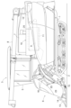
図1及び図2には、自脱型コンバインを示している。本コンバインは、機体フレーム1と、機体フレーム1を支持する走行装置2と、を備えている。機体の前部における右側には、運転キャビン3が設けられている。運転キャビン3は、運転者が搭乗する運転部4と、運転部4を覆うキャビン5と、を備えている。運転部4の下方には、エンジン(図示省略)が設けられている。
[Overall configuration of the combine]
1 and 2 show a head-feeding combine harvester. This combine harvester comprises a
運転キャビン3の前方には、植立穀稈を刈り取る刈取部6が設けられている。運転キャビン3の後方には、穀粒を貯留する穀粒貯留タンク7が設けられている。穀粒貯留タンク7内の穀粒を排出する穀粒排出装置8が設けられている。機体の左側部には、刈取穀稈を挟持搬送するフィードチェーン9が設けられている。穀粒貯留タンク7の左隣には、脱穀装置10が設けられている。脱穀装置10は、フィードチェーン9によって搬送される刈取穀稈を扱胴11によって脱穀処理する。脱穀装置10の後側には、排藁搬送装置12が連設されている。排藁搬送装置12は、フィードチェーン9から脱穀処理後の排藁を受け取って後方へ挟持搬送する。
In front of the driver's
〔刈取部〕
刈取部6は、複数刈り仕様(例えば、六条刈り仕様)に構成されている。刈取部6は、複数(例えば、七個)の分草具13と、複数(例えば、六個)の引起装置14と、切断装置15と、搬送装置16と、を備えている。分草具13は、圃場の植立穀稈を分草する。
引起装置14は、分草された植立穀稈を引き起こす。切断装置15は、引き起こされた植立穀稈を切断する。搬送装置16は、刈取穀稈を脱穀装置10に向けて後方へ搬送する。
[Harvesting department]
The reaping
The raising
〔脱穀装置〕
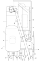
図3に示すように、脱穀装置10の上部には、扱室17が形成されている。扱室17には、扱胴11が設けられている。扱胴11は、機体前後方向に延びる回転軸心Y1周りで回転可能である。扱胴11の下方には、受網18が設けられている。扱室17の後方には、塵埃を外部に排出する排塵ファン19が設けられている。
[Threshing device]
As shown in Fig. 3, a threshing
脱穀装置10の下部には、選別対象物を機体後方に移送しながら篩い選別する揺動選別装置20、揺動選別装置20に選別風を送風する唐箕21、一番物の穀粒(単粒化穀粒等)を回収する一番回収部22、二番物の穀粒(枝梗付き穀粒等)を回収する二番回収部23等が設けられている。
At the bottom of the threshing
一番回収部22には、一番物の穀粒を右方へ搬送する一番スクリュ24が設けられている。一番スクリュ24の右端部には、一番物の穀粒を穀粒貯留タンク7に揚穀搬送する揚穀装置25が連動連結されている。
The
二番回収部23には、二番物の穀粒を右方へ搬送する二番スクリュ26が設けられている。二番スクリュ26の右端部には、二番物の穀粒を揺動選別装置20に還元する二番還元装置27が連動連結されている。
The
〔扱胴〕
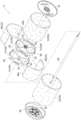
図3から図5に示すように、扱胴11は、機体前後方向に延びる扱胴軸28と、扱胴軸28に支持されると共に複数の扱歯29が外周部に取り付けられる略円筒形状の胴体30と、を有している。扱胴11は、機体前後方向に延びる回転軸心Y1周りで回転可能である。扱胴11は、扱胴軸28を介して扱室17における前壁31F及び後壁31Bに支持されている。胴体30は、胴体30が前後に分割(例えば、三分割)された複数(例えば、三つ)の胴体部を有している。胴体30は、前記胴体部として、前側に位置する前側胴体部32と、後側に位置する後側胴体部33と、前側胴体部32と後側胴体部33との間に位置する中間胴体部34(本発明に係る「着脱胴体部」に相当)と、を有している。前側胴体部32、後側胴体部33及び中間胴体部34は、これらが一体に回転するように、単一の扱胴軸28に支持されている。前側胴体部32の前後長さL1、後側胴体部33の前後長さL2及び中間胴体部34の前後長さL3は、略等しい。すなわち、前側胴体部32、後側胴体部33及び中間胴体部34は、前後方向の長さが略等しい。
[Handling drum]
As shown in Figures 3 to 5, the threshing
扱胴軸28は、前ベアリング35を介して前壁31Fに回転可能に支持されていると共に、後ベアリング36を介して後壁31Bに回転可能に支持されている。扱胴軸28のうち前壁31Fから前方に突出する部分には、前記エンジンからの駆動力が入力される入力プーリ37が設けられている。
The threshing
〔前側胴体部〕
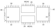
前側胴体部32は、略円筒形状の板材によって構成されている。前側胴体部32の前端開口縁部には、前端開口を塞ぐ前板材38がボルト固定されている。前板材38の後面(胴体30の内部側の面)には、前側ボス39がボルト40によって固定されている。前側ボス39は、扱胴軸28にボルト41によって固定されている。前板材38は、前側ボス39を介して扱胴軸28に扱胴軸28と一定回転可能に支持されている。
[Front fuselage]
The
〔後側胴体部〕
後側胴体部33は、略円筒形状の板材によって構成されている。後側胴体部33の後端開口縁部には、後端開口を塞ぐ後板材42がボルト固定されている。後板材42の前面(胴体30の内部側の面)には、後側ボス43がボルト44によって固定されている。後側ボス43は、扱胴軸28にボルト45によって固定されている。後板材42は、後側ボス43を介して扱胴軸28に扱胴軸28と一体回転可能に支持されている。
[Rear fuselage section]
The
〔中間胴体部〕
中間胴体部34は、中間胴体部34が胴体30の周方向に分割(例えば、二分割)された複数(例えば、二つ)の中間胴体部構成部材46(本発明に係る「胴体部構成部材」に相当)を有している。中間胴体部構成部材46は、略半円筒形状の板材によって構成されている。中間胴体部34は、胴体30の周方向に二分割された半割り構造である。二つの中間胴体部構成部材46は、同一の部材によって構成され、かつ、扱歯29の配列が同一である。各中間胴体部構成部材46は、前側胴体部32及び後側胴体部33に対して着脱可能である。中間胴体部構成部材46のうち胴体30の周方向における一方側の縁部には、他方の中間胴体部構成部材46と連結される連結部46aが設けられている。連結部46aは、他方の中間胴体部構成部材46に内周側から当て付けられた状態でボルト固定されている。
[Middle fuselage section]
The
〔連結部材〕
図4から図6に示すように、胴体30の内部における前後中間部には、前側の連結部材48及び後側の連結部材48が設けられている。前側の連結部材48は、胴体30の内部における前側胴体部32と中間胴体部34との境界部に設けられている。前側の連結部材48は、前側胴体部32と中間胴体部34とを連結し、かつ、扱胴軸28と前側胴体部32及び中間胴体部34とを連結し、かつ、胴体30の周方向で隣り合う中間胴体部構成部材46の前端部同士を連結している。前側の連結部材48は、前側胴体部32及び中間胴体部34に着脱可能にボルト47によって固定されている。
[Connecting member]
4 to 6, a
後側の連結部材48は、胴体30の内部における後側胴体部33と中間胴体部34との境界部に設けられている。後側の連結部材48は、後側胴体部33と中間胴体部34とを連結し、かつ、扱胴軸28と後側胴体部33及び中間胴体部34とを連結し、かつ、胴体30の周方向で隣り合う中間胴体部構成部材46の後端部同士を連結している。後側の連結部材48は、後側胴体部33及び中間胴体部34に着脱可能にボルト47によって固定されている。
The
前側の連結部材48及び後側の連結部材48は、同一の部材によって構成されている。
連結部材48は、胴体30の内周面に沿う胴体部連結部49(本発明に係る「胴体部連結部」、「周方向連結部材」に相当)と、扱胴軸28と胴体部連結部49とに亘る径方向連結部50と、を有している。
The front connecting
The connecting
前側の胴体部連結部49は、前側胴体部32と中間胴体部34とを連結し、かつ、胴体30の周方向で隣り合う中間胴体部構成部材46の前端部同士を連結している。前側の胴体部連結部49に対して、各中間胴体部構成部材46が着脱可能である。後側の胴体部連結部49は、後側胴体部33と中間胴体部34とを連結し、かつ、胴体30の周方向で隣り合う中間胴体部構成部材46の後端部同士を連結している。後側の胴体部連結部49に対して、各中間胴体部構成部材46が着脱可能である。
The front
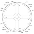
図7から図9に示すように、胴体部連結部49は、胴体30の内周面に沿って設けられている。胴体部連結部49は、胴体30の内周面に沿う略環形状に形成されている。胴体部連結部49は、複数(例えば、二つ)の胴体部連結部構成部材51に胴体30の周方向に分割されて構成されている。すなわち、胴体部連結部49は、胴体30の周方向に二分割された半割り構造である。二つの胴体部連結部構成部材51は、同一の部材によって構成されている。
As shown in Figures 7 to 9, the body
胴体部連結部構成部材51は、略半環形状の板材によって構成されている。胴体部連結部構成部材51のうち胴体30の周方向における一端部には、他方の胴体部連結部構成部材51が重ね合わされる被重合部51aが形成されている。胴体部連結部構成部材51において、被重合部51aとその他の部分との境界部は、被重合部51aが前記その他の部分よりも胴体30の径方向の内周側に位置するように、段差形状に形成されている。胴体部連結部構成部材51には、ボルト47用のボルト孔51bが形成されている。
The
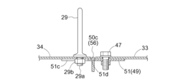
胴体部連結部構成部材51には、扱歯29を胴体30に固定するボルト29a及びナット29bが入り込む切り欠き部51cが複数(例えば、四つ)形成されている(図6及び図10参照)。胴体部連結部構成部材51において、二つの切り欠き部51cが回転軸心Y1方向の一方側に開口し、かつ、二つの切り欠き部51cが回転軸心Y1方向の他方側に開口している。一方側に開口する切り欠き部51cと他方側に開口する切り欠き部51cとは、胴体30の周方向に位置ズレしている。
The
前側の径方向連結部50は、扱胴軸28と前側の胴体部連結部49とを連結している。
前側の径方向連結部50の前面には、中間ボス52がボルト53によって固定されている。中間ボス52は、扱胴軸28にボルト54によって固定されている。前側の連結部材48は、中間ボス52を介して扱胴軸28に扱胴軸28と一体回転可能に支持されている。
The front
An
後側の径方向連結部50は、扱胴軸28と後側の胴体部連結部49とを連結している。
後側の径方向連結部50の後面には、中間ボス52がボルト53によって固定されている。中間ボス52は、扱胴軸28にボルト54によって固定されている。後側の連結部材48は、中間ボス52を介して扱胴軸28に扱胴軸28と一体回転可能に支持されている。
The rear
An
径方向連結部50は、回転軸心Y1方向に向く板面を有する板材によって構成されている。径方向連結部50には、回転軸心Y1方向に開口する複数(例えば、四つ)の開口50aが形成されている。径方向連結部50のうち被重合部51aに対応する箇所には、被重合部51aが入り込む凹部50bが形成されている。
The
前側の連結部材48と後側の連結部材48とに亘って、これらを連結する複数(例えば、四本)の連結ロッド55が設けられている。前側の連結部材48と後側の連結部材48とが連結ロッド55によって連結されることにより、前側の連結部材48と後側の連結部材48とが一体化されている。すなわち、前側の連結部材48、後側の連結部材48及び連結ロッド55がユニットとして構成(ユニット化)されている。連結ロッド55は、断面形状が略L字形状の部材によって構成されている。連結ロッド55は、回転軸心Y1周りに等角度間隔で複数配置されている。本実施形態では、連結ロッド55は、回転軸心Y1周りに90度間隔で四本配置されている。
A plurality of (e.g., four) connecting
前記胴体部と連結部材48との間には、連結部材48が前記胴体部の開口縁部から前記胴体部の内部に入り込むのを規制する規制部56が設けられている(図6及び図10参照)。胴体部連結部49(胴体部連結部構成部材51)に形成された開口51dに、径方向連結部50に設けられた突起50cが差し込まれることにより、規制部56が構成されている。開口51dは、胴体部連結部49において、回転軸心Y1周りに等角度間隔で複数(例えば、四つ)形成されている。開口51dは、胴体30の周方向に長い長孔である。
Between the body section and the connecting
突起50cは、径方向連結部50において、回転軸心Y1周りに等角度間隔で複数(例えば、四つ)形成されている。突起50cは、径方向連結部50のうち胴体30の内周面に対向する部分(径方向連結部50の外周部)から胴体30の径方向の外側に突出している。突起50cは、胴体30の径方向において、胴体部連結部49の外周面よりも外側に突出し、かつ、胴体30の外周面よりも外側に突出していない。
The
一方の胴体部連結部構成部材51が他方の胴体部連結部構成部材51側の被重合部51aに重ね合わされた状態で、かつ、突起50cが開口51dに嵌め込まれた状態で、胴体部連結部49と径方向連結部50とが固定(例えば、溶接固定)されることにより、連結部材48が構成されている。一方の胴体部連結部構成部材51の外周面と他方の胴体部連結部構成部材51の外周面とは、面一となっている。すなわち、一方の胴体部連結部構成部材51の外周面と他方の胴体部連結部構成部材51の外周面とは、回転軸心Y1を中心とする円(同心円)上に位置している。
When one body connecting
図6に示すように、前側の胴体部連結部49は、前側胴体部32の後端開口縁部から前側胴体部32の内部に入り込んだ状態で、前側胴体部32の後端開口縁部にボルト47によって固定されている。その際、前側の連結部材48が前側胴体部32の後端開口縁部から前側胴体部32の内部に入り込むのを規制部56によって規制している。突起50cが前側胴体部32の後端開口縁部に当接することにより、前側の連結部材48がこれ以上前側胴板部32の内部に入り込むことがない。
As shown in FIG. 6, the front
後側の胴体部連結部49は、後側胴体部33の前端開口縁部から後側胴体部33の内部に入り込んだ状態で、後側胴体部33の前端開口縁部にボルト47によって固定されている。その際、後側の連結部材48が後側胴体部33の前端開口縁部から後側胴体部33の内部に入り込むのを規制部56によって規制している。突起50cが後側胴体部33の前端開口縁部に当接することにより、後側の連結部材48がこれ以上後側胴板部33の内部に入り込むことがない。
The rear
中間胴体部34(中間胴体部構成部材46)は、前側の胴体部連結部49の後半部及び後側の胴体部連結部49の前半部にボルト47によって固定されている。ボルト47を取り外すことにより、各中間胴体部構成部材46を前側の胴体部連結部49及び後側の胴体部連結部49から取り外すことができる。
The intermediate fuselage section 34 (intermediate fuselage section constituent member 46) is fixed to the rear half of the front fuselage
〔扱胴の製造方法〕
次に、扱胴11の製造方法について、図11から図14により説明する。図11から図14に示すように、扱胴11の製造方法は、扱歯取り付け工程と、前後連結部材取り付け工程と、扱胴軸取り付け工程と、前後連結工程と、を備えている。
[Manufacturing method of the handling cylinder]
Next, a manufacturing method of the threshing
図11に示すように、扱歯取り付け工程は、前側胴体部32、後側胴体部33及び中間胴体部34に扱歯29を取り付ける工程である。図12に示すように、前後連結部材取り付け工程は、前側の連結部材48を前側胴体部32に取り付けると共に、後側の連結部材48を後側胴体部33に取り付ける工程である。扱歯取り付け工程が行われた後、前後連結部材取り付け工程において、前側の連結部材48を前側胴体部32にボルト47によって固定すると共に、後側の連結部材48を後側胴体部33にボルト47によって固定する。その際、前側の連結部材48が前側胴体部32の後端開口縁部から前側胴体部32の内部に入り込むのを規制部56によって規制した状態で、前側胴体部32の後端開口縁部に前側の連結部材48をボルト47によって固定すると共に、後側の連結部材48が後側胴体部33の前端開口縁部から後側胴体部33の内部に入り込むのを規制部56によって規制した状態で、後側胴体部33の前端開口縁部に後側の連結部材48をボルト47によって固定する。
As shown in Figure 11, the handling teeth attachment process is a process of attaching the handling
図13に示すように、扱胴軸取り付け工程は、扱胴軸28を前側胴体部32及び後側胴体部33に取り付ける工程である。前後連結部材取り付け工程が行われた後、扱胴軸取り付け工程において、扱胴軸28を、前側ボス39にボルト41によって固定し、かつ、前側の中間ボス52にボルト54によって固定し、かつ、後側の中間ボス52にボルト54によって固定し、かつ、後側ボス43にボルト45によって固定する。
As shown in FIG. 13, the handling cylinder shaft installation process is a process of installing the handling
図14に示すように、前後連結工程は、中間胴体部34を、前側の連結部材48を介して前側胴体部32に連結し、かつ、後側の連結部材48を介して後側胴体部33に連結する工程である。扱胴軸取り付け工程が行われた後、前後連結工程において、各中間胴体部構成部材46を、前側の連結部材48にボルト47によって固定し、かつ、後側の連結部材48にボルト47によって固定する。
As shown in FIG. 14, the front-rear connecting process is a process in which the
〔別実施形態〕
(1)上記実施形態では、胴体30が前後に三分割されている。しかし、胴体30が前後に四分割以上されていてもよい。あるいは、胴体30が前後に二分割されていてもよい。
この場合、図15に示すように、前側胴体部32を二つの前側胴体部構成部材に胴体30の周方向に二分割して構成すると共に、各前側胴体部構成部材を後側胴体部33に対して着脱可能に構成してもよい。あるいは、図16に示すように、後側胴体部33を二つの後側胴体部構成部材に胴体30の周方向に二分割して構成すると共に、各後側胴体部構成部材を前側胴体部32に対して着脱可能に構成してもよい。
[Another embodiment]
(1) In the above embodiment, the
In this case, as shown in Fig. 15, the
(2)上記実施形態では、前側胴体部32、後側胴体部33及び中間胴体部34は、前後方向の長さが略等しい。しかし、前側胴体部32、後側胴体部33及び中間胴体部34は、前後方向の長さが異なっていてもよい。この場合、中間胴体部34の前後方向の長さが前側胴体部32及び後側胴体部33の各前後方向の長さよりも長くてもよい。
(2) In the above embodiment, the
(3)上記実施形態では、中間胴体部34が前側胴体部32及び後側胴体部33に対して着脱可能である。しかし、前側胴体部32、後側胴体部33及び中間胴体部34のうち何れの胴体部が着脱可能であってもよい。
(3) In the above embodiment, the
(4)上記実施形態では、中間胴体部34が胴体30の周方向に二分割されている。しかし、中間胴体部34が胴体30の周方向に三分割以上されていてもよい。
(4) In the above embodiment, the
(5)上記実施形態では、各中間胴体部構成部材46が前側胴体部32及び後側胴体部33に対して着脱可能である。しかし、二つの中間胴体部構成部材46のうち一方のみが前側胴体部32及び後側胴体部33に対して着脱可能であってもよい。
(5) In the above embodiment, each
(6)上記実施形態では、二つの中間胴体部構成部材46が同一の部材によって構成され、かつ、扱歯29の配列が同一である。しかし、二つの中間胴体部構成部材46が異なる部材によって構成され、かつ、扱歯29の配列が異なっていてもよい。
(6) In the above embodiment, the two
(7)上記実施形態では、連結部材48(径方向連結部50)に、開口50aが四つ形成されている。しかし、連結部材48(径方向連結部50)に、開口50aが一つから三つ又は五つ以上形成されていてもよい。
(7) In the above embodiment, four
(8)上記実施形態では、胴体30の周壁に点検口が設けられていない。しかし、胴体30の周壁に点検口が設けられていてもよい。
(8) In the above embodiment, no inspection hatch is provided on the peripheral wall of the
本発明は、自脱型コンバインの他、普通型コンバインにも利用可能である。 The present invention can be used for head-feeding combines as well as normal combines.
10 脱穀装置
11 扱胴
28 扱胴軸
29 扱歯
30 胴体
32 前側胴体部(胴体部)
33 後側胴体部(胴体部)
34 中間胴体部(胴体部、着脱胴体部)
46 中間胴体部構成部材(胴体部構成部材)
49 胴体部連結部(胴体部連結部、周方向連結部材)
51c 切り欠き部
10
33 Rear fuselage (fuselage)
34 Intermediate body section (body section, detachable body section)
46 Intermediate fuselage component (fuselage component)
49 Body connection portion (body connection portion, circumferential connection member)
51c Notch
Claims (7)
前記扱胴は、機体前後方向に延びる扱胴軸と、前記扱胴軸に支持されると共に複数の扱歯が外周部に取り付けられる胴体と、を有し、
前記胴体は、前記胴体が前後に分割された複数の胴体部を有し、
前記複数の胴体部のうち少なくとも一つは、着脱可能な着脱胴体部であり、
前記胴体の内部に前記胴体部とは別体にて設けられ、前記複数の胴体部のうち前後に隣り合う胴体部同士を連結する胴体部連結部材が備えられ、
前記胴体部連結部材に、前記扱歯の基部が入り込む切り欠き部が形成されているコンバイン。 A combine harvester equipped with a threshing device that threshes harvested stalks using a threshing drum,
The threshing drum has a threshing drum shaft extending in the fore-and-aft direction of the aircraft body, and a body supported by the threshing drum shaft and having a plurality of threshing teeth attached to an outer periphery thereof,
The fuselage has a plurality of fuselage sections divided into front and rear fuselage sections,
At least one of the plurality of body parts is a detachable body part,
A body portion connecting member is provided inside the body separately from the body portion and connects adjacent body portions in the front-rear direction among the plurality of body portions,
A combine harvester in which a notch into which the base of the handling tooth fits is formed in the body connecting member .
前記前側胴体部、前記後側胴体部及び前記中間胴体部は、前後方向の長さが略等しい請求項1から6の何れか一項に記載のコンバイン。 the fuselage has, as the fuselage portion, a front fuselage portion located on a front side, a rear fuselage portion located on a rear side, and an intermediate fuselage portion located between the front fuselage portion and the rear fuselage portion,
The combine harvester according to claim 1 , wherein the front body portion, the rear body portion and the intermediate body portion have approximately the same length in the front-rear direction.
Priority Applications (2)
| Application Number | Priority Date | Filing Date | Title |
|---|---|---|---|
| JP2023000464A JP7547517B2 (en) | 2017-06-28 | 2023-01-05 | combine |
| JP2024146691A JP2024156027A (en) | 2017-06-28 | 2024-08-28 | combine |
Applications Claiming Priority (3)
| Application Number | Priority Date | Filing Date | Title |
|---|---|---|---|
| JP2017126697A JP6943645B2 (en) | 2017-06-28 | 2017-06-28 | combine |
| JP2021147140A JP7208321B2 (en) | 2017-06-28 | 2021-09-09 | combine |
| JP2023000464A JP7547517B2 (en) | 2017-06-28 | 2023-01-05 | combine |
Related Parent Applications (1)
| Application Number | Title | Priority Date | Filing Date |
|---|---|---|---|
| JP2021147140A Division JP7208321B2 (en) | 2017-06-28 | 2021-09-09 | combine |
Related Child Applications (1)
| Application Number | Title | Priority Date | Filing Date |
|---|---|---|---|
| JP2024146691A Division JP2024156027A (en) | 2017-06-28 | 2024-08-28 | combine |
Publications (3)
| Publication Number | Publication Date |
|---|---|
| JP2023026613A JP2023026613A (en) | 2023-02-24 |
| JP2023026613A5 JP2023026613A5 (en) | 2023-06-26 |
| JP7547517B2 true JP7547517B2 (en) | 2024-09-09 |
Family
ID=65026300
Family Applications (4)
| Application Number | Title | Priority Date | Filing Date |
|---|---|---|---|
| JP2017126697A Active JP6943645B2 (en) | 2017-06-28 | 2017-06-28 | combine |
| JP2021147140A Active JP7208321B2 (en) | 2017-06-28 | 2021-09-09 | combine |
| JP2023000464A Active JP7547517B2 (en) | 2017-06-28 | 2023-01-05 | combine |
| JP2024146691A Pending JP2024156027A (en) | 2017-06-28 | 2024-08-28 | combine |
Family Applications Before (2)
| Application Number | Title | Priority Date | Filing Date |
|---|---|---|---|
| JP2017126697A Active JP6943645B2 (en) | 2017-06-28 | 2017-06-28 | combine |
| JP2021147140A Active JP7208321B2 (en) | 2017-06-28 | 2021-09-09 | combine |
Family Applications After (1)
| Application Number | Title | Priority Date | Filing Date |
|---|---|---|---|
| JP2024146691A Pending JP2024156027A (en) | 2017-06-28 | 2024-08-28 | combine |
Country Status (1)
| Country | Link |
|---|---|
| JP (4) | JP6943645B2 (en) |
Families Citing this family (3)
| Publication number | Priority date | Publication date | Assignee | Title |
|---|---|---|---|---|
| JP6943645B2 (en) * | 2017-06-28 | 2021-10-06 | 株式会社クボタ | combine |
| US12356787B2 (en) | 2018-11-30 | 2025-07-08 | Kyulux, Inc. | Organic light emitting element |
| DE112022005416T5 (en) | 2021-11-12 | 2024-08-22 | J-QuAD DYNAMICS INC. | Wrong-way detection device, wrong-way detection method and wrong-way detection program |
Citations (3)
| Publication number | Priority date | Publication date | Assignee | Title |
|---|---|---|---|---|
| JP2003000039A (en) | 2001-06-22 | 2003-01-07 | Kubota Corp | Handle |
| JP2006067910A (en) | 2004-09-02 | 2006-03-16 | Kubota Corp | Handle structure of threshing equipment |
| JP2019097400A (en) | 2017-11-28 | 2019-06-24 | 株式会社クボタ | Combine-harvester |
Family Cites Families (11)
| Publication number | Priority date | Publication date | Assignee | Title |
|---|---|---|---|---|
| JPS4722122Y1 (en) * | 1967-06-09 | 1972-07-19 | ||
| JPS512563U (en) * | 1974-06-22 | 1976-01-09 | ||
| JPS5118263U (en) * | 1974-07-29 | 1976-02-10 | ||
| JPS5356353U (en) * | 1976-10-18 | 1978-05-13 | ||
| JPS5358358A (en) * | 1976-11-06 | 1978-05-26 | Kubota Ltd | Treshing cylinder for thresher |
| JPS53150765U (en) * | 1977-05-02 | 1978-11-28 | ||
| JPS55136234U (en) * | 1979-03-22 | 1980-09-27 | ||
| JPS60144831U (en) * | 1984-03-02 | 1985-09-26 | ヤンマー農機株式会社 | Threshing machine handling barrel structure |
| JP2011193784A (en) | 2010-03-19 | 2011-10-06 | Yanmar Co Ltd | Threshing device |
| CN101940108B (en) * | 2010-06-13 | 2012-07-18 | 莱恩农业装备有限公司 | Coaxial double-speed threshing cylinder |
| JP6943645B2 (en) | 2017-06-28 | 2021-10-06 | 株式会社クボタ | combine |
-
2017
- 2017-06-28 JP JP2017126697A patent/JP6943645B2/en active Active
-
2021
- 2021-09-09 JP JP2021147140A patent/JP7208321B2/en active Active
-
2023
- 2023-01-05 JP JP2023000464A patent/JP7547517B2/en active Active
-
2024
- 2024-08-28 JP JP2024146691A patent/JP2024156027A/en active Pending
Patent Citations (3)
| Publication number | Priority date | Publication date | Assignee | Title |
|---|---|---|---|---|
| JP2003000039A (en) | 2001-06-22 | 2003-01-07 | Kubota Corp | Handle |
| JP2006067910A (en) | 2004-09-02 | 2006-03-16 | Kubota Corp | Handle structure of threshing equipment |
| JP2019097400A (en) | 2017-11-28 | 2019-06-24 | 株式会社クボタ | Combine-harvester |
Also Published As
| Publication number | Publication date |
|---|---|
| JP7208321B2 (en) | 2023-01-18 |
| JP2021184762A (en) | 2021-12-09 |
| JP2023026613A (en) | 2023-02-24 |
| JP6943645B2 (en) | 2021-10-06 |
| JP2019004850A (en) | 2019-01-17 |
| JP2024156027A (en) | 2024-10-31 |
Similar Documents
| Publication | Publication Date | Title |
|---|---|---|
| JP7547517B2 (en) | combine | |
| EP1385366B1 (en) | Elevator slats for an agricultural harvesting machine | |
| JP2023026613A5 (en) | ||
| CN208227722U (en) | Combine harvester | |
| JP2021184762A5 (en) | ||
| JP5739709B2 (en) | Threshing device | |
| JP2020048474A (en) | Combine | |
| US11917947B2 (en) | Threshing cylinder | |
| JP6941985B2 (en) | combine | |
| JP5797940B2 (en) | Combine handling cylinder | |
| JP6840042B2 (en) | Threshing device | |
| JP6840043B2 (en) | Threshing device | |
| JP6941984B2 (en) | combine | |
| KR102814692B1 (en) | Combine | |
| JP6971811B2 (en) | combine | |
| CN109121740B (en) | Threshing device and method for manufacturing threshing cylinder | |
| JP7292021B2 (en) | Threshing device | |
| JP7313227B2 (en) | combine | |
| JP2023082967A (en) | work vehicle | |
| JP6971810B2 (en) | combine | |
| JP6971809B2 (en) | combine | |
| KR102275501B1 (en) | Teeth of threshing device and Combine with the same, Teeth assembling methods of combine threshing device | |
| JP6832834B2 (en) | combine | |
| JP6619276B2 (en) | Combine | |
| JP2012205564A (en) | Threshing cylinder for thresher |
Legal Events
| Date | Code | Title | Description |
|---|---|---|---|
| A621 | Written request for application examination |
Free format text: JAPANESE INTERMEDIATE CODE: A621 Effective date: 20230203 |
|
| A521 | Request for written amendment filed |
Free format text: JAPANESE INTERMEDIATE CODE: A523 Effective date: 20230616 |
|
| A977 | Report on retrieval |
Free format text: JAPANESE INTERMEDIATE CODE: A971007 Effective date: 20240131 |
|
| A131 | Notification of reasons for refusal |
Free format text: JAPANESE INTERMEDIATE CODE: A131 Effective date: 20240227 |
|
| A521 | Request for written amendment filed |
Free format text: JAPANESE INTERMEDIATE CODE: A523 Effective date: 20240424 |
|
| TRDD | Decision of grant or rejection written | ||
| A01 | Written decision to grant a patent or to grant a registration (utility model) |
Free format text: JAPANESE INTERMEDIATE CODE: A01 Effective date: 20240730 |
|
| A61 | First payment of annual fees (during grant procedure) |
Free format text: JAPANESE INTERMEDIATE CODE: A61 Effective date: 20240828 |
|
| R150 | Certificate of patent or registration of utility model |
Ref document number: 7547517 Country of ref document: JP Free format text: JAPANESE INTERMEDIATE CODE: R150 |