JP7537101B2 - Recording device - Google Patents
Recording device Download PDFInfo
- Publication number
- JP7537101B2 JP7537101B2 JP2020037836A JP2020037836A JP7537101B2 JP 7537101 B2 JP7537101 B2 JP 7537101B2 JP 2020037836 A JP2020037836 A JP 2020037836A JP 2020037836 A JP2020037836 A JP 2020037836A JP 7537101 B2 JP7537101 B2 JP 7537101B2
- Authority
- JP
- Japan
- Prior art keywords
- recording
- light
- medium
- paper
- optical member
- Prior art date
- Legal status (The legal status is an assumption and is not a legal conclusion. Google has not performed a legal analysis and makes no representation as to the accuracy of the status listed.)
- Active
Links
- 230000003287 optical effect Effects 0.000 claims description 65
- 238000001514 detection method Methods 0.000 claims description 17
- 238000005286 illumination Methods 0.000 claims description 7
- 238000011144 upstream manufacturing Methods 0.000 claims description 7
- 239000005338 frosted glass Substances 0.000 claims description 6
- 238000002834 transmittance Methods 0.000 claims 1
- 238000010586 diagram Methods 0.000 description 6
- 239000003795 chemical substances by application Substances 0.000 description 5
- 239000000463 material Substances 0.000 description 5
- VYPSYNLAJGMNEJ-UHFFFAOYSA-N Silicium dioxide Chemical compound O=[Si]=O VYPSYNLAJGMNEJ-UHFFFAOYSA-N 0.000 description 3
- VTYYLEPIZMXCLO-UHFFFAOYSA-L Calcium carbonate Chemical compound [Ca+2].[O-]C([O-])=O VTYYLEPIZMXCLO-UHFFFAOYSA-L 0.000 description 2
- XLOMVQKBTHCTTD-UHFFFAOYSA-N Zinc monoxide Chemical compound [Zn]=O XLOMVQKBTHCTTD-UHFFFAOYSA-N 0.000 description 2
- TZCXTZWJZNENPQ-UHFFFAOYSA-L barium sulfate Chemical compound [Ba+2].[O-]S([O-])(=O)=O TZCXTZWJZNENPQ-UHFFFAOYSA-L 0.000 description 2
- 239000005337 ground glass Substances 0.000 description 2
- 238000012986 modification Methods 0.000 description 2
- 230000004048 modification Effects 0.000 description 2
- 239000000758 substrate Substances 0.000 description 2
- GWEVSGVZZGPLCZ-UHFFFAOYSA-N Titan oxide Chemical compound O=[Ti]=O GWEVSGVZZGPLCZ-UHFFFAOYSA-N 0.000 description 1
- WNROFYMDJYEPJX-UHFFFAOYSA-K aluminium hydroxide Chemical compound [OH-].[OH-].[OH-].[Al+3] WNROFYMDJYEPJX-UHFFFAOYSA-K 0.000 description 1
- 239000011324 bead Substances 0.000 description 1
- 229910000019 calcium carbonate Inorganic materials 0.000 description 1
- 238000007599 discharging Methods 0.000 description 1
- 239000011521 glass Substances 0.000 description 1
- ZLNQQNXFFQJAID-UHFFFAOYSA-L magnesium carbonate Chemical compound [Mg+2].[O-]C([O-])=O ZLNQQNXFFQJAID-UHFFFAOYSA-L 0.000 description 1
- 239000001095 magnesium carbonate Substances 0.000 description 1
- 229910000021 magnesium carbonate Inorganic materials 0.000 description 1
- 238000000034 method Methods 0.000 description 1
- 239000011347 resin Substances 0.000 description 1
- 229920005989 resin Polymers 0.000 description 1
- 239000000377 silicon dioxide Substances 0.000 description 1
- 229910052814 silicon oxide Inorganic materials 0.000 description 1
- OGIDPMRJRNCKJF-UHFFFAOYSA-N titanium oxide Inorganic materials [Ti]=O OGIDPMRJRNCKJF-UHFFFAOYSA-N 0.000 description 1
- 239000011787 zinc oxide Substances 0.000 description 1
Images


Classifications
-
- B—PERFORMING OPERATIONS; TRANSPORTING
- B41—PRINTING; LINING MACHINES; TYPEWRITERS; STAMPS
- B41J—TYPEWRITERS; SELECTIVE PRINTING MECHANISMS, i.e. MECHANISMS PRINTING OTHERWISE THAN FROM A FORME; CORRECTION OF TYPOGRAPHICAL ERRORS
- B41J25/00—Actions or mechanisms not otherwise provided for
-
- B—PERFORMING OPERATIONS; TRANSPORTING
- B41—PRINTING; LINING MACHINES; TYPEWRITERS; STAMPS
- B41J—TYPEWRITERS; SELECTIVE PRINTING MECHANISMS, i.e. MECHANISMS PRINTING OTHERWISE THAN FROM A FORME; CORRECTION OF TYPOGRAPHICAL ERRORS
- B41J29/00—Details of, or accessories for, typewriters or selective printing mechanisms not otherwise provided for
- B41J29/18—Mechanisms for rendering the print visible to the operator
- B41J29/19—Mechanisms for rendering the print visible to the operator with reflectors or illuminating devices
-
- B—PERFORMING OPERATIONS; TRANSPORTING
- B41—PRINTING; LINING MACHINES; TYPEWRITERS; STAMPS
- B41J—TYPEWRITERS; SELECTIVE PRINTING MECHANISMS, i.e. MECHANISMS PRINTING OTHERWISE THAN FROM A FORME; CORRECTION OF TYPOGRAPHICAL ERRORS
- B41J29/00—Details of, or accessories for, typewriters or selective printing mechanisms not otherwise provided for
- B41J29/12—Guards, shields or dust excluders
- B41J29/13—Cases or covers
-
- B—PERFORMING OPERATIONS; TRANSPORTING
- B65—CONVEYING; PACKING; STORING; HANDLING THIN OR FILAMENTARY MATERIAL
- B65H—HANDLING THIN OR FILAMENTARY MATERIAL, e.g. SHEETS, WEBS, CABLES
- B65H31/00—Pile receivers
- B65H31/20—Pile receivers adjustable for different article sizes
-
- B—PERFORMING OPERATIONS; TRANSPORTING
- B41—PRINTING; LINING MACHINES; TYPEWRITERS; STAMPS
- B41J—TYPEWRITERS; SELECTIVE PRINTING MECHANISMS, i.e. MECHANISMS PRINTING OTHERWISE THAN FROM A FORME; CORRECTION OF TYPOGRAPHICAL ERRORS
- B41J29/00—Details of, or accessories for, typewriters or selective printing mechanisms not otherwise provided for
- B41J29/02—Framework
-
- B—PERFORMING OPERATIONS; TRANSPORTING
- B65—CONVEYING; PACKING; STORING; HANDLING THIN OR FILAMENTARY MATERIAL
- B65H—HANDLING THIN OR FILAMENTARY MATERIAL, e.g. SHEETS, WEBS, CABLES
- B65H2701/00—Handled material; Storage means
- B65H2701/10—Handled articles or webs
- B65H2701/19—Specific article or web
- B65H2701/1928—Printing plate
Landscapes
- Engineering & Computer Science (AREA)
- Mechanical Engineering (AREA)
- Pile Receivers (AREA)
- Accessory Devices And Overall Control Thereof (AREA)
- Ink Jet (AREA)
- Controlling Sheets Or Webs (AREA)
Description
本発明は、媒体に記録を行う記録装置に関する。 The present invention relates to a recording device that records on a medium.
ファクシミリやプリンター等に代表される記録装置においては、装置の筐体に、記録が行われた媒体を排紙する排紙空間を設けるとともに、排紙空間内が暗いことに鑑み、特許文献1に示される様に排紙空間内を照らすランプを設ける構成が知られている。
特許文献1記載の構成では、トレイ上に用紙が排出されると排紙空間の天井に設けられたランプが点灯し、これによって排出された用紙の確認や取り出しが容易となり、また、用紙が排出されたことに容易に気付くことができる。
In recording devices such as facsimiles and printers, the housing of the device is provided with a paper discharge space into which media that has been recorded is discharged. In view of the fact that the paper discharge space is dark, a configuration is known in which a lamp is provided to illuminate the paper discharge space, as shown in
In the configuration described in
ユーザーによっては、記録結果をいち早く確認したい場合があり、特に高品質な写真印刷を行うユーザーにとっては、記録結果が所望する品質となっていることを、記録実行途中でいち早く、且つ厳格に確認したい場合がある。また特に記録方式がシリアルタイプのプリンターであれば、記録結果をいち早く確認した結果、所望する品質でなければ、その時点で記録動作を中止することにより、インクの無駄な消費を回避できる。
しかしながら上記特許文献1記載の構成では、排出された用紙の確認や取り出しを容易にする目的でランプを排紙空間の天井に設けたのみであり、記録結果をいち早く、つまり記録が完了する前に、且つ厳格に確認したい要請に対しては、充分に応えることができない。
Some users may want to check the print results as soon as possible, and particularly users who print high-quality photographs may want to check as soon as possible and strictly during the print run to ensure that the print results are of the desired quality. In particular, if the printer uses a serial type print method, if the print results are not of the desired quality after checking them as soon as possible, the print operation can be stopped at that point in time to avoid wasting ink.
However, in the configuration described in
上記課題を解決するための、本発明の記録装置は、媒体に記録を行う記録手段と、前記記録手段によって記録の行われた媒体を排出する排出位置において媒体の記録面と対向する対向部と、を備え、前記対向部は、発光部から発せられた光が入射する場所に位置し、入射した光を少なくとも前記記録面に向けた方向に放射する光学部材を備えて成ることを特徴とする。 To solve the above problem, the recording device of the present invention comprises a recording means for recording on a medium, and a facing portion that faces the recording surface of the medium at a discharge position where the medium on which recording has been performed by the recording means is discharged, and the facing portion is located at a position where light emitted from a light emitting portion is incident, and is characterized in that it comprises an optical member that radiates the incident light at least in a direction toward the recording surface.
以下、本発明を概略的に説明する。
第1の態様に係る記録装置は、媒体に記録を行う記録手段と、前記記録手段によって記録の行われた媒体を排出する排出位置において媒体の記録面と対向する対向部と、を備え、前記対向部は、発光部から発せられた光が入射する場所に位置し、入射した光を少なくとも前記記録面に向けた方向に放射する光学部材を備えて成ることを特徴とする。
The present invention will now be briefly described.
The recording device according to the first aspect comprises a recording means for recording on a medium, and an opposing portion facing the recording surface of the medium at an ejection position where the medium on which recording has been performed by the recording means is ejected, the opposing portion being located at a position where light emitted from a light emitting portion is incident, and comprising an optical member for radiating the incident light at least in a direction toward the recording surface.
本態様によれば、記録手段によって記録の行われた媒体を排出する排出位置において媒体の記録面と対向する対向部は、発光部から発せられた光が入射する場所に位置し、入射した光を少なくとも前記記録面に向けた方向に放射する光学部材を備えて成るので、記録結果をいち早く、つまり記録が完了する前に、且つ明瞭に視認することができ、ユーザーニーズに適切に対応することができる。 According to this aspect, the facing portion that faces the recording surface of the medium at the ejection position where the medium on which recording has been performed by the recording means is ejected is located at a position where the light emitted from the light emitting portion is incident, and is equipped with an optical member that radiates the incident light at least in a direction toward the recording surface, so that the recording results can be quickly and clearly seen, that is, before recording is completed, and user needs can be appropriately met.
第2の態様は、第1の態様において、前記光学部材による前記記録面の照射範囲は、媒体の搬送方向と交差する方向である媒体幅方向において、第1のサイズの媒体の、前記記録面の全域をカバーする幅を有することを特徴とする。
本態様によれば、前記光学部材による前記記録面の照射範囲は、媒体の搬送方向と交差する方向である媒体幅方向において、第1のサイズの媒体の、前記記録面の全域をカバーする幅を有するので、前記幅方向における前記記録面の全域を照射することができ、より適切に記録結果を視認することができる。
The second aspect is characterized in that, in the first aspect, the illumination range of the recording surface by the optical element has a width covering the entire recording surface of a medium of a first size in the medium width direction, which is a direction intersecting the medium transport direction.
According to the present aspect, the illumination range of the recording surface by the optical element has a width in the medium width direction, which is a direction intersecting the medium transport direction, that covers the entire recording surface of a medium of a first size, so that the entire recording surface in the width direction can be illuminated, and the recording results can be more appropriately viewed.
第3の態様は、第1のまたは第2の態様において、前記光学部材は、前記記録面と対向する面が磨りガラス状に形成された、光透過性を有する部材であることを特徴とする。
本態様によれば、前記光学部材は、前記記録面と対向する面が磨りガラス状に形成された、光透過性を有する部材であるので、前記発光部から発せられた光をより広範囲に拡散させることができる。
A third aspect is characterized in that in the first or second aspect, the optical member is a light-transmitting member whose surface facing the recording surface is formed like frosted glass.
According to this aspect, the optical member is a light-transmitting member whose surface facing the recording surface is formed like frosted glass, so that the light emitted from the light-emitting portion can be diffused over a wider range.
第4の態様は、第1のまたは第2の態様において、前記光学部材は、光拡散剤を含んだ光透過性を有する部材であることを特徴とする。
本態様によれば、前記光学部材は、光拡散剤を含んだ光透過性を有する部材であるので、前記発光部から発せられた光をより広範囲に拡散させることができる。
A fourth aspect is the first or second aspect, characterized in that the optical member is a light-transmitting member containing a light diffusing agent.
According to this aspect, the optical member is a light-transmitting member containing a light diffusing agent, so that the light emitted from the light-emitting portion can be diffused over a wider range.
第5の態様は、第1から第4の態様のいずれかにおいて、前記記録面と直交する方向における、前記記録面と前記光学部材との間隔が30mm以下であることを特徴とする。
本態様によれば、前記記録面と直交する方向における、前記記録面と前記光学部材との間隔が30mm以下であるので、前記排出位置において記録結果を明瞭に視認することができる。
A fifth aspect is characterized in that in any one of the first to fourth aspects, the distance between the recording surface and the optical member in a direction perpendicular to the recording surface is 30 mm or less.
According to this aspect, the distance between the recording surface and the optical member in the direction perpendicular to the recording surface is 30 mm or less, so that the recording result can be clearly seen at the ejection position.
第6の態様は、第1から第5の態様のいずれかにおいて、前記発光部から前記光学部材に発せられた光の光路を挟む一対の反射シートが設けられていることを特徴とする。
本態様によれば、前記発光部から前記光学部材に発せられた光の光路を挟む一対の反射シートが設けられているので、前記光学部材から前記記録面に対して照射される光の量を確保できる。
A sixth aspect is the optical element according to any one of the first to fifth aspects, further comprising a pair of reflective sheets sandwiching an optical path of light emitted from the light emitting portion to the optical member.
According to this aspect, a pair of reflective sheets are provided to sandwich the optical path of the light emitted from the light emitting portion to the optical member, so that the amount of light irradiated from the optical member to the recording surface can be ensured.
第7の態様は、第6の態様において、前記一対の反射シートのうち装置の前面を形成する壁部に近い反射シートと前記壁部との間に、遮光シートが設けられていることを特徴とする。
本態様によれば、前記一対の反射シートのうち装置の前面を形成する壁部に近い反射シートと前記壁部との間に、遮光シートが設けられているので、前記壁部から装置前方への光の漏洩を抑制できる。
A seventh aspect is characterized in that, in the sixth aspect, a light-shielding sheet is provided between the wall portion and one of the pair of reflective sheets which is closer to the wall portion forming the front surface of the device.
According to this aspect, a light-shielding sheet is provided between the wall portion forming the front surface of the device and the reflective sheet of the pair of reflective sheets which is closest to the wall portion, thereby preventing light from leaking from the wall portion to the front of the device.
第8の態様は、第1から第7の態様のいずれかにおいて、前記発光部は、少なくとも媒体の先端が前記対向部と対向する位置に到達してから媒体の後端が前記対向部と対向する位置を抜けるまでの間、発光することを特徴とする。
本態様によれば、前記発光部は、少なくとも媒体の先端が前記対向部と対向する位置に到達してから媒体の後端が前記対向部と対向する位置を抜けるまでの間、発光するので、記録結果の全体を適切に視認することができる。
The eighth aspect is characterized in that, in any of the first to seventh aspects, the light-emitting portion emits light at least from the time when the leading end of the medium reaches a position facing the opposing portion until the trailing end of the medium passes the position facing the opposing portion.
According to the present aspect, the light-emitting portion emits light at least from the time when the leading end of the medium reaches the position facing the opposing portion until the time when the trailing end of the medium passes the position facing the opposing portion, so that the entire recording result can be properly viewed.
第9の態様は、第8の態様において、第1の記録品質で媒体に記録を行う第1記録モードと、前記第1の記録品質より高品質で媒体に記録を行う第2記録モードと、を切り換え可能であり、前記第1記録モードでは前記発光部からの発光を行わず、前記第2記録モードでは前記発光部からの発光を行うことを特徴とする。
本態様によれば、記録結果を視認する必要性の低い場合に前記発光部からの発光を行わないので、省電力化を図ることができる。
A ninth aspect is characterized in that, in the eighth aspect, it is possible to switch between a first recording mode in which recording is performed on a medium with a first recording quality and a second recording mode in which recording is performed on a medium with a quality higher than the first recording quality, and in that no light is emitted from the light-emitting unit in the first recording mode, and that light is emitted from the light-emitting unit in the second recording mode.
According to this aspect, when there is little need to visually check the recording result, the light emitting section does not emit light, thereby making it possible to save power.
第10の態様は、第1から第9の態様のいずれかにおいて、媒体をセット可能なトレイを、装置前面から媒体の搬送経路の上流に向けて差し入れ可能に構成されるとともに、前記トレイが搬送可能な位置まで差し入れられたことを検出する検出手段を備え、前記検出手段によって前記トレイが前記搬送可能な位置まで差し入れられたことを検出すると、前記発光部の点灯状態が変化することを特徴とする。 The tenth aspect is characterized in that, in any of the first to ninth aspects, a tray on which media can be set is configured to be inserted from the front of the device toward the upstream of the media transport path, and further includes a detection means for detecting that the tray has been inserted to a position where the media can be transported, and when the detection means detects that the tray has been inserted to the position where the media can be transported, the lighting state of the light-emitting section changes.
本態様によれば、前記検出手段によって前記トレイが前記搬送可能な位置まで差し入れられたことを検出すると、前記発光部の点灯状態が変化するので、前記トレイが前記搬送可能な位置まで差し入れられたこと前記発光部によってユーザーに知らせることができ、ユーザーの使い勝手が向上する。 According to this aspect, when the detection means detects that the tray has been inserted to the position where it can be transported, the lighting state of the light-emitting unit changes, so that the light-emitting unit can inform the user that the tray has been inserted to the position where it can be transported, improving usability for the user.
第11の態様は、第1から第9の態様のいずれかにおいて、前記記録手段を備える装置本体に収納された収納状態と、前記装置本体から最も突出する展開状態と、をモーターの動力によって切り換え可能であり、前記展開状態或いは前記収納状態から前記展開状態に向けて前記装置本体から突出した状態において前記装置本体の外に向けて排出される媒体を受ける媒体受けトレイを備え、前記媒体受けトレイが前記収納状態から前記展開状態に向けて変位するタイミングで、前記発光部が発光することを特徴とする。 The eleventh aspect is characterized in that, in any one of the first to ninth aspects, the device can be switched by the power of a motor between a stored state in which the recording means is stored in a device body having the recording means and a deployed state in which the recording means protrudes most from the device body, the device is provided with a media receiving tray that receives media discharged toward the outside of the device body in the deployed state or in a state in which the recording means protrudes from the device body from the stored state toward the deployed state, and the light emitting unit emits light at the timing when the media receiving tray is displaced from the stored state toward the deployed state.
以下、本発明を具体的に説明する。
尚、各図においてX軸に沿った方向は装置幅方向であり、媒体の一例である用紙を搬送する用紙搬送方向と交差する方向、即ち用紙幅方向となる。-X方向は装置前面をユーザーと対面させた際にユーザーから見て右方向となり、また+X方向は同左方向となる。
またY軸に沿った方向は装置奥行き方向であり、+Y方向は装置背面から前面に向かう方向であり、-Y方向は装置前面から背面に向かう方向である。+Y方向が、記録が行われた用紙を排出する排出口17からの用紙排出方向となる。本実施形態において装置の周囲を構成する側面のうち前面カバー4が設けられた側面が装置前面となる。
またZ軸に沿った方向は鉛直方向であり、+Z方向は鉛直上方、-Z方向は鉛直下方となる。
尚、以下では媒体が送られていく方向を「下流」と称し、その逆方向を「上流」と称する場合がある。
The present invention will be specifically described below.
In each figure, the direction along the X axis is the device width direction, which is the direction intersecting the paper transport direction in which paper, which is an example of a medium, is transported, i.e., the paper width direction. The -X direction is the right direction as seen by a user when the front of the device faces the user, and the +X direction is the left direction as seen by the user.
The direction along the Y axis is the depth direction of the device, the +Y direction is the direction from the rear side to the front side of the device, and the -Y direction is the direction from the front side to the rear side of the device. The +Y direction is the paper discharge direction from the
The direction along the Z axis is the vertical direction, with the +Z direction being vertically upward and the -Z direction being vertically downward.
In the following description, the direction in which the medium is transported may be referred to as "downstream" and the opposite direction may be referred to as "upstream."
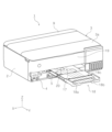
図1及び図2において記録装置の一例であるインクジェットプリンター1は、装置本体2の上部に、スキャナー部3を備えて成る、所謂複合機である。以下においてインクジェットプリンター1は、プリンター1と略称する。
スキャナー部3は、装置本体2に対して回動可能に設けられており、回動することにより、図1に示す閉じた状態と不図示の開いた状態とをとり得る。スキャナー部3は、原稿台3b(図3参照)を開閉する原稿カバー3aを備えている。
1 and 2, an
The
装置本体2の上部において原稿カバー3aに対し背面側には、上部カバー9が設けられている。上部カバー9を開くと、図3に示す様にホッパー6への用紙のセットが可能となる。ホッパー6にセットされた用紙は、ホッパー6の上昇によって給送ローラー11に当接し、給送ローラー11の回転によって下流へ給送される。図3において符号T2は、ホッパー6から送り出される用紙の給送経路を示している。
At the top of the
図1及び図2に戻り、装置本体2の前面において下方には、前面カバー4が設けられている。前面カバー4は、装置本体2の下部に位置する下部給紙トレイ5に対して回転可能に設けられ、回転することにより、図1に示す様に閉じた状態と、図2及び図3に示す様に開いた状態とを取り得る。
前面カバー4を開くと、記録が行われた用紙を排出する排出口17が露呈し、また、排出口17から排出される用紙を受ける用紙受けトレイ18が露呈する。
1 and 2, a
When the
用紙受けトレイ18は、不図示のモーターの動力を受けて、装置本体2の内部に収納された収納状態と、図2及び図3に示す様に装置本体2から突出して展開した展開状態とを取り得る。本実施形態において用紙受けトレイ18は、第1トレイ18cと、展開状態において第1トレイ18cより+Y方向に位置する第2トレイ18bと、展開状態において第2トレイ18bより+Y方向に位置する第3トレイ18aと、を備えて構成されている。
尚、用紙受けトレイ18は、前記収納状態から前記展開状態に向けて変位する途中の状態でも、排出される用紙を受けることができる。
The
The
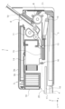
以下、図3を参照して用紙搬送経路について更に説明する。装置本体2の下部に位置する下部給紙トレイ5に収容された用紙は、給送ローラー10によって-Y方向に送り出される。符号T1は、下部給紙トレイ5から送り出される用紙の給送経路を示している。
給送ローラー10の上方には、反転ローラー8が設けられており、下部給紙トレイ5或いはホッパー6から送り出された用紙は反転ローラー8から送り力を受け、反転ローラー8に対して+Y方向に位置する搬送ローラー対13に向けて送られる。
そして用紙は、搬送ローラー対13により、記録ヘッド15と対向する領域即ち記録領域に搬送される。
The paper transport path will be further described below with reference to Fig. 3. Paper stored in the lower
A reversing
The paper is then transported by a
記録手段の一例である記録ヘッド15はキャリッジ14に設けられ、キャリッジ14は、不図示の動力源によってX軸方向に往復動する。記録ヘッド15は、キャリッジ14の移動動作に伴い、用紙に対してインクを吐出する。
そして記録の行われた用紙は、排出ローラー対16により、用紙受けトレイ18に向けて排出される。
A
The paper on which the recording has been performed is then discharged toward a
続いて排出口17について更に説明する。排出口17は、Y軸方向において、記録ヘッド15によって記録の行われた用紙を排出する排出位置となる。
この排出口17の上縁は、記録が行われた用紙の記録面と対向する対向部20で形成されている。
Next, a further description will be given of the
The upper edge of the
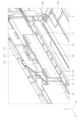
対向部20は、図4~図6に示す様に光学部材21を備えて構成されている。光学部材21は、X軸方向つまり用紙幅方向において、用紙が通過する領域の中央に位置する様に、フレーム30に取り付けられている。換言すれば、排出される用紙の用紙幅方向の中心位置と、光学部材21のX軸方向の中心位置は、概ね一致する。
The facing
光学部材21は、光透過性を有する材料で形成され、レンズとして機能する。光学部材21は、本実施形態では無色透明の樹脂材料で形成されるとともに、用紙の記録面と対向する対向面21aが、磨りガラス状に形成されている。
The
光学部材21に対し+Z方向には、発光部23が設けられている。発光部23は、本実施形態では白色LEDで構成される。また本実施形態において発光部23は、基板24において、X軸方向つまり用紙幅方向に間隔を空けて2つ設けられている。2つの発光部23は、X軸方向つまり用紙幅方向において、光学部材21の中心位置に対し対称に位置する様に配置されている。
A light-emitting
発光部23は、光学部材21に対して図5及び図6の矢印Qで示す方向に発光する。換言すれば、光学部材21は、発光部23から発せられた光が入射する場所に位置している。光学部材21は、入射した光を用紙の記録面に向けた方向に放射する。光学部材21から用紙の記録面に向けて放射される光は、図5に示す様に用紙幅方向に拡がり、また図6に示す様に用紙搬送方向に拡がる。
The light-emitting
図4、図6に示す様に、発光部23から発されられた光の光路に対し用紙搬送方向の上流と下流に、反射シート27が設けられている。換言すれば、発光部23から発されられた光の光路を挟む様に、一対の反射シート27が設けられている。反射シート27は、Z軸方向において発光部23の位置から、光学部材21の上面位置にまで至っている。また反射シート27は、X軸方向において光学部材21のほぼ全域をカバーしている。反射シート27は、例えば白色のシート材で構成することができる。
As shown in Figures 4 and 6,
また、前面パネル19に近い側の反射シート27と前面パネル19との間には、遮光シート28が設けられている。遮光シート28のX軸方向及びZ軸方向の大きさは、本実施形態では反射シート27と同様である。遮光シート28は、例えば黒色のシート材で構成することができる。
A light-shielding
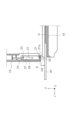
図5及び図6は、用紙受けトレイ18が図2に示す突出状態にあり、用紙受けトレイ18に一例としてA4サイズ用紙が短辺方向を用紙幅方向として排出される場合を示している。A4サイズ用紙は、第1のサイズの媒体の一例である。図5及び図6において符号Pは、A4サイズ用紙を示している。また図5及び図6において符号Sは、光学部材21から用紙の記録面に向けて放射される光による照射範囲を示している。
Figures 5 and 6 show a case where the
発光部23から発せられ、光学部材21に入射した光は、対向面21aが磨りカラス状に形成されていることで光学部材21の内部で用紙幅方向に拡散し、そして用紙の記録面に向けて放射される。その放射範囲は、本実施形態ではA4サイズ用紙Pの、短辺の全域をカバーする幅を有する。
The light emitted from the light-emitting
尚、図5及び図6において符号H1は、Z軸方向つまり用紙の記録面と直交する方向における、用紙受けトレイ18と光学部材21との間隔を示している。間隔H1は、例えば30mm以下とすることができる。これにより用紙の記録面と光学部材21との間隔は、30mm以下となる。
In addition, in Figures 5 and 6, the symbol H1 indicates the distance between the
また、本実施形態に係るプリンター1は、媒体の一例である光ディスクをセット可能なトレイを、装置前面から用紙搬送経路の上流に向けて差し入れ可能に構成されている。図7において符号40は光ディスクRをセット可能なトレイであり、トレイ40は、収納状態にある用紙受けトレイ18に載置した状態で、用紙搬送経路の上流に向けて差し入れることができる。差し入れられたトレイ40の-Y方向の先端が搬送ローラー対13(図3参照)によってニップされると、トレイ40は搬送ローラー対13によって-Y方向に搬送され、次いで+Y方向に搬送され、光ディスクRへの記録を行うことができる。
そして図7において符号H2は、光ディスクRの記録面と光学部材21との間隔を示している。間隔H2は、図6に示した間隔H1より小さく、従って間隔H1も30mm以下となり、より具体的には10mm以下となる。
Furthermore, the
7, the symbol H2 indicates the distance between the recording surface of the optical disc R and the
以上説明した様に記録ヘッド15によって記録の行われた用紙を排出する排出位置において用紙の記録面と対向する対向部20は、発光部23から発せられた光が入射する場所に位置するともに用紙の記録面と対向配置され、入射した光を少なくとも用紙の記録面に向けた方向に放射する光学部材21を備えて成るので、記録結果をいち早く、つまり記録が完了する前に、且つ明瞭に視認することができ、ユーザーニーズに適切に対応することができる。
As described above, the facing
また、光学部材21による用紙の記録面の照射範囲は、用紙幅方向において、第1のサイズの用紙の、記録面の全域をカバーする幅を有するので、より適切に記録結果を視認することができる。尚、本実施形態において第1のサイズの用紙をA4サイズ用紙としたが、これに限られないことは勿論である。
尚、第1のサイズの用紙が、搬送可能な最大サイズの用紙であれば、全てのサイズの用紙について、幅方向全域を照射することができる。
In addition, the illumination range of the recording surface of the paper by the
If the first size of paper is the maximum size of paper that can be transported, the entire width of all sizes of paper can be irradiated.
また本実施形態において光学部材21は、用紙の記録面と対向する対向面21aが磨りガラス状に形成された、光透過性を有する部材であるので、発光部23から発せられた光をより広範囲に拡散させることができる。
In addition, in this embodiment, the
尚、発光部23から発せられた光をより広範囲に拡散させる手段として、対向面21aを磨りガラス状にすることに代えて、或いは磨りガラス状にすることに加え、光学部材21を、光拡散剤を含んだ光透過性を有する部材で形成しても良い。
光拡散剤としては、硫酸バリウム、炭酸カルシウム、酸化シリコン、炭酸マグネシウム、水酸化アルミニウム、酸化チタン、酸化亜鉛、合成シリカ、ガラスビーズなどを用いることができる。
また、発光部23から発せられた光をより広範囲に拡散させる手段は、対向面21aを磨りガラス状にすることや拡散剤を用いることに限られないことも勿論である。
Furthermore, as a means for diffusing the light emitted from the light-emitting
As the light diffusing agent, barium sulfate, calcium carbonate, silicon oxide, magnesium carbonate, aluminum hydroxide, titanium oxide, zinc oxide, synthetic silica, glass beads, etc. can be used.
Furthermore, it goes without saying that the means for diffusing the light emitted from the
また本実施形態においては、用紙の記録面と直交する方向における、記録面と光学部材21との間隔が30mm以下に設定されているので、用紙の排出位置において記録結果を明瞭に視認することができる。
尚、記録面に達する光量が十分であれば、記録面と光学部材21との間隔が30mmより大きくても構わない。
In this embodiment, the distance between the recording surface of the paper and the
If the amount of light reaching the recording surface is sufficient, the distance between the recording surface and the
また本実施形態では、発光部23から光学部材21に発せられた光の光路を挟む一対の反射シート27が設けられているので、光学部材21から用紙の記録面に対して照射される光の量を確保できる。尚、反射シート27を用いずとも十分な光量を確保できる場合には、反射シート27は省略しても良い。
In addition, in this embodiment, a pair of
また本実施形態では、装置の前面を形成する壁部である前面パネル19に近い反射シート27と、前面パネル19との間に、遮光シート28が設けられているので、前面パネル19から装置前方への光の漏洩を抑制できる。尚、前面パネル19の遮光率が高く、前面パネル19を介した装置外側への光の漏洩が視認し難い場合には、遮光シート28は省略しても良い。
In addition, in this embodiment, a light-shielding
尚、発光部23の発光及び用紙への記録を制御する制御部35(図8、図9参照)は、少なくとも用紙の先端が対向部20と対向する位置に到達してから用紙の後端が対向部20と対向する位置を抜けるまでの間、発光することが好ましい。これにより、記録結果の全体を適切に視認することができる。尚、制御部35は、用紙搬送方向における用紙の位置を、後述する用紙検出部36(図8、図9参照)の検出信号を利用して把握することができる。
また勿論、印刷指令を受けた時点、給紙を開始した時点、記録を開始した時点、などから発光を開始しても良い。これは、後に説明する光ディスクへの記録に際しても同様である。
また本実施形態では、用紙受けトレイ18が不図示のモーターの動力を受けて、装置本体2の内部に収納された収納状態と、装置本体2から突出して展開した展開状態とを取り得るので、用紙受けトレイ18が前記収納状態から前記展開状態に向けて変位するタイミングつまり変位を開始するタイミングや、或いは前記展開状態に切り換わったタイミングで発光を開始しても良い。
また用紙受けトレイ18上の用紙有無を検出するセンサーを設けた上で、用紙受けトレイ18上の用紙が取り除かれたことをもって発光を終了する様にしても良い。
It is preferable that the control unit 35 (see Figs. 8 and 9) which controls the light emission of the
Of course, light emission may start when a print command is received, when paper feeding starts, when recording starts, etc. This also applies to recording on an optical disk, which will be described later.
In addition, in this embodiment, the
Also, a sensor may be provided to detect the presence or absence of paper on the
また制御部35は、第1の記録品質で用紙に記録を行う第1記録モードと、第1の記録品質より高品質で用紙に記録を行う第2記録モードと、を切り換え可能であっても良い。その場合制御部35は、第1記録モードでは発光部23からの発光を行わず、第2記録モードでは発光部23からの発光を行う様にすることができる。これにより、記録結果を視認する必要性の低い場合に発光部23からの発光を行わないので、省電力化を図ることができる。
The
また制御部35は、媒体の一例である光ディスクRをセット可能なトレイ40の搬送に際し、発光部23を以下の様に制御することもできる。
用紙搬送経路において搬送ローラー対13の上流には、用紙先端及び後端の通過に伴い検出信号を変化させる用紙検出部36が設けられている。用紙検出部36は検出手段の一例であり、例えば光学式センサーで構成することができる。
トレイ40は全体が黒色で形成されているとともに-Y方向の端部付近に反射板41が設けられていて、トレイ40が-Y方向に差し入れられた際、図8から図9への変化で示す様に反射板41が用紙検出部36に到達することで、制御部35はトレイ40が搬送ローラー対13にニップされたことを検知できる。
Furthermore, when conveying a
In the paper transport path, a
The
この様な構成において、制御部35は用紙検出部36の検出信号に基づき、トレイ40が搬送可能な位置つまり搬送ローラー対13によってニップされる位置まで差し入れられたことを検出すると、発光部23の点灯状態を変化させることができる。
例えば、トレイ40が搬送可能な位置に到達するまでは、発光部23を消灯させておき、トレイ40が搬送可能な位置に到達すると、発光部23を点灯させることができる。或いは逆に、トレイ40が搬送可能な位置に到達するまでは、発光部23を点灯させておき、トレイ40が搬送可能な位置に到達すると、発光部23を消灯させることができる。
ユーザーは、この様な発光部23の点灯状態の変化によってトレイ40が搬送可能な位置まで到達したことを知ることができ、ユーザーの使い勝手が向上する。
In this configuration, when the
For example, the light-emitting
The user can know that the
尚、この様な制御に代えて、トレイ40上に位置合わせマークを設けておき、この位置合わせマークが、光学部材21から照射された光に照らされる位置に到達したことをもって、トレイ40が搬送可能な位置まで到達したとユーザーが判断する様に構成しても良い。
Instead of this type of control, an alignment mark may be provided on the
本発明は上記において説明した実施形態に限定されることなく、特許請求の範囲に記載した発明の範囲内で、種々の変形が可能であり、それらも本発明の範囲内に含まれるものであることは言うまでもない。 The present invention is not limited to the embodiments described above, and various modifications are possible within the scope of the invention described in the claims, and it goes without saying that these modifications are also included within the scope of the present invention.
1…インクジェットプリンター、2…装置本体、3…スキャナー部、4…前面カバー、5…下部給紙トレイ、6…ホッパー、7…ペーパーサポート、8…反転ローラー、9…上部カバー、10…給送ローラー、11…給送ローラー、13…搬送ローラー対、14…キャリッジ、15…記録ヘッド、16…排出ローラー対、17…排出口、18…用紙受けトレイ、19…前面パネル、20…対向部、21…光学部材、21a…対向面、23…発光部、24…基板、27…反射シート、28…遮光シート、30…フレーム、35…制御部、36…用紙検出部、40…プレート状部材、41…反射板、P…用紙、R…光ディスク 1...inkjet printer, 2...device body, 3...scanner unit, 4...front cover, 5...lower paper feed tray, 6...hopper, 7...paper support, 8...reversal roller, 9...upper cover, 10...feed roller, 11...feed roller, 13...pair of transport rollers, 14...carriage, 15...recording head, 16...pair of discharge rollers, 17...discharge port, 18...paper receiving tray, 19...front panel, 20...opposing part, 21...optical member, 21a...opposing surface, 23...light emitting part, 24...substrate, 27...reflective sheet, 28...light shielding sheet, 30...frame, 35...control unit, 36...paper detection unit, 40...plate-shaped member, 41...reflector, P...paper, R...optical disc
Claims (10)
前記記録手段によって記録の行われた媒体を排出する排出位置において媒体の記録面と
対向する対向部と、を備え、
前記対向部は、発光部から発せられた光が入射する場所に位置し、入射した光を少なく
とも前記記録面に向けた方向に放射する光学部材を備え、
第1の記録品質で媒体に記録を行う第1記録モードと、前記第1の記録品質より高品質
で媒体に記録を行う第2記録モードと、を切り換え可能であり、
前記第1記録モードでは前記発光部からの発光を行わず、前記第2記録モードでは前記
発光部からの発光を行う、
ことを特徴とする記録装置。 A recording means for recording on a medium;
a facing portion facing a recording surface of the medium at a discharge position where the medium on which recording has been performed by the recording means is discharged,
the facing portion is located at a position where light emitted from the light emitting portion is incident, and includes an optical member that radiates the incident light at least in a direction toward the recording surface,
a first recording mode in which recording is performed on a medium with a first recording quality and a second recording mode in which recording is performed on a medium with a quality higher than the first recording quality can be switched;
In the first recording mode, the light emitting unit does not emit light, and in the second recording mode, the light emitting unit emits light.
A recording device comprising:
前記記録手段によって記録の行われた媒体を排出する排出位置において媒体の記録面と
対向する対向部と、を備え、
前記対向部は、発光部から発せられた光が入射する場所に位置し、入射した光を少なく
とも前記記録面に向けた方向に放射する光学部材を備え、
媒体をセット可能なトレイを、装置前面から媒体の搬送経路の上流に向けて差し入れ可
能に構成されるとともに、前記トレイが搬送可能な位置まで差し入れられたことを検出す
る検出手段を備え、
前記検出手段によって前記トレイが前記搬送可能な位置まで差し入れられたことを検出
すると、前記発光部の点灯状態が変化する、
ことを特徴とする記録装置。 A recording means for recording on a medium;
a facing portion facing a recording surface of the medium at a discharge position where the medium on which recording has been performed by the recording means is discharged,
the facing portion is located at a position where light emitted from the light emitting portion is incident, and includes an optical member that radiates the incident light at least in a direction toward the recording surface,
A tray on which the medium can be set can be inserted from the front of the device toward the upstream of a medium transport path, and a detection unit is provided to detect when the tray has been inserted to a position where the medium can be transported;
When the detection means detects that the tray has been inserted to the position where the tray can be transported, the lighting state of the light emitting unit is changed.
A recording device comprising:
前記光学部材による前記記録面の照射範囲は、媒体の搬送方向と交差する方向である媒
体幅方向において、第1のサイズの媒体の、前記記録面の全域をカバーする幅を有する、
ことを特徴とする記録装置。 3. The recording apparatus according to claim 1,
an illumination range of the recording surface by the optical member has a width covering the entire recording surface of a medium of a first size in a medium width direction that is a direction intersecting a medium transport direction;
A recording device comprising:
前記光学部材は、前記記録面と対向する面が磨りガラス状に形成された、光透過性を有
する部材である、
ことを特徴とする記録装置。 4. The recording apparatus according to claim 1,
the optical member is a light-transmitting member having a surface facing the recording surface formed like frosted glass;
A recording device comprising:
前記光学部材は、光拡散剤を含んだ光透過性を有する部材である、
ことを特徴とする記録装置。 4. The recording apparatus according to claim 1,
The optical member is a member having light transmittance and containing a light diffusing agent.
A recording device comprising:
前記記録面と直交する方向における、前記記録面と前記光学部材との間隔が30mm以
下である、
ことを特徴とする記録装置。 6. The recording apparatus according to claim 1,
a distance between the recording surface and the optical member in a direction perpendicular to the recording surface is 30 mm or less;
A recording device comprising:
前記発光部から前記光学部材に発せられた光の光路を挟む一対の反射シートが設けられ
ている、
ことを特徴とする記録装置。 7. The recording apparatus according to claim 1,
A pair of reflective sheets is provided to sandwich the optical path of the light emitted from the light emitting unit to the optical member.
A recording device comprising:
前記一対の反射シートのうち装置の前面を形成す
る壁部に近い反射シートと前記壁部との間に、遮光シートが設けられている、
ことを特徴とする記録装置。 8. The recording apparatus according to claim 7,
a light-shielding sheet is provided between the wall portion and one of the pair of reflecting sheets that is closer to the wall portion forming the front surface of the device;
A recording device comprising:
前記発光部は、少なくとも媒体の先端が前記対向部と対向する位置に到達してから媒体
の後端が前記対向部と対向する位置を抜けるまでの間、発光する、
ことを特徴とする記録装置。 9. The recording apparatus according to claim 1,
the light emitting section emits light at least during the period from when the leading end of the medium reaches the position facing the facing section until when the trailing end of the medium passes through the position facing the facing section.
A recording device comprising:
前記記録手段を備える装置本体に収納された収納状態と、前記装置本体から最も突出す
る展開状態と、をモーターの動力によって切り換え可能であり、前記展開状態或いは前記
収納状態から前記展開状態に向けて前記装置本体から突出した状態において前記装置本体
の外に向けて排出される媒体を受ける媒体受けトレイを備え、
前記媒体受けトレイが前記収納状態から前記展開状態に向けて変位するタイミングで、
前記発光部が発光する、
ことを特徴とする記録装置。 10. The recording apparatus according to claim 1,
a storage state in which the recording means is stored in a device body having the recording means and a deployed state in which the recording means protrudes most from the device body can be switched by the power of a motor, and a medium receiving tray is provided for receiving a medium discharged toward the outside of the device body in the deployed state or in a state in which the recording means protrudes from the device body from the storage state toward the deployed state;
At a timing when the medium receiving tray is displaced from the stored state to the deployed state,
The light emitting unit emits light.
A recording device comprising:
Priority Applications (4)
| Application Number | Priority Date | Filing Date | Title |
|---|---|---|---|
| JP2020037836A JP7537101B2 (en) | 2020-03-05 | 2020-03-05 | Recording device |
| CN202110230269.9A CN113352787B (en) | 2020-03-05 | 2021-03-02 | Recording apparatus |
| US17/189,668 US12115801B2 (en) | 2020-03-05 | 2021-03-02 | Recording apparatus |
| CN202211653638.6A CN115742583A (en) | 2020-03-05 | 2021-03-02 | Recording apparatus |
Applications Claiming Priority (1)
| Application Number | Priority Date | Filing Date | Title |
|---|---|---|---|
| JP2020037836A JP7537101B2 (en) | 2020-03-05 | 2020-03-05 | Recording device |
Publications (2)
| Publication Number | Publication Date |
|---|---|
| JP2021138498A JP2021138498A (en) | 2021-09-16 |
| JP7537101B2 true JP7537101B2 (en) | 2024-08-21 |
Family
ID=77524813
Family Applications (1)
| Application Number | Title | Priority Date | Filing Date |
|---|---|---|---|
| JP2020037836A Active JP7537101B2 (en) | 2020-03-05 | 2020-03-05 | Recording device |
Country Status (3)
| Country | Link |
|---|---|
| US (1) | US12115801B2 (en) |
| JP (1) | JP7537101B2 (en) |
| CN (2) | CN115742583A (en) |
Families Citing this family (1)
| Publication number | Priority date | Publication date | Assignee | Title |
|---|---|---|---|---|
| JP7563017B2 (en) * | 2020-07-15 | 2024-10-08 | セイコーエプソン株式会社 | Media ejection device, recording device |
Citations (8)
| Publication number | Priority date | Publication date | Assignee | Title |
|---|---|---|---|---|
| JP2001075322A (en) | 1999-08-31 | 2001-03-23 | Toshiba Tec Corp | Image forming device |
| JP2002271456A (en) | 2001-03-06 | 2002-09-20 | Matsushita Electric Ind Co Ltd | Mobile terminal device |
| JP2007237426A (en) | 2006-03-06 | 2007-09-20 | Seiko Epson Corp | Printer |
| JP2007286333A (en) | 2006-04-17 | 2007-11-01 | Murata Mach Ltd | Image forming apparatus |
| JP2011228963A (en) | 2010-04-20 | 2011-11-10 | Pfu Ltd | Image reader |
| JP2016057351A (en) | 2014-09-05 | 2016-04-21 | シャープ株式会社 | Image forming apparatus and image forming system using the same |
| US20170088387A1 (en) | 2015-09-28 | 2017-03-30 | Fuji Xerox Co., Ltd. | Recording medium processing apparatus |
| JP2018075759A (en) | 2016-11-09 | 2018-05-17 | セイコーエプソン株式会社 | Printing device |
Family Cites Families (12)
| Publication number | Priority date | Publication date | Assignee | Title |
|---|---|---|---|---|
| JPH03279158A (en) * | 1990-03-26 | 1991-12-10 | Canon Inc | Sheet material mounting device |
| JPH08339107A (en) | 1995-06-12 | 1996-12-24 | Ricoh Co Ltd | Image forming device |
| JP2002052778A (en) * | 2000-08-10 | 2002-02-19 | Seiko Epson Corp | Printer |
| JP2006116900A (en) * | 2004-10-25 | 2006-05-11 | Canon Inc | Printing device |
| US7715708B2 (en) * | 2005-03-29 | 2010-05-11 | Seiko Epson Corporation | Method of detecting position of printing medium performed in printing apparatus |
| US8760733B2 (en) * | 2011-08-23 | 2014-06-24 | Canon Kabushiki Kaisha | Image reading apparatus and image forming apparatus |
| JP6123997B2 (en) * | 2013-03-27 | 2017-05-10 | セイコーエプソン株式会社 | Recording device |
| JP6119399B2 (en) * | 2013-04-24 | 2017-04-26 | セイコーエプソン株式会社 | Recording device |
| JP6292371B2 (en) * | 2013-08-26 | 2018-03-14 | セイコーエプソン株式会社 | Recording device |
| JP6506080B2 (en) * | 2015-04-02 | 2019-04-24 | 富士通コンポーネント株式会社 | Portable printing device |
| JP6739997B2 (en) * | 2016-05-18 | 2020-08-12 | キヤノン株式会社 | Image reading device, sheet stacking device, and image forming device |
| JP7259267B2 (en) * | 2018-11-02 | 2023-04-18 | 京セラドキュメントソリューションズ株式会社 | SENSOR UNIT AND IMAGE FORMING APPARATUS INCLUDING THE SAME |
-
2020
- 2020-03-05 JP JP2020037836A patent/JP7537101B2/en active Active
-
2021
- 2021-03-02 CN CN202211653638.6A patent/CN115742583A/en active Pending
- 2021-03-02 CN CN202110230269.9A patent/CN113352787B/en active Active
- 2021-03-02 US US17/189,668 patent/US12115801B2/en active Active
Patent Citations (9)
| Publication number | Priority date | Publication date | Assignee | Title |
|---|---|---|---|---|
| JP2001075322A (en) | 1999-08-31 | 2001-03-23 | Toshiba Tec Corp | Image forming device |
| JP2002271456A (en) | 2001-03-06 | 2002-09-20 | Matsushita Electric Ind Co Ltd | Mobile terminal device |
| JP2007237426A (en) | 2006-03-06 | 2007-09-20 | Seiko Epson Corp | Printer |
| JP2007286333A (en) | 2006-04-17 | 2007-11-01 | Murata Mach Ltd | Image forming apparatus |
| JP2011228963A (en) | 2010-04-20 | 2011-11-10 | Pfu Ltd | Image reader |
| JP2016057351A (en) | 2014-09-05 | 2016-04-21 | シャープ株式会社 | Image forming apparatus and image forming system using the same |
| US20170088387A1 (en) | 2015-09-28 | 2017-03-30 | Fuji Xerox Co., Ltd. | Recording medium processing apparatus |
| JP2017065828A (en) | 2015-09-28 | 2017-04-06 | 富士ゼロックス株式会社 | Recording medium processing apparatus |
| JP2018075759A (en) | 2016-11-09 | 2018-05-17 | セイコーエプソン株式会社 | Printing device |
Also Published As
| Publication number | Publication date |
|---|---|
| CN113352787A (en) | 2021-09-07 |
| US20210276352A1 (en) | 2021-09-09 |
| CN115742583A (en) | 2023-03-07 |
| CN113352787B (en) | 2022-12-27 |
| JP2021138498A (en) | 2021-09-16 |
| US12115801B2 (en) | 2024-10-15 |
Similar Documents
| Publication | Publication Date | Title |
|---|---|---|
| JP4765564B2 (en) | Print media transport tray | |
| JP5246196B2 (en) | Inkjet recording device | |
| JP7750353B2 (en) | Media ejection device, recording device | |
| JP7537101B2 (en) | Recording device | |
| JP4632418B2 (en) | Image input / output device | |
| JP7642992B2 (en) | Recording devices, image reading devices | |
| JP2009006482A (en) | Printer | |
| JP6784651B2 (en) | Inkjet printer | |
| JP6750939B2 (en) | Image reader | |
| JP5915032B2 (en) | Recording device | |
| JP2025039098A (en) | Liquid ejection device | |
| JP2025038994A (en) | Light emitting device, liquid ejection device | |
| JP2025113640A (en) | liquid discharge device | |
| CN119590107A (en) | Liquid spraying device | |
| JP2025038993A (en) | Liquid ejection device | |
| JP2025059268A (en) | Printer and Loading Unit | |
| JP6759747B2 (en) | Conveyor and image forming equipment | |
| JP6394869B2 (en) | Recording device | |
| JP2005271470A (en) | Color thermal printer |
Legal Events
| Date | Code | Title | Description |
|---|---|---|---|
| RD07 | Notification of extinguishment of power of attorney |
Free format text: JAPANESE INTERMEDIATE CODE: A7427 Effective date: 20200828 |
|
| RD04 | Notification of resignation of power of attorney |
Free format text: JAPANESE INTERMEDIATE CODE: A7424 Effective date: 20210913 |
|
| RD03 | Notification of appointment of power of attorney |
Free format text: JAPANESE INTERMEDIATE CODE: A7423 Effective date: 20211108 |
|
| A621 | Written request for application examination |
Free format text: JAPANESE INTERMEDIATE CODE: A621 Effective date: 20230110 |
|
| A977 | Report on retrieval |
Free format text: JAPANESE INTERMEDIATE CODE: A971007 Effective date: 20230927 |
|
| A131 | Notification of reasons for refusal |
Free format text: JAPANESE INTERMEDIATE CODE: A131 Effective date: 20231003 |
|
| A521 | Request for written amendment filed |
Free format text: JAPANESE INTERMEDIATE CODE: A523 Effective date: 20231127 |
|
| A131 | Notification of reasons for refusal |
Free format text: JAPANESE INTERMEDIATE CODE: A131 Effective date: 20240213 |
|
| A521 | Request for written amendment filed |
Free format text: JAPANESE INTERMEDIATE CODE: A523 Effective date: 20240408 |
|
| TRDD | Decision of grant or rejection written | ||
| A01 | Written decision to grant a patent or to grant a registration (utility model) |
Free format text: JAPANESE INTERMEDIATE CODE: A01 Effective date: 20240709 |
|
| A61 | First payment of annual fees (during grant procedure) |
Free format text: JAPANESE INTERMEDIATE CODE: A61 Effective date: 20240722 |
|
| R150 | Certificate of patent or registration of utility model |
Ref document number: 7537101 Country of ref document: JP Free format text: JAPANESE INTERMEDIATE CODE: R150 |