JP6750939B2 - Image reader - Google Patents
Image reader Download PDFInfo
- Publication number
- JP6750939B2 JP6750939B2 JP2015228153A JP2015228153A JP6750939B2 JP 6750939 B2 JP6750939 B2 JP 6750939B2 JP 2015228153 A JP2015228153 A JP 2015228153A JP 2015228153 A JP2015228153 A JP 2015228153A JP 6750939 B2 JP6750939 B2 JP 6750939B2
- Authority
- JP
- Japan
- Prior art keywords
- unit
- background portion
- reading
- sensor
- transport
- Prior art date
- Legal status (The legal status is an assumption and is not a legal conclusion. Google has not performed a legal analysis and makes no representation as to the accuracy of the status listed.)
- Active
Links
Images


Description
本発明は、原稿を搬送しながら原稿を読み取る画像読取装置に関する。 The present invention relates to an image reading device that reads a document while conveying the document.
従来、原稿の表裏両面の画像を2つの画像読取部により読み取るものであって、白色と黒色の両方の背景部材を搭載している画像読取装置があった。原稿が薄紙で裏写りを抑制したいときは原稿の背面に黒面を配置し、原稿が不定形サイズで原稿周囲が黒く読み取られるのを抑制したいときは原稿の背面に白面を配置する。 Conventionally, there has been an image reading apparatus in which images on both front and back sides of a document are read by two image reading units, and both white and black background members are mounted. If the original is thin and you want to suppress show-through, place a black side on the back side of the original, and if you want to prevent the original from being irregularly sized and read black around the original, place a white side on the back side of the original.
背景色を切り替える為には可動機構が必要である。特許文献1に記載の画像読取装置では、可動機構によって表裏どちらかの読取ユニットを搬送方向に沿って移動し画像読取部の位置を変更し、背景色を切り替える方法が提案されている。読取ユニットが移動したとき、表裏両側の画像読取ユニットの読取位置に対向するように白色背景板、または黒色背景板を配置する構成となっている。 A movable mechanism is required to switch the background color. In the image reading device described in Patent Document 1, a method is proposed in which either the front or back reading unit is moved along the transport direction by a movable mechanism to change the position of the image reading unit and switch the background color. When the reading unit moves, a white background plate or a black background plate is arranged so as to face the reading positions of the image reading units on both front and back sides.
しかし、特許文献1記載の技術を2つの画像読取ユニットを備えた画像読取装置の背景切り替えに適用した場合、白背景板と黒背景板を各々読み取る為に光学系を含む筐体自体を移動させるためのスペースを確保する必要があり、装置全体のサイズが大きくなってしまう。 However, when the technique described in Patent Document 1 is applied to the background switching of an image reading apparatus having two image reading units, the housing itself including the optical system is moved to read the white background plate and the black background plate, respectively. It is necessary to secure a space for this, and the size of the entire device becomes large.
本発明によれば、例えば、
シートを給送する給送手段を有する装置本体と、
第1の読取ユニットに設けられ、搬送路に沿って移動する前記シートの一方面を読み取る第1の読取センサと、
前記搬送路を挟んで前記第1の読取センサと対向して設けられる第2の読取ユニットに設けられ、前記シートの他方面の画像を読み取る第2の読取センサと、
前記第1の読取センサによって読み取り可能な位置に設けられ、前記第1の読取センサの読み取り背景となる第1背景部と、
前記第2の読取センサによって読み取り可能な位置に設けられ、前記第2の読取センサの読み取り背景となる第2背景部と、
前記第1の読取センサと前記第2背景部とを前記搬送路に沿って一体的に移動させる移動部と
を備え、
前記第1背景部は前記シートの移動方向において、前記第2の読取センサとは反対側に第3背景部を有し、
前記第2背景部は前記移動方向において、前記第1の読取センサとは反対側に第4背景部を有し、
前記第4背景部は、前記搬送路に対し傾斜した傾斜面を有し、前記シートに照射された光が直接、前記第2の読取センサに入射しないように構成されたことを特徴とする。
According to the invention, for example,
An apparatus main body having a feeding unit that feeds a sheet,
A first reading sensor which is provided in the first reading unit and which reads one side of the sheet moving along the conveyance path;
A second reading sensor which is provided in a second reading unit which is provided so as to face the first reading sensor with the conveyance path interposed therebetween, and which reads an image on the other surface of the sheet;
A first background portion provided at a position readable by the first reading sensor and serving as a reading background of the first reading sensor;
A second background portion provided at a position readable by the second reading sensor and serving as a reading background of the second reading sensor;
A moving unit that integrally moves the first reading sensor and the second background unit along the transport path;
The first background portion has a third background portion on the side opposite to the second reading sensor in the moving direction of the sheet,
The second background portion has a fourth background portion on the side opposite to the first reading sensor in the moving direction,
The fourth background portion has an inclined surface that is inclined with respect to the conveyance path, and is configured such that the light emitted to the sheet does not directly enter the second reading sensor .
本発明によれば、読取ユニットが画像読取装置の本体に固定された構造で背景切り替えが可能にしたことにより装置の小型化の技術を提供することができる。 According to the present invention, it is possible to provide a technique for downsizing the apparatus by enabling the background switching with the structure in which the reading unit is fixed to the main body of the image reading apparatus.
図1は本発明の一実施形態に係る画像読取装置Aの概略図である。 FIG. 1 is a schematic diagram of an image reading apparatus A according to an embodiment of the present invention.
<装置の構成>
画像読取装置Aは、載置台1に積載された一又は複数の搬送媒体Sを1つずつ装置内に経路RTにて搬送してその画像を読み取り、排出トレイ2に排出する装置である。読み取る搬送媒体Sは、例えば、OA紙、チェック、小切手、名刺、カード類等のシートであり、厚手のシートであっても、薄手のシートであってもよい。カード類は、例えば、保険証、免許証、クレジットカード等を挙げることができる。搬送媒体Sには、また、パスポートなどの冊子も含まれる。冊子を対象とする場合、ホルダを用いることができる。ホルダに見開き状態の冊子を収容して載置台1に載置することで、冊子がホルダと共に搬送され、その画像を読み取ることができる。
<Device configuration>
The image reading apparatus A is an apparatus that conveys one or a plurality of conveyance media S loaded on the mounting table 1 one by one into the apparatus via a route RT, reads the image, and discharges the image onto a
<給紙>
経路RTに沿って搬送媒体Sを給送する給送機構としての第1搬送部10が設けられている。第1搬送部10は本実施形態の場合、送りローラ11と、送りローラ11に対向配置される分離ローラ12を備え、載置台1上の搬送媒体Sを搬送方向D1に一つずつ順次搬送する。送りローラ11には、モータ等の駆動部3から伝達部5を介して駆動力が伝達され、図中矢印方向(経路RTに沿って搬送媒体Sを搬送させる正方向)に回転駆動される。伝達部5は例えば電磁クラッチであり、駆動部3からの送りローラ11への駆動力を断続する。
<Paper feeding>
A
<駆動部>
駆動部3と送りローラ11とを接続する伝達部5は、例えば、本実施形態では、通常時において駆動力が伝達される状態とし、搬送媒体Sの逆送の場合に駆動力を遮断する。送りローラ11は伝達部5により駆動力の伝達が遮断されると、自由回転可能な状態となる。なお、このような伝達部5は、送りローラ11を一方向のみに駆動させる場合には設けなくてもよい。
<Drive unit>
For example, in the present embodiment, the
<分離構造>
送りローラ11に対向配置される分離ローラ12は、搬送媒体Sを1枚ずつ分離するためのローラであり、送りローラ11に対して一定圧で圧接している。この圧接状態を確保するため、分離ローラ12は揺動可能に設けると共に送りローラ11へ付勢されるように構成される。分離ローラ12は、トルクリミッタ12aを介して駆動部3から駆動力が伝達され、実線矢印方向(送りローラ11の正方向とは逆方向))に回転駆動される。
<Separation structure>
The
分離ローラ12はトルクリミッタ12aにより駆動力伝達が規制されるため、送りローラ11と当接している際は送りローラ11に連れ回りする方向(破線矢印方向)に回転する。これにより、複数の搬送媒体Sが送りローラ11と分離ローラ12との圧接部に搬送されてきた際には、一つを残して2つ以上の搬送媒体Sが下流に搬送されないようにせき止められる。
Since the driving force transmission of the
なお、本実施形態では分離ローラ12と送りローラ11とで分離機構を構成したが、このような分離機構は必ずしも設けなくてもよく、経路RTに搬送媒体Sを1つずつ順次給送する給送機構であればよい。また、分離機構を設ける場合においては、分離ローラ12のような構成の代わりに、搬送媒体Sに摩擦力を付与する分離パッドを送りローラ11に圧接させて、同様の分離作業を持たせるようにしてもよい。
In the present embodiment, the separation mechanism is composed of the
<搬送構造>
第1搬送部10の搬送方向下流側にある搬送機構としての第2搬送部20は、駆動ローラ21と、駆動ローラ21に従動する従動ローラ22とを備え、第1搬送部10から搬送されてきた搬送媒体Sをその下流側へ搬送する。駆動ローラ21にはモータ等の駆動部4から駆動力が伝達され、図中矢印方向に回転駆動される。従動ローラ22は駆動ローラ21に対して一定圧で圧接し、駆動ローラ21に連れ回る。この従動ローラ22は、バネ等の付勢ユニット(不図示)によって駆動ローラ21に対して付勢された構成としてもよい。
<Transfer structure>
The
このような第2搬送部20よりも搬送方向下流側にある第3搬送部30は、駆動ローラ31と、駆動ローラ31に従動する従動ローラ32とを備え、第2搬送部20から搬送されてきた搬送媒体Sを排出トレイ2へ搬送する。つまり、この第3搬送部30は排出機構として機能する。駆動ローラ31にはモータ等の駆動部4から駆動力が伝達され、図中矢印方向に回転駆動される。従動ローラ32は駆動ローラ31に対して一定圧で圧接し、駆動ローラ31に連れまわる。この従動ローラ32は、バネ等の付勢ユニット(不図示)によって駆動ローラ31に対して付勢された構成としてもよい。
The
排出トレイ2は、画像読取装置Aに対して回動可能なように、画像読取装置Aの下方に設けられた第1ヒンジ101を介して軸支されている。また、第1ヒンジ101側の第1排出トレイ2aとその先端側に接続された第2排出トレイ2bとから構成されており、第2排出トレイ2bは第1排出トレイ2aに対して回動可能に軸支されている。
The
<画像読取構造、制御>
ここで、本実施形態の画像読取装置Aでは、第2搬送部20と第3搬送部30との間に配置される画像読取ユニット70、71によって画像の読み取りを行うため、第2搬送部20及び第3搬送部30は搬送媒体Sを定速搬送する。搬送速度は常に第1搬送部10の搬送速度以上とすることで、先行搬送媒体Sに後続搬送媒体Sが追いついてしまう事態を確実に回避できる。例えば、本実施形態では、第2搬送部20及び第3搬送部30による搬送媒体Sの搬送速度を、第1搬送部10による搬送媒体Sの搬送速度よりも速くなるように速度制御するようにした。
<Image reading structure and control>
Here, in the image reading apparatus A of the present embodiment, since the image is read by the
なお、第2搬送部20及び第3搬送部30による搬送媒体Sの搬送速度と、第1搬送部10による搬送媒体Sの搬送速度とを同一条件とした場合でも、駆動部3を制御して後続搬送媒体Sの給送開始タイミングを間欠的にずらすことにより先行搬送媒体Sと後続搬送媒体Sとの間に最低限の間隔を形成することも可能である。
Even when the transport speed of the transport medium S by the
<重送検出>
第1搬送部10と第2搬送部20との間に配置される重送検出センサ40は、静電気等で紙などの搬送媒体S同士が密着し、第1搬送部10を通過してきた場合(つまり重なって搬送される重送状態の場合)に、これを検出するための検出センサ(シートの挙動や状態を検出するセンサ)の一例である。重送検出センサ40としては、種々のものが利用可能であるが本実施形態の場合には超音波センサであり、超音波の発信部41とその受信部42とを備え、紙等の搬送媒体Sが重送されている場合と1つずつ搬送されている場合とで、搬送媒体Sを通過する超音波の減衰量が異なることを原理として重送を検出する。
<Double feed detection>
In the double feed detection sensor 40 arranged between the
<レジストセンサ>
このような重送検出センサ40よりも搬送方向下流側に配置される媒体検出センサ50は第2搬送部20よりも上流側で、第1搬送部10よりも下流側に配置された上流側の検出センサ(シートの挙動や状態を検出するセンサ)としての一例であり、第1搬送部10により搬送される搬送媒体Sの位置、詳細には、媒体検出センサ50の検出位置に搬送媒体Sの端部が到達又は通過したか否かを検出する。媒体検出センサ50としては、種々のものが利用可能であるが、本実施形態の場合には光学センサであり、発光部51とその受光部52とを備え、搬送媒体Sの到達又は通過により受光強度(受光量)が変化することを原理として搬送媒体Sを検出する。
<Registration sensor>
The
本実施形態の場合、搬送媒体Sの先端が媒体検出センサ50で検出されると、搬送媒体Sが重送検出センサ40により重送を検出可能な位置に到達しているように、上記の媒体検出センサ50は重送検出センサ40の近傍においてその下流側に設けられている。なお、この媒体検出センサ50は、上記の光学センサに限定されず、例えば、搬送媒体Sの端部が検知できるセンサ(イメージセンサ等)を用いてもよいし、経路RTに突出したレバー型のセンサでもよい。
In the case of the present embodiment, when the leading edge of the transport medium S is detected by the
媒体検出センサ50とは別の媒体検出センサ60が画像読取ユニット70、71よりも上流側に配置されている。第2搬送部20よりも下流側に配置された下流側の検出センサとしての一例であり、第2搬送部20により搬送される搬送媒体Sの位置を検出する。媒体検出センサ60としては、種々のものが利用可能であるが、本実施形態の場合、媒体検出センサ50と同様に光センサであり、発光部61と受光部62とを備え、搬送媒体Sの到達又は通過により受光強度(受光量)が変化することを原理として搬送媒体Sを検出する。なお、本実施形態では、第2搬送部20の搬送方向上流側と下流側のそれぞれに媒体検出センサ50、60を配置したが、何れか一方だけでもよい。
A
<CISの配置>
媒体検出センサ60よりも下流側にある画像読取ユニット70、71は、例えば、光学的に走査し、電気信号に変換して画像データとして読み取るものであり、内部にLED等の光源、イメージセンサ、レンズアレー等を備えている。
<CIS placement>
The
<ブロック図の説明>
図2を参照して制御部80について説明する。図2は画像読取装置Aの制御部8のブロック図である。
<Explanation of block diagram>
The
制御部80はCPU81、記憶部82、操作部83、通信部84及びインターフェース部85を備える。CPU81は記憶部82に記憶されたプログラムを実行することにより、画像読取装置A全体の制御を行う。記憶部82は例えばRAM、ROM等から構成される。操作部83は、例えば、スイッチやタッチパネル等で構成され、操作者からの操作を受け付ける。
The
通信部84は、外部装置との情報通信を行うインターフェースである。外部装置としてPC(パソコン)を想定した場合、通信部84としては、例えば、USBインターフェースやSCSIインターフェースを挙げることができる。また、このような有線通信のインターフェースの他、通信部84は無線通信のインターフェースとしてもよく、有線通信、無線通信の双方のインターフェースを備えていてもよい。
The
インターフェース部85はアクチュエータ86やセンサ87とのデータの入出力を行うI/Oインターフェースである。アクチュエータ86には、駆動部3、駆動部4、伝達部5等が含まれる。センサ87には、重送検出センサ40、媒体検出センサ50及び60、画像読取ユニット70、71等が含まれる。
<PCからの開始指示受信による駆動>
画像読取装置Aの基本的な動作について説明する。制御部80は、例えば画像読取装置Aが接続された外部パソコンから画像読み取りの開始指示を受信すると、第1搬送部10から第3搬送部30の駆動を開始する。載置台1に積載された搬送媒体Sはその最も下に位置する搬送媒体Sから1つずつ搬送される。もしくは、画像読取装置Aに設けられた開始時を受け付けて読取動作を開始する。
The
<Drive by receiving start instruction from PC>
The basic operation of the image reading apparatus A will be described. For example, when the
<重送時の制御>
搬送の途中で搬送媒体Sは重送検出センサ40により重送の有無が判定され、重送が無いと判定されると搬送が継続される。なお、重送があると判定された場合には、搬送を停止するか、第1搬送部10による後続搬送媒体Sの取り込みを停止して、重送状態にある搬送媒体Sをそのまま排出するようにしてもよい。
<レジストセンサの出力に応じた読取開始>
制御部80は、媒体検出センサ60の検出結果に基づくタイミングで、第2搬送部20により搬送されてきた搬送媒体Sの、画像読取ユニット70、71による画像の読み取りを開始し、読み取った画像を一次記憶して順次外部パソコンへ送信する。画像が読み取られた搬送媒体Sは第3搬送部30により排出トレイ2に排出されてその搬送媒体Sの画像読取処理が終了する。
<Control during double feeding>
In the middle of the conveyance, the conveyance medium S determines whether or not there is a multifeed, and the conveyance is continued if it is determined that there is no multifeed. When it is determined that there is a double feed, the conveyance is stopped, or the succeeding transport medium S is not taken in by the
<Starting reading according to the output of the registration sensor>
The
<排紙構造>
図3は本発明の一実施形態に係る画像読取装置Aの排出トレイ2を展開した状態の正面図である。
<Paper discharge structure>
FIG. 3 is a front view of the image reading apparatus A according to the embodiment of the present invention in a state where the
正面上部の表示パネル90には表示画面93が設けられ、隣接した位置に操作キー122が設けられている。
A
正面下部の下部パネル91には排出開口92が設けられており、第3搬送部30によって搬送された搬送媒体Sが排出される。
The
図4は本発明の一実施形態に係る画像読取装置Aの排出トレイ2を収納した状態の正面図である。
FIG. 4 is a front view of the image reading apparatus A according to the embodiment of the present invention in a state in which the
排出トレイ2は、画像読取装置Aに対して回動可能なように、画像読取装置Aの下方に設けられた第1ヒンジ101を介して軸支されており、第1排出トレイ2a及び第2排出トレイ2bによって本体前面を覆うように構成されている。
The
第1排出トレイ2aは、第1ヒンジ101を支点として回動可能に画像読取装置Aの本体100に取り付けられている。第1排出トレイ2aは、下部パネル91及び排出開口92を合わせた面積と同サイズで形成され、図4に示すような排出トレイ2の収納状態において、第1ヒンジ101を支点として回動し、下部パネル91及び排出開口92を覆うように折り畳まれる。
The
第2排出トレイ2bは、表示パネル90と同サイズで形成され、図4に示すような排出トレイ2の収納状態において、第1排出トレイ2aの先端に設けられた第2ヒンジ102を支点として回動し、表示パネル90と重なるように折り畳まれる。
The
図5は本発明の一実施形態に係る画像読取装置Aの排出トレイ2を展開した状態における上面図である。
FIG. 5 is a top view of the image reading apparatus A according to the embodiment of the present invention in a state where the
第3搬送部30により搬送されてきた搬送媒体Sは、排出開口92を経て第1排出トレイ2aに排出され、搬送媒体Sのサイズによっては第2排出トレイ2bまで到達し、案内される。
The transport medium S transported by the
第1排出トレイ2aには、排出位置調整部材120が回動可能に設けられており、名刺などのような第1排出トレイ2aに対して小さいサイズの搬送媒体Sが排出されるときなどに、起立状態に回動させることで搬送媒体Sが停止する位置を調整し、排出された搬送媒体Sを散らばりにくくすることができる。
A discharge
また、第2排出トレイ2bには、透光部121が設けられており、表示パネルに設けられた操作キー122と重なる位置に配置されている。操作キー122は本体電源をオン、オフする電源ボタンとなっており、電源オン状態においてはボタンが点灯するように構成されている。操作キー122と重なる位置に配置された透光部121は、排出トレイ2の収納状態においても操作キー122が点灯状態であるか、消灯状態であるかを確認することができ、画像読取装置Aの電源状態を確認することができる。
Further, the
<表示パネルの構成>
第2排出トレイ2bの収納状態において、第2排出トレイ2bと重なる位置に設けられた表示パネル90には、表示画面93が配置されている。
<Display panel configuration>
A
表示画面93は、給送トレイ110および搬送路幅Wと中心線Xが同位置となるように配置されている。尚、本発明の一実施形態に係る画像読取装置Aの最大搬送路幅WmaxとしてA4レターサイズを給送可能に構成されており、その幅はWmax=216mmである。表示画面93の幅は224mmであり、Wmaxを超える長さとなっている。
The
これにより、例えば、読み取った画像を実寸大で表示画面93に表示することができるようになり、仕上がり状態の確認が容易に行えるため、ユーザの利便性を向上することができる。
Thereby, for example, the read image can be displayed on the
<給送構造詳細>
図6は本発明の一実施形態に係る画像読取装置Aの排出トレイ2を収納した状態における上面図である。
<Details of feeding structure>
FIG. 6 is a top view of the image reading apparatus A according to the embodiment of the present invention in a state in which the
積載台1には、配置される搬送媒体Sの大きさに合わせて搬送方向に対して直交する方向にスライド可能に取り付けられた規制部材111が設けられている。
The loading platform 1 is provided with a
<上部ユニット詳細>
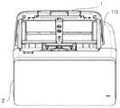
図7は本発明の一実施形態に係る画像読取装置Aの概略断面図である。
<Details of upper unit>
FIG. 7 is a schematic sectional view of the image reading apparatus A according to the embodiment of the present invention.
本体100は、上部ユニット103と下部ユニット104とから構成され、上部ユニット103は下部ユニット104に対し、本体ヒンジ105を支点として回動可能に取り付けられている。
The main body 100 is composed of an
上部ユニット103は、表示パネル90に最大搬送路幅Wmaxを超える幅の表示画面93及び表示画面93の支持フレーム板金を備えているため、図8に示すように上部ユニット103を展開した状態における重心は、図1に示すような上部ユニット103を収納した状態よりも搬送方向前方側に大きくずれることになる。
The
したがって、上部ユニットを展開する際に勢いがあると画像読取装置Aが転倒してしまう虞があるが、本実施形態に係る画像読取装置Aにおいては、突出部130を有することにより、上部ユニット103の展開に伴う重心移動が起こっても画像読取装置Aの転倒を防ぐことができる。突出部130の突出量は、図7のような上部ユニット103及び排出トレイ2の収納状態においては、排出トレイ2の下方に収まるような突出量であって、図8のような上部ユニット103の展開状態においては、上部ユニット103の重心よりも搬送方向前方まで位置するような突出量となっている。これにより、上部ユニット103の展開による画像読取装置Aの転倒を防止しつつ、排出トレイ2を収納した収納状態においては必要以上に突出させず、ユーザの邪魔にならないようにすることができる。
Therefore, if there is momentum when the upper unit is unfolded, the image reading apparatus A may tip over, but in the image reading apparatus A according to the present embodiment, the
<排出トレイ角度調節>
また、突出部130の上面には、排出トレイ2を展開したときにその下面に当接するようにしたトレイ支持部131が回動可能に設けられている。
<Adjusting the discharge tray angle>
Further, on the upper surface of the projecting
図9に示すように、排出トレイ2は、その展開状態においては、突出部130によって支持され、排出される搬送媒体Sを受けることができるようにされている。図10に示すように、トレイ支持部131を突出部130上面から上方に突出するように回動させると、排出トレイ2の下面側に当接して排出トレイ2を支持することとなり、突出部130によって支持する図9の状態から、排出トレイ2の角度を調節できる。
As shown in FIG. 9, the
例えば、図10の状態では、図9の状態と比べて、排出トレイ2が鉛直方向上方に持ち上げられることとなり、排出トレイ2の上面において搬送媒体Sの先端が着地する位置を変更することができる。これにより、図9の状態では、排出される搬送媒体Sの先端が、既に排出済みの搬送媒体Sの後端に当接して押し出してしまうような場合において、図10のように排出トレイ2の角度を変更することで、既に排出済みの搬送媒体Sの後端を下部ユニット104側に寄せる作用に加えて、既に排出済みの搬送媒体Sの上面に、後続の搬送媒体Sの先端を確実に着地させることができる。このような構成により、排出トレイ2上での排出済みの搬送媒体Sの整列性を格段に向上することができる。
For example, in the state of FIG. 10, the
なお、トレイ支持部131は回動範囲の途中においても排出トレイ2を支持可能なように構成し、排出トレイ2の角度を複数段階で調節可能にしてもよい。その場合、搬送媒体Sごとに最も排出トレイ2上での整列性が高い角度で搬送媒体Sを受けることができ、使用性を向上できる。
The
<読取センサ構成>
画像読取ユニット70、71はモールド部材でできたセンサケース70a、71aで覆われており、原稿の搬送面側にガラスを設けた構造になっている。画像読取ユニット71は搬送方向と垂直方向に可動でき、画像読取ユニット70は下部ユニット104に固定されている。
<Reading sensor configuration>
The
ここで、図11を用いて画像読取ユニット70、71のセンサケース70a、71a内の構成の説明をする。
Here, the configuration inside the
センサケース70a、71a内には、読取センサとしてのCIS72、73と、白色基準板74、75を有している。ライン上に設置された光電変換素子と搬送媒体Sを照射するための発光素子150、151を備える。画像読取ユニット70内のCIS72は、搬送媒体Sの表面を読み取る。画像読取ユニット71内のCIS73は、搬送媒体Sの裏面を読み取る。
CISs 72 and 73 as reading sensors and
CIS72とCIS73は同一部材であり、搬送面を中心として点対称に配置される。同一部材を使用するためコスト削減に効果があり、構成も表面と裏面が共通化できるため簡潔にできる。
The
白色基準板74、75はCIS72、73に貼り付けられている。導光体を通して原稿を照射する光が白色基準板74、75に反射してレンズ152、153に入射する為、背景色は白色となる。黒背景部76、77はCIS72、73、白色基準板74、75が配置される筐体の一部である。CISが移動したとき導光体を通して原稿を照射する光が反射する面がなくなる。かつ、光が黒背景部に到達しても対向するレンズに直接反射光が入らないように角度をつけた斜面となっている。これにより、背景色が黒色となる。画像読取ユニット70、71のセンサケース70a、71aの内壁は黒背景部76、77で反射された光を吸収するための材料で構成される。または、光を吸収し、反射させない部材を配置してもよいが、黒背景部76、77に対し、搬送路に平行な方向において対向する位置を含むように設け、黒背景部76、77の傾斜も、搬送路に対して45度以上の角度を成すようにして、入射した光がセンサケース70a、71aの内壁で反射して対向するレンズの方向に導光しないように構成されているのが好ましい。
The
図11では白色基準板と黒背景部は離れているが、黒背景部は白色基準板に隣接してもよい。 Although the white reference plate and the black background portion are separated in FIG. 11, the black background portion may be adjacent to the white reference plate.
白色基準板74は図11のようにCIS72から一部が受発光素子側にせり出すように貼り付けられている。これは白基準板74が発光素子151から対向センサの受光素子154へ向かう光を遮光するためである。すなわち、白色基準板であると同時に遮光板としても機能している。対向センサの白色基準板75も同様に構成され、同様の効果を奏している。
As shown in FIG. 11, the
発光素子151から対向するCIS72の受光素子154へ向かう光の遮光の効果を上げる為に、発光素子151は搬送路側から見て白色基準板74に隣接している方が良い。言い換えれば、発光素子151と白色基準板75の搬送路への投影が隣接するように配置されるのが好ましい。
In order to enhance the effect of blocking the light traveling from the
白基準板75と発光素子151が近いと対向するCIS72のレンズ152および受光素子154に向かう方向に白基準板75があるので遮光効果が良くなる。よって、搬送路に沿って、白色基準板75、発光素子151、受光素子155の順に並んでいるとよい。対向センサの白基準板75も同様の内容が言える。
When the
<背景切り替え構成>
次に背景色切り替えの構成の説明をする。図11は、本実施形態に係る画像読取ユニットの上面図である。
<Background switching configuration>
Next, the background color switching configuration will be described. FIG. 11 is a top view of the image reading unit according to the present embodiment.
図12は、図11の断面Yにおける断面図である。図12(a)は背景色白、図12(b)は背景色黒の状態における位置に対応している。 FIG. 12 is a sectional view taken along the section Y of FIG. FIG. 12A corresponds to the position in the white background color, and FIG. 12B corresponds to the position in the black background color.
画像読取ユニット70のCIS72は下部ユニット104に配置されたCIS摺動モータ79の駆動力を画像読取ユニット70に設けられた伝達部材78を介して伝達することで、CIS72およびCISに貼り付けられた白色基準板74が搬送方向に平行に移動可能となっている。
The
読取画像の背景色を白にする場合はCIS72の読み取り位置を対向する白色基準板75の位置に配置することにより白背景読取が可能となる。このとき、CIS72と白色基準板74が一体となって移動するので、CIS72を白背景位置に配置するとCIS73の読み取り位置と対向する位置に白色基準板74が配置され、白背景の読み取りが可能となる。
When the background color of the read image is white, the white background can be read by arranging the reading position of the
読取画像の背景色を黒にする場合はCIS72の読み取り位置を対向する黒背景部77の位置に配置することにより黒背景の読み取りが可能となる。
When the background color of the read image is set to black, the black background can be read by arranging the reading position of the
CIS72内の発光素子150の発光を黒背景部77の斜面で拡散させ、受光素子154へ入光させないことで黒背景の読み取りを実現する。
The light emission of the light emitting element 150 in CIS72 is diffused at the slope of the
片側のCISが移動すると、対向するセンサも相対的に移動することとなり、少ない距離で背景切り替えを行うことができる。また、片側のCISの移動で第1の読取センサ70と第2の読取センサ71の背景色を同時に切り替えが可能である。
When the CIS on one side moves, the opposing sensor also moves relatively, and the background can be switched over in a short distance. Further, the background color of the
白背景の読み取り位置を基準とすると黒背景読み取りの際、CISの移動に合わせて先端余白の調整制御が必要となる。CISの移動量が決まっているので、黒背景読み取り位置にCIS72が移動したとき、CIS72の移動量に応じた読取開始タイミングの変更を行い、先端余白の調整を行う。
Based on the reading position of the white background, when the black background is read, it is necessary to adjust the tip margin according to the movement of the CIS. Since the amount of CIS movement is fixed, when the
ここで、従来技術としては黒色基準板があり、CISの読み取り位置を黒色基準板の位置に配置することにより黒背景読取を実現している。しかし、塵や紙粉が黒色基準板に付着すると汚れてしまい基準値を保てなくなる。そのために補正制御が必要となっていた。本特許では黒背景部が汚れても背景色の画像には影響が出ないため、黒基準を保つことができ、補正などを行う必要なく、安定した黒基準の取得が可能となる。 Here, as a conventional technique, there is a black reference plate, and black background reading is realized by arranging the CIS reading position at the position of the black reference plate. However, if dust or paper dust adheres to the black reference plate, it becomes dirty and the reference value cannot be maintained. Therefore, correction control is required. In this patent, since the background color image is not affected even if the black background portion becomes dirty, the black reference can be maintained, and stable black reference can be acquired without performing correction or the like.
CIS72内の配置は図面左から黒基準部76、色基準板74、受発光部154となっている。この並びにすることで、CISの移動距離を最小限にすることができている。
The arrangement in the
黒背景部77は装置幅方向全面にわたっている必要があるため、伝達部材連結部140は黒背景部とは反対側にあると良い。
Since the
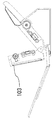
次に、図13、図14を用いて画像読取ユニット70内でCIS72が搬送方向に移動する構成を説明する。図13はCISの斜視図、図14(a)、(b)は読み取りユニット70の断面図であり、それぞれ図11における断面A、断面Bにおける断面図となっている。
Next, a configuration in which the
CIS72の両端部にはボス141があり、画像読取ユニット70の内壁部材とガイド部材142によって挟まれている。CIS摺動モータ79の駆動によって背景を切り替える際にCIS72はこのガイドに沿って搬送方向と平行に移動する。CISは焦点距離が短い特性を持っており、読み取り方向である搬送方向と垂直方向の位置精度を上げる為には前記のようなガイドに沿った平行移動が良い。ボス141の材質としては、画像読取ユニット70のセンサケース70aなどとは異なる摺動性のよい材質とすることが好ましい。
尚、本実施形態においては画像読取ユニット70、71はセンサケース状に読取センサとしてCIS72、73を囲うように配置したが、必ずしもその必要はなく、読取センサと基準板、黒基準部もしくは他の色基準部が一体に移動可能にされたものを有していればよい。
In the present embodiment, the
なお、以上の実施形態の説明の中で、CIS72に関してのみ説明を行っている箇所については、CIS73についても同様となるように構成することが好ましい。
In the description of the above embodiment, it is preferable to configure the
A 画像読取装置
S 搬送媒体
1 載置台
2 排出トレイ
2a 第1排出トレイ
2b 第2排出トレイ
3、4 駆動部
5 伝達部
10 第1搬送部
11 送りローラ
12 分離ローラ
20 第2搬送部
21 駆動ローラ
22 従動ローラ
30 第3搬送部
31 駆動ローラ
32 従動ローラ
40 重送検出センサ
50、60 媒体検出センサ
70、71 画像読取ユニット
70a、71a ケース
72、73 コンタクトイメージセンサ(CIS)
74、75 色基準板
76、77 黒背景色部
78 伝達部材
79 CIS摺動モータ
80 制御部
84 通信部
90 表示パネル
91 下部パネル
93 表示画面
100 本体
101 第1ヒンジ
102 第2ヒンジ
103 上部ユニット
104 下部ユニット
105 本体ヒンジ
111 規制部材
120 排出位置調整部材
121 透光部
122 操作キー
130 突出部
131 トレイ支持部
140 伝達部材連結部
141 ボス
142 ガイド部材
150、151 発光素子
152、153 レンズ
154、155 受光素子
A image reading apparatus S transport medium 1 mounting table 2
74, 75
Claims (7)
第1の読取ユニットに設けられ、搬送路に沿って移動する前記シートの一方面を読み取る第1の読取センサと、
前記搬送路を挟んで前記第1の読取センサと対向して設けられる第2の読取ユニットに設けられ、前記シートの他方面の画像を読み取る第2の読取センサと、
前記第1の読取センサによって読み取り可能な位置に設けられ、前記第1の読取センサの読み取り背景となる第1背景部と、
前記第2の読取センサによって読み取り可能な位置に設けられ、前記第2の読取センサの読み取り背景となる第2背景部と、
前記第1の読取センサと前記第2背景部とを前記搬送路に沿って一体的に移動させる移動部と
を備え、
前記第1背景部は前記シートの移動方向において、前記第2の読取センサとは反対側に第3背景部を有し、
前記第2背景部は前記移動方向において、前記第1の読取センサとは反対側に第4背景部を有し、
前記第4背景部は、前記搬送路に対し傾斜した傾斜面を有し、前記シートに照射された光が直接、前記第2の読取センサに入射しないように構成されたことを特徴とする画像読取装置。 An apparatus main body having a feeding unit that feeds a sheet,
A first reading sensor which is provided in the first reading unit and which reads one side of the sheet moving along the conveyance path;
A second reading sensor which is provided in a second reading unit which is provided so as to face the first reading sensor with the conveyance path interposed therebetween, and which reads an image on the other surface of the sheet;
A first background portion provided at a position readable by the first reading sensor and serving as a reading background of the first reading sensor;
A second background portion provided at a position readable by the second reading sensor and serving as a reading background of the second reading sensor;
A moving unit that integrally moves the first reading sensor and the second background unit along the transport path;
The first background portion has a third background portion on the side opposite to the second reading sensor in the moving direction of the sheet,
The second background portion has a fourth background portion on the side opposite to the first reading sensor in the moving direction,
The fourth background portion has an inclined surface that is inclined with respect to the conveyance path, and is configured so that the light emitted to the sheet does not directly enter the second reading sensor. Reader.
前記第1の読取センサが前記第1背景部を読み取り可能な位置から外れると同時に、前記第2の読取センサが前記第2背景部を読み取り可能な位置から外れることを特徴とする請求項1に記載の画像読取装置。 By moving the first reading sensor and the second background portion integrally along the transport path by the moving unit,
The first reading sensor moves out of a position where the first background portion can be read, and at the same time, the second reading sensor moves out of a position where the second background portion can be read. The image reading device described.
前記第1の読取センサ、前記第2背景部、前記第4背景部はそれぞれ、その順に前記移動方向に隣接して配置されることを特徴とする請求項1に記載の画像読取装置。 The second reading sensor, the first background portion, the third background portion, and
The image reading apparatus according to claim 1 , wherein the first reading sensor, the second background portion, and the fourth background portion are arranged adjacent to each other in that order in the movement direction .
第3背景部および前記第4背景部が黒色であることを特徴とする請求項3に記載の画像読取装置。 The background color of the first background portion and the second background portion is white,
The image reading apparatus according to claim 3, wherein the third background portion and the fourth background portion are black.
Priority Applications (5)
| Application Number | Priority Date | Filing Date | Title |
|---|---|---|---|
| JP2015228153A JP6750939B2 (en) | 2015-11-20 | 2015-11-20 | Image reader |
| PCT/JP2016/084284 WO2017086444A1 (en) | 2015-11-20 | 2016-11-18 | Image-reading device |
| EP16866444.9A EP3379815B1 (en) | 2015-11-20 | 2016-11-18 | Image-reading device |
| CN201680067141.2A CN108353109B (en) | 2015-11-20 | 2016-11-18 | Image read-out |
| US15/979,076 US10484572B2 (en) | 2015-11-20 | 2018-05-14 | Image reading apparatus |
Applications Claiming Priority (1)
| Application Number | Priority Date | Filing Date | Title |
|---|---|---|---|
| JP2015228153A JP6750939B2 (en) | 2015-11-20 | 2015-11-20 | Image reader |
Publications (3)
| Publication Number | Publication Date |
|---|---|
| JP2017098716A JP2017098716A (en) | 2017-06-01 |
| JP2017098716A5 JP2017098716A5 (en) | 2019-01-10 |
| JP6750939B2 true JP6750939B2 (en) | 2020-09-02 |
Family
ID=58804900
Family Applications (1)
| Application Number | Title | Priority Date | Filing Date |
|---|---|---|---|
| JP2015228153A Active JP6750939B2 (en) | 2015-11-20 | 2015-11-20 | Image reader |
Country Status (1)
| Country | Link |
|---|---|
| JP (1) | JP6750939B2 (en) |
Families Citing this family (1)
| Publication number | Priority date | Publication date | Assignee | Title |
|---|---|---|---|---|
| US11831831B2 (en) | 2022-02-25 | 2023-11-28 | Seiko Epson Corporation | Image reading apparatus and method of creating correction data |
-
2015
- 2015-11-20 JP JP2015228153A patent/JP6750939B2/en active Active
Also Published As
| Publication number | Publication date |
|---|---|
| JP2017098716A (en) | 2017-06-01 |
Similar Documents
| Publication | Publication Date | Title |
|---|---|---|
| US10815091B2 (en) | Sheet conveyance apparatus | |
| JP3613160B2 (en) | Image reading apparatus and image forming apparatus | |
| JP4760259B2 (en) | Image forming apparatus | |
| WO2017086444A1 (en) | Image-reading device | |
| JP2020183291A (en) | Image forming device | |
| JP6750939B2 (en) | Image reader | |
| JP2007096803A (en) | Automatic document feeder | |
| US20070086816A1 (en) | Document or sheet material feeder | |
| JP2021095277A (en) | Medium conveyance device, control method and control program | |
| JP2017098717A (en) | Image reading device | |
| JP2018104155A (en) | Sheet carrying device | |
| JP4715740B2 (en) | Sheet conveying apparatus and image reading apparatus | |
| JP6945299B2 (en) | Sheet transfer device | |
| JP2018104158A (en) | Sheet carrier device | |
| JP6630133B2 (en) | Sheet transport device | |
| JP6739997B2 (en) | Image reading device, sheet stacking device, and image forming device | |
| JP2017098713A (en) | Cover and sheet conveyance device with cover | |
| JP2018104154A (en) | Sheet carrying device | |
| JP6514627B2 (en) | Reader and combined device | |
| JP7204563B2 (en) | document feeder | |
| US11811997B2 (en) | Reading apparatus switching between first optical path and second optical path | |
| JP7126375B2 (en) | Image reader | |
| JP2021017349A (en) | Sheet feeding device and image reading device | |
| JP6983572B2 (en) | Image reader | |
| JP2018104157A (en) | Sheet carrying device |
Legal Events
| Date | Code | Title | Description |
|---|---|---|---|
| A521 | Request for written amendment filed |
Free format text: JAPANESE INTERMEDIATE CODE: A523 Effective date: 20181119 |
|
| A621 | Written request for application examination |
Free format text: JAPANESE INTERMEDIATE CODE: A621 Effective date: 20181119 |
|
| A131 | Notification of reasons for refusal |
Free format text: JAPANESE INTERMEDIATE CODE: A131 Effective date: 20200127 |
|
| A521 | Request for written amendment filed |
Free format text: JAPANESE INTERMEDIATE CODE: A523 Effective date: 20200326 |
|
| TRDD | Decision of grant or rejection written | ||
| A01 | Written decision to grant a patent or to grant a registration (utility model) |
Free format text: JAPANESE INTERMEDIATE CODE: A01 Effective date: 20200720 |
|
| A61 | First payment of annual fees (during grant procedure) |
Free format text: JAPANESE INTERMEDIATE CODE: A61 Effective date: 20200813 |
|
| R150 | Certificate of patent or registration of utility model |
Ref document number: 6750939 Country of ref document: JP Free format text: JAPANESE INTERMEDIATE CODE: R150 |
|
| R250 | Receipt of annual fees |
Free format text: JAPANESE INTERMEDIATE CODE: R250 |