JP7532046B2 - Image capture device, control method thereof, and image capture system - Google Patents
Image capture device, control method thereof, and image capture system Download PDFInfo
- Publication number
- JP7532046B2 JP7532046B2 JP2020035762A JP2020035762A JP7532046B2 JP 7532046 B2 JP7532046 B2 JP 7532046B2 JP 2020035762 A JP2020035762 A JP 2020035762A JP 2020035762 A JP2020035762 A JP 2020035762A JP 7532046 B2 JP7532046 B2 JP 7532046B2
- Authority
- JP
- Japan
- Prior art keywords
- lens device
- image
- information
- imaging
- image circle
- Prior art date
- Legal status (The legal status is an assumption and is not a legal conclusion. Google has not performed a legal analysis and makes no representation as to the accuracy of the status listed.)
- Active
Links
- 238000000034 method Methods 0.000 title claims description 22
- 238000003384 imaging method Methods 0.000 claims description 92
- 238000012937 correction Methods 0.000 claims description 86
- 230000003287 optical effect Effects 0.000 claims description 48
- 238000001514 detection method Methods 0.000 claims description 25
- 238000003860 storage Methods 0.000 claims description 11
- 230000006641 stabilisation Effects 0.000 description 17
- 238000011105 stabilization Methods 0.000 description 17
- 238000013461 design Methods 0.000 description 12
- 238000012545 processing Methods 0.000 description 12
- 238000010586 diagram Methods 0.000 description 8
- 238000004519 manufacturing process Methods 0.000 description 5
- 230000000694 effects Effects 0.000 description 4
- 239000007787 solid Substances 0.000 description 4
- 238000004364 calculation method Methods 0.000 description 3
- 238000006243 chemical reaction Methods 0.000 description 3
- 230000006866 deterioration Effects 0.000 description 3
- 230000002093 peripheral effect Effects 0.000 description 3
- 238000005516 engineering process Methods 0.000 description 2
- 230000006870 function Effects 0.000 description 2
- 230000001133 acceleration Effects 0.000 description 1
- 230000015556 catabolic process Effects 0.000 description 1
- 238000004891 communication Methods 0.000 description 1
- 238000006731 degradation reaction Methods 0.000 description 1
- 230000001419 dependent effect Effects 0.000 description 1
- 238000011161 development Methods 0.000 description 1
- 238000005457 optimization Methods 0.000 description 1
- 238000003672 processing method Methods 0.000 description 1
Images


Classifications
-
- H—ELECTRICITY
- H04—ELECTRIC COMMUNICATION TECHNIQUE
- H04N—PICTORIAL COMMUNICATION, e.g. TELEVISION
- H04N23/00—Cameras or camera modules comprising electronic image sensors; Control thereof
- H04N23/50—Constructional details
-
- G—PHYSICS
- G03—PHOTOGRAPHY; CINEMATOGRAPHY; ANALOGOUS TECHNIQUES USING WAVES OTHER THAN OPTICAL WAVES; ELECTROGRAPHY; HOLOGRAPHY
- G03B—APPARATUS OR ARRANGEMENTS FOR TAKING PHOTOGRAPHS OR FOR PROJECTING OR VIEWING THEM; APPARATUS OR ARRANGEMENTS EMPLOYING ANALOGOUS TECHNIQUES USING WAVES OTHER THAN OPTICAL WAVES; ACCESSORIES THEREFOR
- G03B13/00—Viewfinders; Focusing aids for cameras; Means for focusing for cameras; Autofocus systems for cameras
- G03B13/32—Means for focusing
- G03B13/34—Power focusing
- G03B13/36—Autofocus systems
-
- G—PHYSICS
- G03—PHOTOGRAPHY; CINEMATOGRAPHY; ANALOGOUS TECHNIQUES USING WAVES OTHER THAN OPTICAL WAVES; ELECTROGRAPHY; HOLOGRAPHY
- G03B—APPARATUS OR ARRANGEMENTS FOR TAKING PHOTOGRAPHS OR FOR PROJECTING OR VIEWING THEM; APPARATUS OR ARRANGEMENTS EMPLOYING ANALOGOUS TECHNIQUES USING WAVES OTHER THAN OPTICAL WAVES; ACCESSORIES THEREFOR
- G03B17/00—Details of cameras or camera bodies; Accessories therefor
- G03B17/02—Bodies
- G03B17/12—Bodies with means for supporting objectives, supplementary lenses, filters, masks, or turrets
- G03B17/14—Bodies with means for supporting objectives, supplementary lenses, filters, masks, or turrets interchangeably
-
- H—ELECTRICITY
- H04—ELECTRIC COMMUNICATION TECHNIQUE
- H04N—PICTORIAL COMMUNICATION, e.g. TELEVISION
- H04N23/00—Cameras or camera modules comprising electronic image sensors; Control thereof
- H04N23/50—Constructional details
- H04N23/54—Mounting of pick-up tubes, electronic image sensors, deviation or focusing coils
-
- H—ELECTRICITY
- H04—ELECTRIC COMMUNICATION TECHNIQUE
- H04N—PICTORIAL COMMUNICATION, e.g. TELEVISION
- H04N23/00—Cameras or camera modules comprising electronic image sensors; Control thereof
- H04N23/50—Constructional details
- H04N23/55—Optical parts specially adapted for electronic image sensors; Mounting thereof
-
- H—ELECTRICITY
- H04—ELECTRIC COMMUNICATION TECHNIQUE
- H04N—PICTORIAL COMMUNICATION, e.g. TELEVISION
- H04N23/00—Cameras or camera modules comprising electronic image sensors; Control thereof
- H04N23/60—Control of cameras or camera modules
-
- H—ELECTRICITY
- H04—ELECTRIC COMMUNICATION TECHNIQUE
- H04N—PICTORIAL COMMUNICATION, e.g. TELEVISION
- H04N23/00—Cameras or camera modules comprising electronic image sensors; Control thereof
- H04N23/60—Control of cameras or camera modules
- H04N23/68—Control of cameras or camera modules for stable pick-up of the scene, e.g. compensating for camera body vibrations
- H04N23/681—Motion detection
- H04N23/6812—Motion detection based on additional sensors, e.g. acceleration sensors
-
- H—ELECTRICITY
- H04—ELECTRIC COMMUNICATION TECHNIQUE
- H04N—PICTORIAL COMMUNICATION, e.g. TELEVISION
- H04N23/00—Cameras or camera modules comprising electronic image sensors; Control thereof
- H04N23/60—Control of cameras or camera modules
- H04N23/68—Control of cameras or camera modules for stable pick-up of the scene, e.g. compensating for camera body vibrations
- H04N23/682—Vibration or motion blur correction
- H04N23/685—Vibration or motion blur correction performed by mechanical compensation
- H04N23/687—Vibration or motion blur correction performed by mechanical compensation by shifting the lens or sensor position
-
- H—ELECTRICITY
- H04—ELECTRIC COMMUNICATION TECHNIQUE
- H04N—PICTORIAL COMMUNICATION, e.g. TELEVISION
- H04N23/00—Cameras or camera modules comprising electronic image sensors; Control thereof
- H04N23/60—Control of cameras or camera modules
- H04N23/69—Control of means for changing angle of the field of view, e.g. optical zoom objectives or electronic zooming
-
- G—PHYSICS
- G03—PHOTOGRAPHY; CINEMATOGRAPHY; ANALOGOUS TECHNIQUES USING WAVES OTHER THAN OPTICAL WAVES; ELECTROGRAPHY; HOLOGRAPHY
- G03B—APPARATUS OR ARRANGEMENTS FOR TAKING PHOTOGRAPHS OR FOR PROJECTING OR VIEWING THEM; APPARATUS OR ARRANGEMENTS EMPLOYING ANALOGOUS TECHNIQUES USING WAVES OTHER THAN OPTICAL WAVES; ACCESSORIES THEREFOR
- G03B2205/00—Adjustment of optical system relative to image or object surface other than for focusing
- G03B2205/0007—Movement of one or more optical elements for control of motion blur
-
- G—PHYSICS
- G03—PHOTOGRAPHY; CINEMATOGRAPHY; ANALOGOUS TECHNIQUES USING WAVES OTHER THAN OPTICAL WAVES; ELECTROGRAPHY; HOLOGRAPHY
- G03B—APPARATUS OR ARRANGEMENTS FOR TAKING PHOTOGRAPHS OR FOR PROJECTING OR VIEWING THEM; APPARATUS OR ARRANGEMENTS EMPLOYING ANALOGOUS TECHNIQUES USING WAVES OTHER THAN OPTICAL WAVES; ACCESSORIES THEREFOR
- G03B2205/00—Adjustment of optical system relative to image or object surface other than for focusing
- G03B2205/0046—Movement of one or more optical elements for zooming
Landscapes
- Engineering & Computer Science (AREA)
- Multimedia (AREA)
- Signal Processing (AREA)
- Physics & Mathematics (AREA)
- General Physics & Mathematics (AREA)
- Structure And Mechanism Of Cameras (AREA)
- Studio Devices (AREA)
- Adjustment Of Camera Lenses (AREA)
Description
本発明は、レンズ装置を本体部に装着可能な撮像装置において、撮像素子の駆動制御により像ブレ補正を行う技術に関する。 The present invention relates to a technology for correcting image blur by controlling the drive of an image sensor in an imaging device in which a lens device can be attached to the main body.
手振れ等による画像の像ブレを補正する機能を有する撮像装置は、ジャイロセンサ等の振れ検出部からの検出信号、または時間的に連続する撮影画像から検出される動き情報を用いて像ブレ補正処理を行う。特許文献1には、撮像素子や撮像光学系の一部を、撮像光学系の光軸に垂直な面内で移動させることで像ブレ補正を行う技術が開示されている。像ブレ補正の制御では、交換レンズとカメラ本体部との通信によって像ブレ補正に必要な情報の授受が行われ、撮像素子と撮像光学系の一部をそれぞれ駆動する比率の決定処理が行われる。
Image capture devices with a function to correct image blur caused by camera shake and the like perform image blur correction processing using a detection signal from a shake detection unit such as a gyro sensor, or motion information detected from time-successive captured images.
ところで、ユーザは過去に製造された交換レンズや、他のシステムに最適化された交換レンズ等を撮像装置の本体部に装着して使用する場合がある。この場合、撮像装置の本体部内の制御部が像ブレ補正に必要な情報を授受できないと、情報の不足により撮像素子の駆動制御量の範囲を決定することができない可能性がある。よって、交換レンズにおいて撮像光学系の一部(補正レンズ)を駆動することで像ブレ補正が行われるのみとなる。また、このような情報の不足の事態に対応することなく、交換レンズが備える像ブレ補正部材と撮像装置の本体部が備える像ブレ補正部材を各々駆動して像ブレ補正を行うことには問題がある。この場合には光量の不足したイメージサークル辺縁部の影響を受けて撮影画像の周辺部の輝度を確保できなくなる可能性がある。
本発明は、レンズ装置を本体部に装着可能であって、画像品位の低下を抑制しつつ像ブレ補正が可能な撮像装置の提供を目的とする。
However, a user may use an interchangeable lens manufactured in the past or an interchangeable lens optimized for another system by mounting it on the main body of an imaging device. In this case, if the control unit in the main body of the imaging device cannot receive and transmit information necessary for image blur correction, there is a possibility that the range of the drive control amount of the image sensor cannot be determined due to a lack of information. Therefore, image blur correction is only performed by driving a part of the imaging optical system (correction lens) in the interchangeable lens. In addition, there is a problem with performing image blur correction by driving the image blur correction member provided in the interchangeable lens and the image blur correction member provided in the main body of the imaging device, respectively, without dealing with such a situation of lack of information. In this case, there is a possibility that the brightness of the peripheral part of the captured image cannot be ensured due to the influence of the edge of the image circle where the amount of light is insufficient.
An object of the present invention is to provide an imaging apparatus in which a lens device can be attached to a main body and which is capable of correcting image shake while suppressing deterioration of image quality.
本発明の実施形態の装置は、マウント部を介してレンズ装置の装着が可能な撮像装置であって、撮像素子の駆動により像ブレ補正を行う補正手段と、前記レンズ装置または前記撮像装置の振れを検出する検出手段の検出情報に基づく前記補正手段の駆動制御を行う制御手段と、記憶手段と、を備える。前記制御手段は、前記レンズ装置から前記レンズ装置のイメージサークル中心の最大オフセット情報及びイメージサークル径情報を取得できないとき、前記レンズ装置が有する撮像光学系の光軸方向から見た場合に、前記記憶手段に予め記憶された情報に対応する位置にイメージサークル中心があると想定した前記レンズ装置に対応するイメージサークル径を有するイメージサークルを表す円から前記マウント部の中心までの最近接距離に相当する長さから前記撮像素子の撮像範囲に係る対角長を減算した長さと、前記補正手段によって前記撮像素子が前記マウント部の中心に位置決めされるときの位置決め精度との差分に基づいて、前記補正手段の駆動制御量の範囲を決定し、前記レンズ装置から前記レンズ装置のイメージサークル中心の最大オフセット情報及びイメージサークル径情報を取得できないときよりも、前記レンズ装置から前記レンズ装置のイメージサークル中心の最大オフセット情報及びイメージサークル径情報を取得できるときのほうが、前記補正手段の駆動制御量の範囲を大きくする。
An apparatus according to an embodiment of the present invention is an imaging device to which a lens device can be attached via a mount section, and is equipped with a correction means for performing image blur correction by driving an imaging element, a control means for controlling the drive of the correction means based on detection information from a detection means for detecting shake of the lens device or the imaging device, and a memory means. When the control means cannot acquire maximum offset information and image circle diameter information of the image circle center of the lens device from the lens device, the control means determines a range of the drive control amount of the correction means based on the difference between a length obtained by subtracting a diagonal length related to the imaging range of the image element from a length equivalent to the closest distance from a circle representing an image circle having an image circle diameter corresponding to the lens device, which is assumed to have an image circle center at a position corresponding to the information pre-stored in the memory means, when viewed from the optical axis direction of the imaging optical system of the lens device, to the center of the mount section, and the positioning accuracy when the image element is positioned at the center of the mount section by the correction means, and makes the range of the drive control amount of the correction means larger when the control means can acquire maximum offset information and image circle diameter information of the image circle center of the lens device from the lens device than when the control means cannot acquire maximum offset information and image circle diameter information of the image circle center of the lens device from the lens device .
本発明によれば、レンズ装置を本体部に装着可能であって、画像品位の低下を抑制しつつ像ブレ補正が可能な撮像装置を提供することができる。 The present invention provides an imaging device that can mount a lens device to a main body and can perform image blur correction while suppressing degradation of image quality.
以下に、本発明の実施形態について、図面を参照して詳細に説明する。撮像システムの例として、レンズ装置を撮像装置の本体部に装着して使用可能なレンズ交換式のカメラシステムを示す。像ブレ補正機能を有する撮像装置において、レンズ装置と本体部との組み合わせに応じた像ブレ補正ストローク範囲(像ブレ補正手段の駆動制御範囲)の算出および決定処理を説明する。 Below, an embodiment of the present invention will be described in detail with reference to the drawings. As an example of an imaging system, a lens-interchangeable camera system in which a lens device is attached to the main body of an imaging device and can be used is shown. In an imaging device with an image stabilization function, the calculation and determination process of the image stabilization stroke range (the drive control range of the image stabilization means) according to the combination of the lens device and the main body is explained.
図1は、本実施形態の撮像システムの構成例を示す概略図である。図1(A)は撮像システム1000の中央断面図である。図1(B)は撮像システム1000の電気的構成を示すブロック図である。
Figure 1 is a schematic diagram showing an example of the configuration of an imaging system according to this embodiment. Figure 1(A) is a central cross-sectional view of the
撮像システム1000は本体部(撮像装置)1にレンズ装置2を装着可能である。レンズ装置2は、本体部1にマウント部5を介して装着される交換レンズである。交換レンズはユーザが撮影目的に応じて本体部1に装着して使用するレンズユニットである。マウント部5はレンズ装置2と本体部1とを接続するマウントブロック等の接続部材である。撮像システム1000は、いわゆるレンズ交換式の一眼カメラであって、円環形状のマウント部5を介して各種の交換レンズが着脱可能な構成である。図1にはレンズ装置2が有する撮像光学系3の光軸4を示す。
The
本体部1は撮像素子6と像ブレ補正部7を備える。像ブレ補正部7は、光軸4と直交する面内で撮像素子6を移動または回転させることにより、撮影画像の像ブレ補正を行う。撮像システム1000が行う制御に関連する構成要素について、図1(B)を参照して説明する。
The
本体部1は撮像素子6、像ブレ補正部7、カメラ制御部8、像ブレ補正制御部9、画像処理部10、記憶部11、振れ検出部16を備える。またレンズ装置2は撮像光学系3、レンズ制御部13、記憶部14、振れ検出部15を備える。レンズ装置2が本体部1に装着された状態において、撮像光学系3は被写体からの光を結像し、撮像素子6は被写体の光像に対する光電変換を行う。撮像光学系3の光軸4を中心とする撮影画角での光線は撮像光学系3の各光学部材を透過し、撮像素子6上に被写体像として結像する。
The
撮像素子6が備える光電変換部(不図示)は被写体像に対する光電変換を行って電気信号を画像処理部10に出力する。画像処理部10は撮像素子6の出力する画像信号に対する現像処理、ガンマ処理等を行い、所定の画像ファイル形式の画像データを生成する。画像データはカメラ制御部8によって不図示の不揮発性メモリに保存される。カメラ制御部8は、例えばCPU(中央演算処理装置)を備え、所定のプログラムを実行することにより撮像システム1000の各構成部の制御を行う。
The photoelectric conversion section (not shown) included in the
本体部1内の撮像素子6は、像ブレ補正部7によって光軸4に垂直な平面内で移動可能である。カメラ制御部8は、振れ検出センサによる検出信号、あるいは撮像素子6による画像信号から取得される画像の動き情報(動きベクトル等)に基づき、像ブレ補正制御部9を介して像ブレ補正部7の制御を行う。例えば、検出情報の取得には以下の実施形態がある。
(1)本体部1が振れ検出部16を備え、レンズ装置2が振れ検出部15を備える形態。
(2)本体部1およびレンズ装置2の一方が振れ検出部を備える形態。
(3)画像処理部10が撮像素子6の出力信号から画像の動き情報を算出する形態。
(4)(1)または(2)と、(3)とを組み合わせた形態。
振れ検出部15,16は振れ検出センサを備え、レンズ装置2や本体部1に加わる振れを検出する。振れ検出センサは角速度センサ、加速度センサ等である。上記(3)の形態のみを適用する場合には振れ検出センサが不要であるため、構成を簡素化できる。いずれの形態でも像ブレ補正制御部9が像ブレ補正部7の駆動制御を行うことにより、撮影者の手振れ等に起因する不要な振動が撮影画像に及ぼす影響を軽減可能である。
The
(1) A configuration in which the
(2) Either the
(3) A configuration in which the
(4) A form that combines (1) or (2) with (3).
The
像ブレ補正制御部9は、像ブレ補正部7を介して撮像素子6を移動させる制御を行う。その際、マウント部5の中心に所定の位置決め精度で撮像素子6の位置決めが可能である。本実施形態では、像ブレ補正における撮像素子6の位置決め精度の情報を、撮像装置の製造時の工程能力を表す設計値として取り扱うが、これに限定されず、カメラごとの製造時の個体値を用いても構わない。個体値とは各装置に固有の値である。設計値または製造時の個体値は本体部1の記憶部11に保持されるものとする。
The image
カメラ制御部8は、電気接点12を介してレンズ装置2内のレンズ制御部13と通信可能である。電気接点12はマウント部5に配設され、カメラ制御部8とレンズ制御部13は電力や電気信号の送受を、あらかじめ定められたプロトコルにしたがって行う。図1の撮像システム1000において、レンズ制御部13はカメラ制御部8の指令にしたがい、各種の制御部を介して光学部材等の駆動制御を行う。例えばレンズ制御部13は、画像処理部10で得られる撮像光学系の焦点状態検出情報に応じた制御指令信号をカメラ制御部8から受信した場合、焦点調節制御部(不図示)を介して撮像光学系のフォーカスレンズの駆動制御を行う。フォーカスレンズの移動によって被写体に焦点を合わせる焦点調節動作が行われる。またレンズ制御部13は絞りを用いた光量調節制御や、像ブレ補正レンズを用いた像ブレ補正制御を行う。光学的な像ブレ補正では、例えば撮像光学系3を構成する像ブレ補正レンズ(シフトレンズ等)を、光軸4と直交する面内で移動させる制御が行われる。
The
本体部1の記憶部11は、カメラ制御部8が行う制御に必要な情報をあらかじめ記憶するROM(リード・オンリ・メモリ)や、撮影者の選択に対応可能なRAM(ランダム・アクセス・メモリ)により構成される。例えば記憶部11は、本例に示すカメラシステムが製造される以前から存在している、レンズ装置2以外の交換レンズに関する情報を記憶している。カメラ制御部8は、記憶部11に記憶されている情報を用いることにより、交換レンズごとに画像処理方法や焦点検出を最適化することが可能である。
The
レンズ装置2の記憶部14は、記憶部11と同様な構成を有し、例えばカメラ制御部8が行う焦点調節制御のために必要な光学情報等を記憶している。レンズ装置2は、本例に示すカメラシステムにおいて定められた最新のプロトコルに対応している交換レンズである。そのため、記憶部14は、マウント部5に対して光軸4、あるいは全光束の中心位置がどこにあるのかを示す情報をあらかじめ記憶している。つまり各情報については光軸オフセット情報、イメージサークル中心の最大オフセット情報として記憶部14が記憶している。また、記憶部14は、撮像光学系3が撮像面において持つイメージサークル径の情報を記憶している。
The
ここで、レンズ装置2以外の交換レンズが本体部1に装着された場合を想定する。この交換レンズは、本例に示すカメラシステムにおけるプロトコルに対応していない交換レンズである。この場合、カメラ制御部8が前記したオフセット情報やイメージサークル径情報を参照できなくなる事態を回避するために、本体部1の記憶部11は交換レンズに対応する情報を交換レンズごとに記憶している。記憶部11,14がそれぞれ保持している情報は、本例に示すカメラシステムにおける像ブレ補正の最適化に活用される。制御の詳細については後述する。
Here, we consider a case where an interchangeable lens other than the
撮像素子6は、像ブレ補正部7により、マウント部5の中心を基準として駆動制御(移動または回転)が行われる。駆動制御において、カメラ制御部8はレンズ制御部13から通知されるイメージサークル中心の最大オフセット情報に基づいて、レンズ装置2のイメージサークル中心を基準位置に変更可能である。つまりイメージサークル中心の最大オフセット情報に基づいて撮像素子6の中心をイメージサークル中心に合わせることで、画質の向上を実現できる。これに対し、撮像素子6の中心をイメージサークル中心に合わせる処理が行われない場合には、周辺光量の低下により撮影画像の四隅における光量のバランスが崩れる可能性がある。本実施形態では、撮像素子6の中心をイメージサークル中心に合わせる処理が行われることにより光量バランスが担保され、画質低下を抑制可能である。
The
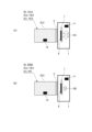
次にカメラシステムにおける像ブレ補正制御の最適化について説明する。図2はカメラシステムを示す概念図である。図2(A)は本体部1にレンズ装置2(a)が取り付けられた状態を示し、図2(B)は本体部1にレンズ装置2(b)が取り付けられた状態を示す。レンズ装置2(a)とレンズ装置2(b)は特徴が異なる交換レンズであり、括弧内に記したアルファベット文字により区別されている。
Next, we will explain the optimization of image stabilization control in a camera system. Figure 2 is a conceptual diagram showing a camera system. Figure 2(A) shows a state in which a lens device 2(a) is attached to a
図2(A)に示すレンズ装置2(a)は、マウント部5を介して本体部1に装着されている。レンズ装置2(a)は記憶部14を備えており、記憶部14はイメージサークル中心の最大オフセット情報およびイメージサークル径情報と、本体部1にレンズ装置2(a)であることを通知するための識別番号を保持している。レンズ装置2(a)の識別番号IDを「AAA」と表記する。イメージサークル中心の最大オフセット情報として、製造時の誤差量(装置固有の個体オフセット情報)を「ICi」と表記する。また、イメージサークル径情報として、設計称呼値(設計イメージサークル径)を「ICd」と表記する。図2(A)に示す「YES」は、記憶部14がICiやICdのデータを記憶していることを意味する。レンズ装置2(a)の記憶部14に記憶されているICiとICdの各データは、レンズ制御部13を介して本体部1のカメラ制御部8および像ブレ補正制御部9が取得する。本体部1の像ブレ補正制御部9は取得したデータを用いて、個体オフセット情報「ICi」をキャンセルする位置を基準位置として、レンズ装置2(a)にとって適切なストローク範囲で撮像素子6の駆動制御を行う。ストローク範囲の決定方法については、図3(A)を用いて後述する。
The lens device 2(a) shown in FIG. 2(A) is attached to the
図2(B)に示すレンズ装置2(b)は、マウント部5を介して本体部1に装着されている。レンズ装置2(b)は記憶部14を備えており、記憶部14はイメージサークル径情報と識別番号を保持している。本体部1にレンズ装置2(b)であることを通知するための識別番号IDを「BBB」と表記する。図2(B)に示す「YES」は記憶部14がICdのデータを記憶していることを意味し、「NO」は記憶部14がICiのデータを記憶していないことを意味する。
Lens device 2(b) shown in FIG. 2(B) is attached to
レンズ装置2(b)は、レンズ装置2(a)とは異なるカメラシステム(以下、システムBと称する)に最適化して製造された交換レンズである。一方、レンズ装置2(a)は図1のカメラシステム(以下、システムAと称する)に準拠した交換レンズである。したがって、レンズ装置2(b)を本体部1に装着して使用する場合、本体部1は、システムAに準拠したレンズ装置2(a)では実施可能な処理を行うことができない。例えば、個体オフセット情報ICiに応じた撮像素子6の基準位置の変更や、後述する最小イメージサークル径の算出は不可能である。しかしながら、システムBに準拠した交換レンズであっても、設計段階において以下に示す最小イメージサークル余裕を確保し得る場合がある。この場合には、最小イメージサークル余裕と、撮像素子6の有効撮像範囲および像ブレ補正部7の位置決め精度に基づく像ブレ補正ストロークで像ブレ補正を行うことができる。図3を参照して、本実施形態における像ブレ補正ストローク(駆動制御量)の算出処理について説明する。
The lens device 2(b) is an interchangeable lens manufactured to be optimized for a camera system (hereinafter referred to as system B) different from the lens device 2(a). On the other hand, the lens device 2(a) is an interchangeable lens that complies with the camera system (hereinafter referred to as system A) of FIG. 1. Therefore, when the lens device 2(b) is attached to the
図3(A)は、レンズ装置2(a)が本体部1に装着された場合の概念図であり、撮像光学系3の光軸方向から見た場合の位置関係を示す。図3(A)中の太実線で示す円は、個体イメージサークルの位置を表わしている。破線で示す円は、設計イメージサークルの位置を表している。つまり、個体イメージサークル径(太実線参照)は、個体オフセット情報ICi(矢印参照)により設計イメージサークル径を表す円が移動した円として表される。図3(A)中の破線で示す矩形は、マウント部5の中心を基準として、像ブレ補正部7の位置決め精度で位置決めされた撮像素子6の有効撮像範囲を表す。マウント部5の中心は1点鎖線(太線)で示す十字線の交点に相当する。位置決め精度は、撮像光学系の光軸方向から見た場合に、像ブレ補正部7によって撮像素子6がマウント部5の中心に位置決めされるときの精度である。位置決め精度についてはデータとして記憶部11に記憶されるか、またはカメラシステムにて規定される製造誤差の限界量としてあらかじめ定められた精度として使用される。撮像素子6の有効撮像範囲の情報はカメラ制御部8または記憶部11が保持している。図3(A)中の実線で示す矩形は、個体オフセット情報ICi(矢印参照)をキャンセルする位置に位置決めされた撮像素子6の有効撮像範囲を示している。個体オフセット除去位置は1点鎖線(細線)で示す十字線の交点の位置である。
3A is a conceptual diagram of the lens device 2(a) mounted on the
図3(A)にて像ブレ補正ストロークは、イメージサークル余裕s(a)で表される。このs(a)は像ブレ補正の駆動信号振幅の片側で表現した場合の量である(駆動信号の振幅全般に亘る範囲では、その2倍である)。設計イメージサークル径ICdの2分の1(半径)から、撮像素子6の有効撮像範囲を示す矩形の対角半径(対角長の2分の1)および像ブレ補正部7の位置決め精度を減算した長さがイメージサークル余裕s(a)である。あるいは、個体イメージサークル半径から、個体オフセット情報ICiに基づく位置決めが行われた撮像素子6の有効撮像範囲を示す矩形の対角半径および像ブレ補正部7の位置決め精度を減算した長さがイメージサークル余裕s(a)である。
In FIG. 3A, the image blur correction stroke is represented by the image circle margin s(a). This s(a) is the amount expressed on one side of the amplitude of the drive signal for image blur correction (it is twice that amount in the range covering the entire amplitude of the drive signal). The image circle margin s(a) is the length obtained by subtracting the diagonal radius (half the diagonal length) of the rectangle showing the effective imaging range of the
レンズ装置2(a)はシステムAに準拠し、あらかじめ定められたプロトコルをすべて満足する情報を記憶している交換レンズである。レンズ装置2(a)に対応するイメージサークル余裕s(a)は、レンズ装置2(a)の焦点距離や想定される手振れの量等に対して十分な値に設計されている。 Lens device 2(a) is an interchangeable lens that conforms to system A and stores information that satisfies all of the predetermined protocols. The image circle margin s(a) corresponding to lens device 2(a) is designed to be a sufficient value for the focal length of lens device 2(a) and the expected amount of camera shake, etc.
図3(B)は、最小イメージサークル径および最小イメージサークル余裕の算出を説明する概念図であり、撮像光学系の光軸方向から見た場合の位置関係を示す。図3(B)にて、最小イメージサークル径を太実線の円で表し、設計イメージサークル径を細実線の円で表している。個体イメージサークル位置を破線の円で表している。最小イメージサークル径はカメラ制御部8において計算される。最小イメージサークル径(太実線の円)は、設計イメージサークル径(細実線の円)が個体オフセット情報ICi(矢印参照)により移動した円(破線の円)から、マウント部5の中心への最近接距離を半径に持つ円で表される。つまり最小イメージサークル径は設計イメージサークル径よりも小さい。マウント部5の中心は、1点鎖線(太線)で示す十字線の交点に相当する。図3(B)に実線で示す矩形は、撮像素子6の有効撮像範囲を表す。有効撮像範囲を表す矩形が最小イメージサークル径を表す円をはみ出すことなく撮像素子6の駆動制御を行うことが望ましい。
Figure 3(B) is a conceptual diagram for explaining the calculation of the minimum image circle diameter and the minimum image circle margin, showing the positional relationship when viewed from the optical axis direction of the imaging optical system. In Figure 3(B), the minimum image circle diameter is represented by a thick solid circle, and the design image circle diameter is represented by a thin solid circle. The individual image circle position is represented by a dashed circle. The minimum image circle diameter is calculated in the
図3(B)にて像ブレ補正ストロークは、最小イメージサークル余裕s(b)で表される。このs(b)は像ブレ補正の駆動信号振幅の片側で表現した場合の量である(駆動信号の振幅全般に亘る範囲では、その2倍である)。より具体的には、レンズ装置2(b)の像ブレ補正ストロークは、最小イメージサークル半径から、撮像素子6の有効撮像範囲を示す矩形の対角半径(対角長の半分)および像ブレ補正部7の位置決め精度を減算した差分量である。この像ブレ補正ストロークについては、レンズ装置2(b)にとって、撮像装置の手振れや焦点距離の関係等に対して、必ずしも十分な像ブレ補正効果が期待できない可能性もある。しかしながら、この像ブレ補正ストロークの範囲内で像ブレ補正を行うことにより、画像の四隅の減光による極端な劣化を抑制しつつ、像ブレ補正効果を発揮することが可能である。また、レンズ装置2(b)が像ブレ補正レンズを備えていない場合には、本体部1における撮像素子6の駆動制御により像ブレ補正効果を奏する。
In FIG. 3B, the image blur correction stroke is represented by the minimum image circle margin s(b). This s(b) is the amount expressed on one side of the drive signal amplitude of the image blur correction (it is twice that amount in the range of the overall amplitude of the drive signal). More specifically, the image blur correction stroke of the lens device 2(b) is the difference amount obtained by subtracting the diagonal radius (half the diagonal length) of the rectangle indicating the effective imaging range of the
図4は、本実施形態において像ブレ補正部7の像ブレ補正ストロークを決定する処理を説明するフローチャートである。以下に示す処理は、本体部1にレンズ装置が装着された際に開始され、または撮像システム1000の電源投入時に開始される。
Figure 4 is a flowchart explaining the process of determining the image blur correction stroke of the image
図4のS001でカメラ制御部8は、本体部1に装着されたレンズ装置の識別処理を実行する。例えばレンズ装置2(a)の記憶部は識別番号IDとして「AAA」を記憶しており、レンズ装置2(b)の記憶部は識別番号IDとして「BBB」を記憶している。カメラ制御部8は、レンズ装置を特定するための識別番号をレンズ装置の記憶部が保持しているか否かを判断する。レンズ装置の記憶部が識別番号を保持していないと判断された場合には、そのレンズ装置では最小イメージサークル余裕を確保できるかどうかが不明である。そのため、別処理へ移行する。別処理とは、例えばカメラ制御部8が最小イメージサークル余裕を確保し得るか否かを判断せずに、像ブレ補正ストロークを決定する処理等である。カメラ制御部8は、撮影者が指定する焦点距離情報等を参照し、画像の四隅での減光(周辺光量の低下)レベルが閾値以上とならない範囲で像ブレ補正ストロークを割り当てる処理を行う。
In S001 of FIG. 4, the
S002でカメラ制御部8は、本体部1に装着されたレンズ装置の記憶部14が記憶している情報について判断する。記憶部14が設計イメージサークル径ICd、個体オフセット情報ICi等の、イメージサークルに関連する情報を記憶していると判断された場合、S004の処理へ進む。また記憶部14がイメージサークルに関連する情報を記憶していないと判断された場合には、S003の処理へ進む。
In S002, the
S003でカメラ制御部8は、記憶部11が記憶している、別システム(例えばシステムB)に準拠する交換レンズに係るイメージサークルに関連する情報を参照する。S002またはS003の後、S004へ進み、カメラ制御部8は、図3を参照して説明した方法によって前記イメージサークル余裕から像ブレ補正ストロークを算出して決定する。例えば、図2(A)に示すレンズ装置2(a)の装着時には、イメージサークル余裕s(a)の2倍から算出される像ブレ補正ストローク範囲(矢印SA参照)が決定される。また、図2(B)に示すレンズ装置2(b)の装着時には、最小イメージサークル余裕s(b)の2倍から算出される像ブレ補正ストローク範囲(矢印SB参照)が決定される。この場合、レンズ装置2(a)の装着時の像ブレ補正ストローク範囲に比べて、レンズ装置2(b)の装着時の像ブレ補正ストローク範囲の方が狭い。
In S003, the
S004の後、一連の処理を終了する。これ以降、本体部1の像ブレ補正制御部9は、S004で決定された像ブレ補正ストローク範囲内で撮像素子6の駆動制御を行い、像ブレ補正された画像が取得される。
After S004, the series of processes ends. After this, the image
本実施形態の記憶部11または記憶部14は、レンズ装置ごとにイメージサークル径情報、イメージサークル中心の最大オフセット情報または撮像光学系の光軸のオフセット情報を記憶している。例えば、イメージサークル径情報およびイメージサークル中心の最大オフセット情報については、撮像光学系のフォーカス状態、ズーム状態、または絞り値に対応する複数のデータが記憶部に記憶されている。フォーカス状態はフォーカスレンズの位置や焦点検出情報に対応する状態であり、ズーム状態はズームレンズの位置や撮影倍率、撮影画角等に対応する状態である。カメラ制御部8は撮影状況に応じて処理に必要な情報を記憶部11または記憶部14から取得することができる。
The
あるいは記憶部11または記憶部14は、イメージサークル径情報およびイメージサークル中心の最大オフセット情報を、撮像光学系のフォーカス状態、ズーム状態、または絞り値に拠らないデータとしてそれぞれ記憶している。この場合、カメラ制御部8は撮像光学系のフォーカス状態、ズーム状態、絞り値の如何に関わらず、それぞれ単一の値を記憶部11または記憶部14から取得できるので処理の簡素化が可能である。
Alternatively, the
レンズ装置が備える記憶部の記憶情報だけでは像ブレ補正に必要な情報が不足する場合にカメラ制御部8は、レンズ装置の識別情報に対応する情報を記憶部11から検索して使用する。レンズ装置の識別情報は、レンズ装置が備える記憶部に記憶されたID情報、または本体部がレンズ装置の識別処理を行う場合にレンズ装置の種類を特定した識別結果を示す情報である。後者の情報については、本体部に装着されたレンズ装置の仕様を示す情報や、ユーザが入力または選択するレンズ装置の情報等からカメラ制御部8が判断して取得可能である。例えばカメラ制御部8はレンズ装置の識別情報に基づき、イメージサークル中心の最大オフセット情報または撮像光学系の光軸のオフセット情報を記憶部11から取得して最小イメージサークル径を計算する。カメラ制御部8は最小イメージサークル径から、撮像素子の撮像範囲の対角長を差し引いた長さである最小イメージサークル余裕を算出する。最小イメージサークル余裕と、撮像素子6に係る位置決め精度との差分により、像ブレ補正部7の駆動制御量の範囲が決定される。
When the information stored in the memory unit of the lens device is insufficient for the information required for image blur correction, the
本実施形態の撮像システムであるシステムAに準拠したレンズ装置2(a)が本体部1に装着された場合はもちろん、異なるシステムBに準拠したレンズ装置2(b)が本体部1に装着された場合でも対応が可能である。像ブレ補正に必要な情報はレンズ装置から本体部1へ通知されるか、または本体部1の記憶部11が保持している。撮像光学系の光軸方向から見た場合に、マウント部5の中心を基準とするイメージサークル径に相当する長さから、撮像素子6の撮像範囲に係る対角長を減算した長さが算出される。算出された長さと、撮像素子6がマウント部5の中心に位置決めされるときの位置決め精度との差分を計算することにより、像ブレ補正の駆動制御量の範囲を決定することができる。
This embodiment can be used not only when a lens device 2(a) conforming to system A, which is an imaging system of this embodiment, is attached to the
本実施形態によれば、異なるシステムに準拠するレンズ装置とカメラ本体部との組み合わせであっても、画像品位を損なわずに適正な駆動制御量で像ブレ補正を実現可能である。 According to this embodiment, even when a lens device and a camera body that comply with different systems are combined, image stabilization can be achieved with an appropriate amount of drive control without compromising image quality.
1・・・本体部
2・・・レンズ装置
5・・・マウント部
7・・・像ブレ補正部
8・・・カメラ制御部
9・・・像ブレ補正制御部
11・・・本体部の記憶部
13・・・レンズ制御部
14・・・レンズ装置の記憶部
Reference Signs List 1: Main body 2: Lens device 5: Mount 7: Image blur correction unit 8: Camera control unit 9: Image blur correction control unit 11: Storage unit of main body 13: Lens control unit 14: Storage unit of lens device
Claims (6)
撮像素子の駆動により像ブレ補正を行う補正手段と、
前記レンズ装置または前記撮像装置の振れを検出する検出手段の検出情報に基づく前記補正手段の駆動制御を行う制御手段と、
記憶手段と、を備え、
前記制御手段は、前記レンズ装置から前記レンズ装置のイメージサークル中心の最大オフセット情報及びイメージサークル径情報を取得できないとき、前記レンズ装置が有する撮像光学系の光軸方向から見た場合に、前記記憶手段に予め記憶された情報に対応する位置にイメージサークル中心があると想定した前記レンズ装置に対応するイメージサークル径を有するイメージサークルを表す円から前記マウント部の中心までの最近接距離に相当する長さから前記撮像素子の撮像範囲に係る対角長を減算した長さと、前記補正手段によって前記撮像素子が前記マウント部の中心に位置決めされるときの位置決め精度との差分に基づいて、前記補正手段の駆動制御量の範囲を決定し、前記レンズ装置から前記レンズ装置のイメージサークル中心の最大オフセット情報及びイメージサークル径情報を取得できないときよりも、前記レンズ装置から前記レンズ装置のイメージサークル中心の最大オフセット情報及びイメージサークル径情報を取得できるときのほうが、前記補正手段の駆動制御量の範囲を大きくする
ことを特徴とする撮像装置。 An imaging device to which a lens device can be attached via a mount portion,
a correction unit that performs image blur correction by driving an image sensor;
a control unit that controls the drive of the correction unit based on detection information from a detection unit that detects a shake of the lens device or the imaging device;
A storage means,
an imaging device characterized in that, when the control means cannot obtain maximum offset information and image circle diameter information of the image circle center of the lens device from the lens device, the control means determines a range of a drive control amount of the correction means based on a difference between a length obtained by subtracting a diagonal length related to the imaging range of the image element from a length equivalent to the closest distance from a circle representing an image circle having an image circle diameter corresponding to the lens device, which is assumed to have an image circle center at a position corresponding to the information pre-stored in the storage means, when viewed from the optical axis direction of the imaging optical system of the lens device, to the center of the mount section, and a positioning accuracy when the image element is positioned at the center of the mount section by the correction means; and the control means determines a range of a drive control amount of the correction means when the control means can obtain maximum offset information and image circle diameter information of the image circle center of the lens device from the lens device compared to when the control means cannot obtain maximum offset information and image circle diameter information of the image circle center of the lens device from the lens device .
ことを特徴とする請求項1に記載の撮像装置。 2. The imaging device according to claim 1, wherein, when the control means is able to acquire maximum offset information of an image circle center of the lens device and image circle diameter information from the lens device, it determines a range of a drive control amount of the correction means based on a difference between the positioning accuracy and a length obtained by subtracting the diagonal length from the image circle diameter indicated by the acquired image circle diameter information when viewed from an optical axis direction of an imaging optical system of the lens device.
ことを特徴とする請求項1または2に記載の撮像装置。 3. The imaging device according to claim 1, wherein the storage unit stores image circle diameter information corresponding to the lens device from which the image circle diameter information cannot be acquired.
ことを特徴とする請求項1乃至3のいずれか1項に記載の撮像装置。 4. The imaging device according to claim 1, wherein the control means determines a range of a drive control amount of the correction means based on focal length information specified by a user when information for identifying the lens device cannot be acquired from the lens device.
前記撮像装置は、
撮像素子の駆動により像ブレ補正を行う補正手段と、
前記レンズ装置または前記撮像装置の振れを検出する検出手段の検出情報に基づく前記補正手段の駆動制御を行う制御手段と、を有し、
前記制御手段は、前記レンズ装置から前記レンズ装置のイメージサークル中心の最大オフセット情報及びイメージサークル径情報を取得できない場合と前記レンズ装置から前記レンズ装置のイメージサークル中心の最大オフセット情報及びイメージサークル径情報を取得できる場合とで、前記補正手段の駆動制御量の範囲の大きさを異ならせて前記補正手段の駆動制御を行う
ことを特徴とする撮像システム。 An imaging system including a lens device and an imaging device to which the lens device can be attached via a mount unit,
The imaging device includes:
a correction unit that performs image blur correction by driving an image sensor;
a control unit that controls the drive of the correction unit based on detection information from a detection unit that detects a shake of the lens device or the image pickup device,
The control means controls the drive of the correction means by changing the size of the range of the drive control amount of the correction means between a case where the maximum offset information of the image circle center of the lens device and the image circle diameter information of the lens device cannot be acquired from the lens device and a case where the maximum offset information of the image circle center of the lens device and the image circle diameter information of the lens device can be acquired from the lens device.
1. An imaging system comprising:
前記レンズ装置または前記撮像装置の振れを検出する検出手段の検出情報を制御手段が取得して、前記撮像装置が備える補正手段の駆動制御量の範囲を決定する決定工程と、
前記駆動制御量にしたがって、前記撮像装置が備える撮像素子を前記補正手段が駆動することにより像ブレ補正を行う工程と、を有し、
前記決定工程にて前記制御手段は、前記レンズ装置から前記レンズ装置のイメージサークル中心の最大オフセット情報及びイメージサークル径情報を取得できないとき、前記レンズ装置が有する撮像光学系の光軸方向から見た場合に、予め撮像装置の記憶手段に記憶された情報に対応する位置にイメージサークル中心があると想定した前記レンズ装置に対応するイメージサークル径を有するイメージサークルを表す円から前記マウント部の中心までの最近接距離に相当する長さから前記撮像素子の撮像範囲に係る対角長を減算した長さと、前記補正手段によって前記撮像素子が前記マウント部の中心に位置決めされるときの位置決め精度との差分に基づいて、前記補正手段の駆動制御量の範囲を決定し、前記レンズ装置から前記レンズ装置のイメージサークル中心の最大オフセット情報及びイメージサークル径情報を取得できないときよりも、前記レンズ装置から前記レンズ装置のイメージサークル中心の最大オフセット情報及びイメージサークル径情報を取得できるときのほうが、前記補正手段の駆動制御量の範囲を大きくする
ことを特徴とする撮像装置の制御方法。
A control method executed in an imaging device to which a lens device can be attached via a mount unit, comprising:
a determination step of determining a range of a drive control amount of a correction unit included in the imaging device by a control unit acquiring detection information of a detection unit that detects a shake of the lens device or the imaging device;
and performing image blur correction by driving an image sensor included in the imaging device by the correction means in accordance with the drive control amount,
a control means for controlling an imaging device, the control means determining a range of a drive control amount of the correction means based on a difference between a length obtained by subtracting a diagonal length related to an imaging range of the imaging element from a length equivalent to the closest distance from a circle representing an image circle having an image circle diameter corresponding to the lens device, the image circle center of which is assumed to be located at a position corresponding to information previously stored in a storage means of the imaging device, when viewed from a direction of an optical axis of an imaging optical system of the lens device, to the center of the mount section, the length being obtained by subtracting a diagonal length related to an imaging range of the imaging element, and the positioning accuracy when the imaging element is positioned at the center of the mount section by the correction means, and determining a range of a drive control amount of the correction means when the control means can obtain the maximum offset information and image circle diameter information of the image circle center of the lens device from the lens device, compared to when the control means cannot obtain the maximum offset information and image circle diameter information of the image circle center of the lens device from the lens device .
Priority Applications (3)
| Application Number | Priority Date | Filing Date | Title |
|---|---|---|---|
| JP2020035762A JP7532046B2 (en) | 2020-03-03 | 2020-03-03 | Image capture device, control method thereof, and image capture system |
| US17/188,196 US11190695B2 (en) | 2020-03-03 | 2021-03-01 | Imaging device, control method thereof, and imaging system correcting blur based on image circle information |
| CN202110235270.0A CN113364944B (en) | 2020-03-03 | 2021-03-03 | Image pickup apparatus, control method thereof, and image pickup system |
Applications Claiming Priority (1)
| Application Number | Priority Date | Filing Date | Title |
|---|---|---|---|
| JP2020035762A JP7532046B2 (en) | 2020-03-03 | 2020-03-03 | Image capture device, control method thereof, and image capture system |
Publications (3)
| Publication Number | Publication Date |
|---|---|
| JP2021139973A JP2021139973A (en) | 2021-09-16 |
| JP2021139973A5 JP2021139973A5 (en) | 2023-03-09 |
| JP7532046B2 true JP7532046B2 (en) | 2024-08-13 |
Family
ID=77524819
Family Applications (1)
| Application Number | Title | Priority Date | Filing Date |
|---|---|---|---|
| JP2020035762A Active JP7532046B2 (en) | 2020-03-03 | 2020-03-03 | Image capture device, control method thereof, and image capture system |
Country Status (3)
| Country | Link |
|---|---|
| US (1) | US11190695B2 (en) |
| JP (1) | JP7532046B2 (en) |
| CN (1) | CN113364944B (en) |
Families Citing this family (1)
| Publication number | Priority date | Publication date | Assignee | Title |
|---|---|---|---|---|
| EP4397906A1 (en) | 2021-08-30 | 2024-07-10 | Koito Manufacturing Co., Ltd. | Micro lens array, and vehicle lamp fitting employing micro lens array |
Citations (8)
| Publication number | Priority date | Publication date | Assignee | Title |
|---|---|---|---|---|
| JP2004056581A (en) | 2002-07-22 | 2004-02-19 | Minolta Co Ltd | Image pickup device and method for acquiring centering information |
| JP2006349942A (en) | 2005-06-15 | 2006-12-28 | Tamron Co Ltd | Image blur correcting device and imaging apparatus equipped therewith |
| JP2008010939A (en) | 2006-06-27 | 2008-01-17 | Fujifilm Corp | Lens unit, camera main body, camera system, and method and program of operating lens unit or camera main body |
| JP2009265550A (en) | 2008-04-30 | 2009-11-12 | Aof Imaging Technology Ltd | Image blur correction device |
| JP2010039292A (en) | 2008-08-06 | 2010-02-18 | Nikon Corp | Camera and lens barrel |
| JP2018033075A (en) | 2016-08-26 | 2018-03-01 | キヤノン株式会社 | Imaging apparatus, lens device, imaging system, vibration isolation control method and vibration isolation control program |
| US20190141246A1 (en) | 2017-11-09 | 2019-05-09 | Canon Kabushiki Kaisha | Imaging apparatus and interchangeable lens apparatus |
| JP2019087937A (en) | 2017-11-09 | 2019-06-06 | キヤノン株式会社 | Imaging device and interchangeable lens device |
Family Cites Families (9)
| Publication number | Priority date | Publication date | Assignee | Title |
|---|---|---|---|---|
| JP4567313B2 (en) | 2003-10-21 | 2010-10-20 | オリンパス株式会社 | camera |
| JP4022595B2 (en) * | 2004-10-26 | 2007-12-19 | コニカミノルタオプト株式会社 | Imaging device |
| JP2007034141A (en) * | 2005-07-29 | 2007-02-08 | Olympus Imaging Corp | Camera system and lens unit |
| CN101395518B (en) * | 2006-03-31 | 2012-01-25 | 株式会社尼康 | Imaging device, imaging method, highly variable magnification zoom lens |
| JP2008203449A (en) * | 2007-02-19 | 2008-09-04 | Sony Corp | Zoom lens and imaging apparatus |
| CN101949768B (en) * | 2010-08-20 | 2012-01-25 | 中国科学院光电技术研究所 | Point source target related Hartmann-shack wavefront slope processor and manufacturing method |
| US9918004B2 (en) * | 2015-02-06 | 2018-03-13 | Panasonic Intellectual Property Management Co., Ltd. | Camera body capable of driving an image sensor along an optical axis in response to a change in an optical state of an object image |
| JP7325216B2 (en) * | 2019-05-08 | 2023-08-14 | キヤノン株式会社 | Vibration isolation control device and method, and imaging device |
| JP7305455B2 (en) * | 2019-06-24 | 2023-07-10 | キヤノン株式会社 | Anti-vibration control device, imaging device, and anti-vibration control method |
-
2020
- 2020-03-03 JP JP2020035762A patent/JP7532046B2/en active Active
-
2021
- 2021-03-01 US US17/188,196 patent/US11190695B2/en active Active
- 2021-03-03 CN CN202110235270.0A patent/CN113364944B/en active Active
Patent Citations (8)
| Publication number | Priority date | Publication date | Assignee | Title |
|---|---|---|---|---|
| JP2004056581A (en) | 2002-07-22 | 2004-02-19 | Minolta Co Ltd | Image pickup device and method for acquiring centering information |
| JP2006349942A (en) | 2005-06-15 | 2006-12-28 | Tamron Co Ltd | Image blur correcting device and imaging apparatus equipped therewith |
| JP2008010939A (en) | 2006-06-27 | 2008-01-17 | Fujifilm Corp | Lens unit, camera main body, camera system, and method and program of operating lens unit or camera main body |
| JP2009265550A (en) | 2008-04-30 | 2009-11-12 | Aof Imaging Technology Ltd | Image blur correction device |
| JP2010039292A (en) | 2008-08-06 | 2010-02-18 | Nikon Corp | Camera and lens barrel |
| JP2018033075A (en) | 2016-08-26 | 2018-03-01 | キヤノン株式会社 | Imaging apparatus, lens device, imaging system, vibration isolation control method and vibration isolation control program |
| US20190141246A1 (en) | 2017-11-09 | 2019-05-09 | Canon Kabushiki Kaisha | Imaging apparatus and interchangeable lens apparatus |
| JP2019087937A (en) | 2017-11-09 | 2019-06-06 | キヤノン株式会社 | Imaging device and interchangeable lens device |
Also Published As
| Publication number | Publication date |
|---|---|
| JP2021139973A (en) | 2021-09-16 |
| CN113364944A (en) | 2021-09-07 |
| US11190695B2 (en) | 2021-11-30 |
| CN113364944B (en) | 2024-03-26 |
| US20210281760A1 (en) | 2021-09-09 |
Similar Documents
| Publication | Publication Date | Title |
|---|---|---|
| US10186021B2 (en) | Camera system, camera body, and control method of camera system | |
| US11516393B2 (en) | Imaging apparatus to which an interchangeable lens apparatus is attached that utilize image circle information of an imaging optical system in the interchangeable lens apparatus | |
| US9800789B2 (en) | Camera system with image blur correction | |
| CN110462507B (en) | Image blur correction device, interchangeable lens, and imaging device | |
| JP2009075441A (en) | Interchangeable lens and optical apparatus | |
| JP6500238B2 (en) | Imaging device, imaging method and imaging program | |
| JP6543946B2 (en) | Shake correction device, camera and electronic device | |
| JP7532046B2 (en) | Image capture device, control method thereof, and image capture system | |
| US11445115B2 (en) | Image capturing and stabilization apparatus and method capable of performing image stabilization control by moving an image sensor | |
| US10992867B2 (en) | Image capturing apparatus and control method thereof and storage medium | |
| US11381746B2 (en) | Apparatus and method for setting a correction axis for image stabilization | |
| WO2020013200A1 (en) | Replacement lens and camera body | |
| JP2021139973A5 (en) | ||
| JP2021097338A (en) | Control apparatus, lens apparatus, imaging apparatus, and imaging system | |
| JP7551315B2 (en) | Image capture device, image capture device control method, and program | |
| JP7214492B2 (en) | Imaging device and lens device | |
| US20220394169A1 (en) | Image pickup apparatus that performs optical image blur correction and alignment composition of plurality of still images shot in time continuous manner, control method thereof, and storage medium | |
| US11659280B2 (en) | Image pickup apparatus, control method, and storage medium for controlling an image stabilization unit | |
| US20240129629A1 (en) | Control apparatus, lens apparatus, image pickup apparatus, imaging system, control method, and storage medium | |
| JPH0690398A (en) | Image blur correction device | |
| US20230049191A1 (en) | Image blur correction apparatus, control method thereof, and storage medium | |
| JP6332521B2 (en) | Lens barrel | |
| JP2023157250A (en) | Control device, lens device, image capturing device, image capturing system, and operating device | |
| JP2006349707A (en) | Digital camera | |
| JP2021097339A (en) | Imaging device and imaging system |
Legal Events
| Date | Code | Title | Description |
|---|---|---|---|
| A521 | Request for written amendment filed |
Free format text: JAPANESE INTERMEDIATE CODE: A523 Effective date: 20230301 |
|
| A621 | Written request for application examination |
Free format text: JAPANESE INTERMEDIATE CODE: A621 Effective date: 20230301 |
|
| A977 | Report on retrieval |
Free format text: JAPANESE INTERMEDIATE CODE: A971007 Effective date: 20231101 |
|
| A131 | Notification of reasons for refusal |
Free format text: JAPANESE INTERMEDIATE CODE: A131 Effective date: 20231205 |
|
| A521 | Request for written amendment filed |
Free format text: JAPANESE INTERMEDIATE CODE: A523 Effective date: 20240130 |
|
| A131 | Notification of reasons for refusal |
Free format text: JAPANESE INTERMEDIATE CODE: A131 Effective date: 20240423 |
|
| A521 | Request for written amendment filed |
Free format text: JAPANESE INTERMEDIATE CODE: A523 Effective date: 20240624 |
|
| TRDD | Decision of grant or rejection written | ||
| A01 | Written decision to grant a patent or to grant a registration (utility model) |
Free format text: JAPANESE INTERMEDIATE CODE: A01 Effective date: 20240702 |
|
| A61 | First payment of annual fees (during grant procedure) |
Free format text: JAPANESE INTERMEDIATE CODE: A61 Effective date: 20240731 |
|
| R150 | Certificate of patent or registration of utility model |
Ref document number: 7532046 Country of ref document: JP Free format text: JAPANESE INTERMEDIATE CODE: R150 |