JP7526257B2 - Microcavitation system, device, and ultrasonic probe assembly for generating directed microcavitation - Google Patents
Microcavitation system, device, and ultrasonic probe assembly for generating directed microcavitation Download PDFInfo
- Publication number
- JP7526257B2 JP7526257B2 JP2022516612A JP2022516612A JP7526257B2 JP 7526257 B2 JP7526257 B2 JP 7526257B2 JP 2022516612 A JP2022516612 A JP 2022516612A JP 2022516612 A JP2022516612 A JP 2022516612A JP 7526257 B2 JP7526257 B2 JP 7526257B2
- Authority
- JP
- Japan
- Prior art keywords
- cannula
- ultrasonic
- fluid
- generating chamber
- distal end
- Prior art date
- Legal status (The legal status is an assumption and is not a legal conclusion. Google has not performed a legal analysis and makes no representation as to the accuracy of the status listed.)
- Active
Links
Images


Classifications
-
- A—HUMAN NECESSITIES
- A61—MEDICAL OR VETERINARY SCIENCE; HYGIENE
- A61B—DIAGNOSIS; SURGERY; IDENTIFICATION
- A61B17/00—Surgical instruments, devices or methods
- A61B17/32—Surgical cutting instruments
- A61B17/3203—Fluid jet cutting instruments
- A61B17/32037—Fluid jet cutting instruments for removing obstructions from inner organs or blood vessels, e.g. for atherectomy
-
- A—HUMAN NECESSITIES
- A61—MEDICAL OR VETERINARY SCIENCE; HYGIENE
- A61B—DIAGNOSIS; SURGERY; IDENTIFICATION
- A61B17/00—Surgical instruments, devices or methods
- A61B17/32—Surgical cutting instruments
- A61B17/320068—Surgical cutting instruments using mechanical vibrations, e.g. ultrasonic
-
- A—HUMAN NECESSITIES
- A61—MEDICAL OR VETERINARY SCIENCE; HYGIENE
- A61B—DIAGNOSIS; SURGERY; IDENTIFICATION
- A61B17/00—Surgical instruments, devices or methods
- A61B17/32—Surgical cutting instruments
- A61B17/3203—Fluid jet cutting instruments
-
- A—HUMAN NECESSITIES
- A61—MEDICAL OR VETERINARY SCIENCE; HYGIENE
- A61B—DIAGNOSIS; SURGERY; IDENTIFICATION
- A61B17/00—Surgical instruments, devices or methods
- A61B17/22—Implements for squeezing-off ulcers or the like on inner organs of the body; Implements for scraping-out cavities of body organs, e.g. bones; for invasive removal or destruction of calculus using mechanical vibrations; for removing obstructions in blood vessels, not otherwise provided for
- A61B17/22004—Implements for squeezing-off ulcers or the like on inner organs of the body; Implements for scraping-out cavities of body organs, e.g. bones; for invasive removal or destruction of calculus using mechanical vibrations; for removing obstructions in blood vessels, not otherwise provided for using mechanical vibrations, e.g. ultrasonic shock waves
- A61B17/22012—Implements for squeezing-off ulcers or the like on inner organs of the body; Implements for scraping-out cavities of body organs, e.g. bones; for invasive removal or destruction of calculus using mechanical vibrations; for removing obstructions in blood vessels, not otherwise provided for using mechanical vibrations, e.g. ultrasonic shock waves in direct contact with, or very close to, the obstruction or concrement
-
- A—HUMAN NECESSITIES
- A61—MEDICAL OR VETERINARY SCIENCE; HYGIENE
- A61B—DIAGNOSIS; SURGERY; IDENTIFICATION
- A61B17/00—Surgical instruments, devices or methods
- A61B17/32—Surgical cutting instruments
- A61B17/320068—Surgical cutting instruments using mechanical vibrations, e.g. ultrasonic
- A61B2017/320084—Irrigation sleeves
-
- A—HUMAN NECESSITIES
- A61—MEDICAL OR VETERINARY SCIENCE; HYGIENE
- A61B—DIAGNOSIS; SURGERY; IDENTIFICATION
- A61B17/00—Surgical instruments, devices or methods
- A61B17/32—Surgical cutting instruments
- A61B17/3203—Fluid jet cutting instruments
- A61B2017/32032—Fluid jet cutting instruments using cavitation of the fluid
Landscapes
- Health & Medical Sciences (AREA)
- Surgery (AREA)
- Life Sciences & Earth Sciences (AREA)
- Engineering & Computer Science (AREA)
- Molecular Biology (AREA)
- Biomedical Technology (AREA)
- Heart & Thoracic Surgery (AREA)
- Medical Informatics (AREA)
- Nuclear Medicine, Radiotherapy & Molecular Imaging (AREA)
- Animal Behavior & Ethology (AREA)
- General Health & Medical Sciences (AREA)
- Public Health (AREA)
- Veterinary Medicine (AREA)
- Dentistry (AREA)
- Mechanical Engineering (AREA)
- Vascular Medicine (AREA)
- Surgical Instruments (AREA)
Description
関連出願の相互参照
[0001]なし。
[0002]本発明は、医学的切除、破砕、および切断に関し、より詳細には、指向性マイクロキャビテーションを生成するためのマイクロキャビテーションシステム、デバイス、および超音波プローブアセンブリに関する。
CROSS-REFERENCE TO RELATED APPLICATIONS
[0001] None.
FIELD OF THEINVENTION [0002] The present invention relates to medical ablation, fracturing, and cutting, and more particularly to microcavitation systems, devices, and ultrasonic probe assemblies for generating directed microcavitation.
[0003]血管閉塞クロッシングおよび/またはアテレクトミーなどの医療処置は、血管閉塞部と係合されたカテーテル先端部の振動を介して、血管閉塞をクロスおよび/または粉砕するための、超音波エネルギーを利用し得る。さらに、介入性腫瘍処置は、腫瘍または癌病変部を除去するための、機械的切断器具、熱切除、または低温技術を利用し得る。 [0003] Medical procedures such as vascular occlusion crossing and/or atherectomy may utilize ultrasonic energy to cross and/or shatter vascular occlusions via vibration of a catheter tip engaged with the vascular occlusion. Additionally, interventional tumor procedures may utilize mechanical cutting instruments, thermal ablation, or cryotechniques to remove tumors or cancerous lesions.
[0004]音波キャビテーションは、強烈な超音波によって放射された液体における気泡の構成および崩壊である。気泡が崩壊するスピードは、液体中で音速に達することがある。したがって気泡の崩壊は、準断熱処理となる。キャビテーション中の激しい気泡の崩壊は、極端な局所的温度、加熱/冷却率、および圧力を生じさせ、遊離基を生成して、多くの化学(音響化学)反応(例えば、汚染物質の酸化、滅菌、重合、脱硫、長鎖分子の劣化など)を起こさせる。 [0004] Acoustic cavitation is the formation and collapse of gas bubbles in liquids irradiated by intense ultrasonic waves. The speed at which the bubbles collapse can reach the speed of sound in the liquid. Thus, bubble collapse is a quasi-adiabatic process. The violent collapse of bubbles during cavitation produces extreme local temperatures, heating/cooling rates, and pressures, generating free radicals that initiate many chemical (sonochemical) reactions (e.g., oxidation of pollutants, sterilization, polymerization, desulfurization, degradation of long-chain molecules, etc.).
[0005]当技術分野で必要とされるのは、例えば血管処置および介入性腫瘍処置に使用され得る、指向性マイクロキャビテーションを生成するための、マイクロキャビテーションシステム、デバイス、および超音波プローブアセンブリである。 [0005] What is needed in the art are microcavitation systems, devices, and ultrasound probe assemblies for generating directed microcavitation that can be used, for example, in vascular and interventional tumor treatments.
[0006]本発明は、例えば血管処置および介入性腫瘍処置に使用され得る、指向性マイクロキャビテーションを生成するための、マイクロキャビテーションシステム、デバイス、および超音波プローブアセンブリを提供する。 [0006] The present invention provides microcavitation systems, devices, and ultrasound probe assemblies for generating directed microcavitation that may be used, for example, in vascular and interventional tumor treatments.
[0007]本発明は、1つの形態において、カニューレおよび超音波伝達部材を含んだ、超音波プローブアセンブリを目標とする。この超音波伝達部材は、第1の端部分、および第1の端部分から離間された第2端を有する。カニューレは、管状側壁、カニューレ管腔、流体入口ポート、近位端、遠位端、および遠位端部分、を有する。超音波伝達部材は、カニューレ管腔の中に配置される。カニューレの流体入口ポートは、カニューレ管腔と流体連通して接続される。カニューレの遠位端部分は、キャビテーション生成チャンバを画定するよう構成される。キャビテーション生成チャンバは、カニューレの遠位端において遠位端壁を有し、それは篩(ふるい)として構成され、複数のアパーチャを画定する。 [0007] In one form, the present invention is directed to an ultrasonic probe assembly including a cannula and an ultrasonic transmission member. The ultrasonic transmission member has a first end portion and a second end spaced from the first end portion. The cannula has a tubular sidewall, a cannula lumen, a fluid inlet port, a proximal end, a distal end, and a distal end portion. The ultrasonic transmission member is disposed within the cannula lumen. The cannula fluid inlet port is connected in fluid communication with the cannula lumen. The cannula distal end portion is configured to define a cavitation generating chamber. The cavitation generating chamber has a distal end wall at the distal end of the cannula that is configured as a sieve and defines a plurality of apertures.
[0008]本発明は別の形態において、超音波マイクロキャビテーションデバイスを目標とする。超音波マイクロキャビテーションデバイスは、ハンドル、超音波伝達部材、およびカニューレを含む。このハンドルは、超音波トランスデューサを含む。超音波伝達部材は、第1の端部分、および第1の端部分から離間された第2端を有する。超音波伝達部材の第1の端部分は、超音波トランスデューサに接続される。カニューレはハンドルに接続される。カニューレは、管状側壁、カニューレ管腔、流体入口ポート、近位端、遠位端、および遠位端部分、を有する。超音波伝達部材は、カニューレ管腔の中に配置される。カニューレの流体入口ポートは、カニューレ管腔と流体連通して接続される。カニューレの遠位端部分は、遠位方向において、カニューレの遠位端で終端する、キャビテーション生成チャンバを画定するよう構成される。キャビテーション生成チャンバは、遠位端壁を有し、それは篩として構成され、流体噴射流を噴出させるための複数のアパーチャを画定する。 [0008] In another form, the invention is directed to an ultrasonic microcavitation device. The ultrasonic microcavitation device includes a handle, an ultrasonic transmission member, and a cannula. The handle includes an ultrasonic transducer. The ultrasonic transmission member has a first end portion and a second end spaced from the first end portion. The first end portion of the ultrasonic transmission member is connected to the ultrasonic transducer. The cannula is connected to the handle. The cannula has a tubular sidewall, a cannula lumen, a fluid inlet port, a proximal end, a distal end, and a distal end portion. The ultrasonic transmission member is disposed within the cannula lumen. The fluid inlet port of the cannula is connected in fluid communication with the cannula lumen. The distal end portion of the cannula is configured to define a cavitation generating chamber that terminates distally at the distal end of the cannula. The cavitation generating chamber has a distal end wall that is configured as a sieve and defines a number of apertures for ejecting the fluid jet.
[0009]本発明は別の形態において、コンソール、ハンドル、超音波伝達部材、およびカニューレを含んだ、マイクロキャビテーションシステムを目標とする。コンソールは、超音波信号生成器および流体源を有する。ハンドルは、超音波トランスデューサを含む。超音波トランスデューサは、超音波信号生成器に電気接続される。この超音波伝達部材は、第1の端部分、および第1の端部分から離間された第2端を有する。超音波伝達部材の第1の端部分は、超音波トランスデューサに機械的に接続される。カニューレはハンドルに接続される。カニューレは、管状側壁、カニューレ管腔、流体入口ポート、近位端、遠位端、および遠位端部分、を有する。この遠位端部分は、遠位方向において、遠位端で終端するキャビテーション生成チャンバを画定するよう構成される。超音波伝達部材は、カニューレ管腔の中に配置される。カニューレの流体入口ポートは、流体源と流体連通して接続され、かつ流体入口ポートは、カニューレ管腔と流体連通して接続される。この流体は、カニューレ管腔を通してキャビテーション生成チャンバに供給される。カニューレのキャビテーション生成チャンバは、流体噴射流を噴出させるよう構成された複数のアパーチャを画定するよう篩として構成された、遠位端壁を有する。 [0009] In another form, the present invention is directed to a microcavitation system including a console, a handle, an ultrasonic transmission member, and a cannula. The console has an ultrasonic signal generator and a fluid source. The handle includes an ultrasonic transducer. The ultrasonic transducer is electrically connected to the ultrasonic signal generator. The ultrasonic transmission member has a first end portion and a second end spaced from the first end portion. The first end portion of the ultrasonic transmission member is mechanically connected to the ultrasonic transducer. The cannula is connected to the handle. The cannula has a tubular sidewall, a cannula lumen, a fluid inlet port, a proximal end, a distal end, and a distal end portion. The distal end portion is configured to define a cavitation generating chamber in a distal direction terminating at the distal end. The ultrasonic transmission member is disposed within the cannula lumen. The fluid inlet port of the cannula is connected in fluid communication with the fluid source, and the fluid inlet port is connected in fluid communication with the cannula lumen. The fluid is delivered through a cannula lumen to a cavitation-generating chamber. The cannula's cavitation-generating chamber has a distal end wall configured as a sieve to define a number of apertures configured to emit fluid jets.
[0010]本発明の利点は、指向性マイクロキャビテーションが、超音波プローブアセンブリのカニューレの遠位端から長手方向に噴出される、指向性流体噴射流を作り出すために生成され、制御された指向性の切断および/または切除を提供することである。 [0010] An advantage of the present invention is that directional microcavitation is generated to create a directional fluid jet that is ejected longitudinally from the distal end of the cannula of the ultrasonic probe assembly, providing controlled, directional cutting and/or ablation.
[0011]別の利点は、マイクロキャビテーションが、生成されたキャビテーション柱を介した指向性であることであり、それによって多くの他の腫瘍除去技術よりも良好な腫瘍境界結果を提供する。 [0011] Another advantage is that microcavitation is directional through the generated cavitation column, thereby providing better tumor border results than many other tumor removal techniques.
[0012]さらに別の利点は、マイクロキャビテーションのエネルギー密度が、RF、熱、またはマイクロ波切除の苛酷な環境と比較して、腫瘍境界周りの組織に対して破壊的ではないことである。 [0012] Yet another advantage is that the energy density of microcavitation is less destructive to tissue around the tumor border compared to the harsh environments of RF, thermal, or microwave ablation.
[0013]添付の図面と共に、本発明の実施形態における以下の説明を参照することによって、本発明の上述および他の特徴および利点、ならびにそれらを実現する方法はより明確となり、かつ本発明がより良好に理解されることになる。 [0013] The above and other features and advantages of the present invention, as well as the methods of implementing them, will become clearer and the present invention will be better understood by referring to the following description of the embodiments of the present invention in conjunction with the accompanying drawings.
[0017]数枚の図面を通して、対応する参照記号は対応する部分を示す。本明細書で記述する例は、本発明の実施形態を例示する。これらの例は、本発明の範囲を限定するものと解釈するべきではない。 [0017] Corresponding reference characters indicate corresponding parts throughout the several drawings. The examples described herein illustrate embodiments of the present invention. These examples should not be construed as limiting the scope of the present invention.
[0018]次に図面、より詳細には図1を参照すると、本発明の実施形態によるマイクロキャビテーションシステム10が示される。マイクロキャビテーションシステム10は、一般的にコンソール12および超音波マイクロキャビテーションデバイス14を含む。超音波マイクロキャビテーションデバイス14は、例えば介入性腫瘍処置または血管処置のために使用され得る。
[0018] Referring now to the drawings, and more particularly to FIG. 1, a
[0019]コンソール12は、例えば多芯ケーブルなどの電気ケーブル16を介して、超音波マイクロキャビテーションデバイス14と電気通信して接続される。コンソール12は、例えば可撓性管またはホースなどの流体導管18を介して、超音波マイクロキャビテーションデバイス14と流体連通して接続される。コンソール12は、単一のハウジングユニット、または別個のハウジングユニットにおいて、複数の構成要素を含み得る。本実施形態において、コンソール12は、ユーザインターフェース20、制御器22、超音波信号生成器24、および流体源26、を含み得る。
[0019] The
[0020]ユーザインターフェース20は、例えば多線ケーブルまたはUSBなどの電気導体12-1を介して制御器22に接続され、電気および通信の相互接続を提供する。代替として、ユーザインターフェース20は、例えばブルートゥース(登録商標)などのワイヤレスリンクであってよく、それは制御器22に通信可能に連結される。ユーザインターフェース20は、例えばタッチスクリーンディスプレイを含み、入力および出力処理回路に関連付けられ得る。タッチスクリーンディスプレイは、例えば液晶ディスプレイ(LCD)または発光ダイオード(LED)ディスプレイを含み得る。代替として、ユーザインターフェース20は、ラップトップコンピュータまたはタブレットの形態であってよい。ユーザインターフェース20は、ユーザの入力に基づいた制御信号を生成するよう構成される。例えばユーザは、ユーザインターフェース20を操作して、制御器22へ制御信号を提供し、超音波信号生成器24の動作を開始および/もしくは終了させ、ならびに/または流体源26の流体供給速度を選択的に開始、停止、もしくは制御する。
[0020] The
[0021]制御器22は、例えば多線ケーブルまたはUSBなどの電気導体12-1を介して、ユーザインターフェース20に電気接続され、かつ通信可能に連結される。さらに、制御器22は、例えば多線ケーブルまたはUSBなどの電気導体12-2を介して、超音波信号生成器24に電気接続され、かつ通信可能に連結される。制御器22は、例えば多線ケーブルまたはUSBなどの電気導体12-3を介して、流体源26に電気接続され、かつ通信可能に連結される。電気導体12-2、12-3の各々は、それぞれの出力制御信号を搬送するよう構成される。
[0021] The
[0022]制御器22は、プロセッサ回路22-1、インターフェース回路22-2、および電子メモリ回路22-3を含む。制御器22は、プログラム命令を実行して、ユーザインターフェース20から受信した信号を処理し、プログラム命令を実行して、インターフェース回路22-2を介して、出力制御信号を超音波信号生成器24に提供し、超音波信号生成器24の動作を制御し、かつ、プログラム命令を実行して、インターフェース回路22-2を介して、出力制御信号を流体源26に提供して、流体源26の動作を制御する。
[0022] The
[0023]より詳細には、制御器22のプロセッサ回路22-1は、1つまたは複数のプログラム可能なマイクロプロセッサと、入力/出力インターフェース、クロック、バッファ、メモリなどの関連の回路と、を含み得る。プロセッサ回路22-1は、例えば電子メモリ回路22-3に記憶されたソフトウェアまたはファームウェアを介してプログラムされ、プログラム命令を実行して、受信した入力データを処理して、出力データを生成して送信し得る。
[0023] More specifically, the processor circuitry 22-1 of the
[0024]インターフェース回路22-2は、入力および出力回路を含み、ユーザインターフェース20と、超音波信号生成器24と、流体源26との、電気接続およびデータ転送を促進させる。
[0024] The interface circuitry 22-2 includes input and output circuitry to facilitate electrical connections and data transfer between the
[0025]電子メモリ回路22-3は、当技術分野で公知の、複数のデータストレージ箇所を有する、非一時的電子メモリである。電子メモリ回路22-3は、ランダムアクセスメモリ(RAM)などの1つまたは複数の揮発性メモリ回路、および読み出し専用メモリ(ROM)、電気的消去可能プログラム可能ROM(EEPROM)、NORフラッシュメモリ、NANDフラッシュメモリなどの不揮発性メモリ回路、を備え得る。電子メモリ回路22-3は、例えばコンソール12の制御器22におけるプロセッサ回路22-1によって実行されるプログラム命令を、記憶するために使用され得る。
[0025] Electronic memory circuit 22-3 is a non-transitory electronic memory having multiple data storage locations as known in the art. Electronic memory circuit 22-3 may include one or more volatile memory circuits, such as random access memory (RAM), and non-volatile memory circuits, such as read only memory (ROM), electrically erasable programmable ROM (EEPROM), NOR flash memory, NAND flash memory, and the like. Electronic memory circuit 22-3 may be used to store program instructions to be executed by processor circuit 22-1 in
[0026]超音波信号生成器24は、当技術分野で公知の典型的なものであり、ユーザインターフェース20および制御器22を介して、周波数範囲20~40kHzの超音波励起信号の形態で超音波電気信号を作り出すよう、調整可能であり得る。超音波生成器24は、ユーザインターフェース20および制御器22を介して、出力電圧および/もしくは電流の大きさを調整することによって、ならびに/または、超音波励起信号の周波数および/もしくはデューティサイクルを調整することによって、超音波励起信号の可変電力出力を作り出すよう、調整可能である。
[0026] The
[0027]図1に示されるように、超音波マイクロキャビテーションデバイス14は、ハンドル28、および超音波プローブアセンブリ30を含む。ハンドル28はハウジング32を含み、ハウジング32は超音波トランスデューサ34を含み、超音波トランスデューサ34はハウジング32の内側に取り付けられる。ハウジング32は、例えば腫瘍処置または血管閉塞に関する処置などの医療処置中に、オペレータによる把持を容易にするような、外形およびサイズを有する。
[0027] As shown in FIG. 1, the
[0028]超音波トランスデューサ34は、例えば圧電型トランスデューサであってよい。ハンドル28の超音波トランスデューサ34は、電気ケーブル16を介して超音波信号生成器24に電気接続され、かつ超音波信号生成器24で生成された超音波励起信号を受信して、超音波振動エネルギーに変換するよう構成される。この超音波振動エネルギーは、超音波信号生成器24によって生成された超音波励起信号の周波数範囲に相当する周波数範囲であってよい。例えば、超音波信号生成器24によって生成され、超音波トランスデューサ34に供給された超音波励起信号の周波数が20kHzである場合、そのとき超音波トランスデューサ34の出力の振動周波数は、それに応じて20kHzとなり得る。
[0028] The
[0029]超音波プローブアセンブリ30は、ハンドル28のハウジング32に機械的に接続される。超音波プローブアセンブリ30は、一般的に超音波伝達部材36、カニューレ38、およびカニューレシース40を備える。カニューレシース40は、超音波プローブアセンブリ30の任意選択の構成要素である。さらに任意選択および代替として、超音波伝達部材36は、ハンドル28の構成要素であってよい。
[0029] The
[0030]超音波マイクロキャビテーションデバイス14が、完全に使い捨てであるよう意図される場合において、超音波プローブアセンブリ30は、ハンドル28に恒久的に装着され得る。しかし、超音波マイクロキャビテーションデバイス14のハンドル28が再利用可能であるよう望まれる場合、超音波プローブアセンブリ30は、例えばネジ連結またはスナップ接続などによって、ハンドル28に取り外し可能に装着されるよう作られ得る。
[0030] In cases where the
[0031]カニューレ38は、超音波プローブアセンブリ30の一部であり、そのためハンドル28のハウジング32に接続される。本実施形態において、カニューレ38は、ステンレススチールなどの生体適合性金属で作られてよく、半剛体であるように、すなわち恒久的に変形せず、ある程度の可撓性を可能にするように、構成される。しかし、他の、より可撓性な材料および/または非金属の生体適合性材料が、医療用途によって使用され得ることが考慮される。
[0031] The
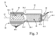
[0032]図2および図3も参照すると、カニューレ38は、管状側壁38-1、カニューレ管腔38-2、流体入口ポート38-3、近位端38-4、遠位端38-5、および遠位端部分38-6、を有する。
[0032] With reference also to Figures 2 and 3, the
[0033]カニューレ38の近位端38-4は、ハンドル28のハウジング32に接続される。
[0034]遠位端部分38-6は、遠位方向において、遠位端38-5で終端する、キャビテーション生成チャンバ42を画定するよう構成される。キャビテーション生成チャンバ42は、カニューレ38の遠位端38-5に配置された遠位端壁42-1を有する。キャビテーション生成チャンバ42の遠位端壁42-1は、篩42-2として構成され、複数のアパーチャ(換言すれば、開口)42-3を画定する。カニューレ38の長手方向軸43は、カニューレ管腔38-2、キャビテーション生成チャンバ42、および篩42-2の各々を介して長手方向に延びる。
The proximal end 38-4 of the
[0034] The distal end portion 38-6 is configured to define a
[0035]カニューレ38は、カニューレ管腔38-2の中で管状側壁38-1から内側に延びた、環状突起部38-7をさらに含む。環状突起部38-7は、遠位端部分38-6の近位終端を画定し、かつカニューレ管腔38-2とキャビテーション生成チャンバ42との間に境界を提供する。換言すると、環状突起部38-7は、カニューレ管腔38-2の遠位終端を画定するよう構成され、かつキャビテーション生成チャンバ42の後端を画定するよう構成される。追加で、環状突起部38-7は、キャビテーション生成チャンバ42に入る流体の流れストリームを、カニューレ38の管状側壁38-1から離すように向ける傾向がある。
[0035] The
[0036]カニューレ38の流体入口ポート38-3は、Y形コネクタの形態であってよく、カニューレ管腔38-2に流体アクセスを提供し、カニューレ管腔38-2と流体連通して接続される。流体入口ポート38-3は、ポンプ26-1を有する、生理食塩水注入器などの流体源26に、流体導管18によって接続される。例えば、流体源26は、滅菌生理食塩水などの流体44を、カニューレ38のカニューレ管腔38-2に送達するよう構成され得る。流体44は、超音波伝達部材36およびカニューレ38を冷却する役割を担い得る。さらに、流体44は、キャビテーション生成チャンバ42において、超音波マイクロキャビテーションデバイス14によって微小気泡キャビテーションエネルギーを生成するために使用される流体である。
[0036] The fluid inlet port 38-3 of the
[0037]本実施形態において、カニューレ管腔38-2は、カニューレ38内で近位端38-4から、遠位端部分38-6のキャビテーション生成チャンバ42まで、しかしキャビテーション生成チャンバ42の中までは入らないよう長手方向に延びた、細長い管腔である。カニューレ管腔38-2は、カニューレ38の直径に対して、カニューレ38の中央管腔として形成され得る。カニューレ管腔38-2は、超音波伝達部材36を受け入れ、かつ保持するように、サイズが決められ構成される。さらに、カニューレ管腔38-2は、流体44をキャビテーション生成チャンバ42に送達するように、サイズが決められ構成される。しかし、カニューレ管腔38-2は代替として、カニューレ38の中における複数管腔として形成され得ることが考慮される。この場合、別個の流体管腔が、流体44をキャビテーション生成チャンバ42に送達し得る。
[0037] In this embodiment, the cannula lumen 38-2 is an elongated lumen extending longitudinally within the
[0038]超音波伝達部材36は、例えばニチノールなどの、細長い可撓性金属ワイヤの形態であってよい。これは当技術分野において、コアワイヤと称されることがある。超音波伝達部材36は、カニューレ38のカニューレ管腔38-2内に配置され、かつその中で長手方向に延びる。超音波伝達部材36は、第1の端部分36-1、および第1の端部分36-1から離間された第2端36-2を有する。超音波伝達部材36の第2端36-2、すなわち遠位端は、遠位方向において、キャビテーション生成チャンバ42の近位の位置(換言すれば、キャビテーション生成チャンバ42に近接する位置)で終端する。
[0038] The
[0039]超音波伝達部材36の第1の端部分36-1は、例えば音響コネクタによって超音波トランスデューサ34に機械的に接続され、超音波伝達部材36の振動運動を作り出すように、振動エネルギーを超音波トランスデューサ34から受け取る。したがって、超音波トランスデューサ34は、超音波信号生成器24によって生成された超音波励起信号の電気エネルギーの出力レベルに相当する振動エネルギーレベルで、振動エネルギーを生成する。超音波伝達部材36の振動運動は、長手方向および横方向の振動の組み合わせであってよい。
[0039] The first end portion 36-1 of the
[0040]例えば、超音波信号生成器24によって生成され、超音波トランスデューサ34に供給された、超音波励起信号の周波数が20kHzである場合、そのとき超音波伝達部材36の遠位端部分38-6における、長手方向および/または横方向の振動運動の振動周波数は、それに応じて20kHzとなり得る。この例において、超音波信号生成器24によって生成され、かつ超音波トランスデューサ34に供給された超音波励起信号が20kHzである場合、超音波伝達部材36の第2端36-2における、長手方向および/または横方向の変位の各々は、概ね100マイクロメートルである。変位の量、および得られる流体キャビテーションは、超音波励起信号周波数、および/または超音波トランスデューサ34に供給された超音波励起信号の電力を増加させることによって、増加し得る。
[0040] For example, if the frequency of the ultrasonic excitation signal generated by the
[0041]流体44は、超音波伝達部材36の周り、かつ超音波伝達部材36にわたって、カニューレ38のカニューレ管腔38-2を通って流れ、キャビテーション生成チャンバ42に入る。超音波伝達部材36の活性化の際に、カニューレ38のキャビテーション生成チャンバ42における流体44はキャビテーションを受け、キャビテーション生成チャンバ42内で、カニューレ38の遠位端38-5に向かうマイクロキャビテーション気泡46の柱(column)を生成する。キャビテーション生成チャンバ42の遠位端壁42-1によって画定された篩42-2の複数のアパーチャ42-3は、例えばサイズおよび形状が、長手方向に向けられた流体噴射流46-1を、長手方向軸43に沿って(すなわち長手方向軸43上およびこれに実質的に平行に)噴出させるように、構成される。キャビテーション生成チャンバ42におけるマイクロキャビテーション気泡46の生成および崩壊の流体力学のため、長手方向に向けられた流体噴射流46-1は、キャビテーション生成チャンバ42の遠位端壁42-1によって画定された篩42-2の複数のアパーチャ42-3を通って、長手方向軸43に沿って噴出する。キャビテーション生成チャンバ42の遠位端壁42-1によって画定された篩42-2における、複数のアパーチャ42-3から噴出された流体噴射流46-1は、例えば毎秒概ね500メートルの高速を有する、高い指向性のマイクロジェットであり、高いせん断力を作り出し、それによって、例えば血管閉塞クロッシング(換言すれば、血管閉塞部切除)、アテレクトミー、および介入性腫瘍処置を実施する際など、物質の切除、切断、または破砕を要する医学的処置の、広い範囲に適合性がある。
[0041]
[0042]超音波マイクロキャビテーションデバイス14の作動中における、カニューレ38の加熱の可能性により、カニューレシース40は、超音波マイクロキャビテーションデバイス14に含まれ、カニューレ38の追加の冷却を提供し得る。本実施形態において、カニューレシース40は、キャビテーション生成チャンバ42の近位の領域において、カニューレ38を覆って位置付けられる。いくつかの実施形態において、カニューレシース40は、カニューレ38に恒久的に装着され得る。カニューレシース40は、マイクロ管の配列48-1として構成された冷却ジャケット48を含み、それはキャビテーション生成チャンバ42の近位の領域において、カニューレ38の管状側壁38-1を取り囲む。冷却ジャケット48におけるマイクロ管の配列48-1は、例えば十字パターンまたは螺旋パターンで構成され得る。マイクロ管の配列48-1は、滅菌生理食塩水などの冷却流体の流れを受け入れるよう構成され、それによって流体源26から送達された流体44を冷却流体として利用し得る。したがって、マイクロ管の配列48-1は、流体源26と流体連通して接続され得る。
[0042] Due to the possibility of heating of the
[0043]操作中、ユーザはユーザインターフェース20で入力を提供することによって、マイクロキャビテーションシステム10を起動させる。ユーザ入力は、例えば押ボタンの押し下げ、または表示されたメニューからの選択、であってよい。次にユーザインターフェース20は、入力信号を制御器22に送る。
[0043] In operation, a user activates the
[0044]制御器22は、ユーザインターフェース22からの入力信号を処理するためのプログラム命令を実行し、出力信号を生成して、それを超音波信号生成器24および流体源26に供給するためのプログラム命令を実行する。次にそれは、超音波マイクロキャビテーションデバイス14の動作に関連した一連の事象をトリガし、長手方向に向けられた流体噴射流46-1の発生に至らせる。流体噴射流46-1は、カニューレ38のキャビテーション生成チャンバ42における遠位端壁42-1によって画定された篩42-2の、複数のアパーチャ42-3から噴出される。
[0044] The
[0045]詳細には、制御器22は、生成器制御信号を作り出して、超音波信号生成器24に出力し、超音波信号生成器24に、所定の電気エネルギーの出力レベルを有する超音波励起信号を生成させる。超音波励起信号は、超音波トランスデューサ34に供給され、ここで超音波トランスデューサ34は、超音波励起信号の電気エネルギーの出力レベルに相当する振動エネルギーレベルにおいて、振動エネルギーを生成する。次に超音波トランスデューサ34は、振動エネルギーを超音波伝達部材36に供給し、超音波伝達部材を活性化させて、第2端36-2すなわち超音波伝達部材36の遠位端において、長手方向および横方向における両方の運動を作り出す。
[0045] In particular, the
[0046]さらに、制御器22は流体制御信号を作り出し、それを流体源26に出力して、流体源26によって生成される流体44の流れの量(例えば単位時間当たりの体積、または所与の体積の速さ/速度)を制御する。流体源26は、流体44の流れを、カニューレ38の流体入口ポート38-3に供給し、次に流体44は、カニューレ管腔38-2を通ってキャビテーション生成チャンバ42に移動する。
[0046] Additionally,
[0047]超音波伝達部材36の活性化の際に、カニューレ38のキャビテーション生成チャンバ42における流体44はキャビテーションを受け、キャビテーション生成チャンバ42内で、カニューレ38の遠位端38-5に向かうマイクロキャビテーション気泡46の柱を生成する。キャビテーション生成チャンバ42における、マイクロキャビテーション気泡46の生成および崩壊の流体力学のため、流体噴射流46-1は、キャビテーション生成チャンバ2の遠位端壁42-1によって画定された篩42-2の、複数のアパーチャ42-3を通って噴出される。このように、キャビテーション生成チャンバ42で生成された指向性マイクロキャビテーションは、指向性流体噴射流46-1を作り出し、それは超音波プローブアセンブリ30のカニューレ38における遠位端38-5から長手方向に噴出され、長手方向軸43に沿って、超音波マイクロキャビテーションデバイス14によって制御された指向性切断および/または切除を提供する。
[0047] Upon activation of the
[0048]ユーザは、別の入力をユーザインターフェース20に供給し、流体噴射流46-1が噴出される箇所、すなわちキャビテーション生成チャンバ42の遠位端壁42-1における複数のアパーチャ42-3を通して放出される箇所、の侵襲性(すなわち速度および/または圧力)を調整し得る。例えば、ユーザは別の入力をユーザインターフェース20に供給して、超音波励起信号の電力出力を選択し得る。この超音波励起信号は、超音波信号生成器24によって生成されて、超音波マイクロキャビテーションデバイス14の超音波トランスデューサ34に供給される。それによって、超音波伝達部材36によってキャビテーション生成チャンバ42における流体に移動された振動エネルギーを制御し、それによって、噴出される流体噴射流46-1、すなわちキャビテーション生成チャンバ42の遠位端壁42-1における複数のアパーチャ42-3を通して放出される流体噴射流46-1の、侵襲性を制御し得る。
[0048] The user may provide another input to the
[0049]本明細書で使用される用語「概ね」、および他の程度に関する単語は、比較修飾であり、そのように修飾された特性からの、許容可能な変動を示すよう意図される。修飾される絶対値または特性に限定することは意図せず、むしろ、その反対よりも多くの物理的もしくは機能的特性を処理し、このような物理的もしくは機能的特性にアプローチすなわち近付けることを意図する。 [0049] As used herein, the term "approximately," and other words of degree, are comparative modifiers and are intended to indicate an acceptable variation from the property so modified. They are not intended to limit the absolute value or property modified, but rather to address or approach more of a physical or functional property than the opposite.
[0050]以下の態様も本発明に関連する。
[0051]1つの形態において、本発明は、第1の端部分と、第1の端部分から離間された第2端とを有する超音波伝達部材を含んだ、超音波プローブアセンブリに関する。超音波プローブアセンブリは、管状側壁、カニューレ管腔、流体入口ポート、近位端、遠位端、および遠位端部分、を有するカニューレを、さらに備える。超音波伝達部材は、カニューレ管腔の中に配置される。カニューレの流体入口ポートは、カニューレ管腔と流体連通して接続される。カニューレの遠位端部分は、キャビテーション生成チャンバを、画定するよう構成されるか、および/または画定するか、および/または備える。キャビテーション生成チャンバは、カニューレの遠位端において遠位端壁を有し、それは篩として構成され、複数のアパーチャを画定するよう、特に機能し得る。
[0050] The following aspects are also relevant to the invention:
In one form, the present invention relates to an ultrasonic probe assembly including an ultrasonic transmission member having a first end portion and a second end spaced from the first end portion. The ultrasonic probe assembly further comprises a cannula having a tubular sidewall, a cannula lumen, a fluid inlet port, a proximal end, a distal end, and a distal end portion. The ultrasonic transmission member is disposed within the cannula lumen. The cannula fluid inlet port is connected in fluid communication with the cannula lumen. The cannula distal end portion is configured to define and/or defines and/or includes a cavitation generating chamber. The cavitation generating chamber has a distal end wall at the distal end of the cannula that is configured as a sieve and may function, among other things, to define a plurality of apertures.
[0052]任意の実施形態において、カニューレは、カニューレ管腔、キャビテーション生成チャンバ、および篩の各々を通って長手方向に延び得る、長手方向軸を有する。
[0053]いくつかの実施形態は、管状側壁から内側に延びた、カニューレ管腔の中の環状突起部を含み得る。この環状突起部は、カニューレ管腔の終端を画定するよう、かつキャビテーション生成チャンバの後端を画定するよう構成(形成)されてよい。詳細には、この環状突起部は、カニューレ管腔の終端およびキャビテーション生成チャンバの後端を画定する。
[0052] In any embodiment, the cannula has a longitudinal axis that can extend longitudinally through each of the cannula lumen, the cavitation-generating chamber, and the sieve.
[0053] Some embodiments may include an annular protrusion in the cannula lumen extending inwardly from the tubular sidewall. The annular protrusion may be configured to define an end of the cannula lumen and to define an aft end of the cavitation generating chamber. In particular, the annular protrusion defines an end of the cannula lumen and an aft end of the cavitation generating chamber.
[0054]任意の実施形態において、超音波伝達部材は、カニューレのカニューレ管腔の中に配置され得る。超音波伝達部材の第2端は、遠位方向において、キャビテーション生成チャンバの近位の位置で終端し得る。 [0054] In any embodiment, the ultrasound transmission member may be disposed within the cannula lumen of the cannula. The second end of the ultrasound transmission member may terminate distally at a location proximal to the cavitation generating chamber.
[0055]任意の実施形態において、カニューレは生体適合性金属で作られていてよい。
[0056]任意の実施形態において、超音波プローブアセンブリは任意選択で、キャビテーション生成チャンバの近位の領域において、カニューレの管状側壁を取り囲んだマイクロ管の配列を有する、カニューレシースを含み、および/またはマイクロ管の配列は、冷却流体の流れを受け入れるよう構成される。
[0055] In any embodiment, the cannula may be made from a biocompatible metal.
[0056] In any embodiment, the ultrasonic probe assembly optionally includes a cannula sheath having an array of microtubes surrounding a tubular sidewall of the cannula in a region proximal to the cavitation generating chamber, and/or the array of microtubes is configured to receive a flow of a cooling fluid.
[0057]直前に表わされた実施形態において、カニューレシースは、恒久的にカニューレに装着され得る。
[0058]別の形態において、本発明は、超音波トランスデューサを含み得るハンドルを含んだ、超音波マイクロキャビテーションデバイスに関する。超音波マイクロキャビテーションデバイスは、第1の端部分と、第1の端部分から離間された第2端とを有する、超音波伝達部材を備え、超音波伝達部材の第1の端部分は、超音波トランスデューサに接続される。超音波マイクロキャビテーションデバイスは、ハンドルに接続され得るカニューレをさらに備える。カニューレは、管状側壁、カニューレ管腔、流体入口ポート、近位端、遠位端、および遠位端部分、を有する。超音波伝達部材は、カニューレ管腔の中に配置される。カニューレの流体入口ポートは、カニューレ管腔と流体連通して接続される。カニューレの遠位端部分は、遠位方向において、カニューレの遠位端で終端するキャビテーション生成チャンバを、画定するよう構成され、および/または画定し、および/または備える。キャビテーション生成チャンバは、流体噴射流を噴出させるよう構成された複数のアパーチャを画定するよう篩として、構成され得る、特に機能し得る、遠位端壁を有する。
[0057] In the embodiment depicted immediately above, the cannula sheath may be permanently attached to the cannula.
[0058] In another aspect, the present invention relates to an ultrasonic microcavitation device including a handle that may include an ultrasonic transducer. The ultrasonic microcavitation device comprises an ultrasonic transmission member having a first end portion and a second end spaced from the first end portion, the first end portion of the ultrasonic transmission member being connected to the ultrasonic transducer. The ultrasonic microcavitation device further comprises a cannula that may be connected to the handle. The cannula has a tubular sidewall, a cannula lumen, a fluid inlet port, a proximal end, a distal end, and a distal end portion. The ultrasonic transmission member is disposed within the cannula lumen. The fluid inlet port of the cannula is connected in fluid communication with the cannula lumen. The distal end portion of the cannula is configured to define and/or defines and/or comprises a cavitation generating chamber that terminates distally at the distal end of the cannula. The cavitation generating chamber has a distal end wall that may be configured, and in particular may function, as a sieve to define a plurality of apertures configured to eject fluid jets.
[0059]したがって超音波マイクロキャビテーションデバイスは、段落[0051]の超音波プローブアセンブリを備え得る。超音波マイクロキャビテーションデバイスは、超音波トランスデューサを含むハンドルをさらに備え、カニューレはこのハンドルに接続される。超音波伝達部材の第1の端部分は、超音波トランスデューサに接続される。複数のアパーチャは、流体噴射流を噴出させるよう構成される。 [0059] Thus, an ultrasonic microcavitation device may comprise the ultrasonic probe assembly of paragraph [0051]. The ultrasonic microcavitation device further comprises a handle including an ultrasonic transducer, the cannula being connected to the handle. A first end portion of the ultrasonic transmission member is connected to the ultrasonic transducer. The plurality of apertures are configured to eject a fluid jet.
[0060]任意の実施形態において、カニューレは、カニューレ管腔、キャビテーション生成チャンバ、および篩の各々を通って長手方向に延び得る、長手方向軸を有する。
[0061]いくつかの実施形態において、管状側壁から内側に延びた、カニューレ管腔の中の環状突起部を含む。この環状突起部は、カニューレ管腔の終端を画定するよう、かつキャビテーション生成チャンバの後端を画定するよう構成(形成)される。詳細には、この環状突起部は、カニューレ管腔の終端およびキャビテーション生成チャンバの後端を画定する。
[0060] In any embodiment, the cannula has a longitudinal axis that can extend longitudinally through each of the cannula lumen, the cavitation-generating chamber, and the sieve.
[0061] In some embodiments, the cannula includes an annular projection inwardly extending from the tubular sidewall and configured to define an end of the cannula lumen and to define an aft end of the cavitation generating chamber. In particular, the annular projection defines an end of the cannula lumen and an aft end of the cavitation generating chamber.
[0062]任意の実施形態において、超音波伝達部材は、カニューレのカニューレ管腔の中に配置される。超音波伝達部材の第2端は、遠位方向において、キャビテーション生成チャンバの近位の位置で終端する。 [0062] In any embodiment, the ultrasound transmission member is disposed within the cannula lumen of the cannula. The second end of the ultrasound transmission member terminates distally at a location proximal to the cavitation generating chamber.
[0063]任意の実施形態において、超音波マイクロキャビテーションデバイスは、キャビテーション生成チャンバの近位の領域において、カニューレの管状側壁を囲んだマイクロ管の配列を任意選択で含み得、および/またはマイクロ管の配列は、冷却流体の流れを受け入れるよう構成される。 [0063] In any embodiment, the ultrasonic microcavitation device may optionally include an array of microtubes surrounding the tubular sidewall of the cannula in a region proximal to the cavitation generating chamber, and/or the array of microtubes is configured to receive a flow of cooling fluid.
[0064]任意の実施形態において、カニューレは生体適合性金属で作られていてよい。
[0065]別の形態において、本発明は、超音波信号生成器および流体源を有し得るコンソールを含んだ、マイクロキャビテーションシステムに関する。マイクロキャビテーションシステムは、超音波トランスデューサを含み得るハンドルを備え、超音波トランスデューサは、超音波信号生成器に電気接続される。超音波伝達部材は、第1の端部分と、第1の端部分から離間された第2端とを有し、超音波伝達部材の第1の端部分は、超音波トランスデューサに機械的に接続される。カニューレはハンドルに接続される。カニューレは、管状側壁、カニューレ管腔、流体入口ポート、近位端、遠位端、および遠位端部分、を含み得る。遠位端部分は、遠位方向において、遠位端で終端するキャビテーション生成チャンバを、画定するよう構成され、および/または画定し、および/または備える。超音波伝達部材は、カニューレ管腔の中に配置される。カニューレの流体入口ポートは、流体源と流体連通して接続され、流体源から流体の流れを受け入れる。カニューレの流体入口ポートは、カニューレ管腔と流体連通して接続され、流体は、カニューレ管腔を通してキャビテーション生成チャンバに供給される。すなわち流体を、カニューレ管腔を通してキャビテーション生成チャンバに供給するためである。カニューレのキャビテーション生成チャンバは、流体噴射流を噴出させるよう構成された複数のアパーチャを画定するよう篩として、構成され得る、特に機能し得る、遠位端壁を有する。
[0064] In any embodiment, the cannula may be made from a biocompatible metal.
[0065] In another aspect, the invention relates to a microcavitation system including a console that may have an ultrasonic signal generator and a fluid source. The microcavitation system includes a handle that may include an ultrasonic transducer, the ultrasonic transducer electrically connected to the ultrasonic signal generator. An ultrasonic transmission member has a first end portion and a second end spaced from the first end portion, the first end portion of the ultrasonic transmission member mechanically connected to the ultrasonic transducer. A cannula is connected to the handle. The cannula may include a tubular sidewall, a cannula lumen, a fluid inlet port, a proximal end, a distal end, and a distal end portion. The distal end portion is configured to define and/or defines and/or comprises a cavitation generating chamber in a distal direction terminating at the distal end. The ultrasonic transmission member is disposed within the cannula lumen. The fluid inlet port of the cannula is connected in fluid communication with the fluid source to receive a flow of fluid from the fluid source. The fluid inlet port of the cannula is connected in fluid communication with the cannula lumen for supplying fluid to the cavitation generating chamber through the cannula lumen, i.e., for supplying fluid to the cavitation generating chamber through the cannula lumen. The cavitation generating chamber of the cannula has a distal end wall that may be configured, and in particular may function, as a sieve to define a plurality of apertures configured to eject a fluid jet.
[0066]したがって、マイクロキャビテーションシステムは、段落[0051]の超音波プローブアセンブリか、または段落[0058]の超音波マイクロキャビテーションデバイスを備え、さらに、超音波信号生成器および流体源を有するコンソールを備え得る。超音波トランスデューサは、超音波信号生成器に電気接続される。カニューレの流体入口ポートは、流体源と流体連通して接続され、この流体源から流体の流れを受け入れ得る。カニューレの流体入口ポートは、流体を、カニューレ管腔を通してキャビテーション生成チャンバに供給するために、カニューレ管腔と流体連通して接続され得る。 [0066] Thus, a microcavitation system may include the ultrasonic probe assembly of paragraph [0051] or the ultrasonic microcavitation device of paragraph [0058], and may further include a console having an ultrasonic signal generator and a fluid source. The ultrasonic transducer is electrically connected to the ultrasonic signal generator. The fluid inlet port of the cannula may be connected in fluid communication with the fluid source and may receive a flow of fluid from the fluid source. The fluid inlet port of the cannula may be connected in fluid communication with the cannula lumen to supply fluid to the cavitation generation chamber through the cannula lumen.
[0067]任意の実施形態において、カニューレは、カニューレ管腔、キャビテーション生成チャンバ、および篩の各々を通って長手方向に延び得る、長手方向軸を有する。
[0068]いくつかの実施形態は、管状側壁から内側に延びた、カニューレ管腔の中の環状突起部を含み得る。この環状突起部は、カニューレ管腔の終端を画定するよう構成され、かつキャビテーション生成チャンバの後端を画定するよう構成され得る。
[0067] In any embodiment, the cannula has a longitudinal axis that can extend longitudinally through each of the cannula lumen, the cavitation-generating chamber, and the sieve.
[0068] Some embodiments may include an annular projection in the cannula lumen extending inwardly from the tubular sidewall, the annular projection configured to define a terminal end of the cannula lumen and may be configured to define a rear end of the cavitation generating chamber.
[0069]任意の実施形態において、超音波伝達部材の第2端は、遠位方向において、キャビテーション生成チャンバの近位の位置で終端する。
[0070]任意の実施形態において、カニューレは生体適合性金属で作られていてよい。
[0069] In any embodiment, the second end of the ultrasound transmission member terminates distally at a location proximal to the cavitation generating chamber.
[0070] In any embodiment, the cannula may be made from a biocompatible metal.
[0071]任意の実施形態において、超音波マイクロキャビテーションデバイスは、キャビテーション生成チャンバの近位の領域において、カニューレの管状側壁を取り囲んだマイクロ管の配列を任意選択で含み得、このマイクロ管の配列は、カニューレを冷却するために、流体の流れを流体源から受け入れるよう構成される。 [0071] In any embodiment, the ultrasonic microcavitation device may optionally include an array of microtubes surrounding the tubular sidewall of the cannula in a region proximal to the cavitation generating chamber, the array of microtubes being configured to receive a flow of fluid from a fluid source to cool the cannula.
[0072]コンソールを含む任意の実施形態によると、コンソールは、ユーザインターフェースおよび制御器をさらに含み得る。制御器は、ユーザインターフェース、超音波信号生成器、および流体源の各々に、通信可能に連結され得る。制御器は:ユーザインターフェースからの入力信号を処理し;電気エネルギーの出力レベルを有し、超音波トランスデューサに供給される超音波励起信号を超音波信号生成器に生成させ、かつ、超音波トランスデューサに、超音波励起信号の電気エネルギーの出力レベルに相当する振動エネルギーレベルにおいて振動エネルギーを生成させるように、第1の出力制御信号を超音波信号生成器に提供し;流体源によって生成される流体の流れの量を制御し、かつ、流体源に流体の流れを、カニューレの流体入口ポートに供給させるように、第2の出力制御信号を流体源に提供するための、プログラム命令を実行するよう構成され得る。 [0072] According to any embodiment including a console, the console may further include a user interface and a controller. The controller may be communicatively coupled to each of the user interface, the ultrasonic signal generator, and the fluid source. The controller may be configured to execute program instructions to: process an input signal from the user interface; cause the ultrasonic signal generator to generate an ultrasonic excitation signal having an output level of electrical energy that is supplied to the ultrasonic transducer, and provide a first output control signal to the ultrasonic signal generator to cause the ultrasonic transducer to generate vibrational energy at a vibrational energy level corresponding to the output level of electrical energy of the ultrasonic excitation signal; and provide a second output control signal to the fluid source to control the amount of fluid flow generated by the fluid source and cause the fluid source to supply a fluid flow to the fluid inlet port of the cannula.
[0073]本発明を少なくとも1つの実施形態に対して説明してきたが、本発明は、本開示の趣旨および範囲内で、さらに変更され得る。したがって本出願は、一般的な原理を使用して、本発明の任意の変形、使用、または適合を網羅するよう意図される。さらに、本出願は、本発明が関連する技術分野の公知または通例の実施内となるような、本開示からの逸脱を網羅するよう意図され、それらは添付した特許請求の範囲の制限内にある。 [0073] While the invention has been described with respect to at least one embodiment, the invention may be further modified within the spirit and scope of the disclosure. This application is therefore intended to cover any variations, uses, or adaptations of the invention using its general principles. Further, this application is intended to cover such departures from the disclosure as come within known or customary practice in the art to which this invention pertains, and which fall within the limits of the appended claims.
Claims (14)
第1の端部分、および前記第1の端部分から離間された第2端を有する、超音波伝達部材と、
管状側壁、カニューレ管腔、前記カニューレ管腔内の環状突起部、流体入口ポート、近位端、遠位端、および遠位端部分、を有するカニューレと、を備え、
前記超音波伝達部材は、前記カニューレ管腔の中に配置され、
前記カニューレの前記流体入口ポートは、前記カニューレ管腔と流体連通して接続され、
前記カニューレの前記遠位端部分は、キャビテーション生成チャンバを画定するよう構成され、前記キャビテーション生成チャンバは、前記カニューレの前記遠位端において、流体噴射流を噴出させるよう構成された複数のアパーチャを画定する篩として構成された遠位端壁を有し、
前記超音波伝達部材の前記第2端は、遠位方向において、前記キャビテーション生成チャンバの近位の位置で終端し、
前記カニューレ管腔内の前記環状突起部は、前記管状側壁から内側に延びており、前記カニューレ管腔の終端及び前記キャビテーション生成チャンバの後端を画定するよう構成される、超音波プローブアセンブリ。 1. An ultrasonic probe assembly comprising:
an ultrasound transmission member having a first end portion and a second end spaced from the first end portion;
a cannula having a tubular sidewall, a cannula lumen, an annular projection within the cannula lumen, a fluid inlet port, a proximal end, a distal end, and a distal end portion;
the ultrasound transmission member is disposed within the cannula lumen;
the fluid inlet port of the cannula is connected in fluid communication with the cannula lumen;
the distal end portion of the cannula is configured to define a cavitation generating chamber having a distal end wall configured as a sieve defining a plurality of apertures configured to emit a fluid jet at the distal end of the cannula;
the second end of the ultrasound transmission member terminates distally at a location proximal to the cavitation generation chamber ;
The annular projection within the cannula lumen extends inwardly from the tubular sidewall and is configured to define a terminal end of the cannula lumen and a rear end of the cavitation generating chamber .
超音波トランスデューサを含むハンドルと、
第1の端部分と、前記第1の端部分から離間された第2端とを有する超音波伝達部材であって、前記超音波伝達部材の前記第1の端部分は、前記超音波トランスデューサに接続された、超音波伝達部材と、
前記ハンドルに接続され、管状側壁、カニューレ管腔、前記カニューレ管腔内の環状突起部、流体入口ポート、近位端、遠位端、および遠位端部分、を有するカニューレと、を備え、
前記超音波伝達部材は、前記カニューレ管腔の中に配置され、
前記カニューレの前記流体入口ポートは、前記カニューレ管腔と流体連通して接続され、
前記カニューレの前記遠位端部分は、遠位方向において、前記カニューレの前記遠位端で終端するキャビテーション生成チャンバを画定するよう構成され、前記キャビテーション生成チャンバは、流体噴射流を噴出させるよう構成された複数のアパーチャを画定するよう篩として構成された、遠位端壁を有し、
前記超音波伝達部材の前記第2端は、遠位方向において、前記キャビテーション生成チャンバの近位の位置で終端し、
前記カニューレ管腔内の前記環状突起部は、前記管状側壁から内側に延びており、前記カニューレ管腔の終端及び前記キャビテーション生成チャンバの後端を画定するよう構成される、超音波マイクロキャビテーションデバイス。 1. An ultrasonic microcavitation device comprising:
a handle including an ultrasonic transducer;
an ultrasound transmission member having a first end portion and a second end spaced from the first end portion, the first end portion of the ultrasound transmission member connected to the ultrasound transducer;
a cannula connected to the handle and having a tubular sidewall, a cannula lumen, an annular projection within the cannula lumen, a fluid inlet port, a proximal end, a distal end, and a distal end portion;
the ultrasound transmission member is disposed within the cannula lumen;
the fluid inlet port of the cannula is connected in fluid communication with the cannula lumen;
the distal end portion of the cannula is configured to define a cavitation generating chamber in a distal direction terminating at the distal end of the cannula, the cavitation generating chamber having a distal end wall configured as a sieve to define a plurality of apertures configured to emit a fluid jet;
the second end of the ultrasound transmission member terminates distally at a location proximal to the cavitation generation chamber ;
The annular projection within the cannula lumen extends inwardly from the tubular sidewall and is configured to define a terminal end of the cannula lumen and a rear end of the cavitation generating chamber .
超音波信号生成器および流体源を有するコンソールと、
超音波トランスデューサを含むハンドルであって、前記超音波トランスデューサは、前記超音波信号生成器に電気接続された、ハンドルと、
第1の端部分、および前記第1の端部分から離間された第2端を有する超音波伝達部材であって、前記超音波伝達部材の前記第1の端部分は、前記超音波トランスデューサに機械的に接続された、超音波伝達部材と、
前記ハンドルに接続されたカニューレであって、前記カニューレは、管状側壁、カニューレ管腔、前記カニューレ管腔内の環状突起部、流体入口ポート、近位端、遠位端、および遠位端部分、を有し、前記遠位端部分は、遠位方向において、前記遠位端で終端するキャビテーション生成チャンバを画定するよう構成された、カニューレと、を備え、
前記超音波伝達部材は、前記カニューレ管腔の中に配置され、
前記カニューレの前記流体入口ポートは、前記流体源から流体の流れを受け入れるように前記流体源と流体連通して接続され、
前記カニューレの前記流体入口ポートは、前記カニューレ管腔に流体連通して接続され、前記流体は、前記カニューレ管腔を通して前記キャビテーション生成チャンバに供給され、
前記カニューレの前記キャビテーション生成チャンバは、流体噴射流を噴出させるよう構成された複数のアパーチャを画定するよう篩として構成された、遠位端壁を有し、
前記超音波伝達部材の前記第2端は、遠位方向において、前記キャビテーション生成チャンバの近位の位置で終端し、
前記カニューレ管腔内の前記環状突起部は、前記管状側壁から内側に延びており、前記カニューレ管腔の終端及び前記キャビテーション生成チャンバの後端を画定するよう構成される、マイクロキャビテーションシステム。 1. A microcavitation system comprising:
a console having an ultrasonic signal generator and a fluid source;
a handle including an ultrasonic transducer, the ultrasonic transducer electrically connected to the ultrasonic signal generator;
an ultrasonic transmission member having a first end portion and a second end spaced from the first end portion, the first end portion of the ultrasonic transmission member mechanically connected to the ultrasonic transducer;
a cannula connected to the handle, the cannula having a tubular sidewall, a cannula lumen, an annular projection within the cannula lumen, a fluid inlet port, a proximal end, a distal end, and a distal end portion, the distal end portion configured to define a cavitation generating chamber distally terminating at the distal end;
the ultrasound transmission member is disposed within the cannula lumen;
the fluid inlet port of the cannula is connected in fluid communication with a fluid source to receive a flow of fluid from the fluid source;
the fluid inlet port of the cannula is connected in fluid communication with the cannula lumen, and the fluid is supplied to the cavitation generating chamber through the cannula lumen;
the cavitation generating chamber of the cannula has a distal end wall configured as a sieve to define a plurality of apertures configured to emit fluid jets;
the second end of the ultrasound transmission member terminates distally at a location proximal to the cavitation generation chamber ;
The annular projection within the cannula lumen extends inwardly from the tubular sidewall and is configured to define a terminal end of the cannula lumen and a rear end of the cavitation generating chamber .
前記ユーザインターフェースからの入力信号を処理し、
電気エネルギーの出力レベルを有し、前記超音波トランスデューサに供給される超音波励起信号を前記超音波信号生成器に生成させるように、第1の出力制御信号を前記超音波信号生成器に提供し、前記超音波トランスデューサが、前記超音波励起信号の前記電気エネルギーの出力レベルに相当する振動エネルギーレベルにおいて振動エネルギーを生成し、
前記流体源によって生成される流体の流れの量を制御するように、第2の出力制御信号を前記流体源に提供し、前記流体源が、前記カニューレの前記流体入口ポートに、流体の前記流れを供給するための、
プログラム命令を実行するよう構成されている、請求項10~13のいずれか一項に記載のマイクロキャビテーションシステム。 The console further includes a user interface and a controller, the controller communicatively coupled to each of the user interface, the ultrasonic signal generator, and the fluid source, the controller comprising:
Processing input signals from the user interface;
providing a first power control signal to the ultrasonic signal generator to cause the ultrasonic signal generator to generate an ultrasonic excitation signal having an electrical energy output level that is supplied to the ultrasonic transducer, the ultrasonic transducer generating vibrational energy at a vibrational energy level corresponding to the electrical energy output level of the ultrasonic excitation signal;
providing a second output control signal to the fluid source to control an amount of fluid flow produced by the fluid source, the fluid source providing the flow of fluid to the fluid inlet port of the cannula;
A microcavitation system according to any one of claims 10 to 13 , configured to execute program instructions.
Applications Claiming Priority (1)
| Application Number | Priority Date | Filing Date | Title |
|---|---|---|---|
| PCT/US2019/051299 WO2021054933A1 (en) | 2019-09-16 | 2019-09-16 | Microcavitation system, device, and ultrasonic probe assembly for generating directional microcavitation |
Publications (2)
| Publication Number | Publication Date |
|---|---|
| JP2022553499A JP2022553499A (en) | 2022-12-23 |
| JP7526257B2 true JP7526257B2 (en) | 2024-07-31 |
Family
ID=68073232
Family Applications (1)
| Application Number | Title | Priority Date | Filing Date |
|---|---|---|---|
| JP2022516612A Active JP7526257B2 (en) | 2019-09-16 | 2019-09-16 | Microcavitation system, device, and ultrasonic probe assembly for generating directed microcavitation |
Country Status (5)
| Country | Link |
|---|---|
| US (1) | US20220395291A1 (en) |
| EP (1) | EP4031028B1 (en) |
| JP (1) | JP7526257B2 (en) |
| CN (1) | CN114401683A (en) |
| WO (1) | WO2021054933A1 (en) |
Families Citing this family (1)
| Publication number | Priority date | Publication date | Assignee | Title |
|---|---|---|---|---|
| CN114236609B (en) * | 2021-12-17 | 2022-07-19 | 河海大学 | A Prediction Method of P-wave Velocity and Attenuation in Partially Saturated Pore-Fractured Media |
Citations (1)
| Publication number | Priority date | Publication date | Assignee | Title |
|---|---|---|---|---|
| JP2014161377A (en) | 2013-02-21 | 2014-09-08 | Olympus Corp | Cavitation device and treatment tool device having cavitation device |
Family Cites Families (13)
| Publication number | Priority date | Publication date | Assignee | Title |
|---|---|---|---|---|
| US5135482A (en) * | 1985-12-31 | 1992-08-04 | Arnold Neracher | Hydrodynamic device for the elimination of an organic deposit obstructing a vessel of a human body |
| US5163433A (en) * | 1989-11-01 | 1992-11-17 | Olympus Optical Co., Ltd. | Ultrasound type treatment apparatus |
| JP2660069B2 (en) * | 1989-11-07 | 1997-10-08 | オリンパス光学工業株式会社 | Ultrasound therapy equipment |
| JP4441000B2 (en) * | 1997-06-23 | 2010-03-24 | 克郎 立花 | Biological tissue processing device |
| US6270471B1 (en) * | 1997-12-23 | 2001-08-07 | Misonix Incorporated | Ultrasonic probe with isolated outer cannula |
| JP2001353165A (en) * | 2000-06-15 | 2001-12-25 | Olympus Optical Co Ltd | Operation instrument |
| SE522810C2 (en) * | 2000-09-05 | 2004-03-09 | Calluna Ide Ab | Method and apparatus for chemically dispersing a gel in an organic structure |
| US7018354B2 (en) * | 2001-11-08 | 2006-03-28 | El Hassane Tazi | Liposuction devices and methods and surrounding aspiration systems and methods |
| US6960307B2 (en) * | 2002-01-18 | 2005-11-01 | Leclair Mark L | Method and apparatus for the controlled formation of cavitation bubbles |
| US20130253387A1 (en) * | 2012-03-08 | 2013-09-26 | Sonitec, LLC | Vibratory energy systems and methods for occluded body cavities |
| IN2014DN08727A (en) * | 2012-03-22 | 2015-05-22 | Sonendo Inc | |
| WO2018136863A1 (en) * | 2017-01-23 | 2018-07-26 | Boston Scientific Scimed, Inc. | Necrosectomy devices and procedures |
| US20190159792A1 (en) * | 2017-11-27 | 2019-05-30 | Justin Panian | Ultrasound Vessel Preparation and Restenosis Therapy |
-
2019
- 2019-09-16 JP JP2022516612A patent/JP7526257B2/en active Active
- 2019-09-16 CN CN201980100441.XA patent/CN114401683A/en active Pending
- 2019-09-16 US US17/642,784 patent/US20220395291A1/en active Pending
- 2019-09-16 WO PCT/US2019/051299 patent/WO2021054933A1/en not_active Ceased
- 2019-09-16 EP EP19779308.6A patent/EP4031028B1/en active Active
Patent Citations (1)
| Publication number | Priority date | Publication date | Assignee | Title |
|---|---|---|---|---|
| JP2014161377A (en) | 2013-02-21 | 2014-09-08 | Olympus Corp | Cavitation device and treatment tool device having cavitation device |
Also Published As
| Publication number | Publication date |
|---|---|
| JP2022553499A (en) | 2022-12-23 |
| EP4031028A1 (en) | 2022-07-27 |
| US20220395291A1 (en) | 2022-12-15 |
| CN114401683A (en) | 2022-04-26 |
| EP4031028B1 (en) | 2025-06-25 |
| WO2021054933A1 (en) | 2021-03-25 |
| EP4031028C0 (en) | 2025-06-25 |
Similar Documents
| Publication | Publication Date | Title |
|---|---|---|
| JP6823639B2 (en) | Tissue excision and treatment with scattering pulses | |
| US11344750B2 (en) | Ultrasound catheter system | |
| JP5115088B2 (en) | Surgical tool | |
| EP1553996B1 (en) | Ultrasound catheter for disrupting blood vessel obstructions | |
| EP3668411B1 (en) | Frequency-tunable intraluminal ultrasound device | |
| US5827203A (en) | Ultrasound system and method for myocardial revascularization | |
| US7771372B2 (en) | Ultrasonic catheter with axial energy field | |
| US20030036705A1 (en) | Ultrasonic probe device having an impedance mismatch with rapid attachment and detachment means | |
| JP2010527678A (en) | Apparatus and method for guided penetration of chronic total occlusion | |
| WO2003039381A1 (en) | Ultrasonic probe device having an impedance mismatch with rapid attachment and detachment means | |
| CN107072636A (en) | Apparatus and method for break-through occlusion | |
| JP7069294B2 (en) | Intraluminal ultrasound device for diagnostic imaging and treatment | |
| EP1929969A2 (en) | Electrosurgical instrument | |
| JP7526257B2 (en) | Microcavitation system, device, and ultrasonic probe assembly for generating directed microcavitation | |
| JP7775564B2 (en) | Dual Ultrasound Catheter | |
| JP2015058233A (en) | Medical liquid ejector | |
| US20050240151A1 (en) | Treatment of vascular occlusions using elevated temperatures | |
| EP4138688B1 (en) | Ultrasonic catheter, device, and system | |
| CN101355910B (en) | Ultrasonic medical instrument | |
| US20230240710A1 (en) | Atherectomy Catheter and System | |
| JP2018086041A (en) | Liquid injection device | |
| AU2002363418A1 (en) | Ultrasonic probe device having an impedance mismatch with rapid attachment and detachment means |
Legal Events
| Date | Code | Title | Description |
|---|---|---|---|
| A621 | Written request for application examination |
Free format text: JAPANESE INTERMEDIATE CODE: A621 Effective date: 20220902 |
|
| A131 | Notification of reasons for refusal |
Free format text: JAPANESE INTERMEDIATE CODE: A131 Effective date: 20230630 |
|
| A977 | Report on retrieval |
Free format text: JAPANESE INTERMEDIATE CODE: A971007 Effective date: 20230630 |
|
| A521 | Request for written amendment filed |
Free format text: JAPANESE INTERMEDIATE CODE: A523 Effective date: 20230929 |
|
| A02 | Decision of refusal |
Free format text: JAPANESE INTERMEDIATE CODE: A02 Effective date: 20240115 |
|
| A521 | Request for written amendment filed |
Free format text: JAPANESE INTERMEDIATE CODE: A523 Effective date: 20240513 |
|
| A911 | Transfer to examiner for re-examination before appeal (zenchi) |
Free format text: JAPANESE INTERMEDIATE CODE: A911 Effective date: 20240523 |
|
| TRDD | Decision of grant or rejection written | ||
| A01 | Written decision to grant a patent or to grant a registration (utility model) |
Free format text: JAPANESE INTERMEDIATE CODE: A01 Effective date: 20240628 |
|
| A61 | First payment of annual fees (during grant procedure) |
Free format text: JAPANESE INTERMEDIATE CODE: A61 Effective date: 20240719 |
|
| R150 | Certificate of patent or registration of utility model |
Ref document number: 7526257 Country of ref document: JP Free format text: JAPANESE INTERMEDIATE CODE: R150 |