JP7516587B2 - Tetherable stent graft and delivery system - Google Patents
Tetherable stent graft and delivery system Download PDFInfo
- Publication number
- JP7516587B2 JP7516587B2 JP2023011954A JP2023011954A JP7516587B2 JP 7516587 B2 JP7516587 B2 JP 7516587B2 JP 2023011954 A JP2023011954 A JP 2023011954A JP 2023011954 A JP2023011954 A JP 2023011954A JP 7516587 B2 JP7516587 B2 JP 7516587B2
- Authority
- JP
- Japan
- Prior art keywords
- stent
- delivery system
- graft
- string
- stent graft
- Prior art date
- Legal status (The legal status is an assumption and is not a legal conclusion. Google has not performed a legal analysis and makes no representation as to the accuracy of the status listed.)
- Active
Links
- 239000000463 material Substances 0.000 claims description 19
- 229910001285 shape-memory alloy Inorganic materials 0.000 claims description 15
- 229920000295 expanded polytetrafluoroethylene Polymers 0.000 claims description 12
- 239000002033 PVDF binder Substances 0.000 claims description 9
- 229920002981 polyvinylidene fluoride Polymers 0.000 claims description 9
- 229920000728 polyester Polymers 0.000 claims description 7
- 239000004677 Nylon Substances 0.000 claims description 6
- 229920001778 nylon Polymers 0.000 claims description 6
- -1 polypropylene Polymers 0.000 claims description 6
- 239000004743 Polypropylene Substances 0.000 claims description 5
- 229920001155 polypropylene Polymers 0.000 claims description 5
- 230000008602 contraction Effects 0.000 claims description 4
- 239000004033 plastic Substances 0.000 claims description 4
- 229920003023 plastic Polymers 0.000 claims description 4
- 229910000851 Alloy steel Inorganic materials 0.000 claims description 3
- 239000010959 steel Substances 0.000 claims description 3
- 238000000034 method Methods 0.000 description 41
- 206010002329 Aneurysm Diseases 0.000 description 20
- 208000007474 aortic aneurysm Diseases 0.000 description 8
- 230000002792 vascular Effects 0.000 description 8
- 208000002223 abdominal aortic aneurysm Diseases 0.000 description 6
- 229910001000 nickel titanium Inorganic materials 0.000 description 6
- HLXZNVUGXRDIFK-UHFFFAOYSA-N nickel titanium Chemical compound [Ti].[Ti].[Ti].[Ti].[Ti].[Ti].[Ti].[Ti].[Ti].[Ti].[Ti].[Ni].[Ni].[Ni].[Ni].[Ni].[Ni].[Ni].[Ni].[Ni].[Ni].[Ni].[Ni].[Ni].[Ni] HLXZNVUGXRDIFK-UHFFFAOYSA-N 0.000 description 6
- 241000237509 Patinopecten sp. Species 0.000 description 5
- 208000024248 Vascular System injury Diseases 0.000 description 5
- 208000012339 Vascular injury Diseases 0.000 description 5
- 235000020637 scallop Nutrition 0.000 description 5
- 210000000709 aorta Anatomy 0.000 description 3
- 210000001367 artery Anatomy 0.000 description 3
- 239000010935 stainless steel Substances 0.000 description 3
- 208000001750 Endoleak Diseases 0.000 description 2
- 206010061307 Neck deformity Diseases 0.000 description 2
- 201000008982 Thoracic Aortic Aneurysm Diseases 0.000 description 2
- TZCXTZWJZNENPQ-UHFFFAOYSA-L barium sulfate Chemical compound [Ba+2].[O-]S([O-])(=O)=O TZCXTZWJZNENPQ-UHFFFAOYSA-L 0.000 description 2
- 230000008901 benefit Effects 0.000 description 2
- 239000008280 blood Substances 0.000 description 2
- 210000004369 blood Anatomy 0.000 description 2
- 210000000056 organ Anatomy 0.000 description 2
- 229920000139 polyethylene terephthalate Polymers 0.000 description 2
- 239000005020 polyethylene terephthalate Substances 0.000 description 2
- 230000000087 stabilizing effect Effects 0.000 description 2
- 229910001220 stainless steel Inorganic materials 0.000 description 2
- 210000003484 anatomy Anatomy 0.000 description 1
- 229910052797 bismuth Inorganic materials 0.000 description 1
- JCXGWMGPZLAOME-UHFFFAOYSA-N bismuth atom Chemical compound [Bi] JCXGWMGPZLAOME-UHFFFAOYSA-N 0.000 description 1
- 230000017531 blood circulation Effects 0.000 description 1
- 210000004204 blood vessel Anatomy 0.000 description 1
- 210000002302 brachial artery Anatomy 0.000 description 1
- 238000011156 evaluation Methods 0.000 description 1
- 230000007717 exclusion Effects 0.000 description 1
- 239000004744 fabric Substances 0.000 description 1
- 239000007943 implant Substances 0.000 description 1
- 238000002513 implantation Methods 0.000 description 1
- 229910001092 metal group alloy Inorganic materials 0.000 description 1
- 230000002093 peripheral effect Effects 0.000 description 1
- HWLDNSXPUQTBOD-UHFFFAOYSA-N platinum-iridium alloy Chemical compound [Ir].[Pt] HWLDNSXPUQTBOD-UHFFFAOYSA-N 0.000 description 1
- 230000002980 postoperative effect Effects 0.000 description 1
- 229910001256 stainless steel alloy Inorganic materials 0.000 description 1
- XGZGDYQRJKMWNM-UHFFFAOYSA-N tantalum tungsten Chemical compound [Ta][W][Ta] XGZGDYQRJKMWNM-UHFFFAOYSA-N 0.000 description 1
- WFKWXMTUELFFGS-UHFFFAOYSA-N tungsten Chemical compound [W] WFKWXMTUELFFGS-UHFFFAOYSA-N 0.000 description 1
- 229910052721 tungsten Inorganic materials 0.000 description 1
- 239000010937 tungsten Substances 0.000 description 1
- 210000005166 vasculature Anatomy 0.000 description 1
- 210000001835 viscera Anatomy 0.000 description 1
Images


Classifications
-
- A—HUMAN NECESSITIES
- A61—MEDICAL OR VETERINARY SCIENCE; HYGIENE
- A61F—FILTERS IMPLANTABLE INTO BLOOD VESSELS; PROSTHESES; DEVICES PROVIDING PATENCY TO, OR PREVENTING COLLAPSING OF, TUBULAR STRUCTURES OF THE BODY, e.g. STENTS; ORTHOPAEDIC, NURSING OR CONTRACEPTIVE DEVICES; FOMENTATION; TREATMENT OR PROTECTION OF EYES OR EARS; BANDAGES, DRESSINGS OR ABSORBENT PADS; FIRST-AID KITS
- A61F2/00—Filters implantable into blood vessels; Prostheses, i.e. artificial substitutes or replacements for parts of the body; Appliances for connecting them with the body; Devices providing patency to, or preventing collapsing of, tubular structures of the body, e.g. stents
- A61F2/02—Prostheses implantable into the body
- A61F2/04—Hollow or tubular parts of organs, e.g. bladders, tracheae, bronchi or bile ducts
- A61F2/06—Blood vessels
- A61F2/07—Stent-grafts
-
- A—HUMAN NECESSITIES
- A61—MEDICAL OR VETERINARY SCIENCE; HYGIENE
- A61F—FILTERS IMPLANTABLE INTO BLOOD VESSELS; PROSTHESES; DEVICES PROVIDING PATENCY TO, OR PREVENTING COLLAPSING OF, TUBULAR STRUCTURES OF THE BODY, e.g. STENTS; ORTHOPAEDIC, NURSING OR CONTRACEPTIVE DEVICES; FOMENTATION; TREATMENT OR PROTECTION OF EYES OR EARS; BANDAGES, DRESSINGS OR ABSORBENT PADS; FIRST-AID KITS
- A61F2/00—Filters implantable into blood vessels; Prostheses, i.e. artificial substitutes or replacements for parts of the body; Appliances for connecting them with the body; Devices providing patency to, or preventing collapsing of, tubular structures of the body, e.g. stents
- A61F2/82—Devices providing patency to, or preventing collapsing of, tubular structures of the body, e.g. stents
- A61F2/86—Stents in a form characterised by the wire-like elements; Stents in the form characterised by a net-like or mesh-like structure
- A61F2/89—Stents in a form characterised by the wire-like elements; Stents in the form characterised by a net-like or mesh-like structure the wire-like elements comprising two or more adjacent rings flexibly connected by separate members
-
- A—HUMAN NECESSITIES
- A61—MEDICAL OR VETERINARY SCIENCE; HYGIENE
- A61F—FILTERS IMPLANTABLE INTO BLOOD VESSELS; PROSTHESES; DEVICES PROVIDING PATENCY TO, OR PREVENTING COLLAPSING OF, TUBULAR STRUCTURES OF THE BODY, e.g. STENTS; ORTHOPAEDIC, NURSING OR CONTRACEPTIVE DEVICES; FOMENTATION; TREATMENT OR PROTECTION OF EYES OR EARS; BANDAGES, DRESSINGS OR ABSORBENT PADS; FIRST-AID KITS
- A61F2/00—Filters implantable into blood vessels; Prostheses, i.e. artificial substitutes or replacements for parts of the body; Appliances for connecting them with the body; Devices providing patency to, or preventing collapsing of, tubular structures of the body, e.g. stents
- A61F2/82—Devices providing patency to, or preventing collapsing of, tubular structures of the body, e.g. stents
- A61F2/86—Stents in a form characterised by the wire-like elements; Stents in the form characterised by a net-like or mesh-like structure
- A61F2/90—Stents in a form characterised by the wire-like elements; Stents in the form characterised by a net-like or mesh-like structure characterised by a net-like or mesh-like structure
-
- A—HUMAN NECESSITIES
- A61—MEDICAL OR VETERINARY SCIENCE; HYGIENE
- A61F—FILTERS IMPLANTABLE INTO BLOOD VESSELS; PROSTHESES; DEVICES PROVIDING PATENCY TO, OR PREVENTING COLLAPSING OF, TUBULAR STRUCTURES OF THE BODY, e.g. STENTS; ORTHOPAEDIC, NURSING OR CONTRACEPTIVE DEVICES; FOMENTATION; TREATMENT OR PROTECTION OF EYES OR EARS; BANDAGES, DRESSINGS OR ABSORBENT PADS; FIRST-AID KITS
- A61F2/00—Filters implantable into blood vessels; Prostheses, i.e. artificial substitutes or replacements for parts of the body; Appliances for connecting them with the body; Devices providing patency to, or preventing collapsing of, tubular structures of the body, e.g. stents
- A61F2/95—Instruments specially adapted for placement or removal of stents or stent-grafts
- A61F2/962—Instruments specially adapted for placement or removal of stents or stent-grafts having an outer sleeve
-
- A—HUMAN NECESSITIES
- A61—MEDICAL OR VETERINARY SCIENCE; HYGIENE
- A61F—FILTERS IMPLANTABLE INTO BLOOD VESSELS; PROSTHESES; DEVICES PROVIDING PATENCY TO, OR PREVENTING COLLAPSING OF, TUBULAR STRUCTURES OF THE BODY, e.g. STENTS; ORTHOPAEDIC, NURSING OR CONTRACEPTIVE DEVICES; FOMENTATION; TREATMENT OR PROTECTION OF EYES OR EARS; BANDAGES, DRESSINGS OR ABSORBENT PADS; FIRST-AID KITS
- A61F2/00—Filters implantable into blood vessels; Prostheses, i.e. artificial substitutes or replacements for parts of the body; Appliances for connecting them with the body; Devices providing patency to, or preventing collapsing of, tubular structures of the body, e.g. stents
- A61F2/02—Prostheses implantable into the body
- A61F2/04—Hollow or tubular parts of organs, e.g. bladders, tracheae, bronchi or bile ducts
- A61F2/06—Blood vessels
- A61F2002/061—Blood vessels provided with means for allowing access to secondary lumens
-
- A—HUMAN NECESSITIES
- A61—MEDICAL OR VETERINARY SCIENCE; HYGIENE
- A61F—FILTERS IMPLANTABLE INTO BLOOD VESSELS; PROSTHESES; DEVICES PROVIDING PATENCY TO, OR PREVENTING COLLAPSING OF, TUBULAR STRUCTURES OF THE BODY, e.g. STENTS; ORTHOPAEDIC, NURSING OR CONTRACEPTIVE DEVICES; FOMENTATION; TREATMENT OR PROTECTION OF EYES OR EARS; BANDAGES, DRESSINGS OR ABSORBENT PADS; FIRST-AID KITS
- A61F2/00—Filters implantable into blood vessels; Prostheses, i.e. artificial substitutes or replacements for parts of the body; Appliances for connecting them with the body; Devices providing patency to, or preventing collapsing of, tubular structures of the body, e.g. stents
- A61F2/02—Prostheses implantable into the body
- A61F2/04—Hollow or tubular parts of organs, e.g. bladders, tracheae, bronchi or bile ducts
- A61F2/06—Blood vessels
- A61F2/07—Stent-grafts
- A61F2002/075—Stent-grafts the stent being loosely attached to the graft material, e.g. by stitching
-
- A—HUMAN NECESSITIES
- A61—MEDICAL OR VETERINARY SCIENCE; HYGIENE
- A61F—FILTERS IMPLANTABLE INTO BLOOD VESSELS; PROSTHESES; DEVICES PROVIDING PATENCY TO, OR PREVENTING COLLAPSING OF, TUBULAR STRUCTURES OF THE BODY, e.g. STENTS; ORTHOPAEDIC, NURSING OR CONTRACEPTIVE DEVICES; FOMENTATION; TREATMENT OR PROTECTION OF EYES OR EARS; BANDAGES, DRESSINGS OR ABSORBENT PADS; FIRST-AID KITS
- A61F2/00—Filters implantable into blood vessels; Prostheses, i.e. artificial substitutes or replacements for parts of the body; Appliances for connecting them with the body; Devices providing patency to, or preventing collapsing of, tubular structures of the body, e.g. stents
- A61F2/82—Devices providing patency to, or preventing collapsing of, tubular structures of the body, e.g. stents
- A61F2002/825—Devices providing patency to, or preventing collapsing of, tubular structures of the body, e.g. stents having longitudinal struts
-
- A—HUMAN NECESSITIES
- A61—MEDICAL OR VETERINARY SCIENCE; HYGIENE
- A61F—FILTERS IMPLANTABLE INTO BLOOD VESSELS; PROSTHESES; DEVICES PROVIDING PATENCY TO, OR PREVENTING COLLAPSING OF, TUBULAR STRUCTURES OF THE BODY, e.g. STENTS; ORTHOPAEDIC, NURSING OR CONTRACEPTIVE DEVICES; FOMENTATION; TREATMENT OR PROTECTION OF EYES OR EARS; BANDAGES, DRESSINGS OR ABSORBENT PADS; FIRST-AID KITS
- A61F2/00—Filters implantable into blood vessels; Prostheses, i.e. artificial substitutes or replacements for parts of the body; Appliances for connecting them with the body; Devices providing patency to, or preventing collapsing of, tubular structures of the body, e.g. stents
- A61F2/95—Instruments specially adapted for placement or removal of stents or stent-grafts
- A61F2002/9505—Instruments specially adapted for placement or removal of stents or stent-grafts having retaining means other than an outer sleeve, e.g. male-female connector between stent and instrument
- A61F2002/9511—Instruments specially adapted for placement or removal of stents or stent-grafts having retaining means other than an outer sleeve, e.g. male-female connector between stent and instrument the retaining means being filaments or wires
-
- A—HUMAN NECESSITIES
- A61—MEDICAL OR VETERINARY SCIENCE; HYGIENE
- A61F—FILTERS IMPLANTABLE INTO BLOOD VESSELS; PROSTHESES; DEVICES PROVIDING PATENCY TO, OR PREVENTING COLLAPSING OF, TUBULAR STRUCTURES OF THE BODY, e.g. STENTS; ORTHOPAEDIC, NURSING OR CONTRACEPTIVE DEVICES; FOMENTATION; TREATMENT OR PROTECTION OF EYES OR EARS; BANDAGES, DRESSINGS OR ABSORBENT PADS; FIRST-AID KITS
- A61F2/00—Filters implantable into blood vessels; Prostheses, i.e. artificial substitutes or replacements for parts of the body; Appliances for connecting them with the body; Devices providing patency to, or preventing collapsing of, tubular structures of the body, e.g. stents
- A61F2/95—Instruments specially adapted for placement or removal of stents or stent-grafts
- A61F2/962—Instruments specially adapted for placement or removal of stents or stent-grafts having an outer sleeve
- A61F2/966—Instruments specially adapted for placement or removal of stents or stent-grafts having an outer sleeve with relative longitudinal movement between outer sleeve and prosthesis, e.g. using a push rod
- A61F2002/9665—Instruments specially adapted for placement or removal of stents or stent-grafts having an outer sleeve with relative longitudinal movement between outer sleeve and prosthesis, e.g. using a push rod with additional retaining means
-
- A—HUMAN NECESSITIES
- A61—MEDICAL OR VETERINARY SCIENCE; HYGIENE
- A61F—FILTERS IMPLANTABLE INTO BLOOD VESSELS; PROSTHESES; DEVICES PROVIDING PATENCY TO, OR PREVENTING COLLAPSING OF, TUBULAR STRUCTURES OF THE BODY, e.g. STENTS; ORTHOPAEDIC, NURSING OR CONTRACEPTIVE DEVICES; FOMENTATION; TREATMENT OR PROTECTION OF EYES OR EARS; BANDAGES, DRESSINGS OR ABSORBENT PADS; FIRST-AID KITS
- A61F2220/00—Fixations or connections for prostheses classified in groups A61F2/00 - A61F2/26 or A61F2/82 or A61F9/00 or A61F11/00 or subgroups thereof
- A61F2220/0008—Fixation appliances for connecting prostheses to the body
- A61F2220/0016—Fixation appliances for connecting prostheses to the body with sharp anchoring protrusions, e.g. barbs, pins, spikes
-
- A—HUMAN NECESSITIES
- A61—MEDICAL OR VETERINARY SCIENCE; HYGIENE
- A61F—FILTERS IMPLANTABLE INTO BLOOD VESSELS; PROSTHESES; DEVICES PROVIDING PATENCY TO, OR PREVENTING COLLAPSING OF, TUBULAR STRUCTURES OF THE BODY, e.g. STENTS; ORTHOPAEDIC, NURSING OR CONTRACEPTIVE DEVICES; FOMENTATION; TREATMENT OR PROTECTION OF EYES OR EARS; BANDAGES, DRESSINGS OR ABSORBENT PADS; FIRST-AID KITS
- A61F2250/00—Special features of prostheses classified in groups A61F2/00 - A61F2/26 or A61F2/82 or A61F9/00 or A61F11/00 or subgroups thereof
- A61F2250/0014—Special features of prostheses classified in groups A61F2/00 - A61F2/26 or A61F2/82 or A61F9/00 or A61F11/00 or subgroups thereof having different values of a given property or geometrical feature, e.g. mechanical property or material property, at different locations within the same prosthesis
- A61F2250/0039—Special features of prostheses classified in groups A61F2/00 - A61F2/26 or A61F2/82 or A61F9/00 or A61F11/00 or subgroups thereof having different values of a given property or geometrical feature, e.g. mechanical property or material property, at different locations within the same prosthesis differing in diameter
Landscapes
- Health & Medical Sciences (AREA)
- Engineering & Computer Science (AREA)
- Biomedical Technology (AREA)
- Heart & Thoracic Surgery (AREA)
- Public Health (AREA)
- Transplantation (AREA)
- Cardiology (AREA)
- Veterinary Medicine (AREA)
- Oral & Maxillofacial Surgery (AREA)
- Vascular Medicine (AREA)
- Life Sciences & Earth Sciences (AREA)
- Animal Behavior & Ethology (AREA)
- General Health & Medical Sciences (AREA)
- Gastroenterology & Hepatology (AREA)
- Pulmonology (AREA)
- Prostheses (AREA)
- Media Introduction/Drainage Providing Device (AREA)
Description
関連出願
本願は、2017年2月24日に出願された米国仮特許出願第62/463,057号の利益を主張する。上記出願の全教示は参照により本明細書に援用される。
RELATED APPLICATIONS This application claims the benefit of U.S. Provisional Patent Application No. 62/463,057, filed Feb. 24, 2017, the entire teachings of which are incorporated herein by reference.
本発明は、束縛可能なステントグラフト、送達システムおよび使用方法に関する。 The present invention relates to constrainable stent grafts, delivery systems and methods of use.
背景
動脈病状、例えば大動脈瘤は、開放外科的再建、または代替的に開放外科的修復の最小侵襲性代替である血管内修復により治療され得る。しかしながら、血管内修復の首尾よい結果を最適化することは、患者の解剖学的構造の評価を必要とし、および動脈、またはより具体的には大動脈瘤の場合は、動脈瘤の近位端および遠位端にわたる適切なステントがエンドリーク(endoleak)を最小にするための大動脈内のステントグラフトの固定による動脈瘤嚢の本質的に完全な排除を確実にすることを必要とする。エンドリークおよび手術後の動脈瘤部位の広がりは、しばしば動脈瘤嚢の任意の拡張を封じるためのさらなる修復を必要とし、かつ一般的に手術部位を通る周囲の内臓および関連のある構造への血流を有意に傷つける(compromise)ことなくなされなければならない。
Background Arterial conditions, such as aortic aneurysms, may be treated with open surgical reconstruction or, alternatively, endovascular repair, which is a minimally invasive alternative to open surgical repair. However, optimizing the successful outcome of endovascular repair requires evaluation of the patient's anatomy and appropriate stenting across the artery, or more specifically, in the case of aortic aneurysms, the proximal and distal ends of the aneurysm to ensure essentially complete exclusion of the aneurysmal sac with fixation of the stent graft within the aorta to minimize endoleaks. Endoleaks and post-operative aneurysmal site widening often require further repair to seal any expansion of the aneurysmal sac, and must be done without significantly compromising blood flow to the surrounding viscera and associated structures through the surgical site in general.
そのため、動脈病状、例えば大動脈瘤を治療するための新規の向上された血管内修復デバイスおよび方法についての必要性が存在する。 Therefore, there is a need for new and improved endovascular repair devices and methods for treating arterial conditions, such as aortic aneurysms.
概要
本発明は、大動脈血管損傷および他の動脈血管損傷、例えば生体臓器および組織に血液を供給する動脈分枝を有する大動脈の領域における大動脈瘤、例えば胸部大動脈瘤、腹部大動脈瘤、胸腹大動脈瘤、腎臓近傍(juxtarenal)大動脈瘤およびショートネック(short-neck)腹部大動脈瘤を含む大動脈瘤に関連する血管損傷の治療および修復における使用のためのステントグラフトに関する。
SUMMARY The present invention relates to a stent graft for use in the treatment and repair of aortic vascular injuries and other arterial vascular injuries, such as vascular injuries associated with aortic aneurysms, including aortic aneurysms in the region of the aorta having arterial branches that supply blood to vital organs and tissues, such as thoracic aortic aneurysms, abdominal aortic aneurysms, thoracic-abdominal aortic aneurysms, juxtarenal aortic aneurysms, and short-neck abdominal aortic aneurysms.
一態様において、本発明は、近位開放端および遠位開放端を有する管腔グラフト構成要素を含むステントグラフトである。複数のステントは、管腔グラフト構成要素に沿って長手方向に分配され、ステントの少なくとも1つは、近位頂部および遠位頂部を画定するように連結される支柱を有する。少なくとも1つの紐(ligature)は、ステントの少なくとも1つの支柱の少なくとも一部を横切る。紐は、連結される場合に、それぞれの対応するステントを少なくとも部分的に半径方向(radially)に収縮させる末端を含む。管腔グラフト構成要素でのアンカーループの組は、対応するステントを半径方向に収縮させるように連結される場合にそれぞれの関連のある紐の末端に長手方向にまたがる。 In one aspect, the invention is a stent graft including a luminal graft component having a proximal open end and a distal open end. A plurality of stents are distributed longitudinally along the luminal graft component, at least one of the stents having struts coupled to define proximal and distal apices. At least one ligature traverses at least a portion of at least one strut of the stent. The ligature includes ends that, when coupled, at least partially radially constrict a respective corresponding stent. A set of anchor loops on the luminal graft component longitudinally span the ends of each associated ligature when coupled to radially constrict a respective corresponding stent.
別の態様において、本発明は、ステントグラフトを含むステントグラフト送達システムである。ステントグラフトは、近位開放端および遠位開放端を有する管腔グラフト構成要素を含み、管腔を画定する。複数のステントは、管腔グラフト構成要素に沿って長手方向に分配され、ステントの少なくとも1つは、近位頂部および遠位頂部を画定するように連結される支柱を有する。少なくとも1つの紐は、支柱の少なくとも一部を横切る。紐は、連結される場合に、ステントを少なくとも部分的に半径方向に収縮させる末端を含む。管腔グラフト構成要素でのアンカーループの組は、対応するステントを半径方向に収縮させるように連結される場合にそれぞれの関連のある紐の末端に長手方向にまたがる。ワイヤは、管腔グラフト構成要素に沿ってかつアンカーループを通って長手方向に伸長し、紐の末端を連結し、それによりステントグラフトのステントの少なくとも一部を半径方向に収縮させ、少なくとも1つの紐の末端からのワイヤの引き込みにより、少なくとも1つの紐による収縮からステントグラフトの末端が解放される。 In another aspect, the invention is a stent-graft delivery system including a stent-graft. The stent-graft includes a luminal graft component having a proximal open end and a distal open end and defines a lumen. A plurality of stents are distributed longitudinally along the luminal graft component, at least one of the stents having struts coupled to define proximal and distal apices. At least one cord traverses at least a portion of the struts. The cords include ends that, when coupled, at least partially radially contract the stent. A set of anchor loops on the luminal graft component longitudinally span the ends of each associated cord when coupled to radially contract the corresponding stent. A wire extends longitudinally along the luminal graft component and through the anchor loops to couple the ends of the cords, thereby radially contracting at least a portion of the stent of the stent-graft, and retraction of the wire from the end of at least one cord releases the end of the stent-graft from contraction by at least one cord.
さらに別の態様において、本発明は、被験体の動脈瘤にステントグラフトを埋め込む方法である。該方法は、被験体の動脈瘤にステントグラフトを進ませる工程を含み、ここで該ステントグラフトは、ステントグラフトの周縁部の周りに伸長する少なくとも1つの紐を含み、該紐は、ステントグラフトの半径方向のステントの支柱を横切り、末端を有し、該末端はステントグラフトの長手軸に対して平行にかつ連結された末端に長手方向にまたがるアンカーループを通って伸長するワイヤにより連結され、それによりステントグラフトを半径方向に収縮された位置に維持する。該ワイヤは、少なくとも1つの紐およびアンカーループから引き込まれ、結果的に紐の末端が互いから解放され、ステントグラフトは、半径方向に収縮された位置から半径方向(radially)に拡張された位置まで半径方向に拡張し、それによりステントグラフトを被験体の動脈瘤に埋め込む。 In yet another aspect, the invention is a method of implanting a stent graft in an aneurysm of a subject. The method includes the step of advancing a stent graft into an aneurysm of a subject, where the stent graft includes at least one string extending around a circumference of the stent graft, the string traversing the radial stent struts of the stent graft and having ends connected by a wire extending parallel to a longitudinal axis of the stent graft and through anchor loops that span longitudinally to the connected ends, thereby maintaining the stent graft in a radially contracted position. The wire is retracted from the at least one string and the anchor loop, resulting in the ends of the string being released from one another and the stent graft radially expanding from the radially contracted position to a radially expanded position, thereby implanting the stent graft in the aneurysm of the subject.
本発明は多くの利点を有する。例えば、医師は、ステントグラフト中の開窓と分枝血管を整列するようにステントグラフトが部分的に展開された後に、例えばステントグラフトのステントを半径方向に収縮させるワイヤを部分的に引き込むことのみにより、ステントグラフトを回転させ得るかまたは再配置し得、それにより、展開の前にステントグラフトを配置し得るのみである送達システムと比較してより大きな制御を提供し得る。結果的に、ステントグラフトは、手術部位に埋め込まれる際に、より高い正確性で、被験体の脈管構造を傷害するリスクがより低く、かつステントグラフトの意図される形状をゆがめる大きなリスクなく、手術部位で展開され得る。 The present invention has many advantages. For example, a physician may rotate or reposition the stent graft after the stent graft has been partially deployed to align the fenestrations in the stent graft with the branch vessels, for example, by only partially retracting the wires that radially contract the stent of the stent graft, thereby providing greater control compared to delivery systems that may only position the stent graft prior to deployment. As a result, the stent graft may be deployed at the surgical site with greater precision, less risk of injuring the subject's vasculature when implanted at the surgical site, and without significant risk of distorting the intended shape of the stent graft.
即ち、本発明の要旨は以下のものに関する。
項1
a) i) 近位開放端および遠位開放端を有し、管腔を画定する管腔グラフト構成要素、
ii) 管腔グラフト構成要素に沿って長手方向に分配される複数のステント、ここで、少なくとも1つのステントは近位頂部および遠位頂部を画定するように連結される支柱を有する、
iii) 支柱の少なくとも一部を横切る少なくとも1つの紐、ここで、該紐は、連結される場合に該ステントを少なくとも部分的に半径方向に収縮させる末端を含む;ならびに
iv) 対応するステントを半径方向に収縮するように連結される場合にそれぞれの関連のある紐の末端に長手方向にまたがる、管腔グラフト構成要素にある一組のアンカーループ
を含む、ステントグラフト、
b) 管腔グラフト構成要素に沿ってかつ該アンカーループを通って長手方向に伸長し、該紐の末端を連結し、それにより、該ステントグラフトのステントの少なくとも一部を半径方向に収縮させるワイヤ、ここで少なくとも1つの紐の末端からの該ワイヤの引き込みは、少なくとも1つの紐による半径方向の収縮からステントグラフトを解放する、
を含む、ステントグラフト送達システム。
項2
該紐が、末端が連結される場合に対応する自己拡張半径方向ステントの周囲の周りに完全に伸長する、項1記載のステントグラフト送達システム。
項3
それぞれを連結する少なくとも1つの紐の末端が、紐末端ループを含む、項2記載のステントグラフト送達システム。
項4
該ワイヤが、管腔グラフト構成要素の外側表面に沿って長手方向に伸長し、管腔グラフト構成要素の外側表面で紐の末端ループを連結してそれにより該ステントを半径方向に収縮させる、項3記載のステントグラフト送達システム。
項5
ワイヤが、管腔内に長手方向に伸長し、管腔内で該紐末端を連結し、ここで該紐が、管腔グラフト構成要素を通って伸長し、管腔グラフト構成要素の外側表面で束縛されたステントの支柱を横切る、項4記載のステントグラフト送達システム。
項6
該紐が、該支柱の外側に面する部分を横切る、項5記載のステントグラフト送達システム。
項7
該紐の少なくとも一部がそれぞれ環状であり、該紐が管腔グラフト構成要素を半径方向に収縮している場合に、直径の反対にある点で、アンカーループを通るワイヤにより連結される、項1記載のステントグラフト送達システム。
項8
該支柱を横切る紐が、該ワイヤの両側すぐの支柱の上を通過する、項1記載のステントグラフト送達システム。
項9
該紐が通過する管腔グラフト構成要素の側方に配置される紐縫合糸をさらに含むステントグラフト送達システムであって、該紐縫合糸が、該ワイヤの両側方に位置している、項8記載のステントグラフト送達システム。
項10
末端が連結される場合に、少なくとも1つの紐が、ステントの周囲の周りに部分的に伸長する2つの紐構成部分を含む、項1記載のステントグラフト送達システム。
項11
連結される末端がそれぞれ紐ループを含み、該末端が、紐ループにおいて直接または間接的に連結される、項10記載のステントグラフト送達システム。
項12
該紐の2つの構成部分がそれぞれ、管腔グラフト構成要素に固定される末端を有する、項11記載のステントグラフト送達システム。
項13
該2つの構成部分がそれぞれ、関連のある半径方向に収縮されたステントの支柱に固定される末端を有する、項11記載のステントグラフト送達システム。
項14
該ワイヤの両側方にあり、かつ該紐が通過する管腔グラフト構成要素にある紐縫合糸をさらに含む、項13記載のステントグラフト送達システム。
項15
該アンカーループがステントの2つの支柱の間で入れ子状であり、該紐縫合糸がそれぞれワイヤと2つの支柱の1つとの間にある、項11記載のステントグラフト送達システム。
項16
a) ステントグラフトが解放可能に固定されるガイドワイヤカテーテル、ここで、該ガイドワイヤカテーテルは、長手軸に沿って伸長し、近位端および遠位端を有し、かつ管腔グラフト構成要素内に伸長する;
b) ガイドワイヤカテーテルが固定される近位ハンドル;
c) ガイドワイヤカテーテルの周囲に伸長する遠位ハンドル、ここで、該遠位ハンドルは、近位ハンドルに対して遠位にある;ならびに
d) 該遠位ハンドルから遠位にかつ該ステントグラフトの周りに伸長するイントロデューサシース
をさらに含む、項1記載の送達システム。
項17
該紐が糸である、項1記載の送達システム。
項18
該糸が、ポリエステル、ナイロン、発泡ポリテトラフルオロエチレン(ePTFE)、ポリフッ化ビニリデン(PVDF)およびポリプロピレンからなる群の少なくとも1つの構成メンバーを含む、項17記載のステントグラフト。
項19
該ワイヤが、プラスチック、鋼鉄および形状記憶合金からなる群の少なくとも1つの構成メンバーを含む、項16記載の送達システム。
項20
該ステントの少なくとも一部が形状記憶合金を含む、項19記載の送達システム。
項21
該ステントが半径方向に自己拡張している、項20記載の送達システム。
項22
該ステントの少なくとも一部が放射線不透過性材料を含む、項21記載の送達システム。
That is, the gist of the present invention relates to the following.
Item 1
a) i) a luminal graft component having a proximal open end and a distal open end and defining a lumen;
ii) a plurality of stents distributed longitudinally along the luminal graft component, where at least one stent has struts connected to define proximal and distal apices;
iii) at least one cord traversing at least a portion of the struts, the cord including ends that when coupled together cause the stent to at least partially radially contract; and
iv) a stent graft including a pair of anchor loops on the luminal graft component that longitudinally span the ends of each associated string when coupled to radially contract a corresponding stent;
b) a wire extending longitudinally along the luminal graft component and through said anchor loop and connecting ends of said strings, thereby radially contracting at least a portion of a stent of said stent graft, wherein retraction of said wire from an end of at least one string releases the stent graft from radial contraction by at least one string;
A stent graft delivery system comprising:
Item 2
2. The stent graft delivery system of claim 1, wherein the strings extend completely around the circumference of the corresponding self-expanding radial stent when the ends are joined.
Item 3
Item 3. The stent graft delivery system of item 2, wherein the end of at least one of the strings connecting each other includes a string end loop.
4. The stent graft delivery system of claim 3, wherein the wire extends longitudinally along the outer surface of the luminal graft component and connects the end loops of the string at the outer surface of the luminal graft component, thereby radially contracting the stent.
Item 5
5. The stent graft delivery system of
Item 6
6. The stent graft delivery system of claim 5, wherein the string traverses the outer facing portion of the strut.
Item 7
2. The stent graft delivery system of claim 1, wherein at least a portion of the strings are each circular and connected by wires passing through anchor loops at points that are diametrically opposed when the strings are radially constricting the luminal graft component.
Item 8
2. The stent graft delivery system of claim 1, wherein the strings across the struts pass over the struts on either side of the wire.
Item 9
9. The stent graft delivery system of claim 8, further comprising a string suture positioned on the side of the luminal graft component through which the string passes, the string suture being located on either side of the wire.
2. The stent graft delivery system of claim 1, wherein at least one cord comprises two cord components that extend partially around the circumference of the stent when the ends are joined.
Item 11
11. The stent graft delivery system of
12. The stent graft delivery system of claim 11, wherein the two components of the string each have an end that is fixed to a luminal graft component.
Item 13
12. The stent graft delivery system of claim 11, wherein each of said two components has an end that is fixed to a strut of an associated radially contracted stent.
14. The stent graft delivery system of claim 13 further comprising a tie suture on either side of said wire and in the luminal graft component through which said tie passes.
Item 15
12. The stent graft delivery system of claim 11, wherein the anchor loop is nested between two struts of the stent, and the tie sutures are each between a wire and one of the two struts.
a) a guidewire catheter to which a stent graft is releasably secured, the guidewire catheter extending along a longitudinal axis, having a proximal end and a distal end, and extending into a luminal graft component;
b) a proximal handle to which the guidewire catheter is secured;
c) a distal handle extending around the guidewire catheter, said distal handle being distal to the proximal handle; and
d) a delivery system as described in paragraph 1, further comprising an introducer sheath extending distally from said distal handle and around said stent graft.
Item 17
2. The delivery system of claim 1, wherein the string is a thread.
18. The stent graft of claim 17, wherein the thread comprises at least one member of the group consisting of polyester, nylon, expanded polytetrafluoroethylene (ePTFE), polyvinylidene fluoride (PVDF) and polypropylene.
Item 19
17. The delivery system of
Item 20
20. The delivery system of claim 19, wherein at least a portion of the stent comprises a shape memory alloy.
Item 21
21. The delivery system of paragraph 20, wherein the stent is radially self-expanding.
Item 22
22. The delivery system of claim 21, wherein at least a portion of the stent comprises a radiopaque material.
本発明により、束縛可能なステントグラフト、送達システムおよび使用方法が提供され得る。 The present invention provides a constrainable stent graft, delivery system and method of use.
前述のものは、添付の図面に図示されるような例示態様の以下のより具体的な記載から明らかであり、図面において、同様の参照符号は、異なる図を通じて同じ部分を言及する。図面は必ずしも一定の割合で作られておらず、その代わりに、態様の例示に重きが置かれる。異なる図面にある同じ番号は同じ項目を示す。
詳細な説明
例示態様の説明を以下にする。
DETAILED DESCRIPTION A description of exemplary embodiments follows.
本発明は一般的に、ステントグラフト、ならびにステントグラフトおよびステントグラフトの管腔を通りかつステントグラフト中の開窓のそれぞれの側方を伸長する複数のワイヤを含む、送達システムに関する。本発明はまた、本発明のステントグラフトおよび送達システムの使用方法に関する。ステントグラフト送達システムおよびその使用(us)方法は、大動脈血管損傷、例えば生体臓器および組織に血液を供給する動脈分枝を有する大動脈の領域におけるもの、例えば胸部大動脈瘤、腹部大動脈瘤、胸腹大動脈瘤、例えば腎臓近傍大動脈瘤およびショートネック腹部大動脈瘤を含む大動脈瘤に関連のある血管損傷を治療する。 The present invention generally relates to a stent graft and a delivery system including a stent graft and a plurality of wires passing through the lumen of the stent graft and extending on each side of the fenestrations in the stent graft. The present invention also relates to methods of using the stent graft and delivery system of the present invention. The stent graft delivery system and its methods of use treat vascular injuries associated with aortic vascular injuries, such as those in the region of the aorta having arterial branches that supply blood to vital organs and tissues, such as thoracic aortic aneurysms, abdominal aortic aneurysms, thoracic-abdominal aortic aneurysms, such as pararenal aortic aneurysms and short-neck abdominal aortic aneurysms.
患者において送達または埋め込まれる「ステントグラフト」、「ステントグラフト」または「血管プロテーゼ」とも本明細書において称されるプロテーゼを本明細書において参照する場合、単語「近位」は、患者の心臓に相対的に近いプロテーゼの部分またはプロテーゼの構成要素を意味し、「遠位」は、プロテーゼの部分またはプロテーゼの構成要素が患者の心臓から相対的に遠いことを意味する。 When referring herein to a prosthesis, also referred to herein as a "stent graft," "stent-graft" or "vascular prosthesis," that is delivered or implanted in a patient, the word "proximal" means the portion of the prosthesis or the component of the prosthesis that is relatively closer to the patient's heart, and "distal" means the portion of the prosthesis or the component of the prosthesis that is relatively farther from the patient's heart.
しかしながら、プロテーゼを送達または埋め込むために使用される送達システムまたは送達システムの構成要素を参照する場合、本明細書で使用されるように、単語「近位」は、送達システムを使用する臨床医に対してより近いことを意味する。送達システムまたは送達システムの構成要素を参照する場合、「遠位」は、該用語が本明細書で使用される場合、送達システムを使用する臨床医からより遠く離れていることを意味する。 However, when referring to a delivery system or a component of a delivery system used to deliver or implant a prosthesis, as used herein, the word "proximal" means closer to the clinician using the delivery system. When referring to a delivery system or a component of a delivery system, "distal" as the term is used herein means farther away from the clinician using the delivery system.
明確化のために、単語「最近位(proximate)」は、プロテーゼまたは送達システムのいずれかに関して上述される「近位」または「遠位」に属する意味とは全く違う、「近い(close to)こと」を意味する。 For clarity, the word "proximate" means "close to," which is quite distinct from the meaning ascribed to "proximal" or "distal" discussed above with respect to either the prosthesis or the delivery system.
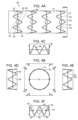
本発明のステントグラフト送達システムの一態様を図1A~1Fに示す。該図に示されるように、ステントグラフト送達システム10は、本発明のステントグラフト12を含む。ステントグラフト12は、近位開放端16、遠位開放端18および外側表面20を有する管腔グラフト構成要素14を含む。内側表面22は、長手軸26の周りの管腔を画定する。管腔グラフト構成要素14は、当該技術分野で公知のものなどの適切な材料で作製される。適切な材料の例としては、発泡ポリテトラフルオロエチレン(ePTFE)およびポリエチレンテレフタレート(PET)、例えば織られたポリエステルが挙げられる。
One embodiment of a stent-graft delivery system of the present invention is shown in Figures 1A-1F. As shown therein, the stent-
ステントグラフト12のステント28は、管腔グラフト構成要素14の周りに半径方向にかつ管腔グラフト構成要素14に沿って長手方向に分配される。ステント28は、近位頂部32および遠位頂部34を画定するようにいずれかの末端で連結される支柱30を含む。ステント28は、当該技術分野で公知のものなどの適切な材料で作製される。一態様において、ステント28は、半径方向の束縛からの解放の際にステントを半径方向に自己拡張させる材料で作製される。半径方向の自己拡張ステントの適切な材料の例としては、形状記憶合金、例えばニチノールが挙げられる。形状記憶合金で形成されないステントの例としては、ステンレス鋼で形成されるものが挙げられる。形状記憶合金を使用しないかまたはそうでなければ半径方向に自己拡張しない本発明の態様において、半径方向の収縮から解放されたステントを半径方向に拡張させるために、当該技術分野で公知なように、例えばバルーンカテーテルが使用され得る。ステント28はまた、当該技術分野で公知なように、放射線不透過性構成要素、例えば硫酸バリウム、ビスマス、タングステン、白金-イリジウムおよびタンタル-タングステンからなる群より選択される少なくとも1つの放射線不透過剤(radiopacifier)を含み得る。
The
紐36は、管腔グラフト構成要素14の周りに伸長し、末端38、40を含む。紐36は、当該技術分野で公知のものなどの適切な材料で形成される。紐36の適切な材料の例としては、ポリエステルおよびナイロンが挙げられる。図1Aに示されるように、紐36の末端は紐ループ42、44を含む。紐ループ42、44は、図1Aに示されるように、ステントグラフト12の径を収縮させるために、ワイヤ46などにより連結される。図1Aに示されるように、紐36は、ステント28と管腔グラフト材料14の間に伸長し、ステント28の支柱を横切り、ここで紐36は、ステント28と管腔グラフト材料14の間に伸長する。ワイヤ46の両側面すぐ上で、紐36は、支柱30の半径方向の外側に面した部分48の上を通過することにより支柱30を横切る。アンカーループ50、52は、ワイヤ46の部分および紐36の紐ループ42、44の両側で長手方向に分配され、結果的にステントグラフト12の周縁部の周りのワイヤ46の側方の移動から、少なくとも部分的にワイヤ46を安定化するために、紐ループ42、44にまたがる(span)。紐36は、当該技術分野で公知のものなどの適切な材料で形成される。紐36の適切な材料の例としては、例えばステンレス鋼または形状記憶合金、例えばニチノールが挙げられる。同様に、アンカーループ50、52は、紐36の作製に適切な材料などの適切な材料で形成される。例えば、紐36を管腔グラフト構成要素14と支柱30の間に通して、それによりワイヤ46が紐36の末端38、40を連結する場合にワイヤ46の側方の移動を実質的に防ぐことにより、紐36が、ステントグラフト12で安定化される態様などの特定の他の態様において、アンカーループ50、52が存在しないことが理解される。
The
図1Aに戻り、ワイヤ46は、紐のループ42、44を通って伸長し、それにより紐36の末端38、40を連結し、かつステントグラフト12を半径方向に収縮された位置に維持する。ステント28がニチノールなどの形状記憶金属合金で形成される場合、紐36は、ステント28を、半径方向に収縮された位置に保持し、ここで半径方向に自己拡張するステント28は、紐36に対して半径方向に外側の力を働かせることが理解される。代替的な態様において、紐36は、支柱30と管腔グラフト構成要素14の間、または図1Aに示されるものとは異なる配置において支柱30の半径方向の外側に面した部分48の周囲で、支柱30を横切り得ることも理解される。さらに、ワイヤ46が、管腔24を通り、かつ管腔グラフト構成要素14の外側表面20とは全く異なる管腔グラフト構成要素14の内側表面に対して伸長する態様などの種々の態様において、紐36は、管腔グラフト構成要素14の構造(fabric)を通って管腔24まで通過し得ることが理解される。また、代替的に、ある態様(示さず)において、ステント28は、管腔グラフト構成要素14の内側表面22で管腔グラフト構成要素14に固定され得、この場合、可能な一態様においてワイヤ46は管腔24内に伸長し、紐36は、支柱30と管腔グラフト構成要素14の内側表面の間で、支柱30を横切る。ワイヤ46、紐36およびステント28の間の他の配置も可能である。
Returning to FIG. 1A, the
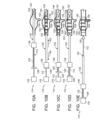
図1Bは、ライン1B-1Bに沿って採られる図1Aに示されるステントグラフト12の末端図である。図1Bに見られ得るように、収縮された開放ステントグラフト12は、D'の内径を有する。図1Cは、図1Bのライン1C-1Cから見た場合の図1Aに示されるステントグラフト12の近位開放端16でのステントおよび管腔グラフト構成要素の側面図である。同様に、図1D、1Eおよび1Fは、ライン1D-1D、1E-1Eおよび1F-1Fのそれぞれに沿って採られる図1Bの末端図に示されるステントグラフト12の最も近位のステントの側面図を示す。まとめると、図1A~1Fは、ワイヤ46の両側方の支柱30を除いて、ステントグラフト12の周の周りで支柱30と管腔グラフト構成要素14の間に伸長する紐36を示し、ここで紐36が支柱30の外側に面する部分48の上を通過する。
FIG. 1B is an end view of the
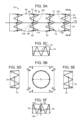
図2Aは、図1Aに示されるステントグラフト12の側面図であるが、その後のアンカーループ50、52および紐36のループ42、44からのワイヤ46の引き込みにより、ステント28の、図1A~1Fに示される収縮された位置から図2Aに示される拡張された位置への半径方向の拡張が可能になる。例えばニチノールで作製される半径方向に自己拡張するステント28の拡張などによるステント28の半径方向の拡張は、末端38、40および特に紐36のループ42、44を、互いから、およびワイヤループ42、44に長手方向にまたがるアンカーループ50、52から分離させ、ここでワイヤ46が以前にアンカーループ50、52の間でループ42、44を連結していた。図2Bは、図1A~1Fに表される半径方向に収縮された位置からのステントグラフト12の解放後の拡張された内径D''を示す、ライン2B-2Bに沿って採られる図2Aのステントグラフト12の末端図である。図2C、2D、2Eおよび2Fは、ライン2C-2C、2D-2D、2E-2Eおよび2F-2Fのそれぞれに沿って採られる、図2Bに示される最も近位のステントおよび近位開放端16での管腔グラフト構成要素の側面図を示す。
2A is a side view of the
図3Aは、本発明のステントグラフト送達システムの別の態様の側面図である。該図に示されるように、ステントグラフト送達システム60はさらに、それぞれのループ42、44と支柱30の間のステントグラフト12での紐縫合糸62、64により紐36を支持し、紐はワイヤ46の両側を横切る。ループ42、44と紐36が横切るそれぞれの支柱30との間の紐縫合糸62、64の配置は、ワイヤ46によるループ42、44の連結を安定化する。さらに別の態様において、紐縫合糸62、64がアンカーループ50、52の代わりに使用され得、それによりワイヤ46により連結される場合にループ42、44が安定化されることが理解される。図3Bは、ライン3B-3Bに沿って採られ、最も半径方向に収縮されたステントグラフト12の内径D'を示す図3Aに示されるステントグラフト12の近位開放端16の末端図である。図3C、3D、3Eおよび3Fは、ライン3C-3C、3D-3D、3E-3Eおよび3F-3Fのそれぞれに沿って採られる図3Bの断面図に示される最も近位のステント28および近位開放端16での管腔グラフト構成要素の側面図を示す。
3A is a side view of another embodiment of the stent-graft delivery system of the present invention. As shown in the figure, the stent-
図4Aは、ワイヤ46のアンカーループ50、52およびループ42、44の連結からの引き込みおよび引き抜き後の、図3Aに示されるステントグラフト送達システム60の側面図である。該図に見られ得るように、半径方向に収縮された位置から半径方向に拡張された位置へのステント28の半径方向の拡張は、ループ42、44を、互いから側方に分離させ、かつ図4Aに見られるように、紐縫合糸62、64のそれぞれから引き込まれるようにする。図4Bは、ライン4B-4Bに沿って採られ、該断面で、ステント28の半径方向の拡張の後に拡張された内径D''を示す、図4Aに示されるような半径方向に拡張された位置にあるステントグラフトの末端図である。図4C、4D、4Eおよび4Fは、ライン4C-4C、4D-4D、4E-4Eおよび4F-4Fのそれぞれに沿って採られる、図4Bの断面図に示される最も近位のステント28および最も近位のステント28での管腔グラフト構成要素14の側面図を示す。
4A is a side view of the stent-
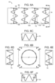
図5Aは、本発明のステントグラフト送達システムのさらに別の態様の側面図である。図5Aに示されるように、ステントグラフト送達システム70は、ステントグラフト94のそれぞれのステント74で紐72を含む。紐72は、そのそれぞれが、それぞれのステント74の別々の支柱80、82で固定される2つの構成部分76、78を含む。紐72は、ワイヤ92により整列されるそれぞれの末端でループ84、86を含み、該ワイヤはループを通過し、それによりステントグラフト94を収縮された位置に維持する。紐部分76、78は、ワイヤ92がループ84、86を通って、それによりステント74を半径方向に収縮させる場合に、ループ84、86に長手方向にまたがるアンカーループ100、102により安定化される。示されないが、紐縫合糸はまた、任意に、図1Aおよび3Aに関して記載されるように使用され得ることが理解される。図5Bは、ライン5B-5Bに沿って採られ、半径方向に収縮された位置にあるステントグラフト94の内径D'を示す図5Aに示されるステントグラフト送達システム70の末端図である。図5C、5D、5E、5Fは、ライン5C-5C、5D-5D、5E-5Eおよび5F-5Fのそれぞれに沿って採られる図5Bに示される最も近位のステント74および最も近位のステント74での管腔グラフト構成要素の一部の側面図を示す。
5A is a side view of yet another embodiment of the stent-graft delivery system of the present invention. As shown in FIG. 5A, the stent-
図6Aは、アンカーループ100、102および紐72のループ82、84からのワイヤ92の引き込みにより、ステントグラフト94が、図5A~5Fに示される半径方向に収縮された位置から図6Aに示される半径方向に拡張した位置へと半径方向に拡張することを可能にした後の図5Aに示されるステントグラフト94の側面図である。図6Aに見られ得るように、ループ84、86は、ステントグラフト94の、半径方向に収縮された状態から拡張された状態への半径方向の拡張の際に、互いからおよびアンカーループ100、102から側方に分離される。図6Bは、ライン6B-6Bに沿って採られ、ステントグラフト94の半径方向に拡張された内径D''を示す図6Bに示されるステントグラフト94の末端図である。図6C、6D、6Eおよび6Fは、ライン6C-6C、6D-6D、6E-6Eおよび6F-6Fのそれぞれに沿って採られる、図6Bに示される最も近位のステント74および最も近位のステント74に対して最も最近位にある管腔グラフト構成要素95の一部の側面図を示す。
6A is a side view of the
別の態様において、環状の紐160は、ステントグラフト12の周縁部の周りに伸長して、ワイヤ46により連結される環状の紐160の遠位の反対にある末端162、164を形成する。ワイヤ46は、図7A、7Fに示されるように、ステントグラフトで、アンカーループ50、52により安定化される。
In another embodiment, the
図8A~8Dに示されるように、ステントグラフト10は、少なくとも1つの近位開窓53(図8A)、スカラップを有する近位開放端54(図8B)、スカラップを有する遠位開放端55(図8C)ならびにスカラップを有する近位開放端および遠位開放端54、55のそれぞれ(図8D)を含み得る。示されないが、ステントグラフト10は、スカラップを有する近位開放端およびスカラップを有する遠位開放端の少なくとも1つと組み合わせて少なくとも1つの開窓を含み得る。さらなる態様において、本発明のステントグラフトは、それぞれの近位頂部または遠位頂部に任意にバーブを含む近位開放端および遠位開放端の少なくとも1つにあるベアステントを含み得る(示さず)。
As shown in Figures 8A-8D, the
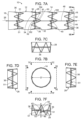
図9は、本発明のステントグラフト送達システムの別の態様の分解組立側面図である。該図に示されるように、ステントグラフト送達システム110は、近位端114および遠位端116を有するガイドワイヤカテーテル112を含む。近位ハンドル118は、ガイドワイヤカテーテル112の近位端114に固定される。ノーズコーン120は、ガイドワイヤカテーテル112の遠位端116に固定される。ワイヤ122は、近位端124および遠位端126を含む。ワイヤ122は、例えばニチノールまたはいくつかの他の形状記憶合金を含む、当該技術分野で公知のものなどの適切な材料で作製され得る。ワイヤ122は、患者の大動脈瘤への進行の際に患者を傷つけないように十分に可撓性である。ワイヤハンドル128は、ワイヤ122の近位端124で固定される。イントロデューサシース130は、近位端132および遠位端134を含み、遠位ハンドル136は、イントロデューサシース130の近位端132に固定される。ステントグラフト138は、上述のように配置および構成される近位端140、遠位端142、管腔グラフト構成要素144、管腔グラフト構成要素144に沿って分配されるステント146および紐148を含む。
FIG. 9 is an exploded side view of another embodiment of a stent graft delivery system of the present invention. As shown in the figure, the stent
図10Aは、図9に示されるステントグラフト送達システム110の組み立てられた側面図であり、ここでステントグラフト138は、イントロデューサシース130の遠位端134内に装填され、上述のように、少なくとも部分的に、紐148の末端でループ150を通るワイヤ122により、およびアンカーループ153を安定化することにより半径方向に収縮される。ある態様において、ステントグラフト138は開窓139を含む。本発明の方法において、ステントグラフト送達システム110は、患者の動脈瘤152に進められる。図10Aに示される一態様において、イントロデューサシース130は、動脈瘤部位152に進められ、それによりステントグラフト138を動脈瘤152に配置する。図10Bに見られ得るように、遠位ハンドル136は、矢印160により示される近位方向で、近位ハンドル118に向かって引き込まれ、それによりイントロデューサシース130が、動脈瘤152にあるステントグラフト138から引き込まれる。図10Bに見られ得るように、イントロデューサシース130の引き込みに関わらず、ステントグラフト138は、紐148の紐ループ150を通って伸長し、ステントグラフト138に沿って長手方向に分配されるステント146の支柱を横切るワイヤ122により、半径方向に収縮された位置に維持される。しかしながら、代替的な態様において、ステントグラフト送達システム110は動脈内で動脈瘤152に対して遠位の位置まで進められ得、ここでステントグラフト138は、近位ハンドル118およびワイヤハンドル128を矢印162に示される遠位方向で遠位ハンドル136に向かって進めることにより動脈瘤152に方向づけられ、それにより半径方向に収縮されたステントグラフト118を、イントロデューサシース130から動脈瘤152に方向づけることが理解される。
10A is an assembled side view of the stent
ステントグラフトの、動脈瘤152にまたがる位置への方向付け、および動脈瘤152でのステントグラフトの少なくとも部分的な回転および軸方向の整列の後、ワイヤ122は、紐のループ150から、およびアンカーループ153から部分的に引き込まれる。図10Cに見られ得るような、矢印160により示される方向での、近位ハンドル118に向かうワイヤハンドル128の近位引き込み。ワイヤ122の継続した引き込みにより、ワイヤ122を、紐148の縫合糸ループ150およびアンカーループ153の全てから引き抜き、それにより、ステントグラフト138を、図10Bに示されるその半径方向に収縮された状態から図10Dに示される半径方向に拡張した状態へと十分に拡張させることが可能になる。ある態様において、ステントグラフト138は、開窓139を通って動脈分枝154への分枝プロテーゼ156のその後の配置のために、開窓139が動脈分枝154と適切に整列されるように配置される。その後、ステントグラフト138は、動脈瘤内に完全に埋めこまれ、図10Eに示されるように、ステントグラフト送達デバイス110の残りはステントグラフト138および患者から引き込まれ、それにより本発明の方法による患者の動脈瘤部位152の治療が完了する。
After orientation of the stent graft to a position spanning the
本発明のステントグラフトシステムおよび方法により埋めこまれる血管プロテーゼは、例えば経大腿(transfemoral)アクセスにより埋めこまれ得る。本発明の血管プロテーゼに方向づけられるさらなる分枝プロテーゼは、例えば大動脈上(supraaortic)血管アクセス(例えば上腕動脈を通る)、または経大腿アクセスもしくは末梢血管を含む主要血管のいくつかの他の分枝(1つまたは複数)からのアクセスにより埋めこまれ得る。 Vascular prostheses implanted with the stent graft systems and methods of the present invention may be implanted, for example, via transfemoral access. Additional branch prostheses directed to the vascular prostheses of the present invention may be implanted, for example, via supraaortic vascular access (e.g., through the brachial artery), or via transfemoral access or access from some other branch or branches of a major blood vessel, including a peripheral vessel.
本明細書に引用される全ての特許、公開出願および参照文献の教示は、それらの全体において、参照により援用される。本明細書に引用される全ての特許、公開出願および参照文献の関連のある教示は、それらの全体において、参照により援用される。米国特許第8,292,943号;同7,763,063号;同8,308,790号;同8,070,790号;同8,740,963号;同8,007,605号;同9,320,631号;同8,062,349号;同9,198,786号;同8,062,345号;同9,561,124号;同9,173,755号;同8,449,595号;同8,636,788号;同9,333,104号;同9,408,734号;同9,408,735号;同8,500,792号;同9,220,617号;同9,364,314号;同9,101,506号;同8,998,970号;同9,554,929号;同9,439,751号;同9,592,112号;同9,655,712号、同9,827,123号、同9,877,857号、同9,907,686号;米国特許出願第14/575,673号;同15/166,818号;同15/167,055号;同14/272,818号;同14/861,479号;同15/478,424号;同15/478,737号;同15/587,664号;同15/604,032号;同15/672,404号;同15/816,772号;同15/839,272号;同15/417,467号;PCT/US2017/025844;PCT/US2017/025849; PCT/US2017/025912;PCT/US2017/034223およびPCT/US2017/046062の関連のある教示も、それらの全体において参照により援用される。 The teachings of all patents, published applications and references cited herein are incorporated by reference in their entirety. The relevant teachings of all patents, published applications and references cited herein are incorporated by reference in their entirety. U.S. Patent Nos. 8,292,943; 7,763,063; 8,308,790; 8,070,790; 8,740,963; 8,007,605; 9,320,631; 8,062,349; 9,198,786; 8,062,345; 9,561,124; 9,1 73,755; 8,449,595; 8,636,788; 9,333,104; 9,408,734; 9,408,735; 8,500,792; 9,220,617; 9,364,314; 9,101,506; 8,99 No. 8,970; No. 9,554,929; Same Nos. 9,439,751; 9,592,112; 9,655,712, 9,827,123, 9,877,857, 9,907,686; U.S. Patent Application Nos. 14/575,673; 15/166,818; 15/167,055; 14/272,818; and 14/861,479. The relevant teachings of PCT Nos. 15/478,424; 15/478,737; 15/587,664; 15/604,032; 15/672,404; 15/816,772; 15/839,272; 15/417,467; PCT/US2017/025844; PCT/US2017/025849; PCT/US2017/025912; PCT/US2017/034223 and PCT/US2017/046062 are also incorporated by reference in their entireties.
Eduardo Alejandro GarciaによるAttorney Docket No.: 4221.1043-001の2018年2月23日に出願された「Delivery System For Radially Constricting a Stent Graft and Method of Use」;Samuel ArbefeuilleによるAttorney Docket No.: 4221.1044-001の2018年2月23日に出願された「System and Method to Radially Constrict Stent Graft」;Timothy LostetterによるAttorney Docket No.: 4221.1046-001の2018年2月23日に出願された「Delivery System and Method to Radially Constrict a Stent Graft」;Samuel ArbefeuilleによるAttorney Docket No.: 4221.1047-001の2018年2月23日に出願された「Vascular Prosthesis with Moveable Fenestration and Method of Use」;Timothy LostetterによるAttorney Docket No.: 4221.1048-001の2018年2月23日に出願された「Stent Graft Delivery System with Constricted Sheath and Method of Use」;Timothy LostetterによるAttorney Docket No.: 4221.1049-001の2018年2月23日に出願された「Stent Graft with Fenestration Lock and Methods of Use」;Samuel ArbefeuilleによるAttorney Docket No.: 4221.1052-001の2018年2月23日に出願された「Vascular Prosthesis with Crimped Adapter and Methods of Use」;Samuel Arbefeuille、Eduardo Alejandro GarciaおよびScott L. RushによるAttorney Docket No.: 4221.1053-001の2018年2月23日に出願された「Radially Adjustable Stent Graft Delivery System and Method of Use」;Timothy LostetterによるAttorney Docket No.: 4221.1054-001の2018年2月23日に出願された「Vascular Prosthesis with Fenestration Ring and Methods of Use」;Samuel ArbefeuilleによるAttorney Docket No.: 4221.1055-001の2018年2月23日に出願された「Distal Torque Component, Delivery System and Method of Using Same」の関連のある教示も、それらの全体において参照により援用される。 "Delivery System For Radially Constricting a Stent Graft and Method of Use" filed February 23, 2018 by Eduardo Alejandro Garcia, Attorney Docket No.: 4221.1043-001; "System and Method to Radially Constrict Stent Graft" filed February 23, 2018 by Samuel Arbefeuille, Attorney Docket No.: 4221.1044-001; "Delivery System and Method to Radially Constrict a Stent Graft" filed February 23, 2018 by Timothy Lostetter, Attorney Docket No.: 4221.1046-001; "Vascular Prosthesis with Moveable Prosthesis" filed February 23, 2018 by Samuel Arbefeuille, Attorney Docket No.: 4221.1047-001 "Stent Graft Delivery System with Constricted Sheath and Method of Use" filed February 23, 2018, Attorney Docket No.: 4221.1048-001 by Timothy Lostetter; "Stent Graft with Fenestration Lock and Methods of Use" filed February 23, 2018, Attorney Docket No.: 4221.1049-001 by Timothy Lostetter; "Vascular Prosthesis with Crimped Adapter and Methods of Use" filed February 23, 2018, Attorney Docket No.: 4221.1052-001 by Samuel Arbefeuille; "Vascular Prosthesis with Crimped Adapter and Methods of Use" filed February 23, 2018, Attorney Docket No.: 4221.1053-001 by Samuel Arbefeuille, Eduardo Alejandro Garcia and Scott L. Rush; The relevant teachings of "Radially Adjustable Stent Graft Delivery System and Method of Use," filed February 23, 2018, Attorney Docket No.: 4221.1053-001; "Vascular Prosthesis with Fenestration Ring and Methods of Use," filed February 23, 2018, Attorney Docket No.: 4221.1054-001, by Timothy Lostetter; and "Distal Torque Component, Delivery System and Method of Using Same," filed February 23, 2018, Attorney Docket No.: 4221.1055-001, by Samuel Arbefeuille, are also incorporated by reference in their entirety.
例示態様が具体的に示され、記載されているが、形態および詳細における種々の変更が、添付の特許請求の範囲に包含される態様の範囲から逸脱することなく、本発明においてなされ得ることが、当業者には理解されよう。 While example embodiments have been specifically shown and described, it will be understood by those skilled in the art that various changes in form and detail may be made in the present invention without departing from the scope of the embodiments encompassed by the appended claims.
本発明の態様として以下のものが挙げられる。
項1
a) 近位開放端および遠位開放端を有する管腔グラフト構成要素;
b) 管腔グラフト構成要素に沿って長手方向に分配される複数のステント、ここで、少なくとも1つのステントは、近位頂部および遠位頂部を画定するように連結される支柱を有する;
c) 少なくとも1つの紐、ここで、それぞれの紐は、少なくとも1つのステントの支柱の少なくとも一部を横切り、該紐は、連結される場合にそれぞれの対応するステントを少なくとも部分的に半径方向に収縮させる末端を含む;ならびに
d) 対応するステントを半径方向に収縮するように連結される場合にそれぞれの関連のある紐の末端に長手方向にまたがる、管腔グラフト構成要素の一組のアンカーループ
を含む、ステントグラフト。
項2
該紐が、末端が連結される場合に該ステントの周囲の周りに完全に伸長する、項1記載のステントグラフト。
項3
該紐の末端のそれぞれが紐ループを含む、項2記載のステントグラフト。
項4
ワイヤが紐ループを通って、アンカーループのそれぞれの組を通って管腔グラフト構成要素に沿って長手方向に伸長する場合に、該紐の末端が該紐ループで連結されるように、該紐の末端が配置される、項3記載のステントグラフト。
項5
該紐の少なくとも一部が、それぞれ環状であり、該紐が該管腔グラフト構成要素を半径方向に収縮している場合に、直径の反対にある点で、アンカーループを通るワイヤにより連結され得る、項1記載のステントグラフト。
項6
該紐の末端が通過する管腔グラフト構成要素で側方に配置される紐縫合糸をさらに含むステントグラフトであって、該紐縫合糸は、アンカーループを通るワイヤの両側方に位置し、ここで該紐末端は、該紐縫合糸の間でワイヤにより連結される、項1記載のステントグラフト。
項7
末端が連結される場合に、該紐が、周囲の周りに部分的に伸長する2つの紐構成部分を含み、ここで該紐末端が連結される、項1記載のステントグラフト。
項8
該紐末端のそれぞれが紐ループを含む、項7記載のステントグラフト。
項9
該紐の2つの構成部分が、それぞれ管腔グラフト構成要素に固定される、項8記載のステントグラフト。
項10
該紐のそれぞれの構成部分の紐ループに対して反対にある末端で、支柱に固定される紐の2つの構成部分をさらに含む、項8記載のステントグラフト。
項11
紐の末端が通過する管腔グラフト構成要素で側方に配置される紐縫合糸をさらに含むステントグラフトであって、該紐縫合糸が、ワイヤの両側に位置してアンカーループを通過しており、ここで該紐末端が、該紐縫合糸の間でワイヤにより連結され得る、項10記載のステントグラフト。
項12
該2つの構成部分がそれぞれ、該紐のもう一方の構成部分の環状の糸に連結される環状の糸の点と直径の反対にある点で、管腔グラフト構成要素または関連のあるステントの支柱に固定される環状の糸である、項7記載のステントグラフト。
項13
該紐が糸である、項1記載のステントグラフト。
項14
該糸が、ポリエステル、ナイロン、発泡ポリテトラフルオロエチレン(ePTFE)、ポリフッ化ビニリデン(PVDF)およびポリプロピレンからなる群の少なくとも1つの構成メンバーを含む、項13記載のステントグラフト
項15
該ステントの少なくとも一部が形状記憶合金を含む、項1記載のステントグラフト。
項16
該形状記憶合金がニチノールを含む、項15記載のステントグラフト送達システム。
項17
該ステントの少なくとも一部が放射線不透過性材料を含む、項16記載のステントグラフト。
項18
a) i) 近位開放端および遠位開放端を有し、管腔を画定する管腔グラフト構成要素、
ii) 管腔グラフト構成要素に沿って長手方向に分配される複数のステント、ここで、少なくとも1つのステントは近位頂部および遠位頂部を画定するように連結される支柱を有する、
iii) 支柱の少なくとも一部を横切る少なくとも1つの紐、ここで、該紐は、連結される場合に該ステントを少なくとも部分的に半径方向に収縮させる末端を含む;ならびに
iv) 対応するステントを半径方向に収縮するように連結される場合にそれぞれの関連のある紐の末端に長手方向にまたがる、管腔グラフト構成要素にある一組のアンカーループ
を含む、ステントグラフト、
b) 管腔グラフト構成要素に沿ってかつ該アンカーループを通って長手方向に伸長し、該紐の末端を連結し、それにより、該ステントグラフトのステントの少なくとも一部を半径方向に収縮させるワイヤ、ここで少なくとも1つの紐の末端からの該ワイヤの引き込みは、少なくとも1つの紐による半径方向の収縮からステントグラフトを解放する、
を含む、ステントグラフト送達システム。
項19
該紐が、末端が連結される場合に対応する自己拡張半径方向ステントの周囲の周りに完全に伸長する、項18記載のステントグラフト送達システム。
項20
それぞれを連結する少なくとも1つの紐の末端が、紐末端ループを含む、項19記載のステントグラフト送達システム。
項21
該ワイヤが、管腔グラフト構成要素の外側表面に沿って長手方向に伸長し、管腔グラフト構成要素の外側表面で紐の末端ループを連結してそれにより該ステントを半径方向に収縮させる、項20記載のステントグラフト送達システム。
項22
ワイヤが、管腔内に長手方向に伸長し、管腔内で該紐末端を連結し、ここで該紐が、管腔グラフト構成要素を通って伸長し、管腔グラフト構成要素の外側表面で束縛されたステントの支柱を横切る、項21記載のステントグラフト送達システム。
項23
該紐が、該支柱の外側に面する部分を横切る、項22記載のステントグラフト送達システム。
項24
該紐の少なくとも一部がそれぞれ環状であり、該紐が管腔グラフト構成要素を半径方向に収縮している場合に、直径の反対にある点で、アンカーループを通るワイヤにより連結される、項18記載のステントグラフト送達システム。
項25
該支柱を横切る紐が、該ワイヤの両側すぐの支柱の上を通過する、項18記載のステントグラフト送達システム。
項26
該紐が通過する管腔グラフト構成要素の側方に配置される紐縫合糸をさらに含むステントグラフト送達システムであって、該紐縫合糸が、該ワイヤの両側方に位置している、項25記載のステントグラフト送達システム。
項27
末端が連結される場合に、少なくとも1つの紐が、ステントの周囲の周りに部分的に伸長する2つの紐構成部分を含む、項18記載のステントグラフト送達システム。
項28
連結される末端がそれぞれ紐ループを含み、該末端が、紐ループにおいて直接または間接的に連結される、項27記載のステントグラフト送達システム。
項29
該紐の2つの構成部分がそれぞれ、管腔グラフト構成要素に固定される末端を有する、項28記載のステントグラフト送達システム。
項30
該2つの構成部分がそれぞれ、関連のある半径方向に収縮されたステントの支柱に固定される末端を有する、項28記載のステントグラフト送達システム。
項31
該ワイヤの両側方にあり、かつ該紐が通過する管腔グラフト構成要素にある紐縫合糸をさらに含む、項30記載のステントグラフト送達システム。
項32
該アンカーループがステントの2つの支柱の間で入れ子状であり、該紐縫合糸がそれぞれワイヤと2つの支柱の1つとの間にある、項28記載のステントグラフト送達システム。
項33
a) ステントグラフトが解放可能に固定されるガイドワイヤカテーテル、ここで、該ガイドワイヤカテーテルは、長手軸に沿って伸長し、近位端および遠位端を有し、かつ管腔グラフト構成要素内に伸長する;
b) ガイドワイヤカテーテルが固定される近位ハンドル;
c) ガイドワイヤカテーテルの周囲に伸長する遠位ハンドル、ここで、該遠位ハンドルは、近位ハンドルに対して遠位にある;ならびに
d) 該遠位ハンドルから遠位にかつ該ステントグラフトの周りに伸長するイントロデューサシース
をさらに含む、項18記載の送達システム。
項34
該紐が糸である、項18記載の送達システム。
項35
該糸が、ポリエステル、ナイロン、発泡ポリテトラフルオロエチレン(ePTFE)、ポリフッ化ビニリデン(PVDF)およびポリプロピレンからなる群の少なくとも1つの構成メンバーを含む、項34記載のステントグラフト。
項36
該ワイヤが、プラスチック、鋼鉄および形状記憶合金からなる群の少なくとも1つの構成メンバーを含む、項33記載の送達システム。
項37
該ステントの少なくとも一部が形状記憶合金を含む、項36記載の送達システム。
項38
該ステントが半径方向に自己拡張している、項37記載の送達システム。
項39
該ステントの少なくとも一部が放射線不透過性材料を含む、項38記載の送達システム。
項40
被験体の動脈瘤部位にステントグラフトを埋め込む方法であって、
a) ステントグラフトを、動脈を通って被験体の動脈瘤まで進める工程、ここで、該ステントグラフトは、該ステントグラフトの周縁部の周りに少なくとも部分的に伸長する少なくとも1つの紐を含み、該紐はステントグラフトの半径方向のステントの支柱を横切り、該紐は、ワイヤにより連結される末端を有し、該ワイヤは、ステントグラフトの長手軸に平行に、かつ該連結される末端に長手方向にまたがるアンカーループを通って伸長し、それにより該ステントグラフトを半径方向に収縮された位置に維持する;および
b) 少なくとも1つの紐の末端(ends at least one ligature)およびアンカーループから該ワイヤを引き込み、その結果、該紐の末端が互いから解放され、該ステントグラフトは、半径方向に収縮された位置から半径方向に拡張した位置まで半径方向に拡張し、それによりステントグラフトプロテーゼを被験体の動脈瘤に埋め込む工程
を含む、方法。
項41
該ステントグラフトが含まれるイントロデューサシースを引き込み、それによりステントグラフトを暴露させる工程をさらに含む、項40記載の方法。
項42
該紐が、末端が連結される場合にステントの周囲の周りに完全に伸長する、項41記載の方法。
項43
該紐の末端のそれぞれが紐ループを含む、項42記載の方法。
項44
該末端が、紐ループで、ワイヤにより直接または間接的に連結される、項43記載の方法。
項45
該紐の少なくとも一部が、それぞれ環状であり、該紐が管腔グラフト構成要素により半径方向に収縮される場合に、直径の反対にある点で、該アンカーループに通されるワイヤにより連結される、項40記載の方法。
項46
該支柱を横切る紐が、ワイヤのすぐ両側で該支柱の上を伸長する、項40記載の方法。
項47
該紐が通過する管腔グラフト構成要素で側方に配置される紐縫合糸をさらに含む方法であって、該紐縫合糸が該ワイヤの両側に位置する、項46記載の方法。
項48
該紐が、末端が連結される場合に、それぞれが周囲の周りに部分的に伸長する2つの紐構成部分を含む、項40記載の方法。
項49
該連結される末端がそれぞれ紐ループを含む方法であって、該末端が、該紐ループにおいて直接または間接的に連結される、項48記載の方法。
項50
該紐の2つの構成部分がそれぞれ該管腔グラフト構成要素に固定される、項49記載の方法。
項51
該2つの構成部分がそれぞれ、関連のある半径方向に収縮されたステントの支柱に固定される末端を有する、項48記載の方法。
項52
該ワイヤの両側面で管腔グラフト構成要素にある紐縫合糸をさらに含む方法であって、該紐の2つの構成部分がそれぞれ、ワイヤの両側の支柱の上を該紐縫合糸を通って伸長することにより該支柱を横切る、項51記載の方法。
項53
該アンカーループが、ステントの2つの支柱の間で入れ子状であり、該紐がそれぞれ、ワイヤと2つの支柱の1つとの間にある、項52記載の方法。
項54
該2つの構成部分がそれぞれ、複数のステントの支柱に固定される末端を有する、項53記載の方法。
項55
該紐が糸である、項51記載の方法。
項56
該糸が、ポリエステル、ナイロン、発泡ポリテトラフルオロエチレン(ePTFE)、ポリフッ化ビニリデンおよびポリプロピレンからなる群より選択される少なくとも1つの構成メンバーを含む、項55記載の方法。
項57
該ワイヤが、プラスチック、ステンレス鋼および形状記憶合金からなる群より選択される少なくとも1つの構成メンバーを含む、項40記載の方法。
項58
該ステントの少なくとも一部が形状記憶合金を含む、項57記載の方法。
項59
該ステントが半径方向に自己拡張している、項58記載の方法。
項60
該ステントの少なくとも一部が放射線不透過性材料を含む、項59記載の方法。
項61
a) 近位開放端および遠位開放端を有する管腔グラフト構成要素;
b) 管腔グラフト構成要素に沿って長手方向に分配される複数のステント、ここで、少なくとも1つのステントは、近位頂部および遠位頂部を画定するように連結される支柱を有する;ならびに
c) 少なくとも1つの紐、ここで、それぞれの紐は、少なくとも1つのステントの支柱を横切り、該紐は、連結される場合に、それぞれの対応するステントを少なくとも部分的に半径方向に収縮させる末端を含む、
を含む、ステントグラフト。
The aspects of the present invention include the following.
Item 1
a) a luminal graft component having a proximal open end and a distal open end;
b) a plurality of stents distributed longitudinally along the luminal graft component, where at least one stent has struts connected to define proximal and distal apices;
c) at least one cord, where each cord traverses at least a portion of the struts of at least one stent, the cord including ends that when coupled together at least partially radially constrict each corresponding stent; and
d) A stent graft including a pair of anchor loops of a luminal graft component that span longitudinally the ends of each associated string when coupled to radially contract a corresponding stent.
Item 2
2. The stent graft of claim 1, wherein the cord extends completely around the circumference of the stent when the ends are connected.
Item 3
3. The stent graft of claim 2, wherein each of the ends of the cords comprises a cord loop.
4. The stent graft of claim 3, wherein the ends of the strings are positioned such that when the wires extend longitudinally through the string loops and along the luminal graft component through the respective sets of anchor loops, the ends of the strings are connected by the string loops.
Item 5
Item 2. The stent graft of item 1, wherein at least some of the strings are each circular and can be connected by wires passing through anchor loops at points on opposite diameters when the strings are radially constricting the luminal graft component.
Item 6
Item 2. A stent graft as described in item 1, further comprising a string suture positioned laterally at the luminal graft component through which the ends of the string pass, the string suture being positioned on either side of a wire passing through the anchor loop, and wherein the string ends are connected by a wire between the string sutures.
Item 7
2. The stent graft of claim 1, wherein the cord comprises two cord components that extend partially around the circumference where the cord ends are joined when the ends are joined.
Item 8
8. The stent graft of paragraph 7, wherein each of the cord ends comprises a cord loop.
Item 9
9. The stent graft of claim 8, wherein the two components of the string are each fixed to a luminal graft component.
9. The stent graft of claim 8, further comprising two sections of string secured to the struts at opposite ends relative to the string loops of each section of string.
Item 11
Item 11. The stent graft of
8. A stent graft as described in item 7, wherein each of the two components is a circular thread that is fixed to a luminal graft component or a strut of an associated stent at a point that is diametrically opposite the point of the circular thread that is connected to the circular thread of the other component of the string.
Item 13
Item 2. The stent graft of item 1, wherein the string is a thread.
Item 15. The stent graft according to item 13, wherein the thread comprises at least one member of the group consisting of polyester, nylon, expanded polytetrafluoroethylene (ePTFE), polyvinylidene fluoride (PVDF) and polypropylene.
Item 2. The stent graft of item 1, wherein at least a portion of the stent comprises a shape memory alloy.
16. The stent graft delivery system of claim 15, wherein the shape memory alloy comprises Nitinol.
Item 17
17. The stent graft of
a) i) a luminal graft component having a proximal open end and a distal open end and defining a lumen;
ii) a plurality of stents distributed longitudinally along the luminal graft component, where at least one stent has struts connected to define proximal and distal apices;
iii) at least one cord traversing at least a portion of the struts, the cord including ends that when coupled together cause the stent to at least partially radially contract; and
iv) a stent graft including a pair of anchor loops on the luminal graft component that longitudinally span the ends of each associated string when coupled to radially contract a corresponding stent;
b) a wire extending longitudinally along the luminal graft component and through said anchor loop and connecting ends of said strings, thereby radially contracting at least a portion of a stent of said stent graft, wherein retraction of said wire from an end of at least one string releases the stent graft from radial contraction by at least one string;
A stent graft delivery system comprising:
Item 19
20. The stent graft delivery system of
Item 20
20. The stent graft delivery system of claim 19, wherein the end of at least one of the connecting strings comprises a string end loop.
Item 21
21. The stent graft delivery system of claim 20, wherein the wire extends longitudinally along the outer surface of the luminal graft component and connects the end loops of the string at the outer surface of the luminal graft component, thereby radially contracting the stent.
Item 22
22. The stent graft delivery system of claim 21, wherein a wire extends longitudinally within the lumen and connects the string ends within the lumen, where the string extends through the luminal graft component and crosses the struts of the stent constrained at the outer surface of the luminal graft component.
Item 23
23. The stent graft delivery system of claim 22, wherein the string traverses the outer facing portion of the strut.
Item 24
20. The stent graft delivery system of
Item 25
20. The stent graft delivery system of
26. The stent graft delivery system of claim 25, further comprising a string suture positioned on the side of the luminal graft component through which the string passes, the string suture being located on either side of the wire.
Item 27
20. The stent graft delivery system of
28. The stent graft delivery system of paragraph 27, wherein each of the connected ends comprises a tying loop, and the ends are connected directly or indirectly at the tying loops.
Item 29
29. The stent graft delivery system of
29. The stent graft delivery system of
Item 31
31. The stent graft delivery system of
29. The stent graft delivery system of
Item 33
a) a guidewire catheter to which a stent graft is releasably secured, the guidewire catheter extending along a longitudinal axis, having a proximal end and a distal end, and extending into a luminal graft component;
b) a proximal handle to which the guidewire catheter is secured;
c) a distal handle extending around the guidewire catheter, said distal handle being distal to the proximal handle; and
d) a delivery system as described in
20. The delivery system of
Item 35
35. The stent graft of
34. The delivery system of claim 33, wherein the wire comprises at least one member of the group consisting of plastic, steel, and shape memory alloy.
Item 37
37. The delivery system of
38. The delivery system of paragraph 37, wherein the stent is radially self-expanding.
Item 39
40. The delivery system of
1. A method of implanting a stent graft at an aneurysm site in a subject, comprising:
a) advancing a stent graft through an artery to an aneurysm of a subject, said stent graft including at least one cord extending at least partially around a circumference of said stent graft, said cord traversing radial stent struts of the stent graft, said cord having ends connected by wires extending parallel to a longitudinal axis of the stent graft and through anchor loops longitudinally spanning said connected ends, thereby maintaining said stent graft in a radially contracted position; and
b) retracting the wire from at least one ligature end and anchor loop such that the ligature ends are released from one another and the stent graft radially expands from a radially contracted position to a radially expanded position, thereby implanting the stent graft prosthesis in the aneurysm of the subject.
Item 41
41. The method of
42. The method of claim 41, wherein the string extends completely around the circumference of the stent when the ends are joined.
Item 43
43. The method of
44. The method of claim 43, wherein the ends are connected directly or indirectly by a wire with a string loop.
Item 45
41. The method of
41. The method of
Item 47
47. The method of
41. The method of
Item 49
49. The method of
50. The method of claim 49, wherein the two components of the string are each secured to the luminal graft component.
49. The method of
52. The method of
53. The method of
54. The method of
52. The method of
Item 56
56. The method of
Item 57
41. The method of
58. The method of paragraph 57, wherein at least a portion of the stent comprises a shape memory alloy.
Item 59
59. The method of
60. The method of paragraph 59, wherein at least a portion of the stent comprises a radiopaque material.
Item 61
a) a luminal graft component having a proximal open end and a distal open end;
b) a plurality of stents distributed longitudinally along the luminal graft component, where at least one stent has struts connected to define proximal and distal apices; and
c) at least one cord, where each cord traverses at least one strut of the stent and where the cord includes ends that, when coupled, at least partially radially constrict each corresponding stent;
Including, a stent graft.
Claims (22)
ii) 管腔グラフト構成要素に沿って長手方向に分配される複数のステント、ここで、少なくとも1つのステントは近位頂部および遠位頂部を画定するように連結される支柱を有する、
iii) 支柱の少なくとも一部を横切る少なくとも1つの紐、ここで、該紐は、連結される場合に該ステントを少なくとも部分的に半径方向に収縮させる末端を含む;ならびに
iv) 対応するステントを半径方向に収縮するように連結される場合にそれぞれの関連のある紐の末端に長手方向にまたがる、管腔グラフト構成要素にある一組のアンカーループ
を含む、ステントグラフト、ならびに
b) 管腔グラフト構成要素に沿ってかつ該アンカーループを通って長手方向に伸長し、該紐の末端を連結し、それにより、該ステントグラフトのステントの少なくとも一部を半径方向に収縮させるワイヤ、ここで連結された位置における少なくとも1つの紐の末端からの該ワイヤの引き込みは、少なくとも1つの紐による半径方向の収縮からステントグラフトを解放する、
を含む、ステントグラフト送達システム。 a) i) a luminal graft component having a proximal open end and a distal open end and defining a lumen;
ii) a plurality of stents distributed longitudinally along the luminal graft component, where at least one stent has struts connected to define proximal and distal apices;
iii) at least one cord traversing at least a portion of the struts, the cord including ends that when coupled together cause the stent to at least partially radially contract; and
iv) a stent graft including a pair of anchor loops on the luminal graft component that longitudinally span the ends of each associated string when coupled to radially contract a corresponding stent; and
b) a wire extending longitudinally along the luminal graft component and through said anchor loop and connecting ends of said strings, thereby radially contracting at least a portion of a stent of said stent graft, wherein retraction of said wire from the end of at least one string at the connected location releases the stent graft from radial contraction by at least one string;
A stent graft delivery system comprising:
b) ガイドワイヤカテーテルが固定される近位ハンドル;
c) ガイドワイヤカテーテルの周囲に伸長する遠位ハンドル、ここで、該遠位ハンドルは、近位ハンドルに対して遠位にある;ならびに
d) 該遠位ハンドルから遠位にかつ該ステントグラフトの周りに伸長するイントロデューサシース
をさらに含む、請求項1記載の送達システム。 a) a guidewire catheter to which a stent graft is releasably secured, the guidewire catheter extending along a longitudinal axis, having proximal and distal ends, and extending into a luminal graft component;
b) a proximal handle to which the guidewire catheter is secured;
c) a distal handle extending around the guidewire catheter, said distal handle being distal to the proximal handle; and
d) an introducer sheath extending distally from said distal handle and around said stent graft.
Applications Claiming Priority (4)
| Application Number | Priority Date | Filing Date | Title |
|---|---|---|---|
| US201762463057P | 2017-02-24 | 2017-02-24 | |
| US62/463,057 | 2017-02-24 | ||
| PCT/US2018/019342 WO2018156840A1 (en) | 2017-02-24 | 2018-02-23 | Constrainable stent graft, delivery system and methods of use |
| JP2019528077A JP7479844B2 (en) | 2017-02-24 | 2018-02-23 | Constrainable stent grafts, delivery systems and methods of use - Patents.com |
Related Parent Applications (1)
| Application Number | Title | Priority Date | Filing Date |
|---|---|---|---|
| JP2019528077A Division JP7479844B2 (en) | 2017-02-24 | 2018-02-23 | Constrainable stent grafts, delivery systems and methods of use - Patents.com |
Publications (2)
| Publication Number | Publication Date |
|---|---|
| JP2023052763A JP2023052763A (en) | 2023-04-12 |
| JP7516587B2 true JP7516587B2 (en) | 2024-07-16 |
Family
ID=61599624
Family Applications (2)
| Application Number | Title | Priority Date | Filing Date |
|---|---|---|---|
| JP2019528077A Active JP7479844B2 (en) | 2017-02-24 | 2018-02-23 | Constrainable stent grafts, delivery systems and methods of use - Patents.com |
| JP2023011954A Active JP7516587B2 (en) | 2017-02-24 | 2023-01-30 | Tetherable stent graft and delivery system |
Family Applications Before (1)
| Application Number | Title | Priority Date | Filing Date |
|---|---|---|---|
| JP2019528077A Active JP7479844B2 (en) | 2017-02-24 | 2018-02-23 | Constrainable stent grafts, delivery systems and methods of use - Patents.com |
Country Status (5)
| Country | Link |
|---|---|
| US (2) | US11491003B2 (en) |
| EP (1) | EP3534837A1 (en) |
| JP (2) | JP7479844B2 (en) |
| CN (1) | CN110022795B (en) |
| WO (1) | WO2018156840A1 (en) |
Families Citing this family (42)
| Publication number | Priority date | Publication date | Assignee | Title |
|---|---|---|---|---|
| US7763063B2 (en) | 2003-09-03 | 2010-07-27 | Bolton Medical, Inc. | Self-aligning stent graft delivery system, kit, and method |
| CN104023673B (en) | 2011-11-11 | 2017-07-28 | 波顿医疗公司 | universal endovascular graft |
| US9439751B2 (en) | 2013-03-15 | 2016-09-13 | Bolton Medical, Inc. | Hemostasis valve and delivery systems |
| EP4403144A3 (en) | 2016-08-02 | 2024-09-25 | Bolton Medical, Inc. | Systems, devices, and methods for coupling a prosthetic implant to a fenestrated body |
| WO2018156848A1 (en) | 2017-02-24 | 2018-08-30 | Bolton Medical, Inc. | Vascular prosthesis with crimped adapter and methods of use |
| EP3932373B1 (en) | 2017-02-24 | 2022-12-21 | Bolton Medical, Inc. | Delivery system for radially constricting a stent graft |
| EP3534838B1 (en) | 2017-02-24 | 2021-01-27 | Bolton Medical, Inc. | Radially adjustable stent graft delivery system |
| EP3534837A1 (en) | 2017-02-24 | 2019-09-11 | Bolton Medical, Inc. | Constrainable stent graft, delivery system and methods of use |
| WO2018156842A1 (en) | 2017-02-24 | 2018-08-30 | Bolton Medical, Inc. | System and method to radially constrict a stent graft |
| WO2018156850A1 (en) | 2017-02-24 | 2018-08-30 | Bolton Medical, Inc. | Stent graft with fenestration lock |
| CN109890331B (en) | 2017-02-24 | 2022-07-12 | 波顿医疗公司 | Stent-graft delivery system with a shrink sheath and method of use |
| WO2018156849A1 (en) | 2017-02-24 | 2018-08-30 | Bolton Medical, Inc. | Vascular prosthesis with fenestration ring and methods of use |
| WO2018156851A1 (en) | 2017-02-24 | 2018-08-30 | Bolton Medical, Inc. | Vascular prosthesis with moveable fenestration |
| JP7271510B2 (en) | 2017-09-25 | 2023-05-11 | ボルトン メディカル インコーポレイテッド | Systems, devices and methods for coupling prosthetic implants to fenestrated bodies |
| EP3900678B1 (en) * | 2018-12-18 | 2023-12-13 | Shenzhen Lifetech Endovascular Medical Co., Ltd. | Lumen stent and implant |
| CN111329633B (en) * | 2018-12-18 | 2022-03-08 | 深圳市先健畅通医疗有限公司 | Implant and method of manufacturing the same |
| US11666464B2 (en) | 2019-01-28 | 2023-06-06 | Tensor Flow Ventures Llc | Magnetic stent and stent delivery |
| US11998467B2 (en) * | 2019-01-28 | 2024-06-04 | Tensor Flow Ventures Llc | Stent delivery for vascular surgery |
| JP7679299B2 (en) | 2019-01-31 | 2025-05-19 | ベクトン・ディキンソン・アンド・カンパニー | MIXED FRAME ENDOLUMENAL PROSTHESIS AND METHODS THEREOF - Patent application |
| US20200246165A1 (en) | 2019-02-01 | 2020-08-06 | Bolton Medical, Inc. | Expandable luminal stents and methods of use |
| DE102019121930A1 (en) * | 2019-08-14 | 2021-02-18 | Jotec Gmbh | Vascular prosthesis |
| CN112891033B (en) * | 2019-12-03 | 2023-07-04 | 先健科技(深圳)有限公司 | Lumen stent |
| CN112891017B (en) * | 2019-12-03 | 2023-06-02 | 先健科技(深圳)有限公司 | Lumen stent |
| CN112891018B (en) * | 2019-12-03 | 2023-06-02 | 先健科技(深圳)有限公司 | Lumen stent |
| CN111035486B (en) * | 2019-12-25 | 2024-01-23 | 上海微创心脉医疗科技(集团)股份有限公司 | Stent delivery system and method of loading stents |
| FR3108029A1 (en) * | 2020-03-13 | 2021-09-17 | Cormove | Device for treating a blood vessel |
| CN113940786B (en) * | 2020-06-30 | 2024-10-22 | 上海微创心脉医疗科技(集团)股份有限公司 | Bracket system |
| CN114099063A (en) * | 2020-08-31 | 2022-03-01 | 上海微创心脉医疗科技(集团)股份有限公司 | Support device and support system |
| EP4240281B1 (en) * | 2020-11-09 | 2025-03-12 | Bolton Medical, Inc. | Aortic prosthesis delivery system |
| WO2022109584A1 (en) * | 2020-11-18 | 2022-05-27 | Microvention, Inc. | Fusiform aneurysm treatment |
| CN112891020B (en) * | 2020-12-31 | 2023-07-21 | 先健科技(深圳)有限公司 | Lumenal Devices, Delivery Devices, and Stent Grafts |
| GB2605559B (en) * | 2021-01-07 | 2023-04-05 | Cook Medical Technologies Llc | Stent graft |
| AU2021201336B1 (en) * | 2021-03-02 | 2021-07-15 | Cook Medical Technologies Llc | A constraint arrangement for a stent-graft loaded onto a delivery system |
| US20240148530A1 (en) * | 2021-03-30 | 2024-05-09 | SB-Kawasumi Laboratories, Inc. | Placement device |
| CN115137526B (en) * | 2021-03-31 | 2024-10-29 | 上海微创心脉医疗科技(集团)股份有限公司 | Tectorial membrane support and medical device |
| EP4355273A1 (en) | 2021-06-14 | 2024-04-24 | Bolton Medical, Inc. | Support ring, aortic prosthesis and method of forming |
| WO2022265989A1 (en) | 2021-06-14 | 2022-12-22 | Bolton Medical, Inc. | Support ring vascular aortic repair and methods of use |
| US20230026939A1 (en) | 2021-07-26 | 2023-01-26 | Tensor Flow Ventures Llc | Dual stent and delivery system, delivery tool apparatus, and method of delivery of dual stents |
| US20230277348A1 (en) | 2021-07-26 | 2023-09-07 | Tensor Flow Ventures Llc | Dual stent and delivery system, delivery tool apparatus, and method of delivery of dual stents |
| CN115869105B (en) * | 2021-08-24 | 2025-08-12 | 先健科技(深圳)有限公司 | Lumen stent |
| CN115887059B (en) * | 2021-08-24 | 2025-08-12 | 先健科技(深圳)有限公司 | Lumen stent |
| CN115040290B (en) * | 2022-07-06 | 2025-01-24 | 昆山茵络医疗器械有限公司 | Annuloplasty ring shrinking device |
Citations (1)
| Publication number | Priority date | Publication date | Assignee | Title |
|---|---|---|---|---|
| US20140180378A1 (en) | 2012-12-26 | 2014-06-26 | Cook Medical Technologies Llc | Expandable stent-graft system having diameter reducing connectors |
Family Cites Families (123)
| Publication number | Priority date | Publication date | Assignee | Title |
|---|---|---|---|---|
| US5123917A (en) | 1990-04-27 | 1992-06-23 | Lee Peter Y | Expandable intraluminal vascular graft |
| FR2688401B1 (en) | 1992-03-12 | 1998-02-27 | Thierry Richard | EXPANDABLE STENT FOR HUMAN OR ANIMAL TUBULAR MEMBER, AND IMPLEMENTATION TOOL. |
| US5507769A (en) | 1994-10-18 | 1996-04-16 | Stentco, Inc. | Method and apparatus for forming an endoluminal bifurcated graft |
| US6113623A (en) | 1994-04-20 | 2000-09-05 | Cabinet Beau De Lomenie | Prosthetic device and method for eventration repair |
| US6015429A (en) * | 1994-09-08 | 2000-01-18 | Gore Enterprise Holdings, Inc. | Procedures for introducing stents and stent-grafts |
| WO1996036297A1 (en) * | 1995-05-19 | 1996-11-21 | Kanji Inoue | Transplantation instrument, method of bending same and method of transplanting same |
| US5713948A (en) * | 1995-07-19 | 1998-02-03 | Uflacker; Renan | Adjustable and retrievable graft and graft delivery system for stent-graft system |
| EP0955954B1 (en) * | 1996-01-05 | 2005-03-16 | Medtronic, Inc. | Expansible endoluminal prostheses |
| US6878161B2 (en) * | 1996-01-05 | 2005-04-12 | Medtronic Vascular, Inc. | Stent graft loading and deployment device and method |
| CA2258732C (en) | 1996-06-20 | 2006-04-04 | Sulzer Vascutek Ltd. | Prosthetic repair of body passages |
| AUPO700897A0 (en) | 1997-05-26 | 1997-06-19 | William A Cook Australia Pty Ltd | A method and means of deploying a graft |
| AUPP083597A0 (en) | 1997-12-10 | 1998-01-08 | William A Cook Australia Pty Ltd | Endoluminal aortic stents |
| WO1999034749A1 (en) | 1998-01-08 | 1999-07-15 | Mark Wilson Ian Webster | Self-expanding bifurcation stent and delivery system |
| US5910144A (en) | 1998-01-09 | 1999-06-08 | Endovascular Technologies, Inc. | Prosthesis gripping system and method |
| US6395018B1 (en) | 1998-02-09 | 2002-05-28 | Wilfrido R. Castaneda | Endovascular graft and process for bridging a defect in a main vessel near one of more branch vessels |
| US6171334B1 (en) | 1998-06-17 | 2001-01-09 | Advanced Cardiovascular Systems, Inc. | Expandable stent and method of use |
| IL145979A0 (en) | 1999-05-07 | 2002-07-25 | Salviac Ltd | An embolic protection device |
| US6648912B2 (en) | 2000-02-15 | 2003-11-18 | Eva Corporation | Temporary stent assembly for use in a surgical procedure |
| US6733521B2 (en) * | 2001-04-11 | 2004-05-11 | Trivascular, Inc. | Delivery system and method for endovascular graft |
| US6761733B2 (en) * | 2001-04-11 | 2004-07-13 | Trivascular, Inc. | Delivery system and method for bifurcated endovascular graft |
| US6821291B2 (en) | 2001-06-01 | 2004-11-23 | Ams Research Corporation | Retrievable stent and method of use thereof |
| WO2002102277A2 (en) | 2001-06-18 | 2002-12-27 | Eva Corporation | Prosthetic graft assembly and method of use |
| AU2003258337A1 (en) | 2002-08-23 | 2004-03-11 | Cook Incorporated | Asymmetric stent graft attachment |
| JP4566988B2 (en) | 2003-04-02 | 2010-10-20 | ボストン サイエンティフィック リミテッド | Separable and recoverable stent assembly |
| US9198786B2 (en) | 2003-09-03 | 2015-12-01 | Bolton Medical, Inc. | Lumen repair device with capture structure |
| US7763063B2 (en) | 2003-09-03 | 2010-07-27 | Bolton Medical, Inc. | Self-aligning stent graft delivery system, kit, and method |
| US8292943B2 (en) | 2003-09-03 | 2012-10-23 | Bolton Medical, Inc. | Stent graft with longitudinal support member |
| US20080264102A1 (en) | 2004-02-23 | 2008-10-30 | Bolton Medical, Inc. | Sheath Capture Device for Stent Graft Delivery System and Method for Operating Same |
| US8500792B2 (en) | 2003-09-03 | 2013-08-06 | Bolton Medical, Inc. | Dual capture device for stent graft delivery system and method for capturing a stent graft |
| DE602004018169D1 (en) | 2003-10-10 | 2009-01-15 | Cook William Europ | STENT WINDOW |
| US8734501B2 (en) | 2003-10-10 | 2014-05-27 | Cook Medical Technologies Llc | Composite stent graft |
| AU2004279458B2 (en) | 2003-10-10 | 2009-12-10 | Cook Incorporated | Fenestrated stent grafts |
| ATE402666T1 (en) | 2003-10-10 | 2008-08-15 | Cook Inc | STRETCHABLE PROSTHETIC WINDOW |
| US20050096725A1 (en) | 2003-10-29 | 2005-05-05 | Pomeranz Mark L. | Expandable stent having removable slat members |
| FR2863160B1 (en) | 2003-12-09 | 2006-03-03 | Perouse Laboratoires | DEVICE FOR TREATING A BLOOD VESSEL AND METHOD FOR PREPARING THE SAME |
| US8308789B2 (en) | 2004-07-16 | 2012-11-13 | W. L. Gore & Associates, Inc. | Deployment system for intraluminal devices |
| US7758626B2 (en) | 2004-07-20 | 2010-07-20 | Medtronic Vascular, Inc. | Device and method for delivering an endovascular stent-graft having a longitudinally unsupported portion |
| AU2005289395B2 (en) | 2004-09-28 | 2010-08-26 | Cook Incorporated | Device for treating aortic dissection |
| US7918880B2 (en) | 2005-02-16 | 2011-04-05 | Boston Scientific Scimed, Inc. | Self-expanding stent and delivery system |
| CA2619587C (en) | 2005-08-18 | 2014-06-10 | William A. Cook Australia Pty. Ltd. | Assembly of stent grafts |
| US8911491B2 (en) | 2005-09-02 | 2014-12-16 | Medtronic Vascular, Inc. | Methods and apparatus for treatment of aneurysms adjacent branch arteries including branch artery flow lumen alignment |
| US8435284B2 (en) | 2005-12-14 | 2013-05-07 | Boston Scientific Scimed, Inc. | Telescoping bifurcated stent |
| US9155641B2 (en) * | 2006-03-09 | 2015-10-13 | Cook Medical Technologies Llc | Expandable stent grafts |
| JP4920274B2 (en) * | 2006-03-17 | 2012-04-18 | 株式会社 京都医療設計 | Vascular stent |
| FR2899096B1 (en) | 2006-04-04 | 2008-12-05 | Perouse Soc Par Actions Simpli | DEVICE FOR TREATING A CIRCULATION CIRCULATION OF THE BLOOD AND METHOD OF PREPARING SAID DEVICE |
| US7678141B2 (en) | 2006-04-18 | 2010-03-16 | Medtronic Vascular, Inc. | Stent graft having a flexible, articulable, and axially compressible branch graft |
| US20070244547A1 (en) | 2006-04-18 | 2007-10-18 | Medtronic Vascular, Inc., A Delaware Corporation | Device and Method for Controlling the Positioning of a Stent Graft Fenestration |
| AU2007258592B2 (en) | 2006-06-06 | 2012-10-25 | Cook Incorporated | Stent with a crush-resistant zone |
| US9358142B2 (en) | 2007-04-24 | 2016-06-07 | W. L. Gore & Associates, Inc. | Catheter having guidewire channel |
| AU2008251804B2 (en) * | 2007-05-11 | 2013-01-10 | Cook Incorporated | Stent grafts for the thoracic aorta |
| US7637940B2 (en) | 2007-07-06 | 2009-12-29 | Boston Scientific Scimed, Inc. | Stent with bioabsorbable membrane |
| EP2249751B1 (en) * | 2008-02-11 | 2013-11-06 | William A. Cook Australia Pty. Ltd. | Curve forming apparatus and curvable stent graft |
| US8236040B2 (en) | 2008-04-11 | 2012-08-07 | Endologix, Inc. | Bifurcated graft deployment systems and methods |
| CN101283937B (en) * | 2008-05-21 | 2010-08-18 | 微创医疗器械(上海)有限公司 | Tethering methods for open stent grafts |
| US20100049294A1 (en) | 2008-06-04 | 2010-02-25 | Zukowski Stanislaw L | Controlled deployable medical device and method of making the same |
| ES2749741T3 (en) | 2008-06-30 | 2020-03-23 | Bolton Medical Inc | Abdominal aortic aneurysm systems |
| WO2010002931A1 (en) | 2008-07-01 | 2010-01-07 | Endologix, Inc. | Catheter system |
| US8353943B2 (en) | 2008-08-29 | 2013-01-15 | Cook Medical Technologies Llc | Variable weave graft with metal strand reinforcement for in situ fenestration |
| JP2012501790A (en) | 2008-09-12 | 2012-01-26 | ウイリアム エー クック オーストラリア ピィティワイ リミテッド | Radiopaque reinforcement |
| GB2464978B (en) | 2008-10-31 | 2010-10-20 | Cook William Europ | Introducer for deploying a stent graft in a curved lumen |
| EP3284447B1 (en) | 2009-03-13 | 2020-05-20 | Bolton Medical Inc. | System for deploying an endoluminal prosthesis at a surgical site |
| US8945202B2 (en) | 2009-04-28 | 2015-02-03 | Endologix, Inc. | Fenestrated prosthesis |
| AU2009202301B8 (en) | 2009-06-10 | 2009-12-03 | Cook Incorporated | Reinforcing ring |
| US8241345B2 (en) | 2009-07-30 | 2012-08-14 | Stryker Corporation | Stent delivery system |
| US8926693B2 (en) | 2010-02-17 | 2015-01-06 | Medtronic, Inc. | Heart valve delivery catheter with safety button |
| US8764811B2 (en) | 2010-04-20 | 2014-07-01 | Medtronic Vascular, Inc. | Controlled tip release stent graft delivery system and method |
| US9101455B2 (en) | 2010-08-13 | 2015-08-11 | Cook Medical Technologies Llc | Preloaded wire for endoluminal device |
| US8702786B2 (en) | 2010-08-21 | 2014-04-22 | Cook Medical Technologies Llc | Prosthesis having pivoting fenestration |
| US8870939B2 (en) | 2010-08-21 | 2014-10-28 | Cook Medical Technologies Llc | Prosthesis having pivoting fenestration |
| US9198787B2 (en) * | 2010-12-31 | 2015-12-01 | Cook Medical Technologies Llc | Conformable prosthesis delivery system and method for deployment thereof |
| US8641752B1 (en) | 2011-01-20 | 2014-02-04 | W. L. Gore & Associates, Inc. | Integrated sheath and deployment |
| US9155619B2 (en) | 2011-02-25 | 2015-10-13 | Edwards Lifesciences Corporation | Prosthetic heart valve delivery apparatus |
| US9839542B2 (en) | 2011-04-19 | 2017-12-12 | Medtronic Ardian Luxembourg S.A.R.L. | Mobile external coupling for branch vessel connection |
| US8840659B2 (en) | 2011-04-28 | 2014-09-23 | Cook Medical Technologies Llc | Stent and stent-graft designs |
| RU2638281C2 (en) | 2011-04-29 | 2017-12-12 | Эваск Ньюроваскулар Лимитед Партнершип | Endovascular prosthesis and device for delivery |
| US8728148B2 (en) | 2011-11-09 | 2014-05-20 | Cook Medical Technologies Llc | Diameter reducing tie arrangement for endoluminal prosthesis |
| US9387097B2 (en) | 2011-11-16 | 2016-07-12 | W. L. Gore & Associates, Inc. | Implant assembly with tactile indicator |
| EP2779940B3 (en) | 2011-11-16 | 2017-09-27 | Bolton Medical Inc. | Device for aortic branched vessel repair |
| WO2013109528A1 (en) | 2012-01-16 | 2013-07-25 | Merit Medical Systems, Inc. | Rotational spun material covered medical appliances and methods of manufacture |
| DE102012101103B3 (en) * | 2012-02-10 | 2013-07-04 | Jotec Gmbh | Stentgraft with fixation elements and insertion system |
| US9375308B2 (en) | 2012-03-13 | 2016-06-28 | W. L. Gore & Associates, Inc. | External steerable fiber for use in endoluminal deployment of expandable devices |
| EP2846743B1 (en) | 2012-04-12 | 2016-12-14 | Bolton Medical Inc. | Vascular prosthetic delivery device |
| US9095421B2 (en) | 2012-04-18 | 2015-08-04 | Medtronic Vascular, Inc. | Multi-leaflet coupling for branch vessel connection |
| US8968384B2 (en) | 2012-04-27 | 2015-03-03 | Medtronic Vascular, Inc. | Circumferentially constraining sutures for a stent-graft |
| US20150202065A1 (en) | 2012-08-01 | 2015-07-23 | Endospan Ltd. | Stent-grafts configured for post-implantation expansion |
| EP2882381B1 (en) | 2012-08-10 | 2018-12-26 | Lombard Medical Limited | Stent delivery system |
| AU2012258395B1 (en) * | 2012-11-27 | 2013-03-28 | Cook Medical Technologies Llc | Assembly of stent grafts with diameter reducing ties |
| AU2012258394B1 (en) | 2012-11-27 | 2013-03-07 | Cook Medical Technologies Llc | Stent graft having a closeable fenestration |
| EP2745813A1 (en) | 2012-12-18 | 2014-06-25 | Cook Medical Technologies LLC | Preloaded wire for endoluminal device |
| EP2745812B1 (en) | 2012-12-19 | 2017-01-18 | Cook Medical Technologies LLC | Repositionable diameter constraints |
| CN103908356A (en) | 2012-12-28 | 2014-07-09 | 库克医学技术有限责任公司 | Prosthesis having pivoting fenestration |
| US9655754B2 (en) | 2013-01-10 | 2017-05-23 | Trivascular, Inc. | Systems and methods for guidewire crossover for bifurcated prostheses |
| CN104027187B (en) * | 2013-03-04 | 2016-05-25 | 微创心脉医疗科技(上海)有限公司 | Branched membrane-covered support, the induction system that comprises it and manufacture method thereof |
| US9439751B2 (en) | 2013-03-15 | 2016-09-13 | Bolton Medical, Inc. | Hemostasis valve and delivery systems |
| EP3666227B1 (en) | 2013-06-14 | 2026-03-18 | Avantec Vascular Corporation | Inferior vena cava filter and retrieval systems |
| US9622895B2 (en) | 2013-10-15 | 2017-04-18 | Boston Scientific Scimed, Inc. | Methods and systems for loading and delivering a stent |
| CN104622600B (en) * | 2013-11-15 | 2017-12-19 | 微创心脉医疗科技(上海)有限公司 | A kind of art medium-height trestle system |
| US10603197B2 (en) | 2013-11-19 | 2020-03-31 | Endospan Ltd. | Stent system with radial-expansion locking |
| AU2014200124B1 (en) | 2014-01-08 | 2014-10-02 | Cook Medical Technologies Llc | A stent graft and delivery device having a low profile |
| CN103948454B (en) * | 2014-04-30 | 2016-02-10 | 四川大学华西医院 | Branch-controllable integral vascular stent and its implantation device |
| US9877854B2 (en) | 2014-05-21 | 2018-01-30 | Boston Scientific Scimed, Inc. | Stent delivery system |
| BR112017012425A2 (en) | 2014-12-18 | 2018-01-02 | Endospan Ltd | endovascular stent graft with fatigue resistant lateral tube |
| US10092428B2 (en) * | 2014-12-30 | 2018-10-09 | Cook Medical Technologies Llc | Low profile prosthesis delivery device |
| US20160184078A1 (en) | 2014-12-31 | 2016-06-30 | Cordis Corporation | Sectional Inserts for Trunk Section in Endoprosthesis for Aortic Aneurysm |
| CN107405206A (en) | 2015-01-14 | 2017-11-28 | 库克医学技术有限责任公司 | Suture wire rack mount deployment system |
| CN107427376B (en) | 2015-01-28 | 2020-09-01 | 俄奥梯科创新有限公司 | Modular internal aortic device and method of use |
| EP3078349B1 (en) | 2015-04-10 | 2019-06-19 | Cook Medical Technologies LLC | Prosthesis with fenestration |
| FR3042702B1 (en) | 2015-10-26 | 2021-12-24 | Id Nest Medical | ELASTIC CROWN AND ASSOCIATED TREATMENT DEVICE FOR IMPLEMENTATION IN A BODY FLUID CIRCULATION DUCT |
| CN205924246U (en) * | 2016-03-21 | 2017-02-08 | 中国医科大学附属第一医院 | Release of aortic aneurysm blood vessel support |
| EP3439586A1 (en) | 2016-04-05 | 2019-02-13 | Bolton Medical, Inc. | Delivery systems with introducer and distal sheaths and methods of use |
| CN105832447A (en) * | 2016-05-27 | 2016-08-10 | 杨威 | Covered stent for aortic dissection surgery, delivery device and use method thereof |
| WO2017218474A1 (en) | 2016-06-13 | 2017-12-21 | Aortica Corporation | Systems, devices, and methods for marking and/or reinforcing fenestrations in prosthetic implants |
| US10433991B2 (en) * | 2016-07-18 | 2019-10-08 | Cook Medical Technologies Llc | Controlled expansion stent graft delivery system |
| EP4403144A3 (en) | 2016-08-02 | 2024-09-25 | Bolton Medical, Inc. | Systems, devices, and methods for coupling a prosthetic implant to a fenestrated body |
| WO2018156849A1 (en) | 2017-02-24 | 2018-08-30 | Bolton Medical, Inc. | Vascular prosthesis with fenestration ring and methods of use |
| WO2018156847A1 (en) | 2017-02-24 | 2018-08-30 | Bolton Medical, Inc. | Delivery system and method to radially constrict a stent graft |
| WO2018156850A1 (en) | 2017-02-24 | 2018-08-30 | Bolton Medical, Inc. | Stent graft with fenestration lock |
| WO2018156848A1 (en) | 2017-02-24 | 2018-08-30 | Bolton Medical, Inc. | Vascular prosthesis with crimped adapter and methods of use |
| CN109890331B (en) | 2017-02-24 | 2022-07-12 | 波顿医疗公司 | Stent-graft delivery system with a shrink sheath and method of use |
| EP3534838B1 (en) | 2017-02-24 | 2021-01-27 | Bolton Medical, Inc. | Radially adjustable stent graft delivery system |
| EP3932373B1 (en) | 2017-02-24 | 2022-12-21 | Bolton Medical, Inc. | Delivery system for radially constricting a stent graft |
| WO2018156851A1 (en) | 2017-02-24 | 2018-08-30 | Bolton Medical, Inc. | Vascular prosthesis with moveable fenestration |
| EP3534837A1 (en) | 2017-02-24 | 2019-09-11 | Bolton Medical, Inc. | Constrainable stent graft, delivery system and methods of use |
-
2018
- 2018-02-23 EP EP18709876.9A patent/EP3534837A1/en active Pending
- 2018-02-23 CN CN201880004592.0A patent/CN110022795B/en active Active
- 2018-02-23 JP JP2019528077A patent/JP7479844B2/en active Active
- 2018-02-23 WO PCT/US2018/019342 patent/WO2018156840A1/en not_active Ceased
-
2019
- 2019-05-16 US US16/414,292 patent/US11491003B2/en active Active
-
2022
- 2022-10-31 US US17/977,399 patent/US20230048537A1/en active Pending
-
2023
- 2023-01-30 JP JP2023011954A patent/JP7516587B2/en active Active
Patent Citations (1)
| Publication number | Priority date | Publication date | Assignee | Title |
|---|---|---|---|---|
| US20140180378A1 (en) | 2012-12-26 | 2014-06-26 | Cook Medical Technologies Llc | Expandable stent-graft system having diameter reducing connectors |
Also Published As
| Publication number | Publication date |
|---|---|
| CN110022795A (en) | 2019-07-16 |
| CN110022795B (en) | 2023-03-14 |
| WO2018156840A1 (en) | 2018-08-30 |
| US11491003B2 (en) | 2022-11-08 |
| JP2020508089A (en) | 2020-03-19 |
| US20230048537A1 (en) | 2023-02-16 |
| EP3534837A1 (en) | 2019-09-11 |
| JP7479844B2 (en) | 2024-05-09 |
| JP2023052763A (en) | 2023-04-12 |
| US20190269498A1 (en) | 2019-09-05 |
Similar Documents
| Publication | Publication Date | Title |
|---|---|---|
| JP7516587B2 (en) | Tetherable stent graft and delivery system | |
| US12336922B2 (en) | Method of use for delivery system for radially constricting a stent graft | |
| JP7498246B2 (en) | Distal torque components, delivery systems and methods of use thereof - Patents.com | |
| US12171651B2 (en) | System and method to radially constrict a stent graft | |
| US12521261B2 (en) | Radially adjustable stent graft delivery system and method of use | |
| EP3534848B1 (en) | Stent graft delivery system with constricted sheath | |
| WO2018156847A1 (en) | Delivery system and method to radially constrict a stent graft |
Legal Events
| Date | Code | Title | Description |
|---|---|---|---|
| A621 | Written request for application examination |
Free format text: JAPANESE INTERMEDIATE CODE: A621 Effective date: 20230203 |
|
| A977 | Report on retrieval |
Free format text: JAPANESE INTERMEDIATE CODE: A971007 Effective date: 20231208 |
|
| A131 | Notification of reasons for refusal |
Free format text: JAPANESE INTERMEDIATE CODE: A131 Effective date: 20231222 |
|
| A601 | Written request for extension of time |
Free format text: JAPANESE INTERMEDIATE CODE: A601 Effective date: 20240321 |
|
| A521 | Request for written amendment filed |
Free format text: JAPANESE INTERMEDIATE CODE: A523 Effective date: 20240408 |
|
| TRDD | Decision of grant or rejection written | ||
| A01 | Written decision to grant a patent or to grant a registration (utility model) |
Free format text: JAPANESE INTERMEDIATE CODE: A01 Effective date: 20240621 |
|
| A61 | First payment of annual fees (during grant procedure) |
Free format text: JAPANESE INTERMEDIATE CODE: A61 Effective date: 20240703 |
|
| R150 | Certificate of patent or registration of utility model |
Ref document number: 7516587 Country of ref document: JP Free format text: JAPANESE INTERMEDIATE CODE: R150 |