JP7515472B2 - Vehicle transmission unit equipped with reverse drive device and vehicle equipped with said transmission unit - Google Patents
Vehicle transmission unit equipped with reverse drive device and vehicle equipped with said transmission unit Download PDFInfo
- Publication number
- JP7515472B2 JP7515472B2 JP2021523427A JP2021523427A JP7515472B2 JP 7515472 B2 JP7515472 B2 JP 7515472B2 JP 2021523427 A JP2021523427 A JP 2021523427A JP 2021523427 A JP2021523427 A JP 2021523427A JP 7515472 B2 JP7515472 B2 JP 7515472B2
- Authority
- JP
- Japan
- Prior art keywords
- bush
- transmission
- transmission unit
- selector
- actuator
- Prior art date
- Legal status (The legal status is an assumption and is not a legal conclusion. Google has not performed a legal analysis and makes no representation as to the accuracy of the status listed.)
- Active
Links
Images


Classifications
-
- B—PERFORMING OPERATIONS; TRANSPORTING
- B62—LAND VEHICLES FOR TRAVELLING OTHERWISE THAN ON RAILS
- B62M—RIDER PROPULSION OF WHEELED VEHICLES OR SLEDGES; POWERED PROPULSION OF SLEDGES OR SINGLE-TRACK CYCLES; TRANSMISSIONS SPECIALLY ADAPTED FOR SUCH VEHICLES
- B62M23/00—Transmissions characterised by use of other elements; Other transmissions
- B62M23/02—Transmissions characterised by use of other elements; Other transmissions characterised by the use of two or more dissimilar sources of power, e.g. transmissions for hybrid motorcycles
-
- B—PERFORMING OPERATIONS; TRANSPORTING
- B62—LAND VEHICLES FOR TRAVELLING OTHERWISE THAN ON RAILS
- B62M—RIDER PROPULSION OF WHEELED VEHICLES OR SLEDGES; POWERED PROPULSION OF SLEDGES OR SINGLE-TRACK CYCLES; TRANSMISSIONS SPECIALLY ADAPTED FOR SUCH VEHICLES
- B62M25/00—Actuators for gearing speed-change mechanisms specially adapted for cycles
- B62M25/08—Actuators for gearing speed-change mechanisms specially adapted for cycles with electrical or fluid transmitting systems
-
- B—PERFORMING OPERATIONS; TRANSPORTING
- B62—LAND VEHICLES FOR TRAVELLING OTHERWISE THAN ON RAILS
- B62M—RIDER PROPULSION OF WHEELED VEHICLES OR SLEDGES; POWERED PROPULSION OF SLEDGES OR SINGLE-TRACK CYCLES; TRANSMISSIONS SPECIALLY ADAPTED FOR SUCH VEHICLES
- B62M9/00—Transmissions characterised by use of an endless chain, belt, or the like
- B62M9/04—Transmissions characterised by use of an endless chain, belt, or the like of changeable ratio
- B62M9/06—Transmissions characterised by use of an endless chain, belt, or the like of changeable ratio using a single chain, belt, or the like
-
- F—MECHANICAL ENGINEERING; LIGHTING; HEATING; WEAPONS; BLASTING
- F16—ENGINEERING ELEMENTS AND UNITS; GENERAL MEASURES FOR PRODUCING AND MAINTAINING EFFECTIVE FUNCTIONING OF MACHINES OR INSTALLATIONS; THERMAL INSULATION IN GENERAL
- F16H—GEARING
- F16H61/00—Control functions within control units of change-speed- or reversing-gearings for conveying rotary motion ; Control of exclusively fluid gearing, friction gearing, gearings with endless flexible members or other particular types of gearing
- F16H61/16—Inhibiting or initiating shift during unfavourable conditions , e.g. preventing forward-reverse shift at high vehicle speed, preventing engine overspeed
-
- F—MECHANICAL ENGINEERING; LIGHTING; HEATING; WEAPONS; BLASTING
- F16—ENGINEERING ELEMENTS AND UNITS; GENERAL MEASURES FOR PRODUCING AND MAINTAINING EFFECTIVE FUNCTIONING OF MACHINES OR INSTALLATIONS; THERMAL INSULATION IN GENERAL
- F16H—GEARING
- F16H63/00—Control outputs from the control unit to change-speed- or reversing-gearings for conveying rotary motion or to other devices than the final output mechanism
- F16H63/02—Final output mechanisms therefor; Actuating means for the final output mechanisms
- F16H63/30—Constructional features of the final output mechanisms
- F16H63/302—Final output mechanisms for reversing
-
- B—PERFORMING OPERATIONS; TRANSPORTING
- B60—VEHICLES IN GENERAL
- B60Y—INDEXING SCHEME RELATING TO ASPECTS CROSS-CUTTING VEHICLE TECHNOLOGY
- B60Y2200/00—Type of vehicle
- B60Y2200/10—Road Vehicles
- B60Y2200/12—Motorcycles, Trikes; Quads; Scooters
- B60Y2200/126—Scooters
-
- B—PERFORMING OPERATIONS; TRANSPORTING
- B62—LAND VEHICLES FOR TRAVELLING OTHERWISE THAN ON RAILS
- B62K—CYCLES; CYCLE FRAMES; CYCLE STEERING DEVICES; RIDER-OPERATED TERMINAL CONTROLS SPECIALLY ADAPTED FOR CYCLES; CYCLE AXLE SUSPENSIONS; CYCLE SIDE-CARS, FORECARS, OR THE LIKE
- B62K2202/00—Motorised scooters
-
- B—PERFORMING OPERATIONS; TRANSPORTING
- B62—LAND VEHICLES FOR TRAVELLING OTHERWISE THAN ON RAILS
- B62M—RIDER PROPULSION OF WHEELED VEHICLES OR SLEDGES; POWERED PROPULSION OF SLEDGES OR SINGLE-TRACK CYCLES; TRANSMISSIONS SPECIALLY ADAPTED FOR SUCH VEHICLES
- B62M7/00—Motorcycles characterised by position of motor or engine
- B62M7/02—Motorcycles characterised by position of motor or engine with engine between front and rear wheels
- B62M7/04—Motorcycles characterised by position of motor or engine with engine between front and rear wheels below the frame
-
- F—MECHANICAL ENGINEERING; LIGHTING; HEATING; WEAPONS; BLASTING
- F16—ENGINEERING ELEMENTS AND UNITS; GENERAL MEASURES FOR PRODUCING AND MAINTAINING EFFECTIVE FUNCTIONING OF MACHINES OR INSTALLATIONS; THERMAL INSULATION IN GENERAL
- F16H—GEARING
- F16H61/00—Control functions within control units of change-speed- or reversing-gearings for conveying rotary motion ; Control of exclusively fluid gearing, friction gearing, gearings with endless flexible members or other particular types of gearing
- F16H61/16—Inhibiting or initiating shift during unfavourable conditions , e.g. preventing forward-reverse shift at high vehicle speed, preventing engine overspeed
- F16H2061/165—Preventing reverse gear shifts if vehicle speed is too high for safe shifting
Landscapes
- Engineering & Computer Science (AREA)
- Mechanical Engineering (AREA)
- Chemical & Material Sciences (AREA)
- Combustion & Propulsion (AREA)
- General Engineering & Computer Science (AREA)
- Transportation (AREA)
- Gear-Shifting Mechanisms (AREA)
- Arrangement Of Transmissions (AREA)
- Arrangement And Mounting Of Devices That Control Transmission Of Motive Force (AREA)
- Structure Of Transmissions (AREA)
- Pharmaceuticals Containing Other Organic And Inorganic Compounds (AREA)
Description
本発明は、特に、排他的ではないが、二つ又は三つの車輪を有する車両用の逆転駆動装置を有するトランスミッションユニットに関する。本発明は、さらに、前記トランスミッションユニットを備えた車両に関する。 The present invention relates in particular, but not exclusively, to a transmission unit with a reverse drive for a vehicle having two or three wheels. The present invention further relates to a vehicle equipped with such a transmission unit.
車両、特に、モーターサイクルが、通常、逆転駆動装置を備えていないことは周知である。従って、後進運転時には、特に、運転者がサドルに跨っている場合には、前記車両は重くて動かしにくいので、動かすのはかなり厄介である。また、サドルから降りて車両を手動で押すのも厄介です。この操作は、車両に同乗者が座っている場合、特に複雑になる。また、車両が滑らかで平坦な地面にない場合、車両を手動で押す操作はほとんど不可能になる。 It is well known that vehicles, especially motorcycles, are usually not equipped with a reverse drive. Therefore, when driving in reverse, it is quite difficult to move the vehicle, especially if the driver is sitting on the saddle, as it is heavy and difficult to move. It is also difficult to get off the saddle and push the vehicle manually. This operation is especially complicated if there is a passenger sitting on the vehicle. Also, if the vehicle is not on a smooth and level ground, the operation of manually pushing the vehicle becomes almost impossible.
このような問題を解決するために、モーターサイクルの中でも特に質量の大きいものには、自動車産業で使用されているものとよく似たギアボックスを使用する逆転駆動装置が設けられている。しかし、これらの解決手段はコストが高く、ギアトランスミッションを使用する必要がある。そのため、速度可変式トランスミッションを使用するモーターサイクルには適用されない。 To solve these problems, motorcycles, especially the heavier ones, are equipped with reverse drives that use gearboxes similar to those used in the automotive industry. However, these solutions are expensive and require the use of gear transmissions, so they are not applicable to motorcycles that use variable speed transmissions.
米国特許US4,923,028号には、逆転駆動装置を制御する電動機を備えたモーターサイクルが開示されている。前記電動機は、前進駆動を制御する吸熱エンジンから動力を得るメインカルダンシャフトとの機械的接続部に配置されている。このシステムは複雑であり、カルダンシャフトを使用する必要があり、本質的に安全ではない。 US Patent US 4,923,028 discloses a motorcycle with an electric motor controlling a reverse drive. The motor is located in mechanical connection with a main cardan shaft that receives power from an endothermic engine that controls the forward drive. This system is complex, requires the use of a cardan shaft and is inherently unsafe.
米国特許US9,926,040号には、車両の逆転駆動装置用の機構が開示されており、この機構は、アクチュエータによって駆動輪に運動を伝達するシャフトに係合可能な減速機に運動を伝達する補助電動機を使用する。電動機から減速機への運動は、可撓性シャフトを介して伝達される。このシステムは、複雑でかさばる上に、機能的にも不十分である。 US Patent US 9,926,040 discloses a mechanism for a vehicle reverse drive which uses an auxiliary motor that transmits motion to a reducer that is engageable with a shaft that transmits motion to the drive wheels by an actuator. Motion from the motor to the reducer is transmitted via a flexible shaft. This system is complex, bulky and functionally inefficient.
従って、従来のトランスミッションの欠点及び限界を完全に又は部分的に克服又は軽減するトランスミッションユニットを提供することが必要である。 Therefore, it is necessary to provide a transmission unit that completely or partially overcomes or mitigates the shortcomings and limitations of conventional transmissions.
従来技術の逆転駆動装置を有するトランスミッションユニットの限界及び欠点の一つ以上を克服又は軽減するために、前進駆動を制御するためのメイントランスミッションに作動的に接続された駆動輪のシャフトと、逆転駆動用電動機とを備えた車両用トランスミッションユニットが提供される。トランスミッションユニットは、逆転駆動用電動機によって回転される制御ブッシュと、駆動輪のシャフトに作動的に接続された従動トランスミッションブッシュとをさらに備えている。また、制御ブッシュと従動トランスミッションブッシュとの相互結合を制御して、逆転駆動用電動機の運動を駆動輪のシャフトに伝達するアクチュエータが設けられている。 To overcome or mitigate one or more of the limitations and drawbacks of the prior art transmission units with reverse drives, a vehicle transmission unit is provided that includes a drive wheel shaft operatively connected to a main transmission for controlling forward drive, and a reverse drive motor. The transmission unit further includes a control bush rotated by the reverse drive motor, and a driven transmission bush operatively connected to the drive wheel shaft. An actuator is also provided that controls the interconnection between the control bush and the driven transmission bush to transmit the motion of the reverse drive motor to the drive wheel shaft.
このようにして、アクチュエータを用いて逆転駆動装置の係合を制御することを可能にし、駆動輪のシャフトは、前進駆動のための通常の回転方向とは逆の方向に電動機で回転され得る。 In this way, the actuator can be used to control engagement of the reverse drive, so that the shaft of the drive wheel can be rotated by the electric motor in a direction opposite to the normal direction of rotation for forward drive.
本明細書に開示される実施形態では、アクチュエータは、好ましくは、リニアアクチュエータであり、即ち、並進軸線に従って移動可能な作動要素が設けられている。前記アクチュエータは、電気アクチュエータ、例えばソレノイドアクチュエータであり得、磁石によって生成される電磁力の効果によって移動可能なアンカーを有し得る作動要素を備え得る。 In the embodiments disclosed herein, the actuator is preferably a linear actuator, i.e. it is provided with an actuating element movable along a translational axis. The actuator may be an electric actuator, for example a solenoid actuator, and may comprise an actuating element having an anchor movable by the effect of an electromagnetic force generated by a magnet.
有利な実施形態では、制御ブッシュ及び従動トランスミッションブッシュは、駆動輪のシャフトと同軸であり、逆転駆動時にこの回転軸を中心に、駆動輪のシャフトと共に回転する。 In an advantageous embodiment, the control bushing and the driven transmission bushing are coaxial with the drive wheel shaft and rotate together with the drive wheel shaft about this axis of rotation during reverse drive.
本明細書で開示される実施形態では、制御ブッシュは、補助駆動装置によって逆転駆動用電動機に接続される。この駆動装置は、電動機と制御ブッシュとの間に正しいギア比を提供する。特に有利な実施形態では、補助駆動装置は、ギアトレイン、即ち、相互に噛み合う一連のギア対を備え、好ましくは、各々に各ギア対がスプライン接続された少なくとも一つの補助シャフト、及び好ましくは二つの補助シャフトを有する。有利な実施形態では、駆動装置は、電動機の回転軸線が駆動輪のシャフトの回転軸線と平行になるようになっている。この場合、駆動部は一連の平歯車を有し得る。 In the embodiment disclosed herein, the control bushing is connected to the reversing drive motor by an auxiliary drive, which provides the correct gear ratio between the motor and the control bushing. In a particularly advantageous embodiment, the auxiliary drive comprises a gear train, i.e. a series of intermeshing gear pairs, preferably at least one auxiliary shaft, and preferably two auxiliary shafts, to which each gear pair is splined. In an advantageous embodiment, the drive is such that the axis of rotation of the motor is parallel to the axis of rotation of the shaft of the drive wheel. In this case, the drive may comprise a series of spur gears.
本明細書に開示された実施形態では、制御ブッシュはセレクタにねじり結合されており、前記セレクタは、制御ブッシュに対して軸線方向に移動可能であり、かつ、アクチュエータに機能的に結合されている。「軸線方向に移動可能」とは、セレクタがそれ自身の回転軸線に対して平行に移動可能であることを意味する。セレクタ及び制御ブッシュが互いに、かつ、駆動輪のシャフトと同軸である場合、セレクタの軸線方向の動きは、駆動輪のシャフト及び制御ブッシュ共通回転軸線と平行な動きになる。 In the embodiments disclosed herein, the control bushing is torsionally coupled to the selector, which is axially movable relative to the control bushing and operably coupled to the actuator. By "axially movable" it is meant that the selector is movable parallel to its own axis of rotation. When the selector and control bushing are coaxial with each other and with the drive wheel shaft, axial movement of the selector is parallel to the common axis of rotation of the drive wheel shaft and the control bushing.
有利な実施形態では、車両の駆動輪は、駆動輪のシャフトに直接、接続されていない。それどころか、追加のトランスミッション、好ましくは、ギアトランスミッションを用いて、駆動輪のシャフトに接続される駆動輪と同軸の軸を設けることができる。これらは、駆動輪のシャフトと駆動輪の軸線とを相互に平行に配置するための平歯車とすることができる。 In an advantageous embodiment, the drive wheels of the vehicle are not directly connected to the shafts of the drive wheels. Instead, an additional transmission, preferably a gear transmission, can be used to provide a coaxial shaft to the drive wheels that is connected to the shafts of the drive wheels. These can be spur gears to arrange the drive wheel shaft and the axis of the drive wheels parallel to each other.
セレクタは、セレクタが制御ブッシュにのみねじり結合される従動トランスミッションブッシュに対する第一非係合位置と、セレクタが制御ブッシュ及び従動トランスミッションブッシュにねじり結合され、トルクを制御ブッシュから従動トランスミッションブッシュに伝達する従動トランスミッションブッシュに対する第二係合位置とをとるように軸線方向に移動可能であり得る。 The selector may be axially movable between a first disengaged position relative to the driven transmission bushing in which the selector is torsionally coupled only to the control bushing, and a second engaged position relative to the driven transmission bushing in which the selector is torsionally coupled to both the control bushing and the driven transmission bushing and transmits torque from the control bushing to the driven transmission bushing.
セレクタは、制御ブッシュの回転を従動トランスミッションブッシュに伝達するために、従動トランスミッションブッシュと一体の第二係合歯と共働するように適合された第一係合歯を有し得る。前記係合歯は、正面係合歯であり得、例えば、面取りされ得、セレクタ及び制御ブッシュの回転速度よりも高い角速度で従動ブッシュが回転する傾向にある時に、セレクタ及び従動ブッシュが互いに離れることを可能にする。 The selector may have a first engagement tooth adapted to cooperate with a second engagement tooth integral with the driven transmission bush to transmit rotation of the control bush to the driven transmission bush. The engagement tooth may be a front engagement tooth, e.g., chamfered, to allow the selector and the driven bush to move away from each other when the driven bush tends to rotate at an angular velocity higher than the rotational velocity of the selector and the control bush.
トランスミッションユニットは、駆動輪のシャフトが前進方向に回転している時に、逆転駆動装置の作動を防止するように適合された安全システムを有し得る。前記安全システムは、例えば、遠心効果に基づく安全システムであり得る。 The transmission unit may have a safety system adapted to prevent operation of the reverse drive when the shaft of the drive wheel is rotating in the forward direction. The safety system may for example be a safety system based on the centrifugal effect.
幾つかの実施形態では、安全システムは、駆動輪のシャフトと一緒に回転し、遠心力の結果として、格納位置から引出位置まで、それに対して径方向に移動可能な少なくとも一つの遠心質量体、好ましくは一対の遠心質量体を備え、前記引出位置において、遠心質量体が逆転駆動装置の作動を防止する。有利な実施形態では、安全システムは、駆動輪のシャフトが最小安全値よりも大きい速度で前進方向に回転している場合に、セレクタと従動トランスミッションブッシュとの間の相互係合を防止するように構成されている。 In some embodiments, the safety system comprises at least one centrifugal mass, preferably a pair of centrifugal masses, rotating with the shaft of the drive wheel and movable radially relative thereto as a result of centrifugal force from a retracted position to an extended position, in which the centrifugal masses prevent operation of the reverse drive. In an advantageous embodiment, the safety system is configured to prevent interengagement between the selector and the driven transmission bushing when the shaft of the drive wheel is rotating in the forward direction at a speed greater than a minimum safety value.
逆転駆動装置の係合及び係合解除を制御するために、有利な実施形態では、逆転駆動装置の起動及び停止を可能にするように、アクチュエータ及びセレクタに動作可能に接続される可動フォークを設けることができる。 To control engagement and disengagement of the reverse drive, in an advantageous embodiment, a moveable fork may be provided that is operably connected to an actuator and a selector to allow activation and deactivation of the reverse drive.
有利な実施形態では、前記フォークは、フォークの並進軸線と平行なピン又はステムと一体であるか、又はステム又はピンを有し得、前記並進運動は、逆転駆動装置の係合及び解除を制御するために、前述のアクチュエータによって与えられる。 In an advantageous embodiment, the fork may be integral with or have a pin or stem parallel to the translation axis of the fork, and the translational motion is provided by the aforementioned actuator to control the engagement and disengagement of the reverse drive.
アクチュエータが、アクチュエータの軸線に従って移動可能な要素を備えたリニアアクチュエータである場合、フォークの並進軸線は、有利には、アクチュエータの軸線と平行である。 If the actuator is a linear actuator with an element movable according to the axis of the actuator, the translation axis of the fork is advantageously parallel to the axis of the actuator.
幾つかの実施形態では、セレクタはフォークに対してねじり方向に自由であり、即ち、回転していないフォークに対してそれ自身の回転軸線周りを回転できるように、フォークに固定されている。さらに、有利には、セレクタはフォークに軸線方向に固定され得、それにより、フォークの動き、例えば、アクチュエータによって与えられるフォークの軸線方向の動きが、セレクタの回転軸線に沿ったセレクタの動きを決定する。 In some embodiments, the selector is fixed to the fork such that it is torsionally free relative to the fork, i.e., can rotate about its own axis of rotation relative to the non-rotating fork. Furthermore, advantageously, the selector may be axially fixed to the fork, whereby movement of the fork, e.g. axial movement of the fork imparted by an actuator, determines movement of the selector along the selector's axis of rotation.
アクチュエータの動きをフォークに伝達するために、関節ピンの周りを回転するように適合され、かつ、アクチュエータ及びフォークに機能的に接続された制御レバーを設けることが有利である。前記レバーは、増力レバーとして構成することができる。特に、有利な実施形態では、関節ピンは、レバーのアクチュエータに対する第一拘束位置と、レバーのフォークに対する第二拘束位置との間の中間位置に配置される。ピンによって決められる、レバーの回転軸線に対する二つの拘束位置の距離の間の適切な比率によって、アクチュエータによって生成される力が増加され、フォークの制御が容易になる。 To transmit the movement of the actuator to the fork, it is advantageous to provide a control lever adapted to rotate about the articulation pin and operatively connected to the actuator and to the fork. Said lever may be configured as a booster lever. In a particularly advantageous embodiment, the articulation pin is arranged in an intermediate position between a first restraining position of the lever relative to the actuator and a second restraining position of the lever relative to the fork. By a suitable ratio between the distances of the two restraining positions relative to the rotation axis of the lever, determined by the pin, the force generated by the actuator is increased, facilitating control of the fork.
本明細書に開示されている実施形態では、電動機及び逆転駆動装置の係合及び係合解除を制御するアクチュエータは、吸熱エンジンの動力を駆動輪に伝達する主駆動装置が収容されているケースに設けられ得、特に有利には、前記主駆動装置は、変速比の連続可変装置を備えた駆動装置である。 In the embodiments disclosed herein, the actuator that controls the engagement and disengagement of the electric motor and the reverse drive can be provided in a case that houses a main drive that transmits the power of the endothermic engine to the drive wheels, and it is particularly advantageous that the main drive is a drive equipped with a continuously variable gear ratio device.
本明細書に開示されている実施形態では、アクチュエータは、ケースの外側に設けられ得る。幾つかの実施形態では、電動機は、ケースの内部に取り付けられることができる。ケースは、駆動輪のシャフト及び駆動輪の車軸、並びに駆動輪のシャフトと同軸の部材、特に制御ブッシュ及び従動トランスミッションブッシュ、及びセレクタを収容することができ、係合及び係合解除動作を制御するためのフォークを備える。電動機と制御ブッシュとの間のトランスミッション、好ましくはギアトランスミッション、並びに、駆動輪のシャフトから駆動輪の車軸へのトランスミッションは、ケース内に取り付けることができる。 In the embodiments disclosed herein, the actuator may be provided outside the case. In some embodiments, the electric motor may be mounted inside the case. The case may house the drive wheel shaft and the drive wheel axle, as well as members coaxial with the drive wheel shaft, in particular the control bush and the driven transmission bush, and the selector, with a fork for controlling the engagement and disengagement movement. A transmission, preferably a gear transmission, between the electric motor and the control bush, as well as a transmission from the drive wheel shaft to the drive wheel axle may be mounted within the case.
有利な実施形態では、ケースに対する逆転駆動装置の部材の配置は、逆転駆動装置を備えていないトランスミッションユニットの従来技術のケースに対して変更を必要としないようになっている。 In an advantageous embodiment, the arrangement of the reverse drive components relative to the case is such that no modifications are required to prior art cases of transmission units not having a reverse drive.
また、本明細書では、上述したトランスミッションユニットと、主駆動装置によって駆動輪のシャフトに動作可能に接続された内燃機関とを備える車両が開示される。 The present specification also discloses a vehicle having the above-described transmission unit and an internal combustion engine operatively connected to a shaft of a drive wheel by a main drive unit.
追加の有利な特徴及び実施形態は、以下の説明及び添付の特許請求の範囲に記載される。
本発明は、本発明の例示的かつ非限定的な実施形態を示す説明及び添付図面によって、よりよく理解される。
Additional advantageous features and embodiments are set forth in the following description and appended claims.
The invention will be better understood from the description and the accompanying drawings which show exemplary and non-limiting embodiments of the invention.
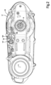
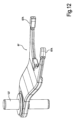
図1は、本発明によるトランスミッションユニットが適用され得る車両1、図示実施例ではスクータの側面図である。車両1は、サドル5を有するシャーシ3、一つ又は二つの前側操舵輪9の操舵を制御するハンドルバー7、後側駆動輪11及び車両が前方に進むために必要な機械的動力を発生させる吸熱エンジン13を備えている。符号15は、吸熱エンジンからの機械的動力を駆動輪11に伝達するトランスミッションユニットを全体的に示している。該トランスミッションユニットはケース17を備え、ケース17の中には、吸熱エンジン13から駆動輪11への動力の機械的トランスミッションと、吸熱エンジン13から駆動輪11への伝達比を変化させる装置、例えば無段変速機(略してCVT)が収容されている。
Figure 1 is a side view of a vehicle 1, in the illustrated embodiment a scooter, to which the transmission unit according to the present invention can be applied. The vehicle 1 includes a
図2及び図3は、ケース17の蓋18の外側及び内側を示す図である。符号A及びBは、各々、吸熱エンジン13のパワーテイクオフにスプライン接続された駆動プーリ(図示せず)の軸線、及び無段変速機の従動プーリ19(図5)の軸線を示している。無段変速機の特徴は、それ自体公知のタイプのものであり得、本明細書では詳細に説明しない。
2 and 3 show the outside and inside of the
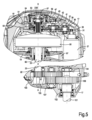
ケース17の内部には、逆転駆動用電動機21が収容されており、この電動機21は、全体を符号22で示すギアトランスミッションを介して、以下に詳細に説明する逆転駆動用制御ブッシュに運動を伝達する(図4)。逆転駆動用制御ブッシュは、図4に全体として符号24で示されている逆転駆動装置に係合するための機構又は装置の一部であり、以下に詳細に説明する。
The
逆転駆動装置に係合するための機構は、ギアトランスミッション22を駆動輪11のシャフト23(図4及び図5)に接続する。シャフト23の端部23Aは、端部軸受22(図5)によってケース17に支持されている。
The mechanism for engaging the reverse drive connects the
特に図3に示すように、逆転駆動用電動機21は、シャフト23に対して、軸線Aから軸線Bに向かって延びる主駆動装置(詳細は図示せず)とは反対側に取り付けられている。
As shown in FIG. 3 in particular, the
ケース17の蓋18の外側には、特に図13を参照して以下に詳細に説明する、逆転駆動装置の係合及び係合解除を制御するアクチュエータユニット25が適用されている。
An
図4には、逆転駆動用電動機21から係合機構24に運動を伝達するギアトランスミッション22が全体として示されている。ギアトランスミッション22を形成する個々のギアは図5により良く示されている。具体的には、逆転駆動用電動機21の出力軸31は、ケース17内に空転するように取り付けられた第一シャフト37にスプライン接続された第一ギア又はギアホイール35と噛み合うピニオン3を備えている。このシャフト37には第二ギア39がスプライン接続されており、第二ギア39は、ケース17内に空転するように取り付けられた第二シャフト42にスプライン接続されたギア41と噛み合い、第二シャフト42には第四ギア45がスプライン接続されている。第四ギア45は、逆転駆動装置係合機構24の制御ブッシュ47に回転運動を伝達する。制御ブッシュ47は、図6の断面にも示されており、制御ブッシュ47は図7の斜視図に図示されている。
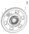
In FIG. 4, the
より詳細には、制御ブッシュ47は、ギア又はギアホイール45と噛み合うギアホイール49を備え、前記ギアホイール49は、円盤状体51の周縁部に形成されている。円盤状体51は、中央に孔が形成されており、円盤状本体51の一方の側面から突出する第一のほぼ円筒形の部分53と、円盤状本体51の反対側の側面から突出する第二のほぼ円筒形の部分55(図6参照)とを有している。前記部分53及び55は、円盤状体51と同軸である。ほぼ円筒状の部分53には、軸受57が取り付けられており、それにより、制御ブッシュ47が駆動輪11のシャフト23に支持されている。また、ケース17に形成された取付座と制御ブッシュ47のほぼ円筒状の部分53との間には、追加の軸受59が介在している。軸受57の内部には、駆動輪11のシャフト23の第二端部23Bが挿入されており、前記シャフト23が、端部23Aの軸受22(図5)だけでなく、端部23Bの軸受57及び59の組み合わせによっても、ケース17に回転可能に支持されているようにされている。
More specifically, the
図7に示すように、ほぼ円筒状の部分55は、制御ブッシュ47及びセレクタ61(図5及び図6参照)の間のねじり結合のためのスプラインプロファイル55Aを備え、セレクタ61は、以下でさらに明らかになるように、逆転駆動装置の係合及び係合解除のために利用される。セレクタ61は、図5及び図6では、取り付けられた状態で示されており、図11の斜視図では分離した状態で示されている。セレクタ61は、実質的に環状の形状を備え、制御ブッシュ47のスプラインプロファイル55Aに結合されるスプラインプロファイル61Aを有している。
7, the generally
特に図11及び図8に示すように、セレクタ61は、以下に詳細に説明される従動トランスミッションブッシュ63に取り付けられており、また、セレクタ61は、円周方向の溝65を有しており、この溝65には、以下に説明する方法で逆転駆動装置の係合及び係合解除を制御するために、アクチュエータユニット25に機能的に接続された制御フォーク67のプロング67Aが係合する。制御フォーク67は、図12の斜視図に分離した状態で示されている。
As shown particularly in Figures 11 and 8, the
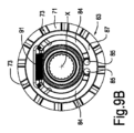
従動トランスミッションブッシュ63は、車両1が前方に移動している場合に逆転駆動装置の係合を防止する安全システムを形成する部材と共に、図10の斜視図に分離した状態で示されている。前記安全システムについては、以下に説明する。図8は、従動トランスミッションブッシュ63及びセレクタ61を、従動トランスミッションブッシュ63及びセレクタ61の回転軸線Xを含む平面に沿った断面で示している。特に図8及び図10に示すように、従動トランスミッションブッシュ63は、環状突起部71を備えた円盤状体69を備え、前記環状突起部71から前側傾歯73が突出しており、この前側歯73が係合歯を画定している。前側斜歯73は、特に図11で見ることができるセレクタ61と一体に形成された面取りされた前側歯75を備えた係合歯と共働し得る。前側歯75は、従動トランスミッションブッシュ63の方向を向いたセレクタ61の表面61Bから突出しており、そこから環状突起77も突出しており、前記突起は、セレクタ61の前側歯75が配置される直径よりも小さい直径を有している。特に図8の断面に示すように、環状突起は、セレクタ61の本体に形成された座部に設けられたリングによって形成され得る。
The driven
駆動トランスミッションブッシュ63は、ブッシュ79にスプライン接続されており、ブッシュ79の内部には、特に図8に示すように、スプラインプロファイル81が設けられている。取付時に、トランスミッションブッシュ63がスプライン接続されたブッシュ79は、駆動輪のシャフト23上に取り付けられる。ブッシュ79のスプラインプロファイル81は、駆動輪のシャフト23に形成された対応する溝付きプロファイル83と係合する。このようにして、従動トランスミッションブッシュ63、ブッシュ79、及び駆動輪11のシャフト23は、互いに同軸でねじり結合されて一体的に回転するようにされている。
The driven
従動トランスミッションブッシュ63は、車両1が進行方向に進んでいて、かつ、駆動輪11が所定の閾値よりも高い角速度で回転している時に、逆転駆動装置の係合を防止する安全システムに関連付けられている。図示の実施形態では、安全システムは、遠心システムである。要約すると、安全システムは、従動トランスミッションブッシュ63及び駆動輪11のシャフト23と一緒に回転する質量体を有している。シャフト23が閾値以上の速度で回転する場合には、遠心力が、従動トランスミッションブッシュ63及びシャフト23と共に、回転する質量体に作用して、回転軸線(軸線X)から離れた径方向の位置に配置させ、それにより、逆転駆動装置の係合が阻止されることになる。
The driven
より詳細には、本明細書に示される実施形態では、従動トランスミッションブッシュ63には、各関節ピン85を介して二つの質量体84が関節接続されている(特に図8、図9A、図9B参照)。例えば、質量体84は、特に図8,9A,9Bに示すように、アーチ状の形状を有し得、かつ、従動トランスミッションブッシュ63の環状シート87に収容され得る。環状シート87は、図9A及び図9Bに示す二つの位置の一方から他方への、ピン85を中心とした質量体84の揺動を可能にするのに十分な径方向の寸法を有する。より詳細には、図9Aでは、質量体は、回転軸線Xから最小距離の位置にある。質量体84が従動トランスミッションブッシュ63にピン85を介して関節接続されている端部とは反対側の質量体84の端部には、弾性部材91、例えば、ヘリカルトラクションスプリング91が固定され得る。前記弾性部材91は、最小エネルギの位置である図9Aの位置において、質量体84に応力を与える。質量体84が従動トランスミッションブッシュ63の軸線Xを中心に回転すると、質量体84が受ける遠心力により、質量体84が弾性部材91の弾性力に抗して、図9Aの位置から図9Bの位置に移動する。
More specifically, in the embodiment shown herein, two
駆動輪11のシャフト23には、可撓性連結部93を備えたクラッチがスプライン接続されており、このクラッチは、無段変速機の従動プーリ19がスプライン接続された中空シャフト95から入力される運動を受ける(特に図5参照)。符号97は、台形断面のベルトを示しており、このベルトは、無段変速機の駆動プーリ(図示せず)からの動きを受けて、従動プーリ19に伝達する。無段変速機によって与えられる回転運動は、車両1が進行方向前方に進まなければならない時に、可撓性連結部を備えたクラッチ93を介して駆動輪11のシャフト23に伝達される。
A clutch with a
図示の実施形態では、駆動輪11のシャフト23は、一連のギアを用いて駆動輪11の車軸101(図5参照)に機械的に連結されている。車軸101は、ベアリング102及び104によってケース17に支持されている。図示の実施形態では、シャフト23と車軸101との間の伝達機構は、シャフト23と一体の、又は、シャフト23と一体に形成された第一ギア101を有する。この第一ギア103は、ケース17内で空転するように取り付けられた中間シャフトにスプライン接続されたギア105と噛み合い、前記中間シャフトには、ギア107がスプライン接続されている。ギア107は、駆動輪11の車軸101にスプライン接続されたギア109と噛み合う。
In the illustrated embodiment, the
これまで説明してきたトランスミッションユニットの動作は以下の通りである。 The operation of the transmission unit described so far is as follows:
車両1の前進走行中、吸熱エンジン13は、駆動プーリ(図示せず)、ベルト97及び従動プーリ19からなる変速機を介して、後側駆動輪11に機械的な動力を供給する。その運動は、従動プーリ95から、中空シャフト95及び可撓性連結部を備えたクラッチ93を介して、シャフト23に伝達され、そこからギア103、105、107及び109を介して、駆動輪11の車軸101に伝達される。
When the vehicle 1 is moving forward, the
車両1の前進走行中は、逆転駆動装置は非動作状態である。制御フォーク67は後方位置にあり、その位置において、圧縮ばね111(図5及び図6)によって押圧されており、前記圧縮ばね111は制御フォーク67を矢印f67の方向に押圧する。この位置では、制御フォーク67は、セレクタ61を、図5及び図6に示す非作動位置に維持する。この非作動位置では、セレクタ61の前側歯75は、従動トランスミッションブッシュ63と一体の前側歯73と係合していない。従って、逆転駆動用電動機21のいかなる回転も、駆動輪11に影響を与えない。
When the vehicle 1 is moving forward, the reverse drive is inactive. The
車両1が前進走行すると、シャフト23の回転により、遠心質量体84が図9Bの拡大位置に維持される。この位置では、質量体84は、セレクタ61の従動トランスミッションブッシュ63への接近動作を阻止する。図9Bの拡大位置では、質量体84は、図8に詳細に示されているように、セレクタ61と一体の環状突起77の前方に位置する。セレクタ61の従動トランスミッションブッシュ63側への軸方向の移動は、質量体84が環状突起77と接触することで阻止される。このようにして、車両1の操作ミスや制御ユニットの故障により、セレクタ61が制御フォーク67を介して押し出されたとしても、そのような押し出しによって、前側歯73及び75の相互係合を引き起こすことはない。
When the vehicle 1 travels forward, the rotation of the
従って、逆転駆動装置は、車両1が動かない場合にのみ、あるいは、駆動輪11の車軸101、ひいては駆動輪11のシャフト23が、質量体84が図9Aに表される最小エネルギ位置にあるような低速(最低速度閾値)で回転する場合にのみ、係合することができる。
The reverse drive can therefore only be engaged when the vehicle 1 is stationary or when the
逆転駆動装置を係合させて車両1を後方に走行させるために、前方への走行動作が停止したら、制御フォーク67を矢印f67(図6)と反対の方向に移動させる。この移動は、圧縮バネ111の力に抗して、アクチュエータによって行われる。フォーク67の矢印f67と反対の方向への移動により、制御ブッシュ47、従動トランスミッションブッシュ63、及びセレクタ61の回転軸線と一致する、駆動輪11のシャフト23の回転軸線Xに平行なセレクタ61の軸方向のスライドが生じる。セレクタ61のスプラインプロファイル61Aと制御ブッシュ47のスプラインプロファイル55Aとの間の結合により、摺動が許容される。
To engage the reverse drive and drive the vehicle 1 backwards, once forward travel has ceased, the
この軸線方向の動きにより、セレクタ61の前側歯75は、従動トランスミッションブッシュ63の前側歯73と係合する。
This axial movement causes the
セレクタ61の従動トランスミッションブッシュ63への軸方向の変位が行われると、逆転駆動用電動機21が作動され得る。これにより、ギア33,35,39及び41を介して制御ブッシュ47が回転駆動される。スプラインプロファイル55A及び61A間の連結により、セレクタ61に運動が伝達され、前側歯75と前側歯73との間の連結により、従動トランスミッションブッシュ63に回転運動を伝達される。従動トランスミッションブッシュ63は、スプラインプロファイル81をシャフト23の溝付きプロファイル83に噛合わせることによって、回転運動を駆動輪11のシャフト23に伝達する。そして、シャフト23は、一連のギア103,105,107及び109並びに車軸101を介して、駆動輪11に運動を伝達する。
When the
例えば、車両を駐車するために、所望のリバース走行が完了すると、逆転駆動用電動機21は停止され得、かつ、セレクタ61が後方に移動され得、逆転駆動装置と係合したアクチュエータを停止させた後に、圧縮ばね111による押圧効果により、制御フォーク67が非係合位置に持って行かれる。
When the desired reverse travel is completed, for example to park the vehicle, the
逆転駆動中に従動トランスミッションブッシュ63の回転速度がセレクタ61及び制御ブッシュ47の回転速度よりも大きくなった場合、前側係合歯75及び73の面取りされた形状により、従動トランスミッションブッシュ63がセレクタ61を回転で追い越すことができ、上述した逆転駆動装置の構成要素が破損する危険性を回避することができる。
If the rotational speed of the driven
制御フォーク67の動きを制御するために、図2に示すように、好ましくはケース17の外側に取り付けられたアクチュエータユニット25が設けられる。また、アクチュエータユニット25は、図13の等角図において、ケース17から分離して示されている。
To control the movement of the
図示された実施形態では、アクチュエータユニット25は、アクチュエータ121、好ましくはリニアアクチュエータ、即ち、並進軸線に従って移動可能な要素を有するアクチュエータを備えている。例えば、アクチュエータ121は、可動式アンカー121Aを有するソレノイドアクチュエータとすることができる。アクチュエータ121は、ケース17と一体のプレート128に取り付けられることができる。アクチュエータ121は、プレート128と一体であり、ひいてはケース17と一体であるピン126を中心に回動するレバー125の第一端部125Aに作用する。回転ピン126は、レバー125の端部125A及び125Bの間の中間位置に位置する。これらの端部は、レバー125とアクチュエータ121との間の拘束、及び、レバー125とフォーク67との間の拘束を規定する。ソレノイドアクチュエータ121の可動アンカー121Aの矢印f121(図13)に従った動きにより、ピン126を中心としたレバー125の揺動と、それに対応するレバー125の第二端部125Bの矢印f125に従った動きが生じる。レバー125の第二端部125Bは、制御フォーク67と一体のピン又はステム127(図12及び図6参照)を押圧する。
In the illustrated embodiment, the
有利な実施形態では、ステム又はピン127は、制御フォーク67の本体と実質的に直交しており、前記本体が二つのプロング67Aを形成している。特に有利な実施形態では、ピン127の軸線は、シャフト23の軸線と平行である。
In an advantageous embodiment, the stem or
ピン127の軸線は、フォークの並進方向を規定し、好ましくは、シャフト23、制御ブッシュ47、セレクタ61、及び従動トランスミッションブッシュ63の回転軸線と平行である。さらに、ピン127の軸線は、好ましくは、アクチュエータ121の可動アンカー121Aの軸線と平行であり、かつ、そこから離れており(即ち、同軸ではなく)、即ち、アクチュエータ121の運動軸線と平行である。この制御フォーク67及びアクチュエータ121の特定の平行配置により、アクチュエータが制御フォーク67のステム127に対して同軸で、且つ、頭部に設けられている実施形態に関しては、モータセットの全体的な嵩を最適化することができる。
The axis of the
実質的に、ソレノイドアクチュエータ121は、増強レバー125を介して、制御フォーク67を圧縮ばね111の力に抗してアクティブな位置に押すように構成されている。
Essentially, the
逆転駆動装置の安全性を高めるために、アクチュエータ及びレバー67の位置を感知できる安全センサが設けられ得る。例えば、レバー125が設けられている場合には,センサ123はレバー125に関連付けられ得、レバー自体の実際の位置,ひいては逆転駆動装置の実際の(係合又は係合解除)位置を検出することができる。センサ123は、例えば、中央電子制御ユニットと連動させることができ、この中央電子制御ユニットは、レバー125が逆転駆動装置を係合解除する位置にある時にのみ、車両1の前方走行に許可を与えるように構成され得る。また、センサ123は、逆転駆動用電動機21の始動を許可する信号を出力することができる。当該許可は、中央制御ユニット(図示せず)が、制御フォーク67を介してセレクタ61の係合完了の信号をセンサ123から受け取った場合にのみ行われる。好ましくは、センサ123は、コントロールフォーク67及びアクチュエータが配置されているレバー125の同じ側に配置され、その軸線はコントロールフォーク67及びアクチュエーの一方と平行である。言い換えれば、例えば図2及び図13に示すように、アクチュエータ121、センサ123及び制御フォーク67に関連するステム127は、ケース17の内部に向けられたフォークの側部に配置されている。制御フォーク67、アクチュエータ121及びセンサ123のこの特定の配置により、制御ブッシュ47の作動ユニットをコンパクトにすることができ、車両の横方向の嵩を最小化することができる。
To increase the safety of the reverse drive, a safety sensor can be provided that can sense the position of the actuator and the
アクチュエータ121及び制御フォーク67間に配置された増強レバー125を使用することにより、アクチュエータ121から必要とされる力を低減することができ、従って、アクチュエータのコスト及び寸法を低減することができる。
By using an
Claims (23)
前進駆動を制御するためにメインドライブ(19,97)に動作可能に接続される駆動輪のシャフト(23)と、
逆転駆動用電動機(21)と、
逆転駆動用電動機(21)によって回転される制御ブッシュ(47)と、
駆動輪のシャフト(23)に動作可能に接続される従動トランスミッションブッシュ(63)と、
前記制御ブッシュ(47)と前記従動トランスミッションブッシュ(63)との間の相互結合を制御して、前記逆転駆動用電動機(21)の運動を前記駆動輪のシャフト(23)に伝達するためのアクチュエータ(121)とを備えており、
制御ブッシュ(47)及び従動トランスミッションブッシュ(63)が、駆動輪のシャフト(23)と同軸であり、逆転駆動時に回転軸線(X)を中心にシャフト(23)と一緒に回転し、
前記無段変速装置が、前記駆動輪のシャフト(23)と同軸であり、周囲に前記無段変速装置の伝動ベルト(97)が案内される、従動プーリ(19)を備えている、
ことを特徴とするトランスミッションユニット。 A transmission unit (15) for a vehicle (1) having a continuously variable transmission,
a drive wheel shaft (23) operatively connected to the main drive (19, 97) for controlling forward drive;
A reverse drive motor (21);
a control bush (47) rotated by a reverse drive motor (21);
a driven transmission bushing (63) operatively connected to the drive wheel shaft (23);
an actuator (121) for controlling the mutual coupling between the control bush (47) and the driven transmission bush (63) to transmit the motion of the reverse drive motor (21) to the drive wheel shaft (23) ;
The control bush (47) and the driven transmission bush (63) are coaxial with the shaft (23) of the drive wheel and rotate together with the shaft (23) about the rotation axis (X) during reverse drive;
The continuously variable transmission comprises a driven pulley (19) coaxial with the shaft (23) of the drive wheel and around which the transmission belt (97) of the continuously variable transmission is guided .
A transmission unit characterized by:
ことを特徴とする請求項1に記載のトランスミッションユニット。2. A transmission unit according to claim 1 .
ことを特徴とする請求項1又は2に記載のトランスミッションユニット。3. A transmission unit according to claim 1 or 2.
従動トランスミッションブッシュ(63)が、駆動輪のシャフト(23)にねじり結合され、A driven transmission bush (63) is torsionally connected to the drive wheel shaft (23),
制御ブッシュ(47)が、駆動輪のシャフト(23)に対して空転可能に取り付けられ、A control bush (47) is attached to the drive wheel shaft (23) so as to be free to rotate;
可動式のセレクタ(61)が、制御ブッシュ(47)にねじり結合され、アクチュエータ(121)の制御下で制御ブッシュ(47)に対して軸線方向に移動可能であり、従動トランスミッションブッシュ(63)に対して係合した位置と従動トランスミッションブッシュ(63)との係合解除した位置とをとるようにされ、a movable selector (61) is torsionally coupled to the control bushing (47) and is axially movable relative to the control bushing (47) under the control of an actuator (121) to assume an engaged position relative to the driven transmission bushing (63) and a disengaged position relative to the driven transmission bushing (63);
セレクタ(61)と従動トランスミッションブッシュ(63)との間には係合歯(75;73)が設けられているEngagement teeth (75; 73) are provided between the selector (61) and the driven transmission bush (63).
ことを特徴とする請求項1に記載のトランスミッションユニット。2. A transmission unit according to claim 1 .
弾性部材(91)が、前記少なくとも一つの遠心質量体(84)を第一径方向位置に偏らせるように適合されており、a resilient member (91) adapted to bias the at least one centrifugal mass (84) toward a first radial position;
前記少なくとも一つの遠心質量体(84)が第二径方向位置にある時に、前記遠心質量体が、セレクタ(61)及び従動トランスミッションブッシュ(63)の係合歯(75;73)間に位置し、前記係合歯形の相互係合を防止するWhen the at least one centrifugal mass (84) is in the second radial position, the centrifugal mass is located between the engagement teeth (75; 73) of the selector (61) and the driven transmission bush (63) to prevent mutual engagement of the engagement teeth profiles.
ことを特徴とする請求項4に記載のトランスミッションユニット。5. A transmission unit according to claim 4.
セレクタ(61)が制御ブッシュ(47)にのみねじり結合されている、従動トランスミッションブッシュ(63)から係合解除された第一位置と、a first position in which the selector (61) is disengaged from the driven transmission bushing (63) and is torsionally coupled only to the control bushing (47);
セレクタ(61)が制御ブッシュ(43)及び従動トランスミッションブッシュ(63)にねじり結合され、制御ブッシュ(47)から従動トランスミッションブッシュ(63)にトルクを伝達する、従動トランスミッションブッシュ(63)に係合している第二位置とa second position in which the selector (61) is torsionally coupled to the control bush (43) and the driven transmission bush (63) and transmits torque from the control bush (47) to the driven transmission bush (63) and engages the driven transmission bush (63);
をとるように構成されているIt is configured to take
ことを特徴とする請求項3に記載のトランスミッションユニット。4. A transmission unit according to claim 3.
好ましくは、前記第一係合歯及び第二係合歯のそれぞれが、各前側係合歯を備えているPreferably, each of the first and second engagement teeth includes a respective front engagement tooth.
ことを特徴とする請求項3又は6に記載のトランスミッションユニット。7. A transmission unit according to claim 3 or 6.
ことを特徴とする請求項7に記載のトランスミッションユニット。8. A transmission unit according to claim 7.
ことを特徴とする請求項1~8の何れか一項に記載のトランスミッションユニット。A transmission unit according to any one of claims 1 to 8.
前記拡大位置において、遠心質量体(84)が逆転駆動装置の作動を防止するIn said expanded position, the centrifugal mass (84) prevents operation of the reverse drive.
ことを特徴とする請求項9に記載のトランスミッションユニット。10. A transmission unit as claimed in claim 9.
ことを特徴とする請求項9に記載のトランスミッションユニット。10. A transmission unit as claimed in claim 9.
弾性部材(91)が、遠心質量体(84)を第一径方向位置に戻すように構成され、かつ、a resilient member (91) configured to return the centrifugal mass (84) to the first radial position; and
遠心質量体(84)が第二径方向位置にある時に、セレクタ(61)の従動トランスミッションブッシュ(63)への係合が防止されるように構成されているThe centrifugal mass (84) is configured to prevent engagement of the selector (61) with the driven transmission bush (63) when the centrifugal mass (84) is in the second radial position.
ことを特徴とする請求項11に記載のトランスミッションユニット。12. A transmission unit according to claim 11, characterized in that
ことを特徴とする請求項3~12の何れか一項に記載のトランスミッションユニット。A transmission unit according to any one of claims 3 to 12.
ことを特徴とする請求項13に記載のトランスミッションユニット。14. A transmission unit according to claim 13, characterized in that
アクチュエータ(121)が、フォーク(67)に軸方向の動きを与えるように適合されているAn actuator (121) is adapted to impart axial movement to the fork (67).
ことを特徴とする請求項13又は14に記載のトランスミッションユニット。15. A transmission unit according to claim 13 or 14.
前記関節ピン(126)が、好ましくは、レバー(125)のアクチュエータ(121)に対する第一拘束位置(125A)と、レバー(125)のフォーク(67)に対する第二拘束位置(125B)との間の中間位置に配置されているThe articulation pin (126) is preferably disposed at an intermediate position between a first restraining position (125A) of the lever (125) relative to the actuator (121) and a second restraining position (125B) of the lever (125) relative to the fork (67).
ことを特徴とする請求項13~15の何れか一項に記載のトランスミッションユニット。A transmission unit according to any one of claims 13 to 15.
ことを特徴とする請求項16に記載のトランスミッションユニット。17. A transmission unit according to claim 16, characterized in that
ことを特徴とする請求項1~17の何れか一項に記載のトランスミッションユニット。A transmission unit according to any one of the preceding claims.
ことを特徴とする請求項1~18の何れか一項に記載のトランスミッションユニット。A transmission unit according to any one of the preceding claims.
ことを特徴とする請求項1~19の何れか一項に記載のトランスミッションユニット。A transmission unit according to any one of the preceding claims.
好ましくは駆動輪のシャフト(23)と車軸(101)とが互いに平行であるPreferably the drive wheel shaft (23) and the axle (101) are parallel to each other.
ことを特徴とする請求項1~20の何れか一項に記載のトランスミッションユニット。A transmission unit according to any one of the preceding claims.
可能性連結部(93)の出力部が駆動輪のシャフト(23)に機械的に結合されているThe output of the movable coupling (93) is mechanically coupled to the shaft (23) of the drive wheel.
ことを特徴とする請求項1~21の何れか一項に記載のトランスミッションユニット。A transmission unit according to any one of the preceding claims.
Applications Claiming Priority (3)
| Application Number | Priority Date | Filing Date | Title |
|---|---|---|---|
| IT102018000009928 | 2018-10-30 | ||
| IT102018000009928A IT201800009928A1 (en) | 2018-10-30 | 2018-10-30 | TRANSMISSION UNIT FOR MOTOR VEHICLES WITH REVERSE GEAR AND MOTOR VEHICLE INCLUDING THE TRANSMISSION UNIT |
| PCT/IB2019/059214 WO2020089766A1 (en) | 2018-10-30 | 2019-10-28 | Transmission unit for motor vehicles with reverse drive and motor vehicle comprising the transmission unit |
Publications (2)
| Publication Number | Publication Date |
|---|---|
| JP2022510106A JP2022510106A (en) | 2022-01-26 |
| JP7515472B2 true JP7515472B2 (en) | 2024-07-12 |
Family
ID=65031739
Family Applications (1)
| Application Number | Title | Priority Date | Filing Date |
|---|---|---|---|
| JP2021523427A Active JP7515472B2 (en) | 2018-10-30 | 2019-10-28 | Vehicle transmission unit equipped with reverse drive device and vehicle equipped with said transmission unit |
Country Status (9)
| Country | Link |
|---|---|
| US (1) | US12208853B2 (en) |
| EP (1) | EP3874181B1 (en) |
| JP (1) | JP7515472B2 (en) |
| CN (1) | CN113167378B (en) |
| ES (1) | ES2981391T3 (en) |
| IL (1) | IL282604B2 (en) |
| IT (1) | IT201800009928A1 (en) |
| TW (1) | TWI828787B (en) |
| WO (1) | WO2020089766A1 (en) |
Families Citing this family (1)
| Publication number | Priority date | Publication date | Assignee | Title |
|---|---|---|---|---|
| US12398786B2 (en) * | 2023-06-07 | 2025-08-26 | Harley-Davidson Motor Company, Inc. | Reverse drive system for a motorized vehicle |
Citations (3)
| Publication number | Priority date | Publication date | Assignee | Title |
|---|---|---|---|---|
| CN1583499A (en) | 2004-05-27 | 2005-02-23 | 胡可怀 | Reverse gear device of motorcycle |
| JP2014108636A (en) | 2012-11-30 | 2014-06-12 | Honda Motor Co Ltd | Vehicle reversing device |
| JP2014152832A (en) | 2013-02-06 | 2014-08-25 | Yamaha Motor Co Ltd | Belt type electronic control non-stage transmission and vehicle including the same |
Family Cites Families (17)
| Publication number | Priority date | Publication date | Assignee | Title |
|---|---|---|---|---|
| US1822673A (en) * | 1928-02-08 | 1931-09-08 | Freiherr Iwan Von Stieteneron | Starting apparatus for motor vehicles with internal combustion engines |
| DE1430222C3 (en) * | 1961-11-02 | 1975-07-03 | Hermann 7742 St. Georgen Papst | Motor vehicle |
| US4410071A (en) * | 1981-02-05 | 1983-10-18 | Osterman Daniel R | Vehicle transmission |
| JPS62178493A (en) * | 1986-01-31 | 1987-08-05 | 本田技研工業株式会社 | Backing drive for minicar |
| US4763538A (en) * | 1985-12-04 | 1988-08-16 | Honda Giken Kogyo Kabushiki Kaisha | Reverse drive for small vehicles |
| JPS63232092A (en) | 1987-03-20 | 1988-09-28 | 本田技研工業株式会社 | Reversing device for motorcycles |
| DE4135215A1 (en) * | 1991-10-25 | 1993-04-29 | Zahnradfabrik Friedrichshafen | Synchroniser for gearwheel switch gears - has centrifugal force locking members and acoustic signal warning driver of developing faulty switching |
| JP3918977B2 (en) * | 2000-03-10 | 2007-05-23 | 本田技研工業株式会社 | Vehicle reverse device |
| WO2005077694A1 (en) * | 2004-02-11 | 2005-08-25 | Avl List Gmbh | Snow mobile |
| JP4840135B2 (en) * | 2006-12-30 | 2011-12-21 | トヨタ自動車株式会社 | Control device for vehicle drive device |
| US8919479B1 (en) * | 2007-07-25 | 2014-12-30 | Polaris Industries Inc. | Mechanism for propelling a vehicle |
| JP5029511B2 (en) * | 2008-06-25 | 2012-09-19 | 日産自動車株式会社 | Manual transmission clutch rotation synchronization control device |
| JP5373678B2 (en) * | 2010-03-18 | 2013-12-18 | 本田技研工業株式会社 | Shift control device for saddle riding type vehicle |
| CN103108525A (en) * | 2011-11-15 | 2013-05-15 | 鸿富锦精密工业(深圳)有限公司 | Heat pipe combination |
| JP5948845B2 (en) * | 2011-12-15 | 2016-07-06 | アイシン精機株式会社 | Vehicle drive device |
| JP5860380B2 (en) * | 2012-10-30 | 2016-02-16 | ヤンマー株式会社 | Shift operation mechanism and work vehicle |
| DE102013205829A1 (en) | 2013-04-03 | 2014-10-09 | Bayerische Motoren Werke Aktiengesellschaft | Routing device for vehicles |
-
2018
- 2018-10-30 IT IT102018000009928A patent/IT201800009928A1/en unknown
-
2019
- 2019-10-28 US US17/288,421 patent/US12208853B2/en active Active
- 2019-10-28 IL IL282604A patent/IL282604B2/en unknown
- 2019-10-28 EP EP19794703.9A patent/EP3874181B1/en active Active
- 2019-10-28 CN CN201980076595.XA patent/CN113167378B/en active Active
- 2019-10-28 JP JP2021523427A patent/JP7515472B2/en active Active
- 2019-10-28 ES ES19794703T patent/ES2981391T3/en active Active
- 2019-10-28 WO PCT/IB2019/059214 patent/WO2020089766A1/en not_active Ceased
- 2019-10-30 TW TW108139246A patent/TWI828787B/en active
Patent Citations (3)
| Publication number | Priority date | Publication date | Assignee | Title |
|---|---|---|---|---|
| CN1583499A (en) | 2004-05-27 | 2005-02-23 | 胡可怀 | Reverse gear device of motorcycle |
| JP2014108636A (en) | 2012-11-30 | 2014-06-12 | Honda Motor Co Ltd | Vehicle reversing device |
| JP2014152832A (en) | 2013-02-06 | 2014-08-25 | Yamaha Motor Co Ltd | Belt type electronic control non-stage transmission and vehicle including the same |
Also Published As
| Publication number | Publication date |
|---|---|
| CN113167378B (en) | 2023-04-28 |
| EP3874181C0 (en) | 2024-02-21 |
| WO2020089766A1 (en) | 2020-05-07 |
| ES2981391T3 (en) | 2024-10-08 |
| IL282604A (en) | 2021-06-30 |
| IL282604B2 (en) | 2025-03-01 |
| TWI828787B (en) | 2024-01-11 |
| US20210380200A1 (en) | 2021-12-09 |
| IL282604B1 (en) | 2024-11-01 |
| EP3874181A1 (en) | 2021-09-08 |
| EP3874181B1 (en) | 2024-02-21 |
| TW202028023A (en) | 2020-08-01 |
| JP2022510106A (en) | 2022-01-26 |
| CN113167378A (en) | 2021-07-23 |
| US12208853B2 (en) | 2025-01-28 |
| IT201800009928A1 (en) | 2020-04-30 |
Similar Documents
| Publication | Publication Date | Title |
|---|---|---|
| US6450915B1 (en) | Driving force transmitting device for vehicle | |
| CN103596794B (en) | Power transmission unit | |
| US8721493B2 (en) | Drive train for a motor vehicle | |
| JP6418218B2 (en) | Differential limiting device for vehicle | |
| CN103182934A (en) | Power switching device for vehicles | |
| KR20140015457A (en) | Seletable grounded gear linear actuation | |
| US6941833B2 (en) | Shift assembly for a single fork shift assembly | |
| JP7515472B2 (en) | Vehicle transmission unit equipped with reverse drive device and vehicle equipped with said transmission unit | |
| JP4883128B2 (en) | Front differential device for vehicles | |
| KR102868346B1 (en) | Electric drive module with transmission having parallel twin gear pairs sharing load to a final drive gear | |
| JP2007333133A (en) | Differential device | |
| JP7379696B2 (en) | Hybrid drive assembly, powertrain assembly and how to control the powertrain | |
| RU2785899C1 (en) | Electric power steering | |
| JP2004299476A (en) | Driving force switching mechanism | |
| JP2004324776A (en) | Torque transmission coupling | |
| JP5367624B2 (en) | Vehicle transfer | |
| JPH05330433A (en) | Drive | |
| CN118049473A (en) | Drive unit | |
| JP2019019950A (en) | Differential limit device of differential gear device for vehicle | |
| JPH01309823A (en) | Front axle device of four-wheel drive tractor | |
| JP2005155681A (en) | Torque transmission coupling | |
| JP2011126378A (en) | Transfer of vehicle | |
| JPH0745897B2 (en) | Gear change device |
Legal Events
| Date | Code | Title | Description |
|---|---|---|---|
| A521 | Request for written amendment filed |
Free format text: JAPANESE INTERMEDIATE CODE: A523 Effective date: 20210913 |
|
| A621 | Written request for application examination |
Free format text: JAPANESE INTERMEDIATE CODE: A621 Effective date: 20220815 |
|
| A131 | Notification of reasons for refusal |
Free format text: JAPANESE INTERMEDIATE CODE: A131 Effective date: 20231018 |
|
| A601 | Written request for extension of time |
Free format text: JAPANESE INTERMEDIATE CODE: A601 Effective date: 20240118 |
|
| A521 | Request for written amendment filed |
Free format text: JAPANESE INTERMEDIATE CODE: A523 Effective date: 20240318 |
|
| TRDD | Decision of grant or rejection written | ||
| A01 | Written decision to grant a patent or to grant a registration (utility model) |
Free format text: JAPANESE INTERMEDIATE CODE: A01 Effective date: 20240605 |
|
| A61 | First payment of annual fees (during grant procedure) |
Free format text: JAPANESE INTERMEDIATE CODE: A61 Effective date: 20240702 |
|
| R150 | Certificate of patent or registration of utility model |
Ref document number: 7515472 Country of ref document: JP Free format text: JAPANESE INTERMEDIATE CODE: R150 |