JP7508317B2 - Embolic coil proximal connecting element and stretch-resistant fiber - Google Patents
Embolic coil proximal connecting element and stretch-resistant fiber Download PDFInfo
- Publication number
- JP7508317B2 JP7508317B2 JP2020155306A JP2020155306A JP7508317B2 JP 7508317 B2 JP7508317 B2 JP 7508317B2 JP 2020155306 A JP2020155306 A JP 2020155306A JP 2020155306 A JP2020155306 A JP 2020155306A JP 7508317 B2 JP7508317 B2 JP 7508317B2
- Authority
- JP
- Japan
- Prior art keywords
- embolic coil
- opening
- embolic
- lumen
- stretch
- Prior art date
- Legal status (The legal status is an assumption and is not a legal conclusion. Google has not performed a legal analysis and makes no representation as to the accuracy of the status listed.)
- Active
Links
- 230000003073 embolic effect Effects 0.000 title claims description 205
- 239000000835 fiber Substances 0.000 title claims description 104
- 239000007943 implant Substances 0.000 claims description 119
- 238000000034 method Methods 0.000 claims description 30
- 238000000926 separation method Methods 0.000 claims description 15
- 238000004804 winding Methods 0.000 claims description 15
- 239000000463 material Substances 0.000 claims description 14
- 238000005520 cutting process Methods 0.000 claims description 12
- 238000003466 welding Methods 0.000 claims description 2
- 206010002329 Aneurysm Diseases 0.000 description 36
- 238000011282 treatment Methods 0.000 description 15
- 238000005452 bending Methods 0.000 description 6
- 230000002028 premature Effects 0.000 description 5
- 230000017531 blood circulation Effects 0.000 description 4
- 230000000694 effects Effects 0.000 description 4
- 238000002513 implantation Methods 0.000 description 4
- 238000004519 manufacturing process Methods 0.000 description 4
- 230000009977 dual effect Effects 0.000 description 3
- 230000001732 thrombotic effect Effects 0.000 description 3
- 238000004873 anchoring Methods 0.000 description 2
- 238000010586 diagram Methods 0.000 description 2
- 230000005012 migration Effects 0.000 description 2
- 238000013508 migration Methods 0.000 description 2
- 238000012986 modification Methods 0.000 description 2
- 230000004048 modification Effects 0.000 description 2
- 230000008569 process Effects 0.000 description 2
- 206010020565 Hyperaemia Diseases 0.000 description 1
- 230000008901 benefit Effects 0.000 description 1
- 230000015572 biosynthetic process Effects 0.000 description 1
- 230000023555 blood coagulation Effects 0.000 description 1
- 210000004204 blood vessel Anatomy 0.000 description 1
- 230000035602 clotting Effects 0.000 description 1
- 230000001627 detrimental effect Effects 0.000 description 1
- 238000000605 extraction Methods 0.000 description 1
- 230000007246 mechanism Effects 0.000 description 1
- 238000012856 packing Methods 0.000 description 1
- 238000002360 preparation method Methods 0.000 description 1
- 210000005166 vasculature Anatomy 0.000 description 1
- 230000009724 venous congestion Effects 0.000 description 1
Images


Classifications
-
- A—HUMAN NECESSITIES
- A61—MEDICAL OR VETERINARY SCIENCE; HYGIENE
- A61B—DIAGNOSIS; SURGERY; IDENTIFICATION
- A61B17/00—Surgical instruments, devices or methods
- A61B17/12—Surgical instruments, devices or methods for ligaturing or otherwise compressing tubular parts of the body, e.g. blood vessels or umbilical cord
- A61B17/12022—Occluding by internal devices, e.g. balloons or releasable wires
- A61B17/12131—Occluding by internal devices, e.g. balloons or releasable wires characterised by the type of occluding device
- A61B17/1214—Coils or wires
-
- A—HUMAN NECESSITIES
- A61—MEDICAL OR VETERINARY SCIENCE; HYGIENE
- A61B—DIAGNOSIS; SURGERY; IDENTIFICATION
- A61B17/00—Surgical instruments, devices or methods
- A61B17/12—Surgical instruments, devices or methods for ligaturing or otherwise compressing tubular parts of the body, e.g. blood vessels or umbilical cord
- A61B17/12022—Occluding by internal devices, e.g. balloons or releasable wires
- A61B17/12099—Occluding by internal devices, e.g. balloons or releasable wires characterised by the location of the occluder
- A61B17/12109—Occluding by internal devices, e.g. balloons or releasable wires characterised by the location of the occluder in a blood vessel
- A61B17/12113—Occluding by internal devices, e.g. balloons or releasable wires characterised by the location of the occluder in a blood vessel within an aneurysm
-
- A—HUMAN NECESSITIES
- A61—MEDICAL OR VETERINARY SCIENCE; HYGIENE
- A61B—DIAGNOSIS; SURGERY; IDENTIFICATION
- A61B17/00—Surgical instruments, devices or methods
- A61B17/12—Surgical instruments, devices or methods for ligaturing or otherwise compressing tubular parts of the body, e.g. blood vessels or umbilical cord
- A61B17/12022—Occluding by internal devices, e.g. balloons or releasable wires
- A61B17/12131—Occluding by internal devices, e.g. balloons or releasable wires characterised by the type of occluding device
- A61B17/1214—Coils or wires
- A61B17/1215—Coils or wires comprising additional materials, e.g. thrombogenic, having filaments, having fibers, being coated
-
- A—HUMAN NECESSITIES
- A61—MEDICAL OR VETERINARY SCIENCE; HYGIENE
- A61B—DIAGNOSIS; SURGERY; IDENTIFICATION
- A61B17/00—Surgical instruments, devices or methods
- A61B17/12—Surgical instruments, devices or methods for ligaturing or otherwise compressing tubular parts of the body, e.g. blood vessels or umbilical cord
- A61B17/12022—Occluding by internal devices, e.g. balloons or releasable wires
- A61B17/12131—Occluding by internal devices, e.g. balloons or releasable wires characterised by the type of occluding device
- A61B17/1214—Coils or wires
- A61B17/12154—Coils or wires having stretch limiting means
-
- A—HUMAN NECESSITIES
- A61—MEDICAL OR VETERINARY SCIENCE; HYGIENE
- A61B—DIAGNOSIS; SURGERY; IDENTIFICATION
- A61B17/00—Surgical instruments, devices or methods
- A61B2017/00477—Coupling
-
- A—HUMAN NECESSITIES
- A61—MEDICAL OR VETERINARY SCIENCE; HYGIENE
- A61B—DIAGNOSIS; SURGERY; IDENTIFICATION
- A61B17/00—Surgical instruments, devices or methods
- A61B2017/00526—Methods of manufacturing
-
- A—HUMAN NECESSITIES
- A61—MEDICAL OR VETERINARY SCIENCE; HYGIENE
- A61B—DIAGNOSIS; SURGERY; IDENTIFICATION
- A61B17/00—Surgical instruments, devices or methods
- A61B2017/00831—Material properties
- A61B2017/00902—Material properties transparent or translucent
- A61B2017/00915—Material properties transparent or translucent for radioactive radiation
- A61B2017/0092—Material properties transparent or translucent for radioactive radiation for X-rays
-
- A—HUMAN NECESSITIES
- A61—MEDICAL OR VETERINARY SCIENCE; HYGIENE
- A61B—DIAGNOSIS; SURGERY; IDENTIFICATION
- A61B17/00—Surgical instruments, devices or methods
- A61B17/12—Surgical instruments, devices or methods for ligaturing or otherwise compressing tubular parts of the body, e.g. blood vessels or umbilical cord
- A61B17/12022—Occluding by internal devices, e.g. balloons or releasable wires
- A61B2017/1205—Introduction devices
- A61B2017/12054—Details concerning the detachment of the occluding device from the introduction device
Landscapes
- Health & Medical Sciences (AREA)
- Surgery (AREA)
- Life Sciences & Earth Sciences (AREA)
- Heart & Thoracic Surgery (AREA)
- Molecular Biology (AREA)
- Vascular Medicine (AREA)
- Engineering & Computer Science (AREA)
- Biomedical Technology (AREA)
- Reproductive Health (AREA)
- Medical Informatics (AREA)
- Nuclear Medicine, Radiotherapy & Molecular Imaging (AREA)
- Animal Behavior & Ethology (AREA)
- General Health & Medical Sciences (AREA)
- Public Health (AREA)
- Veterinary Medicine (AREA)
- Neurosurgery (AREA)
- Surgical Instruments (AREA)
Description
本発明は、概して、移植可能な医療用装置に関し、より具体的には、移植可能な医療用装置を送達システムに機械的に解放可能に固設するための係合特徴部に関する。 The present invention relates generally to implantable medical devices, and more specifically to engagement features for releasably mechanically securing an implantable medical device to a delivery system.
動脈瘤は、動脈瘤に治療装置を送達して動脈瘤の嚢を塞栓材料で装填し、かつ/又は動脈瘤の頸部を遮断して動脈瘤への血流を抑制することによって血管内治療することができる。動脈瘤嚢を装填するときに、塞栓材料が、血液凝固を促して、動脈瘤内に血栓腫瘤を作り出す場合がある。実質的に動脈瘤嚢を装填することなく、動脈瘤頸部を治療する場合、動脈瘤頸部への血流を抑制して、動脈瘤内の静脈うっ血を誘発し、動脈瘤内での血栓腫瘤の自然な形成を容易にすることができる。 Aneurysms can be treated endovascularly by delivering a treatment device to the aneurysm to load the aneurysm's sac with embolic material and/or block the aneurysm's neck to inhibit blood flow to the aneurysm. When loading the aneurysm's sac, the embolic material may promote blood clotting to create a thrombotic mass within the aneurysm. When treating the aneurysm's neck without substantially loading the aneurysm's sac, blood flow to the aneurysm's neck can be inhibited to induce venous congestion within the aneurysm and facilitate the natural formation of a thrombotic mass within the aneurysm.
いくつかの現在の治療では、動脈瘤嚢を装填するか、又は動脈瘤頸部の入口を治療するかのいずれかに複数の塞栓コイルが使用される。塞栓コイル治療の間の一般的な課題は、移植されたコイル及び部分的に移植されたコイルの移植された部分が絡まり、再位置決めが困難となることである。場合によっては、医師は、部分的に移植されたコイルを後退させることができない場合があり、理想的ではない場所にコイルを位置決めするように強いられる場合がある。動脈瘤頸部に不適切に位置決めされる塞栓コイルは、特に、入口及び/又は嚢が過剰に充填されている場合、血管に接合する際に、血液の流れを妨害するという有害作用を潜在的に有し得る。非理想的に移植されたコイルの一部分が取り除かれると、当該部分が、隣接する血管に入り、血塊形成を促す場合があり、最終的に、動脈瘤に繋留され、ひいては、治療が非常に困難な閉塞を引き起こす可能性がある。反対に、入口及び/又は嚢が十分に充填されていない場合、血流が動脈瘤内に残留する可能性がある。 In some current treatments, multiple embolic coils are used to either load the aneurysm sac or treat the ostium of the aneurysm neck. A common challenge during embolic coil treatment is that the implanted coils and the implanted portions of the partially implanted coils become tangled, making repositioning difficult. In some cases, the physician may not be able to retract the partially implanted coil and may be forced to position the coil in a non-ideal location. An embolic coil that is improperly positioned at the aneurysm neck can potentially have the detrimental effect of obstructing blood flow as it interfaces with the vessel, especially if the ostium and/or sac are overfilled. If a portion of a non-ideally implanted coil becomes dislodged, it may enter an adjacent vessel and promote clot formation, ultimately becoming tethered to the aneurysm and thus causing an occlusion that is very difficult to treat. Conversely, if the ostium and/or sac are not fully filled, blood flow may remain within the aneurysm.
いくつかの現在の治療では、塞栓コイルは、管状送達部材に取り付けられ、送達カテーテルを介して動脈瘤に送達される。送達中、塞栓コイルは、送達部材のインプラント係合/展開システム(本明細書では、同等に「係合システム」又は「展開システム」と称される)に係合され得る。塞栓コイルが定位置にあるとき、展開システムはコイルを解放することができ、コイルを移植されたままにすることができ、送達部材を後退させることができる。いくつかの治療は、本明細書において総称的に「プルワイヤ」と称される1つ若しくは2つ以上のワイヤ又は他の伸長された部材を引っ張ることによってインプラントを解放するために医師によって作動され得る機械的係合/展開システムを利用する。 In some current treatments, an embolic coil is attached to a tubular delivery member and delivered to the aneurysm via a delivery catheter. During delivery, the embolic coil may be engaged with an implant engagement/deployment system (equivalently referred to herein as an "engagement system" or a "deployment system") of the delivery member. When the embolic coil is in place, the deployment system may release the coil, leaving the coil implanted, and the delivery member may be retracted. Some treatments utilize a mechanical engagement/deployment system that may be actuated by the physician to release the implant by pulling on one or more wires or other elongated members, collectively referred to herein as "pull wires."
機械的係合システムを有する送達部材を備えた塞栓コイルの送達及び展開に関連した課題のうちのいくつかには、コイルの早期解放、及び高密度に充填された治療部位からの押し戻しによる送達部材の移動が含まれる。 Some of the challenges associated with the delivery and deployment of embolic coils with delivery members having mechanical engagement systems include premature release of the coil and migration of the delivery member due to push-back from the densely packed treatment site.
したがって、同様の課題に直面する塞栓コイル及び他のインプラントの移植を容易にするための改良された方法、装置、及びシステムに対する必要性が存在する。 Therefore, there is a need for improved methods, devices, and systems to facilitate implantation of embolic coils and other implants that face similar challenges.
本発明の目的は、上述の必要性を満たすシステム、装置、及び方法を提供することである。本明細書に提示されるいくつかの実施例では、塞栓コイル内のコイル巻線の分離は、コイルの管腔内に位置決めされた耐延伸性繊維で低減又は阻止される。コイル巻線の分離を低減又は阻止することは、一部の場合には、部分的に移植されたコイルの移植された部分が移植されたコイルと絡まることを阻止し、かつそれによって、コイルの一部又は全てをより簡単に再位置決め及び/又は抽出することを可能にすることができる。本明細書に提示されるいくつかの実施例では、塞栓コイルの送達中、プルワイヤの遠位端は、塞栓コイルの近位端に貼着された係合/脱離特徴部(本明細書では同等に「係合特徴部」、「脱離特徴部」、又は「鍵」と称される)によって支持される。鍵によって提供される支持は、場合によっては、塞栓コイルが早期に解放される可能性を低減し得る。本明細書に提示されるいくつかの例では、塞栓インプラントは、高度に可撓性の近位部分を有し得る。塞栓インプラントの可撓性は、場合によっては、高密度に充填された治療部位からの押し戻しにより送達部材への力を低減し、かつそれによって、押し戻しによる送達部材の移動を低減することができる。 It is an object of the present invention to provide a system, device, and method that meets the above-mentioned needs. In some examples presented herein, separation of the coil windings in an embolic coil is reduced or prevented with a stretch-resistant fiber positioned within the lumen of the coil. Reducing or preventing separation of the coil windings can, in some cases, prevent the implanted portion of a partially implanted coil from entangling with the implanted coil, and thereby allow for easier repositioning and/or extraction of some or all of the coil. In some examples presented herein, during delivery of the embolic coil, the distal end of the pull wire is supported by an engagement/detachment feature (equivalently referred to herein as an "engagement feature," "detachment feature," or "key") affixed to the proximal end of the embolic coil. The support provided by the key can, in some cases, reduce the likelihood of the embolic coil being prematurely released. In some examples presented herein, the embolic implant can have a highly flexible proximal portion. The flexibility of the embolic implant can potentially reduce the force on the delivery member due to push-back from a densely packed treatment site, and thereby reduce migration of the delivery member due to push-back.
必要性のいくつか又は全てを満たすために、塞栓コイルを有するインプラント、コイルを通って延在する耐延伸性繊維、及びコイルの近位端にある脱離特徴部/鍵が提供される。耐延伸性繊維は、塞栓コイルの巻線の分離を制限するのに有効であり得る。鍵は、送達チューブの係合システムに塞栓コイルを固設するため、及び塞栓コイルの近位端に耐延伸性繊維を固設するための取り付け部を提供することができる。 To meet some or all of the needs, an implant is provided having an embolic coil, a stretch-resistant fiber extending through the coil, and a detachment feature/key at the proximal end of the coil. The stretch-resistant fiber can be effective in limiting separation of the windings of the embolic coil. The key can provide an attachment for securing the embolic coil to the engagement system of the delivery tube and for securing the stretch-resistant fiber to the proximal end of the embolic coil.
動脈瘤を治療するための例示的な方法は、特定の順番なしに提示される以下の工程のうちの1つ又は2つ以上を含むことができ、本方法は、ここでは含まれていない追加の工程を含むことができる。塞栓コイル及び耐延伸性繊維を有するインプラントの一部又は全部を動脈瘤内に位置決めすることができる。塞栓コイルの一部分を動脈瘤から後退させることができる。この部分を動脈瘤から後退させるときに、耐延伸性繊維によって、この部分の延長を抑制することができる。塞栓コイルは屈曲させることができ、耐延伸性繊維は、屈曲時の塞栓コイルの巻線の分離を制限することができる。 An exemplary method for treating an aneurysm may include one or more of the following steps, presented in no particular order, and the method may include additional steps not included herein: Part or all of an implant having an embolic coil and stretch-resistant fibers may be positioned within the aneurysm. A portion of the embolic coil may be retracted from the aneurysm. The stretch-resistant fibers may inhibit the extension of the portion as it is retracted from the aneurysm. The embolic coil may be bent, and the stretch-resistant fibers may limit separation of the windings of the embolic coil upon bending.
耐延伸性繊維は、塞栓コイルの管腔内に延在するように位置決めされ得る。耐延伸性繊維は、耐延伸性繊維の長さの大部分に沿って張力下にあり得る。 The stretch-resistant fiber may be positioned to extend within the lumen of the embolic coil. The stretch-resistant fiber may be under tension along a majority of the length of the stretch-resistant fiber.
インプラントは、耐延伸性繊維に係合した鍵で送達システムに固設され得る。インプラントを送達システムに固設するために、鍵を通して送達システムのループワイヤを位置決めすることができ、ループワイヤの開口部を通してプルワイヤを位置決めすることができる。インプラントが送達システムに固設されているとき、プルワイヤは、ループワイヤから近位方向及びループワイヤから遠位方向の両方に、鍵によって支持され得る。 The implant may be secured to the delivery system with a key engaged with the stretch-resistant fiber. To secure the implant to the delivery system, a loop wire of the delivery system may be positioned through the key and a pull wire may be positioned through an opening in the loop wire. When the implant is secured to the delivery system, the pull wire may be supported by the key both proximally from the loop wire and distally from the loop wire.
インプラントの送達及び/又は位置決めの間、鍵をX線撮影で可視化することができる。 The key can be visualized radiographically during delivery and/or positioning of the implant.
鍵を送達システムから解放し、それによって、送達システムからインプラントを解放することができる。インプラントを解放するときに、鍵をインプラントに取り付けたままにすることができる。 The key can be released from the delivery system, thereby releasing the implant from the delivery system. The key can remain attached to the implant when the implant is released.
例示的な塞栓インプラントは、塞栓コイル、脱離特徴部、及び耐延伸性繊維を含み得る。脱離特徴部は、塞栓コイルの近位端で塞栓コイルに貼着され得る。耐延伸性繊維は、脱離特徴部に係合し、塞栓コイルの管腔を通って延在し得、塞栓コイルの遠位端で塞栓コイルに貼着され得る。このように構成されると、耐延伸性繊維は、塞栓コイルを再成形する際に、塞栓コイルの巻線の分離を制限するのに有効であり得る。 An exemplary embolic implant may include an embolic coil, a detachment feature, and a stretch-resistant fiber. The detachment feature may be affixed to the embolic coil at a proximal end of the embolic coil. The stretch-resistant fiber may engage the detachment feature, extend through the lumen of the embolic coil, and be affixed to the embolic coil at a distal end of the embolic coil. Configured in this manner, the stretch-resistant fiber may be effective to limit separation of the windings of the embolic coil when the embolic coil is reshaped.
耐延伸性繊維は、縫合糸であり得る。耐延伸性繊維は、非弾性であり得る。 The stretch-resistant fiber may be a suture. The stretch-resistant fiber may be inelastic.
脱離特徴部は、放射線不透過性であり得る。 The detachment feature may be radiopaque.
脱離特徴部は、耐延伸性繊維が通過する開口部を有し得る。開口部は、塞栓コイルの近位端から近位に延在し得る。 The detachment feature may have an opening through which the stretch-resistant fiber passes. The opening may extend proximally from the proximal end of the embolic coil.
脱離特徴部は、機械的送達システムのループワイヤを受容するようにサイズ決めされ、かつ耐延伸性繊維が通過する、単一の開口部を有し得る。 The detachment feature may have a single opening sized to receive the loop wire of the mechanical delivery system and through which the stretch-resistant fiber passes.
代替的に、脱離特徴部は、2つの別個の開口部、耐延伸性繊維が通過する第1の開口部、及び機械的送達システムのループワイヤを受容するようにサイズ決めされた第2の開口部、を有し得る。第1の開口部は、塞栓コイルの管腔内に少なくとも部分的に位置決めされ得る。第2の開口部は、塞栓コイルの近位端から近位方向に少なくとも部分的に位置決めされ得る。 Alternatively, the detachment feature may have two separate openings, a first opening through which the stretch-resistant fiber passes and a second opening sized to receive a loop wire of a mechanical delivery system. The first opening may be positioned at least partially within the lumen of the embolic coil. The second opening may be positioned at least partially proximally from the proximal end of the embolic coil.
例示的なシステムは、2つの別個の開口部と、ループワイヤ及びプルワイヤを含む機械的送達システムとを備える脱離特徴部を有する例示的な塞栓インプラントを含み得る。耐延伸性繊維は、2つの開口部のうちの一方を通過することができ、ループワイヤは、2つの開口部のうちの他方を通過することができる。プルワイヤは、ループワイヤの開口部を通して位置決めし、それによって、ループワイヤでインプラントを機械的送達システムに固設することができる。脱離特徴部は、脱離特徴部の2つの開口部の間に位置決めされたブリッジを更に含むことができ、ブリッジは、ループワイヤのループ開口部から遠位方向にある、プルワイヤの一部分を支持することができる。 An exemplary system may include an exemplary embolic implant having a detachment feature with two separate openings and a mechanical delivery system including a loop wire and a pull wire. The stretch-resistant fiber may pass through one of the two openings and the loop wire may pass through the other of the two openings. The pull wire may be positioned through the opening of the loop wire, thereby anchoring the implant to the mechanical delivery system with the loop wire. The detachment feature may further include a bridge positioned between the two openings of the detachment feature, the bridge may support a portion of the pull wire distal to the loop opening of the loop wire.
脱離特徴部は、塞栓コイルの管腔から近位に配設された近位部分と、管腔内に配設された遠位部分と、を有し得る。近位部分は、塞栓コイル管腔の内径よりも大きい寸法の幅を有することができ、遠位部分は、塞栓コイル管腔の内径とほぼ等しい寸法の幅を有することができる。 The detachment feature may have a proximal portion disposed proximally from the lumen of the embolic coil and a distal portion disposed within the lumen. The proximal portion may have a width dimension greater than the inner diameter of the embolic coil lumen, and the distal portion may have a width dimension approximately equal to the inner diameter of the embolic coil lumen.
本明細書に記載される例示的なインプラントなどの塞栓インプラントを構築又は設計するための例示的な方法は、特定の順番なしに提示される以下の工程のうちの1つ又は2つ以上を含むことができ、本方法は、ここでは含まれていない追加の工程を含むことができる。脱離特徴部は、平坦なシート材料から切断され得る。1つ又は2つ以上の開口部は、脱離特徴部から切断され得る。耐延伸性繊維は、脱離特徴部の開口部に通され得る。耐延伸性繊維は、塞栓コイルの管腔を通って延在し得る。脱離特徴部は、塞栓コイルの一方の端部に貼着され得る。耐延伸性繊維は、塞栓コイルの他方の端部に貼着され得る。脱離特徴部と塞栓コイルの第2の端部との間に、耐延伸性繊維に沿って張力を提供することができる。 An exemplary method for constructing or designing an embolic implant, such as the exemplary implants described herein, may include one or more of the following steps, presented in no particular order, and the method may include additional steps not included herein: A detachment feature may be cut from a flat sheet of material. One or more openings may be cut from the detachment feature. A stretch-resistant fiber may be threaded through the openings in the detachment feature. The stretch-resistant fiber may extend through the lumen of the embolic coil. The detachment feature may be affixed to one end of the embolic coil. The stretch-resistant fiber may be affixed to the other end of the embolic coil. Tension may be provided along the stretch-resistant fiber between the detachment feature and a second end of the embolic coil.
機械的展開システムの一部分は、脱離特徴部の開口部を通って延在して、脱離特徴部を送達チューブに係合することができる。機械的展開システムは、内部を通して耐延伸性繊維が通される同じ開口部、又は内部を通して耐延伸性繊維が通される開口部とは別個の、脱離特徴部の開口部を通って延在し得る。 A portion of the mechanical deployment system can extend through an opening in the detachment feature to engage the detachment feature with the delivery tube. The mechanical deployment system can extend through the same opening through which the stretch-resistant fiber is threaded or through an opening in the detachment feature that is separate from the opening through which the stretch-resistant fiber is threaded.
脱離特徴部は、放射線不透過性の平坦なシート材料から切断され得る。 The breakaway features may be cut from a flat sheet of radiopaque material.
脱離特徴部の遠位部分は、塞栓コイルの管腔内に挿入することができ、脱離特徴部の近位部分は、塞栓コイルの近位端から近位に延在することができる。塞栓コイル及び脱離特徴部は、脱離特徴部の近位部分が塞栓コイルの管腔の内径よりも広く、脱離特徴部の遠位部分が塞栓コイルの管腔の内径とほぼ等しいように選択され得る。 A distal portion of the detachment feature can be inserted into the lumen of the embolic coil, and a proximal portion of the detachment feature can extend proximally from the proximal end of the embolic coil. The embolic coil and detachment feature can be selected such that the proximal portion of the detachment feature is wider than the inner diameter of the lumen of the embolic coil, and the distal portion of the detachment feature is approximately equal to the inner diameter of the lumen of the embolic coil.
脱離特徴部を塞栓コイルに貼着するために、脱離特徴部を塞栓コイルに溶接することができる。 The detachment feature can be welded to the embolic coil to attach it to the embolic coil.
本発明の上記及び更なる態様は、
添付の図面と併せて以下の説明を参照して更に考察され、様々な図面において、同様の数字は、同様の構造要素及び特徴を示す。図面は、必ずしも縮尺どおりではなく、代わりに、本発明の原理を例示することが重視されている。図は、限定としてではなく単なる例示として、本発明の装置の1つ又は2つ以上の実装形態を描写している。
Consider further with reference to the following description in conjunction with the accompanying drawings, in which like numerals indicate like structural elements and features in the various drawings. The drawings are not necessarily to scale, emphasis instead being placed upon illustrating the principles of the invention. The figures depict one or more implementations of the apparatus of the present invention, by way of example only and not by way of limitation.
本発明の目的は、より正確かつ反復可能なインプラント脱離を達成することである。より具体的には、本発明の目的は、部分的に移植されたインプラントの再位置決めが困難になること、移植中に押し戻されることにより送達システムが位置をシフトすること、及び/又はインプラントが早期に解放されることなどの課題に直面する、塞栓コイル及び他のインプラントの移植を容易にすることである。これらの必要性のいくつか又は全てを満たすために、例示的なインプラントは、インプラントの塞栓部分(例えば、塞栓コイル)の延伸及び他の変形を制限するための耐延伸性繊維と、耐延伸性繊維を固設することができ、送達システムを脱離可能に取り付けることができる脱離特徴部と、を含み得る。 An object of the present invention is to achieve more accurate and repeatable implant detachment. More specifically, an object of the present invention is to facilitate implantation of embolic coils and other implants that face challenges such as difficulty in repositioning a partially implanted implant, delivery systems that shift position due to being pushed back during implantation, and/or premature release of the implant. To meet some or all of these needs, an exemplary implant may include stretch-resistant fibers to limit stretch and other deformation of the embolic portion of the implant (e.g., the embolic coil) and detachment features to which the stretch-resistant fibers may be anchored and to which the delivery system may be releasably attached.
インプラントの再位置決めを容易にするために、耐延伸性繊維は塞栓コイルを通って延在し、コイルが屈曲して引っ張られるとコイルの巻線の分離を制限することができる。巻線の分離を制限することによって、塞栓コイルは、部分的に移植された場合に絡まる可能性が低くなり、部分的に移植された場合に後退させたときに延伸するか、又は別様に変形する可能性が低くなる。これによって、塞栓コイルをより容易に再位置決めすることができる。いくつかの実施例では、脱離特徴部は、2つの別個の開口部を含むことができ、一方は、耐延伸性繊維を固設するためのものであり、他方は、係合システムに係合するためのものである。二重開口脱離特徴部は、信頼性の高い耐延伸性繊維の位置決めを提供するため、ひいては、より容易に再位置決めすることができるインプラントをより確実に提供するための潜在的な製造上の課題を低減し得る。 To facilitate repositioning of the implant, a stretch-resistant fiber can extend through the embolic coil to limit separation of the coil's windings as the coil is bent and pulled. By limiting separation of the windings, the embolic coil is less likely to tangle when partially implanted and less likely to stretch or otherwise deform when retracted when partially implanted. This allows the embolic coil to be more easily repositioned. In some embodiments, the detachment feature can include two separate openings, one for anchoring the stretch-resistant fiber and the other for engaging the engagement system. A dual-opening detachment feature can reduce potential manufacturing challenges to provide reliable positioning of the stretch-resistant fiber and thus more reliably provide an implant that can be more easily repositioned.
移植中の押し戻しの効果を低減するために、脱離特徴部は、高可撓性近位セクションを有する塞栓コイルインプラントを提供するようにサイズ決めされて塞栓コイルに貼着され得る。高可撓性近位セクションを有する塞栓コイルインプラントは、送達チューブに対する押し戻し力を低減し、かつそれによって、送達チューブがシフトする効果を軽減することができる。追加的に又は代替的に、脱離特徴部は、高可撓性遠位セクションを有する送達チューブと噛み合うようにサイズ決めすることができ、送達チューブの高可撓性遠位セクションは、送達チューブがシフトする効果を軽減することができる。高可撓性近位セクションを有する塞栓コイルインプラントが、高可撓性遠位セクションを有する送達チューブと噛み合うと、送達チューブの可撓性遠位セクションとインプラントの可撓性近位セクションとの組み合わせにより、送達チューブがシフトする効果を更に軽減することができる。 To reduce the effects of pushback during implantation, the detachment feature can be sized and affixed to the embolic coil to provide an embolic coil implant with a highly flexible proximal section. The embolic coil implant with a highly flexible proximal section can reduce the pushback force on the delivery tube and thereby reduce the effects of the delivery tube shifting. Additionally or alternatively, the detachment feature can be sized to mate with a delivery tube with a highly flexible distal section, which can reduce the effects of the delivery tube shifting. When an embolic coil implant with a highly flexible proximal section mates with a delivery tube with a highly flexible distal section, the combination of the flexible distal section of the delivery tube and the flexible proximal section of the implant can further reduce the effects of the delivery tube shifting.
早期展開の事例を低減するために、脱離特徴部は、プルワイヤを支持するためのブリッジを含み得る。脱離特徴部は、送達チューブ上の機械的係合/展開システムに脱離可能に取り付けることができる。脱離特徴部は、機械的係合システムのループワイヤが通過することができる開口部を含み得る。いくつかの実施例では、脱離特徴部は、プルワイヤの遠位部分が載置され得る開口部から遠位に位置決めされたブリッジを更に含み得る。ブリッジは、ループワイヤとの係合により、プルワイヤが変形することを抑制することができ、ひいては、プルワイヤの屈曲により、インプラントが早期に解放される可能性を低減することができる。 To reduce instances of premature deployment, the detachment feature may include a bridge to support the pull wire. The detachment feature may be releasably attached to a mechanical engagement/deployment system on the delivery tube. The detachment feature may include an opening through which a loop wire of the mechanical engagement system may pass. In some examples, the detachment feature may further include a bridge positioned distally from the opening through which a distal portion of the pull wire may rest. The bridge may inhibit the pull wire from deforming due to engagement with the loop wire, thus reducing the likelihood of premature release of the implant due to bending of the pull wire.
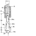
図1Aは、内部を通る管腔13を有する塞栓コイル12と、脱離特徴部18aと、耐延伸性繊維16と、を含むインプラント10aの例示である。例示目的のために切り欠き図で例示されるコイル12及び溶接部42の一部分。脱離特徴部18aは、コイル12の管腔13内に部分的に位置決めすることができ、かつコイル12から外に延在することができる。脱離特徴部18aは、内部を通して耐延伸性ワイヤ16がループ状にされる遠位開口部24aと、機械的インプラント係合システムのループワイヤ又は他の係合機構を受容するようにサイズ決めされた近位開口部22aと、を含み得る。脱離特徴部18aは、遠位開口部24aと近位開口部22aとの間に位置決めされたブリッジ28aを含み得る。脱離特徴部18aは、送達チューブの管腔内に嵌合するようにサイズ決めされた近位タブ38を含み得る。耐延伸性繊維16は、塞栓コイル12の端部で、脱離特徴部18aが溶接部44又は他の適切な取り付け部で取り付けられる端部の反対側に固設することができる。
FIG. 1A is an illustration of an
脱離特徴部18aを塞栓コイル12の管腔13内に更に延在するようにテーパ状にして、塞栓コイル12がテーパ状領域を取り囲む追加の可撓性を塞栓コイル12が有することを可能にすることができる。脱離特徴部18aはまた、実質的に平坦な輪郭を有することができ、画像の平面内及び外への方向に更に高い可撓性を提供する。
The
脱離特徴部18aは、コイル12のいかなる巻線も融着させることなく(例示されるように)、又は少数の巻線(例えば、5つ若しくは4つ以下の巻線)を融着させることによって、取り付け部42を用いてコイル12に十分に固設することができる。典型的には10個又は11個以上の巻線が一緒にはんだ付けされる(融着される巻線の数の制御が制限された状態)既知の解決策と比較して、コイル12への取り付け部42は、著しくより少ない融着コイル巻線を用いて実現され得る。融着される巻線の数を低減することによって、インプラント10aの近位セクションは、塞栓コイルの近位端から巻線を融着させることに依存する既知の設計と比較して、高い可撓性を有することができる。
The
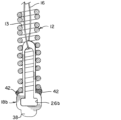
図1Bは、同様の要素を示す同様の参照番号を有する図1Aに関連して説明される要素を有する、代替的に構築されたインプラント10bの例示である。例示目的のために切り欠き図で例示されるコイル12及び溶接部42の一部分。図1Aに例示されるインプラント10aと比較して、インプラント10bは、機械的係合システムを係合することができ、かつ内部を通して耐延伸性繊維16をループ状にすることができる開口部を提供する、単一の開口部26bを有する代替的な脱離特徴部18bを有し得る。図1Bに例示される脱離特徴部18bはまた、図1Aに例示される脱離特徴部18aの延在するテーパ状領域を欠いている。図1Aに例示される脱離特徴部18aのテーパ状領域は、図1Bのインプラント10bと比較して、インプラント10aのより可撓性の近位セクションを提供し得るが、それにもかかわらず、図1Bに例示される脱離特徴部18bは、平坦であることにより、画像の平面内及び外への方向に可撓性を提供することによって、既知の塞栓コイルインプラントよりも高い可撓性を提供し、かつ低い輪郭の取り付け部42によって、塞栓コイルの近位端からの巻線の融着に依存する設計よりも高い可撓性を提供することができる。
FIG. 1B is an illustration of an alternatively constructed implant 10b having elements described in connection with FIG. 1A with like reference numbers indicating like elements. A portion of the
図2A及び図2B~図7は、図1A及び図1Bに例示されるインプラント10a及び10bを構築するための一連の工程を例示している。図2A及び図2Bは、脱離特徴部18a、18bを通過している耐延伸性繊維16を例示している。脱離特徴部18a、18bは、平坦なシート材料からレーザー切断することができる。平坦なシート材料は、好ましくは、塞栓コイル12に溶接され得るか、又は別様に貼着され得る放射線不透過性材料である。
2A and 2B-7 illustrate a sequence of steps for constructing the
図2Aは、機械的係合システム及び/又は送達チューブと係合するようにサイズ決めされた近位部分32を有する、二重開口脱離特徴部18aを例示している。近位部分32は、幅W1を有するものとして例示されている。二重開口脱離特徴部18aは、塞栓コイルの管腔13内に嵌合するようにサイズ決めされた遠位部分34を有し得る。遠位部分34は、塞栓コイル12の内径とほぼ同じ幅の幅W2を有するより広いセクションと、塞栓コイル12の内径よりも著しく狭い幅W3を有するテーパ状セクションと、を有し得る。脱離特徴部18aは、近位部分32よりも狭く、かつ送達チューブの管腔内に嵌合するようにサイズ決めされている、近位タブ38を有し得る。
2A illustrates a dual
図2Bは、機械的係合システム及び/又は送達チューブと係合するようにサイズ決めされた近位部分32を有する、単一開口脱離特徴部18bを例示している。近位部分32は、幅W1を有して例示されている。単一開口脱離特徴部18bは、近位部分32よりも狭く、かつコイル12の管腔13内に嵌合するようにサイズ決めされている、遠位部分34bを有し得る。単一開口脱離特徴部18bは、近位部分32よりも狭く、かつ送達チューブの管腔内に嵌合するようにサイズ決めされている、近位タブ38を有し得る。
2B illustrates a single
脱離特徴部18a、18bが形成された後、耐延伸性繊維16は、二重開口脱離特徴部18aの遠位開口部24a、又は単一開口脱離特徴部18bの単一開口部26bに通され得る。
After the release features 18a, 18b are formed, the stretch-
図3は、塞栓コイル12の近位端15に挿入されている耐延伸性繊維16の自由端の例示である。図3に例示される工程では、耐延伸性繊維16は、図2A及び図2Bに例示されるような脱離特徴部10a、10bを通してループ状にすることができる。
Figure 3 is an illustration of a free end of a stretch-
図4は、塞栓コイル12の遠位端14で塞栓コイル12の管腔13から出る耐延伸性繊維16の自由端の例示である。
Figure 4 is an illustration of the free ends of the stretch-
図5A及び図5Bは、塞栓コイル12の管腔13に挿入されている脱離特徴部18a、18bの例示である。塞栓コイル12の遠位端14を出た後、耐延伸性繊維16の自由端を、図4の矢印によって示されるように、更に引っ張って、脱離解特徴部18a、18bを、図5A及び図5B、並びに矢印によって示される例示されるように、塞栓コイル12の近位端15において塞栓コイル12の管腔13内へと移動させることができる。塞栓コイル12の管腔13内への脱離特徴部18a、18bの進入前に、塞栓コイルは、図5Aに示されるような内径Dを有し得る。脱離特徴部18a、18bの近位部分34は、滑り嵌めのために、内径Dとほぼ等しい遠位部分34の少なくとも一部分を上回る幅を有するようにサイズ決めすることができる。代替的又は追加的に、遠位部分34の少なくとも一部分は、締まり嵌めを作り出すために、直径Dよりも大きい幅を有し得る。代替的又は追加的に、遠位部分34の少なくとも一部分は、コイル12の近位端15付近でより高い可撓性のコイル12を可能にするために、直径Dよりも小さい幅を有し得る。
5A and 5B are illustrations of the detachment features 18a, 18b being inserted into the
図6A及び図6Bは、遠位部分34が塞栓コイル12の管腔13に完全に挿入された状態の脱離特徴部10a、10b、並びに溶接部42又は他の取り付け部によって塞栓コイル12に貼着された脱離特徴部18a、18bの例示である。図6A及び図6Bの両方において、脱離特徴部18a、18bは、塞栓コイル12の管腔13の内径Dにほぼ等しい遠位部分34の長さの少なくとも一部分を上回る幅を有する、遠位部分34を有して例示されている。
6A and 6B are illustrations of detachment features 10a, 10b with
図7は、塞栓コイル12の遠位端に貼着された耐延伸性繊維16の例示である。脱離特徴部18a、18bを貼着するか、又は少なくとも、図6A及び図6Bに例示されるように脱離特徴部18a~18bを位置決めした後に、耐延伸性繊維16をきつく引っ張って、繊維16内の弛緩を低減し、かつ/又は繊維16内に張力を作り出すことができ、繊維16を溶接部44又は他の取り付け部で貼着することができる。繊維16が取り付けられた後、繊維は、治療の準備中、インプラントの10a、10bの送達中、治療部位でのインプラントの位置決め中、インプラントの後退中、及びインプラントの展開中に、塞栓コイル12に加えられる力による著しい伸長に抵抗するように、実質的に耐延伸性になり得る。換言すれば、耐延伸性繊維16は、塞栓コイル12を動脈瘤から後退させるときに塞栓コイル12の延長を制限するのに有効であり得、かつ耐延伸性繊維16は、塞栓コイル12を屈曲させたときに塞栓コイル12内の巻線の分離を制限するのに有効であり得る。
7 is an illustration of a stretch-
図8A~図8Cは、最適ではない耐延伸性繊維16の留置の結果として塞栓コイル12を延伸させることができる時間順序を例示している。図8Aは、単一開口脱離特徴部18b内の最適ではない繊維16の留置を例示している。繊維16は、最適ではない、脱離特徴部18bのセクション上でループ状にすることができ、それにより、図8Bに例示されるような繊維16の移動により、最適ではない位置から繊維16を係脱させることができ、図8Cに例示されるような繊維16の移動により、少なくとも繊維16が脱離特徴部18aに再び係合するまで塞栓コイル12を延伸させることができる。したがって、製造上の課題は、図7に例示される取り付け工程が実施されるときに、図8Aに例示されるような最適ではない場所に繊維16が位置決めされることを阻止することである。製造が完了した後に、図8Bに例示されるような最適ではない場所から繊維16が取り除かれた場合、治療中に再位置決めしている間など、インプラント10bを操作しているときに、塞栓コイル12を、図8Cに例示されるように伸長させるか、又は別様に変形させることができる。
8A-8C illustrate a time sequence in which the
二重開口脱離特徴部18aの利点は、図1Aに例示されるインプラント10aの製造中に、耐延伸性繊維16が、脱離特徴部18aの最適ではないセクション上でループ状になる可能性が低いことである。
An advantage of the dual
図9は、送達カテーテル200を通して送達され、血管BVの動脈瘤A内に位置決めされている、塞栓インプラント(複数可)10の例示である。インプラント(複数可)は、動脈瘤嚢内でループ状になり屈曲して、血栓腫瘤を形成し得る。インプラント(複数可)は、それら自体及び/又は他のインプラントの隣のループにループバックし得る。動脈瘤Aが次第に充填されると、インプラント10の重複部分が互いに押し込まれ得る。
FIG. 9 is an illustration of embolic implant(s) 10 delivered through
図10Aは、コイルの重複部分が互いに押し込まれるときに、耐延伸性繊維16が絡まることがない塞栓コイル12の例示である。この絡まりにより、コイル12のいずれかを再位置決めすることが困難又は不可能になることがあり、これは、一部の現在の塞栓コイルインプラントの既知の問題である。図10Bは、力Fにより、図10Aに例示されるセクションの長さL1より長い長さL2まで伸長する塞栓コイル12の一部分を例示している。図10Bは、医師が、絡まった部分的に移植された塞栓コイルを後退させようと試みる場合があり、コイルを後退させることができないだけでなく、変形した伸長されたコイルをここで位置決めする必要があることにより、既に困難な治療を悪化させる場合もある、シナリオを例示している。塞栓コイルの巻線が、例えば、屈曲により分離したとき、又は高密度な充填によってコイルがより引密に圧縮されたときに、絡まる可能性がより高くなることがある。
FIG. 10A illustrates an
図11は、本発明のある態様による、絡まること及び伸長されることが阻止されている耐延伸性繊維16を各々が有する、例示的な塞栓コイル12の例示である。各コイル12は、屈曲部分20を有するものとして例示されている。耐延伸性繊維16は、移植されたときに必要に応じてコイル12を撓ませ、屈曲させることを可能にするように、各コイルの管腔13内でシフトし得る。繊維16は、屈曲部分20の巻線間の分離量を制限するのに十分な張力を有し得る。巻装の分離は、図10Aに例示されるように、2つの隣接するコイル12の巻線が絡まることを抑制するように制限され得る。図11はまた、コイル12の一部分40に加えられた力Fを例示しており、耐延伸性繊維16内の張力により、部分40が伸長することが抑制されている。図11は、医師が、耐延伸性繊維16が中に通されている、部分的に移植された塞栓コイル12をうまく後退させることができるシナリオを例示している。
FIG. 11 illustrates exemplary
図12は、本明細書に記載されるような例示的なインプラント10、10a、10bを使用した動脈瘤治療の一部として行われ得る工程を含む、方法500を例示しているフロー図である。工程510では、塞栓コイル及び耐延伸性繊維を有するインプラントを、動脈瘤嚢内に少なくとも部分的に位置決めすることができる。工程520では、塞栓コイルの一部分を屈曲させることができる。工程530では、コイルが屈曲するときに、耐延伸性繊維が塞栓コイルの屈曲部分内の巻線の分離を抑制し得る。工程540では、インプラントの移植された部分の一部又は全部を動脈瘤から後退させることができる。工程550では、インプラントが後退するときに、耐延伸性繊維が塞栓コイルの延長を抑制し得る。
12 is a flow diagram illustrating a
図13は、送達チューブ300に固設された、図1A及び図1Bに例示されるか、又は別様に本明細書に記載されるインプラント10a、10bのいずれかのような例示的な塞栓インプラント10の例示である。例示的な送達チューブ及び係合/展開システムは、米国特許公開第2019/0192162号、及び米国特許出願公開第15/964,857号に記載されており、これらの各々は、参照により本明細書に組み込まれる。送達チューブ300は、インプラント10の脱離特徴部18の近位部分32を受容するようにサイズ決めされたノッチ310を含むことができ、同様に、脱離特徴部18の近位部分32は、送達チューブ300のノッチ310内に嵌合するようにサイズ決めされ得る。図13は、脱離特徴部18の平坦な輪郭を強調する、インプラント10の側面図を例示している。図1A及び図1Bに関連して記載されるように、インプラント10は、脱離特徴部18が平坦であることによって、及び/又はいくつかのコイル巻線を融着することなく、脱離特徴部18がコイル12に固設されることによって、高可撓性近位部分を有し得る。脱離特徴部18は、画像の平面内及び外への方向に可撓性が増加するようにテーパ状にすることもできる。脱離特徴部18は、送達チューブ300の管腔内に位置決めされた近位タブ38を更に含み得る。
FIG. 13 is an illustration of an exemplary
動脈瘤閉塞治療中に、既知の塞栓インプラントの近位部分の可撓性の欠如、及び/又は送達チューブの遠位部分の可撓性の欠如により、インプラントが動脈瘤内に留置されている間に、送達チューブが治療部位から引き戻されるか、又は別様に適所を外れて移動することがある。したがって、より可撓性の遠位部分を有する送達チューブ、及びより可撓性の近位部分を有するインプラントは、単独で又は組み合わせにより、インプラントを送達するためのより安定したシステムを提供することができる。しかしながら、可撓性の構造は、操作時に変形又は拡張しやすい場合がある。耐延伸性繊維16及び/又は脱離特徴部18は、単独で又は組み合わせにより、コイル12を支持し、本明細書に記載される原理に従って、コイル12の変形及び拡張を抑制することができる。本発明の目的は、高可撓性近位部分を有し、かつ/又は高可撓性遠位部分を有する送達チューブ300と噛み合うように構成されたインプラント10を提供することである。
During aneurysm occlusion treatment, the lack of flexibility of the proximal portion of known embolic implants and/or the lack of flexibility of the distal portion of the delivery tube may cause the delivery tube to be pulled back from the treatment site or otherwise move out of place while the implant is in place within the aneurysm. Thus, a delivery tube with a more flexible distal portion and an implant with a more flexible proximal portion, alone or in combination, may provide a more stable system for delivering the implant. However, flexible structures may be prone to deformation or expansion during manipulation. The stretch-
図14Aは、インプラント10を送達及び位置決めするように構成された、インプラント10及び送達チューブ300の例示である。図14B~図14Dは、例示的な塞栓インプラント10を送達チューブ300から解放するための一連の工程の例示である。送達チューブ300の一部分は、例示目的のために切り取られている。
FIG. 14A is an illustration of an
図14Aは、プルワイヤ140と、インプラント12の脱離特徴部18内に係止されたループワイヤ400と、を含む、係合システムを例示している。送達チューブ300は、圧縮され得る圧縮可能部分306を含み得る。ループワイヤ400は、ループワイヤ400の遠位端404に開口部405を有することができ、開口部405は、脱離特徴部18の開口部22aを通して留置され得る。プルワイヤ140が開口部405を通って入れられると、ここでインプラント12が固設される。
14A illustrates an engagement system including a
脱離特徴部18は、ループワイヤ開口部405から遠位に位置決めされ、ループワイヤ開口部405がプルワイヤ140によって支持される場所の遠位にある、プルワイヤ140の遠位部分を支持するように位置決めされている、ブリッジ28を含み得る。このように構成されると、ブリッジ28は、ループワイヤ400がループ開口部405でプルワイヤ140を強く引いたときに、ブリッジ28がプルワイヤ140の遠位部分の変形を抑制し得るように、プルワイヤ140の遠位部分を支持することができる。近位タブ38は、ループワイヤ開口部405がプルワイヤ140によって支持される場所の近位にある、プルワイヤ140の一部分を支持するように位置決めされ得る。ブリッジ28と近位タブ38との組み合わせは、ループワイヤ400によって加えられる力によってプルワイヤ140が変形することを抑制することができる。送達チューブ300は、脈管構造を通してインプラント10を送達する間、及びインプラント10が治療部位に位置決めされている間、図14Aに例示されるように、インプラント10に脱離可能に取り付けることができる。ブリッジ28は、ループワイヤ400からの力によるプルワイヤ140の屈曲により、インプラント10が早期に解放される可能性を低減し得る。
The
ブリッジ28は、例示されるような二重開口インプラントにおいて、近位開口部22aと遠位開口部24aとを分離し得る。単一開口インプラントが、例示されるブリッジ28に関して記載されるものと同様に、プルワイヤ140の遠位部分を支持するように機能し得る構造を含むように適合され得ることも企図される。したがって、代替的なブリッジ構造が、本発明の範囲内であるように意図される。
The
図14Bは、インプラント10の解放順序を開始するために、近位に引き込まれているプルワイヤ140を例示している。図14Cは、プルワイヤ140が開口部405から出て、ループワイヤ400から引きほどかれた瞬間を例示している。ループワイヤ400の遠位端部404は脱落し、かつ係止部分18から出る。図から分かるように、ここでインプラント10を送達チューブ300に保持しているものは何もない。図14Dは、解放順序の終了を例示している。ここで、圧縮可能部分306は元の形状に拡張し/戻り、前方に「弾ける」。送達チューブ300の遠位端304により弾性力Eが医療用装置10に付与されて、これを離れる方向に「押し出し」、医療用装置10のきれいな分離及び送達を確実にする。
14B illustrates the
図15は、同様の要素を示す同様の参照番号を有する図1Aに関連して説明される要素を有する、代替的に構築されたインプラント10cの近位セクションの断面図である。図1Aに例示されるインプラント10aと比較して、図15に例示されるインプラント10cは、代替的な脱離特徴部18cを有し得る。図18cに例示される脱離特徴部18cは、内径D1を有する塞栓コイル12の管腔13内に嵌合するようにサイズ決めされた幅D2を備える部分を有し得る。脱離特徴部18cの幅D2は、脱離特徴部18cが管腔13内に位置決めされるときに、管腔13の近位部分が直径D2まで拡張して、脱離特徴部18cの幅D2を収容するように、コイル管腔13の内径D1よりも大きくすることができる。このように構成されると、コイル12の拡張部分は、脱離特徴部18cをコイル12に固設することを助けるために、幅D2を有する脱離特徴部のセクションに対して圧縮力を提供することができる。
15 is a cross-sectional view of a proximal section of an alternatively constructed
図1Aに例示されるインプラント10aと比較して、ブリッジ28cは、塞栓コイル12の近位端から近位に延在し得る。このように構成されると、いくつかの構成では、ブリッジ28cによって支持される塞栓コイル12の管腔13にプルワイヤ140を挿入する必要はない。塞栓コイル12に挿入されるプルワイヤ140の長さを制限することにより、塞栓コイルの近位セクションの可撓性を増加させることができる。
Compared to the
図15に例示されるインプラント10cは、図2A及び図2B~図7に例示される原理に従って構築され得る。図15に例示されるインプラント10cは、図9及び図11~図14Dに例示される原理に従って使用され得る。
The
本明細書で任意の数値又は数値の範囲について用いる「約」又は「およそ」という用語は、構成要素の部分又は構成要素の集合が、本明細書で述べるその意図された目的に沿って機能することを可能とする、好適な寸法の許容誤差を示すものである。より具体的には、「約」又は「およそ」は、列挙された値の±20%の値の範囲を指し得、例えば、「約90%」は、71%~99%の値の範囲を指し得る。 The term "about" or "approximately" as used herein with respect to any numerical value or range of numerical values indicates a suitable dimensional tolerance that allows a portion of a component or a collection of components to function in accordance with its intended purpose as described herein. More specifically, "about" or "approximately" may refer to a range of values of ±20% of the recited value, e.g., "about 90%" may refer to a range of values of 71% to 99%.
本明細書に含まれる記述は、本発明の実施形態の例であり、本発明の範囲を何ら制限するものではない。本明細書に記載されるように、本発明は、代替的な材料、構成要素部品の代替的な幾何学形状、構成要素部品の互いに対する代替的な位置決めなどを含む、インプラントの多くの変形例及び修正例、並びにインプラントを作製及び使用するための方法を企図する。これらの修正例は、本発明が関連する当業者には明らかであり、以下の特許請求の範囲内であることが企図される。 The descriptions contained herein are examples of embodiments of the invention and are not intended to limit the scope of the invention in any way. As described herein, the invention contemplates many variations and modifications of the implant and methods for making and using the implant, including alternative materials, alternative geometries of the component parts, alternative positioning of the component parts relative to one another, and the like. These modifications will be apparent to those skilled in the art to which the invention pertains and are contemplated to be within the scope of the following claims.
〔実施の態様〕
(1) 方法であって、
塞栓コイル及び耐延伸性繊維を含むインプラントの一部又は全てを動脈瘤内に位置決めすることと、
前記塞栓コイルの第1の部分を前記動脈瘤から後退させることと、
前記第1の部分を前記動脈瘤から後退させる際に、前記耐延伸性繊維で前記塞栓コイルの前記第1の部分の延長を制限することと、を含む、方法。
(2) 前記塞栓コイルの管腔内に延在させるように前記耐延伸性繊維を位置決めすることを更に含む、実施態様1に記載の方法。
(3) 前記塞栓コイルの第2の部分を屈曲させることと、
前記塞栓コイルの前記第2の部分を屈曲させながら、前記耐延伸性繊維を用いて、前記塞栓コイルの前記第2の部分内の巻線の分離を制限することと、を更に含む、実施態様1に記載の方法。
(4) 前記耐延伸性繊維に係合した鍵によって前記インプラントを送達システムに固設することと、
前記送達システムから前記鍵を解放し、それによって、前記インプラントを前記送達システムから解放することと、更に含む、実施態様1に記載の方法。
(5) 前記インプラントを前記送達システムに固設する前記工程が、
前記鍵を通して前記送達システムのループワイヤを位置決めすることと、
前記ループワイヤの開口部を通して前記送達システムのプルワイヤを位置決めすることと、を更に含み、
前記方法が、
前記鍵によって、前記ループ開口部に対して遠位方向に位置決めされた前記プルワイヤの第1の部分を支持することと、
前記鍵によって、前記ループ開口部に対して近位方向に位置決めされた前記プルワイヤの第2の部分を支持することと、を更に含む、実施態様4に記載の方法。
[Embodiment]
(1) A method comprising the steps of:
positioning some or all of an implant including an embolic coil and a stretch-resistant fiber within the aneurysm;
retracting a first portion of the embolic coil from the aneurysm;
and limiting the extension of the first portion of the embolic coil with the stretch-resistant fiber as the first portion is retracted from the aneurysm.
2. The method of claim 1, further comprising positioning the stretch-resistant fiber to extend within a lumen of the embolic coil.
(3) bending a second portion of the embolic coil; and
2. The method of claim 1, further comprising: using the stretch resistant fiber to limit separation of windings within the second portion of the embolic coil while bending the second portion of the embolic coil.
(4) securing the implant to a delivery system with a key engaged with the stretch resistant fiber; and
2. The method of claim 1, further comprising releasing the key from the delivery system, thereby releasing the implant from the delivery system.
(5) the step of securing the implant to the delivery system comprises:
Positioning a loop wire of the delivery system through the key;
and positioning a pull wire of the delivery system through an opening in the loop wire;
The method,
supporting a first portion of the pull wire with the key positioned distally relative to the loop opening;
5. The method of claim 4, further comprising supporting a second portion of the pull wire positioned proximally relative to the loop opening with the key.
(6) 塞栓インプラントであって、
内部を通る管腔、近位端、及び遠位端を含む、塞栓コイルと、
前記塞栓コイルの前記近位端近くで前記塞栓コイルに貼着された脱離特徴部と、
前記脱離特徴部に係合し、前記塞栓コイルの前記管腔を通って延在し、前記塞栓コイルの前記遠位端近くで前記塞栓コイルに貼着された耐延伸性繊維と、を備え、
前記耐延伸性繊維は、前記塞栓コイルが再成形される際に、前記塞栓コイルの巻線の分離を制限するのに有効である、塞栓インプラント。
(7) 前記耐延伸性繊維が、縫合糸である、実施態様6に記載の塞栓インプラント。
(8) 前記耐延伸性繊維が、非弾性である、実施態様6に記載の塞栓インプラント。
(9) 前記脱離特徴部が、放射線不透過性である、実施態様6に記載の塞栓インプラント。
(10) 前記脱離特徴部が、内部を通る開口部を備え、
前記耐延伸性繊維が、前記脱離特徴部の前記開口部を通過し、
前記開口部が、前記塞栓コイルの前記近位端から近位に延在し、
前記開口部が、機械的送達システムのループワイヤを受容するようにサイズ決め及び位置決めされている、実施態様6に記載の塞栓インプラント。
(6) An embolic implant, comprising:
an embolic coil including a lumen therethrough, a proximal end, and a distal end;
a detachment feature affixed to the embolic coil near the proximal end of the embolic coil;
a stretch resistant fiber engaging the detachment feature, extending through the lumen of the embolic coil and affixed to the embolic coil near the distal end of the embolic coil;
An embolic implant, wherein the stretch resistant fibers are effective to limit separation of the windings of the embolic coil as the embolic coil is reshaped.
(7) The embolic implant of claim 6, wherein the stretch-resistant fiber is a suture.
8. The embolic implant of claim 6, wherein the stretch-resistant fibers are inelastic.
9. The embolic implant of claim 6, wherein the detachment feature is radiopaque.
(10) The detachment feature includes an opening therethrough;
the stretch resistant fiber passes through the opening in the detachment feature;
the opening extends proximally from the proximal end of the embolic coil;
The embolic implant of embodiment 6, wherein the opening is sized and positioned to receive a loop wire of a mechanical delivery system.
(11) 前記脱離特徴部が、内部を通る第1の開口部と、前記第1の開口部とは別個の、内部を通る第2の開口部と、を備え、
前記耐延伸性繊維が、前記第1の開口部を通過し、
前記第1の開口部の少なくとも一部分が、前記塞栓コイルの前記管腔内に位置決めされており、
前記第2の開口部の少なくとも一部分が、前記塞栓コイルの前記近位端から近位に位置決めされている、実施態様6に記載の塞栓インプラント。
(12) システムであって、
実施態様11に記載の塞栓インプラントと、
前記第2の開口部を通して位置決めされたループワイヤ、及び前記ループワイヤの開口部を通して位置決めされたプルワイヤ、を含む、機械的送達システムと、を備え、
前記脱離特徴部が、前記第1の開口部と前記第2の開口部とを分離するブリッジを更に備え、
前記ブリッジが、前記ループワイヤの前記開口部から遠位方向に前記プルワイヤの一部分を支持する、システム。
(13) 前記塞栓コイルの前記管腔が、内径を含み、
前記脱離特徴部が、前記管腔から近位に配設された近位部分と、前記管腔内に配設された遠位部分と、を備え、
前記近位部分が、前記管腔の前記内径よりも大きい寸法の第1の幅を含み、
前記遠位部分が、前記管腔の前記内径とほぼ等しい寸法の第2の幅を含む、実施態様6に記載の塞栓インプラント。
(14) 方法であって、
脱離特徴部の第1の開口部に耐延伸性繊維を通すことと、
塞栓コイルの管腔を通して前記耐延伸性繊維を延在させることと、
前記塞栓コイルの第1の端部に前記脱離特徴部を貼着することと、
前記第1の端部とは反対側の前記塞栓コイルの前記第2の端部に前記耐延伸性繊維を貼着することと、
前記脱離特徴部と前記塞栓コイルの前記第2の端部との間に、前記耐延伸性繊維に沿って張力を提供することと、を含む、方法。
(15) 平坦なシート材料から前記脱離特徴部を切断することと、
前記脱離特徴部内の前記第1の開口部を切断することと、
前記第1の開口部(26b)を通して機械的展開システムの一部分を延在させて、前記脱離特徴部を送達チューブに係合させることと、を更に含む、実施態様14に記載の方法。
(11) The detachment feature comprises a first opening therethrough and a second opening therethrough, separate from the first opening;
the stretch resistant fiber passes through the first opening;
at least a portion of the first opening is positioned within the lumen of the embolic coil;
7. The embolic implant of embodiment 6, wherein at least a portion of the second opening is positioned proximally from the proximal end of the embolic coil.
(12) A system comprising:
12. An embolic implant according to claim 11,
a mechanical delivery system including a loop wire positioned through the second opening and a pull wire positioned through an opening in the loop wire;
the detachment feature further comprises a bridge separating the first opening and the second opening;
The system, wherein the bridge supports a portion of the pull wire distally from the opening in the loop wire.
(13) The lumen of the embolic coil includes an inner diameter;
the detachment feature comprises a proximal portion disposed proximally from the lumen and a distal portion disposed within the lumen;
the proximal portion includes a first width that is greater than the inner diameter of the lumen;
7. The embolic implant of claim 6, wherein the distal portion includes a second width having a dimension approximately equal to the inner diameter of the lumen.
(14) A method comprising the steps of:
threading a stretch resistant fiber through a first opening of the detachment feature;
extending the stretch-resistant fiber through a lumen of an embolic coil;
affixing the detachment feature to a first end of the embolic coil;
affixing the stretch-resistant fiber to the second end of the embolic coil opposite the first end;
providing tension along the stretch resistant fiber between the detachment feature and the second end of the embolic coil.
(15) cutting the break-away feature from a flat sheet of material;
cutting the first opening in the detachment feature;
15. The method of claim 14, further comprising extending a portion of a mechanical deployment system through the first opening (26b) to engage the detachment feature with a delivery tube.
(16) 平坦なシート材料から前記脱離特徴部を切断することと、
前記脱離特徴部内の前記第1の開口部を切断することと、
前記第1の開口部とは別個の、前記脱離特徴部内の第2の開口部を切断することと、
前記第2の開口部を通して機械的展開システムの一部分を延在させて、前記脱離特徴部を送達チューブに係合させることと、を更に含む、実施態様14に記載の方法。
(17) 放射線不透過性の平坦なシート材料から前記脱離特徴部を切断することを更に含む、実施態様14に記載の方法。
(18) 前記塞栓コイルの前記管腔内に前記脱離特徴部の遠位部分を挿入することと、
前記塞栓コイルの前記近位端から近位に前記脱離特徴部の近位部分を延在させることと、を更に含む、実施態様14に記載の方法。
(19) 前記管腔が内径を含むように前記塞栓コイルを選択することと、
前記脱離特徴部の前記近位部分が、前記管腔の前記内径よりも大きい寸法の第1の幅を含むように、かつ前記脱離特徴部の前記遠位部分が、前記管腔の前記内径とほぼ等しい寸法の第2の幅を含むように、前記脱離特徴部を選択することと、を更に含む、実施態様18に記載の方法。
(20) 前記塞栓コイルの第1の端部に前記脱離特徴部を貼着することが、前記塞栓コイルの前記第1の端部に前記脱離特徴部を溶接することを含む、実施態様14に記載の方法。
(16) cutting the break-away feature from a flat sheet of material;
cutting the first opening in the detachment feature;
cutting a second opening in the detachment feature separate from the first opening;
15. The method of claim 14, further comprising extending a portion of a mechanical deployment system through the second opening to engage the detachment feature with a delivery tube.
17. The method of claim 14, further comprising cutting the breakaway feature from a radiopaque flat sheet material.
(18) inserting a distal portion of the detachment feature into the lumen of the embolic coil;
15. The method of claim 14, further comprising extending a proximal portion of the detachment feature proximally from the proximal end of the embolic coil.
(19) selecting the embolic coil such that the lumen includes an inner diameter;
19. The method of
20. The method of claim 14, wherein affixing the detachment feature to a first end of the embolic coil comprises welding the detachment feature to the first end of the embolic coil.
Claims (13)
内部を通る管腔、近位端、及び遠位端を含む、塞栓コイルと、
前記塞栓コイルの前記近位端近くで前記塞栓コイルに溶接された脱離特徴部と、
前記脱離特徴部に係合し、前記塞栓コイルの前記管腔を通って延在し、前記塞栓コイルの前記遠位端近くで前記塞栓コイルに貼着された耐延伸性繊維と、を備え、
前記塞栓コイルの前記管腔が、内径を含み、
前記脱離特徴部が、前記管腔から近位に配設された近位部分と、前記管腔内に配設された遠位部分と、を備え、
前記近位部分が、前記管腔の前記内径よりも大きい第1の幅を含み、
前記遠位部分が、前記管腔の前記内径とほぼ等しい第2の幅を有する幅広セクションと、前記管腔の前記内径よりも小さい第3の幅を有する幅狭セクションと、前記幅広セクションと前記幅狭セクションとの間のテーパ状セクションと、を含み、
前記耐延伸性繊維は、前記塞栓コイルが再成形される際に、前記塞栓コイルの巻線の分離を制限するのに有効である、塞栓インプラント。 1. An embolic implant comprising:
an embolic coil including a lumen therethrough, a proximal end, and a distal end;
a detachment feature welded to the embolic coil near the proximal end of the embolic coil;
a stretch resistant fiber that engages the detachment feature, extends through the lumen of the embolic coil, and is affixed to the embolic coil near the distal end of the embolic coil;
the lumen of the embolic coil includes an inner diameter;
the detachment feature comprises a proximal portion disposed proximally from the lumen and a distal portion disposed within the lumen;
the proximal portion includes a first width greater than the inner diameter of the lumen;
the distal portion includes a wide section having a second width approximately equal to the inner diameter of the lumen, a narrow section having a third width less than the inner diameter of the lumen, and a tapered section between the wide and narrow sections;
An embolic implant, wherein the stretch resistant fibers are effective to limit separation of the windings of the embolic coil as the embolic coil is reshaped.
前記耐延伸性繊維が、前記脱離特徴部の前記開口部を通過し、
前記開口部が、前記塞栓コイルの前記近位端から近位に延在し、
前記開口部が、機械的送達システムのループワイヤを受容するようにサイズ決め及び位置決めされている、請求項1に記載の塞栓インプラント。 the detachment feature includes an opening therethrough;
the stretch resistant fiber passes through the opening in the detachment feature;
the opening extends proximally from the proximal end of the embolic coil;
The embolic implant of claim 1 , wherein the opening is sized and positioned to receive a loop wire of a mechanical delivery system.
前記耐延伸性繊維が、前記第1の開口部を通過し、
前記第1の開口部の少なくとも一部分が、前記塞栓コイルの前記管腔内に位置決めされており、
前記第2の開口部の少なくとも一部分が、前記塞栓コイルの前記近位端から近位に位置決めされている、請求項1に記載の塞栓インプラント。 the detachment feature comprises a first opening therethrough and a second opening therethrough, separate from the first opening;
the stretch resistant fiber passes through the first opening;
at least a portion of the first opening is positioned within the lumen of the embolic coil;
The embolic implant of claim 1 , wherein at least a portion of the second opening is positioned proximally from the proximal end of the embolic coil.
請求項6に記載の塞栓インプラントと、
前記第2の開口部を通して位置決めされたループワイヤ、及び前記ループワイヤの開口部を通して位置決めされたプルワイヤ、を含む、機械的送達システムと、を備え、
前記脱離特徴部が、前記第1の開口部と前記第2の開口部とを分離するブリッジを更に備え、
前記ブリッジが、前記ループワイヤの前記開口部から遠位方向に前記プルワイヤの一部分を支持する、システム。 1. A system comprising:
7. The embolic implant of claim 6 ;
a mechanical delivery system including a loop wire positioned through the second opening and a pull wire positioned through an opening in the loop wire;
the detachment feature further comprises a bridge separating the first opening and the second opening;
The system, wherein the bridge supports a portion of the pull wire distally from the opening in the loop wire.
前記塞栓コイルの前記管腔が、非拡張部分と拡張部分とを含み、the lumen of the embolic coil includes a non-expanded portion and an expanded portion;
前記拡張部分が前記第1の内径を有し、前記非拡張部分が前記第1の内径よりも小さい第2の内径を有する、請求項1に記載の塞栓インプラント。The embolic implant of claim 1 , wherein the expanded portion has the first inner diameter and the non-expanded portion has a second inner diameter that is smaller than the first inner diameter.
脱離特徴部の第1の開口部に耐延伸性繊維を通すことと、
塞栓コイルの管腔を通して前記耐延伸性繊維を延在させることと、
前記塞栓コイルの近位端から近位に前記脱離特徴部の近位部分が延在するように、前記塞栓コイルの前記管腔内に前記脱離特徴部の遠位部分を挿入することと、
前記塞栓コイルの前記近位端に前記脱離特徴部を溶接することと、
前記塞栓コイルの遠位端に前記耐延伸性繊維を貼着することと、
前記脱離特徴部と前記塞栓コイルの前記遠位端との間に、前記耐延伸性繊維に沿って張力を提供することと、を含み、
前記塞栓コイルの前記管腔が、内径を含み、
前記近位部分が、前記管腔の前記内径よりも大きい第1の幅を含み、
前記遠位部分が、前記管腔の前記内径とほぼ等しい第2の幅を有する幅広セクションと、前記管腔の前記内径よりも小さい第3の幅を有する幅狭セクションと、前記幅広セクションと前記幅狭セクションとの間のテーパ状セクションと、を含む、方法。 1. A method comprising:
threading a stretch resistant fiber through a first opening of the detachment feature;
extending the stretch-resistant fiber through a lumen of an embolic coil;
inserting a distal portion of the detachment feature into the lumen of the embolic coil such that a proximal portion of the detachment feature extends proximally from a proximal end of the embolic coil;
welding the detachment feature to the proximal end of the embolic coil;
affixing the stretch-resistant fiber to a distal end of the embolic coil;
providing tension along the stretch resistant fiber between the detachment feature and the distal end of the embolic coil ;
the lumen of the embolic coil includes an inner diameter;
the proximal portion includes a first width greater than the inner diameter of the lumen;
the distal portion includes a wide section having a second width approximately equal to the inner diameter of the lumen, a narrow section having a third width less than the inner diameter of the lumen, and a tapered section between the wide and narrow sections.
前記脱離特徴部内の前記第1の開口部を切断することと、
前記第1の開口部を通して機械的送達システムの一部分を延在させて、前記脱離特徴部を送達チューブに係合させることと、を更に含む、請求項9に記載の方法。 cutting the break-away feature from a flat sheet of material;
cutting the first opening in the detachment feature;
10. The method of claim 9, further comprising extending a portion of a mechanical delivery system through the first opening to engage the detachment feature with a delivery tube.
前記脱離特徴部内の前記第1の開口部を切断することと、
前記第1の開口部とは別個の、前記脱離特徴部内の第2の開口部を切断することと、
前記第2の開口部を通して機械的送達システムの一部分を延在させて、前記脱離特徴部を送達チューブに係合させることと、を更に含む、請求項9に記載の方法。 cutting the break-away feature from a flat sheet of material;
cutting the first opening in the detachment feature;
cutting a second opening in the detachment feature separate from the first opening;
10. The method of claim 9, further comprising extending a portion of a mechanical delivery system through the second opening to engage the detachment feature with a delivery tube.
前記塞栓コイルの前記管腔が、非拡張部分と拡張部分とを含み、the lumen of the embolic coil includes a non-expanded portion and an expanded portion;
前記拡張部分が前記第1の内径を有し、前記非拡張部分が前記第1の内径よりも小さい第2の内径を有する、請求項9に記載の方法。10. The method of claim 9, wherein the expanding portion has the first inner diameter and the non-expanding portion has a second inner diameter that is smaller than the first inner diameter.
Applications Claiming Priority (2)
| Application Number | Priority Date | Filing Date | Title |
|---|---|---|---|
| US16/573,469 | 2019-09-17 | ||
| US16/573,469 US11439403B2 (en) | 2019-09-17 | 2019-09-17 | Embolic coil proximal connecting element and stretch resistant fiber |
Publications (2)
| Publication Number | Publication Date |
|---|---|
| JP2021045547A JP2021045547A (en) | 2021-03-25 |
| JP7508317B2 true JP7508317B2 (en) | 2024-07-01 |
Family
ID=72560334
Family Applications (1)
| Application Number | Title | Priority Date | Filing Date |
|---|---|---|---|
| JP2020155306A Active JP7508317B2 (en) | 2019-09-17 | 2020-09-16 | Embolic coil proximal connecting element and stretch-resistant fiber |
Country Status (6)
| Country | Link |
|---|---|
| US (2) | US11439403B2 (en) |
| EP (1) | EP3795097B1 (en) |
| JP (1) | JP7508317B2 (en) |
| KR (1) | KR20210032908A (en) |
| CN (1) | CN112515726B (en) |
| ES (1) | ES2999631T3 (en) |
Cited By (1)
| Publication number | Priority date | Publication date | Assignee | Title |
|---|---|---|---|---|
| JP2021058586A (en) * | 2019-10-03 | 2021-04-15 | デピュイ・シンセス・プロダクツ・インコーポレイテッド | Medical device delivery member with flexible stretch resistant mechanical release |
Families Citing this family (11)
| Publication number | Priority date | Publication date | Assignee | Title |
|---|---|---|---|---|
| US10806462B2 (en) | 2017-12-21 | 2020-10-20 | DePuy Synthes Products, Inc. | Implantable medical device detachment system with split tube and cylindrical coupling |
| US11253265B2 (en) | 2019-06-18 | 2022-02-22 | DePuy Synthes Products, Inc. | Pull wire detachment for intravascular devices |
| US11207494B2 (en) | 2019-07-03 | 2021-12-28 | DePuy Synthes Products, Inc. | Medical device delivery member with flexible stretch resistant distal portion |
| JPWO2023048142A1 (en) * | 2021-09-24 | 2023-03-30 | ||
| US12508032B2 (en) | 2021-12-31 | 2025-12-30 | DePuy Synthes Products, Inc. | Medical device delivery systems with twisting loop wires |
| US12011171B2 (en) | 2022-01-06 | 2024-06-18 | DePuy Synthes Products, Inc. | Systems and methods for inhibiting premature embolic implant deployment |
| US11937825B2 (en) | 2022-03-02 | 2024-03-26 | DePuy Synthes Products, Inc. | Hook wire for preventing premature embolic implant detachment |
| US12471924B2 (en) | 2022-03-02 | 2025-11-18 | DePuy Synthes Products, Inc. | Flexible feature for embolic implant deployment |
| US11937826B2 (en) | 2022-03-14 | 2024-03-26 | DePuy Synthes Products, Inc. | Proximal link wire for preventing premature implant detachment |
| CN119789821A (en) * | 2022-06-21 | 2025-04-08 | 库克医疗科技有限责任公司 | Embolic Coil Delivery Systems and Components |
| US12402886B2 (en) | 2022-06-23 | 2025-09-02 | DePuy Synthes Products, Inc. | Detachment indicator for implant deployment |
Citations (3)
| Publication number | Priority date | Publication date | Assignee | Title |
|---|---|---|---|---|
| JP2012000464A (en) | 2010-06-16 | 2012-01-05 | Codman & Shurtleff Inc | Occlusive device with stretch resistant member and anchor filament |
| JP2013212372A (en) | 2012-03-30 | 2013-10-17 | Depuy Synthes Products Llc | Embolic coil detachment mechanism with flexible distal member and coupling joint |
| JP2019111339A (en) | 2017-12-21 | 2019-07-11 | デピュイ・シンセス・プロダクツ・インコーポレイテッド | Implantable medical device detachment system with split tube and cylindrical coupling |
Family Cites Families (220)
| Publication number | Priority date | Publication date | Assignee | Title |
|---|---|---|---|---|
| US3429408A (en) | 1967-04-25 | 1969-02-25 | Associated Spring Corp | Actuator sleeves for spring clutch |
| US5484409A (en) | 1989-08-25 | 1996-01-16 | Scimed Life Systems, Inc. | Intravascular catheter and method for use thereof |
| US5122136A (en) | 1990-03-13 | 1992-06-16 | The Regents Of The University Of California | Endovascular electrolytically detachable guidewire tip for the electroformation of thrombus in arteries, veins, aneurysms, vascular malformations and arteriovenous fistulas |
| US5108407A (en) | 1990-06-08 | 1992-04-28 | Rush-Presbyterian St. Luke's Medical Center | Method and apparatus for placement of an embolic coil |
| US5636639A (en) | 1992-02-18 | 1997-06-10 | Symbiosis Corporation | Endoscopic multiple sample bioptome with enhanced biting action |
| US5263964A (en) | 1992-05-06 | 1993-11-23 | Coil Partners Ltd. | Coaxial traction detachment apparatus and method |
| US5350397A (en) | 1992-11-13 | 1994-09-27 | Target Therapeutics, Inc. | Axially detachable embolic coil assembly |
| US5250071A (en) | 1992-09-22 | 1993-10-05 | Target Therapeutics, Inc. | Detachable embolic coil assembly using interlocking clasps and method of use |
| US5382259A (en) | 1992-10-26 | 1995-01-17 | Target Therapeutics, Inc. | Vasoocclusion coil with attached tubular woven or braided fibrous covering |
| US5334210A (en) | 1993-04-09 | 1994-08-02 | Cook Incorporated | Vascular occlusion assembly |
| US5925059A (en) | 1993-04-19 | 1999-07-20 | Target Therapeutics, Inc. | Detachable embolic coil assembly |
| US5569221A (en) | 1994-07-07 | 1996-10-29 | Ep Technologies, Inc. | Catheter component bond and method |
| US6273404B1 (en) | 1995-06-05 | 2001-08-14 | Scimed Life Systems, Inc. | Method of making monolithic hub and strain relief |
| US5582619A (en) * | 1995-06-30 | 1996-12-10 | Target Therapeutics, Inc. | Stretch resistant vaso-occlusive coils |
| US5853418A (en) | 1995-06-30 | 1998-12-29 | Target Therapeutics, Inc. | Stretch resistant vaso-occlusive coils (II) |
| US6168622B1 (en) | 1996-01-24 | 2001-01-02 | Microvena Corporation | Method and apparatus for occluding aneurysms |
| US5899935A (en) | 1997-08-04 | 1999-05-04 | Schneider (Usa) Inc. | Balloon expandable braided stent with restraint |
| US6203547B1 (en) | 1997-12-19 | 2001-03-20 | Target Therapeutics, Inc. | Vaso-occlusion apparatus having a manipulable mechanical detachment joint and a method for using the apparatus |
| US6379374B1 (en) * | 1998-10-22 | 2002-04-30 | Cordis Neurovascular, Inc. | Small diameter embolic coil hydraulic deployment system |
| US6113622A (en) | 1998-03-10 | 2000-09-05 | Cordis Corporation | Embolic coil hydraulic deployment system |
| US6835185B2 (en) | 1998-12-21 | 2004-12-28 | Micrus Corporation | Intravascular device deployment mechanism incorporating mechanical detachment |
| US6391037B1 (en) | 2000-03-02 | 2002-05-21 | Prodesco, Inc. | Bag for use in the intravascular treatment of saccular aneurysms |
| US6689141B2 (en) * | 2000-10-18 | 2004-02-10 | Microvention, Inc. | Mechanism for the deployment of endovascular implants |
| US6623504B2 (en) | 2000-12-08 | 2003-09-23 | Scimed Life Systems, Inc. | Balloon catheter with radiopaque distal tip |
| DE60224502T2 (en) | 2001-01-10 | 2008-12-24 | Cordis Neurovascular, Inc., Miami Lakes | System for introducing an embolic coil |
| US6454780B1 (en) | 2001-06-21 | 2002-09-24 | Scimed Life Systems, Inc. | Aneurysm neck obstruction device |
| US8252040B2 (en) | 2001-07-20 | 2012-08-28 | Microvention, Inc. | Aneurysm treatment device and method of use |
| US8715312B2 (en) | 2001-07-20 | 2014-05-06 | Microvention, Inc. | Aneurysm treatment device and method of use |
| US20030195553A1 (en) | 2002-04-12 | 2003-10-16 | Scimed Life Systems, Inc. | System and method for retaining vaso-occlusive devices within an aneurysm |
| US20040002732A1 (en) * | 2002-06-27 | 2004-01-01 | Clifford Teoh | Stretch-resistant vaso-occlusive assembly with multiple detaching points |
| US7608058B2 (en) | 2002-07-23 | 2009-10-27 | Micrus Corporation | Stretch resistant therapeutic device |
| US8425549B2 (en) | 2002-07-23 | 2013-04-23 | Reverse Medical Corporation | Systems and methods for removing obstructive matter from body lumens and treating vascular defects |
| US7208003B2 (en) | 2002-09-20 | 2007-04-24 | Cordis Neurovascular, Inc. | Reattachable introducer for a medical device deployment system |
| FR2853521B1 (en) | 2003-04-10 | 2005-12-02 | Claude Mialhe | DEVICE FOR EXPANDING A VESSEL AND INTRODUCING VASCULAR IMPLANT |
| US7371228B2 (en) | 2003-09-19 | 2008-05-13 | Medtronic Vascular, Inc. | Delivery of therapeutics to treat aneurysms |
| US20050149108A1 (en) | 2003-12-17 | 2005-07-07 | Microvention, Inc. | Implant delivery and detachment system and method |
| US9308382B2 (en) | 2004-06-10 | 2016-04-12 | Medtronic Urinary Solutions, Inc. | Implantable pulse generator systems and methods for providing functional and/or therapeutic stimulation of muscles and/or nerves and/or central nervous system tissue |
| US20060025802A1 (en) | 2004-07-30 | 2006-02-02 | Sowers William W | Embolic coil delivery system with U-shaped fiber release mechanism |
| US9655633B2 (en) | 2004-09-10 | 2017-05-23 | Penumbra, Inc. | System and method for treating ischemic stroke |
| WO2006052322A2 (en) | 2004-09-22 | 2006-05-18 | Guterman Lee R | Cranial aneurysm treatment arrangement |
| US20060089637A1 (en) | 2004-10-14 | 2006-04-27 | Werneth Randell L | Ablation catheter |
| US8562672B2 (en) | 2004-11-19 | 2013-10-22 | Medtronic, Inc. | Apparatus for treatment of cardiac valves and method of its manufacture |
| US8425550B2 (en) | 2004-12-01 | 2013-04-23 | Boston Scientific Scimed, Inc. | Embolic coils |
| US7238423B2 (en) * | 2004-12-20 | 2007-07-03 | Kimberly-Clark Worldwide, Inc. | Multicomponent fiber including elastic elements |
| US7819892B2 (en) | 2005-06-02 | 2010-10-26 | Codman & Shurtleff, Inc. | Embolic coil delivery system with spring wire release mechanism |
| US7367987B2 (en) | 2005-06-02 | 2008-05-06 | Cordis Neurovascular, Inc. | Stretch resistant embolic coil delivery system with mechanical release mechanism |
| US7799052B2 (en) | 2005-06-02 | 2010-09-21 | Codman & Shurtleff, Inc. | Stretch resistant embolic coil delivery system with mechanical release mechanism |
| US7985238B2 (en) | 2005-06-02 | 2011-07-26 | Codman & Shurtleff, Inc. | Embolic coil delivery system with spring wire release mechanism |
| US7811305B2 (en) | 2005-06-02 | 2010-10-12 | Codman & Shurtleff, Inc. | Stretch resistant embolic coil delivery system with spring release mechanism |
| US7371251B2 (en) | 2005-06-02 | 2008-05-13 | Cordis Neurovascular, Inc. | Stretch resistant embolic coil delivery system with mechanical release mechanism |
| US20060276833A1 (en) | 2005-06-02 | 2006-12-07 | Keith Balgobin | Stretch resistant embolic coil delivery system with spring assisted release mechanism |
| US7819891B2 (en) | 2005-06-02 | 2010-10-26 | Codman & Shurtleff, Inc. | Stretch resistant embolic coil delivery system with spring release mechanism |
| US20060276825A1 (en) | 2005-06-02 | 2006-12-07 | Vladimir Mitelberg | Stretch resistant embolic coil delivery system with mechanical release mechanism |
| US7377932B2 (en) | 2005-06-02 | 2008-05-27 | Cordis Neurovascular, Inc. | Embolic coil delivery system with mechanical release mechanism |
| US20060276826A1 (en) | 2005-06-02 | 2006-12-07 | Vladimir Mitelberg | Stretch resistant embolic coil delivery system with mechanical release mechanism |
| US7708754B2 (en) | 2005-06-02 | 2010-05-04 | Codman & Shurtleff, Pc | Stretch resistant embolic coil delivery system with mechanical release mechanism |
| US20060276830A1 (en) | 2005-06-02 | 2006-12-07 | Keith Balgobin | Stretch resistant embolic coil delivery system with mechanical release mechanism |
| US7708755B2 (en) | 2005-06-02 | 2010-05-04 | Codman & Shurtleff Inc. | Stretch resistant embolic coil delivery system with combined mechanical and pressure release mechanism |
| US7371252B2 (en) | 2005-06-02 | 2008-05-13 | Cordis Neurovascular, Inc. | Stretch resistant embolic coil delivery system with mechanical release mechanism |
| US9636115B2 (en) | 2005-06-14 | 2017-05-02 | Stryker Corporation | Vaso-occlusive delivery device with kink resistant, flexible distal end |
| AU2006262447A1 (en) | 2005-06-20 | 2007-01-04 | Medtronic Ablation Frontiers Llc | Ablation catheter |
| US20070083132A1 (en) | 2005-10-11 | 2007-04-12 | Sharrow James S | Medical device coil |
| EP1973680B1 (en) | 2005-11-17 | 2018-01-10 | Microvention, Inc. | Three-dimensional complex coil |
| US7942894B2 (en) | 2006-01-31 | 2011-05-17 | Codman & Shurtleff, Inc. | Embolic device delivery system |
| US9757260B2 (en) | 2006-03-30 | 2017-09-12 | Medtronic Vascular, Inc. | Prosthesis with guide lumen |
| US7766933B2 (en) | 2006-03-31 | 2010-08-03 | Codman & Shurtleff, Inc. | Stretch resistant design for embolic coils with stabilization bead |
| US7553321B2 (en) | 2006-03-31 | 2009-06-30 | Cordis Development Corporation | Chemically based vascular occlusion device deployment |
| US9615832B2 (en) | 2006-04-07 | 2017-04-11 | Penumbra, Inc. | Aneurysm occlusion system and method |
| US8777979B2 (en) | 2006-04-17 | 2014-07-15 | Covidien Lp | System and method for mechanically positioning intravascular implants |
| EP2027729A2 (en) | 2006-06-15 | 2009-02-25 | MicroVention, Inc. | Embolization device constructed from expansible polymer |
| US7934506B2 (en) | 2006-06-21 | 2011-05-03 | Koninklijke Philips Electronics N.V. | System and method for temporary tongue suspension |
| US8062325B2 (en) | 2006-07-31 | 2011-11-22 | Codman & Shurtleff, Inc. | Implantable medical device detachment system and methods of using the same |
| US8366720B2 (en) | 2006-07-31 | 2013-02-05 | Codman & Shurtleff, Inc. | Interventional medical device system having an elongation retarding portion and method of using the same |
| US7901444B2 (en) | 2006-09-29 | 2011-03-08 | Codman & Shurtleff, Inc. | Embolic coil delivery system with mechanical release mechanism |
| EP2076214A2 (en) * | 2006-10-03 | 2009-07-08 | Alure Medical, Inc. | Minimally invasive tissue support |
| US8926650B2 (en) | 2006-11-20 | 2015-01-06 | Boston Scientific Scimed, Inc. | Mechanically detachable vaso-occlusive device |
| WO2008064205A2 (en) | 2006-11-20 | 2008-05-29 | Boston Scientific Limited | Mechanically detachable vaso-occlusive device |
| WO2008064209A1 (en) | 2006-11-20 | 2008-05-29 | Boston Scientific Scimed, Inc. | Mechanically detachable vaso-occlusive device |
| US20080281350A1 (en) | 2006-12-13 | 2008-11-13 | Biomerix Corporation | Aneurysm Occlusion Devices |
| US8197442B2 (en) | 2007-04-27 | 2012-06-12 | Codman & Shurtleff, Inc. | Interventional medical device system having a slotted section and radiopaque marker and method of making the same |
| EP2444010B1 (en) | 2007-05-18 | 2017-03-01 | Stryker European Holdings I, LLC | Medical implant detachment systems |
| DE102007038446A1 (en) | 2007-08-14 | 2009-02-19 | pfm Produkte für die Medizin AG | Embolisiereinrichtung |
| US20090099592A1 (en) | 2007-10-15 | 2009-04-16 | Boston Scientific Scimed, Inc. | Detachable Interlock Systems and Methods of Use |
| WO2009086208A2 (en) | 2007-12-21 | 2009-07-09 | Microvention, Inc. | Hydrogel filaments for biomedical uses |
| US8974518B2 (en) | 2008-03-25 | 2015-03-10 | Medtronic Vascular, Inc. | Eversible branch stent-graft and deployment method |
| US20090276022A1 (en) | 2008-04-30 | 2009-11-05 | Medtronic , Inc. | Techniques for placing medical leads for electrical stimulation of nerve tissue |
| US20090312748A1 (en) | 2008-06-11 | 2009-12-17 | Johnson Kirk L | Rotational detachment mechanism |
| US8070694B2 (en) | 2008-07-14 | 2011-12-06 | Medtronic Vascular, Inc. | Fiber based medical devices and aspiration catheters |
| US8333796B2 (en) | 2008-07-15 | 2012-12-18 | Penumbra, Inc. | Embolic coil implant system and implantation method |
| US9232992B2 (en) | 2008-07-24 | 2016-01-12 | Aga Medical Corporation | Multi-layered medical device for treating a target site and associated method |
| US8721714B2 (en) | 2008-09-17 | 2014-05-13 | Medtronic Corevalve Llc | Delivery system for deployment of medical devices |
| CN102186426B (en) * | 2008-10-13 | 2013-05-15 | 斯瑞克公司 | Vaso-Occlusive Coil Delivery System |
| US20100160944A1 (en) * | 2008-12-24 | 2010-06-24 | Boston Scientific Scimed, Inc. | Thermally detachable embolic assemblies |
| AU2010236337B2 (en) | 2009-04-15 | 2015-01-29 | Microvention, Inc. | Implant delivery system |
| EP2421482B1 (en) | 2009-04-20 | 2019-11-13 | Achieva Medical Limited | Delivery assembly for occlusion device using mechanical interlocking coupling mechanism |
| US8758423B2 (en) | 2009-06-18 | 2014-06-24 | Graftcraft I Goteborg Ab | Device and method for treating ruptured aneurysms |
| US8911487B2 (en) | 2009-09-22 | 2014-12-16 | Penumbra, Inc. | Manual actuation system for deployment of implant |
| KR20110043799A (en) | 2009-10-16 | 2011-04-28 | 강호창 | Microcoil assembly |
| CN102188300B (en) | 2010-03-02 | 2014-05-28 | 上海微创医疗器械(集团)有限公司 | Aneurismal surgical device |
| CN103037776B (en) | 2010-04-14 | 2017-07-04 | 微排放器公司 | Implant conveying device |
| US8764811B2 (en) | 2010-04-20 | 2014-07-01 | Medtronic Vascular, Inc. | Controlled tip release stent graft delivery system and method |
| US8876878B2 (en) | 2010-07-23 | 2014-11-04 | Medtronic, Inc. | Attachment mechanism for stent release |
| US8616040B2 (en) | 2010-09-17 | 2013-12-31 | Medtronic Vascular, Inc. | Method of forming a drug-eluting medical device |
| EP2654820A1 (en) | 2010-12-20 | 2013-10-30 | Microvention, Inc. | Polymer stents and methods of manufacture |
| US20120283768A1 (en) | 2011-05-05 | 2012-11-08 | Sequent Medical Inc. | Method and apparatus for the treatment of large and giant vascular defects |
| US9486604B2 (en) | 2011-05-12 | 2016-11-08 | Medtronic, Inc. | Packaging and preparation tray for a delivery system |
| CN106333749B (en) | 2011-05-13 | 2020-01-03 | 斯波瑞申有限公司 | Deployment catheter |
| WO2012158668A1 (en) | 2011-05-17 | 2012-11-22 | Stryker Corporation | Method of fabricating an implantable medical device that includes one or more thin film polymer support layers |
| WO2012166467A1 (en) | 2011-05-27 | 2012-12-06 | Stryker Corporation | Assembly for percutaneously inserting an implantable medical device, steering the device to a target location and deploying the device |
| US9750565B2 (en) | 2011-09-30 | 2017-09-05 | Medtronic Advanced Energy Llc | Electrosurgical balloons |
| CN104487024B (en) | 2012-03-16 | 2017-08-29 | 微仙美国有限公司 | Stents and Stent Delivery Devices |
| US9717421B2 (en) | 2012-03-26 | 2017-08-01 | Medtronic, Inc. | Implantable medical device delivery catheter with tether |
| US9833625B2 (en) | 2012-03-26 | 2017-12-05 | Medtronic, Inc. | Implantable medical device delivery with inner and outer sheaths |
| US9155540B2 (en) | 2012-03-30 | 2015-10-13 | DePuy Synthes Products, Inc. | Embolic coil detachment mechanism with heating element and kicker |
| US8920459B2 (en) * | 2012-03-30 | 2014-12-30 | DePuy Synthes Products, LLC | Embolic coil detachment mechanism with flexible distal member and resistive electrical heating element |
| US9242290B2 (en) | 2012-04-03 | 2016-01-26 | Medtronic Vascular, Inc. | Method and apparatus for creating formed elements used to make wound stents |
| US9549832B2 (en) | 2012-04-26 | 2017-01-24 | Medtronic Vascular, Inc. | Apparatus and methods for filling a drug eluting medical device via capillary action |
| US9700399B2 (en) | 2012-04-26 | 2017-07-11 | Medtronic Vascular, Inc. | Stopper to prevent graft material slippage in a closed web stent-graft |
| US9149190B2 (en) | 2012-07-17 | 2015-10-06 | Stryker Corporation | Notification system of deviation from predefined conditions |
| WO2014028528A1 (en) | 2012-08-13 | 2014-02-20 | Microvention, Inc. | Shaped removal device |
| US20140058435A1 (en) | 2012-08-21 | 2014-02-27 | Donald K. Jones | Implant delivery and release system |
| US9504476B2 (en) | 2012-10-01 | 2016-11-29 | Microvention, Inc. | Catheter markers |
| AU2013331439B2 (en) | 2012-10-15 | 2016-05-12 | Microvention, Inc. | Polymeric treatment compositions |
| CN108354645B (en) | 2012-11-13 | 2026-03-13 | 柯惠有限合伙公司 | Sealing device |
| US9539022B2 (en) | 2012-11-28 | 2017-01-10 | Microvention, Inc. | Matter conveyance system |
| EP2928550B1 (en) | 2012-12-07 | 2023-06-07 | Medtronic, Inc. | Minimally invasive implantable neurostimulation system |
| US9943313B2 (en) | 2013-01-03 | 2018-04-17 | Empirilon Technology Llc | Detachable coil release system and handle assembly |
| US10342546B2 (en) | 2013-01-14 | 2019-07-09 | Microvention, Inc. | Occlusive device |
| GB2509952B (en) | 2013-01-18 | 2015-01-28 | Cook Medical Technologies Llc | Medical device loading and carrier tool |
| US9539382B2 (en) | 2013-03-12 | 2017-01-10 | Medtronic, Inc. | Stepped catheters with flow restrictors and infusion systems using the same |
| CN107468298A (en) | 2013-03-14 | 2017-12-15 | 因库麦迪斯有限公司 | The method of implantable component and the implantable component of manufacture |
| WO2014150824A1 (en) | 2013-03-14 | 2014-09-25 | Stryker Corporation | Vaso-occlusive device delivery system |
| EP2967573B1 (en) | 2013-03-14 | 2021-04-21 | Stryker Corporation | Vaso-occlusive device delivery system |
| EP3009084B1 (en) | 2013-03-14 | 2017-09-13 | Stryker Corporation | Vaso-occlusive device delivery system |
| KR102366362B1 (en) | 2013-03-15 | 2022-02-23 | 테루모 코퍼레이션 | Embolic protection device |
| US9833252B2 (en) | 2013-03-15 | 2017-12-05 | Microvention, Inc. | Multi-component obstruction removal system and method |
| US9398966B2 (en) | 2013-03-15 | 2016-07-26 | Medtronic Vascular, Inc. | Welded stent and stent delivery system |
| ES2717678T3 (en) | 2013-04-22 | 2019-06-24 | Stryker European Holdings I Llc | Procedure for loading drugs onto implant surfaces coated with hydroxyapatite |
| US9445928B2 (en) | 2013-05-30 | 2016-09-20 | Medtronic Vascular, Inc. | Delivery system having a single handed deployment handle for a retractable outer sheath |
| US9662120B2 (en) | 2013-08-23 | 2017-05-30 | Cook Medical Technologies Llc | Detachable treatment device delivery system utilizing compression at attachment zone |
| US9675782B2 (en) | 2013-10-10 | 2017-06-13 | Medtronic Vascular, Inc. | Catheter pull wire actuation mechanism |
| US9439827B2 (en) | 2013-10-25 | 2016-09-13 | Medtronic Vascular, Inc. | Tissue compression device with pressure indicator |
| US9833604B2 (en) | 2013-12-20 | 2017-12-05 | Microvention, Inc. | Delivery adapter |
| WO2015095806A2 (en) | 2013-12-20 | 2015-06-25 | Microvention, Inc. | Device delivery system |
| US9566072B2 (en) | 2013-12-27 | 2017-02-14 | Blockade Medical, LLC | Coil system |
| US9788839B2 (en) | 2014-02-14 | 2017-10-17 | Cook Medical Technologies Llc | Stable screw-type detachment mechanism |
| US9775732B2 (en) | 2014-04-08 | 2017-10-03 | Stryker Corporation | Implant delivery system and method of use |
| WO2015167997A1 (en) | 2014-04-30 | 2015-11-05 | Stryker Corporation | Implant delivery system and method of use |
| US9060777B1 (en) | 2014-05-28 | 2015-06-23 | Tw Medical Technologies, Llc | Vaso-occlusive devices and methods of use |
| US9668898B2 (en) | 2014-07-24 | 2017-06-06 | Medtronic Vascular, Inc. | Stent delivery system having dynamic deployment and methods of manufacturing same |
| CA2955953A1 (en) | 2014-07-25 | 2016-01-28 | Incumedx, Inc. | Covered embolic coils |
| US9918718B2 (en) | 2014-08-08 | 2018-03-20 | DePuy Synthes Products, Inc. | Embolic coil delivery system with retractable mechanical release mechanism |
| US9770577B2 (en) | 2014-09-15 | 2017-09-26 | Medtronic Xomed, Inc. | Pressure relief for a catheter balloon device |
| RU2721288C2 (en) | 2014-09-17 | 2020-05-18 | Метэктив Медикал, Инк. | Medical device for saccular aneurysm treatment |
| US9579484B2 (en) | 2014-09-19 | 2017-02-28 | Medtronic Vascular, Inc. | Sterile molded dispenser |
| GB2533087B (en) | 2014-12-08 | 2018-08-08 | Cook Medical Technologies Llc | Medical implant detachment mechanism and introducer assembly |
| US10925611B2 (en) | 2015-01-20 | 2021-02-23 | Neurogami Medical, Inc. | Packaging for surgical implant |
| US10857012B2 (en) | 2015-01-20 | 2020-12-08 | Neurogami Medical, Inc. | Vascular implant |
| US9692557B2 (en) | 2015-02-04 | 2017-06-27 | Stryker European Holdings I, Llc | Apparatus and methods for administering treatment within a bodily duct of a patient |
| EP3256058A1 (en) | 2015-02-10 | 2017-12-20 | Boston Scientific Scimed, Inc. | Active release of embolic coils |
| EP3291773B1 (en) | 2015-05-07 | 2026-01-07 | The Medical Research, Infrastructure, And Health Services Fund Of The Tel Aviv Medical Center | Temporary interatrial shunts |
| US9717503B2 (en) | 2015-05-11 | 2017-08-01 | Covidien Lp | Electrolytic detachment for implant delivery systems |
| US10398874B2 (en) | 2015-05-29 | 2019-09-03 | Covidien Lp | Catheter distal tip configuration |
| US10154905B2 (en) | 2015-08-07 | 2018-12-18 | Medtronic Vascular, Inc. | System and method for deflecting a delivery catheter |
| US10307168B2 (en) | 2015-08-07 | 2019-06-04 | Terumo Corporation | Complex coil and manufacturing techniques |
| JP6735814B2 (en) | 2015-08-11 | 2020-08-05 | テルモ株式会社 | Systems and methods for implant delivery |
| JP6816126B2 (en) | 2015-09-18 | 2021-01-20 | マイクロベンション インコーポレイテッドMicrovention, Inc. | Releasable delivery system |
| EP3349689B1 (en) | 2015-09-18 | 2023-12-27 | Microvention, Inc. | Implant retention, detachment, and delivery system |
| JP6816127B2 (en) | 2015-09-18 | 2021-01-20 | テルモ株式会社 | Vascular prosthesis |
| EP4327786A3 (en) | 2015-09-18 | 2024-05-01 | Terumo Corporation | Pushable implant delivery system |
| ES2788738T3 (en) | 2015-09-21 | 2020-10-22 | Stryker Corp | Embolectomy devices |
| ES2716926T3 (en) | 2015-09-21 | 2019-06-18 | Stryker Corp | Embolectomy devices |
| US10172632B2 (en) | 2015-09-22 | 2019-01-08 | Medtronic Vascular, Inc. | Occlusion bypassing apparatus with a re-entry needle and a stabilization tube |
| US20170100143A1 (en) | 2015-10-07 | 2017-04-13 | Stryker Corporation | Multiple barrel clot removal devices |
| US10327791B2 (en) | 2015-10-07 | 2019-06-25 | Medtronic Vascular, Inc. | Occlusion bypassing apparatus with a re-entry needle and a distal stabilization balloon |
| US10786302B2 (en) | 2015-10-09 | 2020-09-29 | Medtronic, Inc. | Method for closure and ablation of atrial appendage |
| WO2017066386A1 (en) | 2015-10-14 | 2017-04-20 | Three Rivers Medical Inc. | Mechanical embolization delivery apparatus and methods |
| US10271873B2 (en) | 2015-10-26 | 2019-04-30 | Medtronic Vascular, Inc. | Sheathless guide catheter assembly |
| WO2017087816A1 (en) | 2015-11-19 | 2017-05-26 | Penumbra, Inc. | Systems and methods for treatment of stroke |
| US10631946B2 (en) | 2015-11-30 | 2020-04-28 | Penumbra, Inc. | System for endoscopic intracranial procedures |
| WO2017100472A1 (en) | 2015-12-09 | 2017-06-15 | Medtronic Vascular Inc. | Catheter with a lumen shaped as an identification symbol |
| US10159568B2 (en) | 2015-12-14 | 2018-12-25 | Medtronic, Inc. | Delivery system having retractable wires as a coupling mechanism and a deployment mechanism for a self-expanding prosthesis |
| US10500046B2 (en) | 2015-12-14 | 2019-12-10 | Medtronic, Inc. | Delivery system having retractable wires as a coupling mechanism and a deployment mechanism for a self-expanding prosthesis |
| US10743883B2 (en) | 2015-12-30 | 2020-08-18 | Stryker European Holdings I, Llc | Embolic devices and methods of manufacturing same |
| US20170189033A1 (en) | 2016-01-06 | 2017-07-06 | Microvention, Inc. | Occlusive Embolic Coil |
| US10070950B2 (en) | 2016-02-09 | 2018-09-11 | Medtronic Vascular, Inc. | Endoluminal prosthetic assemblies, and associated systems and methods for percutaneous repair of a vascular tissue defect |
| EP3413808B1 (en) | 2016-02-10 | 2023-07-26 | Microvention, Inc. | Devices for vascular occlusion |
| EP3413963A4 (en) | 2016-02-10 | 2019-09-18 | Microvention, Inc. | ACCESS TO AN INTRAVASCULAR TREATMENT SITE |
| US10188500B2 (en) | 2016-02-12 | 2019-01-29 | Medtronic Vascular, Inc. | Stent graft with external scaffolding and method |
| US10485579B2 (en) | 2016-02-25 | 2019-11-26 | Indian Wells Medical, Inc. | Steerable endoluminal punch |
| US20170258476A1 (en) | 2016-03-08 | 2017-09-14 | Terumo Kabushiki Kaisha | Blood vessel treatment method |
| CN108601647B (en) | 2016-03-31 | 2020-10-02 | 美敦力瓦斯科尔勒公司 | Endoprosthetic device for repairing vascular tissue defects with fluid-absorbing components |
| CN108883254B (en) | 2016-03-31 | 2022-03-29 | 美敦力瓦斯科尔勒公司 | Expandable introducer sheath with steering mechanism |
| US10695542B2 (en) | 2016-04-04 | 2020-06-30 | Medtronic Vascular, Inc. | Drug coated balloon |
| US10252024B2 (en) | 2016-04-05 | 2019-04-09 | Stryker Corporation | Medical devices and methods of manufacturing same |
| US10441407B2 (en) | 2016-04-12 | 2019-10-15 | Medtronic Vascular, Inc. | Gutter filling stent-graft and method |
| US9987122B2 (en) | 2016-04-13 | 2018-06-05 | Medtronic Vascular, Inc. | Iliac branch device and method |
| US10010403B2 (en) | 2016-04-18 | 2018-07-03 | Medtronic Vascular, Inc. | Stent-graft prosthesis and method of manufacture |
| US20170304097A1 (en) | 2016-04-21 | 2017-10-26 | Medtronic Vascular, Inc. | Stent-graft delivery system having an inner shaft component with a loading pad or covering on a distal segment thereof for stent retention |
| US10517711B2 (en) | 2016-04-25 | 2019-12-31 | Medtronic Vascular, Inc. | Dissection prosthesis system and method |
| US10888342B2 (en) | 2016-04-25 | 2021-01-12 | Stryker Corporation | Anti-jamming and macerating thrombectomy apparatuses and methods |
| JP6924256B2 (en) | 2016-04-25 | 2021-08-25 | ストライカー コーポレイションStryker Corporation | Pre-installed reversing tractor thrombectomy device and method |
| CN109414272B (en) | 2016-04-25 | 2021-09-28 | 斯瑞克公司 | Reverse mechanical thrombectomy device and method for use in a vascular system |
| US10940294B2 (en) | 2016-04-25 | 2021-03-09 | Medtronic Vascular, Inc. | Balloon catheter including a drug delivery sheath |
| US11147952B2 (en) | 2016-04-28 | 2021-10-19 | Medtronic Vascular, Inc. | Drug coated inflatable balloon having a thermal dependent release layer |
| US10191615B2 (en) | 2016-04-28 | 2019-01-29 | Medtronic Navigation, Inc. | Method and apparatus for image-based navigation |
| US10406011B2 (en) | 2016-04-28 | 2019-09-10 | Medtronic Vascular, Inc. | Implantable medical device delivery system |
| US10292844B2 (en) | 2016-05-17 | 2019-05-21 | Medtronic Vascular, Inc. | Method for compressing a stented prosthesis |
| WO2017210092A1 (en) | 2016-06-01 | 2017-12-07 | Microvention, Inc. | Improved reinforced balloon catheter |
| US10285710B2 (en) | 2016-06-01 | 2019-05-14 | DePuy Synthes Products, Inc. | Endovascular detachment system with flexible distal end and heater activated detachment |
| US10517624B2 (en) | 2016-06-03 | 2019-12-31 | Stryker Corporation | Inverting thrombectomy apparatuses and methods |
| US10646689B2 (en) | 2016-07-29 | 2020-05-12 | Cephea Valve Technologies, Inc. | Mechanical interlock for catheters |
| KR20180047232A (en) | 2016-10-31 | 2018-05-10 | 삼성에스디에스 주식회사 | Method and apparatus for video analysis based on pattern analysis of network packets of real-time video streaming |
| US10258492B2 (en) | 2017-03-03 | 2019-04-16 | Cook Medical Technologies Llc | Prosthesis delivery system with axially collapsible sheath |
| US11305095B2 (en) | 2018-02-22 | 2022-04-19 | Scientia Vascular, Llc | Microfabricated catheter having an intermediate preferred bending section |
| US10806461B2 (en) | 2018-04-27 | 2020-10-20 | DePuy Synthes Products, Inc. | Implantable medical device detachment system with split tube |
| US10631791B2 (en) | 2018-06-25 | 2020-04-28 | Caption Health, Inc. | Video clip selector for medical imaging and diagnosis |
| US11051928B2 (en) | 2019-04-11 | 2021-07-06 | Neuravi Limited | Floating carotid filter |
| US10653425B1 (en) | 2019-05-21 | 2020-05-19 | DePuy Synthes Products, Inc. | Layered braided aneurysm treatment device |
| US11207494B2 (en) | 2019-07-03 | 2021-12-28 | DePuy Synthes Products, Inc. | Medical device delivery member with flexible stretch resistant distal portion |
-
2019
- 2019-09-17 US US16/573,469 patent/US11439403B2/en active Active
-
2020
- 2020-09-11 KR KR1020200116735A patent/KR20210032908A/en not_active Ceased
- 2020-09-16 JP JP2020155306A patent/JP7508317B2/en active Active
- 2020-09-16 ES ES20196478T patent/ES2999631T3/en active Active
- 2020-09-16 EP EP20196478.0A patent/EP3795097B1/en active Active
- 2020-09-17 CN CN202010979459.6A patent/CN112515726B/en active Active
-
2022
- 2022-08-16 US US17/888,677 patent/US12127744B2/en active Active
Patent Citations (3)
| Publication number | Priority date | Publication date | Assignee | Title |
|---|---|---|---|---|
| JP2012000464A (en) | 2010-06-16 | 2012-01-05 | Codman & Shurtleff Inc | Occlusive device with stretch resistant member and anchor filament |
| JP2013212372A (en) | 2012-03-30 | 2013-10-17 | Depuy Synthes Products Llc | Embolic coil detachment mechanism with flexible distal member and coupling joint |
| JP2019111339A (en) | 2017-12-21 | 2019-07-11 | デピュイ・シンセス・プロダクツ・インコーポレイテッド | Implantable medical device detachment system with split tube and cylindrical coupling |
Cited By (2)
| Publication number | Priority date | Publication date | Assignee | Title |
|---|---|---|---|---|
| JP2021058586A (en) * | 2019-10-03 | 2021-04-15 | デピュイ・シンセス・プロダクツ・インコーポレイテッド | Medical device delivery member with flexible stretch resistant mechanical release |
| JP7593549B2 (en) | 2019-10-03 | 2024-12-03 | デピュイ・シンセス・プロダクツ・インコーポレイテッド | Medical device delivery member having flexible stretch-resistant mechanical release - Patents.com |
Also Published As
| Publication number | Publication date |
|---|---|
| EP3795097B1 (en) | 2024-10-30 |
| JP2021045547A (en) | 2021-03-25 |
| ES2999631T3 (en) | 2025-02-26 |
| US12127744B2 (en) | 2024-10-29 |
| US20220387045A1 (en) | 2022-12-08 |
| CN112515726A (en) | 2021-03-19 |
| KR20210032908A (en) | 2021-03-25 |
| EP3795097A1 (en) | 2021-03-24 |
| CN112515726B (en) | 2025-09-05 |
| US20210077118A1 (en) | 2021-03-18 |
| EP3795097C0 (en) | 2024-10-30 |
| US11439403B2 (en) | 2022-09-13 |
Similar Documents
| Publication | Publication Date | Title |
|---|---|---|
| JP7508317B2 (en) | Embolic coil proximal connecting element and stretch-resistant fiber | |
| US12376859B2 (en) | Embolic coil proximal connecting element and stretch resistant fiber | |
| JP7680112B2 (en) | Medical device delivery member having a flexible stretch-resistant distal portion - Patents.com | |
| EP4119065B1 (en) | Implant with modified detachment feature and pull wire engagement | |
| US9034026B2 (en) | Implant for influencing blood flow | |
| EP3181064B1 (en) | Occlusive device delivery system with mechanical detachment | |
| EP2854704B1 (en) | Aneurysm occlusion system | |
| US20170172581A1 (en) | Aneursym occlusion system and method | |
| EP2397081B1 (en) | Occlusive device with stretch resistant member and anchor filament | |
| KR20210103957A (en) | Intravascular implant deployment system | |
| US20240138843A1 (en) | Implant detachment systems with a modified pull wire | |
| EP4119064B1 (en) | Embolic coil proximal connecting element and stretch resistant fiber | |
| JP7852194B2 (en) | Embolization coil proximal connection element and stretch-resistant fiber | |
| WO2024125147A1 (en) | Intravascular interventional therapy apparatus | |
| JP2025507638A (en) | Neurovascular Flow Diverters and Delivery Systems | |
| EP4205671B1 (en) | Medical device delivery systems with twisting loop wires | |
| EP4398814B1 (en) | Vaso-occlusive device |
Legal Events
| Date | Code | Title | Description |
|---|---|---|---|
| A621 | Written request for application examination |
Free format text: JAPANESE INTERMEDIATE CODE: A621 Effective date: 20230726 |
|
| A131 | Notification of reasons for refusal |
Free format text: JAPANESE INTERMEDIATE CODE: A131 Effective date: 20240220 |
|
| A977 | Report on retrieval |
Free format text: JAPANESE INTERMEDIATE CODE: A971007 Effective date: 20240222 |
|
| A521 | Request for written amendment filed |
Free format text: JAPANESE INTERMEDIATE CODE: A523 Effective date: 20240517 |
|
| TRDD | Decision of grant or rejection written | ||
| A01 | Written decision to grant a patent or to grant a registration (utility model) |
Free format text: JAPANESE INTERMEDIATE CODE: A01 Effective date: 20240604 |
|
| A61 | First payment of annual fees (during grant procedure) |
Free format text: JAPANESE INTERMEDIATE CODE: A61 Effective date: 20240619 |
|
| R150 | Certificate of patent or registration of utility model |
Ref document number: 7508317 Country of ref document: JP Free format text: JAPANESE INTERMEDIATE CODE: R150 |