JP7479580B1 - Power Semiconductor Device - Google Patents
Power Semiconductor Device Download PDFInfo
- Publication number
- JP7479580B1 JP7479580B1 JP2023577463A JP2023577463A JP7479580B1 JP 7479580 B1 JP7479580 B1 JP 7479580B1 JP 2023577463 A JP2023577463 A JP 2023577463A JP 2023577463 A JP2023577463 A JP 2023577463A JP 7479580 B1 JP7479580 B1 JP 7479580B1
- Authority
- JP
- Japan
- Prior art keywords
- heat sink
- semiconductor device
- power semiconductor
- air flow
- power
- Prior art date
- Legal status (The legal status is an assumption and is not a legal conclusion. Google has not performed a legal analysis and makes no representation as to the accuracy of the status listed.)
- Active
Links
- 239000004065 semiconductor Substances 0.000 title claims abstract description 143
- 239000000463 material Substances 0.000 description 20
- 238000001816 cooling Methods 0.000 description 15
- 229910000831 Steel Inorganic materials 0.000 description 9
- 239000010959 steel Substances 0.000 description 9
- 230000000052 comparative effect Effects 0.000 description 8
- 239000003566 sealing material Substances 0.000 description 8
- 229910052782 aluminium Inorganic materials 0.000 description 7
- XAGFODPZIPBFFR-UHFFFAOYSA-N aluminium Chemical compound [Al] XAGFODPZIPBFFR-UHFFFAOYSA-N 0.000 description 7
- 230000017525 heat dissipation Effects 0.000 description 7
- 239000011810 insulating material Substances 0.000 description 7
- 239000007769 metal material Substances 0.000 description 7
- 238000010586 diagram Methods 0.000 description 6
- 230000000694 effects Effects 0.000 description 6
- 239000004020 conductor Substances 0.000 description 5
- 238000013461 design Methods 0.000 description 5
- 238000005304 joining Methods 0.000 description 5
- 229910052751 metal Inorganic materials 0.000 description 5
- 239000002184 metal Substances 0.000 description 5
- 238000004512 die casting Methods 0.000 description 4
- 238000009826 distribution Methods 0.000 description 4
- 238000001125 extrusion Methods 0.000 description 4
- 239000004519 grease Substances 0.000 description 4
- 229910000838 Al alloy Inorganic materials 0.000 description 3
- 238000005260 corrosion Methods 0.000 description 3
- 230000007797 corrosion Effects 0.000 description 3
- 230000001186 cumulative effect Effects 0.000 description 3
- 238000005520 cutting process Methods 0.000 description 3
- 238000005242 forging Methods 0.000 description 3
- 238000012986 modification Methods 0.000 description 3
- 230000004048 modification Effects 0.000 description 3
- 238000003672 processing method Methods 0.000 description 3
- 239000011347 resin Substances 0.000 description 3
- 229920005989 resin Polymers 0.000 description 3
- XUIMIQQOPSSXEZ-UHFFFAOYSA-N Silicon Chemical compound [Si] XUIMIQQOPSSXEZ-UHFFFAOYSA-N 0.000 description 2
- 238000002788 crimping Methods 0.000 description 2
- 230000012447 hatching Effects 0.000 description 2
- 230000002093 peripheral effect Effects 0.000 description 2
- 238000012545 processing Methods 0.000 description 2
- 229910052710 silicon Inorganic materials 0.000 description 2
- 239000010703 silicon Substances 0.000 description 2
- 229910000679 solder Inorganic materials 0.000 description 2
- 229920001187 thermosetting polymer Polymers 0.000 description 2
- 238000001721 transfer moulding Methods 0.000 description 2
- RYGMFSIKBFXOCR-UHFFFAOYSA-N Copper Chemical compound [Cu] RYGMFSIKBFXOCR-UHFFFAOYSA-N 0.000 description 1
- 239000004593 Epoxy Substances 0.000 description 1
- 229910002601 GaN Inorganic materials 0.000 description 1
- JMASRVWKEDWRBT-UHFFFAOYSA-N Gallium nitride Chemical compound [Ga]#N JMASRVWKEDWRBT-UHFFFAOYSA-N 0.000 description 1
- 238000013459 approach Methods 0.000 description 1
- 238000007664 blowing Methods 0.000 description 1
- 229910052802 copper Inorganic materials 0.000 description 1
- 239000010949 copper Substances 0.000 description 1
- 239000010432 diamond Substances 0.000 description 1
- 229910003460 diamond Inorganic materials 0.000 description 1
- 238000005516 engineering process Methods 0.000 description 1
- 230000020169 heat generation Effects 0.000 description 1
- 238000003780 insertion Methods 0.000 description 1
- 230000037431 insertion Effects 0.000 description 1
- 238000009413 insulation Methods 0.000 description 1
- 238000004519 manufacturing process Methods 0.000 description 1
- 238000000034 method Methods 0.000 description 1
- 238000000465 moulding Methods 0.000 description 1
- HBMJWWWQQXIZIP-UHFFFAOYSA-N silicon carbide Chemical compound [Si+]#[C-] HBMJWWWQQXIZIP-UHFFFAOYSA-N 0.000 description 1
- 238000009751 slip forming Methods 0.000 description 1
- 239000000758 substrate Substances 0.000 description 1
- 238000012546 transfer Methods 0.000 description 1
Images


Landscapes
- Cooling Or The Like Of Semiconductors Or Solid State Devices (AREA)
Abstract
電力半導体装置(100)は、風路(10)を有する筐体(1)と、風路(10)に複数のフィン(21)が配置された状態で筐体(1)に保持されたヒートシンク(2)と、複数のパワーモジュール(3)と、を備えている。ヒートシンクベース(20)の他面には、凹凸面(20a)が形成されている。パワーモジュール(3)は、ヒートシンクベース(20)の凹凸面(20a)に嵌る凹凸部(30a)を有し、ヒートシンクベース(20)の凹凸面(20a)に凹凸部(30a)が嵌め込まれ、空気流(A)の進行方向に沿って間隔をあけて設けられている。空気流(A)の進行方向において隣り合う一方のパワーモジュール(3)は、隣り合う他方のパワーモジュール(3)に対して、空気流(A)の進行方向と直交する方向にオフセットされて配置されている。The power semiconductor device (100) includes a housing (1) having an air passage (10), a heat sink (2) held in the housing (1) with a plurality of fins (21) arranged in the air passage (10), and a plurality of power modules (3). An uneven surface (20a) is formed on the other surface of the heat sink base (20). The power modules (3) have uneven portions (30a) that fit into the uneven surface (20a) of the heat sink base (20), and the uneven portions (30a) are fitted into the uneven surface (20a) of the heat sink base (20), and are provided at intervals along the traveling direction of the air flow (A). One of the power modules (3) adjacent to each other in the traveling direction of the air flow (A) is offset from the other adjacent power module (3) in a direction perpendicular to the traveling direction of the air flow (A).
Description
本開示は、ヒートシンクとパワーモジュールとが搭載された電力半導体装置に関する。 The present disclosure relates to a power semiconductor device equipped with a heat sink and a power module.
従来、ヒートシンクとパワーモジュールとが搭載された電力半導体装置が知られている。例えば特許文献1に開示されたパワー半導体装置は、ベース、及びベースの一面に間隔をあけて並列させて設けられた複数のフィンを有するヒートシンクと、ベースの他面に設けた複数個のパワー半導体モジュールと、を備える。特許文献1に記載のパワー半導体装置は、ヒートシンクのフィンの列に沿って冷却空気が送風されることによって、パワー半導体モジュールの温度上昇を低減させる。複数個のパワー半導体モジュールは、風上側のパワー半導体モジュールの発熱の影響を、風下側のパワー半導体モジュールが受けないように、冷却空気の流れ方向に対して、斜め方向に整列させて設けられている。Conventionally, power semiconductor devices equipped with a heat sink and a power module are known. For example, the power semiconductor device disclosed in
しかしながら、特許文献1に開示されたパワー半導体装置では、複数個のパワー半導体モジュールを冷却空気の流れ方向に対して斜め方向に整列させるため、パワー半導体モジュールを搭載するベースの領域を考えると、十分に間隔をあけてパワー半導体モジュールを配置することが難しく、風上側のパワー半導体モジュールの発熱の影響を、風下側のパワー半導体モジュールが受けるおそれがある。However, in the power semiconductor device disclosed in
本開示は、上記に鑑みてなされたものであって、風上側のパワー半導体モジュールの発熱の影響を、風下側のパワー半導体モジュールが受け難い電力半導体装置を得ることを目的とする。The present disclosure has been made in consideration of the above, and aims to obtain a power semiconductor device in which a power semiconductor module on the downwind side is less susceptible to the effects of heat generated by a power semiconductor module on the upwind side.
上述した課題を解決し、目的を達成するために、本開示にかかる電力半導体装置は、空気流の流入口と流出口とを対向させて形成された風路を有する筐体と、平板状のヒートシンクベースと、ヒートシンクベースの一面に間隔をあけて並列させて設けられた複数の平板状のフィンと、を有し、風路に複数のフィンが配置された状態で筐体に保持されたヒートシンクと、ヒートシンクベースの他面に設けられた複数のパワーモジュールと、を備えている。ヒートシンクベースの他面には、凹凸面が形成されている。パワーモジュールは、ヒートシンクベースの凹凸面に嵌る凹凸部を有し、ヒートシンクベースの凹凸面に凹凸部が嵌め込まれ、空気流の進行方向に沿って間隔をあけて設けられており、空気流の進行方向において隣り合う一方のパワーモジュールは、隣り合う他方のパワーモジュールに対して、ヒートシンクベースの凹凸面が形成された領域の範囲内で空気流の進行方向と直交する方向にオフセットされて配置されている。 In order to solve the above problems and achieve the object, the power semiconductor device according to the present disclosure includes a housing having an air passage formed with an inlet and an outlet for an air flow facing each other, a flat heat sink base, and a heat sink having a plurality of flat fins arranged in parallel at intervals on one surface of the heat sink base, the heat sink being held by the housing with the plurality of fins arranged in the air passage, and a plurality of power modules provided on the other surface of the heat sink base. An uneven surface is formed on the other surface of the heat sink base. The power modules have uneven portions that fit into the uneven surface of the heat sink base, and the uneven portions are fitted into the uneven surface of the heat sink base and are provided at intervals along the traveling direction of the air flow, and one power module adjacent to the traveling direction of the air flow is offset from the other adjacent power module in a direction perpendicular to the traveling direction of the air flow within a range of the area where the uneven surface of the heat sink base is formed .
本開示にかかる電力半導体装置によれば、風上側のパワー半導体モジュールの発熱の影響を、風下側のパワー半導体モジュールが受け難い、という効果を奏する。The power semiconductor device disclosed herein has the effect that the power semiconductor module on the downwind side is less susceptible to the effects of heat generated by the power semiconductor module on the upwind side.
以下、本開示の実施の形態にかかる電力半導体装置を図面に基づいて詳細に説明する。 Below, the power semiconductor device relating to the embodiment of the present disclosure is described in detail with reference to the drawings.
実施の形態1.
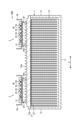
図1は、実施の形態1にかかる電力半導体装置の平面図である。図1に示した白抜きの矢印は、空気流Aの進行方向を示している。図2は、図1に示したII-II矢視断面図である。図3は、図1に示したIII-III矢視断面図である。なお、断面図については、パワーモジュール3の構成部を見やすくするために、一部のハッチングを省略している。
Fig. 1 is a plan view of a power semiconductor device according to a first embodiment. The outline arrows in Fig. 1 indicate the direction of travel of air flow A. Fig. 2 is a cross-sectional view taken along line II-II in Fig. 1. Fig. 3 is a cross-sectional view taken along line III-III in Fig. 1. Note that some hatching has been omitted from the cross-sectional views in order to make it easier to see the components of the
図1~図3に示すように、本実施の形態1にかかる電力半導体装置100は、筐体1と、ヒートシンク2と、複数のパワーモジュール3と、冷却ファン4と、を備えている。As shown in Figures 1 to 3, the
図1~図3に示すように、筐体1は、空気流Aの流入口10aと流出口10bとが対向する風路10を形成すると共に、ヒートシンク2と複数のパワーモジュール3とが一体化されたヒートシンク一体型パワーモジュールを保持するものである。筐体1は、底面部11と一対の側面部12とで凹形状とされている。筐体1は、空気流Aの進行方向に沿って延びる両端が開放されており、開放された一端が空気流Aの流入口10aとされ、開放された他端が空気流Aの流出口10bとされている。風路10は、底面部11と1対の側面部12とで囲まれた空間である。なお、図1に示す例では、空気流Aの進行方向は、流入口10aから流出口10bに向かう方向としたが、これに限定されず、流出口10bを流入口とし、冷却ファン4が配置された流入口10aを流出口として、流出口10bから流入口10aに向かう逆方向でもよい。
As shown in Figs. 1 to 3, the
筐体1は、メッキ鋼板で形成されている。メッキ鋼板は、ヒートシンク一体型パワーモジュールを保持できる剛性を有しており、薄肉化及び軽量化を実現可能な材料である。なお、筐体1は、メッキ鋼板以外の材料で形成してもよい。
The
ヒートシンク2は、複数のパワーモジュール3と一体とされ、パワーモジュール3で発生した熱を放熱するものである。図2及び図3に示すように、ヒートシンク2は、平板状のヒートシンクベース20と、ヒートシンクベース20の一面に間隔をあけて並列させて設けられた複数の平板状のフィン21と、を有している。ヒートシンク2は、一例として、ヒートシンクベース20とフィン21とが「かしめ加工」により一体化された、かしめ加工ヒートシンクである。ヒートシンク2は、風路10に複数のフィン21が配置された状態で筐体1に保持される。The
ヒートシンクベース20は、一例として矩形状である。ヒートシンクベース20は、パワーモジュール3の発熱をフィン21に効率良く伝熱できるように、熱伝導性が相対的に高い金属材料によって形成されている。ヒートシンクベース20は、一例として、アルミニウム又はアルミニウム合金といった腐食し難い金属材料によって形成されている。ヒートシンクベース20は、切削加工、ダイキャスト加工、鍛造加工、押出加工などの加工方法によって作製される。
The
ヒートシンクベース20の他面には、複数のパワーモジュール3が設けられる1つの領域に、空気流Aの進行方向に沿って凹部と凸部とが延びる凹凸面20aが形成されている。複数のパワーモジュール3が設けられる1つの領域とは、一例としてヒートシンクベース20の他面の全面である。On the other side of the
ヒートシンクベース20は、凹形状とされた筐体1の内部に複数のフィン21が収納された状態で、外周縁が側面部12の上端面に載置され、ネジ等の接合部材(図示省略)で側面部12に固定される。なお、側面部12には、ネジ等をねじ込むためのねじ孔(図示省略)が設けられている。また、ヒートシンクベース20には、側面部12に設けられたねじ孔に対応する位置にねじ孔又は貫通孔(図示省略)が設けられている。With the
フィン21は、矩形形状の薄板からなる放熱部品である。フィン21は、パワーモジュール3の発熱を放熱することができるように、熱伝導性が相対的に高い金属材料によって形成されている。フィン21は、一例として、アルミニウム又はアルミニウム合金といった腐食し難い金属材料によって形成されている。フィン21にアルミニウム等の金属材料の圧延材が用いられることにより、フィン21の加工性と放熱性とを両立させることができる。The
複数のフィン21の各々は、ヒートシンクベース20における一面に形成されたフィン挿入溝(図示省略)に挿入され、かしめられることによって、ヒートシンクベース20に固定されている。ヒートシンク2は、かしめ加工ヒートシンクである場合、ダイキャスト加工及び押出加工においてアスペクト比の加工制約がないため、フィン21を自由に設計することができ、放熱能力を向上させることができる。ただし、ヒートシンク2は、かしめ加工ヒートシンクに限定されず、他の加工方法によって作製されたものでもよい。例えば、ヒートシンク2は、押出加工又はダイキャスト加工によってフィン21とヒートシンクベース20とを一体的に作製してもよい。また、ヒートシンク一体型パワーモジュールにおいては、切削加工又は鍛造加工で作製されたヒートシンク2を用いてもよい。Each of the
パワーモジュール3は、電力半導体モジュールであり、樹脂モールドタイプである。図1に示すように、パワーモジュール3は、空気流Aの進行方向に沿って間隔をあけて複数設けられている。図1に示した電力半導体装置100では、一例として2列×3行に配列された6個のパワーモジュール3が搭載されている。なお、パワーモジュール3は、図示した6個に限定されず、空気流Aの進行方向に沿って間隔をあけて2個以上あればよい。The
図1に示すように、本実施の形態1にかかる電力半導体装置100では、空気流Aの進行方向において隣り合う一方のパワーモジュール3が、隣り合う他方のパワーモジュール3に対して、空気流Aの進行方向と直交する方向Xにオフセットされて配置されている。具体的には、空気流Aの進行方向に沿って設けられた3つのパワーモジュール3のうち、中間に位置するパワーモジュール3が、最も風上側のパワーモジュール3と最も風下側のパワーモジュール3に対して、空気流Aの進行方向と直交する方向Xにオフセットされて配置されている。1, in the
図1~図3に示すように、パワーモジュール3は、フィンベース30と、絶縁材31と、金属導体32と、半導体素子33と、接合材34と、配線ワイヤ35と、制御端子36と、主端子37と、封止材38と、を備えている。As shown in Figures 1 to 3, the
フィンベース30は、ヒートシンクベース20よりも小さい矩形形状の平板であり、パワーモジュール3をヒートシンク2へ接続するための接続部品である。フィンベース30は、パワーモジュール3の発熱をヒートシンク2に効率良く伝熱できるように、熱伝導性が相対的に高い金属材料によって形成されている。フィンベース30は、一例として、アルミニウム又はアルミニウム合金といった腐食し難い金属材料によって形成されている。フィンベース30は、切削加工、ダイキャスト加工、鍛造加工、押出加工などの加工方法によって作製される。The
フィンベース30は、ヒートシンクベース20と対向する一面に、ヒートシンクベース20の凹凸面20aに嵌る凹凸部30aが形成されている。パワーモジュール3は、フィンベース30の凹凸部30aと、ヒートシンクベース20の凹凸面20aとがプレス加工によって嵌合されることにより、ヒートシンク2と一体化される。パワーモジュール3は、凹凸面20aが形成された領域の範囲内で、自由に配置を変えて設置される。また、パワーモジュール3は、ヒートシンク2との間に熱伝導性グリスが使用されていないグリスレスパワーモジュールである。グリスレスパワーモジュールは、熱伝導性グリスを使用したパワーモジュールと比較して、パワーモジュール3において発生した熱の放熱性能を向上させることができるので、電力容量が大きい電力半導体装置に好適に用いられる。また、電力半導体装置100では、パワーモジュール3を交換する場合、熱伝導性グリスが使用されていないため、熱伝導性グリスの除去及び再配置といった処理が不要となり、生産性及びメンテナンス性が良い。The
なお、ヒートシンクベース20、フィン21及びフィンベース30の各々の材料は、ともに上述したアルミニウム系材料に限定されるものではなく、他の材料であってもよい。すなわち、ヒートシンクベース20、フィン21及びフィンベース30との材料の組み合わせは、上記とは異なる材料の組み合わせであってもよい。例えば、フィン21をアルミニウム系材料よりも熱伝導率が大きい銅系の板部品とすることで、フィン21がアルミニウム系材料からなる板部品である場合よりも、さらにフィン21の放熱能力が向上する。The materials of the
絶縁材31は、放熱性を有する絶縁シートである。絶縁材31は、フィンベース30の他面に固定されている。絶縁材31は、封止材38によって封止されたパワーモジュール3の構成部とヒートシンクベース20とを絶縁すると共に、半導体素子33が発生させた熱をヒートシンクベース20に放熱する。絶縁材31は、封止材38と同等以上の放熱性を有する。The insulating
金属導体32は、半導体素子33が搭載される基板であり、半導体素子33が発生させた熱を絶縁材31に放熱する。
The
半導体素子33は、電力制御用の半導体素子である。半導体素子33の一例は、整流ダイオード、パワートランジスタ、サイリスタ、IGBT(Insulated Gate Bipolar Transistor)である。半導体素子33は、珪素(Si)によって形成される素子、又は珪素に比べてバンドギャップが大きいワイドバンドギャップ半導体によって形成される素子が例示される。ワイドバンドギャップ半導体の一例は、炭化珪素(SiC)、窒化ガリウム系材料又はダイヤモンドである。ワイドバンドギャップ半導体を用いた半導体素子33は、許容電流密度が高く、電力損失が低いため、パワーモジュール3を小型化させることができ、ひいてはヒートシンク2及び電力半導体装置100を小型化させることができる。The
接合材34は、一例としてはんだであり、金属導体32と半導体素子33とを接合するものである。半導体素子33は、接合材34を用いて金属導体32にダイボンドされる。なお、接合材34は、はんだに限定されず、その他の構成でもよい。The
配線ワイヤ35は、半導体素子33同士を電気的に接続する。また、配線ワイヤ35は、半導体素子33と主端子37とを電気的に接続する。The
制御端子36及び主端子37は、半導体素子33に接続され、半導体素子33に電力を供給し、又は半導体素子33と外部の装置との間で信号の伝送を行う。
The
封止材38は、例えばエポキシなどの熱硬化性樹脂により形成され、パワーモジュール3の構成部間の絶縁性を確保する。封止材38は、例えばトランスファー成型によって形成されたトランスファーモールドである。ただし、封止材38は、熱硬化性樹脂に限定されない。また、封止材38の成型方法は、トランスファー成型に限定されない。The sealing
冷却ファン4は、筐体1の流入口10aから流出口10bに向かう空気流Aを生成するものである。冷却ファン4は、筐体1の流入口10aに設けられている。冷却ファン4を筐体1に取り付ける手段は、筐体1の一部にファン取付け構造を設けて冷却ファン4を取り付けてもよいし、筐体1とは別体の取付部材を流入口10aに設けて冷却ファン4を取り付けてもよい。The cooling
図4は、比較例1の電力半導体装置を示した平面図である。図5は、図4に示したV-V矢視断面図である。図6は、比較例1の電力半導体装置において、流入口から流出口に向かって流れる空気の温度分布を示したコンター図である。 Figure 4 is a plan view showing the power semiconductor device of Comparative Example 1. Figure 5 is a cross-sectional view taken along the line V-V shown in Figure 4. Figure 6 is a contour diagram showing the temperature distribution of air flowing from the inlet to the outlet in the power semiconductor device of Comparative Example 1.
ところで、図4及び図5に示した比較例1の電力半導体装置100Aでは、空気流Aの進行方向に沿って複数のパワーモジュール3が間隔をあけて設けられている。パワーモジュール3は、一例として2列×3行に配置され、空気流Aの進行方向に沿って整列させて設けられている。この場合、図6に示すように、風上側から風下側に向かってヒートシンク2のフィン21間を流れる空気の温度が連続的に高くなってしまう。すなわち、風上側のパワーモジュール3の半導体素子33からの発熱の影響を、風下側のパワーモジュール3の半導体素子33が受けるため、熱干渉により風下側のパワーモジュール3の温度が上昇してしまう。
In the
一方、図1に示すように、本実施の形態1にかかる電力半導体装置100では、空気流Aの進行方向において隣り合う一方のパワーモジュール3が、隣り合う他方のパワーモジュール3に対して、空気流Aの進行方向と直交する方向Xにオフセットされて配置されている。具体的には、空気流Aの進行方向に沿って設けられた3つのパワーモジュール3のうち、中間に位置するパワーモジュール3が、最も風上側のパワーモジュール3と最も風下側のパワーモジュール3に対して、空気流Aの進行方向と直交する方向Xにオフセットされて配置されている。1, in the
図7は、実施の形態1にかかる電力半導体装置において、流入口から流出口に向かって流れる空気の温度分布を示したコンター図である。図7に示すように、本実施の形態1にかかる電力半導体装置100では、累積的な熱干渉を低減させることができるので、風上側のパワーモジュール3の半導体素子33からの発熱の影響を、風下側のパワーモジュール3の半導体素子33が受け難くなり、風下側に低温の空気を送ることができる。よって、本実施の形態1にかかる電力半導体装置100は、パワーモジュール3の温度上昇を効果的に抑制することができる。
Figure 7 is a contour diagram showing the temperature distribution of air flowing from the inlet to the outlet in the power semiconductor device of the first embodiment. As shown in Figure 7, the
図8は、比較例2の電力半導体装置を示した平面図である。図9は、図8に示したIX-IX矢視断面図である。図10は、図8に示したX-X矢視断面図である。 Figure 8 is a plan view showing a power semiconductor device of Comparative Example 2. Figure 9 is a cross-sectional view taken along the line IX-IX shown in Figure 8. Figure 10 is a cross-sectional view taken along the line X-X shown in Figure 8.
図8~図10に示した比較例2の電力半導体装置100Bでは、ヒートシンクベース20の他面において、空気流Aの進行方向に沿って凹部と凸部とが延びる複数の凹凸面20aが、パワーモジュール3ごとに形成されている。パワーモジュール3は、ヒートシンクベース20の凹凸面20aに嵌る凹凸部30aが形成されたフィンベース30を有している。電力半導体装置100Bでは、ヒートシンクベース20に設置するパワーモジュール3の位置が凹凸面20aの設計段階で決まってしまうため、当該設計後にパワーモジュール3の配置を変更する必要が生じた場合、新たにヒートシンクベース20を作製する必要がある。
In the
一方、図1に示すように、本実施の形態1にかかる電力半導体装置100では、ヒートシンクベース20の他面に、凹凸面20aが形成されている。パワーモジュール3は、ヒートシンクベース20の凹凸面20aに嵌る凹凸部30aが形成されたフィンベース30を有している。すなわち、本実施の形態1にかかる電力半導体装置100は、ヒートシンクベース20の凹凸面20aを形成した領域内において、パワーモジュール3を自由に配置させることができるため、設計の自由度が高く、ヒートシンク一体型パワーモジュールの生産性を高めることができる。1, in the
なお、図11は、実施の形態1にかかる電力半導体装置であって、凹凸面の変形例1を示した平面図である。図12は、実施の形態1にかかる電力半導体装置であって、凹凸面の変形例2を示した平面図である。図13は、実施の形態1にかかる電力半導体装置であって、凹凸面の変形例3を示した平面図である。ヒートシンクベース20の凹凸面20aは、図1に示したように、空気流Aの進行方向に沿って凹部と凸部とが延びる構成に限定されない。図11に示すように、凹凸面20aは、例えば空気流Aの進行方向と直交する方向等、空気流Aの進行方向と交差する方向に沿って凹部と凸部とが延びるように形成された構成でもよい。また、凹部と凸部は、図1に示す連続的に形成された構成に限定されず、図12に示すように、延伸する方向に沿って断続的に形成した構成でもよい。また、図13に示すように、凹凸面20aは、例えばドット状の凸部が整列配置された構成でもよいし、その他の構成でもよい。要するに、凹凸面20aは、パワーモジュール3の凹凸部30aが嵌る構成であればよく、電力半導体装置100の構成に応じて、凹部と凸部の形状、凹部と凸部の向き、及び凹部と凸部を形成する範囲を、適宜変更して設ける。この場合、凹凸面20aの構成に合わせて、パワーモジュール3の凹凸部30aが形成される。11 is a plan view showing a first modified uneven surface of the power semiconductor device according to the first embodiment. FIG. 12 is a plan view showing a second modified uneven surface of the power semiconductor device according to the first embodiment. FIG. 13 is a plan view showing a third modified uneven surface of the power semiconductor device according to the first embodiment. The
実施の形態2.
次に、実施の形態2にかかる電力半導体装置101について説明する。図14は、実施の形態2にかかる電力半導体装置を示した平面図である。図15は、図14に示したXV-XV矢視断面図である。図16は、図14に示したXVI-XVI矢視断面図である。図17は、実施の形態2にかかる電力半導体装置の取付板を示した平面図である。なお、断面図については、パワーモジュール3の構成部を見やすくするために、一部のハッチングを省略している。
Next, a
図14~図16に示すように、本実施の形態2にかかる電力半導体装置101の筐体1は、風路10を形成する一面に複数の開口部14aが、空気流Aの進行方向に沿って間隔をあけて形成された構成である。具体的には、筐体1は、底面部11と一対の側面部12とで形成された凹形状のハウジング13と、底面部11と対向して配置され、ハウジング13の開口面を覆う取付板14と、を有している。筐体1は、ハウジング13と取付板14とで矩形の筒状とされている。筐体1は、空気流Aの進行方向に沿って延びる両端部が開放されており、開放された一端が冷却ファン4から送風された空気流Aの流入口10aとされ、開放された他端が空気流Aの流出口10bとされている。風路10は、ハウジング13と取付板14とで囲まれた空間である。なお、図14に示す例では、空気流Aの進行方向は、流入口10aから流出口10bに向かう方向としたが、これに限定されず、流出口10bを流入口とし、冷却ファン4が配置された流入口10aを流出口として、流出口10bから流入口10aに向かう逆方向でもよい。
As shown in Figures 14 to 16, the
ハウジング13及び取付板14は、メッキ鋼板で形成されている。メッキ鋼板は、ヒートシンク一体型パワーモジュールを保持できる剛性を有しており、薄肉化及び軽量化を実現可能な材料である。なお、ハウジング13及び取付板14は、メッキ鋼板以外の材料で形成してもよい。The
取付板14は、外周縁が側面部12の上端面に載置され、ネジ等の接合部材(図示省略)で側面部12に固定される。側面部12には、ネジ等の接合部材をねじ込むためのねじ孔(図示省略)が設けられている。また、取付板14には、側面部12に設けられたねじ孔に対応する位置にねじ孔又は貫通孔(図示省略)が設けられている。The outer peripheral edge of the mounting
図17に示すように、取付板14には、同形同大の3つの開口部14aが空気流Aの進行方向に沿って間隔をあけて整列させて形成されている。開口部14aは、一例として電力半導体装置101を平面的に見て、空気流Aの進行方向と直交する方向Xに長い長方形状である。17, the mounting
図14に示すように、ヒートシンク2は、開口部14aごとに個片化して設けられ、図15及び図16に示すように、フィン21が開口部14aから嵌め込まれて風路10に配置された状態で筐体1に支持されている。ヒートシンク2は、開口部14aの大きさ及び形状に合わせて形成されている。ヒートシンクベース20は、フィン21が開口部14aから嵌め込まれて風路10に配置された状態で、その外周縁が取付板14の上面に載置され、ネジ等の接合部材(図示省略)で取付板14に固定される。取付板14には、ネジ等の接合部材をねじ込むためのねじ孔(図示省略)が設けられている。また、ヒートシンクベース20には、取付板14に設けられたねじ孔に対応する位置にねじ孔又は貫通孔(図示省略)が設けられている。14, the
個片化されたヒートシンク2には、左右に並べた2つのパワーモジュール3が一体化させて設けられている。すなわち、本実施の形態2にかかる電力半導体装置101は、実施の形態1の構成と比べて、ヒートシンク2を一部省略した構成なので、装置の軽量化を図ることができる。また、本実施の形態2にかかる電力半導体装置101は、パワーモジュール3が故障した場合などにおいて、故障したパワーモジュール3が搭載されたヒートシンク2のみを交換すればよいので、メンテナンス性が向上する。The two
また、本実施の形態2にかかる電力半導体装置101においても、空気流Aの進行方向において隣り合う一方のパワーモジュール3が、隣り合う他方のパワーモジュール3に対して、空気流Aの進行方向と直交する方向Xにオフセットされて配置されている。具体的には、空気流Aの進行方向に沿って設けられた3つのパワーモジュール3のうち、中間に位置するパワーモジュール3が、最も風上側のパワーモジュール3と最も風下側のパワーモジュール3に対して、空気流Aの進行方向と直交する方向Xにオフセットされて配置されている。Also, in the
これにより、本実施の形態2にかかる電力半導体装置101は、累積的な熱干渉を低減させることができるので、風上側のパワーモジュール3の半導体素子33からの発熱の影響を、風下側のパワーモジュール3の半導体素子33が受け難くなり、風下側に低温の空気を送ることができる。よって、本実施の形態2にかかる電力半導体装置101は、パワーモジュール3の温度上昇を効果的に抑制することができる。
As a result, the
また、本実施の形態2にかかる電力半導体装置101は、ヒートシンクベース20の凹凸面20aを形成した領域内において、パワーモジュール3を自由に配置させることができるため、設計の自由度が高く、ヒートシンク一体型パワーモジュールの生産性を高めることができる。
Furthermore, in the
なお、ハウジング13と取付板14とは、別部材として形成した後に接合した構成であるが、1つの部材として一体的に成形した構成でもよい。また、開口部14aの個数は、図示した3つに限定されず、2つでもよいし、4つ以上でもよい。また、開口部14aの形状は、空気流Aの進行方向と直交する方向Xに長い長方形状に限定されず、正方形等の他の形状でもよいし、空気流Aの進行方向に沿って長い長方形状でもよい。また、個片化された1つのヒートシンク2に設けられるパワーモジュール3の個数は、図示した2つに限定されず、1つでもよいし、3つ以上でもよい。Although the
実施の形態3.
次に、実施の形態3にかかる電力半導体装置102及び102Aについて説明する。図18は、実施の形態3にかかる電力半導体装置を示した平面図である。図19は、図18に示したXIX-XIX矢視断面図である。図20は、実施の形態3にかかる電力半導体装置の取付板を示した平面図である。
Next, a description will be given of
図18~図20に示すように、本実施の形態3にかかる電力半導体装置102の筐体1は、風路10を形成する一面に複数の開口部14aが、空気流Aの進行方向に沿って間隔をあけて形成された構成である。具体的には、筐体1は、底面部11と一対の側面部12とで形成された凹形状のハウジング13と、底面部11と対向して配置され、ハウジング13の開口面を覆う取付板14と、を有している。筐体1は、ハウジング13と取付板14とで矩形の筒状とされている。筐体1は、空気流Aの進行方向に沿って延びる両端部が開放されており、開放された一端が冷却ファン4から送風された空気流Aの流入口10aとされ、開放された他端が空気流Aの流出口10bとされている。風路10は、ハウジング13と取付板14とで囲まれた空間である。なお、図18に示す例では、空気流Aの進行方向は、流入口10aから流出口10bに向かう方向としたが、これに限定されず、流出口10bを流入口とし、冷却ファン4が配置された流入口10aを流出口として、流出口10bから流入口10aに向かう逆方向でもよい。
As shown in Figures 18 to 20, the
ハウジング13及び取付板14は、メッキ鋼板で形成されている。メッキ鋼板は、複数のパワーモジュール3が一体化されたヒートシンク2を保持できる剛性を有しており、薄肉化及び軽量化を実現可能な材料である。なお、ハウジング13及び取付板14は、メッキ鋼板以外の材料で形成してもよい。The
取付板14は、外周縁が側面部12の上端面に載置され、ネジ等の接合部材(図示省略)で側面部12に固定される。側面部12には、ネジ等の接合部材をねじ込むためのねじ孔(図示省略)が設けられている。また、取付板14には、側面部12に設けられたねじ孔に対応する位置にねじ孔又は貫通孔(図示省略)が設けられている。The outer peripheral edge of the mounting
また、取付板14には、空気流Aの進行方向に沿って複数の開口部14aが間隔をあけて形成されている。複数の開口部14aは、複数列で構成されている。本実施の形態3における開口部14aは、一例として2列×3行であり、空気流Aの進行方向に沿って整列させて形成されている。図20に示すように、開口部14aは、一例として空気流Aの進行方向と直交する方向Xに長い長方形状である。In addition, a plurality of
図18に示すように、ヒートシンク2は、開口部14aごとに個片化して設けられ、図19に示すように、フィン21が開口部14aから嵌め込まれて風路10に配置された状態で筐体1に支持されている。ヒートシンク2は、開口部14aの大きさ及び形状に合わせて形成されている。ヒートシンクベース20は、フィン21が開口部14aから嵌め込まれて風路10に配置された状態で、その外周縁が取付板14の上面に載置され、ネジ等の接合部材(図示省略)で取付板14に固定される。取付板14には、ネジ等の接合部材をねじ込むためのねじ孔(図示省略)が設けられている。また、ヒートシンクベース20には、取付板14に設けられたねじ孔に対応する位置にねじ孔又は貫通孔(図示省略)が設けられている。18, the
個片化されたヒートシンク2には、それぞれ1つずつパワーモジュール3が一体化させて設けられている。すなわち、本実施の形態3にかかる電力半導体装置102は、実施の形態1の構成と比べて、ヒートシンク2を一部省略した構成なので、装置の軽量化を図ることができる。また、本実施の形態3にかかる電力半導体装置102は、パワーモジュール3が故障した場合などにおいて、故障したパワーモジュール3が搭載されたヒートシンク2のみを交換すればよいので、メンテナンス性が向上する。Each of the
また、本実施の形態3にかかる電力半導体装置102においても、空気流Aの進行方向において隣り合う一方のパワーモジュール3が、隣り合う他方のパワーモジュール3に対して、空気流Aの進行方向と直交する方向Xにオフセットされて配置されている。具体的には、空気流Aの進行方向に沿って設けられた3つのパワーモジュール3のうち、中間に位置するパワーモジュール3が、最も風上側のパワーモジュール3と最も風下側のパワーモジュール3に対して、空気流Aの進行方向と直交する方向Xにオフセットされて配置されている。Also, in the
これにより、本実施の形態3にかかる電力半導体装置102は、累積的な熱干渉を低減させることができるので、風上側のパワーモジュール3の半導体素子33からの発熱の影響を、風下側のパワーモジュール3の半導体素子33が受け難くなり、風下側に低温の空気を送ることができる。よって、本実施の形態3にかかる電力半導体装置102は、パワーモジュール3の温度上昇を効果的に抑制することができる。
As a result, the
また、本実施の形態3にかかる電力半導体装置102は、ヒートシンクベース20の凹凸面20aを形成した領域内において、パワーモジュール3を自由に配置させることができるため、設計の自由度が高く、ヒートシンク一体型パワーモジュールの生産性を高めることができる。
Furthermore, in the
なお、ハウジング13と取付板14とは、別部材として形成した後に接合した構成であるが、1つの部材として一体的に成形した構成でもよい。また、開口部14aの個数は、図示した6つに限定されず、各列に2つ以上あればよい。また、開口部14aの形状は、空気流Aの進行方向と直交する方向Xに長い長方形状に限定されず、正方形等の他の形状でもよいし、空気流Aの進行方向に沿って長い長方形状でもよい。Although the
図21は、実施の形態3にかかる電力半導体装置の変形例を示した平面図である。図22は、実施の形態3にかかる電力半導体装置の変形例の取付板を示した平面図である。図21及び図22に示した電力半導体装置102Aは、空気流Aの進行方向において隣り合う一方の開口部14aが、隣り合う他方の開口部14aに対して、空気流Aの進行方向と直交する方向Xにオフセットされて形成された構成である。具体的には、流入口10aから流出口10bに沿って形成された3つの開口部14aのうち、中間に位置する開口部14aが、最も風上側の開口部14aと最も風下側の開口部14aとに対して、空気流Aの進行方向と直交する方向Xにオフセットされて形成されている。
Figure 21 is a plan view showing a modified example of the power semiconductor device according to the third embodiment. Figure 22 is a plan view showing a mounting plate of a modified example of the power semiconductor device according to the third embodiment. The
このように構成することにより、同一構造のヒートシンク一体型パワーモジュールを取付板14の開口部14aに嵌め込んで設置するだけで、空気流Aの進行方向において隣り合う一方のパワーモジュール3を、隣り合う他方のパワーモジュール3に対して、空気流Aの進行方向と直交する方向Xにオフセットさせて配置することができる。
By configuring in this manner, simply by fitting and installing a heat sink-integrated power module of the same structure into the
実施の形態4.
次に、実施の形態4にかかる電力半導体装置103,103A及び103Bについて説明する。図23は、実施の形態4にかかる電力半導体装置を模式的に示した縦断面図である。図23に示したように、本実施の形態4にかかる電力半導体装置103は、筐体1の底面部11の構成が実施の形態2及び3で説明した構成と異なる。その他の構成は、実施の形態2又は3で説明した構成と同じである。本実施の形態4における筐体1は、風路10を形成する一面に複数の開口部14aが、空気流Aの進行方向に沿って間隔をあけて形成されている。ヒートシンク2は、開口部14aごとに個片化して設けられ、フィン21が開口部14aから嵌め込まれて風路10に配置された状態で筐体1に支持されている。
Next, the
図23に示すように、筐体1は、ヒートシンク2のフィン21と対向する底面部11において、空気流Aの進行方向の一端側を形成する流入口10aから他端側を形成する流出口10bに向かってフィン21に近づく傾斜面11aが形成されている。傾斜面11aは、流入口10aから最も風下側のヒートシンク一体型パワーモジュールの手前まで形成され、以降は流出口10bまで、フィン21と平行に延びる水平面11bとされている。すなわち、風路10は、風上側から風下側に向かうにつれて断面積が小さくなり、最も風下側のヒートシンク一体型パワーモジュールの手前で断面積が最小となり、以降は流出口10bまで同じ断面積を維持した形状で構成されている。なお、水平面11bは、厳密に水平である必要はなく、概ね水平であればよく多少傾斜していてもよい。23, the
このような構成とすることにより、底面部11とフィン21との間に沿って流れる温度上昇がほぼない空気流Bを、風下側に位置するヒートシンク2のフィン21間に多く流入させることができ、風下側に位置するパワーモジュール3の温度上昇を効果的に低減させることができる。なお、傾斜面11aは、流入口10aから最も風下側のヒートシンク一体型パワーモジュールの手前まで形成される構成に限定されず、中間に位置するヒートシンク一体型パワーモジュールの手前まで形成した構成でもよい。また、傾斜面11aは、例えば流入口10aから流出口10bまで連続させて形成した構成でもよいし、水平面11bと組み合わせて段階的に傾斜させた構成でもよい。
By adopting such a configuration, the air flow B, which flows between the
図24は、実施の形態4にかかる電力半導体装置の変形例1を模式的に示した縦断面図である。図24に示した電力半導体装置103Aでは、ヒートシンク2のフィン21と対向する底面部11において、空気流Aの進行方向の一端側を形成する流出口10bから他端側を形成する流入口10aに向かってフィン21に近づく傾斜面11aが形成された構成である。すなわち、図24に示した電力半導体装置103Aは、図23で示した電力半導体装置103と比べて、空気流Aの方向が逆である。
Figure 24 is a vertical cross-sectional view showing a first modified example of a power semiconductor device according to the fourth embodiment. In the power semiconductor device 103A shown in Figure 24, a
このように、図24に示した電力半導体装置103Aであっても、底面部11とフィン21との間に沿って流れる温度上昇がほぼない空気を、風下側に位置するヒートシンク2のフィン21間に多く流入させることができ、風下側に位置するパワーモジュール3の発熱を効果的に低減させることができる。In this way, even in the power semiconductor device 103A shown in Figure 24, the air that flows between the
図25は、実施の形態4にかかる電力半導体装置の変形例2を模式的に示した縦断面図である。図25に示した電力半導体装置103Bは、図23を参照して説明した実施の形態4の特徴を、実施の形態1の構成に適用したものである。すなわち、電力半導体装置103Bは、1つのヒートシンク2に複数のパワーモジュール3を設けた構成において、筐体1の底面部11に傾斜面11aを形成した構成である。なお、図示は省略したが、図24に示した電力半導体装置103Aの傾斜面11aを、実施の形態1の構成に適用してもよい。
Figure 25 is a vertical cross-sectional view showing a schematic diagram of a second modified example of a power semiconductor device according to the fourth embodiment. The
以上の実施の形態に示した構成は、一例を示すものであり、別の公知の技術と組み合わせることも可能であるし、実施の形態同士を組み合わせることも可能であるし、要旨を逸脱しない範囲で、構成の一部を省略、変更することも可能である。 The configurations shown in the above embodiments are merely examples, and may be combined with other known technologies, or the embodiments may be combined with each other. Also, parts of the configurations may be omitted or modified without departing from the spirit of the invention.
1 筐体、2 ヒートシンク、3 パワーモジュール、4 冷却ファン、10 風路、10a 流入口、10b 流出口、11 底面部、11a 傾斜面、11b 水平面、12 側面部、13 ハウジング、14 取付板、14a 開口部、20 ヒートシンクベース、20a 凹凸面、21 フィン、30 フィンベース、30a 凹凸部、31 絶縁材、32 金属導体、33 半導体素子、34 接合材、35 配線ワイヤ、36 制御端子、37 主端子、38 封止材、100,100A,100B,101,102,102A,103,103A,103B 電力半導体装置、A,B 空気流。 1 housing, 2 heat sink, 3 power module, 4 cooling fan, 10 air passage, 10a inlet, 10b outlet, 11 bottom surface, 11a inclined surface, 11b horizontal surface, 12 side surface, 13 housing, 14 mounting plate, 14a opening, 20 heat sink base, 20a uneven surface, 21 fin, 30 fin base, 30a uneven portion, 31 insulating material, 32 metal conductor, 33 semiconductor element, 34 bonding material, 35 wiring wire, 36 control terminal, 37 main terminal, 38 sealing material, 100, 100A, 100B, 101, 102, 102A, 103, 103A, 103B power semiconductor device, A, B air flow.
Claims (12)
平板状のヒートシンクベースと、前記ヒートシンクベースの一面に間隔をあけて並列させて設けられた複数の平板状のフィンと、を有し、前記風路に複数の前記フィンが配置された状態で前記筐体に保持されたヒートシンクと、
前記ヒートシンクベースの他面に設けられた複数のパワーモジュールと、を備え、
前記ヒートシンクベースの他面には、凹凸面が形成されており、
前記パワーモジュールは、前記ヒートシンクベースの前記凹凸面に嵌る凹凸部を有し、前記ヒートシンクベースの前記凹凸面に前記凹凸部が嵌め込まれ、前記空気流の進行方向に沿って間隔をあけて設けられており、
前記空気流の進行方向において隣り合う一方の前記パワーモジュールは、隣り合う他方の前記パワーモジュールに対して、前記ヒートシンクベースの前記凹凸面が形成された領域の範囲内で前記空気流の進行方向と直交する方向にオフセットされて配置されている、
ことを特徴とする電力半導体装置。 a housing having an air passage formed with an air inlet and an air outlet facing each other;
a heat sink having a flat heat sink base and a plurality of flat fins arranged in parallel at intervals on one surface of the heat sink base, the heat sink being held in the housing with the plurality of fins arranged in the air passage;
a plurality of power modules provided on the other surface of the heat sink base,
The other surface of the heat sink base is formed with an uneven surface,
the power module has a concave-convex portion that fits into the concave-convex surface of the heat sink base, the concave-convex portion is fitted into the concave-convex surface of the heat sink base, and the power module is provided at intervals along a direction in which the air flow advances,
one of the power modules adjacent to each other in the traveling direction of the air flow is offset from the other adjacent power module in a direction perpendicular to the traveling direction of the air flow within a range of an area in which the uneven surface of the heat sink base is formed .
2. A power semiconductor device comprising:
ことを特徴とする請求項1に記載の電力半導体装置。 The uneven surface is formed so that the concave and convex portions extend along the direction of the air flow.
2. The power semiconductor device according to claim 1 .
ことを特徴とする請求項1に記載の電力半導体装置。 The uneven surface is formed so that the recesses and protrusions extend in a direction intersecting the direction of travel of the air flow.
2. The power semiconductor device according to claim 1 .
ことを特徴とする請求項2に記載の電力半導体装置。 The recesses and the protrusions are formed continuously or intermittently along the extending direction.
3. The power semiconductor device according to claim 2 .
ことを特徴とする請求項3に記載の電力半導体装置。4. The power semiconductor device according to claim 3.
ことを特徴とする請求項1に記載の電力半導体装置。 The uneven surface has a configuration in which dot-shaped protrusions are aligned.
2. The power semiconductor device according to claim 1 .
前記ヒートシンクは、前記開口部ごとに個片化して設けられ、前記フィンが前記開口部から嵌め込まれて前記風路に配置された状態で前記筐体に保持されている、
ことを特徴とする請求項1から6のいずれか一項に記載の電力半導体装置。 The housing has a surface that defines the air passage and has a plurality of openings that are spaced apart along a direction in which the air flows,
The heat sink is provided as an individual piece for each of the openings, and is held in the housing with the fins fitted into the openings and disposed in the air passage.
7. A power semiconductor device according to claim 1, wherein the first and second electrodes are electrically connected to each other.
ことを特徴とする請求項7に記載の電力半導体装置。 The plurality of openings are aligned along the direction of travel of the air flow.
8. The power semiconductor device according to claim 7 .
ことを特徴とする請求項7に記載の電力半導体装置。 One of the openings adjacent to each other in the traveling direction of the air flow is offset from the other of the openings adjacent to each other in a direction perpendicular to the traveling direction of the air flow.
8. The power semiconductor device according to claim 7 .
ことを特徴とする請求項7に記載の電力半導体装置。 The power modules are provided one by one on the individualized heat sinks.
8. The power semiconductor device according to claim 7 .
ことを特徴とする請求項7に記載の電力半導体装置。 The plurality of openings formed at intervals along the direction of travel of the air flow are configured in a plurality of rows.
8. The power semiconductor device according to claim 7 .
ことを特徴とする請求項1から6のいずれか一項に記載の電力半導体装置。 The housing has a bottom surface facing the fins of the heat sink, the bottom surface being inclined toward the fins from one end side toward the other end side in the direction of travel of the air flow.
7. A power semiconductor device according to claim 1, wherein the first and second electrodes are electrically connected to each other.
Applications Claiming Priority (1)
| Application Number | Priority Date | Filing Date | Title |
|---|---|---|---|
| JP2023027643 | 2023-07-27 |
Publications (1)
| Publication Number | Publication Date |
|---|---|
| JP7479580B1 true JP7479580B1 (en) | 2024-05-08 |
Family
ID=90926143
Family Applications (1)
| Application Number | Title | Priority Date | Filing Date |
|---|---|---|---|
| JP2023577463A Active JP7479580B1 (en) | 2023-07-27 | 2023-07-27 | Power Semiconductor Device |
Country Status (1)
| Country | Link |
|---|---|
| JP (1) | JP7479580B1 (en) |
Citations (5)
| Publication number | Priority date | Publication date | Assignee | Title |
|---|---|---|---|---|
| JP2008263137A (en) | 2007-04-13 | 2008-10-30 | Nippon Inter Electronics Corp | Cooling device |
| JP2011066123A (en) | 2009-09-16 | 2011-03-31 | Fuji Electric Systems Co Ltd | Air-cooled power semiconductor device |
| WO2013157467A1 (en) | 2012-04-16 | 2013-10-24 | 富士電機株式会社 | Semiconductor device and cooler for semiconductor device |
| WO2022265003A1 (en) | 2021-06-18 | 2022-12-22 | 三菱電機株式会社 | Power semiconductor device, method for manufacturing same, and power conversion device |
| JP7258269B1 (en) | 2022-10-13 | 2023-04-14 | 三菱電機株式会社 | Power semiconductor device and method for manufacturing power semiconductor device |
-
2023
- 2023-07-27 JP JP2023577463A patent/JP7479580B1/en active Active
Patent Citations (5)
| Publication number | Priority date | Publication date | Assignee | Title |
|---|---|---|---|---|
| JP2008263137A (en) | 2007-04-13 | 2008-10-30 | Nippon Inter Electronics Corp | Cooling device |
| JP2011066123A (en) | 2009-09-16 | 2011-03-31 | Fuji Electric Systems Co Ltd | Air-cooled power semiconductor device |
| WO2013157467A1 (en) | 2012-04-16 | 2013-10-24 | 富士電機株式会社 | Semiconductor device and cooler for semiconductor device |
| WO2022265003A1 (en) | 2021-06-18 | 2022-12-22 | 三菱電機株式会社 | Power semiconductor device, method for manufacturing same, and power conversion device |
| JP7258269B1 (en) | 2022-10-13 | 2023-04-14 | 三菱電機株式会社 | Power semiconductor device and method for manufacturing power semiconductor device |
Similar Documents
| Publication | Publication Date | Title |
|---|---|---|
| US7190581B1 (en) | Low thermal resistance power module assembly | |
| JP5729374B2 (en) | Semiconductor module and heat dissipation member | |
| JP4569473B2 (en) | Resin-encapsulated power semiconductor module | |
| US11145571B2 (en) | Heat transfer for power modules | |
| US20090321924A1 (en) | Power Semiconductor Module | |
| JP5432085B2 (en) | Power semiconductor device | |
| WO2018146933A1 (en) | Semiconductor device and method for manufacturing semiconductor device | |
| JP2007184501A (en) | Resin-sealed semiconductor device with externally exposed radiators at its top, and method for fabrication thereof | |
| CN111261598B (en) | Packaging structure and power module applicable to same | |
| JP2013123014A (en) | Semiconductor device | |
| US9842786B2 (en) | Semiconductor device | |
| JP2006287080A (en) | Memory module | |
| JP2000323593A (en) | Semiconductor device | |
| CN114496953A (en) | Molded semiconductor package with dual integrated heat spreader | |
| JP2022065238A (en) | Semiconductor device | |
| US11232994B2 (en) | Power semiconductor device having a distance regulation portion and power conversion apparatus including the same | |
| JP7479580B1 (en) | Power Semiconductor Device | |
| JP7258269B1 (en) | Power semiconductor device and method for manufacturing power semiconductor device | |
| JP2000156439A (en) | Power semiconductor module | |
| US20100289135A1 (en) | Semiconductor chip package | |
| JP4063091B2 (en) | Power semiconductor module | |
| JP2007142472A (en) | Inverter | |
| JP2018198508A (en) | Power semiconductor device and electric power conversion system | |
| KR20140135443A (en) | method for fabricating semiconductor module and semiconductor module thereof | |
| KR102568056B1 (en) | Double heat dissipation structure for surface mount type power semiconductor |
Legal Events
| Date | Code | Title | Description |
|---|---|---|---|
| A521 | Request for written amendment filed |
Free format text: JAPANESE INTERMEDIATE CODE: A523 Effective date: 20231214 |
|
| A621 | Written request for application examination |
Free format text: JAPANESE INTERMEDIATE CODE: A621 Effective date: 20231214 |
|
| A871 | Explanation of circumstances concerning accelerated examination |
Free format text: JAPANESE INTERMEDIATE CODE: A871 Effective date: 20231214 |
|
| TRDD | Decision of grant or rejection written | ||
| A01 | Written decision to grant a patent or to grant a registration (utility model) |
Free format text: JAPANESE INTERMEDIATE CODE: A01 Effective date: 20240326 |
|
| A61 | First payment of annual fees (during grant procedure) |
Free format text: JAPANESE INTERMEDIATE CODE: A61 Effective date: 20240423 |
|
| R150 | Certificate of patent or registration of utility model |
Ref document number: 7479580 Country of ref document: JP Free format text: JAPANESE INTERMEDIATE CODE: R150 |