JP7475889B2 - Image forming device - Google Patents
Image forming device Download PDFInfo
- Publication number
- JP7475889B2 JP7475889B2 JP2020026328A JP2020026328A JP7475889B2 JP 7475889 B2 JP7475889 B2 JP 7475889B2 JP 2020026328 A JP2020026328 A JP 2020026328A JP 2020026328 A JP2020026328 A JP 2020026328A JP 7475889 B2 JP7475889 B2 JP 7475889B2
- Authority
- JP
- Japan
- Prior art keywords
- gear
- teeth
- container
- drive
- image forming
- Prior art date
- Legal status (The legal status is an assumption and is not a legal conclusion. Google has not performed a legal analysis and makes no representation as to the accuracy of the status listed.)
- Active
Links
Images


Landscapes
- Dry Development In Electrophotography (AREA)
- Electrophotography Configuration And Component (AREA)
Description
本発明は、複写機、プリンタ、ファクシミリ、これらの複数の機能を有する複合機などの画像形成装置に関する。 The present invention relates to image forming devices such as copiers, printers, facsimiles, and multifunction devices that have multiple functions.
画像形成装置では、画像形成に伴い現像剤(主にトナー)が消費されるために、補給用の現像剤を収容した収容容器(トナーボトルなどと呼ばれる)を装置本体に着脱自在とし、装着した収容容器から装置本体内の現像装置へ現像剤を補給可能な構成としている。装置本体に装着された収容容器が回転されることで、収容容器内に収容している現像剤は容器外へ排出され得る。収容容器を回転させるため、収容容器は筒状に形成されており、その外周の一周に亘って容器ギア(駆動受けギア)が設けられている。他方、装置本体にはモータなどの駆動力を生じる駆動源と、収容容器の容器ギアに噛み合うことで駆動源の駆動力を伝達する容器駆動ギア(駆動入力ギア)が設けられている。 In an image forming device, developer (mainly toner) is consumed during image formation, so a container (called a toner bottle, etc.) that contains replenishment developer is detachably attached to the device body, and developer can be replenished from the attached container to the developing device in the device body. When the container attached to the device body is rotated, the developer contained in the container can be discharged outside the container. To rotate the container, the container is formed in a cylindrical shape and a container gear (drive receiving gear) is provided around its outer periphery. On the other hand, the device body is provided with a drive source that generates a drive force, such as a motor, and a container drive gear (drive input gear) that transmits the drive force of the drive source by meshing with the container gear of the container.
ただし、収容容器を装置本体に装着する際に、容器駆動ギアの歯と容器ギアの歯との位相が合わないと、収容容器の装着が阻害され得、また場合によっては容器駆動ギア又は容器ギアが破損して、その後の収容容器の回転時に動作不良が引き起こされ得る。そこで、収容容器の装着の際に容器駆動ギアの歯と容器ギアの歯との位相が合わなければ、案内手段により容器駆動ギアと容器ギアとを相対回転させ、容器駆動ギアと容器ギアとの噛み合わせを円滑に行うようにしたものが従来から提案されている(特許文献1)。 However, if the teeth of the container drive gear and the teeth of the container gear do not match when the storage container is attached to the device body, the attachment of the storage container may be hindered, and in some cases the container drive gear or container gear may be damaged, causing malfunction when the storage container is subsequently rotated. Therefore, a device has been proposed in the past that rotates the container drive gear and the container gear relative to each other using a guide means if the teeth of the container drive gear and the teeth of the container gear do not match when the storage container is attached, thereby smoothly meshing the container drive gear and the container gear (Patent Document 1).
しかし、上記した特許文献1に記載の装置のように、容器駆動ギアや容器ギアとは別に案内手段を設けておき、この案内手段により容器駆動ギアと容器ギアとを噛み合わせる構成は複雑な構成であるが故に、部品点数が多くなり、高いコストがかかっていた。 However, as in the device described in Patent Document 1 above, a guide means is provided separately from the container drive gear and container gear, and the configuration in which the container drive gear and container gear are meshed together using this guide means is a complex configuration, resulting in a large number of parts and high costs.
本発明は上記点に鑑み、装置本体に設けられた駆動源により回転駆動される収容容器を装置本体に装着する際に、装置本体に設けられた容器駆動ギアと収容容器の容器ギアとを円滑に噛み合わせることが容易な構成でできる画像形成装置の提供を目的とする。 In view of the above, the present invention aims to provide an image forming device that can be easily configured to smoothly mesh a container drive gear provided on the device body with a container gear of the storage container when the storage container is attached to the device body and rotated by a drive source provided in the device body.
本発明の一実施形態に係る画像形成装置は、現像剤を収容する回転可能な収容容器と、前記収容容器の外周面に設けられ、回転駆動力を受ける複数のギア歯を有する駆動受けギアと、前記駆動受けギアに回転駆動力を伝達する駆動入力ギアと、前記駆動入力ギアを駆動する駆動源と、前記収容容器の回転軸線に沿って挿入された前記収容容器を、前記収容容器が所定の装着位置にあるときに前記駆動入力ギアによる回転を可能に受け入れる受け入れ装置と、を備え、前記駆動入力ギアは、前記収容容器が前記装着位置にあるときに前記ギア歯と噛み合って回転駆動力を伝達する複数の駆動伝達歯と、前記収容容器が挿入される挿入方向において前記駆動伝達歯の上流側に設けられ、前記収容容器の前記受け入れ装置への挿入動作中に前記ギア歯に当接し、前記駆動受けギアと当該駆動入力ギアとを相対回転させて、前記ギア歯と前記駆動伝達歯との位相を合わせる複数の位相合わせ歯とを有し、前記複数のギア歯は、前記収容容器が前記装着位置にあるときに、前記挿入方向に交差する方向から見て、前記挿入方向の下流側先端が前記複数の駆動伝達歯と重なり合っていない、ことを特徴とする。 An image forming apparatus according to an embodiment of the present invention includes a rotatable container that contains a developer, a drive receiving gear provided on an outer circumferential surface of the container and having a plurality of gear teeth that receive a rotational drive force, a drive input gear that transmits the rotational drive force to the drive receiving gear, a drive source that drives the drive input gear, and a receiving device that receives the container inserted along a rotation axis of the container so as to be rotatable by the drive input gear when the container is in a predetermined mounting position, and the drive input gear engages with the gear teeth when the container is in the mounting position. the drive receiving gear and the drive input gear are rotated relative to each other, and when the storage container is in the mounting position, the downstream end of the gear teeth in the insertion direction does not overlap with the multiple drive transmission teeth when viewed from a direction intersecting the insertion direction.
本発明の一実施形態に係る画像形成装置は、画像形成装置であって、前記画像形成装置に装着可能に設けられ、回転駆動力を受ける複数のギア歯が形成された駆動受けギアを有する所定のユニットと、前記駆動受けギアに回転駆動力を伝達する駆動入力ギアと、前記駆動入力ギアを駆動する駆動源と、前記所定のユニットが所定の装着位置にあるときに前記駆動入力ギアによる回転を可能に受け入れる受け入れ装置と、を備え、前記駆動入力ギアは、前記所定のユニットが前記装着位置にあるときに前記ギア歯と噛み合って回転駆動力を伝達する複数の駆動伝達歯と、前記所定のユニットが装着される装着方向において前記駆動伝達歯の上流側に設けられ、前記所定のユニットの前記受け入れ装置への装着動作中に前記ギア歯に当接し、前記駆動受けギアと当該駆動入力ギアとを相対回転させて、前記ギア歯と前記駆動伝達歯との位相を合わせる複数の位相合わせ歯とを有し、前記複数のギア歯は、前記所定のユニットが前記装着位置にあるときに、前記装着方向に交差する方向から見て、前記装着方向の下流側先端が前記複数の駆動伝達歯と重なり合っていない、ことを特徴とする。 An image forming apparatus according to one embodiment of the present invention is an image forming apparatus comprising: a specified unit having a drive receiving gear formed with a plurality of gear teeth that receive a rotational driving force and is mountable to the image forming apparatus; a drive input gear that transmits a rotational driving force to the drive receiving gear; a drive source that drives the drive input gear; and a receiving device that can receive rotation by the drive input gear when the specified unit is in a specified mounting position, wherein the drive input gear has a plurality of drive transmission teeth that mesh with the gear teeth to transmit a rotational driving force when the specified unit is in the mounting position, and a plurality of phase alignment teeth that are provided upstream of the drive transmission teeth in the mounting direction in which the specified unit is mounted, abut against the gear teeth during the mounting operation of the specified unit to the receiving device, causing the drive receiving gear and the drive input gear to rotate relative to each other, thereby aligning the phase of the gear teeth and the drive transmission teeth, and wherein when the specified unit is in the mounting position, the downstream end of the plurality of gear teeth in the mounting direction does not overlap with the plurality of drive transmission teeth when viewed from a direction intersecting the mounting direction .
本発明によれば、収容容器が装置本体に設けられた駆動源により回転駆動される構成の場合に、収容容器を装置本体に装着する際に、装置本体に設けられた駆動入力ギアと収容容器の駆動受けギアとを円滑に噛み合わせることが容易な構成で実現できる。 According to the present invention, when the storage container is configured to be rotated by a drive source provided in the device body, when the storage container is attached to the device body, it is possible to easily achieve a configuration in which the drive input gear provided in the device body and the drive receiving gear of the storage container are smoothly meshed with each other.
[画像形成装置]
まず、本実施形態の画像形成装置の概略構成について、図1を用いて説明する。画像形成装置200は、電子写真方式を用いたカラー画像形成装置であり、4色の画像形成部Pa~Pdを中間転写ベルト7上に並べて配置した、所謂中間転写タンデム方式の画像形成装置である。本実施形態の場合、画像形成装置200は、イエロー(Y)、マゼンタ(M)、シアン(C)及びブラック(Bk)の4色により画像を形成する。勿論、色数は4色に限定されるものではなく、また色の並び順もこの限りではない。
[Image forming apparatus]
First, the schematic configuration of the image forming apparatus of this embodiment will be described with reference to Fig. 1. The
画像形成装置200は、装置本体200Aに接続された原稿読取装置(図示せず)又は装置本体200Aに対し通信可能に接続されたパーソナルコンピュータ等のホスト機器からの画像信号に応じてトナー像(画像)を記録材Sに形成する。記録材Sとしては、用紙、プラスチックフィルム、布などのシート材が挙げられる。
The
記録材Sは、収納庫10内に積載されるように収納されており、摩擦分離方式を採用した給送ローラ61により画像形成タイミングに合わせて給送される。給送ローラ61により送り出された記録材Sは、搬送パスを通過し、レジストレーションローラ62へと搬送される。そして、レジストレーションローラ62において記録材Sの斜行補正やタイミング補正を行った後、記録材Sは、2次転写部T2へと送られる。2次転写部T2は、対向する2次転写内ローラ8及び2次転写外ローラ9により形成される転写ニップ部であり、所定の加圧力と静電的負荷バイアスを与えることで中間転写ベルト7上のトナー像を記録材S上に2次転写させる。
The recording material S is stored in a stack in the
次に、以上に説明した2次転写部T2までの記録材Sの搬送プロセスに対して、同様のタイミングで2次転写部T2まで送られて来るトナー像の画像形成プロセスについて説明する。画像形成部Pa~Pdは、主に、像担持体としての円筒状の感光体である感光ドラム1a~1d、帯電装置2a~2d、露光装置3a~3d、現像装置100a~100d、1次転写ローラ5a~5d、及びドラムクリーナ6a~6d等から構成される。
Next, we will explain the image formation process of the toner image sent to the secondary transfer station T2 at the same timing as the transport process of the recording material S to the secondary transfer station T2 described above. The image forming stations Pa to Pd are mainly composed of
まず、図示しない駆動装置によって矢印方向に回転駆動される感光ドラム1a~1dは、予め帯電装置2a~2dにより表面を一様に帯電される。そして、原稿読取装置などから送られてきた画像情報の信号(画像信号)に基づいて露光装置3a~3dが駆動され、レーザ光をミラーなどの回折部材を適宜経由して感光ドラム1a~1dに照射する。これにより、感光ドラム1a~1d上にそれぞれの色に応じた静電潜像が形成される。次に、感光ドラム1a~1d上に形成された静電潜像は、現像装置100a~100dによるトナー現像を経て、トナー像として顕在化する。
First, the
現像ユニットとしての現像装置100a~100dは、それぞれ、現像剤を収容する現像容器101a~101d、現像剤担持体としての現像スリーブ102a~102d、撹拌スクリュー700a~700d、現像スクリュー800a~800dなどを有する。現像スリーブ102a~102dは、現像容器101a~101d内の現像剤を担持して、感光ドラム1a~1dと対向する現像用領域に搬送し、所定の現像バイアスが印加されることで感光ドラム1a~1d上にトナーを供給して、静電潜像を現像する。本実施形態では、現像剤は、非磁性のトナーと、磁性を有するキャリアを含む2成分現像剤である。ただし、現像剤は、トナーを有する1成分現像剤であってもよい。
The developing
感光ドラム1a~1d上にトナー像が形成された後、1次転写部T1a~T1dにて、1次転写ローラ5a~5dにより所定の加圧力及び静電的負荷バイアスが与えられ、感光ドラム1a~1d上のトナー像が中間転写ベルト7上に1次転写される。感光ドラム1a~1d上に僅かに残った転写残トナーは、ドラムクリーナ6a~6dにより回収され、再び次の画像形成プロセスに備える。
After the toner images are formed on the
なお、上述のように画像形成を行うことで、現像装置100a~100dの現像容器101a~101d内のトナーが消費される。このため、現像容器101a~101d内のトナー量が低下した際には、対応する収容容器Ta~Tdからトナーが現像容器101a~101dに補給される。このために、収容容器Ta~Tdと現像容器101a~101dとの間には、それぞれトナーを供給するための搬送パイプ70が設けられている。このようなトナー補給動作についての詳細については、後述する。
Note that by forming images as described above, the toner in the developing
中間転写ベルト7は、無端状のベルトで、図示しない中間転写ベルトフレームに設置され、中間転写ベルト7の回転駆動を兼ねる2次転写内ローラ8、テンションローラ17、2次転写上流ローラ18によって張架される。2次転写内ローラ8が矢印R1方向に回転駆動すると、中間転写ベルト7が矢印R2方向へと回転駆動される。
The
上述の画像形成プロセスは、Y、M、C及びBkの画像形成部Pa~Pdにより並列処理され、中間転写ベルト7上に1次転写されたトナー像上に下流側のトナー像が順次重ね合わせるタイミングで行われる。その結果、フルカラーのトナー像が中間転写ベルト7上に形成され、2次転写部T2へと搬送される。なお、2次転写部T2を通過した後に中間転写ベルト7上に残った転写残トナーは、ベルトクリーナ装置11によって回収される。
The image formation process described above is performed in parallel by the Y, M, C and Bk image forming units Pa to Pd, and is timed so that the downstream toner images are sequentially superimposed on the toner images primarily transferred onto the
以上、それぞれ説明した搬送プロセス及び画像形成プロセスによって、2次転写部T2において記録材Sとフルカラートナー像の搬送タイミングを一致させて2次転写が行われる。その後、記録材Sは、定着装置13へと搬送される。定着ユニットとしての定着装置13は、内部にヒータを有する定着ローラ14と、定着ローラ14と対向して定着ニップ部を形成する対向ローラ15とを有する。定着装置13に搬送された記録材Sは、定着ニップ部内を通過し、定着ニップ部内で所定の圧力と熱量が加えられて、記録材Sに形成されたトナー像が加熱・加圧される。これにより、記録材S上にトナー像が溶融固着(定着)される。トナー像が定着された記録材Sは、排出トレイ63に排出される。
By the above-described conveying process and image forming process, secondary transfer is performed by matching the conveying timing of the recording material S and the full-color toner image at the secondary transfer section T2. The recording material S is then conveyed to the
上述のような各プロセスは、制御部50により制御される。制御部50は、CPU(Central Processing Unit)、ROM(Read Only Memory)、RAM(Random Access Memory)を有している。CPUは、ROMに格納された制御手順に対応するプログラム読み出しながら各部の制御を行う。また、RAMには、作業用データや入力データが格納されており、CPUは、前述のプログラム等に基づいてRAMに収納されたデータを参照して制御を行う。また、画像形成装置200は、操作パネルなどの操作部60を有し、ユーザは、操作部60により画像形成装置200の各種設定が可能である。
Each process as described above is controlled by the
[収容容器]
次に、図2(a)乃至図3を用いて、トナーを収容した収容容器Ta~Tdについて説明する。なお、収容容器Ta~Tdは各容器とも共通の構成を有するため、以下では、代表して収容容器Taについて説明する。
[Containment Container]
Next, the toner containers Ta to Td that contain the toner will be described with reference to Figures 2(a) to 3. Note that since the toner containers Ta to Td all have a common configuration, the toner container Ta will be described below as a representative.
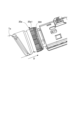
収容容器Taは、図2(a)、(b)に示すように、中空円筒状に形成され内部にトナーを収容する内部空間を備えたトナー収容部20を有する。更に、収容容器Taは、トナー収容部20の長手方向(トナー搬送方向)一端側にフランジ部21を有する。トナー収容部20は、フランジ部21に対して相対回転可能に構成されている。フランジ部21には、トナー収容部20内から搬送されてきたトナーを一時的に貯留するための中空形状を備えた排出部21hが設けられている。排出部21hの底部には、収容容器Taの外部へトナーを排出する、即ち、現像装置100a~100dへトナーを補給するための排出口21aが形成されている。また、フランジ部21の内部には、排出口21aを開閉するためのシャッタ4が設けられている。シャッタ4は、収容容器Taの内部で、フランジ部21に対して相対的に移動可能に設けられている。
2(a) and (b), the storage container Ta has a
トナー収容部20には、容器ギア20a、ポンプ部20b、突起部20dなどが形成されている。駆動受けギアとしての容器ギア20aは平歯ギアであり、装置本体200A側の容器駆動ギア302(後述する図5参照)と噛み合うことで、装置本体200A側からの回転駆動力をトナー収容部20に伝達する働きをする。ポンプ部20bは、往復動に伴いその容積が可変な樹脂製の容積可変型ポンプとなっている。なお、図2(a)、(b)の矢印ωと矢印γは、ポンプ部20bの移動方向を示す。
The
具体的には、図2(a)、(b)に示すように、ポンプ部20bは、長手方向に「山折り」部と「谷折り」部が外周部に周期的に交互に複数形成されている蛇腹状のポンプとなっている。ポンプ部20bは、往復動することで伸縮し、排出口21aを介して吸気動作と排気動作を交互に行わせる吸排気機構として機能する。フランジ部21の内周面には、カム形状の溝部21bが形成されており、トナー収容部20に備えられた突起部20dと係合する構成となっている。
Specifically, as shown in Figures 2(a) and (b),
突起部20dと溝部21bの関係について、図3を用いて説明する。図3は、溝部21bが形成された部分を展開して示した模式図である。図3において、矢印Aはトナー収容部20の回転方向(突起部20dの移動方向)、矢印B、Cはポンプ部20bの伸縮方向を示している。溝部21bは、図3に示すように、互いに傾斜方向が異なる第1溝21cと第2溝21dとが、交互に連結された構造となっている。トナー収容部20は、回転駆動されることで、突起部20dと溝部21bとの係合によりフランジ部21に対して回転軸線方向に相対移動する。これにより、ポンプ部20bが伸縮動作を行う。即ち、トナー収容部20が回転されると、ポンプ部20bは伸縮動作を行い、これにより吸排気機構を利用して排出口21aからトナーの排出が行われる。
The relationship between the
[トナー補給部の駆動構成]
次に、図4乃至図6(b)を用いて、収容容器Taから現像装置100aに補給用トナーを供給する構成について説明する。装置本体200Aは、収容容器Taを受け入れる受け入れ装置400を有する。受け入れ装置は、収容容器Taから現像装置100aにトナーを補給するトナー補給部を備えている。収容容器Tb~Tdから現像装置100b~100dに補給用トナーを供給するトナー補給部、及び、収容容器Tb~Tdを受け入れる受け入れ装置の構成についても、収容容器Taからトナーを供給するトナー補給部、及び、受け入れ装置400と同じである。そのため、それらについては説明を省略する。
[Drive configuration of toner supply unit]
Next, a configuration for supplying replenishment toner from the storage container Ta to the developing
図4に示すように、装置本体200Aの受け入れ装置400には、枠体を形成する前側板201、後側板202、前側板201と後側板202とに保持された容器上保持ガイド401、容器下保持ガイド402が備えられている。収容容器Taは、装置本体200Aの受け入れ装置400に対して着脱自在であり、受け入れ装置400に装着されている時には、容器上保持ガイド401と容器下保持ガイド402に回転可能に収容保持されている。
As shown in FIG. 4, the receiving
本実施形態では、収容容器Taは、装置本体200Aの前側から奥側(後側)に向かって、略水平方向に挿入されることで装置本体200Aの受け入れ装置400内に装着される。また、収容容器Taは、逆方向に引き抜くことで装置本体200Aの受け入れ装置400から抜き出される。このような収容容器Taの挿入方向及び抜き出し方向は、収容容器Taの長手方向及びポンプ部20bの伸縮方向と同じである。また、収容容器Taの回転軸線方向と同じである。なお、装置本体200Aの前側は、ユーザが画像形成装置200を操作する側で、図1の紙面手前側であり、奥側は図1の紙面奥側である。
In this embodiment, the storage container Ta is attached to the receiving
後側板202には、容器駆動装置300、搬送パイプ70が取り付けられている。容器駆動装置300は、図5に示すように、駆動源としての駆動モータ301、駆動入力ギアとしての容器駆動ギア302、ピニオンギア311、アイドラギア312、アイドラ段ギア308、駆動伝達ギア306、容器駆動軸307で構成される。容器駆動装置300では、駆動モータ301から生じる回転駆動力がピニオンギア311、アイドラギア312、アイドラ段ギア308、駆動伝達ギア306、容器駆動軸307を通して容器駆動ギア302に伝達される。そして、この回転駆動力が容器駆動ギア302から収容容器Taの容器ギア20aに伝達されることで、収容容器Taが回転駆動し、上述のように収容容器Taからトナーを排出させる。
The
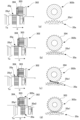
容器駆動装置300には、回動可能に支持された位相検知フラグ309が設けられ、収容容器Taのトナー収容部20、容器ギア20aと一体的に回転するカム部24に接触している。カム部24には、図6(a)、(b)に示すように、大径部24aと小径部24bがカム部24の1周で各々2ヶ所ずつ交互に設けられている。
The
図6(a)に示すように、位相検知フラグ309が大径部24aに接触しているとき、位相検知フラグ309は、容器駆動装置300に配置されたフォトセンサ310を遮光する。一方、図6(b)に示すように、位相検知フラグ309が小径部24bに接触しているとき、位相検知フラグ309はフォトセンサ310の透過範囲から外れて、フォトセンサ310は透過される。制御部50(図1参照)は、フォトセンサ310の変化(遮光→透過→遮光)を検知することで、収容容器Taの半回転を検知することができる。また、駆動モータ301の回転は、フォトセンサ310が遮光→透過→遮光を検知した後、所定時間後に停止されるように制御部50で制御されている。ポンプ部20bは、収容容器Taが半回転する毎に1往復する。
6(a), when the
このように制御部50は、収容容器Taを半回転毎に1往復させ、回転停止させることで、収容容器Taからのトナーの排出をコントロールしている。収容容器Taから排出されたトナーは、搬送パイプ70の中を通り下流側にある現像装置100a(図1参照)へと受け渡される。
In this way, the
[収容容器の着脱について]
次に、図7(a)乃至図7(d)を用いて、収容容器Taの装置本体200Aに対する着脱機構について説明する。上述したように、装置本体200Aの受け入れ装置400(図4参照)は、収容容器Taの回転軸線方向に沿って挿入された収容容器Taを受け入れるものである。図7(a)乃至図7(d)に示すように、収容容器Taの挿入方向(図中矢印D方向)に関し、容器下保持ガイド402の片側端部(下流側端部)には、引き込み部としての容器引き込み装置410が設けられている。容器引き込み装置410は、容器引き込みレバー403、引き込みばね404を有する。容器引き込みレバー403は、容器下保持ガイド402に対して回動可能に保持されている。引き込みばね404は、容器引き込みレバー403と容器下保持ガイド402とに張架されている。
[Attaching and detaching the storage container]
Next, the mechanism for attaching and detaching the storage container Ta to the device
装置本体200Aの受け入れ装置400に収容容器Taを装着する際は、まず、図7(a)に示すように、収容容器Taの先端(挿入方向下流端)と容器引き込みレバー403が接触し、容器引き込みレバー403が押し込まれる形で矢印E方向に回動を始める。このとき、引き込みばね404による力は、容器引き込みレバー403を矢印F1方向に回転させる力として働く。
When the storage container Ta is attached to the receiving
更に、収容容器Taを受け入れ装置400に押し込むと、図7(b)に示すように、容器引き込みレバー403が更に回動し、引き込みばね404の位置が死点(ばね掛け部同士を結ぶ直線上に容器引き込みレバー403の回転中心が乗る点)を超える。すると、図7(c)に示すように、引き込みばね404によって容器引き込みレバー403を回転させようとする力の方向がF2方向に切り替わる。そして、容器引き込みレバー403が収容容器Taに設けられたボス21kと係合し、収容容器Tには装置本体200Aの受け入れ装置400の奥側に引き込む力が働く。
When the storage container Ta is further pushed into the receiving
この結果、図7(d)に示すように、収容容器Taは、引き込みばね404の付勢力により容器引き込みレバー403が更に回動することで、自動で、容器下保持ガイド402に備えられた突き当て部402aまで引き込まれる。収容容器Taの先端が突き当て部402aに突き当たると、収容容器Taの装置本体200Aの受け入れ装置400に対する装着動作が完了し、収容容器Taからトナーを排出可能とする所定の装着位置(第1位置)に収容容器Taが装着される。即ち、容器引き込みレバー403は、収容容器Taの装置本体200Aの受け入れ装置400への装着動作中(挿入動作中)に収容容器Taの一部であるボス21kと係合し、引き込みばね404の付勢力により収容容器Taを第1位置に引き込む。
As a result, as shown in FIG. 7(d), the
ここで、収容容器Taの先端には、第1接点としての容器側接点23が、装置本体200Aの受け入れ装置400の収容容器Taの先端と対向する位置には、第2接点としての本体側接点405がそれぞれ設けられている。本体側接点405は、容器側接点23と接触することで収容容器Taと装置本体200Aとの間で通信が可能となる。容器側接点23は、収容容器Taに関する情報が記憶されたメモリに接続されている。収容容器Taが第1位置に装着されると、容器側接点23が本体側接点405と接触して、この情報が装置本体200Aの制御部50に送られる。
Here, a
そして、収容容器Taが装置本体200Aの受け入れ装置400の第1位置(装着位置)に装着された状態では、図5に示したように、装置本体200A側に設けられた容器駆動ギア302と、収容容器Ta側に設けられた容器ギア20aとが適切に噛み合う。つまり、容器駆動ギア302から容器ギア20aへと駆動力の伝達が可能となる。
When the storage container Ta is attached to the first position (attachment position) of the receiving
[容器駆動ギア]
次に、本実施形態の容器駆動ギア302について、図8乃至図10を用いて説明する。図8に示すように、本実施形態の容器駆動ギア302は、収容容器Taの挿入方向(装着方向:図中矢印D方向)に関し、下流側に駆動伝達部302aを有し、駆動伝達部302aの上流側に位相合わせ部302bを有している。駆動伝達部302aは複数の駆動伝達歯303が形成された平歯ギアであり、収容容器Taが上述した第1位置にあるときに容器ギア20aのギア歯20a1と噛み合って回転駆動力を伝達し得る。
[Container drive gear]
Next, the
位相合わせ部302bには、複数の位相合わせ歯304が形成されている。本実施形態では、1つの駆動伝達歯303に対し1つの位相合わせ歯304が割り当てられ、それら駆動伝達歯303と位相合わせ歯304とが挿入方向に関し間隔を空けずに連続的に一体形成されている。図9(a)に示すように、駆動伝達歯303の高さは一定であるが、位相合わせ歯304の高さは挿入方向の上流側の方が下流側よりも低くなっている。即ち、位相合わせ歯304は挿入方向に沿って上流側が低くなるように傾斜状に形成されている。
The
図9(b)に示すように、位相合わせ歯304は、ギア歯20a1(図8参照)の挿入方向の先端面と当接するガイド面304a(第一面)と、ギア歯20a1の側面に摺動されることで位相合わせ歯304を退避させる被摺擦面304b(第二面)とを有する。後述するように、本実施形態では、収容容器Taの挿入時、ギア歯20a1によって位相合わせ歯304が回転方向に退避され、容器駆動ギア302が容器ギア20aに対し相対回転される。ガイド面304aは、位相合わせ部302bの挿入方向の上流端305から各々に割り当てられた駆動伝達歯303に向かって伸びている。ガイド面304aの挿入方向の上流端が下流端よりも容器駆動ギア302の回転中心寄りとなるように、位相合わせ歯304は上記したように挿入方向に沿って上流側が低くなるように傾斜状に形成されている。
9B, the
また、被摺擦面304bは、位相合わせ歯304と位相合わせ歯304との間において、回転方向に関し挿入方向の上流側の間隔が下流側の間隔よりも広くなるように形成されている。そして、上記したガイド面304aと被摺擦面304bとで形成される位相合わせ歯304の外周面は、面取りされた滑らかな曲線に形成されている。言い換えるなら、位相合わせ歯304は略半円錐状に形成されている。
The rubbing
さらに、位相合わせ部302bでは、挿入方向の上流端が下流端よりも回転中心寄りとなるように、歯底304dが傾斜状に形成されている。このように、位相合わせ部302bには、上流端305から駆動伝達部302aに設けられた駆動伝達歯303の1歯1歯に向かって伸びるように、略半円錐形状に形成された位相合わせ歯304が複数設けられている。
Furthermore, in the
また、本実施形態の場合、図10に示すように、容器引き込みレバー403は、挿入方向に交差する方向から見て、複数のギア歯20a1の挿入方向の下流側先端20a2が複数の位相合わせ歯304と重なる状態で収容容器Taの引き込みを開始する。そうできるようにすべく、本実施形態では、引き込みレバー403の反転が始まるより先に(図7(a)、(b)参照)、ギア歯20a1とオーバーラップするように、位相合わせ歯304が設けられている。
In addition, in this embodiment, as shown in Figure 10, the
[容器駆動ギアと容器ギアとの噛み合わせについて]
次に、本実施形態の容器駆動ギア302を用いた場合における、装置本体200Aの容器駆動ギア302と、収容容器Taの容器ギア20aとの噛み合わせについて、図9(a)乃至図10を参照しながら図11(a)乃至図11(d)を用いて説明する。なお、図11(a)乃至図11(d)において、右図は左図において1点鎖線で示す位置での断面図である。
[Regarding meshing between container drive gear and container gear]
Next, the meshing between the
図11(a)は、ギア歯20a1と位相合わせ歯304とが当接する前まで収容容器Taを挿入した状態を示す。上述のように、位相合わせ歯304は、被摺擦面304b(図9(b)参照)が位相合わせ歯304と位相合わせ歯304との間において、回転方向に関し挿入方向(図中矢印D方向)の上流側の間隔が下流側の間隔よりも広くなるように形成されている。こうすると、容器駆動ギア302と容器ギア20aとの間に、クリアランスが確保される。そのため、容器駆動ギア302と容器ギア20aとが挿入方向において重なり始めたときに、ギア歯20a1は位相合わせ歯304(具体的にはガイド面304a)に当接することなく、位相合わせ歯304と位相合わせ歯304との間に侵入しやすくなる。
Figure 11 (a) shows the state in which the storage container Ta has been inserted before the gear teeth 20a1 and the
図11(b)は、容器引き込みレバー403(図10参照)により引き込み開始される位置まで収容容器Taを挿入した状態を示す。本実施形態の場合、容器駆動ギア302と容器ギア20aとが挿入方向において重なり始めてからさらに収容容器Taが押し込まれることで、ギア歯20a1は位相合わせ歯304(具体的にはガイド面304a)に当接し得る。本実施形態の場合、上述したように、容器駆動ギア302は位相合わせ部302bを有し、位相合わせ部302bには外周面が面取りされ滑らかな曲線に形成された略半円錐形状の位相合わせ歯304が形成されている。そして、位相合わせ歯304は挿入方向に沿って上流側が低くなるように傾斜状に形成されている。それ故、図11(b)右図に示すように、容器駆動ギア302と容器ギア20aとが挿入方向において重なり始めたとき(図11(a)参照)に比べて、位相合わせ歯304の歯先が容器ギア20aに近づく。
Figure 11 (b) shows the state where the storage container Ta is inserted to the position where retraction is started by the container retraction lever 403 (see Figure 10). In the case of this embodiment, the
なお、図11(b)の位置では、収容容器Taが容器引き込みレバー403によって引き込まれ始める。本実施形態の場合、上述したように、容器駆動ギア302は位相合わせ部302bを有し、位相合わせ部302bには外周面が面取りされ滑らかな曲線に形成された略半円錐形状の位相合わせ歯304が形成されている。ただし、容器駆動ギア302と容器ギア20aとが挿入方向において重なり始める前に収容容器Taの引き込みが開始されると、引き込み不良を生じさせる虞がある。そこで、本実施形態では、上述したように、引き込みレバー403の反転が始まるより先に(図7(a)、(b)参照)、ギア歯20a1とオーバーラップするように位相合わせ歯304を設けている。これにより、ギア歯20a1と位相合わせ歯304が挿入方向においてオーバーラップしてから、容器引き込みレバー403によって収容容器Taが引き込まれ始める。
At the position shown in FIG. 11(b), the container Ta starts to be drawn in by the
図11(c)は、ギア歯20a1と位相合わせ歯304とが当接する位置まで収容容器Taを挿入した状態を示す。ここでは、引き込みレバー403の引き込みによって引き込まれた収容容器Taが図11(c)に示す位置に到達すると、ギア歯20a1の上流端面が位相合わせ歯304のガイド面304aに当接する。ギア歯20a1の上流端面が位相合わせ歯304のガイド面304aに当接した状態で、収容容器Taは引き込みレバー403によってさらに下流側に引き込まれる。収容容器Taがより下流側に引き込まれることに応じて、位相合わせ歯304はギア歯20a1によって挿入方向により強く押圧される。そうすると、押圧された位相合わせ歯304はギア歯20a1の挿入方向に沿う進行経路から外れるように、ギア歯20a1によって回転方向に退避される。これに応じて、容器駆動ギア302が容器ギア20aに対して相対回転する。このように、本実施形態の場合、収容容器Taの挿入に伴いギア歯20a1と位相合わせ歯304とが衝突したとしても、容器駆動ギア302が容器ギア20aに対して相対回転するので、収容容器Taの装着の阻害が抑制される。また、容器駆動ギア302の位相合わせ歯304ひいては駆動伝達歯303と、容器ギア20aのギア歯20a1との位相が合わせられる。
Figure 11 (c) shows the state where the storage container Ta is inserted to a position where the gear teeth 20a1 and the
図11(d)は、ギア歯20a1と駆動伝達歯303とが噛み合う位置まで収容容器Taを挿入した状態を示す。引き込みレバー403による収容容器Taの引き込みは、最終的に図11(d)に示す所定の装着位置(第1位置)まで行われる。収容容器Taが第1位置に装着されることで、容器ギア20aのギア歯20a1と容器駆動ギア302の駆動伝達歯303とが適切に噛み合って、容器駆動ギア302から容器ギア20aへと駆動力の伝達が可能な状態となる。
Figure 11 (d) shows the state where the storage container Ta has been inserted to a position where the gear teeth 20a1 and the
ここで、図11(d)に示すように、本実施形態の場合、駆動伝達歯303の各々は、収容容器Taが第1位置にあるときに、ギア歯20a1の挿入方向(図中矢印D方向)の下流側先端20a2とは噛み合わない挿入方向長さに設定されている。こうすると、例えギア歯20a1の下流側先端20a2が何らかの原因によって傷ついたり欠けたりしていたとしても、収容容器Taの回転時に異音や振動などの不具合を発生させ難いので好ましい。
As shown in FIG. 11(d), in this embodiment, each of the
以上のように、本実施形態の容器駆動ギア302は、容器ギア20aのギア歯20a1と噛み合って回転駆動力を伝達する複数の駆動伝達歯303の他に、ギア歯20a1と駆動伝達歯303の位相を合わせるための複数の位相合わせ歯304を有する。位相合わせ歯304は、挿入方向に沿って上流側が低くなるように傾斜した略半円錐状に形成されている。収容容器Taの装着の際に、ギア歯20a1によって挿入方向に押圧された位相合わせ歯304はギア歯20a1の進行経路から外れる。即ち、容器駆動ギア302が容器ギア20aに対して相対回転し、位相合わせ歯304ひいては駆動伝達歯303と、容器ギア20aのギア歯20a1との位相が合わせられる。このように、本実施形態では、収容容器Taを装置本体200Aに装着する際に、装置本体200Aに設けられた容器駆動ギア302と収容容器Taの容器ギア20aとを円滑に噛み合わせることが容易な構成でできる。
As described above, the
<他の実施形態>
なお、上述の実施形態では、1つの駆動伝達歯303に対し1つの位相合わせ歯304が割り当てられ、それら駆動伝達歯303と位相合わせ歯304とが連続的に一体形成されているものを例に示したが(図9(a)参照)、これに限らない。例えば、図12に示すように、複数の位相合わせ歯304は、1乃至複数個の駆動伝達歯303を飛ばした駆動伝達歯303毎に飛び飛びに設けられていてもよい。
<Other embodiments>
In the above embodiment, one
なお、上述の実施形態では、容器駆動ギア302に位相合わせ歯304を形成した場合を例に説明したが(図9(a)参照)、これに限らない。例えば、図13に示すように、収容容器Taに位相合わせ歯304を形成してもよい。この場合、複数の位相合わせ歯304は、収容容器Taの挿入方向(図中矢印D方向)に関し、容器ギア20aの下流側に形成される。位相合わせ歯304は、収容容器Taの受け入れ装置400(図4参照)への挿入動作中に容器駆動ギア(不図示)に当接し、容器ギア20aと容器駆動ギアとを相対回転させて、容器ギア20aのギア歯20a1と容器駆動ギアの駆動伝達歯との位相を合わせる。位相合わせ歯304の構成については、上述の容器駆動ギア302に形成した場合と同じであってよいことから、ここでは説明を省略する。また、容器駆動ギア302と収容容器Taのいずれか一方のみに位相合わせ歯304を形成することに限らず、それらの両方ともに位相合わせ歯304を形成してもよい。
In the above embodiment, the
なお、上述した実施形態では、着脱可能なユニットとしてトナーを収容する収容容器Taの例を示したが、これに限られない。駆動源を持った装置本体に対し、着脱可能な被駆動側となる所定のユニットであっても、本発明を同様に実施可能である。例えば、像担持体に形成された静電潜像を現像剤を用いて現像するための現像ユニット(現像装置100a~100d)や、記録材に形成された画像を加熱・加圧することにより定着するための定着ユニット(定着装置13)にも適用可能である。現像装置100a~100dを装置本体200Aに装着可能とし、現像スリーブ102a~102d、撹拌スクリュー700a~700d、現像スクリュー800a~800dなどを、装置本体200A側からの回転駆動力により駆動させる構成に適用できる。また、定着装置13を装置本体200Aに装着可能とし、定着ローラ14や対向ローラ15などを、装置本体200A側からの回転駆動力により駆動させる構成に適用できる。
In the above embodiment, the toner container Ta is used as a removable unit, but the present invention is not limited to this. The present invention can be implemented in the same way with a specific unit that is a removable driven unit with respect to a device body having a drive source. For example, the present invention can be applied to a development unit (developing
13…定着ユニット(定着装置)、20a…駆動受けギア(容器ギア)、20a1…ギア歯、100a~100d…現像ユニット(現像装置)、301…駆動源(駆動モータ)、302…駆動入力ギア(容器駆動ギア)、303…駆動伝達歯、304…位相合わせ歯、304a…第一面(ガイド面)、304b…第二面(被摺擦面)、304d…歯底、400…受け入れ装置、410…引き込み部(容器引き込み装置)、Ta(Tb~Td)…収容容器 13...fixing unit (fixing device), 20a...drive receiving gear (container gear), 20a1...gear teeth, 100a-100d...developing unit (developing device), 301...drive source (drive motor), 302...drive input gear (container drive gear), 303...drive transmission teeth, 304...phase alignment teeth, 304a...first surface (guide surface), 304b...second surface (sliding surface), 304d...tooth bottom, 400...receiving device, 410...retraction section (container retraction device), Ta (Tb-Td)...storage container
Claims (12)
前記収容容器の外周面に設けられ、回転駆動力を受ける複数のギア歯を有する駆動受けギアと、
前記駆動受けギアに回転駆動力を伝達する駆動入力ギアと、
前記駆動入力ギアを駆動する駆動源と、
前記収容容器の回転軸線に沿って挿入された前記収容容器を、前記収容容器が所定の装着位置にあるときに前記駆動入力ギアによる回転を可能に受け入れる受け入れ装置と、を備え、
前記駆動入力ギアは、前記収容容器が前記装着位置にあるときに前記ギア歯と噛み合って回転駆動力を伝達する複数の駆動伝達歯と、前記収容容器が挿入される挿入方向において前記駆動伝達歯の上流側に設けられ、前記収容容器の前記受け入れ装置への挿入動作中に前記ギア歯に当接し、前記駆動受けギアと当該駆動入力ギアとを相対回転させて、前記ギア歯と前記駆動伝達歯との位相を合わせる複数の位相合わせ歯とを有し、
前記複数のギア歯は、前記収容容器が前記装着位置にあるときに、前記挿入方向に交差する方向から見て、前記挿入方向の下流側先端が前記複数の駆動伝達歯と重なり合っていない、
ことを特徴とする画像形成装置。 a rotatable container for containing a developer;
a drive receiving gear provided on an outer circumferential surface of the container and having a plurality of gear teeth for receiving a rotational drive force;
a drive input gear that transmits a rotational drive force to the drive receiving gear;
A drive source that drives the drive input gear;
a receiving device that receives the container inserted along the rotation axis of the container so as to be rotated by the drive input gear when the container is in a predetermined mounting position,
the drive input gear has a plurality of drive transmission teeth that mesh with the gear teeth to transmit a rotational drive force when the storage container is in the mounting position, and a plurality of phase matching teeth that are provided upstream of the drive transmission teeth in an insertion direction in which the storage container is inserted, abut against the gear teeth during an insertion operation of the storage container into the receiving device, and rotate the drive receiving gear and the drive input gear relative to each other to match the phases of the gear teeth and the drive transmission teeth ;
When the container is in the mounting position, downstream ends of the gear teeth in the insertion direction do not overlap with the drive transmission teeth when viewed in a direction intersecting the insertion direction.
1. An image forming apparatus comprising:
前記第一面は、前記挿入方向の上流端が下流端よりも回転中心寄りとなるように傾斜状に形成され、
前記第二面は、前記位相合わせ歯と前記位相合わせ歯との間において、回転方向に関し前記挿入方向の上流端の間隔が下流端の間隔よりも広くなるように形成されている、
ことを特徴とする請求項1に記載の画像形成装置。 the phase adjustment tooth has a first surface that abuts against a tip surface of the gear tooth in the insertion direction, and a second surface that abuts against a side surface of the gear tooth to relatively rotate the drive input gear,
the first surface is formed in an inclined shape such that an upstream end in the insertion direction is closer to a rotation center than a downstream end,
The second surface is formed such that a distance between the phase matching teeth at an upstream end in the insertion direction is wider than a distance between the downstream ends in the rotation direction between the phase matching teeth.
2. The image forming apparatus according to claim 1,
ことを特徴とする請求項1又は2に記載の画像形成装置。 the drive input gear has a tooth bottom formed between the phase matching teeth and the phase matching teeth so that an upstream end in the insertion direction is closer to a rotation center than a downstream end,
3. The image forming apparatus according to claim 1, wherein the image forming apparatus is a multi-color image forming apparatus.
前記引き込み部は、前記挿入方向に交差する方向から見て、前記複数のギア歯の前記挿入方向の下流側先端が前記複数の位相合わせ歯と重なる状態で前記収容容器の引き込みを開始する、
ことを特徴とする請求項1乃至3のいずれか1項に記載の画像形成装置。 the receiving device has a retracting portion that engages with a portion of the container during an insertion operation of the container into the receiving device and retracts the container into the mounting position;
the retraction section starts retracting the storage container in a state in which downstream tips of the gear teeth in the insertion direction overlap with the phase matching teeth when viewed from a direction intersecting the insertion direction.
4. The image forming apparatus according to claim 1, wherein the first and second electrodes are arranged in a first direction.
ことを特徴とする請求項1乃至4のいずれか1項に記載の画像形成装置。 The plurality of phase matching teeth are provided at intervals with respect to the plurality of drive transmission teeth.
5. The image forming apparatus according to claim 1, wherein the first and second electrodes are arranged in a first direction.
前記画像形成装置に装着可能に設けられ、回転駆動力を受ける複数のギア歯が形成された駆動受けギアを有する所定のユニットと、
前記駆動受けギアに回転駆動力を伝達する駆動入力ギアと、
前記駆動入力ギアを駆動する駆動源と、
前記所定のユニットが所定の装着位置にあるときに前記駆動入力ギアによる回転を可能に受け入れる受け入れ装置と、を備え、
前記駆動入力ギアは、前記所定のユニットが前記装着位置にあるときに前記ギア歯と噛み合って回転駆動力を伝達する複数の駆動伝達歯と、前記所定のユニットが装着される装着方向において前記駆動伝達歯の上流側に設けられ、前記所定のユニットの前記受け入れ装置への装着動作中に前記ギア歯に当接し、前記駆動受けギアと当該駆動入力ギアとを相対回転させて、前記ギア歯と前記駆動伝達歯との位相を合わせる複数の位相合わせ歯とを有し、
前記複数のギア歯は、前記所定のユニットが前記装着位置にあるときに、前記装着方向に交差する方向から見て、前記装着方向の下流側先端が前記複数の駆動伝達歯と重なり合っていない、
ことを特徴とする画像形成装置。 An image forming apparatus,
a predetermined unit that is mountably provided on the image forming apparatus and has a drive receiving gear on which a plurality of gear teeth are formed to receive a rotational drive force;
a drive input gear that transmits a rotational drive force to the drive receiving gear;
A drive source that drives the drive input gear;
a receiving device that receives the predetermined unit so as to be capable of being rotated by the drive input gear when the predetermined unit is in a predetermined mounting position;
the drive input gear has a plurality of drive transmission teeth that mesh with the gear teeth to transmit a rotational drive force when the specified unit is in the mounting position, and a plurality of phase matching teeth that are provided upstream of the drive transmission teeth in the mounting direction in which the specified unit is mounted, abut against the gear teeth during the mounting operation of the specified unit to the receiving device, rotate the drive receiving gear and the drive input gear relative to each other, and match the phases of the gear teeth and the drive transmission teeth ,
When the predetermined unit is in the mounting position, downstream ends of the gear teeth in the mounting direction do not overlap with the drive transmission teeth when viewed in a direction intersecting the mounting direction.
1. An image forming apparatus comprising:
前記第一面は、前記装着方向の上流端が下流端よりも回転中心寄りとなるように傾斜状に形成され、
前記第二面は、前記位相合わせ歯と前記位相合わせ歯との間において、回転方向に関し前記装着方向の上流端の間隔が下流端の間隔よりも広くなるように形成されている、
ことを特徴とする請求項6に記載の画像形成装置。 the phase adjustment tooth has a first surface that abuts against a tip surface of the gear tooth in the mounting direction, and a second surface that abuts against a side surface of the gear tooth to relatively rotate the drive input gear,
The first surface is formed in an inclined shape such that an upstream end in the mounting direction is closer to a rotation center than a downstream end,
The second surface is formed such that a distance between the phase matching teeth at an upstream end in the mounting direction is wider than a distance between the downstream ends in the rotation direction between the phase matching teeth.
7. The image forming apparatus according to claim 6 ,
ことを特徴とする請求項6又は7に記載の画像形成装置。 the drive input gear has a tooth bottom formed between the phase matching teeth and the phase matching teeth so that an upstream end in the mounting direction is closer to a rotation center than a downstream end,
8. The image forming apparatus according to claim 6 , wherein the first and second electrodes are arranged in a first direction.
前記引き込み部は、前記装着方向に交差する方向から見て、前記複数のギア歯の前記装着方向の下流側先端が前記複数の位相合わせ歯と重なる状態で前記所定のユニットの引き込みを開始する、
ことを特徴とする請求項6乃至8のいずれか1項に記載の画像形成装置。 the receiving device has a retracting portion that engages with a portion of the predetermined unit during an attachment operation of the predetermined unit to the receiving device and retracts the predetermined unit to the attachment position;
the retraction section starts retracting the predetermined unit in a state where downstream ends of the plurality of gear teeth in the mounting direction overlap with the plurality of phase matching teeth when viewed from a direction intersecting the mounting direction.
9. The image forming apparatus according to claim 6 , wherein the first and second electrodes are arranged in a first direction.
ことを特徴とする請求項6乃至9のいずれか1項に記載の画像形成装置。 The plurality of phase matching teeth are provided at intervals with respect to the plurality of drive transmission teeth.
10. The image forming apparatus according to claim 6 , wherein the first and second electrodes are arranged in a first direction.
ことを特徴とする請求項6乃至10のいずれか1項に記載の画像形成装置。 the predetermined unit is a developing unit for developing an electrostatic latent image formed on an image carrier by using a developer;
11. The image forming apparatus according to claim 6 , wherein the first and second electrodes are arranged in a first direction.
ことを特徴とする請求項6乃至10のいずれか1項に記載の画像形成装置。 the predetermined unit is a fixing unit for fixing an image formed on a recording material by applying heat and pressure to the image,
11. The image forming apparatus according to claim 6 , wherein the first and second electrodes are arranged in a first direction.
Priority Applications (1)
| Application Number | Priority Date | Filing Date | Title |
|---|---|---|---|
| JP2020026328A JP7475889B2 (en) | 2020-02-19 | 2020-02-19 | Image forming device |
Applications Claiming Priority (1)
| Application Number | Priority Date | Filing Date | Title |
|---|---|---|---|
| JP2020026328A JP7475889B2 (en) | 2020-02-19 | 2020-02-19 | Image forming device |
Publications (2)
| Publication Number | Publication Date |
|---|---|
| JP2021131451A JP2021131451A (en) | 2021-09-09 |
| JP7475889B2 true JP7475889B2 (en) | 2024-04-30 |
Family
ID=77550899
Family Applications (1)
| Application Number | Title | Priority Date | Filing Date |
|---|---|---|---|
| JP2020026328A Active JP7475889B2 (en) | 2020-02-19 | 2020-02-19 | Image forming device |
Country Status (1)
| Country | Link |
|---|---|
| JP (1) | JP7475889B2 (en) |
Citations (3)
| Publication number | Priority date | Publication date | Assignee | Title |
|---|---|---|---|---|
| JP2012041881A (en) | 2010-08-20 | 2012-03-01 | Mitsubishi Electric Corp | Engine starting device |
| JP2018044642A (en) | 2016-09-15 | 2018-03-22 | 株式会社リコー | Drive transmission device and image forming device |
| JP2019040189A (en) | 2017-08-28 | 2019-03-14 | キヤノン株式会社 | Image formation apparatus |
Family Cites Families (3)
| Publication number | Priority date | Publication date | Assignee | Title |
|---|---|---|---|---|
| JPH0320153A (en) * | 1989-06-16 | 1991-01-29 | Nec Corp | Gear with mesh guide |
| JPH06258884A (en) * | 1993-03-02 | 1994-09-16 | Canon Inc | Image forming device |
| JPH1124434A (en) * | 1997-06-30 | 1999-01-29 | Ricoh Co Ltd | Drive contact / separation mechanism |
-
2020
- 2020-02-19 JP JP2020026328A patent/JP7475889B2/en active Active
Patent Citations (3)
| Publication number | Priority date | Publication date | Assignee | Title |
|---|---|---|---|---|
| JP2012041881A (en) | 2010-08-20 | 2012-03-01 | Mitsubishi Electric Corp | Engine starting device |
| JP2018044642A (en) | 2016-09-15 | 2018-03-22 | 株式会社リコー | Drive transmission device and image forming device |
| JP2019040189A (en) | 2017-08-28 | 2019-03-14 | キヤノン株式会社 | Image formation apparatus |
Also Published As
| Publication number | Publication date |
|---|---|
| JP2021131451A (en) | 2021-09-09 |
Similar Documents
| Publication | Publication Date | Title |
|---|---|---|
| US9389538B2 (en) | Image forming apparatus having toner supply control | |
| US7424263B2 (en) | Toner recovery belt conveyor, process cartridge, and image forming apparatus using the same | |
| CN109426119B (en) | Image forming apparatus | |
| JPH10133450A (en) | Color image forming equipment | |
| JP7003523B2 (en) | Image forming device | |
| US20070212109A1 (en) | Image forming apparatus | |
| JP5196302B2 (en) | Image forming apparatus | |
| JP5531687B2 (en) | Image forming apparatus | |
| JP5961575B2 (en) | Toner transport mechanism and image forming apparatus | |
| US11592758B2 (en) | Photosensitive member unit capable of preventing a photosensitive member and a charging roller from accidentally being released from a separation state | |
| JP2001235970A (en) | Driving device for image carrier and image forming apparatus having the driving device | |
| JP7475889B2 (en) | Image forming device | |
| US7085517B2 (en) | Image forming apparatus and image forming unit detachably mountable thereto | |
| US20180305161A1 (en) | Drive transmission apparatus and image forming apparatus | |
| JP2004093987A (en) | Connecting mechanism and image forming apparatus having the same | |
| JP5811441B2 (en) | Image forming apparatus and transfer unit | |
| CN115248541A (en) | Image forming apparatus with a plurality of image forming units | |
| US20190391521A1 (en) | Image forming apparatus | |
| JP7658209B2 (en) | Toner supply device and image forming apparatus | |
| US20240036511A1 (en) | Driving force transmission mechanism, toner conveying device, and image forming apparatus | |
| US11835918B2 (en) | Image forming apparatus | |
| JP5306271B2 (en) | Shaft member holding mechanism, photosensitive drum unit, and image forming apparatus | |
| JP7395369B2 (en) | Image forming device | |
| JP2004061798A (en) | Intermediate transfer unit and image forming apparatus | |
| JP2002023513A (en) | Image forming device |
Legal Events
| Date | Code | Title | Description |
|---|---|---|---|
| A621 | Written request for application examination |
Free format text: JAPANESE INTERMEDIATE CODE: A621 Effective date: 20230117 |
|
| A977 | Report on retrieval |
Free format text: JAPANESE INTERMEDIATE CODE: A971007 Effective date: 20231026 |
|
| A131 | Notification of reasons for refusal |
Free format text: JAPANESE INTERMEDIATE CODE: A131 Effective date: 20231121 |
|
| A521 | Request for written amendment filed |
Free format text: JAPANESE INTERMEDIATE CODE: A523 Effective date: 20240110 |
|
| TRDD | Decision of grant or rejection written | ||
| A01 | Written decision to grant a patent or to grant a registration (utility model) |
Free format text: JAPANESE INTERMEDIATE CODE: A01 Effective date: 20240319 |
|
| A61 | First payment of annual fees (during grant procedure) |
Free format text: JAPANESE INTERMEDIATE CODE: A61 Effective date: 20240417 |
|
| R150 | Certificate of patent or registration of utility model |
Ref document number: 7475889 Country of ref document: JP Free format text: JAPANESE INTERMEDIATE CODE: R150 |