JP7475600B2 - Gaming Machines - Google Patents
Gaming Machines Download PDFInfo
- Publication number
- JP7475600B2 JP7475600B2 JP2020067367A JP2020067367A JP7475600B2 JP 7475600 B2 JP7475600 B2 JP 7475600B2 JP 2020067367 A JP2020067367 A JP 2020067367A JP 2020067367 A JP2020067367 A JP 2020067367A JP 7475600 B2 JP7475600 B2 JP 7475600B2
- Authority
- JP
- Japan
- Prior art keywords
- game
- data
- display
- main control
- unit
- Prior art date
- Legal status (The legal status is an assumption and is not a legal conclusion. Google has not performed a legal analysis and makes no representation as to the accuracy of the status listed.)
- Active
Links
- 238000004364 calculation method Methods 0.000 claims description 829
- 238000007689 inspection Methods 0.000 claims description 60
- 238000013459 approach Methods 0.000 claims description 4
- 238000000034 method Methods 0.000 description 1162
- 230000008569 process Effects 0.000 description 1078
- 230000002093 peripheral effect Effects 0.000 description 445
- 230000008859 change Effects 0.000 description 368
- 238000012545 processing Methods 0.000 description 349
- 230000005856 abnormality Effects 0.000 description 311
- 239000000872 buffer Substances 0.000 description 257
- 238000010586 diagram Methods 0.000 description 218
- 230000015654 memory Effects 0.000 description 214
- 230000000694 effects Effects 0.000 description 186
- 230000006870 function Effects 0.000 description 169
- 238000001514 detection method Methods 0.000 description 165
- 238000003860 storage Methods 0.000 description 143
- 230000005540 biological transmission Effects 0.000 description 98
- 238000012790 confirmation Methods 0.000 description 89
- 230000002159 abnormal effect Effects 0.000 description 88
- 230000001186 cumulative effect Effects 0.000 description 85
- 239000004973 liquid crystal related substance Substances 0.000 description 79
- 230000006854 communication Effects 0.000 description 72
- 238000004891 communication Methods 0.000 description 72
- 238000012360 testing method Methods 0.000 description 44
- 230000002829 reductive effect Effects 0.000 description 41
- 238000012986 modification Methods 0.000 description 35
- 230000004048 modification Effects 0.000 description 35
- FFBHFFJDDLITSX-UHFFFAOYSA-N benzyl N-[2-hydroxy-4-(3-oxomorpholin-4-yl)phenyl]carbamate Chemical compound OC1=C(NC(=O)OCC2=CC=CC=C2)C=CC(=C1)N1CCOCC1=O FFBHFFJDDLITSX-UHFFFAOYSA-N 0.000 description 34
- 230000004397 blinking Effects 0.000 description 26
- 230000007423 decrease Effects 0.000 description 22
- 230000000630 rising effect Effects 0.000 description 21
- 230000001276 controlling effect Effects 0.000 description 20
- 239000010410 layer Substances 0.000 description 20
- 230000007704 transition Effects 0.000 description 20
- 230000001965 increasing effect Effects 0.000 description 18
- 238000012546 transfer Methods 0.000 description 18
- 238000009826 distribution Methods 0.000 description 15
- 238000012544 monitoring process Methods 0.000 description 15
- 238000013461 design Methods 0.000 description 14
- 238000012423 maintenance Methods 0.000 description 14
- 239000000284 extract Substances 0.000 description 12
- 230000003247 decreasing effect Effects 0.000 description 11
- 230000007257 malfunction Effects 0.000 description 11
- 230000006872 improvement Effects 0.000 description 10
- 238000007726 management method Methods 0.000 description 10
- 238000004519 manufacturing process Methods 0.000 description 10
- 230000001360 synchronised effect Effects 0.000 description 10
- 239000003990 capacitor Substances 0.000 description 9
- 238000005034 decoration Methods 0.000 description 9
- 230000009467 reduction Effects 0.000 description 9
- 230000004913 activation Effects 0.000 description 8
- 238000001994 activation Methods 0.000 description 8
- 238000004458 analytical method Methods 0.000 description 8
- 230000007246 mechanism Effects 0.000 description 8
- 229920005989 resin Polymers 0.000 description 8
- 239000011347 resin Substances 0.000 description 8
- 238000010304 firing Methods 0.000 description 7
- 210000003128 head Anatomy 0.000 description 7
- 230000000149 penetrating effect Effects 0.000 description 7
- 241000722921 Tulipa gesneriana Species 0.000 description 6
- 230000002349 favourable effect Effects 0.000 description 6
- 230000001976 improved effect Effects 0.000 description 6
- 238000003780 insertion Methods 0.000 description 6
- 230000037431 insertion Effects 0.000 description 6
- 238000003825 pressing Methods 0.000 description 6
- 230000002265 prevention Effects 0.000 description 6
- 230000004044 response Effects 0.000 description 6
- 230000000717 retained effect Effects 0.000 description 6
- 238000005096 rolling process Methods 0.000 description 6
- 230000001960 triggered effect Effects 0.000 description 6
- 238000006243 chemical reaction Methods 0.000 description 5
- 230000007774 longterm Effects 0.000 description 5
- 208000001613 Gambling Diseases 0.000 description 4
- 230000008901 benefit Effects 0.000 description 4
- 238000012937 correction Methods 0.000 description 4
- 238000013480 data collection Methods 0.000 description 4
- 230000001419 dependent effect Effects 0.000 description 4
- 230000005389 magnetism Effects 0.000 description 4
- 238000005259 measurement Methods 0.000 description 4
- 238000002360 preparation method Methods 0.000 description 4
- 230000003111 delayed effect Effects 0.000 description 3
- 230000002452 interceptive effect Effects 0.000 description 3
- 230000007935 neutral effect Effects 0.000 description 3
- 239000000047 product Substances 0.000 description 3
- 238000007789 sealing Methods 0.000 description 3
- 101100113576 Arabidopsis thaliana CINV2 gene Proteins 0.000 description 2
- 101100452681 Arabidopsis thaliana INVD gene Proteins 0.000 description 2
- 208000002693 Multiple Abnormalities Diseases 0.000 description 2
- 238000009825 accumulation Methods 0.000 description 2
- 230000006399 behavior Effects 0.000 description 2
- 239000011521 glass Substances 0.000 description 2
- 230000008676 import Effects 0.000 description 2
- 238000009434 installation Methods 0.000 description 2
- 230000010355 oscillation Effects 0.000 description 2
- 238000011084 recovery Methods 0.000 description 2
- 230000003014 reinforcing effect Effects 0.000 description 2
- 238000011144 upstream manufacturing Methods 0.000 description 2
- ZHVOBYWXERUHMN-KVJKMEBSSA-N 3-[(3s,5r,8r,9s,10s,13s,14s,17s)-10,13-dimethyl-3-[(2r,3r,4s,5s,6r)-3,4,5-trihydroxy-6-(hydroxymethyl)oxan-2-yl]oxy-2,3,4,5,6,7,8,9,11,12,14,15,16,17-tetradecahydro-1h-cyclopenta[a]phenanthren-17-yl]-2h-furan-5-one Chemical compound O([C@@H]1C[C@H]2CC[C@@H]3[C@@H]([C@]2(CC1)C)CC[C@]1([C@H]3CC[C@@H]1C=1COC(=O)C=1)C)[C@@H]1O[C@H](CO)[C@@H](O)[C@H](O)[C@H]1O ZHVOBYWXERUHMN-KVJKMEBSSA-N 0.000 description 1
- 206010011971 Decreased interest Diseases 0.000 description 1
- 101000746134 Homo sapiens DNA endonuclease RBBP8 Proteins 0.000 description 1
- 101000998711 Homo sapiens Inversin Proteins 0.000 description 1
- 101000969031 Homo sapiens Nuclear protein 1 Proteins 0.000 description 1
- 102100033257 Inversin Human genes 0.000 description 1
- HBBGRARXTFLTSG-UHFFFAOYSA-N Lithium ion Chemical compound [Li+] HBBGRARXTFLTSG-UHFFFAOYSA-N 0.000 description 1
- 208000035450 Malformed Nails Diseases 0.000 description 1
- 101100205847 Mus musculus Srst gene Proteins 0.000 description 1
- 102100021133 Nuclear protein 1 Human genes 0.000 description 1
- 229910004444 SUB1 Inorganic materials 0.000 description 1
- 102100026785 Unconventional myosin-Ic Human genes 0.000 description 1
- 235000009754 Vitis X bourquina Nutrition 0.000 description 1
- 235000012333 Vitis X labruscana Nutrition 0.000 description 1
- 235000014787 Vitis vinifera Nutrition 0.000 description 1
- 240000006365 Vitis vinifera Species 0.000 description 1
- 230000002730 additional effect Effects 0.000 description 1
- 230000004931 aggregating effect Effects 0.000 description 1
- 239000007853 buffer solution Substances 0.000 description 1
- 244000145845 chattering Species 0.000 description 1
- 235000019504 cigarettes Nutrition 0.000 description 1
- 239000003086 colorant Substances 0.000 description 1
- 230000002860 competitive effect Effects 0.000 description 1
- 238000007906 compression Methods 0.000 description 1
- 230000006835 compression Effects 0.000 description 1
- 239000012141 concentrate Substances 0.000 description 1
- 230000006378 damage Effects 0.000 description 1
- 230000001934 delay Effects 0.000 description 1
- 238000011161 development Methods 0.000 description 1
- 238000007599 discharging Methods 0.000 description 1
- 238000005553 drilling Methods 0.000 description 1
- 238000005265 energy consumption Methods 0.000 description 1
- 238000000605 extraction Methods 0.000 description 1
- 238000007667 floating Methods 0.000 description 1
- 238000005286 illumination Methods 0.000 description 1
- 238000011423 initialization method Methods 0.000 description 1
- 229910001416 lithium ion Inorganic materials 0.000 description 1
- 239000000463 material Substances 0.000 description 1
- 230000013011 mating Effects 0.000 description 1
- 238000002156 mixing Methods 0.000 description 1
- 239000000203 mixture Substances 0.000 description 1
- 230000008450 motivation Effects 0.000 description 1
- 238000011017 operating method Methods 0.000 description 1
- 230000001151 other effect Effects 0.000 description 1
- 230000003864 performance function Effects 0.000 description 1
- 230000000737 periodic effect Effects 0.000 description 1
- 208000003580 polydactyly Diseases 0.000 description 1
- 238000007639 printing Methods 0.000 description 1
- 230000002250 progressing effect Effects 0.000 description 1
- 238000009877 rendering Methods 0.000 description 1
- 230000008439 repair process Effects 0.000 description 1
- 239000011435 rock Substances 0.000 description 1
- 238000007493 shaping process Methods 0.000 description 1
- 238000004904 shortening Methods 0.000 description 1
- 230000008054 signal transmission Effects 0.000 description 1
- 230000005236 sound signal Effects 0.000 description 1
- 239000007858 starting material Substances 0.000 description 1
- 230000003068 static effect Effects 0.000 description 1
- 239000000758 substrate Substances 0.000 description 1
- 239000002344 surface layer Substances 0.000 description 1
- 229920003002 synthetic resin Polymers 0.000 description 1
- 239000000057 synthetic resin Substances 0.000 description 1
- 238000012795 verification Methods 0.000 description 1
Images


Landscapes
- Pinball Game Machines (AREA)
Description
本発明は、ぱちんこ遊技機(一般的に「パチンコ機」とも称する)や回胴式遊技機(一般に「パチスロ機」とも称する)等の遊技機に関するものである。 The present invention relates to gaming machines such as pachinko gaming machines (commonly referred to as "pachinko machines") and slot machine gaming machines (commonly referred to as "pachislot machines").
パチンコ機等の遊技機では、始動入賞口に遊技媒体が入賞することによって抽選が実行され、抽選の結果に基づいて遊技者に遊技価値を付与するように構成されている(例えば、特許文献1参照)。
In gaming machines such as pachinko machines, a lottery is held when a gaming medium enters a starting winning slot, and gaming value is awarded to the player based on the results of the lottery (see, for example, Patent Document 1).
特許文献1に開示された遊技機では、遊技者が所定回数のハズレが続いたときに救済するための機能が設けられている遊技機があるが、このような救済機能が発動されるまではひたすらハズレ抽選を繰り返すだけの単調な遊技となってしまい興趣の低下を招くおそれがあった。The gaming machine disclosed in
本発明は、上記事情に鑑みなされたもので、遊技の興趣の低下を抑制可能な遊技機を提供することを目的とする。
The present invention has been made in consideration of the above circumstances, and has an object to provide a gaming machine that can prevent a decline in interest in gaming.
当り遊技に関する抽選を行う抽選手段と、
前記抽選手段による抽選の契機となる遊技球の入球が可能な特定始動口と、
前記特定始動口への入球に基づいて計数値を更新する計数手段と、を備え、
前記計数値が特定値になることに基づいて通常の遊技状態とは異なる特定状態に変更可能とされ、
前記計数値は、前記特定始動口に入球した場合に前記特定値に近づくように更新可能とされるだけでなく、前記特定始動口とは異なる非始動口に入球した場合にも前記特定値に近づくように更新可能とされ、
さらに、
少なくとも前記抽選手段による抽選を含めた遊技の進行を制御する主制御基板を備えた遊技機であって、
前記主制御基板は、
前記遊技の進行を制御するための演算装置と、
前記遊技を実行するための所定の機能を有する電子部品と、を搭載し、
前記電子部品は、前記演算装置の制御に伴う各種入力信号及び出力信号を送受信可能なロジック部品を含み、
前記ロジック部品には、前記遊技の進行を制御するための信号を出力可能な第1ロジック部品と、前記遊技に関連する情報を表示するための信号を出力可能な第2ロジック部品と、を含み、
前記主制御基板には、前記演算装置が配置された領域を含む第1領域と、当該第1領域の外側に第2領域があり、
前記第2領域には、当該遊技機の検査に用いる電子部品を配置可能な検査用部品実装領域が含まれ、
前記第1ロジック部品は、前記第2ロジック部品よりも前記検査用部品実装領域から離れた領域に配置される
ことを特徴とする遊技機。
A lottery means for performing a lottery regarding a winning game;
a specific starting hole into which a game ball can enter, which triggers a lottery by the lottery means;
and a counting means for updating the count value based on the ball entering the specific starting hole,
When the count value reaches a specific value, the game state can be changed to a specific state different from the normal game state.
The count value can be updated to approach the specific value when the ball enters the specific starting hole, and can also be updated to approach the specific value when the ball enters a non-starting hole different from the specific starting hole,
moreover,
A gaming machine including a main control board that controls the progress of a game including at least the lottery by the lottery means,
The main control board includes:
A calculation device for controlling the progress of the game;
and an electronic component having a predetermined function for executing the game;
the electronic components include logic components capable of transmitting and receiving various input signals and output signals associated with the control of the arithmetic device;
the logic components include a first logic component capable of outputting a signal for controlling the progress of the game, and a second logic component capable of outputting a signal for displaying information related to the game;
the main control board has a first area including an area in which the arithmetic device is disposed, and a second area outside the first area;
The second area includes an inspection component mounting area in which electronic components used for inspecting the gaming machine can be arranged,
The first logic component is disposed in a region farther from the inspection component mounting region than the second logic component.
A gaming machine characterized by:
本発明の一形態によれば、上記課題を解決し、遊技の興趣の低下を抑制することができる。 According to one embodiment of the present invention, the above-mentioned problems can be solved and a decline in interest in the game can be suppressed.
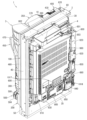
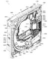
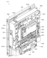
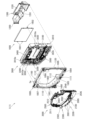
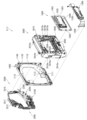
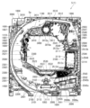
本発明の一実施形態であるパチンコ機1について、図面を参照して詳細に説明する。まず、図1乃至図9を参照して本実施形態のパチンコ機1の全体構成について説明する。図1は本発明の一実施形態であるパチンコ機の正面図である。図2はパチンコ機の右側面図であり、図3はパチンコ機の平面図であり、図4はパチンコ機の背面図である。図5はパチンコ機を前から見た斜視図であり、図6はパチンコ機を後ろから見た斜視図である。図7は本体枠から扉枠3を開放させると共に、外枠2から本体枠4を開放させた状態で前から見たパチンコ機の斜視図である。図8はパチンコ機を扉枠3、遊技盤5、本体枠4、及び外枠2に分解して前から見た分解斜視図であり、図9はパチンコ機を扉枠3、遊技盤5、本体枠4、及び外枠2に分解して後ろから見た分解斜視図である。
A
本実施形態のパチンコ機1は、遊技ホールの島設備(図示しない)に設置される枠状の外枠2と、外枠2の前面を開閉可能に閉鎖する扉枠3と、扉枠3を開閉可能に支持していると共に外枠2に開閉可能に取付けられている本体枠4と、本体枠4に前側から着脱可能に取付けられると共に扉枠3を通して遊技者側から視認可能とされ遊技者によって遊技球が打込まれる遊技領域5aを有した遊技盤5と、を備えている。
The
パチンコ機1の外枠2は、図8及び図9等に示すように、上下に離間しており左右に延びている上枠部材10及び下枠部材20と、上枠部材10及び下枠部材20の両端同士を連結しており上下に延びている左枠部材30及び右枠部材40と、を備えている。上枠部材10、下枠部材20、左枠部材30、及び右枠部材40は、前後の幅が同じ幅に形成されている。また、上枠部材10及び下枠部材20の左右の長さに対して、左枠部材30及び右枠部材40の上下の長さが、長く形成されている。
As shown in Figures 8 and 9, the
また、外枠2は、左枠部材30及び右枠部材40の下端同士を連結し下枠部材20の前側に取付けられる幕板部材50と、上枠部材10の正面視左端部側に取付けられている外枠側上ヒンジ部材60と、幕板部材50の正面視左端側上部と左枠部材30とに取付けられている外枠側下ヒンジ部材70と、を備えている。外枠2の外枠側上ヒンジ部材60と外枠側下ヒンジ部材70とによって、本体枠4及び扉枠3が開閉可能に取付けられている。
The
パチンコ機1の扉枠3は、正面視の外形が四角形で前後に貫通している貫通口111を有した枠状の扉枠ベースユニット100と、扉枠ベースユニット100の前面下部に取付けられ遊技球を貯留可能な上皿201及び下皿202を有した皿ユニット200と、扉枠ベースユニット100の前面上部に取付けられるトップユニット350と、扉枠ベースユニット100の前面左部に取付けられる左サイドユニット400と、扉枠ベースユニット100の前面右部に取付けられる右サイドユニット450と、扉枠ベースユニット100の前面右下部に皿ユニット200を貫通して取付けられ上皿201に貯留された遊技球を遊技盤5の遊技領域内へ打込むために遊技者が操作可能なハンドルユニット500と、扉枠ベースユニット100の後面下部に取付けられ遊技領域内へ打ち損じた遊技球を受けて皿ユニット200の下皿202へ排出するファールカバーユニット520と、扉枠ベースユニット100の後面下部に取付けられ上皿201の遊技球を球発射装置680へ送るための球送りユニット540と、扉枠ベースユニット100の後面に取付けられ貫通口111を閉鎖するガラスユニット560と、ガラスユニット560の後面下部を覆う防犯カバー580と、を備えている。
The
パチンコ機1の本体枠4は、一部が外枠2の枠内に挿入可能とされると共に遊技盤5の外周を支持可能とされた枠状の本体枠ベース600と、本体枠ベース600の正面視左側の上下両端に取付けられ外枠2の外枠側上ヒンジ部材60及び外枠側下ヒンジ部材70に夫々回転可能に取付けられると共に扉枠3の扉枠側上ヒンジ部材140及び扉枠側下ヒンジ部材150が夫々回転可能に取付けられる本体枠側上ヒンジ部材620及び本体枠側下ヒンジ部材640と、本体枠ベース600の正面視左側面に取付けられる補強フレーム660と、本体枠ベース600の前面下部に取付けられており遊技盤5の遊技領域5a内に遊技球を打込むための球発射装置680と、本体枠ベースの正面視右側面に取付けられており外枠2と本体枠4、及び扉枠3と本体枠4の間を施錠する施錠ユニット700と、本体枠ベース600の正面視上辺及び左辺に沿って後側に取付けられており遊技者側へ遊技球を払出す逆L字状の払出ユニット800と、本体枠ベース600の後面下部に取付けられている基板ユニット900と、本体枠ベース600の後側に開閉可能に取付けられ本体枠ベース600に取付けられた遊技盤5の後側を覆う裏カバー980と、を備えている。
The
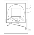
裏カバー980の内部には、パチンコ機1で行われる遊技の進行にかかる制御を行う主制御ユニット1300が設けられる。主制御ユニット1300には役物比率表示器が設けられる。役物比率表示器1317は、例えば、4桁の7セグメントLEDによって構成される。液晶表示装置によって役物比率表示器1317を構成してもよい。なお、役物比率表示器1317を主制御ユニット1300ではなく、払出制御基板ユニット950に設けられてもよい。
Inside the
また、役物比率を表示する表示装置を別に設けず、液晶表示装置1600、3114、244に役物比率を表示してもよい。この場合、液晶表示装置1600、3114、244のいずれかに役物比率を常時表示すると、役物比率を遊技者に報知でき、遊技者がパチンコ機の調子を確認できてよい。
In addition, instead of providing a separate display device to display the role ratio, the role ratio may be displayed on the liquid
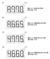
役物比率は、後述するように、役物獲得球数÷総獲得球数で計算でき、例えば役物比率の数値が高い(例えば、90%)のパチンコ機は、大当たりによって多くの賞球が得られているので、調子がよいといえる。一方、役物比率の数値が低い(例えば、10%)のパチンコ機は、大当たり遊技が少なく、大当たり中の賞球が少ないので、調子が悪いといえる。したがって、遊技者は、役物比率の数値を考慮して、遊技するパチンコ機を選択できる。 As described below, the bonus feature ratio can be calculated by dividing the number of bonus feature balls by the total number of bonus feature balls. For example, a pachinko machine with a high bonus feature ratio (e.g., 90%) can be said to be in good condition because it has won many prize balls from jackpots. On the other hand, a pachinko machine with a low bonus feature ratio (e.g., 10%) can be said to be in bad condition because it has won few jackpots and won few prize balls during jackpots. Therefore, players can choose a pachinko machine to play on by taking the bonus feature ratio into consideration.
遊技者に役物比率を報知する態様として、役物比率の数値をメイン液晶表示装置1600に表示してもよい。例えば、役物比率が70%以上の場合は赤色で数値を表示し、枠ランプを赤点灯または点滅し、69%~30%の場合は緑色で数値を表示し、枠ランプを緑点灯または点滅する。役物比率の数値は、装飾図柄と間違えないような態様で表示するとよい。例えば、変動していないときの装飾図柄の表示位置と重ならない位置に表示したり、役物比率を示す数字の大きさを装飾図柄より小さくするなどの態様で表示するとよい。表示態様は何段階に分けてもよい。
The number of the reel ratio may be displayed on the main liquid
また、役物比率の数値によってメイン液晶表示装置1600に表示される装飾図柄の態様を変えて、役物比率を遊技者に報知してもよい。例えば、役物比率が70%以上の場合は赤色で装飾図柄を表示し、枠ランプを赤点灯または点滅し、69%~30%の場合は緑色で装飾図柄を表示し、枠ランプを緑点灯または点滅する。表示態様は何段階に分けてもよい。
The mode of the decorative pattern displayed on the main
また、扉枠3に備わる液晶表示装置244に表示してもよい。その際、上述した表示態様を変えてもよいし、役物比率だけでなく、他の情報とともに表示してもよい。他の情報とは、大当たり回数や大当たりの連続回数(所謂、連チャン回数)や持ち球数、残り残金などである。
It may also be displayed on the liquid
また、役物比率に限らず、後述する連続役物比率やベース値などを、前述したように態様を変化させて表示してもよい。役物比率、連続役物比率、ベース値は、各々表示態様を変えてもよい。 In addition to the role ratio, the consecutive role ratio and base value described below may be displayed in different ways as described above. The role ratio, consecutive role ratio, and base value may each be displayed in different ways.
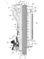
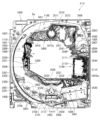
主制御ユニット1300は、図13に示すように、一度閉めたら破壊せずに開けることができない構造で封印された透明の樹脂製の主制御基板ボックス1320に封入されており、プリント基板上に配置された部品を外部から見ることができる。さらに、例えば、裏カバー980が透明な樹脂で形成されている場合、パチンコ機1の裏面側から主制御ユニット1300を見ることができ、主制御ユニット1300に設けられる役物比率表示器1317をパチンコ機1の裏面側から見ることができる。役物比率表示器1317を主制御基板ボックス1320内に封入することによって、パチンコ機1の射幸性を低く見せるための役物比率表示器1317の不正な改造を防止でき、パチンコ機1の正確な射幸性を表示できる。
As shown in FIG. 13, the
なお、裏カバー980が不透明な樹脂で形成されている場合、役物比率表示器1317の位置の裏カバー980に穴を開けたり、役物比率表示器1317の位置を透明にすることによって、パチンコ機1の裏面側から役物比率表示器1317を見られるようにしてもよい。
If the
また、裏カバー980が透明な樹脂で形成されている場合でも、役物比率表示器1317の位置の裏カバー980の表面を平坦に形成したり、裏カバー980を薄く形成することによって、役物比率表示器1317をパチンコ機1の裏面側から見やすくしてもよい。
Even if the
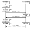
パチンコ機1の裏面下方には、アウト口1111や入賞口2001、2005、2006などを経由して遊技領域5aから流出した遊技球を集合し、パチンコ機1の外部に排出する排出口が設けられている。なお、排出口から排出された遊技球は、島設備を通じて球タンク802に供給される。本実施例のパチンコ機1には、排出口から排出される遊技球を検出する排出球センサ3060を設ける。
A discharge port is provided on the underside of the rear surface of the
図13に示すように、主制御ユニット1300には表示スイッチ1318が設けられる。主制御基板ボックス1320には、表示スイッチ1318が操作可能な穴が設けられる。表示スイッチ1318の近傍のプリント基板上又は主制御基板ボックス1320に、役物比率の表示を操作するためのスイッチであることを表示(印刷、刻印、シールなど)するとよい。なお、表示スイッチ1318は、役物比率表示器1317の近くに設けることが望ましいが、主制御ユニット1300ではなくても、操作が容易な場所であれば、他の基板(例えば、演出制御基板4700、電源装置4112)や筐体4100や前面部材4200に設けてもよい。周辺制御ユニット1500や、主制御ユニット1300とは別体で設けられた中継基板や、枠側の電源基板ボックス930内の電源基板や、払出制御基板ユニット950に設けられてもよい。また、後述するように、表示スイッチ1318はRAMクリアスイッチと兼用してもよい。表示スイッチ1318を遊技者が操作できない位置に設けることで、遊技者が誤って操作することを防止できる。
As shown in FIG. 13, the
本体枠4の払出ユニット800は、本体枠ベース600の後側に取付けられる逆L字状の払出ユニットベース801と、払出ユニットベース801の上部に取付けられており上方へ開放された左右に延びた箱状で図示しない島設備から供給される遊技球を貯留する球タンク802と、球タンク802の下側で払出ユニットベース801に取付けられており球タンク802内の遊技球を正面視左方向へ誘導する左右に延びたタンクレール803と、払出ユニットベース801における正面視左側上部の後面に取付けられタンクレール803からの遊技球を蛇行状に下方へ誘導する球誘導ユニット820と、球誘導ユニット820の下側で払出ユニットベース801から着脱可能に取付けられており球誘導ユニット820により誘導された遊技球を払出制御基板ユニット950に収容された払出制御基板951(図17を参照)からの指示に基づいて一つずつ払出す払出装置830と、払出ユニットベース801の後面に取付けられ払出装置830によって払出された遊技球を下方へ誘導すると共に皿ユニット200における上皿201での遊技球の貯留状態に応じて遊技球を通常放出口又は満タン放出口の何れかから放出させる上部満タン球経路ユニット850と、払出ユニットベース801の下端に取付けられ上部満タン球経路ユニット850の通常放出口から放出された遊技球を前方へ誘導して前端から扉枠3の貫通球通路526へ誘導する通常誘導路及び満タン放出口から放出された遊技球を前方へ誘導して前端から扉枠3の満タン球受口530へ誘導する満タン誘導路を有した下部満タン球経路ユニット860と、を備えている。
The
本体枠4の基板ユニット900は、本体枠ベース600の後側に取付けられる基板ユニットベース910と、基板ユニットベース910の正面視左側で本体枠ベース600の後側に取付けられ内部に低音用のスピーカ921を有したスピーカユニット920と、基板ユニットベース910の後側で正面視右側に取付けられ内部に電源基板が収容されている電源基板ボックス930と、スピーカユニット920の後側に取付けられており内部にインターフェイス制御基板が収容されているインターフェイス制御基板ボックス940と、電源基板ボックス930及びインターフェイス制御基板ボックス940に跨って取付けられており内部に遊技球の払出しを制御する払出制御基板951が収容された払出制御基板ユニット950と、を備えている。
The
パチンコ機1の遊技盤5は、図8及び図9等に示すように、遊技球が打込まれる遊技領域5aの外周を区画し球発射装置680から発射された遊技球を遊技領域5aの上部に案内する外レール1001及び内レール1002を有した前構成部材1000と、前構成部材1000の後側に取付けられると共に遊技領域5aの後端を区画する平板状の遊技パネル1100と、遊技パネル1100の後側の下部に取付けられており上方に開放された箱状の基板ホルダ1200と、基板ホルダ1200の後側に取付けられておりパチンコ機1の遊技を制御するための主制御基板1310を有している主制御ユニット1300と、遊技パネル1100の前側で遊技領域5a内に取付けられ遊技領域5a内に打込まれた遊技球を受入可能な複数の入賞口を有した表ユニット(図示は省略)と、基板ホルダ1200の上側で遊技パネル1100の後側に取付けられている裏ユニット3000と、を備えている。
As shown in Figures 8 and 9, the
本実施形態のパチンコ機1は、上皿201に遊技球を貯留した状態で、遊技者がハンドルレバー504を回転操作すると、球発射装置680によってハンドルレバー504の回転角度に応じた強さで遊技球が遊技盤5の遊技領域5a内へ打込まれる。そして、遊技領域5a内に打込まれた遊技球が、図示しない入賞口に受入れられると、受入れられた入賞口に応じて、所定数の遊技球が払出装置830によって上皿201に払出される。この遊技球の払出しによって遊技者の興趣を高めることができるため、上皿201内の遊技球を遊技領域5a内へ打込ませることができ、遊技者に遊技を楽しませることができる。
In the
[2.遊技盤の全体構成]
次に、パチンコ機1の遊技盤5の全体構成について、図10乃至図16を参照して詳細に説明する。図10は、遊技盤の正面図である。図11は遊技盤を右前から見た斜視図であり、図12は遊技盤を左前から見た斜視図であり、図13は遊技盤を後ろから見た斜視図である。また、図14は遊技盤を主な構成毎に分解して前から見た分解斜視図であり、図15は遊技盤を主な構成毎に分解して後ろから見た分解斜視図である。更に、図16は、遊技盤における前構成部材及び表ユニットを遊技領域内の前後方向の略中央で切断した正面図である。
[2. Overall configuration of the game board]
Next, the overall structure of the
本実施形態の遊技盤5は、遊技者がハンドルユニット500のハンドルレバー504を操作することで遊技球が打込まれる遊技領域5aを有している。また、遊技盤5は、遊技領域5aの外周を区画し外形が正面視略四角形状とされた前構成部材1000と、前構成部材1000の後側に取付けられており遊技領域5aの後端を区画する板状の遊技パネル1100と、遊技パネル1100の後側下部に取付けられている基板ホルダ1200と、基板ホルダ1200の後面に取付けられており遊技球を遊技領域5a内へ打込むことで行われる遊技内容を制御する主制御基板1310(図17を参照)を有している主制御ユニット1300と、を備えている。遊技パネル1100の前面において遊技領域5a内となる部位には、遊技球と当接する複数の障害釘が所定のゲージ配列で植設されている(図示は省略)。
The
また、遊技盤5は、主制御基板1310からの制御信号に基づいて遊技状況を表示し前構成部材1000の左下隅に遊技者側へ視認可能に取付けられている機能表示ユニット1400と、遊技パネル1100の後側に取付けられている周辺制御ユニット1500と、正面視において遊技領域5aの中央に配置されており所定の演出画像を表示可能なメイン液晶表示装置1600と、遊技パネル1100の前面に取付けられる表ユニット2000と、遊技パネル1100の後面に取付けられる裏ユニット3000と、を更に備えている。裏ユニット3000の後面にメイン液晶表示装置1600が取付けられていると共に、メイン液晶表示装置1600の後面に周辺制御ユニット1500が取付けられている。
The
遊技パネル1100は、外周が枠状の前構成部材1000の内周よりもやや大きく形成されていると共に透明な平板状のパネル板1110と、パネル板1110の外周を保持しており前構成部材1000の後側に取付けられると共に後面に裏ユニット3000が取付けられる枠状のパネルホルダ1120と、を備えている。
The
表ユニット2000は、遊技領域5a内に打込まれた遊技球を受入可能に常時開口している複数の一般入賞口2001と、複数の一般入賞口2001とは遊技領域5a内の異なる位置で遊技球を受入可能に常時開口している第一始動口2002と、遊技領域5a内の所定位置に取付けられており遊技球の通過を検知するゲート部2003と、遊技球がゲート部2003を通過することにより抽選される普通抽選結果に応じて遊技球の受入れが可能となる第二始動口2004と、第一始動口2002又は第二始動口2004への遊技球の受入れにより抽選される第一特別抽選結果又は第二特別抽選結果に応じて遊技球の受入れが何れかにおいて可能となる第一大入賞口2005及び第二大入賞口2006と、を備えている。第二大入賞口2006は、遊技球が流通する一つの流路に配置された第二上大入賞口2006aと第二下大入賞口2006bとの二つの大入賞口により構成されている(図16を参照)。
The
また、表ユニット2000は、遊技領域5a内の左右方向中央でアウト口1111の直上に取付けられており第一始動口2002及び第一大入賞口2005を有している始動口ユニット2100と、始動口ユニット2100の正面視左方で内レール1002に沿って取付けられており三つの一般入賞口2001を有しているサイドユニット下2200と、サイドユニット下2200の正面視左端上方に取付けられているサイドユニット上2300と、遊技領域5a内の略中央に取付けられており一つの一般入賞口2001、ゲート部2003、第二始動口2004、及び第二大入賞口2006を有している枠状のセンター役物2500と、を備えている。
The
裏ユニット3000は、パネルホルダ1120の後面に取付けられ前方が開放されている箱状で後壁に四角い開口部3010aを有している裏箱3010と、裏箱3010内の所定位置に配置されており表ユニット2000の一般入賞口2001に受入れられた遊技球を検知する複数の一般入賞口センサ3015と、裏箱3010の後面に取付けられておりメイン液晶表示装置1600を着脱可能に取付けるためのロック機構3020と、裏箱3010内の正面視右端に取付けられておりセンター役物2500の一般入賞口2001や第二始動口2004に受入れられた遊技球を排出するための右球通路ユニット3030と、裏箱3010内の正面視右下隅の前端付近に取付けられておりセンター役物2500の第二大入賞口2006や第二アウト口2543cに受入れられた遊技球を排出するための右下球通路ユニット3035と、を備えている。
The
また、裏ユニット3000は、裏箱3010の後面に取付けられている上中継基板3040と、上中継基板3040の後側を覆う上中継基板カバー3041と、裏箱3010の後面に回動可能に取付けられている箱状の演出駆動基板ボックス3042と、演出駆動基板ボックス3042内に収容されている演出駆動基板3043と、裏箱3010の後面に取付けられているパネル中継基板3044と、パネル中継基板3044の後側を覆うパネル中継基板カバー3045と、を備えている。
The
更に、裏ユニット3000は、裏箱3010内の前端で正面視左辺側の上下方向中央から上寄りに取付けられている裏左中装飾ユニット3050と、裏箱3010内における開口部3010aの下方で裏箱3010の後壁付近に取付けられている裏下後可動演出ユニット3100と、裏箱3010内における開口部3010aの上方で正面視左側に取付けられている裏上左可動演出ユニット3200と、裏箱3010内で開口部3010aの正面視左側に取付けられている裏左可動演出ユニット3300と、裏箱3010内における開口部3010aの上方で左右方向中央から正面視右端までにかけて取付けられている裏上中可動演出ユニット3400と、裏箱3010内における開口部3010aの下方で裏下後可動演出ユニット3100の前方に取付けられている裏下前可動演出ユニット3500と、を備えている。
The
[2-1.前構成部材]
次に、前構成部材1000について、主に図14及び図15を参照して説明する。前構成部材1000は、正面視の外形が略正方形とされ、内形が略円形状に前後方向へ貫通しており、内形の内周によって遊技領域5aの外周を区画している。この前構成部材1000は、正面視で左右方向中央から左寄りの下端から時計回りの周方向へ沿って円弧状に延び正面視左右方向中央上端を通り過ぎて右斜め上部まで延びた外レール1001と、外レール1001に略沿って前構成部材1000の内側に配置され正面視左右方向中央下部から正面視左斜め上部まで円弧状に延びた内レール1002と、内レール1002の下端の正面視右側で遊技領域5aの最も低くなった位置に形成されており後方へ向かって低くなるように傾斜しているアウト誘導部1003と、を備えている。
[2-1. Previous components]
Next, the
また、前構成部材1000は、アウト誘導部1003の正面視右端から前構成部材1000の右辺付近まで右端側が僅かに高くなるように直線状に傾斜している右下レール1004と、右下レール1004の右端から前構成部材1000の右辺に沿って外レール1001の上端の下側まで延びており上部が前構成部材1000の内側へ湾曲している右レール1005と、右レール1005の上端と外レール1001の上端とを繋いでおり外レール1001に沿って転動して来た遊技球が当接する衝止部1006と、を備えている。
The
また、前構成部材1000は、内レール1002の上端に回動可能に軸支され、外レール1001との間を閉鎖するように内レール1002の上端から上方へ延出した閉鎖位置と正面視時計回りの方向へ回動して外レール1001との間を開放した開放位置との間でのみ回動可能とされると共に閉鎖位置側へ復帰するように図示しないバネによって付勢された逆流防止部材1007を、備えている。
The
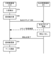
レール1001、1002の出口付近(望ましくは、逆流防止部材1007を通過した直後)の遊技盤5の裏面側には、遊技領域5aに打ち込まれた遊技球を検出する発射球センサ1020を設ける。例えば、発射球センサ1020は、磁気センサで構成し、逆流防止部材1007を通過して遊技領域5aに流入した遊技球を検出すると、信号を出力する。なお、発射球センサ1020は、遊技領域内で遊技球が必ず通過する位置に設けてもよい。遊技盤5における発射球センサ1020の位置を固定化することによって、複数機種間で仕様を共通化でき、製造現場での検査やホールでの設置後検査が容易になる。
A launched
また、レール1001、1002の出口付近などの遊技領域5aの上流に設けた発射球センサ1020は、入賞口センサが遊技球の入賞を検出する前にアウト球を検出する。すなわち、アウト球、賞球の順で遊技球を検出するので、アウト球として計数されていない遊技球に起因した賞球を検出せず、正確にベース値を計算できる。
In addition, the launched
[2-2.遊技パネル]
次に、遊技パネル1100について、主に図14及び図15を参照して説明する。遊技パネル1100は、外周が枠状の前構成部材1000の内周よりもやや大きく形成されていると共に透明な合成樹脂で形成されている平板状のパネル板1110と、パネル板1110の外周を保持しており前構成部材1000の後側に取付けられると共に後面に裏ユニット3000が取付けられる枠状のパネルホルダ1120と、を備えている。遊技パネル1100のパネル板1110は、遊技領域5a内において最も低い位置となる部位に前後に貫通しているアウト口1111が形成されている。また、パネル板1110には、前後に貫通しており表ユニット2000を取付けるための開口部1112が複数形成されている。
[2-2. Game Panel]
Next, the
遊技パネル1100のパネルホルダ1120は、パネル板1110を後側から着脱可能に保持している。また、パネルホルダ1120は、裏ユニット3000を取付けるための取付孔と、位置決め孔とが後面に複数形成されている。
The
遊技パネル1100を前構成部材1000の後側に取付けた状態では、前構成部材1000のアウト誘導部1003の後側にパネル板1110のアウト口1111が開口した状態となる。これにより、遊技領域5aの下端へ流下した遊技球が、アウト誘導部1003によって後側のアウト口1111へ誘導され、アウト口1111を通って遊技パネル1100の後側へ排出される。
When the
[2-3.基板ホルダ]
次に、基板ホルダ1200について、図11乃至図15を参照して説明する。基板ホルダ1200は、上方及び前方が開放された横長の箱状に形成されており、底面が左右方向中央へ向かって低くなるように傾斜している。この基板ホルダ1200は、遊技盤5に組立てた状態では、遊技パネル1100の後側に取付けられている裏ユニット3000の下部を下側から覆うことができる。これにより、アウト口1111を通って遊技パネル1100の後側へ排出された遊技球、及び、表ユニット2000及び裏ユニット3000から下方へ排出された遊技球、を全て受けることができ、底面に形成された排出部1201(図14を参照)から下方へ排出させることができる。
[2-3. Substrate holder]
Next, the
[2-4.主制御基板ユニット]
次に、主制御ユニット1300について、図11乃至図15、及び図17を参照して説明する。主制御ユニット1300は、基板ホルダ1200の後面に着脱可能に取付けられている。この主制御ユニット1300は、遊技内容及び遊技球の払出し等を制御する主制御基板1310と、主制御基板1310を収容しており基板ホルダ1200に取付けられる主制御基板ボックス1320と、を備えている。
[2-4. Main control board unit]
Next, the
主制御基板ボックス1320は、複数の封印機構を備えており、一つの封印機構を用いて主制御基板ボックス1320を閉じると、次に、主制御基板ボックス1320を開けるためにはその封印機構を破壊する必要があり、主制御基板ボックス1320の開閉の痕跡を残すことができる。従って、開閉の痕跡を見ることで、主制御基板ボックス1320の不正な開閉を発見することができ、主制御基板1310への不正行為に対する抑止力が高められている。
The main
[2-5.機能表示ユニット]
次に、機能表示ユニット1400について、図10乃至図12を参照して説明する。機能表示ユニット1400は、図示するように、遊技領域5aの外側で前構成部材1000の左下隅に取付けられている。この機能表示ユニット1400は、遊技盤5をパチンコ機1に組立てた状態で、扉枠3の貫通口111を通して前方(遊技者側)から視認することができる(図1を参照)。この機能表示ユニット1400は、主制御基板1310からの制御信号に基づき複数のLEDを用いて、遊技状態(遊技状況)や、普通抽選結果や特別抽選結果等を表示するものである。
[2-5. Function display unit]
Next, the
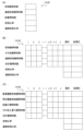
機能表示ユニット1400は、詳細な図示は省略するが、遊技状態を表示する一つのLEDからなる状態表示器と、ゲート部2003に対する遊技球の通過により抽選される普通抽選結果に基づいて二つのLEDを点滅制御することにより普通図柄を変動表示した後にこれら二つのLEDを普通抽選結果に応じた点灯態様で表示させる普通図柄表示器と、ゲート部2003に対する遊技球の通過に係る普通図柄の変動表示のうち未だ変動表示の開始条件が成立していない変動表示の個数である保留数を表示する二つのLEDからなる普通保留表示器と、第一始動口2002への遊技球の受入れ(始動入賞の発生)により抽選された第一特別抽選結果に基づいて八つのLEDを点滅制御することにより第一特別図柄を変動表示した後にこれら八つのLEDを第一特別抽選結果に応じた点灯態様で表示させる第一特別図柄表示器と、第一始動口2002への遊技球の受入れに係る第一特別図柄の変動表示のうち未だ変動表示の開始条件が成立していない変動表示の個数である保留数を表示する二つのLEDからなる第一特別保留数表示器と、第二始動口2004への遊技球の受入れ(始動入賞の発生)により抽選された第二特別抽選結果に基づいて八つのLEDを点滅制御することにより第二特別図柄を変動表示した後にこれら八つのLEDを第二特別抽選結果に応じた点灯態様で表示させる第二特別図柄表示器と、第二始動口2004への遊技球の受入れに係る第二特別図柄の変動表示のうち未だ変動表示の開始条件が成立していない変動表示の個数である保留数を表示する二つのLEDからなる第二特別保留数表示器と、第一特別抽選結果又は第二特別抽選結果が「大当り」等の時に、第一大入賞口2005や第二大入賞口2006の開閉パターンの繰返し回数(ラウンド数)を表示する二つのLEDからなるラウンド表示器と、を主に備えている。なお、機能表示ユニット1400の一部の表示器(例えば、第一特別図柄表示器)を7セグメントLEDで構成してもよい。 The function display unit 1400, although not shown in detail, comprises a status indicator consisting of one LED for displaying the game status, a normal pattern display which displays normal patterns by controlling the blinking of two LEDs based on the result of a normal lottery drawn when a game ball passes through the gate unit 2003, and then displays these two LEDs in a lighting mode corresponding to the result of the normal lottery, a normal hold display consisting of two LEDs for displaying the number of holds, which is the number of variable displays of normal patterns related to the passage of a game ball through the gate unit 2003 for which the conditions for starting the variable display have not yet been met, a first special pattern display which displays a first special pattern by controlling the blinking of eight LEDs based on the result of a first special lottery drawn when a game ball is accepted through the first start port 2002 (occurrence of a start winning), and a normal hold display which displays a number of variable displays of normal patterns related to the passage of a game ball through the gate unit 2003 for which the conditions for starting the variable display have not yet been met, The display device mainly comprises a first special reserved number display consisting of two LEDs for displaying the reserved number, which is the number of variable displays of the first special pattern for which the start conditions for the variable display have not yet been met, a second special pattern display device which displays the second special pattern by controlling the blinking of the eight LEDs based on the second special lottery result drawn upon the acceptance of a game ball into the second starting port 2004 (occurrence of a start winning), thereby displaying the second special pattern in a variable display state and then displays these eight LEDs in a lighting mode according to the second special lottery result, a second special reserved number display consisting of two LEDs for displaying the reserved number, which is the number of variable displays of the second special pattern related to the acceptance of a game ball into the second starting port 2004 for which the start conditions for the variable display have not yet been met, and a round display device consisting of two LEDs for displaying the number of times (number of rounds) the opening and closing pattern of the first large winning port 2005 and the second large winning port 2006 is repeated when the first special lottery result or the second special lottery result is a "jackpot" or the like. In addition, some of the displays of the function display unit 1400 (for example, the first special pattern display) may be configured with a 7-segment LED.
この機能表示ユニット1400では、備えられているLEDを、適宜、点灯、消灯、及び、点滅、等させることにより、保留数や図柄等を表示することができる。
This
[2-6.周辺制御ユニット]
次に、周辺制御ユニット1500について、図13及び図15を参照して説明する。周辺制御ユニット1500は、裏ユニット3000の裏箱3010の後面に取付けられている。周辺制御ユニット1500は、主制御基板1310からの制御信号に基づいて遊技者に提示する演出を制御する周辺制御基板1510(図17を参照)と、周辺制御基板1510を収容している周辺制御基板ボックス1520と、を備えている。周辺制御基板1510は、発光演出、サウンド演出、及び可動演出、等を制御するための周辺制御部1511と、演出画像を制御するための液晶表示制御部1512と、を備えている(図17を参照)。
[2-6. Peripheral control unit]
Next, the
[2-7.メイン液晶表示装置]
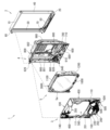
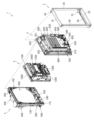
次に、メイン液晶表示装置1600について、図10乃至図16を参照して説明する。メイン液晶表示装置1600は、正面視において遊技領域5aの中央に配置されており、遊技パネル1100の後側に裏ユニット3000の裏箱3010を介して取付けられている。詳述すると、メイン液晶表示装置1600は、裏箱3010の後壁の略中央の後面に対して、着脱可能に取付けられている。このメイン液晶表示装置1600は、遊技盤5を組立てた状態で、枠状のセンター役物2500の枠内を通して、前側(遊技者側)から視認することができる。このメイン液晶表示装置1600は、白色LEDをバックライトとしたフルカラーの表示装置であり、静止画像や動画を表示することができる。
[2-7. Main LCD display device]
Next, the main liquid
メイン液晶表示装置1600は、図14及び図15に示すように、正面視左側面から外方へ突出している二つの左固定片1601と、正面視右側面から外方へ突出している右固定片1602と、を備えている。このメイン液晶表示装置1600は、液晶画面を前方へ向けた状態で、後述する裏箱3010の枠状の液晶取付部内の正面視左内周面に開口している二つの固定溝3010cに、裏箱3010の斜め後方から二つの左固定片1601を挿入した上で、右固定片1602側を前方へ移動させて、右固定片1602をロック機構3020の開口部内に挿入し、ロック機構3020を下方へスライドさせることにより、裏箱3010に取付けられる。
As shown in Figs. 14 and 15, the main
[2-8.表ユニットの全体構成]
次に、表ユニット2000について、主に図10乃至図12、図14乃至図16を参照して説明する。遊技盤5の表ユニット2000は、遊技パネル1100のパネル板1110に、前方から取付けられており、前端がパネル板1110の前面よりも前方へ突出していると共に、後端が開口部1112を貫通してパネル板1110の後面よりも後方へ突出している。本実施形態の表ユニット2000は、遊技領域5a内に打込まれた遊技球を受入可能としており常時開口している複数の一般入賞口2001と、複数の一般入賞口2001とは遊技領域5a内の異なる位置で遊技球を受入可能に常時開口している第一始動口2002と、遊技領域5a内の所定位置に取付けられており遊技球の通過を検知するゲート部2003と、遊技球がゲート部2003を通過することにより抽選される普通抽選結果に応じて遊技球の受入れが可能となる第二始動口2004と、第一始動口2002又は第二始動口2004への遊技球の受入れにより抽選される第一特別抽選結果又は第二特別抽選結果に応じて何れかにおいて遊技球の受入れが可能となる第一大入賞口2005及び第二大入賞口2006と、を備えている。
[2-8. Overall structure of the table unit]
Next, the
複数(ここでは四つ)の一般入賞口2001は、三つが遊技領域5a内の下部に配置されており、残りの一つが遊技領域5a内における正面視右上付近に配置されている。第一始動口2002は、遊技領域5a内の左右方向中央でアウト口1111の直上に配置されている。ゲート部2003は、遊技領域5a内における正面視右上で衝止部1006の略直下に配置されている。第二始動口2004は、ゲート部2003の直下から正面視右寄りに配置されている。上述した複数の一般入賞口2001のうち遊技領域5a内の正面視右上付近に配置されている一般入賞口2001は、第二始動口2004の直上に配置されている。第一大入賞口2005は、第一始動口2002とアウト口1111との間に配置されている。第二大入賞口2006は、第一始動口2002の正面視右方で第一大入賞口2005よりも上方に配置されている。
Three of the multiple (four here) general winning
表ユニット2000における第二大入賞口2006は、図16に示すように、遊技球が流通する一つの流路に沿って配置された第二上大入賞口2006aと第二下大入賞口2006bとにより構成されている。第二大入賞口2006は、第二上大入賞口2006aが遊技領域5a内における正面視右下付近に配置されており、第二下大入賞口2006bが第二上大入賞口2006aの正面視左側で下方に配置されている。
As shown in FIG. 16, the second
また、表ユニット2000は、遊技領域5a内の左右方向中央でアウト口1111の直上に取付けられており第一始動口2002及び第一大入賞口2005を有している始動口ユニット2100と、始動口ユニット2100の正面視左方で内レール1002に沿って取付けられており三つの一般入賞口2001を有しているサイドユニット下2200と、サイドユニット下2200の正面視左端上方に取付けられているサイドユニット上2300と、遊技領域5a内の略中央に取付けられており一つの一般入賞口2001、ゲート部2003、第二始動口2004、及び第二大入賞口2006を有している枠状のセンター役物2500と、を備えている。
The
[2-8a.始動口ユニット]
次に、表ユニット2000の始動口ユニット2100について、説明する。始動口ユニット2100は、遊技領域5a内において、左右方向中央の下端部付近でアウト口1111の直上に配置されており、パネル板1110に前方から取付けられている。この始動口ユニット2100は、第一始動口2002及び第一大入賞口2005を有している。
[2-8a. Starting unit]
Next, the
始動口ユニット2100は、パネル板1110の前面に取付けられ左右に延びた矩形状で前後に貫通している第一大入賞口2005を有した平板状のユニットベース2101と、ユニットベース2101における第一大入賞口2005の上方で左右方向略中央の上部から前方へ突出しており第一始動口2002を形成している球受部2102と、ユニットベース2101の後側に取付けられており第一始動口2002に受入れられた遊技球を下方へ誘導する球誘導部2103と、球誘導部2103に取付けられており第一始動口2002に受入れられた遊技球を検知する第一始動口センサ2104と、第一大入賞口2005を閉鎖するようにユニットベース2101の後面に取付けられている第一アタッカユニット2110と、を備えている。
The starting
始動口ユニット2100の第一アタッカユニット2110は、第一大入賞口2005を後方から閉鎖するようにユニットベース2101の後面に取付けられ前端が第一大入賞口2005と略同じ大きさで前方に開放されている箱状のユニットケース2111と、第一大入賞口2005を開閉可能にユニットケース2111の前端で下辺が回動可能に支持されている横長矩形状で平板状の第一大入賞口扉部材2112と、ユニットケース2111内に取付けられており第一大入賞口扉部材2112を開閉駆動させる第一アタッカソレノイド2113と、ユニットケース2111内に取付けられており第一大入賞口2005に受入れられた遊技球を検知する第一大入賞口センサ2114と、ユニットケース2111の上面に取付けられており第一始動口センサ2104、第一アタッカソレノイド、及び第一大入賞口センサ2114と主制御基板1310との接続を中継する始動口ユニット中継基板2115と、ユニットケース2111の下部に取付けられており第一大入賞口2005を発光装飾させるための始動口ユニット装飾基板(図示は省略)と、を備えている。
The first attacker unit 2110 of the starting
第一始動口2002を形成している球受部2102は、遊技球を一度に一つのみ受入可能な大きさで上方に向かって開口している。ユニットベース2101を貫通している第一大入賞口2005は、遊技球を一度に複数(例えば、4個~6個)受入可能な大きさで前方に向かって開口している。
The
始動口ユニット2100は、球受部2102により形成されている第一始動口2002が上方に向かって開口しており、第一始動口2002に受入れられた遊技球を、球誘導部2103によりユニットベース2101の後側で下方へ誘導し、第一始動口センサ2104に検知させた後に、第一アタッカユニット2110を貫通して下方へ排出させることができる。本実施形態では、第一始動口センサ2104が二つ備えられており、主制御基板1310では、所定の時間範囲内で二つの第一始動口センサ2104が遊技球を検知すると、第一始動口2002に遊技球が受入れられたと判断するようになっている。これにより、第一始動口2002への不正な工具の挿入による不正行為を検知することができる。
In the
始動口ユニット2100では、ユニットベース2101の後面に第一アタッカユニット2110を取付けることにより、第一アタッカユニット2110の第一大入賞口扉部材2112が、ユニットベース2101に開口している第一大入賞口2005内に後方から挿入されて、第一大入賞口2005を閉鎖している。この第一大入賞口扉部材2112は、第一大入賞口2005を閉鎖している直立した状態で、下辺の左右両端部がユニットケース2111によって回動可能に取付けられており、上辺が前方且つ下方へ移動するように回動させることで第一大入賞口2005を閉状態から開状態とすることができる。
In the starting
第一アタッカユニット2110の第一大入賞口扉部材2112は、通常の状態(第一アタッカソレノイド2113が非通電の状態)では直立して、第一大入賞口2005を閉鎖している。そして、第一アタッカソレノイド2113が遊技状態に応じて通電されると、上辺が前方且つ下方へ移動するように第一大入賞口扉部材2112が回動して、上辺が下辺よりもやや上方へ位置した状態となる。つまり、第一大入賞口扉部材2112が、第一大入賞口2005の下辺から前方へ向かって高くなるように傾斜した状態となる。
The first large prize opening
この状態で第一大入賞口2005の前方を遊技球が流下して第一大入賞口扉部材2112に当接すると、第一大入賞口扉部材2112の傾斜により遊技球の流通方向が下方から後方へと変化し、第一大入賞口2005に受入れられてユニットケース2111内に進入することとなる。そして、第一大入賞口2005に受入れられた遊技球は、第一大入賞口センサ2114により検知された後に、ユニットケース2111の下面から下方へ排出される。
In this state, when a game ball flows down in front of the first
[3.制御構成]
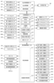
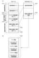
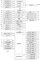
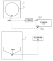
次に、パチンコ機1の各種制御を行う制御構成について、図17を参照して説明する。図17は、パチンコ機の制御構成を概略的に示すブロック図である。パチンコ機1の主な制御構成は、図示するように、遊技盤5に取付けられる主制御基板1310及び周辺制御基板1510と、本体枠4に取付けられる払出制御基板951と、から構成されており、夫々の制御が分担されている。主制御基板1310は、遊技動作(遊技の進行)を制御する。周辺制御基板1510は、主制御基板1310からのコマンドに基いて遊技中の各種演出装置を制御する周辺制御部1511と、周辺制御部1511からのコマンドに基いてメイン液晶表示装置1600や上皿液晶表示装置244等での演出画像の表示を制御する液晶表示制御部1512と、を備えている。払出制御基板951は、遊技球の払出し等を制御する払出制御部952と、ハンドルレバー504の回転操作による遊技球の発射を制御する発射制御部953と、を備えている。
3. Control Configuration
Next, the control configuration for performing various controls of the
[3-1.主制御基板]
遊技の進行を制御する主制御基板1310は、各種処理プログラムや各種コマンドを記憶するROM1313や一時的にデータを記憶するRAM1312等が内蔵されるマイクロプロセッサである主制御MPU1311と、入出力デバイス(I/Oデバイス)としての主制御I/Oポート1314と、各種検出スイッチからの検出信号が入力される主制御入力回路1315と、各種ソレノイドを駆動するための主制御ソレノイド駆動回路1316と、主制御MPU1311に内蔵されているRAMに記憶された情報を完全に消去するためのRAMクリアスイッチと、を備えている。主制御MPU1311は、その内蔵されたROMやRAMのほかに、その動作(システム)を監視するウォッチドッグタイマや不正を防止するための機能等も内蔵されている。
[3-1. Main control board]
The
主制御基板1310の主制御MPU1311は、第一始動口2002に受入れられた遊技球を検出する第一始動口センサ2104、第二始動口2004に受入れられた遊技球を検出する第二始動口センサ2551、一般入賞口2001に受入れられた遊技球を検出する一般入賞口センサ3015、ゲート部2003を通過した遊技球を検知するゲートセンサ2547、第一大入賞口2005に受入れられた遊技球を検知する第一大入賞口センサ2114、第二大入賞口2006としての第二上大入賞口2006a及び第二下大入賞口2006bに受入れられた遊技球を検知する第二上大入賞口センサ2554及び第二下大入賞口センサ2557、排出球センサ3060、発射球センサ1020及び遊技領域5a内における不正な磁気を検知する磁気検出センサ、等からの検出信号が夫々主制御I/Oポート1314を介して入力される。 The main control MPU 1311 of the main control board 1310 detects game balls received in the first start opening 2002, the second start opening sensor 2551 detects game balls received in the second start opening 2004, the general winning opening sensor 3015 detects game balls received in the general winning opening 2001, the gate sensor 2547 detects game balls that have passed through the gate section 2003, the first large winning opening 2005 detects game balls that have passed through the gate section 2003, the first large winning opening 2006 detects game balls that have passed through the gate section 2007, the first large winning opening 2009 detects game balls that have passed through the gate section 2008, the first large winning opening 2010 detects game balls that have passed through the gate section 2009, the first large winning opening 2011 detects game balls that have passed through the gate section 2009, the first large winning opening 2012 detects game balls that have passed through the gate section 2009, the first large winning opening 2013 detects game balls that have passed through the gate section 2001, the first large winning opening 2014 detects game balls that have passed through the gate section 2001, the second large winning opening 2015 detects game balls that have passed through the gate section 2001, the first large winning opening 2016 detects game balls that have passed through the gate section 2002, the second large winning opening 2017 detects game balls that have passed through the gate section 2003, the first large winning opening 2018 detects game balls that have passed through the gate section 2003, the second large winning opening 2019 detects game balls that have passed through the gate section 2004, the second large winning opening 2016 detects game balls that have passed through the gate section 2005, the second Detection signals from the first large prize opening sensor 2114, which detects the game balls received by the second upper large prize opening 2006a and the second lower large prize opening 2006b as the second large prize opening 2006, the second upper large prize opening sensor 2554 and the second lower large prize opening sensor 2557, the ejected ball sensor 3060, the launched ball sensor 1020, and the magnetic detection sensor that detects unauthorized magnetism within the game area 5a, etc. are each input via the main control I/O port 1314.
主制御MPU1311は、これらの検出信号に基づいて、主制御I/Oポート1314から主制御ソレノイド駆動回路に制御信号を出力することにより、始動口ソレノイド2550、第一アタッカソレノイド2113、第二上アタッカソレノイド2553、及び第二下アタッカソレノイド2556に駆動信号を出力したり、主制御I/Oポート1314から機能表示ユニット1400の第一特別図柄表示器、第二特別図柄表示器、第一特別図柄記憶表示器、第二特別図柄記憶表示器、普通図柄表示器、普通図柄記憶表示器、遊技状態表示器、ラウンド表示器、等に駆動信号を出力したりする。
Based on these detection signals, the
なお、本実施形態おいて、第一始動口センサ2104、第二始動口センサ2551、ゲートセンサ2547、第一大入賞口センサ2114、第二上大入賞口センサ2554、及び第二下大入賞口センサ2557には、非接触タイプの電磁式の近接スイッチを用いているのに対して、一般入賞口センサ3015には、接触タイプのON/OFF動作式のメカニカルスイッチを用いている。これは、遊技球が、第一始動口2002や第二始動口2004に頻繁に入球すると共に、ゲート部2003を頻繁に通過するため、第一始動口センサ2104、第二始動口センサ2551、及びゲートセンサ2547による遊技球の検出も頻繁に発生する。このため、第一始動口センサ2104、第二始動口センサ2551、及びゲートセンサ2547には、耐久性が高く寿命の長い近接スイッチを用いている。また、遊技者にとって有利となる有利遊技状態(「大当り」遊技、等)が発生すると、第一大入賞口2005や第二大入賞口2006が開放(又は、拡大)されて遊技球が頻繁に入球するため、第一大入賞口センサ2114、第二上大入賞口センサ2554、及び第二下大入賞口センサ2557による遊技球の検出も頻繁に発生する。このため、第一大入賞口センサ2114、第二上大入賞口センサ2554、及び第二下大入賞口センサ2557にも、耐久性が高く寿命の長い近接スイッチを用いている。これに対して、遊技球が頻繁に入球しない一般入賞口2001には、一般入賞口センサ3015による検出も頻繁に発生しない。このため、一般入賞口センサ3015には、近接スイッチより寿命が短いメカニカルスイッチを用いている。
In this embodiment, the first
また、主制御MPU1311は、遊技に関する各種情報(遊技情報)及び払出しに関する各種コマンド等を払出制御基板951に送信したり、この払出制御基板951からのパチンコ機1の状態に関する各種コマンド等を受信したりする。更に、主制御MPU1311は、メイン液晶表示装置1600等で実行される遊技演出の制御に関する各種コマンド及びパチンコ機1の状態に関する各種コマンドを、主制御I/Oポート1314を介して周辺制御基板1510の周辺制御部1511に送信したりする。なお、主制御MPU1311は、払出制御基板951からパチンコ機1の状態に関する各種コマンドを受信すると、これらの各種コマンドを整形して周辺制御部1511に送信する。
The
主制御基板1310には、電源基板ボックス930内の電源基板から各種電圧が供給されている。この主制御基板1310に各種電圧を供給する電源基板は、電源遮断時にでも所定時間、主制御基板1310に電力を供給するためのバックアップ電源としての電気二重層キャパシタ(以下、単に「キャパシタ」と記載する。)を備えている。このキャパシタにより主制御MPU1311は、電源遮断時にでも電源断時処理において各種情報をRAM1312に記憶することができる。この記憶した各種情報は、電源投入時に主制御基板1310のRAMクリアスイッチが操作されると、RAM1312から完全に消去(クリア)される。このRAMクリアスイッチの操作信号(検出信号)は、払出制御基板951にも出力される。
Various voltages are supplied to the
また、主制御基板1310には、停電監視回路が設けられている。この停電監視回路は、電源基板から供給される各種電圧の低下を監視しており、それらの電圧が停電予告電圧以下となると、停電予告として停電予告信号を出力する。この停電予告信号は、主制御I/Oポート1314を介して主制御MPU1311に入力される他に、払出制御基板951等にも出力されている。
The
主制御基板1310には、パチンコ機1の裏面側から視認可能な位置に役物比率表示器1317が取り付けられる。役物比率表示器1317は、主制御MPU1311が計算した役物比率を表示する。
A bonus
また、主制御基板1310には、表示スイッチ1318が設けられる。表示スイッチ1318は、モーメンタリ動作をする押ボタンスイッチで構成するとよいが、他の形式のスイッチでもよい。表示スイッチ1318を操作すると、役物比率表示器1317に役物比率を表示する。なお、役物比率表示器1317は常時、役物比率を表示し、表示スイッチ1318の操作によって表示内容を切り替えてもよい。
The
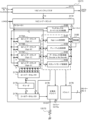
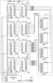
図18は、主制御MPU1311内の構成を示す図である。
Figure 18 shows the internal configuration of the
主制御MPU1311は、CPU13111、RAM1312、ROM1313、乱数発生回路13112、パラレル入力ポート13113、シリアル通信回路13114、タイマ回路13115、割込コントローラ13116、外部バスインターフェイス13117、クロック回路13118、照合用ブロック13119、固有情報13120、演算回路13121及びリセット回路13122を有する。
The
CPU13111は、ROM1313に記憶されたプログラムを実行する。RAM1312は、プログラム実行時に必要なデータを記憶する。
The
主制御MPU1311には、一つ以上の乱数発生回路13112が設けられている。乱数発生回路13112は、変動表示ゲームの結果(第一特別抽選結果、第二特別抽選結果)の抽選結果や変動表示ゲームの演出内容を決定するための乱数を提供する。乱数発生回路13112は、例えば、主制御MPU1311に供給されるクロック周期(又は、該クロック周期を分周した信号)のタイミングで更新した乱数を出力する、いわゆるハード乱数生成手段である。乱数発生回路13112が生成するハード乱数は、特別図柄の当たりの抽選や、特別図柄変動表示ゲームの当たり図柄の抽選や、普通図柄の当たりの抽選に用いられる。
The
パラレル入力ポート13113は、主制御入力回路1315を経由して各種検出スイッチからの検出信号が入力されるポートである。
The
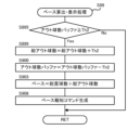
シリアル通信回路13114は、主制御I/Oポート1314を介して、遊技演出の制御に関する各種コマンド及びパチンコ機1の状態に関する各種コマンドを周辺制御基板1510の周辺制御部1511と送受信する。また、シリアル通信回路13114は、主制御I/Oポート1314を介して、遊技に関する各種情報(遊技情報)及び遊技球の払い出しに関する各種コマンド等を払出制御基板951と送受信する。さらに、シリアル通信回路13114は、役物比率を表示するためのデータを役物比率表示器1317に送信する。シリアル通信回路13114の詳細な構成は、図20を参照して後述する。
The
タイマ回路13115は、タイマ割り込みや各種時間制御のためのタイマである。割込コントローラ13116は、CPU13111に対する各種の割り込み(一般割り込み、ソフトウェアでマスク不可能なNMI)を制御する。すなわち、割込コントローラ13116が割り込みを検出した場合、割り込みの種類毎に定められた処理アドレステーブルを参照し、処理アドレステーブルに設定されたアドレスにジャンプする。
The
外部バスインターフェイス13117は、主制御MPU1311の内部バスを外部のデバイスと接続するためのインターフェイスである。外部バスインターフェイス13117からは、I/Oリクエスト(IORQ)、リード(RD)、ライト(WR)、16ビットのアドレス(A0~A15)、8ビットのデータ(D0~D7)が入出力できる。
The
クロック回路13118は、入力された外部クロック信号(例えば、32MHz)から主制御MPU1311の内部クロックを生成する。また、クロック回路13118は、入力されたクロック信号に、設定された数の分周をして、CLKO端子から外部に出力する。例えば、役物比率表示器1317のドライバ回路13171(図28参照)に供給するクロック信号を出力してもよい。
The
照合用ブロック13119は、ROM1313が不正に改造されていないかを所定のコードを用いて照合する機能ブロックである。固有情報13120は、主制御MPU1311に固有のIDであり、チップの製造時に書き換え不能に書き込まれている。
The
演算回路13121は、ROM1313に記録されたプログラムによらない演算機能を提供する。この演算機能は、チップの製造時に固定的に書き込まれている。
The
リセット回路13122は、指定外走行禁止回路、ウォッチドッグタイマ及びユーザリセット機能を有する。指定外走行禁止回路は、ROM1313の所定外のアドレスにCPU13111がアクセスした場合、不正なプログラムによるアクセスであると推定し、主制御MPU1311の動作をリセットする。ウォッチドッグタイマは、所定のタイマ時間が経過した際にタイムアウト信号を出力し、主制御MPU1311の動作をリセットする。ユーザリセット機能は、SRST端子に入力されたリセット信号によって、主制御MPU1311の動作をリセットする。
The
図19は、演算回路13121の詳細な構成を示すブロック図である。
Figure 19 is a block diagram showing the detailed configuration of the
演算回路13121は、演算結果についてプログラムによらない演算機能を提供するものであり、乗算回路131211及び除算回路131215を有する。
The
乗算回路131211は、所定ビット数(例えば、16ビット)の二つの値を乗じて、32ビットの積を出力する演算回路であり、乗算関数によって入力値(乗数、被乗数)を積に変換して出力する変換回路として機能する。
The
主制御MPU1311のCPU13111は、乗算入力レジスタA131212及び乗算入力レジスタB131213に16ビット以下の乗数及び被乗数を格納する。乗算回路131211は、二つの16ビットの乗算入力レジスタ131212、131213に格納された値を所定のタイミングで読み出し、二つの値を乗じた結果を乗算結果レジスタ131214に格納する。CPU13111は、乗算結果レジスタ131214から乗算結果を取得する。乗算入力レジスタ131212、131213への値の書き込みから乗算結果レジスタ131214への演算結果の格納までは、所定の時間(例えば1クロック)で完了するように構成されており、CPU13111は、乗算入力レジスタ131212、131213に値を格納して、所定のクロック数が経過した後に、乗算結果レジスタ131214を参照して乗算結果を取得できる。
The
除算回路131215は、所定ビット数(例えば、32ビット)の被除数を所定ビット数(例えば、32ビット)の除数で割って、32ビットの商と32ビットの剰余を出力する演算回路であり、除算関数によって入力値(除数、被除数)を商及び剰余変換して出力する変換回路として機能する。
The
主制御MPU1311のCPU13111は、除算入力レジスタA131216に32ビット以下の被除数を格納し、除算入力レジスタB131217に32ビット以下の除数を格納する。除算回路131215は、二つの32ビットの除算入力レジスタ131216、131217の両方に値が格納されことを検出すると、格納された値を所定のタイミングで読み出し、被除数を除数で割った結果である商を除算結果レジスタA131218に格納し、剰余を除算結果レジスタB131219に格納する。また、除算回路131215は、除算入力レジスタ131216、131217に格納された値を読み込むと、読み込んだ値を消去し、当該レジスタをクリアするとよい。また、除算回路131215は、スタート命令が入力されたタイミングで、除算入力レジスタ131216、131217に格納された値を読み出し、除算結果を除算結果レジスタ131218、131219に格納してもよい。この場合、除算入力レジスタ131216、131217に格納された値を、読み込みタイミングで消去しなくてもよい。また、除算入力レジスタ131216、131217は、既に値が格納されていても(格納されている値をクリアせずに)、さらに、値を上書き可能でもよい。
The
CPU13111は、除算結果レジスタ131218、131219から除算結果を取得する。除算入力レジスタ131216、131217への値の書き込みから除算結果レジスタ131218、131219への演算結果の格納までは、所定の時間(例えば32クロック)で完了するように構成されており、CPU13111は、除算入力レジスタ131216、131217に値を格納して、所定のクロック数が経過した後に、除算結果レジスタ131218、131219をそれぞれ参照して商及び剰余を取得できる。
The
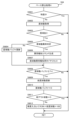
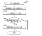
本実施例のパチンコ機1では、後述するように、ベース値を計算するために除算処理が必要であり、CPU13111がプログラムを実行する除算は複数の乗算及び減算で実行されるので相当の時間がかかるものである。このため、タイマ割込み処理毎にベース計算処理を実行するのは困難であり、遅滞ないベース値の表示は困難であった。これに対し、演算回路13121を用いて除算処理を行うことによって、ベース値の計算に必要な時間を短縮でき、一つのタイマ割込み処理において複数回ベース値を計算できる(図75、図80参照)。また、演算回路13121の除算入力レジスタ131216、131217への値の書き込みから除算結果レジスタA131218からの演算結果の読み出しまでの間、CPU13111は除算処理のために占有されないので、他の処理を実行でき、タイマ割込み処理中のベース算出処理を効率的に実行できる。
As described later, in the
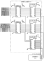
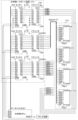
図20は、シリアル通信回路13114の構成を示す図である。
Figure 20 shows the configuration of the
シリアル通信回路13114は、四つのデータ送受信回路を有しており、各データ送受信回路が1チャネル分のデータを所定のデバイスと送受信する。なお、図20では、データ送信回路のみを図示し、データ受信回路(例えば、1チャネル分が実装)の説明は省略する。
The
本実施例の遊技機では、シリアル通信回路13114は、前述したように、周辺制御基板1510との通信に使用されるチャネル0、払出制御基板951との通信に使用されるチャネル1、役物比率表示器1317のドライバ回路13171との通信に使用されるチャネル2の三つのチャネルが使用され、チャネル3は未使用である。
As described above, in the gaming machine of this embodiment, the
シリアル通信回路13114は、データレジスタ3141、送信データレジスタ3142、パリティ生成回路3143、送信用シフトレジスタ3144、コマンドステータスレジスタ3145、通信設定レジスタ3146、送信トリガ設定レベルレジスタ3147、ボーレートレジスタ3148及びボーレート生成回路3149を有する。
The
CPU13111から入力されたデータは、データレジスタ3141に格納された後、送信データレジスタ3142に格納される。送信データレジスタ3142は、所定の容量(例えば、64バイト)のFIFOで構成される。送信データレジスタ3142は、パリティ生成回路3143がデータの送信単位毎に生成した誤り検出符号を、送信すべきデータに付加し、送信用シフトレジスタ3144に格納する。
The data input from the
ボーレート生成回路3149は、クロック回路13118から供給されるクロック信号から、ボーレートレジスタ3148に設定されたレートでデータを送信するための送信用クロック信号を生成する。そして、送信用シフトレジスタ3144は、送信用クロック信号に従って、データを送信する。
The baud
コマンドステータスレジスタ3145は、送信状態を確認するために参照されるレジスタである。
The
通信設定レジスタ3146は、データの送信を制御するためのコマンドを格納する。送信トリガ設定レベルレジスタ3147は、送信データレジスタ3142のFIFOが割り込みを発生させるデータ量を制御するための閾値を格納する。ボーレートレジスタ3148は、データの送信レートを規定するためのボーレートの設定を格納する。通信設定レジスタ3146、送信トリガ設定レベルレジスタ3147及びボーレートレジスタ3148は、図21のステップS28において初期設定として、4チャネルの各々について設定される。
The
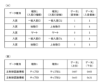
以下、これらの設定について詳しく説明する。通信設定レジスタには、各チャネルの通信フォーマットが設定される。具体的には、FIFOの使用の有無(FIFOモード、ノーマルモード)、ストップビットのビット数、パリティ(パリティを使用するか、偶数パリティか奇数パリティか)を設定する。例えば、周辺制御基板1510との通信に使用されるチャネル0及び払出制御基板951との通信に使用されるチャネル1では、FIFOモード、ストップビット=1ビット、偶数パリティを意味する1×××1010Bを設定し、役物比率表示器1317のドライバ回路13171との通信に使用されるチャネル2では、FIFOモード、ストップビット=1ビット、パリティ未使用を意味する1×××1000Bを設定する。
These settings are explained in detail below. The communication setting register is set to the communication format of each channel. Specifically, it sets whether or not FIFO is used (FIFO mode, normal mode), the number of stop bits, and parity (whether parity is used, even parity, or odd parity). For example, for
FIFOモードでは、送信データレジスタ3142のFIFOを使用してデータを送信する。また、遊技機はノイズが多い環境にあることから、主制御基板1310の外に高速でデータを送信する際は、パリティを設定することが望ましい。
In FIFO mode, data is transmitted using the FIFO of the
役物比率表示器1317は主制御基板1310に実装されるので、通信用の電線を経由する他の基板との通信と比較し、ノイズの影響は少ない。また、送受信するデータ量が少ないので、通信速度は低くてよく、パリティを使用する必要性は乏しい。なお、役物比率表示器1317のドライバ回路13171と主制御MPU1311との間で信号を伝達するパターンに沿って(例えば、プリント基板の表面又は内層に設けられた信号線の左右及び/又は厚み方向に隣接する層)にグランドパターンを設け、グランドパターンによるシールド効果によって、当該信号伝達パターンに重畳するノイズを低減できる。
The
送信トリガ設定レベルレジスタ3147は、送信データレジスタ3142のFIFOが割り込みを発生させるデータ量を定める。具体的には、送信データレジスタ3142のFIFOに格納されている送信データの量が設定したバイト数より小さい場合、各チャンネルに対応したステータスレジスタの所定ビットがセットされる。ステータスレジスタの当該ビットを判定することによって、送信データレジスタ3142のFIFOに空きがあるか否かを確認でき、送信データレジスタ3142のFIFOに格納されたデータの送信タイミングを判定できる。
The transmission trigger
なお、送信FIFOに異常があるかを判定するために、ステータスレジスタの当該ビットを利用できる。例えば、送信データレジスタ3142のFIFOに所定の期間データが書き込まれない場合でも、ステータスレジスタの当該ビットがセットされない場合、送信データレジスタ3142のFIFOに空きが生じていないことから、送信データレジスタ3142のFIFOからデータが送信されていないと判定して、エラー処理(例えば、エラー報知)を実行してもよい。
The relevant bit of the status register can be used to determine whether there is an abnormality in the transmission FIFO. For example, even if no data is written to the FIFO of the transmission data register 3142 for a predetermined period of time, if the relevant bit of the status register is not set, it is possible to determine that no data is being transmitted from the FIFO of the transmission data register 3142 because there is no free space in the FIFO of the
ボーレートレジスタ3148は、データ送信レートを定める。例えば、周辺制御基板1510との通信に使用されるチャネル0では19200bpsを設定し、払出制御基板951との通信に使用されるチャネル1では1200bpsを設定し、役物比率表示器1317のドライバ回路13171との通信に使用されるチャネル2では1200bpsを設定する。
The
このように、各チャネルで送信されるデータによって送信レートを変えている。これは、遊技機の内部は遊技球が転動しており、遊技機の電子回路はノイズの影響を受けやすい環境下にある。このため、遊技者に付与される利益に直接関係する出球を制御するためのデータは確実に送信されるように、低速で払出制御基板951にデータを送信する。一方、周辺制御基板1510は、送信されるデータ量が多く、出球に関係がないので、高いレートでデータを送信する。また、周辺制御基板1510は、受信したコマンドが異常かを検証しており、異常であると判定した場合、周辺制御基板1510を動作させない又は異常処理(例えば、通信エラー報知)を実行し、コマンドの再送を要求する。そして、再送されたコマンドが正常であると判定された場合、該正常コマンドを用いて周辺制御基板1510の状態が復旧される。このため、周辺制御基板1510との通信は、高いレートでデータを送信できる。さらに、周辺制御基板1510との通信レートを低くすると、始動口の入賞から図柄の変動開始までの遅延を遊技者が認識できるようになり、興趣を低下させる可能性がある。
In this way, the transmission rate is changed depending on the data transmitted through each channel. This is because the gaming balls are rolling inside the gaming machine, and the electronic circuits of the gaming machine are in an environment that is easily affected by noise. For this reason, data for controlling the ball output, which is directly related to the profit given to the player, is transmitted to the
役物比率表示器1317のドライバ回路13171との通信は、高いレート(周辺制御基板1510とのデータ送信レートである19200bps)でも、低いレート(払出制御基板951とのデータ送信レートである1200bps)でもよい。また、役物比率表示器1317のドライバ回路13171との通信は、高いレート(周辺制御基板1510とのデータ送信レートである19200bps)と低いレート(払出制御基板951とのデータ送信レートである1200bps)との間のレートを採用してもよい。これは、データ送信レートを高くすると、役物比率表示器1317のドライバ回路13171のトランジスタのスイッチングノイズ等により他の回路に誤動作を起こさせる可能性がある。一方、ノイズにより送信されたデータに異常が生じても、送信データが更新されない限りタイマ割込みごとに同じデータを再送し、再送されたコマンドが正常であれは、役物比率表示器1317の表示内容は正常に戻るので、送信レートを極端に低速にする必要はないためである。
The communication with the
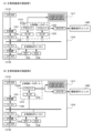
コマンドステータスレジスタ3145は、送信状態を確認するために参照されるレジスタであり、例えば、各ビットは以下のように定義される。
ビット7:SnTC 送信完了を示すフラグであり、0は送信中、1は送信完了を示す。ビット6:SnTDBE ノーマルモード(FIFOを使用しない通信モード)においては、送信データエンプティを示すフラグであり、0は送信用シフトレジスタに未転送、1は送信用シフトレジスタに転送済みを示す。すなわち、送信データレジスタ3142から送信用シフトレジスタ3144にデータが転送され、送信データレジスタ3142に送信データが格納されていない状態になると、セットされる。
The
Bit 7: SnTC A flag indicating completion of transmission, where 0 indicates transmission in progress and 1 indicates completion of transmission. Bit 6: SnTDBE A flag indicating transmission data empty in normal mode (a communication mode that does not use FIFO), where 0 indicates that data has not been transferred to the transmission shift register and 1 indicates that data has been transferred to the transmission shift register. In other words, this flag is set when data is transferred from the transmission data register 3142 to the
SnTFTL FIFOモードにおいては、送信FIFOトリガレベルを示すフラグであり、0は送信データレジスタ3142のFIFOに格納されている送信データの量がトリガレベル以上、1は送信データレジスタ3142のFIFOに格納されている送信データの量がトリガレベル未満を示す。すなわち、送信データレジスタ3142のFIFOに格納されている送信データの量が、送信トリガレベル設定レジスタに設定されたバイト数より少ないときにセットされる。このため、FIFOモードでの通信時には、当該ビットが1であることを確認した後、送信データレジスタ3142のFIFOにデータを書き込む。
ビット5~2:未使用(0固定)
ビット1:SnTCL 送信バッファ、ブレークコード送信をクリアし、送信データを空にして、又は送信FIFOトリガレベルを(SnTFL)を設定するためのビットであり、外部から書き込まれる。例えば、バッファの内容を強制的にクリアする場合、当該ビットに1をセットする。より具体的には、FIFOにコマンドを書き込んだが、なんらかの事情(例えば、異常発生)によって、書き込んだコマンドの送信を中止する場合に使用される。なお、ビット1が設定されても、送信用シフトレジスタのデータはクリアされない。
In the SnTFTL FIFO mode, this is a flag indicating the transmission FIFO trigger level, with 0 indicating that the amount of transmission data stored in the FIFO of the transmission data register 3142 is equal to or greater than the trigger level, and 1 indicating that the amount of transmission data stored in the FIFO of the transmission data register 3142 is less than the trigger level. In other words, this is set when the amount of transmission data stored in the FIFO of the transmission data register 3142 is less than the number of bytes set in the transmission trigger level setting register. Therefore, during communication in the FIFO mode, data is written to the FIFO of the transmission data register 3142 after confirming that the bit is 1.
Bits 5-2: Unused (fixed to 0)
Bit 1: SnTCL This bit is written from the outside to clear the transmission buffer, break code transmission, empty the transmission data, or set the transmission FIFO trigger level (SnTFL). For example, to forcibly clear the contents of the buffer, set this bit to 1. More specifically, this is used when a command has been written to the FIFO, but due to some circumstances (for example, an abnormality has occurred), the transmission of the written command is stopped. Note that even if
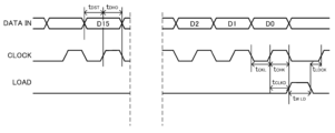
以上に説明した構成で、シリアル通信回路13114は、調歩同期通信(非同期通信)が可能であるが、図示しない同期通信用のクロック信号を出力する。この場合、通信相手方(役物比率表示器1317のドライバ回路13171)に供給するクロック信号は、クロック回路13118ではなく、シリアル通信回路13114から出力される。シリアル通信回路13114の各送受信回路は、少なくとも一つのチャネルが設定によって同期通信が可能でもよく、調歩同期用シリアル通信回路と同期通信用シリアル通信回路とを別に設けてもよい。
In the configuration described above, the
また、図示を省略したが、シリアル通信回路13114は、同期通信時に使用されるデータ取り込みタイミングを示す信号(LOAD)を出力する。
Although not shown in the figure, the
[3-2.払出制御基板]
図17に戻って、パチンコ機の制御構成の説明を続ける。遊技球の払出し等を制御する払出制御基板951は、詳細な図示は省略するが、払出しに関する各種制御を行う払出制御部952と、発射ソレノイド682による発射制御を行うとともに、球送りソレノイド551による球送り制御を行う発射制御部953と、パチンコ機1の状態を表示するエラーLED表示器と、エラーLED表示器に表示されているエラーを解除するためのエラー解除スイッチと、球タンク802、タンクレール803、球誘導ユニット820、及び払出装置830内の遊技球を、パチンコ機1の外部へ排出して球抜き動作を開始するための球抜きスイッチと、を備えている。
[3-2. Dispense control board]
Returning to Fig. 17, the explanation of the control configuration of the pachinko machine will be continued. Although detailed illustration is omitted, the
[3-2a.払出制御部]
払出制御基板951における払出しに関する各種制御を行う払出制御部952は、詳細な図示は省略するが、各種処理プログラムや各種コマンドを記憶するROMや一時的にデータを記憶するRAM等が内蔵されるマイクロプロセッサである払出制御MPUと、I/Oデバイスとしての払出制御I/Oポートと、払出制御MPUが正常に動作しているか否かを監視するための外部WDT(外部ウォッチドッグタイマ)と、払出装置830の払出モータ834に駆動信号を出力するための払出モータ駆動回路と、払出しに関する各種検出スイッチからの検出信号が入力される払出制御入力回路と、を備えている。払出制御MPUには、その内蔵されたROMやRAMのほかに、不正を防止するため機能等も内蔵されている。
[3-2a. Dispense control unit]
The
払出制御部952の払出制御MPUは、主制御基板1310からの遊技に関する各種情報(遊技情報)及び払い出しに関する各種コマンドを払出制御I/Oポートを介してシリアル方式で受信したり、主制御基板1310からのRAMクリアスイッチの操作信号(検出信号)が払出制御I/Oポートを介して入力されたりする他に、満タン検知センサ535からの検出信号が入力されたり、球切れ検知センサ827、払出検知センサ842、及び羽根回転検知センサ840からの検出信号が入力される。
The payout control MPU of the
払出装置830の球切れ検知センサ827、払出検知センサ842、及び羽根回転検知センサ840からの検出信号は、払出制御入力回路に入力され、払出制御I/Oポートを介して払出制御MPUに入力される。
The detection signals from the ball out
また、本体枠4に対する扉枠3の開放を検出する扉枠開放スイッチ、及び外枠2に対する本体枠4の開放を検出する本体枠開放スイッチからの検出信号は、払出制御入力回路に入力され、払出制御I/Oポートを介して払出制御MPUに入力される。
In addition, the detection signals from the door frame opening switch, which detects the opening of the
また、ファールカバーユニット520の満タン検知センサ535からの検出信号は、払出制御入力回路に入力され、払出制御I/Oポートを介して払出制御MPUに入力される。
In addition, the detection signal from the full
払出制御MPUは、払出モータ834を駆動するための駆動信号を、払出制御I/Oを介して払出モータ834に出力したり、パチンコ機1の状態をエラーLED表示器に表示するための信号を、払出制御I/Oポートを介してエラーLED表示器に出力したり、パチンコ機1の状態を示すためのコマンドを、払出制御I/Oポートを介して主制御基板1310にシリアル方式で送信したり、実際に払出した遊技球の球数を払出制御I/Oポートを介して外部端子板784に出力したりする。この外部端子板784は、遊技ホール側に設置されたホールコンピュータに接続されている。このホールコンピュータは、パチンコ機1が払出した遊技球の球数やパチンコ機1の遊技情報等を把握することにより遊技者の遊技を監視している。外部端子板784から出力する信号のうち主制御基板1310が生成する信号は、主制御基板1310から払出制御基板951を経由して外部端子板784から出力する。なお、主制御基板1310が生成する信号を、払出制御基板951を経由せずに外部端子板784から出力してもよい。
The payout control MPU outputs a drive signal for driving the payout motor 834 to the payout motor 834 via the payout control I/O, outputs a signal for displaying the status of the
エラーLED表示器は、セグメント表示器であり、英数字や図形等を表示してパチンコ機1の状態を表示している。エラーLED表示器が表示して報知する内容としては、次のようなものがある。例えば、図形「-」が表示されているときには「正常」である旨を報知し、数字「0」が表示されているときには「接続異常」である旨(具体的には、主制御基板1310と払出制御基板951との基板間の電気的な接続に異常が生じている旨)を報知し、数字「1」が表示されているときには「球切れ」である旨(具体的には、球切れ検知センサ827からの検出信号に基づいて払出装置830内に遊技球がない旨)を報知し、数字「2」が表示されているときには「球がみ」である旨(具体的には、羽根回転検知センサ840からの検出信号に基づいて払出装置830の払出通路において払出羽根と遊技球とがかみ合って払出羽根が回転困難となっている旨)を報知し、数字「3」が表示されているときには「計数スイッチエラー」である旨(具体的には、払出検知センサ842からの検出信号に基づいて払出検知センサ842に不具合が生じている旨)を報知し、数字「5」が表示されているときには「リトライエラー」である旨(具体的には、払出し動作のリトライ回数が予め設定された上限値に達した旨)を報知し、数字「6」が表示されているときには「満タン」である旨(具体的には、満タン検知センサ535からの検出信号に基づいてファールカバーユニット520内に貯留された遊技球で満タンである旨)を報知し、数字「7」が表示されているときには「CR未接続」である旨(払出制御基板951からCRユニットまでに亘るいずれかにおいて電気的な接続が切断されている旨)を報知し、数字「9」が表示されているときには「ストック中」である旨(具体的には、まだ払出していない遊技球の球数が予め定めた球数に達している旨)を報知している。
The error LED display is a segment display that displays alphanumeric characters, figures, etc. to indicate the status of the
球貸ボタンからの遊技球の球貸要求信号、及び返却ボタンからのプリペイドカードの返却要求信号は、CRユニットに入力される。CRユニットは、球貸要求信号に従って貸し出す遊技球の球数を指定した信号を、払出制御基板951にシリアル方式で送信し、この信号が払出制御I/Oポートで受信されて払出制御MPUに入力される。またCRユニットは、貸出した遊技球の球数に応じて挿入されたプリペイドカードの残度を更新するとともに、その残度を表示部に表示するための信号を出力し、この信号が表示部に入力されて表示される。
A signal requesting the loan of game balls from the ball loan button, and a signal requesting the return of a prepaid card from the return button are input to the CR unit. The CR unit serially transmits a signal specifying the number of game balls to be loaned in accordance with the ball loan request signal to the
[3-2b.発射制御部]
発射ソレノイド682による発射制御と、球送りソレノイド551による球送制御と、を行う発射制御部953は、詳細に図示は省略するが、発射に関する各種検出スイッチからの検出信号が入力される発射制御入力回路と、定時間毎にクロック信号を出力する発振回路と、このクロック信号に基づいて遊技球を遊技領域5aに向かって打ち出すための発射基準パルスを出力する発射タイミング制御回路と、この発射基準パルスに基づいて発射ソレノイド682に駆動信号を出力する発射ソレノイド駆動回路と、発射基準パルスに基づいて球送りソレノイド551に駆動信号を出力する球送りソレノイド駆動回路と、を備えている。発射タイミング制御回路は、発振回路からのクロック信号に基づいて、1分当たり100個の遊技球が遊技領域5aに向かって打ち出されるよう発射基準パルスを生成して発射ソレノイド駆動回路に出力するとともに、発射基準パルスを所定数倍した球送基準パルスを生成して球送りソレノイド駆動回路に出力する。
[3-2b. Launch control section]
The
ハンドルユニット500関係では、ハンドルレバー504に手のひらや指が触れているか否かを検出する接触検知センサ509、及び遊技者の意志によって遊技球の打ち出しを強制的に停止するか否かを検出するストップボタンからの検出信号は、発射制御入力回路に入力された後に、発射タイミング制御回路に入力される。またCRユニットとCRユニット接続端子板とが電気的に接続されると、CR接続信号として発射制御入力回路に入力され、発射タイミング制御回路に入力される。ハンドルレバー504の回転位置に応じて遊技球を遊技領域5aに向かって打ち出す強度を電気的に調節するハンドル操作センサ507からの信号は、発射ソレノイド駆動回路に入力される。
In relation to the
この発射ソレノイド駆動回路は、ハンドル操作センサ507からの信号に基づいて、ハンドルレバー504の回転位置に見合う打ち出し強度で遊技球を遊技領域5aに向かって打ち出すための駆動電流を、発射基準パルスが入力されたことを契機として、発射ソレノイド682に出力する。一方、球送りソレノイド駆動回路は、球送基準パルスが入力されたことを契機として、球送りソレノイド551に一定電流を出力することにより、皿ユニット200の上皿201に貯留された遊技球を球送りユニット540内に1球受入れ、その球送基準パルスの入力が終了したことを契機として、その一定電流の出力を停止することにより受入れた遊技球を球発射装置680側へ送る。このように、発射ソレノイド駆動回路から発射ソレノイド682に出力される駆動電流は可変に制御されるのに対して、球送りソレノイド駆動回路から球送りソレノイド551に出力される駆動電流は一定に制御されている。
Based on the signal from the
なお、払出制御基板951に各種電圧を供給する電源基板は、電源遮断時にでも所定時間、主制御基板1310に電力を供給するためのバックアップ電源としてのキャパシタを備えている。このキャパシタにより払出制御MPUは、電源遮断時にでも電源断時処理において各種情報を払出制御基板951のRAMに記憶することができる。この記憶した各種情報は、電源投入時に主制御基板1310のRAMクリアスイッチが操作されると、払出制御基板951のRAMから完全に消去(クリア)される。
The power supply board that supplies various voltages to the dispensing
[3-3.周辺制御基板]
周辺制御基板1510は、図17に示すように、主制御基板1310からのコマンドに基づいて演出制御を行う周辺制御部1511と、この周辺制御部1511からの制御データに基づいてメイン液晶表示装置1600、サブ液晶表示装置3114や上皿液晶表示装置244の描画制御を行う液晶表示制御部1512と、を備えている。
[3-3. Peripheral control board]
As shown in Figure 17, the
[3-3a.周辺制御部]
周辺制御基板1510における演出制御を行う周辺制御部1511は、詳細な図示は省略するが、マイクロプロセッサとしての周辺制御MPUと、各種処理プログラムや各種コマンドを記憶する周辺制御ROMと、高音質の演奏を行う音源ICと、この音源ICが参照する音楽及び効果音等の音情報が記憶されている音ROMと、を備えている。
[3-3a. Peripheral control unit]
The
周辺制御MPUは、パラレルI/Oポート、シリアルI/Oポート等を複数内蔵しており、主制御基板1310から各種コマンドを受信すると、この各種コマンドに基づいて、遊技盤5の各装飾基板に設けられたカラーLED等への点灯信号、点滅信号又は階調点灯信号を出力するための遊技盤側発光データをランプ駆動基板用シリアルI/Oポートから演出駆動基板3043に送信したり、遊技盤5に設けられた各種演出ユニットを作動させる駆動モータへの駆動信号を出力するための遊技盤側駆動データを遊技盤装飾駆動基板用シリアルI/Oポートから演出駆動基板3043に送信したり、扉枠3に設けられた加振装置242や扉右下駆動モータ272等の電気的駆動源への駆動信号を出力するための扉側駆動データと、扉枠3の各装飾基板に設けられたカラーLED等への点灯信号、点滅信号又は階調点灯信号を出力するための扉側発光データと、から構成される扉側駆動発光データを枠装飾駆動基板用シリアルI/Oポートから扉枠3側に送信したり、メイン液晶表示装置1600や上皿液晶表示装置244に表示させる画面を示す制御データ(表示コマンド)を液晶制御部用シリアルI/Oポートから液晶表示制御部1512に送信したり、するほかに、音ROMから音情報を抽出するための制御信号(音コマンド)を音源ICに出力したりする。
The peripheral control MPU has multiple built-in parallel I/O ports, serial I/O ports, etc., and when it receives various commands from the
遊技盤5に設けられた各種演出ユニットの位置を検出するための各種位置検出センサからの検出信号は、裏箱の後面に取付けられた演出駆動基板3043を介して周辺制御MPUに入力されている。また、扉枠3に設けられた演出操作ユニット220のタッチパネル246、演出ボタン押圧センサ258からの検出信号は、周辺制御MPUに入力されている。
The detection signals from the various position detection sensors for detecting the positions of the various presentation units provided on the
また周辺制御MPUは、液晶表示制御部1512が正常に動作している旨を伝える信号(動作信号)が液晶表示制御部1512から入力されており、この動作信号に基づいて液晶表示制御部1512の動作を監視している。
In addition, the peripheral control MPU receives a signal (operation signal) from the LCD
音源ICは、周辺制御MPUからの制御データ(音コマンド)に基づいて音ROMから音情報を抽出し、扉枠3や本体枠4等に設けられたスピーカ921等から各種演出に合せた音楽及び効果音等が流れるように制御を行う。なお、周辺制御基板1510が収容された周辺制御基板ボックス1520から後方へ突出しているボリュームを回転操作することで、音量を調整することができるようになっている。本実施形態では、扉枠3側の複数のスピーカと本体枠4の低音用のスピーカ921とに、音情報としての音響信号(例えば、2chステレオ信号、4chステレオ信号、2.1chサラウンド信号、或いは、4.1chサラウンド信号、等)を送ることで、従来よりも臨場感のある音響効果(音響演出)を提示することができる。
The sound source IC extracts sound information from the sound ROM based on control data (sound commands) from the peripheral control MPU, and controls the playback of music and sound effects in accordance with various performances from
なお、周辺制御部1511は、周辺制御MPUに内蔵された内蔵WDT(ウォッチドッグタイマ)のほかに、図示しない、外部WDT(ウォッチドッグタイマ)も備えており、周辺制御MPUは、内蔵WDTと外部WDTとを併用して自身のシステムが暴走しているか否かを診断している。
In addition to the built-in WDT (watchdog timer) built into the peripheral control MPU, the
この周辺制御MPUから液晶表示制御部1512に出力される表示コマンドはシリアル入出力ポートにより行われ、本実施形態では、ビットレート(単位時間あたりに送信できるデータの大きさ)として19.2キロ(k)ビーピーエス(bits per second、以下、「bps」と記載する)が設定されている。一方、周辺制御MPUから裏箱の後面に取付けられた演出駆動基板3043に出力される、初期データ、扉枠側点灯点滅コマンド、遊技盤側点灯点滅コマンド、可動体駆動コマンド、表示コマンドと異なる複数のシリアル入出力ポートにより行われ、本実施形態では、ビットレートとして250kbpsが設定されている。
The display commands output from this peripheral control MPU to the LCD
この演出駆動基板3043は、受信した扉枠側点灯点滅コマンドに基いた点灯信号又は点滅信号を、扉枠3に備えられた各装飾基板のLEDに出力したり、受信した遊技盤側点灯点滅コマンドに基いた点灯信号又は点滅信号を遊技盤5に備えられた各装飾基板のLEDに出力したりする。
This
また、演出駆動基板3043は、受信した駆動コマンドに基いた駆動信号を、扉枠3に備えられた加振装置242及び扉右下駆動モータ272や、遊技盤5に備えられた各駆動モータ等に出力したりする。
The
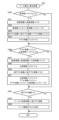
[3-3b.周辺制御部の各種制御処理]
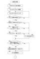
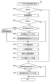
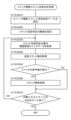
まず、周辺制御部電源投入時処理について、図60を参照して説明する。パチンコ機1に電源が投入されると、図17に示した周辺制御部1511の周辺制御MPU(図示省略)は、図60に示すように、周辺制御部電源投入時処理を行う。この周辺制御部電源投入時処理が開始されると、演出制御プログラムが周辺制御MPUの制御の下、初期設定処理を行う(ステップS1000)。この初期設定処理では、演出制御プログラムが、周辺制御MPU自身を初期化する処理と、ホットスタート/コールドスタートの判定処理と、リセット後のウェイトタイマを設定する処理等を行う。周辺制御MPUは、まず自身を初期化する処理を行うが、この周辺制御MPUを初期化する処理にかかる時間は、マイクロ秒(μs)オーダーであり、極めて短い時間で周辺制御MPUを初期化することができる。これにより、周辺制御MPUは、割り込み許可が設定された状態となることによって、例えば、後述する周辺制御部コマンド受信割り込み処理において、主制御基板1310から出力される、遊技演出の制御に関するコマンドやパチンコ機1の状態に関するコマンド等の各種コマンドを受信することができる状態となる。
[3-3b. Various control processes of peripheral control units]
First, the peripheral control unit power-on process will be described with reference to FIG. 60. When the power is turned on to the
ステップS1000に続いて、演出制御プログラムは現在時刻情報取得処理を行う(ステップS1002)。この現在時刻情報取得処理では、RTC制御部から、年月日を特定するカレンダー情報と時分秒を特定する時刻情報とを取得して、周辺制御RAMに、現在のカレンダー情報としてカレンダー情報記憶部にセットするとともに、現在の時刻情報として時刻情報記憶部にセットする。 Following step S1000, the performance control program performs a current time information acquisition process (step S1002). In this current time information acquisition process, calendar information specifying the date and time information specifying the hour, minute, and second are acquired from the RTC control unit, and are set in the calendar information storage unit of the peripheral control RAM as the current calendar information, and are also set in the time information storage unit as the current time information.
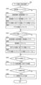
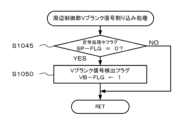
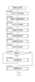
ステップS1002に続いて、演出制御プログラムは、Vブランク信号検出フラグVB-FLGに値0をセットする(ステップS1006)。このVブランク信号検出フラグVB-FLGは、後述する周辺制御部定常処理を実行するか否かを決定するためのフラグであり、周辺制御部定常処理を実行するとき値1、周辺制御部定常処理を実行しないとき値0にそれぞれ設定される。Vブランク信号検出フラグVB-FLGは、周辺制御MPUからの画面データを受け入れることができる状態である旨を伝えるVブランク信号が入力されたことを契機として実行される後述する周辺制御部Vブランク信号割り込み処理において値1がセットされるようになっている。このステップS1006では、Vブランク信号検出フラグVB-FLGに値0をセットすることによりVブランク信号検出フラグVB-FLGを一度初期化している。 Following step S1002, the performance control program sets the V blank signal detection flag VB-FLG to a value of 0 (step S1006). This V blank signal detection flag VB-FLG is a flag for determining whether or not to execute the peripheral control unit regular processing described below, and is set to a value of 1 when the peripheral control unit regular processing is executed, and to a value of 0 when the peripheral control unit regular processing is not executed. The V blank signal detection flag VB-FLG is set to a value of 1 in the peripheral control unit V blank signal interrupt processing described below, which is executed in response to the input of a V blank signal indicating that the peripheral control MPU is in a state where it is possible to accept screen data. In this step S1006, the V blank signal detection flag VB-FLG is initialized once by setting the V blank signal detection flag VB-FLG to a value of 0.
ステップS1006に続いて、演出制御プログラムは、Vブランク信号検出フラグVB-FLGが値1であるか否かを判定する(ステップS1008)。このVブランク信号検出フラグVB-FLGが値1でない(値0である)ときには、再びステップS1008に戻ってVブランク信号検出フラグVB-FLGが値1であるか否かを繰り返し判定する。このような判定を繰り返すことにより、周辺制御部定常処理を実行するまで待機する状態となる。
Following step S1006, the performance control program determines whether the V blank signal detection flag VB-FLG is equal to the value 1 (step S1008). If the V blank signal detection flag VB-FLG is not equal to the value 1 (it is equal to the value 0), the program returns to step S1008 and repeatedly determines whether the V blank signal detection flag VB-FLG is equal to the
ステップS1008でVブランク信号検出フラグVB-FLGが値1であるとき、つまり周辺制御部定常処理を実行するときには、まず定常処理中フラグSP-FLGに値1をセットする(ステップS1009)。この定常処理中フラグSP-FLGは、周辺制御部定常処理を実行中であるとき値1、周辺制御部定常処理を実行完了したとき値0にそれぞれセットされる。 When the V blank signal detection flag VB-FLG is set to a value of 1 in step S1008, that is, when peripheral control unit steady-state processing is to be executed, the steady-state processing in progress flag SP-FLG is first set to a value of 1 (step S1009). This steady-state processing in progress flag SP-FLG is set to a value of 1 when peripheral control unit steady-state processing is being executed, and to a value of 0 when peripheral control unit steady-state processing has been completed.
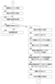
ステップS1009に続いて、演出制御プログラムは1ms割り込みタイマ起動処理を行う(ステップS1010)。この1ms割り込みタイマ起動処理では、後述する周辺制御部1msタイマ割り込み処理を実行するための1ms割り込みタイマを起動するとともに、この1ms割り込みタイマが起動して周辺制御部1msタイマ割り込み処理が実行された回数をカウントするための1msタイマ割り込み実行回数STNに値1をセットして1msタイマ割り込み実行回数STNの初期化も行う。この1msタイマ割り込み実行回数STNは周辺制御部1msタイマ割り込み処理で更新される。
Following step S1009, the performance control program performs a 1 ms interrupt timer start process (step S1010). In this 1 ms interrupt timer start process, a 1 ms interrupt timer is started to execute the
ステップS1010に続いて、演出制御プログラムは、ランプデータ出力処理を行う(ステップS1012)。このランプデータ出力処理では、演出制御プログラムが図119に示したランプ駆動基板4170へのDMAシリアル連続送信を行う。ここでは、周辺制御MPUの周辺制御DMAコントローラを利用してランプ駆動基板用シリアルI/Oポート連続送信を行う。 Following step S1010, the performance control program performs lamp data output processing (step S1012). In this lamp data output processing, the performance control program performs DMA serial continuous transmission to the lamp drive board 4170 shown in FIG. 119. Here, continuous transmission is performed to the serial I/O port for the lamp drive board by utilizing the peripheral control DMA controller of the peripheral control MPU.
ステップS1012に続いて、演出制御プログラムは、演出操作ユニット監視処理を行う(ステップS1014)。この演出操作ユニット監視処理では、後述する周辺制御部1msタイマ割り込み処理における演出操作ユニット情報取得処理において、演出操作ユニット220に設けられた各種検出スイッチからの検出信号に基づいて操作ボタン220Cの操作等を取得した各種情報に基づいて、操作ボタン220Cの操作有無を監視し、操作ボタン220Cの操作の状態を遊技演出に反映するか否かを適宜決定する。
Following step S1012, the presentation control program performs a presentation operation unit monitoring process (step S1014). In this presentation operation unit monitoring process, the
ステップS1014に続いて、演出制御プログラムは、表示データ出力処理を行う(ステップS1016)。この表示データ出力処理では、後述する表示データ作成処理で音源内蔵VDPの内蔵VRAM上に生成した1画面分(1フレーム分)の描画データを音源内蔵VDPが遊技盤側装飾基板3053及び扉枠側装飾基板233に出力する。これにより、遊技盤側装飾基板3053及び扉枠側装飾基板233にさまざまな画面が描画される。
Following step S1014, the presentation control program performs a display data output process (step S1016). In this display data output process, the sound source VDP outputs one screen's worth of drawing data (one frame's worth) generated on the built-in VRAM of the sound source VDP in the display data creation process described below to the game board side
ステップS1016に続いて、演出制御プログラムは、音データ出力処理を行う(ステップS1018)。この音データ出力処理では、演出制御プログラムが、後述する音データ作成処理で音源内蔵VDPに設定された音楽及び効果音等の音データをスピーカ921に出力したり、音楽及び効果音のほかに報知音や告知音の音データをスピーカ921に出力したりする。
Following step S1016, the performance control program performs a sound data output process (step S1018). In this sound data output process, the performance control program outputs sound data such as music and sound effects set in the sound source built-in VDP in the sound data creation process described below to the
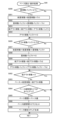
ステップS1018に続いて、演出制御プログラムはスケジューラ更新処理を行う(ステップS1020)。このスケジューラ更新処理では、演出制御プログラムが周辺制御RAMにセットされた各種スケジュールデータを更新する。例えば、スケジューラ更新処理では、画面生成用スケジュールデータを構成する時系列に配列された画面データのうち、先頭の画面データから何番目の画面データを音源内蔵VDPに出力するのかを指示するために、ポインタを更新する。 Following step S1018, the performance control program performs a scheduler update process (step S1020). In this scheduler update process, the performance control program updates various schedule data set in the peripheral control RAM. For example, in the scheduler update process, a pointer is updated to indicate which screen data, from the first screen data, among the screen data arranged in chronological order that constitutes the schedule data for screen generation, is to be output to the VDP with built-in sound source.
またスケジューラ更新処理では、発光態様生成用スケジュールデータを構成する時系列に配列された発光データのうち、先頭の発光データから何番目の発光データを各種LEDの発光態様とするのかを指示するために、ポインタを更新する。 The scheduler update process also updates the pointer to indicate which light emission data from the first light emission data among the light emission data arranged in chronological order that constitutes the schedule data for generating light emission modes should be used as the light emission mode for each LED.
またスケジューラ更新処理では、音生成用スケジュールデータを構成する時系列に配列された、音楽や効果音等の音データ、報知音や告知音の音データを指示する音指令データのうち、先頭の音指令データから何番目の音指令データを音源内蔵VDPに出力するのかを指示するために、ポインタを更新する。 The scheduler update process also updates a pointer to indicate which sound command data, starting from the first sound command data, should be output to the VDP with built-in sound source among the sound command data that indicates sound data such as music and sound effects, and sound data for alarms and announcements, arranged in chronological order to make up the schedule data for sound generation.
またスケジューラ更新処理では、電気的駆動源スケジュールデータを構成する時系列に配列されたモータやソレノイド等の電気的駆動源の駆動データのうち、先頭の駆動データから何番目の駆動データを出力対象とするのかを指示するために、ポインタを更新する。 The scheduler update process also updates a pointer to indicate which drive data from the first drive data is to be output among the drive data for electric drive sources such as motors and solenoids arranged in chronological order that constitutes the electric drive source schedule data.
ステップS1020に続いて、演出制御プログラムは、受信コマンド解析処理を行う(ステップS1022)。この受信コマンド解析処理では、演出制御プログラムが、遊技盤側装飾基板3053から送信された情報や、主制御基板1310から送信された各種コマンドであって、後述する周辺制御部コマンド受信割り込み処理(コマンド受信手段)において受信した各種コマンドの解析を行う(コマンド解析手段)。
Following step S1020, the presentation control program performs a received command analysis process (step S1022). In this received command analysis process, the presentation control program analyzes the information sent from the game board side
ステップS1022に続いて、演出制御プログラムが警告処理を行う(ステップS1024)。この警告処理では、さらに、演出制御プログラムが、上述のようにステップS1022の受信コマンド解析処理で解析したコマンドに、所定の報知表示に区分される各種コマンドが含まれているときには、各種異常報知を実行するための異常表示態様に設定されている、画面生成用スケジュールデータ、発光態様生成用スケジュールデータ、音生成用スケジュールデータ、及び電気的駆動源スケジュールデータ等を、周辺制御部1511の周辺制御ROM又は周辺制御RAMから抽出して周辺制御RAMにセットする。なお、警告処理では、複数の異常が同時に発生した場合には、予め登録した優先度の高い順から異常報知から行われ、その異常が解決して残っている他の異常報知に自動的に遷移するようになっている。これにより、一の異常が発生した後であってその異常を解決する前に他の異常が発生して一の異常が発生しているという情報を失うことなく、複数の異常を同時に監視することができる。
Following step S1022, the performance control program performs a warning process (step S1024). In this warning process, when the commands analyzed in the received command analysis process in step S1022 as described above include various commands classified as a predetermined notification display, the performance control program extracts the screen generation schedule data, the light emission mode generation schedule data, the sound generation schedule data, and the electrical drive source schedule data, which are set in the abnormality display mode for executing various abnormality notifications, from the peripheral control ROM or peripheral control RAM of the
またさらに、この警告処理では、電源投入時から所定時間が経過した後に、演出制御プログラムが、上述した受信コマンド解析処理(ステップS1022)において解析したコマンドが、状態表示に区分される各種コマンド、例えばエラー解除ナビコマンド(第2のエラー解除コマンド)である場合、演出動作に伴う通常の演出態様とは異なる態様に制御することにより、例えば、遊技盤側装飾基板3053(演出装置)、扉枠側装飾基板233(演出装置)、ランプ(演出装置)を用いて視覚的に外部に警告したり、スピーカを用いて聴覚的に外部に警告する(エラー報知手段)。このようにすると、悪意のある遊技者が、遊技状態であるにも拘わらず払出制御基板951の操作スイッチを操作することにより主制御基板1310にエラー解除ナビコマンドを入力しようと試行した際に、パチンコ機1が外部に警告を行う構成となっているため、遊技の進行に影響を及ぼしかねない主制御基板1310に対する不正行為が抑止されるようになる。
Furthermore, in this warning process, after a predetermined time has elapsed since the power was turned on, if the command analyzed by the presentation control program in the above-mentioned received command analysis process (step S1022) is one of the various commands classified as status indications, such as an error reset navigation command (second error reset command), the presentation control program controls the presentation to a different mode from the normal presentation mode associated with the presentation operation, for example, by visually warning the outside using the game board side decorative board 3053 (presentation device), the door frame side decorative board 233 (presentation device), or a lamp (presentation device), or by audibly warning the outside using a speaker (error notification means). In this way, when a malicious player attempts to input an error reset navigation command to the
次に、上述したステップS1024に続いて、演出制御プログラムはRCT取得情報更新処理を行う(ステップS1026)。このRTC取得情報更新処理では、演出制御プログラムが、ステップS1002の現在時刻情報取得処理で取得して周辺制御RAMにセットした、カレンダー情報記憶部に記憶されたカレンダー情報と時刻情報記憶部に記憶された時刻情報とを更新する。このRCT取得情報更新処理により、時刻情報記憶部に記憶される時刻情報である時分秒が更新され、この更新される時刻情報に基づいてカレンダー情報記憶部に記憶されるカレンダー情報である年月日が更新される。 Next, following step S1024 described above, the performance control program performs an RCT acquisition information update process (step S1026). In this RTC acquisition information update process, the performance control program updates the calendar information stored in the calendar information storage unit and the time information stored in the time information storage unit that were acquired in the current time information acquisition process in step S1002 and set in the peripheral control RAM. This RCT acquisition information update process updates the time information stored in the time information storage unit, which is the hour, minute, and second, and updates the calendar information stored in the calendar information storage unit, which is the year, month, and date, based on the updated time information.
ステップS1026に続いて、演出制御プログラムはランプデータ作成処理を行う(ステップS1028)。このランプデータ作成処理では、この演出制御プログラムが、ステップS1020のスケジューラ更新処理においてポインタが更新されて、発光態様生成用スケジュールデータを構成する時系列に配列された発光データのうち、そのポインタが指示する発光データに基づいて、遊技盤5に設けた各種装飾基板の複数のLEDへの点灯信号、点滅信号、又は階調点灯信号を出力するための遊技盤側発光データSL-DATを、周辺制御部1511の周辺制御ROM又は周辺制御RAMから抽出して作成するとともに、周辺制御RAMにセットするとともに、扉枠3に設けた各種装飾基板の複数のLEDへの点灯信号、点滅信号又は階調点灯信号を出力するための扉側発光データSTL-DATを、周辺制御部1511の周辺制御ROM又は周辺制御RAMから抽出して作成して、周辺制御RAMにセットする。
Following step S1026, the performance control program performs lamp data creation processing (step S1028). In this lamp data creation processing, the performance control program updates the pointer in the scheduler update processing in step S1020, and based on the light emission data indicated by the pointer among the light emission data arranged in time series that constitute the schedule data for generating light emission modes, extracts and creates game board side light emission data SL-DAT from the peripheral control ROM or peripheral control RAM of the
ステップS1028に続いて、演出制御プログラムは表示データ作成処理を行う(ステップS1030)。この表示データ作成処理では、演出制御プログラムが、ステップS1020のスケジューラ更新処理においてポインタが更新されて、画面生成用スケジュールデータを構成する時系列に配列された画面データのうち、そのポインタが示す画面データを、周辺制御部1511の周辺制御ROM又は周辺制御RAMから抽出して音源内蔵VDPに出力する。音源内蔵VDPは、周辺制御MPUから画面データが入力されると、この入力された画面データに基づいて液晶及び音制御ROM1512bからキャラクタデータを抽出してスプライトデータを作成して遊技盤側装飾基板3053及び扉枠側装飾基板233に表示する1画面分(1フレーム分)の描画データを内蔵VRAM上に生成する。
Following step S1028, the presentation control program performs a display data creation process (step S1030). In this display data creation process, the presentation control program updates the pointer in the scheduler update process in step S1020, and extracts the screen data indicated by the pointer from the peripheral control ROM or peripheral control RAM of the
ステップS1030に続いて、演出制御プログラムは音データ作成処理を行う(ステップS1032)。この音データ作成処理では、演出制御プログラムが、ステップS1020のスケジューラ更新処理においてポインタが更新されて、音生成用スケジュールデータを構成する時系列に配列された音指令データのうち、そのポインタが指示する音指令データを、周辺制御部1511の周辺制御ROM又は周辺制御RAMから抽出して音源内蔵VDPに出力する。音源内蔵VDPは、周辺制御MPUから音指令データが入力されると、液晶及び音制御ROMに記憶されている音楽や効果音等の音データを抽出して内蔵音源を制御することにより、音指令データに規定された、トラック番号に従って音楽及び効果音等の音データを組み込むとともに、出力チャンネル番号に従って使用する出力チャンネルを設定する。
Following step S1030, the performance control program performs a sound data creation process (step S1032). In this sound data creation process, the performance control program updates the pointer in the scheduler update process in step S1020, and among the sound command data arranged in chronological order that constitutes the sound generation schedule data, extracts the sound command data pointed to by the pointer from the peripheral control ROM or peripheral control RAM of the
ステップS1032に続いて、演出制御プログラムはバックアップ処理を行う(ステップS1034)。このバックアップ処理では、演出制御プログラムが、周辺制御MPUと外付けされる周辺制御RAMに記憶されている内容を、バックアップ第1エリアと、バックアップ第2エリアと、にそれぞれコピーしてバックアップするとともに、周辺制御MPUと外付けされる周辺制御SRAMに記憶されている内容を、バックアップ第1エリアと、バックアップ第2エリアと、にそれぞれコピーしてバックアップする。 Following step S1032, the performance control program performs a backup process (step S1034). In this backup process, the performance control program copies and backs up the contents stored in the peripheral control MPU and the external peripheral control RAM to the first backup area and the second backup area, respectively, and also copies and backs up the contents stored in the peripheral control MPU and the external peripheral control SRAM to the first backup area and the second backup area, respectively.
ステップS1034に続いて、WDTクリア処理を行う(ステップS1036)。このWDTクリア処理では、周辺制御内蔵WDT1511afと、周辺制御外部WDT1511eと、にクリア信号を出力して周辺制御MPUにリセットがかからないようにしている。 Following step S1034, a WDT clear process is performed (step S1036). In this WDT clear process, a clear signal is output to the peripheral control internal WDT 1511af and the peripheral control external WDT 1511e to prevent the peripheral control MPU from being reset.
ステップS1036に続いて、演出制御プログラムが、周辺制御部定常処理の実行完了として定常処理中フラグSP-FLGに値0をセットし(ステップS1038)、再びステップS1006に戻り、Vブランク信号検出フラグVB-FLGに値0をセットして初期化し、後述する周辺制御部Vブランク信号割り込み処理においてVブランク信号検出フラグVB-FLGに値1がセットされるまで、ステップS1008の判定を繰り返し行う。つまりステップS1008では、Vブランク信号検出フラグVB-FLGに値1がセットされるまで待機し、ステップS1008でVブランク信号検出フラグVB-FLGが値1であると判定されると、ステップS1009~ステップS1038の処理を行い、再びステップS1006に戻る。このように、ステップS1008でVブランク信号検出フラグVB-FLGが値1であると判定されると、ステップS1009~ステップS1038の処理を行うようになっている。ステップS1009~ステップS1038の処理を「周辺制御部定常処理」という。 Following step S1036, the performance control program sets the steady-state processing in progress flag SP-FLG to a value of 0 as the peripheral control unit steady-state processing has been completed (step S1038), returns to step S1006, sets the V blank signal detection flag VB-FLG to a value of 0 to initialize it, and repeats the judgment of step S1008 until the V blank signal detection flag VB-FLG is set to a value of 1 in the peripheral control unit V blank signal interrupt processing described below. In other words, in step S1008, the program waits until the V blank signal detection flag VB-FLG is set to a value of 1, and if it is determined in step S1008 that the V blank signal detection flag VB-FLG is a value of 1, it performs the processing of steps S1009 to S1038, and returns to step S1006 again. In this way, if it is determined in step S1008 that the V blank signal detection flag VB-FLG is a value of 1, it performs the processing of steps S1009 to S1038. The processing of steps S1009 to S1038 is referred to as "peripheral control unit regular processing."
この周辺制御部定常処理は、演出制御プログラムが、まずステップS1009で周辺制御部定常処理を実行中であるとして定常処理中フラグSP-FLGに値1をセットすることから開始し、ステップS1010で1ms割り込みタイマ起動処理を行い、ステップS1012、ステップS1014、・・・、そしてステップS1036の各処理を行って最後にステップS1038において周辺制御部定常処理の実行完了として定常処理中フラグSP-FLGに値0をセットすると、完了することとなる。周辺制御部定常処理は、ステップS1008でVブランク信号検出フラグVB-FLGが値1であるときに実行される。このVブランク信号検出フラグVB-FLGは、上述したように、周辺制御MPUからの画面データを受け入れることができる状態である旨を伝えるVブランク信号が音源内蔵VDPから入力されたことを契機として実行される後述する周辺制御部Vブランク信号割り込み処理において値1がセットされるようになっている。本実施形態では、遊技盤側装飾基板3053及び扉枠側装飾基板233のフレーム周波数(1秒間あたりの画面更新回数)として、上述したように、概ね秒間30fpsに設定しているため、Vブランク信号が入力される間隔は、約33.3ms(=1000ms÷30fps)となっている。つまり、周辺制御部定常処理は、約33.3msごとに繰り返し実行されるようになっている。
This peripheral control unit steady-state processing starts with the performance control program first setting the steady-state processing in progress flag SP-FLG to a value of 1 in step S1009, indicating that the peripheral control unit steady-state processing is being executed, then in step S1010, it performs a 1 ms interrupt timer start process, and then in step S1012, step S1014, ..., and step S1036, it finally completes in step S1038 by setting the steady-state processing in progress flag SP-FLG to a value of 0, indicating that the peripheral control unit steady-state processing has been completed. The peripheral control unit steady-state processing is executed when the V blank signal detection flag VB-FLG is a value of 1 in step S1008. As described above, this V blank signal detection flag VB-FLG is set to a value of 1 in the peripheral control unit V blank signal interrupt processing described later, which is executed when a V blank signal indicating that the peripheral control unit is in a state where it can accept screen data from the peripheral control MPU is input from the sound source built-in VDP. In this embodiment, the frame frequency (number of screen updates per second) of the game board side
次に、図61に示した、周辺制御部1511の周辺制御MPUからの画面データを受け入れることができる状態である旨を伝えるVブランク信号が液晶表示制御部1512の音源内蔵VDPから入力されたことを契機として実行する周辺制御部Vブランク信号割り込み処理について説明する。この周辺制御部Vブランク信号割り込み処理が開始されると、周辺制御部1511の周辺制御MPUは、図61に示すように、定常処理中フラグSP-FLGが値0であるかを判定する(ステップS1045)。この定常処理中フラグSP-FLGは、上述したように、図60の周辺制御部電源投入時処理におけるステップS1009~ステップS1038の周辺制御部定常処理を実行中であるとき値1、周辺制御部定常処理を実行完了したとき値0にそれぞれセットされる。
Next, the peripheral control unit V blank signal interrupt process shown in FIG. 61 will be described, which is executed when a V blank signal indicating that the
ステップS1045で定常処理中フラグSP-FLGが値0でない(値1である)とき、つまり周辺制御部定常処理を実行中であるときには、そのままこのルーチンを終了する。一方、ステップS1045で定常処理中フラグSP-FLGが値0であるとき、つまり周辺制御部定常処理を実行完了したときには、Vブランク信号検出フラグVB-FLGに値1をセットし(ステップS1050)、このルーチンを終了する。このVブランク信号検出フラグVB-FLGは、上述したように、周辺制御部定常処理を実行するか否かを決定するためのフラグであり、周辺制御部定常処理を実行するとき値1、周辺制御部定常処理を実行しないとき値0にそれぞれ設定される。 When the steady-state processing flag SP-FLG is not 0 (is 1) in step S1045, that is, when the peripheral control unit steady-state processing is being executed, this routine ends. On the other hand, when the steady-state processing flag SP-FLG is 0 in step S1045, that is, when the peripheral control unit steady-state processing has been completed, the V blank signal detection flag VB-FLG is set to 1 (step S1050), and this routine ends. As described above, this V blank signal detection flag VB-FLG is a flag for determining whether or not to execute the peripheral control unit steady-state processing, and is set to 1 when the peripheral control unit steady-state processing is executed, and to 0 when the peripheral control unit steady-state processing is not executed.
次に、図60の周辺制御部電源投入時処理の周辺制御部定常処理におけるステップS1010で1ms割り込みタイマの起動により1ms割り込みタイマが発生するごとに繰り返し実行する周辺制御部1msタイマ割り込み処理について説明する。この周辺制御部1msタイマ割り込み処理が開始されると、周辺制御部1511の周辺制御MPUは、図62に示すように、1msタイマ割り込み実行回数STNが33回より小さいか否かを判定する(ステップS1100)。この1msタイマ割り込み実行回数STNは、上述したように、図60の周辺制御部電源投入時処理の周辺制御部定常処理におけるステップS1010の1ms割り込みタイマ起動処理で1ms割り込みタイマが起動して本ルーチンである周辺制御部1msタイマ割り込み処理が実行された回数をカウントするカウンタである。本実施形態では、遊技盤側装飾基板3053及び扉枠側装飾基板233のフレーム周波数(1秒間あたりの画面更新回数)として、上述したように、概ね秒間30fpsに設定しているため、Vブランク信号が入力される間隔は、約33.3ms(=1000ms÷30fps)となっている。つまり、周辺制御部定常処理は、約33.3msごとに繰り返し実行されるようになっているため、周辺制御部定常処理におけるステップS1010で1ms割り込みタイマを起動した後、次の周辺制御部定常処理が実行されるまでに、周辺制御部1msタイマ割り込み処理が32回だけ実行されるようになっている。具体的には、周辺制御部定常処理におけるステップS1010で1ms割り込みタイマが起動されると、まず1回目の1msタイマ割り込みが発生し、2回目、・・・、そして32回目の1msタイマ割り込みが順次発生することとなる。
Next, the
ステップS1100で1msタイマ割り込み実行回数STNが33回より小さくないとき、つまり33回目の1msタイマ割り込みが発生してこの周辺制御部1msタイマ割り込み処理が開始されたときには、そのままこのルーチンを終了する。33回目の1msタイマ割り込みの発生が次回のVブランク信号の発生よりたまたま先行した場合には、本実施形態では、割り込み処理の優先順位として、周辺制御部1msタイマ割り込み処理の方が周辺制御部Vブランク割り込み処理と比べて高く設定されているものの、この33回目の1msタイマ割り込みによる周辺制御部1msタイマ割り込み処理の開始を強制的にキャンセルするようになっている。換言すると、本実施形態では、Vブランク信号が周辺制御基板1510のシステム全体を支配する信号であるため、33回目の1msタイマ割り込みの発生が次回のVブランク信号の発生よりたまたま先行した場合には、周辺制御部Vブランク割り込み処理を実行するために33回目の1msタイマ割り込みによる周辺制御部1msタイマ割り込み処理の開始が強制的にキャンセルさせられている。そして、Vブランク信号の発生により周辺制御部定常処理におけるステップS1010で1ms割り込みタイマを再び起動した後、新たに1回目の1msタイマ割り込みの発生による周辺制御部1msタイマ割り込み処理を開始するようになっている。
When the 1 ms timer interrupt execution count STN is not less than 33 in step S1100, that is, when the 33rd 1 ms timer interrupt occurs and the
一方、ステップS1100で1msタイマ割り込み実行回数STNが33回より小さいときには、1msタイマ割り込み実行回数STNに値1だけ足す(インクリメントする、ステップS1102)。この1msタイマ割り込み実行回数STNに値1が足されることにより、図60の周辺制御部電源投入時処理の周辺制御部定常処理におけるステップS1010の1ms割り込みタイマ起動処理で1ms割り込みタイマが起動して本ルーチンである周辺制御部1msタイマ割り込み処理が実行された回数が1回分だけ増えることとなる。
On the other hand, if the 1 ms timer interrupt execution count STN is less than 33 in step S1100, the 1 ms timer interrupt execution count STN is incremented by a value of 1 (step S1102). By adding the value of 1 to the 1 ms timer interrupt execution count STN, the 1 ms interrupt timer is started in the 1 ms interrupt timer start process in step S1010 of the peripheral control unit regular processing of the peripheral control unit power-on processing in FIG. 60, and the number of times that the
ステップS1102に続いて、モータ及びソレノイド駆動処理を行う(ステップS1104)。このモータ及びソレノイド駆動処理では、周辺制御MPUと周辺制御RAMにセットされた電気的駆動源スケジュールデータを構成する時系列に配列されたモータやソレノイド等の電気的駆動源の駆動データのうち、ポインタが指示する駆動データに従って、各種モータやソレノイド等の電気的駆動源を駆動するとともに、時系列に規定された次の駆動データにポインタを更新し、このモータ及びソレノイド駆動処理を実行するごとに、ポインタを更新する。 Following step S1102, motor and solenoid drive processing is performed (step S1104). In this motor and solenoid drive processing, various motors, solenoids, and other electric drive sources are driven according to the drive data indicated by the pointer among the drive data for the electric drive sources such as motors and solenoids arranged in chronological order that constitute the electric drive source schedule data set in the peripheral control MPU and peripheral control RAM, and the pointer is updated to the next drive data specified in the chronological order, and the pointer is updated each time this motor and solenoid drive processing is performed.
ステップS1104に続いて、可動体情報取得処理を行う(ステップS1106)。この可動体情報取得処理では、遊技盤5に設けた各種検出スイッチからの検出信号が入力されているか否かを判定することにより各種検出スイッチからの検出信号の履歴情報(例えば、原位置履歴情報、可動位置履歴情報など。)を作成し、周辺制御RAMにセットする。この周辺制御RAMにセットされる各種検出スイッチからの検出信号の履歴情報から遊技盤5に設けた各種可動体の原位置や可動位置等を取得することができる。
Following step S1104, a movable body information acquisition process is performed (step S1106). In this movable body information acquisition process, by determining whether or not detection signals are being input from the various detection switches provided on the
ステップS1106に続いて、演出操作ユニット情報取得処理を行う(ステップS1108)。この演出操作ユニット情報取得処理では、演出操作ユニット220に設けられた各種検出スイッチからの検出信号が入力されているか否かを判定することにより各種検出スイッチからの検出信号の履歴情報(例えば、操作ボタン220Cの操作履歴情報など)を作成し、周辺制御RAMにセットする。この周辺制御RAMにセットされる各種検出スイッチからの検出信号の履歴情報から操作ボタン220Cの操作有無を取得することができる。
Following step S1106, a production operation unit information acquisition process is performed (step S1108). In this production operation unit information acquisition process, by determining whether or not detection signals are being input from the various detection switches provided in the
ステップS1108に続いて、描画状態情報取得処理を行う(ステップS1110)。この描画状態情報取得処理では、扉枠側装飾基板233の扉枠側演出用レシーバICから出力されるLOCKN信号の履歴情報を作成し、周辺制御RAMにセットする。LOCKN信号は、前述したように、扉枠側装飾基板233の扉枠側演出用レシーバICSDIC0が、周辺制御基板1510に備える扉枠側演出用トランスミッタIC1512dから受信した描画データが異常なデータであると判断すると、その旨を伝えるために出力する信号である。
Following step S1108, a drawing status information acquisition process is performed (step S1110). In this drawing status information acquisition process, history information of the LOCKN signal output from the door frame side performance receiver IC of the door frame side
ステップS1110に続いて、バックアップ処理を行い(ステップS1112)、このルーチンを終了する。このバックアップ処理では、周辺制御RAMに記憶されている内容を、バックアップ第1エリアと、バックアップ第2エリアと、にそれぞれコピーしてバックアップするとともに、周辺制御SRAMに記憶されている内容を、バックアップ第1エリアと、バックアップ第2エリアと、にそれぞれコピーしてバックアップする。 Following step S1110, backup processing is performed (step S1112), and this routine ends. In this backup processing, the contents stored in the peripheral control RAM are copied and backed up to the first backup area and the second backup area, respectively, and the contents stored in the peripheral control SRAM are copied and backed up to the first backup area and the second backup area, respectively.
このように、周辺制御部1msタイマ割り込み処理では、1msという期間内において、演出の進行として上述したステップS1104~ステップS1108の演出に関する各種処理を実行している。これに対して、図60の周辺制御部電源投入時処理における周辺制御部定常処理では、約33.3msという期間内において、演出の進行として上述したステップS1012~ステップS1032の演出に関する各種処理を実行している。周辺制御部1msタイマ割り込み処理では、ステップS1100で1msタイマ割り込み実行回数STNが値33より小さくないとき、つまり33回目の1msタイマ割り込みが発生してこの周辺制御部1msタイマ割り込み処理が開始されたときには、そのままこのルーチンを終了するようになっているため、仮に、33回目の1msタイマ割り込みの発生が次回のVブランク信号の発生よりたまたま先行した場合でも、この33回目の1msタイマ割り込みによる周辺制御部1msタイマ割り込み処理の開始を強制的にキャンセルし、Vブランク信号の発生により周辺制御部定常処理におけるステップS1010で1ms割り込みタイマを再び起動した後、新たに1回目の1msタイマ割り込みの発生による周辺制御部1msタイマ割り込み処理を開始するようになっている。つまり、周辺制御部定常処理による演出の進行状態とタイマ割り込み制御である周辺制御部1msタイマ割り込み処理による演出の進行状態との整合性が崩れないようになっている。したがって、演出の進行状態を確実に整合させることができる。
In this way, in the
また、上述したように、Vブランク信号が出力される間隔は、遊技盤側装飾基板3053及び扉枠側装飾基板233の液晶サイズによって多少変化するし、周辺制御MPUと音源内蔵VDPとが実装された周辺制御基板1510の製造ロットにおいてもVブランク信号が出力される間隔が多少変化する場合もある。本実施形態では、Vブランク信号が周辺制御基板1510のシステム全体を支配する信号であるため、33回目の1msタイマ割り込みの発生が次回のVブランク信号の発生よりたまたま先行した場合には、周辺制御部Vブランク割り込み処理を実行するために33回目の1msタイマ割り込みによる周辺制御部1msタイマ割り込み処理の開始が強制的にキャンセルさせられている。つまり本実施形態では、Vブランク信号が出力される間隔が多少変化する場合であっても、33回目の1msタイマ割り込みによる周辺制御部1msタイマ割り込み処理の開始を強制的にキャンセルすることによって、このVブランク信号が出力される間隔が多少変化することによる時間ズレを吸収することができるようになっている。
As mentioned above, the interval at which the V blank signal is output varies slightly depending on the liquid crystal size of the game board side
[3-4.液晶表示制御部]
次に、周辺制御基板1510におけるメイン液晶表示装置1600、サブ液晶表示装置3114や上皿液晶表示装置244の描画制御を行う液晶表示制御部1512は、詳細な図示は省略するが、マイクロプロセッサとしての表示制御MPUと、各種処理プログラム、各種コマンド及び各種データを記憶する表示制御ROMと、メイン液晶表示装置1600や上皿液晶表示装置244を表示制御するVDP(Video Display Processorの略)と、メイン液晶表示装置1600、サブ液晶表示装置3114や上皿液晶表示装置244に表示される画面の各種データを記憶する画像ROMと、この画像ROMに記憶されている各種データが転送されてコピーされる画像RAMと、を備えている。
[3-4. Liquid crystal display control unit]
Next, the LCD
この表示制御MPUは、パラレルI/Oポート、シリアルI/Oポート等を内蔵しており、周辺制御部1511からの制御データ(表示コマンド)に基づいてVDPを制御してメイン液晶表示装置1600、サブ液晶表示装置3114や上皿液晶表示装置244の描画制御を行っている。なお、表示制御MPUは、正常に動作していると、その旨を伝える動作信号を周辺制御部1511に出力する。また表示制御MPUは、VDPから実行中信号が入力されており、この実行中信号の出力が16msごとに停止されたことを契機として、割り込み処理を行っている。
This display control MPU has built-in parallel I/O ports, serial I/O ports, etc., and controls the VDP based on control data (display commands) from the
表示制御ROMは、メイン液晶表示装置1600、サブ液晶表示装置3114や上皿液晶表示装置244に描画する画面を生成するための各種プログラムのほかに、周辺制御部1511からの制御データ(表示コマンド)と対応するスケジュールデータ、その制御データ(表示コマンド)と対応する非常駐領域転送スケジュールデータ等を複数記憶している。スケジュールデータは、画面の構成を規定する画面データが時系列に配列されて構成されており、メイン液晶表示装置1600、サブ液晶表示装置3114や上皿液晶表示装置244に描画する画面の順序が規定されている。非常駐領域転送スケジュールデータは、画像ROMに記憶されている各種データを画像RAMの非常駐領域に転送する際に、その順序を規定する非常駐領域転送データが時系列に配列されて構成されている。この非常駐領域転送データは、スケジュールデータの進行に従ってメイン液晶表示装置1600、サブ液晶表示装置3114や上皿液晶表示装置244に描画される画面データを、前もって、画像ROMから画像RAMの非常駐領域に各種データを転送する順序が規定されている。
The display control ROM stores a variety of programs for generating screens to be drawn on the
表示制御MPUは、周辺制御部1511からの制御データ(表示コマンド)と対応するスケジュールデータの先頭の画面データを表示制御ROMから抽出してVDPに出力した後に、先頭の画面データに続く画面データを表示制御ROMから抽出してVDPに出力する。このように、表示制御MPUは、スケジュールデータに時系列に配列された画面データを、先頭の画面データから1つずつ表示制御ROMから抽出してVDPに出力する。
The display control MPU extracts the first screen data of the schedule data corresponding to the control data (display command) from the
VDPは、表示制御MPUから出力された画面データが入力されると、この入力された画面データに基づいて画像RAMからスプライトデータを抽出してメイン液晶表示装置1600、サブ液晶表示装置3114や上皿液晶表示装置244に表示する描画データを生成し、この生成した描画データを、メイン液晶表示装置1600、サブ液晶表示装置3114や上皿液晶表示装置244に出力する。またVDPは、メイン液晶表示装置1600、サブ液晶表示装置3114や上皿液晶表示装置244が、表示制御MPUからの画面データを受入れないときに、その旨を伝える実行中信号を表示制御MPUに出力する。なお、VDPは、ラインバッファ方式が採用されている。この「ラインバッファ方式」とは、メイン液晶表示装置1600、サブ液晶表示装置3114や上皿液晶表示装置244の左右方向を描画する1ライン分の描画データをラインバッファに保持し、このラインバッファに保持した1ライン分の描画データを、メイン液晶表示装置1600、サブ液晶表示装置3114や上皿液晶表示装置244に出力する方式である。
When the VDP receives screen data output from the display control MPU, it extracts sprite data from the image RAM based on the input screen data, generates drawing data to be displayed on the
画像ROMには、極めて多くのスプライトデータが記憶されており、その容量が大きくなっている。画像ROMの容量が大きくなると、つまり、メイン液晶表示装置1600、サブ液晶表示装置3114や上皿液晶表示装置244に描画するスプライトの数が多くなると、画像ROMのアクセス速度が無視できなくなり、メイン液晶表示装置1600、サブ液晶表示装置3114や上皿液晶表示装置244に描画する速度に影響することとなる。そこで、本実施形態では、アクセス速度の速い画像RAMに、画像ROMに記憶されているスプライトデータを転送してコピーし、この画像RAMからスプライトデータを抽出している。なお、スプライトデータは、スプライトをビットマップ形式に展開する前のデータである基データであり、圧縮された状態で画像ROMに記憶されている。
The image ROM stores a large amount of sprite data, and its capacity is large. When the capacity of the image ROM becomes large, that is, when the number of sprites to be drawn on the
ここで、「スプライト」について説明すると、「スプライト」とは、メイン液晶表示装置1600や上皿液晶表示装置244に、纏まった単位として表示されるイメージである。例えば、メイン液晶表示装置1600、サブ液晶表示装置3114や上皿液晶表示装置244に、種々の人物(キャラクタ)を表示させる場合には、夫々の人物を描くためのデータを「スプライト」と呼ぶ。これにより、メイン液晶表示装置1600、サブ液晶表示装置3114や上皿液晶表示装置244に複数人の人物を表示させる場合には、複数のスプライトを用いることとなる。また人物のほかに、背景を構成する家、山、道路等もスプライトであり、背景全体を1つのスプライトとすることもできる。これらのスプライトは、画面に配置される位置やスプライト同士が重なる場合の上下関係(以下、「スプライトの重ね合わせの順序」と記載する。)が設定されてメイン液晶表示装置1600、サブ液晶表示装置3114や上皿液晶表示装置244に描画される。
Now, to explain what a "sprite" is, a "sprite" is an image displayed as a unit on the
なお、スプライトは縦横それぞれ64画素の矩形領域を複数張り合わせて構成されている。この矩形領域を描くためのデータを「スプライトキャラクタ」と呼ぶ。小さなスプライトの場合には1つのスプライトキャラクタを用いて表現することができるし、人物など比較的大きいスプライトの場合には、例えば横2×縦3などで配置した合計6個のスプライトキャラクタを用いて表現することができる。背景のように更に大きいスプライトの場合には更に多数のスプライトキャラクタを用いて表現することができる。このように、スプライトキャラクタの数及び配置は、スプライトごとに任意に指定することができるようになっている。 A sprite is made up of multiple rectangular areas of 64 pixels each. The data used to draw these rectangular areas is called a "sprite character." Small sprites can be represented using one sprite character, while relatively large sprites such as people can be represented using a total of six sprite characters arranged, for example, 2 x 3. Even larger sprites such as backgrounds can be represented using even more sprite characters. In this way, the number and arrangement of sprite characters can be specified arbitrarily for each sprite.
メイン液晶表示装置1600、サブ液晶表示装置3114や上皿液晶表示装置244は、その正面から見て左から右に向かって順次、画素に沿った一方向に画素ごとの表示状態を設定する主走査と、その一方向と交差する方向に主走査を繰り返し行う副走査と、によって駆動される。メイン液晶表示装置1600、サブ液晶表示装置3114や上皿液晶表示装置244は、液晶表示制御部1512から出力された1ライン分の描画データが入力されると、主走査としてメイン液晶表示装置1600、サブ液晶表示装置3114や上皿液晶表示装置244の正面から見て左から右に向かって順次、1ライン分の画素にそれぞれ出力する。そして1ライン分の出力が完了すると、メイン液晶表示装置1600、サブ液晶表示装置3114や上皿液晶表示装置244は、副走査として直下のラインに移行し、同様に次ライン分の描画データが入力されると、この次ライン分の描画データに基づいて主走査としてメイン液晶表示装置1600、サブ液晶表示装置3114や上皿液晶表示装置244の正面から見て左から右に向かって順次、1ライン分の画素にそれぞれ出力する。
The
[4.遊技内容]
次に、本実施形態のパチンコ機1による遊技内容について、主に図10、図16及び図17等を参照して説明する。本実施形態のパチンコ機1は、扉枠3の前面右下隅に配置されたハンドルユニット500のハンドルレバー504を遊技者が回転操作することで、皿ユニット200の上皿201に貯留された遊技球が、遊技盤5における外レール1001と内レール1002との間を通って遊技領域5a内の上部へと打ち込まれて、遊技球による遊技が開始される。遊技領域5a内の上部へ打ち込まれた遊技球は、その打込強さによってセンター役物2500の左側、或いは、右側の何れかを流下する。なお、遊技球の打込み強さは、ハンドルレバー504の回転量によって調整することができ、時計回りの方向へ回転させるほど強く打込むことができ、連続で一分間に最大100個の遊技球、つまり、0.6秒間隔で遊技球を打込むことができる。
[4. Game Contents]
Next, the game contents of the
また、遊技領域5a内には、適宜位置に所定のゲージ配列で複数の障害釘(図示は省略)が遊技パネル1100(パネル板1110)の前面に植設されており、遊技球が障害釘に当接することで、遊技球の流下速度が抑制されると共に、遊技球に様々な動きが付与されて、その動きを楽しませられるようになっている。また、遊技領域5a内には、障害釘の他に、遊技球の当接により回転する風車(図示は省略)が適宜位置に備えられている。
In addition, within the
センター役物2500の上部へ打込まれた遊技球は、センター役物2500の前周壁部2512の外周面のうち、最も高くなった部位よりも正面視左側へ進入すると、図示しない複数の障害釘に当接しながら、センター役物2500よりも左側の領域を流下することとなる。そして、センター役物2500の左側の領域を流下する遊技球が、センター役物2500の前周壁部2512の外周面に開口しているワープ入口2520に進入すると、ワープ通路2521を通ってセンター役物2500の枠内に開口しているワープ出口2522から誘導路2523を通ってステージ2530に供給される。
When a game ball is shot into the top of the
ワープ出口2522からステージ2530に供給された遊技球は、ステージ2530上を転動して左右に行ったり来たりして、左右方向中央の中央誘導部2531、又は、その左右にあるサイド誘導部2532の何れかから後方に放出される。ステージ2530の中央誘導部2531から遊技球が遊技領域5a内に放出されと、この中央誘導部2531が第一始動口2002の直上に位置していることから、中央誘導部2531から放出された遊技球は、高い確率で第一始動口2002に受入れられる。この第一始動口2002に遊技球が受入れられると、主制御基板1310及び払出制御基板951を介して払出装置830から所定数(例えば、3個)の遊技球が、上皿201に払出される。
The game balls supplied to the
ステージ2530を転動している遊技球が、サイド誘導部2532から遊技領域5a内に放出されと、始動口ユニット2100へ向かって流下する。センター役物2500のステージ2530から遊技領域5a内に放出された遊技球は、始動口ユニット2100の第一始動口2002や、開状態の第一大入賞口2005等に受入れられる可能性がある。
When the game ball rolling on the
ところで、センター役物2500の左側へ流下した遊技球が、ワープ入口2520に進入しなかった場合、サイドユニット上2300の棚部2302により左右方向中央側へ寄せられ、サイドユニット下2200の一般入賞口2001や第一始動口2002等に受入れられる可能性がある。そして、一般入賞口2001に遊技球が受入れられると、主制御基板1310及び払出制御基板951を介して払出装置830から所定数(例えば、10個)の遊技球が、上皿201に払出される。
If a game ball that has flowed down to the left side of the
一方、遊技領域5a内においてセンター役物2500の上部に打込まれた遊技球が、センター役物2500の前周壁部2512の外周面の最も高くなった部位よりも右側に進入する(打込まれる)と、右打遊技領域2540の右上流通空間2541内に進入する。この右上流通空間2541内には、図示は省略するが、複数の障害釘が植設されており、遊技球が障害釘に当接してその流下方向を様々に変化させながら流通する。この右上流通空間3541内には、上部にゲート部2003が、下部に一般入賞口2001と通常は第二始動口扉部材2549により閉鎖されている第二始動口2004が備えられている。
On the other hand, when a game ball that is shot into the top of the
右上流通空間2541内を流下した遊技球は、その下流側の右流通路2542を通って右下流通空間2543内に進入する。この右下流通空間2543に進入した遊技球は、第二大入賞口2006として左右に並んだ第二上大入賞口2006aと第二下大入賞口2006bを閉鎖している第二上大入賞口扉部材2552と第二下大入賞口扉部材2555の上面が底面を形成している第二アタッカ通路2543aを通り、低くなっている正面視左側の放出板部2559の左端から遊技領域5a内に放出される。第二アタッカ通路2543aの下流端(放出板部2559)は、始動口ユニット2100の第一大入賞口2005へ遊技球が向かうように開口しており、第一大入賞口2005が開状態の時に、第二アタッカ通路2543aから遊技領域5a内に遊技球が放出されると、高い確率で遊技球が第一大入賞口2005に受入れられる。
The game balls that flow down the upper
この右流通路2542及び右下流通空間2543を流通する遊技球は、複数の減速リブ2546により、流通速度の増加が抑制されながら流下する。なお、ごくまれに、右下流通空間2543内において、第二アタッカ通路2543aの上流端付近で分岐している排出通路2543bに進入することがあり、排出通路2543bに進入した遊技球は遊技領域5a内に戻されることなく第二アウト口2543cから遊技盤5外に排出される。
The game balls flowing through the right flow passage 2542 and the lower
右打して右上流通空間2541内に進入した遊技球が、ゲート部2003を通過してゲートセンサ2547により検知されると、主制御基板1310において予め決められている数値範囲で更新される普通乱数の中から一の普通乱数を取得し、この取得した普通乱数を予め決められた普通当り判定テーブルと照合することで普通抽選を行う。後述する時短制御を実行していない場合にこの普通抽選の結果が「普通当り」となると第二始動口扉部材2549が1回だけ正面視反時計回りの方向に回動して第二始動口2004を開状態とし、所定時間(この例では0.5秒)の間に亘り第二始動口2004への遊技球の受入れが可能となる。一方、時短制御を実行している場合には普通抽選にて「普通当り」として「第一普通当り」、「第二普通当り」、「第三普通当り」のいずれとなったかを抽選する。そして、時短制御を実行している場合に普通抽選の普通抽選結果が「第一普通当り」、「第二普通当り」、「第三普通当り」のいずれかとなると第二始動口扉部材2549が正面視反時計回りの方向へ回動して第二始動口2004を開状態とすることで所定期間に亘って第二始動口2004への遊技球の受入れが可能な状態とした後、正面視反時計回りの方向へ回動して第二始動口2004を閉状態とすることで第二始動口2004への遊技球の受入れが不可能な状態にする開閉制御を所定回数(この例では5回)に亘って繰り返す。なお、普通抽選の普通抽選結果が「第一普通当り」となった場合には第二始動口2004が遊技球の受入れを可能な状態とされる5回夫々の期間として「0.3秒」、「0.28秒」、「0.3秒」、「0.28秒」、「0.3秒」とされ、普通抽選の普通抽選結果が「第二普通当り」となった場合には第二始動口2004が遊技球の受入れを可能な状態とされる5回夫々の期間として「0.3秒」、「0.28秒」、「1.1秒」、「0.28秒」、「0.3秒」とされ、普通抽選の普通抽選結果が「第三普通当り」となった場合には第二始動口2004が遊技球の受入れを可能な状態とされる5回夫々の期間として「0.3秒」、「0.28秒」、「0.3秒」、「0.28秒」、「1.1秒」とされ、「第二普通当り」及び「第三普通当り」では「第一普通当り」よりも遊技者に有利(第二始動口2004への遊技球の受入れが容易)な当りとなっている。また、第二始動口2004に遊技球が受入れられると、主制御基板1310及び払出制御基板951を介して払出装置830から所定数(例えば、3個)の遊技球が、上皿201に払出される。
When a game ball that has been hit to the right and entered the upper
本実施形態では、ゲート部2003を遊技球が通過したことに基づいて機能表示ユニット1400の普通図柄表示器で行われる普通図柄の変動表示において、普通図柄の変動表示を開始してから普通図柄を停止表示するまで(普通抽選結果を示唆するまで)にある程度の時間を設定している(例えば、0.01~60秒、普通変動時間とも称す)。第二始動口2004では、普通変動時間の経過後に第二始動口扉部材2549が回動して開状態となる。なお、後述する時短制御の実行中には通常(時短制御を実行していない状態)よりも普通変動時間を短縮させる制御を実行するようになっている。また、第二始動口扉部材2549を回動して第二始動口2004を開状態とする開放時間については、遊技状態に応じて変化させるようにしても良く、例えば、時短制御を実行していない場合には時短制御を実行している場合に比べて、第二始動口2004の開放時間を長い時間に変更するようにしても良い。
In this embodiment, in the normal pattern display performed by the normal pattern display of the
また、遊技球がゲート部2003を通過してから普通図柄表示器に変動表示される普通図柄を停止表示するまで(普通抽選結果が示唆されるまで)の間に、新たな遊技球がゲート部2003を通過すると、普通図柄表示器にて新たに普通図柄の変動表示を開始することができないため、普通図柄の変動表示開始を、先の普通図柄の変動表示が終了するまで(普通抽選結果の示唆が終了するまで)保留するようにしている。具体的にはゲートセンサ2547によりゲート部2003を通過した遊技球を検知したことに基づいて主制御基板1310にて取得した普通乱数を記憶しておき、普通図柄の変動表示を開始できる状態になるまで普通図柄の変動表示開始を保留する。なお、主制御基板1310にて記憶可能な普通乱数の保留数は、4つまでを上限とし、それ以上については、ゲート部2003を遊技球が通過しても、保留せずに破棄している。これにより、保留が貯まることで遊技ホール側の負担の増加を抑制している。
In addition, if a new game ball passes through the
本実施形態のパチンコ機1は、第一始動口2002に受入れられた遊技球が第一始動口センサ2104により検知されると、主制御基板1310において予め決められている数値範囲で更新される第一特別乱数の中から一の第一特別乱数を取得し、この取得した第一特別乱数を予め決められた大当り判定テーブルと照合することで遊技者に有利な有利遊技状態(例えば、「大当り」、「小当り」、等)を発生させる第一特別抽選結果の抽選が行われる。そして、抽選された第一特別抽選結果に基づいて第一特別図柄表示器の八つのLEDを所定の変動時間(例えば、0.1~360秒)に亘って点滅制御した後に第一特別抽選結果に応じた点灯態様で表示する(第一特別図柄を変動表示した後に第一特別抽選結果に応じた停止図柄を表示する)ことにより第一特別抽選結果を遊技者に示唆する。なお、第一始動口2002に遊技球が受入れられることで抽選される第一特別抽選結果には、「はずれ」、「小当り」、「2R大当り」、「8R大当り」、「10R大当り」があり、取得した第一特別乱数を大当り判定テーブルと照合することでこれらのうち何れであるかが判別され、さらには大当り遊技後に通常(低確率状態:本例では約395分の1の確率で大当りに当選する)よりも大当りに当選する確率(当選確率)を向上させる確率向上制御(高確率状態(確変状態ともいう):本例では約44分の1の確率で大当りに当選する)を実行するか否か(確変大当りか否か)と、少なくとも第一特別抽選結果がはずれの場合に通常よりも変動時間を短縮させる時短制御(時短状態)を実行するか否か(時短大当りか否か)及び時短制御を実行する期間(時短回数:特別図柄(第一特別打図柄及び第二特別図柄の変動回数))と、も判別されるようになっている。なお、「小当り」の当選確率は遊技状態に関わらず常に一定とされる(本例では約300分の1)。
In the
また、第二始動口2004に受入れられた遊技球が第二始動口センサ2551により検知されると、主制御基板1310において予め決められている数値範囲で更新される第二特別乱数の中から一の第二特別乱数を取得し、この取得した第二特別乱数を予め決められた大当り判定テーブルと照合することで遊技者に有利な有利遊技状態(例えば、「大当り」、「小当り」、等)を発生させる第二特別抽選結果の抽選が行われる。そして、抽選された第二特別抽選結果に基づいて第二特別図柄表示器の八つのLEDを所定の変動時間(例えば、0.1~360秒)に亘って点滅制御した後に第二特別抽選結果に応じた点灯態様で表示する(第二特別図柄を変動表示した後に第二特別抽選結果に応じた停止図柄を表示する)ことにより第二特別抽選結果を遊技者に示唆する。なお、第二始動口2004に遊技球が受入れられることで抽選される第二特別抽選結果には、「はずれ」、「2R大当り」、「4R大当り」、「5R大当り」、「6R大当り」、「7R大当り」、「8R大当り」、「16R大当り」があり、取得した第二特別乱数を大当り判定テーブルと照合することでこれらのうち何れであるかが判別され、さらには大当り遊技後に通常(低確率状態:本例では約395分の1の確率で大当りに当選する)よりも大当りに当選する確率(当選確率)を向上させる確率向上制御(高確率状態(確変状態ともいう):本例では約44分の1の確率で大当りに当選する)を実行するか否か(確変大当りか否か)と、少なくとも第二特別抽選結果がはずれの場合に通常よりも変動時間を短縮させる時短制御(時短状態)を実行するか否か(時短大当りか否か)及び時短制御を実行する期間(時短回数:特別図柄(第一特別打図柄及び第二特別図柄の変動回数))と、も判別されるようになっている。
In addition, when a game ball received in the
第一始動口2002及び第二始動口2004への遊技球の受入れにより抽選された特別抽選結果(第一特別抽選結果及び第二特別抽選結果)が、有利遊技状態を発生させる特別抽選結果の場合、所定の変動時間の経過後に特別図柄表示器(第一特別図柄表示器、第二特別図柄表示器)の8つのLEDを特別抽選結果に応じた点灯態様で表示させ、その後第一大入賞口2005及び第二大入賞口2006の何れが所定の開閉パターンで遊技球の受入れが可能な状態となる。第一大入賞口2005や第二大入賞口2006が開状態の時に、第一大入賞口2005や第二大入賞口2006に遊技球が受入れられると、主制御基板1310及び払出制御基板951によって払出装置830から所定数(例えば、第一大入賞口2005に遊技球が受入れられた場合には11個、又は、第二大入賞口2006に遊技球が受入れられた場合には15個)の遊技球が、上皿201に払出される。従って、第一大入賞口2005や第二大入賞口2006が遊技球を受入可能としている時に、第一大入賞口2005や第二大入賞口2006に遊技球を受入れさせることで、多くの遊技球を払出させることができ、遊技者を楽しませることができる。
If the special lottery result (first special lottery result and second special lottery result) drawn by the acceptance of game balls into the
特別抽選結果が「小当り」や「2R大当り」の場合には、第一大入賞口2005が、所定短時間(例えば、0.2秒~0.6秒の間)の間、遊技球を受入可能な開状態となってから閉鎖する開閉パターンを複数回(例えば、2回)繰返す。一方、特別抽選結果が「4R大当り」、「5R大当り」、「6R大当り」、「7R大当り」、「8R大当り」、「10R大当り」、「16R大当り」の場合には、第一大入賞口2005又は第二大入賞口2006が、遊技球を受入可能な開状態となった後に、所定時間(例えば、約30秒)経過するか、或いは、第一大入賞口2005へ予め決められている個数(例えば、7個)の遊技球が受入れられるか又は第二大入賞口2006へ予め決められている個数(例えば、10個)の遊技球が受入れられるか、の何れかの条件が充足すると、遊技球を受入不能な閉状態とする開閉パターン(一回の開閉パターンを1ラウンドと称す)を、所定回数(所定ラウンド数)繰返す。例えば、「4R大当り」であれば4ラウンド、「5R大当り」であれば5ラウンド、「16R大当り」であれば16ラウンド、夫々繰返して、遊技者に有利な有利遊技状態を発生させる。また、特別抽選結果が「小当り」や「2R大当り」の場合に実行される開閉パターン(第一大入賞口2005が所定短時間(例えば、0.2秒~0.6秒の間)の間、遊技球を受入可能な開状態となってから閉鎖する開閉パターン)では実質的に第一大入賞口2005へ遊技球を入球させることは困難である。これに対して特別抽選結果が「4R大当り」、「5R大当り」、「6R大当り」、「7R大当り」、「8R大当り」、「10R大当り」、「16R大当り」の場合に実行される開閉パターン(第一大入賞口2005又は第二大入賞口2006が、遊技球を受入可能な開状態となった後に、所定時間(例えば、約30秒)経過するか、或いは、第一大入賞口2005へ予め決められている個数(例えば、7個)の遊技球が受入れられるか又は第二大入賞口2006へ予め決められている個数(例えば、10個)の遊技球が受入れられるか、の何れかの条件が充足すると、遊技球を受入不能な閉状態とする開閉パターン)では第一大入賞口2005又は第二大入賞口2006へ遊技球を入球させることは容易となっている。なお、特別抽選結果が「4R大当り」、「5R大当り」、「6R大当り」、「7R大当り」、「8R大当り」、「10R大当り」、「16R大当り」の場合には、上記第一大入賞口2005又は第二大入賞口2006が、遊技球を受入可能な開状態となった後に、所定時間(例えば、約30秒)経過するか、或いは、第一大入賞口2005へ予め決められている個数(例えば、7個)の遊技球が受入れられるか又は第二大入賞口2006へ予め決められている個数(例えば、10個)の遊技球が受入れられるか、の何れかの条件が充足すると、遊技球を受入不能な閉状態とする開閉パターンが実行されるラウンド数を実質的な特別抽選結果としてもよく、特別抽選結果として第一大入賞口2005へ予め決められている個数(例えば、7個)の遊技球が受入れられるか又は第二大入賞口2006へ予め決められている個数(例えば、10個)の遊技球が受入れられるか、の何れかの条件が充足すると、遊技球を受入不能な閉状態とする開閉パターンと特別抽選結果が「小当り」や「2R大当り」の場合に実行される開閉パターン(第一大入賞口2005が所定短時間(例えば、0.2秒~0.6秒の間)の間、遊技球を受入可能な開状態となってから閉鎖する開閉パターン)とを含む複数のラウンドを実行するものを設けるようにしてもよい。例えば、特別抽選結果として「実質4Rとする8R大当り」を設けて、第一大入賞口2005へ予め決められている個数(例えば、7個)の遊技球が受入れられるか又は第二大入賞口2006へ予め決められている個数(例えば、10個)の遊技球が受入れられるか、の何れかの条件が充足すると、遊技球を受入不能な閉状態とする開閉パターンを4回繰り返した後、特別抽選結果が「小当り」や「2R大当り」の場合に実行される開閉パターン(第一大入賞口2005が所定短時間(例えば、0.2秒~0.6秒の間)の間、遊技球を受入可能な開状態となってから閉鎖する開閉パターン)を4回繰り返すようにしてもよい。
If the special lottery result is a "small win" or a "2R big win," the first
ところで、本実施形態では第二大入賞口2006が、左右に並んだ第二上大入賞口2006aと第二下大入賞口2006bとで構成されており、第二大入賞口2006が用いられる「大当り」の場合、例えば、初めのラウンド(1R目)は第二上大入賞口2006aが開いて遊技球を受入可能とし、受入不能とする条件の充足により閉鎖されて、次に受入可能とするまでの間(インターバルの間)、第二下大入賞口2006bを開いて遊技球を受入可能とする次のラウンド(2R目)を開始させ、第二下大入賞口2006bが受入不能となると、その間にインターバルの期間が経過しているため、第二上大入賞口2006aを再び開いて遊技球を受入可能とする。そして、第二上大入賞口2006aと第二下大入賞口2006bとを、所定ラウンド数の消化まで交互に開閉させる。これにより、第二アタッカ通路2543a内では、「大当り」中は第二上大入賞口2006a及び第二下大入賞口2006bの何れかが遊技球を受入可能な状態となっているため、この状態で右打して第二アタッカ通路2543a内に遊技球を流通させると、その遊技球が必ず第二大入賞口2006に受入れられることとなり、遊技球の取りこぼしをなくして、遊技者を楽しませることができる。
In this embodiment, the second
また、本実施形態では上記した複数種類の大当りのうち一部の大当りでは、大当り当選時の遊技状態に応じて大当り遊技の終了後に上記時短制御を実行するか否かを異ならせている。例えば、非時短状態(時短制御を実行していない状態)で第一特別抽選結果が大当り遊技後に確率向上制御を実行しない8R通常大当りである場合には、大当り遊技後に時短制御を実行しない。一方、時短状態(時短制御を実行している状態)で第一特別抽選結果が8R通常大当りである場合には、大当り遊技後に時短制御を実行するようになっている。また、非時短状態(時短制御を実行していない状態)で第二特別抽選結果が大当り遊技後に確率向上制御を実行しない2R通常大当りである場合には、大当り遊技後に時短制御を実行しない。一方、時短状態(時短制御を実行している状態)で第二特別抽選結果が2R通常大当りである場合には、大当り遊技後に時短制御を実行するようになっている。また、低確率非時短状態(確率向上制御と時短制御との両方ともに実行していない状態:通常状態ともいう)で第一特別抽選結果及び第二特別抽選結果が大当り遊技後に確率向上制御を実行する2R確変大当りである場合には、大当り遊技後に時短制御を実行しない。一方、確率向上制御を実行しているか又は時短制御を実行している状態、即ち通常状態以外の状態で第一特別抽選結果及び第二特別抽選結果が大当り遊技後に確率向上制御を実行する2R確変大当りである場合には、大当り遊技後に時短制御を実行するようになっている。 In addition, in this embodiment, in some of the multiple types of jackpots described above, whether or not the above-mentioned time-saving control is executed after the end of the jackpot game is different depending on the game state at the time of winning the jackpot. For example, in a non-time-saving state (a state in which time-saving control is not being executed), if the first special lottery result is an 8R normal jackpot in which the probability improvement control is not executed after the jackpot game, the time-saving control is not executed after the jackpot game. On the other hand, in a time-saving state (a state in which time-saving control is being executed), if the first special lottery result is an 8R normal jackpot in which the probability improvement control is not executed after the jackpot game, the time-saving control is executed after the jackpot game. Also, in a non-time-saving state (a state in which time-saving control is not being executed), if the second special lottery result is a 2R normal jackpot in which the probability improvement control is not executed after the jackpot game, the time-saving control is not executed after the jackpot game. On the other hand, in a time-saving state (a state in which time-saving control is being executed), if the second special lottery result is a 2R normal jackpot in which the probability improvement control is executed after the jackpot game, the time-saving control is executed after the jackpot game. Also, in a low probability non-time-saving state (a state where neither probability improvement control nor time-saving control is being executed: also called the normal state), if the first special lottery result and the second special lottery result are a 2R variable probability jackpot that executes probability improvement control after the jackpot game, time-saving control is not executed after the jackpot game. On the other hand, in a state where probability improvement control or time-saving control is being executed, that is, in a state other than the normal state, if the first special lottery result and the second special lottery result are a 2R variable probability jackpot that executes probability improvement control after the jackpot game, time-saving control is executed after the jackpot game.
本実施形態では、第一始動口2002への遊技球の受入れにより第一特別図柄表示器にて実行される第一特別図柄の変動表示と、第二始動口2004への遊技球の受入れにより第二特別図柄表示器にて実行される第二特別図柄の変動表示と、は同時に実行されず、いずれか一方のみを実行するようにしている。そのため、第一始動口2002への遊技球の受入れにより第一特別図柄表示器に変動表示される第一特別図柄を停止表示するまで(第一特別抽選結果が示唆されるまで)の間と第二始動口2004への遊技球の受入れにより第二特別図柄表示器に変動表示される第二特別図柄を停止表示するまで(第二特別抽選結果が示唆されるまで)の間に、第一始動口2002や第二始動口2004に新たな遊技球が受入れられると、第一特別図柄表示器や第二特別図柄表示器にて新たに第一特別図柄や第二特別図柄の変動表示を開始することができないため、特別図柄(第一特別図柄、第二特別図柄)の変動表示開始を先の特別図柄(第一特別図柄、第二特別図柄)の変動表示が終了するまで(第一特別抽選結果や第二特別抽選結果の示唆が完了するまで)保留するようにしている。具体的には、第一始動口センサ2104により第一始動口2002に受入れられた遊技球を検知したことに基づいて主制御基板1310にて取得した第一特別乱数と、第二始動口センサ2551により第二始動口2004に受入れられた遊技球を検知したことに基づいて主制御基板1310にて取得した第二特別乱数と、を記憶しておき、特別図柄(第一特別図柄、第二特別図柄)の変動表示を開始できる状態になるまで特別図柄(第一特別図柄、第二特別図柄)の変動表示開始を保留する。なお、主制御基板1310にて記憶可能な第一特別乱数及び第二特別乱数の保留数は夫々4つまでを上限とし、それ以上については、第一始動口2002及び第二始動口2004に遊技球が受入れられても保留せずに、破棄している。これにより、保留が貯まることで遊技ホール側の負担の増加を抑制している。また、主制御基板1310に記憶されている第一特別乱数及び第二特別乱数は、第二特別乱数の方を優先して消化させるようになっている。つまり、第一始動口2002及び第二始動口2004への遊技球の受入れタイミングに関わらず、第二特別乱数が記憶されて第二特別図柄の変動表示開始が保留されていれば、第一特別図柄よりも第二特別図柄の変動表示が優先して実行されるようになっている。
In this embodiment, the display of the first special pattern change executed by the first special pattern display device upon receipt of a gaming ball into the
この特別抽選結果の示唆は、機能表示ユニット1400(第一特別図柄表示器、第二特別図柄表示器)とメイン液晶表示装置1600とで行われる(サブ液晶表示装置3114も用いても良い)。機能表示ユニット1400では、主制御基板1310によって直接制御されて特別抽選結果の示唆が行われる。機能表示ユニット1400での特別抽選結果の示唆は、特別図柄表示器(第一特別図柄表示器、第二特別図柄表示器)を構成する上記した八つのLEDを、点灯・消灯を繰返して所定時間点滅させ、その後に、所定の点灯態様で停止して、この停止時に点灯しているLEDの組み合わせによって特別抽選結果を示唆する。
The special lottery result is suggested by the function display unit 1400 (first special symbol display, second special symbol display) and the main LCD display device 1600 (the sub
一方、メイン液晶表示装置1600では、主制御基板1310からの制御信号(変動パターンコマンド、判定結果通知コマンド等)に基いて、周辺制御基板1510によって間接的に制御され、演出画像によって特別抽選結果の示唆が行われる。具体的には、メイン液晶表示装置1600において、複数の異なる図柄からなる一連の装飾図柄列が複数列(例えば、左装飾図柄・中装飾図柄・右装飾図柄の三列)表示された状態で各装飾図柄列の変動表示が開始され、その後に、順次停止表示され(本例では左装飾図柄→右装飾図柄→中装飾図柄の順に停止表示される)、最終的に全ての装飾図柄列が停止表示されると、停止表示された図柄の組合せによって抽出された特別乱数(第一特別乱数、第二特別乱数)の抽選結果が遊技者側に示唆されるようになっている。つまり、始動入賞発生時に取得した特別乱数(第一特別乱数、第二特別乱数)に基づく特別抽選結果(第一特別抽選結果、第二特別抽選結果)に応じて、複数の装飾図柄列が変動表示された後に特別抽選結果(第一特別抽選結果、第二特別抽選結果)を示唆するように停止表示される演出画像が表示されるようになっている。なお、第一特別図柄表示器に変動表示される第一特別図柄や第二特別図柄表示器に変動表示される第二特別図柄よりも、メイン液晶表示装置1600に表示される装飾図柄の方が大きく見易いため、一般的に遊技者はメイン液晶表示装置1600に表示された装飾図柄に注目することとなる。
On the other hand, the main liquid
なお、機能表示ユニット1400での特別抽選結果を示唆する時間(LEDの点滅時間(変動時間))と、メイン液晶表示装置1600での特別抽選結果を示唆する時間(図柄列が変動して確定画像が表示されるまでの時間)とは、異なっており、機能表示ユニット1400の方が短い時間に設定されている。
The time indicating the special lottery result on the function display unit 1400 (LED blinking time (variation time)) is different from the time indicating the special lottery result on the main LCD display device 1600 (the time from when the pattern row changes until the final image is displayed), and is set to a shorter time on the
また、周辺制御基板1510では、メイン液晶表示装置1600による特別抽選結果を示唆するための演出画像の表示の他に、抽選された特別抽選結果に応じて、センター役物2500の装飾体、裏左中装飾ユニット3050、裏下後可動演出ユニット3100、裏上左可動演出ユニット3200、裏左可動演出ユニット3300、裏上中可動演出ユニット3400、及び裏下前可動演出ユニット3500、等を適宜用いて、発光演出、可動演出、表示演出、等を行うことが可能であり、各種の演出によっても遊技者を楽しませることができ、遊技者の遊技に対する興趣が低下するのを抑制することができる。
In addition to the display of performance images suggesting the results of the special lottery by the main
[5.主制御基板の各種制御処理]
次に、パチンコ機1の遊技の進行に応じて、主制御基板1310によって実行される処理について説明する。具体的には、遊技機の電源投入時に実行されるシステム/ユーザリセット処理と、システム/ユーザリセット処理で起動されるタイマによって所定周期(本実施形態では、4ms)で実行されるタイマ割込み処理について説明する。
[5. Various control processes on the main control board]
Next, we will explain the processing executed by the
[5-1.初期化処理]
図21及び図22は、本発明の実施形態における主制御基板の初期化処理の手順を示すフローチャートである。
[5-1. Initialization process]
21 and 22 are flowcharts showing the procedure of the initialization process of the main control board in the embodiment of the present invention.
パチンコ機1に電源が投入されると、主制御基板1310の主制御MPU1311が主制御プログラムを実行することによって初期化処理を行う。初期化処理が開始されると、主制御MPU1311は、まず、主制御MPU1311に内蔵されたRAM1312のプロテクトを書き込み許可に設定し、RAM1312への書き込みができる状態にする(ステップS10)。具体的には、RAMプロテクトレジスタに書き込み許可を示す”00H”を出力する。
When the power is turned on to the
続いて、主制御MPU1311は、内蔵されたウォッチドッグタイマを起動する(ステップS12)。具体的には、まず、ウォッチドッグタイマコントロールレジスタに、モード設定を示す”03H”を書き込み、さらに、ウォッチドッグタイマの起動を示す”03H”を書き込む。さらに、ウォッチドッグタイマをクリアして、リセットする(ステップS14)。
Then, the
続いて、所定のウェイト時間が経過したかを判定する(ステップS16)。パチンコ機1の電源を投入してから所定電圧となるまでの間は電圧がすぐに上昇しないため、電源投入時から所定電圧に上がるまでの間に電圧が停電予告電圧より小さくなると、停電監視回路から停電予告信号が入力される。ウェイト処理では、所定の監視ウェイト値を設定し、ウォッチドッグタイマを起動させながら所定時間(例えば、200ミリ秒)処理を待機させる。
Next, it is determined whether a predetermined wait time has elapsed (step S16). Since the voltage does not rise immediately after the
所定のウェイト時間が経過していれば、サブ基板(周辺制御基板1510など)が起動するために必要な時間が経過しているので、RAMクリアスイッチが操作されているかを判定する(ステップS18)。RAMクリアスイッチが操作されている場合、内蔵RAM1312のワークエリアにバックアップされているデータのうち役物比率算出用ワークエリア(役物比率算出用領域13128)以外の領域のデータを消去し(ステップS30)、ステップS24に進む。一方、RAMクリアスイッチが操作されていない場合、内蔵RAM1312にバックアップされているデータを消去せず、停電フラグが設定されているかを判定する(ステップS20)。停電フラグは、停電発生など、パチンコ機1の電源が正常な処理を経て遮断された場合にセットされるフラグである(図22のステップS56参照)。
If the predetermined wait time has elapsed, the time required for the sub-board (such as the peripheral control board 1510) to start has elapsed, and it is determined whether the RAM clear switch has been operated (step S18). If the RAM clear switch has been operated, data backed up in the work area of the built-in
その結果、停電フラグが設定されていなければ、内蔵RAM1312のワークエリアのデータは正しくない恐れがあるので、ワークエリアにバックアップされているデータ(役物比率算出用領域13128以外)を消去し(ステップS30)、ステップS24に進む。一方、停電フラグが設定されていれば、停電フラグをクリアし、前回の電源遮断時に計算されたチェックサムを用いて内蔵RAM1312のワークエリアにバックアップされているデータから算出したチェックサムとステップS48で記憶したチェックサムとを比較(検証)する(ステップS22)。
If the power outage flag is not set, the data in the work area of the built-in
その結果、バックアップデータから算出されたチェックサムとステップS48で記憶したチェックサムとが一致しなければ、内蔵RAM1312のワークエリアのデータは正しくない恐れがあるので、ワークエリアにバックアップされているデータ(役物比率算出用領域13128以外)を消去し(ステップS30)、ステップS24に進む。一方、バックアップデータから算出されたチェックサムとステップS48で記憶したチェックサムとが一致すれば、内蔵RAM1312のワークエリアのデータは正しいので、ワークエリアにバックアップされているデータを消去せず、ステップS24に進む。
If the checksum calculated from the backup data does not match the checksum stored in step S48, the data in the work area of the built-in
続いて、チェックコードを用いて役物比率算出用ワークエリア(役物比率算出用領域13128)が正常かを判定する(ステップS24)。異常であると判定された場合、役物比率算出用ワークエリアのデータは正しくない恐れがあるので、役物比率算出用ワークエリアに格納されているデータを消去する(ステップS26)。
Then, the check code is used to determine whether the work area for calculating the ratio of features (
なお、役物比率算出用領域13128に、1又は複数のバックアップ領域を設ける場合、最初に、チェックコードを用いてメイン領域を判定し、メイン領域が異常であると判定された場合、バックアップ領域1、2、Nの順で判定し、最初に正常であると判定されたバックアップ領域のデータをメイン領域に複製するとよい。その後、バックアップ領域のデータは消去しても、そのまま残してもよい。メイン領域が正常であると判定された場合、バックアップ領域のデータは消去しても、そのまま残してもよい。
When one or more backup areas are provided in the
役物比率算出用領域については、電源投入時によるチェックコードの判定結果とは別に、所定時間毎に役物比率算出用領域13128のデータを消去してもよい。また、所定の稼動量毎(例えば、所定の発射球数毎、所定の入賞球数毎、所定数の特別図柄変動表示ゲーム毎、所定数の特別図柄変動表示ゲームの大当り毎など)に役物比率算出用領域13128のデータを消去してもよい。
The data in the feature
このように、本実施形態のパチンコ機では、内蔵RAM1312のワークエリアにバックアップされているデータを、データの種別毎に(遊技制御用データ13132と役物比率算出・表示用データ13136とを)異なる条件で消去する。すなわち、RAMクリアスイッチの操作によって、バックアップされた遊技制御用データ13132は消去されるが、バックアップされた役物比率算出・表示用データ13136は消去されない。RAMクリアスイッチの操作によって役物比率算出・表示用データ13136が消去できると、パチンコ機1が算出した役物比率を任意のタイミングで消去できる。このため、RAMクリアスイッチの操作によって、バックアップされた役物比率算出・表示用データ13136は消去されないようにして、遊技場の係員の操作による役物比率算出・表示用データ13136の消去を防止し、役物比率が異常な状態の隠蔽を防止できる。このため、役物比率が高い状態や低い状態へ改造された遊技機を容易に検出できる。
In this way, in the pachinko machine of this embodiment, the data backed up in the work area of the built-in
主制御MPU1311は、RAM作業領域の復電時設定又はRAM初期化処理が実行されると、主制御MPU1311(CPU13111)の各種設定レジスタに設定するための初期設定を実行する(ステップS28)。主制御MPU1311の初期設定では、まず、CTC(Counter/Timer Circuit)の初期設定を行い、割り込みを許可する。さらに、シリアル通信ポート及び試験信号出力ポートの初期設定を行う。ハードウェア乱数の生成回路を起動する。そして、周辺制御基板1510、払出制御基板951及び役物比率表示器1317との通信に使用するシリアル通信回路13114の設定を行う。さらに、シリアル通信回路13114の動作開始後に、役物比率表示器1317のドライバ回路13171の初期設定を行う。
When the power recovery setting of the RAM work area or the RAM initialization process is executed, the
続いて、主制御MPU1311は、周辺制御基板1510に送信するための電源投入時コマンドを設定する処理を実行する(ステップS32)。電源投入時コマンド作成処理では、遊技バックアップ情報から遊技情報を読み出して、遊技情報に応じた各種コマンドを主制御内蔵RAM1312の所定記憶領域に記憶する。電源投入時コマンドの生成は、電源投入時状態基準コマンドを基準コマンドデータとしてセットし、生成するコマンドに対応するコマンド加算データを加算する。
Then, the
電源投入時のコマンドには、電源投入時状態バッファコマンドや特別図柄・電動役物動作番号コマンドが含まれる。電源投入時状態バッファコマンドは、電源断後の復帰時に遊技状態を通知するコマンドであり、特別抽選の当選確率及び普通電動役物の動作態様を通知する。一方、特別図柄・電動役物動作番号コマンドは、特別図柄の変動表示の実行状況を通知する。 The commands issued when the power is turned on include a power-on status buffer command and special symbol/electric device operation number commands. The power-on status buffer command is a command that notifies the game status when the power is restored after being turned off, and notifies the probability of winning the special lottery and the operation mode of the regular electric device. Meanwhile, the special symbol/electric device operation number command notifies the execution status of the variable display of the special symbol.
その後、主制御MPU1311は、タイマ割込み処理をはじめとする割り込み処理の実行を許可する(ステップS34)。パチンコ機1の電源投入からステップS34までの処理によりパチンコ機1の初期設定が完了する(初期設定手段)。
Then, the
続いて、主制御MPU1311は、停電予告信号を取得し(ステップS36)、停電予告信号がONであるか否かを判定する(ステップS38)。停電予告信号がONでない場合(ステップS38の結果が「No」)、すなわち、乱数更新処理を実行する(ステップS40)。ステップS46の乱数更新処理では、主として特別抽選や普通抽選において当選判定を行うための乱数以外の乱数を更新する。なお、特別抽選や普通抽選において当選判定を行うための乱数の更新処理は、後述するタイマ割込み処理で実行される。停電予告信号が検出されるまでステップS36からステップS40までの処理を実行し、これらの処理を主制御側メイン処理とする(初期設定後通常手段)。
Then, the
一方、停電予告信号を検出した場合には(ステップS38の結果が「Yes」)、主制御MPU1311は、電源断時処理を実行する(電断時設定手段)。電源断時処理では、停電発生前の状態に復帰させるためのデータをバックアップする処理を実行する。具体的には、まず、割込み処理の実行を禁止する(ステップS42)。これにより後述するタイマ割り込み処理が行われなくなり、主制御内蔵RAM1312への書き込みを防ぎ、遊技情報の書き換えを保護することができる。さらに、主制御MPU1311は、出力ポートをクリアして、各ポートからの出力によって制御される機器の動作を停止する(ステップS44)。具体的には、ソレノイド・停電クリア・ACK出力ポートに停電クリア信号OFFビットデータを設定する。なお、全ての出力ポートがクリアされなくてもよく、例えば、電力消費が大きいソレノイドやモータを制御するための出力ポートをクリアすればよい。これらの出力ポートをクリアすることによって、主基板側電源断時処理が終了するまでの時間の消費電力を低減し、主基板側電源断時処理を確実に終了できるようになる。
On the other hand, if a power failure warning signal is detected (the result of step S38 is "Yes"), the
続いて、主制御MPU1311は、バックアップされるワークエリアに格納されたデータが正常に保持されたか否かを判定するためのチェックサムを計算する(ステップS46)。さらに、チェックサムの計算結果をRAM1312のチェックサムエリアに格納する(ステップS48)。このチェックサムはワークエリアにバックアップされたデータが正常かの判定に使用される。
Then, the
続いて、役物比率算出用ワークエリア(役物比率算出用領域13128)のデータからチェックコード(例えば、チェックサム)算出する(ステップS50)。チェックコードが固定値である場合には、ステップS50においてチェックコードを算出する必要はない。なお、チェックコードは、主基板電源断時処理ではなく、役物比率算出・表示処理でデータの更新の都度、算出し、記憶してもよい。
Next, a check code (e.g., a checksum) is calculated from the data in the work area for calculating the ratio of features (
続いて、算出したチェックコード(又は、チェックコードとして用いる所定値)を役物比率算出用領域13128の所定の領域に格納する(ステップS52)。 Next, the calculated check code (or a predetermined value used as the check code) is stored in a predetermined area of the reel ratio calculation area 13128 (step S52).
続いて、役物比率算出用ワーク(役物比率算出用領域13128)のメイン領域のデータを各バックアップ領域に複製する(ステップS54)。このとき、計算されたチェックコードも複製する。バックアップは、主基板側電源断時処理ではなく、役物比率算出・表示処理で適宜(例えば、データの更新の都度)、実行してもよい。
Next, the data in the main area of the work for calculating the ratio of features (
このように、役物比率の算出に使用するデータを、計算された(又は、所定値の)チェックコードと共にバックアップ領域に格納することによって、電源遮断時にも役物比率算出用のデータを保持し、長期間の稼動における役物比率を算出できる。 In this way, by storing the data used to calculate the feature ratio in a backup area together with the calculated (or predetermined) check code, the data for calculating the feature ratio can be retained even when the power is cut off, making it possible to calculate the feature ratio over a long period of operation.
さらに、停電フラグとしてバックアップフラグエリアに正常にバックアップされたことを示す値を格納する(ステップS56)。これにより、遊技バックアップ情報の記憶が完了する。最後に、RAMプロテクトレジスタに書き込み禁止を示す”01H”を出力することでRAM1312の書き込みを禁止し(ステップS58)、停電から復旧するまでの間、待機する(無限ループ)。
Furthermore, a value indicating that the backup has been successful is stored in the backup flag area as a power outage flag (step S56). This completes the storage of the game backup information. Finally, writing to
[5-2.タイマ割込み処理]
次に、タイマ割込み処理について説明する。タイマ割込み処理は、図21及び図22に示した初期化処理において設定された割り込み周期(本実施形態では、4ms)ごとに繰り返し行われる。図23はタイマ割込み処理の一例を示すフローチャートである。
[5-2. Timer interrupt processing]
Next, the timer interrupt process will be described. The timer interrupt process is repeatedly performed at intervals of the interrupt period (4 ms in this embodiment) set in the initialization process shown in Fig. 21 and Fig. 22. Fig. 23 is a flowchart showing an example of the timer interrupt process.
タイマ割込み処理が開始されると、主制御MPU1311は、主制御プログラムを実行することによって、まず、プログラムステータスワードのRBS(レジスタバンク選択フラグ)に1を設定し、レジスタを切り替える(ステップS70)。本実施形態における主制御基板1310には、バンク0とバンク1を有しており、タイマ割込み処理が実行されるたびに切り替えて使用される。
When timer interrupt processing starts, the
次に、主制御MPU1311は、スイッチ入力処理を実行する(ステップS74)。スイッチ入力処理では、主制御MPU1311の各種入力ポートの入力端子に入力されている各種信号を読み取り、入力情報として主制御内蔵RAM1312の入力情報記憶領域に記憶する。具体的には、一般入賞口などの入賞口に入球した遊技球を検出する各種センサからの検出信号、磁石を用いた不正行為を検出する磁気検出スイッチ3024からの検出信号、賞球制御処理で送信した賞球コマンドを払出制御基板951が正常に受信した旨を伝える払出制御基板951からの払主ACK信号などをそれぞれ読み取り、入力情報として入力情報記憶領域に記憶する。また、スイッチ入力処理では、排出球センサ3060や発射球センサ1020からの検出信号を読み取って、アウト球数を計数する。
Next, the
続いて、主制御MPU1311は、タイマ更新処理を行う(ステップS76)。タイマ更新処理では、例えば、後述する特別図柄及び特別電動役物制御処理で決定される変動表示パターンに従って特別図柄表示器1185が点灯する時間、普通図柄及び普通電動役物制御処理で決定される普通図柄変動表示パターンに従って普通図柄表示器1189が点灯する時間のほかに、主制御基板1310(主制御MPU1311)が送信した各種コマンドを払出制御基板951が正常に受信した旨を伝える払主ACK信号が入力されているか否かを判定する際にその判定条件として設定されているACK信号入力判定時間等の時間管理を行う。具体的には、変動表示パターン又は普通図柄変動表示パターンの変動時間が5秒間であるときには、タイマ割り込み周期が4msに設定されているので、このタイマ減算処理を行うごとに変動時間を4msずつ減算し、その減算結果が値0になることで変動表示パターン又は普通図柄変動表示パターンの変動時間を正確に計測している。
Next, the
続いて、主制御MPU1311は、乱数更新処理1を実行する(ステップS78)。乱数更新処理1では、大当り判定用乱数、大当り図柄用乱数、及び小当り図柄用乱数を更新する。またこれらの乱数に加えて、図に示したシステム/ユーザリセット処理(主制御側メイン処理)におけるステップS40の非当落乱数更新処理で更新される、大当り図柄用初期値決定用乱数、及び小当り図柄用初期値決定用乱数も更新する。
Then, the
続いて、主制御MPU1311は、賞球制御処理を実行する(ステップS80)。賞球制御処理では、入力情報記憶領域から入力情報を読み出し、読み出した入力情報に基づいて払い出される遊技球(賞球)の数を計算し、主制御内蔵RAM1312に書き込む。また、賞球数の計算結果に基づいて、遊技球を払い出すための賞球コマンドを作成したり、主制御基板1310と払出制御基板951との基板間の接続状態を確認するためのセルフチェックコマンドを作成したりする。主制御MPU1311は、作成した賞球コマンドやセルフチェックコマンドを主払シリアルデータとして払出制御基板951に送信する。
Then, the
続いて、主制御MPU1311は、現在の遊技状態を判定し、遊技価値として払い出される賞球数を現在の遊技状態に対応した領域に加算して、主制御内蔵RAM1312の役物比率算出用領域13128(図26参照)を更新する(ステップS81)。ステップS81の処理は、ステップS80で払い出されるべき賞球がない場合にはスキップでき、パチンコ機1の負荷を軽減できる。
Then, the
続いて、主制御MPU1311は、枠コマンド受信処理を実行する(ステップS82)。払出制御基板951では、払出制御プログラムによって、状態表示に区分される1バイト(8ビット)の各種コマンド(例えば、枠状態1コマンド、エラー解除ナビコマンド、及び枠状態2コマンド)を送信する。一方、後述するように、払出制御プログラムによって、払出動作にエラーが発生した場合にエラー発生コマンドを出力したり、操作スイッチの検出信号に基づいてエラー解除報知コマンドを出力する。枠コマンド受信処理では、各種コマンドを払主シリアルデータとして正常に受信すると、その旨を払出制御基板951に伝える情報を、出力情報として主制御内蔵RAM1312の出力情報記憶領域に記憶する。また、主制御MPU1311は、払主シリアルデータとして正常に受信したコマンドを2バイト(16ビット)のコマンドに整形し(例えば、枠状態表示コマンド、エラー解除報知コマンドなど)、送信情報として上述した送信情報記憶領域に記憶する。また、賞球排出処理では、役物比率算出用領域13128の遊技状態により定められた記憶領域(図27参照)に賞球排出数を記録する。
Next, the
役物比率算出用領域更新処理(ステップS81)は、賞球制御処理(ステップS80)の後で役物比率算出・表示処理(ステップS89)の前であれば、どの順序で実行してもよい。 The area update process for calculating the ratio of prizes (step S81) may be performed in any order, provided that it is performed after the prize ball control process (step S80) and before the calculation and display process for the ratio of prizes (step S89).
続いて、主制御MPU1311は、不正行為検出処理を実行する(ステップS84)。不正行為検出処理では、賞球に関する異常状態を確認する。例えば、上述した入力情報記憶領域から入力情報を読み出し、大当り遊技状態でない場合にカウントスイッチによって大入賞口2005,2006に遊技球が入球していると検知されたとき等には、主制御プログラムは、異常状態として報知表示に区分される入賞異常表示コマンドを作成し、送信情報として上述した送信情報記憶領域に記憶する。
Then, the
続いて、主制御MPU1311は、特別図柄及び特別電動役物制御処理を実行する(ステップS86)。特別図柄及び特別電動役物制御処理では、大当り用乱数値が主制御内蔵ROMに予め記憶されている当り判定値と一致するか否かを判定する。さらに、大当り図柄乱数値に基づいて確率変動状態に移行させるか否かを判定する。そして、確変移行条件が成立している場合には、その後、確率変動状態に移行させる一方、確変移行条件が成立していない場合には当該確率変動状態以外の遊技状態に移行させる。ここで、「確率変動状態」とは、上述した特別抽選の当選確率が通常遊技状態(低確率状態)と比較して相対的に高く設定された状態(高確率状態)をいう。
Then, the
続いて、主制御MPU1311は、普通図柄及び普通電動役物制御処理を実行する(ステップS88)。普通図柄及び普通電動役物制御処理では、上述した入力情報記憶領域から入力情報を読み出し、ゲートスイッチ2352からの検出信号が入力端子に入力されていたか否かを判定する。検出信号が入力端子に入力されていた場合には、普通図柄当り判定用乱数を抽出し、主制御内蔵ROMに予め記憶されている普通図柄当り判定値と一致するか否かを判定する(「普通抽選」という)。そして、普通抽選による抽選結果に応じて第二始動口扉部材2549を開閉動作させるか否かを決定する。この決定により開閉動作をさせる場合、第二始動口扉部材2549が開放(又は、拡大)状態となることで始動口2004に遊技球が受け入れ可能となる遊技状態となって遊技者にとって有利な遊技状態に移行させる。
Next, the
続いて、主制御MPU1311は、表示スイッチ1318が操作されているかを判定し、表示スイッチ1318が操作されていれば、役物比率算出・表示処理(図24、図25)を呼び出し、役物比率算出用領域13128に格納された賞球数を参照して役物比率を算出する。そして、算出された役物比率を役物比率表示器1317に表示する(ステップS89)。このように、タイマ割込み処理において役物比率算出・表示処理を呼び出して、役物比率を算出することによって、直近のデータによる役物比率(パチンコ機1の射幸性)を確認できる。
The
なお、表示スイッチ1318が操作されているかにかかわらず、本体枠4が外枠2から開放したことを本体枠開放スイッチ(図示省略)が検出していれば、役物比率を表示してもよい。また、本体枠4が外枠2から開放したことを本体枠開放スイッチ(図示省略)が検出中に表示スイッチ1318が操作された場合に、役物比率表示器1317に役物比率を表示してもよい。表示スイッチ1318は、遊技盤の裏面側に設けられていることから、表示スイッチ1318が表示されていれば、通常、本体枠4が開放しており、遊技の進行が停止している。このように、遊技の進行が停止したタイミングで役物比率を算出すると、遊技中に役物比率の算出のための除算や減算によってCPUリソースを消費することがなく、CPUの負荷を軽減できる。
Regardless of whether the
役物比率算出・表示処理の詳細は、図24、図25において後述する。また、役物比率の表示方法の具体例は後述する。なお、表示スイッチ1318が操作されていると、全ての種類の値(役物比率、連続役物比率、累計、総累計)を計算してもよいが、表示スイッチ1318の操作毎に、表示される値のみを計算してもよい。また、表示スイッチ1318が操作されているかにかかわらず役物比率を計算し、表示スイッチ1318が操作されていれば、算出された役物比率を役物比率表示器1317に表示してもよい。
Details of the role ratio calculation and display process will be described later in FIG. 24 and FIG. 25. Specific examples of the role ratio display method will be described later. When the
なお、パチンコ機1が不正を検出して遊技を中止した場合でも、役物比率算出用領域更新処理(ステップS81)及び役物比率算出・表示処理(ステップS89)を実行する。不正が検出されたか否かにかかわらず、これらの処理を実行することによって、不正報知中でも役物比率を確認できる。
Even if the
続いて、主制御MPU1311は、出力データ設定処理を実行する(ステップS90)。出力データ設定処理では、主制御MPU1311の各種出力ポートの出力端子から各種信号を出力する。例えば、出力情報に基づいて主制御MPU1311の所定の出力ポートの出力端子から、払出制御基板951からの各種コマンドを正常に受信したときには主払ACK信号を払出制御基板951に出力したり、大当り遊技状態であるときには大入賞口2005、2006の開閉部材2107の開閉動作を行うアタッカソレノイド(第一アタッカソレノイド2113、第二上アタッカソレノイド2553、第二下アタッカソレノイド2556)に駆動信号を出力したり、始動口(第二始動口扉部材2549)の開閉動作を行う始動口ソレノイド2550に駆動信号を出力したりするほかに、確率変動中情報出力信号、特別図柄表示情報出力信号、普通図柄表示情報出力信号、時短中情報出力情報、始動口入賞情報出力信号等の遊技に関する各種情報(遊技情報)信号及びセキュリティ信号を払出制御基板951に出力したりする。
Next, the
また、出力データ設定処理では、スイッチ入力処理(ステップS74)で計数されたアウト球数に対応する信号を外部端子板784から出力する。例えば、所定のアウト球数(10個など)毎に外部端子板784から所定長のパルス信号を出力してもよい。
In addition, in the output data setting process, a signal corresponding to the number of out balls counted in the switch input process (step S74) is output from the external
また、出力データ設定処理では、パチンコ機1に接続された検査装置に出力するための試験信号の設定を行う。試験信号には、例えば、遊技状態を示す信号や普通図柄、特別図柄の停止図柄を示す信号が含まれる(情報信号出力手段)。
The output data setting process also sets test signals to be output to an inspection device connected to the
続いて、主制御MPU1311は、周辺制御基板コマンド送信処理を実行する(ステップS92)。周辺制御基板コマンド送信処理では、上述した送信情報記憶領域からコマンドやデータなどの送信情報を読み出し、送信情報を主周シリアルデータとして周辺制御基板1510に送信する。送信情報には、本ルーチンであるタイマ割込み処理で作成した各種コマンドが記憶されている。主周シリアルデータは、1パケットが3バイトに構成されている。具体的には、主周シリアルデータは、1バイト(8ビット)の記憶容量を有するコマンドの種類を示すステータスと、1バイト(8ビット)の記憶容量を有する演出のバリエーションを示すモードと、ステータス及びモードを数値とみなしてその合計を算出したサム値と、から構成されており、このサム値は、送信時に作成されている。
Then, the
最後に、主制御MPU1311は、ウォッチドッグタイマクリアレジスタWCLに所定値(18H)をセットする(ステップS96)。ウォッチドッグタイマクリアレジスタWCLに所定値がセットされることにより、ウォッチドッグタイマクリアレジスタWCLがクリア設定される。また、最後に、主制御MPU1311は、レジスタバンクを切り替える(復帰する)。以上の処理が終了すると、タイマ割込み処理を終了し、割り込み前の処理に復帰する。
Finally, the
本実施例のパチンコ機1では、主制御MPU1311が、タイマ割込み処理において、役物比率や連続役物比率の計算処理を実行するが、払出制御部952の払出制御MPUが役物比率や連続役物比率の計算処理を実行してもよい。この場合、主制御基板1310から周辺制御基板1510の周辺制御部1511に役物比率や連続役物比率を表示するためのコマンドを送信してもよいし、払出制御部952から周辺制御部1511に役物比率や連続役物比率を表示するためのコマンドを送信してもよい。
In the
[5-3.役物比率算出・表示処理]
図24及び図25は、役物比率算出・表示処理の一例を示すフローチャートである。役物比率算出・表示処理は、主制御MPU1311が実行する。なお、周辺制御基板1510の周辺制御部1511が役物比率算出・表示処理を実行してもよい。周辺制御部1511が役物比率を算出する場合、算出された役物比率はメイン液晶表示装置1600に表示してもよい。例えば、算出された役物比率が所定の範囲内(又は、範囲外)である場合、遊技における演出を変えてもよい。具体的には、役物比率が所定の閾値(基準値より小さい閾値)を超えている場合に、予告演出を変えて、通常の予告演出より興趣が高まる予告演出を行ってもよい。
[5-3. Calculation and display processing of the reel ratio]
24 and 25 are flowcharts showing an example of a role ratio calculation and display process. The role ratio calculation and display process is executed by the
まず、主制御MPU1311のRAM1312の役物比率算出用領域13128のメイン領域からチェックコードを算出し(ステップS140)、算出したチェックコードが、役物比率算出用領域13128に格納されているチェックコードと一致しているかを判定する(ステップS142)。算出したチェックコードと役物比率算出用領域13128に格納されているチェックコードとが一致していれば、メイン領域のデータは正常なので、役物比率算出処理を実行し、メイン領域のデータから役物比率及び連続役物比率を算出し、役物比率算出用領域13128に格納する(ステップS156)。具体的には、役物獲得球数÷総獲得球数で役物比率を計算し、連続役物獲得球数÷総獲得球数で連続役物比率を計算する。計算された役物比率及び連続役物比率の小数部分(小数点以下の値)は切り捨てるか、四捨五入するとよい。そして、ステップS160に進む。
First, a check code is calculated from the main area of the feature
なお、ステップS156において、役物比率算出用領域13128の役物比率及び/又は連続役物比率の更新毎に、更新された値をバックアップ領域に複製してもよい。
In addition, in step S156, each time the reel ratio and/or continuous reel ratio in the reel
獲得球数が格納されるビット数が大きく、主制御MPU1311で演算可能なビット数が不足する場合、役物比率の演算において、獲得球数の下位ビットを省略して除算をして役物比率を算出してもよい。例えば、獲得球数の格納領域が32ビットであれば、0~42億9496万7295までの数値を記憶できる。しかし、主制御MPUが8ビットプロセッサであり、8又は16ビットの演算ができる場合、32ビットで格納された獲得球数のうち、値が1の最上位ビットから下の16ビットを取り出して演算用レジスタ(16ビット)に格納して除算するとよい。なお、獲得球数が演算に使用可能なビット数の最大値(16ビットの最大値である32767)以下である場合、下位16ビットを取り出して演算に使用すればよい。
If the number of bits in which the number of acquired balls is stored is large and the number of bits available for calculation by the
また、総獲得球数を100で除して(小数点以下を切り捨てて)、被除数(割られる数)として用いて役物比率を計算すると、小数での計算を避けることができる。 You can also avoid using decimals to calculate the ratio of winning balls by dividing the total number of winning balls by 100 (rounding down to the nearest whole number) and using that as the dividend (the number to be divided).
また、役物比率の上限を99に設定し、役物比率の計算結果が100以上となった場合には99としてもよい。 Also, the upper limit of the reel ratio can be set to 99, and if the calculated reel ratio is 100 or more, it can be set to 99.
一方、算出したチェックコードと役物比率算出用領域13128に格納されているチェックコードとが一致していなければ、メイン領域のデータは異常なので、バックアップ領域1のデータからの役物比率の算出を試みる。具体的には、役物比率算出用領域13128のバックアップ領域1からチェックコードを算出し(ステップS144)、算出したチェックコードが、役物比率算出用領域13128に格納されているチェックコードと一致しているかを判定する(ステップS146)。算出したチェックコードと役物比率算出用領域13128に格納されているチェックコードとが一致していれば、バックアップ領域1のデータは正常なので、バックアップ領域1のデータをメイン領域に複製し(ステップS148)、役物比率算出処理を実行し、メイン領域のデータから役物比率及び連続役物比率を算出する(ステップS156)。そして、ステップS160に進む。
On the other hand, if the calculated check code does not match the check code stored in the reel
一方、算出したチェックコードと役物比率算出用領域13128に格納されているチェックコードとが一致していなければ、バックアップ領域1のデータは異常なので、バックアップ領域2のデータからの役物比率の算出を試みる。具体的には、役物比率算出用領域13128のバックアップ領域2からチェックコードを算出し(ステップS150)、算出したチェックコードが、役物比率算出用領域13128に格納されているチェックコードと一致しているかを判定する(ステップS152)。算出したチェックコードと役物比率算出用領域13128に格納されているチェックコードとが一致していれば、バックアップ領域1のデータは正常なので、バックアップ領域2のデータをメイン領域に複製し(ステップS154)、役物比率算出処理を実行し、メイン領域のデータを読み出して役物比率及び連続役物比率を算出する(ステップS156)。そして、ステップS160に進む。
On the other hand, if the calculated check code does not match the check code stored in the reel
他にバックアップ領域があれば、同様に、当該バックアップ領域のデータが正常かを判定し、正常なバックアップ領域のデータから役物比率及び連続役物比率を算出する。 If there are other backup areas, it is similarly determined whether the data in those backup areas is normal, and the reel ratio and continuous reel ratio are calculated from the data in the normal backup areas.
メイン領域及び全てのバックアップ領域のデータが異常であれば、役物比率算出用ワークエリア(役物比率算出用領域13128)を初期化し、異常を報知する(ステップS158)。
If the data in the main area and all backup areas is abnormal, the work area for calculating the ratio of reels (
続いて、メイン領域からチェックコードを算出し(ステップS160)、算出したチェックコードを役物比率算出用領域13128に格納する(ステップS162)。役物比率算出・表示処理でチェックコードを算出するのは、主基板側電源断時処理の途中でリセットされた場合、停電フラグやチェックサムが算出されていないために、初期化処理においてRAM1312にバックアップされたデータが初期化されるが、役物比率算出・表示処理で定期的にチェックコードを算出して記憶すれば、パチンコ機の電源が再投入されても、役物比率算出用ワークエリア(役物比率算出用領域13128)のデータは消去されずに残すことができるためである。
Next, a check code is calculated from the main area (step S160), and the calculated check code is stored in the feature ratio calculation area 13128 (step S162). The reason why the check code is calculated in the feature ratio calculation/display process is that if the main board is reset during the power-off process, the power failure flag and checksum are not calculated, and the data backed up in the
続いて、バックアップ領域振り分けカウンタ値に1を加算して更新し(ステップS164)、バックアップ領域振り分けカウンタ値が奇数かを判定する(ステップS166)。バックアップ領域振り分けカウンタ値が奇数であれば、メイン領域のデータをバックアップ領域1に複製する(ステップS168)。一方、バックアップ領域振り分けカウンタ値が偶数であれば、メイン領域のデータをバックアップ領域2に複製する(ステップS170)。バックアップ領域振り分けカウンタ値によって、メイン領域のデータの複製先を振り分けて、一部のバックアップ領域のみにデータを書き込むことによって、異常な値が複数のバックアップ領域に書き込まれることを防止できる。 Then, the backup area allocation counter value is updated by adding 1 (step S164), and it is determined whether the backup area allocation counter value is an odd number (step S166). If the backup area allocation counter value is an odd number, the data in the main area is copied to backup area 1 (step S168). On the other hand, if the backup area allocation counter value is an even number, the data in the main area is copied to backup area 2 (step S170). By allocating the destination for copying the data in the main area according to the backup area allocation counter value and writing the data to only some of the backup areas, it is possible to prevent abnormal values from being written to multiple backup areas.
なお、3以上のバックアップ領域を設ける場合、バックアップ領域振り分けカウンタ値をバックアップ領域の数で除した余りによって、データを書き込むバックアップ領域を振り分ければよい。 When three or more backup areas are provided, the backup area to which data is written can be allocated based on the remainder obtained by dividing the backup area allocation counter value by the number of backup areas.
続いて、算出された役物比率を役物比率表示器1317に表示する(ステップS172)。具体的には、算出した役物比率の種類と算出された値とを用いて、変換表(図示省略)を参照して、役物比率表示器1317の各桁に表示するデータを取得し、取得したデータを役物比率表示器1317のドライバ回路13171に送る。例えば、役物比率の種類が役物比率(累計)であれば、上2桁にA7を表示し、算出された役物比率が66%であれば、下2桁に66を表示する。
Then, the calculated feature ratio is displayed on the feature ratio display 1317 (step S172). Specifically, using the calculated feature ratio type and the calculated value, a conversion table (not shown) is referenced to obtain data to be displayed in each digit of the
役物比率算出・表示処理の役物比率算出処理(ステップS156)は、役物比率算出用領域13128(すなわち、図27に示す役物比率算出用ワークエリア)から獲得球数のデータを読み出すが、役物比率算出用領域13128の獲得球数に関わる記憶領域にデータを書き込むことはできない。すなわち、後述するように、ステップS156、S172の処理を共通プログラムモジュールで構成した場合、当該共通プログラムモジュールは、役物比率算出用領域13128の獲得球数に関わる記憶領域にデータを書き込む権限がなく、算出した役物比率及び連続役物比率の記憶領域にはデータを書き込むことができる。
The feature ratio calculation process (step S156) of the feature ratio calculation and display process reads data on the number of balls acquired from the feature ratio calculation area 13128 (i.e., the feature ratio calculation work area shown in FIG. 27), but cannot write data to the memory area related to the number of balls acquired in the feature
以上に説明したように、役物比率算出・表示処理において役物比率を算出するためのデータをバックアップ領域に複製するので、異常リセット等により、正常な電源断時処理が実行されなかった場合に、役物比率を算出するためのデータを保護できる。 As explained above, the data used to calculate the reel ratio during the reel ratio calculation and display process is duplicated in the backup area, so that the data used to calculate the reel ratio can be protected if normal power-off processing is not performed due to an abnormal reset, etc.
なお、ステップS156、S172の処理は、遊技機の種類によらず共通であるため、一つ又は複数の共通プログラムモジュールで構成するとよい。この場合、メイン領域のチェックコード及びバックアップ領域のチェックコードが間違っていないかを判定する処理は、共通プログラムモジュールとは別に非共通側に構成するとよい。これは、データのチェック、バックアップ方法は機種ごとに異なるためである。しかし、データのチェック、バックアップ方法を機種間で共通化すれば、共通プログラムモジュールに配置してもよい。 The processes of steps S156 and S172 are common regardless of the type of gaming machine, so they may be configured in one or more common program modules. In this case, the process of determining whether the check code in the main area and the check code in the backup area are correct may be configured on the non-common side, separate from the common program module. This is because the methods of checking and backing up data differ from model to model. However, if the methods of checking and backing up data are standardized between models, they may be placed in the common program module.
[6.記憶領域の構成]
続いて、ROM1313に格納されたプログラム及びデータの配置について説明する。図26(A)は、主制御基板1310の主制御MPU1311に内蔵されたROM1313及びRAM1312に格納されたプログラム(コード)及びデータの配置の一例を示す図である。
[6. Storage Area Configuration]
Next, a description will be given of the arrangement of programs and data stored in the
ROM1313には、遊技制御用コード13131、遊技制御用データ13132、デバッグ(検査機能)用コード13133、デバッグ(検査機能)用データ13134、役物比率算出・表示用コード13135及び役物比率算出・表示用データ13136を格納する領域が含まれている。本実施形態のROM1313には、遊技制御用コード13131及び遊技制御用データ13132などのパチンコ機1に関わるプログラムやデータを格納する遊技制御領域(第一記憶領域)と、デバッグ(検査機能)コード13133及びデバッグ(検査機能)データ13134などの、パチンコ機1のデバッグ(検査機能)に必要な信号の出力を目的として使用されるプログラムやデータを格納するデバッグ(検査機能)領域(第二記憶領域)と、役物比率算出・表示用コード13135及び役物比率算出・表示用データ13136などの、役物比率の算出を目的として使用されるプログラムを格納する役物比率算出領域(第三記憶領域)が割り当てられている。
遊技制御用データ13132の最終アドレスと、デバッグ(検査機能)用コード13133の先頭アドレスとの間には16バイト以上の空き領域(未使用空間)が設けられており、ダンプリスト形式で表示した場合に遊技制御領域とデバッグ(検査機能)領域とが容易に区別できるようになっている。同様に、デバッグ(検査機能)用コード13133の最終アドレスと、役物比率算出・表示用コード13135の先頭アドレスとの間には16バイト以上の空き領域(未使用空間)が設けられており、ダンプリスト形式で表示した場合にデバッグ(検査機能)領域と役物比率算出用領域とが容易に区別できるようになっている。なお、空き領域に格納される値は、同一の値である固定値とし、かつ、遊技領域、デバッグ領域で設定される値とは異なる値又は頻度が低い値で設定されるとよい。また、空き領域に格納される値は、No OperationコードなどCPUが何もしない命令でもよい。このようにすると、ダンプリスト形式で表示される場合、遊技制御領域、デバッグ(検査機能)領域、役物比率算出領域が容易に区別できるようになる。
Between the final address of the
また、デバッグ(検査機能)領域と役物比率算出領域とを分けずに、デバッグ領域の一部に役物比率算出・表示用コード13135や役物比率算出・表示用データ13136を格納してもよい。すなわち、遊技制御領域と他の領域とが明確に区別されていればよい。このように、遊技制御領域と他の領域とを明確に区別することによって、遊技の進行の制御に直接関わらない処理である役物比率算出領域(役物比率算出・表示用コード13135や役物比率算出・表示用データ13136)を遊技制御領域と分けて配置して、役物比率算出・表示用コード13135の不具合(バグ等)が遊技制御に影響を及ぼす危険性を回避している。
Also, instead of separating the debug (inspection function) area from the feature ratio calculation area, the feature ratio calculation/
なお、デバッグ(検査機能)領域には、遊技に直接関連しない目的のプログラムやデータが格納されており、例えば、パチンコ機1の遊技制御以外のパチンコ機1のデバッグ時のみに使用される各種機能検査信号を出力するためのコード13133が格納される。これらデバッグ用(検査機能)コード13133は、デバッグ用(検査機能)信号を出力するためのプログラムである。また、役物比率算出領域には、遊技の進行に直接関係しない、役物比率を算出する目的のプログラムが格納される。
The debug (inspection function) area stores programs and data for purposes not directly related to play, for example,
また、遊技制御用コード13131は、主制御MPU1311によって実行される。また、遊技制御用コード13131は、RAM1312に対して適宜読み書きが可能であるが、遊技制御用コード13131で使用する遊技制御用領域13126に対しては、デバッグ(検査機能)用コードから読み出しのみが実行可能となるように構成されており、当該領域に対する書き込みが実行できないように構成されている。このように、遊技制御用領域13126は、遊技制御用コード13131のみからアクセス可能な、遊技領域を構成する。デバッグ(検査機能)用コード13133に基づく処理は、遊技制御用コード13131の実行中において、一方的に呼び出して実行することが可能であるが、デバッグ(検査機能)用コードから遊技制御用コード13131を呼び出して実行することができないように構成している。これにより、デバッグ(検査機能)用コード13133の独立性を高められるので、遊技制御用コード13131を変更した場合であってもデバッグ(検査機能)用コード13133の変更を最小限にとどめることができる。
The
また、役物比率算出・表示用コード13135は、遊技制御用コード13131から呼び出され(例えば、図23に示すタイマ割込み処理のステップS89)、主制御MPU1311によって実行される。役物比率算出・表示用コード13135によって計算された役物比率は、RAM1312の役物比率算出用領域13128に格納される。役物比率算出用領域13128は、図示するように、遊技制御用領域13126とは別に(遊技制御領域外に)設けられる。このように、役物比率算出・表示用コード13135を遊技制御用コード13131と別に設計し、別の領域に格納することによって、役物比率算出・表示用コード13135の検査と遊技制御用コード13131の検査とを別に行うことができ、パチンコ機1の検査の手間を減少できる。また、役物比率算出・表示用コード13135を、機種に依存せず、複数の機種で共通に使用できる。
The feature ratio calculation/
図26(B)は、役物比率算出用領域13128の詳細を示す図である。役物比率算出用領域13128は、役物比率の算出結果が格納されるメイン領域の他、メイン領域に格納されたデータの複製が格納されるバックアップ領域1及びバックアップ領域2を設けてもよい。バックアップ領域は一つでも複数でもよい。各領域には、データの誤りを検出するためのチェックコードが付加される。チェックコードは、各領域のデータのチェックサムでも予め定めた値でもよい。チェックコードは、パチンコ機1の電源投入時に初期化処理で設定したり、役物比率算出・表示処理においてメイン領域のデータが更新される毎に設定したり、主制御側電源断時処理(図22のステップS50~S54)において設定してもよい。特に、チェックコードが固定値である場合、初期化処理で正常と判定した又はデータを消去した際にチェックコードを初期化し、主制御側電源断時処理(図20のステップS50)において固定値をセットしてもよい。チェックコードは、停電フラグと兼用してもよい。すなわち、メイン領域のチェックコードに所定値が設定されていれば、停電フラグが設定されていると判定してもよい。また、停電フラグに所定値が設定されていれば、各領域のチェックコードが正しい値である(すなわち、各領域のデータが正常である)と判定してもよい。
Figure 26 (B) is a diagram showing details of the feature
なお、メイン領域が異常であると判定された場合にバックアップ領域が正常であるかを判定し、正常であると判定されたバックアップ領域のデータをメイン領域に複製してもよい(図21のステップS24)。また、主制御側電源断時処理において、メイン領域の値を各バックアップ領域に複製してもよい(図22のステップS54)。また、役物比率算出・表示処理において、メイン領域の値が更新される毎に、更新されたデータをバックアップ領域に複製してもよい(図25のステップS168、S170)。 When it is determined that the main area is abnormal, it may be determined whether the backup area is normal, and data from the backup area that is determined to be normal may be copied to the main area (step S24 in FIG. 21). In addition, in the process when the power supply to the main control side is cut off, the value of the main area may be copied to each backup area (step S54 in FIG. 22). In addition, in the reel ratio calculation and display process, each time the value of the main area is updated, the updated data may be copied to the backup area (steps S168 and S170 in FIG. 25).
メイン領域とバックアップ領域1との間、及びバックアップ領域1とバックアップ領域2との間には、未使用空間が設けられる。各領域の間に未使用空間を設けることによって、各領域のアドレスを遠ざけることができ、アドレスの上位桁で各領域を区別できる。
Unused space is provided between the main area and
図27は、役物比率算出用領域13128における各データを格納するためのワークエリアの具体的な構造を示す図である。役物比率算出用領域13128の獲得球数のデータは、主制御MPU1311が時刻するタイマ割り込み処理(図23)において書き込まれ、役物比率算出・表示処理の役物比率算出処理(図24のステップS156)において読み出される。このように、役物比率算出・表示処理が役物比率算出用領域13128から獲得球数のデータを読み出し、タイマ割り込み処理(遊技制御プログラム)が役物比率算出用領域13128に獲得球数のデータを書き込むことによって、遊技制御プログラムと役物比率算出・表示処理を実行するプログラムとを完全に分けることができ、異なる仕様の遊技機でも役物比率算出・表示処理のためのプログラムを共通化できる。
Figure 27 is a diagram showing the specific structure of the work area for storing each data in the feature
なお、役物比率算出・表示処理の役物比率算出処理(図24のステップS156)は、算出した役物比率及び連続役物比率を役物比率算出用領域13128の役物比率及び連続役物比率の記憶領域に書き込む。算出された役物比率及び連続役物比率のデータは、役物比率を表示する際、役物比率算出・表示処理の役物比率表示処理(図25のステップS170)において読み出される。遊技制御プログラムは、役物比率算出用領域13128の役物比率及び連続役物比率の記憶領域にアクセスしない。
The reel ratio calculation process (step S156 in FIG. 24) of the reel ratio calculation and display process writes the calculated reel ratio and continuous reel ratio to the reel ratio and continuous reel ratio storage areas of the reel
図27(A)は、最も簡単な方法のワークエリアの構造を示す。図27(A)に示すワークエリアの構造では、役物獲得球数、連続役物獲得球数、総獲得球数、役物比率及び連続役物比率を格納する。役物獲得球数は、動作中の役物(例えば、開放中の大入賞口2005、2006、第二始動口扉部材2549が開放中の第二始動口2004)への入賞による賞球数である。連続役物獲得球数は、役物が連続して動作中(例えば、大当りの連チャン中で入賞口が開放中)の役物への入賞による賞球数である。総獲得球数は、遊技者に払い出された全賞球数である。役物比率は、役物獲得球数÷総獲得球数で計算できる。連続役物比率は、連続役物獲得球数÷総獲得球数で計算できる。役物獲得球数、連続役物獲得球数、及び総獲得球数は、タイマ割込み処理のステップS81で更新され、役物比率及び連続役物比率は、タイマ割込み処理のステップS91で計算され、格納される。
Figure 27 (A) shows the structure of the work area in the simplest way. In the structure of the work area shown in Figure 27 (A), the number of balls acquired from the role, the number of balls acquired from consecutive roles, the total number of balls acquired, the role ratio, and the consecutive role ratio are stored. The number of balls acquired from the role is the number of prize balls that have been awarded to the role in operation (for example, the
図27(A)に示すワークエリアの構造のうち、役物獲得球数、連続役物獲得球数及び総獲得球数は、後述する図27(B)の総累計に相当し、各々3又は4バイトの記憶領域であり、10進数で16777215又は4294967295までの数値を記憶できる。これらのデータはデータに異常が生じない限り消去されないことから、長期間のデータを格納できるように大きな記憶領域を用意している。また、役物比率及び連続役物比率は、1バイトの記憶領域であり、10進数で255までの数値を記憶できる。 Of the work area structure shown in Figure 27 (A), the number of balls acquired by special features, the number of balls acquired by consecutive special features, and the total number of balls acquired correspond to the total cumulative total in Figure 27 (B) described below, and each is a 3 or 4 byte memory area that can store values up to 16777215 or 4294967295 in decimal. Since this data is not erased unless an abnormality occurs in the data, a large memory area is provided so that data can be stored for a long period of time. Additionally, the special feature ratio and consecutive special feature ratio are 1 byte memory areas that can store values up to 255 in decimal.
図27(B)は、リングバッファを用いたワークエリアの構造を示す。図27(B)に示すワークエリアの構造では、役物獲得球数、その他獲得球数、連続役物獲得球数、合計獲得球数、役物比率及び連続役物比率を格納する。また各データの記憶領域は、所定数の賞球毎にn個の記憶領域(例えば、賞球6000個毎にn=10個の記憶領域)を持つリングバッファによって構成されており、合計獲得球数が所定数(6000個)になると全てのデータの書き込みポインタが移動して、データが更新される記憶領域が変わる。そして、n番目の記憶領域に所定数の賞球分のデータが格納された後、書き込みポインタは1番目の記憶領域に移動し、1番目の記憶領域にデータを格納する。なお、合計獲得球数以外のデータ(役物獲得球数、発射球数、入賞球数、特別図柄変動表示ゲーム数、特別図柄変動表示ゲームの大当り回数など)が所定数となった場合に、書き込みポインタを移動してもよい。 Figure 27 (B) shows the structure of the work area using a ring buffer. In the structure of the work area shown in Figure 27 (B), the number of balls acquired from the special feature, the number of other balls acquired, the number of consecutive balls acquired from the special feature, the total number of balls acquired, the special feature ratio, and the consecutive feature ratio are stored. In addition, the storage area for each data is configured by a ring buffer having n storage areas (for example, n = 10 storage areas for every 6000 prize balls) for each predetermined number of prize balls, and when the total number of balls acquired reaches a predetermined number (6000 balls), the write pointer for all data moves and the storage area in which the data is updated changes. Then, after the data for the predetermined number of prize balls is stored in the nth storage area, the write pointer moves to the first storage area and the data is stored in the first storage area. Note that the write pointer may be moved when data other than the total number of balls acquired (number of balls acquired from the special feature, number of balls fired, number of winning balls, number of games with special symbol variation display, number of jackpots in the special symbol variation display game, etc.) reaches a predetermined number.
なお、リングバッファの書き込みポインタ及び読み出しポインタは全てのデータに共通であり、所定の賞球数毎に全てのデータ列の書き込みポインタが移動する。また、書き込みポインタの移動に伴い、読み出しポインタも移動する。読み出しポインタは、書き込みポインタより一つ前の記憶領域を指す。これは、賞球6000個分の直近のデータを用いて役物比率を計算するためである。 The write pointer and read pointer of the ring buffer are common to all data, and the write pointer of all data columns moves for each specified number of winning balls. In addition, the read pointer also moves as the write pointer moves. The read pointer points to the memory area immediately before the write pointer. This is because the most recent data for 6,000 winning balls is used to calculate the ratio of winning balls.
各データの累計は、リングバッファのn個の記憶領域に格納されているデータの累計値であり、役物比率、連続役物比率の累計の値は各データの累計値から算出された値であり、リングバッファが一巡して、新たなデータを書き込むためにリングバッファの一つの記憶領域がクリアされると、当該クリアされた領域のデータを除外して累計値が計算される。各データの総累計は、過去に収集したデータの累計値であり、当該累計値から計算された役物比率、連続役物比率の総累計の値は各データの総累計値から算出された値であり、リングバッファが一巡して、新たなデータを書き込むためにリングバッファの一つの記憶領域がクリアされても、当該クリアされた領域のデータを含めて総累計値が計算される。 The cumulative total of each data is the cumulative value of the data stored in the n memory areas of the ring buffer, and the cumulative values of the feature ratio and continuous feature ratio are values calculated from the cumulative values of each data, and when the ring buffer goes through one cycle and one memory area of the ring buffer is cleared to write new data, the cumulative value is calculated excluding the data of the cleared area. The total cumulative total of each data is the cumulative value of data collected in the past, and the total cumulative values of the feature ratio and continuous feature ratio calculated from the cumulative values are values calculated from the total cumulative values of each data, and even when the ring buffer goes through one cycle and one memory area of the ring buffer is cleared to write new data, the total cumulative value is calculated including the data of the cleared area.
図27(B)に示すワークエリアの構造のうち、役物獲得球数、連続役物獲得球数、役物比率、連続役物比率は、図27(A)における説明と同じである。その他獲得球数は、役物以外(開閉しない入賞口、例えば一般入賞口2001)への入賞による賞球数である。合計獲得球数は、遊技者に払い出された全賞球数であり、この値が所定数になると書き込みポインタが移動する。役物獲得球数、その他獲得球数、連続役物獲得球数、及び合計獲得球数は、タイマ割込み処理のステップS81で書き込みポインタがある記憶領域のデータが更新され、役物比率及び連続役物比率は、タイマ割込み処理のステップS91で計算され、格納される。 Of the work area structure shown in FIG. 27(B), the number of balls acquired from special features, the number of balls acquired from consecutive special features, the special feature ratio, and the consecutive special feature ratio are the same as those explained in FIG. 27(A). The number of other acquired balls is the number of prize balls that have been won through prizes other than special features (a prize opening that does not open or close, such as the general prize opening 2001). The total number of acquired balls is the total number of prize balls paid out to the player, and when this value reaches a predetermined number, the write pointer moves. The number of balls acquired from special features, the number of other acquired balls, the number of balls acquired from consecutive special features, and the total number of acquired balls are updated in the data of the memory area where the write pointer is located in step S81 of the timer interrupt process, and the special feature ratio and consecutive special feature ratio are calculated and stored in step S91 of the timer interrupt process.
図27(C)は、リングバッファを用いたワークエリアの構造を示す。図27(C)に示すワークエリアの構造では、図27(B)に示すものより詳細なデータを取得でき、普通電動役物獲得球数、特別電動役物獲得球数、始動口獲得球数、その他入賞口獲得球数、連続役物獲得球数、合計獲得球数、役物比率及び連続役物比率を格納する。また各データの記憶領域は、所定数の賞球毎にn個の記憶領域(例えば、賞球6000個毎に10個の記憶領域)を持つリングバッファによって構成されており、合計獲得球数が所定数(6000個)になると書き込みポインタが移動して、データが更新される記憶領域が変わる。そして、n番目の記憶領域に所定数の賞球分のデータが格納された後、書き込みポインタは1番目の記憶領域に移動し、1番目の記憶領域にデータを格納する。なお、合計獲得球数以外のデータ(特別電動役物獲得球数、発射球数、入賞球数、特別図柄変動表示ゲーム数、特別図柄変動表示ゲームの大当り回数など)が所定数となった場合に、書き込みポインタを移動してもよい。 Figure 27 (C) shows the structure of the work area using a ring buffer. The work area structure shown in Figure 27 (C) can obtain more detailed data than that shown in Figure 27 (B), and stores the number of balls acquired for normal electric role devices, the number of balls acquired for special electric role devices, the number of balls acquired for the starting port, the number of balls acquired for other winning ports, the number of balls acquired for consecutive role devices, the total number of balls acquired, the role device ratio, and the consecutive role device ratio. In addition, the storage area for each data is composed of a ring buffer with n storage areas (for example, 10 storage areas for every 6000 winning balls) for each predetermined number of winning balls, and when the total number of winning balls reaches a predetermined number (6000 balls), the write pointer moves and the storage area in which the data is updated changes. Then, after the data for the predetermined number of winning balls is stored in the nth storage area, the write pointer moves to the first storage area and the data is stored in the first storage area. In addition, the write pointer may be moved when data other than the total number of balls won (number of balls won by special electric devices, number of balls fired, number of winning balls, number of games with special symbol change display, number of jackpots in the special symbol change display game, etc.) reaches a predetermined number.
各データの累計は、リングバッファのn個の記憶領域に格納されているデータの累計値であり、役物比率、連続役物比率の累計の値は各データの累計値から算出された値であり、リングバッファが一巡して、新たなデータを書き込むためにリングバッファの一つの記憶領域にクリアされると、当該クリアされた領域のデータを除外して累計値が計算される。各データの総累計は、過去に収集したデータの累計値であり、役物比率、連続役物比率の累計の値は各データの累計値から算出された値であり、リングバッファが一巡して、新たなデータを書き込むためにリングバッファの一つの記憶領域にクリアされても、当該クリアされた領域のデータを含めて総累計値が計算される。 The cumulative total of each data is the cumulative value of the data stored in the n memory areas of the ring buffer, and the cumulative values of the reel ratio and continuous reel ratio are values calculated from the cumulative values of each data, and when the ring buffer goes through one cycle and is cleared to one memory area of the ring buffer to write new data, the cumulative value is calculated excluding the data in that cleared area. The total cumulative total of each data is the cumulative value of data collected in the past, and the cumulative values of the reel ratio and continuous reel ratio are values calculated from the cumulative values of each data, and even when the ring buffer goes through one cycle and is cleared to one memory area of the ring buffer to write new data, the total cumulative value is calculated including the data in that cleared area.
図27(B)(C)に示すワークエリアの構造のうち、リングバッファ内の役物獲得球数、その他獲得球数、連続役物獲得球数、合計獲得球数、普通電動役物獲得球数、特別電動役物獲得球数、始動口獲得球数、その他入賞口獲得球数は、各々2バイトの記憶領域であり、10進数で65535までの数値を記憶できる。役物獲得球数、その他獲得球数、連続役物獲得球数、合計獲得球数、普通電動役物獲得球数、特別電動役物獲得球数、始動口獲得球数及びその他入賞口獲得球数の累計は、各々3バイトの記憶領域であり、10進数で16777215までの数値を記憶できる。累計は賞球6000個×n(n=10の場合は60000個の賞球)分のデータの合計であることから、大きな記憶領域を用意している。役物獲得球数、その他獲得球数、連続役物獲得球数、合計獲得球数、役物比率、連続役物比率、普通電動役物獲得球数、特別電動役物獲得球数、始動口獲得球数及びその他入賞口獲得球数の総累計は、各々3又は4バイトの記憶領域であり、10進数で16777215又は4294967295までの数値を記憶できる。総累計はデータに異常が生じない限り消去されないことから、長期間のデータを格納できるように、さらに大きな記憶領域を用意している。また、役物比率及び連続役物比率の累計及び総累計は、各々1バイトの記憶領域であり、10進数で255までの数値を記憶できる。 In the work area structure shown in Figures 27 (B) and (C), the number of balls acquired from the special feature in the ring buffer, the number of other balls acquired, the number of consecutive feature balls acquired, the total number of balls acquired, the number of balls acquired from the normal electric feature, the number of balls acquired from the special electric feature, the number of balls acquired from the starting port, and the number of balls acquired from the other winning ports are each 2-byte memory areas that can store values up to 65535 in decimal. The cumulative number of balls acquired from the special feature, the number of other balls acquired, the number of consecutive feature balls acquired, the total number of balls acquired, the number of balls acquired from the normal electric feature, the number of balls acquired from the special electric feature, the number of balls acquired from the starting port, and the number of balls acquired from the other winning ports are each 3-byte memory areas that can store values up to 16777215 in decimal. The cumulative total is the sum of data for 6000 prize balls x n (60000 prize balls when n = 10), so a large memory area is provided. The total cumulative totals of the number of balls acquired from the reel, the number of other balls acquired, the number of balls acquired from consecutive reels, the total number of balls acquired, the reel ratio, the consecutive reel ratio, the number of balls acquired from normal electric reels, the number of balls acquired from special electric reels, the number of balls acquired from the starting port, and the number of balls acquired from other winning ports are each 3 or 4 bytes of memory area and can store values up to 16777215 or 4294967295 in decimal. Since the total cumulative totals are not erased unless an abnormality occurs in the data, an even larger memory area is provided so that data can be stored for a long period of time. Additionally, the cumulative totals and total cumulative totals of the reel ratio and consecutive reel ratio are each 1 byte of memory area and can store values up to 255 in decimal.
図27(C)に示すワークエリアの構造のうち、合計獲得球数、役物比率、連続役物比率は、図27(B)における説明と同じである。その他獲得球数は、役物以外(開閉しない入賞口)への入賞による賞球数である。普通電動役物獲得球数は、普通図柄による抽選の結果によって動作中の普通電動役物(第二始動口扉部材2549が開放中の第二始動口2004)への入賞により獲得される賞球数である。特別電動役物獲得球数は、特別図柄による抽選の結果によって動作中の特別電動役物(例えば、開放中の大入賞口2005、2006)への入賞による賞球数である。始動口獲得球数は、始動口(第一始動口2002)への入賞により獲得される賞球数である。その他入賞口獲得球数は、役物ではなく(動作せず)、特別図柄の抽選の契機とならない入賞口(一般入賞口2001)への入賞により獲得される賞球数である。普通電動役物獲得球数、特別電動役物獲得球数、始動口獲得球数、その他入賞口獲得球数、連続役物獲得球数、及び合計獲得球数は、タイマ割込み処理のステップS81で書き込みポインタがある記憶領域のデータが更新され、役物比率及び連続役物比率は、タイマ割込み処理のステップS91で計算され、格納される。
In the structure of the work area shown in FIG. 27(C), the total number of balls won, the ratio of the role, and the ratio of the consecutive role are the same as those explained in FIG. 27(B). The number of other balls won is the number of prize balls won by winning a prize other than a role (a prize opening that does not open or close). The number of balls won by a normal electric role is the number of prize balls won by winning a normal electric role (the second start opening 2004 with the second start opening
図27(A)に示すデータ構造では、格納されている値が異常であると判定された場合に、初期化処理のステップS116で役物比率算出用領域13128のデータが消去されるが、他の契機でデータは消去されない。このため、所定期間(例えば、1日、1週間、1月など)毎に役物比率算出用領域13128のデータを消去してもよい。同様に、図25(B)(C)の総累計を所定期間毎に消去してもよい。
In the data structure shown in FIG. 27(A), if the stored value is determined to be abnormal, the data in the reel
また、役物比率算出用領域13128のデータや、算出された役物比率が異常値である(例えば、役物比率が100%超、役物比率の算出結果が前回の算出値から大きく変化した、役物獲得球数>総獲得球数など)場合、当該異常値を消去してもよい。当該異常値だけでなく、役物比率算出用領域13128の全データを消去してもよい。また、役物比率算出用領域13128のデータや、算出された役物比率が異常値である場合、異常であることを報知してもよい。また、チェックコードを用いてバックアップ領域のデータを検査し、正常なバックアップ領域のデータをメイン領域に複製後に、再度役物比率を計算してもよい。
In addition, if the data in the device
[7.役物比率表示器の構成]
図28は、役物比率表示器1317の構成を示す図である。
[7. Configuration of the role ratio display device]
FIG. 28 is a diagram showing the configuration of the
役物比率表示器1317は、ドライバ回路13171及び複数の7セグメントLED13172によって構成される。例えば、7セグメントLED13172は4桁で構成される。
The
ドライバ回路13171と7セグメントLED13172とは、一体として一つのパッケージに収容されるとよいが、両者が別のパッケージに収容されてもよい。
The
ドライバ回路13171と主制御MPU1311とは、3本の信号線(DATA、LOAD、CLOCK)によって接続される。
The
DATA線は、役物比率表示器1317に表示するデータや役物比率表示器1317の動作状態を設定する信号を転送し、主制御MPU1311のシリアル通信回路13114に接続される。LOAD線は、データの取り込みタイミングを示す信号を転送し、主制御MPU1311のシリアル通信回路13114に接続される。CLOCK線は、ドライバ回路13171の動作周期を規定するクロック信号を転送し、主制御MPU1311のシリアル通信回路13114に接続される。
The DATA line transfers data to be displayed on the
ドライバ回路13171と7セグメントLED13172とは、4本の桁選択信号線IDIG-0~IDIG-3と、8本のセグメント点灯信号線ISEG-a~ISEG-Dpとで接続される。セグメント点灯信号線ISEG-a~ISEG-Dpは、7セグメントLED13172の各LED素子(7セグメント及び小数点)を点灯させる信号を伝達する。桁選択信号線IDIG-0~IDIG-3は、セグメント点灯信号線ISEG-a~ISEG-Dpで伝送される信号が、7セグメントLED13172のどの桁の信号かを示す制御信号を伝達する。なお、図示した信号(電流)の向きは7セグメントLED13172がアノードコモン型かカソードコモン型かで異なるが、アノードコモン型の例を図示した。
The
ドライバ回路13171のR-EXT端子には、7セグメントLED13172の各LED素子に流す電流値を定める抵抗13174が接続される。抵抗13174の抵抗値の変更によって、7セグメントLED13172の各LED素子の発光輝度を変えることができる。
A
図29は、役物比率表示器1317のドライバ回路13171の構成を示す図である。
Figure 29 shows the configuration of the
ドライバ回路13171は、16ビットシフトレジスタ3171、16ビットデータラッチ3172、8ビットデータラッチ3173A~D、8×4データセレクタ3174、デコーダ3175、2×8データセレクタ3176、定電流ドライバ3178、ドライバ3179、ラッチセレクタ・ロードパルス分配器3180、Digit-Limit制御部3181、デューティ比制御部3182、データセレクタ制御部3183、スタンバイモード制御部3184及び発振器3185を有する。
The
16ビットシフトレジスタ3171は、DATA IN端子に入力されたシリアルデータを取り込み、16ビット分のデータを保持し、パラレルデータとして16ビットデータラッチ3172に送る。なお、D15(MSB)~D12の4ビットは、ドライバ回路13171の動作モード(図35参照)を選択するためのデータであり、D11~D8の4ビットは動作モードと対応するレジスタを選択させるデータであり(図33参照)、D7~D0(LSB)は、その詳細設定のデータである。
The 16-
16ビットデータラッチ3172は、LOAD信号のタイミングでデータをラッチし、D15~D8を各制御部(ラッチセレクタ・ロードパルス分配器3180、Digit-Limit制御部3181、デューティ比制御部3182、データセレクタ制御部3183、スタンバイモード制御部3184)に送り、D7~D0を8ビットデータラッチ3173A~Dに送る。
The 16-bit data latch 3172 latches data at the timing of the LOAD signal, sends D15 to D8 to each control unit (latch selector/
具体的には、図30に示すように、16ビットシフトレジスタ3171は、CLOCK信号の立ち上がりタイミングでDATA IN端子に入力されたシリアルデータを取り込み、データをシフトする。16ビットデータラッチ3172は、LOAD信号の立ち上がりタイミングで、16ビット分のデータをパラレルデータとして16ビットシフトレジスタ3171から取得し、データをラッチする。そして、D15~D8を各制御部(ラッチセレクタ・ロードパルス分配器3180、Digit-Limit制御部3181、デューティ比制御部3182、データセレクタ制御部3183、スタンバイモード制御部3184)に送る。また、16ビットデータラッチ3172は、LOAD信号の立ち下がりタイミングで、ラッチしたデータのうちD7~D0を8ビットデータラッチ3173A~Dに送る。
Specifically, as shown in FIG. 30, the 16-
LOAD信号はラッチセレクタ・ロードパルス分配器3180にも入力される。ラッチセレクタ・ロードパルス分配器3180は、D15~D8を取得し、表示データ(D7~D0の8ビット)を格納する8ビットデータラッチ3173を選択する。具体的には、ロードレジスタ選択テーブル(図33参照)に示すように、D15~D8が00100010Bであれば、ラッチセレクタ・ロードパルス分配器3180は、データレジスタ0、すなわち、Digit-Aの8ビットデータラッチ3173Aがデータを格納するように、8ビットデータラッチ3173を選択する信号を送る。
The LOAD signal is also input to the latch selector and
8ビットデータラッチ3173は、7セグメントLED13172の数(表示桁数)だけ設けられており、ラッチセレクタ・ロードパルス分配器3180からの選択信号に従って、各7セグメントLEDに表示するためのデータを取り込み、保持する。8ビットデータラッチ3173は、保持したデータを8×4データセレクタ3174に送る。
The 8-bit data latches 3173 are provided in the same number as the 7-segment LEDs 13172 (number of display digits), and capture and hold data to be displayed on each 7-segment LED in accordance with the selection signal from the latch selector/
8×4データセレクタ3174は、各8ビットデータラッチ3173A~Dから送られたデータを、予め定められた各桁の表示タイミングで選択し、デコーダ3175及び2×8データセレクタ3176に送る。
The
デコーダ3175は、キャラクタジェネレータデコードテーブル(図34参照)を用いて、入力されたデータを7セグメントLED13172に表示するキャラクタに変換し、各セグメントを点灯させるためのデータを生成する。生成されたデータは、2×8データセレクタ3176に入力される。
The
2×8データセレクタ3176は、デコード設定を参照して、デコーダを使用するモードに設定されている場合はデコーダ3175からのデータを選択し、デコーダを使用しないモードに設定されている場合は8×4データセレクタ3174からのデータを選択する。選択されたデータは、定電流ドライバ3178に入力される。
The
定電流ドライバ3178は、2×8データセレクタ3176からのデータを用いて、各セグメントを点灯させるための電流信号をデータ出力端子OUTa~OUTDpから出力する。定電流ドライバ3178から出力される電流は、前述したように、R-EXT端子に接続された抵抗の抵抗値によって制御される。
The constant
ドライバ3179は、7セグメントLED13172の各セグメントを点灯させるために定電流ドライバ3178から出力された電流のシンク電流を受け入れる。ドライバ3179が、端子DIG-0~DIG-3の電流吸い込みタイミングを制御することによって、どの7セグメントLED(桁)を表示するかが決まる。
The
Digit-Limit制御部3181は、ドライバ回路13171が制御する7セグメントLED13172の表示桁数を制御する。すなわち、ドライバ回路13171は、外部からの設定によって、点灯する桁数を1から4桁に制御できる。具体的には、D15~D8を00100001Bとし、D7~D0を××××0011Bとしたデータを入力することによって、Digit-Limit制御部3181の桁レジスタ(DIGITREGISTER)に4桁全てを使用する設定が書き込まれる。なお、×はH又はLのいずれのデータでもよいことを示し、入力データがHかLかは真理表には影響しない。
The Digit-
デューティ比制御部3182は、7セグメントLED13172を点灯させる際のデューティ比を制御する。すなわち、ドライバ回路13171は、外部からの設定によってデューティ比を制御でき、7セグメントLED13172が点灯する明るさを制御する。デューティ比制御部3182は、定電流ドライバ3178及びドライバ3179に送るタイミング信号のうち少なくとも一方のパルス幅を制御することによって、デューティ比を制御する。具体的には、D15~D8を00100000Bとし、D3~D0に任意のデータを入力することによって、デューティ比制御部3182のデューティレジスタ(DUTY REGISTER)に0/16~15/16の16段階のデューティ比の設定が書き込まれる。
The duty
データセレクタ制御部3183は、デコーダの設定を制御する。すなわち、ドライバ回路13171は、外部からの設定によってデコーダ3175を使用するか否かを制御する。具体的には、D15~D8を00100001Bとし、D7~D0を0001××××Bとしたデータを入力することによって、デコーダを使用する設定がデコードレジスタに書き込まれ、D7~D0を0000××××Bとしたデータを入力することによって、デコーダを使用しないNO DECODERの設定が書き込まれる。データセレクタ制御部3183は、デコーダを使用する設定がされている場合、2×8データセレクタ3176がデコーダ3175からのデータを選択するように制御し、デコーダを使用しない設定がされている場合、2×8データセレクタ3176が8×4データセレクタ3174からのデータを選択するように制御する。
The data
スタンバイモード制御部3184は、スタンバイモードの設定、データクリアの設定を制御する。すなわち、ドライバ回路13171は、外部からの設定によってスタンバイモードに移行できる。具体的には、D15~D12を0100Bとし、D3~D0を0000Bとしたデータを入力することによって、スタンバイモードに設定できる。スタンバイモードでは、その時点での設定をそのまま維持し、7セグメントLED13172へ出力される電流を遮断して、ドライバ回路13171の消費電力を抑制する。
The standby
また、ドライバ回路13171は、外部からの設定によって、内部に保持された全てのデータをクリアできる。具体的には、D15~D12を0100Bとし、D3~D0を0001Bとしたデータを入力することによって、レジスタやラッチに保持された全てのデータをクリアして初期化する。
The
発振器3185は、ドライバ回路13171内で使用されるクロックを生成する。
The
図31は、主制御基板1310の実装例を示す図である。なお、本図において、主制御基板ボックス1320の構成を実線で示し、主制御基板1310上の構成を点線で示す。
Figure 31 is a diagram showing an example of the implementation of the
図31(A)は、実装例1の主制御基板ボックス1320を示す。主制御基板ボックス1320は、一度閉めたら破壊せずに開けることができない構造で封印可能に主制御基板1310を収容する透明の樹脂によって構成されおり、その表面には、主制御基板1310の型番表示(シール貼付、刻印、印刷など)や開封シールが貼付されている。開封シールは、主制御基板1310の封印を開封した履歴を記録するシールである。
Figure 31 (A) shows the main
図31(B)に示す実装例1は、(A)に示す主制御基板ボックス1320に主制御基板1310を収容した状態を示す。実装例1では、主制御基板1310上に主制御MPU1311が実装されている。なお、主制御基板1310の長手方向と主制御MPU1311の長手方向が同じ方向になるように、主制御MPU1311が実装されるとよい。
Mounting example 1 shown in FIG. 31 (B) shows the state in which the
主制御基板1310は、主制御基板ボックス1320に封入され、主制御ユニット1300を構成している。主制御MPU1311は、不適切な改造がされていないことを外部から確認可能な位置に配置されている。また、主制御MPU1311は、その周囲に部品を配置しないことによって、不適切な改造がされていないことを外部から容易に確認できるように配置されている。
The
役物比率表示器1317は、主制御基板1310上で、外部から視認可能な位置に配置される。役物比率表示器1317に表示される数字の向きは、主制御MPU1311の型番表示や主制御基板ボックスに1320の型番表示と同一方向にするとよい。また、役物比率表示器1317の長手方向と主制御基板1310の長手方向と主制御MPU1311の長手方向が同じ方向になるように実装されるとよい。なお、主制御基板1310が横長の向きで遊技機に実装される場合には、役物比率表示器1317の長手方向や主制御MPU1311の長手方向と主制御基板1310の長手方向とが同じ向きになるように役物比率表示器1317や主制御MPU1311を実装するとよい。また、主制御基板1310が縦長の向きで遊技機に実装される場合には、役物比率表示器1317の長手方向や主制御MPU1311の長手方向と主制御基板1310の長手方向とが90度の向きになるように役物比率表示器1317や主制御MPU1311を実装するとよい。
The
また、主制御基板1310から信号線を引き出すためのコネクタCN1、CN2は、役物比率表示器1317と長手が揃う方向で、主制御基板1310の長辺に沿った端部(図では上側の長辺に沿った上端部であるが、下側の長辺に沿った下端部や、左右辺に沿った端部でもよい)に実装されるとよい。すなわち、コネクタCN1、CN2に接続される配線(ハーネス)が役物比率表示器1317と重なって、役物比率表示器1317の視認を妨げない位置に、コネクタCN1、CN2が配置されることが望ましい。
In addition, the connectors CN1 and CN2 for drawing out signal lines from the
さらに、主制御基板ボックス1320の型番表示や主制御基板ボックス1320に貼付された開封シールは、主制御MPU及び役物比率表示器1317のいずれとも重ならない位置に貼付される。
Furthermore, the model number of the main
このように役物比率表示器1317を実装することによって、役物比率表示器1317や主制御MPU1311の型番表示が正しい向きで表示され、これらの視認性を向上し、製造過程や、遊技場に設置後の検査においても、無理な姿勢を取ることなく、役物比率や主制御MPU1311の改造の有無を確認できる。
By implementing the
図31(C)に示す別の実装例では、主制御MPU1311の型番表示と役物比率表示器1317の数字表示の向きは同じ方向となるように実装されているが、主制御MPU1311以外の回路モジュール(例えばIC)の型番表示の向きが、主制御MPU1311の型番表示や役物比率表示器1317の数字表示の向きと異なる。また、主制御MPU1311以外の回路モジュールは、主制御基板ボックス1320の型番表示や主制御基板ボックス1320に貼付された開封シールと重なる位置に配置されてもよい。これは、主制御MPU1311以外の回路モジュールは、不正な改造を検査する際の重要性が低いので、主制御基板1310上に配置される向きを同じにする意義が薄いためである。
In another implementation example shown in FIG. 31(C), the model number display of the
図32は、主制御MPU1311と役物比率表示器1317との位置関係を示す図である。
Figure 32 shows the positional relationship between the
図32(A)に示すように、役物比率表示器1317のドライバ回路13171と7セグメントLED13172との間の信号線13173は、ノイズによる影響で、信号が不安定になる場合がある。このため、ドライバ回路13171と7セグメントLED13172とは可能な限り近づけて配置することが望ましい。
As shown in FIG. 32(A), the
例えば、図示したように、ドライバ回路13171と7セグメントLED13172との距離(配線13173の長さL2)は、主制御MPU1311と役物比率表示器1317のドライバ回路13171との距離(配線13191の長さL1)より短くなるように配置する。すなわち、L1がL2より大きくなる。
For example, as shown in the figure, the distance between the
また、前述したように、主制御MPU1311の周囲には、点線で示すように、不適切な改造がされていないことを外部から容易に確認するために、部品を配置しない。このため、配線長L1はある程度の長さになってしまうが、L2は可能な限り短くする。
As mentioned above, no parts are placed around the
なお、ドライバ回路13171と7セグメントLED13172とは、一つのパッケージに収容されても、別のパッケージに収容されてもよく、いずれの場合でも、L1がL2より大きくなるように実装される。
The
図32(B)は、別の実装例において、主制御MPU1311と役物比率表示器1317との位置関係を示す図であり、図32(C)は、図32(B)に示す実装例におけるプリント基板の断面図である。
Figure 32(B) is a diagram showing the positional relationship between the
図32(B)に示すように、主制御MPU1311と役物比率表示器1317のドライバ回路13171との間の信号線13191の両側にグランドパターン13192を設けている。さらに、プリント基板において、信号線13191の裏面及び内層には信号パターンを設けない禁止領域13196を設ける。禁止領域13196のプリント基板の裏面及び内層の少なくとも一方にガードパターンとしてのグランドパターン13197又は電源パターンを設けるとよい。
As shown in FIG. 32(B),
本実装例における他の信号線の配置を説明すると、例えば、発振器から主制御MPU1311にクロック信号を供給する信号線13193は、禁止領域13196を避けて(すなわち、信号線13193と信号線13191とが交差しないように)配置される。また、主制御MPU1311に接続される信号線13194は、スルーホール13195によって裏面又は内層に抜けるように配置してもよい。この場合も、信号線13194は禁止領域13196を避けて(すなわち、信号線13194と信号線13191とが交差しないように)配置される。
To explain the arrangement of other signal lines in this implementation example, for example,
なお、主制御基板1310は、不正な改造を防止する観点から、一般的に、表面及び裏面にパターンを有し、内層を有さない二層基板で構成されるが、前述した実装例は、内層を有する(4層、6層などの)多層基板にも適用できる。
To prevent unauthorized modification, the
図33は、ドライバ回路13171のロードレジスタ選択テーブルを示す図である。
Figure 33 shows the load register selection table for the
ロードレジスタ選択テーブルは、ドライバ回路13171に入力されたデータを格納するレジスタを決定するためのテーブルである。
The load register selection table is a table for determining the register that stores the data input to the
本実施例のドライバ回路13171は、7個のレジスタを有する。デューティレジスタは、デューティ比制御部3182によって使用され、7セグメントLED13172を点灯するデューティ比が設定される。例えば、D15~D8が00100000Bである場合、D7~D0にセットされたデータは、デューティ比を設定するためのデータであり、デューティ比制御部3182のデューティレジスタに書き込まれる。
The
デコードレジスタは、データセレクタ制御部3183又はDigit-Limit制御部3181によって使用され、デコーダ3175の使用、すなわちデコードの有無及び表示桁数が設定される。デコードレジスタと桁数レジスタとを一つのレジスタとして構成してもよい。例えば、D15~D8が00100001Bである場合、D7~D0にセットされたデータは、デコードの有無を設定するためのデータ又は表示桁数を設定するためのデータであり、データセレクタ制御部3183のデコードレジスタ又はDigit-Limit制御部3181の桁レジスタに書き込まれる。
The decode register is used by the data
データレジスタは、8ビットデータラッチ3173A~Dによって使用され、7セグメントLED13172の各桁に表示するデータが設定される。例えば、D15~D8が00100010B~00100101Bである場合、D7~D0にセットされたデータは、7セグメントLEDを点灯するためのデータであり、8ビットデータラッチ3173A~D内のデータレジスタに書き込まれる。
The data registers are used by the 8-bit data latches 3173A-D, and data is set to be displayed in each digit of the 7-
以上に説明したレジスタに設定される、デューティ比、デコードの有無及び表示桁数は、役物比率を表示する都度設定する必要がなく、一度設定すればよいので、図21のステップS28において初期設定として設定される。なお、初期設定で1度のみ設定した場合には、初期設定後にノイズ等の影響で設定が変更される可能性があるため、所定条件(例えば、本体枠4の開放を検出するごと、切替ボタンが押下されるごと)に再設定してもよい。これにより、ノイズで設定が切り替わってしまっても、正しい表示を常に行うことができるようになる。
The duty ratio, whether to decode, and number of display digits set in the registers described above do not need to be set each time the feature ratio is displayed, but only need to be set once, so they are set as the initial settings in step S28 of FIG. 21. Note that if the initial settings are set only once, there is a possibility that the settings may change after the initial settings due to the effects of noise, etc., so they may be reset to a specified condition (for example, each time the opening of the
図34は、キャラクタジェネレータデコードテーブルを示す図である。キャラクタジェネレータデコードテーブルは、デコーダ3175が、入力データを7セグメントLED13172に表示するキャラクタのデータに変換するために使用される。キャラクタジェネレータデコードテーブルを用いることによって、数字や一部のアルファベットなどの文字を、字体を考えることなく表示できる。また、数字を表示する場合、D5~D0は表示される数字と一致するので、演算結果を変換することなくドライバ回路13171に入力して、7セグメントLED13172に表示できる。
Figure 34 shows the character generator decode table. The character generator decode table is used by the
なお、7セグメントLED13172の各桁の小数点の点灯はD6によって制御される。
The lighting of the decimal point for each digit of the 7-
図35は、ドライバ回路13171の状態遷移図であり、図36は、役物比率表示器1317の表示例を示す図である。
Figure 35 is a state transition diagram of the
本実施例のドライバ回路13171には、五つの状態、すなわち、初期状態、データ入力済状態、LED点灯状態(0000)、LED点灯状態(入力データに応じた点灯)、LED点灯状態(全点灯)が準備されている。
In this embodiment, the
この五つの状態を制御するために、ブランク、通常動作、レジスタ書込、全点灯、スタンバイのモード設定命令がある。ブランク命令は、定電流ドライバ3178の出力とドライバ3179の出力を遮断する。通常動作命令は、各設定の終了後に7セグメントLED13172の表示を行う。表示データを設定しないで通常動作命令を入力すると、7セグメントLED13172は全桁で数字の0を表示する。レジスタ書き込み命令は、使用桁数の設定、デューティ比の設定、デコーダの使用又は未使用の設定、表示データの入力を行う。D11~D8でデータを書き込むレジスタを選択し、D7~D0でレジスタへ設定する内容を入力する(図33参照)。全点灯命令はデータ側の定電流ドライバ3178の出力をオンにして、7セグメントLED13172の全セグメントを点灯する。スタンバイ命令には、パラメータによって二つに分かれ、スタンバイ状態に遷移するスタンバイ命令と、初期状態に遷移するクリア命令とがある。スタンバイ命令は、その時点での設定を維持し、定電流ドライバ3178及びドライバ3179の動作を停止し、7セグメントLED13172へ出力される電流を遮断して、ドライバ回路13171の消費電力を抑制する。また、クリア命令は、レジスタやラッチに保持された全てのデータをクリアして初期化し、表示も消灯する。
To control these five states, there are mode setting commands: blank, normal operation, register write, all on, and standby. The blank command shuts off the output of the constant
なお、ブランク命令も表示命令の一種であることから、本明細書において、「表示」は、7セグメントLEDの全点灯、一部のセグメントの点灯及び全消灯のいずれの状態も含むものである。 Note that since the blank command is also a type of display command, in this specification, "display" includes all states of the 7-segment LED, including all lights, some segments, and all lights off.
図36を参照して、前述した各状態における表示例を説明する。 With reference to Figure 36, we will explain display examples for each of the above-mentioned states.
遊技機の電源投入時は、ドライバ回路13171の初期設定が完了していない又は表示データが設定されていないため、初期状態(ALL BLANK)であり、図36(A)に示すように7セグメントLED13172の全セグメントが消灯する非点灯状態となる。また、本体枠4が閉鎖され遊技が可能な状態では、役物比率表示器1317を視認できないので、スタンバイモードに設定して、7セグメントLED13172を消灯し、遊技機の消費電力を低減するとよい。
When the gaming machine is turned on, the initial settings of the
そして、ドライバ回路13171に各種制御用のレジスタに制御用データを設定して初期設定が完了した後、表示データを入力すると、7セグメントLED13172に所定の表示をする。この所定の表示は、図36(B)に示すように、全桁に「-」を表示したり、全セグメントを点灯してもよい。この所定の表示によって、役物比率表示器1317の正常動作を確認できるようにするとよい。
After the
また、本体枠4が開放された場合には、役物比率表示器1317が正常に動作していることを確認できるように、全桁に所定の表示をするとよい。例えば、図36(B)に示すように全桁に「-」を表示したり、全セグメントを点灯してもよい。
In addition, when the
そして、表示スイッチ1318が操作され表示データがドライバ回路13171に入力されると、LED点灯状態(入力データに応じた点灯)となる。具体的には、役物比率表示状態となり、7セグメントLED13172の左2桁に表示内容を示すコードを表示し、右2桁に役物比率の数値を表示する。図36(C)に示す例では、「y175」が表示されており、役物比率1が75%であることを示している。なお、表示される役物比率が規定範囲外の異常値である場合、その旨を識別できる表示をするとよい。例えば、全桁(または、数字)を点滅して表示したり、小数点を点灯又は点滅させる。
When the
さらに表示スイッチ1318が操作され表示データがドライバ回路13171に入力されると、7セグメントLED13172の表示内容が変更される。すなわち、別な種類の役物比率を表示する。この場合も、左2桁に表示内容を示すコードを、右2桁に役物比率の数値を表示する。図36(D)に示す例では、「y263」が表示されており、役物比率2が63%であることを示している。なお、この場合も、前述と同様に、表示される役物比率が規定範囲外の異常値である旨を識別できる表示をするとよい。役物比率のより具体的な表示例は、図37を用いて後述する。
Furthermore, when the
そして本体枠4が閉鎖されると、役物比率表示器1317の正常動作を確認できる所定の表示を行い(図36(E))、所定時間(例えば、30秒)経過後、7セグメントLED13172を消灯し、遊技機の消費電力を低減するとよい。この役物比率非表示状態は、初期設定完了後と同じ態様であるが、異なる態様でもよく、役物比率表示と区別可能な態様であればよい。
When the
図36(E)は、役物比率表示器1317や主制御MPU1311に異常があり、役物比率を表示できない場合の表示例である。小数点は点灯でも点滅でも、桁毎に異なる表示でもよい。また、異常表示は、図示したものと異なる態様でもよく、役物比率表示ができない状態であることを示すために正常な役物比率表示と区別可能な態様であればよい。
Figure 36 (E) is an example of a display when an abnormality occurs in the
また、いずれかの状態において、全点灯命令を入力すると、7セグメントLED13172の全セグメントが点灯する。また、いずれかの状態において、ブランク命令又はスタンバイ命令を入力すると、データを保持したまま、7セグメントLED13172の全セグメントが消灯する。また、いずれかの状態において、データクリア命令を入力すると、レジスタやラッチに保持された全てのデータをクリアし、7セグメントLED13172の全セグメントを点灯して、初期状態に戻る。
In either state, if an all-on command is input, all segments of the 7-
[8.役物比率の表示]
次に、役物比率の算出及び表示の方法を説明する。
[8. Display of role ratio]
Next, a method for calculating and displaying the role ratio will be explained.
前述したように、役物比率は、主制御基板1310に設けられた役物比率表示器1317に表示される。前述したように、役物比率表示器1317は、例えば、4桁の7セグメントLEDや、液晶表示装置によって構成され、下2桁に役物比率の数値を表示し、上2桁に数値の種類を表示する。
As mentioned above, the role ratio is displayed on the
また、2桁の7セグメントLEDで役物比率表示器1317を構成してもよい。この場合、役物比率の数値と当該数値の種類とを交互に表示するとよい。
The
役物比率の数値の表示態様は、役物比率と所定の基準値との比較結果によって異なる表示態様で表示してもよい。例えば、役物比率が所定の基準値を超えた場合に、数値を点滅させたり、色を変えたり(通常時は緑色で、基準超時は赤色など)して表示する。基準値との比較結果により表示態様を変えることによって、役物比率が異常であることを容易に認識できる。 The display mode of the role ratio value may be different depending on the result of comparing the role ratio with a predetermined reference value. For example, if the role ratio exceeds a predetermined reference value, the value may be displayed by flashing or changing color (green under normal circumstances, red when the reference value is exceeded, etc.). By changing the display mode depending on the result of the comparison with the reference value, it is easy to recognize that the role ratio is abnormal.
役物比率表示器1317を、一つ又は複数のLEDランプで構成してもよい。役物比率表示器1317を一つのLEDランプで構成した場合、役物比率と所定の基準値との比較結果を異なる態様で表示する。例えば、役物比率が基準値より小さい場合は緑色、役物比率が基準値より大きい場合は赤色で表示する。また、役物比率が基準値より小さい場合は点灯、役物比率が基準閾値より大きい場合は点滅で表示する。
The
役物比率表示器1317を複数(例えば、10個)のLEDランプで構成した場合、一つのLEDランプを10%として役物比率を表示する。例えば、役物比率が70%以上80%未満であれば、7個のLEDを点灯させる。この場合、表示内容(役物比率か連続役物比率か、直近データ表示か中期データ表示かなど)によって、異なる表示態様(表示色)で表示してもよい。
When the
また、総獲得球数が6000個より小さい場合、賞球データの収集期間が短く、役物比率の値が収束していない可能性があるため、異なる表示態様(表示色、点滅など)で表示してもよい。総獲得球数が閾値より少ない場合の表示態様と、前述した基準値を超えた場合の表示態様とは異なる態様とすることが望ましい。 In addition, if the total number of balls won is less than 6,000, the period during which prize ball data is collected is short and the value of the bonus item ratio may not have converged, so a different display mode (display color, flashing, etc.) may be used. It is desirable to have a different display mode when the total number of balls won is less than the threshold value and when it exceeds the aforementioned reference value.
役物比率表示器1317は、直近データ表示と中期データ表示と長期データ表示とを切り替えて表示してもよい。直近データ表示は、図27(B)(C)に示すリングカウンタにおいて、現在書き込み中の一つ前のカウンタ値を用いて計算した役物比率である。中期データ表示は、図27(B)(C)に示すリングカウンタにおいて、累計を用いて計算した役物比率である。長期データ表示は、図27(B)(C)に示すリングカウンタにおいて、総累計を用いて計算した役物比率である。
The
役物比率表示器1317を機能表示ユニット1400で兼用してもよい。機能表示ユニット1400は通常は主制御基板1310からの制御信号に基づいて遊技状況を表示するが、本体枠4が外枠2から開放したことを本体枠開放スイッチ(図示省略)が検出すると、主制御基板1310は、機能表示ユニット1400が役物比率を表示するように表示を切り替える。本体枠4の開放によって機能表示ユニット1400の表示を切り替えるが、遊技の進行は継続するとよい。遊技の進行を継続することによって、本体枠4が閉鎖すると役物比率表示から遊技状態の表示に迅速に切り替えることができる。例えば、特別図柄変動表示ゲーム中に本体枠4が開放すると役物比率が表示されるが、変動時間の経過前に本体枠4が閉鎖されると、残りの時間分の変動表示を行うことができる。機能表示ユニット1400に表示される特別図柄はメイン液晶表示装置1600に表示される装飾図柄と同期しているので、機能表示ユニット1400の特別図柄変動表示が停止するタイミングで装飾図柄が停止する。このため、機能表示ユニット1400が役物比率を表示しても、遊技者に違和感を与えないように構成できる。
The
役物比率表示器1317は、役物比率以外を表示してもよい。例えば、単位時間あたりの入賞口の種類毎の入賞数や払い出された賞球数を表示してもよい。単位時間は、1分、10分、1時間、10時間など、表示スイッチ1318の操作によって切り替えて表示するとよい。
The
役物比率表示器1317は、ベースを表示してもよい。ベースは、特賞中(大当り中)を除いた通常時の出玉率であり、セーフ球数÷アウト球数で計算できる。発射球数(アウト球数)は、発射球センサ1020によって検出する。前述したように、発射球センサ1020は、球発射装置から遊技領域5aに遊技球を導くレール1001、1002の出口(逆流防止部材1007)付近に設ける(図10、図16参照)。また、アウト球数を、排出球センサ3060によって検出してもよい。前述したように、排出球センサ3060は、遊技領域5aから流出した遊技球をパチンコ機1の外部に排出する排出口に設ける(図4参照)。また、遊技領域5aの下部に設けられるアウト口1111を通過する遊技球を検出するアウト口通過球センサ1021(図53参照)を設け、アウト口通過球センサ1021が検出した遊技球の数と、始動口センサ2104、2551が検出した遊技球の数と、各種入賞口センサ3015、2114、2554、2557が検出した遊技球の数との合計によって、アウト球数を検出してもよい。さらに、球発射装置680へ供給される遊技球を検出する発射供給球センサ(図示省略)と、球発射装置680から打ち出されたが遊技領域5aに到達しなかった遊技球(いわゆる、ファール球)を検出するファール球センサ(図示省略)とを設け、発射供給球センサが検出した球発射装置680へ供給された遊技球の数からファール球数を減じて、アウト球数(発射球数)を検出してもよい。
The
アウト球数は、前述したいずれかの方法で計数すればよい。すなわち、図示したセンサのうち、排出球センサ3060か発射球センサ1020のいずれかが設けられれば足りる。
The number of out balls can be counted using any of the methods described above. In other words, it is sufficient to have either the ejected
また、セーフ球数は払い出した賞球数に等しい。また、ベースを、遊技状態毎(通常遊技中、電サポ中、確率変動中、時間短縮中)の出玉率と定義し、遊技状態毎のセーフ球数÷アウト球数で計算してもよい。役物比率表示器1317にベースを表示することによって、稼動中における出球性能の設計値からのズレを遊技機ごとにその場で確認できる。また、ホールコンを使用せずに出球性能を確認できるので、遊技場の立入検査時に遊技機毎の検査が容易になる。
The number of safe balls is equal to the number of prize balls paid out. The base may be defined as the ball output rate for each game state (normal play, electric support, probability fluctuation, time reduction), and calculated as the number of safe balls divided by the number of out balls for each game state. By displaying the base on the
役物比率表示器1317は、ベースの他の入賞や賞球に関する情報(一般入賞口2001への入賞数や当該入賞による賞球数、始動口2002への入賞数や当該入賞による賞球数、大入賞口2005、2006への入賞数や当該入賞による賞球数など)を表示してもよい。
The
役物比率表示器1317は、常に役物比率を表示しても、表示スイッチ1318の操作によって役物比率を表示してもよい。例えば、押ボタンスイッチである表示スイッチ1318を押すと、役物比率の表示を開始し、所定時間表示した後に表示を消す。なお、本体枠4が外枠2から開放したことを本体枠開放スイッチ(図示省略)が検出中に表示スイッチ1318が操作されると、役物比率表示器1317に役物比率を表示してもよい。すなわち、本体枠開放中でなければ表示スイッチ1318が操作されても、役物比率表示器1317は役物比率を表示しない。
The
また、表示スイッチ1318の操作毎に、表示内容を変えてもよい。例えば、図37に示すように、表示スイッチ1318を1回操作すると、役物比率(累計)を意味するA7を上2桁に表示し、所定数(例えば、60000個)の賞球に対する役物比率を下2桁に表示する。表示スイッチ1318を、もう1回操作すると、上2桁の表示が連続役物比率(累計)を意味するA6に切り替わり、所定数(例えば、60000個)の賞球に対する連続役物比率を下2桁に表示してもよい(図37(B))。さらに、表示スイッチ1318を1回操作すると役物比率(賞球6000個)を意味するy7を上2桁に表示し、直近のデータによる役物比率を下2桁に表示(直近データ表示)をする(図37(C))。表示スイッチ1318を、もう1回操作すると、上2桁の表示が役物比率(累計)を意味するy6に切り替わり、所定数(例えば、60000個)の賞球に対する役物比率を下2桁に表示(中期データ表示)をしてもよい(図37(D))。
The display contents may be changed each time the
表示スイッチ1318は、独立したスイッチとして設けなくても、主制御基板1310又は周辺制御基板1510に設けられるRAMクリアスイッチと兼用してもよい。すなわち、当該スイッチは、電源投入時に操作されるとRAMクリアスイッチとして機能し、パチンコ機1の動作中に操作されると表示スイッチ1318として機能する。RAMクリアスイッチと表示スイッチ1318とを一つのスイッチに機能を集約することによって、遊技場の係員が操作するスイッチは一つとなり、経験が浅い係員による誤操作を減少できる。
The
以上のように、本実施形態によれば、稼働中の遊技機の役物比率を正確に計算でき、稼働中の遊技機の射幸性を確認できる。 As described above, according to this embodiment, the ratio of the game features of an operating gaming machine can be accurately calculated, and the gambling nature of the operating gaming machine can be confirmed.
また、賞球数のデータを役物比率算出・表示用データ13136として蓄積し、チェックコードが異常である場合に役物比率算出・表示用データ13136を消去するので、誤った役物比率の表示を避けることができる。
In addition, data on the number of winning balls is stored as the
また、主制御MPU1311のRAM1312にバックアップされた遊技の進行に関係するデータの消去条件と別の条件で役物比率算出・表示用データ13136を消去するので、正確な賞球数のデータを保持し、正確な役物比率を計算できる。
In addition, the
また、RAMクリアスイッチの操作によっては役物比率算出・表示用データ13136を消去しないので、遊技場の係員の操作により、誤って役物比率算出・表示用データ13136を消去することがなく、役物比率算出・表示用データがRAMクリアスイッチの操作によって消去されないので、遊技場の係員の誤操作によって、当該データが消去されないように構成されている。また、遊技場が意図的に役物比率算出・表示用データを消去できないので、表示される役物比率の信頼性が高まり、役物比率が高い状態の隠蔽を防止できる。
In addition, because the operation of the RAM clear switch does not erase the
[9.ベースの表示]
[9-1.ベースを表示する遊技機の基本構成]
ここまで、役物比率を計算し表示するパチンコ機の実施例を説明したが、次に、ベース値を計算し表示するパチンコ機の実施例を説明する。なお、本実施例では、専ら、ベース値を計算し表示するパチンコ機を説明するが、ベース値と共に役物比率を計算し表示してもよい。
[9. Base Display]
[9-1. Basic configuration of a gaming machine that displays a base]
So far, an embodiment of a pachinko machine that calculates and displays the bonus ratio has been described, but next, an embodiment of a pachinko machine that calculates and displays the base value will be described. Note that in this embodiment, a pachinko machine that mainly calculates and displays the base value will be described, but the bonus ratio may be calculated and displayed together with the base value.
以下に説明するパチンコ機では、前述したように、始動口(第一始動口2002、第二始動口2004)に遊技球が入賞すると、乱数による抽選が行われ、特別図柄変動表示ゲームを実行する。特別図柄変動表示ゲームの変動パターン(変動時間)は、相対的に短い時間の変動パターン(10秒程度の通常変動パターン、保留数が多いときに選択されやすい2~5秒程度の短縮変動パターン)や、相対的に長い時間の変動パターン(1分を超えるスーパーリーチなどの変動パターン)がある。パチンコ機でベース値を計算する場合、ベース値の報知はエラーの報知より緊急性を要さないことから、特別図柄変動表示ゲームが次の変動表示ゲームに切り替わるタイミングで報知できる。しかし、変動表示時間が長い場合は、一つの特別図柄変動表示ゲームの終了を待たずに、所定の条件を満たしたときに(例えば、アウト球数(発射球数)や賞球数(払出球数)が変化した場合に)、ベース値を計算し表示を更新する方が望ましい。このため、本実施例のパチンコ機では、遊技中(例えば、特別図柄変動表示ゲーム中でも)に所定の条件を満たしたとき(例えば、アウト球数(発射球数)や賞球数(払出球数)が変化した場合)に、ベース値を計算し、表示する。次に、このような動作をするパチンコ機の具体的な構成を説明する。
In the pachinko machine described below, as described above, when a game ball enters the start hole (
図38は、ベース値を計算し表示するパチンコ機1の主制御基板1310の周辺の構成を示すブロック図である。
Figure 38 is a block diagram showing the peripheral configuration of the
図38に示すパチンコ機1は、図17に示すパチンコ機1とほぼ同様の構成を有するが、符号1317で表される構成が、役物比率表示器ではなくベース表示器である。本実施例のパチンコ機1のベース表示器1317は、例えば、図4や図28に示すように、4桁の7セグメントLEDを使用してもよく、他の桁数(例えば、2桁)の7セグメントLEDを使用してもよい。
The
本実施例のパチンコ機1は、主制御MPU1311が実行するタイマ割込み処理(図23)の役物比率算出用領域更新処理(ステップS81)において、賞球数やアウト球数のデータを取得し、役物比率算出・表示処理(ステップS89)において、ベース値を計算して表示する。なお、以下の説明では、図23のステップS81の「役物比率算出用領域更新処理」を「ベース算出用領域更新処理」と読み替え、ステップS89の「役物比率算出・表示処理」を「ベース算出・表示処理」と読み替えて説明する。また、図26に示す「役物比率算出用領域13128」を「ベース算出用領域13128」と読み替え、「役物比率算出・表示用コード13135」を「ベース算出・表示用コード13135」と読み替え、「役物比率算出・表示用データ13136」を「ベース算出・表示用データ13136」と読み替えて説明する。
In the
図39は、ベース算出用領域更新処理(ステップS81)の一例を示すフローチャートである。ベース算出用領域更新処理は、現在の遊技状態を判定し、遊技価値として払い出される賞球数を現在の遊技状態に対応した領域に加算して、主制御内蔵RAM1312のベース算出用領域13128を更新する。特に、図39に示すベース算出用領域更新処理は、タイマ割込み周期ごとに毎回ベース値を計算するために、賞球制御処理(ステップS80)で算出された賞球数を用いて総賞球数を直接更新し(ステップS814)、アウト球数を用いて総アウト球数を直接更新する(ステップS822)。
Figure 39 is a flow chart showing an example of the base calculation area update process (step S81). The base calculation area update process determines the current game state, adds the number of prize balls paid out as game value to an area corresponding to the current game state, and updates the
まず、遊技状態が特賞中であるかを判定する(ステップS810)。遊技状態が特賞中であるとは、大入賞口2005、2006が開放しており、遊技者が多くの賞球を獲得できる時間中であるが、大当り遊技のオープニングやエンディングの時間を含めてもよい。一つの大当り中で大入賞口2005、2006が開放と閉鎖を繰り返す場合、大入賞口の閉鎖から次の開放までの間(閉鎖インターバル)の時間を含んでもよい。すなわち、ステップS810における特賞中は、条件装置作動中を意味し、例えば、特別図柄変動表示ゲームの大当たり図柄の確定からエンディング終了までである。また、右打ち指示中の全ての時間を含んでもよい。
First, it is determined whether the game is in the special prize state (step S810). The game is in the special prize state when the
さらに、始動口2002、2004においては、時短中、確変中(ST中)、電サポ中を特賞中に含めてもよい。さらに、時短中、確変中(ST中)、電サポ中以外の遊技状態において、始動口2004の開放から閉鎖後の所定時間(例えば、始動口に入賞した球がアウト球として検出されるまでに必要な数秒)までの間を特賞中に含めてもよい。
Furthermore, in the starting
本実施例のパチンコ機1に設けられる電動作動役物は、ベース値の計算の観点から2種類に分けられる。前述したように、本実施例の遊技機における、大入賞口2005、2006に関する特賞中とは、条件装置作動中(例えば、特別図柄変動表示ゲームの大当たり図柄の確定からエンディング終了まで)であり、ベース値は特賞中以外の賞球およびアウト球数で計算されるので、大入賞口2005、2006への正常な(いわゆる大当り中の)入賞はベース値の算出に使用されない。一方、開閉部材を有する始動口2004(いわゆる、電動チューリップ)は、特賞中以外(低確率時や非時短時)の入賞球および賞球がベース値の算出に使用される。つまり、電動作動役物のうち、一部の役物(大入賞口2005、2006)は、遊技状態(特賞中か否か)に関係なく、入賞球数および賞球数をベース値の計算に使用せず、他の役物(始動口2004)は、入賞球数および賞球数をベース値の計算に使用するか使用しないかが、遊技状態(特賞中か否か)に応じて切り替えられることになる。入賞球数および賞球数をベース値の計算に使用しないとは、払い出された賞球をイン(ベース値の計算における被除数である特賞中以外の賞球数)に計数しないことの他、入賞信号が入力されても、当該入賞信号によって賞球を払い出すためのエッジ情報を作成しないことも含まれる。
The electrically operated parts provided in the
また、大入賞口2005、2006は、条件装置が作動しない場合でも(いわゆる小当たりとして)開放するときがある。一般的に小当りは時短中に発生し、短時間開放のため遊技球が入賞する可能性が低いので、ベース値の計算には影響しない。しかし、特賞中以外(通常時)に小当たりを発生させ、遊技球が入賞する可能性が高くなる時間だけ開放してもよい。この場合、特賞中以外に発生した小当りにおける大入賞口2005、2006への入賞球および賞球はベース値の計算に使用してもよい。このようにすると、特賞中以外の小当たりの発生確率を制御することによって、ベース値の期待値(設計値)を変更できる。すなわち、ベース値の規格に対し柔軟に対応できるパチンコ機を提供でき、設計の自由度を向上できる。
The
遊技状態が特賞中であれば、ベース値の計算に関係しない賞球であるため、賞球数やアウト球数を更新せずに、ベース算出用領域更新処理を終了する。一方、遊技状態が特賞中でなければ、賞球制御処理(ステップS80)で入力情報に基づいて算出された賞球数を取得する(ステップS811)。ベース算出用領域更新処理で取得する賞球数は、払い出しが決定した賞球数でもよい。また、作成済みの払出コマンドに対応する賞球数でもよい。また、送信済の払出コマンドに対応する賞球数でもよい。また、主制御基板1310が払出制御基板951に払出コマンドを送信し、払出制御基板951から受信確認(ACK)を受信した払出コマンドに対応する賞球数でもよい。さらに、主制御基板1310が払出制御基板951に払出コマンドを送信し、払出制御基板951から払出完了の報告を受けた賞球数(払出済み賞球数)でもよい。このバリエーションは図41から図44を用いて説明する。
If the game is in the special prize state, the prize balls are not related to the calculation of the base value, so the number of prize balls and the number of out balls are not updated, and the base calculation area update process is terminated. On the other hand, if the game is not in the special prize state, the number of prize balls calculated based on the input information in the prize ball control process (step S80) is obtained (step S811). The number of prize balls obtained in the base calculation area update process may be the number of prize balls for which the payout has been decided. It may also be the number of prize balls corresponding to a payout command that has already been created. It may also be the number of prize balls corresponding to a payout command that has already been sent. It may also be the number of prize balls corresponding to a payout command that the
そして、取得した賞球数を総賞球数に加算して、総賞球数を更新する(ステップS814)。なお、賞球があるかを判定し、賞球がなければ、総賞球数を更新する処理をスキップしてもよい。また、始動口2002、2004に遊技球が入賞したが、保留が上限値であり、始動口への入賞が保留されなかった場合でも賞球は払い出されるので、総賞球数が更新される。また、入賞口に遊技球が入賞しても賞球が発生しない遊技状態(例えば、特定のエラー発生時など)においては、当該入賞に起因する賞球が発生せず、取得する賞球数が0であるため、総賞球数は更新されない。総賞球数は、主制御内蔵RAM1312のベース算出用領域13128に設けられる総賞球数格納領域(図52参照)に記録される。すなわち、図39に示すベース算出用領域更新処理では、賞球数が計算される都度、ベース値の計算に用いられる総賞球数が更新される。
Then, the number of prize balls acquired is added to the total number of prize balls to update the total number of prize balls (step S814). It is to be noted that it is possible to determine whether there are prize balls, and if there are no prize balls, the process of updating the total number of prize balls may be skipped. In addition, even if a game ball enters the
その後、アウト球数を取得し(ステップS818)、取得したアウト球数を総アウト球数に加算するように、総アウト球数を更新する(ステップS822)。アウト球数は、前述したように、発射球センサ1020や排出球センサ3060などによって検出され、ステップS74のスイッチ入力処理で、これらのセンサの検出信号を読み取って、センサの検出信号があればアウト球数=1を取得する。総アウト球数は、主制御内蔵RAM1312のベース算出用領域13128に設けられる総アウト球数格納領域(図52参照)に記録される。すなわち、図39に示すベース算出用領域更新処理では、アウト球が検出される都度、ベース値の計算に用いられる総アウト球数が更新される。このように、タイマ割込み処理ごとにベース算出処理を実行して、総アウト球数を更新し、ベース算出表示処理(図40)にてベース値を計算し表示するので、ベース値を遅滞なく表示でき、ベースが正常か異常かを遅滞なく判断できる。
After that, the number of out balls is obtained (step S818), and the total number of out balls is updated so that the obtained number of out balls is added to the total number of out balls (step S822). As described above, the number of out balls is detected by the launched
なお、後述するベース算出用領域更新処理(図46)のステップS815からS817のように、賞球数に異常があるかを判定し、賞球数に異常があれば、異常報知コマンドを生成し、賞球異常報知用タイマをリセットしてもよい。さらに、ステップS824からS825のように、賞球異常報知用タイマがタイムアップしたかを判定し、賞球異常報知用タイマがタイムアップすると、賞球異常報知停止コマンドを生成し、賞球異常報知を停止してもよい。 In addition, as in steps S815 to S817 of the base calculation area update process (Figure 46) described later, it may be determined whether there is an abnormality in the number of prize balls, and if there is an abnormality in the number of prize balls, an abnormality notification command may be generated and the prize ball abnormality notification timer may be reset. Furthermore, as in steps S824 to S825, it may be determined whether the prize ball abnormality notification timer has timed out, and if the prize ball abnormality notification timer has timed out, a prize ball abnormality notification stop command may be generated and the prize ball abnormality notification may be stopped.
本実施例のパチンコ機1では、主制御MPU1311が、タイマ割込み処理においてベース値の計算処理を実行するが、払出制御部952の払出制御MPUがベース値の計算処理を実行してもよい。この場合、主制御基板1310から周辺制御基板1510の周辺制御部1511にベースを報知するためのコマンドを送信してもよいし、払出制御部952から周辺制御部1511にベースを報知するためのコマンドを送信してもよい。
In the
また、一つのタイマ割込み処理において、入賞口への入賞とアウト球との両方の情報を取得しても、賞球数を総賞球数(または、後述する実施例では賞球数バッファ)に加算し、アウト球数を総アウト球数(または、後述する実施例ではアウト球数バッファ)に加算する。また、一つのタイマ割込み処理において、複数の入賞口への入賞の情報を取得しても、複数の入賞による賞球数の合計を総賞球数(または、後述する実施例では賞球数バッファ)に加算する。このため、ベース値を正確に計算し、表示できる。例えば、賞球数が5個の入賞口の入賞口センサと賞球数が3個の入賞口の入賞口センサとへの入賞を検出した場合は、合計8個の賞球を総賞球数(または、賞球数バッファ)に加算する。 In addition, even if information on both winning balls and out balls at a winning port is obtained in one timer interrupt process, the number of winning balls is added to the total number of winning balls (or the prize ball number buffer in the embodiment described later), and the number of out balls is added to the total number of out balls (or the out ball number buffer in the embodiment described later). In addition, even if information on winning balls at multiple winning ports is obtained in one timer interrupt process, the sum of the number of winning balls from the multiple winning balls is added to the total number of winning balls (or the prize ball number buffer in the embodiment described later). This allows the base value to be accurately calculated and displayed. For example, if winning balls are detected at the winning port sensor of a winning port with five prize balls and at the winning port sensor of a winning port with three prize balls, a total of eight prize balls are added to the total number of winning balls (or the prize ball number buffer).
また、遊技球の発射が検出されている場合にのみ、賞球数を総賞球数(または、賞球数バッファ)に加算してもよい。すなわち、発射球センサ1020の検出から所定時間以内に検出した入賞に関する賞球数のみを総賞球数(または、賞球数バッファ)に加算してもよい。また、発射制御部953または球発射装置680の動作を検出し、発射制御部953または球発射装置680が動作している間(さらに、発射制御部953または球発射装置680が動作を停止してから所定時間(例えば、5秒)後まで)に検出した入賞に関する賞球数のみを総賞球数または賞球数バッファに加算してもよい。また、遊技者が発射ハンドルを操作している場合に、賞球数を総賞球数(または、賞球数バッファ)に加算してもよい。すなわち、ハンドルユニット500の接触検知センサ509に手のひらや指が触れていることが検出されている時間から所定時間(例えば、5秒)以内に検出した入賞に関する賞球数のみを総賞球数(または、賞球数バッファ)に加算してもよい。このようにすると、遊技球が発射されていない状態で賞球を検出する異常や不正行為による賞球のベース値への反映を防止でき、不正確なベース値の表示を防止できる。また、接触検知センサ509を用いると、遊技球の発射を検出するセンサを新たに設けなくてもよいので、パチンコ機1のコストの上昇を抑制できる。
Also, the number of prize balls may be added to the total number of prize balls (or the number of prize balls buffer) only when the launch of the game ball is detected. In other words, only the number of prize balls related to winning detected within a predetermined time from the detection of the launched
図39に示すベース算出用領域更新処理では、特賞中の賞球数およびアウト球数を除外してベースを計算したが、特賞中でも一般入賞口及び始動口への入賞による賞球数を計数し、大入賞口へ入賞した球数を除外してアウト球数を計数して、ベース値を計算してもよい。 In the base calculation area update process shown in Figure 39, the base was calculated excluding the number of prize balls and the number of out balls during the special prize period, but the number of prize balls that enter the general prize slot and the starting slot, even during the special prize period, may be counted, and the number of out balls may be counted excluding the number of balls that enter the large prize slot to calculate the base value.
図40は、ベース算出・表示処理(ステップS89)の一例を示すフローチャートである。図40に示すベース算出・表示処理では、毎回(タイマ割込み周期ごと)にベース値を計算する。 Figure 40 is a flowchart showing an example of the base calculation and display process (step S89). In the base calculation and display process shown in Figure 40, the base value is calculated every time (every timer interrupt period).
まず、総アウト球数が0であるかを判定する(ステップS902)。総アウト球数が0であれば、ベース値を計算できないので、ベース値を計算せず、ベース算出・表示処理を終了する。一方、総アウト球数が0でなければ、総賞球数を総アウト球数で除してベース値を計算する(ステップS903)。なお、総賞球数が0である場合はベース値として0が計算されるが、ベース値を計算しなくてもよい。さらに、異常なベース値が計算される場合(例えば、総賞球数が総アウト数より大きく、ベース値として1(100%)以上の値が計算される場合)、ベース値を計算しなくてもよい。ベース値を百分率で表す場合、総賞球数÷総アウト球数に100を乗じてベース値を計算する。具体的には、総賞球数に所定数(例えば100)を乗じて除算入力レジスタA131216に格納し、総アウト球数を除算入力レジスタB131217に格納する。 First, it is determined whether the total number of out balls is 0 (step S902). If the total number of out balls is 0, the base value cannot be calculated, so the base value is not calculated and the base calculation and display process is terminated. On the other hand, if the total number of out balls is not 0, the total number of prize balls is divided by the total number of out balls to calculate the base value (step S903). Note that if the total number of prize balls is 0, the base value is calculated as 0, but the base value does not have to be calculated. Furthermore, if an abnormal base value is calculated (for example, if the total number of prize balls is greater than the total number of outs and a value of 1 (100%) or more is calculated as the base value), the base value does not have to be calculated. When the base value is expressed as a percentage, the total number of prize balls divided by the total number of out balls is multiplied by 100 to calculate the base value. Specifically, the total number of prize balls is multiplied by a predetermined number (for example, 100) and stored in the division input register A131216, and the total number of out balls is stored in the division input register B131217.
除算入力レジスタA131216に格納される総賞球数に乗じられる所定数は、計算されるベース値の桁数を制御する。例えば、この所定数を100とすれば、ベース値は100分率で1の位まで計算され、少数以下は計算されない。また、この所定数を10000とすれば、ベース値は100分率で小数2桁まで計算される。すなわち、演算回路から出力された商を100で除すると、小数2桁の100分率のベース値が計算できる。 The predetermined number multiplied by the total number of winning balls stored in division input register A131216 controls the number of digits of the base value calculated. For example, if this predetermined number is 100, the base value is calculated as a percentage to the one's place, and no decimal places are calculated. Also, if this predetermined number is 10,000, the base value is calculated as a percentage to two decimal places. In other words, if the quotient output from the calculation circuit is divided by 100, a base value as a percentage with two decimal places can be calculated.
そして、32クロック経過後に、除算結果レジスタA131218から商を読み出して、ベース値とする。なお、除算入力レジスタ131216、131217へのデータの書き込みから除算結果レジスタA131218からデータを読み出すまでの32クロックのウェイト時間には、主制御MPU1311は、処理を行わずに待機しても、他の処理を行ってもよい。例えば、除算入力レジスタ131216、131217へのデータの書き込みから除算結果レジスタA131218からデータを読み出すまでの間に大当たりの当落を判定する乱数を更新してもよい。より具体的には、乱数発生回路13112で生成されるハード乱数は、主制御MPU1311に供給されるクロック周期(又は、該クロック周期を分周した信号)のタイミングで更新されるので、該ウェイト時間にもハード乱数が更新される。
After 32 clocks have elapsed, the quotient is read from the division result register A131218 and used as the base value. During the 32 clock wait time from when data is written to the division input registers 131216 and 131217 until when data is read from the division result register A131218, the
すなわち、本実施例の遊技機では、演算回路13121がベース演算処理を実行中においても、遊技にかかる他の処理を並行して実行可能となっている。遊技にかかる他の処理は、少なくとも、当落を判定するための乱数を更新する処理が含まれる。また、演算回路13121における演算(除算)処理中に、遊技の結果に影響を与える乱数の更新が1回以上行われる。
In other words, in the gaming machine of this embodiment, even while the
また、総アウト球数が0である場合、ベース値を計算しても、演算回路13121からの返り値はエラーとなるので、ベース算出用領域13128に格納しなくてよい。この場合、ベース表示器1317に表示されるベース値は更新されない。
In addition, if the total number of out balls is 0, even if the base value is calculated, the return value from the
その後、ベース報知コマンドを生成し(ステップS908)、遊技者やホール従業員にベースを報知する。ベース報知コマンドは、単にベース値を報知するものでも、ベース値の異常を報知するものでもよい。ベース値の異常とは、例えば、計算されたベース値が設計値(正常値)から所定の許容範囲を超えて大きくまたは小さくなった場合などである。なお、複数段階の許容範囲を設けてベース値の乖離の程度によって異常の程度を複数段階で判定してもよい。 After that, a base notification command is generated (step S908) to notify the player and hall employees of the base. The base notification command may simply notify the base value, or may notify an abnormality in the base value. An abnormality in the base value is, for example, when the calculated base value becomes larger or smaller than the design value (normal value) beyond a predetermined tolerance range. Note that multiple tolerance levels may be set, and the degree of abnormality may be determined in multiple stages depending on the degree of deviation of the base value.
ベースの報知は、様々な方法があり、以下に説明する方法の一つでも、二つ以上を組み合わせてもよい。例えば、ベース表示器(7セグメントLED)1317、液晶表示装置1600、3114、244などでベースの値を常時または所定のタイミングで報知してもよい。遊技者にベース値を報知すると、遊技者がパチンコ機の調子を確認できてよい。その際、役物比率で説明した表示態様をベース値に適用してもよい。ベースの値を報知する場合、計算されたベース値をパーセンテージ表記として、前述した表示器や表示装置に表示する。なお、小数点以下の値は切り捨て、四捨五入、切り上げのいずれでもよいし、液晶表示装置1600、3114、244など画像を表示可能な表示装置では、小数点以下第1位まで表示し、より詳細に表示してもよい。
There are various methods for notifying the base, and one of the methods described below may be used, or two or more may be combined. For example, the base value may be notified constantly or at a specified timing using the base display (7-segment LED) 1317, the liquid
7セグメントLEDで構成されるベース表示器1317にベース値を表示する場合、主制御MPU1311がベース表示器1317のドライバ回路13171に設けられた所定のレジスタに表示データを入力する。すなわち、主制御MPU1311は、ベース報知コマンドとして、ドライバ回路13171のレジスタに設定される表示データを生成する。より具体的には、主制御MPU1311は、図33、図34に示すように、D15~D8に数値を表示する桁を「データn設定」で指定し、D7~D0に表示内容を指定したデータを生成し、シフトレジスタ3171に書き込む。
When displaying a base value on the
また、液晶表示装置1600、3114、244にベース値を表示する場合、ベース値に所定の基準値(例えば、50%など)を設け、当該基準値を超えた場合は、表示態様を変更するとよい。例えば、数値を点滅させたり、色を変えたり(通常時は緑色で、基準超時は赤色など)して表示する。さらに、複数段階でベース値の表示態様を変えてもよい。具体的には、表示されるベース値が、30%以上、25%以上30%未満、20%以上25%未満、15%以上20%未満、10%以上15%未満、10%未満のように複数の段階に分けて、各段階で白、青、黄のように発光色を変えて表示してもよい。また、各段階で「調子いいね」「調子が下がってきてるよ」「やばいんじゃない」「ある意味凄いね」など、ベース値が低いときには自虐的なコメントを表示してもよい。ベース値が基準値を超えている場合、パチンコ機が想定とは異なる動作をしており、不正が行われている可能性がある。このため、赤色などの警告を示す態様による表示が望ましい。また、遊技の進行を停止しない程度の弱いエラーと同一又は同様の表示態様でもよい。ここで、同様とは、表示、ランプ、音の少なくとも一つが同じことを意味する。
In addition, when the base value is displayed on the liquid
また、各種ランプ、液晶表示装置、音などでベース値がどの範囲にあるか(ベース値が高いのか低いのか、異常値か正常値か、など)を報知してもよい。また、ベースが計算できず(ステップS902でYes)、かつ、過去に計算されたベース値がない場合、ベース報知不可を液晶表示装置に表示するためのベース報知コマンドを生成してもよい。報知コマンドを生成したサブ基板に送信することによって、サブ基板が制御する演出装置でベースの状態を報知することができるので、主基板で報知するより多種多様の報知ができ、主基板の負荷を軽減できる。また、ベース表示器1317に何も表示されていないときにベース表示不可を報知することによって、ベース表示器1317の故障と、表示するベース値がないこととを切り分けることができる。さらに、ベース値の異常を液晶表示装置に表示することによって、ベース表示器1317が設けられた遊技盤の裏面側を見ることなく、ベース値の異常を知ることができる。
In addition, the range of the base value (whether the base value is high or low, whether it is an abnormal value or a normal value, etc.) may be notified using various lamps, liquid crystal display devices, sounds, etc. In addition, if the base cannot be calculated (Yes in step S902) and there is no previously calculated base value, a base notification command may be generated to display a base notification impossible on the liquid crystal display device. By sending the notification command to the sub-board that generated it, the base state can be notified by the performance device controlled by the sub-board, so a wider variety of notifications can be made than when the main board is used for notification, and the load on the main board can be reduced. In addition, by notifying that the base display is impossible when nothing is displayed on the
機能表示ユニット1400がベース表示器1317を兼ねてもよい。この場合、機能表示ユニット1400の特定のLEDランプ(または7セグメントLED)を使用して常時報知するとよい。また、所定のタイミング(例えば、本体枠4の開放時、特別図柄変動表示ゲームが実行されていない間、特別図柄変動表示ゲームが終了したタイミング)で報知するとよい。
The
外部端子板784から遊技場に設置されたホールコンピュータにベースの情報を出力してもよい。この場合、後述するベース算出・表示処理(図47、図49など)のように、所定のタイミングで(所定の賞球数ごとに、所定のアウト球数ごとに)、ベースの情報を出力するとよい。
The base information may be output from the external
外部端子板784から出力するベースの情報は、算出されたベース値が所定の閾値に対して高いか低いかを表す2値(ハイ、ロー)の信号でもよい。また、算出されたベース値の概略を示す長さの信号を出力してもよい(例えば、ベース値が30%以上40%未満は、30ミリ秒のパルス)。また、算出されたベース値の概略を示す数の連続パルスを出力してもよい(例えば、ベース値が30%以上40%未満は、3個の連続パルス)。
The base information output from the external
なお、ベース値が更新されない場合でも、ベース報知コマンドを生成してもよく、ベース値が更新されない場合には、ベース報知コマンドを生成しなくてもよい。ベース報知コマンドを生成しなくても、ベース値の表示は継続される。 Note that a base notification command may be generated even if the base value is not updated, and a base notification command may not be generated if the base value is not updated. The display of the base value will continue even if a base notification command is not generated.
また、図56などで後述するように、計算されたベース値が異常であるかを判定し、ベース値の異常を報知するベース報知コマンドを生成し、遊技者やホール従業員にベースの異常を報知してもよい。 In addition, as described later in FIG. 56, etc., it may be possible to determine whether the calculated base value is abnormal, generate a base notification command to notify the player or hall employee of the abnormality in the base value.
また、遊技者へのベースを報知するかを、遊技状態(遊技状況)に応じて決定してもよい。これは、ベース値を遊技者に常時報知すると、パチンコ機の本来の楽しみである特別図柄変動表示ゲームの演出に対する遊技者の注意が疎かになり、遊技者の意識が分散する可能性があるためである。 In addition, whether to notify the player of the base value may be determined based on the game state (game situation). This is because if the base value is constantly notified to the player, the player may not pay attention to the presentation of the special pattern change display game, which is the original enjoyment of the pachinko machine, and the player's attention may be distracted.
また、計算されたベース値に基づいて、実行中や今後実行される特別図柄変動表示ゲームの演出を変化させてもよい。例えば、複数の表示選択テーブルを準備し、ベース値によって異なる表示選択テーブル(図64~図68参照)から演出を選択するとよい。 In addition, the presentation of the special symbol variation display game that is currently being played or will be played in the future may be changed based on the calculated base value. For example, multiple display selection tables may be prepared, and presentations may be selected from different display selection tables (see Figures 64 to 68) depending on the base value.
また、特別図柄変動表示ゲーム中に、ベース値が所定の閾値(例えば、30%)を越えたり下回ることもある。このため、特別図柄変動表示ゲーム中に閾値を越えたり、下回ったときに、特別図柄変動表示ゲームの演出を変化させてもよい。ベース値が所定の閾値を超えて上昇したときと下降したときで、演出を同じ態様で変化させてもよいし、演出を異なる態様で変化させてもよい。 In addition, during the special symbol change display game, the base value may exceed or fall below a predetermined threshold (e.g., 30%). For this reason, the presentation of the special symbol change display game may be changed when the threshold is exceeded or fallen below during the special symbol change display game. The presentation may be changed in the same manner when the base value rises above the predetermined threshold and when it falls below it, or the presentation may be changed in different manners.
図41は、賞球数の更新タイミングとベース値の計算タイミングの一例を示す図である。図23に示すように、本実施例ではステップS81のベース算出用領域更新処理で賞球数を更新し、ステップS89のベース比率算出・表示処理でベース値を計算する。 Figure 41 shows an example of the timing of updating the number of prize balls and the timing of calculating the base value. As shown in Figure 23, in this embodiment, the number of prize balls is updated in the base calculation area update process in step S81, and the base value is calculated in the base ratio calculation and display process in step S89.
このため、主制御MPU1311は、スイッチ入力処理(ステップS74)で遊技球の入賞を検出し、賞球制御処理(ステップS80)で入賞口毎に定められた賞球数を計算し、ベース算出用領域更新処理(ステップS81)で賞球数バッファを更新する。その後、ベース比率算出・表示処理(ステップS89)でベース値を更新し、出力データ設定処理(ステップS90)で払出制御基板951に払出コマンドを送信する。
For this reason, the
払出制御基板951は、受信した払出コマンドをメモリに格納すると、払出コマンド受信確認を主制御基板1310に送信する。そして、払出制御基板951は、払出コマンドに従って賞球を払い出すと、球払出完了を主制御基板1310に通知する。なお、賞球制御処理(ステップS80)で計算された賞球数のうち未払出し賞球数は、主制御基板1310又は払出制御基板951でバックアップされる。払出制御基板951で未払出し賞球数をバックアップする場合、払出制御基板951が払出コマンド受信確認を主制御基板1310に送信する必要があるが、球払出完了を主制御基板1310に通知する必要はない。一方、主制御基板1310で未払出し賞球数をバックアップする場合、払出制御基板951が球払出完了を主制御基板1310に通知する必要があるが、払出コマンド受信確認を主制御基板1310に送信する必要はない。
When the
以上に説明した実施例にかかるパチンコ機では、遊技中にベース値が遅滞なく計算され、遊技機の状態をリアルタイムで知ることができる。このため、遊技機の異常を早期に発見できる。例えば、ベース値が所定の閾値より低いまたは高いとベースが異常であると判定する場合、一つの特別図柄変動表示ゲーム中にベース値が複数回計算され、所定の閾値を跨いで上下して異常であると判定されても遊技を止めることなく、異常の判定にかかわらずベース値の計算処理は継続して実行する。例えば、特別図柄変動表示ゲームには、通常変動などの短時間のものや、リーチ変動などの長時間のものがあり、一つの特別図柄変動表示ゲームの開始から終了までの間にベース値を計算する条件を複数回満たした場合、その都度ベース値を計算し、その都度ベース値を更新して表示するとよい。これは、特別図柄変動表示ゲーム中のベース値の計算を制限すると(例えば、変動表示終了時に1回だけベース値を計算し更新する)、ベース値の計算タイミングによっては、ベース値の変化に長時間気が付かず、ホール運営に必要な情報が適切なタイミングで出力されず、ホールが迷惑を被る可能性があるからである。 In the pachinko machine according to the embodiment described above, the base value is calculated without delay during play, and the state of the gaming machine can be known in real time. Therefore, abnormalities in the gaming machine can be discovered early. For example, if the base value is determined to be abnormal if it is lower or higher than a predetermined threshold, the base value is calculated multiple times during one special symbol variation display game, and even if it is determined to be abnormal because it goes up and down above the predetermined threshold, the game is not stopped and the calculation process of the base value continues regardless of the abnormality determination. For example, there are short-term special symbol variation display games such as normal variation and long-term special symbol variation display games such as reach variation, and if the conditions for calculating the base value are met multiple times between the start and end of one special symbol variation display game, the base value can be calculated each time and updated and displayed each time. This is because if the calculation of the base value during the special symbol variation display game is limited (for example, the base value is calculated and updated only once at the end of the variation display), depending on the timing of the calculation of the base value, the change in the base value may not be noticed for a long time, and the information necessary for the hall operation may not be output at the appropriate time, which may cause inconvenience to the hall.
また、発射された遊技球が始動口や一般入賞口に入賞していなければ、ベース値が低下する。この状態では、遊技者は損をしているので、例えば、液晶で行われている演出に追加演出(例えば、ベース値の変化に関連しない当落に関する演出や、ベース値の変化に伴って現出する特定の演出)を付加したり、大当りの期待度が高い予告演出(ベース値の変化に関連しない演出のうち、次回予告演出などの期待度が高い予告演出や、ベース値の変化に伴って現出する特定の演出のうち期待度が高い予告演出(例えば、ベース値をレインボー表示で表示))を行ってもよい。これによって、遊技者は、始動口および一般入賞口に入賞しないことにより感じる不快感を軽減し、遊技を継続する動機づけを与えることができる。 In addition, if the released game ball does not enter the starting hole or the general winning hole, the base value will decrease. In this state, the player is at a loss, so for example, additional effects (for example, effects related to winning or losing that are not related to changes in the base value, or specific effects that appear with changes in the base value) may be added to the effects being displayed on the LCD, or a preview effect with a high expectation of a jackpot (a preview effect with a high expectation of a jackpot, such as a preview effect with a high expectation of the next event, among effects that are not related to changes in the base value, or a preview effect with a high expectation of a jackpot among specific effects that appear with changes in the base value (for example, displaying the base value in a rainbow color)) may be performed. This reduces the discomfort felt by the player when the ball does not enter the starting hole or the general winning hole, and motivates him to continue playing.
一方、発射された遊技球の多くが始動口や一般入賞口に入賞すれば(過去の入賞数の平均値より多く入賞すれば)、ベース値が上昇する。この状態では、大当り抽選の結果がはずれでも、遊技者には通常より多くの遊技球の払い出しを受けているため、遊技者のがっかり感は軽減される。変動表示ゲームの演出を、期待度が低い演出に変えてもよい。 On the other hand, if many of the released game balls enter the starting hole or general winning hole (if more balls enter than the average number of past winning holes), the base value will rise. In this state, even if the jackpot lottery results in a miss, the player will have received more game balls than usual, so the player's disappointment will be reduced. The presentation of the variable display game may be changed to one with a lower expectation level.
[9-2.賞球数の更新タイミングとベース値の計算タイミングのバリエーション]
次に、図42から図44を用いて、賞球数の更新タイミングとベース値の計算タイミングのバリエーションを説明する。各バリエーションにおける賞球数の更新タイミング、ベース値の計算タイミングの概要は以下の通りである。
・図41:賞球数計算→賞球数更新→ベース値計算→払出コマンド送信
・図42:賞球数計算→賞球数更新→払出コマンド送信→ベース値計算
・図43:賞球数計算→払出コマンド送信→賞球数更新→ベース値計算
・図44:賞球数計算→払出コマンド送信→コマンド受信確認→賞球数更新→ベース値計算
・図45:賞球数計算→払出コマンド送信→払出完了通知→賞球数更新→ベース値計算
なお、上記図41から図44のバリエーションは、図39に示すベース算出用領域更新処理および図40に示すベース算出・表示処理だけでなく、後述するいずれのベース算出用領域更新処理およびベース算出・表示処理にも適用可能である。
[9-2. Variations in timing of updating the number of prize balls and calculating the base value]
Next, variations in the timing of updating the number of prize balls and the timing of calculating the base value will be described with reference to Figures 42 to 44. The timing of updating the number of prize balls and the timing of calculating the base value in each variation are outlined below.
- Figure 41: Calculate number of prize balls → Update number of prize balls → Calculate base value → Send payout command - Figure 42: Calculate number of prize balls → Update number of prize balls → Send payout command → Calculate base value - Figure 43: Calculate number of prize balls → Send payout command → Update number of prize balls → Calculate base value - Figure 44: Calculate number of prize balls → Send payout command → Confirm command reception → Update number of prize balls → Calculate base value - Figure 45: Calculate number of prize balls → Send payout command → Notification of payout completion → Update number of prize balls → Calculate base value It should be noted that the variations of Figures 41 to 44 above can be applied not only to the base calculation area update process shown in Figure 39 and the base calculation/display process shown in Figure 40, but also to any of the base calculation area update processes and base calculation/display processes described below.
図42に示す手順では、図23に示すタイマ割込み処理の手順と異なり、ベース算出用領域更新処理(ステップS81)は図示した位置で実行し、出力データ設定処理(ステップS90)の後にベース比率算出・表示処理(ステップS89)を実行する。 In the procedure shown in FIG. 42, unlike the timer interrupt processing procedure shown in FIG. 23, the base calculation area update processing (step S81) is executed at the position shown in the figure, and the base ratio calculation and display processing (step S89) is executed after the output data setting processing (step S90).
すなわち、主制御MPU1311は、スイッチ入力処理(ステップS74)で遊技球の入賞を検出し、賞球制御処理(ステップS80)で入賞口毎に定められた賞球数を計算し、ベース算出用領域更新処理(ステップS81)で総賞球数(または、後述する実施例では賞球数バッファ)を更新する。その後、出力データ設定処理(ステップS90)で払出制御基板951に払出コマンドを送信し、ベース比率算出・表示処理(ステップS89)でベース値を更新する。
That is, the
払出制御基板951は、受信した払出コマンドをメモリに格納すると、払出コマンド受信確認を主制御基板1310に送信する。そして、払出制御基板951は、払出コマンドに従って賞球を払い出すと、球払出完了を主制御基板1310に通知する。前述したように、賞球制御処理(ステップS80)で計算された賞球数のうち未払出し賞球数を主制御基板1310又は払出制御基板951のいずれでバックアップするかによって、払出コマンド受信確認又は球払出完了のいずれかを省略してもよい。
When the
図43に示す手順では、図23に示すタイマ割込み処理の手順と異なり、出力データ設定処理(ステップS90)の後にベース算出用領域更新処理(ステップS81)及びベース比率算出・表示処理(ステップS89)を実行する。 The procedure shown in FIG. 43 differs from the timer interrupt processing procedure shown in FIG. 23 in that the output data setting process (step S90) is followed by the base calculation area update process (step S81) and the base ratio calculation and display process (step S89).
すなわち、主制御MPU1311は、スイッチ入力処理(ステップS74)で遊技球の入賞を検出し、賞球制御処理(ステップS80)で入賞口毎に定められた賞球数を計算し、出力データ設定処理(ステップS90)で払出制御基板951に払出コマンドを送信する。その後、ベース算出用領域更新処理(ステップS81)で、送信した払出コマンドに対応する賞球数で総賞球数(または、後述する実施例では賞球数バッファ)を更新し、ベース比率算出・表示処理(ステップS89)でベース値を更新する。なお、送信した払出コマンドに対応する賞球数ではなく、作成した払出コマンドに対応する賞球数で(払出コマンドが未送信であっても)賞球数バッファを更新してもよい。
That is, the
払出制御基板951は、受信した払出コマンドをメモリに格納すると、払出コマンド受信確認を主制御基板1310に送信する。そして、払出制御基板951は、払出コマンドに従って賞球を払い出すと、球払出完了を主制御基板1310に通知する。前述したように、賞球制御処理(ステップS80)で計算された賞球数のうち未払出し賞球数を主制御基板1310又は払出制御基板951のいずれでバックアップするかによって、払出コマンド受信確認又は球払出完了のいずれかを省略してもよい。
When the
なお、主制御MPU1311が、払出制御基板951からコマンド受信確認や球払出完了通知を受信するタイミングは、払出制御基板951の処理速度や払出装置830の動作速度によるので、ベース算出用領域更新処理(ステップS81)やベース比率算出・表示処理(ステップS89)との順序は問わない。
The timing at which the
図44に示す手順では、図23に示すタイマ割込み処理の手順と異なり、払出制御基板951から払出コマンド受信確認を受信した後に、ベース算出用領域更新処理(ステップS81)及びベース比率算出・表示処理(ステップS89)を実行する。
In the procedure shown in FIG. 44, unlike the timer interrupt processing procedure shown in FIG. 23, after receiving a dispensing command reception confirmation from the dispensing
すなわち、主制御MPU1311は、スイッチ入力処理(ステップS74)で遊技球の入賞を検出し、賞球制御処理(ステップS80)で入賞口毎に定められた賞球数を計算し、出力データ設定処理(ステップS90)で払出制御基板951に払出コマンドを送信する。
That is, the
払出制御基板951は、受信した払出コマンドをメモリに格納すると、払出コマンド受信確認を主制御基板1310に送信する。
When the dispensing
主制御MPU1311は、払出制御基板951から払出コマンド受信確認を受信すると、ベース算出用領域更新処理(ステップS81)で、コマンド受信確認を受信した払出コマンドに対応する賞球数で総賞球数(または、後述する実施例では賞球数バッファ)を更新し、ベース比率算出・表示処理(ステップS89)でベース値を更新する。
When the
そして、払出制御基板951は、払出コマンドに従って賞球を払い出すと、球払出完了を主制御基板1310に通知する。なお、図44に示す手順では、停電発生時に未払出し賞球数のデータを消失しないため、払出制御基板951で未払出し賞球数のデータバックアップしている。このため、払出制御基板951から主制御基板1310へのコマンド受信確認は必要であるが、球払出完了通知は省略してもよい。
Then, when the
図45に示す手順では、図23に示すタイマ割込み処理の手順と異なり、払出制御基板951から球払出完了通知を受信した後に、ベース算出用領域更新処理(ステップS81)及びベース比率算出・表示処理(ステップS89)を実行する。
In the procedure shown in FIG. 45, unlike the timer interrupt processing procedure shown in FIG. 23, after receiving a ball payout completion notification from the
すなわち、主制御MPU1311は、スイッチ入力処理(ステップS74)で遊技球の入賞を検出し、賞球制御処理(ステップS80)で入賞口毎に定められた賞球数を計算し、出力データ設定処理(ステップS90)で払出制御基板951に払出コマンドを送信する。
That is, the
払出制御基板951は、受信した払出コマンドをメモリに格納すると、払出コマンド受信確認を主制御基板1310に送信する。そして、払出制御基板951は、払出コマンドに従って賞球を払い出すと、球払出完了を主制御基板1310に通知する。
When the
主制御MPU1311は、払出制御基板951から球払出完了通知を受信すると、ベース算出用領域更新処理(ステップS81)で、払い出しが完了した賞球数で総賞球数(または、後述する実施例では賞球数バッファ)を更新し、ベース比率算出・表示処理(ステップS89)でベース値を更新する。
When the
なお、図44に示す手順では、停電発生時に未払出し賞球数のデータを消失しないため、主制御基板1310で未払出し賞球数のデータバックアップしている。このため、払出制御基板951から主制御基板1310への球払出完了通知は必要であるが、コマンド受信確認は省略してもよい。
In the procedure shown in FIG. 44, the data on the number of unpaid prize balls is backed up by the
以上に説明したように、本実施例のパチンコ機は、所定の条件が満たされた場合に、ベース値の計算に使用するパラメータである賞球数やアウト球数を更新する。例えば、図41や図42に示す処理では、スイッチ入力処理(ステップS74)で入賞口センサが遊技球の入賞を検出すると賞球数を更新する。また、図43に示す処理では、払い出しコマンドを送信すると賞球数を更新する。また、図44に示す処理では、払い出しコマンドの受信を確認すると賞球数を更新する。また、図45に示す処理では、賞球の払い出しが完了すると賞球数を更新する。 As described above, the pachinko machine of this embodiment updates the number of prize balls and the number of out balls, which are parameters used to calculate the base value, when certain conditions are met. For example, in the process shown in Figures 41 and 42, the number of prize balls is updated when the prize opening sensor detects the entry of a game ball in the switch input process (step S74). In the process shown in Figure 43, the number of prize balls is updated when a payout command is sent. In the process shown in Figure 44, the number of prize balls is updated when it is confirmed that a payout command has been received. In the process shown in Figure 45, the number of prize balls is updated when the payout of the prize balls is completed.
なお、本実施例のパチンコ機では、遊技状態が特賞中であるかの判定タイミングと賞球数の更新タイミングとのズレによって、特賞中の賞球数を正確に計数できない可能性がある。特に、入賞口への入賞から賞球数の更新までの時間が長い場合に問題が大きくなる。このため、特賞中の入賞にフラグを付し、当該入賞による賞球数、払出コマンド、受信確認および払出完了通知に当該フラグを引き継ぐ。そして、当該フラグを用いて、各段階で特賞中の賞球であるかを判定する。このようにすると、入賞口への入賞から賞球数の更新までの時間が長くても、特賞中の賞球数を正確に計数して更新できる。 In the pachinko machine of this embodiment, there is a possibility that the number of prize balls during the special prize cannot be counted accurately due to a discrepancy between the timing of determining whether the game state is during the special prize and the timing of updating the number of prize balls. This problem is particularly serious when there is a long time between the ball entering the prize slot and the number of prize balls being updated. For this reason, a flag is attached to the prize balls during the special prize, and this flag is carried over to the number of prize balls due to the prize, the payout command, the receipt confirmation, and the payout completion notification. Then, using this flag, it is determined at each stage whether the ball is during the special prize. In this way, even if there is a long time between the ball entering the prize slot and the number of prize balls being updated, the number of prize balls during the special prize can be counted and updated accurately.
また、本実施例のパチンコ機では、これらの契機で賞球数やアウト球数を更新して、ベース値を計算して表示する。すなわち、遊技機単体でベース値を知ることができるので、製造工程や検査工程での釘調整に必要な時間を短縮でき、効率良く遊技機を製造できる。 In addition, in the pachinko machine of this embodiment, the number of winning balls and the number of out balls are updated at these times, and the base value is calculated and displayed. In other words, since the base value can be known for the gaming machine alone, the time required for nail adjustment during the manufacturing and inspection processes can be shortened, and gaming machines can be manufactured efficiently.
また、本実施例のパチンコ機では、パチンコ機が球切れ状態で賞球を払い出せない場合、主制御基板1310又は払出制御基板951が未払出球の数を保持する。
In addition, in the pachinko machine of this embodiment, if the pachinko machine runs out of balls and is unable to pay out prize balls, the
主制御基板1310が未払出球の数を保持する場合、スイッチ入力処理(ステップS74)で入賞口センサが遊技球の入賞を検出すると、入賞が検出された入賞口に対応する賞球数を未払出球数に加算する。なお、この未払出球数には、所定の上限を設けてもよいが、上限を設けなくてもよい。この場合、払い出される賞球数が計算される都度、ベース値を計算するための賞球数バッファまたは総賞球数を更新するとよい。また、主制御基板1310から払出制御基板951に払出コマンドの送信後に賞球数を更新してもよい。
When the
一方、払出制御基板951が未払出球の数を保持する場合、スイッチ入力処理(ステップS74)で入賞口センサが遊技球の入賞を検出すると、入賞が検出された入賞口に対応する賞球数の払出コマンドを払出制御基板951に送信する。パチンコ機が球切れ状態で賞球を払い出せない場合でも払出コマンドが送信され、未払出球数は払出制御基板951で保持される。この場合、払出コマンドが送信される都度、ベース値を計算するための賞球数バッファまたは総賞球数を更新するとよい。
On the other hand, if the
また、払出制御基板951が払出コマンドを受信すると、ベース値を計算するための賞球数を更新してもよい。なお、この賞球数には、所定の上限を設けてもよいが、上限を設けなくてもよい。また、実際に賞球が払い出される都度、ベース値を計算するための賞球数を更新してもよい。払出制御基板951はベース値を計算するための賞球数を主制御基板1310に送信し、主制御基板1310は、受信した賞球数を用いてベース値を計算する。
When the
また、図47において後述するように、賞球数バッファ値と閾値Th1とを比較せずに、所定回数(例えば、10回)の入賞毎に、または、所定時間(例えば、5秒)毎に、ステップS891およびS892を実行してもよい。 Also, as described later in FIG. 47, steps S891 and S892 may be executed after a predetermined number of winnings (e.g., 10 winnings) or after a predetermined time period (e.g., 5 seconds) without comparing the prize ball count buffer value with threshold value Th1.
以上に説明したように、ベース値を計算するための賞球数の更新は様々なタイミングで行うことができるが、賞球数を更新すると遅滞なくベース値を計算し、ベース表示器1317にリアルタイムに表示してもよいし、所定のタイミング(例えば、1分ごと)にベース値を計算し、表示してもよい。
As explained above, the number of prize balls used to calculate the base value can be updated at various times, but when the number of prize balls is updated, the base value may be calculated without delay and displayed in real time on the
[9-3.賞球数の更新とベース値の計算のタイミング]
次に、図46から図51を用いて、ベース算出用領域更新処理(ステップS81)、ベース算出表示処理(ステップS89)のバリエーションを説明する。各バリエーションにおけるベース値の計算タイミングの概要は以下の通りである。
・図39及び図40:タイマ割込み周期ごとに毎回ベース値を計算
・図46及び図47:所定賞球数ごとにベース値を計算
・図48及び図49:所定アウト球数ごとにベース値を計算
・図50及び図51:賞球数及びアウト球数の一方が所定数に達したらベース値が更新
[9-3. Timing of updating the number of prize balls and calculating the base value]
Next, variations of the base calculation area update process (step S81) and the base calculation display process (step S89) will be described with reference to Figures 46 to 51. The calculation timing of the base value in each variation is outlined below.
・Figures 39 and 40: Calculate the base value for each timer interrupt period. ・Figures 46 and 47: Calculate the base value for each specified number of prize balls. ・Figures 48 and 49: Calculate the base value for each specified number of out balls. ・Figures 50 and 51: When either the number of prize balls or the number of out balls reaches a specified number, the base value is updated.
図46は、ベース算出用領域更新処理(ステップS81)の別の一例を示すフローチャートである。図46に示すベース算出用領域更新処理は、賞球数が所定の条件を満たしたタイミングでベース値を計算するために、賞球数を賞球数バッファに記録する(ステップS813)。なお、図46において、前述したベース算出用領域更新処理(図39)と同じ部分には同じステップ番号を付し、その詳細の説明は省略する。 Figure 46 is a flow chart showing another example of the base calculation area update process (step S81). The base calculation area update process shown in Figure 46 records the number of prize balls in the prize ball number buffer (step S813) in order to calculate the base value when the number of prize balls satisfies a predetermined condition. Note that in Figure 46, the same step numbers are used for parts that are the same as those in the base calculation area update process described above (Figure 39), and detailed explanations are omitted.
まず、遊技状態が特賞中であるかを判定する(ステップS810)。特賞中であるかの判定基準は図39で説明したものと同じものを用いることができる。遊技状態が特賞中であれば、ベース値の計算に関係しない賞球であるため、賞球数やアウト球数を更新せずに、ステップS824に進む。一方、遊技状態が特賞中でなければ、賞球制御処理(ステップS80)で入力情報に基づいて算出された賞球数を取得する(ステップS811)。 First, it is determined whether the game is in a special prize state (step S810). The criteria for determining whether a special prize state is in progress can be the same as those described in FIG. 39. If the game is in a special prize state, the number of prize balls and the number of out balls are not updated and the process proceeds to step S824, since the prize balls are not related to the calculation of the base value. On the other hand, if the game is not in a special prize state, the number of prize balls calculated based on the input information in the prize ball control process (step S80) is obtained (step S811).
そして、賞球があるか、すなわち、取得した賞球数が1以上であるかを判定する(ステップS812)。その結果、賞球がなければ、賞球数を更新せずにステップS818に進む。一方、賞球があれば、取得した賞球数を賞球数バッファに加算する(ステップS813)。なお、賞球数バッファに加算する都度、外部端子板784から遊技場に設置されたホールコンピュータに賞球数を出力してもよいし、後述する賞球数が所定の閾値Th1以上となった場合に当該閾値Th1を外部端子板784からホールコンピュータに出力してもよい。ここで賞球数バッファは、ベース値を計算するために主制御内蔵RAM1312に設けられる領域であり、パチンコ機1が払い出す賞球数が一時的に格納される。
Then, it is determined whether there are any prize balls, i.e., whether the number of prize balls acquired is 1 or more (step S812). As a result, if there are no prize balls, the number of prize balls is not updated and the process proceeds to step S818. On the other hand, if there are any prize balls, the number of prize balls acquired is added to the prize ball number buffer (step S813). Note that the number of prize balls may be output from the external
そして、賞球数に異常があるかを判定する(ステップS815)。例えば、賞球数の異常とは、特賞中以外の所定時間に多くの賞球(例えば、一般入賞口や始動口の賞球数から考えて、1分間に10発以上の入賞に相当する賞球)が得られている場合などである。なお、複数段階の許容範囲を設けて賞球数の基準値からの乖離の程度によって異常の程度を複数段階で判定してもよい。また、賞球数に異常がある場合、ステップS813において、取得した賞球数を賞球数バッファに加算しなくてもよく、ステップS813において賞球数バッファに加算した賞球数を減算してもよい。 Then, it is determined whether there is an abnormality in the number of prize balls (step S815). For example, an abnormality in the number of prize balls is when a large number of prize balls are obtained during a specified time other than during the special prize period (for example, prize balls equivalent to more than 10 prizes per minute, considering the number of prize balls at the general prize opening and the starting opening). Note that a multiple-stage tolerance range may be set and the degree of abnormality may be determined in multiple stages depending on the degree of deviation of the number of prize balls from the reference value. Also, if there is an abnormality in the number of prize balls, in step S813, it is not necessary to add the obtained number of prize balls to the prize ball number buffer, and the number of prize balls added to the prize ball number buffer in step S813 may be subtracted.
その結果、賞球数に異常があれば、異常報知コマンドを生成し(ステップS816)、遊技者やホール従業員に賞球が異常であることを報知する。異常の報知は、様々な方法があり、以下に説明する方法の一つでも、二つ以上を組み合わせてもよい。例えば、各種ランプ、液晶表示装置1600、3114、244、音などで賞球数の異常を報知してもよい。また、外部端子板784から遊技場に設置されたホールコンピュータに賞球数の異常を出力してもよい。さらに、当該異常と判定された賞球数をベース値の計算に使用しなくてもよい。この場合、遊技者に賞球を払い出してもよい。また、賞球数が異常と判定され且つ前述した報知手段(音、ランプ、LED、液晶表示装置、外部端子板784からの情報出力など)によって報知する場合、異常と判定された賞球数をベース値の計算に使用してもよい。さらに、遊技を一時的に停止してもよい。具体的には、主制御基板1310は、RAMクリアスイッチが操作されなくても、主制御内蔵RAM1312の全データを初期化し、周辺制御部1511のRAMの全データを初期化する。そして、初期状態で動作確認から遊技を開始する。遊技を停止する他の方法として、遊技を一旦停止(例えば、特別図柄の変動表示を停止)した後、エラー報知停止後に元の状態に復帰して遊技を再開する。このため、停電監視回路が電源電圧の低下を検出しなくても停電検知信号を出力し、主制御MPU1311は主制御内蔵RAM1312の全データをバックアップして、遊技を停止する。そして、エラー報知終了後に、主制御内蔵RAM1312のデータをバックアップ領域からリストアして、遊技を再開する。このとき、周辺制御部1511は、そのままの状態で、主制御基板1310からのコマンドを待つので、主制御基板1310の動作の再開によって、中断していた遊技を再開する。とはいえ、100個の遊技球(すなわち、アウト球)が遊技領域5aに発射され、全ての遊技球が一般入賞口や始動口に入賞する可能性があるので、賞球数の異常を報知する態様は、通常のエラー(磁気センサエラーなど)より緊急度が低い、おとなしい態様(例えば、通常のエラー報知より小音量や低光量)が望ましい。また、表示時間も通常のエラーと同じか、短時間でもよい。場合によっては、報知時間を0秒にして報知しなくてもよい。
As a result, if there is an abnormality in the number of prize balls, an abnormality notification command is generated (step S816), and the player or hall employee is notified that the number of prize balls is abnormal. There are various methods for notifying an abnormality, and one of the methods described below may be used, or two or more may be combined. For example, an abnormality in the number of prize balls may be notified by various lamps, liquid
そして、賞球異常報知用タイマをリセットし(ステップS817)、賞球異常報知時間の計数を開始する。 Then, the prize ball abnormality notification timer is reset (step S817), and counting the prize ball abnormality notification time begins.
その後、アウト球数を取得し(ステップS818)、取得したアウト球数を総アウト球数に加算するように、総アウト球数を更新する(ステップS822)。 Then, the number of out balls is obtained (step S818), and the total number of out balls is updated by adding the obtained number of out balls to the total number of out balls (step S822).
その後、ステップS817で起動した賞球異常報知用タイマがタイムアップしたかを判定する(ステップS824)。そして、賞球異常報知用タイマがタイムアップすると、賞球異常報知停止コマンドを生成し、賞球異常報知を停止する(ステップS825)。なお、ステップS824では、所定時間だけ賞球異常を報知するためのタイマの時間によって報知の終了を判定したが、所定の発射球数だけ賞球異常を報知するように報知の終了を判定してもよい。また、ホール従業員が確認するまで異常を報知し続けてもよい。 Then, it is determined whether the prize ball abnormality notification timer started in step S817 has timed out (step S824). Then, when the prize ball abnormality notification timer has timed out, a prize ball abnormality notification stop command is generated and the prize ball abnormality notification is stopped (step S825). Note that in step S824, the end of the notification is determined based on the time of the timer for notifying the prize ball abnormality for a predetermined period of time, but the end of the notification may also be determined so that the prize ball abnormality is notified for a predetermined number of balls fired. Also, the abnormality may continue to be notified until a hall employee confirms it.
図46に示すベース算出用領域更新処理では、ステップS985で賞球数に異常があるかを判定したが、アウト球数を取得した後に、アウト球数との比較において賞球数に異常があるか(すなわち、ベース値に異常があるか)を判定してもよい。例えば、所定の時間においてアウト球数を超える賞球数が計数された場合や、一般入賞口や始動口の賞球数から考えて、アウト球が高い割合(例えば、50%以上)で入賞している場合などである。 In the base calculation area update process shown in FIG. 46, it was determined in step S985 whether there was an abnormality in the number of prize balls, but after obtaining the number of out balls, it may also be determined whether there is an abnormality in the number of prize balls (i.e., whether there is an abnormality in the base value) by comparing it with the number of out balls. For example, this may be the case when the number of prize balls counted in a specified period of time exceeds the number of out balls, or when a high proportion of out balls (e.g., 50% or more) have won compared to the number of prize balls at the general winning hole and the starting hole.
図47は、ベース算出・表示処理(ステップS89)の別の一例を示すフローチャートである。図47に示すベース算出・表示処理では、賞球数が所定の条件を満たすタイミングでベース値が更新される。なお、図47において、前述したベース算出・表示処理(図40)と同じ部分には同じステップ番号を付し、その詳細の説明は省略する。 Figure 47 is a flow chart showing another example of the base calculation and display process (step S89). In the base calculation and display process shown in Figure 47, the base value is updated when the number of prize balls meets a predetermined condition. Note that in Figure 47, the same steps as in the base calculation and display process described above (Figure 40) are given the same step numbers, and detailed explanations are omitted.
まず、賞球数バッファに格納されている賞球数が予め定められている閾値Th1以上であるかを判定する(ステップS890)。賞球数バッファ値が所定の閾値Th1以上であるかの判定には様々な方法がとり得る。例えば、賞球数バッファ値と閾値Th1とを比較したり、賞球数の格納領域の所定のビットの値で判定してもよい(具体的には、賞球数の格納領域を8ビットで構成し、最上位ビットが1になればアウト球数が128以上であると判定できる)。またベース算出用領域更新処理(図46)で賞球数と閾値Th1とを比較した判定結果をフラグに記録し、ベース算出・表示処理(図47)では、当該フラグによって、賞球数バッファ値が所定の閾値Th1以上であるかを判定してもよい。 First, it is determined whether the number of prize balls stored in the prize ball number buffer is equal to or greater than a predetermined threshold value Th1 (step S890). Various methods can be used to determine whether the prize ball number buffer value is equal to or greater than the predetermined threshold value Th1. For example, the prize ball number buffer value can be compared to the threshold value Th1, or the value of a predetermined bit in the prize ball number storage area can be used to determine this (specifically, the prize ball number storage area can be composed of 8 bits, and if the most significant bit is 1, it can be determined that the number of out balls is 128 or greater). In addition, the result of the comparison between the prize ball number and the threshold value Th1 in the base calculation area update process (Figure 46) can be recorded in a flag, and in the base calculation/display process (Figure 47), the flag can be used to determine whether the prize ball number buffer value is equal to or greater than the predetermined threshold value Th1.
そして、賞球数バッファ値が閾値Th1より小さければ、ベース値を計算するタイミングではないので、ベース算出・表示処理を終了する。 If the prize ball count buffer value is smaller than the threshold value Th1, it is not time to calculate the base value, so the base calculation and display process is terminated.
一方、賞球数バッファ値が閾値Th1以上であれば、総賞球数に閾値Th1を加算し(ステップS891)、賞球数バッファから閾値Th1を減算する(ステップS892)。すなわち、所定の起点から計数した賞球数が所定の条件を満たす(賞球数バッファに格納された賞球数が閾値Th1以上となる)遊技状況であれば、当該賞球数の端数部分を残し(賞球数バッファから閾値Th1を減算した端数を賞球数バッファに残し)、他の部分をメモリに格納して(総賞球数に閾値Th1を加算し)、ベース値の計算に使用する処理を実行する。具体的には、閾値Th1が100個である場合に、賞球数バッファ値が99個であり、一般入賞口に入賞して5個の賞球が発生すると、賞球数バッファ値は104個となるが、100個を総賞球数に移動してベース値の計算に使用し、残り4個は賞球数バッファに残す。この場合、賞球数バッファに残された4個の賞球のカウントは、次に賞球数バッファ値が閾値Th1以上となった場合にベース値の計算に使用される。また、閾値Th1=100個で説明したが、1000個など他の数値でもよい。しかし、大当たりが得られてもベースが計算されないような大きな閾値Th1を設定すると、不正の発見が遅延する可能性があるので、閾値Th1は1回の大当たりで払い出される賞球数以下(複数種類の大当たり(例えば、4ラウンドと8ラウンドの大当たり)がある場合、大当たりの賞球数の最小値以下)に設定するとよい。また、早期に不正を発見する観点から、頻繁にベース値を更新するとよい。例えば、閾値Th1が100個ではなく10個の方が、頻繁にベース値が更新される点で好ましい。 On the other hand, if the prize ball number buffer value is equal to or greater than the threshold Th1, the threshold Th1 is added to the total prize ball number (step S891), and the threshold Th1 is subtracted from the prize ball number buffer (step S892). In other words, if the number of prize balls counted from a predetermined starting point meets a predetermined condition (the number of prize balls stored in the prize ball number buffer is equal to or greater than the threshold Th1), the fractional part of the prize ball number is left (the fraction obtained by subtracting the threshold Th1 from the prize ball number buffer is left in the prize ball number buffer), and the other part is stored in memory (the threshold Th1 is added to the total prize ball number), and a process is executed to use it for calculating the base value. Specifically, when the threshold Th1 is 100, if the prize ball number buffer value is 99 and five prize balls are generated by winning at the general winning port, the prize ball number buffer value becomes 104, but 100 are moved to the total prize ball number and used to calculate the base value, and the remaining four are left in the prize ball number buffer. In this case, the count of the four prize balls remaining in the prize ball number buffer is used to calculate the base value the next time the prize ball number buffer value becomes equal to or greater than the threshold value Th1. Although the threshold value Th1 is described as 100, it may be another value such as 1000. However, if a large threshold value Th1 is set such that the base is not calculated even if a jackpot is obtained, there is a possibility that the detection of fraud may be delayed, so it is recommended that the threshold value Th1 be set to the number of prize balls paid out in one jackpot (or the minimum number of prize balls in a jackpot if there are multiple types of jackpots (for example, 4-round and 8-round jackpots). In addition, it is recommended to update the base value frequently from the viewpoint of early detection of fraud. For example, it is preferable that the threshold value Th1 is 10 rather than 100, since the base value is updated frequently.
なお、賞球数バッファ値と閾値Th1とを比較せずに、所定回数(例えば、10回)の入賞毎に、ステップS891およびS892を実行してもよい。さらに、賞球数バッファ値と閾値Th1とを比較せずに、所定時間(例えば、5秒)毎に、ステップS891およびS892を実行してもよい。この所定時間は、主制御MPU1311で動作するタイマで計測しても、RTC(リアルタイムクロック)の出力で計測してもよい。
In addition, steps S891 and S892 may be executed after a predetermined number of winnings (e.g., 10 times) without comparing the prize ball count buffer value with the threshold value Th1. Furthermore, steps S891 and S892 may be executed every predetermined time (e.g., 5 seconds) without comparing the prize ball count buffer value with the threshold value Th1. This predetermined time may be measured by a timer operated by the
その後、総アウト球数が0であるかを判定する(ステップS902)。総アウト球数が0であればベース値を計算できないので、ベース値を計算せず、ベース算出・表示処理を終了する。一方、総アウト球数が0でなければ、総賞球数を総アウト球数で除してベース値を計算する(ステップS903)。具体的には、総賞球数に所定数(例えば100)を乗じて除算入力レジスタA131216に格納し、総アウト球数を除算入力レジスタB131217に格納する。そして、32クロック経過後に、除算結果レジスタA131218から商を読み出して、ベース値とする。なお、総アウト球数が0である場合、ベース値を計算しても、演算回路13121からの返り値はエラー(又は、不定)となるので、ベース算出用領域13128に格納しなくてよい。この場合、ベース表示器1317に表示されるベース値は更新されない。
After that, it is determined whether the total number of out balls is 0 (step S902). If the total number of out balls is 0, the base value cannot be calculated, so the base value is not calculated and the base calculation and display process is terminated. On the other hand, if the total number of out balls is not 0, the total number of prize balls is divided by the total number of out balls to calculate the base value (step S903). Specifically, the total number of prize balls is multiplied by a predetermined number (for example, 100) and stored in the division input register A131216, and the total number of out balls is stored in the division input register B131217. Then, after 32 clocks have elapsed, the quotient is read from the division result register A131218 and used as the base value. Note that if the total number of out balls is 0, even if the base value is calculated, the return value from the
また、総アウト球数が0である場合の他、算出されるベース値が異常値となる場合に、ベース値を計算せず、ベース算出用領域13128を更新しなくてもよい。例えば、総アウト球数が総賞球数以下である場合、ベース値は100%以上となり、発射球数(アウト球)と同数以上の賞球が得られており、通常に遊技が行われている状態ではないので、除算入力レジスタ131216、131217に数値を格納せず、ベース値を計算しなくてもよい。また、ベース値を計算して、除算結果レジスタA131218から読み出した値が100%以上である場合、除算結果レジスタA131218から読み出した値でベース算出用領域13128を更新しなくてもよい。
In addition, when the total number of out balls is 0 or when the calculated base value is an abnormal value, the base value does not need to be calculated and the
また、ベース値の異常は、1500%を閾値として判定してもよい。入賞口に対する最大賞球数が15個であるパチンコ機の理論的なベース値の上限値は1500%なので、1500%を超えているベース値は、あり得ない値であり、遊技機が異常であると判定できる。この場合も、ベース値を計算しなくてもよい、又は、除算結果レジスタA131218から読み出した値でベース算出用領域13128を更新しなくてもよい。
Also, an abnormality in the base value may be determined using 1500% as a threshold value. Since the theoretical upper limit of the base value for a pachinko machine in which the maximum number of winning balls per winning slot is 15 is 1500%, a base value exceeding 1500% is an impossible value, and it can be determined that the gaming machine is abnormal. In this case, too, it is not necessary to calculate the base value, or to update the
また、ベース値の異常を判定する閾値は他の値でもよい。パチンコ機の通常の稼働におけるベース値の正常値(例えば、30%~50%)を定めて、当該正常値の範囲外であれば、除算結果レジスタA131218から読み出した値でベース算出用領域13128を更新せず、ベース値の表示を更新しなくてもよい。
The threshold value for determining whether the base value is abnormal may be another value. A normal value for the base value during normal operation of the pachinko machine (e.g., 30% to 50%) may be defined, and if the base value is outside the normal range, the
以上にベース値を表示しない場合を説明したが、計算されたベース値が異常な値であっても、当該異常なベース値を表示してもよい。 Although we have explained above the case where the base value is not displayed, even if the calculated base value is abnormal, the abnormal base value may be displayed.
なお、総賞球数と総アウト球数は、図52で後述するように、パチンコ機1が稼働を開始したときからの累計の数値であるが、総賞球数と総アウト球数を同じタイミングで(例えば、所定の賞球数毎、所定のアウト球数毎に)初期化してもよい。
Note that the total number of winning balls and the total number of out balls are cumulative values from the time the
その後、ベース報知コマンドを生成し(ステップS908)、遊技者やホール従業員にベースを報知する。 Then, a base notification command is generated (step S908) and the base is notified to the player and hall employees.
以上に説明したように、本実施例のパチンコ機は、賞球数を取得する毎に賞球数が異常でないかを判定するので、不正行為を早期に発見できる。これは、通常の遊技中では、一般入賞口2001や始動口2002、2004に、高い確率で相当数の遊技球(例えば発射球数の50%)が入賞することはない。そこで、常に開口している入賞口(一般入賞口2001や始動口2002、2004)への入賞の異常を判定し、報知する。
As explained above, the pachinko machine of this embodiment judges whether the number of winning balls is abnormal each time the number of winning balls is obtained, so that fraudulent behavior can be detected early. This is because, during normal play, there is a high probability that a significant number of game balls (for example, 50% of the number of balls fired) will not enter the
また、本実施例のパチンコ機では、賞球数が所定の条件を満たした場合にベース値を計算するので、適切なタイミングで正確なベース値を表示できる。 In addition, in the pachinko machine of this embodiment, the base value is calculated when the number of winning balls meets a predetermined condition, so the accurate base value can be displayed at the appropriate time.
図46、図47に示す例では、賞球数が所定数の達したタイミングでベース値を計算するので、賞球毎にベース値を計算する場合より、ベース値の計算に要する演算量(例えば主制御MPU1311の負荷)を低減できる。なお、新たなベース値が計算されると、計算されたベース値を報知するためのベース報知コマンドが生成されて新たなベース値が報知されるが、それまでの間は従来のベース値が報知される。 In the examples shown in Figures 46 and 47, the base value is calculated when the number of prize balls reaches a predetermined number, so the amount of calculation required to calculate the base value (e.g., the load on the main control MPU 1311) can be reduced compared to when the base value is calculated for each prize ball. When a new base value is calculated, a base notification command is generated to notify the calculated base value and the new base value is notified, but until then the previous base value is notified.
図48は、ベース算出用領域更新処理(ステップS81)の別の一例を示すフローチャートである。図48に示すベース算出用領域更新処理は、アウト球数が所定の条件を満たしたタイミングでベース値を計算するために、アウト球数をアウト球数バッファに記録する(ステップS819)。なお、図48において、前述したベース算出用領域更新処理と同じ部分には同じステップ番号を付し、その詳細の説明は省略する。 Figure 48 is a flow chart showing another example of the base calculation area update process (step S81). The base calculation area update process shown in Figure 48 records the number of out balls in the out ball count buffer in order to calculate the base value when the number of out balls meets a predetermined condition (step S819). Note that in Figure 48, the same step numbers are used for the same parts as in the base calculation area update process described above, and detailed explanations are omitted.
まず、遊技状態が特賞中であるかを判定する(ステップS810)。特賞中であるかの判定基準は図39で説明したものと同じものを用いることができる。そして、特賞中以外の賞球数を取得し(ステップS811)、賞球があるかを判定する(ステップS812)。そして、ステップS812における判定の結果、賞球があれば、取得した賞球数を総賞球数に加算する(ステップS814)。すなわち、図48に示すベース算出用領域更新処理では、賞球数が計算される都度、ベース値の計算に用いられる総賞球数が更新される。 First, it is determined whether the game is in a special prize state (step S810). The criteria for determining whether a special prize state is in progress can be the same as those described in Figure 39. Then, the number of prize balls other than those in the special prize state is obtained (step S811), and it is determined whether there are any prize balls (step S812). Then, if the result of the determination in step S812 is that there are any prize balls, the obtained number of prize balls is added to the total number of prize balls (step S814). In other words, in the base calculation area update process shown in Figure 48, the total number of prize balls used to calculate the base value is updated each time the number of prize balls is calculated.
そして、賞球数に異常があるかを判定し(ステップS815)、賞球数に異常があれば、異常報知コマンドを生成し(ステップS816)、賞球異常報知用タイマをリセットする(ステップS817)。 Then, it is determined whether there is an abnormality in the number of prize balls (step S815), and if there is an abnormality in the number of prize balls, an abnormality notification command is generated (step S816), and the timer for notifying abnormality in prize balls is reset (step S817).
その後、アウト球数を取得し(ステップS818)。取得したアウト球数をアウト球数バッファに加算する(ステップS819)。 Then, the number of out balls is obtained (step S818). The obtained number of out balls is added to the out ball number buffer (step S819).
その後、賞球異常報知用タイマがタイムアップしたかを判定し(ステップS824)、賞球異常報知用タイマがタイムアップすると、賞球異常報知停止コマンドを生成し、賞球異常報知を停止する(ステップS825)。 Then, it is determined whether the prize ball abnormality notification timer has timed out (step S824), and if the prize ball abnormality notification timer has timed out, a prize ball abnormality notification stop command is generated and the prize ball abnormality notification is stopped (step S825).
また、本実施例のパチンコ機では、所定の賞球数毎にベース値を計算する。このため、例えば、始動口に遊技球が入賞して、先読み演出を発生させることが決定され、保留表示の表示態様を通常とは異なる態様(点滅表示や赤色保留など)で表示する場合に、遊技者は先読みされた保留に対応する特別図柄変動表示ゲームが大当りになることを期待するが、当該特別図柄変動表示ゲームがハズレであると、遊技者は落胆する。このような場合でも、本実施例のように、所定の賞球数毎にベース値を計算すると、前述したような遊技者の落胆を低減できる。これは、賞球発生タイミングよりベース値の計算が遅延するので、始動口に入賞したことによる賞球によって高くなったベース値が報知されるためである。すなわち、始動口への入賞時に先読み演出を実行すると判定された場合でも、当該始動口への入賞時に払い出される賞球数を加算しても上述した所定数(例えば、閾値Th1=100個)に達しない場合にはベース値は更新されない。つまり、遊技者に表示されるベース値は変化していない。しかし、賞球を得られたので、ベース値は上昇するはずである(表示桁数の関係で下位の数値しか変わらず、表示は変わらない場合がある)。このため、前述した先読み演出がはずれであっても、遊技者は、後にベース値が上昇する(すなわち、調子がよい)と思い、興趣の低下が抑制できる。換言すると、先読み演出を実行すると判定された場合でも、賞球バッファ値が所定数(閾値Th1)に達していない場合にはベース値が更新されない。また、先読み演出を実行すると判定された場合で且つ賞球バッファ値が所定数に達した場合には、次に賞球バッファ値が所定数に達するまで、ベース値の計算が遅延させてもよい。 In addition, in the pachinko machine of this embodiment, the base value is calculated for each predetermined number of winning balls. For this reason, for example, when a game ball enters the starting hole and it is determined that a pre-reading performance is to be generated, and the display mode of the reserved display is displayed in a different mode from the normal mode (such as a flashing display or a red reserved display), the player hopes that the special pattern change display game corresponding to the pre-read reserved will be a big hit, but if the special pattern change display game is a miss, the player will be disappointed. Even in such a case, if the base value is calculated for each predetermined number of winning balls as in this embodiment, the player's disappointment as described above can be reduced. This is because the calculation of the base value is delayed from the timing of the prize ball generation, and the base value that is higher due to the winning ball entering the starting hole is notified. In other words, even if it is determined that a pre-reading performance is to be executed when a ball enters the starting hole, if the number of winning balls paid out at the time of the ball entering the starting hole does not reach the above-mentioned predetermined number (for example, the threshold value Th1 = 100 balls), the base value is not updated. In other words, the base value displayed to the player has not changed. However, since a prize ball has been obtained, the base value should increase (due to the number of digits displayed, it is possible that only the lower digits change, and the display does not change). For this reason, even if the above-mentioned look-ahead performance is a miss, the player will think that the base value will increase later (i.e., the player is doing well), and this helps prevent a decline in interest. In other words, even if it is determined that the look-ahead performance should be executed, the base value will not be updated if the prize ball buffer value has not reached a predetermined number (threshold value Th1). Also, if it is determined that the look-ahead performance should be executed and the prize ball buffer value has reached a predetermined number, the calculation of the base value may be delayed until the next time the prize ball buffer value reaches the predetermined number.
なお、ベース値の計算を遅延させるか、遅滞なく計算するかを遊技者が選択できるようにしてもよい。例えば、遊技の開始時に操作ボタン220Cによって選択できるようにする。また、抽選によって、ベース値の計算タイミングを決定してもよい。また、先読み演出を行うことが決定されると、ベース値の計算の遅延を報知可能な演出を実行するとよい。なお、特別図柄変動表示ゲームの保留記憶が上限に到達している場合、始動口に入賞しても大当たり抽選は実行されない。この場合でも、始動口への入賞に伴い賞球が払い出されるので、当該賞球数は計数され、ベース値の計算に使用される。なお、特定のエラー時に、始動口や一般入賞口に入賞しても、入賞がなかったと取り扱われて、賞球が払い出されない場合は、賞球数は計数されず、当該入賞によってはベース値は更新されない。
The player may be allowed to select whether to delay the calculation of the base value or to calculate it without delay. For example, the selection may be made by the
図49は、ベース算出・表示処理(ステップS89)の別の一例を示すフローチャートである。図49に示すベース算出・表示処理では、アウト球数が所定の条件を満たすタイミングでベース値が更新される。なお、図49において、前述したベース算出・表示処理と同じ部分には同じステップ番号を付し、その詳細の説明は省略する。 Figure 49 is a flow chart showing another example of the base calculation and display process (step S89). In the base calculation and display process shown in Figure 49, the base value is updated when the number of out balls meets a predetermined condition. Note that in Figure 49, the same steps as in the base calculation and display process described above are given the same step numbers, and detailed explanations are omitted.
まず、アウト球数バッファに格納されているアウト球数が予め定められている閾値Th2以上であるかを判定する(ステップS895)。アウト球数バッファ値が所定の閾値Th2以上であるかの判定には様々な方法がとり得る。例えば、アウト球数と閾値Th2とを比較したり、アウト球数の格納領域の所定のビットの値で判定してもよい(具体的には、アウト球数の格納領域を8ビットで構成し、最上位ビットが1になればアウト球数が128以上であると判定できる)。またベース算出用領域更新処理(図48)でアウト球数と閾値Th2とを比較した判定結果をフラグに記録し、ベース算出・表示処理(図49)では、当該フラグによって、アウト球数が所定の閾値Th2以上であるかを判定してもよい。 First, it is determined whether the number of out balls stored in the out ball count buffer is equal to or greater than a predetermined threshold value Th2 (step S895). Various methods can be used to determine whether the out ball count buffer value is equal to or greater than the predetermined threshold value Th2. For example, the number of out balls may be compared to the threshold value Th2, or the determination may be made based on the value of a predetermined bit in the storage area for the number of out balls (specifically, the storage area for the number of out balls may be composed of 8 bits, and if the most significant bit is 1, it can be determined that the number of out balls is 128 or greater). In addition, the result of the comparison between the number of out balls and the threshold value Th2 in the base calculation area update process (Figure 48) may be recorded in a flag, and in the base calculation/display process (Figure 49), the flag may be used to determine whether the number of out balls is equal to or greater than the predetermined threshold value Th2.
そして、アウト球数バッファ値が閾値Th2より小さければ、ベース値を計算するタイミングではないので、ベース算出・表示処理を終了する。 If the out ball count buffer value is smaller than threshold value Th2, it is not time to calculate the base value, so the base calculation and display process ends.
一方、アウト球数バッファ値が閾値Th2以上であれば、総アウト球数に閾値Th2を加算し(ステップS899)、アウト球数バッファから閾値Th2を減算する(ステップS900)。なお、アウト球数バッファ値と閾値Th2とを比較せずに、所定時間(例えば、1分)毎に、ステップS899およびS900を実行してもよい。 On the other hand, if the out ball count buffer value is equal to or greater than the threshold value Th2, the threshold value Th2 is added to the total out ball count (step S899), and the threshold value Th2 is subtracted from the out ball count buffer (step S900). Note that steps S899 and S900 may be executed at predetermined intervals (e.g., one minute) without comparing the out ball count buffer value with the threshold value Th2.
その後、総賞球数を総アウト球数で除してベース値を計算する(ステップS903)。具体的には、総賞球数に所定数(例えば100)を乗じて除算入力レジスタA131216に格納し、総アウト球数を除算入力レジスタB131217に格納する。そして、32クロック経過後に、除算結果レジスタA131218から商を読み出して、ベース値とする。なお、総アウト球数が0である場合、ベース値を計算しても、演算回路13121からの返り値はエラーとなるので、ベース算出用領域13128に格納しなくてよい。この場合、ベース表示器1317に表示されるベース値は更新されない。
Then, the total number of winning balls is divided by the total number of out balls to calculate the base value (step S903). Specifically, the total number of winning balls is multiplied by a predetermined number (e.g., 100) and stored in division input register A131216, and the total number of out balls is stored in division input register B131217. Then, after 32 clocks have elapsed, the quotient is read from division result register A131218 and used as the base value. Note that if the total number of out balls is 0, even if the base value is calculated, the return value from the
なお、総賞球数と総アウト球数は、パチンコ機1が稼働を開始したときからの累計の数値であるが、総賞球数と総アウト球数を同じタイミングで(例えば、所定の賞球数毎、所定のアウト球数毎に)初期化してもよい。
Note that the total number of winning balls and the total number of out balls are cumulative values from when the
その後、ベース報知コマンドを生成し(ステップS908)、遊技者やホール従業員にベースを報知する。ベース報知コマンドは、単にベース値を報知するものでも、特定の演出でベース値を報知するものでも、ベース値の異常を報知するものでもよい。 A base notification command is then generated (step S908) to notify the player and hall staff of the base. The base notification command may simply notify the base value, may notify the base value in a specific presentation, or may notify an abnormality in the base value.
以上に説明したように、本実施例のパチンコ機では、アウト球数(発射球数)が所定数に達する毎にベース値を更新し表示できる。このため、適切なタイミングでベース値を表示できる。また、面白さが追求された遊技機を提供できる。 As explained above, in the pachinko machine of this embodiment, the base value can be updated and displayed each time the number of out balls (number of shot balls) reaches a predetermined number. This allows the base value to be displayed at the appropriate time. In addition, it is possible to provide a gaming machine that pursues entertainment.
また、賞球(入賞検出、払出コマンド送信、払出コマンド到達、賞球払出完了など)の都度、賞球数を総賞球数に加算する。これは、賞球数を加算する際に所定の条件を満たしているか(例えば、賞球に対応するアウト球があるか)を確認すると、ベース値を正しく計算できないおそれがあるためである。例えば、発射が所定時間(1分程度)行われなくても、遊技領域に配設された釘に遊技球が引っ掛かって生じる玉掛り(ぶどう)状態が解消し、遅れて入賞口に遊技球が入賞する場合があるからである。このため、アウト球の有無にかかわらず賞球数を更新することが望ましい。 In addition, the number of prize balls is added to the total number of prize balls each time a prize ball is entered (detection of winning, transmission of a payout command, arrival of the payout command, completion of prize ball payout, etc.). This is because if checking whether a certain condition is met when adding the number of prize balls (for example, whether there is an out ball corresponding to the prize ball), there is a risk that the base value will not be calculated correctly. For example, even if the ball is not released for a certain period of time (about one minute), the game ball may get caught on a nail arranged in the play area, causing a sling (grape) state to be resolved, and the game ball may enter the winning hole after a delay. For this reason, it is desirable to update the number of prize balls regardless of whether there are out balls or not.
アウト球数およびアウト球数バッファ値のいずれもが閾値Th2より小さい場合、アウト球数バッファ値が閾値Th2より小さい端数であることを表示したり、アウト球数バッファ値を表示してもよい。 If both the number of out balls and the out ball number buffer value are smaller than threshold value Th2, it may be displayed that the out ball number buffer value is a fraction smaller than threshold value Th2, or the out ball number buffer value may be displayed.
図48、図49に示す例では、アウト球数が所定数の達したタイミングでベース値を計算するので、アウト球が検出される毎にベース値を計算する場合より、ベース値の計算に要する演算量(例えば主制御MPU1311の負荷)を低減できる。なお、新たなベース値が計算されると、計算されたベース値を報知するためのベース報知コマンドが生成されて新たなベース値が報知されるが、それまでの間は従来のベース値が報知される。 In the examples shown in Figures 48 and 49, the base value is calculated when the number of out balls reaches a predetermined number, so the amount of calculation required to calculate the base value (e.g., the load on the main control MPU 1311) can be reduced compared to when the base value is calculated every time an out ball is detected. When a new base value is calculated, a base notification command is generated to notify the calculated base value and the new base value is notified, but until then the previous base value is notified.
図50は、ベース算出用領域更新処理(ステップS81)の別の一例を示すフローチャートである。図50に示すベース算出用領域更新処理は、賞球数とアウト球数のいずれかが所定の条件を満たしたタイミングでベース値を計算するために、賞球数を賞球数バッファに記録し、アウト球数をアウト球数バッファに記録する。なお、図50において、前述したベース算出用領域更新処理と同じ部分には同じステップ番号を付し、その詳細の説明は省略する。 Figure 50 is a flow chart showing another example of the base calculation area update process (step S81). The base calculation area update process shown in Figure 50 records the number of prize balls in the prize ball number buffer and the number of out balls in the out ball number buffer in order to calculate the base value when either the number of prize balls or the number of out balls meets a specified condition. Note that in Figure 50, the same step numbers are used for the same parts as in the base calculation area update process described above, and detailed explanations are omitted.
まず、遊技状態が特賞中であるかを判定する(ステップS810)。特賞中であるかの判定基準は図39で説明したものと同じものを用いることができる。そして、特賞中以外の賞球数を取得し(ステップS811)、賞球があるかを判定する(ステップS812)。そして、賞球があれば、取得した賞球数を賞球数バッファに加算する(ステップS813)。 First, it is determined whether the game is in a special prize state (step S810). The criteria for determining whether a special prize state is in progress can be the same as those described in FIG. 39. Then, the number of prize balls other than those in the special prize state is obtained (step S811), and it is determined whether there are any prize balls (step S812). Then, if there are any prize balls, the obtained number of prize balls is added to the prize ball number buffer (step S813).
そして、賞球数に異常があるかを判定し(ステップS815)、賞球数に異常があれば、異常報知コマンドを生成し(ステップS816)、賞球異常報知用タイマをリセットする(ステップS817)。 Then, it is determined whether there is an abnormality in the number of prize balls (step S815), and if there is an abnormality in the number of prize balls, an abnormality notification command is generated (step S816), and the timer for notifying abnormality in prize balls is reset (step S817).
その後、アウト球数を取得し(ステップS818)、取得したアウト球数をアウト球数バッファに加算する(ステップS819)。 Then, the number of out balls is obtained (step S818), and the obtained number of out balls is added to the out ball number buffer (step S819).
その後、賞球異常報知用タイマがタイムアップしたかを判定し(ステップS824)、賞球異常報知用タイマがタイムアップすると、賞球異常報知停止コマンドを生成し、賞球異常報知を停止する(ステップS825)。 Then, it is determined whether the prize ball abnormality notification timer has timed out (step S824), and if the prize ball abnormality notification timer has timed out, a prize ball abnormality notification stop command is generated and the prize ball abnormality notification is stopped (step S825).
図51は、ベース算出・表示処理(ステップS89)の別の一例を示すフローチャートである。図51に示すベース算出・表示処理では、賞球数とアウト球数のいずれかが所定の条件を満たすタイミングでベース値が更新される。なお、図51において、前述したベース算出・表示処理と同じ部分には同じステップ番号を付し、その詳細の説明は省略する。 Figure 51 is a flow chart showing another example of the base calculation and display process (step S89). In the base calculation and display process shown in Figure 51, the base value is updated when either the number of winning balls or the number of out balls meets a predetermined condition. Note that in Figure 51, the same step numbers are used for the same parts as in the base calculation and display process described above, and detailed explanations thereof are omitted.
まず、賞球数バッファに格納されている賞球数が予め定められている閾値Th1以上であるかを判定する(ステップS890)。賞球数バッファ値が閾値Th1より小さければ、総賞球数を更新するタイミングではないので、ステップS895に進む。一方、賞球数バッファ値が閾値Th1以上であれば、総賞球数に閾値Th1を加算し(ステップS891)、賞球数バッファから閾値Th1を減算する(ステップS892)。そして、総アウト球数にアウト球数バッファ値を加算し(ステップS893)、アウト球数バッファを0にする(ステップS894)。なお、賞球数バッファ値と閾値Th1とを比較せずに、所定回数の入賞毎や所定時間毎に、ステップS891からS894を実行してもよい。 First, it is determined whether the number of prize balls stored in the prize ball count buffer is equal to or greater than a predetermined threshold value Th1 (step S890). If the prize ball count buffer value is smaller than the threshold value Th1, it is not time to update the total number of prize balls, so proceed to step S895. On the other hand, if the prize ball count buffer value is equal to or greater than the threshold value Th1, the threshold value Th1 is added to the total number of prize balls (step S891), and the threshold value Th1 is subtracted from the prize ball count buffer (step S892). Then, the out ball count buffer value is added to the total number of out balls (step S893), and the out ball count buffer is set to 0 (step S894). Note that steps S891 to S894 may be executed after each predetermined number of winnings or at predetermined time intervals, without comparing the prize ball count buffer value with the threshold value Th1.
その後、アウト球数バッファに格納されているアウト球数が予め定められている閾値Th2以上であるかを判定する(ステップS895)。アウト球数バッファ値が閾値Th2より小さければ、総アウト球数を更新するタイミングではないので、ステップS902に進む。一方、アウト球数バッファ値が閾値Th2以上であれば、総賞球数に賞球数バッファ値を加算し(ステップS897)、賞球数バッファを0にする(ステップS898)。そして、総アウト球数に閾値Th2を加算し(ステップS899)、アウト球数バッファから閾値Th2を減算する(ステップS900)。 Then, it is determined whether the number of out balls stored in the out ball count buffer is equal to or greater than a predetermined threshold value Th2 (step S895). If the out ball count buffer value is smaller than the threshold value Th2, it is not time to update the total number of out balls, so proceed to step S902. On the other hand, if the out ball count buffer value is equal to or greater than the threshold value Th2, the prize ball count buffer value is added to the total number of prize balls (step S897), and the prize ball count buffer is set to 0 (step S898). Then, the threshold value Th2 is added to the total number of out balls (step S899), and the threshold value Th2 is subtracted from the out ball count buffer (step S900).
その後、総アウト球数が0であるかを判定する(ステップS902)。総アウト球数が0であれば、ベース値を計算できないので、ベース算出・表示処理を終了する。一方、総アウト球数が0でなければ、総賞球数を総アウト球数で除してベース値を計算する(ステップS903)。具体的には、総賞球数に所定数(例えば100)を乗じて除算入力レジスタA131216に格納し、総アウト球数を除算入力レジスタB131217に格納する。そして、32クロック経過後に、除算結果レジスタA131218から商を読み出して、ベース値とする。なお、総アウト球数が0である場合、ベース値を計算しても、演算回路13121からの返り値はエラーとなるので、ベース算出用領域13128に格納しなくてよい。この場合、ベース表示器1317に表示されるベース値は更新されない。
After that, it is determined whether the total number of out balls is 0 (step S902). If the total number of out balls is 0, the base value cannot be calculated, and the base calculation and display process is terminated. On the other hand, if the total number of out balls is not 0, the total number of prize balls is divided by the total number of out balls to calculate the base value (step S903). Specifically, the total number of prize balls is multiplied by a predetermined number (for example, 100) and stored in division input register A131216, and the total number of out balls is stored in division input register B131217. Then, after 32 clocks have elapsed, the quotient is read from division result register A131218 and used as the base value. Note that if the total number of out balls is 0, even if the base value is calculated, the return value from the
その後、ベース報知コマンドを生成し(ステップS908)、遊技者やホール従業員にベースを報知する。ベース報知コマンドは、単にベース値を報知するものでも、ベース値の異常を報知するものでもよい。なお、ベース値を計算する毎にベース報知コマンドを生成しても、ベース値を計算してもベース報知コマンドを生成しなくてもよい。 After that, a base notification command is generated (step S908) to notify the player and hall employees of the base. The base notification command may simply notify the base value, or may notify an abnormality in the base value. Note that the base notification command may be generated each time the base value is calculated, or may not be generated even when the base value is calculated.
図51に示すベース算出・表示処理では、総賞球数や総アウト球数が更新されなくても、毎回ベース値を計算している。すなわち、総賞球数および総アウト球数が更新されなければ、ベース値として同じ値が計算され、ベース値は同じ値を維持する。一方、総賞球数または総アウト球数が更新されれば、ベース値は違う値に更新される。 In the base calculation and display process shown in Figure 51, the base value is calculated every time, even if the total number of winning balls or the total number of out balls is not updated. In other words, if the total number of winning balls and the total number of out balls are not updated, the same value is calculated as the base value, and the base value remains the same. On the other hand, if the total number of winning balls or the total number of out balls is updated, the base value is updated to a different value.
図52は、ベース算出用領域13128における各データを格納するためのワークエリアの具体的な構造を示す図である。
Figure 52 shows the specific structure of the work area for storing each data in the
ベース算出用領域13128の総賞球数および総アウト球数のデータは、主制御MPU1311が実行するベース算出用領域更新処理およびベース算出・表示処理(図39、図46、図47、図48、図49、図51など)で書き込まれ、ベース算出・表示処理(図40、図47、図49、図51など)で読み出される。また、ベース算出用領域13128の賞球数バッファおよびアウト球数バッファのデータは、主制御MPU1311が実行するベース算出用領域更新処理(図46、図48、図50など)で書き込まれ、ベース算出・表示処理(図47、図49、図51など)で読み出される。このため、ベース算出用領域更新処理およびベース算出・表示処理をタイマ割込み処理(遊技制御プログラム)と分けて構成でき、異なる仕様の遊技機でも役物比率算出・表示処理のためのプログラムを共通化できる。
The data of the total number of winning balls and the total number of out balls in the
図52(A)は、最も簡単な方法のワークエリアの構造の一例を示す。図52(A)に示すワークエリアの構造では、賞球数バッファ、総賞球数、アウト球数バッファ、入賞球数バッファ、特定入賞球数バッファ、総アウト球数及びベースを格納する。賞球数バッファは、特賞中以外に遊技者に払い出された賞球数を一時的に格納し、賞球数が所定の条件を満たした場合(例えば、所定数の賞球ごと)にベースを計算するために用いられる。総賞球数は、特賞中以外に遊技者に払い出された全賞球数である。アウト球数バッファは、特賞中以外に遊技者が発射した遊技球数であり、アウト球数が所定の条件を満たした場合(例えば、所定数のアウト球ごと)にベースを計算するために用いられる。入賞球数バッファは、一般入賞口や始動口に入賞した球数を一時的に格納する。特定入賞球数バッファは、特定の一般入賞口や始動口に入賞した球数を一時的に格納する。入賞球数バッファは、アウト口通過球数によってアウト球数を計数する場合(図55、図56)に使用される。特定入賞球数バッファは、特定一般入賞口への入賞球数でアウト球数を補正する場合(図71、図72)に使用される。総アウト球数は、特賞中以外に遊技者が発射した全遊技球数である。ベースは、総賞球数÷総アウト球数×100で計算され、パーセンテージで表された数値であり、ベース算出・表示処理のステップS903で計算される。 Figure 52 (A) shows an example of the structure of the work area in the simplest way. In the structure of the work area shown in Figure 52 (A), a prize ball number buffer, a total prize ball number, an out ball number buffer, a winning ball number buffer, a specific winning ball number buffer, a total out ball number, and a base are stored. The prize ball number buffer temporarily stores the number of prize balls paid out to the player other than during the special prize, and is used to calculate the base when the number of prize balls meets a predetermined condition (for example, for each predetermined number of prize balls). The total prize ball number is the total number of prize balls paid out to the player other than during the special prize. The out ball number buffer is the number of game balls fired by the player other than during the special prize, and is used to calculate the base when the number of out balls meets a predetermined condition (for example, for each predetermined number of out balls). The winning ball number buffer temporarily stores the number of balls that have won in the general winning hole or the starting hole. The specific winning ball number buffer temporarily stores the number of balls that have won in a specific general winning hole or starting hole. The winning ball count buffer is used when counting the number of out balls based on the number of balls that pass through the out port (Figures 55 and 56). The specific winning ball count buffer is used when correcting the number of out balls based on the number of winning balls that enter specific general winning ports (Figures 71 and 72). The total number of out balls is the total number of game balls fired by the player other than during special prizes. The base is calculated as total number of winning balls ÷ total number of out balls × 100, and is a number expressed as a percentage, and is calculated in step S903 of the base calculation and display process.
図52(A)に示すワークエリアの構造のうち、総賞球数及び総アウト球数は、後述する図52(B)の総累計の各領域に相当し、各々3又は4バイトの記憶領域であり、10進数で16777215又は4294967295までの数値を記憶できる。これらのデータはデータに異常が生じない限り消去されないことから、長期間のデータを格納できるように大きな記憶領域を用意する。また、ベースは、後述する図52(B)のベースの総累計に相当する1バイトの記憶領域であり、10進数で255までの数値を記憶できる。なお、ベース値が小数で記録できる容量を割り当ててもよい。 Of the work area structures shown in FIG. 52(A), the total number of winning balls and the total number of out balls correspond to the respective areas of the total cumulative total in FIG. 52(B) described later, and are 3 or 4 byte memory areas each, capable of storing values up to 16777215 or 4294967295 in decimal. Since this data is not erased unless an abnormality occurs in the data, a large memory area is provided so that data can be stored for a long period of time. The base is a 1 byte memory area equivalent to the total cumulative total base in FIG. 52(B) described later, and can store values up to 255 in decimal. It is also possible to allocate a capacity that allows the base value to be recorded as a decimal.
図52(B)は、リングバッファを用いたワークエリアの構造の別の一例を示す。図52(B)に示すワークエリアの構造では、賞球数バッファ、総賞球数、アウト球数バッファ、入賞球数バッファ、特定入賞球数バッファ、総アウト球数及びベースを格納する。各データ項目は、図52(A)における説明と同じである。総賞球数および総アウト球数の記憶領域は、所定数の賞球毎(または、所定数のアウト球数毎、所定時間毎)にn個の記憶領域(例えば、賞球6000個毎にn=10個の記憶領域)を持つリングバッファによって構成されており、賞球数が所定数(6000個)になると全てのデータの書き込みポインタが移動して、データが更新される記憶領域が変わる。そして、n番目の記憶領域に所定数の賞球分のデータが格納された後、書き込みポインタは1番目の記憶領域に移動し、1番目の記憶領域にデータを格納する。なお、賞球数以外のデータ(アウト球数、所定時間など)が所定数となった場合に、書き込みポインタを移動してもよい。 Figure 52 (B) shows another example of the structure of the work area using a ring buffer. In the structure of the work area shown in Figure 52 (B), a prize ball number buffer, a total prize ball number, an out ball number buffer, a winning ball number buffer, a specific winning ball number buffer, a total out ball number, and a base are stored. Each data item is the same as that described in Figure 52 (A). The memory area for the total prize ball number and the total out ball number is configured by a ring buffer with n memory areas (for example, n = 10 memory areas for every 6000 prize balls) for every predetermined number of prize balls (or every predetermined number of out balls, every predetermined time). When the number of prize balls reaches a predetermined number (6000), the write pointer for all data moves and the memory area in which the data is updated changes. Then, after the data for the predetermined number of prize balls is stored in the nth memory area, the write pointer moves to the first memory area, and the data is stored in the first memory area. Note that the write pointer may be moved when data other than the number of prize balls (number of out balls, predetermined time, etc.) reaches a predetermined number.
なお、リングバッファの書き込みポインタ及び読み出しポインタは全てのデータに共通であり、所定の賞球数毎に全てのデータ列の書き込みポインタが移動する。また、書き込みポインタの移動に伴い、読み出しポインタも移動する。読み出しポインタは、書き込みポインタより一つ前の記憶領域を指す。これは、賞球6000個分の直近のデータを用いてベース値を計算するためである。 The write pointer and read pointer of the ring buffer are common to all data, and the write pointer of all data columns moves for each specified number of prize balls. In addition, the read pointer also moves as the write pointer moves. The read pointer points to the memory area immediately before the write pointer. This is because the base value is calculated using the most recent data for 6,000 prize balls.
総賞球数及び総アウト球数の累計は、リングバッファのn個の記憶領域に格納されているデータの累計値であり、ベースの累計の値は総賞球数及び総アウト球数の累計値から算出された値であり、リングバッファが一巡して、新たなデータを書き込むためにリングバッファの一つの記憶領域がクリアされると、当該クリアされた領域のデータを除外して累計値が再計算される。各データの総累計は、過去に収集した全データの累計値であり、当該累計値から計算されたベースの総累計の値は各データの総累計値から算出された値であり、リングバッファが一巡して、新たなデータを書き込むためにリングバッファの一つの記憶領域がクリアされても、当該クリアされた領域の元のデータを含めて総累計値が計算される。 The cumulative totals of the total number of winning balls and the total number of out balls are the cumulative values of the data stored in the n memory areas of the ring buffer, and the base cumulative value is a value calculated from the cumulative totals of the total number of winning balls and the total number of out balls. When the ring buffer goes through one cycle and one memory area of the ring buffer is cleared to write new data, the cumulative value is recalculated excluding the data in the cleared area. The total cumulative total of each data is the cumulative value of all data collected in the past, and the base total cumulative value calculated from the cumulative value is a value calculated from the total cumulative value of each data. Even when the ring buffer goes through one cycle and one memory area of the ring buffer is cleared to write new data, the total cumulative value is calculated including the original data in the cleared area.
図52(B)に示すワークエリアの構造のうち、リングバッファ内の総賞球数、総アウト球数は、各々2バイトの記憶領域であり、10進数で65535までの数値を記憶できる。累計は賞球6000個×n(n=10の場合は60000個の賞球)分のデータの合計であることから、大きな記憶領域を用意する。総賞球数および総アウト球数の累計は、各々3又は4バイトの記憶領域であり、10進数で16777215又は4294967295までの数値を記憶できる。総累計はデータに異常が生じない限り消去されないことから、長期間のデータを格納できるように、さらに大きな記憶領域を用意する。また、ベースの累計及び総累計は、各々1バイトの記憶領域であり、10進数で255までの数値を記憶できる。なお、ベース値が小数で記録できる容量を割り当ててもよい。 In the work area structure shown in FIG. 52(B), the total number of winning balls and the total number of out balls in the ring buffer are each 2-byte storage areas, and can store values up to 65535 in decimal. The cumulative total is the sum of data for 6000 winning balls x n (60000 winning balls when n=10), so a large storage area is provided. The cumulative total of the total number of winning balls and the total number of out balls are each 3 or 4-byte storage areas, and can store values up to 16777215 or 4294967295 in decimal. The total cumulative total is not erased unless an abnormality occurs in the data, so an even larger storage area is provided to store data for a long period of time. In addition, the base cumulative total and the total cumulative total are each 1-byte storage areas, and can store values up to 255 in decimal. Note that a capacity that allows the base value to be recorded in decimal may be allocated.
図52(A)に示すデータ構造では、格納されているデータは消去されないので、所定期間(例えば、1日、1週間、1月など)毎にベース算出用領域13128のデータを消去してもよい。同様に、図52(B)の総累計を所定期間毎に消去してもよい。
In the data structure shown in FIG. 52(A), the stored data is not erased, so the data in the
また、ベース算出用領域13128のデータや、算出されたベース値が異常値である場合、当該異常値を消去してもよい。当該異常値だけでなく、ベース算出用領域13128の全データを消去してもよい。また、ベース算出用領域13128のデータや、算出されたベース値が異常であることを報知してもよい。また、チェックコードを用いてバックアップ領域のデータを検査し、正常なバックアップ領域のデータをメイン領域に複製後に、再度ベース値を計算してもよい。
In addition, if the data in
[9-4.ベース値の表示]
前述したように計算されたベース値は、パチンコ機1の電源が投入されている間は表示し続けてもよいが、本体枠4が閉鎖され遊技が可能な状態では、ベース表示器1317を視認できないので、7セグメントLED13172を消灯し、遊技機の消費電力を低減してもよい。当然ながら、7セグメントLED13172の消灯中でも、ベース算出用領域更新処理(ステップS81)及びベース算出・表示処理(ステップS89)は実行される。
[9-4. Display of base value]
As described above, the calculated base value may continue to be displayed while the power of the
また、ベース表示器1317は、ベース値を常に表示しても、表示スイッチ1318の操作によってベース値を表示してもよい。例えば、押ボタンスイッチである表示スイッチ1318を押すと、ベース値の表示を開始し、所定時間表示した後に表示を消す。なお、本体枠4が外枠2から開放したことを本体枠開放スイッチ(図示省略)が検出中に表示スイッチ1318が操作されると、ベース表示器1317にベース値を表示してもよい。すなわち、本体枠4の開放中でなければ表示スイッチ1318が操作されても、ベース表示器1317は役物比率を表示しない。
The
また、本体枠4が開放された場合には、ベース表示器1317が正常に動作していることを確認できるように、全桁に所定の表示をするとよい。例えば、図36(B)に示すように全桁に「-」を表示したり、全セグメントを点灯してもよい。
In addition, when the
そして本体枠4が閉鎖されると、ベース表示器1317の正常動作を確認できる所定の表示を行い(図36(E))、所定時間(例えば、30秒)経過後、7セグメントLED13172を消灯し、遊技機の消費電力を低減するとよい。このベース非表示状態は、初期設定完了後(図36(B))と同じ態様であるが、異なる態様でもよく、表示されるベース値と区別可能な態様であればよい。
When the
ベース表示器1317を機能表示ユニット1400で兼用してもよい。機能表示ユニット1400は通常は主制御基板1310からの制御信号に基づいて遊技状況を表示するが、本体枠4が外枠2から開放したことを本体枠開放スイッチ(図示省略)が検出すると、主制御基板1310は、機能表示ユニット1400がベース値を表示するように表示を切り替える。本体枠4の開放によって機能表示ユニット1400の表示を切り替えても、遊技の進行は継続するとよい。遊技の進行を継続することによって、本体枠4が閉鎖するとベース表示から遊技状態の表示に迅速に切り替えることができる。例えば、特別図柄変動表示ゲーム中に本体枠4が開放するとベース値が表示されるが、変動時間の経過前に本体枠4が閉鎖されると、残りの時間分の変動表示を行うことができる。機能表示ユニット1400に表示される特別図柄はメイン液晶表示装置1600に表示される装飾図柄と同期しているので、機能表示ユニット1400の特別図柄変動表示が停止するタイミングで装飾図柄が停止する。このため、機能表示ユニット1400がベース値を表示しても、遊技者に違和感を与えないように構成できる。
The
また、本体枠4の閉鎖中でも、計算されたベース値(前述した実施例では、役物比率)をベース表示器(役物比率表示器)1317に表示してもよい。このようにすると、本体枠4を開けずにベース値(役物比率)を確認できるので、遊技機の稼働の低下を抑制できる。また、本体枠4が開放しているかの判定が不要である。また、パチンコ機が両側に設置される島設備では、片側のパチンコ機の本体枠4を開放すると、反対側に設置されたパチンコ機の裏面を見ることができる。このような遊技機において、片側のパチンコ機の本体枠4を開放することによって、背中合わせに設置された2台のパチンコ機のベース(役物比率)を確認できる。また、本体枠4の閉鎖中でもベース値を表示する場合、遊技者が認識できる形態で(例えば、特別図柄変動表示ゲームの演出を表示する表示装置や枠に取り付けられた表示装置などに)ベース値を表示するとよい。ベース値は、パチンコ機の調子を表すバロメータとして利用可能であり、遊技者が見る価値があるからである。主制御基板1310でベース値を計算する場合にはベース値を表示するための信号を主制御基板1310から周辺制御基板1510に送信すればよい。払出制御基板951でベース値を計算する場合にはベース値を表示するための信号を払出制御基板951から周辺制御基板1510に送信すればよい。また、ベース値を表示するための信号を中継基板を介して送信してもよい。
In addition, even when the
また、本実施例のパチンコ機では、省エネモードに移行してもベース表示器1317の光量(輝度)を変化させない。省エネモード中にベース表示器1317の光量を低下させると、開店時間以外にパチンコ機を調整する場合にベース表示器1317によるベース値の確認が困難になるからである。
In addition, in the pachinko machine of this embodiment, the light intensity (brightness) of the
具体的には、本実施例の遊技機は、いずれの入賞口にも遊技球が入賞せず、特別図柄変動表示ゲームの保留記憶が消化された後、所定時間が経過すると、待機状態になる。待機状態において、周辺制御部1511は、いわゆる通常変動で出力するBGMを継続して出力する。さらに、待機状態で所定時間(例えば、30秒)が経過するとデモ状態に移行する。デモ状態では、遊技機のモチーフが分かる動画を再生したり、遊技機の説明が行われたりする。さらに、デモ状態で所定時間(例えば、30秒)が経過すると省エネモードに移行する(なお、デモ状態と省エネモードとを区別しなくてもよい)。省エネモードでは、電力消費を抑制するために、周辺制御部1511が制御する液晶表示装置1600、3114、244や各種ランプの光量を低減する。しかし、主制御基板1310が制御する表示装置(機能表示ユニット1400やベース表示器1317)の消費電力は、パチンコ機全体の消費電力と比べて小さいので、これらの表示装置の光量を低減しなくてもよい。また、機能表示ユニット1400の光量を低減しなければ、空き台で遊技しようとする遊技者が前回の抽選の結果を容易に視認できる。
Specifically, the gaming machine of this embodiment enters a standby state after a predetermined time has elapsed after the game ball has not entered any of the winning slots and the reserved memory of the special symbol variation display game has been consumed. In the standby state, the
また、始動口や一般入賞口に遊技球が入賞しなくても、遊技球が遊技領域に向けて発射されアウト球が検出されると、表示されているベース値が再計算され更新される可能性がある。遊技球が発射されアウト球数が増加しても賞球数が増えなければ、計算されるベース値は低下するが、リベンジに燃える遊技者もいる。 In addition, even if the game ball does not enter the start hole or general winning hole, if a game ball is launched into the game area and an out ball is detected, the displayed base value may be recalculated and updated. If game balls are launched and the number of out balls increases but the number of winning balls does not increase, the calculated base value will decrease, but some players are fired up for revenge.
このような遊技者に、ベース表示器1317を兼ねた機能表示ユニット1400で遊技の状態を報知することによって、遊技の興趣を再興できる。すなわち、デモモードや省エネモードに移行しても、ベース値が表示される表示器の表示態様をデモモードや省エネモードに移行する前の光量を維持するか、光量を上昇させて、遊技者がベース値をきちんと確認できるようにするとよい。
For such players, the interest in the game can be revived by informing them of the game status using the
このようにベース値が表示される表示器の光量の維持または上昇について説明したが、消費エネルギーの低減という観点を重視して、ベース値が表示される表示器の光量を下降または消灯してもよい。例えば、省エネモード中に所定の操作(発射を強制的に停止させる発射停止ボタン、現出される演出に変化を与える操作ボタン、RAMの内容をクリアするRAMクリアボタン、遊技機への電力の供給の有無を切り替える供給調整ボタンなどの遊技機に備わる操作手段の操作)を検出すると、ベース値が表示される表示器の光量を低減するとよい。さらに、省エネモード中に限らず、前述した所定の操作を行うと、省エネモード中に消費電力を低減するランプ等とベース値が表示される表示器との両方の光量を低減したり消灯してもよい。 Although the above has been described with respect to maintaining or increasing the light intensity of the display showing the base value, the light intensity of the display showing the base value may be decreased or turned off in order to emphasize the viewpoint of reducing energy consumption. For example, when a specific operation is detected during the energy saving mode (operation of an operating means provided on the gaming machine, such as a firing stop button that forcibly stops firing, an operating button that changes the displayed presentation, a RAM clear button that clears the contents of the RAM, or a supply adjustment button that switches between supplying and not supplying power to the gaming machine), the light intensity of the display showing the base value may be decreased. Furthermore, when the specific operation described above is performed, not only during the energy saving mode, the light intensity of both the lamp or the like that reduces power consumption during the energy saving mode and the display showing the base value may be decreased or turned off.
ランプ等とベース値が表示される表示器との両方の光量を低減や消灯する場合、ベース値が表示される表示器より先に、省エネモード中に消費電力を低減するランプ等の光量を低減したり消灯してもよく、この場合、消費電力が大きいランプ等の光量を先に低減して消費電力を大きく減少させる効果を奏する。また、ベース値が表示される表示器をランプ等より先に、ベース値が表示される表示器の光量を低減したり消灯してもよく、この場合、省エネモード中でも遊技機の華やかさを維持する効果を奏する。また、省エネモード中に消費電力を低減するランプ等とベース値が表示される表示器とを同時に低減したり消灯してもよく、この場合、消費電力の低減量を大きくでき、省エネ効果が高い。なお、これらの説明における時間の前後(「先に」や「同時に」の意味)は、内部的な処理のタイミングの順序や、遊技者からの見た目の順序も含む。 When reducing or turning off both the light intensity of lamps, etc. and the display that displays the base value, the light intensity of lamps, etc. that reduce power consumption during the energy saving mode may be reduced or turned off before the display that displays the base value. In this case, the light intensity of lamps, etc. that consume a large amount of power is reduced first, which has the effect of greatly reducing power consumption. Also, the light intensity of the display that displays the base value may be reduced or turned off before the display that displays the base value. In this case, the effect of maintaining the glamor of the gaming machine even during the energy saving mode is achieved. Also, during the energy saving mode, lamps, etc. that reduce power consumption and the display that displays the base value may be reduced or turned off at the same time. In this case, the amount of reduction in power consumption can be increased, resulting in a high energy saving effect. Note that the terms "before" and "at the same time" in these explanations include the order of timing of internal processing and the order of appearance from the player.
また、ベース値の表示態様を複数段階に設定し、各段階の表示態様を変えてもよい。具体的には、表示されるベース値が、30%以上、25%以上30%未満、20%以上25%未満、15%以上20%未満、10%以上15%未満、10%未満のように複数の段階に分ける。ベース値を表示する表示器をマルチカラーLEDで構成して、各段階で白、青、黄のように発光色を変えて表示してもよい。また、ベース値を表示する表示器を液晶表示装置で構成して、各段階で「調子いいね」「調子が下がってきてるよ」「やばいんじゃない」「ある意味凄いね」など、ベース値が低いときには自虐的なコメントを表示してもよい。さらに、ベース値を表示する表示器の表示態様は変えずに、装飾図柄が表示されるメイン液晶表示装置1600に前述したようなコメントを付加する演出を実行してもよい。
The display mode of the base value may be set to multiple stages, and the display mode of each stage may be changed. Specifically, the displayed base value may be divided into multiple stages, such as 30% or more, 25% or more but less than 30%, 20% or more but less than 25%, 15% or more but less than 20%, 10% or more but less than 15%, and less than 10%. The display device that displays the base value may be configured with a multi-color LED, and the light color may be changed to white, blue, or yellow for each stage. The display device that displays the base value may be configured with a liquid crystal display device, and self-deprecating comments such as "You're doing well," "You're getting worse," "That's bad," and "In a way, it's amazing" may be displayed for each stage when the base value is low. Furthermore, without changing the display mode of the display device that displays the base value, a performance may be performed in which the above-mentioned comments are added to the main liquid
[9-5.アウト口通過球数を用いるベース値の計算]
次に、図53から図56を用いて、ベース算出用領域更新処理(ステップS81)、ベース算出表示処理(ステップS89)のさらなるバリエーションを説明する。図54から図56で説明する処理では、入賞球数とアウト口通過球数を用いてアウト球数を計算し、ベース値を計算する。各バリエーションにおけるベース値の計算タイミングの概要は以下の通りである。
・図54及び図40:タイマ割込み周期ごとに毎回ベース値を計算
・図55及び図56:所定賞球数ごとおよび所定アウト球数ごとにベース値を計算
なお、所定賞球数ごとにベース値を計算するパターン、所定アウト球数ごとにベース値を計算するパターンの説明は省略するが、図54から図56を組み合わせることによって実現できる。
9-5. Calculating the base value using the number of balls passing through the out hole
Next, further variations of the base calculation area update process (step S81) and the base calculation display process (step S89) will be described with reference to Figures 53 to 56. In the process described with reference to Figures 54 to 56, the number of out balls is calculated using the number of winning balls and the number of balls passing through the out hole, and the base value is calculated. The calculation timing of the base value in each variation is as follows:
- Figures 54 and 40: Calculate the base value every timer interrupt period - Figures 55 and 56: Calculate the base value for each specified number of prize balls and each specified number of out balls.Note that we will not explain the patterns for calculating the base value for each specified number of prize balls and each specified number of out balls, but these can be realized by combining Figures 54 to 56.
アウト球を、アウト口1111付近に設けたアウト口通過球センサ1021で検出すると、正確なアウト球数を計数できない問題がある。これは、遊技領域5aに向けて打ち出された遊技球は、アウト口1111の他、一般入賞口2001、始動口2002、大入賞口2005、2006を経由して遊技領域5aから流出する。このため、アウト口通過球センサ1021では、遊技領域5aに向けて発射された遊技球の数を正確に計数できない。そこで、本実施例のパチンコ機では、入賞球数とアウト口通過球数を用いて正確にアウト球数を計算し、ベース値を正確に計算する。
When out balls are detected by the out-port passing
図53は、遊技盤の別の一例を示す正面図である。 Figure 53 is a front view showing another example of a game board.
本実施例のパチンコ機の遊技盤は、図10に示す遊技盤と概ね同じ構造であるが、遊技領域5aの下部に設けられアウト口1111を通過して遊技領域5aから流出する遊技球(アウト口通過球数)を検出するアウト口通過球センサ1021を設ける。アウト口通過球センサ1021は、遊技者がアウト口1111を通して見える位置に設置するとよい。遊技者がアウト口1111を通して見える位置にアウト口通過球センサ1021を設置することによって、アウト球が計数されていること、すなわち、ベースが計算されていることを意識させることができる。
The game board of the pachinko machine of this embodiment has a structure roughly the same as that shown in FIG. 10, but has an out-outlet passing
また、アウト口通過球センサ1021を、遊技領域5aからアウト口1111を通過して流下する遊技球が整列する集合樋など、遊技者から見ない位置に設置してもよい。遊技者が視認不可能な位置に設置すると、アウト球の計数を遊技者に意識させなくてよい。また、アウト口通過球センサ1021をアウト口1111の奥側に設けることによって、液晶表示装置や役物(可動体)を配置する場所を十分に確保でき、遊技盤5の設計の自由度を向上できる。また、遊技球の二重カウントを防止するため、アウト口通過球センサ1021を通過した遊技球が跳ね返らないように、アウト口通過球センサ1021を通過した遊技球が転動する転動面に傾斜をつけたり、曲面にするとよい。
The out-port passing
図54は、ベース算出用領域更新処理(ステップS81)の別の一例を示すフローチャートである。図54に示すベース算出用領域更新処理は、タイマ割込み周期ごとにアウト口通過球数を用いてベース値を計算するために、賞球数、アウト口通過球数および入賞球数を取得する。なお、図54において、前述したベース算出用領域更新処理と同じ部分には同じステップ番号を付し、その詳細の説明は省略する。 Figure 54 is a flow chart showing another example of the base calculation area update process (step S81). The base calculation area update process shown in Figure 54 obtains the number of winning balls, the number of balls that pass through the out exit, and the number of winning balls in order to calculate a base value using the number of balls that pass through the out exit for each timer interrupt period. Note that in Figure 54, the same step numbers are used for the same parts as in the base calculation area update process described above, and detailed explanations are omitted.
まず、遊技状態が特賞中であるかを判定する(ステップS810)。特賞中であるかの判定基準は図39で説明したものと同じものを用いることができる。そして、特賞中以外の賞球数を取得し(ステップS811)、取得した賞球数を総賞球数に加算する(ステップS814)。すなわち、図54に示すベース算出用領域更新処理では、賞球数が計算される都度、ベース値の計算に用いられる総賞球数が更新される。なお、賞球があるかを判定し、賞球がなければ、総賞球数を更新する処理をスキップしてもよい。 First, it is determined whether the game is in a special prize state (step S810). The criteria for determining whether a special prize state is in progress can be the same as those described in FIG. 39. Then, the number of prize balls other than those in the special prize state is obtained (step S811), and the obtained number of prize balls is added to the total number of prize balls (step S814). That is, in the base calculation area update process shown in FIG. 54, the total number of prize balls used to calculate the base value is updated each time the number of prize balls is calculated. Note that it is possible to determine whether there are any prize balls, and if there are no prize balls, skip the process of updating the total number of prize balls.
その後、アウト口通過球数を取得し(ステップS818)、入賞球数を取得する(ステップS820)。そして、アウト口通過球数と入賞球数の和を総アウト球数に加算する(ステップS822)。すなわち、図54に示すベース算出用領域更新処理では、アウト球や入賞球が検出される都度、ベース値の計算に用いられる総アウト球数が更新される。 Then, the number of balls that pass through the out port is obtained (step S818), and the number of winning balls is obtained (step S820). The sum of the number of balls that pass through the out port and the number of winning balls is then added to the total number of out balls (step S822). That is, in the base calculation area update process shown in FIG. 54, the total number of out balls used to calculate the base value is updated each time an out ball or winning ball is detected.
なお、前述したベース算出用領域更新処理(図46)のステップS815からS817のように、賞球数に異常があるかを判定し、賞球数に異常があれば、異常報知コマンドを生成し、賞球異常報知用タイマをリセットしてもよい。さらに、図46のステップS824からS825のように、賞球異常報知用タイマがタイムアップしたかを判定し、賞球異常報知用タイマがタイムアップすると、賞球異常報知停止コマンドを生成し、賞球異常報知を停止してもよい。 As in steps S815 to S817 of the base calculation area update process (Figure 46) described above, it may be determined whether there is an abnormality in the number of prize balls, and if there is an abnormality in the number of prize balls, an abnormality notification command may be generated and the prize ball abnormality notification timer may be reset. Furthermore, as in steps S824 to S825 of Figure 46, it may be determined whether the prize ball abnormality notification timer has timed out, and if the prize ball abnormality notification timer has timed out, a prize ball abnormality notification stop command may be generated and the prize ball abnormality notification may be stopped.
図54に示すベース算出用領域更新処理で総賞球数および総アウト球数を記録した後、図40に示すベース算出・表示処理によってベース値を計算できる。 After recording the total number of winning balls and the total number of out balls in the base calculation area update process shown in Figure 54, the base value can be calculated using the base calculation and display process shown in Figure 40.
図55は、ベース算出用領域更新処理(ステップS81)の別の一例を示すフローチャートである。図55に示すベース算出用領域更新処理は、賞球数とアウト球数のいずれかが所定の条件を満たしたタイミングでベース値を計算するために、賞球数を賞球数バッファに記録し、アウト口通過球数をアウト球数バッファに記録し、入賞球数を入賞球数バッファに記録する。なお、図55において、前述したベース算出用領域更新処理と同じ部分には同じステップ番号を付し、その詳細の説明は省略する。 Figure 55 is a flow chart showing another example of the base calculation area update process (step S81). The base calculation area update process shown in Figure 55 records the number of prize balls in the prize ball number buffer, records the number of balls passing through the out hole in the out ball number buffer, and records the number of winning balls in the winning ball number buffer in order to calculate the base value when either the number of prize balls or the number of out balls meets a specified condition. Note that in Figure 55, the same step numbers are used for the same parts as in the base calculation area update process described above, and detailed explanations are omitted.
まず、遊技状態が特賞中であるかを判定する(ステップS810)。特賞中であるかの判定基準は図39で説明したものと同じものを用いることができる。そして、特賞中以外の賞球数を取得し(ステップS811)、賞球があるかを判定する(ステップS812)。そして、賞球があれば、取得した賞球数を賞球数バッファに加算する(ステップS813)。 First, it is determined whether the game is in a special prize state (step S810). The criteria for determining whether a special prize state is in progress can be the same as those described in FIG. 39. Then, the number of prize balls other than those in the special prize state is obtained (step S811), and it is determined whether there are any prize balls (step S812). Then, if there are any prize balls, the obtained number of prize balls is added to the prize ball number buffer (step S813).
そして、賞球数に異常があるかを判定し(ステップS815)、賞球数に異常があれば、異常報知コマンドを生成し(ステップS816)、賞球異常報知用タイマをリセットする(ステップS817)。 Then, it is determined whether there is an abnormality in the number of prize balls (step S815), and if there is an abnormality in the number of prize balls, an abnormality notification command is generated (step S816), and the timer for notifying abnormality in prize balls is reset (step S817).
その後、アウト口通過球数を取得し(ステップS818)、取得したアウト口通過球数をアウト球数バッファに加算する(ステップS819)。そして、入賞球数を取得し(ステップS820)、取得した入賞球数を入賞球数バッファに加算する(ステップS821)。 Then, the number of balls passing through the out hole is obtained (step S818), and the obtained number of balls passing through the out hole is added to the out hole number buffer (step S819). Then, the number of winning balls is obtained (step S820), and the obtained number of winning balls is added to the winning ball number buffer (step S821).
その後、賞球異常報知用タイマがタイムアップしたかを判定し(ステップS824)、賞球異常報知用タイマがタイムアップすると、賞球異常報知停止コマンドを生成し、賞球異常報知を停止する(ステップS825)。 Then, it is determined whether the prize ball abnormality notification timer has timed out (step S824), and if the prize ball abnormality notification timer has timed out, a prize ball abnormality notification stop command is generated and the prize ball abnormality notification is stopped (step S825).
図54に示すベース算出用領域更新処理では、取得したアウト口通過球数と入賞球数の和を一つの記憶領域(総アウト球数)に加算し、図55に示すベース算出用領域更新処理では、取得したアウト口通過球数と入賞球数を、別の記憶領域(アウト球数バッファ、入賞球数バッファ)に加算する。このように、アウト口通過球数と入賞球数を一つの記憶領域に記録しても、別の記憶領域に記録してもよい。 In the base calculation area update process shown in Figure 54, the sum of the number of balls that passed through the out exit and the number of winning balls is added to one memory area (total number of out balls), and in the base calculation area update process shown in Figure 55, the number of balls that passed through the out exit and the number of winning balls are added to another memory area (number of out balls buffer, number of winning balls buffer). In this way, the number of balls that passed through the out exit and the number of winning balls may be recorded in one memory area or in separate memory areas.
また、図55に示すベース算出用領域更新処理で、取得したアウト口通過球数と入賞球数を別の記憶領域に記録する場合、入賞口に入賞したときにアウト球数が1増えるので、アウト口通過球数の計数と入賞球数の計数が同時に(一つのタイマ割込み処理内で)実行されるが、アウト球数バッファと入賞球数バッファの両方を更新した後にベース値を計算する。その際、一つのタイマ割込み処理内でアウト球数バッファと入賞球数バッファの両方を更新できない場合に、アウト口通過球数を優先して計数するか、入賞球数を優先して計数するかを、適宜抽選によって決定するのではなく、予め定めておいたほうがよい。その際、賞球に関する処理を他の処理より優先すると、賞球の払出処理を迅速に実行できるが、遊技機の仕様に応じて適宜決定すればよい。 In addition, when the number of balls passing through the out exit and the number of winning balls are recorded in separate memory areas in the base calculation area update process shown in FIG. 55, the number of out balls increases by one when a ball enters the winning exit, so the counting of the number of balls passing through the out exit and the counting of the number of winning balls are performed simultaneously (within one timer interrupt process), but the base value is calculated after both the out ball count buffer and the winning ball count buffer are updated. In this case, if it is not possible to update both the out ball count buffer and the winning ball count buffer within one timer interrupt process, it is better to determine in advance whether to prioritize counting the number of balls passing through the out exit or the number of winning balls, rather than deciding by lottery. In this case, if the process related to the winning balls is given priority over other processes, the prize ball payout process can be executed quickly, but this can be determined appropriately according to the specifications of the gaming machine.
図56は、ベース算出・表示処理(ステップS89)の別の一例を示すフローチャートである。図56に示すベース算出・表示処理では、賞球数とアウト球数のいずれかが所定の条件を満たすタイミングでベース値が更新される。なお、図56において、前述したベース算出・表示処理と同じ部分には同じステップ番号を付し、その詳細の説明は省略する。 Figure 56 is a flow chart showing another example of the base calculation and display process (step S89). In the base calculation and display process shown in Figure 56, the base value is updated when either the number of winning balls or the number of out balls meets a predetermined condition. Note that in Figure 56, the same steps as in the base calculation and display process described above are given the same step numbers, and detailed explanations are omitted.
まず、賞球数バッファに格納されている賞球数が予め定められている閾値Th1以上であるかを判定する(ステップS890)。賞球数バッファ値が閾値Th1より小さければ、総賞球数を更新するタイミングではないので、ステップS896に進む。一方、賞球数バッファ値が閾値Th1以上であれば、総賞球数に閾値Th1を加算し(ステップS891)、賞球数バッファから閾値Th1を減算する(ステップS892)。そして、総アウト球数にアウト球数バッファ値を加算し(ステップS893)、アウト球数バッファを0にする(ステップS894)。なお、賞球数バッファ値と閾値Th1とを比較せずに、所定回数の入賞毎や所定時間毎に、ステップS891からS894を実行してもよい。 First, it is determined whether the number of prize balls stored in the prize ball count buffer is equal to or greater than a predetermined threshold value Th1 (step S890). If the prize ball count buffer value is smaller than the threshold value Th1, it is not time to update the total number of prize balls, so proceed to step S896. On the other hand, if the prize ball count buffer value is equal to or greater than the threshold value Th1, the threshold value Th1 is added to the total number of prize balls (step S891), and the threshold value Th1 is subtracted from the prize ball count buffer (step S892). Then, the out ball count buffer value is added to the total number of out balls (step S893), and the out ball count buffer is set to 0 (step S894). Note that steps S891 to S894 may be executed after each predetermined number of winnings or at predetermined time intervals, without comparing the prize ball count buffer value with the threshold value Th1.
その後、アウト球数バッファに格納されているアウト口通過球数と入賞球数バッファに格納されている入賞球数との和が予め定められている閾値Th2以上であるかを判定する(ステップS896)。アウト口通過球数と入賞球数の合計が遊技領域に流入した遊技球の数でありアウト球数となる。判定の結果、計算されたアウト球数が閾値Th2より小さければ、総アウト球数を更新するタイミングではないので、ステップS902に進む。一方、計算されたアウト球数が閾値Th2以上であれば、総賞球数に賞球数バッファ値を加算し(ステップS897)、賞球数バッファを0にする(ステップS898)。そして、総アウト球数に閾値Th2を加算し(ステップS899)、入賞球数バッファを0に設定し、アウト球数バッファに入賞球数バッファ値を加算し、閾値Th2を減算する(ステップS901)。なお、アウト球数(アウト球数バッファ値+入賞球数バッファ値)と閾値Th2とを比較せずに、所定回数の入賞毎や所定時間毎に、ステップS896からS901を実行してもよい。 Then, it is determined whether the sum of the number of balls passing through the out port stored in the out ball number buffer and the number of winning balls stored in the winning ball number buffer is equal to or greater than a predetermined threshold value Th2 (step S896). The sum of the number of balls passing through the out port and the number of winning balls is the number of game balls that have flowed into the game area, which is the number of out balls. If the result of the determination is that the calculated number of out balls is smaller than the threshold value Th2, it is not time to update the total number of out balls, so proceed to step S902. On the other hand, if the calculated number of out balls is equal to or greater than the threshold value Th2, the prize ball number buffer value is added to the total number of winning balls (step S897), and the prize ball number buffer is set to 0 (step S898). Then, the threshold value Th2 is added to the total number of out balls (step S899), the winning ball number buffer is set to 0, the winning ball number buffer value is added to the out ball number buffer, and the threshold value Th2 is subtracted (step S901). In addition, steps S896 to S901 may be executed every predetermined number of winning attempts or every predetermined time without comparing the number of out balls (out ball number buffer value + winning ball number buffer value) with threshold value Th2.
その後、総アウト球数が0であるかを判定する(ステップS902)。総アウト球数が0であれば、ベース値を計算できないので、ベース算出・表示処理を終了する。一方、総アウト球数が0でなければ、総賞球数を総アウト球数で除してベース値を計算する(ステップS903)。具体的には、総賞球数に所定数(例えば100)を乗じて除算入力レジスタA131216に格納し、総アウト球数を除算入力レジスタB131217に格納する。そして、32クロック経過後に、除算結果レジスタA131218から商を読み出して、ベース値とする。なお、総アウト球数が0である場合、ベース値を計算しても、演算回路13121からの返り値はエラーとなるので、ベース算出用領域13128に格納しなくてよい。この場合、ベース表示器1317に表示されるベース値は更新されない。
After that, it is determined whether the total number of out balls is 0 (step S902). If the total number of out balls is 0, the base value cannot be calculated, and the base calculation and display process is terminated. On the other hand, if the total number of out balls is not 0, the total number of prize balls is divided by the total number of out balls to calculate the base value (step S903). Specifically, the total number of prize balls is multiplied by a predetermined number (for example, 100) and stored in division input register A131216, and the total number of out balls is stored in division input register B131217. Then, after 32 clocks have elapsed, the quotient is read from division result register A131218 and used as the base value. Note that if the total number of out balls is 0, even if the base value is calculated, the return value from the
その後、ベース報知コマンドを生成し(ステップS908)、遊技者やホール従業員にベースを報知する。 Then, a base notification command is generated (step S908) and the base is notified to the player and hall employees.
図56に示すベース算出・表示処理では、総賞球数や総アウト球数が更新されなくても、毎回ベース値を計算している。すなわち、総賞球数および総アウト球数が更新されなければ、ベース値として同じ値が計算され、ベース値は同じ値を維持する。一方、総賞球数または総アウト球数が更新されれば、ベース値は違う値に更新される。 In the base calculation and display process shown in Figure 56, the base value is calculated every time, even if the total number of winning balls or the total number of out balls is not updated. In other words, if the total number of winning balls and the total number of out balls are not updated, the same value is calculated as the base value, and the base value remains the same. On the other hand, if the total number of winning balls or the total number of out balls is updated, the base value is updated to a different value.
以上に説明したように本実施例のパチンコ機では、アウト口通過球数に入賞球数を加算してアウト球数を計算するので、アウト球数を正確に計数し、ベース値を正確に計算できる。さらに、遊技機の製造工程や検査工程において、ベース値を確認することによって、入賞口スイッチ、ベース表示器1317およびベース値を計算する処理が正常かを確認できる。
As described above, in the pachinko machine of this embodiment, the number of out balls is calculated by adding the number of winning balls to the number of balls that pass through the out port, so the number of out balls can be counted accurately and the base value can be calculated accurately. Furthermore, by checking the base value during the manufacturing and inspection processes of the gaming machine, it can be confirmed whether the winning port switch,
[9-6.ベースの異常の報知]
以上に説明した処理は、計算されたベース値を報知するためのコマンドを生成するものであるが、次に、ベース値の異常を判定し、該異常を報知する処理を説明する。
・図57:タイマ割込み周期ごとに毎回ベース値を計算
・図58:所定賞球数ごとおよび所定アウト球数ごとにベース値を計算
なお、所定賞球数ごとにベース値を計算するパターン、所定アウト球数ごとにベース値を計算するパターンの説明は省略するが、図57と図58を組み合わせることによって実現できる。
[9-6. Base Abnormality Notification]
The process described above is for generating a command for notifying the calculated base value. Next, a process for determining whether the base value is abnormal and notifying the abnormality will be described.
- Figure 57: Calculates the base value every timer interrupt period - Figure 58: Calculates the base value for each specified number of prize balls and each specified number of out balls.Note that we will not explain the patterns for calculating the base value for each specified number of prize balls and each specified number of out balls, but these can be realized by combining Figures 57 and 58.
図57は、ベース算出・表示処理(ステップS89)の別の一例を示すフローチャートである。図57に示すベース算出・表示処理では、毎回(タイマ割込み周期ごと)にベース値を計算する。 Figure 57 is a flowchart showing another example of the base calculation and display process (step S89). In the base calculation and display process shown in Figure 57, the base value is calculated every time (every timer interrupt period).
まず、総アウト球数が0であるかを判定する(ステップS902)。総アウト球数が0であれば、ベース値を計算できないので、ベース値を計算せず、ベース算出・表示処理を終了する。一方、総アウト球数が0でなければ、総賞球数を総アウト球数で除してベース値を計算する(ステップS903)。具体的には、総賞球数に所定数(例えば100)を乗じて除算入力レジスタA131216に格納し、総アウト球数を除算入力レジスタB131217に格納する。そして、32クロック経過後に、除算結果レジスタA131218から商を読み出して、ベース値とする。なお、総アウト球数が0である場合、ベース値を計算しても、演算回路13121からの返り値はエラーとなるので、ベース算出用領域13128に格納しなくてよい。この場合、ベース表示器1317に表示されるベース値は更新されない。
First, it is determined whether the total number of out balls is 0 (step S902). If the total number of out balls is 0, the base value cannot be calculated, so the base value is not calculated and the base calculation and display process is terminated. On the other hand, if the total number of out balls is not 0, the total number of prize balls is divided by the total number of out balls to calculate the base value (step S903). Specifically, the total number of prize balls is multiplied by a predetermined number (for example, 100) and stored in division input register A131216, and the total number of out balls is stored in division input register B131217. Then, after 32 clocks have elapsed, the quotient is read from division result register A131218 and used as the base value. Note that if the total number of out balls is 0, even if the base value is calculated, the return value from the
その後、計算されたベース値が異常であるかを判定する(ステップS907)。ベース値の異常とは、例えば、計算されたベース値が設計値(正常値)から所定の許容範囲を超えて大きくまたは小さくなった場合などである。なお、複数段階の許容範囲を設けてベース値の乖離の程度によって異常の程度を複数段階で判定してもよい。そして、ベース値が異常であれば、ベース報知コマンドを生成し(ステップS908)、遊技者やホール従業員にベースを報知する。一方、ベース値が異常でなければ、ベース算出・表示処理を終了する。ベースの異常を報知する方法は、前述したベースの報知と同じ方法を採用できる。 Then, it is determined whether the calculated base value is abnormal (step S907). An abnormality in the base value occurs, for example, when the calculated base value becomes larger or smaller than a specified tolerance range from the design value (normal value). Note that multiple tolerance levels may be set and the degree of abnormality may be determined in multiple levels depending on the degree of deviation of the base value. If the base value is abnormal, a base notification command is generated (step S908) to notify the player and hall staff of the base. On the other hand, if the base value is not abnormal, the base calculation and display process is terminated. The method of notifying an abnormality in the base can be the same as that of the base notification described above.
例えば、以下に説明する方法の一つでも、二つ以上を組み合わせてもよい。具体的には、ベース表示器(7セグメントLED)1317、液晶表示装置1600、3114、244などでベース値の異常を報知してもよい。遊技者にベース値の異常を報知すると、遊技者がパチンコ機の異常を確認できてよい。計算されたベース値をパーセンテージ表記として、前述した表示器や表示装置に表示して、ベース値の異常を報知してもよい。なお、小数点以下の値は切り捨て、四捨五入、切り上げのいずれでもよいし、液晶表示装置1600、3114、244など画像を表示可能な表示装置では、小数点以下第1位まで表示し、より詳細に表示してもよい。
For example, one of the methods described below may be used, or two or more may be combined. Specifically, an abnormality in the base value may be notified using the base display (7-segment LED) 1317, the liquid
また、液晶表示装置1600、3114、244にベース値を表示する場合、ベース値が異常である場合は、表示態様を変更するとよい。例えば、数値を点滅させたり、色を変えたり(通常時は緑色で、異常時は赤色など)して表示する。さらに、複数段階でベース値の表示態様を変えてもよい。具体的には、表示されるベース値が、30%以上、25%以上30%未満、20%以上25%未満、15%以上20%未満、10%以上15%未満、10%未満のように複数の段階に分けて、各段階で白、青、黄のように発光色を変えて表示してもよい。
In addition, when the base value is displayed on the liquid
また、各種ランプ、液晶表示装置、音などでベース値がどの範囲にあるか(ベース値が高いのか低いのか、異常値か正常値か、など)を報知してもよい。機能表示ユニット1400でベース値の異常を報知してもよい。また、外部端子板784から遊技場に設置されたホールコンピュータにベースの異常の情報を出力してもよい。
In addition, various lamps, liquid crystal displays, sounds, etc. may be used to indicate the range of the base value (whether the base value is high or low, whether it is an abnormal value or a normal value, etc.). Abnormalities in the base value may be indicated by the
なお、図57に示すベース算出・表示処理は、例えば、図50、図55に示すような、賞球数やアウト球数が所定の条件を満たすタイミングで総賞球数や総アウト球数を更新するベース算出用領域更新処理と組み合わせて使用するとよい。 The base calculation and display process shown in FIG. 57 may be used in combination with a base calculation area update process, for example, as shown in FIG. 50 and FIG. 55, which updates the total number of prize balls and the total number of out balls when the number of prize balls and the number of out balls meet certain conditions.
図58は、ベース算出・表示処理(ステップS89)の別の一例を示すフローチャートである。図58に示すベース算出・表示処理では、賞球数とアウト球数のいずれかが所定の条件を満たすタイミングでベース値が更新される。なお、図58において、前述したベース算出・表示処理と同じ部分には同じステップ番号を付し、その詳細の説明は省略する。 Figure 58 is a flow chart showing another example of the base calculation and display process (step S89). In the base calculation and display process shown in Figure 58, the base value is updated when either the number of winning balls or the number of out balls meets a predetermined condition. Note that in Figure 58, the same step numbers are used for the same parts as in the base calculation and display process described above, and detailed explanations are omitted.
まず、賞球数バッファに格納されている賞球数が予め定められている閾値Th1以上であるかを判定する(ステップS890)。賞球数バッファ値が閾値Th1より小さければ、総賞球数を更新するタイミングではないので、ステップS895に進む。一方、賞球数バッファ値が閾値Th1以上であれば、総賞球数に閾値Th1を加算し(ステップS891)、賞球数バッファから閾値Th1を減算する(ステップS892)。そして、総アウト球数にアウト球数バッファ値を加算し(ステップS893)、アウト球数バッファを0にする(ステップS894)。なお、賞球数バッファ値と閾値Th1とを比較せずに、所定回数の入賞毎や所定時間毎に、ステップS891からS894を実行してもよい。 First, it is determined whether the number of prize balls stored in the prize ball count buffer is equal to or greater than a predetermined threshold value Th1 (step S890). If the prize ball count buffer value is smaller than the threshold value Th1, it is not time to update the total number of prize balls, so proceed to step S895. On the other hand, if the prize ball count buffer value is equal to or greater than the threshold value Th1, the threshold value Th1 is added to the total number of prize balls (step S891), and the threshold value Th1 is subtracted from the prize ball count buffer (step S892). Then, the out ball count buffer value is added to the total number of out balls (step S893), and the out ball count buffer is set to 0 (step S894). Note that steps S891 to S894 may be executed after each predetermined number of winnings or at predetermined time intervals, without comparing the prize ball count buffer value with the threshold value Th1.
その後、アウト球数バッファに格納されているアウト球数が予め定められている閾値Th2以上であるかを判定する(ステップS895)。アウト球数バッファ値が閾値Th2より小さければ、総アウト球数を更新するタイミングではないので、ステップS902に進む。一方、アウト球数バッファ値が閾値Th2以上であれば、総賞球数に賞球数バッファ値を加算し(ステップS897)、賞球数バッファを0にする(ステップS898)。そして、総アウト球数に閾値Th2を加算し(ステップS899)、アウト球数バッファから閾値Th2を減算する(ステップS900)。 Then, it is determined whether the number of out balls stored in the out ball count buffer is equal to or greater than a predetermined threshold value Th2 (step S895). If the out ball count buffer value is smaller than the threshold value Th2, it is not time to update the total number of out balls, so proceed to step S902. On the other hand, if the out ball count buffer value is equal to or greater than the threshold value Th2, the prize ball count buffer value is added to the total number of prize balls (step S897), and the prize ball count buffer is set to 0 (step S898). Then, the threshold value Th2 is added to the total number of out balls (step S899), and the threshold value Th2 is subtracted from the out ball count buffer (step S900).
その後、総アウト球数が0であるかを判定する(ステップS902)。総アウト球数が0であれば、ベース値を計算できないので、ベース算出・表示処理を終了する。一方、総アウト球数が0でなければ、総賞球数を総アウト球数で除してベース値を計算する(ステップS903)。具体的には、総賞球数に所定数(例えば100)を乗じて除算入力レジスタA131216に格納し、総アウト球数を除算入力レジスタB131217に格納する。そして、32クロック経過後に、除算結果レジスタA131218から商を読み出して、ベース値とする。なお、総アウト球数が0である場合、ベース値を計算しても、演算回路13121からの返り値はエラーとなるので、ベース算出用領域13128に格納しなくてよい。この場合、ベース表示器1317に表示されるベース値は更新されない。
After that, it is determined whether the total number of out balls is 0 (step S902). If the total number of out balls is 0, the base value cannot be calculated, and the base calculation and display process is terminated. On the other hand, if the total number of out balls is not 0, the total number of prize balls is divided by the total number of out balls to calculate the base value (step S903). Specifically, the total number of prize balls is multiplied by a predetermined number (for example, 100) and stored in division input register A131216, and the total number of out balls is stored in division input register B131217. Then, after 32 clocks have elapsed, the quotient is read from division result register A131218 and used as the base value. Note that if the total number of out balls is 0, even if the base value is calculated, the return value from the
その後、計算されたベース値が異常であるかを判定する(ステップS907)。ベース値の異常とは、例えば、計算されたベース値が設計値(正常値)から所定の許容範囲を超えて大きくまたは小さくなった場合などである。なお、複数段階の許容範囲を設けてベース値の乖離の程度によって異常の程度を複数段階で判定してもよい。そして、ベース値が異常であれば、ベース報知コマンドを生成し(ステップS908)、遊技者やホール従業員にベースを報知する。一方、ベース値が異常でなければ、ベース算出・表示処理を終了する。 Then, it is determined whether the calculated base value is abnormal (step S907). An abnormality in the base value occurs, for example, when the calculated base value becomes larger or smaller than a predetermined tolerance range from the design value (normal value). Note that multiple tolerance levels may be set and the degree of abnormality may be determined in multiple stages depending on the degree of deviation of the base value. If the base value is abnormal, a base notification command is generated (step S908) to notify the player and hall staff of the base. On the other hand, if the base value is not abnormal, the base calculation and display process is terminated.
図58に示すベース算出・表示処理では、総賞球数や総アウト球数が更新されなくても、毎回ベース値を計算している。すなわち、総賞球数および総アウト球数が更新されなければ、ベース値として同じ値が計算され、ベース値は同じ値を維持する。一方、総賞球数または総アウト球数が更新されれば、ベース値は違う値に更新される。 In the base calculation and display process shown in Figure 58, the base value is calculated every time, even if the total number of winning balls or the total number of out balls is not updated. In other words, if the total number of winning balls and the total number of out balls are not updated, the same value is calculated as the base value, and the base value remains the same. On the other hand, if the total number of winning balls or the total number of out balls is updated, the base value is updated to a different value.
なお、図58に示すベース算出・表示処理は、例えば、図39や図54に示すように、取得した賞球数やアウト球数を用いて直接、総賞球数や総アウト球数を更新するベース算出用領域更新処理と組み合わせて使用するとよい。 The base calculation and display process shown in FIG. 58 may be used in combination with a base calculation area update process that directly updates the total number of prize balls and the total number of out balls using the acquired number of prize balls and number of out balls, as shown in, for example, FIG. 39 and FIG. 54.
以上に説明したように、本実施例のパチンコ機では、計算されたベース値が異常である場合に当該異常を報知するので、遊技者は遊技機の状態を知ることができ、ホール従業員は遊技機への不正な操作の可能性を知ることができる。また、従来のエラー検出では発見できない遊技機の異常を検出し報知できる。 As explained above, in the pachinko machine of this embodiment, if the calculated base value is abnormal, the abnormality is reported, so the player can know the state of the gaming machine, and hall employees can be made aware of the possibility of fraudulent operation of the gaming machine. In addition, it is possible to detect and report abnormalities in the gaming machine that cannot be found by conventional error detection.
[9-7.ベースの変化の報知]
次に、計算されたベース値の変化を報知する遊技機の実施例を説明する。
[9-7. Notification of base change]
Next, an embodiment of a gaming machine that notifies a change in a calculated base value will be described.
パチンコ機で計算されるベース値は、当然ながら上下する。ベース値は遊技機の調子を表すため、遊技中の遊技者はベース値そのものの他、ベース値の変化を気にする。このため、遊技者へのベース値の変化の報知が望まれる。ベース値の上下の目安となる表示が出現すると、遊技者は安心して遊技を行うことができる。 The base value calculated by a pachinko machine will naturally go up and down. Because the base value indicates the condition of the gaming machine, players are concerned about the base value itself as well as any changes to the base value while playing. For this reason, it is desirable for players to be notified of changes in the base value. When a display appears that serves as a guide for whether the base value is up or down, players can play with peace of mind.
図59は、ベース算出・表示処理(ステップS89)の別の一例を示すフローチャートである。図59に示すベース算出・表示処理では、現在のベース値と過去のベース値の履歴とを比較するために、計算されたベース値の履歴を記録する。なお、図59において、前述したベース算出・表示処理と同じ部分には同じステップ番号を付し、その詳細の説明は省略する。 Figure 59 is a flow chart showing another example of the base calculation and display process (step S89). In the base calculation and display process shown in Figure 59, the history of calculated base values is recorded in order to compare the current base value with the history of past base values. Note that in Figure 59, the same step numbers are used for the same parts as in the base calculation and display process described above, and detailed explanations thereof are omitted.
まず、賞球数バッファに格納されている賞球数が予め定められている閾値Th1以上であるかを判定する(ステップS890)。賞球数バッファ値が閾値Th1より小さければ、総賞球数を更新するタイミングではないので、ステップS895に進む。一方、賞球数バッファ値が閾値Th1以上であれば、総賞球数に閾値Th1を加算し(ステップS891)、賞球数バッファから閾値Th1を減算する(ステップS892)。そして、総アウト球数にアウト球数バッファ値を加算し(ステップS893)、アウト球数バッファを0にする(ステップS894)。なお、賞球数バッファ値と閾値Th1とを比較せずに、所定回数の入賞毎や所定時間毎に、ステップS891からS894を実行してもよい。 First, it is determined whether the number of prize balls stored in the prize ball count buffer is equal to or greater than a predetermined threshold value Th1 (step S890). If the prize ball count buffer value is smaller than the threshold value Th1, it is not time to update the total number of prize balls, so proceed to step S895. On the other hand, if the prize ball count buffer value is equal to or greater than the threshold value Th1, the threshold value Th1 is added to the total number of prize balls (step S891), and the threshold value Th1 is subtracted from the prize ball count buffer (step S892). Then, the out ball count buffer value is added to the total number of out balls (step S893), and the out ball count buffer is set to 0 (step S894). Note that steps S891 to S894 may be executed after each predetermined number of winnings or at predetermined time intervals, without comparing the prize ball count buffer value with the threshold value Th1.
その後、アウト球数バッファに格納されているアウト球数が予め定められている閾値Th2以上であるかを判定する(ステップS895)。アウト球数バッファ値が閾値Th2より小さければ、総アウト球数を更新するタイミングではないので、ステップS902に進む。一方、アウト球数バッファ値が閾値Th2以上であれば、総賞球数に賞球数バッファ値を加算し(ステップS897)、賞球数バッファを0にする(ステップS898)。そして、総アウト球数に閾値Th2を加算し(ステップS899)、アウト球数バッファから閾値Th2を減算する(ステップS900)。 Then, it is determined whether the number of out balls stored in the out ball count buffer is equal to or greater than a predetermined threshold value Th2 (step S895). If the out ball count buffer value is smaller than the threshold value Th2, it is not time to update the total number of out balls, so proceed to step S902. On the other hand, if the out ball count buffer value is equal to or greater than the threshold value Th2, the prize ball count buffer value is added to the total number of prize balls (step S897), and the prize ball count buffer is set to 0 (step S898). Then, the threshold value Th2 is added to the total number of out balls (step S899), and the threshold value Th2 is subtracted from the out ball count buffer (step S900).
その後、総アウト球数が0であるかを判定する(ステップS902)。総アウト球数が0であれば、ベース値を計算できないので、ベース算出・表示処理を終了する。一方、総アウト球数が0でなければ、総賞球数を総アウト球数で除してベース値を計算する(ステップS903)。具体的には、総賞球数に所定数(例えば100)を乗じて除算入力レジスタA131216に格納し、総アウト球数を除算入力レジスタB131217に格納する。そして、32クロック経過後に、除算結果レジスタA131218から商を読み出して、ベース値とする。なお、総アウト球数が0である場合、ベース値を計算しても、演算回路13121からの返り値はエラーとなるので、ベース算出用領域13128に格納しなくてよい。この場合、ベース表示器1317に表示されるベース値は更新されない。
After that, it is determined whether the total number of out balls is 0 (step S902). If the total number of out balls is 0, the base value cannot be calculated, and the base calculation and display process is terminated. On the other hand, if the total number of out balls is not 0, the total number of prize balls is divided by the total number of out balls to calculate the base value (step S903). Specifically, the total number of prize balls is multiplied by a predetermined number (for example, 100) and stored in division input register A131216, and the total number of out balls is stored in division input register B131217. Then, after 32 clocks have elapsed, the quotient is read from division result register A131218 and used as the base value. Note that if the total number of out balls is 0, even if the base value is calculated, the return value from the
その後、ベース値管理タイマがタイムアップしたかを判定する(ステップS904)。ベース値管理タイマがタイムアップしていなければ、ベース値をベース履歴に格納するタイミングではないので、ベース算出・表示処理を終了する。一方、ベース値管理タイマがタイムアップしていれば、ベース値をベース履歴に格納し(ステップS905)、ベース値管理タイマをリセットする(ステップS906)。 Then, it is determined whether the base value management timer has timed out (step S904). If the base value management timer has not timed out, it is not time to store the base value in the base history, and the base calculation and display process is terminated. On the other hand, if the base value management timer has timed out, the base value is stored in the base history (step S905), and the base value management timer is reset (step S906).
ベース値管理タイマは、所定時間(例えば、10分)毎にベース値を記録するために使用されるタイマで、ベース値管理タイマがタイムアップする毎に現在のベース値をベース履歴に格納する。ベース履歴は、ベース算出用領域13128に格納される。ベース履歴は、一つのみをベース算出用領域13128に格納しても、複数をベース算出用領域13128に格納してもよい。複数のベース履歴をベース算出用領域13128に格納する場合、ベース算出用領域13128にリングバッファを構成し、例えば所定時間×10個のベース値を格納してもよい。また、図52に示すように、ベース算出用領域13128に総賞球数と総アウト球数のリングバッファを構成し、例えば所定時間×n個の賞球数と総アウト球数を格納し、必要に応じてベース値を計算してもよい。
The base value management timer is a timer used to record the base value every predetermined time (e.g., 10 minutes), and stores the current base value in the base history every time the base value management timer times out. The base history is stored in the
その後、ベース報知コマンドを生成し(ステップS908)、遊技者やホール従業員にベースを報知する。 Then, a base notification command is generated (step S908) and the base is notified to the player and hall employees.
図63は、表示選択処理の一例を示すフローチャートである。表示選択処理は、周辺制御部電源投入時処理(図60)の表示データ作成処理(ステップS1030)から呼び出される。 Figure 63 is a flowchart showing an example of the display selection process. The display selection process is called from the display data creation process (step S1030) of the peripheral control unit power-on process ( Figure 60 ).
まず、周辺制御部1511のMPUは、ベース算出用領域13128に格納された特定のベース履歴(例えば、直近の過去のベース値)を選択し、選択されたベース履歴値が現在のベース値より小さいかを判定する(ステップS10301)。その結果、選択されたベース履歴値が現在のベース値より小さければ、ベース低下継続時間計測タイマを参照し、ベース値の低下開始から所定時間(例えば、30秒)が経過しているかを判定する(ステップS10302)。そして、ベースの低下開始から所定時間が経過していなければ、ベース低下中の演出テーブルを選択する(ステップS10303)。一方、ベースの低下開始から所定時間が経過していれば、ベース低下継続中の演出テーブルを選択する(ステップS10304)。
First, the MPU of the
一方、選択されたベース履歴値が現在のベース値より小さくなければ(等しいまたは大きい)、ベース低下継続時間計測タイマをリセットし(ステップS10305)、ベース上昇中の表示選択テーブルを選択する(ステップS10306)。 On the other hand, if the selected base history value is not smaller than the current base value (is equal to or greater than the current base value), the base drop duration measurement timer is reset (step S10305), and the display selection table for when the base is rising is selected (step S10306).
以上に説明した表示選択処理では、ステップS10301において、現在のベース値がベース履歴値より小さいかを判定したが、現在のベース値とベース履歴値とを比較して、大きい、等しい、小さいを判定してもよい。ベース値は除算で求まることから一般的に小数値である。このため、所定の許容範囲(例えば、3%)を考慮してベース履歴値と現在のベース値とが等しいかを判定するとよい。 In the display selection process described above, in step S10301, it is determined whether the current base value is smaller than the base history value, but the current base value may be compared with the base history value to determine whether they are larger, equal, or smaller. The base value is generally a decimal value since it is calculated by division. For this reason, it is advisable to determine whether the base history value and the current base value are equal taking into account a predetermined tolerance range (e.g., 3%).
図64から図68は、表示選択テーブルの一例を示す図である。これらの表示選択テーブルは、始動口への入賞を契機として(または、特別図柄変動表示ゲームの開始前に)選択された乱数によって、特別図柄変動表示ゲームの演出を選択するために用いられる。図64から図66に示す表示選択テーブル1はベース値の上昇中またはベース値に変化がない場合に選択され、図67、図68に示す表示選択テーブル2、3は、ベース値の低下中に選択される。特に、図68に示す表示選択テーブル3は、ベース値が低下し始めてから所定時間(例えば30秒)の経過後に選択される。 Figures 64 to 68 are diagrams showing examples of display selection tables. These display selection tables are used to select the presentation of the special symbol change display game based on a random number selected upon winning at the starting gate (or before the start of the special symbol change display game). Display selection table 1 shown in Figures 64 to 66 is selected when the base value is increasing or there is no change in the base value, and display selection tables 2 and 3 shown in Figures 67 and 68 are selected when the base value is decreasing. In particular, display selection table 3 shown in Figure 68 is selected after a predetermined time (e.g., 30 seconds) has elapsed since the base value began to decrease.
各表示選択テーブルは、演出番号、演出内容、変動時間、備考、振り分けの各項目を含む。演出番号は、表示選択テーブルで選択される演出を一意に識別するための識別子である。演出内容は、当該演出の名称である。変動時間は、当該演出により特別図柄の変動が開始してから終了するまでの時間である。備考は、当該演出の概要を設計者が理解可能なように記載した情報である。振り分けは、当該演出が選択される確率であり、65536を分母とした分子で定義されている。 Each display selection table contains the following fields: effect number, effect content, change time, remarks, and allocation. The effect number is an identifier that uniquely identifies the effect selected in the display selection table. The effect content is the name of the effect. The change time is the time from when the change in the special pattern due to the effect starts to when it ends. The remarks are information written to allow the designer to understand the outline of the effect. Allocation is the probability that the effect will be selected, and is defined as the numerator with 65536 as the denominator.
図64に示す表示選択テーブル1(はずれ)は、大当り抽選の結果がはずれであって、ベース値の上昇中または変化がない場合に選択される、図65に示す表示選択テーブル1(当たり1)は、大当り抽選の結果が確変状態を導出しない通常大当りであって、ベース値の上昇中または変化がない場合に選択される。図66に示す表示選択テーブル1(当たり2)は、大当り抽選の結果が確変状態を導出する確変大当りであって、ベース値の上昇中または変化がない場合に選択される。 Display selection table 1 (Miss) shown in FIG. 64 is selected when the result of the jackpot lottery is a miss and the base value is rising or has not changed. Display selection table 1 (Win 1) shown in FIG. 65 is selected when the result of the jackpot lottery is a normal jackpot that does not result in a high probability state and the base value is rising or has not changed. Display selection table 1 (Win 2) shown in FIG. 66 is selected when the result of the jackpot lottery is a high probability jackpot that results in a high probability state and the base value is rising or has not changed.
図67に示す表示選択テーブル2は、ベース値の低下中に選択される。また、図68に示す表示選択テーブル3は、ベース値が低下し始めてから所定時間(例えば30秒)が経過しても、ベース値が低下している場合に選択される。 Display selection table 2 shown in FIG. 67 is selected while the base value is decreasing. Display selection table 3 shown in FIG. 68 is selected when the base value is still decreasing even after a predetermined time (e.g., 30 seconds) has elapsed since the base value began to decrease.
図示するように、表示選択テーブル2、3には、図柄が変動しない演出であるフリーズ演出1、2が含まれており、高い確率でフリーズ演出が選択される。フリーズ演出は、演出決定後所定時間(例えば5秒)が経過すると表示される。
As shown in the figure, display selection tables 2 and 3 include
また、ベース値が低下し始めてから所定時間(例えば30秒)が経過しても、ベース値が低下している場合には、表示選択テーブル3を用いて演出を選択し、選択された演出に切り替えてもよい。 In addition, if the base value is still decreasing after a predetermined time (e.g., 30 seconds) has elapsed since the base value began to decrease, a presentation may be selected using display selection table 3, and the display may be switched to the selected presentation.
また、ベース値の変化を報知する特定の演出を表示するかを、遊技状態(遊技状況)に応じて決定してもよい。これは、ベース値の変化を遊技者に常時報知すると、パチンコ機の本来の楽しみである特別図柄変動表示ゲームの演出に対する遊技者の注意が疎かになり、遊技者の意識が分散する可能性があるためである。 In addition, whether or not to display a specific effect notifying the player of a change in the base value may be determined according to the game state (game situation). This is because constantly notifying the player of changes in the base value may distract the player from the effects of the special symbol change display game, which is the original enjoyment of the pachinko machine, and the player's attention may become distracted.
例えば、特別図柄変動表示ゲームの実行中(大当たり抽選の結果が示されていない遊技状況)においては、特別図柄変動表示ゲームの演出を優先して実行し、変動中でないときは、ベース値の上昇時または下降時に特定の演出(ベース値の変化の目安となる演出)を表示するとよい。 For example, when the special symbol change display game is in progress (a gaming situation in which the result of the jackpot lottery is not being shown), the presentation of the special symbol change display game is executed as a priority, and when the base value is not changing, a specific presentation (a presentation that serves as an indication of the change in the base value) is displayed when the base value increases or decreases.
当該特定の演出は、特別図柄変動表示ゲームが実行されない時間が所定時間継続したタイミングで表示するとよい。こでは、当該特定の演出を特別図柄変動表示ゲーム終了後直ちに表示すると、遊技者の緊張感が持続し、疲労が蓄積されるからである。当該特定の演出が表示されている状態で、始動口に遊技球が入賞すると、当該特定の演出の表示を中止して、特別図柄変動表示ゲームの演出を実行する。これは、始動口への入賞を契機に、大当たり抽選が行われ、特別図柄変動表示ゲームが開始するので、遊技者を特別図柄変動表示ゲームに注視させる方がよいためである。 The specific effect should be displayed when a specified period of time has passed during which the special symbol change display game has not been executed. If the specific effect is displayed immediately after the special symbol change display game ends, the player will feel tense and fatigue will accumulate. If the game ball enters the starting hole while the specific effect is being displayed, the display of the specific effect is stopped and the special symbol change display game effect is executed. This is because the entry into the starting hole triggers a jackpot lottery and the special symbol change display game begins, so it is better to have the player focus on the special symbol change display game.
当該特定の演出は、賞球数が所定数(閾値Th1)に達していない状況、または、アウト球数が所定数(閾値Th2)に達していない状況でも表示されるとよい。また、当該特定の演出を抽選の結果に応じて表示してもよいが、同一条件を満たせば必ず実行されるようにしてもよい。 The specific effect may be displayed even when the number of winning balls has not reached a predetermined number (threshold Th1) or when the number of out balls has not reached a predetermined number (threshold Th2). The specific effect may be displayed according to the results of a lottery, but may also be executed whenever the same conditions are met.
また、当該特定の演出は、ベース値の上昇時には表示せず、ベース値の下降時にのみ表示するとよい。これは、ベース値の上昇を遊技者に報知すると、遊技者の期待が高まり、遊技者が期待する程度にベース値が上昇しなければ、期待とのギャップによって、遊技者は落胆する可能性がある。一方、ベース値の下降を遊技者に報知すると、ベース値を上昇させるべく闘争心を高める遊技者もいるためである。 In addition, it is advisable to display the specific effect only when the base value is decreasing, and not when the base value is increasing. This is because notifying a player that the base value is increasing raises the player's expectations, and if the base value does not increase to the extent the player expected, the player may become disappointed due to the gap between their expectations and the actual result. On the other hand, notifying a player that the base value is decreasing may increase some players' competitive spirit in an attempt to increase the base value.
また、本実施例では、ベース値の低下中とそれ以外(上昇中、定常中)で表示選択テーブルを変えたが、ベース値の低下中と定常中と上昇中との3状態に分けて表示選択テーブルを定義して、ベースの上昇中を遊技者に報知してもよい。この場合、所定の許容範囲(例えば、3%)を考慮してベース値が定常中か(ベース履歴値と現在のベース値とが等しいか)を判定するとよい。 In addition, in this embodiment, the display selection table is different for when the base value is decreasing and when it is not (rising, steady), but the display selection table may be defined to separate the base value into three states: when the base value is decreasing, steady, and rising, and the player may be notified when the base is rising. In this case, it is advisable to determine whether the base value is steady (whether the base history value and the current base value are equal) taking into account a predetermined tolerance range (e.g., 3%).
また、当該特定の演出を特別図柄変動表示ゲーム中に表示してもよい。この場合、特別図柄変動表示ゲーム中に表示されたときより、特別図柄変動表示ゲーム中以外で表示されたときの方が、ベース値が下降するする可能性が高くなっている。 The specific effect may also be displayed during a special symbol change display game. In this case, the base value is more likely to decrease when the effect is displayed outside of the special symbol change display game than when the effect is displayed during the special symbol change display game.
なお、始動口へ遊技球が入賞せず、特別図柄変動表示ゲームが行われない状態では、通常、ベース値は低下する。また、特別図柄変動表示ゲームが所定時間行われなければ、メイン液晶表示装置1600にはデモ画面が表示される。
When the game ball does not enter the starting hole and the special symbol change display game is not played, the base value usually decreases. Also, if the special symbol change display game is not played for a specified period of time, a demo screen is displayed on the main
図69は、本実施例のパチンコ機の表示画面の一例を示す図である。 Figure 69 shows an example of the display screen of a pachinko machine in this embodiment.
図69(A)は、ノーマルリーチの表示例であり、左図柄と右図柄とが7で停止しており、中図柄が変動している。図69(B)は、スペシャルリーチ1の表示例であり、画面左上に表示される左図柄と右図柄とが7で停止しており、中図柄が変動している。画面中央部では、遊技者と相手がじゃんけんで対戦しており、じゃんけんの結果によって中図柄が決定される。図69(C)は、スペシャルリーチ2の表示例であり、画面左上に表示される左図柄と右図柄とが7で停止しており、中図柄が変動している。画面中央部では、遊技者と相手が対戦しており、対戦の結果によって中図柄が決定される。
Figure 69 (A) is a display example of a normal reach, where the left and right symbols have stopped at 7, and the middle symbol is changing. Figure 69 (B) is a display example of a
図69(D)は、フリーズ演出1の表示例であり、停止した装飾図柄が画面中央部に表示されており、装飾図柄の認識を邪魔しない位置(例えば、画面右下部)にベース値の低下を認識可能な表示をする。図69(E)は、フリーズ演出2の表示例であり、停止した装飾図柄が画面中央部に表示されており、装飾図柄の認識を邪魔しない位置(例えば、画面下部)にベース値の低下の継続を認識可能な表示をする。フリーズ演出において、ベース値の低下を示す表示は装飾図柄の認識を邪魔しない位置であれば任意の位置でよい。また、ベース値の低下を示す表示は装飾図柄と重なる位置に表示してもよい。例えば、表示画面の中央にポップアップする表示でもよい。
Figure 69 (D) is a display example of
以上にベース値の変化の程度をメイン液晶表示装置1600に表示する例を説明したが、装飾ランプの点灯態様を変更してもよい。また、ベース値の上下の傾向ではなく、ベース値の変化を数値で表示してもよい。
Although an example of displaying the degree of change in the base value on the main
表示されるベース値の変化は、所定時間前の時間区間で計算されたベース値と現在の時間区間で計算されたベース値との比較結果でも、所定時間前に計算されたベース値の総累計と最新のベース値の総累計との比較結果でもよい。 The displayed change in base value may be the result of a comparison between the base value calculated in a time interval a predetermined time ago and the base value calculated in the current time interval, or the result of a comparison between the total cumulative base value calculated in a predetermined time ago and the total cumulative base value of the latest time.
[9-8.特定の一般入賞口を考慮したベースの計算]
次に、特定の一般入賞口への入賞を考慮してベース値を正確に計算する処理を説明する。
[9-8. Calculation of the base taking into account specific general winning slots]
Next, a process for accurately calculating the base value taking into account winnings at specific general winning slots will be described.
パチンコ機では、遊技者は、大当たり中に遊技球が入賞しやすい状態となった特定の入賞口(例えば、開放状態となった大入賞口2005、2006)への入賞を狙って、遊技球の発射の強さを調整する。大当り中でも、いわゆる通常打ちと同じ箇所を狙って遊技球を発射させて大入賞口2005を狙ったり、発射の強さを最大まで強めた、いわゆる右打ちによって大入賞口2006を狙ったりする遊技のバリエーションがある。このようなバリエーションがある中で、大入賞口の下流に始動口や一般入賞口を配置して、大入賞口からこぼれた球を拾うように遊技盤を設計することがある。
In pachinko machines, the player adjusts the strength of the game ball's launch, aiming for a prize in a specific prize hole (for example,
ここで、大当り中に右打ちさせるパチンコ機における、下流(下部)について詳しく説明する。大当り中には開放した大入賞口に遊技球を入賞させるため、遊技者は右打ちを行う。遊技領域に向けて発射された遊技球の多くは開放中の大入賞口2006に入賞する。前述したように、本実施例のパチンコ機は、図10や図16に示すように、大入賞口2005の右側に一般入賞口2001が設けられており、右打ちをした遊技球が開放中の大入賞口2006に入賞しなかったときに、この一般入賞口2001に入賞する。すなわち、大入賞口2005の右側の一般入賞口2001は、右打ちをした遊技球が開放中の大入賞口2006に入賞しなかったときにのみ入賞するといえる。
Here, the downstream (lower part) of a pachinko machine that allows a player to hit to the right during a jackpot will be described in detail. During a jackpot, the player hits to the right in order to make the game ball enter the open
ベース値は100発の遊技球を遊技領域5aに向けて発射したときに、始動口および一般入賞口への入賞によって払い出された賞球数(すなわち、100個のアウト球数に対して払い出された賞球数の割合)を示すため、遊技領域に流入したが始動口および一般入賞口に入賞する可能性が低い(大入賞口に入賞する可能性が高い)遊技球を発射球数(アウト球数)に計数すると、ベース値として計算したときに、実際のベース値と乖離することが想定される。
The base value indicates the number of prize balls paid out as a result of winning at the starting hole and the general winning hole when 100 game balls are fired into the
このため、本実施例では、大入賞口2005の右側の一般入賞口2001を特定の一般入賞口と定義し、特賞中に該特定の一般入賞口に入賞した球数をアウト球数から除外してベース値を計算する。
For this reason, in this embodiment, the
特定の一般入賞口を考慮してベース値を計算する遊技機の各バリエーションにおけるベース値の計算タイミングの概要は以下の通りである。
・図70及び図40:タイマ割込み周期ごとに毎回ベース値を計算
・図71及び図72:所定賞球数ごとおよび所定アウト球数ごとにベース値を計算
なお、所定賞球数ごとにベース値を計算するパターン、所定アウト球数ごとにベース値を計算するパターンの説明は省略するが、図70から図72を組み合わせることによって実現できる。
The timing of calculation of the base value in each variation of a gaming machine that calculates the base value taking into account a specific general winning port is outlined below.
- Figures 70 and 40: Calculate the base value every timer interrupt period - Figures 71 and 72: Calculate the base value for each specified number of prize balls and each specified number of out balls.Note that we will not explain the patterns for calculating the base value for each specified number of prize balls and each specified number of out balls, but these can be realized by combining Figures 70 to 72.
図70は、ベース算出用領域更新処理(ステップS81)の別の一例を示すフローチャートである。図70に示すベース算出用領域更新処理は、タイマ割込み周期ごとに特定の一般入賞口への入賞球数で補正されたアウト球数を用いてベース値を計算するために、賞球数、アウト球数および特定入賞球数を取得する。なお、図70において、前述したベース算出用領域更新処理と同じ部分には同じステップ番号を付し、その詳細の説明は省略する。 Figure 70 is a flow chart showing another example of the base calculation area update process (step S81). The base calculation area update process shown in Figure 70 obtains the number of prize balls, the number of out balls, and the number of specific winning balls in order to calculate a base value using the number of out balls corrected by the number of winning balls into a specific general winning port for each timer interrupt period. Note that in Figure 70, the same step numbers are used for the same parts as in the base calculation area update process described above, and detailed explanations are omitted.
まず、遊技状態が特賞中であるかを判定する(ステップS810)。特賞中であるかの判定基準は図39で説明したものと同じものを用いることができる。そして、特賞中以外の賞球数を取得し(ステップS811)、取得した賞球数を総賞球数に加算する(ステップS814)。すなわち、図70に示すベース算出用領域更新処理では、賞球数が計算される都度、ベース値の計算に用いられる総賞球数が更新される。なお、賞球があるかを判定し、賞球がなければ、総賞球数を更新する処理をスキップしてもよい。 First, it is determined whether the game is in a special prize state (step S810). The criteria for determining whether a special prize state is in progress can be the same as those described in FIG. 39. Then, the number of prize balls other than those in the special prize state is obtained (step S811), and the obtained number of prize balls is added to the total number of prize balls (step S814). That is, in the base calculation area update process shown in FIG. 70, the total number of prize balls used to calculate the base value is updated each time the number of prize balls is calculated. Note that it is possible to determine whether there are any prize balls, and if there are no prize balls, to skip the process of updating the total number of prize balls.
その後、アウト球数を取得し(ステップS818)、特定の一般入賞口への入賞球数(特定入賞球数)を取得する(ステップS820)。そして、アウト球数から特定入賞球数を減じた値を総アウト球数に加算する(ステップS822)。すなわち、図70に示すベース算出用領域更新処理では、アウト球や入賞球が検出される都度、ベース値の計算に用いられる総アウト球数が更新される。 Then, the number of out balls is obtained (step S818), and the number of winning balls at a specific general winning port (specific winning balls) is obtained (step S820). The value obtained by subtracting the specific winning balls from the number of out balls is then added to the total number of out balls (step S822). That is, in the base calculation area update process shown in FIG. 70, the total number of out balls used to calculate the base value is updated each time an out ball or winning ball is detected.
なお、前述したベース算出用領域更新処理(図46)のステップS815からS817のように、賞球数に異常があるかを判定し、賞球数に異常があれば、異常報知コマンドを生成し、賞球異常報知用タイマをリセットしてもよい。さらに、図46のステップS824からS825のように、賞球異常報知用タイマがタイムアップしたかを判定し、賞球異常報知用タイマがタイムアップすると、賞球異常報知停止コマンドを生成し、賞球異常報知を停止してもよい。 As in steps S815 to S817 of the base calculation area update process (Figure 46) described above, it may be determined whether there is an abnormality in the number of prize balls, and if there is an abnormality in the number of prize balls, an abnormality notification command may be generated and the prize ball abnormality notification timer may be reset. Furthermore, as in steps S824 to S825 of Figure 46, it may be determined whether the prize ball abnormality notification timer has timed out, and if the prize ball abnormality notification timer has timed out, a prize ball abnormality notification stop command may be generated and the prize ball abnormality notification may be stopped.
図70に示すベース算出用領域更新処理で総賞球数および総アウト球数を記録した後、図40に示すベース算出・表示処理によってベース値を計算できる。 After recording the total number of winning balls and the total number of out balls in the base calculation area update process shown in Figure 70, the base value can be calculated using the base calculation and display process shown in Figure 40.
図71は、ベース算出用領域更新処理(ステップS81)の別の一例を示すフローチャートである。図71に示すベース算出用領域更新処理は、賞球数とアウト球数が所定の条件を満たしたタイミングでベース値を計算するために、賞球数を賞球数バッファに記録し、アウト球数をアウト球数バッファに記録する。なお、図71において、前述したベース算出用領域更新処理と同じ部分には同じステップ番号を付し、その詳細の説明は省略する。 Figure 71 is a flowchart showing another example of the base calculation area update process (step S81). The base calculation area update process shown in Figure 71 records the number of prize balls in the prize ball number buffer and the number of out balls in the out ball number buffer in order to calculate the base value at the time when the number of prize balls and the number of out balls satisfy a specified condition. Note that in Figure 71, the same step numbers are used for the same parts as in the base calculation area update process described above, and detailed explanations are omitted.
まず、遊技状態が特賞中であるかを判定する(ステップS810)。特賞中であるかの判定基準は図39で説明したものと同じものを用いることができる。そして、特賞中以外の賞球数を取得し(ステップS811)、賞球があるかを判定する(ステップS812)。そして、賞球があれば、取得した賞球数を賞球数バッファに加算する(ステップS813)。 First, it is determined whether the game is in a special prize state (step S810). The criteria for determining whether a special prize state is in progress can be the same as those described in FIG. 39. Then, the number of prize balls other than those in the special prize state is obtained (step S811), and it is determined whether there are any prize balls (step S812). Then, if there are any prize balls, the obtained number of prize balls is added to the prize ball number buffer (step S813).
そして、賞球数に異常があるかを判定し(ステップS815)、賞球数に異常があれば、異常報知コマンドを生成し(ステップS816)、賞球異常報知用タイマをリセットする(ステップS817)。 Then, it is determined whether there is an abnormality in the number of prize balls (step S815), and if there is an abnormality in the number of prize balls, an abnormality notification command is generated (step S816), and the timer for notifying abnormality in prize balls is reset (step S817).
その後、アウト球数を取得し(ステップS818)、取得したアウト球数をアウト球数バッファに加算する(ステップS819)。そして、入賞球数を取得し、取得した入賞球数にかかる入賞口が特定の一般入賞口であるかを判定し、特定の一般入賞口への入賞球数を取得する(ステップS820)。そして、取得した特定の一般入賞口への入賞球数を特定入賞球数バッファに加算する(ステップS823)。 Then, the number of out balls is obtained (step S818), and the obtained number of out balls is added to the out ball number buffer (step S819). Then, the number of winning balls is obtained, and it is determined whether the winning slot related to the obtained number of winning balls is a specific general winning slot, and the number of winning balls at the specific general winning slot is obtained (step S820). Then, the obtained number of winning balls at the specific general winning slot is added to the specific winning ball number buffer (step S823).
その後、賞球異常報知用タイマがタイムアップしたかを判定し(ステップS824)、賞球異常報知用タイマがタイムアップすると、賞球異常報知停止コマンドを生成し、賞球異常報知を停止する(ステップS825)。 Then, it is determined whether the prize ball abnormality notification timer has timed out (step S824), and if the prize ball abnormality notification timer has timed out, a prize ball abnormality notification stop command is generated and the prize ball abnormality notification is stopped (step S825).
図72は、ベース算出・表示処理(ステップS89)の別の一例を示すフローチャートである。図72に示すベース算出・表示処理では、特定入賞球数バッファに記録された特定入賞球数を考慮してベース値を計算する。なお、図72において、前述したベース算出・表示処理と同じ部分には同じステップ番号を付し、その詳細の説明は省略する。 Figure 72 is a flow chart showing another example of the base calculation and display process (step S89). In the base calculation and display process shown in Figure 72, the base value is calculated taking into account the specific winning ball count recorded in the specific winning ball count buffer. Note that in Figure 72, the same step numbers are used for the same parts as in the base calculation and display process described above, and detailed explanations are omitted.
まず、賞球数バッファに格納されている賞球数が予め定められている閾値Th1以上であるかを判定する(ステップS890)。賞球数バッファ値が閾値Th1より小さければ、総賞球数を更新するタイミングではないので、ステップS895に進む。一方、賞球数バッファ値が閾値Th1以上であれば、総賞球数に閾値Th1を加算し(ステップS891)、賞球数バッファから閾値Th1を減算する(ステップS892)。そして、総アウト球数にアウト球数バッファ値を加算し(ステップS893)、アウト球数バッファを0にする(ステップS894)。なお、賞球数バッファ値と閾値Th1とを比較せずに、所定回数の入賞毎や所定時間毎に、ステップS891からS894を実行してもよい。 First, it is determined whether the number of prize balls stored in the prize ball count buffer is equal to or greater than a predetermined threshold value Th1 (step S890). If the prize ball count buffer value is smaller than the threshold value Th1, it is not time to update the total number of prize balls, so proceed to step S895. On the other hand, if the prize ball count buffer value is equal to or greater than the threshold value Th1, the threshold value Th1 is added to the total number of prize balls (step S891), and the threshold value Th1 is subtracted from the prize ball count buffer (step S892). Then, the out ball count buffer value is added to the total number of out balls (step S893), and the out ball count buffer is set to 0 (step S894). Note that steps S891 to S894 may be executed after each predetermined number of winnings or at predetermined time intervals, without comparing the prize ball count buffer value with the threshold value Th1.
その後、アウト球数バッファに格納されているアウト口通過球数と入賞球数バッファに格納されている入賞球数との和が予め定められている閾値Th2以上であるかを判定する(ステップS895)。アウト口通過球数と入賞球数の合計が遊技領域に流入した遊技球の数でありアウト球数となる。判定の結果、計算されたアウト球数が閾値Th2より小さければ、総アウト球数を更新するタイミングではないので、ステップS902に進む。一方、計算されたアウト球数が閾値Th2以上であれば、総賞球数に賞球数バッファ値を加算し(ステップS897)、賞球数バッファを0にする(ステップS898)。そして、総アウト球数から特定入賞球数を減算し、閾値Th2を加算する(ステップS899)、入賞球数バッファを0に設定し、アウト球数バッファから閾値Th2を減算する(ステップS900)。 After that, it is determined whether the sum of the number of balls passing through the out port stored in the out ball number buffer and the number of winning balls stored in the winning ball number buffer is equal to or greater than a predetermined threshold value Th2 (step S895). The sum of the number of balls passing through the out port and the number of winning balls is the number of game balls that have flowed into the game area, which is the number of out balls. If the result of the determination is that the calculated number of out balls is smaller than the threshold value Th2, it is not time to update the total number of out balls, so proceed to step S902. On the other hand, if the calculated number of out balls is equal to or greater than the threshold value Th2, the prize ball number buffer value is added to the total number of winning balls (step S897), and the prize ball number buffer is set to 0 (step S898). Then, the specific winning ball number is subtracted from the total number of out balls, and the threshold value Th2 is added (step S899), the winning ball number buffer is set to 0, and the threshold value Th2 is subtracted from the out ball number buffer (step S900).
その後、総アウト球数が0であるかを判定する(ステップS902)。総アウト球数が0であれば、ベース値を計算できないので、ベース算出・表示処理を終了する。一方、総アウト球数が0でなければ、総賞球数を総アウト球数で除してベース値を計算する(ステップS903)。具体的には、総賞球数に所定数(例えば100)を乗じて除算入力レジスタA131216に格納し、総アウト球数を除算入力レジスタB131217に格納する。そして、32クロック経過後に、除算結果レジスタA131218から商を読み出して、ベース値とする。なお、総アウト球数が0である場合、ベース値を計算しても、演算回路13121からの返り値はエラーとなるので、ベース算出用領域13128に格納しなくてよい。この場合、ベース表示器1317に表示されるベース値は更新されない。
After that, it is determined whether the total number of out balls is 0 (step S902). If the total number of out balls is 0, the base value cannot be calculated, and the base calculation and display process is terminated. On the other hand, if the total number of out balls is not 0, the total number of prize balls is divided by the total number of out balls to calculate the base value (step S903). Specifically, the total number of prize balls is multiplied by a predetermined number (for example, 100) and stored in division input register A131216, and the total number of out balls is stored in division input register B131217. Then, after 32 clocks have elapsed, the quotient is read from division result register A131218 and used as the base value. Note that if the total number of out balls is 0, even if the base value is calculated, the return value from the
その後、計算されたベース値が異常であるかを判定する(ステップS907)。ベース値の異常とは、例えば、計算されたベース値が設計値(正常値)から所定の許容範囲を超えて大きくまたは小さくなった場合などである。なお、複数段階の許容範囲を設けてベース値の乖離の程度によって異常の程度を複数段階で判定してもよい。そして、ベース値が異常であれば、ベース報知コマンドを生成し(ステップS908)、遊技者やホール従業員にベースを報知する。一方、ベース値が異常でなければ、ベース算出・表示処理を終了する。 Then, it is determined whether the calculated base value is abnormal (step S907). An abnormality in the base value occurs, for example, when the calculated base value becomes larger or smaller than a predetermined tolerance range from the design value (normal value). Note that multiple tolerance levels may be set and the degree of abnormality may be determined in multiple stages depending on the degree of deviation of the base value. If the base value is abnormal, a base notification command is generated (step S908) to notify the player and hall staff of the base. On the other hand, if the base value is not abnormal, the base calculation and display process is terminated.
図72に示すベース算出・表示処理では、総賞球数や総アウト球数が更新されなくても、毎回ベース値を計算している。すなわち、総賞球数および総アウト球数が更新されなければ、ベース値として同じ値が計算され、ベース値は同じ値を維持し、総賞球数または総アウト球数が更新されれば、ベース値は違う値に更新される。なお、総賞球数および総アウト球数の一方が更新されたタイミングでベース値を計算してもよく、両方が更新されたタイミングでベース値を計算してもよい。 In the base calculation/display process shown in FIG. 72, the base value is calculated every time, even if the total number of prize balls or the total number of out balls is not updated. In other words, if the total number of prize balls and the total number of out balls are not updated, the same value is calculated as the base value and the base value remains the same, and if the total number of prize balls or the total number of out balls is updated, the base value is updated to a different value. Note that the base value may be calculated when either the total number of prize balls or the total number of out balls is updated, or when both are updated.
また、本実施例のパチンコ機では、遊技領域に流入したが始動口および一般入賞口に入賞する可能性が低い遊技球を除外してベース値を計算するので、実際のベース値との乖離が少ないベース値を正確に計算できる。 In addition, in the pachinko machine of this embodiment, the base value is calculated by excluding game balls that have entered the game area but have a low probability of winning in the start hole or general winning hole, so that an accurate base value that is less likely to deviate from the actual base value can be calculated.
また、大当り中に右打ちするパチンコ機で大入賞口2006の下流に一般入賞口2001がある場合を説明したが、本実施例にかかる発明は、大当り中に通常打ちで大入賞口2005を狙うパチンコ機でも、大入賞口2005の下流に始動口または一般入賞口が配設されている遊技機にも適用できる。
In addition, the above description was given of a pachinko machine in which the player hits the ball from the right during a jackpot, and in which the
また、遊技領域5aには、通常は遊技球を受け入れないが、大当たり抽選結果に応じて遊技球の受け入れが可能となる大入賞口2005、2006が配置されている。この大入賞口2005、2006への入賞による賞球をベース値の計算から除外してもよい。この場合、遊技球が始動口2002、2004に入賞して特別図柄変動表示ゲームが開始し、特別図柄が確定してから大入賞口2005、2006が開放するまで(大当たりオープニング)から、大入賞口2005、2006が閉鎖してから次の特別図柄変動表示ゲームが開始するまで(大当たりエンディング)の間を特賞中として、検出されたアウト球をアウト球数から除外する。このようにすれば、図39などのステップS810で特賞中であるかを判定せずに特賞中の賞球数およびアウト球数を計数できる。なお、一つの大当たりで大入賞口2005、2006が開放と閉鎖を繰り返す場合、大入賞口2005、2006の閉鎖から次の開放までの間(閉鎖インターバル)の時間を特賞中に含めてもよい。すなわち、特賞中は、条件装置作動中を意味し、例えば、特別図柄変動表示ゲームの大当たり図柄の確定からエンディング終了までである。また、右打ち指示中の全ての時間を含んでもよい。さらに、始動口2002、2004においては、時短中、確変中(ST中)、電サポ中を特賞中に含めてもよい。さらに、時短中、確変中(ST中)、電サポ中以外の遊技状態において、始動口2004の開放から閉鎖後の所定時間(例えば、始動口に入賞した球がアウト球として検出されるまでに必要な数秒)までの間を特賞中に含めてもよい。
In addition, the
また、遊技領域5aには、通常は遊技球を受け入れないが、普通図柄の抽選結果に応じて遊技球の受け入れが可能となる第二始動口2004が配置されている。この第二始動口2004への入賞による賞球をベース値の計算から除外してもよい。この場合、遊技球がゲート部2003を通過して普通図柄の抽選が行われ、普通図柄変動表示ゲームが開始し、普通図柄が確定してから開放するまで(オープニング)から、第二始動口2004が閉鎖してから次の普通図柄変動表示ゲームが開始するまで(エンディング)の間を特賞中として、検出されたアウト球をアウト球数から除外する。なお、第二始動口2004が普通図柄の抽選結果によって開放と閉鎖を繰り返す場合、第二始動口2004の閉鎖から次の開放までの間(閉鎖インターバル)の時間を特賞中に含めてもよい。このようにすると、時短中だけでなく、第二始動口2004への全ての入賞をベース値の計算から除外できる。
In addition, the
前述のようにすれば、図39などのステップS810で特賞中であるかを判定せずに特賞中(大当たり、時短など)以外の賞球数およびアウト球数を正確に計数できる。 By doing as described above, it is possible to accurately count the number of winning balls and the number of out balls when a special prize is not being awarded (jackpot, time reduction, etc.) without determining whether or not a special prize is being awarded in step S810 of FIG. 39, etc.
このようにすると、遊技者が右打ちをしている間のアウト球数、賞球数を正確に除外し、ベース値を正確に計算できる。 This allows the number of out balls and winning balls while the player is hitting to the right to be accurately excluded, and the base value to be accurately calculated.
また、パチンコ機によっては、大当り中でも時短中でもない状態(いわゆる通常状態)では左打ちで遊技を行い、大当り中または時短中は右打ちで遊技を行うことが推奨される。このような遊技機では、左打ち時に入賞する一般入賞口2001、第一始動口2002および右打ち時に入賞する一般入賞口2001、第二始動口2004が設けられている。このような遊技機において、遊技領域5aの左側から中央(左打ち時に遊技球が転動する領域)および遊技領域5aの右側(右打ち時に遊技球が転動する領域)における入賞口の数や配置、釘の配設位置によって、各入賞口への入球率が異なる。言い換えると左打ちのときのベース値と右打ちのときのベース値が異なる。
In addition, depending on the pachinko machine, it is recommended to play with the left hand when neither a jackpot nor time-saving is occurring (so-called normal state), and to play with the right hand when a jackpot or time-saving is occurring. In such a gaming machine, a
パチンコ機のベース値は、通常状態において遊技者が左打ちを行うことを想定して設定されている。ところが、前述した理由のように、左打ち時と右打ち時とでベース値が異なる場合(例えば、通常状態における右打ち時のベース値は左打ち時より低くなるように設計されている場合)、通常状態において遊技者が右打ちをすると、低いベース値が計算される。 The base value of a pachinko machine is set on the assumption that the player will hit with the left hand under normal conditions. However, for the reasons mentioned above, if the base value differs between hitting with the left and hitting with the right hand (for example, if the base value is designed to be lower when hitting with the right hand under normal conditions than when hitting with the left hand), a lower base value will be calculated when the player hits with the right hand under normal conditions.
ホールは、ベース値が低いパチンコ機は、異常があると考え点検をするか、出玉性能が悪い遊技機であると判断する。出玉性能が悪い(想定されるベースより低い)と判断されたパチンコ機においても、ホールは、遊技者が左打ちを行っていると判断するので、左打ち時のベースに作用する始動口や一般入賞口の入球率を高める調整を行う。そして、異常がある釘を調整して、ベース値を高めるようにする。このように調整された遊技機で左打ちをすると、通常状態でも多くの賞球が得られる。換言すると少額で多くの抽選を受けられることになる。つまり、左打ち時のベースがホールが想定していたものと相違がなくても、ホールが勘違いして、左打ち時に入賞する始動口や一般入賞口の入球率を高める調整を行う。このような遊技者の悪意によってホールが不利益を被る可能性があることから、左打ち時のベース値と右打ち時のベース値とを正確に計算する必要がある。 When a pachinko machine has a low base value, the hall will inspect it, or determine that it is a machine with poor ball-out performance. Even if the machine is determined to have poor ball-out performance (lower than the expected base), the hall will determine that the player is hitting the ball from the left, and will make adjustments to increase the ball-entry rate of the starting hole and general winning hole that affect the base when hitting from the left. Then, the abnormal nails will be adjusted to increase the base value. When hitting the ball from the left with a machine adjusted in this way, many prize balls will be obtained even in normal conditions. In other words, many lotteries can be held for a small amount of money. In other words, even if the base when hitting from the left is not different from what the hall expected, the hall will misunderstand and make adjustments to increase the ball-entry rate of the starting hole and general winning hole that win when hitting from the left. Since the hall may suffer a disadvantage due to such malicious intent of the player, it is necessary to accurately calculate the base value when hitting from the left and the base value when hitting from the right.
ところで、時短中に右打ちを行うパチンコ機は、遊技状態によって開閉する第二始動口2004と、第二始動口2004を開放させるための普通図柄抽選を行うためのゲート部2003は、右打ち時に遊技球が転動する領域に配置されている。また、通常状態に右打ちしてゲート部2003を遊技球が通過した場合、普通図柄の抽選は行っても普図当選確率を極めて低くして第二始動口2004が開かないようにしたり、普通図柄抽選に当選しても第二始動口2004の開放時間を短くして、通常状態では第二始動口2004への入賞を困難にしている。
Incidentally, in pachinko machines that use right-hand play during time-saving play, the
ここで、通常状態で右打ちした状態でベース値を高めるためには、第二始動口2004への入球率を高めることになる。しかし、一般に第一始動口2002より第二始動口2004は有利に設定されていることから、第二始動口2004への入球率を高めるとホールの利益を圧迫する。そこで、通常状態にゲート部2003を通過した遊技球を計数し、ベース値を計算する際に、ゲート部2003の通過球数を用いて補正したベース値を計算するとよい。
To increase the base value when hitting from the right side in normal conditions, the rate at which balls enter the
具体的には、通常状態においてゲート部2003を通過した遊技球数を特定入賞球数としてアウト球数(遊技領域5aに向けて打ち込まれた遊技球数)から減算する。アウト球数の減少によって、高いベースの計算値を得ることができる。例えば、相当数の遊技球がゲート部2003を通過した場合、には極めて高いベース値が計算されることになる。なお、補正処理の程度は、遊技機の設計値(性能)に基づいて、適宜決定すればよい。
Specifically, the number of game balls that pass through the
さらに、ゲート部2003の通過を監視し、遊技球がゲート部2003を通過した場合(始動口に入賞せずに所定数(例えば、3個)の遊技球がゲート部2003を通過した場合などの条件をつけてもよい)、ゲート部2003を通過した後(または、前後)の所定時間または所定発射数において計数されたアウト球数をベース値の計算に使用しなくてもよい。このようにすると、より正確にベース値を計算できる。ゲート部2003の通過を検出すると、ベース値の計算結果に反映されないことを積極的に遊技者に報知せずに、「左打ちに戻してください」などの表示や音声を出力してもよい。また、ゲート部2003の通過の検出時に、右打ちがされていることをホールに報知してもよい。例えば、特定のランプを点灯させたり、点灯態様を変えたり、外部端子板784から遊技場に設置されたホールコンピュータに右打ち中であることを出力してもよい。
Furthermore, by monitoring the passage of the
以上に説明したように、遊技領域5aの右側(右打ち時に遊技球が転動する領域)に設けられたゲート部2003の通過球数をアウト球数から除外することによって、通常状態で右打ち時のベース値を大きい値へ補正できる。このため、遊技者の遊技スタイルによるベースの計算値の変動を防止できる。
As explained above, by excluding the number of balls that pass through the
[9-9.ベース値の初期化]
パチンコ機1の稼働状況を確認するというベース値の役割を鑑みると、算出されたベース値は長期間保持されることが望ましい。また、算出されたベース値は容易に消去できないことが望ましい。このため、主制御MPU1311のRAM1312にバックアップされた遊技の進行に関係するデータの消去条件と別の条件でベース算出・表示用データ13136を消去する。これにより、正確な賞球数のデータを保持し、正確な役物比率を計算できる。
[9-9. Initialization of base value]
Considering the role of the base value in checking the operating status of the
具体的には、RAMクリアスイッチの操作(第1の操作)によってはベース算出・表示用データ13136を消去しないが、主制御MPU1311に供給されるバックアップ電源を遮断し、かつパチンコ機1の電源の遮断する第2の操作によって、主制御MPU1311のRAM1312にバックアップされた全てのデータを消去できる。第2の操作は、この操作を実現する一つのスイッチを設けてもよいし、遊技店の従業員が主制御基板1310に供給されるバックアップ用の電源線のコネクタを抜去して、パチンコ機1の電源を遮断してもよい。
Specifically, the base calculation and
換言すると、主制御MPU1311のRAM1312を消去するために二つの操作が準備されており、第1の操作では遊技の進行に関係するデータのみを消去するが、第2の操作では算出されたベース値や遊技の進行に関係するデータを含む全てのデータを消去する。
In other words, two operations are provided to erase the
このように構成することによって、遊技場の係員の誤操作によってベース算出・表示用データ13136が消去されないので、表示される役物比率の信頼性が高まり、役物比率が高い状態の隠蔽を防止できる。
By configuring it in this way, the base calculation and
[9-10.入賞異常を考慮したベースの計算]
図73、図74は、入賞異常を考慮したベース算出領域更新処理のフローチャートである。
[9-10. Calculation of the base taking into account winning anomalies]
73 and 74 are flowcharts of the base calculation area update process taking into account winning anomalies.
パチンコ機1においては、前述したステップS815で判定される賞球数の異常の他、入賞異常が検出される場合がある。例えば、特別図柄変動表示ゲームで大当たりが導出されたことによる大入賞口2005、2006の開放中以外に入賞が検出された場合や、普通図柄変動表示ゲームで当たりが導出されたことによる始動口2004の開放中以外に入賞が検出された場合は入賞異常である。すなわち、ステップS815で判定される賞球数の異常は、賞球数から検出される異常な動作であり、主に所定時間に多くの賞球が得られている場合である。一方、入賞異常は、入賞球数から検出される異常な動作であり、主に入賞不可能な状態における入賞や、所定時間に多くの入賞が検出される場合である。
In the
この入賞異常にかかる入賞球はアウト球としてカウントされるので、この分を補正してベースを正確に計算することが望ましい。このため、入賞異常を考慮したベース算出領域更新処理では、検出した入賞異常にかかる入賞球数を減じるように総アウト球数を補正する。 Since winning balls that are affected by this winning anomaly are counted as out balls, it is desirable to correct this amount to accurately calculate the base. For this reason, in the base calculation area update process that takes winning anomalies into account, the total number of out balls is corrected to subtract the number of winning balls that are affected by the detected winning anomaly.
なお、通常は大入賞口2005、2006や始動口2004へは特賞中にのみ入賞するので、これらの入賞口への入賞球はベースを計算するためのアウト球として計数されることがなく、入賞異常を考慮する必要がない。
Note that, since the
図73は、ベース算出用領域更新処理(ステップS81)の一例を示すフローチャートである。ベース算出用領域更新処理は、現在の遊技状態を判定し、遊技価値として払い出される賞球数を現在の遊技状態に対応した領域に加算して、主制御内蔵RAM1312のベース算出用領域13128を更新する。特に、図73に示すベース算出用領域更新処理は、図39に示すベース算出用領域更新処理と同様に、タイマ割込み周期ごとに毎回ベース値を計算するために、賞球制御処理(ステップS80)で算出された賞球数を用いて総賞球数を直接更新し(ステップS814)、アウト球数を用いて総アウト球数を直接更新する(ステップS822)。なお、図73において、前述したベース算出用領域更新処理と同じ部分には同じステップ番号を付し、その詳細の説明は省略する。
Figure 73 is a flow chart showing an example of the base calculation area update process (step S81). The base calculation area update process determines the current game state, adds the number of prize balls paid out as a game value to the area corresponding to the current game state, and updates the
まず、遊技状態が特賞中であるかを判定する(ステップS810)。特賞中であるかの判定基準は図39で説明したものと同じものを用いることができる。 First, it is determined whether the game is in a special prize state (step S810). The criteria for determining whether a special prize is being awarded can be the same as those described in FIG. 39.
遊技状態が特賞中であれば、ベース値の計算に関係しない賞球であるため、賞球数やアウト球数を更新せずに、ベース算出用領域更新処理を終了する。一方、遊技状態が特賞中でなければ、賞球制御処理(ステップS80)で入力情報に基づいて算出された賞球数を取得する(ステップS811)。ベース算出用領域更新処理で取得する賞球数は、払い出しが決定した賞球数でもよい。また、作成済みの払出コマンドに対応する賞球数でもよい。また、送信済の払出コマンドに対応する賞球数でもよい。また、主制御基板1310が払出制御基板951に払出コマンドを送信し、払出制御基板951から受信確認(ACK)を受信した払出コマンドに対応する賞球数でもよい。さらに、主制御基板1310が払出制御基板951に払出コマンドを送信し、払出制御基板951から払出完了の報告を受けた賞球数(払出済み賞球数)でもよい。このバリエーションは図41から図44を用いて説明済みである。
If the game is in the special prize state, the prize balls are not related to the calculation of the base value, so the number of prize balls and the number of out balls are not updated, and the base calculation area update process is terminated. On the other hand, if the game is not in the special prize state, the number of prize balls calculated based on the input information in the prize ball control process (step S80) is obtained (step S811). The number of prize balls obtained in the base calculation area update process may be the number of prize balls for which the payout has been decided. It may also be the number of prize balls corresponding to the payout command that has already been created. It may also be the number of prize balls corresponding to the payout command that has already been sent. It may also be the number of prize balls corresponding to the payout command that the
そして、取得した賞球数を総賞球数に加算して、総賞球数を更新する(ステップS814)。なお、賞球があるかを判定し、賞球がなければ、総賞球数を更新する処理をスキップしてもよい。また、始動口2002、2004に遊技球が入賞したが、保留が上限値であり、始動口への入賞が保留されなかった場合でも賞球は払い出されるので、総賞球数が更新される。また、入賞口に遊技球が入賞しても賞球が発生しない遊技状態(例えば、特定のエラー発生時など)においては、当該入賞に起因する賞球が発生せず、取得する賞球数が0であるため、総賞球数は更新されない。総賞球数は、主制御内蔵RAM1312のベース算出用領域13128に設けられる総賞球数格納領域(図52参照)に記録される。すなわち、図73に示すベース算出用領域更新処理では、賞球数が計算される都度、ベース値の計算に用いられる総賞球数が更新される。
Then, the number of prize balls acquired is added to the total number of prize balls to update the total number of prize balls (step S814). It is to be noted that it is possible to determine whether there are prize balls, and if there are no prize balls, the process of updating the total number of prize balls may be skipped. Even if a game ball enters the
その後、アウト球数を取得する(ステップS818)。そして、入賞異常が検出されているかを判定する(ステップS826)。そして、異常と判定された入賞に対応する遊技球数を取得する(ステップS827)。具体的には、前述したように、特別図柄変動表示ゲームで大当たりが導出されたことにより生起する特賞中(条件装置作動中)以外に大入賞口2005、2006への入賞が検出された場合や、普通図柄変動表示ゲームで当たりが導出されたことによる開放中ではないのに始動口2004への入賞が検出された場合は入賞異常であると判定する。
Then, the number of balls out is obtained (step S818). Then, it is determined whether a winning abnormality has been detected (step S826). Then, the number of game balls corresponding to the winning determined to be abnormal is obtained (step S827). Specifically, as described above, if a winning is detected in the large winning
入賞異常にかかる入賞球が一つ検出されると入賞異常と判定してもよいし、入賞異常にかかる入賞球が所定数検出されると入賞異常と判定してもよい。また、入賞異常にかかる入賞球が連続して所定数検出されると入賞異常と判定してもよいし、入賞異常にかかる入賞球が所定の時間内に所定数検出されると入賞異常と判定してもよい。 A winning abnormality may be determined when one winning ball related to the winning abnormality is detected, or when a predetermined number of winning balls related to the winning abnormality are detected. A winning abnormality may also be determined when a predetermined number of winning balls related to the winning abnormality are detected consecutively, or when a predetermined number of winning balls related to the winning abnormality are detected within a predetermined time.
そして、取得したアウト球数を総アウト球数に加算するように、総アウト球数を更新する(ステップS822)。アウト球数は、前述したように、発射球センサ1020や排出球センサ3060などによって検出され、ステップS74のスイッチ入力処理で、これらのセンサの検出信号を読み取って、取得する。このとき、取得したアウト球数から入賞異常にかかる入賞球数を減じた値を総アウト球数に加算してもよく、また、取得したアウト球数を総アウト球数に加算した後に、入賞異常にかかる入賞球数を総アウト球数から減じてもよい。総アウト球数は、主制御内蔵RAM1312のベース算出用領域13128に設けられる総アウト球数格納領域(図52参照)に記録される。すなわち、図73に示すベース算出用領域更新処理では、アウト球が検出される都度、ベース値の計算に用いられる総アウト球数が更新される。このように、タイマ割込み処理ごとにベース算出処理を実行して、総アウト球数を更新し、ベース算出表示処理(図40)にてベース値を計算し表示するので、ベース値を遅滞なく表示でき、ベース値が正常か異常かを遅滞なく判断できる。
Then, the total number of out balls is updated so that the acquired number of out balls is added to the total number of out balls (step S822). As described above, the number of out balls is detected by the launched
なお、後述するベース算出用領域更新処理(図74)のステップS815からS817のように、賞球数に異常があるかを判定し、賞球数に異常があれば、異常報知コマンドを生成し、賞球異常報知用タイマをリセットしてもよい。さらに、ステップS824からS825のように、賞球異常報知用タイマがタイムアップしたかを判定し、賞球異常報知用タイマがタイムアップすると、賞球異常報知停止コマンドを生成し、賞球異常報知を停止してもよい。 In addition, as in steps S815 to S817 of the base calculation area update process (Figure 74) described later, it may be determined whether there is an abnormality in the number of prize balls, and if there is an abnormality in the number of prize balls, an abnormality notification command may be generated and the prize ball abnormality notification timer may be reset. Furthermore, as in steps S824 to S825, it may be determined whether the prize ball abnormality notification timer has timed out, and if the prize ball abnormality notification timer has timed out, a prize ball abnormality notification stop command may be generated and the prize ball abnormality notification may be stopped.
本実施例のパチンコ機1では、主制御MPU1311が、タイマ割込み処理においてベース値の計算処理を実行するが、払出制御部952の払出制御MPUがベース値の計算処理を実行してもよい。この場合、主制御基板1310から周辺制御基板1510の周辺制御部1511にベースを報知するためのコマンドを送信してもよいし、払出制御部952から周辺制御部1511にベースを報知するためのコマンドを送信してもよい。
In the
また、一つのタイマ割込み処理において、入賞口への入賞とアウト球との両方の情報を取得しても、賞球数を総賞球数(または、後述する実施例では賞球数バッファ)に加算し、アウト球数を総アウト球数(または、後述する実施例ではアウト球数バッファ)に加算する。また、一つのタイマ割込み処理において、複数の入賞口への入賞の情報を取得しても、複数の入賞による賞球数の合計を総賞球数(または、後述する実施例では賞球数バッファ)に加算する。このため、ベース値を正確に計算し、表示できる。例えば、賞球数が5個の入賞口の入賞口センサと賞球数が3個の入賞口の入賞口センサとへの入賞を検出した場合は、合計8個の賞球を総賞球数(または、賞球数バッファ)に加算する。 In addition, even if information on both winning balls and out balls at a winning port is obtained in one timer interrupt process, the number of winning balls is added to the total number of winning balls (or the prize ball number buffer in the embodiment described later), and the number of out balls is added to the total number of out balls (or the out ball number buffer in the embodiment described later). In addition, even if information on winning balls at multiple winning ports is obtained in one timer interrupt process, the sum of the number of winning balls from the multiple winning balls is added to the total number of winning balls (or the prize ball number buffer in the embodiment described later). This allows the base value to be accurately calculated and displayed. For example, if winning balls are detected at the winning port sensor of a winning port with five prize balls and at the winning port sensor of a winning port with three prize balls, a total of eight prize balls are added to the total number of winning balls (or the prize ball number buffer).
また、遊技球の発射が検出されている場合にのみ、賞球数を総賞球数(または、賞球数バッファ)に加算してもよい。すなわち、発射球センサ1020の検出から所定時間以内に検出した入賞に関する賞球数のみを総賞球数(または、賞球数バッファ)に加算してもよい。また、発射制御部953または球発射装置680の動作を検出し、発射制御部953または球発射装置680が動作している間(さらに、発射制御部953または球発射装置680が動作を停止してから所定時間(例えば、5秒)後まで)に検出した入賞に関する賞球数のみを総賞球数または賞球数バッファに加算してもよい。また、遊技者が発射ハンドルを操作している場合にのみ、賞球数を総賞球数(または、賞球数バッファ)に加算してもよい。すなわち、ハンドルユニット500の接触検知センサ509に手や指が触れていることが検出されている時間から所定時間(例えば、5秒)以内に検出した入賞に関する賞球数のみを総賞球数(または、賞球数バッファ)に加算してもよい。このようにすると、遊技球が発射されていない状態で賞球を検出する異常や不正行為による賞球のベース値への反映を防止でき、不正確なベース値の表示を防止できる。この場合、接触検知センサ509を用いると、遊技球の発射を検出するセンサを新たに設けなくてもよいので、パチンコ機1のコストの上昇を抑制できる。
Also, the number of prize balls may be added to the total number of prize balls (or the number of prize balls buffer) only when the launch of the game ball is detected. In other words, only the number of prize balls related to winning detected within a predetermined time from the detection of the launched
図74は、ベース算出用領域更新処理(ステップS81)の別の一例を示すフローチャートである。図74に示すベース算出用領域更新処理は、アウト球数が所定の条件を満たしたタイミングでベース値を計算するために、アウト球数をアウト球数バッファに記録する(ステップS819)。なお、図74において、前述したベース算出用領域更新処理と同じ部分には同じステップ番号を付し、その詳細の説明は省略する。 Figure 74 is a flow chart showing another example of the base calculation area update process (step S81). The base calculation area update process shown in Figure 74 records the number of out balls in the out ball count buffer in order to calculate the base value when the number of out balls meets a predetermined condition (step S819). Note that in Figure 74, the same step numbers are used for the same parts as in the base calculation area update process described above, and detailed explanations are omitted.
まず、遊技状態が特賞中であるかを判定する(ステップS810)。特賞中であるかの判定基準は図39で説明したものと同じものを用いることができる。そして、特賞中以外の賞球数を取得し(ステップS811)、賞球があるかを判定する(ステップS812)。そして、ステップS812における判定の結果、賞球がなければ、賞球数を更新せずにステップS818に進む。一方、賞球があれば、賞球数に異常があるかを判定し(ステップS815)、賞球数に異常がなければ、取得した賞球数を総賞球数に加算する(ステップS814)。すなわち、図74に示すベース算出用領域更新処理では、賞球数が計算される都度、ベース値の計算に用いられる総賞球数が更新される。 First, it is determined whether the game is in a special prize state (step S810). The criteria for determining whether a special prize state is in use can be the same as those described in FIG. 39. Then, the number of prize balls other than those in a special prize state is obtained (step S811), and it is determined whether there are any prize balls (step S812). If the result of the determination in step S812 is that there are no prize balls, the number of prize balls is not updated and the process proceeds to step S818. On the other hand, if there are prize balls, it is determined whether there is an abnormality in the number of prize balls (step S815), and if there is no abnormality in the number of prize balls, the obtained number of prize balls is added to the total number of prize balls (step S814). In other words, in the base calculation area update process shown in FIG. 74, the total number of prize balls used to calculate the base value is updated each time the number of prize balls is calculated.
一方、賞球数に異常があれば、異常報知コマンドを生成し(ステップS816)、賞球異常報知用タイマをリセットする(ステップS817)。 On the other hand, if there is an abnormality in the number of prize balls, an abnormality notification command is generated (step S816), and the timer for prize ball abnormality notification is reset (step S817).
その後、アウト球数を取得し(ステップS818)。取得したアウト球数をアウト球数バッファに加算する(ステップS819)。そして、入賞異常が検出されているかを判定し(ステップS826)、異常と判定された入賞に対応する遊技球数を取得する(ステップS827)。 Then, the number of out balls is obtained (step S818). The obtained number of out balls is added to the out ball number buffer (step S819). Then, it is determined whether a winning abnormality has been detected (step S826), and the number of game balls corresponding to the winning determined to be abnormal is obtained (step S827).
その後、賞球異常報知用タイマがタイムアップしたかを判定し(ステップS824)、賞球異常報知用タイマがタイムアップすると、賞球異常報知停止コマンドを生成し、賞球異常報知を停止する(ステップS825)。 Then, it is determined whether the prize ball abnormality notification timer has timed out (step S824), and if the prize ball abnormality notification timer has timed out, a prize ball abnormality notification stop command is generated and the prize ball abnormality notification is stopped (step S825).
図73、図74に示すベース算出領域更新処理では、入賞異常にかかる全ての入賞球数分アウト球を補正したが、特定の種類の入賞異常にかかる入賞球ではアウト球を補正して、他の特定の種類の入賞異常にかかる入賞球ではアウト球を補正しなくてもよい。例えば、入賞異常にかかる入賞球の種類によっては、当該入賞球に対する賞球を払い出すことや払い出さないことがある。この入賞異常に対して賞球を払い出すかは入賞口毎に定められているとよい。この場合、賞球が払い出されない入賞異常については、入賞球を総アウト球として計数せず、ベース値の計算に使用しないとよい。一方、賞球が払い出される入賞異常については、入賞球を総アウト球として計数し、払い出される賞球も総賞球数として計数して、ベース値の計算に使用するとよい。なお、賞球が払い出される入賞異常でも、入賞球を総アウト球として計数せず、払い出される賞球も総賞球数として計数せず、ベース値の計算に使用しなくてもよい。 In the base calculation area update process shown in Figures 73 and 74, the out balls are corrected for all winning balls related to the winning abnormality, but it is also possible to correct the out balls for winning balls related to a specific type of winning abnormality and not correct the out balls for winning balls related to other specific types of winning abnormalities. For example, depending on the type of winning ball related to the winning abnormality, prize balls for the winning ball may or may not be paid out. It is preferable that whether prize balls are paid out for this winning abnormality is determined for each winning port. In this case, for winning abnormalities in which prize balls are not paid out, the winning balls should not be counted as total out balls and should not be used in calculating the base value. On the other hand, for winning abnormalities in which prize balls are paid out, the winning balls should be counted as total out balls and the paid out prize balls should also be counted as total prize balls and used in calculating the base value. Note that even for winning abnormalities in which prize balls are paid out, the winning balls should not be counted as total out balls, and the paid out prize balls should not be counted as total prize balls, and should not be used in calculating the base value.
例えば、遊技機の故障をメンテナンス(球詰まりの解除等)した結果、ホール従業員が手で始動口に遊技球を入れて、遊技者が損しないように出球を補償することがあり、この場合は当該始動口への入賞に対して賞球が払い出される。この始動口への入賞は入賞異常として検出されるが、賞球が払い出される。このように賞球が払い出される場合は、ベース値に反映すべきなので、入賞異常と判定しないとよい。この場合、ベース値の計算に反映する入賞口(始動口2002、2004)においては賞球を払い出し、入賞異常を判定せず、他の入賞口(大入賞口2005、2006)においては賞球を払い出さずに、入賞異常を判定するとよい。入賞異常を判定する入賞口は、入賞異常を判定しない入賞口より、入賞により払い出される賞球の数が少ないものである(始動口は3個賞球、大入賞口は15個賞球)。このため、大入賞口において入賞異常を判定するが、始動口において異常入賞を判定しなくても、不正行為に対する防御の観点からは、大きなセキュリティホールにはならない。このように、入賞異常を判定することによって、アウト球と賞球数との不整合を防止できる。特に、賞球を発生しない入賞異常にかかる入賞球数を用いてアウト球数を補正することによって、賞球数と当該賞球の原因となるアウト球とを整合させることができる。
For example, as a result of maintenance of a gaming machine malfunction (clearing a ball jam, etc.), a hall employee may manually put a game ball into the start port to compensate for the balls that are not dispensed so that the player does not lose money. In this case, a prize ball is paid out for a winning entry into that start port. A winning entry into this start port is detected as a winning abnormality, but a prize ball is paid out. When a prize ball is paid out in this way, it should be reflected in the base value, so it is better not to judge it as a winning abnormality. In this case, prize balls are paid out from the winning ports reflected in the calculation of the base value (start
前述したように様々な入賞口で入賞異常を判定できるが、パチンコ機への具体的な実装例について説明する。 As mentioned above, various winning slots can be used to detect winning anomalies, but we will explain a specific implementation example for a pachinko machine.
まず、一般入賞口2001では入賞異常を判定せず、一般入賞口2001以外の入賞口(大入賞口2005、2006、始動口2002、2004)で入賞異常を判定してもよい。一般入賞口は、複数の遊技球の同時入賞が困難であることから、不正行為に対する遊技機のセキュリティ耐性を向上しつつ、開閉する電動役物である大入賞口2005、2006や始動口2002(合計3個)より数多く設けられている一般入賞口2001(合計4個)への入球によって遊技者に出球を補償できる。また、一般入賞口2001は、ホールの従業員が容易に識別できることから、パチンコ機1のメンテナンスや出球補償のための操作が容易である。ホールの従業員が一般入賞口2001を容易に識別できる理由としては、一般入賞口2001は遊技領域にまとめて(分かれた領域に)配置されることが多く、また、電動役物(大入賞口2005、2006、始動口2002、2004)と飾り部材(外観)が異なったりするためである。また、一般入賞口の1球の入賞に対する賞球数が少ない場合には、不正行為に対する遊技機のセキュリティ耐性が向上する効果がある。なお、特定の一般入賞口(例えば、左端)のみで入賞異常を判定せず、他の一般入賞口では入賞異常を判定してもよい。
First, the general winning
また、賞球数が多い大入賞口2005、2006では入賞異常を判定せず、大入賞口2005、2006以外の入賞口(賞球数が少ない一般入賞口2001、始動口2002、2004)で入賞異常を判定してもよい。大入賞口は、1球の入賞に対する賞球数が多いので、少ない入賞球でもベース値が大きく変化する。このため、パチンコ機の検査時にベース値の変化を容易に検査できて便利である。なお、特定の大入賞口(例えば、遊技球を手で入れやすい大入賞口2005)のみで入賞異常を判定せず、他の大入賞口(例えば、2006)では入賞異常を判定してもよい。
Also, it is possible not to judge whether there is a winning abnormality in the large
また、始動口2002、2004では入賞異常を判定せず、始動口2002、2004以外の入賞口(一般入賞口2001、大入賞口2005、2006)で入賞異常を判定してもよい。始動口は、1球の入賞に対する賞球数が大入賞口より少ないので、ゴトに対する遊技機のセキュリティ耐性を向上しつつ、遊技者に出球を補償できる。なお、特定の始動口(例えば、遊技盤の中央に設けられた始動口2002は位置が分かりやすい)のみで入賞異常を判定せず、他の始動口2004では入賞異常を判定してもよい。
Also, it is possible not to judge whether there is a winning abnormality at the
さらに、大入賞口や始動口においては、当該入賞口の開閉部材がパチンコ機の正面から視認可能な位置にある、すなわち、ホールの従業員が開閉部材を操作容易な入賞口では入賞異常を判定せず、当該入賞口の開閉部材がパチンコ機の正面から視認できない位置にある、すなわち、ホールの従業員が開閉部材を操作困難な入賞口では入賞異常を判定してもよい。例えば、閉状態で垂直に位置する開閉部材が斜め位置に傾斜することによって、開閉部材が遊技球を拾う構造の入賞口(いわゆる、電動チューリップ)ではホールの従業員が操作容易である。一方、閉状態では平板状部材で入賞口が塞がれており、該平板状部材が奥に引っ込むことによって、入賞口への入口が開く構造の入賞口(いわゆる、ベロチュー)ではホールの従業員が操作困難である。このようにすると、遊技者への出球補償に使用される入賞口に限定してセキュリティレベルを緩和するので、ホールの従業員に分かりやすく、かつ、遊技機のセキュリティ耐性を向上できる。 Furthermore, for the large prize opening and the starting opening, the opening and closing member of the prize opening is in a position visible from the front of the pachinko machine, i.e., the opening and closing member is easy for the hall employee to operate, so it is possible not to judge the winning abnormality, but to judge the winning abnormality for the prize opening that is in a position that cannot be seen from the front of the pachinko machine, i.e., the opening and closing member is difficult for the hall employee to operate. For example, the opening and closing member that is vertical in the closed state is tilted to an oblique position, so that the opening and closing member picks up the game balls (so-called electric tulip) is easy for the hall employee to operate. On the other hand, the winning opening is blocked by a flat member in the closed state, and the opening to the winning opening is opened by the flat member retracting to the back (so-called tongue kiss) is difficult for the hall employee to operate. In this way, the security level is relaxed only for the winning opening used to compensate the player for winning balls, which is easy for the hall employee to understand and improves the security resistance of the game machine.
また、検出された入賞異常を報知してもよい。入賞異常の報知の方法は、前述した賞球数異常の報知の方法と同じでよい(例えば、外部端子板へのセキュリティ信号の出力、液晶等の表示装置への警告表示、遊技盤又は枠の装飾ランプの点灯や点滅、音声や効果音、警告音の出力など)が、入賞異常の報知は他の異常の報知より緩い報知にするとよい。具体的には、異常報知の時間が短かったり、異常を報知する文字が小さかったり、異常報知時にランプが点灯しなかったり、異常報知音を他の異常時の報知音の音量よりも小さく(抑制)するとよい。 In addition, a detected winning abnormality may be notified. The method of notifying a winning abnormality may be the same as the method of notifying an abnormality in the number of winning balls described above (for example, outputting a security signal to an external terminal board, displaying a warning on a display device such as an LCD, lighting or blinking decorative lamps on the game board or frame, outputting voice, sound effects, or warning sounds, etc.), but it is preferable to notify a winning abnormality in a less strict manner than other abnormalities. Specifically, the abnormality notification time may be short, the letters notifying the abnormality may be small, a lamp may not be lit when an abnormality is notified, or the abnormality notification sound may be lower in volume (suppressed) than the notification sounds for other abnormalities.
また、入賞異常の報知では、入賞異常を検出してから所定時間の異常報知をし、当該所定時間中にさらに入賞異常を検出しても、当該所定時間を延長せずに、最初に設定された所定時間で報知を終了したり、報知の態様を変えるとよい。このように、入賞異常が所定の時間(例えば、数分間)連続して発生する場合、遊技者による不正行為ではなく、ホールが遊技機をメンテナンスしていると判断できる。このため、所定時間だけ入賞異常を報知して、その後は報知を継続しないようにすると、ホールによる遊技機のメンテナンス作業を妨害せず、作業効率を向上できる。また、所定時間後に報知の態様を変えることによって、遊技機のメンテナンス作業を妨害せず、正しく作業が継続して行われていることが分かる。具体的には、表示装置やランプによる報知は継続するが、音による報知を停止する(又は、音量を低下する)とよい。 In addition, when announcing a winning abnormality, the abnormality is notified for a predetermined time after the winning abnormality is detected, and even if another winning abnormality is detected during the predetermined time, the predetermined time is not extended, but the notification is terminated at the initially set predetermined time or the notification mode is changed. In this way, if a winning abnormality occurs continuously for a predetermined time (for example, several minutes), it can be determined that the hall is performing maintenance on the gaming machine, rather than that the player is cheating. For this reason, if the winning abnormality is notified for a predetermined time and the notification is not continued thereafter, the maintenance work of the gaming machine by the hall is not hindered, and the work efficiency can be improved. In addition, by changing the notification mode after the predetermined time, it is possible to know that the maintenance work of the gaming machine is being continued correctly without hindering it. Specifically, the notification by the display device or lamp continues, but the notification by sound is stopped (or the volume is reduced).
纏めると、本実施例の遊技機は、入賞球数によってアウト球数を補正する補正手段を有し、該補正手段は、複数の入賞口を複数の種別(始動口、大入賞口)に区分し、第1の種別の入賞口については、所定の条件の成立中(特賞中)以外に検出した入賞球に基づいてアウト球数を補正し、第2の種別の入賞口については、所定の条件の成立中(特賞中)以外に検出した入賞球に基づいてアウト球数を補正しない。これによって、前述したように、遊技機のメンテナンスによる遊技者への補償の際のアウト球数のズレを防止でき、アウト球数を正確に計算できる。また、遊技機の誤動作により異常なベース値が計算されることがあり、その調整(メンテナンス)としてベース値の調整が可能となる。これにより、正確なベース値を計算し、表示できる。 In summary, the gaming machine of this embodiment has a correction means for correcting the number of out balls based on the number of winning balls, and the correction means divides the multiple winning ports into multiple types (starting port, large winning port), and for the first type of winning port, corrects the number of out balls based on winning balls detected other than when a specified condition is met (during a special prize), and for the second type of winning port, does not correct the number of out balls based on winning balls detected other than when a specified condition is met (during a special prize). As described above, this prevents discrepancies in the number of out balls when compensating players due to maintenance of the gaming machine, and allows the number of out balls to be calculated accurately. In addition, an abnormal base value may be calculated due to a malfunction of the gaming machine, and the base value can be adjusted as an adjustment (maintenance). This allows accurate base values to be calculated and displayed.
ここまで、入賞異常の検出や、入賞異常の検出の例外的な取り扱い(検出しない場合)について説明したが、入賞異常と判定される遊技球は、遊技において取得した賞球ではなく、パチンコ機のメンテナンス(ベース値の調整)に用いられる可能性が高いので、望ましくは、入賞異常を判定された入賞球はアウト球数に反映せず、ベース値の計算に使用しないとよい。 So far, we have explained how to detect winning anomalies and exceptional cases in which the detection of winning anomalies is not detected (when no detection is performed). However, since game balls that are determined to have winning anomalies are not prize balls obtained during play, but are likely to be used for the maintenance of the pachinko machine (adjusting the base value), it is desirable that winning balls that are determined to have winning anomalies are not reflected in the number of out balls and are not used to calculate the base value.
また、図73、図74に示すベース算出領域更新処理において検出された入賞異常を報知してもよい。例えば、タイマ割込み処理の不正行為検出処理(ステップS84)において、入賞異常を異常状態として入賞異常表示コマンドを作成し、周辺制御基板コマンド送信処理(ステップS92)において送信する。この入賞異常の報知は、入賞異常にかかる入賞球が一つ検出されると行ってもよいし、入賞異常にかかる入賞球が所定数検出されると行ってもよい。また、入賞異常にかかる入賞球が連続して所定数検出されると入賞異常の報知を行ってもよいし、入賞異常にかかる入賞球が所定の時間内に所定数検出されると入賞異常の報知を行ってもよい。 In addition, a winning abnormality detected in the base calculation area update process shown in Figures 73 and 74 may be reported. For example, in the fraud detection process of the timer interrupt process (step S84), a winning abnormality display command is created as an abnormal state when the winning abnormality is detected, and is transmitted in the peripheral control board command transmission process (step S92). This winning abnormality may be reported when one winning ball related to the winning abnormality is detected, or when a predetermined number of winning balls related to the winning abnormality are detected. In addition, a winning abnormality may be reported when a predetermined number of winning balls related to the winning abnormality are detected consecutively, or when a predetermined number of winning balls related to the winning abnormality are detected within a predetermined time.
さらに、入賞異常の報知は、所定時間の経過後に終了してもよいし、次に当該入賞口が開放した(条件装置が作動した)場合に終了してもよい。 Furthermore, the notification of the winning abnormality may end after a predetermined time has elapsed, or may end the next time the winning opening is opened (the condition device is activated).
なお、入賞異常を報知しなくてもよい。 Note that it is not necessary to report winning abnormalities.
[9-11.演算回路の特性を生かしたベース値の算出処理]
本実施例のパチンコ機1では、ベース値を計算する除算処理を演算回路13121が行うので、CPU13111がプログラムによって除算を実行するより他の処理を妨げることなくベース値を計算できる。ここまで説明したベース算出処理は、この特性を生かしたものではなかった。
[9-11. Base value calculation process taking advantage of the characteristics of the calculation circuit]
In the
すなわち、ベース値の計算に関連し、前述したタイマ割込み処理(図23)では、スイッチ入力処理(ステップS74)において、排出球センサ3060や発射球センサ1020からの検出信号を読み取って、アウト球数を計数し、賞球制御処理(ステップS80)において、払い出される遊技球(賞球)の数を計算する。その後、ベース算出用領域更新処理(ステップS98)において、ベース算出用領域13128の賞球数とアウト球数を更新する。
In other words, in relation to the calculation of the base value, in the timer interrupt process (Figure 23) described above, in the switch input process (step S74), the detection signals from the discharged
その後、ベース算出・表示処理(ステップS89)において、ベース算出用領域13128に格納された賞球数とアウト球数を参照してベース値を算出し、算出されたベース値をベース表示器1317に表示する。
Then, in the base calculation and display process (step S89), the base value is calculated by referring to the number of winning balls and the number of out balls stored in the
タイマ割込み処理は、所定時間毎に実行されるものであるところ、タイマ割込み毎に所定の処理が必ず終了する必要があるので、プログラムによる遅い除算処理では、時間がかかる処理をタイマ割込み処理に含める、すなわち、複数回のベース計算処理をタイマ割込み処理に含めるのは困難であった。一方、演算回路13121を用いて除算処理を行うことによって、ベース値の計算に必要な時間を短縮でき、一つのタイマ割込み処理において複数回ベース値を計算でき、遅滞なくベース値を表示できる。
Timer interrupt processing is executed at specified time intervals, and the specified processing must be completed for each timer interrupt. Therefore, with slow division processing by a program, it is difficult to include time-consuming processing in the timer interrupt processing, i.e., to include multiple base calculation processes in the timer interrupt processing. On the other hand, by performing division processing using the
また、演算回路13121の除算入力レジスタ131216、131217への値の書き込みから除算結果レジスタA131218からの演算結果の読み出しまでの間、CPU13111は除算処理のために占有されない。すなわち、被除数及び除数の入力タイミングから商の出力タイミングまでの32クロックのウェイト時間を有効に活用でき、この間に他の処理を行うことができる。換言すると、被除数及び除数の入力タイミングと商の出力タイミングとが別になるので、タイマ割込み処理におけるベース値計算処理の自由度が向上する。
In addition, the
図75は、演算回路の特性を生かしたタイマ割込み処理の一例を示すフローチャートである。図75に示すタイマ割込み処理は、ベース算出処理(ステップS97、S98)を除いて前述したタイマ割込み処理(図23)と同じなので、同一の処理の説明は省略する。 Figure 75 is a flowchart showing an example of timer interrupt processing that makes use of the characteristics of an arithmetic circuit. The timer interrupt processing shown in Figure 75 is the same as the timer interrupt processing described above (Figure 23) except for the base calculation processing (steps S97 and S98), so a description of the same processing will be omitted.
タイマ割込み処理が開始されると、主制御MPU1311は、主制御プログラムを実行することによって、まず、レジスタを切り替える(ステップS70)。
When the timer interrupt process starts, the
次に、主制御MPU1311は、スイッチ入力処理を実行する(ステップS74)。スイッチ入力処理では、主制御MPU1311の各種入力ポートの入力端子に入力されている各種信号を読み取り、入力情報として主制御内蔵RAM1312の入力情報記憶領域に記憶する。具体的には、入賞球を検出するセンサからの検出信号や、不正行為を検出するスイッチからの検出信号や、排出球センサ3060や、発射球センサ1020からの検出信号を読み取って、アウト球数を計数する。
Next, the
続いて、主制御MPU1311は、ベース算出処理1を実行する(ステップS97)。ベース算出処理1では、ステップS74で計数されたアウト球数を用いて総アウト球数を更新し、ベース値を計算する。ベース算出処理1の詳細は、図76、図78を用いて後述する。
Then, the
続いて、主制御MPU1311は、タイマ更新処理(ステップS76)と、乱数更新処理1(ステップS78)を実行する。
Then, the
続いて、主制御MPU1311は、賞球制御処理を実行する(ステップS80)。賞球制御処理では、入力情報記憶領域から入力情報を読み出し、読み出した入力情報に基づいて払い出される遊技球(賞球)の数を計算し、主制御内蔵RAM1312に書き込む。また、賞球数の計算結果に基づいて、遊技球を払い出すための賞球コマンドを作成する。
Then, the
続いて、主制御MPU1311は、ベース算出処理2を実行する(ステップS98)。ベース算出処理2では、ステップS80で算出された賞球数を用いて総賞球数を更新し、ベース値を計算する。ベース算出処理2の詳細は、図77、図79を用いて後述する。
Then, the
続いて、主制御MPU1311は、枠コマンド受信処理(ステップS82)と、不正行為検出処理(ステップS84)と、特別図柄及び特別電動役物制御処理(ステップS86)と、普通図柄及び普通電動役物制御処理(ステップS88)とを実行する。続いて、主制御MPU1311は、出力データ設定処理(ステップS90)と、周辺制御基板コマンド送信処理(ステップS92)とを実行する。最後に、主制御MPU1311は、ウォッチドッグタイマクリアレジスタWCLに所定値(18H)をセットする(ステップS96)。ウォッチドッグタイマクリアレジスタWCLに所定値がセットされることにより、ウォッチドッグタイマクリアレジスタWCLがクリア設定される。また、最後に、主制御MPU1311は、レジスタバンクを切り替える(復帰する)。以上の処理が終了すると、タイマ割込み処理を終了し、割り込み前の処理に復帰する。
Then, the
図76は、ベース算出処理1(ステップS97)の一例を示すフローチャートである。 Figure 76 is a flowchart showing an example of base calculation process 1 (step S97).
まず、主制御MPU1311は、遊技状態が特賞中であるかを判定する(ステップS9701)。特賞中であるかの判定基準は図39で説明したものと同じものを用いることができる。そして、遊技状態が特賞中であれば、ベース値の計算に関係しないアウト球であるため、ベースを計算せず、ベース算出処理1を終了する。一方、遊技状態が特賞中でなければ、スイッチ入力処理(ステップS74)で検出されたアウト球数を取得し(ステップS9702)、取得したアウト球数を総アウト球数に加算するように、総アウト球数を更新する(ステップS9705)。なお、アウト球数が取得できない又は取得したアウト球数が0である場合、ベース算出処理1を直ちに終了してもよい。このようにすると、無駄にベース値を計算することなく、主制御MPU1311の負荷を低減できる。
First, the
その後、総アウト球数が0であるかを判定する(ステップS9707)。総アウト球数が0であればベース値を計算できないので、ベース値を計算せず、ベース算出処理1を終了する。一方、総アウト球数が0でなければ、総賞球数に所定数(例えば100)を乗じた値を演算回路13121の除算入力レジスタA131216に格納し、総アウト球数を除算入力レジスタB131217に格納する(ステップS9708)。そして、所定時間(32クロック)経過後に、除算結果レジスタA131218から演算結果(総賞球数÷総アウト球数)を読み出して、ベース値とする(ステップS9709)。
After that, it is determined whether the total number of out balls is 0 (step S9707). If the total number of out balls is 0, the base value cannot be calculated, so the base value is not calculated and
その後、前述したステップS908と同様に、ベース報知コマンドを生成し(ステップS9710)、遊技者やホール従業員にベース(ベース値や、ベース値の異常)を報知する。ベース報知コマンドは、周辺制御部1511や液晶表示制御部1512が制御する表示装置(液晶表示装置1600、3114、244)やスピーカ921でベース値を報知する場合には、周辺制御部1511に対する表示コマンドや音出力コマンドである。また、主制御基板1310が制御するベース表示器1317や機能表示ユニット1400で報知する場合、これらの表示装置は7セグメントLEDやLEDランプで構成されていることから、ベース報知コマンドはLED素子への駆動信号である。具体的には、7セグメントLEDがドライバによって駆動される場合、ドライバ(ドライバ内のキャラクタジェネレータ)に設定された文字コードを含む駆動信号がベース報知コマンドである。また、7セグメントLEDが直接駆動される場合、各LED素子を点灯するための駆動信号がベース報知コマンドである。
After that, as in step S908 described above, a base notification command is generated (step S9710) to notify the player or hall employee of the base (base value or abnormality in the base value). When the base value is notified by the display device (liquid
図77は、ベース算出処理2(ステップS98)の一例を示すフローチャートである。 Figure 77 is a flowchart showing an example of base calculation process 2 (step S98).
まず、主制御MPU1311は、遊技状態が特賞中であるかを判定する(ステップS9801)。特賞中であるかの判定基準は図39で説明したものと同じものを用いることができる。
First, the
その結果、遊技状態が特賞中であれば、ベース値の計算に関係しない賞球であるため、ベースを計算せず、ベース算出処理2を終了する。一方、遊技状態が特賞中でなければ、賞球制御処理(ステップS80)で算出された賞球数を取得し(ステップS9802)、取得した賞球数を総賞球数に加算するように、総賞球数を更新する(ステップS9809)。なお、賞球数が取得できない又は取得した賞球数が0である場合、ベース算出処理2を直ちに終了してもよい。このようにすると、無駄にベース値を計算することなく、主制御MPU1311の負荷を低減できる。
As a result, if the game state is during the special prize period, the base is not calculated and
その後、総アウト球数が0であるかを判定する(ステップS9810)。総アウト球数が0であればベース値を計算できないので、ベース値を計算せず、ベース算出処理2を終了する。一方、総アウト球数が0でなければ、総賞球数に所定数(例えば100)を乗じた値を演算回路13121の除算入力レジスタA131216に格納し、総アウト球数を除算入力レジスタB131217に格納する(ステップS9812)。なお、総賞球数が0である場合はベース値として0が計算されるが、ベース値を計算しなくてもよい。さらに、総賞球数が総アウト数より大きい場合はベース値として1(100%)以上の値が計算されるが、ベース値を計算しなくてもよい。そして、所定時間(32クロック)経過後に、除算結果レジスタA131218から演算結果(総賞球数÷総アウト球数)を読み出して、ベース値とする(ステップS9813)。
After that, it is determined whether the total number of out balls is 0 (step S9810). If the total number of out balls is 0, the base value cannot be calculated, so the base value is not calculated and the
その後、ベース報知コマンドを生成し(ステップS9814)、遊技者やホール従業員にベースを報知する。 Then, a base notification command is generated (step S9814) and the base is notified to the player and hall employees.
図76、図77に示すベース算出処理は、タイマ割込み処理毎に実行されるので、遅滞なくベース値を計算し表示できる。なお、ベース算出処理1、ベース算出処理2をタイマ割込み処理毎に実行せずに、所定時間(例えば、タイマ割込み処理より長い周期の1分)毎のタイマ割込み処理において実行してもよい。タイマ割込み処理毎にベース算出表示処理を実行しないことによって、タイマ割込み処理毎にベース値を計算する場合より、ベース値の計算に要する演算量(例えば主制御MPU1311の負荷)を低減できる。
The base calculation process shown in Figures 76 and 77 is executed for each timer interrupt process, so that the base value can be calculated and displayed without delay. Note that
次に、図78から図79を用いて、ベース算出処理(ステップS97、S98)の別な例を説明する。図78、図79に示すベース算出処理は、所定アウト球数毎、所定賞球数毎にベース値を計算する。 Next, another example of the base calculation process (steps S97, S98) will be described using Figures 78 and 79. The base calculation process shown in Figures 78 and 79 calculates a base value for each predetermined number of out balls and each predetermined number of winning balls.
図78は、ベース算出処理1(ステップS97)の別な一例を示すフローチャートである。 Figure 78 is a flowchart showing another example of base calculation process 1 (step S97).
まず、主制御MPU1311は、遊技状態が特賞中であるかを判定する(ステップS9701)。特賞中であるかの判定基準は図39で説明したものと同じものを用いることができる。そして、遊技状態が特賞中であれば、ベース値の計算に関係しないアウト球であるため、ベースを計算せず、ベース算出処理1を終了する。一方、遊技状態が特賞中でなければ、スイッチ入力処理(ステップS74)で検出されたアウト球数を取得し(ステップS9702)、取得したアウト球数をアウト球数バッファに加算するように、アウト球数バッファを更新する(ステップS9703)。なお、アウト球数が取得できない又は取得したアウト球数が0である場合、ベース算出処理1を直ちに終了してもよい。このようにすると、無駄にベース値を計算することなく、主制御MPU1311の負荷を低減できる。
First, the
その後、アウト球数バッファに格納されているアウト球数が予め定められている閾値Th2以上であるかを判定する(ステップS9704)。アウト球数が所定の閾値Th2以上であるかの判定には様々な方法がとり得る。例えば、アウト球数バッファ値と閾値Th2とを比較したり、アウト球数の格納領域の所定のビットの値で判定してもよい(具体的には、アウト球数の格納領域を8ビットで構成し、最上位ビットが1になればアウト球数が128以上であると判定できる)。 Then, it is determined whether the number of out balls stored in the out ball count buffer is equal to or greater than a predetermined threshold value Th2 (step S9704). There are various methods that can be used to determine whether the number of out balls is equal to or greater than the predetermined threshold value Th2. For example, the out ball count buffer value may be compared with the threshold value Th2, or the determination may be made based on the value of a predetermined bit in the storage area for the number of out balls (specifically, the storage area for the number of out balls may be composed of 8 bits, and if the most significant bit is 1, it can be determined that the number of out balls is 128 or greater).
そして、アウト球数バッファ値が閾値Th2より小さければ、ベース値を計算するタイミングではないので、ベース算出処理1を終了する。
If the out ball count buffer value is smaller than threshold value Th2, it is not time to calculate the base value, so
一方、アウト球数バッファ値が閾値Th2以上であれば、総アウト球数にアウト球数バッファ値を加算するように、総アウト球数を更新し(ステップS9705)、アウト球数バッファを0に設定する(ステップS9706)。 On the other hand, if the out ball count buffer value is greater than or equal to threshold value Th2, the total number of out balls is updated by adding the out ball count buffer value to the total number of out balls (step S9705), and the out ball count buffer is set to 0 (step S9706).
その後、総アウト球数が0であるかを判定する(ステップS9707)。総アウト球数が0であればベース値を計算できないので、ベース値を計算せず、ベース算出処理1を終了する。一方、総アウト球数が0でなければ、総賞球数に所定数(例えば100)を乗じた値を演算回路13121の除算入力レジスタA131216に格納し、総アウト球数を除算入力レジスタB131217に格納する(ステップS9708)。そして、所定時間(32クロック)経過後に、除算結果レジスタA131218から演算結果(総賞球数÷総アウト球数)を読み出して、ベース値とする(ステップS9709)。
After that, it is determined whether the total number of out balls is 0 (step S9707). If the total number of out balls is 0, the base value cannot be calculated, so the base value is not calculated and
その後、ベース報知コマンドを生成し(ステップS9710)、遊技者やホール従業員にベースを報知する。 Then, a base notification command is generated (step S9710) and the base is notified to the player and hall employees.
図79は、ベース算出処理2(ステップS98)の別な一例を示すフローチャートである。 Figure 79 is a flowchart showing another example of base calculation process 2 (step S98).
まず、主制御MPU1311は、遊技状態が特賞中であるかを判定する(ステップS9801)。特賞中であるかの判定基準は図39で説明したものと同じものを用いることができる。そして、遊技状態が特賞中であれば、ベース値の計算に関係しない賞球であるため、ベースを計算せず、ベース算出処理2を終了する。一方、遊技状態が特賞中でなければ、賞球制御処理(ステップS80)で算出された賞球数を取得し(ステップS9802)、賞球があるか、すなわち、取得した賞球数が1以上であるかを判定する(ステップS9803)。その結果、賞球がなければ、賞球数を更新せずにステップS9808に進む。一方、賞球があれば、賞球数に異常があるかを判定し(ステップS9805)、賞球数に異常がなければ、取得した賞球数を賞球数バッファに加算するように、賞球数バッファを更新する(ステップS9804)。
First, the
一方、賞球数に異常があれば、異常報知コマンドを生成し(ステップS9806)、遊技者やホール従業員に賞球が異常であることを報知する。異常の報知は、様々な方法があり、以下に説明する方法の一つでも、二つ以上を組み合わせてもよい。具体的には、図46のステップS816で説明した様々な方法をとりうる。 On the other hand, if there is an abnormality in the number of prize balls, an abnormality notification command is generated (step S9806), and the player and hall staff are notified that there is an abnormality in the number of prize balls. There are various methods for notifying the abnormality, and one of the methods described below may be used, or two or more may be combined. Specifically, the various methods described in step S816 of FIG. 46 may be used.
賞球数の異常とは、例えば、特賞中以外の所定時間に多くの賞球(例えば、一般入賞口や始動口の賞球数から考えて、1分間に10発以上の入賞に相当する賞球)が得られている場合などである。なお、複数段階の許容範囲を設けて賞球数の基準値からの乖離の程度によって異常の程度を複数段階で判定してもよい。 An abnormality in the number of prize balls is, for example, when a large number of prize balls are obtained during a specified time other than during the special prize period (for example, the number of prize balls equivalent to 10 or more prizes per minute, considering the number of prize balls at the general prize slot and the starting slot). Note that the degree of abnormality may be judged in multiple stages depending on the deviation of the number of prize balls from the standard value by setting multiple tolerance levels.
そして、賞球異常報知用タイマをリセットし(ステップS9807)、賞球異常報知時間の計数を開始する。 Then, the prize ball abnormality notification timer is reset (step S9807), and counting the prize ball abnormality notification time begins.
そして、賞球数バッファに格納されている賞球数が予め定められている閾値Th1以上であるかを判定する(ステップS9808)。賞球数バッファ値が所定の閾値Th1以上であるかの判定には様々な方法がとり得る。例えば、賞球数バッファ値と閾値Th1とを比較したり、賞球数の格納領域の所定のビットの値で判定してもよい(具体的には、賞球数の格納領域を8ビットで構成し、最上位ビットが1になればアウト球数が128以上であると判定できる)。 Then, it is determined whether the number of prize balls stored in the prize ball number buffer is equal to or greater than a predetermined threshold value Th1 (step S9808). Various methods can be used to determine whether the prize ball number buffer value is equal to or greater than the predetermined threshold value Th1. For example, the prize ball number buffer value may be compared with the threshold value Th1, or the determination may be made based on the value of a predetermined bit in the prize ball number storage area (specifically, the prize ball number storage area may be composed of 8 bits, and if the most significant bit is 1, it can be determined that the number of out balls is 128 or greater).
そして、賞球数バッファ値が閾値Th1より小さければ、ベース値を計算するタイミングではないので、ベースを計算せず、ベース算出処理2を終了する。
If the prize ball count buffer value is smaller than the threshold value Th1, it is not time to calculate the base value, so the base is not calculated and
一方、賞球数バッファ値が閾値Th1以上であれば、総賞球数に賞球数バッファ値を加算するように、総賞球数を更新し(ステップS9809)、賞球数バッファを0に設定する(ステップS9810)。 On the other hand, if the prize ball count buffer value is greater than or equal to the threshold value Th1, the total prize ball count is updated by adding the prize ball count buffer value to the total prize ball count (step S9809), and the prize ball count buffer is set to 0 (step S9810).
なお、賞球数バッファに加算する都度、外部端子板784から遊技場に設置されたホールコンピュータに賞球数を出力してもよいし、後述する賞球数が所定の閾値Th1以上となった場合に当該閾値Th1を外部端子板784からホールコンピュータに出力してもよい。ここで賞球数バッファは、ベース値を計算するために主制御内蔵RAM1312に設けられる領域であり、パチンコ機1が払い出す賞球数が一時的に格納される。
Each time the number of prize balls is added to the prize ball count buffer, the number of prize balls may be output from the external
その後、総アウト球数が0であるかを判定する(ステップS9811)。総アウト球数が0であればベース値を計算できないので、ベース値を計算せず、ベース算出処理2を終了する。一方、総アウト球数が0でなければ、総賞球数に所定数(例えば100)を乗じた値を演算回路13121の除算入力レジスタA131216に格納し、総アウト球数を除算入力レジスタB131217に格納する(ステップS9812)。そして、所定時間(32クロック)経過後に、除算結果レジスタA131218から演算結果(総賞球数÷総アウト球数)を読み出して、ベース値とする(ステップS9813)。
After that, it is determined whether the total number of out balls is 0 (step S9811). If the total number of out balls is 0, the base value cannot be calculated, so the base value is not calculated and the
その後、ベース報知コマンドを生成し(ステップS9814)、遊技者やホール従業員にベースを報知する。 Then, a base notification command is generated (step S9814) and the base is notified to the player and hall employees.
その後、ステップS9807で起動した賞球異常報知用タイマがタイムアップしたかを判定する(ステップS9815)。そして、賞球異常報知用タイマがタイムアップすると、賞球異常報知停止コマンドを生成し、賞球異常報知を停止する(ステップS9816)。なお、ステップS9815では、所定時間だけ賞球異常を報知するためのタイマの時間によって報知の終了を判定したが、所定の発射球数だけ賞球異常を報知するように報知の終了を判定してもよい。また、ホール従業員が確認するまで異常を報知し続けてもよい。 Then, it is determined whether the prize ball abnormality notification timer started in step S9807 has timed out (step S9815). When the prize ball abnormality notification timer has timed out, a prize ball abnormality notification stop command is generated and the prize ball abnormality notification is stopped (step S9816). Note that in step S9815, the end of the notification is determined based on the time of the timer for notifying the prize ball abnormality for a predetermined period of time, but the end of the notification may also be determined so that the prize ball abnormality is notified for a predetermined number of balls fired. Also, the abnormality may continue to be notified until a hall employee confirms it.
図80は、タイマ割込み処理の別な一例を示すフローチャートである。図80に示すタイマ割込み処理は、ベース算出処理(ステップS93、S94)とベース表示処理(ステップS95)を除いて前述したタイマ割込み処理(図23、図75)と同じなので、同一の処理の説明は省略する。 Figure 80 is a flow chart showing another example of timer interrupt processing. The timer interrupt processing shown in Figure 80 is the same as the timer interrupt processing described above (Figures 23 and 75) except for the base calculation processing (steps S93 and S94) and the base display processing (step S95), so a description of the same processing will be omitted.
タイマ割込み処理が開始されると、主制御MPU1311は、主制御プログラムを実行することによって、まず、レジスタを切り替える(ステップS70)。
When the timer interrupt process starts, the
次に、主制御MPU1311は、スイッチ入力処理を実行する(ステップS74)。スイッチ入力処理では、排出球センサ3060や発射球センサ1020からの検出信号を読み取って、アウト球数を計数する。
Next, the
続いて、主制御MPU1311は、ベース算出処理3を実行する(ステップS93)。ベース算出処理3では、ステップS74で計数されたアウト球数を用いて総アウト球数を更新し、ベース値を計算するためのパラメータを演算回路13121に書き込む。ベース算出処理3の詳細は、図81、図84を用いて後述する。
Then, the
続いて、主制御MPU1311は、タイマ更新処理(ステップS76)と、乱数更新処理1(ステップS78)を実行する。
Then, the
続いて、主制御MPU1311は、賞球制御処理を実行する(ステップS80)。賞球制御処理では、入力情報記憶領域から入力情報を読み出し、読み出した入力情報に基づいて払い出される遊技球(賞球)の数を計算し、主制御内蔵RAM1312に書き込む。また、賞球数の計算結果に基づいて、遊技球を払い出すための賞球コマンドを作成する。
Then, the
続いて、主制御MPU1311は、ベース算出処理4を実行する(ステップS94)。ベース算出処理2では、ステップS80で計数された賞球数を用いて総賞球数を更新し、ベース値を計算するためのパラメータを演算回路13121に書き込む。ベース算出処理4の詳細は、図82、図85を用いて後述する。
Then, the
続いて、主制御MPU1311は、枠コマンド受信処理(ステップS82)と、不正行為検出処理(ステップS84)と、特別図柄及び特別電動役物制御処理(ステップS86)と、普通図柄及び普通電動役物制御処理(ステップS88)とを実行する。
Then, the
続いて、主制御MPU1311は、演算回路13121から読み出し、ベースを報知するためのコマンドを生成するベース表示処理を実行する(ステップS95)。
Next, the
続いて、主制御MPU1311は、出力データ設定処理(ステップS90)と、周辺制御基板コマンド送信処理(ステップS92)とを実行する。最後に、主制御MPU1311は、ウォッチドッグタイマクリアレジスタWCLに所定値(18H)をセットする(ステップS96)。ウォッチドッグタイマクリアレジスタWCLに所定値がセットされることにより、ウォッチドッグタイマクリアレジスタWCLがクリア設定される。また、最後に、主制御MPU1311は、レジスタバンクを切り替える(復帰する)。以上の処理が終了すると、タイマ割込み処理を終了し、割り込み前の処理に復帰する。
Next, the
図81は、ベース算出処理3(ステップS93)の一例を示すフローチャートである。図81に示すベース算出処理3は、図76に示すベース算出処理1からステップS9709以後を取り除いたものである。
Figure 81 is a flowchart showing an example of base calculation process 3 (step S93).
まず、主制御MPU1311は、遊技状態が特賞中であるかを判定する(ステップS9701)。特賞中であるかの判定基準は図39で説明したものと同じものを用いることができる。そして、遊技状態が特賞中であれば、ベース値の計算に関係しないアウト球であるため、ベースを計算せず、ベース算出処理1を終了する。一方、遊技状態が特賞中でなければ、スイッチ入力処理(ステップS74)で検出されたアウト球数を取得し(ステップS9702)、取得したアウト球数を総アウト球数に加算するように、総アウト球数を更新する(ステップS9705)。なお、アウト球数が取得できない又は取得したアウト球数が0である場合、ベース算出処理3を直ちに終了してもよい。このようにすると、無駄にベース値を計算することなく、主制御MPU1311の負荷を低減できる。
First, the
その後、総アウト球数が0であるかを判定する(ステップS9707)。総アウト球数が0であればベース値を計算できないので、ベース値を計算せず、ベース算出処理3を終了する。一方、総アウト球数が0でなければ、演算回路13121の除算入力レジスタB131217に総アウト球数を格納する(ステップS9708)。
After that, it is determined whether the total number of out balls is 0 (step S9707). If the total number of out balls is 0, the base value cannot be calculated, so the base value is not calculated and
図82は、ベース算出処理4(ステップS94)の一例を示すフローチャートである。図82に示すベース算出処理4は、図77に示すベース算出処理2からステップS9813以後を取り除いたものである。
Figure 82 is a flowchart showing an example of base calculation process 4 (step S94).
まず、主制御MPU1311は、遊技状態が特賞中であるかを判定する(ステップS9801)。特賞中であるかの判定基準は図39で説明したものと同じものを用いることができる。そして、遊技状態が特賞中であれば、ベース値の計算に関係しない賞球であるため、ベースを計算せず、ベース算出処理2を終了する。一方、遊技状態が特賞中でなければ、賞球制御処理(ステップS80)で算出された賞球数を取得し(ステップS9802)、取得した賞球数を総賞球数に加算するように、総賞球数を更新する(ステップS9809)。なお、賞球数が取得できない又は取得した賞球数が0である場合、ベース算出処理1を直ちに終了してもよい。このようにすると、無駄にベース値を計算することなく、主制御MPU1311の負荷を低減できる。
First, the
その後、総アウト球数が0であるかを判定する(ステップS9810)。総アウト球数が0であればベース値を計算できないので、ベース値を計算せず、ベース算出処理2を終了する。一方、総アウト球数が0でなければ、総賞球数に所定数(例えば100)を乗じた値を演算回路13121の除算入力レジスタA131216に格納する(ステップS9812)。
After that, it is determined whether the total number of out balls is 0 (step S9810). If the total number of out balls is 0, the base value cannot be calculated, so the base value is not calculated and
なお、図81のステップS9708で、総アウト球数を除算入力レジスタB131217に格納せず、図82のステップS9812で、総賞球数に所定数(例えば100)を乗じた値を除算入力レジスタA131216に格納し、総アウト球数を除算入力レジスタB131217に格納してもよい。 In addition, in step S9708 of FIG. 81, the total number of out balls may not be stored in division input register B131217, and in step S9812 of FIG. 82, the total number of winning balls multiplied by a predetermined number (e.g., 100) may be stored in division input register A131216, and the total number of out balls may be stored in division input register B131217.
図83は、ベース表示処理(ステップS95)の一例を示すフローチャートである。 Figure 83 is a flowchart showing an example of the base display process (step S95).
主制御MPU1311は、除算結果レジスタA131218から演算結果(総賞球数÷総アウト球数)を読み出して、ベース値とする(ステップS8901)。その後、ベース報知コマンドを生成し(ステップS8902)、遊技者やホール従業員にベースを報知する。
The
図81、図82に示すベース算出処理と、図83に示すベース表示処理は、タイマ割込み処理毎に実行されるので、遅滞なくベース値を計算し表示できる。なお、ベース算出処理1、ベース算出処理2をタイマ割込み処理毎に実行せずに、所定時間(例えば、1分)毎のタイマ割込み処理において実行してもよい。
The base calculation process shown in Figures 81 and 82 and the base display process shown in Figure 83 are executed for each timer interrupt process, so that the base value can be calculated and displayed without delay. Note that
次に、図84から図85を用いて、ベース算出処理(ステップS97、S98)の別な例を説明する。図84、図85に示すベース算出処理は、所定アウト球数毎、所定賞球数毎にベース値を計算する。 Next, another example of the base calculation process (steps S97, S98) will be described using Figures 84 and 85. The base calculation process shown in Figures 84 and 85 calculates a base value for each predetermined number of out balls and each predetermined number of winning balls.
図84は、ベース算出処理3(ステップS93)の別な一例を示すフローチャートである。図84に示すベース算出処理3は、図78に示すベース算出処理1からステップS9709以後を取り除いたものである。
Figure 84 is a flowchart showing another example of base calculation process 3 (step S93).
まず、主制御MPU1311は、遊技状態が特賞中であるかを判定する(ステップS9701)。特賞中であるかの判定基準は図39で説明したものと同じものを用いることができる。そして、遊技状態が特賞中であれば、ベース値の計算に関係しないアウト球であるため、ベースを計算せず、ベース算出処理1を終了する。一方、遊技状態が特賞中でなければ、スイッチ入力処理(ステップS74)で検出されたアウト球数を取得し(ステップS9702)、取得したアウト球数をアウト球数バッファに加算するように、アウト球数バッファを更新する(ステップS9703)。なお、アウト球数が取得できない又は取得したアウト球数が0である場合、ベース算出処理3を直ちに終了してもよい。このようにすると、無駄にベース値を計算することなく、主制御MPU1311の負荷を低減できる。
First, the
その後、アウト球数バッファに格納されているアウト球数が予め定められている閾値Th2以上であるかを判定する(ステップS9704)。アウト球数が所定の閾値Th2以上であるかの判定には様々な方法がとり得る。例えば、アウト球数バッファ値と閾値Th2とを比較したり、アウト球数の格納領域の所定のビットの値で判定してもよい(具体的には、アウト球数の格納領域を8ビットで構成し、最上位ビットが1になればアウト球数が128以上であると判定できる)。 Then, it is determined whether the number of out balls stored in the out ball count buffer is equal to or greater than a predetermined threshold value Th2 (step S9704). There are various methods that can be used to determine whether the number of out balls is equal to or greater than the predetermined threshold value Th2. For example, the out ball count buffer value may be compared with the threshold value Th2, or the determination may be made based on the value of a predetermined bit in the storage area for the number of out balls (specifically, the storage area for the number of out balls may be composed of 8 bits, and if the most significant bit is 1, it can be determined that the number of out balls is 128 or greater).
そして、アウト球数バッファ値が閾値Th2より小さければ、ベース値を計算するタイミングではないので、ベース算出処理1を終了する。
If the out ball count buffer value is smaller than threshold value Th2, it is not time to calculate the base value, so
一方、アウト球数バッファ値が閾値Th2以上であれば、総アウト球数にアウト球数バッファ値を加算するように、総アウト球数を更新し(ステップS9705)、アウト球数バッファを0に設定する(ステップS9706)。 On the other hand, if the out ball count buffer value is greater than or equal to threshold value Th2, the total number of out balls is updated by adding the out ball count buffer value to the total number of out balls (step S9705), and the out ball count buffer is set to 0 (step S9706).
その後、総アウト球数が0であるかを判定する(ステップS9707)。総アウト球数が0であればベース値を計算できないので、ベース値を計算せず、ベース算出処理1を終了する。一方、総アウト球数が0でなければ、演算回路13121の除算入力レジスタB131217に総アウト球数を格納する(ステップS9708)。
After that, it is determined whether the total number of out balls is 0 (step S9707). If the total number of out balls is 0, the base value cannot be calculated, so the base value is not calculated and
図85は、ベース算出処理4(ステップS94)の別な一例を示すフローチャートである。図85に示すベース算出処理4は、図79に示すベース算出処理2からステップS9813以後を取り除いたものである。
Figure 85 is a flowchart showing another example of base calculation process 4 (step S94).
まず、主制御MPU1311は、遊技状態が特賞中であるかを判定する(ステップS9801)。特賞中であるかの判定基準は図39で説明したものと同じものを用いることができる。そして、遊技状態が特賞中であれば、ベース値の計算に関係しない賞球であるため、ベースを計算せず、ベース算出処理2を終了する。一方、遊技状態が特賞中でなければ、賞球制御処理(ステップS80)で算出された賞球数を取得し(ステップS9802)、賞球があるか、すなわち、取得した賞球数が1以上であるかを判定する(ステップS9803)。その結果、賞球がなければ、賞球数を更新せずにステップS9808に進む。一方、賞球があれば、賞球数に異常があるかを判定し(ステップS9805)、賞球数に異常がなければ、取得した賞球数を賞球数バッファに加算するように、賞球数バッファを更新する(ステップS9804)。
First, the
一方、賞球数に異常があれば、異常報知コマンドを生成し(ステップS9806)、遊技者やホール従業員に賞球が異常であることを報知する。異常の報知は、様々な方法があり、以下に説明する方法の一つでも、二つ以上を組み合わせてもよい。具体的には、図46のステップS816で説明した様々な方法をとりうる。 On the other hand, if there is an abnormality in the number of prize balls, an abnormality notification command is generated (step S9806), and the player and hall staff are notified that there is an abnormality in the number of prize balls. There are various methods for notifying the abnormality, and one of the methods described below may be used, or two or more may be combined. Specifically, the various methods described in step S816 of FIG. 46 may be used.
賞球数の異常とは、例えば、特賞中以外の所定時間に多くの賞球(例えば、一般入賞口や始動口の賞球数から考えて、1分間に10発以上の入賞)が得られている場合などである。なお、複数段階の許容範囲を設けて賞球数の基準値からの乖離の程度によって異常の程度を複数段階で判定してもよい。 An abnormality in the number of prize balls is, for example, when a large number of prize balls are won during a specified period of time other than during the special prize period (for example, 10 or more prize balls won per minute, taking into account the number of prize balls won at the general prize slot and the starting prize slot). Note that multiple tolerance levels may be set, and the degree of abnormality may be determined in multiple stages depending on the degree of deviation of the number of prize balls from the standard value.
そして、賞球異常報知用タイマをリセットし(ステップS9807)、賞球異常報知時間の計数を開始する。 Then, the prize ball abnormality notification timer is reset (step S9807), and counting the prize ball abnormality notification time begins.
そして、賞球数バッファに格納されている賞球数が予め定められている閾値Th1以上であるかを判定する(ステップS9808)。賞球数バッファ値が所定の閾値Th1以上であるかの判定には様々な方法がとり得る。例えば、賞球数バッファ値と閾値Th1とを比較したり、賞球数の格納領域の所定のビットの値で判定してもよい(具体的には、賞球数の格納領域を8ビットで構成し、最上位ビットが1になればアウト球数が128以上であると判定できる)。 Then, it is determined whether the number of prize balls stored in the prize ball number buffer is equal to or greater than a predetermined threshold value Th1 (step S9808). Various methods can be used to determine whether the prize ball number buffer value is equal to or greater than the predetermined threshold value Th1. For example, the prize ball number buffer value may be compared with the threshold value Th1, or the determination may be made based on the value of a predetermined bit in the prize ball number storage area (specifically, the prize ball number storage area may be composed of 8 bits, and if the most significant bit is 1, it can be determined that the number of out balls is 128 or greater).
そして、賞球数バッファ値が閾値Th1より小さければ、ベース値を計算するタイミングではないので、ベースを計算せず、ベース算出処理2を終了する。
If the prize ball count buffer value is smaller than the threshold value Th1, it is not time to calculate the base value, so the base is not calculated and
一方、賞球数バッファ値が閾値Th1以上であれば、総賞球数に賞球数バッファ値を加算するように、総賞球数を更新し(ステップS9809)、賞球数バッファを0に設定する(ステップS9810)。 On the other hand, if the prize ball count buffer value is greater than or equal to the threshold value Th1, the total prize ball count is updated by adding the prize ball count buffer value to the total prize ball count (step S9809), and the prize ball count buffer is set to 0 (step S9810).
なお、賞球数バッファに加算する都度、外部端子板784から遊技場に設置されたホールコンピュータに賞球数を出力してもよいし、後述する賞球数が所定の閾値Th1以上となった場合に当該閾値Th1を外部端子板784からホールコンピュータに出力してもよい。ここで賞球数バッファは、ベース値を計算するために主制御内蔵RAM1312に設けられる領域であり、パチンコ機1が払い出す賞球数が一時的に格納される。
Each time the number of prize balls is added to the prize ball count buffer, the number of prize balls may be output from the external
その後、総アウト球数が0であるかを判定する(ステップS9811)。総アウト球数が0であればベース値を計算できないので、ベース値を計算せず、ベース算出処理2を終了する。一方、総アウト球数が0でなければ、総賞球数に所定数(例えば100)を乗じた値を演算回路13121の除算入力レジスタA131216に格納する(ステップS9812)。
After that, it is determined whether the total number of out balls is 0 (step S9811). If the total number of out balls is 0, the base value cannot be calculated, so the base value is not calculated and
なお、図84のステップS9708で、総アウト球数を除算入力レジスタB131217に格納せず、図85のステップS9812で、総賞球数に所定数(例えば100)を乗じた値を除算入力レジスタA131216に格納し、総アウト球数を除算入力レジスタB131217に格納してもよい。 In addition, in step S9708 of FIG. 84, the total number of out balls may not be stored in division input register B131217, and in step S9812 of FIG. 85, the total number of winning balls multiplied by a predetermined number (e.g., 100) may be stored in division input register A131216, and the total number of out balls may be stored in division input register B131217.
図86は、ベース表示処理(ステップS95)の別な一例を示すフローチャートである。 Figure 86 is a flowchart showing another example of the base display process (step S95).
主制御MPU1311は、除算結果レジスタA131218から演算結果(総賞球数÷総アウト球数)を読み出して、ベース値とする(ステップS8901)。その後、ベース報知コマンドを生成し(ステップS8902)、遊技者やホール従業員にベースを報知する。
The
その後、ベース算出処理4のステップS9807で起動した賞球異常報知用タイマがタイムアップしたかを判定する(ステップS8903)。そして、賞球異常報知用タイマがタイムアップすると、賞球異常報知停止コマンドを生成し、賞球異常報知を停止する(ステップS8904)。なお、ステップS8903では、所定時間だけ賞球異常を報知するためのタイマの時間によって報知の終了を判定したが、所定の発射球数だけ賞球異常を報知するように報知の終了を判定してもよい。また、ホール従業員が確認するまで異常を報知し続けてもよい。
After that, it is determined whether the prize ball abnormality notification timer started in step S9807 of
図75、図80に示すように、本実施例のタイマ割込み処理では、タイマ割込み処理が終了する前に(タイマ割り込み周期が経過して、次のタイマ割込み処理が開始する前に)、演算回路13121から除算結果を読み出せるタイミングで、演算回路13121への入力値(除数、被除数)を書き込む。具体的には、演算回路13121への入力値(除数、被除数)の書き込みタイミングは、タイマ割込み処理の前半であったり、乱数更新処理(ステップS78)より前であったり、特別図柄や普通図柄の制御処理(ステップS86、S88)より前がよい。
As shown in Figures 75 and 80, in the timer interrupt process of this embodiment, before the timer interrupt process ends (before the timer interrupt period has elapsed and the next timer interrupt process starts), the input values (divisor, dividend) are written to the
また、遊技者に付与する遊技媒体(賞球)の数によって、ベース値を計算する処理の実行の有無を判定してもよい。すなわち、入賞口毎に定められた賞球数の観点から、賞球数やアウト球数をベース値の計算に使用するかを切り替えてもよい。例えば、一つの入賞球に対して最大の賞球を付与する入賞口の賞球は、ベース値の計算に使用しなくてもよい。 The number of game media (prize balls) awarded to a player may also determine whether or not to execute the process of calculating the base value. In other words, from the perspective of the number of prize balls set for each winning slot, it may be possible to switch between using the number of prize balls or the number of out balls to calculate the base value. For example, the prize balls of a winning slot that awards the maximum number of prize balls per winning ball may not be used in calculating the base value.
具体的には、遊技領域に設けられた入賞口毎に定められた遊技媒体が入賞したときに付与する賞遊技媒体(1つの入賞球に対して払い出される賞球)の数が1個、3個、5個の3種類である場合、最大である5個の賞球数及びこれに対応するアウト球数をベース値の計算に使用しなくてもよい。これは、賞球数が大きい入賞をベース値の計算に使用すると、計算されたベース値の変化が大きくなり、計算されたベース値の下位桁を加工手段によって丸めて(四捨五入、切り上げ、切り捨て等をして)表示しても、表示される値が頻繁に変化する場合が生じる。このような場合、パチンコ機が所定の性能を発揮しているか(例えば、設定した出玉率通りなのか)のホールによる判断が困難になるからである。 Specifically, if the number of prize game media (prize balls paid out for one winning ball) awarded when a game medium determined for each winning slot in the game area wins is one, three, or five, the maximum number of five prize balls and the corresponding number of out balls do not need to be used to calculate the base value. This is because if a winning prize with a large number of prize balls is used to calculate the base value, the calculated base value will fluctuate greatly, and even if the lowest digits of the calculated base value are rounded by a processing means (by rounding up, down, etc.), the displayed value may change frequently. In such cases, it becomes difficult for the hall to determine whether the pachinko machine is performing as specified (for example, whether the ball payout rate is as set).
また、最小である1個の賞球数及びこれに対応するアウト球数をベース値の計算に使用しなくてもよい。これは、賞球数が小さい入賞によるベース値の変化は小さいことから、当該1個の賞球をベース値の計算に使用しなくても、加工手段によって計算されたベース値の下位桁を丸めて(四捨五入、切り上げ、切り捨て等をして)表示すると、表示されるベース値は変化しない場合が生じるので、表示の変化に貢献しない処理は省略してもよいからである。 In addition, the minimum number of prize balls (one) and the corresponding number of out balls do not have to be used in calculating the base value. This is because the change in the base value due to a win with a small number of prize balls is small, and so even if that one prize ball is not used in calculating the base value, if the lowest digits of the base value calculated by the processing means are rounded (by rounding, rounding up, rounding down, etc.) and displayed, there are cases in which the displayed base value does not change, and therefore processing that does not contribute to a change in the display can be omitted.
また、賞球数が最大の場合と最小の場合で説明したが、最大と最小の間にある中間値の賞球数をベース値の計算に使用しなくてもよい。この場合、最大と最小の賞球数はベース値の計算に使用するため、最大と最小が平均化されることによってパチンコ機全体の動作を表す賞球数やアウト球数が示され、適切なベース値を示すことができる。 Also, as explained above for the maximum and minimum number of winning balls, the intermediate number of winning balls between the maximum and minimum does not have to be used to calculate the base value. In this case, the maximum and minimum number of winning balls are used to calculate the base value, and the maximum and minimum are averaged to show the number of winning balls and the number of out balls that represent the operation of the entire pachinko machine, making it possible to show an appropriate base value.
なお、3種類の賞球数のパターンで説明したが、3種類に限らず、5種類や7種類など他の種類の賞球数のパターンでもよい。 Note that although three types of prize ball number patterns have been described, the number of prize balls is not limited to three, and other types, such as five or seven, may also be used.
さらに、特定の種類(前述した最小値の1個や、中間値の3個や、最大値の5個など)の賞球数の入賞をベース値の計算に使用しなかった場合、当該入賞が検出された際の遊技状態における全ての入賞はベース値の計算に使用しなくてもよい。例えば、5個の賞球を付与する入賞口への入賞をベース値の計算に使用しない場合、当該入賞口への入賞が検出された遊技状態においては、当該遊技状態の終了までは、当該入賞口や他の入賞口への入賞をベース値の計算に使用しない。また、当該遊技状態の開始以後についても、当該入賞口や他の入賞口への入賞は遡ってベース値の計算に使用しない。 Furthermore, if a winning ball of a specific type (such as the minimum value of 1, the intermediate value of 3, or the maximum value of 5, as mentioned above) is not used in calculating the base value, all winning balls in the game state when that winning ball is detected do not have to be used in calculating the base value. For example, if a winning ball in a winning slot that awards 5 prize balls is not used in calculating the base value, in the game state in which a winning ball in that winning slot is detected, winning balls in that winning slot or other winning slots will not be used in calculating the base value until the end of that game state. Furthermore, winning balls in that winning slot or other winning slots after the start of that game state will not be used retroactively in calculating the base value.
また、当該入賞が検出された際の遊技状態が再び生じた場合における入賞はベース値の計算に使用しなくてもよく、当該入賞が検出された際の遊技状態が他の遊技状態に遷移するまでの入賞をベース値の計算に使用しなくてもよい。これは、計算されるベース値の変化が大きい遊技状態の賞球数とアウト球数をベース値の計算に使用しないことによって、パチンコ機が正常か(例えば、設定した出玉率通りなのか)の判断が遅延する可能性を排除するためである。 In addition, if the game state when the winning was detected occurs again, the winning does not have to be used in calculating the base value, and winnings up until the game state when the winning was detected transitions to another game state do not have to be used in calculating the base value. This is to eliminate the possibility of delays in determining whether the pachinko machine is normal (for example, whether the payout rate is as set) by not using the number of winning balls and the number of out balls in a game state where the calculated base value changes greatly in calculating the base value.
なお、遊技状態によって賞球数が変化する場合に1個の入賞球に対して最大(又は、最小、中間)となる賞球について、ベース値の計算に使用しなくてもよい。 In addition, when the number of winning balls changes depending on the game state, the maximum (or minimum or intermediate) winning ball for one winning ball does not need to be used in calculating the base value.
次に、前述した遊技媒体(賞球)の数によって、賞球数及びアウト球数をベース値の計算に使用しない具体的な処理を説明する。 Next, we will explain the specific process for not using the number of prize balls and the number of out balls in calculating the base value, depending on the number of game media (prize balls) mentioned above.
スイッチ入力処理(ステップS74)において、各入賞口センサからの検出信号が主制御基板1310に入力されたときに、主制御MPU1311が当該入賞をベース値の計算に使用するかを判定してもよい。そして、ベース値の計算に使用しないと判定される入賞については、ベース値を計算するための総賞球数や総アウト球数の更新をしなかったり、ベース値の計算処理を実行しなかったりする。より具体的には、例えば、図75に示すタイマ割込み処理で、ベース算出処理1(ステップS97)において、ベース値の計算から除外する入賞球数を0にしてアウト球数から除外し、ベース算出処理2(ステップS98)において、ベース値の計算から除外する賞球数を0にして総賞球数に加算しないとよい。また、検出された全ての入賞がベース値の計算に使用しない場合、図75のベース算出処理1(ステップS97)及びベース算出処理2(ステップS98)を実行しなくてもよい。
In the switch input process (step S74), when the detection signal from each winning port sensor is input to the
また、図80に示すタイマ割込み処理では、ベース算出処理3(ステップS93)において、ベース値の計算から除外する入賞球数を0にしてアウト球数から除外し、ベース算出処理4(ステップS94)において、ベース値の計算から除外する賞球数を0にして総賞球数に加算しないとよい。また、検出された全ての入賞がベース値の計算に使用しない場合、図80のベース算出処理3(ステップS93)、ベース算出処理4(ステップS94)及びベース表示処理(ステップS95)を実行しなくてもよい。 In addition, in the timer interrupt processing shown in FIG. 80, in base calculation processing 3 (step S93), the number of winning balls to be excluded from the calculation of the base value is set to 0 and excluded from the number of out balls, and in base calculation processing 4 (step S94), the number of prize balls to be excluded from the calculation of the base value is set to 0 and not added to the total number of prize balls. Also, if all detected winning balls are not used in the calculation of the base value, it is not necessary to execute base calculation processing 3 (step S93), base calculation processing 4 (step S94), and base display processing (step S95) in FIG. 80.
ベース値の計算に使用しないと判定された入賞球数をアウト球数から除外する方法は、図73や図74で説明した異常入賞によるアウト球の補正と同様の方法を採用してもよい。 The method for excluding the number of winning balls that are determined not to be used in calculating the base value from the number of out balls may be the same as the correction of out balls due to abnormal winning balls described in Figures 73 and 74.
なお、この場合、検出された入賞をベース値の計算に使用するかを入賞球数から判定するので、ベース算出処理1(ステップS97)、ベース算出処理2(ステップS98)、ベース算出処理3(ステップS93)及びベース算出処理4(ステップS94)において、特賞中かを判定しなくてもよい。 In this case, since it is determined from the number of winning balls whether the detected winning is to be used in calculating the base value, it is not necessary to determine whether a special prize is being awarded in base calculation process 1 (step S97), base calculation process 2 (step S98), base calculation process 3 (step S93), and base calculation process 4 (step S94).
このように、所定の入賞にかかるアウト球数及び入賞球数をベース値の計算から除外することによって、処理を飛ばさずに実行するので、特に開発段階において処理が正確に実行されているかを容易に確認できる。また、ベース値を計算する処理を実行せずに、ベース値を更新しないことによって、主制御MPU1311の処理が軽減され、他の処理(抽選処理や変動パターンを決定する処理など)を正確に実行できる。
In this way, by excluding the number of out balls and winning balls required for a given win from the calculation of the base value, no processing is skipped, making it easy to check whether the processing is being performed accurately, especially during the development stage. Also, by not executing the processing to calculate the base value and not updating the base value, the processing of the
すなわち、有利度合いが異なる複数の賞がある中で、最大の賞は遊技者に付与されても、ベース値の計算には使用されず、当該賞の付与によってベース値は変化せずに表示される。さらに、当該最大となる賞を付与した遊技状態が少なくとも終了するまでは、計算されるベース値は変化せずに表示される。 In other words, even if the maximum prize among multiple prizes with different degrees of advantage is awarded to the player, it is not used in calculating the base value, and the base value is displayed unchanged by the award of that prize. Furthermore, the calculated base value is displayed unchanged at least until the game state in which the maximum prize was awarded ends.
[9-12.ベースを表示する遊技機の別な構成]
図87は、本実施例のパチンコ機の制御構成を概略的に示すブロック図である。
[9-12. Another configuration of a gaming machine that displays the base]
FIG. 87 is a block diagram showing the control configuration of the pachinko machine of this embodiment.
本実施例のパチンコ機1では、図17に示すパチンコ機の制御構成と異なり、排出球センサ3060として、盤側排出球センサ3060Aが遊技盤5に設けられ、枠側排出球センサ3060Bが本体枠4に設けられる。なお、盤側排出球センサ3060A及び枠側排出球センサ3060Bのいずれか一方が設けられても、両方が設けられてもよい。
In the
盤側排出球センサ3060Aは、前述したように、遊技領域5aの下部に設けられるアウト口1111を通過する遊技球を検出するアウト口通過球センサ1021である(図53参照)。盤側排出球センサ3060Aの出力信号は、図92を用いて後述するように、主制御基板1310に入力され、主制御MPU1311に入力される。この場合、アウト口通過球センサ1021が検出した遊技球の数と、始動口センサ2104、2551が検出した遊技球の数と、各種入賞口センサ3015、2114、2554、2557が検出した遊技球の数との合計をアウト球数とする。
As described above, the board-side ejected
枠側排出球センサ3060Bは、前述したように、遊技領域5aから流出した遊技球をパチンコ機1の外部に排出する排出口に設けられる(図4参照)。枠側排出球センサ3060Bの出力信号は、払出制御基板951や、本体枠4と遊技盤5とを接続するコネクタを経由して主制御基板1310に入力される。
As described above, the frame-side discharged
盤側排出球センサ3060Aと枠側排出球センサ3060Bとの両方を設けた場合、盤側排出球センサ3060Aの計数結果と枠側排出球センサ3060Bの計数結果とを比較して、二つの計数結果に所定以上の差が生じた場合にエラーを報知してもよい。また、所定時間内の二つの計数結果に所定以上の差が生じた場合に、エラーを報知してもよい。
When both the board-side discharged
なお、本実施例のパチンコ機では、表示スイッチ1318は必須の構成ではなく、後述するように所定の時間間隔でベース表示器1317の表示内容(暫定区間表示と確定区間表示)が切り替えられるが(図99参照)、表示スイッチ1318の操作によって、ベース値を表示したり、表示内容を切り替えてもよい。
In the pachinko machine of this embodiment, the
前述した以外の構成は、図17に示すパチンコ機の制御構成と同じである。 The configuration other than that described above is the same as the control configuration of the pachinko machine shown in Figure 17.
図88、図89は、枠側排出球センサ3060Bの配置を示す図である。
Figures 88 and 89 show the placement of the frame side
図88は、遊技盤の裏面側の本体枠4に設けられる球流路960においてアウト球を1条に整列させて、一つの枠側排出球センサ3060Bでアウト球を計数する機構の例を示す。遊技領域5aを転動する遊技球は、アウト口1111、一般入賞口2001、大入賞口2005、2006を経由して遊技盤5の裏面側の本体枠4に流入する。本体枠4には、排出された遊技球を正面視の右側に流下させ、1条に整列させる球流路960が設けられている。枠側排出球センサ3060Bは、1条に整列した遊技球を計数する。
Figure 88 shows an example of a mechanism that aligns out balls in a line in a
図89は、遊技盤の裏面に設けられる球流路960において整列させたアウト球を2条で流下させ、複数の排出球センサ3060で計数する機構の例を示す。遊技領域5aを転動する遊技球は、アウト口1111、一般入賞口2001、始動口2002、2004、大入賞口2005、2006を経由して遊技盤5の裏面側の本体枠4に流入する。本体枠4には、排出された遊技球を左右から中央付近に流下させ、2条に整列させる球流路960が設けられている。二つ設けられた枠側排出球センサ3060Bの各々は、各条に整列した遊技球を計数する。
Figure 89 shows an example of a mechanism in which out balls aligned in a
枠側排出球センサ3060Bは、図53、図88、図89に示す位置に設けられるが、球流路960と共にユニット化して、本体枠4から着脱可能に構成してもよい。また、枠側排出球センサ3060Bを本体枠4から着脱可能に構成してもよい。
The frame-side discharged
図90は、排出球センサと主制御基板との接続例を示す図である。 Figure 90 shows an example of the connection between the ejected ball sensor and the main control board.
盤側排出球センサ3060Aの出力線は、中継基板を経由して主制御基板1310に設けられたコネクタ13101に接続され、盤側排出球センサ3060Aの出力信号が主制御MPU1311に入力される。枠側排出球センサ3060Bの出力線は、主制御基板1310に設けられたコネクタ13102に接続され、枠側排出球センサ3060Bの出力信号が主制御MPU1311に入力される。
The output line of the board-side ejected
盤側排出球センサ3060Aの出力線が接続されるコネクタ13101は、主制御基板1310の上側に設けられるとよく、枠側排出球センサ3060Bの出力線が接続されるコネクタ13102は、主制御基板1310の下側に設けられるとよい。
The
盤側排出球センサ3060Aの出力線が接続されるコネクタ13101と、枠側排出球センサ3060Bの出力線が接続されるコネクタ13102とは別に設けられるが、破線で示すように、盤側排出球センサ3060Aの出力線と枠側排出球センサ3060Bの出力線とが一つのコネクタ(例えば、13102)に接続されてもよい。
The
なお、盤側排出球センサ3060Aの出力線を、中継基板を経由せずに主制御基板1310に接続してもよい。枠側排出球センサ3060Bの出力線を、直接、主制御基板1310に接続してもよい。枠側排出球センサ3060Bの出力線を払出制御基板951を経由して主制御基板1310に接続してもよい。枠側排出球センサ3060Bの出力線を中継基板(図示省略)を経由して主制御基板1310に接続してもよい。枠側排出球センサ3060Bの出力線を払出制御基板951又は中継基板に接続後、遊技盤5と本体枠4とを接続するコネクタ(例えば、フローティングコネクタ)を経由して、主制御基板1310に接続してもよい。
The output line of the board-side ejected
また、本実施例のパチンコ機には複数の磁気検出センサ1030が設けられる。磁気検出センサ1030の出力信号は、図92を用いて後述するように、主制御MPU1311に入力される。
The pachinko machine of this embodiment is also provided with multiple
図91は、遊技盤5の一例を示す正面図であり、特に、遊技盤5に設けられた磁気検出センサ1030の配置を示す。
Figure 91 is a front view showing an example of a
磁気検出センサ1030は、遊技領域5a内における不正な磁気を検知するセンサであり、各種入賞口2001、2002、2004、2005、2006への入賞を検出するセンサの近傍(図において星印の位置)に設けられる。磁気検出センサ1030の検出範囲は遊技盤5上の破線で示し、一部重複している。
The
本実施例のパチンコ機1では、アウト口1111の付近にも磁気検出センサ1030が設けられる。これは、不正なベース値の計算を防止するためである。すなわち、遊技者がアウト口1111に磁石を近づけて排出球センサ3060を動作させた場合、アウト球数が実際より多く計数され、ベース値が低下する。このため、遊技店では、ベース値を所定の規格値に戻すようにパチンコ機1のメンテナンス作業を行うことがある。実際と異なるベース値に基づいてメンテナンス作業がされたパチンコ機では通常状態の出球が増加することになり、遊技者が通常より有利な状態で遊技でき、多くの出球を獲得できる。正確なベース値を計算し、このように不正な出球の払い出しを防止するために、アウト口1111の付近に磁気検出センサ1030を設ける。なお、アウト口1111の付近以外にも排出球センサ3060が磁気によって誤動作する可能性がある箇所には磁気検出センサ1030を設けるとよい。
In the
アウト口1111付近に設けられる磁気検出センサ1030は、図示したように、他の磁気検出センサ1030より検出範囲が広い方がよい。これは、図89に示したように、複数の排出球センサ3060でアウト球を検出する場合、複数の排出球センサ3060をカバー可能な十分な範囲で磁気を検出するためである。また、アウト口1111付近に設けられる磁気検出センサ1030の磁気検出範囲は、他の入賞口(例えば、アウト口1111の上部に設けられる大入賞口2005)を含んでもよい。
As shown in the figure, it is preferable that the
図92は、主制御入力回路1315の構成を示す図である。主制御入力回路1315は、排出球センサ3060や入賞口センサ(一般入賞口センサ3015、第一始動口センサ2104、第二始動口センサ2551、第一大入賞口センサ2114、第二上大入賞口センサ2554、第二下大入賞口センサ2557など)、磁気検出センサ1030の出力信号を受け、主制御MPU1311に入力する。
Figure 92 is a diagram showing the configuration of the main
主制御入力回路1315は、インターフェイス回路1331及びバッファ回路1332を含む。インターフェイス回路1331は、各種センサから入力された信号をレベル変換や整形(例えば、チャタリング除去)して出力する。バッファ回路1332は、主制御MPU1311から指示されたタイミングで、入力された信号をデータバスに出力する。
The main
具体的には、各センサからの出力信号はインターフェイス回路1331のA1~A8のいずれかの端子に入力され、インターフェイス回路1331でレベル変換や整形がされた信号がY1~Y8端子から出力され、バッファ回路1332のA1~A8のいずれかの端子に入力される。バッファ回路1332は、主制御MPU1311のチップセレクト信号CS4、CS5が入力されたタイミングで、Y1~Y8端子に入力された信号をデータバスに出力する。これによって、各センサによる検出結果が主制御MPU1311に取り込まれる。
Specifically, the output signal from each sensor is input to one of terminals A1 to A8 of
インターフェイス回路1331は、異常検出回路及び電源監視回路を含む。インターフェイス回路1331の異常検出回路は、A1~A8端子の入力を監視しており、各端子への入力信号が所定の閾値(例えば、4V)より低いレベルや、所定の閾値(例えば、電源電圧-0.1V)より高いレベルになると、スイッチへの接続線の断線やスイッチの短絡を検出し、いずれかの端子の入力が前記所定の閾値によって定義される正常範囲を超えた場合、異常信号Eを出力するとともに、A1~A8端子の入力信号とは無関係に、各センサがOFFであるレベルの信号をY1~Y8端子から出力する。インターフェイス回路1331の電源監視回路は、電源電圧VSを監視しており、電源電圧が所定の閾値(例えば、12V-20%)より低いレベルとなり、電源の異常を検出すると、異常信号Eを出力するとともに、A1~A8端子の入力信号とは無関係に、各センサがOFFであるレベルの信号をY1~Y8端子から出力する。つまり、センサからONレベルの信号が入力されても、当該入力に対するインターフェイス回路の出力はOFFレベルとなる。このため、主制御MPU1311は、当該センサから出力された信号を有効なものとして判定しない(当該センサの出力は無効とされる)。これにより、主制御MPU1311は、スイッチの電源が低下したか否かによって、入力信号の処理を実行するか否かを判定する必要がなくなり、処理負荷を軽減できるとともに、Y1~Y8の出力信号を入力信号A1~8の状態に無関係に、各センサがOFFとなるレベルの信号を出力できる。
The
後述するように、主制御MPU1311は、異常信号を検出すると、ベース値の計算を行わない(図105参照)。インターフェイス回路1331には、ベース値の計算に使用されるセンサからの信号(排出球数、賞球数)とベース値の計算に使用されないセンサからの信号(ゲートセンサ2547など)とが入力される。インターフェイス回路1331は、いずれかの入力信号が異常となった場合に異常信号を出力する。このため、ベースの計算に関係ないセンサに異常が検出されても、ベースの計算が実行されずに、ベース表示器1317の表示内容は維持されて変化しないことになる。
As described below, when the
すなわち、主制御入力回路1315は、ベース値の計算に使用されるセンサからの信号とベース値の計算に使用されないセンサからの信号とを監視して、いずれかの信号が異常となった場合、ベースの計算を停止するために異常信号を出力する。
That is, the main
図93、図94、図95は、主制御基板1310の実装例を示す図である。図93(A)は、機能表示ユニット1400とベース表示器1317とが異なるドライバ回路1334に接続される例を示し、図93(B)は、機能表示ユニット1400とベース表示器1317とが一つのドライバ回路1334に接続される例を示す。図94は、主制御MPU1311とベース表示器1317と主制御基板1310上の配置を示す。図95(A)は、主制御基板ボックス1320に収容された主制御基板1310の正面図であり、図95(B)は下面図であり、図95(C)は右側面図である。
Figures 93, 94, and 95 are diagrams showing examples of implementation of the
図93(A)、(B)に示すように、主制御I/Oポート1314は、ラッチ回路1333及びドライバ回路1334を含む。
As shown in Figures 93 (A) and (B), the main control I/
図93(A)に示す例において、機能表示ユニット1400の表示データとベース表示器1317の表示データとは、主制御MPU1311から出力され、異なるラッチ回路1333に取り込まれる。そして、異なるドライバ回路1334から表示データが機能表示ユニット1400及びベース表示器1317に出力される。
In the example shown in FIG. 93(A), the display data of the
図93(B)に示す例において、機能表示ユニット1400の表示データとベース表示器1317の表示データとは、主制御MPU1311から出力され、一つのラッチ回路1333に取り込まれる。そして、一つのドライバ回路1334から表示データが機能表示ユニット1400及びベース表示器1317に出力される。
In the example shown in FIG. 93(B), the display data of the
図93(A)及び(B)に示す例において、主制御MPU1311には、リセット回路1335からのリセット信号や、クロック発振器1336からのクロック信号が入力される。主制御MPU1311から機能表示ユニット1400とベース表示器1317の表示データが出力される信号線と、リセット信号やクロック信号の信号線とは交差しないように配置されるとよい。
In the example shown in Figures 93 (A) and (B), a reset signal from a
コネクタ13101は、盤側排出球センサ3060Aの出力線が接続されるコネクタであり、主制御基板1310の上側に設けられるとよい。コネクタ13101には、盤側排出球センサ3060Aからの出力線だけでなく、他の入賞口センサ3015、2104等や、磁気検出センサ1030からの出力線が接続される。コネクタ13102は、枠側排出球センサ3060Bの出力線が接続されるコネクタであり、主制御基板1310の下側に設けられるとよい。コネクタ13101、13102に入力された排出球センサ3060からの信号は、インターフェイス回路1331及びバッファ回路1332を介して、主制御MPU1311に入力される。
The
図94は、主制御MPU1311とベース表示器1317との間に配置される部品の主制御基板1310上の配置を示す図である。図94は、主制御基板1310を構成するプリント基板を裏面側から示した図であり、実線が裏面側のパターン、破線が部品面側のパターン、点線がプリント基板の部品面に実装された部品を示す。なお、グランドパターンと電源パターンの図示は省略した。
Figure 94 is a diagram showing the arrangement on the
主制御MPU1311から出力されるデータ線(D1~D8)は、ラッチ2(1333)に入力され、ドライバ2(1334)を経由してベース表示器1317の7セグメントLEDの各桁のカソード側のセグメント端子に接続される。
The data lines (D1 to D8) output from the
また、主制御MPU1311から出力されるデータ線の一部(D1~D4)は、ラッチ1(1333)に入力され、ドライバ1(1334)を経由してベース表示器1317の7セグメントLEDの各桁のアノード側のコモン端子に接続される。
In addition, some of the data lines (D1 to D4) output from the
主制御MPU1311からは、ラッチ回路1333の動作タイミングを制御するチップセレクト信号が出力されている、具体的には、ラッチ回路2(1333)は、主制御MPU1311のチップセレクト信号CS2が入力されたタイミングで、各セグメントの点滅を制御するためのデータをデータ線(D1~D8)から取り込む。また、ラッチ回路1(1333)は、主制御MPU1311のチップセレクト信号CS3が入力されたタイミングで、各桁の点滅を制御するためのデータをデータ線(D1~D4)から取り込む。
The
主制御MPU1311には、リセット回路1335からのリセット信号や、クロック発振器1336からのクロック信号が入力される。また、リセット信号はリセット回路1335から各ラッチ回路1333にも入力される、ラッチ回路1333は、リセット信号によって、ラッチされたデータをクリアする。
The
主制御MPU1311とベース表示器1317との間のデータ線(D1~D8)と、リセット信号やクロック信号の信号線とは交差しないように配置される。同様に、図示は省略するが、主制御MPU1311と機能表示ユニット1400との間のデータ線(D1~D8)と、リセット信号やクロック信号の信号線とは交差しないように配置される。
The data lines (D1 to D8) between the
これは、本実施例のパチンコ機1では、ダイナミック点灯によってベース表示器1317を制御することから、主制御MPU1311とベース表示器1317との間のデータ線ではパルス信号が伝達され、主制御MPU1311とベース表示器1317との間のデータ線では、頻繁にレベルが変化する。特に、ドライバ回路1334とベース表示器1317との間はLED素子を駆動するために必要な大きな電流が流れる。このため、主制御MPU1311とベース表示器1317との間(特に、ドライバ回路1334とベース表示器1317との間)のデータ線はノイズの発生要因となる。そして、主制御MPU1311とベース表示器1317との間のデータ線と、リセット信号やクロック信号の信号線とが交差すると、リセット信号やクロック信号の信号線にノイズが載って、パチンコ機1が誤動作する可能性がある。この信号線の交差は、プリント基板の表面と裏面における配線パターンの交差や、内層と表面層(表面、裏面)の配線パターンの交差でも生じうる。
This is because in the
具体的には、本来生じ得ないタイミングで主制御MPU1311にリセット信号が入力されることによって、遊技中に主制御MPU1311がリセットされ、遊技が停止したり、遊技状態が消去されることが生じ得る。なお、本来生じ得ないタイミングで遊技状態が消去されると、正常な電源断時処理が実行されずにリセットされるので、RAM1312に記憶されたデータがクリアされ、大当りが終了したり、変動表示ゲームが途中で終了したり、特別図柄変動表示ゲームや普通図柄変動表示ゲームの保留が消去されたりする。
Specifically, if a reset signal is input to the
主制御基板ボックス1320は、主制御基板1310に取り付けられた部品の高さや、組み付けたときの他の部材との干渉に応じて、部分的に高さが低く、他の部分の高さが高くなっている。例えば、図95に示すように、主制御MPU1311は高さが高いので、主制御MPU1311が実装される箇所は主制御基板ボックス1320の高さが高くなっており、主制御MPU1311が実装される箇所の左側の領域は主制御基板ボックス1320の高さが高くなっており、比較的背が高い電解コンデンサ等の部品が搭載される。一方、主制御MPU1311が実装される箇所の右側の領域は主制御基板ボックス1320の高さが低くなっており、背が低いIC等の部品が搭載される(背が高い部品が配置できない)。なお、主制御基板ボックス1320の高さが高く、高さが高い部品を実装可能な領域をハッチングで示す。また、コネクタ13101、13102が取り付けられる領域では、主制御基板ボックス1320は、相手方コネクタが挿抜される面と同程度以下(基板面と同じ高さとすることが望ましい)の高さに形成し、他の基板と接続するケーブル(コネクタ)の挿抜に支障が生じないようにするとよい。
The main
このように、基板上に搭載される部品の高さに合わせて主制御基板ボックス1320の高さを部分的に変えることによって、主制御基板上の不正な部品(回路)を取り付けるゴト行為を抑制できる。
In this way, by partially changing the height of the main
図95では、主制御基板1310の右上部にベース表示器1317を配置したが、メンテナンスの都合で本体枠4を所定の角度だけ開放しても、遊技者が表示内容を視認困難な位置にベース表示器1317を配置するとよい。例えば、営業中のメンテナンス(補給タンクの遊技球の有無が確認する)ために本体枠4を所定の角度だけ開放したときに、遊技者がベース表示器1317の表示内容を視認できると、遊技者はベース表示器1317の表示の読み方を正しく理解していない場合が多いことから、ベース表示器1317の表示内容について、遊技者から説明を求められることがあり、このような煩雑さを防止するために、遊技者が表示内容を視認困難な位置にベース表示器1317を配置するとよい。また、このようにベース表示器1317を配置すると、遊技者からの問い合わせを抑制できる。すなわち、ベース表示器1317は、最大でアウト球数で52000個の稼動分のベース値を表示するが、当該遊技者による短時間の遊技におけるベース値と異なるため、出球率についてクレームが生じることがある。このようにベース表示器1317を配置すると、遊技者からのクレームを抑制できる。以上のことは、前述した役物比率表示器1317でも同様であり、遊技者が表示内容を視認困難な位置に役物比率表示器1317を配置するとよい。
In FIG. 95, the
図示したように、ベース表示器(7セグメントLED)1317は高さが低いので、主制御基板ボックス1320の高さが低い領域に実装される。
As shown, the base display (7-segment LED) 1317 has a low height and is therefore mounted in a low height area of the main
図96は、主制御I/Oポート1314の構成を示す図であり、図93(A)に示すように、機能表示ユニット1400とベース表示器1317とが異なるドライバ回路1334に接続される例の回路図である。本実施例では、機能表示ユニット1400及びベース表示器1317が発光ダイオード(LED)で構成される例を説明するが、ランプ(電球)や他の発光素子で構成されてもよい。主制御I/Oポート1314は、主制御MPU1311とベース表示器1317や機能表示ユニット1400との間に配置され、主制御MPU1311から出力された表示データをベース表示器1317や機能表示ユニット1400へ出力する。
Figure 96 is a diagram showing the configuration of the main control I/
前述したように、主制御I/Oポート1314は、ラッチ回路1333及びドライバ回路1334を含む。
As described above, the main control I/
ラッチ回路1333は、入力されたデータをクロック信号のタイミングで取り込み、次にクロック信号又はクリア信号が入力されるまで保持し、出力する。ドライバ回路1334は、入力された信号に従ってスイッチングトランジスタを動作させ、それぞれ、ドライバ回路1334のVCC端子に入力される電源電圧(+12V)を出力する。
The
具体的には、ラッチ回路1333は、クロック信号CKの立ち上がりタイミングでD1~D8端子に入力されたバスデータを取り込み、それぞれ、Q1~Q8端子からドライバ回路1334に出力する。ドライバ回路1334は、I1~I8端子に入力された信号に従ってスイッチングトランジスタを動作させ、それぞれ、O1~O8端子の電圧を変化させる。ドライバ回路1334の出力O1~O8は、ベース表示器1317を構成する7セグメントLEDのセグメント端子や機能表示ユニット1400の7セグメントLEDに接続される。
Specifically, the
例えば、ベース表示器1317の1桁目の7セグメントLED(7seg1)を点灯させるため、CS1の立ち上がりタイミングで、ラッチ2(1333)に取り込まれたバスデータD1~D8を、ドライバ2(1334)がセグメントデータ(点灯時がLOW)として出力する。また、ベース表示器1317の7セグメントLEDの駆動タイミングはコモン端子に印加される電圧のタイミングによって定まる。すなわち、CS0の立ち上がりタイミングで、ラッチ1(1333)に取り込まれたバスデータD1~D4を、ドライバ1(1334)がコモンデータ(駆動時がHIGH)として出力する。具体的には、CS0の立ち上がりタイミングで、バスデータD1がHIGHであれば、ドライバ1(1334)から出力されるCOM1がHIGHとなり、ベース表示器1317の1桁目の7セグメントLED(7seg1)が駆動される。
For example, to light up the 7-segment LED (7seg1) for the first digit on the
また、機能表示ユニット1400の7セグメントLEDを点灯させるため、CS2の立ち上がりタイミングで、ラッチ3(1333)に取り込まれたバスデータD1~D8を、ドライバ3(1334)がセグメントデータ(点灯時がLOW)として出力する。また、機能表示ユニット1400の7セグメントLEDの駆動タイミングはコモン端子(LED-C1)に印加される電圧のタイミングによって定まる。すなわち、CS3の立ち上がりタイミングで、ラッチ4(1333)に取り込まれたバスデータD1~D4を、ドライバ4(1334)がコモンデータ(駆動時がHIGH)として出力する。具体的には、CS3の立ち上がりタイミングで、バスデータD1がHIGHであれば、ドライバ4(1334)のO1端子がHIGHとなり、機能表示ユニット1400の7セグメントLED(LED-C1)が駆動される。
In order to light up the 7-segment LED of the
本実施例では、ベース表示器1317も機能表示ユニット1400も7セグメントLEDはアノードコモン型であるため、7セグメントLEDにはドライバ1からドライバ2への電流が流れる。このため、当該セグメントの点灯時のドライバ1、4の出力はVCC(+12V)であり、ドライバ2、3の出力はGND(0V)となる。
In this embodiment, the 7-segment LEDs in both the
なお、コモン側のラッチ1、4(1333)は、データバスから入力されたデータをそのままQ1~Q8端子に出力するものであるが、ラッチ1、4(1333)がデコーダ機能を有しデータバスから取得した2進数データに従って、Q1~Q8のいずれかの端子から信号を出力してもよい。
Note that the
次に、図93(A)や図96に示すように、機能表示ユニット1400とベース表示器1317とを異なるドライバ回路1334に接続した場合の信号の出力タイミングについて説明する。
Next, we will explain the signal output timing when the
ドライバ2(1334)からベース表示器1317に送られるセグメントデータと、ドライバ1(1334)からベース表示器1317に送られるコモンデータとは、同じタイマ割込み処理において出力される。また、ドライバ3(1334)から機能表示ユニット1400に送られるセグメントデータと、ドライバ4(1334)から機能表示ユニット1400に送られるコモンデータも、同じタイマ割込み処理において出力される。すなわち、コモンデータもセグメントデータも別の信号線でベース表示器1317及び機能表示ユニット1400へ送られるので、ベース表示器1317への表示データと、機能表示ユニット1400への表示データとの両方が、一つのタイマ割込み処理において出力される。
The segment data sent from driver 2 (1334) to the
そして、次のタイマ割込み処理で、次の桁(LEDのグループ)を選択するコモンデータを出力し、コモンデータの出力と同じタイミングで各LEDの点灯を制御するセグメントデータを出力する。 Then, in the next timer interrupt process, common data that selects the next digit (group of LEDs) is output, and segment data that controls the lighting of each LED is output at the same timing as the common data output.
ベース表示器1317への表示データと、機能表示ユニット1400への表示データとは、タイマ割込み処理内の別の処理で生成され、タイマ割込み処理内の別のタイミングで出力される。すなわち、主制御MPU1311が遊技制御領域外のベース算出・表示用コード13135を実行することによって、ベース表示器1317への表示データを生成し、出力する。一方、主制御MPU1311が遊技制御領域の遊技制御用コード13131を実行することによって、機能表示ユニット1400への表示データを生成し、出力する。これらのデータは、別のプログラム(コード)によって生成され、別なタイミングで出力されることになる。
The display data for the
次に、機能表示ユニット1400とベース表示器1317とを異なるドライバ回路1334に接続した場合の信号の出力タイミングの変形例について説明する。
Next, we will explain modified examples of signal output timing when the
ドライバ2(1334)からベース表示器1317に送られるセグメントデータと、ドライバ1(1334)からベース表示器1317に送られるコモンデータとは、同じタイマ割込み処理において出力される。同様に、ドライバ3(1334)から機能表示ユニット1400に送られるセグメントデータと、ドライバ4(1334)から機能表示ユニット1400に送られるコモンデータとは、同じタイマ割込み処理において出力される。ベース表示器1317に送るデータを出力するタイマ割込み処理は、機能表示ユニット1400に送るデータを出力するタイマ割込み処理と異なるタイミングで実行され、続いて実行するとよい。
The segment data sent from driver 2 (1334) to the
機能表示ユニット1400とベース表示器1317とに信号を出力する処理は、RAM1312の異なる領域に格納されたプログラム(遊技制御用コード13131、ベース算出・表示用コード13135)に従って実行されるが、同一のタイミングでコモン信号が送信されないように、二つのコードで共通する制御用のデータを使用して、コモン信号の送信タイミングが重複しないように制御するとよい。例えば、遊技制御用コード13131とベース算出・表示用コード13135とが共通に使用するコモンカウンタを設け、例えば、コモンカウンタが0~3の場合に機能表示ユニット1400にコモン信号を出力し、コモンカウンタが4~7の場合にベース表示器1317にコモン信号を出力するように制御する。
The process of outputting signals to the
コモン信号を出力する処理とセグメント信号を出力する処理とを別個又は一つのサブルーチンで構成してもよい。機能表示ユニット1400に送るデータを出力する処理を実行するための遊技制御用コード13131と、ベース表示器1317に送るデータを出力する処理を実行するためのベース算出・表示用コード13135とが、各プログラムで定められたタイミングで当該サブルーチンを呼び出して、機能表示ユニット1400やベース表示器1317に信号を出力するとよい。この場合、機能表示ユニット1400に送るデータの出力と、ベース表示器1317に送るデータを出力とは、同じタイマ割込み処理内では行われない。遊技制御用コード13131及びベース算出・表示用コード13135は、一つのタイマ割込み処理内で実行されるものの、当該サブルーチンは異なるタイマ割込み処理で呼び出される。
The process of outputting the common signal and the process of outputting the segment signal may be configured as separate subroutines or as one subroutine. The
図93(A)や図96に示すように、機能表示ユニット1400とベース表示器1317とを異なるドライバ回路1334に接続すると、主制御基板1310の外部に設けられた表示器(機能表示ユニット1400)からノイズが混入しても、主制御基板1310の内部の表示器(ベース表示器1317)や主制御基板1310の回路に及ぼす影響を抑制できる。
As shown in Figures 93(A) and 96, if the
図97は、主制御I/Oポート1314の構成を示す図であり、図93(B)に示すように、機能表示ユニット1400とベース表示器1317とがコモン側で共通するドライバ回路1334に接続される例の回路図である。主制御I/Oポート1314は、主制御MPU1311とベース表示器1317や機能表示ユニット1400との間に配置され、主制御MPU1311から出力された表示データをベース表示器1317や機能表示ユニット1400へ出力する。
Figure 97 shows the configuration of the main control I/
前述したように、主制御I/Oポート1314は、ラッチ回路1333及びドライバ回路1334を含む。主制御I/Oポート1314に含まれる回路の構成は、前述した回路構成と同じであるため、以下では図96に示す構成例との違いを説明する。
As described above, the main control I/
図97に示す例では、ベース表示器1317の7セグメントLEDを点灯させるための動作は、図96に示す例と同じであるが、機能表示ユニット1400のコモンがベース表示器1317とでコモン信号が共通である。
In the example shown in FIG. 97, the operation for lighting the 7-segment LED of the
機能表示ユニット1400の7セグメントLEDを点灯させるため、CS2の立ち上がりタイミングで、ラッチ3(1333)に取り込まれたバスデータD1~D8を、ドライバ3(1334)がセグメントデータ(点灯時がLOW)として出力する。また、機能表示ユニット1400の7セグメントLEDの駆動タイミングはコモン端子(LED-C1)に印加される電圧のタイミングによって定まる。すなわち、CS0の立ち上がりタイミングで、ラッチ1(1333)に取り込まれたバスデータD1~D4を、ドライバ1(1334)がコモンデータ(駆動時がHIGH)として出力する。
To light up the 7-segment LED of the
このように、ベース表示器1317と機能表示ユニット1400とでドライバ回路を共通にすることによって、回路規模を削減できる。部品点数が減ることで、故障率が低下し、基板のサイズも小さくすることができ、基板ユニット(主制御基板1310と主制御基板ボックス1320を含め)を容易に小型化できる。パチンコ機において、主制御基板1310では、内層パターン(3層以上のプリント基板)を使用せず、表面と裏面にのみパターンを有する2層基板を使用する。このため、2層基板で構成した主制御基板1310上に、部品が物理的に配置が可能であっても配線パターンを引き回す領域が確保できず、3層以上の多層基板より基板が大きくならざるを得ないことから、部品点数の削減による小型化が重要となる。
In this way, by sharing the driver circuit between the
図98は、図97に示す主制御I/Oポート1314の構成例におけるタイミング図である。図98において、時間軸と垂直な点線はタイマ割込み処理の区切り(タイマ割込み処理の開始タイミング)を示す。
Figure 98 is a timing diagram for the example configuration of the main control I/
タイマ割込み処理内で、主制御MPU1311は、CS0を出力するタイミングで、桁選択データをデータバスに出力する。CS0で選択されるラッチ1(1333)は、CS0の立ち上がりタイミングで、データバスからD1~D4を取り込み、ドライバ1(1334)は、D1~D4で指示された桁に対応するコモンデータ(駆動時がHIGH)を出力する。
During timer interrupt processing, the
次に、主制御MPU1311は、CS2を出力するタイミングで、機能表示ユニット1400で点灯するセグメントのデータをデータバスに出力する。CS2で選択されるラッチ3(1333)は、CS2の立ち上がりタイミングで、データバスからD1~D8を取り込み、ドライバ3(1334)は、D1~D8で指示されたセグメントデータ(点灯時がLOW)を出力し、機能表示ユニット1400の7セグメントLEDを点灯する。
Next, the
その後、主制御MPU1311は、CS1を出力するタイミングで、ベース表示器1317で点灯するセグメントのデータをデータバスに出力する。CS1で選択されるラッチ2(1333)は、CS1の立ち上がりタイミングで、データバスからD1~D8を取り込み、ドライバ2(1334)は、D1~D8で指示されたセグメントデータ(点灯時がLOW)を出力し、ベース表示器1317の7セグメントLEDを点灯する。
Then, the
最後に、主制御MPU1311は、CS0、CS1、CS2を出力するタイミングで、データバスのデータを全て0に設定する。これによって、ラッチ1(1333)に設定された桁選択データと、ラッチ2、3(1333)に設定された表示データとが消去され、7セグメントLEDが消灯する。
Finally, the
次のタイマ割込み処理において、主制御MPU1311は、CS0を出力するタイミングで、次の桁選択データをデータバスに出力し、前述した処理を繰り返して、桁選択データ及び表示データを出力する。このようにして、ベース表示器1317と機能表示ユニット1400とでコモン側のドライバ回路を共通にして、セグメントデータを時分割して出力し、共通のコモンデータを用いて、ベース表示器1317と機能表示ユニット1400とのLED素子を点灯できる。
In the next timer interrupt process, the
図93(B)や図97に示すように、機能表示ユニット1400とベース表示器1317とを共通のドライバ回路1334に接続するので、主制御基板1310の回路規模を小さくでき、高密度実装(例えば、多層基板の採用や部品の近接配置)が不可能な主制御基板1310における部品の実装を容易にできる。
As shown in Figures 93(B) and 97, the
また、一つのタイマ割込み処理において機能表示ユニット1400とベース表示器1317との両方を共通のコモンデータによって制御するために、当該コモンデータを出力している期間において、機能表示ユニット1400とベース表示器1317とに異なるタイミングでセグメントデータを出力する。このため、機能表示ユニット1400とベース表示器1317との両方を共通のコモンデータ線によって制御しつつ、機能表示ユニット1400とベース表示器1317との両方を、一つのタイマ割込み処理内で表示制御できる。
In addition, in order to control both the
図98に示す場合では、機能表示ユニット1400の表示用データを先に出力し、ベース表示器1317の表示用データを後に出力している。各表示用データは、チップセレクト(CS2、CS1)の立ち上がりタイミングでラッチされ、消去データに対応するチップセレクト(CS0)の立ち上がりタイミングで消去される。このため、図示するように、機能表示ユニット1400の表示用データを先に出力し、ベース表示器1317の表示用データを後に出力すると、機能表示ユニット1400の表示時間がベース表示器1317の表示時間より長くなる。これは、パチンコ機1の表面側に配置されている機能表示ユニット1400のLEDの1サイクルにおける点灯時間を長くし、輝度を上げることによって、ホールの照明に直接照らされることによる視認性の低下を防ぐためである。また、ベース表示器1317は、パチンコ機1の表面側より暗い裏面側に配置されているため、LEDを低輝度で発光させても、ベース表示器1317の視認性への影響が小さい。すなわち、本実施例のパチンコ機1では、主制御MPU1311で制御される第1LEDと第2LEDが設けられており、第1LEDの発光輝度を第2LEDの発光輝度より高くしている。
In the case shown in FIG. 98, the display data of the
なお、上記とは逆に、ベース表示器1317の表示用データを先に出力し、機能表示ユニット1400の表示用データを後に出力して、ベース表示器1317の表示時間を機能表示ユニット1400の表示時間より長くしてもよい。
In addition, the display data for the
図99は、ベース値の計算にかかる状態(区間)の変化を示す図である。 Figure 99 shows the changes in state (section) for calculating the base value.
本実施例のパチンコ機1のベース表示器1317には、暫定区間表示と確定区間表示とが所定時間(例えば5秒)間隔で切り替えられて表示される。暫定区間表示では、計測中の区間のベース値を表示する。具体的には、上2桁に「bA.」を表示してベース値Aを表示していることを示し、下2桁に計測中のベース値Aを2桁の百分率で表示する。なお、ベース値Aの百分率の整数部分が99である場合は「99」を表示し、100以上である場合は「99.」を表示し、0である場合は「00」を表示する。このため、ベース表示器1317の表示桁数が2桁でも、ベース値Aが0%か100%かが分かるように表示できる。
The
また、暫定区間表示では、低確率・非時短アウト球数が所定数(例えば、6000個)未満の場合は上2桁(又は4桁全て)を点滅表示して(例えば、周期0.6秒で、0.3秒点灯と0.3秒消灯を繰り返す)、正確なベース値が計測できていないことを示す。一方、低確率・非時短アウト球数が所定数(例えば、6000個)以上の場合は上2桁を点灯表示して、正確なベース値が計測できていることを示す。 In addition, in the provisional interval display, if the number of low-probability/non-time-saving out balls is less than a specified number (e.g., 6,000 balls), the top two digits (or all four digits) will flash (e.g., 0.6 second cycle, with 0.3 second lights on and 0.3 second lights off), indicating that an accurate base value has not been measured. On the other hand, if the number of low-probability/non-time-saving out balls is equal to or greater than the specified number (e.g., 6,000 balls), the top two digits will light up, indicating that an accurate base value has been measured.
確定区間表示では、一つ前の区間のベース値を表示する。具体的には、上2桁に「bb.」を点灯表示してベース値Bを表示していることを示し、下2桁に一つ前の区間のベース値(一つ前の期間の下2桁の最終値であるベース値B)を2桁の百分率で点灯表示する。なお、ベース値Bの百分率の整数部分が99である場合は「99」を表示し、100以上である場合は「99.」を表示し、0である場合は「00」を表示する。このため、ベース表示器1317の表示桁数が2桁でも、ベース値Bが0%か100%かが分かるように表示できる。
The confirmed interval display shows the base value of the previous interval. Specifically, the top two digits show "bb." to indicate that base value B is being displayed, and the bottom two digits show the base value of the previous interval (base value B, which is the final value of the bottom two digits of the previous period) as a two-digit percentage. Note that if the integer part of the percentage of base value B is 99, "99" is displayed, if it is 100 or greater, "99." is displayed, and if it is 0, "00" is displayed. Therefore, even if the
なお、第1区間においては、一つ前の区間はテスト区間であるため、ベース値が計測されていない。このため、確定区間表示では、上2桁に「bb.」を点滅表示し、下2桁に「--」を点滅表示する。 In the first section, the base value has not been measured because the previous section is a test section. For this reason, the confirmed section display shows a blinking "bb." in the top two digits and a blinking "--" in the bottom two digits.
本実施例のパチンコ機1では、初回電源投入からアウト球数が500個未満の所定数(例えば、256個)はテスト区間として、ベース値を計算しない。これは、パチンコ機1の初回電源投入から所定数の発射においては、確率分布の範囲内で出球がばらつくことがあり、ベース値が安定せず、意味のあるベース値が計測できないからである。このため、テスト区間においては、ベース表示器1317にベース値を表示せずに、ベース値を不定とする。具体的には、暫定区間表示では、上2桁に「bA.」を表示し、下1桁に「--」を表示し、確定区間表示では、上2桁に「bb.」を表示し、下1桁に「--」を表示する。テスト区間においては、ベース表示器1317の全桁数を点滅表示して、正確なベース値が計測できていないことを示す。なお、テスト区間においてもベース値を計算して、計算されたベース値をベース表示器1317に表示せずに、ベース値を不定としてもよい。
In the
ここで、初回電源投入時とは、パチンコ機の1の完成後の初めての電源投入時や、ベース算出用ワークエリアの初期化(図101のS26、図108のS8013)が実行された直後の状態である。また、本明細書で一般的に用いられる電源投入時とは、初回電源投入時以外の電源投入時である。 The initial power-on here refers to the first power-on after the pachinko machine completes a turn on, or the state immediately after the initialization of the base calculation work area (S26 in FIG. 101, S8013 in FIG. 108) is performed. Also, the power-on as generally used in this specification refers to any power-on other than the initial power-on.
また、電源投入後の所定時間や、設定変更モードや設定確認モードの終了後(設定キー971のOFF操作から)所定時間において、ベース表示器1317の全ての桁の全LEDを点滅してもよい。
In addition, all LEDs of all digits on the
なお、後述するベース算出用領域13128のデータの検査において、データに異常が検出され、データが消去された場合、ベース値の計算はテスト区間から再開する。 Note that if an abnormality is detected in the data during inspection of the base calculation area 13128 (described below) and the data is erased, calculation of the base value will resume from the test section.
テスト区間以外の各区間において、全ての遊技状態(大当たり中、通常遊技中、時短中、非時短中、高確率中、低確率中など)の全アウト球数が52000に至ると、次の区間に切り替え、新たにベース値を計測する。なお、1区間のアウト球数は52000個ではなく、予め定めた値であれば他の数でもよい。例えば、パチンコ機1の1日の稼動時間を10時間だと想定すると、1日の稼動(アウト球数)である60000個を1区間のアウト球数に採用してもよい。切りのよい数字である50000個や100000個を採用してもよい。
When the total number of out balls in all game states (jackpot, normal game, time-saving, non-time-saving, high probability, low probability, etc.) in each section other than the test section reaches 52,000, the next section is started and a new base value is measured. Note that the number of out balls in one section does not have to be 52,000, and may be any other number that is a predetermined value. For example, assuming that the operating time of the
なお、1区間のアウト球数を適宜変更可能とする構成にしてもよい。例えば、主制御基板1310に設定用のスイッチ(DIPスイッチ、ロータリースイッチなど)を設け、当該スイッチの設定に応じて1区間のアウト球数が設定されるとよい。当該スイッチは、パチンコ機1の裏面側に設けられる主制御基板1310又は主制御基板1310に接続される他の基板上に設けられる。さらに、当該スイッチの設定を変更すると、RAM1312のベース算出用ワークエリア(ベース算出用領域13128)を初期化してテスト区間からベース値の計算を再開したり、現在の区間の最初から再開してもよい。パチンコ機は、新台として導入された直後は稼動が多いので、1区間のアウト球数を大きい数に設定し、営業期間が経過すると、1区間のアウト球数を小さい数に設定する。すなわち、本実施例のパチンコ機1ではベース値の計算の単位となる区間の長さを定める稼動が設定可能な設定手段を有し、初回電源投入時には、該設定手段によって設定された稼動に基づいて1区間の長さが設定される。
The number of out balls in one section may be changed as appropriate. For example, a setting switch (DIP switch, rotary switch, etc.) may be provided on the
なお、確定区間表示として、現在測定中の暫定区間の一つ前の区間を表示する例を説明するが、複数の確定区間(例えば、1~3区間前の区間)のベース値を切り替えて表示してもよい。このとき、所定時間毎に暫定区間→確定区間1→確定区間2→確定区間3と切り替えて表示しても、別途設けた表示切替スイッチの操作によって、暫定区間→確定区間1→確定区間2→確定区間3を切り替えて表示してもよい。
As an example of the confirmed section display, the section immediately preceding the provisional section currently being measured will be described, but the base values of multiple confirmed sections (for example,
この場合、確定区間表示におけるベース表示器1317の上2桁を「bb.」ではなく、「b1」「b2」「b3」のように、表示されている区間が分かるように、各確定区間で異なる表示をするとよい。
In this case, it is advisable to display the top two digits of the
このように、ベース表示器1317に、現在計測中の区間のベース値と、直前の一つ又は複数の区間のベース値とを所定時間毎に切り替えて表示する。また、ベース表示器1317の一部に表示内容を区別可能な表示を行い、他の一部に計測されたベース値を表示する。
In this way, the
図100は、ベース表示器1317に表示される文字の例を示す図である。
Figure 100 shows an example of text displayed on the
前述したように、ベース表示器1317は、複数桁(例えば4桁)の7セグメントLEDで構成されており、各桁のセグメントを点灯又は点滅することによって、数字や文字を表示する。数字として0から9を表示でき、文字としてアルファベットのA、b、c、d、E、F、Lや-符号も表示できる。さらに、数字や文字と同時に小数点も表示できる。小数点と同時に数字の6が表示される場合と数字の9が表示される場合を図示した。
As mentioned above, the
図101及び図102は、本実施例のパチンコ機の初期化処理の一例を示すフローチャートである。 Figures 101 and 102 are flowcharts showing an example of the initialization process of a pachinko machine in this embodiment.
図101及び図102に示す初期化処理は、図21及び図22で前述した初期化処理と比較し、チェックコード算出処理(ステップS50)及びチェックコード格納処理(ステップS52)が削除される。このため、ベース算出用領域のチェックコードの計算は、タイマ割込み処理のベース算出処理(ステップS8038)で実行される。なお、図21及び図22で前述した初期化処理と同じステップには同じ符号を付し、その詳細な説明は省略する。 Compared to the initialization process described above in FIGS. 21 and 22, the initialization process shown in FIGS. 101 and 102 eliminates the check code calculation process (step S50) and the check code storage process (step S52). Therefore, the calculation of the check code in the base calculation area is performed in the base calculation process (step S8038) of the timer interrupt process. Note that the same steps as those in the initialization process described above in FIGS. 21 and 22 are given the same reference numerals, and detailed descriptions thereof will be omitted.
パチンコ機1に電源が投入されると、主制御基板1310の主制御MPU1311が主制御プログラムを実行することによって初期化処理を行う。主制御MPU1311は、まず、主制御MPU1311に内蔵されたRAM1312のプロテクトを書き込み許可に設定し、RAM1312への書き込みができる状態にする(ステップS10)。続いて、主制御MPU1311は、内蔵されたウォッチドッグタイマを起動し(ステップS12)、所定のウェイト時間(サブ基板(周辺制御基板1510など)が起動するために必要な時間)が経過したかを判定する(ステップS16)。所定のウェイト時間が経過していれば、RAMクリアスイッチが操作されているかを判定する(ステップS18)。RAMクリアスイッチが操作されている場合、内蔵RAM1312のワークエリアにバックアップされているデータのうちベース算出用ワークエリア(ベース算出用領域13128)以外の領域のデータを消去し(ステップS30)、ステップS24に進む。一方、RAMクリアスイッチが操作されていない場合、内蔵RAM1312にバックアップされているデータを消去せず、停電フラグが設定されているかを判定する(ステップS20)。
When the power is turned on to the
その結果、停電フラグが設定されていなければ、内蔵RAM1312のワークエリアのデータは正しくない恐れがあるので、ワークエリアにバックアップされているデータ(ベース算出用領域13128以外)を消去し(ステップS30)、ステップS24に進む。一方、停電フラグが設定されていれば、停電フラグをクリアし、前回の電源遮断時に計算されたチェックサムを用いて内蔵RAM1312のワークエリアにバックアップされているデータから算出したチェックサムとステップS48で記憶したチェックサムとを比較(検証)する(ステップS22)。
If the power outage flag is not set, the data in the work area of the
その結果、バックアップデータから算出されたチェックサムとステップS48で記憶したチェックサムとが一致しなければ、内蔵RAM1312のワークエリアのデータは正しくない恐れがあるので、ワークエリアにバックアップされているデータ(ベース算出用領域13128以外)を消去し(ステップS30)、ステップS24に進む。一方、バックアップデータから算出されたチェックサムとステップS48で記憶したチェックサムとが一致すれば、内蔵RAM1312のワークエリアのデータは正しいので、ワークエリアにバックアップされているデータを消去せず、ステップS24に進む。
If the checksum calculated from the backup data does not match the checksum stored in step S48, the data in the work area of the built-in
続いて、チェックコードを用いてベース算出用ワークエリア(ベース算出用領域13128)が正常かを判定する(ステップS24)。異常であると判定された場合、ベース算出用ワークエリアのデータは正しくない恐れがあるので、ベース算出用ワークエリアに格納されているデータを消去する(ステップS26)。 Then, the check code is used to determine whether the base calculation work area (base calculation area 13128) is normal (step S24). If it is determined to be abnormal, the data in the base calculation work area may be incorrect, so the data stored in the base calculation work area is erased (step S26).
本実施例のパチンコ機1では、RAM1312の少なくとも一部の領域が初期化されるケースとして、RAMクリアスイッチの操作(ステップS18)と、停電フラグがセットされていない停電フラグ異常(ステップS20)と、RAMのチェックサムが一致しないRAM異常(ステップS22)と、ベース算出用ワークの異常(ステップS24)とがある。これらのうち、図示したように、電源投入時にRAMクリアスイッチの操作が検出された場合、及び停電フラグ異常、RAM異常の場合は、遊技制御用領域13126(遊技用ワーク領域と遊技用スタック領域を含む)をクリアし、ベース算出用領域13128(ベース算出用ワーク領域とベース算出用スタック領域を含む)はクリアしない。また、ベース算出用ワーク異常の場合、ベース算出用領域13128(遊技制御領域外)をクリアし、遊技制御用領域13126はクリアしない。
In the
なお、図示したものと異なり、停電フラグ異常、RAM異常、ベース算出用ワーク異常の場合は、RAM1312に格納されたデータの正当性が保証されないことから、遊技制御用領域13126及びベース算出用領域13128を含む全RAM領域をクリアしてもよい。ベース算出用ワーク異常の場合に全RAM領域をクリアすると、遊技状態を示すデータが消失して正常な処理が実行不可能になるメモリ構成である場合、ベース算出用ワーク領域とベース算出用スタック領域のみを初期化するとよい。また、電源投入時にRAMクリアスイッチの操作が検出された場合は、前述と同様に、遊技制御用領域13126(遊技用ワーク領域と遊技用スタック領域を含む)をクリアし、ベース算出用領域13128はクリアしなくてよい。
Unlike the illustrated example, in the case of a power outage flag abnormality, a RAM abnormality, or a base calculation work abnormality, the validity of the data stored in the
なお、ベース算出用領域13128に、1又は複数のバックアップ領域を設ける場合、最初に、チェックコードを用いてメイン領域を判定し、メイン領域が異常であると判定された場合、バックアップ領域1、2、Nの順で判定し、最初に正常であると判定されたバックアップ領域のデータをメイン領域に複製するとよい。その後、バックアップ領域のデータは消去しても、そのまま残してもよい。メイン領域が正常であると判定された場合、バックアップ領域のデータは消去しても、そのまま残してもよい。
When one or more backup areas are provided in the
このように、本実施形態のパチンコ機1では、内蔵RAM1312のワークエリアにバックアップされているデータを、データの種別毎に(遊技制御用領域13126とベース算出用領域13128とを)異なる条件で消去する。すなわち、RAMクリアスイッチの操作によって、バックアップされた遊技制御用領域13126は消去されるが、バックアップされたベース算出用領域13128は消去されない。RAMクリアスイッチの操作によってベース算出用領域13128が消去できると、パチンコ機1が算出したベース値を任意のタイミングで消去できる。このため、RAMクリアスイッチの操作によって、バックアップされたベース算出用領域13128が消去されないようにして、遊技場の係員の操作によるベース算出用領域13128の消去を防止し、異常なベース値の隠蔽を防止できる。このため、ベース値が高い状態や低い状態へ改造された遊技機を確実に検出できる。
In this way, in the
主制御MPU1311は、RAM作業領域の復電時設定又はRAM初期化処理が実行されると、主制御MPU1311(CPU13111)の各種設定レジスタに設定するための初期設定処理(ステップS28)、周辺制御基板1510に送信するための電源投入時コマンド設定処理(ステップS32)を実行し、タイマ割込み処理をはじめとする割り込み処理の実行を許可する(ステップS34)。続いて、主制御MPU1311は、停電予告信号を取得し(ステップS36)、停電予告信号がONであるか否かを判定する(ステップS38)。停電予告信号がONでない場合(ステップS38の結果が「No」)、乱数更新処理を実行する(ステップS40)。
When the power recovery setting of the RAM work area or the RAM initialization process is executed, the
一方、停電予告信号を検出した場合には(ステップS38の結果が「Yes」)、主制御MPU1311は、電源断時処理を実行する(電断時設定手段)。電源断時処理では、まず、割込み処理の実行を禁止し(ステップS42)、出力ポートをクリアして、各ポートからの出力によって制御される機器の動作を停止する(ステップS44)。続いて、主制御MPU1311は、バックアップされるワークエリアに格納されたデータが正常に保持されたか否かを判定するためのチェックサムを計算し(ステップS46)、チェックサムの計算結果をRAM1312のチェックサムエリアに格納する(ステップS48)。
On the other hand, if a power outage warning signal is detected (the result of step S38 is "Yes"), the
続いて、ベース算出用ワーク(ベース算出用領域13128)のメイン領域のデータを各バックアップ領域に複製する(ステップS54)。このとき、計算されたチェックコードも複製する。バックアップは、主基板側電源断時処理ではなく、ベース算出処理で適宜(例えば、データの更新の都度)、実行してもよい。このように、ベース値の算出に使用するデータを、計算された(又は、所定値の)チェックコードと共にバックアップ領域に格納することによって、電源遮断時にもベース算出用のデータや算出されたベース値を保持し、長期間の稼動におけるベース値を算出できる。 Next, the data in the main area of the base calculation work (base calculation area 13128) is copied to each backup area (step S54). At this time, the calculated check code is also copied. Backup may be performed as appropriate in the base calculation process (for example, each time data is updated) rather than as a process when the power is turned off on the main board. In this way, by storing the data used to calculate the base value in the backup area together with the calculated (or predetermined) check code, the data for base calculation and the calculated base value can be retained even when the power is turned off, and the base value can be calculated for long-term operation.
なお、ステップS24でチェックされるチェックコードは、ベース算出処理のステップS8038(図106)で算出される。また、後述する変形例においては、初期化処理のステップS50(図22)で算出される。 The check code checked in step S24 is calculated in step S8038 (Figure 106) of the base calculation process. In the modified example described below, it is calculated in step S50 (Figure 22) of the initialization process.
さらに、停電フラグとしてバックアップフラグエリアに正常にバックアップされたことを示す値を格納し(ステップS56)、RAMプロテクトレジスタに書き込み禁止を示す”01H”を出力することでRAM1312の書き込みを禁止し(ステップS58)、停電から復旧するまでの間、待機する(無限ループ)。
Furthermore, a value indicating that the backup was successful is stored in the backup flag area as a power outage flag (step S56), and writing to
図103は、本実施例のパチンコ機1において、図26(A)に示す役物比率算出用領域が読み替えられるベース算出用領域13128の構成を示す図である。
Figure 103 is a diagram showing the configuration of the
ベース算出用領域13128は、RAM1312の一部の領域で構成され、前述したように、遊技制御用領域13126とは別に(遊技制御領域外に)設けられる。
The
ベース算出用領域13128は、ベース値A、ベース値B、区間カウンタ、全アウト球数、低確率・非時短アウト球数及び低確率・非時短賞球数の格納領域を含む。
The
ベース値Aの格納領域は、1バイトで構成され、現在計測中の暫定区間のベース値を格納する。ベース値Bの格納領域は、1バイトで構成され、前記暫定区間の一つ前の区間において計測されたベース値を格納する。区間カウンタの格納領域は、1バイトで構成され、現在ベース値を測定中の区間を示す値を格納する。区間カウンタは、区間が切り替えられる毎に更新され、区間によって異なる表示内容を制御するために使用される。なお、区間カウンタは、0、1、2のいずれかの値、すなわち、2より大きくならないように制御するとよい。具体的には、テスト区間では区間カウンタ=0、第1区間では区間カウンタ=1、第2区間以後では区間カウンタ=2である。また、区間カウンタは、0から255の値として、255より大きくならないように制御してもよく、第2区間以後では区間カウンタ=2以上となる。
The storage area for base value A is made up of 1 byte and stores the base value of the provisional section currently being measured. The storage area for base value B is made up of 1 byte and stores the base value measured in the section immediately before the provisional section. The storage area for the section counter is made up of 1 byte and stores a value indicating the section for which the base value is currently being measured. The section counter is updated every time the section is switched and is used to control the display content, which differs depending on the section. The section counter should be controlled to take any of the
全アウト球数の格納領域は、2バイトで構成され、遊技状態によらない全てのアウト球数(すなわち、遊技機の稼働を示す値)を格納する。全アウト球数は、ベースの測定単位である区間の切り替えを判定するために使用される。本実施例のパチンコ機では、概ね1日の稼働を一つの区間として、各区間におけるベース値を計測する。このため、2バイト(65536)を全アウト球数の格納領域に割り当てている。全アウト球数は、前述したように、遊技状態によらない全てのアウト球数を区間毎に計数するための記憶領域であり、前述した実施例の総アウト球数(特賞中のアウト球数のパチンコ機1の稼働開始からの合計値)とは異なるものである。 The storage area for the total number of out balls consists of 2 bytes, and stores all the numbers of out balls that are not dependent on the game state (i.e., a value indicating the operation of the game machine). The total number of out balls is used to determine the switching of intervals, which are the base measurement unit. In the pachinko machine of this embodiment, the operation of roughly one day is considered as one interval, and the base value in each interval is measured. For this reason, 2 bytes (65,536) are allocated to the storage area for the total number of out balls. As mentioned above, the total number of out balls is a memory area for counting all the numbers of out balls that are not dependent on the game state for each interval, and is different from the total number of out balls in the previously described embodiment (the total value of the number of out balls during the special prize from the start of operation of the pachinko machine 1).
低確率・非時短アウト球数の格納領域は、2バイト以上(望ましくは、4バイト)で構成され、ベース値を計算するためのアウト球数(特賞中以外の遊技状態のアウト球数)を格納する。低確率・非時短賞球数の格納領域は、2バイト以上(望ましくは、4バイト)で構成され、ベース値を計算するための賞球数(特賞中以外の遊技状態の賞球数)を格納する。なお、低確率・非時短アウト球数の格納領域と低確率・非時短賞球数の格納領域は2バイト以上の領域であればよいが、ベース値の計算処理を考慮すると、同じバイト数にする方が望ましい。 The storage area for the low probability, non-time-saving out ball count is configured with 2 bytes or more (preferably 4 bytes) and stores the number of out balls (the number of out balls in a game state other than during a special prize) for calculating the base value.The storage area for the low probability, non-time-saving prize ball count is configured with 2 bytes or more (preferably 4 bytes) and stores the number of prize balls (the number of prize balls in a game state other than during a special prize) for calculating the base value.Note that the storage area for the low probability, non-time-saving out ball count and the storage area for the low probability, non-time-saving prize ball count can be 2 bytes or more, but considering the calculation process of the base value, it is preferable to have the same number of bytes.
前述した各格納領域の記憶容量(バイト数)は、前述したものは一例に過ぎず、1区間のアウト球数に応じて定めるとよい。 The memory capacity (number of bytes) of each of the above-mentioned storage areas is merely an example, and should be determined according to the number of out balls in one section.
また、ベース算出用領域13128のメイン領域とバックアップ領域とを設ける場合、同じ構成の記憶領域をRAM1312に設ける。
In addition, when a main area and a backup area are provided for the
図104は、本実施例のパチンコ機のタイマ割込み処理の一例を示すフローチャートである。 Figure 104 is a flowchart showing an example of timer interrupt processing in a pachinko machine of this embodiment.
図104に示すタイマ割込み処理は、図23で前述したタイマ割込み処理と比較し、ステップS81の役物比率算出用領域更新処理に代えてベース算出処理(ステップS801)が設けられ、ステップS89の役物比率算出・表示処理が削除される。なお、図23で前述したタイマ割込み処理と同じステップには同じ符号を付し、その詳細な説明は省略する。 Compared to the timer interrupt process described above in FIG. 23, the timer interrupt process shown in FIG. 104 has a base calculation process (step S801) instead of the reel ratio calculation area update process in step S81, and the reel ratio calculation and display process in step S89 is deleted. Note that the same steps as those in the timer interrupt process described above in FIG. 23 are given the same reference numerals, and detailed explanations thereof are omitted.
タイマ割込み処理が開始されると、主制御MPU1311は、主制御プログラムを実行することによって、まず、プログラムステータスワードのRBS(レジスタバンク選択フラグ)に1を設定し、レジスタを切り替える(ステップS70)。
When the timer interrupt process starts, the
次に、主制御MPU1311は、スイッチ入力処理(ステップS74)、タイマ更新処理(ステップS76)、乱数更新処理1(ステップS78)、賞球制御処理を実行する(ステップS80)。
Next, the
続いて、主制御MPU1311は、現在の遊技状態を参照して、遊技価値として払い出される賞球数を現在の遊技状態に対応した領域に加算して、主制御内蔵RAM1312のベース算出用領域13128(図103参照)を更新し、ベース値を計算する(ステップS801)。ベース算出処理の詳細は、図105及び図106を用いて後述する。ベース算出処理(ステップS801)は、賞球制御処理(ステップS80)の後であれば、どの順序で実行してもよいが、タイマ割込み毎に確実に実行するために、早い順序で実行するとよい。
Then, the
続いて、主制御MPU1311は、枠コマンド受信処理(ステップS82)、不正行為検出処理(ステップS84)、特別図柄及び特別電動役物制御処理(ステップS86)、普通図柄及び普通電動役物制御処理(ステップS88)、出力データ設定処理(ステップS90)、周辺制御基板コマンド送信処理(ステップS92)を実行する。
Then, the
最後に、主制御MPU1311は、ウォッチドッグタイマクリアレジスタWCLに所定値(18H)をセットする(ステップS96)。また、最後に、主制御MPU1311は、レジスタバンクを切り替える(復帰する)。以上の処理が終了すると、タイマ割込み処理を終了し、割り込み前の処理に復帰する。
Finally, the
このように、本実施例のパチンコ機では、タイマ割込み処理でベース値を計測するので、遊技中のベース値をリアルタイムに計測できる。 In this way, in the pachinko machine of this embodiment, the base value is measured using timer interrupt processing, so the base value can be measured in real time during play.
図105、図106は、ベース算出処理の一例を示すフローチャートである。 Figures 105 and 106 are flowcharts showing an example of the base calculation process.
ベース算出処理(ステップS801)は、タイマ割込み処理から呼び出されて、主制御MPU1311が実行する。
The base calculation process (step S801) is called from the timer interrupt process and executed by the
主制御MPU1311は、ベース算出プログラムを実行することによって、まず、ベース値の計算にエラーがあるかを判定する(ステップS8011)。例えば、前述したように、入賞口センサ(一般入賞口センサ3015、第一始動口センサ2104、第二始動口センサ2551、第一大入賞口センサ2114、第二上大入賞口センサ2554、第二下大入賞口センサ2557など)や排出球センサ(盤側排出球センサ3060A、枠側排出球センサ3060B)に異常がある場合、インターフェイス回路1331から出力された異常信号によって、ベース値を正確に計算できないエラーがあると判定する。また、不正行為が行われていると判定された(例えば、磁気検出センサが磁気を検出した、振動検出センサが振動を検出した、電波検出センサが電波を検出した)場合も、ベース値を正確に計算できないエラーがあると判定する。このエラーがあると判定された場合、ベース表示器1317の表示を消灯してもよい。ステップS8011では、遊技停止を伴うエラー(例えば、磁気、振動、電波エラー等)については、エラーである(YES)と判定し、遊技停止を伴わないエラー(例えば、賞球異常、扉開放等)やベースに算出に直接関係しない故障(補給切れ、満タンエラー等)については、エラーではない(NO)と判定してもよい。つまり、複数種類の異常状態のうち、一部の異常があってもベース算出処理を実行して、他の異常があればベース算出処理を実行しなくてもよい。
The
次に、主制御MPU1311は、アウト球数を取得する(ステップS8014)。アウト球数は、前述したように、発射球センサ1020や排出球センサ3060などによって検出され、ステップS74のスイッチ入力処理で、これらのセンサの検出信号を読み取って、センサの検出信号があればアウト球数=1を取得する。複数の排出球センサ3060でアウト球が検出された場合、各センサで検出された数の合計値をアウト球数として取得する。すなわち、1回のタイマ割込み処理において、複数のアウト球を検出することがある。
Next, the
次に、主制御MPU1311は、賞球数を取得する(ステップS8015)。賞球数は、前述したように、ステップS80の賞球制御処理で入力情報に基づいて算出された賞球数を取得する。ベース算出処理で取得する賞球数は、払い出しが決定した賞球数でもよい。また、作成済みの払出コマンドに対応する賞球数でもよい。また、送信済の払出コマンドに対応する賞球数でもよい。また、主制御基板1310が払出制御基板951に払出コマンドを送信し、払出制御基板951から受信確認(ACK)を受信した払出コマンドに対応する賞球数でもよい。さらに、主制御基板1310が払出制御基板951に払出コマンドを送信し、払出制御基板951から払出完了の報告を受けた賞球数(払出済み賞球数)でもよい。このバリエーションは図41から図44を用いて説明した通りである。
Next, the
次に、主制御MPU1311は、ステップS8014でアウト球が検出されているかを判定する(ステップS8016)。アウト球が検出されていなければ、アウト球に関する処理を実行せずに、ステップS8022に進む。一方、アウト球が検出されていれば、ベース算出用領域13128に格納されている全アウト球数に検出されたアウト球数を加算する(ステップS8017)。
Next, the
次に、主制御MPU1311は、ベース算出用領域13128に格納されている区間カウンタを参照して、現在、テスト区間であるかを判定する(ステップS8018)。テスト区間は、パチンコ機の初回電源投入(又は、ベース算出用領域13128の初期化)からアウト球数が500個未満の所定値である区間であり、区間カウンタの値は初期値である0となっている。このため、区間カウンタ値が0であればテスト区間であると判定できる。テスト区間であれば、ベース値を計算する必要がないので、ステップS8028に進む。一方、テスト区間でなければ、現在の遊技状態が特賞中であるかを判定する(ステップS8019)。特賞中であるかの判定は、前述した図39のステップS810と同様に判定できる。遊技状態が特賞中であるとは、大当りにより大入賞口2005、2006が開放しており、遊技者が多くの賞球を獲得できる時間中であるが、大当り遊技のオープニングやエンディングの時間を含めてもよい。一つの大当り中で大入賞口2005、2006が開放と閉鎖を繰り返す場合、大入賞口の閉鎖から次の開放までの間(閉鎖インターバル)の時間を含んでもよい。すなわち、ステップS810における特賞中は、条件装置作動中を意味し、例えば、特別図柄変動表示ゲームの大当たり図柄の確定からエンディング終了までである。また、右打ち指示中の全ての時間を含んでもよい。
Next, the
さらに、始動口2002、2004においては、時短中、確変中(ST中)、電サポ中を特賞中に含めてもよい。さらに、時短中、確変中(ST中)、電サポ中以外の遊技状態において、始動口2004の開放から閉鎖後の所定時間(例えば、始動口に入賞した球がアウト球として検出されるまでに必要な数秒)までの間を特賞中に含めてもよい。なお、高確率遊技状態であるが時短中(電サポ中)とならない所謂「潜伏遊技状態」は特賞中に含まずに、通常状態(低確率・非時短状態)と同様に、当該遊技状態における賞球数やアウト球数を使用してベース値を算出してもよい。この場合、通常遊技状態と潜伏遊技状態の各々において、別個にベース値を算出し、何れのベース表示か否かが識別可能にベース値を表示してもよい。
Furthermore, in the
潜伏遊技状態は高確率であっても遊技者には高確率状態であることを認識させない遊技状態であるが、潜伏遊技状態をベース値の算出から除外すると、営業中に枠が開放された場合に、遊技者がベース表示器1317を見て、潜伏遊技状態(すなわち、高確率)であることを認識することがある。つまり、枠開放状態で、ホールの従業員が入賞口に球を手入れしたりアウト口に球を流した場合に、遊技者はベース表示が変わるかによって遊技状態を知ることができる。通常遊技状態と潜伏遊技状態とを区別せずにベース値を計算することによって、このような問題を回避できる。
The latent game state is a game state in which even if the probability is high, the player is not aware that it is a high probability state. However, if the latent game state is excluded from the calculation of the base value, when the slot is opened during business hours, the player may look at the
一方、ホールの営業上、低確率・非時短状態におけるベース値の管理が必要な場合があり、潜伏遊技状態を含めてベース値を計算すると、ホールの営業形態に応じた管理ができない場合がある。潜伏遊技状態を除外してベース値を計算することによって、このような問題を回避できる。通常遊技状態と潜伏遊技状態とで分けてベース値を計算することによって、同様の問題を回避できる。すなわち、通常遊技状態と潜伏遊技状態とは、そもそも異なる遊技状態であることから、ホールの営業形態によっては、各遊技状態で分けてベース値を管理(検査)したいと考える場合もあるためである。 On the other hand, for the purposes of hall operations, it may be necessary to manage the base value in low probability/non-time-saving states, and if the base value is calculated including the latent game state, it may not be possible to manage it in accordance with the hall's business format. This type of problem can be avoided by calculating the base value excluding the latent game state. The same problem can be avoided by calculating the base value separately for the normal game state and the latent game state. In other words, since the normal game state and the latent game state are different game states to begin with, depending on the business format of the hall, it may be desirable to manage (inspect) the base value separately for each game state.
なお、通常遊技状態と潜伏遊技状態とを分けてベース値を算出する場合、各遊技状態の専用の計算処理を用いてベース値を算出しても、共通の計算処理を用いてベース値を算出してもよい。共通の計算処理を用いてベース値を算出することによって、CPUの処理負担を軽減でき、プログラム容量を軽減できる。 When calculating the base value separately for the normal game state and the latent game state, the base value may be calculated using a dedicated calculation process for each game state, or the base value may be calculated using a common calculation process. By calculating the base value using a common calculation process, the processing load on the CPU can be reduced, and the program capacity can be reduced.
本実施例のパチンコ機1に設けられる電動作動役物は、ベース値の計算の観点から2種類に分けられる。前述したように、本実施例の遊技機における、大入賞口2005、2006に関する特賞中とは、条件装置作動中(例えば、特別図柄変動表示ゲームの大当たり図柄の確定からエンディング終了まで)であり、ベース値は特賞中以外の賞球およびアウト球数で計算されるので、大入賞口2005、2006への正常な(いわゆる大当り中の)入賞はベース値の算出に使用されない。一方、開閉部材を有する始動口2004(いわゆる、電動チューリップ)は、特賞中以外(低確率時や非時短時)の入賞球および賞球がベース値の算出に使用される。つまり、電動作動役物のうち、一部の役物(大入賞口2005、2006)は、遊技状態(特賞中か否か)に関係なく、入賞球数および賞球数をベース値の計算に使用せず、他の役物(始動口2004)は、入賞球数および賞球数をベース値の計算に使用するか使用しないかが、遊技状態(特賞中か否か)に応じて切り替えられることになる。
The electrically operated parts provided in the
また、大入賞口2005、2006は、条件装置が作動しない場合でも(いわゆる小当たりとして)開放するときがある。一般的に小当りは時短中に発生し、短時間開放のため遊技球が入賞する可能性が低いので、ベース値の計算には影響しない。しかし、特賞中以外(通常時)に小当たりを発生させ、遊技球が入賞する可能性が高くなる時間だけ開放してもよい。この場合、特賞中以外に発生した小当りにおける大入賞口2005、2006への入賞球および賞球はベース値の計算に使用してもよい。このようにすると、特賞中以外の小当たりの発生確率を制御することによって、ベース値の期待値(設計値)を変更できる。すなわち、ベース値の規格に対し柔軟に対応できるパチンコ機を提供でき、設計の自由度を向上できる。
The
遊技状態が特賞中であれば、ベース値の計算に関係しないアウト球であるため、低確率・非時短アウト球数を更新せずに、ステップS8022に進む。一方、遊技状態が特賞中でなければ、ステップS8014で検出されたアウト球数はベースの計算に用いるべきものなので、ベース算出用領域13128に格納されている低確率・非時短アウト球数に検出されたアウト球数を加算する(ステップS8020)。そして、更新フラグを1に設定する(ステップS8021)。更新フラグは、ベース算出処理(タイマ割込み処理)の実行毎に特賞中以外のアウト球や賞球が検出された場合に1に設定され、ベース値を計算すべきタイミングを示す(ステップS8026からS8027参照)。 If the game is in a special prize state, the out balls are not related to the calculation of the base value, so the number of low-probability, non-time-saving out balls is not updated and the process proceeds to step S8022. On the other hand, if the game is not in a special prize state, the number of out balls detected in step S8014 should be used to calculate the base, so the number of detected out balls is added to the number of low-probability, non-time-saving out balls stored in the base calculation area 13128 (step S8020). Then, the update flag is set to 1 (step S8021). The update flag is set to 1 when an out ball or prize ball other than a special prize is detected each time the base calculation process (timer interrupt process) is executed, and indicates the timing at which the base value should be calculated (see steps S8026 to S8027).
次に、主制御MPU1311は、ステップS8015で賞球が検出されているかを判定する(ステップS8022)。賞球が検出されていなければ、賞球に関する処理を実行せずに、ステップS8026に進む。一方、賞球が検出されていれば、現在の遊技状態が特賞中であるかを判定する(ステップS8023)。特賞中であるかの判定は、ステップS8019と同じでよい。
Next, the
遊技状態が特賞中であれば、ベース値の計算に関係しない賞球であるため、低確率・非時短賞球数を更新せずに、ステップS8026に進む。一方、遊技状態が特賞中でなければ、ステップS8015で検出された賞球数はベースの計算に用いるべきものなので、ベース算出用領域13128に格納されている低確率・非時短賞球数に検出された賞球数を加算する(ステップS8024)。そして、更新フラグを1に設定する(ステップS8025)。 If the game is in a special prize state, the number of low probability/non-time-saving prize balls is not updated since the prize balls are not related to the calculation of the base value, and the process proceeds to step S8026. On the other hand, if the game is not in a special prize state, the number of prize balls detected in step S8015 should be used to calculate the base, and the detected number of prize balls is added to the number of low probability/non-time-saving prize balls stored in the base calculation area 13128 (step S8024). Then, the update flag is set to 1 (step S8025).
次に、主制御MPU1311は、更新フラグが1であるかを判定する(ステップS8026)。更新フラグが1である場合、当該ベース算出処理(タイマ割込み処理)において特賞中以外のアウト球又は賞球が検出されているので、低確率・非時短賞球数を低確率・非時短アウト球数で除してベース値を計算し、ベース算出用領域13128のベース値Aの格納領域に格納する(ステップS8027)。
Next, the
次に、主制御MPU1311は、区間カウンタを参照して、テスト区間中であるかを判定する(ステップS8028)。そして、区間カウンタ値が0であり、テスト区間であることを示す場合、テスト区間を終了するタイミングであるかを判定する(ステップS8029)。テスト区間は、パチンコ機の初回電源投入(ベース算出用領域13128の初期化を含む)からアウト球数が500個未満の所定値である区間であり、区間カウンタがテスト区間であることを示し、全アウト球数が当該所定値以上であれば、テスト区間を終了するタイミングであると判定できる。
Next, the
その結果、テスト区間を終了するタイミングでなければ、テスト区間を継続するために、ベース算出用領域13128を更新せずに、ステップS8034に進む。一方、テスト区間中でありかつテスト区間を終了するタイミングであれば、テスト区間から第1区間に移行するため、ステップS8032に進む。具体的には、主制御MPU1311は、区間カウンタに1を加算する(ステップS8032)。区間カウンタは、テスト区間を表す0から第1区間を表す1に変化する。そして、全アウト球数、低確率・非時短アウト球数、及び低確率・非時短賞球数を0に初期化する(ステップS8033)。この処理によって、テスト区間を終了して、第1区間に移行する。
If it is not time to end the test section, the process proceeds to step S8034 without updating the
一方、ステップS8028で、区間カウンタ値が0ではなく、テスト区間中ではないと判定された場合、主制御MPU1311は、全アウト球数が52000以上であるかを判定する(ステップS8030)。全アウト球数が52000より小さければ、現在の区間を継続するために、ステップS8034に進む。
On the other hand, if it is determined in step S8028 that the section counter value is not 0 and that the test section is not in progress, the
一方、全アウト球数が52000以上であれば、当該区間が終了し、新たな区間を開始するための処理(ステップS8031~S8033)を実行する。具体的には、主制御MPU1311は、ベース算出用領域13128において、ベース値A格納領域からベース値Aを読み出し、ベース値B格納領域に書き込む(ステップS8031)。その後、区間カウンタに1を加算する(ステップS8032)。区間カウンタは、前述したように、0、1、2のいずれかの値、すなわち、2より大きくならないように制御されるので、区間カウンタ値が2の場合に区間カウンタに1を加算しても区間カウンタ値は増加せず、2のままである。そして、全アウト球数、低確率・非時短アウト球数、及び低確率・非時短賞球数を0に初期化し(ステップS8033)、次の区間に移行する。
On the other hand, if the total number of out balls is 52,000 or more, the section ends and the process to start a new section (steps S8031 to S8033) is executed. Specifically, the
次に、主制御MPU1311は、更新フラグが1であるかを判定する(ステップS8034)。更新フラグが1である場合、新しく算出されたベース値を表示するためのデータを生成する(ステップS8035)。ベース表示データ生成処理の詳細は、図107を用いて後述する。その後、主制御MPU1311は、更新フラグを0に設定する(ステップS8036)。
Next, the
次に、主制御MPU1311は、表示切替カウンタに1を加算する(ステップS8037)。表示切替カウンタは、図99で説明した暫定区間表示と確定区間表示とを所定時間間隔(例えば5秒)で切り替えて表示するために使用される。暫定区間表示と確定区間表示とを切り替える所定時間は、各区間における低確率・非時短アウト球数が6000個未満である場合の点滅表示(図107のステップS8051で制御される点滅表示)の周期より十分に長い時間にするとよい。これは、点滅と表示切り替えとが同程度の周期だと、点滅表示(すなわち、低確率・非時短アウト球数が6000個未満であるか)が分かりにくくなることから、点滅表示なのか表示の切り替えなのかを分かりやすくするためである。
Next, the
次に、主制御MPU1311は、ベース算出用領域13128のデータからチェックコード(例えば、チェックサム)算出する(ステップS8038)。チェックコードの算出方法は、初期化処理(図22)のステップS50でチェックコードを算出する処理と同じ算出方法を用いる。また、チェックコードを算出することなく固定値とする場合には、チェックコードの隣り合うビット同士が同値とならない複数バイトの値とするとよい(例えば、2バイトであれば、A55AH(1010010101011010B)のようにする)。また、連続したエリアに固定値を設定するのではなく、分けて配置してもよい。例えば、ベース算出用領域13128の先頭に第1固定値を格納し、中間に第2固定値を格納し、最後に第3固定値を格納する。チェックコードが固定値である場合、チェックサムの算出によるチェックデータより多いバイト数で構成して、RAM異常の判定可能性を向上するとよい。
Next, the
このように、本実施例のベース算出処理によると、タイマ割込み処理ごとにベース値を算出して、表示するので、賞球の発生毎やアウト球の発生毎のタイミングでベース値を遅滞なく(リアルタイムに)表示でき、ベース値が正常か異常かを遅滞なく判断できる。なお、ベース算出用に使用する記憶領域であるベース算出用領域13128の容量は、遊技制御用領域13126の容量と比較して極めて少ないため、ベース算出処理の実行毎に、その終了時にチェックコードを算出しても、主制御MPU1311の処理負荷に及ぼす影響は少ない。
In this way, according to the base calculation process of this embodiment, the base value is calculated and displayed for each timer interrupt process, so that the base value can be displayed without delay (in real time) each time a winning ball or an out ball is generated, and it can be determined without delay whether the base value is normal or abnormal. Furthermore, since the capacity of the
また、賞球について、発生した入賞信号に基づく賞球払出予定数を用いてベース値を算出・表示している場合、ベース値として算出・表示されるタイミングと、賞球が払出されるタイミングとが異なる。すなわち、払出装置に異常が生じて、賞球が払い出されない状態(補給切れ、上皿が満タン、賞球通路に設けられた払出数カウントセンサの故障、払出モータの故障などによる払出装置の停止など)になっても、ベース値は算出され、表示される。 In addition, when the base value for prize balls is calculated and displayed using the number of prize balls scheduled to be paid out based on the winning signal that has been generated, the timing at which the base value is calculated and displayed differs from the timing at which the prize balls are paid out. In other words, even if an abnormality occurs in the payout device and prize balls cannot be paid out (such as when the supply runs out, the upper tray is full, the payout device stops due to a failure of the payout number count sensor installed in the prize ball passage, or a failure of the payout motor), the base value is still calculated and displayed.
なお、前述したベース算出処理では、タイマ割込み処理からベース算出処理が呼び出される毎に当該タイマ割込み処理で検出されたアウト球数及び計算された賞球数を用いてベース値を計算したが、排出球センサ3060がアウト球を検出する毎、及び各種入賞口センサが入賞球を検出する毎にベース値を計算してもよい。すなわち、1回のタイマ割り込み処理において、ベース値計算処理が複数回呼び出され、ベース値が複数回計算される。このようにすると、1回のベース算出処理の中で前述した区間の切り替え(アウト球数が52000個)のタイミングが到来しても、前後のいずれの区間のベース値として計算するかを区別でき、リアルタイムに正確なベース値を表示できる。
In the above-mentioned base calculation process, the base value is calculated using the number of out balls detected in the timer interrupt process and the calculated number of winning balls each time the base calculation process is called from the timer interrupt process, but the base value may also be calculated each time the
また、前述したベース算出用領域更新処理(図46)のステップS815からS817のように、賞球数に異常があるかを判定し、賞球数に異常があれば、異常報知コマンドを生成し、賞球異常報知用タイマをリセットしてもよい。さらに、ステップS824からS825のように、賞球異常報知用タイマがタイムアップしたかを判定し、賞球異常報知用タイマがタイムアップすると、賞球異常報知停止コマンドを生成し、賞球異常報知を停止してもよい。 Also, as in steps S815 to S817 of the base calculation area update process (Figure 46) described above, it may be determined whether there is an abnormality in the number of prize balls, and if there is an abnormality in the number of prize balls, an abnormality notification command may be generated and the prize ball abnormality notification timer may be reset. Furthermore, as in steps S824 to S825, it may be determined whether the prize ball abnormality notification timer has timed out, and if the prize ball abnormality notification timer has timed out, a prize ball abnormality notification stop command may be generated and the prize ball abnormality notification may be stopped.
図107は、ベース表示データ生成処理の一例を示すフローチャートである。 Figure 107 is a flowchart showing an example of the base display data generation process.
ベース表示データ生成処理は、ベース算出処理のステップS8035から呼び出されて実行される。 The base display data generation process is called and executed from step S8035 of the base calculation process.
主制御MPU1311は、ベース表示データ生成プログラムを実行することによって、まず、表示切替カウンタが1250より小さいかを判定する(ステップS8041)。前述したタイマ割込み処理は4ミリ秒ごとに実行されることから、表示切替カウンタが1250に到達すると、表示切替カウンタが0に初期化されてから5秒の時間が経過している。ステップS8053において、表示切替カウンタは、2499に到達すると0に初期化されるので、表示切替カウンタが0~1249の間はステップS8042~S8045の処理を実行し、表示切替カウンタが1250~2499の間はステップS8046~S8049の処理を実行する。このため、本実施例のベース表示データ生成処理では、5秒ごとにベース表示器1317の表示データを切り替える。
The
表示切替カウンタが1250より小さければ、ベース表示器1317の上2桁に「bA.」を表示するためのデータを生成する(ステップS8042)。その後、主制御MPU1311は、ベース算出用領域13128に格納されている区間カウンタを参照して、現在、テスト区間であるかを判定する(ステップS8043)。テスト区間ではベース値が計算されていないので、下2桁に「--」を表示するためのデータを生成する(ステップS8044)。一方、テスト区間でなければ、暫定区間において現在計測中のベース値Aを表示するためのデータを生成する(ステップS8045)。
If the display switching counter is less than 1250, data is generated to display "bA." in the top two digits of the base display 1317 (step S8042). The
ステップS8041において、表示切替カウンタが1250以上であると判定されると、ベース表示器1317の上2桁に「bb.」を表示するためのデータを生成する(ステップS8046)。その後、主制御MPU1311は、ベース算出用領域13128に格納されている区間カウンタを参照して、現在、テスト区間又は第1区間であるかを判定する(ステップS8047)。テスト区間又は第1区間では過去の確定区間でベース値が計測されていないので、下2桁に「--」を表示するためのデータを生成する(ステップS8048)。一方、テスト区間及び第1区間のいずれでもなければ、直近の確定区間において計測されたベース値Bを表示するためのデータを生成する(ステップS8049)。
If it is determined in step S8041 that the display switching counter is 1250 or greater, data is generated to display "bb." in the top two digits of the base display 1317 (step S8046). The
次に、主制御MPU1311は、ベース算出用領域13128に格納されている低確率・非時短アウト球数を参照して、低確率・非時短アウト球数が6000より小さいかを判定する(ステップS8050)。そして、低確率・非時短アウト球数が6000より小さければ、当該区間でベース値の計測を開始した後の稼働数(アウト球数)が少ないので、ベース値が安定していないことがあり、ベース表示器1317の表示が点滅するように制御する(ステップS8051)。一方、低確率・非時短アウト球数が6000以上であれば、ベース表示器1317の表示が点滅しないで点灯するように制御する(ステップS8052)。
Next, the
次に、主制御MPU1311は、表示切替カウンタが2499以上であるかを判定する(ステップS8053)。表示切替カウンタが2499より小さければ、表示切替カウンタを初期化せず、ステップS8055に進む。一方、表示切替カウンタが2499以上であれば、一つの繰り返しが終了したので、表示切替カウンタを0に初期化する(ステップS8054)。
Next, the
最後、主制御MPU1311は、生成された表示データと点灯態様(点灯又は点滅)が指定された表示パターンを生成する(ステップS8055)。
Finally, the
このように、所定時間毎に実行されるタイマ割込み処理(ベース算出処理)において、定期的に更新される表示切替カウンタを用いてベース表示器1317への表示内容を切り替えることによって、暫定区間において現在計測中のベース値Aと確定区間において過去に計測したベース値Bとを分かりやすく表示できる。
In this way, in the timer interrupt process (base calculation process) that is executed at predetermined time intervals, the display switching counter that is periodically updated is used to switch the display content on the
また、各区間においてベース値が安定しない範囲では点滅表示をするので、ベース値が安定した範囲にあるか、安定していない範囲にあるかを、ベース表示器1317の表示によって容易に確認できる。
In addition, in each section, the base value flashes in the range where it is unstable, so you can easily check from the display on the
図108は、ベース算出処理の変形例を示すフローチャートである。図108に示す変形例では、ベース算出用ワークのチェック処理(ステップS8012、S8013)が追加された他は、図105に示すベース算出処理と同じである。なお、図108では、ベース算出処理のうちベース値Aの計算(ステップS8027)までを説明するが、ステップS8028からS8038の処理は、前述した図106と同じである。 Figure 108 is a flowchart showing a modified example of the base calculation process. The modified example shown in Figure 108 is the same as the base calculation process shown in Figure 105, except that a check process for the work for base calculation (steps S8012, S8013) has been added. Note that Figure 108 explains up to the calculation of base value A (step S8027) of the base calculation process, but the processes from steps S8028 to S8038 are the same as those in Figure 106 described above.
主制御MPU1311は、ベース算出プログラムを実行することによって、まず、ベース値の計算にエラーがあるかを判定する(ステップS8011)。
The
次に、主制御MPU1311は、チェックコードを用いてベース算出用ワークエリア(ベース算出用領域13128)が正常かを判定する(ステップS8012)。異常であると判定された場合、ベース算出用ワークエリアのデータは正しくない恐れがあるので、ベース算出用ワークエリアに格納されているデータを消去する(ステップS8013)。
Next, the
なお、ベース算出用領域13128に、1又は複数のバックアップ領域を設ける場合、最初に、チェックコードを用いてメイン領域を判定し、メイン領域が異常であると判定された場合、バックアップ領域1、2、Nの順で判定し、最初に正常であると判定されたバックアップ領域のデータをメイン領域に複製するとよい。その後、バックアップ領域のデータは消去しても、そのまま残してもよい。メイン領域が正常であると判定された場合、バックアップ領域のデータは消去しても、そのまま残してもよい。
When one or more backup areas are provided in the
図示した例では、ベース値の計算にエラーがあるかを判定(ステップS8011)した後に、ベース算出用領域13128が正常かを判定(ステップS8012)したが、これとは逆に、ベース算出用領域13128が正常かを判定(ステップS8012)して、判定結果に基づく必要な処理を実行した後に、ベース値の計算にエラーがあるかを判定(ステップS8011)してもよい。
In the illustrated example, it is determined whether there is an error in the calculation of the base value (step S8011), and then it is determined whether the
以後の処理(ステップS8014~)は前述した図105及び図106と同じなので、それらの説明は省略する。 The subsequent processing (from step S8014) is the same as that described above in Figures 105 and 106, so the explanation will be omitted.
図108に示すベース算出処理では、タイマ割込み毎(すなわち、4ミリ秒毎)に、ベース算出用領域13128のデータが正常かを判定するので、ベース算出用領域13128の異常が早く検出でき、異常なベース値の表示を抑制できる。
In the base calculation process shown in FIG. 108, a check is made every time a timer interrupt occurs (i.e., every 4 milliseconds) to see if the data in the
次に、本実施例のパチンコ機においてベース算出用領域13128の異常判定方法を説明する。ベース値の計算に用いられる値及び計算されたベース値は、内蔵RAM1312のワークエリアのベース算出用領域13128(図26に示す「役物比率算出用領域13128」は「ベース算出用領域13128」と読み替えられる)に格納されており、所定のタイミングでデータが正常かを判定する。この正常・異常の判定ステップと、チェックコードの計算ステップとを、どの処理(タイミング)で行うかは以下のバリエーションがある。
・図101及び図106:ベース算出処理(タイマ割込み処理)で計算したチェックコードを、電源投入時に判定する。
・図21及び図22:電源遮断時に計算したチェックコードを、電源投入時(初期化処理)に判定する。
・図106及び図108:ベース算出処理(タイマ割込み処理)で計算したチェックコードを、ベース算出処理(タイマ割込み処理)で判定する。
Next, a method of determining whether the
101 and 106: The check code calculated in the base calculation process (timer interrupt process) is judged when the power is turned on.
21 and 22: The check code calculated when the power is turned off is checked when the power is turned on (initialization process).
106 and 108: The check code calculated in the base calculation process (timer interrupt process) is judged in the base calculation process (timer interrupt process).
(チェックコードをタイマ割込み毎に算出し、電源投入時に判定するケース)
まず、図101及び図106を用いて、ベース算出処理(タイマ割込み処理)で計算したチェックコードを、電源投入時に判定する処理を説明する。
(The check code is calculated at each timer interrupt and judged when the power is turned on.)
First, the process of determining the check code calculated in the base calculation process (timer interrupt process) at power-on will be described with reference to FIGS.
初期化処理を図101、図102に示すものとし、ベース算出処理を図105、図106に示すものとした場合、ベース算出処理(図105、図106)のステップS8038で、ベース算出用領域13128のデータからチェックコード(例えば、チェックサム)算出する。
If the initialization process is as shown in Figures 101 and 102 and the base calculation process is as shown in Figures 105 and 106, in step S8038 of the base calculation process (Figures 105 and 106), a check code (e.g., a checksum) is calculated from the data in the
また、初期化処理(図101、図102)のステップS24で、チェックコードを用いてベース算出用ワークエリア(ベース算出用領域13128)が正常かを判定する。その結果、異常であると判定された場合、ベース算出用ワークエリアのデータは正しくない恐れがあるので、ベース算出用ワークエリアに格納されているデータを消去する(ステップS26)。 In addition, in step S24 of the initialization process (Figs. 101 and 102), the check code is used to determine whether the base calculation work area (base calculation area 13128) is normal. If it is determined to be abnormal, the data in the base calculation work area may be incorrect, so the data stored in the base calculation work area is erased (step S26).
ベース算出用領域13128のデータが消去された場合、ベース値の計算にかかる状態が初期化されるので、計算されたベース値はクリアされ、ベース値の計算はテスト期間から開始される。
When the data in the
なお、ベース算出用領域13128に、1又は複数のバックアップ領域を設ける場合、最初に、チェックコードを用いてメイン領域を判定し、メイン領域が異常であると判定された場合、バックアップ領域1、2、Nの順で判定し、最初に正常であると判定されたバックアップ領域のデータをメイン領域に複製して、ベース算出用領域13128のデータを復旧してもよい。その後、バックアップ領域のデータは消去しても、そのまま残してもよい。メイン領域が正常であると判定された場合、バックアップ領域のデータは消去しても、そのまま残してもよい。
When one or more backup areas are provided in the
この場合、チェックコードの判定の頻度が少なく、異常判定にかかる計算リソース(主制御MPU1311)の消費を低減できる。 In this case, the check code is judged less frequently, and the consumption of computational resources (main control MPU 1311) required for abnormality judgment can be reduced.
(チェックコードを電源遮断時に算出し、電源投入時に判定するケース)
次に、図21及び図22を用いて、電源遮断時に計算したチェックコードを、電源投入時(初期化処理)に判定する処理を説明する。
(The check code is calculated when the power is turned off and judged when the power is turned on.)
Next, a process of judging the check code calculated when the power is cut off when the power is turned on (initialization process) will be described with reference to FIGS. 21 and 22. FIG.
初期化処理を図21、図22に示すものとし、ベース算出処理を図105、図106に示すものとした場合、初期化処理(図21、図22)の電源断時処理のステップS50で、ベース算出用ワークエリア(ベース算出用領域13128)のデータからチェックコード(例えば、チェックサム)算出する。 If the initialization process is as shown in Figures 21 and 22 and the base calculation process is as shown in Figures 105 and 106, in step S50 of the power-off process of the initialization process (Figures 21 and 22), a check code (e.g., checksum) is calculated from the data in the base calculation work area (base calculation area 13128).
また、初期化処理(図21、図22)のステップS24で、チェックコードを用いてベース算出用ワークエリア(ベース算出用領域13128)が正常かを判定する。その結果、異常であると判定された場合、ベース算出用ワークエリアのデータは正しくない恐れがあるので、ベース算出用ワークエリアに格納されているデータを消去する(ステップS26)。 In addition, in step S24 of the initialization process (FIGS. 21 and 22), the check code is used to determine whether the base calculation work area (base calculation area 13128) is normal. If it is determined to be abnormal, the data in the base calculation work area may be incorrect, so the data stored in the base calculation work area is erased (step S26).
この場合、ベース算出処理のステップS8038でのチェックコードの算出は省略してよい。 In this case, calculation of the check code in step S8038 of the base calculation process may be omitted.
この場合、チェックコードの計算及び判定の頻度が少なく、異常判定にかかる計算リソース(主制御MPU1311)の消費を低減できる。 In this case, the frequency of calculation and judgment of the check code is reduced, and the consumption of calculation resources (main control MPU 1311) required for abnormality judgment can be reduced.
(チェックコードをタイマ割込み処理で算出し、判定するケース)
次に、図106及び図108を用いて、ベース算出処理(タイマ割込み処理)で計算したチェックコードを、ベース算出処理(タイマ割込み処理)で判定する処理を説明する。
(The check code is calculated and judged by timer interrupt processing)
Next, a process of determining the check code calculated in the base calculation process (timer interrupt process) in the base calculation process (timer interrupt process) will be described with reference to FIGS. 106 and 108. FIG.
ベース算出処理を図108、図106に示すものとした場合、ベース算出処理(図108、図106)のステップS8038で、ベース算出用領域13128のデータからチェックコード(例えば、チェックサム)算出する。
If the base calculation process is as shown in Figures 108 and 106, in step S8038 of the base calculation process (Figures 108 and 106), a check code (e.g., a checksum) is calculated from the data in the
また、ベース算出処理(図108、図106)のステップS8012で、チェックコードを用いてベース算出用ワークエリア(ベース算出用領域13128)が正常かを判定する。その結果、異常であると判定された場合、ベース算出用ワークエリアのデータは正しくない恐れがあるので、ベース算出用ワークエリアに格納されているデータを消去する(ステップS8013)。 In addition, in step S8012 of the base calculation process (FIGS. 108 and 106), the check code is used to determine whether the base calculation work area (base calculation area 13128) is normal. If it is determined to be abnormal, the data in the base calculation work area may be incorrect, so the data stored in the base calculation work area is erased (step S8013).
この場合、初期化処理を図101、図102に示すものとし、ステップS24、S26のベース算出用ワークエリアが正常かの判定ステップは省略してよい。 In this case, the initialization process is as shown in Figures 101 and 102, and the steps of determining whether the base calculation work area is normal in steps S24 and S26 may be omitted.
この場合、前述した場合と比較して、ベース算出用領域13128の異常を迅速に検出できる。
In this case, abnormalities in the
なお、チェックコードにチェックサムではなく固定値を用いる場合、チェックコードの設定及び判定のタイミングは、チェックサムの算出及び判定のタイミングと同じでよい。また、チェックコードとしてチェックサムと固定値の両方を併用して判定してもよい。 When using a fixed value instead of a checksum as the check code, the timing of setting the check code and judging it may be the same as the timing of calculating the checksum and judging it. Also, it is possible to use both a checksum and a fixed value as the check code for judgment.
図109は、遊技状態が切り替わるときのベース値の計算を示す図である。 Figure 109 shows the calculation of the base value when the game state changes.
始動口2004(電動チューリップ)の開放中に一つの遊技球が入賞し、その後に所定回数の変動表示ゲームが終了して、時短状態が終了し通常状態に戻った。その後、通常状態において、さらに、開放中の始動口2004に遊技球が入賞した場合を想定する。
A game ball enters the starting hole 2004 (electric tulip) while it is open, and then a predetermined number of variable display games are completed, the time-saving state ends, and the normal state is restored. After that, in the normal state, it is assumed that another game ball enters the
本実施例のパチンコ機1では、始動口2004への入賞に従って、第二特別図柄表示器に第二特別図柄が変動表示する。すなわち、図示した、始動口2004へのいずれの入賞に関連して第二特別図柄が変動表示する変動表示ゲームが行われる。
In the
また、本実施例のパチンコ機1では、特賞中のアウト球をベース計算に用いないので、始動口2004への一つ目の入賞球は低確率・非時短アウト球数に加算されずに、二つ目の入賞球は低確率・非時短アウト球数に加算される。
In addition, in the
前述では、時短状態終了時について説明したが、STによる確変終了時も同様である。 The above explains what happens when the time-saving mode ends, but the same applies when the special mode ends due to ST.
前述した時短状態終了時の他、特別図柄変動表示ゲームの大当り発生時にも同様の現象が生じる。通常状態で、始動口2004(電動チューリップ)の開放中に一つの遊技球が入賞し、その後に大当り状態が開始し、さらに、開放中の始動口2004に遊技球が入賞した場合を想定する。
In addition to when the time-saving state described above ends, the same phenomenon also occurs when a jackpot occurs in the special symbol change display game. Assume that in the normal state, one game ball enters the starting hole 2004 (electric tulip) while it is open, then the jackpot state begins, and furthermore, a game ball enters the
この場合も、いずれの始動口2004への入賞に関連して第二特別図柄が変動表示する変動表示ゲームが行われる。一方、特賞中のアウト球をベース計算に用いないので、始動口2004への一つ目の入賞球は低確率・非時短アウト球数に加算されるが、二つ目の入賞球は低確率・非時短アウト球数に加算されない。
In this case, a variable display game is also played in which the second special symbol is displayed in a variable manner in relation to the winning of any of the starting holes 2004. On the other hand, since the out balls during the special prize are not used in the base calculation, the first winning ball in the
さらに、特定のエラー発生時にも同様の現象が生じる。通常状態で、始動口2004(電動チューリップ)の開放中に一つの遊技球が入賞し、その後に特定のエラーが発生し、さらに、開放中の始動口2004に遊技球が入賞した場合を想定する。前述したように、本実施例のパチンコ機1では、特定のエラー発生時(インターフェイス回路1331から出力された異常信号によって、ベース値を正確に計算できないエラーがあると判定される場合)に、アウト球をベース計算に用いない。
Furthermore, a similar phenomenon occurs when a specific error occurs. Assume that under normal conditions, one game ball enters the starting hole 2004 (electric tulip) while it is open, and then a specific error occurs, and then another game ball enters the
この場合も、いずれの始動口2004への入賞に関連して第二特別図柄が変動表示する変動表示ゲームが行われる。一方、特定のエラー発生中のアウト球をベース計算に用いないので、始動口2004への一つ目の入賞球は低確率・非時短アウト球数に加算されるが、二つ目の入賞球は低確率・非時短アウト球数に加算されない。
In this case, a variable display game is also played in which the second special symbol is displayed in a variable manner in relation to a winning entry into any of the starting holes 2004. On the other hand, since the out ball during a specific error is not used in the base calculation, the first winning ball into the
すなわち、本実施例のパチンコ機1では、特定の条件(時短終了時、特別図柄変動表示ゲームの大当り発生時、特定のエラー発生時など)において、電動役物作動中に入賞した複数の遊技球について、ベース値の算出に用いられる場合とベース算出に用いられない場合があり、何れの入賞においても特図の変動を開始し得るものである。
In other words, in the
また、本実施例のパチンコ機1では、保留中の特別図柄変動表示ゲームの先読み演出について、始動口2004へ時短状態で入賞した一つ目の入賞は先読み演出の対象とならず、通常状態で入賞した二つ目の入賞は先読み演出の対象としてもよい。これとは逆に、始動口2004へ時短状態で入賞した一つ目の入賞は先読み演出の対象として、通常状態で入賞した二つ目の入賞は先読み演出の対象としなくてもよい。
In addition, in the
なお、時短状態から通常状態へ変化するタイミングについて説明したが、確変状態(ST)又は電サポ状態から通常状態へ変化するタイミングについても同様である。 Note that while we have explained the timing for changing from the time-saving state to the normal state, the same applies to the timing for changing from the special state (ST) or electric support state to the normal state.
[10.遊技制御領域外の処理におけるメモリの切り替え]
次に、遊技制御領域外の処理(例えば、ベース算出処理)において、CPUが使用するメモリの切り替えを説明する。
[10. Memory switching during processing outside the game control area]
Next, switching of the memory used by the CPU in processing outside the game control area (for example, base calculation processing) will be described.
図110は、主制御MPU1311の内部構成のうち記憶領域に関する構成を示す図である。
Figure 110 shows the internal configuration of the
主制御MPU1311は、全体として図18に示すように構成されているが、図110では記憶領域に関する構成を詳細に示す。
The
主制御MPU1311内にはデータを格納する記憶領域としてRAM1312とROM1313とCPU内補助記憶部13142とが設けられている。CPU内補助記憶部13142は、専ら、CPU13111によるプログラム実行時のデータ(例えば、演算結果の状態を表すフラグ、プログラムの実行状態、CPU13111に入出力されるデータなど)を一時的に格納する。CPU内補助記憶部13142には、例えば、乱数更新処理(図22のステップS40)において更新される乱数値や、乱数値更新演算における中間的な値を一時的に格納する。また、実行するサブルーチンのアドレスやジャンプ先のアドレスをCPU内補助記憶部13142に一時的に格納し、プロセッサコア13141が当該格納したアドレスに対応した処理を実行するようにする。さらには、主制御基板1310に接続される各種のスイッチからポートに入力された値(例えば、スイッチから入力された信号のエッジ情報を作成する途中の値や、エッジ情報の検出結果)を一時的に格納する。
The
また、始動口入賞時に乱数を取得して保留記憶領域に記憶する際に、乱数値をCPU内補助記憶部13142に一時的に格納し、一時的に格納された乱数値をRAM1312の保留記憶領域に記憶する。また、始動口入賞時の乱数を取得して当該乱数の値に基づいて先読み判定(始動口入賞時における当落判定)を行う際には、CPU内補助記憶部13142に一時的に格納された乱数値に基づいて、先読み判定を行ってもよいし、保留記憶領域に記憶した乱数値をCPU内補助記憶部13142の何れかの記憶領域に(再度)読み出して先読み判定を行ってもよい。
In addition, when a random number is obtained at the time of winning the start gate and stored in the reserved memory area, the random number value is temporarily stored in the
CPU内補助記憶部13142は、RAM1312及びROM1313によって構成されアドレスで指定されるメモリ空間とは別に設けられ、CPU内補助記憶部13142に含まれる各記憶領域の名称(例えば、Area0)で特定される。CPU内補助記憶部13142は、切替部13143、切替用レジスタ13144及び複数の補助記憶領域13145A~Cを含む。
The intra-CPU
補助記憶領域13145A~Cは、所定のビット数(例えば、1バイトや2バイト)の複数の記憶領域(Area0~6)で構成され、所定数(図では7個)の記憶領域毎にグループが構成され、該グループ毎にプロセッサコア13141からのアクセスが可能となる。すなわち、補助記憶領域13145Aが選択されている場合、プロセッサコア13141は、補助記憶領域13145Aのみにアクセス可能であって、他の補助記憶領域13145B、Cにはアクセスできない。
この補助記憶領域13145の選択は、後述するように、一つのCHANGE命令でグループ毎に複数の記憶領域を一括して切り替えることができる。例えば、命令CHANGE 0によって、グループ0の補助記憶領域13145Aが選択され、プロセッサコア13141がアクセス可能な補助記憶領域がグループ0に切り替えられる。
As described below, the selection of this auxiliary memory area 13145 can be performed by switching multiple memory areas for each group at once with one CHANGE command. For example, the
補助記憶領域13145は、図示した例では三つのグループで構成されるが、二つ以上であればいくつでもよい。すなわち、補助記憶領域13145は、同じ構成で少なくとも二つ設けられる。 In the illustrated example, the auxiliary memory area 13145 is configured with three groups, but any number greater than or equal to two may be used. In other words, at least two auxiliary memory areas 13145 are provided with the same configuration.
補助記憶領域13145の記憶領域(Area0~5)は、プログラム実行時のデータを一時的に格納するためにRAM1312とは別に設けられる記憶領域であり、一つ(1バイト=8ビット)でも使用可能であり、複数をセットにしても(例えば、Area0とArea1を組とした2バイト=16ビットでも)使用可能である。このため、記憶領域に余剰の容量を生じさせることなく、8ビットのデータや16ビットのデータを補助記憶領域13145に格納できる。また、記憶領域(Area6)は、他の記憶領域の整数倍(例えば、2バイト)の容量で使用される記憶領域として設定されており、1バイトの記憶領域に分割して使用できない。このように、複数の容量の記憶領域によって補助記憶領域13145を構成し、また任意に組み合わせて使用できる記憶領域を設けたので、演算処理における用途(例えば、データ長)に応じて記憶領域を使い分けることができる。例えば、アドレス空間が16ビットで表される場合、一つの(又は組み合わされた一組の)記憶領域でアドレスを指定できる。このため、命令の引数を少なくでき、少ないクロック数で命令を実行できる。
The auxiliary memory area 13145 memory areas (Area0-5) are provided separately from the
切替部13143は、切替用レジスタ13144に格納された値に従って、プロセッサコア13141がアクセス可能となる記憶領域のグループを切り替える。
The
切替用レジスタ13144は、アクセス可能な補助記憶領域13145を決定するためのデータを格納する記憶領域であり、補助記憶領域13145の選択によらずにプロセッサコア13141がアクセス可能な領域である。切替用レジスタ13144には、例えば、選択される補助記憶領域13145を識別するためのデータ(例えば、4領域を切り替えるための2ビットのデータ)、切り替えが正常に行われなかったことを示す異常フラグ(異常フラグが設定されると、再度切替命令を実行することになる)、及び、選択されていない補助記憶領域13145の値が変化した異常が生じた場合に設定される不正アクセスフラグが記憶されるとよい。
The
また、切替用レジスタ13144は、演算結果の状態を表すフラグ(例えば、キャリーフラグ、パリティ/オーバーフローフラグ、ゼロフラグ、サインフラグなど)を格納してもよい。
The
切替用レジスタ13144の他に、補助記憶領域13145の選択によらずにプロセッサコア13141がアクセス可能な記憶領域を設けてもよい。例えば、プログラムを実行中のアドレスを示すプログラムカウンタ、RAM1312に設けられたスタック領域の先頭アドレスを示すスタックポインタを設けてもよい。
In addition to the
図111は、タイマ割込み処理及びベース算出処理のプログラムの一例を示す図であり、タイマ割込み処理からベース算出処理を呼び出し、ベース算出処理から復帰する部分の具体例を示す。 Figure 111 shows an example of a program for timer interrupt processing and base calculation processing, and shows a specific example of the part where the base calculation processing is called from the timer interrupt processing and where the base calculation processing is returned to.
タイマ割込み処理(図104)では、ステップS801においてベース算出処理を呼び出すが、ベース算出処理に移行する前に、DI命令によって割り込みを禁止する。DI命令からEI命令までの間の処理が割り込みによって中断することなくベース算出処理を行うことができる。 In the timer interrupt process (Figure 104), the base calculation process is called in step S801, but before moving to the base calculation process, interrupts are prohibited by the DI command. The base calculation process can be performed without interrupting the process between the DI command and the EI command due to an interrupt.
その後、PUSH命令によって、切替用レジスタ13144のデータを遊技制御用スタック領域13137(図113参照)に退避する。その後、CALL命令によってベース算出処理の先頭番地xxxxからプログラムが実行される。
Then, the data in the
ベース算出処理では、図105~図108に示す処理を開始する前に、CHANGE命令によって、補助記憶領域13145を、呼び出し元のタイマ割込み処理で使用するグループ0から呼び出し先のベース算出処理で使用するグループ1に切り替える。このように、一つのCHANGE命令によって、複数の記憶領域をグループ毎に切り替えることができ、一つの命令(すなわち、少ないステップ)で、複数の記憶領域を一括して切り替えることができる。
In the base calculation process, before starting the processes shown in Figures 105 to 108, a CHANGE instruction is used to switch the auxiliary memory area 13145 from
また、LD命令によって、タイマ割込み処理で使用中のスタックポインタ値をRAM1312の任意のアドレス(例えば、zzzz)に書き込み、スタックポインタ値を退避する。その後、LD命令によって、ベース算出用スタック領域13138のアドレスyyyyをスタックポインタに書き込み、スタック領域を変更する。
The LD instruction writes the stack pointer value being used in the timer interrupt process to an arbitrary address (e.g., zzzz) in
ベース算出処理を実行する準備が完了した後、図105又は図108のステップS8011から処理を実行する。そして、ベース算出処理が終了した後(図106のステップS8038の後)、LD命令によって、タイマ割込み処理で使用していたスタックポインタ値をRAM1312のアドレスzzzzから復旧する。その後、CHANGE命令によって、補助記憶領域13145を、呼び出し先のベース算出処理で使用するグループ1から呼び出し元のタイマ割込み処理で使用するグループ0に切り替えた後、RET命令によって呼び出し元のタイマ割込み処理に戻る。なお、一般的には、補助記憶領域13145を切り替える命令とスタックに退避されたデータを復帰する命令とは異なる役割を有するが、本実施例では、ベース算出処理からタイマ割込み処理に戻った後に、スタックに退避されたデータを切替用レジスタ13144に戻すことによって、補助記憶領域13145が切り替わる。このため、本実施例では、ベース算出処理が終了した後にCHANGE命令によって、補助記憶領域13145をグループ0に切り替えなくてもよいが、CHANGE命令によって補助記憶領域13145を確実に切り替えてもよい。
After preparations for executing the base calculation process are complete, the process is executed from step S8011 in FIG. 105 or FIG. 108. Then, after the base calculation process is completed (after step S8038 in FIG. 106), the LD instruction restores the stack pointer value used in the timer interrupt process from address zzzz in
このように、CHANGE命令は、引数(オペランド)を変えることによって補助記憶領域13145を切り替えるが、各補助記憶領域13145毎に異なる命令を設けてもよい。 In this way, the CHANGE command switches the auxiliary memory area 13145 by changing the argument (operand), but a different command may be provided for each auxiliary memory area 13145.
その後、ベース算出処理から復帰すると、POP命令によって、遊技制御用スタック領域13137に退避した切替用レジスタ13144のデータを切替用レジスタ13144に復旧する。なお、切替用レジスタ13144のデータの退避及び復旧は、スタック操作命令であるPUSHやPOPを使用せず、他の命令(例えば、データ転送命令LD、交換命令EX)を使用してもよい。
After that, when returning from the base calculation process, the data of the
その後、EI命令によって割り込みを許可した後、タイマ割込み処理を続行し、RETIでタイマ割込み処理を終了して、主制御側メイン処理(図21のステップS36~S40)に戻る。 Then, after enabling the interrupt with the EI command, the timer interrupt processing continues, and the timer interrupt processing ends with RETI, returning to the main processing on the main control side (steps S36 to S40 in Figure 21).
なお、タイマ割込み処理の先頭でDI命令によって割り込みを禁止し、タイマ割込み処理の最後にEI命令によって割り込みを許可してもよい。また、DI命令やEI命令によらず、割り込み許可フラグを直接操作することによって、タイマ割込み処理が開始すると割り込みが禁止され、RETI命令の実行タイミングで割り込みを許可してもよい。 Note that interrupts may be disabled at the beginning of timer interrupt processing by the DI instruction, and enabled at the end of timer interrupt processing by the EI instruction. Also, by directly manipulating the interrupt enable flag without using the DI or EI instruction, interrupts may be disabled when timer interrupt processing begins, and enabled when the RETI instruction is executed.
また、タイマ割込み処理は、本来、割り込みが禁止された状態で実行されるものであるため、タイマ割込み処理内でさらに割り込みを禁止したり、割り込みを許可する必要はない。図示したプログラム例において、DI命令による割込禁止は、何らかの事情によって割込許可となった状態を割込禁止に設定するためである。この場合、タイマ割込み処理の最後まで割込禁止状態を継続すべきなので、EI命令は、POP命令の直後ではなく、タイマ割込み処理の最後に行うとよい。 Also, since timer interrupt processing is originally executed with interrupts disabled, there is no need to further disable or enable interrupts within the timer interrupt processing. In the example program shown, the DI command disables interrupts in order to disable an interrupt that was enabled for some reason. In this case, the interrupts should remain disabled until the end of the timer interrupt processing, so it is better to issue the EI command at the end of the timer interrupt processing, rather than immediately after the POP command.
なお、前述した例では、切替用レジスタ13144の退避は呼び出し元のタイマ割込み処理で実行し、補助記憶領域13145の切り替えとスタック領域の切り替えは、呼び出し先のベース算出処理で実行したが、この三つの処理は、遊技制御領域外に処理が移る際、及び遊技制御領域内に処理が戻る際に呼び出し元又は呼び出し先のいずれかで実行すればよい。呼び出し元のタイマ割り込み処理で補助記憶領域13145を切り替える例を図112で説明する。
In the above example, the saving of the
図112は、タイマ割込み処理及びベース算出処理のプログラムの別の一例を示す図であり、タイマ割込み処理からベース算出処理を呼び出し、ベース算出処理から復帰する部分の具体例を示す。 Figure 112 shows another example of a program for timer interrupt processing and base calculation processing, and shows a specific example of the part where base calculation processing is called from timer interrupt processing and where the program returns from base calculation processing.
タイマ割込み処理(図104)では、ステップS801においてベース算出処理を呼び出すが、ベース算出処理に移行する前に、DI命令によって割り込みを禁止する。DI命令からEI命令までの間に割り込みによって、その間の処理が割り込みによって中断することなくベース算出処理を行うことができる。 In the timer interrupt process (Figure 104), the base calculation process is called in step S801, but before moving to the base calculation process, interrupts are prohibited by the DI command. An interrupt is issued between the DI command and the EI command, allowing the base calculation process to be performed without interrupting the processing in between.
その後、PUSH命令によって、切替用レジスタ13144のデータを遊技制御用スタック領域13137(図113参照)に退避する。その後、CHANGE命令によって、補助記憶領域13145を、呼び出し元のタイマ割込み処理で使用するグループ0から呼び出し先のベース算出処理で使用するグループ1に切り替える。このように、一つのCHANGE命令によって、複数の記憶領域をグループ毎に切り替えることができ、一つの命令(すなわち、少ないステップ)で、複数の記憶領域を一括して切り替えることができる。
Then, the data in the
その後、CALL命令によってベース算出処理の先頭番地xxxxからプログラムが実行される。 Then, the program is executed from the starting address xxxx of the base calculation process by the CALL instruction.
ベース算出処理では、図105~図108に示す処理を開始する前に、LD命令によって、タイマ割込み処理で使用中のスタックポインタ値をRAM1312の任意のアドレス(例えば、zzzz)に書き込み、スタックポインタ値を退避する。その後、LD命令によって、ベース算出用スタック領域13138のアドレスyyyyをスタックポインタに書き込み、スタック領域を変更する。
In the base calculation process, before starting the processes shown in Figures 105 to 108, the LD instruction is used to write the stack pointer value being used in the timer interrupt process to any address (e.g., zzzz) in the
ベース算出処理を実行する準備が完了した後、図105又は図108のステップS8011から処理を実行する。そして、ベース算出処理が終了した後(図106のステップS8038の後)、LD命令によって、タイマ割込み処理で使用していたスタックポインタ値をRAM1312のアドレスzzzzから復旧する。
After preparations for executing the base calculation process are complete, processing is executed from step S8011 in FIG. 105 or FIG. 108. Then, after the base calculation process is completed (after step S8038 in FIG. 106), the stack pointer value used in the timer interrupt process is restored from address zzzz in
その後、ベース算出処理から復帰すると、CHANGE命令によって、補助記憶領域13145を、呼び出し先のベース算出処理で使用するグループ1から呼び出し元のタイマ割込み処理で使用するグループ0に切り替え、POP命令によって、遊技制御用スタック領域13137に退避した切替用レジスタ13144のデータを切替用レジスタ13144に復旧する。なお、切替用レジスタ13144のデータの退避及び復旧は、スタック操作命令であるPUSHやPOPを使用せず、他の命令(例えば、データ転送命令LD、交換命令EX)を使用してもよい。
After that, when returning from the base calculation process, the CHANGE command switches the auxiliary memory area 13145 from
前述したように、切替用レジスタ13144の復帰によって補助記憶領域13145はベース算出処理を呼び出す前の状態に戻るので、CHANGE命令によって補助記憶領域13145を切り替えなくてもよい。しかし、CHANGE命令によって補助記憶領域13145を確実に切り替えてもよい。
As described above, the auxiliary memory area 13145 returns to the state before the base calculation process was called by restoring the
その後、EI命令によって割り込みを許可した後、タイマ割込み処理を続行し、RETIでタイマ割込み処理を終了して、主制御側メイン処理(図21のステップS36~S40)に戻る。 Then, after enabling the interrupt with the EI command, the timer interrupt processing continues, and the timer interrupt processing ends with RETI, returning to the main processing on the main control side (steps S36 to S40 in Figure 21).
なお、前述と同様に、タイマ割込み処理の先頭でDI命令によって割り込みを禁止し、タイマ割込み処理の最後にEI命令によって割り込みを許可してもよい。また、DI命令やEI命令によらず、割り込み許可フラグを直接操作することによって、タイマ割込み処理が開始すると割り込みが禁止され、RETI命令の実行タイミングで割り込みを許可してもよい。 As described above, interrupts may be disabled at the beginning of timer interrupt processing by the DI instruction, and enabled at the end of timer interrupt processing by the EI instruction. Also, instead of using the DI or EI instruction, interrupts may be disabled when timer interrupt processing starts and enabled when the RETI instruction is executed by directly manipulating the interrupt enable flag.
また、タイマ割込み処理は、本来、割り込みが禁止された状態で実行されるものであるため、タイマ割込み処理内でさらに割り込みを禁止したり、割り込みを許可する必要はない。図示したプログラム例において、DI命令による割込禁止は、何らかの事情によって割込許可となった状態を割込禁止に設定するためである。この場合、タイマ割込み処理の最後まで割込禁止状態を継続すべきなので、EI命令は、POP命令の直後ではなく、タイマ割込み処理の最後に行うとよい。 Also, since timer interrupt processing is originally executed with interrupts disabled, there is no need to further disable or enable interrupts within the timer interrupt processing. In the example program shown, the DI command disables interrupts in order to disable an interrupt that was enabled for some reason. In this case, the interrupts should remain disabled until the end of the timer interrupt processing, so it is better to issue the EI command at the end of the timer interrupt processing, rather than immediately after the POP command.
図111では、タイマ割込み処理とベース算出処理と補助記憶領域13145を切り替える例を説明したが、さらに、デバッグ(検査機能)用コード13133が実行する検査処理でも補助記憶領域13145を切り替えてもよい。この場合、デバッグ(検査機能)用コード13133の先頭で、CHANGE命令によって補助記憶領域13145を検査処理用の補助記憶領域13145に切り替えるとよい。また、初期化処理(図21のステップS10~図22のステップS34)と、主制御側メイン処理(図21のステップS36~S40)と、電源断時処理(図21のステップS42~S58)と、タイマ割込み処理(図23、図75、図80など)とで補助記憶領域13145を切り替えて、各処理で異なる補助記憶領域13145を使い分けてもよい。
In FIG. 111, an example of switching between timer interrupt processing, base calculation processing, and auxiliary memory area 13145 has been described, but auxiliary memory area 13145 may also be switched during inspection processing executed by debugging (inspection function)
さらに、補助記憶領域13145が二つだけ設けられている場合、遊技制御領域内で実行される処理(例えば、主制御側メイン処理、タイマ割込み処理など)と、遊技制御領域外(例えば、デバッグ(検査機能)領域、ベース算出領域など)で実行される処理(例えば、デバッグ処理、ベース算出処理など)とで補助記憶領域13145を切り替えて、遊技制御領域の内外で異なる補助記憶領域13145を使い分けてもよい。 Furthermore, when only two auxiliary memory areas 13145 are provided, the auxiliary memory area 13145 may be switched between processes executed within the game control area (e.g., main control side main processing, timer interrupt processing, etc.) and processes executed outside the game control area (e.g., debug processing, base calculation processing, etc.) (e.g., debug (inspection function) area, base calculation area, etc.), and different auxiliary memory areas 13145 may be used inside and outside the game control area.
この場合、主制御側メイン処理とタイマ割込み処理とで同じ補助記憶領域13145を使用することになるが、実行中の主制御側メイン処理を中断してタイマ割込み処理を開始することから、タイマ割込み処理の開始時に(例えば、タイマ割込み処理の先頭で)補助記憶領域13145の値を遊技制御用スタック領域13137に一時的に格納し、タイマ割込み処理の終了時に(例えば、タイマ割込み処理の最後に)遊技制御用スタック領域13137に一時的に格納された値を補助記憶領域13145に戻すとよい。
In this case, the main control side main processing and the timer interrupt processing use the same auxiliary memory area 13145, but since the main control side main processing being executed is interrupted to start the timer interrupt processing, it is advisable to temporarily store the value of the auxiliary memory area 13145 in the game
例えば、補助記憶領域13145は複数(バイト)の記憶領域を有することから、一単位(バイト又はワード)ずつスタック領域へ退避すると、退避のための命令数が増える。同様に、スタック領域からデータを復旧するための命令数が増える。また、この場合、スタック領域へのデータ退避とスタック領域からのデータ復旧とで処理の順序を間違えると、異なるデータをスタック領域から読み出してしまうため、以降の処理が正確に行われないことがある。このため、補助記憶領域13145の複数の記憶領域の全てを一括してスタック領域に退避し、補助記憶領域13145の複数の記憶領域の全てを一括してスタック領域から復旧する命令を設けることによって、上記問題を解決できる。 For example, because auxiliary memory area 13145 has multiple (byte) memory areas, if data is saved to the stack area one unit (byte or word) at a time, the number of instructions for saving increases. Similarly, the number of instructions for restoring data from the stack area increases. Also, in this case, if the order of saving data to the stack area and restoring data from the stack area is incorrect, different data will be read from the stack area, and subsequent processing may not be performed accurately. For this reason, the above problem can be solved by providing instructions to save all of the multiple memory areas of auxiliary memory area 13145 to the stack area all at once, and to restore all of the multiple memory areas of auxiliary memory area 13145 from the stack area all at once.
さらに、補助記憶領域13145の全ての記憶領域をスタック領域に退避すると、スタック領域がオーバーフローして、スタック領域として予定されている領域外(他の用途のスタック領域など)のデータを書き換える可能性がある。このため、補助記憶領域13145の全ての記憶領域を一括してスタック領域に記憶する命令以外に、補助記憶領域13145のうち任意に指定した複数の記憶領域を一括してスタック領域に退避する命令と、スタック領域に退避した補助記憶領域13145のうちの任意に指定した複数の記憶領域に一括して復旧する命令を設けて、実行するようにしてもよい。 Furthermore, if all the memory areas of the auxiliary memory area 13145 are saved to the stack area, the stack area may overflow, and data outside the area intended for the stack area (such as a stack area for other purposes) may be overwritten. For this reason, in addition to a command to collectively store all the memory areas of the auxiliary memory area 13145 in the stack area, a command to collectively save multiple arbitrarily designated memory areas of the auxiliary memory area 13145 to the stack area, and a command to collectively restore multiple arbitrarily designated memory areas of the auxiliary memory area 13145 saved to the stack area may be provided and executed.
このように、遊技制御領域外の処理に移る際に別の補助記憶領域13145に切り替えて、遊技制御領域内の処理に移る際に元の補助記憶領域13145に切り替えるので、補助記憶領域13145に格納されたデータをRAM1312(例えば、スタック領域)に退避させずに処理を進行できる。 In this way, when moving to processing outside the game control area, a different auxiliary memory area 13145 is switched to, and when moving to processing within the game control area, the original auxiliary memory area 13145 is switched back, so processing can proceed without having to back up data stored in the auxiliary memory area 13145 to RAM 1312 (e.g., a stack area).
また、遊技制御領域外の処理に移る際に切替用レジスタ13144をRAM1312(例えば、スタック領域)に退避して、遊技制御領域内の処理に移る際に切替用レジスタ13144をRAM1312から回復するので、遊技制御領域内の処理に移る際に補助記憶領域13145を切り替えることができ、補助記憶領域13145のデータをRAM1312から回復することなく、復旧できる。
In addition, when moving to processing outside the game control area, the switching
また、遊技制御領域外の処理に移行する際に別のスタック領域に切り替え、遊技制御領域内の処理に移る際に元のスタック領域に切り替えるので、遊技制御領域内の処理で使用するスタック領域が、遊技制御領域外の処理において更新されることなく、遊技制御領域内外の処理を完全に分けることができる。 In addition, when moving to processing outside the game control area, a different stack area is switched to, and when moving to processing within the game control area, the original stack area is switched back to, so the stack area used for processing within the game control area is not updated in processing outside the game control area, and processing inside and outside the game control area can be completely separated.
また、遊技制御領域外の処理に移行する際に切替用レジスタ13144に格納された値をRAM1312(例えば、スタック領域)に退避し、遊技制御領域内の処理に移る際に退避した値を切替用レジスタ13144に復旧するので、遊技制御領域内におけるプログラムの実行結果に関する値が、遊技制御領域外の処理において更新されることなく、遊技制御領域内外の処理を完全に分けることができる。
In addition, when transitioning to processing outside the game control area, the value stored in the
図113(A)は、主制御基板1310の主制御MPU1311に内蔵されたROM1313及びRAM1312に格納されたプログラム(コード)及びデータの配置の一例を示す図である。図113に示すメモリ上の配置は、図26で前述したメモリ上の配置では省略したスタック領域をRAM1312内に図示しているが、図26に示すRAM1312にもスタック領域は設けられている。
Figure 113 (A) is a diagram showing an example of the arrangement of programs (code) and data stored in
ROM1313には、遊技制御用コード13131、遊技制御用データ13132、デバッグ(検査機能)用コード13133、デバッグ(検査機能)用データ13134、ベース算出・表示用コード13135及びベース算出・表示用データ13136を格納する領域が含まれている。本実施形態のROM1313には、遊技制御用コード13131及び遊技制御用データ13132などのパチンコ機1に関わるプログラムやデータを格納する遊技制御領域(第一記憶領域)と、デバッグ(検査機能)コード13133及びデバッグ(検査機能)データ13134などの、パチンコ機1のデバッグ(検査機能)に必要な信号の出力を目的として使用されるプログラムやデータを格納するデバッグ(検査機能)領域(第二記憶領域)と、ベース算出・表示用コード13135及びベース算出・表示用データ13136などの、ベース値の算出を目的として使用されるプログラムを格納するベース算出領域(第三記憶領域)が割り当てられている。
The
遊技制御用データ13132の最終アドレスと、デバッグ(検査機能)用コード13133の先頭アドレスとの間には16バイト以上の空き領域(未使用空間)が設けられており、ダンプリスト形式で表示した場合に遊技制御領域とデバッグ(検査機能)領域とが容易に区別できるようになっている。同様に、デバッグ(検査機能)用コード13133の最終アドレスと、ベース算出・表示用コード13135の先頭アドレスとの間には所定長の空き領域(未使用空間)が設けられている。この所定長を16バイト以上とすると、ダンプリスト形式で表示した場合にデバッグ(検査機能)領域とベース算出用領域とが容易に区別できるので望ましいが、所定長は16バイトより短くてもよい。なお、空き領域に格納される値は、同一の値である固定値とし、かつ、遊技制御領域、デバッグ領域で設定される値とは異なる値又は頻度が低い値で設定されるとよい。また、空き領域に格納される値は、No OperationコードなどCPUが何もしない命令でもよい。このようにすると、ダンプリスト形式で表示される場合、遊技制御領域、デバッグ(検査機能)領域、ベース算出領域が容易に区別できるようになる。
Between the final address of the
また、デバッグ(検査機能)領域とベース算出領域とを分けずに、デバッグ領域の一部にベース算出・表示用コード13135やベース算出・表示用データ13136を格納してもよい。すなわち、遊技制御領域と他の領域とが明確に区別されていればよい。このように、遊技制御領域と他の領域とを明確に区別することによって、遊技の進行の制御に直接関わらない処理であるデバック領域(デバック(検査機能)用コード、デバック(検査機能)用データ)やベース算出領域(ベース算出・表示用コード13135やベース算出・表示用データ13136)を遊技制御領域と分けて配置して、ベース算出・表示用コード13135の不具合(バグ等)が遊技制御に影響を及ぼす危険性を回避している。
Also, instead of separating the debug (inspection function) area from the base calculation area, the base calculation/
なお、デバッグ(検査機能)領域には、遊技に直接関連しない目的のプログラムやデータが格納されており、例えば、パチンコ機1の遊技制御以外にパチンコ機1のデバッグ時のみに使用される各種機能検査信号を出力するためのコード13133が格納される。これらデバッグ用(検査機能)コード13133は、デバッグ用(検査機能)信号を出力するためのプログラムである。また、ベース算出領域には、遊技の進行に直接関係しない、ベース値を算出するためのプログラムが格納される。
The debug (inspection function) area stores programs and data for purposes that are not directly related to play, for example,
また、遊技制御用コード13131は、主制御MPU1311によって実行される。また、遊技制御用コード13131は、RAM1312に対して適宜読み書きが可能であるが、遊技制御用コード13131で使用する遊技制御用領域13126に対しては、デバッグ(検査機能)用コード13133から読み出しのみが実行可能となるように構成されており、当該領域に対する書き込みが実行できないように構成されている。このように、遊技制御用領域13126は、遊技制御用コード13131のみからアクセス可能な、遊技制御領域を構成する。デバッグ(検査機能)用コードに基づく処理は、遊技制御用コード13131の実行中において、一方的に呼び出して実行することが可能であるが、デバッグ(検査機能)用コードから遊技制御用コード13131を呼び出して実行することができないように構成している。これにより、デバッグ(検査機能)用コード13133の独立性を高められるので、遊技制御用コード13131を変更した場合であってもデバッグ(検査機能)用コード13133の変更を最小限にとどめることができる。
The
また、ベース算出・表示用コード13135は、遊技制御用コード13131から呼び出され(例えば、図23に示すタイマ割込み処理のステップS89)、主制御MPU1311によって実行される。ベース算出・表示用コード13135によって計算されたベース値は、RAM1312のベース算出用領域13128に格納される。ベース算出用領域13128は、図示するように、遊技制御用領域13126とは別に(遊技制御領域外に)設けられる。このように、ベース算出・表示用コード13135を遊技制御用コード13131と別に設計し、別の領域に格納することによって、ベース算出・表示用コード13135の検査と遊技制御用コード13131の検査とを別に行うことができ、パチンコ機1の検査の手間を減少できる。また、ベース算出・表示用コード13135を、機種に依存せず、複数の機種で共通に使用できる。
The base calculation/
RAM1312には、遊技制御用領域13126、デバッグ用領域、ベース算出用領域13128、遊技制御用スタック領域13137、デバッグ用スタック領域、及びベース算出用スタック領域13138が設けられる。
遊技制御用領域13126は、遊技制御用コード13131が使用するデータが格納さる領域であり、遊技制御用領域13126からは読み書きが可能である。また、遊技制御用領域13126は、デバッグ(検査機能)用コード13133及びベース算出・表示用コード13135からデータを書き込めないが、リードアクセスが可能であり、デバッグ(検査機能)用コード13133及びベース算出・表示用コード13135は遊技制御用領域13126に格納されているデータを参照できる。
The
デバッグ用領域は、デバッグ(検査機能)用コード13133が使用するデータが格納される領域である。デバック用領域は、遊技制御用コード13131、ベース算出・表示用コード13135からアクセス可能であるが、データの読み出しのみが許可され、データの書き込みが禁止されている。ベース算出用領域13128は、ベース算出・表示用コード13135が使用するデータを格納する領域である。ベース算出用領域13128は、遊技制御用コード13131、デバッグ(検査機能)用コード13133からアクセス可能であるが、データの読み出しのみが許可され、データの書き込みが禁止されている。
The debug area is an area where data used by the debugging (inspection function)
遊技制御用スタック領域13137は、遊技制御用コード13131が使用するデータが退避される領域である。デバッグ用スタック領域は、デバッグ(検査機能)用コード13133が使用するデータが退避される領域である。ベース算出用スタック領域13138は、ベース算出・表示用コード13135が使用するデータが退避される領域である。各スタック領域は、専ら、CPU内補助記憶部13142に格納されたデータを一時的に退避するために用いられる。各スタック領域は、CPU13111が管理するスタックポインタの値を変更することによって、切り替えることができる。なお、スタックポインタは、スタック領域の開始アドレスを指定する記憶領域である。
The game
図113(B)は、ベース算出用領域13128の詳細を示す図である。ベース算出用領域13128は、ベースの算出結果が格納されるメイン領域の他、メイン領域に格納されたデータの複製が格納されるバックアップ領域1及びバックアップ領域2とを設けてもよい。バックアップ領域は一つでも複数でもよい。各領域には、データの誤りを検出するためのチェックコードが付加される。チェックコードは、各領域のデータのチェックサムでも予め定めた値でもよい。チェックコードは、パチンコ機1の電源投入時に初期化処理で設定したり、ベース算出・表示処理においてメイン領域のデータが更新される毎に設定したり、主制御側電源断時処理(図22のステップS50~S54)において設定してもよい。特に、チェックコードが固定値である場合、初期化処理で正常と判定した又はデータを消去した際にチェックコードを初期化し、主制御側電源断時処理(図20のステップS50)において固定値をセットしてもよい。チェックコードは、停電フラグと兼用してもよい。すなわち、メイン領域のチェックコードに所定値が設定されていれば、停電フラグが設定されていると判定してもよい。また、停電フラグに所定値が設定されていれば、各領域のチェックコードが正しい値である(すなわち、各領域のデータが正常である)と判定してもよい。
Figure 113 (B) is a diagram showing details of the
なお、メイン領域が異常であると判定された場合にバックアップ領域が正常であるかを判定し、正常であると判定されたバックアップ領域のデータをメイン領域に複製してもよい(図21のステップS24)。また、主制御側電源断時処理において、メイン領域の値を各バックアップ領域に複製してもよい(図22のステップS54)。また、ベース算出・表示処理において、ベース算出・表示処理の終了時にメイン領域の値をバックアップ領域に複製してもよい。少なくともメイン領域の一部が更新された際に、メイン領域の全部又は更新された値の領域のみをバックアップ領域に複製するものであればよい(図25のステップS168、S170)。 When the main area is determined to be abnormal, it may be determined whether the backup area is normal, and data from the backup area determined to be normal may be copied to the main area (step S24 in FIG. 21). In addition, in the process when the main control side power is cut off, the value of the main area may be copied to each backup area (step S54 in FIG. 22). In addition, in the base calculation/display process, the value of the main area may be copied to the backup area when the base calculation/display process ends. When at least a part of the main area is updated, it is sufficient that the entire main area or only the area of the updated value is copied to the backup area (steps S168, S170 in FIG. 25).
メイン領域とバックアップ領域1との間、及びバックアップ領域1とバックアップ領域2との間には、未使用空間が設けられる。各領域の間に未使用空間を設けることによって、各領域のアドレスを遠ざけることができ、アドレスの上位桁で各領域を区別できる。
Unused space is provided between the main area and
[11.遊技履歴の記録]
次に、遊技履歴を記録し、出力するパチンコ機の実施例を説明する。
[11. Recording of gaming history]
Next, an embodiment of a pachinko machine that records and outputs a game history will be described.
[11-1.遊技履歴を記録する遊技機の基本構成]
本実施例のパチンコ機1では、周辺制御部1511は、主制御基板1310から送信される変動パターンコマンドに適合する演出を複数用意された演出の中から決定し、決定された演出をメイン液晶表示装置1600に表示する。その際、周辺制御部1511は複数用意された演出のうち特定の演出(例えば、3種類のスーパーリーチのうち2種類の特定の演出)を現出することが決定すると、遊技状態の切り替わりを起点として何回の特別図柄変動表示ゲームが行われて、その特定の演出が現出されたか(換言すると、何回転目に当該演出が出現したか)を、ゲームの進行状況と共にメイン液晶表示装置1600に表示する。
[11-1. Basic configuration of a gaming machine that records gaming history]
In the
具体的には、図114に示す遊技履歴に従って、10時25分の34回転目にスーパーリーチ1が現出して、特別図柄変動表示ゲームの結果はハズレとなり、10時54分の127回転目にスーパーリーチ2が現出して、特別図柄変動表示ゲームの結果はハズレとなり、11時30分の428回転目にスーパーリーチ2が出現して、特別図柄変動表示ゲームの結果は確変大当りとなった、という内容が表示される。
Specifically, according to the game history shown in Figure 114,
大当たり履歴の表示(例えば、15回転目に大当たり、50回転目に大当たりという履歴)は、ホールに備え付けられているデータ表示器で確認できるが、大当たりまでに現出した特定の演出は確認できない。特定の演出が現出する程度からパチンコ機1が好調か不調かを見極める遊技者もいる(例えば、大当たり終了後50回転以内にスーパーリーチ2が出現すると、短時間で大当たりに当選すると考える)。このような遊技者の期待に応えるために、演出の現出の程度を視認可能に表示する。また、遊技者が演出の現出の程度を確認しているときは遊技球を発射しないことから、複数用意されている演出の全ての現出の程度が分かる表示をすると、遊技者が演出毎の現出の程度を確認する時間がかかり、遊技台の稼働が低下する可能性がある。このため、リーチ演出のうちの特定のリーチ演出(大当たりに対する期待度が高いリーチ演出)のみを表示するとよい。また、所定の操作手段(操作ボタン220Cなど)の操作によって、演出毎の現出の履歴を確認できるようにしてもよい。
The display of the jackpot history (for example, a history of a jackpot on the 15th spin, a jackpot on the 50th spin) can be confirmed on a data display installed in the hall, but the specific effects that appeared before the jackpot cannot be confirmed. Some players judge whether the
具体的な処理として、周辺制御部1511は、主制御基板1310から変動パターンコマンドを受信すると、変動回数と現出された演出の情報を記憶する。さらに、周辺制御部1511は、受信した変動パターンコマンドに基づいて、変動回数と現出された演出の情報を更新する。そして、所定の操作手段(操作ボタン220Cなど)が操作されると、現出された全ての演出ではなく、限定された特定の演出が現出するまでに要した変動回数を加算して表示する処理を行えばよい。
Specific processing involves the
また、営業中のパチンコ機1にエラーが発生した場合、パチンコ機1からエラー情報を出力しホールの従業員に報知する。この通知の形態は、図115(A)に示すエラー画面をメイン液晶表示装置1600に表示したり、図115(B)に示す詳細エラー画面をメイン液晶表示装置1600に表示して、エラーの原因を報知したり、警報音を出力したり、図116に示すエラー信号を外部端子板784から出力する。また、パチンコ機1における代表的なエラーは、図117、図118、図119に示すものがある。パチンコ機1に発生するエラーはホールの従業員がその原因を知ることができるように、パチンコ機1の外に報知される。例えば、エラーの種別毎に定められたコードを、機能表示ユニット1400に含まれる状態表示LEDに表示していてもよい。具体的には、主制御基板1310と払出制御基板951との間のケーブルの接続不良である場合、機能表示ユニット1400に含まれる状態表示LEDに「0」を表示し、扉右中のLEDが青色に点灯する。
If an error occurs in the
しかしながら、エラーは、パチンコ機1の軽微な故障(例えば、コネクタ外れ)によるものや、部品交換が必要な重度の故障によるものや、不正行為に起因するもの等、様々な原因により発生する。 However, errors can occur for a variety of reasons, including minor malfunctions of the pachinko machine 1 (e.g., a connector coming loose), major malfunctions that require part replacement, or fraudulent activity.
エラーが発生したパチンコ機1は、エラー発生原因を探り、エラーから復旧して稼動させなければならない。エラー発生原因の探求には時間やコストが必要であり、エラーによるパチンコ機1の稼働停止は、売上の低下を招く。従って、ホールは、発生したエラーの詳細な情報を知ることができれば、エラーを早期に解決でき、パチンコ機1の稼動停止時間を短縮できる。
When an error occurs in a
より具体的には、ホールは、ホールコンピュータを用いて、外部端子板784から出力された信号によってパチンコ機1の状態を判定する。しかし、エラーの原因の探求には、外部端子板784から出力された信号に加え、望ましくは、「一般入賞口の入賞数」「大入賞口の入賞数」「ゲート通過数」「普通図柄変動数」などの遊技履歴情報が必要である。パチンコ機1の故障であれば、修理や部品交換で解決するので、それほど大きな問題はないが、不正行為によって遊技球が取得された場合、正常な遊技者が利益を得られる機会が減り、ホールの営業を妨害し、最終的には、ホールが経営難となる可能性がある。
More specifically, the hall uses the hall computer to determine the state of the
このような遊技履歴情報を外部端子板784から出力すると、外部端子板784に用いられるコネクタの端子数が増加し、パチンコ機1のコストが増大する。さらに、「一般入賞口への入賞」「大入賞口への入賞」「ゲートの通過」「普通図柄が変動」等のイベントは頻繁に生じるため、パチンコ機1から全てのデータを出力すると、データを解析するために高性能のホールコンピュータが必要となり、ホールの負担が増大する。
If such game history information is output from the external
本実施例のパチンコ機1は、前述した課題を解決するために、外部端子板748からリアルタイムな信号として出力されないデータをパチンコ機1の内部に記憶し、記憶されたデータを後に参照可能とすることによって、エラー発生までの経緯の詳細を確認できるようにした。
To solve the above-mentioned problems, the
さらに、これらエラー発生までの経過において生じたイベント(一般入賞口の入賞数、大入賞口の入賞数、ゲート通過数、普通図柄変動数など)の発生時刻が記録されるので、どれだけの時間にどれだけのイベントが発生したかを把握できる。例えば、一般入賞口の入賞数が1分間に50個だった等の異常が分かる。 In addition, the time of occurrence of events that occurred leading up to the error (number of wins at the general prize slot, number of wins at the large prize slot, number of passes through the gate, number of normal symbol changes, etc.) is recorded, so it is possible to determine how many events occurred over what time. For example, it is possible to determine an abnormality such as 50 wins at the general prize slot in one minute.
なお、イベント毎に発生日時を記録すると、エラー発生原因の探求に使用するデータ量が多くなり、エラー発生原因の探求に時間がかかる。このため、所定時間(例えば、1分間)に所定数以上のイベントが発生している場合にエラー情報として出力し、報知してもよい。 Note that if the date and time of occurrence for each event is recorded, the amount of data used to investigate the cause of the error increases, and it takes time to investigate the cause of the error. For this reason, if a certain number of events or more occur within a certain period of time (e.g., one minute), they may be output as error information and reported.
例えば、どの遊技状態においても一般入賞口へは入賞可能なので、所定時間に所定数以上の入賞があった場合にエラー情報を出力し報知するとよいが、大入賞口へは大当たり遊技中のみで入賞するので、所定時間を大当たり遊技開始から終了までに設定し、所定時間に所定数以上の大入賞口への入賞があった場合にエラー情報を出力し報知するとよい。 For example, since it is possible to win at the general prize slot in any game state, it is a good idea to output error information and notify if a predetermined number of wins occur in a predetermined time, but since a prize can only be won at the jackpot prize slot during jackpot play, it is a good idea to set the predetermined time from the start to the end of jackpot play, and output error information and notify if a predetermined number of wins occur in the jackpot prize slot within the predetermined time.
以下に説明するパチンコ機では、周辺制御部1511が遊技履歴を記録し、所定の形式のデータで出力する。
In the pachinko machine described below, the
図120は、本実施例の周辺制御部電源投入時処理の一例を示すフローチャートである。図120に示す周辺制御部電源投入時処理は、図60を用いて前述した周辺制御部電源投入時処理に遊技履歴記録処理(ステップS1023)が追加されている。 Figure 120 is a flow chart showing an example of the peripheral control unit power-on process of this embodiment. The peripheral control unit power-on process shown in Figure 120 has a game history recording process (step S1023) added to the peripheral control unit power-on process described above with reference to Figure 60.
遊技履歴記録処理は、周辺制御部1511が、主制御基板1310から受信したコマンドの解析結果に基づいて、受信したコマンドが所定のコマンドである場合、遊技履歴をメモリに記録する。遊技履歴は、例えば、図122に示すような形式でイベントの発生日時として記録される。遊技履歴が記録されるメモリは、DRAMでもよいが、電源遮断時にも記憶内容を保持することを考慮しリフレッシュ動作が不要で消費電力が低いSRAMに記録するとよい。
In the game history recording process, the
遊技履歴記録処理(ステップS1023)は、遊技制御に関する処理(ステップS1024~S1032)より前に実行するとよい。遊技履歴記録処理を周辺制御部定常処理の早い段階で実行することによって、遊技制御に関する処理が途中で停止して、一部の演出が実行されなくても、遊技履歴を正確に記録できる。すなわち、一部の演出が実行されなくても(たとえ全ての演出が実行されなくても)、主制御基板1310で既に行われた抽選の結果は変わらず、遊技者に付与される特典も変わらないことから、演出より優先して遊技履歴を記録している。また、遊技履歴記録処理が遊技制御に関する処理に影響されないので、複数の機種のパチンコ機で遊技履歴記録処理を共通化できる。
The game history recording process (step S1023) should be executed before the game control-related processes (steps S1024 to S1032). By executing the game history recording process at an early stage of the peripheral control unit routine processing, the game history can be accurately recorded even if the game control-related processes are stopped midway and some effects are not executed. In other words, even if some effects are not executed (even if all effects are not executed), the results of the lottery already performed on the
次に、記録される遊技履歴のメモリの容量が上限に達した場合の処理を説明する。記録される遊技履歴のデータ量がメモリの容量の上限に達している場合、遊技履歴記録処理を実行するが、メモリに記録されている遊技履歴を更新しなくてもよい。つまり、メモリに記録されている情報は変化しない。このように、遊技履歴を記録するメモリの容量に空きがなくても遊技履歴記録処理を実行することによって、遊技履歴を記録するメモリの空き状態を確認する必要がなく、周辺制御部1511の毎回の処理を軽減できる。
Next, the process when the memory capacity for recording the game history reaches its upper limit will be described. When the amount of data for the game history to be recorded reaches the upper limit of the memory capacity, the game history recording process is executed, but the game history recorded in the memory does not need to be updated. In other words, the information recorded in the memory does not change. In this way, by executing the game history recording process even if there is no free space in the memory for recording the game history, there is no need to check the free space in the memory for recording the game history, and the processing by the
また、記録される遊技履歴のメモリの容量が上限に達している場合、遊技履歴記録処理を実行し、メモリに記録されている遊技履歴を更新してもよい。この場合、複数(例えば10個)の記憶領域を有するリングバッファを周辺制御SRAM1511dの遊技履歴格納領域に設け、最古の遊技履歴を消去して最新の遊技履歴を記録してもよい。この場合でも、遊技履歴を記録するメモリの空き状態を確認する必要がなく、周辺制御部1511の毎回の処理を軽減できる。
Also, if the memory capacity for recording game history has reached its upper limit, a game history recording process may be executed to update the game history recorded in memory. In this case, a ring buffer with multiple (e.g., 10) memory areas may be provided in the game history storage area of the
また、記録される遊技履歴がメモリの容量の上限に達した場合に、ステップS1023をスキップして、遊技履歴記録処理を実行しなくてもよい。記録される遊技履歴がメモリの容量の上限に達した場合に遊技履歴記録処理を実行しないことによって、無駄な処理の実行を防止できるため、周辺制御部1511が行う他の処理(演出制御、ランプ制御、音制御)を確実に実行できるとともに、空いた処理時間を利用して、新たな処理(例えば、処理時間に余裕がないために複数回の周辺制御部定常処理に跨って実行される処理や、毎回実行する必要がないために何回かの周辺制御部定常処理に1回実行される処理(例えば、選択テーブルを切り替える処理))を実行してもよい。
In addition, if the game history to be recorded reaches the upper limit of the memory capacity, step S1023 may be skipped and the game history recording process may not be executed. By not executing the game history recording process when the game history to be recorded reaches the upper limit of the memory capacity, it is possible to prevent the execution of unnecessary processes, so that other processes (performance control, lamp control, sound control) performed by the
なお、割り込みタイマ起動処理(ステップS1010)の直後に受信コマンドを解析し(ステップS1022)、遊技履歴記録処理(ステップS1023)を実行してもよい。 In addition, the received command may be analyzed (step S1022) and the game history recording process (step S1023) may be executed immediately after the interrupt timer start process (step S1010).
図121は、遊技履歴記録条件設定テーブルの構成例を示す図である。 Figure 121 shows an example of the configuration of a game history recording condition setting table.
遊技履歴記録条件設定テーブルは、周辺制御部1511が主制御基板1310から受信するコマンドのうち、遊技履歴として記録されるコマンドの種別、すなわち、遊技履歴として記録されるイベントを登録する。
The game history recording condition setting table registers the types of commands that are to be recorded as game history from among the commands that the
例えば、遊技履歴記録条件設定テーブルには、以下のコマンド種別が登録され、当該コマンドの発生条件や、遊技履歴として記録する目的は以下の通りである。 For example, the following command types are registered in the game history recording condition setting table, and the conditions for generating these commands and the purpose of recording them as game history are as follows:
例えば、始動口1入賞時コマンド、始動口2入賞時コマンドは、それぞれ、始動口2002、始動口2004への遊技球の入賞を検出すると主制御基板1310から周辺制御部1511へコマンド送信され、周辺制御部1511が各始動口への入賞球数を計数できる。また、特別図柄1図柄種別コマンド、特別図柄2図柄種別コマンドは、それぞれ、特別図柄の変動開始時に主制御基板1310から周辺制御部1511へコマンド送信され、周辺制御部1511が特別図柄1、2の変動数を計数できる。
For example, the
また、電源投入コマンドは、電源投入時に主制御基板1310から周辺制御部1511へコマンド送信され、周辺制御部1511がラムクリア操作などを取得できる。変動開始時状態コマンドは、特別図柄の変動開始時に主制御基板1310から周辺制御部1511へコマンド送信され、周辺制御部1511が特別図柄の変動開始時の状態を取得できる。変動開始時状態コマンドで区別可能な状態は、低確率・時短、低確率・非時短、高確率・時短、高確率・非時短の4状態であり、状態の変化を取得でき、各状態で開始した変動の数を計数できる。ここで、低確率とは、特別図柄変動表示ゲームに伴う大当たり抽選において大当たりが導出される確率が通常の確率である状態であり、高確率とは、特別図柄変動表示ゲームに伴う大当たり抽選において大当たりが導出される確率が通常より高い状態である。時短は、前述した第二始動口扉部材2549が開放(又は、拡大)状態となる確率が非時短と比べて高確率になったり、普通図柄が変動を開始してから確定するまでの時間が短くなるなど、第二始動口扉部材2549が開放(又は、拡大)状態となる頻度が非時短状態より高い状態である。それに伴い、1回の特別図柄変動表示ゲームの時間が短い演出が選択される確率が高くなる。
In addition, the power-on command is sent from the
大入賞口1入賞コマンド(入賞毎)、大入賞口2入賞コマンド(入賞毎)は、それぞれ、大入賞口2005、大入賞口2006へ遊技球が入賞すると主制御基板1310から周辺制御部1511へコマンド送信され、周辺制御部1511が各大入賞口への入賞球数を計数できる。
The
大入賞口1入賞コマンド(規定入賞以下)、大入賞口2入賞コマンド(規定入賞以下)は、それぞれ、大入賞口2005、大入賞口2006において、ラウンド終了までに規定数以下の遊技球しか入賞しなかった場合、各大入賞口の閉鎖時から所定時間経過時(例えば、1秒後から次回の開放前まで)に主制御基板1310から周辺制御部1511へコマンド送信され、周辺制御部1511が各大入賞口への1ラウンドにおける入賞の状態を取得できる。大入賞口1入賞コマンド(規定入賞より大きい)、大入賞口2入賞コマンド(規定入賞より大きい)は、それぞれ、大入賞口2005、大入賞口2006において規定数を超える遊技球が入賞してラウンドが終了した場合、各大入賞口の閉鎖時から所定時間経過時(例えば、1秒後から次回の開放前まで)に主制御基板1310から周辺制御部1511へコマンド送信され、周辺制御部1511が各大入賞口への1ラウンドにおける入賞の状況を取得できる。なお、このコマンドが各大入賞口2005、2006の閉鎖時から所定時間経過時に送信されるのは、1回のラウンドで定める規定数(例えば、10個)の入賞球を検出して大入賞口を閉鎖した時に未検出の遊技球が大入賞口内に存在する可能性もあり、このようなオーバー入賞時にも正確に入賞の状況を把握するためである。
The
大当たりOPコマンドは、大当たり発生時(すなわち、条件装置作動時又は役物連続作動装置作動)に主制御基板1310から周辺制御部1511へコマンド送信され、周辺制御部1511が大当たり状態への変化を取得でき、大当たり回数を計数できる。大当たり動作終了時移行先コマンドは、大当たり状態の終了時に主制御基板1310から周辺制御部1511へコマンド送信され、大当たり状態の終了と、周辺制御部1511が大当たり後の状況を取得できる。
The jackpot OP command is sent from the
小当りOPコマンドは、大入賞口の開放が比較的短時間(例えば、1回の開放時間が1.8秒であったり、複数回の開放時間の合計が1.8秒未満)の開放であって、役物連続作動装置が作動しない当たり(いわゆる、小当たり)に、主制御基板1310から周辺制御部1511へコマンド送信され、周辺制御部1511が小当り回数を計数できる。
The small win OP command is sent from the
普通図柄停止コマンドは、普通図柄の停止時に主制御基板1310から周辺制御部1511へコマンド送信され、周辺制御部1511が普通図柄の停止図柄を取得でき、普通図柄の変動数を計数できる。普図ゲート通過コマンドは、遊技球がゲート部2003を通過すると主制御基板1310から周辺制御部1511へコマンド送信され、周辺制御部1511がゲート部2003を通過した遊技球数を取得できる。
The normal symbol stop command is sent from the
始動口に入賞したりゲートを通過しても特別図柄や普通図柄の抽選が行われない場合(オーバーフローや記憶がない場合など)でも、主制御基板1310は周辺制御部1511に、始動口1入賞時コマンド、始動口2入賞時コマンドおよび普図ゲート通過コマンドを送信する。このため、周辺制御部1511は始動口への入賞球数とゲート部を通過した球数を計数できる。
Even if a ball wins at the start gate or passes through the gate and a lottery for a special or normal symbol is not held (for example, if there is an overflow or no memory), the
エラー表示コマンドは、エラー発生時に主制御基板1310から周辺制御部1511へコマンド送信され、周辺制御部1511がエラーの発生タイミングを取得でき、エラー発生数を計数できる。
When an error occurs, the error display command is sent from the
一般入賞口1入賞コマンド、一般入賞口2入賞コマンド、一般入賞口3入賞コマンドは、それぞれ、各一般入賞口2001へ遊技球が入賞すると主制御基板1310から周辺制御部1511へコマンド送信され、周辺制御部1511が各一般入賞口2001への入賞球数を計数できる。なお、一般入賞口入賞コマンドは、遊技領域5aに設けられる一般入賞口2001の数だけ定められるとよく、前述では三つの一般入賞口2001が設けられている場合を例示している。本実施例のパチンコ機1は図10や図16に示すように、四つの一般入賞口2001が設けられるので、一般入賞口1入賞コマンドから一般入賞口4入賞コマンドの四種類の一般入賞口入賞コマンドが定められるものである。
When a game ball enters each general winning
図122は、メモリに記録された遊技履歴の構成例を示す図である。 Figure 122 shows an example of the structure of the game history recorded in memory.
遊技履歴は、履歴番号、イベント、及びイベント発生日時を含み、望ましくは、イベント発生時刻順にメモリに記録される。イベント発生日時は、周辺制御部1511が主制御基板1310からコマンドを受信した時刻をイベント発生日時として記録してもよく、主制御基板1310がイベント発生を検出した時刻を周辺制御部1511に通知して、周辺制御部1511は、主制御基板1310から通知されたイベント発生時刻を記録してもよい。図示した遊技履歴では、イベント発生日時は分までの粒度で記録されているが、秒まで記録してもよい。
The game history includes a history number, an event, and the date and time of the event, and is preferably recorded in memory in the order of the event occurrence. The event occurrence date and time may be recorded as the time when the
図122に示す形態の遊技履歴の解析によって、主制御基板1310から送信されたコマンドに関連して発生したイベントの詳細(例えば、遊技状態の変化、変動表示ゲームの結果など)を知ることができる。例えば、履歴番号1の電源投入コマンドは、2016年3月15日の15時30分に発生し、コマンドの内容からRAMクリアが行われて、低確率・非時短状態で遊技が開始したことが分かる。すなわち、ホールが15時30分に営業を開始しパチンコ機1の電源を投入し、遊技者がしばらくして(例えば、煙草に火をつけた後に)打ち始めて、一般入賞口2001に入賞した経緯が分かる。また、履歴番号4の特図1変動開始イベントは、2016年3月15日の15時34分に発生し、受信した特別図柄1図柄種別コマンドの内容(停止図柄の種別)から、特別図柄変動表示ゲームの結果が分かる。履歴番号6の特図1変動開始イベントは、2016年3月15日の15時34分に発生し、受信した特別図柄1図柄種別コマンドの内容(停止図柄の種別)から、特別図柄変動表示ゲームの結果が分かる。なお、図122には特別図柄変動表示ゲームの結果を図示していないが、特別図柄の変動開始時に受信する図柄種別コマンドに含まれる変動表示ゲームの結果を示す数値によって、各特別図柄変動表示ゲームの結果を知ることができ、変動表示ゲームの結果(ハズレ、通常4ラウンド当たり、高確率4ラウンド当たり、高確率16ラウンド当たりなど)を遊技履歴として記録してもよい。
By analyzing the game history in the form shown in FIG. 122, the details of the events that occurred in relation to the commands sent from the main control board 1310 (for example, changes in the game state, the results of the variable display game, etc.) can be known. For example, the power-on command of
次に、メモリに記録された情報(遊技履歴)をホールが参照する方法を説明する。 Next, we will explain how the hall can refer to the information (game history) recorded in the memory.
まず、周辺制御部1511からメモリに記録された情報を出力する履歴出力インターフェイス1590を設ける。そして、周辺制御部1511は、主制御基板1310から履歴参照コマンドを受信すると、メモリに記録される遊技履歴を履歴出力インターフェイス1590から出力する。
First, a history output interface 1590 is provided to output information recorded in memory from the
また、パチンコ機1にデータ収集端末を接続し、周辺制御部1511は、該データ収集端末から履歴参照コマンドを受信すると、メモリに記録される遊技履歴を履歴出力インターフェイス1590から出力する。履歴出力インターフェイス1590は、周辺制御部1511に設けた履歴出力端子で構成しても、周辺制御部1511とは別に設けてもよい。データ収集端末は、パチンコ機1のデータ管理用にホールが保有するとよい。
In addition, a data collection terminal is connected to the
データ収集端末とパチンコ機1との間の接続は、履歴出力インターフェイス1590を介したケーブルによる接続でも、近距離無線(たとえば、ブルートゥース(登録商標))を介した無線接続でもよい。
The connection between the data collection terminal and the
周辺制御部1511が遊技履歴を出力するトリガとなるコマンドは、遊技履歴出力専用の履歴参照コマンドでも、パチンコ機1に電源が投入されてから通常の遊技を行っているときには送信されないコマンド(図121には定義されていないコマンド)で特別な条件(操作)が行われたときのコマンドを履歴参照コマンドとしてもよい。特別な条件(操作)は、例えば、パチンコ機1に電源が投入されている状態でRAMクリアボタンを操作するなどである。また、通常の遊技を行っているときに送信されるコマンドでも、起こりえない(または、起こりにくい)事象を条件として、履歴参照コマンドを送信してもよい。例えば、1分間に始動口や一般入賞口に50個入賞した場合などである。また、遊技制御に使用するコマンドを通常はあり得ない特殊な順序で受信した場合に遊技履歴を出力してもよい。
The command that triggers the
なお、パチンコ機1の裏面側(遊技者から見えない場所)に操作パネル(キーボード)及び表示器(液晶表示装置)を設け、遊技履歴を表示してもよい。 In addition, an operation panel (keyboard) and a display (liquid crystal display device) may be provided on the back side of the pachinko machine 1 (in a place not visible to the player) to display the game history.
図123は、周辺制御基板及びその周辺の構成を示すブロック図である。 Figure 123 is a block diagram showing the configuration of the peripheral control board and its surroundings.
周辺制御基板1510は、主制御基板1310からの各種コマンドに基づいて演出制御を行い、かつ、枠周辺中継端子板868を介して、演出表示駆動基板4450と制御コマンドや各種情報(各種データ)をやり取りする周辺制御部1511と、メイン液晶表示装置1600及び扉枠側演出表示装置460の描画制御を行い、かつ、下部スピーカ921及び上部スピーカ573から流れる音楽や効果音等の音制御を行う液晶表示制御部1512と、年月日を特定するカレンダー情報と時分秒を特定する時刻情報とを保持するリアルタイムクロック(以下、「RTC」と記載する。)制御部4165とを有する。
The
演出制御を行う周辺制御部1511は、図123に示すように、マイクロプロセッサとしての周辺制御MPU1511aと、電源投入時に実行される電源投入時処理を制御し、電源投入時から所定時間が経過した後に実行される演出動作を制御するサブ制御プログラムなどの各種制御プログラム、各種データ、各種制御データ及び各種スケジュールデータを記憶する周辺制御ROM1511bと、後述する液晶表示制御部1512の音源内蔵VDP1512aからのVブランク信号が入力されるごとに実行される周辺制御部定常処理をまたいで継続される各種情報(例えば、メイン液晶表示装置1600に描画する画面を規定するスケジュールデータや各種LED等の発光態様を規定するスケジュールデータなどを管理するための情報など)を記憶する周辺制御RAM1511cと、日をまたいで継続される各種情報(例えば、大当たり遊技状態が発生した履歴を管理するための情報や特別な演出フラグの管理するための情報など)を記憶する周辺制御SRAM1511dと、周辺制御MPU1511aが正常に動作しているか否かを監視するための周辺制御外部ウォッチドッグタイマ1511e(以下、「周辺制御外部WDT1511e」と記載する。)とを有する。
As shown in FIG. 123, the
周辺制御RAM1511cは、電力が長時間遮断された状態(長時間の電断が発生した場合)ではその内容を失うのに対して、周辺制御SRAM1511dは、電源基板931に設けられた図示しない大容量の電解コンデンサ(以下、「SRAM用電解コンデンサ」と記載する。)によりバックアップ電源が供給されることにより、記憶された内容を50時間程度、保持することができるようになっている。電源基板931にSRAM用電解コンデンサが設けられるので、遊技盤5をパチンコ機1から取り外した場合には、周辺制御SRAM1511dにバックアップ電源が供給されなくなるため、周辺制御SRAM1511dは、記憶された内容を保持することができなくなってその内容を失う。
Whereas the
また、周辺制御SRAM1511dの一部の領域は、電源基板931から供給されるバックアップ電源と異なるバックアップ電源1513によって電源が供給される。バックアップ電源1513によって電源が供給される周辺制御SRAM1511dの領域には、遊技履歴が記録され、パチンコ機1の電源が遮断されても、記憶内容を保持できるように構成されている。バックアップ電源1513は、リチウムイオン電池などの二次電池で構成され、数週間から1か月程度の間、周辺制御SRAM1511dの少なくとも一部の領域のデータを保持可能な電源供給能力を有するとよい。
In addition, a portion of the
図124は、周辺制御SRAM1511dの周辺の構成を示すブロック図である。
Figure 124 is a block diagram showing the peripheral configuration of the
周辺制御SRAM1511dのうち、遊技履歴を格納する領域は、周辺制御MPUを含む周辺制御CPUとは別のパッケージで構成されても、周辺制御MPUと共に周辺制御CPUのパッケージ内に構成されてもよい。
The area of
図124(A)は、周辺制御CPUとは別のパッケージで遊技履歴を格納する領域を構成した周辺制御SRAM1511dの周辺の構成を示す。図示するように、バックアップ電源1513から電源が供給されない演出制御用領域は周辺制御CPUパッケージの外部に設けられ、バックアップ電源1513から電源が供給される遊技履歴格納領域は周辺制御CPUパッケージの外部に設けられる。
Figure 124 (A) shows the peripheral configuration of the
RAMクリアスイッチを操作してパチンコ機1をリセットする場合、周辺制御CPU内の周辺制御SRAM(演出制御用領域)1511dのデータはクリアされるが、周辺制御CPU外の周辺制御SRAM(遊技履歴格納用領域)1511dのデータはクリアされない。
When the RAM clear switch is operated to reset the
図124(B)は、周辺制御CPUのパッケージ内に遊技履歴を格納する領域を構成した周辺制御SRAM1511dの周辺の構成を示す。図示するように、バックアップ電源1513から電源が供給されない演出制御用領域及びバックアップ電源1513から電源が供給される遊技履歴格納領域の両方が周辺制御CPUパッケージ内に設けられる。
Figure 124 (B) shows the peripheral configuration of the
図124(B)に示す構成でも、RAMクリアスイッチを操作してパチンコ機1をリセットする場合、周辺制御CPU内の周辺制御SRAM(演出制御用領域)1511dのデータはクリアされるが、周辺制御CPU外の周辺制御SRAM(遊技履歴格納用領域)1511dのデータはクリアされない。このため、周辺制御SRAM1511dの演出制御用領域と遊技履歴格納領域とは、望ましくは、物理的に分けて構成されているとよい。
Even in the configuration shown in FIG. 124(B), when the RAM clear switch is operated to reset the
なお、周辺制御SRAM1511dのうち、遊技履歴を格納する領域を、SRAMではなく、フラッシュメモリで構成してもよい。フラッシュメモリに遊技履歴を格納することによって、バックアップ電源1513を設けることなく、電源が供給されていないパチンコ機1においても遊技履歴を保持できる。
The area of the
図124(A)、(B)いずれの形態においても、パチンコ機1は、周辺制御SRAM1511dの遊技履歴格納領域のデータを初期化する手段を有する。周辺制御SRAM1511dの遊技履歴格納領域のデータを初期化する手段は、RAMクリアスイッチを操作しながらパチンコ機1の電源を投入するという通常のデータの初期化方法とは異なる手順の方法であれば何でもよい。例えば、RAMクリアスイッチの他に履歴クリアスイッチを設け、履歴クリアスイッチを操作しながらパチンコ機1の電源を投入すると、記憶された遊技履歴を初期化する。この場合、RAMクリアスイッチと履歴クリアスイッチの両方を操作しながらパチンコ機1の電源を投入すると、記憶された遊技状態の情報と遊技履歴の両方を初期化する。履歴クリアスイッチは、周辺制御基板1510に直接接続されてもよい。
In either of the forms shown in FIG. 124(A) and (B), the
また、RAMクリアスイッチを操作しながらパチンコ機1の電源を投入し、電源投入後も所定時間RAMクリアスイッチを継続して操作した場合に、記憶された遊技状態の情報と遊技履歴の両方を初期化してもよい。
In addition, if the
周辺制御SRAM1511dに記憶された遊技履歴を初期化する場合、主制御基板1310は、通常の電源投入コマンドと異なるコマンドを周辺制御基板1510に送信する。
When initializing the game history stored in the
また、主制御基板1310は、RAMクリアスイッチが操作されている間は、周辺制御基板1510に電源投入コマンドを送信し続け、周辺制御基板1510は、所定時間内に所定回数の電源投入コマンドを受信した場合、又は電源投入コマンドを連続して受信した場合周辺制御SRAM(遊技履歴格納用領域)1511dに記憶された遊技履歴を初期化してもよい。このように遊技履歴格納領域のデータを初期化する手段を設けることによって、例えば、遊技機が1年間ホールで稼働し続けても、最新の情報を正確に記録し、解析できる。
In addition, the
周辺制御外部WDT1511eは、周辺制御MPU1511aのシステムが暴走していないかを監視するためのタイマであり、このタイマがタイマアップすると、ハードウェア的にリセットをかけるようになっている。つまり、周辺制御MPU1511aは、一定期間内(タイマがタイマアップするまで)に周辺制御外部WDT1511eのタイマをクリアするクリア信号を周辺制御外部WDT1511eに出力しないときには、リセットがかかることとなる。周辺制御MPU1511aは、一定期間内にクリア信号を周辺制御外部WDT1511eに出力するときには、周辺制御外部WDT1511eのタイマカウントを再スタートさせるため、リセットがかからない。
The peripheral control external WDT 1511e is a timer that monitors whether the
周辺制御MPU1511aは、パラレルI/Oポート、シリアルI/Oポート等を複数内蔵しており、主制御基板1310からの各種コマンドを受信すると、この各種コマンドに基づいて、遊技盤5の各装飾基板に設けた複数のLED等への点灯信号、点滅信号又は階調点灯信号を出力するための遊技盤側発光データをランプ駆動基板用シリアルI/Oポートから図示しない周辺制御出力回路を介してランプ駆動基板4170に送信したり、遊技盤5に設けた各種可動体を作動させるモータやソレノイド等の電気的駆動源への駆動信号を出力するための遊技盤側モータ駆動データをモータ駆動基板用シリアルI/Oポートから周辺制御出力回路を介してモータ駆動基板4180に送信したり、扉枠3に設けられた電気的駆動源への駆動信号を出力するための扉側モータ駆動データを枠装飾駆動アンプ基板モータ用シリアルI/Oポートから周辺制御出力回路、枠周辺中継端子板868を介して枠装飾駆動アンプ基板に送信したり、扉枠3の各装飾基板に設けた複数のLED等への点灯信号、点滅信号又は階調点灯信号を出力するための扉側発光データを枠装飾駆動アンプ基板LED用シリアルI/Oポートから周辺制御出力回路、枠周辺中継端子板868を介して枠装飾駆動アンプ基板に送信したりする。
The
主制御基板1310からの各種コマンドは、図示しない周辺制御入力回路を介して、周辺制御MPU1511aの主制御基板用シリアルI/Oポートに入力されている。また、演出操作ユニット220に設けられた、ダイヤル操作部401の回転(回転方向)を検出するための回転検出スイッチからの検出信号、及び押圧操作部405の操作を検出するための押圧検出スイッチからの検出信号は、枠装飾駆動アンプ基板194に設けた図示しない扉側シリアル送信回路でシリアル化され、このシリアル化された演出操作ユニット検出データが扉側シリアル送信回路から、周辺扉中継端子板882、枠周辺中継端子板868、そして周辺制御入力回路を介して、周辺制御MPU1511aの演出操作ユニット検出用シリアルI/Oポートに入力されている。
Various commands from the
遊技盤5に設けた各種可動体の原位置や可動位置等を検出するための各種検出スイッチ(例えば、フォトセンサなど。)からの検出信号は、モータ駆動基板4180に設けた図示しない遊技盤側シリアル送信回路でシリアル化され、このシリアル化された可動体検出データが遊技盤側シリアル送信回路から周辺制御入力回路を介して、周辺制御MPU1511aのモータ駆動基板用シリアルI/Oポートに入力されている。周辺制御MPU1511aは、モータ駆動基板用シリアルI/Oポートの入出力を切り替えることにより周辺制御基板1510とモータ駆動基板4180との基板間における各種データのやり取りを行うようになっている。
The detection signals from various detection switches (e.g., photosensors, etc.) for detecting the original positions and movable positions of various movable bodies provided on the
以上に説明したように、本実施例の遊技機では、主制御基板1310から周辺制御基板1510へ送信されるコマンドに従って、遊技中に生じたイベントを遊技履歴として記録するので、遊技中に生じたイベントを後で(例えば、ホールの営業終了後など)解析して、遊技機の性能や故障を把握できる。また、遊技履歴は不揮発性メモリ(バックアップ電源が入力されたSRAM)に格納するので、遊技機を再起動した後でも遊技履歴を確認できる。
As described above, in the gaming machine of this embodiment, events that occur during play are recorded as a gaming history in accordance with commands sent from the
本実施例のパチンコ機1では、図121、図122等に示すように、様々な情報が発生時刻とともに記録される。また、例えば、始動口1に入賞した場合は、(1)始動口1に入賞した事実、(2)始動口1に入賞した時刻、(3)始動口1に入賞する前に起きたイベントのように、図116に示す外部端子板748から出力される情報よりも多くの情報をパチンコ機1の内部に記憶している。これは、始動口に入賞した場合など、必要最低限の情報(前述の(1)始動口に入賞した事実を示す情報)は外部端子板784から出力し、特別な場合(例えば、エラーの原因を調査するとき)には、パチンコ機1の内部に記憶した情報を確認できるようにしたためである。これは、始動口への入賞時に内部に記憶している情報の全てを外部端子板784から出力すると、パチンコ機1の稼動に関する情報の出力量が多くなり、ホールに負担となる恐れがあるからである。つまり、イベント発生時に、外部端子板784から出力される情報より多くの情報をパチンコ機1の内部に記録しておき、内部に記録される情報の一部を外部端子板784を介してパチンコ機1の外部に出力し、特別な場合にはパチンコ機1の内部に記憶した情報を確認できるようにした。
In the
[11-2.コンパクト案1]
次に、遊技履歴を記録し、出力するパチンコ機の変形例を説明する。なお、以下に説明するいくつかの変形例は、前述した実施例の一部を変更するものであって、当該実施例の一部を成すものである。
[11-2. Compact Plan 1]
Next, modified examples of a pachinko machine that records and outputs a game history will be described. Note that the following modified examples are modifications of parts of the above-mentioned embodiment, and constitute a part of the embodiment.
前述した実施例では、主制御基板1310から周辺制御基板1510へ送信されるコマンドのうち、予め定められた所定のコマンドについて、発生したイベント(コマンドの種別)及びイベント発生日時を記録した。しかし、遊技履歴を記録するSRAM1511dの容量は有限であり、遊技中に発生する膨大な量のイベントの全てを長時間にわたり記録することは困難である。このため、変形例1(コンパクト案1)では、パチンコ機1の状態の変化と、当該状態において生じた計数イベントの数を記録するものとした。
In the above-mentioned embodiment, the generated event (type of command) and the date and time of the event were recorded for predetermined commands sent from the
図125は、変形例1の遊技履歴記録条件設定テーブルの構成例を示す図である。 Figure 125 shows an example of the configuration of a game history recording condition setting table for variant example 1.
変形例1の遊技履歴記録条件設定テーブルでは、遊技履歴として記録されるコマンドが、計数するコマンドと状態変化の契機となるコマンドとに分けて定義されており、両方の属性が設定されているコマンドもある。なお、計数可能な情報の欄と取得可能な状態変化の欄は説明の便宜上設けたものであり、遊技履歴記録条件設定テーブルがパチンコ機1に実装される場合には、コマンド種別欄だけでよい。
In the game history recording condition setting table of
周辺制御部1511は、計数する属性が設定されているコマンドを受信すると、コマンド解析の結果、コマンド発行の契機となったイベントの数を計数する。また、周辺制御部1511は、状態変化の契機となる属性が設定されているコマンドを受信すると、コマンド解析の結果、メモリに記録される遊技履歴の状態を新しくして、イベント数を計数するレコードを追加する。
When the
例えば、電源投入コマンド、変動開始時状態コマンド、大当たりOPコマンド、大当たり動作終了時移行先コマンド、エラー表示コマンドは、状態変化によって発行されるコマンドであり、それぞれ、電源投入、特別図柄変動表示開始、大当たり状態開始、大当たり状態終了、エラー状態発生の状態の切り替わりとして把握できる。 For example, the power-on command, state command at the start of fluctuation, jackpot OP command, destination command at the end of jackpot operation, and error display command are commands issued due to state changes, and can be understood as state changes of power-on, start of special pattern fluctuation display, start of jackpot state, end of jackpot state, and occurrence of an error state, respectively.
また、計数コマンドを用いて、計数コマンド発行の契機となったイベント数を計数する。具体的には、始動口1入賞時コマンド、始動口2入賞時コマンドでは、各始動口への入賞球数を計数できる。特別図柄1図柄種別コマンド、特別図柄2図柄種別コマンドは、各特別図柄の変動数を計数できる。大入賞口1入賞コマンド(入賞毎)、大入賞口2入賞コマンド(入賞毎)は、各大入賞口への入賞球数を計数できる。大入賞口1入賞コマンド(規定入賞以下)、大入賞口2入賞コマンド(規定入賞以下)は、規定入賞数以下で終了したラウンドの数を計数できる。大入賞口1入賞コマンド(規定入賞より大きい)、大入賞口2入賞コマンド(規定入賞より大きい)は、規定入賞数を超えて(すなわち、オーバー入賞で)終了したラウンドの数を計数できる。
Counting commands are also used to count the number of events that trigger the issuance of a counting command. Specifically, the
小当りOPコマンドは、小当り回数を計数できる。普通図柄停止コマンドは、普通図柄の変動数を計数できる。普図ゲート通過コマンドは、ゲート部を通過した遊技球数を取得できる。エラー表示コマンドは、エラー発生数を計数できる。一般入賞口1入賞コマンド、一般入賞口2入賞コマンド、一般入賞口3入賞コマンドは、各一般入賞口への入賞球数を計数できる。
The small win OP command can count the number of small wins. The normal symbol stop command can count the number of normal symbol changes. The normal symbol gate pass command can obtain the number of game balls that have passed through the gate section. The error display command can count the number of errors that have occurred. The
図126は、変形例1のメモリに記録された遊技履歴を示す図である。
Figure 126 shows the game history recorded in the memory of
変形例1の遊技履歴は、パチンコ機1の状態変化の契機となった状態変化イベントと、当該状態変化イベント後の状態と、当該状態変化イベントが発生した時刻と、所定の起算点から当該状態の終了まで(次の状態変化イベントまで)に検出された計数イベントの累計数とを含む。遊技履歴として記録される計数イベントの数は、当該状態中(一つ前の状態変化イベントから当該状態変化イベントまでの間)に検出された計数イベントの数でもよい。所定の起算点は、周辺制御SRAM1511dの遊技履歴記憶領域の初期化時点である。計数イベントが分けて記録される状態は、低確率・非時短状態、低確率・時短状態、高確率・非時短状態、高確率・時短状態、大当たり状態の5状態を想定しているが、この状態を更に細分化してもよい。
The game history of the first modified example includes the state change event that triggered the state change of the
次に、変形例1における遊技履歴記録処理の詳細を説明する。図126に示す遊技履歴では、計数イベントとして、始動口1入賞数、始動口2入賞数、特別図柄1変動数、特別図柄2変動数、一般入賞口1入賞数、一般入賞口2入賞数、一般入賞口3入賞数、大入賞口1入賞数、大入賞口2入賞数、ゲート通過数、普通図柄変動数が記録される。なお、図示した以外のイベントの数を計数してもよい。
Next, the game history recording process in
各計数イベントの累積数の記憶領域は2バイトあれば十分である。特に、それほど頻繁に派生せず、累積数が大きくならないデータ(例えば、一般入賞口入賞数)は1バイトでもよく、それ以外は2バイトにするとよい。この場合、1バイトのデータと2バイトのデータとを混在させることなく、2バイト、1バイトの順(又は、1バイト、2バイトの順)で並べるとよい。 Two bytes of storage space for the cumulative number of each counting event is sufficient. In particular, data that is not generated very frequently and does not have a large cumulative number (for example, the number of wins at the general prize slots) can be one byte, while the rest should be two bytes. In this case, it is best to arrange the data in the order of two bytes, one byte (or one byte, two bytes), without mixing one-byte data and two-byte data.
また、状態変化イベントが生じると、状態変化イベントの種別、当該イベント発生後の状態、当該イベントの発生日時が記録され、遊技履歴に新たなレコードが作られる。そして、状態変化後の計数イベントは新たなレコードに記録される。 In addition, when a status change event occurs, the type of status change event, the status after the event occurred, and the date and time of the event are recorded, and a new record is created in the game history. The counting event after the status change is then recorded in the new record.
なお、現在の状態における計数イベントの計数結果は、周辺制御RAM1511cの作業領域に記録し、状態変化後にSRAM1511dの遊技履歴格納領域に作られた新たなレコードに格納するとよい。なお、周辺制御SRAM1511dの遊技履歴格納領域の新たなレコードは状態変化を契機として作成されるが、計数イベントが計数される期間の開始時に新たなレコードを作成してもよい。この場合、計数イベントが計数される間、作成された新たなレコードにデータは格納されていなくても、初期値として0を格納してもよい。また、計数イベントが計数される期間の終了時に新たなレコードを作成してもよい。この場合、新たなレコードを作成した直後に、当該期間の計数イベントの計数結果が新たなレコードに格納される。
The counting results of the counting events in the current state may be recorded in the working area of the
遊技状態が変化して作業領域(周辺制御RAM1511c)に記録されたデータを遊技履歴格納領域(周辺制御SRAM1511d)に格納する場合、遊技履歴格納領域からデータを読み出して、作業領域に記録された計数値を加算して、遊技履歴格納領域に格納する。一方、当該状態中(一つ前の状態変化イベントから当該状態変化イベントまでの間)に検出された計数イベントの数が遊技履歴として記録される場合、計数イベントの計数値を周辺制御SRAM1511dの遊技履歴格納領域に格納する。
When the game state changes and data recorded in the working area (
すなわち、状態変化イベントが生じる毎に、周辺制御SRAM1511dの遊技履歴格納領域の計数値が更新される。このため、周辺制御RAM1511cの作業領域に記録されている現在の状態における計数結果は、次の状態変化イベントが発生するまで周辺制御RAM1511cに記録されており、停電発生時には記憶内容がバックアップされるが、通常のラムクリア操作によって初期化されることになる。具体的には、例えば、低確率・非時短状態において、始動口1への入賞数が50個が作業領域(周辺制御RAM1511c)に記録されている遊技履歴の情報は、変形例1のパチンコ機1では遊技状態が変化した後に周辺制御SRAM1511dの遊技履歴格納領域に記録される。換言すれば、遊技状態が変化しなければ、周辺制御SRAM1511dの遊技履歴格納領域に遊技履歴が記録されない。このため、低確率・非時短状態のまま、電源を遮断してラムクリア操作すると、この50個の入賞数は初期化され0個となる。
That is, each time a state change event occurs, the count value in the game history storage area of the
また、現在の状態における計数イベントの計数結果を、周辺制御SRAM1511dの遊技履歴格納領域に書き込んでもよい。すなわち、計数イベントが生じる毎に、周辺制御SRAM1511dの遊技履歴格納領域の計数値が更新される。この場合、周辺制御SRAM1511dに記録されている現在の状態における計数結果は、通常のラムクリア操作によっては初期化されないが、前述した遊技履歴初期化操作によって初期化される。
The counting result of the counting event in the current state may also be written to the game history storage area of the
また、記録される遊技履歴がメモリの容量の上限に達した場合でも、遊技履歴記録処理を実行するとよい。この場合、現在の状態において遊技履歴の周辺制御RAM1511cへの記録は継続して実行し、計数イベントの累積数を状態変化時に周辺制御RAM1511cから周辺制御SRAM1511d格納しなくてもよい。また、最古の状態における遊技履歴(計数イベントの累積数)を消去して直前の状態における計数イベントの累積数を記録してもよい。この場合、周辺制御SRAM1511dの遊技履歴格納領域にリングバッファを構成するとよい。
In addition, it is advisable to execute the game history recording process even if the game history to be recorded reaches the upper limit of the memory capacity. In this case, recording of the game history to the
遊技履歴を記録するメモリの容量に空きがなくても遊技履歴記録処理を実行することによって、遊技履歴を記録するメモリの空き状態を確認する必要がなく、周辺制御部1511の毎回の処理を軽減できる。また、現在の状態における計数イベントの累積数は周辺制御RAM1511cに記録されているので、直近の遊技履歴を確認できる。
By executing the game history recording process even if there is no free space in the memory for recording the game history, there is no need to check the free space in the memory for recording the game history, and the processing performed each time by the
また、記録される遊技履歴がメモリの容量の上限に達した場合に、ステップS1023をスキップして、遊技履歴記録処理を実行しなくてもよい。記録される遊技履歴がメモリの容量の上限に達した場合に遊技履歴記録処理を実行しないことによって、無駄な処理の実行を防止し、周辺制御部1511の処理を軽減できる。
In addition, if the game history to be recorded reaches the upper limit of the memory capacity, step S1023 may be skipped and the game history recording process may not be executed. By not executing the game history recording process when the game history to be recorded reaches the upper limit of the memory capacity, it is possible to prevent the execution of unnecessary processes and reduce the processing load of the
以上に説明したように、変形例1では、パチンコ機1の状態の切り替わりを記録し、切り替わり間の各状態における計数イベント(各入賞数、変動数など)の数を記録するので、SRAM1511dの遊技履歴格納領域の容量を大きくせずに、長時間の遊技履歴が記録できる。
As explained above, in
また、前述したように、変形例1のパチンコ機1では、外部端子板784から出力される情報よりも多くの情報を内部的に記録しているのも特徴である。
As mentioned above, another feature of the
さらに、前述したように、変形例1のパチンコ機1では、遊技履歴に新たなレコードが作られる条件は遊技状態の変化であり、遊技状態が変化しなければ周辺制御SRAM1511dの遊技履歴格納領域に情報(遊技履歴)が書き込まれない。つまり、遊技履歴格納領域に新たなレコードが作られない状態(同じ遊技状態の継続中)において不正が行われると、不正の発見が困難となるおそれがある。前述したように、ホールは、メモリに書き込まれた情報(遊技履歴)を解析するために、周辺制御SRAM1511dの遊技履歴格納領域に書き込まれた情報を確認できるものの、変形例1のパチンコ機1では、遊技状態が変化しないかぎり、周辺制御SRAM1511dの遊技履歴格納領域に情報が書き込まれないので、周辺制御SRAM1511dから情報を読み出しても、現在の状態の情報(遊技履歴)を確認できない。このような場合にも早期に不正を発見できるチェック機能を設けてもよい。
Furthermore, as described above, in the
具体的には、直近の状態の遊技履歴が記録された第1のレコード(周辺制御SRAM1511dの最新のレコード)と現在の状態の遊技履歴が記録された第2のレコード(周辺制御RAM1511cのレコード)との比較結果が所定の条件を満たした場合、エラーを報知してもよい。
Specifically, an error may be reported if the comparison result between a first record (the most recent record in
例えば、高確率・時短状態や大当たり遊技状態では遊技領域5aの右側を転動するように遊技球を発射する、いわゆる右打ちを行うパチンコ機1において、高確率・時短状態から大当たり遊技状態へ遷移し、さらに大当たり遊技状態終了後に高確率・時短状態へ遷移した場合、状態が切り替わっても、通常は右打ちを行っているため、遊技領域5aの左側にある一般入賞口に入賞する可能性は極めて低い。この場合、一般入賞口への入賞数を大当たり遊技状態とその後の高確率・時短状態とで比較して、差が検出されると、エラーを報知してもよい。状態間の一般入賞口への入賞球数の差の許容値は1個とし、2個以上の差が生じるとエラーを報知するとよい。これは、発射ハンドルから手を離すと発射勢にムラが生じ遊技領域5aの左側を遊技球が転動する可能性があるからである。
For example, in a
エラー報知に代えて、図116に示す外部端子板784からセキュリティ信号を送信してもよい。前述した早期不正発見チェック機能は、パチンコ機1の遊技状態から、遊技を予想して(例えば、高確率・時短状態だから右打ちするだろう)エラーを検出しているので、不慣れな遊技者が想定外の打ち方をする場合にエラーを検出する可能性がある。このため、パチンコ機1においてエラーを報知せず、外部端子板784からセキュリティ信号を出力するのみとし、遊技客には知らせないようにしてもよい。このようにすれば、ホールの店員がパチンコ機1から離れた場所から、遊技者に気付かれずにエラーの可能性を確認でき、遊技客とのトラブルも防止できる。
Instead of reporting an error, a security signal may be sent from the external
このように、パチンコ機1のエラー検出機能は万全ではないため、パチンコ機1の外部で遊技履歴を解析することによって、エラーの原因をチェックできるようにした。
As such, since the error detection function of the
[11-3.コンパクト案2]
前述した変形例1では、主制御基板1310から周辺制御基板1510へ送信されるコマンドのうち、状態変化イベントでパチンコ機1の状態の切り替わりを記録し、切り替わりの間の各状態における計数イベントの数を記録した。しかし、変化する個々の状態におけるイベントの数は重要ではない場合もあり、繰り返し発生する状態の種別毎のイベントの数が分かれば十分な場合も考えられる。このため、変形例2(コンパクト案2)では、パチンコ機1の状態と、当該状態毎の計数イベントの累計数を記録するものとした。
[11-3. Compact Plan 2]
In the above-mentioned modified example 1, among the commands sent from the
変形例2では、変形例1と同じ遊技履歴記録条件設定テーブル(図125)を用いて、遊技履歴を記録する。
In
図127は、変形例2のメモリに記録された遊技履歴を示す図である。
Figure 127 shows the game history recorded in the memory of
図127に示すように、変形例2の遊技履歴は、状態イベントの履歴と状態毎の各計数イベントの累計数とで構成される。状態イベントの履歴は、パチンコ機1の状態変化の契機となった状態変化イベントと、当該状態変化イベント後の状態と、当該状態変化イベントが発生した時刻とを含む。変形例2のパチンコ機1では、低確率・非時短状態、低確率・時短状態、高確率・非時短状態、高確率・時短状態、大当たり状態の5状態において、計数イベントの累計数が記録される。変形例2において記録される計数イベント(及び、当該イベントに関連するコマンド)は、始動口1入賞数(始動口1入賞時コマンド)、始動口2入賞数(始動口2入賞時コマンド)、特別図柄1変動数(特別図柄1図柄種別コマンド)、特別図柄2変動数(特別図柄2図柄種別コマンド)、一般入賞口1入賞数(一般入賞口1入賞コマンド)、一般入賞口2入賞数(一般入賞口2入賞コマンド)、一般入賞口3入賞数(一般入賞口3入賞コマンド)、大入賞口1入賞数(大入賞口1入賞コマンド)、大入賞口2入賞数(大入賞口2入賞コマンド)、ゲート通過数(普図ゲート通過コマンド)、普通図柄変動数(普通図柄停止コマンド)である。
As shown in FIG. 127, the game history of
なお、前述した以外の計数イベントの数を計数してもよく、計数イベントが分けて記録される状態を更に細分化してもよい。 It is also possible to count the number of counting events other than those mentioned above, and the state in which counting events are recorded separately may be further subdivided.
次に、変形例2における遊技履歴記録処理の詳細を説明する。図127に示す遊技履歴では、状態変化イベントが生じると、状態変化イベントの種別、当該イベント発生後の状態、当該イベントの発生日時が状態イベント履歴に記録される。状態変化イベントによって遊技機の状態の変化が検出されると、変化前の状態において計数された計数イベントの累計数を不揮発性メモリに記録し、変化後の状態に対応して、前述した計数イベントの累計数の記録を開始する。
Next, the game history recording process in
なお、現在の状態における計数イベントの計数結果は、周辺制御RAM1511cの作業領域に記録し、状態変化後にSRAM1511dの遊技履歴格納領域(当該状態の累積値)を読み出して、周辺制御RAM1511cの作業領域に記録された値を加算して、SRAM1511dの遊技履歴格納領域に格納するとよい。すなわち、状態変化イベントが生じる毎に、SRAM1511dの遊技履歴格納領域の累積値が、周辺制御RAM1511cの作業領域に記録された当該状態変化前の値を用いて更新される。このため、周辺制御RAM1511cの作業領域に記録されている現在の状態における計数結果は、停電発生時には記憶内容がバックアップされるが、通常のラムクリア操作によって初期化される。
The counting results of the counting events in the current state are recorded in the working area of the
また、現在の状態における計数イベントの計数結果を、SRAM1511dの遊技履歴格納領域に書き込んでもよい。すなわち、計数イベントが生じる毎に、SRAM1511dの遊技履歴格納領域の累積値が更新される。この場合、SRAM1511dに記録されている現在の状態における計数結果は、通常のラムクリア操作によっては初期化されないが、前述した遊技履歴初期化操作によって初期化される。
The counting results of the counting events in the current state may also be written to the game history storage area of
以上に説明したように、変形例2では、パチンコ機1の状態の切り替わりを記録し、状態の種別毎の計数イベント(各入賞数、変動数など)を記録するので、SRAM1511dの遊技履歴格納領域の容量を大きくせずに、長時間の遊技履歴が記録できる。
As described above, in
[11-4.コンパクト案3]
前述した変形例2では、主制御基板1310から周辺制御基板1510へ送信されるコマンドのうち、状態変化イベントでパチンコ機1の状態変化を記録し、状態毎の計数イベントの累積数を記録した。しかし、状態が切り替わったタイミングは重要ではない場合もあり、状態の種別毎のイベントの数が分かれば十分な場合も考えられる。このため、変形例3(コンパクト案3)では、パチンコ機1の状態の切り替わりを記録せず、状態毎の計数イベントの累計数を記録するものとした。
[11-4. Compact Plan 3]
In the above-mentioned modified example 2, among the commands sent from the
変形例3では、変形例1と同じ遊技履歴記録条件設定テーブル(図125)を用いて、遊技履歴を記録する。
In
変形例3では、図125に示す遊技履歴記録条件設定テーブルを用いて、変形例1で記録されるイベントと同じイベントを記録する。
In
図128は、変形例3のメモリに記録された遊技履歴を示す図である。 Figure 128 shows the game history recorded in the memory of variant example 3.
図128に示すように、変形例3の遊技履歴は、各状態における計数イベントの累計数で構成される。さらに、変形例3の遊技履歴は、各状態の累積時間を含む。累積時間を含めたのは、累積時間からイベントの発生回数(例えば、大当たりの発生回数等)をホールが推測できるようにするためである。計数イベントが分けて記録される状態は、低確率・非時短状態、低確率・時短状態、高確率・非時短状態、高確率・時短状態、大当たり状態の5状態であるが、更に細分化して計数イベントを記録してもよい。
As shown in FIG. 128, the gaming history of
変形例3において記録される計数イベント(及び、当該イベントに関連するコマンド)は、始動口1入賞数(始動口1入賞時コマンド)、始動口2入賞数(始動口2入賞時コマンド)、特別図柄1変動数(特別図柄1図柄種別コマンド)、特別図柄2変動数(特別図柄2図柄種別コマンド)、一般入賞口1入賞数(一般入賞口1入賞コマンド)、一般入賞口2入賞数(一般入賞口2入賞コマンド)、一般入賞口3入賞数(一般入賞口3入賞コマンド)、大入賞口1入賞数(大入賞口1入賞コマンド)、大入賞口2入賞数(大入賞口2入賞コマンド)、ゲート通過数(普図ゲート通過コマンド)、普通図柄変動数(普通図柄停止コマンド)である。なお、前述した以外の計数イベントの数を計数してもよい。
The counting events (and commands related to the events) recorded in
次に、変形例2における遊技履歴記録処理の詳細を説明する。図128に示す遊技履歴では、状態変化イベントが生じると、当該状態変化イベントによって変化した遊技機の状態に対応して、前述した計数イベントの累計数が記録される。
Next, the game history recording process in
なお、現在の状態における計数イベントの計数結果は、周辺制御RAM1511cの作業領域に記録し、状態変化後にSRAM1511dの遊技履歴格納領域(当該状態の累積値)を読み出して、周辺制御RAM1511cの作業領域に記録された値を加算して、SRAM1511dの遊技履歴格納領域に格納するとよい。すなわち、状態変化イベントが生じる毎に、SRAM1511dの遊技履歴格納領域の累積値が更新される。このため、周辺制御RAM1511cの作業領域に記録されている現在の状態における計数結果は、停電発生時には記憶内容がバックアップされるが、通常のラムクリア操作によって初期化される。
The counting results of the counting events in the current state are recorded in the working area of the
また、現在の状態における計数イベントの計数結果を、SRAM1511dの遊技履歴格納領域に書き込んでもよい。すなわち、計数イベントが生じる毎に、SRAM1511dの遊技履歴格納領域の累積値が更新される。この場合、SRAM1511dに記録されている現在の状態における計数結果は、通常のラムクリア操作によっては初期化されないが、前述した遊技履歴初期化操作によって初期化される。
The counting results of the counting events in the current state may also be written to the game history storage area of
以上に説明したように、変形例2では、パチンコ機1の状態の切り替わりを記録し、状態の種別毎の計数イベント(各入賞数、変動数など)を記録するので、SRAM1511dの遊技履歴格納領域の容量を大きくせずに、長時間の遊技履歴が記録できる。
As described above, in
以上に説明したように、変形例1~3については、遊技履歴記録処理によってイベント発生時に一旦作業領域(周辺制御RAM1511c)に記録し、周辺制御SRAM1511dの遊技履歴格納領域に書き込む条件を満たしたときに、作業領域のデータをSRAM1511dの遊技履歴格納領域に書き込む。また、通常のラムクリア操作では、SRAM1511dの遊技履歴格納領域に書き込まれた情報は消去(初期化)しないが、作業領域(周辺制御RAM1511c)に記録した情報は消去(初期化)される。
As explained above, in
ここでホールの営業について簡単に触れておく。多くの場合、ホールは営業時間が定められており、例えば開店時間が10:00で閉店時間が23:00である。このため、開店から間もない時間帯や夕方の時間帯などの、多くの遊技客がいる時間帯では、遊技客が不正な遊技をしているかの店員による監視は困難な場合がある。しかしながら、閉店時間が近づくと遊技客も減り、閉店間際において高確率・時短状態のパチンコ機があると、翌日の営業に向けて、高確率・時短状態のパチンコ機を初期化して、低確率・非時短状態にすることがある。この場合、遊技客が少ないことから、高確率・時短状態のパチンコ機を監視できるため、直近の遊技については不正されているかが分かる。つまり、直近の遊技履歴は必要ないパチンコ機もあるという状況を考慮すると、店員が直近の情報を残すかを選択可能にすることで、効率のよい遊技機を提供できる。 Here, we will briefly touch on the business hours of the hall. In many cases, the business hours of the hall are set, for example, opening at 10:00 and closing at 23:00. For this reason, during times when there are many players, such as shortly after opening or in the evening, it may be difficult for the staff to monitor whether the players are playing illegally. However, as the closing time approaches, the number of players decreases, and if there is a pachinko machine in a high probability/time-saving state just before closing, the pachinko machine in the high probability/time-saving state may be initialized to a low probability/non-time-saving state in preparation for the next day's business. In this case, since there are few players, the pachinko machine in the high probability/time-saving state can be monitored, so it is possible to know whether the most recent play has been illegal. In other words, considering the situation where there are some pachinko machines for which the most recent play history is not necessary, by allowing the staff to select whether to leave the most recent information, it is possible to provide an efficient gaming machine.
具体的には、ラムクリア操作によるパチンコ機1の初期化によって、直近のイベントの後に発生したイベントに関して作業領域に格納された遊技履歴を消去し、直近のイベントの前に発生したイベントに関して遊技履歴格納領域に格納された遊技履歴は残している。つまり、パチンコ機は外部端子板784から出力されない情報を記録するものの、RAMクリア操作によって消去される作業領域に記録された情報と、RAMクリア操作によって消去されない遊技履歴格納領域に記録された情報とに分けて、遊技履歴を記録している。このようにすることで、作業領域に記録される全てのイベントの記録を残したい場合、店員がパチンコ機の状態変化を引き起こせばよく、作業領域に記録されたイベントの記録を消去したい場合、店員はラムクリア操作を行えばよい。ラムクリア操作によって、全ての遊技履歴を消去せず、直近のイベントの後に発生したイベントに関する作業領域に格納された遊技履歴のみを消去することとしたのは、前述したように、直近のイベントの前までに発生したイベントは店員は見ていない(遊技客が多いため見られない)ためである。
Specifically, by initializing the
前述したように、本実施例のパチンコ機1では、始動口に入賞したという情報の記録だけでなく、抽選と関係ない一般入賞口への入賞も作業領域に一旦は記録するため、特別図柄(始動口に入賞したことによって変動を開始する図柄で、この図柄の停止態様をもって当落の抽選結果が示される図柄)が変動していなくとも、遊技領域5aに遊技球が打ち出されている間は遊技履歴を収集することを特徴としている。つまり、遊技履歴記録処理は、当落の抽選を契機に実行される処理ではなく、パチンコ機に電源が供給されている間は常に実行される可能性がある処理であると言える。
As mentioned above, the
また、低確率・非時短状態であれば、いわゆる左打ちやちょろ打ちのように、始動口2002へ遊技球が入賞するように遊技球を発射する。このような場合、始動口2002や一般入賞口2001へは適度に入賞するはずである。しかし、一般入賞口2001への入賞が無い(または、極めて少ない)が、始動口2002に多くの遊技球が入賞している場合や、逆に始動口2002への入賞が無い(または、極めて少ない)が、一般入賞口2001に多くの遊技球が入賞している場合には、不正が行われている可能性がある。そこで、同時期に遊技球が入賞する第1の入賞口と第2の入賞口を監視対象に設定し、第1の入賞口への入賞数が第2の入賞口への入賞数の所定倍率を超えるときに、エラーを報知してもよい。
In addition, in a low probability/non-time shortening state, the game balls are shot so that they enter the
また、エラー報知に代えて、外部端子板784からセキュリティ信号を送信してもよい。前述の検出方法では、不慣れな遊技者が想定外の打ち方をする場合にエラーを検出する可能性がある。このため、パチンコ機1においてエラーを報知せず、外部端子板784からセキュリティ信号を出力するのみとし、遊技客には知らせないようにしてもよい。このようにすれば、ホールの店員がパチンコ機1から離れた場所から、遊技者に気付かれずにエラーの可能性を確認でき、遊技客とのトラブルも防止できる。
Also, instead of reporting an error, a security signal may be sent from the external
また、本実施例のパチンコ機1は、複数ゲームで累積した情報を遊技履歴として収集していることも特徴としている。記録可能な遊技履歴のデータ量には上限があるため、1ゲーム(1変動)ごとに記録すると、多くのゲーム(長時間)の記録ができないため、より多くのゲームの記録を保持可能にしている。
The
[12.遊技性能の設定機能]
次に、設定機能を有するパチンコ機の実施例を説明する。本実施例のパチンコ機は、遊技性能として、例えば条件装置の作動割合を変更する設定機能を有する。
[12. Game Performance Setting Function]
Next, an embodiment of a pachinko machine having a setting function will be described. The pachinko machine of this embodiment has a setting function for changing the operation rate of a condition device, for example, as a gaming performance.
[12-1.設定機能を有するパチンコ機の基本構成]
図129は、設定部を有するパチンコ機の制御構成を概略的に示すブロック図であり、図130は、設定部を有するパチンコ機を開扉状態で裏面側から見た斜視図であり、図131は、図130に示すパチンコ機を閉扉状態で裏面側から見た斜視図であり、図132は、図130に示すパチンコ機の設定部を示す図である。
[12-1. Basic configuration of a pachinko machine with setting function]
Figure 129 is a block diagram showing generally the control configuration of a pachinko machine having a setting unit, Figure 130 is an oblique view of a pachinko machine having a setting unit seen from the back side with the door open, Figure 131 is an oblique view of the pachinko machine shown in Figure 130 seen from the back side with the door closed, and Figure 132 is a diagram showing the setting unit of the pachinko machine shown in Figure 130.
図129に示すパチンコ機は、パチンコ機の遊技性能を設定するための設定基板970を有する。設定基板970は、払出制御基板951と接続されており、払出制御部952が各スイッチの操作状態を取得し、設定表示器974の表示を制御する。
The pachinko machine shown in FIG. 129 has a setting
図132(A)の正面図に示すように、設定基板970には、パチンコ機1の動作モードを設定変更モードや設定確認モードに変更するための設定キー971、設定値を変更するための設定変更スイッチ972、変更された設定値を確定入力するための設定確定スイッチ973、及び、設定又は選択された設定値を表示する設定表示器974が設けられる。設定基板970は、設定変更の操作を受け付ける設定変更操作部として機能する。
As shown in the front view of FIG. 132(A), the setting
本実施例では、設定基板970上の設定キー971、設定変更スイッチ972及び設定確定スイッチ973の操作信号は、払出制御部952に取り込まれる。また、設定表示器974は、払出制御部952によって制御される。確定した設定は、払出制御部952から主制御基板1310に送信される。なお、後述するように、主制御基板1310が設定基板970上の部品を制御してもよい。
In this embodiment, the operation signals of the setting
設定キー971は、鍵穴(鍵挿入部)に所定の鍵を挿入して、設定位置に鍵を回す操作によって接点の短絡又は開放状態を維持して、設定変更モードや設定確認モードに変更するための契機となる信号を出力するスイッチである。なお、設定キー971を設けずに、他のスイッチで兼用してもよい。この場合、設定変更スイッチ972を所定時間(例えば5秒)以上操作すること(長押し)によって、設定変更モードや設定確認モードを開始し、設定変更モードや設定確認モード中における設定変更スイッチ972の長押しによって、設定変更モードや設定確認モードを終了してもよい。
The setting
また、RAMクリアスイッチ954の操作によって設定変更モードを開始・終了してもよい。例えば、RAMクリアスイッチ954を操作しながら電源を投入し、さらにRAMクリアスイッチ954の操作を所定時間(例えば5秒)以上継続すること(長押し)によって、設定変更モードを開始する。また、RAMクリアスイッチ954を操作しながら電源を投入し、RAMクリアスイッチ954の継続した操作が所定時間未満であれば、RAMクリア処理を実行する。さらに、設定変更モード中におけるRAMクリアスイッチ954の長押しによって、設定変更モードを終了してもよい。
The setting change mode may also be started and ended by operating the RAM
このようにすると、設定キー971用の鍵を保有していない従業員でも設定変更が可能なことから、ホールでのパチンコ機1の取り扱いが容易になる。また、設定変更スイッチ972の操作時間を検出することから、設定変更スイッチ972の立ち下がりで操作を検出するとよい。
In this way, even employees who do not have a key for the setting key 971 can change the settings, making it easier to handle the
設定変更スイッチ972は、例えば押しボタンスイッチで構成され、設定値(1~6)を順に切り替えて選択するために操作される。つまり、設定変更スイッチ972が1回押されると、設定値が1増加し、設定値=6の時に設定変更スイッチ972が操作されると設定値=1となる。なお、設定変更スイッチ972を設けずに、RAMクリアスイッチ954の操作によって設定値が選択可能でもよい。なお、設定値は、6段階でなく、これより少ない段階(例えば2段階)でも、多い段階(例えば8段階)でもよい。
The setting
また、設定変更スイッチ972を設けず、設定キー971が設定変更スイッチ972を兼ねてもよい。この場合、設定キー971が3段階に操作可能で、中立位置(通常位置)では鍵が挿抜可能で、左に回すと設定変更モードを開始するための操作となり、右に回すと設定すべき設定値を選択するための操作となる(右に回すと設定変更スイッチ972として機能する)。設定キー971は、左位置及び中立位置を保持可能なアルタネイティブ動作をし、右位置が保持されない(鍵から手を離すと中立位置に戻る)モーメンタリ動作をする。
Also, the setting
なお、設定値は条件装置の作動割合(つまり、特別図柄の当り確率)を変更するものであり、設定値=1が当り確率が低く、設定値=6が当り確率が高い。また、設定値によって、確変大当りの割り合い、大当り後の時短(ST)の割り合い、時短回数、大当りのラウンド数やカウント数、普図当り確率、一般入賞口や始動口や大入賞口の賞球数など、遊技に関する様々なパラメータを変更して遊技者が獲得できる賞球の数を変化させてもよい。 The setting value changes the rate at which the condition device operates (i.e., the probability of a special symbol hitting), with a setting value of 1 indicating a low probability of hitting, and a setting value of 6 indicating a high probability of hitting. The setting value may also change various game-related parameters, such as the rate of guaranteed jackpots, the rate of time-saving (ST) after a jackpot, the number of time-saving rounds, the number of jackpot rounds and counts, the probability of hitting a normal symbol, and the number of prize balls in the normal prize slot, start slot, and large prize slot, thereby changing the number of prize balls the player can win.
設定確定スイッチ973は、例えばモーメンタリ型のスイッチで構成され、設定変更スイッチ972の操作によって選択された設定値を確定し、パチンコ機1に入力するためのスイッチである。設定確定スイッチ973は、モーメンタリ型のスイッチであれば、押しボタンスイッチでも、モーメンタリ型のトグルスイッチでもよい。設定変更スイッチ972と設定確定スイッチ973とは、両スイッチを間違えて操作しないように、操作方法(操作方向)や形状が異なるスイッチで構成するとよい。例えば、設定変更スイッチ972を押しボタンスイッチで構成し、設定確定スイッチ973をモーメンタリ型のトグルスイッチで構成するとよい。
The setting
なお、設定確定スイッチ973を設けずに、設定キー971を通常位置に戻す操作によって選択された設定を確定してもよい。また、パチンコ機1に設けられた他のスイッチやセンサの動作を契機に選択された設定値を確定してもよい。例えば、ハンドルユニット500のハンドルレバー504の操作や、ハンドルレバー504に触ったことによる接触検知センサ509による接触検出や、ハンドルユニット500のストップボタンの操作や、操作ボタン220Cの操作や、球貸ボタンの操作や、返却ボタンの操作や、始動口2002、2004への遊技球の入賞検出などによって、選択された設定を確定してもよい。設定確定スイッチ973を代用する操作部は、遊技者が操作可能な(遊技に使用する)スイッチでも、遊技者が操作不可能な(パチンコ機の裏面側に設けられた)スイッチでもよい。
In addition, the setting
つまり、図示した例では、パチンコ機1に遊技性能を設定するために、設定基板970に三つのスイッチ(設定キーも含む)を設けたが、設定基板970には、一つ又は二つのスイッチを設ければ足りる。
In other words, in the illustrated example, three switches (including a setting key) are provided on the setting
さらに、設定キー971、設定変更スイッチ972及び設定確定スイッチ973のいずれも設けず、RAMクリアスイッチ954のみで設定変更操作を可能としてもよい。例えば、RAMクリアスイッチ954を操作しながら電源を投入し、さらにRAMクリアスイッチ954の操作を所定時間(例えば5秒)以上継続すること(長押し)によって、設定変更モードを開始する。また、RAMクリアスイッチ954を操作しながら電源を投入し、RAMクリアスイッチ954の継続した操作が所定時間未満であれば、RAMクリア処理を実行する。さらに、設定変更スイッチ972に代えて、設定変更モード中におけるRAMクリアスイッチ954の所定時間(例えば5秒)未満の操作によって、設定値を選択可能とし、設定確定スイッチ973に代えて、RAMクリアスイッチ954の所定時間以上の操作(長押し)によって、設定値を確定可能とする。さらに、設定確定後のRAMクリアスイッチ954の長押しによって、設定変更モードを終了してもよい。
Furthermore, without providing any of the setting
設定表示器974は、例えば7セグメントLEDで構成され、設定変更スイッチ972の操作によって選択された設定値を表示し、所定の操作(例えば、設定キー971の操作)によって現在の設定値を表示する。なお、設定表示器974を7セグメントLEDではなく、設定可能な値の数のLEDによって構成してもよい。この場合、設定値に対応するLEDが点灯して、設定値を表示する。
The
本実施例のパチンコ機1では、払出制御基板951に払出エラーの種別を表示する7セグメントLEDによるエラー種別表示器が設けられているが、このエラー種別表示器と設定表示器974を兼用し、選択された設定値や現在の設定値をエラー種別表示器に表示してもよい。この場合、エラー種別の表示と設定値の表示とを区別できるように表示態様を変えるとよい。例えば、エラー種別の表示においてはドットを消灯し、設定値の表示においてはドットを点灯してもよい。また、エラー種別の表示は(点滅しない)点灯表示をし、設定値の表示は点滅表示をしてもよい。
In the
図示した例では、設定基板970が払出制御基板951と接続されているが、電源基板ボックス930内の電源基板(図示省略)と接続されてもよい。設定基板970を電源基板に併設して(又は、電源基板ボックス930の内部に)設けることによって、設定変更時に操作される設定キー971と電源スイッチ932を近隣に配置して、設定変更の操作性を向上できる。
In the illustrated example, the setting
また、後述するように、設定基板970が主制御基板1310と接続されてもよい。
In addition, as described below, the setting
さらに別な形態として、設定基板970が独立した基板ではなく、払出制御基板951や電源基板や主制御基板1310の一部でも構成されてもよい。すなわち、払出制御基板951、電源基板又は主制御基板1310のいずれかに、設定キー971、設定変更スイッチ972、設定確定スイッチ973及び設定表示器974が搭載されてもよい。
In yet another embodiment, the setting
図130に示すように、設定基板970は、パチンコ機1を構成する本体枠4の下部(つまり、遊技盤5ではなく枠側)の右側面に取り付けられており、図131に示すように、本体枠4を外枠2に収容すると設定基板970の少なくとも一部が外枠2の右枠部材40とが対向する。本体枠4が外枠2に収容された状態では、設定基板970と右枠部材40との間隔は狭いので、この状態で設定基板970上のキーやスイッチの操作は困難となっている。このように、右枠部材40は、設定キー971を隠蔽し、設定キー971の鍵穴への鍵の挿入を阻害し、設定基板970(設定変更操作部)の操作を困難にする設定変更困難化手段として機能する。本実施例のパチンコ機1では、本体枠4を外枠2に収容した状態で、設定基板970の少なくとも一部として設定キー971が外枠2の右枠部材40と狭い間隔で対向すればよいが、設定基板970の全部が外枠2の右枠部材40と狭い間隔で対向してもよい。この場合、設定基板970の幅が右枠部材40の幅を超えないように、キーやスイッチを縦に並べて配置するとよい。このように、設定基板970の全部が外枠2の右枠部材40と狭い間隔で対向すると、パチンコ機1の稼動中に(つまり、本体枠4が外枠2に収容された状態で)設定基板970の操作を困難にして、遊技者がパチンコ機1の設定を変える不正行為を抑制できる。
As shown in FIG. 130, the setting
本体枠4が外枠2に収容された状態で設定基板970と対向する部材(設定変更困難化手段)は、図示した例では、右枠部材40であるが、他の部材でもよい。例えば、外枠2に設けられるカバーが、本体枠4が外枠2に収容された状態では、設定基板970と狭い間隔で対向する位置に配置されてもよい。また、本体枠4の開閉に連動して移動するカバーを設け、本体枠4が外枠2に収容された状態では、該カバーが設定基板970と狭い間隔で対向する位置に配置されてもよい。
In the illustrated example, the member (means for making it difficult to change settings) that faces the setting
設定基板970と対向して設けられる部材によって構成される設定変更困難化手段は、設定基板970を覆うカバーでもよい。この場合、設定変更モードを開始する契機となる設定キー971を2重のカバーで覆うとよい。例えば、設定基板970を覆う内カバーと、設定基板970を含めた各種制御基板を覆う外カバーとを設ける。また、設定キー971の鍵穴を覆う内カバーと、設定基板970を覆う外カバーとを設けてもよい。より具体的には、設定基板970は設定基板ケースに収容されており、設定基板ケースには設定キー971や各スイッチ972、973(少なくとも設定キー971)の不用意な操作を妨げる第1のカバー体(例えば、操作時に開けることができる扉状の蓋体)を設ける。さらに、設定基板970や主制御基板1310も含めた各種制御基板を覆う第2のカバー体を、外枠2に設ける。なお、第2のカバー体は、本体枠4や遊技盤5に設けて各種制御基板を覆ってもよい。このようにすると、不用意な操作による設定変更モードの開始を防止でき、不正な遊技者がパチンコ機1の設定を変える不正行為を抑制できる。
The setting change difficult means constituted by a member provided opposite the setting
本体枠4が外枠2に収容された状態で設定基板970が右枠部材40などの部材と対向する距離は、設定キー971の鍵穴に挿入される鍵の頭部(操作時に把持するキーヘッド)の長さより短ければよい。
When the
設定変更時に操作される設定キー971と電源スイッチ932とが近隣に配置されるように、設定基板970を電源スイッチ932の近傍に配置するとよい。このようにすると、設定変更モードを起動する際の操作性を向上できる。
The setting
また、図131に示すように、電源基板ボックス930には、パチンコ機1に通電するための電源スイッチ932が設けられており、払出制御基板ユニット950には、パチンコ機1の主制御RAM1312を初期化するRAMクリアスイッチ954が設けられている。このように、パチンコ機1には、遊技中には操作されず、裏面側から操作可能な複数のスイッチが設けられているが、前述した電源スイッチ932とRAMクリアスイッチ954とは、裏面側から視認及び操作可能な位置に設けられている。一方、設定キー971は(望ましくは、設定変更スイッチ972と設定確定スイッチ973も)、パチンコ機1の稼動中には裏面側から視認及び操作困難な位置に設けられている。これは、電源スイッチ932やRAMクリアスイッチ954は、製造工程で頻繁に操作されることから、パチンコ機1の稼動中に裏面側から操作可能な位置に設けられる。一方、設定キー971は、パチンコ機1の稼動中には操作困難に隠しておくことによって、遊技中に設定基板970を操作して、パチンコ機1の設定を変える不正行為を抑制している。このように本実施例のパチンコ機1では、利便性と不正行為の抑制を両立させるように、パチンコ機1の裏面側のスイッチを配置している。
As shown in FIG. 131, the power
同様に、パチンコ機1の現在の設定値は、遊技客の台の選択に重要な情報であることから、遊技客に知られないことが望ましい。このため、図131に示すように、設定キー971と同様に、設定表示器974も右枠部材40と狭い間隔で対向させて表示が見えないようにするとよい。なお、通常は、本体枠4が外枠2に収容された状態や設定キー971が操作されていない状態では、設定表示器974は消灯して、遊技者に設定値を知られないようにすることが望ましい。このように、右枠部材40は、設定表示器974の表示内容を隠蔽し、設定表示器974(設定状態表示部)の表示内容の視認を困難にする視認困難化手段として機能する。
Similarly, since the current setting value of the
図132(B)は、本体枠4が外枠2に収容された状態で、設定基板970を上から見た図である。この状態では、設定基板970は右枠部材40と狭い間隔で対向しているので、設定キー971の鍵穴に挿入された鍵975の頭部と右枠部材40とが干渉し、設定キー971の鍵穴に鍵975を挿入できない。
Figure 132 (B) is a top view of the setting
一方、本体枠4が外枠2から開放された状態では、設定キー971の鍵穴の前面に右枠部材40が位置せず、設定キー971の鍵穴に鍵975を挿入可能となる。
On the other hand, when the
また、設定表示器974の表示面は、パチンコ機1の側面を向いており、本体枠4が外枠2に収容された状態では右枠部材40と対向しているので、遊技者による正面からパチンコ機の現在の設定値の確認が困難になっている。
In addition, the display surface of the
図133は、設定基板970の変形例を示す図である。
Figure 133 shows a modified example of the setting
本変形例でも、前述した例と同様に、設定基板970には、設定キー971、設定変更スイッチ972、設定確定スイッチ973及び設定表示器974が設けられる。しかし、本変形例では、設定キー971が設定基板970に横向きに配置されており、設定基板の側方から鍵975を挿入するようになっている。
In this modified example, as in the previous example, the setting
このため、本変形例の設定基板970は、本体枠4の側面側ではなく裏面側に、鍵穴が側面を向くように設置する。そして、図133(B)に示すように、設定基板970を上から見ると、本体枠4が外枠2に収容された状態で、設定基板970の側面(すなわち、鍵穴)は右枠部材40と狭い間隔で対向しているので、設定キー971の鍵穴に挿入された鍵975の頭部と右枠部材40とが干渉し、設定キー971の鍵穴に鍵975を挿入できない。
For this reason, the setting
図133に示す変形例では、パチンコ機1の基板を他の基板と同じ向きに配置でき、基板配置の困難性を低くしても、パチンコ機1の稼動中に設定基板970を操作して、パチンコ機1の設定を変える不正行為を抑制できる。
In the modified example shown in FIG. 133, the board of the
次に、設定部を有するパチンコ機の変形例を説明する。本変形例では、設定基板970が本体枠4ではなく遊技盤5に設けられており、主制御基板1310に接続されている。
Next, we will explain a modified version of a pachinko machine with a setting unit. In this modified version, the setting
図134は、本変形例のパチンコ機の制御構成を概略的に示すブロック図であり、図135は、設定部を有する遊技盤を後ろから見た斜視図であり、図136は、図135に示す遊技盤を実装したパチンコ機を後ろから見た斜視図である。 Figure 134 is a block diagram showing the control configuration of this modified pachinko machine, Figure 135 is a perspective view of a game board having a setting section seen from behind, and Figure 136 is a perspective view of a pachinko machine equipped with the game board shown in Figure 135 seen from behind.
設定基板970は、設定キー971、設定変更スイッチ972、設定確定スイッチ973及び設定表示器974が設けられる。設定基板970は、図132(A)に示すものでも図133(A)に示すものでもよい。
The setting
図134に示すパチンコ機1では、パチンコ機の遊技性能を設定するための設定基板970は、主制御基板1310と接続されており、主制御MPU1311が各スイッチの操作状態を取得し、主制御MPU1311が設定表示器974の表示を制御する。
In the
設定基板970や、設定基板上の各部品の機能及び構成は、前述した実施例と同じであり、共通する説明は省略する。
The function and configuration of the setting
主制御基板1310には7セグメントLEDで構成されるベース表示器1317が設けられている。このため、ベース表示器1317と設定表示器974を兼用し、選択された設定値や現在の設定値をベース表示器1317に表示してもよい。ベース表示器1317には、通常は、暫定区間(現在計測中の区間)のベース値と確定区間(直線の区間)のベース値とが所定時間間隔で切り替えて表示される。一方、設定変更モード中では、選択された(次に設定される)設定値が表示され、設定確認中(図152参照)では、現在の設定値が表示される。
The
この場合、ベース値の表示と設定値の表示とを区別できるように表示態様を変えるとよい。例えば、ベース値の表示は4桁を使用するが、設定値の表示は所定の1桁(例えば、最右の桁)のみを使用し、「-」を表示してもよい。設定値の表示で使用されない桁には、「-」ではなく、ベース値の表示で使用されないものであれば他の数字、文字、記号を表示してもよい。また、設定値を表示する場合、ベース値の表示で使用されない文字を表示してもよい。例えば、設定値をアルファベットのA、b、C、d、E、Fの6段階で表示する。 In this case, it is advisable to change the display format so that the display of the base value and the display of the set value can be distinguished. For example, the display of the base value may use four digits, but the display of the set value may use only one specified digit (for example, the rightmost digit) and display "- ". The digits not used to display the set value may display other numbers, letters, or symbols, rather than "-", as long as they are not used to display the base value. Furthermore, when displaying the set value, letters not used to display the base value may be displayed. For example, the set value may be displayed in six alphabetical levels: A, b, C, d, E, and F.
さらに、設定変更モードにおいて設定値の選択中は点滅表示し、確定した設定値は点灯表示するとよい。また、現在の設定値は点灯表示するとよい。また、ベース表示において上2桁は表示データの種別を表し、数字が表示されることはない。このため、最上位桁を使用して設定値を表示してもよい。なお、ベース表示器1317と設定表示器974を兼用する場合、設定変更モード及び設定確認中は設定値が優先して表示されるので、ベース値の計算は行われているものの、ベース値が表示されない。その後、設定変更モードや設定値の確認が終了すると、ベース表示器1317は、ベース値の表示を再開する。
Furthermore, in the setting change mode, the setting value may be displayed blinking while being selected, and the confirmed setting value may be displayed lit. The current setting value may be displayed lit. In addition, the top two digits of the base display indicate the type of display data, and no numbers are displayed. For this reason, the most significant digit may be used to display the setting value. Note that when the
また、ベース表示器1317と設定表示器974を兼用する場合、設定表示器974へ表示内容を出力する処理は遊技制御領域内の遊技制御用コード13131によって実行され、ベース表示器1317へ表示内容を出力する処理は遊技制御領域外のベース算出・表示用コード13135で実行される。しかし、ベース算出・表示用コード13135の一部(例えば、表示データをドライバ回路に出力する処理)を遊技制御領域内に設けてもよい。処理の共通化によってプログラムの容量を小さくでき、メモリを節約できる。
In addition, when the
一方、設定表示器974へ表示内容を出力する処理は遊技制御領域内の遊技制御用コード13131によって実行され、ベース表示器1317へ表示内容を出力する処理は遊技制御領域外のベース算出・表示用コード13135で実行すると、遊技制御領域内外の処理を完全に分離でき、セキュリティを向上できる。
On the other hand, if the process of outputting the display contents to the
また、設定変更や設定確認の処理は、遊技制御領域外で実行してもよい。 In addition, processing for changing settings and checking settings may be performed outside the game control area.
つまり、設定表示器974が、ベース表示器1317と別に設けられても、ベース表示器1317と兼用されても、いずれの場合も、本明細書に記載された発明の範疇に含まれる。このように、設定変更モードや設定値の確認中において、主制御基板ボックス1320に設けられる複数の表示を紛らわしくないように表示することによって、設定変更時の誤操作や設定値の誤認を防止できる。
In other words, whether the
また、ベース表示器1317と設定表示器974を兼用しない場合でも、設定表示器974が設定値を表示中は、ベース表示器1317の表示を消したり、全点灯してもよい。この場合でも、設定変更モードや設定値の確認が終了すると、ベース表示器1317はベース値の表示を再開する。設定変更モードや設定値の確認中において、主制御基板ボックス1320に複数の表示をしないことによって、設定変更時の誤操作や設定値の誤認を防止できる。
Even if the
図示した例では、設定基板970が主制御基板1310と接続されているが、設定基板970が独立した基板ではなく、主制御基板1310の一部に形成されてもよい。すなわち、主制御基板1310に、設定キー971、設定変更スイッチ972、設定確定スイッチ973及び設定表示器974が搭載されてもよい。
In the illustrated example, the setting
設定基板970は、主制御基板1310と共に主制御基板ボックス1320に封入されてもよい。設定基板970が主制御基板ボックス1320に封入される場合、主制御基板ボックス1320には、設定基板970上の設定キー971、設定変更スイッチ972及び設定確定スイッチ973を操作するための穴や切り欠きが設けられる。
The setting
設定基板970を主制御基板ボックス1320に封入する場合、設定基板970上の設定キー971の鍵穴の向きによって主制御基板ボックス1320の構造、つまり開閉方向が異なる。具体的には、鍵975を基板の正面から基板に垂直に挿入する場合、主制御基板ボックス1320は、設定基板970の表面と裏面とで設定基板970に垂直に分離する又は表面側箱体(又はカバー)と裏面側箱体とを1辺を蝶番として開閉可能な構造にするとよい。一方、鍵975を側方から基板が延伸する方向に挿入する場合、主制御基板ボックス1320は、設定基板970の表面側箱体(又はカバー)と裏面側箱体とで設定基板970の延伸方向(鍵975の挿入方向)にスライドして分離する構造にするとよい。
When the setting
本変形例では、設定基板970上の設定キー971、設定変更スイッチ972及び設定確定スイッチ973の操作信号は、主制御MPU1311に取り込まれる。また、設定表示器974は、主制御MPU1311によって制御される。
In this modified example, the operation signals of the setting
図135に示すように、設定基板970は、パチンコ機1を構成する遊技盤5の右側面(図135では左側)に取り付けられており、図136に示すように、遊技盤5が取り付けられた本体枠4を外枠2に収容すると設定基板970の少なくとも一部が外枠2の右枠部材40とが対向する。本体枠4が外枠2に収容された状態では、設定基板970と右枠部材40との間隔は狭いので、本体枠4が外枠2に収容された状態では、設定基板970上のキーやスイッチの操作は困難となっている。本実施例のパチンコ機1では、本体枠4を外枠2に収容した状態で、設定基板970の少なくとも一部として設定キー971が外枠2の右枠部材40と狭い間隔で対向すればよいが、設定基板970の全部が外枠2の右枠部材40と狭い間隔で対向してもよい。この場合、設定基板970の幅が右枠部材40の幅を超えないように、キーやスイッチを縦に並べて配置するとよい。このように、設定基板970の全部が外枠2の右枠部材40と狭い間隔で対向すると、パチンコ機1の稼動中に(つまり、本体枠4が外枠2に収容された状態で)設定基板970を操作して、パチンコ機1の設定を変える不正行為を抑制できる。
As shown in FIG. 135, the setting
本体枠4が外枠2に収容された状態で設定基板970と対向する部材(設定変更困難化手段)は、図示した例では、右枠部材40であるが、他の部材でもよい。例えば、外枠2に設けられるカバーが、本体枠4が外枠2に収容された状態では、設定基板970と狭い間隔で対向する位置に配置されてもよい。また、本体枠4の開閉に連動して移動するカバーを設け、本体枠4が外枠2に収容された状態では、該カバーが設定基板970と狭い間隔で対向する位置に配置されてもよい。
In the illustrated example, the member (means for making it difficult to change settings) that faces the setting
本体枠4が外枠2に収容された状態で設定基板970が右枠部材40などの部材と対向する距離は、設定キー971の鍵穴に挿入される鍵の頭部(操作時に把持するキーヘッド)の長さより短ければよい。
When the
また、図136に示すように、電源基板ボックス930には、パチンコ機1に通電するための電源スイッチ932が設けられており、払出制御基板ユニット950には、パチンコ機1の主制御RAM1312を初期化するRAMクリアスイッチ954が設けられている。このように、パチンコ機1には、遊技中には操作されず、裏面側から操作可能な複数のスイッチが設けられているが、前述した電源スイッチ932とRAMクリアスイッチ954とは、裏面側から視認及び操作可能な位置に設けられている。一方、設定キー971は(望ましくは、設定変更スイッチ972と設定確定スイッチ973も)、パチンコ機1の稼動中には裏面側から視認及び操作困難な位置に設けられている。これは、電源スイッチ932やRAMクリアスイッチ954は、製造工程で頻繁に操作されることから、パチンコ機1の稼動中に裏面側から操作可能な位置に設けられる。一方、設定キー971は、パチンコ機1の稼動中には操作困難に隠しておくことによって、遊技中に設定基板970を操作して、パチンコ機1の設定を変える不正行為を抑制している。このように本実施例のパチンコ機1では、利便性と不正行為の抑制を両立させるように、パチンコ機1の裏面側のスイッチを配置している。
As shown in FIG. 136, the power
同様に、パチンコ機1の現在の設定値は、遊技客の台の選択に重要な情報であることから、遊技客に知られないことが望ましい。このため、図136に示すように、設定キー971と同様に、設定表示器974も右枠部材40と狭い間隔で対向させて表示が見えないようにするとよい。なお、通常は、本体枠4が外枠2に収容された状態や設定キー971が操作されていない状態では、設定表示器974は消灯して、遊技者に設定値を知られないようにすることが望ましい。このように、右枠部材40は、設定表示器974の表示内容を隠蔽し、設定表示器974(設定状態表示部)の表示内容の視認を困難にする視認困難化手段として機能する。
Similarly, since the current setting value of the
図134に示すパチンコ機1において、本体枠4が外枠2に収容された状態で、設定基板970を上から見た図は、図132(B)や図133(B)に示すとおりである。この状態では、設定基板970や設定キー971の鍵穴は右枠部材40と狭い間隔で対向しているので、設定キー971の鍵穴に挿入された鍵975の頭部と右枠部材40とが干渉し、設定キー971の鍵穴に鍵975を挿入できない。
In the
また、設定表示器974の表示面は、パチンコ機1の側面を向いており、本体枠4が外枠2に収容された状態では右枠部材40と対向しているので、遊技者による正面からパチンコ機の現在の設定値を確認できなくなっている。
In addition, the display surface of the
次に、設定変更に関する処理を説明する。 Next, we will explain the process for changing settings.
図137は、初期化処理の一例を示すフローチャートである。図137に示す初期化処理は、図21で前述した初期化処理と比較し、設定キーが操作されている場合にRAMクリア処理を行う点(ステップS17、ステップS30)及びCPU初期設定処理(ステップS28)内で設定変更処理を行う点が相違する。なお、図21で前述した初期化処理と同じステップには同じ符号を付し、その詳細な説明は省略する。 Figure 137 is a flow chart showing an example of the initialization process. The initialization process shown in Figure 137 differs from the initialization process described above in Figure 21 in that it performs a RAM clear process when the setting key is operated (steps S17, S30) and in that it performs a setting change process within the CPU initial setting process (step S28). Note that the same steps as those in the initialization process described above in Figure 21 are given the same reference numerals, and detailed explanations thereof will be omitted.
パチンコ機1に電源が投入されると、主制御基板1310の主制御MPU1311が主制御プログラムを実行することによって初期化処理を行う。主制御MPU1311は、まず、主制御MPU1311に内蔵されたRAM1312のプロテクトを書き込み許可に設定し、RAM1312への書き込みができる状態にする(ステップS10)。続いて、主制御MPU1311は、内蔵されたウォッチドッグタイマを起動し(ステップS12)、所定のウェイト時間(サブ基板(周辺制御基板1510など)が起動するために必要な時間)が経過したかを判定する(ステップS16)。所定のウェイト時間が経過していれば、設定キー971が操作されており、その出力がオンであるかを判定する(ステップS17)。設定キー971が操作されている場合、内蔵RAM1312のワークエリアにバックアップされているデータのうち設定値のデータと遊技状態(例えば、確変状態、時短状態、特別図柄や普通図柄の保留記憶、賞球に関する情報)のデータを残し、それ以外のデータを消去し(ステップS30)、ステップS24に進む。
When the power is turned on to the
一方、設定キー971が操作されていない場合、RAMクリアスイッチが操作されているかを判定する(ステップS18)。RAMクリアスイッチが操作されている場合、内蔵RAM1312のワークエリアにバックアップされているデータのうちベース算出用ワークエリア(ベース算出用領域13128)以外の領域のデータを消去し(ステップS30)、ステップS24に進む。一方、RAMクリアスイッチが操作されていない場合、内蔵RAM1312にバックアップされているデータを消去せず、停電フラグが設定されているかを判定する(ステップS20)。
On the other hand, if the setting
その結果、停電フラグが設定されていなければ、内蔵RAM1312のワークエリアのデータは正しくない恐れがあるので、ワークエリアにバックアップされているデータ(ベース算出用領域13128以外)を消去し(ステップS30)、ステップS24に進む。一方、停電フラグが設定されていれば、停電フラグをクリアし、前回の電源遮断時に計算されたチェックサムを用いて内蔵RAM1312のワークエリアにバックアップされているデータから算出したチェックサムとステップS48で記憶したチェックサムとを比較(検証)する(ステップS22)。
If the power outage flag is not set, the data in the work area of the
その結果、バックアップデータから算出されたチェックサムとステップS48で記憶したチェックサムとが一致しなければ、内蔵RAM1312のワークエリアのデータは正しくない恐れがあるので、ワークエリアにバックアップされているデータ(ベース算出用領域13128以外)を消去し(ステップS30)、ステップS24に進む。一方、バックアップデータから算出されたチェックサムとステップS48で記憶したチェックサムとが一致すれば、内蔵RAM1312のワークエリアのデータは正しいので、ワークエリアにバックアップされているデータを消去せず、ステップS24に進む。
If the checksum calculated from the backup data does not match the checksum stored in step S48, the data in the work area of the built-in
続いて、チェックコードを用いてベース算出用ワークエリア(ベース算出用領域13128)が正常かを判定する(ステップS24)。異常であると判定された場合、ベース算出用ワークエリアのデータは正しくない恐れがあるので、ベース算出用ワークエリアに格納されているデータを消去する(ステップS26)。 Then, the check code is used to determine whether the base calculation work area (base calculation area 13128) is normal (step S24). If it is determined to be abnormal, the data in the base calculation work area may be incorrect, so the data stored in the base calculation work area is erased (step S26).
本実施例のパチンコ機1では、RAM1312の少なくとも一部の領域が初期化されるケースとして、設定キー971の操作(ステップS17)と、RAMクリアスイッチの操作(ステップS18)と、停電フラグがセットされていない停電フラグ異常(ステップS20)と、RAMのチェックサムが一致しないRAM異常(ステップS22)と、ベース算出用ワークの異常(ステップS24)とがある。これらのうち、図示したように、電源投入時に設定キー971の操作が検出された場合は、遊技制御用領域13126(遊技用ワーク領域と遊技用スタック領域を含む)のうち、設定値と遊技状態(例えば、確変状態、時短状態、特別図柄や普通図柄の保留記憶、賞球に関する情報)のデータを残し、それ以外のデータをクリアし、ベース算出用領域13128(遊技制御領域外)はクリアしない。電源投入時にRAMクリアスイッチの操作が検出された場合、及び停電フラグ異常、RAM異常の場合は、遊技制御用領域13126(遊技用ワーク領域と遊技用スタック領域を含む)をクリアし、ベース算出用領域13128(ベース算出用ワーク領域とベース算出用スタック領域を含む)はクリアしない。また、ベース算出用ワーク異常の場合、ベース算出用領域13128(遊技制御領域外)をクリアし、遊技制御用領域13126はクリアしない。
In the
なお、図示したものと異なり、停電フラグ異常、RAM異常、ベース算出用ワーク異常の場合は、RAM1312に格納されたデータの正当性が保証されないことから、遊技制御用領域13126及びベース算出用領域13128を含む全RAM領域をクリアしてもよい。ベース算出用ワーク異常の場合に全RAM領域をクリアすると、遊技状態を示すデータが消失して正常な処理が実行不可能になるメモリ構成である場合、ベース算出用ワーク領域とベース算出用スタック領域のみを初期化するとよい。また、電源投入時にRAMクリアスイッチの操作が検出された場合は、前述と同様に、遊技制御用領域13126(遊技用ワーク領域と遊技用スタック領域を含む)をクリアし、ベース算出用領域13128はクリアしなくてよい。
Unlike the illustrated example, in the case of a power outage flag abnormality, a RAM abnormality, or a base calculation work abnormality, the validity of the data stored in the
このように、本実施形態のパチンコ機1では、内蔵RAM1312のワークエリアにバックアップされているデータを、データの種別毎に(遊技制御用領域13126(設定値、遊技状態のデータ)、ベース算出用領域13128)異なる条件で消去する。すなわち、RAMクリアスイッチの操作によって、設定値以外のバックアップされた遊技制御用領域13126は消去され、設定値とベース算出用領域13128は消去されない。RAMクリアスイッチの操作によって設定値が消去されると、RAMクリア操作毎に設定値を再設定する必要があり、ホールのパチンコ機1のメンテナンスが煩雑になるからである。このため、RAMクリアスイッチの操作によって、設定値が消去されないようにしている。
In this way, in the
ステップS28より後の処理は、必要に応じて、図22と図102とのいずれかを採用すればよい。図22と図102との違いは、電源遮断時にベース算出用ワークエリア(ベース算出用領域13128)のデータからチェックコード算出して格納する処理(ステップS50、S52)の有無である。 For the processing after step S28, either the processing shown in FIG. 22 or the processing shown in FIG. 102 may be adopted as necessary. The difference between FIG. 22 and FIG. 102 is the presence or absence of processing (steps S50, S52) to calculate and store a check code from the data in the base calculation work area (base calculation area 13128) when the power is cut off.
図138、図139は、設定変更処理及び設定表示処理の一例を示すフローチャートであり、図138は設定基板970が払出制御基板951に接続されている(又は払出制御基板951と一体に構成されている)場合の処理を示し、図139は設定基板970が主制御基板1310に接続されている(又は主制御基板1310と一体に構成されている)場合の処理を示す。
Figures 138 and 139 are flow charts showing an example of setting change processing and setting display processing, where Figure 138 shows processing when the setting
まず、図138(A)に示す主制御基板1310と払出制御基板951とが連携した設定変更処理を説明する。
First, we will explain the setting change process in which the
パチンコ機1に電源が投入されると、(1)払出制御部952が、設定キー971がオンに操作されているか、及び、本体枠4が外枠2から開放しているかを判定する。本体枠4が外枠2から開放しているかは、本体枠開放スイッチからの検出信号によって判定できる。なお、設定キー971の配置位置から考えると、設定キー971を操作するためには、本体枠4が外枠2から開放しているので、この本体枠4の開放の判定は省略してもよい。
When the power is turned on to the
設定キー971がオンに操作されており、かつ、本体枠4が外枠2から開放していれば、払出制御部952は設定変更モードを開始する。このように、払出制御部952は設定変更許容状態発生手段として機能する。前述以外の設定変更モードの開始条件として、ハンドルユニット500のハンドルレバー504の操作や、ハンドルレバー504に触ったことによる接触検知センサ509による検出や、CRユニットにプリペイドカードが挿入されていたり(プリペイドカードの残高がある)、現金サンドに投入された残高がある場合に設定変更モードを開始しなくてもよい。また、パチンコ機1が何らかの不正行為の可能性(例えば磁気エラー)を検出している場合にも、設定変更モードを開始しない方がよい。これらの条件の判定は、払出制御部952ではなく主制御MPU1311が、設定変更開始コマンドを受信した後に行ってもよい。このような場合、ホールによるパチンコ機1のメンテナンスではないと推定され、不正な遊技者による設定変更操作が行われようとしている可能性があるため、設定変更モードへ移行しない方がよいからである。
If the setting
(2)設定変更モードが開始すると、払出制御部952は、主制御基板1310に設定変更開始コマンドを送信する。
(2) When the setting change mode starts, the
(3)主制御MPU1311は、払出制御部952から設定変更開始コマンドを受信すると、設定変更前のRAMクリア処理を実行する。この設定変更前のRAMクリア処理は、遊技制御用領域13126(遊技用ワーク領域と遊技用スタック領域を含む)のうち、遊技状態(例えば、確変状態、時短状態、特別図柄や普通図柄の保留記憶、賞球に関する情報)のデータを残し、それ以外のデータをクリアし、ベース算出用領域13128(遊技制御領域外)はクリアしない。なお、設定値は、後に手順(6)で初期値に設定されるので、本ステップでクリアしなくてもよい。
(3) When the
(4)その後、主制御MPU1311は、周辺制御部1511に設定変更開始コマンドを送信する。
(4) The
(5)周辺制御部1511は、主制御MPU1311から設定変更開始コマンドを受信すると、設定変更モード中であることを報知する。設定変更モード中の報知は、役物の初期動作を行ったり、メイン液晶表示装置1600に所定の表示を行う。なお、周辺制御部1511は、役物の初期動作を行わなくてもよい。例えば、メイン液晶表示装置1600に設定変更の手順や状態を表示する場合に、設定変更中に役物の初期動作を行うと、メイン液晶表示装置1600の表示を部分的に隠すことになり、設定変更作業の邪魔をするからである。
(5) When the
また、周辺制御部1511による設定変更モードの報知に合わせて、主制御MPU1311も設定変更モードを報知してもよい。例えば、機能表示ユニット1400の表示を、通常の遊技中には表れない特殊な態様の表示(例えば、特別図柄表示用のLEDを全部消灯又は点灯)をして遊技の進行を停止してもよい。また、主制御MPU1311は、入賞球やアウト球の検出を停止して、遊技の進行を停止することによって、設定変更モードを報知してもよい。その結果、設定変更モードにおいては、ベース値が計算されない。また、主制御MPU1311は、発射許可信号の出力を停止して、発射制御装置によって制御される遊技球の発射を停止して、発射不能化手段として機能することによって、設定変更モードを報知してもよい。設定変更モード中に遊技球の発射を停止する場合、発射停止期間中の遊技球の発射をエラーとして、当該期間中にハンドルユニット500のハンドルレバー504が操作されるとエラーを検知してもよい。
In addition, the
(6)次に、主制御MPU1311は、設定値を0にリセットする。前述したように、設定値は1~6の間で選択可能で、設定値=0は設定がされていない状態であり、設定値=0では設定変更モードを終了できず、遊技(遊技球の発射、変動表示ゲームなど)が開始しない。
(6) Next, the
(7)その後、遊技者が設定変更スイッチ972を操作する毎に、払出制御部952は選択された設定値を設定表示器974に表示する。
(7) After that, each time the player operates the setting
(8)払出制御部952は、本体枠4が外枠2から開放しているかを判定する。なお、前述した手順(1)でも本体枠4の開放を判定しているが、設定確定スイッチ973の操作を判定する前に少なくとも1回判定すればよい。このように、払出制御部952は、設定変更の確定前に設定変更の条件が整っているかを判定する設定変更許容状態発生手段として機能する。
(8) The
(9)さらに、払出制御部952は、設定確定スイッチ973が操作されているかを判定する。
(9) Furthermore, the
(10)払出制御部952は、本体枠4が外枠2から開放しており、かつ、設定確定スイッチ973が操作されていれば、選択された設定値を確定し、設定値が確定したことを設定表示器974に表示する。設定値確定表示は、設定値として選択できない値(例えば8)を表示したり、確定した設定値を所定時間点滅表示してもよい。
(10) If the
(11)その後、払出制御部952は、設定キー971のオフに操作されているかを判定する。
(11) After that, the
(12)設定キー971がオフに操作されていれば、設定変更モードを終了するので、払出制御部952は、主制御基板1310に設定変更終了コマンドを送信する。この設定変更終了コマンドによって、確定した設定値が主制御MPU1311に通知される。
(12) If the setting
(13)主制御MPU1311は、払出制御部952から設定変更終了コマンドを受信すると、周辺制御部1511に設定変更終了コマンドを送信する。
(13) When the
(14)周辺制御部1511は、主制御MPU1311から設定変更終了コマンドを受信すると、設定変更中の報知を終了する。これと共に、主制御MPU1311で設定変更中の報知を行っていれば、これも終了する。
(14) When the
なお、設定変更モードが終了すると直ちに報知(遊技停止、発射停止も含む)を解除しても、所定時間経過後に解除してもよい。手順(5)で行う報知を、単なる外部(遊技者、ホール従業員)への報知と考えれば、設定変更モード終了後、直ちに報知を解除するとよい。しかし、手順(5)で行う報知を不正行為の発見の観点で捕らえると、設定変更モードが終了して所定時間経過後に報知を解除するとよい。これは、設定変更が行われた場合、所定時間だけ所定の表示が行われたり、遊技が停止するので、不正な遊技者が営業時間中に設定を変更したことの発見が容易になるためである。 When the setting change mode ends, the notification (including the halt of play and firing) may be cancelled immediately, or after a predetermined time has passed. If the notification made in step (5) is considered simply as a notification to the outside world (players, hall employees), it is best to cancel the notification immediately after the setting change mode ends. However, if the notification made in step (5) is viewed from the perspective of detecting fraudulent activity, it is best to cancel the notification a predetermined time has passed after the setting change mode ends. This is because when a setting change is made, a predetermined display is displayed or play is stopped for a predetermined period of time, making it easier to detect if a fraudulent player has changed the settings during business hours.
設定変更モード終了後の所定期間に遊技球の発射を停止する場合、発射停止期間中の遊技球の発射をエラーとして、当該期間中にハンドルユニット500のハンドルレバー504が操作されるとエラーを検知してもよい。
If the launch of game balls is to be stopped for a specified period after the setting change mode ends, the launch of game balls during the launch stop period may be considered an error, and an error may be detected if the
(15)その後、主制御MPU1311は、設定変更後のRAMクリア処理を実行する。この設定変更後のRAMクリア処理は、遊技制御用領域13126(遊技用ワーク領域と遊技用スタック領域を含む)のうち、設定値と遊技状態(例えば、確変状態、時短状態、特別図柄や普通図柄の保留記憶、賞球に関する情報)のデータを残し、それ以外のデータをクリアし、ベース算出用領域13128(遊技制御領域外)はクリアしない。つまり、設定変更後のRAMクリア処理では、設定変更前のRAMクリア処理と異なり、設定値が初期化されない。
(15) After that, the
そして、設定変更モードを終了する。 Then exit the setting change mode.
このように、設定基板970が払出制御基板951に接続されており、払出制御基板951の子基板として機能している(又は、設定基板970が払出制御基板951と一体に構成されている)場合、主制御基板1310と払出制御基板951とが連携して設定変更処理を実行する。
In this way, when the setting
なお、前述した処理では、設定キー971が操作されているかを払出制御部952が判定しているが、主制御MPU1311が判定してもよい。この場合、払出制御部952から主制御基板1310への設定キー971の操作に関する信号は、シリアル通信で送信したり、所定のパルス信号(所定周波数のパルスを所定回数)を送信したり、電源電圧でもグランド電圧でもない中間電位の信号を出力してもよい。これは、設定キー971の端子を短絡して設定変更モードを起動する不正行為を防止するために、端子の短絡では生じ得ない信号によって設定キー971の操作に関する信号を払出制御部952から主制御基板1310に送信することが好ましいからである。
In the above process, the
次に、図138(B)に示す主制御基板1310と払出制御基板951とが連携した設定表示処理を説明する。
Next, we will explain the setting display process in which the
パチンコ機1の稼働中(通電中)に設定キー971をオンに操作すると、払出制御部952は、当該設定キー971の操作を検出し、設定表示モードを開始する。
When the setting
(1)設定表示モードでは、払出制御部952は、本体枠4が外枠2から開放しているかを判定する。なお、設定キー971の配置位置から考えると、設定キー971を操作するためには、本体枠4が外枠2から開放しているので、この本体枠4の開放の判定は省略してもよい。
(1) In the setting display mode, the
(2)払出制御部952は、本体枠4が外枠2から開放していると判定されると、主制御基板1310に設定値要求コマンドを送信する。
(2) When the dispensing
(3)主制御MPU1311は、払出制御部952から設定値要求コマンドを受信すると、主制御RAM1312に記憶された設定値を読み出し、設定値通知コマンドを払出制御部952に送信する。
(3) When the
(4)払出制御部952は、主制御MPU1311から設定値通知コマンドで通知された設定値を設定表示器974に表示する。
(4) The
なお、上記では、主制御基板1310(主制御RAM1312)に格納された設定値を設定表示器974に表示したが、払出制御部952が設定値を格納しておき、払出制御部952に格納された設定値を設定表示器974に表示してもよい。
In the above, the setting values stored in the main control board 1310 (main control RAM 1312) are displayed on the
次に、図139(A)に示す主制御基板1310による設定変更処理を説明する。
Next, we will explain the setting change process by the
パチンコ機1に電源が投入されると、(1)主制御MPU1311が、設定キー971がオンに操作されているか、及び、本体枠4が外枠2から開放しているかを判定する。このように、主制御MPU1311は設定変更許容状態発生手段として機能する。本体枠4が外枠2から開放しているかは、本体枠開放スイッチからの検出信号によって判定できる。本体枠開放スイッチの検出信号は、払出制御基板951を経由して主制御基板1310に送信される。払出制御基板951は、受信した本体枠開放検出スイッチの検出信号に基づいて、主制御基板1310に本体枠開放検出コマンドを送信してもよい。また、払出制御基板951は、受信した本体枠開放検出スイッチの検出信号をそのまま主制御基板1310に出力してもよい。なお、設定キー971の配置位置から考えると、設定キー971を操作するためには、本体枠4が外枠2から開放しているので、この本体枠4の開放の判定は省略してもよい。
When the power is turned on to the
設定キー971がオンに操作されており、かつ、本体枠4が外枠2から開放していれば、主制御MPU1311は設定変更モードを開始する。前述以外の設定変更モードの開始条件として、ハンドルユニット500のハンドルレバー504の操作や、ハンドルレバー504に触ったことによる接触検知センサ509による検出や、CRユニットにプリペイドカードが挿入されていたり(プリペイドカードの残高がある)、現金サンドに投入された残高がある場合に設定変更モードを開始しなくてもよい。また、パチンコ機1が何らかの不正行為の可能性(例えば磁気エラー)を検出している場合にも、設定変更モードを開始しない方がよい。このような場合、ホールによるパチンコ機1のメンテナンスではないと推定され、不正な遊技者による設定変更操作が行われようとしている可能性があるため、設定変更モードへ移行しない方がよいからである。
When the setting
(3)設定変更モードが開始すると、主制御MPU1311は、払出制御部952から設定変更開始コマンドを受信すると、設定変更前のRAMクリア処理を実行する。この設定変更前のRAMクリア処理は、遊技制御用領域13126(遊技用ワーク領域と遊技用スタック領域を含む)のうち、遊技状態(例えば、確変状態、時短状態、特別図柄や普通図柄の保留記憶、賞球に関する情報)のデータを残し、それ以外のデータをクリアし、ベース算出用領域13128(遊技制御領域外)はクリアしない。なお、設定値は、後に手順(6)で初期値に設定されるので、本ステップでクリアしなくてもよい。
(3) When the setting change mode starts, the
(4)その後、主制御MPU1311は、周辺制御部1511に設定変更開始コマンドを送信する。
(4) The
(5)周辺制御部1511は、主制御MPU1311から設定変更開始コマンドを受信すると、設定変更モード中であることを報知する。設定変更モード中の報知は、役物の初期動作を行ったり、メイン液晶表示装置1600に所定の表示を行う。なお、周辺制御部1511は、役物の初期動作を行わなくてもよい。例えば、メイン液晶表示装置1600に設定変更の手順や状態を表示する場合に、設定変更中に役物の初期動作を行うと、メイン液晶表示装置1600の表示を部分的に隠すことになり、設定変更作業の邪魔をするからである。
(5) When the
また、周辺制御部1511による設定変更モードの報知に合わせて、主制御MPU1311も設定変更モードを報知してもよい。例えば、機能表示ユニット1400の表示を、通常の遊技中には表れない特種な態様の表示(例えば、特別図柄表示用のLEDを全部消灯又は点灯)をして遊技の進行を停止してもよい。また、主制御MPU1311は、入賞球やアウト球の検出を停止して、遊技の進行を停止することによって、設定変更モードを報知してもよい。その結果、設定変更モードにおいては、ベース値が計算されない。また、主制御MPU1311は、発射許可信号の出力を停止して、発射制御装置によって制御される遊技球の発射を停止して、発射不能化手段として機能することによって、設定変更モードを報知してもよい。設定変更モード中に遊技球の発射を停止する場合、発射停止期間中の遊技球の発射をエラーとして、当該期間中にハンドルユニット500のハンドルレバー504が操作されるとエラーを検知してもよい。
In addition, the
(6)次に、主制御MPU1311は、設定値を0にリセットする。前述したように、設定値は1~6の間で選択可能で、設定値=0は設定がされていない状態であり、設定値=0では設定変更モードを終了できず、遊技(遊技球の発射、変動表示ゲームなど)が開始しない。
(6) Next, the
(7)その後、遊技者が設定変更スイッチ972を操作する毎に、主制御MPU1311は選択された設定値を設定表示器974に表示する。
(7) After that, each time the player operates the setting
(8)主制御MPU1311は、本体枠4が外枠2から開放しているかを判定する。なお、前述した手順(1)でも本体枠4の開放を判定しているが、設定確定スイッチ973の操作を判定する前に少なくとも1回判定すればよい。このように、払出制御部952は、設定変更の確定前に設定変更の条件が整っているか(特に、払出制御基板951から本体枠開放スイッチの検出信号が入力されているか)を判定する設定変更許容状態発生手段として機能する。
(8) The
(9)さらに、主制御MPU1311は、設定確定スイッチ973が操作されているかを判定する。
(9) Furthermore, the
(10)主制御MPU1311は、本体枠4が外枠2から開放しており、かつ、設定確定スイッチ973が操作されていれば、選択された設定値を確定し、設定値が確定したことを設定表示器974に表示する。設定値確定表示は、設定値として選択できない値(例えば8)を表示したり、確定した設定値を所定時間点滅表示してもよい。
(10) If the
(11)その後、主制御MPU1311は、設定キー971のオフに操作されているかを判定する。
(11) After that, the
(13)設定キー971がオフに操作されていれば、設定変更モードを終了するので、主制御MPU1311は、周辺制御部1511に設定変更終了コマンドを送信する。
(13) If the setting
(14)周辺制御部1511は、主制御MPU1311から設定変更終了コマンドを受信すると、設定変更中の報知を終了する。これと共に、主制御MPU1311で設定変更中の報知を行っていれば、これも終了する。
(14) When the
なお、設定変更モードが終了すると直ちに報知(遊技停止、発射停止も含む)を解除しても、所定時間経過後に解除してもよい。手順(5)で行う報知を、単なる外部(遊技者、ホール従業員)への報知と考えれば、設定変更モード終了後、直ちに報知を解除するとよい。しかし、手順(5)で行う報知を不正行為の発見の観点で捕らえると、設定変更モードが終了して所定時間経過後に報知を解除するとよい。これは、設定変更が行われた場合、所定時間だけ所定の表示が行われたり、遊技が停止するので、不正な遊技者が営業時間中に設定を変更したことの発見が容易になるためである。 When the setting change mode ends, the notification (including the halt of play and firing) may be cancelled immediately, or after a predetermined time has passed. If the notification made in step (5) is considered simply as a notification to the outside world (players, hall employees), it is best to cancel the notification immediately after the setting change mode ends. However, if the notification made in step (5) is viewed from the perspective of detecting fraudulent activity, it is best to cancel the notification a predetermined time has passed after the setting change mode ends. This is because when a setting change is made, a predetermined display is displayed or play is stopped for a predetermined period of time, making it easier to detect if a fraudulent player has changed the settings during business hours.
設定変更モード終了後の所定期間に遊技球の発射を停止する場合、発射停止期間中の遊技球の発射をエラーとして、当該期間中にハンドルユニット500のハンドルレバー504が操作されるとエラーを検知してもよい。
If the launch of game balls is to be stopped for a specified period after the setting change mode ends, the launch of game balls during the launch stop period may be considered an error, and an error may be detected if the
(15)その後、主制御MPU1311は、設定変更後のRAMクリア処理を実行する。この設定変更後のRAMクリア処理は、遊技制御用領域13126(遊技用ワーク領域と遊技用スタック領域を含む)のうち、設定値と遊技状態(例えば、確変状態、時短状態、特別図柄や普通図柄の保留記憶、賞球に関する情報)のデータを残し、それ以外のデータをクリアし、ベース算出用領域13128(遊技制御領域外)はクリアしない。つまり、設定変更後のRAMクリア処理では、設定変更前のRAMクリア処理と異なり、設定値が初期化されない。
(15) After that, the
そして、設定変更モードを終了する。 Then exit the setting change mode.
このように、設定基板970が主制御基板1310に接続されており、主制御基板1310の子基板として機能している(又は、設定基板970が主制御基板1310と一体に構成されている)場合、主制御基板1310は払出制御基板951から本体枠開放スイッチの検出信号を取得するので、主制御基板1310のみでは設定変更処理を実行できず、主制御基板1310と払出制御基板951とが連携して設定変更処理を実行している。
In this way, when the setting
次に、図139(B)に示す設定基板970と払出制御基板951とが連携した設定表示処理を説明する。
Next, we will explain the setting display process in which the setting
パチンコ機1の稼働中(通電中)に設定キー971をオンに操作すると、主制御MPU1311は、当該設定キー971の操作を検出し、設定表示モードを開始する。
When the setting
設定表示モードでは、主制御MPU1311は、本体枠4が外枠2から開放しているかを判定する。なお、設定キー971の配置位置から考えると、設定キー971を操作するためには、本体枠4が外枠2から開放しているので、この本体枠4の開放の判定は省略してもよい。
In the setting display mode, the
主制御MPU1311は、本体枠4が外枠2から開放していると判定されると、主制御RAM1312に記憶された設定値を読み出し、設定表示器974に表示する。
When the
図138(A)及び図139(A)で説明した設定変更処理において、設定変更モード中にパチンコ機1がエラーを検出すると、設定変更モードを無効とし、一旦設定変更モードを停止するとよい。そして、パチンコ機1の電源を遮断し、再度電源を投入することによって、停止した設定変更モードを再開する。設定変更モードの再開は、エラー検出によって停止した段階から行っても、設定変更モードの最初(設定値が選択されていない状態の設定値=0)から行ってもよい。
In the setting change processing described in Figures 138 (A) and 139 (A), if the
設定値の変更は、所定回数履歴を記録するとよい。具体的には、設定を確定した日時及び確定した設定値を主制御RAM1312又は周辺制御部1511のRAMに格納する。設定値の履歴を周辺制御部1511に格納する場合、周辺制御部1511内に設けられたRTC内のRAMに格納すると、パチンコ機1の電源遮断時にも記憶内容がバックアップされるので好ましい。さらに、記録された設定値の変更の履歴は出力できる。例えば、所定の操作によって、記録された設定値の変更の履歴をメイン液晶表示装置1600に表示するとよい。
It is advisable to record a history of changes to the setting value a predetermined number of times. Specifically, the date and time when the setting was confirmed and the confirmed setting value are stored in the
設定値が変更された場合にベース値の計測の区間を変えてもよい。すなわち、設定値が変更されると、現在ベース値を計測中の区間の全アウト球数が52000未満でも、当該区間を終了して、次の区間を開始する。設定値によって遊技機の遊技性能が変更されることから、設定値の変更で区間を変えることによって、異なる遊技性能が混在しないベース値を計算でき、設定値の変更によるベース値の推移を把握できる。 The interval for measuring the base value may be changed when the set value is changed. In other words, when the set value is changed, even if the total number of out balls in the interval for which the base value is currently being measured is less than 52,000, that interval will end and the next interval will begin. Because the gaming performance of the gaming machine changes depending on the set value, by changing the interval by changing the set value, it is possible to calculate a base value that does not include a mixture of different gaming performances, and to understand the transition of the base value due to the change in the set value.
また、設定値が変更された場合にベース値の計測の区間を変えずに、現在ベース値を計測中の区間を継続してもよい。設定値は条件装置の作動割合を変えるものであるところ、設定値の変更によってベース値は大きく変化しない設計も可能である。このような場合には、設定値の変更によって、ベース値の計算の区間を変更する必要がないからである。 In addition, when the set value is changed, the interval for measuring the base value may be continued without changing the interval for measuring the base value. The set value changes the operating ratio of the condition device, and it is possible to design the base value so that changing the set value does not change it significantly. In such a case, there is no need to change the interval for calculating the base value when the set value is changed.
また、電源投入時にRAMクリアスイッチ954の操作と設定キー971のオン操作との両方が検出されている場合、設定変更モードを起動してもよい。RAMクリアスイッチ954と設定キー971のオン操作とでは、その操作の方法や操作手段の配置から考えると、設定キー971の操作の方が誤って操作する可能性が低いので、設定変更モードの起動が操作者の意思だと考えられるからである。また、設定変更モードでは、遊技状態とベース値以外の主制御RAM1312の記憶内容がクリアされることから、RAMクリアを希望する場合でも、設定変更モードを起動すれば十分だと考えられるからである。
In addition, if both the operation of the RAM
一方、電源投入時にRAMクリアスイッチ954の操作と設定キー971のオン操作との両方が検出されている場合に、設定変更モードを起動せず、RAMクリアを行ってもよい。これは、両方が操作されている場合に、操作者は少なくともRAMクリアを望んでいると考えられるからである。また、電源投入時にRAMクリアスイッチ954の操作と設定キー971のオン操作との両方が検出されている場合に、設定変更モードの起動もRAMクリアも行わなくてもよい。これは、誤操作に対するファイルセーフの観点からは、操作者の意思が明確ではない操作は受け付けないことが好ましいからである。
On the other hand, if both the operation of the RAM
前述した手順(3)や(15)のRAMクリアにおいて、遊技状態のデータを維持しているが、特別図柄の保留記憶は消去してもよい。設定値は条件装置の作動割合を変えるものであるところ、特別図柄抽選の乱数の判定結果が変わることがある。このため、特別図柄の保留記憶は消去して、新たに抽選を行わせる方が好ましいからである。 When the RAM is cleared in steps (3) and (15) described above, the game status data is maintained, but the reserved memory of the special symbols may be erased. The set value changes the rate at which the condition device is activated, which may change the results of the random number determination for the special symbol lottery. For this reason, it is preferable to erase the reserved memory of the special symbols and hold a new lottery.
一方、特別図柄の抽選(当たり乱数の抽出)は始動口への遊技球の入賞時に行われるが、抽選結果の判定は変動表示ゲームの開始時に行われることから、設定値の変更後の条件で保留記憶された乱数値を判定すればよい。このため、特別図柄の保留記憶を維持してもよい。 On the other hand, the lottery for the special symbol (extraction of the winning random number) is performed when the game ball enters the starting hole, but since the lottery result is determined at the start of the variable display game, the reserved random number value can be determined under the conditions after the setting value is changed. For this reason, the reserved memory of the special symbol may be maintained.
また、前述した手順(3)や(15)のRAMクリアにおいて、RAMクリアスイッチ954の操作に起因して消去される領域と同じ領域で主制御RAM1312を初期化してもよい。すなわち、設定変更モード中のRAMクリア処理において、設定値以外のバックアップされた遊技制御用領域13126は消去され(遊技状態のデータも消去し)、設定値とベース算出用領域13128は消去されない。通常、設定変更は、ホールの閉店から翌日の開店までの間に行われることから、遊技状態のデータ(確変状態、時短状態、特別図柄や普通図柄の保留記憶、賞球に関する情報など)を消去せずに維持する必要はないからである。
In addition, in the RAM clearing of the above-mentioned steps (3) and (15), the
[12-2.設定機能を有するパチンコ機における演出]
[12-2-1.特別図柄及び特別電動役物制御処理]
以下、主制御MPU1311による処理の詳細を説明する。まず、特別図柄及び特別電動役物制御処理について説明する。図140は、特別図柄及び特別電動役物制御処理の手順の一例を示すフローチャートである。特別図柄及び特別電動役物制御処理は、主制御側タイマ割り込み処理におけるステップS86の処理で実行される。以下、第一始動口2002及び第二始動口2004を総称して始動口とも呼ぶ。また、第一大入賞口2005及び第二大入賞口2006を総称して単に大入賞口とも呼ぶ。また、第一特別図柄と第二特別図柄を総称して単に特別図柄とも呼ぶ。
[12-2. Effects in pachinko machines with setting functions]
[12-2-1. Special symbols and special electric device control processing]
The details of the processing by the
特別図柄及び特別電動役物制御処理では、始動口への遊技球の受け入れ、すなわち、始動入賞を契機として(始動条件の成立)、この始動条件が成立した始動記憶情報(始動情報)ごとに大当り判定用乱数を取得し、この大当り判定用乱数が主制御内蔵ROMに予め記憶されている大当り判定値と一致するか否かを判定する(抽選手段)。そして、抽選結果に基づいて大当り遊技状態を発生させるか否かを判定し、大当り用乱数値が大当り判定値と一致している(予め定められた当選条件が成立している)場合には通常遊技状態から大当り遊技状態に移行させる。以下、図140に示したフローチャートに沿って特別図柄及び特別電動役物制御処理の手順を説明する。 In the special symbol and special electric device control process, when a game ball is received in the start hole, that is, when a start winning occurs (start condition is satisfied), a random number for determining a jackpot is obtained for each start memory information (start information) for which the start condition is satisfied, and it is determined whether or not this random number for determining a jackpot matches a jackpot determination value previously stored in the main control built-in ROM (lottery means). Then, based on the lottery result, it is determined whether or not a jackpot game state is to be generated, and if the random number for a jackpot matches the jackpot determination value (predetermined winning conditions are satisfied), the game is transitioned from the normal game state to the jackpot game state. Below, the procedure for the special symbol and special electric device control process is explained according to the flowchart shown in FIG. 140.
特別図柄及び特別電動役物制御処理が開始されると、主制御MPU1311は、まず、大入賞口に遊技球Bが入賞したか否かを判定する(ステップS100)。大入賞口に遊技球Bが入賞した場合には(ステップS100の結果が「yes」)、大入賞口入賞指定コマンドをセットする(ステップS102)。
When the special symbol and special electric device control process is started, the
続いて、主制御MPU1311は、始動口に遊技球が入賞したか否かを判定する(ステップS112)。そして、始動口に遊技球が入賞したか否かは、主制御側タイマ割り込み処理におけるスイッチ入力処理(ステップS74)で第一始動口センサ3002又は第二始動口センサ2511からの検出信号の有無を読み取って主制御内蔵RAMの入力情報記憶領域に記憶された入力情報に基づいて行われる。
Then, the
主制御MPU1311は、始動口に遊技球が入賞した場合には(ステップS114の結果が「yes」)、始動口入賞時処理を実行する(ステップS116)。始動口入賞時処理では、始動口に新たに遊技球が入賞した場合に送信される始動口入賞コマンドを設定したり、大当り判定用乱数等を抽出して所定の領域に格納したり、特別図柄先読み演出を実行するための処理等を実行したりする。
When a game ball enters the start hole (the result of step S114 is "yes"), the
続いて、主制御MPU1311は、遊技の進行に応じて実行される分岐処理の種類が指定された遊技進行状態変数である特別図柄・電動役物動作番号に基づいて対応する処理を実行する(ステップS124)。遊技進行状態変数は、主制御内蔵RAMの遊技進行状態記憶領域に記憶されており、遊技の進行に応じて実行された各分岐処理において更新される。ステップS124の処理では、遊技進行状態記憶領域に記憶されている遊技進行状態変数の値に基づいて指定された分岐処理に移行し、移行した分岐処理を終えると、特別図柄及び特別電動役物制御処理を終了する。なお、遊技進行状態記憶領域に記憶される遊技進行状態変数の値等は、遊技情報であるため、主制御側電源断時処理においてバックアップされる。
Then, the
ステップS130の処理では、遊技進行状態変数の値に基づいて、分岐処理として、特別図柄変動待ち処理(ステップS130)、特別図柄変動中処理(ステップS132)、特別図柄大当り判定処理(ステップS134)、特別図柄はずれ停止処理(ステップS136)、特別図柄大当り停止処理(ステップS138)、大入賞口開放前インターバル処理(ステップS140)、大入賞口開放処理(ステップS142)、大入賞口閉鎖中処理(ステップS144)又は大入賞口開放終了インターバル処理(ステップS146)が実行される。 In the processing of step S130, based on the value of the game progress state variable, the following branching processing is executed: special symbol change waiting processing (step S130), special symbol change processing (step S132), special symbol jackpot determination processing (step S134), special symbol miss stop processing (step S136), special symbol jackpot stop processing (step S138), interval processing before opening of large prize opening (step S140), large prize opening opening processing (step S142), large prize opening closing processing (step S144), or large prize opening end interval processing (step S146).
特別図柄変動待ち処理(ステップS130)では、始動口に遊技球Bが入球したことに基づいて、特別図柄表示器における特別図柄の変動表示を開始させる処理等を行う。 In the special symbol change waiting process (step S130), a process is performed to start the change display of the special symbol on the special symbol display device based on the game ball B entering the start hole.
特別図柄変動中処理(ステップS132)では、特別図柄の変動表示を制御する処理等を行う。特別図柄大当り判定処理(ステップS134)では、始動口に遊技球が入球したことに基づいて、確定停止した特別図柄が大当り遊技状態を発生させるか否かの判定を行う。 In the special symbol changing process (step S132), processes such as controlling the changing display of the special symbol are performed. In the special symbol jackpot determination process (step S134), a determination is made as to whether or not the special symbol that has been confirmed and stopped will generate a jackpot game state based on the game ball entering the starting hole.
特別図柄はずれ停止処理(ステップS136)では、大当り遊技状態を発生させない場合に特別図柄の変動表示を停止させてその旨を報知する処理等を行う。特別図柄大当り停止処理(ステップS138)では、大当り遊技状態を発生させる場合に特別図柄の変動表示を停止させてその旨を報知する処理等を行う。 In the special symbol miss stop process (step S136), if a jackpot game state is not generated, the display of the changing special symbols is stopped and a notification to that effect is performed. In the special symbol jackpot stop process (step S138), if a jackpot game state is generated, the display of the changing special symbols is stopped and a notification to that effect is performed.
大入賞口開放前インターバル処理(ステップS140)では、大当り遊技状態を発生させて大当り動作が開始される旨を報知するための処理等を行う。大入賞口開放処理(ステップS142)では、大入賞口を開状態とすることにより各大入賞口に遊技球が入球容易とする大当り動作に関する処理等を行う。 The interval process before the opening of the large prize opening (step S140) performs processes such as generating a large prize game state and notifying the player that the large prize operation is about to begin. The large prize opening process (step S142) performs processes related to the large prize operation, such as opening the large prize openings to make it easier for game balls to enter each large prize opening.
大入賞口閉鎖中処理(ステップS144)では、大入賞口を開状態から閉状態とすることにより各大入賞口に遊技球が入球困難とする大当り動作に関する処理等を行う。入賞口開放終了インターバル処理(ステップS146)では、大当り動作が終了しているときにはその旨を報知する処理等を行う。 The process for closing the large prize opening (step S144) performs processes related to the large prize opening operation, such as changing the large prize opening from an open state to a closed state, to make it difficult for the game ball to enter each large prize opening. The process for the interval when the large prize opening has ended (step S146) performs processes such as notifying the user that the large prize opening operation has ended.
[12-2-2.特別図柄変動待ち処理]
続いて、特別図柄及び特別電動役物制御処理における特別図柄変動待ち処理(ステップS130)の詳細について説明する。図141は、特別図柄変動待ち処理の手順の一例を示すフローチャートである。特別図柄変動待ち処理では、特別図柄の変動表示が実行されていない状態で実行され、当該変動表示が保留されている場合には、特別図柄の変動表示を開始する準備を行う。
[12-2-2. Special symbol change waiting process]
Next, the details of the special symbol change waiting process (step S130) in the special symbol and special electric role control process will be described. Fig. 141 is a flow chart showing an example of the procedure of the special symbol change waiting process. The special symbol change waiting process is executed in a state where the special symbol change display is not being executed, and if the change display is held, preparations are made to start the special symbol change display.
主制御MPU1311は、まず、特別図柄の変動が保留されているか否かを判定する(ステップS420)。具体的には、特別図柄作動保留球数が0でないか否を判定する。なお、特別図柄作動保留球数は、複数の始動口が設けられている場合には始動口ごとに記憶される。特別図柄の変動が保留されていない場合には(ステップS420の結果が「no」)、特別図柄の変動表示を開始しないので本処理を終了する。
The
一方、特別図柄の変動表示が保留されている場合には(ステップS420の結果が「yes」)、主制御MPU1311は、コマンドデータとして保留球数指定コマンドをセットする(ステップS438)。
On the other hand, if the variable display of the special pattern is on hold (the result of step S420 is "yes"), the
続いて、主制御MPU1311は、特別図柄・フラグ設定処理を実行する(ステップS442)。特別図柄・フラグ設定処理では、始動口入賞時に取得された大当り判定用の乱数などに基づいて、特別抽選を実行する。
Then, the
さらに、主制御MPU1311は、特別図柄変動パターン設定処理を実行する(ステップS444)。特別図柄変動パターン設定処理では、特別抽選の結果に基づいて、変動パターンを設定する。特別図柄変動パターン設定処理の詳細については、図126にて後述する。
The
次に、主制御MPU1311は、周辺制御基板1510に送信するための変動パターンコマンドを作成する。具体的には、まず、コマンド値として、特別図柄識別フラグに対応する特図変動パターン基準コマンドの上位バイトを設定する(ステップS452)。さらに、下位のコマンドデータとして、変動パターンエリアに格納された変動パターン値を設定する(ステップS458)。さらに、変動タイプ種別エリアから変動タイプ種別値を取得し(ステップS460)、ステップS452の処理で設定されたコマンド値に変動タイプ種別値を加算することによって変動タイプに応じた変動パターンコマンドの上位バイトを算出する(ステップS462)。このようにして作成された変動パターンコマンドのコマンドデータを所定の領域に格納する。
Next, the
続いて、主制御MPU1311は、周辺制御基板1510に送信するための図柄種別コマンドを設定する(ステップS466)。さらに、変動時状態指定コマンドをコマンドバッファに設定する(ステップS474)。
Then, the
以上の処理で作成された各コマンドは、コマンドバッファに設定される。コマンドバッファに設定された保留球数指定コマンドは、主制御側タイマ割り込み処理における周辺制御基板コマンド送信処理(ステップS92)によって送信される。 Each command created by the above process is set in the command buffer. The reserved ball count designation command set in the command buffer is sent by the peripheral control board command sending process (step S92) in the main control side timer interrupt process.
[12-2-3.特別図柄変動パターン設定処理]
続いて、特別図柄変動待ち処理における特別図柄変動パターン設定処理(ステップS444)の詳細について説明する。特別図柄変動パターン設定処理では、特別図柄の変動表示における変動パターンを設定するための処理である。図142は、特別図柄変動パターン設定処理の手順の一例を示すフローチャートである。
[12-2-3. Special symbol variation pattern setting process]
Next, the details of the special symbol variation pattern setting process (step S444) in the special symbol variation waiting process will be described. The special symbol variation pattern setting process is a process for setting a variation pattern in the variation display of the special symbol. Figure 142 is a flowchart showing an example of the procedure of the special symbol variation pattern setting process.
主制御MPU1311は、まず、特別図柄作動保留球数を取得する(ステップS530)。特別図柄作動保留球数は、特別図柄作動保留球数バッファに格納される。さらに、主制御MPU1311は、大当りフラグエリアから大当りフラグを設定する(ステップS538)。
The
そして、主制御MPU1311は、特別図柄作動保留球数及び大当りフラグに基づいて、特別図柄の変動パターンを選択する変動パターン選択判定処理を実行する(ステップS542)。変動パターン選択判定処理の詳細については、図143にて後述する。
Then, the
次に、主制御MPU1311は、変動パターン選択判定処理によって抽出された変動パターン値を取得する(ステップS544)。そして、特別図柄変動時間データから変動パターン値に対応するデータ(変動時間値)を検索する(ステップS546)。
Next, the
さらに、主制御MPU1311は、特別図柄の変動表示における変動パターンに定義された変動タイプを選択するための変動タイプ判定処理を実行する(ステップS548)。変動タイプ判定処理によって取得された変動タイプ種別値を設定する(ステップS550)。
Furthermore, the
続いて、主制御MPU1311は、変動時間加算値データから変動タイプ種別値に対応する変動時間加算値を検索する(ステップS552)。変動時間加算値は変動タイプに対応する加算時間であり、例えば、疑似連回数に応じた加算時間などに相当する。そして、主制御MPU1311は、ステップS546の処理で検索された基準となる変動時間値にステップS552の処理で検索された変動時間加算値を加算し、最終的な変動時間を取得する(ステップS554)。最後に、最終的な変動時間を特別図柄・電動役物動作タイマエリアに格納し(ステップS556)、特別図柄変動パターン設定処理を終了する。
Then, the
[12-2-4.変動パターン選択判定処理]
続いて、変動パターン選択判定処理(ステップS542)の詳細について説明する。図143は、変動パターン選択判定処理の手順の一例を示すフローチャートである。変動パターン選択判定処理は、特別図柄の変動表示における変動パターンを選択するための処理である。
[12-2-4. Variation pattern selection determination process]
Next, the details of the variation pattern selection determination process (step S542) will be described. Fig. 143 is a flowchart showing an example of the procedure of the variation pattern selection determination process. The variation pattern selection determination process is a process for selecting a variation pattern in the variation display of the special pattern.
主制御MPU1311は、まず、変動テーブル番号に基づいて変動情報源テーブルを取得する(ステップS340)。変動テーブル番号は、変動情報源アドレステーブルから変動情報源テーブルを選択(取得)するための値である。変動情報源テーブルは、遊技状態などに応じた、当り(当り変動選択情報状態テーブル)、はずれ(はずれ変動選択情報状態テーブル)、リーチ(リーチ変動選択情報状態テーブル)、リーチ確率(特別図柄リーチ確率テーブル)、変動タイプ(変動タイプ判定データテーブル)を参照するためのテーブル情報が記憶されたデータテーブルである。
The
続いて、主制御MPU1311は、特別抽選の結果を導出するための当り判定値を取得する(ステップS346)。当り判定値が大当り値と一致するか否かを判定することによって大当りに当選したか否かを判定する(ステップS350)。大当りに当選した場合には(ステップS350の結果が「yes」)、大当りフラグ及び大当り図柄種別を取得する(ステップS354)。
Then, the
次に、主制御MPU1311は、大当りフラグ及び大当り図柄種別に基づいて、変動情報番号検索処理を実行する(ステップS358)。変動情報番号検索処理では、大当り変動選択情報種別テーブルから当り時変動パターン選択値データテーブルを決定するための変動情報番号を取得する。主制御MPU1311は、取得された変動情報番号に基づいて、大当り変動選択情報種別テーブルから変動パターン用乱数1を取得する(ステップS360)。
Next, the
一方、主制御MPU1311は、大当り若しくは小当りに当選していない場合には(ステップS350の結果が「no」)、始動入賞に対応する変動表示においてリーチを発生させるか否かを判定する(ステップS372)。
On the other hand, if neither a big win nor a small win has been won (the result of step S350 is "no"), the
主制御MPU1311は、当該変動表示においてリーチを発生させない場合には(ステップS372の結果が「no」)、保留球数に基づいてはずれ変動選択情報保留テーブルから変動パターン用乱数1を取得する(ステップS376)。
If the
一方、主制御MPU1311は、当該変動表示においてリーチを発生させる場合には(ステップS372の結果が「yes」)、状態フラグに基づいて、リーチ変動選択情報状態テーブルから変動パターン用乱数1を取得する(ステップS382)。
On the other hand, if the
続いて、主制御MPU1311は、ステップS360、ステップS378又はステップS382の処理で取得された変動パターン用乱数1に基づいて、変動情報番号検索処理を実行する(ステップS388)。そして、変動情報番号検索処理によって変動パターン選択値データテーブルを取得し、変動パターン選択値データテーブルから変動パターン用乱数2を取得する(ステップS392)。さらに、変動パターン用乱数2及び変動パターン選択値データテーブルに基づいて、変動情報番号検索処理を実行する(ステップS394)。変動情報番号検索処理の結果に基づいて変動パターンを選択し(ステップS396)、本処理を終了する。
Then, the
本実施形態では、変動パターン用乱数1(ステップS360、S372、S378)及び変動パターン用乱数2(ステップS392)の2種類の乱数によって2段階で変動パターンが選択される。まず、変動パターン用乱数1に基づいて変動パターンの種別(○○系リーチといった変動パターン群)を選択する。さらに、変動パターン用乱数2に基づいて変動パターン用乱数1によって選択した変動パターン群から、最終的に変動表示する変動パターン(変動パターンコマンドに設定される値)が選択される。なお、2段階で抽選する方法に限定されず、3段階以上で抽選する方式でもよいし、一の変動パターン用乱数で直接変動パターンを選択するようにしてもよい。
In this embodiment, a fluctuation pattern is selected in two stages by two types of random numbers,
[12-3.設定機能を有するパチンコ機における演出の説明]
以下、設定機能を有するパチンコ機1における演出について説明する。具体的には、現在の設定を示唆する設定示唆演出について説明する。設定機能を有するパチンコ機1においては、例えば、設定が高いほど特別抽選の回数に対する遊技球の払い出し数が多くなる。具体的には、例えば、設定が高いほど非確変状態における大当り当選確率が高い(例えば、設定1:1/300、設定2:1/290、設定3:1/280、設定4:1/270、設定5:1/250、設定6:1/230等)。従って、遊技者はなるべく高い設定のパチンコ機1で遊技を行いたいため、設定示唆演出が搭載されることにより、遊技意欲が高まる。
[12-3. Explanation of effects in pachinko machines with setting functions]
The following describes the effects in the
以下、本章では、説明の便宜のため、主制御MPU1311は、ステップS542の変動パターン選択判定処理において、一の変動パターン用乱数で直接変動パターンを選択するものとする。具体的には、本章では、主制御MPU1311は、ステップS542において以下の処理を実行するものとする。
For ease of explanation, in the following description of this chapter, the
主制御MPU1311は、ステップS542において、現在の遊技状態(時短状態(時短制御が実行されている状態)であるか、時短状態以外の通常状態であるか)と、特別抽選の結果(大当りに当選したか外れであるか)と、に応じた変動パターンテーブルを選択する。主制御MPU1311は、特別抽選の結果が大当りである場合には、変動パターン用乱数を取得し、取得した変動パターン用乱数と、選択した変動パターンテーブルにおける各変動パターンの振り分けと、に基づいて、選択した変動パターンテーブルから変動パターンを選択するものとする。また、特別抽選の結果が外れである場合にはさらにリーチ発生有無を判定し、変動パターン用乱数を取得し、取得した変動パターン用乱数と、選択した変動パターンテーブルにおける各変動パターンの振り分けと、に基づいて、選択した変動パターンテーブルから変動パターンを選択するものとする。
In step S542, the
図144(A)は、遊技状態が通常状態であり、かつ特別抽選の結果が外れである場合に選択される変動パターンテーブルの一例である。図144(B)は、遊技状態が通常状態であり、かつ特別抽選の結果が大当りである場合に選択される変動パターンテーブルの一例である。 Figure 144 (A) is an example of a variation pattern table that is selected when the game state is normal and the result of the special lottery is a miss. Figure 144 (B) is an example of a variation pattern table that is selected when the game state is normal and the result of the special lottery is a jackpot.
変動パターンテーブルは、例えば、主制御基板1310のROM1313に格納されている。変動パターンテーブルは、例えば、変動パターン種別欄、変動時間欄、対応する演出内容欄、及び変動パターン決定用乱数振り分け欄を含む。変動パターン種別欄は変動パターンをテーブル内で識別するための種別を特定する情報を格納する。変動時間欄は、対応する変動パターン種別における変動時間を特定する情報を格納する。対応する演出内容欄は、対応する変動パターンにおいて実行される演出内容を特定する情報を格納する。
The fluctuation pattern table is stored, for example, in the
変動パターン決定用振り分け乱数欄は、対応する変動パターンが選択される振り分けを設定ごとに格納する。なお、特別抽選結果が外れである場合に選択される変動パターンテーブル(即ち図144(A)及び後述する図149(A)の変動パターンテーブル)の変動パターン決定用振り分け乱数欄は、リーチ発生時及びリーチ非発生時のそれぞれについて、対応する変動パターンが選択される振り分けを設定ごとに格納する。 The random number column for determining the fluctuation pattern stores the allocation for which the corresponding fluctuation pattern is selected for each setting. The random number column for determining the fluctuation pattern of the fluctuation pattern table (i.e., the fluctuation pattern table in FIG. 144(A) and FIG. 149(A) described below) that is selected when the special lottery result is a miss stores the allocation for which the corresponding fluctuation pattern is selected for each setting when a reach occurs and when a reach does not occur.
[12-4.特別抽選結果の仮表示後に実行される設定示唆演出]
まず、図144(A)の変動パターンテーブルに格納された、外れ変動パターンにおける設定示唆演出について説明する。まず、外れ変動パターン24~29において実行される演出について、図144も併せて用いながら説明する。
[12-4. Setting suggestion effect executed after provisional display of special lottery results]
First, the setting suggestion effect in the failure variation pattern stored in the variation pattern table of Fig. 144 (A) will be described. First, the effect executed in the
図144は、図144(A)の変動パターンテーブルにおける外れ変動パターン20、及び24~29において実行される演出の一例を示す概要図である。外れ変動パターン20の変動では、SPリーチ1が実行された後に特別抽選結果が外れである可能性が高いことを示す仮表示をメイン液晶表示装置1600上に表示した後に、その後特別抽選結果が外れであることを示す確定表示をメイン液晶表示装置1600上に表示する。これに対し、外れ変動パターン25~29の変動では、SPリーチ1が実行された後に特別抽選結果が外れである可能性が高いことを示す仮表示をメイン液晶表示装置1600上に表示した後に、設定示唆演出を実行し、その後特別抽選結果が外れであることを示す確定表示をメイン液晶表示装置1600上に表示する。
Figure 144 is a schematic diagram showing an example of the effects executed in
このように、変動パターン25~29において、特別抽選結果が外れである可能性が高いことを示す仮表示を行った後に、設定示唆演出が実行されることにより、当該仮表示が実行されても遊技者は、その後の設定示唆演出の発生を期待し、期待感を維持することができる。また、外れ変動において設定示唆演出が発生した場合には、特別抽選結果が外れであっても、特別抽選の結果による遊技者の落胆を抑制し、ひいては高揚感を高めることができる。
In this way, in
なお、外れ変動パターン24の変動では、SPリーチ1が実行された後に特別抽選結果が外れである可能性が高いことを示す仮表示をメイン液晶表示装置1600上に表示した後に、設定示唆演出の実行を示唆するガセ演出を実行するものの、設定示唆演出自体を行わずに、特別抽選結果が外れであることを示す確定表示をメイン液晶表示装置1600上に表示する。
In the variation of
なお、SPリーチとは、特別抽選の結果が大当りである場合に選択される割合が高く、特別抽選の結果が外れである場合に選択される割合が低いリーチ演出である。つまり、SPリーチが実行される変動の大当り期待度は高い。 The SP reach is a reach effect that is likely to be selected if the result of the special lottery is a jackpot, and is unlikely to be selected if the result of the special lottery is a miss. In other words, the chance of a jackpot occurring when the SP reach is executed is high.
以下、外れ変動パターン20、及び24~29において実行される演出について具体的に説明する。なお、各演出においては、以下に説明する内容以外にも、各種スピーカからの音出力、各種ランプからの発光、各種可動体の動作、及び/又はメイン液晶表示装置1600における表示等が同時に実行されてもよい。
The following is a detailed explanation of the effects that are executed in
外れ変動パターン20、及び24~29において、まず、リーチ前演出が実行される。リーチ前演出では、メイン液晶表示装置1600において全ての装飾図柄が変動する。続いて、外れ変動パターン20、及び24~29において、ノーマルリーチ演出に発展する。ノーマルリーチ演出では、メイン液晶表示装置1600において装飾図柄がリーチ状態となる。具体的には、例えば、3つの装飾図柄(例えば、左図柄、中図柄、及び右図柄)のうち、左図柄と右図柄が同一の図柄で停止し、中図柄が変動中の状態となる。
In
続いて、外れ変動パターン20、及び24~29において、SPリーチ1に発展し、SPリーチ1の前半演出が実行される。SPリーチ1では、例えば、メイン液晶表示装置1600において1人の主人公キャラクタと1人の敵キャラクタが表示され、じゃんけん勝負をする。外れ変動パターン20、及び24~29におけるSPリーチ1の前半演出では、メイン液晶表示装置1600において、主人公キャラクタが敵キャラクタにじゃんけん勝負で負けてしまう演出が実行される。なお、SPリーチ中において装飾図柄は、例えば、リーチ前演出時及びノーマルリーチ演出時と比較して、小さく、かつメイン液晶表示装置1600の周囲に近い位置に表示されてもよい。
Next, in
続いて、外れ変動パターン20、及び24~29において、SPリーチ1の後半演出に発展する。外れ変動パターン20、及び24~29におけるSPリーチ1の後半演出では、例えば、所謂復活演出が実行され、例えば後半演出の開始時に「まだまだ!」等の主人公の声が各種スピーカから出力され、メイン液晶表示装置1600上において、再度主人公キャラクタと敵キャラクタとのじゃんけん勝負が行われる演出が実行される。外れ変動パターン24~29におけるSPリーチ1の後半演出では、メイン液晶表示装置1600において、主人公キャラクタが敵キャラクタにじゃんけん勝負で再度負けてしまう演出が実行される。
Next, in
続いて、特別抽選結果が外れである仮表示がメイン液晶表示装置1600上で実行される。具体的には、例えば、メイン液晶表示装置1600において、外れ状態の装飾図柄の1つの組み合わせ(例えば、装飾図柄の左図柄と右図柄はリーチ状態で停止した図柄と同一の図柄で、中図柄は当該同一の図柄とは異なる図柄)が、小さい幅で揺れているような態様で表示される。
Then, a provisional display indicating that the special lottery result is a miss is executed on the main liquid
続いて、外れ変動パターン20においては仮表示後に、他の演出が行われることなく、特別抽選結果が外れであったことを示す確定表示がメイン液晶表示装置1600に表示される。外れ変動パターン24においては仮表示後に設定示唆ガセ演出が実行され、その後特別抽選結果が外れであったことを示す確定表示がメイン液晶表示装置1600に表示される。これに対して、外れ変動パターン25~29においては仮表示後に設定示唆演出が実行され、その後特別抽選結果が外れであったことを示す確定表示がメイン液晶表示装置1600に表示される。確定表示においては、例えば、メイン液晶表示装置1600において、仮表示において表示した装飾図柄の組み合わせと同一の組み合わせが、完全に停止した態様で表示される。なお、仮表示及び確定表示においては、装飾図柄は、例えば、メイン液晶表示装置1600の中央部に、リーチ前演出及びノーマルリーチ演出時と同様の大きさで、表示される。
Next, in the
外れ変動パターン24における設定示唆ガセ演出では、例えば、メイン液晶表示装置1600において、主人公キャラクタ1人が敵キャラクタ2人を発見して、当該敵キャラクタを追いかけるものの捕まえることができない演出が実行される。図144(A)における外れ変動パターン24の振り分けのように、設定示唆ガセ演出が実行される変動パターンの振り分けは、全ての設定において均等又はおおよそ均等であることが望ましい。当該振り分けが均等でない場合には、設定示唆ガセ演出が設定を示唆してしまうからである。
In the false setting suggestion effect in the
また、SPリーチ1が実行される変動の振り分けの合計に占める外れ変動パターン24の振り分けの割合は低い(例えば、20%以下)であることが望ましい。当該振り分けが高いと、SPリーチ1に発展した場合に頻繁に設定示唆ガセ演出が発生することになり、設定示唆演出の発生に対する遊技者の期待感を削ぐおそれがあるからである。
In addition, it is desirable that the ratio of the allocation of
外れ変動パターン25~29における設定示唆演出では、例えば、メイン液晶表示装置1600において、主人公キャラクタ1人が敵キャラクタ2人を発見して、当該敵キャラクタを追いかけて捕まえ、その後3人でじゃんけん勝負をする演出が実行される。
In the setting suggestion effects in
外れ変動パターン25における設定示唆演出では、3人でのじゃんけん勝負において3人ともグーを出してあいこになる演出が実行される。また、図144(A)において外れ変動パターン25は、低設定(設定1、2、及び3)においてのみ振り分けられるように定められている。即ち、外れ変動パターン25における設定示唆演出は、低設定が確定する演出である。
In the setting suggestion effect in
なお、図144(A)の例では、外れ変動パターン25の振り分けは、高設定(設定4、5、及び6)における外れ変動パターン26等の振り分けと同じ値であるが、低設定確定演出が発生すると、遊技者が遊技を早期に中止する可能性もあるため、外れ変動パターン25の振り分けは、他の設定における他の設定確定演出の振り分けより低く設定されていてもよいし、外れ変動パターン25自体が存在しなくてもよい。
In the example of FIG. 144(A), the allocation of
外れ変動パターン26における設定示唆演出では、3人でのじゃんけん勝負において3人ともチョキを出してあいこになる演出が実行される。また、図144(A)において外れ変動パターン26は高設定(設定4、5、及び6)においてのみ振り分けられるように定められている。即ち、外れ変動パターン26における設定示唆演出は、高設定が確定する演出である。
In the setting suggestion effect in
外れ変動パターン27における設定示唆演出では、3人でのじゃんけん勝負において3人ともパーを出してあいこになる演出が実行される。また、図144(A)において外れ変動パターン27は偶数設定(設定2、4、及び6)においてのみ振り分けられるように定められている。即ち、外れ変動パターン27における設定示唆演出は、偶数設定が確定する演出である。
In the setting suggestion effect in
外れ変動パターン28における設定示唆演出では、3人でのじゃんけん勝負において3人とも違う手を出してあいこになる演出が実行される。また、図144(A)において外れ変動パターン28は奇数設定(設定1、3、及び5)においてのみ振り分けられるように定められている。即ち、外れ変動パターン28における設定示唆演出は、奇数設定が確定する演出である。
In the setting suggestion effect in the
なお、例えば、奇数設定と偶数設定とが異なる特性を有する場合には、上述のような奇数設定確定演出又は偶数設定確定演出が搭載されることにより、遊技者の演出に対する興味を惹くことができる。 For example, if the odd number setting and the even number setting have different characteristics, the odd number setting confirmation effect or the even number setting confirmation effect described above can be implemented to attract the player's interest in the presentation.
具体的には、例えば、設定6、4、2、5、3、1の順に通常状態の大当り当選確率が高く(6が最高、1が最低)、設定5、3、1、6、4、2の順に大当り当選のうちの確変大当りの割合が高く(5が最高、2が最低)、かつ設定6、5、4、3、2、1の順に第一始動口2002及び第二始動口2004への遊技球の入賞個数に対する遊技球払い出し総数の割合が高く(6が最高、1が最低)なるように、各設定における大当り当選確率及び確変割合が定められているとする。
Specifically, for example, the probability of winning a jackpot in normal state is highest for
この場合、偶数設定は奇数設定と比較して、通常状態における大当り当選確率が高い代わりに、確変割合が低い、即ち、所謂初当りに当選するために要する遊技球の数は少なくなりやすいものの、初当りからの一度の連荘で得られる遊技球の総量も少なくなりがちである。一方、奇数設定は偶数設定と比較して、通常状態における大当り当選確率が低い代わりに、確変割合が高い、即ち、初当りに当選するために要する遊技球の数は多くなりがちだが、初当りからの一度の連荘で得られる遊技球の総量は多くなりやすい。このよう場合、ある遊技者は偶数設定の出玉傾向を好み、別の遊技者は奇数設定の出玉傾向を好む、という事態が発生する可能性があるため、奇数設定確定演出又は偶数設定確定演出への遊技者の関心が高くなる。また、偶数設定は奇数設定と比較して、通常状態における大当り当選確率が高い代わりに、ラウンド数の少ない大当りが選択されやすい等の、特徴があってもよい。 In this case, compared to the odd number setting, the even number setting has a higher probability of winning a jackpot in the normal state, but a lower probability of winning, i.e., the number of game balls required to win the so-called first jackpot tends to be smaller, but the total number of game balls obtained in one consecutive win from the first jackpot also tends to be smaller. On the other hand, compared to the even number setting, the odd number setting has a lower probability of winning a jackpot in the normal state, but a higher probability of winning, i.e., the number of game balls required to win the first jackpot tends to be larger, but the total number of game balls obtained in one consecutive win from the first jackpot also tends to be larger. In such a case, there is a possibility that a situation will occur in which one player prefers the ball output tendency of the even number setting and another player prefers the ball output tendency of the odd number setting, so players will be more interested in the odd number setting confirmation performance or the even number setting confirmation performance. In addition, compared to the odd number setting, the even number setting may have a characteristic that, while the odd number setting has a higher probability of winning a jackpot in the normal state, a jackpot with fewer rounds is more likely to be selected.
上述した外れ変動パターン25~29においては、設定示唆演出が開始するまでの演出は同一であるが、設定示唆演出の内容は異なる(3人でのじゃんけん勝負における結果が異なる)。なお、3人でのじゃんけん勝負演出は外れ変動パターン25~29のみで用いられることが望ましい。これにより3人でのじゃんけん勝負演出が開始した時点で、遊技者は設定示唆演出が開始したことを認識することができ、高揚感がより高まる。
In the above-mentioned
なお、例えば、外れ変動パターン25は、高設定が確定する演出が実行される変動パターンであるが、高設定の可能性が高いことを示唆する演出が実行される変動パターンであってもよい。具体的には、例えば、低設定においても変動パターン25の振り分けを有し、かつ当該振り分けが高設定における変動パターン25の振り分けよりも低ければ(例えば、50%以下)、外れ変動パターン25における演出は高設定が確定する演出ではなく、高設定の可能性が高いことを示唆する演出となる。
For example, the
なお、高設定が確定する演出が実行される変動パターンに加えて上述のような高設定の可能性が高いことを示唆する演出が実行される変動パターンが定められていてもよい。上述したことは、低設定確定演出、奇数設定確定演出、偶数設定確定演出、及び最高設定確定演出等についても同様である。 In addition to the variation patterns in which a performance that confirms a high setting is executed, variation patterns in which a performance that suggests that a high setting is highly likely as described above may be executed may also be defined. The above also applies to the performance that confirms a low setting, the performance that confirms an odd setting, the performance that confirms an even setting, and the performance that confirms a highest setting, etc.
なお、図144(B)の変動パターンテーブル(通常時かつ大当り当選時の変動パターンテーブル)によれば通常状態において特別抽選結果が大当りである場合には、最高設定が確定する当り変動パターン34以外の設定示唆演出は実行されない。また、設定示唆演出が実行されない変動パターンの振り分けが、特別抽選結果が外れである場合と比較して高くなっている。これにより、設定示唆演出は、主として特別抽選結果が外れであるときに実行される演出となり、特別抽選結果が外れである場合においても遊技者は期待感を得ることができる。
In addition, according to the fluctuation pattern table in FIG. 144 (B) (fluctuation pattern table during normal times and when a jackpot is won), when the special lottery result is a jackpot under normal conditions, no setting suggestion effects are executed other than winning
[12-5.短縮変動を用いた設定示唆演出]
以下、外れ変動パターン30について図146も併せて用いて説明する。図146は、図144(A)の変動パターンテーブルにおける外れ変動パターン1、2、及び30において実行される演出の一例を示す概要図である。
[12-5. Setting suggestion using shortened variation]
Hereinafter, the
外れ変動パターン1、2、及び30において、短縮変動が実行される。短縮変動とは、例えば、他の変動パターンと比較して、変動時間が短い変動であり、メイン液晶表示装置1600上で装飾図柄の変動を開始した後に、リーチ状態に発展することなく全ての装飾図柄が停止する変動である。通常の変動においては、メイン液晶表示装置1600において、装飾図柄が、例えば左図柄、右図柄、中図柄の順に停止するが、短縮変動においては全ての装飾図柄が一斉に停止してもよい。
In
続いて、外れ変動パターン1、2、及び30において、特別抽選結果が外れである可能性が高いことを示す仮表示を行った後に、特別抽選結果が外れであることを示す確定表示を行う。仮表示、及び確定表示についての説明は上述した説明と同様であるため、省略する。
Next, in the case of
外れ変動パターン30は、外れ変動パターン1、2のような短縮変動が実行される他の全ての変動パターンの変動時間と異なる変動時間を有する。図144(A)の例では、外れ変動パターン1の変動時間は2秒であり、外れ変動パターン2の変動時間は、5秒であり、外れ変動パターン30の変動時間は3.5秒である。また、図144(A)において外れ変動パターン30は最高設定(設定6)においてのみ振り分けられるように定められている。即ち、外れ変動パターン30が実行されると、最高設定が確定する。
The
また、短縮変動が実行されかつ設定を示唆する変動パターンである外れ変動パターン30の振り分けは、短縮変動が実行される他の変動パターンの振り分けと比較して、極めて低い(例えば当該他の変動パターンの最小の振り分けの10%以下である)ことが望ましい。また、短縮変動が実行される各変動パターンにおいて、仮表示及び確定表示の実行時間は同じであり、短縮変動の時間のみが異なることが望ましい。また、外れ変動パターン30の変動時間と、他の短縮変動が実行される変動パターンの変動時間と、の差は、遊技者が認識可能な程度(例えば1.5秒以上)であることが望ましい。
In addition, it is desirable that the allocation of the
これにより、短縮変動が実行された時点で遊技者は、振り分けの多い外れ変動パターン1、2のような変動時間を想定するが、外れ変動パターン30が実行された場合には想定した変動時間と異なることを認識することができ、最高設定が確定する演出を楽しむことができる。特に、図144(A)の例では、短縮変動を含む変動パターンは、リーチなし外れ時にしか選択されないため、遊技者は短縮変動が実行されると期待感が削がれ、短縮変動に興味を持てなくなってしまう。しかし、このように短縮変動を用いた設定示唆演出が実行されることにより、遊技者は、リーチなし外れ時にしか選択されない短縮変動に対しても期待感を有することができ、興趣の低下を抑制することができる。
As a result, when the shortened variation is executed, the player will expect a variation time like the
また外れ変動パターン1、2、及び30では、メイン液晶表示装置1600に表示される内容は同一であるものの、短縮変動の時間だけが異なる。これにより、遊技者を、最高設定確定演出を見逃さないように演出に集中させることができる。
In addition, in the
なお、外れ変動パターン30は、最高設定が確定し、かつ短縮変動が実行される変動パターンであるが、最高設定以外の各設定についても、当該設定が確定し、かつ短縮変動が実行される変動パターンが存在してもよい。この場合、例えば、当該変動パターンそれぞれの変動時間は、短縮変動が実行される他の外れ変動パターンの変動時間と異なることが望ましい。
Note that the
[12-6.特別抽選結果の仮表示前に実行される設定示唆演出]
以下、外れ変動パターン31、及び当り変動パターン34について図147も併せて用いて説明する。図147は、図144(A)の変動パターンテーブルにおける外れ変動パターン31、及び当り変動パターン34において実行される演出の一例を示す概要図である。図144において外れ変動パターン31、及び当り変動パターン34は最高設定(設定6)においてのみ振り分けられるように定められている。即ち、外れ変動パターン31及び当り変動パターン34が実行されると、最高設定が確定する。
[12-6. Setting suggestion effect executed before provisional display of special lottery results]
Below, the
外れ変動パターン31、及び当り変動パターン34では、例えば、変動開始と同時に、メイン液晶表示装置1600において、スペシャルムービー1が流れる。スペシャルムービー1は、外れ変動パターン31及び当り変動パターン34においてのみ発生する演出であり、つまり最高設定が確定する演出である。
In the case of
外れ変動パターン31においては、スペシャルムービー1の終了後、特別抽選結果が外れである可能性が高いことを示す仮表示を行った後に、特別抽選結果が外れであることを示す確定表示を行う。当り変動パターン34においては、スペシャルムービー1の終了後、特別抽選結果が当りであることを示す仮表示を行った後に、特別抽選結果が当りであることを示す確定表示を行う。
In
外れ変動パターン31及び当り変動パターン34は、外れ変動パターン25~30等と異なり、仮表示の前に(具体的には、例えば、変動開始と同時に)設定示唆演出が開始されている。これにより、遊技者は最高設定が確定した状態で、大当り抽選結果の報知を待つ高揚感を得ることができる。また、特にスペシャルムービー1の表示時間が長い(例えば30秒以上)場合には、他の遊技者に対して当該パチンコ機1の設定が最高設定であることをアピールすることができ、ひいては遊技者は当該他の遊技者に対して優越感を感じることができ、ホールにとっても当該他の遊技者に対して最高設定を使用していることをアピールしやすくなる。
Unlike
[12-7.大当り当選又は高設定が確定する設定示唆演出]
以下、外れ変動パターン32、及び当り変動パターン35について図148も併せて用いて説明する。図148は、図144(A)の変動パターンテーブルにおける外れ変動パターン32、及び当り変動パターン35において実行される演出の一例を示す概要図である。図144(A)において外れ変動パターン32は高設定(設定4、5、6)のみにおいて振り分けられるように定められている。即ち、外れ変動パターン32が実行されると、最高設定が確定する。
[12-7. Setting suggestion effect that determines a big win or high setting]
Below, the
外れ変動パターン32、及び当り変動パターン35では、例えば、変動開始と同時に、メイン液晶表示装置1600において、スペシャルムービー2が流れる。スペシャルムービー2は、外れ変動パターン31及び当り変動パターン34のみで発生する演出である。
In the case of
外れ変動パターン32においては、スペシャルムービー2の終了後、特別抽選結果が外れである可能性が高いことを示す仮表示を行った後に、特別抽選結果が外れであることを示す確定表示を行う。当り変動パターン35においては、スペシャルムービー2の終了後、特別抽選結果が当りであることを示す仮表示を行った後に、特別抽選結果が当りであることを示す確定表示を行う。
In the
従って、スペシャルムービー2が発生した場合には、高設定又は当該変動における大当りの一方が確定する。つまり、スペシャルムービー2が発生した後に特別抽選結果が外れであった場合には高設定が確定するため、遊技者は特別抽選結果が外れであったことに対する落胆を抑えることができ、ひいては高設定が確定したことにより高揚感を得ることができる。
Therefore, when
また、特にスペシャルムービー2の表示時間が長い場合には(例えば30秒以上)、遊技者は他の遊技者に対して優越感を感じることができる上に、さらにスペシャルムービー2が発生した上で特別抽選結果が外れである場合には、他の遊技者に対しても高設定を使用していることをホールがアピールしやすくなる。
In particular, if the display time of
[12-8.時短状態における設定示唆演出]
以下、遊技状態時短状態である場合において選択される変動パターンについて説明する。図149(A)は、遊技状態が時短状態であり、かつ特別抽選の結果が外れである場合に選択される変動パターンテーブルの一例である。図149(B)は、遊技状態が時短状態であり、かつ特別抽選の結果が大当りである場合に選択される変動パターンテーブルの一例である。
[12-8. Setting suggestion effect during time-saving state]
The following describes the variation pattern selected when the game state is in the time-saving state. Figure 149 (A) is an example of a variation pattern table selected when the game state is in the time-saving state and the result of the special lottery is a miss. Figure 149 (B) is an example of a variation pattern table selected when the game state is in the time-saving state and the result of the special lottery is a big win.
図149(A)の例では、設定が高いほど、リーチなし外れ時における、外れ変動パターン3の振り分けが大きく、かつ外れ変動パターン2の振り分けが小さくなっている。また、外れ変動パターン2の変動時間は、外れ変動パターン3の変動時間より短い。例えば、設定が高いほど大当り当選確率が高い場合には、仮に全ての設定において各変動パターンの振り分けが同一であるとすると、設定が高いほど短時間で大当りに当選しやすくなり、単位時間あたりの遊技球の払い出し数が増加し、ホールの負担につながるおそれがある。
In the example of Figure 149 (A), the higher the setting, the greater the distribution of
しかし図149(A)の例のように、設定が高いほど、変動時間の長い変動パターンの振り分けが多いことにより、各設定における単位時間あたりの大当りによる遊技球の払い出し数を均等にすることができる。また、設定が高いほど、短縮変動を含む変動パターンの中では変動時間が長い外れ変動パターン3、の選択率が高くなるため、外れ変動パターン3は高設定を示唆する変動パターンとしても機能することができる。
However, as in the example of Figure 149 (A), the higher the setting, the more likely it is that there will be a distribution of fluctuation patterns with longer fluctuation times, making it possible to equalize the number of game balls paid out due to jackpots per unit time at each setting. Also, the higher the setting, the higher the selection rate of
また、リーチあり外れ時においても、同様に、設定が高いほど、変動時間の長い外れ変動パターン11の振り分けが大きくなり、かつ変動時間の短い外れ変動パターン12の振り分けが小さくなっている。また、大当り当選時においても、同様に、設定が高いほど、変動時間の長い当り変動パターン2の振り分けが大きくなり、かつ変動時間の短い当り変動パターン3の振り分けが小さくなっている。
Similarly, when there is a reach and a miss, the higher the setting, the greater the distribution of
上述したように、例えば、設定が高いほど大当り当選確率が高い場合には、仮に全ての設定において各変動パターンの振り分けが同一であるとすると、設定が高いほど短時間で大当りに当選しやすくなる、換言すれば、設定が低いほど大当りに当選するために長時間を要し、大当りに当選するまでに発射する遊技球の数が多くなる。例えば、設定が低いほど変動時間の長い変動パターンの振り分けが大きくなり、かつ変動時間の短い変動パターンの選択率が小さくなれば、変動中に遊技球の発射を中止する遊技者であれば、各設定における単位時間あたりの遊技球の発射数を均等にすることができる。 As mentioned above, for example, if the higher the setting, the higher the probability of winning the jackpot, and if the distribution of each fluctuation pattern is the same for all settings, the higher the setting, the easier it is to win a jackpot in a short time; in other words, the lower the setting, the longer it takes to win a jackpot, and the more game balls are fired before winning a jackpot. For example, if the lower the setting, the greater the distribution of fluctuation patterns with long fluctuation times and the smaller the selection rate of fluctuation patterns with short fluctuation times, then a player who stops firing game balls during the fluctuation can equalize the number of game balls fired per unit time for each setting.
なお、本章で述べた各種設定示唆演出において設定が示唆されるタイミングにおいて、所定の効果音が出力されたり、所定の発光演出が実行されたりしてもよい。なお、当該所定の効果音及び当該所定の発光演出は、設定示唆演出時のみに実行される専用のものであってもよい。また、特に高設定や最高設定が確定する設定示唆演出においては、当該設定示唆演出のみで実行される、所定の効果音の出力や、所定の発光演出が実行されるとよい。 At the timing when a setting is suggested in the various setting suggestion effects described in this chapter, a specified sound effect may be output or a specified light emission may be executed. The specified sound effect and the specified light emission may be dedicated to be executed only during the setting suggestion effect. In particular, in a setting suggestion effect in which a high or maximum setting is confirmed, it is preferable to output a specified sound effect or execute a specified light emission that is executed only during the setting suggestion effect.
なお、高設定や最高設定が確定する、又は可能性が高いことを示唆する演出が実行される変動パターンの振り分けは、他の変動パターンの振り分けと比較して極めて低いことが望ましい。当該変動パターンの振り分けが高いと、遊技者が、少ない遊技時間しか遊技していないにも関わらず、高設定示唆演出や最高設定示唆演出が実行されないと、期待感を失い、ひいては早期に遊技を中止するおそれがあるからである。 It is desirable that the allocation of a variation pattern in which an effect suggesting that a high or maximum setting has been confirmed or is highly likely is executed is extremely low compared to the allocation of other variation patterns. If the allocation of such a variation pattern is high, a player may lose expectation and stop playing early if an effect suggesting a high or maximum setting is not executed even though the player has only played for a short period of time.
また、低設定や最低設定が確定する、又は可能性が高いことを示唆する演出が実行される変動パターンの振り分けは、他の変動パターンの振り分けと比較して極めて低いことが望ましい。当該変動パターンの振り分けが高いと、低設定示唆演出や最低設定示唆演出が頻繁に実行されてしまうことにより、遊技者が期待感を失い、ひいては早期に遊技を中止するおそれがあるからである。 In addition, it is desirable that the allocation of a fluctuation pattern in which an effect suggesting that a low or minimum setting is confirmed or highly likely is executed is extremely low compared to the allocation of other fluctuation patterns. If the allocation of such a fluctuation pattern is high, the effect suggesting a low or minimum setting is executed frequently, which may cause the player to lose expectation and ultimately stop playing early.
また、高設定、低設定、最高設定、奇数設定、偶数設定等の設定のグループを示唆する設定示唆演出について説明したが、設定示唆演出における設定のグループはこれらに限られない。1以上の設定からなる任意のグループについての設定示唆演出が実行されてもよい。例えば、設定1、2を低設定、設定3、4を中間設定、設定5、6を高設定としてグループ分けされていてもよいし、設定5のみからなるグループがあってもよい。
In addition, while the setting suggestion effects suggesting groups of settings such as high settings, low settings, highest settings, odd settings, and even settings have been described, the setting groups in the setting suggestion effects are not limited to these. Setting suggestion effects may be executed for any group consisting of one or more settings. For example,
[12-9.設定機能を有するパチンコ機の他の形態]
図150は、主制御基板1310の実装例を示す図である。なお、本図において、主制御基板ボックス1320の構成を実線で示し、主制御基板ボックス1320内の構成を点線で示す。
[12-9. Other forms of pachinko machines with setting functions]
Fig. 150 is a diagram showing an example of mounting
前述した説明では、設定基板970が払出制御基板951と接続されており、払出制御部952が各スイッチの操作状態を取得し、設定表示器974の表示を制御していたが、以後の説明では、設定基板970は主制御基板1310と接続されており、主制御MPU1311が各スイッチの操作状態を取得し、設定表示器974の表示を制御する。
In the above explanation, the setting
図150(A)は、本実装例の主制御基板ボックス1320を示す。主制御基板ボックス1320は、一度閉めたら破壊せずに開けることができない構造で封印可能に主制御基板1310を収容する透明の樹脂によって構成される。主制御基板ボックス1320には、表示スイッチ1318を操作するための穴1318A、RAMクリアスイッチ954を操作するための穴954A、及び設定キー971を操作するための穴971Aが設けられる。
Figure 150 (A) shows the main
図150(B)は、(A)に示す主制御基板ボックス1320に、主制御基板1310及び設定基板970を収容した状態を示す。図150(B)に示す例では、主制御基板1310上には、主制御MPU1311やドライバ回路(図示省略)の他、ベース表示器1317、表示スイッチ1318及びRAMクリアスイッチ954が実装されている。なお、RAMクリアスイッチ954は主制御基板1310に実装されずに、他の制御基板(例えば、払出制御基板951や電源基板)に実装されてもよい。この場合、主制御基板ボックス1320には穴954Aを設けない。
Figure 150 (B) shows the
本実施例のパチンコ機1では、主制御基板ボックス1320内にRAMクリアの契機となる二つの操作部(RAMクリアスイッチ954、設定キー971)が設けられている。なお、後述するように、RAMクリアスイッチ954のみの操作時と、設定キー971が操作された場合とは、データが消去される主制御RAM1312の記憶領域が異なる。
In the
設定基板970は、主制御基板1310に近接して設けられ、設定基板970と主制御基板1310とは、信号が伝達可能なように電気的に接続される。設定基板970と主制御基板1310との接続は、コネクタによって基板間を直接接続したり、電線によって接続してもよい。設定基板970上には、パチンコ機1の動作モードを設定変更モードや設定確認モードに変更するための設定キー971、及び設定又は選択された設定値を表示する設定表示器974が実装される。なお、設定値を変更するための設定変更スイッチ972及び変更された設定値を確定入力するための設定確定スイッチ973が設定基板970上に実装されてもよい。
The setting
設定基板970に設けられる各種スイッチ971、972、973の出力は、主制御基板1310に送られ、主制御MPU1311のポートに入力される。
The outputs of the
また、主制御基板1310と設定基板970とがシリアル通信を行い、設定表示器974のドライバ回路を設定基板970に実装してもよい。
In addition, the
主制御基板ボックス1320は、パチンコ機1の裏面側に配置されるので、設定基板970上の設定表示器974はパチンコ機1の裏面側から見ることができる位置に実装される。
The main
主制御基板1310は、初期化処理(図21、図22)において設定基板970を認証してもよい。例えば、パチンコ機の製造者毎の認証用コードを設定基板970に設定し、主制御基板1310が設定基板970に設定された認証用コードを読み出して照合する。そして、設定基板970が認証できなければ、パチンコ機1で遊技を開始できないようにする。つまり、遊技領域5aに向けて遊技球を発射可能であるが、入賞口に入賞しても賞球は払い出されず、変動表示ゲームの実行されない状態となる。認証用コードは、パチンコ機の機種毎に設定してもよいし、パチンコ機毎のシリアル番号を設定してもよい。認証用コードの設定方法は、例えば、設定基板970に設けたDIPスイッチ、ジャンパ線、ジャンパピン、パターンの短絡などで認証用コードを設定したり、認証用コードが設定されたロジック回路(例えば、小容量のFPGA(Field Programmable Gate Array))を設定基板970に搭載してもよい。
The
また、主制御基板ボックス1320内に実装されている基板が、設定基板970なのかダミー基板979なのかを、主制御基板1310(主制御MPU1311)が識別可能としてもよい。例えば、設定基板970とダミー基板979とが異なる信号を主制御基板1310に出力することによって、主制御MPU1311が、接続されている基板が設定基板970とダミー基板979とのいずれであるかを認識する。具体的には、設定基板970は+5Vを出力し、ダミー基板979は0V(グランドレベル)を出力する。設定基板970及びダミー基板979からの信号は、主制御基板1310のインターフェイス回路1331回路の特定のポートに入力される。主制御MPU1311は、該ポートへの入力信号によって、接続されている基板を判定する。
The main control board 1310 (main control MPU 1311) may be able to identify whether the board mounted in the main
このように、製造者毎(機種毎)に設定基板970のコードを変えることによって、誤った設定基板970の主制御基板ボックス1320への実装を防止できる。また、設定基板970上のロジック回路に認証用コードを設定することによって、設定基板970の不正な交換を防止できる。
In this way, by changing the code of the setting
図150(C)は、(A)に示す主制御基板ボックス1320に、主制御基板1310及びダミー基板979を収容した状態を示す。
Figure 150 (C) shows the
前述したように、近年、パチンコ機1は遊技性能の設定機能を有するものがある。この設定機能は、特別図柄変動表示ゲームにおける大当り確率など遊技者が獲得する賞球に関するパチンコ機の性能を変更でき、設定機能によって、ホールの営業方針に沿ってパチンコ機1の性能を変更できる。一方、設定機能を有さない従来のパチンコ機で十分であり、設定機能が不要だと思うホールもある。このため、パチンコ機の製造者は、設定機能を有さないパチンコ機と、設定機能を有するパチンコ機との両方を設計、生産する必要があり、パチンコ機の仕様を共通化して、二種類のパチンコ機の設計、生産を効率的に行うことが求められている。
As mentioned above, in recent years, some
このため、設定機能を有さないパチンコ機1においては、設定基板970の実装スペースにダミー基板979を実装して、設定基板970が実装されている場合と同様に、パチンコ機1が生産できるようにする。また、設定機能を有さないパチンコ機と、設定機能を有するパチンコ機とで、主制御基板1310を共通化できる。
For this reason, in a
ダミー基板979は、設定基板970上に実装される設定キー971や設定表示器974などのデバイスが実装されていないが、これらのデバイスを実装するためのパターンを有してもよい。すなわち、ダミー基板979上にはデバイスを実装するためのパターンが設けられているが、当該パターン上にデバイスは実装されていない。
The
ダミー基板979は、プリント基板によって構成されなくても、設定基板970と同じ位置で主制御基板ボックス1320に取り付け可能な部材(例えば、樹脂ケースで構成されたユニット)でもよい。
The
また、設定表示器974のドライバ回路は主制御基板1310に実装されることから、設定表示器974のドライバ回路の出力は、ダミー基板979においては、オープンでもグランドでもなく、ダミー抵抗によって終端されるとよい。これによってドライバ回路の過電流による破損を防止できる。また、主制御基板1310と設定基板970とがシリアル通信を行う場合、ダミー基板979は、主制御基板1310とのシリアル通信を終端するとよい。
In addition, since the driver circuit of the
ダミー基板979が実装される場合、主制御基板ボックス1320には穴971Aを設けない。なお、穴971Aを塞ぐように移動可能な小扉を、主制御基板ボックス1320の内側からは操作可能で、外側からは操作不可能に主制御基板ボックス1320に設けることによって、設定機能を有さないパチンコ機と、設定機能を有するパチンコ機と、主制御基板ボックス1320を共通化してもよい。
When the
なお、後述するダミー基板979にも、主制御基板1310が認証するための、認証用コードを設定してもよい。また、ダミー基板979は、主制御基板1310による認証を不要とし、認証用コードを設定しなくてもよい。主制御基板1310とダミー基板979とがシリアル通信を行い、主制御基板1310がダミー基板を認証してもよい。
The
以上に説明した設定基板970に実装される操作手段のバリエーションを纏めると以下の通りとなる。
The variations in the operating means that can be implemented on the setting
(1)設定変更スイッチ972有り、設定確定スイッチ973有り
この場合、設定キー971に鍵975を挿入し、設定位置に回した状態で(さらに、RAMクリアスイッチ954を押した状態で)、パチンコ機1の電源スイッチを操作して電源を投入する。そして、設定変更スイッチ972を操作して設定すべき設定値を選択した後、設定確定スイッチ973を操作する。
(1) With setting
(2)設定変更スイッチ972有り、設定確定スイッチ973無し
この場合、設定キー971に鍵975を挿入し、設定位置に回した状態で(さらに、RAMクリアスイッチ954を押した状態で)、パチンコ機1の電源スイッチを操作して電源を投入する。そして、設定変更スイッチ972を操作して設定すべき設定値を選択した後、設定キー971を通常位置に戻す。
(2)
(3)設定変更スイッチ972無し、設定確定スイッチ973有り
この場合、設定キー971に鍵975を挿入し、設定位置に回した状態で(さらに、RAMクリアスイッチ954を押した状態で)、パチンコ機1の電源スイッチを操作して電源を投入する。そして、RAMクリアスイッチ954を操作して設定すべき設定値を選択した後、設定確定スイッチ973を操作する。なお、RAMクリアスイッチ954の操作に代えて、設定キー971を右に回して、設定すべき設定値を選択してもよい。
(3) No
(4)設定変更スイッチ972無し、設定確定スイッチ973無し
この場合、設定キー971に鍵975を挿入し、設定位置に回した状態で(さらに、RAMクリアスイッチ954を押した状態で)、パチンコ機1の電源スイッチを操作して電源を投入する。そして、RAMクリアスイッチ954を操作して設定すべき設定値を選択した後、設定キー971を通常位置に戻す。なお、RAMクリアスイッチ954の操作に代えて、設定キー971を右に回して、設定すべき設定値を選択してもよい。
(4) No
図151、図152は、主制御基板1310の別の実装例を示す図である。なお、本図において、主制御基板ボックス1320の構成を実線で示し、主制御基板ボックス1320内の構成を点線で示す。
Figures 151 and 152 are diagrams showing another implementation example of the
図151、図152に示す実装例では、主制御基板ボックス1320に小扉1321が設けられている点が、図150に示す実装例と異なる。
The implementation example shown in Figures 151 and 152 differs from the implementation example shown in Figure 150 in that a
図151(A)は、本実装例の主制御基板ボックス1320を示す。主制御基板ボックス1320は、前述と同様に、一度閉めたら破壊せずに開けることができない構造で封印可能に主制御基板1310を収容する透明の樹脂によって構成される。主制御基板ボックス1320には、表示スイッチ1318を操作するための穴1318A、RAMクリアスイッチ954を操作するための穴954A、及びパチンコ機1の動作モードを設定変更モードに変更するための設定モードスイッチ976を操作するための穴976Aが設けられる。
Figure 151 (A) shows the main
穴976Aは、通常時は、小扉1321によって覆われている。小扉1321には鍵ユニット1322が設けられており、鍵ユニット1322の鍵穴に鍵975を挿入して操作することによって主制御基板ボックス1320から小扉1321を開放し、穴976Aが露出し、設定モードスイッチ976を操作可能となる。
The
図152(A)に示すように、鍵975が挿抜可能な通常状態では、鍵ユニット1322から閂1323が最大突出位置にあり、閂1323が受座1324に挿入されて、閂1323と受座1324とが係合して、小扉1321は閉鎖位置に固定される。一方、図152(B)に示すように、鍵975を鍵穴に挿入して回転操作をすると、閂1323が最大突出位置から後退して、閂1323と受座1324との係合が解除されて、蝶番1325を軸として、小扉1321が開放可能となる。小扉1321が開放状態(図152(B))では、穴976Aが露出して、設定モードスイッチ976が操作可能となる。
As shown in FIG. 152(A), in the normal state where the key 975 can be inserted and removed, the
図153は、主制御基板1310のさらに別の実装例を示す図である。図153に示す実装例では、パチンコ機1の裏面側を覆う裏カバー980に鍵ユニット1322が設けられている。すなわち、鍵ユニット1322の鍵穴に鍵975を挿入して操作することによって裏カバー980を本体枠ベース600から開放し、主制御基板ボックス1320(設定基板970に設けられた設定モードスイッチ976)を操作可能となる。
Figure 153 is a diagram showing yet another implementation example of the
すなわち、鍵975が挿抜可能な通常状態では、裏カバー980が本体枠ベース600の裏面側を閉鎖して固定されており、主制御基板ボックス1320は裏カバー980に収容された状態となる。一方、鍵975を鍵穴に挿入して回転操作をすると、裏カバー980を本体枠ベース600から開放可能となり、裏カバー980の内部に収容されている主制御基板ボックス1320が裏面側に露出し、設定モードスイッチ976が操作可能となる。
In other words, in the normal state where the key 975 can be inserted and removed, the
裏カバー980に鍵ユニット1322を設ける場合、主制御基板ボックス1320(主制御基板1310)は、図151(C)に示す構成でよい。具体的には、主制御基板ボックス1320は、一度閉めたら破壊せずに開けることができない構造で封印可能に主制御基板1310を収容する透明の樹脂によって構成される。主制御基板ボックス1320には、表示スイッチ1318を操作するための穴1318A、RAMクリアスイッチ954を操作するための穴954A及びパチンコ機1の動作モードを設定変更モードに変更するための設定モードスイッチ976を操作するための穴976Aが設けられる。主制御基板ボックス1320には、主制御基板1310及び設定基板970を収容される。主制御基板1310上には、主制御MPUやドライバ回路(図示省略)の他、ベース表示器1317、表示スイッチ1318及びRAMクリアスイッチ954が実装される。なお、RAMクリアスイッチ954は主制御基板1310に実装されずに、他の制御基板(例えば、払出制御基板951や電源基板)に実装されてもよい。この場合、主制御基板ボックス1320には穴954Aを設けない。
When the
設定基板970は、主制御基板1310に近接して設けられ、設定基板970と主制御基板1310とは、信号は伝達可能なように電気的に接続される。設定基板970と主制御基板1310との接続は、コネクタによって基板間を直接接続したり、電線によって接続してもよい。設定基板970上には、パチンコ機1の動作モードを設定変更モードに変更するための設定モードスイッチ976、及び設定又は選択された設定値を表示する設定表示器974が実装される。なお、設定値を変更するための設定変更スイッチ972及び変更された設定値を確定入力するための設定確定スイッチ973が設定基板970上に実装されてもよい。
The setting
[12-10.設定変更処理の詳細]
図154は、初期化処理の一例を示すフローチャートである。図154に示す初期化処理は、図101で前述した初期化処理と比較し、設定キー971が操作されている場合にRAMクリア処理を行う点(ステップS17、ステップS30)が相違する。なお、図21、図101で前述した初期化処理と同じステップには同じ符号を付し、その詳細な説明は省略する。
[12-10. Details of setting change process]
Fig. 154 is a flow chart showing an example of the initialization process. The initialization process shown in Fig. 154 differs from the initialization process described above in Fig. 101 in that the RAM clear process is performed when the setting
パチンコ機1に電源が投入されると、主制御基板1310の主制御MPU1311が主制御プログラムを実行することによって初期化処理を行う。主制御MPU1311は、まず、主制御MPU1311に内蔵されたRAM1312のプロテクトを書き込み許可に設定し、RAM1312への書き込みができる状態にする(ステップS10)。続いて、主制御MPU1311は、内蔵されたウォッチドッグタイマを起動し(ステップS12)、所定のウェイト時間(サブ基板(周辺制御基板1510など)が起動するために必要な時間)が経過したかを判定する(ステップS16)。所定のウェイト時間が経過していれば、RAMクリアスイッチ954が操作されているかを判定する(ステップS18)。
When the power is turned on to the
なお、RAMクリアスイッチ954は、電源投入後直ちに(例えばステップS12の前に)検出して、検出結果を所定のレジスタに格納しておき、格納した値をステップS18で判定するとよい。電源投入後、直ぐにRAMクリアスイッチ954を検出することによって、電源投入後短時間しかRAMクリアスイッチ954が操作されなくても、確実にRAMクリアスイッチ954の操作を検出できる。
The RAM
RAMクリアスイッチ954が操作されている場合、設定キー971が操作されており、その出力がオンであるかを判定する(ステップS17)。設定キー971が操作されていない場合は、通常のRAMクリア操作なので、ステップS30に進み、内蔵RAM1312の所定領域を初期化する。一方、設定キー971が操作されている場合、すなわち、設定キー971とRAMクリアスイッチ954との両方が操作された状態で電源が投入された場合、設定変更モードに移行する。すなわち、設定変更モードを開始するために二つのスイッチの操作と電源スイッチの操作が必要なので、誤って設定変更モードを開始する誤操作を防止できる。
If the RAM
設定変更モードでは、まず、設定値を表示する(ステップS60)。具体的には、主制御MPU1311は、主制御RAM1312から現在の設定値を読み出して設定表示器974に表示するためのデータを生成する。そして、セキュリティ信号を出力する(ステップS61)。具体的には、主制御MPU1311は、セキュリティ信号を出力するためのデータを生成する。セキュリティ信号は、パチンコ機1が異常を検出した場合に外部端子板784から出力される信号であるが、遊技中にパチンコ機1を設定変更モードにすることは極めて希であり、不正行為の可能性があることから、営業時間中に設定変更モードに移行した場合にはホールコンピュータに通知すべきだからである。
In the setting change mode, first, the setting value is displayed (step S60). Specifically, the
セキュリティ信号は、設定変更モードの開始から所定時間だけ出力しても、設定変更モードの開始から終了までの間に出力しても、設定変更モードの開始から設定変更モードの終了後の所定期間まで出力してもよい。設定変更モードの終了後の所定期間までセキュリティ信号を出力することによって、異常を検出できる期間が長くなり、セキュリティ性をより高くできる。 The security signal may be output for a predetermined time from the start of the setting change mode, or may be output between the start and end of the setting change mode, or may be output from the start of the setting change mode until a predetermined period after the end of the setting change mode. By outputting the security signal until a predetermined period after the end of the setting change mode, the period during which abnormalities can be detected is extended, thereby improving security.
その後、主制御MPU1311は、設定変更スイッチ972の操作の有無によって、設定変更操作がされたかを判定し(ステップS62)、設定変更スイッチ972の操作に従って設定値を変更して、主制御RAM1312に書き込む(ステップS63)。例えば、設定変更スイッチ972が押しボタンスイッチで構成される場合、設定変更スイッチ972が1回押されると、設定値を1段階変更する。また、設定キー971が設定変更スイッチ972を兼ねる場合、設定キー971が1回右に回されると、設定値を1段階変更する。そして、主制御MPU1311は、変更後の設定値を設定表示器974に表示するためのデータを生成する(ステップS64)。
Then, the
その後、設定変更モードを終了して設定値を確定するかを判定する(ステップS65)。具体的には、主制御MPU1311が設定確定スイッチ973の操作を検出すると、設定変更モードを終了し、ステップS30に進む。また、設定キー971を通常位置に戻す操作によって設定変更モードを終了してもよい。また、パチンコ機1に設けられた他のスイッチやセンサの動作を契機に設定変更モードを終了してもよい。
Then, it is determined whether to end the setting change mode and confirm the setting value (step S65). Specifically, when the
前述した処理では、設定変更モード終了後、又は、ステップS17で設定キーがオンではないと判定された場合、ステップS30に進んだが、ステップS20に進んでもよい。この場合、設定変更モード終了後に、停電フラグが設定されているかを判定し(ステップS20)、チェックサムが一致したかを判定し(ステップS22)、停電フラグが設定されておらず、かつ、チェックサムが一致しない場合に、内蔵RAM1312の所定領域を初期化する。なお、ステップS17で設定キーがオンではないと判定された場合はステップS30に進む。
In the above-mentioned process, the process proceeds to step S30 after the setting change mode is ended or if it is determined in step S17 that the setting key is not on, but it may also proceed to step S20. In this case, after the setting change mode is ended, it is determined whether the power outage flag is set (step S20), and it is determined whether the checksums match (step S22). If the power outage flag is not set and the checksums do not match, a specified area of the
設定変更モードの終了後、ステップS30において、内蔵RAM1312のワークエリアにバックアップされているデータのうち設定値のデータとベース算出用ワークエリア(ベース算出用領域13128)と遊技状態(例えば、確変状態、時短状態、特別図柄や普通図柄の保留記憶、賞球に関する情報)のデータを残し、それ以外のデータを消去し、ステップS24に進む。なお、遊技状態のデータは残さずに消去してもよい。この場合、設定変更操作後において消去されるRAM領域によって消去される記憶領域とRAMクリア操作によって消去される記憶領域とは同じになる。
After the setting change mode ends, in step S30, the setting value data, the base calculation work area (base calculation area 13128), and the game status (for example, special bonus state, time-saving state, reserved memory for special and normal symbols, information on winning balls) among the data backed up in the work area of the built-in
一方、設定変更モードを終了する操作を検出しなければ、ステップS62に戻り、さらに、設定変更操作を検出する。 On the other hand, if no operation to end the setting change mode is detected, the process returns to step S62 and further detects a setting change operation.
また、ステップS17において、設定キー971の操作が検出されなければ、ステップS30において、内蔵RAM1312のワークエリアにバックアップされているデータのうち設定値のデータとベース算出用ワークエリア(ベース算出用領域13128)のデータを残し、それ以外のデータを消去し、ステップS24に進む。
Also, if operation of the setting
また、ステップS18で、RAMクリアスイッチ954の操作が検出されなければ、主制御MPU1311は、内蔵RAM1312にバックアップされているデータを消去せず、停電フラグが設定されているかを判定する(ステップS20)。
Also, if operation of the RAM
その結果、停電フラグが設定されていなければ、内蔵RAM1312のワークエリアのデータは正しくない恐れがあるので、主制御MPU1311は、ワークエリアにバックアップされているデータ(ベース算出用領域13128以外)を消去し(ステップS30)、ステップS24に進む。一方、停電フラグが設定されていれば、主制御MPU1311は、停電フラグをクリアし、前回の電源遮断時に計算されたチェックサムを用いて内蔵RAM1312のワークエリアにバックアップされているデータから算出したチェックサムとステップS48で記憶したチェックサムとを比較(検証)する(ステップS22)。
If the power outage flag is not set, the data in the work area of the built-in
その結果、バックアップデータから算出されたチェックサムとステップS48で記憶したチェックサムとが一致しなければ、内蔵RAM1312のワークエリアのデータは正しくない恐れがあるので、主制御MPU1311は、ワークエリアにバックアップされているデータ(ベース算出用領域13128以外)を消去し(ステップS30)、ステップS24に進む。一方、バックアップデータから算出されたチェックサムとステップS48で記憶したチェックサムとが一致すれば、内蔵RAM1312のワークエリアのデータは正しいので、ワークエリアにバックアップされているデータを消去せず、ステップS24に進む。
If the checksum calculated from the backup data does not match the checksum stored in step S48, the data in the work area of the built-in
ステップS24では、主制御MPU1311は、チェックコードを用いてベース算出用ワークエリア(ベース算出用領域13128)が正常かを判定する。異常であると判定された場合、ベース算出用ワークエリアのデータは正しくない恐れがあるので、主制御MPU1311は、ベース算出用ワークエリアに格納されているデータを消去する(ステップS26)。
In step S24, the
本実施例のパチンコ機1では、RAM1312の少なくとも一部の領域が初期化されるケースとして、設定キー971の操作(ステップS17)と、RAMクリアスイッチのみの操作(ステップS18)と、停電フラグがセットされていない停電フラグ異常(ステップS20)と、RAMのチェックサムが一致しないRAM異常(ステップS22)と、ベース算出用ワークの異常(ステップS24)とがある。これらのうち、図示したように、電源投入時に設定キー971の操作が検出された場合は、遊技制御用領域13126(遊技用ワーク領域と遊技用スタック領域を含む)のうち、設定値と遊技状態(例えば、確変状態、時短状態、特別図柄や普通図柄の保留記憶、賞球に関する情報)のデータを残し、それ以外のデータをクリアし、ベース算出用領域13128(遊技制御領域外)はクリアしない。電源投入時にRAMクリアスイッチ954の操作が検出されたが、設定キー971の操作が検出されない場合、及び停電フラグ異常、RAM異常の場合は、遊技制御用領域13126(遊技用ワーク領域と遊技用スタック領域を含む)をクリアし、ベース算出用領域13128(ベース算出用ワーク領域とベース算出用スタック領域を含む)はクリアしない。また、ベース算出用ワーク異常の場合、ベース算出用領域13128(遊技制御領域外)をクリアし、遊技制御用領域13126はクリアしない。
In the
なお、図示したものと異なり、停電フラグ異常、RAM異常、ベース算出用ワーク異常の場合は、RAM1312に格納されたデータの正当性が保証されないことから、遊技制御用領域13126及びベース算出用領域13128を含む全RAM領域をクリアしてもよい。ベース算出用ワーク異常の場合に全RAM領域をクリアすると、遊技状態を示すデータが消失して正常な処理が実行不可能になるメモリ構成である場合、ベース算出用ワーク領域とベース算出用スタック領域のみを初期化するとよい。また、電源投入時にRAMクリアスイッチの操作が検出された場合は、前述と同様に、遊技制御用領域13126(遊技用ワーク領域と遊技用スタック領域を含む)をクリアし、ベース算出用領域13128はクリアしなくてよい。
Unlike the illustrated example, in the case of a power outage flag abnormality, a RAM abnormality, or a base calculation work abnormality, the validity of the data stored in the
このように、本実施形態のパチンコ機1では、内蔵RAM1312のワークエリアにバックアップされているデータを、データの種別毎に(遊技制御用領域13126(設定値、遊技状態のデータ)、ベース算出用領域13128)異なる条件で消去する。すなわち、RAMクリアスイッチの操作によって、設定値以外のバックアップされた遊技制御用領域13126は消去され、設定値とベース算出用領域13128は消去されない。RAMクリアスイッチの操作によって設定値が消去されると、RAMクリア操作毎に設定値を再設定する必要があり、ホールのパチンコ機1のメンテナンスが煩雑になるからである。このため、RAMクリアスイッチの操作によって、設定値が消去されないようにしている。
In this way, in the
ステップS28より後の処理は、必要に応じて、図22と図102とのいずれかを採用すればよい。図22と図102との違いは、電源遮断時にベース算出用ワークエリア(ベース算出用領域13128)のデータからチェックコード算出して格納する処理(ステップS50、S52)の有無である。 For the processing after step S28, either the processing shown in FIG. 22 or the processing shown in FIG. 102 may be adopted as necessary. The difference between FIG. 22 and FIG. 102 is the presence or absence of processing (steps S50, S52) to calculate and store a check code from the data in the base calculation work area (base calculation area 13128) when the power is cut off.
以上に説明した初期化処理では設定確認処理を実行せず、後述するタイマ割込み処理から呼び出される設定確認処理で実行するものとしたが(図155、図156)、初期化処理で設定確認処理を実行してもよい。初期化処理で設定確認処理を実行することによって、電源投入時のみに設定確認を許可でき、パチンコ機1の動作中の不用意な操作による設定値の確認を防止できる。
The setting confirmation process is not executed in the initialization process described above, but is executed in the setting confirmation process called from the timer interrupt process described below (Figs. 155 and 156), but the setting confirmation process may be executed in the initialization process. By executing the setting confirmation process in the initialization process, setting confirmation can be permitted only when the power is turned on, and it is possible to prevent confirmation of setting values due to inadvertent operations while the
この場合、設定キー971とは別に、設定確認用の操作部(例えば、押しボタンスイッチ)を設け(設定変更スイッチ972が設定確認用の操作部の機能を有してもよい)、電源投入時に当該設定確認用操作部が操作されている場合には、主制御RAM1312から現在の設定値を読み出して設定表示器974に表示するためのデータを生成して、設定値を設定表示器974に表示するとよい。この場合も、設定値の表示に伴いセキュリティ信号を出力するとよい。
In this case, an operation unit for confirming the settings (e.g., a push button switch) may be provided in addition to the setting key 971 (the setting
本実施例のパチンコ機1の主制御基板1310は、RAMクリアスイッチ954が操作されても直ちにRAMクリア処理を実行しない場合があることになる。具体的には、設定キー971をオンに操作した状態で、RAMクリアスイッチ954を操作して電源を投入すると、設定変更モードの終了後に主制御RAMがクリアされる(ステップS30)。すなわち、主制御MPU1311がRAMクリア処理を保留して、所定の条件が満たされた(設定変更モードの終了)後にRAMクリア処理を実行する。設定変更モード中は、主制御MPU1311がRAMクリア処理を実行することを記憶するように制御していると言える。一方、設定キー971を操作せずに、RAMクリアスイッチ954を操作して電源を投入すると、設定変更モードを開始せずに主制御RAMがクリアされる(ステップS30)。
In the
以上、主制御RAM1312のクリア(初期化)について詳しく述べたが、次に払出制御基板951に搭載された払出制御部952のRAMのクリアについて説明する。
We have explained in detail above how to clear (initialize) the
設定変更モードの後、ステップS30で主制御RAM1312をクリアするが、これと共に払出制御部のRAMをクリアしてもよい。また、払出制御部952のRAMをクリアしなくてもよい。さらに、操作によって払出制御部のRAMをクリアするかを切り替えてもよい。例えば、設定キー971をオンに操作した状態で、RAMクリアスイッチ954を操作しながら電源を投入すると主制御RAM1312と払出制御部952のRAMをクリアし、設定キー971をオンに操作した状態で、RAMクリアスイッチ954を操作しないで電源を投入すると主制御RAM1312をクリアし、払出制御部952のRAMをクリアしない。このように、操作方法を変えることによって、主制御RAM1312の一部の領域をクリアし、払出制御部952のRAMはクリアされない処理を実行できる。
After the setting change mode, the
また、主制御RAM1312と払出制御部952のRAMをクリアする場合、設定キー971の操作の有無によって、主制御RAM1312がクリアされるタイミングと払出制御部952のRAMがクリアされるタイミングとにずれが生じることがある。すなわち、設定キー971がオンに操作された状態で、RAMクリアスイッチ954を操作して電源を投入した場合、設定変更モードの終了後に主制御RAM1312がクリアされる(ステップS30)。一方、払出制御部952は、RAMクリアスイッチ954の操作を検出すると、直ちにRAMをクリアする。このため、条件(操作)によっては、払出制御部952のRAMはクリアされるが、主制御RAM1312がクリアされていない状態が生じ得る。
When clearing the
また、RAMクリアスイッチ954を主制御基板1310に設ける場合だけでなく、払出制御基板951や電源基板931に設けたパチンコ機1においても、設定値を変更する際にRAMクリアスイッチ954を操作しながら電源を投入すると払出制御部952のRAMがクリアされるとよい。すなわち、主制御基板1310からのRAMクリアコマンドによって払出制御部952がRAMクリアするのではなく、電源投入時に払出制御部952がRAMクリアスイッチ954の信号のレベルを検出して、RAMクリアスイッチ954が操作されているかを判定し、払出制御部952のRAMをクリアするかを判定する。払出制御基板951にRAMクリアスイッチを設けると、枠側の制御プログラムを変えることなく、多様な機種に対応できる効果がある。
In addition, not only when the RAM
[12-11.設定確認処理の詳細]
図155は、本実施例のパチンコ機のタイマ割込み処理の一例を示すフローチャートである。
[12-11. Details of setting confirmation process]
Figure 155 is a flowchart showing an example of timer interrupt processing in a pachinko machine of this embodiment.
図155に示すタイマ割込み処理は、図23で前述したタイマ割込み処理と比較し、ステップS81の役物比率算出用領域更新処理に代えてベース算出処理(ステップS801)が設けられ、ステップS89の役物比率算出・表示処理が削除される。また、パチンコ機1の遊技性能(例えば、条件装置の作動割合)を示す設定値を表示するための設定確認処理(ステップS802)が追加される。なお、図23や図104で前述したタイマ割込み処理と同じステップには同じ符号を付し、その詳細な説明は省略する。 Compared to the timer interrupt processing described above in FIG. 23, the timer interrupt processing shown in FIG. 155 has a base calculation process (step S801) instead of the feature ratio calculation area update process of step S81, and the feature ratio calculation/display process of step S89 is deleted. In addition, a setting confirmation process (step S802) is added to display a setting value indicating the gaming performance of the pachinko machine 1 (for example, the operation rate of a condition device). Note that the same steps as those in the timer interrupt processing described above in FIG. 23 and FIG. 104 are given the same reference numerals, and detailed explanations thereof are omitted.
タイマ割込み処理が開始されると、主制御MPU1311は、主制御プログラムを実行することによって、まず、プログラムステータスワードのRBS(レジスタバンク選択フラグ)に1を設定し、レジスタを切り替える(ステップS70)。
When the timer interrupt process starts, the
次に、主制御MPU1311は、スイッチ入力処理(ステップS74)、タイマ更新処理(ステップS76)、乱数更新処理1(ステップS78)、賞球制御処理を実行する(ステップS80)。
Next, the
続いて、主制御MPU1311は、現在の遊技状態を参照して、遊技価値として払い出される賞球数を現在の遊技状態に対応した領域に加算して、主制御内蔵RAM1312のベース算出用領域13128(図103参照)を更新し、ベース値を計算する(ステップS801、ベース算出処理の詳細は図105及び図106を参照)。ベース算出処理(ステップS801)は、賞球制御処理(ステップS80)の後であれば、どの順序で実行してもよいが、タイマ割込み毎に確実に実行するために、早い順序で実行するとよい。
Then, the
続いて、主制御MPU1311は、枠コマンド受信処理(ステップS82)、不正行為検出処理(ステップS84)、特別図柄及び特別電動役物制御処理(ステップS86)、普通図柄及び普通電動役物制御処理(ステップS88)を実行する。
Then, the
その後、パチンコ機1の遊技性能を示す設定値を表示するための設定確認処理(ステップS802)を実行する。設定確認処理では、ホールの従業員が所定の操作をすることによって、現在の設定値を設定表示器974に表示する。設定確認処理の詳細は図156を用いて後述する。
Then, a setting confirmation process (step S802) is executed to display the setting values indicating the gaming performance of the
続いて、出力データ設定処理(ステップS90)、周辺制御基板コマンド送信処理(ステップS92)を実行する。 Next, the output data setting process (step S90) and the peripheral control board command transmission process (step S92) are executed.
最後に、主制御MPU1311は、ウォッチドッグタイマクリアレジスタWCLに所定値(18H)をセットする(ステップS96)。また、最後に、主制御MPU1311は、レジスタバンクを切り替える(復帰する)。以上の処理が終了すると、タイマ割込み処理を終了し、割り込み前の処理に復帰する。
Finally, the
図156は、本実施例のパチンコ機の設定確認処理の一例を示すフローチャートである。設定確認処理は、タイマ割込み処理(図155)のステップS802から呼び出されて実行される。 Figure 156 is a flow chart showing an example of the setting confirmation process of the pachinko machine of this embodiment. The setting confirmation process is called and executed from step S802 of the timer interrupt process (Figure 155).
設定確認処理では、まず、主制御MPU1311は、設定確認操作中であるかを判定する(ステップS8061)。具体的には、設定キー971が操作されているかを判定する。設定キー971は、電源投入時に操作されていると設定変更モードへの移行の契機となり(図154のステップS17)、動作中に操作されると設定確認操作となり、現在の設定を表示できる。
In the setting confirmation process, first, the
設定キー971の操作を検出しなければ、設定キー971が通常位置に戻されたので、設定値を表示しないためのデータを生成し、設定値を非表示にする(ステップS8065)。
If no operation of the setting
一方、設定キー971の操作を検出すると、設定表示条件を満たすかを判定する(ステップS8062)。
On the other hand, if operation of the setting
設定表示条件としては、枠開放スイッチの出力によって、本体枠4が外枠2から開放しているかを判定する。設定キー971はパチンコ機1の裏面側に設置されているので、外枠2が開放していなければ設定キー971を操作できない。しかし、外枠2が閉鎖しているのに設定キー971の操作が検出された場合、パチンコ機1に何らかの異常(故障や、不正行為)が生じていることが推定され、この場合には設定を表示しない方がよい。また、設定表示器974はパチンコ機1の裏面側に設置されているので、外枠2が開放していなければ設定表示器974を見ることができず、設定を表示する必要がない。
As a condition for displaying the settings, the output of the frame open switch is used to determine whether the
パチンコ機1の動作中はいつでも設定値を表示してもよい。また、特定の時間において表示可能とする設定表示条件を設けてもよい。例えば、電源投入時から所定時間(例えば、10秒間)だけ設定位置を表示可能としてもよい。この場合、電源投入(又は、ステップS28のCPU初期設定)からの経過時間を計測するタイマを動作させ、当該タイマがタイムアップするまでは設定値の表示を可能とするとよい。
The setting value may be displayed at any time while the
また、特定の遊技状態において設定値を表示可能とする設定表示条件を設けてもよい。例えば、特別図柄の変動表示中や大当たり遊技中には設定表示条件を表示不可能とする。すなわち、特別図柄変動中及び大当たり中以外の期間において設定値を表示可能とする設定表示条件を設ける。なお、前述した以外の遊技状態で設定値を表示不可としてもよい。この場合、特別図柄変動ゲーム中や大当たり遊技中に設定キーが操作された場合、特別図柄変動ゲームや大当たり遊技が終了するタイミングに設定値を表示してもよい。 Also, a setting display condition may be set that allows the setting value to be displayed in a specific game state. For example, the setting display condition may not be displayed while the special pattern is changing or during a jackpot game. In other words, a setting display condition is set that allows the setting value to be displayed during periods other than when the special pattern is changing or during a jackpot game. Note that the setting value may not be displayed in game states other than those mentioned above. In this case, if the setting key is operated during a special pattern changing game or a jackpot game, the setting value may be displayed at the timing when the special pattern changing game or jackpot game ends.
設定表示条件を満たすと判定されると、セキュリティ信号を出力する(ステップS8063)。具体的には、主制御MPU1311は、セキュリティ信号を出力するためのデータを生成する。セキュリティ信号は、パチンコ機1が異常を検出した場合に外部端子板784から出力される信号であるが、パチンコ機1が遊技中に設定を確認することは希であり、不正行為の前触れとなることもあるので、営業時間中に設定確認操作がされた場合にはホールコンピュータに通知すべきだからである。
If it is determined that the setting display conditions are met, a security signal is output (step S8063). Specifically, the
セキュリティ信号は、設定値表示開始から所定時間だけ出力しても、設定値表示開始から終了までの間に出力しても、設定値表示開始から設定値表示終了後の所定期間まで出力してもよい。設定値表示終了後の所定期間までセキュリティ信号を出力することによって、異常を検出できる期間が長くなり、セキュリティ性をより高くできる。 The security signal may be output for a predetermined time from the start of the display of the setting values, or may be output between the start and end of the display of the setting values, or may be output from the start of the display of the setting values until a predetermined period after the display of the setting values ends. By outputting the security signal until a predetermined period after the display of the setting values ends, the period during which abnormalities can be detected is extended, thereby improving security.
図示した設定確認処理では、設定表示条件を満たす場合にセキュリティ信号を送信するが、設定表示条件を満たさない場合でも、設定確認操作(設定キー971の操作)を検出するとセキュリティ信号を送信してもよい。 In the illustrated setting confirmation process, a security signal is sent when the setting display conditions are met, but even if the setting display conditions are not met, a security signal may be sent when a setting confirmation operation (operation of the setting key 971) is detected.
その後、設定値を表示する(ステップS8064)。具体的には、主制御MPU1311は、主制御RAM1312から現在の設定値を読み出して設定表示器974に表示するためのデータを生成する。
Then, the setting value is displayed (step S8064). Specifically, the
なお、設定表示条件を満たさない場合、設定表示条件を満たすまで条件を確認するが、長時間ループから抜け出せない可能性があるので、所定の時間、連続して設定表示条件を満たさない場合、設定確認処理を終了してもよい。例えば、特別図柄変動表示中であるために設定値を表示しないと判定された後、所定時間内に特別図柄変動表示が終了すると、特別図柄変動表示の終了を契機に設定表示条件を満たすことになり、設定値を表示する。また、設定条件を満たさない場合、設定条件の確認を繰り返さず、直ちに設定確認処理を終了してもよい。 If the setting display conditions are not met, the conditions are checked until they are met, but since there is a possibility that the loop cannot be broken for a long time, the setting confirmation process may be terminated if the setting display conditions are not met continuously for a predetermined time. For example, after it is determined that the setting value is not to be displayed because a special pattern change display is in progress, if the special pattern change display ends within a predetermined time, the setting display conditions are met upon the end of the special pattern change display, and the setting value is displayed. Also, if the setting conditions are not met, the setting confirmation process may be terminated immediately without repeating the checking of the setting conditions.
このとき、設定値を表示中でないことを特別図柄変動表示開始条件に含めてもよい。このようにすると、設定値の表示中は新たな特別図柄変動表示を開始せず、設定値が非表示になった後に新たな特別図柄変動表示を開始する。 At this time, the special pattern change display start condition may include that the set value is not being displayed. In this way, a new special pattern change display will not start while the set value is being displayed, and a new special pattern change display will start after the set value is no longer displayed.
以上に説明したように、本実施例のパチンコ機1では、所定のタイミングで設定値を確認できるようにしたので、他の表示を妨げることなく、設定値を確認できる。特にベース表示器1317と設定表示器974を兼用する場合、設定確認中は設定値が優先して表示されるので、ベース値の計算は行われているものの、ベース値が表示されない。短時間に多くの賞球が払い出される遊技状態では、ベース値の変化を確認したい場合がある。このため、ベース値のリアルタイム表示を妨げることなく、設定値を表示できる。
As described above, in the
[12-12.設定変更、設定確認に伴うセキュリティ信号の出力]
図157は、設定変更、設定確認に伴って出力されるセキュリティ信号のタイミング図である。
[12-12. Security signal output associated with setting changes and setting confirmation]
FIG. 157 is a timing diagram of security signals output in conjunction with setting changes and setting confirmations.
前述したように、設定変更モード及び設定確認時にセキュリティ信号が出力される(図154のS61、図156のS8063)。 As mentioned above, a security signal is output in setting change mode and when confirming settings (S61 in FIG. 154, S8063 in FIG. 156).
設定変更モードには、図157(A)に示すように、設定変更モードの開始から所定時間だけ外部端子板784からセキュリティ信号が出力される。セキュリティ信号が出力される所定時間(T秒)は、ホールコンピュータがセキュリティ信号を認識できる時間以上であればよく、1秒以下でも、数十秒の長さでもよい。
In the setting change mode, as shown in FIG. 157(A), a security signal is output from the external
また、セキュリティ信号は、設定変更モードの開始から所定時間ではなく、設定変更モードの開始から終了までの期間、出力されてもよい。 The security signal may also be output for the period from the start to the end of the setting change mode, rather than for a predetermined time from the start of the setting change mode.
また、設定変更モードには、図157(B)に示すように、設定変更モードに伴って実行されるRAMクリア処理のタイミングで所定時間(T秒)だけセキュリティ信号を出力してもよい。 In addition, in the setting change mode, as shown in FIG. 157 (B), a security signal may be output for a predetermined time (T seconds) at the timing of the RAM clear process executed in conjunction with the setting change mode.
設定確認時には、図157(C)に示すように、設定確認の開始から所定時間だけ外部端子板784からセキュリティ信号が出力される。セキュリティ信号が出力される所定時間(T秒)は、ホールコンピュータがセキュリティ信号を認識できる時間以上であればよく、1秒以下でも、数十秒の長さでもよい。
When checking the settings, as shown in FIG. 157(C), a security signal is output from the external
また、セキュリティ信号は、設定確認の開始から所定時間ではなく、設定確認の開始から終了までの期間(設定値が表示されている期間)、出力されてもよい。 In addition, the security signal may be output during the period from the start to the end of the setting check (the period during which the setting value is displayed) rather than for a predetermined time from the start of the setting check.
パチンコ機1がエラーを検出すると、図157(D)に示すように、エラーの検出から所定時間(T秒)だけ外部端子板784からセキュリティ信号が出力される。設定確認中にパチンコ機1がエラーを検出した場合、図157(E)に示すように、エラーの検出から所定時間だけセキュリティ信号が出力される。すなわち、設定確認に起因するセキュリティ信号と、エラー検出に起因するセキュリティ信号とが連続して、所定時間(T秒)を超えて(エラー検出から所定時間)出力される。なお、設定確認中にエラーが検出された場合でも、セキュリティ信号の出力時間を延長しなくてもよい。すなわち、セキュリティ信号出力中にエラーが検出されても、エラー検出に起因するセキュリティ信号が出力されず、出力中のセキュリティ信号に吸収される。
When the
なお、設定変更モード中は、パチンコ機1がエラーを検出しないので、設定確認に起因するセキュリティ信号と、エラー検出に起因するセキュリティ信号とは重複しない。すなわち、設定変更モード中はエラーが発生してもセキュリティ信号の出力時間が延長しないが、設定確認時にエラーが発生するとセキュリティ信号の出力時間が延長する。
In addition, during the setting change mode, the
[12-13.設定確認処理の別例]
以下、設定確認処理の別例について説明する。上記説明では、周辺制御部定常処理におけるタイマ割り込み処理において、設定確認処理が行われる例について主に説明したが、以下では、パチンコ機1への電源投入時の初期化処理において設定確認処理が行わる例について説明する。
[12-13. Another example of setting confirmation process]
Another example of the setting confirmation process will be described below. In the above explanation, the setting confirmation process is mainly performed in the timer interrupt process in the peripheral control unit regular process. In the following, the setting confirmation process is performed in the initialization process when the power is turned on to the
具体的には、例えば、パチンコ機1への電源投入時に設定キーがオンである場合に、設定確認処理へ移行する。以下、当該処理の詳細を説明する。なお、本章における周辺制御MPUが実行するタイマ割込み処理は、図23におけるタイマ割込み処理(即ちステップS802における設定確認処理を含まないタイマ割込み処理)であるものとする。
Specifically, for example, if the setting key is on when the power is turned on to the
図158は、初期化処理の別例を示すフローチャートである。図154との相違点を説明する。主制御MPU1311は、ステップS18において、RAMクリアスイッチ954が操作されていないと判定した場合(ステップS18:No)、設定キー971が操作されており、その出力がオンであるかを判定する(ステップS29)。
Figure 158 is a flowchart showing another example of the initialization process. The differences from Figure 154 will be explained. If the
主制御MPU1311は、設定キー971の出力がオンであると判定した場合(ステップS29:Yes)、ステップS807における設定確認処理へと移行し、その後ステップS20へ移行する。ステップS807における設定確認処理については後述する。主制御MPU1311は、設定キー971の出力がオフであると判定した場合(ステップS29:No)、ステップS20へ移行する。
If the
図159は、設定確認処理の別例(ステップS807における設定確認処理)を示すフローチャートである。図156との相違点について説明する。主制御MPU1311は、ステップS8061の処理を行うことなく、設定表示条件を満たすかを判定する(ステップS8062)。主制御MPU1311は、設定表示条件を満たすと判定した場合(ステップS8062:Yes)、セキュリティ信号を出力(ステップS8063)し、設定値を表示する(ステップS8064)。主制御MPU1311は、設定表示条件を満たさないと判定した場合(ステップS8062:No)、ステップS8062の処理を再度実行する。
Figure 159 is a flowchart showing another example of the setting confirmation process (the setting confirmation process in step S807). The differences from Figure 156 will be explained. The
主制御MPU1311は、ステップS8064の処理に続いて、設定キー971が操作されており、その出力がオフであるかを判定する(ステップS8071)。主制御MPU1311は、設定キー971の出力がオンであると判定した場合(ステップS8071:No)、例えば所定時間経過後に、再度ステップS8071の判定を実行する。主制御MPU1311は、設定キー971の出力がオフであると判定した場合(ステップS8071:Yes)、設定値を非表示にし(ステップS8075)、設定確認処理を終了する。つまり、RAMクリアボタンを押下することなく、設定キー971をオン状態にして電源を立ち上げた場合に設定確認状態に移行する。
Following the processing of step S8064, the
なお、特別図柄変動中にパチンコ機1の電源をオフにした場合、主制御基板1310が管理する保留記憶数や当該特別図柄における残り変動時間等は、そのまま記憶される。その後、次回の電源投入時に設定確認処理が行われた場合(設定キー971がオン状態とされた状態で電源を立ち上げたとき)、設定確認処理終了後(電源をオフ状態にすることなく設定キー971を初期位置に戻した後)に当該特別図柄変動が再開する。このとき、例えば、当該特別図柄変動とともに実行されていた演出(表示装置を用いた演出、ランプを用いた演出、スピーカを用いた音演出、及び可動体を用いた演出等)は、当該特別図柄変動の再開後は一切行われない。
If the power supply of the
また、特別図柄変動中にパチンコ機1の電源をオフにして、次回の電源投入時に設定確認処理が行われた場合において、設定確認処理終了後の当該特別図柄変動の再開時に、当該特別図柄変動とともに実行されていた演出を再開してもよい。例えば、中断されていた、表示装置、ランプ、及びスピーカを用いた演出を再開する。また、可動体を用いた演出については、例えば、当該特別図柄変動の再開後又は電源投入時に当該可動体を初期位置に戻した後に、当該演出の演出パターンにおいて可動体を動作させることが定められている場合、当該演出パターンに従って可動体を動作させる。
In addition, if the power supply of the
つまり、可動体が初期位置ではないときに設定確認状態に移行した場合は、電源立ち上げ時又は設定確認処理が終了したときに一度初期位置に戻し、その後、特別図柄変動の変動パターンに基づいて決定された演出の中に可動体を動作(移動)させる演出が含まれているのであれば、可動体を動作(移動)させてもよい。なお、可動体が動作(移動)しているときに設定確認状態に移行した場合は、当該動作(移動)の動作パターンは実行されないものとしてもよいし、当該可動体を一度初期位置に戻してからでも動作可能なパターンであれば可動体を動作させてよい。 In other words, if the setting confirmation state is entered when the movable body is not in the initial position, it is returned to the initial position once when the power is turned on or when the setting confirmation process is completed, and then the movable body may be operated (moved) if the performance determined based on the variation pattern of the special pattern variation includes a performance in which the movable body is operated (moved). Note that, if the setting confirmation state is entered when the movable body is operating (moving), the operation pattern of that operation (movement) may not be executed, or the movable body may be operated if the pattern allows it to operate even after it is returned to the initial position.
また、特別図柄変動中にパチンコ機1の電源をオフにして、次回の電源投入時に設定確認処理が行われた場合において、設定確認処理終了後の当該特別図柄変動の再開時に、当該特別図柄変動とともに実行されていた演出のうち表示装置を用いた演出、ランプを用いた演出、及びスピーカを用いた音演出を再開し、当該特別図柄変動の再開後又は電源投入時に当該可動体を初期位置に戻し、可動体を用いた演出については行わなくてもよい。
In addition, if the power supply of the
また、特別図柄変動中にパチンコ機1の電源をオフにして、次回の電源投入時に設定確認処理が行われた場合において、設定確認処理終了後の当該特別図柄変動の再開時に、メイン液晶表示装置1600に表示されていた装飾図柄の変動を再開(もともと行う予定の演出を再開)するようにしてもよいし、装飾図柄の変動において図柄確定時まで(又は図柄確定時の直前の揺れ変動時まで)装飾図柄を透明にした高速変動を行うようにしてもよいし、図柄確定時まで(又は図柄確定時の直前の揺れ変動時まで)装飾図柄を非表示にしてもよい。また、図柄確定時においては、例えば、電源をオフにする前に予定されていた装飾図柄の組み合わせをメイン液晶表示装置1600に表示する。また、この場合において、再開後の当該特別図柄変動の終了時に、所定の装飾図柄の組み合わせ、初期電源投入時に表示される装飾図柄の組み合わせ、又は通常の特別図柄変動時には表示されない特殊な装飾図柄の組み合わせ(例えば、「×××」等)を、メイン液晶表示装置1600に表示してもよい。
In addition, if the power supply of the
なお、特別図柄変動中にパチンコ機1の電源をオフにして、次回の電源投入時に設定確認処理が行われ、設定確認処理が終了して通常状態に復帰するときに、設定キー971がオフ状態の電源投入時(つまり、通常に電源を立ち上げたとき)と同様の初期動作(例えば、可動体の所定の動作や、LEDの所定の発光などを確認等の動作)が行われてもよい(この初期動作を行ってから上述した演出等を再開させるようにしてもよい)。
If the power to the
また、特別図柄変動中に先読み演出が行われているときにパチンコ機1の電源をオフにして、次回の電源投入時に設定確認処理が行われた場合、例えば、設定確認処理終了後の当該特別図柄変動の再開時に、当該先読み演出、及び電源をオフにする直前に保留されていた特別図柄変動についての先読み演出を実行しない(具体的には、例えば、電源をオフ状態にする前に行われていた特別図柄の変動中に表示していた特別なゾーン(例えば、大当たりの期待が高いことを複数の変動に跨って遊技者に見せる特別なステージで、後述するライバル馬演出から競馬演出へと発展するゾーン(競馬演出は、それ自体の期待度が高めに(例えば後述する台詞演出よりも相対的に期待が高めに)設定されている特別なゾーン))待機中の表示や、当該特別なゾーン中の表示演出を消去したり、保留表示の態様が例えば通常の白色ではなく青色であった場合、通常の白色に戻したりする)。但し、設定確認処理終了後の入賞に対応する特別図柄変動については先読み演出を実行してもよい。
In addition, if the power supply of the
また、特別図柄変動中に先読み演出が行われているときにパチンコ機1の電源をオフにして、次回の電源投入時に設定確認処理が行われた場合、例えば、設定確認処理終了後の当該特別図柄変動の再開時に、当該特別図柄変動中における先読み演出は中止(具体的には、例えば、電源をオフ状態にする前に行われていた特別図柄の変動中に表示していた当該特別なゾーン待機中の表示や、当該特別なゾーン中の表示演出を消去したり、保留表示の態様が例えば通常の白色ではなく青色であった場合、通常の白色に戻したりする)されるが、次の特別図柄変動から先読み演出が再開されてもよい(消去した表示を元に戻したり、変動開始時に先読み演出を昇格させる演出パターンであった場合には昇格後の表示態様にて復帰させたりしてもよい)。この場合、次の特別図柄変動から実行される先読み演出は、例えば、当該特別図柄変動中における先読み演出は中止されなかったものとして再開される。つまり、パチンコ機1の電源をオフにする前に、当該次の特別図柄変動以降において実行される予定だった先読み演出を実行する。また、新たな先読み演出のパターンを設定して、当該次の特別図柄変動から当該新たな先読みパターンの演出が実行されてもよい。
In addition, if the power supply of the
[12-14.設定示唆演出の別例]
以下、設定示唆演出の実行が制限される処理の一例について説明する。なお、以下の説明において、通常時における設定1~設定6の大当り確率が、それぞれ1/240、1/230、1/220、1/210、1/200、1/190であるものとし、確変時における設定1~設定6の大当り確率が、それぞれ1/48、1/46、1/44、1/42、1/40、1/38であるものとする。また、大当り当選時の確変割合が50%であるものとする。
[12-14. Another example of setting suggestion]
An example of a process for restricting the execution of the setting suggestion effect will be described below. In the following description, the jackpot probabilities of
[12-14-1.変動パターンテーブル]
図160は、変動パターンテーブルの別例である。変動パターンテーブルは、例えば、主制御基板1310のROM1313に格納されている。図142等の説明においては、特別抽選結果の当落種別ごとに変動パターンテーブルが存在する例を説明したが、図160の例では、1つの変動パターンテーブルで特別抽選結果の当落種別ごとの変動パターンが定義されている。また、図160の例では、全設定において共通の変動パターンテーブルが使用されるものとする。
[12-14-1. Fluctuation pattern table]
Fig. 160 is another example of a variation pattern table. The variation pattern table is stored, for example, in the
図160の変動パターンテーブルは、特別抽選結果の当落種別と、変動パターンの識別子と、当該変動パターンの演出の概要と、選択率と、の対応を示す。上述したように図160の例では、各特別抽選結果の変動パターンの情報が、1つの変動パターンテーブルに格納されている。従って、主制御MPU1311は、入賞に対応する当落種別に対応する変動パターンを、変動パターンテーブルが示す選択率に従って選択する。なお、図144の例のように、変動パターンテーブル内に各変動パターンの変動時間が定義されていてもよい。
The fluctuation pattern table in FIG. 160 shows the correspondence between the winning/losing type of the special lottery result, the identifier of the fluctuation pattern, an overview of the presentation of the fluctuation pattern, and the selection rate. As described above, in the example of FIG. 160, information on the fluctuation pattern of each special lottery result is stored in one fluctuation pattern table. Therefore, the
なお、概要欄に記載されているムービーリーチとは、特別抽選の結果が大当りである場合に選択される割合が高く、特別抽選の結果が外れである場合に選択される割合が極めて低いリーチ演出である。つまり、ムービーリーチが実行される変動の大当り期待度は高い。また、ムービーリーチ発生時には所定のムービーがメイン液晶表示装置1600に表示される。
The movie reach described in the summary section is a reach effect that is selected with a high probability when the result of the special lottery is a jackpot, and is selected with an extremely low probability when the result of the special lottery is a miss. In other words, the probability of a jackpot occurring when a movie reach is executed is high. Furthermore, when a movie reach occurs, a specified movie is displayed on the main
また、概要欄に記載されている、当落種別が「はずれ」である場合の「+1図柄」とは、装飾図柄がリーチ状態で停止した後、最後まで変動している装飾図柄が、リーチ状態の装飾図柄を1つ通り過ぎて停止することを示す。具体的には、例えば、装飾図柄「7」でリーチ状態になった後に、最後まで変動していた装飾図柄が「8」で停止する。当落種別が「大当り」である場合の「+1図柄」とは、装飾図柄がリーチ状態で停止した後、最後まで変動している装飾図柄が、リーチ状態の装飾図柄を1つ通り過ぎて一旦停止したように見せかけた後に、当該装飾図柄がリーチ状態の装飾図柄と同一の図柄として停止する。具体的には、例えば、装飾図柄「7」でリーチ状態になった後に、最後まで変動していた装飾図柄が「8」で一旦停止したように見せかけ、その後当該装飾図柄が「7」で停止し、大当りを報知する。 In addition, the "+1 symbol" in the summary column when the winning/losing type is "miss" indicates that after the decorative symbol stops in a reach state, the decorative symbol that has been fluctuating to the end passes one of the decorative symbols in the reach state and stops. Specifically, for example, after the reach state is reached with the decorative symbol "7", the decorative symbol that has been fluctuating to the end stops at "8". In the case of a "jackpot" type, the "+1 symbol" indicates that after the decorative symbol stops in a reach state, the decorative symbol that has been fluctuating to the end passes one of the decorative symbols in the reach state and appears to stop once, and then the decorative symbol stops as the same symbol as the decorative symbol in the reach state. Specifically, for example, after the reach state is reached with the decorative symbol "7", the decorative symbol that has been fluctuating to the end appears to stop at "8", and then the decorative symbol stops at "7", announcing a jackpot.
なお、図161の例における概要欄において、「+1図柄」は当落種別が大当りのうち「大当たり(非確変)」の場合のみ選択されるようになっているが、「大当たり(確変)」の場合のみ選択されてもよいし、「大当り(非確変)」及び「大当たり(確変)」の場合に選択されてもよい。また、「+1図柄」は当落種別が「はずれ」である場合のみ選択されてもよい。 In the summary column in the example of FIG. 161, the "+1 symbol" is selected only when the winning/losing type is "jackpot (non-probable win)", but it may be selected only when it is "jackpot (probable win)", or it may be selected when it is "jackpot (non-probable win)" and "jackpot (probable win)". Also, the "+1 symbol" may be selected only when the winning/losing type is "miss".
また、概要欄に記載されている「+擬似1」及び「+擬似2」は、それぞれ2連の擬似連続演出、及び3連の擬似連続演出が実行されることを示す。擬似連続演出とは、装飾図柄の変動を行い装飾図柄の変動を終了させる動作を、第一特別図柄表示器又は第二特別図柄表示器の一回の変動中に、複数回実行する演出である。「装飾図柄の変動を終了させる」とは、例えば、装飾図柄の一部または全部を停止表示させる態様、装飾図柄の変動が一旦終了したように遊技者に認識させるような態様、及び装飾図柄の一部に擬似連図柄(この図柄が停止すれば擬似連が確定する図柄)が停止する態様、などである。なお、当該動作がN回(Nは1以上の自然数)行われる擬似連続演出をN連の擬似連続演出と呼び、N連の擬似連続演出におけるM回目の装飾図柄の変動(Mは1以上N以下の自然数)をM連目の擬似連続演出と呼ぶ。また、第一特別図柄表示器又は第二特別図柄表示器の一回の変動中に、当該動作を再度実行する可能性があることを遊技者に示唆しつつ、実際には当該動作を再度実行しない演出を、「擬似ガセ演出」と呼ぶ。また、以下、擬似連続演出のことを単に「擬似連演出」とも呼ぶ。
In addition, "+
擬似連演出が発生又は継続する、即ち、装飾図柄の変動を行い装飾図柄の変動を終了させる動作を、第一特別図柄表示器又は第二特別図柄表示器の一回の変動中に、再度実行することが確定している場合に、周辺制御MPUは、左装飾図柄、中装飾図柄、及び右装飾図柄の少なくとも1つに擬似連図柄を停止させてもよい。以下の例では、周辺制御MPUは、「続く!」のような文字を擬似連図柄として中装飾図柄に停止させる。なお、例えば、特定の装飾図柄の組み合わせ(例えば、左装飾図柄、中装飾図柄、右装飾図柄の全てが奇数又は偶数かつリーチ非発生)を擬似連図柄としてもよい。なお、擬似ガセ演出は、例えば、演出の概要が「通常変動」等のときに実行され得る。また、例えば、「+擬似1」が実行される変動パターンであっても、「+擬似2」における3連目の擬似連の発生を示唆する擬似ガセ演出を実行するようにしてもよい。
When the pseudo consecutive performance occurs or continues, that is, when it is determined that the operation of changing the decorative pattern and terminating the change of the decorative pattern is to be executed again during one change of the first special pattern display or the second special pattern display, the peripheral control MPU may stop the pseudo consecutive pattern on at least one of the left decorative pattern, the middle decorative pattern, and the right decorative pattern. In the following example, the peripheral control MPU stops a character such as "Continue!" on the middle decorative pattern as a pseudo consecutive pattern. Note that, for example, a combination of specific decorative patterns (for example, all of the left decorative pattern, the middle decorative pattern, and the right decorative pattern are odd or even numbers and no reach occurs) may be the pseudo consecutive pattern. Note that the pseudo false performance may be executed, for example, when the summary of the performance is "normal change" or the like. Also, for example, even if the change pattern is one in which "+
[12-14-2.最終保留色テーブル]
図161は、最終保留色テーブルの一例である。最終保留色テーブルは、例えば、周辺主制御ROMに格納されている。最終保留色テーブルは、例えば、変動パターン(特別抽選結果の当落種別、変動パターンの識別子、及び当該変動パターンの演出の概要)ごとの当該変動終了時の保留表示の表示色(以下、最終保留色とも呼ぶ)の選択率と、を保持する。
[12-14-2. Final reserved color table]
FIG. 161 is an example of a final reserved color table. The final reserved color table is stored in, for example, the peripheral main control ROM. The final reserved color table holds, for example, the selection rate of the display color of the reserved display at the end of the corresponding fluctuation pattern (hereinafter also referred to as the final reserved color) for each fluctuation pattern (the winning or losing type of the special lottery result, the identifier of the fluctuation pattern, and the outline of the performance of the corresponding fluctuation pattern).
なお、メイン液晶表示装置1600は、保留中の第一特別乱数及び第二特別乱数の数を示す保留表示領域を含む。図142のステップS116の始動口入賞時処理では、第一特別乱数及び第二特別乱数の保留数を指定する保留数指定コマンドが周辺制御基板1510に対して送信される。周辺制御MPUは、保留数指定コマンドが示す保留数を示す表示を、保留表示領域に行う。
The main
具体的には、第一始動口2002又は第二始動口2004に遊技球が入賞(始動条件が成立)したときには、保留数指定コマンドから特定される保留数(保留記憶数)が増加することで、保留表示領域に1つの保留表示を追加して表示する。一方、保留表示に基づいた装飾図柄の変動表示(特別図柄の変動表示)を開始(開始条件が成立)するときには、保留数指定コマンドから特定される保留数(保留記憶数)が減少することで、保留表示領域における当該保留表示を消去する。
Specifically, when a game ball enters the
なお、保留表示には複数の表示態様が存在してもよい。例えば、当該複数の表示態様として、複数の色(白、青、緑、赤、虹)による保留表示の表示態様が存在する。以下、保留表示の色が白、青、緑、赤、虹の順で、当該保留表示に対応する特別抽選結果の大当り期待度が高くなるものとする。特に図161の例では、虹色の保留表示は特別抽選の結果が大当りである場合にのみに選択される。 Note that the reserved display may have multiple display modes. For example, the multiple display modes include a reserved display mode in multiple colors (white, blue, green, red, rainbow). Hereinafter, the colors of the reserved display will be white, blue, green, red, rainbow, in that order, and the likelihood of a jackpot for the special lottery result corresponding to the reserved display will increase. In particular, in the example of Figure 161, the rainbow-colored reserved display will be selected only if the special lottery result is a jackpot.
つまり、周辺制御MPUは、選択された変動パターンに対応する最終保留色を、最終保留色テーブルが示す選択率に従って選択する。また、周辺制御MPUは、例えば、保留表示領域に保留表示を表示してから当該保留表示が消去されるまでの表示期間中に、保留表示の表示態様を変化させることで、当該保留表示に対応する装飾図柄の変動表示(特別図柄の変動表示)に対する大当り期待度を示唆する保留予告演出を実行可能としている。 In other words, the peripheral control MPU selects the final reserved color corresponding to the selected variation pattern according to the selection rate indicated by the final reserved color table. In addition, the peripheral control MPU can execute a reserved preview performance that suggests the likelihood of a jackpot for the decorative pattern variation display (special pattern variation display) corresponding to the reserved display, for example, by changing the display mode of the reserved display during the display period from when the reserved display is displayed in the reserved display area until the reserved display is erased.
また、本実施例において、保留表示の表示期間中において、保留表示の表示態様が変化する可能性を示唆する保留変化演出を実行可能としている。なお、保留表示の表示期間中かつ当該保留に対応する変動開始前、における保留変化演出及び保留予告演出を保留先読み演出とも呼ぶ。 In addition, in this embodiment, during the display period of the hold display, it is possible to execute a hold change effect that suggests that the display mode of the hold display may change. Note that the hold change effect and hold notice effect during the display period of the hold display and before the start of the change corresponding to the hold are also called hold pre-reading effects.
例えば、周辺制御ROMは、保留表示の表示態様の変化タイミングを定義する保留予告テーブル(図示しない)を保持する。具体的には、例えば、保留予告テーブルは、保留表示の表示態様の変化タイミングと、入賞時及び各変化タイミングにおける保留表示の表示態様(表示色)と、を最終保留色ごとに定義する。入賞時以降かつ当該入賞に対応する特別図柄変動以前の特別図柄変動の開始時、変動中、及び終了時等は、当該変化タイミングの一例である。 For example, the peripheral control ROM holds a hold notification table (not shown) that defines the timing of changes in the display mode of the hold display. Specifically, for example, the hold notification table defines the timing of changes in the display mode of the hold display and the display mode (display color) of the hold display at the time of winning and at each change timing for each final hold color. The start, during, and end of the special pattern change after the win and before the special pattern change corresponding to the win are examples of such change timing.
なお、各変化タイミングにおける保留表示の表示態様は、最終保留色の大当り期待度以下の大当り期待度を有する保留色であることが望ましい。また、各変化タイミングにおいて保留表示が示す大当り期待度が降格しないことが望ましい(例えば、青色の保留表示が白色の保留表示に変化しないことが望ましい)。なお、入賞時の保留記憶数ごとに異なる保留予告テーブルが存在してもよい。 It is preferable that the display mode of the reserved display at each change timing is a reserved color with a jackpot expectancy equal to or lower than the jackpot expectancy of the final reserved color. It is also preferable that the jackpot expectancy indicated by the reserved display at each change timing is not downgraded (for example, it is preferable that a blue reserved display does not change to a white reserved display). It is also possible that there is a different reserved notification table for each reserved memory number at the time of winning.
なお、例えば、当該保留表示以前に保留された特別図柄変動の開始時は、上述した保留表示の表示態様の変化タイミングの一例であるまた、例えば、当該保留表示に対応する特別図柄変動中にも、保留表示の表示態様の変化タイミングが設けられていてもよい。 For example, the start of a special pattern change that was reserved before the reserved display is an example of the timing for changing the display mode of the reserved display described above. Also, for example, a timing for changing the display mode of the reserved display may be provided even during the special pattern change that corresponds to the reserved display.
なお、保留先読み演出を含む先読み演出は、図142のステップS116の始動口入賞時処理において行われる事前判定処理において、主制御MPU1311から周辺制御基板1510へ送信される事前判定コマンドに基づいて実行される。
The pre-reading effects, including the reserved pre-reading effects, are executed based on the pre-determination command sent from the
以下、第一特別図柄についての始動口入賞処理における事前判定処理について説明する。なお、第二特別図柄についての始動口入賞処理における事前判定処理についても同様であるため、ここでは第一特別図柄についてのみ説明する。事前判定処理において、主制御MPU1311は、事前判定テーブル(図示しない)と、特別乱数、図柄乱数、リーチ乱数、及び変動乱数とを比較することにより大当りとなるか否か、大当りとなる場合には大当りの種類、大当りとならない場合にはメイン液晶表示装置1600で実行される遊技演出としてリーチ演出を実行するか、実行する遊技演出の態様種別、を特定する。
The following describes the pre-determination process in the start-hole winning process for the first special symbol. Note that the pre-determination process in the start-hole winning process for the second special symbol is similar, so only the first special symbol will be described here. In the pre-determination process, the
そして、特定した事前判定情報(大当りとなるか否か、大当りとなる場合には大当りの種類、大当りとならない場合にはメイン液晶表示装置1600で実行される遊技演出としてリーチ演出を実行するか、実行する遊技演出の態様種別など)と、取得した特別乱数の種別(第一特別乱数)と、取得した特別乱数に対応して記憶される保留記憶数(保留数カウンタの値)と、に応じた事前判定コマンドをセットする。例えば、第一特別図柄に関する演出事前判定処理では、特定した事前判定情報と、第一特別乱数を取得したことと、第一保留記憶数と、に応じた第一特別図柄事前判定コマンドをセットする。
Then, a pre-determination command is set according to the specified pre-determination information (whether or not a jackpot will be reached, and if so, the type of jackpot; if not, whether a reach effect will be executed as a game effect executed by the main
そして、主制御基板1310から周辺制御基板1510に事前判定コマンドが送信されることにより、始動入賞が発生した始動口に対応して記憶される保留記憶数に加え、発生した始動入賞に基づく特別図柄の変動表示の表示結果を大当りとするか否か、大当りとなる場合には大当りの種類、大当りとならない場合にはメイン液晶表示装置1600で実行される遊技演出としてリーチ演出を実行するか、実行する遊技演出の態様種別などの事前判定情報を、当該始動入賞に応じた変動表示を開始する以前に周辺制御基板1510に搭載される周辺制御IC1510aが把握できるようになる。
Then, by transmitting a pre-determination command from the
図162は、図160の変動パターンテーブルによって変動パターンが決定され、かつ図161の最終保留色テーブルによって最終保留色が決定された場合における、設定1の変動パターンごとの各最終保留色の出現率を示すテーブルの一例である。図163は、同様の場合における、設定3の変動パターンごとの各最終保留色の出現率を示すテーブルの一例である。図164は、同様の場合における、設定5の変動パターンごとの各最終保留色の出現率を示すテーブルの一例である。図162乃至図164によれば、高設定ほど上位の大当り期待度の保留表示の表示態様の出現率が高い。また、各色の大当り期待度は高設定ほど高い。なお、これらの出現率や期待度は、上述した各設定の大当り確率に基づいて算出されたものであり、最終保留色テーブルについては、全ての設定において図161の最終保留色テーブルが用いられているものとしている。 Figure 162 is an example of a table showing the appearance rate of each final reserved color for each fluctuation pattern of setting 1 when the fluctuation pattern is determined by the fluctuation pattern table of Figure 160 and the final reserved color is determined by the final reserved color table of Figure 161. Figure 163 is an example of a table showing the appearance rate of each final reserved color for each fluctuation pattern of setting 3 in a similar case. Figure 164 is an example of a table showing the appearance rate of each final reserved color for each fluctuation pattern of setting 5 in a similar case. According to Figures 162 to 164, the higher the setting, the higher the appearance rate of the display mode of the reserved display with a higher jackpot expectation. Also, the higher the setting, the higher the jackpot expectation of each color. Note that these appearance rates and expectations are calculated based on the jackpot probability of each setting described above, and it is assumed that the final reserved color table of Figure 161 is used for all settings.
なお、周辺制御ROMは、設定ごとに異なる最終保留色テーブルを保持してもよい。この場合、例えば、同一の保留表示の表示態様において、高設定になるほど大当り期待度が高くなるように最終保留色の最終保留色テーブルの選択率が設定されている。これにより、例えば、赤色の保留表示に対応する特別図柄変動において大当りに当選した場合、さらに高設定への期待度も高くなるため、遊技者は高揚感を得ることができる。 The peripheral control ROM may hold a different final reservation color table for each setting. In this case, for example, for the same reservation display display mode, the selection rate of the final reservation color table is set so that the higher the setting, the higher the chance of winning. As a result, for example, if a jackpot is won in a special pattern change corresponding to a red reservation display, the chance of winning an even higher setting also increases, giving the player a sense of elation.
また、例えば、最も多く選択される白色以外の保留表示の表示態様において、同一の保留表示の表示態様については、低設定になるほど大当り期待度が高くなるように最終保留色テーブルの最終保留色の選択率が設定されていてもよい(具体的には、例えば、保留表示の態様が赤色である場合の大当り期待度が、低設定である設定1では50%、高設定である設定6では30%になるように設定する)。これにより、例えば、赤色の保留表示に対応する特別図柄変動において大当りに当選しなかった場合であっても、高設定への期待度が高くなるため、遊技者の落胆を抑制、遊技の継続を促進することができる。 Also, for example, in the display mode of the reserve display other than white, which is the most frequently selected, the selection rate of the final reserve color in the final reserve color table may be set so that for the same reserve display mode, the lower the setting, the higher the jackpot expectation (specifically, for example, the jackpot expectation when the reserve display mode is red is set to 50% for setting 1, which is a low setting, and 30% for setting 6, which is a high setting). This makes it possible to suppress disappointment among players and encourage them to continue playing, even if they do not win a jackpot in the special pattern change corresponding to a red reserve display, as the expectation for a high setting is higher.
また、例えば、最も多く選択される白色以外の保留表示の表示態様において、同一の保留表示の表示態様については、全設定で大当り期待度が略共通になるように最終保留色テーブルの最終保留色の選択率が設定されていてもよい。これにより、例えば、最終保留色と特別抽選結果との組み合わせから設定を推定することが困難となり、遊技者は保留表示の表示態様から特別抽選結果に対する期待感のみに集中することができる。また、例えば、赤色の表示態様に対応する特別図柄変動において大当りに当選しなかった場合に、低設定の可能性が高くなるという事態が発生しないようにすることができる。 Also, for example, in the display mode of the reserve display other than white, which is the most frequently selected, the selection rate of the final reserve color in the final reserve color table may be set so that the expectation of a jackpot is approximately the same for all settings for the same reserve display mode. This makes it difficult to infer the setting from the combination of the final reserve color and the special lottery result, for example, and allows the player to concentrate only on the expectation for the special lottery result from the display mode of the reserve display. Also, for example, it is possible to prevent a situation in which the possibility of a low setting increases when a jackpot is not won in the special pattern variation corresponding to the red display mode.
[12-14-3.予告演出テーブル]
図165は、予告演出テーブルの一例である。予告演出テーブルは、例えば周辺制御ROMに格納されている。予告演出テーブルは、例えば、変動パターン(特別抽選結果の当落種別、変動パターンの識別子、及び当該変動パターンの演出の概要で特定される)ごとの予告演出の選択率を保持する。
[12-14-3. Preview table]
FIG. 165 is an example of a preview performance table. The preview performance table is stored in, for example, a peripheral control ROM. The preview performance table holds, for example, the selection rate of the preview performance for each variation pattern (specified by the winning or losing type of the special lottery result, the identifier of the variation pattern, and the summary of the performance of the variation pattern).
図165の例では、予告演出として、台詞演出、天候変化演出、及びライバル馬演出がある。台詞演出は、例えば、当該変動において所定のキャラクタがメイン液晶表示装置1600に表示され、台詞を言う演出である。天候変化演出は、例えば、当該変動において、メイン液晶表示装置1600上に表示された装飾図柄の背景における天候が変化する演出である。ライバル馬演出は、当該変動において、メイン液晶表示装置1600に主人公キャラクタが育てる馬のライバル馬が出現する演出である。
In the example of FIG. 165, the preview effects include a dialogue effect, a weather change effect, and a rival horse effect. A dialogue effect is, for example, an effect in which a specified character is displayed on the main
なお、予告演出を用いた設定示唆演出の実行が可能であり、予告演出テーブルには、設定示唆演出の実行有無別の各予告演出の選択率が格納されている。図165の例における「set無し」は設定示唆演出が実行されないことを示し、「set有」は設定示唆演出が実行されることを示す。周辺制御MPUは、変動パターンと予告演出テーブルの選択率とに基づいて、実行する予告演出を決定する。 It is possible to execute a setting suggestion effect using a preview effect, and the preview effect table stores the selection rate of each preview effect depending on whether or not the setting suggestion effect is executed. In the example of Figure 165, "no set" indicates that the setting suggestion effect will not be executed, and "set" indicates that the setting suggestion effect will be executed. The peripheral control MPU decides which preview effect to execute based on the fluctuation pattern and the selection rate of the preview effect table.
なお、予告演出テーブルの各変動パターンにおける各予告演出において、設定示唆演出有りの選択率より、設定示唆演出無しの選択率の方が十分に高いことが望ましい。設定示唆演出有りの選択率が高いと、設定示唆演出が頻繁に発生する。この状態で高設定を示唆する設定示唆演出の発生頻度が低い場合には、遊技者は短時間で遊技を中止してしまう可能性が高いからである。つまり、低設定であるパチンコ機1の稼働率が著しく低下してしまい、ホールに過大な負担を強いるおそれがある。逆に、例えば、高設定を示唆する設定示唆演出の発生頻度が高い場合には、ホール内の他のパチンコ機1の設定が低いと推測する遊技者が増えて当該他のパチンコ機1の稼働率が低下してしまい、ホールに過大な負担を強いるおそれがある。
In addition, it is desirable that the selection rate of no setting suggestion effects is sufficiently higher than the selection rate of settings with suggestion effects in each preview effect in each variation pattern of the preview effect table. If the selection rate of settings with suggestion effects is high, setting suggestion effects occur frequently. In this state, if the frequency of occurrence of setting suggestion effects suggesting a high setting is low, there is a high possibility that players will stop playing after a short time. In other words, the operating rate of
なお、擬似連回数が多くなるほど大当り期待度が向上するよう、変動パターンテーブルにおける変動パターンの選択率が決定されているが、例えば、設定示唆演出の出現率は擬似連回数によって概ね変化しないように、予告演出テーブルにおける設定示唆演出の実行有無の選択率が決定されている。つまり、例えば、概要が「SPリーチ」、「SPリーチ+擬似1」、「SPリーチ+擬似2」である変動パターンについて、設定示唆演出の出現率が略同一となるように、擬設定示唆演出の実行有無の選択率が決定されている。これにより、擬似連回数が少ない変動パターンについては、大当り期待度は低いものの、設定示唆演出の発生率は擬似連回数が多い変動パターンと比較しても低くないため、遊技者は擬似連回数が少ない変動パターンの変動についても興味を抱くことができる。
The selection rate of the variation pattern in the variation pattern table is determined so that the greater the number of pseudo consecutive hits, the higher the chance of winning. However, the selection rate of whether or not to execute the setting suggestion effect in the advance notice effect table is determined so that the appearance rate of the setting suggestion effect does not change substantially depending on the number of pseudo consecutive hits. In other words, for example, the selection rate of whether or not to execute the pseudo setting suggestion effect is determined so that the appearance rate of the setting suggestion effect is approximately the same for variation patterns with an overview of "SP reach", "SP reach +
また、擬似連回数が多くなるほど、設定示唆演出の出現率が高くなるように、予告演出テーブルにおける設定示唆演出の実行有無の選択率が決定されていてもよいし、擬似連回数が少なくなるほど、設定示唆演出の出現率が高くなるように、予告演出テーブルにおける設定示唆演出の実行有無の選択率が決定されていてもよい。なお、擬似連回数が少なくなるほど設定示唆演出の出現率を高くした場合には上述した課題が発生するおそれがあるため、擬似連回数が少なくなるほど設定示唆演出の出現率を高くした場合であっても、ほぼ同等の数値として設定するほうが望ましい(具体的には、例えば、はずれ時における変動パターン5選択時の台詞演出のset有りは15/256、変動パターン6選択時の台詞演出のset有りは16/256、のように設定する)。
The selection rate of whether to execute the setting suggestion effect in the preview effect table may be determined so that the appearance rate of the setting suggestion effect increases as the number of pseudo consecutive hits increases, or the selection rate of whether to execute the setting suggestion effect in the preview effect table may be determined so that the appearance rate of the setting suggestion effect increases as the number of pseudo consecutive hits decreases. Note that, since the above-mentioned problem may occur if the appearance rate of the setting suggestion effect is increased as the number of pseudo consecutive hits decreases, it is preferable to set the numerical value to be approximately the same even if the appearance rate of the setting suggestion effect is increased as the number of pseudo consecutive hits decreases (specifically, for example, the setting of the dialogue effect with set when the
また、大当り期待度の高い変動パターン(又は大当たり期待度の高い変動パターンではないものの、現出された演出の期待度合いが相対的に高い演出(例えば、大当り期待度が所定値以上である演出))ほど、設定示唆演出の出現率が高くなるように、予告演出テーブルにおける設定示唆演出の実行有無の選択率が決定されていてもよい。具体的には、例えば、「通常変動」、「ノーマルリーチ」を含む変動、「SPリーチ」を含む変動、「ムービーリーチ」を含む変動の順で、設定示唆演出の出現率が高くなるように、予告演出テーブルにおける設定示唆演出の実行有無の選択率が決定されていてもよい。 The selection rate for whether or not to execute a setting suggestion effect in the preview effect table may be determined so that the appearance rate of a setting suggestion effect is higher for a fluctuation pattern with a higher expectation of a jackpot (or for an effect that is not a fluctuation pattern with a higher expectation of a jackpot but has a relatively higher expectation of the effect that appears (for example, an effect with a jackpot expectation rate of a predetermined value or higher)). Specifically, the selection rate for whether or not to execute a setting suggestion effect in the preview effect table may be determined so that the appearance rate of a setting suggestion effect is higher in the following order: "normal fluctuation," "fluctuation including normal reach," "fluctuation including SP reach," and "fluctuation including movie reach."
また、図165の例では、全ての予告演出(台詞演出、天候変化演出、及びライバル馬演出)において、設定示唆演出が発生する可能性があるが、例えば、設定示唆演出が発生しない予告演出が存在してもよい。 In the example of FIG. 165, there is a possibility that a setting suggestion effect will occur in all preview effects (dialogue effects, weather change effects, and rival horse effects), but for example, there may be preview effects in which no setting suggestion effect will occur.
また、変動パターンの概要が同一であれば、特別抽選結果が確変ありの大当りである場合より、特別抽選結果が確変無しの大当りである方が、設定示唆演出の出現率が高くなるように、予告演出テーブルにおける設定示唆演出の実行有無の選択率が決定されていてもよい。これにより、確変無しの大当りに当選した場合において設定示唆演出の出現率が高くなり、確変が付与されなかったことに対する遊技者の落胆を軽減することができる。なお、上述の例において、台詞演出、天候変化演出、及びライバル馬演出の3種類の予告演出について説明したが、3種類に限らないことは言うまでもない。 In addition, if the outline of the fluctuation pattern is the same, the selection rate for whether or not to execute the setting suggestion effect in the preview effect table may be determined so that the appearance rate of the setting suggestion effect is higher when the special lottery result is a jackpot without a probability change than when the special lottery result is a jackpot with a probability change. This increases the appearance rate of the setting suggestion effect when a jackpot without a probability change is won, reducing the player's disappointment at not being granted a probability change. In the above example, three types of preview effects were described: dialogue effects, weather change effects, and rival horse effects, but it goes without saying that they are not limited to three types.
[12-14-4.台詞演出]
以下、予告演出のうち、台詞演出の詳細について説明する。周辺制御MPUは、予告演出として設定示唆演出無しの台詞演出を選択した場合、例えば、当該変動の開始から所定時間経過後(例えば2秒後)に、メイン液晶表示装置1600にキャラAを出現させ、キャラAの台詞として「今日、何日だっけ?」と表示する。そして、周辺制御MPUは、例えば、キャラAの台詞表示から所定時間後(例えば3秒後)に、メイン液晶表示装置1600にキャラBを出現させ、キャラBの台詞として「さあ・・・・」と表示する。なお、例えば、キャラA及びキャラBの台詞は当該変動の大当り期待度を示唆するものであってもよい。
[12-14-4. Dialogue Direction]
The following is a detailed description of the dialogue effect among the preview effects. When the peripheral control MPU selects a dialogue effect without a setting suggestion effect as the preview effect, for example, after a predetermined time has elapsed (for example, 2 seconds) from the start of the change, After that, character A appears on the main liquid
一方、周辺制御MPUは、予告演出として設定示唆演出有りの台詞演出を選択した場合、後述する台詞演出テーブルからキャラBの台詞(設定を示唆する台詞)を選択する。周辺制御MPUは、例えば、当該変動の開始から所定時間経過後(例えば2秒後、つまり上述の設定示唆演出無しの場合のキャラAが出現するタイミングと同じタイミング)に、メイン液晶表示装置1600にキャラAを出現させ、キャラAの台詞として「今日、何日だっけ?」と表示する。周辺制御MPUは、例えば、キャラAの台詞表示から所定時間後(例えば3秒後)に、メイン液晶表示装置1600にキャラBを出現させ、選択したキャラBの台詞を表示する。なお、キャラAの台詞は、例えば、「今日のこの台の設定って知ってる?」のような設定値を直接表現する台詞であってもよい。 On the other hand, when the peripheral control MPU selects a dialogue performance with a setting suggestion performance as the preview performance, it selects character B's dialogue (a dialogue that suggests the setting) from the dialogue performance table described later. For example, the peripheral control MPU makes character A appear on the main liquid crystal display device 1600 a predetermined time after the start of the fluctuation (e.g., 2 seconds later, i.e., the same timing as when character A appears when the setting suggestion performance described above is not performed), and displays character A's dialogue, "What day is it today?". For example, the peripheral control MPU makes character B appear on the main liquid crystal display device 1600 a predetermined time after the display of character A's dialogue (e.g., 3 seconds later), and displays the selected dialogue of character B. Note that character A's dialogue may be a dialogue that directly expresses a setting value, such as, "Do you know what the setting of this machine is today?".
図166は、台詞演出テーブルの一例である。台詞演出テーブルは、例えば周辺制御ROMに格納されている。台詞演出テーブルは、台詞演出の演出種別及びキャラBの台詞の内容の選択率、を設定ごとに保持する。なお、演出種別は、「途中まで一緒のパターン」と「いきなり分岐するパターン」とを含み、当該2つのパターンそれぞれに対して「かもね系」の台詞と「確定系」の台詞とが存在する。 Figure 166 is an example of a dialogue performance table. The dialogue performance table is stored, for example, in a peripheral control ROM. The dialogue performance table holds the type of dialogue performance and the selection rate of the content of Character B's dialogue for each setting. Note that the performance types include a "pattern that is the same until halfway through" and a "pattern that suddenly branches off", and for each of these two patterns, there are "maybe" type dialogues and "definite" type dialogues.
「途中まで一緒のパターン」に属する各台詞は、途中まで同一の台詞を含み、その後異なる台詞へと分岐する。図166の例では、「途中まで一緒のパターン」に属する台詞は、全て「さあ・・・」で始まり、その後異なる台詞へと分岐する。一方、「いきなり分岐するパターン」に属する台詞は、始めから異なる台詞へと分岐する。なお、「途中まで一緒のパターン」に属する台詞の選択率の方が、「いきなり分岐するパターン」に属する台詞の選択率より高いほうが望ましい。期待感を引っ張るためである。 Lines belonging to a "pattern that is the same until partway through" contain the same lines until partway through, and then branch off to different lines. In the example in Figure 166, lines belonging to a "pattern that is the same until partway through" all start with "Now...", and then branch off to different lines. On the other hand, lines belonging to a "pattern that branches off suddenly" branch off to different lines from the beginning. Note that it is desirable for the selection rate of lines belonging to a "pattern that is the same until partway through" to be higher than the selection rate of lines belonging to a "pattern that branches off suddenly". This is to build up a sense of anticipation.
「かもね系」に属する台詞は、現在の設定を示唆するものの、設定を確定的には告知しない台詞である。例えば、「でも、偶数の日だったような気がする・・・」は、偶数設定を示唆する「かもね系」の台詞である。「でも、偶数の日だったような気がする・・・」は「かもね」系の台詞であるため、奇数設定でも出現する可能性があるように選択率が決定されている。但し、奇数設定での当該台詞の選択率は、偶数設定での当該台詞の選択率より十分に低いものとする。他の「かもね系」の台詞についても同様に、台詞が示唆する設定における当該台詞の選択率は、他の設定における当該台詞の選択率より十分に高いものとする。 Lines that belong to the "Maybe" category are lines that hint at the current setting but do not definitively announce the setting. For example, "But I think it was an even day..." is a "Maybe" category line that hints at an even setting. Because "But I think it was an even day..." is a "Maybe" category line, the selection rate is determined so that it can also appear in an odd setting. However, the selection rate of the line in an odd setting is sufficiently lower than the selection rate of the line in an even setting. Similarly, for other "Maybe" category lines, the selection rate of the line in the setting it hints at is sufficiently higher than the selection rate of the line in other settings.
一方「確定系」に属する台詞は、設定を確定的に告知する台詞である。例えば、「あっ!思い出した!偶数の日だ!」は、偶数設定を確定的に告知する「確定系」の台詞である。従って、奇数設定における当該台詞の選択率は0であり、偶数設定においてのみ選択率が0を超える。 On the other hand, lines that belong to the "definite" category are lines that definitively announce the setting. For example, "Ah! I remember! It's an even day!" is a "definite" line that definitively announces the even number setting. Therefore, the selection rate of this line in the odd number setting is 0, and the selection rate exceeds 0 only in the even number setting.
なお、「確定系」に属する台詞の選択率より、「かもね系」に属する台詞の選択率の方が高いことが望ましい。仮に「確定系」に属する台詞の選択率が高いとすると、遊技を開始してから短い時間で確定的に高設定を遊技者に報知する可能性が十分にあり、この場合、ホール内の他のパチンコ機1の設定がよくないと推測する遊技者が一定数存在するため、他の遊技機の稼働を低下させてしまうおそれがあるからである。
It is desirable that the selection rate of lines belonging to the "possible" category is higher than the selection rate of lines belonging to the "definite" category. If the selection rate of lines belonging to the "definite" category were high, there would be a good possibility that the player would be notified of a high setting definitively within a short time after starting play. In this case, there would be a certain number of players who would assume that the settings of the
なお、SPリーチやムービーリーチなどの特定のリーチ演出を実行する場合の台詞演出や、擬似連を行う場合の台詞演出では、キャラクタBの設定示唆を行う台詞を赤文字(大当り期待示唆演出等における通常演出の台詞は白文字)で表示してもよい。これにより、遊技者にとって期待示唆演出の台詞と設定示唆演出の台詞とが区別しやすくなるため、遊技者に不自然さを感じさせることなく2種類の演出(設定示唆演出と期待示唆演出)共存させることができる。なお、期待示唆演出とは、当該特別図柄変動における大当り期待度が所定値であることを示す演出であり、具体的には、1回の変動内で大当たりに対する期待を示唆する予告演出や、複数の変動に跨って大当たりに対する期待を示唆する先読み演出を含む。 In addition, in dialogue effects when executing specific reach effects such as SP reach and movie reach, or dialogue effects when performing pseudo consecutive hits, the dialogue suggesting the setting of character B may be displayed in red text (dialogue for normal effects such as jackpot expectation suggestion effects is in white text). This makes it easier for players to distinguish between the dialogue for expectation suggestion effects and the dialogue for setting suggestion effects, allowing the two types of effects (setting suggestion effects and expectation suggestion effects) to coexist without making the player feel unnatural. Expectation suggestion effects are effects that indicate that the jackpot expectation rate in the special pattern fluctuation is a predetermined value, and specifically include advance notice effects that suggest the expectation of a jackpot within one fluctuation, and look-ahead effects that suggest the expectation of a jackpot across multiple fluctuations.
なお、周辺制御MPUは、天候変化演出やライバル馬演出についても、図示はしないが、台詞演出テーブルと同様の抽選テーブルによって設定示唆演出を決定するとよい。例えば、天候変化演出における設定示唆演出において、メイン液晶表示装置1600に雷雲が表示され、雷光によって「246?」等の数字が表示されたり(偶数設定を示唆する「かもね系」の演出)、ライバル馬演出における設定示唆演出において、主人公キャラクタが育てている馬とライバル馬による併せ馬演出がメイン液晶表示装置1600に表示され、例えばライバル馬のゼッケンに「135?」等の数字が表示されたりする(奇数設定を示唆する「かもね系」の演出)。
The peripheral control MPU may determine the setting suggestion effects for the weather change effects and rival horse effects using a lottery table similar to the dialogue effect table, although this is not shown in the figures. For example, in a setting suggestion effect for a weather change effect, a thundercloud is displayed on the main
上述の例では台詞演出におけるキャラAの台詞として「今日、何日だっけ?」を表示するようにしたが、この台詞の他にも、キャラAが「先週のテスト何点だった?」、キャラBが「66点だよ!(設定6が確定する「確定系」)」や「55点だった気が・・(設定5を示唆する「かもね系」)」のように、一の演出(例えば台詞演出)に対して複数のバリエーションを設けるようにしてもよい。その場合に、A演出(例えば日付を聞く演出)よりもB演出(例えばテストの点数を聞く演出)のほうが設定示唆に対する信憑性を高めるようにするとよい。具体的には、例えば、A演出で「6が付いた日だった気が・・(かもね系)」といわれたときの設定6である期待度は30%に留まるものの、B演出で「66点だった気が・・(かもね系)」といわれたときの設定6である期待度は50%といったようにするとよい。 In the above example, "What day is it today?" is displayed as the line of character A in the dialogue performance, but in addition to this line, multiple variations can be provided for one performance (e.g., dialogue performance), such as character A saying "How many points did you get on the test last week?" and character B saying "66 points! (Definite type, which confirms setting 6)" or "I think it was 55 points... (Maybe type, which suggests setting 5)." In that case, it is better to make the credibility of the setting suggestion higher in performance B (e.g., a performance asking about the test score) than in performance A (e.g., a performance asking about the date). Specifically, for example, when "I think it was a day with a 6 on it... (Maybe type)" is said in performance A, the expectation of setting 6 is only 30%, but when "I think it was 66 points... (Maybe type)" is said in performance B, the expectation of setting 6 is 50%.
[12-14-5.予告演出テーブルの別例]
図167は予告演出テーブルの別例である。図167の例では、予告演出テーブル173は各変動パターンについての予告演出の選択率を保持する。図165の例と異なり、図167の予告演出テーブルは、設定示唆演出の実行有無についての情報を保持していない。つまり、周辺制御MPUは、図167の予告演出テーブルの変動パターンに対応する選択率に従って、予告演出の種類のみを選択する。
[12-14-5. Another example of a preview table]
FIG. 167 is another example of a preview performance table. In the example of FIG. 167, the preview performance table 173 holds the selection rate of the preview performance for each variation pattern. Unlike the example of FIG. 165, the preview performance table of FIG. 167 does not hold information on whether or not the setting suggestion performance is executed. In other words, the peripheral control MPU selects only the type of preview performance according to the selection rate corresponding to the variation pattern of the preview performance table of FIG. 167.
そして、周辺制御MPUは、変動パターンと、選択した予告演出の種類に基づいて、設定示唆演出を実行するか否かを決定する。図168(A)は、変動パターンの概要が「通常変動」であり、かつ予告演出として「台詞演出」が選択された場合の、設定示唆演出実行有無の振り分けを示す設定示唆演出テーブルの一例である。図168(B)は、変動パターンの概要が「ノーマルリーチ+1図柄」であり、かつ予告演出として「台詞演出」が選択された場合の、設定示唆演出実行有無の振り分けを示す設定示唆演出テーブルの一例である。図168のような、変動パターンと予告演出との全ての組み合わせについての設定示唆演出テーブルが、予め周辺制御ROMに格納されている。
The peripheral control MPU then decides whether or not to execute a setting suggestion effect based on the fluctuation pattern and the type of preview effect selected. Figure 168 (A) is an example of a setting suggestion effect table showing whether or not to execute a setting suggestion effect when the outline of the fluctuation pattern is "normal fluctuation" and "dialogue effect" is selected as the preview effect. Figure 168 (B) is an example of a setting suggestion effect table showing whether or not to execute a setting suggestion effect when the outline of the fluctuation pattern is "
なお、上述の例では、周辺制御MPUは、予告演出の内容を決定した後に設定示唆演出の実行有無を決定しているが、設定示唆演出の実行有無を決定してから予告演出の内容を決定してもよい。このような手法を用いることで、図165のようなテーブルよりもデータ量が多くなるものの、演出の出現率や信頼度を詳細に設定することができる。また、図165に示すテーブルと本別例で示す処理とを複合させてもよい。 In the above example, the peripheral control MPU determines the content of the preview performance and then determines whether or not to execute the setting suggestion performance, but the content of the preview performance may be determined after determining whether or not to execute the setting suggestion performance. By using such a method, although the amount of data will be greater than in a table such as that shown in FIG. 165, it is possible to set the occurrence rate and reliability of the performance in detail. Also, the table shown in FIG. 165 may be combined with the processing shown in this other example.
[12-14-6.設定示唆演出の具体例]
図169は、設定示唆演出の概要の一例を示す説明図である。図169(A)、(B)、(C)の順に進行する演出は、台詞演出において、キャラBの台詞として「4か5か6が付く日だよ!」が選択された場合における設定示唆演出の概要である。
[12-14-6. Specific examples of setting suggestions]
Fig. 169 is an explanatory diagram showing an example of the outline of the setting suggestion effect. The effect proceeding in the order of Fig. 169(A), (B), and (C) is an outline of the setting suggestion effect when "It's a day with a 4, 5, or 6!" is selected as the line of character B in the line effect.
図169(A)において、特別図柄変動が開始する。図169(B)において、当該特別図柄変動の開始後に、メイン液晶表示装置1600にキャラBの台詞「4か5か6が付く日だよ!」が表示される。図169(C)において、特別図柄変動の終了時まで、当該台詞がメイン液晶表示装置1600に表示される。
In FIG. 169(A), the special symbol variation begins. In FIG. 169(B), after the special symbol variation begins, the
図169(A)、(D)、(E)の順に進行する演出は、台詞演出において、キャラBの台詞として「6が付く日だよ!」が選択された場合における設定示唆演出の概要である。図169(A)、(D)、(E)の順に進行する演出において、設定示唆演出は特別図柄変動の開始時から開始しつつ、設定示唆演出において示唆される設定が特別図柄変動終了中に変更されている。具体的には、図169(D)において、当該特別図柄変動の開始後に、メイン液晶表示装置1600にキャラBの台詞「4か5か6が付く日だよ!」が表示される。図169(E)において、特別図柄変動の終了時に、キャラBの台詞「6が付く日だよ!」が表示される。つまり、キャラBの台詞が示唆する設定が昇格している。
The presentation, which progresses in the order of Fig. 169(A), (D), and (E), is an overview of the setting suggestion presentation when "It's a day with a 6!" is selected as the line for character B in the line presentation. In the presentation, which progresses in the order of Fig. 169(A), (D), and (E), the setting suggestion presentation starts at the start of the special pattern variation, while the setting suggested in the setting suggestion presentation is changed while the special pattern variation is ending. Specifically, in Fig. 169(D), after the special pattern variation begins, character B's line "It's a day with a 4, 5, or 6!" is displayed on the main
具体的には、例えば、台詞演出テーブルにおける台詞(最終的に表示される台詞)それぞれについて、台詞変更のタイミングと各タイミングにおける台詞とを示す1以上のシナリオ、及び各シナリオの選択率が、設定ごとに定義されていてもよい。周辺制御MPUは、選択したシナリオに従って、台詞変更のタイミングにおいて当該タイミングにおける台詞を表示する。 Specifically, for example, for each line in the line performance table (the line that is finally displayed), one or more scenarios indicating the timing of the line change and the line at each timing, and the selection rate of each scenario may be defined for each setting. The peripheral control MPU displays the line at the timing of the line change according to the selected scenario.
なお、この場合、台詞演出テーブルは、示唆する設定が降格する可能性があるシナリオを保持しないことが望ましい。具体的には、例えば、台詞演出テーブルは、「4か5か6が付く日だよ!」という台詞の後に、「偶数の日だよ!」という台詞が表示されるシナリオを保持しないことが望ましい。 In this case, it is preferable that the dialogue production table does not hold scenarios that may result in a downgrade of the suggested setting. Specifically, for example, it is preferable that the dialogue production table does not hold a scenario in which the line "It's a day that ends in 4, 5, or 6!" is followed by the line "It's an even-numbered day!".
また、図169の例では、特別図柄変動において設定示唆演出のみが行われているが、他の演出(例えば大当り期待度を示唆する演出等)が並行して実行されてもよい。なお、特別図柄変動の終了時にキャラBの台詞が昇格する例を示したが、これに限らず、特別図柄変動の終了前に昇格させるようにしてもよい。なお、キャラBの台詞の前にキャラAが出現し、キャラAがキャラBに話しかける演出を行うが、図面では割愛している。 In the example of FIG. 169, only the setting suggestion effect is performed during the special pattern change, but other effects (such as an effect suggesting the likelihood of a jackpot) may be performed in parallel. Although an example has been shown in which character B's lines are promoted at the end of the special pattern change, this is not limiting, and the lines may be promoted before the end of the special pattern change. Note that character A appears before character B's lines and an effect is performed in which character A talks to character B, but this is omitted from the drawing.
図170は、先読み演出としての設定示唆演出の概要の一例を示す説明図である。図170(A)において、特別図柄変動の保留がない状態での特別図柄変動中に、第一始動口2002に遊技球Bが入賞している。続いて、図170(B)において、第一始動口2002への遊技球Bの入賞直後に、メイン液晶表示装置1600にキャラBの台詞「4か5か6が付く日だよ!」が表示される。この場合、既に変動している特別図柄の残り時間が不定となるため、キャラAを表示することなくキャラBを即座に表示してもよいし、入賞から所定時間経過後にキャラBを表示してもよいし、キャラAを表示してからキャラBを表示するようにしてもよい。また、図170(B)において保留表示領域内の表示が示す保留数が1つ増えている。
Figure 170 is an explanatory diagram showing an example of the outline of a setting suggestion effect as a pre-reading effect. In Figure 170 (A), during the special pattern change without a pending special pattern change, game ball B enters the
続いて、図170(C)において、全ての装飾図柄が停止し、当該特別図柄変動が終了する。また、メイン液晶表示装置1600にキャラBの台詞「4か5か6が付く日だよ!」が表示されたままである。続いて、図170(D)において、当該入賞に対応する特別図柄変動が開始する。また、当該特別図柄変動の開始と同時に、メイン液晶表示装置1600に表示されるキャラBの台詞が「5か6が付く日だよ!」に変化する。つまり、キャラBの台詞が示す設定が昇格している。
Next, in Figure 170 (C), all decorative symbols stop and the special symbol variation ends. Additionally, character B's lines "It's a day with a 4, 5, or 6!" remain displayed on the
続いて図170(E)において、全ての装飾図柄が停止し、当該入賞に対応する特別図柄変動が終了する。当該入賞に対応する特別図柄変動の終了時に、メイン液晶表示装置1600に表示されるキャラBの台詞が「6が付く日だよ!」に変化する。つまり、キャラBの台詞が示す設定が昇格している。
Next, in FIG. 170(E), all decorative symbols stop and the special symbol variation corresponding to the winning prize ends. When the special symbol variation corresponding to the winning prize ends, the words of character B displayed on the
なお、例えば、周辺制御ROMは、キャラBの台詞及び台詞の変化タイミングを定義する台詞先読み演出テーブル(図示しない)を保持する。具体的には、例えば、台詞先読み演出テーブルは、キャラBの台詞の変化タイミングと、入賞時及び各変化タイミングにおけるキャラBの台詞と、を定義する。入賞時以降かつ当該入賞に対応する特別図柄変動以前の特別図柄変動の開始時、変動中、及び終了時等は、当該変化タイミングの一例である。なお、各変化タイミングにおいて台詞が示唆する設定が降格しないことが望ましい。なお、入賞時の保留記憶数ごとに異なる台詞先読み演出テーブルが存在してもよい。周辺制御MPUは、事前判定コマンドに基づいて先読み演出を実行すると決定した場合に、例えば、所定の割合で、台詞先読み演出テーブルを参照して台詞先読み演出を実行する。また、昇格する場合において図170では1段階ずつ昇格させている(「4か5か6が付く日だよ!」、「5か6が付く日だよ!」、「6が付く日だよ!」の順に昇格)が、一気に複数段階昇格させるようにしてもよい。具体的には、例えば、図170において、(D)の台詞を表示することなく(E)の台詞を表示してもよい。 For example, the peripheral control ROM holds a dialogue pre-reading performance table (not shown) that defines the dialogue of character B and the timing of the change in the dialogue. Specifically, for example, the dialogue pre-reading performance table defines the timing of the change in the dialogue of character B and the dialogue of character B at the time of winning and at each change timing. The start, during, and end of the special pattern change after the time of winning and before the special pattern change corresponding to the winning are examples of the change timing. It is desirable that the setting suggested by the dialogue at each change timing is not demoted. There may be a different dialogue pre-reading performance table for each reserved memory number at the time of winning. When the peripheral control MPU determines to execute the pre-reading performance based on the advance judgment command, it executes the dialogue pre-reading performance by referring to the dialogue pre-reading performance table at a predetermined ratio, for example. Also, in the case of promotion, in FIG. 170, the promotion is done one step at a time (promotion in the order of "It's a day with a 4, 5, or 6!", "It's a day with a 5 or 6!", "It's a day with a 6!"), but it may be promoted multiple steps at once. Specifically, for example, in FIG. 170, the line (E) may be displayed without displaying the line (D).
なお、設定示唆演出は、上記した以外の特定の状況下で実行されてもよい。例えば、保留連の条件を満たした場合に、設定示唆演出が実行されてもよい。保留連とは、大当り遊技の終了までに保留された特別乱数によって次回の大当りが実現されることである。この場合、例えば、当該保留が行われた後、かつ当該大当り遊技終了前に、設定示唆演出が実行される。また、例えば、特定の変動パターンが所定回数連続した場合において、当該所定回数目の特別図柄変動において、設定示唆演出が実行されてもよい。 The setting suggestion effect may be executed under specific circumstances other than those described above. For example, the setting suggestion effect may be executed when the conditions for a series of reserved plays are met. A series of reserved plays means that the next jackpot is realized by a special random number that has been reserved until the end of the jackpot game. In this case, for example, after the reservation is made and before the end of the jackpot game, the setting suggestion effect may be executed. Also, for example, if a specific variation pattern occurs a predetermined number of times in succession, the setting suggestion effect may be executed at the special pattern variation for the predetermined number of times.
[12-15.設定示唆演出の制限]
以下、特定の条件下における設定示唆演出の制限について説明する。
[12-15. Restrictions on setting suggestion effects]
The following explains the restrictions on setting suggestion effects under certain conditions.
[12-15-1.特殊状態以降時における設定示唆演出の制限]
まず、特殊状態以降時における設定示唆演出の制限について説明する。以下、設定確認モード中とエラー発生中は、いずれも特殊状態の一例である。なお、設定確認モードとは、設定確認処理において、設定表示条件を満たすと判定された場合(ステップS8062:Yes)に開始する、設定値を表示するためのモードである。
[12-15-1. Restrictions on setting suggestion effects after special states]
First, the restriction on the setting suggestion effect after the special state will be described. In the following, the setting confirmation mode and the error occurrence are both examples of the special state. The setting confirmation mode is a mode for displaying the setting value that is started when it is determined that the setting display condition is satisfied in the setting confirmation process (step S8062: Yes).
図171(A)は、設定確認モード時演出制限テーブルの一例である。図171(B)は、エラー発生時演出制限テーブルの一例である。設定確認モード時演出制限テーブル及びエラー発生時演出制限テーブルは、例えば、周辺制御ROMに格納されている。 Figure 171 (A) is an example of a performance restriction table in setting confirmation mode. Figure 171 (B) is an example of a performance restriction table when an error occurs. The performance restriction table in setting confirmation mode and the performance restriction table when an error occurs are stored, for example, in the peripheral control ROM.
[12-15-1-1.設定確認モード以降時における設定示唆演出の制限]
まず、設定確認モード時演出制限テーブルについて説明する。設定確認モード時演出制限テーブルは、設定示唆演出を実行すると決定された変動(以下、本章において設定示唆変動と呼ぶ)の実行中又は保留中に、設定確認モードが開始した場合における、当該変動の設定示唆演出を制限するか否かを示す制限フラグを格納する。
[12-15-1-1. Restrictions on setting suggestion effects after setting confirmation mode]
First, the setting confirmation mode effect restriction table will be described. The setting confirmation mode effect restriction table stores a restriction flag indicating whether or not to restrict the setting suggestion effect of a change that has been determined to execute a setting suggestion effect (hereinafter, referred to as a setting suggestion change in this chapter) when the setting confirmation mode is started while the change is being executed or pending.
設定確認モード時演出制限テーブルは、設定示唆演出の開始前(つまり、設定示唆演出を行うと判定されたにも関わらず設定示唆にかかわる演出が実行(表示)されていないとき)に設定確認モードが開始した場合における制限フラグを格納するレコード1701と、設定示唆変動における設定示唆演出の開始後(つまり、設定示唆演出を行うと判定され設定示唆にかかわる演出が実行(表示)されたとき)に設定確認モードが開始した場合における制限フラグを格納するレコード1702と、を含む。
The effect restriction table during setting confirmation mode includes
図159に示す設定確認処理が行われる場合には、設定確認モード開始時に遊技が停止しており、図156に示す設定確認処理が行われる場合には、設定確認モード中にも遊技が進行する。従って、設定確認モード時演出制限テーブルは、設定確認モード開始時に遊技が停止している場合における制限フラグを格納するカラム1703と、設定確認モード中にも遊技が進行する場合における制限フラグを格納するカラム1704と、を含む。
When the setting confirmation process shown in FIG. 159 is performed, game play is stopped when the setting confirmation mode is started, and when the setting confirmation process shown in FIG. 156 is performed, game play continues even during the setting confirmation mode. Therefore, the setting confirmation mode performance restriction table includes
また、設定確認モード中にも遊技が進行する場合には、設定確認モード中に始動口に遊技球が入賞することにより、新たな設定示唆変動を保留する可能性がある。従って、カラム1704は、設定確認モード中の始動口への入賞に対応する新たな設定示唆変動における制限フラグを格納するカラム1705を含む。なお、設定確認モード時演出制限テーブル中の各制限フラグは、例えば、パチンコ機1の製造時又はホール等において、パチンコ機1に備え付けられた操作媒体(遊技者が操作できない操作媒体でも遊技者が操作できる操作媒体でも構わない)によって、設定可能である。なお、設定確認モード中に、始動口に遊技球が入球した場合に、当該入球に対しては抽選情報の取得及び賞球が実施されなくてもよい。但し、このような場合においても、既に保留されている特別図柄変動においては、設定確認モード中又は設定変更モード終了後に実行される。
In addition, if the game continues during the setting confirmation mode, there is a possibility that a new setting suggestion change will be reserved by a game ball entering the start hole during the setting confirmation mode. Therefore,
設定確認モード開始時に遊技が停止する場合においては、フィールド1706及びフィールド1707の一方の値が1かつ他方の値が0であり、フィールド1708~1711の値が0であり、フィールド1712及びフィールド1713の一方の値が1かつ他方の値が0であり、フィールド1714~1717の値が0である。
When play stops at the start of the setting confirmation mode, one of
また、設定確認モード中にも遊技が進行する場合においては、フィールド1706及びフィールド1707の値が0であり、フィールド1708及びフィールド1709の一方の値が1かつ他方の値が0であり、フィールド1710及びフィールド1711の一方の値が1かつ他方の値が0であり、フィールド1712及びフィールド1713の値が0であり、フィールド1714及びフィールド1715の一方の値が1かつ他方の値が0であり、フィールド1716又はフィールド1717の一方の値が1かつ他方の値が0である。
In addition, when gameplay progresses during the setting confirmation mode, the values of
周辺制御MPUは、設定確認モード開始時演出制限テーブルやエラー発生時演出制限テーブルに定義された各状態における制限フラグに従って、設定示唆演出の制限パターンを実行する。以下、これらの制限パターンについて説明する。 The peripheral control MPU executes the setting suggestion effect restriction pattern according to the restriction flags for each state defined in the effect restriction table when the setting confirmation mode starts and the effect restriction table when an error occurs. These restriction patterns are explained below.
(1)設定示唆演出の開始前に設定確認モードが開始し、かつ設定確認モード開始時に遊技が停止する場合について。 (1) What to do if the setting confirmation mode starts before the setting suggestion performance begins, and gameplay stops when the setting confirmation mode starts.
(1-1)遊技再開後に設定示唆演出を実行する(フィールド1706の値が1かつフィールド1707の値が0)。設定示唆演出が実行されることで、設定変更処理が実行される設定変更モードではなく設定確認モードが実行されたことを遊技者に知らせることができ、遊技の結果に影響がないという安心感を与えることができる。
(1-1) After gameplay is resumed, a setting suggestion effect is executed (the value of
(1-2)遊技再開後に設定示唆演出を実行しない(フィールド1706の値が0かつフィールド1707の値が1)。例えば、設定確認モード中に、設定確認中であることを示す音声や画像が各種スピーカ及びメイン液晶表示装置1600に出力される場合、このように設定示唆演出を実行しないことで、設定確認モード中でありながら高設定に変更されたかもしれないという期待感を、遊技者に提供することができる。
(1-2) Do not execute the setting suggestion display after gameplay is resumed (the value of
(2)設定示唆演出の開始前に設定確認モードが開始し、かつ設定確認モード中にも遊技が進行する場合における、当該設定示唆変動の設定示唆演出について。 (2) Regarding the setting suggestion effect of the setting suggestion change when the setting confirmation mode starts before the setting suggestion effect starts and gameplay continues during the setting confirmation mode.
(2-1)設定示唆演出を実行する(フィールド1708の値が1かつフィールド1709の値が0)。設定確認モード中にも遊技が進行するため、稼働を落とすことがない。なお、設定確認モード中であることを示す音声及び画像が、各種スピーカ及びメイン液晶表示装置1600に出力される場合には、これらの音声及び画像を、設定示唆演出における音声及び画像に優先して出力する。このとき、遊技者に対して不快感を与えないために、設定示唆演出の一部又は全部が表示されるように、設定確認モード中であることを示す画像をメイン液晶表示装置1600に表示する。また、「設定示唆演出がいつ表示されたのか」、「高設定を示唆する設定示唆演出が表示されたかもしれない」、という期待感を遊技者に提供するために、設定示唆演出の全てを隠すようにして、設定確認モード中であることを示す画像をメイン液晶表示装置1600に表示してもよい。
(2-1) Execute the setting suggestion effect (the value of
(2-2)設定示唆演出を実行しない(フィールド1708の値が0かつフィールド1709の値が1)。例えば、設定値を遊技者が確認した場合において、設定示唆演出による設定示唆と実際の設定とが相違すると(例えば、設定値が1であるときに「高設定かも?」のような高設定を示唆する演出が発生すると)、遊技者が遊技機に対して不信感を抱く可能性があり、設定示唆演出を実行しないことにより、このような事態を回避することができる。
(2-2) Do not execute the setting suggestion effect (the value of
(2’)設定示唆演出の開始前に設定確認モードが開始し、かつ設定確認モード中にも遊技が進行する場合における、設定確認モード中の始動口への入賞に対応する新たな設定示唆変動の設定示唆演出について。 (2') Regarding the setting suggestion effect of a new setting suggestion change corresponding to a winning entry at the start gate during the setting confirmation mode, in cases where the setting confirmation mode starts before the setting suggestion effect starts and gameplay continues during the setting confirmation mode.
(2’-1)設定示唆演出を実行する(フィールド1710の値が1かつフィールド1711の値が0)。設定示唆演出が実行されることで、設定変更モードではなく設定確認モードが実行されたことを遊技者に知らせることができ、遊技の結果に影響がないという安心感を与えることができる。
(2'-1) Execute a setting suggestion effect (the value of
(2’-2)設定示唆演出を実行しない(フィールド1710の値が0かつフィールド1711の値が1)。例えば、ホールが設定値に疑問を感じているために設定確認モードに移行させた場合には、その後設定値を変更する可能性がある。このような場合において当該設定示唆演出が実行されると、当該設定示唆演出と実際の設定とが異なる(例えば、当該設定示唆演出において偶数設定が確定する表示がされながら、異なる設定に変更された後の当該設定示唆演出において奇数設定が確定する表示がされる)可能性があるため、ホールと遊技者との間でトラブルが発生しかねない。設定示唆演出を実行しないことにより、このような事態の発生を回避することができる。
(2'-2) Do not execute the setting suggestion effect (the value of
なお、上述した設定確認状態であること示す画像、音、及び光などについては、上述したフィールドの値に問わず現出させるようにしたほうが望ましい。また、設定確認状態に移行したら遊技を停止させる場合にも新たな入賞を有効とする場合も想定されるため、その場合には遊技を進行させる処理と同様の処理を行えばよい。 It is preferable that the images, sounds, lights, etc., indicating that the game is in the setting confirmation state described above are displayed regardless of the values in the fields described above. It is also possible that new wins will be valid even if gameplay is stopped after the game has transitioned to the setting confirmation state, and in that case, the same processing as for progressing the game can be performed.
(3)設定示唆変動中かつ設定示唆演出の開始後(設定示唆演出を表示しているとき、及び設定示唆演出を表示し該設定示唆演出の表示を終了した後)に設定確認モードが開始し、かつ設定確認モード開始時に遊技が停止する場合について。 (3) When the setting confirmation mode starts during a setting suggestion change and after the setting suggestion effect has started (when the setting suggestion effect is being displayed, or after the setting suggestion effect has been displayed and the display of the setting suggestion effect has ended), and gameplay stops when the setting confirmation mode starts.
(3-1)遊技再開後に設定示唆演出を再開する(フィールド1712の値が1かつフィールド1713の値が0)。開始済みの設定示唆演出が中止されると、遊技者は設定が変更されたのではないかと不信感を抱いてしまう可能性があり、遊技再開後に設定示唆演出を再開することにより、このような事態の発生を回避することができる。
(3-1) Resume the setting suggestion presentation after gameplay is resumed (the value of
(3-2)遊技再開後に設定示唆演出を再開しない(フィールド1712の値が0かつフィールド1713の値が1)。例えば、設定確認モード中に、設定確認中であることを示す音声や画像が各種スピーカ及びメイン液晶表示装置1600に出力される場合、このように設定示唆演出を実行しないことで、設定確認モード中でありながら高設定に変更されたかもしれないという期待感を、遊技者に提供することができる。
(3-2) Do not resume the setting suggestion display after gameplay is resumed (the value of
(4)設定示唆変動中かつ設定示唆演出の開始後(設定示唆演出を表示しているとき、及び設定示唆演出を表示し該設定示唆演出の表示を終了した後)に設定確認モードが開始し、かつ設定確認モード中にも遊技が進行する場合における、当該設定示唆変動の設定示唆演出について。 (4) Regarding the setting suggestion effects of the setting suggestion changes when the setting confirmation mode starts during the setting suggestion changes and after the setting suggestion effects have started (when the setting suggestion effects are being displayed, or after the setting suggestion effects have been displayed and the display of the setting suggestion effects has ended), and gameplay continues during the setting confirmation mode.
(4-1)設定示唆演出を継続する(フィールド1714の値が1かつフィールド1715の値が0)。設定確認モード中にも遊技が進行するため、稼働を落とすことがない。なお、設定確認モード中であることを示す音声及び画像が、各種スピーカ及びメイン液晶表示装置1600に出力される場合には、これらの音声及び画像を、設定示唆演出における音声及び画像に優先して出力する。このとき、遊技者に対して不快感を与えないために、設定示唆演出の一部又は全部が表示されるように、設定確認モード中であることを示す画像をメイン液晶表示装置1600に表示する(設定示唆演出にかかる画像と設定確認モードを示す画像とが重ならない、又は設定示唆演出にかかる画像と「設定確認モード中」のように設定確認モードを示す文字とが重ならないように表示する)。なお、この表示等については、後述するエラー発生時でも同様の処理とすることができる。なお、ここでいう「重ならない」とは、実際にRAMに設定されている画像データではなく、遊技者からの見た目が重ならないことを示す。
(4-1) The setting suggestion presentation is continued (the value of
また、「設定示唆演出がいつ表示されたのか」、「高設定を示唆する設定示唆演出が表示されたかもしれない」、という期待感を遊技者に提供するために、設定示唆演出の全てを隠すようにして、設定確認モード中であることを示す画像をメイン液晶表示装置1600に表示してもよい。
Also, to provide the player with a sense of anticipation, such as "when will the setting suggestion effect be displayed?" and "maybe a setting suggestion effect suggesting a high setting will be displayed," all setting suggestion effects may be hidden and an image indicating that the setting confirmation mode is in progress may be displayed on the main
(4-2)設定示唆演出を中止する(フィールド1714の値が0かつフィールド1715の値が1)。例えば、設定値を遊技者が確認した場合において、設定示唆演出による設定示唆と実際の設定とが相違すると(例えば、設定値が1であるときに「高設定かも?」のような高設定を示唆する演出が発生すると)、遊技者が遊技機に対して不信感を抱く可能性があり、設定示唆演出を実行しないことにより、このような事態を回避することができる。
(4-2) Stop the setting suggestion display (the value of
(4’)設定示唆変動中かつ設定示唆演出の開始後に設定確認モードが開始し、かつ設定確認モード中にも遊技が進行する場合における、設定確認モード中の始動口への入賞に対応する新たな設定示唆変動の設定示唆演出について。 (4') Regarding the setting suggestion presentation of a new setting suggestion change corresponding to a win at the start gate during the setting confirmation mode, when the setting confirmation mode starts during the setting suggestion change and after the setting suggestion presentation starts, and the game continues during the setting confirmation mode.
(4’-1)設定示唆演出を実行する(フィールド1716の値が1かつフィールド1717の値が0)。設定示唆演出が実行されることで、設定変更モードではなく設定確認モードが実行されたことを遊技者に知らせることができ、遊技の結果に影響がないという安心感を与えることができる。
(4'-1) Execute a setting suggestion effect (the value of
(4’-2)設定示唆演出を実行しない(フィールド1716の値が0かつフィールド1717の値が1)。例えば、ホールが設定値に疑問を感じているために設定確認モードに移行させた場合には、その後設定値を変更する可能性がある。このような場合において当該設定示唆演出が実行されると、当該設定示唆演出と実際の設定とが異なる(例えば、当該設定示唆演出において偶数設定が確定する表示がされながら、異なる設定に変更された後の設定示唆演出において奇数設定が確定する表示がされる)ため、ホールと遊技者との間でトラブルが発生しかねない。設定示唆演出を実行しないことにより、このような事態の発生を回避することができる。
(4'-2) Do not execute the setting suggestion effect (the value of
なお、設定確認モードにおいても遊技が進行する場合において、設定確認モードが複数の変動に跨った場合、例えば、周辺制御MPUは、例えば、主制御MPU1311からの通知に基づいて、設定確認モード開始後の最初の図柄確定時又は次の変動開始時に、設定確認モードか否かの判定を行う。周辺制御MPUは、設定確認モードである判定した場合、新たに入賞した保留が設定示唆変動であれば当該保留に対応する変動とともに設定示唆演出を行う。設定示唆演出が実行されることで、設定変更処理が実行される設定変更モードではなく設定確認モードが実行されたことを遊技者に知らせることができ、遊技の結果に影響がないという安心感を与えることができる。
When gameplay continues in the setting check mode and the setting check mode spans multiple variations, the peripheral control MPU, for example, determines whether or not the setting check mode is in effect when the first symbol is determined after the setting check mode is started or when the next variation begins, based on a notification from the
また、周辺制御MPUは、この場合に設定示唆演出を実行しないようにしてもよい。設定値を遊技者が確認した場合において、設定示唆演出による設定示唆と実際の設定とが相違すると(例えば、設定値が1であるときに「高設定かも?」のような高設定を示唆する演出が発生すると)、遊技者が遊技機に対して不信感を抱く可能性があり、設定示唆演出を実行しないことにより、このような事態を回避することができる。 The peripheral control MPU may also choose not to execute the setting suggestion display in this case. If the player checks the setting value and the setting suggested by the setting suggestion display differs from the actual setting (for example, when the setting value is 1 and a display suggesting a high setting such as "Maybe it's a high setting?" occurs), the player may become distrustful of the gaming machine, and by not executing the setting suggestion display, such a situation can be avoided.
このように、設定示唆演出を行う場合、及び設定示唆演出を行わない場合において、双方に効果が発揮されるため、設定示唆演出に対する演出制限等をホール等が設定可能にすることで、ホール等の営業スタイルのニーズに合わせた遊技機を提供することができる。 In this way, the effect is achieved both when the setting suggestion effect is performed and when the setting suggestion effect is not performed, so by allowing halls and other businesses to set performance restrictions on the setting suggestion effect, it is possible to provide gaming machines that meet the needs of the halls' business style.
[12-15-1-2.エラー発生時における設定示唆演出の制限]
続いて、図171(B)を用いて、エラー発生時演出制限テーブルについて説明する。エラー発生時演出制限テーブルは、設定示唆演出を実行すると決定された変動(以下、本章において設定示唆変動と呼ぶ)の実行中又は保留中に、エラーが発生した場合における、当該変動の設定示唆演出を制限するか否かを示す制限フラグを格納する。
[12-15-1-2. Restrictions on setting suggestion effects when an error occurs]
Next, the error occurrence time performance restriction table will be described with reference to Fig. 171 (B). The error occurrence time performance restriction table stores a restriction flag indicating whether or not to restrict the setting suggestion performance of a change (hereinafter, referred to as a setting suggestion change in this chapter) that has been determined to execute a setting suggestion performance when an error occurs during execution or pending of the change.
エラー発生時演出制限テーブルは、設定示唆演出の開始前にエラーが発生した場合における制限フラグを格納するレコード1801と、設定示唆変動の変動中かつ設定示唆変動における設定示唆演出の開始後にエラーが発生した場合における制限フラグを格納するレコード1802と、を含む。
The error occurrence effect restriction table includes
なお、エラーには、遊技を停止させて報知される強エラーと、遊技が進行したまま報知される弱エラーと、がある。発射球センサ1020及び遊技領域5a内における不正な磁気を検知したエラーは、強エラーの一例である。満タンエラー(満タン検知センサ535からの検出信号に基づいてファールカバーユニット520内に貯留された遊技球で満タンであることを示すエラー)は、弱エラーの一例である。
There are strong errors that are reported by stopping the game, and weak errors that are reported while the game continues. An error that detects illegal magnetism in the launched
従って、エラー発生時演出制限テーブル、遊技が停止して報知されるエラーに対応する制限フラグを格納するカラム1803と、遊技が進行したまま報知されるエラーに対応する制限フラグを格納するカラム1804と、を含む。
Therefore, the table includes a
また、エラー発生中にも遊技が進行する場合には、エラー発生中に始動口に遊技球が入賞することにより、新たな設定示唆変動を保留する可能性がある。従って、カラム1804は、エラー発生中の始動口への入賞に対応する新たな設定示唆変動における制限フラグを格納するカラム1805を含む。
In addition, if the game continues even during an error, there is a possibility that a new setting suggestion change will be put on hold if a game ball enters the starting hole while an error is occurring. Therefore,
なお、エラー発生時演出制限テーブル中の制限フラグは、例えば、パチンコ機1の製造時又はホール等において、パチンコ機1に備え付けられた操作媒体(遊技者が操作できない操作媒体でも遊技者が操作できる操作媒体でも構わない)によって、設定可能である。
The restriction flag in the error occurrence performance restriction table can be set, for example, by an operating medium (which can be an operating medium that the player can operate or cannot be operated by the player) that is installed in the
なお、エラー発生時演出制限テーブルにおいて、フィールド1806及びフィールド1807の一方の値が1かつ他方の値が0であり、フィールド1808及びフィールド1809の一方の値が1かつ他方の値が0であり、フィールド1810及びフィールド1811の一方の値が1かつ他方の値が0であり、フィールド1812及びフィールド1813の一方の値が1かつ他方の値が0であり、フィールド1814及びフィールド1815の一方の値が1かつ他方の値が0であり、フィールド1816及びフィールド1817の一方の値が1かつ他方の値が0である。
In the error occurrence performance restriction table, one of
周辺制御MPUは、エラー発生時演出制限テーブルに定義された各ケースの制限フラグに従って、設定示唆演出の制限パターンを実行する。以下、これらの制限パターンについて説明する。 The peripheral control MPU executes the restriction pattern of the setting suggestion effect according to the restriction flag for each case defined in the effect restriction table when an error occurs. These restriction patterns are explained below.
(1)設定示唆演出の開始前にエラーが開始し、かつ当該エラー発生時に遊技が停止する(強エラー)場合について。 (1) Regarding the case where an error occurs before the setting suggestion effect starts and gameplay stops when the error occurs (serious error).
(1-1)遊技再開後に設定示唆演出を実行する(フィールド1806の値が1かつフィールド1807の値が0)。設定示唆演出が実行されることで、ホール店員によってエラーが解除された際に設定が変更されていないことを遊技者に知らせることができ、遊技の結果に影響がないという安心感を与えることができる。
(1-1) After the game is resumed, a setting suggestion effect is executed (the value of
(1-2)遊技再開後に設定示唆演出を実行しない(フィールド1806の値が0かつフィールド1807の値が1)。これにより、エラーが発生した場合には、設定示唆演出が実行されなくなるという遊技者にとって不利となる事態が発生し得るため、遊技者はエラーを発生させないように遊技を進行させるようになり、遊技が円滑に進行し、かつホールの負担を軽減することができる。
(1-2) Do not execute the setting suggestion effect after restarting the game (the value of
(2)設定示唆演出の開始前にエラーが発生し、かつ当該エラー発生始後も遊技が進行する(弱エラー)場合における、当該設定示唆変動の設定示唆演出について。 (2) Regarding the setting suggestion effect of the setting suggestion fluctuation in the case where an error occurs before the setting suggestion effect starts and the game continues after the error starts occurring (weak error).
(2-1)設定示唆演出を実行する(フィールド1808の値が1かつフィールド1809の値が0)。これにより、エラー発生中にも遊技が進行するため、遊技機の稼働を落とすことがない。また、エラー発生中にも設定示唆演出が発生するため、遊技者の興趣を向上させることができる。なお、エラー発生中であることを示す音声及び画像が、各種スピーカ及びメイン液晶表示装置1600に出力される場合には、これらの音声及び画像を、設定示唆演出における音声及び画像に優先して出力する。このとき、遊技者に対して不快感を与えないために、設定示唆演出の一部又は全部が表示されるように、エラー発生中であることを示す画像をメイン液晶表示装置1600に表示する。また、「設定示唆演出がいつ表示されたのか」、「高設定を示唆する設定示唆演出が表示されたかもしれない」、という期待感を遊技者に提供するために、設定示唆演出の全てを隠すようにして、エラー発生中であることを示す画像をメイン液晶表示装置1600に表示してもよい。
(2-1) Execute a setting suggestion effect (the value of
(2-2)設定示唆演出を実行しない(フィールド1808の値が0かつフィールド1809の値が1)。これにより、エラーが発生した場合には、設定示唆演出が実行されなくなるという遊技者にとって不利となる事態が発生し得るため、遊技者はエラーを発生させないように遊技を進行させるようになり、遊技が円滑に進行し、かつホールの負担を軽減することができる。
(2-2) Do not execute the setting suggestion effect (the value of
(2’)設定示唆演出の開始前にエラーが発生し、かつ当該エラー発生中も遊技が進行する(弱エラー)場合における、当該エラー発生中の始動口への入賞に対応する新たな設定示唆変動の設定示唆演出について。 (2') Regarding the setting suggestion effect of a new setting suggestion change corresponding to a win at the starting hole during the occurrence of the error, in the case where an error occurs before the start of the setting suggestion effect and the game continues while the error occurs (weak error).
(2’-1)設定示唆演出を実行する(フィールド1810の値が1かつフィールド1811の値が0)。これにより、エラー発生中にも遊技が進行するため、遊技機の稼働を落とすことがない。また、エラー発生中にも設定示唆演出が発生するため、遊技者の興趣を向上させることができる。
(2'-1) A setting suggestion effect is executed (the value of
(2’-2)設定示唆演出を実行しない(フィールド1810の値が0かつフィールド1811の値が1)。これにより、エラー発生中の入賞については設定示唆演出が実行されないため、遊技者は遊技球の打ち出しを中止して、早期にエラー解除をするようになる。
(2'-2) Do not execute the setting suggestion effect (the value of
(3)設定示唆変動中かつ設定示唆演出の開始後にエラーが発生し、かつ当該エラー発生時に遊技が停止する(強エラー)場合について。 (3) Regarding cases where an error occurs during setting suggestion fluctuation and after the setting suggestion performance has started, and gameplay stops when the error occurs (serious error).
(3-1)遊技再開後に設定示唆演出を再開する(フィールド1812の値が1かつフィールド1813の値が0)。開始済みの設定示唆演出が中止されると、遊技者は設定が変更されたのではないかと不信感を抱いてしまう可能性があり、遊技再開後に設定示唆演出を再開することにより、このような事態の発生を回避することができる。
(3-1) Resume the setting suggestion presentation after gameplay is resumed (the value of
(3-2)遊技再開後に設定示唆演出を再開しない(フィールド1812の値が0かつフィールド1813の値が1)。これにより、エラーが発生した場合には、設定示唆演出が中止されるという遊技者にとって不利となる事態が発生し得るため、遊技者はエラーを発生させないように遊技を進行させるようになり、遊技が円滑に進行し、かつホールの負担を軽減することができる。
(3-2) Do not resume the setting suggestion display after gameplay is resumed (the value of
(4)設定示唆変動中かつ設定示唆演出の開始後にエラーが発生し、かつ当該エラー発生中にも遊技が進行する(弱エラー)場合における、当該設定示唆変動の設定示唆演出について。 (4) Regarding the setting suggestion presentation of the setting suggestion change when an error occurs during the setting suggestion change and after the start of the setting suggestion presentation, and the game continues even while the error occurs (weak error).
(4-1)設定示唆演出を継続する(フィールド1814の値が1かつフィールド1815の値が0)。これにより、エラー発生中にも遊技が進行するため、遊技機の稼働を落とすことがない。また、エラー発生中にも設定示唆演出が発生するため、遊技者の興趣を向上させることができる。なお、エラー発生中であることを示す音声及び画像が、各種スピーカ及びメイン液晶表示装置1600に出力される場合には、これらの音声及び画像を、設定示唆演出における音声及び画像に優先して出力する。このとき、遊技者に対して不快感を与えないために、設定示唆演出の一部又は全部が表示されるように、エラー発生中であることを示す画像をメイン液晶表示装置1600に表示する。また、「設定示唆演出がいつ表示されたのか」、「高設定を示唆する設定示唆演出が表示されたのか」、という期待感を遊技者に提供するために、設定示唆演出の全てを隠すようにして、エラー発生中であることを示す画像をメイン液晶表示装置1600に表示してもよい。
(4-1) The setting suggestion effect is continued (the value of
(4-2)設定示唆演出を中止する(フィールド1814の値が0かつフィールド1815の値が1)。これにより、エラーが発生した場合には、設定示唆演出が中止するという遊技者にとって不利となる事態が発生し得るため、遊技者はエラーを発生させないように遊技を進行させるようになり、遊技が円滑に進行し、かつホールの負担を軽減することができる。
(4-2) Stop the setting suggestion effect (the value of
(4’)設定示唆変動中かつ設定示唆演出の開始後にエラーが発生し、かつ当該エラー発生中も遊技が進行する(弱エラー)場合における、エラー発生中の始動口への入賞に対応する新たな設定示唆変動の設定示唆演出について。 (4') Regarding the setting suggestion presentation of a new setting suggestion change corresponding to winning at the start hole during the error, in the case where an error occurs during the setting suggestion change and after the start of the setting suggestion presentation, and the game continues while the error is occurring (weak error).
(4’-1)設定示唆演出を実行する(フィールド1816の値が1かつフィールド1817の値が0)。これにより、エラー発生中にも遊技が進行するため、遊技機の稼働を落とすことがない。また、エラー発生中にも設定示唆演出が発生するため、遊技者の興趣を向上させることができる。
(4'-1) Execute a setting suggestion display (the value of
(4’-2)設定示唆演出を実行しない(フィールド1816の値が0かつフィールド1817の値が1)。これにより、エラー発生中の入賞については設定示唆演出が実行されないため、遊技者は遊技球の打ち出しを中止して、早期にエラー解除をするようになる。
(4'-2) Do not execute the setting suggestion effect (the value of
このように、設定示唆演出を行う場合、及び設定示唆演出を行わない場合において、双方に効果が発揮されるため、設定示唆演出に対する演出制限等をホール等が設定可能にすることで、ホール等の営業スタイルのニーズに合わせた遊技機を提供することができる。 In this way, the effect is achieved both when the setting suggestion effect is performed and when the setting suggestion effect is not performed, so by allowing halls and other businesses to set performance restrictions on the setting suggestion effect, it is possible to provide gaming machines that meet the needs of the halls' business style.
[12-15-2.新たな始動入賞における演出の制限]
以下、特別図柄変動中かつ新たな変動を保留可能な状態での新たな始動入賞、に対応する変動における演出の制限について説明する。図172は、新始動入賞演出制限テーブルの一例である。新始動入賞演出制限テーブルは、例えば、周辺制御ROMに格納されている。
[12-15-2. Restrictions on effects when winning a new prize]
The following describes the restrictions on the effects in the change corresponding to the new start winning during the special pattern change and in the state where a new change can be reserved. Figure 172 is an example of a new start winning effect restriction table. The new start winning effect restriction table is stored in, for example, a peripheral control ROM.
新始動入賞演出制限テーブルは、例えば、条件欄と、参照処理テーブル欄と、フラグ欄と、を含む。条件欄の条件は、前変動の演出についての仮定と、当該仮定における新たな始動入賞における演出における演出制限と、によって定義されている。なお、本章における前変動とは、新たな始動入賞に対応する変動の直前の変動である。前変動の演出の条件として、当該変動に対応する特別抽選結果が大当りであるかの期待示唆演出のみが行われる場合と、期待示唆演出及び設定示唆演出が行われる場合と、がある。 The new start winning performance restriction table includes, for example, a condition column, a reference processing table column, and a flag column. The conditions in the condition column are defined by assumptions about the performance of the previous change and the performance restrictions in the performance of the new start winning under that assumption. Note that the previous change in this chapter is the change immediately before the change corresponding to the new start winning. As conditions for the performance of the previous change, there are cases where only an expectation suggestion performance is performed to see if the special lottery result corresponding to the change is a jackpot, and cases where an expectation suggestion performance and a setting suggestion performance are performed.
また、新たな始動入賞における先読み演出の演出制限として、先読み演出における設定示唆演出のみを制限(つまり設定示唆演出を実行しない)、先読み演出における設定示唆演出と期待示唆演出の両方を制限(つまり設定示唆演出及び期待示唆演出を実行しない)、及び先読み演出における設定示唆演出及び期待示唆演出のいずれも制限しない(つまり設定示唆演出及び先読み演出を実行する)、がある。 In addition, the performance restrictions for the look-ahead performance in a new start winning include restricting only the setting suggestion performance in the look-ahead performance (i.e. not executing the setting suggestion performance), restricting both the setting suggestion performance and the expectation suggestion performance in the look-ahead performance (i.e. not executing the setting suggestion performance and the expectation suggestion performance), and not restricting either the setting suggestion performance or the expectation suggestion performance in the look-ahead performance (i.e. executing the setting suggestion performance and the look-ahead performance).
参照処理テーブル欄は、対応する条件に含まれる、新たな始動入賞における先読み演出制限を実行する場合に参照する処理テーブルの識別子を格納する。フラグ欄は、どの条件を実行し、かつどの処理テーブルを用いて新たな始動入賞における先読み演出に対する処理を決定するかを示すフラグを格納する。 The reference processing table column stores the identifier of the processing table to be referenced when executing the pre-reading performance restriction for a new start winning that is included in the corresponding condition. The flag column stores a flag indicating which condition is executed and which processing table is used to determine the processing for the pre-reading performance for a new start winning.
なお、処理テーブル1~3のいずれか1つに対応するフラグ欄に1が格納され、処理テーブル1~3の他の2つに対応するフラグ欄には0が格納される。また、処理テーブル4~6のいずれか1つに対応するフラグ欄に1が格納され、処理テーブル4~6の他の2つに対応するフラグ欄には0が格納される。新始動入賞演出制限テーブル中のフラグは、例えば、パチンコ機1の製造時又はホール等において、パチンコ機1に備え付けられた操作媒体(遊技者が操作できない操作媒体でも遊技者が操作できる操作媒体でも構わない)によって、設定可能である。
A 1 is stored in the flag column corresponding to any one of processing tables 1 to 3, and a 0 is stored in the flag column corresponding to the other two of processing tables 1 to 3. A 1 is stored in the flag column corresponding to any one of processing tables 4 to 6, and a 0 is stored in the flag column corresponding to the other two of processing tables 4 to 6. The flags in the new start winning performance restriction table can be set, for example, by an operating medium (which can be an operating medium that the player cannot operate or an operating medium that the player can operate) installed in the
周辺制御MPUは、特別図柄変動中かつ新たな変動を保留可能な状態での新たな始動入賞があり、かつ前変動において期待示唆演出のみが実行されると判定した場合、新始動入賞演出制限テーブルの「前変動の演出」欄の値が「期待示唆のみ」に対応するフラグ欄であって、値として1を格納するフラグ欄、に対応する、条件欄が示す条件を実行する。さらに、周辺制御MPUは、当該フラグ欄に対応する処理テーブルを参照して、新たな始動入賞に対応する変動における先読み演出の内容を決定する。 When the peripheral control MPU determines that there is a new start winning during a special pattern change and that a new change can be held, and that only the expectation suggestion effect is executed in the previous change, it executes the condition indicated by the condition column corresponding to the flag column that stores a value of 1, where the value of the "Previous change effect" column in the new start winning effect restriction table is a flag column that corresponds to "expectation suggestion only." Furthermore, the peripheral control MPU refers to the processing table that corresponds to the flag column, and determines the content of the look-ahead effect in the change that corresponds to the new start winning.
同様に、周辺制御MPUは、特別図柄変動中かつ新たな変動を保留可能な状態での新たな始動入賞があり、かつ前変動において期待示唆演出及び設定示唆演出が実行される場合、新始動入賞演出制限テーブルの「前変動の演出」欄の値が「期待示唆+設定示唆」に対応するフラグ欄であって、値として1を格納するフラグ欄、に対応する処理テーブルを参照して、新たな始動入賞に対応する変動における先読み演出の内容を決定する。 Similarly, when there is a new start winning during a special pattern change and a new change can be held, and an expectation suggestion effect and a setting suggestion effect are executed in the previous change, the peripheral control MPU refers to the processing table corresponding to the flag column in the new start winning effect restriction table, which is a flag column that stores a value of 1 and corresponds to "expectation suggestion + setting suggestion," to determine the content of the pre-reading effect in the change corresponding to the new start winning.
以下、条件欄が示す各条件について説明する。第1の条件(処理テーブル1が選択される条件)は、前変動において期待示唆演出のみが実行される場合に、新たな始動入賞に対応する変動の先読み演出制限として、設定示唆演出のみが制限されることである。第1の条件において、前変動において期待示唆演出が行われるため、遊技者は大当りに対する期待による高揚感が高まっている。このような状態で当該新たな始動入賞に対応する変動の先読み演出として設定示唆演出が実行されると、遊技者の意識が当該設定示唆演出に対しても向けられることにより、前変動の演出における高揚感が低下するおそれがある。また、遊技者が当該設定示唆演出を当該期待示唆演出と混同して、遊技者をぬか喜びさせてしまうおそれがある。従って、第1の条件が実行されることにより、これらの事態の発生を抑制することができる。 The following describes each condition indicated in the condition column. The first condition (the condition for selecting processing table 1) is that when only the expectation suggestion effect is executed in the previous variation, only the setting suggestion effect is restricted as a pre-reading effect restriction for the variation corresponding to the new start winning. Under the first condition, the expectation suggestion effect is executed in the previous variation, so the player feels excited due to the expectation of a big win. In this situation, if the setting suggestion effect is executed as a pre-reading effect for the variation corresponding to the new start winning, the player's attention may be directed to the setting suggestion effect, which may reduce the excitement of the previous variation effect. In addition, the player may confuse the setting suggestion effect with the expectation suggestion effect, which may lead to false joy. Therefore, by executing the first condition, it is possible to prevent the occurrence of these situations.
また、第1の条件において、前変動において期待示唆演出が行われるが、この状態でさらに当該新たな始動入賞に対応する変動の先読み演出として設定示唆演出が実行された場合には、遊技者は、前変動ではずれることを想定した場合であっても、まだ当該新たな始動入賞に対応する変動にも期待ができるため、遊技者に安心感を提供することができる。 In addition, under the first condition, an expectation suggestion effect is performed in the previous variation, but if a setting suggestion effect is executed in this state as a pre-reading effect of the variation corresponding to the new starting winning, the player can still expect a variation corresponding to the new starting winning even if he or she expects a miss in the previous variation, providing the player with a sense of security.
例えば、例えば図165の予告演出テーブルによって演出を選択する場合、周辺制御MPUは、当該テーブルによって演出を決定し、その後に設定示唆演出を制限することを示す条件欄のフラグが1であるか否か(制限するか否か)を判定し、1(制限する)であればset有りが選択されたとしてもset無しに書き換えて表示するような処理を行うことで、設定示唆演出の制限を実施する。つまり、周辺制御MPUは、演出を決定した後に、判定処理を実施することで、図165に示した予告演出テーブルを用いて、設定示唆演出の制限を実行することができる。即ち、パチンコ機1は演出の制限種別ごとの演出テーブルを保持する必要がないため、データ量を削減することができる。なお、後述する期待示唆演出も同様に、周辺制御MPUは、図161の最終保留色テーブルを用いて先読み保留表示が白以外を選択した場合であっても、期待示唆演出を制限した場合には選択した保留表示を白に書き換えて表示する。
For example, when selecting an effect using the advance notice effect table of FIG. 165, the peripheral control MPU determines the effect using the table, and then determines whether the flag in the condition column indicating the restriction of the setting suggestion effect is 1 (whether to restrict or not), and if it is 1 (restrict), performs a process to rewrite and display "set not set" even if "set yes" is selected, thereby restricting the setting suggestion effect. In other words, the peripheral control MPU can execute the restriction of the setting suggestion effect using the advance notice effect table shown in FIG. 165 by performing a judgment process after determining the effect. In other words, since the
第2の条件(処理テーブル2が選択される条件)は、前変動において期待示唆演出のみが実行される場合に、新たな始動入賞に対応する変動の先読み演出制限として、設定示唆演出及び期待示唆演出の双方を制限することである。第2の条件において、前変動において期待示唆演出が行われるため、遊技者は大当りに対する期待による高揚感が高まっている。このような状態で当該新たな始動入賞に対応する変動の先読み演出として、設定示唆演出及び期態度示唆演出が実行されると、遊技者の意識がこれらの演出に対しても向けられることにより、前変動の演出における高揚感が低下するおそれがある。従って、第2の条件が実行されることにより、これらの事態の発生を抑制することができる。 The second condition (the condition under which processing table 2 is selected) is that when only the expectation suggestion effect is executed in the previous variation, both the setting suggestion effect and the expectation suggestion effect are restricted as a pre-reading effect restriction for the variation corresponding to the new starting winning. Under the second condition, the expectation suggestion effect is executed in the previous variation, so the player's sense of excitement due to the expectation of a big win is heightened. In this situation, if the setting suggestion effect and the expectation attitude suggestion effect are executed as a pre-reading effect for the variation corresponding to the new starting winning, the player's attention will be directed to these effects as well, which may reduce the sense of excitement in the previous variation effect. Therefore, by executing the second condition, it is possible to prevent these situations from occurring.
第3の条件(処理テーブル3が選択される条件)は、前変動において期待示唆演出のみが実行される場合に、新たな始動入賞に対応する変動の先読み演出制限として、設定示唆演出及び期待示唆演出のいずれも制限しないことである。第3の条件において、前変動において期待示唆演出が行われるため、遊技者は大当りに対する期待による高揚感が高まっている。このような状態で、当該新たな始動入賞に対応する変動の先読み演出として設定示唆演出が実行されることにより、大当りに対する高揚感に加え、設定示唆演出に対する高揚感(特に、高設定確定示唆演出又は高設定確定演出等が実行された場合)を遊技者に与えることができる。 The third condition (the condition for selecting processing table 3) is that when only the expectation suggestion effect is executed in the previous variation, neither the setting suggestion effect nor the expectation suggestion effect is restricted as a pre-reading effect restriction for the variation corresponding to the new starting winning. Under the third condition, the expectation suggestion effect is executed in the previous variation, so the player's sense of excitement due to the expectation of a jackpot is heightened. In this state, the setting suggestion effect is executed as a pre-reading effect for the variation corresponding to the new starting winning, so that the player can be given a sense of excitement for the setting suggestion effect (particularly when a high setting confirmation suggestion effect or a high setting confirmation effect, etc. is executed) in addition to the excitement of the jackpot.
第4の条件(処理テーブル4が選択される条件)は、前変動において期待示唆演出及び設定示唆演出が実行される場合に、新たな始動入賞に対応する変動の先読み演出制限として、設定示唆演出のみが制限されることである。第4の条件において、前変動において期待示唆演出及び設定示唆演出が行われるため、遊技者は前変動で大当りに当選するかもしれないという高揚感と、(特に高設定示唆演出又は高設定確定演出が実行された場合)設定示唆による高揚感と、を感じている。このような状態で、当該新たな始動入賞に対応する変動の先読み演出として設定示唆演出が実行されると、前変動の保留における大当りに対する期待への高揚感が低下する事態が発生するおそれがある。 The fourth condition (the condition under which processing table 4 is selected) is that when an expectation suggestion effect and a setting suggestion effect are executed in the previous variation, only the setting suggestion effect is restricted as a pre-reading effect restriction for the variation corresponding to the new starting winning. Under the fourth condition, because an expectation suggestion effect and a setting suggestion effect are executed in the previous variation, the player feels a sense of excitement that he or she may win a jackpot in the previous variation, and a sense of excitement due to the setting suggestion (especially when a high setting suggestion effect or a high setting confirmation effect is executed). In such a situation, if a setting suggestion effect is executed as a pre-reading effect for the variation corresponding to the new starting winning, there is a risk that a situation will occur in which the excitement of expecting a jackpot in the pending previous variation will decrease.
具体的には、例えば、前変動の設定示唆演出において設定4以上が確定し、当該新たな始動入賞に対応する変動の先読み演出としての設定示唆演出で設定5以上が確定する場合、前変動における設定示唆演出は不正確な情報を多く含んでいる(本来は設定5以上であるにも関わらず、設定4である可能性も示唆している)。このような場合には、遊技者は、前変動における設定示唆演出だけでなく期待示唆演出についても、不正確な情報を多く含んでいると推測する(具体的には、例えば、表示態様が赤色である保留についても大当り期待度が高くないと推測する)可能性があり、当該期待示唆演出に対する高揚感が低下するおそれがある。第4の条件が実行されることにより、このような事態の発生を抑制することができる。 Specifically, for example, if a setting suggestion effect in a previous variation confirms a setting of 4 or higher, and a setting suggestion effect as a pre-reading effect for the variation corresponding to the new starting winning confirms a setting of 5 or higher, the setting suggestion effect in the previous variation contains a lot of inaccurate information (it suggests the possibility of a setting of 4, even though the setting is actually 5 or higher). In such a case, the player may infer that not only the setting suggestion effect in the previous variation but also the expectation suggestion effect contains a lot of inaccurate information (specifically, for example, the player may infer that the probability of a jackpot being expected is not high for reserves that are displayed in red), which may reduce the excitement felt by the expectation suggestion effect. By implementing the fourth condition, it is possible to prevent such a situation from occurring.
第5の条件(処理テーブル5が選択される条件)は、前変動において期待示唆演出及び設定示唆演出が実行される場合に、新たな始動入賞に対応する変動の先読み演出制限として、設定示唆演出及び期待示唆演出の双方を制限することである。第5の条件において、前変動において期待示唆演出及び設定示唆演出が行われるため、当該新たな始動入賞に対応する先読み演出で設定示唆演出が行われると、短期間で複数回の設定示唆演出が行われることになり、遊技者が設定値を高精度に推測してしまうおそれがある(例えば、奇数設定示唆演出と高設定示唆演出が行われた場合、設定5である可能性が高い)。このような状態で遊技者に低設定だと判断された場合には、当該パチンコ機1での遊技を中止するおそれがあり、高設定だと判断された場合には、ホール内の他のパチンコ機1の稼働が低下するおそれがある。第5の条件が実行されることにより、このような事態の発生を抑制することができる。
The fifth condition (the condition for selecting the processing table 5) is that when the expectation suggestion effect and the setting suggestion effect are executed in the previous variation, both the setting suggestion effect and the expectation suggestion effect are restricted as a pre-reading effect restriction for the variation corresponding to the new start winning. Under the fifth condition, since the expectation suggestion effect and the setting suggestion effect are executed in the previous variation, if the setting suggestion effect is executed in the pre-reading effect corresponding to the new start winning, multiple setting suggestion effects will be executed in a short period of time, and there is a risk that the player will guess the setting value with high accuracy (for example, if an odd setting suggestion effect and a high setting suggestion effect are executed, there is a high possibility that the setting is 5). In such a situation, if the player judges that the setting is low, there is a risk that the player will stop playing with the
また特に、前変動において期待示唆演出及び設定示唆演出が行われ、かつ新たな始動入賞に対応する変動でも先読み演出として期待示唆演出及び設定示唆演出が行われると、短期間に多くの演出が発生し、遊技者が混乱するおそれがある。第5の条件が実行されることにより、このような事態の発生を抑制することができる。 In particular, if an expectation suggestion effect and a setting suggestion effect are performed in the previous variation, and an expectation suggestion effect and a setting suggestion effect are also performed as pre-reading effects in the variation corresponding to a new starting winning, there is a risk that many effects will occur in a short period of time, confusing the player. By implementing the fifth condition, it is possible to prevent such a situation from occurring.
第6の条件(処理テーブル6が選択される条件)は、前変動において期待示唆演出及び設定示唆演出が実行される場合に、新たな始動入賞に対応する変動の先読み演出制限として、設定示唆演出及び期待示唆演出のいずれも制限しないことである。第6の条件において、前変動において期待示唆演出及び設定示唆演出が行われるため、遊技者は当該設定示唆演出で示唆された設定における、当該期待示唆演出の期待度を想定している。この状態で、当該新たな始動入賞に対応する変動において、設定示唆演出及び期待示唆演出が行われることにより、これら2つの期待示唆演出による期待度が挙がる可能性がある。 The sixth condition (the condition under which processing table 6 is selected) is that when an expectation suggestion effect and a setting suggestion effect are executed in the previous variation, neither the setting suggestion effect nor the expectation suggestion effect are restricted as a pre-reading effect restriction for the variation corresponding to the new starting winning. Under the sixth condition, an expectation suggestion effect and a setting suggestion effect are executed in the previous variation, so the player estimates the expectation of the expectation suggestion effect in the setting suggested by the setting suggestion effect. In this state, by executing a setting suggestion effect and an expectation suggestion effect in the variation corresponding to the new starting winning, there is a possibility that the expectation of these two expectation suggestion effects will increase.
具体的には、例えば、前変動において設定4以上を示唆する設定示唆演出が実行され、かつ新たな始動入賞における先読み演出として設定5以上を示唆する設定示唆演出が実行された場合、遊技者は前変動における期待示唆演出について設定4以上における期待度を想定している。しかし、その後、新たな始動入賞における先読み演出としての設定示唆演出によって設定5以上が示唆されるため、当該期待示唆演出についての期待度が設定5以上の期待度を想定するようになり、遊技者の高揚感が増す。 Specifically, for example, if a setting suggestion effect suggesting a setting of 4 or higher is executed in the previous variation, and a setting suggestion effect suggesting a setting of 5 or higher is executed as a look-ahead effect in a new starting winning, the player will assume an expectation of a setting of 4 or higher for the expectation suggestion effect in the previous variation. However, since a setting suggestion effect as a look-ahead effect in a new starting winning subsequently suggests a setting of 5 or higher, the expectation for that expectation suggestion effect will assume an expectation of a setting of 5 or higher, increasing the player's sense of excitement.
このように、新たな始動入賞に対応する先読み演出制限内容それぞれについて、効果が発揮されるため、このような先読み演出制限内容をホール等が設定可能にすることで、ホール等の営業スタイルのニーズに合わせた遊技機を提供することができる。 In this way, the effect is realized for each of the look-ahead performance restriction contents that correspond to a new starting winning, so by allowing halls and other businesses to set such look-ahead performance restriction contents, it is possible to provide gaming machines that meet the needs of the halls' business style.
以下、各処理テーブル、及び各処理テーブルを参照して実行される先読み演出について説明する。なお、各処理テーブルは、例えば、周辺制御ROMに格納されている。 Below, we will explain each processing table and the look-ahead effects that are executed by referring to each processing table. Each processing table is stored, for example, in the peripheral control ROM.
図173は、処理テーブル1の一例である。まず、各処理テーブルについて共通の内容について説明する。各処理テーブルは、前変動の特別抽選結果における当選種別と、当該当選種別に対応する新たな始動入賞に係る処理内容と、当該処理内容の識別子である処理番号と、を格納する。 Figure 173 is an example of processing table 1. First, the common contents of each processing table will be explained. Each processing table stores the winning type in the special lottery result of the previous change, the processing content related to the new start winning corresponding to that winning type, and a processing number which is an identifier of that processing content.
なお、各処理テーブルが保持する処理内容は、制限対象でない先読み演出についての処理内容が定義されている。具体的には、例えば、新たな始動入賞に対応する変動の先読み演出制限として、設定示唆演出のみを制限する場合に参照されるテーブルである処理テーブル1の処理内容には、期待示唆演出についての処理内容が定義されている。同様に、新たな始動入賞に対応する変動の先読み演出制限として、期待示唆演出及び設定示唆演出の双方を制限する場合に参照されるテーブルである処理テーブル3の処理内容には、期待示唆演出及び設定示唆演出についての処理内容が定義されている。 The processing contents held in each processing table define the processing contents for look-ahead effects that are not subject to restrictions. Specifically, for example, the processing contents for expectation suggestion effects are defined in the processing contents of processing table 1, which is a table referenced when restricting only setting suggestion effects as a look-ahead effect restriction for fluctuations corresponding to a new starting winning. Similarly, the processing contents for expectation suggestion effects and setting suggestion effects are defined in the processing contents of processing table 3, which is a table referenced when restricting both expectation suggestion effects and setting suggestion effects as a look-ahead effect restriction for fluctuations corresponding to a new starting winning.
従って、周辺制御MPUは、新始動入賞演出制限テーブルのフラグに基づいて、新たな始動入賞における制限対象の先読み演出、及び参照する処理テーブルを決定し、当該処理テーブルに基づいて、制限対象ではない先読み演出に対する処理を決定する。 The peripheral control MPU therefore determines the look-ahead effects that are subject to restriction in a new start winning event and the processing table to reference based on the flags in the new start winning event restriction table, and then determines the processing for the look-ahead effects that are not subject to restriction based on the processing table.
なお、後述する処理テーブル3及び処理テーブル6は、新たな始動入賞に係る処理内容を複数の処理内容から選択するためのフラグを格納する。なお、処理テーブル中のフラグは、例えば、パチンコ機1の製造時又はホール等において、パチンコ機1に備え付けられた操作媒体(遊技者が操作できない操作媒体でも遊技者が操作できる操作媒体でも構わない)によって、設定可能である。
Processing table 3 and processing table 6, which will be described later, store flags for selecting processing contents related to a new starting winning from multiple processing contents. The flags in the processing tables can be set, for example, by an operating medium (which can be an operating medium that the player cannot operate or an operating medium that the player can operate) that is installed in the
以下、処理テーブル1が定義する新たな始動入賞に係る処理内容について説明する。処理テーブル1は、前変動において期待示唆演出のみが実行され、かつ新たな始動入賞に対応する変動の先読み演出制限として、設定示唆演出のみを制限する場合に参照されるテーブルである。以下、期待示唆を行う先読み演出として保留先読みが行われる例について記載する。 Below, we will explain the processing content related to the new start winning defined by Processing Table 1. Processing Table 1 is a table that is referenced when only the expectation suggestion effect is executed in the previous change, and only the setting suggestion effect is restricted as a look-ahead effect restriction for the change corresponding to the new start winning. Below, we will describe an example in which a reserve look-ahead is performed as a look-ahead effect that gives an expectation suggestion.
処理番号1の処理は、前変動の当選種別が時短ありの大当りである場合の、新たな始動入賞に係る処理である。処理番号1の処理において、周辺制御MPUは、新たな始動入賞の保留表示の態様が、大当り期待度が高い特定の態様(例えば、青、緑、赤等の保留表示態様)である場合、例えば、前変動で当選した大当りのオープニング画面の開始時に、新たな始動入賞の保留表示の態様をデフォルト(図161の最終保留色テーブルにおける白色の表示態様)に戻す。但し、大当りのオープニング画面の開始時に、保留表示領域において保留が表示されなくなる場合には、当該特定の態様の保留表示を、他の保留表示と同様に消去する。また、周辺制御MPUは、当該大当り終了後の時短移行時に、当該新たな始動入賞の保留表示の態様を、当該特定の表示態様に戻さない(即ちデフォルト表示のままにする)。なお、周辺制御MPUは、当該時短終了時に当該新たな入賞の保留が消化されていない場合であっても、当該新たな始動入賞の保留表示の態様を、当該特定の表示態様に戻さない(即ちデフォルト表示のままにする)。
The process of
処理番号2の処理は、前変動の当選種別が時短なしの大当りである場合の、新たな始動入賞に係る処理である。処理番号2の処理において、周辺制御MPUは、新たな始動入賞の保留表示の態様が、大当り期待度が高い特定の態様である場合、例えば、前変動で当選した大当りのオープニング画面の開始時に、新たな始動入賞の保留表示の態様をデフォルトに戻す。但し、大当りのオープニング画面の開始時に、保留表示領域において保留が表示されなくなる場合には、当該特定の態様の保留表示を、他の保留表示と同様に消去する。また、当該大当り遊技が終了した後に制御される通常状態移行時も、当該新たな始動入賞の保留表示の態様を、当該特定の表示態様に戻さない(即ちデフォルト表示のままにする)。
処理番号3の処理は、前変動の当選種別が小当りである場合の、新たな始動入賞に係る処理である。処理番号3の処理において、周辺制御MPUは、新たな始動入賞の保留表示の態様を変更しない(つまり、当該保留表示を継続、具体的には、例えば、青色の保留表示態様であれば、青色の保留表示態様を継続して表示する)。また、周辺制御MPUは、前変動で当選した小当りのオープニング画面の開始時に、新たな始動入賞の保留表示の態様をデフォルトに戻してもよい。但し、小当りのオープニング画面の開始時に、保留表示領域において保留が表示されなくなる場合には、当該特定の態様の保留表示を、他の保留表示と同様に消去する。
処理番号4の処理は、前変動の当選種別がはずれである場合の、新たな始動入賞に係る処理である。処理番号4の処理において、周辺制御MPUは、新たな始動入賞の保留表示の態様を変更しない(つまり、当該保留表示を継続、具体的には、例えば、青色の保留表示態様であれば、青色の保留表示態様を継続して表示する)。
図174は、処理テーブル2の一例である。処理テーブル2は、前変動において期待示唆演出のみが実行され、かつ新たな始動入賞に対応する変動の先読み演出制限として、設定示唆演出及び期待示唆演出の双方を制限する場合に参照されるテーブルである。処理テーブル2は、新たな始動入賞に対応する変動の先読み演出制限として、設定示唆演出及び期待示唆演出の双方を制限する場合に参照されるテーブルであるため、前変動の大当り種別に関わらず、新たな始動入賞に対応する変動における先読み演出に対して特別な処理が実行されないことが定義されている。 Figure 174 is an example of processing table 2. Processing table 2 is a table that is referenced when only the expectation suggestion effect is executed in the previous variation, and when both the setting suggestion effect and the expectation suggestion effect are restricted as a pre-reading effect restriction for the variation corresponding to a new start winning. Since processing table 2 is a table that is referenced when both the setting suggestion effect and the expectation suggestion effect are restricted as a pre-reading effect restriction for the variation corresponding to a new start winning, it is defined that no special processing is executed for the pre-reading effect in the variation corresponding to a new start winning, regardless of the type of jackpot in the previous variation.
図175は、処理テーブル3の一例である。処理テーブル3は、前変動において期待示唆演出のみが実行され、かつ新たな始動入賞に対応する変動の先読み演出制限として、設定示唆演出及び期待示唆演出のいずれも制限しない場合に参照されるテーブルである。 Figure 175 is an example of processing table 3. Processing table 3 is a table that is referenced when only the expectation suggestion effect is executed in the previous fluctuation, and neither the setting suggestion effect nor the expectation suggestion effect is restricted as a pre-reading effect restriction for the fluctuation corresponding to a new starting winning.
処理番号5~6の処理は、前変動の当選種別が時短ありの大当りである場合の、新たな始動入賞に係る処理である。処理番号5~6の処理のうちの1つをフラグによって選択可能である。処理番号5~6の処理における、新たな始動入賞に対応する先読み演出としての期待示唆演出についての処理は、処理番号1の処理と同様である。
処理番号5の処理において、周辺制御MPUは、当該新たな始動入賞に対応する変動の開始前に先読み演出としての設定示唆演出を実行する。当該新たな始動入賞に対応する変動の開始前とは、具体的には、例えば、前変動の変動中、前変動で当選した大当り遊技中、又は前変動で当選した大当りに付随する時短中の第二特別図柄の保留の消化中等である。処理番号5の処理により、前変動の開始前等に設定示唆演出が開始したことを遊技者が認識している場合に、設定示唆演出が行われることを遊技者が忘れないようにすることができる。
In the processing of
処理番号6の処理において、周辺制御MPUは、当該新たな始動入賞に対応する変動中に設定示唆演出を実行する。なお、前変動において時短付きの大当りに当選しているため、当該新たな入賞に対応する変動は当該時短の終了後に開始する可能性が高い(時短中には第二始動口2004に遊技球が高頻度で入賞し、かつ第一特別図柄変動及び第二特別図柄変動の保留がある場合には、第一特別図柄変動に優先して第二特別図柄変動が実行されるため)。従って、処理番号6の処理により、時短終了後に設定示唆演出が実行されるため、時短が終了してしまったことによる遊技者の落胆を軽減することができる。
In the process of
処理番号7~8の処理は、前変動の当選種別が時短無しの大当りである場合の、新たな始動入賞に係る処理である。処理番号7~8の処理のうちの1つをフラグによって選択可能である。処理番号7~8の処理における、新たな始動入賞に対応する先読み演出としての期待示唆演出についての処理は、処理番号2の処理と同様である。
The processes of
処理番号7の処理において、周辺制御MPUは、当該新たな始動入賞に対応する変動の開始前に先読み演出としての設定示唆演出を実行する。当該新たな始動入賞に対応する変動の開始前とは、具体的には、例えば、前変動の変動中、前変動で当選した大当り遊技中等である。遊技者は、大当りに当選したものの時短に当選しなかったことに対して落胆を感じるものの、処理番号7の処理により、遅くとも大当り遊技中には設定示唆演出が開始する場合には、当該落胆を軽減した状態で大当り遊技を楽しむことができる。
In the process of
処理番号8の処理において、周辺制御MPUは、当該新たな始動入賞に対応する変動中に設定示唆演出を実行する。処理番号8の処理により、大当り終了後にすぐに設定示唆演出が開始するため、時短が付与されなかったことに対する遊技者の落胆を軽減することができる。
In the process of
処理番号9~10の処理は、前変動の当選種別が小当りである場合の、新たな始動入賞に係る処理である。処理番号9~10の処理のうちの1つをフラグによって選択可能である。処理番号9~10の処理における、新たな始動入賞に対応する先読み演出としての期待示唆演出についての処理は、処理番号3の処理と同様である。
The processes of
処理番号9の処理において、周辺制御MPUは、当該新たな始動入賞に対応する変動の開始前に先読み演出としての設定示唆演出を実行する。当該新たな始動入賞に対応する変動の開始前とは、具体的には、例えば、前変動の変動中、前変動で当選した小当りのオープニング中、又は当該小当り中等である。小当りでは、遊技者に対して小さな特典が付与されるだけであるため、遊技者は落胆する可能性があるが、処理番号9の処理により、早いタイミングで設定示唆演出が開始することで落胆を軽減することができる。
In the processing of
処理番号10の処理において、周辺制御MPUは、当該新たな始動入賞に対応する変動中に設定示唆演出を実行する。小当りに係る一連の消化時間は大当りに係る一連の消化時間よりも短いため、前変動の開始前等に設定示唆演出が開始したことを遊技者が認識している場合に、当該設定示唆演出を実行しないと遊技者は不信感を感じる可能性がある。処理番号10の処理により、遊技者に対してこのような不信感を与えないようにすることができる。
In
処理番号11~13の処理は、前変動の当選種別がはずれである場合の、新たな始動入賞に係る処理である。処理番号11~13の処理のうちの1つをフラグによって選択可能である。処理番号11~13の処理における、新たな始動入賞に対応する先読み演出としての期待示唆演出についての処理は、処理番号4の処理と同様である。
処理番号11の処理において、周辺制御MPUは、当該新たな始動入賞に対応する変動中に設定示唆演出を実行する。
In
処理番号12の処理において、周辺制御MPUは、前変動の保留先読み演出における保留表示の態様が大当たり期待度の高い特定の態様(例えば、緑又は赤)である場合に限って、当該新たな始動入賞に対応する変動中に、当該新たな始動入賞における先読み演出としての設定示唆演出を実行する。なお、当該設定示唆演出の実行タイミングについては、変更しない、即ち特別な処理を行わないが、設定示唆演出の実行タイミングを異なるように制御(例えば、キャラBによる設定を示唆する台詞が現出するタイミングを通常よりも所定秒数(例えば2秒)遅らせたり、所定秒数(例えば2秒)早めたりなど)してもよい。処理番号12の処理により、前変動において大当り期待度が高い保留表示の態様が出現したにも関わらずはずれたことに対する落胆を感じている遊技者に対して、このような落胆を軽減することができる。なお、図175及び後述する図178における、旧保留とは前変動に対応する保留であり、新保留とは当該新たな始動入賞に対応する保留である。
In the process of
処理番号13の処理において、周辺制御MPUは、保留表示の態様が大当たり期待度の高い特定の態様(例えば、緑又は赤)である場合には、当該新たな始動入賞における先読み演出としての設定示唆演出を実行しない。処理番号13の処理により、前変動において大当り期待度が高い保留表示の態様が出現したにも関わらずはずれ、さらに当該新たな始動入賞に対応する変動でも先読み演出としての設定示唆演出も出現しないため、遊技者の遊技に対するのめりこみを抑止することができる。
In the process of
図176は、処理テーブル4の一例である。処理テーブル4は、前変動において期待示唆演出及び設定示唆演出が実行され、かつ新たな始動入賞に対応する変動の先読み演出制限として、設定示唆演出のみが制限される場合に参照されるテーブルである。 Figure 176 is an example of processing table 4. Processing table 4 is a table that is referenced when expectation suggestion effects and setting suggestion effects are executed in the previous fluctuation, and only setting suggestion effects are restricted as a pre-reading effect restriction for fluctuations corresponding to a new starting winning.
処理番号14の処理は、前変動の当選種別が時短有りの大当りである場合の、新たな始動入賞に係る処理である。処理番号14の処理における、新たな始動入賞に対応する先読み演出としての期待示唆演出についての処理は、処理番号1の処理と同様である。
Processing
処理番号15の処理は、前変動の当選種別が時短無しの大当りである場合の、新たな始動入賞に係る処理である。処理番号15の処理における、新たな始動入賞に対応する先読み演出としての期待示唆演出についての処理は、処理番号2の処理と同様である。
Processing
処理番号16の処理は、前変動の当選種別が小当りである場合の、新たな始動入賞に係る処理である。処理番号16の処理における、新たな始動入賞に対応する先読み演出としての期待示唆演出についての処理は、処理番号3の処理と同様である。
Processing
処理番号17の処理は、前変動の当選種別がはずれである場合の、新たな始動入賞に係る処理である。処理番号16の処理における、新たな始動入賞に対応する先読み演出としての期待示唆演出についての処理は、処理番号4の処理と同様である。
Processing
なお、処理テーブル4は、新たな始動入賞に対応する変動の先読み演出制限として、設定示唆演出のみを制限する場合に参照されるテーブルであるため、前変動の大当り種別に関わらず、新たな始動入賞に対応する変動における設定示唆演出に対して特別な処理が実行されないことが定義されている。 In addition, since processing table 4 is a table that is referenced when restricting only the setting suggestion effects as a pre-reading effect restriction for fluctuations corresponding to new starting winnings, it is defined that no special processing is executed for the setting suggestion effects in fluctuations corresponding to new starting winnings, regardless of the jackpot type of the previous fluctuation.
図177は、処理テーブル5の一例である。処理テーブル5は、前変動において期待示唆演出及び設定示唆演出が実行され、かつ新たな始動入賞に対応する変動の先読み演出制限として、設定示唆演出及び期待示唆演出の双方が制限される場合に参照されるテーブルである。処理テーブル5は、新たな始動入賞に対応する変動の先読み演出制限として、設定示唆演出及び期待示唆演出の双方を制限する場合に参照されるテーブルであるため、前変動の大当り種別に関わらず、新たな始動入賞に対応する変動における先読み演出に対して特別な処理が実行されないことが定義されている。 Figure 177 is an example of processing table 5. Processing table 5 is a table that is referenced when expectation suggestion effects and setting suggestion effects are executed in the previous variation, and both setting suggestion effects and expectation suggestion effects are restricted as a pre-reading effect restriction for a variation corresponding to a new start winning. Since processing table 5 is a table that is referenced when both setting suggestion effects and expectation suggestion effects are restricted as a pre-reading effect restriction for a variation corresponding to a new start winning, it is defined that no special processing is executed for the pre-reading effect in a variation corresponding to a new start winning, regardless of the type of jackpot in the previous variation.
図178は、処理テーブル6の一例である。処理テーブル6は、前変動において期待示唆演出及び設定示唆演出が実行され、かつ新たな始動入賞に対応する変動の先読み演出制限として、設定示唆演出及び期待示唆演出のいずれも制限されない場合に参照されるテーブルである。 Figure 178 is an example of a processing table 6. Processing table 6 is a table that is referenced when an expectation suggestion effect and a setting suggestion effect are executed in the previous fluctuation, and neither the setting suggestion effect nor the expectation suggestion effect is restricted as a pre-reading effect restriction for the fluctuation corresponding to a new starting winning.
処理番号18~21の処理は、前変動の当選種別が時短ありの大当りである場合の、新たな始動入賞に係る処理である。処理番号18~21の処理のうちの1つをフラグによって選択可能である。処理番号18~21の処理における、新たな始動入賞に対応する先読み演出としての期待示唆演出についての処理は、処理番号1の処理と同様である。
The processes of
処理番号18の処理において、周辺制御MPUは、当該新たな始動入賞に対応する変動の開始前に先読み演出としての設定示唆演出を実行する。当該新たな始動入賞に対応する変動の開始前とは、具体的には、例えば、前変動の変動中、前変動で当選した大当り遊技中、又は前変動で当選した大当りに付随する時短中の第二特別図柄の保留の消化中等である。処理番号18の処理により、前変動の開始前等に設定示唆演出が開始したことを遊技者が認識している場合に、設定示唆演出が行われることを遊技者が忘れないようにすることができる。
In the processing of
処理番号19の処理において、周辺制御MPUは、前変動の設定示唆演出において示唆される設定より、当該新たな始動入賞に対応する変動の開始前に先読み演出としての設定示唆演出において示唆される設定の方が良好な場合(具体的には、例えば、前変動の設定示唆演出において設定4以上が確定することが報知され、当該新たな始動入賞に対応する変動の開始前に先読み演出としての設定示唆演出において設定5以上が確定することが報知される場合)にのみ、当該新たな始動入賞に対応する変動の開始前に先読み演出としての設定示唆演出を実行する。当該新たな始動入賞に対応する変動の開始前とは、具体的には、例えば、前変動の変動中、前変動で当選した大当り遊技中、又は前変動で当選した大当りに付随する時短中の第二特別図柄の保留の消化中等である。
In the process of
処理番号19の処理により、遊技者は、遅くとも時短付き大当り中には高設定示唆演出を見ることができるため、時短付き大当りと高設定示唆とによる二重の高揚感を得ることができる。また、例えば、前変動の設定示唆演出において設定5以上が確定することが報知され、当該新たな始動入賞に対応する変動の開始前に先読み演出としての設定示唆演出において設定4以上が確定することが報知されるような場合は、当該新たな始動入賞に対応する変動の開始前に先読み演出としての設定示唆演出は遊技者に対して新たな情報を提供していない無駄な演出であり、処理番号19の処理によりこのような無駄な演出を省略することができる。逆に、例えば、前変動の設定示唆演出において設定4以上が確定することが報知された場合には、当該新たな始動入賞に対応する変動の開始前に先読み演出としての設定示唆演出において設定5以上が確定することが報知されなくても遊技者は遊技を続行する可能性が高いため、当該設定示唆演出は無駄な演出になる可能性が高く、処理番号19の処理によりこのような無駄な演出を省略することができる。
By processing the
処理番号20の処理において、周辺制御MPUは、当該新たな始動入賞に対応する変動中に設定示唆演出を実行する。処理番号20の処理により、時短終了後にすぐに設定示唆演出が開始することが多いため、時短状態が終了したことに対する遊技者の落胆を軽減することができる。
In the process of
処理番号21の処理において、周辺制御MPUは、前変動の設定示唆演出において示唆される設定より、当該新たな始動入賞に対応する変動の開始前に先読み演出としての設定示唆演出において示唆される設定の方が良好な場合にのみ、当該新たな始動入賞に対応する変動中に設定示唆演出を実行する。処理番号21の処理により、処理番号19の処理において説明したような無駄な設定示唆演出を省略したり、時短状態が終了したことに対する遊技者の落胆を軽減したりすることができる。
In the process of
処理番号22~25の処理は、前変動の当選種別が時短なしの大当りである場合の、新たな始動入賞に係る処理である。処理番号22~25の処理のうちの1つをフラグによって選択可能である。処理番号22~25の処理における、新たな始動入賞に対応する先読み演出としての期待示唆演出についての処理は、処理番号2の処理と同様である。
The processes of
処理番号22の処理において、周辺制御MPUは、当該新たな始動入賞に対応する変動の開始前に先読み演出としての設定示唆演出を実行する。当該新たな始動入賞に対応する変動の開始前とは、具体的には、例えば、前変動の変動中、前変動で当選した大当り遊技中等である。遊技者は、大当りに当選したものの時短に当選しなかったことに対して落胆を感じるものの、処理番号22の処理により、遅くとも大当り遊技中には設定示唆演出が開始する場合には、当該落胆を軽減した状態で大当り遊技を楽しむことができる。
In the process of
処理番号23の処理において、周辺制御MPUは、前変動の設定示唆演出において示唆される設定より、当該新たな始動入賞に対応する変動の開始前に先読み演出としての設定示唆演出において示唆される設定の方が良好な場合にのみ、当該新たな始動入賞に対応する変動の開始前に先読み演出としての設定示唆演出を実行する。当該新たな始動入賞に対応する変動の開始前とは、具体的には、例えば、前変動の変動中、前変動で当選した大当り遊技中等である。処理番号23の処理により、遅くとも大当り遊技中には設定示唆演出が開始する場合には、当該落胆を軽減した状態で大当り遊技を楽しむことができる。
In the process of
処理番号24の処理において、周辺制御MPUは、当該新たな始動入賞に対応する変動中に設定示唆演出を実行する。処理番号24の処理により、大当り終了後にすぐに設定示唆演出が開始するため、時短に突入しなかったことに対する遊技者の落胆を軽減することができる。
In the process of
処理番号25の処理において、周辺制御MPUは、前変動の設定示唆演出において示唆される設定より、当該新たな始動入賞に対応する変動の開始前に先読み演出としての設定示唆演出において示唆される設定の方が良好な場合にのみ、当該新たな始動入賞に対応する変動中に設定示唆演出を実行する。処理番号21の処理により、処理番号19の処理において説明したような無駄な設定示唆演出を省略したり、時短に突入しなかったことに対する遊技者の落胆を軽減したりすることができる。また、仮に、前変動の設定示唆演出において示唆される設定より、当該新たな始動入賞に対応する変動の開始前に先読み演出としての設定示唆演出において示唆される設定の方が良好でない場合に、当該新たな始動入賞に対応する変動の開始前に先読み演出としての設定示唆演出を実行すると、時短に突入しないことに落胆している遊技者にさらに無駄な設定示唆演出を見せることになり、遊技者を逆なでするおそれがある。
In the process of
処理番号26~29の処理は、前変動の当選種別が小当りである場合の、新たな始動入賞に係る処理である。処理番号26~29の処理のうちの1つをフラグによって選択可能である。処理番号26~29の処理における、新たな始動入賞に対応する先読み演出としての期待示唆演出についての処理は、処理番号3の処理と同様である。
The processes of
処理番号26の処理において、周辺制御MPUは、当該新たな始動入賞に対応する変動の開始前に先読み演出としての設定示唆演出を実行する。当該新たな始動入賞に対応する変動の開始前とは、具体的には、例えば、前変動の変動中、前変動で当選した小当りのオープニング中、又は当該小当り中等である。小当りでは、遊技者に対して小さな特典が付与されるだけであるため、遊技者は落胆する可能性があるが、処理番号26の処理により、早いタイミングで設定示唆演出が開始することで落胆を軽減することができる。
In the process of
処理番号27の処理において、周辺制御MPUは、前変動の設定示唆演出において示唆される設定より、当該新たな始動入賞に対応する変動の開始前に先読み演出としての設定示唆演出において示唆される設定の方が良好な場合にのみ、当該新たな始動入賞に対応する変動の開始前に先読み演出としての設定示唆演出を実行する。当該新たな始動入賞に対応する変動の開始前とは、具体的には、例えば、前変動の変動中、前変動で当選した小当りのオープニング中、又は当該小当り中等である。処理番号27の処理により、処理番号19の処理において説明したような無駄な設定示唆演出を省略したり、小当りにおいて小さなメリットしか付与されないことによる遊技者の落胆を軽減したりすることができる。
In the process of
処理番号28の処理において、周辺制御MPUは、当該新たな始動入賞に対応する変動中に設定示唆演出を実行する。小当りに係る一連の消化時間は大当りに係る一連の消化時間よりも短いため、前変動の開始前等に設定示唆演出が開始したことを遊技者が認識している場合に、当該設定示唆演出を実行しないと遊技者は不信感を感じる可能性がある。処理番号28の処理により、遊技者に対してこのような不信感を与えないようにすることができる。
In
処理番号29の処理において、周辺制御MPUは、前変動の設定示唆演出において示唆される設定より、当該新たな始動入賞に対応する変動の開始前に先読み演出としての設定示唆演出において示唆される設定の方が良好な場合にのみ、当該新たな始動入賞に対応する変動中に設定示唆演出を実行する。処理番号29の処理により、処理番号19の処理において説明したような無駄な設定示唆演出を省略したり、小当りにおいて小さなメリットしか付与されないことに対する遊技者の落胆を軽減したりすることができる。また、仮に、前変動の設定示唆演出において示唆される設定より、当該新たな始動入賞に対応する変動の開始前に先読み演出としての設定示唆演出において示唆される設定の方が良好でない場合に、当該新たな始動入賞に対応する変動の開始前に先読み演出としての設定示唆演出を実行すると、小当りにおいて小さなメリットしか付与されないことに対して落胆している遊技者にさらに無駄な設定示唆演出を見せることになり、遊技者を逆なでするおそれがある。
In the process of
処理番号30~34の処理は、前変動の当選種別がはずれである場合の、新たな始動入賞に係る処理である。処理番号30~34の処理のうちの1つをフラグによって選択可能である。処理番号30~34の処理における、新たな始動入賞に対応する先読み演出としての期待示唆演出についての処理は、処理番号4の処理と同様である。
The processes of
処理番号30の処理において、周辺制御MPUは、当該新たな始動入賞に対応する変動中に設定示唆演出を実行する。処理番号30の処理により、前変動がはずれたことによる遊技者の落胆を軽減することができる。
In the process of
処理番号31の処理において、周辺制御MPUは、前変動の保留先読み演出における保留表示の態様が大当たり期待度の高い特定の態様(例えば、緑又は赤)である場合に限って、当該新たな始動入賞に対応する変動中に、当該新たな始動入賞における先読み演出としての設定示唆演出を実行する。なお、当該設定示唆演出の実行タイミングについては、変更しない、即ち特別な処理を行わないが、設定示唆演出の実行タイミングを異なるように制御(例えば、キャラBによる設定を示唆する台詞が現出するタイミングを通常よりも所定秒数(例えば2秒)遅らせたり、所定秒数(例えば2秒)早めたりなど)してもよい。処理番号31の処理により、前変動において大当り期待度が高い保留表示の態様が出現したにも関わらずはずれたことに対する落胆を感じている遊技者に対して、このような落胆を軽減することができる。
In the process of
処理番号32の処理において、周辺制御MPUは、前変動の保留先読み演出における保留表示の態様が大当たり期待度の高い特定の態様(例えば、緑又は赤)である場合であって、前変動の設定示唆演出において示唆される設定より、当該新たな始動入賞に対応する変動の開始前に先読み演出としての設定示唆演出において示唆される設定の方が良好な場合、に限って、当該新たな始動入賞に対応する変動中に、当該新たな始動入賞における先読み演出としての設定示唆演出を実行する。処理番号32の処理により、大当り期待度の高い保留表示の態様であった前変動がはずれであったことに対する遊技者の落胆を、設定示唆演出によって軽減することができる。
In the processing of
処理番号33の処理において、周辺制御MPUは、前変動の保留先読み演出における保留表示の態様が大当たり期待度の高い特定の態様(例えば、緑又は赤)でない場合に限って、当該新たな始動入賞に対応する変動中に、当該新たな始動入賞における先読み演出としての設定示唆演出を実行する。処理番号33の処理によって、前変動の保留先読み演出では大当りに対する期待度を得られず落胆が続いていた遊技者に対して、設定示唆演出によってこのような落胆を軽減することができる。
In the process of
処理番号34の処理において、周辺制御MPUは、保留表示の態様が大当たり期待度の高い特定の態様(例えば、緑又は赤)ではない場合であって、前変動の設定示唆演出において示唆される設定より、当該新たな始動入賞に対応する変動の開始前に先読み演出としての設定示唆演出において示唆される設定の方が良好な場合、に限って、当該新たな始動入賞に対応する変動中に、当該新たな始動入賞における先読み演出としての設定示唆演出を実行する。処理番号34の処理により、前変動の保留表示の態様が低期待度かつ当該新たな始動入賞に対応する変動における設定示唆演出において低設定を示唆する、という遊技者の苛立ちを増幅させるような事態の発生を抑制することができる。
In the process of
なお、上述した処理において、新たな始動入賞に対応する変動の先読み演出制限として、設定示唆演出が制限されない状況下であっても、以下のような場合には、周辺制御MPUは、当該設定示唆演出を実行しなくてもよい。例えば、当該新たな始動入賞が大当り中に行われた場合には、周辺制御MPUは、当該設定示唆演出を実行しなくてもよい。大当り遊技の直後においては、設定示唆演出によるインセンティブを与えなくても遊技者は遊技を続行する可能性が高いためである。 In the above-mentioned process, even in a situation where the setting suggestion effect is not restricted as a pre-reading effect restriction of fluctuations corresponding to a new starting winning, the peripheral control MPU may not execute the setting suggestion effect in the following cases. For example, if the new starting winning occurs during a jackpot, the peripheral control MPU may not execute the setting suggestion effect. This is because immediately after a jackpot game, the player is likely to continue playing even without the incentive of a setting suggestion effect.
処理テーブル3及び処理テーブル6の例のように、各処理番号が定める新たな始動入賞に係る処理それぞれにおいて効果が発揮されるため、新たな始動入賞に係る処理をホール等が設定可能にすることで、ホール等の営業スタイルのニーズに合わせた遊技機を提供することができる。 As in the examples of Processing Table 3 and Processing Table 6, the effect is achieved in each process related to the new start winning defined by each processing number, so by allowing the hall or the like to set the process related to the new start winning, it is possible to provide gaming machines that meet the needs of the hall or the like's business style.
また、例えば、当該新たな始動入賞がST状態(大当りに当選する又は所定回数の特別図柄変動が実行するまで継続する確変状態)の終了間際(具体的には、例えば、ST状態終了までの特別図柄の残り変動数が、特別図柄の最大保留数である4以下である状態、又はST状態終了までの特別図柄の残り変動数が、メイン液晶表示装置1600に表示されている状態等)に行われた場合には、周辺制御MPUは、当該設定示唆演出を実行しなくてもよい。ST状態終了直前においては、遊技者の最大の関心事は当該STにおいて大当りに当選するか否かである。このような状態で新たな始動入賞に係る先読み演出として設定示唆演出が開始すると、遊技者は当該設定示唆演出を咄嗟に大当り期待度の高い演出と勘違いし、遊技者をぬか喜びさせる事態が発生するおそれがある。上述した処理により、このような事態の発生を抑制することができる。 In addition, for example, if the new start winning occurs just before the end of the ST state (a state of probability that continues until a jackpot is won or a specified number of special symbol variations are performed) (specifically, for example, when the number of remaining variations of the special symbol until the end of the ST state is equal to or less than 4, which is the maximum number of reserved special symbols, or when the number of remaining variations of the special symbol until the end of the ST state is displayed on the main liquid crystal display device 1600), the peripheral control MPU does not need to execute the setting suggestion effect. Just before the end of the ST state, the player's biggest concern is whether or not he will win a jackpot in that ST. If a setting suggestion effect begins as a pre-reading effect related to a new start winning in such a state, the player may mistake the setting suggestion effect for an effect with a high probability of winning, which may cause the player to get excited. The above-mentioned processing can prevent such an occurrence.
また、例えば、ST状態が終了して通常状態に移行してから所定回数の特別図柄変動(具体的には、例えば、特別図柄の最大保留数である4回の特別図柄変動、又はST状態から通常状態に移行した直後には第二始動口2004が開放している場合もあり、それを考慮して所定回数(例えば5回)の特別図柄変動)が行われるまでの間に、当該新たな始動入賞が行われた場合には、周辺制御MPUは、当該設定示唆演出を実行しなくてもよい。ST状態終了直後においては、遊技者の最大の関心事はすぐに大当りに当選するか否かである。特にST状態終了直後には、遊技者にとってメリットの大きい種別の大当りに当選しやすい第二特別図柄の保留に対応する変動が実行される可能性が高い。このような状態で新たな始動入賞に係る先読み演出として設定示唆演出が開始すると、遊技者は当該設定示唆演出を咄嗟に大当り期待度の高い演出と勘違いし、遊技者をぬか喜びさせる事態が発生するおそれがある。上述した処理により、このような事態の発生を抑制することができる。
In addition, for example, if a new start winning occurs between the end of the ST state and the transition to the normal state and the time when a predetermined number of special symbol variations (specifically, for example, four special symbol variations, which is the maximum number of reserved special symbols, or a predetermined number of special symbol variations (for example, five) taking into consideration the fact that the
また、複数の保留において、それぞれ単独で完結する設定示唆演出が実行されると決定された場合、当該複数の保留に対応する変動に跨る1つの設定示唆演出が実行されるように、前変動における設定示唆演出を変更してもよい。 In addition, when it is determined that a setting suggestion effect that is complete in itself will be executed for multiple pending events, the setting suggestion effect for the previous change may be changed so that a single setting suggestion effect that spans the changes corresponding to the multiple pending events is executed.
[12-16.設定変更・確認処理の別例1]
以下、設定変更機能を有するパチンコ機の別な実施例について説明する。以下に説明する実施例では、設定変更スイッチ972を設けずに、RAMクリアスイッチ954の操作によって設定値が選択できるものであるが、RAMクリアスイッチ954の本来の主制御RAM1312の初期化機能と、設定変更機能とを区別して記載するために、設定値の変更にかかる操作については設定変更スイッチ972として説明することがある。
[12-16. Alternative example 1 of setting change/confirmation processing]
Another embodiment of a pachinko machine with a setting change function will be described below. In the embodiment described below, the setting value can be selected by operating the RAM
図179、図180は、電源投入時に主制御MPU1311が実行する電源投入時処理のフローチャートである。図179、図180に示す電源投入時処理は、図21のステップS10から図22のステップS34の別例である。
Figures 179 and 180 are flowcharts of the power-on process executed by the
まず、主制御MPU1311は、RAMクリアスイッチ954の信号のレベル及び設定キー971の信号のレベルを入力ポートから取り込み、取り込んだレベルのデータをレジスタに格納する(ステップS201)。なお、RAMクリアスイッチ954と設定キー971が操作されているか否かの判定は、周辺制御基板1510が確実に起動した後のステップS212、S214で主制御MPU1311が行う。このため、周辺制御基板1510が起動するまでの待機中に、ホールの従業員がRAMクリアスイッチ954や設定キー971の操作を誤って中断すると、ホールの従業員が意図していない状態でRAMクリアスイッチ954と設定キー971が判定されてしまう。このため、電源投入時処理開始後の早い段階でRAMクリアスイッチ954と設定キー971の入力状態(レベル)をレジスタ等の一時的な記憶手段に格納し、周辺制御基板1510の待機状態の終了後にレジスタ等の一時的な記憶手段に格納したRAMクリアスイッチ954と設定キー971の状態を判定することによって、ホールの従業員が電源投入後の早い段階でキー操作を誤って中断しても、電源投入操作時のRAMクリアスイッチ954や設定キー971の操作を確実に検出する。
First, the
なお、RAMクリアスイッチ954のONレベルと設定キー971のONレベルとを異ならせてもよい。例えば、RAMクリアスイッチ954と設定キー971とで論理の正負を変えて、RAMクリアスイッチ954はHighレベルでON、設定キー971はLowレベルのときONとしてもよい。また、RAMクリアスイッチ954と設定キー971とでONと判定する電圧を変えてもよい。このようにすることによって、パチンコ機1への電波の照射によって信号レベルを変化させて、設定変更モードを起動する不正行為を困難にできる。また、後述するように、設定変更モードや設定確認モードにおいて、不正検出用のセンサの信号のレベルを監視する必要がなくなる。
The ON level of the RAM
そして、設定値が所定の範囲内であるかを判定する(ステップS202)。例えば、設定が1~6までの段階で選択可能なパチンコ機1において、設定値が格納されるワークの値が0~5に対応している(設定1のとき=0、設定6のとき=5)場合には、5以下の値が格納されていれば、所定の範囲内であると判定される。
Then, it is determined whether the setting value is within a predetermined range (step S202). For example, in a
設定値が所定の範囲内でなければ、設定状態管理エリアにRAM異常を示す値(08H)を記録し、パチンコ機1のリセット信号による初期化を待つ(ステップS203)。設定値は、チェックサムが計算される範囲ではなく、RAMクリア操作によって消去されないので、異常な設定値は修正されない。このため、電源投入時に設定値に異常がないかを判定して、異常があれば特図や普図等の通常遊技に関する処理を実行しないようにしている。
If the setting value is not within the specified range, a value (08H) indicating a RAM abnormality is recorded in the setting status management area, and initialization by a reset signal from the
なお、設定値は、電源投入時に判定するだけでなく、始動口への入賞時や、変動表示ゲームの開始時や、遊技状態が切り替わるとき(通常状態から大当り状態、低確率状態から高確率状態、非時短状態から時短状態など)等の所定の条件が成立したときにも判定する。これによって、設定値に誤って異常な値となっても、誤った設定値に基づいて、抽選が行われることを防止している。 The set value is not only determined when the power is turned on, but also when a certain condition is met, such as when a winning ball enters the starting hole, when a variable display game starts, or when the game state changes (from normal state to jackpot state, from low probability state to high probability state, from non-time-saving state to time-saving state, etc.). This prevents a lottery from being held based on an incorrect set value, even if the set value is mistakenly set to an abnormal value.
設定値が異常と判定された場合には、遊技が停止し、電源を再投入するか、又は、設定値の変更操作がされるまでは、設定値異常(RAM異常)の状態が維持される。設定値が異常と判定された場合には、予め定められた値を設定するとよい。予め定められた値としては、最高設定を示す設定6に対応した値や、最低設定を示す設定1に対応した値を用いて、設定値の格納エリアを更新するとよい。 If the setting value is determined to be abnormal, gameplay will stop and the abnormal setting value (RAM abnormal) state will be maintained until the power is turned back on or the setting value is changed. If the setting value is determined to be abnormal, a predetermined value should be set. As the predetermined value, a value corresponding to setting 6 indicating the highest setting or a value corresponding to setting 1 indicating the lowest setting should be used to update the setting value storage area.
本実施例のパチンコ機1では、設定変更モードを経由してのみRAM異常を解消でき、電源の再投入のみではRAM異常が解消しないようになっている。これは、RAM異常は不具合の他、不正によって発生する場合があり、不正により発生したRAM異常を電源再投入操作で解消できると、RAM異常を簡単に解消できることになる。これに対して、設定変更モードを経由しないとRAM異常を解消できないようにすれば、電源スイッチ932、設定キー971、RAMクリアスイッチ954の三つを操作しないとRAM異常を解消できず、さらに、鍵を有するホールの従業員しか操作し得ない設定キー971の操作を含むので、不正行為に対するセキュリティ性能を高めることができる。
In the
なお、不正に設定値を不定な値に変更するゴト行為に対応するため、設定値が異常と判定された場合には、最低設定を示す設定1に対応した値に更新すると、遊技機のセキュリティ性を向上できて、有効である。 To deal with cheating by illegally changing the setting value to an indefinite value, if a setting value is determined to be abnormal, it can be updated to a value corresponding to setting 1, which indicates the lowest setting, which is an effective way of improving the security of the gaming machine.
設定状態管理エリアは、図201(B)に示すように、パチンコ機1の動作モードが記録される記憶領域であり、例えば、通常遊技状態(遊技開始可能状態)、設定確認モード、設定変更モード、主制御RAM1312の異常が記録される。
The setting status management area, as shown in FIG. 201 (B), is a memory area in which the operating mode of the
一方、設定値が所定の範囲内であれば、周辺制御基板1510の起動を待つ(ステップS204)。
On the other hand, if the set value is within the predetermined range, the system waits for the
そして、前回の電源遮断時に主制御RAM1312にバックアップされているデータから算出したチェックサムと、前回の電源遮断時に計算されてステップS48で記憶されたチェックサムとを比較(検証)する。なお、チェックサムではなく、固定値のチェックコードを用いてもよい。さらに、バックアップフラグエリアの値が正常であるかを判定する。正常にバックアップされたことを示す停電フラグの値がバックアップフラグエリアに格納されていれば、停電発生時にRAMのデータが正常にバックアップされている(ステップS205)。
Then, the checksum calculated from the data backed up in the
判定の結果、チェックサム又はバックアップフラグエリアの値のいずれかが異常であれば、設定状態管理エリアにRAM異常を示す値(08H)を記録し(ステップS206)、主制御RAM1312の全領域(設定値が格納されている領域も含む)を初期化して(ステップS207)、ステップS216に進む。なお、主制御RAM1312の全領域又は所定の領域に格納されたデータの消去を「初期化」と称するが、「RAMクリア」も同じ意味で使用される。
If the result of the determination is that either the checksum or the value in the backup flag area is abnormal, a value (08H) indicating a RAM abnormality is recorded in the setting status management area (step S206), all areas of the main control RAM 1312 (including the area in which the setting values are stored) are initialized (step S207), and the process proceeds to step S216. Note that the erasure of data stored in all areas or a specified area of the
一方、チェックサム及びバックアップフラグエリアの値が正常であれば、レジスタに格納された設定キーの値(内容)に基づいて設定変更操作(RAMクリアスイッチ954がON、設定キー971がON)がされているかを判定する。設定変更操作ではない(RAMクリアスイッチ954と設定キー971の両方もしくは、いずれかがOFF)場合には、電源投入前に状態が設定変更中であったかを判定するために、設定状態管理エリアに設定変更中を示す値(02H)が記録されているかを判定する(ステップS208)。
On the other hand, if the checksum and backup flag area values are normal, it is determined whether a setting change operation (RAM
その結果、設定変更操作がされていることがレジスタに格納されていれば、電源投入時にRAMクリアスイッチ954及び設定キー971で設定変更モードにする操作がされており、設定変更動作を開始すべき状態であると判定できる。また、設定状態管理エリアに設定変更中を示す値(02H)が記録されていれば、設定変更動作中に停電した後の電源投入であると判定できる。レジスタに格納された値又は設定状態管理エリアに記憶された値に基づいて、設定変更モードに移行すると判定されたときには、設定状態管理エリアに設定変更状態を示す値(02H)を記録し(ステップS209)、RAM正常時に初期化すべき主制御RAM1312のクリア領域を初期化して(ステップS210)、ステップS216に進む。
As a result, if the register has stored information that a setting change operation has been performed, it can be determined that the RAM
なお、ステップS208において、設定状態管理エリアに記憶された値に基づいて設定変更モードに移行するときに、ステップS209において設定状態管理エリアに設定変更状態(02H)を示す値を記録するが、この際、同じ値(設定変更状態(02H))を再度設定する必要はないため、設定状態管理エリアに記憶された値に基づいて設定変更モードに移行すると判定したときには、設定状態管理エリアに設定変更状態を示す値(02H)を記録しなくてもよい。 When transitioning to the setting change mode based on the value stored in the setting state management area in step S208, a value indicating the setting change state (02H) is recorded in the setting state management area in step S209. However, since there is no need to set the same value (setting change state (02H)) again at this time, when it is determined to transition to the setting change mode based on the value stored in the setting state management area, it is not necessary to record the value indicating the setting change state (02H) in the setting state management area.
一方、レジスタに設定変更操作が設定されておらず、かつ、設定状態管理エリアに設定変更中を示す値(02H)が記録されていなければ、設定変更動作を開始すべきでないため、電源投入前の状態がRAM異常中であったかを判定するために、設定状態管理エリアにRAM異常を示す値(08H)が記録されているかを判定する(ステップS211)。 On the other hand, if the setting change operation is not set in the register and the value (02H) indicating that the setting is being changed is not recorded in the setting status management area, the setting change operation should not be started. Therefore, to determine whether the RAM was abnormal before the power was turned on, it is determined whether the value (08H) indicating a RAM abnormality is recorded in the setting status management area (step S211).
その結果、設定状態管理エリアにRAM異常を示す値が記録されていれば、電源投入前の状態がRAM異常中(主制御RAM1312が異常)と判定し、ステップS216に進む。一方、設定状態管理エリアにRAM異常を示す値が記録されていなければ、電源投入前の状態がRAM異常中(主制御RAM1312が異常)ではないため、レジスタにRAMクリアスイッチ954のONレベルが格納されているかを判定する(ステップS212)。
If a value indicating a RAM abnormality is recorded in the setting status management area, it is determined that the state before power was turned on is a RAM abnormality (the
その結果、レジスタにRAMクリアスイッチ954のONレベルが格納されていれば、電源投入時にRAMクリアスイッチ954がONに操作されているので、設定値や設定状態管理エリアを除く遊技制御領域内のRAM領域(RAM正常時のクリア領域)を初期化するために、ステップS210に進む。
As a result, if the ON level of the RAM
一方、レジスタにRAMクリアスイッチ954のON操作のレベルが格納されていなければ、電源投入時にRAMクリアスイッチ954が操作されていないので、電源投入時状態バッファを設定する(ステップS213)。電源投入時状態バッファに設定された内容は、電源復帰時に主制御MPU1311で管理している遊技状態を通知するための電源投入時状態コマンドとして主制御基板1310から周辺制御基板1510に送信される。
On the other hand, if the ON operation level of the RAM
その後、レジスタに設定キー971のONレベルが格納されているかを判定する(ステップS214)。その結果、レジスタに設定キー971のONレベルが格納されていれば、電源投入時に設定キー971が操作されており設定確認動作を開始すべきであるため、設定状態管理エリアに設定確認モードを示す値(01H)を記録する(ステップS215)。
Then, it is determined whether the ON level of the setting
その後、主制御MPU1311に内蔵されているデバイスの初期設定を行い(ステップS216)、電源投入時の各部の動作を通知する電源投入時動作コマンドを周辺制御基板1510に送信する(ステップS217)。電源投入時動作コマンドは、図22のステップS32で説明した電源投入時コマンドの一つである。そして、主制御RAM1312を電源投入時の状態に初期設定する(ステップS218)。
Then, the devices built into the
その後、設定状態管理エリアに遊技開始可能状態を示す値(00H)が記録されているかを判定する(ステップS219)。設定状態管理エリアに遊技開始可能状態を示す値が記録されていれば、通常遊技が開始可能なので、ステップS220に進み、初期設定を続ける。一方、設定状態管理エリアに遊技開始可能状態を示す値が記録されていなければ、通常遊技が開始できないので、初期設定を終了し、ステップS224に進む。 Then, it is determined whether a value (00H) indicating a state in which game can be started is recorded in the setting state management area (step S219). If a value indicating a state in which game can be started is recorded in the setting state management area, normal game can be started, so the process proceeds to step S220 and continues with the initial settings. On the other hand, if a value indicating a state in which game can be started is not recorded in the setting state management area, normal game cannot be started, so the initial settings are terminated and the process proceeds to step S224.
ステップS220では、遊技開始時の初期設定又は停電復帰時の初期設定を行う。その後、電源投入時の各部の状態を通知する電源投入時状態コマンドを周辺制御基板1510に送信する(ステップS221)。そして、停電復帰時に特別図柄の状態を通知する電源投入時復帰先コマンドを周辺制御基板1510に送信するためにバッファに格納する(ステップS222)。電源投入時状態コマンドや電源投入時復帰先コマンドは、図22のステップS32で説明した電源投入時コマンドの一つである。なお、バッファに格納された各種コマンドは、タイマ割込み処理において送信される。 In step S220, the initial settings at the start of play or when power is restored are performed. After that, a power-on state command that notifies the state of each part when power is turned on is sent to the peripheral control board 1510 (step S221). Then, a power-on return destination command that notifies the state of the special pattern when power is restored is stored in a buffer for transmission to the peripheral control board 1510 (step S222). The power-on state command and power-on return destination command are one of the power-on commands described in step S32 of FIG. 22. The various commands stored in the buffer are sent during timer interrupt processing.
さらに、設定値を通知する設定値コマンドを周辺制御基板1510に送信し(ステップS223)、割り込みを許可して(ステップS224)、通常のメインループ(例えば、図22のステップS36)に進む。 Furthermore, a setting value command notifying the setting value is sent to the peripheral control board 1510 (step S223), an interrupt is enabled (step S224), and the process proceeds to the normal main loop (e.g., step S36 in FIG. 22).
図181、図182は、主制御MPU1311が実行するタイマ割込み処理のフローチャートである。図181、図182に示すタイマ割込み処理は、図24、図75、図80、図104、図155で示すタイマ割込み処理とは異なり、タイマ割込み処理内で設定変更の処理を実行する。
Figures 181 and 182 are flowcharts of the timer interrupt processing executed by the
まず、主制御MPU1311は、LEDコモンカウンタ(LED_CT)を更新する(ステップS230)。LEDコモンカウンタは、ベース表示器1317のどのコモン端子をオンにするか、すなわち表示する桁を定めるカウンタである。なお、本実施例では、ベース表示器1317と設定表示器974を兼用する例を説明するが、ベース表示器1317と設定表示器974とは、別に設けてもよい。この場合、表示器の数だけLEDコモンカウンタが設けられるとよい。
First, the
その後、スイッチ入力処理を実行する(ステップS231)。スイッチ入力処理は、図23のステップS74と同じである。 Then, the switch input process is executed (step S231). The switch input process is the same as step S74 in FIG. 23.
次に、設定状態管理エリアに初期値(遊技開始可能状態を示す値)が記録されているかを判定する(ステップS232)。設定状態管理エリアに初期値(遊技開始可能状態を示す値)が記録されていれば、タイマ割込み処理で設定変更/確認処理(ステップS234以後)を実行する必要がないので、通常のタイマ割込み処理(例えば、図23のステップS76以後)を実行する(ステップS233)。ステップS233の通常のタイマ割込み処理では、後述する性能表示処理(図183)が実行される。一方、設定状態管理エリアに初期値(遊技開始可能状態を示す値)が記録されていなければ、タイマ割込み処理で通常の遊技処理を実行せず、設定変更/確認処理を実行する。 Next, it is determined whether an initial value (a value indicating a state in which game play can be started) is recorded in the setting state management area (step S232). If an initial value (a value indicating a state in which game play can be started) is recorded in the setting state management area, there is no need to execute the setting change/confirmation process (step S234 and onwards) in the timer interrupt process, so normal timer interrupt process (for example, step S76 and onwards in Figure 23) is executed (step S233). In the normal timer interrupt process in step S233, a performance display process (Figure 183) described below is executed. On the other hand, if an initial value (a value indicating a state in which game play can be started) is not recorded in the setting state management area, normal game process is not executed in the timer interrupt process, and setting change/confirmation process is executed.
設定変更/確認処理では、まず、LEDコモンポートからOFFを出力し、外部端子板784からセキュリティ信号を出力し、遊技中断信号をONに設定する(ステップS234)。タイマ割込み処理の早い段階でLEDコモン信号をOFFにすることによって、LEDコモン信号がオンになるまでの時間、すなわちLEDの消灯時間を確保し、LEDの表示切替前後の表示が混ざって見えるゴースト現象を抑制し、LEDのちらつきを防止している。
In the setting change/confirmation process, first, OFF is output from the LED common port, a security signal is output from the external
その後、設定状態管理エリアにRAM異常を示す値(08H)が記録されているかを判定する(ステップS235)。設定状態管理エリアにRAM異常を示す値が記録されていれば、設定値を変更/確認する処理を実行することなく、ステップS245に進む。一方、設定状態管理エリアにRAM異常を示す値が記録されていなければ、設定値を変更/確認する操作がされているかを判定する(ステップS236、S237)。具体的には、設定状態管理エリアに設定変更を示す値(02H)が記録されているかを判定する(ステップS236)。 Then, it is determined whether a value (08H) indicating a RAM abnormality is recorded in the setting status management area (step S235). If a value indicating a RAM abnormality is recorded in the setting status management area, the process proceeds to step S245 without executing a process to change/check the setting value. On the other hand, if a value indicating a RAM abnormality is not recorded in the setting status management area, it is determined whether an operation to change/check the setting value has been performed (steps S236, S237). Specifically, it is determined whether a value (02H) indicating a setting change is recorded in the setting status management area (step S236).
そして、設定変更スイッチ972が操作されていれば、設定値を1加算して(ステップS238)、ステップS245に進む。なお、設定値を加算した結果上限値を超えていれば初期値に戻す。一方、設定状態管理エリアに設定変更を示す値が記録されていない(設定状態管理エリアに設定確認を示す値が記録されている)、又は、設定変更スイッチ972が操作されていなければ、設定キー971の出力レベルのOFFエッジが検出されたかを判定する(ステップS239)。設定キー971の出力レベルのOFFエッジが検出されると、設定キー971が通常位置へ操作されたので、設定変更/確認モード終了処理を実行する(ステップS240~S244)。一方、設定キー971の出力レベルのOFFエッジが検出されていなければ、設定変更/確認モードを終了せず、ステップS245に進む。
If the setting
設定変更/確認モード終了処理では、図182に示すように、設定状態管理エリアに初期値(遊技開始可能状態を示す値)を記録し(ステップS240)、遊技開始時の初期設定又は停電復帰時の初期設定を行い(ステップS241)、電源投入時の各部の状態(低確率/高確率、時短/非時短等の遊技状態)を通知する電源投入時状態コマンドを周辺制御基板1510に送信するためにバッファに格納する(ステップS242)。そして、停電後の復帰時に特別図柄の状態を通知する電源投入時復帰先コマンドを周辺制御基板1510に送信するためにバッファに格納する(ステップS243)。具体的には、特別図柄/特別電動役物に関する処理状態(特別図柄/特別電動役物に関する各処理(待機中、変動中、判定、大当り中等)の状態)を示すカウンタ値をコマンドとして送信する。これにより、周辺制御基板1510は、電源復帰時に特別図柄に関する遊技状態や特別電動役物の動作状態を判定できる。そして、設定値を通知する設定値コマンドを周辺制御基板1510に送信するためにバッファに格納して(ステップS244)、ステップS245に進む。
In the setting change/confirmation mode termination process, as shown in FIG. 182, the initial value (value indicating a state in which play can be started) is recorded in the setting state management area (step S240), the initial setting at the start of play or the initial setting at the time of power recovery is performed (step S241), and the power-on state command notifying the state of each part at the time of power-on (play state such as low probability/high probability, time-saving/non-time-saving) is stored in the buffer to be sent to the peripheral control board 1510 (step S242). Then, the power-on return destination command notifying the state of the special pattern at the time of recovery after a power outage is stored in the buffer to be sent to the peripheral control board 1510 (step S243). Specifically, the counter value indicating the processing state regarding the special pattern/special electric role (the state of each process regarding the special pattern/special electric role (waiting, fluctuating, judgment, jackpot, etc.)) is sent as a command. As a result, the
なお、設定値を通知するコマンドは、電源投入時の設定変更/確認モード終了処理だけでなく、変動開始時や遊技状態の切り替わり時にも送信するとよい。そのとき、電源投入時に送信する設定値のコマンドと変動開始時等の通常遊技中で送信するコマンドとは同じコマンドでも、異なるコマンド(例えば、上位バイトの値が異なる等)でもよい。 The command to notify the setting value should be sent not only when the setting change/check mode is ended when the power is turned on, but also when a change starts or when the game state is changed. In that case, the setting value command sent when the power is turned on and the command sent during normal gameplay such as when a change starts may be the same command or different commands (for example, the value of the upper byte may be different).
電源投入時と通常遊技時とで設定値コマンドを異ならせた場合、周辺制御基板1510は、特別図柄変動表示ゲームの開始時に、設定値を含む一連のコマンド(変動パターンコマンド、図柄コマンド等)を受信すると、コマンドが欠落していないかを判定する。コマンドが送信されるタイミング(電源投入時、通常遊技中など)でコマンドの内容を異ならせることによって、周辺制御基板1510は、電源投入時に正しく受信した設定値なのか、変動開始時に設定値以外の変動パターンコマンドや図柄コマンドが欠落したのかを判定できる。
If the setting value commands are different when the power is turned on and during normal play, when the
ステップS245では、設定状態管理エリアにRAM異常を示す値(08H)が記憶されているかを判定する。設定状態管理エリアにRAM異常を示す値が記録されていれば、ベース表示器1317(別体の場合は設定表示器974)にエラー表示をするための設定を行う(ステップS246)。一方、設定状態管理エリアにRAM異常を示す値が記録されていなければ、現在の設定値をベース表示器1317(別体の場合は設定表示器974)に表示をするための設定を行う(ステップS247)。
In step S245, it is determined whether a value (08H) indicating a RAM abnormality is stored in the setting status management area. If a value indicating a RAM abnormality is recorded in the setting status management area, a setting is made to display an error on the base display 1317 (or the
その後、ベース表示器1317のLEDのコモン端子にONを出力し、ステップS246又はS247における設定に従って出力されるセグメント信号によってベース表示器1317を点灯させる(ステップS248)。このように、タイマ割込み処理の開始後に、設定値変更操作を判定し(ステップS237)、その後、タイマ割り込み毎にLEDのコモン端子にONを出力して、設定値を表示する(設定値の表示を切り替える)。設定操作をトリガとしないで、設定値が表示されることになる。具体的には、設定変更/確認に関する処理を電源投入時の処理として行うのではなく、通常の遊技が開始されたときと同じタイマ割込み処理内で行うことによって、設定変更/確認処理の実行中に停電し、設定キー971が元の状態に戻された後に電源が復帰した場合でも、設定キー971や設定変更スイッチ972を停電発生時と同じ位置に操作しなくても、停電発生時の設定変更/確認処理の状態に戻すことができるようにしている。さらに、設定変更/確認処理において、コマンド送信処理、LEDのダイナミック点灯の制御等、通常の遊技処理でも実行される処理を共通化できる。
Then, ON is output to the common terminal of the LED of the
そして、周辺制御基板1510にコマンドを送信し(ステップS249)、タイマ割込み処理を終了する。すなわち、ステップS249では、ステップS242、S243、S244等においてバッファに格納されたコマンドが、実際に主制御基板1310からシリアルデータとして出力される。
Then, a command is sent to the peripheral control board 1510 (step S249), and the timer interrupt process ends. That is, in step S249, the commands stored in the buffer in steps S242, S243, S244, etc. are actually output as serial data from the
以上で説明したタイマ割込み処理では、通常遊技を実行するか、設定変更モード(又は設定確認モード)を実行するかで処理を分岐しているが(図181のステップS232)、複数のタイマ割込み処理を設け、通常遊技状態と設定変更モード及び/設定変更モードとで、異なるタイマ割込み処理を起動してもよい。この複数のタイマ割込み処理は、一部に共通の処理を含んでも(例えば、各タイマ割込み処理で共通のサブルーチンが呼び出されても)、すべてが異なるルーチンで構成されてもよい。つまり、設定変更モード及び設定確認モードではタイマ割込み処理1(設定変更/確認用)が呼び出され、通常遊技状態ではタイマ割込み2(通常遊技用)が呼び出され、この二つのタイマ割込み処理で共通に実行される処理(モジュール)と、一方のタイマ割込み処理のみで実行される専用の処理(モジュール)とを有することになる。共通に実行される処理には、例えば、入賞口センサなど各種検出スイッチの出力を取り込むスイッチ入力処理や周辺制御基板1510にコマンドを送信する周辺基板コマンド処理などがある。
In the timer interrupt process described above, the process branches depending on whether normal play is performed or the setting change mode (or setting confirmation mode) is performed (step S232 in FIG. 181), but multiple timer interrupt processes may be provided and different timer interrupt processes may be started in the normal play state and the setting change mode and/or the setting change mode. These multiple timer interrupt processes may include some common processes (for example, a common subroutine may be called in each timer interrupt process), or may all be composed of different routines. In other words, in the setting change mode and setting confirmation mode, timer interrupt process 1 (for setting change/confirmation) is called, and in the normal play state, timer interrupt 2 (for normal play) is called, and there are processes (modules) that are commonly executed in these two timer interrupt processes and dedicated processes (modules) that are executed only in one of the timer interrupt processes. Common processes include, for example, switch input processing that captures the output of various detection switches such as winning slot sensors and peripheral board command processing that transmits commands to the
また、通常遊技で実行される処理と設定変更モードで実行される処理とでレジスタバンクを共通してもよい。主制御側メイン処理でバンク0を使用する場合には、二つのタイマ割込み処理では共にバンク1を使用する。二つのタイマ割込み処理は同時に起動することがないため、一つのレジスタバンクを共用できる。すなわち、本実施例のパチンコ機では、主制御MPU1311は、バンクによって切り替え可能な2以上のレジスタを有しており、繰り返し実行される主制御側メイン処理と、周期的に実行されるタイマ割込み処理1(通常遊技中)と周期的に実行されるタイマ割込み処理2(設定変更モード)とを有し、主制御側メイン処理とタイマ割込み処理1とタイマ割込み処理2のうち少なくとも二つの処理では共通のバンクのレジスタを使用する。
The register bank may also be shared between the processes executed in normal play and the processes executed in the setting change mode. When
通常遊技で実行されるタイマ割込み処理と設定変更モードで実行されるタイマ割込み処理とでは、その実行周期は同じにするとよいが、異なる周期で実行してもよい。設定変更時モードで実行されるタイマ割込み処理におけるスイッチのサンプリングはRAMクリアスイッチ954と設定キー971だけなので、通常遊技状態のタイマ割込み処理の実行周期が4msであるところ、設定変更モードで実行されるタイマ割込み処理の実行周期が早かったり(例えば2ms)、遅かったり(例8ms)してもよい。なお、設定変更モードで実行されるタイマ割込み処理の実行周期を遅くすると、設定値を表示するLEDのダイナミック点灯制御の周期が遅くなり、設定値の表示態様が通常遊技中のベース表示と異なることになる。LEDのコモンが8本ある場合、タイマ割込み処理の実行周期が8msであると、表示周期は64ms(表示ONが8ms、OFFが56ms)となり、タイマ割込み処理の実行周期が4msであると、表示周期は32ms(表示ONが4ms、OFFが20ms)となり、タイマ割込み処理の実行周期に比例してOFF時間が長くなり、LEDの点灯ちらつきが大きくなることにより通常遊技中のベース表示との表示態様とが異なって認識することが可能となる。
The execution cycle of the timer interrupt processing executed in normal play and the timer interrupt processing executed in the setting change mode should be the same, but they may be executed with different cycles. Since the only switches sampled in the timer interrupt processing executed in the setting change mode are the RAM
また、電源起動時に設定変更モード又は設定確認モードを起動するときには、設定変更/確認用のタイマ割込み処理1を許可し、通常遊技用のタイマ割込み処理2を禁止する。一方、電源起動時に通常遊技状態で起動する(設定変更/確認モードに移行しない)ときには、設定変更/確認用のタイマ割込み処理1を禁止、通常遊技用のタイマ割込み処理2を許可する。そして、設定変更モード又は設定確認モードの終了時には、設定変更/確認用のタイマ割込み処理1を禁止し、通常遊技用のタイマ割込み処理2を許可する。
In addition, when the setting change mode or setting confirmation mode is started at power-on, timer interrupt
図183は、主制御MPU1311が実行する性能表示処理のフローチャートである。性能表示処理では、ベース表示器1317にパチンコ機1の性能(例えばベース値)を表示する。
Figure 183 is a flowchart of the performance display process executed by the
性能表示処理は、前述した通常遊技状態のタイマ割込みにおいて実行される。具体的には、図181に示すタイマ割込み処理のステップS233の通常の割り込み処理や、図191に示すタイマ割込み処理のステップS2087のベース表示器出力処理で実行される。 The performance display process is executed in the timer interrupt in the normal game mode described above. Specifically, it is executed in the normal interrupt process of step S233 of the timer interrupt process shown in FIG. 181, or in the base display output process of step S2087 of the timer interrupt process shown in FIG. 191.
まず、主制御MPU1311は、遊技制御領域内のスタックアドレスを退避し、遊技制御領域外スタックアドレスを設定し(ステップS260)、レジスタ退避用バッファに遊技制御領域内で使用するレジスタを退避する(ステップS261)。ステップS261における、遊技制御領域内で使用されるレジスタの退避先は、主制御RAM1312の遊技制御領域外のワークエリアであるとよい。なお、遊技制御領域内で使用されるレジスタの退避先は、主制御RAM1312の遊技制御領域外のスタックエリアでもよい。
First, the
その後、初回電源投入フラグが正常かを判定する(ステップS262)。初回電源投入フラグは、主制御RAM1312の遊技制御領域外の領域が初期化されているか(すなわち、最初の電源投入か)を示すフラグであり、遊技制御領域外の領域を初期化すると5AHが設定される。すなわち、初回電源投入フラグの値が5AHであれば、初回の電源投入時における主制御RAM1312が初期化(すなわち、遊技制御領域外の領域も初期化)されていると判定できる。
Then, it is determined whether the first power-on flag is normal (step S262). The first power-on flag is a flag that indicates whether the areas outside the game control area of the
そして、ベース値の表示に使用されるパラメータの値は所定の範囲内であるかを判定する(ステップS263)。例えば、ベース表示器1317の表示桁を切り替えるためのLEDコモンカウンタの値が0~3以外であると、パラメータの値が異常であると判定し、ステップS264で遊技制御領域外の主制御RAM1312を初期化する。
Then, it is determined whether the value of the parameter used to display the base value is within a predetermined range (step S263). For example, if the value of the LED common counter for switching the display digits of the
停電フラグが正常ではなく、又は、各パラメータの値は所定の範囲内でなければ、遊技制御領域外の主制御RAM1312を初期化し、停電フラグ5AHに設定し(ステップS264)、ステップS265に進む。一方、停電フラグが正常であり、かつ、各パラメータの値は所定の範囲内であれば、各種入賞口センサ3015、2114、2554、2557及び排出球センサ3060を検出し、ベース値を計算する(ステップS265)。
If the power outage flag is not normal or the values of each parameter are not within the specified range, the
そして、ベース値計算の区間の切替時間であるかを判定し(ステップS266)、切替時間が到来していれば、表示モードを切り替える(ステップS267)。そして、表示モードに従って表示データを作成し、バッファに格納する(ステップS268)。そして、区間毎に表示を制御する。例えば、区間毎の表示制御には、アウト球数500個未満のテスト区間の表示や、低確率・非時短アウト球数が所定数(例えば、6000個)未満の場合の点滅表示などがある(ステップS269)。 Then, it is determined whether it is time to switch the base value calculation interval (step S266), and if the time has come to switch, the display mode is switched (step S267). Display data is then created according to the display mode and stored in a buffer (step S268). The display is then controlled for each interval. For example, display control for each interval may include displaying a test interval with fewer than 500 out balls, or flashing the display when the number of low probability/non-time-saving out balls is less than a predetermined number (e.g., 6,000) (step S269).
その後、レジスタ退避用バッファからレジスタの値を元に戻し(ステップS270)、遊技制御領域内のスタックアドレスを元に戻して(ステップS271)、性能表示処理を終了する。 Then, the register values are restored from the register save buffer (step S270), the stack address in the game control area is restored (step S271), and the performance display process is terminated.
次に、図184を参照して、本実施例のパチンコ機1の報知態様について説明する。前述したように、本実施例のパチンコ機では、電源投入時に主制御RAM1312が異常である場合や、設定変更モード中や、設定確認モード中に報知をして、ホールの従業員にパチンコ機の状態を分かりやすく知らせる。
Next, the notification mode of the
なお、以下に説明する報知態様(例えば、機能表示ユニット1400の表示態様)は、設定変更モードや設定確認モードの中で選択された態様で出力される。これらの報知は、タイマ割込み処理(図181)のステップS246、S247でベース表示器1317への表示設定と合わせて、報知パターンを選択して報知を制御する。具体的には、図190に示すタイマ割込み処理のステップS2069の設定表示処理で実行される。なお、パチンコ機1の動作モードを表示するための専用モジュールを設けて処理を実行してもよい。
The notification modes (for example, the display mode of the function display unit 1400) described below are output in the mode selected in the setting change mode or setting confirmation mode. These notifications are controlled by selecting a notification pattern in conjunction with the display settings on the
まず、主制御RAM1312が異常である場合、タイマ割込み処理(図181)のステップS249で周辺制御基板1510に送信されるコマンドで制御される。なお、主制御RAM1312の異常は、他の異常や状態の報知より優先して報知される。
機能表示ユニット1400 全消灯、又は、全LEDを同一周期で高速点滅
メイン液晶表示装置1600 「RAMエラー」の文字を表示
音(効果音) RAM異常報知音を出力(RAM異常報知音は、設定変更モードや設定確認モード以外の報知音と同じでもよい)
音(音声) 「RAMエラーです」の音声を出力
音量 周辺制御基板ボックス1520のボリュームや遊技者による音量設定に依存しない最大音量
枠装飾LED 扉枠3に設けられた所定の枠ランプ(トップランプを含み、球切れやストック報知LEDを除く)を赤色で点滅表示
パネル装飾LED 全消灯
外部出力(セキュリティ信号) 出力
試験信号(遊技機エラー信号) 出力
再報知 する
解除条件 主制御基板1310で設定変更によりRAMクリアされた、又は、周辺制御基板1510に電源が再投入された
First, if the
Function display unit 1400: All lights off, or all LEDs flash at high speed at the same cycle. Main LCD display unit 1600: Displays the words "RAM error". Sound (sound effect) Outputs a RAM abnormality alarm sound (the RAM abnormality alarm sound may be the same as the alarm sound for modes other than the setting change mode and setting confirmation mode).
Sound (audio): "RAM error" sound output volume: maximum volume independent of the volume of the peripheral
次に、主制御RAM1312が設定変更モードで起動した場合の設定変更報知を説明する。設定変更報知は、タイマ割込み処理(図181)のステップS249で周辺制御基板1510に送信されるコマンドで制御される。
機能表示ユニット1400 全点灯、又は、全LEDを同一周期で中速点滅
メイン液晶表示装置1600 「設定変更中」の文字を表示
音(効果音) 設定変更モードの報知音を出力
音(音声) 「設定変更中です」の音声を所定回数(例えば16回)出力
音量 周辺制御基板ボックス1520のボリュームや遊技者による音量設定に依存しない最大音量
枠装飾LED 扉枠3に設けられた所定の枠ランプ(トップランプを含み、球切れやストック報知LEDを除く)を白色で点滅表示
パネル装飾LED 全消灯
外部出力(セキュリティ信号) 出力
試験信号(遊技機エラー信号) 出力
再報知 する
解除条件 周辺制御基板1510が電源投入時動作コマンドとして「A001H」を受信した
Next, a description will be given of a setting change notification when the
次に、主制御RAM1312が設定確認モードで起動した場合の設定確認報知を説明する。設定確認報知は、タイマ割込み処理(図181)のステップS249で周辺制御基板1510に送信されるコマンドで制御される。
機能表示ユニット1400 全点灯、又は、全LEDを同一周期で低速点滅
メイン液晶表示装置1600 「設定確認中」の文字を表示
音(効果音) 設定確認モードの報知音を出力(設定確認モードの報知音は、設定変更モードの報知音と同じでもよい)
音(音声) 「設定確認中です」の音声を所定回数(例えば16回)出力
音量 周辺制御基板ボックス1520のボリュームや遊技者による音量設定に依存しない最大音量
枠装飾LED 扉枠3に設けられた所定の枠ランプ(トップランプを含み、球切れやストック報知LEDを除く)を白色で点滅表示
パネル装飾LED 全消灯
外部出力(セキュリティ信号) 出力
試験信号(遊技機エラー信号) 出力
再報知 する
解除条件 周辺制御基板1510が電源投入時動作コマンドとして「A001H」を受信して所定時間(例えば30秒)が経過
Next, a description will be given of a setting check notification when the
Function display unit 1400: All lights on, or all LEDs flash slowly at the same cycle. Main LCD display unit 1600: Displays the words "Checking settings" Sound (sound effect) Outputs a sound to inform the user of the setting check mode (the sound to inform the user of the setting change mode may be the same as the sound to inform the user of the setting check mode).
Sound (audio): The voice "Checking settings" is played a predetermined number of times (e.g. 16 times). Output volume: Maximum volume, independent of the volume of the peripheral
前述した三つの状態の報知は、主制御RAM1312の異常が最優先で報知され、設定変更モード、設定確認モードの順に優先して報知が行われるとよい。より具体的には、図185に示す順序で優先度を定めるとよい。なお、優先度1が報知の優先度が高く、優先度9が報知の優先度が低い。すなわち、複数の報知をすべき場合には、優先度が高い(数字が小さい)報知が行われる。また、優先度が同じ複数の報知の条件が成立したて、報知が競合する場合、競合する複数の報知を切り替えて報知しても、先に成立した報知を行い、当該報知が解除された後に競合する報知が条件を満たしていれば当該競合する報知を行ってもよい。具体的には、優先度3において、RAMクリア報知と設定確認報知とは同時に発生しないので報知は競合しない。優先度4において、賞球過多異常報知と普通電動役物入賞異常報知は同時に発生して、二つの報知が競合することがある。
優先度1:RAMの異常が検出された場合のRAMエラー報知
優先度2:設定変更モードにおける設定変更報知
優先度3:RAMクリアスイッチ954の操作により主制御RAMが初期化された場合のRAMクリア報知(設定変更によるRAMクリアは除く)
優先度3:設定確認モードにおける設定確認報知
優先度4:賞球が所定数以上多く払いだされた場合の賞球過多異常報知
優先度4:普通電動役物非作動時に所定数以上連続して入賞を検出した場合、又は、一回の普通電動焼役物作動時に所定以上の入賞を検出した場合の普通電動役物入賞異常報知
優先度5:大入賞口の入賞数と排出数との差が所定数以上となった場合の排出異常報知
優先度6:振動を検知した場合の振動センサ異常報知
優先度7:扉枠3又は本体枠4の開放を検出した場合の扉開放異常報知
優先度8:磁気センサが磁気を検知した場合の磁気センサ異常報知
優先度9:大入賞口の非作動時に所定数以上連続して入賞を検出した場合、又は、一回の大当り時に所定以上の入賞を検出した場合の大入賞口入賞異常報知
The above-mentioned three states are preferably notified in the order of the abnormality of the
Priority 1: RAM error notification when a RAM abnormality is detected. Priority 2: Setting change notification in setting change mode. Priority 3: RAM clear notification when the main control RAM is initialized by operating the RAM clear switch 954 (excluding RAM clear due to setting change).
Priority 3: Setting confirmation notification in setting confirmation mode Priority 4: Excessive prize ball abnormality notification when more than a predetermined number of prize balls are paid out Priority 4: Normal electric device prize winning abnormality notification when a predetermined number or more of winnings are detected consecutively when a normal electric device is not in operation, or a predetermined number or more of winnings are detected during one operation of a normal electric grilling device Priority 5: Ejection abnormality notification when the difference between the number of winnings and the number of ejections at the large prize opening becomes a predetermined number or more Priority 6: Vibration sensor abnormality notification when vibration is detected Priority 7: Door open abnormality notification when the opening of the
次に、前述した電源投入時処理(図179、図180)の詳細を説明する。図186、図187は、電源投入時に主制御MPU1311が実行する電源投入時処理のフローチャートである。
Next, the details of the power-on process (FIGS. 179 and 180) described above will be explained. FIG. 186 and FIG. 187 are flowcharts of the power-on process executed by the
まず、主制御MPU1311は、電源の投入により、リセット信号が解除されるとプログラムコードの開始番地である8000番地の処理から開始する。主制御RAM1312のプロテクト無効及び禁止領域無効をRAMプロテクトレジスタに設定する(ステップS2000)。主制御MPU1311は、主制御RAM1312の使用領域を指定することによって、指定領域以外の禁止領域へアクセスがあった場合には、異常と判定してリセットする機能を有する。主制御RAM1312の禁止領域へのアクセスによるリセット機能を解除するために、禁止領域を無効に設定することで主制御RAM1312の全領域へのアクセスを可能とする。なお、主制御RAM1312のうち未使用領域を禁止領域に指定して、禁止領域を有効にして、指定された禁止領域にアクセスを検出した場合には、主制御MPU1311がリセットされるようにしてもよい。
First, when the power is turned on and the reset signal is released, the
次に、所定時間の単純クリアモードタイマをウォッチドッグタイマに設定し(ステップS2001)、ウォッチドッグタイマをクリアする(ステップS2002)。その後、停電クリア信号をONに設定し(ステップS2003)、停電クリア信号をOFFに設定する(ステップS2004)。一旦、停電クリア信号をONに設定してから、OFFに設定することによって、ラッチに記憶された停電信号を正常な値に設定できる。 Next, a simple clear mode timer of a predetermined time is set to the watchdog timer (step S2001), and the watchdog timer is cleared (step S2002). After that, the power outage clear signal is set to ON (step S2003), and the power outage clear signal is set to OFF (step S2004). By first setting the power outage clear signal to ON and then to OFF, the power outage signal stored in the latch can be set to a normal value.
次に、設定キー971とRAMクリアスイッチ954の信号のレベルをPFポートから読み出し、レジスタに記憶する(ステップS2005)。RAMクリアスイッチ954と設定キー971が操作されているか否かの判定は、周辺制御基板1510が確実に起動した後に主制御MPU1311が行うため、周辺制御基板1510が起動するまでの待機中に、ホールの従業員がRAMクリアスイッチ954や設定キー971の操作を誤って中断すると、ホールの従業員が意図していない状態でRAMクリアスイッチ954と設定キー971が判定されてしまう。このため、電源投入時処理開始後の早い段階でRAMクリアスイッチ954と設定キー971の入力状態(レベル)を一時的な記憶手段であるレジスタ等に格納し、周辺制御基板1510の待機状態の終了後に一時的な記憶手段であるレジスタ等に格納したRAMクリアスイッチ954と設定キー971の状態を判定することによって、ホールの従業員が電源投入後の早い段階でキー操作を誤って中断しても、電源投入操作時のRAMクリアスイッチ954や設定キー971の操作を確実に検出する。
Next, the signal levels of the setting
その後、停電予告信号が停電中であるかを判定する(ステップS2006)。停電予告信号が検出されていれば、パチンコ機の電源電圧が正常ではないので、ステップS2006で電源電圧が安定するまで待機する。 Then, it is determined whether the power outage warning signal indicates that a power outage is occurring (step S2006). If a power outage warning signal has been detected, the power supply voltage of the pachinko machine is not normal, so in step S2006, the machine waits until the power supply voltage stabilizes.
その後、設定値が所定の範囲内であるかを判定する(ステップS2007)。例えば、設定が1~6までの段階で選択可能なパチンコ機1において、設定値が格納されるワークの値が0~5に対応している(設定1のとき=0、設定6のとき=5)場合には、5以下の値が格納されていれば、所定の範囲内であると判定される。
Then, it is determined whether the setting value is within a predetermined range (step S2007). For example, in a
設定値が所定の範囲内でなければ、設定値を0に初期化し(ステップS2023)、設定状態管理エリアにRAM異常を示す値(08H)を記録し(ステップS2024)、パチンコ機1のリセット信号による初期化を待つ。設定値は、チェックサムが計算される範囲ではなく、RAMクリア操作によって消去されないので、設定値が異常な値となっていても修正されない。このため、電源投入時に設定値に異常がないかを判定して、異常があれば通常遊技を起動しないようにしている。パチンコ機が設置されているホールでは、設定値を維持したまま遊技状態を初期化したい(例えば、潜伏確変(高確率非時短)をクリアして、低確率時短である通常の状態に戻したい)場合に、RAMクリア操作をすることがある。営業中のRAMクリア操作によって設定値が初期化されると、設定値を再設定して営業を継続するために電源を遮断して設定変更モードを起動して、元の設定値を設定し直す必要がある。このような手間を発生させないために、RAMクリア操作によって、設定値をクリアせずに維持している。
If the set value is not within the predetermined range, the set value is initialized to 0 (step S2023), a value (08H) indicating a RAM abnormality is recorded in the setting state management area (step S2024), and initialization by the reset signal of the
一方、設定値が所定の範囲内であれば、サブ起動待ちタイマ(例えば約2秒)を開始し、当該タイマがタイムアップするまでの間ウォッチドッグタイマを継続的にクリアし、周辺制御基板1510の起動を待つ(ステップS2008)。周辺制御基板1510の起動待ちは、設定値を判定した後でなくても、電源投入後から周辺制御基板1510に最初にコマンドを送信するまでの期間であればいつでもよい。
On the other hand, if the set value is within the predetermined range, a sub-startup waiting timer (e.g., about 2 seconds) is started, and the watchdog timer is continuously cleared until the timer times out, while waiting for the
その後、停電予告信号が停電中であるかを再度判定する(ステップS2009)。停電予告信号が検出されていれば、パチンコ機1の電源電圧が異常なので、ステップS2009で待機する。
Then, it is determined again whether the power outage warning signal indicates that a power outage is occurring (step S2009). If the power outage warning signal is detected, the power supply voltage of the
また、主制御RAM1312の遊技制御領域に異常があるかを判定し、判定結果をレジスタに格納する(ステップS2010)。具体的には、前回の電源遮断時に内蔵RAM1312にバックアップされている領域のうち遊技制御領域として使用されているデータ(スタックに退避されたデータは除く)から算出して記憶されたチェックサムと、同じ領域を使用して算出されたチェックサムとを比較し、両者が異なれば、主制御RAM1312に異常があると判定する。また、正常にバックアップされた(電源断時処理が正常に実行された)ことを示す停電フラグの値がバックアップフラグエリアに格納されていなければ、停電発生時に主制御RAM1312のデータが正常にバックアップされておらず(電源断時処理が正常に実行されておらず)、主制御RAM1312に異常があると判定する。
It also determines whether there is an abnormality in the game control area of the
そして、主制御RAM1312の遊技制御領域に異常があれば、設定状態管理エリアの情報を退避し(ステップS2011)、設定状態管理エリアにRAM異常を示す値(08H)を仮に記録する(ステップS2012)。
If an abnormality is found in the game control area of the
そして、PFポートの値が記録されたレジスタ値のうち、設定キー971とRAMクリアスイッチ954のビットをマスクする(ステップS2013)。その後、電源投入時に設定キー971がONに操作されており、かつ、RAMクリアスイッチ954がONに操作されていたかを、レジスタに記憶された値を用いて判定する(ステップS2014)。そして、設定キー971がONに操作されており、かつ、RAMクリアスイッチ954がONに操作されていれば、設定変更操作がされていると判定し、図187のステップS2030に進む。
Then, among the register values in which the PF port value is recorded, the bits of the setting
一方、設定キー971が操作されておらず、かつ、RAMクリアスイッチ954が操作されていなければ、停電発生時に設定変更モードであったかを判定する(ステップS2015)。例えば、S2011で退避した設定状態管理エリアの値が設定変更モード(02H)のときに、設定変更モード中に停電が発生したと判定する。
On the other hand, if the setting
そして、設定変更モード中に停電が発生したと判定したときには図187のステップS2030に進む。 If it is determined that a power outage has occurred during the setting change mode, the process proceeds to step S2030 in FIG. 187.
一方、設定変更モード中に停電が発生していないと判定したときには、主制御RAM1312の遊技制御領域に異常があるかを判定する(ステップS2016)。具体的には、前述したステップS2010でレジスタに格納された判定結果を用いて判定できる。その結果、主制御RAM1312の遊技制御領域に異常があれば、図187のステップS2031に進む。
On the other hand, if it is determined that no power outage has occurred during the setting change mode, it is determined whether there is an abnormality in the game control area of the main control RAM 1312 (step S2016). Specifically, this can be determined using the determination result stored in the register in step S2010 described above. If there is an abnormality in the game control area of the
一方、主制御RAM1312の遊技制御領域に異常がなければ、RAM異常処理中に停電が発生したかを判定する(ステップS2017)。例えば、退避した設定状態管理エリアの値がRAM異常を示す値(08H)のときに、RAM異常処理中に停電が発生したと判定する。
On the other hand, if there is no abnormality in the game control area of the
そして、RAM異常処理中に停電が発生したと判定したときには、図187のステップS2036に進む。一方、RAM異常処理中に停電が発生していないと判定したときには、設定状態管理エリアに通常遊技状態を示す値(00H)を記録する(ステップS2018)。ステップS2018で設定状態管理エリアに00Hを記録することによって、ステップS2012で設定状態管理エリアに仮に記録されたRAM異常を示す値(08H)を、正常な状態に戻している。また、ステップS2018で設定状態管理エリアに00Hを記録することによって、ステップS2016とS2019とからステップS2031にジャンプした際の設定状態管理エリアの値が異なることから、両者でプログラムを共通にでき、プログラムサイズを小さくできる。 If it is determined that a power outage has occurred during RAM abnormality processing, the process proceeds to step S2036 in FIG. 187. On the other hand, if it is determined that a power outage has not occurred during RAM abnormality processing, a value (00H) indicating a normal game state is recorded in the setting state management area (step S2018). By recording 00H in the setting state management area in step S2018, the value (08H) indicating a RAM abnormality that was provisionally recorded in the setting state management area in step S2012 is returned to a normal state. Also, by recording 00H in the setting state management area in step S2018, the values in the setting state management area when jumping from steps S2016 and S2019 to step S2031 are different, so that the program can be shared between the two, thereby reducing the program size.
その後、電源投入時にRAMクリアスイッチ954がONに操作されていたかを、レジスタに記憶された値を用いて判定する(ステップS2019)。そして、RAMクリアスイッチ954がONに操作されていれば、RAMクリア操作がされていると判定し、図187のステップS2031に進む。
Then, the value stored in the register is used to determine whether the RAM
本実施例のパチンコ機では、RAMクリアスイッチ954と設定キー971の操作と、設定状態管理エリアに記録された値とに基づいて、処理を振り分ける。例えば、主制御RAM1312が異常であると判定されると、設定状態管理エリアには08Hが記録され、電源が遮断されるまでに08Hが維持されるため、通常遊技処理を実行できない。このとき、一旦電源を遮断した後に設定変更操作をして電源を投入すると、RAM異常を解除できる。すなわち、ステップS2014で設定キー971とRAMクリアスイッチ954の両方が操作されている(設定変更操作)と判定されると、設定状態管理エリアがRAM異常を示す値(08H)から設定変更を示す値(02H)に更新され(ステップS2030)、RAM異常状態が終了する。このように、RAM異常からの復帰は、必ず設定変更を経由することになっている。換言すると、停電発生時の状態がRAM異常かを判定する前に、設定変更操作がされているかを判定するので、RAM異常は設定値の変更を契機としてのみ解消できる。
In the pachinko machine of this embodiment, processing is allocated based on the operation of the RAM
一方、RAMクリアスイッチ954が操作されていなければ、停電発生前の状態に復旧するために、停電発生時点での遊技状態の情報を電源投入時状態バッファに記憶する(ステップS2020)。
On the other hand, if the RAM
その後、電源投入時に設定キー971がONに操作されていたかを、レジスタに記憶された値を用いて判定する(ステップS2021)。そして、設定キー971がONに操作されていれば、設定確認操作がされていると判定し、設定状態管理エリアに設定確認モードを示す値(01H)を記録し(ステップS2022)、図187のステップS2036に進む。すなわち、停電発生時の状態が設定確認中かにかかわらず、設定キー971のみが操作されていれば(RAMクリアスイッチ954が操作されていなければ)、設定確認モードに移行する。
Then, the value stored in the register is used to determine whether the setting
ステップS2018からS2022は、RAMクリアスイッチ954か設定キー971の少なくとも一つが操作されていない場合に実行される処理であることから、RAMクリアスイッチ954の操作の判定(ステップS2019)と、設定キー971の操作の判定(ステップS2021)とのいずれを先に行ってもよい。すなわち、図示したように、RAMクリアスイッチ954の操作を判定(ステップS2019)した後に設定キー971の操作を判定(ステップS2021)してもよく、設定キー971の操作を判定(ステップS2021)した後にRAMクリアスイッチ954の操作を判定(ステップS2019)してもよい。
Since steps S2018 to S2022 are processes that are executed when at least one of the RAM
次に、電源投入時処理(図186)の続きである図187を説明する。 Next, we will explain Figure 187, which is a continuation of the power-on process (Figure 186).
ステップS2014または、ステップS2015でYESと判定されると、設定状態管理エリアに設定変更モードを示す値(02H)を記録する(ステップS2030)。そして、主制御RAM1312の遊技制御領域内の設定値及び設定状態管理エリア以外の領域と遊技制御領域内のスタック領域とを初期化する(ステップS2031)。その後、主制御RAM1312の遊技制御領域に異常があるかを判定する(ステップS2032)。具体的には、前述したステップS2010での判定結果がレジスタに記憶されているので、ステップS2032では、レジスタに格納された判定結果を用いてに基づいて判定できる。
If step S2014 or step S2015 returns YES, a value (02H) indicating the setting change mode is recorded in the setting state management area (step S2030). Then, the setting values in the game control area of the
主制御RAM1312の遊技制御領域に異常があると判定されたときには、フラグレジスタを遊技制御領域内スタック領域に退避し(ステップS2033)、RAM異常時初期化処理によって、主制御RAM1312のうち遊技制御領域外で使用されるRAM(ワークエリアとスタック領域)を初期化する(ステップS2034)。RAM異常時初期化処理の詳細は図189で後述する。そして、遊技制御領域内スタック領域に退避したフラグレジスタを復帰する(ステップS2035)。
When it is determined that there is an abnormality in the game control area of the
その後、主制御MPU1311に内蔵されたデバイス(CTC、SIO等)の機能を初期設定し(ステップS2036)、主制御MPU1311に内蔵されたハードウェア乱数(例えば当落乱数)を起動する(ステップS2037)。そして、電源投入時設定処理を実行する(ステップS2038)。電源投入時設定処理の詳細は図194で後述する。
Then, the functions of the devices (CTC, SIO, etc.) built into the
最後にタイマ割込みを許可に設定し(ステップS2039)、主制御側メイン処理(図188)に進む。 Finally, the timer interrupt is set to enabled (step S2039), and the process proceeds to the main control side main processing (Figure 188).
図188は、主制御MPU1311が実行する主制御側メイン処理のフローチャートである。主制御側メイン処理は、電源投入時処理(図187)のステップS2039の後に実行される。
Figure 188 is a flowchart of the main control side main processing executed by the
まず、主制御MPU1311は、停電予告信号を取得し、停電予告信号がONであるかによって停電が発生しているかを判定する(ステップS2040)。停電予告信号がONでない場合、正常に電源が供給されているので、乱数更新処理2を実行する(ステップ2041)。乱数更新処理2の詳細は図195で後述する。乱数更新処理2では、主として特別抽選や普通抽選において当選判定を行うための乱数以外の乱数を更新する。
First, the
一方、停電予告信号を検出した場合、電源断時処理(ステップS2042~S2046)を実行する。電源断時処理では、停電発生前の状態に復帰させるためのデータをバックアップする処理を実行する。具体的には、まず、割込みを禁止する(ステップS2042)。これにより後述するタイマ割込み処理が行われなくなり、主制御内蔵RAM1312へのデータの書き込みを禁止し、遊技情報の書き換えを保護する。さらに、主制御MPU1311は、出力ポートをクリアして、各ポートからの出力によって制御される機器の動作を停止する(ステップS2043)。具体的には、ソレノイド・停電クリア・ACK出力ポートに停電クリア信号OFFビットデータを出力する。なお、全ての出力ポートがクリアされなくてもよく、例えば、電力消費が大きいソレノイドやモータを制御するための出力ポートをクリアしてもよい。これらの出力ポートをクリアすることによって、主基板側電源断時処理が終了するまでの消費電力を低減し、主基板側電源断時処理を確実に終了できるようにする。
On the other hand, if a power failure warning signal is detected, the power failure process (steps S2042 to S2046) is executed. In the power failure process, a process is executed to back up data to restore the state before the power failure. Specifically, interrupts are first prohibited (step S2042). This prevents the timer interrupt process described later from being performed, prohibits writing data to the main control built-in
続いて、主制御MPU1311は、バックアップされるワークエリアに格納されたデータが正常に保持されたか否かを判定するためのチェックサムを計算し、主制御RAM1312の所定のチェックサム格納エリアに記憶する(ステップS2044)。このチェックサムはワークエリアにバックアップされたデータが正常かの判定に使用される。なお、チェックサムが算出される対象の領域は、遊技制御領域内のワークエリアのうち、電源投入後主制御側メイン処理の実行までの間に変更される可能性がある設定状態管理(設定値と設定状態管理エリアの値)や、バックアップフラグや、チェックサムエリアの値を除外するとよい。
Then, the
さらに、停電フラグとしてバックアップフラグエリアに正常に電源断時処理が実行されたことを示す値(5AH)を格納する(ステップS2045)。これにより、遊技バックアップ情報の記憶が完了する。最後に、RAMプロテクト有効(書き込み禁止)、禁止領域の無効をRAMプロテクトレジスタに書き込み、主制御RAM1312の所定の領域への書き込みを禁止し(ステップS2046)、停電から復旧するまでの間、待機する(無限ループ)。主制御MPU1311は、主制御RAM1312の使用領域を指定することによって、指定領域以外の禁止領域へアクセスがあった場合には、異常と判定してリセットする機能を有する。主制御RAM1312の禁止領域へのアクセスによるリセット機能を解除するために、禁止領域をとして無効に設定することで主制御RAM1312の全領域へのアクセスを可能としている。なお、主制御RAM1312のうち未使用領域を禁止領域に指定して、禁止領域を有効にして、指定された禁止領域にアクセスを検出した場合には、主制御MPU1311がリセットされるようにしてもよい。
Furthermore, a value (5AH) indicating that the power failure process has been normally executed is stored in the backup flag area as a power failure flag (step S2045). This completes the storage of the game backup information. Finally, RAM protection is enabled (write prohibited) and the prohibited area is disabled is written to the RAM protection register, writing to a specified area of the
図189は、主制御MPU1311が実行するRAM異常時初期化処理のフローチャートである。RAM異常時初期化処理は、電源投入時処理(図187)のステップS2034において実行される。
Figure 189 is a flowchart of the RAM initialization process executed by the
まず、主制御MPU1311は、スタックポインタの値を遊技制御領域外のSP退避用バッファに格納し(ステップS2050)、遊技制御領域外スタックポインタ値をスタックポインタに設定し(ステップS2051)、全てのレジスタ値を遊技制御領域外のレジスタ退避用バッファに格納する(ステップS2052)。
First, the
その後、最初の電源投入時における初期化かを電源投入時の初回電源投入フラグの値にもとづいて判定する(ステップS2053)。最初の電源投入時とは、パチンコ機として最初に電源が投入されるとき、及び、バックアップ電源が途絶して主制御RAM1312にバックアップされたデータが消去した状態からの電源投入時を意味する。例えば、主制御基板1310とバックアップ電源(例えば、本体枠4に設置)との接続線を外すと、主制御RAM1312へのバックアップ電源の供給が絶たれ、主制御RAM1312のデータが保持できなくなる。
After that, it is determined whether the initialization is at the first power-on based on the value of the first power-on flag at the time of power-on (step S2053). The first power-on refers to the first time the power is turned on as a pachinko machine, and the time the power is turned on from a state in which the backup power is interrupted and the data backed up in the
最初の電源投入時における初期化であれば、ステップS2056に進む。一方、最初の電源投入時における初期化でなければ、ベース算出対象の排出球が所定の範囲外かを判定する(ステップS2054)。ベース算出対象の排出球が所定の範囲外であれば、ステップS2056に進む。一方、ベース算出対象の排出球が所定の範囲内であれば、性能表示モニタの表示用パラメータが正常範囲内かを判定する(ステップS2055)。そして、性能表示モニタの表示用パラメータが正常範囲内であれば、RAM異常時初期化処理を終了し、呼出元の処理に戻る。 If it is initialization at the first power-on, proceed to step S2056. On the other hand, if it is not initialization at the first power-on, it is determined whether the discharged ball for the base calculation is outside the predetermined range (step S2054). If the discharged ball for the base calculation is outside the predetermined range, proceed to step S2056. On the other hand, if the discharged ball for the base calculation is within the predetermined range, it is determined whether the display parameters of the performance display monitor are within the normal range (step S2055). Then, if the display parameters of the performance display monitor are within the normal range, the RAM abnormality initialization process is terminated and the process from which it was called is returned to.
一方、性能表示モニタの表示モードが正常範囲外であれば、主制御RAM1312の使用領域外の全てのワークエリアに00Hを書き込んで初期化し(ステップS2056)、使用領域外の全てのスタック領域に00Hを書き込んで初期化し(ステップS2057)、電源投入時の初期化フラグに所定値(例えば、5AH)を設定して(ステップS2058)、呼出元の処理に戻る。
On the other hand, if the display mode of the performance display monitor is outside the normal range, 00H is written to all work areas outside the used area of the
図190、図191は、主制御MPU1311が実行するタイマ割込み処理のフローチャートである。
Figures 190 and 191 are flowcharts of the timer interrupt processing executed by the
まず、主制御MPU1311は、レジスタバンク選択フラグを1に設定し、レジスタのバンクを切り替える(ステップS2060)。なお、主制御MPU1311は、演算に使用するレジスタ群を二つ有し、一つはバンク0のレジスタ群として使用し、他はバンク1のレジスタ群として使用可能とされており、バンク切換を行わずに、両方のバンクのレジスタを使用できないように構成されている。主制御側メイン処理ではレジスタバンク0が使用され、タイマ割込み処理ではレジスタバンク1が使用される。このため、タイマ割込み処理の開始時にはバンクを1に切り替える命令を実行するが、タイマ割込み処理の終了時にはバンクを0切り替える命令を実行する必要がない。これは、主制御MPU1311は、バンクの状態をフラグレジスタ(例えば、Zフラグ、Cフラグがセットされているレジスタ)に記憶しており、フラグレジスタは、割込開始時にスタック領域に退避され、RET命令の実行によってスタック領域から復帰する。このため、RET命令を実行することでフラグレジスタに記憶したレジスタのバンクフラグも元に戻る。なお、バンクの状態をフラグレジスタに記憶しない構成を採用した場合、タイマ割込み処理の終了時にバンク切替命令を実行して、バンク0に戻す。
First, the
なお、フラグレジスタには、割込可否を制御するフラグも記憶されているため、割り込み許可に設定してからRET命令を実行しなくてもよい。なお、割込可否を制御するフラグは、タイマ割込み処理の開始時に、フラグレジスタをスタックした後に割込禁止状態に設定される。このため、タイマ割込処理中に割込を許可(EI命令など)するか、RETI命令を実行しない限り、割込み許可状態にはならない。 The flag register also stores a flag that controls whether interrupts are enabled, so there is no need to set it to interrupt enabled before executing the RET instruction. The flag that controls whether interrupts are enabled is set to interrupt disabled state after the flag register is stacked at the start of timer interrupt processing. Therefore, unless interrupts are enabled during timer interrupt processing (by using the EI instruction, for example) or the RETI instruction is executed, the interrupts will not be enabled.
次に、LEDコモンカウンタを+1更新する。なお、LEDコモンカウンタ値が上限を超える場合は0にする(ステップS2061)。 Next, the LED common counter is incremented by +1. If the LED common counter value exceeds the upper limit, it is reset to 0 (step S2061).
次に、スイッチ入力処理1を実行する(ステップS2062)。スイッチ入力処理1では、主制御MPU1311の各種入力ポートの入力端子に入力されている各種信号を読み取り、ONエッジを作成し、入力情報として主制御RAM1312の入力情報記憶領域に記憶する。
Next, switch
なお、ステップS2062のスイッチ入力処理1は入賞信号に関する処理であり、後述するステップS2080のスイッチ入力処理2は不正検出センサ(磁石センサ、電波センサ、振動センサ等)の入力に関する処理である。このため、設定変更モードや設定確認モードで実行されるタイマ割込み処理では、ステップS2604においてNOと判定されるので、入賞検出は行われるが、不正は検出されない。なお、入賞が検出されても、賞球の払出しや変動表示等は実行されない。設定変更操作や設定確認操作はホールの従業員が行うものであり、設定変更モードや設定確認モードでは不正が行われず、不正を検出しない方が望ましいと考えられるからである。
なお、設定変更モードや設定確認モードでも、一部の不正検出センサ(例えば電波センサ)はスイッチ入力処理1で検出し、特定の種類の不正を監視してもよい。このようにすると、不正行為を行おうとする者(ゴト師)が電波を照射する等によって強制的に設定変更モードを起動する不正を検出できる。
Note that even in the setting change mode or setting confirmation mode, some fraud detection sensors (e.g., radio wave sensors) may be used to detect specific types of fraud in
続いて、乱数更新処理1を実行する(ステップS2063)。乱数更新処理1では、大当り判定用乱数、大当り図柄用乱数、及び小当り図柄用乱数を更新する。またこれらの乱数に加えて、図188に示した主制御側メイン処理の乱数更新処理2で更新される大当り図柄決定用乱数及び小当り図柄決定用乱数の初期値を変更するための、それぞれの初期値決定用乱数を更新する。
Next, random
その後、設定状態管理エリアに遊技開始を示す値(00H)が記録されているかを判定する(ステップS2064)。設定状態管理エリアに遊技開始を示す値が記録されていれば、図191のステップS2080に進む。一方、設定状態管理エリアに遊技開始を示す値が記録されていなければ、LEDコモンポートをOFFにする(ステップS2065)。タイマ割込み処理の早い段階でLEDコモン信号をOFFにすることによって、LEDコモン信号がオンになるまでの時間、すなわちLEDの消灯時間を確保し、LEDの表示切替前後の表示が混ざって見えるゴースト現象を抑制し、LEDのちらつきを防止している。 It is then determined whether a value (00H) indicating the start of play has been recorded in the setting state management area (step S2064). If a value indicating the start of play has been recorded in the setting state management area, the process proceeds to step S2080 in FIG. 191. On the other hand, if a value indicating the start of play has not been recorded in the setting state management area, the LED common port is turned OFF (step S2065). By turning OFF the LED common signal at an early stage of the timer interrupt process, the time until the LED common signal is turned ON, i.e., the LED off time, is secured, the ghost phenomenon in which the display before and after the LED display change appears mixed, and LED flickering is prevented.
その後、外部端子板784からセキュリティ信号を出力し(ステップS2066)、試験信号を出力する(ステップS2067)。ステップS2067では、遊技状態エラー信号のみONし、それ以外はOFFにするとよい。 After that, a security signal is output from the external terminal board 784 (step S2066), and a test signal is output (step S2067). In step S2067, it is preferable to turn only the game status error signal ON and turn the others OFF.
そして、設定処理を実行する(ステップS2068)。設定処理の詳細は図192で後述する。 Then, the setting process is executed (step S2068). Details of the setting process will be described later with reference to FIG. 192.
その後、設定表示処理を実行する(ステップS2069)。設定表示処理の詳細は図193で後述する。 Then, the setting display process is executed (step S2069). Details of the setting display process will be described later with reference to FIG. 193.
さらに、送信情報記憶領域の値をシリアル通信回路に出力する周辺基板コマンド送信処理を実行する(ステップS2070)。送信情報記憶領域は、生成された送信コマンドを一時的に格納する記憶領域である。送信情報記憶領域に格納された値(コマンド)は、ステップ2070で読み出されてシリアル通信回路(SIO)の送信情報記憶領域に格納される。シリアル通信回路は、複数バイトのFIFO形式の送信バッファである送信情報記憶領域を有し、送信情報記憶領域に格納された値を、順次、周辺制御基板1510に送信する。
Furthermore, a peripheral board command transmission process is executed to output the value of the transmission information storage area to the serial communication circuit (step S2070). The transmission information storage area is a storage area that temporarily stores the generated transmission command. The value (command) stored in the transmission information storage area is read out in step 2070 and stored in the transmission information storage area of the serial communication circuit (SIO). The serial communication circuit has a transmission information storage area that is a multi-byte FIFO-type transmission buffer, and sequentially transmits the values stored in the transmission information storage area to the
その後、ウォッチドッグタイマクリアレジスタWCLに所定値(18H)をセットして、ウォッチドッグタイマをクリアする(ステップS2071)。なお、ウォッチドッグタイマは、単純クリアモードを使用しているので、1ワードをセットすることによってウォッチドッグタイマがクリアされる。その後、復帰命令(例えばRETI)によって、レジスタのバンクを切り替え(ステップS2072)、割り込み前の処理に復帰する。 Then, a predetermined value (18H) is set in the watchdog timer clear register WCL to clear the watchdog timer (step S2071). Note that since the watchdog timer uses the simple clear mode, the watchdog timer is cleared by setting one word. Then, a return instruction (e.g. RETI) is issued to switch the register bank (step S2072), and the process before the interrupt is resumed.
続いて図191を説明する。図190のステップS2064において設定状態管理エリアに遊技開始を示す値が記録されていると判定されると、主制御MPU1311は、不正検出のためのセンサ(スイッチ)の状態を検出するスイッチ入力処理2を実行する(ステップS2080)。具体的には、磁石を用いた不正行為を検出する磁気検出スイッチ3024からの検出信号などを読み取り、所定のレベル(ONレベル又はOFFレベル)が所定時間継続している場合、入力情報記憶領域に記憶する。スイッチ入力処理2で生成された各不正検出センサの検出状態に基づいて、ステップS2084の不正行為検出処理で不正が検出されたか否かを判定する。なお、不正行為検出処理(ステップS2084)では、不正検出センサによる不正検出の他に、大入賞口、普通電動役物の入賞過多等の入賞異常も判定する。
Next, FIG. 191 will be described. When it is determined in step S2064 of FIG. 190 that a value indicating the start of the game is recorded in the setting state management area, the
その後、タイマ更新処理を実行する(ステップS2081)。タイマ更新処理では、例えば、特別図柄及び特別電動役物制御処理で決定される変動表示パターンに従って特別図柄表示器1185が点灯する時間、普通図柄及び普通電動役物制御処理で決定される普通図柄変動表示パターンに従って普通図柄表示器1189が点灯する時間のほかに、主制御基板1310(主制御MPU1311)が送信した各種コマンドを払出制御基板951が正常に受信した旨を伝える払主ACK信号が入力されているか否かを判定する際にその判定条件として設定されているACK信号入力判定時間等の時間管理を行う。具体的には、変動表示パターン又は普通図柄変動表示パターンの変動時間が5秒間であるときには、タイマ割り込み周期が4msに設定されているので、このタイマ減算処理を行うごとに変動時間を4msずつ減算し、その減算結果が値0になることで変動表示パターン又は普通図柄変動表示パターンの変動時間を正確に計測している。
Then, the timer update process is executed (step S2081). In the timer update process, for example, in addition to the time during which the special symbol display 1185 is lit according to the variable display pattern determined by the special symbol and special electric role control process, and the time during which the normal symbol display 1189 is lit according to the normal symbol variable display pattern determined by the normal symbol and normal electric role control process, the ACK signal input judgment time, which is set as a judgment condition when judging whether or not the payer ACK signal that informs the
続いて、賞球制御処理を実行する(ステップS2082)。賞球制御処理では、入力情報記憶領域から入力情報を読み出し、読み出した入力情報に基づいて払い出される遊技球(賞球)の数を計算し、主制御RAM1312に書き込む。また、賞球数の計算結果に基づいて、遊技球を払い出すための賞球コマンドを作成したり、主制御基板1310と払出制御基板951との基板間の接続状態を確認するためのセルフチェックコマンドを作成したりする。主制御MPU1311は、作成した賞球コマンドやセルフチェックコマンドを主払シリアルデータとして払出制御基板951に送信する。
Next, the prize ball control process is executed (step S2082). In the prize ball control process, input information is read from the input information storage area, the number of game balls (prize balls) to be paid out is calculated based on the read input information, and the result is written to the
続いて、枠コマンド受信処理を実行する(ステップS2083)。払出制御基板951では、払出制御プログラムによって、状態表示に区分される1バイト(8ビット)の各種コマンド(例えば、枠状態1コマンド、エラー解除ナビコマンド、及び枠状態2コマンド)を送信する。一方、後述するように、払出制御プログラムによって、払出動作にエラーが発生した場合にエラー発生コマンドを出力したり、操作スイッチの検出信号に基づいてエラー解除報知コマンドを出力する。枠コマンド受信処理では、各種コマンドを払主シリアルデータとして正常に受信すると、その旨を払出制御基板951に伝える情報を主制御内蔵RAM1312の出力情報記憶領域に記憶する。また、主制御MPU1311は、払主シリアルデータとして正常に受信したコマンドを2バイト(16ビット)のコマンドに整形し(例えば、枠状態表示コマンド、エラー解除報知コマンドなど)、上述した送信情報記憶領域に記憶する。具体的には、枠コマンド受信処理では、払出制御基板951から受信したコマンドに対応した報知を行うために、払出制御基板951から受信したコマンドを周辺制御基板1510に送信するコマンドの体系に適合するように修正して、他の生成したコマンドと同様にシリアル通信回路(SIO)の送信情報記憶領域に格納する。また、払出制御基板951からのコマンドを正常に受信した場合には、主ACK信号の出力を制御するための信号を生成する。主ACK信号は、シリアル通信回路ではなく、出力ポートから払出制御基板951に直接出力される。
Next, the slot command reception process is executed (step S2083). In the dispensing
続いて、不正行為検出処理を実行する(ステップS2084)。不正行為検出処理では、不正に関連した異常状態(磁気、振動、入賞異常等)を確認する。例えば、上述した入力情報記憶領域から入力情報を読み出し、大当り遊技状態でない場合にカウントスイッチによって大入賞口2005、2006に遊技球が入球していると検知されたとき等には、主制御プログラムは、異常状態として報知表示に区分される入賞異常表示コマンドを作成し、送信情報として上述した送信情報記憶領域に記憶する。
Next, a fraud detection process is executed (step S2084). In the fraud detection process, abnormal conditions related to fraud (magnetism, vibration, winning abnormality, etc.) are checked. For example, when the input information is read from the input information storage area described above, and the count switch detects that a game ball has entered the
続いて、入賞スイッチや始動口スイッチに関する各種スイッチの通過検出時に対応するコマンドを作成し送信情報記憶領域にセットするスイッチ通過時コマンド出力処理を実行する(ステップS2085)。 Next, a switch passing command output process is executed to create a corresponding command when the passing of various switches related to the winning switch and the starting switch is detected, and set the command in the transmission information storage area (step S2085).
そして、フラグレジスタを遊技制御領域内のスタック領域に退避し(ステップS2086)、ベース表示器出力処理を実行する(ステップS2087)。ベース表示器出力処理は、他の処理と異なり、遊技制御領域外の第2領域を使用して実行される処理であり、パチンコ機1の仕様に影響を受けない共通の処理である。このため、ベース表示器出力処理の独立性を担保するために、ベース表示器出力処理の実行前後に、フラグレジスタなどの所定のデータを遊技制御領域内のスタック領域に退避して、ベース表示器出力処理で更新されないようにしている。その後、遊技制御領域内のスタック領域に退避したフラグレジスタを復帰する(ステップS2088)。
Then, the flag register is saved to a stack area in the game control area (step S2086), and the base display output process is executed (step S2087). Unlike other processes, the base display output process is executed using a second area outside the game control area, and is a common process that is not affected by the specifications of the
続いて、特別図柄及び特別電動役物制御処理を実行する(ステップS2089)。特別図柄及び特別電動役物制御処理では、大当り用乱数値が主制御内蔵ROMに予め記憶されている当り判定値と一致するか否かを判定し、大当り図柄乱数値に基づいて確率変動状態に移行するか否かを判定する。そして、大当り用乱数値が当り判定値と一致している場合には、大入賞口2005、2006を開閉動作させるか否かを決定する。この決定により大入賞口2005、2006を開閉動作させる場合、大入賞口2005、2006が開放(又は、拡大)状態となることで大入賞口2005、2006に遊技球が受け入れ可能となる遊技状態となって遊技者にとって有利な遊技状態に移行する。また、確変移行条件が成立している場合には、その後、確率変動状態に移行する一方、確変移行条件が成立していない場合には当該確率変動状態以外の遊技状態に移行する。ここで、「確率変動状態」とは、上述した特別抽選の当選確率が通常遊技状態(低確率状態)と比較して相対的に高く設定された状態(高確率状態)をいう。
Next, the special symbol and special electric device control process is executed (step S2089). In the special symbol and special electric device control process, it is determined whether the random number value for the big win matches the winning judgment value previously stored in the main control built-in ROM, and it is determined whether to transition to a probability variation state based on the random number value of the big win symbol. Then, if the random number value for the big win matches the winning judgment value, it is determined whether to open or close the
続いて、普通図柄及び普通電動役物制御処理を実行する(ステップS2090)。普通図柄及び普通電動役物制御処理では、上述した入力情報記憶領域から入力情報を読み出し、ゲートスイッチ2352からの検出信号が入力端子に入力されていたか否かを判定する。検出信号が入力端子に入力されていた場合には、普通図柄当り判定用乱数を抽出し、主制御内蔵ROMに予め記憶されている普通図柄当り判定値と一致するか否かを判定する(「普通抽選」という)。そして、普通抽選による抽選結果に応じて第二始動口扉部材2549を開閉動作させるか否かを決定する。この決定により開閉動作をさせる場合、第二始動口扉部材2549が開放(又は、拡大)状態となることで始動口2004に遊技球が受け入れ可能となる遊技状態となって遊技者にとって有利な遊技状態に移行する。
Next, the normal symbol and normal electric device control process is executed (step S2090). In the normal symbol and normal electric device control process, the input information is read from the input information storage area described above, and it is determined whether or not a detection signal from the gate switch 2352 has been input to the input terminal. If a detection signal has been input to the input terminal, a random number for determining whether or not a normal symbol has been hit is extracted, and it is determined whether or not it matches the normal symbol hit determination value previously stored in the main control built-in ROM (called a "normal lottery"). Then, depending on the result of the normal lottery, it is determined whether or not to open or close the second start opening
続いて、出力データ設定処理を実行する(ステップS2091)。出力データ設定処理では、主制御MPU1311の各種出力ポートの出力端子から各種信号を出力する。例えば、出力情報に基づいて主制御MPU1311の所定の出力ポートの出力端子から、払出制御基板951からの各種コマンドを正常に受信したときには主払ACK信号を払出制御基板951に出力したり、大当り遊技状態であるときには大入賞口2005、2006の開閉部材2107の開閉動作を行うアタッカソレノイド(第一アタッカソレノイド2113、第二上アタッカソレノイド2553、第二下アタッカソレノイド2556)に駆動信号を出力したり、始動口(第二始動口扉部材2549)の開閉動作を行う始動口ソレノイド2550に駆動信号を出力したりするほかに、ホールコンピュータへの出力情報として、確率変動中情報出力信号、特別図柄表示情報出力信号、普通図柄表示情報出力信号、時短中情報出力情報、始動口入賞情報出力信号等の遊技に関する各種情報(遊技情報)信号及びセキュリティ信号を外部端子板784に出力する。
Next, the output data setting process is executed (step S2091). In the output data setting process, various signals are output from the output terminals of the various output ports of the
また、出力データ設定処理では、スイッチ入力処理2(ステップS2080)で計数されたアウト球数に対応する信号を外部端子板784から出力する。例えば、所定のアウト球数(10個など)毎に外部端子板784から所定長のパルス信号を出力してもよい。
In addition, in the output data setting process, a signal corresponding to the number of out balls counted in switch input process 2 (step S2080) is output from the external
また、出力データ設定処理では、パチンコ機1に接続された検査装置に出力するための試験信号を設定する。試験信号には、例えば、遊技状態を示す信号や普通図柄、特別図柄の停止図柄を示す信号が含まれる。
The output data setting process also sets test signals to be output to an inspection device connected to the
その後、図190のステップS2070に進む。 Then, proceed to step S2070 in FIG. 190.
図192は、設定処理のフローチャートである。設定処理は、設定状態管理エリアが通常遊技状態を示す値(00H)ではない場合に、タイマ割込み処理のステップS2068において実行され、主に設定値を変更する処理を実行する。 Figure 192 is a flowchart of the setting process. The setting process is executed in step S2068 of the timer interrupt process when the setting status management area is not a value (00H) indicating the normal game status, and mainly executes processing to change the setting value.
まず、主制御MPU1311は、設定状態管理エリアにRAM異常を示す値(08H)が記録されているかを判定する(ステップS2100)。設定状態管理エリアにRAM異常を示す値が記録されていれば、設定処理を実行することなく、呼出元の処理に戻る。
First, the
RAM異常と判定されると設定処理を繰り返し実行することになるため、特別図柄や普通図柄に関する処理が実行されず、遊技が全くできない状態になる。このRAM異常は、一旦電源を遮断して停電処理を実行後、電源を再投入する際に、設定キー971とRAMクリアスイッチ954とで設定変更モードを起動する操作をすることによって、設定変更状態となりRAM異常が解消される。そして、設定キー971を元に戻す操作によって設定変更モードが終了して通常遊技が開始可能となる。
If a RAM abnormality is detected, the setting process will be executed repeatedly, and processing related to special and normal symbols will not be executed, making it impossible to play. This RAM abnormality can be resolved by turning the power off to perform power outage processing, and then using the setting
また、電源を再投入する際に、設定キー971とRAMクリアスイッチ954とで設定変更モードを起動する以外の操作をした場合、設定状態管理エリアのRAM異常を示す値(08H)は維持され、RAM異常状態が継続し、通常遊技を開始できない。つまり、RAM異常を解消して通常遊技状態にするためには、必ず、設定変更モードを経由する必要がある。
In addition, when the power is turned back on, if any operation other than starting the setting change mode with the setting
一方、設定状態管理エリアにRAM異常を示す値が記録されていなければ、設定キー971がOFF位置に戻ったかを判定する(ステップS2101)。具体的には、設定キー971のONからOFFへのエッジ、又は、ONからOFFへ変化してから所定期間経過したかを検出する。
On the other hand, if no value indicating a RAM abnormality is recorded in the setting status management area, it is determined whether the setting
設定キー971がOFF位置に戻ったと判定されると、セキュリティ信号出力タイマに出力時間を設定し(ステップS2102)、設定状態管理エリアを初期化して(ステップS2103)、電源投入時設定処理を実行し(ステップS2104)、呼出元の処理に戻る。
When it is determined that the setting
設定変更モードを終了する操作(設定キー971をOFF)がされた場合、セキュリティ信号出力タイマに出力時間値を設定することによって、設定変更モードの終了後セキュリティ信号がOFFになるまでの遅延時間を設ける。このため、設定変更モードや設定確認モードが短時間(例えば、一度のタイマ割込み処理内)で終了しても、セキュリティ信号の最短の出力信号をセキュリティ信号出力タイマに出力時間値として設定した分だけ確保でき、ホールコンピュータが確実にセキュリティ信号を検出できる。 When an operation to end the setting change mode is performed (setting key 971 is turned OFF), an output time value is set in the security signal output timer, providing a delay time until the security signal is turned OFF after the setting change mode ends. Therefore, even if the setting change mode or setting confirmation mode ends in a short time (for example, within a single timer interrupt process), the shortest output signal of the security signal can be secured for the amount of time set as the output time value in the security signal output timer, and the hall computer can reliably detect the security signal.
また、セキュリティ信号がOFFになるまでの遅延時間中に不正を検出した場合、セキュリティ信号を維持したまま、新たに検出した不正に対応した期間又は時間分、セキュリティ信号を出力するとよい。 In addition, if fraud is detected during the delay time until the security signal is turned OFF, it is advisable to maintain the security signal and output the security signal for a period or time corresponding to the newly detected fraud.
さらに、セキュリティ信号がOFFになるまでの遅延時間中に停電が発生した場合、電源復帰時に通常遊技状態でホットスタートすると、残時間分のセキュリティ信号を出力し、RAMクリアスイッチの操作によるRAMクリア時又はRAM異常によるRAMクリア時には、残時間分のセキュリティ信号を出力しない。これは、主制御RAM1312の初期化によって、セキュリティ信号出力タイマ値がリセットされ、セキュリティ信号の出力が停止するためである。
Furthermore, if a power outage occurs during the delay time until the security signal is turned OFF, when a hot start is performed in normal game mode when power is restored, a security signal for the remaining time is output, but when the RAM is cleared by operating the RAM clear switch or due to a RAM abnormality, the security signal for the remaining time is not output. This is because the initialization of the
セキュリティ信号出力中に停電が発生した後に電源が投入されたときには、ホットスタート、RAMクリア、設定変更モード、設定確認モード、RAM異常状態継続の5パターンのいずれかになる。 When power is turned on after a power outage occurs while a security signal is being output, the device will enter one of five modes: hot start, RAM clear, setting change mode, setting check mode, or continued RAM abnormal state.
設定変更モード及び設定確認モードに移行した場合、起動されたモードが終了し、遅延時間が経過するまでセキュリティ信号が出力される。RAM異常状態が継続する場合、電源が復帰しても設定変更操作がされていないので、継続するRAM異常によるセキュリティ信号が出力される。ホットスタートの場合、残余時間分だけセキュリティ信号が出力される。 When switching to setting change mode or setting confirmation mode, the activated mode ends and a security signal is output until the delay time has elapsed. If the RAM abnormality continues, a security signal is output due to the continuing RAM abnormality, since no setting changes have been made even after power is restored. In the case of a hot start, a security signal is output for the remaining time.
セキュリティ信号を継続して出力する場合でも、電源投入時のパワーオンリセット信号によってセキュリティ信号の出力が停止し、所定時間(例えば、周辺制御基板1510の起動待ち時間中)の経過後にタイマ割込み処理に移行してからセキュリティ信号の出力が再開する。つまり、以下の場合においてセキュリティ信号出力中に停電が発生した後にセキュリティ信号を継続して出力するときでも、電源復帰後の所定の期間はセキュリティ信号の出力を停止する期間を設けている。
・不正検出などによるセキュリティ信号出力中に停電が発生した後、ホットスタートで電源が復帰する場合
・RAM異常によるセキュリティ信号出力中に停電が発生した後、電源が復帰して、RAM異常が継続する場合
・設定変更モードによるセキュリティ信号出力中に停電が発生した後、電源が復帰して、設定変更モードが継続する場合
・設定確認モードによるセキュリティ信号出力中に停電が発生した後、電源が復帰して、設定確認モードが継続する場合
このように、セキュリティ信号出力中に停電が発生した後にセキュリティ信号を継続して出力するときでも、電源復帰後の所定の期間はセキュリティ信号の出力を停止することによって、ホールコンピュータ側でセキュリティ信号に異常があったのか、セキュリティ信号の出力に伴う状態が解除されたのかを判別できる。
Even when the security signal is continuously output, the output of the security signal is stopped by a power-on reset signal when the power is turned on, and after a predetermined time (e.g., during the startup waiting time of the peripheral control board 1510) has elapsed, the process shifts to timer interrupt processing, and the output of the security signal is resumed. In other words, even when the security signal is continuously output after a power outage occurs in the following cases, a predetermined period of time after the power is restored is set during which the output of the security signal is stopped.
- When a power outage occurs while a security signal is being output due to fraud detection, etc., and then power is restored with a hot start; - When a power outage occurs while a security signal is being output due to a RAM abnormality, then power is restored and the RAM abnormality continues; - When a power outage occurs while a security signal is being output in setting change mode, then power is restored and the setting change mode continues; - When a power outage occurs while a security signal is being output in setting check mode, then power is restored and the setting check mode continues.In this way, even when the security signal continues to be output after a power outage occurs while a security signal is being output, by stopping the output of the security signal for a predetermined period of time after power is restored, the hall computer can determine whether there was an abnormality in the security signal or whether the state associated with the output of the security signal has been lifted.
また、設定キー971のみが操作された設定確認モードでは、セキュリティ信号が出力される残時間にかかわらず、設定確認モードが終了するまでセキュリティ信号を出力し、設定確認モードが終了して遅延時間が経過した後にセキュリティ信号の出力を停止する。また、設定キー971及びRAMクリアスイッチ954が操作された設定変更モードでも設定確認モードと同様の処理を行うとよい。
In addition, in the setting confirmation mode where only the setting
一方、設定キー971がOFF位置に戻っていないと判定されると、設定状態管理エリアに設定変更を示す値(02H)が記録されているかを判定し(ステップS2105)、設定変更スイッチ972が操作されたかを判定する(ステップS2106)。なお、設定変更スイッチ972は、RAMクリアスイッチ954と兼用される構成でもよい。その結果、設定状態管理エリアに設定変更を示す値が記録されており、かつ、設定変更スイッチ972が操作されたと判定されると、設定値を+1更新する。なお、設定値が上限6を超える場合は1にする(ステップS2107)。その後、呼出元の処理に戻る。
On the other hand, if it is determined that the setting
一方、設定状態管理エリアに設定変更を示す値が記録されておらず(つまり、設定確認モードであり)、又は、設定変更スイッチ972が操作されていないと判定されると、設定値を更新せずに、呼出元の処理に戻る。
On the other hand, if it is determined that no value indicating a setting change has been recorded in the setting status management area (i.e., the setting confirmation mode is active) or that the setting
なお、設定変更スイッチ972の操作を判定する際(直前又は直後に)、設定キー971がONに操作されているかを判定してもよい。このように、設定変更スイッチ972の操作時に設定キー971の操作を判定すると、停電発生時に設定変更モードであり、停電復帰時に設定キー971がONに操作されていなくても、設定変更スイッチ972の操作によって設定変更が可能となることを防止できる。
When determining whether the setting
図193は、設定表示処理のフローチャートである。設定表示処理は、タイマ割込み処理のステップS2069において実行される。 Figure 193 is a flowchart of the setting display process. The setting display process is executed in step S2069 of the timer interrupt process.
まず、主制御MPU1311は、設定状態管理エリアにRAM異常を示す値(08H)が記録されているかを判定する(ステップS2110)。設定状態管理エリアにRAM異常を示す値が記録されていなければ、現在の設定値がベース表示器1317に表示されるようにLEDのセグメント端子の出力を設定する(ステップS2111)。一方、設定状態管理エリアにRAM異常を示す値が記録されていれば、エラーがベース表示器1317に表示されるように、LEDのセグメント端子の出力を設定する(ステップS2112)。
First, the
その後、LEDコモンカウンタに対応したLEDコモン信号を出力し(ステップS2113)、設定値又はエラー表示に対応する表示データ(セグメント信号)をベース表示器1317に出力するようドライバを駆動し(ステップS2114)、呼出元の処理に戻る。 Then, an LED common signal corresponding to the LED common counter is output (step S2113), and the driver is driven to output display data (segment signal) corresponding to the set value or error display to the base display 1317 (step S2114), and the process returns to the calling process.
図194は、電源投入時設定処理のフローチャートである。電源投入時設定処理は、サブルーチン化されており、電源投入時処理(図187)のステップS2038と設定処理のS2104で呼び出されて実行される。 Figure 194 is a flowchart of the power-on setting process. The power-on setting process is a subroutine that is called and executed in step S2038 of the power-on process (Figure 187) and in step S2104 of the setting process.
まず、主制御MPU1311は、電源投入時動作コマンドを作成し、作成したコマンドを送信情報記憶領域にセットする(ステップS2120)。電源投入時動作コマンドは、図202(A)に示すように、設定状態管理エリアの記録内容を通知するコマンドである。
First, the
次に、入力レベルデータ2領域の設定キー971に対応するビットと設定変更スイッチ972に対応するビットとを初期値である1に設定する。なお、他のビットは0を設定するとよい(ステップS2121)。入力レベルデータ2エリアの設定キー971に対応するビットと設定変更スイッチ972に対応するビットを1に設定するのは、次のタイマ割込み時に当該スイッチのビットを1で検知して、ONエッジが誤って作られないようにするためである。
Next, the bit corresponding to the setting key 971 in the
その後、設定状態管理エリアに遊技開始可能状態を示す値(00H)が記録されているかを判定する(ステップS2122)。設定状態管理エリアに遊技開始可能状態を示す値が記録されていなければ、設定変更モードであるか設定確認モードであるかRAM異常のいずれかなので、電源投入時設定処理を終了し、呼出元の処理に戻る。 Then, it is determined whether a value (00H) indicating a state in which game play can be started is recorded in the setting status management area (step S2122). If a value indicating a state in which game play can be started is not recorded in the setting status management area, the device is in setting change mode, setting confirmation mode, or has a RAM abnormality, so the power-on setting process is terminated and the process returns to the calling process.
一方、設定状態管理エリアに遊技開始可能状態を示す値(00H)が記録されていれば、通常遊技を開始できる状態なので、主制御RAM1312を初期化したか否かに応じて遊技制御領域内ワークエリアを初期設定する(ステップS2123)。
On the other hand, if a value (00H) indicating a state in which game play can be started is recorded in the setting status management area, normal game play can be started, so the work area in the game control area is initialized depending on whether the
その後、電源投入時状態コマンドを作成し、作成したコマンドを送信情報記憶領域に格納する(ステップS2124)。電源投入時状態コマンドは、図202(B)に示すように、設定状態管理エリアの記録内容に基づいて、通常遊技開始可能状態であるかを通知するコマンドである。 Then, a power-on state command is created, and the created command is stored in the transmission information storage area (step S2124). The power-on state command is a command that notifies whether or not normal play can be started based on the contents recorded in the setting state management area, as shown in FIG. 202 (B).
そして、電源投入時復帰先コマンドを作成し、作成したコマンドを送信情報記憶領域にセットする(ステップS2125)。電源投入時復帰先コマンドは、図202(C)に示すように、特別図柄に関する遊技状態を通知するコマンドである。 Then, a power-on return destination command is created, and the created command is set in the transmission information storage area (step S2125). The power-on return destination command is a command that notifies the game status related to the special symbol, as shown in FIG. 202 (C).
さらに、設定値コマンドを作成し、作成したコマンドを送信情報記憶領域にセットする(ステップS2126)。設定値コマンドは、図202(D)に示すように、設定値を通知するコマンドである。 Furthermore, a setting value command is created and the created command is set in the transmission information storage area (step S2126). The setting value command is a command that notifies the setting value, as shown in FIG. 202 (D).
なお、電源投入時状態コマンド、電源投入時復帰先コマンド、設定値コマンドと共に、特別図柄変動表示ゲームの保留数を示す特別図柄保留数コマンドを送信して、機能表示ユニット1400やメイン液晶表示装置1600において保留数表示を停電発生前の状態に復旧させてもよい。なお、特別図柄保留数コマンドを送信順序は、電源投入時状態コマンド、電源投入時復帰先コマンド及び設定値コマンドの送信後でも、これらのコマンドの送信前でも、これらのコマンドの送信途中に送信してもよい。
A special symbol pending number command indicating the number of pending special symbol variable display games may be sent together with the power-on state command, power-on return destination command, and setting value command to restore the pending number display on the
その後、呼出元の処理に戻る。 Then it returns to the calling process.
電源投入時設定処理は、停電復帰時に設定変更モードでも設定確認モードでもない場合や、設定変更モードの終了時や設定確認モードの終了時に実行されるので、前述した各コマンド(電源投入時動作コマンド、電源投入時状態コマンド、電源投入時復帰先コマンド、設定値コマンド)は、設定変更モードでも設定確認モードでもない停電復帰時や設定変更モードの終了時や設定確認モードの終了時に送信される。 The power-on setting process is executed when the power is restored from a power outage and the mode is neither setting change mode nor setting confirmation mode, or when the setting change mode or setting confirmation mode ends. Therefore, the commands mentioned above (power-on operation command, power-on state command, power-on return destination command, and setting value command) are sent when the power is restored from a power outage and the mode is neither setting change mode nor setting confirmation mode, or when the setting change mode or setting confirmation mode ends.
図195は、乱数更新処理2のフローチャートである。乱数更新処理2は、メイン処理(図188)のステップS2041において実行され、主として特別抽選や普通抽選において当選判定を行うための乱数以外の乱数を更新する。
Figure 195 is a flowchart of random
まず、主制御MPU1311は、割込み禁止を設定し(ステップS2131)、初期値乱数を更新し(ステップS2132)、割込み許可を設定する(ステップS2133)。初期値乱数は、タイマ割込み処理のステップS2063の乱数更新処理1でも更新されるため、タイマ割込み処理によって初期値乱数更新処理が中断しないように、初期値乱数更新処理の前に割込みを禁止し、初期値乱数更新処理の後に割込みを許可している。初期値乱数は、特別図柄の大当りを抽選するための大当り判定用乱数、普通図柄の当りを抽選する当り乱数、特別図柄の大当り時の図柄の種別(低確率/高確率/時短/非時短等)を決定する乱数などの一周期ごとの初期値を変更するための乱数である。
First, the
その後、当落乱数以外の乱数(初期値乱数を除く)を更新し(ステップS2134)、呼出元の処理に戻る。 Then, the random numbers other than the winning/losing random number (excluding the initial value random number) are updated (step S2134), and the process returns to the calling process.
図196は、主制御MPU1311が実行するタイマ割込み処理の別例のフローチャートである。なお、図181、図182で前述したタイマ割込み処理と同じ処理ステップには同じ符号を付し、その詳細の説明は省略する。
Figure 196 is a flowchart of another example of timer interrupt processing executed by the
以下に説明する別例1においては、設定確認モードにおいても設定変更モードと同様に、主制御RAM1312が初期化されるとよい。この別例1において、電源復帰時に設定キー971の操作が検出されると、設定変更モードでも設定確認モードでも主制御RAM1312が初期化されることから、RAMクリアスイッチ954は、設定変更モードか設定確認モードかを切り替えるものではなく、設定値を変更する操作としての機能のみを有することになる。
In the modified example 1 described below, the
まず、主制御MPU1311は、レジスタバンク選択フラグを1に設定し、レジスタのバンクを切り替え(ステップS2060)、スイッチ入力処理3を実行し(ステップS2141)、スイッチ入力処理3の詳細は図197で後述する。なお、ステップS2141では、図197で説明するスイッチ入力処理3ではなく、S2062のスイッチ入力処理1を適用してもよい。
First, the
そして、乱数更新処理1を実行し(ステップS2063)、設定変更/確認処理を実行する(ステップS2142)。設定変更/確認処理の詳細は図200で後述する。
Then, random
続いて、スイッチ入力処理2を実行し(ステップS2080)、タイマ更新処理を実行し(ステップS2081)、賞球制御処理を実行する(ステップS2082)。続いて、枠コマンド受信処理を実行し(ステップS2083)、不正行為検出処理を実行し(ステップS2084)、スイッチ通過時コマンド出力処理を実行する(ステップS2085)。
Next, switch
そして、フラグレジスタを遊技制御領域内のスタック領域に退避し(ステップS2086)、ベース表示器出力処理を実行し(ステップS2087)、遊技制御領域内のスタック領域に退避したフラグレジスタを復帰する(ステップS2088)。続いて、特別図柄及び特別電動役物制御処理を実行し(ステップS2089)、普通図柄及び普通電動役物制御処理を実行し(ステップS2090)、出力データ設定処理を実行する(ステップS2091)。さらに、周辺基板コマンド送信処理を実行し(ステップS2070)、ウォッチドッグタイマをクリアし(ステップS2071)、復帰命令(例えばRETI)によって、レジスタのバンクを切り替え(ステップS2072)、割り込み前の処理に復帰する。 Then, the flag register is saved to the stack area in the game control area (step S2086), the base display output process is executed (step S2087), and the flag register saved to the stack area in the game control area is restored (step S2088). Next, the special symbol and special electric device control process is executed (step S2089), the normal symbol and normal electric device control process is executed (step S2090), and the output data setting process is executed (step S2091). Furthermore, the peripheral board command transmission process is executed (step S2070), the watchdog timer is cleared (step S2071), and the register bank is switched by a return command (e.g., RETI) (step S2072), and the process before the interrupt is restored.
図197は、スイッチ入力処理3のフローチャートである。スイッチ入力処理3は、タイマ割込み処理のステップS2141において実行され、主制御MPU1311の各種入力ポートの入力端子に入力されている各種信号を読み取り、ONエッジを作成し、入力情報として主制御RAM1312の入力情報記憶領域に記憶する。
Figure 197 is a flowchart of
まず、主制御MPU1311は、スイッチ入賞情報データの先頭アドレスを設定し(ステップS2160)、スイッチ入賞情報データから処理の繰り返し回数を取得する(ステップS2161)。処理の繰り返し回数は、スイッチ入賞情報データテーブルのブロックの数nである。そして、スイッチ入賞情報データで指定された入力ポートアドレスを取得し(ステップS2162)、スイッチ入賞情報データで指定された入力レベルデータエリアアドレスを取得する(ステップS2163)。さらに、取得した入力ポートアドレスから入力情報を読み込み(ステップS2164)、読み込んだ入力情報をスイッチ入賞情報データで指定された論理補正値を用いて補正する(ステップS2165)。
First, the
その後、設定状態管理エリアに記録された値を参照して、設定変更モードである又は設定確認モードであるかを判定する(ステップS2166)。そして、設定変更モード又は設定確認モードでなければ、補正値をスイッチ入賞情報データに指定された通常遊技中のマスク値でマスクする(ステップS2167)。このマスクによって、入力ポートのうち通常遊技中に使用するビットを取得できる。 Then, by referring to the value recorded in the setting status management area, it is determined whether the mode is the setting change mode or the setting confirmation mode (step S2166). Then, if the mode is not the setting change mode or the setting confirmation mode, the correction value is masked with the mask value during normal play specified in the switch winning information data (step S2167). This mask makes it possible to obtain the bit of the input port to be used during normal play.
一方、設定変更モード又は設定確認モードであれば、補正値をスイッチ入賞情報データに指定された設定変更/確認中のマスク値でマスクする(ステップS2168)。このマスクによって、入力ポートのうち設定変更モード又は設定確認モードにおいて使用するビットのみを取得できる。 On the other hand, if the mode is the setting change mode or the setting confirmation mode, the correction value is masked with the mask value during the setting change/confirmation specified in the switch winning information data (step S2168). This mask makes it possible to obtain only the bits of the input port that are used in the setting change mode or the setting confirmation mode.
その後、マスク処理で取得したビットから入力レベルデータを生成し、スイッチ入賞情報データで指定された入力レベルデータエリアを更新する(ステップS2169)。 Then, input level data is generated from the bits obtained by the masking process, and the input level data area specified by the switch winning information data is updated (step S2169).
そして、OFFからONへの変化のエッジデータを入力レベルデータから生成して、スイッチ入賞情報データで指定された入力エッジデータエリアを更新する(ステップS2170)。 Then, edge data for the change from OFF to ON is generated from the input level data, and the input edge data area specified by the switch winning information data is updated (step S2170).
その後、スイッチ入賞情報データとして次のブロックに設定し(ステップS2171)、全スイッチ入力ポートの処理が終了しているかを判定する(ステップS2172)。全スイッチ入力ポートの処理が終了していないと判定したときには、ステップS2162に戻り、次の入力ポートを処理する。一方、全スイッチ入力ポートの処理が終了したと判定したときには、スイッチ入力処理3を終了し、割り込み前の処理に復帰する。
Then, the switch winning information data is set in the next block (step S2171), and it is determined whether processing of all switch input ports has been completed (step S2172). If it is determined that processing of all switch input ports has not been completed, the process returns to step S2162 and the next input port is processed. On the other hand, if it is determined that processing of all switch input ports has been completed, switch
図198(A)は、スイッチ入賞情報データテーブルの構成例を示す図である。 Figure 198 (A) shows an example of the configuration of a switch winning information data table.
図198(A)に示すスイッチ入賞情報データテーブルはn個のブロック毎に分かれて構成されており(nは処理の繰り返し回数)、各ブロックには入力ポートアドレス、論理補正値、通常遊技中マスク値、設定変更/確認中マスク値、及び入力レベルデータエリアのアドレスが含まれる。 The switch winning information data table shown in FIG. 198 (A) is divided into n blocks (n is the number of times the process is repeated), and each block contains an input port address, a logical correction value, a mask value during normal play, a mask value during setting change/confirmation, and an address of the input level data area.
図198(B)は、スイッチ入力レベル/エッジデータエリアの構成例を示す図である。 Figure 198 (B) shows an example of the configuration of the switch input level/edge data area.
スイッチ入力レベル/エッジデータエリアは、入力レベルデータエリアのアドレスと入力エッジデータエリアのアドレスとの組がn個含まれる。 The switch input level/edge data area contains n pairs of addresses of the input level data area and the input edge data area.
入力エッジデータエリアのアドレスは、図示するように、入力レベルデータエリアの次のアドレスに設定されているので、スイッチ入賞情報データには指定されない。入力レベルデータエリアと入力エッジデータエリアとを連続して配置しない場合には、同テーブルに入力レベルデータエリアとともに入力エッジデータエリアのアドレスを設定することになる。なお、入力レベルデータエリアや入力エッジデータエリアのアドレスは、16ビット(2バイト)の値であるが、スイッチ入賞情報データテーブルに設定される入力レベルデータエリアや入力エッジデータエリアのアドレスとして設定される値は、下位の8ビット(1バイト)の値であってもよい。すなわち、アドレスの上位バイトは入力レベルデータエリアや入力エッジデータエリアの値で変化しない固定値なので、上位バイトはRAM領域のアドレスの上位バイトであり、下位バイトだけ設定すればよいことから、データ容量を削減できる。 The address of the input edge data area is set to the next address of the input level data area as shown in the figure, so it is not specified in the switch winning information data. If the input level data area and the input edge data area are not placed consecutively, the address of the input edge data area will be set in the same table along with the input level data area. The addresses of the input level data area and the input edge data area are 16-bit (2-byte) values, but the value set as the address of the input level data area and the input edge data area set in the switch winning information data table may be the lower 8-bit (1-byte) value. In other words, since the upper byte of the address is a fixed value that does not change with the value of the input level data area or the input edge data area, the upper byte is the upper byte of the address of the RAM area, and since only the lower byte needs to be set, the data capacity can be reduced.
図199は、スイッチ入賞情報データテーブルの別な構成例を示す図であり、図199(A)は、通常遊技状態で使用されるスイッチ入賞情報データテーブルの構成例を示し、図199(B)は、設定変更モード及び設定確認モードで使用されるスイッチ入賞情報データテーブルの構成例を示す。 Figure 199 shows another example of the configuration of the switch winning information data table, where Figure 199(A) shows an example of the configuration of the switch winning information data table used in normal gameplay, and Figure 199(B) shows an example of the configuration of the switch winning information data table used in setting change mode and setting confirmation mode.
図199に示すスイッチ入賞情報データテーブルは、いずれも、n個のブロック毎に分かれて構成されており(nは処理の繰り返し回数)、各ブロックには入力ポートアドレス、論理補正値、マスク値、及び入力レベルデータエリアのアドレスを含む。通常遊技状態で使用されるスイッチ入賞情報データテーブルと、設定変更モード及び設定確認モードで使用されるスイッチ入賞情報データテーブルとでは、論理補正値とマスク値とが異なるポートが含まれる。つまり、図198(A)に示すスイッチ入賞情報データテーブルでは、設定変更モード(及び設定確認モード)と通常遊技状態とでマスク値を異なる値にしているが、図199に示すスイッチ入賞情報データテーブルでは、設定変更モード(及び設定確認モード)と通常遊技状態とで異なるスイッチ入賞情報データテーブルを使用し、異なるスイッチ入賞情報データを取得可能としている。 The switch winning information data table shown in FIG. 199 is divided into n blocks (n is the number of times the process is repeated), and each block includes an input port address, a logical correction value, a mask value, and an address of the input level data area. The switch winning information data table used in the normal game state and the switch winning information data table used in the setting change mode and the setting confirmation mode include ports with different logical correction values and mask values. In other words, the switch winning information data table shown in FIG. 198(A) has different mask values in the setting change mode (and setting confirmation mode) and the normal game state, but the switch winning information data table shown in FIG. 199 uses different switch winning information data tables in the setting change mode (and setting confirmation mode) and the normal game state, making it possible to obtain different switch winning information data.
このような構成に対応するため、スイッチ入力処理3(図197)を以下のように変更する。例えば、ステップS2160において、設定変更モード(又は設定確認モード)であるか通常遊技状態であるかを判定し、該判定結果に応じたスイッチ入賞情報データの先頭アドレスを設定する。そして、ステップS2166で、設定変更モードである又は設定確認モードであるかを判定することなく、ステップS2167において、補正値をスイッチ入賞情報データに指定されたマスク値でマスクする。 To accommodate this configuration, switch input process 3 (Fig. 197) is modified as follows. For example, in step S2160, it is determined whether the mode is the setting change mode (or the setting confirmation mode) or the normal game mode, and the top address of the switch winning information data is set according to the determination result. Then, in step S2166, without determining whether the mode is the setting change mode or the setting confirmation mode, in step S2167, the correction value is masked with the mask value specified in the switch winning information data.
図200は、設定変更/確認処理のフローチャートである。設定変更/確認処理は、タイマ割込み処理のステップS2142において実行される。図200に示す設定変更/確認処理において、図181、図182で前述したタイマ割込み処理と同じ処理ステップには同じ符号を付し、その詳細の説明は省略する。 Figure 200 is a flowchart of the setting change/confirmation process. The setting change/confirmation process is executed in step S2142 of the timer interrupt process. In the setting change/confirmation process shown in Figure 200, the same processing steps as in the timer interrupt process described above in Figures 181 and 182 are given the same reference numerals, and detailed explanations thereof are omitted.
まず、主制御MPU1311は、設定状態管理エリアに遊技開始を示す値(00H)が記録されているかを判定する(ステップS2064)。設定状態管理エリアに遊技開始を示す値が記録されていれば、設定変更/確認処理を終了し、割り込み前の処理に復帰する。一方、設定状態管理エリアに遊技開始を示す値が記録されていなければ、LEDコモンポートをOFFにし(ステップS2065)、外部端子板784からセキュリティ信号を出力し(ステップS2066)、試験信号を出力する(ステップS2067)。そして、設定処理(図192)を実行し(ステップS2068)、設定表示処理(図193)を実行する(ステップS2069)。
First, the
図201(A)は、スイッチ入力ポート2の構成例を示す図である。
Figure 201 (A) shows an example of the configuration of
スイッチ入力ポート2は、各種スイッチやセンサの出力が入力されるポート群の一つであり、8ビットで構成される。図示する例では、ビット7では、レベル1で払出制御基板951からの受信確認信号(ACK)が検出される。ビット6では、レベル0で停電監視回路からの停電予告信号が検出される。ビット5では、RAMクリアスイッチ954が操作されると、信号レベルが1になる。ビット4では、設定キー971がONに操作されると、信号レベルが0になる。ビット3では、扉開放センサが扉枠3の開を検出すると、信号レベルが1になる。ビット2では、磁気検出スイッチ(磁気検出センサ)が磁気を検出するとレベルが0になる。ビット1、0は使用されていない。
The
図201(B)は、設定状態管理エリアの構成例を示す図である。 Figure 201 (B) shows an example of the configuration of the setting status management area.
設定状態管理エリアは、図201(B)に示すように、パチンコ機1の動作モードが記録される1バイトの記憶領域であり、例えば下位の4ビットが使用され、上位の4ビットは定義されていない。具体的には、通常遊技状態では00H、設定確認モードでは01H、設定変更モードでは02H、主制御RAM1312に異常があれば08Hが記録される。
As shown in FIG. 201(B), the setting status management area is a 1-byte memory area in which the operating mode of the
設定状態管理エリアは、RAMクリアスイッチ954のみの操作によるRAMクリア処理では00Hに更新されず、現在の値が維持される。また、設定確認モードの終了時には01Hから00Hに更新され、設定変更モードの終了時には02Hから00Hに更新される。さらに、主制御RAM1312が異常である場合、次の電源投入時の設定変更操作によって設定変更モードになると08Hから02Hに更新され、設定変更モードの終了時に02Hから00Hに更新される。
The setting status management area is not updated to 00H by the RAM clear process performed by operating only the RAM
図202(A)は、電源投入時動作コマンドの構成例を示す図である。電源投入時動作コマンドは、設定状態管理エリアの記録内容を通知するコマンドである。例えば、電源投入時動作コマンドは2バイトで構成され、上位バイトがA0Hで、下位バイトが設定状態管理エリアの記録内容を示す。下位バイトの値は設定状態管理エリアの値に1を加算した値を格納している。これは、通常遊技中のときに設定状態管理エリアの値は00Hとなるため、コマンドとして送信される値が00Hであると、出力が0となるハードウェア異常と区別できないので、いずれかのビットが1にセットされるようにしている。 Figure 202 (A) is a diagram showing an example of the configuration of a power-on operation command. The power-on operation command is a command that notifies the contents recorded in the setting state management area. For example, the power-on operation command is composed of two bytes, with the upper byte being A0H and the lower byte indicating the contents recorded in the setting state management area. The value of the lower byte stores the value of the setting state management area plus 1. This is because during normal play, the value of the setting state management area is 00H, and so if the value sent as a command is 00H, it cannot be distinguished from a hardware abnormality that results in an output of 0, so one of the bits is set to 1.
なお、電源投入時動作コマンドは、電源投入時処理で少なくとも1度作られる。具体的には、ホットスタート、RAMクリア及びRAM異常のときには1度作られ、設定変更モード及び設定確認モードでは、電源投入時処理と設定変更/確認終了時との2度作られる。 The power-on operation command is generated at least once during power-on processing. Specifically, it is generated once for hot start, RAM clear, and RAM abnormality, and twice in setting change mode and setting confirmation mode, once during power-on processing and once when setting change/confirmation is completed.
周辺制御基板1510は、電源投入時動作コマンドを受信すると、設定確認モード、設定変更モード、RAM異常の状態に応じて、前述した態様で報知を行う(図184参照)。
When the
周辺制御基板1510が、電源投入時動作コマンドでA001Hを受信することなく、通常遊技中の遊技コマンドを受信した場合、遊技状態が不整合となっている可能性があるため、受信した遊技コマンドを無効と判定し、当該遊技コマンドに対する遊技動作(演出など)を開始しない。但し、所定条件を満たした(例えば、通常遊技中の遊技コマンドが連続して所定回数送信された)場合、周辺制御基板1510が電源投入時動作コマンド(A001H)を取りこぼした可能性があるため、受信した遊技コマンドの無効化を解除し、遊技コマンドに対応する演出を行うとよい。
If the
なお、遊技コマンドが無効化されている状態で、受信した遊技コマンドのうち、所定条件を満たす演出を行い(例えば、図柄の動作、ランプ、可動体、音声等については受信したコマンドに対応する演出を行い)、表示装置の背景や所定のランプを用いて、遊技状態の不整合が発生している旨を報知してもよい。また、遊技状態の不整合が発生している旨を小さな音量で報知してもよい。これは、所定条件となるまで、何の演出も行わないと、遊技状態の不整合が発生していることを理解できない遊技者は、始動口に入賞しても特別図柄変動表示ゲームが開始しないようなパチンコ機1の故障だと思い、ホールで発生する可能性があるトラブルを防止するためである。なお、周辺制御基板1510が遊技コマンドを無効化していても、主制御基板1310は通常の遊技処理を実行しているので、機能表示ユニット1400における特別図柄や普通図柄などの機能表示は正常に表示される。
When the game command is disabled, the game command that satisfies a predetermined condition may be performed (for example, the movement of the symbols, the lamps, the movable body, the sound, etc. may be performed according to the received command), and the background of the display device or a predetermined lamp may be used to notify that an inconsistency in the game state has occurred. The game state inconsistency may also be notified at a low volume. This is to prevent possible trouble in the hall, as players who do not understand that an inconsistency in the game state has occurred unless any performance is performed until the predetermined condition is met may think that the
図202(B)は、電源投入時状態コマンドの構成例を示す図である。電源投入時状態コマンドは、設定状態管理エリアの記録内容に基づいて、通常遊技開始可能状態であるかを通知するコマンドである。例えば、電源投入時状態コマンドは2バイトで構成され、上位バイトが30Hで、下位バイトが01Hであれば、通常遊技開始可能状態であることを示す。電源投入時状態コマンドの下位バイトを用いて、パチンコ機の機種毎のシリーズコードを通知してもよい。例えば、ビット6~4を使用すると8種類のシリーズを識別できる。なお、電源投入時状態コマンドは、図220(C)に示す別例でもよい。図220(C)に示す電源投入時状態コマンドを使用すると、電源投入時バッファに記録された情報(停電前の遊技状態)を周辺制御基板1510に通知できる。
Figure 202 (B) is a diagram showing an example of the configuration of a power-on state command. The power-on state command is a command that notifies whether normal play can be started based on the contents recorded in the setting state management area. For example, the power-on state command is composed of two bytes, and if the upper byte is 30H and the lower byte is 01H, it indicates that normal play can be started. The lower byte of the power-on state command may be used to notify the series code for each type of pachinko machine. For example, using
図202(C)は、電源投入時復帰先コマンドの構成例を示す図である。電源投入時復帰先コマンドは、特別図柄に関する遊技状態を通知するコマンドであり、例えば、電源投入時復帰先コマンドは2バイトで構成され、上位バイトが31Hで、下位バイトが特別図柄に関する遊技状態を示す。電源投入時復帰先コマンドは、停電発生時の特別図柄の状態及び特別電動役物の動作状態を通知する。電源投入時復帰先コマンドは、電源投入時に1回送信される。 Figure 202 (C) is a diagram showing an example of the configuration of a power-on return destination command. The power-on return destination command is a command that notifies the game status related to the special symbol. For example, the power-on return destination command is composed of two bytes, with the upper byte being 31H and the lower byte indicating the game status related to the special symbol. The power-on return destination command notifies the state of the special symbol and the operating state of the special electric device at the time of the power outage. The power-on return destination command is sent once when the power is turned on.
図202(D)は、設定値コマンドの構成例を示す図である。設定値コマンドは、設定値を通知するコマンドであり、例えば、設定値コマンドは2バイトで構成され、上位バイトがA1Hで、下位バイトが設定値を示す。設定値コマンドは、設定変更モードでも設定確認モードでもない停電復帰時や設定変更モードの終了時や設定確認モードの終了時に送信される。また、特別図柄変動開始時や、遊技状態の変化時(大当り、確変、時短などの開始及び終了時)に送信する。これにより、周辺制御基板1510は、電源投入時に送信される設定値コマンドを取りこぼしても、その後の遊技において(例えば、特別図柄の変動開始)により、正しい設定値に変更されるため、誤った設定値に基づいて演出が行われないようになっている。設定値に基づく演出とは、表示器、ランプ、音声、可動体等の演出装置を用いて設定値を示唆する演出であり、通常時には発生し難い(又は発生しない)演出態様を所定の確率で発生させることによって設定値を示唆するものである。この設定値示唆演出は、以下に例示する演出の他の態様の演出も考えられ、ガセも含んでもよい。設定値示唆演出として、表示器の一例であるメイン液晶表示装置1600では、設定値に対応した予告等の演出を表示したり、図柄の変動態様を通常時と変える(例えば、左右中図柄の変動開始や確定のタイミングが通常時と違うタイミングになる(通常時は各図柄が同時に変動を開始し、高設定の場合には、左、中、右の順で変動を開始する等))、音声を用いると、始動口入賞時に設定値に対応した報知音が所定の確率で発生させたり、演出中の音声を通常時とは異なる音声を発生する(通常時が男性の声、高設定時には女性の声など)、などを行う。
Figure 202 (D) is a diagram showing an example of the configuration of a setting value command. The setting value command is a command that notifies the setting value. For example, the setting value command is composed of two bytes, with the upper byte being A1H and the lower byte indicating the setting value. The setting value command is transmitted when the power is restored when the setting change mode or setting confirmation mode is not in effect, when the setting change mode or setting confirmation mode is ended. It is also transmitted when the special pattern starts to change or when the game state changes (when a big win, a probability change, a time reduction, etc. starts and ends). As a result, even if the
図203は、様々な状態において、主制御基板1310から周辺制御基板1510へ送信されるコマンドを示す図である。以下の説明において、nは特別図柄/特別電動役物に関する処理状態を示すカウンタ値、mは設定値に応じた値である。
Figure 203 shows commands sent from the
図示するように、通常遊技状態が起動するホットスタートでは、電源投入時動作コマンド(A001H)→電源投入時状態コマンド(3001H)→電源投入時復帰先コマンド(310nH)→設定値コマンド(A10mH)の順に送信される。 As shown in the figure, in a hot start where the normal game mode is activated, the following commands are sent in this order: power-on operation command (A001H) → power-on state command (3001H) → power-on return destination command (310nH) → setting value command (A10mH).
また、RAMクリアスイッチ954のみの操作による主制御RAM1312の初期化時には、電源投入時動作コマンド(A001H)→電源投入時状態コマンド(3001H)→電源投入時復帰先コマンド(3101H)→設定値コマンド(A10mH)の順に送信される。
When the
また、設定変更モードでは、まず、電源投入時動作コマンド(A003H)が送信された後、設定変更モードで設定値が変更されて、設定キー971を通常位置に戻す操作の後、電源投入時動作コマンド(A001H)→電源投入時状態コマンド(3001H)→電源投入時復帰先コマンド(3101H)→設定値コマンド(A10mH)の順に送信される。
In addition, in the setting change mode, first the power-on operation command (A003H) is sent, then the setting value is changed in the setting change mode, and after the setting
また、設定確認モードでは、まず、電源投入時動作コマンド(A002H)が送信された後、設定値を確認して、設定キー971を通常位置に戻す操作の後、電源投入時動作コマンド(A001H)→電源投入時状態コマンド(3001H)→電源投入時復帰先コマンド(310nH)→設定値コマンド(A10mH)の順に送信される。
In addition, in the setting confirmation mode, first the power-on operation command (A002H) is sent, then the setting value is confirmed and the setting
また、RAM異常時には、まず、電源投入時動作コマンド(A009H)が送信され、電源遮断後の電源復帰時に設定変更操作(設定キー971及びRAMクリアスイッチ954がオン)によって設定変更モードが起動し、電源投入時動作コマンド(A003H)が送信される。その後、設定キー971を通常位置に戻す操作の後、電源投入時動作コマンド(A001H)→電源投入時状態コマンド(3001H)→電源投入時復帰先コマンド(3101H)→設定値コマンド(A10mH)の順に送信される。
In addition, in the event of a RAM abnormality, first the power-on operation command (A009H) is sent, and when power is restored after a power outage, the setting change mode is activated by a setting change operation (setting key 971 and RAM
なお、RAM異常時には、まず、電源投入時動作コマンド(A009H)が送信され、電源遮断後の電源復帰時に設定変更操作がされていなければ、RAM異常状態が継続し、電源投入時動作コマンド(A009H)が送信される。その後、設定キー971を通常位置に戻す操作の後、電源投入時動作コマンド(A001H)→電源投入時状態コマンド(3001H)→電源投入時復帰先コマンド(3101H)→設定値コマンド(A10mH)の順に送信される。 When a RAM abnormality occurs, first the power-on operation command (A009H) is sent, and if no setting change operation is performed when power is restored after a power cut, the RAM abnormal state continues and the power-on operation command (A009H) is sent. After that, after returning the setting key 971 to its normal position, the following are sent in this order: power-on operation command (A001H) → power-on state command (3001H) → power-on return destination command (3101H) → setting value command (A10mH).
以上に説明したように、通常の遊技状態で主制御基板1310が起動する場合には、複数のコマンドが電源の復帰を示すコマンド群(所定順序の複数のコマンドの組み合わせ)が所定のタイミングで周辺制御基板1510に送信される。このため、A001H~A10mHまでの一連のコマンドの全ての受信が完了した後に通常遊技状態を開始可能であると判定し、当該一連のコマンドの一部のコマンドの受信ができない(取りこぼした)ときには、通常遊技状態を開始できないと判定して、通常遊技状態の開始不可を報知する。
As explained above, when the
すなわち、前述した遊技コマンドが無効化されている状態の演出と同様に、受信した遊技コマンドのうち、所定条件を満たす演出を行い(例えば、図柄の動作、ランプ、可動体、音声等については受信したコマンドに対応する演出を行い)、表示装置の背景や所定のランプを用いて、遊技状態の不整合が発生している旨を報知してもよい。 In other words, similar to the presentation when the game command is disabled as described above, presentations that satisfy predetermined conditions among the received game commands are presented (for example, presentations that correspond to the received command in terms of the movement of symbols, lamps, movable objects, sounds, etc.), and the background of the display device or predetermined lamps may be used to notify that an inconsistency has occurred in the game state.
なお、周辺制御基板1510は、設定値コマンドを受信しなかった場合、特別図柄変動表示ゲームの開始時に送信される設定値コマンドによって、電源投入時に取りこぼした設定値コマンドを補って、通常遊技を開始してもよい。
If the
また、周辺制御基板1510は、設定値コマンドを受信しなかった場合、周辺制御基板1510の電源投入時に所定の初期値(例えば、設定1)を設定値として、設定値コマンドを受信すると、受信したコマンドに対応する設定値に更新してもよい。
In addition, if the
なお、電源投入時動作コマンド(A0001H)と電源投入時状態コマンド(3001H)とは、共に通常遊技開始可能状態を通知するものであり、通常は続けて送信されることから、いずれかを主制御基板に送信すれば足りる。 Note that the power-on operation command (A0001H) and power-on status command (3001H) both notify the user that normal gameplay can begin, and are usually sent consecutively, so it is sufficient to send either one of them to the main control board.
図204は、設定状態管理エリアの電源遮断前の状態から電源復旧後に設定される値の状態遷移を示す図である。 Figure 204 shows the state transition of the values set in the setting status management area from the state before power was cut off to the state after power is restored.
設定機能を有するパチンコ機の電源投入時の動作は、RAMクリアスイッチ954が操作されているか、また、設定キー971が操作されているかによって異なり、不正防止対策と利用者(ホールの従業員)の利便性を考慮した複数のパターンがある。
The behavior of a pachinko machine with a setting function when it is turned on varies depending on whether the RAM
<パターン1>
図204(A)に示す、直前の電源遮断時に通常遊技状態(VALID_PLAY=00H)であり、かつ、停電復帰時に主制御RAM1312が正常である場合の動作例を説明する。まず、電源投入時にRAMクリアスイッチ954がONに操作されており、かつ、設定キー971がONに操作されている場合、主制御RAM1312は設定値とベース値以外の全領域スタック領域を含む遊技制御領域として使用される領域を初期化する。また、主制御MPU1311は、設定変更モードで起動し、設定状態管理エリアの値は02Hに更新される。また、ベース表示器1317は、設定変更に伴う設定値を表示する。
<
An example of operation will be described below in the case shown in Fig. 204 (A) where the normal game state (VALID_PLAY = 00H) was observed at the time of the previous power outage and the
電源投入時にRAMクリアスイッチ954が操作されておらず(OFF)、かつ、設定キー971がONに操作されている場合、主制御RAM1312の記憶内容は初期化されない。また、主制御MPU1311は、設定確認モードで起動し、設定状態管理エリアの値は01Hに更新される。また、ベース表示器1317は、設定確認のために現在の設定値を表示する。
If the RAM
電源投入時にRAMクリアスイッチ954がONに操作されており、かつ、設定キー971が操作されていない(OFF)場合、主制御RAM1312は設定値とベース値以外の全領域スタック領域を含む遊技制御領域として使用される領域を初期化する。また、主制御MPU1311は、通常遊技状態で起動し、設定状態管理エリアの値は00Hに維持される。また、ベース表示器1317は、電源投入時の初期表示として性能表示に切り替えられたことを示す表示(例えば、5秒の全点滅)をした後にパチンコ機の性能を表すベース値を表示する。
When the RAM
電源投入時にRAMクリアスイッチ954が操作されておらず(OFF)、かつ、設定キー971が操作されていない(OFF)場合、主制御RAM1312の記憶内容は停電前の状態が維持される。なお、主制御RAM1312の遊技制御領域内の全ての記憶内容が維持されなくても、少なくとも、停電前の遊技状態に戻すための情報が記憶されている領域(遊技に関する情報が格納されている記憶領域(特別図柄、普通図柄に関する領域、賞球に関する領域、プログラムで生成される乱数(変動パターン乱数、初期値乱数など)))が維持されればよく、停電前の遊技状態に戻すために必要でない情報が記憶されている領域は電源復帰後に停電前と異なる状態となってもよい。また、主制御MPU1311は、通常遊技状態で起動し、設定状態管理エリアの値は00Hが維持される。なお、元の値にかかわらず、同じ値(00H)を設定してもよい。また、ベース表示器1317は、電源投入時の初期表示として性能表示に切り替えられたことを示す表示(例えば、5秒の全点滅)をした後にパチンコ機の性能を表すベース値を表示する。
When the RAM
<パターン2-1>
図204(B)に示すように、直前の電源遮断時に設定変更モードであり、かつ、停電復帰時に主制御RAM1312が正常である場合の動作例1では、電源投入時にRAMクリアスイッチ954の操作の有無や、設定キー971の操作の有無にかかわらず、主制御RAM1312は設定値とベース値以外のスタック領域を含む遊技制御領域として使用される領域を初期化する。また、主制御MPU1311は、設定変更モードで起動し、設定状態管理エリアの値は02Hが維持される。なお、元の値にかかわらず、同じ値(02H)を設定してもよい。また、ベース表示器1317は、設定変更に伴う設定値を表示する。
<Pattern 2-1>
As shown in FIG. 204(B), in operation example 1 in which the setting change mode was active at the time of the most recent power outage and the
パターン2-1における主制御RAM1312の初期化は、停電発生時に既に実行された初期化処理で初期化された記憶領域とあわせてスタック領域を含む遊技制御領域として使用される領域を初期化すればよい。例えば、主制御RAM1312の初期化処理中に電源が遮断した場合、初期化処理が終わっていない残りの記憶領域を初期化すればよい。一方、停電時における初期化処理の進捗にかかわらず、電源復帰後に主制御RAM1312のスタック領域を含む遊技制御領域として使用される領域を初期化してもよい。
In the initialization of the
初期化処理中に停電が発生した場合、主制御RAM1312の初期化処理中であるかを記憶する領域(例えば、RAMクリア処理中フラグ)を設け、RAMクリア処理中フラグが設定されている間は初期化処理の対象となる記憶領域へのデータの書き込みを禁止するとよい。
If a power outage occurs during the initialization process, it is advisable to provide an area (e.g., a RAM clearing process in progress flag) that stores whether the
また、設定変更モードや設定確認モードで停電を監視する処理を繰り返し実行してもよい。このため、メインループ(図22のステップS36からS40)の他、例えば、タイマ割り込みで停電予告信号を監視してもよい。 The process of monitoring for power outages may also be executed repeatedly in the setting change mode or setting confirmation mode. For this reason, in addition to the main loop (steps S36 to S40 in FIG. 22), the power outage warning signal may be monitored, for example, by a timer interrupt.
停電監視処理及び電源断時処理は、設定変更モードと設定確認モードと通常遊技状態との何れにおいても共通の処理で実行しても、別個の処理で実行しても、設定変更モードと設定確認モードでは共通の処理で実行し、通常遊技状態では別の処理で実行してもよい。すなわち、パチンコ機の動作における三つ以上の状態(動作モード)のうち、少なくとも二つの状態で停電監視処理及び電源断時処理を共通にしてもよい。 The power outage monitoring process and power cut process may be executed by a common process in the setting change mode, the setting confirmation mode, and the normal game mode, or may be executed by separate processes, or may be executed by a common process in the setting change mode and the setting confirmation mode and by separate processes in the normal game mode. In other words, the power outage monitoring process and power cut process may be common in at least two of the three or more states (operation modes) in the operation of the pachinko machine.
以上に説明したように、設定変更モードにおいて電源が遮断し、停電復帰時に主制御RAM1312が正常である場合のパターン2-1では、設定キー971やRAMクリアスイッチ954の操作にかかわらず、常に設定変更モードで起動する。例えば、ホールで設定変更作業中に停電が発生すると、電源復帰時にも設定変更モードが起動するとよい。しかし、電源復帰時に設定変更モードを起動するための設定キー971やRAMクリアスイッチ954の操作がされていないことがある。このため、パターン2-1のように制御することによって、電源復帰時に意図しない(設定変更モードとは異なる)状態になることを防止できる。
As explained above, in pattern 2-1, when power is cut off in setting change mode and the
例えば、電源復帰時に設定キー971のみが操作されている(RAMクリアスイッチ954が操作されていない)と、設定変更モードではなく設定確認モードで起動したり、RAMクリアスイッチ954のみが操作されている(設定キー971が操作されていない)と、主制御RAM1312を初期化して通常の遊技状態が起動したり、何れのスイッチも操作されていないと、通常の遊技状態が起動することになる。しかし、パターン2-1のように制御すると、設定キー971やRAMクリアスイッチ954の操作にかかわらず、常に設定変更モードで起動する。
For example, if only the setting
<パターン2-2>
直前の電源遮断時に設定変更モードであり、かつ、停電復帰時に主制御RAM1312が正常である場合には、パターン2-1とは異なり、図204(C)に示す別のパターンで動作してもよい。電源投入時にRAMクリアスイッチ954がONに操作されており、かつ、設定キー971がONに操作されている場合、主制御RAM1312は設定値とベース値以外のスタック領域を含む遊技制御領域として使用される領域を初期化する。また、主制御MPU1311は、設定変更モードで起動し、設定状態管理エリアの値は02Hが維持される。なお、元の値にかかわらず、同じ値(02H)を設定してもよい。また、ベース表示器1317は、設定変更に伴う設定値を表示する。
<Pattern 2-2>
If the setting change mode was selected when the power was shut off immediately before, and the
電源投入時のRAMクリアスイッチ954及び設定キー971の操作が上記以外の場合、電源投入時に、少なくともRAMクリアスイッチ954と設定キー971のいずれかが操作されていない(OFF)場合では、主制御RAM1312の記憶内容は変化しない。また、主制御MPU1311は、遊技停止状態で起動し、設定状態管理エリアの値は主制御RAM1312の異常を示す08Hに更新される。また、ベース表示器1317は、エラー(例えば、エラーコード)を表示する。遊技停止状態は、主制御MPU1311に無限ループを実行することによる遊技停止でも、通常遊技処理を実行しないことによる遊技停止でもよい。
In cases other than those described above, where at least either the RAM
すなわち、パターン2-1では、電源復旧後に設定キーとRAMクリアスイッチが何れの状態であったとしても無条件に設定変更モードに移行するものであるが、パターン2-2では、電源復帰時に設定キー971及びRAMクリアスイッチ954で設定変更モードを起動する操作がされているときには設定変更モードを起動し、設定キー971及びRAMクリアスイッチ954が他の状態では、遊技を実行できない状態(RAM異常)とする。すなわち、パターン2-2では、電源復帰時の設定キー971及びRAMクリアスイッチ954の少なくとも一つが操作されていたとしても、RAM異常状態として通常遊技を開始せず、設定変更モードを経由した後に通常遊技を開始する。このため、設定変更モードを起動する操作がされていないとき、RAM異常などの設定変更モードや設定確認モードとは別の状態で通常遊技を実行せず、遊技中止状態を報知することによって、ホールの従業員に設定変更モードを起動する操作を促してもよい。
In other words, in pattern 2-1, the setting change mode is entered unconditionally regardless of the state of the setting key and RAM clear switch after power is restored, but in pattern 2-2, if the setting change mode is activated by the setting
設定状態管理エリアにRAM異常を示す値(08H)が記録されている場合、主制御RAM1312の遊技制御領域と遊技制御領域内スタック領域を初期化することなく、次に設定変更操作がされるまで遊技停止状態で待機する。遊技停止状態は、主制御MPU1311に無限ループを実行することによる遊技停止でも、通常遊技処理を実行しないことによる遊技停止でもよい。その後、一旦電源を遮断し、設定キーとRAMクリアスイッチとを設定変更モードに操作し、電源を投入することで、設定状態管理エリアの値は02Hに更新され、主制御RAM1312の遊技制御領域と遊技制御領域内スタック領域をクリアし、設定変更モードを開始する。
If a value (08H) indicating a RAM abnormality is recorded in the setting status management area, the game control area of the
<パターン3-1、3-2>
図204(D)に示す、直前の電源遮断時に設定確認モードであり、かつ、停電復帰時に主制御RAM1312が正常である場合の動作例を説明する。まず、電源投入時にRAMクリアスイッチ954がONに操作されており、かつ、設定キー971がONに操作されている場合、主制御RAM1312は設定値とベース値以外のスタック領域を含む遊技制御領域として使用される領域を初期化する。また、主制御MPU1311は、設定変更モードで起動し、設定状態管理エリアの値は02Hに更新される。また、ベース表示器1317は、設定変更に伴う設定値を表示する。
<Patterns 3-1 and 3-2>
An example of operation when the setting confirmation mode was selected at the time of the previous power cut and the
電源投入時にRAMクリアスイッチ954が操作されておらず(OFF)、かつ、設定キー971がONに操作されている場合、主制御RAM1312の記憶内容は変化しない。また、主制御MPU1311は、設定確認モードで起動し、設定状態管理エリアの値は01Hに維持される。なお、元の値にかかわらず、同じ値(01H)を設定してもよい。また、ベース表示器1317は、設定確認のために現在の設定値を表示する。
If the RAM
電源投入時にRAMクリアスイッチ954がONに操作されており、かつ、設定キー971が操作されていない(OFF)場合、主制御RAM1312は設定値とベース値以外のスタック領域を含む遊技制御領域として使用される領域を初期化する。また、主制御MPU1311は、通常遊技状態で起動し、設定状態管理エリアの値は00Hに更新される。また、ベース表示器1317は、電源投入時の初期表示として性能表示に切り替えられたことを示す表示(例えば、5秒の全点滅)をした後にパチンコ機の性能を表すベース値を表示する。
When the RAM
電源投入時にRAMクリアスイッチ954が操作されておらず(OFF)、かつ、設定キー971が操作されていない(OFF)場合、主制御RAM1312の記憶内容は変化しない。また、主制御MPU1311は、通常遊技状態で起動し、設定状態管理エリアの値は00Hに更新される。また、ベース表示器1317は、電源投入時の初期表示として性能表示に切り替えられたことを示す表示(例えば、5秒の全点滅)をした後にパチンコ機の性能を表すベース値を表示する。なお、この場合、図204(E)に示すパターン3-2のように、主制御MPU1311は、設定確認モードで起動してもよく、設定状態管理エリアの値は01Hに維持され(元の値にかかわらず同じ値(01H)を設定してもよい)、ベース表示器1317は、設定確認のために現在の設定値を表示してもよい。
When the RAM
<パターン4>
図204(F)に示すように、停電復帰時に主制御RAM1312に異常がある場合の動作例を説明する。まず、電源投入時にRAMクリアスイッチ954がONに操作されており、かつ、設定キー971がONに操作されている場合、主制御RAM1312は設定値とベース値以外の全領域スタック領域を含む遊技制御領域として使用される領域を初期化する。また、主制御MPU1311は、設定変更モードで起動し、設定状態管理エリアの値は02Hとなる。また、ベース表示器1317は、設定変更のための表示をする。
<
As shown in Fig. 204(F), an example of operation when there is an abnormality in the
電源投入時のRAMクリアスイッチ954及び設定キー971の操作が上記以外の場合、すなわち、電源投入時に、少なくともRAMクリアスイッチ954と設定キー971のいずれかが操作されていない(OFF)場合では、主制御RAM1312の記憶内容は変化しない。また、主制御MPU1311は、遊技停止状態で起動し、設定状態管理エリアの値は08Hが維持される。なお、元の値にかかわらず、同じ値(08H)を設定してもよい。また、ベース表示器1317は、エラー(例えば、エラーコード)を表示する。
If the RAM
なお、直前の電源遮断時に主制御RAM1312に異常がある場合には、電源遮断前に主制御RAM1312が初期化されていれば、停電復帰時に主制御RAM1312を再度初期化せずに、(1)主制御MPU1311に内蔵されているデバイスの初期設定を行う。(2)ハードウェア乱数を再起動する。(3)割り込み許可を設定するの少なくとも一つを実行後にメインループを実行するとよい。
If there is an abnormality in the
また、直前の電源遮断時に主制御RAM1312に異常があっても、電源投入時には、停電前の状態がRAM異常かの判定(図179のステップS211)の前に、RAMクリアスイッチ954及び設定キー971の操作の有無を判定する。そして、電源投入時に設定変更操作(RAMクリアスイッチ954及び設定キー971がオン)が検出されると設定変更モードを起動するが、電源投入時に設定変更操作がされていない場合でも(設定確認モードを起動する操作がされている、RAMクリアスイッチ954のみが操作されている、何れも操作されていないの何れの場合でも)、RAM異常の状態を維持する。すなわち、通常は、設定変更モードの起動時と設定確認モードの起動時とは、タイマ割り込み処理内で設定変更モードの処理や設定確認モードの処理を実行するが、RAM異常状態から電源が再投入された場合には、設定変更モードと設定確認モードでは異なる処理を実行する。換言すると、RAM異常状態から電源が再投入されて復帰する場合、設定変更モードで起動するときは、通常と同様にタイマ割り込み処理内で設定変更モードの処理を実行するが、設定確認モードで起動するときは、タイマ割り込み処理内では通常と異なる処理を実行する。
Also, even if there was an abnormality in the
このように、設定状態管理エリアにRAM異常を示す値(08H)が記録されると、電源を再投入しても遊技が開始できない状態となる。ただし、主制御RAM1312は既に初期化されているので、再度主制御RAM1312を初期化しなくてもよい。
In this way, when a value (08H) indicating a RAM abnormality is recorded in the setting status management area, the game cannot be started even if the power is turned back on. However, since the
次に、タイムチャートを用いてパチンコ機1の動作及びそのバリエーションを説明する。以下に説明するタイムチャートの概要は以下のとおりである。
・通常の設定変更に関するタイムチャート(図205)
・通常の設定確認に関するタイムチャート(図206)
・停電時に設定変更モードで、電源復帰後に設定キー971がOFFかつRAMクリアスイッチ954がOFFの状態で設定変更モードに移行する場合のタイムチャート(図207)
・停電時に設定変更モードで、電源復帰後に設定キー971がONかつRAMクリアスイッチ954がOFFの状態で設定変更モードに移行する場合のタイムチャート(図208)
・停電時に設定確認モードで、電源復帰後に設定キー971がOFFかつRAMクリアスイッチ954がOFFの状態で設定確認モードに移行する場合のタイムチャート(図209)
Next, the operation of the
・Time chart for normal setting changes (Figure 205)
・Time chart for normal setting confirmation (Figure 206)
A time chart (FIG. 207) showing a case where the setting change mode is entered during a power outage and the setting
A time chart (FIG. 208) showing a case where the setting change mode is entered during a power outage and the setting
A time chart (FIG. 209) showing a case where the setting confirmation mode is entered during a power outage and the setting
図205は、設定変更モードの開始から終了のタイムチャートである。 Figure 205 is a time chart showing the start and end of the setting change mode.
図205に示すタイムチャートでは、電源投入時にRAMクリアスイッチ954がONに操作されており、かつ、設定キー971がONに操作されているので、主制御MPU1311は設定変更モードで起動する。
In the time chart shown in FIG. 205, when the power is turned on, the RAM
まず、主制御基板1310に電源が供給され、5V電源が立ち上がると(T1)、リセット回路1335からリセット信号が出力され、主制御MPU1311が起動する(T2)。
First, power is supplied to the
主制御MPU1311は、リセット信号によってプログラムコードの先頭アドレスからプログラムを実行する。具体的には、主制御MPU1311はセキュリティチェック実行し、タイミングT3で主制御プログラムを開始する。その後、タイミングT4で設定キー971の信号のレベルとRAMクリアスイッチ954の信号のレベルをレジスタに記憶し、タイミングT5まで周辺制御基板1510の起動を待つ。
The
周辺制御基板1510は、通電の開始によって起動すると、客待ち演出を開始する。なお、周辺制御基板1510は、主制御基板1310からのコマンドを受信した後に客待ち演出を開始してもよい。
When the
主制御MPU1311は、周辺制御基板起動待ち時間が経過したタイミングT5において、設定キー971の信号のレベルとRAMクリアスイッチ954の信号のレベルをレジスタから読み出し、設定状態管理エリアに02Hを記録して設定変更モードに移行する。また、主制御MPU1311は、機能表示ユニット1400の全LEDを点灯させる。さらに、主制御MPU1311は、セキュリティ信号の出力を開始する。なお、機能表示ユニットの表示態様については前述の図184に記載した通りである。
At timing T5 when the peripheral control board startup waiting time has elapsed, the
また、主制御MPU1311は、設定変更モードに移行することを示す電源投入時動作コマンド(A003H)を作成し、所定のタイミングで周辺制御基板1510に送信する。
In addition, the
周辺制御基板1510は、受信した電源投入時コマンドに従って、前述の図184に示した設定変更モードにおける演出(報知)を実行する。
The
設定変更モード中において、RAMクリアスイッチ954(設定変更スイッチ972兼用)が操作されると、主制御MPU1311はRAMクリアスイッチ954のONを検出し、設定値をNからN+1に更新し、ベース表示器1317は更新後の設定値N+1を表示する(T6)。さらに、RAMクリアスイッチ954(設定変更スイッチ972兼用)の2回目の操作によって、主制御MPU1311はRAMクリアスイッチ954のONを検出し、設定値をN+1からN+2に更新し、ベース表示器1317は更新後の設定値N+2を表示する(T7)。すなわち、設定変更モードでは、RAMクリアスイッチ954(設定変更スイッチ972兼用)が操作される毎に設定値が1~6の範囲で変更され、設定値が6を超えた場合には1に更新される。
When the RAM clear switch 954 (also used as the setting change switch 972) is operated during the setting change mode, the
ホールの従業員は、設定値の変更が終わると設定キー971をOFF位置に操作する。主制御MPU1311は、設定キー971のOFFエッジを検出すると、設定変更モードを終了し、設定状態管理エリアに00Hを記録し、電源投入時動作コマンド(A0001H)を作成して、通常遊技状態に移行する(T8)。作成された電源投入時動作コマンド(A0001H)は、所定のタイミングで周辺制御基板1510に送信される。設定状態管理エリアに00Hが記録されることによって、タイマ割込み処理において通常遊技中の処理を実行可能となる。また、主制御MPU1311は、機能表示ユニット1400の全点灯を終了し、通常遊技状態における表示を開始する。さらに、ベース表示器1317は、所定時間(例えば5秒)全LEDを点滅表示した後、通常遊技状態におけるベース値を表示する。このように、通常遊技状態の開始時にベース表示器1317を所定の態様で表示することによって、設定変更モードの終了が明確に分かり、設定変更モード終了時の操作ミスを低減できる。さらに、主制御MPU1311は、電源投入時状態コマンド(3001H)と電源投入時復帰先コマンド(3101H)と設定値コマンド(A10mH)を周辺制御基板1510に送信する。設定変更モードでは主制御RAM1312が初期化されるため、電源投入時復帰先コマンドの下位バイトは01Hになる。設定値コマンド(A10mH)のmは、図202(D)に示すように設定値に応じた1から6の数値である。なお、電源投入時動作コマンド(A0001H)と電源投入時状態コマンド(3001H)とは共に通常遊技開始可能状態を通知するものであり、通常は続けて送信されることから、いずれかを主制御基板に送信すれば足りる。
After changing the setting value, the hall employee operates the setting key 971 to the OFF position. When the
周辺制御基板1510は、受信した電源投入時状態コマンドで通常遊技開始可能状態であることを知り、通常遊技状態における演出(例えば、客待ち演出)を実行する。なお、周辺制御基板1510は、電源投入時状態コマンドで通常遊技開始可能状態であることを知ってから所定の遅延時間が経過した後に、設定変更中の報知演出を中止し通常遊技状態における演出(例えば、客待ち演出)を開始するように演出を切り替えてもよい。なお、所定の遅延時間中は、一部の演出装置によって設定変更中の報知演出を行うとよい、例えば、メイン液晶表示装置1600や音は通常遊技状態の演出に戻り、装飾ランプは設定変更中の報知演出を継続する。また、装飾ランプによる報知演出の継続は、一部の装飾ランプ(例えば、枠側)は報知演出を継続し、他の装飾ランプ(例えば、パネル側)はは通常遊技状態の演出に戻ってもよい。
The
また、主制御MPU1311は、設定変更モードの終了から所定時間(例えば、50ミリ秒)遅延した後、セキュリティ信号の出力を停止する(T9)。これは、設定変更モードが極めて短時間で終了して、セキュリティ信号が全く又は短時間しか出力されないと、ホールコンピュータで設定変更モードへの移行を把握できないため、セキュリティ信号の最低限の出力時間を確保するためである。
The
図206は、設定確認モードの開始から終了のタイムチャートである。 Figure 206 is a time chart showing the start and end of the setting confirmation mode.
図206に示すタイムチャートでは、直前の電源遮断時に通常遊技状態又は設定確認モードであり、電源投入時にRAMクリアスイッチ954が操作されておらず、かつ、設定キー971がONに操作されているので、主制御MPU1311は設定確認モードで起動する。
In the time chart shown in FIG. 206, the machine was in normal game mode or setting confirmation mode when the power was shut off immediately before, and the RAM
まず、主制御基板1310に電源が供給され、5V電源が立ち上がると(T1)、リセット回路1335からリセット信号が出力され、主制御MPU1311が起動する(T2)。
First, power is supplied to the
主制御MPU1311は、リセット信号によってプログラムコードの先頭アドレスからプログラムを実行する。具体的には、主制御MPU1311はセキュリティチェック実行し、タイミングT3で主制御プログラムを開始する。その後、タイミングT4で設定キー971の信号のレベルとRAMクリアスイッチ954の信号のレベルをレジスタに記憶し、タイミングT5まで周辺制御基板1510の起動を待つ。
The
周辺制御基板1510は、通電の開始によって起動すると、客待ち演出を開始する。なお、周辺制御基板1510は、主制御基板1310からのコマンドを受信した後に客待ち演出を開始してもよい。
When the
主制御MPU1311は、周辺制御基板起動待ち時間が経過したタイミングT5において、設定キー971の信号のレベルとRAMクリアスイッチ954の信号のレベルをレジスタから読み出し、設定状態管理エリアに01Hを記録して設定確認モードに移行する。また、主制御MPU1311は、機能表示ユニット1400の全LEDを点灯させる。さらに、主制御MPU1311は、セキュリティ信号の出力を開始する。
At timing T5 when the peripheral control board startup waiting time has elapsed, the
また、主制御MPU1311は、設定確認モードに移行することを示す電源投入時動作コマンド(A002H)を作成し、所定のタイミングで周辺制御基板1510に送信する。
In addition, the
周辺制御基板1510は、受信した電源投入時コマンドに従って、設定確認モードにおける演出を実行する。
The
ホールの従業員は、設定値の確認が終わると設定キー971をOFF位置に操作する。主制御MPU1311は、設定キー971のOFFエッジを検出すると、設定変更モードを終了し、設定状態管理エリアに00Hを記録し、通常遊技状態に移行する(T6)。設定状態管理エリアの値が00Hとなることによって、タイマ割込み処理において通常遊技中の処理を実行可能となる。また、ベース表示器1317は、所定時間(例えば5秒)全LEDを点滅表示した後、通常遊技状態におけるベース値を表示する。
After checking the setting value, the hall employee operates the setting key 971 to the OFF position. When the
さらに、主制御MPU1311は、電源投入時状態コマンド(3001H)と電源投入時復帰先コマンド(310nH)と設定値コマンド(A10mH)を周辺制御基板1510に送信する。設定値コマンド(A10mH)のmは、図202(D)に示すように設定値に応じた1から6の数値である。設定確認モードでは、原則として主制御RAM1312は初期化されないため、電源投入時復帰先コマンドの下位バイトとしては、停電前の状態が送信される。
Furthermore, the
周辺制御基板1510は、受信した電源投入時状態コマンドで通常遊技開始可能状態であることを知り、通常遊技状態における演出(例えば、客待ち演出)を実行する。なお、周辺制御基板1510は、電源投入時状態コマンドで通常遊技開始可能状態であることを知ってから所定の遅延時間が経過した後に、設定変更中の報知演出を中止し通常遊技状態における演出(例えば、客待ち演出)を開始するように演出を切り替えてもよい。なお、所定の遅延時間中は、一部の演出装置によって設定変更中の報知演出を行うとよい、例えば、メイン液晶表示装置1600や音は通常遊技状態の演出に戻り、装飾ランプは設定変更中の報知演出を継続する。また、装飾ランプによる報知演出の継続は、一部の装飾ランプ(例えば、枠側)は報知演出を継続し、他の装飾ランプ(例えば、パネル側)はは通常遊技状態の演出に戻ってもよい。
The
また、主制御MPU1311は、設定確認モードの終了から所定時間(例えば、50ミリ秒)遅延した後、セキュリティ信号の出力を停止する(T7)。
The
図207は、設定変更モードの開始から終了の別なタイムチャートである。 Figure 207 is another time chart showing the start and end of the setting change mode.
図207に示すタイムチャートでは、直前の電源遮断時に設定変更モードであるので、主制御MPU1311は設定変更モードで起動する。なお、図204(B)に示すように、直前の電源遮断時に設定変更モードであれば、電源投入時のRAMクリアスイッチ954や設定キー971の操作によらず、主制御MPU1311は設定変更モードで起動する場合を示している。
In the time chart shown in FIG. 207, since the setting change mode was active at the time of the most recent power outage, the
まず、主制御基板1310に電源が供給され、5V電源が立ち上がると(T1)、リセット回路1335からリセット信号が出力され、主制御MPU1311が起動する(T2)。
First, power is supplied to the
主制御MPU1311は、リセット信号によってプログラムコードの先頭アドレスからプログラムを実行する。具体的には、主制御MPU1311はセキュリティチェック実行し、タイミングT3で主制御プログラムを開始する。その後、タイミングT4で設定キー971の信号のレベルとRAMクリアスイッチ954の信号のレベルをレジスタに記憶し、タイミングT5まで周辺制御基板1510の起動を待つ。
The
周辺制御基板1510は、通電の開始によって起動すると、客待ち演出を開始する。なお、周辺制御基板1510は、主制御基板1310からのコマンドを受信した後に客待ち演出を開始してもよい。
When the
主制御MPU1311は、周辺制御基板起動待ち時間が経過したタイミングT5において、設定キー971の信号のレベルとRAMクリアスイッチ954の信号のレベルをレジスタから読み出し、設定状態管理エリアに02Hを記録して設定変更モードに移行する。また、主制御MPU1311は、機能表示ユニット1400の全LEDを点灯させる。さらに、主制御MPU1311は、セキュリティ信号の出力を開始する。
At timing T5 when the peripheral control board startup waiting time has elapsed, the
また、主制御MPU1311は、設定変更モードに移行することを示す電源投入時動作コマンド(A003H)を作成し、所定のタイミングで周辺制御基板1510に送信する。
In addition, the
周辺制御基板1510は、受信した電源投入時コマンドに従って、設定変更モードにおける演出を実行する。周辺制御基板1510は、電源の遮断によって動作状態がリセットされ初期状態に戻るので、電源復帰時に主制御基板1310送信した電源投入時動作コマンドを受信して、設定変更状態を継続する。
The
設定変更モード中において、RAMクリアスイッチ954(設定変更スイッチ972兼用)が操作されると、主制御MPU1311はRAMクリアスイッチ954のONを検出し、設定値をNからN+1に更新し、ベース表示器1317は更新後の設定値N+1を表示する(T6)。
When the RAM clear switch 954 (also used as the setting change switch 972) is operated during the setting change mode, the
その後、主制御基板への電源供給が停止すると、主制御MPU1311は停電を検出し電源断時処理を実行する(T7)。そして、リセット回路1335からリセット信号の出力が停止し、ベース表示器1317による設定値の表示が消え、セキュリティ信号の出力が停止する(T8)。なお、電源断時処理において、セキュリティ信号の出力を停止し、ベース表示器1317を消灯してもよい。例えば、電源断時処理のプログラムによってセキュリティ信号の出力ポートやベース表示器1317への出力ポートをOFFすることによって、セキュリティ信号の出力を停止し、ベース表示器1317を消灯できる。
After that, when the power supply to the main control board is stopped, the
電源断時処理で出力ポートをOFFすることによって、電源断時処理中の消費電力低減し、電源断時処理の完了前に電源(5V)が低下することによるリセットを防止できる。例えば、電源断時処理におけるチェックサムの算出前に、出力ポートをOFFすると効果的である。なお、大入賞口2005、2006や第二始動口2004等の開閉を制御するソレノイドへの信号の出力ポートもOFFしてソレノイドの駆動信号を停止するとよい。
By turning off the output port during power-off processing, power consumption during power-off processing can be reduced, and a reset caused by a drop in the power supply (5V) before the power-off processing is completed can be prevented. For example, it is effective to turn off the output port before calculating the checksum during power-off processing. It is also advisable to turn off the output port for signals to the solenoids that control the opening and closing of the
その後、主制御基板1310に電源が供給され、5V電源が立ち上がると(T9)、リセット回路1335からリセット信号が出力され、主制御MPU1311が起動する(T10)。
After that, power is supplied to the
主制御MPU1311は、リセット信号によってプログラムコードの先頭アドレスからプログラムを実行する。具体的には、主制御MPU1311はセキュリティチェック実行し、タイミングT11で主制御プログラムを開始し、その後、タイミングT12で設定キー971の信号のレベルとRAMクリアスイッチ954の信号のレベルをレジスタに記憶し、タイミングT13まで周辺制御基板1510の起動を待つ。
The
主制御MPU1311は、設定状態管理エリアの値を参照する。図207に示す例では、設定状態管理エリアに02Hが記録されているので、設定キー971やRAMクリアスイッチ954の操作にかかわらず、周辺制御基板起動待ち時間が経過したタイミングT13において、設定変更モードに移行する。設定変更モードに移行する際、通常の設定変更モードへの移行と同様に、主制御RAM1312の遊技制御領域と遊技制御領域内のスタック領域を再度初期化する。なお、主制御RAM1312の初期化が完了してから停電を監視し、その後停電処理を実行するため、RAMクリア処理が電源断時処理により中断されることはないため、停電時に設定変更モードである場合には、主制御RAM1312の遊技制御領域は既に初期化されているので、停電復帰時にRAMクリア処理を実行して遊技制御領域を初期化しないようにしてもよい。再度初期化した後に、主制御MPU1311は、機能表示ユニット1400の全LEDを点灯させ、セキュリティ信号の出力を開始する。
The
また、主制御MPU1311は、設定変更モードに移行することを示す電源投入時動作コマンド(A003H)を作成し、所定のタイミングで周辺制御基板1510に送信する。
In addition, the
周辺制御基板1510は、受信した電源投入時コマンドに従って、設定変更モードにおける演出を実行する。周辺制御基板1510は、電源の遮断によって動作状態がリセットされ初期状態に戻るので、電源復帰時に主制御基板1310から送信される電源投入時動作コマンドを受信して、設定変更状態を継続する。
The
設定変更モード中において、RAMクリアスイッチ954(設定変更スイッチ972兼用)が操作されると、主制御MPU1311はRAMクリアスイッチ954のONを検出し、設定値を更新し、更新後の設定値をベース表示器1317に表示する。
When the RAM clear switch 954 (also used as the setting change switch 972) is operated during the setting change mode, the
ホールの従業員は、設定値の変更が終わると設定キー971をOFF位置に操作する。主制御MPU1311は、設定キー971のOFFエッジを検出すると、設定変更モードを終了し、設定状態管理エリアに00Hを記録し、通常遊技状態に移行する(T14)。設定状態管理エリアに00Hが記録されることによって、タイマ割込み処理において処理が通常遊技中の処理を実行可能となる。また、ベース表示器1317は、所定時間(例えば5秒)全LEDを点滅表示した後、通常遊技状態におけるベース値を表示する。さらに、主制御MPU1311は、電源投入時状態コマンド(3001H)と電源投入時復帰先コマンド(3101H)と設定値コマンド(A10mH)を周辺制御基板1510に送信する。設定値コマンド(A10mH)のmは、図202(D)に示すように設定値に応じた1から6の数値である。
After changing the setting value, the hall employee operates the setting key 971 to the OFF position. When the
周辺制御基板1510は、受信した電源投入時状態コマンドで通常遊技開始可能状態であることを知り、通常遊技状態における演出(例えば、客待ち演出)を実行する。なお、周辺制御基板1510は、電源投入時状態コマンドで通常遊技開始可能状態であることを知ってから所定の遅延時間が経過した後に、設定変更中の報知演出を中止し通常遊技状態における演出(例えば、客待ち演出)を開始するように演出を切り替えてもよい。なお、所定の遅延時間中は、一部の演出装置によって設定変更中の報知演出を行うとよい、例えば、メイン液晶表示装置1600や音は通常遊技状態の演出に戻り、装飾ランプは設定変更中の報知演出を継続する。また、装飾ランプによる報知演出の継続は、一部の装飾ランプ(例えば、枠側)は報知演出を継続し、他の装飾ランプ(例えば、パネル側)はは通常遊技状態の演出に戻ってもよい。
The
また、主制御MPU1311は、設定変更モードの終了から所定時間(例えば、50ミリ秒)遅延した後、セキュリティ信号の出力を停止する(T15)。これは、設定変更モードが極めて短時間で終了して、セキュリティ信号が全く又は短時間しか出力されないことが生じると、設定変更モードへの移行をホールコンピュータで把握できないため、セキュリティ信号の最低限の出力時間を確保するためである。
The
図208は、設定変更モードの開始から終了の別なタイムチャートである。 Figure 208 is another time chart showing the start and end of the setting change mode.
図208に示すタイムチャートでは、直前の電源遮断時に設定変更モードである場合でも、主制御MPU1311は、電源投入時のRAMクリアスイッチ954や設定キー971の操作によって異なる動作モードで起動する。
In the time chart shown in FIG. 208, even if the setting change mode was selected at the time of the most recent power outage, the
まず、主制御基板1310に電源が供給され、5V電源が立ち上がると(T1)、リセット回路1335からリセット信号が出力され、主制御MPU1311が起動する(T2)。
First, power is supplied to the
主制御MPU1311は、リセット信号によってプログラムコードの先頭アドレスからプログラムを実行する。具体的には、主制御MPU1311はセキュリティチェック実行し、タイミングT3で主制御プログラムを開始する。その後、タイミングT4で設定キー971の信号のレベルとRAMクリアスイッチ954の信号のレベルをレジスタに記憶し、タイミングT5まで周辺制御基板1510の起動を待つ。
The
周辺制御基板1510は、通電の開始によって起動すると、客待ち演出を開始する。なお、周辺制御基板1510は、主制御基板1310からのコマンドを受信した後に客待ち演出を開始してもよい。
When the
主制御MPU1311は、周辺制御基板起動待ち時間が経過したタイミングT5において、設定キー971の信号のレベルとRAMクリアスイッチ954の信号のレベルをレジスタから読み出し、設定状態管理エリアに02Hを記録して設定変更モードに移行する。また、主制御MPU1311は、セキュリティ信号の出力を開始する。
At timing T5 when the peripheral control board startup waiting time has elapsed, the
また、主制御MPU1311は、設定変更モードに移行することを示す電源投入時動作コマンド(A003H)を作成し、所定のタイミングで周辺制御基板1510に送信する。
In addition, the
周辺制御基板1510は、受信した電源投入時コマンドに従って、設定変更モードにおける演出を実行する。周辺制御基板1510は、電源の遮断によって動作状態がリセットされ初期状態に戻るので、電源復帰時に主制御基板1310送信した電源投入時動作コマンドを受信して、設定変更状態を継続する。
The
設定変更モード中において、RAMクリアスイッチ954(設定変更スイッチ972兼用)が操作されると、主制御MPU1311はRAMクリアスイッチ954のONを検出し、設定値をNからN+1に更新し、ベース表示器1317は更新後の設定値N+1を表示する(T6)。
When the RAM clear switch 954 (also used as the setting change switch 972) is operated during the setting change mode, the
その後、主制御基板への電源供給が停止すると、主制御MPU1311は停電を検出し電源断時処理を実行する(T7)。そして、リセット回路1335からリセット信号の出力が停止し、ベース表示器1317による設定値の表示が消え、セキュリティ信号の出力が停止する(T8)。なお、電源断時処理において、セキュリティ信号の出力を停止し、ベース表示器1317を消灯してもよい。例えば、電源断時処理のプログラムによってセキュリティ信号の出力ポートやベース表示器1317への出力ポートをOFFすることによって、セキュリティ信号の出力を停止し、ベース表示器1317を消灯できる。
After that, when the power supply to the main control board is stopped, the
電源断時処理で出力ポートをOFFすることによって、電源断時処理中の消費電力低減し、電源断時処理の完了前に電源(5V)が低下することによるリセットを防止できる。例えば、電源断時処理におけるチェックサムの算出前に、出力ポートをOFFすると効果的である。なお、大入賞口2005、2006や第二始動口2004等の開閉を制御するソレノイドへの信号の出力ポートもOFFしてソレノイドの駆動信号を停止するとよい。
By turning off the output port during power-off processing, power consumption during power-off processing can be reduced, and a reset caused by a drop in the power supply (5V) before the power-off processing is completed can be prevented. For example, it is effective to turn off the output port before calculating the checksum during power-off processing. It is also advisable to turn off the output port for signals to the solenoids that control the opening and closing of the
その後、主制御基板1310に電源が供給され、5V電源が立ち上がると(T9)、リセット回路1335からリセット信号が出力され、主制御MPU1311が起動する(T10)。
After that, power is supplied to the
主制御MPU1311は、リセット信号によってプログラムコードの先頭アドレスからプログラムを実行する。具体的には、主制御MPU1311はセキュリティチェック実行し、タイミングT11で主制御プログラムを開始し、その後、タイミングT12で設定キー971の信号のレベルとRAMクリアスイッチ954の信号のレベルをレジスタに記憶し、タイミングT13まで周辺制御基板1510の起動を待つ。
The
主制御MPU1311は、周辺制御基板起動待ち時間が経過したタイミングT13において、設定キー971の信号のレベルとRAMクリアスイッチ954の信号のレベルをレジスタから読み出し、設定キー971の信号のレベルとRAMクリアスイッチ954の信号のレベルとによって動作モードを変える。図208に示す例では、電源再投入時に設定確認モードとなるようにRAMクリアスイッチ954がOFFで設定キー971がONに操作されているが、設定状態管理エリアに記録された停電前の状態が設定変更を示す値(02H)となっているために、周辺制御基板起動待ち時間が経過したタイミングT13において、主制御MPU1311は設定変更モードで再起動し、設定状態管理エリアの値は02Hが維持される。なお、元の値にかかわらず、同じ値(02H)を設定してもよい。設定変更モードに移行する際、通常の設定変更モードへの移行と同様に、主制御RAM1312の遊技制御領域と遊技制御領域内のスタック領域を再度初期化する。なお、主制御RAM1312の初期化が完了してから停電を監視し、その後停電処理を実行するため、RAMクリア処理が電源断時処理により中断されることはないため、停電時に設定変更モードである場合には、主制御RAM1312の遊技制御領域は既に初期化されているので、停電復帰時にRAMクリア処理を実行して遊技制御領域を初期化しないようにしてもよい。例えば、前述した図186では、停電前の状態が設定変更中であればステップS2015でYESとなり、RESET_P_5A(図187のステップS2030)に分岐してRAM異常時初期化処理(ステップS2034)を実行するが、RESET_P_7(図187のS2036)に分岐すれば、RAM異常時初期化処理ステップS2034を実行することなく、電源遮断前の状態を継続することになる。再度初期化した後に、主制御MPU1311は、機能表示ユニット1400の全LEDを点灯させ、セキュリティ信号の出力を開始する。つまり、図208に示すタイムチャートでは、設定キー971がONに操作されていなくても設定変更モードが起動可能となっている。換言すると、設定変更モードについては、電源投入時に設定キー971及びRAMクリアスイッチ954がONに操作されていることによって設定変更モードが起動し、さらに、電源投入時に設定キー971やRAMクリアスイッチ954がONでなくても設定変更モードの起動が可能となっている。
At timing T13 when the peripheral control board startup waiting time has elapsed, the
なお、タイミングT12の箇所に破線で示すが、電源再投入時にRAMクリアスイッチ954がOFFで設定キー971がOFFに操作されている場合は、図207に示すタイムチャートと異なり、設定状態管理エリアに00Hを記録して、設定変更モードに戻すことなく通常遊技が実行できない状態(例えばRAM異常)で再起動してもよい。つまり、図208に示す動作パターンでは、停電時に設定変更モードであっても、電源復帰時に設定変更操作がされていなければ、RAM異常の状態で再起動する。つまり、設定変更モード中に電源が遮断されると、いずれかの時点で設定変更モードを正常に終了しないと通常遊技を開始できない。
Note that, as indicated by the dashed line at timing T12, if the RAM
また、主制御MPU1311は、設定変更モードに移行することを示す電源投入時動作コマンド(A003H)を作成し、所定のタイミングで周辺制御基板1510に送信する。
In addition, the
周辺制御基板1510は、受信した電源投入時コマンドに従って、設定変更モードにおける演出を実行する。周辺制御基板1510は、電源の遮断によって動作状態がリセットされ初期状態に戻るので、電源復帰時に主制御基板1310送信した電源投入時動作コマンドを受信して、設定変更状態を継続する。
The
設定変更モード中において、RAMクリアスイッチ954(設定変更スイッチ972兼用)が操作されると、主制御MPU1311はRAMクリアスイッチ954のONを検出し、設定値を更新し、更新後の設定値をベース表示器1317に表示する(T14)。
When the RAM clear switch 954 (also used as the setting change switch 972) is operated during the setting change mode, the
ホールの従業員は、設定値の変更が終わると設定キー971をOFF位置に操作する。主制御MPU1311は、設定キー971のOFFエッジを検出すると、設定変更モードを終了し、設定状態管理エリアに00Hを記録し、通常遊技状態に移行する(T15)。設定状態管理エリアに00Hが記録されることによって、タイマ割込み処理において処理が通常遊技中の処理を実行可能となる。また、ベース表示器1317は、所定時間(例えば5秒)全LEDを点滅表示した後、通常遊技状態におけるベース値を表示する。さらに、主制御MPU1311は、電源投入時状態コマンド(3001H)と電源投入時復帰先コマンド(3101H)と設定値コマンド(A10mH)を周辺制御基板1510に送信する。設定変更モードでは主制御RAM1312が初期化されるため、電源投入時復帰先コマンドの下位バイトは01Hになる。設定値コマンド(A10mH)のmは、図202(D)に示すように設定値に応じた1から6の数値である。なお、電源投入時動作コマンド(A0001H)と電源投入時状態コマンド(3001H)とは、共に通常遊技開始可能状態を通知するものであり、通常は続けて送信されることから、いずれかを主制御基板に送信すれば足りる。
After the hall employee has finished changing the setting value, he or she operates the setting key 971 to the OFF position. When the
周辺制御基板1510は、受信した電源投入時状態コマンドで通常遊技開始可能状態であることを知り、通常遊技状態における演出(例えば、客待ち演出)を実行する。なお、周辺制御基板1510は、電源投入時状態コマンドで通常遊技開始可能状態であることを知ってから所定の遅延時間が経過した後に、設定変更中の報知演出を中止し通常遊技状態における演出(例えば、客待ち演出)を開始するように演出を切り替えてもよい。なお、所定の遅延時間中は、一部の演出装置によって設定変更中の報知演出を行うとよい、例えば、メイン液晶表示装置1600や音は通常遊技状態の演出に戻り、装飾ランプは設定変更中の報知演出を継続する。また、装飾ランプによる報知演出の継続は、一部の装飾ランプ(例えば、枠側)は報知演出を継続し、他の装飾ランプ(例えば、パネル側)はは通常遊技状態の演出に戻ってもよい。
The
また、主制御MPU1311は、設定変更モードの終了から所定時間(例えば、50ミリ秒)遅延した後、セキュリティ信号の出力を停止する(T16)。これは、設定変更モードが極めて短時間で終了して、セキュリティ信号が全く又は短時間しか出力されないことが生じると、設定変更モードへの移行をホールコンピュータで把握できないため、セキュリティ信号の最低限の出力時間を確保するためである。
The
図209は、設定確認モードの開始から終了の別なタイムチャートである。 Figure 209 is another time chart showing the start and end of the setting confirmation mode.
図209に示すタイムチャートでは、直前の電源遮断時に設定確認モードであれば、電源投入時のRAMクリアスイッチ954や設定キー971の操作によらず、主制御MPU1311は設定確認モードで起動する。
In the time chart shown in FIG. 209, if the setting confirmation mode was selected when the power was shut off immediately before, the
まず、主制御基板1310に電源が供給され、5V電源が立ち上がると(T1)、リセット回路1335からリセット信号が出力され、主制御MPU1311が起動する(T2)。
First, power is supplied to the
主制御MPU1311は、リセット信号によってプログラムコードの先頭アドレスからプログラムを実行する。具体的には、主制御MPU1311はセキュリティチェック実行し、タイミングT3で主制御プログラムを開始する。その後、タイミングT4で設定キー971の信号のレベルとRAMクリアスイッチ954の信号のレベルをレジスタに記憶し、タイミングT5まで周辺制御基板1510の起動を待つ。
The
周辺制御基板1510は、通電の開始によって起動すると、客待ち演出を開始する。なお、周辺制御基板1510は、主制御基板1310からのコマンドを受信した後に客待ち演出を開始してもよい。
When the
主制御MPU1311は、周辺制御基板起動待ち時間が経過したタイミングT5において、設定キー971の信号のレベルとRAMクリアスイッチ954の信号のレベルをレジスタから読み出し、設定状態管理エリアに02Hを記録して設定変更モードに移行する。また、主制御MPU1311は、セキュリティ信号の出力を開始する。
At timing T5 when the peripheral control board startup waiting time has elapsed, the
また、主制御MPU1311は、設定確認モードに移行することを示す電源投入時動作コマンド(A002H)を作成し、所定のタイミングで周辺制御基板1510に送信する。
The
周辺制御基板1510は、受信した電源投入時動作コマンドに従って、設定確認モードにおける演出を実行する。
The
その後、主制御基板への電源供給が停止すると、主制御MPU1311は停電を検出し電源断時処理を実行し、主制御MPU1311は動作を停止する(T7)。そして、リセット回路1335からリセット信号の出力が停止し、ベース表示器1317による設定値の表示が消え、セキュリティ信号の出力が停止する(T8)。なお、電源断時処理において、セキュリティ信号の出力を停止し、ベース表示器1317を消灯してもよい。例えば、電源断時処理のプログラムによってセキュリティ信号の出力ポートやベース表示器1317への出力ポートをOFFすることによって、セキュリティ信号の出力を停止し、ベース表示器1317を消灯できる。
After that, when the power supply to the main control board is stopped, the
電源断時処理で出力ポートをOFFすることによって、電源断時処理中の消費電力低減し、電源断時処理の完了前に電源(5V)が低下することによるリセットを防止できる。例えば、電源断時処理におけるチェックサムの算出前に、出力ポートをOFFすると効果的である。なお、大入賞口2005、2006や第二始動口2004等の開閉を制御するソレノイドへの信号の出力ポートもOFFしてソレノイドの駆動信号を停止するとよい。
By turning off the output port during power-off processing, power consumption during power-off processing can be reduced, and a reset caused by a drop in the power supply (5V) before the power-off processing is completed can be prevented. For example, it is effective to turn off the output port before calculating the checksum during power-off processing. It is also advisable to turn off the output port for signals to the solenoids that control the opening and closing of the
その後、主制御基板1310に電源が供給され、5V電源が立ち上がると(T9)、リセット回路1335からリセット信号が出力され、主制御MPU1311が起動する(T10)。
After that, power is supplied to the
主制御MPU1311は、リセット信号によってプログラムコードの先頭アドレスからプログラムを実行する。具体的には、主制御MPU1311はセキュリティチェック実行し、タイミングT11で主制御プログラムを開始し、その後、タイミングT12で設定キー971の信号のレベルとRAMクリアスイッチ954の信号のレベルをレジスタに記憶し、タイミングT13まで周辺制御基板1510の起動を待つ。
The
主制御MPU1311は、設定状態管理エリアの値を参照する。図209に示す例では、電源再投入時に設定確認モードとなるようにRAMクリアスイッチ954がOFFで設定キー971がONに操作されているが、設定状態管理エリアに記録された停電前の状態が設定確認を示す値(01H)となっているために、周辺制御基板起動待ち時間が経過したタイミングT13において、設定確認モードで再起動し、設定状態管理エリアの値は01Hが維持される。なお、元の値にかかわらず、同じ値(01H)を設定してもよい。その後、主制御MPU1311は、セキュリティ信号の出力を開始する。つまり、図209に示すタイムチャートでは、設定キー971がONに操作されていなくても設定確認モードが起動可能となっている。換言すると、電源投入時に設定キー971がONに操作されており及びRAMクリアスイッチ954がOFFに操作されていることによって設定確認モードが起動し、さらに、電源投入時に設定キー971がONでなくても設定確認モードの起動が可能となっている。
The
また、主制御MPU1311は、設定確認モードに移行することを示す電源投入時動作コマンド(A002H)を作成し、所定のタイミングで周辺制御基板1510に送信する。
In addition, the
周辺制御基板1510は、受信した電源投入時コマンドに従って、設定確認モードにおける演出を実行する。
The
設定確認モード中において、RAMクリアスイッチ954(設定変更スイッチ972兼用)が操作され、主制御MPU1311はRAMクリアスイッチ954のONを検出しても、設定値を更新することなく設定値をベース表示器1317に継続して表示する。
When in the setting confirmation mode, even if the RAM clear switch 954 (also used as the setting change switch 972) is operated and the
ホールの従業員は、設定値の確認が終わると設定キー971をOFF位置に操作する。主制御MPU1311は、設定キー971のOFFエッジを検出すると、設定確認モードを終了し、設定状態管理エリアに00Hを記録し、通常遊技状態に移行する(T15)。設定状態管理エリアに00Hが記録されることによって、タイマ割込み処理において処理が通常遊技中の処理を実行可能となる。また、ベース表示器1317は、所定時間(例えば5秒)全LEDを点滅表示した後、通常遊技状態におけるベース値を表示する。さらに、主制御MPU1311は、電源投入時状態コマンド(3001H)と電源投入時復帰先コマンド(310nH)と設定値コマンド(A10mH)を周辺制御基板1510に送信する。
After checking the setting value, the hall employee operates the setting key 971 to the OFF position. When the
周辺制御基板1510は、受信した電源投入時状態コマンドで通常遊技開始可能状態であることを知り、通常遊技状態における演出(例えば、客待ち演出)を実行する。なお、周辺制御基板1510は、電源投入時状態コマンドで通常遊技開始可能状態であることを知ってから所定の遅延時間が経過した後に、通常遊技状態における演出(例えば、客待ち演出)を開始してもよい。また、周辺制御基板1510は、電源投入時状態コマンドで通常遊技開始可能状態であることを知ってから所定の遅延時間が経過した後に、設定変更中の報知演出を中止し通常遊技状態における演出(例えば、客待ち演出)を開始するように演出を切り替えてもよい。なお、所定の遅延時間中は、一部の演出装置によって設定変更中の報知演出を行うとよい、例えば、メイン液晶表示装置1600や音は通常遊技状態の演出に戻り、装飾ランプは設定変更中の報知演出を継続する。また、装飾ランプによる報知演出の継続は、一部の装飾ランプ(例えば、枠側)は報知演出を継続し、他の装飾ランプ(例えば、パネル側)はは通常遊技状態の演出に戻ってもよい。
The
また、主制御MPU1311は、設定確認モードの終了から所定時間(例えば、50ミリ秒)遅延した後、セキュリティ信号の出力を停止する(T16)。これは、設定変更モードが極めて短時間で終了して、セキュリティ信号が全く又は短時間しか出力されないことが生じると、設定変更モードへの移行をホールコンピュータで把握できないため、セキュリティ信号の最低限の出力時間を確保するためである。
The
図210から図212は、大当り判定閾値テーブルの構成例を示す図である。大当り判定閾値テーブルは、特別図柄の大当りを抽選するための大当り判定用乱数値の当たり判定用閾値が格納される。 Figures 210 to 212 are diagrams showing examples of the configuration of a jackpot determination threshold table. The jackpot determination threshold table stores the jackpot determination thresholds for the random number values for jackpot determination used to draw jackpots with special patterns.
図210に示す大当り閾値判定テーブルは、設定値テーブル選択用アドレステーブル及び各設定値用判定閾値テーブルで構成される。図210に示す大当り判定閾値テーブルは、大当り判定用乱数値がテーブルに定義される閾値より大きい場合に大当りと判定する例である。 The jackpot threshold judgment table shown in FIG. 210 is composed of an address table for setting value table selection and a judgment threshold table for each setting value. The jackpot judgment threshold table shown in FIG. 210 is an example in which a jackpot is judged to have occurred when the random number value for jackpot judgment is greater than the threshold defined in the table.
設定値テーブル選択用アドレステーブルには、各設定値において選択される判定閾値テーブルのポインタアドレスが定義されており、各データは2バイトの値として構成するとよい。なお、上位バイトが固定値であれば、下位バイトのみを定義してもよい。各設定値用判定閾値テーブルは、低確率(通常状態)時の閾値と高確率(確変状態)時の閾値を格納する。 The address table for setting value table selection defines the pointer address of the judgment threshold table selected for each setting value, and each data should be configured as a 2-byte value. If the upper byte is a fixed value, only the lower byte may be defined. Each setting value judgment threshold table stores the threshold for low probability (normal state) and the threshold for high probability (high probability state).
大当り判定時に、設定値テーブル選択用のアドレステーブルに定義されているポインタアドレスを取得し、この値をオフセットとして現在の設定値の閾値判定用テーブルを選択する。そして、確変状態フラグ(0:低確率、1:高確率)をオフセットとして、選択された閾値判定用テーブルから大当り判定用の閾値を取得する。そして、始動口の入賞時に取得した大当り判定用乱数値が、取得した閾値以上である場合に大当りと判定し、閾値未満である場合にはずれと判定する。 When determining whether or not a jackpot has occurred, the pointer address defined in the address table for selecting the setting value table is obtained, and this value is used as an offset to select the threshold value determination table for the current setting value. Then, the threshold value for jackpot determination is obtained from the selected threshold value determination table, using the probability bonus state flag (0: low probability, 1: high probability) as an offset. Then, if the random number value for jackpot determination obtained when the ball enters the starting hole is equal to or greater than the obtained threshold value, it is determined to be a jackpot, and if it is less than the threshold value, it is determined to be a miss.
図211に示す大当り判定閾値テーブルは、設定値テーブル選択用アドレステーブル及び各設定値用判定閾値テーブルで構成される。図211に示す大当り判定閾値テーブルは、大当り判定用乱数値が、テーブルに定義される下限から上限までの範囲である場合に大当りと判定する例である。 The jackpot determination threshold table shown in FIG. 211 is composed of an address table for setting value table selection and a determination threshold table for each setting value. The jackpot determination threshold table shown in FIG. 211 is an example in which a jackpot is determined to have occurred when the random number value for jackpot determination is in the range from the lower limit to the upper limit defined in the table.
設定値テーブル選択用アドレステーブルには、各設定値において選択される判定閾値テーブルのポインタアドレスが定義されており、各データは2バイトの値として構成するとよい。なお、上位バイトが固定値であれば、下位バイトのみを定義してもよい。各設定値用判定閾値テーブルは、低確率(通常状態)時の下限閾値と低確率(通常状態)時の上限閾値と高確率(確変状態)時の下限閾値と高確率(確変状態)時の上限閾値を格納する。 The address table for setting value table selection defines the pointer address of the judgment threshold table selected for each setting value, and each data should be configured as a 2-byte value. If the upper byte is a fixed value, only the lower byte may be defined. The judgment threshold table for each setting value stores the lower threshold for low probability (normal state), the upper threshold for low probability (normal state), the lower threshold for high probability (high probability state), and the upper threshold for high probability (high probability state).
大当り判定時に、設定値テーブル選択用のアドレステーブルに定義されているポインタアドレスを取得し、この値をオフセットとして現在の設定値の閾値判定用テーブルを選択する。そして、確変状態フラグ(0:低確率、1:高確率)をオフセットとして、選択された閾値判定用テーブルの低確率のブロックか高確率のブロックかを決定し、大当り判定用の下限閾値と上限閾値を取得する。そして、始動口の入賞時に取得した大当り判定用乱数値が、取得した下限閾値以上かつ上限閾値以下の場合に大当りと判定し、下限閾値から上限閾値の範囲外の場合にはずれと判定する。 When determining whether a jackpot has occurred, the pointer address defined in the address table for selecting the setting value table is obtained, and this value is used as an offset to select the threshold value determination table for the current setting value. Then, using the probability bonus state flag (0: low probability, 1: high probability) as an offset, it is determined whether the selected threshold value determination table has a low probability block or a high probability block, and the lower and upper thresholds for jackpot determination are obtained. Then, if the random number value for jackpot determination obtained when the starting hole is entered is equal to or greater than the obtained lower threshold value and equal to or less than the upper threshold value, it is determined to be a jackpot, and if it is outside the range between the lower threshold value and the upper threshold value, it is determined to be a miss.
図212に示す大当り判定閾値テーブルは、低確率用設定値テーブル選択用アドレステーブル、低確率用の各設定値用判定閾値テーブル、高確率用設定値テーブル選択用アドレステーブル及び高確率用の各設定値用判定閾値テーブルで構成される。図211に示す大当り判定閾値テーブルは、低確率用のテーブルと高確率のテーブルが一体に構成されているが、図212に示す大当り判定閾値テーブルは、低確率用のテーブルと高確率のテーブルが別に構成されている。 The jackpot determination threshold table shown in FIG. 212 is composed of an address table for selecting a setting value table for low probability, a determination threshold table for each setting value for low probability, an address table for selecting a setting value table for high probability, and a determination threshold table for each setting value for high probability. The jackpot determination threshold table shown in FIG. 211 is composed of a table for low probability and a table for high probability that are integrated, but the jackpot determination threshold table shown in FIG. 212 is composed of a table for low probability and a table for high probability that are separate.
低確率用設定値テーブル選択用アドレステーブルには、低確率(通常状態)の各設定値において選択される判定閾値テーブルのポインタアドレスが定義されており、高確率用設定値テーブル選択用アドレステーブルには、高確率(確変状態)の各設定値において選択される判定閾値テーブルのポインタアドレスが定義されている。各設定値テーブル選択用アドレステーブルに定義されるデータは2バイトの値として構成するとよい。なお、上位バイトが固定値であれば、下位バイトのみを定義してもよい。低確率用の各設定値用判定閾値テーブルは、低確率(通常状態)時の下限閾値と低確率(通常状態)時の上限閾値を格納する。高確率用の各設定値用判定閾値テーブルは、高確率(通常状態)時の下限閾値と高確率(通常状態)時の上限閾値を格納する。 The address table for selecting a setting value table for low probability defines the pointer address of the judgment threshold table selected for each setting value of low probability (normal state), and the address table for selecting a setting value table for high probability defines the pointer address of the judgment threshold table selected for each setting value of high probability (high probability state). The data defined in each address table for selecting a setting value table may be configured as a 2-byte value. If the upper byte is a fixed value, only the lower byte may be defined. The judgment threshold table for each setting value for low probability stores the lower limit threshold for low probability (normal state) and the upper limit threshold for low probability (normal state). The judgment threshold table for each setting value for high probability stores the lower limit threshold for high probability (normal state) and the upper limit threshold for high probability (normal state).
大当り判定時に、確変状態フラグ(0:低確率、1:高確率)により低確率用設定値テーブル選択用のアドレステーブルか高確率用設定値テーブル選択用のアドレステーブルかを決定し、決定された設定値テーブル選択用のアドレステーブルから設定値をオフセットとして取得し、取得したオフセットによって現在の設定値に対応した判定閾値テーブルを選択する。そして、始動口の入賞時に取得した大当り判定用乱数値が、取得した下限閾値以上かつ上限閾値以下の場合に大当りと判定し、下限閾値から上限閾値の範囲外の場合にはずれと判定する。 When determining whether a jackpot has occurred, the system determines whether the address table is for selecting the low probability setting value table or the high probability setting value table based on the probability change state flag (0: low probability, 1: high probability), obtains the setting value as an offset from the determined address table for selecting the setting value table, and selects the determination threshold table corresponding to the current setting value based on the obtained offset. Then, if the random number value for jackpot determination obtained when the starting hole is entered is equal to or greater than the obtained lower threshold value and equal to or less than the upper threshold value, it determines that a jackpot has occurred, and if it is outside the range between the lower threshold value and the upper threshold value, it determines that a miss has occurred.
[12-17.設定変更・確認処理の別例2]
次に、設定変更機能を有するパチンコ機の別な実施例について説明する。以下に説明する実施例では、設定変更スイッチ972を設けずに、RAMクリアスイッチ954の操作によって設定値が選択できるものであるが、RAMクリアスイッチ954の本来の主制御RAM1312の初期化機能と、設定変更機能とを区別して記載するために、設定値の変更にかかる操作については設定変更スイッチ972として説明することがある。
[12-17. Alternative example 2 of setting change/confirmation processing]
Next, another embodiment of a pachinko machine with a setting change function will be described. In the embodiment described below, the setting value can be selected by operating the RAM
図213、図214は、電源投入時に主制御MPU1311が実行する電源投入時処理のフローチャートである。
Figures 213 and 214 are flowcharts of the power-on processing executed by the
まず、主制御MPU1311は、電源の投入により、リセット信号が解除されるとプログラムコードの開始番地である8000番地の処理から開始する。主制御RAM1312のプロテクト無効及び禁止領域無効をRAMプロテクトレジスタに設定する(ステップS2200)。主制御MPU1311は、主制御RAM1312の使用領域を指定することによって、指定領域以外の禁止領域へアクセスがあった場合には、異常と判定してリセットする機能を有する。主制御RAM1312の禁止領域へのアクセスによるリセット機能を解除するために、禁止領域を無効に設定することで主制御RAM1312の全領域へのアクセスを可能としている。なお、主制御RAM1312のうち未使用領域を禁止領域に指定して、禁止領域を有効にして、指定された禁止領域にアクセスを検出した場合には、主制御MPU1311がリセットされるようにしてもよい。
First, when the power is turned on and the reset signal is released, the
次に、所定時間の単純クリアモードタイマをウォッチドッグタイマに設定し(ステップS2201)、ウォッチドッグタイマをクリアする(ステップS2202)。その後、停電クリア信号をONに設定し(ステップS2203)、停電クリア信号をOFFに設定する(ステップS2204)。一旦、停電クリア信号をONに設定してから、OFFに設定することによって、ラッチに記憶された停電信号を正常な値に設定できる。 Next, a simple clear mode timer of a predetermined time is set to the watchdog timer (step S2201), and the watchdog timer is cleared (step S2202). After that, the power outage clear signal is set to ON (step S2203), and the power outage clear signal is set to OFF (step S2204). By first setting the power outage clear signal to ON and then to OFF, the power outage signal stored in the latch can be set to a normal value.
次に、設定キー971とRAMクリアスイッチ954の信号のレベルをPFポートから読み出し、レジスタに記憶する(ステップS2205)。レジスタは、主制御MPU1311に予め設けられた複数の汎用レジスタ(処理の演算で演算に係る情報を一時的に記憶する記憶手段)の何れかを利用すればよい。汎用レジスタは、バンク0とバンク1とに分かれており、ステップS2205ではバンク0のレジスタが使用される。レジスタは、主制御RAM1312に設けられ、停電時に情報が保持されることなく消去されるものであり、停電時に情報がバックアップされるRAMの領域とは異なる。RAMクリアスイッチ954と設定キー971が操作されているか否かの判定は、周辺制御基板1510が確実に起動した後に主制御MPU1311が行うため、周辺制御基板1510が起動するまでの待機中に、ホールの従業員がRAMクリアスイッチ954や設定キー971の操作を誤って中断すると、ホールの従業員が意図していない状態でRAMクリアスイッチ954と設定キー971が判定されてしまう。このため、電源投入時処理開始後の早い段階でRAMクリアスイッチ954と設定キー971の入力状態(レベル)を一時的な記憶手段であるレジスタ等に格納し、周辺制御基板1510の待機状態の終了後に一時的な記憶手段であるレジスタ等に格納したRAMクリアスイッチ954と設定キー971の状態を判定することによって、ホールの従業員が電源投入後の早い段階でキー操作を誤って中断しても、電源投入操作時のRAMクリアスイッチ954や設定キー971の操作を確実に検出する。
Next, the signal levels of the setting
その後、停電予告信号が停電中であるかを判定する(ステップS2206)。停電予告信号が検出されていれば、パチンコ機の電源電圧が正常ではないので、ステップS2206で電源電圧が安定するまで待機する。 Then, it is determined whether the power outage warning signal indicates that a power outage is occurring (step S2206). If a power outage warning signal has been detected, the power supply voltage of the pachinko machine is not normal, so in step S2206, the machine waits until the power supply voltage stabilizes.
その後、サブ起動待ちタイマ(例えば約2秒)を開始し、当該タイマがタイムアップするまでの間ウォッチドッグタイマを継続的にクリアし、周辺制御基板1510の起動を待つ(ステップS2207)。周辺制御基板1510の起動待ちは、電源投入後から周辺制御基板1510に最初にコマンドを送信するまでの期間であればいつでもよい。
Then, a sub-startup waiting timer (e.g., about 2 seconds) is started, and the watchdog timer is continuously cleared until the timer times out, while waiting for the
その後、停電予告信号が停電中であるかを再度判定する(ステップS2208)。停電予告信号が検出されていれば、パチンコ機1の電源電圧が異常なので、ステップS2208で待機する。
Then, it is determined again whether the power outage warning signal indicates that a power outage is occurring (step S2208). If the power outage warning signal is detected, the power supply voltage of the
その後、設定値確認処理を実行して、設定値が正常範囲内かを判定し、設定状態管理エリアの値が正常範囲内かを判定する(ステップS2209)。設定値確認処理の詳細は図215で後述する。 Then, a setting value confirmation process is executed to determine whether the setting value is within the normal range, and whether the value in the setting status management area is within the normal range (step S2209). Details of the setting value confirmation process will be described later with reference to FIG. 215.
その後、フラグレジスタを遊技制御領域内スタックエリアに退避する(ステップS2210)。これは、遊技制御領域外の処理と遊技制御領域内の処理との独立性を確保するために、一方の処理で使用した情報を他方の処理に影響させないためである。その後、電源投入時遊技領域外RAM確認処理を実行して、主制御RAM1312の遊技制御領域外の異常を判定する(ステップS2211)。電源投入時遊技領域外RAM確認処理の詳細は図216で後述する。そして、遊技制御領域内スタックエリアに退避したフラグレジスタを復帰する(ステップS2212)。 Then, the flag register is saved to the stack area within the game control area (step S2210). This is to ensure the independence of the processing outside the game control area from the processing within the game control area, and to prevent information used in one processing from affecting the other processing. Then, a power-on RAM outside game area confirmation process is executed to determine whether there is an abnormality outside the game control area of the main control RAM 1312 (step S2211). Details of the power-on RAM outside game area confirmation process will be described later in FIG. 216. Then, the flag register saved in the stack area within the game control area is restored (step S2212).
その後、RAM異常判定結果値をCレジスタに仮設定し(ステップS2213)、設定状態管理エリアにおけるRAM異常値(03H)をBレジスタに仮設定する(ステップS2214)。ステップS2213及びS2214で使用されるBレジスタ及びCレジスタは汎用レジスタである。なお、電源投入時の処理ではバンク0の汎用レジスタが使用される。
Then, the RAM abnormality determination result value is provisionally set in the C register (step S2213), and the RAM abnormality value (03H) in the setting status management area is provisionally set in the B register (step S2214). The B register and C register used in steps S2213 and S2214 are general-purpose registers. Note that the general-purpose register in
別例2において設定状態管理エリアに設定される値は、前述した実施例において図201(B)に示したものと異なり、図220(A)に示すように、主制御RAM1312に異常があれば03Hが記録される。すなわち、別例2の設定状態管理エリアは、パチンコ機1の動作モードが記録される1バイトの記憶領域であり、例えば下位の4ビットが使用され、上位の4ビットは定義されていない。具体的には、通常遊技状態では00H、設定確認モードでは01H、設定変更モードでは02H、主制御RAM1312に異常があれば03Hが記録される。
The value set in the setting status management area in Alternative Example 2 differs from that shown in FIG. 201(B) in the previously described embodiment, and as shown in FIG. 220(A), if there is an abnormality in the
設定状態管理エリアは、RAMクリアスイッチ954のみの操作によるRAMクリア処理では00Hに更新されず、現在の値が維持される。また、設定確認モードの終了時には01Hから00Hに更新され、設定変更モードの終了時には02Hから00Hに更新される。さらに、主制御RAM1312が異常である場合、次の電源投入時の設定変更操作によって設定変更モードになると03Hから02Hに更新され、設定変更モードの終了時に02Hから00Hに更新される。
The setting status management area is not updated to 00H by the RAM clear process performed by operating only the RAM
さらに、主制御RAM1312の遊技制御領域に異常があるかを判定し、判定結果をCレジスタに格納し(ステップS2215、S2216)、ステップ2219に進む。具体的には、前回の電源遮断時に内蔵RAM1312にバックアップされている領域のうち遊技制御領域として使用されているデータ(スタックに退避されたデータは除く)から算出して記憶されたチェックサムと、同じ領域を使用して算出されたチェックサムとを比較し、両者が異なれば、主制御RAM1312に異常があると判定する。また、正常にバックアップされた(電源断時処理が正常に実行された)ことを示す停電フラグの値がバックアップフラグエリアに格納されていなければ、停電発生時に主制御RAM1312のデータが正常にバックアップされておらず(電源断時処理が正常に実行されておらず)、主制御RAM1312に異常があると判定する。
Furthermore, it is determined whether there is an abnormality in the game control area of the
そして、主制御RAM1312の遊技制御領域内及び遊技制御領域外のいずれにも異常がなければ、RAM正常判定結果値をCレジスタに仮設定し(ステップS2217)、設定状態管理エリアの情報をBレジスタに設定して(ステップS2218)、ステップ2219に進む。
If no abnormality is found either inside or outside the game control area of the
その後、設定状態管理エリアにRAM異常を示す値(03H)を仮に記録する(ステップS2219)。 Then, a value (03H) indicating a RAM abnormality is provisionally recorded in the setting status management area (step S2219).
そして、PFポートの値が記録されたレジスタ値のうち、設定キー971とRAMクリアスイッチ954のビットをマスクする(ステップS2220)。PFポートの値が記憶されるレジスタは汎用レジスタのうちS2213、S2214で仮設定されるレジスタとは異なるものを使用する。その後、電源投入時に設定キー971がONに操作されており、かつ、RAMクリアスイッチ954がONに操作されていたかを、レジスタに記憶された値を用いて判定する(ステップS2221)。そして、設定キー971がONに操作されており、かつ、RAMクリアスイッチ954がONに操作されていれば、設定変更操作がされていると判定し、ステップS2230に進む。
Then, among the register values in which the PF port value is recorded, the bits of the setting
一方、設定キー971が操作されておらず、かつ、RAMクリアスイッチ954が操作されていなければ、停電発生時に設定変更モードであったかを判定する(ステップS2222)。例えば、設定状態管理エリアの値が設定変更モード(02H)のときに、設定変更モード中に停電が発生したと判定する。
On the other hand, if the setting
そして、設定変更モード中に停電が発生したと判定したときには、ステップS2230に進む。 If it is determined that a power outage has occurred during the setting change mode, the process proceeds to step S2230.
一方、設定変更モード中に停電が発生していないと判定したときは、主制御RAM1312の遊技制御領域内及び遊技制御領域外に異常があるかを判定する(ステップS2223)。例えば、前述したステップS2213、S2217でCレジスタに格納された判定結果を用いて、遊技制御領域内の異常を判定できる。その結果、主制御RAM1312の遊技制御領域内及び遊技制御領域外のいずれかに異常があれば、ステップS2236に進む。
On the other hand, if it is determined that no power outage has occurred during the setting change mode, it is determined whether there is an abnormality inside or outside the game control area of the main control RAM 1312 (step S2223). For example, the determination results stored in the C register in steps S2213 and S2217 described above can be used to determine whether there is an abnormality inside the game control area. If there is an abnormality either inside or outside the game control area of the
一方、主制御RAM1312の遊技制御領域内及び遊技制御領域外のいずれにも異常がなければ、RAM異常処理中に停電が発生したかを判定する(ステップS2224)。例えば、退避した設定状態管理エリアの値がRAM異常を示す値(03H)であれば、RAM異常処理中に停電が発生したと判定する。
On the other hand, if there is no abnormality either inside or outside the game control area of the
そして、RAM異常処理中に停電が発生したと判定したときには、ステップS2236に進む。一方、RAM異常処理中に停電が発生していないと判定したときには、設定状態管理エリアに通常遊技状態を示す値(00H)を記録する(ステップS2225)。ステップS2225で設定状態管理エリアに00Hを記録することによって、ステップS2214で設定状態管理エリアに仮に記録されたRAM異常を示す値(03H)を、正常な状態に戻している。また、ステップS2225で設定状態管理エリアに00Hを記録することによって、ステップS2226とS2231とからステップS2235にジャンプした際の設定状態管理エリアの値が異なる。このように、通常のRAMクリア処理と設定変更処理に伴うRAMクリア処理とで設定状態管理エリアの値が異なることから、両方のRAMクリア処理のためのプログラムを共通にしても呼出元を区別でき、別個にプログラムを設ける必要がなく、プログラムサイズのサイズを小さくできる。 If it is determined that a power outage has occurred during RAM abnormality processing, the process proceeds to step S2236. On the other hand, if it is determined that no power outage has occurred during RAM abnormality processing, a value (00H) indicating a normal game state is recorded in the setting state management area (step S2225). By recording 00H in the setting state management area in step S2225, the value (03H) indicating a RAM abnormality that was provisionally recorded in the setting state management area in step S2214 is returned to a normal state. Also, by recording 00H in the setting state management area in step S2225, the value of the setting state management area when jumping from step S2226 to step S2231 is different from that when jumping to step S2235 from step S2226 and S2231. In this way, since the value of the setting state management area is different between the normal RAM clear processing and the RAM clear processing associated with the setting change processing, the call source can be distinguished even if the program for both RAM clear processings is the same, and there is no need to provide separate programs, which allows the program size to be reduced.
その後、電源投入時にRAMクリアスイッチ954がONに操作されていたかを、レジスタに記憶された値を用いて判定する(ステップS2226)。そして、RAMクリアスイッチ954がONに操作されていれば、ステップS2235に進む。
Then, the value stored in the register is used to determine whether the RAM
本実施例のパチンコ機では、RAMクリアスイッチ954の操作と設定キー971の操作と設定状態管理エリアに記録された値とに基づいて、処理を振り分ける。例えば、主制御RAM1312が異常であると判定されると、設定状態管理エリアには03Hが記録され、電源が遮断されるまで03Hが維持されるため、通常遊技処理を実行できない。このとき、一旦電源を遮断した後に設定変更操作をして電源を投入すると、RAM異常を解除できる。すなわち、ステップS2221で設定キー971とRAMクリアスイッチ954の両方が操作されている(設定変更操作)と判定されると、設定状態管理エリアがRAM異常を示す値(03H)から設定変更を示す値(02H)に更新され(ステップS2230)、RAM異常状態が終了する。このように、RAM異常からの復帰は、必ず設定変更を経由することになっている。換言すると、停電発生時の状態がRAM異常かを判定する前に、設定変更操作がされているかを判定するので、設定値の変更を契機としてのみRAM異常を解消できる。
In the pachinko machine of this embodiment, processing is allocated based on the operation of the RAM
一方、RAMクリアスイッチ954が操作されていなければ、停電発生前の状態に復旧すために、停電発生時点での遊技状態の情報を電源投入時状態バッファに記憶する(ステップS2227)。
On the other hand, if the RAM
その後、電源投入時に設定キー971がONに操作されていたかを、レジスタに記憶された値を用いて判定する(ステップS2228)。そして、設定キー971がONに操作されていれば、設定確認操作がされていると判定し、設定状態管理エリアに設定確認モードを示す値(01H)を記録し(ステップS2229)、S2236に進む。すなわち、停電発生時の状態が設定確認モードであっても、電源投入時に設定キー971が操作されていない場合には通常遊技状態となる。なお、停電発生時の状態が設定確認モードで、電源投入時に設定キー971が操作されていない場合に、通常遊技状態ではなく、停電発生前と同じ停電確認モードに移行してもよい。
Then, the value stored in the register is used to determine whether the setting
ステップS2225からS2229は、RAMクリアスイッチ954か設定キー971の少なくとも一つが操作されていない場合に実行される処理であることから、RAMクリアスイッチ954の操作の判定(ステップS2226)と、設定キー971の操作の判定(ステップS2228)とのいずれを先に行ってもよい。すなわち、図示したように、RAMクリアスイッチ954の操作を判定(ステップS2226)した後に設定キー971の操作を判定(ステップS2228)してもよく、設定キー971の操作を判定(ステップS2228)した後にRAMクリアスイッチ954の操作を判定(ステップS2226)してもよい。
Because steps S2225 to S2229 are processes that are executed when at least one of the RAM
ステップS2221又はステップS2222でYESと判定されると、設定状態管理エリアに設定変更モードを示す値(02H)を記録する(ステップS2230)。そして、主制御RAM1312の遊技制御領域外に異常があるかを判定する(ステップS2231)。例えば、前述したステップS2266で遊技領域外RAM異常判別エリアに設定されたRAM異常判定結果に基づいて、遊技制御領域外の異常を判定できる。その結果、主制御RAM1312の遊技制御領域外に異常がなければ、ステップS2235に進む。
If step S2221 or step S2222 returns YES, a value (02H) indicating the setting change mode is recorded in the setting status management area (step S2230). Then, it is determined whether there is an abnormality outside the game control area of the main control RAM 1312 (step S2231). For example, an abnormality outside the game control area can be determined based on the RAM abnormality determination result set in the RAM abnormality determination area outside the game area in step S2266 described above. If there is no abnormality outside the game control area of the
一方、主制御RAM1312の遊技制御領域外に異常があれば、遊技制御領域外のRAMクリア処理を実行する。すなわち、フラグレジスタを遊技領域内スタックエリアに退避し(ステップS2232)、遊技領域外RAM異常時処理を実行する(ステップS2233)。遊技領域外RAM異常時処理の詳細は図217で後述する。その後、ステップS2232で遊技領域内スタックエリアに退避したフラグレジスタを復帰する(ステップS2234)。
On the other hand, if there is an abnormality outside the game control area of the
そして、主制御RAM1312の遊技制御領域内の設定値と設定状態管理エリア以外の領域と遊技制御領域内のスタックエリアとを初期化する(ステップS2235)。つまり、遊技制御領域外のRAMクリア処理は、設定変更を経由しないと実行されないことになる。遊技制御領域外のRAM異常時には、遊技制御領域内のRAM異常時と同様に、設定状態管理エリアに03Hが記録されており、遊技が停止するため、設定変更を経由しないとRAM異常状態から復帰できないようになっている。但し、遊技制御領域外のRAMクリアの条件は設定変更のみであるのに対し、遊技制御領域内のRAMクリアの条件は設定変更及びRAMクリアスイッチ954操作(RAM異常が発生していないにも場合に従業員の操作によって強制的にRAMクリアする場合)の二つになる。
Then, the setting values in the game control area of the
ステップS2235の遊技領域内のRAMクリア処理において、設定値と設定状態管理エリアを除外するのは、遊技者による不正なRAMクリア操作によって設定値が高設定になる場合にホール側に損害が発生すること、高設定で遊技中に不具合(RAM異常)が生じて遊技が停止すると、RAMクリア操作によって高設定から低設定となり、遊技者に損害が発生するためである。 In the RAM clearing process in the game area in step S2235, the setting value and setting status management area are excluded because if a player performs an illegal RAM clearing operation to set the setting value to a high value, the hall will suffer damages, and if a malfunction (RAM abnormality) occurs during play at a high setting and game play stops, the RAM clearing operation will cause the high setting to change to a low setting, causing damages to the player.
その後、全コマンドバッファを初期化する(ステップS2236)。これは、コマンドバッファにコマンドが記憶された状態で電源が遮断された後にRAMクリアせずに電源を復帰すると、コマンドバッファに格納された未送信のコマンドが送信される。例えば、変動コマンドの送信中に電源が遮断されることによって、図柄コマンドは送信したが、後続する変動パターンコマンドが未送信となることがある。そして、電源投入時に、変動パターンコマンドだけが送信されると、周辺制御基板1510が異常と判定することがある。さらに、設定変更に関する処理における未送信のコマンドがコマンドバッファに格納されている場合、電源復帰後に設定処理中に未送信となったコマンドが送信されることによって、周辺制御基板1510が当該コマンドに基づいて遊技状態を設定して、誤動作する可能性がある。このような異常の発生を防止するために、ステップS2236において、コマンドバッファを初期化している。
After that, all command buffers are initialized (step S2236). This is because if the power is turned off while commands are stored in the command buffer and then turned back on without clearing the RAM, the unsent commands stored in the command buffer are sent. For example, if the power is turned off while a variation command is being sent, the symbol command may be sent but the subsequent variation pattern command may not be sent. If only the variation pattern command is sent when the power is turned on, the
なお、ステップS2236でコマンドバッファを初期化しているが、設定変更処理を開始するとき及び設定確認処理を開始するときにのみ、コマンドバッファをクリアしてもよい。なお、設定変更処理においては、主制御RAM1312の初期化に伴ってコマンドバッファがクリアされるので、別途コマンドバッファをクリアしなくてもよいが、設定確認モードにおいては、主制御RAM1312が初期化されないことから、設定確認モードに移行するときに、コマンドバッファをクリアするとよい。
Note that while the command buffer is initialized in step S2236, the command buffer may be cleared only when the setting change process and the setting confirmation process are started. Note that in the setting change process, the command buffer is cleared along with the initialization of the
その後、主制御MPU1311に内蔵されたデバイス(CTC、SIO等)の機能を初期設定し(ステップS2237)、主制御MPU1311に内蔵されたハードウェア乱数(例えば当落乱数)を起動する(ステップS2238)。ステップS2238でハードウェア乱数を起動することによって、設定変更モードや設定確認モードにおいてもハードウェア乱数が更新されるようにしているが、設定変更モードや設定確認モードの終了時にハードウェア乱数を起動してもよい。そして、電源投入時設定処理を実行する(ステップS2239)。電源投入時設定処理の詳細は図219で後述する。
Then, the functions of the devices (CTC, SIO, etc.) built into the
最後にタイマ割込みを許可に設定し(ステップS2240)、主制御側メイン処理(図221)に進む。 Finally, the timer interrupt is set to enabled (step S2240), and the process proceeds to the main control side main processing (Figure 221).
図215は、設定値確認処理のフローチャートである。設定値確認処理は、電源投入時処理(図213)のステップS2209において実行され、設定状態管理エリアの設定値が正常範囲内かを判定し、設定状態管理エリアの値が正常範囲内かを判定する。なお、設定値確認処理は、電源投入時の他、設定変更モードの終了時や設定確認モードの終了時に実行してもよい。また、特別図柄変動開始時や、遊技状態の変化時(大当り、確変、時短などの開始及び終了時)に実行してもよい。 Figure 215 is a flowchart of the setting value confirmation process. The setting value confirmation process is executed in step S2209 of the power-on process (Figure 213), and determines whether the setting value in the setting status management area is within the normal range, and determines whether the value in the setting status management area is within the normal range. The setting value confirmation process may be executed when the power is turned on, or when the setting change mode or setting confirmation mode ends. It may also be executed when special patterns start to change, or when the game state changes (when a jackpot, special bonus, time-saving, etc., starts and ends).
設定値確認処理では、まず、主制御MPU1311は、設定状態管理エリアに本来記録される値以外の値が設定されているかを判定する(ステップS2250)。設定状態管理エリアは、図220(A)に示すように、00H~03Hが記録されるので、04H以上の値が設定されていれば異常であり、ステップS2252に進む。
In the setting value confirmation process, the
一方、設定状態管理エリアに正常な値(03H以下)が設定されていれば、設定値が所定の範囲内であるかを判定する(ステップS2251)。例えば、設定が1~6までの段階で選択可能なパチンコ機1において、設定値が格納されるワークの値が0~5に対応している(設定1のとき=0、設定6のとき=5)場合には、6以上の値が格納されていれば、所定の範囲外であると判定される。
On the other hand, if a normal value (03H or less) is set in the setting status management area, it is determined whether the setting value is within a predetermined range (step S2251). For example, in a
設定値が所定の範囲外であれば、設定状態管理エリアにRAM異常を示す値(03H)を記録し(ステップS2252)、設定値を0に初期化し(ステップS2253)、電源投入時処理に戻る。一方、設定値が所定の範囲内であれば、電源投入時処理に戻る。 If the setting value is outside the specified range, a value (03H) indicating a RAM abnormality is recorded in the setting status management area (step S2252), the setting value is initialized to 0 (step S2253), and the process returns to power-on processing. On the other hand, if the setting value is within the specified range, the process returns to power-on processing.
設定状態管理エリアに記録される値及び設定値に関しては、主制御RAM1312が異常であるかが遊技の進行中(変動開始毎、遊技状態の切り替え時など)にも判定される。このため、遊技中に設定状態管理エリア及び設定値に関するRAM異常と判定される条件と、電源投入時にRAM異常(設定状態管理エリア及び設定値を除く遊技領域内のワークエリアと、遊技領域外のワークRAMの異常)と判定される条件の二つの条件は異なっている。なお、この二つのRAM異常判定条件は、一部が同じでもよい。例えば、電源投入時も設定状態管理エリア及び設定値が異常であるかを判定すると、二つの判定条件は一部が同じであるといえる。
Regarding the values and setting values recorded in the setting state management area, whether the
このように、RAM異常の判定条件が異なるのは、設定値に関するRAM異常の判定を電源投入時のみに行うとすると、不正行為やノイズ等による誤動作によって設定値が変更された場合、ホールや遊技者に不利益が生じることから、早期に異常を検出して、不利益が生じる期間を短くすることが望ましいからである。 The reason why the conditions for determining RAM abnormalities are different in this way is that if RAM abnormalities related to the setting values were determined only when the power was turned on, if the setting values were changed due to a malfunction caused by fraud or noise, etc., it would cause disadvantages to the hall and players, so it is desirable to detect abnormalities early and shorten the period during which disadvantages occur.
また、遊技中に設定状態管理エリアと設定値に関するRAM異常判定処理をサブルーチン化することによって、遊技の進行中に必要に応じて当該サブルーチンを呼び出してRAM異常を判定することによって、同じプログラムを複数箇所に設けることなく、プログラムのサイズを小さくできる。 In addition, by making the RAM abnormality judgment process for the setting status management area and setting values during gameplay into a subroutine, the subroutine can be called as necessary while gameplay is in progress to judge RAM abnormalities, making it possible to reduce the size of the program without having to set up the same program in multiple places.
また、設定状態管理エリアは、電源投入時のRAM異常判定対象外としているが、RAM異常判定対象として、主制御RAM1312の他の領域と同様に取り扱ってもよい。設定状態管理エリアを電源投入時のRAM異常判定対象とすることによって、停電前に設定変更モードであり、電源復帰時にRAM異常と判定された場合には、RAM異常が優先される。このため、設定状態管理エリアの値に異常(すなわち、RAM異常)が生じれば、設定状態管理エリアに記録された値を初期化することが望ましいからである。なお、この場合、主制御RAM1312のうち設定値が格納された記憶領域は、電源投入時のRAM異常判定対象としても、RAM異常判定対象外としてもよい。
Although the setting state management area is excluded from the RAM abnormality judgment when the power is turned on, it may be treated as a RAM abnormality judgment target in the same way as other areas of the
なお、電源投入時の判定における優先順は、RAM異常が最も優先度が高く、通常遊技状態になることが最も優先度が低くなっている。さらに、設定変更モードになることは、設定確認モードになることやRAMクリア操作によってRAMクリア処理を実行することより優先度が高くなっている。このように、導出される状態の優先度の順に判定処理を実行することによって、電源復帰後に複数の条件が成立している場合にも、優先度が高い状態を的確に導出することができる。 The order of priority for judgment when the power is turned on is such that a RAM abnormality has the highest priority, and entering the normal game mode has the lowest priority. Furthermore, entering the setting change mode has a higher priority than entering the setting confirmation mode or executing the RAM clear process by a RAM clear operation. In this way, by executing the judgment process in the order of the priority of the derived state, it is possible to accurately derive the state with the highest priority, even if multiple conditions are met after the power is restored.
図216は、電源投入時遊技領域外RAM確認処理のフローチャートである。電源投入時遊技領域外RAM確認処理は、電源投入時処理(図213)のステップS2211において実行され、主制御RAM1312の遊技制御領域外の異常を判定する。
Figure 216 is a flowchart of the RAM outside the game area check process when power is turned on. The RAM outside the game area check process when power is turned on is executed in step S2211 of the power-on process (Figure 213) and determines whether there is an abnormality outside the game control area of the
まず、主制御MPU1311は、主制御RAM1312の遊技制御領域外のSP退避用バッファにスタックポインタの値を格納し(ステップS2260)、遊技領域値外スタックポインタ値をスタックポインタに設定し(ステップS2261)、呼出元の処理で使用されているバンク(バンク0又はバンク1)の全てのレジスタ値を遊技領域外のレジスタ退避用バッファに格納する(ステップS2262)。なお、遊技制御領域外で実行される処理において全レジスタを格納する退避用バッファとして遊技制御領域外のスタックエリアを使用してもよい。
First, the
そして、既に初回の電源投入等で主制御RAM1312の遊技制御領域外が初期化されているか否かを判定する(ステップS2263)。具体的には、パワーダウンチェックエリア(EX_PDIND)の値が5AHであれば、初回の電源投入等で主制御RAM1312の遊技制御領域外が初期化されていると判定できる。
Then, it is determined whether the outside of the game control area of the
初回の電源投入等で主制御RAM1312が初期化されていなければ、ステップS2264~S2265を実行することなく、ステップS2266に進む。一方、初回の電源投入等で主制御RAM1312の遊技制御領域外が初期化済みであれば、主制御RAM1312の遊技制御領域外のチェックサムを算出し(ステップS2264)、算出したチェックサムが正常かを判定する(ステップS2265)。
If the
算出したチェックサムが正常であれば、ステップS2267に進む。一方、算出したチェックサムが異常であれば、遊技領域外RAM異常判別エリアにRAM異常判定結果値(01H)を設定し(ステップS2266)、ステップS2271に進む。なお、S2266で遊技領域外RAM異常判別エリアに設定した値に基づいて、S2231で遊技制御領域外のRAM異常が判定される。 If the calculated checksum is normal, proceed to step S2267. On the other hand, if the calculated checksum is abnormal, set the RAM abnormality judgment result value (01H) in the RAM abnormality judgment area outside the game area (step S2266), and proceed to step S2271. Note that a RAM abnormality outside the game control area is judged in S2231 based on the value set in the RAM abnormality judgment area outside the game area in S2266.
一方、ステップS2265で算出したチェックサムが正常であると判定されると、LEDチェックタイマに5秒を設定し、LEDチェックタイマを起動し(ステップS2267)、LED点滅周期タイマに点滅周期値(600ミリ秒)を設定し(ステップS2268)、モード切替時間タイマにモード切替時間(5秒)を設定する(ステップS2269)。LED点滅周期タイマは、ベース表示器1317の上2桁(又は4桁全て)を点滅表示するためのタイマであり、LED点滅周期タイマのタイムアップで一つの点滅周期になる。モード切替時間タイマは、ベース表示器1317におけるモード切り替えを制御するためのタイマであり、モード切替時間タイマがタイムアップすることで、ベース表示のモードに切り替わる。
On the other hand, if it is determined that the checksum calculated in step S2265 is normal, the LED check timer is set to 5 seconds, the LED check timer is started (step S2267), the LED blinking cycle timer is set to a blinking cycle value (600 milliseconds) (step S2268), and the mode switching time timer is set to a mode switching time (5 seconds) (step S2269). The LED blinking cycle timer is a timer for blinking the top two digits (or all four digits) of the
その後、性能表示モニタ表示管理エリアに0を設定して初期化し(ステップS2270)、ステップS2271に進む。 Then, initialize the performance display monitor display management area by setting it to 0 (step S2270), and proceed to step S2271.
その後、パワーダウンチェックエリアを00Hに初期化する(ステップS2271)。 Then, the power down check area is initialized to 00H (step S2271).
そして、遊技領域外のレジスタ退避用バッファに退避した、呼出元の処理で使用するバンク(バンク0又はバンク1)の全レジスタ値を復帰し(ステップS2272)、遊技領域外のSP退避用バッファに退避したスタックポインタ値を復帰し(ステップS2273)、電源投入時処理に戻る。
Then, all register values of the bank (
図217は、遊技領域外RAM異常時処理のフローチャートである。遊技領域外RAM異常時処理は、電源投入時処理(図214)のステップS2233において実行され、主制御RAM1312の遊技制御領域外の領域を初期化する。
Figure 217 is a flowchart of the processing when an abnormality occurs in the RAM outside the game area. The processing when an abnormality occurs in the RAM outside the game area is executed in step S2233 of the power-on processing (Figure 214), and initializes the area outside the game control area of the
まず、主制御MPU1311は、主制御RAM1312の遊技制御領域外のSP退避用バッファにスタックポインタの値を格納し(ステップS2280)、遊技領域外スタックポインタ値をスタックポインタに設定し(ステップS2281)、呼出元の処理で使用されているバンク(バンク0又はバンク1)の全てのレジスタ値を遊技領域外のレジスタ退避用バッファに格納する(ステップS2282)。なお、遊技制御領域外で実行される処理において全レジスタを格納する退避用バッファとして遊技制御領域外のスタックエリアを使用してもよい。
First, the
そして、使用領域外RWM初期化処理を実行して、主制御RAM1312の遊技制御領域外の領域を初期化する(ステップS2283)。使用領域外RWM初期化処理の詳細は図218で後述する。 Then, execute the RWM initialization process outside the area in use to initialize the area outside the game control area of the main control RAM 1312 (step S2283). Details of the RWM initialization process outside the area in use will be described later in FIG. 218.
その後、主制御RAM1312の遊技領域外RAM異常判別エリア(EX_RWMERROR)にRAM正常判別値(00H)を設定する(ステップS2284)。ステップS2284で遊技領域外RAM異常判別エリアに設定した値に基づいて、次の電源投入時にステップS2231で主制御RAM1312の遊技制御領域外が異常か否かが判定される。
Then, the RAM normality judgment value (00H) is set in the RAM abnormality judgment area outside the game area (EX_RWMERROR) of the main control RAM 1312 (step S2284). Based on the value set in the RAM abnormality judgment area outside the game area in step S2284, it is determined in step S2231 at the next power-on whether or not there is an abnormality outside the game control area of the
そして、LEDチェックタイマに5秒を設定し、LEDチェックタイマを起動し(ステップS2285)、LED点滅周期タイマに点滅周期値(600ミリ秒)を設定し(ステップS2286)、モード切替時間タイマにモード切替時間(5秒)を設定する(ステップS2287)。これらのタイマ値は、ベース表示器1317にベース値を表示するための初期設定である。
Then, the LED check timer is set to 5 seconds, the LED check timer is started (step S2285), the LED blinking cycle timer is set to a blinking cycle value (600 milliseconds) (step S2286), and the mode switching time timer is set to a mode switching time (5 seconds) (step S2287). These timer values are the initial settings for displaying the base value on the
そして、遊技領域外のレジスタ退避用バッファに退避した全レジスタ値(ステップS2262で退避した呼出元の処理で使用されていたバンク(バンク0又はバンク1)のレジスタ値)を復帰し(ステップS2288)、遊技領域外のSP退避用バッファに退避したスタックポインタ値を復帰し(ステップS2289)、呼び出し元の電源投入時処理に戻る。
Then, all register values saved in the register save buffer outside the play area (register values of the bank (
図218は、使用領域外RWM初期化処理のフローチャートである。使用領域外RWM初期化処理は、遊技領域外RAM異常時処理のステップS2283において実行され、主制御RAM1312の遊技制御領域外の領域を初期化する。
Figure 218 is a flowchart of the RWM initialization process outside the used area. The RWM initialization process outside the used area is executed in step S2283 of the processing when an abnormality occurs in the RAM outside the game area, and initializes the area outside the game control area of the
まず、主制御MPU1311は、主制御RAM1312の遊技制御領域外のワークエリアに00Hを書き込んで初期化する(ステップS2290)。そして、主制御RAM1312の遊技制御領域外のスタックエリアに00Hを書き込んで初期化する(ステップS2291)。その後、遊技領域外RAM異常時処理に戻る。
First, the
図219は、電源投入時設定処理のフローチャートである。電源投入時設定処理は、サブルーチン化されており、電源投入時処理(図214)のステップS2239で実行され、電源投入時の初期設定を実行する。 Figure 219 is a flowchart of the power-on setting process. The power-on setting process is a subroutine that is executed in step S2239 of the power-on process (Figure 214) to perform the initial settings when the power is turned on.
まず、主制御MPU1311は、電源投入時動作コマンドを作成し、作成したコマンドを送信情報記憶領域にセットする(ステップS2300)。電源投入時動作コマンドは、図220(B)で後述するように、設定状態管理エリアの記録内容を通知する、2バイトで構成されるコマンドであり、上位バイトがA0Hで下位バイトが設定状態管理エリアの値に1を加算した値となっている。
First, the
次に、入力レベルデータ2領域の設定キー971に対応するビットと設定変更スイッチ972に対応するビットとを初期値である1に設定する。なお、他のビットは0を設定するとよい(ステップS2301)。入力レベルデータ2エリアの設定キー971に対応するビットと設定変更スイッチ972に対応するビットを1に設定するのは、次のタイマ割込み時に当該スイッチのビットを1で検知して、ONエッジが誤って作られないようにするためである。
Next, the bit corresponding to the setting key 971 in the
次に、バックアップフラグをクリアする(ステップS2302)。 Next, the backup flag is cleared (step S2302).
その後、設定状態管理エリアに遊技開始可能状態を示す値(00H)が記録されているかを判定する(ステップS2303)。設定状態管理エリアに遊技開始可能状態を示す値が記録されていなければ、設定変更モードであるか設定確認モードであるかRAM異常のいずれかなので、電源投入時設定処理を終了し、呼出元の処理に戻る。 Then, it is determined whether a value (00H) indicating a state in which game play can be started is recorded in the setting status management area (step S2303). If a value indicating a state in which game play can be started is not recorded in the setting status management area, the device is in setting change mode, setting confirmation mode, or has a RAM abnormality, so the power-on setting process is terminated and the process returns to the calling device.
一方、設定状態管理エリアに遊技開始可能状態を示す値(00H)が記録されていれば、通常遊技を開始できる状態なので、主制御RAM1312を初期化したか否かに応じて遊技制御領域内ワークエリアを初期設定する(ステップS2304)。
On the other hand, if a value (00H) indicating a state in which game play can be started is recorded in the setting status management area, normal game play can be started, so the work area in the game control area is initialized depending on whether the
その後、電源投入時状態コマンドを作成し、作成したコマンドを送信情報記憶領域に格納する(ステップS2305)。電源投入時状態コマンドは、図220(C)に示すように、、2バイトで構成されるコマンドであり、上位バイトが30Hで下位バイトが停電前の状態を示す。 Then, a power-on state command is created and stored in the transmission information storage area (step S2305). As shown in FIG. 220 (C), the power-on state command is a two-byte command, with the upper byte being 30H and the lower byte indicating the state before the power outage.
そして、電源投入時復帰先コマンドを作成し、作成したコマンドを送信情報記憶領域にセットする(ステップS2306)。電源投入時復帰先コマンドは、図202(C)に示すように、特別図柄に関する遊技状態を通知する、2バイトで構成されるコマンドであり、上位バイトが31Hで下位バイトが停電発生時の特別図柄の状態及び特別電動役物の動作状態を示す。電源投入時復帰先コマンドは、電源投入時に1回送信される。 Then, a power-on return destination command is created, and the created command is set in the transmission information storage area (step S2306). The power-on return destination command is a 2-byte command that notifies the game status related to the special symbol, as shown in FIG. 202 (C), with the upper byte being 31H and the lower byte indicating the status of the special symbol and the operating status of the special electric device at the time of the power outage. The power-on return destination command is transmitted once when the power is turned on.
さらに、設定値コマンドを作成し、作成したコマンドを送信情報記憶領域にセットする(ステップS2307)。設定値コマンドは、図202(D)に示すように、設定値を通知する、2バイトで構成されるコマンドであり、上位バイトがA1Hで、下位バイトが設定値を示す。 Furthermore, a setting value command is created and the created command is set in the transmission information storage area (step S2307). As shown in FIG. 202 (D), the setting value command is a 2-byte command that notifies the setting value, with the upper byte being A1H and the lower byte indicating the setting value.
なお、電源投入時状態コマンド、電源投入時復帰先コマンド、設定値コマンドと共に、特別図柄変動表示ゲームの保留数を示す特別図柄保留数コマンドを送信して、メイン液晶表示装置1600において保留数表示を停電発生前の状態に復旧させてもよい。なお、特別図柄保留数コマンドの送信順序は、電源投入時状態コマンド、電源投入時復帰先コマンド及び設定値コマンドの送信後でも、これらのコマンドの送信前でも、これらのコマンドの送信途中に送信してもよい。
A special symbol reserved number command indicating the reserved number of special symbol variable display games may be sent together with the power-on state command, power-on return destination command, and setting value command to restore the reserved number display on the main
その後、呼出元の処理に戻る。 Then it returns to the calling process.
電源投入時設定処理は、設定変更モードであるかにかかわらず必ず実行される。また、電源投入時設定処理は、設定キー971のOFFを検出して、設定変更/確認処理を終了する際に設定処理(図224)から呼び出される。このとき、設定状態管理エリアには00Hが記録されているので、S2300~S2307までの全ての処理が実行される。
The power-on setting process is always executed regardless of whether the device is in setting change mode. The power-on setting process is also called from the setting process (Fig. 224) when the setting
なお、設定変更/確認処理を実行する場合、電源投入時設定処理が電源投入処理のステップS2239及び設定処理のステップS2355から呼び出されるので、電源投入時動作コマンドが2回送信される。一方、設定変更/確認処理を実行しない場合、電源投入処理のステップS2239から呼び出された電源投入時設定処理のみで、電源投入時動作コマンドが1回送信される。電源投入時動作コマンドは、主制御基板1310の状態(設定変更モード、設定確認モード、RAM異常など)を周辺制御基板1510で識別するために送信される。周辺制御基板1510は、当該コマンドを受信することによって、設定変更モード、設定確認モード、RAM異常時などの状態に対応した報知を行なう。
When the setting change/confirmation process is executed, the power-on setting process is called from step S2239 of the power-on process and from step S2355 of the setting process, and so the power-on operation command is sent twice. On the other hand, when the setting change/confirmation process is not executed, the power-on operation command is sent once only by the power-on setting process called from step S2239 of the power-on process. The power-on operation command is sent to allow the
なお、設定/確認変更モードでは、遊技者による設定調整機能(例えば、扉枠3に設けられたボタンの操作による音量や輝度の調整)を停止し、ホールの従業員による調整(周辺基板ボックス1520に設けられたボリュームによる音量や輝度の調整)は有効としてもよい。具体的には、通常遊技状態を示す電源投入時動作コマンドを受信するまでは、遊技者による設定調整機能を停止するとよい。 In addition, in the setting/check/change mode, the setting adjustment function by the player (for example, adjusting the volume or brightness by operating the buttons on the door frame 3) may be stopped, while adjustments by hall employees (adjusting the volume or brightness by using the volume controls on the peripheral board box 1520) may be enabled. Specifically, the setting adjustment function by the player may be stopped until a power-on operation command indicating the normal game mode is received.
また、設定変更モード及び設定確認モードのいずれにおいても、メイン液晶表示装置1600の全画面を用いて、設定変更モードであるか設定確認モードであるかRAM異常状態であるかを表示してもよい。この場合、設定変更モードであるか設定確認モードであるかの音声メッセージを出力してもよい。さらに、一部又のランプ又は全てのランプ(扉枠3に設けられたランプを含めてもよい)を使用して報知してもよい。
In addition, in both the setting change mode and the setting confirmation mode, the entire screen of the main
図220(B)は、電源投入時動作コマンドの構成例を示す図である。電源投入時動作コマンドは、設定状態管理エリアの記録内容を通知するコマンドであり、下位バイトの値は設定状態管理エリアの値に1を加算した値を格納しているため、前述した実施例において図202(A)に示したものと異なり、別例2ではRAM異常発生時は下位バイトが04Hとなる。 Figure 220 (B) is a diagram showing an example of the configuration of a power-on operation command. The power-on operation command is a command that notifies the contents recorded in the setting status management area, and the value stored in the lower byte is the value in the setting status management area plus 1. Therefore, unlike what was shown in Figure 202 (A) in the embodiment described above, in Alternative Example 2, when a RAM abnormality occurs, the lower byte becomes 04H.
具体的には、電源投入時動作コマンドは2バイトで構成され、上位バイトがA0Hで、下位バイトが設定状態管理エリアの記録内容を示す。下位バイトの値は設定状態管理エリアの値に1を加算した値を格納している。これは、通常遊技中のときに設定状態管理エリアの値は00Hとなるため、コマンドとして送信される値が00Hであると、出力が0となるハードウェア異常と区別できないので、いずれかのビットが1にセットされるようにしている。 Specifically, the power-on operation command consists of two bytes, with the upper byte being A0H, and the lower byte indicating the contents recorded in the setting status management area. The value of the lower byte stores the value of the setting status management area plus 1. This is because during normal play, the value of the setting status management area is 00H, and so if the value sent as a command were 00H, it would be indistinguishable from a hardware abnormality that would result in an output of 0, so one of the bits is set to 1.
なお、電源投入時動作コマンドは、電源投入時処理で少なくとも1度作られる。具体的には、ホットスタート、RAMクリア及びRAM異常のときに対応してA001H又はA004Hのコマンドが一度作られ、設定変更モード及び設定確認モードでは、電源投入時処理でA002H又はA003Hのコマンドが作られ、その後、設定変更/確認終了時とでA001Hのコマンドとして2度作られる。 The power-on operation command is generated at least once during power-on processing. Specifically, the A001H or A004H command is generated once in response to hot start, RAM clear, and RAM abnormality, and in the setting change mode and setting confirmation mode, the A002H or A003H command is generated during power-on processing, and then the A001H command is generated twice when the setting change/confirmation is completed.
周辺制御基板1510は、電源投入時動作コマンドを受信すると、通常遊技開始可能状態(A001H)、設定確認モード(A002H)、設定変更モード(A003H)、RAM異常の状態(A004H)に応じて、前述した態様で報知を行う(図184参照)。なお、通常遊技開始可能状態の報知は、図184に示していないが、デモ画面を表示したり、遊技内容を説明する待機状態の演出を行う。
When the
周辺制御基板1510が、電源投入時動作コマンドでA001Hを受信することなく、通常遊技中の遊技コマンドを受信した場合、遊技状態が不整合となっている可能性があるため、受信した遊技コマンドを無効と判定し、当該遊技コマンドに対する遊技動作(演出など)を開始しない。但し、所定条件を満たした(例えば、通常遊技中の遊技コマンドが連続して所定回数送信された)場合、周辺制御基板1510が電源投入時動作コマンド(A001H)を取りこぼした可能性があるため、受信した遊技コマンドの無効化を解除し、遊技コマンドに対応する演出を行うとよい。
If the
なお、遊技コマンドが無効化されている状態で、受信した遊技コマンドのうち、所定条件を満たす演出を行い(例えば、図柄の動作、ランプ、可動体、音声等については受信したコマンドに対応する演出を行い)、表示装置の背景や所定のランプを用いて、遊技状態の不整合が発生している旨を報知してもよい。また、遊技状態の不整合が発生している旨を小さな音量で報知してもよい。これは、所定条件となるまで、何の演出も行わないと、遊技状態の不整合が発生していることを理解できない遊技者は、始動口に入賞しても特別図柄変動表示ゲームが開始しないようなパチンコ機1の故障だと思い、ホールで発生する可能性があるトラブルを防止するためである。なお、周辺制御基板1510が遊技コマンドを無効化していても、主制御基板1310は通常の遊技処理を実行しているので、機能表示ユニット1400における特別図柄や普通図柄などの機能表示は正常に表示される。
When the game command is disabled, the game command that satisfies a predetermined condition may be performed (for example, the movement of the symbols, the lamps, the movable body, the sound, etc. may be performed according to the received command), and the background of the display device or a predetermined lamp may be used to notify that an inconsistency in the game state has occurred. The game state inconsistency may also be notified at a low volume. This is to prevent possible trouble in the hall, as players who do not understand that an inconsistency in the game state has occurred unless any performance is performed until the predetermined condition is met may think that the
図220(C)は、電源投入時状態コマンドの構成例を示す図である。前述した実施例において図202(B)に示したものと異なり、別例2の電源投入時状態コマンドは、01H、02H、03H、04Hの4状態が定義される。すなわち、電源投入時状態コマンドは、電源投入時状態バッファの記録内容に基づいて、通常遊技開始可能状態であるかを通知し、さらに、停電前の状態を通知するコマンドである。例えば、電源投入時状態コマンドは2バイトで構成され、上位バイトが30Hで、下位バイトが01Hであれば、RAMクリアを報知するために主制御RAM1312が初期化された状態であることを示す。また、下位バイトが02Hであれば、停電前の状態が低確率・非時短状態であり、主制御RAM1312が初期化されずに復帰し、通常遊技開始可能状態であることを示す。また、下位バイトが03Hであれば、停電前の状態が高確率・時短状態であり、主制御RAM1312が初期化されずに復帰し、通常遊技開始可能状態であることを示す。また、下位バイトが04Hであれば、停電前の状態が低確率・時短状態であり、主制御RAM1312が初期化されずに復帰し、通常遊技開始可能状態であることを示す。
Figure 220 (C) is a diagram showing an example of the configuration of a power-on state command. Unlike the one shown in Figure 202 (B) in the above-mentioned embodiment, the power-on state command in the second example defines four states: 01H, 02H, 03H, and 04H. That is, the power-on state command is a command that notifies whether the state is ready to start normal play based on the recorded contents of the power-on state buffer, and further notifies the state before the power outage. For example, the power-on state command is composed of two bytes, and if the upper byte is 30H and the lower byte is 01H, it indicates that the
また、電源投入時状態バッファは、前述したように、停電発生前の状態に復旧するために、停電発生時点での遊技状態の情報を記憶する記憶領域であるが、電源投入時状態コマンドには、電源投入時状態バッファの値に1を加算した値が格納される。例えば、低確率非時短では、電源投入時状態バッファには1が記憶されており、この値に1を加算した2が電源投入時状態コマンドに格納される。また、主制御RAM1312が初期化された場合、電源投入時状態バッファが0となっているので、電源投入時状態コマンドには1が格納され、主制御RAM1312が初期化されたことを通知できる。
As mentioned above, the power-on state buffer is a memory area that stores information about the game state at the time of a power outage in order to restore the state before the power outage, and the power-on state command stores a value obtained by adding 1 to the value of the power-on state buffer. For example, in a low-probability non-time-saving mode, the power-on
図221は、主制御MPU1311が実行する主制御側メイン処理のフローチャートである。主制御側メイン処理は、電源投入時処理(図214)のステップS2240の後に実行される。
Figure 221 is a flowchart of the main control side main processing executed by the
まず、主制御MPU1311は、停電予告信号を取得し、停電予告信号がONであるかによって停電が発生しているかを判定する(ステップS2310)。別例2では、メイン処理において停電を監視しているが、タイマ割込み処理で停電を監視して、停電発生が検出された場合に停電処理を実行してもよい。例えば、タイマ割込みの開始及び終了時の少なくとも一方で停電予告信号がONであるかを判定し、停電予告信号が継続的に出力されている期間をカウントし、カウント結果が所定値となった場合に停電が発生していると判定してもよい。
First, the
停電予告信号がONでない場合、正常に電源が供給されているので、乱数更新処理2を実行する(ステップS2311)。乱数更新処理2は、図195で説明したものと同じでよく、主として特別抽選や普通抽選において当選判定を行うための乱数以外の乱数を更新する。
If the power outage warning signal is not ON, power is being supplied normally, so random
一方、停電予告信号を検出した場合、電源断時処理(ステップS2312~S2319)を実行する。電源断時処理では、停電発生前の状態に復帰させるためのデータをバックアップする処理を実行する。具体的には、まず、割込みを禁止する(ステップS2312)。これにより後述するタイマ割込み処理が行われなくなる。さらに、主制御MPU1311は、出力ポートをクリアして、各ポートからの出力によって制御される機器の動作を停止する(ステップS2313)。具体的には、ソレノイド・停電クリア・ACK出力ポートに停電クリア信号OFFビットデータを出力する。なお、全ての出力ポートがクリアされなくてもよく、例えば、電力消費が大きいソレノイドやモータを制御するための出力ポートをクリアしてもよい。これらの出力ポートをクリアすることによって、主基板側電源断時処理が終了するまでの消費電力を低減し、主基板側電源断時処理を確実に終了できるようにする。
On the other hand, if a power outage warning signal is detected, the power outage process (steps S2312 to S2319) is executed. In the power outage process, a process is executed to back up data to restore the state before the power outage occurred. Specifically, first, interrupts are prohibited (step S2312). This prevents the timer interrupt process described later from being performed. Furthermore, the
その後、フラグレジスタを遊技領域内スタックエリアに退避し(ステップS2314)、電源OFF時処理を実行して、電源が遮断される前に必要な処理を実行する(ステップS2315)。電源OFF時処理の詳細は図222で後述する。そして、遊技領域内スタックエリアに退避したフラグレジスタを復帰する(ステップS2316)。 Then, the flag register is saved to a stack area in the play area (step S2314), and power-off processing is executed to execute any processing required before the power is cut off (step S2315). Details of the power-off processing are described later in FIG. 222. Then, the flag register saved in the stack area in the play area is restored (step S2316).
続いて、主制御MPU1311は、バックアップされるワークエリアに格納されたデータが正常に保持されたか否かを判定するための、主制御RAM1312の遊技制御領域内のワークエリアのチェックサムを計算し、主制御RAM1312の所定のチェックサム格納エリアに記憶する(ステップS2317)。このチェックサムはワークエリアにバックアップされたデータが正常かの判定に使用される。なお、チェックサムが算出される対象の領域は、遊技制御領域内のワークエリアのうち、電源投入後主制御側メイン処理の実行までの間に変更される可能性がある設定状態管理(設定値と設定状態管理エリアの値)や、バックアップフラグや、チェックサムエリアの値を除外するとよい。
Then, the
さらに、停電フラグとしてバックアップフラグエリアに正常に電源断時処理が実行されたことを示す値(5AH)を格納する(ステップS2318)。これにより、遊技バックアップ情報の記憶が完了する。最後に、RAMプロテクト有効(書き込み禁止)、禁止領域の無効をRAMプロテクトレジスタに書き込み、主制御RAM1312の所定の領域への書き込みを禁止し(ステップS2319)、停電から復旧するまでの間、待機する(無限ループ)。主制御MPU1311は、主制御RAM1312の使用領域を指定することによって、指定領域以外の禁止領域へアクセスがあった場合には、異常と判定してリセットする機能を有する。このため、RAMプロテクトレジスタの禁止領域を無効に設定することで主制御RAM1312へのアクセスによるリセット機能が解除される(リセットされない)ようにして、全領域へのアクセスを可能とする。なお、主制御RAM1312のうち未使用領域を禁止領域に指定して、禁止領域を有効にして、指定された禁止領域にアクセスを検出した場合には、主制御MPU1311がリセットされるようにしてもよい。
Furthermore, a value (5AH) indicating that the power failure process has been normally executed is stored in the backup flag area as a power failure flag (step S2318). This completes the storage of the game backup information. Finally, RAM protection is enabled (write prohibited) and the prohibited area is disabled is written to the RAM protection register, writing to a specified area of the
図222は、電源OFF時処理のフローチャートである。電源OFF時処理は、主制御側メイン処理(図221)のステップS2315において実行され、電源が遮断される前に必要な処理を実行する。 Figure 222 is a flowchart of the power-off processing. The power-off processing is executed in step S2315 of the main control main processing (Figure 221), and executes the necessary processing before the power is cut off.
まず、主制御MPU1311は、主制御RAM1312の遊技制御領域外のSP退避用バッファにスタックポインタの値を格納し(ステップS2320)、遊技領域外スタックポインタ値をスタックポインタに設定し(ステップS2321)、全てのレジスタ値を遊技領域外のレジスタ退避用バッファに格納する(ステップS2322)。
First, the
続いて、主制御RAM1312の遊技制御領域外のチェックサムを算出し、主制御RAM1312の遊技領域外チェックサム格納エリアに格納する(ステップS2323)。その後、パワーダウンチェックエリア(EX_PDIND)に5AHを設定し、主制御RAM1312のうち遊技領域外のRAMエリアが初期化済みであることを記録する(ステップS2324)。パワーダウンチェックエリアに5AHが記録されている場合、停電処理が正常に実行されている。この意味において、パワーダウンチェックエリアと遊技制御領域内のRAMのバックアップフラグとは実質的に同じである。停電処理が正常に実行されているので、既に主制御RAM1312の遊技制御領域外の領域については正常であると判定されており、結果としてパワーダウンチェックエリアに5AHが設定されていれば、主制御RAM1312の遊技制御領域外の領域の初期化が完了している。
Next, the checksum outside the game control area of the
このように、本実施例のパチンコ機1では、停電処理が正常に実行されたことを示す二種類のフラグが、主制御RAM1312の遊技制御領域内と遊技制御領域外の各々に設けられている。これは、遊技制御領域内と遊技制御領域外とで二重に判定するためであり、また、遊技制御領域内と遊技制御領域外とで一つの記憶領域を共有していないことから、独立に処理することが望ましいからである。例えば、停電処理が正常に実行されたことを示すフラグが一つであると、誤って当該フラグに5AHがセットされて、停電処理を行なうことなく復帰すると、停電処理が正常に実行されたと誤って判定される。このように二重で判定することによって、誤判定の可能性を低減している。
In this way, in the
さらに、二つのフラグは、領域として離れた領域(例えば、アドレスの下位バイト(**00H~**FFH)又は上位バイト(00**H又は01**H)が重ならない領域)に設けることによって、ノイズなどの不具合によってデータが書き換えられても正しく復帰できるようになっている。 In addition, by providing the two flags in separate areas (for example, areas where the lower bytes (**00H to **FFH) or upper bytes (00**H or 01**H) of the address do not overlap), data can be restored correctly even if it is rewritten due to noise or other malfunctions.
そして、遊技領域外のレジスタ退避用バッファに退避した、呼出元の処理で使用するバンク(バンク0又はバンク1)の全レジスタ値を復帰し(ステップS2325)、遊技領域外のSP退避用バッファに退避したスタックポインタ値を復帰し(ステップS2326)、呼び出し元に戻る。
Then, all register values of the bank (
図223は、主制御MPU1311が実行するタイマ割込み処理のフローチャートである。
Figure 223 is a flowchart of the timer interrupt processing executed by the
まず、主制御MPU1311は、レジスタバンク選択フラグを1に設定し、レジスタのバンクを切り替える(ステップS2330)。なお、主制御MPU1311は、演算に使用するレジスタ群を二つ有し、一つはバンク0のレジスタ群として使用し、他はバンク1のレジスタ群として使用可能とされており、バンク切換を行わずに、両方のバンクのレジスタを使用できないように構成されている。主制御側メイン処理ではレジスタバンク0が使用され、タイマ割込み処理ではレジスタバンク1が使用される。このため、タイマ割込み処理の開始時にはバンクを1に切り替える命令を実行するが、タイマ割込み処理の終了時にはバンクを0切り替える命令を実行する必要がない。これは、主制御MPU1311は、バンクの状態をフラグレジスタ(例えば、Zフラグ、Cフラグがセットされているレジスタ)に記憶しており、フラグレジスタは、割込開始時にスタックエリアに退避され、RET命令の実行によってスタックエリアから復帰する。このため、RET命令を実行することでフラグレジスタに記憶したレジスタのバンクフラグも元に戻る。なお、バンクの状態をフラグレジスタに記憶しない構成を採用した場合、タイマ割込み処理の終了時にバンク切替命令を実行して、バンク0に戻す。
First, the
なお、フラグレジスタには、割込可否を制御するフラグも記憶されているため、割り込み許可に設定してからRET命令を実行しなくてもよい。なお、割込可否を制御するフラグは、タイマ割込み処理の開始時に、フラグレジスタをスタックした後に割込禁止状態に設定される。このため、タイマ割込処理中に割込を許可(EI命令など)するか、RETI命令を実行しない限り、割込み許可状態にはならない。 The flag register also stores a flag that controls whether interrupts are enabled, so there is no need to set it to interrupt enabled before executing the RET instruction. The flag that controls whether interrupts are enabled is set to interrupt disabled state after the flag register is stacked at the start of timer interrupt processing. Therefore, unless interrupts are enabled during timer interrupt processing (by using the EI instruction, for example) or the RETI instruction is executed, the interrupts will not be enabled.
次に、LEDコモンカウンタを+1更新する。なお、LEDコモンカウンタ値が上限を超える場合は0にする(ステップS2331)。 Next, the LED common counter is incremented by +1. If the LED common counter value exceeds the upper limit, it is reset to 0 (step S2331).
次に、スイッチ入力処理1を実行する(ステップS2332)。スイッチ入力処理1では、主制御MPU1311の各種入力ポートの入力端子に入力されている各種信号を読み取り、ONエッジを作成し、入力情報として主制御RAM1312の入力情報記憶領域に記憶する。
Next,
なお、ステップS2332のスイッチ入力処理1は入賞信号に関する処理であり、図191のステップS2080のスイッチ入力処理2は不正検出センサ(磁石センサ、電波センサ、振動センサ等)の入力に関する処理である。このため、設定変更モードや設定確認モードで実行されるタイマ割込み処理では、ステップS2335においてNOと判定されるので、入賞検出は行われるが、不正検出センサによる不正は検出されない。なお、入賞が検出されても、賞球の払出しや変動表示等は実行されない。設定変更操作や設定確認操作はホールの従業員が行うものであり、設定変更モードや設定確認モードでは不正が行われず、不正を検出しない方が望ましいと考えられるからである。例えば、設定変更や設定確認の操作は扉が開放された状態で行われるため、ヒンジ部材によって外枠2と接続された扉枠3及び本体枠4が揺れやすい状態となることから、振動センサが振動を誤検知する可能性がある。このため、設定変更モードや設定確認モードにおいて不正検出センサによる不正の検出を止めることによって、このような誤報知を防止できる。また、ホールの従業員が床に落ちている球を回収するための磁石を所持しており、設定変更や設定確認の操作時の従業員が保持している磁石の誤報知を防止できる。すなわち、本実施例のパチンコ機1は、不正検出を無効化(又は、制限、規制、抑制など)する手段を有し、通常の遊技処理に移行した後(例えば、電源投入時の初期設定処理の終了後)に、不正検出を有効化し、特定の遊技状態(例えば、設定処理中)においては、前記手段により不正検出を無効化(又は、制限、規制、抑制など)する。
Note that the
なお、設定変更モードや設定確認モードでも、一部の不正検出センサ(例えば電波センサ)はスイッチ入力処理1で検出し、特定の種類の不正を監視してもよい。このようにすると、不正行為を行おうとする者(ゴト師)が電波を照射する等によって強制的に設定変更モードを起動する不正を検出できる。
Note that even in the setting change mode or setting confirmation mode, some fraud detection sensors (e.g., radio wave sensors) may be used to detect specific types of fraud in
続いて、乱数更新処理1を実行する(ステップS2333)。乱数更新処理1では、大当り判定用乱数、大当り図柄用乱数、及び小当り図柄用乱数を更新する。またこれらの乱数に加えて、図221に示した主制御側メイン処理の乱数更新処理2で更新される大当り図柄決定用乱数及び小当り図柄決定用乱数の初期値を変更するための、それぞれの初期値決定用乱数を更新する。図223に示すタイマ割込み処理では、設定値を変更するための設定処理を実行する場合でも乱数を更新する。これは、当落を判定するハードウェア乱数は、設定変更や設定確認の処理中かにかかわらず更新されるため、ソフトウェアで生成する乱数も、ハードウェア乱数の起動と同じタイミングで更新する、すなわち、設定変更や設定確認の処理中も更新することによって、ハードウェア乱数とソフトウェア乱数との不整合が生じにくく、遊技における演出の期待値や、特定の演出時に大当りが導出される期待値の設計値からの乖離を抑制できる。
Next, the random
その後、設定値確認処理(図215)を実行して、設定値が正常範囲内かを判定する(ステップS2334)。なお、設定値確認処理は、タイマ割込み処理において定期的に実行されるが、タイマ割込み処理において設定値確認処理を実行しなくても、変動開始時、遊技状態の切替時(例えば、大当り確率の切替時、大当り遊技の開始時や終了時、時短状態の開始時や終了時)、不正検出時(例えば、扉開放時、磁気検知時)などの特定の条件の成立を契機に行なうとよい。タイマ割込み処理の実行時のように短周期で定期的に判定しなくても、特定条件の成立時に判定すれば、主制御MPU1311のリソースの消費を抑制できる。
Then, the set value confirmation process (FIG. 215) is executed to determine whether the set value is within the normal range (step S2334). The set value confirmation process is executed periodically in the timer interrupt process, but even if the set value confirmation process is not executed in the timer interrupt process, it may be executed when a specific condition is met, such as when the fluctuation starts, when the game state is switched (e.g., when the jackpot probability is switched, when the jackpot game starts or ends, when the time-saving state starts or ends), or when fraud is detected (e.g., when a door is opened, when a magnetic field is detected). Even if the determination is not made periodically at short intervals as in the execution of the timer interrupt process, by making the determination when a specific condition is met, the consumption of resources of the
そして、設定状態管理エリアに遊技開始を示す値(00H)が記録されているかを判定する(ステップS2335)。設定値確認処理(ステップS2334、図215)の後に設定状態管理エリアの値を確認することによって、設定値が異常と判定されたときに、直後の設定状態管理エリアの値を確認(S2335)で通常遊技処理が実行されないように制御している。設定状態管理エリアに遊技開始を示す値が記録されていれば、図191のステップS2080に進む。一方、設定状態管理エリアに遊技開始を示す値が記録されていなければ、LEDコモンポートをOFFにする(ステップS2336)。タイマ割込み処理の早い段階でLEDコモン信号をOFFにすることによって、LEDコモン信号がオンになるまでの時間、すなわちLEDの消灯時間を確保し、LEDの表示切替前後の表示が混ざって見えるゴースト現象を抑制し、LEDのちらつきを防止している。 Then, it is determined whether a value (00H) indicating the start of a game is recorded in the setting state management area (step S2335). By checking the value in the setting state management area after the setting value confirmation process (step S2334, FIG. 215), if the setting value is determined to be abnormal, the normal game process is not executed by checking the value in the setting state management area immediately after (S2335). If a value indicating the start of a game is recorded in the setting state management area, the process proceeds to step S2080 in FIG. 191. On the other hand, if a value indicating the start of a game is not recorded in the setting state management area, the LED common port is turned OFF (step S2336). By turning OFF the LED common signal at an early stage of the timer interrupt process, the time until the LED common signal is turned ON, i.e., the LED is turned off, is secured, and the ghost phenomenon in which the display before and after the LED display switching appears mixed is suppressed, and LED flickering is prevented.
その後、外部端子板784からセキュリティ信号を出力し(ステップS2337)、フラグレジスタを遊技領域内スタックエリアに退避する(ステップS2338)。そして、試験信号出力処理を実行して、試験信号を出力する(ステップS2339)。そして、フラグレジスタを遊技領域内スタックエリアに退避する(ステップS2340)。試験信号を出力するための処理の実行の開始前後において、他の遊技領域外処理と同様にスタックポインタ、レジスタを退避し、処理終了後に復帰している。試験信号処理は、遊技の進行を制御するものではないことから、遊技制御領域外の処理として実行している。なお、試験信号処理を、遊技制御領域内の処理として実行しても遊技に影響を及ぼさなければ、遊技制御領域内の処理として実行してもよい。試験信号処理を遊技制御領域内の処理として実行する場合、試験信号出力処理(ステップS2339)の前後で実行されるフラグレジスタの退避及び復帰(ステップS2337、S2340)が不要となる。 After that, a security signal is output from the external terminal board 784 (step S2337), and the flag register is saved to the stack area in the game area (step S2338). Then, a test signal output process is executed to output a test signal (step S2339). Then, the flag register is saved to the stack area in the game area (step S2340). Before and after the start of the process to output the test signal, the stack pointer and register are saved as in other processes outside the game area, and are restored after the process is completed. The test signal process does not control the progress of the game, so it is executed as a process outside the game control area. Note that the test signal process may be executed as a process within the game control area if it does not affect the game. When the test signal process is executed as a process within the game control area, the saving and restoration of the flag register (steps S2337, S2340) executed before and after the test signal output process (step S2339) is not necessary.
そして、設定処理を実行する(ステップS2341)。設定処理の詳細は図224で後述する。 Then, the setting process is executed (step S2341). Details of the setting process will be described later with reference to FIG. 224.
その後、設定表示処理を実行する(ステップS2342)。設定表示処理の詳細は図225で後述する。 Then, the settings display process is executed (step S2342). Details of the settings display process will be described later in FIG. 225.
さらに、送信情報記憶領域の値をシリアル通信回路に出力する周辺基板コマンド送信処理を実行する(ステップS2343)。送信情報記憶領域は、生成された送信コマンドを一時的に格納する記憶領域である。送信情報記憶領域に格納された値(コマンド)は、ステップ2070で読み出されてシリアル通信回路(SIO)の送信情報記憶領域に格納される。シリアル通信回路は、複数バイトのFIFO形式の送信情報記憶領域を有する。この送信情報記憶領域には、コマンド生成毎に生成されたコマンドが格納され、送信情報記憶領域に格納された値(コマンド)を、順次、周辺制御基板1510に送信する。なお、コマンド生成毎に、シリアル通信回路のFIFO形式の送信情報記憶領域に、生成されたコマンドを直接格納してもよい。
Furthermore, a peripheral board command transmission process is executed to output the value of the transmission information storage area to the serial communication circuit (step S2343). The transmission information storage area is a storage area that temporarily stores the generated transmission command. The value (command) stored in the transmission information storage area is read out in step 2070 and stored in the transmission information storage area of the serial communication circuit (SIO). The serial communication circuit has a multi-byte FIFO-format transmission information storage area. This transmission information storage area stores the command generated each time a command is generated, and the values (commands) stored in the transmission information storage area are sequentially transmitted to the
その後、ウォッチドッグタイマクリアレジスタWCLに所定値(18H)をセットして、ウォッチドッグタイマをクリアする(ステップS2344)。なお、ウォッチドッグタイマは、単純クリアモードを使用しているので、1ワードをセットすることによってウォッチドッグタイマがクリアされる。その後、復帰命令(例えばRETI)によって、レジスタのバンクを切り替え(ステップS2345)、割り込み前の処理に復帰する。 Then, a predetermined value (18H) is set in the watchdog timer clear register WCL to clear the watchdog timer (step S2344). Note that since the watchdog timer uses the simple clear mode, the watchdog timer is cleared by setting one word. Then, a return instruction (e.g., RETI) is issued to switch the register bank (step S2345), and the process returns to that before the interrupt.
ステップS2335で設定状態管理エリアに遊技開始を示す値が記録されていると判定された後の処理は、図191で前述した処理と同じである。ステップS2091で、出力データ設定処理を実行した後、図223のステップS2343に進む。 The processing that follows after it is determined in step S2335 that a value indicating the start of play has been recorded in the setting status management area is the same as the processing described above in FIG. 191. After the output data setting processing is executed in step S2091, the processing proceeds to step S2343 in FIG. 223.
図224は、設定処理のフローチャートである。設定処理は、設定状態管理エリアが通常遊技状態を示す値(00H)ではない場合に、タイマ割込み処理(図223)のステップS2341において実行され、主に設定値を変更する処理を実行する。 Figure 224 is a flowchart of the setting process. The setting process is executed in step S2341 of the timer interrupt process (Figure 223) when the setting status management area is not a value (00H) indicating the normal game status, and mainly executes processing to change the setting value.
まず、主制御MPU1311は、設定状態管理エリアにRAM異常を示す値(03H)が記録されているかを判定する(ステップS2350)。設定状態管理エリアにRAM異常を示す値が記録されていれば、電源投入時コマンドを作成し(ステップS2351)、呼出元の処理に戻る。
First, the
これにより、RAM異常の場合、RAM異常が解除されるまでRAM異常を示す電源投入時動作コマンド(A004H)がタイマ割込み毎に送信される。これは、RAM異常を示す電源投入時動作コマンドを1回しか送らないと、コマンドが欠落した場合にRAM異常再通知がされないことから、周辺制御基板1510が遊技機の状態を知ることができないためである。また、機能表示ユニット1400が全消灯なので、周辺制御基板1510が遊技機の状態を知らないと、異常報知が行われなくなるため、遊技機の状態を外部から確認できなくなることを防ぐためである。また、RAM異常時には、遊技が行われないために、当該電源投入時動作コマンド以外のコマンドが周辺制御基板1510に送信されないために、RAM異常状態が継続する限り、電源投入時動作コマンドを繰り返し送信している。
As a result, in the event of a RAM abnormality, a power-on operation command (A004H) indicating a RAM abnormality is sent at each timer interrupt until the RAM abnormality is resolved. This is because if a power-on operation command indicating a RAM abnormality is sent only once, the RAM abnormality will not be notified again if the command is missed, and the
すなわち、本実施例のパチンコ機は、同一系統のコマンド(例えば、電源投入時動作コマンド)において、所定の周期毎に実行される定期処理(タイマ割込み処理)の実行を契機として、所定回数(例えば、1回、2、3回などの少ない回数の複数回)だけ送信する第1のケースと、パチンコ機の動作中において、回数を制限することなく、所定の周期毎に繰り返し送信される第2のケースとを含み、前記第2のケースでは、周辺制御基板1510が正しく受信したか否かに関わらず、同一のコマンドが繰り返し送信され、通常遊技の停止時に他の遊技関連コマンドが送信されない状態でも送信されるコマンドである。
In other words, the pachinko machine of this embodiment includes a first case in which commands of the same system (e.g., power-on operation commands) are sent a predetermined number of times (e.g., multiple small numbers such as once, twice, or three times) triggered by the execution of periodic processing (timer interrupt processing) that is executed at a predetermined cycle, and a second case in which commands are sent repeatedly at a predetermined cycle without limiting the number of times while the pachinko machine is in operation, and in the second case, the same command is sent repeatedly regardless of whether it has been received correctly by the
周辺制御基板1510は、RAM異常に関するコマンドを受信すると、RAM異常に関する報知を行なう。なお、RAM異常報知中に再度同じコマンドを受信しても、受信したRAM異常に関するコマンドを無効として、現在行われている報知を継続するとよい。後続するコマンドを無効とすることによって、例えば、音声による報知を最初から繰り返すことを防止でき、正常な報知ができる。
When the
RAM異常に関するコマンドは、常に同じでもよいが、送信されるタイミングによって異なってもよい。送信されるタイミングによってRAM異常に関するコマンドを変えることによって、コマンドの整合性を判定してもよい。例えば、電源投入時にRAM異常であるときに送信される電源投入時動作コマンド(A004H)と、通常のタイマ割込み時にRAM異常であるときに送信される電源投入時動作コマンド(A005H)とすることによって、周辺制御基板1510は、電源投入時コマンド(A004H)の後に電源投入時コマンド(A005H)を受信すると、電源投入時のRAM異常が継続していると判定できる。一方、電源投入時コマンド(A004H)を受信せずに電源投入時コマンド(A005H)を受信すると、電源復帰後(例えば、通常遊技中)に主制御RAM1312に記録された設定値や設定状態管理エリアが異常になったと判定できる。このようにすると、判定される二つの状態の各々で、報知態様を異ならせることができる。例えば、電源投入時のRAM異常が継続している場合はRAM異常と報知し、電源復帰後にRAM異常が発生した場合は設定値異常と報知する等が可能となる。
The command regarding the RAM abnormality may always be the same, but may be different depending on the timing of transmission. The consistency of the command may be determined by changing the command regarding the RAM abnormality depending on the timing of transmission. For example, by using a power-on operation command (A004H) that is transmitted when the RAM is abnormal when the power is turned on, and a power-on operation command (A005H) that is transmitted when the RAM is abnormal during a normal timer interrupt, the
なお、RAM異常報知中では、遊技者による設定調整機能(例えば、扉枠3に設けられたボタンの操作による音量や輝度の調整)を停止してもよい。これは、RAM異常報知中の遊技者による設定調整操作は、誤操作だと考えられるからである。具体的には、通常遊技状態を示す電源投入時動作コマンドを受信するまでは、遊技者による設定調整機能を停止するとよい。 Note that while a RAM abnormality is being notified, the player's ability to adjust settings (for example, adjusting the volume or brightness by operating the buttons on the door frame 3) may be stopped. This is because any adjustments to settings made by the player while a RAM abnormality is being notified are considered to be erroneous operations. Specifically, the player's ability to adjust settings should be stopped until a power-on operation command indicating a normal game mode is received.
RAM異常と判定されると設定処理を繰り返し実行することになるため、特別図柄や普通図柄に関する処理が実行されず、遊技が全くできない状態になる。このRAM異常は、一旦電源を遮断して停電処理を実行後、電源を再投入する際に、設定キー971とRAMクリアスイッチ954とで設定変更モードを起動する操作をすることによって、設定変更状態となりRAM異常が解消される。そして、設定キー971を元に戻す操作によって設定変更モードが終了して通常遊技が開始可能となる。
If a RAM abnormality is detected, the setting process will be executed repeatedly, and processing related to special and normal symbols will not be executed, making it impossible to play. This RAM abnormality can be resolved by turning the power off to perform power outage processing, and then using the setting
また、電源を再投入する際に、設定キー971とRAMクリアスイッチ954とで設定変更モードを起動する以外の操作をした場合、設定状態管理エリアのRAM異常を示す値(03H)は維持され、RAM異常状態が継続し、通常遊技を開始できない。つまり、RAM異常を解消して通常遊技状態にするためには、必ず、設定変更モードを経由する必要がある。
In addition, when the power is turned back on, if any operation other than starting the setting change mode with the setting
一方、設定状態管理エリアにRAM異常を示す値が記録されていなければ、設定キー971がOFF位置に戻ったかを判定する(ステップS2352)。具体的には、設定キー971のONからOFFへのエッジ、又は、ONからOFFへ変化してから所定期間経過したかを検出する。
On the other hand, if no value indicating a RAM abnormality is recorded in the setting status management area, it is determined whether the setting
設定キー971がOFF位置に戻ったと判定(設定変更又は設定確認の終了と判定)されると、セキュリティ信号出力タイマに出力時間を設定し(ステップS2353)、設定状態管理エリアを初期化して(ステップS2354)、図219に示す電源投入時設定処理を実行し(ステップS2355)、呼出元の処理に戻る。
When it is determined that the setting
設定変更モードを終了する操作(設定キー971をOFF)がされた場合、セキュリティ信号出力タイマに出力時間値を設定することによって、設定変更モードの終了後セキュリティ信号がOFFになるまでの遅延時間を設ける。このため、設定変更モードや設定確認モードが短時間(例えば、一度のタイマ割込み処理内)で終了しても、セキュリティ信号の最短の出力信号をセキュリティ信号出力タイマに出力時間値として設定した分だけ確保でき、ホールコンピュータが確実にセキュリティ信号を検出できる。 When an operation to end the setting change mode is performed (setting key 971 is turned OFF), an output time value is set in the security signal output timer, providing a delay time until the security signal is turned OFF after the setting change mode ends. Therefore, even if the setting change mode or setting confirmation mode ends in a short time (for example, within a single timer interrupt process), the shortest output signal of the security signal can be secured for the amount of time set as the output time value in the security signal output timer, and the hall computer can reliably detect the security signal.
また、セキュリティ信号がOFFになるまでの遅延時間中に不正を検出した場合、セキュリティ信号を維持したまま、新たに検出した不正に対応した期間又は時間分、セキュリティ信号を出力するとよい。 In addition, if fraud is detected during the delay time until the security signal is turned OFF, it is advisable to maintain the security signal and output the security signal for a period or time corresponding to the newly detected fraud.
さらに、セキュリティ信号がOFFになるまでの遅延時間中に停電が発生した場合、電源復帰時に通常遊技状態でホットスタートすると、残時間分のセキュリティ信号を出力し、RAMクリアスイッチの操作によるRAMクリア時又は設定変更によるRAMクリア時には、残時間分のセキュリティ信号を出力しない。これは、主制御RAM1312の初期化によって、セキュリティ信号出力タイマ値がリセットされ、当該主制御RAM1312の初期化に伴うセキュリティ信号の出力が開始するためである。
Furthermore, if a power outage occurs during the delay time until the security signal is turned OFF, when a hot start is performed in normal game mode when power is restored, a security signal for the remaining time is output, but when the RAM is cleared by operating the RAM clear switch or by changing settings, the security signal for the remaining time is not output. This is because the initialization of the
セキュリティ信号出力中に停電が発生した後に電源が投入されたときには、ホットスタート、RAMクリア、設定変更モード、設定確認モード、RAM異常状態継続の5パターンのいずれかになる。 When power is turned on after a power outage occurs while a security signal is being output, the device will enter one of five modes: hot start, RAM clear, setting change mode, setting check mode, or continued RAM abnormal state.
設定変更モード及び設定確認モードに移行した場合、起動されたモードが終了し、遅延時間が経過するまでセキュリティ信号が出力される。RAM異常状態が継続する場合、電源が復帰しても設定変更操作がされていないので、継続するRAM異常によるセキュリティ信号が出力される。設定変更モードまたは設定確認モードが終了し、遅延時間が経過する前に停電した場合、電源の復旧後にホットスタートの場合、残余時間分だけセキュリティ信号が出力される。 When the setting change mode or setting check mode is entered, the activated mode ends and a security signal is output until the delay time has elapsed. If the RAM abnormality continues, a security signal is output due to the continuing RAM abnormality since no setting change operation has been performed even when power is restored. If a power outage occurs after the setting change mode or setting check mode ends and before the delay time has elapsed, a security signal is output for the remaining time if a hot start is performed after power is restored.
セキュリティ信号を継続して出力する場合でも、電源投入時のパワーオンリセット信号によってセキュリティ信号の出力が停止し、所定時間(例えば、周辺制御基板1510の起動待ち時間中)の経過後にタイマ割込み処理に移行してからセキュリティ信号の出力が再開する。つまり、以下の場合においてセキュリティ信号出力中に停電が発生した後にセキュリティ信号を継続して出力するときでも、電源復帰後の所定の期間はセキュリティ信号の出力を停止する期間を設けている。
・不正検出などによるセキュリティ信号出力中に停電が発生した後、ホットスタートで電源が復帰する場合
・RAM異常によるセキュリティ信号出力中に停電が発生した後、電源が復帰して、RAM異常が継続する場合
・設定変更モードによるセキュリティ信号出力中に停電が発生した後、電源が復帰して、設定変更モードが継続する場合
・設定確認モードによるセキュリティ信号出力中に停電が発生した後、電源が復帰して、設定確認モードが継続する場合
このように、セキュリティ信号出力中に停電が発生した後にセキュリティ信号を継続して出力するときでも、電源復帰後の所定の期間はセキュリティ信号の出力を停止することによって、ホールコンピュータ側でセキュリティ信号に異常があったのか、セキュリティ信号の出力に伴う状態が解除されたのかを判別できる。
Even when the security signal is continuously output, the output of the security signal is stopped by a power-on reset signal when the power is turned on, and after a predetermined time (e.g., during the startup waiting time of the peripheral control board 1510) has elapsed, the process shifts to timer interrupt processing, and the output of the security signal is resumed. In other words, even when the security signal is continuously output after a power outage occurs in the following cases, a predetermined period of time after the power is restored is set during which the output of the security signal is stopped.
- When a power outage occurs while a security signal is being output due to fraud detection, etc., and then power is restored with a hot start; - When a power outage occurs while a security signal is being output due to a RAM abnormality, then power is restored and the RAM abnormality continues; - When a power outage occurs while a security signal is being output in setting change mode, then power is restored and the setting change mode continues; - When a power outage occurs while a security signal is being output in setting check mode, then power is restored and the setting check mode continues.In this way, even when the security signal continues to be output after a power outage occurs while a security signal is being output, by stopping the output of the security signal for a predetermined period of time after power is restored, the hall computer can determine whether there was an abnormality in the security signal or whether the state associated with the output of the security signal has been lifted.
また、設定キー971のみが操作された設定確認モードでは、セキュリティ信号が出力される残時間にかかわらず、設定確認モードが終了するまでセキュリティ信号を出力し、設定確認モードが終了して遅延時間が経過した後にセキュリティ信号の出力を停止する。また、設定キー971及びRAMクリアスイッチ954が操作された設定変更モードでも設定確認モードと同様の処理を行うとよい。
In addition, in the setting confirmation mode where only the setting
一方、ステップS2352で、設定キー971がOFF位置に戻っていないと判定されると、設定状態管理エリアに設定変更を示す値(02H)が記録されているかを判定し(ステップS2356)、設定変更モードであると判定された場合には、設定変更スイッチ972が操作されたかを判定する(ステップS2357)。なお、設定変更スイッチ972は、RAMクリアスイッチ954と兼用される構成でもよい。その結果、設定状態管理エリアに設定変更を示す値が記録されており、かつ、設定変更スイッチ972が操作されたと判定されると、設定値を+1更新する(ステップS2358)。なお、設定値が上限6を超える場合は0にする(ステップS2359、S2360)。その後、呼出元の処理に戻る。
On the other hand, if it is determined in step S2352 that the setting
一方、設定状態管理エリアに設定変更を示す値が記録されておらず(つまり、設定確認モードであり)、又は、設定変更スイッチ972が操作されていないと判定されると、設定値を更新せずに、呼出元の処理に戻る。
On the other hand, if it is determined that no value indicating a setting change has been recorded in the setting status management area (i.e., the setting confirmation mode is active) or that the setting
なお、設定変更スイッチ972の操作を判定する際(直前又は直後に)、設定キー971がONに操作されているかを判定してもよい。このように、設定変更スイッチ972の操作時に設定キー971の操作を判定すると、停電発生時に設定変更モードであり、停電復帰時に設定キー971がONに操作されていなくても、設定変更スイッチ972の操作によって設定変更が可能となることを防止できる。
When determining whether the setting
図225は、主制御MPU1311が実行する設定表示処理のフローチャートである。設定表示処理は、設定状態管理エリアが通常遊技状態を示す値(00H)ではない場合に、タイマ割込み処理(図223)のステップS2342において実行され、設定値を表示する処理を実行する。
Figure 225 is a flowchart of the setting display process executed by the
まず、主制御MPU1311は、LEDセグメントポートをクリアする(ステップS2370)。
First, the
そして設定状態管理エリアにRAM異常を示す値(03H)が記録されているかを判定する(ステップS2371)。設定状態管理エリアにRAM異常を示す値が記録されていなければ、現在の設定値がベース表示器1317に表示されるようにLEDのセグメント端子の出力を設定する(ステップS2372)。一方、設定状態管理エリアにRAM異常を示す値が記録されていれば、エラーがベース表示器1317に表示されるように、LEDのセグメント端子の出力を設定する(ステップS2373)。 Then, it is determined whether a value (03H) indicating a RAM abnormality is recorded in the setting status management area (step S2371). If a value indicating a RAM abnormality is not recorded in the setting status management area, the output of the LED segment terminal is set so that the current setting value is displayed on the base display 1317 (step S2372). On the other hand, if a value indicating a RAM abnormality is recorded in the setting status management area, the output of the LED segment terminal is set so that an error is displayed on the base display 1317 (step S2373).
その後、LEDコモンカウンタに対応したLEDコモン信号を出力し(ステップS2374)、設定値又はエラー表示に対応する表示データ(セグメント信号)をベース表示器1317に出力するようドライバを駆動し(ステップS2375)、呼出元の処理に戻る。 Then, an LED common signal corresponding to the LED common counter is output (step S2374), and the driver is driven to output display data (segment signal) corresponding to the set value or error display to the base display 1317 (step S2375), and the process returns to the calling process.
[12-18.設定変更・確認処理の別例3]
次に、設定変更機能を有するパチンコ機の別な実施例について説明する。以下に説明する別例3では、設定変更処理用のタイマ割込み処理が通常遊技用のタイマ割込み処理と別に設けられている点が、前述した別例2との主な相違点である。以下に説明する以外の処理は、前述した別例2と同じである。
[12-18. Alternative example 3 of setting change/confirmation processing]
Next, another embodiment of a pachinko machine having a setting change function will be described. In the following described Example 3, the main difference from the above-mentioned Example 2 is that the timer interrupt processing for the setting change processing is provided separately from the timer interrupt processing for normal play. The processing other than that described below is the same as that of the above-mentioned Example 2.
なお、別例3では、別例2と同様に、設定変更スイッチ972を設けずに、RAMクリアスイッチ954の操作によって設定値が選択できるものであるが、RAMクリアスイッチ954の本来の主制御RAM1312の初期化機能と、設定変更機能とを区別して記載するために、設定値の変更にかかる操作については設定変更スイッチ972として説明することがある。
In addition, in the third example, similar to the second example, the setting
図226、図227は、電源投入時に主制御MPU1311が実行する電源投入時処理のフローチャートである。
Figures 226 and 227 are flowcharts of the power-on processing executed by the
まず、主制御MPU1311は、電源の投入により、リセット信号が解除されるとプログラムコードの開始番地である8000番地から処理を開始する。主制御RAM1312のプロテクト無効及び禁止領域無効をRAMプロテクトレジスタに設定する(ステップS2400)。主制御MPU1311は、主制御RAM1312の使用領域を指定することによって、指定領域以外の禁止領域へアクセスがあった場合には、異常と判定してリセットする機能を有する。本別例3においては、主制御RAM1312の禁止領域へのアクセスによるリセット機能を解除するために、禁止領域を無効に設定することで主制御RAM1312の全領域へのアクセスを可能としている。なお、主制御RAM1312のうち未使用領域を禁止領域に指定して、禁止領域を有効にして、指定された禁止領域にアクセスを検出した場合には、主制御MPU1311がリセットされるようにしてもよい。
First, when the power is turned on and the reset signal is released, the
すなわち、本実施例のパチンコ機1では、RAMクリアスイッチ954が操作された状態で電源が投入された場合には、直ちに主制御RAM1312の所定の領域を初期化している。しかし、チェックサムが不一致の場合や、バックアップフラグが正常に設定されていない場合には、RAM異常として遊技機の機能を停止して、遊技ができない状態にした後に、設定変更操作が行なわれないと、主制御RAM1312は初期化されず、遊技も実行されないように制御している。
In other words, in the
このため、RAMプロテクトレジスタの禁止領域を有効に設定した場合、誤動作や不具合などによるRAMの禁止領域への誤ったアクセスによってリセットが発生し、主制御MPU1311が電源投入時処理を実行した際に、停電処理が実行されておらず、チェックサムが計算されず、バックアップフラグが設定されていないために、RAM異常と判定される。RAM異常と判定されるとRAMクリア処理によって遊技が初期化されるだけでなく、ホールの従業員によるRAM異常解除操作(設定変更操作)がされない限り、遊技を再開できないため、RAMプロテクトレジスタの禁止領域の設定としては「無効」とするのが望ましい。
For this reason, if the prohibited area of the RAM protect register is set to enabled, a reset will occur due to incorrect access to the prohibited area of RAM caused by a malfunction or defect, and when the
なお、禁止領域を有効に設定してもよい。禁止領域を有効に設定することによって、不正等で主制御RAM1312の禁止領域へのアクセスがあった場合に、ホールの店員によるRAM異常解除操作(設定変更操作)がされない限り、遊技を再開できないことから、不正行為に対する耐性を向上できる。
The prohibited area may be set to enabled. By setting the prohibited area to enabled, if there is any unauthorized access to the prohibited area of the
次に、所定時間の単純クリアモードタイマをウォッチドッグタイマに設定し(ステップS2401)、ウォッチドッグタイマをクリアする(ステップS2402)。その後、停電クリア信号をONに設定し(ステップS2403)、停電クリア信号をOFFに設定する(ステップS2404)。これは、停電クリア信号をONに設定してから、OFFに設定することによって、ラッチに記憶された停電予告信号を正常な状態(停電ではない状態)に設定できる。 Next, a simple clear mode timer of a predetermined time is set to the watchdog timer (step S2401), and the watchdog timer is cleared (step S2402). After that, the power outage clear signal is set to ON (step S2403), and the power outage clear signal is set to OFF (step S2404). By setting the power outage clear signal to ON and then to OFF, the power outage warning signal stored in the latch can be set to a normal state (a state where there is no power outage).
次に、設定キー971とRAMクリアスイッチ954の信号のレベルをPFポートから読み出し、レジスタに記憶する(ステップS2405)。RAMクリアスイッチ954と設定キー971が操作されているか否かの判定は、周辺制御基板1510が確実に起動した後に主制御MPU1311が行うため、周辺制御基板1510が起動するまでの待機中に、ホールの従業員がRAMクリアスイッチ954や設定キー971の操作を誤って中断すると、ホールの従業員が意図していない状態でRAMクリアスイッチ954と設定キー971が判定されてしまう。このため、電源投入時処理開始後の早い段階でRAMクリアスイッチ954と設定キー971の入力状態(レベル)を一時的な記憶手段であるレジスタ等に格納し、周辺制御基板1510の待機状態の終了後に一時的な記憶手段であるレジスタ等に格納したRAMクリアスイッチ954と設定キー971の状態を判定することによって、ホールの従業員が電源投入後の早い段階でキー操作を誤って中断しても、電源投入操作時のRAMクリアスイッチ954や設定キー971の操作を確実に検出する。
Next, the signal levels of the setting
その後、停電予告信号が停電中であるかを判定する(ステップS2406)。停電予告信号が検出されていれば、パチンコ機の電源電圧が正常ではないので、ステップS2406で電源電圧が安定するまで待機する。ステップS2406のループでは、ウォッチドッグタイマをクリアしないため、停電が解除されなければウォッチドッグタイマがリセットを発生する。このウォッチドッグタイマによるリセットでは、システムリセットのようにセキュリティチェックを実行することなく直ちにスタートアドレスからプログラムを開始し、電源投入時処理が実行される。このため、ステップS2406のループにおいて停電予告信号が解除されない限り、ループから抜け出さない。 Then, it is determined whether the power outage warning signal indicates that a power outage is occurring (step S2406). If the power outage warning signal has been detected, the power supply voltage of the pachinko machine is not normal, so in step S2406, the process waits until the power supply voltage stabilizes. In the loop of step S2406, the watchdog timer is not cleared, so the watchdog timer will generate a reset if the power outage is not resolved. In this watchdog timer reset, the program is started immediately from the start address without performing a security check as in a system reset, and power-on processing is executed. For this reason, the loop will not be exited unless the power outage warning signal is released in the loop of step S2406.
このように、停電予告信号を検出する停電判定処理が、一つ目は電源投入時処理中のステップS2406、S2408で、二つ目は通常遊技中の主制御側メイン処理のステップS2450で、2箇所で実行している。後者(ステップS2450)では、停電を検出することでステップS2462以後の停電処理を実行するが、前者(ステップS2406、2408)では、停電を検出しても停電処理を実行しない。なお、ループの期間は、チェックサムの値とバックアップフラグの値が維持されるために、停電処理を実行しなくても、停電発生時の状態に正しく復帰できる。 In this way, the power outage determination process that detects the power outage warning signal is executed in two places: first, in steps S2406 and S2408 during power-on processing, and second, in step S2450 of the main control side main processing during normal play. In the latter (step S2450), power outage processing from step S2462 onwards is executed upon detecting a power outage, but in the former (steps S2406 and S2408), power outage processing is not executed even if a power outage is detected. Note that, since the checksum value and backup flag value are maintained during the loop period, it is possible to correctly return to the state at the time of the power outage without executing power outage processing.
なお、本実施例のパチンコ機1におけるリセットは、リセット回路によって発生するシステムリセットと、ウォッチドッグタイマや遊技制御RAM1312の指定領域外のアクセスによって発生するユーザリセットがある。システムリセットでは、数百ミリ秒のセキュリティチェックが実行された後にプログラムが起動するが、ユーザリセットでは、リセットの解除時にセキュリティチェックを実行することなく直ちにプログラムを起動する。
In the
このため、例えば、通常の遊技処理中にウォッチドッグタイマによりリセットが発生すると、停電処理が実行されず、チェックサムが計算されず、かつバックアップフラグが設定されていないために、RAM異常と判定される。RAM異常と判定されるとRAMクリア処理によって遊技状態が初期化され、ホールの店員によるRAM異常解除操作(設定変更操作)が行われない限り遊技を再開できない。一方、電源投入時処理中のステップS2406、S2408において、ウォッチドッグタイマによってリセットが発生しても、ホールの店員によるRAM異常解除操作(設定変更操作)が行われずに、停電発生時の状態に正しく復帰できる。 For this reason, for example, if a reset occurs due to the watchdog timer during normal game processing, a RAM abnormality is determined because power outage processing is not executed, the checksum is not calculated, and the backup flag is not set. If a RAM abnormality is determined, the game state is initialized by a RAM clear process, and game play cannot be resumed unless a store attendant clears the RAM abnormality (changes settings). On the other hand, even if a reset occurs due to the watchdog timer in steps S2406 and S2408 during power-on processing, the state at the time of the power outage can be correctly restored without a store attendant clearing the RAM abnormality (changing settings).
このように、ウォッチドッグタイマにより発生したリセットについて、パチンコ機1を再起動するためにRAM異常を解除するための設定変更操作を必要とする場合と必要とない場合とを設けたのは、通常時遊技中にウォッチドッグタイマによるリセットの発生は、ソフト的な不具合が発生したときであり、主制御RAM1312に格納されたデータが破壊されており、停電発生時の遊技状態と違う内容が記憶されている可能性が高いため、主制御RAM1312を初期化することが望ましい。一方、電源投入時処理でウォッチドッグタイマによるリセットの発生は、ハード的な不具合が発生したときであり、主制御RAM1312に格納されたデータが破壊される可能性は低いため、主制御RAM1312を初期化する必要性が低いからである。
In this way, the reason why resets caused by the watchdog timer are divided into cases where a setting change operation is required to cancel the RAM abnormality in order to restart the
以上にウォッチドッグタイマにより発生するリセットについて説明したが、ウォッチドッグタイマにより発生するリセットの他の種類のユーザリセットでも同様な処理が行われる。すなわち、本実施例のパチンコ機1では、複数のリセットの要因があり、そのうちの一つのリセット要因に伴って発生するリセット(例えば、ウォッチドッグタイマによるユーザーリセット)によって前述した処理が実行され得る。
The above describes a reset caused by a watchdog timer, but similar processing is also performed for other types of user resets other than those caused by a watchdog timer. In other words, in the
その後、サブ起動待ちタイマ(例えば約2秒)を開始し、当該タイマがタイムアップするまでの間ウォッチドッグタイマを継続的にクリアし、周辺制御基板1510の起動を待つ(ステップS2407)。周辺制御基板1510の起動待ちは、設定値を判定した後でなくても、電源投入後から周辺制御基板1510に最初にコマンドを送信するまでの期間であればいつでもよい。
Then, a sub-startup waiting timer (e.g., about 2 seconds) is started, and the watchdog timer is continuously cleared until the timer times out, while waiting for the
その後、停電予告信号が停電中であるかを再度判定する(ステップS2408)。停電予告信号が検出されていれば、パチンコ機1の電源電圧が異常なので、ステップS2408で待機する。なお、停電予告信号が停電中であるかの判定は、ステップS2406とS2408の両方で判定しなくても、いずれか一方で判定してもよい。
Then, it is again determined whether the power outage warning signal indicates that a power outage is occurring (step S2408). If the power outage warning signal has been detected, the power supply voltage of the
その後、図215に示す設定値確認処理を実行して、設定値が正常範囲内かを判定する(ステップS2409)。 Then, the setting value confirmation process shown in FIG. 215 is executed to determine whether the setting value is within the normal range (step S2409).
その後、フラグレジスタを遊技制御領域内スタックエリアに退避し(ステップS2410)、図216に示す電源投入時遊技領域外RAM確認処理を実行して、主制御RAM1312の遊技制御領域外の異常を判定する(ステップS2411)。そして、遊技制御領域内スタックエリアに退避したフラグレジスタを復帰する(ステップS2412)。 Then, the flag register is saved to the stack area in the game control area (step S2410), and the power-on RAM outside game area confirmation process shown in FIG. 216 is executed to determine whether there is an abnormality outside the game control area of the main control RAM 1312 (step S2411). Then, the flag register saved in the stack area in the game control area is restored (step S2412).
その後、RAM異常判定結果値をCレジスタに仮設定し(ステップS2413)、設定状態管理エリアにおけるRAM異常値(03H)をBレジスタに仮設定する(ステップS2414)。 Then, the RAM abnormality determination result value is provisionally set in the C register (step S2413), and the RAM abnormality value (03H) in the setting status management area is provisionally set in the B register (step S2414).
別例3において設定状態管理エリアに設定される値は、前述した実施例において図201(B)に示したものと異なり、図220(A)に示すように、主制御RAM1312に異常があれば03Hが記録される。すなわち、別例3の設定状態管理エリアは、パチンコ機1の動作モードが記録される1バイトの記憶領域であり、例えば下位の4ビットが使用され、上位の4ビットは定義されていない。具体的には、通常遊技状態では00H、設定確認モードでは01H、設定変更モードでは02H、主制御RAM1312に異常があれば03Hが記録される。
The value set in the setting status management area in Alternative Example 3 differs from that shown in FIG. 201(B) in the previously described embodiment, and as shown in FIG. 220(A), 03H is recorded if there is an abnormality in the
設定状態管理エリアは、RAMクリアスイッチ954のみの操作によるRAMクリア処理では00Hに更新されず、現在の値が維持される。また、設定確認モードの終了時には01Hから00Hに更新され、設定変更モードの終了時には02Hから00Hに更新される。さらに、主制御RAM1312が異常である場合、次の電源投入時の設定変更操作によって設定変更モードになると03Hから02Hに更新され、設定変更モードの終了時に02Hから00Hに更新される。
The setting status management area is not updated to 00H by the RAM clear process performed by operating only the RAM
さらに、主制御RAM1312に異常があるかを判定する(ステップS2415、S2416)。具体的には、前回の電源遮断時に内蔵RAM1312にバックアップされている領域のうち遊技制御領域として使用されているデータ(スタックに退避されたデータは除く)から算出して記憶されたチェックサムと、同じ領域を使用して算出されたチェックサムとを比較し、両者が異なれば、主制御RAM1312に異常があると判定する。また、正常にバックアップされた(電源断時処理が正常に実行された)ことを示す停電フラグの値がバックアップフラグエリアに格納されていなければ、停電発生時に主制御RAM1312のデータが正常にバックアップされておらず(電源断時処理が正常に実行されておらず)、主制御RAM1312に異常があると判定する。
Furthermore, it is determined whether there is an abnormality in the main control RAM 1312 (steps S2415, S2416). Specifically, a checksum calculated and stored from the data used as the game control area (excluding data saved in the stack) among the areas backed up in the
そして、主制御RAM1312の遊技制御領域内及び遊技制御領域外のいずれかに異常があれば、ステップS2419に進む。一方、主制御RAM1312の遊技制御領域内及び遊技制御領域外のいずれにも異常がなければ、RAM正常判定結果値をCレジスタに仮設定し(ステップS2417)、設定状態管理エリアの情報をBレジスタに設定して(ステップS2418)、ステップ2219に進む。これにより、Cレジスタには、主制御RAM1312が異常か否かの判定結果が設定されるため、以降の処理で「RAM異常」「電断前の遊技状態」の判定として、RAM異常を判定する処理(チェックサム、バックアップフラグの一致を判定する処理)を再度実行する必要がなく、プログラムのサイズを小さくできる。
If there is an abnormality either within the game control area of the
また、Bレジスタには、停電発生時の設定状態管理エリアの値又は電源復帰時の主制御RAM1312の判定結果(RAM異常値)が設定され、ステップS2419で設定状態管理エリアにRAM異常値を仮設定することで、不要な処理を削除でき、プログラムのサイズを小さくできる。例えば、ステップS2419で設定状態管理エリアにRAM異常値を仮設定しなければ、ステップS2423やS2424の各判定でYESと判定されたとき、設定状態管理エリアにRAM異常値を設定して、ステップS2436へのJUMP命令を実行する必要がある。しかし、ステップS2419で既に設定状態管理エリアにRAM異常値が仮設定されているため、ステップS2423の判定時にJUMP先としてS2436を指定することによって、以下に例示するソースコード例に示すように、JUMP命令を減少できる。
In addition, the B register is set with the value of the setting state management area at the time of a power outage or the judgment result of the
ステップS2419でRAM異常値を仮設定しない場合のソースコード例
AND A,30H ;S2420
CP A,30H ;S2421(bit5:設定キー,bit4:RAMクリアSWとした場合)
JR Z,RESET_P_6 ;
CP B,02H ;S2422
JR Z,RESET_P_6 ;
CP C,00H ;S2423
JR Z,$111 ;
$000:
LD W,03H ;S2419相当
LD (VALID_PALY),W ;
JR S2436 ;S2436へのジャンプ命令
$111:
CP B,03H ;S2424
JR Z,$000 ;
XOR W,W ;S2425
LD (VALID_PALY),W ;
ステップS2419でRAM異常値を仮設定する場合のソースコード例
LD W,03H ;S2419
LD (VALID_PALY),W ;
AND A,30H ;S2420
CP A,30H ;S2421
JR Z,RESET_P_6 ;
CP B,02H ;S2422
JR Z,RESET_P_6 ;
CP C,00H ;S2423
JR NZ,S2436 ;
CP B,03H ;S2424
JR Z,S2436 ;
XOR W,W ;S2425
LD (VALID_PALY),W ;
Example of source code when RAM abnormal value is not provisionally set in step S2419
AND A,30H ;S2420
CP A,30H ;S2421 (bit5: setting key, bit4: RAM clear SW)
J R Z,RESET_P_6 ;
CP B,02H ;S2422
J R Z,RESET_P_6 ;
CP C,00H ;S2423
J.R. Z, $111 ;
$000:
LD W,03H ; equivalent to S2419
LD ( VALID_PALY ), W ;
JR S2436 ;Jump command to S2436
$111:
CP B,03H ;S2424
J.R. Z,$000 ;
XOR W,W ;S2425
LD ( VALID_PALY ), W ;
Example of source code when provisionally setting RAM abnormal value in step S2419
LD W,03H ;S2419
LD ( VALID_PALY ), W ;
AND A,30H ;S2420
CP A,30H ;S2421
J R Z,RESET_P_6 ;
CP B,02H ;S2422
J R Z,RESET_P_6 ;
CP C,00H ;S2423
JR NZ,S2436 ;
CP B,03H ;S2424
J.R. Z,S2436 ;
XOR W,W ;S2425
LD ( VALID_PALY ), W ;
その後、ステップS2419では、設定状態管理エリアにRAM異常を示す値(03H)を仮に記録する(ステップS2419)。 Then, in step S2419, a value (03H) indicating a RAM abnormality is provisionally recorded in the setting status management area (step S2419).
そして、PFポートの値が記録されたレジスタ値のうち、設定キー971とRAMクリアスイッチ954のビットをマスクする(ステップS2420)。その後、電源投入時に設定キー971がONに操作されており、かつ、RAMクリアスイッチ954がONに操作されていたかを、レジスタに記憶された値を用いて判定する(ステップS2421)。そして、設定キー971がONに操作されており、かつ、RAMクリアスイッチ954がONに操作されていれば、設定変更操作がされていると判定し、ステップS2430に進む。
Then, among the register values in which the PF port value is recorded, the bits of the setting
一方、設定キー971が操作されておらず、かつ、RAMクリアスイッチ954が操作されていなければ、停電発生時に設定変更モードであったかを判定する(ステップS2422)。例えば、ステップS2418で設定されたBレジスタの値が設定変更モード(02H)であるときに、設定変更モード中に停電が発生したと判定する。
On the other hand, if the setting
そして、設定変更モード中に停電が発生したと判定したときには、ステップS2430に進む。 If it is determined that a power outage occurred during the setting change mode, the process proceeds to step S2430.
一方、設定変更モード中に停電が発生していないと判定したときは、主制御RAM1312の遊技制御領域内及び遊技制御領域外に異常があるかを判定する(ステップS2423)。例えば、前述したステップS2413でCレジスタに格納された判定結果を用いて、遊技制御領域内の異常を判定できる。その結果、主制御RAM1312の遊技制御領域内及び遊技制御領域外のいずれかに異常があれば、ステップS2436に進む。
On the other hand, if it is determined that no power outage has occurred during the setting change mode, it is determined whether there is an abnormality inside or outside the game control area of the main control RAM 1312 (step S2423). For example, the determination result stored in the C register in the above-mentioned step S2413 can be used to determine whether there is an abnormality inside the game control area. As a result, if there is an abnormality either inside or outside the game control area of the
一方、主制御RAM1312の遊技制御領域内及び遊技制御領域外のいずれにも異常がなければ、RAM異常処理中に停電が発生したかを判定する(ステップS2424)。例えば、S2418でBレジスタに設定された設定状態管理エリアの値がRAM異常を示す値(03H)であれば、RAM異常処理中に停電が発生したと判定する。
On the other hand, if there is no abnormality either inside or outside the game control area of the
そして、RAM異常処理中に停電が発生したと判定したときには、ステップS2436に進む。一方、RAM異常処理中に停電が発生していないと判定したときには、設定状態管理エリアに通常遊技状態を示す値(00H)を記録する(ステップS2425)。ステップS2425で設定状態管理エリアに00Hを記録することによって、ステップS2419で設定状態管理エリアに仮に記録されたRAM異常を示す値(03H)から、仮設定値として00Hに再設定される。また、ステップS2425で設定状態管理エリアに00Hを記録することによって、ステップS2426とS2431とからステップS2435にジャンプした際の設定状態管理エリアの値が異なる。このため、通常のRAMクリア処理と設定変更処理に伴うRAMクリア処理とで設定状態管理エリアの値が異なることから、両方のRAMクリア処理のためのプログラムを共通にしても、呼出元を区別でき、別個にプログラムを設ける必要がなく、プログラムサイズを小さくできる。 If it is determined that a power outage has occurred during RAM abnormality processing, the process proceeds to step S2436. On the other hand, if it is determined that a power outage has not occurred during RAM abnormality processing, a value (00H) indicating a normal game state is recorded in the setting state management area (step S2425). By recording 00H in the setting state management area in step S2425, the value (03H) indicating a RAM abnormality provisionally recorded in the setting state management area in step S2419 is reset to 00H as a provisional setting value. Also, by recording 00H in the setting state management area in step S2425, the value of the setting state management area when jumping from step S2426 to step S2431 is different from that when jumping to step S2435 from step S2426 and S2431. Therefore, since the value of the setting state management area is different between the normal RAM clear processing and the RAM clear processing associated with the setting change processing, even if the program for both RAM clear processing is common, the call source can be distinguished, and there is no need to provide separate programs, which reduces the program size.
以下に例示するソースコード例に示すように、ステップS2425のタイミングでは、設定状態管理エリアに01H又は00Hのいずれが記録されるかが決定していない。設定状態管理エリアには、決定時点で、決定した値を設定すべきだが、そうすると、RAMクリアスイッチ954がONに操作されていると判定されたときのRAMクリア処理後に設定状態管理エリアに00Hを記録する処理が必要になる。このため、電源投入時処理と設定変更時のRAMクリア処理とで処理内容が異なるため、主制御RAM1312を初期化する処理以外の部分で、それぞれで専用の処理が必要になる。このため、主制御RAM1312を初期化する処理を設定変更時とRAMクリアスイッチ954のみが操作された時とで共通化するため、ステップS2425にて00Hを仮設定している。
As shown in the source code example below, at the timing of step S2425, it has not been determined whether 01H or 00H will be recorded in the setting state management area. The setting state management area should be set to the determined value at the time of determination, but if this is done, a process is required to record 00H in the setting state management area after the RAM clear process when it is determined that the RAM
ステップS2425で設定状態管理エリアに00Hを仮設定しない場合のソースコード例
CP A,10H ;S2426(AレジスタにPFポートの情報が記憶されている)
JR NZ,$000 ;(bit5:設定キー bit4:RAMクリアSW)
LD A,(JOTAI_BF) ;S2427
LD (POWER_BF),A ;
CP A,20H ;S2428
JR NZ,$111 ;
LD W,01H ;S2429
LD (VALID_PALY),W ;
JR S2436 ;
$000:
XOR W,W ;S2425に相当
LD (VALID_PALY),W ;
JR S2435 ;増加分
$111:
XOR W,W ;増加分
LD (VALID_PALY),W ;増加分
JR S2436 ;増加分
S2430:
LD W,02H ;S2430
LD (VALID_PALY),W ;
・・・・・
S2435:
[RAMクリア処理] ;S2435
S2436:
[全コマンドバッファ初期化] ;S2436
ステップS2425で設定状態管理エリアに00Hを仮設定する場合のソースコード例
XOR W,W ;S2425
LD (VALID_PALY),W ;
CP A,10H ;S2426
JR NZ,S2435 ;
LD A,(JOTAI_BF) ;S2427
LD (POWER_BF),A ;
CP A,20H ;S2428
JR Z,S2436 ;
LD W,01H ;
LD (VALID_PALY),W ;
JR S2436 ;
S2430:
LD W,02H ;S2430
LD (VALID_PALY),W ;
・・・・・
S2435:
[RAMクリア処理] ;S2435
S2436:
[全コマンドバッファ初期化] ;S2436
Example of source code when 00H is not temporarily set in the setting status management area in step S2425
CP A,10H; S2426 (PF port information is stored in the A register)
JR NZ,$000 ;(bit5: setting key bit4: RAM clear switch)
LD A,(JOTAI_BF) ;S2427
LD ( POWER_BF ), A ;
CP A,20H ;S2428
JR NZ, $111 ;
LD W,01H ;S2429
LD ( VALID_PALY ), W ;
JR S2436 ;
$000:
XOR W,W ;equivalent to S2425
LD ( VALID_PALY ), W ;
JR S2435 ;Increase
$111:
XOR W,W ; increment
LD (VALID_PALY), W ; Increment
JR S2436 ;Increase
S2430:
LD W,02H ;S2430
LD ( VALID_PALY ), W ;
....
S2435:
[RAM clear processing] ;S2435
S2436:
[Initialize all command buffers]; S2436
Example of source code when provisionally setting 00H in the setting status management area in step S2425
XOR W,W ;S2425
LD ( VALID_PALY ), W ;
CP A,10H ;S2426
JR NZ,S2435 ;
LD A,(JOTAI_BF) ;S2427
LD ( POWER_BF ), A ;
CP A,20H ;S2428
J.R. Z,S2436 ;
LD W,01H ;
LD ( VALID_PALY ), W ;
JR S2436 ;
S2430:
LD W,02H ;S2430
LD ( VALID_PALY ), W ;
....
S2435:
[RAM clear processing] ;S2435
S2436:
[Initialize all command buffers]; S2436
その後、電源投入時にRAMクリアスイッチ954がONに操作されていたかを、レジスタに記憶された値を用いて判定する(ステップS2426)。そして、RAMクリアスイッチ954がONに操作されていれば、ステップS2435に進む。
Then, the value stored in the register is used to determine whether the RAM
本実施例のパチンコ機では、RAMクリアスイッチ954の操作と設定キー971の操作と設定状態管理エリアに記録された値とに基づいて、処理を振り分ける。例えば、主制御RAM1312が異常であると判定されると、設定状態管理エリアには03Hが記録され、電源が遮断されるまで03Hが維持されるため、通常遊技処理を実行できない。このとき、一旦電源を遮断した後に設定変更操作をして電源を投入すると、RAM異常を解除できる。すなわち、ステップS2421で設定キー971とRAMクリアスイッチ954の両方が操作されている(設定変更操作)と判定されると、設定状態管理エリアがRAM異常を示す値(03H)から設定変更を示す値(02H)に更新され(ステップS2430)、RAM異常状態が終了する。このように、RAM異常からの復帰は、必ず設定変更を経由することになっている。換言すると、停電発生時の状態がRAM異常かを判定する前に、設定変更操作がされているかを判定するので、設定値の変更を契機としてのみRAM異常を解消できる。
In the pachinko machine of this embodiment, processing is allocated based on the operation of the RAM
なお、RAM異常と判定された場合に、遊技制御領域内の領域及び遊技制御領域外の領域のワークエリアとスタックエリアを初期化して遊技処理を開始してもよい。このようにすると、主制御RAM1312が異常であると判定されても自動的に通常遊技状態に復帰できる。
If a RAM abnormality is determined, the work area and stack area in the area inside the game control area and the area outside the game control area may be initialized and game processing may be started. In this way, even if the
また、RAM異常と判定された場合に、遊技を停止し、電源遮断後、電源復帰時に遊技制御領域内の領域及び遊技制御領域外の領域のワークエリアが正常であると判定されたときに、遊技制御領域内の領域及び遊技制御領域外の領域のワークエリアとスタックエリアを初期化して遊技処理を開始してもよい。このようにすると、電源スイッチのON/OFFの操作によって通常遊技状態に復帰できる。 In addition, if a RAM abnormality is determined, game play may be stopped, and if the work areas in the areas within the game control area and the areas outside the game control area are determined to be normal when the power is restored after a power cut, the work areas and stack areas in the areas within the game control area and the areas outside the game control area may be initialized and game processing may be started. In this way, the normal game state can be restored by turning the power switch ON/OFF.
また、RAM異常と判定された場合に遊技を停止し、電源遮断後、電源復帰時に遊技制御領域内の領域及び遊技制御領域外の領域のワークエリアが正常であると判定され、かつ、RAMクリアスイッチが操作されているときに、遊技制御領域内の領域及び遊技制御領域外の領域のワークエリアとスタックエリアを初期化して遊技処理を開始してもよい。このようにすると、電源遮断後のRAMクリアスイッチ954の操作によって通常遊技状態に復帰できる。
In addition, if a RAM abnormality is determined, game play may be stopped, and if the work areas in the game control area and outside the game control area are determined to be normal when the power is restored after a power cut, and the RAM clear switch is operated, the work areas and stack areas in the game control area and outside the game control area may be initialized and game processing may be started. In this way, the normal game state can be restored by operating the RAM
また、RAM異常と判定された場合に、遊技を停止し、電源遮断後、電源復帰時に遊技制御領域内の領域及び遊技制御領域外の領域のワークエリアが正常であると判定され、かつ、設定キー971が操作されているときに、遊技制御領域内の領域及び遊技制御領域外の領域のワークエリアとスタックエリアを初期化して遊技処理を開始してもよい。このようにすると、電源遮断後の設定キー971の操作によって通常遊技状態に復帰できる。
In addition, if a RAM abnormality is determined, game play is stopped, and if the work areas in the game control area and outside the game control area are determined to be normal when the power is restored after a power cut, and the setting
一方、RAMクリアスイッチ954が操作されていなければ、停電発生前の遊技状態に復旧するために、停電発生時点での遊技状態の情報を電源投入時状態バッファに記憶する(ステップS2427)。このようにすると、周辺制御基板1510側の、各遊技状態(例えば、低確率状態か高確率状態か、時短状態か非時短状態か)に対応した演出(背景、装飾図柄の態様(低確率時と高確率時とで異なる態様の装飾図柄を使用する)を元に戻すための準備が行われる。ステップS2439で実行される電源投入時設定処理(INITIAL_SET)のステップS2300において、電源投入時動作コマンドを作成する際に使用される。
On the other hand, if the RAM
その後、電源投入時に設定キー971がONに操作されていたかを、レジスタに記憶された値を用いて判定する(ステップS2428)。そして、設定キー971がONに操作されていれば、設定確認操作がされていると判定し、設定状態管理エリアに設定確認モードを示す値(01H)を記録し(ステップS2429)、S2436に進む。すなわち、停電発生時の状態が設定確認モードかにかかわらず、設定キー971のみが操作されていれば(RAMクリアスイッチ954が操作されていなければ)、設定確認モードに移行する。
Then, the value stored in the register is used to determine whether the setting
ステップS2425からS2429は、RAMクリアスイッチ954か設定キー971の少なくとも一つが操作されていない場合に実行される処理であることから、RAMクリアスイッチ954の操作の判定(ステップS2426)と、設定キー971の操作の判定(ステップS2428)とのいずれを先に行ってもよい。すなわち、図示したように、RAMクリアスイッチ954の操作を判定(ステップS2426)した後に設定キー971の操作を判定(ステップS2428)してもよく、設定キー971の操作を判定(ステップS2428)した後にRAMクリアスイッチ954の操作を判定(ステップS2426)してもよい。
Because steps S2425 to S2429 are processes that are executed when at least one of the RAM
ステップS2421又はステップS2422でYESと判定されると、設定状態管理エリアに設定変更モードを示す値(02H)を記録する(ステップS2430)。そして、主制御RAM1312の遊技制御領域外のワークエリアに異常があるかを判定する(ステップS2431)。例えば、前述したステップS2413でCレジスタに格納された判定結果を用いて、遊技制御領域外の異常を判定できる。その結果、主制御RAM1312の遊技制御領域外に異常がなければ、ステップS2435に進む。
If step S2421 or step S2422 returns YES, a value (02H) indicating the setting change mode is recorded in the setting status management area (step S2430). Then, it is determined whether there is an abnormality in the work area outside the game control area of the main control RAM 1312 (step S2431). For example, the determination result stored in the C register in the above-mentioned step S2413 can be used to determine whether there is an abnormality outside the game control area. If there is no abnormality outside the game control area of the
一方、主制御RAM1312の遊技制御領域外に異常があれば、フラグレジスタを遊技領域内スタックエリアに退避し(ステップS2432)、図217に示す遊技領域外RAM異常時処理を実行する(S2433)。その後、ステップS2432で遊技領域内スタックエリアに退避したフラグレジスタを復帰する(ステップS2434)。
On the other hand, if there is an abnormality outside the game control area of the
そして、主制御RAM1312の遊技制御領域内の設定値及び設定状態管理エリア以外のワークエリアと遊技制御領域内のスタックエリアとを初期化する(ステップS2435)。なお、ワークエリアとスタックエリアの間に設けられる未使用領域をあわせて初期化してもよい。
Then, the work area other than the setting value and setting status management area in the game control area of the
その後、全コマンドバッファを初期化する(ステップS2436)。これは、コマンドバッファアにコマンドが記憶された状態で電源が遮断された後にRAMクリアをせずに電源を復帰すると、コマンドバッファに格納された未送信のコマンドが送信される。例えば、変動コマンドの送信中に電源が遮断されることによって、図柄コマンドは送信したが、後続する変動パターンコマンドが未送信となることがある。そして、電源投入時に、変動パターンコマンドだけが送信されると、周辺制御基板1510が異常と判定することがある。さらに、設定変更に関する処理における未送信のコマンドがコマンドバッファに格納されている場合、電源復帰後に設定処理中に未送信となったコマンドが送信されることによって、周辺制御基板1510が当該コマンドに基づいて遊技状態を設定して、誤動作する可能性がある。このような異常の発生を防止するために、ステップS2436において、コマンドバッファを初期化している。
After that, all command buffers are initialized (step S2436). This is because if the power is turned off while commands are stored in the command buffer and then turned back on without clearing the RAM, the unsent commands stored in the command buffer are sent. For example, if the power is turned off while a variation command is being sent, the symbol command may be sent but the subsequent variation pattern command may not be sent. If only the variation pattern command is sent when the power is turned on, the
なお、ステップS2436でコマンドバッファを初期化しているが、設定変更処理を開始するとき又は設定確認処理を開始するときに、コマンドバッファをクリアしてもよい。なお、設定変更処理においては、主制御RAM1312の初期化に伴ってコマンドバッファがクリアされるので、別途コマンドバッファをクリアする必要はないが、設定確認時処理においては、主制御RAM1312が初期化されないことから、設定確認に移行するときに、コマンドバッファをクリアするとよい。
Although the command buffer is initialized in step S2436, the command buffer may be cleared when starting the setting change process or the setting confirmation process. In the setting change process, the command buffer is cleared when the
その後、主制御MPU1311に内蔵されたデバイス(CTC、SIO等)の機能を初期設定する(ステップS2437)。具体的には、設定変更処理用のCTC0にタイマ割込み周期時間を設定し、CTC0を割込み許可に設定する。なお、通常遊技状態におけるタイマ割込み処理を制御するCTC1の時間は設定せず、通常遊技用のCTC1の割込みは禁止に設定されたままとなっている。
Then, the functions of the devices (CTC, SIO, etc.) built into the
そして、主制御MPU1311に内蔵されたハードウェア乱数(例えば当落乱数)を起動し(ステップS2438)てハード乱数の更新を開始し、図219に示す電源投入時設定処理を実行する(ステップS2439)。
Then, the hardware random number (e.g., the winning/losing random number) built into the
最後にタイマ割込みを許可に設定し(ステップS2440)、主制御側メイン処理(図228)に進む。 Finally, the timer interrupt is set to enabled (step S2440), and the process proceeds to the main control side main processing (Figure 228).
図228は、主制御MPU1311が実行する主制御側メイン処理のフローチャートである。主制御側メイン処理は、電源投入時処理(図227)のステップS2440の後に実行される。
Figure 228 is a flowchart of the main control side main processing executed by the
まず、主制御MPU1311は、設定変更処理用の第1メインループ処理(ステップS2450~S2453)を実行する。第1メインループ処理では、まず、主制御MPU1311は、停電予告信号を取得し、停電予告信号がONであるかによって停電が発生しているかを判定する(ステップS2450)。別例3では、メイン処理において停電を監視しているが、タイマ割込み処理で停電を監視して、停電発生が検出された場合に停電処理を実行してもよい。例えば、タイマ割込みの開始及び終了時の少なくとも一方で停電予告信号がONであるかを判定し、停電予告信号が継続的に出力されている期間をカウントし、カウント結果が所定値となった場合に停電が発生していると判定してもよい。別例3では、設定処理用のタイマ割込み処理と通常遊技処理用のタイマ割込み処理とが別に設けられているため、何れのタイマ割込み処理で停電を監視してもよく、両方のタイマ割込み処理で停電を監視してもよい。このため、停電監視処理と停電処理をサブルーチン化して、二つのタイマ割込み処理の各々でこれらのサブルーチン(停電監視処理、停電処理)を実行することによって、停電監視処理と停電処理の同じプログラム(コード)を各タイマ割込み処理に組み込む必要がなく、プログラムのサイズを小さくできる。
First, the
停電予告信号を検出した場合、電源断時処理(ステップS2462~S2469)を実行する。 If a power outage warning signal is detected, power outage processing (steps S2462 to S2469) is executed.
一方、停電予告信号がONでない場合、正常に電源が供給されているので、割込みを禁止に設定し(ステップS2451)、設定状態管理エリアに遊技開始を示す値(00H)が記録されているかを判定する(ステップS2452)。設定状態管理エリアに遊技開始を示す値が記録されていれば、通常遊技を開始するためにステップS2454に進む。一方、設定状態管理エリアに遊技開始を示す値が記録されていなければ、割込を許可に設定し(ステップS2453)、ステップS2450に戻る、設定変更処理用の第1メインループ処理を繰り返し実行する。 On the other hand, if the power outage warning signal is not ON, power is being supplied normally, so interrupts are set to prohibited (step S2451), and it is determined whether a value indicating the start of play (00H) is recorded in the setting status management area (step S2452). If a value indicating the start of play is recorded in the setting status management area, proceed to step S2454 to start normal play. On the other hand, if a value indicating the start of play is not recorded in the setting status management area, interrupts are set to permitted (step S2453), and the process returns to step S2450, and the first main loop process for setting change processing is repeatedly executed.
ステップS2452で設定状態管理エリアに遊技開始を示す値が記録されていると判定されると、割込みタイマを通常遊技用に切り替えた後、通常遊技用の第2メインループ処理(ステップS2457~S2458)を実行する。第2メインループ処理を実行する前に、まず、通常遊技用のCTC1にタイマ割込み周期時間を設定し(ステップS2454)、CTC0の割込み(設定処理用のタイマ割込み)を停止し、CTC1の割込み(通常遊技処理用のタイマ割込み)を起動して(ステップS2455)、割込み許可に設定する(ステップS2456)。 When it is determined in step S2452 that a value indicating the start of play has been recorded in the setting state management area, the interrupt timer is switched to normal play, and then the second main loop process for normal play (steps S2457 to S2458) is executed. Before executing the second main loop process, the timer interrupt period time is first set in CTC1 for normal play (step S2454), the CTC0 interrupt (timer interrupt for setting process) is stopped, and the CTC1 interrupt (timer interrupt for normal play process) is started (step S2455), and the interrupt is set to permitted (step S2456).
その後、停電予告信号を取得し、停電予告信号がONであるかによって停電が発生しているかを判定する(ステップS2457)。停電予告信号を検出した場合、電源断時処理(ステップS2462~S2469)を実行する。一方、停電予告信号がONでない場合、正常に電源が供給されているので、乱数更新処理2を実行する(ステップS2458)。乱数更新処理2は、図195で説明したものと同じでよく、主として特別抽選や普通抽選において当選判定を行うための乱数以外の乱数を更新する。その後、ステップS2457に戻り、通常遊技用の第2メインループ処理を繰り返し実行する。
Then, a power outage warning signal is acquired, and it is determined whether a power outage has occurred depending on whether the power outage warning signal is ON (step S2457). If a power outage warning signal is detected, power off processing (steps S2462 to S2469) is executed. On the other hand, if the power outage warning signal is not ON, power is being supplied normally, so random
ステップS2450、S2457で停電予告信号を検出した場合、電源断時処理(ステップS2462~S2469)を実行する。図228に示す主制御側メイン処理における電源断時処理では、停電発生前の状態に復帰させるためのデータをバックアップする処理を実行する。具体的には、まず、割込みを禁止する(ステップS2462)。これにより後述するタイマ割込み処理が行われなくなる。さらに、主制御MPU1311は、出力ポートをクリアして、各ポートからの出力によって制御される機器の動作を停止する(ステップS2463)。具体的には、ソレノイド・停電クリア・ACK出力ポートに停電クリア信号OFFビットデータを出力する。なお、全ての出力ポートがクリアされなくてもよく、例えば、電力消費が大きいソレノイドやモータを制御するための出力ポートをクリアしてもよい。これらの出力ポートをクリアすることによって、主基板側電源断時処理が終了するまでの消費電力を低減し、主基板側電源断時処理を確実に終了できるようにする。
When a power failure warning signal is detected in steps S2450 and S2457, power failure processing (steps S2462 to S2469) is executed. In the power failure processing in the main processing on the main control side shown in FIG. 228, a process is executed to back up data for restoring the state before the power failure. Specifically, first, interrupts are prohibited (step S2462). This prevents the timer interrupt processing described later from being performed. Furthermore, the
その後、フラグレジスタを遊技領域内スタックエリアに退避し(ステップS2464)、電源OFF時処理を実行して、遊技領域外のワークエリアについて電源が遮断される前に必要な処理を実行する(ステップS2465)。電源OFF時処理の詳細は図222の通りである。そして、遊技領域内スタックエリアに退避したフラグレジスタを復帰する(ステップS2466)。 Then, the flag register is saved to a stack area within the play area (step S2464), and power-off processing is executed to execute necessary processing before power is cut off for the work area outside the play area (step S2465). Details of the power-off processing are as shown in FIG. 222. Then, the flag register saved in the stack area within the play area is restored (step S2466).
続いて、主制御MPU1311は、バックアップされるワークエリアに格納されたデータが正常に保持されたか否かを判定するための、主制御RAM1312の遊技制御領域内のワークエリアのチェックサムを計算し、主制御RAM1312の所定のチェックサム格納エリアに記憶する(ステップS2467)。このチェックサムはワークエリアにバックアップされたデータが正常かの判定に使用される。なお、チェックサムが算出される対象の領域は、遊技制御領域内のワークエリアのうち、電源投入後主制御側メイン処理の実行までの間に変更される可能性がある設定状態管理(設定値と設定状態管理エリアの値)や、バックアップフラグや、チェックサムエリアの値を除外するとよい。
Then, the
さらに、停電フラグとしてバックアップフラグエリアに正常に電源断時処理が実行されたことを示す値(5AH)を格納する(ステップS2468)。これにより、遊技バックアップ情報の記憶が完了する。最後に、RAMプロテクト有効(書き込み禁止)、禁止領域の無効とする設定値をRAMプロテクトレジスタに書き込み、主制御RAM1312の書き込みを禁止し(ステップS2469)、停電から復旧するまでの間、待機する(無限ループ)。主制御MPU1311は、主制御RAM1312の使用領域を指定することによって、指定領域以外の禁止領域へアクセスがあった場合には、異常と判定してリセットする機能を有する。本実施例では、この禁止領域へのアクセスによるリセット機能を解除して、全領域へのアクセスを可能としている。なお、主制御RAM1312のうち未使用領域を禁止領域に指定して、RAMプロテクトレジスタに禁止領域を有効として設定することで、指定された禁止領域にアクセスを検出した場合には、主制御MPU1311がリセットされるようにしてもよい。
Furthermore, a value (5AH) indicating that the power failure processing has been normally executed is stored in the backup flag area as a power failure flag (step S2468). This completes the storage of the game backup information. Finally, a setting value that enables RAM protection (write prohibited) and disables the prohibited area is written to the RAM protect register, prohibiting writing to the main control RAM 1312 (step S2469), and waiting until recovery from the power failure (infinite loop). The
なお、前述した処理では、出力ポートのクリア(ステップS2463)、電源OFF時処理(ステップS2465)、チェックサムの算出(ステップS2467)、バックアップフラグの設定(ステップS2468)の順に処理を実行しているが、この四つの処理の実行順は、図示したものに限定されず、他の順序でもよい。 In the above-mentioned process, the steps are executed in the following order: clearing the output port (step S2463), processing when the power is turned off (step S2465), calculating the checksum (step S2467), and setting the backup flag (step S2468). However, the execution order of these four steps is not limited to that shown in the figure, and other orders may also be used.
なお、別例3では、主制御側メイン処理で停電の発生を監視しているが、タイマ割込み処理で停電の発生を監視し、監視結果に基づいて停電処理を実行してもよい。例えば、二つのメインループの各々において、開始時及び終了時の少なくとも一方で停電信号を確認し、停電信号が継続的に出力されている期間を測定し、測定結果が所定値となった場合に停電の発生を検知するとよい。 In the third example, the occurrence of a power outage is monitored by the main processing on the main control side, but the occurrence of a power outage may be monitored by timer interrupt processing, and power outage processing may be executed based on the monitoring results. For example, in each of the two main loops, the power outage signal may be checked at least at the start and end, the period during which the power outage signal is continuously output may be measured, and the occurrence of a power outage may be detected when the measurement result reaches a predetermined value.
図228に示す主制御側メイン処理では、設定変更処理用のタイマ割込み処理と通常遊技用タイマ割込みとの各々に対応して二つのメインループが設けられており、必ず一回は設定変更処理用のタイマ割込み処理の実行契機がある。また、この実行契機において、設定変更処理用のタイマ割込み処理が実行されないこともある(例えば、ステップS2454でYESに分岐する場合)。このようにメインループを二つ設けることによって、通常遊技用のメインループ(タイマ割込み処理)でベース値を計算する処理を実行し、設定変更処理用のタイマ割込み処理では不要なベース値を計算する処理を実行しないように、ベース値を計算する処理を実行するかを切り替えることができる。別例3では、設定処理用のタイマ割込み処理と通常遊技処理用のタイマ割込み処理とが別に設けられているため、何れのタイマ割込み処理で停電を監視してもよく、両方のタイマ割込み処理で停電を監視してもよい。このため、停電監視処理と停電処理をサブルーチン化して、二つのタイマ割込み処理の各々でこれらのサブルーチン(停電監視処理、停電処理)を実行することによって、停電監視処理と停電処理の同じプログラム(コード)を各タイマ割込み処理に組み込む必要がなく、プログラムのサイズを小さくできる。 In the main control main processing shown in FIG. 228, two main loops are provided corresponding to the timer interrupt processing for the setting change processing and the timer interrupt for normal play, and there is always one opportunity to execute the timer interrupt processing for the setting change processing. In addition, at this execution opportunity, the timer interrupt processing for the setting change processing may not be executed (for example, when branching to YES in step S2454). By providing two main loops in this way, it is possible to switch between executing the processing to calculate the base value in the main loop for normal play (timer interrupt processing) and executing the processing to calculate the base value so as not to execute the processing to calculate the unnecessary base value in the timer interrupt processing for the setting change processing. In the alternative example 3, since the timer interrupt processing for the setting processing and the timer interrupt processing for normal play processing are provided separately, power outages may be monitored in either timer interrupt processing, or power outages may be monitored in both timer interrupt processing. Therefore, by making the power outage monitoring process and power outage processing into subroutines and executing these subroutines (power outage monitoring process, power outage processing) in each of the two timer interrupt processes, there is no need to incorporate the same program (code) for the power outage monitoring process and power outage processing into each timer interrupt process, and the program size can be reduced.
図229は、主制御MPU1311が実行する設定処理用のタイマ割込み処理のフローチャートである。
Figure 229 is a flowchart of the timer interrupt processing for the setting processing executed by the
まず、主制御MPU1311は、レジスタバンク選択フラグを1に設定し、レジスタのバンクを切り替える(ステップS2470)。なお、主制御MPU1311は、演算に使用するレジスタ群を二つ有し、一つはバンク0のレジスタ群として使用し、他はバンク1のレジスタ群として使用可能とされており、バンクを切り換えることによって、いずれかのバンクが使用できるように構成されている。本実施例では、主制御側メイン処理ではレジスタバンク0が使用され、設定処理用または通常遊技用のタイマ割込み処理ではレジスタバンク1が使用される。このため、タイマ割込み処理の開始時にはバンク1に切り替える命令を実行するが、タイマ割込み処理の終了時にはバンク0に切り替える命令を実行する必要がない。これは、主制御MPU1311は、バンクの状態をフラグレジスタ(例えば、Zフラグ、Cフラグがセットされているレジスタ)に記憶しており、フラグレジスタは、割込開始時にスタックエリアに退避され、RET命令の実行によってスタックエリアから復帰する。このため、RET命令を実行することでフラグレジスタに記憶したレジスタのバンクフラグも元に戻るように構成しているためである。なお、バンクの状態をフラグレジスタに記憶しない構成を採用した場合、タイマ割込み処理の終了時にバンク切替命令を実行して、バンク0に戻す必要がある。
First, the
なお、フラグレジスタには、割込可否を制御するフラグも記憶されているため、割り込み許可に設定してからRET命令を実行しなくてもよい。なお、割込可否を制御するフラグは、タイマ割込み処理の開始時に、フラグレジスタをスタックした後に割込禁止状態に設定される。このため、タイマ割込処理中に割込を許可(EI命令など)するか、RETI命令を実行しない限り、割込み許可状態にはならない。 The flag register also stores a flag that controls whether interrupts are enabled, so there is no need to set it to interrupt enabled before executing the RET instruction. The flag that controls whether interrupts are enabled is set to interrupt disabled state after the flag register is stacked at the start of timer interrupt processing. Therefore, unless interrupts are enabled during timer interrupt processing (by using the EI instruction, for example) or the RETI instruction is executed, the interrupts will not be enabled.
次に、LEDコモンカウンタを+1更新する。なお、LEDコモンカウンタ値が上限を超える場合は0にする(ステップS2471)。 Next, the LED common counter is incremented by +1. If the LED common counter value exceeds the upper limit, it is reset to 0 (step S2471).
次に、スイッチ入力処理1を実行する(ステップS2472)。スイッチ入力処理1では、主制御MPU1311の各種入力ポートの入力端子に入力されている各種信号を読み取り、ONエッジを作成し、入力情報として主制御RAM1312の入力情報記憶領域に記憶する。
Next, switch
なお、ステップS2472のスイッチ入力処理1は入賞信号に関する処理であるため、設定変更モードや設定確認モードで実行されるタイマ割込み処理では、ステップS2473においてNOと判定されるので、入賞検出は行われるが、不正は検出されない。なお、入賞が検出されても、賞球の払出しや変動表示等は実行されない。設定変更操作や設定確認操作はホールの従業員が行うものであり、設定変更モードや設定確認モードでは不正が行われず、不正を検出しない方が望ましいと考えられるからである。
Note that because
なお、設定変更モードや設定確認モードでも、一部の不正検出センサ(例えば電波センサ)はスイッチ入力処理1で検出し、特定の種類の不正を監視してもよい。このようにすると、不正行為を行おうとする者(ゴト師)が電波を照射する等によって強制的に設定変更モードを起動する不正を検出できる。例えば、ホールの従業員が設定変更や設定確認の操作をしている間は、扉が開放されており、扉に取り付けられたセンサが隣のパチンコ機に近づく位置になる。このため、設定変更操作や設定確認を行っている間は、隣のパチンコ機における電波等によるゴト行為を検出できるようになっている。
Note that even in the setting change mode or setting confirmation mode, some fraud detection sensors (e.g., radio wave sensors) may be detected by
そして、設定状態管理エリアに遊技開始を示す値(00H)が記録されているかを判定する(ステップS2473)。なお、設定変更処理用のタイマ割込み処理において、通常であれば遊技状態管理エリアの値は、00H以外(01H~03H)となっているため、設定状態管理エリアに遊技開始を示す値(00H)が記録されているかを判定しなくてもよいが、通常遊技中に、不正に設定変更モードに移行するような不正行為防止するために、あえて判定を行なっている。 Then, it is determined whether a value (00H) indicating the start of play is recorded in the setting status management area (step S2473). Note that in the timer interrupt process for the setting change process, since the value in the game status management area is normally other than 00H (01H to 03H), it is not necessary to determine whether a value (00H) indicating the start of play is recorded in the setting status management area; however, the determination is made to prevent fraudulent behavior such as illegally switching to setting change mode during normal play.
設定状態管理エリアに遊技開始を示す値が記録されていれば、設定値の変更、設定表示に関する処理(ステップS2474~S2478)を実行せず、ステップS2479に進む。一方、設定状態管理エリアに遊技開始を示す値が記録されていなければ、特定の出力ポートをクリアする(ステップS2474)、例えば、ステップ2474で特定の出力ポートとしてクリアされる信号は、停電クリア信号、大入賞口・電チュー等のソレノイド信号、払出制御基板951へのコマンド受信時の応答信号(ACK)がある。その後、LEDコモンポートをOFFにする(ステップS2475)。タイマ割込み処理の早い段階でLEDコモン信号をOFFにすることによって、LEDコモン信号がオンになるまでの時間、すなわちLEDの消灯時間を確保し、LEDの表示切替前後の表示が混ざって見えるゴースト現象を抑制し、LEDのちらつきを防止している。
If a value indicating the start of play is recorded in the setting status management area, the process proceeds to step S2479 without executing the process for changing the setting value and displaying the setting (steps S2474 to S2478). On the other hand, if a value indicating the start of play is not recorded in the setting status management area, a specific output port is cleared (step S2474). For example, the signals cleared as specific output ports in step 2474 include the power outage clear signal, the solenoid signals for the big prize opening and electric chute, and the response signal (ACK) when a command is received by the
その後、外部端子板784からセキュリティ信号を出力し(ステップS2476)、図224に示した設定処理を実行する(ステップS2477)。その後、図225に示した設定表示処理を実行する(ステップS2478)。 Then, a security signal is output from the external terminal board 784 (step S2476), and the setting process shown in FIG. 224 is executed (step S2477). Then, the setting display process shown in FIG. 225 is executed (step S2478).
さらに、送信情報記憶領域の値をシリアル通信回路に出力する周辺基板コマンド送信処理を実行する(ステップS2479)。送信情報記憶領域は、生成された送信コマンドを一時的に格納する記憶領域である。送信情報記憶領域に格納された値(コマンド)が読み出されてシリアル通信回路(SIO)の送信情報記憶領域に格納される。シリアル通信回路は、複数バイトのFIFO形式の送信バッファである送信情報記憶領域を有し、シリアル通信回路の送信情報記憶領域に格納された値を、順次、周辺制御基板1510に送信する。なお、シリアル通信回路の送信情報記憶領域の容量は有限であるため、シリアル通信回路の送信情報記憶領域に未送信のコマンドが残っており、シリアル通信回路の送信情報記憶領域が満状態又は満状態に近い場合には、シリアル通信回路の送信情報記憶領域の空き状態に応じて、コマンドをシリアル通信回路の送信情報記憶領域に格納するかを制御するとよい。例えば、シリアル通信回路の送信情報記憶領域に格納するコマンドの大きさ(バイト数)よりもシリアル通信回路の送信情報記憶領域の空き容量が大きいかを判定し、空き容量の方が大きければコマンドをシリアル通信回路の送信情報記憶領域に格納してもよい。また、1回の周辺制御基板1510へのコマンド送信処理の実行毎に、シリアル通信回路の送信情報記憶領域に格納するコマンドの大きさに所定の上限を設け、シリアル通信回路の送信情報記憶領域の空き容量を判定することなく、シリアル通信回路の送信情報記憶領域に格納するコマンドの大きさが所定の上限を超える場合には、全てのコマンドをシリアル通信回路の送信情報記憶領域に格納できなくても、次のタイマ割込み処理で実行される周辺基板コマンド送信処理において、残りのコマンドをシリアル通信回路の送信情報記憶領域に格納して、周辺制御基板1510に送信するとよい。
Furthermore, a peripheral board command transmission process is executed to output the value of the transmission information storage area to the serial communication circuit (step S2479). The transmission information storage area is a storage area that temporarily stores the generated transmission command. The value (command) stored in the transmission information storage area is read and stored in the transmission information storage area of the serial communication circuit (SIO). The serial communication circuit has a transmission information storage area that is a multi-byte FIFO-type transmission buffer, and sequentially transmits the values stored in the transmission information storage area of the serial communication circuit to the
なお、上限数は、1回のタイマ割込み周期でシリアル通信回路(SIO)が送信可能なデータ量と同じか、少ない量に設定するとよい。例えば、シリアル通信回路の通信速度20kbpsであり、タイマ割込み周期が4m秒である場合、一回のタイマ割込み周期で約80ビットのシリアル通信が可能となる。一つのコマンドが20ビットで構成されている場合、80÷20=4となるので4コマンドを上限とするとよい。なお、実質的には、一つ多い5コマンドを上限に設定してもよい。これは、コマンドの最大長を20ビットと仮定したが、最大長より短いコマンドも多くあるからである。 The upper limit should be set to the same amount as or less than the amount of data that the serial communication circuit (SIO) can transmit in one timer interrupt period. For example, if the communication speed of the serial communication circuit is 20 kbps and the timer interrupt period is 4 ms, approximately 80 bits of serial communication are possible in one timer interrupt period. If one command consists of 20 bits, 80÷20=4, so a limit of 4 commands should be set. In practice, the upper limit may be set to 5 commands, which is one more. This is because, although the maximum length of a command is assumed to be 20 bits, there are many commands that are shorter than the maximum length.
なお、1回のコマンド送信処理において送信情報記憶領域に格納されるコマンドのデータ量に所定の上限を設けるかにかかわらず、送信情報記憶領域が満状態にならないように、送信情報記憶領域に格納前のコマンドが格納される記憶領域の容量を送信情報記憶領域の容量より小さいか、同じにするとよい。 Regardless of whether or not a specified upper limit is set on the amount of command data stored in the transmission information storage area in one command transmission process, it is advisable to set the capacity of the storage area in which commands are stored before being stored in the transmission information storage area to be smaller than or equal to the capacity of the transmission information storage area so that the transmission information storage area does not become full.
その後、ウォッチドッグタイマクリアレジスタWCLに所定値(18H)をセットして、ウォッチドッグタイマをクリアする(ステップS2480)。なお、ウォッチドッグタイマは、単純クリアモードを使用しているので、1ワードをセットすることによってウォッチドッグタイマがクリアされる。その後、復帰命令(例えばRETI)によって、レジスタのバンクを切り替え(ステップS2481)、割り込み前の処理に復帰する。 Then, a predetermined value (18H) is set in the watchdog timer clear register WCL to clear the watchdog timer (step S2480). Note that since the watchdog timer uses the simple clear mode, the watchdog timer is cleared by setting one word. Then, a return instruction (e.g. RETI) is issued to switch the register bank (step S2481), and the process returns to that before the interrupt.
図229に示す設定変更処理用のタイマ割込み処理では、他のタイマ割込み処理と異なり、乱数更新処理(R_ATART_K)を実行しないようにしているが、S2438でハード乱数を起動済みであるために、ハード乱数と同様に設定変更処理用のタイマ割込み処理において乱数更新処理を実行してもよい。 The timer interrupt processing for the setting change processing shown in FIG. 229 differs from other timer interrupt processing in that the random number update processing (R_ATART_K) is not executed, but since the hard random number has already been started in S2438, the random number update processing may be executed in the timer interrupt processing for the setting change processing in the same way as the hard random number.
なお、別例3では、試験信号出力処理は、通常遊技用のタイマ割込み処理(例えば、図230の出力データ設定処理S2505)で実行しても、設定変更処理用のタイマ割込み処理内で呼び出してもよい。 In addition, in the third example, the test signal output process may be executed in a timer interrupt process for normal play (for example, the output data setting process S2505 in FIG. 230), or may be called within a timer interrupt process for setting change processing.
図230は、主制御MPU1311が実行する通常遊技用のタイマ割込み処理のフローチャートである。
Figure 230 is a flowchart of the timer interrupt processing for normal play executed by the
まず、主制御MPU1311は、レジスタバンク選択フラグを1に設定し、レジスタのバンクを切り替える(ステップS2490)。なお、主制御MPU1311は、演算に使用する二つのレジスタ群を有し、一つはバンク0のレジスタ群として使用し、他はバンク1のレジスタ群として使用可能とされており、バンクを切り換えることにより、いずれかのバンクが使用できるように構成されている。本実施例では、主制御側メイン処理ではレジスタバンク0が使用され、設定処理又は通常遊技用のタイマ割込み処理ではレジスタバンク1が使用される。このため、タイマ割込み処理の開始時にはバンク1に切り替える命令を実行するが、タイマ割込み処理の終了時にはバンク0に切り替える命令を実行する必要がない。これは、主制御MPU1311は、バンクの状態をフラグレジスタ(例えば、Zフラグ、Cフラグがセットされているレジスタ)に記憶しており、フラグレジスタは、割込開始時にスタックエリアに退避され、RET命令の実行によってスタックエリアから復帰する。このため、RET命令を実行することでフラグレジスタに記憶したレジスタのバンクフラグも元に戻るように構成しているためである。なお、バンクの状態をフラグレジスタに記憶しない構成を採用した場合、タイマ割込み処理の終了時にバンク切替命令を実行して、バンク0に戻す必要がある。
First, the
なお、フラグレジスタには、割込可否を制御するフラグも記憶されているため、割り込み許可に設定してからRET命令を実行しなくてもよい。なお、割込可否を制御するフラグは、タイマ割込み処理の開始時に、フラグレジスタをスタックした後に割込禁止状態に設定される。このため、タイマ割込処理中に割込を許可(EI命令など)するか、RETI命令を実行しない限り、割込み許可状態にはならない。 The flag register also stores a flag that controls whether interrupts are enabled, so there is no need to set it to interrupt enabled before executing the RET instruction. The flag that controls whether interrupts are enabled is set to interrupt disabled state after the flag register is stacked at the start of timer interrupt processing. Therefore, unless interrupts are enabled during timer interrupt processing (by using the EI instruction, for example) or the RETI instruction is executed, the interrupts will not be enabled.
次に、LEDコモンカウンタを+1更新する。なお、LEDコモンカウンタ値が上限を超える場合は0にする(ステップS2491)。 Next, the LED common counter is incremented by +1. If the LED common counter value exceeds the upper limit, it is reset to 0 (step S2491).
次に、スイッチ入力処理1を実行する(ステップS2492)。スイッチ入力処理1では、主制御MPU1311の各種入力ポートの入力端子に入力されている各種信号を読み取り、ONエッジを作成し、入力情報として主制御RAM1312の入力情報記憶領域に記憶する。
Next, switch
続いて、乱数更新処理1を実行する(ステップS2493)。乱数更新処理1では、大当り判定用乱数、大当り図柄用乱数、及び小当り図柄用乱数を更新する。またこれらの乱数に加えて、図221に示した主制御側メイン処理の乱数更新処理2で更新される大当り図柄決定用乱数及び小当り図柄決定用乱数の初期値を変更するための、それぞれの初期値決定用乱数を更新する。
Next, random
その後、スイッチ入力特殊処理を実行する(ステップS2494)。 Then, execute special switch input processing (step S2494).
その後、タイマ更新処理を実行する(ステップS2495)。タイマ更新処理では、例えば、特別図柄及び特別電動役物制御処理で決定される変動表示パターンに従って特別図柄表示器1185が点灯する時間、普通図柄及び普通電動役物制御処理で決定される普通図柄変動表示パターンに従って普通図柄表示器1189が点灯する時間のほかに、主制御基板1310(主制御MPU1311)が送信した各種コマンドを払出制御基板951が正常に受信した旨を伝える払主ACK信号が入力されているか否かを判定する際にその判定条件として設定されているACK信号入力判定時間等の時間管理を行う。具体的には、変動表示パターン又は普通図柄変動表示パターンの変動時間が5秒間であるときには、タイマ割り込み周期が4msに設定されているので、このタイマ減算処理を行うごとに変動時間を4msずつ減算し、その減算結果が値0になることで変動表示パターン又は普通図柄変動表示パターンの変動時間を正確に計測している。
Then, the timer update process is executed (step S2495). In the timer update process, for example, in addition to the time during which the special symbol display 1185 is lit according to the variable display pattern determined by the special symbol and special electric role control process, and the time during which the normal symbol display 1189 is lit according to the normal symbol variable display pattern determined by the normal symbol and normal electric role control process, the ACK signal input judgment time, which is set as a judgment condition when judging whether or not the payer ACK signal that informs the
続いて、賞球制御処理を実行する(ステップS2496)。賞球制御処理では、入力情報記憶領域から入力情報を読み出し、読み出した入力情報に基づいて払い出される遊技球(賞球)の数を計算し、主制御RAM1312に書き込む。また、賞球数の計算結果に基づいて、遊技球を払い出すための賞球コマンドを作成したり、主制御基板1310と払出制御基板951との基板間の接続状態を確認するためのセルフチェックコマンドを作成したりする。主制御MPU1311は、作成した賞球コマンドやセルフチェックコマンドを主払シリアルデータとして払出制御基板951に送信する。主制御MPU1311は、2チャネルの出力用のシリアル通信回路を有しており、1チャネルで周辺制御基板1510へコマンドを送信し、他の1チャネルで払出制御基板951へコマンドを送信している。シリアル通信の転送レート(ボーレート)は、チャネルごとに設定可能となっており、例えば、ステップS2437において、シリアル通信回路の転送レートを設定する。例えば、転送レートは、払出制御基板951側の転送レートを、周辺制御基板1510側の転送データより低く設定するとよい。これは、払出制御基板951が制御する賞球は遊技価値を伴うために、ノイズ等の影響を受けづらく、コマンド化けや欠落等により、異常な賞球コマンドにならないように低速で転送するが、周辺制御基板1510側では、遊技価値を伴わない演出用のコマンドが送信されるため、次のコマンドで演出が復帰すればよく、さらに、多数のコマンドが送信され、レスポンスよく演出を行って、遊技者に違和感を与えないために、周辺制御基板1510に早くコマンドを送信することが望ましい。なお、演出のレスポンスが悪い(例えば、始動入賞口に遊技球が入賞し、機能表示ユニット1400の特別図柄表示が変動を開始しても、メイン液晶表示装置1600において装飾図柄が変動を開始しない)と、遊技者は、故障ではないかと不安を感じるためである。
Next, the prize ball control process is executed (step S2496). In the prize ball control process, input information is read from the input information storage area, the number of game balls (prize balls) to be paid out is calculated based on the read input information, and written to the
続いて、枠コマンド受信処理を実行する(ステップS2497)。払出制御基板951では、払出制御プログラムによって、状態表示に区分される1バイト(8ビット)の各種コマンド(例えば、枠状態1コマンド、エラー解除ナビコマンド、及び枠状態2コマンド)を送信する。一方、後述するように、払出制御プログラムによって、払出動作にエラーが発生した場合にエラー発生コマンドを出力したり、操作スイッチの検出信号に基づいてエラー解除報知コマンドを出力する。枠コマンド受信処理では、各種コマンドを払主シリアルデータとして正常に受信すると、その旨を払出制御基板951に伝える情報を主制御内蔵RAM1312の出力情報記憶領域に記憶する。また、主制御MPU1311は、払主シリアルデータとして正常に受信したコマンドを2バイト(16ビット)のコマンドに整形し(例えば、枠状態表示コマンド、エラー解除報知コマンドなど)、上述した送信情報記憶領域に記憶する。具体的には、枠コマンド受信処理では、払出制御基板951から受信したコマンドに対応した報知を行うために、払出制御基板951から受信したコマンドを周辺制御基板1510に送信するコマンドの体系に適合するように修正して、他の生成したコマンドと同様にシリアル通信回路(SIO)の送信情報記憶領域に格納する。また、払出制御基板951からのコマンドを正常に受信した場合には、主ACK信号の出力を制御するための信号を生成する。主ACK信号は、シリアル通信回路ではなく、出力ポートから払出制御基板951に直接出力される。なお、主ACK信号は、シリアル通信回路からコマンドとして出力してもよい。
Next, the slot command reception process is executed (step S2497). In the dispensing
続いて、不正行為検出処理を実行する(ステップS2498)。不正行為検出処理では、不正に関連した異常状態(磁気、振動、入賞異常等)を確認する。例えば、上述した入力情報記憶領域から入力情報を読み出し、大当り遊技状態でない場合にカウントスイッチによって大入賞口2005、2006に遊技球が入球していると検知されたとき等には、主制御プログラムは、異常状態として報知表示に区分される入賞異常表示コマンドを作成し、送信情報として上述した送信情報記憶領域に記憶する。
Next, a fraud detection process is executed (step S2498). In the fraud detection process, abnormal conditions related to fraud (magnetism, vibration, winning abnormality, etc.) are checked. For example, when the input information is read from the input information storage area described above, and the count switch detects that a game ball has entered the
続いて、入賞スイッチや始動口スイッチに関する各種スイッチの通過検出時に対応するコマンドを作成し送信情報記憶領域にセットするスイッチ通過時コマンド出力処理を実行する(ステップS2499)。 Next, a switch passing command output process is executed to create a command corresponding to the detection of the passing of various switches related to the winning switch and the starting port switch, and set the command in the transmission information storage area (step S2499).
そして、フラグレジスタを遊技制御領域内のスタックエリアに退避し(ステップS2500)、ベース表示器出力処理を実行する(ステップS2501)。ベース表示器出力処理は、他の処理と異なり、遊技制御領域外の第2領域を使用して実行される処理であり、パチンコ機1の仕様に影響を受けない共通の処理である。このため、ベース表示器出力処理の独立性を担保するために、ベース表示器出力処理の実行前後に、フラグレジスタなどの所定のデータを遊技制御領域内のスタックエリアに退避して、ベース表示器出力処理で更新されないようにしている。その後、遊技制御領域内のスタックエリアに退避したフラグレジスタを復帰する(ステップS2502)。
Then, the flag register is saved to a stack area in the game control area (step S2500), and the base display output process is executed (step S2501). Unlike other processes, the base display output process is executed using a second area outside the game control area, and is a common process that is not affected by the specifications of the
続いて、特別図柄及び特別電動役物制御処理を実行する(ステップS2503)。特別図柄及び特別電動役物制御処理では、大当り用乱数値が主制御内蔵ROMに予め記憶されている当り判定値と一致するか否かを判定し、大当り図柄乱数値に基づいて確率変動状態に移行するか否かを判定する。そして、大当り用乱数値が当り判定値と一致している場合には、大入賞口2005、2006を開閉動作させるか否かを決定する。この決定により大入賞口2005、2006を開閉動作させる場合、大入賞口2005、2006が開放(又は、拡大)状態となることで大入賞口2005、2006に遊技球が受け入れ可能となる遊技状態となって遊技者にとって有利な遊技状態に移行する。また、確変移行条件が成立している場合には、その後、確率変動状態に移行する一方、確変移行条件が成立していない場合には当該確率変動状態以外の遊技状態に移行する。ここで、「確率変動状態」とは、上述した特別抽選の当選確率が通常遊技状態(低確率状態)と比較して相対的に高く設定された状態(高確率状態)をいう。
Next, the special symbol and special electric device control process is executed (step S2503). In the special symbol and special electric device control process, it is determined whether the random number value for the big win matches the winning judgment value previously stored in the main control built-in ROM, and it is determined whether to transition to a probability variation state based on the random number value of the big win symbol. Then, if the random number value for the big win matches the winning judgment value, it is determined whether to open or close the
続いて、普通図柄及び普通電動役物制御処理を実行する(ステップS504)。普通図柄及び普通電動役物制御処理では、上述した入力情報記憶領域から入力情報を読み出し、ゲートスイッチ2352からの検出信号が入力端子に入力されていたか否かを判定する。検出信号が入力端子に入力されていた場合には、普通図柄当り判定用乱数を抽出し、主制御内蔵ROMに予め記憶されている普通図柄当り判定値と一致するか否かを判定する(「普通抽選」という)。そして、普通抽選による抽選結果に応じて第二始動口扉部材2549を開閉動作させるか否かを決定する。この決定により開閉動作をさせる場合、第二始動口扉部材2549が開放(又は、拡大)状態となることで始動口2004に遊技球が受け入れ可能となる遊技状態となって遊技者にとって有利な遊技状態に移行する。
Next, the normal symbol and normal electric device control process is executed (step S504). In the normal symbol and normal electric device control process, the input information is read from the input information storage area described above, and it is determined whether or not a detection signal from the gate switch 2352 has been input to the input terminal. If a detection signal has been input to the input terminal, a random number for determining whether or not a normal symbol has been hit is extracted, and it is determined whether or not it matches the normal symbol hit determination value previously stored in the main control built-in ROM (called a "normal lottery"). Then, depending on the result of the normal lottery, it is determined whether or not to open or close the second start
続いて、出力データ設定処理を実行する(ステップS2505)。出力データ設定処理では、主制御MPU1311の各種出力ポートの出力端子から各種信号を出力する。例えば、出力情報に基づいて主制御MPU1311の所定の出力ポートの出力端子から、払出制御基板951からの各種コマンドを正常に受信したときには主払ACK信号を払出制御基板951に出力したり、大当り遊技状態であるときには大入賞口2005、2006の開閉部材2107の開閉動作を行うアタッカソレノイド(第一アタッカソレノイド2113、第二上アタッカソレノイド2553、第二下アタッカソレノイド2556)に駆動信号を出力したり、始動口(第二始動口扉部材2549)の開閉動作を行う始動口ソレノイド2550に駆動信号を出力したりするほかに、ホールコンピュータへの出力情報として、確率変動中情報出力信号、特別図柄表示情報出力信号、普通図柄表示情報出力信号、時短中情報出力情報、始動口入賞情報出力信号等の遊技に関する各種情報(遊技情報)信号及びセキュリティ信号を外部端子板784に出力する。また、出力データ設定処理では、試験信号出力処理を実行して、試験信号を出力してもよい。
Next, an output data setting process is executed (step S2505). In the output data setting process, various signals are output from the output terminals of various output ports of the
また、出力データ設定処理では、スイッチ入力特殊処理(ステップS2494)で計数されたアウト球数に対応する信号を外部端子板784から出力する。例えば、所定のアウト球数(10個など)毎に外部端子板784から所定長のパルス信号を出力してもよい。
In addition, in the output data setting process, a signal corresponding to the number of out balls counted in the switch input special process (step S2494) is output from the external
また、出力データ設定処理では、パチンコ機1に接続された検査装置に出力するための試験信号を設定する。試験信号には、例えば、遊技状態を示す信号や普通図柄、特別図柄の停止図柄を示す信号が含まれる。
The output data setting process also sets test signals to be output to an inspection device connected to the
さらに、送信情報記憶領域の値をシリアル通信回路に出力する周辺基板コマンド送信処理を実行する(ステップS2506)。送信情報記憶領域は、生成された送信コマンドを一時的に格納する記憶領域である。送信情報記憶領域に格納された値(コマンド)は、ステップ2070で読み出されてシリアル通信回路(SIO)の送信情報記憶領域に格納される。シリアル通信回路は、複数バイトのFIFO形式の送信バッファである送信情報記憶領域を有し、シリアル通信回路の送信情報記憶領域に格納された値を、順次、周辺制御基板1510に送信する。
Furthermore, a peripheral board command transmission process is executed to output the value of the transmission information storage area to the serial communication circuit (step S2506). The transmission information storage area is a storage area that temporarily stores the generated transmission command. The value (command) stored in the transmission information storage area is read out in step 2070 and stored in the transmission information storage area of the serial communication circuit (SIO). The serial communication circuit has a transmission information storage area that is a multi-byte FIFO-type transmission buffer, and sequentially transmits the values stored in the transmission information storage area of the serial communication circuit to the
その後、ウォッチドッグタイマクリアレジスタWCLに所定値(18H)をセットして、ウォッチドッグタイマをクリアする(ステップS2507)。なお、ウォッチドッグタイマは、単純クリアモードを使用しているので、1ワードをセットすることによってウォッチドッグタイマがクリアされる。その後、復帰命令(例えばRETI)によって、レジスタのバンクを切り替え(ステップS2508)、割り込み前の処理に復帰する。 Then, a predetermined value (18H) is set in the watchdog timer clear register WCL to clear the watchdog timer (step S2507). Note that since the watchdog timer uses the simple clear mode, the watchdog timer is cleared by setting one word. Then, a return instruction (e.g., RETI) is issued to switch the register bank (step S2508), and the process before the interrupt is resumed.
[12-18.設定変更・確認処理の別例4]
次に、設定変更機能を有するパチンコ機の別な実施例について説明する。以下に説明する別例4では、タイマ割込み処理ではなく主制御側メイン処理で設定変更に関する処理を実行する。以下に説明する以外の処理は、前述した別例3と同じである。
[12-18. Alternative example 4 of setting change/confirmation processing]
Next, another embodiment of a pachinko machine with a setting change function will be described. In the following example 4, the setting change process is executed by the main control main process, not the timer interrupt process. The process other than that described below is the same as the above-mentioned example 3.
なお、別例4では、別例2と同様に、設定変更スイッチ972を設けずに、RAMクリアスイッチ954の操作によって設定値が選択できるものであるが、RAMクリアスイッチ954の本来の主制御RAM1312の初期化機能と、設定変更機能とを区別して記載するために、設定値の変更にかかる操作については設定変更スイッチ972として説明することがある。
In addition, in the
図231は、主制御MPU1311が実行する主制御側メイン処理のフローチャートである。主制御側メイン処理は、電源投入時処理(図227)のステップS2440の後に実行される。別例4の主制御側メイン処理は、別例3の主制御側メイン処理(図228)のステップS2452に代えて、ステップS2481~S2484を実行する。主制御側メイン処理で設定変更や設定確認の処理を実行するのは、別例4のように設定処理用のタイマ割込み処理と通常遊技処理用のタイマ割込み処理とを別に設ける場合だけでなく、別例1や別例2にも適用可能である。例えば、図231に示す主制御メイン処理は、設定処理用の第1メインループ処理(ステップS2450~S2453)と通常遊技用の第2メインループ処理(ステップS2457~S2458)とを含むところ、いずれのメインループ処理でも、一つのタイマ割込み処理(別例1の図196、別例2の図223)が実行される、タイマ割込み処理の中で設定処理(図190のステップ2068、図223のステップS2341)と通常遊技処理とが実行される。この場合、メインループで実行されるタイマ割込み処理が一つであるため、後述するステップS2454、S2455のCTCの切り替えは不要となる。
Figure 231 is a flowchart of the main control side main processing executed by the
図231に示す主制御側メイン処理では、別例3の主制御側メイン処理(図228)と同じ処理には同じ符号を付す。 In the main processing on the master control side shown in FIG. 231, the same processes as those in the main processing on the master control side of Alternative Example 3 (FIG. 228) are given the same reference numerals.
まず、主制御MPU1311は、設定処理用の第1メインループ処理(ステップS2450~S2453)を実行する。第1メインループ処理では、まず、主制御MPU1311は、停電予告信号を取得し、停電予告信号がONであるかによって停電が発生しているかを判定する(ステップS2450)。別例4では、メイン処理において停電を監視しているが、タイマ割込み処理で停電を監視して、停電発生が検出された場合に停電処理を実行してもよい。例えば、タイマ割込みの開始及び終了時の少なくとも一方で停電予告信号がONであるかを判定し、停電予告信号が継続的に出力されている期間をカウントし、カウント結果が所定値となった場合に停電が発生していると判定してもよい。別例4では、設定処理用のタイマ割込み処理と通常遊技処理用のタイマ割込み処理とが別に設けられているため、何れのタイマ割込み処理で停電を監視してもよく、両方のタイマ割込み処理で停電を監視してもよい。このため、停電監視処理と停電処理をサブルーチン化して、二つのタイマ割込み処理の各々でこれらのサブルーチン(停電監視処理、停電処理)を実行することによって、停電監視処理と停電処理の同じプログラム(コード)を各タイマ割込み処理に組み込む必要がなく、プログラムのサイズを小さくできる。
First, the
停電予告信号を検出した場合、電源断時処理(ステップS2462~S2469)を実行する。 If a power outage warning signal is detected, power outage processing (steps S2462 to S2469) is executed.
一方、停電予告信号がONでない場合、正常に電源が供給されているので、割込みを禁止に設定し(ステップS2451)、図224に示した設定処理を実行する(ステップS2482)。その後、図225に示した設定表示処理を実行する(ステップS2483)。 On the other hand, if the power outage warning signal is not ON, power is being supplied normally, so interrupts are set to prohibited (step S2451) and the setting process shown in FIG. 224 is executed (step S2482). After that, the setting display process shown in FIG. 225 is executed (step S2483).
その後、設定キー971がOFF位置に戻ったかによって、設定変更・設定確認の処理が終了したかを判定する(ステップS2484)。具体的には、設定キー971のONからOFFへのエッジ、又は、ONからOFFへ変化してから所定期間経過したかを検出する。設定変更・設定確認の処理を終了する操作がされていれば、通常遊技を開始するためにステップS2454に進む。一方、設定変更・設定確認の処理が終了していなければ、RAMクリアスイッチ954と設定キー971のエッジ情報をクリアする(ステップS2485)。エッジ情報のクリアによって、1回の操作で複数回の設定値の変更を防止する。これは、RAMクリアスイッチ954や設定キー971のエッジを検出するタイマ割込み処理が1回実行される間に、第1のメインループ処理が複数回実行されることがあるため、1回設定変更した後に実行される第1のメインループ処理において、前回と同じエッジ情報を使って設定変更しないようにするためである。なお、設定キー971のエッジ情報をクリアせず、RAMクリアスイッチ954のエッジ情報だけをクリアしてもよい。その後、割込を許可に設定し(ステップS2453)、ステップS2450に戻る、設定変更処理用の第1メインループ処理を繰り返し実行する。S2482~S2485までの処理において割込み禁止に設定しているのは、設定変更処理や設定確認処理がタイマ割込みで中断されることを防止するためである。
After that, it is determined whether the setting change/setting confirmation process is completed based on whether the setting
なお、設定処理用の第1メインループ処理(ステップS2450~S2453)では、RAMクリアスイッチ954と設定キー971のエッジ情報をクリアし続けており、通常遊技に移行すると(第2メインループ処理の実行中は)、RAMクリアスイッチ954と設定キー971のエッジ情報を参照されないようになっている。
In addition, in the first main loop process for setting processing (steps S2450 to S2453), the edge information of the RAM
ステップS2484で設定変更・設定確認の処理が終了したと判定されると、通常遊技用の第2メインループ処理(ステップS2457~S2458)を実行する。第2メインループ処理を実行する際は、まず、通常遊技用のCTC1にタイマ割込み周期時間を設定し(ステップS2454)、CTC0の割込みを停止し、CTC1の割込みを起動して(ステップS2455)、CTC1を割込み許可に設定する(ステップS2456)。 When it is determined in step S2484 that the setting change/setting confirmation processing has ended, the second main loop processing for normal play (steps S2457-S2458) is executed. When executing the second main loop processing, first, the timer interrupt period time is set in CTC1 for normal play (step S2454), the CTC0 interrupt is stopped, the CTC1 interrupt is activated (step S2455), and CTC1 is set to interrupt permitted (step S2456).
その後、停電予告信号を取得し、停電予告信号がONであるかによって停電が発生しているかを判定する(ステップS2457)。停電予告信号を検出した場合、電源断時処理(ステップS2462~S2469)を実行する。一方、停電予告信号がONでない場合、正常に電源が供給されているので、乱数更新処理2を実行する(ステップS2458)。乱数更新処理2は、図195で説明したものと同じでよく、主として特別抽選や普通抽選において当選判定を行うための乱数以外の乱数を更新する。その後、ステップS2457に戻り、通常遊技用の第2メインループ処理を繰り返し実行する。なお、通常遊技中(第2メインループに入った後)に設定キー971がONに操作されていることを検出した場合、主制御MPU1311は、その旨を報知するコマンドを生成して、周辺制御基板1510が表示装置に報知演出を行なってもよい。この報知演出は通常遊技中に行われるものであることから、通常遊技の進行に邪魔にならない程度の態様が望ましく、例えば、特定のLEDのみ点灯表示したり、メイン液晶表示装置1600の狭い領域に文字や特定の記号などを表示したり、設定キー971がONに操作されていることを示す特定のキャラクタを遊技の進行に合わせて表示してもよい。
After that, the power outage warning signal is acquired, and it is determined whether a power outage has occurred depending on whether the power outage warning signal is ON (step S2457). If a power outage warning signal is detected, the power outage processing (steps S2462 to S2469) is executed. On the other hand, if the power outage warning signal is not ON, the power is being supplied normally, so the random
ステップS2450、S2457で停電予告信号を検出した場合、電源断時処理(ステップS2462~S2469)を実行する。 If a power outage warning signal is detected in steps S2450 and S2457, power outage processing (steps S2462 to S2469) is executed.
電源断時処理では、停電発生前の状態に復帰させるためのデータをバックアップする処理を実行する。具体的には、まず、割込みを禁止する(ステップS2462)。これにより後述するタイマ割込み処理が行われなくなる。さらに、主制御MPU1311は、出力ポートをクリアして、各ポートからの出力によって制御される機器の動作を停止する(ステップS2463)。具体的には、ソレノイド・停電クリア・ACK出力ポートに停電クリア信号OFFビットデータを出力する。なお、全ての出力ポートがクリアされなくてもよく、例えば、電力消費が大きいソレノイドやモータを制御するための出力ポートをクリアしてもよい。これらの出力ポートをクリアすることによって、主基板側電源断時処理が終了するまでの消費電力を低減し、主基板側電源断時処理を確実に終了できるようにする。
In the power failure processing, a process is executed to back up data to restore the state before the power failure occurred. Specifically, interrupts are first prohibited (step S2462). This prevents the timer interrupt processing described below from being performed. Furthermore, the
その後、フラグレジスタを遊技領域内スタックエリアに退避し(ステップS2464)、電源OFF時処理を実行して、遊技領域外のワークエリアについて電源が遮断される前に必要な処理を実行する(ステップS2465)。電源OFF時処理の詳細は図222の通りである。そして、遊技領域内スタックエリアに退避したフラグレジスタを復帰する(ステップS2466)。 Then, the flag register is saved to a stack area within the play area (step S2464), and power-off processing is executed to execute necessary processing before power is cut off for the work area outside the play area (step S2465). Details of the power-off processing are as shown in FIG. 222. Then, the flag register saved in the stack area within the play area is restored (step S2466).
続いて、主制御MPU1311は、バックアップされるワークエリアに格納されたデータが正常に保持されたか否かを判定するための、主制御RAM1312の遊技制御領域内のワークエリアのチェックサムを計算し、主制御RAM1312の所定のチェックサム格納エリアに記憶する(ステップS2467)。このチェックサムはワークエリアにバックアップされたデータが正常かの判定に使用される。なお、チェックサムが算出される対象の領域は、遊技制御領域内のワークエリアのうち、電源投入後主制御側メイン処理の実行までの間に変更される可能性がある設定状態管理(設定値と設定状態管理エリアの値)や、バックアップフラグや、チェックサムエリアの値を除外するとよい。
Then, the
さらに、停電フラグとしてバックアップフラグエリアに正常に電源断時処理が実行されたことを示す値(5AH)を格納する(ステップS2468)。これにより、遊技バックアップ情報の記憶が完了する。最後に、RAMプロテクト有効(書き込み禁止)、禁止領域の無効とする設定値をRAMプロテクトレジスタに書き込み、主制御RAM1312の書き込みを禁止し(ステップS2469)、停電から復旧するまでの間、待機する(無限ループ)。主制御MPU1311は、主制御RAM1312の使用領域を指定することによって、指定領域以外の禁止領域へアクセスがあった場合には、異常と判定してリセットする機能を有する。本実施例では、この禁止領域へのアクセスによるリセット機能を解除して、全領域へのアクセスを可能としている。なお、主制御RAM1312のうち未使用領域を禁止領域に指定して、RAMプロテクトレジスタに禁止領域を有効として設定することで、指定された禁止領域にアクセスを検出した場合には、主制御MPU1311がリセットされるようにしてもよい。
Furthermore, a value (5AH) indicating that the power failure processing has been normally executed is stored in the backup flag area as a power failure flag (step S2468). This completes the storage of the game backup information. Finally, a setting value that enables RAM protection (write prohibited) and disables the prohibited area is written to the RAM protect register, prohibiting writing to the main control RAM 1312 (step S2469), and waiting until recovery from the power failure (infinite loop). The
なお、前述した処理では、出力ポートのクリア(ステップS2463)、電源OFF時処理(ステップS2465)、チェックサムの算出(ステップS2467)、バックアップフラグの設定(ステップS2468)の順に処理を実行しているが、この四つの処理の実行順は、図示したものに限定されず、他の順序でもよい。 In the above-mentioned process, the steps are executed in the following order: clearing the output port (step S2463), processing when the power is turned off (step S2465), calculating the checksum (step S2467), and setting the backup flag (step S2468). However, the execution order of these four steps is not limited to that shown in the figure, and other orders may also be used.
なお、別例4では、主制御側メイン処理で停電の発生を監視しているが、タイマ割込み処理で停電の発生を監視し、監視結果に基づいて停電処理を実行してもよい。例えば、二つのメインループの各々において、開始時及び終了時の少なくとも一方で停電信号を確認し、停電信号が継続的に出力されている期間を測定し、測定結果が所定値となった場合に停電の発生を検知するとよい。別例4では、設定処理用のタイマ割込み処理と通常遊技処理用のタイマ割込み処理とが別に設けられているため、何れのタイマ割込み処理で停電を監視してもよく、両方のタイマ割込み処理で停電を監視してもよい。このため、停電監視処理と停電処理をサブルーチン化して、二つのタイマ割込み処理の各々でこれらのサブルーチン(停電監視処理、停電処理)を実行することによって、停電監視処理と停電処理の同じプログラム(コード)を各タイマ割込み処理に組み込む必要がなく、プログラムのサイズを小さくできる。 In the fourth example, the occurrence of a power outage is monitored by the main processing on the main control side, but the occurrence of a power outage may be monitored by the timer interrupt processing and the power outage processing may be executed based on the monitoring result. For example, in each of the two main loops, the power outage signal may be checked at least at the start and end, the period during which the power outage signal is continuously output may be measured, and the occurrence of a power outage may be detected when the measurement result reaches a predetermined value. In the fourth example, the timer interrupt processing for the setting processing and the timer interrupt processing for the normal game processing are separately provided, so that the power outage may be monitored by either timer interrupt processing, or by both timer interrupt processing. For this reason, the power outage monitoring processing and the power outage processing are made into subroutines, and by executing these subroutines (power outage monitoring processing, power outage processing) in each of the two timer interrupt processing, it is not necessary to incorporate the same program (code) for the power outage monitoring processing and the power outage processing into each timer interrupt processing, and the program size can be reduced.
図231に示す主制御側メイン処理では、設定変更処理用のタイマ割込み処理と通常遊技用タイマ割込みとの各々に対応して二つのメインループが設けられており、必ず一回は設定変更処理用のタイマ割込み処理の実行契機がある。また、この実行契機において、設定変更処理用のタイマ割込み処理が実行されないこともある(例えば、ステップS2454でYESに分岐する場合)。このようにメインループを二つ設けることによって、通常遊技用のメインループ(タイマ割込み処理)でベース値を計算する処理を実行し、設定変更処理用のタイマ割込み処理では不要なベース値を計算する処理を実行しないように、ベース値を計算する処理を実行するかを切り替えることができる。 In the main processing on the main control side shown in FIG. 231, two main loops are provided, one for the timer interrupt processing for the setting change processing and one for the timer interrupt for normal play, and there is always one opportunity to execute the timer interrupt processing for the setting change processing. In addition, at this execution opportunity, the timer interrupt processing for the setting change processing may not be executed (for example, when branching to YES in step S2454). By providing two main loops in this way, it is possible to switch between executing the processing to calculate the base value in the main loop for normal play (timer interrupt processing) and executing the processing to calculate the base value so that the processing to calculate the unnecessary base value is not executed in the timer interrupt processing for the setting change processing.
図232は、主制御MPU1311が実行する設定変更処理用のタイマ割込み処理のフローチャートである。別例4では、設定変更・設定確認の処理は、設定処理用のメインループで繰り返し実行される。このため、別例4における設定変更処理用のタイマ割込み処理は、別例3における設定変更処理用のタイマ割込み処理(図229)の設定変更・設定確認の処理(ステップS2477~S2478)が削除されたものである。
Figure 232 is a flowchart of the timer interrupt processing for the setting change processing executed by the
まず、主制御MPU1311は、レジスタバンク選択フラグを1に設定し、レジスタのバンクを切り替える(ステップS2470)。なお、主制御MPU1311は、演算に使用するレジスタ群を二つ有し、一つはバンク0のレジスタ群として使用し、他はバンク1のレジスタ群として使用可能とされており、バンク切換を行わずに、両方のバンクのレジスタを使用できないように構成されている。主制御側メイン処理ではレジスタバンク0が使用され、タイマ割込み処理ではレジスタバンク1が使用される。このため、タイマ割込み処理の開始時にはバンクを1に切り替える命令を実行するが、タイマ割込み処理の終了時にはバンクを0切り替える命令を実行する必要がない。これは、主制御MPU1311は、バンクの状態をフラグレジスタ(例えば、Zフラグ、Cフラグがセットされているレジスタ)に記憶しており、フラグレジスタは、割込開始時にスタックエリアに退避され、RET命令の実行によってスタックエリアから復帰する。このため、RET命令を実行することでフラグレジスタに記憶したレジスタのバンクフラグも元に戻る。なお、バンクの状態をフラグレジスタに記憶しない構成を採用した場合、タイマ割込み処理の終了時にバンク切替命令を実行して、バンク0に戻す。
First, the
なお、フラグレジスタには、割込可否を制御するフラグも記憶されているため、割り込み許可に設定してからRET命令を実行しなくてもよい。なお、割込可否を制御するフラグは、タイマ割込み処理の開始時に、フラグレジスタをスタックした後に割込禁止状態に設定される。このため、タイマ割込処理中に割込を許可(EI命令など)するか、RETI命令を実行しない限り、割込み許可状態にはならない。 The flag register also stores a flag that controls whether interrupts are enabled, so there is no need to set it to interrupt enabled before executing the RET instruction. The flag that controls whether interrupts are enabled is set to interrupt disabled state after the flag register is stacked at the start of timer interrupt processing. Therefore, unless interrupts are enabled during timer interrupt processing (by using the EI instruction, for example) or the RETI instruction is executed, the interrupts will not be enabled.
次に、LEDコモンカウンタを+1更新する。なお、LEDコモンカウンタ値が上限を超える場合は0にする(ステップS2471)。 Next, the LED common counter is incremented by +1. If the LED common counter value exceeds the upper limit, it is reset to 0 (step S2471).
次に、スイッチ入力処理1を実行する(ステップS2472)。スイッチ入力処理1では、主制御MPU1311の各種入力ポートの入力端子に入力されている各種信号を読み取り、ONエッジを作成し、入力情報として主制御RAM1312の入力情報記憶領域に記憶する。
Next, switch
なお、ステップS2472のスイッチ入力処理1は入賞信号に関する処理であるため、設定変更モードや設定確認モードで実行されるタイマ割込み処理では、入賞が検出されても、賞球の払出しや特別図柄、普通図柄の変動表示等の遊技の進行にかかる処理が実行されない。また、遊技の進行に関する入賞検出は行われるが、磁石や衝撃(振動)等の不正に関する検出は実行しないようになっている。これは、設定変更操作や設定確認操作はホールの従業員が行なうものであり、設定変更モードや設定確認モードでは、磁石や衝撃(振動)等の不正が行われず、磁気や振動等による不正を検出しない方が望ましいと考えられるためである。
Incidentally, since
なお、設定変更モードや設定確認モードでも、一部の不正検出センサ(例えば電波センサ)はスイッチ入力処理1で検出し、特定の種類の不正を監視してもよい。このようにすると、不正行為を行おうとする者(ゴト師)が電波を照射する等によって強制的に設定変更モードを起動する不正を検出できる。
Note that even in the setting change mode or setting confirmation mode, some fraud detection sensors (e.g., radio wave sensors) may be used to detect specific types of fraud in
そして、設定状態管理エリアに遊技開始を示す値(00H)が記録されているかを判定する(ステップS2473)。なお、設定変更処理用のタイマ割込み処理において、遊技状態管理エリアの値を判定しなくてもよい。これは、不正に設定変更処理に移行する不正行為へ対応するためである。また、設定状態管理エリアに遊技開始を示す値(00H)が記録されているかの判定はスイッチ入力処理1(ステップS2472)の前に判定し、設定状態管理エリアに遊技開始を示す値が記録されていれば、周辺基板コマンド送信処理(ステップS2479)の後に進んでもよい。 Then, it is determined whether a value (00H) indicating the start of play is recorded in the setting state management area (step S2473). Note that the value in the game state management area does not have to be determined in the timer interrupt process for the setting change process. This is to deal with fraudulent behavior that involves illegally transitioning to the setting change process. Also, the determination of whether a value (00H) indicating the start of play is recorded in the setting state management area may be made before switch input process 1 (step S2472), and if a value indicating the start of play is recorded in the setting state management area, the process may proceed to after the peripheral board command transmission process (step S2479).
設定状態管理エリアに遊技開始を示す値が記録されていれば、設定値の変更、表示に関する処理(ステップS2474~S2476)を実行せず、ステップS2479に進む。なお、設定状態管理エリアに遊技開始を示す値が記録されている場合、異常なタイマ割込み処理が実行されていることを報知する異常報知用コマンドを生成してもよい。設定状態管理エリアに遊技開始を示す値が記録されている場合、図232に示す設定変更処理用のタイマ割込み処理が実行されることはなく、何らかの異常が発生しているからである。この異常報知の態様は、磁石、電波、振動等の報知のように液晶やランプや音を使う報知や、外部端子板784からセキュリティ信号を出力してもよい。これらの報知態様の一つ以上を採用して、一つ又は組合せで報知してもよい。
If a value indicating the start of play is recorded in the setting state management area, the process proceeds to step S2479 without executing the process for changing and displaying the setting value (steps S2474 to S2476). Note that if a value indicating the start of play is recorded in the setting state management area, an abnormality notification command may be generated to notify that an abnormal timer interrupt process is being executed. This is because if a value indicating the start of play is recorded in the setting state management area, the timer interrupt process for the setting change process shown in FIG. 232 is not executed, and some abnormality has occurred. This abnormality notification may be a notification using a liquid crystal, lamp, or sound, such as a magnet, radio wave, or vibration notification, or a security signal may be output from the external
一方、設定状態管理エリアに遊技開始を示す値が記録されていなければ、特定の出力ポートをクリアする(ステップS2474)、例えば、ステップ2474で特定の出力ポートとしてクリアされる信号は、停電クリア信号、大入賞口・電チュー等のソレノイド信号、払出制御基板951へのコマンド受信時の応答信号(ACK)がある。その後、LEDコモンポートをOFFにする(ステップS2475)。タイマ割込み処理の早い段階でLEDコモン信号をOFFにすることによって、LEDコモン信号がオンになるまでの時間、すなわちLEDの消灯時間を確保し、LEDの表示切替前後の表示が混ざって見えるゴースト現象を抑制し、LEDのちらつきを防止している。
On the other hand, if a value indicating the start of play is not recorded in the setting status management area, a specific output port is cleared (step S2474). For example, signals that are cleared as specific output ports in step 2474 include a power outage clear signal, solenoid signals for the big prize opening and electric chute, and a response signal (ACK) when a command is received by the
その後、外部端子板784からセキュリティ信号を出力する(ステップS2476)。なお、セキュリティ信号を出力する処理も、設定変更・設定確認の処理と同様に、図231に示す主制御側メイン処理の設定変更処理用のメインループで実行してもよい。 Then, a security signal is output from the external terminal board 784 (step S2476). Note that the process of outputting the security signal may be executed in the main loop for the setting change process of the main control side main process shown in FIG. 231, similar to the setting change and setting confirmation process.
さらに、送信情報記憶領域の値をシリアル通信回路に出力する周辺基板コマンド送信処理を実行する(ステップS2479)。送信情報記憶領域は、生成された送信コマンドを一時的に格納する記憶領域である。送信情報記憶領域に格納された値(コマンド)は、ステップ2070で読み出されてシリアル通信回路(SIO)の送信情報記憶領域に格納される。シリアル通信回路は、複数バイトのFIFO形式の送信バッファである送信情報記憶領域を有し、シリアル通信回路の送信情報記憶領域に格納された値を、順次、周辺制御基板1510に送信する。周辺基板コマンド送信処理を、タイマ割込み処理ではなく、メイン処理のS2480又はS2481の処理の終了後に実行してもよい。
Furthermore, a peripheral board command transmission process is executed to output the value of the transmission information storage area to the serial communication circuit (step S2479). The transmission information storage area is a storage area that temporarily stores the generated transmission command. The value (command) stored in the transmission information storage area is read out in step 2070 and stored in the transmission information storage area of the serial communication circuit (SIO). The serial communication circuit has a transmission information storage area that is a multi-byte FIFO-type transmission buffer, and sequentially transmits the values stored in the transmission information storage area of the serial communication circuit to the
その後、ウォッチドッグタイマクリアレジスタWCLに所定値(18H)をセットして、ウォッチドッグタイマをクリアする(ステップS2480)。なお、ウォッチドッグタイマは、単純クリアモードを使用しているので、1ワードをセットすることによってウォッチドッグタイマがクリアされる。その後、復帰命令(例えばRETI)によって、レジスタのバンクを切り替え(ステップS2481)、割り込み前の処理に復帰する。 Then, a predetermined value (18H) is set in the watchdog timer clear register WCL to clear the watchdog timer (step S2480). Note that since the watchdog timer uses the simple clear mode, the watchdog timer is cleared by setting one word. Then, a return instruction (e.g. RETI) is issued to switch the register bank (step S2481), and the process returns to that before the interrupt.
図232に示す設定変更処理用のタイマ割込み処理では、他のタイマ割込み処理と異なり、乱数更新処理(R_ATART_K)を実行しない。これは、RAM異常時にソフトウェアで生成される乱数を更新する必要がないためであるが、乱数更新処理を実行してもよい。 The timer interrupt process for the setting change process shown in FIG. 232 differs from other timer interrupt processes in that it does not execute a random number update process (R_ATART_K). This is because there is no need to update the random numbers generated by software when a RAM abnormality occurs, but the random number update process may be executed.
[13.導光板を備えるパチンコ機]
次に、導光板を備えるパチンコ機の実施例を説明する。近年のパチンコ機は、照光によって発光する導光板をメイン液晶表示装置1600の前面側に備え、メイン液晶表示装置1600と共に特別図柄変動表示ゲームの演出を行っている。この種のパチンコ機では、液晶表示装置と導光板を用いて、例えば画像を重畳させることによって、複雑な演出が可能である。また、導光板は、液晶表示装置の前面に設けられているので、液晶表示装置に表示される画像と合わせて、立体感がある演出を表示している。また、左右眼の視差を利用した立体視が可能な導光板があり、さらに大きな立体感がある演出を表示している。
[13. Pachinko machine equipped with light guide plate]
Next, an embodiment of a pachinko machine equipped with a light guide plate will be described. Recent pachinko machines are equipped with a light guide plate that emits light when illuminated on the front side of the main liquid
しかし、導光板を用いた演出がマンネリ化しており、新たな発光演出による興趣の向上が必要となっている。さらに、1枚で複数の絵柄を表示できる導光板があり、さらに多様な絵柄を表示して、興趣の高い演出が求められている。 However, the presentations using light guide plates have become monotonous, and there is a need to increase interest with new light-emitting presentations. Furthermore, there are light guide plates that can display multiple images on a single sheet, and there is a demand for more diverse images to display and create more interesting presentations.
[13-1.構造]
図233は、遊技盤5の表ユニット2000のセンター役物2500と表演出ユニット2600とを分解して前から見た分解斜視図である。図234は、表演出ユニットにおいて第一絵柄を発光表示した状態を示す正面図である。図235は、表演出ユニットにおいて第二絵柄を発光表示した状態を示す正面図である。
[13-1. Structure]
Fig. 233 is an exploded perspective view of the
表ユニット2000の表演出ユニット2600は、枠状のセンター役物2500の枠内を閉鎖するように、センター役物2500に取付けられている。表演出ユニット2600は、センター役物2500の後側に取付けられている。表演出ユニット2600は、センター役物2500の枠内を閉鎖する透明な平板状の導光板2610と、センター役物2500の後側に取付けられている第一絵柄用基板2611及び第二絵柄用基板2612とを有する。第一絵柄用基板2611には、導光板2610の右側面に光を照射可能な複数の導光板用LED2613が実装されており、第二絵柄用基板2612には、導光板2610の上側面に光を照射可能な複数の導光板用LED2614が実装されている。
The
第一絵柄用基板2611及び第二絵柄用基板2612は、導光板2610の側面に光を照射可能なように、導光板2610と垂直に配置されている。このため、パチンコ機1の正面側からは、第一絵柄用基板2611及び第二絵柄用基板2612の側面しか見えず、第一絵柄用基板2611及び第二絵柄用基板2612が遊技者側から見え辛くなっており、遊技領域5a内の見栄えを良くしている。
The
なお、本実施例では、導光板(表導光板)2610について説明するが、導光板2610と液晶表示装置1600との間に他の裏導光板を設けてもよい。
In this embodiment, the light guide plate (front light guide plate) 2610 is described, but another rear light guide plate may be provided between the
導光板2610は、上方向からの光を前面側へ反射させる凹凸状の無数の第一反射部により形成されている第一絵柄2621(図234を参照)と、横方向からの光を前面側へ反射させる凹凸状の無数の第二反射部により形成されている第二絵柄2622(図235を参照)とを有している。つまり、表演出ユニット2600は、第一絵柄用基板2611の導光板用LEDを2613発光させると、導光板2610に第一絵柄2621を発光表示でき、第二絵柄用基板2612の導光板用LED2614を発光させると、導光板2610に第二絵柄2622を発光表示する。第一絵柄用基板2611及び第二絵柄用基板2612に実装されている複数のLED2613、2614は、望ましくはフルカラーLEDであり、狭い範囲に光を照射する指向性が強い発光源(レンズ付きLED)が望ましい。フルカラーLEDを用いることによって、任意の単一色や複数色(例えば、7色のレインボーカラー)によって第一絵柄2621や第二絵柄2622を導光板2610に写すことができる。
The
導光板2610には、第一絵柄2621を写すための複数の第一反射部を構成する凹凸、第二絵柄2622を写すための複数の第二反射部を構成する凹凸が微細に形成されており、第一絵柄用基板2611の導光板用LED2613や第二絵柄用基板2612の導光板用LED2614が発光していない状態では、導光板2610が光を透過して、後側に配置されている裏ユニット3000の各種の装飾体や演出表示装置1600に表示されている演出画像等を良好に視認できる。導光板2610には、導光板用LED2613、2614が発光状態でも、裏面側に設けられた液晶表示装置1600が透過して見える透過領域と、導光板2610に照射された光を反射せず、磨りガラス状の加工がされたマット領域と、導光板2610内の光の進行方向によらずに、透過する光を反射する反射パターンが形成されているラメ領域と、導光板用LED2613の発光箇所(すなわち、導光板2610内の光の進行方向)によって発光するかが変わるように反射パターンが形成されているムービング領域とが設けられる。
The
図234に示すように、第一絵柄2621は、後述するように液晶表示装置1600に表示される画像と共に特別図柄変動表示ゲームの演出の一部となる。第一絵柄2621は、ムービング領域2621a、2621cと、ラメ領域2621b、2621dと、マット領域2621eとによって構成される。第一絵柄2621の外側は透過領域2621fとなっている。ムービング領域2621a、2621cは、第一絵柄用基板2611の導光板用LED2613の一部を点灯させ、点灯箇所を切り替えることによって、ムービング領域2621aが発光したり、ムービング領域2621cが発光したりする。このため、導光板用LED2613を点滅させることによって、第一絵柄2621の大きさが変わるように見せることができる。
As shown in FIG. 234, the
図234に示す第一絵柄2621では、ムービング領域とラメ領域とが2回繰り返されて配置されているが、繰り返しは何回でもよい。ムービング領域とラメ領域とが複数回繰り返されて第一絵柄2621を構成することによって、第一絵柄2621によって複雑な動きを表すことができる。また、図234に示す第一絵柄2621では、ムービング領域とラメ領域とが交互に繰り返されているが、ムービング領域の間にラメ領域を挟まずに、特性(すなわち、当該ムービング領域が発光するための光の入射位置)が異なるムービング領域を隣接して配置してもよい。
In the
導光板用LED2613によって発光色が変わるように導光板用LED2613を発光させることによって、ムービング領域2621a毎に色を変えて光らせることができる。そして、導光板用LED2613の発光色を順次変える(例えば、赤→橙→黄→緑→青→藍→紫→赤、と繰り返す)ことによって、色の変化に伴って絵柄が移動するように見せることができる。 By illuminating the LEDs 2613 for the light guide plate so that the emitted color changes depending on the LEDs 2613 for the light guide plate, it is possible to make each moving area 2621a emit a different color. Then, by sequentially changing the emitted color of the LEDs 2613 for the light guide plate (for example, repeating the sequence of red → orange → yellow → green → blue → indigo → purple → red), it is possible to make the image appear to move as the color changes.
図235に示すように、第二絵柄2622は、複数の光の筋が斜め下方へ延びている絵柄である。第二絵柄2622は、斜めに延びた光の筋が、第二絵柄用基板2612に実装されている導光板用LED2614の位置と対応するように、形成されている。つまり、一つの導光板用LED2614を発光させると、導光板2610の上辺の、発光した導光板用LED2614の部位を起点として、導光板2610の下方向へ斜めに延びた光の筋が発光する。
As shown in FIG. 235, the second pattern 2622 is a pattern in which multiple light streaks extend diagonally downward. The second pattern 2622 is formed so that the diagonally extending light streaks correspond to the positions of the light
この第二絵柄2622は、導光板2610の下方向へ向かうほど、導光板用LED2614から遠くなるため、光の筋の明るさは、導光板2610の下方向へ向かうに従って暗くなる。これにより、第二絵柄2622を前方(遊技者側)から見ると、導光板2610の下方向へ向かうほど、光の筋が後方へ延びているように見え、光が立体的に放射されているように錯覚させることができ、導光板2610による発光演出を楽しませることができる。
The further this second pattern 2622 is downward on the
さらに、左右眼の視差による立体視が可能なように反射部を配置するとよい。例えば、第二絵柄2622を構成する1本の光の筋に着目すると、当該光の筋を遊技者の網膜に結像させる光を発する第二反射部を、左右眼で、導光板2610の異なる位置に配置することによって、遊技者の左右眼の視差を生じさせることができ、奥行きを持った第二絵柄を見せることができる。
Furthermore, it is advisable to position the reflecting parts so that stereoscopic vision due to the parallax between the left and right eyes is possible. For example, when focusing on one light streak that constitutes the second image 2622, by positioning the second reflecting parts that emit light to form an image of the light streak on the player's retina at different positions on the
本実施例の導光板2610は、図234に示すように、一方向からの光の照射によって映し出される第一絵柄2621を、照射された光を反射しないマット領域2621eや、光の進行方向によらずに、透過する光を反射する反射パターンが形成されているラメ領域2621b、2621dや、特定の進行方向の光を反射する反射パターンが形成されているムービング領域2621a、2621c、2622aによって構成するので、第一絵柄を動いて見えるムービング絵柄領域(動的な絵柄)と静止して見える静止絵柄領域(静的な絵柄)とで構成できる。
As shown in FIG. 234, the
また、1枚の導光板2610で、照光方向の違いによって、図234に示す第一絵柄2621と、図235に示す第二絵柄2622とを映し出すことができる。このため、横方向から単一色(例えば、単一波長の赤色や複数波長の光が混在している白色)の光を照射し、上方向から複数色の光を照射(例えば、隣接するLED群2614が異なる波長で発光)することによって、1枚の導光板2610で、7色に輝くレインボー絵柄(レインボービーム)と単一色の絵柄とによる演出を行うことができる。
In addition, a single
本実施例の導光板2610において、横方向からの光の照射によって、第一絵柄2621のマット領域2621eやラメ領域2621b、2621dで静止絵柄、及びムービング領域2621a、2621c、2622aで動いて見えるムービング絵柄を映している。すなわち、横方向からの光の照射による第一絵柄2621によって、静止絵柄とムービング絵柄の両方による導光板演出が行われる。この場合、第一絵柄2621による静止絵柄とムービング絵柄とは同時に映し出されることになる。
In the
前述とは異なり、第一絵柄2621をマット領域及びラメ領域によって構成し、第一絵柄2621にはムービング絵柄を含めなくてもよい。この場合、横方向からの光の照射による第一絵柄2621による静止絵柄と、上方向からの光の照射による第二絵柄2622とで導光板演出が行われる。この場合、第一絵柄2621による静止絵柄と第二絵柄2622によるムービング絵柄とは異なるタイミングで映し出すことができる。すなわち、静止絵柄を映した後にムービング絵柄を映してもよく、ムービング絵柄を映した後に静止絵柄を映してもよい。このように、静止絵柄とムービング絵柄とを異なるタイミングで映すことによって、多様な演出を行うことができる。特に、レインボー絵柄をムービング絵柄として表示した後に静止絵柄で特定のキャラクタを表示することによって、当該キャラクタが降臨するような演出を行うことができる。一方、静止絵柄で背景を表示した後にムービング絵柄でキャラクタを表示することによって、特定の場所でキャラクタが移動するような演出を行うことができる。
Unlike the above, the
本実施例の導光板2610において、第一絵柄2621と第二絵柄2622とを重畳させて配置してもよい。横方向と上方向とから光を照射した場合、導光板2610上で二つの絵柄が重畳している領域では、二つの絵柄の反射パターンが混在して設けられるので、二つの絵柄が共に認識できる。しかし、第一絵柄2621が平面視される絵柄であり、第二絵柄2622が立体視される絵柄である場合、二つの絵柄が混在する領域では立体視が困難になる場合がある、このため、第一絵柄2621の反射パターンが設けられず、裏面側(液晶表示装置1600)が透過して見える透過領域2621fを設け、第二絵柄2622の反射パターンによる絵柄を映し出すと、第二絵柄2622を遊技者に容易に立体視させることができる。
In the
本実施例の導光板2610において、第一絵柄2621と第二絵柄2622とを重畳させずに、別領域に配置してもよい。第一絵柄2621が平面視される絵柄であり、第二絵柄2622が立体視される絵柄である場合、二つの絵柄が混在する領域では立体視が困難になる場合がある、このため、第一絵柄2621の反射パターンが設けられる領域と、第二絵柄2622の反射パターンが設けられる領域とを分けて、第二絵柄2622の反射パターンによる絵柄を映し出すと、第二絵柄を遊技者に容易に立体視させることができる。
In the
[13-2.導光板の構成]
次に、反射部の具体的な構成を説明する。図236は、導光板2610の構造(特に、反射部の配置)を示す図である。
[13-2. Configuration of light guide plate]
Next, a specific configuration of the reflecting portion will be described. Fig. 236 is a diagram showing the structure of a light guide plate 2610 (particularly, the arrangement of the reflecting portion).
前述したように、導光板2610には、裏面側(液晶表示装置1600)が透過して見える透過領域2621fと、照射された光を反射しないマット領域2621eと、光の進行方向によらずに、透過する光を反射する反射パターンが形成されているラメ領域2621b、2621dと、特定の進行方向の光を反射する反射パターンが形成されているムービング領域2621a、2621c、2622aとが設けられる。
As described above, the
図237は、反射部の構造を示す図である。 Figure 237 shows the structure of the reflecting part.
反射部は導光板2610の裏面側に設けられた凹部で形成され、境界面(反射面2651)における光の反射によって、導光板2610の内部を進行する光を、導光板2610の前面側に反射して、導光板2610の絵柄部分を発光させ、遊技者に絵柄を視認させる。導光板2610の内部では導光板用LED2614から入射した光は、ある程度の広がり(例えば±30度)で導光板2610の内部を進行する。第二絵柄2622を構成する光の筋は、当該光の筋の方向に進行する光が、以下に説明する反射部2650で反射することによって見える。
The reflecting portion is formed by a recess provided on the back side of the
図237(A)に示すムービング領域2622aの反射部は、光の筋に沿って複数の反射部2650が配置されている。なお、反射部2650の大きさは、望ましくは数百マイクロメートルから数ミリメートルであり、導光板2610上に表れる光の筋より極めて小さい大きさであるが、図では大きく図示している。
The reflecting portion of the moving area 2622a shown in FIG. 237(A) has multiple reflecting portions 2650 arranged along the light streaks. The size of the reflecting portion 2650 is preferably several hundred micrometers to several millimeters, which is much smaller than the light streaks that appear on the
反射部2650は、光を反射する反射面2651と、反射面2651の裏側の傾斜面2652と、曲面によって形成された側面2653とによって構成される。反射面2651は、導光板2610の表面に対して略45度の角度で、かつ、反射面2651の垂線と反射する光の入射方向とが略45度になるように配置される。このため、導光板2610の内部を進行し、反射部2650の反射面2651に当たった光は、図237(B)に示すように、導光板2610の前面側に反射する。
The reflecting section 2650 is composed of a reflecting surface 2651 that reflects light, an inclined surface 2652 on the back side of the reflecting surface 2651, and a side surface 2653 formed by a curved surface. The reflecting surface 2651 is arranged at an angle of approximately 45 degrees to the surface of the
また、ムービング領域2622aに表れる光の筋に垂直な方向、すなわち、反射面2651に沿って反射面2651と平行に進行する光は反射面2651に当たらず、反射部2650で反射して導光板2610の表面から出射しない。同様に、ムービング領域2622aに表れる光の筋と角度を持った(特に、鋭角となる)方向に進行する光は反射面2651に当たる量が少なく、反射部2650では少しの光しか反射せず、導光板2610の表面からは弱い光しか出射しない。このため、多く到達する波長の光が遊技者の目には見え、特定位置で発光する導光板用LED2614の色で絵柄を見せることができる。
In addition, light traveling in a direction perpendicular to the streaks of light appearing in the moving area 2622a, i.e., light traveling parallel to the reflective surface 2651 along the reflective surface 2651, does not hit the reflective surface 2651, but is reflected by the reflective section 2650 and does not exit from the surface of the
このとき、反射面2651を少し傾けることによって、反射光の出射方向を導光板2610に垂直方向から左右に少しずらしてもよい。本実施例の導光板2601を照射する光源は指向性が強い光を照射するので、反射部2650からの反射光も指向性を持った光のビームとして遊技者に到達する。このため、遊技者の左右眼の視差を生じさせることができ、奥行きを持った第二絵柄を見せることができる。すなわち、右眼へ到達する光を反射する反射部2650と左眼へ到達する光を反射する反射部2650とが異なる位置にあるため、右眼へ到達する光と左眼へ到達する光との仮想的な交点は導光板2610上にはない。つまり、右眼へ到達する光と左眼へ到達する光との仮想的な交点が導光板2610より後方にあれば、絵柄が奥まった位置に見え、右眼へ到達する光と左眼へ到達する光との仮想的な交点が導光板2610より前方にあれば、絵柄が手前の位置に見える。
At this time, the direction of reflected light may be shifted slightly to the left or right from the perpendicular direction to the
反射面2651の反対側に設けられる傾斜面2652は、反射面2651と同様に導光板2610の表面に対して略45度の角度で設けられてもよいし、導光板2610の内部を進行する光を導光板2610の前面側に反射しない角度で(例えば、導光板2610の表面と垂直に)形成してもよい。
The inclined surface 2652 provided on the opposite side of the reflecting surface 2651 may be provided at an angle of approximately 45 degrees with respect to the surface of the
側面2653は、曲面に加工されている。側面2653を、平面ではなく、曲面に加工することによって、一方向から入射した光を強く反射することなく、特定の方向以外から到来する光によって絵柄が表示されることを防止できる。 The side surface 2653 is curved. By processing the side surface 2653 into a curved surface rather than a flat surface, it is possible to prevent the light incident from one direction from being strongly reflected, and to prevent the pattern from being displayed by light coming from any direction other than that specified.
図238に示すラメ領域2621b、2621dの反射部2660は、導光板2610の裏面側に設けられた球面状の凹部によって構成されており、導光板2610内を進行し、複数の方向から(すなわち、複数の経路で)反射部2660に到来する光を反射し、導光板2610の前面側に出射する。ラメ領域の反射部2660は、複数の導光板用LED2614からの光を反射するので、導光板用LED2614の各々が異なるタイミングで点滅すると、ラメ領域2621bは、キラキラ光ることになる。また、導光板用LED2614が異なる色で発光すると、ラメ領域2621bは、複数色が混ざって光ることになる。さらに、導光板用LED2614が異なる色で点滅すると、ラメ領域2621bは、複数色が混ざってキラキラ光ることになる。
The reflecting
なお、マット領域2621eには、反射部が設けられておらず、すりガラス状に不定形の凹凸に加工されており、導光板2610内を進行する光を前面側に反射しない。
The matte area 2621e does not have a reflecting portion, but is processed to have irregular irregularities like frosted glass, so that the light traveling through the
ここまで第一絵柄と第二絵柄とを表す導光板2610を説明したが、次に、異なる絵柄を表す導光板の実施例を説明する。図239は、図240から図242に示す絵柄を構成する導光板におけるLEDと反射部との関係を模式的に示す図である。
So far, we have explained the
図239に示す導光板2610は、その裏面に形成されており、導光板2610の上側面の複数の特定入光部2630の何れかから入射した光を反射し、導光板2610の前面側へ出射する微細な複数の反射部2670を有している。導光板2610の複数の特定入光部2630は、複数の位置から導光板2610内を光が進行するように、光を導入するものである。複数の特定入光部2630は、第一特定入光部2630a、第二特定入光部2630b、第三特定入光部2630c、第四特定入光部2630dの四つを図示したが、第一特定入光部2630aから第七特定入光部までが設けられている。これは、導光板を七色に発光させるレインボー演出のために七つの特定入光部2630(LED群2614)を繰り返し設けるものであり、発光色の種類によって特定入光部の数を決めるとよい。第一特定入光部2630aから第七特定入光部(図示省略)は、導光板2610の上側面を長手方向(図において左右方向)で左から右へ順番に繰り返し(第七特定入光部の次は初めに戻って第一特定入光部2630aとなる順で)配置されている。
The
反射部2670は、対応している特定入光部2630と結んだ直線(特定入光部2630から入射した光が導光板2610内を進行する方向)に対して、直角方向へ延びていると共に導光板2610の後面に対して45度傾斜している境界面を有している。反射部2670は、ペントルーフ状の三角形に凹んでいる。反射部2670は、対応している特定入光部2630から入射した光を反射して、導光板2610の前面に対して略垂直な方向へ出射する。また、反射部2670は、対応していない特定入光部2630から入射した光を反射し、導光板2610の前面の垂直線に対して傾斜している方向へ出射する。
The reflecting portion 2670 has a boundary surface that extends perpendicular to the straight line (the direction in which the light incident from the specific
これにより、図239において破線で示すように、対応している特定入光部2630から入射した光はと、反射部2670により導光板2610の前面側の正面(紙面に対して垂直方向)へ反射し、パチンコ機1の正面に着座している遊技者からは当該反射部2670が発光して見える。これに対して、図239において一点鎖線で示すように、対応していない特定入光部2630から入射した光は、反射部2670により導光板2610の前方正面以外の方向へ反射し、パチンコ機1の正面に着座している遊技者からは当該反射部2670が発光していないように見える。
As a result, as shown by the dashed line in FIG. 239, light incident from the corresponding specific
なお、本実施例では、反射部2670として、三角形に凹んだ状態で、対応している特定入光部2630と結んだ直線に対して直角方向へ延びている形態のものを示したが、これに限定するものではなく、対応する特定入光部2630と結んだ直線に対して直角方向へ延びているものであればよい。
In this embodiment, the reflecting portion 2670 is shown to be recessed in a triangular shape and extending perpendicular to the line connecting the corresponding specific
複数の反射部2670は、複数の特定入光部2630の何れかに対応しており、第一特定入光部2630aに対応している複数の第一反射部2670a、第二特定入光部2630bに対応している複数の第二反射部2670b、第三特定入光部2630cに対応している複数の第三反射部2670c、第四特定入光部2630dに対応している複数の第四反射部2670dなどを含む。
The multiple reflective portions 2670 correspond to any of the multiple specific
また、導光板2610は、複数の反射部2670のうちの特定の反射部2670が前方へ光を反射させることにより、互いに異なる態様に発光表示可能な複数の絵柄2623を表示可能となっている。複数の絵柄2623は、複数の第一反射部2670aからなる絵柄2623aと、複数の第二反射部2670bからなる絵柄2623bと、複数の第三反射部2670cからなる絵柄2623cと、複数の第四反射部2670dからなる絵柄2623dなどを含む。
The
絵柄は、図240から図242に示すように、中心から外側へ順番に且つ巡回するように配置されている。 The images are arranged in a circular pattern from the center to the outside, as shown in Figures 240 to 242.
第二絵柄用基板2612は、左右に延びた帯板状で、各特定入光部2630に対応する位置にLED2614が実装されている。複数のLED2614は、第一特定入光部2630aと対応している第一LED群2614aと、第二特定入光部2630bと対応している第二LED群2614bと、第三特定入光部2630cと対応している第三LED群2614cと、第四特定入光部2630dと対応している第四LED群2614dと、第五特定入光部(図示省略)と対応している第五LED群(図示省略)と、第六特定入光部(図示省略)と対応している第六LED群(図示省略)と、第七特定入光部(図示省略)と対応している第七LED群(図示省略)とから構成されている。なお、図239には、第一LED群2614aから第四LED群2614dを図示し、第五LED群から第七LED群の図示は省略した。各LED群は、第二絵柄用基板2612上で長手方向(図において左右方向)に列設されている複数のLED2614を、第二絵柄用基板2612の左右方向で分割し、左から右へ順番に繰り返し(第七LED群の次は初めに戻って第一LED群2614aとなる順で)配置されている。本実施例では、各LED群は、夫々6個ずつLED2614を有している。
The
次に、本実施形態の表演出ユニット2600による発光演出について、詳細に説明する。第二絵柄用基板2612の第一LED群2614aを発光させると、導光板2610内に第一特定入光部2630aから光が入射し、第一反射部2670aでは導光板2610の正面へ反射し、他の第二反射部2670b、第三反射部2670c、第四反射部2670d等では正面以外へ反射するため、パチンコ機1の正面に着座した遊技者からは第一反射部2670aのみが光って見えることとなり、複数の第一反射部2670aから構成されている絵柄を発光させることができる。
Next, the light-emitting effect by the
第二絵柄用基板2612の第二LED群2614bを発光させると、導光板2610内に第二特定入光部2630bから光が入射し、第二反射部2670bでは導光板2610の正面へ反射し、他の第一反射部2670a、第三反射部2670c、第四反射部2670d等では正面以外へ反射するため、パチンコ機1の正面に着座した遊技者からは第二反射部2670bのみが光って見えることとなり、複数の第二反射部2670bから構成されている絵柄を発光させることができる。
When the
第二絵柄用基板2612の第三LED群2614cを発光させると、導光板2610内に第三特定入光部2630cから光が入射し、第三反射部2670cでは導光板2610の正面へ反射し、他の第一反射部2670a、第二反射部2670b、第四反射部2670d等では正面以外へ反射するため、パチンコ機1の正面に着座した遊技者からは第三反射部2670cのみが光って見えることとなり、複数の第三反射部2670cから構成されている絵柄を発光させることができる。
When the
第二絵柄用基板2612の第四LED群2614dを発光させると、導光板2610内に第四特定入光部2630dから光が入射し、第四反射部2670dでは導光板2610の正面へ反射し、他の第一反射部2670a、第二反射部2670b、第三反射部2670c等では正面以外へ反射するため、パチンコ機1の正面に着座した遊技者からは第四反射部2670dのみが光って見えることとなり、複数の第四反射部2670dから構成されている絵柄を発光させることができる。
When the
第五LED群から第七LED群2614も同様に、各LED群を発光させると、対応する特定入光部2630から導光板2610内に光が入射し、対応する反射部2670で導光板2610の正面へ反射し、他の反射部2670では正面以外へ反射し、パチンコ機1の正面に着座した遊技者からは対応する反射部2670のみが光って見えることとなり、対応する反射部2670から構成されている絵柄を発光させることができる。
Similarly, when each LED group from the fifth LED group to the
前述したように、本実施例のパチンコ機1では、LED群を切り替えて発光させることによって、複数の絵柄2623を夫々発光させることができ、複数の絵柄を順に発光させて、動きのあるアニメーションのような発光演出を行うことができる。特に、図240に示すように、相似形の絵柄を重畳させた導光板2610においては、中心から外側へ広がる、又は外側から中心へ縮むような動きがあるアニメーションのように絵柄を発光させるムービング演出ができる。
As described above, in the
図240は、導光板によるムービング演出で表示される絵柄の例を示す図である。図240に示す例では、発光するLED群の位置を時間の経過と共に切り替えることによって、絵柄の大きさが変化するムービング演出を行う。 Figure 240 shows an example of an image displayed in a moving effect using a light guide plate. In the example shown in Figure 240, the position of the emitting LED group is switched over time to create a moving effect in which the size of the image changes.
前述したように、導光板2610には、第一特定入光部2630aから第七特定入光部2630gが設けられており、各特定入光部2630a~2630gに対応して第一LED群2614aから第七LED群2614gが配置されている。なお、図240では、各特定入光部に対応する位置を符号の最後の一文字のアルファベットによって表す。
As described above, the
図240(A)に示すように、第六LED群2614f及び第七LED群2614gが点灯し、第六特定入光部2630f及び第七特定入光部2630gから光が入射すると、導光板2610に入射した光を第六反射部2670f及び第七反射部2670gが反射し、第六反射部2670f及び第七反射部2670gが配置された絵柄が発光し、遊技者が認識できる。
As shown in FIG. 240(A), when the sixth LED group 2614f and the seventh LED group 2614g are lit and light is incident from the sixth specific light entrance portion 2630f and the seventh specific light entrance portion 2630g, the sixth reflecting portion 2670f and the seventh reflecting portion 2670g reflect the light incident on the
その後、第五LED群2614e及び第六LED群2614fが点灯し、第五特定入光部2630e及び第六特定入光部2630fから光が入射すると、導光板2610に入射した光を第五反射部2670e及び第六反射部2670fが反射し、第五反射部2670e及び第六反射部2670fが配置された絵柄が発光し、遊技者が認識できる。
Then, the fifth LED group 2614e and the sixth LED group 2614f are lit up, and when light is incident from the fifth specific light entrance section 2630e and the sixth specific light entrance section 2630f, the fifth reflecting section 2670e and the sixth reflecting section 2670f reflect the light incident on the
さらに、図240(B)に示すように、第四LED群2614d及び第五LED群2614eが点灯し、第四特定入光部2630d及び第五特定入光部2630eから光が入射すると、導光板2610に入射した光を第四反射部2670d及び第五反射部2670eが反射し、第四反射部2670d及び第五反射部2670eが配置された絵柄が発光し、遊技者が認識できる。
Furthermore, as shown in FIG. 240(B), when the
その後、第三LED群2614c及び第四LED群2614dが点灯し、第三特定入光部2630c及び第四特定入光部2630dから光が入射すると、導光板2610に入射した光を第三反射部2670c及び第四反射部2670dが反射し、第三反射部2670cd及び第四反射部2670dが配置された絵柄が発光し、遊技者が認識できる。
Then, the
さらに、図240(C)に示すように、第二LED群2614b及び第三LED群2614cが点灯し、第二特定入光部2630b及び第三特定入光部2630cから光が入射すると、導光板2610に入射した光を第二反射部2670b及び第三反射部2670cが反射し、第二反射部2670b及び第三反射部2670cが配置された絵柄が発光し、遊技者が認識できる。
Furthermore, as shown in FIG. 240(C), when the
このように、発光させるLED群(LED素子)の数を変えずに、位置を変えることによって、絵柄の大きさを変化させ、中心から外側へ動くように絵柄を発光させるムービング演出ができる。このとき、LED群は単一色で発光しても、各群で(すなわち、位置によって)異なる色で発光してもよい。 In this way, by changing the position of the illuminating LED groups (LED elements) without changing the number of them, the size of the image can be changed, and a moving effect can be created in which the image is illuminated as if moving from the center outwards. In this case, the LED groups can emit light in a single color, or each group (i.e., depending on the position) can emit a different color.
図241は、導光板による別のムービング演出で表示される絵柄の例を示す図である。図241に示す例では、発光するLED群の数を時間の経過と共に変えることによって、絵柄の大きさが変化するムービング演出を行う。 Figure 241 is a diagram showing an example of an image displayed in another moving effect using a light guide plate. In the example shown in Figure 241, a moving effect in which the size of the image changes is performed by changing the number of emitting LED groups over time.
前述したように、導光板2610には、第一特定入光部2630aから第七特定入光部2630gが設けられており、各特定入光部2630a~2630gに対応して第一LED群2614aから第七LED群2614gが配置されている。なお、図241では、各特定入光部に対応する位置を符号の最後の一文字のアルファベットによって表す。
As described above, the
図241(A)に示すように、第二LED群2614b~第七LED群2614gが点灯し、第二特定入光部2630b~第七特定入光部2630gから入射した光を第二反射部2670b~第七反射部2670gが反射し、第二反射部2670b~第七反射部2670gが配置された絵柄が発光し、遊技者が認識できる。
As shown in FIG. 241(A), the
その後、第三LED群2614c~第七LED群2614gが点灯し、第三特定入光部2630c~第七特定入光部2630gから入射した光を第三反射部2670c~第七反射部2670gが反射し、第三反射部2670c~第七反射部2670gが配置された絵柄が発光し、遊技者が認識できる。
Then, the
さらに、図241(B)に示すように、第四LED群2614d~第七LED群2614gが点灯し、第四特定入光部2630d~第七特定入光部2630gから入射した光を第四反射部2670d~第七反射部2670gが反射し、第四反射部2670d~第七反射部2670gが配置された絵柄が発光し、遊技者が認識できる。
Furthermore, as shown in FIG. 241(B), the
その後、第五LED群2614e~第七LED群2614gが点灯し、第五特定入光部2630e~第七特定入光部2630gから入射した光を第五反射部2670e~第七反射部2670gが反射し、第五反射部2670e~第七反射部2670gが配置された絵柄が発光し、遊技者が認識できる。 Then, the fifth LED group 2614e to the seventh LED group 2614g light up, the fifth reflecting portion 2670e to the seventh reflecting portion 2670g reflect the light incident from the fifth specific light entrance portion 2630e to the seventh specific light entrance portion 2630g, and the images arranged on the fifth reflecting portion 2670e to the seventh reflecting portion 2670g emit light, which can be recognized by the player.
さらに、図241(C)に示すように、第六LED群2614f~第七LED群2614gが点灯し、第六特定入光部2630f~第七特定入光部2630gから入射した光を第六反射部2670f~第七反射部2670gが反射し、第六反射部2670f~第七反射部2670gが配置された絵柄が発光し、遊技者が認識できる。 Furthermore, as shown in FIG. 241(C), the sixth LED group 2614f to the seventh LED group 2614g are lit up, the sixth reflecting portion 2670f to the seventh reflecting portion 2670g reflect the light incident from the sixth specific light entrance portion 2630f to the seventh specific light entrance portion 2630g, and the images arranged on the sixth reflecting portion 2670f to the seventh reflecting portion 2670g emit light, which can be recognized by the player.
このように、発光させるLED群(LED素子)の数を変えることによって、絵柄の大きさ(発光範囲)を変化させ、縮むように絵柄を発光させるムービング演出ができる。このとき、LED群は単一色で発光しても、各群で(すなわち、位置によって)異なる色で発光してもよい。 In this way, by changing the number of LED groups (LED elements) that emit light, the size of the image (light-emitting range) can be changed, creating a moving effect in which the image emits light as if it is shrinking. In this case, the LED groups can emit light in a single color, or each group (i.e., depending on the position) can emit a different color.
図242は、導光板による別のムービング演出で表示される絵柄の例を示す図である。図242に示す例では、LED群の発光色を時間の経過と共に変えることによって、絵柄の色が変化するムービング演出を行う。 Figure 242 shows an example of an image displayed in another moving effect using a light guide plate. In the example shown in Figure 242, the color of the light emitted by the LED group is changed over time to create a moving effect in which the color of the image changes.
前述したように、導光板2610には、第一特定入光部2630aから第七特定入光部2630gが設けられており、各特定入光部2630a~2630gに対応して第一LED群2614aから第七LED群2614gが配置されている。第一LED群2614aから第七LED群2614gは、フルカラーLEDによって構成されており、多色で発光できる。なお、図242では、各特定入光部に対応する位置を符号の最後の一文字のアルファベットによって表す。
As described above, the
図242(A)に示すように、第一LED群2614aが赤色で点灯し、第一特定入光部2630aから入射した赤色光が第一反射部2670aで反射し、第一反射部2670aが配置された絵柄が赤色で発光し、遊技者は赤色の絵柄を認識する。同様に、第二LED群2614bが橙色で点灯し、第二特定入光部2630bから入射した橙色光が第二反射部2670bで反射して絵柄が橙色で発光する。また、第三LED群2614cが黄色で点灯し、第三特定入光部2630cから入射した黄色光が第三反射部2670cで反射して絵柄が黄色で発光する。また、第四LED群2614dが緑色で点灯し、第四特定入光部2630dから入射した緑色光が第四反射部2670dで反射して絵柄が緑色で発光する。また、第五LED群2614eが青色で点灯し、第五特定入光部2630eから入射した青色光が第五反射部2670eで反射して絵柄が青色で発光する。また、第六LED群2614fが藍色で点灯し、第六特定入光部2630fから入射した藍色光が第六反射部2670fで反射して絵柄が藍色で発光する。また、第七LED群2614gが紫色で点灯し、第七特定入光部2630gから入射した紫色光を第七反射部2670gが反射して絵柄が紫色で発光する。
As shown in FIG. 242(A), the
その後、図242(B)に示すように、第一LED群2614a~第七LED群2614gが、それぞれ紫色、赤色、橙色、黄色、緑色、青色、藍色で点灯し、絵柄の色が変わる。さらに時間が経過すると、図242(C)に示すように、第一LED群2614a~第七LED群2614gが、それぞれ藍色、紫色、赤色、橙色、黄色、緑色、青色で点灯し、絵柄の色が変わる。
After that, as shown in Fig. 242(B), the
このように、LED群を構成するLEDの発光色を変化させ、絵柄の色を順次(例えば0.5秒ごとに)変えていく。人間の目は、同じ色で発光する絵柄を注視するので、内側に動くように絵柄を発光させるムービング演出ができる。 In this way, the light color of the LEDs that make up the LED group is changed, and the color of the pattern is changed sequentially (for example, every 0.5 seconds). Because the human eye focuses on patterns that emit the same color, a moving effect can be created by making the patterns emit light inward.
図243は、導光板2610上の絵柄の配置とLED群2614の配置を示す図である。
Figure 243 shows the arrangement of the images on the
本実施例では、複数のLED群2614が一つの絵柄を構成する反射部2670に対応しており、当該複数のLED群2614が所定のパターンで発光して一つの絵柄の表示している。具体的には、7個のLED群を繰り返し単位として、LED群2614(特定入光部2630)の発光パターンが繰り返されるように制御している。また、LEDは指向性を持って発光し、LEDの正面から所定の角度範囲を照光するように構成されている。
In this embodiment,
つまり、図243に示すように、同じパターンで発光する(一つの絵柄を構成する光の発光源である)LEDの照光範囲は、図中の扇形で示す範囲となり、第二絵柄用基板2612の近傍では、LEDからの光が到達しない範囲が生じる。
In other words, as shown in FIG. 243, the illumination range of the LEDs that emit light in the same pattern (the light source that constitutes one picture) is the range shown in the sector in the figure, and there is a range near the
このため、導光板2610に光が入射する端部から所定の距離だけ離した位置に絵柄を設ける。例えば、LEDの照光範囲が60度(半値全角θ=±30度)である場合、LEDからの光が到達しない範囲は正三角形となることから、LED群の繰り返し単位の長さ(同じパターンで発光するLEDの間隔)αの0.87倍の長さだけ導光板2610の端部から絵柄を離して設ける。
For this reason, the pattern is provided at a position a predetermined distance away from the end where light enters the
一般化すると、LED群の繰り返し単位の長さα、LEDの照光角度をθ、導光板2610の端部から絵柄を離す距離をLとすると、以下の関係となる。
L=tanθ×α/2
In general, if the length of the repeating unit of the LED group is α, the illumination angle of the LED is θ, and the distance from the edge of the
L = tan θ × α / 2
このように、動いて見えるムービング絵柄が複数のLED群からの光で構成される場合、導光板2610の端部から所定の距離だけ離れた位置にムービング絵柄を配置しなければならない。すなわち、動いて見える絵柄を映し出すムービング絵柄領域は、静止している絵柄を映し出す静止絵柄領域より小さくなる。導光板2610を液晶表示装置1600の表示領域と同じ大きさとした場合、液晶表示装置1600の表示領域より狭い領域で導光板2610によるムービング演出が可能となる。このため、変動表示ゲームの演出において、通常は液晶表示装置1600の表示領域の端部近くに表示される特別図柄の視認を阻害せず、変動表示ゲームの進行を遊技者に認識させることができる。また、遊技者が注視する液晶表示装置1600の中央部でムービング演出を行うことによって、ムービング演出による遊技者のワクワク感によって、興趣の低下を抑制できる。
In this way, when a moving image that appears to move is composed of light from multiple LED groups, the moving image must be placed at a position a predetermined distance away from the end of the
前述した実施例では、表ユニット2000のセンター役物2500導光板2610が取り付けられている例を説明したが、この場合、センター役物2500の内枠(パチンコ機1の前側に位置する遊技者から視認可能な開口窓部)の中に、導光板2610の端部から所定の距離以内のムービング演出が不可能な領域ができてしまい、ムービング演出が不可能な領域が遊技者に視認できる。また、ムービング演出が可能な領域が狭くなり、演出効果が減少する。
In the above-mentioned embodiment, an example was explained in which the
このため、前述とは異なり、導光板2610を裏ユニット3000に取り付けてもよい。この場合、導光板2610をセンター役物2500の内枠より大きくできるので、ムービング演出が不可能な領域をセンター役物2500で隠し、ムービング演出が不可能な領域をメイン液晶表示装置1600の表示領域の外側に配置し、センター役物2500の内枠の全て(又は、大部分)の領域でムービング演出が可能となる。つまり、パチンコ機1を正面から見た場合、導光板2610の端部はメイン液晶表示装置1600の周縁やセンター役物2500の外周から外側に離れたところに位置することとなる。
Therefore, unlike the above, the
裏ユニット3000は各種装飾体(装飾ユニット3050、可動演出ユニット3100、3200、3300、3400、3500等)を備えているため、これらの装飾体の背後に導光板2610の端部が位置するように導光板2610を配置し、装飾体の後方に発光装置(第一絵柄用基板2611、第二絵柄用基板2612)を位置させることができる。これにより、光源となる基板を遊技者が見えない位置に配置でき、装飾性を担保できる。
Since the
さらに、導光板2610用のLED(導光板用LED2613、2614)と装飾体を発光させるLEDとを一つの基板に実装してもよい。
Furthermore, the LEDs for the light guide plate 2610 (
このように、導光板2610を裏ユニット3000に取り付けると、メイン液晶表示装置1600の表示領域の全部をムービング演出が可能な領域にでき、ムービング演出領域の制限による不自然さを遊技者に気付かせないようにできる。
In this way, by attaching the
図244は、導光板による別のムービング演出で表示される絵柄の例を示す図である。図244に示す例では、LED群の発光色を時間の経過と共に変えることによって、絵柄の色が変化するムービング演出を行う。 Figure 244 is a diagram showing an example of an image displayed in another moving effect using a light guide plate. In the example shown in Figure 244, the color of the light emitted by the LED group is changed over time to create a moving effect in which the color of the image changes.
前述したように、導光板2610には、第一特定入光部2630aから第七特定入光部2630gが設けられており、各特定入光部に対応して第一LED群2614aから第七LED群2614gが配置されている。第一LED群2614aから第七LED群2614gは、フルカラーLEDによって構成されており、多色で発光できる。なお、図244では、各特定入光部に対応する位置を符号の最後の一文字のアルファベットによって表す。
As described above, the
図示するように、第一LED群2614aが赤色で点灯し、第一特定入光部2630aから入射した赤色光を第一反射部2670aが反射し、第一反射部2670aが配置された絵柄が赤色で発光し、遊技者は赤色の絵柄を認識する。同様に、第二LED群2614bが橙色で点灯し、第二特定入光部2630bから入射した橙色光を第二反射部2670bが反射して絵柄が橙色で発光する。また、第三LED群2614cが黄色で点灯し、第三特定入光部2630cから入射した黄色光を第三反射部2670cが反射して絵柄が黄色で発光する。また、第四LED群2614dが緑色で点灯し、第四特定入光部2630dから入射した緑色光を第四反射部2670dが反射して絵柄が緑色で発光する。また、第五LED群2614eが青色で点灯し、第五特定入光部2630eから入射した青色光を第五反射部2670eが反射して絵柄が青色で発光する。また、第六LED群2614fが藍色で点灯し、第六特定入光部2630fから入射した藍色光を第六反射部2670fが反射して絵柄が藍色で発光する。また、第七LED群2614gが紫色で点灯し、第七特定入光部2630gから入射した紫色光を第七反射部2670gが反射して絵柄が紫色で発光する。
As shown in the figure, the
その後、第一LED群2614a~第七LED群2614gのそれぞれが、紫色、赤色、橙色、黄色、緑色、青色、藍色で点灯し、絵柄の色が変わる。さらに時間が経過すると、第一LED群2614a~第七LED群2614gのそれぞれが、藍色、紫色、赤色、橙色、黄色、緑色、青色で点灯し、絵柄の色が変わる。
After that, the
このように、LED群を構成するLEDの発光色を変化させ、絵柄の色を順次(例えば0.5秒ごとに)変えていく。人間の目は、同じ色で発光する絵柄を注視するので、七色の光の筋が流れるように絵柄を発光させるムービング演出ができる。 In this way, the light color of the LEDs that make up the LED group is changed, and the color of the pattern is changed sequentially (for example, every 0.5 seconds). Because the human eye focuses on patterns that emit the same color, a moving effect is created in which the patterns emit light with flowing streaks of seven colors.
詳しい説明は省略するが、図235に示す2本の光の筋が交差するような絵柄を有する導光板2610でも、図244で説明したと同様に各LED群2614の発光色を変えることによって、絵柄(光の筋)の色が変わり、七色の光の筋が流れるように絵柄を発光させるムービング演出ができる。また、左右眼視差を用いて、光の筋が光源から離れるに従って奥まって又は手前側に見えるようにすると、立体感がある絵柄を表示できる。
Although a detailed explanation is omitted, even with the
次に、導光板2610による立体視絵柄と平面視絵柄とを説明する。
Next, we will explain the stereoscopic and planar image patterns produced by the
図245は、導光板2610によって平面視される絵柄が表示される様子を表す図である。
Figure 245 shows how an image is displayed in a planar view by the
図245(B)に示すように、導光板2610の裏面に設けられた反射部2660は、反射面が曲面となっているので、導光板2610内を進行する光は、複数の方向に反射し、遊技者の右眼10R及び左眼10Lに到達する。また、反射部2660は、導光板2610内を進行し、複数の方向から(すなわち、複数の経路で)反射部2660に到来する光を反射し、導光板2610の前面側に出射する。このため、図245(A)に示すように、反射部2660によって構成される絵柄2621には左右眼の視差が生じないため、遊技者は絵柄2621を導光板2610の位置にある平面的な絵柄として見ることとなる。
As shown in FIG. 245(B), the reflecting
図246は、導光板2610によって平面視される絵柄が表示される様子を表す図である。
Figure 246 shows how an image is displayed in plan view by the
図246(B)に示すように、導光板2610の裏面に設けられた反射部2650Lは、導光板2610内を進行する光を遊技者の左眼10Lの方向に反射し、反射部2650Rは、導光板2610内を進行する光を遊技者の右眼10Rの方向に反射する。しかし、反射部2650Lと反射部2650Rとは近接して(例えば、1mm以下で)配置されているので、図246(A)に示すように、反射部2650L、Rによって構成される絵柄2621の左右眼の視差は小さく、反射部2650Lによって構成される左眼用絵柄と、反射部2650Rによって構成される右眼用絵柄とは同じ位置に配置されていると言える。このため、遊技者は絵柄2621を導光板2610の位置にある平面的な絵柄として見ることとなる。
As shown in FIG. 246(B), the reflecting
図247は、導光板2610によって立体視可能な絵柄が表示される様子を表す図である。
Figure 247 shows how a stereoscopic image is displayed by the
図247(B)に示すように、導光板2610の裏面に設けられた反射部2650Lの反射面2651は導光板2610内を進行する光を遊技者の左眼10Lの方向に反射する角度に設定されており、反射部2650Rの反射面2651は導光板2610内を進行する光を遊技者の右眼10Rの方向に反射する角度に設定されている。このため、図247(A)に示すように、導光板2610上では反射部2650Lと反射部2650Rとの距離だけ左眼画像2621Lと右眼画像2621Rとがズレた位置となり、遊技者は左右眼視差がある右眼画像と左眼画像とを認識する。図247に示す状態では、遊技者の左眼10Lへ到達する光と右眼10Rへ到達する光とは導光板2610の裏面側の点2621Cで交差する。このため、遊技者は反射部2650L、Rによって構成される絵柄2621を導光板2610の後方位置にある立体的な絵柄として見ることとなる。
As shown in FIG. 247(B), the reflecting surface 2651 of the reflecting
図248は、導光板2610によって立体視可能な絵柄が表示される様子を表す図である。
Figure 248 shows how a stereoscopic image is displayed by the
図248(B)に示すように、導光板2610の裏面に設けられた反射部2650Lの反射面2651は導光板2610内を進行する光を遊技者の左眼10Lの方向に反射する角度に設定されており、反射部2650Rの反射面2651は導光板2610内を進行する光を遊技者の右眼10Rの方向に反射する角度に設定されている。このため、図248(A)に示すように、導光板2610上では反射部2650Lと反射部2650Rとの距離だけ左眼画像2621Lと右眼画像2621Rとがズレた位置となり、遊技者は左右眼視差がある右眼画像と左眼画像とを認識する。図248に示す状態では、遊技者の左眼10Lへ到達する光と右眼10Rへ到達する光とは導光板2610の表面側の点2621Cで交差する。このため、遊技者は反射部2650L、Rによって構成される絵柄2621を導光板2610の手前にある立体的な絵柄として見ることとなる。
As shown in FIG. 248(B), the reflecting surface 2651 of the reflecting
このように、表演出ユニット2600によれば、一枚の導光板2610により、複数の異なる絵柄を発光させることができるため、アニメーション表示等をさせるために絵柄毎に複数の導光板を備える必要がなく、表演出ユニット2600の前後方向の厚さを可及的に薄くできる。また、導光板2610をセンター役物2500に取付けているため、導光板2610を遊技者側へ可及的に近付けた位置とすることができ、導光板2610の後側に広いスペースを確保し易くできる。従って、導光板2610の後側に広いスペースを確保できるため、導光板2610の後側に、下部可動演出ユニット3100、上部後可動演出ユニット3200、及び上部前可動演出ユニット3300等を配置でき、それらにより遊技領域5a内の見栄えを良くして遊技者に対する訴求力の高いパチンコ機1にできると共に、絵柄2623の発光表示による演出に加えて、下部可動演出ユニット3100、上部後可動演出ユニット3200、及び上部前可動演出ユニット3300等による可動演出を行うことで遊技者に多彩な演出を提供することができ、遊技者を楽しませて興趣の低下を抑制できる。
In this way, according to the
また、演出ユニットや装飾体、演出表示装置1600の前方に導光板2610を配置することによって、複数の反射部2670の発光による半透明な複数の絵柄が浮かびあがってアニメーションのよう動く発光装飾を見せることができるため、従来の導光板を用いた発光演出に見慣れた遊技者に対して強いインパクトを与えることができ、遊技者を驚かせて楽しませることができると共に、遊技者に対して何か良いことがあるのではないかと思わせることができ、遊技者の遊技に対する期待感を高めさせて興趣の低下を抑制できる。
In addition, by placing a
また、パチンコ機1の前方正面に着座している遊技者のみが導光板2610による絵柄の発光表示を良好に見ることができるため、正面から離れている他の遊技者からは絵柄2623の発光表示が見辛くなり、他の遊技者に対して、導光板2610を用いた演出が行われていることを気付かせ難くでき、他の遊技者が注目するのを抑制することができると共に、他の遊技者に気兼ねすことなく遊技ができ、遊技を楽しませて興趣の低下を抑制できる。
In addition, only players seated directly in front of the
更に、正面視遊技領域5a内の中央にセンター役物2500を取り付けられているセンター役物2500の枠内に導光板2610を取付けているため、LED2613、2614により絵柄2621、2622を発光表示しても、発光表示されている絵柄が遊技領域5a内での遊技の妨げとなることはなく、実際に遊技が行われる領域を遊技者側から良好な状態で視認でき、遊技が見え辛くなることで遊技者に不信感を与えるのを防止して良好な状態で遊技を楽しませることができる。
Furthermore, since the
また、枠状のセンター役物2500に導光板2610を取り付けていることから、導光板2610の周縁とセンター役物2500の枠とを一致させることで、導光板2610の周縁(第一絵柄用基板2611、第二絵柄用基板2612)を遊技者側から見え難くでき、遊技者に対して導光板2610の存在に気付かせ難くできるため、絵柄を発光表示させた時に、導光板2610が存在していないと思っていた遊技者に対して強いインパクトを与えて驚かせることができ、導光板2610による複数の絵柄の発光表示を楽しませて興趣の低下を抑制できる。
In addition, since the
更に、導光板2610の後方に演出画像を表示可能な演出表示装置1600を備えていることから、導光板2610による互いに異なる複数の絵柄の発光表示と、演出表示装置1600による演出画像とを合わせた演出を遊技者に見せることができるため、それらを適宜組み合わせることで多様な演出ができ、遊技者を飽きさせ難くできると共に、導光板2610と演出表示装置1600とによる演出によって遊技者を楽しませることができ、遊技者の遊技に対する興趣の低下を抑制できる。
Furthermore, since the device is equipped with a
また、導光板2610の後方に演出表示装置1600を配置していることから、パチンコ機1の前方に着座した遊技者からの導光板2610までの距離と、演出表示装置1600までの距離とが異なっているため、導光板2610で発光表示される複数の絵柄2623と関連した演出画像を表示して、発光表示されている絵柄2623に奥行き感や立体感を付与させることが可能となり、遊技者の関心を強く引付けさせることが可能な演出(表示演出)を遊技者に見せることができ、遊技者を楽しませて遊技に対する興趣の低下を抑制できる。
In addition, since the
また、LED2613、2614は、単色LEDでもよいし、フルカラーLEDでもよい。また、絵柄の数、形状、大きさに合わせて、特定入光部、反射部、及びLED群の数を適宜選択できる。
[13-3.演出例]
次に、特別図柄変動表示ゲームにおける導光板を用いた演出表示の例を説明する。図249から図254は、導光板を用いた演出例を示す図である。
[13-3. Production examples]
Next, an example of the effect display using a light guide plate in the special symbol variation display game will be described. Figures 249 to 254 are diagrams showing an example of the effect using a light guide plate.
図249に示す演出表示では、導光板2610に所定の絵柄が映るように導光板2610を発光させ、該所定の画像に向かって画像を移動させる移動演出を液晶表示装置1600に表示する。この演出表示は、特定の特別図柄変動表示ゲーム(例えば、特定のリーチ演出や予告演出として)で実行されてもよい。
In the effect display shown in FIG. 249, the
具体的には、まず、図249(A)に示すように、液晶表示装置1600に何も表示されず、画面が全て黒色に暗転(ブラックアウト)する。このブラックアウトによって、遊技者を液晶表示装置1600に注視させる。
Specifically, first, as shown in FIG. 249(A), nothing is displayed on the liquid
その後、図249(B)に示すように、第一絵柄用基板2611に実装されているLED2613を点灯し、導光板2610に第一絵柄2621を映す。これによって、遊技者を第一絵柄2621に注視させる。そして、図249(C)に示すように、第一絵柄2621に向かって移動する画像を液晶表示装置1600に表示する移動演出を行う。また、図249(D)に示すように、移動演出は、液晶表示装置1600の複数箇所(すなわち複数方向)から第一絵柄2621に向かって画像1611を移動させてもよい。液晶表示装置1600に移動して表示される画像1611は、第一絵柄2621と同じ色でも異なる色でもよい。また、液晶表示装置1600に移動して表示される画像1611は、図249に示すように、第一絵柄2621と同じ形状(相似形)でも、図250に示すように、異なる形状でもよい。また、移動して表示される画像1611と第一絵柄2621とは、同じキャラクタの画像(ポーズや顔が同じでも異なってもよい)や、同じ文字(例えば、キャラクタの称呼)で字体や色が同じでも異なってもよい。本実施例のパチンコ機1では、液晶表示装置1600の前面側に導光板2610が配置されているので、図249(D)に示すように導光板2610上に映された第一絵柄2621の裏にも液晶表示装置1600によって画像が表示されるとよい。
After that, as shown in FIG. 249(B), the LED 2613 mounted on the
その後、図249(E)に示すように、移動演出において、第一絵柄2621に向かって移動する画像1611の数や、当該移動画像1611が液晶表示装置1600の表示領域において占める割合を時間の経過に伴って変化させてもよい。
After that, as shown in FIG. 249(E), in the movement performance, the number of images 1611 moving toward the
移動演出の間、導光板2610に映される第一絵柄2621の態様を変えてもよい。例えば、図251に示すように、導光板2610に映される第一絵柄2621の色や明るさを、移動演出の間に変更してもよい。第一絵柄2621の色や明るさは、連続的に(徐々に)変えても、段階的に(ステップ的に)変えてもよい。
During the movement performance, the appearance of the
また、図252に示すように、導光板2610に映される第一絵柄2621の大きさを、移動演出の間、変えてもよい。この場合、複数の導光板を設け、他の導光板を用いて大きさが違う絵柄を映すとよい。また、導光板2610は、異なる方向からの光の照射によって複数の異なる絵柄を映すことができるので、初期の大きさの第一絵柄2621を映すための照射方向(横方向)と異なる方向(例えば、斜め方向)からの光の照射によって、異なる大きさの(大きな又は小さな)第一絵柄2621を映してもよい。
Also, as shown in FIG. 252, the size of the
所定の時間、移動演出を行った後、図249(F)に示すように、第一絵柄用基板2611に実装されているLED2613を消灯し、導光板2610から第一絵柄2621を消す。さらに、液晶表示装置1600に表示されている画像も消して、画面が全て黒色に暗転(ブラックアウト)する。このブラックアウトによって、遊技者を液晶表示装置1600に注視させ、次の演出への期待感を向上させるための間を作る。
After the movement effect has been performed for a prescribed period of time, as shown in FIG. 249(F), the LED 2613 mounted on the
その後、図249(G)に示すように、第一絵柄2621や移動表示された画像と異なる画像1612(例えば、当りの信頼度が高いキャラクタ)を液晶表示装置1600に表示する。さらに、図249(H)に示すように、キャラクタ画像1612の大きさを変更する。例えば、キャラクタ画像1612の大きさを大きくすると、遊技者の当りへの期待感が高まるが、キャラクタ画像1612の大きさを小さくすると、遊技者の当りへの期待感が低くなる。なお、キャラクタ画像1612の色や表情を変えてもよい。また、キャラクタ画像1612は第一絵柄2621の表示領域と重なる領域に表示するとよい。さらに、キャラクタ画像1612の表示と共に、導光板2610を上方向から照射して、レインボー絵柄を映してもよい(図235参照)。
After that, as shown in FIG. 249(G), an image 1612 (e.g., a character with a high probability of winning) different from the
なお、このキャラクタ画像を導光板2610に映してもよい。前述したように、導光板2610は、異なる方向からの光の照射によって複数の異なる絵柄を映すことができるので、第一絵柄2621を映すための照射方向(横方向)と異なる方向(例えば、斜め方向)からの光の照射によって、キャラクタ画像を映してもよい。また、複数の導光板を設け、他の導光板でキャラクタ画像を映してもよい。導光板2610の他に設けた導光板で、大きさや表情が異なるキャラクタ画像を映すと、平面的な液晶表示装置1600と異なり、奥行き感がある演出表示が可能となる。
This character image may be projected onto
以上説明した、第一絵柄2621に向かって画像が移動する移動演出は、第一絵柄2621が映された後に、液晶表示装置1600上の画像が移動するが、液晶表示装置1600上の画像が移動を開始した後、第一絵柄2621が映されてもよい。具体的には、図253に示すように、ブラックアウト(図253(A))の後、図253(B)に示すように、第一絵柄2621が映される前に、第一絵柄2621が映される位置に向かって移動する画像を液晶表示装置1600に表示する移動演出を開始する。その後、図253(C)に示すように、第一絵柄用基板2611に実装されているLED2613を点灯し、導光板2610に第一絵柄2621を映す。その後、図253(D)に示すように、第一絵柄2621に向かって画像が移動する移動演出を継続する。
In the moving effect in which the image moves toward the
このように、第一絵柄2621が映される時間(導光板演出の時間)と、画像1611が移動する演出時間(液晶表示装置1600に移動画像が表示される時間)とは、第一絵柄2621が映される導光板演出が、画像1611が移動する演出より先に開始しても、後に開始してもよい。また、第一絵柄2621が映される導光板演出の時間が、画像1611が移動する演出時間より長くても、短くてもよい。
In this way, the time during which the
また、図254に示すように、画像が集まる先の絵柄が動いて見えるムービング絵柄と動かないように見える静止絵柄とを切り替えて変動表示ゲームの演出を行ってもよい。 Also, as shown in FIG. 254, the image to which the images are gathered may be switched between a moving image, in which the image appears to move, and a still image, in which the image appears to not move, to produce the effect of a variable display game.
図254に示す導光板演出では、ムービング絵柄が登場すると大当りへの期待が高く、静止絵柄が登場しただけだと大当りへの期待が低い演出を行う。具体的には、図254(A)に示すように、変動表示ゲームの進行に応じて、導光板2610に静止絵柄2621を表示し、図254(B)に示すように、表示された静止絵柄2621に向かって移動する画像1611を液晶表示装置1600に表示する移動演出を行う。また、変動表示ゲームの進行に伴って、図254(C)に示すように、静止絵柄2621をムービング絵柄に切り替える。さらに、図254(D)に示すように、液晶表示装置1600の複数箇所(すなわち複数方向)から第一絵柄2621に向かって画像1611を移動させる移動演出を行ってもよい。
In the light guide plate effect shown in FIG. 254, when a moving image appears, the expectation of a big win is high, and when only a still image appears, the expectation of a big win is low. Specifically, as shown in FIG. 254(A), a
一方、図254(E)に示すように、変動表示ゲームの進行に応じて、導光板2610に静止絵柄2621を表示し、図254(F)に示すように、表示された静止絵柄2621に向かって移動する画像1611を液晶表示装置1600に表示する移動演出を行う。また、変動表示ゲームの進行に伴って、図254(G)に示すように、液晶表示装置1600の複数箇所(すなわち複数方向)から絵柄1613に向かって画像1611を移動させる移動演出を行ってもよい。その後、図254(H)に示すように、静止絵柄2621をムービング絵柄に切り替えることなく、変動表示ゲームがハズレで終了する。
On the other hand, as shown in FIG. 254(E), a
図254に示す演出では、特別図柄変動表示ゲームにおいて特定の表示演出(例えば、特定のリーチ演出、擬似連演出、特定の先読み演出)が選択された場合に、上記特定の表示演出において表示される特定の画像1611が第一絵柄2621によるムービング演出と一体に演出を行い、その他の場合には第一絵柄はムービング演出を行わなくてもよい。
In the presentation shown in FIG. 254, when a specific display presentation (for example, a specific reach presentation, a pseudo consecutive presentation, or a specific look-ahead presentation) is selected in the special pattern change display game, the specific image 1611 displayed in the specific display presentation is presented in conjunction with the moving presentation of the
このように、図254に示す変動表示ゲームの演出において、導光板2610による静止絵柄とムービング絵柄とが選択的に表示される演出を行うので、変動表示ゲームの発展に遊技者が期待感を持ち、遊技興趣の低下を抑制できる。
In this way, in the presentation of the variable display game shown in FIG. 254, a still image and a moving image are selectively displayed by the
次に、特別図柄変動表示ゲームにおける導光板を用いた演出表示に、稼動体による演出を加えた演出の例を説明する。 Next, we will explain an example of a special symbol change display game that uses a light guide plate to add a moving object effect.
図255、図256は、導光板2610と可動体3601を用いた演出例を示す図である。
Figures 255 and 256 show examples of effects using a
図255に示す演出では、導光板2610に表示される絵柄と、液晶表示装置1600の前面に登場する可動体3601とで一つの絵柄を構成する。具体的には、図255(A)に示すように、変動表示ゲームの進行に応じて、液晶表示装置1600の表示画面の上部から可動体3601の一部が現れたり、隠れたりを短周期で繰り返し、遊技者に大当りへの期待を高める。そして、図255(B)に示すように、可動体3601の全部が液晶表示装置1600の表示画面の前面に出現する。
In the presentation shown in FIG. 255, a single image is composed of the image displayed on the
その後、図255(C)に示すように、可動体に重畳する絵柄2621を導光板2610の発光によって表示し、可動体3601に向かって移動する画像1611を液晶表示装置1600に表示する移動演出を行う。また、変動表示ゲームの進行に伴って、図255(D)に示すように、液晶表示装置1600の複数箇所(すなわち複数方向)から絵柄2621に向かって画像を移動させる移動演出を行ってもよい。
After that, as shown in Fig. 255(C), a
この移動演出が開始するタイミング、又は移動演出の途中で、可動体3601を発光させてもよい。可動体3601の発光態様(発光色や発光タイミング)は、導光板2610の発光態様と同じでも、異なってもよい。
The movable body 3601 may be illuminated when the movement effect starts or during the movement effect. The illumination mode (illumination color and illumination timing) of the movable body 3601 may be the same as or different from the illumination mode of the
図249に示す可動体3601が登場しない演出表示と、図255に示す可動体3601が登場する演出表示とのいずれかを選択的に行うことによって、変動表示ゲームの発展についての遊技者の期待を高めることができ、興趣が高いパチンコ機とすることができる。 By selectively performing either the presentation display in which the movable body 3601 shown in FIG. 249 does not appear, or the presentation display in which the movable body 3601 shown in FIG. 255 appears, the player's expectations regarding the development of the variable display game can be heightened, resulting in a highly entertaining pachinko machine.
前述した例では、画像が集まる先の絵柄に代えて可動体3601を出現させたが、一つのキャラクタを導光板2610と可動体3601とによって構成してもよい。例えば、可動体3601で胴体を表し、導光板2610によって顔を表すと、導光板2610に表示される絵柄を切り替えることによって、顔の表情を変えることができる。このように、液晶表示装置1600による演出に加えて、導光板2610による多様な演出を実現できる。
In the above example, the movable body 3601 appears in place of the image to which the images are directed, but a single character may be composed of the
図256に示す演出では、可動体3601の出現を示唆する演出として導光板2610を用いる。具体的には、図256(A)に示すように、変動表示ゲームの進行に応じて、導光板2610の発光によって絵柄2621を表示し、図256(B)に示すように、導光板2610によって表示された絵柄に向かって移動する画像1611を液晶表示装置1600に表示する移動演出を行う。また、変動表示ゲームの進行に伴って、図256(C)に示すように、液晶表示装置1600の複数箇所(すなわち複数方向)から第一絵柄2621に向かって画像1611を移動させる移動演出を行ってもよい。その後、図256(D)に示すように、液晶表示装置1600の表示画面の上部から可動体3601が現れ、導光板2610の絵柄2621と重なる位置で停止する。
256, the
一方、図256(E)に示すように、変動表示ゲームの進行に応じて、液晶表示装置1600に絵柄1613を表示し、図256(F)に示すように、表示された絵柄1613に向かって移動する画像1611を液晶表示装置1600に表示する移動演出を行う。また、変動表示ゲームの進行に伴って、図256(G)に示すように、液晶表示装置1600の複数箇所(すなわち複数方向)から絵柄1613に向かって画像1611を移動させる移動演出を行ってもよい。その後、図256(H)に示すように、可動体は表れずに変動表示ゲームがハズレで終了する。
On the other hand, as shown in FIG. 256(E), a picture 1613 is displayed on the liquid
このように、図256に示す演出では、可動体が出てくることを示唆する演出を、導光板を用いて行うことができる。 In this way, in the presentation shown in FIG. 256, a light guide plate can be used to create a presentation that suggests a moving object is coming out.
[14.シリアル通信機能を有する主制御MPUを用いたパチンコ機]
本実施例のパチンコ機1の主制御MPU1311は、従来の8ビットのパラレルバスによる通信機能の他に同期シリアル通信機能を有する。
[14. Pachinko machine using a main control MPU with serial communication function]
The
従来のパチンコ機では、主制御基板1310内における主制御MPU1311の入出力信号は、一つの信号が1本の信号線で伝送されるパラレルポートや、8ビットバスを用いて伝送されていることから、主制御MPU1311から出力されるデータを読み取ったり、主制御MPU1311に不正な信号を入力して不正行為が行われることがあった。このため、主制御MPU1311の入出力信号を外部から検出困難な構成が求められており、1本の信号線で所定のタイミングで連続しでデータを伝送するシリアル通信機能を用いると、当該シリアル通信線のタイミングに合わせてデータを読み取ったり、データを入力することは困難となる。
In conventional pachinko machines, the input/output signals of the
また、主制御基板1310は、検査機関がパチンコ機を検査する際に信号をモニタする目的で試験用信号出力回路を搭載している。例えば、特別電動役物の動作を検査する場合、特別電動役物を開閉動作させるソレノイドの出力信号をモニタするため、ソレノイド駆動用ドライバ(トランジスタ)へ入力される信号(例えば、5Vのオン・オフ信号)を分岐して、検査用の信号としていた。前述した主制御基板1310内で伝送されるシリアル信号を検査用信号として出力すると、検査機関はシリアル信号を解析する装置が必要になることから、該シリアル信号を検査用の信号に用いることは困難である。このため、主制御基板1310内でシリアル通信で信号を伝送するパチンコ機においては、検査用信号の出力に工夫が必要である。このため、本実施例のパチンコ機では、並列に接続された二つのシリアル・パラレル変換回路に一つのシリアル信号を入力することによって、ソレノイド駆動用の信号と同じタイミングでレベルを変化させる検査用信号を生成するものとした。シリアル・パラレル変換回路の出力トランジスタオープンコレクタ(又は、オープンドレイン)で構成すると、並列に接続された二つのシリアル・パラレル変換回路に印加する電圧(5Vと12V)を変えることによって、電圧レベルが異なる二つの同期した信号を生成できる。
The
さらに、シリアル通信による入力を検出するためのプログラムのステップ数を減らしソフト的な負荷を低減する必要がある。本実施例のパチンコ機では、主制御MPU1311へ入力される信号の一部をパラレル・シリアル変換回路に入力し、一部を主制御MPU1311の汎用ポートに直接入力する構成としたので、どのポートで入力信号を受け入れるかに工夫が必要である。例えば、電源投入直後に入力レベルを判定する必要がある信号はパラレル・シリアル変換回路に入力せず、主制御MPU1311の汎用ポートに直接入力するとよい。これは、割り込み処理を実行する前でも、主制御MPU1311の汎用ポートに入力された信号のレベルを検出できることから、電源投入直後などのタイマ割り込み処理以外でも信号レベルを検出できるからである。
Furthermore, it is necessary to reduce the number of program steps for detecting input via serial communication and reduce the software load. In the pachinko machine of this embodiment, some of the signals input to the
特に、本実施例のパチンコ機1では、主制御MPU1311に直接入力される信号の数によっては、チップセレクトを使用した拡張I/Oを使用しなくてよく、主制御MPU1311の汎用ポートに入力された信号のレベルをクロック毎にbit単位で取り込むことができ、シリアル信号の受信を待たずに信号レベルをリアルタイムで検出できる。
In particular, in the
図257は、主制御基板1310の同期シリアルインターフェイスの周辺のブロック図であり、図258は、シリアル・パラレル変換回路とLEDとの接続を示す回路図であり、図259は、主制御MPU1311及び周辺部品の主制御基板1310上の配置を示す図である。なお、図257、図258及び図259において、太線はパラレル信号の伝送ラインを示し、細線はシリアル信号の伝送ラインを示す。
Figure 257 is a block diagram of the periphery of the synchronous serial interface of the
本実施例の主制御MPU1311は、他の基板(周辺制御基板1510、払出制御基板951など)との間で通信するための非同期シリアル通信ポート(非同期シリアル通信機能)と、主制御基板1310内のインターフェイス回路と通信するための同期シリアル通信ポート(同期シリアル通信機能)と、他の装置(ソレノイドなど)の制御信号を出力したり、振動検出センサ、磁気検出センサなどの異常検出センサから出力される信号が入力される汎用ポートを有する。
The
主制御MPU1311の同期シリアル通信機能は、複数の送受信ポートと、複数の送信ポートとを有する。送受信ポートの通信相手は、主制御MPU1311から出力されるチップセレクト信号によって選択される。
The synchronous serial communication function of the
送受信ポートは、シリアル信号送信端子(SERTX)、受信信号入力端子(SERRX)、チップセレクト出力端子(SERS0~SERS3)、同期信号出力端子(SERCK)から構成される。また、送信ポートは、シリアル信号送信端子(SERTXT)、チップセレクト出力端子(SERST)、同期信号出力端子(SERCKT)から構成される。 The transmit/receive port is composed of a serial signal transmit terminal (SERTX), a receive signal input terminal (SERRX), a chip select output terminal (SERS0 to SERS3), and a synchronization signal output terminal (SERCK). The transmit port is composed of a serial signal transmit terminal (SERTXT), a chip select output terminal (SERST), and a synchronization signal output terminal (SERCKT).
図257に示すように、送受信ポートには一つのパラレル・シリアル変換回路1341と、二つのシリアル・パラレル変換回路1342、1343が接続される。送受信ポートに接続されるパラレル・シリアル変換回路の数は、図示したものに限られない。
As shown in FIG. 257, one parallel-
なお、チップセレクト端子を使用せずに、パラレル・シリアル変換回路1341のような接続をすることによって、更に多くのシリアル・パラレル変換回路を接続してもよい。この場合、シリアル・パラレル変換回路から出力される信号の種類は増加しない。
In addition, even more serial-parallel conversion circuits may be connected by making a connection like that of parallel-
送受信ポートに接続されるパラレル・シリアル変換回路1341は、CLEAR/LOAD(負論理)が0レベルの時に入力されたパラレルデータを取り込み、CLEAR/LOAD(負論理)が1に立ち上がった後に所定のクロックのタイミングでシリアルポートからデータを出力する。パラレル・シリアル変換回路1341には、遊技球検出スイッチ(始動入賞口、大入賞口カウントスイッチ、普通入賞口、特定領域スイッチ、普通図柄ゲートスイッチ、遊技板排出スイッチ)やフォトセンサなどの信号が入力されており、主に遊技領域5aを流下する遊技球を検出する。パラレル・シリアル変換回路1341は、16ビットの入力ポートを有する構成であるが、8ビットの入力ポートを有する集積回路を並列に接続して、16ビット構成としてもよい。
The parallel-
具体的には、パラレル・シリアル変換回路1341のCLEAR/LOAD(負論理)には、シリアル信号送信端子(SERTX)が接続されているので、主制御MPU1311が出力するシリアル送信信号が0レベルの時に入力された遊技球検出スイッチの出力信号を取り込み、シリアル送信信号(SERTX)が1に立ち上がった後に所定のクロックのタイミングでシリアルポートから、遊技球検出スイッチのレベルに応じたシリアルデータを出力する。このように、パラレル・シリアル変換回路1341は、SERTX信号をトリガにして遊技球検出スイッチの出力信号を取り込むので、任意のタイミングで球検出センサのデータを取り込むことができる。
Specifically, the parallel-
また、送受信ポートに接続されるシリアル・パラレル変換回路1342及びシリアル・パラレル変換回路1343は、いずれも、LED(機能表示ユニット1400、ベース表示器1317)を点灯するための信号を出力するものであり、主制御MPU1311からのチップセレクト信号によって、データの送信先が選択される。シリアル・パラレル変換回路1342、1343は、チップセレクト(CS)信号が0レベルの時に入力されたシリアルデータを所定のクロック信号に従って取り込み、チップセレクト信号が1に立ち上がったタイミングでパラレルポートから信号を出力する。パラレルポートからの出力レベルは、シリアル・パラレル変換回路1342、1343内でラッチされており、チップセレクト信号が次回に1に立ち上がるタイミングまで維持される。
The serial-
具体的には、図258に示すように、シリアル・パラレル変換回路1342はLEDのセグメント側に接続され、シリアル・パラレル変換回路1343はLEDのコモン側に接続される、シリアル・パラレル変換回路1342及びシリアル・パラレル変換回路1343が所定のタイミングで信号を出力することによって、LEDをダイナミック点灯する。シリアル・パラレル変換回路1342、1343は、16ビットの出力ポートを有する構成であるが、8ビットの出力ポートを有する集積回路を並列に接続して、16ビット構成としてもよい。
Specifically, as shown in FIG. 258, serial-
主制御MPU1311は、チップセレクト端子(SERS0)から0を出力するタイミングでコモン信号を出力し、ベース表示器1317の7セグメントLEDの表示桁を設定し、チップセレクト端子(SERS1)から0を出力するタイミングでセグメント信号を出力して、LEDを点灯させる。
The
なお、本実施例では、LEDのアノード側がコモン端子となっている7セグメントLEDをベース表示器1317に使用しており、LEDの点灯時にはアノード側のコモン端子からカソード側のセグメント端子に駆動電流が流れる。しかし、シリアル・パラレル変換回路1342及びシリアル・パラレル変換回路1343に同じ構成の集積回路を用いているので、各変換回路1342、1343内のドライバ回路が出力する電流の向き(ドライバ回路の出力トランジスタの極性)は同じになる。このため、シリアル・パラレル変換回路1343の後段にドライバ回路1344を設け、アノード側のコモン端子に電流を供給できるようにしている。すなわち、ドライバ回路1344はLEDを点灯するための駆動電流を出力する機能を有し、シリアル・パラレル変換回路1343はLEDを点灯するための駆動電流を吸い込む機能を有する。
In this embodiment, a 7-segment LED with the anode side of the LED as the common terminal is used for the
パラレル・シリアル変換回路と1341とシリアル・パラレル変換回路1342、1343とは、それぞれ、パラレル・シリアル変換機能のみを有する集積回路と、シリアル・パラレル変換機能のみを有する集積回路を使用してもよく、また、シリアル信号とパラレル信号とを相互に変換可能な集積回路でパラレル・シリアル変換機能とシリアル・パラレル変換機能とを切り替えて使用してもよい。
The parallel-
また、主制御MPU1311の送信ポートには、二つのシリアル・パラレル変換回路1345及び1346が接続されている。シリアル・パラレル変換回路1345、1346は、前述したシリアル・パラレル変換回路1342、1343と同様に、チップセレクト(CS)が0レベルの時に入力されたシリアルデータを所定のクロック信号に従って取り込み、CSが1に立ち上がったタイミングでパラレルポートから出力する。パラレルポートの出力にはドライバ用のトランジスタが備わっており、ドライバ用トランジスタに印加された電圧をスイッチングして、出力信号を生成する。すなわち、ドライバ用トランジスタに印加する電圧によって、様々な電圧の出力信号を生成できる。
Two serial-
シリアル・パラレル変換回路1345のチャネルAの出力ポート(PA0~PA7)には、外部端子板784が接続されており、外部端子板784から出力する信号(例えば、セキュリティ信号や、球払出信号など)が出力される。また、シリアル・パラレル変換回路1345のチャネルBの出力ポート(PB0~PB7)には、各種ソレノイドが接続されており、各種ソレノイドの駆動信号が出力される。また、シリアル・パラレル変換回路1346のチャネルBの出力ポート(PB0~PB7)には、検査用端子1348が接続されており、検査用端子1348から出力する信号(例えば、特別電動役物開放信号、普通電動役物開放信号など)が出力される。また、シリアル・パラレル変換回路1346のチャネルAの出力ポートには、何も接続されていない。
The output ports (PA0 to PA7) of channel A of the serial-
主制御MPU1311の送信ポートは、1チャネル(16ビット)しか制御できず、シリアル・パラレル変換回路1345及びシリアル・パラレル変換回路1346には、チップセレクトも含めて分岐された同じ信号が入力されているので、パラレル側には同じ信号が出力される。このため、シリアル・パラレル変換回路1345及びシリアル・パラレル変換回路1346は、一つのシリアル信号から同じタイミングで変化するパラレル信号の組を生成している。つまり、シリアル・パラレル変換回路1345のチャネルBの出力ポート(PB0~PB7)から出力されるソレノイド駆動信号と、シリアル・パラレル変換回路1346のチャネルBの出力ポート(PB0~PB7)出力される検査用信号とは、同じタイミングで変化する。このため、ソレノイドの動きを正確に検査用端子1348から出力できる。なお、シリアル・パラレル変換回路1345には+12Vを印加して、12Vでソレノイドを駆動し、シリアル・パラレル変換回路1346には+5Vを印加して、5Vの検査用信号を出力する。このように、異なる電圧が印加された二つのシリアル・パラレル変換回路を用いることによって、電圧レベルが異なる同期した信号を生成できる。
The transmission port of the
シリアル・パラレル変換回路1345及びシリアル・パラレル変換回路1346から出力のうち、比較的大きな電流が流れるソレノイド駆動信号の出力側のパターンは太くし、比較的小さな電流しか流れない検査用信号の出力側のパターンは細くてもよい。なお、パターンを太くしなくても、パターンの抵抗を減少すればよく、表裏の両面にパターンを形成して実質的な断面積を増加したり、内層パターンを形成して実質的な断面積を増加してもよい。
Of the outputs from the serial-
また、二つのシリアル・パラレル変換回路1345及び1346は独立して動作するので、一方の変換回路の負荷が大きくなっても、他方の変換回路の出力信号の波形が乱れることなく、出力信号に影響が生じない。すなわち、シリアル・パラレル変換回路1346は、シリアル・パラレル変換回路1345に接続されたソレノイドの動作によらず、ソレノイドの駆動信号の本来の波形と同じ波形の検査信号を出力でき、正確な検査に役立つ。
In addition, because the two serial-
次に、図259を参照して、主制御MPU1311及び周辺部品の主制御基板1310上での配置を説明する。
Next, referring to FIG. 259, the layout of the
図259に示すように、主制御基板1310上には主制御MPU1311が搭載されており、その周辺に各種インターフェイス回路が配置されている。また、主制御基板1310上には、検査用回路配置エリアが設けられており、該検査用回路配置エリアには、シリアル・パラレル変換回路1346とインターフェイス回路1347と検査用端子1348が設けられる。検査用回路配置エリアに設けられる回路部品(シリアル・パラレル変換回路1346、インターフェイス回路1347、検査用端子1348など)は、検査機関による検査を受けるパチンコ機1にのみ搭載され、一般に市販されるパチンコ機1には搭載されない(部品搭載用のパターンは設けられている)。すなわち、一般に市販されるパチンコ機1には、シリアル・パラレル変換回路1345からソレノイドに出力される信号を中継するコネクタは実装されているが、シリアル・パラレル変換回路1346から出力される検査用信号を中継する検査用端子1348は実装されていない。このため、市販されるパチンコ機1では、検査用信号が不正行為者に検出されて不正行為に利用されることがない構成となっている。
As shown in FIG. 259, the
前述したように、市販用のパチンコ機1では、検査用回路配置エリアには部品が搭載されないがプリントパターン(例えば、インターフェース回路1347に繋がるデータバス)が設けられている。このため、ノイズがデータバスに誘起し誤動作を引き起こす可能性があることから、検査用回路配置エリアの配線(プリントパターン)を抵抗を介して電源(+5V)へプルアップして(又は、GNDへプルダウンして)、ノイズの影響を低減するとよい。
As mentioned above, in commercially
さらに、不正改造防止の観点から、市販されるパチンコ機1には表面実装部品は使用していないが、検査用回路配置エリアに設けられる回路部品は市販されるパチンコ機1には搭載されないので、表面実装部品を使用できる。このため、検査用回路の部品を小型化でき、検査用回路配置エリアを小さくでき、ひいては、主制御基板1310を小型化できる。同様に不正改造防止の観点から、市販されるパチンコ機1には主制御基板1310の裏面側には部品を搭載していないが、検査用回路配置エリアに設けられる回路部品は市販されるパチンコ機1には搭載されないので、主制御基板1310の裏面側には部品を搭載できる。
Furthermore, from the viewpoint of preventing unauthorized tampering, commercially
なお、検査用回路の部品のうち、シリアル・パラレル変換回路1346及び検査用端子1348を、主制御基板1310の近傍に配置される別基板に設けてもよい。この別基板は、検査機関による検査を受けるパチンコ機1にのみ実装され、一般に市販されるパチンコ機1には実装されない。この場合も、一般に市販されるパチンコ機1からは、検査用信号が出力されない。
Of the components of the inspection circuit, the serial-
このように、パチンコ機1の検査に用いる回路部品を検査用回路配置エリアに集約して配置することによって、市販用のパチンコ機1における部品の欠落を発見しやすく、不正のための付加部品の取り付けを発見しやすい。また、シリアル・パラレル変換回路1346及びインターフェイス回路1347を検査用端子1348の近くに配置でき、ノイズ耐性が高い主制御基板1310を構成できる。
In this way, by concentrating and arranging the circuit components used in the inspection of the
さらに、図259に示すように、検査用回路配置エリアに配置される回路部品は、主制御基板1310の他の場所に配置される同種の回路部品と異なる向き(例えば、図示するように180度回転した方向)に配置するとよい。このように、検査用回路配置エリアと主制御基板1310の他の場所とで回路部品を異なる向きに配置することによって、通常遊技に用いる部品と検査用の部品を容易に区別できるようになり、市販されるパチンコ機1の製造工程において、検査用回路配置エリアに誤って部品を配置する誤実装を防止できる。
Furthermore, as shown in FIG. 259, the circuit components placed in the inspection circuit layout area may be arranged in a different orientation (e.g., rotated 180 degrees as shown) from the same type of circuit components placed in other locations on the
また、主制御基板1310上には、搭載されている回路部品の記号や番号(又はその組み合わせ)が例えばシルク印刷で表示されているが、検査用回路配置エリアに配置される回路部品の記号や番号は、遊技制御に使用される回路部品の記号や番号に後続する記号や番号で纏めて付けるとよい。例えば、遊技制御用の集積回路はIC1~IC11とし、検査用回路配置エリアに配置される集積回路はIC12以後の記号を付す。このようにすると、市販されるパチンコ機1に実装される遊技制御用の回路部品に飛びがない記号や番号を付すことができ、回路部品を主制御基板1310に搭載した後のチェックを簡易にできる。
The symbols and numbers (or combinations thereof) of the circuit components mounted on the
さらに、検査用端子の記号や番号は、遊技制御用の部品と接続されるコネクタの記号や番号とは別系統にすると、遊技制御用の部品と接続されるコネクタと検査用端子とを容易に区別でき、ケーブルを誤って接続する誤配線を防止できる。特に、検査用端子の記号や番号を相手方の検査用装置の接続先の記号や番号と同じにすると、検査時のケーブルの接続に便利であり、接続ミスを低減できる。 Furthermore, if the symbols and numbers of the inspection terminals are on a different system from the symbols and numbers of the connectors connected to the game control components, it will be easy to distinguish between the connectors connected to the game control components and the inspection terminals, and it will be possible to prevent incorrect wiring resulting from incorrectly connecting cables. In particular, if the symbols and numbers of the inspection terminals are the same as the symbols and numbers of the connections of the other inspection device, it will be convenient to connect cables during inspection and connection errors can be reduced.
また、主制御MPU1311の汎用ポートの一部は使用されていない空きポートとなっており、主制御MPU1311の隣接した端子に集約するように空きポートを配置するとよい。すなわち、未使用ポートのポート番号が連続かにかかわらず、空きポートの端子が集約した位置に配置されるとよい。空き端子を集約して配置することによって、主制御基板1310上のプリントパターンが設けられていない領域が集約されており、部品の欠落を発見しやすく、不正のための付加部品の取り付けを発見しやすくなっている。
In addition, some of the general-purpose ports of the
また、空きポートの端子は、コネクタとの位置関係において、比較的大きな電流が流れる(例えば、ソレノイドが接続される)コネクタに近い位置に配置している。すなわち、主制御MPU1311の長手方向において、空きポートの端子がある側の左右(図では上下)に遊技制御用の信号を入出力するコネクタを配置している。このため、パチンコ機1に追加の機能を付加する場合に、長いパターンを引き回すことなく、主制御基板1310を容易に設計変更できる。
The terminals of the free ports are positioned in a position close to the connector through which a relatively large current flows (for example, to which a solenoid is connected) in terms of their positional relationship with the connector. In other words, in the longitudinal direction of the
以上に説明したように、主制御基板1310内の信号伝送にシリアル通信を使用することによって、データバスの配線を減らすことができ、不正のための付加部品の取り付けを発見しやすくなる。すなわち、複数のパラレルインターフェイス回路に接続される多数本のデータバスがなくなり、制御線も含めて何本かの信号線になることによって、多数本のデータバスの回路パターンが複雑に配置された配線から、すっきりした回路パターンとなる。また、データ線の引き回し距離が短くなることによって、ノイズに強い主制御基板1310を構成できる。
As explained above, by using serial communication for signal transmission within the
また、データ線の数が減るので、データ線の引き回しに影響されずに回路を配置できることから、I/O用IC(パラレルインターフェイス回路、シリアルインターフェイス回路)を主制御MPU1311の近くに配置できる。
In addition, because the number of data lines is reduced, circuits can be arranged without being affected by the routing of data lines, so I/O ICs (parallel interface circuits, serial interface circuits) can be arranged close to the
また、回路パターンが減少することによって、主制御基板1310の面積を変えずにグランドパターンを増やすことができ、よりノイズに強い主制御基板1310を構成できる。
In addition, by reducing the circuit pattern, the ground pattern can be increased without changing the area of the
図260は、主制御MPU1311におけるポートの配置を示す図である。
Figure 260 shows the arrangement of ports in the
アドレスD2(チップセレクトSERS0)のパラレル出力ポートはシリアル・パラレル変換回路1343であり、図258に示すように、チャネルAの出力ポートPA0~PA3が機能表示ユニット1400のコモン側(LEDのアノード端子)に接続されており、出力ポートPA4~PA7がベース表示器1317のコモン側(7セグメントLEDのアノード端子)に接続されている。シリアル・パラレル変換回路1343のチャネルBの出力ポートPB0~PB7は使用されていない。
The parallel output port of address D2 (chip select SERS0) is the serial-
また、アドレスD3(チップセレクトSERS1)のパラレル出力ポートはシリアル・パラレル変換回路1342であり、図258に示すように、チャネルAの出力ポートPA0~PA7が機能表示ユニット1400のセグメント側(LEDのカソード端子)に接続されており、チャネルBの出力ポートPB0~PB7がベース表示器1317のセグメント側(7セグメントLEDのカソード端子)に接続されている。
The parallel output port of address D3 (chip select SERS1) is a serial-
LEDのコモン側(LEDのアノード端子)は一定周期(例えば、4ms毎の割り込み)でONにする出力ポートを切り替えている。チャネルAの出力ポートに注目した場合、タイマ割込み処理でPA0だけをON、次のタイマ割込み処理(4ms後)でPA1だけをON、・・・、次のタイマ割込み処理(4ms後)でPA7だけをONを一定周期(4ms×ポートの数)で繰り返している。すなわち、8ポートを繰り返して切り替える場合、各ポートは32ms毎にONになる。もしくは、チャネルAの出力ポートPA0~PA3とPA4~PA7をそれぞれグループとして、チャネルAの出力ポートに注目した場合、タイマ割込み処理でPA0とPA4だけをON、次のタイマ割り込み処理(4ms後)でPA1とPA5だけをON、・・・、次のタイマ割込み処理(4ms後)でPA3とPA7だけをONを一定周期(4ms×ポートの数)で繰り返してもよい。この一定周期の動作をシリアル通信とすることで、主制御MPU1311の動作タイミングの察知を困難にできる。
The common side of the LED (anode terminal of the LED) switches the output port to be turned on at a fixed cycle (for example, an interrupt every 4 ms). If we look at the output ports of channel A, only PA0 is turned on in the timer interrupt process, only PA1 is turned on in the next timer interrupt process (4 ms later), ... only PA7 is turned on in the next timer interrupt process (4 ms later), and this is repeated at a fixed cycle (4 ms x number of ports). In other words, if 8 ports are repeatedly switched, each port is turned on every 32 ms. Alternatively, if we look at the output ports of channel A, with the output ports PA0 to PA3 and PA4 to PA7 of channel A as groups, only PA0 and PA4 are turned on in the timer interrupt process, only PA1 and PA5 are turned on in the next timer interrupt process (4 ms later), ... only PA3 and PA7 are turned on in the next timer interrupt process (4 ms later), and this is repeated at a fixed cycle (4 ms x number of ports). By making this constant-cycle operation a serial communication, it becomes difficult to detect the operation timing of the
また、アドレスD5のパラレル入力ポートはパラレル・シリアル変換回路1341であり、入力PA1~PA7及びPB0~PB7に遊技球を検出するためのスイッチ(球検出センサ)が接続されている。これらの球検出センサの出力はシリアル信号として主制御MPU1311に入力され、アドレスD5の信号として読み取られる。
The parallel input port at address D5 is a parallel-
さらに、主制御MPU1311に備わる汎用入力ポートINP0~INP4には、設定キー971の操作情報、RAMクリアスイッチ954の操作情報、停電予告信号、主払ACK信号、枠開放検出スイッチの検出信号が入力されている。これらの信号はリアルタイム(プログラムが要求した時点)での監視が必要であったり、タイマ割込み処理外(例えば、電源投入直後)に監視が必要なため、パラレル・シリアル変換回路を介さずに主制御MPU1311に直接入力される。
Furthermore, the general-purpose input ports INP0 to INP4 of the
さらに、主制御MPU1311に備わる汎用入出力ポート(入出力兼用)IOP0~IOP3には、電波検出センサの検出信号、振動検出センサの検出信号、磁気検出スイッチの検出信号、近接エラースイッチの検出信号が入力されている。これらの信号はパチンコ機1に異常(不正行為や故障など)が生じている時に出力される信号であり、リアルタイム(プログラムが要求した時点)での監視が必要なため、パラレル・シリアル変換回路を介さずに主制御MPU1311に直接入力されている。また、これらのセンサやスイッチの検出信号によって、メイン液晶表示装置1600や音声で異常が報知される。この異常報知によって、ホールの従業員がパチンコ機の状態を確認に来るので、実質的に遊技が停止することになる。この異常報知が誤報知であれば、遊技者に不快な思いをさせることから、誤検出を抑制する必要がある。このため、これらの信号を汎用入出力ポートに入力して、短時間で複数回検出して(いわゆる2度読みをして)ノイズの影響による誤検出を抑制するとよい。
Furthermore, the general-purpose input/output ports (combined for input/output) IOP0 to IOP3 of the
この2度読みの処理は、1回のタイマ割込み処理において、読み込み命令を連続して実行して汎用入出力ポート(又は汎用入力ポート)に入力される信号レベルを短い時間間隔で判定したり、数個の命令を挟んだ複数の読み込み命令を実行して汎用入出力ポート(又は汎用入力ポート)に入力される信号レベルを短い時間間隔で判定したり、数クロックのウェイトを挟んだ複数の読み込み命令を実行して汎用入出力ポート(又は汎用入力ポート)に入力される信号レベルを短い時間間隔で判定することによって行われる。このため、パラレル・シリアル変換回路を介してポートのレベルを続けて判定する場合は数十マイクロ秒間隔でしかレベルを検出できないのに対し、汎用ポートのレベルを続けて判定する場合は1マイクロ秒以下の間隔でレベルを検出でき、信号レベルを短い周期で検出できる。 This double read process is performed by executing read commands consecutively in one timer interrupt process to determine the signal level input to the general-purpose I/O port (or general-purpose input port) at short time intervals, executing multiple read commands with several commands in between to determine the signal level input to the general-purpose I/O port (or general-purpose input port) at short time intervals, or executing multiple read commands with several clock waits in between to determine the signal level input to the general-purpose I/O port (or general-purpose input port) at short time intervals. For this reason, when the port level is continuously determined via a parallel-serial conversion circuit, the level can only be detected at intervals of several tens of microseconds, whereas when the general-purpose port level is continuously determined, the level can be detected at intervals of one microsecond or less, allowing the signal level to be detected in a short cycle.
このように、本実施例のパチンコ機1では、チップセレクトを使用した拡張I/Oを使用せずに、リアルタイム性が必要な各種スイッチやセンサの信号を汎用入力ポート及び汎用出力ポートに直接入力でき、汎用入出力ポート(入出力兼用)に入力された信号のレベルをクロック毎にbit単位で取り込むので、シリアル信号の受信を待たずに信号レベルをリアルタイムで検出できる。
In this way, in the
なお、汎用入出力ポート(入出力兼用)IOP4~IOP7は使用されていないが、パラレル・シリアル変換回路1341を介して入力される信号の一部を汎用入出力ポート(入出力兼用)IOP4~IOP7に入力してもよい。
Although the general-purpose input/output ports (both input and output) IOP4 to IOP7 are not used, some of the signals input via the parallel-
また、図示を省略したが、主制御MPU1311は、汎用出力ポートを有してもよい。
Although not shown in the figure, the
なお、汎用入力ポートが空き端子である場合、抵抗を介して5Vへプルアップするか、GNDへプルダウンして、端子が中間電位になることを防止し、電源ラインに誘起されるノイズの影響を低減するとよい。また、汎用出力ポートが空き端子である場合、オープンとしてもよいが、ダミー抵抗を介して5Vへプルアップするか、GNDへプルダウンして、出力ポートのレベル変化がノイズとならないようにするとよい。 If the general-purpose input port is an unused terminal, it is recommended to either pull it up to 5V via a resistor or pull it down to GND to prevent the terminal from becoming an intermediate potential and reduce the effects of noise induced on the power supply line. Also, if the general-purpose output port is an unused terminal, it may be left open, but it is recommended to either pull it up to 5V via a dummy resistor or pull it down to GND to prevent level changes at the output port from causing noise.
以上に説明したように、本実施例のパチンコ機1では、検査用信号は主制御MPU1311の汎用ポートから出力し、遊技制御に用いる信号はシリアル・パラレル変換回路を介して出力する。このため、入賞球検出信号は一つのポートに集約されて入力され、遊技制御プログラムで取り扱いやすくなる。
As explained above, in the
また、主制御MPU1311に入力される信号のうち、短時間で複数回検出する(いわゆる2度読みをする)必要がある信号を汎用ポートに入力し、2度読みする必要がない信号をシリアル・パラレル変換回路を介して主制御MPU1311に入力する。汎用ポートはリアルタイムに信号レベルを確認できるので、信号レベルを短時間に複数回検出して、ノイズによる影響を排除して判定ができる。汎用入力ポートが空いていれば、2度読みする必要がない信号が汎用ポートに入力されるように、ポートを割り当ててもよい。
Furthermore, of the signals input to the
汎用入力ポートには主制御MPU1311に入力される信号を割り当て可能であるが、汎用入出力ポート(入出力兼用)には主制御MPU1311に入力される信号と主制御MPU1311から出力される信号とのいずれも割り当て可能であるので、汎用入出力ポートは、仕様の変更に対する汎用性が高い。このため、新機能の追加のために予備として残しておくポートは汎用入出力ポート(入出力兼用)が望ましく、汎用入力ポートを優先して割り当てることが望ましい。
A general-purpose input port can be assigned to a signal that is input to the
次に、図261を用いて、同期シリアル信号によるデータの出力と取り込みのタイミングを説明する。 Next, using Figure 261, we will explain the timing of data output and input using a synchronous serial signal.
主制御MPU1311が、チップセレクト端子SERS0から0(LOW)を出力すると、シリアル・パラレル変換回路1343が選択され、主制御MPU1311が、ベース表示器1317のコモン側の選択信号を出力する。図では、PA7~PA4においてPA7(COM4)が選択されている。その後、主制御MPU1311が、シリアル信号送信端子SERTXから機能表示ユニット1400のコモン側の選択信号を出力する。図では、PA3~PA0においてPA3(LED-C4)が選択されている。
When the
シリアル・パラレル変換回路1343のBチャネルポートには出力が割り当てられていないので、本来PB7~PB0のデータ取り込みタイミングには何も出力せず、1(HIGH)を維持する。しかし、本実施例のパチンコ機では、主制御MPU1311から出力されるシリアル送信信号SERTXは、パラレル・シリアル変換回路1341のデータ取り込みタイミングを定めるCLR/LOAD端子に接続されており、この信号が0(LOW)のときにPA0からPB7からデータが取り込まれる。このため、PB7~PB0のいずれかのタイミングでシリアル送信信号SERTXを0(LOW)にして、パラレル・シリアル変換回路1341のPA0~PB7からデータを取り込む。
Since no output is assigned to the B channel port of the serial-
パラレル・シリアル変換回路1341は、データを取り込み、シリアル送信信号SERTXが1(HIGH)に立ち上がった後、クロック信号に従ってシリアル信号出力端子(Q8C)からシリアルデータを出力する。なお、この間、シリアル送信信号SERTXが1(HIGH)を維持して、新たなデータを取り込まないように制御する。
The parallel-
このように、本実施例のパチンコ機では、遊技球検出センサの出力を取り込むトリガに空いている出力ポートの送信信号を使用するので、任意のタイミングで球検出センサのデータを取り込むことができる。 In this way, in the pachinko machine of this embodiment, the transmission signal of an available output port is used as a trigger to capture the output of the game ball detection sensor, so data from the ball detection sensor can be captured at any time.
次に、図262、図263を用いて、主制御基板ボックス1320における主制御基板1310の別の配置を説明する。
Next, using Figures 262 and 263, we will explain another arrangement of the
主制御基板1310は、再設計をせずに複数の機種で共通に使用することが望ましい。しかし、主制御基板1310の入出力信号は機種や仕様によって異なることがある。このため、本実施例では、機種によって異なる主制御基板1310の入出力インターフェイスを別基板(入出力基板1351)に実装し、各機種で共通となる主制御MPU1311の周辺は主制御基板1310に実装する構成とする。主制御基板1310を複数機種で共通にする、すなわち、基板サイズ、回路設計、プリント基板のアートワーク、部品配置などを同じにすることによって、性能(例えば、耐ノイズ性能)が評価されており設計品質が安定している主制御基板1310を再設計をせずに複数の機種で共通に使用できる。
It is desirable to use the
また、主制御基板1310の入出力インターフェイスを別の入出力基板1351に実装する場合に、どこで回路を分けるかが問題となる。一つは、シリアル信号線で別ける方法であり、二つ目はシリアル信号を変換したパラレル信号で別ける方法である。前者の場合、後者より基板間の配線の数を減少でき望ましい。また、シリアル信号は、信号自体が取得されても、データが送信される順序を知ることが困難であり、どのタイミングでどのデータが送信されているかが不明である。さらに、シリアル信号用のクロックに同期した速度で出力され、この同期クロックは、主制御MPU1311の動作クロックと異なってもよく、変更可能である。このため、外部からデータレートを推測され難く、シリアル信号を取得しても、伝送されているデータの内容を知ることは困難である。このため、主制御基板1310と入出力基板1351との間はシリアル信号線で接続すると好ましい。
In addition, when the input/output interface of the
図262に示すように、主制御基板1310に附属する入出力基板1351が設けられ、主制御基板1310及び入出力基板1351は、主制御基板ボックス1320内に取り付けられる。主制御基板ボックス1320は、一度閉めたら破壊せずに開けることができない構造で封印可能に主制御基板1310及び入出力基板1351を収容する透明の樹脂によって構成される。入出力基板1351には、パラレル・シリアル変換回路1341及びシリアル・パラレル変換回路1345が設けられる。主制御基板1310と入出力基板1351(主制御MPU1311とパラレル・シリアル変換回路1341及びシリアル・パラレル変換回路1345)との間は、シリアル通信線で接続されており、パラレルバスや汎用ポートで接続するより少ない本数で基板間を接続できる。シリアル信号線は、電線で接続しても、基板間コネクタで接続してもよい。
As shown in FIG. 262, an input/output board 1351 is provided to the
また、基板間をシリアル通信にすれば、その信号を取得されても、データの解析が困難であることから、伝送されているデータの内容を不正行為者に知られる可能性を低減できる。また、遊技制御のための信号を入出力する入出力基板1351を主制御基板1310から分離して構成し、機種によって変わる入出力信号を入出力基板1351に設定するので、主制御基板1310を改造することなく適用できる機種が増え、主制御基板1310の汎用性を向上できる。
In addition, if serial communication is used between the boards, even if the signal is obtained, it is difficult to analyze the data, reducing the possibility that the contents of the transmitted data will be discovered by a fraudster. Also, the input/output board 1351 that inputs and outputs signals for game control is configured separately from the
さらに、主制御基板1310及び入出力基板1351を一つの主制御基板ボックス1320内に収容することによってシリアル通信の信号線を短くできる。
Furthermore, by housing the
また、他の機種に主制御基板1310を使用するときには、入出力基板1351を設計変更すればよく、主制御基板1310のコネクタと主制御MPU1311との関係は機種によって変わることがないので、パチンコ機の設計が容易になり、性能(例えば、耐ノイズ性能)が評価されており設計品質が安定している主制御基板1310を使用できる。また、入出力基板1351の大きさや取付穴の位置を変えなければ主制御基板ボックス1320を設計し直さなくても、従来の主制御基板ボックス1320を流用できる。また、機種毎に変化するノイズ対策は、主制御基板1310ではなく、入出力基板1351で行えばよい。
When using the
ベース表示器1317の駆動信号を出力するシリアル・パラレル変換回路1342、1343は、主制御基板1310上に配置するとよい。なお、ベース表示器1317を入出力基板1351上に配置する場合は、シリアル・パラレル変換回路1342、1343を入出力基板1351上に配置し、機能表示ユニット1400を駆動するための信号を入出力基板1351から出力するとよい。
The serial-
また、検査用信号を生成するシリアル・パラレル変換回路1346は、主制御基板1310上に配置するとよい。すなわち、検査用回路配置エリア及び検査用端子1348は主制御基板1310に設けるちとよい。これは、検査用端子1348から出力される信号の一部は、主制御MPU1311からパラレルバスによって出力されることから、入出力基板1351上に検査用端子1348を配置すると主制御基板1310と入出力基板1351との間の接続線が増えるからである。
In addition, it is preferable to place serial-
また、図263に示すように、主制御基板1310を主制御基板ボックス1320内に収容し、入出力基板1351を主制御基板ボックス1320の外に取り付けてもよい。
Also, as shown in FIG. 263, the
図263に示す形態では、主制御基板ボックス1320の外に入出力基板1351を設けるので、主制御基板ボックス1320の大きさが変わっても、主制御基板ボックス1320を共通で使用できる。また、入出力基板1351と主制御基板1310とを別な基板ボックスに収容するので、基板の配置の自由度が向上する。また、主制御基板1310が収容される主制御基板ボックス1320と入出力基板1351が収容される入出力基板ボックス1350を別体に設けると、各基板ボックスが小さくなり、基板設置位置が自由になる。さらに、主制御基板1310はベース表示器1317やエラーコードを表示するLEDや設定キー971が設けられているので、パチンコ機1の裏面側に表れている必要があるが、入出力基板1351はパチンコ機1の裏面側から視認できなくてもよいので、基板設置位置が自由になる。このように、図263に示す形態では、設計の自由度を向上できる。
In the embodiment shown in FIG. 263, the input/output board 1351 is provided outside the main
なお、図263に示す形態では、主制御MPU1311から出力されるシリアル信号が主制御基板ボックス1320の外部に出力されることになる。主制御MPU1311は、シリアル信号の他にデータバスからデータを出力する。パチンコ機においては、不正行為者にパチンコ機の動作を察知されないようにするために、封印されている主制御基板ボックス1320の外部には主制御MPU1311から出力されるデータバスを出力しないのが望ましい。しかし、主制御MPU1311から出力されるシリアル信号は主制御基板ボックス1320の外部に出力されても、不正行為者にパチンコ機の動作状況を察知される可能性は低い。これは、データバスは主制御MPU1311の動作クロックに従ってデータが出力されて、データレートが一定であることから、外部からデータレートを推測されやすく、その結果、データバスで伝送される信号を取得されることがある。しかし、シリアル信号は、シリアル信号用のクロックに同期した速度で出力され、この同期クロックの速度は、主制御MPU1311の動作クロックと異なってもよく、変更可能である。このため、外部からデータレートを推測され難く、シリアル信号を取得しても、伝送されているデータの内容を知ることは困難である。
In the embodiment shown in FIG. 263, the serial signal output from the
以上に、主制御基板1310と別体に入出力基板1351を設け、機種依存性がある信号の入出力機能を入出力基板1351に搭載する例を説明したが、他に主制御基板1310外に配置しても不正やノイズへの耐性が低下しない部分があれば、入出力基板1351に搭載してもよい。例えば、遊技盤5に取り付けられるソレノイドやモータなどの駆動電流を必要する信号の出力や、機能表示ユニット1400の駆動信号の出力や、各種センサ(入賞球検出、電波センサ、磁気センサ、振動センサ)の信号の入力は、入出力基板1351に搭載してもよい機能である。また、払出制御基板951との通信、外部端子板784から出力する信号の出力、停電検知、設定キー971の入力(設定キー971自体は主制御基板1310外に設けてもよい)、ベース表示器1317への出力は、主制御基板に1310に搭載するとよい機能である。
The above describes an example in which the input/output board 1351 is provided separately from the
また、入出力基板1351に搭載されるパラレル・シリアル変換回路1341及びシリアル・パラレル変換回路1345は、空き入力端子にダミー信号(0V又は5V)を入力するか、空き出力端子にダミー抵抗を接続するとよい。これは、空き端子に何も接続しないと、ノイズを取り込んで、回路が誤動作することがあるからである。
In addition, it is recommended that the parallel-
特に、不正行為者が取得しようとする複数の信号のうち一部の信号をパラレルバスや汎用ポートで伝送し、他の信号をシリアル信号で伝送すると、シリアル信号の解析が困難であることから、不正行為者は主制御基板1310と入出力基板1351とを含む複数箇所から信号を取得する必要があり、不正に対する抑止力を高められる。
In particular, if some of the multiple signals that a fraudster attempts to obtain are transmitted via a parallel bus or general-purpose port and the other signals are transmitted as serial signals, it will be difficult to analyze the serial signals, so the fraudster will need to obtain signals from multiple locations, including the
[15.スロットマシン]
ここまでパチンコ機のROMに記憶されるプログラム及びデータの配置について説明したが、続いて、スロットマシン(回胴式遊技機)のRAM及びROMに記憶されるプログラム及びデータの配置について説明する。なお、パチンコ機については、図26にて概略を説明したが、以降説明するスロットマシン4000の場合と同様にRAM及びROMにプログラム及びデータが配置されている。
[15. Slot Machines]
Up to this point, the arrangement of programs and data stored in the ROM of a pachinko machine has been explained, and next, the arrangement of programs and data stored in the RAM and ROM of a slot machine (reel type gaming machine) will be explained. Note that, although the outline of a pachinko machine has been explained in FIG. 26, programs and data are arranged in the RAM and ROM in the same manner as in the case of the
[15-1.構造]
まず、本実施形態におけるスロットマシン4000の構造について説明する。図264は、スロットマシン4000の斜視図であり、図265は、前面部材4200を開いた状態のスロットマシン4000の斜視図である。
[15-1. Structure]
First, a description will be given of the structure of the
図264及び図265に示すように、本実施形態のスロットマシン4000は、前面が開放した箱形の筐体4100の内部に各種の機器が設けられるとともに、この筐体4100の前面に、前面部材4200が片開き形式に開閉可能に設けられている。前面部材4200の上部には、遊技の進行状況に応じて表示による演出や情報表示を行う画像表示体4500、音による演出を行うスピーカ等が設けられている。画像表示体4500は、例えば液晶表示パネルで構成され、遊技に関する演出表示のほか、様々な情報を表示する。そして、画像表示体4500における各種演出表示や履歴情報表示は、演出制御基板4700によって制御される。すなわち、画像表示体4500が、ゲームの進行に応じた演出を表示することが可能な演出表示手段をなし、演出制御基板4700が、演出表示手段の表示制御を行うことが可能な表示制御手段をなす。
As shown in Figures 264 and 265, the
前面部材4200の中央部には、後方を視認できないようにするとともに装飾のための絵柄等が描かれた前面パネルが配され、前面パネルの中央部には後方を視認可能な(例えば、透明の)図柄表示窓4401が形成されている。なお、前面パネルを表示装置で構成しても良く、図柄表示窓4401の部分に画像を表示しない状態ではリール4301を視認可能とし、主に図柄表示窓4401の周囲において遊技を演出する画像を表示する。この場合、図柄表示窓4401の部分に遊技を演出する画像を表示することも可能である。
A front panel is disposed in the center of the
図柄表示窓4401(窓部)を透して、筐体内に配設されたリール4301の回転により変動表示される図柄を視認可能となっている。リール4301は、円筒形の左リール4301a、中リール4301b、右リール4301cが水平方向に並設されて構成されている。これらのリール4301a,4301b,4301cの外周面には、長手方向に沿って複数の図柄が描画された短冊状のシートが巻き付けられることで、所定の配列に従って複数の図柄が配されている。 Through the pattern display window 4401 (window portion), it is possible to see the patterns that change as the reels 4301 arranged inside the housing rotate. The reels 4301 are composed of a cylindrical left reel 4301a, a center reel 4301b, and a right reel 4301c arranged side by side in the horizontal direction. A rectangular sheet on which multiple patterns are drawn is wrapped around the outer periphery of these reels 4301a, 4301b, and 4301c in the longitudinal direction, so that the multiple patterns are arranged in a predetermined sequence.
各リール4301a,4301b,4301cには、それぞれステッピングモータであるリール駆動モータ4341a,4341b,4341c(図266参照)が設けられており、各リール4301a,4301b,4301cを独立して回転駆動及び回転停止することが可能となっている。すなわち、リール駆動モータ4341a,4341b,4341cが各リール4301a,4301b,4301cの駆動源をなしている。さらに、リール駆動モータ4341a,4341b,4341cは、前述したパチンコ機1の払出モータ839と同様に、2相励磁方式によって制御することにより、駆動トルクと静止トルクとを大きくしている。これにより、駆動源に小型のモータを採用することが可能となり、コストを削減することができる。
Each reel 4301a, 4301b, 4301c is provided with a
なお、以下では必要に応じて、リール4301a,4301b,4301cをそれぞれ左リール4301a,中リール4301b,右リール4301cとする。そして、これに対応するそれぞれのリール停止ボタン4211a,4211b,4211cを左リール停止ボタン4211a,中リール停止ボタン4211b,右リール停止ボタン4211cとする。さらに、各リールに対応するリール駆動モータ4341を左リール駆動モータ4341a,中リール駆動モータ4341b,右リール駆動モータ4341cとする。
In the following, where necessary, the reels 4301a, 4301b, and 4301c will be referred to as the left reel 4301a, center reel 4301b, and right reel 4301c, respectively. The corresponding
また、リール駆動モータ4341によりリール4301を回転させることによって、図柄表示窓4401から視認される複数種類の図柄を、例えば上から下へと循環するように変動させる(変動表示)。一方、リール4301が停止している状態では、各リール4301a,4301b,4301cについて、連続する所定数(例えば、3つ)の図柄、つまり3×3の計9つの図柄が図柄表示窓4401を介して視認可能となっている。すなわち、図柄表示窓4401を透して、ゲームの停止結果を導出表示するためのリール4301a,4301b,4301cの有効表示部を視認可能となっている。
In addition, by rotating the reel 4301 with the reel drive motor 4341, the multiple types of symbols visible through the
図柄表示窓4401から視認される3×3の図柄行列に対しては、所定の有効化可能ラインが設定される。本実施形態では各リール4301a,4301b,4301c中段の図柄を横切るライン(中段ライン)、左リール4301a下段-中リール4301b中段-右リール4301c上段にかけて各リール4301a,4301b,4301cを斜めに横切るライン(右上がりライン)、左リール4301a上段-中リール4301b中段-右リール4301c下段にかけて各リール4301a,4301b,4301cを斜めに横切るライン(右下がりライン)が有効化可能ラインとなっている。そして、遊技者によるメダルの投入又はクレジットからの入力(以下「賭操作」という。)によって有効化可能ラインが有効化され、この有効ライン上に形成された図柄組合せ態様(出目)に基づいて入賞(役)の成立/不成立が判断される。
Predetermined activation possible lines are set for the 3x3 pattern matrix visible through the
入賞が成立する場合には、有効ライン上に所定の図柄が3つ並ぶ場合の他、見た目上で他のラインで所定の図柄が3つ並ぶ場合もある。このようなラインとしては、各リール4301a,4301b,4301c上段の図柄を横切るライン(上段ライン)がある。なお、各リール4301a,4301b,4301c下段の図柄を横切るライン(下段ライン)や、上記以外の各リール4301a,4301b,4301cの図柄表示窓4401に臨む前面部(視認可能な部分)を横切るように位置する仮想的なラインに見た目上図柄が並ぶようにしても良い。以下、有効化可能ライン(中段、右上がり、右下がりライン)や、入賞時に見た目上図柄が整列可能なライン(上段ライン)、その他のライン(下段ライン等)をまとめて図柄停止ライン(図柄整列ライン)と称する。
When a win is achieved, three predetermined symbols may line up on an active line, or three predetermined symbols may line up on other lines. Such lines include lines (upper lines) that cross the symbols on the upper row of each reel 4301a, 4301b, 4301c. Note that the symbols may be lined up on imaginary lines that cross the front part (visible part) of each reel 4301a, 4301b, 4301c that faces the
上段、中段、下段、右上がり及び右下がりラインを有効化可能ラインとして、賭数に応じて所定の有効化可能ラインを有効化し、この有効ライン上に形成された図柄組合せ態様に基づいて入賞(役)の成立/不成立を判断する。例えば、賭数1では中段ラインを有効ラインとし、賭数2では中段ラインに加え、上下段ラインを有効ラインとし、賭数3では上中下段ラインに加え、右上がり、右下がりラインを有効ラインとする。また、賭数には無関係に(賭数が1または2であっても)すべてのラインを有効としてもよいし、3枚がけ専用としてもよい。 The top, middle, bottom, upward-right and downward-right lines are considered as possible activation lines, and a certain number of possible activation lines are activated according to the bet amount, and the establishment or non-establishment of a winning combination (handling) is determined based on the pattern combination pattern formed on this effective line. For example, for a bet amount of 1, the middle line is considered as the effective line, for a bet amount of 2, the middle line as well as the upper and lower lines are considered as effective lines, and for a bet amount of 3, the upper, middle and lower lines as well as the upward-right and downward-right lines are considered as effective lines. Also, all lines may be considered as effective regardless of the bet amount (even if the bet amount is 1 or 2), or may be considered as the only lines for betting 3 coins.
図柄表示窓4401の周辺(例えば、下方)には、ゲームによって払い出されるメダルの枚数を表示する払出枚数表示LED4562が設けられる。スロットマシン4000内に貯留されたメダルの枚数を表示するクレジット表示器や、特賞中の残りのゲーム数を表示するカウント表示器が設けられてもよい。
A payout
図柄表示窓4401の下方には、前側に突出する段部が形成されており、この段部の上面は前面側下方に向かって傾斜する操作部4202となっている。操作部4202には、メダル投入口4203と、ゲームを進行させるための進行操作部としての1枚投入ボタン4205、マックスベットボタン4206が設けられている。
Below the
メダル投入口4203は、操作部4202における当該スロットマシン4000の前面側から見て右側に配設されている。遊技者がこのメダル投入口4203にメダルを投入して賭操作を行うことにより、ゲームが実行可能となる。メダル投入口4203から投入されたメダルが通過する経路には、メダルの通過を検出する投入センサ4207bが設けられており、投入センサ4207bによる検出情報をもとにメダルの投入枚数がカウントされる。
The medal insertion slot 4203 is disposed on the right side of the operation unit 4202 when viewed from the front side of the
1枚投入ボタン4205及びマックスベットボタン4206は、操作部4202における当該スロットマシン4000の前面側から見て左側に配設されている。1枚投入ボタン4205は、押圧操作を一度行うことでクレジットから1枚ずつ入力できる。マックスベットボタン4206は、押圧操作を一度行うことでクレジットから賭数の上限数(例えば、3枚)まで入力できるが、クレジット数が上限数に満たない場合にはクレジット数を賭数として入力するようになっている。
The insert one
操作部4202の下方には、払戻ボタン4209、始動レバー4210、返却ボタン4208、リール停止ボタン4211、鍵装置4215等が設けられている。払戻ボタン4209は、メダル投入口4203から投入されたメダルや1枚投入ボタン4205、マックスベットボタン4206により賭数として入力されたメダル(賭メダル)又は入賞が成立することにより払い出されクレジットとして記憶されているメダル(貯留メダル)をメダル用受け皿4201に返却させる指令を与える際に用いられる。なお、再遊技入賞(リプレイ入賞)の成立に基づく自動賭操作の後にメダル投入口4203からメダルが投入された場合や、クレジットとして記憶可能な所定数を超えるメダルもメダルセレクタ4207を介してメダル用受け皿4201に返却される。
Below the operation unit 4202, a payout button 4209, a start lever 4210, a return button 4208, a reel stop button 4211, a key device 4215, etc. are provided. The payout button 4209 is used to give a command to return to the medal tray 4201 medals inserted from the medal insertion slot 4203, medals (bet medals) input as the number of bets using the 1-
始動レバー4210は、一区切りのゲームを開始させるための操作レバーである。鍵装置4215は、前面部材4200を開く際、或いは当該スロットマシン4000のエラー(例えば、ホッパーエラー)状態をリセットする際に鍵を差し込むためのものである。返却ボタン4208は、メダル投入口4203から投入されてメダルセレクタ4207の内部に詰まったメダルをメダル用受け皿4201に返却させる際に用いられる。
The start lever 4210 is an operating lever for starting a game at one stage. The key device 4215 is for inserting a key when opening the
リール停止ボタン4211は、左リール4301a、中リール4301b及び右リール4301cとそれぞれ1対1で対応付けられて設けられた、左リール停止ボタン4211a、中リール停止ボタン4211b及び右リール停止ボタン4211cで構成され、停止操作に応じて対応するリール4301a,4301b,4301cの回転をそれぞれ停止させるためのものである。
The reel stop button 4211 is composed of a left
また、これらの操作ボタン類が設けられた部分の下方には、前面部材4200の下部領域を構成する装飾板(化粧パネル)が設けられている。さらに、装飾板の下方であって前面部材4200の最下部には、メダルを貯留するためのメダル用受け皿4201、メダル払出口、音声を出力するためのスピーカ4512等が設けられている。
In addition, below the area where these operation buttons are provided, a decorative plate (decorative panel) that constitutes the lower area of the
筐体内部の上部には、スロットマシン4000全体を制御するメイン基板(遊技制御装置)4600(図266参照)が配設されている。メイン基板4600上には役物比率表示器1317及び表示スイッチ1318が設けられる。役物比率表示器1317は、前述したパチンコ機と同様に、例えば、4桁の7セグメントLEDによって構成される。メイン基板4600上に設けられた液晶表示装置によって役物比率表示器1317を構成してもよい。
At the top of the inside of the cabinet, a main board (game control device) 4600 (see FIG. 266) that controls the
役物比率表示器1317を、メイン基板4600上に設けず、スロットマシン4000の正面に設けられた他の表示器(例えば、払出枚数表示LED4562や画像表示体4500)と兼用し、払出枚数表示LED4562や画像表示体4500に役物比率を表示してもよい。
The bonus
表示スイッチ1318を操作すると、役物比率表示器1317に役物比率を表示する。表示スイッチ1318の近傍のプリント基板上又は筐体4100に、役物比率の表示を操作するためのスイッチであることを表示(印刷、刻印、シールなど)するとよい。なお、表示スイッチ1318は、役物比率表示器1317の付近に設けることが望ましいが、主制御ユニット1300ではなくても、操作が容易な場所であれば、他の基板(例えば、演出制御基板4700、電源装置4112)や筐体4100や前面部材4200に設けられてもよい。また、後述するように、表示スイッチ1318はRAMクリアスイッチと兼用してもよい。表示スイッチ1318を遊技者が操作できない位置に設けることで、遊技者が誤って操作することを防止できる。
When the
また、筐体内部のほぼ中央には、図柄変動表示装置4300が設けられ、回転可能なリール4301a,4301b,4301cが載置されている。また、当該スロットマシン4000の筐体内部にはメイン基板4600から外部の装置へ信号を出力するための外部中継端子板4131が設けられている。
Also, a symbol-changing
さらに、筐体内部の下部には、メダル払出装置(ホッパー)4110が配設されている。メダル払出装置4110は、メダル投入口4203から投入されてメダルセレクタ4207により誘導されたメダルを受け入れて貯留するとともに、有効ライン上に所定の図柄組合せ態様が形成され入賞が成立した場合に、この入賞に対応する枚数のメダル(払出メダル)又は入賞成立に伴う加算によりクレジットの上限を超えた分のメダルをメダル用受け皿4201に払い出す。クレジット分のメダルは払戻ボタン4209を操作することによりメダル払出装置4110によってメダル用受け皿4201に払い出される。また、メダル払出装置4110の右方には、メダル払出装置4110からオーバーフローして流入してくるメダルを貯留したり、流入してきたメダルを当該スロットマシン4000が設置される設置島のメダル回収機構へ誘導したりするためのオーバーフロータンクが設けられている。
Furthermore, a medal payout device (hopper) 4110 is disposed at the bottom inside the housing. The
[15-2.スロットマシンの内部構成]
図266は、スロットマシン4000に備えられた各種の機構要素や電子機器類、操作部材等の構成を示すブロック図である。スロットマシン4000は遊技の進行を統括的に制御するためのメイン基板4600を有しており、メイン基板4600にはCPU4601をはじめ、ROM4602、RAM4603、入出力インターフェイス4604等が実装されている。
[15-2. Internal structure of slot machine]
266 is a block diagram showing the configuration of various mechanical elements, electronic devices, operating members, etc. provided in a
また、前述したように、メイン基板4600には、CPU4601が計算した役物比率を表示する役物比率表示器1317及び役物比率表示器1317の表示を切り替える表示スイッチ1318が設けられる。表示スイッチ1318は、モーメンタリ動作をする押ボタンスイッチで構成するとよいが、他の形式のスイッチでもよい。表示スイッチ1318を操作すると、役物比率表示器1317に役物比率を表示してもよい。
As described above, the
前述した1枚投入ボタン4205、マックスベットボタン4206、始動レバー4210、リール停止ボタン4211a,4211b,4211c、払戻ボタン4209等はいずれもメイン基板4600に接続されており、これら操作ボタン類は図示しないセンサを用いて遊技者による操作をし、検出された操作信号をメイン基板4600に出力する。具体的には、始動レバー4210が操作されると前述した図柄変動表示装置4300を始動させる(リール4301a,4301b,4301cの回転を開始させる)操作信号がメイン基板4600に出力され、リール停止ボタン4211a,4211b,4211cが操作されると、リール4301a,4301b,4301cをそれぞれ停止させる操作信号がメイン基板4600に出力される。
The aforementioned one
また、スロットマシン4000にはメイン基板4600とともにその他の機器類が収容されており、これら機器類からメイン基板4600に各種の信号が入力されている。機器類には、図柄変動表示装置4300のほか、メダル払出装置4110等がある。
The
図柄変動表示装置4300は、前述のように、リール4301a,4301b,4301cをそれぞれ回転させるためのリール駆動モータ4341a,4341b,4341cを備えている(左リール駆動モータ4341a、中リール駆動モータ4341b、右リール駆動モータ4341c)。リール駆動モータ4341はステッピングモータからなり、それぞれのリール4301a,4301b,4301cは独立して回転、停止することが可能となっており、その回転時には図柄表示窓4401にて複数種類の図柄が上から下へ連続的に変化しつつ表示される。
As described above, the variable
また、各リール4301a,4301b,4301cの回転に関する基準位置を検出するための位置センサ4331a,4331b,4331cを有しており、各リール4301a,4301b,4301cにはそれぞれ位置センサ4331a,4331b,4331cがリール内に対応して設けられている(左リール位置センサ4331a、中リール位置センサ4331b、右リール位置センサ4331c)。これら位置センサからの検出信号(インデックス信号)がメイン基板4600に入力されることで、メイン基板4600では各リールの停止位置情報を得ることができる。
The reels 4301a, 4301b, and 4301c also have
メダルセレクタ4207内には、前述したソレノイド4207aや投入センサ4207bが設置されている。投入センサ4207bは、メダル投入口4203から投入されたメダルを検出し、メダルの検出信号をメイン基板4600に出力する。ソレノイド4207aがOFFの状態のとき、投入されたメダルは投入センサ4207bで検出される。逆にソレノイド4207aがONの状態のときは、メダルセレクタ4207内で投入センサ4207bに到達する通路がロックアウトされてメダルの投入が受け付けられなくなり、遊技者がメダルを投入しても、メダルセレクタ4207を通って返却樋に流れたメダルはメダル用受け皿4201に戻る。このとき合わせて投入センサ4207bの機能が無効化されるので、メダル投入によるベット又はメダルの貯留のいずれも行われなくなる。
The
メダル払出装置4110は、払い出されたメダルを1枚ずつ検出する払出センサ4110eを放出口内に有しており、払出センサ4110eからメダル1枚ごとの払出メダル信号がメイン基板4600に入力されている。また、遊技メダル用補助収納箱にはメダル満タンセンサ4111aが設けられており、内部に貯留されたメダルの貯留数が所定数量を超えた場合、メダルが所定数量を超えた検出信号をメイン基板4600に出力する。このとき、画像表示体4500、エラーランプ4554等によりメダル貯留の異常を知らせるエラー表示が行われ、遊技者やホール従業員等に異常が発生したことが報知される。
The
一方、メイン基板4600からは、図柄変動表示装置4300やメダル払出装置4110に対して制御信号が出力される。すなわち、前述した各リール駆動モータ4341a,4341b,4341cの起動及び停止を制御するための駆動パルス信号がメイン基板4600から出力される。また、メダル払出装置4110には、有効ライン上に停止した図柄の組合せの種類に応じてメイン基板4600から駆動信号が入力され、これを受けてメダル払出装置4110はメダルの払い出し動作を行う。このとき、メダル払出装置4110内に払い出しに必要な枚数のメダルが不足しているか、あるいはメダルが全く無い状態であった場合、払出センサ4110eによる枚数検出が滞ることとなる。そして所定時間(例えば3秒間)が経過すると、払出センサ4110eより払い出しメダルの異常信号がメイン基板4600へ出力され、これを受けてメイン基板4600は、メダルの払い出しに異常が発生したことを知らせる内容をエラーランプ4554や画像表示体4500等に表示させて遊技者やホール従業員等に異常が発生したことを報知する。
On the other hand, the
スロットマシン4000は、メイン基板4600の他に演出制御基板4700を備えており、この演出制御基板4700にはCPU4701やROM4702、RAM4703、入出力インターフェイス4707、VDP(Video Display Processor)4704、AMP(オーディオアンプ)4705、音源IC4706等が実装されている。演出制御基板4700はメイン基板4600から各種の指令信号を受け、画像表示体4500の表示や照明装置4502等の発光(または点灯、点滅、消灯等)及びスピーカ4512の作動を制御している。
The
さらに、外部中継端子板4131を設け、スロットマシン4000は外部中継端子板4131を介して遊技場のホールコンピュータ4800に接続される。外部中継端子板4131はメイン基板4600から送信される各種信号(投入メダル信号や払出メダル信号、遊技ステータス等)をホールコンピュータ4800に中継する役割を担っている。
In addition, an external
電源装置4112は、島設備から供給される交流24ボルト(AC24V)の電源から、複数種類の直流電源を作成する。例えば、直流+5V(以下、「+5V」)、直流+12V(以下、「+12V」)、及び直流+24V(以下、「+24V」)の3種類の電源が作成される。電源装置4112で作成された+5V、+12V、及び+24Vの3種類の電源は、スロットマシン4000に含まれる各構成に供給され、例えば、+5V及び+12Vの2種類の電源がリール4301及びリール駆動モータ4341を備える図柄変動表示装置4300に供給される。
The
その他、電源装置4112には、設定変更キースイッチ4112tやリセットスイッチ4112u、電源スイッチ4112v等が付属している。これらスイッチ類はいずれもスロットマシン4000の外側に露出しておらず、前面部材4200を開けることではじめて操作可能となる。電源スイッチ4112vは、スロットマシン4000への電力供給をON-OFFするためのものであり、設定変更キースイッチ4112tはスロットマシン4000の設定(例えば設定1~6)を変更するためのものである。また、リセットスイッチ4112uはスロットマシン4000で発生したエラーを解除するためのものであり、更には設定変更キースイッチ4112tとともに設定を変更する際にも操作される。
The
また、メイン基板4600には、リール駆動モータ電圧切替回路4605を設けられている。リール駆動モータ4341の出力軸を回転駆動してリール4301を回転させるための駆動トルクを得る場合には、CPU4601が電圧切替信号の論理(例えば、HI)に設定してリール駆動モータ電圧切替回路4605に出力することでモータ駆動電圧として+12Vをリール駆動モータ4341に供給する制御を行う。一方、リール駆動モータ4341の出力軸を停止させた状態を維持するための静止トルクを得る場合には、CPU4601が電圧切替信号の論理(例えば、LOW)に設定してリール駆動モータ電圧切替回路4605に出力することでモータ駆動電圧として+5Vをリール駆動モータ4341に供給する制御を行うようになっている。
The
以上がスロットマシン4000の構成例である。スロットマシン4000によるゲームは、遊技者がメダルの掛け数を決定した状態で始動レバー4210を操作すると各リール4301a,4301b,4301cが回転し、この後、遊技者がリール停止ボタン4211a,4211b,4211cを操作すると、対応する各リール4301a,4301b,4301cが停止制御され、そして、全てのリール4301a,4301b,4301cが停止すると、有効ライン上での図柄の組合せ態様からゲーム結果を判断し、必要に応じて該当する当選役に対応する規定数のメダルが付与される。
The above is an example of the configuration of the
前述したとおり、各リール4301a,4301b,4301cには、それぞれ図柄が描かれたリール帯が付されている。そして、全てのリール4301a,4301b,4301cを停止させた際に図柄表示窓4401内に表示される表示内容(有効ライン上に表示された図柄の組合せ態様)から所定の当選役に対応する図柄の組合せ態様(図柄組合せ)が表示されたか否かが判断される。具体的には、図柄表示窓4401内で前述の有効ラインに所定の当選役に対応する図柄の組合せ態様が表示されているか否かが判断される。なお、複数の有効ラインの各々で当選役に対応する図柄組合せが表示されているか否かが判断される。その結果、複数の当選役の図柄組合せが表示されていると判断された場合には、表示された各当選役に対応する払出数を合算した数量のメダルの払い出しが行われる。
As described above, each of the reels 4301a, 4301b, and 4301c has a reel band with a pattern drawn on it. When all the reels 4301a, 4301b, and 4301c are stopped, it is determined whether or not a pattern combination (pattern combination) corresponding to a predetermined winning combination is displayed from the display content (pattern combination displayed on the winning line) displayed in the
[15-3.記憶領域の構成]
続いて、メイン基板4600に備えられたROM4602及びRAM4603などによって提供される記憶領域について説明する。なお、パチンコ機の記憶領域については、図24にて概略を説明したが、図267から図270に示したスロットマシン4000の場合と同様に構成されている。図267は、本実施形態におけるスロットマシン4000の遊技制御におけるアクセス領域と、ROM4602に対応する記憶領域であるROM領域4910の詳細を示す図である。
[15-3. Storage area configuration]
Next, the memory area provided by the
本実施形態における記憶領域は、ROM4602、RAM4603などの媒体によって提供されており、”0000H”から”FFFFH”までのアドレスが付与された一のアクセス領域として提供されている。また、本実施形態のアクセス領域は、当該アクセス領域を提供する媒体に対応した所定の領域に分割されており、ROM領域4910、RAM領域4920、I/O領域4930、パラメータ情報設定領域4940が含まれている。なお、各領域は、必ずしもアクセス領域を提供する媒体に対応する必要はなく、複数の媒体で一の領域を提供してもよいし、一の媒体で複数の領域を提供してもよい。
The memory area in this embodiment is provided by media such as
本実施形態のアクセス領域が以上のように構成されていることによって、CPU4601がアドレスを指定することで実際にアクセス領域を提供する媒体を意識せずにプログラムやデータにアクセスすることができる。以下、アクセス領域の詳細について説明する。
The access area of this embodiment is configured as described above, so that the
[15-3-1.ROM領域]
まず、ROM領域4910の構成について説明する。ROM領域4910は、ROM4602によって提供される記憶領域に対応する。ROM4602はパチンコ機1の電源が切断された場合であっても記憶内容が保持される不揮発性の記憶媒体であり、記憶されたデータを読み出すことは可能であるが、更新したり削除したりすることはできないようになっている。なお、ROM4602は不揮発性の記憶媒体であれば良く、ROM領域4910に記憶されるデータを更新可能としてもよい。
[15-3-1. ROM area]
First, the configuration of the
ROM領域4910は、”0000H”から”1FFFH”までのアドレスが付与されている。CPU4601がアドレス”0000H”から”1FFFH”を指定することでROM4602に記憶されたデータにアクセスすることができる。
The
ROM領域4910は、第一制御領域、第一隔離領域、第一データ領域、第二制御領域、第二隔離領域、第二データ領域、第三制御領域、第三隔離領域及び第四隔離領域が含まれる。各領域には、開始アドレスと終了アドレスが設定されている。
The
第一制御領域は、遊技制御領域であり、遊技制御を行うためのプログラムなどが記憶されている。また、第一データ領域は、遊技制御を行うために必要なデータが記憶されている遊技データ領域である。すなわち、第一制御領域に記憶されたプログラムを実行し、第一データ領域に記憶されたデータを参照しながら遊技制御を行う。なお、遊技制御に使用される領域(第一制御領域、第一データ領域)を遊技制御用領域(第一記憶領域)とする。 The first control area is a game control area in which programs for game control and the like are stored. The first data area is a game data area in which data necessary for game control is stored. In other words, the program stored in the first control area is executed, and game control is performed while referring to the data stored in the first data area. The areas used for game control (first control area, first data area) are referred to as game control areas (first memory area).
第二制御領域は、制御プログラムのデバッグ(機能検査)を行うためのプログラムなどが記憶されている。また、第二データ領域は、デバッグ(機能検査)を行うためのデータを記憶するための領域である。なお、第二データ領域は必ずしも必要ではなく、第二制御領域にデバッグ用のデータを格納するようにしてもよい。なお、遊技制御に使用されずに遊技制御プログラムのデバッグ(機能検査)を行うためのプログラムやデータが格納される領域(第二制御領域、第二データ領域)をデバッグ(検査機能)用領域(第二記憶領域)とする。 The second control area stores programs for debugging (functionality testing) the control program, etc. The second data area is an area for storing data for debugging (functionality testing). The second data area is not necessarily required, and debugging data may be stored in the second control area. The area (second control area, second data area) in which programs and data for debugging (functionality testing) the game control program that are not used for game control are stored is referred to as the debugging (functionality testing) area (second storage area).
第三制御領域は、役物比率を算出及び表示するためのプログラムなどが記憶されている。第三制御領域には、役物比率算出用のデータも格納される。役物比率算出用のデータを格納する第三データ領域を設けてもよい。なお、遊技制御に使用されずに役物比率を算出するためのプログラムやデータが格納される領域(第三制御領域)を役物比率算出用領域(第三記憶領域)とする。このように、役物比率算出・表示用コード13135を遊技制御用コード13131と別に設計し、別の領域に格納することによって、役物比率算出・表示用コード13135の検査と遊技制御用コード13131の検査とを別に行うことができ、スロットマシン4000の検査の手間を減少できる。また、役物比率算出・表示用コード13135を、機種に依存せず、複数の機種で共通に使用できる。
The third control area stores a program for calculating and displaying the bonus feature ratio. The third control area also stores data for bonus feature ratio calculation. A third data area may be provided for storing data for bonus feature ratio calculation. The area (third control area) in which the program and data for calculating the bonus feature ratio are stored without being used for game control is referred to as a bonus feature ratio calculation area (third storage area). In this way, by designing the bonus feature ratio calculation/
第一隔離領域、第二隔離領域、第三隔離領域及び第四隔離領域は、制御領域及びデータ領域の間に割り当てられた領域であり、アクセスが禁止された領域である。CPU4601による処理において、隔離領域にアクセスされた場合には、強制的にリセット処理を実行するように構成されている。第一隔離領域、第二隔離領域第三隔離領域及び第四隔離領域は、前後の領域と連続する領域であり、例えば、第一隔離領域の開始アドレスは、第一制御領域の終了アドレスの次のアドレス(”0A00H”)となり、第一隔離領域の終了アドレスは、第一データ領域の一つ前のアドレス(”0AFFH”)となる。また、第三隔離領域は、遊技制御用領域及びデバッグ(機能検査)用領域の間に配置されており、図30では遊技制御用領域として扱うようにしているが、デバッグ(機能検査)用領域として扱うようにしてもよい。同様に、第四隔離領域は、デバッグ(機能検査)用領域及び役物比率算出用領域の間に配置されており、図267ではデバッグ(機能検査)用領域として扱うようにしているが、役物比率算出用領域として扱うようにしてもよい。
The first, second, third and fourth isolation areas are areas allocated between the control area and the data area, and are areas to which access is prohibited. In the processing by the
[15-3-2.RAM領域]
続いて、RAM領域4920の構成について説明する。図268は、本実施形態におけるRAM領域4920の詳細を示す図である。RAM領域4920は、RAM4603によって提供される記憶領域に対応する。RAM4603はパチンコ機1の電源を切断すると、記憶内容が消去される揮発性の記憶媒体であり、記憶されたデータの読み書きが可能となっている。RAM領域4920は、ROM領域4910に記憶されたプログラムやデータを一時的に記憶したり、プログラムの実行によって導出されたデータを記憶する。なお、RAM4603はデータが読み書き可能であればよく、不揮発性の記憶媒体であってもよい。また、停電発生時には、バックアップ電源によってRAM4603に記憶されたデータは所定期間保持することが可能となっている。
[15-3-2. RAM area]
Next, the configuration of the
RAM領域4920は、”3000H”から”31FFH”までのアドレスが付与されている。CPU4601がアドレス”3000H”から”31FFH”を指定することでRAM4603に記憶されたデータにアクセスすることができる。
RAM領域4920は、遊技制御用ワーク領域、デバッグ(検査機能)用ワーク領域、退避領域及び隔離領域を含む。各領域には、開始アドレスと終了アドレスが設定されている。
遊技制御用ワーク領域は、遊技制御(第一制御)を実行する際に使用するワークエリア(一時領域)である。デバッグ(検査機能)用ワーク領域は、プログラムのデバッグ制御(第二制御)を実行する際に使用するワークエリアである。役物比率算出用ワーク領域は、役物比率を算出するためのデータや算出された役物比率(役物比率、連続役物比率、有利区間役物比率など)を格納する領域である。なお、デバッグ(検査機能)用ワーク領域や役物比率算出用ワーク領域は、必ずしも専用のワークエリアを確保する必要はなく、遊技制御用ワーク領域を使用するようにしてもよいし、遊技制御用ワーク領域に、デバッグ(検査機能)用ワーク領域や役物比率算出用ワーク領域を割り当ててもよい。この場合、遊技制御領域とデバッグ(検査機能)用制御領域と役物比率算出用ワーク領域との独立性は低下することになる。ただし、デバッグ(検査機能)用ワーク領域や役物比率算出用ワーク領域を使用しないようなプログラム構成とすれば必ずしもデバッグ(検査機能)用ワーク領域や役物比率算出用ワーク領域を使用しなくてもよい。 The game control work area is a work area (temporary area) used when executing game control (first control). The debug (inspection function) work area is a work area used when executing debug control (second control) of the program. The role ratio calculation work area is an area that stores data for calculating role ratios and calculated role ratios (role ratio, continuous role ratio, advantageous zone role ratio, etc.). It is not necessary to secure a dedicated work area for the debug (inspection function) work area or the role ratio calculation work area, and the game control work area may be used, or the debug (inspection function) work area or the role ratio calculation work area may be assigned to the game control work area. In this case, the independence of the game control area, the debug (inspection function) control area, and the role ratio calculation work area is reduced. However, if the program is configured so that the debug (inspection function) work area or the role ratio calculation work area is not used, the debug (inspection function) work area or the role ratio calculation work area is not necessarily used.
退避領域は、遊技制御またはデバック(検査機能)制御または役物比率算出において使用されるデータを退避させるために一時的に記憶する領域である。例えば、割り込みが発生して所定の処理を実行する場合に、当該所定の処理を実行する前にCPUの各種レジスタ(演算用レジスタ、フラグレジスタ、スタックポインタ等)の値を退避領域にコピーし、処理終了後にコピーされた値をCPUの各種レジスタに戻す。なお、退避領域は、遊技制御とデバック(検査機能)と役物比率算出とで共通に使用してもよいが、ワーク領域と同様に、遊技制御用とデバック(検査機能)用と役物比率算出とで個別に分けてもよい。それにより、遊技制御とデバック(検査機能)制御と役物比率算出とで、より独立性を保つことができる。 The save area is an area that temporarily stores data used in game control, debug (inspection function) control, or bonus ratio calculation. For example, when an interrupt occurs and a specified process is executed, the values of the CPU's various registers (arithmetic registers, flag registers, stack pointer, etc.) are copied to the save area before the specified process is executed, and the copied values are returned to the CPU's various registers after the process is completed. The save area may be used in common for game control, debug (inspection function), and bonus ratio calculation, but like the work area, it may also be divided into game control, debug (inspection function), and bonus ratio calculation. This allows for greater independence between game control, debug (inspection function) control, and bonus ratio calculation.
隔離領域は、遊技制御用ワーク領域とデバッグ(検査機能)用ワーク領域と役物比率算出用ワーク領域との間、デバッグ(検査機能)用ワーク領域と退避領域と役物比率算出用退避領域との間に割り当てられており、各領域(前後の領域)と連続する領域となっている。例えば、遊技制御用ワーク領域とデバッグ(検査機能)用ワーク領域との間の隔離領域の開始アドレスは、遊技制御用ワーク領域の終了アドレスの次のアドレス(”3076H”)となり、終了アドレスは、デバッグ(検査機能)用ワーク領域の一つ前のアドレス(”307FH”)となる。また、隔離領域は、アクセスが禁止された領域となっており、CPU4601による処理においてアクセスされた場合には、強制的にリセット処理を実行するように構成されている。
The isolated areas are allocated between the game control work area, the debug (inspection function) work area, and the role ratio calculation work area, and between the debug (inspection function) work area, the evacuation area, and the role ratio calculation evacuation area, and are areas that are continuous with each area (the area before and after). For example, the start address of the isolated area between the game control work area and the debug (inspection function) work area is the address next to the end address of the game control work area ("3076H"), and the end address is the address just before the debug (inspection function) work area ("307FH"). In addition, the isolated areas are areas that are prohibited from being accessed, and are configured to forcibly execute a reset process if accessed during processing by the
図268は、その右側に役物比率算出用ワーク領域の詳細を示す。役物比率算出用ワーク領域は、役物比率の算出結果が格納されるメイン領域の他、メイン領域に格納されたデータの複製が格納されるバックアップ領域1及びバックアップ領域2とを設けてもよい。バックアップ領域は一つでも複数でもよい。各領域には、データの誤りを検出するためのチェックコードが付加される。チェックコードは、各領域のデータのチェックサムでも予め定めた値でもよい。チェックコードは、スロットマシン4000の電源投入時に初期化処理で設定したり、役物比率算出・表示処理においてメイン領域のデータが更新される毎に設定したり、初期化処理(図271のステップS1020)において設定してもよい。特に、チェックコードが固定値である場合、初期化処理で正常と判定した又はデータを消去した際にチェックコードを初期化し、初期化処理(図271のステップS1020)において固定値をセットしてもよい。チェックコードは、電断フラグと兼用してもよい。すなわち、メイン領域のチェックコードに所定値が設定されていれば、電断フラグが設定されていると判定してもよい。また、電断フラグに所定値が設定されていれば、各領域のチェックコードが正しい値である(すなわち、各領域のデータが正常である)と判定してもよい。
Figure 268 shows the details of the work area for calculating the ratio of features on the right side. The work area for calculating the ratio of features may be provided with a main area in which the calculation result of the ratio of features is stored, as well as a
なお、初期化処理(図271のステップS1020)において、バックアップ領域のデータが正常か否かが判定され、正常であると判定されたバックアップ領域のデータをメイン領域に複製するとよい。また、電源遮断時に実行される電源断時処理において、メイン領域の値を各バックアップ領域に複製してもよい。 In the initialization process (step S1020 in FIG. 271), it is determined whether the data in the backup area is normal, and data in the backup area that is determined to be normal may be copied to the main area. Also, in the power-off process that is executed when the power is cut off, values in the main area may be copied to each backup area.
メイン領域とバックアップ領域1との間、及びバックアップ領域1とバックアップ領域2との間には、未使用空間が設けられる。各領域の間に未使用空間を設けることによって、各領域のアドレスを遠ざけることができ、アドレスの上位桁で各領域を区別できる。
Unused space is provided between the main area and
図269は、役物比率算出用ワーク領域における各データを格納するためのワークエリアの具体的な構造を示す図である。 Figure 269 shows the specific structure of the work area for storing each data in the work area for calculating the role ratio.
図269(A)は、最も簡単な方法のワークエリアの構造を示す。図269(A)に示すワークエリアの構造では、役物払出数、連続役物払出数、総払出数、役物比率、連続役物比率、有利区間遊技数、非有利区間遊技数及び有利区間割合を格納する。役物払出数は、役物作動中(例えば、レギュラーボーナス中)に払い出されるメダルの数である。連続役物獲得球数は、連続役物作動中(例えば、ビッグボーナス中)に払い出されるメダルの数である。総払出数は、ゲームによって払い出された全てのメダルの数である。役物比率は、役物払出数÷総払出数で計算できる。連続役物比率は、連続役物払出数÷総獲払出数で計算できる。有利区間遊技数は、遊技者に有利な遊技状態(例えば、ART(アシスト・リプレイ・タイム)などの手持ちのメダルが減りにくい遊技状態)で実行されたゲーム数であり、非有利区間遊技数は、有利区間以外の遊技状態で実行されたゲーム数である。有利区間割合は、有利区間遊技数÷(有利区間遊技数+非有利区間遊技数)で計算できる。 Figure 269 (A) shows the structure of the work area in the simplest way. In the work area structure shown in Figure 269 (A), the number of feature payouts, the number of consecutive feature payouts, the total number of payouts, the feature ratio, the consecutive feature ratio, the number of advantageous zone plays, the number of non-advantage zone plays, and the advantageous zone ratio are stored. The number of feature payouts is the number of medals paid out while the feature is in operation (e.g., during a regular bonus). The number of consecutive feature balls acquired is the number of medals paid out while consecutive feature functions are in operation (e.g., during a big bonus). The total number of payouts is the total number of medals paid out by the game. The feature ratio can be calculated by dividing the number of feature payouts by the total number of payouts. The consecutive feature ratio can be calculated by dividing the number of consecutive feature payouts by the total number of payouts. The number of games played in advantageous zones is the number of games played in a game state that is advantageous to the player (for example, a game state such as ART (Assist Replay Time) in which the player's medals are less likely to be lost), and the number of games played in non-advantageous zones is the number of games played in a game state other than an advantageous zone. The advantageous zone ratio can be calculated by the number of games played in advantageous zones / (number of games played in advantageous zones + number of games played in non-advantageous zones).
図269(A)に示すワークエリアの構造のうち、役物払出数、連続役物払出数、総払出数、有利区間遊技数及び非有利区間遊技数は、後述する図269(B)の総累計に相当し、各々3又は4バイトの記憶領域であり、10進数で16777215又は4294967295までの数値を記憶できる。これらのデータはデータに異常が生じない限り消去されないことから、長期間のデータを格納できるように大きな記憶領域を用意している。また、役物比率、連続役物比率及び有利区間割合は、1バイトの記憶領域であり、10進数で255までの数値を記憶できる。 Of the work area structure shown in Figure 269 (A), the number of feature payouts, number of consecutive feature payouts, total payouts, number of advantageous zone plays, and number of non-advantage zone plays correspond to the total cumulative totals in Figure 269 (B) described below, and each is a 3 or 4 byte memory area that can store values up to 16777215 or 4294967295 in decimal. Since this data is not erased unless an abnormality occurs in the data, a large memory area is provided so that data can be stored for a long period of time. Additionally, the feature ratio, consecutive feature ratio, and advantageous zone ratio are 1 byte memory areas that can store values up to 255 in decimal.
役物払出数、連続役物払出数、総払出数、有利区間遊技数、及び非有利区間遊技数は、役物比率算出用領域更新処理(図271のステップS1038)で更新され、役物比率、連続役物比率、及び有利区間割合は、役物比率算出・表示処理(図272のステップS1119)で計算され、格納される。 The number of reel payouts, number of consecutive reel payouts, total number of payouts, number of plays in the advantageous zone, and number of plays in the non-advantageous zone are updated in the reel ratio calculation area update process (step S1038 in FIG. 271), and the reel ratio, consecutive reel ratio, and advantageous zone ratio are calculated and stored in the reel ratio calculation/display process (step S1119 in FIG. 272).
図269(B)は、リングバッファを用いたワークエリアの構造を示す。図269(B)に示すワークエリアの構造では、再遊技回数、入賞払出数、役物払出数、連続役物払出数、遊技回数、役物比率、連続役物比率、有利区間遊技数、非有利区間遊技数及び有利区間割合を格納する。また、各データの記憶領域は、所定数のゲーム毎にn個の記憶領域(例えば、400ゲーム毎に15個の記憶領域)を持つリングバッファによって構成されており、実行されたゲーム数が所定数(400回)になると全てのデータの書き込みポインタが移動して、データが更新される記憶領域が変わる。そして、n番目の記憶領域に所定数の遊技回数のデータが格納された後、書き込みポインタは1番目の記憶領域に移動し、1番目の記憶領域にデータを格納する。 Figure 269 (B) shows the structure of a work area using a ring buffer. In the structure of the work area shown in Figure 269 (B), the number of replays, the number of winning payouts, the number of feature payouts, the number of consecutive feature payouts, the number of plays, the feature ratio, the consecutive feature ratio, the number of games played in the advantageous zone, the number of games played in the non-advantageous zone, and the advantageous zone ratio are stored. In addition, the storage area for each data is configured by a ring buffer having n storage areas for each predetermined number of games (for example, 15 storage areas for each 400 games), and when the number of games played reaches the predetermined number (400 times), the write pointer for all data moves and the storage area in which the data is updated changes. Then, after the data for the predetermined number of games is stored in the nth storage area, the write pointer moves to the first storage area and the data is stored in the first storage area.
なお、リングバッファの書き込みポインタ及び読み出しポインタは全てのデータに共通であり、所定の賞球数毎に全てのデータの書き込みポインタが移動する。また、書き込みポインタの移動に伴い、読み出しポインタも移動する。読み出しポインタは、書き込みポインタより一つ遅れた記憶領域を指す。これは400ゲーム分のデータを用いて役物比率を計算するためである。 The write pointer and read pointer of the ring buffer are common to all data, and the write pointer of all data moves for every specified number of winning balls. In addition, the read pointer also moves along with the movement of the write pointer. The read pointer points to a memory area one step behind the write pointer. This is because the ratio of winning devices is calculated using data from 400 games.
各データの累計は、リングバッファのn個の記憶領域に格納されているデータの累計値であり、役物比率、連続役物比率の累計の値は各データの累計値から算出された値であり、リングバッファが一巡して、新たなデータを書き込むためにリングバッファの一つの記憶領域にクリアされると、当該クリアされた領域のデータを除外して累計値が計算される。各データの総累計は、過去に収集したデータの累計値であり、役物比率、連続役物比率の累計の値は各データの累計値から算出された値であり、リングバッファが一巡して、新たなデータを書き込むためにリングバッファの一つの記憶領域にクリアされても、当該クリアされた領域のデータを含めて総累計値が計算される。 The cumulative total of each data is the cumulative value of the data stored in the n memory areas of the ring buffer, and the cumulative values of the reel ratio and continuous reel ratio are values calculated from the cumulative values of each data, and when the ring buffer goes through one cycle and is cleared to one memory area of the ring buffer to write new data, the cumulative value is calculated excluding the data in that cleared area. The total cumulative total of each data is the cumulative value of data collected in the past, and the cumulative values of the reel ratio and continuous reel ratio are values calculated from the cumulative values of each data, and even when the ring buffer goes through one cycle and is cleared to one memory area of the ring buffer to write new data, the total cumulative value is calculated including the data in that cleared area.
図269(B)に示すワークエリアの構造のうち、リングバッファ内の再遊技回数、入賞払出数、役物払出数、連続役物払出数及び遊技回数は、各々2バイトの記憶領域であり、10進数で65535までの数値を記憶できる。再遊技回数、入賞払出数、役物払出数、連続役物払出数及び遊技回数の累計は、各々3バイトの記憶領域であり、10進数で16777215までの数値を記憶できる。累計は例えば400ゲーム×n(n=15の場合は6000ゲーム)分のデータの合計であることから、大きな記憶領域を用意している。再遊技回数、入賞払出数、役物払出数、連続役物払出数及び遊技回数の総累計は、各々3又は4バイトの記憶領域であり、10進数で16777215又は4294967295までの数値を記憶できる。総累計はデータに異常が生じない限り消去されないことから、長期間のデータを格納できるように、さらに大きな記憶領域を用意している。また、役物比率及び連続役物比率の累計及び総累計は、各々1バイトの記憶領域であり、10進数で255までの数値を記憶できる。有利区間遊技数及び非有利区間遊技数は、各々3バイトの記憶領域であり、10進数で16777215までの数値を記憶できる。有利区間割合は、1バイトの記憶領域であり、10進数で255までの数値を記憶できる。 In the structure of the work area shown in FIG. 269(B), the number of replays, number of winning payouts, number of special feature payouts, number of consecutive special feature payouts, and number of plays in the ring buffer are each 2-byte storage areas, and can store values up to 65535 in decimal. The cumulative total of the number of replays, number of winning payouts, number of special feature payouts, number of consecutive special feature payouts, and number of plays is each 3-byte storage areas, and can store values up to 16777215 in decimal. The cumulative total is, for example, the sum of data for 400 games x n (6000 games when n = 15), so a large storage area is provided. The total cumulative total of the number of replays, number of winning payouts, number of special feature payouts, number of consecutive special feature payouts, and number of plays is each 3 or 4-byte storage areas, and can store values up to 16777215 or 4294967295 in decimal. Since the total cumulative total is not erased unless an abnormality occurs in the data, a larger memory area is provided to allow data to be stored for a long period of time. In addition, the cumulative total and total cumulative total of the feature ratio and consecutive feature ratio each occupy a 1-byte memory area and can store values up to 255 in decimal. The number of plays in the advantageous zone and the number of plays in the non-advantageous zone each occupy a 3-byte memory area and can store values up to 16777215 in decimal. The advantageous zone ratio occupies a 1-byte memory area and can store values up to 255 in decimal.
なお、リングバッファを構成する各記憶領域に格納されるデータに対応するゲーム数を多くする(例えば、600ゲーム)にすることによって、時系列のデータを格納するための連続する記憶領域の数(n)を10に減らしても、累計で同じ6000ゲーム分のデータを格納できる。このため、リングバッファとして使用する記憶領域のサイズを小さくできる。 Note that by increasing the number of games corresponding to the data stored in each memory area that makes up the ring buffer (for example, 600 games), it is possible to store the same cumulative data for 6,000 games even if the number (n) of consecutive memory areas for storing time-series data is reduced to 10. This allows the size of the memory area used as the ring buffer to be reduced.
図269(B)に示すワークエリアの構造のうち、役物払出数、連続役物払出数、役物比率、連続役物比率、有利区間遊技数、非有利区間遊技数、有利区間割合は、図269(A)における説明と同じである。再遊技回数は、リプレイとなったゲームの数である。入賞払出数は、ゲームによって払い出された全てのメダルの数である。遊技回数は、実行されたゲームの回数であり、この値が所定数になると書き込みポインタが移動する。 Of the work area structure shown in Figure 269 (B), the number of feature payouts, number of consecutive feature payouts, feature ratio, consecutive feature ratio, number of advantageous zone plays, number of non-advantage zone plays, and advantageous zone ratio are the same as those explained in Figure 269 (A). The number of replays is the number of games that were replayed. The number of winning payouts is the total number of medals paid out by a game. The number of plays is the number of games that have been played, and when this value reaches a specified number, the write pointer moves.
再遊技回数、入賞払出数、役物払出数、連続役物払出数、総払出数、有利区間遊技数、及び非有利区間遊技数は、役物比率算出用領域更新処理(図271のステップS1038)で更新され、役物比率、連続役物比率、及び有利区間割合は、役物比率算出・表示処理(図272のステップS1119)で計算され、格納される。 The number of replays, number of winning payouts, number of feature payouts, number of consecutive feature payouts, total payouts, number of plays in favorable zones, and number of plays in non-favorable zones are updated in the feature ratio calculation area update process (step S1038 in FIG. 271), and the feature ratio, consecutive feature ratio, and favorable zone ratio are calculated and stored in the feature ratio calculation/display process (step S1119 in FIG. 272).
図269(A)に示すデータ構造では、格納されている値が異常であると判定された場合に、初期化処理(図271のステップS1020)で役物比率算出用ワーク領域のデータが消去されるが、他の契機でデータは消去されない。このため、所定期間(例えば、1日、1週間、1月など)毎に役物比率算出用ワーク領域のデータを消去してもよい。同様に、図269(B)の総累計を所定期間毎に消去してもよい。 In the data structure shown in FIG. 269(A), if the stored value is determined to be abnormal, the data in the work area for calculating the ratio of features is erased in the initialization process (step S1020 in FIG. 271), but the data is not erased due to other triggers. For this reason, the data in the work area for calculating the ratio of features may be erased every predetermined period (e.g., one day, one week, one month, etc.). Similarly, the total cumulative value in FIG. 269(B) may be erased every predetermined period.
また、役物比率算出用ワーク領域のデータや、算出された役物比率が異常値である(例えば、役物比率が100%超、役物比率の算出結果が前回の算出値から大きく変化した、役物払出数>総払出数など)場合、当該異常値を消去してもよい。当該異常値だけでなく、役物比率算出用ワーク領域の全データを消去してもよい。また、役物比率算出用ワーク領域のデータや、算出された役物比率が異常値である場合、異常であることを報知してもよい。また、チェックコードを用いてバックアップ領域のデータを検査し、正常なバックアップ領域のデータをメイン領域に複製後に、再度役物比率を計算してもよい。 In addition, if the data in the work area for calculating the ratio of features or the calculated ratio of features is an abnormal value (for example, the ratio of features is over 100%, the calculation result of the ratio of features has changed significantly from the previous calculation value, the number of features paid out is greater than the total number of features paid out, etc.), the abnormal value may be erased. Not only the abnormal value but also all data in the work area for calculating the ratio of features may be erased. In addition, if the data in the work area for calculating the ratio of features or the calculated ratio of features is an abnormal value, an abnormality may be notified. In addition, the data in the backup area may be inspected using a check code, and the normal data in the backup area may be copied to the main area, after which the ratio of features is calculated again.
[15-3-3.I/O領域の構成]
続いて、I/O領域4930について説明する。I/O領域4930には入出力ポートが対応しており、CPU4601がI/O領域4930にアクセスすることによって各入出力ポートにアクセスすることができる。入出力ポートは、例えば、スイッチ等の入力に関するポートや、大入賞口ソレノイド、LED駆動信号等の出力に関するポートが該当する。入出力ポートの設定(入力設定や出力設定等の使用/未使用に関する設定)は、パラメータ情報設定領域4940の設定値に基づいて設定される。
[15-3-3. I/O Area Configuration]
Next, the I/
[15-3-4.パラメータ情報設定領域]
続いて、パラメータ情報設定領域4940について説明する。図270は、本実施形態のパラメータ情報設定領域4940の詳細を示す図である。パラメータ情報設定領域4940は各種設定が可能な領域である。例えば、各種設定には、図270に示すように、各制御領域、データ領域の開始/終了アドレスが含まれる。なお、図270では、第三制御領域、役物比率算出用ワーク領域、役物比率算出用退避領域の各領域の開始アドレス及び終了アドレスの定義について図示を省略したが、第三制御領域開始設定及び第三制御領域終了設定は他の制御領域の開始及び終了設定と同様に定義され、役物比率算出用ワーク領域開始設定及び役物比率算出用ワーク領域終了設定は他のワーク領域の開始及び終了設定と同様に定義され、役物比率算出用退避領域開始設定及び役物比率算出用退避領域終了設定は他の退避領域の開始及び終了設定と同様に定義さる。ここで設定された領域以外の領域が未使用(未設定)領域とされる。これにより、未使用領域にCPU4601がアクセスした場合には、強制的にリセット信号がCPU4601に入力されるように構成している。なお、図270には連続した領域に設定しているが、設定領域として連続している必要はなく、例えば、パラメータをグループ化して所定間隔で配置してもよい。
[15-3-4. Parameter information setting area]
Next, the parameter
また、本実施形態では、設定領域以外の領域(ROM4910の第一~四隔離領域、RAM4920の隔離領域)にアクセスした場合には、強制的にリセットを発生させる構成となっている。そこで、意図的に隔離領域にアクセスすることによってリセットが発生することでプログラムの初期起動を行うことが可能となる。スロットマシンではシーケンシャルに処理を実行するため、最後のゲーム処理が完了した後に隔離領域にアクセスすることによって起動処理からプログラムを実行させて再度初期設定を実行することができる。これにより、遊技中に初期設定の機能がノイズ等で設定値とは異なる値に設定されたとしても初期設定が再度実行されることで正常な値を再設定することが可能となる。さらに、初期設定処理では、電断フラグによりRAMクリアを判定するようになっているが、電断フラグをセットすることなく隔離領域にアクセスさせることで強制的にRAMクリアを発生させることが可能となる。一方、前述したパチンコ機では並行して遊技が行われるため、遊技自体が初期化されてしまうと遊技を継続することができなくなってしまうが、スロットマシンの場合にはゲーム終了後に不要となったRAMの情報を初期化する必要があるため、隔離領域にアクセスさせることによってRAMの情報を初期化するための処理を不要にすることができる。
In addition, in this embodiment, when an area other than the setting area (the first to fourth isolated areas of the
パラメータ情報設定領域4940に設定される値は、CPU4601の初期設定などのユーザープログラム処理で順次設定するものではなく、ROM4602にパラメータ領域のアドレスと設定値とをプログラムとは別に設定しておくことによって、CPU4601が起動時に制御プログラムを開始する前に、ROM4602に設定されたパラメータ情報をCPUの各機能設定レジスタに順次設定するようになっている。これにより、パチンコ機1の電源投入とともに各種パラメータを設定することができる。各種パラメータの設定値はユーザー側で管理(決定)する情報のため、遊技制御プログラムが記憶されたROM4602に設定されている。
The values set in the parameter
[15-4.遊技制御]
[15-4-1.システムリセット起動処理]
続いて、本実施形態のスロットマシンの制御について説明する。図271は、スロットマシン4000がリセットされた場合に実行されるシステムリセット起動処理の手順を説明するフローチャートである。システムリセット起動処理は、スロットマシン4000の電源投入時や停電発生時などに実行される処理であり、CPU4601にリセット信号が入力された場合に起動する処理である。
[15-4. Game control]
[15-4-1. System reset startup process]
Next, the control of the slot machine of this embodiment will be described. Fig. 271 is a flow chart for explaining the procedure of the system reset start-up process executed when the
CPU4601は、システムリセット起動処理が開始されると、まず、遊技の実行に必要な各種パラメータを設定するパラメータ設定処理を実行する(ステップS1010)。具体的には、記憶領域に含まれるパラメータ情報設定領域4940に格納された設定値をCPU4601の各機能設定レジスタに設定したり、アクセス領域に割り当てられた各領域のアドレスを設定値として設定する。各領域のアドレスを設定値として設定することにより、例えば、RAM領域4920にワーク領域や退避領域を使用領域として割り当て、使用領域として割り当てられていない領域(図268の隔離領域)は未使用領域として割り当てられる。また、ワーク領域及び退避領域は、それぞれ遊技制御用とデバッグ(検査機能)用(又はその他の用途)に切り分けられている。また、ROM領域4910は、RAM領域4920と同様に、プログラムやデータを格納する領域を使用領域として割り当て、使用領域として割り当てられていない領域は未使用領域として割り当てられる。
When the system reset start process is started, the
次に、CPU4601は、セキュリティチェック処理を実行する(ステップS1012)。セキュリティチェック処理は、ROM4602に記憶されたデータが正常なデータであるか否かを判定する処理である。ROM4602に記憶されたデータが正常なデータでない場合には、例えば、ROM4602が不正なROMに交換されているおそれがあるので、スロットマシン4000の起動を中止する。さらに、CPU4601は、セキュリティチェックに要する時間が経過するまで待機する(ステップS1014)。
Next, the
なお、スロットマシンの電源投入からセキュリティチェックが終了するまでの処理(ステップS1014までの処理)は、ユーザープログラムによって定義された処理ではなく、開発者が変更できないCPU内のハードウェアで構成される処理となっている。 The processing from when the slot machine is powered on until the security check is completed (the processing up to step S1014) is not processing defined by a user program, but is processing configured by hardware within the CPU that cannot be changed by the developer.
続いて、CPU4601は、初期化を行うためのデバイス初期化設定処理を実行する(ステップS1016)。デバイス初期化設定処理では、定期的に所定の処理を実行する定期処理(図272、タイマ割込み処理)の起動設定などの処理を実行する。本実施形態では、乱数機能の設定など遊技の抽選に関する設定をセキュリティチェック後にユーザープログラムによって書き換えることができないようにする機能などをパラメータ設定処理で実行し、これらの機能以外についてはデバイス初期化設定処理で実行している。このようにCPU4601の初期化をパラメータ設定処理とデバイス初期化設定処理とに分けることによって、遊技制御の自由度を高めるとともに遊技において不正が行われにくくしている。
Next, the
さらに、CPU4601は、RAM4603の初期化を実行するか否かを判定する(ステップS1018)。ステップS1018の処理では、RAM4603を初期化するコールドスタートを行うか、バックアップされたRAM4603の内容で遊技に復帰するホットスタートを行うかを判定する。
The
CPU4601は、RAM4603を初期化するコールドスタートを行う場合には(ステップS1018の結果が「Yes」)、RAM4603の初期化を実行する初期化処理を実行する(ステップS1020)。コールドスタートは、パチンコ機1の設定変更操作した場合、RAM4603の内容に異常が発生した場合、電断フラグが設定されていない場合などに行われる。
When performing a cold start to initialize the RAM 4603 (the result of step S1018 is "Yes"), the
一方、CPU4601は、RAM4603の内容に基づいて遊技に復帰させるホットスタートを行う場合には(ステップS1018の結果が「No」)、バックアップされたRAM4603の内容に基づいて遊技を復帰させる処理を実行する(ステップS1022)。このとき、復帰処理によって、電断時に中断した処理に復帰する。具体的には、後述するシステムリセット起動処理のステップS1024からステップS1042又は定期処理(図272)のステップS1110からステップS1130までのいずれかの処理で、電断時に中断した処理に復帰させる。
On the other hand, when the
なお、本実施形態におけるスロットマシン4000では、停電発生時及び復帰処理実行時にRAM4603に記憶された情報に基づいてチェックサムを算出する。このとき、チェックサムの算出対象をワークとして使用(遊技制御用ワーク領域とデバッグ(検査機能)用ワーク領域)する全領域のうちデバッグ(検査機能)用ワーク領域を除いた遊技制御用ワーク領域のみとしてもよい。遊技制御用ワーク領域のみでチェックサムを算出するのは、デバッグ(検査機能)処理は遊技制御処理とは独立性を維持するように作られており、かつ、遊技の結果に影響を与えることのない処理であることから、不十分な検証により多少バグが残ることも考えられ、この場合、そのような処理を実行することで得られた情報が保持されるデバッグ(検査機能)用ワーク領域をチェックサムの算出対象とすることは、電断から正常に復帰する信頼性を損ねる可能性がある。一方、遊技制御処理は遊技に直接関わるため、バグ等が残ったまま製品に搭載されると、市場で大きなトラブルとなる。場合によっては、販売が中止され、製品の回収が必要とする可能性が考えられ、この場合には製造メーカ及びホールに対して費用面等で甚大な損害をもたらす可能性が極めて高いことから徹底的に検証が行われるために、遊技制御用ワーク領域はデバッグ(検査機能)用ワーク領域と比較して信頼性が高いためである。
In the
CPU4601は、初期化処理が終了すると、又は、一連のゲームが終了すると、新たにゲームを開始するために、遊技初期設定処理を実行する(ステップS1024)。遊技初期設定処理では、一連の遊技制御を行う上で不要となったRAM4603の情報を一旦初期設定状態に戻す処理を実行する。
When the initialization process is completed or when the series of games is completed, the
CPU4601は、遊技初期設定処理が終了すると、遊技開始時におけるデバック(検査機能)信号を出力するための情報信号1出力処理を実行する(ステップS1026)。情報信号1出力処理では、デバック用(検査機能)信号を初期状態に設定するなどの処理を行っている。なお、情報信号出力処理は、情報信号1~N出力処理が定義されており、情報信号を出力するタイミングで必要なモジュールが呼び出される。例えば、ゲーム開始時処理内でゲーム開始にともなうデバック(検査機能)信号(リールの回転開始、スタートレバーのON、当選役に関する情報)の出力時、図柄停止処理内で各リールの停止に関するデバック(検査機能)信号(停止操作信号、停止した図柄情報等)の出力時、入賞判定処理内で確定役に関するデバック(検査機能)信号(各リール上で停止表示された確定役、確定役に伴う払出枚数情報、払出時の払出数に関する出力信号の情報(払出メダル数)等)の出力時に、当該処理に必要な「情報信号N出力処理」モジュールが適宜呼び出されて実行される。
When the game initial setting process is completed, the
続いて、CPU4601は、遊技者が始動レバー4210を操作する前段階の処理を行う待機処理を実行する(ステップS1028)。始動レバー4210を操作する前段階には、例えば、再遊技(リプレイ)の実行指示がなされたか否か、メダルが投入されたか否か、メダル清算が行われたか否かなどを判定し、さらに、ゲームの設定値の確認等が行われる。
Then, the
始動レバー4210が操作されると、CPU4601は、ゲームを開始させるゲーム開始処理を実行する(ステップS1030)。ゲーム開始処理では、遊技の抽選を行うための乱数値を取得し、入賞役等の判定を行うとともに、リール4301の回転を開始させる。その後、CPU4601は、リール4301が正常な回転速度に到達するまで待機するためのWait処理を実行する(ステップS1032)。
When the start lever 4210 is operated, the
CPU4601は、リール4301が正常な回転速度に到達すると、リール停止ボタン4211の入力を受付可能とし、すべてのリール4301が停止するまでの処理を行う図柄停止処理を実行する(ステップS1034)。
When the reels 4301 reach a normal rotation speed, the
さらに、すべてのリール4301が停止すると、CPU4601は、停止した図柄に基づく入賞役を判定する入賞判定処理を実行する(ステップS1036)。入賞判定処理では、入賞役を判定するとともに、入賞と判定された場合には入賞役に対応した設定を行い、入賞役に対応した払出処理を実行するための設定を行う。
Furthermore, when all reels 4301 have stopped, the
続いて、CPU4601は、現在の遊技状態を判定し、遊技価値として払い出される賞メダルの数を現在の遊技状態に対応した領域に加算して、RAM領域4920の役物比率算出用ワーク領域(図268、図269参照)を更新する(ステップS1038)。ステップS1038の処理は、ステップS1036で払い出されるべき賞メダルがない場合にはスキップでき、CPU4601の負荷を軽減できる。
Then, the
なお、スロットマシン4000が不正を検出して遊技を中止した場合でも、役物比率算出用領域更新処理(ステップS1038)を実行する。不正が検出されたか否かにかかわらず、これらの処理を実行することによって、不正報知中でも役物比率計算用のデータを収集できる。
Even if the
最後に、CPU4601は、ゲーム終了時の処理を行うゲーム終了処理を実行する(ステップS1042)。ゲーム終了処理では、入賞役に対応した払出処理を実行し、入賞していない場合、又は、払い出しのない入賞の場合には、当該処理をスキップする。ゲーム終了処理が終了すると、遊技初期設定処理に戻り、ステップS1024からステップS1038までのメインループ処理を実行する。
Finally, the
[15-4-2.定期処理]
続いて、システムリセット初期起動処理のメインループ処理が実行されている間に、あらかじめ定められた周期で起動される割り込み処理である定期処理について説明する。図272は、定期処理の手順を示すフローチャートである。
[15-4-2. Periodic processing]
Next, a description will be given of periodic processing, which is an interrupt processing started at a predetermined cycle while the main loop processing of the system reset initial startup processing is being executed. Fig. 272 is a flow chart showing the procedure of the periodic processing.
CPU4601は、定期処理が実行されると、まず、全レジスタに格納されている値を退避する(ステップS1110)。このとき、退避されるデータは、図268に示した遊技制御用退避領域に格納される。前述のように、定期処理はメインループ処理が実行されている間に起動される割り込み処理であるため、メインループ処理で使用しているCPUのレジスタを退避することによって復帰後に処理を継続できるようにする必要がある。
When periodic processing is executed, the
続いて、CPU4601は、CPUに内蔵されたウォッチドッグタイマをリセットする(ステップS1112)。これにより、ウォッチドッグタイマを定期的にクリアすることができる。
Then, the
次に、CPU4601は、各種スイッチからの入力信号をサンプリングするスイッチ入力処理を実行する(ステップS1114)。さらに、遊技状態チェック処理を実行する(ステップS1116)。遊技状態チェック処理では、リール4301を回転させる駆動体(ステッピングモータ)の駆動制御に関する処理を行う。具体的には、ステッピングモータのパルス出力、原点位置の検出等を行う。
Next, the
続いて、CPU4601は、遊技制御で使用される各種タイマの更新を行うタイマ計測処理を実行する(ステップS1118)。定期処理は周期的に実行されるため、設定時間は定期処理の実行間隔×設定回数となる。
Next, the
続いて、CPU4601は、表示スイッチ1318が操作されているかを判定し、表示スイッチ1318が操作されていれば、役物比率算出・表示処理を呼び出し、役物比率算出用ワーク領域に格納されたメダルの払出数を参照して役物比率を算出する。そして、算出された役物比率を役物比率表示器1317に表示する(ステップS1119)。役物比率算出・表示処理は、パチンコ機1の実施例で説明した役物比率算出・表示処理(図24、図25)と同じである。また、役物比率の具体的な計算方法、及び役物比率の具体的な表示方法は、パチンコ機1の実施例で説明した方法と同じである。このように、タイマ割込み処理において役物比率算出・表示処理を呼び出して、役物比率を算出することによって、直近のデータによる役物比率(スロットマシン4000の射幸性)を確認できる。
Then, the
なお、表示スイッチ1318が操作されている場合に、全ての種類の値(役物比率、連続役物比率、累計、総累計)を計算してもよいが、表示スイッチ1318の操作毎に、表示される値のみを計算してもよい。また、表示スイッチ1318が操作されているかにかかわらず役物比率を計算し、算出された役物比率を表示スイッチ1318の操作を契機に役物比率表示器1317に表示してもよい。
When the
続いて、CPU4601は、LEDの制御を行うためのLED出力処理を実行する(ステップS1120)。制御対象のLEDはメイン基板4600で制御されるものが対象であり、例えば、払出枚数表示LED4562である。また、役物比率をLEDに表示するためのデータを出力する。
Then, the
CPU4601は、外部中継端子板4131に信号を出力する情報出力処理を実行する(ステップS1122)。出力された信号は、外部中継端子板4131を介してホールコンピュータ4800に送信される。さらに、CPU4601は、コマンドバッファに記憶されたコマンドを演出制御基板4700に出力する(ステップS1124)。
The
CPU4601は、遊技に用いられる乱数を更新する乱数更新処理を実行する(ステップS1126)。乱数更新処理では、ソフト処理で生成するための乱数の更新を実行する。ここでは、ソフトウェアのみで生成する乱数の他に、CPUに内蔵されたソフト乱数の更新処理を実行する。CPU内蔵のソフト乱数では、カウント自体はハードウェアで実行するものの、更新の契機を本処理で決定する。このように構成することによって、乱数更新に係るプログラム処理を削減することが可能となる。
The
乱数更新処理が終了すると、CPU4601は、割り込まれた処理(メインループ処理)に復帰するための処理を行う。具体的には、ステップS1110の処理で退避したレジスタの値を復帰させる(ステップS1128)。さらに、割り込みの実行を許可する(ステップS1130)。定期処理(タイマ割込み処理)の実行中は、新たなタイマ割込みが発生したとしても、新たなタイマ割込みはペンディングされ、直前に実行されたタイマ割込み処理が正常に終了して割り込みが許可されてから実行されるようになっている。このため、定期処理(タイマ割込み処理)が多重に実行されることがないように構成されている。
When the random number update process is completed, the
[15-4-3.情報信号出力処理]
続いて、システムリセット起動処理などで実行される情報信号出力処理について説明する。情報信号出力処理は、出力信号の機能毎(1~N)に応じて設けられており、複数のモジュールによって構成されている。例えば、「条件装置出力信号用(条件装置作動に係る信号出力)」「抽選判定処理(抽選に係る信号出力)」などがある。出力する信号は異なるものの、各情報出力処理の構成は基本的には同じであるため、それぞれのフローについては説明を割愛する。図273は、本実施形態の情報信号出力処理の手順を示すフローチャートである。
[15-4-3. Information signal output processing]
Next, the information signal output process executed in the system reset start process and the like will be described. The information signal output process is provided for each function (1 to N) of the output signal, and is composed of multiple modules. For example, there are "condition device output signal (signal output related to condition device operation)" and "lottery judgment process (signal output related to lottery)". Although the signals to be output are different, the configuration of each information output process is basically the same, so the description of each flow will be omitted. Figure 273 is a flowchart showing the procedure of the information signal output process of this embodiment.
CPU4601は、情報信号出力処理が開始されると、まず、CPUの全レジスタの値を退避させる(ステップS1210)。これは、情報信号出力処理を実行することによってレジスタに設定された値が破壊されることを防止するため(破壊しても確実に復帰させるため)であり、全レジスタの値をスタック領域に退避させるようになっている。また、このとき使用されるスタック領域は、デバッグ(検査機能)用退避領域に割り当てられており、遊技制御用退避領域とは切り分けられた異なる領域に割り当てられる。
When the information signal output process is started, the
続いて、CPU4601は、出力する情報信号(デバック用(検査機能)信号)を選択(ON/OFF)するために参照する情報をRAM4603から取得する(ステップS1212)。各情報信号出力処理では、RAM4603に記憶された情報を参照するのみで、当該処理内でRAM4603にデータを書き込むことはなく、書き込みが必要な場合にはデバッグ(検査機能)用ワーク領域に情報出力専用のワークを設け、当該ワークは、情報信号出力処理以外の処理で使用(参照含む)しないように構成する。これにより、情報信号出力処理を実行するプログラムを他の遊技制御プログラムと別の場所に配置しても共通の領域を使用せずに、他の遊技制御プログラムとの独立性を担保することができる。
Next, the
次に、CPU4601は、ステップS1212の処理で取得された情報に基づいて、出力する情報信号を生成し(ステップS1214)、生成した信号を対応するポートに出力する(ステップS1216)。さらに、出力した信号を維持するための時間である情報信号出力時間が経過するまで待機する(ステップS1218)。情報信号出力時間は、あらかじめ決められており、十分な時間を設定することでデバック用(検査機能)信号を送信先に確実に伝達することができる。その後、ステップS1210の処理で退避した全レジスタの値を復帰させ(ステップS1220)、本処理を終了する。
Next, the
以上のように、ステップS1210からステップS1220までの処理で情報信号(デバック用(検査機能)信号)を生成及び出力する。そして、出力するデバック用(検査機能)信号の分だけ、ステップS1210からステップS1220までの処理を実行する。出力信号の機能毎(1~N)に異なる種類及び数の信号を出力する。なお、本実施形態では、機能ごとに複数種類の情報信号出力処理が定義されているように構成されているが、機能に対応する出力信号を定義したテーブルをデバッグ(検査機能)用領域の第二データ領域に用意し、呼び出し元から指定された機能に対応する信号を選択し、出力するように構成することによって、情報信号出力処理を共通化するようにしてもよい。 As described above, the information signal (debug (inspection function) signal) is generated and output by the process from step S1210 to step S1220. Then, the process from step S1210 to step S1220 is executed for the number of debug (inspection function) signals to be output. Different types and numbers of signals are output for each output signal function (1 to N). Note that, in this embodiment, multiple types of information signal output processing are defined for each function, but the information signal output processing may be standardized by preparing a table that defines the output signals corresponding to the functions in the second data area of the debug (inspection function) area and configuring it to select and output a signal corresponding to the function specified by the caller.
以上のように、本実施形態では、遊技制御プログラムを格納する領域(遊技制御用領域)とは明確に区別された領域に、情報信号出力処理などを実行するプログラム(信号出力プログラム)を格納する領域(デバッグ(検査機能)用領域)を設けることによって、パチンコ機1のデバッグ(検査機能)を目的とするプログラムを独立して配置することができる。信号出力プログラムは、パチンコ機1のデバッグ(検査機能)を目的として使用され、遊技の結果に影響を与えることのない処理であって、遊技の公正を害さないものとなっている。また、これ以外の目的(例えば、遊技制御用のプログラムや汎用的なプログラムを配置し、遊技制御用領域の容量の不足を補うため)では、デバッグ(検査機能)用領域にプログラムが配置されないようになっている。
As described above, in this embodiment, by providing an area (debug (inspection function) area) for storing a program (signal output program) that executes information signal output processing, etc., in an area clearly distinguished from an area (game control area) for storing a game control program, it is possible to independently place a program for the purpose of debugging (inspection function) of the
信号出力プログラムは、遊技制御プログラムから静的に呼び出された上で実行され、この際、呼び出し先のアドレスが明示されている。さらに、信号出力プログラムは、機能ごとにモジュール化されており、呼び出された際には遊技制御用領域で利用している全レジスタを保護する。また、前述したように、遊技制御用領域のプログラム処理を実行している場合にはデバック(検査機能)用ワーク領域へのアクセスを禁止し、デバッグ(検査機能)用領域のプログラム処理を実行している場合には、遊技制御用ワーク領域の参照のみを許可し、書込を禁止するように構成されている。さらに、デバッグ(検査機能)用領域から遊技制御用領域に配置されたモジュール(サブルーチンを含む)を呼び出すことも禁止するように構成されている。信号出力プログラムを含むデバッグ(検査機能)用領域に配置されたプログラムは、必ずサブルーチン形式で呼び出され、サブルーチン終了後は復帰命令により呼び出し直後に戻る。なお、デバッグ(検査機能)用領域に格納されるモジュールは目的ごとに構成されている。このように構成することによって、信号出力プログラム(デバッグ(検査機能)用領域に配置されたプログラム)の実行により、遊技制御プログラムの実行が影響されないように構成されている。 The signal output program is executed after being statically called from the game control program, and the address of the call destination is specified. Furthermore, the signal output program is modularized for each function, and when it is called, all registers used in the game control area are protected. Also, as described above, when program processing in the game control area is being executed, access to the debug (inspection function) work area is prohibited, and when program processing in the debug (inspection function) area is being executed, only reference to the game control work area is permitted and writing is prohibited. Furthermore, it is configured to prohibit calling modules (including subroutines) placed in the game control area from the debug (inspection function) area. Programs placed in the debug (inspection function) area, including the signal output program, are always called in subroutine format, and after the subroutine ends, a return command is issued to return to the state immediately after the call. The modules stored in the debug (inspection function) area are configured for each purpose. By configuring in this way, it is configured so that the execution of the game control program is not affected by the execution of the signal output program (program placed in the debug (inspection function) area).
スロットマシン4000の実施例において、RAM(遊技制御用ワーク領域、役物比率算出用ワーク領域)の消去タイミングは、パチンコ機1の実施例の図21のステップS18~S26と同様でよい。なお、スロットマシン4000は、RAMクリアスイッチを有さず、設定変更キースイッチ4112tが操作されていると、遊技状態のバックアップデータを消去する。
In the embodiment of the
以上のように、本実施形態によれば、前述したパチンコ機の実施例で説明した効果の他、稼働中のスロットマシンの役物比率を正確に計算でき、稼働中の遊技機の射幸性を確認できる。 As described above, according to this embodiment, in addition to the effects described in the pachinko machine example above, it is possible to accurately calculate the ratio of the features of a slot machine in operation, and to confirm the gambling nature of the gaming machine in operation.
以上、本発明を添付の図面を参照して詳細に説明したが、本発明はこのような具体的構成に限定されるものではなく、添付した請求の範囲の趣旨内における様々な変更及び同等の構成を含むものである。 The present invention has been described in detail above with reference to the attached drawings, but the present invention is not limited to such specific configurations, and includes various modifications and equivalent configurations within the spirit of the appended claims.
本明細書に開示された発明のうち、特許請求の範囲に記載した以外の発明の観点の代表的なものとして、次のものがあげられる。 Among the inventions disclosed in this specification, the following are representative aspects of the invention other than those described in the claims:
(0)遊技者に遊技価値を付与する遊技機であって、
遊技の進行を制御するプログラムを実行する主制御装置と、
付与された遊技価値に関する情報を表示する役物比率表示器とを備え、
前記役物比率表示器は、表示デバイスと、前記表示デバイスを駆動するドライバ回路とを有し、
前記主制御装置は、
前記役物比率表示器に表示するためのデータをシリアル通信によって前記ドライバ回路に送信し、
電源投入後に、前記ドライバ回路とのシリアル通信のために、同期方法、通信レート、パリティを使用するか、及びストップビットを使用するかを設定することを特徴とする、前各項に記載の遊技機。
(0) A gaming machine that provides a gaming value to a player,
A main control device that executes a program that controls the progress of a game;
and a bonus ratio display that displays information about the awarded game value;
The role ratio display device has a display device and a driver circuit that drives the display device,
The main control device includes:
Data to be displayed on the character ratio display is transmitted to the driver circuit via serial communication;
The gaming machine described in each of the preceding paragraphs is characterized in that after power is turned on, the synchronization method, communication rate, whether to use parity, and whether to use stop bits are set for serial communication with the driver circuit.
(1)前記主制御装置と前記ドライバ回路との通信は、前記主制御装置と周辺制御装置との通信より低速であることを特徴とする、前各項に記載の遊技機。 (1) The gaming machine described in each of the preceding paragraphs is characterized in that the communication between the main control device and the driver circuit is slower than the communication between the main control device and the peripheral control device.
これによって、通信中のデータ化けによる役物比率の不正確な表示を抑制できる。 This helps prevent inaccurate display of the ratio of game elements caused by data corruption during communication.
(2)前記主制御装置は、
遊技の進行に関するデータや役物比率計算用のデータを電源遮断中も保持するワークRAMを有し、
前記ワークRAMをクリアした後に前記シリアル通信のための設定を実行することを特徴とする、前各項に記載の遊技機。
(2) The main control device is
A work RAM is provided for storing data on game progress and data for calculating the ratio of special features even when the power is cut off.
The gaming machine described in each of the preceding paragraphs is characterized in that the settings for the serial communication are executed after the work RAM is cleared.
これによって、誤った内容のRAMのデータを用いて、誤った役物比率の表示を防止できる。 This prevents the display of incorrect reel ratios due to incorrect RAM data being used.
(3)前記主制御装置は、
FIFOバッファに蓄積されたデータをシリアル通信によって送信する機能を有し、
電源投入後に、前記FIFOバッファからデータを送出するタイミングを決定するデータ蓄積量を設定することを特徴とする、前各項に記載の遊技機。
(3) The main control device is
The data stored in the FIFO buffer is transmitted by serial communication.
The gaming machine described in each of the preceding paragraphs is characterized in that after power is turned on, a data accumulation amount is set which determines the timing for sending data from the FIFO buffer.
これによって、FIFOバッファから任意のビット数でデータを送信できる。 This allows data to be sent from the FIFO buffer in any number of bits.
(4)遊技者に遊技価値を付与する遊技機であって、
遊技の進行を制御するプログラムを実行する主制御装置と、
付与された遊技価値に関する情報を表示する役物比率表示器とを備え、
前記役物比率表示器は、表示デバイスと、前記表示デバイスを駆動するドライバ回路とを有し、
前記主制御装置と前記ドライバ回路とを接続する信号線の長さは、前記ドライバ回路と前記表示デバイスを接続する信号線の長さより長くなるように、前記主制御装置、前記表示デバイス及び前記ドライバ回路を配置することを特徴とする、前各項に記載の遊技機。
(4) A gaming machine that provides a gaming value to a player,
A main control device that executes a program that controls the progress of a game;
and a bonus ratio display that displays information about the awarded game value;
The role ratio display device has a display device and a driver circuit that drives the display device,
The gaming machine described in each of the preceding paragraphs is characterized in that the main control device, the display device and the driver circuit are arranged so that the length of the signal line connecting the main control device and the driver circuit is longer than the length of the signal line connecting the driver circuit and the display device.
主制御装置とドライバ回路とを接続する信号線を長くすることによって、主制御装置の周囲に部品を配置しないで、不正な改造を発見容易とし、さらに、ドライバ回路と表示デバイスを接続する信号線を主制御装置とドライバ回路とを接続する信号線より短くすることによって、ノイズの影響を低減し、より正確に役物比率を表示できる。 By lengthening the signal line connecting the main control unit and the driver circuit, unauthorized modifications can be easily detected without placing components around the main control unit. Furthermore, by making the signal line connecting the driver circuit and the display device shorter than the signal line connecting the main control unit and the driver circuit, the effects of noise are reduced and the ratio of the features can be displayed more accurately.
(5)前記主制御装置と前記役物比率表示器とは、一つのケース内に収容されている、前各項に記載の遊技機。 (5) The gaming machine described in the preceding paragraphs, in which the main control device and the role ratio display are housed in a single case.
これによって、主制御装置の周囲に他の部品を配置しないで、不正な改造を発見容易とし、さらに、ノイズの影響を低減できる。 This makes it easier to detect unauthorized tampering without placing other components around the main control device, and also reduces the effects of noise.
(6)前記主制御装置と前記役物比率表示器とは、一つのプリント基板上に配置されている、前各項に記載の遊技機。 (6) The gaming machine described in each of the preceding paragraphs, in which the main control device and the role ratio display are arranged on a single printed circuit board.
これによって、主制御装置の周囲のプリント基板上に他の部品を配置しないで、不正な改造を発見容易とし、さらに、ノイズの影響を低減できる。 This makes it easier to detect unauthorized tampering without placing other components on the printed circuit board around the main control device, and also reduces the effects of noise.
(7)前記役物比率表示器は、前記表示デバイスと前記ドライバ回路とを一つのパッケージに収容して構成されている、前各項に記載の遊技機。 (7) The gaming machine described in each of the preceding paragraphs, in which the feature ratio display is configured by housing the display device and the driver circuit in a single package.
これによって、前記ドライバ回路と前記表示デバイスを接続する信号線に対するノイズの影響を低減できる。また、前記ドライバ回路と前記表示デバイスを接続する信号線を短くできる。 This reduces the effect of noise on the signal lines connecting the driver circuit and the display device. It also shortens the signal lines connecting the driver circuit and the display device.
(8)前記主制御装置と前記ドライバ回路とを接続する信号線に沿って、ガードパターン(グランドパターン又は電源パターン)を設ける、前各項に記載の遊技機。 (8) The gaming machine described in each of the preceding paragraphs has a guard pattern (ground pattern or power supply pattern) provided along the signal line connecting the main control device and the driver circuit.
これによって、前記主制御装置と前記ドライバ回路とを接続する信号線に対するノイズの影響を低減できる。 This reduces the effect of noise on the signal lines connecting the main control unit and the driver circuit.
(9)前記役物比率表示器の表示向きは、前記主制御装置の表面の型番の表示向きと同じ方向である、前各項に記載の遊技機。 (9) The gaming machine described in each of the preceding paragraphs, in which the display direction of the feature ratio display is the same as the display direction of the model number on the surface of the main control device.
これによって、主制御装置の交換の有無と、表示された役物比率を、無理な姿勢を取ることなく容易に確認できる。 This makes it easy to check whether the main control unit needs to be replaced and the displayed role ratio without having to assume an awkward position.
(10)前記ドライバ回路は、前記表示デバイスに文字及び数字を表示せず、消費電力を低減する待機モードを有し、
前記主制御装置は、遊技機の設置状態において、前記役物比率表示器が視認できない閉鎖状態である場合、前記ドライバ回路を待機状態に設定することを特徴とする、前各項に記載の遊技機。
(10) The driver circuit has a standby mode in which characters and numbers are not displayed on the display device and power consumption is reduced,
The gaming machine described in each of the preceding paragraphs is characterized in that the main control device sets the driver circuit to a standby state when the feature ratio display is in a closed state where it is not visible when the gaming machine is installed.
これによって、役物比率の表示が不要な場合に、遊技機の無駄な電力消費を防止できる。 This prevents the gaming machine from wasting power when the device ratio display is not required.
(11)遊技領域に向けて発射された遊技球の所定の入賞口への入賞によって、遊技者に遊技価値として賞球を付与する遊技機であって、
遊技の進行を制御する主制御装置と、
賞球に関する情報を表示する役物比率表示器とを備え、
前記入賞口は、遊技状態によって入口の形状が変化しない一般入賞口と、遊技状態によって入口が開き又は拡大する電動入賞口とがあり、
前記主制御装置は、遊技者に払い出される賞球の数を、少なくとも、前記一般入賞口への入賞を契機として払い出される第1の賞球の数と、前記電動入賞口への入賞を契機として払い出される第2の賞球の数とを分けて計数し、
前記役物比率表示器は、前記第1の賞球の数と前記第2の賞球の数との比率に関する情報を表示することを特徴とする、前各項に記載の遊技機。
(11) A gaming machine that awards a prize ball as a gaming value to a player by a game ball shot toward a game area entering a predetermined winning hole,
A main control device that controls the progress of a game;
and a role ratio display that displays information about the winning ball;
The winning openings include a general winning opening whose shape does not change depending on the game state, and an electric winning opening whose shape opens or expands depending on the game state.
The main control device counts the number of prize balls paid out to the player by dividing the number of first prize balls paid out in response to a win in the general prize opening and the number of second prize balls paid out in response to a win in the electric prize opening;
The gaming machine described in each of the preceding paragraphs, wherein the feature ratio display displays information regarding the ratio between the number of the first prize balls and the number of the second prize balls.
(12)前記主制御装置は、前記計数された賞球の数をメモリに記憶し、
前記メモリは、前記記憶された賞球の数を検証するためのチェックコードを記憶し、
前記主制御装置は、前記チェックコードが正常でない場合、前記メモリに記憶された賞球の数を消去する、前各項に記載の遊技機。
(12) The main control device stores the counted number of winning balls in a memory,
The memory stores a check code for verifying the number of winning balls stored,
The gaming machine described in each of the preceding paragraphs, wherein the main control device erases the number of winning balls stored in the memory if the check code is not normal.
これによって、メモリに記憶された賞球の数の異常を検出でき、誤った役物比率(第1の賞球の数と第2の賞球の数との比率)の表示を抑制できる。 This allows abnormalities in the number of prize balls stored in the memory to be detected, and prevents the display of an incorrect ratio of prize balls (the ratio between the number of first prize balls and the number of second prize balls).
(13)前記主制御装置は、
メモリに、電源遮断時にも記憶内容が保持される第1バックアップ領域及び第2バックアップ領域を有し、
遊技制御用のデータを前記第1バックアップ領域に記憶し、
役物比率計算用の賞球の数のデータを前記第2のバックアップ領域に記憶し、
前記第1のバックアップ領域に記憶されたデータと、前記第2のバックアップ領域に記憶されたデータとは、異なる条件で消去される、前各項に記載の遊技機。
(13) The main control device includes:
The memory has a first backup area and a second backup area in which stored contents are retained even when the power is cut off,
storing game control data in the first backup area;
The data of the number of winning balls for calculating the ratio of the winning balls is stored in the second backup area.
The gaming machine according to any one of the preceding paragraphs, wherein the data stored in the first backup area and the data stored in the second backup area are erased under different conditions.
これによって、遊技制御用のデータと役物比率計算用の賞球数のデータとの少なくとも一方が正常である場合、異常であるデータのみを消去し、正常であるデータは残すことができる。 This means that if at least one of the data for game control and the data on the number of winning balls used to calculate the ratio of winning devices is normal, only the abnormal data is erased and the normal data remains.
(14)前記主制御装置は、
メモリに、電源遮断時にも記憶内容が保持される第1バックアップ領域及び第2バックアップ領域を有し、
遊技制御用のデータを前記第1バックアップ領域に記憶し、
役物比率計算用の賞球の数のデータを前記第2のバックアップ領域に記憶し、
遊技機の電源等投入時にRAMクリアスイッチが操作されていれば、前記第1のバックアップ領域に記憶されたデータを消去するが、前記第2のバックアップ領域に記憶されたデータは消去しない、前各項に記載の遊技機。
(14) The main control device includes:
The memory has a first backup area and a second backup area in which stored contents are retained even when the power is cut off,
storing game control data in the first backup area;
The data of the number of winning balls for calculating the ratio of the winning balls is stored in the second backup area.
A gaming machine as described in any of the preceding paragraphs, in which if a RAM clear switch is operated when the power of the gaming machine is turned on, the data stored in the first backup area is erased, but the data stored in the second backup area is not erased.
RAMクリアスイッチの操作によって役物比率算出・表示用データ13136が消去できると、遊技機が算出した役物比率を任意のタイミングで消去できる。このため、RAMクリアスイッチの操作によって、バックアップされた役物比率算出・表示用データ13136は消去されないようにして、遊技場の係員の操作による役物比率算出・表示用データ13136の消去を防止し、役物比率が高い状態の隠蔽蔽を防止できる。このため、役物比率が高い状態へ改造された遊技機を容易に検出でき、役物比率が高い状態の隠蔽を防止できる。
If the device ratio calculation and
(15A)遊技者に遊技価値を付与する遊技機であって、
遊技の進行を制御するプログラムを実行する制御手段と、
付与された遊技価値に関する情報を表示する表示手段とを備え、
前記制御手段は、所定の信号の入出力を契機として、前記表示手段に表示するための遊技価値に関する情報を更新することを特徴とする、前各項に記載の遊技機。
(15A) A gaming machine that provides a gaming value to a player,
A control means for executing a program for controlling the progress of a game;
A display means for displaying information regarding the awarded game value,
The gaming machine according to any one of the preceding paragraphs, wherein the control means updates information relating to the gaming value to be displayed on the display means in response to input/output of a predetermined signal.
(15B)前記遊技価値に関する情報はベースであり、
前記制御手段は、
遊技者が多くの遊技価値を獲得可能な特別遊技状態と、前記特別遊技状態以外の通常遊技状態とを切り替えて遊技の進行を制御し、
前記通常遊技状態において遊技者に払い出された賞球数を、前記通常遊技状態において遊技者が消費した消費球数(例えば、遊技領域に打ち出された遊技球数、遊技機から排出された遊技球数、アウト口を通過した遊技球数と入賞球数との和)で除することによって、前記ベースを算出することを特徴とする、前各項に記載の遊技機。
(15B) The information regarding the gaming value is a base,
The control means
Controlling the progress of a game by switching between a special game state in which a player can obtain a large amount of game value and a normal game state other than the special game state;
A gaming machine as described in each of the preceding paragraphs, characterized in that the base is calculated by dividing the number of winning balls paid out to the player in the normal gaming state by the number of balls consumed by the player in the normal gaming state (for example, the sum of the number of gaming balls shot into the gaming area, the number of gaming balls ejected from the gaming machine, the number of gaming balls that have passed through the outlet, and the number of winning balls).
(15C)前記制御手段は、前記所定の信号として、入賞口への入賞を検出した入賞検出信号、賞球払出コマンドの受信確認信号若しくは賞球払出完了信号を受信したタイミング、又は、賞球の払い出しを指示する賞球払出コマンドを送信したタイミングで前記表示手段に表示するためのベースの算出に使用する賞球数を更新することを特徴とする、前各項に記載の遊技機。 (15C) The gaming machine described in each of the preceding paragraphs is characterized in that the control means updates the number of prize balls used to calculate the base for display on the display means when the predetermined signal is received, such as a winning detection signal that detects a winning ball entering a winning slot, a prize ball payout command reception confirmation signal or a prize ball payout completion signal, or when a prize ball payout command that instructs the payout of prize balls is sent.
(15D)前記制御手段は、
前記ベースの算出に使用する総賞球数を記憶しており、
前記通常遊技状態において、遊技領域に設けられた入賞口へ遊技球の入賞を検出した信号を受信すると、前記入賞口に対応して定められた賞球数を計算し、
前記計算された賞球数を用いて前記総賞球数を更新し、
前記更新された総賞球数を前記通常遊技状態における消費球数で除することによって、前記ベースを算出することを特徴とする、前各項に記載の遊技機。
(15D) The control means
The total number of winning balls used to calculate the base is stored,
In the normal game state, when a signal is received indicating that a game ball has entered a winning hole provided in a game area, a number of winning balls determined corresponding to the winning hole is calculated;
updating the total number of winning balls using the calculated number of winning balls;
The gaming machine described in each of the preceding paragraphs is characterized in that the base is calculated by dividing the updated total number of winning balls by the number of balls consumed in the normal gaming state.
(15E)遊技者への賞球の払い出しを制御する払出制御手段を備え、
前記制御手段は、
前記ベースの算出に使用する総賞球数を記憶しており、
前記通常遊技状態において、遊技領域に設けられた入賞口へ遊技球の入賞が検出されると、前記入賞口に対応して定められた賞球数を計算し、
前記計算された賞球数の遊技者への払い出しを前記払出制御手段に指示し、
前記払出制御手段に指示した賞球数を用いて前記総賞球数を更新し、
前記更新された総賞球数を前記通常遊技状態における消費球数で除することによって、前記ベースを算出することを特徴とする、前各項に記載の遊技機。
(15E) a payout control means for controlling the payout of prize balls to players,
The control means
The total number of winning balls used to calculate the base is stored,
In the normal game state, when it is detected that a game ball has entered a winning hole provided in the game area, a number of winning balls determined corresponding to the winning hole is calculated;
instructing the payout control means to pay out the calculated number of winning balls to the player;
The total number of winning balls is updated using the number of winning balls instructed to the payout control means;
The gaming machine described in each of the preceding paragraphs is characterized in that the base is calculated by dividing the updated total number of winning balls by the number of balls consumed in the normal gaming state.
(15F)遊技者への賞球の払い出しを制御する払出制御手段を備え、
前記制御手段は、
前記ベースの算出に使用する総賞球数を記憶しており、
前記通常遊技状態において、遊技領域に設けられた入賞口へ遊技球の入賞が検出されると、前記入賞口に対応して定められた賞球数を計算し、
前記計算された賞球数の遊技者への払い出しを前記払出制御手段に指示し、
前記指示の受信確認を前記払出制御手段から受信し、
前記受信確認を受信した指示に対応する賞球数を用いて前記総賞球数を更新し、
前記更新された総賞球数を前記通常遊技状態における消費球数で除することによって、前記ベースを算出することを特徴とする、前各項に記載の遊技機。
(15F) a payout control means for controlling the payout of prize balls to a player is provided;
The control means
The total number of winning balls used to calculate the base is stored,
In the normal game state, when it is detected that a game ball has entered a winning hole provided in the game area, a number of winning balls determined corresponding to the winning hole is calculated;
instructing the payout control means to pay out the calculated number of winning balls to the player;
receiving a confirmation of receipt of the instruction from the dispensing control means;
updating the total number of prize balls using the number of prize balls corresponding to the instruction for which the receipt confirmation was received;
The gaming machine described in each of the preceding paragraphs is characterized in that the base is calculated by dividing the updated total number of winning balls by the number of balls consumed in the normal gaming state.
(15G)遊技者への賞球の払い出しを制御する払出制御手段を備え、
前記制御手段は、
前記ベースの算出に使用する総賞球数を記憶しており、
前記通常遊技状態において、遊技領域に設けられた入賞口へ遊技球の入賞が検出されると、前記入賞口に対応して定められた賞球数を計算し、
前記計算された賞球数の遊技者への払い出しを前記払出制御手段に指示し、
前記指示にかかる賞球の払い出しの完了を前記払出制御手段から受信し、
前記払い出しの完了を受信した指示に対応する賞球数を用いて前記総賞球数を更新し、
前記更新された総賞球数を前記通常遊技状態における消費球数で除することによって、前記ベースを算出することを特徴とする、前各項に記載の遊技機。
(15G) a payout control means for controlling the payout of prize balls to a player,
The control means
The total number of winning balls used to calculate the base is stored,
In the normal game state, when it is detected that a game ball has entered a winning hole provided in the game area, a number of winning balls determined corresponding to the winning hole is calculated;
instructing the payout control means to pay out the calculated number of winning balls to the player;
Receive a completion of the payout of the prize balls according to the instruction from the payout control means;
updating the total number of prize balls using the number of prize balls corresponding to the instruction received indicating completion of the payout;
The gaming machine described in each of the preceding paragraphs is characterized in that the base is calculated by dividing the updated total number of winning balls by the number of balls consumed in the normal gaming state.
(15H)前記制御手段は、所定の信号の入出力を契機として、前記表示手段に表示するための遊技価値に関する情報を更新する情報更新手段と、前記更新された遊技価値に関する情報を前記表示手段に表示するにあたり、前記情報を更新する際に行った演算処理の結果を加工(統計処理)して表示しうる加工表示手段とを有することを特徴とする、前各項に記載の遊技機。 (15H) The gaming machine described in each of the preceding paragraphs is characterized in that the control means includes an information update means for updating information relating to the game value to be displayed on the display means in response to input/output of a predetermined signal, and a processing/display means for processing (statistically processing) the results of the calculation process performed when updating the information and displaying the updated information relating to the game value on the display means.
15Aから15Hの発明によれば、遊技媒体の獲得に関する処理を正確に実行できる。 According to inventions 15A to 15H, processing related to the acquisition of gaming media can be executed accurately.
(16A)遊技者に遊技価値を付与する遊技機であって、
遊技の進行を制御するプログラムを実行する制御手段と、
付与された遊技価値に関する情報を表示する表示手段とを備え、
前記制御手段は、遊技の状況が所定の条件を満たすことに関連して、前記表示手段に表示するための遊技価値に関する情報を更新することを特徴とする、前各項に記載の遊技機。
(16A) A gaming machine that provides a gaming value to a player,
A control means for executing a program for controlling the progress of a game;
A display means for displaying information regarding the awarded game value,
The gaming machine described in each of the preceding paragraphs is characterized in that the control means updates information regarding the gaming value to be displayed on the display means in relation to the gaming situation satisfying a predetermined condition.
(16B)前記遊技価値に関する情報はベースであり、
前記制御手段は、
遊技者が多くの遊技価値を獲得可能な特別遊技状態と、前記特別遊技状態以外の通常遊技状態とを切り替えて遊技の進行を制御し、
前記通常遊技状態において遊技者に払い出された賞球数が所定数に到達したタイミングで、前記ベースを算出することを特徴とする、前各項に記載の遊技機。
(16B) The information about the gaming value is a base,
The control means
Controlling the progress of a game by switching between a special game state in which a player can obtain a large amount of game value and a normal game state other than the special game state;
The gaming machine described in each of the preceding paragraphs is characterized in that the base is calculated when the number of prize balls paid out to the player in the normal gaming state reaches a predetermined number.
(16C)前記制御手段は、
前記ベースの算出に使用する総賞球数を記憶しており、
前記通常遊技状態において、遊技領域に設けられた入賞口へ遊技球の入賞が検出されると、入賞口に対応して定められた賞球数を計算して、バッファに格納し、
所定のタイミングで前記バッファから総賞球数に前記所定数を移動し、前記総賞球数を前記通常遊技状態において遊技者が消費した消費球数(例えば、遊技領域に打ち出された遊技球数、遊技機から排出された遊技球数、アウト口通過球数と入賞球数との和)で除することによって、前記ベースを算出することを特徴とする、前各項に記載の遊技機。
(16C) The control means
The total number of winning balls used to calculate the base is stored,
In the normal game state, when the entry of a game ball into a winning hole provided in the game area is detected, the number of winning balls determined corresponding to the winning hole is calculated and stored in a buffer;
The gaming machine described in each of the preceding paragraphs is characterized in that the base is calculated by moving the specified number from the buffer to the total number of winning balls at a specified timing, and dividing the total number of winning balls by the number of balls consumed by the player in the normal gaming state (for example, the number of gaming balls shot into the gaming area, the number of gaming balls ejected from the gaming machine, the number of balls passing through the outlet, and the number of winning balls).
(16D)前記所定のタイミングは、前記バッファの賞球数が前記所定数を超えたタイミングであって、
前記制御手段は、前記バッファの賞球数が前記所定数を超えると、前記バッファから前記所定数を減算し、前記所定数を前記総賞球数に加算することによって、前記バッファから総賞球数に前記所定数を移動することを特徴とする、前各項に記載の遊技機。
(16D) The predetermined timing is a timing when the number of winning balls in the buffer exceeds the predetermined number,
The gaming machine described in each of the preceding paragraphs is characterized in that, when the number of prize balls in the buffer exceeds the predetermined number, the control means moves the predetermined number from the buffer to the total number of prize balls by subtracting the predetermined number from the buffer and adding the predetermined number to the total number of prize balls.
(16E)前記制御手段は、所定の信号の入出力を契機として、前記表示手段に表示するための遊技価値に関する情報を更新する情報更新手段と、前記更新された遊技価値に関する情報を前記表示手段に表示するにあたり、前記情報を更新する際に行った演算処理の結果を加工(統計処理)して表示しうる加工表示手段とを有することを特徴とする、前各項に記載の遊技機。 (16E) The gaming machine described in each of the preceding paragraphs is characterized in that the control means has an information update means for updating information relating to the game value to be displayed on the display means in response to input/output of a predetermined signal, and a processing/display means for processing (statistically processing) the results of the calculation processing performed when updating the information and displaying the updated information relating to the game value on the display means.
16Aから16Eの発明によれば、規則上の主制御装置の制約の中で、ゲーム性を維持しつつ、ゲーム性と異なる処理を正確に実行できる。 The inventions 16A to 16E allow accurate execution of processes that are different from the gameplay while maintaining the gameplay within the constraints of the main control device based on the rules.
(17A)遊技者に遊技価値を付与する遊技機であって、
遊技の進行を制御するプログラムを実行する制御手段と、
付与された遊技価値に関する情報を表示する表示手段とを備え、
前記制御手段は、
遊技者が消費した消費球数を計数し、
前記計数された消費球数が所定の条件を満たすことに関連して、前記表示手段に表示するための遊技価値に関する情報を更新することを特徴とする、前各項に記載の遊技機。
(17A) A gaming machine that provides a gaming value to a player,
A control means for executing a program for controlling the progress of a game;
A display means for displaying information regarding the awarded game value,
The control means
Counting the number of balls consumed by the player;
A gaming machine as described in any of the preceding paragraphs, characterized in that information regarding the gaming value to be displayed on the display means is updated in relation to the counted number of consumed balls satisfying a predetermined condition.
(17B)前記制御手段は、
遊技者が多くの遊技価値を獲得可能な特別遊技状態と、前記特別遊技状態以外の通常遊技状態とを切り替えて遊技の進行を制御し、
前記通常遊技状態における消費球数が所定数に到達したタイミングで、前記遊技価値に関する情報を算出することを特徴とする、前各項に記載の遊技機。
(17B) The control means
Controlling the progress of a game by switching between a special game state in which a player can obtain a large amount of game value and a normal game state other than the special game state;
The gaming machine described in each of the preceding paragraphs is characterized in that information regarding the gaming value is calculated at the timing when the number of balls consumed in the normal gaming state reaches a predetermined number.
(17C)制御手段は、遊技領域に打ち出された遊技球数、遊技機から排出された遊技球数、または、アウト口を通過した遊技球数と入賞球数との和によって、前記消費球数を計数することを特徴とする、前各項に記載の遊技機。 (17C) The gaming machine described in each of the preceding paragraphs is characterized in that the control means counts the number of consumed balls by the sum of the number of gaming balls shot into the gaming area, the number of gaming balls ejected from the gaming machine, or the number of gaming balls that have passed through the outlet and the number of winning balls.
(17D)前記遊技価値に関する情報はベースであり、
前記制御手段は、
前記ベースの算出に使用する総アウト球数を記憶しており、
前記通常遊技状態における消費球数を計算して、バッファに格納し、
所定のタイミングで前記バッファから総アウト球数に所定数を移動し、前記通常遊技状態において遊技者に払い出された賞球数を前記総アウト球数で除することによって、前記ベースを算出することを特徴とする、前各項に記載の遊技機。
(17D) the information on the gaming value is a base,
The control means
The total number of balls out used to calculate the base is stored,
Calculate the number of balls consumed in the normal game state and store it in a buffer;
The gaming machine described in each of the preceding paragraphs is characterized in that the base is calculated by moving a predetermined number from the buffer to the total number of out balls at a predetermined timing, and dividing the number of prize balls paid out to the player in the normal game state by the total number of out balls.
(17E)前記所定のタイミングは、前記バッファの消費球数が前記所定数を超えたタイミングであって、
前記制御手段は、前記バッファの消費球数が前記所定数を超えると、前記バッファから前記所定数を減算し、前記総アウト球数に前記所定数を加算することによって、前記バッファから総アウト球数に所定数を移動することを特徴とする、前各項に記載の遊技機。
(17E) The predetermined timing is a timing when the number of balls consumed in the buffer exceeds the predetermined number,
The gaming machine described in each of the preceding paragraphs is characterized in that, when the number of balls consumed in the buffer exceeds the predetermined number, the control means moves the predetermined number from the buffer to the total number of out balls by subtracting the predetermined number from the buffer and adding the predetermined number to the total number of out balls.
(17F)前記制御手段は、
始動入賞口への入賞を契機として、前記特別遊技状態を導出する特別図柄変動表示ゲームを実行し、
前記特別図柄変動表示ゲームの保留記憶が上限値である場合、前記始動入賞口への入賞を記憶せず、前記賞球数を計数することを特徴とする、前各項に記載の遊技機。
(17F) The control means
A special symbol variation display game is executed to derive the special game state when a winning ball is won at the start winning port.
A gaming machine as described in each of the preceding paragraphs, characterized in that when the reserved memory of the special pattern change display game is at its upper limit value, the winning of the start winning hole is not stored, and the number of winning balls is counted.
(17G)前記制御手段は、所定の信号の入出力を契機として、前記表示手段に表示するための遊技価値に関する情報を更新する情報更新手段と、前記更新された遊技価値に関する情報を前記表示手段に表示するにあたり、前記情報を更新する際に行った演算処理の結果を加工(統計処理)して表示しうる加工表示手段とを有することを特徴とする、前各項に記載の遊技機。 (17G) The gaming machine described in each of the preceding paragraphs is characterized in that the control means includes information update means for updating information relating to the game value to be displayed on the display means in response to input/output of a predetermined signal, and processing/display means for processing (statistically processing) the results of the calculation process performed when updating the information and displaying the updated information relating to the game value on the display means.
17Aから17Gの発明によれば、ゲーム性を維持しつつ、ゲーム性と異なる処理を正確に実行できる。 The inventions 17A to 17G allow accurate execution of processes that are not related to the gameplay while maintaining the gameplay.
(18A)遊技者に遊技価値を付与する遊技機であって、
遊技の進行を制御するプログラムを実行する制御手段と、
付与された遊技価値に関する情報を表示する表示手段と、
前記遊技が行われる遊技領域を有する遊技盤が着脱可能に取り付けられる本体枠とを備え、
前記表示手段は、前記本体枠が閉鎖状態でも、前記遊技価値に関する情報を表示することを特徴とする、前各項に記載の遊技機。
(18A) A gaming machine that provides a gaming value to a player,
A control means for executing a program for controlling the progress of a game;
A display means for displaying information regarding the awarded gaming value;
A main frame to which a game board having a game area in which the game is played is detachably attached;
The gaming machine according to any one of the preceding paragraphs, wherein the display means displays information regarding the gaming value even when the main body frame is in a closed state.
(18B)前記本体枠は、遊技場の島設備に取り付けられる外枠に対して回動可能に取り付けられており、
前記表示手段は、前記本体枠を開放した場合に視認可能な前記遊技機の裏面側に設けられていることを特徴とする、前各項に記載の遊技機。
(18B) The main body frame is rotatably attached to an outer frame attached to an island equipment of the game center,
The gaming machine described in each of the preceding paragraphs is characterized in that the display means is provided on the back side of the gaming machine which is visible when the main body frame is opened.
(18C)前記制御手段は、前記本体枠に取り付けられており、
前記表示手段は、前記制御手段のケース内に、前記遊技機の裏面側から視認可能に設けられることを特徴とする、前各項に記載の遊技機。
(18C) The control means is attached to the main body frame,
The gaming machine described in each of the preceding paragraphs, wherein the display means is provided within a case of the control means so as to be visible from the back side of the gaming machine.
18Aから18Cの発明によれば、ホールの売り上げの減少を抑制できる。 The inventions 18A to 18C can prevent a decline in pachinko parlor sales.
(19A)
遊技者に遊技価値を付与する遊技機であって、
遊技の進行を制御するプログラムを実行する制御手段と、
付与された遊技価値に関する情報を表示する表示手段とを備え、
前記制御手段は、
遊技における所定の条件を満たすことに関連して、前記表示手段に表示するための遊技価値に関する情報を更新する情報更新手段と、
始動入賞口への入賞を契機として特別図柄変動表示ゲームを行うゲーム実行手段とを有し、
前記ゲーム実行手段によって前記特別図柄変動表示ゲームが行われているときに前記所定の条件が満たされたときであっても、前記遊技価値に関する情報を更新することを特徴とする、前各項に記載の遊技機。
(19A)
A gaming machine that provides a gaming value to a player,
A control means for executing a program for controlling the progress of a game;
A display means for displaying information regarding the awarded game value,
The control means
an information updating means for updating information on a game value to be displayed on the display means in association with satisfaction of a predetermined condition in a game;
a game execution means for executing a special symbol variation display game in response to a winning entry into a start winning slot;
The gaming machine described in each of the preceding paragraphs is characterized in that the information regarding the game value is updated even when the predetermined condition is satisfied while the special pattern variation display game is being played by the game execution means.
(19B)前記遊技価値に関する情報はベースであり、
前記制御手段は、前記所定の条件として、入賞口への入賞の検出、賞球払出コマンドの送信、賞球払出コマンドの受信確認の受信及び賞球払出完了信号の受信のいずれかのタイミングで前記表示手段に表示するためのベースの算出に使用する賞球数を更新することを特徴とする、前各項に記載の遊技機。
(19B) The information regarding the gaming value is a base,
The gaming machine described in each of the preceding paragraphs is characterized in that the control means updates the number of prize balls used to calculate the base for display on the display means at any of the following timings: detection of a prize at a prize opening, sending a prize ball payout command, receiving confirmation of receipt of the prize ball payout command, and receiving a prize ball payout completion signal, as the specified condition.
19Aから19Bの発明によれば、変動表示ゲーム中でも不正に対する十分な対策がされた遊技機を提供できる。 The inventions 19A and 19B make it possible to provide a gaming machine that provides sufficient protection against fraud even during variable display games.
(20A)遊技者に遊技価値を付与する遊技機であって、
遊技の進行を制御するプログラムを実行する主制御手段と、
始動口への入賞を契機として行われる特別図柄変動表示ゲームの演出を制御する演出制御手段と、
付与された遊技価値に関する情報を表示する遊技価値情報表示手段とを備え、
前記演出制御手段は、
通常モードより前記遊技機の消費電力が低減する低電力モードへの遷移を制御し、
前記低電力モードの間、前記遊技価値情報表示手段の消費電力が低減するような表示態様の変更をしないことを特徴とする、前各項に記載の遊技機。
(20A) A gaming machine that provides a gaming value to a player,
A main control means for executing a program for controlling the progress of a game;
A presentation control means for controlling the presentation of a special symbol variation display game which is triggered by winning at a starting port;
a game value information display means for displaying information regarding the awarded game value,
The performance control means includes:
Controlling a transition to a low power mode in which the power consumption of the gaming machine is reduced from a normal mode;
The gaming machine according to any one of the preceding paragraphs, wherein during the low power mode, the display mode of the gaming value information display means is not changed so as to reduce power consumption.
(20B)前記特別図柄変動表示ゲームの演出を表示し、バックライトを有する液晶表示手段で構成される演出表示手段を備え、
前記演出表示手段は、前記低電力モードの間はバックライトの輝度を低減し、
前記遊技価値情報表示手段は、発光ダイオードで構成され、前記低電力モードの間でも輝度を低減しないことを特徴とする、前各項に記載の遊技機。
(20B) A performance display means is provided which displays the performance of the special symbol variation display game and is composed of a liquid crystal display means having a backlight,
The effect display means reduces the brightness of a backlight during the low power mode,
The gaming machine according to any one of the preceding paragraphs, wherein the gaming value information display means is constituted by a light-emitting diode, and the brightness is not reduced even during the low power mode.
(20C)前記特別図柄変動表示ゲームの演出を表示する演出表示手段を備え、
前記演出表示手段は、前記特別図柄変動表示ゲームの保留記憶が消化された後、所定時間が経過すると、前記低電力モードに表示態様を制御し、
前記遊技価値情報表示手段は、前記特別図柄変動表示ゲームの保留記憶が消化された後、所定時間が経過しても、消費電力が低減するような表示態様の変更をしないことを特徴とする、前各項に記載の遊技機。
(20C) A presentation display means for displaying the presentation of the special symbol variation display game is provided,
the effect display means controls the display mode to the low power mode when a predetermined time has elapsed after the reserved memory of the special symbol variation display game has been consumed,
The gaming machine described in each of the preceding paragraphs is characterized in that the gaming value information display means does not change the display mode to reduce power consumption even after a predetermined time has passed after the reserved memory of the special pattern change display game has been consumed.
20Aから20Cの発明によれば、省エネモードが充実した遊技機を提供できる。 The inventions 20A to 20C make it possible to provide a gaming machine with a wide range of energy saving modes.
(21A)遊技者に遊技価値を付与する遊技機であって、
遊技の進行を制御するプログラムを実行する制御手段と、
付与された遊技価値に関する情報を表示する表示手段とを備え、
前記制御手段は、
通常遊技状態と、前記通常遊技状態より遊技者に有利な複数の有利遊技状態の中でいずれかの遊技状態に制御する遊技状態制御手段を有し、
前記通常遊技状態における賞球数を前記通常遊技状態に遊技者が消費した消費球数で除することによって、前記遊技価値に関する情報を算出し、更新することを特徴とする、前各項に記載の遊技機。
(21A) A gaming machine that provides a gaming value to a player,
A control means for executing a program for controlling the progress of a game;
A display means for displaying information regarding the awarded game value,
The control means
A game state control means is provided for controlling a game state to one of a normal game state and a plurality of advantageous game states which are more advantageous to a player than the normal game state,
A gaming machine as described in any of the preceding paragraphs, characterized in that information regarding the gaming value is calculated and updated by dividing the number of winning balls in the normal gaming state by the number of balls consumed by the player in the normal gaming state.
(21B)前記制御手段は、遊技領域に打ち出された遊技球数、遊技機から排出された遊技球数、および、アウト口を通過した遊技球数と入賞球数との和のいずれかによって、前記通常遊技状態の消費球数を計数することを特徴とする、前各項に記載の遊技機。 (21B) The gaming machine described in each of the preceding paragraphs is characterized in that the control means counts the number of balls consumed in the normal gaming state by either the number of gaming balls shot into the gaming area, the number of gaming balls ejected from the gaming machine, or the sum of the number of gaming balls that have passed through the outlet and the number of winning balls.
(21C)前記制御手段は、
特別図柄変動表示ゲームが大当たりとなった場合、前記有利遊技状態を導出し、遊技者が多くの遊技価値を取得可能な入賞口を開放するように制御し、
前記特別図柄変動表示ゲームによる大当たり確定から次の特別図柄変動表示ゲームの開始までの間を前記有利遊技状態として、この間における賞球数および消費球数を前記遊技価値に関する情報の計算から除外することを特徴とする、前各項に記載の遊技機。
(21C) The control means
When the special symbol variation display game is a big win, the advantageous game state is derived, and a winning hole through which the player can obtain a large amount of game value is opened.
A gaming machine as described in each of the preceding paragraphs, characterized in that the period from the confirmation of a jackpot in the special pattern change display game to the start of the next special pattern change display game is considered to be the advantageous gaming state, and the number of winning balls and the number of consumed balls during this period are excluded from the calculation of information regarding the gaming value.
(21D)前記制御手段は、
前記有利遊技状態では、遊技者が多くの遊技価値を取得可能な入賞口を開放するように制御し、
当該入賞口に入賞した遊技球数を遊技領域に打ち出された遊技球数から除外して、前記通常遊技状態の消費球数を計数することを特徴とする、前各項に記載の遊技機。
(21D) The control means
In the advantageous gaming state, a winning slot through which a player can obtain a large amount of gaming value is opened,
The gaming machine described in each of the preceding paragraphs is characterized in that the number of game balls consumed in the normal gaming state is counted by excluding the number of game balls that have entered the winning slot from the number of game balls that have been shot into the gaming area.
21Aから21Dの発明によれば、正確な情報を遊技機外部に出力できる。 According to inventions 21A to 21D, accurate information can be output outside the gaming machine.
(22A)所定の条件を満たした場合に遊技球を付与する遊技機であって、
遊技の進行を制御するプログラムを実行する制御手段と、
付与された遊技球に関する情報を表示する表示手段とを備え、
発射された遊技球が転動する遊技領域には、多量の遊技球の獲得を容易にする特別遊技状態を導出する契機となる始動口と、当該始動口の閉状態から開状態を導出する契機となる通過口が少なくとも設けられており、
前記制御手段は、
前記始動口の開状態を導出しやすい特殊遊技状態にも制御可能とされており、
前記特別遊技状態または前記特殊遊技状態のいずれかに制御されているときにおいて付与された賞球数と遊技者が消費した消費球数を除外して、遊技者に付与された賞球数を遊技者が消費した消費球数で除することによって、前記遊技球に関する情報を算出し、更新することを特徴とする、前各項に記載の遊技機。
(22A) A gaming machine that awards gaming balls when a predetermined condition is met,
A control means for executing a program for controlling the progress of a game;
A display means for displaying information regarding the provided game balls,
In the game area in which the launched game balls roll, at least a start port which is a trigger for deriving a special game state that makes it easy to acquire a large number of game balls, and a passage port which is a trigger for deriving an open state from a closed state of the start port are provided;
The control means
It is also possible to control the special game state in which the opening state of the starting hole is easily derived,
A gaming machine as described in any of the preceding paragraphs, characterized in that when controlled in either the special gaming state or the special game state, information regarding the gaming balls is calculated and updated by excluding the number of prize balls awarded to the player and the number of balls consumed by the player, and dividing the number of prize balls awarded to the player by the number of balls consumed by the player.
(22B)前記制御手段は、遊技領域に打ち出された遊技球数、遊技機から排出された遊技球数、および、アウト口を通過した遊技球数と入賞球数との和のいずれかによって、前記通常状態の消費球数を計数することを特徴とする、前各項に記載の遊技機。 (22B) The gaming machine described in each of the preceding paragraphs is characterized in that the control means counts the number of balls consumed in the normal state by either the number of gaming balls shot into the gaming area, the number of gaming balls ejected from the gaming machine, or the sum of the number of gaming balls that have passed through the outlet and the number of winning balls.
(22C)前記制御手段は、普通図柄変動表示ゲームによる当たり確定から次の普通図柄変動表示ゲームの開始までの間を前記拡開状態として、この間における賞球数及び消費球数を前記遊技球に関する情報の計算から除外することを特徴とする、前各項に記載の遊技機。 (22C) The gaming machine described in each of the preceding paragraphs is characterized in that the control means sets the period between the confirmation of a win in the normal pattern change display game and the start of the next normal pattern change display game as the expanded state, and excludes the number of winning balls and the number of consumed balls during this period from the calculation of information related to the gaming balls.
(22D)前記制御手段は、遊技領域に打ち出された遊技球数から前記始動口に入賞した遊技球の数を除外して、前記通常状態の消費球数を計数することを特徴とする、前各項に記載の遊技機。 (22D) The gaming machine described in each of the preceding paragraphs is characterized in that the control means counts the number of balls consumed in the normal state by excluding the number of game balls that have entered the starting hole from the number of game balls that have been shot into the game area.
22Aから22Dの発明によれば、正確な情報を遊技機外部に出力できる。 According to inventions 22A to 22D, accurate information can be output outside the gaming machine.
(23A)遊技者が操作可能であり、遊技領域に向けて遊技球を発射する発射装置と、
前記遊技領域に設けられた入賞口で前記遊技球が検出されると所定数の賞球を付与する賞球付与手段と、
前記入賞口のうち所定の入賞口で前記遊技球が検出された場合、遊技者に有利な有利遊技状態を付与するか否かの抽選を実行する主制御手段と、
前記主制御手段から送信された情報に基づいて、現出させる演出を決定する周辺制御手段と、を備えた遊技機であって、
前記主制御手段は、付与した遊技球に関する情報を増減いずれにも更新可能な情報更新手段を有しており、
前記情報更新手段によって前記付与した遊技球に関する情報を増減いずれにも更新可能な第1状態と、前記情報更新手段によって前記付与した遊技球に関する情報を増減いずれにも更新可能でありながらも当該第1状態に比して前記付与した遊技球に関する情報が増加へと更新される割合が抑制された第2状態とが少なくともあり、
前記周辺制御手段は、前記第1状態から前記第2状態へと移行したことが示される特別演出の現出を決定することを特徴とする、前各項に記載の遊技機。
(23A) a launching device that is operable by a player and launches a game ball toward a game area;
a prize ball awarding means for awarding a predetermined number of prize balls when the game ball is detected at a prize winning hole provided in the game area;
a main control means for executing a lottery to determine whether or not to grant an advantageous gaming state to a player when the gaming ball is detected in a predetermined winning hole among the winning holes;
A peripheral control means for determining a performance to be displayed based on information transmitted from the main control means,
The main control means has an information updating means capable of updating information regarding the provided game balls to either increase or decrease the information,
There is at least a first state in which the information updating means can update the information about the given game balls to either increase or decrease, and a second state in which the information updating means can update the information about the given game balls to either increase or decrease, but the rate at which the information about the given game balls is updated to an increase is suppressed compared to the first state,
The gaming machine described in each of the preceding paragraphs is characterized in that the peripheral control means determines the appearance of a special effect indicating a transition from the first state to the second state.
(23B)前記遊技価値に関する情報はベースであり、
前記主制御手段は、
遊技者が多くの遊技価値を獲得可能な特別遊技状態と、前記特別遊技状態以外の通常遊技状態とを切り替えて遊技の進行を制御し、
前記通常遊技状態における賞球数を前記通常遊技状態において遊技者が消費した消費球数で除することによって、前記ベースを計算し、
前記周辺制御手段は、前記ベースが低下する可能性が高いタイミングを前記第2状態として、前記逆境演出の現出を決定することを特徴とする、前各項に記載の遊技機。
(23B) The information regarding the gaming value is a base,
The main control means
Controlling the progress of a game by switching between a special game state in which a player can obtain a large amount of game value and a normal game state other than the special game state;
Calculating the base by dividing the number of winning balls in the normal gaming state by the number of balls consumed by the player in the normal gaming state;
The gaming machine described in each of the preceding paragraphs is characterized in that the peripheral control means determines the appearance of the adversity presentation by setting the timing when the base is likely to drop as the second state.
(23C)前記主制御手段は、
所定の時間毎、所定数の賞球毎または所定の消費球数毎のいずれかのタイミングで遊技球に関する情報を記憶領域に書き込み、
前記記憶領域に書き込まれた遊技球に関する情報と、当該書き込み前に前記記憶領域に記憶されていた遊技球に関する情報とを比較して、前記遊技球に関する情報の増減を判定し、
前記周辺制御手段は、前記判定された増減に応じて、前記逆境演出の現出を決定することを特徴とする、前各項に記載の遊技機。
(23C) The main control means
writing information about the game balls into a memory area at any one of a predetermined time interval, a predetermined number of winning balls, and a predetermined number of consumed balls;
comparing the information about the game ball written in the memory area with the information about the game ball stored in the memory area before the writing to determine an increase or decrease in the information about the game ball;
The gaming machine described in each of the preceding paragraphs is characterized in that the peripheral control means determines whether or not the adverse situation presentation will occur depending on the determined increase or decrease.
23Aから23Cの発明によれば、変動表示ゲームが途切れた状態が長く続いても興趣の低下を抑制できる。 The inventions 23A to 23C make it possible to prevent a decline in interest even if the variable display game is interrupted for a long period of time.
(24A)遊技者に遊技価値を付与する遊技機であって、
遊技の進行を制御するプログラムを繰り返し実行する制御手段と、
付与された遊技価値に関する情報を表示する表示手段と、
所定のタイミングで遊技者が獲得する賞球数を取得する賞球数取得手段と、
遊技者が消費した消費球を検出する消費球検出手段とを備え、
前記制御手段は、
前記所定のタイミングと前記消費球数検出手段による消費球の検出とが同じ繰り返し内で発生した場合、当該所定のタイミングに取得された賞球数と前記検出された消費球数とを同じ繰り返し内で計数し、
前記計数された賞球数と消費球数とを用いて、前記遊技価値に関する情報を算出することを特徴とする、前各項に記載の遊技機。
(24A) A gaming machine that provides a gaming value to a player,
A control means for repeatedly executing a program for controlling the progress of a game;
A display means for displaying information regarding the awarded gaming value;
A prize ball number acquisition means for acquiring the number of prize balls acquired by a player at a predetermined timing;
a consumed ball detection means for detecting consumed balls consumed by a player;
The control means
If the predetermined timing and the detection of consumed balls by the consumed ball number detection means occur within the same repetition, the number of winning balls acquired at the predetermined timing and the detected number of consumed balls are counted within the same repetition;
The gaming machine described in each of the preceding paragraphs is characterized in that information regarding the gaming value is calculated using the counted number of winning balls and the number of consumed balls.
(24B)前記遊技価値に関する情報はベースであって、
前記制御手段は、
遊技者が多くの遊技価値を獲得可能な特別遊技状態と、前記特別遊技状態以外の通常遊技状態とを切り替えて遊技の進行を制御し、
前記通常遊技状態の総賞球数と前記通常遊技状態において遊技者が消費した遊技球数とを同じ繰り返し内で計数し、
前記通常遊技状態の総賞球数を前記通常遊技状態において遊技者が消費した遊技球数で除することによって、前記遊技価値に関する情報を算出することを特徴とする、前各項に記載の遊技機。
(24B) The information regarding the gaming value is a base,
The control means
Controlling the progress of a game by switching between a special game state in which a player can obtain a large amount of game value and a normal game state other than the special game state;
Counting the total number of winning balls in the normal game state and the number of game balls consumed by the player in the normal game state within the same repetition;
The gaming machine described in each of the preceding paragraphs is characterized in that the information regarding the gaming value is calculated by dividing the total number of winning balls in the normal gaming state by the number of gaming balls consumed by the player in the normal gaming state.
24Aから24Bの発明によれば、遊技者が取得した遊技媒体数の情報を迅速に表示できる。 According to inventions 24A and 24B, information on the number of gaming media acquired by a player can be quickly displayed.
(25A)遊技者に遊技価値を付与する遊技機であって、
遊技の進行を制御するプログラムを実行する制御手段と、
付与された遊技価値に関する情報を表示する表示手段と、
遊技領域の下部に設けられたアウト口を通過した遊技球を検出するアウト口検出手段と、
所定の入賞口への入賞球を検出する入賞球検出手段とを備え、
前記制御手段は、
通常遊技状態と、前記通常遊技状態よりも遊技者が多くの遊技価値を獲得可能な特別遊技状態とが少なくともある中でいずれかの遊技状態に制御する遊技状態制御手段を有し、
前記アウト口検出手段の出力から前記アウト口を通過した遊技球数を計数し、
前記入賞球検出手段の出力から入賞球数を計数し、
計数された前記アウト口を通過した遊技球数と前記入賞球数との和によって、遊技者が消費した消費球数を計数し、
所定のタイミングで、前記通常遊技状態において遊技者に払い出された賞球数を、前記通常遊技状態における前記消費球数で除することによって、前記遊技価値に関する情報を算出することを特徴とする、前各項に記載の遊技機。
(25A) A gaming machine that provides a gaming value to a player,
A control means for executing a program for controlling the progress of a game;
A display means for displaying information regarding the awarded gaming value;
An outlet detection means for detecting a gaming ball passing through an outlet provided at a lower portion of the gaming area;
A winning ball detection means for detecting a winning ball entering a predetermined winning hole is provided.
The control means
a game state control means for controlling a game state to one of at least a normal game state and a special game state in which a player can obtain more game value than in the normal game state;
Counting the number of game balls that have passed through the outlet from the output of the outlet detection means;
Counting the number of winning balls from the output of the winning ball detection means;
Counting the number of balls consumed by the player by adding the number of game balls that have passed through the outlet and the number of winning balls,
The gaming machine described in each of the preceding paragraphs is characterized in that, at a predetermined timing, information regarding the gaming value is calculated by dividing the number of prize balls paid out to a player in the normal gaming state by the number of balls consumed in the normal gaming state.
(25B)遊技者に遊技価値を付与する遊技機であって、
遊技の進行を制御するプログラムを実行する制御手段と、
付与された遊技価値に関する情報を表示する表示手段と、
遊技領域に打ち出された遊技球の数を計数する検出手段とを備え、
前記制御手段は、
通常遊技状態と、前記通常遊技状態よりも遊技者が多くの遊技価値を獲得可能な特別遊技状態とが少なくともある中でいずれかの遊技状態に制御する遊技状態制御手段を有し、
前記検出手段の出力から遊技領域に打ち出された遊技球の数を計数して、遊技者が消費した消費技球を計数し、
所定のタイミングで、前記通常遊技状態において遊技者に払い出された賞球数を、前記通常遊技状態における前記消費球数で除することによって、前記遊技価値に関する情報を算出することを特徴とする、前各項に記載の遊技機。
(25B) A gaming machine that provides a gaming value to a player,
A control means for executing a program for controlling the progress of a game;
A display means for displaying information regarding the awarded gaming value;
A detection means for counting the number of game balls shot into the game area,
The control means
a game state control means for controlling a game state to one of at least a normal game state and a special game state in which a player can obtain more game value than in the normal game state;
Counting the number of game balls that have been shot into the game area from the output of the detection means, and counting the game balls that have been consumed by the player;
The gaming machine described in each of the preceding paragraphs is characterized in that, at a predetermined timing, information regarding the gaming value is calculated by dividing the number of prize balls paid out to a player in the normal gaming state by the number of balls consumed in the normal gaming state.
(25C)遊技者に遊技価値を付与する遊技機であって、
遊技の進行を制御するプログラムを実行する制御手段と、
付与された遊技価値に関する情報を表示する表示手段と、
遊技機から排出された遊技球の数を計数する検出手段とを備え、
前記制御手段は、
通常遊技状態と、前記通常遊技状態よりも遊技者が多くの遊技価値を獲得可能な特別遊技状態とが少なくともある中でいずれかの遊技状態に制御する遊技状態制御手段を有し、
前記検出手段の出力から遊技機から排出された遊技球の数を計数して、遊技者が消費した消費球数を計数し、
所定のタイミングで、前記通常遊技状態において遊技者に払い出された賞球数を、前記通常遊技状態における前記消費球数で除することによって、前記遊技価値に関する情報を算出することを特徴とする、前各項に記載の遊技機。
(25C) A gaming machine that provides a gaming value to a player,
A control means for executing a program for controlling the progress of a game;
A display means for displaying information regarding the awarded gaming value;
A detection means for counting the number of game balls dispensed from the game machine,
The control means
a game state control means for controlling a game state to one of at least a normal game state and a special game state in which a player can obtain more game value than in the normal game state;
Counting the number of game balls discharged from the gaming machine from the output of the detection means, and counting the number of balls consumed by the player;
The gaming machine described in each of the preceding paragraphs is characterized in that, at a predetermined timing, information regarding the gaming value is calculated by dividing the number of prize balls paid out to a player in the normal gaming state by the number of balls consumed in the normal gaming state.
25Aから25Cの発明によれば、遊技媒体の獲得に関する処理を正確に実行できる。 According to inventions 25A to 25C, processing related to the acquisition of gaming media can be executed accurately.
(26A)遊技者に遊技価値を付与する遊技機であって、
遊技の進行を制御するプログラムを実行する制御手段と、
付与された遊技価値に関する情報を表示する表示手段とを備え、
前記制御手段は、
通常遊技状態と、前記通常遊技状態よりも遊技者が多くの遊技価値を獲得可能な特別遊技状態とが少なくともある中でいずれかの遊技状態に制御する遊技状態制御手段と、
遊技領域の右側に向かって打ち出された遊技球が入賞可能とされている入賞口に入賞したときに付与される賞球数を除外して賞球数を計数する賞球数計数手段と、
遊技領域の右側に向かって打ち出された遊技球数を除外して遊技者が消費した消費球数を計数する消費球数計数手段とを有し、
前記制御手段は、前記計数された賞球数および消費球数を用いて、前記遊技価値に関する情報を更新することを特徴とする、前各項に記載の遊技機。
(26A) A gaming machine that provides a gaming value to a player,
A control means for executing a program for controlling the progress of a game;
A display means for displaying information regarding the awarded game value,
The control means
a game state control means for controlling a game state to one of at least a normal game state and a special game state in which a player can obtain more game value than in the normal game state;
a prize ball counting means for counting the number of prize balls excluding the number of prize balls awarded when a game ball shot toward the right side of the game area enters a prize winning hole;
and a ball consumption counting means for counting the number of balls consumed by a player, excluding the number of game balls shot toward the right side of the game area;
The gaming machine described in each of the preceding paragraphs is characterized in that the control means updates information regarding the gaming value using the counted number of winning balls and number of consumed balls.
(26B)前記遊技価値に関する情報はベースであって、
遊技領域の右側に向かって打ち出された遊技球が入賞可能とされている入賞口に入賞したときに付与される賞球数を除外して、前記通常遊技状態の賞球数を計数し、
遊技領域の右側に向かって打ち出された遊技球数を除外して前記通常遊技状態の消費球数を計数し、
前記制御手段は、計数された前記通常遊技状態の賞球数を前記通常遊技状態の消費球数で除することによって、前記遊技価値に関する情報を算出することを特徴とする、前各項に記載の遊技機。
(26B) The information about the gaming value is a base,
Counting the number of prize balls in the normal game state, excluding the number of prize balls awarded when the game ball shot toward the right side of the game area enters a prize winning hole in which a prize can be won;
Counting the number of balls consumed in the normal game state, excluding the number of game balls shot toward the right side of the game area;
The gaming machine described in each of the preceding paragraphs is characterized in that the control means calculates information regarding the gaming value by dividing the counted number of winning balls in the normal gaming state by the number of balls consumed in the normal gaming state.
(26C)前記制御手段は、前記遊技領域の右側に設けられたゲート部の遊技球の通過または前記遊技領域の右側に設けられた入賞口への入賞を検出してから所定の期間は、前記賞球数および前記消費球数の計数から除外することを特徴とする、前各項に記載の遊技機。 (26C) The gaming machine described in each of the preceding paragraphs is characterized in that the control means excludes the number of winning balls and the number of consumed balls from the count for a predetermined period of time after detecting the passage of a gaming ball through a gate section provided to the right of the gaming area or the entry of a winning ball into a winning hole provided to the right of the gaming area.
(26D)前記制御手段は、最後の検出から所定時間の経過、所定数の遊技球を消費する時間、または、所定数の賞球が払い出される時間のいずれかによって、前記所定の期間を定めることを特徴とする、前各項に記載の遊技機。 (26D) The gaming machine described in each of the preceding paragraphs is characterized in that the control means determines the predetermined period based on either the passage of a predetermined amount of time from the last detection, the time it takes for a predetermined number of gaming balls to be consumed, or the time it takes for a predetermined number of prize balls to be paid out.
(26E)前記制御手段は、前記遊技領域の右側に設けられたゲート部の通過球数および前記遊技領域の右側に設けられた入賞口への入賞球数を除外して、前記賞球数および前記消費球数を計数することを特徴とする、前各項に記載の遊技機。 (26E) The gaming machine described in each of the preceding paragraphs is characterized in that the control means counts the number of winning balls and the number of consumed balls, excluding the number of balls that pass through a gate section provided to the right of the gaming area and the number of winning balls that enter a winning hole provided to the right of the gaming area.
26Aから26Eの発明によれば、正確な情報を遊技機外部に出力できる。 According to inventions 26A to 26E, accurate information can be output outside the gaming machine.
(27A)遊技者に遊技価値を付与する遊技機であって、
遊技における当落抽選の結果によって遊技者に有利な遊技状態を導出する主制御手段と、
遊技の結果によって第1データを設定する第1データ設定手段と、
遊技の結果によらない第2データを設定する第2データ設定手段と、
遊技の結果によって第3データを設定する第3データ設定手段と、
第1データ設定手段によって設定された第1データ及び前記第2データ設定手段によって設定された第2データから第1変換データを得る第1変換手段と、
前記第1変換手段によって得られた第1変換データ及び前記第3データ設定手段によって設定された第3データから第2変換データを得る第2変換手段と、
前記第1変換データを表示せず、前記第2変換データを表示する表示手段と、を有することを特徴とする遊技機。
(27A) A gaming machine that provides a gaming value to a player,
A main control means for deriving a game state advantageous to a player based on the result of a lottery in a game;
a first data setting means for setting first data according to a result of a game;
A second data setting means for setting second data independent of the result of a game;
a third data setting means for setting third data according to a result of a game;
a first conversion means for obtaining first conversion data from the first data set by the first data setting means and the second data set by the second data setting means;
a second conversion means for obtaining second conversion data from the first conversion data obtained by the first conversion means and the third data set by the third data setting means;
and a display means for displaying the second conversion data without displaying the first conversion data.
(27B)前記表示手段器は、前記第2変換データが所定の範囲の数値である場合、当該第2変換データを表示しないことを特徴とする、前各項に記載の遊技機。 (27B) The gaming machine described in each of the preceding paragraphs is characterized in that the display means does not display the second conversion data if the second conversion data is a numerical value within a predetermined range.
(27C)前記第1変換手段は、乗算手段であって、所定の条件が成立したタイミングで、前記第1データと前記第2データとを乗じて第1変換データを得ることを特徴とする、前各項に記載の遊技機。 (27C) The gaming machine described in each of the preceding paragraphs is characterized in that the first conversion means is a multiplication means that multiplies the first data and the second data together to obtain first conversion data when a predetermined condition is met.
(27D)前記第2変換手段は、除算手段であって、所定の条件が成立したタイミングで、前記第1変換データを前記第3データで除して第2変換データを得ることを特徴とする、前各項に記載の遊技機。 (27D) The gaming machine described in each of the preceding paragraphs is characterized in that the second conversion means is a division means that divides the first conversion data by the third data when a predetermined condition is met to obtain the second conversion data.
(27E)前記第1データは、遊技者に付与された遊技価値(例えば賞球数)であり、
前記第3データは、遊技者が消費した遊技価値(例えばアウト球数)であり、
前記第2変換手段は、前記第1変換データを前記第3データで除して第2変換データとして、付与された遊技価値に関する情報を得て、
前記表示器は、前記第2変換手段によって得られた遊技価値に関する情報(例えばベース)を表示することを特徴とする、前各項に記載の遊技機。
(27E) The first data is a game value (e.g., a number of winning balls) given to the player,
The third data is a game value consumed by the player (e.g., the number of out balls),
the second conversion means divides the first conversion data by the third data to obtain second conversion data, and obtains information regarding the awarded game value;
The gaming machine according to any one of the preceding paragraphs, wherein the display displays information (e.g., base) relating to the gaming value obtained by the second conversion means.
27Aから27Eの発明によると、遊技の結果に関する情報を正確かつ迅速に表示できる。特に、遊技機の評価に必要なベース値をリアルタイムで正確に表示できる。また、第2変換手段(除算手段)を用いることによって、制御手段の処理負荷の増加を抑制しつつ、遊技価値に関する情報(例えばベース値)をリアルタイムで正確に表示できる。 According to the inventions of 27A to 27E, information relating to game results can be displayed accurately and quickly. In particular, the base value required for evaluating a gaming machine can be displayed accurately in real time. Furthermore, by using the second conversion means (division means), information relating to game value (e.g., base value) can be displayed accurately in real time while suppressing an increase in the processing load of the control means.
(28A)遊技者に遊技価値を付与する遊技機であって、
遊技の進行を制御する定期処理を実行する制御手段と、
付与された遊技価値に関する情報を表示する表示手段と、
前記遊技価値に関する情報を算出する変換手段と、を有し、
前記制御手段は、
所定のタイミングで前記変換手段に引数を渡し、前記変換手段によって当該引数に基づいて変換された結果を前記変換手段から取得し、
前記引数を渡す処理と前記変換の結果を取得する処理とを1回の定期処理内で実行可能であることを特徴とする遊技機。
(28A) A gaming machine that provides a gaming value to a player,
A control means for executing periodic processing for controlling the progress of a game;
A display means for displaying information regarding the awarded gaming value;
A conversion means for calculating information regarding the gaming value,
The control means
Passing arguments to the conversion means at a predetermined timing, and obtaining a result of conversion by the conversion means based on the arguments from the conversion means;
A gaming machine characterized in that the process of passing the argument and the process of obtaining the result of the conversion can be executed within a single periodic process.
(28B)前記変換手段は、
除算演算をする演算回路であり、
除数が入力される除数レジスタと、被除数が入力される被除数レジスタと、除算演算の商を出力するための結果レジスタとを有し、
前記制御手段は、
前記除数レジスタ及び前記被除数レジスタに引数を書き込み、
引数の書き込みから所定時間経過後に、前記結果レジスタから商を読み出し、
前記除数レジスタ及び前記被除数レジスタに引数を書き込む処理を、前記繰り返し実行されるプログラムの終了から前記所定時間より前に実行することを特徴とする、前各項に記載の遊技機。
(28B) The conversion means
An arithmetic circuit that performs a division operation,
a divisor register for receiving a divisor, a dividend register for receiving a dividend, and a result register for outputting a quotient of the division operation;
The control means
writing arguments to said divisor register and said dividend register;
After a predetermined time has elapsed since the argument was written, the quotient is read from the result register;
The gaming machine described in each of the preceding paragraphs is characterized in that the process of writing arguments to the divisor register and the dividend register is executed before the specified time from the end of the repeatedly executed program.
(28C)所定の遊技状態において遊技者に付与される遊技媒体を計数する賞遊技媒体数計数手段と、
前記所定の遊技状態において遊技者が消費した遊技媒体を計数する消費遊技媒体数計数手段とを有し、
前記制御手段は、
前記賞遊技媒体数計数手段が計数した賞遊技媒体数を100倍した値を前記被除数レジスタに書き込み、
前記消費遊技媒体数計数手段が計数した消費遊技媒体数を前記除数ジスタに書き込み、
前記結果レジスタから、ベース値を読み出すことを特徴とする、前各項に記載の遊技機。
(28C) a prize game medium counting means for counting the number of game media awarded to a player in a predetermined game state;
a consumed game media counting means for counting the game media consumed by the player in the predetermined game state,
The control means
writing a value obtained by multiplying the number of prize game media counted by said prize game media counting means by 100 into said dividend register;
writing the number of consumed game media counted by said consumed game media counting means into said divisor register;
The gaming machine described in each of the preceding paragraphs, wherein a base value is read from the result register.
28Aから28Cの発明によると、遊技の結果に関する情報を正確かつ迅速に表示できる。特に、変換回路に引数を渡す処理と変換回路から変換の結果を取得する処理とを1回の繰り返し処理(タイマ割込み処理)内で実行するので、制御の複雑化を抑制できる。 According to the inventions of 28A to 28C, information regarding the results of a game can be displayed accurately and quickly. In particular, the process of passing arguments to the conversion circuit and the process of obtaining the conversion results from the conversion circuit are executed within a single repeated process (timer interrupt process), which makes it possible to suppress the complexity of control.
(29A)遊技者に遊技価値を付与する遊技機であって、
遊技球が入賞可能な入賞口と、
遊技の進行を制御する制御手段と、
付与された遊技価値に関する情報を表示する表示手段と、
遊技者が消費した消費球を計数する消費球計数手段と、
遊技者に付与する賞球を計数する賞球計数手段と、を有し、
前記入賞口の少なくとも一つは、遊技球の入賞が容易な開状態と入賞が困難な閉状態とに切り替え可能な特定入賞口であり、
前記制御手段は、
前記計数された消費球数及び賞球数に基づいて、前記表示手段に表示するための遊技価値に関する情報を更新し、
前記特定入賞口が前記閉状態であるにもかかわらず該特定入賞口への入賞が検出された場合には入賞異常であると判定し、該判定がなされると当該入賞異常にかかる入賞球数を消費球数から除外して、前記表示手段に表示するための遊技価値に関する情報を更新することを特徴とする遊技機。
(29A) A gaming machine that provides a gaming value to a player,
A winning port into which the game ball can enter;
A control means for controlling the progress of a game;
A display means for displaying information regarding the awarded gaming value;
A consumed ball counting means for counting the consumed balls consumed by a player;
and a prize ball counting means for counting the prize balls to be awarded to a player.
At least one of the winning openings is a specific winning opening that can be switched between an open state in which it is easy for a game ball to win and a closed state in which it is difficult for a game ball to win,
The control means
updating information regarding the game value to be displayed on the display means based on the counted number of consumed balls and the number of winning balls;
This gaming machine is characterized in that when a winning entry into a specific winning opening is detected even though the specific winning opening is in the closed state, it is determined that a winning abnormality has occurred, and when this determination is made, the number of winning balls related to the winning abnormality is excluded from the number of balls consumed, and information regarding the game value to be displayed on the display means is updated.
(29B)前記入賞口の少なくとも一つは、多量の遊技球の獲得を容易にする特別遊技状態を導出する契機となる始動入賞口、
前記制御手段は、前記始動入賞口が閉状態において当該始動入賞口への入賞が検出された場合、入賞異常であると判定して、当該入賞にかかる入賞球数を消費球数から除外して、前記表示手段に表示するための遊技価値に関する情報を更新することを特徴とする、前各項に記載の遊技機。
(29B) At least one of the winning holes is a starting winning hole that triggers a special game state that makes it easier to win a large number of game balls;
The gaming machine described in each of the preceding paragraphs is characterized in that when a winning entry into the start winning entry is detected while the start winning entry is in a closed state, the control means determines that a winning abnormality has occurred, excludes the number of winning balls relating to the winning entry from the number of balls consumed, and updates information regarding the game value to be displayed on the display means.
(29C)前記入賞口の少なくとも一つは、特別遊技状態において開放される大入賞口であり、
前記制御手段は、前記大入賞口が閉状態において当該大入賞口への入賞が検出された場合、入賞異常であると判定して、当該入賞にかかる入賞球数を消費球数から除外して、前記表示手段に表示するための遊技価値に関する情報を更新することを特徴とする、前各項に記載の遊技機。
(29C) At least one of the winning openings is a big winning opening that is opened in a special game state,
The gaming machine described in each of the preceding paragraphs is characterized in that when the control means detects a win in the large prize opening while the large prize opening is in a closed state, it determines that a winning abnormality has occurred, excludes the number of winning balls related to the win from the number of balls consumed, and updates information regarding the game value to be displayed on the display means.
(29D)遊技者が消費した消費球を検出する消費球検出手段を有し、
前記消費球計数手段は、前記消費球数検出手段が検出した消費球数から前記入賞異常にかかる入賞球数を減じて、遊技者が消費した消費球を計数することを特徴とする、前各項に記載の遊技機。
(29D) having a consumed ball detection means for detecting consumed balls consumed by a player,
The gaming machine described in each of the preceding paragraphs is characterized in that the consumed ball counting means counts the number of consumed balls consumed by the player by subtracting the number of winning balls related to the winning abnormality from the number of consumed balls detected by the consumed ball number detection means.
(29E)前記制御手段は、前記遊技価値に関する情報の算出に使用する総消費球数を記憶しており、
前記消費球計数手段は、前記消費球数検出手段が検出した消費球数を前記総消費球数に加算し、前記総消費球数から前記入賞異常にかかる入賞球数を減じて、消費球を計数することを特徴とする、前各項に記載の遊技機。
(29E) The control means stores a total number of consumed balls used to calculate the information on the game value,
The gaming machine described in each of the preceding paragraphs, characterized in that the consumed ball counting means counts the consumed balls by adding the number of consumed balls detected by the consumed ball number detection means to the total number of consumed balls and subtracting the number of winning balls related to the winning abnormality from the total number of consumed balls.
(29F)前記制御手段は、前記遊技価値に関する情報の算出に使用する総消費球数を記憶しており、
前記消費球計数手段は、前記消費球数検出手段が検出した消費球数から前記入賞異常にかかる消費球数を減じた値を前記総消費球数に加算して、消費球を計数することを特徴とする、前各項に記載の遊技機。
(29F) The control means stores a total number of consumed balls used to calculate the information on the game value,
The gaming machine described in each of the preceding paragraphs is characterized in that the consumed ball counting means counts the consumed balls by subtracting the number of consumed balls related to the winning abnormality from the number of consumed balls detected by the consumed ball detection means and adding the result to the total number of consumed balls.
(29G)前記入賞口は、遊技球の入賞が容易な開状態と入賞が困難な閉状態とに切り替え可能であって、
前記制御手段は、閉状態において前記入賞口への入賞が検出され、かつ、当該入賞に関連して賞球を払い出さない場合、入賞異常であると判定して、当該入賞にかかる入賞球数を消費球数から除外して、前記表示手段に表示するための遊技価値に関する情報を更新することを特徴とする、前各項に記載の遊技機。
(29G) The winning hole can be switched between an open state in which it is easy for the game ball to win and a closed state in which it is difficult for the game ball to win,
The gaming machine described in each of the preceding paragraphs is characterized in that when a winning entry into the winning port is detected in a closed state and no prize balls are paid out in connection with the winning entry, the control means determines that a winning abnormality has occurred, excludes the number of winning balls relating to the winning entry from the number of balls consumed, and updates information regarding the game value to be displayed on the display means.
(29H)前記制御手段は、前記入賞口への入賞異常が所定の期間内に複数回検出された場合、当該入賞異常にかかる入賞球数を消費球数から除外して、前記表示手段に表示するための遊技価値に関する情報を更新することを特徴とする、前各項に記載の遊技機。 (29H) The gaming machine described in each of the preceding paragraphs is characterized in that, when an abnormality in the winning of the winning slot is detected multiple times within a predetermined period, the control means excludes the number of winning balls related to the abnormality from the number of balls consumed, and updates information related to the game value to be displayed on the display means.
29Aから29Hの発明によると、遊技の結果に関する情報を正確かつ迅速に表示できる。特に、入賞異常にかかる入賞球数をアウト球数から除外して、遊技価値に関する情報(例えばベース値)をリアルタイムで正確に表示できる。 According to the inventions 29A to 29H, information on the results of the game can be displayed accurately and quickly. In particular, the number of winning balls related to the winning abnormality is excluded from the number of out balls, and information on the game value (for example, the base value) can be displayed accurately in real time.
(30)遊技者に賞として遊技媒体を付与する遊技機であって、
複数の入賞口が配設された遊技領域と、
前記各入賞口において遊技媒体が検出された場合に、複数ある賞のいずれかうち予め定められている特定の賞を付与する賞付与手段と、
前記遊技領域に流入する遊技媒体の数と、前記賞付与手段によって付与された賞として付与される遊技媒体の数とを用いて所定の演算処理を実行する演算処理手段と、
前記演算処理手段により実行された演算処理の結果を加工する加工手段と、
前記加工手段によって加工された演算処理の結果を所定の表示装置に表示する表示手段と、を備え、
遊技において前記複数ある賞のうち特定の賞が発生した場合、前記賞付与手段は当該特定の賞を付与し、前記表示手段は前記演算処理の結果が変化しないように表示することを特徴とする遊技機。
(30) A gaming machine that awards gaming media to a player as a prize, comprising:
a gaming area in which a plurality of winning slots are arranged;
a prize awarding means for awarding a specific prize, which is determined in advance, from among a plurality of prizes when a gaming medium is detected in each of the prize winning openings;
a calculation processing means for executing a predetermined calculation process using the number of game media flowing into the game area and the number of game media awarded as a prize by the prize awarding means;
a processing means for processing a result of the arithmetic processing executed by the arithmetic processing means;
a display means for displaying the result of the arithmetic processing processed by the processing means on a predetermined display device,
When a specific prize among the plurality of prizes occurs during a game, the prize awarding means awards the specific prize, and the display means displays the result of the arithmetic processing so as not to change.
30の発明によると、遊技の結果に関する情報を正確かつ迅速に表示できる。特に、特定の賞の発生に伴って賞(例えば、高価値の賞が付与される入賞口(賞球数が多い一般入賞口や大入賞口など)への入賞に伴い払い出される賞球)が付与されても、演算処理の結果(計算されたベース値)が変化しないように表示でき、遊技機が所定の性能を発揮しているか(例えば、設定した出玉率通りか)を容易に判断できる。 According to the invention of 30, information on the results of a game can be displayed accurately and quickly. In particular, even if a prize (for example, prize balls paid out in connection with a win at a winning port that awards a high-value prize (such as a general winning port or a large winning port that awards a large number of prize balls)) is awarded in conjunction with the occurrence of a specific prize, the results of the calculation process (calculated base value) can be displayed without changing, and it is easy to determine whether the gaming machine is performing as specified (for example, whether the ball payout rate is as set).
(31A)特定の条件を満たした場合に当落に関する抽選を実行する抽選手段を含む主制御手段と、前記主制御手段からの信号に基づいて所定の演出を制御する周辺制御手段と、を備える遊技機であって、
前記周辺制御手段は、
前記主制御手段から受信した信号に基づいて情報を記憶する一時記憶手段と、
前記一時記憶手段に記憶されている情報によって更新される情報記憶手段と、
所定の条件を満たした場合に、前記情報記憶手段に記憶されている情報の少なくとも一部を外部に出力する第1情報出力手段とを備えることで、
前記遊技機の状況履歴を把握可能にしたことを特徴とする遊技機。
(31A) A gaming machine including a main control means including a lottery means for executing a lottery regarding winning or losing when a specific condition is satisfied, and a peripheral control means for controlling a predetermined presentation based on a signal from the main control means,
The peripheral control means includes:
a temporary storage means for storing information based on a signal received from the main control means;
an information storage means that is updated by the information stored in the temporary storage means;
and a first information output means for outputting at least a part of the information stored in the information storage means to an outside when a predetermined condition is satisfied,
A gaming machine characterized in that the status history of the gaming machine can be grasped.
(31B)特別な遊技状態でなくても、遊技領域に打ち出された遊技球が入賞可能な一般入賞口を備え、
前記主制御手段から前記周辺制御手段へ送信される信号は、前記一般入賞口への入賞を示す信号を含み、
前記第1情報出力手段は、所定の条件を満たした場合に、前記一般入賞口への入賞に関する情報を外部に出力することを特徴とする前各項に記載の遊技機。
(31B) A general winning hole is provided through which a game ball shot into the game area can win a prize even if the game is not in a special game state,
The signal transmitted from the main control means to the peripheral control means includes a signal indicating a win at the general winning port,
The gaming machine described in each of the preceding paragraphs is characterized in that the first information output means outputs information regarding a win at the general winning port to the outside when a predetermined condition is satisfied.
(31C)所定の条件を満たした場合、当該所定の条件に基づいた情報を外部端子板に向けて出力する外部出力手段と、
前記所定の条件を満たした場合、前記外部端子板に向けて出力される情報より詳細な情報を記憶する情報記憶手段と、
前記情報記憶手段によって記憶された情報を提示する情報提示手段と、を備えることを特徴とする前各項に記載の遊技機。
(31C) an external output means for outputting information based on a predetermined condition to an external terminal board when the predetermined condition is satisfied;
an information storage means for storing more detailed information than the information outputted to the external terminal board when the predetermined condition is satisfied;
4. The gaming machine according to any one of the preceding paragraphs, further comprising: information presentation means for presenting the information stored by the information storage means.
(31D)遊技機の状態を初期化する第1初期化手段を備え、
前記周辺制御手段は、
前記主制御手段から受信した信号に基づいて情報を記憶する記憶手段と、
前記第1初期化手段によって初期化された場合でも、前記記憶手段に記憶されている情報の一部を初期化しない限定初期化手段と、を有することを特徴とする前各項に記載の遊技機。
(31D) a first initialization means for initializing the state of the gaming machine;
The peripheral control means includes:
a storage means for storing information based on a signal received from the main control means;
A gaming machine as described in any of the preceding paragraphs, characterized in that it has a limited initialization means which does not initialize part of the information stored in the memory means even when initialized by the first initialization means.
(31E)遊技機の状態を初期化する第1初期化手段と、
前記情報記憶手段の記憶内容を初期化する第2初期化手段と、を備え、
前記情報記憶手段は、遊技機の電源遮断時にも記憶内容を保持可能であって、
前記第1初期化手段は、前記情報記憶手段の記憶内容を初期化せず、前記一時記憶手段の記憶内容を初期化することを特徴とする前各項に記載の遊技機。
(31E) a first initialization means for initializing a state of the gaming machine;
A second initialization means for initializing the stored contents of the information storage means,
The information storage means is capable of retaining the stored contents even when the power supply to the gaming machine is cut off,
The gaming machine according to any one of the preceding paragraphs, wherein the first initialization means does not initialize the stored contents of the information storage means, but initializes the stored contents of the temporary storage means.
(31F)前記周辺制御手段は、前記主制御手段から受信した信号の種別及び当該信号を受信した時刻を前記情報記憶手段に記憶することを特徴とする前各項に記載の遊技機。 (31F) The gaming machine described in each of the preceding paragraphs is characterized in that the peripheral control means stores the type of signal received from the main control means and the time at which the signal was received in the information storage means.
(31G)前記主制御手段から前記周辺制御手段に送信される信号は、遊技の進行に応じて計数される計数イベントに関する信号と、遊技機の状態の変化の契機となる状態変化イベントに関する信号とを含み、
前記周辺制御手段は、
前記主制御手段から受信した信号に基づいて情報を記憶する一時記憶手段と、
前記一時記憶手段に記憶されている情報によって更新される情報記憶手段と、
所定の条件を満たした場合に、前記情報記憶手段に記憶されている情報の少なくとも一部を外部に出力する第1情報出力手段と、を有し、
前記周辺制御手段は、
前記主制御手段から受信した信号に基づいて前記計数イベントを計数して、計数結果を前記一時記憶手段に記憶し、
前記主制御手段から前記状態変化イベントに関する信号を受信すると、前記状態変化イベントを前記情報記憶手段に記憶し、前記一時記憶手段に記憶された前記計数イベントの計数結果を前記情報記憶手段に記憶することを特徴とする前各項に記載の遊技機。
(31G) the signals transmitted from the main control means to the peripheral control means include a signal relating to a counting event that is counted according to the progress of a game, and a signal relating to a state change event that triggers a change in the state of the gaming machine,
The peripheral control means includes:
a temporary storage means for storing information based on a signal received from the main control means;
an information storage means that is updated by the information stored in the temporary storage means;
a first information output means for outputting at least a part of the information stored in the information storage means to an outside when a predetermined condition is satisfied,
The peripheral control means includes:
counting the count events based on a signal received from the main control means, and storing the count results in the temporary storage means;
A gaming machine as described in any of the preceding paragraphs, characterized in that when a signal regarding the status change event is received from the main control means, the status change event is stored in the information storage means, and the counting result of the counting event stored in the temporary storage means is stored in the information storage means.
(31H)前記主制御手段から送信される信号は、遊技機の管理のために計数される計数イベントに関する信号と、遊技機の状態の変化の契機となる状態変化イベントに関する信号とを含み、
前記情報記憶手段は、遊技機の状態毎に前記計数イベントの計数結果を記憶するものであり、
前記周辺制御手段は、
前記主制御手段から受信した前記計数イベントに関する信号を計数して、前記一時記憶手段に記憶し、
前記主制御手段から前記状態変化イベントに関する信号を受信すると、前記状態変化イベントに関する信号の種別及び当該信号を受信した時刻と前記情報記憶手段に記憶し、前記一時記憶手段に記憶された前記計数イベントの計数結果を前記情報記憶手段に記憶された計数イベントの計数結果を加算することを特徴とする前各項に記載の遊技機。
(31H) the signals transmitted from the main control means include a signal related to a counting event counted for managing the gaming machine, and a signal related to a state change event which is a trigger for a change in the state of the gaming machine,
the information storage means stores a counting result of the counting event for each state of the gaming machine;
The peripheral control means includes:
counting the signals relating to the counting event received from the main control means and storing the signals in the temporary storage means;
A gaming machine as described in any of the preceding paragraphs, characterized in that when a signal regarding the status change event is received from the main control means, the type of signal regarding the status change event and the time when the signal was received are stored in the information storage means, and the counting result of the counting event stored in the temporary storage means is added to the counting result of the counting event stored in the information storage means.
(31I)前記主制御手段から送信される信号は、遊技機の管理のために計数される計数イベントに関する信号と、遊技機の状態の変化の契機となる状態変化イベントに関する信号とを含み、
前記情報記憶手段は、遊技機の状態毎に前記計数イベントの計数結果を記憶するものであり、
前記周辺制御手段は、
前記主制御手段から受信した前記計数イベントに関する信号を計数して、前記一時記憶手段に記憶し、
前記主制御手段から前記状態変化イベントに関する信号を受信すると、前記一時記憶手段に記憶された前記計数イベントの計数結果を前記情報記憶手段に記憶された計数イベントの計数結果を加算することを特徴とする前各項に記載の遊技機。
(31I) the signals transmitted from the main control means include a signal relating to a counting event counted for managing the gaming machine, and a signal relating to a state change event which triggers a change in the state of the gaming machine;
the information storage means stores a counting result of the counting event for each state of the gaming machine;
The peripheral control means includes:
counting the signals relating to the counting event received from the main control means and storing the signals in the temporary storage means;
The gaming machine described in each of the preceding paragraphs is characterized in that when a signal regarding the state change event is received from the main control means, the counting result of the counting event stored in the temporary storage means is added to the counting result of the counting event stored in the information storage means.
31Aから31Iの発明によると、出玉が推移した経緯を知ることができる。特に、31D、31Eの発明によると、遊技に関する情報を適正に記憶できる。 The inventions 31A to 31I allow the user to know how the number of balls dispensed has changed. In particular, the inventions 31D and 31E allow the user to properly store information related to the game.
(32)遊技者に遊技価値として賞遊技媒体を付与する遊技機であって、
遊技の進行にかかる定期処理を実行する制御手段と、
遊技者が消費した消費遊技媒体を計数する消費遊技媒体計数手段と、
遊技者に付与する賞遊技媒体を計数する賞遊技媒体計数手段と、
前記計数された消費遊技媒体数と賞遊技媒体数とを用いて、付与された遊技価値に関する情報を算出する算出手段と、
図柄の変動表示を含む遊技に関する情報を表示する複数の発光素子を含む第1の発光素子群と、
前記付与された遊技価値に関する情報を表示する複数の発光素子を含む第2の発光素子群とを有し、
前記第1の発光素子群は、その複数の発光素子の一方の端子が共通に接続される第1の端子と、当該複数の発光素子の他方の端子がそれぞれ接続される複数の第2の端子とを有し、
前記第2の発光素子群は、その複数の発光素子の一方の端子が共通に接続される第3の端子と、当該複数の発光素子の他方の端子がそれぞれ接続される複数の第4の端子とを有し、
前記第1の発光素子群の第1の端子と前記第2の発光素子群の第3の端子とは、一つの出力駆動手段に接続されており、
前記制御手段は、前記第1の端子と前記第3の端子とに共通のタイミングで選択信号を出力するものの、前記選択信号を出力している期間において、前記第1の発光素子群の少なくとも一つの発光素子を点灯させるために前記複数の第2の端子に出力する信号と前記第2の発光素子群の少なくとも一つの発光素子を点灯させるために前記複数の第4の端子に出力する信号とを異なるタイミングで出力することで、前記第1の発光素子群と前記第2の発光素子群とを1回の定期処理内で表示制御することを特徴とする遊技機。
(32) A gaming machine that awards a prize gaming medium as a gaming value to a player,
A control means for executing periodic processing related to the progress of a game;
a consumed game media counting means for counting the consumed game media consumed by a player;
a prize game medium counting means for counting the prize game media awarded to a player;
a calculation means for calculating information on an awarded game value using the counted number of consumed game media and the counted number of prize game media;
A first light-emitting element group including a plurality of light-emitting elements for displaying information related to a game including a variation display of a symbol;
a second light-emitting element group including a plurality of light-emitting elements for displaying information regarding the awarded game value;
the first light-emitting element group has a first terminal to which one terminals of the plurality of light-emitting elements are commonly connected, and a plurality of second terminals to which the other terminals of the plurality of light-emitting elements are respectively connected,
the second light-emitting element group has a third terminal to which one terminals of the plurality of light-emitting elements are commonly connected, and a plurality of fourth terminals to which the other terminals of the plurality of light-emitting elements are respectively connected,
a first terminal of the first light-emitting element group and a third terminal of the second light-emitting element group are connected to one output driving means;
The control means outputs a selection signal to the first terminal and the third terminal at a common timing, but during the period in which the selection signal is being output, outputs a signal to the plurality of second terminals to light up at least one light-emitting element in the first group of light-emitting elements and a signal to the plurality of fourth terminals to light up at least one light-emitting element in the second group of light-emitting elements at different timings, thereby controlling the display of the first group of light-emitting elements and the second group of light-emitting elements within a single periodic processing.
32の発明によると、付与される遊技価値に関する情報(例えば、ベース値や役物比率)を表示するための回路をシンプルに構成でき、遊技価値に関する情報を迅速かつ正確に表示できる。 According to the invention of 32, the circuit for displaying information about the awarded gaming value (e.g., base value and role ratio) can be configured simply, and the information about the gaming value can be displayed quickly and accurately.
(33)遊技者に遊技価値として賞遊技媒体を付与する遊技機であって、
遊技の進行にかかる定期処理を実行する制御手段と、
遊技者が消費した消費遊技媒体を計数する消費遊技媒体計数手段と、
遊技者に付与する賞遊技媒体を計数する賞遊技媒体計数手段と、
前記計数された消費遊技媒体数と賞遊技媒体数とを用いて、付与された遊技価値に関する情報を算出する算出手段と、
図柄の変動表示を含む遊技に関する情報を表示する複数の発光素子を含む第1の発光素子群と、
前記付与された遊技価値に関する情報を表示する複数の発光素子を含む第2の発光素子群とを有し、
前記第1の発光素子群は、その複数の発光素子の一方の端子が共通に接続される第1の端子と、当該複数の発光素子の他方の端子がそれぞれ接続される複数の第2の端子とを有し、
前記第2の発光素子群は、その複数の発光素子の一方の端子が共通に接続される第3の端子と、当該複数の発光素子の他方の端子がそれぞれ接続される複数の第4の端子とを有し、
前記第1の発光素子群の前記第1の端子に出力される選択信号と、前記第1の端子に出力される選択信号に対応して前記第1の発光素子群の少なくとも一つの発光素子を点灯させるために前記複数の第2の端子に出力される信号と、前記第2の発光素子群の前記第3の端子に出力される選択信号と、前記第3の端子に出力される選択信号に対応して前記第2の発光素子群の少なくとも一つの発光素子を点灯させるために前記複数の第4の端子に出力される信号とは、同一の定期処理内で出力されるものの、前記第1の端子に出力される選択信号及び該選択信号に対応する前記複数の第2の端子に出力される信号を出力する処理と、前記第3の端子に出力される選択信号及び該選択信号に対応する前記複数の第4の端子に出力される信号を出力する処理とは、同一の定期処理内の異なる処理によって、前記定期処理内で異なるタイミングで信号を出力することを特徴とする遊技機。
(33) A gaming machine that awards a prize gaming medium as a gaming value to a player,
A control means for executing periodic processing related to the progress of a game;
a consumed game media counting means for counting the consumed game media consumed by a player;
a prize game medium counting means for counting the prize game media awarded to a player;
a calculation means for calculating information on an awarded game value using the counted number of consumed game media and the counted number of prize game media;
A first light-emitting element group including a plurality of light-emitting elements for displaying information related to a game including a variation display of a symbol;
a second light-emitting element group including a plurality of light-emitting elements for displaying information regarding the awarded game value;
the first light-emitting element group has a first terminal to which one terminals of the plurality of light-emitting elements are commonly connected, and a plurality of second terminals to which the other terminals of the plurality of light-emitting elements are respectively connected,
the second light-emitting element group has a third terminal to which one terminals of the plurality of light-emitting elements are commonly connected, and a plurality of fourth terminals to which the other terminals of the plurality of light-emitting elements are respectively connected,
a selection signal output to the first terminal of the first group of light-emitting elements, a signal output to the plurality of second terminals for lighting at least one light-emitting element of the first group of light-emitting elements in response to the selection signal output to the first terminal, a selection signal output to the third terminal of the second group of light-emitting elements, and a signal output to the plurality of fourth terminals for lighting at least one light-emitting element of the second group of light-emitting elements in response to the selection signal output to the third terminal are output within the same periodic processing, but a process of outputting the selection signal output to the first terminal and the signals output to the plurality of second terminals corresponding to the selection signal, and a process of outputting the selection signal output to the third terminal and the signals output to the plurality of fourth terminals corresponding to the selection signal are output at different times within the same periodic processing.
33の発明によると、付与される遊技価値に関する情報を表示するための回路をシンプルに構成できる。このため、遊技価値に関する情報を迅速かつ正確に表示できる。 According to the invention of 33, the circuit for displaying information about the awarded gaming value can be configured simply. This allows the information about the gaming value to be displayed quickly and accurately.
(34A)遊技者に遊技価値として賞遊技媒体を付与する遊技機であって、
遊技の進行を制御する制御手段と、
遊技者が消費した消費遊技媒体を計数する消費遊技媒体計数手段と、
遊技者に付与する賞遊技媒体を計数する賞遊技媒体計数手段と、
前記計数された消費遊技媒体数と賞遊技媒体数とを用いて、付与された遊技価値に関する情報を算出する算出手段と、
前記算出手段によって算出された遊技価値に関する情報を表示する算出結果表示手段とを有し、
前記制御手段は、
遊技制御のための処理を実行する制御装置と、
前記制御装置の動作タイミングを定める信号(例えば、クロック信号やリセット信号)を生成するタイミング手段と、
前記制御装置に制御され、少なくとも、前記算出結果表示手段で表示をするための制御信号を出力する出力駆動手段とを有し、
前記制御装置が実装される基板において、前記タイミング手段を前記制御装置からみて一の方向に配置し、前記出力駆動手段及び前記算出結果表示手段を前記一の方向とは異なる他の方向に、前記タイミング手段と離れて配置することを特徴とする遊技機。
(34A) A gaming machine that awards a prize gaming medium as a gaming value to a player,
A control means for controlling the progress of a game;
a consumed game media counting means for counting the consumed game media consumed by a player;
a prize game medium counting means for counting the prize game media awarded to a player;
a calculation means for calculating information on an awarded game value using the counted number of consumed game media and the counted number of prize game media;
a calculation result display means for displaying information about the game value calculated by the calculation means;
The control means
A control device that executes processing for game control;
A timing means for generating a signal (e.g., a clock signal or a reset signal) that determines the operation timing of the control device;
an output driving means controlled by the control device and outputting at least a control signal for displaying the calculation result on the calculation result display means;
A gaming machine characterized in that, on a board on which the control device is mounted, the timing means is arranged in one direction as viewed from the control device, and the output driving means and the calculation result display means are arranged in another direction different from the one direction, away from the timing means.
(34B)前記制御装置と前記タイミング手段との間の接続線と、前記制御装置と前記出力駆動手段との間の接続線とは、互いに交差しないように前記基板上に配置されることを特徴とする前各項に記載の遊技機。 (34B) The gaming machine described in each of the preceding paragraphs is characterized in that the connection lines between the control device and the timing means and the connection lines between the control device and the output drive means are arranged on the board so as not to cross each other.
(34C)前記タイミング手段は、前記制御装置に入力されるリセット信号を生成するリセット回路と、前記制御装置に入力されるクロック信号を生成する発振回路とを有し、
前記制御手段が実現されるプリント基板上において、前記リセット回路は前記プロセッサから前記発振回路と同じ方向に配置され、前記ドライバ回路及び前記表示デバイスは前記リセット回路及び前記発振回路と離れて配置されることを特徴とする前各項に記載の遊技機。
(34C) The timing means has a reset circuit that generates a reset signal input to the control device, and an oscillation circuit that generates a clock signal input to the control device,
The gaming machine described in each of the preceding paragraphs is characterized in that, on a printed circuit board on which the control means is realized, the reset circuit is arranged in the same direction as the oscillator circuit from the processor, and the driver circuit and the display device are arranged away from the reset circuit and the oscillator circuit.
34Aから34Cの発明によれば、遊技制御に関する信号と遊技に関する情報を表示するための信号との干渉を抑制できる。このため、遊技制御への影響を抑制し、遊技価値に関する情報を迅速かつ正確に表示できる。 The inventions 34A to 34C can suppress interference between signals related to game control and signals for displaying information related to the game. This suppresses the effect on game control and allows information related to the game value to be displayed quickly and accurately.
(35A)遊技者に遊技価値として賞遊技媒体を付与する遊技機であって、
遊技の進行を制御する制御手段と、
遊技者が消費した消費遊技媒体を計数する消費遊技媒体計数手段と、
遊技者に付与する賞遊技媒体を計数する賞遊技媒体計数手段と、
前記計数された消費遊技媒体数と賞遊技媒体数とを用いて、付与された遊技価値に関する情報を算出する算出手段と、
前記制御手段に制御され、前記遊技価値に関する情報を表示する表示手段とを有し、
前記制御手段は、
遊技制御のための処理を実行する制御装置と、
前記処理の実行時に前記制御装置がアクセスし、少なくとも前記遊技価値に関する情報を記憶するメモリとを有し、
前記遊技機には、前記メモリの初期化を指示するための入力手段が設けられ、
前記制御手段は、
所定のタイミングで、前記メモリに格納されたデータが正常か否かを判定し、異常であると判定された場合、前記メモリの所定の第1の領域を初期化する第1の初期化手段と、
電源投入時において、前記入力手段が操作されているか否かを判定し、操作されていると判定された場合、前記メモリの所定の第2の領域を初期化する第2の初期化手段とを有し、
前記第1の初期化手段により初期化される第1の領域と前記第2の初期化手段により初期化される第2の領域とは、前記第1の初期化手段によっても前記第2の初期化手段によっても共通して初期化される重複領域を含み、
少なくとも前記第1の領域は、前記第2の領域と重複しない領域を含み、
前記遊技価値に関する情報は、前記重複領域以外の前記第1の領域に格納されることを特徴とする遊技機。
(35A) A gaming machine that awards a prize gaming medium as a gaming value to a player,
A control means for controlling the progress of a game;
a consumed game media counting means for counting the consumed game media consumed by a player;
a prize game medium counting means for counting the prize game media awarded to a player;
a calculation means for calculating information on an awarded game value using the counted number of consumed game media and the counted number of prize game media;
a display means controlled by the control means to display information regarding the game value;
The control means
A control device that executes processing for game control;
a memory that is accessed by the control device when the process is executed and that stores at least information related to the game value;
the gaming machine is provided with an input means for instructing initialization of the memory,
The control means
a first initialization means for judging at a predetermined timing whether the data stored in the memory is normal or not, and initializing a predetermined first area of the memory when the data is judged to be abnormal;
a second initialization means for judging whether or not the input means is operated when power is turned on, and initializing a predetermined second area of the memory when it is judged that the input means is operated,
a first area initialized by the first initialization means and a second area initialized by the second initialization means include an overlapping area that is commonly initialized by both the first initialization means and the second initialization means;
At least the first region includes an area that does not overlap with the second region;
A gaming machine characterized in that information regarding the gaming value is stored in the first area other than the overlap area.
(35B)前記第1の領域には、前記遊技価値に関する情報の算出に使用するデータが格納され、
前記第2の領域には、遊技の進行の制御に使用するデータが格納され、
前記制御手段は、
前記第1の領域に格納されたデータが異常であると判定された場合、前記第1の領域を初期化し、
前記第2の領域に格納されたデータが異常であると判定された場合、前記第2の領域を初期化し、
前記入力手段が操作されていると判定された場合、前記第1の領域を初期化せずに、前記第2の領域を初期化することを特徴とする前各項に記載の遊技機。
(35B) The first area stores data used to calculate the information about the gaming value,
The second area stores data used to control the progress of a game,
The control means
If it is determined that the data stored in the first area is abnormal, initializing the first area;
If it is determined that the data stored in the second area is abnormal, initializing the second area;
The gaming machine described in each of the preceding paragraphs, characterized in that when it is determined that the input means is being operated, the second area is initialized without initializing the first area.
(35C)前記第1の領域には、前記遊技価値に関する情報の算出に使用するデータが格納され、
前記第2の領域には、遊技の進行の制御に使用するデータが格納され、
前記制御手段は、
前記第1の領域に格納されたデータが異常であると判定された場合、前記第1の領域及び前記第2の領域を初期化し、
前記第2の領域に格納されたデータが異常であると判定された場合、前記第1の領域及び前記第2の領域を初期化し、
前記入力手段が操作されていると判定された場合、前記第1の領域を初期化せずに、前記第2の領域を初期化することを特徴とする前各項に記載の遊技機。
(35C) the first area stores data used to calculate information about the gaming value,
The second area stores data used to control the progress of a game,
The control means
If it is determined that the data stored in the first area is abnormal, the first area and the second area are initialized;
If it is determined that the data stored in the second area is abnormal, initializing the first area and the second area;
The gaming machine described in each of the preceding paragraphs, characterized in that when it is determined that the input means is being operated, the second area is initialized without initializing the first area.
(35D)前記制御手段は、所定の時間間隔で繰り返し実行される定期処理の実行毎に、前記第1の領域に格納されたデータが異常であるかを判定することを特徴とする前各項に記載の遊技機。 (35D) The gaming machine described in each of the preceding paragraphs is characterized in that the control means determines whether the data stored in the first area is abnormal each time a periodic process that is repeatedly executed at a predetermined time interval is executed.
(35E)前記制御手段は、前記遊技価値に関する情報を算出する毎に、前記第1の領域に格納されたデータが異常であるかを判定することを特徴とする前各項に記載の遊技機。 (35E) The gaming machine described in each of the preceding paragraphs is characterized in that the control means determines whether the data stored in the first area is abnormal each time the information related to the gaming value is calculated.
(35F)前記制御手段は、遊技機の電源投入時に、前記第1の領域に格納されたデータが異常であるかを判定することを特徴とする前各項に記載の遊技機。 (35F) The gaming machine described in each of the preceding paragraphs is characterized in that the control means determines whether the data stored in the first area is abnormal when the gaming machine is powered on.
35Aから35Fの発明によると、付与される遊技価値に関する情報(ベース値や役物比率)を格納するメモリを適切に制御できる。このため、遊技に関する情報を正確かつ迅速に表示できる。 According to the inventions 35A to 35F, the memory that stores information about the awarded game value (base value and ratio of features) can be appropriately controlled. This allows the information about the game to be displayed accurately and quickly.
(36A)遊技者に遊技価値として賞遊技媒体を付与する遊技機であって、
遊技の進行を制御する制御手段と、
遊技者が消費した消費遊技媒体を計数する消費遊技媒体計数手段と、
遊技者に付与する賞遊技媒体を計数する賞遊技媒体計数手段と、
前記計数された消費遊技媒体数と賞遊技媒体数とを用いて、付与された遊技価値に関する情報を算出する算出手段と、
前記遊技価値に関する情報を表示する表示手段と、
前記制御手段によって作動する電動役物とを有し、
特定の条件において、1回の当たりを契機とした電動役物の作動中に複数の遊技媒体が入賞した場合に、入賞した遊技媒体のうち、一部の遊技媒体については前記遊技価値に関する情報の算出に使用され、他の遊技媒体については前記遊技価値に関する情報の算出に使用されないものの、いずれの遊技媒体についても変動表示ゲームの契機となりうることを特徴とする遊技機。
(36A) A gaming machine that awards a prize gaming medium as a gaming value to a player,
A control means for controlling the progress of a game;
a consumed game media counting means for counting the consumed game media consumed by a player;
a prize game medium counting means for counting the prize game media awarded to a player;
a calculation means for calculating information on an awarded game value using the counted number of consumed game media and the counted number of prize game media;
A display means for displaying information regarding the gaming value;
An electric accessory operated by the control means,
A gaming machine characterized in that, under specific conditions, when multiple gaming media are won during the operation of an electric device triggered by a single win, some of the winning gaming media are used to calculate information about the gaming value, while other gaming media are not used to calculate information about the gaming value, but any of the winning gaming media can trigger a variable display game.
(36B)前記制御手段は、
所定の始動条件を満たした場合に変動表示ゲームを実行し、
前記変動表示ゲームの結果によって、遊技者に有利な第1の遊技状態(時短、高確率状態、大当りなど)と、前記第1の遊技状態より有利度が低い第2の遊技状態(通常状態)とのいずれかに制御し、
前記電動役物の1回の作動中に複数の遊技媒体が入賞した場合に、前記第2の遊技状態で入賞した遊技媒体については前記遊技価値に関する情報の算出に使用され、前記第1の遊技状態で入賞した遊技媒体については前記遊技価値に関する情報の算出に使用されないものの、いずれの遊技媒体についても変動表示ゲームの契機となりうることを特徴とする前各項に記載の遊技機。
(36B) The control means
When a predetermined start condition is satisfied, a variable display game is executed.
Depending on the result of the variable display game, control is made to either a first game state (time reduction, high probability state, big win, etc.) which is advantageous to the player, or a second game state (normal state) which is less advantageous than the first game state;
A gaming machine as described in the preceding paragraphs, characterized in that when multiple gaming media are won during one operation of the electric role device, the gaming media won in the second gaming state are used in calculating information regarding the gaming value, and the gaming media won in the first gaming state are not used in calculating information regarding the gaming value, but any of the gaming media can trigger a variable display game.
(36C)前記制御手段は、
遊技機に生じる複数種類のエラーを検出し、
前記電動役物の1回の作動中に複数の遊技媒体が入賞した場合に、所定の種類の前記エラーが検出されている状態で入賞した遊技媒体については前記遊技価値に関する情報の算出に使用せず、所定の種類の前記エラーが検出されていない状態で入賞した遊技媒体については前記遊技価値に関する情報の算出に使用するものの、いずれの遊技媒体についても変動表示ゲームの契機となりうることを特徴とする前各項に記載の遊技機。
(36C) The control means
Detecting multiple types of errors that occur in gaming machines,
A gaming machine as described in the preceding paragraphs, characterized in that when multiple gaming media are won during one operation of the electric device, the gaming media that were won while a specified type of error was detected are not used in calculating information regarding the gaming value, and the gaming media that were won while a specified type of error was not detected are used in calculating information regarding the gaming value, but any of the gaming media can trigger a variable display game.
36Aから36Cの発明によると、遊技機の状態に応じて、遊技媒体を遊技価値に関する情報の算出に使用するかを切り替えるので、遊技価値に関する情報を迅速かつ正確に表示できる。 According to inventions 36A to 36C, whether or not the gaming medium is used to calculate information about the gaming value is switched depending on the state of the gaming machine, so that information about the gaming value can be displayed quickly and accurately.
(37A)外枠と、前記外枠に対して開閉可能に支持されるとともに遊技盤が設けられる本体枠と、遊技に関する設定状態を変更するための設定変更操作部とを備えた遊技機であって、
前記外枠に対して前記本体枠が閉状態にあるときに、前記外枠に対して前記本体枠が開状態にあるときに比べて、前記設定変更操作部に対する操作を困難にする設定変更困難化手段を有することを特徴とする遊技機。
(37A) A gaming machine including an outer frame, a main frame supported by the outer frame so as to be openable and closable and on which a game board is provided, and a setting change operation unit for changing a setting state related to a game,
A gaming machine characterized by having a setting change difficulty making means for making it more difficult to operate the setting change operation unit when the main body frame is in a closed state relative to the outer frame compared to when the main body frame is in an open state relative to the outer frame.
(37B)外枠と、前記外枠に対して開閉可能に支持されるとともに遊技盤が設けられる本体枠と、遊技に関する設定状態を変更する設定変更操作を行うときに、変更後の設定状態を表示する設定状態表示部と、を備えた遊技機であって、
前記外枠に対して前記本体枠が閉状態にあるときに、前記設定状態表示部による表示内容を視認困難にする視認困難化手段を有することを特徴とする遊技機。
(37B) A gaming machine including an outer frame, a main frame supported by the outer frame so as to be openable and closable and on which a game board is provided, and a setting state display unit that displays a setting state after a change is made when a setting change operation is performed to change a setting state related to a game,
A gaming machine characterized in that it has a visibility-obscuring means for making the contents displayed by the setting status display unit difficult to see when the main body frame is in a closed state relative to the outer frame.
(37C)外枠と、前記外枠に対して開閉可能に支持されるとともに遊技盤が設けられる本体枠と、遊技に関する設定状態を決定する設定決定操作が行われる設定決定操作部と、を備えた遊技機であって、
前記外枠に対して前記本体枠が閉状態にあるときに、前記設定決定操作部に対する操作を困難にする決定困難化手段を有することを特徴とする遊技機。
(37C) A gaming machine including an outer frame, a main frame supported by the outer frame so as to be openable and closable and on which a game board is provided, and a setting determination operation unit for performing a setting determination operation for determining a setting state related to a game,
A gaming machine characterized by having a decision difficulty making means for making it difficult to operate the setting decision operation unit when the main body frame is in a closed state relative to the outer frame.
(37D)外枠と、前記外枠に対して開閉可能に支持されるとともに遊技盤が設けられる本体枠と、遊技に関する設定状態を変更するための設定変更操作部とを備えた遊技機であって、
前記設定変更操作部は、設定鍵が挿入される設定キー挿入部を有し、
前記外枠に対して前記本体枠が閉状態にあるときに、前記外枠の特定部位によって前記設定キー挿入部に前記設定鍵を挿入することを阻害するように構成されてなることを特徴とする遊技機。
(37D) A gaming machine comprising an outer frame, a main frame supported by the outer frame so as to be openable and closable and on which a game board is provided, and a setting change operation unit for changing a setting state relating to a game,
the setting change operation unit has a setting key insertion unit into which a setting key is inserted,
A gaming machine characterized in that, when the main body frame is in a closed state relative to the outer frame, a specific portion of the outer frame is configured to prevent the setting key from being inserted into the setting key insertion portion.
37Aから37Dの発明によると、不正行為者による不正な設定状態の変更を困難にし、遊技機の信頼性を高めることができる。 The inventions 37A to 37D make it more difficult for fraudsters to fraudulently change the settings, thereby improving the reliability of the gaming machine.
(37E)始動条件の成立に基づいて図柄の変動表示を行い、該図柄の変動表示結果として当り結果を導出する場合に、所定の遊技利益を付与する遊技機であって、
前記図柄の変動時間を決定する変動時間決定手段と、
特定操作部に対する操作に基づいて、遊技に関する所定の設定情報を複数のうちのいずれかに決定する設定情報決定部と、を備え、
前記変動時間決定手段は、前記特定操作部に対する操作に基づいて前記設定情報が特定情報に決定されている場合に、特定の変動時間を決定可能であることを特徴とする遊技機。
(37E) A gaming machine that performs a variable display of a pattern based on the establishment of a start condition, and awards a predetermined gaming profit when a winning result is derived as a result of the variable display of the pattern,
A variation time determination means for determining a variation time of the symbol;
a setting information determination unit that determines one of a plurality of predetermined setting information related to a game based on an operation on the specific operation unit,
The variable time determination means is capable of determining a specific variable time when the setting information is determined to be specific information based on an operation on the specific operation unit.
(37F)始動条件の成立に基づいて図柄の変動表示を行い、該図柄の変動表示結果として当り結果を導出する場合に、所定の遊技利益を付与する遊技機であって、
前記図柄の変動時間を決定する変動時間決定手段と、
特定操作部に対する操作に基づいて、前記当り結果が導出される確率を複数の確率うちのいずれかに決定する確率決定部と、を備え、
前記変動時間決定手段は、前記特定操作部に対する操作に基づいて決定された確率が特定の確率である場合に、特定の変動時間を決定可能であることを特徴とする遊技機。
(37F) A gaming machine that performs a variable display of a pattern based on the establishment of a start condition, and awards a predetermined gaming profit when a winning result is derived as a result of the variable display of the pattern,
A variation time determination means for determining a variation time of the symbol;
A probability determination unit that determines the probability of the winning result being derived to be one of a plurality of probabilities based on an operation on a specific operation unit,
The variable time determination means is capable of determining a specific variable time when a probability determined based on an operation on the specific operation unit is a specific probability.
(37G)始動条件の成立に基づいて図柄の変動表示を行い、該図柄の変動表示結果として当り結果を導出する場合に、所定の遊技利益を付与する遊技機であって、
前記図柄の変動時間を決定する変動時間決定手段と、
特定操作部に対する操作に基づいて、遊技に関する所定の設定情報を複数のうちのいずれかに決定する設定情報決定部と、を備え、
前記変動時間決定手段は、前記設定情報を問わず共通の変動時間を決定する場合と、前記設定情報に応じて異なる変動時間を決定する場合とがあり、
前記設定情報に応じて異なる変動時間が決定される確率は、前記共通の変動時間が決定される確率よりも低く設定されることを特徴とする遊技機。
(37G) A gaming machine that performs a variable display of a pattern based on the establishment of a start condition, and awards a predetermined gaming profit when a winning result is derived as a result of the variable display of the pattern,
A variation time determination means for determining a variation time of the symbol;
a setting information determination unit that determines one of a plurality of predetermined setting information related to a game based on an operation on the specific operation unit,
The variable time determination means may determine a common variable time regardless of the setting information, or may determine a different variable time depending on the setting information,
A gaming machine characterized in that the probability that a different variable time is determined according to the setting information is set lower than the probability that the common variable time is determined.
(37H)始動条件の成立に基づいて図柄の変動表示を行い、該図柄の変動表示結果として当り結果を導出する場合に、所定の遊技利益を付与する遊技機であって、
前記図柄の変動時間を決定する変動時間決定手段と、
特定操作部に対する操作に基づいて、遊技に関する所定の設定情報を複数のうちのいずれかに決定する設定情報決定部と、
所定の演出を行う演出制御部と、を備え、
前記変動時間決定手段は、前記設定情報に応じて異なる変動時間を決定可能であり、
前記演出制御部は、前記設定情報のうちの特定の設定情報に対応して特定の変動時間が前記変動時間決定手段によって決定された場合、該特定の変動時間内で、前記図柄の変動表示の結果を示唆する結果示唆演出と、前記設定情報決定部が決定した設定情報の内容を示唆する設定示唆演出とを順次に行うことを特徴とする遊技機。
(37H) A gaming machine that performs a variable display of a pattern based on the establishment of a starting condition, and awards a predetermined gaming profit when a winning result is derived as a result of the variable display of the pattern,
A variation time determination means for determining a variation time of the symbol;
a setting information determination unit that determines one of a plurality of predetermined setting information related to a game based on an operation on the specific operation unit;
A performance control unit that performs a predetermined performance,
The variable time determination means is capable of determining different variable times according to the setting information,
The gaming machine is characterized in that, when a specific change time is determined by the change time determination means in response to specific setting information among the setting information, the effect control unit sequentially performs, within the specific change time, a result suggestion effect suggesting the result of the change display of the patterns, and a setting suggestion effect suggesting the content of the setting information determined by the setting information determination unit.
37Eから37Hの発明によると、新たな態様で遊技者に対して設定状態を察知させて、遊技興趣の向上を図ることができる。 The inventions 37E to 37H allow players to sense the setting status in a new way, enhancing the player's interest in the game.
(37I)遊技に関する制御を行う遊技制御部が設けられた主制御基板と、前記主制御基板に接続され、前記遊技制御部とは別の制御部が設けられた別制御基板と、前記遊技制御部が行う遊技に関する設定状態を変更するための設定関連操作部と、を備えた遊技機であって、
前記遊技制御部は、前記設定関連操作部に対する前記設定状態の変更に係る操作を許容する設定変更許容状態発生手段を有し、
前記設定変更許容状態発生手段は、前記別制御基板から前記主制御基板に伝達される情報が特定の情報である場合に、前記設定状態の変更に係る操作を許容することを特徴とする遊技機。
(37I) A gaming machine including a main control board on which a game control unit that controls a game is provided, a separate control board connected to the main control board and on which a control unit separate from the game control unit is provided, and a setting-related operation unit for changing a setting state related to a game performed by the game control unit,
The game control unit has a setting change permission state generating means for permitting an operation related to a change of the setting state of the setting-related operation unit,
A gaming machine characterized in that the setting change allowing state generating means allows operations related to changing the setting state when the information transmitted from the separate control board to the main control board is specific information.
37Iの発明によると、不正行為者による不正な設定状態の変更を困難にし、遊技機の信頼性を高めることができる。 The invention of 37I makes it more difficult for fraudsters to fraudulently change the settings, thereby increasing the reliability of the gaming machine.
(37J)遊技に関する制御を行う遊技制御部と、前記遊技制御部が行う制御に関する設定状態を変更するための設定変更操作部とを具備し、遊技者による所定の発射操作部の操作により遊技領域に向けて発射された遊技球が所定の入賞口に入賞することで、遊技利益を付与する遊技機であって、
前記設定変更操作部が操作されて前記設定状態が変更される場合に、所定期間に亘って前記発射操作部の操作による遊技球の発射を不能にする発射不能化手段を有することを特徴とする遊技機。
(37J) A gaming machine comprising a gaming control unit which controls games, and a setting change operation unit for changing a setting state related to the control performed by the gaming control unit, and which awards a gaming profit when a gaming ball shot toward a gaming area by a player operating a predetermined shooting operation unit enters a predetermined winning hole,
A gaming machine characterized in that it has a launch disabling means for disabling the launch of gaming balls by operating the launch operation unit for a predetermined period of time when the setting change operation unit is operated to change the setting state.
37Jの発明によると、不正に設定状態を変更する行為を抑制することができる。 The invention of 37J makes it possible to prevent unauthorized changes to settings.
(38A)遊技に関する制御を行う遊技制御部と、前記遊技制御部が行う制御に関する設定を変更するための設定操作部とを備える遊技機であって、
前記遊技制御部を構成する遊技制御基板と前記設定操作部構成する設定基板とは一つのケース内に収容されていることを特徴とする遊技機。
(38A) A gaming machine including a game control unit that controls a game and a setting operation unit for changing settings related to the control performed by the game control unit,
A gaming machine characterized in that a gaming control board constituting the gaming control unit and a setting board constituting the setting operation unit are housed within a single case.
(38B)前記ケースは、前記設定操作部に代えて、設定を変更するための操作を行えないダミーユニットが、前記遊技制御部と共に収容可能であることを特徴とする、前各項に記載の遊技機。 (38B) The gaming machine described in each of the preceding paragraphs is characterized in that the case can accommodate a dummy unit, which cannot be operated to change settings, together with the gaming control unit, in place of the setting operation unit.
(38C)前記設定操作部は、
前記設定を変更可能な設定状態を開始するための第1操作部と、
前記設定を確定し、前記設定状態を終了するための第2操作部と、
設定の内容を表示する設定表示器とを有することを特徴とする、前各項に記載の遊技機。
(38C) The setting operation unit is
a first operation unit for starting a setting state in which the setting can be changed;
a second operation unit for confirming the setting and terminating the setting state;
4. The gaming machine according to any one of the preceding paragraphs, further comprising a setting display for displaying the contents of the settings.
(38D)前記ダミーユニットは、前記第1操作部、前記第2操作部、及び前記設定表示器のいずれも有さないことを特徴とする、前各項に記載の遊技機。 (38D) The gaming machine described in each of the preceding paragraphs, characterized in that the dummy unit does not have any of the first operation unit, the second operation unit, or the setting display.
38Aから38Dの発明によれば、設定機能を有する遊技機と、設定機能を有さない遊技機との仕様を共通化し、効率的に設計、生産できる。 According to inventions 38A to 38D, the specifications of gaming machines with and without a setting function can be standardized, allowing for efficient design and production.
(39A)遊技に関する制御を行うためのプログラムを実行するプロセッサと、前記プロセッサがアクセスするメモリとを有する遊技制御部と、
前記メモリの所定領域を初期化するためのクリアスイッチと、
前記遊技制御部が行う制御に関する設定を変更するための設定操作部とを備える遊技機であって、
前記設定操作部は、前記設定を変更可能な設定状態を開始するための設定変更操作部を有し、
前記遊技制御部は、
遊技機の電源が投入された場合、前記クリアスイッチの操作及び前記設定変更操作部の操作を検出し、
前記クリアスイッチが操作されており、かつ、前記設定変更操作部が操作されている場合、前記設定状態を開始することを特徴とする遊技機。
(39A) a game control unit having a processor that executes a program for controlling a game and a memory that is accessed by the processor;
a clear switch for initializing a predetermined area of the memory;
A gaming machine including a setting operation unit for changing settings related to the control performed by the gaming control unit,
the setting operation unit has a setting change operation unit for starting a setting state in which the setting can be changed,
The game control unit includes:
When the power supply of the gaming machine is turned on, the operation of the clear switch and the operation of the setting change operation unit are detected,
A gaming machine characterized in that, when the clear switch is operated and the setting change operation unit is operated, the setting state is initiated.
(39B)前記遊技制御部は、前記設定状態の終了後に、前記メモリの第1の領域を初期化することを特徴とする、前各項に記載の遊技機。 (39B) The gaming machine described in each of the preceding paragraphs is characterized in that the gaming control unit initializes the first area of the memory after the setting state ends.
(39C)前記遊技制御部は、前記クリアスイッチが操作されており、かつ、前記設定変更操作部が操作されていない場合、前記第1の領域と少なくとも一部が異なる第2の領域において、前記メモリを初期化することを特徴とする、前各項に記載の遊技機。 (39C) The gaming machine described in each of the preceding paragraphs is characterized in that the gaming control unit initializes the memory in a second area that is at least partially different from the first area when the clear switch is operated and the setting change operation unit is not operated.
39Aから39Cの発明によると、設定変更の誤操作を防止できる。 The inventions 39A to 39C can prevent erroneous setting changes.
(40A)遊技に関する制御を行う遊技制御部と、前記遊技制御部が行う制御に関する設定を変更するための設定操作部とを備える遊技機であって、
前記遊技制御部は、付与された遊技価値に関する情報を表示する遊技価値表示手段を有し、
前記設定操作部は、前記設定を変更可能な設定状態を開始するための設定変更操作部と、前記設定の内容を表示する設定表示手段とを有し、
前記遊技制御部は、前記設定状態において、前記遊技価値表示手段と前記設定表示手段とで紛らわしくないように表示することを特徴とする遊技機。
(40A) A gaming machine including a game control unit that controls a game and a setting operation unit for changing settings related to the control performed by the game control unit,
The game control unit has a game value display means for displaying information regarding the awarded game value,
the setting operation unit includes a setting change operation unit for starting a setting state in which the setting can be changed, and a setting display unit for displaying the contents of the setting,
The gaming control unit displays, in the setting state, the gaming value display means and the setting display means in a manner that does not confuse the two.
(40B)前記遊技制御部と前記設定操作部とは一つのケース内に収容されていることを特徴とする、前各項に記載の遊技機。 (40B) The gaming machine described in each of the preceding paragraphs, characterized in that the gaming control unit and the setting operation unit are housed in a single case.
(40C)前記遊技価値表示手段と前記設定表示手段とは、一つの表示器で構成されることを特徴とする、前各項に記載の遊技機。 (40C) The gaming machine described in each of the preceding paragraphs, characterized in that the gaming value display means and the setting display means are configured as a single display device.
(40D)前記遊技価値表示手段は、付与された遊技価値に関する情報を遊技の進行に従って遅滞なく前記表示器に表示し、
前記設定表示手段は、前記設定状態において、前記付与された遊技価値に関する情報に代えて、前記設定に関する情報を前記表示器に表示することを特徴とする、前各項に記載の遊技機。
(40D) the game value display means displays information on the awarded game value on the display device without delay in accordance with the progress of the game,
The gaming machine described in each of the preceding paragraphs is characterized in that, in the setting state, the setting display means displays information regarding the setting on the display device instead of information regarding the awarded gaming value.
(40E)前記遊技価値表示手段と前記設定表示手段とは、別の表示器で構成されることを特徴とする、前各項に記載の遊技機。 (40E) The gaming machine described in each of the preceding paragraphs, characterized in that the gaming value display means and the setting display means are configured as separate displays.
(40F)前記遊技価値表示手段は、
前記設定状態以外では、付与された遊技価値に関する情報を遊技の進行に従って遅滞なく表示し、
前記設定状態において、前記設定状態において表示されない文字、数字、図形のいずれかを表示し、
前記設定表示手段は、前記設定状態において、前記設定に関する情報を表示することを特徴とする、前各項に記載の遊技機。
(40F) The game value display means is
In a state other than the above setting state, information regarding the awarded game value is displayed without delay according to the progress of the game,
In the setting state, displaying any one of letters, numbers, and figures that is not displayed in the setting state,
The gaming machine according to any one of the preceding paragraphs, wherein the setting display means displays information relating to the setting in the setting state.
(40G)前記遊技価値表示手段は、
前記設定状態以外では、付与された遊技価値に関する情報を遊技の進行に従って遅滞なく表示し、
前記設定状態において、消灯又は全点灯し、
前記設定表示手段は、前記設定状態において、前記設定に関する情報を表示することを特徴とする、前各項に記載の遊技機。
(40G) The game value display means
In a state other than the above setting state, information regarding the awarded game value is displayed without delay according to the progress of the game,
In the setting state, the lights are turned off or all lights are turned on,
The gaming machine according to any one of the preceding paragraphs, wherein the setting display means displays information relating to the setting in the setting state.
40Aから40Gの発明によると、基板上に配置される複数の表示の混同を防止できる。 The inventions 40A to 40G make it possible to prevent confusion between multiple displays arranged on a substrate.
(41A)遊技媒体が始動口を通過したことに基づいて当りに関する抽選を行う抽選手段と、
前記抽選の結果に基づいて複数の演出からいずれかの演出を決定する演出決定手段と、
前記演出決定手段によって決定された演出を実行する演出実行手段と、
所定の操作部に対して所定の操作が行われると、遊技に関する所定の設定情報を複数のうちのいずれかに決定する設定情報決定手段と、
前記所定の操作とは異なる操作が行われると、前記設定情報決定手段によって決定されている前記設定情報を所定の表示部に表示する設定情報確認手段と、を備え、
前記複数の演出には、前記設定情報決定手段によって決定されている前記設定情報を示唆可能な設定示唆演出が含まれており、
前記演出決定手段によって前記設定示唆演出を行うと決定されているときに前記異なる操作が行われたとしても当該設定示唆演出を実行することを可能とすることを特徴とする遊技機。
(41A) a lottery means for performing a lottery regarding a winning result based on the game medium passing through a starting hole;
An effect determination means for determining one of a plurality of effects based on a result of the lottery;
a performance execution means for executing the performance determined by the performance determination means;
a setting information determination means for determining, when a predetermined operation is performed on a predetermined operation unit, one of a plurality of predetermined setting information relating to a game;
a setting information confirmation means for displaying the setting information determined by the setting information determination means on a predetermined display unit when an operation other than the predetermined operation is performed,
The plurality of effects include a setting suggestion effect capable of suggesting the setting information determined by the setting information determination means,
A gaming machine characterized in that it is possible to execute the setting suggestion effect even if the different operation is performed when the effect determination means has determined that the setting suggestion effect should be executed.
(41B)遊技媒体が始動口を通過したことに基づいて当りに関する抽選を行う抽選手段と、
所定の操作部に対して所定の操作が行われると、遊技に関する所定の設定情報を複数のうちのいずれかに決定する設定情報決定手段と、
前記抽選の結果に基づいて複数の演出からいずれかの演出を決定する演出決定手段と、
前記演出決定手段によって決定された演出を実行する演出実行手段と、
エラーを検知するエラー検知手段と、
前記エラー検知手段が検知したエラーを報知するエラー報知手段と、を備え、
前記複数の演出には、前記設定情報決定手段によって決定されている前記設定情報を示唆可能な設定示唆演出が含まれており、
前記演出実行手段は、所定条件を満たすエラーを前記エラー報知手段が報知している期間において、前記設定示唆演出を実行可能であることを特徴とする遊技機。
(41B) a lottery means for performing a lottery regarding a winning result based on the game medium passing through a starting hole;
a setting information determination means for determining, when a predetermined operation is performed on a predetermined operation unit, one of a plurality of predetermined setting information relating to a game;
An effect determination means for determining one of a plurality of effects based on a result of the lottery;
a performance execution means for executing the performance determined by the performance determination means;
An error detection means for detecting an error;
an error notification means for notifying an error detected by the error detection means;
The plurality of effects include a setting suggestion effect capable of suggesting the setting information determined by the setting information determination means,
The effect execution means is capable of executing the setting suggestion effect during a period in which the error notification means is notifying an error that satisfies a predetermined condition.
(41C)始動条件の成立に基づいて、抽選情報を取得する抽選情報取得手段と、
前記抽選情報取得手段が取得した抽選情報に基づいて、当りであるかを判定する判定手段と、
開始条件の成立に基づいて特別図柄変動を実行する特別図柄変動実行手段と、
前記始動条件の成立は満たされたものの前記開始条件の成立が満たされなかった場合には、所定数を上限として前記抽選情報を記憶して保留する保留手段と、
所定の操作部に対する操作に基づいて、遊技に関する所定の設定情報を複数のうちのいずれかに決定する設定情報決定手段と、
所定の演出が表示される表示手段と、を備え、
前記演出は、前記判定手段による判定結果に対する期待示唆演出、及び前記設定情報決定手段によって決定された前記設定情報を示唆可能な設定示唆演出を含み、
前記期待示唆演出が実行されることが決定されている特別図柄変動の変動期間中、又は該特別図柄変動に対応する抽選情報の保留中に前記始動条件が新たに成立した場合、該新たに成立した始動条件に対応した特別図柄変動における前記設定示唆演出の実行を制限することを特徴とする遊技機。
(41C) a lottery information acquisition means for acquiring lottery information based on the establishment of a start condition;
A determination means for determining whether or not a winning ticket has been awarded based on the lottery information acquired by the lottery information acquisition means;
A special symbol variation execution means for executing a special symbol variation based on the establishment of a start condition;
a holding means for storing and holding the lottery information up to a predetermined number when the establishment of the starting condition is satisfied but the establishment of the starting condition is not satisfied;
A setting information determination means for determining one of a plurality of predetermined setting information related to a game based on an operation on a predetermined operation unit;
A display means for displaying a predetermined effect,
The performance includes an expectation suggestion performance for the determination result by the determination means, and a setting suggestion performance capable of suggesting the setting information determined by the setting information determination means,
A gaming machine characterized in that, when the start condition is newly established during the period of special pattern change during which it has been decided that the expectation suggestion effect will be executed, or while lottery information corresponding to the special pattern change is pending, the execution of the setting suggestion effect in the special pattern change corresponding to the newly established start condition is restricted.
(41D)始動条件の成立に基づいて、抽選情報を取得する抽選情報取得手段と、
前記抽選情報取得手段が取得した抽選情報に基づいて、当りであるかを判定する判定手段と、
開始条件の成立に基づいて特別図柄変動を実行する特別図柄変動実行手段と、
前記始動条件の成立は満たされたものの前記開始条件の成立が満たされなかった場合には、所定数を上限として前記抽選情報を記憶して保留する保留手段と、
所定の操作部に対する操作に基づいて、遊技に関する所定の設定情報を複数のうちのいずれかに決定する設定情報決定手段と、
所定の演出が表示される表示手段と、を備え、
前記演出は、前記判定手段による判定結果に対する期待示唆演出、及び前記設定情報決定手段によって決定された前記設定情報を示唆可能な設定示唆演出を含み、
前記期待示唆演出が実行されることが決定されている特別図柄変動の変動期間中、又は該特別図柄変動に対応する抽選情報の保留中に前記始動条件が新たに成立した場合、該新たに成立した始動条件に対応した特別図柄変動において前記期待示唆演出及び前記設定示唆演出を実行可能であることを特徴とする遊技機。
(41D) a lottery information acquisition means for acquiring lottery information based on the establishment of a start condition;
A determination means for determining whether or not a winning ticket has been awarded based on the lottery information acquired by the lottery information acquisition means;
A special symbol variation execution means for executing a special symbol variation based on the establishment of a start condition;
a holding means for storing and holding the lottery information up to a predetermined number when the establishment of the starting condition is satisfied but the establishment of the starting condition is not satisfied;
A setting information determination means for determining one of a plurality of predetermined setting information related to a game based on an operation on a predetermined operation unit;
A display means for displaying a predetermined effect,
The performance includes an expectation suggestion performance for the determination result by the determination means, and a setting suggestion performance capable of suggesting the setting information determined by the setting information determination means,
A gaming machine characterized in that, when the start condition is newly established during the period of special pattern change during which it has been decided that the expectation suggestion effect will be executed, or while lottery information corresponding to the special pattern change is pending, the expectation suggestion effect and the setting suggestion effect can be executed in the special pattern change corresponding to the newly established start condition.
(41E)始動条件の成立に基づいて、抽選情報を取得する抽選情報取得手段と、
前記抽選情報取得手段が取得した抽選情報に基づいて、当りであるかを判定する判定手段と、
開始条件の成立に基づいて特別図柄変動を実行する特別図柄変動実行手段と、
前記始動条件の成立は満たされたものの前記開始条件の成立が満たされなかった場合には、所定数を上限として前記抽選情報を記憶して保留する保留手段と、
所定の操作部に対する操作に基づいて、遊技に関する所定の設定情報を複数のうちのいずれかに決定する設定情報決定手段と、
所定の演出が表示される表示手段と、を備え、
前記演出は、前記判定手段による判定結果に対する期待示唆演出、及び前記設定情報決定手段によって決定された前記設定情報を示唆可能な設定示唆演出を含み、
前記期待示唆演出及び前記設定示唆演出が実行されることが決定されている特別図柄変動の変動期間中、又は該特別図柄変動に対応する抽選情報の保留中に前記始動条件が新たに成立した場合、該新たに成立した始動条件に対応した特別図柄変動における前記設定示唆演出の実行を制限することを特徴とする遊技機。
(41E) a lottery information acquisition means for acquiring lottery information based on the establishment of a start condition;
A determination means for determining whether or not a winning ticket has been awarded based on the lottery information acquired by the lottery information acquisition means;
A special symbol variation execution means for executing a special symbol variation based on the establishment of a start condition;
a holding means for storing and holding the lottery information up to a predetermined number when the establishment of the starting condition is satisfied but the establishment of the starting condition is not satisfied;
A setting information determination means for determining one of a plurality of predetermined setting information related to a game based on an operation on a predetermined operation unit;
A display means for displaying a predetermined effect,
The performance includes an expectation suggestion performance for the determination result by the determination means, and a setting suggestion performance capable of suggesting the setting information determined by the setting information determination means,
A gaming machine characterized in that, when the start condition is newly established during the period of special pattern change during which it has been decided that the expectation suggestion effect and the setting suggestion effect will be executed, or while lottery information corresponding to the special pattern change is pending, the execution of the setting suggestion effect in the special pattern change corresponding to the newly established start condition is restricted.
(41F)始動条件の成立に基づいて、抽選情報を取得する抽選情報取得手段と、
前記抽選情報取得手段が取得した抽選情報に基づいて、当りであるかを判定する判定手段と、
開始条件の成立に基づいて特別図柄変動を実行する特別図柄変動実行手段と、
前記始動条件の成立は満たされたものの前記開始条件の成立が満たされなかった場合には、所定数を上限として前記抽選情報を記憶して保留する保留手段と、
所定の操作部に対する操作に基づいて、遊技に関する所定の設定情報を複数のうちのいずれかに決定する設定情報決定手段と、
所定の演出が表示される表示手段と、を備え、
前記演出は、前記判定手段による判定結果に対する期待示唆演出、及び前記設定情報決定手段によって決定された前記設定情報を示唆可能な設定示唆演出を含み、
前記期待示唆演出及び前記設定示唆演出が実行されることが決定されている特別図柄変動の変動期間中、又は該特別図柄変動に対応する抽選情報の保留中に前記始動条件が新たに成立した場合、該新たに成立した始動条件に対応した特別図柄変動において前記期待示唆演出及び前記設定示唆演出の実行を制限することを特徴とする遊技機。
(41F) a lottery information acquisition means for acquiring lottery information based on the establishment of a start condition;
A determination means for determining whether or not a winning ticket has been awarded based on the lottery information acquired by the lottery information acquisition means;
A special symbol variation execution means for executing a special symbol variation based on the establishment of a start condition;
a holding means for storing and holding the lottery information up to a predetermined number when the establishment of the starting condition is satisfied but the establishment of the starting condition is not satisfied;
A setting information determination means for determining one of a plurality of predetermined setting information related to a game based on an operation on a predetermined operation unit;
A display means for displaying a predetermined effect,
The performance includes an expectation suggestion performance for the determination result by the determination means, and a setting suggestion performance capable of suggesting the setting information determined by the setting information determination means,
A gaming machine characterized in that, when the start condition is newly established during the period of special pattern change during which it has been decided that the expectation suggestion effect and the setting suggestion effect will be executed, or while lottery information corresponding to the special pattern change is pending, the execution of the expectation suggestion effect and the setting suggestion effect is restricted in the special pattern change corresponding to the newly established start condition.
(41G)始動条件の成立に基づいて、抽選情報を取得する抽選情報取得手段と、
前記抽選情報取得手段が取得した抽選情報に基づいて、当りであるかを判定する判定手段と、
開始条件の成立に基づいて特別図柄変動を実行する特別図柄変動実行手段と、
前記始動条件の成立は満たされたものの前記開始条件の成立が満たされなかった場合には、所定数を上限として前記抽選情報を記憶して保留する保留手段と、
所定の操作部に対する操作に基づいて、遊技に関する所定の設定情報を複数のうちのいずれかに決定する設定情報決定手段と、
所定の演出が表示される表示手段と、を備え、
前記演出は、前記判定手段による判定結果に対する期待示唆演出、及び前記設定情報決定手段によって決定された前記設定情報を示唆可能な設定示唆演出を含み、
前記期待示唆演出及び前記設定示唆演出が実行されることが決定されている特別図柄変動の変動期間中、又は該特別図柄変動に対応する抽選情報の保留中に前記始動条件が新たに成立した場合、該新たに成立した始動条件に対応した特別図柄変動において前記期待示唆演出及び前記設定示唆演出を実行可能であることを特徴とする遊技機。
(41G) a lottery information acquisition means for acquiring lottery information based on the establishment of a start condition;
A determination means for determining whether or not a winning ticket has been awarded based on the lottery information acquired by the lottery information acquisition means;
A special symbol variation execution means for executing a special symbol variation based on the establishment of a start condition;
a holding means for storing and holding the lottery information up to a predetermined number when the establishment of the starting condition is satisfied but the establishment of the starting condition is not satisfied;
A setting information determination means for determining one of a plurality of predetermined setting information related to a game based on an operation on a predetermined operation unit;
A display means for displaying a predetermined effect,
The performance includes an expectation suggestion performance for the determination result by the determination means, and a setting suggestion performance capable of suggesting the setting information determined by the setting information determination means,
A gaming machine characterized in that, when the start condition is newly established during the period of special pattern change during which it has been decided that the expectation suggestion effect and the setting suggestion effect will be executed, or while lottery information corresponding to the special pattern change is pending, the expectation suggestion effect and the setting suggestion effect can be executed in the special pattern change corresponding to the newly established start condition.
41A~41Gの発明によれば、遊技興趣を向上することができる。 The inventions 41A to 41G can increase the interest in playing games.
(42A)遊技における当落抽選の結果によって遊技者に有利な遊技状態を導出する主制御手段を備える遊技機であって、
前記主制御手段は、
第1プログラム及び第2プログラムを記憶するプログラム記憶手段と、
前記第1プログラム及び前記第2プログラムにより所要の演算処理を行う演算手段と、
前記演算処理においてデータを一時的に格納する複数の記憶領域を有する第1記憶手段と、
前記第1記憶手段と同一の構成の記憶領域を有する第2記憶手段と、を有し、
前記第1記憶手段及び前記第2記憶手段は、いずれかがアクセス可能となるように、アクセス可否が切り替えられるものであって、
前記演算手段は、
前記第1プログラムの実行時に前記第1記憶手段を使用し、
前記第2プログラムの実行時に前記第2記憶手段を使用することを特徴とする遊技機。
(42A) A gaming machine having a main control means for deriving a gaming state advantageous to a player based on the result of a lottery for winning or losing in a game,
The main control means
a program storage means for storing a first program and a second program;
A calculation means for performing required calculation processing according to the first program and the second program;
a first storage means having a plurality of storage areas for temporarily storing data in the arithmetic processing;
A second storage means having a storage area having the same configuration as that of the first storage means,
the first storage means and the second storage means are switchable between accessible and inaccessible states so that either one of them is accessible;
The calculation means includes:
The first storage means is used when the first program is executed;
A gaming machine, characterized in that the second storage means is used when the second program is executed.
(42B)前記第1記憶手段及び前記第2記憶手段は、前記演算手段に入力された一つの命令によって、アクセス可否が切り替えられることを特徴とする遊技機。 (42B) A gaming machine characterized in that the first storage means and the second storage means are switchable between accessible and inaccessible by a single command input to the calculation means.
(42C)前記第1記憶手段をアクセス可能に切り替える命令と、前記第2記憶手段をアクセス可能に切り替える命令とは、命令(オペコード)及び引数(オペランド)の少なくともいずれかが異なることを特徴とする遊技機。 (42C) A gaming machine characterized in that the instruction for switching the first storage means to be accessible and the instruction for switching the second storage means to be accessible have different instructions (opcodes) and/or arguments (operands).
(42D)前記第1プログラムは、遊技における当落抽選を行う(遊技制御領域内の)プログラムであり、
前記第2プログラムは、遊技において付与された遊技価値に関する情報を算出する(遊技制御領域外の)プログラムであり、前記第1プログラムから呼び出されて実行されることを特徴とする遊技機。
(42D) the first program is a program (in a game control area) for performing a lottery for a game,
The second program is a program (outside the game control area) that calculates information regarding the game value awarded in a game, and is called and executed from the first program, in this gaming machine.
(42E)遊技における当落抽選の結果によって遊技者に有利な遊技状態を導出する主制御手段を備える遊技機であって、
前記主制御手段は、
第1プログラム及び第2プログラムを記憶するプログラム記憶手段と、
前記第1プログラム及び前記第2プログラムにより所要の演算処理を行う演算手段と、
前記演算処理においてデータを一時的に格納する複数の記憶領域を有する第1記憶手段と、
前記第1記憶手段と同一の構成の記憶領域を有する第2記憶手段と、を有し、
前記第1記憶手段及び前記第2記憶手段は、いずれかがアクセス可能となるように、アクセス可否が切り替えられるものであって、
前記演算手段は、
前記第1プログラムの実行時には、前記第1記憶手段を使用し、
前記第2プログラムの開始時に、前記第2プログラムにおいて、前記第1記憶手段へアクセス不能に、前記第2記憶手段へアクセス可能に切り替え、
前記第2プログラムの実行時には、前記第2記憶手段を使用することを特徴とする遊技機。
(42E) A gaming machine having a main control means for deriving a gaming state advantageous to a player based on the result of a lottery for winning or losing in a game,
The main control means
a program storage means for storing a first program and a second program;
A calculation means for performing required calculation processing according to the first program and the second program;
a first storage means having a plurality of storage areas for temporarily storing data in the arithmetic processing;
A second storage means having a storage area having the same configuration as that of the first storage means,
the first storage means and the second storage means are switchable between accessible and inaccessible states so that either one of them is accessible;
The calculation means includes:
When the first program is executed, the first storage means is used;
at the start of the second program, switching the second program so that the first storage means is inaccessible and the second storage means is accessible;
A gaming machine, characterized in that the second storage means is used when the second program is executed.
(42F)前記演算手段は、前記第2プログラムの終了時に、前記第2プログラムにおいて、前記第2記憶手段へアクセス不能に、前記第1記憶手段へアクセス可能に切り替えることを特徴とする遊技機。 (42F) A gaming machine characterized in that the calculation means switches the second program so that the second storage means is inaccessible and the first storage means is accessible when the second program is terminated.
(42G)遊技における当落抽選の結果によって遊技者に有利な遊技状態を導出する主制御手段を備える遊技機であって、
前記主制御手段は、
第1プログラム及び第2プログラムを記憶するプログラム記憶手段と、
前記第1プログラム及び前記第2プログラムにより所要の演算処理を行う演算手段と、
前記演算処理においてデータを一時的に格納する複数の記憶領域を有する第1記憶手段と、
前記第1記憶手段と同一の構成の記憶領域を有する第2記憶手段と、を有し、
前記第1記憶手段及び前記第2記憶手段は、いずれかがアクセス可能となるように、アクセス可否が切り替えられるものであって、
前記演算手段は、
前記第1プログラムの実行時には、前記第1記憶手段を使用し、
前記第2プログラムを開始する場合に、前記第1プログラムにおいて、前記第1記憶手段へアクセス不能に、前記第2記憶手段へアクセス可能に切り替え、
前記第2プログラムの実行時には、前記第2記憶手段を使用することを特徴とする遊技機。
(42G) A gaming machine having a main control means for deriving a game state advantageous to a player based on the result of a lottery in a game,
The main control means
a program storage means for storing a first program and a second program;
A calculation means for performing required calculation processing according to the first program and the second program;
a first storage means having a plurality of storage areas for temporarily storing data in the arithmetic processing;
A second storage means having a storage area having the same configuration as that of the first storage means,
the first storage means and the second storage means are switchable between accessible and inaccessible states so that either one of them is accessible;
The calculation means includes:
When the first program is executed, the first storage means is used;
when the second program is started, the first program is switched so as to be inaccessible to the first storage means and to be accessible to the second storage means;
A gaming machine, characterized in that the second storage means is used when the second program is executed.
(42H)前記演算手段は、前記第2プログラムの終了後に、前記第2プログラムから復帰した前記第1プログラムにおいて、前記第2記憶手段へアクセス不能に、前記第1記憶手段へアクセス可能に切り替えることを特徴とする遊技機。 (42H) A gaming machine characterized in that the calculation means switches the second storage means to be inaccessible and the first storage means to be accessible in the first program that has returned from the second program after the second program has ended.
42A~42Hの発明によれば、プログラム間で処理を移行する際に、簡素な命令で高速にデータを退避でき、プログラム作成時の注意事項を低減できる。 According to inventions 42A to 42H, when transferring processing between programs, data can be quickly evacuated using simple commands, reducing the amount of care required when creating programs.
(43A)遊技者に遊技価値を付与する遊技機であって、
遊技における当落抽選の結果によって遊技者に有利な遊技状態を導出する主制御手段と、
前記主制御手段からの指示に基づいて遊技における演出を制御する周辺制御手段と、
前記周辺制御手段に制御されて演出表示が行われる表示装置と、
演出絵柄を表示する表示パネルと、
前記周辺制御手段に制御されて、前記表示パネルの側方の複数の位置から、前記表示パネル内を進行するように光を照射する発光装置とを備え、
前記表示パネルは、前記表示パネル内を特定の経路で進行する光を前記遊技機の前面側に反射する複数の第1の反射部と、前記表示パネル内を複数の経路で進行する光を前記遊技機の前面側に反射する複数の第2の反射部とを有し、
前記周辺制御手段は、
前記発光装置を所定のパターンで発光させて前記第1の反射部が反射する光を変化させることによって、動的な絵柄を前記表示パネルに表示し、
前記発光装置からの光を前記第2の反射部が反射することによって、静的な絵柄を前記表示パネルに表示することを特徴とする遊技機。
(43A) A gaming machine that provides a gaming value to a player,
A main control means for deriving a game state advantageous to a player based on the result of a lottery in a game;
A peripheral control means for controlling presentations in a game based on instructions from the main control means;
A display device which is controlled by the peripheral control means to perform a performance display;
A display panel for displaying a performance image;
a light-emitting device that is controlled by the peripheral control means and that irradiates light from a plurality of positions on the sides of the display panel so as to travel within the display panel;
the display panel has a plurality of first reflecting sections that reflect light traveling through a specific path within the display panel to a front side of the gaming machine, and a plurality of second reflecting sections that reflect light traveling through a plurality of paths within the display panel to the front side of the gaming machine;
The peripheral control means includes:
causing the light emitting device to emit light in a predetermined pattern and changing the light reflected by the first reflecting portion to display a dynamic image on the display panel;
A gaming machine, characterized in that a static image is displayed on the display panel by the second reflecting portion reflecting light from the light emitting device.
(43B)前記発光装置は、複数の位置から前記表示パネルの側方に光を照射する複数の発光素子を有し、
前記周辺制御手段は、前記複数の発光素子の発光色を時間の経過に応じて変更し、前記表示パネル内を異なる色の光が異なる経路で進行するようにして、前記複数の第1の反射部から異なる色の光を出射させることによって、前記複数の第1の反射部により映し出される絵柄の色を時間の経過に応じて変化させることを特徴とする、前各項に記載の遊技機。
(43B) The light-emitting device has a plurality of light-emitting elements that irradiate light from a plurality of positions toward a side of the display panel,
The gaming machine described in each of the preceding paragraphs is characterized in that the peripheral control means changes the light emission color of the multiple light-emitting elements over time, causes light of different colors to travel different paths within the display panel, and emits light of different colors from the multiple first reflecting sections, thereby changing the color of the picture projected by the multiple first reflecting sections over time.
(43C)前記発光装置は、複数の位置から前記表示パネルの側方に光を照射する複数の発光素子を有し、
前記周辺制御手段は、前記複数の発光素子の点灯を時間の経過に応じて切り替え、前記表示パネル内の光の経路を制御し、前記複数の第1の反射部の少なくとも一部から光を出射させることによって、前記複数の第1の反射部により映し出される絵柄の色を時間の経過に応じて変化させることを特徴とする、前各項に記載の遊技機。
(43C) The light-emitting device has a plurality of light-emitting elements that irradiate light from a plurality of positions toward the sides of the display panel,
The gaming machine described in each of the preceding paragraphs is characterized in that the peripheral control means changes the color of the image projected by the plurality of first reflective sections over time by switching the illumination of the plurality of light-emitting elements over time, controlling the path of light within the display panel, and causing light to be emitted from at least some of the plurality of first reflective sections.
(43D)前記発光装置は、複数の位置から前記表示パネルの側方に光を照射する複数の発光素子を有し、
前記周辺制御手段は、前記複数の発光素子のうち、発光する発光素子の数を時間の経過に応じて切り替え、前記表示パネル内の光の経路を制御し、前記複数の第1の反射部の少なくとも一部から光を出射させることによって、前記複数の第1の反射部により映し出される絵柄の色を時間の経過に応じて変化させることを特徴とする、前各項に記載の遊技機。
(43D) The light-emitting device has a plurality of light-emitting elements that irradiate light from a plurality of positions toward a side of the display panel,
The gaming machine described in each of the preceding paragraphs is characterized in that the peripheral control means changes the number of light-emitting elements that emit light among the plurality of light-emitting elements over time, controls the path of light within the display panel, and causes light to be emitted from at least some of the plurality of first reflective sections, thereby changing the color of the image projected by the plurality of first reflective sections over time.
43Aから43Dの発明によると、動いて見える絵柄と静止して見える絵柄を一枚の導光板で表示でき、遊技興趣の低下を抑制できる。 According to inventions 43A to 43D, both moving and still images can be displayed on a single light guide plate, preventing a decline in interest in the game.
(44A)遊技者に遊技価値を付与する遊技機であって、
遊技における当落抽選の結果によって遊技者に有利な遊技状態を導出する主制御手段と、
前記主制御手段からの指示に基づいて遊技における演出を制御する周辺制御手段と、
前記周辺制御手段に制御されて演出表示が行われる表示装置と、
演出絵柄を表示する表示パネルと、
前記周辺制御手段に制御されて、前記表示パネルの側方の複数の位置から、前記表示パネル内を進行するように光を照射する発光装置と備え、
前記表示パネルは、前記表示パネル内を特定の経路で進行する光を前記遊技機の前面側に反射する複数の第1の反射部と、前記表示パネル内を複数の経路で進行する光を前記遊技機の前面側に反射する複数の第2の反射部とを有し、
前記第1の反射部は、前記表示パネル内を特定の経路で進行する光を、遊技者の右眼に到達する方向に反射する複数の第1右眼用反射部と、遊技者の左眼に到達する方向に反射する複数の第1左眼用反射部とを含み、
前記複数の第1右眼用反射部は、右眼用絵柄を形成するように、前記表示パネルに配置され、
前記複数の第1左眼用反射部は、前記右眼用絵柄と異なる位置に左眼用絵柄を形成するように、前記表示パネルに配置され、
前記周辺制御手段は、
前記第1右眼用反射部と前記第1左眼用反射部とに同じパターンで発光する光が到達するように前記発光装置を発光させることによって、前記右眼用絵柄と前記左眼用絵柄とを前記表示パネルに表示させて、左右眼の視差が生じる立体絵柄を遊技者に認識させ、
前記発光装置からの光を前記第2の反射部で反射することによって、左右眼の視差が生じない平面絵柄を前記表示パネルに表示することを特徴とする遊技機。
(44A) A gaming machine that provides a gaming value to a player,
A main control means for deriving a game state advantageous to a player based on the result of a lottery in a game;
A peripheral control means for controlling presentations in a game based on instructions from the main control means;
A display device that performs a performance display under the control of the peripheral control means;
A display panel for displaying a performance image;
a light-emitting device that is controlled by the peripheral control means to irradiate light from a plurality of positions on the sides of the display panel so as to travel within the display panel;
the display panel has a plurality of first reflecting sections that reflect light traveling through a specific path within the display panel to a front side of the gaming machine, and a plurality of second reflecting sections that reflect light traveling through a plurality of paths within the display panel to the front side of the gaming machine;
the first reflecting section includes a plurality of first right-eye reflecting sections that reflect light traveling along a specific path within the display panel in a direction that reaches the right eye of a player, and a plurality of first left-eye reflecting sections that reflect the light in a direction that reaches the left eye of the player;
the first right-eye reflecting portions are disposed on the display panel so as to form a right-eye image;
the first left-eye reflecting portions are disposed on the display panel so as to form a left-eye picture at a position different from the right-eye picture;
The peripheral control means includes:
by illuminating the light emitting device so that light emitted in the same pattern reaches the first right eye reflecting portion and the first left eye reflecting portion, the right eye pattern and the left eye pattern are displayed on the display panel, and a player is allowed to recognize a three-dimensional pattern that generates a parallax between the left and right eyes;
A gaming machine characterized in that a flat image that does not cause parallax between the left and right eyes is displayed on the display panel by reflecting light from the light emitting device by the second reflecting portion.
(44B)前記第2の反射部は、前記表示パネル内を複数の経路で進行する光を前記遊技機の前面側であって、遊技者の右眼に到達する方向及び左眼に到達する方向に反射することによって、前記表示パネルに前記平面絵柄を表示することを特徴とする、前各項に記載の遊技機。 (44B) The gaming machine described in each of the preceding paragraphs is characterized in that the second reflecting section reflects light that travels through multiple paths within the display panel in a direction that reaches the player's right eye and a direction that reaches the player's left eye on the front side of the gaming machine, thereby displaying the flat image on the display panel.
(44C)前記第2の反射部は、前記表示パネル内を特定の経路で進行する光を遊技者の右眼に到達する方向に反射する複数の第2右眼用反射部と、遊技者の左眼に到達する方向に反射する複数の第2左眼用反射部とを含み、
前記複数の第2右眼用反射部は、右眼用絵柄を形成するように、前記表示パネルに配置され、
前記複数の第2左眼用反射部は、前記右眼用絵柄と同じ位置に左眼用絵柄を形成するように、前記表示パネルに配置され、
前記第2の反射部が反射する光によって、前記表示パネルに前記平面絵柄を表示することを特徴とする、前各項に記載の遊技機。
(44C) the second reflecting portion includes a plurality of second right-eye reflecting portions that reflect light traveling along a specific path within the display panel in a direction that reaches the right eye of the player, and a plurality of second left-eye reflecting portions that reflect the light in a direction that reaches the left eye of the player,
the second right-eye reflecting portions are disposed on the display panel so as to form a right-eye image;
the second left-eye reflecting portions are disposed on the display panel so as to form a left-eye picture at the same position as the right-eye picture,
The gaming machine described in each of the preceding paragraphs, characterized in that the flat image is displayed on the display panel by light reflected by the second reflecting portion.
44Aから44Cの発明によると、立体的な絵柄と平面的な絵柄を一枚の導光板で表示でき、遊技興趣の低下を抑制できる。 According to inventions 44A to 44C, three-dimensional and two-dimensional images can be displayed on a single light guide plate, preventing a decline in interest in the game.
(45A)遊技者に遊技価値を付与する遊技機であって、
遊技における当落抽選の結果によって遊技者に有利な遊技状態を導出する主制御手段と、
前記主制御手段からの指示に基づいて遊技における演出を制御する周辺制御手段と、
前記周辺制御手段に制御されて演出表示が行われる表示装置と、
演出絵柄を表示する表示パネルと、
前記周辺制御手段に制御されて、前記表示パネルの側方の複数の位置から、前記表示パネル内を進行するように光を照射する発光装置と備え、
前記周辺制御手段は、
前記発光装置を発光させることによって動的な絵柄と静的な絵柄とを前記表示パネルに表示可能であり、
前記動的な絵柄の表示、及び、前記静的な絵柄の表示を組み合わせることによって、前記当落抽選の結果を示唆する演出を行うことを特徴とする遊技機。
(45A) A gaming machine that provides a gaming value to a player,
A main control means for deriving a game state advantageous to a player based on the result of a lottery in a game;
A peripheral control means for controlling presentations in a game based on instructions from the main control means;
A display device which is controlled by the peripheral control means to perform a performance display;
A display panel for displaying a performance image;
a light-emitting device that is controlled by the peripheral control means to irradiate light from a plurality of positions on the sides of the display panel so as to travel within the display panel;
The peripheral control means includes:
A dynamic image and a static image can be displayed on the display panel by illuminating the light emitting device,
The gaming machine is characterized in that the dynamic picture display and the static picture display are combined to produce an effect suggesting the result of the lottery.
(45B)前記表示パネルは、前記表示パネル内を特定の経路で進行する光を反射し前記遊技機の前面側に出射する複数の第1の反射部と、前記表示パネル内を複数の経路で進行する光を反射し前記遊技機の前面側に出射する複数の第2の反射部とを有し、
前記周辺制御手段は、
前記発光装置を所定のパターンで発光させることによって、前記表示パネル内を進行する光の経路を変えて、前記第1の反射部が反射する光を変化させることによって、変化する絵柄を前記表示パネルに表示し、
前記発光装置からの光を前記第2の反射部が反射することによって、静止している絵柄を前記表示パネルに表示し、
前記変化する絵柄の表示、及び、前記静止している絵柄の表示を組み合わせることによって、前記当落抽選の結果を示唆する演出を行うことを特徴とする、前各項に記載の遊技機。
(45B) the display panel has a plurality of first reflecting sections that reflect light traveling through a specific path within the display panel and emit the light toward the front side of the gaming machine, and a plurality of second reflecting sections that reflect light traveling through a plurality of paths within the display panel and emit the light toward the front side of the gaming machine,
The peripheral control means includes:
a light path of the light traveling through the display panel is changed by causing the light emitting device to emit light in a predetermined pattern, and a changing image is displayed on the display panel by changing the light reflected by the first reflecting portion;
a stationary image is displayed on the display panel by reflecting the light from the light emitting device by the second reflecting portion;
The gaming machine described in each of the preceding paragraphs is characterized in that the display of the changing pictures and the display of the stationary pictures are combined to create an effect that suggests the result of the lottery.
45Aから45Bの発明によると、動いて見える絵柄と静止して見える絵柄を一枚の導光板で表示でき、遊技興趣の低下を抑制できる。 According to the inventions 45A and 45B, both moving and still images can be displayed on a single light guide plate, preventing a decline in interest in the game.
(46A)遊技者に遊技価値を付与する遊技機であって、
遊技における当落抽選の結果によって遊技者に有利な遊技状態を導出する主制御手段と、
前記主制御手段からの指示に基づいて遊技における演出を制御する周辺制御手段と、
前記周辺制御手段に制御されて演出画像を表示する表示装置と、
演出絵柄を表示する表示パネルと、
前記周辺制御手段に制御されて、前記表示パネルの側方の複数の位置から、前記表示パネル内を進行するように光を照射する発光装置と備え、
前記表示パネルは、前記表示パネル内を進行する光を前記遊技機の前面側に反射する複数の反射部を有し、
前記周辺制御手段は、
前記発光装置を発光させることによって、ターゲット絵柄を前記表示パネルに表示し、
前記ターゲット絵柄に向かって移動する画像を前記表示装置に表示することを特徴とする遊技機。
(46A) A gaming machine that provides a gaming value to a player,
A main control means for deriving a game state advantageous to a player based on the result of a lottery in a game;
A peripheral control means for controlling presentations in a game based on instructions from the main control means;
A display device that displays a performance image under the control of the peripheral control means;
A display panel for displaying a performance image;
a light-emitting device that is controlled by the peripheral control means to irradiate light from a plurality of positions on the sides of the display panel so as to travel within the display panel;
the display panel has a plurality of reflecting portions that reflect light traveling within the display panel toward a front side of the gaming machine,
The peripheral control means includes:
By illuminating the light emitting device, a target picture is displayed on the display panel;
A gaming machine characterized in that an image moving toward the target pattern is displayed on the display device.
(46B)前記表示パネルに表示される絵柄と前記表示装置に表示される画像とは、同じキャラクタ又は文字を表すものであることを特徴とする、前各項に記載の遊技機。 (46B) The gaming machine described in each of the preceding paragraphs is characterized in that the image displayed on the display panel and the image displayed on the display device represent the same character or letter.
(46C)前記周辺制御手段は、前記ターゲット絵柄を前記表示パネルに表示した後に、前記ターゲット絵柄に向かって移動する画像を前記表示装置に表示することを特徴とする、前各項に記載の遊技機。 (46C) The gaming machine described in each of the preceding paragraphs is characterized in that the peripheral control means displays an image on the display device that moves toward the target image after the target image is displayed on the display panel.
(46D)前記周辺制御手段は、前記ターゲット絵柄に向かって移動する画像を前記表示装置に表示した後に、前記ターゲット絵柄を前記表示パネルに表示させることを特徴とする、前各項に記載の遊技機。 (46D) The gaming machine described in each of the preceding paragraphs is characterized in that the peripheral control means displays an image on the display device that moves toward the target image, and then causes the target image to be displayed on the display panel.
46Aから46Dの発明によると、一枚の導光板で複数の絵柄や異なる態様の絵柄を表示でき、遊技興趣の低下を抑制できる。 According to inventions 46A to 46D, multiple images or images of different shapes can be displayed on a single light guide plate, preventing a decline in interest in the game.
(47A)所定条件が成立したことに伴い、遊技者に有益となる特別遊技の抽選を行う遊技制御手段と、
前記遊技制御手段が行う制御に関する設定値を変更または確認するために操作される設定操作手段と、を備える遊技機であって、
前記遊技制御手段は、
前記遊技機への電源投入時に実行される電源投入時処理と、所定の周期毎に実行される定期処理とを実行し、
前記設定操作手段が操作された状態で前記遊技機への電源が投入された場合に、前記電源投入時処理において、前記設定操作手段の操作状態に応じて、前記設定値を変更可能な設定変更状態または前記設定値を変更不能な設定確認状態に対応する設定を実行し、
前記設定変更状態または前記設定確認状態において、前記設定変更状態または前記設定確認状態に対応する設定を実行した後に、前記定期処理において、前記設定変更状態または前記設定確認状態に対応する処理を実行可能とすることを特徴とする遊技機。
(47A) a game control means for drawing a lottery for a special game beneficial to a player when a predetermined condition is satisfied;
A setting operation means for changing or confirming a setting value related to the control performed by the game control means,
The game control means includes:
A power-on process is executed when the gaming machine is powered on, and a periodic process is executed at a predetermined interval.
When the power supply to the gaming machine is turned on in a state in which the setting operation means is operated, in the power-on processing, a setting corresponding to a setting change state in which the setting value can be changed or a setting confirmation state in which the setting value cannot be changed is executed according to the operation state of the setting operation means;
A gaming machine characterized in that, in the setting change state or the setting confirmation state, after executing a setting corresponding to the setting change state or the setting confirmation state, in the periodic processing, the processing corresponding to the setting change state or the setting confirmation state is made possible.
(47B)前記定期処理は、前記設定値の変更に関連する処理と、前記設定値の確認に関連する処理と、通常の遊技に関連する処理と、前記複数の処理のうち少なくとも二つにおいて共通に実行される処理とを含むことを特徴とする前各項に記載の遊技機。 (47B) The gaming machine described in each of the preceding paragraphs, characterized in that the periodic processing includes processing related to changing the setting value, processing related to checking the setting value, processing related to normal play, and processing that is commonly executed in at least two of the multiple processing.
(47C)前記定期処理は、少なくとも、前記通常の遊技に関連する処理を実行する第1の繰り返し処理と、前記設定の変更に関連する処理を実行する第2の繰り返し処理とによって構成され、
前記遊技制御手段は、遊技機の動作モードによって、前記第1の繰り返し処理と前記第2の繰り返し処理とを選択的に実行することを特徴とする前各項に記載の遊技機。
(47C) the periodic processing is composed of at least a first repetitive process for executing a process related to the normal game and a second repetitive process for executing a process related to a change in the setting,
The gaming machine described in each of the preceding paragraphs is characterized in that the gaming control means selectively executes the first repetitive process and the second repetitive process depending on the operation mode of the gaming machine.
(47D)前記メモリは、電源遮断時に記憶内容がバックアップされる領域に、遊技機の動作状態を記録する設定状態管理領域を含み、
前記遊技制御手段は、
前記設定変更モードにおいて、前記所定の条件として、前記設定変更モードである旨を前記設定状態管理領域に設定し、
前記設定確認モードにおいて、前記所定の条件として、前記設定確認モードである旨を前記設定状態管理領域に設定することを特徴とする遊技機。
(47D) The memory includes a setting state management area for recording the operating state of the gaming machine in an area where the memory contents are backed up when the power is cut off,
The game control means includes:
In the setting change mode, a setting state management area is set to indicate that the setting change mode is in effect, as the predetermined condition;
A gaming machine characterized in that, in the setting confirmation mode, the fact that the mode is the setting confirmation mode is set in the setting status management area as the specified condition.
(48)所定条件が成立したことに伴い、遊技者に有益となる特別遊技の抽選を行う遊技制御手段と、
前記遊技制御手段が行う制御に関する設定値を変更または確認するために操作される設定操作手段と、を備える遊技機であって、
前記遊技制御手段は、
前記遊技機への電源投入時に実行される電源投入時処理と、所定の周期毎に実行される定期処理とを実行し、
前記設定操作手段が操作された状態で前記遊技機への電源が投入された場合に、前記電源投入時処理において、前記設定操作手段の操作状態に応じて、前記設定値を変更可能な設定変更状態または前記設定値を変更不能な設定確認状態に対応する設定を実行し、
前記定期処理は、通常遊技に関する通常遊技処理と、設定変更または設定確認に関する設定処理と、を実行可能とし、
前記通常遊技処理は、複数の処理によって構成され、前記複数の処理のうち特定の処理は、前記通常遊技と前記設定処理とで共通に実行されうる処理であることを特徴とする遊技機。
(48) a game control means for drawing a lottery for a special game beneficial to a player when a predetermined condition is satisfied;
A setting operation means for changing or confirming a setting value related to the control performed by the game control means,
The game control means includes:
A power-on process is executed when the gaming machine is powered on, and a periodic process is executed at a predetermined interval.
When the power supply to the gaming machine is turned on in a state in which the setting operation means is operated, in the power-on processing, a setting corresponding to a setting change state in which the setting value can be changed or a setting confirmation state in which the setting value cannot be changed is executed according to the operation state of the setting operation means;
The periodic processing can execute a normal game processing related to a normal game and a setting processing related to a setting change or a setting confirmation,
A gaming machine characterized in that the normal game processing is composed of a plurality of processes, and a specific process among the plurality of processes is a process that can be executed in common in the normal game and the setting processing.
(49A)所定条件が成立したことに伴い、遊技者に有益となる特別遊技の抽選を行う遊技制御手段と、
前記遊技制御手段が行う制御に関する設定値を変更または確認するために操作される設定操作手段と、
を備える遊技機であって、
前記設定操作手段は、少なくとも第1の設定操作手段と第2の設定操作手段とで構成され、
前記遊技制御手段は、
遊技に関連する情報を記憶可能な記憶手段を備え、
前記遊技機への電源投入時に実行される電源投入時処理において、前記設定操作手段の出力信号を前記記憶手段のうちの特定の記憶手段に記憶保持し、
前記電源投入時処理において、前記設定操作手段が操作されているか否かを判定するときに、前記設定操作手段の出力信号を読み込むことなく、前記特定の記憶手段に記憶保持した情報にもとづいて判定し、
前記第2の設定操作手段は、前記電源投入時処理において、前記第1の設定操作手段が操作されておらず、かつ前記第2の設定操作手段のみが操作されている場合に、前記記憶手段を初期化するための手段であって、
前記電源投入時処理において、前記第1の設定操作手段が操作されておらず、かつ前記第2の設定操作手段のみが操作されている場合に、前記記憶手段を初期化するときには、前記特定の記憶手段を初期化しないことを特徴とする遊技機。
(49A) a game control means for drawing a lottery for a special game that is beneficial to a player when a predetermined condition is satisfied;
A setting operation means for changing or confirming a setting value related to the control performed by the game control means;
A gaming machine comprising:
the setting operation means is composed of at least a first setting operation means and a second setting operation means,
The game control means includes:
A storage means capable of storing information related to a game is provided,
In a power-on process executed when the gaming machine is powered on, an output signal of the setting operation means is stored and held in a specific storage means among the storage means;
in the power-on process, when determining whether or not the setting operation means has been operated, the determination is made based on information stored and held in the specific storage means without reading an output signal from the setting operation means;
the second setting operation means is means for initializing the storage means when the first setting operation means is not operated and only the second setting operation means is operated during the power-on process,
A gaming machine characterized in that, in the power-on processing, when the first setting operation means is not operated and only the second setting operation means is operated, when initializing the storage means, the specific storage means is not initialized.
(49B)表示装置における演出を制御する周辺制御手段を備え、
前記遊技制御手段は、前記周辺制御手段の起動後に、前記メモリに格納された出力信号によって、遊技機を起動するモードを判定することを特徴とする前各項に記載の遊技機。
(49B) A peripheral control means for controlling the performance on the display device is provided,
The gaming machine described in each of the preceding paragraphs is characterized in that the gaming control means determines the mode in which to start the gaming machine based on the output signal stored in the memory after the peripheral control means is started.
(50A)所定条件が成立したことに伴い、遊技者に有益となる特別遊技の抽選を行う遊技制御手段と、
前記遊技制御手段が行う制御に関する設定値を変更または確認するために操作される設定操作手段と、
を備える遊技機であって、
前記設定操作手段は、少なくとも第1の設定操作手段と第2の設定操作手段とで構成され、
前記遊技制御手段は、
遊技に関連する情報を記憶可能な第1の記憶領域と、前記第1の記憶領域とは異なる第2の記憶領域とを少なくとも有する記憶手段を備え、
前記第1の記憶領域は、前記設定値を格納する領域であり、
前記第2の記憶領域は、遊技によって使用される各種パラメータを格納する領域であって、
前記遊技制御手段は、
前記設定値が正常な値でないと判定した場合に、前記第1の記憶領域及び前記第2の記憶領域を初期化し、
前記設定操作手段のうち前記第1の設定操作手段が操作されておらず、かつ前記第2の設定操作手段が操作されていると判定した場合に、前記第1の記憶領域を初期化せず、前記第2の記憶領域を初期化することを特徴とする遊技機。
(50A) a game control means for drawing a lottery for a special game that is beneficial to a player when a predetermined condition is satisfied;
A setting operation means for changing or confirming a setting value related to the control performed by the game control means;
A gaming machine comprising:
the setting operation means is composed of at least a first setting operation means and a second setting operation means,
The game control means includes:
A storage means having at least a first storage area capable of storing information related to a game and a second storage area different from the first storage area,
the first storage area is an area for storing the setting value,
The second memory area is an area for storing various parameters used in a game,
The game control means includes:
When it is determined that the setting value is not a normal value, the first storage area and the second storage area are initialized;
A gaming machine characterized in that, when it is determined that the first setting operation means among the setting operation means is not operated and the second setting operation means is operated, the first memory area is not initialized and the second memory area is initialized.
(50B)前記メモリは、さらに第3の記憶領域を含み、
前記遊技制御手段は、前記第3の条件が成立した場合に、前記第1の記憶領域、前記第2の記憶領域及び前記第3の記憶領域を初期化することを特徴とする前各項に記載の遊技機。
(50B) the memory further includes a third storage area;
The gaming machine described in each of the preceding paragraphs is characterized in that the game control means initializes the first memory area, the second memory area, and the third memory area when the third condition is met.
(50C)前記第3の記憶領域は、通常遊技によって使用される各種パラメータを格納する領域以外の記憶領域であり、
前記遊技制御手段は、停電発生時に前記メモリにバックアップされたデータが消去した場合、前記第3の条件が成立したと判定し、前記第1の記憶領域、前記第2の記憶領域及び前記第3の記憶領域を初期化することを特徴とする前各項に記載の遊技機。
(50C) the third memory area is a memory area other than the area for storing various parameters used in normal games,
The gaming machine described in each of the preceding paragraphs is characterized in that when the data backed up in the memory is erased when a power outage occurs, the gaming control means determines that the third condition has been met and initializes the first memory area, the second memory area and the third memory area.
(51A)所定条件が成立したことに伴い、遊技者に有益となる特別遊技の抽選を行う遊技制御手段と、
前記遊技制御手段が行う制御に関する設定値を変更または確認するために操作される設定操作手段と、
を備える遊技機であって、
前記遊技制御手段は、
遊技に関連する情報を電源遮断中でも保持可能な記憶手段を備え、
前記遊技機への電源投入時に実行される電源投入時処理と、所定の周期毎に実行される定期処理とを実行し、
前記設定操作手段が操作された状態で前記遊技機への電源が投入された場合に、前記電源投入時処理において、前記設定操作手段の操作状態に応じて、前記設定値を変更可能な設定変更状態または前記設定値を変更不能な設定確認状態に対応する設定を実行し、
前記記憶手段は、少なくとも前記電源投入時処理において、前記設定操作手段の操作状態に応じて、前記設定変更状態または前記設定確認状態に対応して設定される値が記憶される設定状態管理領域を含むことを特徴とする遊技機。
(51A) a game control means for drawing a lottery for a special game that is beneficial to a player when a predetermined condition is satisfied;
A setting operation means for changing or confirming a setting value related to the control performed by the game control means;
A gaming machine comprising:
The game control means includes:
A storage means capable of retaining information related to a game even when the power is cut off is provided;
A power-on process is executed when the gaming machine is powered on, and a periodic process is executed at a predetermined interval.
When the power supply to the gaming machine is turned on in a state in which the setting operation means is operated, in the power-on processing, a setting corresponding to a setting change state in which the setting value can be changed or a setting confirmation state in which the setting value cannot be changed is executed according to the operation state of the setting operation means;
A gaming machine characterized in that the storage means includes a setting state management area in which a value that is set corresponding to the setting change state or the setting confirmation state is stored depending on the operation state of the setting operation means, at least during the power-on processing.
(51B)前記遊技制御手段が行う制御に関する設定値を変更する設定変更モードで起動するために操作される設定操作手段を備え、
前記遊技制御手段は、
前記設定状態管理領域にRAM異常が格納されている状態で前記遊技機が前記設定変更モードで起動するための操作がされると、前記設定状態管理領域に設定変更モードを記録し、前記メモリの所定の領域を初期化し、前記設定操作手段によって前記設定変更モードを終了する操作がされると、前記設定状態管理領域に通常遊技状態を記録し、遊技球の発射が可能な通常遊技状態で遊技機を起動し、
前記設定状態管理領域にRAM異常が格納されている状態で前記遊技機が前記設定確認モードで起動するための操作がされると、前記設定状態管理領域に記録されたRAM異常を継続し、前記設定操作手段によって前記設定確認モードを終了する操作がされても、前記設定状態管理領域に通常遊技状態を記録しないことを特徴とする前各項に記載の遊技機。
(51B) A setting operation means is provided for starting the game in a setting change mode in which a setting value related to the control performed by the game control means is changed,
The game control means includes:
When an operation is performed to start the gaming machine in the setting change mode while a RAM abnormality is stored in the setting state management area, the setting change mode is recorded in the setting state management area, and a predetermined area of the memory is initialized; when an operation is performed to end the setting change mode by the setting operation means, a normal gaming state is recorded in the setting state management area, and the gaming machine is started in a normal gaming state in which gaming balls can be shot;
A gaming machine as described in the preceding paragraphs, characterized in that when an operation is performed to start the gaming machine in the setting confirmation mode while a RAM abnormality is stored in the setting state management area, the RAM abnormality recorded in the setting state management area continues, and even if an operation is performed by the setting operation means to end the setting confirmation mode, the normal gaming state is not recorded in the setting state management area.
(52)所定条件が成立したことに伴い、遊技者に有益となる特別遊技の抽選を行う遊技制御手段と、
前記遊技制御手段が行う制御に関する設定値を変更または確認するために操作される設定操作手段と、
を備える遊技機であって、
前記遊技制御手段は、
前記遊技機への電源投入時に実行される電源投入時処理と、所定の第1周期毎に実行される第1定期処理と、所定の第2周期毎に実行される第2定期処理とを実行可能とし、
前記電源投入時処理において、前記設定操作手段において設定操作に伴う操作が行われているか否かを判定し、
前記設定操作手段において設定操作に伴う操作が行われていると判定した場合には、当該操作状態に応じて、前記設定値を変更可能な設定変更状態または前記設定値を変更不能な設定確認状態に対応する設定を実行し、
前記設定操作手段において設定操作に伴う操作が行われていないと判定した場合には、前記設定値を変更可能な設定変更状態または前記設定値を変更不能な設定確認状態に対応する設定を行うことなく、通常の遊技開始処理を実行可能とし、
前記第1定期処理は、前記電源投入時処理において、前記設定変更状態または前記設定確認状態に対応する設定を実行した後に実行され、
前記第2定期処理は、前記電源投入時処理において、通常の遊技開始処理を実行可能とした後に実行されることを特徴とする遊技機。
(52) a game control means for drawing a lottery for a special game beneficial to a player when a predetermined condition is satisfied;
A setting operation means for changing or confirming a setting value related to the control performed by the game control means;
A gaming machine comprising:
The game control means includes:
a power-on process which is executed when the gaming machine is powered on, a first periodic process which is executed at a first predetermined cycle, and a second periodic process which is executed at a second predetermined cycle;
In the power-on process, it is determined whether or not an operation associated with a setting operation is being performed on the setting operation means;
When it is determined that an operation associated with a setting operation is being performed on the setting operation means, a setting corresponding to a setting change state in which the setting value can be changed or a setting confirmation state in which the setting value cannot be changed is executed according to the operation state;
When it is determined that no operation associated with the setting operation has been performed in the setting operation means, a normal game start process can be executed without performing a setting corresponding to a setting change state in which the setting value can be changed or a setting confirmation state in which the setting value cannot be changed;
the first periodic process is executed after a setting corresponding to the setting change state or the setting confirmation state is executed in the power-on process,
The second periodic process is executed after a normal game start process is made executable during the power-on process.
(53A)遊技の進行を制御する遊技制御手段と、
前記遊技制御手段から出力される制御信号に従って制御される役物と、
前記役物を駆動するための駆動信号を出力する第1のドライバ回路と、を備え、
遊技機の検査に使用される検査用信号を出力するための検査用信号生成回路を搭載可能な遊技機であって、
前記検査用信号生成回路は、
前記第1のドライバ回路と同じ制御信号が入力され、該制御信号から検査用信号を生成する第2のドライバ回路と、
前記生成された検査用信号を出力する検査用コネクタとを含み、
前記第1のドライバ回路は、前記遊技制御手段からシリアル信号として出力される制御信号を、前記役物を駆動するための駆動信号に変換し、
前記第2のドライバ回路は、前記遊技制御手段からシリアル信号として出力される制御信号を、前記検査用信号に変換することを特徴とする遊技機。
(53A) a game control means for controlling the progress of a game;
A role-playing device controlled according to a control signal output from the game control means;
A first driver circuit outputs a drive signal for driving the character.
A gaming machine capable of mounting an inspection signal generating circuit for outputting an inspection signal used for inspecting the gaming machine,
The inspection signal generating circuit includes:
a second driver circuit that receives the same control signal as that of the first driver circuit and generates a test signal from the control signal;
an inspection connector that outputs the generated inspection signal;
The first driver circuit converts a control signal output as a serial signal from the game control means into a drive signal for driving the role-playing device,
The second driver circuit converts a control signal output as a serial signal from the game control means into the inspection signal.
(53B)前記第1のドライバ回路及び前記第2のドライバ回路は、入力された電源をスイッチングして出力信号を生成する出力トランジスタを有し、
前記第1のドライバ回路及び前記第2のドライバ回路は、異なる電圧が入力され、同じタイミングで変化する異なる電圧の信号を独立して生成することを特徴とする前各項に記載の遊技機。
(53B) The first driver circuit and the second driver circuit each have an output transistor that switches an input power supply to generate an output signal,
The gaming machine described in each of the preceding paragraphs, wherein the first driver circuit and the second driver circuit are input with different voltages and independently generate signals of different voltages that change at the same timing.
(53C)前記第1のドライバ回路と接続されるコネクタが実装されており、前記第2のドライバ回路と接続されるコネクタが実装されていないことを特徴とする前各項に記載の遊技機。 (53C) A gaming machine as described in any of the preceding paragraphs, characterized in that a connector that is connected to the first driver circuit is implemented, and a connector that is connected to the second driver circuit is not implemented.
(53D)第1のドライバ回路と接続されるコネクタはデスクリート部品であり、前記第2のドライバ回路と接続されるコネクタは面実装部品であることを特徴とする前各項に記載の遊技機。 (53D) The gaming machine described in each of the preceding paragraphs, characterized in that the connector connected to the first driver circuit is a discrete component, and the connector connected to the second driver circuit is a surface-mounted component.
(53E)遊技の進行を制御するために、所定の周期毎に定期処理を実行する遊技制御手段と、
前記遊技の進行に関する事象のうち、前記定期処理において前記遊技制御手段が取り込む事象を検出する第1の検出手段と、
前記遊技の進行に関する事象のうち、前記定期処理以外の処理において前記遊技制御手段が取り込む事象を検出する第2の検出手段とを備える遊技機であって、
前記遊技制御手段は、
前記第1の検出手段からの信号をシリアル信号に変換する変換手段と、
シリアル信号が入力されるシリアル入力ポートと、
前記第1の検出手段又は前記第2の検出手段の信号が個別に入力される汎用入力ポートとを有し、
前記第1の検出手段の信号は、前記汎用入力ポートへ、又は前記変換手段を介して前記シリアル入力ポートへのいずれかに入力され、
前記第2の検出手段の信号は、前記汎用入力ポートへ入力されることを特徴とする遊技機。
(53E) a game control means for executing periodic processing at a predetermined cycle in order to control the progress of a game;
A first detection means for detecting an event that is captured by the game control means in the periodic processing among events related to the progress of the game;
A second detection means for detecting an event that is captured by the game control means in a process other than the periodic process among the events related to the progress of the game,
The game control means includes:
a conversion means for converting a signal from the first detection means into a serial signal;
a serial input port for inputting a serial signal;
a general-purpose input port to which the signal of the first detection means or the signal of the second detection means is individually input,
a signal from the first detection means is input to either the general-purpose input port or, via the conversion means, to the serial input port;
A gaming machine characterized in that the signal of the second detection means is input to the general-purpose input port.
(53F)前記第1の検出手段は、遊技領域に向けて発射された遊技球を検出する球検出手段であり、
前記第2の検出手段は、前記遊技制御手段が行う制御に関する設定値を変更又は確認するために操作される設定操作手段であることを特徴とする前各項に記載の遊技機。
(53F) The first detection means is a ball detection means for detecting a game ball launched toward the game area,
The gaming machine described in each of the preceding paragraphs is characterized in that the second detection means is a setting operation means that is operated to change or confirm a setting value related to the control performed by the gaming control means.
(53G)前記遊技制御手段から出力される制御信号に従って駆動される役物と、
前記役物を駆動するための駆動信号を出力する第1のドライバ回路とを備え、
前記シリアル入力ポートは、シリアル信号の入力及びシリアル信号の出力が可能なシリアル入出力ポートであって、
前記遊技制御手段は、前記役物を駆動するための制御信号を、前記シリアル入出力ポートから出力し、
前記第1のドライバ回路は、前記制御信号を前記駆動信号に変換することを特徴とする前各項に記載の遊技機。
(53G) a role-playing device driven according to a control signal output from the game control means;
A first driver circuit outputs a drive signal for driving the character.
The serial input port is a serial input/output port capable of inputting and outputting a serial signal,
The game control means outputs a control signal for driving the role from the serial input/output port,
The gaming machine described in each of the preceding paragraphs, wherein the first driver circuit converts the control signal into the drive signal.
(53H)遊技の進行を制御するために、所定の周期毎に定期処理を実行する遊技制御手段と、
前記遊技の進行に関する事象を検出する第1の検出手段及び第2の検出手段とを備える遊技機であって、
前記遊技制御手段は、
前記第1の検出手段からの信号をシリアル信号に変換する変換手段と、
シリアル信号が入力されるシリアル入力ポートと、
前記第1の検出手段又は前記第2の検出手段の信号が個別に入力される汎用入力ポートとを有し、
前記第1の検出手段は、一回の前記定期処理内で一回信号を検出した結果に基づいて信号レベルが判定されるものであって、
前記第2の検出手段は、一回の前記定期処理内で複数回信号を検出した結果に基づいて信号レベルが判定されるものであって、
前記第1の検出手段の信号は、前記汎用入力ポートへ、又は前記変換手段を介して前記シリアル入力ポートへのいずれかに入力され、
前記第2の検出手段の信号は、前記汎用入力ポートへ入力され、
前記遊技制御手段は、一回の前記定期処理内で、前記第2の検出手段の信号を複数回検出して信号レベルを判定することを特徴とする遊技機。
(53H) a game control means for executing periodic processing at a predetermined cycle in order to control the progress of a game;
A gaming machine comprising a first detection means and a second detection means for detecting an event related to the progress of the game,
The game control means includes:
a conversion means for converting a signal from the first detection means into a serial signal;
a serial input port to which a serial signal is input;
a general-purpose input port to which the signal of the first detection means or the signal of the second detection means is individually input,
the first detection means detects a signal once during one of the periodic processes and determines a signal level based on the result,
the second detection means detects a signal a plurality of times during one of the periodic processes and determines a signal level based on the result,
a signal from the first detection means is input to either the general-purpose input port or, via the conversion means, to the serial input port;
a signal from the second detection means is input to the general-purpose input port;
The gaming machine is characterized in that the gaming control means detects the signal of the second detection means a plurality of times during one of the periodic processing and determines the signal level.
(53I)前記第1の検出手段は、遊技領域に向けて発射された遊技球を検出する球検出手段であり、
前記第2の検出手段は、前記遊技制御手段が行う制御に関する設定値を変更又は確認するために操作される設定操作手段であることを特徴とする前各項に記載の遊技機。
(53I) The first detection means is a ball detection means for detecting a game ball launched toward the game area,
The gaming machine described in each of the preceding paragraphs, wherein the second detection means is a setting operation means which is operated to change or confirm a setting value related to the control performed by the gaming control means.
(53J)遊技の進行を制御する遊技制御手段と、
前記遊技制御手段から出力される制御信号に従って駆動される表示装置と、
前記役物を駆動するための駆動信号を出力する第1のドライバ回路とを備える遊技機であって、
前記遊技制御手段は、第1のプリント基板に搭載されており、
前記第1のドライバ回路は、前記遊技制御手段からシリアル信号として出力される制御信号を、前記表示装置を駆動するための駆動信号に変換するものであって、第2のプリント基板に搭載されており、
前記第1のプリント基板及び前記第2のプリント基板は、前記所定の周期で繰り返す信号が変換されたシリアル信号を第1のプリント基板側から伝送するシリアル通信線で接続されることを特徴とする遊技機。
(53J) a game control means for controlling the progress of a game;
A display device that is driven in accordance with a control signal output from the game control means;
A gaming machine comprising: a first driver circuit that outputs a drive signal for driving the gambling device;
The game control means is mounted on a first printed circuit board,
the first driver circuit converts a control signal output as a serial signal from the game control means into a drive signal for driving the display device, and is mounted on a second printed circuit board;
A gaming machine characterized in that the first printed circuit board and the second printed circuit board are connected by a serial communication line that transmits a serial signal converted from the signal that repeats at a predetermined period from the first printed circuit board side.
(53K)遊技機の検査に使用される検査用信号を出力するための検査用信号生成回路を搭載可能であり、
前記検査用信号生成回路は、
前記第1のドライバ回路と同じ制御信号が入力され、該制御信号から検査用信号を生成する第2のドライバ回路と、
前記生成された検査用信号を出力する検査用コネクタとを含み、
前記第2のドライバ回路は、前記遊技制御手段からシリアル信号として出力される制御信号を、前記検査用信号に変換するものであって、前記第1のプリント基板に搭載されることを特徴とする遊技機。
(53K) A test signal generating circuit for outputting a test signal used for testing the gaming machine can be mounted,
The inspection signal generating circuit includes:
a second driver circuit that receives the same control signal as that of the first driver circuit and generates a test signal from the control signal;
an inspection connector that outputs the generated inspection signal;
The second driver circuit converts a control signal output as a serial signal from the game control means into the inspection signal, and is mounted on the first printed circuit board.
(53L)前記第1のプリント基板及び前記第2のプリント基板は、一つの基板ボックスに収容されることを特徴とする前各項に記載の遊技機。 (53L) The gaming machine described in the preceding paragraphs, characterized in that the first printed circuit board and the second printed circuit board are housed in a single board box.
(53M)前記第1のプリント基板及び前記第2のプリント基板は、異なる基板ボックスに収容され、
前記第1のプリント基板はかしめ機構によって封印されていることを特徴とする前各項に記載の遊技機。
(53M) The first printed circuit board and the second printed circuit board are housed in different board boxes;
The gaming machine described in each of the preceding paragraphs, wherein the first printed circuit board is sealed by a crimping mechanism.
(53N)前記第1のドライバ回路及び前記第2のドライバ回路は、入力された電源をスイッチングして出力信号を生成する出力トランジスタを有し、
前記第1のドライバ回路及び前記第2のドライバ回路は、異なる電圧が入力され、同じタイミングで変化する異なる電圧の信号を独立して生成することを特徴とする前各項に記載の遊技機。
(53N) The first driver circuit and the second driver circuit each have an output transistor that switches an input power supply to generate an output signal,
The gaming machine described in each of the preceding paragraphs, wherein the first driver circuit and the second driver circuit are input with different voltages and independently generate signals of different voltages that change at the same timing.
[16.設定機能実行時における各種基板との通信]
前述したように、設定機能を有する遊技機では、特定の操作部を操作した場合に設定機能(設定情報の確認(「設定確認」)及び変更(「設定変更」))を実行可能としている。設定機能の起動方法等については、前述したとおりであるが、電源投入時の主制御基板側の処理やタイマ割込み処理については別例を掲げて説明する。
[16. Communication with various boards when executing setting function]
As described above, in gaming machines with a setting function, the setting function (checking ("checking settings") and changing ("changing settings")) can be executed by operating a specific operation unit. The method of starting up the setting function has been described above, but the processing on the main control board when the power is turned on and the timer interrupt processing will be explained using separate examples.
本実施例では、遊技機の電源投入時及び設定情報を変更した場合に、主制御基板1310を認識するための情報である主制御認識情報を球情報制御基板(払出制御基板951)に送信する。主制御認識情報には、例えば、主制御MPU1311のチップID番号が含まれる。これにより、遊技機に設置されている主制御MPU1311(主制御基板1310)が正規なものであるのか球情報制御基板側で判断し、正規なものと判断されなかった場合には、球情報制御基板は賞球に関する動作を停止させることができ、主制御MPU1311(主制御基板1310)の改竄等の不正の防止を可能にするとともに、主制御基板1310での設定情報の変更を球情報制御基板に適切なタイミングで反映させることができる。
In this embodiment, when the gaming machine is powered on or when the setting information is changed, main control recognition information, which is information for recognizing the
[16-1.初期化処理]
まず、本実施形態における初期化処理(別例5)について説明する。図274及び図275は、別例5の初期化処理を示すフローチャートである。別例5の初期化処理は、図21及び図22にて説明した初期化処理の他に設定機能に関連する処理を追加し、役物比率算出に関連する処理を省略したものであるが、役物比率算出に関連する処理を省略しなくてもよく、簡略化するために除いたものである。
[16-1. Initialization process]
First, the initialization process (another example 5) in this embodiment will be described. Figures 274 and 275 are flowcharts showing the initialization process of the other example 5. The initialization process of the other example 5 is a process that adds a process related to the setting function in addition to the initialization process described in Figures 21 and 22, and omits the process related to the role ratio calculation, but the process related to the role ratio calculation does not need to be omitted, and has been omitted for simplification.
遊技機1に電源が投入されると、主制御基板1310の主制御MPU1311は、電源投入時処理を行う。具体的には、まず、スタックポインタの設定を行う(ステップP10)。スタックポインタは、例えば、使用中の記憶素子(レジスタ)の内容を一時記憶するためにスタックに積んだアドレスを示したり、サブルーチンを終了して本ルーチンに復帰するときの本ルーチンの復帰アドレスを一時記憶するためにスタックに積んだアドレスを示したりするものであり、スタックが積まれるごとにスタックポインタが進む。ステップP10では、スタックポインタに初期アドレスをセットし、この初期アドレスから、レジスタの内容、復帰アドレス等をスタックに積んで行く。そして最後に積まれたスタックから最初に積まれたスタックまで、順に読み出すことによりスタックポインタが初期アドレスに戻る。電源投入時処理は、ステップP10~ステップP52の処理に相当する。
When the power is turned on to the
ステップP10に続いて、主制御MPU1311は、ウェイトタイマ処理1を行い(ステップP12)、停電予告信号が入力されているか否かを判定する(ステップP14)。なお、電源投入時から所定電圧となるまでの間では電圧がすぐに上がらない。一方、停電又は瞬停(突発的に電力の供給が一時停止する現象)となるときでは電圧が下がり、停電予告電圧より小さくなると、球情報制御基板の停電監視回路から停電予告として停電予告信号が出力されて主制御MPUに入力される。電源投入時から所定電圧に上がるまでの間では同様に電圧が停電予告電圧より小さくなると、球情報制御基板の停電監視回路から停電予告信号が入力される。
Following step P10, the
そこで、ステップP12のウェイトタイマ処理1は、電源投入後、電圧が停電予告電圧より大きくなって安定するまで待つための処理であり、本実施形態では、待ち時間(ウェイトタイマ)として200ミリ秒(ms)が設定されている。ステップP14の判定では、球情報制御基板の停電監視回路からの停電予告信号に基づいて行う。電源投入後、電圧が停電予告電圧より大きくなって安定すると、停電監視回路からの停電予告信号が出力なしとなり、ステップP16に進む。
The
ステップP16に進むと、主制御MPU1311は、RAMクリアスイッチ(図76)が操作されているか否かを判定する(ステップP16)。この判定は、主制御基板1310のRAMクリアスイッチが操作され、その操作信号(検出信号)が主制御MPUに入力されているか否かにより行う。検出信号が入力されているときにはRAMクリアスイッチが操作されていると判定する一方、検出信号が入力されていないときにはRAMクリアスイッチが操作されていないと判定する。
When the process proceeds to step P16, the
ステップP16でRAMクリアスイッチが操作されていると判定したときには、主制御MPU1311は、RAMクリア報知フラグRCL-FLGに値1をセットし(ステップP18)、ステップP30に移行する一方、ステップP16でRAMクリアスイッチが操作されていないと判定したときには、RAMクリア報知フラグRCL-FLGに値0をセットし(ステップP19)、ステップP20に移行する。
If it is determined in step P16 that the RAM clear switch has been operated, the
このRAMクリア報知フラグRCL-FLGは、主制御MPU1311に内蔵されたRAM(以下、「主制御内蔵RAM」と記載する。)に記憶されている、確率変動、未払い出し賞球等の遊技に関する遊技情報を消去するか否かを示すフラグであり、遊技情報を消去するとき値1、遊技情報を消去しないとき値0にそれぞれ設定される。なお、ステップP18及びステップP19でセットされたRAMクリア報知フラグRCL-FLGの値は、主制御MPUの汎用記憶素子(汎用レジスタ)に記憶される。 This RAM clear notification flag RCL-FLG is a flag that indicates whether or not to erase game information related to the game, such as probability fluctuations and unpaid prize balls, stored in the RAM built into the main control MPU 1311 (hereinafter referred to as the "main control built-in RAM"), and is set to a value of 1 when the game information is to be erased, and a value of 0 when the game information is not to be erased. The value of the RAM clear notification flag RCL-FLG set in steps P18 and P19 is stored in a general-purpose memory element (general-purpose register) of the main control MPU.
ステップP20に進むと、主制御MPU1311は、主制御MPU1311と球情報制御基板のMPUとの組み合わせが、適正なものであるか否かを判定する組合せ認証処理を実行する。球情報制御基板から出力される枠メーカー識別情報を主制御MPU1311の枠メーカー識別情報格納部に格納し、適正な枠メーカー識別情報が出力されたか否かを認証する。前記認証が適正に行われればステップP30に進む一方、適正なものでは無いと判定された場合は、スピーカーや液晶表示装置等を用いて異常報知を行う。
When proceeding to step P20, the
主制御MPUは、ステップP30に移行すると、ウェイトタイマ処理2を行う(ステップP30)。このウェイトタイマ処理2では、周辺制御基板1510の液晶制御部による液晶表示装置1600の描画制御を行うシステムが起動する(ブートする)まで待っている。本実施形態では、ブートするまでの時間(ブートタイマ)として2秒(s)が設定されている。
When the main control MPU proceeds to step P30, it performs wait timer processing 2 (step P30). In this
主制御MPU1311は、ウェイトタイマ処理2(ステップP30)が完了すると、本実施形態では、主制御MPU1311は、設定情報を変更する操作があったか否かを判定する(ステップP3031)。設定情報を変更する操作とは、設定情報を確認するための操作ではなく、設定情報を変更するための操作である。
When the wait timer process 2 (step P30) is completed, in this embodiment, the
主制御MPU1311は、設定情報を変更する操作があった場合には(ステップP3031の結果が「YES」)、新たな設定情報に基づいて電源投入後の遊技が進行されるため、記憶領域内の遊技情報をクリアするために、ステップP44以降の処理を実行する。
If an operation to change the setting information is performed (the result of step P3031 is "YES"), the
一方、主制御MPU1311は、設定情報を変更する操作がなかった場合には(ステップP3031の結果が「NO」)、RAMクリア報知フラグRCL-FLGが値0である否かを判定し、RAMクリア報知フラグRCL_FLGの値に基づいて処理を分岐させる(ステップP32)。上述したように、RAMクリア報知フラグRCL-FLGは、遊技情報を消去するとき値1、遊技情報を消去しないとき値0にそれぞれ設定される。ステップP32においてRAMクリア報知フラグRCL-FLGが値0であると判定した場合、つまり遊技情報を消去しないときには、チェックサムの算出を行う(ステップP34)。このチェックサムは、主制御内蔵RAMに記憶されている遊技情報を数値とみなしてその合計を算出するものである。
On the other hand, if there has been no operation to change the setting information (the result of step P3031 is "NO"), the
ステップP34に続いて、主制御MPU1311は、算出したチェックサムの値(サム値)が後述する電源断時処理(電源断時)において記憶されているチェックサムの値(サム値)と一致しているか否かを判定する(ステップP36)。一致しているときには、バックアップフラグBK-FLGが値1であるか否かを判定する(ステップP38)。このバックアップフラグBK-FLGは、遊技情報、チェックサムの値(サム値)及びバックアップフラグBK-FLGの値等のバックアップ情報を後述する電源断時処理において主制御内蔵RAMに記憶保持したか否かを示すフラグであり、電源断時処理を正常に終了したとき値1、電源断時処理を正常に終了していないとき値0にそれぞれ設定される。
Following step P34, the
バックアップフラグの判定処理(ステップP38)が終了すると、主制御MPU1311は、設定情報を確認する操作があったか否かを判定する(ステップP3038)。設定情報を確認する操作があった場合には(ステップP3038の結果が「YES」)、設定情報を確認中であることを示す設定確認中情報をセットする(ステップP3039)。設定情報を確認中の場合には遊技を継続できないようにするため、設定確認中情報をセットすることによって遊技や賞球に関わる処理を実行しないように制御することができる。設定情報を確認する操作がなかった場合(ステップP3039の結果が「NO」)、又は、設定確認中情報をセットした後には(ステップP3039)、復電時として主制御内蔵RAMの作業領域を設定する(ステップP40)。この設定は、バックアップフラグBK-FLGに値0をセットするほか、主制御MPUに内蔵されたROM(以下、「主制御内蔵ROM」と記載する。)から復電時情報を読み出し、この復電時情報を主制御内蔵RAMの作業領域にセットする。なお、「復電」とは、電源を遮断した状態から電源を投入した状態のほかに、停電又は瞬停からその後の電力の復旧した状態、高周波が照射されたことを検出してリセットし、その後に復帰した状態も含める。
When the backup flag determination process (step P38) is completed, the
ステップP40に続いて、主制御MPU1311は、電源投入時コマンド作成処理を行う(ステップP42)。この電源投入時コマンド作成処理では、バックアップ情報から遊技情報を読み出してこの遊技情報に応じた各種コマンドを主制御内蔵RAMの所定記憶領域に記憶する。
Following step P40, the
一方、ステップP32でRAMクリア報知フラグRCL-FLGが値0でない(値1である)と判定した場合、つまり遊技情報を消去するときには、又はステップP36でチェックサムの値(サム値)が一致していないときには、又はステップP38でバックアップフラグBK-FLGが値1でない(値0である)と判定した場合、つまり電源断時処理が正常に終了していないときには、主制御MPU1311は、主制御内蔵RAMの全領域をクリアする(ステップP44)。具体的には、値“00h”を主制御内蔵RAMに書き込むことよって行う(なお、初期値として主制御内蔵ROMから所定値を読み出して、セットしてもよい)。また、大当り判定用乱数の初期値の決定に用いるための大当り判定用初期値決定用乱数は、RAMクリアスイッチが操作されて遊技情報を消去するとき、サム値が一致していないとき、又は電源断時処理を正常に終了していないときには、主制御MPUの不揮発性のRAMに予め記憶された固有のIDコードを取り出し、この取り出したIDコードに基づいて大当り判定用乱数を更新するカウンタの固定数値範囲から常に同一の固定値を導出する初期値導出処理を実行し、この固定値が初期値としてセットされる。
On the other hand, if it is determined in step P32 that the RAM clear notification flag RCL-FLG is not 0 (is 1), i.e., when erasing game information, or if the checksum values (sum values) do not match in step P36, or if it is determined in step P38 that the backup flag BK-FLG is not 1 (is 0), i.e., when power-off processing has not ended normally, the
一方、RAMクリアスイッチが操作された場合(RAMクリア操作、ステップP32の結果が「NO」)、正常にRAMに情報が記憶されていない場合(RAM異常、ステップP36の結果が「NO」、ステップP38の結果が「NO」)、設定変更時(ステップP3031の結果が「YES」)の場合には、主制御内蔵RAMの全領域をクリアする(ステップP44)。具体的には、値“00h”を主制御内蔵RAMに書き込むことよって行う(なお、初期値として主制御内蔵ROMから所定値を読み出して、セットしてもよい)。また、大当り判定用乱数の初期値の決定に用いるための大当り判定用初期値決定用乱数は、RAMクリアスイッチが操作されて遊技情報を消去するとき、サム値が一致していないとき、又は電源断時処理を正常に終了していないときには、主制御MPUの不揮発性のRAMに予め記憶された固有のIDコードを取り出し、この取り出したIDコードに基づいて大当り判定用乱数を更新するカウンタの固定数値範囲から常に同一の固定値を導出する初期値導出処理を実行し、この固定値が初期値としてセットされる。 On the other hand, when the RAM clear switch is operated (RAM clear operation, the result of step P32 is "NO"), when information is not stored normally in the RAM (RAM abnormality, the result of step P36 is "NO", the result of step P38 is "NO"), or when the setting is changed (the result of step P3031 is "YES"), the entire area of the main control built-in RAM is cleared (step P44). Specifically, this is done by writing the value "00h" to the main control built-in RAM (note that a predetermined value may be read from the main control built-in ROM as the initial value and set). In addition, when the RAM clear switch is operated to erase the game information, when the sum value does not match, or when the power-off process has not ended normally, the random number for determining the initial value for the jackpot determination is used to determine the initial value of the random number for the jackpot determination, a unique ID code previously stored in the non-volatile RAM of the main control MPU is retrieved, and an initial value derivation process is executed to always derive the same fixed value from the fixed numerical range of the counter that updates the random number for the jackpot determination based on this retrieved ID code, and this fixed value is set as the initial value.
なお、主制御内蔵RAMをクリアする領域を全領域ではなく、各状況に応じてクリアする領域を異ならせてもよい。例えば、RAMクリア操作時には、設定値及び設定に関するワーク領域以外(遊技処理に関わる一部のRAM領域を含む)をクリアし、RAM異常時にはRAM内のすべての領域をクリアし、設定変更時は、遊技処理に関わる一部のRAM領域のみをクリアするようにしてもよい。すなわち、RAM異常時にはすべての領域をクリアするが、その他の場合には操作内容に応じて対応する領域をクリアし、例えば、設定値、設定処理に関するワーク領域については、RAM異常と判定されない限りクリアしないようにする。 It is also possible to clear different areas of the main control built-in RAM depending on the situation, rather than clearing all areas. For example, when a RAM clear operation is performed, everything except the setting values and work areas related to settings (including some RAM areas related to game processing) is cleared, when a RAM abnormality occurs, all areas in the RAM are cleared, and when a setting is changed, only some RAM areas related to game processing are cleared. In other words, when a RAM abnormality occurs, all areas are cleared, but in other cases, the corresponding areas are cleared depending on the operation content, and for example, the setting values and work areas related to setting processing are not cleared unless a RAM abnormality is determined.
また、領域のクリアは各領域に“00h”を設定する以外にも、遊技者や遊技場(ホール)に不利益とならない初期値を設定するようにしてもよい。例えば、設定値が“00h”の場合に最も遊技者に有利な設定(高設定)となっていると、RAMクリア時に00hが設定されて高設定から遊技がスタートすることで遊技者にとっては有利となるがホールには不利益となるため、設定値のワーク領域をクリアする際には、最低設定(例えば、“05h”)をセットする。 In addition, when clearing an area, other than setting each area to "00h," it is also possible to set an initial value that is not detrimental to the player or the game center (hall). For example, if the setting value is "00h," which is the most advantageous setting for the player (high setting), and 00h is set when the RAM is cleared and play starts from the high setting, which is advantageous for the player but detrimental to the hall, then when the setting value work area is cleared, the minimum setting (for example, "05h") is set.
ステップP42又はステップP48の処理が終了すると、主制御MPU1311は、設定処理があるか否か、すなわち、設定確認又は設定変更があるか否かを判定する(ステップP3048)。設定処理がない場合には(ステップP3048の結果が「NO」)には、主制御認識情報を球情報制御基板に通知する設定を行う(ステップP3049)。なお、設定処理がある場合には(ステップP3048の結果が「YES」)には、主制御認識情報を球情報制御基板に通知する設定を行わずに、ステップP50以降の処理を実行する。この場合、タイマ割込み処理において、設定確認又は設定変更が終了した後、主制御認識情報を球情報制御基板に通知する設定を行う。
When the processing of step P42 or step P48 is completed, the
また、主制御MPU1311は、主制御認識情報の通知設定時に、球情報制御基板に送信する情報を格納するための記憶領域をクリアする。例えば、未送信の情報を格納する領域がリングバッファ形式であれば、バッファ内の読み出し位置及び書き込み位置を示すリードカウンタ及びライトカウンタを初期化(ともに0を設定)し、さらに、SIO通信用のバッファもあわせてクリアする。これらのバッファに情報が残存していると電源復旧時に最初に残存した情報が送信されてしまうので、電源投入後必ず最初に主制御認識情報が球情報制御基板に送信されるようにするためにこのように構成している。球情報制御基板は、主制御基板1310から主制御認識情報を受信すると対応する処理を実行するとともに、主制御基板1310に応答信号を送信する。主制御認識情報の通知を設定してから応答信号を受信するまでの間、主制御基板1310は主制御認識情報応答信号受信待機状態となる。主制御認識情報の応答信号を受信すると、主制御認識情報応答信号受信待機状態は解除される。
In addition, when setting the notification of main control recognition information, the
続いて、主制御MPU1311は、割り込み関連の処理(ステップP50及びP52)を実行することによって、タイマ割込み処理の実行を許可する。なお、本実施形態では、主制御認識情報を球情報制御基板に通知する設定がなされた場合、球情報制御基板から応答信号を受信するまで通常遊技を行うための処理を実行しないように構成される。例えば、後述するタイマ割込み処理で応答信号を受信しているか否かを判定し、受信していない場合には処理をスキップする。このように構成することによって、球情報制御基板の起動を確実にしてから遊技を開始することが可能となる。
Then, the
タイマ割込み処理の実行が許可されると、主制御MPU1311は、メインループ処理を実行する。具体的には、まず、ウォッチドックタイマクリアレジスタWCLに値Aをセットする(ステップP54)。このウォッチドックタイマクリアレジスタWCLに、値A、値Bそして値Cを順にセットすることによりウォッチドックタイマがクリア設定される。
When execution of the timer interrupt process is permitted, the
続いて、主制御MPU1311は、停電予告信号が入力されているか否かを判定する(ステップP56)。上述したように、遊技機1の電源を遮断したり、停電又は瞬停したりするときには、電圧が停電予告電圧以下となると、停電予告として停電予告信号が球情報制御基板の停電監視回路から入力される。ステップP56の判定は、この停電予告信号に基づいて行う。
The
ステップP56で停電予告信号の入力がないときには、主制御MPU1311は、非当落乱数更新処理を行う(ステップP58)。この非当落乱数更新処理では、例えば、リーチ判定用乱数、変動表示パターン用乱数、大当り図柄用初期値決定用乱数、及び小当り図柄用初期値決定用乱数等を更新する。このように、非当落乱数更新処理では、当落判定(大当り判定)にかかわらない乱数を更新する。なお、普通図柄当り判定用乱数、普通図柄当り判定用初期値決定用乱数及び普通図柄変動表示パターン用乱数等もこの非当落乱数更新処理により更新される。
When no power outage warning signal is input in step P56, the
ステップP58に続いて、再びステップP54に戻り、ウォッチドックタイマクリアレジスタWCLに値Aをセットし、ステップP56で停電予告信号の入力があるか否かを判定し、この停電予告信号の入力がなければ、ステップP58で非当落乱数更新処理を行い、ステップP54~ステップP58を繰り返し行う。なお、このステップP54~ステップP58の処理が「メインループ処理」に相当する。 Following step P58, the process returns to step P54, where the watchdog timer clear register WCL is set to value A, and in step P56 it is determined whether a power outage warning signal has been input. If no power outage warning signal has been input, in step P58 a non-win/lose random number update process is performed, and steps P54 to P58 are repeated. The process of steps P54 to P58 corresponds to the "main loop process."
一方、ステップP56で停電予告信号の入力があったときには、主制御MPU1311は、割り込み禁止設定を行う(ステップP60)。この設定により後述するタイマ割り込み処理が行われなくなり、主制御内蔵RAMへの書き込みを防ぎ、遊技情報の書き換えを保護している。
On the other hand, when a power outage warning signal is input in step P56, the
ステップP60に続いて、主制御MPU1311は、始動口ソレノイド2550、大入賞口ソレノイド(アタッカソレノイド(第一アタッカソレノイド2113、第二上アタッカソレノイド2553、第二下アタッカソレノイド2556)、特別図柄表示器(第一特別図柄表示器、第二特別図柄表示器)1185、特別図柄記憶表示器、普通図柄表示器1189、普通図柄記憶表示器、遊技状態表示器、ラウンド表示器等に出力している駆動信号を停止する(ステップP62)。
Following step P60, the
ステップP62に続いて、主制御MPU1311は、チェックサムの算出を行ってこの算出した値を記憶する(ステップP64)。このチェックサムは、上述したチェックサムの値(サム値)及びバックアップフラグBK-FLGの値の記憶領域を除く、主制御内蔵RAMの作業領域の遊技情報を数値とみなしてその合計を算出する。
Following step P62, the
ステップP64に続いて、主制御MPU1311は、バックアップフラグBK-FLGに値1をセットする(ステップP66)。これにより、バックアップ情報の記憶が完了する。
Following step P64, the
ステップP66に続いて、主制御MPU1311は、ウォッチドックタイマのクリア設定を行う(ステップP68)。このクリア設定は、上述したように、ウォッチドックタイマクリアレジスタWCLに値A、値Bそして値Cを順にセットすることにより行われる。
Following step P66, the
ステップP68に続いて、主制御MPU1311は、何も実行しない状態を繰り返すというループ処理に入る。なお、ステップP60~ステップP68の処理及びループ処理を「電源断時処理」という。このループ処理では、ウォッチドックタイマクリアレジスタWCLに値A、値Bそして値Cを順にセットしないためウォッチドックタイマがクリア設定されなくなる。このため、ウォッチドックタイマがタイムアウトしてタイムアウト信号を出力し、タイムアウト信号によって主制御MPUにリセットがかかり、その後主制御MPUは、この電源投入時処理を再び最初から行う。
Following step P68, the
遊技機1(主制御MPU1311)は、停電したとき又は瞬停したときにはリセットがかかり、その後の電力の復旧により電源投入時処理を行う。 The gaming machine 1 (main control MPU 1311) is reset when there is a power outage or momentary power outage, and performs power-on processing when power is subsequently restored.
なお、ステップP36では主制御内蔵RAMに記憶されているバックアップ情報が正常なものであるか否かを検査し、続いてステップP38では電源断時処理が正常に終了された否かを検査している。このように、主制御内蔵RAMに記憶されているバックアップ情報を2重にチェックすることによりバックアップ情報が不正行為により記憶されたものであるか否かを検査している。 In step P36, it is checked whether the backup information stored in the main control's built-in RAM is normal, and then in step P38 it is checked whether the power-off process has been completed normally. In this way, by double-checking the backup information stored in the main control's built-in RAM, it is checked whether the backup information was stored due to fraudulent activity.
[16-2.タイマ割り込み処理]
次に、主制御基板1310におけるタイマ割り込み処理(別例5)について説明する。図276は、別例5のタイマ割り込み処理を示すフローチャートである。別例5のタイマ割り込み処理は、図274に示した電源投入時処理において設定された割り込み周期(本実施形態では、4ms)ごとに繰り返し行われる。本実施形態におけるタイマ割込み処理では、設定情報の確認及び変更するための処理が追加されている。
[16-2. Timer interrupt processing]
Next, the timer interrupt process (variant example 5) in the
タイマ割り込み処理が開始されると、主制御基板1310の主制御MPU1311は、まず、主制御認識情報応答信号受信待機状態であるか否かを判定する(ステップP3070)。主制御認識情報応答信号受信待機状態は、前述したとおり、主制御認識情報の通知設定後、球情報制御基板から出力された応答信号を受信するまで待機している状態である。主制御MPU1311は、主制御認識情報応答信号受信待機状態である場合には(ステップP3070の結果が「YES」)、以降の処理をスキップし、タイマ割り込み処理を終了する。なお、ステップP3070の処理では、主制御認識情報応答信号受信待機状態であるか否かを判定するだけでなく、球情報制御基板との通信を行う処理を実行するようにしてもよい。例えば、ステップP3070の処理で球情報制御基板から送信された各種信号を受信し、主制御認識情報の応答信号が含まれている場合には主制御認識情報応答信号受信待機状態を解除し、その他の信号の場合には受信した信号に対応する処理を実行すればよい。主制御認識情報応答信号受信待機状態が解除されたときに球情報制御基板に発射許可信号が入力され、打球発射装置から遊技球の発射を可能となり遊技を開始することが可能な状態となる。
When the timer interrupt process is started, the
主制御MPU1311は、主制御認識情報応答信号受信待機状態でない場合には(ステップP3070の結果が「NO」)、ウォッチドックタイマクリアレジスタWCLに値Bをセットする(ステップP70)。このとき、ウォッチドックタイマクリアレジスタWCLには、メインループ処理のステップP54においてセットされた値Aに続いて値Bがセットされる。
If the
ステップP70に続いて、主制御MPU1311は、割り込みフラグのクリアを行う(ステップP72)。この割り込みフラグがクリアされることにより割り込み周期が初期化され、次の割り込み周期がその初期値から計時される。
Following step P70, the
ステップP72に続いて、主制御MPU1311は、スイッチ入力処理を行う(ステップP74)。このスイッチ入力処理では、主制御I/Oポート1314の入力端子に入力されている各種信号を読み取り、入力情報として主制御内蔵RAMの入力情報記憶領域に記憶する。
Following step P72, the
ステップP74に続いて、主制御MPU1311は、タイマ減算処理を行う(ステップP76)。このタイマ減算処理では、例えば、後述する特別図柄及び特別電動役物制御処理で決定される変動表示パターンに従って特別図柄表示器(第一特別図柄表示器、第二特別図柄表示器)1185が点灯する時間、後述する普通図柄及び普通電動役物制御処理で決定される普通図柄変動表示パターンに従って普通図柄表示器1189が点灯する時間のほかに、主制御基板1310(主制御MPU)が送信した各種コマンドを球情報制御基板が正常に受信した旨を伝える球情報主ACK信号が入力されているか否かを判定する際にその判定条件として設定されているACK信号入力判定時間等の時間管理を行う。具体的には、変動表示パターン又は普通図柄変動表示パターンの変動時間が5秒間であるときには、タイマ割り込み周期が4msに設定されているので、このタイマ減算処理を行うごとに変動時間を4msずつ減算し、その減算結果が値0になることで変動表示パターン又は普通図柄変動表示パターンの変動時間を正確に計っている。
Following step P74, the
本実施形態では、ACK信号入力判定時間が100msに設定されている。このタイマ減算処理を行うごとにACK信号入力判定時間が4msずつ減算し、その減算結果が値0になることでACK信号入力判定時間を正確に計っている。なお、これらの各種時間及びACK信号入力判定時間は、時間管理情報として主制御内蔵RAMの時間管理情報記憶領域に記憶される。 In this embodiment, the ACK signal input judgment time is set to 100 ms. Each time this timer subtraction process is performed, the ACK signal input judgment time is subtracted by 4 ms, and the ACK signal input judgment time is accurately measured when the subtraction result becomes a value of 0. These various times and the ACK signal input judgment time are stored as time management information in the time management information storage area of the main control built-in RAM.
ステップP76に続いて、主制御MPU1311は、当落乱数更新処理を行う(ステップP78)。この当落乱数更新処理では、上述した、大当り判定用乱数、大当り図柄用乱数、及び小当り図柄用乱数を更新する。またこれらの乱数に加えて、図274に示した初期化処理(メインループ処理)におけるステップP58の非当落乱数更新処理で更新される、大当り図柄用初期値決定用乱数、及び小当り図柄用初期値決定用乱数も更新する。これらの大当り図柄用初期値決定用乱数、及び小当り図柄用初期値決定用乱数は、メインループ処理及びこのタイマ割り込み処理においてそれぞれ更新されることでランダム性をより高めている。これに対して、大当り判定用乱数、大当り図柄用乱数、及び小当り図柄用乱数は、当落判定(大当り判定)にかかわる乱数であるためこの当落乱数更新処理が行われるごとにのみ、それぞれのカウンタがカウントアップする。例えば、大当り判定用乱数を更新するカウンタは、上述したように、初期値更新型のカウンタであり、最小値から最大値までに亘る予め定めた固定数値範囲(本実施形態では、最小値として値0~最大値として値32767)内において更新され、この最小値から最大値までに亘る範囲を、このタイマ割り込み処理が行われるごとに値1ずつ加算されることでカウントアップする。大当り判定用初期値決定用乱数から最大値(値32767)に向かってカウントアップし、続いて最小値(値0)から大当り判定用初期値決定用乱数に向かってカウントアップする。大当り判定用乱数の最小値から最大値までに亘る範囲を、大当り判定用乱数を更新するカウンタがカウントアップし終えると、この当落乱数更新処理により大当り判定用初期値決定用乱数は更新される。このとき、その更新される値は、主制御MPUがその内蔵する不揮発性のRAMからIDコードを取り出し、この取り出したIDコードに基づいて大当り判定用乱数を更新するカウンタの固定数値範囲から常に同一の固定値を導出する初期値導出処理を実行し、この導出した固定値が初期値としてセットされる仕組みとなっている。つまり、大当り判定用初期値決定用乱数は、初期値導出処理の実行によりIDコードに基づいて導出された同一の固定値が初期値として常に上書き更新されるようになっている。なお、上述した、普通図柄当り判定用乱数、普通図柄当り判定用初期値決定用乱数もこの当落乱数更新処理により更新される。普通図柄当り判定用乱数等は、上述した大当り判定用乱数の更新方法と同一であり、その説明を省略する。
Following step P76, the
ステップP78の当落乱数更新処理が終了すると、主制御MPU1311は、設定情報に関する処理(設定処理)が実行中であるか否かを判定する(ステップP3080)。具体的には、設定情報の変更中又は確認中であるか否を判定する。例えば、設定確認中情報がセットされている否かを判定すればよい。
When the winning/losing random number update process in step P78 is completed, the
主制御MPU1311は、設定情報に関する処理が実行中でない場合には(ステップP3080の結果が「NO」)、賞球制御処理を行う(ステップP80)。この賞球制御処理では、上述した入力情報記憶領域から入力情報を読み出してこの入力情報に基づいて球情報制御基板に送信するための賞球コマンドを作成したり、主制御基板1310と球情報制御基板との基板間の接続状態を確認するためのセルフチェックコマンドを作成したりする。そして作成した賞球コマンドやセルフチェックコマンドを主球情報シリアルデータとして球情報制御基板に送信する。例えば、大入賞口に遊技球が1球、入球すると、賞球数として15球を表す賞球コマンドを作成して球情報制御基板に送信したり、この賞球コマンドを球情報制御基板が正常に受信完了した旨を伝える球情報主ACK信号が所定時間内に入力されないときには主制御基板1310と球情報制御基板との基板間の接続状態を確認するセルフチェックコマンドを作成して球情報制御基板に送信したりする。
When the
ステップP80に続いて、主制御MPU1311は、枠コマンド受信処理を行う(ステップP82)。球情報制御基板は、状態表示に区分される1バイト(8ビット)の各種コマンドを送信する。ステップP82の枠コマンド受信処理では、この各種コマンドを球情報主シリアルデータとして正常に受信すると、その旨を球情報制御基板に伝える情報を、出力情報として主制御内蔵RAMの出力情報記憶領域に記憶する。また、その正常に球情報主シリアルデータとして受信したコマンドを2バイト(16ビット)のコマンドに整形し、送信情報として上述した送信情報記憶領域に記憶する。
Following step P80, the
ステップP82に続いて、主制御MPU1311は、不正行為検出処理を行う(ステップP84)。この不正行為検出処理では、賞球に関する異常状態を確認する。例えば、上述した入力情報記憶領域から入力情報を読み出し、大当り遊技状態でない場合にカウントスイッチからの検出信号が入力されているとき(大入賞口に遊技球が入球するとき)等には、異常状態として報知表示に区分される入賞異常表示コマンドを作成し、送信情報として上述した送信情報記憶領域に記憶する。
Following step P82, the
ステップP84に続いて、主制御MPU1311は、特別図柄及び特別電動役物制御処理を行う(ステップP86)。この特別図柄及び特別電動役物制御処理では、上述した大当り判定用乱数を更新するカウンタの値を取り出して主制御内蔵ROMに予め記憶されている大当り判定値と一致するか否かを判定(大当り遊技状態を発生させるか否かを判定(「特別抽選」という。))したり、大当り図柄用乱数を更新するカウンタの値を取り出して主制御内蔵ROMに予め記憶されている確変当り判定値と一致するか否かを判定(確率変動を発生させるか否かの判定)したりする。ここで、「確率変動」とは、大当りする確率が通常時(低確率)にくらべて高く設定された高確率(確変時)に変化することである。本実施形態では、上述した大当り判定値の範囲(大当り判定範囲)として、低確率では値32668~値32767が設定されており、通常時判定テーブルから読み出されるのに対して、高確率では値32438~値32767が設定されており、確変時判定テーブルから読み出される。このように、ステップP86の特別図柄及び特別電動役物制御処理では、大当り判定用乱数を更新するカウンタの値と、主制御内蔵ROMに予め記憶されている大当り判定値と、が一致するか否かを判定するときには、大当り判定用乱数を更新するカウンタの値が大当り判定範囲に含まれているか否かにより行う。
Following step P84, the
これらの判定結果が第一始動口センサ2104によるものである場合には特図1同調演出関連の各種コマンドを作成する一方、その抽選結果が第二始動口センサ2511によるものである場合には特図2同調演出関連の各種コマンドを作成し、送信情報として送信情報記憶領域に記憶するとともに、その決定した特別図柄の変動表示パターンに従って特別図柄表示器1185を点灯させるよう特別図柄表示器1185への点灯信号の出力を設定し、出力情報として上述した出力情報記憶領域に記憶する。
If these judgment results are from the first
また、発生させる遊技状態に応じて、例えば大当り遊技状態となるときには、大当り関連に区分される各種コマンドを作成し、送信情報として送信情報記憶領域に記憶したり、開閉部材を開閉動作させるよう大入賞口ソレノイドへの駆動信号の出力を設定し、出力情報として出力情報記憶領域に記憶したり、大入賞口が閉鎖状態から開放状態となる回数(ラウンド)が2回であるときには、ラウンド表示器の2ラウンド表示ランプを点灯させるよう2ラウンド表示ランプへの点灯信号の出力を設定し、出力情報として出力情報記憶領域に記憶したり、ラウンドが15回であるときには、ラウンド表示器の15ラウンド表示ランプを点灯させるよう15ラウンド表示ランプへの点灯信号の出力を設定し、出力情報として出力情報記憶領域に記憶したり、確率変動の発生の有無を所定の色で点灯させるよう遊技状態表示器への点灯信号の出力を設定し、出力情報として出力情報記憶領域に記憶したりする。 In addition, depending on the game state to be generated, for example, when a jackpot game state is reached, various commands classified as jackpot-related are created and stored in the transmission information storage area as transmission information, the output of a drive signal to the jackpot opening solenoid is set to open and close the opening and closing member, and stored in the output information storage area as output information, when the number of times (rounds) that the jackpot opening goes from a closed state to an open state is 2, the output of a lighting signal to the 2 round indicator lamp is set to light the 2 round indicator lamp of the round indicator, and stored in the output information storage area as output information, when the number of rounds is 15, the output of a lighting signal to the 15 round indicator lamp is set to light the 15 round indicator lamp of the round indicator, and stored in the output information storage area as output information, and the output of a lighting signal to the game state indicator is set to light a predetermined color to indicate whether or not a probability fluctuation has occurred, and stored in the output information storage area as output information.
ステップP86に続いて、主制御MPU1311は、普通図柄及び普通電動役物制御処理を行う(ステップP88)。この普通図柄及び普通電動役物制御処理では、上述した入力情報記憶領域から入力情報を読み出してこの入力情報に基づいてゲート入賞処理を行う。このゲート入賞処理では、入力情報からゲートスイッチ2352からの検出信号が入力端子に入力されていたか否かを判定する。この判定結果に基づいて、検出信号が入力端子に入力されていたときには、上述した普通図柄当り判定用乱数を更新するカウンタの値等を抽出してゲート情報として主制御内蔵RAMのゲート情報記憶領域に記憶する。
Following step P86, the
一方、設定情報に関する処理が実行中である場合には(ステップP3080の結果が「YES」)、主制御MPU1311は、賞球制御処理(ステップP80)等の処理をスキップさせることで遊技の進行を停止させる。そして、設定情報を変更又は確認するための設定変更/確認処理を実行する(ステップP3082)。設定変更/確認処理では、設定情報をタッチパネルや液晶表示装置1600に表示させたり、タッチパネル等の入力装置から設定情報の変更を受け付けたりする。
On the other hand, if processing related to the setting information is being executed (the result of step P3080 is "YES"), the
続いて、主制御MPU1311は、設定処理(設定変更/確認処理)が完了したか否かを判定する(ステップP3083)。設定処理が完了していない場合には(ステップP3083の結果が「NO」)、以降の処理を実行する。一方、設定変更/確認処理が完了すると(ステップP3083の結果が「YES」)、主制御認識情報を球情報制御基板に送信し(ステップP3084)、ステップP92以降の処理を実行する。このとき、設定処理を実行するために一時的に使用した記憶領域(ワーク領域)を初期化し、以降、設定確認中情報などを解除するなど設定処理が実行されないように設定する。その後、球情報制御基板から主制御認識情報の応答信号を受信するまでの間、主制御基板1310は主制御認識情報応答信号受信待機状態となる。
The
以上のように、設定情報を変更又は確認する場合には、設定処理完了後に主制御認識情報を球情報制御基板に送信する一方、設定情報を変更又は確認しない場合には、電源投入時処理にて主制御認識情報を球情報制御基板に送信する(ステップP3039)。このように、本実施形態では、電源投入時に一度だけ主制御認識情報を球情報制御基板に送信するように構成されている。また、設定処理を実行した場合には、完了後に一度だけ主制御認識情報を球情報制御基板に送信するように構成されている。これにより、球情報制御基板において不必要に設定情報に関する処理が複数回実行されることを防止し、遊技機の起動時の負荷を低減することによって迅速に起動を完了させることができる。また、球情報制御基板から主制御認識情報の応答信号を受信するまでの間、主制御基板1310は主制御認識情報応答信号受信待機状態となるため(ステップP3070)、設定変更が確実に通知されてから主制御基板側の処理を実行することが可能となる。
As described above, when the setting information is changed or confirmed, the main control recognition information is sent to the ball information control board after the setting process is completed, whereas when the setting information is not changed or confirmed, the main control recognition information is sent to the ball information control board in the power-on process (step P3039). In this way, in this embodiment, the main control recognition information is sent to the ball information control board only once when the power is turned on. Also, when the setting process is executed, the main control recognition information is sent to the ball information control board only once after completion. This prevents the ball information control board from unnecessarily executing processing related to the setting information multiple times, and reduces the load at the time of starting up the gaming machine, thereby allowing the start-up to be completed quickly. Also, until a response signal for the main control recognition information is received from the ball information control board, the
ここで、図276に示したタイマ割り込み処理において、設定処理時にステップP80からステップP90までの処理をスキップしていたが、スイッチ入力処理(ステップP74)やタイマ減算処理(ステップP76)、当落乱数更新処理(ステップP78)をスキップするようにしてもよい。また、ポート出力処理(ステップP90)をスキップするようにしてもよい。設定処理の実行中には通常遊技を行うための処理は実行されないため、これらの処理を実行しなくてもその後の遊技に支障はない。そのため、乱数関連の処理をスキップすることによって設定処理中の遊技機の負荷を低減するようにしてもよいし、遊技場の従業員等によって設定処理が実行されている間にも乱数関連の処理を実行することによって乱数の更新を進行させて乱数のランダム性がより高くなるようにしてもよい。また、スイッチ入力処理やポート出力処理についても、設定変更中に処理をスキップさせることによって遊技機の負荷を低減させるようにしてもよいし、設定変更中にも処理を継続させることによって設定処理から設定変更中に受け付けたスイッチ入力の結果を復帰後に即座に反映させたり、ポート出力を継続的に行うことで出力先における処理が滞らないようにしてもよい。 Here, in the timer interrupt processing shown in FIG. 276, the processing from step P80 to step P90 was skipped during the setting processing, but the switch input processing (step P74), timer subtraction processing (step P76), and winning/losing random number update processing (step P78) may be skipped. Also, the port output processing (step P90) may be skipped. Since the processing for normal play is not executed during the setting processing, there is no problem with subsequent play even if these processing are not executed. Therefore, the load on the gaming machine during the setting processing may be reduced by skipping random number-related processing, or the random number-related processing may be executed while the setting processing is being executed by an employee of the gaming facility, etc., to progress the update of the random numbers and increase the randomness of the random numbers. Also, for the switch input processing and port output processing, the processing may be skipped during the setting change to reduce the load on the gaming machine, or the processing may be continued during the setting change to immediately reflect the results of the switch input received during the setting change after returning from the setting processing, or the port output may be continuously executed to prevent processing at the output destination from being delayed.
ステップP88又はステップP3084の処理が終了すると、主制御MPU1311は、ポート出力処理を行う(ステップP90)。このポート出力処理では、主制御I/Oポート1314の出力端子から、上述した出力情報記憶領域から出力情報を読み出してこの出力情報に基づいて各種信号を出力する。例えば、出力情報に基づいて主制御I/Oポート1314の出力端子から、球情報制御基板からの各種コマンドを正常に受信完了したときには主球情報ACK信号を球情報制御基板に出力したり、大当り遊技状態であるときには大入賞口の開閉部材の開閉動作を行う大入賞口ソレノイドに駆動信号を出力したり、可動片の開閉動作を行う始動口ソレノイド2550に駆動信号を出力したりするほかに、15ラウンド大当り情報出力信号、2ラウンド大当り情報出力信号、確率変動中情報出力信号、特別図柄表示情報出力信号、普通図柄表示情報出力信号、時短中情報出力情報、始動口入賞情報出力信号等の遊技に関する各種情報(遊技情報)信号を球情報制御基板に出力したりする。
When the processing of step P88 or step P3084 is completed, the
ステップP90に続いて、主制御MPU1311は、周辺制御基板コマンド送信処理を行う(ステップP92)。この周辺制御基板コマンド送信処理では、上述した送信情報記憶領域から送信情報を読み出してこの送信情報を主周シリアルデータとして周辺制御基板1510に送信する。この送信情報には、本ルーチンであるタイマ割り込み処理で作成した、特図1同調演出関連に区分される各種コマンド、特図2同調演出関連に区分される各種コマンド、大当り関連に区分される各種コマンド、電源投入に区分される各種コマンド、普図同調演出関連に区分される各種コマンド、普通電役演出関連に区分される各種コマンド、報知表示に区分される各種コマンド、状態表示に区分される各種コマンド、テスト関連に区分される各種コマンド及びその他に区分される各種コマンドが記憶されている。主周シリアルデータは、1パケットが3バイトに構成されている。
Following step P90, the
具体的には、主周シリアルデータは、1バイト(8ビット)の記憶容量を有するコマンドの種類を示すステータスと、1バイト(8ビット)の記憶容量を有する演出のバリエーションを示すモードと、ステータス及びモードを数値とみなしてその合計を算出したサム値と、から構成されており、このサム値は、送信時に作成されている。なお、ステップP74~ステップP92の処理を「遊技制御処理」ということにする。 Specifically, the main serial data is composed of a status indicating the type of command with a memory capacity of 1 byte (8 bits), a mode indicating the variation of the presentation with a memory capacity of 1 byte (8 bits), and a sum value calculated by treating the status and mode as numerical values and adding them up, and this sum value is created at the time of transmission. The processing from step P74 to step P92 is referred to as the "game control processing."
ステップP92に続いて、主制御MPU1311は、ウォッチドックタイマクリアレジスタWCLに値Cをセットする(ステップP94)。ステップP94でウォッチドックタイマクリアレジスタWCLに値Cがセットされることにより、ウォッチドックタイマクリアレジスタWCLには、ステップP70においてセットされた値Bに続いて値Cがセットされる。これにより、ウォッチドックタイマクリアレジスタWCLには、値A、値Bそして値Cが順にセットされ、ウォッチドックタイマがクリア設定される。
Following step P92, the
ステップP94に続いて、主制御MPU1311は、レジスタの切替(復帰)を行い(ステップP96)、このルーチンを終了する。ここで、本ルーチンであるタイマ割り込み処理が開始されると、主制御MPU1311は、ハード的に汎用レジスタの内容をスタックに積んで退避する。これにより、初期化処理で使用していた汎用レジスタの内容の破壊を防いでいる。ステップP96では、スタックに積んで退避した内容を読み出し、もとのレジスタに書き込む。なお、主制御MPU1311は、ステップP96による復帰の後に割り込み許可の設定を行う。
Following step P94, the
[16-3.球情報制御基板へのデータ送信]
前述した遊技機では、主制御基板1310から球情報制御基板へのデータ(主球情報シリアルデータ)の送信は、タイマ割込み処理のポート出力処理によって実行されていた。主球情報シリアルデータには、前述のように、賞球に関する情報(賞球コマンド)や接続状態を確認するための情報(セルフチェックコマンド)が含まれ、本実施形態における主制御認識情報も含まれる。
[16-3. Data transmission to ball information control board]
In the above-mentioned gaming machine, the transmission of data (main ball information serial data) from the
タイマ割込み処理は4msごとに実行されるため、球情報制御基板に頻繁に主球情報シリアルデータが送信されていたが、賞球の総数が誤っておらず、かつ、遊技者が違和感を感じない程度であれば必ずしも入賞口の入賞発生順に沿って賞球を払い出す必要はない。短期間に複数種類の入賞口に入賞が発生した場合、例えば、賞球数「4」に設定されている入賞口に入賞が発生した後に、賞球数「15」に設定されている入賞口(大入賞口)に入賞が発生した場合であっても、賞球数「15」、賞球数「4」の順で処理しても問題はない。そのため、大当り遊技状態など頻繁に賞球コマンドが作成される状況が発生すると、一時的に負荷が増大するおそれがあった。 Because the timer interrupt process is executed every 4 ms, the main ball information serial data was frequently sent to the ball information control board, but as long as the total number of prize balls is not incorrect and the player does not feel uncomfortable, it is not necessary to pay out the prize balls in the order of the winning balls at the winning ports. If multiple winning ports have won in a short period of time, for example, if a winning port set to "4" prize balls wins and then a winning port (large winning port) set to "15" prize balls wins, there is no problem with processing in the order of "15" prize balls and then "4" prize balls. Therefore, if a situation occurs in which prize ball commands are frequently created, such as a jackpot game state, there is a risk of a temporary increase in the load.
ここで、本実施形態では、主制御基板1310から球情報制御基板にデータを送信する間隔をタイマ割込み処理の実行間隔(4ms)よりも長くなるように設定し(例えば、100ms)、通信回数を削減することによって、主制御基板1310から球情報制御基板にデータを送信する負荷を低減する。また、1回の入賞ごとに賞球コマンドを発生させるのではなく、球情報制御基板への通信周期ごとに賞球情報を集約することによって通信するデータ量を削減することでさらに負荷の低減を図る。以下、球情報制御基板に送信する賞球データの構成例について説明する。
In this embodiment, the interval for transmitting data from the
図277は、主制御基板1310から球情報制御基板に送信する入賞情報の一例を説明する図である。本実施形態では、図277に示すように、ゲートを含む入賞口ごとの入賞数をカウントし、入賞情報として記憶する。そして、通信周期が到来するたびに、記憶された入賞情報を球情報制御基板に送信する。このとき、入賞個数が0の場合には、送信しないようにしてもよい。
Figure 277 is a diagram explaining an example of winning information transmitted from the
球情報制御基板は、主制御基板1310から入賞情報を受信すると、図278に示した賞球数テーブルとつき合わせて賞球数を計算する。図277及び図278に示した例では、ゲートの入賞個数が1、上始動口の入賞個数が2、一般入賞口1の入賞個数が1、一般入賞口2の入賞個数が1であるから、ゲートの賞球は1×0=1、上始動口の賞球は2×3=6、一般入賞口1の賞球は1×1=1、一般入賞口2の賞球は1×1=1となり、総賞球数は0+6+1+1=8個となる。
When the ball information control board receives winning information from the
また、球情報制御基板が賞球数テーブルを保持せずに、入賞情報に賞球数を含めて送信するようにしてもよい。さらに、一般入賞口のように、複数遊技領域に配置されていても賞球数が同じであれば、集約してもよい。図279は、入賞情報に賞球数を含めた場合の例を示す図であり、(A)は一般入賞口ごとに入賞数を集計する場合、(B)は一般入賞口を集約して入賞数を集計する場合である。これにより、球情報制御基板に賞球数テーブルを保持する必要がなくなり、主制御基板1310で一元的に管理することが可能となる。
In addition, the ball information control board may not hold a prize ball number table, but may include the number of prize balls in the winning information and send it. Furthermore, as with general winning ports, if the number of prize balls is the same even if the ports are located in multiple play areas, they may be aggregated. Figure 279 shows an example of when the number of prize balls is included in the winning information, where (A) is the case when the number of winning balls is tallied for each general winning port, and (B) is the case when the number of winning balls is tallied by aggregating the general winning ports. This eliminates the need to hold a prize ball number table on the ball information control board, and allows for centralized management on the
図277から図279で説明した例では、通信周期内での入賞順序を無視して入賞情報を作成していたが、従来は入賞時に逐次コマンドを生成することで入賞順序を把握できるようにしていた。ここで、通信周期ごとにまとめて入賞情報を送信する一方、入賞順序に関する情報を付加する例を図280に示す。図280は、入賞情報を入賞順に記憶した例を示す図である。 In the example described in Figures 277 to 279, the winning information was created ignoring the winning order within a communication cycle, but in the past, the winning order was known by generating commands one by one when a prize was won. Figure 280 shows an example in which winning information is sent collectively for each communication cycle, while information regarding the winning order is added. Figure 280 shows an example in which winning information is stored in the order of winning.
図280に示す例では、入賞口に遊技球が入賞するたびに順序カウンタに1加算し、順序、入賞種別(入賞口)、賞球数、入賞個数によって構成されるレコードを生成する。賞球数は球情報制御基板が保持している場合であれば省略してもよい。また、入賞個数は通常1個となるため省略してもよいが、連続して同じ入賞口で入賞が発生した場合には入賞個数を連続して入賞した数だけ加算してもよい。 In the example shown in FIG. 280, the sequence counter is incremented by 1 each time a game ball enters a winning port, and a record is generated consisting of the sequence, type of winning (winning port), number of winning balls, and number of winning balls. The number of winning balls may be omitted if it is stored in the ball information control board. Also, the number of winning balls may be omitted as it is usually one, but if consecutive winnings occur in the same winning port, the number of winning balls may be incremented by the number of consecutive winning balls.
図277から図279に示した例では、入賞ごとに入賞個数に1加算し、球情報制御基板に入賞情報を送信するタイミングで送信用の入賞情報を作成していたが、図280に示す例では、入賞ごとに入賞情報の各レコードを生成し、通信周期ごとに生成された入賞情報を送信する。いずれの場合も送信された入賞情報を破棄し、図277から図279に示した例では入賞個数を0にクリアする。また、図280に示す例では、送信済みのレコードを削除すればよい。 In the example shown in Figures 277 to 279, the number of winning prizes is incremented by 1 for each win, and winning information to be sent is created at the same time as sending the winning information to the ball information control board, but in the example shown in Figure 280, each record of the winning information is generated for each win, and the generated winning information is sent for each communication cycle. In either case, the sent winning information is discarded, and in the examples shown in Figures 277 to 279, the number of winning prizes is cleared to 0. Also, in the example shown in Figure 280, records that have already been sent can be deleted.
図277から図279に示した例のように、入賞順序を無視して入賞個数のみをカウントすることによって、入賞時の処理の負荷を削減することが可能となる。一方、図280に示す例のように、入賞時に入賞情報を作成することによって入賞順序を保持することを可能とするとともに、入賞情報の送信時には改めて入賞情報を作成する必要がなく生成されている入賞情報をそのまま送信すればよいため、入賞情報送信時の負荷を削減することができる。また、連続して同じ入賞口に入賞した場合に入賞個数を加算することによって、入賞情報のレコード数を削減することができる。通常、大当り遊技状態であれば大入賞口を狙って遊技球を発射し、特定の遊技状態(例えば、確変状態)にのみ入賞可能となる入賞口が配置されている場合には特定の遊技状態になればこの入賞口を狙って遊技球を発射するため、特に入賞数が多くなる状態において入賞情報の数が増大することを抑制することができる。 As shown in the examples of Figs. 277 to 279, the processing load at the time of winning can be reduced by counting only the number of winning balls while ignoring the winning order. On the other hand, as shown in the example of Fig. 280, the winning order can be maintained by creating winning information at the time of winning, and since the winning information does not need to be created again when transmitting the winning information and the generated winning information can be transmitted as is, the load at the time of transmitting the winning information can be reduced. In addition, the number of winning balls can be reduced by adding the number of winning balls when the same winning hole is continuously won. Normally, in a jackpot game state, the game ball is shot aiming at the big winning hole, and in the case where a winning hole that can win only in a specific game state (for example, a high probability state) is arranged, the game ball is shot aiming at this winning hole when the specific game state is reached, so that the increase in the number of winning information can be suppressed, especially in a state where the number of winning balls is large.
以上、主制御基板1310から球情報制御基板に入賞情報を送信する構成について説明した。主制御基板1310から球情報制御基板に送信する情報には、入賞情報(賞球情報、賞球コマンド)だけでなく、遊技状態信号や主制御基板1310と球情報制御基板との基板間の接続状態を確認するためのセルフチェックコマンドが送信され、さらに、本実施形態では電源投入時や設定処理(設定変更/確認)時には主制御認識情報が送信される。
The above describes the configuration for transmitting winning information from the
ここで、遊技状態信号を少なくとも遊技状態が変化するたびに球情報制御基板に送信する必要がある。そこで、入賞情報を送信する通信周期で同様に送信し、入賞情報及び遊技状態信号、その他の球情報制御基板に送信する情報を共通のフォーマットで遊技情報として集約することによって送信処理を共通化し、制御を簡略化することができる。 Here, the game status signal needs to be sent to the ball information control board at least every time the game status changes. Therefore, by sending the winning information in the same communication cycle as the winning information, and aggregating the winning information, game status signal, and other information sent to the ball information control board as game information in a common format, the transmission process can be standardized and control can be simplified.
図281は、主制御基板1310から球情報制御基板に送信する遊技情報の一例を示す図であり、(A)は入賞情報の一例、(B)は主制御認識情報の一例である。図281に示す例では、送信するデータの種類を区別するために、大分類としての「データ種別」、小分類としての「種別1」「種別2」を定義している。データの種類を区別するための項目は必要に応じて変更すればよく、例えば、データ種別を詳細に定義することによってその他の種別を除いてもよいし、さらに詳細な分類を設定可能とするために項目を増やしてもよい。なお、図281にはデータの種類を区別するための項目には、理解しやすいように名称をそのまま記載しているが、実際にはあらかじめコード化された情報が設定される。また、図281に示す例では、2種類のデータを格納可能とし、各データのサイズは1バイトとしている。
Figure 281 shows an example of game information sent from the
図281(A)は入賞情報に対応するデータであり、データ種別には入賞情報(賞球データ)であることを示す「入賞」(「賞球」としてもよい)が設定されている。また、種別1には入賞口の種類、種別2には入賞口を特定する情報が設定されている。このとき、入賞口を特定する情報のみ設定されていればよいのであれば、一方の項目を空欄としてもよい。図281に示す例では、2種類のデータを設定することが可能となっており、(A)に示す例では、賞球数と入賞個数を設定することができるようになっている。なお、賞球数及び入賞個数は現実的には100を超える数にはならないため、上位4ビットに賞球数、下位4ビットに入賞個数を設定し、一の項目で賞球数と入賞個数を設定するようにしてもよい。また、入賞がなかった場合には入賞がないこと、賞球数が0であることを示すデータを送信するようにしてもよい。
Figure 281 (A) shows data corresponding to winning information, and the data type is set to "winning" (or "prize balls"), which indicates that the data is winning information (prize ball data). In addition,
図281(A)では、一回のデータ(コマンド)送信周期で5種類の賞球情報(賞球コマンド)を送信している場合を示しているが、一回の周期でより多く(例えば、10種類)の賞球情報をまとめて送信してもよい。一方、賞球が大量に発生する場合など送信するデータ(コマンド)数が多くなりすぎると、データ(コマンド)の送信側(主制御基板1310)及び受信側(玉情報制御基板110)にとって単位時間当たりの負荷が高くなるため、一回の周期で送信される上限を設けてもよい。この場合には、一回の周期で送信できなかった分(上限を超えた分)のデータ(コマンド)については、次の周期で送信する。なお、大当り中などの大量に賞球が発生する場合には、実際の入賞と賞球の加算分にタイムラグが発生して遊技者に違和感を与える可能性があるが、実際には、発射周期が600msに対し、データ(コマンド)の送信周期が約100msのため、一時的に上限数を超えることが発生したとしても、直ちに上限数未満となるので遊技者が違和感を覚える可能性は少なくなっている。また、発射周期(600ms)は固定となっているが、コマンドの送信周期は任意に設定可能であるため、データ(コマンド)送信周期を発射周期よりも短く設定するほど送信するデータ(コマンド)の数が上限数を超えてタイムラグが発生してしまうことを抑制することができる。 In FIG. 281(A), five types of prize ball information (prize ball commands) are transmitted in one data (command) transmission cycle, but more (for example, 10 types) of prize ball information may be transmitted in one cycle. On the other hand, if the number of data (commands) transmitted becomes too large, such as when a large number of prize balls are generated, the load per unit time on the data (command) transmission side (main control board 1310) and the reception side (ball information control board 110) will be high, so an upper limit may be set for the amount of data (commands) transmitted in one cycle. In this case, the amount of data (commands) that could not be transmitted in one cycle (exceeding the upper limit) is transmitted in the next cycle. In addition, when a large number of prize balls are generated, such as during a jackpot, a time lag occurs between the actual winning and the amount of prize balls added, which may cause the player to feel uncomfortable. However, in reality, since the firing cycle is 600 ms and the data (command) transmission cycle is about 100 ms, even if the upper limit is temporarily exceeded, the upper limit is immediately exceeded, so the player is less likely to feel uncomfortable. Also, while the firing cycle is fixed (600 ms), the command transmission cycle can be set arbitrarily, so the more the data (command) transmission cycle is set shorter than the firing cycle, the more likely it is that the number of data (commands) being transmitted will exceed the upper limit, preventing time lags from occurring.
図281(B)は主制御認識情報に含まれる主制御基板1310の主制御MPU1311を識別するチップIDを送信する場合の例である。ここでは、チップIDのデータ長が4バイトとし、2レコード分のデータで格納している。チップIDは、主制御MPU1311に記録されており、例えば、特定のレジスタで定義され、プログラムから読み出すことができる。本実施形態では、複数種類のデータ種別のデータ(コマンド)を一回の周期で送信することを可能とするが、一回の周期で送信可能なデータ(コマンド)の上限数を超える場合には、データ種別ごとに優先順位を設定し、優先順位の高いデータ(コマンド)を優先して送信してもよい。例えば、前述したように、賞球情報については他のデータよりも大量に送信するデータが発生しやすいが、前述のように多少のタイムラグが発生しても遊技者が違和感を覚える可能性が低いため、他のデータ種別のデータ(コマンド)を優先して送信するようにしてもよい。なお、データ種別によらずに、データ(コマンド)の生成順に上限数まで送信するようにしてもよい。
Figure 281 (B) is an example of a case where a chip ID for identifying the
図281に示した例では、データのサイズが固定されているため、容量の大きいデータを送信する場合には、レコード数が大きくなってしまう問題がある。例えば、図281(B)に示した主制御認識情報に含まれるチップIDが9バイトであれば、5レコード分のデータを送信する必要があり、各レコードにデータ種別等の情報をすべて設定する必要がある。そこで、各レコードにデータ長を設定し、データを可変長とすることによって多くの種類の態様のデータにも対応できるように構成する。図282は、主制御基板1310から球情報制御基板に送信する遊技情報の別例を示す図である。
In the example shown in Figure 281, the data size is fixed, so when transmitting large data, there is a problem that the number of records becomes large. For example, if the chip ID included in the main control recognition information shown in Figure 281 (B) is 9 bytes, five records of data must be transmitted, and all information such as data type must be set in each record. Therefore, by setting the data length in each record and making the data variable length, it is possible to accommodate many types of data. Figure 282 is a diagram showing another example of game information transmitted from the
図282に示す例では、データ長を示す項目が追加され、データを示す項目には許容される範囲で任意のサイズのデータを格納することができる。図282に示す例では、データを分割する必要がないため、詳細な分類を示す項目を2から1に削減している。なお、送信されるデータが可変長となり、容量が大きくなる可能性があるため、チェックサムなどのチェック用の項目を追加してもよい。 In the example shown in FIG. 282, an item indicating the data length is added, and data of any size within the allowable range can be stored in the item indicating the data. In the example shown in FIG. 282, since there is no need to divide the data, the number of items indicating detailed classification is reduced from two to one. Note that since the data to be sent is of variable length and there is a possibility that the volume will be large, an item for checking such as a checksum may be added.
続いて、主制御基板1310と球情報制御基板との間の通信について説明する。図283は、遊技機の起動時における主制御基板1310と球情報制御基板との通信について説明する図である。本実施形態における遊技機1では、電源が投入され、主制御基板1310が起動されると、初期化処理又はタイマ割込み処理によって球情報制御基板に主制御認識情報を通知する(主制御認識情報通知)。主制御認識情報は、前述のように、主制御基板1310を識別するための情報であり、球情報制御基板は受信した主制御認識情報が正常であるか否かを判定する。主制御認識情報通知が正常でない場合、例えば、主制御基板1310が正規なものでなく不正なMPUが搭載されている場合等であれば、主制御基板1310が異常であることを報知する。
Next, the communication between the
また、電源投入から主制御認識情報通知を送信するまでの時間が所定時間(例えば、200秒)を超えた場合にも異常が発生したものと判定し、異常発生を報知する。このとき、主制御基板1310の起動をそのまま継続してもよく、異常発生報知中に起動処理が完了した場合にはその時点で警報出力を中止してもよいし、報知をそのまま継続してもよい。報知をそのまま継続する場合には、遊技場の従業員等が状況を確認し、当該遊技機をそのまま使用するか否かを判断すればよい。
In addition, if the time from when the power is turned on until the main control recognition information notification is sent exceeds a predetermined time (e.g., 200 seconds), it is determined that an abnormality has occurred and the abnormality is notified. At this time, the startup of the
球情報制御基板は、主制御基板1310から主制御認識情報通知を受信すると、応答信号(主制御認識情報応答通知)を主制御基板1310に送信する。主制御基板1310は、主制御認識情報応答通知を球情報制御基板から受信すると、通常遊技を開始可能な状態となる。
When the ball information control board receives a main control recognition information notification from the
その後、主制御基板1310は、球情報制御基板に周期的に遊技情報を送信する(遊技情報通知)。遊技情報の送信間隔は、前述したように、100ミリ秒である。遊技情報の具体例としては、賞球情報(賞球コマンド)が挙げられる。球情報制御基板は、主制御基板1310から遊技情報を受信すると、応答信号(遊技情報応答通知)を主制御基板1310に送信する。このように、主制御基板1310からの遊技情報通知に対し、球情報制御基板から応答信号を送信することで正常に通信が行われていることを担保することができる。なお、球情報制御基板から主制御基板1310に通知する場合も同様に主制御基板1310から球情報制御基板に応答信号を送信する。
Then, the
続いて、主制御基板1310からと球情報制御基板との間の通信に異常が発生した場合について説明する。図284は、遊技機の主制御基板1310と球情報制御基板との通信において、主制御基板1310からの通知に対し、球情報制御基板からの応答がない場合を示す図である。
Next, we will explain what happens when an abnormality occurs in the communication between the
図284に示す例では、主制御基板1310から球情報制御基板に所定の通信周期で遊技情報を通知しており、球情報制御基板からの応答が連続して所定回数なかった場合に異常が発生したものとして通信を遮断し、異常発生を報知する。ここでは、所定回数を8回に設定しており、最大8回同じ内容の遊技情報を通知する。なお、主制御基板1310からの通信が遮断された後であっても、球情報制御基板から応答信号を受信した場合には、正常な状態に復帰したものとして通信遮断を解除し、処理を再開する。なお、図に示す例では、1回の通信周期内に応答信号を受信できなかった場合に再度通知しているが、次の周期の通知を中止して応答を待機し、次の周期の終了後に応答信号を受信できなかった場合に1回の通信が失敗したと判定してもよい。このように構成することで応答信号の取りこぼしを避けることができる。
In the example shown in FIG. 284, the
また、球情報制御基板からの応答がない場合には、主制御基板1310から球情報制御基板に遊技情報が到達していない場合の他に、主制御基板1310から球情報制御基板に遊技情報が到達しているにもかかわらず応答信号が球情報制御基板から主制御基板1310に到達していない場合がある。ここで、遊技情報が賞球情報(賞球コマンド)であるとき後者の場合では、同じ賞球情報に基づいて連続して賞球が払い出されてしまうおそれがあり、遊技の抽選結果と払い出された賞球数に齟齬が生じてしまうおそれがある。そこで、このような不具合を避けるために、応答信号を正常に受信できない場合であっても遊技情報を再送信せずに次の遊技情報を送信する例について説明する。
In addition, when there is no response from the ball information control board, in addition to the case where game information has not reached the ball information control board from the
図285は、遊技機の主制御基板1310と球情報制御基板との通信において、主制御基板1310からの通知に対し、球情報制御基板からの応答がない場合の別例を示す図である。ここでは、図284に示す例と同様に、通信周期ごとに遊技情報を送信し、応答信号を受信できなかった場合であっても次の遊技情報を送信する。そして、連続して最大送信回数(例えば、8回)分の応答信号を受信できなかった場合には異常が発生したと判定して通信を遮断し、異常発生を報知する。このように構成することによって、遊技情報が賞球情報の場合に賞球数に齟齬が生じる可能性を低減することができる。
Figure 285 is a diagram showing another example of communication between the
また、同じ遊技情報を再送することによって遊技の進行の過程で新たに生成された遊技情報がバッファに滞留して保持しきれなくなる可能性があるが、これを防止することが可能となる。なお、大量にデータが作成される可能性のある賞球情報の場合にのみ再送を行わずに次の情報を送信する一方、その他の作成されるデータが比較的少量の情報については図284に示したように再送するなどして、データ種別に応じて処理を異ならせてもよい。この場合、応答信号を連続して受信できない回数(送信の失敗回数)をカウントし、所定回数に到達した場合に通信を遮断し、異常発生を報知する。 In addition, retransmitting the same game information may cause newly generated game information during the progress of the game to accumulate in the buffer and become unable to be stored, but this can be prevented. Note that processing may differ depending on the type of data, such as sending the next information without retransmission only in the case of winning ball information, for which a large amount of data may be generated, while retransmitting other information for which a relatively small amount of data is generated, as shown in FIG. 284. In this case, the number of times a response signal cannot be received consecutively (number of transmission failures) is counted, and when a predetermined number of times is reached, communication is cut off and an abnormality is notified.
[17.不正判定用エッジバッファ]
本実施形態における遊技機では、入賞装置に遊技媒体が入賞することによって、所定の遊技価値(賞球)を得られるように構成されている。遊技媒体の入賞は、入賞装置に備えられているセンサやスイッチによって検出され、検出結果は所定間隔で入力され、所定の記憶領域に記憶される。
[17. Edge Buffer for Fraud Detection]
In the gaming machine of this embodiment, a predetermined gaming value (prize balls) can be obtained by winning a game medium in a prize-winning device. The winning of a game medium is detected by a sensor or a switch provided in the prize-winning device, and the detection results are input at a predetermined interval and stored in a predetermined memory area.
また、遊技媒体の入賞には、入賞装置が受け入れ可能になっている期間などの有効期間が設けられている。一方、故障や不正行為を検出するために有効期間外の入賞についても計数し、有効期間外の入賞数が所定値以上に到達した場合には異常発生と判定し、セキュリティ信号を外部に出力したり、異常を報知したりしていた。 In addition, winning game media is subject to a valid period during which the winning device can accept winnings. However, to detect malfunctions or fraudulent activity, winnings outside the valid period are also counted, and if the number of winnings outside the valid period reaches or exceeds a predetermined value, it is determined that an abnormality has occurred, and a security signal is output to the outside or an abnormality is reported.
このように、賞球を払い出す場合等、有効期間内の入賞のみを検出する必要がある一方、異常を検出する場合には有効期間に関わらず遊技媒体の入賞を検出する必要があった。そのため、センサやスイッチなどによって入力された各種信号に対する入力判定処理が複雑化するおそれがあった。 In this way, when paying out prize balls, etc., it is necessary to detect only winnings within the valid period, but when detecting abnormalities, it is necessary to detect winning of gaming media regardless of the valid period. This could lead to a complex input judgment process for various signals input by sensors, switches, etc.
本実施形態では、センサやスイッチなどによって入力された各種信号を常に計数して記憶するバッファ1(第1記憶領域)と、有効期間内(若しくは有効期間外)であるか否かなど状態に応じて入力された各種信号を計数して記憶するためのバッファ2(第2記憶領域、不正判定用エッジバッファ)とを備える。これにより、入力判定処理実行時に状態に応じて参照する領域を指定する箇所を切り替えるだけで入力判定に伴う処理の大部分を共通化することができ、入賞判定にともなう処理全体を簡素化することが可能となる。 In this embodiment, there is provided a buffer 1 (first storage area) that constantly counts and stores various signals input by sensors, switches, etc., and a buffer 2 (second storage area, edge buffer for fraud determination) that counts and stores various signals input depending on the state, such as whether or not it is within the valid period (or outside the valid period). This makes it possible to standardize most of the processing associated with input determination simply by switching the location that specifies the area to be referenced depending on the state when the input determination process is executed, and to simplify the entire processing associated with winning determination.
[17-1.バッファ構造]
まず、各種処理を実行するために一時的に情報を記憶するバッファの構造について説明する。このバッファは、入力情報記憶領域として主制御MPU1311に内蔵されているRAM(主制御内蔵RAM)に割り当てられている。なお、入力情報記憶領域は、主制御MPU1311の外部に備えられたRAMに割り当てるようにしてもよい。入力情報記憶領域は、主制御MPU1311の各種入力ポートの入力端子に入力されている各種信号などを記憶する。主制御内蔵RAMには、入力情報記憶領域のほかに、電源投入時にRAMの内容が正常か否かを判定するためのバックアップフラグやチェックサムの情報、各種抽選のための乱数値、周辺制御基板1510や払出制御基板951等に送信するためのコマンドなどを記憶する領域が割り当てられている。
[17-1. Buffer structure]
First, the structure of the buffer that temporarily stores information to execute various processes will be described. This buffer is assigned to a RAM (main control built-in RAM) built into the
図286は、本実施形態の遊技機による遊技制御において主制御内蔵RAMに割り当てられる記憶領域の一例を示す図である。各記憶領域には、バックアップフラグエリア、チェックサムエリア、入力レベルデータエリア、入力エッジデータエリア、賞球判定エリア等が含まれており、これ以外にも抽選に用いる各種乱数値を記憶したり、送信するコマンドを格納したりする領域が含まれている。また、各エリアは、1バイト単位で区切られており、1バイト又は複数バイトの領域となっている。 Figure 286 is a diagram showing an example of memory areas allocated to the main control built-in RAM in game control by the gaming machine of this embodiment. Each memory area includes a backup flag area, checksum area, input level data area, input edge data area, prize ball determination area, etc., and also includes areas for storing various random number values used in lotteries and commands to be transmitted. Each area is divided into 1-byte units, and is an area of 1 byte or multiple bytes.
続いて、入力情報記憶領域の構成について説明する。ここでは、入賞口への遊技球の入賞の検出を示す入力情報を記憶する入力情報記憶領域、具体的には、入力エッジデータ1エリア(INPUT_EDG1)及び賞球判定エリア(PAY_JDG_AR)の構成について説明する。図287は、本実施形態の入力情報記憶領域に含まれるデータエリアの一例を示す図であり、(A)は入力エッジデータ1エリア(INPUT_EDG1)、(B)は賞球判定エリア(PAY_JDG_AR)を示す。
Next, the configuration of the input information storage area will be explained. Here, the input information storage area that stores input information indicating the detection of a game ball entering a winning slot, specifically, the configuration of the
入力エッジデータ1エリア(INPUT_EDG1)は、(A)に示すように、1バイト(8ビット)で構成されており、各Bitに対応するスイッチ(センサ)の入力情報が記憶される。具体的には、Bit0は第一始動口2002の入球を検出する第一始動口センサ2104、Bit1は第二始動口2004の入球を検出する第二始動口センサ2511、Bit2及びBit3は一般入賞口2001,2201の入球を検出する一般入賞口センサ3015、Bit4は大入賞口2005の入球を検出するカウントスイッチ(大入賞口センサ)、Bit5は未使用、Bit6は排出口への入球を検出するセンサによる入力情報となっている。なお、本実施形態における遊技機には、始動入賞口や大入賞口の他に確変領域(V-ATのV領域)を有しており、Bit7は遊技球の確変領域の通過を検出するセンサによる入力情報となっている。確変領域センサは、V領域への通過のみを検出するセンサであって、他のセンサとは異なり賞球を伴うセンサではない。また、ビットの配列は任意の配列でよく、例えば、ビット0に第二始動口2004、ビット1に大入賞口2005を対応させ、有効期間内か否かを判定する対象となるセンサを連続させるように配置してもよい。
As shown in (A), the
また、(B)に示すように、賞球判定エリア(PAY_JDG_AR)は、入力エッジデータ1エリア(INPUT_EDG1)と同様に、1バイト(8ビット)で構成されており、各バイトに対応するスイッチ(センサ)の入力情報が記憶される。賞球判定エリアの各ビットは、入力エッジデータ1エリアの各ビットと対応しているが、第二始動口(Bit1)、大入賞口(Bit4)、確変領域(Bit7)については、有効期間中にセンサが検出した場合にのみ“1”(ON)に設定される。すなわち、入力エッジデータ1エリアの各ビットには各センサによる入力情報がそのまま設定されるが、賞球判定エリアの各ビットのうち、遊技球の受け入れに有効期間が設定されている入賞装置(入賞領域)に対応するビットには有効期間内にセンサによって検出された場合にのみ“1”が設定される。
As shown in (B), the prize ball determination area (PAY_JDG_AR) is composed of one byte (8 bits) like the
なお、第二始動口2004の有効期間は、ゲート部2003に遊技球が通過することによって普通電動役物が開放して第二始動口2004が遊技球を受け入れ可能な状態になってから普通電動役物が閉鎖されるまでの期間(普通電動役物開放時間)に加え、普通電動役物が閉鎖された後、第二始動口2004の内部に遊技球が滞留する時間を考慮した有効判定期間(OFFディレイ、例えば1000m秒)が設定される。また、大入賞口2005の有効期間は、第二始動口2004と同様に、大入賞口2005を開放する時間(大入賞口開放時間)に加え、大入賞口2005の内部に滞留し、カウントセンサに検出されるまでのタイムラグを考慮した有効判定期間(OFFディレイ、例えば1994m秒)が設定される。一方、確変領域(V-ATのV領域)では、Vアタッカー(大入賞口)を開放するタイミングで確変領域有効期間が設定され、確変領域有効期間終了後の有効判定期間は設定されないようになっている。
The valid period of the
[17-2.スイッチ入力処理]
続いて、前述したバッファにデータを設定する手順について説明する。図288は、本実施形態の遊技機に備えられたセンサ等によって検出された情報を取得するスイッチ入力処理の手順の一例を示すフローチャートである。スイッチ入力処理は、図23に示したタイマ割り込み処理におけるステップS74の処理で実行される。
[17-2. Switch input processing]
Next, the procedure for setting data in the buffer described above will be described. Fig. 288 is a flow chart showing an example of the procedure for switch input processing for acquiring information detected by a sensor or the like provided in the gaming machine of this embodiment. The switch input processing is executed in the processing of step S74 in the timer interrupt processing shown in Fig. 23.
図288に示した手順は、始動入賞口や大入賞口への入賞情報などを入力エッジデータ1エリア(INPUT_EDG1、バッファ1)及び賞球判定エリア(PAY_JDG_AR、バッファ2)に記憶する手順を抜粋したものであり、磁気検出センサ4024の検出信号や払出制御基板951からの払主ACK信号などの情報を記憶する場合についても同様に処理することが可能となっている。また、図288に示すスイッチ処理では、入力エッジデータ1エリア(INPUT_EDG1)及び賞球判定エリア(PAY_JDG_AR)の1ポート(1バイト)分のデータを処理する例について説明しているが、それに限定されず、スイッチの入力ポートが2バイト以上の場合には、対応するバイト数分の処理を実行する。
The procedure shown in FIG. 288 is an excerpt of the procedure for storing winning information for the start winning slot and the large winning slot in the
主制御基板1310の主制御MPU1311は、まず、スイッチ入力ポートから各スイッチに対応したOFFからONへの変化を判定してスイッチエッジ情報を生成する(ステップP6001)。さらに、生成したスイッチエッジ情報を入力エッジデータ1エリアに格納し(ステップP6002)、入賞有効判定回数をセットする(ステップP6003)。なお、スイッチエッジ情報は、各スイッチに対応する個別の入力情報(スイッチ入力情報)をバイト単位でまとめたデータである。また、入賞有効判定回数は、スイッチエッジ情報に含まれるスイッチ入力情報の数に対応させてもよいし、スイッチエッジ情報のbit数であってもよい。
The
続いて、主制御MPU1311は、入賞判定に対応するスイッチの有効期間内か否かを判定し(ステップP6004)、有効期間外のスイッチ入力情報の更新をクリアする。具体的には、入賞判定に対応するスイッチの有効期間内でない場合には(ステップP6004の結果が「no」)、入力エッジデータ1エリアの入賞判定に対応するスイッチエッジ情報をクリアする(ステップP6005)。
Then, the
続いて、主制御MPU1311は、有効期間外のスイッチ入力情報の更新をクリア後、又は、有効期間内の場合には(ステップP6004の結果が「yes」)、判定対象となるスイッチ入力情報を変更するために、入賞有効判定回数を-1更新する(ステップP6006)。さらに、入賞判定に対応するスイッチの有効期間を-1更新する(ステップP6007)。なお、有効期間が設定されていないスイッチについては、スイッチ入力情報をクリアせずにステップP6006以降の処理を実行する。この場合の有効期間の判定は、有効期間が設定されていないスイッチ入力情報であれば無条件に処理をスキップするようにしてもよいし、例えば、有効期間として大きな値を設定することで常に有効期間内となるようにしてもよい。
Next, after clearing the updates of the switch input information that is outside the valid period, or if it is within the valid period (the result of step P6004 is "yes"), the
続いて、主制御MPU1311は、入賞有効判定回数が0になったか否か、すなわち、スイッチエッジ情報に含まれるすべてのスイッチ入力情報の入賞有効判定が終了したか否かを判定する(ステップP6008)。すべてのスイッチ入力情報の入賞有効判定が終了していない場合には(ステップP6008の結果が「no」)、ステップP6004から処理を再度実行する。なお、本処理では、有効期間内か否かを判定した後に有効期間を判定するタイマを更新するようになっているが、タイマ割込み毎に実行される各種タイマ更新処理で他のタイマとともに更新するようにしてもよい。
Then, the
主制御MPU1311は、スイッチエッジ情報に含まれるスイッチ入力情報のうち有効期間が設定されているスイッチ入力情報の入賞有効判定が完了し、入賞有効判定回数が0になった場合には(ステップP6008の結果が「yes」)、有効期間が設定されたスイッチ入力情報に対して有効期間内か否かを反映したスイッチエッジ情報を賞球判定エリアに格納する(ステップP6009)。
When the
以上のように、スイッチ入力情報を入力エッジデータ1エリアにそのまま格納するとともに、有効期間を考慮して賞球判定エリアにスイッチ入力情報を格納することによって、処理に対応するエリアを参照することによって処理を簡素化することができる。例えば、賞球を払い出す場合に実行される賞球制御処理(タイマ割り込み処理(図23)のステップS80)において、賞球の有無を判定する場合に、有効期間内のみに賞球するセンサによる賞球か否かの判定や、有効期間か否かにより賞球を実行するか否かの判定等の処理を必要とせず、賞球を払い出す場合には賞球判定エリアの情報を参照することのみで賞球の払い出しを行うことができ、賞球払出処理を簡素化することが可能となる。また、不正行為検出処理(タイマ割り込み処理(図23)のステップS84)によって有効期間外に入賞することのないセンサについて有効期間外に入球した遊技球の数を計数する場合には、入力エッジデータ1エリアの情報を参照することで有効期間外に入賞した入賞数(不正入賞と思われる数)を計数することで不正入賞を検出することが可能となる。また、入力エッジデータ1エリアにより検出した入賞数と賞球判定エリアにより検出した入賞数との差分により不正入賞を計数することが可能となる。
As described above, by storing the switch input information in the
[17-3.大入賞口開放処理]
続いて、抽選に当選することによって開放される大入賞口2005の制御を行う大入賞口開放処理について説明する。大入賞口開放処理では、大入賞口2005に遊技球が入賞するとカウントスイッチ(大入賞口センサ)によって検出され、前述したスイッチ入力処理によって大入賞口2005に入球した遊技球の数が計数される。図289は、本実施形態の大入賞口開放処理の手順を説明するフローチャートである。大入賞口開放処理は、タイマ割り込み処理における特別図柄・特別電動役物制御処理(ステップS86)から呼び出される。なお、特別図柄・特別電動役物制御処理は、各始動口通過処理実行後、大入賞口開放処理を含む特別図柄・電動役物動作番号に対応した処理が呼び出される。大入賞口開放処理では、前述したスイッチ入力処理で生成した大入賞口(カウント)スイッチの情報に基づいて大入賞口に入球した遊技球の数が計数される。
[17-3. Large prize opening process]
Next, the large prize opening process that controls the
主制御基板1310の主制御MPU1311は、まず、賞球判定エリア(PAY_JDG_AR)から大入賞口入賞数を取得する(ステップP6011)。具体的には、大入賞口カウントスイッチ数をループ回数としてセットし、判定用ビット値として大入賞口カウントスイッチ1ビットをセットする。ループ回数分だけ賞球判定エリアの大入賞口カウントスイッチの値と判定用ビット値から入賞の有無を判定し、大入賞口入賞数を計数する。さらに、取得した大入賞口入賞数が大入賞口最大入賞数未満であるか否かを判定する(ステップP6012)。大入賞口最大入賞数は、1ラウンドにおいて大入賞口2005が開放してから閉鎖するための規定入賞数である。大入賞口最大入賞数分の遊技球が入賞しない場合であっても所定期間経過後には大入賞口2005は閉鎖する。
The
なお、ステップP6011の処理では、大入賞口2005のカウントスイッチの数分だけループさせて大入賞口入賞数を計数している。このとき、カウントスイッチが単一の場合にはループ回数として1をセットし、1回分だけ賞球判定エリアの大入賞口入賞数を計数する。また、複数の大入賞口を備える構成では、カウントスイッチの数分だけループ回数をセットし、ループ回分だけ賞球判定エリアの大入賞口入賞数を計数する。カウントスイッチが単一の場合には、ループ回数としてセットすることなく大入賞口入賞数の計数を一度だけ行なうようにしてもよいが、大入賞口2005のカウントスイッチの個数は、遊技機により異なることからカウントスイッチが1個用と複数用とで大入賞口開放処理を二種類設ける必要になるため、大入賞口開放処理を大入賞口スイッチの数に影響することなく共通して実行できるようにするために単一の場合でもループ回数を1としてセットしている。
In the process of step P6011, the number of winning entries in the large prize entry port is counted by looping the number of count switches of the large
また、大当り中のオーバー入賞(大入賞口最大入賞数を超えて大入賞口2005に遊技球が入賞すること)については、大入賞口2005が有効期間内であることため賞球判定エリアの値に基づいて判定する(なお、入力エッジデータ1エリアの値に基づいて判定しても同様に判定することが可能である)。一方、大当り以外の不正入賞(大入賞口2005への不正入賞)については、賞球判定エリアの値では計数することができないため、入力エッジデータ1エリアの値で不正入賞を判定する。
In addition, for over-entries during a jackpot (entering the
主制御MPU1311は、大入賞口入賞数が大入賞口最大入賞数以上の場合には(ステップP6012の結果が「no」)、大入賞口においてオーバー入賞となっているので、大入賞口オーバー入賞フラグに大入賞口オーバー入賞ありフラグを設定する(ステップP6013)。なお、バッファ2(賞球判定エリア)から大入賞口入賞数を取得してオーバー入賞を判定しているが、バッファ1(入力エッジデータ1エリア)で大入賞口入賞数を計数してオーバー入賞を判定してもよい。また、大入賞口2005が閉鎖されている間にも大入賞口入賞数を継続して計数し、大入賞口入賞数が大入賞口最大入賞数を超えると、大入賞口オーバー入賞フラグに大入賞口オーバー入賞ありフラグを設定する。その後、主制御MPU1311は、大入賞口開放状態番号に“00H”を設定し、その後、大入賞口2005を閉鎖する(ステップP6015)。
When the number of winnings at the large prize opening is equal to or greater than the maximum number of winnings at the large prize opening (the result of step P6012 is "no"), the
一方、主制御MPU1311は、大入賞口入賞数が大入賞口最大入賞数未満の場合には(ステップP6012の結果が「yes」)、大入賞口の開放時間を計測するタイマの値を参照し、大入賞口の開放時間が終了したか否かを判定する(ステップP6014)。大入賞口の開放時間が終了していない場合には(ステップP6014の結果が「no」)、本処理を終了し、大入賞口2005への遊技球の受け入れを継続する。
On the other hand, if the number of winnings in the large prize opening is less than the maximum number of winnings for the large prize opening (the result of step P6012 is "yes"), the
主制御MPU1311は、大入賞口2005の開放時間が終了した場合には(ステップP6014の結果が「yes」)、開放されている大入賞口2005を閉鎖するための設定を行う(ステップP6015)。ステップP6015の処理では大入賞口2005を閉鎖するために必要なデータを設定する。
When the opening time of the
ステップP6015の処理が終了すると、主制御MPU1311は、大入賞口2005の動作を設定する(ステップ6016)。具体的には、選択された大入賞口開放パターンから大入賞口開閉時間データを取得し、特電作動中信号出力タイマに設定する。特電作動中信号出力タイマには、大入賞口スイッチが有効か否かを判定するための時間(有効期間)が設定される。有効期間は、大入賞口開放間のインターバル時間(大入賞口閉鎖時間)-αである。なお、有効期間が大入賞口閉鎖時間より大きくなる場合には、閉鎖期間よりも長い時間が設定されることになるため、当該タイマが0になる前に大入賞口2005の開放により新たな値がセットされる。大入賞口2005の開放開始時に大入賞口開放パターンに対応した開放時間が特電作動中信号出力タイマに設定される。例えば、大入賞口2005の開放パターンが、1~7ラウンド、9~16ラウンドが29秒、8ラウンドが5秒とした場合に、特電作動中信号出力タイマは、1~7と9~16ラウンドの開始前に29秒が設定され、8ラウンドの開始前に5秒が設定されることになる。
When the processing of step P6015 is completed, the
続いて、主制御MPU1311は、大入賞口2005の開放を継続するか否か、すなわち、最終ラウンドであるか否かを判定する(ステップP6017)。大入賞口2005の開放を継続する(最終ラウンドでない)場合には(ステップP6017の結果が「yes」)、本処理を終了する。大入賞口2005の開放を継続しない(最終ラウンドである)場合には(ステップP6017の結果が「no」)、エンディング時の設定を行うためのエンディングコマンドをセットするなど大当り終了後の処理を実行する(ステップP6018)。大当り終了後の処理では、大入賞口2005を閉鎖した後にカウントスイッチによる遊技球の検出を有効とするエンディング時に対応した有効判定期間(OFFディレイ期間)が設定される。エンディング時に対応した有効判定期間は、大入賞口開放インターバルごとの時間と同じでよいが、異なる時間(例えば、エンディング期間に対応する時間等)であってもよい。
Then, the
[17-4.タイミングチャート(大入賞口)]
続いて、大入賞口2005の遊技球の入賞を検出する処理を時系列に沿って説明する。図290は、本実施形態における遊技機で大入賞口2005に遊技球が入賞した場合の各構成の処理を説明するタイミングチャートである。なお、タイミングチャート上に記載した数値情報及び時間値等については一例であり、これらの値に限定されない。
[17-4. Timing chart (big prize gate)]
Next, the process of detecting the entry of a gaming ball into the
図290に示す例では、前述のように、大当り開始時に、有効時間を設定する。有効時間は例えば、開放時は大入賞口開放時間、閉鎖時は閉鎖インターバル期間-4m秒とする。不正カウント値は初期値を大当りの種類に対応した値(L)を設定し、有効期間内外を問わず大入賞口2005への遊技球の入球を検出した場合に順次減算し、0に到達した場合には不正が発生したものとする。なお、不正カウント値の初期値は、例えば、16ラウンド10カウントの大当り1の場合には16×(10+3)=208、4ラウンド9カウントの大当り2の場合には4×(9+3)=48とする。また、12ラウンド(実質2ラウンド5カウント)の大当り3の場合には2×(5+3)とし、10ラウンドは最大でも1個入賞する(10×1)として合計26として決定する。以下、タイミングチャートについて説明する。
In the example shown in FIG. 290, as described above, the effective time is set at the start of the jackpot. For example, the effective time is the opening time of the jackpot when it is open, and the closing interval period -4 ms when it is closed. The initial value of the fraudulent count value is set to a value (L) corresponding to the type of jackpot, and is subtracted sequentially when a game ball is detected entering the
まず、時刻t1では有効期間中に大入賞口2005への入賞があり(入賞センサ(カウントスイッチ)OFF→ON)、バッファ1(入力エッジデータ1エリア(INPUT_EDG1))の対応するbit(大入賞口カウントスイッチ)に“1”を設定し、同様にバッファ2(賞球判定エリア(PAY_JDG_AR))の対応するbit(大入賞口カウントスイッチ)にも1を設定する。このとき、バッファ2の値に基づいて大入賞口入賞数Nに“1”加算する。さらに、バッファ1の値に基づいて不正カウントを“1”減算する(M-1)。さらに、周辺制御基板1510に大入賞口入賞コマンド等の大入賞口入賞に係る演出コマンドを送信し、払出制御基板951に大入賞口の入賞に対する賞球数コマンドを送信する。
First, at time t1, a win occurs in the
時刻t2では、時刻t1と同様に、有効期間中に大入賞口への入賞が発生し、バッファ1及びバッファ2の対応するbit(大入賞口カウントスイッチ)に“1”を設定する。さらに、バッファ2の値に基づいて大入賞口入賞数に“1”加算し(N+2)、バッファ1の値に基づいて不正カウントを“1”減算する(M-2)。さらに、周辺制御基板1510及び払出制御基板951に対応するコマンドを送信する。
At time t2, just like time t1, a win occurs at the large prize slot during the valid period, and the corresponding bits (large prize slot count switches) of
時刻t3では、大当り遊技が終了し、不正カウント値の初期値(15)を設定する。大入賞口2005の有効時間は、前述のように、大入賞口開放時間に加えて入賞検出を許容する時間となっている。なお、不正カウントの初期値は、大当りエンディングの終了タイミング、例えば、特別図柄及び特別電動役物制御処理における特別図柄変動待ち処理(図示せず)で設定するようにしてもよい。
At time t3, the big win game ends, and the initial value (15) of the fraudulent count value is set. As described above, the effective time of the
その後、時刻t4~t6では、大当り以外の状態(大入賞口未作動)で遊技球が大入賞口2005に入球する不正入賞が発生し、入力エッジデータ1エリアに対応するバッファ1の対応するbit(大入賞口カウントスイッチ)には“1”(有効、ON)を設定する一方、賞球判定エリアに対応するバッファ2の対応するbit(大入賞口カウントスイッチ)に“0”(無効、OFF)を設定する。そして、バッファ1の値に基づいて不正カウントを“1”ずつ減算する。演出コマンドや賞球コマンドはバッファ2の値に基づいて送信されるが、このとき、バッファ2の値が“0”(無効、OFF)となっているため、このように適正な入賞でない場合にはこれらのコマンドは送信されないようになっている。
After that, from time t4 to t6, an illegal win occurs in which a game ball enters the
時刻t8になると、さらに不正入賞が発生し、不正カウントを1減算することで不正カウントが“0”に到達する。これにより、セキュリティ信号(外部出力信号)の出力を開始する(30秒出力)。さらに、不正報知を開始するために、周辺制御基板1510に報知コマンドを送信する。この場合についても賞球コマンドは送信しない。なお、不正報知とセキュリティ信号の出力はいずれか一方であってもよい。
At time t8, another illegal win occurs, and the illegal count is subtracted by 1, causing it to reach "0". This starts the output of a security signal (external output signal) (output at 30 seconds). Furthermore, to start an illegality alert, an alert command is sent to the
さらに、時刻t9において不正カウント数を1に設定する。これにより、不正入賞が継続して発生する場合であっても、セキュリティ信号(外部出力信号)の出力及び不正報知を継続して行うことができる。なお、時刻t8と時刻t9は、同一のタイマ割込み内で実行される。 Furthermore, at time t9, the fraud count number is set to 1. This allows the security signal (external output signal) to be output and the fraud notification to be continued even if fraudulent winning continues to occur. Note that times t8 and t9 are executed within the same timer interrupt.
時刻t10では、さらに不正入賞が発生し、不正カウントを“1”減算する。時刻t9で不正カウントを“1”に設定したため、再び不正カウントが“0”となり、セキュリティ信号(外部出力信号)の再出力が開始される(30秒出力)。さらに、再度不正報知を開始するために、周辺制御基板1510に報知コマンドを送信する。なお、セキュリティ信号出力中に再度不正入賞を検出した場合には、セキュリティ信号の出力を継続したまま、出力時間を再設定(延長)する。続いて、時刻t11では、再度不正カウント数を“1”に設定する。時刻t10と時刻t11における処理は、同一のタイマ割込み内で実行される。
At time t10, another illegal win occurs, and the illegal count is decremented by "1". Because the illegal count was set to "1" at time t9, it becomes "0" again, and the security signal (external output signal) begins to be output again (output for 30 seconds). Furthermore, to start the illegal alert again, an alert command is sent to the
その後、時刻t12にて抽選の結果が大当りとなり、有効時間及び大当り中の不正カウント数を初期値(L)に設定する。時刻t13では、時刻t2と同様に、有効期間中に大入賞口への入賞が発生し、バッファ1及びバッファ2の対応するbit(大入賞口カウントスイッチ)に“1”を設定する。そして、バッファ2の値に基づいて大入賞口入賞数に“1”加算し(1)、バッファ1の値に基づいて不正カウントを“1”減算する(L-1)。さらに、周辺制御基板1510に賞球コマンド、払出制御基板951に演出コマンドを送信する。
After that, at time t12, the lottery results in a jackpot, and the valid time and the number of illegal counts during the jackpot are set to their initial values (L). At time t13, just like time t2, a win occurs in the large prize slot during the valid period, and the corresponding bits (large prize slot count switches) of
以上のような遊技機では、始動口(始動領域)に遊技球(遊技媒体)が受け入れられた(通過した)ことに基づいて抽選による図柄の変動表示の結果によって賞球を払い出す大入賞口2005(遊技媒体受入手段)が遊技球を受入可能となる(遊技価値付与手段)。大入賞口2005に備えられたカウントスイッチ(大入賞口センサ、遊技媒体検出手段)によって受け入れられた遊技球が検出され、入力情報記憶領域(遊技媒体検出情報記憶手段)に記憶される。入力情報記憶領域には、大入賞口2005に遊技球を受け入れた場合に常時入力情報(遊技媒体検出情報)を記憶するバッファ1(第1記憶手段)と、図柄の変動表示の結果(抽選結果)に基づく有効期間(所定期間)に遊技球を受け入れた場合に入力情報(遊技媒体検出情報)を記憶するバッファ2(第2記憶手段)が割り当てられている。このように構成することによって、賞球の払い出し時にはバッファ2を参照し、バッファ1(及びバッファ2)を参照して不正入賞(異常発生)を検出し、不正入賞数などを計数することが可能となる。
In the gaming machine described above, the large prize opening 2005 (game medium receiving means), which pays out prize balls based on the result of the display of the changing patterns by lottery based on the fact that the game ball (game medium) has been accepted (passed through) the start opening (start area), becomes able to accept the game ball (game value imparting means). The accepted game ball is detected by a count switch (large prize opening sensor, game medium detection means) provided in the
[17-5.タイミングチャート(第二始動口)]
以上、大入賞口2005に遊技球が入賞した場合について説明した。続いて、普通電動役物を備える第二始動口2004の遊技球の入賞を検出する処理を時系列に沿って説明する。図291は、本実施形態における遊技機で普通電動役物を備える第二始動口2004に遊技球が入賞した場合の各構成の処理を説明するタイミングチャートである。なお、タイミングチャート上に記載した数値情報及び時間値等については一例であり、これらの値に限定されない。
[17-5. Timing chart (second starting port)]
The above describes the case where a game ball wins the
まず、時刻t1では、普通電動役物の開放の開始にともない、有効時間を設定する。有効時間は、例えば、普通電動役物の作動時間(=開放時間)とする。また、不正カウントの初期値(例えば、“15”)を設定する。不正カウントの初期値は、例えば、普通電動役物作動時の最大入賞数+αとする。 First, at time t1, the valid time is set when the normal electric device starts to open. The valid time is, for example, the operation time (=open time) of the normal electric device. In addition, an initial value for the fraud count is set (for example, "15"). The initial value for the fraud count is, for example, the maximum number of winnings when the normal electric device is in operation + α.
時刻t2では、有効期間中に第二始動口2004への入賞が発生し、バッファ1(入力エッジデータ1エリア)及びバッファ2(賞球判定エリア)の対応するbit(第二始動口スイッチ)に“1”を設定する。さらに、バッファ2の値に基づいて保留記憶数Nに“1”を加算し、バッファ1の値に基づいて不正カウントを“1”減算する。そして、入賞の発生に基づく抽選が実行され、抽選結果や保留数増加に基づいて、各種演出コマンド(例えば、先読みコマンド、保留数増加コマンド)を周辺制御基板1510に送信する。さらに、第二始動口2004の入賞に対応する賞球コマンドを払出制御基板951に送信する。時刻t3についても有効期間中に第二始動口2004への入賞が発生するため、正常な入賞として時刻t2の場合と同様に処理する。
At time t2, a winning entry into the
時刻t4では、第二始動口2004の遊技球の受け入れの有効時間が経過(終了)し、不正カウント値の初期値(不正判定数:“10”)を設定する。第二始動口2004の遊技球の受け入れの有効時間は、前述のように、普通電動役物の動作時間に加え、普通電動役物が閉鎖状態となってから入賞検出を許容する時間となっている。なお、不正判定数は、普通電動役物の開放時と閉鎖後とで異なる値に設定しているが、同じであってもよいし、普通電動役物の開放時には閉鎖後よりも大きな値を設定してもよい。また、普通電動役物の開放時間が複数種類ある場合には、その開放時間に合わせて不正入賞数を切り替えるようにしてもよい。例えば、短開放のときには3個、長開放(もしくは、複数回の開放)のときには15個のように不正入賞数を設定する。
At time t4, the effective time for the
その後、時刻t5~t8では、普通電動役物未作動時に遊技球が第二始動口2004に入賞する不正入賞により、入力エッジデータ1エリアに対応するバッファ1の対応するbit(第二始動口スイッチ)には“1”(有効、ON)を設定し、賞球判定エリアに対応するバッファ2の対応するbit(第二始動口スイッチ)に“0”(無効、OFF)を設定する。そして、バッファ1に基づいて不正カウントを“1”ずつ減算する。このとき、バッファ1の値に基づいて不正を判定しているため、このように適正な入賞でない場合には演出コマンドや賞球コマンドを送信しない。すなわち、第二始動口2004への入賞は有効を判定する場合にはバッファ2の値に基づいて処理を実行し、また、不正を判定する(不正カウントを計数する)場合にはバッファ1の値に基づいて処理を実行する。
After that, from time t5 to t8, when an illegal winning occurs in which a game ball enters the
以上のように、有効期間内に第二始動口2004への入賞(正常な入賞)が発生した場合、バッファ1及びバッファ2の対応するbit(第二始動口スイッチ)の値に“1”が設定され、各種コマンドが周辺制御基板1510や払出制御基板951に送信される。また、有効期間外に第二始動口2004への入賞が発生した場合には、バッファ1の対応するbitの値にのみ“1”が設定され、正常な場合に送信される各種コマンドを送信せずに不正カウントを更新する。なお、各バッファの値の設定時に不正カウントを更新するのではなく、各バッファの値を更新した後、各バッファの値に基づいて不正カウントを更新してもよい。これにより、各バッファの値を更新するモジュールと不正カウントの更新を行うモジュールとを独立させることが可能となり、スイッチ入力から対応するバッファの値の設定までの処理を共通化することができる。各バッファの値に基づく不正カウントの更新は、例えば、バッファ1及びバッファ2の対応するbitの値がいずれも“1”の場合以外に行ってもよいし、バッファ1の対応するbitの値が“1”、かつ、バッファ2の対応するbitの値が“0”の場合に行ってもよい。
As described above, if a winning entry (normal winning entry) occurs in the
時刻t9になると、さらに不正入賞が発生し、不正カウントを“1”減算することで不正カウントが“0”に到達する。これにより、セキュリティ信号(外部出力信号)の出力を開始する(30秒出力)。さらに、不正報知を開始するために、周辺制御基板1510に報知コマンドを送信する。この場合についても賞球コマンドは送信しない。なお、不正報知とセキュリティ信号の出力はいずれか一方であってもよい。
At time t9, another illegal win occurs, and the illegal count is subtracted by "1", causing it to reach "0". This starts the output of a security signal (external output signal) (output at 30 seconds). Furthermore, to start an illegality alert, an alert command is sent to the
さらに、時刻t10において不正カウント数を“1”に設定する。これにより、不正入賞が継続して発生する場合であっても、セキュリティ信号(外部出力信号)の出力及び不正入賞が発生すると直ちに報知を行うことができる。なお、必ずしも不正カウント数を“1”に設定する必要はないが不正入賞が継続していることを認識できるように、初期値(“15”)よりも小さい値を設定することが望ましい。また、ノイズ等の誤検知により、不正でないにも関わらず不正報知が頻繁に行われることを防止するために“1”よりも大きい値を設定するようにしてもよい。時刻t9と時刻t10は、同一のタイマ割込み内で実行される。 Furthermore, at time t10, the fraudulent count number is set to "1". This allows an immediate notification when a security signal (external output signal) is output and a fraudulent win occurs, even if fraudulent wins continue to occur. Note that it is not necessary to set the fraudulent count number to "1", but it is preferable to set a value smaller than the initial value ("15") so that it is possible to recognize that fraudulent wins are continuing. Also, a value larger than "1" may be set to prevent frequent fraud notifications being made even when there is no fraud due to false detections such as noise. Times t9 and t10 are executed within the same timer interrupt.
時刻t11では、さらに不正入賞が発生し、不正カウントを“1”減算する。時刻t10で不正カウントを“1”に設定したため、再び不正カウントが“0”となり、セキュリティ信号(外部出力信号)の再出力が開始される(30秒出力)。さらに、再度不正報知を開始するために、周辺制御基板1510に報知コマンドを送信する。なお、セキュリティ信号出力中に再度不正入賞を検出した場合には、セキュリティ信号の出力を継続したまま、出力時間を再設定する。続いて、時刻t12では、再度不正カウント数を“1”に設定する。時刻t11と時刻t12における処理は、同一のタイマ割込み内で実行される。
At time t11, another illegal win occurs, and the illegal count is decremented by "1". Because the illegal count was set to "1" at time t10, it becomes "0" again, and the security signal (external output signal) starts to be output again (output for 30 seconds). Furthermore, to start the illegal alert again, an alert command is sent to the
その後、時刻t13にて、時刻t1と同様に、普通電動役物の開放にともない、有効時間を設定する。有効時間は、例えば、普通電動役物の作動時間(=開放時間)とする。また、不正カウントの初期値(例えば、“15”)を設定する。 After that, at time t13, in the same way as at time t1, the valid time is set with the opening of the normal electric device. The valid time is, for example, the operation time (= opening time) of the normal electric device. In addition, an initial value for the fraud count (for example, "15") is set.
時刻t14では、時刻t2と同様に、有効期間中に第二始動口2004への入賞が発生し、バッファ1及びバッファ2の対応するbit(第二始動口スイッチ)に“1”を設定する。バッファ2の値に基づいて保留記憶数Nに“1”加算するとともに、バッファ1の値に基づいて不正カウントを“1”減算する。そして、保留数増加に伴い、周辺制御基板1510に各種演出コマンドを送信する。さらに、第二始動口2004の入賞に対応する賞球コマンドを払出制御基板951に送信する。時刻t15では、時刻t4と同様に、第二始動口2004の遊技球の受け入れ可能な有効時間が経過し、不正カウント値の初期値(“10”)を設定する。
At time t14, as at time t2, a winning entry into the
なお、第一始動口2003は遊技球を常時受け入れ可能となっているため、遊技球入賞時にはバッファ1(入力エッジデータ1エリア)及びバッファ2(賞球判定エリア)のbit0にそのまま“1”を設定すればよく、不正カウントを計数する必要はない。すなわち、始動口や大入賞口などのうち入賞可能な有効期間を有する入賞口については、不正入賞であるか否かを条件としてバッファ2にセットし、常時受け入れ可能な入賞口についてはバッファ1の内容をそのままバッファ2にセットするか、バッファ1を参照先として参照するようにしてもよい。
Incidentally, since the
本実施形態の遊技機では、始動口に遊技球(遊技媒体)が入球すると、入賞の発生に基づく抽選を実行する。抽選の実行は、有効期間内に入賞が発生した場合(正常な入賞の場合)にのみ行えばよいが、入賞が有効期間内であるか有効期間外であるかに関わらず、バッファ1及びバッファ2の対応するbitの値に基づいて抽選を実行するか否かを判定してもよい。すなわち、各バッファの対応するbitの値を設定した後、入賞が有効期間内であるか否かを判定せずに、バッファ1及びバッファ2の対応するbitの値を参照して抽選を実行する。以下、各バッファに設定された値に基づいて抽選を実行する変形例について説明する。
In the gaming machine of this embodiment, when a gaming ball (gaming medium) enters the starting hole, a lottery is executed based on the occurrence of a win. The lottery need only be executed if a win occurs within the valid period (in the case of a normal win), but it may be determined whether or not to execute the lottery based on the values of the corresponding bits in
まず、バッファ1及びバッファ2の対応するbitの値が異なっている場合には、何らかの異常が発生したことによる(異常が発生した可能性が高い)無効な入賞として抽選を実行せずに、周辺制御基板1510に専用コマンドを送信するようにしてもよい。周辺制御基板1510は、この専用コマンドを受信すると、入賞に異常が発生している可能性があることを報知可能とする。本実施形態では、前述したように、有効期間外に複数回の入賞が発生した場合に不正の発生を報知するため、不正カウントが“0”に到達した場合にはこの専用コマンドとは異なるコマンドを送信し、異常発生を明確に報知するようにしてもよい。また、専用コマンドに不正カウントの値を含めるようにしてもよく、この場合、不正カウントが“0”であるか否かを周辺制御基板1510が判定し、不正カウントが“0”の場合には異常発生を明確に報知すればよい。
First, if the values of the corresponding bits in
さらに、いずれか一方のバッファを優先し、優先されたバッファの対応するbitの値に“1”が設定されている場合に抽選を実行可能としてもよい。例えば、入賞の有効性を重視し、バッファ2の値に基づいて(バッファ2の値を優先して)抽選を実行する。一方、遊技球が入賞口に入賞した事実を重視し、バッファ1の値に基づいて(バッファ1の値を優先して)抽選を実行してもよい。この際、バッファ1及びバッファ2の対応するbitの値が相違することを示す専用コマンドを周辺制御基板1510に送信するようにしてもよい。この専用コマンドを所定回数以上連続して受信した場合、又は、所定期間内に所定回数以上受信した場合に異常が発生したものとして異常報知を行うようにしてもよい。
Furthermore, one of the buffers may be given priority, and a lottery may be executed if the value of the corresponding bit of the prioritized buffer is set to "1". For example, the importance of the validity of the win may be emphasized, and the lottery may be executed based on the value of buffer 2 (with priority given to the value of buffer 2). On the other hand, the importance of the fact that the game ball has entered the winning slot may be emphasized, and the lottery may be executed based on the value of buffer 1 (with priority given to the value of buffer 1). At this time, a dedicated command indicating that the values of the corresponding bits of
また、優先するバッファは、パラメータ等によって抽選処理の実行時に決定するようにしてもよい。例えば、優先するバッファを指定する情報を含むテーブルをあらかじめ保持し、抽選処理の実行時にテーブルを参照し、優先するバッファを特定する。これにより、テーブルのデータ値を変更することによって、プログラムコードを修正することなく、優先するバッファを切り替えることができる。このように構成することによって、例えば、機種ごとに優先するバッファが異なる場合であっても共通のプログラムコードを利用することが可能となり、プログラムの汎用性を高め、開発効率を向上させることができる。 The prioritized buffer may also be determined when the lottery process is executed based on parameters, etc. For example, a table containing information specifying the prioritized buffer is stored in advance, and the table is referenced when the lottery process is executed to identify the prioritized buffer. This makes it possible to switch the prioritized buffer by changing the data value in the table, without modifying the program code. By configuring in this way, it becomes possible to use common program code even if the prioritized buffer differs for each model, increasing the versatility of the program and improving development efficiency.
さらに、優先するバッファを指定する手順について説明すると、抽選処理の実行開始時に優先するバッファを示すデータ値を格納するテーブルの先頭アドレスを所定のレジスタに格納する。この所定のレジスタに格納されたアドレスからテーブルを特定して必要な情報を取り込み、優先するバッファを特定する。テーブルに格納される情報は、バッファ1の値に基づいて抽選を実行する場合にはバッファ1のアドレス、バッファ2の値に基づいて抽選を実行する場合にはバッファ2のアドレスが格納される。抽選処理の実行時には、テーブルに指定されたバッファのアドレスを参照することになるため、テーブルに格納されたデータ値を変更するだけで参照先を切り替えることが可能となり、共通の処理として構成することができる。また、遊技状態などによって参照先を切り替えることも可能となり、例えば、第二始動口2004へ遊技球が受入可能となる遊技状態では入賞が有効である可能性が高いために遊技球が入賞口に入賞した事実を重視してバッファ1を優先し、第二始動口2004へ遊技球が受入可能でない遊技状態では、入賞の有効性を重視してバッファ2を優先するようにしてもよい。
Furthermore, the procedure for designating a priority buffer will be described. At the start of the lottery process, the top address of a table that stores data values indicating the priority buffer is stored in a specified register. The table is identified from the address stored in this specified register, and the necessary information is retrieved to identify the priority buffer. The information stored in the table is the address of
また、バッファ1及びバッファ2の対応するbitの値が異なっている状態で抽選を実行した場合には、抽選結果に基づくコマンド(変動パターンコマンド、図柄種別コマンド等、通常の変動開始時に送信されるコマンドと同じ)を送信するとともに、周辺制御基板1510に相違することを示す専用コマンドを送信する。抽選結果に基づくコマンドと専用コマンドの送信順序は、抽選結果に基づくコマンドを先に送信してもよいし、専用コマンドを先に送信してもよい。また、専用コマンドを送信する代わりに、抽選結果に基づくコマンドにバッファ1及びバッファ2の対応するbitの値が異なっていることを示す情報を付加してもよい。このとき、バッファ1及びバッファ2の対応するbitの値が異なっていることを示す情報を、抽選結果に基づくコマンドのすべてのコマンドに付加してもよいし、いずれか一つ(一部)のコマンド(例えば、最初に送信するコマンド)にのみ付加してもよい。バッファ1及びバッファ2の対応するbitの値が異なっていることを示す情報の付加は、例えば、通常(一致)時の変動パターンコマンドを“3001h”~“30FFh”としたとき、異常(相違)時の変動パターンコマンドを“B001h”~“B0FFh”とする。具体的には、変動パターンコマンドの先頭bitを変更することで、変動パターンコマンドの上位1バイトが“30h”(“00110000b”)から“B0h”(“10110000b”)に変更される。
In addition, when a lottery is executed with the corresponding bit values of
また、バッファ1及びバッファ2の対応するbitの値にいずれも“1”(有効)が設定されている場合には、バッファ1に格納された(対応する)情報を用いることなく、有効期間内に入賞した場合に設定されるバッファ2に格納された(対応する)情報に基づいて抽選を実行する。これにより、有効性が担保された情報に基づいて抽選を実行することができる。一方、バッファ2に格納された(対応する)情報ではなく、バッファ1に格納された(対応する)情報に基づいて抽選を実行するようにしてもよい。この場合、バッファ2にはスイッチ入力に関連する最低限の情報のみを保持すればよいため、必要な記憶容量の削減等を図ることができる。
In addition, if the values of the corresponding bits in both
以上のような遊技機では、始動口(始動領域)に遊技球(遊技媒体)が受け入れられた(通過した)ことに基づいて抽選を実行するとともに図柄の変動表示を開始し(抽選実行手段)、抽選の結果によって賞球を払い出すなど遊技者に遊技価値を付与可能な状態(特別遊技状態)に移行する。始動口に備えられた始動口スイッチ(遊技媒体検出手段)によって受け入れられた遊技球が検出され、入力情報記憶領域(遊技媒体検出情報記憶手段)に記憶される。入力情報記憶領域には、始動口に遊技球を受け入れた場合に常時入力情報(遊技媒体検出情報)を記憶するバッファ1(入力エッジデータ1エリア、第1記憶手段)と、第二始動口2004のように普通電動役物の開放時(遊技球の受入条件成立時)にのみ遊技球の受入可能な期間(有効期間)内に入力情報(遊技媒体検出情報)を記憶するバッファ2(賞球判定エリア、第2記憶手段)が割り当てられている。このように構成することによって、バッファ2に記憶された入力情報に基づいて抽選を実行し、バッファ1(及びバッファ2)を参照して不正入賞(異常発生)を検出し、不正入賞数などを計数することが可能となる。
In the gaming machine described above, a lottery is executed based on the acceptance (passage) of a gaming ball (gaming medium) at the start port (start area), and the display of changing patterns is started (lottery execution means), and a state in which a gaming value can be given to a player, such as paying out a prize ball, is entered (special gaming state) according to the result of the lottery. The accepted gaming ball is detected by a start port switch (gaming medium detection means) provided at the start port, and stored in an input information storage area (gaming medium detection information storage means). The input information storage area is assigned to a buffer 1 (input
[17-6.タイミングチャート(確変領域スイッチ)]
以上、第二始動口2004に遊技球が入賞した場合について説明した。続いて、大当り遊技中の特定のタイミング(特定ラウンド)に入賞すると、当該大当り終了後に確変状態に移行する確変領域に対する遊技球の入賞を検出する処理を時系列に沿って説明する。図292は、本実施形態における遊技機で確変領域(V-AT領域)に遊技球が入賞した場合の各構成の処理を説明するタイミングチャートである。なお、タイミングチャート上に記載した数値情報及び時間値等については一例であり、これらの値に限定されない。
[17-6. Timing chart (probability change area switch)]
The above describes the case where a gaming ball enters the
まず、時刻t1では、遊技球の確変領域スイッチの通過を検出する。これにより、確変領域スイッチがOFFからONとなる。このとき、特定ラウンド(V通過可能ラウンド)となっているため(有効期間)、バッファ1(入力エッジデータ1エリア(INPUT_EDG1))の対応するbit(確変領域スイッチ)に“1”を設定するとともに、バッファ2(賞球判定エリア(PAY_JDG_AR))の対応するbit(確変領域スイッチ)にも“1”を設定し、バッファ2の値に基づいて対応ビットに1が設定されている場合には確変判定用フラグをセットする。大当り終了後、確変判定用フラグがセットされている場合に確変状態に移行する。また、バッファ1の対応bitとバッファ2の対応bitに同じ値が設定されている場合に、確変判定用フラグをセットするようにしてもよい。このとき、バッファ1の対応bitとバッファ2の対応bitとでAND値(論理積)を算出し、値が1の場合に確変判定用フラグをセットするようにしてもよい。時刻t1では、正常と判定されるため、V通過演出に関する演出コマンドを周辺制御基板1510に送信する。特定ラウンド(V通過可能ラウンド)は、時刻t2にて終了するが、1回分の大当り遊技において複数回の特定ラウンドが発生するようにしてもよい。
First, at time t1, the passage of the game ball through the probability change area switch is detected. This causes the probability change area switch to turn from OFF to ON. At this time, since it is a specific round (V passing round) (valid period), the corresponding bit (probability change area switch) of buffer 1 (input
続いて、時刻t3では、時刻t1と同様に、遊技球の確変領域スイッチの通過を検出する。このとき、特定ラウンド内(有効期間内)ではないので、入力エッジデータ1エリアに対応するバッファ1の対応するbit(確変領域スイッチ)には“1”を設定し、賞球判定エリアに対応するバッファ2の対応するbit(確変領域スイッチ)には“0”(無効、OFF)を設定する。バッファ1の対応bitとバッファ2の対応bitとが異なる値であるため、異常、すなわち、特定ラウンド以外でのV通過と判定して、大当り後に高確率(有利状態)に移行することはなく、V通過異常報知としてセキュリティ信号を時刻t4まで出力するとともに、V通過異常報知コマンドを周辺制御基板1510に送信する。なお、セキュリティ信号については、大入賞口2005や第二始動口2004における異常時の信号と同じであってもよいし、異なる外部出力であってもよい。また、出力時間は、予め定められた時間であればよく、大入賞口入賞異常等と同じ時間である必要はない。さらに、V通過異常報知とセキュリティ信号の出力はいずれか一方であってもよい。
Next, at time t3, the passage of the game ball through the probability change area switch is detected in the same manner as at time t1. At this time, since it is not within a specific round (within a valid period), the corresponding bit (probability change area switch) of
なお、特定ラウンドにおいて確変領域スイッチの通過を検出後に、特定ラウンド以外においても確変領域スイッチの通過を検出した場合には、特定ラウンド以外の通過時に異常報知のみが実行(異常報知コマンドが送信)されるものの、大当り後に高確率(有利状態)に移行させてもよい(確変判定フラグの値が維持される)し、大当り後に高確率(有利状態)に移行させない(確変判定フラグの値がクリアされる)ようにしてもよい。また、特定ラウンド以外においても確変領域スイッチの通過を検出したときに、異常報知コマンドは送信されるものの、セキュリティ信号については出力させずに、ランプや音声等の周辺制御基板1510側での異常報知のみを行なってもよいし、報知コマンドは送信されるものの当該コマンドに対して周辺制御基板1510では異常報知を行わないようにしてもよい。
In addition, if the passage of the probability change area switch is detected outside of the specific round after the passage of the probability change area switch is detected in the specific round, only the abnormality notification is executed (the abnormality notification command is sent) when passing outside of the specific round, but the probability may be shifted to a high probability (advantageous state) after the jackpot (the value of the probability change determination flag is maintained), or the probability may not be shifted to a high probability (advantageous state) after the jackpot (the value of the probability change determination flag is cleared). Also, when the passage of the probability change area switch is detected outside of the specific round, the abnormality notification command is sent, but the security signal is not output, and only the abnormality notification on the
図292に示すタイミングチャートでは、バッファ1とバッファ2の対応するbitが一致するか否かを判定することで異常を判定しているが、大入賞口の入賞異常を判定する場合と同様に、カウント数をあらかじめ設定する方法であってもよい。例えば、特定ラウンドの開始時に不正判定カウンタに“2”を設定し、バッファ1の情報に基づいて不正判定カウンタを減算する。また、特定ラウンドの終了時に“1”に設定し、不正カウントを減算した結果0となった場合に不正と判定するようにしてもよい。なお、特定ラウンドの開始時に設定する不正カウントの初期値については、通常時では起こり得ない値に設定すればよいため“2”に限定する必要はなく、遊技球の2個以上の通過があり得ない場合には2を設定すればよい。また、特定ラウンド以外では1個でも遊技球が通過した場合に不正と判定する必要があるため、特定ラウンド終了時には“1”を設定し、減算した結果“0”となり不正報知した後に“1”に設定する。
In the timing chart shown in FIG. 292, an abnormality is judged by judging whether the corresponding bits of
ここで説明している遊技機では大当り遊技中の所定のタイミング(特定ラウンド中)で遊技球が確変領域に入賞する条件で確変状態に移行する。確変領域が遊技球を受入可能な状態でない場合には、遊技球が入賞困難(若しくは不可能)な状態になっており、このような状態で確変領域に遊技球が受け入れられた場合には不正入賞と判定される。そこで、上述のように、確変領域スイッチに対応するbitをバッファ1(入力エッジデータ1エリア)及びバッファ2(賞球判定エリア)を設け、バッファ1には有効/無効を問わずにセットし、バッファ2には有効な場合にのみセットする。これにより、確変状態に移行する処理において不正入賞を判定することなくバッファ2を参照すればよいため、処理を簡素化することができる。一方、バッファ1及びバッファ2を参照することで不正入賞の判定や不正入賞数を計数することが可能となる。
In the gaming machine described here, the game machine transitions to the probability variable state when the game ball enters the probability variable area at a specific timing (during a specific round) during a jackpot game. If the probability variable area is not in a state where the game ball can be received, it is difficult (or impossible) for the game ball to enter, and if the game ball is received in the probability variable area in such a state, it is determined that an illegal entry has occurred. Therefore, as described above, a bit corresponding to the probability variable area switch is provided in buffer 1 (input
[17-7.まとめ・変形例]
以上より、本実施形態の遊技機は、大入賞口や始動口等に遊技球(遊技媒体)の受け入れを検出センサ(スイッチ)により検出する(所定の領域を遊技媒体が通過したことを検出する)遊技媒体検出手段と、これらの遊技球(遊技媒体)の検出情報(遊技媒体検出情報)を記憶可能な遊技媒体検出情報記憶手段(入力情報記憶領域)と、を備え、遊技媒体検出情報記憶手段は、遊技媒体検出情報を常時記憶可能なバッファ1(第1記憶手段、不正判定用エッジバッファ、入力エッジデータ1エリア)と、有効期間内(所定条件の成立時)に遊技媒体検出情報を記憶するバッファ2(第2記憶手段、賞球判定エリア)とを有しており、例えば、有効期間内に遊技球が入賞し、賞球を払い出す場合(所定条件の成立に基づく処理を実行する場合)には賞球判定エリア(第2記憶手段)に記憶された遊技媒体検出情報を参照して処理を実行する。
[17-7. Summary and Modifications]
As described above, the gaming machine of this embodiment is equipped with a gaming medium detection means that detects the receipt of a gaming ball (gaming medium) at a large prize opening, a starting opening, etc. using a detection sensor (switch) (detects that the gaming medium has passed through a specified area), and a gaming medium detection information storage means (input information storage area) that can store detection information (gaming medium detection information) of these gaming balls (gaming media). The gaming medium detection information storage means has a buffer 1 (first storage means, edge buffer for fraud determination,
また、入賞口や確変領域などにおいて遊技球の受け入れに有効期間が設定されている場合には、バッファ1にのみスイッチ入力情報(遊技媒体検出情報)が記憶された回数(不正入賞数)を計数することで異常判定を行うことができる。不正入賞数の計数は、異常判定用の閾値を初期値として不正入賞が発生するごとに1ずつ減算し、0に到達したら異常と判定するようにしてもよいし、初期値を0として1ずつ加算し、異常判定用の閾値に到達したら異常と判定するようにしてもよい。 In addition, when a valid period is set for the acceptance of game balls in a winning slot or a probability change area, an abnormality can be determined by counting the number of times switch input information (game medium detection information) is stored only in buffer 1 (number of illegal wins). The number of illegal wins can be counted by subtracting 1 each time an illegal win occurs from an initial value set as a threshold for determining an abnormality, and determining that an abnormality has occurred when the count reaches 0, or by adding 1 each time with the initial value set as 0, and determining that an abnormality has occurred when the threshold for determining an abnormality has been reached.
したがって、本実施形態によれば、入力判定処理実行時に参照する領域を切り替えることによって入力判定に伴う処理を共通化し、処理全体を簡素化することができる。前述のように、有効期間内に検出された情報に基づいて賞球を払い出したり、有効期間外に入賞した遊技球の数を計数することで異常判定を行ったりすることが可能となり、遊技機の開発効率を向上させることができる。例えば、大入賞口2005の入賞を判定する場合に、前述した実施形態では、賞球判定エリアの値に基づいて判定していたが、大当り状態における大入賞口2005への入賞の計数については、入力エッジデータエリア1の値で判定し、賞球に伴う入賞判定のみ賞球判定エリアの値を参照するようにしてもよい。
Therefore, according to this embodiment, by switching the area to be referenced when executing the input judgment process, the processing associated with the input judgment can be standardized, and the entire processing can be simplified. As described above, it is possible to pay out prize balls based on information detected within the valid period, and to perform abnormality judgment by counting the number of game balls that have entered outside the valid period, thereby improving the development efficiency of gaming machines. For example, when judging whether or not a prize has been won at the large
なお、本実施形態では、常時入力を記憶するバッファ1と、有効期間内に入力を記憶するバッファ2の2種類のバッファを有する構成について説明したが、遊技状態ごとにバッファを備えるなど2種類以上のバッファを有するように構成してもよい。
In this embodiment, a configuration has been described in which there are two types of buffers:
さらに、ここまで説明した実施形態では、入賞時に有効期間が設定されている入賞口について説明したが、常時遊技球を受け入れ可能な第一始動口2002は、遊技球が入賞すると、有効期間を判定することなく、バッファ1(入力エッジデータ1エリア)及びバッファ2(賞球判定エリア)の対応するbit(第一始動口スイッチ)に“1”(有効)を設定する。このため、第一始動口2002については、バッファ1の値に基づいて賞球を行ってもよいし、第二始動口2004と同様にバッファ2の値に基づいて賞球を行ってもよい。また、バッファ1の値とバッファ2の値とが一致し、第二始動口2004における有効期間の判定処理の結果が常に正常となるため、例えば、第一始動口2002に入賞した場合の賞球の処理を第二始動口2004の賞球の処理と共通としてもよい。
In addition, in the embodiment described so far, the winning port has a valid period set at the time of winning, but the
バッファ1及びバッファ2は、RAM(主制御内蔵RAM)に割り当てられた入力情報記憶領域に含まれているが、これらのバッファを連続した領域に配置してもよいし、離れた領域に配置してもよい。バッファ1及びバッファ2を連続した領域に割り当てる場合には、それぞれのバッファに値を格納する場合に、INC命令/DEC命令を実行するだけでそれぞれのバッファへの設定が可能となり、処理を簡素化できる。一方、バッファ1及びバッファ2を離れた領域に割り当てる場合には、各バッファを自由に配置できるため、記憶領域の設計に自由度が高くなり、開発効率を向上させることができる。
[18.ビット転送命令]
近年の遊技機では、遊技の興趣をより高めるために複雑な遊技制御が求められるようになっている。一方、遊技制御を実際に行う遊技制御装置には遊技の公平性の担保や過剰に射幸心を煽ることを防ぐために一定の制約が加えられ、所定の枠組みの中で遊技が行われるようになっている。
[18. Bit Transfer Instructions]
In recent gaming machines, complex game control is required to enhance the interest of the game. On the other hand, certain restrictions are imposed on the game control device that actually controls the game to ensure the fairness of the game and to prevent excessive gambling, so that the game is played within a predetermined framework.
そのため、複雑な遊技制御を実現するためにプログラムの構造が複雑化するなどして不具合が発生するなど問題が生じるおそれがあった。そこで、遊技制御をデータ化することでプログラムの簡略化を図っていた。例えば、制御内容が定義されたデータをプログラムが順次処理することでプログラムの構造が簡略化されるとともに、データを変更することで仕様変更にも対応しやすくなった。 As a result, there was a risk that problems would arise, such as malfunctions occurring due to the complex structure of the program in order to achieve complex game control. To address this issue, efforts were made to simplify the program by converting game control into data. For example, the program structure is simplified by having the program sequentially process data in which the control content is defined, and it also becomes easier to respond to specification changes by modifying the data.
一方、遊技制御のデータ化によってデータへの依存が高くなってしまい、遊技機の仕様の複雑化によってデータ容量の増大を招くこととなっていた。また、遊技機の制御を行うためのデータを記憶するための容量には制限があるため、データ容量の増大を抑制する必要があった。 On the other hand, the digitization of game control has led to a high reliance on data, and the complexity of gaming machine specifications has led to an increase in data volume. Also, since there is a limit to the capacity for storing data for controlling gaming machines, it has been necessary to curb the increase in data volume.
本実施形態の遊技機は、上記事情に鑑みなされたもので、遊技機で使用されるデータ容量の増大を抑制するために、データを圧縮して格納することでデータ容量を削減することを可能とする遊技機を提供することを目的とする。 The gaming machine of this embodiment has been developed in consideration of the above circumstances, and aims to provide a gaming machine that makes it possible to reduce the amount of data used by the gaming machine by compressing and storing the data in order to suppress an increase in the amount of data used by the gaming machine.
本実施形態の遊技機によれば、データを圧縮することによって、より多くのデータを保持することが可能となり、複雑な仕様を盛り込んだ遊技を提供することが可能となり、遊技の興趣を高めることが可能となる。また、遊技制御のデータ化をさらに進めることで、プログラムをより簡略化することが可能となり、遊技制御の複雑化を抑制し、不具合の発生確率を低減することが可能となる。さらに、遊技機の仕様変更に対応しやすくなり、また、一部のデータを差し替えることで様々なバリエーションの遊技機を容易に提供することが可能となる。 According to the gaming machine of this embodiment, by compressing data, it becomes possible to hold more data, making it possible to provide games incorporating complex specifications and increasing the interest of the game. In addition, by further digitizing the game control, it becomes possible to further simplify the program, suppressing the complexity of the game control and reducing the probability of malfunctions. Furthermore, it becomes easier to respond to changes in the specifications of the gaming machine, and by replacing some of the data, it becomes possible to easily provide a variety of variations of gaming machines.
具体的に本実施形態における遊技機では、遊技データを読み出す命令を改良することによって、遊技データを保持するテーブルの構造の自由度を向上させたり、遊技データを読み出す処理を簡素化させたりすることによって、遊技データの容量を圧縮したり、データの読み出しをともなう遊技制御を簡素化させたりする。以下、本実施形態におけるデータを読み出すための構成及び手順について説明する。 Specifically, in the gaming machine of this embodiment, the command for reading game data is improved to increase the degree of freedom in the structure of the table that holds the game data, and the process for reading game data is simplified to compress the size of the game data and simplify the game control that accompanies reading data. The configuration and procedure for reading data in this embodiment are described below.
[18-1.ビット転送手順概要]
まず、本実施形態におけるデータを読み出すための構成及び手順の概要について説明する。本実施形態におけるデータ転送手順では、指定されたアドレスからバイト単位でデータを読み出すのではなく、テーブルの指定されたビット位置からビット単位でデータを読み出すことが可能となっている。
[18-1. Bit transfer procedure overview]
First, an overview of the configuration and procedure for reading data in this embodiment will be described. In the data transfer procedure in this embodiment, data can be read in units of bits from a specified bit position in a table, rather than reading data in units of bytes from a specified address.
図293は、本実施形態のビット転送手順の概要を説明する図である。本実施形態におけるビット転送手順では、データを読み出し元を指定するインデックス(インデックス情報)に基づいてデータを読み出す位置(アドレス)を特定し、指定されたビット数分のデータを読み出すように構成されている。本手順の実行時には、インデックス、読み出すデータのビット数に対応する抽出指定情報及び読み出したデータの格納先がパラメータとして指定される。インデックスには、インデックス情報が格納されたレジスタを指定するようにしてもよいし、値を直接指定するようにしてもよい。 Figure 293 is a diagram outlining the bit transfer procedure of this embodiment. The bit transfer procedure of this embodiment is configured to identify the location (address) from which data is read based on an index (index information) that specifies the source from which the data is read, and to read the specified number of bits of data. When this procedure is executed, the index, extraction specification information corresponding to the number of bits of the data to be read, and the storage destination of the read data are specified as parameters. The index may specify a register in which the index information is stored, or a value may be specified directly.
本実施形態におけるインデックスは、2バイト(16ビット)で構成されている。上位13ビットはデータテーブルの先頭アドレスを示す情報(テーブルの位置情報)が格納されており、下位3ビットは指定されたデータテーブルからデータを読み出す位置を示す情報(データの相対位置情報)を示している。本実施形態では、指定されたインデックスを補正することによって、指定されたデータテーブルのアドレスを特定し、当該データテーブルのデータの読み出し位置を取得する。具体的には、補正前のインデックスの上位13ビットを下位13ビットとし、上位に“000”を付加して2バイト(16ビット)とすることで、補正後のインデックスを作成する。 In this embodiment, the index is composed of 2 bytes (16 bits). The upper 13 bits store information indicating the top address of the data table (table position information), and the lower 3 bits indicate information indicating the position from which data is read from the specified data table (data relative position information). In this embodiment, the specified index is corrected to identify the address of the specified data table and obtain the read position of the data in the data table. Specifically, the upper 13 bits of the index before correction are made the lower 13 bits, and "000" is added to the upper part to make it 2 bytes (16 bits), thereby creating the corrected index.
次に、データの格納位置(テーブルの配置)の基準となるアドレスを示す「TP(レジスタ)」に設定された値と、補正後のインデックスを加算することによって取得するデータの参照アドレス(N)を算出し、テーブルの格納位置(アドレス)を特定する。さらに、補正前のインデックスの下位3ビットの値から参照アドレス(N)のデータの読み出し位置(読み出し開始ビット位置)を特定する。図293に示す例では、補正前のインデックスの下位3ビットの値(左下がりのハッチング部)が、参照アドレス(N)の読み出し開始ビット位置となっており、例えば、下位3ビットの値に“100”がセットされている場合には、参照アドレス(N)の読み出し開始ビット位置が4ビット(“100”)目となる。 Next, the reference address (N) of the data to be acquired is calculated by adding the value set in "TP (register)," which indicates the address that is the reference for the data storage location (table arrangement), to the corrected index, and the table storage location (address) is identified. Furthermore, the read position (read start bit position) of the data at the reference address (N) is identified from the value of the lowest 3 bits of the index before correction. In the example shown in FIG. 293, the value of the lowest 3 bits of the index before correction (hatched area slanting downward to the left) is the read start bit position of the reference address (N). For example, if the value of the lowest 3 bits is set to "100," the read start bit position of the reference address (N) will be the 4th bit ("100").
このように、本実施形態では、TPレジスタに設定された値をインデックスの値に加算してデータが格納された領域のアドレスを特定可能であるため、データ格納位置の下位アドレスを指定すればよく、上位アドレスを格納するための領域を他の用途に利用することができる。具体的には、データの読み出し開始ビット位置を指定するための領域(補正後のインデックスの下位3ビット)として使用している。以上のように構成することによって、本実施形態では、データ格納領域のアドレス及びデータの読み出し開始ビット位置を2バイトのインデックスで特定することが可能となっている。すなわち、従来のロード命令のように、アドレスを指定してデータを読み出す場合と比較しても容量の増大を招くことなく、ビット単位でデータの格納位置を特定し、データを読み出すことが可能となっている。 In this way, in this embodiment, the address of the area where the data is stored can be specified by adding the value set in the TP register to the index value, so it is only necessary to specify the lower address of the data storage location, and the area for storing the upper address can be used for other purposes. Specifically, it is used as an area for specifying the data read start bit position (the lower 3 bits of the corrected index). By configuring it as described above, in this embodiment, it is possible to specify the address of the data storage area and the data read start bit position with a 2-byte index. In other words, it is possible to specify the storage location of data in bit units and read the data without increasing the capacity compared to when data is read by specifying an address as in the conventional load command.
また、本実施形態におけるビット転送手順では、実行時にパラメータとして読み出すデータのビット数に対応する抽出指定情報を指定する。抽出指定情報には、取得するデータのビット数-1の値が設定される。図293に示す例では、参照先アドレス(N番地)が示すテーブルの5ビット目から6ビット(抽出指定情報=5の場合)分のデータを読み出して指定された格納先に格納する。 In addition, in the bit transfer procedure in this embodiment, extraction specification information corresponding to the number of bits of data to be read as a parameter at execution time is specified. The value of the number of bits of data to be acquired minus 1 is set to the extraction specification information. In the example shown in FIG. 293, 6 bits (when extraction specification information = 5) of data are read from the 5th bit of the table indicated by the reference address (address N) and stored in the specified storage destination.
本実施形態では、あらかじめTPレジスタに設定されたデータ領域の先頭アドレス(基準アドレス)の値に補正後のインデックスを加算した値が実際にデータが格納されたアドレスとなっている。また、電源投入時等でCPUがリセットされた場合には、TPレジスタに設定される値は、デフォルト値(初期値)としてデータ領域の先頭アドレスが設定されるようになっている。さらに、TPレジスタは、プログラムによって任意の値に書き換えることが可能となっている。このように構成することによって、遊技状態などに応じてTPレジスタの値を適宜書き換えることにより、プログラムコードを変更することなくデータの参照先を変更することが可能となり、プログラムコードを簡素化し、遊技機の開発効率を向上させることができる。なお、ビット転送手順の詳細については、図299以降を参照しながら後述する。 In this embodiment, the address where the data is actually stored is the value obtained by adding the corrected index to the value of the top address (reference address) of the data area previously set in the TP register. In addition, when the CPU is reset, such as when the power is turned on, the value set in the TP register is set to the top address of the data area as the default value (initial value). Furthermore, the TP register can be rewritten to any value by a program. By configuring it in this way, it is possible to change the data reference destination without changing the program code by appropriately rewriting the value of the TP register depending on the game status, etc., simplifying the program code and improving the development efficiency of the gaming machine. Details of the bit transfer procedure will be described later with reference to FIG. 299 and subsequent figures.
TPレジスタは、CPUが有するレジスタのうちの基準アドレスとなるインデックスを指定するための専用レジスタである。演算等で用いられる汎用レジスタは2以上のバンクで構成されているが、TPレジスタはフラグレジスタと同様にバンク構成とならず、一のレジスタとして構成されている。なお、汎用レジスタのようにバンクごとにTPレジスタを設け、バンクの切替毎に汎用レジスタと同様に一方のバンクのTPレジスタを使用可能とするように構成してもよい。例えば、初期化処理でバンク0を使用し、タイマ割込み処理でバンク1の汎用レジスタを使用する場合、初期化処理で使われるTPレジスタは、バンク0として設定されたものを使用し、タイマ割込み処理で使用されるTPレジスタは、バンク1として設定されたものを使用することになる。これにより、処理に応じてTPレジスタの値を切り替えることが可能となり、例えば、データの参照先を処理ごとに切り替えることができる。なお、バンク毎にTPレジスタを設けた場合であってもバンク毎に設けていない場合と同様にプログラムにより書き換えが可能でであり、リセット時にはデフォルト値が設定される。また、デフォルト値はバンクによらずに共通の値であってもよいし、バンク毎に異なる値が設定されるようにしてもよい。
The TP register is a dedicated register for specifying an index that is a base address among the registers held by the CPU. The general-purpose registers used in calculations, etc., are composed of two or more banks, but the TP register is composed of one register, not a bank configuration like the flag register. Note that a TP register may be provided for each bank like the general-purpose register, and the TP register of one bank may be used each time the bank is switched, like the general-purpose register. For example, if
[18-2.ビット転送命令の種類]
続いて、上記手順(ビット転送命令)を実行するための命令コード(コマンド)について説明する。本実施形態では、アセンブラ(ニーモニック)でビット転送命令を実行する場合について説明するが、他の開発言語でも同様である。図294は、本実施形態におけるビット転送命令を実行するための命令コードの構成例を示す図である。
[18-2. Types of bit transfer instructions]
Next, the instruction code (command) for executing the above procedure (bit transfer instruction) will be described. In this embodiment, the case where the bit transfer instruction is executed in assembler (mnemonic) will be described, but the same applies to other development languages. Figure 294 is a diagram showing an example of the configuration of the instruction code for executing the bit transfer instruction in this embodiment.
ビット転送命令は、命令コード「RBT」と、パラメータによって構成される。パラメータは、参照するデータの格納先、参照先アドレスを示すインデックス及び抽出されるデータのビット数に対応する抽出指定情報である。本実施形態では、参照するデータの格納先をレジスタとしているが、直接RAM上の記憶領域に書き込んでもよい。インデックスの値は、図293に示した例のように、読み出すデータを格納したテーブルのアドレスと読み出すデータの位置を指定するものである。 The bit transfer instruction consists of the instruction code "RBT" and parameters. The parameters are the storage destination of the referenced data, an index indicating the referenced address, and extraction specification information corresponding to the number of bits of the data to be extracted. In this embodiment, the storage destination of the referenced data is a register, but it may also be written directly to a memory area on the RAM. The index value specifies the address of the table storing the data to be read and the position of the data to be read, as in the example shown in Figure 293.
次に、実際に命令コードを使用する例について説明する。図295は、本実施形態のビット転送命令の種類の一例を示す図である。前述のように、命令コードは「RBT」であり、取得されたデータがレジスタrに格納される。レジスタrは、例えば、汎用レジスタであるWレジスタ、Aレジスタ、Bレジスタ、Cレジスタ、Dレジスタ、Hレジスタ、Lレジスタが指定される。なお、読み出すデータが2バイトの場合には、WAレジスタ、BCレジスタ、DEレジスタなどのペアレジスタを指定すればよい。 Next, an example of actually using an instruction code will be described. Figure 295 is a diagram showing an example of a type of bit transfer instruction in this embodiment. As described above, the instruction code is "RBT", and the acquired data is stored in register r. Register r is specified to be, for example, the general-purpose registers W register, A register, B register, C register, D register, H register, and L register. Note that if the data to be read is 2 bytes, a pair of registers such as the WA register, BC register, and DE register can be specified.
また、パラメータ(参照するデータの格納先、参照先アドレス及び抽出指定情報)の指定は、インデックス(アドレス)の値mmを直接指定する場合と、アドレス指定用のレジスタrrを指定する場合とがある。レジスタrrが指定された場合には、当該レジスタに格納された値を読み出して処理する。アドレス指定用のレジスタrrには、2バイトの値が格納されるため、DEレジスタ、HLレジスタ、インデックスレジスタ(IXレジスタ、IYレジスタ)等が対応する。以下、図295に示したビット転送命令コードの例について説明する。 In addition, the parameters (storage destination of the referenced data, reference address, and extraction specification information) can be specified either by directly specifying the index (address) value mm or by specifying a register rr for address specification. When register rr is specified, the value stored in that register is read and processed. A 2-byte value is stored in the register rr for address specification, so it corresponds to the DE register, HL register, index register (IX register, IY register), etc. An example of the bit transfer instruction code shown in Figure 295 is explained below.
“RBT r,(mm).n”は、データを格納するテーブルのアドレスmmを直接指定し、抽出指定情報nに基づくビット数分のデータを読み出し、レジスタrに格納する。抽出指定情報nは、0~7若しくは0~15の範囲の数を直接指定する、若しくは、レジスタAを指定する。レジスタAが指定される場合には、レジスタAに格納された数分に対応するデータが読み出される。 "RBT r, (mm).n" directly specifies the address mm of the table that stores the data, reads out the number of bits of data based on the extraction specification information n, and stores it in register r. The extraction specification information n directly specifies a number in the range of 0 to 7 or 0 to 15, or specifies register A. If register A is specified, the data corresponding to the number stored in register A is read out.
さらに、“RBT r,(mm).n”の具体的なオペレーション(手順)について説明すると、図293にて説明したように、16ビットのインデックスmmの上位13ビットによって特定されるテーブルのアドレスに対応するため、mm/8が補正後のインデックスに対応する。補正後のインデックスに前述したTPレジスタに設定された値を加算し、参照するテーブルの実際のアドレスを算出する。さらに、インデックスmmの下位3ビットを抽出し(mm∧07H)、参照するテーブルからデータを読み出し開始のビット位置を特定する。そして、特定された位置から抽出指定情報n+1ビット分のデータを抽出し、レジスタrに格納する。このとき、命令を処理するサイクルは11となり、命令を記憶するための容量は5バイトとなる。また、命令実行後についてもフラグレジスタのうちJフラグ及びZフラグはゼロとなり、その他については命令実行前の値が保持される。なお、フラグレジスタの変化については、以下に記載する命令コードであっても同様となる。 Furthermore, to explain the specific operation (procedure) of "RBT r, (mm).n", as explained in FIG. 293, since it corresponds to the address of the table specified by the upper 13 bits of the 16-bit index mm, mm/8 corresponds to the corrected index. The corrected index is added to the value set in the TP register described above to calculate the actual address of the referenced table. Furthermore, the lower 3 bits of the index mm are extracted (mm^07H) to specify the bit position at which to start reading data from the referenced table. Then, n+1 bits of data of the extraction specification information are extracted from the specified position and stored in register r. At this time, the cycles for processing the instruction are 11, and the capacity for storing the instruction is 5 bytes. In addition, even after the instruction is executed, the J flag and Z flag of the flag register become zero, and the other flags retain the values before the instruction is executed. The change in the flag register is the same for the instruction codes described below.
“RBT r,(rr).n”は、テーブルのアドレスを格納したレジスタrrを指定し、当該テーブルから抽出指定情報nに基づくビット数分のデータを読み出し、レジスタrに格納する。他のパラメータについては、“RBT r,(mm).n”のパラメータと同様である。具体的には、HLレジスタに参照するテーブルのアドレスが格納され、Aレジスタに読み出したデータを格納する場合には“RBT A,(HL).n”となる。“RBT r,(rr).n”の具体的なオペレーションについては、“RBT r,(mm).n”のアドレスmmをレジスタrrに格納された値に置き換えた場合と同じであるため説明を省略するが、詳細な手順については図300にて後述する。このとき、命令を処理するサイクルは9となり、命令を記憶するための容量は3バイトとなる。なお、読み出す対象が8ビット(1バイト)より大きい場合には、格納先として、DEレジスタ、HLレジスタ、インデックスレジスタ(IXレジスタ、IYレジスタ)等のレジスタを指定するために、容量としては1バイト分増加して4バイトとなる。この場合のビット転送命令の詳細な手順については図302にて後述する。 "RBT r, (rr).n" specifies the register rr that stores the address of the table, reads out the number of bits of data based on the extraction specification information n from the table, and stores it in the register r. The other parameters are the same as those of "RBT r, (mm).n". Specifically, the address of the table to be referenced is stored in the HL register, and "RBT A, (HL).n" is used when storing the read data in the A register. The specific operation of "RBT r, (rr).n" is omitted because it is the same as when the address mm of "RBT r, (mm).n" is replaced with the value stored in the register rr, but the detailed procedure will be described later in Figure 300. In this case, the cycles for processing the instruction are 9, and the capacity for storing the instruction is 3 bytes. Note that if the target to be read is larger than 8 bits (1 byte), the capacity is increased by 1 byte to 4 bytes in order to specify a register such as the DE register, HL register, or index register (IX register, IY register) as the storage destination. The detailed procedure for the bit transfer command in this case will be described later in Figure 302.
“RBT r,(rr+).n”は、“RBT r,(rr).n”と同じオペレーションで実行された後、レジスタrrに格納されたアドレスの値をn+1だけ加算する。このとき、命令を処理するサイクルは10となり、命令を記憶するための容量は3バイトとなる。これにより、指定した領域を連続して読み出すことが可能となる。例えば、“RBT A,(HL+).n”を実行した後、“RBT W,(HL).m”を実行することによって、最初にHLレジスタに格納されたアドレスのテーブルの指定された位置からnビットのデータを読み出してAレジスタに格納した後、次の領域からmビットのデータを読み出してWレジスタに格納することができる。このように、“RBT r,(rr+).n”を連続して実行することによって連続した領域から複数のデータを読み出すことができ、同じビット数のデータを必要な分だけ読み出す場合や複数種類のビット数のデータによって構成されているレコード(データ群)を読み出す場合の処理を簡素化することができる。なお、連続した領域から複数のデータを読み出す詳細な手順については図301にて後述する。 After "RBT r, (rr+).n" is executed with the same operation as "RBT r, (rr).n", the address value stored in register rr is incremented by n+1. In this case, the cycles for processing the command are 10, and the capacity for storing the command is 3 bytes. This allows the specified area to be read continuously. For example, by executing "RBT A, (HL+).n" and then "RBT W, (HL).m", n bits of data can be read from the specified position of the table of the address stored in the HL register first and stored in the A register, and then m bits of data can be read from the next area and stored in the W register. In this way, by executing "RBT r, (rr+).n" continuously, multiple data can be read from consecutive areas, simplifying the process of reading the same number of bits of data as needed or reading records (data groups) composed of data of multiple types of bits. The detailed procedure for reading multiple data from consecutive areas will be described later in FIG. 301.
“RBT r,(rr+d).n”は、レジスタrrに格納されたテーブルのアドレスに値dを加算した位置からデータを読み出す。これにより、指定したテーブルの任意のデータを指定してデータを読み出すことが可能となる。このとき、命令を処理するサイクルは10となり、命令を記憶するための容量は4バイトとなる。 "RBT r, (rr+d).n" reads data from the location obtained by adding the value d to the address of the table stored in register rr. This makes it possible to specify any data in a specified table and read the data. In this case, the cycles to process the instruction will be 10, and the capacity for storing the instruction will be 4 bytes.
“RBT r,(rr+W).n”は、レジスタrrに格納されたテーブルのアドレスにレジスタWに格納された値を加算した位置からデータを読み出す。これにより、指定したテーブルの任意のデータを指定してデータを読み出すことが可能となる。また、レジスタWの値を更新することによって共通のコードで連続して指定した位置からデータを読み出すことができる。“RBT r,(rr+A).n”についてもレジスタWからレジスタAに変更されるだけで同様に処理可能となっている。これらの命令を処理するサイクルは10となり、命令を記憶するための容量は3バイトとなる。 "RBT r, (rr+W).n" reads data from the location obtained by adding the value stored in register W to the address of the table stored in register rr. This makes it possible to specify any data in a specified table and read the data. Also, by updating the value of register W, it is possible to read data from consecutively specified locations using a common code. "RBT r, (rr+A).n" can be processed in the same way by simply changing register W to register A. The cycles for processing these instructions are 10, and the capacity for storing instructions is 3 bytes.
[18-3.プログラム例]
続いて、前述したビット転送命令“RBT”の適用例について説明する。図296は、本実施形態におけるビット転送命令“RBT”を使用する処理のフローチャートの一例を示す図である。また、図297は、本実施形態におけるビット転送命令“RBT”を使用する処理のフローチャート(図296)に対応するプログラムの一例を示す図である。プログラムのコメントとして対応するフローチャートのステップを記載している。図296及び図297に示す処理は、テーブルから6ビット単位でデータを読み出す処理である。本処理は、主制御基板1310の主制御MPU1311によって実行される。
[18-3. Program example]
Next, an application example of the bit transfer command "RBT" described above will be described. FIG. 296 is a diagram showing an example of a flowchart of a process using the bit transfer command "RBT" in this embodiment. FIG. 297 is a diagram showing an example of a program corresponding to the flowchart (FIG. 296) of the process using the bit transfer command "RBT" in this embodiment. The steps of the corresponding flowchart are described as program comments. The process shown in FIG. 296 and FIG. 297 is a process of reading data from a table in 6-bit units. This process is executed by the
主制御基板1310の主制御MPU1311は、まず、参照先アドレスの初期値として参照テーブルの先頭アドレスからデータ領域の先頭アドレスを減算した値をインデックス値として設定する(ステップP8001)。具体的には、図297のプログラムに示すように、参照するテーブルのアドレスをHLレジスタに格納する(“LD HL,table_Top”)。参照するテーブルのアドレスは、ラベル“table_Top”によって特定され、テーブルの内容はプログラムの最後に定義されている。このテーブルは、1データに割り当てられるビット数(基本構成ブロックの総ビット数)を6とし、4個のデータ(“25,48,32,63”)が格納されている。なお、データ領域の先頭アドレスについて、電源復旧時等のリセット信号が入力される毎にデフォルト値として「データ領域の先頭アドレス」がTPレジスタに設定されるため、TPレジスタを書き換えない場合、すなわち、データ領域の先頭アドレスが格納されたままの場合には、データ領域の先頭アドレスの値の代わりにTPレジスタの値を減算してもよい。
The
次に、主制御MPU1311は、参照テーブルから参照するデータのポインタ情報(pointa_a)を抽出する(ステップP8002)。プログラムに示すように、ポインタ情報のアドレスは、Aレジスタに格納される(“LD A,(pointa_a)”)。
Next, the
主制御MPU1311は、抽出したポインタ情報を参照テーブルの基本構成ブロックの総ビット数を乗算する(ステップP8003)。基本構成ブロックとは、参照テーブルに格納される一単位のデータ(レコード)を格納するための領域を示すものである。また、基本構成ブロックの総数はデータを格納する領域のビット数であり、レコード単位のデータ容量に相当する。例えば、0から30までの範囲の整数値を格納するテーブルでは、各データを格納するためには5ビット分の領域が必要であるため、基本構成ブロックの総数は5となる。本実施形態では、基本構成ブロックの総ビット数は6となっている。乗算した結果は、プログラムに示すように、Aレジスタに格納される(“MUL A,6”)。
The
主制御MPU1311は、乗算した値を基本単位数で除算する(ステップP8004)。本実施形態の遊技機の演算装置(主制御基板1310の主制御MPU1311)で扱うデータの基本単位数は8(1バイトのビット数)である。演算結果は、プログラムに示すように、WAレジスタに格納される(“LD C,8→DIV WA,C”)。なお、「DIV」命令を実行した場合には、商がAレジスタ、余りがWレジスタに格納される。
The
主制御MPU1311は、ステップP8004の処理で算出された除算結果の商をインデックス値に加算する(ステップP8005)。プログラムに示すように、インデックス値は、HLレジスタに格納されており、WAレジスタに格納された値を加算する(“ADD HL,WA”)。なお、プログラムを参照すると、HLレジスタに格納された値にWAレジスタに格納された値を加算する前に、「PUSH WA」を実行することでWAレジスタをスタック領域に退避しているが、これは余りが記憶されたWレジスタの値がクリア(“XOR W”)され、その後に余りの値を演算値として使用するためである(“POP WA→LD A,W→・・・”)。
The
さらに、主制御MPU1311は、ステップP8005の処理の算出結果をN(本実施形態では8)倍する(ステップP8006)。プログラム上では、左シフト(SLA HL)を3回行う(3ビットシフトする)ことによってHLレジスタの値を8倍する。
The
主制御MPU1311は、ステップP8006の処理の算出結果に、ステップP8005の除算の余り値を加算し、参照先アドレス情報として設定する(ステップP8006)。Wレジスタに格納された余り値は、参照テーブルの先頭アドレスから参照データを読み出す開始ビット位置となっている。プログラム上では、余り値を算出し(“POP WA”→“LD A,W”→“XOR W”)、インデックス値が格納されているHLレジスタに余り値(WAレジスタに格納された値)を加算している(“ADD HL,WA”)。これらの処理によって、図293に示したインデックス(補正前インデックス)を作成することができる。
The
最後に、主制御MPU1311は、取得する情報数(参照するデータのビット数、本実施形態では6)に基づいて抽出指定情報を指定し、参照先アドレス情報からビット転送命令により、参照データの格納先にセットする(ステップP8009)。プログラム上では、HLレジスタに格納された値を補正前インデックスとし、抽出指定情報nに対応するビット数(6ビット)分のデータをAレジスタに格納する(“RBT A,(HL).n”)。
Finally, the
[18-4.変形例]
前述のように、本実施形態におけるビット転送命令を行うための手順は、(1)参照するデータの指定、(2)インデックス(補正前インデックス)の作成、(3)データの読み出し/格納となっている。ここで、ビット転送命令を実行する処理に依存せずに実行可能な処理をサブルーチンとして独立させてプログラムの構造の簡素化を図る変形例について説明する。
[18-4. Modifications]
As described above, the procedure for executing a bit transfer command in this embodiment is (1) specifying the data to be referenced, (2) creating an index (pre-correction index), and (3) reading/storing the data. Here, a modified example will be described in which processes that can be executed independently of the process for executing the bit transfer command are separated as subroutines to simplify the program structure.
(1)参照するデータの指定は、実行中の処理に必要なデータ(参照データ)を特定するための情報を設定するものであり、図296のフローチャートでは、ステップP8001で参照するテーブルに対応する情報を指定し、ステップP8002でデータの読み出し位置に対応する情報を指定する処理が相当する。これらの処理は実行中(呼び出し元)の内容に特化したものであり各種機能実行時に個別に指定される。(3)データを読み出す/格納する処理についても同様であり、取得されたデータに基づいて後続の処理で実行される。 (1) Specifying the data to be referenced involves setting information for identifying data (reference data) required for the processing currently being performed. In the flowchart in FIG. 296, this corresponds to the process of specifying information corresponding to the table to be referenced in step P8001, and specifying information corresponding to the data read location in step P8002. These processes are specialized for the content currently being performed (caller) and are specified individually when various functions are executed. (3) The same applies to the process of reading/storing data, which is executed in subsequent processing based on the obtained data.
一方、(2)インデックス(補正前インデックス)の作成では、(1)で指定されている参照先のテーブルのアドレス及びデータの参照位置のポインタ情報に加え、基本構成ブロックの総ビット数を指定することで、実行中の処理とは独立して補正前のインデックスを作成することができる。そのため、(2)インデックス作成処理をサブルーチン化することができる。 On the other hand, when creating an index (pre-correction index) (2), by specifying the total number of bits in the basic configuration block in addition to the address of the referenced table specified in (1) and the pointer information of the data reference position, it is possible to create a pre-correction index independent of the ongoing process. Therefore, the index creation process (2) can be made into a subroutine.
図298は、本実施形態におけるインデックス作成処理をサブルーチン化したフローチャートの一例であり、(A)はインデックス作成処理の呼び出し元の処理であり、(B)はサブルーチン化されたインデックス作成処理である。図298(A)に示すフローチャートは、図296と同じ処理を実行するものである。図298(B)のインデックス作成処理のフローチャートは、図296のステップP8003からステップP8008までの処理をサブルーチン化したものである。このように、インデックス作成処理をサブルーチン化することによって、呼び出し元の処理を簡素化することが可能となり、開発効率を向上させることができる。 Figure 298 is an example of a flowchart in which the index creation process in this embodiment has been made into a subroutine, where (A) is the process that calls the index creation process, and (B) is the subroutine index creation process. The flowchart shown in Figure 298 (A) executes the same process as Figure 296. The index creation process flowchart in Figure 298 (B) is a subroutine of the processes from step P8003 to step P8008 in Figure 296. In this way, by making the index creation process into a subroutine, it is possible to simplify the process that calls it, improving development efficiency.
また、インデックス作成処理の入力パラメータは、参照テーブルの先頭アドレスである「インデックス値」、参照するデータの「ポインタ情報」、格納されたデータの「基本構成ブロックの総ビット数」となる。本実施形態では、HLレジスタに「インデックス値」として参照テーブルの先頭アドレスからデータ領域の先頭アドレスを減算した結果が設定され(ステップP8001)、Aレジスタに「ポインタ情報」が設定される(ステップP8002)。さらに、パラメータとして「基本構成ブロックの総ビット数」を設定する(ステップP8013)。したがって、インデックス作成処理の入力パラメータとして、「インデックス値」及び「ポインタ情報」を設定する際にはインデックス作成処理において「インデックス値」「ポインタ値」として扱うレジスタに設定(指定)することでにより行う。また、「基本構成ブロックの総ビット数」については、数値そのものを指定してもよいし、「基本構成ブロックの総ビット数」として扱うレジスタに設定(指定)するようにしてもよい。 The input parameters for the index creation process are the "index value" which is the top address of the reference table, the "pointer information" of the data to be referenced, and the "total number of bits of the basic building blocks" of the stored data. In this embodiment, the result of subtracting the top address of the data area from the top address of the reference table is set as the "index value" in the HL register (step P8001), and the "pointer information" is set in the A register (step P8002). Furthermore, the "total number of bits of the basic building blocks" is set as a parameter (step P8013). Therefore, when setting the "index value" and "pointer information" as input parameters for the index creation process, they are set (specified) in the registers that are treated as the "index value" and "pointer value" in the index creation process. For the "total number of bits of the basic building blocks", the numerical value itself may be specified, or it may be set (specified) in the register that is treated as the "total number of bits of the basic building blocks".
[18-5.圧縮データ]
従来のデータ読み出し命令では、データの格納が所定の基本単位(バイト単位)で管理されているため、この単位でテーブルからデータを読み出す必要があった。本実施形態の遊技機のように1バイト(8ビット)単位で管理されている従来のテーブル構造では、1バイト(8ビット)分の容量を必要としないデータであってもバイト単位でデータを格納する必要があった。例えば、0から63までの範囲の数値であればデータごとに6ビット分の容量を確保すればよいにもかかわらず、各データに1バイト分の容量を割り当てて保持する必要があった。
[18-5. Compressed Data]
In the conventional data read command, data storage is managed in a predetermined basic unit (byte unit), so it is necessary to read data from the table in this unit. In the conventional table structure managed in 1 byte (8 bits) units like the gaming machine of this embodiment, even data that does not require 1 byte (8 bits) of capacity must be stored in byte units. For example, for numbers in the range from 0 to 63, it is necessary to secure 6 bits of capacity for each data, but it is necessary to allocate 1 byte of capacity to each data and hold it.
一方、本実施形態のビット転送命令では、参照するテーブルの指定された位置から指定されたビット数分のデータを読み出すことができる。そのため、必要な分だけデータの領域を割り当てればよく、データを圧縮して保持することが可能となる。データを圧縮して保持する構造について、以下、図299を参照しながら説明する。 On the other hand, the bit transfer instruction of this embodiment can read a specified number of bits of data from a specified position in the referenced table. Therefore, it is only necessary to allocate an area for the data as needed, and the data can be compressed and stored. The structure for compressing and storing data is explained below with reference to FIG. 299.
図299は、本実施形態におけるテーブル構造の一例を説明する図である。図299に示すテーブルでは、4個のレコード(データ)“25,48,32,63”を保持している。これらのデータは16進数に変換すると、“19h,30h,20h,3Fh”となり、2進数に変換(ビット変換)すると、“00011001b,00110000b,00100000b,00111111b”となる。遊技機の演算装置で扱うデータの基本単位数が8であるため、従来は点線で示した4771の領域のような8ビット単位でデータを保持するテーブル構造となっており、各レコードの上位2ビットは“0”となっていた。 Figure 299 is a diagram for explaining an example of a table structure in this embodiment. The table shown in Figure 299 holds four records (data): "25, 48, 32, 63". When converted to hexadecimal, these data become "19h, 30h, 20h, 3Fh", and when converted to binary (bit conversion), they become "00011001b, 00110000b, 00100000b, 00111111b". Since the basic unit of data handled by the arithmetic device of the gaming machine is 8, conventionally, the table structure holds data in 8-bit units, such as the 4771 area indicated by the dotted line, and the upper two bits of each record are "0".
前述したビット転送命令では、指定したアドレスの任意のビットからデータを読み出すことができるため、本実施形態では、各レコードの6ビット分のデータ、すなわち、領域4772に含まれるデータを連続して格納することによって、領域4773に示すようにデータを配置することが可能となる。これにより、“19h,0Ch,FEh”が格納される。
The bit transfer command described above allows data to be read from any bit of a specified address, so in this embodiment, by consecutively storing 6 bits of data for each record, i.e., the data contained in
以上のように、従来のテーブル構造では、4バイト(32ビット)の容量を必要としていたが、本実施形態のビット転送命令によってデータを読み出すことで、不要なビットを削除して3バイト(24ビット)に圧縮したテーブル構造とすることができる。このように、本実施形態によれば、データを保持する領域を最小限に抑制することが可能となり、記憶容量を節約することが可能となる。これにより、より多くのデータを管理することが可能となり、さらに詳細な遊技制御を行うことが可能となる。 As described above, conventional table structures required a capacity of 4 bytes (32 bits), but by reading data using the bit transfer command of this embodiment, unnecessary bits can be deleted to create a compressed table structure of 3 bytes (24 bits). In this way, this embodiment makes it possible to minimize the area in which data is stored, making it possible to save on memory capacity. This makes it possible to manage more data and perform more detailed game control.
[18-6.ビット転送命令の詳細手順]
続いて、本実施形態のビット転送命令の詳細手順について、代表的なパターンを説明する。ここでは、指定した単独のデータを読み出す場合(RBT A,(HL).5)、テーブルから連続してデータを読み出す場合([1]RBT A,(HL+).5 →[2]RBT B,(HL).5)、1バイトよりも大きい容量のデータを読み出す場合(RBT DE,(HL).9)について説明する。なお、以降説明する例では、TPレジスタの値をデータ領域の先頭アドレスである“8000h”とする。
[18-6. Detailed procedure of bit transfer instructions]
Next, typical patterns of detailed procedures of the bit transfer command of this embodiment will be explained. Here, the case of reading a single specified data (RBT A, (HL).5), the case of reading consecutive data from a table ([1] RBT A, (HL+).5 → [2] RBT B, (HL).5), and the case of reading data of a capacity larger than 1 byte (RBT DE, (HL).9) will be explained. In the examples described below, the value of the TP register is set to "8000h", which is the top address of the data area.
[18-6-1.単独のデータの読み出し]
図300は、本実施形態のビット転送命令の詳細な手順を説明する図であり、参照するテーブルから単独のデータを読み出す場合を説明する図である。参照するテーブルは、図299に示したテーブルと同じである。また、実行するビット転送命令は、“RBT A,(HL).5”である。
[18-6-1. Reading of Single Data]
Fig. 300 is a diagram for explaining the detailed procedure of the bit transfer instruction of this embodiment, and is a diagram for explaining the case where a single piece of data is read from a reference table. The reference table is the same as the table shown in Fig. 299. The bit transfer instruction to be executed is "RBT A, (HL).5".
図300に示すように、HLレジスタには、補正前インデックス“4C6E”が格納されている。参照するテーブルのアドレスは“898Dh”となっており、ここで説明する例では参照するテーブルの2番目に格納されたデータ(30h)を転送する場合を示す。前述のように、参照するテーブルの基本構成ブロックの総ビット数は6であり、基本単位は8ビット(1バイト)となっている。これらの情報を元にインデックス作成処理(図298(B))を実行することで補正前インデックス“4C6E”を算出することができる。 As shown in Figure 300, the pre-correction index "4C6E" is stored in the HL register. The address of the referenced table is "898Dh", and the example described here shows the case where the second piece of data stored in the referenced table (30h) is transferred. As mentioned above, the total number of bits in the basic constituent block of the referenced table is 6, and the basic unit is 8 bits (1 byte). The pre-correction index "4C6E" can be calculated by executing the index creation process (Figure 298 (B)) based on this information.
ビット転送命令“RBT A,(HL).5”が実行されると、まず、データを読み出すための参照先アドレスが特定される。具体的には、補正前インデックス“4C6E”を基本単位数(8)で除算し(“098Dh”)、TP“8000h”を加算することで参照先アドレス(“898Dh”)を算出することができる。 When the bit transfer instruction "RBT A, (HL).5" is executed, the reference address for reading data is first identified. Specifically, the pre-correction index "4C6E" is divided by the number of basic units (8) ("098Dh"), and the TP "8000h" is added to calculate the reference address ("898Dh").
さらに、補正前インデックス“4C6E”と“07h”の論理積を算出することで下位3ビット(“110b”)を取得し、参照先アドレスの読み出し開始位置(ビット)を特定する。図300に示した例では、参照先アドレスの6(=“110b”)ビット目となる。そして、参照先アドレス“898Dh”の6ビット目から6(n+1)ビット分のデータを抽出することで“110000b”(=48(“30h”))を取得することができる。取得された値を基本単位数(8)にあわせて上位2ビットに“00”を補完し、Aレジスタに格納する。 Furthermore, the logical AND of the pre-correction index "4C6E" and "07h" is calculated to obtain the lowest 3 bits ("110b"), and the read start position (bit) of the reference address is identified. In the example shown in FIG. 300, this is the 6th (= "110b") bit of the reference address. Then, by extracting 6 (n+1) bits of data from the 6th bit of the reference address "898Dh", "110000b" (= 48 ("30h")) can be obtained. The upper 2 bits of the obtained value are complemented with "00" to match the number of basic units (8), and the value is stored in the A register.
[18-6-2.データの連続読み出し]
図301は、本実施形態のビット転送命令の詳細な手順を説明する図であり、参照するテーブルから連続してデータを読み出す場合を説明する図である。参照するテーブルは、図300の場合と同様に、図299に示したテーブルとなっている。また、ビット転送命令[1]“RBT A,(HL+).5”を実行した後、[2]“RBT B,(HL).5”を実行する場合について説明する。なお、[1][2]は各ビット転送命令の実行順に対応し、図301の参照先アドレスの矢印に対応している。
[18-6-2. Continuous reading of data]
Fig. 301 is a diagram for explaining the detailed procedure of the bit transfer instruction of this embodiment, and is a diagram for explaining the case where data is read continuously from a reference table. The reference table is the table shown in Fig. 299, as in the case of Fig. 300. Also, a case where a bit transfer instruction [1] "RBT A, (HL+).5" is executed, and then [2] "RBT B, (HL).5" is executed will be explained. Note that [1] and [2] correspond to the execution order of each bit transfer instruction, and correspond to the arrows of the reference address in Fig. 301.
ビット転送命令“RBT A,(HL+).5”の実行過程は、転送するデータをAレジスタに格納するまでは“RBT A,(HL).5”(図300)と同じである。ビット転送命令“RBT A,(HL+).5”では、取得したデータをAレジスタに格納した後、HLレジスタに格納されているインデックス値“4C6Eh”に抽出指定情報n+1(5+1)の値を加算する。なお、HLレジスタに格納されている値(補正前のインデックス)は、ビット転送命令を実行した後(データを読み出した後)であってもビット転送命令実行前に設定された値から変更されないようになっている。このようにインデックス値を次のデータの格納位置に更新するインデックス更新処理を実行することにより、読み出したデータの次のデータの格納位置を指定することができる。図301に示す例では、“4C74h”となる。 The execution process of the bit transfer instruction "RBT A, (HL+).5" is the same as "RBT A, (HL).5" (Fig. 300) until the data to be transferred is stored in the A register. In the bit transfer instruction "RBT A, (HL+).5", after storing the acquired data in the A register, the value of the extraction specification information n+1 (5+1) is added to the index value "4C6Eh" stored in the HL register. Note that the value stored in the HL register (index before correction) is not changed from the value set before the bit transfer instruction is executed, even after the bit transfer instruction is executed (after data is read). In this way, by executing the index update process that updates the index value to the storage location of the next data, the storage location of the next data of the read data can be specified. In the example shown in Fig. 301, it becomes "4C74h".
その後、図300にて説明した単独のデータを読み出す場合と同様に、参照先アドレスと読み出し開始位置(ビット)を特定する。図301に示す例では、参照先アドレス“898Eh”の4(=“100b”)ビット目から6ビット分のデータが読み出され、Bレジスタに格納される。 Then, in the same way as when reading a single piece of data as described in FIG. 300, the reference address and the read start position (bit) are identified. In the example shown in FIG. 301, 6 bits of data are read from the 4th (="100b") bit of the reference address "898Eh" and stored in the B register.
このように、指定されたテーブルから連続してデータを読み出す場合には、最初にインデックス作成処理を実行することでインデックス値を算出し、以降、読み出したデータのビット数分インデックス値に加算することによってインデックス値を順次更新することができる。 In this way, when reading data continuously from a specified table, the index value is calculated by first executing the index creation process, and thereafter the index value is updated sequentially by adding the number of bits of the read data to the index value.
また、テーブルの各レコードが異なるビット数のデータの組み合わせによって構成されている場合には、レコードを構成するビット数に合わせて抽出指定情報を指定することによって、レコードごとにデータを取得することが可能となる。例えば、レコードが4ビット、6ビット、10ビットのデータで構成されている場合、抽出指定情報として4、6、10を指定してビット転送命令を順次実行することで1レコード分のデータを取得することができる。このとき、4ビット、6ビット、10ビットのデータで構成した場合、基本構成ブロックの総数(ビット数)は、20(=4+6+10)となる。この場合、例えば、“RBT A,(HL+).4”、“RBT B,(HL+).6”、“RBT DE,(HL).10”の順でビット転送命令を実行するプログラム構成とすることで、レコードを構成する各データを取得することが可能となる。以上のように構成することで、個別にインデックス値を作成しながらデータを取得する必要がなくなるため、レコード単位でデータを取得するためのプログラムを簡素化し、実行時間を高速化することができる。 In addition, when each record in a table is composed of a combination of data with different bit numbers, data can be acquired for each record by specifying the extraction specification information according to the number of bits that make up the record. For example, if a record is composed of 4-bit, 6-bit, and 10-bit data, data for one record can be acquired by specifying 4, 6, and 10 as the extraction specification information and executing the bit transfer command in sequence. In this case, if the data is composed of 4-bit, 6-bit, and 10-bit data, the total number of basic configuration blocks (number of bits) is 20 (= 4 + 6 + 10). In this case, for example, by configuring the program to execute the bit transfer command in the order of "RBT A, (HL +). 4", "RBT B, (HL +). 6", and "RBT DE, (HL). 10", it is possible to acquire each data that makes up the record. With the above configuration, it is no longer necessary to acquire data while creating index values individually, so the program for acquiring data on a record-by-record basis can be simplified and the execution time can be increased.
[18-6-3.1バイトよりも大きい容量のデータの読み出し]
図302は、本実施形態の1バイトよりもサイズの大きいデータに対するビット転送命令を説明する図であり、(A)は参照するテーブルを示す図であり、(B)は手順を説明する図である。
[18-6-3. Reading Data Larger than 1 Byte]
FIG. 302 is a diagram for explaining a bit transfer command for data larger than 1 byte in this embodiment, where (A) is a diagram showing the table to be referenced and (B) is a diagram for explaining the procedure.
図302(A)に示すテーブルは、0から1000までの値を格納するものであり、例として、3個のレコード(データ)“55,258,942”を保持している。これらのデータは16進数に変換すると、“37h,102h,3AEh”となり、2進数に変換(ビット変換)すると、“0000110111b,0100000010b,1110101110b”となる。 The table shown in FIG. 302(A) stores values from 0 to 1000, and as an example, holds three records (data) "55, 258, 942". When this data is converted into hexadecimal, it becomes "37h, 102h, 3AEh", and when converted into binary (bit conversion), it becomes "0000110111b, 0100000010b, 1110101110b".
しかしながら、図302(A)に示すテーブルは、上限が1000であるため、10ビットで格納可能となっている。前述のように、遊技機の演算装置で扱うデータの基本単位数が8であるため、8ビット(1バイト)単位でデータを格納する必要があり、実際にデータを格納するためには16ビット分の容量を必要としていた。そのため、従来は、点線で示した4801のようなテーブル構造となっており、使用されない各レコードの上位6ビットは“0”が割り当てられていた。そこで、図299に示した例と同様に、各レコードの10ビット分のデータ、すなわち、領域4802のデータを連続して格納することによって、4803に示すようにデータを配置する。これにより、“37h,08h,E4h,3Ah”が格納される。このように、8ビット(1バイト)を超える容量のデータについても同様に圧縮して保持することが可能となる。
However, the table shown in FIG. 302(A) can store 10 bits because the upper limit is 1000. As mentioned above, the basic unit of data handled by the arithmetic device of the gaming machine is 8, so data must be stored in 8-bit (1-byte) units, and a capacity of 16 bits is required to actually store the data. For this reason, the table structure shown by the dotted line in 4801 was conventionally used, and the upper 6 bits of each unused record were assigned "0". Therefore, as in the example shown in FIG. 299, the data of 10 bits of each record, that is, the data in
なお、基本構成ブロックの総数は、構成されるデータの最大値のビット数を指定すればよい。例えば、上述した例のように、構成されるデータの上限が1000(3E8h)であればビット数である10が基本構成ブロックの総数となる。また、基本構成ブロックの総数が10であれば、格納可能な値の範囲は0hから3FFh(1023)となる。また、前述したように、テーブルの各レコードが異なるビット数のデータの組み合わせ(例えば、第1データ、第2データ、第3データ)によって構成されている場合には、第1データの最大値のビット数、第2データの最大値のビット数、第3データの最大値のビット数がそれぞれ第1データの基本構成ブロックの総数、第2データの基本構成ブロックの総数、第3データの基本構成ブロックの総数となる。 The total number of basic building blocks can be specified by the number of bits of the maximum value of the data that is configured. For example, as in the above example, if the upper limit of the data that is configured is 1000 (3E8h), the total number of basic building blocks is the number of bits, 10. If the total number of basic building blocks is 10, the range of values that can be stored is 0h to 3FFh (1023). As described above, if each record in the table is composed of a combination of data with different numbers of bits (for example, first data, second data, third data), the number of bits of the maximum value of the first data, the number of bits of the maximum value of the second data, and the number of bits of the maximum value of the third data are the total number of basic building blocks of the first data, the total number of basic building blocks of the second data, and the total number of basic building blocks of the third data, respectively.
前述のように、図302(B)は、1バイトよりもサイズの大きいデータに対するビット転送命令を実行する手順を説明する図であり、ビット転送命令“RBT DE,(HL).9”を実行する。HLレジスタには、補正前インデックス“4C72h”が格納されている。参照するテーブルの先頭アドレスは、“898Dh”となっており、参照するテーブルの2番目のデータを転送する例を示す。また、参照するテーブルの基本構成ブロックの総ビット数は10であり、基本単位は8となっている。これらの情報を元にインデックス作成処理(図298(B))を実行することで補正前インデックス“4C72h”を算出することができる。 As mentioned above, FIG. 302(B) is a diagram explaining the procedure for executing a bit transfer command for data larger than 1 byte in size, and executes the bit transfer command "RBT DE, (HL).9". The HL register stores the pre-correction index "4C72h". The top address of the referenced table is "898Dh", and this shows an example of transferring the second data in the referenced table. In addition, the total number of bits in the basic constituent blocks of the referenced table is 10, and the basic unit is 8. The pre-correction index "4C72h" can be calculated by executing the index creation process (FIG. 298(B)) based on this information.
参照先アドレスの特定は、図300に示した手順と同様に行い、“898Eh”が算出される。さらに、同様の手順で参照先アドレスの読み出し開始位置(“010b”)を特定する。そして、参照先アドレス“898Eh”の読み出し開始位置である2(“010b”)ビット目から10(n+1)ビットのデータを抽出することで“0100000010b”(=258(“102h”))を取得することができる。取得された値は基本単位数(8)を超えているため、上位ビットを取得された値の上位2ビット(“01b”)を取り出して、取り出した値の上位6ビットに“000000”を補完(“00000001b”)し、Dレジスタに格納する。さらに、残りの下位8ビット(“00000010b”)をEレジスタに格納する。 The reference address is identified in the same manner as in FIG. 300, and "898Eh" is calculated. Furthermore, the read start position ("010b") of the reference address is identified in the same manner. Then, by extracting 10 (n+1) bits of data from the 2nd ("010b") bit, which is the read start position of the reference address "898Eh", it is possible to obtain "0100000010b" (=258 ("102h")). Since the obtained value exceeds the number of basic units (8), the upper two bits ("01b") of the obtained value are extracted, and the upper six bits of the extracted value are complemented with "000000" ("00000001b") and stored in the D register. Furthermore, the remaining lower eight bits ("00000010b") are stored in the E register.
以上のように、本実施形態によれば、8ビット(1バイト)を超える容量を必要とするデータであっても圧縮してデータを保持可能とするとともに、簡易な手順でデータを読み出すことが可能となる。 As described above, according to this embodiment, even data that requires a capacity of more than 8 bits (1 byte) can be compressed and stored, and the data can be read using a simple procedure.
[18-7.適用例]
続いて、遊技制御において、本実施形態のビット転送命令を適用する例について説明する。ここでは、乱数を抽出し、この抽出された乱数に基づいて、遊技制御における図柄の変動表示(動的表示)の変動パターンを選択する処理を例として説明する。この処理では、抽出した乱数を変動パターンテーブルから取得した閾値と順次比較し、抽出した乱数が閾値以上の場合にこの閾値に対応する変動パターン番号を抽選結果として選択する。以下、図303から図305の図面を参照しながら説明する。
[18-7. Application examples]
Next, an example of applying the bit transfer command of this embodiment to game control will be described. Here, a process of extracting a random number and selecting a variation pattern of the variable display (dynamic display) of the pattern in game control based on the extracted random number will be described as an example. In this process, the extracted random number is sequentially compared with a threshold value obtained from the variation pattern table, and if the extracted random number is equal to or greater than the threshold value, the variation pattern number corresponding to this threshold value is selected as the lottery result. The following description will be given with reference to the drawings of FIG. 303 to FIG. 305.
[18-7-1.変動パターンテーブルの構成]
まず、本実施形態における変動パターンテーブルについて説明する。図303は、本実施形態のビット転送命令の適用例を説明する図であり、(A)は変動パターンと対応する範囲の関係を説明する図、(B)は変動パターンテーブルを示すプログラムコード、(C)は(B)に対応する変動パターンテーブルについて、圧縮前のテーブル及び圧縮後のテーブルの構造の一例を説明する図である。
[18-7-1. Configuration of fluctuation pattern table]
First, the variation pattern table in this embodiment will be described. Figure 303 is a diagram for explaining an application example of the bit transfer command of this embodiment, (A) is a diagram for explaining the relationship between the variation pattern and the corresponding range, (B) is a program code showing the variation pattern table, and (C) is a diagram for explaining an example of the structure of the table before and after compression for the variation pattern table corresponding to (B).
本実施形態では、抽出される乱数の範囲は0から63(整数値)となっており、図303(A)に示すように、各変動パターンに対応する範囲に抽出された乱数が含まれる場合に対応する変動パターン番号が選択される。本実施形態では、パターン1(PT1)からパターン5(PT5)までの変動パターンが定義されており、乱数値が0~32の場合にパターン1、33~45の場合がパターン2、46~54の場合がパターン3、55~60の場合がパターン4、61~63の場合がパターン5となっている。また、パターン番号が大きいほど遊技者にとって有利な状態に移行する(抽選結果が大当りとなる)期待度が高くなる変動演出となっている。なお、パターン番号が大きいほど期待度が高くなるように配置せずにパターン番号が小さいほど期待度が高くなるようにしてもよく、また、管理上の期待度以外の基準でパターン番号を設定するようにしてもよい。
In this embodiment, the range of the extracted random numbers is 0 to 63 (integer value), and as shown in FIG. 303(A), when the extracted random number is included in the range corresponding to each variation pattern, the corresponding variation pattern number is selected. In this embodiment, variation patterns from pattern 1 (PT1) to pattern 5 (PT5) are defined, and when the random number value is 0 to 32,
また、図303(B)に示すように、変動パターンテーブル(hp_table)は、乱数の閾値とパターン番号との一組と1レコードして定義している。乱数の閾値と変動パターン番号が同じテーブルに連続して保持される。 Also, as shown in FIG. 303 (B), the fluctuation pattern table (hp_table) defines one record as a pair of a random number threshold and a pattern number. The random number threshold and the fluctuation pattern number are stored consecutively in the same table.
前述のように、抽出される乱数の範囲は0から63であり、閾値は最大6ビットの容量を必要とする。同様に、変動パターン番号は1から5の範囲で定義されているため、最大3ビット(0~7)の容量を必要とする。従来の手法でデータを格納する場合には、本実施形態の遊技機では一のデータを格納するために1バイト(8ビット)の容量を必要としているため、図303(C)の左に示すように、乱数の閾値及び変動パターン番号によって構成されるレコードの数が5であれば合計10バイトの容量を使用する。一方、図303(C)の右に示すように、本実施形態のデータ圧縮技術を採用することで閾値は6ビット、変動パターン番号は3ビットの容量を確保すればよく、これらのデータを連続して格納するため、レコード数が5であれば合計45ビット(6バイト)の容量でデータを格納することができ、40%以上の容量を削減することができる。 As mentioned above, the range of the extracted random numbers is 0 to 63, and the threshold requires a maximum capacity of 6 bits. Similarly, the variation pattern number is defined in the range of 1 to 5, so a maximum capacity of 3 bits (0 to 7) is required. When storing data using the conventional method, the gaming machine of this embodiment requires a capacity of 1 byte (8 bits) to store one piece of data, so as shown on the left side of FIG. 303(C), if the number of records consisting of the random number threshold and the variation pattern number is 5, a total capacity of 10 bytes is used. On the other hand, as shown on the right side of FIG. 303(C), by adopting the data compression technology of this embodiment, it is sufficient to secure a capacity of 6 bits for the threshold and 3 bits for the variation pattern number, and since these data are stored consecutively, if the number of records is 5, the data can be stored with a total capacity of 45 bits (6 bytes), which is a reduction of more than 40%.
なお、図303に示したテーブルは一例であり、乱数の閾値や変動パターン番号の範囲などに応じてテーブルの圧縮率が変化する。例えば、乱数の閾値の容量がバイト(8ビット)単位であればデータを圧縮できないが、乱数の閾値の容量がバイト単位でない場合、すなわち、1から7ビットの端数がある場合には、データごとに8ビットから端数ビット分だけ容量を削減することができる。特に、データ容量が9ビットや17ビットなど端数ビットが1ビット分の場合には、一のデータで7ビット分の容量を削減することが可能となり、最大限の効果を得ることができる。 Note that the table shown in FIG. 303 is just an example, and the compression rate of the table changes depending on the random number threshold and the range of the variation pattern number. For example, if the capacity of the random number threshold is in bytes (8 bits), the data cannot be compressed, but if the capacity of the random number threshold is not in bytes, that is, if there is a fraction of 1 to 7 bits, the capacity can be reduced by the fractional bit from 8 bits for each data. In particular, if the data capacity is 9 bits or 17 bits, such as 1 bit of fractional bit, it is possible to reduce the capacity by 7 bits for one data, achieving the maximum effect.
[18-7-2.変動パターンを選択する手順]
次に、本実施形態における変動パターンを選択する手順の概要について説明する。なお。複数種類の変動パターンテーブルが定義されている場合には、遊技状態などに応じてあらかじめ変動パターンテーブルを選択しておく。
[18-7-2. Procedure for selecting a variation pattern]
Next, an outline of the procedure for selecting a variation pattern in this embodiment will be described. Note that, when multiple types of variation pattern tables are defined, a variation pattern table is selected in advance according to the game state, etc.
まず、変動パターンの抽選用の乱数として0から63の範囲の乱数値を抽出する。次に、変動パターンテーブルから乱数の閾値及び変動パターン番号をテーブルの先頭からレコード単位で順次取得する。さらに、取得された乱数の閾値と抽出された乱数とを比較し、乱数の値が取得された閾値以上の場合には、対応する変動パターンを抽選結果として選択する。一方、乱数の値が取得された閾値未満の場合には、変動パターンテーブルから次のレコードを取得し、同様の手順で閾値と比較することで変動パターンを選択する。このように、閾値は対応する変動パターンを選択するための乱数の範囲の下限値に対応する。また、変動パターンテーブルの最後のレコードの閾値は0となっているため、必ず最終レコードで変動パターンが選択される。変動パターンの選択手順について数値例を示すと、抽出された乱数が“48”であれば、最初にテーブルの先頭のレコードに対応する閾値“60”と比較すると閾値未満であるため、次のレコードの閾値“54”と比較する。同様に、さらに次のレコードの閾値“45”と比較すると、抽出された乱数“45”が閾値以上になるため、対応末右辺同パターン“PT3”(変動パターン番号3)を選択する。 First, a random number in the range of 0 to 63 is extracted as a random number for the lottery of the variation pattern. Next, the random number threshold and the variation pattern number are sequentially obtained from the variation pattern table, record by record, starting from the top of the table. Furthermore, the obtained random number threshold is compared with the extracted random number, and if the value of the random number is equal to or greater than the obtained threshold, the corresponding variation pattern is selected as the lottery result. On the other hand, if the value of the random number is less than the obtained threshold, the next record is obtained from the variation pattern table, and a variation pattern is selected by comparing it with the threshold in the same procedure. In this way, the threshold corresponds to the lower limit of the range of random numbers for selecting the corresponding variation pattern. Also, since the threshold of the last record in the variation pattern table is 0, the variation pattern is always selected in the last record. To give a numerical example of the procedure for selecting a variation pattern, if the extracted random number is "48", it is first compared with the threshold "60" corresponding to the record at the top of the table, and is therefore less than the threshold, so it is compared with the threshold "54" of the next record. Similarly, when compared with the threshold "45" of the next record, the extracted random number "45" is equal to or greater than the threshold, so the corresponding last right-hand side same pattern "PT3" (variation pattern number 3) is selected.
ここで、変動パターンテーブルから変動パターン番号を取得する手順(変動パターン選択処理)について具体的に説明する。図304は、本実施形態における変動パターンを選択する手順の一例を示すフローチャートである。図305は、本実施形態における変動パターンを選択するプログラムの一例を示す図である。図304のフローチャートは、図305のプログラムに対応する。本処理は、主制御基板1310の主制御MPU1311によって実行される。
Here, the procedure for obtaining the fluctuation pattern number from the fluctuation pattern table (fluctuation pattern selection process) will be specifically described. Figure 304 is a flowchart showing an example of the procedure for selecting a fluctuation pattern in this embodiment. Figure 305 is a diagram showing an example of a program for selecting a fluctuation pattern in this embodiment. The flowchart in Figure 304 corresponds to the program in Figure 305. This process is executed by the
変動パターン選択処理の基本的な手順は、まず、変動パターン(番号)を選択するための変動パターンテーブルを特定する。次に、特定された変動パターンテーブルから本実施形態におけるビット転送命令によってデータを取得するためにインデックスを作成する。続いて、変動パターンを選択するための乱数を抽出する。最後に、変動パターンテーブルからビット転送命令を使用して乱数の閾値及び対応する変動パターン番号を取得し、乱数の閾値と乱数を比較して変動パターン番号を選択する。 The basic procedure for the fluctuation pattern selection process is to first identify a fluctuation pattern table for selecting a fluctuation pattern (number). Next, an index is created to obtain data from the identified fluctuation pattern table using a bit transfer command in this embodiment. Next, a random number for selecting a fluctuation pattern is extracted. Finally, a random number threshold and the corresponding fluctuation pattern number are obtained from the fluctuation pattern table using a bit transfer command, and the random number threshold and the random number are compared to select a fluctuation pattern number.
主制御基板1310の主制御MPU1311は、まず、変動パターンテーブルのアドレス(Hp_no_table)を取得する(ステップP8021)。本実施形態では、一の変動パターンテーブルが定義されているが、遊技状態などに応じて複数の変動パターンテーブルが定義されている場合には、このタイミングで変動パターンテーブルを特定する。
The
次に、主制御MPU1311は、本実施形態のビット転送命令RBTを実行するためのインデックス作成用のパラメータを設定する(ステップP8022)。インデックスを作成するための手順は、図296及び図297等で説明した手順で行う。
Next, the
具体的に説明すると、主制御MPU1311は、まず、インデックスの初期値としてステップP8021の処理で特定された変動パターンテーブルの先頭アドレスからデータ領域の先頭アドレスを減算した値をインデックス値としてHLレジスタに設定する(“LD
HL,Hp_no_table-9000h”、“9000h”は図297に示すプログラムコードにおける“TP”に相当し、TPレジスタに格納された値である)。
Specifically, the
HL, Hp_no_table-9000h", "9000h" corresponds to "TP" in the program code shown in FIG. 297, and is the value stored in the TP register).
次に、主制御MPU1311は、インデックス作成用のパラメータを設定する(ステップP8022)。具体的には、まず、参照するデータ(変動パターンテーブルのレコード)のポインタ情報を抽出し、パラメータとして設定する。ここでは変動パターンテーブルの先頭からデータを取得するので、データのポインタ情報は0となる。さらに、基本構成ブロックの総数をパラメータとして設定する。基本構成ブロックの総数は、前述のように、参照テーブルに格納される一単位のデータ(レコード)を格納するための領域のデータ容量に相当する。本適用例では、乱数の閾値が6ビット、変動パターン番号が3ビットであるため、1レコードを格納するために9ビット分の容量が必要であり、基本構成ブロックの総数は9となる。
Next, the
続いて、主制御MPU1311は、設定されたパラメータに基づいて、ビット転送命令RBTを実行するためのインデックスを作成するためのインデックス作成処理を実行する(ステップP8023)。インデックス作成処理では、まず、参照するデータ(変動パターンテーブル)のポインタ情報(0)を基本構成ブロックの総ビット数(9)に乗算する。乗算した結果は0となり、Aレジスタに格納される。
Then, the
次に、主制御MPU1311は、Wレジスタをクリア(0を格納)し、WAレジスタの値を基本単位数(8)で除算する。このとき、商がAレジスタ(0)、余りがWレジスタ(0)に格納される。さらに、主制御MPU1311は、Wレジスタをクリアし、WAレジスタの値をHLレジスタに加算する。前述のように、後の演算で使用するために、Wレジスタをクリアする前の値はあらかじめスタック領域に退避しておく。さらに、主制御MPU1311は、HLレジスタの値を3ビット分左シフトする(8倍する)。さらに、退避したWレジスタの値をHLレジスタに加算し、インデックスの作成を完了する。
Next, the
インデックスの作成が完了し、変動パターンテーブルから変動パターン番号を取得する準備が完了すると、主制御MPU1311は、変動パターンを抽選するための乱数を取得する(ステップP8024)。抽出される乱数は、前述のように、0から63までの6ビットの整数であり、Dレジスタに格納される(LD D,(Rnd))。
When the index creation is complete and preparations for obtaining the fluctuation pattern number from the fluctuation pattern table are complete, the
続いて、抽出された乱数値を変動パターンテーブルに格納された閾値と比較して変動パターン番号を特定する処理を行う。主制御MPU1311は、まず、ビット転送命令によってステップP8023の処理で作成したインデックスに基づいて変動パターンテーブルから乱数の閾値を取得する(ステップP8025)。具体的には、インデックスによって指定された位置から6ビット分のデータを取得し、Aレジスタに格納する(RBT A,(HL+).5)。さらに、連続した領域に格納された変動パターン番号をビット転送命令によって取得する(ステップP8026)。変動パターン番号は3ビットであり、Wレジスタに格納される(RBT W,(HL+).2)。
Then, the extracted random number value is compared with the threshold value stored in the fluctuation pattern table to identify the fluctuation pattern number. The
次に、主制御MPU1311は、変動パターンテーブルから乱数の閾値と変動パターン番号を取得すると、閾値が0であるか否かを判定する(ステップP8027)。本実施形態では、変動パターンテーブルの最終レコードの閾値を0としているため、閾値が0であるか否かの判定は、最終レコードが検出されたか否かを判定することとなる(AND A,FFh→JR Z,hp_select_2)。主制御MPU1311は、閾値が0の場合には(ステップP8027の結果が「yes」)、ステップP8026の処理で取得した変動パターン番号を抽選結果として本処理を終了する(ステップP8029)。
Next, when the
一方、主制御MPU1311は、乱数の閾値が0でない場合には(ステップP8027の結果が「no」)、乱数の閾値が変動パターン選択用乱数よりも小さいか否かを判定する(ステップP8028)。乱数の閾値が変動パターン選択用乱数よりも大きい場合には(ステップP8028の結果が「yes」)、次のレコードを選択し、閾値及び対応する変動パターン番号を取得するために、ステップP8025の処理に戻る。
On the other hand, if the random number threshold is not 0 (the result of step P8027 is "no"), the
また、主制御MPU1311は、乱数の閾値が変動パターン選択用乱数以下の場合には(ステップP8028の結果が「no」)、ステップP8026の処理で取得した変動パターン番号を抽選結果として本処理を終了する(ステップP8029)。
In addition, if the random number threshold is equal to or less than the random number for selecting a variation pattern (the result of step P8028 is "no"), the
本実施形態の変動パターン選択処理では、ステップP8025からステップP8028までの処理をループさせることによって、変動パターンテーブルの先頭のレコードから最終レコードの閾値と取得した乱数値とを順次比較して変動パターンを特定し、変動パターンが特定されるとループから抜けるように構成されている。プログラム上では、図305に示すように、タグ「hp_select_1」からタグ「hp_select_2」までの処理がこのループに相当する。 In the fluctuation pattern selection process of this embodiment, the process from step P8025 to step P8028 is looped to sequentially compare the thresholds of the first record to the last record in the fluctuation pattern table with the acquired random number value to identify the fluctuation pattern, and the loop is exited when the fluctuation pattern is identified. In terms of the program, the process from tag "hp_select_1" to tag "hp_select_2" corresponds to this loop, as shown in FIG. 305.
また、本実施形態の変動パターン選択処理では、テーブルの先頭アドレスをデータの読み出し開始位置としてインデックスを作成し、ビット転送命令“RBT A,(HL+).5”及び“RBT W,(HL+).2”を順次実行する。これにより、テーブルの先頭からデータの読み出しが開始され、インデックスの再計算をせずに連続して次のデータを読み出すことが可能となる。このように、連続してデータを取得する際にもパラメータの再設定を行うことなくデータを取得することができるため、プログラムを簡素化することが可能となる。 In addition, in the variation pattern selection process of this embodiment, an index is created with the top address of the table as the data reading start position, and the bit transfer instructions "RBT A, (HL+).5" and "RBT W, (HL+).2" are executed sequentially. This starts reading data from the top of the table, making it possible to read the next data consecutively without recalculating the index. In this way, data can be obtained without resetting parameters even when obtaining data consecutively, making it possible to simplify the program.
[18-8.その他の適用例]
ここで、図303に示した適用例は変動パターンを選択するためのテーブルに対して本実施形態におけるビット転送命令を使用するものであったが、これに用途を限定する必要はなく、他の用途のテーブルに対しても適用可能である。例えば、主制御基板1310の主制御MPU1311の各種ポートから入力情報を特定するためのテーブルであって、ポートごとに、ポートのアドレス、論理補正値、マスク値、データエリアのアドレス等によって構成されているものにも適用可能である。このとき、テーブルを構成するすべてのデータがバイト単位でなければ本実施形態におけるデータ転送命令の効果を得ることができる。
[18-8. Other application examples]
Here, the application example shown in Fig. 303 uses the bit transfer command in this embodiment for a table for selecting a variation pattern, but it is not necessary to limit the use to this, and it can be applied to tables for other uses. For example, it can be applied to a table for identifying input information from various ports of the
また、その他の例としては、各種基板に送信するコマンドを作成するためのデータ、例えば、送信するコマンドのパラメータを特定するデータにも適用することができる。具体的には、払い出す賞球の数を指示する賞球コマンドの賞球数を指定するコマンドであれば、賞球数が1から15ならば4ビット分の容量で特定可能となる。このとき、16以上の賞球数を指定可能とするために5ビット分の容量を確保してもよいし、賞球数であることを特定するために先頭ビットを“1”に固定し、賞球数を下位4ビットで指定するようにしてもよい。 As another example, it can also be applied to data for creating commands to be sent to various boards, for example data specifying parameters of the command to be sent. Specifically, if the command is for specifying the number of prize balls in a prize ball command that indicates the number of prize balls to be paid out, then if the number of prize balls is between 1 and 15, it can be specified with a capacity of 4 bits. In this case, a capacity of 5 bits can be reserved to allow the specification of a number of prize balls greater than 16, or the first bit can be fixed to "1" to specify the number of prize balls, and the number of prize balls can be specified with the lowest 4 bits.
さらに別の例としては、各種データを格納する領域を特定するためのテーブルに適用することができる。具体的には、データを特定するための情報(データを識別するための情報)と当該データを格納する領域のアドレスを特定する情報を含むレコードによって構成されたテーブルである。データを格納する領域のアドレスを特定する情報は、アドレスそのものを格納するのではなく、基準アドレスをあらかじめ別の領域に記憶しておき、テーブルには基準アドレスからの差分値(差分アドレス)を格納するようにしてもよい。これにより、アドレスを記憶するための容量を削減することが可能となる。また、データ数又はデータ容量が多い場合やデータ容量が変化する場合にも柔軟に対応することが可能となる。 As yet another example, it can be applied to a table for identifying areas in which various data are stored. Specifically, it is a table made up of records including information for identifying data (information for identifying data) and information for identifying the address of the area in which the data is stored. Rather than storing the address itself, the information for identifying the address of the area in which the data is stored may be such that a base address is stored in another area beforehand, and the table stores the difference value from the base address (difference address). This makes it possible to reduce the capacity required to store addresses. It also makes it possible to flexibly respond to cases where there is a large amount of data or data capacity, or when the data capacity changes.
また、各種データを格納する領域を特定するためのテーブルの別例として、データを格納する領域のアドレス(2バイト)を上位アドレス(1バイト)と下位アドレス(1バイト)とを組み合わせることで特定するように構成してもよい。この場合には、上位アドレスを基準アドレス情報としてあらかじめ別の領域に記憶しておき、テーブルには下位アドレスのみを格納すればよい。下位アドレスを1バイトよりも小さい領域で格納可能とすることでデータ容量を削減することができる。また、データを格納するアドレスを演算することなく(若しくは単純な演算で)特定できるため、アドレスを特定するための処理を簡略化することができる。さらに、実際にデータが格納されるアドレスを、テーブルを参照することで容易に特定できるため、データを格納するアドレスを見直す場合など、メンテナンスを容易にすることができる。 As another example of a table for identifying an area in which various data are stored, the address (2 bytes) of the area in which data is stored may be identified by combining an upper address (1 byte) and a lower address (1 byte). In this case, the upper address is stored in a separate area in advance as reference address information, and only the lower address is stored in the table. By making it possible to store the lower address in an area smaller than 1 byte, the data volume can be reduced. Furthermore, since the address in which data is stored can be identified without calculation (or with a simple calculation), the process for identifying the address can be simplified. Furthermore, since the address in which data is actually stored can be easily identified by referring to the table, maintenance can be facilitated, such as when reviewing the address in which data is stored.
また、本実施形態におけるデータ圧縮技術では、前述のように、指定したビット数のデータを取得することを可能としているため、異なるサイズのデータを連続的に格納する場合であっても適用できる。しかしながら、異なるサイズのデータが連続的に格納されている場合には各データのサイズを特定する必要があり、各データのサイズを個別に保持することでデータ容量を効率的に削減することができない可能性がある。そのため、一連のデータの最大値に対応するデータ容量分の領域を確保して各データを格納することによって、データごとにサイズを特定することなくデータの取得を可能とし、処理全体を簡略化させることができる。なお、前述したように、複数種類のデータを1レコードとしてテーブルに格納する場合には、まず、レコードを構成する各データのサイズを特定し、その後、特定されたデータのサイズに基づいてテーブルの各レコードを取得することによって、データ容量の削減と処理の簡略化を両立することができる。 In addition, as described above, the data compression technology in this embodiment makes it possible to obtain data of a specified number of bits, so it can be applied even when data of different sizes are stored consecutively. However, when data of different sizes are stored consecutively, it is necessary to specify the size of each piece of data, and there is a possibility that the data volume cannot be efficiently reduced by individually storing the size of each piece of data. Therefore, by reserving an area for the data volume corresponding to the maximum value of a series of data and storing each piece of data, it is possible to obtain data without specifying the size of each piece of data, and the entire process can be simplified. Note that, as described above, when storing multiple types of data as one record in a table, first, the size of each piece of data constituting the record is specified, and then each record of the table is obtained based on the specified size of the data, thereby reducing the data volume and simplifying the process at the same time.
また、テーブルの構成が同じであれば、共通の処理で圧縮されたデータを取得することができるので、類似するテーブルは構造を共通化するとよい。例えば、前述した変動パターンテーブルが遊技状態に応じて複数定義される場合には、変動パターンの種類の少ない等の理由でテーブルごとにデータの容量を削減することが可能であっても共通の構造とすることで遊技状態に依存せずに共通の処理で変動パターンテーブルからデータを取得することが可能となり、処理全体を簡略化することができる。 In addition, if the tables have the same configuration, compressed data can be obtained using common processing, so it is a good idea to standardize the structure of similar tables. For example, if multiple fluctuation pattern tables as described above are defined depending on the game state, even if it is possible to reduce the amount of data for each table because there are a small number of fluctuation pattern types, by making them a common structure, it becomes possible to obtain data from the fluctuation pattern tables using common processing regardless of the game state, and the overall processing can be simplified.
[18-9.効果等]
以上のように、本実施形態のビット転送命令によってデータを読み出すことで、不要なビットを削除して圧縮したテーブル構造とすることができるため、データを保持する領域を最小限に抑制することが可能となる。これにより、より多くのデータを管理することが可能となり、さらに詳細な遊技制御を行うことが可能となる。
[18-9. Effects, etc.]
As described above, by reading data using the bit transfer command of this embodiment, unnecessary bits can be deleted to create a compressed table structure, making it possible to minimize the area in which data is stored. This makes it possible to manage more data and perform more detailed game control.
また、本実施形態のビット転送命令を実行するためのインデックスを作成する処理を独立させることが可能となるため、本来の遊技制御が複雑化することを抑制することが可能となっている。したがって、従来の遊技制御の複雑化を抑制しながらデータ容量の増大を抑制することが可能となる。 In addition, since it is possible to separate the process of creating an index for executing the bit transfer command of this embodiment, it is possible to prevent the original game control from becoming complicated. Therefore, it is possible to prevent an increase in data capacity while preventing the conventional game control from becoming complicated.
また、本実施形態によれば、インデックスをインクリメントしながら連続してビット転送命令を実行することによって連続した領域から複数のデータを読み出すことが可能であるため、同じビット数のデータを必要な分だけ読み出す場合や複数種類のビット数のデータによって構成されているレコード(データ群)を読み出す場合の処理を簡素化することができる。 In addition, according to this embodiment, it is possible to read multiple data from consecutive areas by continuously executing bit transfer commands while incrementing the index, which simplifies the process of reading the required amount of data with the same number of bits or reading records (data groups) composed of data with multiple types of bit numbers.
また、本実施形態によれば、8ビット(1バイト)を超える容量を必要とするデータであっても圧縮してデータを保持可能であり、8ビット未満のデータと同様の手順でデータを読み出すことが可能となり、汎用性の高いデータの読み出し手段を提供することが可能となる。 In addition, according to this embodiment, even data that requires a capacity of more than 8 bits (1 byte) can be compressed and stored, and the data can be read using the same procedure as data of less than 8 bits, making it possible to provide a highly versatile means of reading data.
本実施形態のビット転送命令によって読み出し可能なデータ構造では、データのサイズがバイト単位でない場合に有効であり、さらに、データ数が多いほど節約される容量が多くなる。そのため、特別図柄や普通図柄に関連する処理に使用されるデータ、例えば、変動パターンなど、定義されているデータの種類が多い場合に特に有用となる。なお、バイト単位のデータで構成されている場合には、通常のロード命令(“LD”)等を使用した方が効率的である。一方、本実施形態のビット転送命令ではデータを読み出すための手順がロード命令よりも多くなるため、電源投入時の処理や停電処理のように定型の処理を迅速に行う必要がある場合や扱うデータの数が少ない場合には、本実施形態のビット転送命令ではなくロード命令を優先して使用するようにしてもよい。このように、特別図柄や普通図柄の変動表示に関連する制御など多種多様なデータに基づいて遊技の制御を行う場合には、ビット単位でデータを取得可能なビット転送命令を使用してデータ容量の削減を図ることが可能となる。一方、定型的な手順を迅速に処理する必要がある場合には、インデックスの作成を必要とせずに直接指定したアドレスに格納されたデータをアクセス可能なロード命令を使用することで処理の単純化や高速化を図るようにしてもよい。 The data structure that can be read by the bit transfer command of this embodiment is effective when the size of the data is not in bytes, and the more data there is, the more capacity is saved. Therefore, it is particularly useful when there are many types of defined data, such as data used in processing related to special and normal symbols, such as variable patterns. Note that, when the data is composed of bytes, it is more efficient to use a normal load command ("LD") or the like. On the other hand, since the bit transfer command of this embodiment requires more procedures for reading data than the load command, when it is necessary to quickly perform standard processing such as processing at power-on or power outage processing, or when the number of data to be handled is small, the load command may be used in preference to the bit transfer command of this embodiment. In this way, when controlling a game based on a wide variety of data, such as control related to the variable display of special and normal symbols, it is possible to reduce the data capacity by using a bit transfer command that can acquire data in bits. On the other hand, when it is necessary to quickly process standard procedures, it is possible to simplify and speed up the processing by using a load command that can access data stored in a directly specified address without the need to create an index.
[19.処理を呼び出す命令の改良]
以上、データを格納する領域を圧縮することによって容量を削減する手段について説明した。続いて、プログラムを構成する命令(コマンド)の語長を短くすることによって演算手段(主制御MPU1311)が処理する手順(クロック数、ステップ数)を削減して処理を高速化したり、頻繁に組み合わせて実行される命令をまとめて実行することによってプログラムを簡素化する手段について説明する。ここでは、特にあらかじめ定義された処理を実行するための命令(INV命令)を改良した命令について説明する。INV命令の実行頻度は非常に多いため、INV命令の実行を高速化することで遊技制御処理全体を高速化することが可能となる。また、INV命令実行時に組み合わせて実行される処理を統合した命令を実装することによってプログラムを簡素化することが可能となる。
[19. Improvement of instructions for invoking processing]
Above, the means for reducing the capacity by compressing the area for storing data has been described. Next, the means for speeding up the processing by shortening the word length of the instructions (commands) constituting the program, thereby reducing the procedure (number of clocks, number of steps) processed by the calculation means (main control MPU 1311), and for simplifying the program by executing instructions that are frequently combined and executed together will be described. Here, an instruction that is an improvement of an instruction (INV instruction) for executing a predefined process will be described. Since the INV instruction is executed very frequently, it is possible to speed up the entire game control process by speeding up the execution of the INV instruction. In addition, it is possible to simplify the program by implementing an instruction that integrates the processes that are combined and executed when the INV instruction is executed.
[19-1.INV命令]
まず、通常のINV命令の概要を説明する。INV命令の語長はMPU(プロセッサ)の種類に応じて異なっているが、本実施形態における遊技機の主制御基板1310に搭載された主制御MPU1311では4バイトとなっている。
[19-1. INV command]
First, an outline of a normal INV command will be described. The word length of the INV command differs depending on the type of MPU (processor). So it is 4 bytes.
INV命令では実行しようとする処理が格納されたアドレスを指定する。このとき、呼び出した処理の実行が完了した後に呼び出し元の処理に復帰するための戻り先となる復帰アドレスをスタック領域に格納する。これにより、呼び出した処理で復帰命令を実行することによって、スタック領域に格納された復帰アドレスにプログラムカウンタの値を書き換えて呼び出し元に復帰し、実行したINV命令の次の命令から処理を継続することができる。 The INV instruction specifies the address where the process to be executed is stored. At this time, the return address that will be used to return to the calling process after the called process has completed is stored in the stack area. This means that by executing a return instruction in the called process, the program counter value is rewritten to the return address stored in the stack area, returning to the caller and allowing processing to continue from the instruction following the INV instruction that was executed.
また、INV命令は、記憶領域のすべてのアドレスを指定することができるため、メモリ内に格納されたすべての処理を呼び出すことが可能となっている。このため、プログラムやデータの配置を自由に設定することができる。一方、自由度の高さから処理を呼び出す手順(必要なクロック数)が増加してオーバーヘッドが生じることがあるため、これを軽減することで処理全体の負荷を低減させることが望ましかった。 In addition, the INV instruction can specify all addresses in the memory area, making it possible to call all processes stored in memory. This allows the placement of programs and data to be set freely. However, this high degree of freedom can increase the procedure for calling processes (number of clocks required), which can result in overhead; it is therefore desirable to reduce this and thereby reduce the overall processing load.
そこで、上記した課題を解決するために、実行頻度の高い処理を呼び出すための負荷を低減するために、呼び出す処理のアドレスが格納されたテーブルをあらかじめ定義し、当該テーブルに基づいて処理の配置を特定するための負荷を削減しながら処理を呼び出すことを可能とした先行技術が提案されている(例えば、特開2016-174833号公報)。以下、先行技術と類似する機能を有するINVD命令の概要について説明する。 In order to solve the above problem, a prior art has been proposed that reduces the load required to call frequently executed processes by defining a table in advance that stores the addresses of the processes to be called, and that makes it possible to call processes while reducing the load required to identify the placement of the processes based on the table (for example, JP 2016-174833 A). Below, we will provide an overview of the INVD instruction, which has a function similar to that of the prior art.
[19-2.INVD命令]
INVD命令では、前述したように、実行頻度の高い処理が格納されたアドレスを含む処理アドレステーブルをあらかじめ作成し、INVD命令実行時に呼び出す処理を処理アドレステーブルに基づいて指定する。処理アドレステーブルには、処理ごとにインデックス(1バイト)が付与されており、アドレス(2バイト)を直接指定することなくインデックス(1バイト)を指定するだけで特定の処理を呼び出すことが可能となる。これにより、命令の語長を短くして処理の高速化を図るとともに、プログラム構造を簡素化することが可能となる。また、メモリ内のプログラムの配置(処理の格納先)を変更する場合であっても処理アドレステーブルに定義されたデータを変更すればよいため、プログラムの配置や構成が変更された場合であっても柔軟に対応することが可能となり、プログラム開発の効率を向上させることができる。
[19-2. INVD command]
As described above, in the INVD instruction, a processing address table including addresses where frequently executed processes are stored is created in advance, and the process to be called when the INVD instruction is executed is specified based on the processing address table. An index (1 byte) is assigned to each process, and it is possible to call a specific process by simply specifying the index (1 byte) without directly specifying the address (2 bytes). By shortening the instruction word length, it is possible to speed up processing and simplify the program structure. In addition, even if the program layout in memory (the storage location of the processing) is changed, Since it is only necessary to change the data defined in the processing address table, it is possible to flexibly respond even when the program layout or configuration is changed, thereby improving the efficiency of program development.
ここで、処理アドレステーブルを格納する記憶領域の構成について説明する。図306は、本実施形態の遊技機の主制御基板1310の記憶領域の構成を示すアドレスマップの一例を示す図である。記憶領域は、RAM1312及びROM1313によって提供される。
Here, we will explain the configuration of the memory area that stores the processing address table. Figure 306 is a diagram showing an example of an address map that shows the configuration of the memory area of the
本実施形態の遊技機の主制御基板1310における遊技制御でアクセスされる領域には、RAM領域(0000h~03FFh)、内部機能レジスタ領域(1300h~13DFh,1400h~14DFh)、ROM領域(8000h~C12Fh)及び拡張ROM領域(C130h~FDFFh)を含む。これら以外の領域は未使用領域(使用領域外)であり、遊技制御プログラムによるアクセスが原則的に禁止される。
The areas accessed by game control in the
各領域について説明すると、RAM領域は、プログラム実行時に読み書きするデータを一時的に記憶する領域である。また、内部機能レジスタ領域は、内部機能を制御するための各種レジスタの設定値が格納される。本実施形態では、内部機能レジスタ領域は2カ所に配置されているが、一の領域であってもよいし、三以上の領域に分割してもよい。なお、内部機能レジスタ領域は、情報を記憶する点においてRAM領域と類似するものの、RAM領域のように主制御MPU1311の演算等の過程で値が記憶されるものではなく、主制御MPU1311が実行するための機能を特定するものである。つまり、内部機能レジスタ領域の値は電源投入時のタイミングで一度設定されると、RAM領域に記憶される情報のように、設定された情報を変更するということはない。
Regarding each area, the RAM area is an area that temporarily stores data to be read and written when a program is executed. The internal function register area stores the setting values of various registers for controlling internal functions. In this embodiment, the internal function register area is located in two places, but it may be one area, or it may be divided into three or more areas. Note that the internal function register area is similar to the RAM area in that it stores information, but unlike the RAM area, values are not stored during the process of calculations, etc. of the
ROM領域は、プログラム/データ領域(8000h~BFFFh)と、ROMコメント領域(C000h~C07Fh)と、処理アドレステーブル領域(C080h~C0FFh)と、HWパラメータ領域(C100h~C12Fh)を含む。プログラム/データ領域は、読み出し専用のデータとプログラムが格納される。ROMコメント領域は、プログラムのタイトル、バージョン等のデータが設定される。処理アドレステーブル領域は、特定の処理呼出命令(例えば、後述するINVD命令)実行時に呼び出される処理(サブルーチン)に関するデータを格納する。HWパラメータ領域は、主制御基板1310の内部機能を実行するためのハードウェア関連のパラメータが設定される。
The ROM area includes a program/data area (8000h-BFFFh), a ROM comment area (C000h-C07Fh), a processing address table area (C080h-C0FFh), and a HW parameter area (C100h-C12Fh). The program/data area stores read-only data and programs. The ROM comment area stores data such as the program title and version. The processing address table area stores data related to the process (subroutine) that is called when a specific process call command (for example, the INVD command described below) is executed. The HW parameter area stores hardware-related parameters for executing the internal functions of the
拡張ROM領域(C130h~FDFFh)は、通常の(量産用)遊技機では未使用(アクセス禁止)領域として割り当てられる一方、開発用の遊技機ではプログラム/データ領域として割り当てが可能な領域であり、プログラム/データが記憶されたROMと別のROMに割り当てられている。こうすることで、量産用遊技機では、拡張ROMを有しないようにすることで、開発用に拡張ROM領域に配置されたプログラム/データが誤って機能しなくなるようになっている。 The expansion ROM area (C130h-FDFFh) is allocated as an unused (access prohibited) area in normal (mass-produced) gaming machines, but in development gaming machines it is an area that can be allocated as a program/data area, and is allocated to a ROM separate from the ROM in which the programs/data are stored. By doing this, mass-produced gaming machines do not have an expansion ROM, and programs/data placed in the expansion ROM area for development purposes will not function by mistake.
なお、拡張ROM領域は、プログラム/データが格納されるROMと同一のROMに記憶されるものであってもよい、その場合、量産用遊技機で拡張ROM領域がアクセス不能な領域として設定することで、誤って拡張ROM領域に開発用のプログラム/データが残っていたとしても、当該プログラム/データが機能することがないようにHWパラメータに設定されていればよい。 The expansion ROM area may be stored in the same ROM as the ROM in which the programs/data are stored. In this case, the expansion ROM area is set as an inaccessible area in mass-produced gaming machines, so that even if development programs/data are mistakenly left in the expansion ROM area, the HW parameters should be set so that the programs/data will not function.
続いて、処理アドレステーブルの構成について説明する。図307は、処理(サブルーチン)のアドレスが格納された処理アドレステーブルのプログラム実装例を示す図である。図307に示す実装例では、INVD命令によって実行される処理のアドレスが格納されたINVD命令処理アドレステーブルの他に、各種割込み発生時に実行される処理のアドレスが格納された割込み処理アドレステーブルも含まれる場合がある。以下の説明では、特に断らない限り、「処理アドレステーブル」はINVD命令で使用されるINVD命令処理アドレステーブルを指すこととする。 Next, the configuration of the processing address table will be explained. Figure 307 is a diagram showing an example of program implementation of a processing address table in which the addresses of processes (subroutines) are stored. In the implementation example shown in Figure 307, in addition to the INVD instruction processing address table in which the addresses of processes executed by the INVD instruction are stored, an interrupt processing address table in which the addresses of processes executed when various interrupts occur may also be included. In the following explanation, unless otherwise specified, "processing address table" refers to the INVD instruction processing address table used by the INVD instruction.
処理アドレステーブルには、実行頻度が高く、汎用的に使用される処理のアドレスが格納されている。実行頻度の高い処理とは、例えば、タイマ割り込み処理や主制御基板における初期化処理のメインループ処理内で実行される処理などである。また、汎用的に使用される処理とは、具体的には後述するが、指定されたポートから信号を読み取る処理や指定された数値に対して所定の演算を行う処理などである。これらの処理は汎用性を損なわないようにするため、遊技制御に特化した処理(例えば、大当り判定処理や変動パターン選択処理)と比較して非常に簡略化されたもの(例えば、プログラム容量の少ない処理や処理時間の短い処理など)となっている。 The process address table stores the addresses of processes that are executed frequently and are used generally. Examples of frequently executed processes include timer interrupt processes and processes executed within the main loop process of the initialization process on the main control board. Examples of generally used processes include processes that read signals from specified ports and processes that perform specified calculations on specified numerical values, which will be described in detail later. In order to maintain versatility, these processes are very simplified (for example, processes with small program capacity and short processing times) compared to processes specialized for game control (for example, jackpot determination processes and variation pattern selection processes).
また、処理アドレステーブルは、図306に示したように、プログラムが格納された領域とは異なる領域に格納されている。前述のように、INVD命令によって呼び出される処理は、汎用性が高いため、別の遊技機の開発においても共通の処理として利用される場合がある。このように領域を分離して配置することにより、機種に依存する処理のプログラムと分離して管理することが可能となり、遊技制御プログラムの開発効率を向上させることができる。また、処理アドレステーブルを格納する領域とプログラムが格納されている領域との間にはROMコメント領域が配置されているため、プログラム実行時に不具合が発生したことによりプログラム/データ領域を超えて処理が実行されても、ROMコメント領域にはプログラムのタイトル等のプログラムコードとは一致しないデータが格納されていることによって、処理アドレステーブルに格納された領域に到達することなく予期しない処理が実行されることを防止できる。 As shown in FIG. 306, the processing address table is stored in an area different from the area where the program is stored. As mentioned above, the processing called by the INVD command is highly versatile, and may be used as a common processing in the development of other gaming machines. By separating and arranging the areas in this way, it is possible to manage the processing separately from the program of the model-dependent processing, and the development efficiency of the gaming control program can be improved. In addition, since a ROM comment area is arranged between the area where the processing address table is stored and the area where the program is stored, even if a malfunction occurs during program execution and processing is executed beyond the program/data area, data that does not match the program code, such as the program title, is stored in the ROM comment area, so that unexpected processing can be prevented from being executed without reaching the area stored in the processing address table.
図307に示す例では、INVD0~INVD15の16種類の処理が定義されており、例えば、INVD0にポート読み込み処理(PORT_RD)、INVD1にデータ設定処理(DAT_SET)などが含まれる。INVD命令実行時には、呼び出す処理に対応する番号(処理インデックス)を指定すればよい。 In the example shown in Figure 307, 16 types of processing are defined, INVD0 to INVD15. For example, INVD0 includes a port read processing (PORT_RD), and INVD1 includes a data setting processing (DAT_SET). When executing the INVD command, simply specify the number (processing index) corresponding to the processing to be called.
ここで、処理インデックスについて図308を参照しながら説明する。図308は、処理アドレステーブルに格納されたアドレスに格納された処理を識別するインデックスを定義するプログラムコードの一例を示す図である。図308に示すプログラムコードには、INVD命令で呼び出し可能な処理インデックスがあらかじめ定義されている。プログラム内では、直接数値を指定するのではなく、処理名(関数名)に対応する変数を指定すればよい。例えば、ポート読み込み処理(PORT_RD)を実行する場合には、定数“0”を直接指定するのではなく、ラベル(_PORT_RD)で指定すればよい。これにより、プログラムの可読性が向上し、遊技制御プログラムの開発効率を向上させることができる。 Here, the process index will be explained with reference to FIG. 308. FIG. 308 is a diagram showing an example of program code that defines an index that identifies a process stored at an address stored in a process address table. In the program code shown in FIG. 308, a process index that can be called with the INVD command is predefined. Within the program, rather than directly specifying a numerical value, a variable corresponding to the process name (function name) can be specified. For example, when executing a port read process (PORT_RD), rather than directly specifying the constant "0", it is sufficient to specify it with a label (_PORT_RD). This improves the readability of the program and improves the development efficiency of game control programs.
また、前述した先行技術(特開2016-174833号公報)では、上位アドレスがあらかじめ設定され、下位アドレスを指定するように構成されており、本実施形態のように、番号(処理インデックス)を指定するものではない。そのため、処理のアドレスが変更された場合には当該処理を実行する命令を都度修正する必要があるため、番号を指定する場合と比較して開発効率を向上させることができない。 In addition, in the above-mentioned prior art (JP Patent Publication 2016-174833), the upper address is set in advance and the lower address is specified, rather than specifying a number (processing index) as in this embodiment. Therefore, when the address of a process is changed, the command that executes that process must be modified each time, and development efficiency cannot be improved compared to when a number is specified.
一方、本実施形態では、処理インデックスを0~15として処理アドレステーブルで定義する処理の数を16としていることから、インデックスの容量が4ビットとなる。これにより、INVD命令によって実行する処理を特定するために必要な記憶容量を(下位)アドレスを指定するよりも削減することができる。さらに、INVD命令の命令部分(オペコード)は4ビットで構成されているため、インデックスの容量(オペランド)とあわせて合計8ビット(1バイト)で構成することができる。したがって、INVD命令の語長は1バイトとなり、通常の呼出し命令(INV命令)で処理を呼び出す場合と比較して主制御MPU1311がINVD命令で指定された処理を呼び出すためのクロック数を削減することができ、さらに、プログラム容量を削減することも可能となる。
In contrast, in this embodiment, the process index is set to 0 to 15, and the number of processes defined in the process address table is set to 16, so the index capacity is 4 bits. This makes it possible to reduce the memory capacity required to identify the process to be executed by the INVD instruction compared to specifying a (lower) address. Furthermore, since the instruction portion (opcode) of the INVD instruction is composed of 4 bits, it can be configured with a total of 8 bits (1 byte) including the index capacity (operand). Therefore, the word length of the INVD instruction is 1 byte, and compared to calling a process with a normal call instruction (INV instruction), the number of clocks required for the
また、本実施形態において、INVD命令は、電源投入時に実行される処理や遊技継続中の処理(主制御側メイン処理、タイマ割り込み処理等)で頻繁に使用される一方、電源遮断時処理における使用頻度は少なくなっている。これは電源が遮断されている間にメモリ内の参照箇所を多くすることによって処理呼び出し時のオーバーヘッドが増大することを防止し、電力消費を少しでも抑制するためである。また、電源遮断時処理は、遊技継続中の処理と比較して実行頻度は少なく、仕様が頻繁に変更されるものでもなく、さらに、INVD命令によって呼び出し可能な処理の数に制限があることから、電源遮断時に呼び出される処理は汎用性のある処理を除いてINVD命令によって実行されないように構成されている。このように、電源遮断時処理では、INVD命令を用いてプログラム容量を削減することよりも制御を単純化して処理の実行負荷が小さくなるように構成されている。 In this embodiment, the INVD command is frequently used in processes executed when the power is turned on and processes during gameplay (main control side main processing, timer interrupt processing, etc.), but is used less frequently in processes during power interruption. This is to prevent an increase in overhead when calling processes by increasing the number of reference points in memory while the power is cut off, and to reduce power consumption as much as possible. Furthermore, since processes during power interruption are executed less frequently than processes during gameplay, and their specifications do not change frequently, and there is a limit to the number of processes that can be called by the INVD command, processes called when the power is cut off are configured not to be executed by the INVD command, except for general-purpose processes. In this way, the processes during power interruption are configured to simplify control and reduce the execution load of processes, rather than using the INVD command to reduce program capacity.
続いて、INVD命令により処理を実行する手順を説明する。図309は、本実施形態におけるINVD命令実行時の動作を説明する図である。図309では、アドレス“80A4h”に格納されたINVD命令実行時におけるプログラムカウンタ及びスタックポインタの変化を説明する。 Next, the procedure for executing processing by the INVD instruction will be described. Figure 309 is a diagram for explaining the operation when the INVD instruction is executed in this embodiment. Figure 309 explains the changes in the program counter and stack pointer when the INVD instruction stored at address "80A4h" is executed.
INVD命令が実行されると、まず、INVD命令によって実行された処理終了後の戻り先となるアドレスをスタックに退避する。図309の例では、アドレス“80A4h”に格納されたINVD命令を実行し、INVD命令の語長は1バイトであるため、スタックに退避される値は“80A5h”となる。 When the INVD instruction is executed, the address to which the program will return after the processing executed by the INVD instruction is completed is first saved to the stack. In the example in Figure 309, the INVD instruction stored at address "80A4h" is executed, and since the word length of the INVD instruction is 1 byte, the value saved to the stack is "80A5h".
次に、INVD命令で指定された番号(オペランド、処理インデックス)に対応する2バイト長のデータ(呼び出し先アドレス)を処理アドレステーブルから取り出す。取り出した2バイト長のデータ(呼び出し先アドレス)をプログラムカウンタにセットし、指定された処理を呼び出す。ここで、図310を参照しながら指定された処理を呼び出す手順を説明する。 Next, the 2-byte data (call destination address) corresponding to the number (operand, process index) specified by the INVD instruction is retrieved from the process address table. The retrieved 2-byte data (call destination address) is set in the program counter, and the specified process is called. Here, the procedure for calling the specified process is explained with reference to Figure 310.
図310は、本実施形態におけるINVD命令によって呼び出す処理を特定する手順を説明する図である。ここでは、ポート読込み処理(PORT_RD)を実行する手順について説明する。図307にて示したように、ポート読込み処理(PORT_RD)は、処理アドレステーブルの先頭(0番目)に定義されている。 Figure 310 is a diagram explaining the procedure for identifying the process to be called by the INVD command in this embodiment. Here, the procedure for executing the port read process (PORT_RD) is explained. As shown in Figure 307, the port read process (PORT_RD) is defined at the top (0th) of the process address table.
図310に示すINVD命令で指定される番号は“_PORT_RD”であり、INVD命令処理アドレス番号定義を参照すると、“_PORT_RD”の実際の値は“0”となっている。続いて、処理アドレステーブルを参照し、指定された番号に対応する命令を特定する。具体的には、“PORT_RD”が特定される。なお、図310の処理アドレステーブルの左列は行数に対応しており、説明のために付加したものである。図307に示したように、実際の処理アドレステーブルには含まれない。INVD命令では指定された番号に対応する命令が特定される。“PORT_RD”は、処理のアドレス(“80D4h”)を示すラベルである。 The number specified by the INVD command shown in Figure 310 is "_PORT_RD", and referring to the INVD command processing address number definition, the actual value of "_PORT_RD" is "0". Next, the processing address table is referenced to identify the command corresponding to the specified number. Specifically, "PORT_RD" is identified. Note that the left column of the processing address table in Figure 310 corresponds to the row number and is added for explanation purposes. As shown in Figure 307, it is not included in the actual processing address table. The INVD command identifies the command corresponding to the specified number. "PORT_RD" is a label indicating the processing address ("80D4h").
INVD命令で指定された処理のアドレスを特定すると、プログラムカウンタを指定された処理のアドレスに更新する。図309の説明に戻ると、INVD命令実行時には、プログラムカウンタをポート読み込み処理“PORT_RD”の先頭アドレスである“80D4h”に更新する。このとき、スタックポインタの値は、呼び出し元の処理復帰時のアドレスをスタック領域に格納したため2バイト分移動し、“01F8h”から“01F6h”に更新される。 When the address of the process specified by the INVD instruction is identified, the program counter is updated to the address of the specified process. Returning to the explanation of Figure 309, when the INVD instruction is executed, the program counter is updated to "80D4h", which is the starting address of the port read process "PORT_RD". At this time, the value of the stack pointer moves two bytes because the address at the time of return of the calling process was stored in the stack area, and is updated from "01F8h" to "01F6h".
その後、呼び出し先の処理(ポート読み込み処理“PORT_RD”)を実行し、呼び出し先アドレス(“80D4h”)から順次命令を実行する。その後、復帰命令で呼び出し元に復帰するために、スタック領域に退避した復帰アドレスをプログラムカウンタに戻し、以降の処理を順次実行する。このとき、プログラムカウンタの値は復帰命令のアドレス“80E8h”からスタック領域に退避されていたアドレス“80A5h”に更新される。さらに、スタックポインタを“01F6h”から“01F8h”とすることで、スタック領域の復帰先のアドレスが格納されていた領域が再び使用可能となる。呼び出し元の処理に復帰後、アドレス“80A5h”から順次処理を実行する。 Then, the called process (port read process "PORT_RD") is executed, and instructions are executed sequentially from the called address ("80D4h"). Then, to return to the caller with a return command, the return address saved in the stack area is returned to the program counter, and subsequent processes are executed sequentially. At this time, the value of the program counter is updated from the address of the return command, "80E8h", to the address saved in the stack area, "80A5h". Furthermore, by changing the stack pointer from "01F6h" to "01F8h", the area in the stack area where the return address was stored becomes usable again. After returning to the caller process, sequential processes are executed from address "80A5h".
以上のように、本実施形態におけるINVD命令では、通常の処理呼出命令よりも少ないクロック数、すなわち、高速に処理を呼び出すことが可能となり、さらに、プログラム容量の圧縮を図ることができる。特に、前述したように、頻繁に呼び出される処理をINVD命令で呼び出し可能となるように構成することで、制御処理全体を高速化することが可能となる。本実施形態では、処理アドレステーブル(図307)に定義されていたように、16種類の処理が定義されている。具体的には、ポート読み込み処理(PORT_RD)、データ設定処理(DAT_SET)、作業領域設定処理1(WORK_AD)、作業領域設定処理2(WORK_AD_INC_HL)、2バイトデータ検索処理(LD_HLA_HL)、コマンドバッファ設定処理1(CMBF_SET1)、コマンド格納処理(COM_SET)、出力判定共通処理1(OHAN_SUB1)、出力判定共通処理2(OHAN_SUB2)、出力ポートデータ設定処理(PORT_DAT_SET)、変動情報番号検索処理(TI_SRCH)、不正報知設定処理(ILG_OUTSET)、データ検索処理(HLA_SRCH)、乗算値加算アドレス取得処理(MUL_WA_HL)及びSPI2バイト出力処理(SPI_TX__WA)である。 As described above, the INVD instruction in this embodiment makes it possible to call a process in fewer clocks than a normal process call instruction, i.e., at higher speed, and furthermore, it is possible to compress the program capacity. In particular, as described above, by configuring frequently called processes to be callable with the INVD instruction, it is possible to speed up the entire control process. In this embodiment, 16 types of processes are defined, as defined in the process address table (Figure 307). Specifically, these are port read processing (PORT_RD), data setting processing (DAT_SET), work area setting processing 1 (WORK_AD), work area setting processing 2 (WORK_AD_INC_HL), 2-byte data search processing (LD_HLA_HL), command buffer setting processing 1 (CMBF_SET1), command storage processing (COM_SET), output judgment common processing 1 (OHAN_SUB1), output judgment common processing 2 (OHAN_SUB2), output port data setting processing (PORT_DAT_SET), variable information number search processing (TI_SRCH), fraud notification setting processing (ILG_OUTSET), data search processing (HLA_SRCH), multiplication value addition address acquisition processing (MUL_WA_HL), and SPI 2-byte output processing (SPI_TX_WA).
以下、本実施形態においてINVD命令により実行される各処理について説明する。図311~図324に各処理のプログラム(モジュール)例を示す。各プログラムの先頭部分のコメントには、入力レジスタ、出力レジスタ、保護レジスタ及び呼出し元が記載されている。入力レジスタは、呼出し元のモジュールで設定する値が格納されるレジスタである。入力レジスタに設定された値を用いて呼び出し先のモジュールが実行される。出力レジスタは、呼び出し先のモジュールで設定する値が格納されるレジスタである。処理の実行結果などが格納される。保護レジスタは、呼び出し先のモジュールで使用を制限するレジスタである。なお、呼び出し先のモジュールの実行開始時と終了時の値が同じであれば使用してもよく、例えば、当該レジスタを破壊(使用)する際にスタック等に一旦格納し、使用後に元に戻すのであれば使用することは差し支えない。呼出し元は、当該モジュールを呼び出すモジュールである。ここに記載されるモジュールの数が多ければ、使用頻度が高いことを認識できる。なお、実際の実行回数は呼出し元のモジュール自体の呼び出し頻度にもよるのでモジュールの数が少なくても必ずしも使用頻度が少ないとは限らない。 In the following, each process executed by the INVD command in this embodiment will be described. Examples of programs (modules) for each process are shown in Figures 311 to 324. The comments at the beginning of each program describe the input register, output register, protection register, and caller. The input register is a register in which a value set in the caller module is stored. The called module is executed using the value set in the input register. The output register is a register in which a value set in the called module is stored. The execution result of the process, etc. is stored. The protection register is a register whose use is restricted in the called module. Note that it may be used if the value at the start and end of execution of the called module is the same. For example, it is acceptable to use the register if it is temporarily stored in a stack or the like when it is destroyed (used), and then restored after use. The caller is the module that calls the module. If the number of modules listed here is large, it can be recognized that the module is used frequently. Note that the actual number of executions depends on the frequency of calling the caller module itself, so even if the number of modules is small, it does not necessarily mean that the module is used less frequently.
図311は、本実施形態のポート読み込み処理(PORT_RD)のプログラム例を示す図である。ポート読み込み処理は、指定されたポートの入力信号を読み込む処理である。具体的には、ポート読み込み処理(PORT_RD)は、Wレジスタ(入力レジスタ)に指定されたポートアドレスに対応するポートの入力信号を読み込み、Aレジスタ(出力レジスタ)にポートデータを出力する。このとき、ポートの入力信号を複数回読み込み、取得した信号が一致するか否かによってPSW(プロセッサステータスワード、ステータスレジスタ;出力レジスタ)に含まれる所定のフラグ(例えば、Jフラグ、Zフラグ)を更新する。これにより、指定されたポートから入力信号を読み込むだけでなく、正常に信号が入力されているか否かを判定することも可能となっている。 Figure 311 is a diagram showing an example program for the port read process (PORT_RD) of this embodiment. The port read process is a process for reading the input signal of a specified port. Specifically, the port read process (PORT_RD) reads the input signal of the port corresponding to the port address specified in the W register (input register) and outputs the port data to the A register (output register). At this time, the port input signal is read multiple times, and a specific flag (e.g., J flag, Z flag) included in the PSW (processor status word, status register; output register) is updated depending on whether the acquired signals match. This makes it possible not only to read the input signal from the specified port, but also to determine whether the signal is being input normally.
図312は、本実施形態のデータ設定処理(DAT_SET)のプログラム例を示す図である。データ設定処理は、HLレジスタに設定された設定データアドレスで特定されるテーブルに定義された一連のデータを一括して作業領域(例えば、DEレジスタ)にセットする処理である。また、データ設定処理で指定されるテーブルの先頭データ(レコード)にはデータ設定数(テーブルのデータ数)が定義され、以降のデータ(レコード)は、設定値を格納する作業領域の(下位)アドレスと該作業領域に格納される設定値で構成される。設定値は後述する作業領域設定処理2(WORK_AD_INC_HL)をINVD命令で呼び出すことによって順次読み出される。以上のように、データ設定処理が開始されると、最初に入力レジスタに指定されたアドレスに格納されたデータ設定数を取得した後、データ設定数分のデータ(レコード)を取得することでデータ数に依存せずに一連のデータの取得が可能となっている。 Figure 312 is a diagram showing an example of a program for the data setting process (DAT_SET) of this embodiment. The data setting process is a process for setting a series of data defined in a table specified by a setting data address set in the HL register in a work area (for example, the DE register) all at once. The first data (record) of the table specified in the data setting process defines the number of data settings (the number of data in the table), and the subsequent data (records) are composed of the (lower) address of the work area that stores the setting value and the setting value stored in the work area. The setting values are read out sequentially by calling the work area setting process 2 (WORK_AD_INC_HL) described later with the INVD command. As described above, when the data setting process is started, the number of data settings stored in the address specified in the input register is first obtained, and then the number of data (records) corresponding to the number of data settings is obtained, making it possible to obtain a series of data regardless of the number of data.
図313は、本実施形態の作業領域設定処理1(WORK_AD)のプログラム例を示す図である。作業領域設定処理1は、プログラム実行時に一時的に使用される作業領域を設定する処理である。本実施形態では、作業領域のアドレスをDEレジスタに格納する。作業領域のアドレスは、HLレジスタに格納されたアドレスによって特定されたテーブルのデータによって決定する。また、作業領域設定処理1(WORK_AD)は、他のINVD命令によって実行される処理からも呼び出される。このように、INVD命令によって実行される処理は、汎用的な機能を実現する非常に短いプログラムで構成され、多重に呼び出すことを可能としている。これにより、INVD命令によって呼び出す処理を組み合わせて構成することによって、遊技制御全体の高速化を実現することができる。また、プログラムコードの重複を避けられるため、プログラム容量を圧縮することができる。
Figure 313 is a diagram showing an example of a program for the work area setting process 1 (WORK_AD) of this embodiment. The work
図314は、本実施形態の作業領域設定処理2(WORK_AD_INC_HL)のプログラム例を示す図である。作業領域設定処理2では、作業領域設定処理1を実行した後、指定された設定データアドレスを次のアドレスに設定することによって、作業領域を連続して設定する処理を簡素化することが可能となる。
Figure 314 is a diagram showing an example program of work area setting process 2 (WORK_AD_INC_HL) in this embodiment. In work
ここで、データ設定処理、作業領域設定処理1及び作業領域設定処理2を使用する例について、図312に示したデータ設定処理のプログラムに沿って、作業領域の(下位)アドレスと該作業領域に格納する設定値で構成されるテーブルからデータを取得して作業領域に格納する処理を説明する。
Here, we will explain an example of using data setting process, work
データ設定処理では、設定データアドレスによって指定されたテーブルの最初の行に格納されたレコード数を取得し、レコード数分だけ作業領域設定処理2による作業領域の設定と、当該作業領域へのデータの設定を繰り返す(ループ処理)。ループ処理では、まず、設定データアドレスを更新(インクリメント)して次行に移行し、次に、INVD命令によって作業領域設定処理2を呼び出す。
In the data setting process, the number of records stored in the first row of the table specified by the setting data address is obtained, and the setting of a work area by work
作業領域設定処理2では、作業領域設定処理1によって設定データアドレスで特定されるアドレスにより作業領域を設定する。続いて、設定データアドレスを更新(インクリメント)することでデータの格納領域のアドレスに更新する。その後、作業領域設定処理2からデータ設定処理に復帰し、設定データアドレス(HLレジスタに設定された値)によって特定されるデータを作業領域(DEレジスタに設定された値)に格納する。テーブルのレコード数分のデータを対応する作業領域に設定するとループ処理から抜け出し、データ設定処理を終了する。
In work
以上のように構成することで、データ設定処理、作業領域設定処理2、作業領域設定処理をINVD命令によって階層的に呼び出すことによってプログラムの構造を簡素化し、プログラム容量を削減することができる。
By configuring it as described above, the data setting process, work
図315は、本実施形態の2バイトデータ検索処理(LD_HLA_HL)のプログラム例を示す図である。2バイトデータ検索処理は、HLレジスタ(入力レジスタ)で指定されるデータテーブルに設定されたアドレスを選択してHLレジスタに設定する処理である。アドレス値は2バイトのため、選択値であるAレジスタ(入力レジスタ)を2倍(2加算)することで、対象となるテータテーブルのアドレスを特定し、当該アドレスをHLレジスタ(出力レジスタ)に設定し直す。例えば、特別図柄・特別電動役物制御処理において各種処理に移行する際に、ジャンプテーブルに基づいてジョブ番号(選択値)により移行先アドレスを選択する処理を実行する際などに使用される。 Figure 315 is a diagram showing an example program for the 2-byte data search process (LD_HLA_HL) of this embodiment. The 2-byte data search process is a process that selects an address set in a data table specified by the HL register (input register) and sets it in the HL register. Since the address value is 2 bytes, the address of the target data table is identified by doubling (adding 2) the selection value A register (input register), and the address is then reset to the HL register (output register). For example, it is used when executing a process to select a destination address based on a job number (selection value) based on a jump table when transitioning to various processes in special symbol/special electric role control processing.
図316は、本実施形態の大当り情報コマンド設定処理(TDINF_CMBF_SET)、コマンドバッファ設定処理1(CMBF_SET1)及びコマンド格納処理(COM_SET)のプログラム例を示す図である。通常、INVD命令などによって呼び出される処理では、最後に復帰(BK)命令等が配置され、呼び出し元の処理に復帰する。図316に示す大当り情報コマンド設定処理(TDINF_CMBF_SET)及びコマンドバッファ設定処理1(CMBF_SET1)には、呼出し元の処理に復帰するための命令が配置されていないので、大当り情報コマンド設定処理が終了した後、引き続きコマンドバッファ設定処理1が実行され、さらに、コマンド格納処理が実行される。そして、コマンド格納処理の最後に配置された復帰命令によって呼出し元の処理に復帰する。
Figure 316 is a diagram showing example programs for the jackpot information command setting process (TDINF_CMBF_SET), command buffer setting process 1 (CMBF_SET1), and command storage process (COM_SET) of this embodiment. Normally, in a process called by an INVD command or the like, a return (BK) command or the like is placed at the end, and the process returns to the original process. Since the jackpot information command setting process (TDINF_CMBF_SET) and command buffer setting process 1 (CMBF_SET1) shown in Figure 316 do not have an instruction for returning to the original process, after the jackpot information command setting process is completed, command
大当り情報コマンド設定処理においてINVD命令でコマンドバッファ設定処理1を呼び出そうとすると、図309にて説明したように、復帰先のアドレスをスタック領域に格納するなどの処理が必要となるが、プログラムを連続して配置することでこれらの処理を省略することができ、プログラム容量を削減することができる。また、スタック領域を使用しないため、メモリの使用量を削減できるといった効果も得ることができる。
When trying to call command
大当り情報コマンド設定処理(TDINF_CMBF_SET)は、大当りが発生した場合の動作を指定する大当り情報コマンドを設定する処理である。大当り状態における大入賞口の開閉動作などを状況に応じた対応する大当り情報コマンドをセットする。その後、継続して実行されるコマンドバッファ設定処理1及びコマンド格納処理によって送信バッファから送信先に送信される。
The jackpot information command setting process (TDINF_CMBF_SET) is a process for setting a jackpot information command that specifies the action to be taken when a jackpot occurs. It sets the corresponding jackpot information command according to the situation, such as the opening and closing action of the jackpot entry port during a jackpot. After that, the command is sent from the transmission buffer to the destination by the command
コマンドバッファ設定処理1(CMBF_SET1)は、基準コマンドデータ(MODE値)とコマンドを具体的に特定するためのコマンド加算データによって、実際に送信するコマンドを特定し、後述するコマンド格納処理によって送信バッファに格納する。送信バッファに格納されたコマンドは適宜送信先に送信される。「基準コマンドデータ」は2バイトで構成され、例えば、特図1の変動パターンの場合であれば、「1001h」(上位1バイト:変動パターン種別、下位1バイト:コマンド基準値(01hから開始))となる。特図1の変動パターンとして変動パターン5(05h)が選択された場合には、上記基準コマンドである“1001h”の下位8ビットに変動パターン5の値(05h)を加算した結果(“1006h”)が送信されるコマンドとなる。
The command buffer setting process 1 (CMBF_SET1) identifies the command to be actually sent using the reference command data (MODE value) and the command addition data for specifically identifying the command, and stores it in the transmission buffer using the command storage process described below. The command stored in the transmission buffer is sent to the destination as appropriate. The "reference command data" consists of two bytes, and for example, in the case of the variation pattern of
コマンド格納処理(COM_SET)は、送信バッファにコマンド等を格納する処理である。具体的な手順としては、まず、送信バッファの状態を判定して所定バイト数以上の空きがあるか否かを判定する。送信バッファに空きがない場合には処理を終了する一方、送信バッファに空きがある場合には、HLレジスタに格納されたコマンドを構成するステータス及びモードを送信バッファにセットする。さらに、Hレジスタの値とLレジスタの値を加算したサム値を送信バッファにセットする。前述した特図1の変動パターンとして変動パターン5(05h)を選択したコマンド“1006h”の場合には、“10h”+“06h”=“16h”がサム値となる。なお、サム値は必ずしも送信バッファにセットしなくてもよい。 The command storage process (COM_SET) is a process for storing commands, etc., in the transmission buffer. The specific procedure is as follows: first, the state of the transmission buffer is judged to determine whether or not there is a certain number of bytes or more of free space. If there is no free space in the transmission buffer, the process is terminated. On the other hand, if there is free space in the transmission buffer, the status and mode constituting the command stored in the HL register are set in the transmission buffer. Furthermore, a sum value obtained by adding the values of the H register and L register is set in the transmission buffer. In the case of the command "1006h" which selects variation pattern 5 (05h) as the variation pattern of the special diagram 1 mentioned above, the sum value is "10h" + "06h" = "16h". Note that the sum value does not necessarily have to be set in the transmission buffer.
また、送信バッファに格納されるコマンドは2バイトで構成され(サム値を除く)、1バイト目が送信されるコマンドの種別(変動パターン、図柄停止、保留記憶、大当り等)を示し、2バイト目が種別に対する具体的な動作(変動パターン種別であれば、具体的な変動パターン番号)を示す。 In addition, the commands stored in the transmission buffer consist of two bytes (excluding the sum value), with the first byte indicating the type of command being sent (variation pattern, symbol stop, reserved memory, jackpot, etc.), and the second byte indicating the specific action for that type (if it is a variation pattern type, the specific variation pattern number).
なお、送信バッファは、主制御MPU1311に内蔵されたシリアル通信用のFIFOメモリであり、RAM1312とは別のメモリである。送信バッファは、複数バイトの情報を格納できる(64バイトの容量がある)ように構成される。送信バッファに格納されたコマンドは、ハードウェアによって先に格納した順に送信先にシリアル出力される。
The transmission buffer is a FIFO memory for serial communication built into the
図317は、本実施形態の出力判定共通処理1(OHAN_SUB1)のプログラム例を示す図である。出力判定共通処理1は、情報判定出力データ(HLレジスタが示す値)からデータを取得し、情報判定出力データに設定された作業領域(下位アドレス)にフラグが設定されているか否かを判定し、フラグが設定されている場合には、当該フラグ(作業領域)に対応して設定された情報をAレジスタ(ポート出力演算値)に設定する。上記作業を、情報判定出力データに設定された回数分ループすることで、ポートに出力する値がAレジスタに格納される。例えば、情報判定出力データが「ソレノイド情報判定出力データ」の場合には、ループ回数として3が設定され、最初に大入賞口1ソレノイドフラグ(DSOL1_FG)の内容を判定し、DSOL1_FGに1(フラグ値)が設定されている場合には、DSOL1_FGに対応して設定された_TDSOL1_PB(大入賞口ソレノイド1ビットデータ)が出力値として設定される(この値が出力されることで大入賞口ソレノイド1がONされる)。このような処理を、ソレノイド情報判定出力データに設定された回数分(3回)繰り返す。
Figure 317 is a diagram showing an example of a program for the output judgment common process 1 (OHAN_SUB1) of this embodiment. The output judgment
図318は、本実施形態の出力判定共通処理2(OHAN_SUB2)のプログラム例を示す図である。出力判定共通処理2は、状態判定出力データからデータを取得し、LEDのポート出力値などを処理する。状態判定出力データは、情報判定出力データと同様に、テーブル構造となっており、テーブル内のレコード件数を取得し、件数分のデータを処理する。
Figure 318 is a diagram showing an example program for the output judgment common process 2 (OHAN_SUB2) of this embodiment. The output judgment
図319は、本実施形態の出力ポートデータ設定処理(PORT_DAT_SET)のプログラム例を示す図である。出力ポートデータ設定処理は、I/O領域の情報を出力ポート又は内蔵レジスタに設定するための処理であり、テーブル(設定データアドレス)に設定された出力先に、出力先(出力ポート、内蔵レジスタ)に対応して設定された設定値を出力する。 Figure 319 is a diagram showing an example program for the output port data setting process (PORT_DAT_SET) of this embodiment. The output port data setting process is a process for setting information in the I/O area to an output port or built-in register, and outputs the setting value set corresponding to the output destination (output port, built-in register) to the output destination set in the table (setting data address).
図320は、本実施形態の変動情報番号検索処理(TI_SRCH)のプログラム例を示す図である。変動情報番号検索処理は、指定された比較値と一致する情報番号を所定のデータ領域から検索する処理であり、変動パターン乱数に基づいて変動パターン情報を選択する際に使用される。例えば、比較値をWレジスタ、データ領域のアドレスをHLレジスタに格納しておき、検索結果をAレジスタに書き込む。具体的には、Wレジスタの内容(乱数値など)とHLレジスタで特定されるテーブルに設定された情報(乱数との比較する値(判定値))を比較し、条件(例えば、乱数値<判定値)を満たすまで、処理を繰り返し、条件を満たすと、判定値に対応して設定された情報(検索結果(例えば、変動パターン番号等)をAレジスタに格納し呼び出し元に復帰する。 Figure 320 is a diagram showing an example program of the variable information number search process (TI_SRCH) of this embodiment. The variable information number search process is a process for searching a specified data area for an information number that matches a specified comparison value, and is used when selecting variable pattern information based on a variable pattern random number. For example, the comparison value is stored in the W register, the address of the data area is stored in the HL register, and the search result is written to the A register. Specifically, the contents of the W register (random number value, etc.) are compared with the information (value to be compared with the random number (judgment value)) set in the table specified by the HL register, and the process is repeated until the condition (for example, random number value < judgment value) is satisfied, and when the condition is satisfied, the information set corresponding to the judgment value (search result (for example, variable pattern number, etc.) is stored in the A register and the caller is returned to.
図321は、本実施形態の不正報知設定処理(ILG_OUTSET)のプログラム例を示す図である。不正報知設定処理は、異常発生時などの報知を行うための処理である。具体的には、指定された異常表示コマンドをコマンド格納処理によってセットし、不正報知を行う時間を設定する。 Figure 321 is a diagram showing an example program for the fraud notification setting process (ILG_OUTSET) of this embodiment. The fraud notification setting process is a process for issuing a notification when an abnormality occurs. Specifically, the specified abnormality display command is set by the command storage process, and the time for issuing the fraud notification is set.
図322は、本実施形態のデータ検索処理(HLA_SRCH)のプログラム例を示す図である。データ検索処理は、指定された検索データから指定されたデータを検索する処理である。データ検索処理では、まず、指定された検索データを格納する領域(アドレス)から比較値と一致するデータを検索する。このとき、検索されるデータは次に検索する対象となる領域のアドレスである。さらに、検索されたアドレスの領域から、指定された選択値に基づいて検索を行う。データ検索処理は、複数の検索処理を組み合わせて実行し、先行する検索処理の検索結果に基づいて後続の検索処理を実行する。本実施形態では、最初の検索は2バイトデータ検索処理(LD_HLA_HL)によって行い、次の検索は変動情報番号検索処理(TI_SRCH)によって実行する。これにより、遊技状態などに応じて複数定義されたテーブルを最初の検索で特定し、次の検索で具体的な変動情報番号を取得することが可能となる。このように実装することで、多段階の検索を実行しやすくすることができるとともに、データを段階的に保持することによってデータ量を削減することができる。 Figure 322 is a diagram showing an example of a program for the data search process (HLA_SRCH) of this embodiment. The data search process is a process for searching for specified data from specified search data. In the data search process, first, data matching the comparison value is searched from the area (address) storing the specified search data. At this time, the data to be searched is the address of the area to be searched next. Furthermore, a search is performed based on the specified selection value from the area of the searched address. The data search process is performed by combining multiple search processes, and the subsequent search process is performed based on the search result of the preceding search process. In this embodiment, the first search is performed by the 2-byte data search process (LD_HLA_HL), and the next search is performed by the variable information number search process (TI_SRCH). This makes it possible to identify multiple tables defined according to the game state, etc. in the first search, and to obtain a specific variable information number in the next search. By implementing it in this way, it is possible to make it easier to perform multi-stage searches, and to reduce the amount of data by storing data in stages.
以上のように、本実施形態では、他の呼出し命令よりも語長の短いINVD命令によって呼出し可能な複数の処理を組み合わせて一の処理を構成している。このように構成された処理をINVD命令で呼び出すことによって、プログラム容量を削減しながら処理全体を高速化することが可能となる。また、多段階で実行される処理であればデータ検索処理に限らず適用可能であり、例えば、INVD命令で呼出し可能な複数の演算処理が定義されていれば、これらを組み合わせてより複雑な演算処理を実現することが可能となる。 As described above, in this embodiment, a single process is constructed by combining multiple processes that can be called by the INVD instruction, which has a shorter word length than other call instructions. By calling processes configured in this way with the INVD instruction, it is possible to speed up the entire process while reducing the program size. In addition, this is not limited to data search processes and can be applied to any process that is executed in multiple stages. For example, if multiple arithmetic processes that can be called by the INVD instruction are defined, these can be combined to realize more complex arithmetic processes.
図323は、本実施形態の乗算値加算アドレス取得処理(MUL_WA_HL)のプログラム例を示す図である。乗算値加算アドレス取得処理は、指定されたベース値に乗算値を掛け合わせ、指定されたベースアドレス値に加算する処理である。頻繁に実行される定型的な演算をまとめたものであり、プログラムを簡素化することができる。 Figure 323 is a diagram showing an example program for the multiplication value addition address acquisition process (MUL_WA_HL) of this embodiment. The multiplication value addition address acquisition process multiplies a specified base value by a multiplication value, and adds the result to a specified base address value. This process brings together commonly performed standard operations, allowing the program to be simplified.
図324は、本実施形態のSPI2バイト出力処理(SPI_TX__WA)のプログラム例を示す図である。SPI2バイト出力処理は、SPI(Serial Peripheral Interface)通信によって2バイトのデータを出力する際に出力データをSPIポートに設定するための処理である。SPI通信は、LEDなどの発光体やモータ・ソレノイドなどの駆動体にデータを送信する場合に用いられる。 Figure 324 is a diagram showing an example program for the SPI 2-byte output process (SPI_TX_WA) of this embodiment. The SPI 2-byte output process is a process for setting output data to the SPI port when outputting 2 bytes of data by SPI (Serial Peripheral Interface) communication. SPI communication is used when transmitting data to light-emitting elements such as LEDs or drivers such as motors and solenoids.
以上のように、本実施形態におけるINVD命令で呼び出される処理は、数~数十バイト程度の短い処理で構成されることで汎用性が高まり、INVD命令により1バイトの語長で処理を呼出し可能となるため、遊技制御プログラム全体の高速化を実現するとともに、プログラム容量の圧縮を図ることができる。 As described above, the process called by the INVD command in this embodiment is made up of short processes of a few to several tens of bytes, which increases its versatility, and the INVD command can call processes with a word length of 1 byte, which speeds up the entire game control program and reduces the program size.
[19-3.INVS命令]
INVD命令では、処理アドレステーブルにあらかじめアドレスを格納することによって処理(サブルーチン)を呼び出す手順を効率化していた。しかしながら、あらかじめ定義された処理だけが呼び出し可能であるため新たに呼び出す処理を追加したり変更したりする場合には、処理アドレステーブルの内容や処理アドレステーブル番号の定義情報を更新しなければならなかった。また、INVD命令で呼び出し可能な処理を16種類に制限することで語長を1バイトとしていたが、17種類以上の処理に対して適用しようとすると、処理速度の悪化を招くこととなり、INVD命令を使用する効果が損なわれるおそれがあった。
[19-3. INVS Command]
The INVD instruction makes the procedure of calling a process (subroutine) more efficient by storing the address in a process address table in advance. However, since only predefined processes can be called, adding new processes to be called or When changing the address table, the contents of the processing address table and the definition information of the processing address table number had to be updated. Also, the word length was reduced by limiting the number of processes that could be called by the INVD instruction to 16. However, if an attempt is made to apply this to 17 or more types of processing, the processing speed will be reduced, and the effect of using the INVD instruction may be lost.
そこで、本実施形態では、通常のINV命令よりも短い語長としながら、INVD命令よりも自由度の高いINVS命令を提案する。INVS命令は、処理(サブルーチン)を特定領域に格納することによって、処理を呼び出すためのオーバーヘッド(手順、クロック数)を低減し、INV命令よりも少ない語長で同等の処理を実現することができる。また、特定領域内に処理が格納されていれば、任意の数の処理(サブルーチン)を定義できるため、INVD命令よりも自由度を高くすることができる。なお、特定領域(第3領域)は、図306にて説明したROM領域のプログラム/データ領域に含まれる。 Therefore, in this embodiment, we propose the INVS instruction, which has a shorter word length than the normal INV instruction but has more flexibility than the INVD instruction. By storing a process (subroutine) in a specific area, the INVS instruction reduces the overhead (procedures, number of clocks) required to call the process, and can achieve equivalent processing with a smaller word length than the INV instruction. Furthermore, if the process is stored in a specific area, any number of processes (subroutines) can be defined, allowing for more flexibility than the INVD instruction. Note that the specific area (third area) is included in the program/data area of the ROM area described in FIG. 306.
続いて、INVS命令についてさらに説明する。図325は、本実施形態のINVS命令による処理の呼び出しを行うプログラムの一部を抜粋した図であり、(A)はソレノイド駆動処理及びモータ駆動処理を呼び出す部分を抜粋したプログラム、(B)はソレノイド駆動処理のプログラム例(一部)、(C)はモータ駆動処理のプログラム例(一部)を示す。図325に示したプログラム例では、「アドレス」「プログラム」「ニモニック」「コメント」で構成されている。「アドレス」は、プログラムが格納されている場所である。「プログラム」はいわゆる機械語(マシン語)であり、主制御MPU1311が直接解釈実行可能な命令である。「ニモニック」は、プログラムを実行させるための機械語(数字の羅列)を、プログラミングしやすくするための簡略記憶記号のことである。「プログラム」の値は、「ニモニック」の値に対応する。「コメント」は、プログラムを読みやすくするための説明であり、処理実行時には無視される。
Next, the INVS command will be further explained. FIG. 325 is a diagram of an excerpt of a part of a program that calls a process by the INVS command of this embodiment, where (A) is an excerpt of a program that calls a solenoid drive process and a motor drive process, (B) is an example program (part) of the solenoid drive process, and (C) is an example program (part) of the motor drive process. The example program shown in FIG. 325 is composed of "address", "program", "mnemonic", and "comment". "Address" is the location where the program is stored. "Program" is so-called machine language, and is an instruction that can be directly interpreted and executed by the
図325に示す例では、ソレノイド駆動処理(“89A6h”)及びモータ駆動処理(“89CCh”)をINVS命令で呼び出している。INVS命令は、上位4ビット(“Ch”)が特定領域のうち第1領域(8000h~8BFFh)にアクセスする命令を構成し、下位12ビットが呼び出す処理のアドレスを示している。具体的には、ソレノイド駆動処理を呼び出すプログラム“C9A6”の下位12ビット(“9A6h”)は、ソレノイド駆動処理を格納するアドレスを特定するものであり、第1領域の上位4ビットは固定で“8***h”となるため、プログラムの下位12ビットと組み合わせてソレノイド駆動処理の格納場所のアドレスは、図325(B)に示すように、“89A6h”となる。同様に、モータ駆動処理についても下位12ビットが“9CCh”であることから格納場所のアドレスは“89CCh”となる。以上のように、本実施形態では、特定領域に処理を格納することによって呼び出す処理を特定するまでのプロセス(手順、クロック数)を削減し、2バイト長の命令で第1領域に格納された処理を実行することを可能としている。 In the example shown in FIG. 325, solenoid drive processing ("89A6h") and motor drive processing ("89CCh") are called by the INVS command. The upper 4 bits of the INVS command ("Ch") constitute a command to access the first area (8000h to 8BFFh) of the specific area, and the lower 12 bits indicate the address of the process to be called. Specifically, the lower 12 bits ("9A6h") of the program "C9A6" that calls the solenoid drive processing specify the address where the solenoid drive processing is stored, and since the upper 4 bits of the first area are fixed to "8***h", the address of the storage location of the solenoid drive processing, combined with the lower 12 bits of the program, is "89A6h", as shown in FIG. 325 (B). Similarly, the lower 12 bits of the motor drive processing are "9CCh", so the address of the storage location is "89CCh". As described above, in this embodiment, by storing the process in a specific area, the process (steps, number of clocks) required to identify the process to be called is reduced, and it is possible to execute the process stored in the first area with a 2-byte command.
また、特定領域のうち第2領域(8C00h~93FFh)にアクセス可能であるが、その場合には、第1領域にアクセスする場合と異なり、上位の1バイトがINVS命令のオペコードとなり、下位の2バイトが呼び出し先アドレスとなっているため、3バイト長の命令となっている。
It is also possible to access the second area (8C00h to 93FFh) of the specific areas, but in this case, unlike when accessing the first area, the most significant byte is the opcode of the INVS instruction and the least significant 2 bytes are the call destination address, making the
遊技制御プログラムは、8000h番地を開始アドレスとしてプログラムが設計されており、第1領域に対してアクセスする頻度が、第2領域に対してアクセスする頻度と比較して非常に高くなっている。そこで、使用頻度の高い領域にアクセスする場合の語長を短くすることによりプログラム容量の圧縮を図るとともに、当該命令に対する処理時間(クロック数)を削減することが可能となっている。
The game control program is designed with
一方、メモリ内の任意の領域に格納された処理を実行するINV命令では、上位2バイトがINV命令のコード情報(オペコード)、下位2バイトが呼び出し先アドレス(オペランド)となっているため、4バイト長の命令となっている。したがって、本実施形態では、特定領域に格納された処理を実行するINVS命令を使用することによって、メモリ内の任意の領域に格納された処理を実行するINV命令と比較して少ない語長で処理を実行することが可能となる。 On the other hand, the INV instruction, which executes processing stored in any area in memory, has a four-byte instruction length, with the upper two bytes being the INV instruction's code information (opcode) and the lower two bytes being the callee address (operand). Therefore, in this embodiment, by using the INVS instruction, which executes processing stored in a specific area, it becomes possible to execute processing with a smaller word length than the INV instruction, which executes processing stored in any area in memory.
本実施形態では、特定領域(特に、第1領域)には呼び出し頻度の高い処理(サブルーチン)を配置し、特定領域以外の領域には、呼び出し頻度の低い処理(例えば、エラー処理や試験信号を出力するための処理など)やデータを配置することによって、全体の処理を高速化することが可能となる。なお、規則などによりプログラムコードの容量に制限がある場合には、第1領域を優先してプログラムを配置する。プログラムコードの容量の制限が第1領域の容量よりも小さいなど、可能であればINVS命令で呼び出される処理はすべて第1領域に格納される。また、INVS命令で呼び出される処理(プログラム)はすべて第1領域に格納されるように構成し、第2領域にはプログラムを格納しないようにしてもよい。プログラムを格納する領域を明確に規定することによって構成を簡素化し、管理を容易にすることができる。 In this embodiment, frequently called processes (subroutines) are placed in specific areas (particularly the first area), and less frequently called processes (e.g., error processing and processing for outputting a test signal) and data are placed in areas other than the specific area, thereby making it possible to speed up overall processing. Note that if there is a limit to the capacity of the program code due to regulations, etc., the first area is given priority for placing the program. If possible, such as when the capacity limit of the program code is smaller than the capacity of the first area, all processes called by the INVS instruction are stored in the first area. It is also possible to configure the system so that all processes (programs) called by the INVS instruction are stored in the first area, and no programs are stored in the second area. By clearly defining the area in which the programs are stored, the configuration can be simplified and management can be made easier.
また、第1領域には、少なくとも遊技制御に直接関連する処理が配置され、遊技制御に直接関連しない、エラー処理や役比モニタ(ベースモニタ)の表示などは第2領域に配置される。前述のように、第1領域に呼び出し頻度の高い処理を配置することで遊技制御処理全体の高速化を図ることができるが、関連する処理を集約することによってプログラム全体の可読性を向上させて開発効率を高めるように配置してもよい。INVS命令で呼び出し可能な処理は特定領域内で自由に配置することができることから、例えば、同一機種に複数のスペックがある場合に、各スペック共通の制御を所定の領域に集約し、スペックごとに制御が異なる(スペックに依存する)処理については別の領域に集約して配置する。具体的には、特図関連処理、特別電動役物関連処理、普図関連処理、普通電動役物関連処理などは、分散して配置することなく、関連する処理(例えば、変動開始処理、変動中処理、図柄確定処理、変動停止処理などの特図関連処理)を集約して配置する。さらに、集約して配置された領域内でも実行タイミングに応じ、例えば、通常の遊技において実行される制御に沿った順序でプログラムを配置するようにしてもよい。具体的には、特図関連処理では、始動入賞時、変動開始時、変動終了時などのタイミングに応じた順序で配置すればよい。 In addition, at least processes directly related to game control are placed in the first area, and error processing and display of the role ratio monitor (base monitor), which are not directly related to game control, are placed in the second area. As mentioned above, by placing processes that are frequently called in the first area, the overall game control processing can be accelerated, but related processes may also be arranged to improve the readability of the entire program and increase development efficiency by consolidating them. Since processes that can be called with the INVS command can be freely placed in a specific area, for example, when there are multiple specifications for the same model, controls common to each specification are consolidated in a specified area, and processes whose controls differ for each specification (depending on the specification) are consolidated and placed in another area. Specifically, special chart-related processes, special electric role-related processes, normal chart-related processes, normal electric role-related processes, etc. are not distributed and placed, but related processes (for example, special chart-related processes such as fluctuation start processing, fluctuation processing, pattern determination processing, and fluctuation stop processing) are consolidated and placed. Furthermore, even in the consolidated and placed area, programs may be placed in an order according to the execution timing, for example, in accordance with the control executed in normal play. Specifically, in special chart-related processing, the symbols can be arranged in an order that corresponds to the timing of the initial winning, the start of the change, the end of the change, etc.
一方、機種の異なる遊技機であっても汎用的に使用可能であり、遊技仕様に影響されないエラー処理や役比モニタ(ベースモニタ)の表示処理なども集約して配置する。これらの処理は、複数種類の機種で利用される可能性があるため、分離して管理すると都合がよい。例えば、複数種類の機種を並行して開発するチームがある場合、前述した遊技仕様に依存する処理はチーム内で共用する一方、これらの機種間で共通の処理についてはチーム間で共用することで遊技機開発全体の開発効率を向上させることが可能となる。また、遊技仕様に依存する処理は容量の上限が定まっていても機種ごとに異なる可能性があるため、機種の異なる遊技機であっても汎用的に使用可能な処理のプログラム(モジュール)は第2領域に配置することによって、異なる機種の遊技制御プログラムから処理を呼び出す場合であってもアドレスを共通化することができる。 On the other hand, error processing and display processing of the role ratio monitor (base monitor) that can be used universally even for different gaming machines and are not affected by the game specifications are also consolidated and placed. Since these processes may be used for multiple types of machines, it is convenient to manage them separately. For example, if there is a team developing multiple types of machines in parallel, the above-mentioned processing that depends on the game specifications is shared within the team, while processing that is common to these machines is shared between the teams, which makes it possible to improve the overall development efficiency of gaming machine development. Furthermore, since processing that depends on the game specifications may differ for each machine even if the capacity upper limit is set, by placing the program (module) of the processing that can be used universally even for different gaming machines in the second area, it is possible to share the address even when the processing is called from the game control program of a different machine.
以上のように、INVS命令では、特定領域内に任意の処理を開発効率や管理効率(メンテナンス効率)に合わせてプログラム(モジュール)を配置することが可能となる。これにより、INVD命令では定義可能な処理の数に抑制するためにポートの読み込みやデータの読み出しなどの汎用的な処理を優先して定義していたが、遊技内容に依存する処理をまとめて配置することが可能となり、機能ごとに処理を集約するなど管理を容易にすることができ、開発効率を向上させることができる。 As described above, the INVS command makes it possible to place programs (modules) of any process within a specific area in accordance with development efficiency and management efficiency (maintenance efficiency). While the INVD command prioritizes general-purpose processes such as port reading and data reading in order to limit the number of processes that can be defined, it is now possible to place processes that depend on the game content together, making management easier by aggregating processes by function and improving development efficiency.
また、INVS命令で呼び出されたモジュール内においてINVD命令によって処理を実行することも可能である。このように構成することで、INVS命令によって呼び出される処理をさらに高速化し、プログラム容量の圧縮を図ることが可能となり、さらには、遊技制御プログラム全体の高速化及びプログラム容量の圧縮を図ることが可能となる。なお、INVD命令で呼び出されたモジュール内にINVS命令でモジュールを呼び出すことも可能である。処理アドレステーブルで定義可能な処理の数には制限があるため、処理アドレステーブルに定義できなかった汎用性の高い処理をINVS命令によって呼び出すことを可能としている。このように、INVD命令及びINVS命令から呼び出されたモジュール内で相互に処理を呼び出すことができるように構成されている。 It is also possible to execute processing by the INVD command within a module called by the INVS command. This configuration makes it possible to further speed up processing called by the INVS command and compress the program size, and furthermore to speed up the entire game control program and compress the program size. It is also possible to call a module by the INVS command within a module called by the INVD command. Since there is a limit to the number of processes that can be defined in a processing address table, it is possible to call highly versatile processes that could not be defined in the processing address table by the INVS command. In this way, it is configured so that processing can be called mutually within modules called by the INVD command and the INVS command.
また、タイマ割込み処理のように所定間隔で実行され、極めて実行頻度の多い処理は特定領域(第1領域)に配置する一方、設定操作時処理のようにタイマ割込み処理から呼び出し可能であっても実際に呼び出される頻度が少ない処理については、特定領域の範囲外に配置するとよい。このように構成することによって、処理速度を低下させずに特定領域の容量を確保することができる。 In addition, processes that are executed at regular intervals and are executed very frequently, such as timer interrupt processes, are placed in a specific area (first area), while processes that can be called from timer interrupt processes but are actually called less frequently, such as setting operation processes, are placed outside the scope of the specific area. By configuring in this way, it is possible to secure the capacity of the specific area without reducing the processing speed.
さらに、INVS命令による高速化の効果がより発揮される第1領域にのみプログラムを配置し、INVS命令から第2領域にアクセスしないように構成してもよい。これにより、プログラムの配置など記憶領域の管理を簡素化することができる。例えば、異なる機種間で共用可能な処理を定義するプログラムを第2領域ではなく制約の少ない特定領域外に配置することで、プログラムの配置の自由度が高くなり、プログラムを共用化する際にプログラム容量の相違などから生じる制約を削減することができる。また、主制御MPU1311の仕様変更にともなってINVS命令の仕様が変更された場合であってもINVS命令によるアクセス可能な領域が単一であれば対応が容易になり、遊技制御プログラムの基本構成を大幅に変更する必要がなくなるため、既存のプログラムやデータを活用でき、開発効率を向上させることができる。
Furthermore, the program may be placed only in the first area where the speed-up effect of the INVS instruction is more pronounced, and the second area may not be accessed from the INVS instruction. This simplifies the management of memory areas, such as program placement. For example, by placing a program that defines a process that can be shared between different models outside a specific area with fewer constraints rather than in the second area, the degree of freedom in program placement is increased, and constraints that arise from differences in program capacity when sharing programs can be reduced. Furthermore, even if the specifications of the INVS instruction change due to a change in the specifications of the
[19-4.INVI命令]
ここまで、処理を呼び出す命令を高速化する態様について説明していたが、頻繁に組み合わせて実行される処理を統合した命令を実装することによってプログラムを簡素化するための手段について説明する。
[19-4. INVI Command]
So far, we have described ways of speeding up instructions that call processes. Now, we will describe means for simplifying programs by implementing instructions that integrate processes that are frequently executed in combination.
遊技制御を実行する際に特定のプログラムを実行する場合、並行して実行される他の処理によってメモリ内の情報が書き換えられると、遊技の進行に支障が生じる場合がある。そのため、複数の処理で共通にアクセスされる領域に格納された情報が書き換えられないように、処理が終了するまで割り込みを禁止する手段が一般的に用いられる。特に、特定の処理を実行する場合に割り込みを禁止し、当該特定の処理が終了した後、割り込み禁止を解除する手順が頻繁に行われる。 When a specific program is executed to control a game, if information in memory is rewritten by other processes executed in parallel, this may cause problems in the progress of the game. For this reason, a method is generally used to prohibit interrupts until the process is completed so that information stored in an area commonly accessed by multiple processes is not rewritten. In particular, a procedure is frequently used in which interrupts are prohibited when a specific process is executed, and the prohibition of interrupts is released after the specific process is completed.
遊技制御では、割り込みの禁止、処理の呼び出し、割り込み禁止の解除といった手順を頻繁に実行することになるが、プログラム領域のサイズに制限があることから、共通の手順を省略してプログラムのサイズを小さくすることが望まれていた。そこで、本実施形態では、処理を呼び出すINV命令を拡張し、処理の呼び出し前に割り込みを禁止するINVI命令を提案する。 In game control, procedures such as disabling interrupts, calling a process, and lifting the interrupt ban are frequently executed, but because there is a limit to the size of the program area, it has been desirable to reduce the size of the program by omitting common procedures. Therefore, in this embodiment, the INV command that calls a process is extended, and an INVI command that disables interrupts before the process is called is proposed.
INVI命令では呼び出す処理を指定して実行するため、INV命令と実行手順は同じである。しかしながら、INVI命令実行時の内部処理としては、指定されたアドレスにプログラムカウンタを移す前に、スタック領域に必要なデータを格納し、割り込みを禁止する。その後、呼び出された処理を実行する。呼び出された処理の最後には、処理を呼び出す前の割り込み状態に戻しながら呼び出し元の処理に戻るBKI命令が実行される。すなわち、INVI命令の割込み状態が割り込み禁止状態であればそのまま割り込み禁止状態を維持し、INVI命令の割込み状態が割り込み許可状態であれば、割り込みの禁止を解除する。以下、INVI命令の一連の手順について、図326を参照しながら説明する。 The INVI instruction specifies the process to be called and executes it, so the execution procedure is the same as the INV instruction. However, the internal processing when the INVI instruction is executed involves storing the necessary data in the stack area and disabling interrupts before moving the program counter to the specified address. The called process is then executed. At the end of the called process, a BKI instruction is executed, which returns to the caller's process while restoring the process to the interrupt state before it was called. In other words, if the interrupt state of the INVI instruction is in an interrupt disabled state, the interrupt disabled state is maintained, and if the interrupt state of the INVI instruction is in an interrupt enabled state, the interrupt prohibition is released. Below, the sequence of steps for the INVI instruction is explained with reference to Figure 326.
図326は、本実施形態におけるINVI命令の手順を説明する図である。アドレス“8200h”に格納されたINVI命令実行時の手順を説明する。 Figure 326 is a diagram explaining the procedure for the INVI command in this embodiment. The procedure when the INVI command stored at address "8200h" is executed is explained.
INVI命令で指定された処理の格納先は“A800h”であるため、プログラムカウンタの値は“8200h”から“A800h”に変化する。このとき、スタック領域に処理実行後に復帰する位置を示すアドレス“8202h”(呼び出し元の次のアドレス、呼び出し先の処理終了後の戻りアドレス)と、処理呼び出し時のPSW(Program Status Word)を格納する。そのため、スタックポインタは、“01F8h”から“01F5h”に変化する。図326の例では、“01F6h”、“01F7h”に戻りアドレスを格納し、“01F8h”にPSWを格納する。 Because the storage destination for the process specified by the INVI command is "A800h," the value of the program counter changes from "8200h" to "A800h." At this time, the address "8202h" indicating the location to return to after the process is executed (the next address of the caller, the return address after the callee process is completed) and the PSW (Program Status Word) at the time the process was called are stored in the stack area. Therefore, the stack pointer changes from "01F8h" to "01F5h." In the example in Figure 326, the return addresses are stored at "01F6h" and "01F7h," and the PSW is stored at "01F8h."
PSWとは、主制御MPU1311において命令の実行される順番を制御したり、特定のプログラムに関連するコンピュータシステムの状態を示し保持しておくための制御ワード(ステータスレジスタ)であり、実行中の主制御MPU1311の状況も含んでいる。また、フラグレジスタの内容、割込みの状態などを1バイトにまとめて記憶している。図327を参照しながらPSWについて説明する。
The PSW is a control word (status register) that controls the order in which instructions are executed in the
図327は、本実施形態のPSWの一例を示す図であり、(A)はPSWの構成、(B)は各構成の説明である。PSWは、ジャンプステータスフラグ(JF)、ゼロフラグ(ZF)、キャリーフラグ(CF)、ハーフキャリーフラグ(HF)、サインフラグ(SF)、オーバーフローフラグ(VF)、レジスタバンクフラグ(RES)、割り込みマスタ許可フラグ(IMF)によって構成される。 Figure 327 shows an example of a PSW in this embodiment, where (A) shows the configuration of the PSW and (B) explains each component. The PSW is composed of a jump status flag (JF), a zero flag (ZF), a carry flag (CF), a half carry flag (HF), a sign flag (SF), an overflow flag (VF), a register bank flag (RES), and an interrupt master enable flag (IMF).
ジャンプステータスフラグ(JF)は、ジャンプ命令、サブルーチン命令の動作条件を判断するために使用するフラグである。実行した命令により、ZF又はCFがセットされる。 The jump status flag (JF) is a flag used to determine the operating conditions of jump instructions and subroutine instructions. ZF or CF is set depending on the executed instruction.
ゼロフラグ(ZF)は、演算結果若しくは転送データが“00H(0000H)”の場合には1がセットされ、その他の場合には0にクリアされる。また、ビット/フラグ操作命令では、指定ビットが0の場合には1がセットされ、指定ビットが1の場合には0にクリアされる。 The zero flag (ZF) is set to 1 if the operation result or transfer data is "00H (0000H)", and is cleared to 0 in other cases. In addition, in bit/flag manipulation instructions, if the specified bit is 0, it is set to 1, and if the specified bit is 1, it is cleared to 0.
キャリーフラグ(CF)は、キャリーフラグ演算時のキャリー/ボローをセットする。また、シフト/ローテイト命令又はビット/フラグ操作命令では、命令実行内容をセットする。ハーフキャリーフラグ(HF)は、8ビット演算の場合に4ビット目のキャリー/ボローをセットする。 The carry flag (CF) sets the carry/borrow during carry flag calculations. It also sets the execution content of a shift/rotate instruction or a bit/flag manipulation instruction. The half carry flag (HF) sets the carry/borrow of the 4th bit in 8-bit calculations.
サインフラグ(SF)は、演算結果のMSB(最大有効ビット数)が1の場合に1にセットされ、それ以外の場合に0にクリアされる。最上位ビットが正負の符号を示す場合には、サインフラグによって符号を識別することができる。オーバーフローフラグ(VF)は、演算結果にオーバーフローが生じたときに1にセットされ、それ以外は0にクリアされる。 The sign flag (SF) is set to 1 when the MSB (most significant bit) of the operation result is 1, and is cleared to 0 otherwise. When the most significant bit indicates a positive or negative sign, the sign can be identified by the sign flag. The overflow flag (VF) is set to 1 when an overflow occurs in the operation result, and is cleared to 0 otherwise.
レジスタバンクフラグ(RES)は、汎用レジスタの選択されているバンクを示す。バンク0の場合は0、バンク1の場合は1がセットされる。
The register bank flag (RES) indicates the selected bank of the general-purpose register. It is set to 0 for
割り込みマスタ許可フラグ(IMF)は、IMF=0の場合に割り込み禁止、IMF=1の場合には割り込み許可となる。また、DI(ディスエーブルインタラプト)命令実行時には、IMF=0となり、割り込みが禁止される。また、EI(イネーブルインタラプト)命令実行時には、IMF=1となり、割り込みが許可される。このように、割り込みの発生を禁止/許可できる割り込みをマスカブル割り込みという。 When the interrupt master enable flag (IMF) is 0, interrupts are disabled, and when it is 1, interrupts are enabled. When the DI (disable interrupt) command is executed, IMF = 0 and interrupts are disabled. When the EI (enable interrupt) command is executed, IMF = 1 and interrupts are enabled. An interrupt that can be disabled/enabled in this way is called a maskable interrupt.
ここで、図326の説明に戻る。INVI命令が実行されると、PSWに含まれるIMFの値を“0”に設定し、割り込みを禁止する。このとき、割り込み禁止命令(DI命令)を実行することなく、INVI命令の実行に伴って割り込みが禁止される。さらに、プログラムカウンタの値は“A800h”に設定され、アドレス“A800h”から順次処理を実行する。そして、アドレス“A80Eh”まで処理を実行すると、呼び出し元に復帰するBKI命令が実行される。BKI命令では、スタック領域に格納された復帰先のアドレスをプログラムカウンタの値に設定するとともに、PSWの内容をスタック領域に退避されていたPSWの内容に戻す。具体的には、プログラムカウンタの値は“A800h”から復帰先のアドレスである“8202h”に設定する。また、PSWの内容をINVI命令実行前のPSWの内容に戻すため、INVI命令実行前のIMF(割り込みマスタ許可フラグ)の値が1(割り込み許可)であれば、割り込み禁止が解除される。INVI命令実行時にスタック領域に格納された値は消去されるため、スタックポインタの値は“01F5h”から“01F8h”に設定される。 Now, let us return to the explanation of FIG. 326. When the INVI instruction is executed, the value of IMF included in the PSW is set to "0" to disable interrupts. At this time, interrupts are disabled with the execution of the INVI instruction without executing the interrupt disable instruction (DI instruction). Furthermore, the value of the program counter is set to "A800h", and processing is executed sequentially from the address "A800h". Then, when processing is executed up to the address "A80Eh", the BKI instruction is executed to return to the caller. In the BKI instruction, the return address stored in the stack area is set to the value of the program counter, and the contents of the PSW are restored to the contents of the PSW saved in the stack area. Specifically, the value of the program counter is set from "A800h" to "8202h", which is the return address. In addition, in order to restore the contents of the PSW to the contents of the PSW before the execution of the INVI instruction, if the value of the IMF (interrupt master enable flag) before the execution of the INVI instruction is 1 (interrupt enabled), the interrupt disable is released. When the INVI command is executed, the value stored in the stack area is erased, so the value of the stack pointer is set from "01F5h" to "01F8h".
以上のように、INVI命令によって処理を実行すると、割り込み禁止命令(DI命令)を明示的に実行することなく指定した処理の実行が完了するまでの間、割り込みを禁止することが可能となる。さらに、BKI命令を実行することによって呼び出し元に復帰することによって、INVI命令が実行される前に割り込み許可状態であれば、割り込み禁止解除命令(EI命令)を明示的に実行することなく、割り込み禁止を解除することが可能となり、INVI命令が実行される前に割り込み許可状態であれば、割り込み禁止状態が維持される。なお、INVI命令の実行に限らず、DI命令などによって割り込みを禁止した状態で処理を実行した後、元の処理に復帰する場合にも使用可能である。また、BKI命令は、割り込み禁止を直接解除する命令ではなく、PSWをINVI命令実行前の状態に戻すことによって割り込みマスタ許可フラグ(IMF)をINVI命令実行前の値に戻すだけであるため、INVI命令実行前に割り込み許可状態であれば割込み禁止状態から割り込み許可状態に戻す一方、INVI命令実行前から割り込み禁止状態であれば復帰後も継続して割り込み禁止状態となる。また、割り込み禁止命令及び割り込み禁止解除命令を実行する必要がないため、制御を簡素化し、プログラム容量を圧縮することができる。これにより、他の処理によってデータが変更されることなく処理を実行することができる。 As described above, when a process is executed by the INVI instruction, it is possible to disable interrupts until the execution of the specified process is completed without explicitly executing an interrupt disable instruction (DI instruction). Furthermore, by returning to the caller by executing the BKI instruction, if the interrupts were enabled before the INVI instruction was executed, it is possible to disable interrupts without explicitly executing an interrupt disable release instruction (EI instruction), and if the interrupts were enabled before the INVI instruction was executed, the interrupt disable state is maintained. It can also be used not only by executing the INVI instruction, but also when returning to the original process after executing a process in a state in which interrupts were disabled by a DI instruction or the like. In addition, the BKI instruction is not an instruction that directly disables interrupts, but simply returns the interrupt master enable flag (IMF) to the value before the INVI instruction was executed by returning the PSW to the state before the INVI instruction was executed, so if the interrupts were enabled before the INVI instruction was executed, the interrupts are returned from the disabled state to the enabled state, while if the interrupts were disabled before the INVI instruction was executed, the interrupts remain disabled after the return. In addition, since there is no need to execute the interrupt disable instruction and the interrupt disable release instruction, the control can be simplified and the program capacity can be compressed. This allows processing to be performed without the data being changed by other processes.
前述のように、本実施形態の遊技機では、あらかじめプログラムを実装可能な領域(使用領域、遊技領域)が規定されており、基本的に使用領域外でプログラムを実行することは禁止されているが、試験信号処理などの一部の処理は遊技制御に直接関わらないため使用領域外での実行が許容される。また、役比モニタ(ベースモニタ)やエラーに関する処理も遊技制御に直接関わらないため使用領域外での実行が許容される。このような処理を実行する場合には、INVI命令によって割り込みを禁止し、PSW(ステータスレジスタ)を退避して実行することによって、他の処理への影響を抑制することができる。 As mentioned above, in the gaming machine of this embodiment, the area (use area, game area) where a program can be implemented is predefined, and it is generally prohibited to execute a program outside the use area. However, some processes such as test signal processing are not directly related to game control and therefore allowed to be executed outside the use area. In addition, the role ratio monitor (base monitor) and error-related processes are also not directly related to game control and therefore allowed to be executed outside the use area. When executing such processes, the impact on other processes can be suppressed by prohibiting interrupts with the INVI command and saving the PSW (status register) before executing the process.
また、INVI命令により使用領域外の領域に格納された処理を呼び出す場合、前述したINVD命令のように、処理アドレステーブルを使用して格納先を特定することも可能であるが、使用領域内の処理から直接領域外のアドレスを指定して処理を呼び出すことになるため不都合が生じるおそれがある。そこで、INVI命令実行用に必ず経由する一時領域を設定するようにしてもよい。この場合、INVI命令から呼び出される処理は、限定された一時領域(例えば、“A800h”~“A8FFh”の範囲)に定義される。しかしながら、この限定された範囲内にすべての処理を定義することはできないため、呼び出し元の処理からは一時領域内のアドレスを指定するが、当該アドレスから使用領域外に実際に格納された処理を実行する。具体的には、使用領域内から指定されたアドレスからジャンプ命令などによって指定された処理が格納されたアドレスに移動する。図328に具体例を示す。 When calling a process stored in an area outside the area of use with the INVI command, it is possible to specify the storage destination using a process address table, as with the INVD command described above, but this can cause inconvenience because the process in the area of use is called by directly specifying an address outside the area. Therefore, a temporary area that must be passed through for the execution of the INVI command may be set. In this case, the process called from the INVI command is defined in a limited temporary area (for example, the range from "A800h" to "A8FFh"). However, since it is not possible to define all processes within this limited range, an address within the temporary area is specified from the calling process, but the process that is actually stored outside the area of use is executed from that address. Specifically, the address specified from the area of use is moved to the address where the process specified by a jump command or the like is stored. A specific example is shown in Figure 328.
図328は、本実施形態のINVI命令によって呼び出される処理の配置を説明するプログラム例を示す図であり、(A)は処理の読み出し先となる領域のプログラム例、(B)は処理の実体のプログラム例を示す。ここでは、アドレス“A8FFh”までの領域が使用領域となっており、アドレス“A900h”以降が領域外となる。 Figure 328 shows an example program that explains the placement of the process called by the INVI command of this embodiment, where (A) shows an example program of the area from which the process is read, and (B) shows an example program of the actual process. Here, the area up to address "A8FFh" is the used area, and addresses from "A900h" onwards are outside the area.
図328(A)に示すように、INVI命令によって呼び出される処理は、処理を示すラベルとジャンプ命令(JP)との組で定義されている。例えば、INVI命令によって性能表示モニタ処理を呼び出す場合には、「INVI _EX_MONITOR_OUT」と記述される。ラベル「_EX_MONITOR_OUT」は別の領域にあらかじめ定義されている。「_EX_MONITOR_OUT」の値は、“A900h”となっている。 As shown in FIG. 328 (A), the process called by the INVI command is defined by a combination of a label indicating the process and a jump command (JP). For example, when calling the performance display monitor process by the INVI command, "INVI _EX_MONITOR_OUT" is written. The label "_EX_MONITOR_OUT" is predefined in another area. The value of "_EX_MONITOR_OUT" is "A900h".
命令「INVI _EX_MONITOR_OUT」が実行されると、プログラムカウンタの値が定義されたラベルに対応するアドレス“A800h”に更新され、PSWがスタック領域に退避される。さらに、PSWのIMF(割り込みマスタ許可フラグ)の値が0(割り込み禁止)に設定される。その後、ジャンプ命令のオペランドに設定された飛び先であるアドレス“A900h”に定義された性能表示モニタ処理(“EX_MONITOR_OUT”)が実行される。 When the instruction "INVI_EX_MONITOR_OUT" is executed, the value of the program counter is updated to the address "A800h" corresponding to the defined label, and the PSW is saved to the stack area. In addition, the value of the IMF (interrupt master enable flag) of the PSW is set to 0 (interrupts disabled). After that, the performance display monitor process ("EX_MONITOR_OUT") defined at the address "A900h", which is the jump destination set in the operand of the jump instruction, is executed.
性能表示モニタ処理は使用領域外の処理であるため、使用領域内の処理に影響を与えないように、レジスタの内容が退避される(使用領域内レジスタ退避処理)。その後、性能表示モニタ処理本体を実行する。最後に、退避したレジスタの内容を復帰させ、BKI命令によって呼び出し元の処理に復帰するとともに、処理実行前の割り込み状態に復帰させる。 Since the performance display monitor process is a process outside the area of use, the register contents are saved so as not to affect the process within the area of use (in-area register save process). After that, the performance display monitor process itself is executed. Finally, the saved register contents are restored, and the process that called it is returned to by the BKI command, and the interrupt state before the process was executed is restored.
以上のように構成することによって、使用領域外の処理を分離しやすくなり、プログラムの管理が容易になる。また、INVI命令実行時に割り込みが禁止されているので、使用領域外での処理が実行されている間は割り込みが禁止され、使用領域内に格納された処理との独立性を担保し、安全性を確保することができる。なお、図328を参照しながら説明した例では、INVI命令によって呼び出される処理を格納する領域を限定する場合としたが、これに限定しなくてもよい。これにより、任意の領域に格納された処理について、割り込みを禁止した状態で実行する処理の呼び出しを簡素化することが可能となる。 The above configuration makes it easier to separate processes outside the area of use, facilitating program management. In addition, because interrupts are prohibited when the INVI command is executed, interrupts are prohibited while a process outside the area of use is being executed, ensuring independence from processes stored in the area of use and ensuring safety. Note that in the example described with reference to FIG. 328, the area that stores the process called by the INVI command is limited, but this is not necessary. This makes it possible to simplify the calling of processes stored in any area to be executed with interrupts prohibited.
[19-5.拡張された処理呼出命令の適用例]
以上説明した処理(サブルーチン)を呼び出すための各種命令(INVD命令、INVS命令、INVI命令)の具体的な適用例について説明する。ここでは、主制御基板1310の主制御MPU1311によって実行されるタイマ割込み処理に適用する。具体的な処理呼出命令の適用例は、タイマ割込み処理に含まれる遊技停止時処理について、プログラムコードと合わせて説明する。
[19-5. Example of application of extended process call command]
A specific application example of the various commands (INVD command, INVS command, INVI command) for calling the above-described processes (subroutines) will be described. Here, they are applied to timer interrupt processing executed by the
図329は、本実施形態の各種処理呼出命令を使用したタイマ割込み処理を示すフローチャートである。タイマ割込み処理の基本的な機能については、これまでに説明した内容と同等である。 Figure 329 is a flowchart showing timer interrupt processing using various process call instructions of this embodiment. The basic functions of timer interrupt processing are the same as those described above.
主制御MPU1311は、まず、レジスタバンク1を指定する(ステップP101)。主制御MPU1311は、前述のように、バンク0及びバンク1の2種類のレジスタ群を備えており、バンクを切り替えていずれか一方を使用する。タイマ割込み処理ではバンク1を使用し、主制御側メイン処理ではバンク0が使用される。なお、タイマ割込み処理で必ずしもバンクを切り替える必要はなく、例えば、スタック領域にレジスタの値を退避し、処理終了後に復帰させるように構成してもよい。
The
次に、主制御MPU1311は、スイッチ入力処理を実行する(ステップP102)。スイッチ入力処理では、前述のように、主制御MPU1311の各種入力ポートの入力端子に入力されている各種信号を読み取り、入力情報として主制御内蔵RAM1312の入力情報記憶領域に記憶する。続いて、主制御MPU1311は、設定状態管理エリアの値が正常範囲内かを判定する設定値確認処理を実行する(ステップP103)。
Next, the
設定値確認処理が終了すると、主制御MPU1311は、遊技機が遊技可能状態であるか否かを判定する(ステップP104)。遊技可能状態でない場合(ステップP104の結果が「NO」)、すなわち、設定操作を行う場合には(設定変更モード、設定確認モード)、設定操作時処理を実行する(ステップP105)。
When the setting value confirmation process is completed, the
設定操作時処理では、遊技機の設定を変更や確認するための処理を実行する。設定操作用の設定データをロードし、それぞれ対応する出力ポートにセットする。具体的には、停電クリア信号をOFF出力し、ACK出力ポートをクリアする。さらに、LEDコモンポート及びLEDカソードポートをOFF出力するとともに、モーターポート及びソレノイドポートをクリアし、セキュリティ信号を出力する。その後、設定表示処理及び設定確認/変更処理を実行する。 In the setting operation process, processing is executed to change or confirm the settings of the gaming machine. Setting data for the setting operation is loaded and set to the corresponding output port. Specifically, the power outage clear signal is output as OFF, and the ACK output port is cleared. Furthermore, the LED common port and LED cathode port are output as OFF, the motor port and solenoid port are cleared, and a security signal is output. After that, the setting display process and setting confirmation/change process are executed.
一方、主制御MPU1311は、遊技機が遊技可能状態である場合には(ステップP104の結果が「YES」)、遊技停止要因があるか否かを判定する(ステップP106)。遊技停止要因がある場合には(ステップP106の結果が「YES」)、遊技停止時処理を実行する(ステップP107)。遊技停止時処理では、遊技機を停止するために必要な処理を実行する。詳細については、図330を参照して後述する。
On the other hand, if the gaming machine is in a playable state (the result of step P104 is "YES"), the
また、主制御MPU1311は、遊技停止要因がない場合には(ステップP106の結果が「NO」)、遊技を進行させるために、遊技可能時処理を実行する(ステップP108)。遊技可能時処理は、通常の遊技を行うための処理である。具体的には、スイッチ入力特殊処理、タイマ更新処理、賞球制御処理、枠コマンド受信処理、不正行為検出処理、スイッチ通過時コマンド出力処理、性能表示モニタ処理、特別図柄・特別電動役物制御処理、ソレノイド駆動処理、モータ駆動処理、出力データ設定処理などの処理を行う。各処理については、前述したとおりである。
Furthermore, if there is no cause for stopping the game (the result of step P106 is "NO"), the
遊技可能時処理又は遊技停止時処理が終了すると、主制御MPU1311は、表示LED出力処理を実行する(ステップP109)。さらに、表示LED出力処理又は設定操作時処理終了後、試験信号出力処理を実行する(ステップP110)。試験信号出力処理では、遊技機に接続された検査装置に出力するための試験信号を出力するための処理を行う。最後に、主制御MPU1311は、ウォッチドッグタイマクリアレジスタWCLに所定値(18H)をセットしてウォッチドッグタイマをクリアしたり(ステップP111)、レジスタバンクを0に戻したりするなどの処理を実行し、タイマ割り込み処理を終了する。
When the game ready processing or the game stopped processing is completed, the
以上、タイマ割り込み処理の概要を説明した。続いて、各種処理呼出命令を使用した処理について説明する。前述のように、タイマ割り込み処理の遊技停止時処理を抜粋して説明する。まず、遊技停止時処理の手順について説明し、プログラムコードを参照しながら各種処理呼出命令の適用例を適宜説明する。 Above, we have explained an overview of timer interrupt processing. Next, we will explain processing using various processing call commands. As mentioned above, we will explain an excerpt of the timer interrupt processing when game play stops. First, we will explain the procedure for processing when game play stops, and then, with reference to the program code, we will explain appropriate examples of application of various processing call commands.
図330は、本実施形態のタイマ割り込み処理における遊技停止時処理の手順を示すフローチャートである。図331は、本実施形態のタイマ割り込み処理における遊技停止時処理のプログラムコードである。遊技停止時処理は、磁気異常や振動異常などの異常を検出した場合や設定変更などを行う場合に遊技を停止させるための処理である。磁気異常や振動異常の他に、扉/本体枠開放中、電波異常、入賞異常があり、設定変更以外にも設定確認中の場合がある。遊技機のタイプに応じてエラー報知のみとしたり、遊技を停止させたりする。特に、役物内の特定領域(V領域)を通過させることで大当りを獲得することができるタイプでは、不正入賞によって大当りを獲得できるため、異常検出時には不正行為として遊技を停止するように構成される。 Figure 330 is a flow chart showing the procedure for processing when a game is stopped in the timer interrupt processing of this embodiment. Figure 331 is a program code for processing when a game is stopped in the timer interrupt processing of this embodiment. The processing when a game is stopped is a process for stopping a game when an abnormality such as a magnetic anomaly or a vibration anomaly is detected or when a setting change is performed. In addition to magnetic anomalies and vibration anomalies, there are also cases where the door/main body frame is open, radio wave anomalies, and winning anomalies, and there are also cases where the setting is being confirmed in addition to a setting change. Depending on the type of gaming machine, only an error notification may be issued or the game may be stopped. In particular, in types where a jackpot can be won by passing through a specific area (V area) in the role, a jackpot can be won by an illegal winning, so the game is configured to be stopped as a fraudulent act when an abnormality is detected.
遊技停止時処理が開始されると、主制御MPU1311は、まず、遊技停止コマンドを設定する(ステップP121)。遊技停止コマンドは、遊技機を停止することを外部に通知するコマンドである。プログラムコードを参照すると、遊技停止コマンドの設定は、まず、前述したステップP106の処理で遊技停止要因があるか否かを判定する際にAレジスタにコマンド加算値(遊技停止要因;PLAY_STOP_NO)がされており、この状態でHLレジスタに基準コマンドデータ(_ILG_MAG2_CM-1)を設定した後、コマンドバッファ設定処理1(CMBF_SET1)を実行する。
When the game stop processing starts, the
コマンドバッファ設定処理1は、INVD命令によって呼び出される処理となっている。INVD命令で指定された変数“_CMBF_SET1”は、処理アドレステーブル内で定義されたコマンドバッファ設定処理1(CMBF_SET1)のアドレスに対応する番号であり、本実施形態では“4”(INVD4)となっている。主制御MPU1311は、INVD命令によって処理アドレステーブルの番号が指定されると、処理アドレステーブルを参照し、指定された番号に対応する処理を実行する。これにより、アドレスを直接指定することなく処理を実行することが可能となるため、処理の呼び出しを高速化するとともにプログラム容量を圧縮することが可能となる。
Command
コマンドバッファ設定処理1では、前述したように、基準コマンドデータ(HLレジスタの値)と、コマンド加算データ(Aレジスタの値、遊技停止要因に対応する値)に基づいて遊技停止コマンドを特定し、コマンド格納処理によって送信バッファに格納し、遊技停止コマンドを出力する。
As described above, in command
主制御MPU1311は、遊技停止コマンドを送信バッファに格納した後、外部出力情報を出力するための外部出力処理(GAIB_OUT)を実行する(ステップP123)。外部出力情報には、例えば、図柄確定データ、始動口データ、大入賞口入賞データ、メイン賞球データ、セキュリティデータなどを含む。
After storing the game stop command in the transmission buffer, the
外部出力処理(GAIB_OUT)は、INVS命令によって実行される。INVS命令では、前述のように、特定領域に処理を格納することによって、任意のアドレスに格納された場合と比較して迅速に処理を呼び出すことができる。外部出力処理(GAIB_OUT)は、遊技中(遊技可能時処理実行時)に出力データ設定処理(PORT_SET)から呼び出されるなど実行頻度が高いため、特定領域に格納されている。なお、出力データ設定処理(PORT_SET)では、処理全体の高速化を図るために、外部出力処理(GAIB_OUT)の他にも、出力判定共通処理1(OHAN_SUB1)や出力判定共通処理2(OHAN_SUB2)など処理アドレステーブルに定義されたINVD命令によって呼び出される処理や特定領域に格納されたINVS命令によって呼び出される処理が多く呼び出されるように構成されている。 The external output process (GAIB_OUT) is executed by the INVS command. As mentioned above, the INVS command stores the process in a specific area, allowing it to be called more quickly than if it were stored at an arbitrary address. The external output process (GAIB_OUT) is stored in a specific area because it is frequently executed, such as being called from the output data setting process (PORT_SET) during play (when gameplay is possible while processing is being executed). In addition to the external output process (GAIB_OUT), the output data setting process (PORT_SET) is configured to call many processes that are called by the INVD command defined in the processing address table, such as output judgment common process 1 (OHAN_SUB1) and output judgment common process 2 (OHAN_SUB2), and processes that are called by the INVS command stored in a specific area, in order to speed up the entire process.
次に、主制御MPU1311は、SPI通信によってソレノイドなどの駆動体や外部に送信するための各種信号を出力するためのSPI通信処理を実行する(ステップP124)。SPI通信処理では、WAレジスタに出力するデータを設定し、EレジスタにWAレジスタに設定したデータを出力する先のアドレスを設定した後、SPI2バイト出力処理(SPI_TX__WA)を実行する。SPI2バイト出力処理(SPI_TX__WA)は、コマンドバッファ設定処理1(CMBF_SET1)と同様に、INVD命令によって呼び出される処理であり、INVD命令で指定された変数“_SPI_TX__WA”は“14”(INVD14)となっている。
Next, the
さらに、主制御MPU1311は、遊技を停止するための遊技停止データを設定する(ステップP125)。さらに、設定された遊技停止データを出力ポートにセットするための出力ポートデータ設定処理(PORT_DAT_SET)を実行する(ステップP126)。遊技停止データは、例えば、停電クリア信号、LEDコモンポート、LEDカソードポートなどをOFF出力し、モーターポートやACK出力ポートなどをクリアするためのデータである。
The
出力ポートデータ設定処理(PORT_DAT_SET)は、コマンドバッファ設定処理1(CMBF_SET1)と同様に、INVD命令によって呼び出される処理であり、INVD命令で指定された変数“_PORT_DAT_SET”は“10”(INVD10)となっている。 The output port data setting process (PORT_DAT_SET), like the command buffer setting process 1 (CMBF_SET1), is a process that is called by the INVD command, and the variable "_PORT_DAT_SET" specified by the INVD command is "10" (INVD10).
最後に、主制御MPU1311は、性能表示モニタに遊技に関する各種情報を表示する性能表示モニタ処理を実行する(ステップP127)。性能表示モニタ処理は各種情報を表示するだけであり、遊技制御に直接関わる処理は実行されず、また、性能表示モニタ自体も遊技者が意図して参照するものではない。そこで、本実施形態の性能表示モニタ処理は使用領域外に格納されており、INVI命令によって性能表示モニタに性能情報を表示する処理を実行する間は割り込みが禁止されて遊技制御処理とは独立して実行することができる。なお、性能表示モニタ処理の最後にBKI命令によって処理呼び出し前の割り込み状態に復帰してから呼び出し元に戻るようになっているため、処理呼び出し前の割り込み状態が割り込み許可状態であっても呼び出し元で割り込み禁止を解除する必要はない。
Finally, the
また、タイマ割込み処理における試験信号出力処理も通常の遊技ではなく試験時に呼び出されて遊技情報を出力する処理であるため、使用領域外に格納されている。電源断時の処理や使用領域外の処理を実行するための初期化処理やバックアップ処理などを使用領域外に格納するようにしてもよい。 The test signal output process in the timer interrupt process is also stored outside the usage area because it is a process that is called during testing and not during normal play to output game information. Processing when the power is turned off, initialization processing for executing processing outside the usage area, and backup processing may also be stored outside the usage area.
なお、タイマ割込み処理などの割込み処理を実行する際に、多重割り込みを防止するために割り込み禁止に設定するようにしてもよいが、多重割り込みが発生しても問題ないように設計することでタイマ割込み処理内では割り込み許可状態に設定するようにしてもよい。本実施形態のINVI命令では、処理実行前の割り込み状態に戻すため、いずれの場合であっても多重割り込みを許容するか否かに関わらず、問題なく使用することが可能となっている。 When executing an interrupt process such as a timer interrupt process, interrupts may be set to disabled to prevent multiple interrupts, but the interrupts may be set to enabled within the timer interrupt process by designing it so that no problems occur even if multiple interrupts occur. The INVI command of this embodiment returns to the interrupt state before the process was executed, so in either case, it can be used without problems regardless of whether multiple interrupts are allowed or not.
[19-6.拡張された処理呼出命令から呼び出されるプログラムの配置]
続いて、本実施形態の遊技機の遊技制御における各種呼出し命令によって実行される処理が定義されたプログラムの配置について詳細を説明する。プログラムは、主制御基板1310によって提供される記憶領域のROM領域に含まれるプログラム/データ領域(8000h~BFFFh)に格納される。
[19-6. Placement of programs called from extended process call instructions]
Next, the arrangement of the programs that define the processes executed by the various call commands in the game control of the gaming machine of this embodiment will be described in detail. The programs are stored in the program/data area (8000h to BFFFh) included in the ROM area of the memory area provided by the
図332は、図306に示すROM領域のうちのプログラム/データに関する領域のメモリマップの一例を示す図である。図332の左側はプログラム/データに関する領域の構成、図332の右側はプログラム/データ領域の第1領域の構成の詳細を示す。 Figure 332 is a diagram showing an example of a memory map of the program/data related area of the ROM area shown in Figure 306. The left side of Figure 332 shows the configuration of the program/data related area, and the right side of Figure 332 shows the details of the configuration of the first area of the program/data area.
本実施形態の遊技機の主制御基板1310におけるプログラム/データに関する領域には、第1領域(8000h~8BFFh)及び第2領域(A800h~BFFFh)が含まれる(図332の左)。これら以外の領域は未使用領域(使用領域外)となっており、遊技制御プログラムによるアクセスが原則的に禁止される。さらに、当該領域には、未使用データとして00Hのデータが設定されており、00Hは、CPUの命令としてNOP(non operation命令)であり、当該領域に誤ってアクセスしたとしても、不要な制御が実行されないようになっている。なお、当該領域に誤ってアクセスした際には、CPUに対してリセット信号が入力されるようになっており、直ちに、遊技処理に復帰できるようになっている。
The program/data areas in the
また、図332に示すように、第1領域はプログラム/データに関する領域の先頭アドレス側、第2領域はプログラム/データに関する領域の最終アドレス側に配置され、第1領域と第2領域の間に未使用領域(使用領域外)が配置される。後述するように、第1領域には遊技の結果に関与する処理を含む主な遊技制御を実行する処理が定義されたプログラムが配置され、第2領域には、エラー処理、試射試験処理、役物比率算出に関連する処理など遊技の結果に直接的に関与しない処理が定義されたプログラムが配置される。第1領域と第2領域との間に未使用領域を配置することによって各領域の独立性を高めることができる。例えば、第1領域を拡張した場合であっても第2領域のアドレスを変更する必要がない程度の未使用領域を十分に確保することで、仕様変更による影響を最小限にすることができる。 As shown in FIG. 332, the first area is located at the top address side of the area related to the program/data, the second area is located at the last address side of the area related to the program/data, and an unused area (outside the area in use) is located between the first and second areas. As described later, the first area contains programs that define processes for executing main game control, including processes related to the game result, and the second area contains programs that define processes that are not directly related to the game result, such as error processing, test firing processing, and processes related to the calculation of the ratio of the game devices. By placing an unused area between the first and second areas, the independence of each area can be increased. For example, even if the first area is expanded, the impact of specification changes can be minimized by ensuring a sufficient amount of unused area so that the address of the second area does not need to be changed.
続いて、各領域について説明すると、第1領域は、各種呼出し命令によって呼び出される処理(プログラム)を含む遊技制御に関わる処理(プログラム)が格納されている。図332(右)に示すように、第1領域はアドレスの先頭(8000h)にスタート処理が配置される。スタート処理は、遊技機起動時などに実行される処理であり、機種に依存しにくい処理となっている。具体的には、電源投入時処理(図213等)に対応する。また、スタート処理を領域の先頭に配置してプログラムカウンタの初期値を“8000h”とすると、初期化時にスタート処理を自動的に開始することが可能となる。なお、初期化時とは、主制御基板1310の主制御MPU1311のコアにリセット信号が入力されるときである。具体的には、電源投入時に主制御MPU1311のリセット端子からリセット信号が入力されるとき、主制御MPU1311内部の不具合検出(イリーガル命令の実行、ROM・RAMの指定領域外へのアクセス、ウォッチドッグタイマ等)によってリセット信号が入力されるときなどである。
Next, each area will be explained. The first area stores processes (programs) related to game control, including processes (programs) called by various call commands. As shown in FIG. 332 (right), the start process is located at the top address (8000h) of the first area. The start process is a process that is executed when the gaming machine is started, and is not easily dependent on the model. Specifically, it corresponds to the process when the power is turned on (FIG. 213, etc.). Also, if the start process is located at the top of the area and the initial value of the program counter is set to "8000h", it becomes possible to automatically start the start process at initialization. Note that initialization is when a reset signal is input to the core of the
スタート処理の格納される領域に続いて、INVD命令によって呼び出される処理群が格納される領域となっている。スタート処理が格納された領域の容量は小さいため、INVD命令によって呼び出される処理群が格納される領域は第1領域の先頭アドレスに近い領域(相対的に若い番地のアドレス)となっている。INVD命令によって呼び出される処理群は、処理アドレステーブルに定義されている処理であり、この領域には処理アドレステーブルに定義されている処理の実体(プログラム)が格納される。なお、INVD命令によって呼び出される処理群が格納される領域には、全てのINVD命令によって呼出される処理を集中的に配置されているのが好ましいが、当該領域にINVD命令以外で呼出される処理が含まれていてもよい。 Following the area where the start process is stored is an area where the process group called by the INVD instruction is stored. Because the capacity of the area where the start process is stored is small, the area where the process group called by the INVD instruction is stored is an area close to the top address of the first area (a relatively low address). The process group called by the INVD instruction is the process defined in the process address table, and this area stores the actual process (program) defined in the process address table. Note that it is preferable that the process called by all INVD instructions are concentrated in the area where the process group called by the INVD instruction is stored, but this area may also include processes called by instructions other than the INVD instruction.
前述のように、INVD命令によって呼び出される処理群は、汎用処理であり、スタート処理と同様に機種に依存しない(依存しにくい)処理となっている。本実施形態では、スタート処理やINVD命令によって呼び出される処理といった機種に依存しにくい処理を、後述する遊技制御処理などの機種に依存する処理を格納する領域よりも第1領域の先頭アドレス(8000h)に近い領域に配置することによって、異なる機種でも共通の配置(アドレス)とすることが可能となる。これにより、これらの汎用的な処理を再利用することが容易になり、遊技機の開発効率を向上させることが可能となる。また、遊技機の開発初期に汎用処理の内容や配置(アドレス)が特定されることで、開発資料の作成を効率化したり、機種ごとの遊技制御処理の着手時期を早めたりすることができる。さらに、複数のチームで遊技機の開発を行う場合であっても各処理(プログラム)を共用することが容易になり、開発期間を短縮することができる。 As mentioned above, the processing group called by the INVD command is a general-purpose processing, and like the start processing, it is a processing that is not (is not) dependent on the model. In this embodiment, by arranging the processing that is not dependent on the model, such as the start processing and the processing called by the INVD command, in an area closer to the top address (8000h) of the first area than the area that stores the processing that is dependent on the model, such as the game control processing described later, it is possible to make the location (address) common to different models. This makes it easier to reuse these general-purpose processes, and makes it possible to improve the development efficiency of gaming machines. In addition, by identifying the content and location (address) of the general-purpose processing at the early stage of development of the gaming machine, it is possible to make the creation of development materials more efficient and to start the game control processing for each model earlier. Furthermore, even when multiple teams are developing a gaming machine, it is easy to share each process (program), and the development period can be shortened.
INVD命令によって呼び出される処理群を格納する領域に続く第1領域の残りの領域は、遊技制御処理を定義するプログラムが格納される領域となっており、第1領域の最終アドレス側の領域となっている。遊技制御処理は、遊技の進行制御を行うための各種処理であり、機種に依存する処理が含まれる。具体的には、遊技を制御するタイマ割込み処理(図190、図329等)から呼び出される処理、例えば、図柄の変動表示(動的表示)の制御などの処理(特別図柄・特別電動役物制御処理(TOK_JOB;図190のステップS2089)、普通図柄・普通電動役物制御処理(FUT_JOB;図190のステップS2090)等)が含まれる。 The remaining area of the first area following the area storing the process group called by the INVD command is an area where the program that defines the game control process is stored, and is the area on the final address side of the first area. The game control process is various processes for controlling the progress of the game, and includes processes that are dependent on the machine type. Specifically, it includes processes called from timer interrupt processes (Fig. 190, Fig. 329, etc.) that control the game, such as processes for controlling the variable display (dynamic display) of patterns (special pattern/special electric role control process (TOK_JOB; step S2089 in Fig. 190), normal pattern/normal electric role control process (FUT_JOB; step S2090 in Fig. 190), etc.).
なお、INVS命令によって呼び出される処理を定義するプログラムは、遊技制御処理を定義するプログラムが格納される領域に含まれる。前述のように、特定領域に配置されたプログラムに基づく処理をINVS命令で呼び出すことによって、通常のINV命令の語長(4)よりも少ない語長(2ないし3)で実行することが可能となる。なお、語長とは、命令を構成するオペコードとオペランドとを合わせた長さを指す。オペコードは、プロセッサにフェッチされた後に命令デコーダによって解読される部分であり、実行する操作の種類を指定する部分である。オペランドは、操作対象となる値又は変数を指定する部分である。 The program that defines the process called by the INVS instruction is included in the area that stores the program that defines the game control process. As mentioned above, by calling a process based on a program located in a specific area with the INVS instruction, it is possible to execute it with a word length (2 or 3) that is shorter than the word length of a normal INV instruction (4). Note that the word length refers to the combined length of the opcode and operand that make up the instruction. The opcode is the part that is decoded by the instruction decoder after being fetched by the processor, and specifies the type of operation to be performed. The operand specifies the value or variable to be operated on.
第2領域(A800h~BFFFh)には、エラー処理、試射試験処理、役物比率算出に関連する処理など、遊技(図柄の変動表示・動的表示)の結果に直接関与しない処理が格納される。遊技の結果に直接関与しない処理には、例えば、タイマ割り込み処理(図190、図191、図329等)において遊技を制御する過程で遊技機に接続された検査装置に試験信号を出力するなどの処理を行う試験信号処理(図190のステップS2067、図329のステップP109)や性能表示モニタに遊技に関する各種情報を表示する性能表示モニタ処理が含まれる。性能表示モニタ処理は、遊技可能時処理(図329のステップP108)や遊技停止時処理(図329のステップP107、図330のステップP127)で呼び出して実行される。また、タイマ割り込み処理(図23)における役物比率算出・表示処理(図23のステップS89)についても、遊技の結果に直接関与しない処理に含まれる。役物比率算出・表示処理では、役物比率算出用領域13128に格納された賞球数を参照して役物比率を算出し、算出された役物比率を役物比率表示器1317に表示することによって遊技機の射幸性を確認することができる。なお、性能表示モニタ処理と役物比率表示処理とは、用語の違いはあるものの、遊技機の射幸性を確認するための情報を表示する点で共通であり、遊技機の種類に応じて必要な情報を表示する。例えば、パチンコ遊技機ではベース(非時短中における入賞口への入球による総賞球数(大当り中の出玉は除く)/非時短中の総発射数)を表示し、回胴式遊技機では役物比率を表示する。
The second area (A800h to BFFFh) stores processes that are not directly related to the results of the game (variable display and dynamic display of symbols), such as error processing, test firing test processing, and processing related to the calculation of the ratio of game features. Examples of processes that are not directly related to the results of the game include test signal processing (step S2067 in FIG. 190, step P109 in FIG. 329) that performs processing such as outputting a test signal to an inspection device connected to the gaming machine in the process of controlling the game in timer interrupt processing (FIG. 190, FIG. 191, FIG. 329, etc.) and performance display monitor processing that displays various information related to the game on the performance display monitor. The performance display monitor processing is called and executed in the game available processing (step P108 in FIG. 329) and game stop processing (step P107 in FIG. 329, step P127 in FIG. 330). In addition, the game feature ratio calculation and display processing (step S89 in FIG. 23) in the timer interrupt processing (FIG. 23) is also included in the processing that is not directly related to the results of the game. In the bonus feature ratio calculation and display process, the bonus feature ratio is calculated by referring to the number of winning balls stored in the bonus feature
また、第2領域内に格納された処理から他の処理を呼び出す場合には、INV命令のみが使用される。INV命令(4バイト)は、拡張された処理呼出命令(INVS命令(2バイト)、INVD命令(1バイト)、INVI命令(2バイト))と比較して語長が長くなるが、拡張された処理呼出命令は演算装置(主制御基板1310の主制御MPU1311)によって仕様が異なる可能性がある一方、特別な制約なく指定した処理を呼び出すINV命令については演算装置を変更した場合であっても確実に互換性が維持される。そのため、第2領域内に定義された処理において他の処理を呼び出す際にINV命令のみを使用することによってプログラムを構成することで、第2領域内に定義された処理の独立性を担保し、機種の変更(更新)だけでなく演算装置の変更などハードウェアの更新などの大幅な遊技機の仕様変更があった場合であってもプログラムの再利用を容易にすることができる。
In addition, when calling another process from a process stored in the second area, only the INV instruction is used. The INV instruction (4 bytes) has a longer word length than the extended process call instructions (INVS instruction (2 bytes), INVD instruction (1 byte), INVI instruction (2 bytes)), but the specifications of the extended process call instructions may differ depending on the arithmetic device (
これに対し、第1領域内に格納される処理は、INV命令以外だけでなく、改良された処理呼出命令であるINVD命令、INVS命令、INVI命令を使用してプログラムが構成されている。また、INVD命令及びINVS命令によって呼び出される処理は、第1領域にのみ配置するプログラム構成としている。このため、INVS命令によって呼び出される処理において、必要に応じて(任意の回数)、INVS命令やINVD命令による処理の呼び出しが可能となっており、処理の高速化及びプログラムの簡素化を一層図ることができる。 In contrast, the processes stored in the first area are programmed using not only the INV instruction, but also the improved process call instructions INVD, INVS, and INVI. In addition, the processes called by the INVD and INVS instructions are programmed to be placed only in the first area. For this reason, in processes called by the INVS instruction, it is possible to call the process by the INVS or INVD instruction as necessary (any number of times), which allows for faster processing and further simplification of programs.
例えば、遊技機の設定を変更や確認するための処理を実行する設定操作時処理(図329のステップP105)では、前述したように、設定操作用の設定データをロードして対応する出力ポートにセットし、その後、設定確認/変更処理(設定処理、SET_PROCESS、図192)及び設定表示処理(SET_DISPLAY、図193)を実行する。設定確認/変更処理及び設定表示処理は、遊技制御処理(タイマ割込み処理;図190等)からINVS命令によって呼び出すようにプログラムを構成している。 For example, in the setting operation process (step P105 in Fig. 329) which executes the process for changing and confirming the settings of the gaming machine, as described above, the setting data for the setting operation is loaded and set to the corresponding output port, and then the setting confirmation/change process (setting process, SET_PROCESS, Fig. 192) and the setting display process (SET_DISPLAY, Fig. 193) are executed. The setting confirmation/change process and the setting display process are programmed to be called by the INVS command from the game control process (timer interrupt process; Fig. 190, etc.).
設定確認/変更処理(設定処理、SET_PROCESS)では、RAM異常を検出せずに設定キー971がON位置からOFF位置に戻った場合にINVS命令によって遊技開始時の状態を判定するための電源投入時設定処理(図192のステップS2104、図194等)を呼び出すようにプログラムを構成している。 The setting confirmation/change process (setting process, SET_PROCESS) is programmed to call the power-on setting process (step S2104 in FIG. 192, FIG. 194, etc.) to determine the state at the start of play using the INVS command if the setting key 971 returns from the ON position to the OFF position without detecting a RAM abnormality.
電源投入時設定処理では、電源投入時動作コマンドをセットするためにINVD命令によってコマンドバッファ設定処理(CMBF_SET1、図316)を実行するようにプログラムを構成している(図194のステップS2120)。続いて、遊技領域内ワークの初期設定をするために、INVD命令によってデータ設定処理(DAT_SET、図312)によって指定された電源投入時初期データを作業領域に一括してセットするようにプログラムを構成している(図194のステップS2123)。そして、遊技開始状態であれば、RAM初期化時遊技開始時データ又は復電時遊技開始時データを指定してINVD命令によって電源投入時状態コマンド及び電源投入時復帰先コマンドをコマンドバッファ設定処理(CMBF_SET1、図316)によってセットするようにプログラムを構成している(図194のステップ2124、ステップ2125)。さらに、INVS命令によって設定値コマンドを送信するための設定値コマンド送信処理を実行するようにプログラムを構成している(図194のステップ2126)。 In the power-on setting process, the program is configured to execute a command buffer setting process (CMBF_SET1, FIG. 316) by an INVD command to set a power-on operation command (step S2120 in FIG. 194). Next, in order to initialize the work in the play area, the program is configured to set the power-on initial data specified by the data setting process (DAT_SET, FIG. 312) in the work area all at once by an INVD command (step S2123 in FIG. 194). Then, if the game is in a start state, the program is configured to set the power-on state command and the power-on return destination command by the INVD command by specifying the game start data at the time of RAM initialization or the game start data at the time of power recovery (steps 2124 and 2125 in FIG. 194). Furthermore, the program is configured to execute a setting value command transmission process to transmit a setting value command by an INVS command (step 2126 in FIG. 194).
設定表示処理(SET_DISPLAY)では、まず、設定状態が異常であるか否かを判定し、正常である場合には現在の設定値がベース表示器1317に表示されるように設定する一方(ステップS2111)、異常である場合にはエラーがベース表示器1317に表示されるように設定する(図193のステップS2112)。その後、LEDコモン出力ポートにLEDコモン信号を出力し(図193のステップS2113)、設定値又はエラー表示に対応する表示データ(セグメント信号)をベース表示器1317に出力する(図193のステップS2114)。ベース表示器1317に出力する処理では、まず、LED状態判定出力データアドレステーブルに基づいてLEDのポート出力値(LEDコモン信号)を取得するために、INVD命令によって出力判定共通処理2(_OHAN_SUB2;図318)を実行するようにプログラムを構成している。さらに、SPI通信によってLEDコモン信号をSPIポート(LEDコモン出力ポート)に設定することでベース表示器1317に出力データを送信するために、INVD命令によってSPI2バイト出力処理(SPI_TX__WA;図324)を実行するようにプログラムを構成している。
In the setting display process (SET_DISPLAY), first, it is determined whether the setting status is abnormal or not, and if it is normal, the current setting value is set to be displayed on the base display 1317 (step S2111), while if it is abnormal, an error is set to be displayed on the base display 1317 (step S2112 in FIG. 193). After that, an LED common signal is output to the LED common output port (step S2113 in FIG. 193), and display data (segment signal) corresponding to the setting value or error display is output to the base display 1317 (step S2114 in FIG. 193). In the process of outputting to the
タイマ割り込み処理では、前述した設定確認/変更処理(設定処理、SET_PROCESS)や設定表示処理(SET_PROCESS)の他に、拡張した処理呼出命令によって種々の処理が実行される。以下、タイマ割り込み処理で呼び出される処理を列挙する。なお、図329に示したタイマ割り込み処理では一部処理が集約されているため、図190及び図191のタイマ割り込み処理と対応させて説明する。 In addition to the setting confirmation/change process (setting process, SET_PROCESS) and setting display process (SET_PROCESS) described above, various other processes are executed by extended process call commands in the timer interrupt process. The processes called by the timer interrupt process are listed below. Note that some of the processes are consolidated in the timer interrupt process shown in Figure 329, so it will be explained in relation to the timer interrupt process in Figures 190 and 191.
INVS命令によって実行される処理には、スイッチ入力処理1(SW_INPUT;ステップS2062)、乱数更新処理1(R_ATAR_K;ステップS2063)、周辺基板コマンド送信処理(SCM_JOB;ステップS2070)、設定処理(SET_PROCESS;ステップS2068)、設定表示処理(SET_DISPLAY;ステップS2069)、スイッチ入力処理2(SW_INPUT2;ステップS2080)、タイマ更新処理(TIM_DEC;ステップS2081)、賞球制御処理(PAY_JOB;ステップS2082)、枠コマンド受信処理(WK_CM_JOB;ステップS2083)、スイッチ通過時コマンド出力処理(SW_COMSET_JOB;ステップS2085)、特別図柄・特別電動役物制御処理(TOK_JOB;ステップS2089)、普通図柄・普通電動役物制御処理(FUT_JOB;ステップS2090)、出力データ設定処理(PORT_SET;ステップS2091)が含まれる。これらの処理については、比較的処理量が多いモジュールであったり、遊技機の仕様により再利用することができない処理であることから、あえて、INVS命令で呼び出すようにプログラムを構成している。 The processes executed by the INVS command include switch input process 1 (SW_INPUT; step S2062), random number update process 1 (R_ATAR_K; step S2063), peripheral board command transmission process (SCM_JOB; step S2070), setting process (SET_PROCESS; step S2068), setting display process (SET_DISPLAY; step S2069), switch input process 2 (SW_INPUT2; step S2080), timer update process (TIM_DEC ; step S2081), prize ball control process (PAY_JOB; step S2082), frame command reception process (WK_CM_JOB; step S2083), switch passing command output process (SW_COMSET_JOB; step S2085), special symbol/special electric device control process (TOK_JOB; step S2089), normal symbol/normal electric device control process (FUT_JOB; step S2090), output data setting process (PORT_SET; step S2091). These processes are modules with a relatively large amount of processing, and cannot be reused due to the specifications of the gaming machine, so the program is deliberately structured to be called by the INVS command.
INVS命令によって実行される処理では、前述のように、内部からINVS命令又はINVD命令によって各種処理が実行され、プログラム容量の圧縮と、処理速度の高速化を図っている。 As mentioned above, in the processing executed by the INVS instruction, various processes are executed internally by the INVS or INVD instruction, which aims to compress the program size and increase the processing speed.
また、INVI命令によって実行される処理には、試験信号を出力する処理(KENIG_OUT;ステップS2067)、不正行為検出処理(ILG_ACT_JUDG;ステップS2084)、ベース表示器出力処理(EX_MONITOR_OUT;ステップS2087)が含まれる。これらの処理を定義するプログラムは、前述のように、第2領域に格納されており、第2領域に格納されたプログラムに基づく処理はINVS命令やINVD命令によって呼び出すことができないように構成している。これらの処理については、遊技機の仕様にかかわらず再利用しやすく、また、遊技の結果に影響を与えない処理であることから、あえて、INVI命令で呼び出すようにプログラムを構成している。 The processes executed by the INVI command include a process for outputting a test signal (KENIG_OUT; step S2067), a fraud detection process (ILG_ACT_JUDG; step S2084), and a base display output process (EX_MONITOR_OUT; step S2087). As described above, the programs that define these processes are stored in the second area, and the processes based on the programs stored in the second area are configured not to be called by the INVS or INVD command. These processes are easy to reuse regardless of the specifications of the gaming machine, and do not affect the outcome of the game, so the programs are intentionally configured to be called by the INVI command.
以上のように、一のタイマ割込み処理内でINVS命令によって呼び出す処理とINVI命令によって呼び出す処理とが混在するようにプログラムを構成している。このように構成することで、プログラム容量の圧縮を図りつつ、プログラムコードの構造を簡素化することができる。また、INVS命令による処理の呼び出しとINVI命令による処理の呼び出しをそれぞれ集約してプログラムを構成するようにしてもよく、例えば、INVI命令による処理の呼び出しをタイマ割込み処理を定義するプログラムの最初又は最後若しくは特定箇所に集約して配置するようにしてもよい。INVI命令では実行前の割り込み状態に復帰するため、INVI命令による処理の呼び出しをプログラム内の特定箇所に集約するように構成することによって、当該特定箇所に集約された処理が実行されている間は割り込み状態が維持されることとなり、割り込み状態を把握しやすくなることからデバッグなどが容易になる。また、INVI命令によって呼び出される処理は遊技の結果に関与しない処理なので、INVI命令による処理の呼び出しをプログラム内の特定箇所に集約するように構成することによって、当該特定箇所で呼び出された処理が遊技の結果に関与する処理か否かを容易に判別可能としている。 As described above, the program is configured so that the process called by the INVS command and the process called by the INVI command are mixed in one timer interrupt process. By configuring in this way, it is possible to simplify the structure of the program code while compressing the program capacity. In addition, the program may be configured by consolidating the calls of processes by the INVS command and the calls of processes by the INVI command, respectively. For example, the calls of processes by the INVI command may be consolidated and placed at the beginning or end or at a specific location in the program that defines the timer interrupt process. Since the INVI command returns to the interrupt state before execution, by consolidating the calls of processes by the INVI command at a specific location in the program, the interrupt state is maintained while the processes consolidated at the specific location are being executed, and the interrupt state is easily grasped, making debugging easier. In addition, since the processes called by the INVI command are processes that are not related to the result of the game, by consolidating the calls of processes by the INVI command at a specific location in the program, it is possible to easily determine whether the processes called at the specific location are related to the result of the game.
また、電源投入時処理(スタート処理)についても、タイマ割り込み処理と同様に、拡張した処理呼出命令によって種々の処理を実行するようにプログラムを構成している。図213及び図214の電源投入時処理で呼び出される処理として、INVS命令によって実行する処理には、設定値確認処理(SET_LV_CHK;ステップS2209)、電源投入時設定処理(INITIAL_SET;ステップS2239)が含まれる。また、INVI命令によって実行する処理には、電源投入時遊技領域外RAM確認処理(EX_RWMSUMCK;ステップS2211)、電源投入時遊技領域外RAM異常時処理(EX_INITIAL_RWM;ステップS2233;図217)が含まれている。 As with the timer interrupt processing, the program is also configured to execute various processes using extended process call instructions for power-on processing (start processing). Processes called in the power-on processing of Figs. 213 and 214 include setting value confirmation processing (SET_LV_CHK; step S2209) and power-on setting processing (INITIAL_SET; step S2239) executed by the INVS instruction. Processes executed by the INVI instruction include RAM outside the game area at power-on confirmation processing (EX_RWMSUMCK; step S2211) and RAM abnormality processing outside the game area at power-on (EX_INITIAL_RWM; step S2233; Fig. 217).
このように、タイマ割り込み処理だけでなく、電源投入時処理(スタート処理)においてもINVS命令、INVD命令、INVI命令によって各種処理が呼び出すようにプログラムを構成している。特に、タイマ割り込み処理などでINVS命令によって呼び出す汎用的な処理を電源投入時処理(スタート処理)でも使用することによって遊技制御プログラム全体の容量を圧縮することが可能となり、INV命令によって実行するよりも高速に処理することができるため、遊技機の起動を高速化することができる。また、遊技機起動時に各種初期化処理を確実に実行するために割り込みを禁止する場合であってもINVI命令によってプログラムコードに割り込みの制御を追加する必要がなくなるため、プログラムの容量を圧縮し、プログラムの可読性を向上させることができる。 In this way, the program is configured so that various processes are called by the INVS, INVD, and INVI commands not only for timer interrupt processing, but also for power-on processing (start processing). In particular, by using general-purpose processing called by the INVS command in timer interrupt processing, etc., for power-on processing (start processing), it is possible to compress the size of the entire game control program, and processing can be performed faster than with an INV command, making it possible to speed up the startup of the gaming machine. Also, even if interrupts are prohibited to ensure that various initialization processes are executed when the gaming machine is started, there is no need to add interrupt control to the program code by the INVI command, making it possible to compress the size of the program and improve program readability.
INV命令、INVS命令、INVD命令では、いずれもBK命令によって呼び出し元の処理に復帰するが、INVI命令では、BKI命令によって呼び出し元の処理に復帰するとともに、処理実行前の割り込み状態に復帰させる。すなわち、INVI命令実行時の割込み状態が割り込み禁止状態であればそのまま割り込み禁止状態を維持し、INVI命令実行時の割込み状態が割り込み許可状態であれば、割り込みの禁止を解除するようにしている。なお、BKI命令は、タイマ割り込み処理から復帰する場合にも兼用可能な復帰命令であり、タイマ割込み処理実行前の割り込み許可/禁止状態を維持するようになっている。例えば、電源投入時遊技領域外RAM異常時処理(EX_INITIAL_RWM;ステップS2233)は、電源投入時処理でINVI命令によって呼び出されるため、図217に示したように、割り込み禁止設定された状態でステップS2280以降の処理を実行し、INV命令で使用領域外RWM初期化処理(EX_EXRWMCLR)を呼び出すことによって遊技制御以外の処理を実行するように構成している。さらに、ステップS2289の処理実行後のRET命令(BKI命令に相当)によって復帰することによって、電源投入時遊技領域外RAM異常時処理(EX_INITIAL_RWM)を呼び出す前の割り込み状態に復帰するように構成されている。 The INV, INVS, and INVD commands all return to the process that called the command by the BK command, but the INVI command returns to the process that called the command by the BKI command and also returns to the interrupt state before the command was executed. In other words, if the interrupt state is in the interrupt disabled state when the INVI command is executed, the interrupt disabled state is maintained, and if the interrupt state is in the interrupt enabled state when the INVI command is executed, the interrupt disable is released. The BKI command is a return command that can also be used when returning from a timer interrupt process, and is configured to maintain the interrupt enabled/disabled state before the timer interrupt process was executed. For example, the power-on RAM abnormality processing outside the game area (EX_INITIAL_RWM; step S2233) is called by the INVI command during the power-on process, so that, as shown in FIG. 217, the processing from step S2280 onwards is executed in the interrupt disabled state, and the INV command is used to call the RWM initialization processing outside the game area (EX_EXRWMCLR) to execute processing other than game control. Furthermore, by returning with a RET command (equivalent to a BKI command) after the processing of step S2289 is executed, the system is configured to return to the interrupt state before the processing for RAM abnormality outside the game area when power is turned on (EX_INITIAL_RWM) is called.
スタート処理に続いて実行される処理(図221等)においても、INVS命令やINVI命令によって処理が呼び出される。ステップS2310の処理とステップS2311の処理を繰り返す実行するメインループでは、INVS命令によって乱数更新処理(R_OTHE_K;ステップS2311)を繰り返し実行して次のタイマ割込み処理が開始されるまで待機する構成としている。また、停電処理(ステップS2312以降の処理)では、INVI命令によって電源OFF時処理(EX_POWER_DOWN)を実行し、INVS命令によってチェックサムの算出処理(S2317)を呼び出すように構成することで、INVI命令により第2領域に配置されている処理(電源OFF時処理)を呼び出し、INVS命令により停電処理における遊技領域外の処理で使用するワークRAMと遊技領域内の処理で使用するワークRAMのそれぞれのチェックサム(ワークRAMの検査値)を算出する処理(第1領域に配置)を実行可能としている。このように、停電処理では、第1領域に配置されたプログラムに基づく処理と第2領域に配置されたプログラムに基づく処理とを必要に応じて呼び出せるように構成しているので、遊技に関連する処理と遊技に関連しない処理とを組み合わせてプログラムを構成することが容易になることから、プログラムの配置の自由度が高くなり管理効率を向上させることができる。 In the process executed following the start process (Fig. 221, etc.), the process is also called by the INVS command or the INVI command. In the main loop that repeats the process of step S2310 and the process of step S2311, the random number update process (R_OTHE_K; step S2311) is repeatedly executed by the INVS command, and the process waits until the next timer interrupt process is started. In addition, in the power failure process (processing after step S2312), the power OFF process (EX_POWER_DOWN) is executed by the INVI command, and the checksum calculation process (S2317) is called by the INVS command, so that the process (power OFF process) located in the second area is called by the INVI command, and the process (located in the first area) of calculating the checksum (inspection value of the work RAM) of the work RAM used in the process outside the play area in the power failure process and the work RAM used in the process inside the play area can be executed by the INVS command. In this way, the power outage processing is configured to be able to call up processing based on the program placed in the first area and processing based on the program placed in the second area as needed, making it easy to configure a program by combining processing related to gaming with processing unrelated to gaming, allowing for greater freedom in program placement and improved management efficiency.
また、遊技領域内のチェックサムを算出する処理と遊技領域外のチェックサムを算出する処理とをそれぞれ別々に設け、遊技領域内のチェックサムを算出する処理を第1領域に、遊技領域外のチェックサムを算出する処理を第2領域に配置するようにしてもよい。この場合には、INVS命令により第1領域に配置された遊技領域内のチェックサムを算出する処理を呼び出し、INVI命令により電源OFF時処理を呼び出した後に、INV命令により第2領域に配置されている遊技領域外のチェックサムを算出する処理を呼び出してもよい。このように構成することで、遊技領域外の領域に対する処理の独立性を高めることが可能となる。 In addition, a process for calculating a checksum within the play area and a process for calculating a checksum outside the play area may be provided separately, with the process for calculating the checksum within the play area being placed in a first area and the process for calculating the checksum outside the play area being placed in a second area. In this case, the process for calculating the checksum within the play area placed in the first area may be called by an INVS command, and the process for when the power is turned off may be called by an INVI command, and then the process for calculating the checksum outside the play area placed in the second area may be called by an INV command. By configuring in this way, it is possible to increase the independence of the processes for the areas outside the play area.
また、図柄の変動表示(動的表示)を実行する際の変動パターンを選択する処理も遊技制御処理に含まれており、タイマ割込み処理内でINVS命令によって呼び出される。変動パターン選択処理(Hp_select)では、前述したビット転送命令を使用することによって変動パターン番号を特定する。図333は、変動パターン選択処理(Hp_select)のプログラムコードの一例を示す図である。なお、図333に示したプログラムコードによる処理は、図305に示したプログラムコードによる処理と同等の機能を実現し、一部機能に拡張された処理呼出命令を使用するようにしたものであり、図305に示したプログラムコードと同様に、図304に示した変動パターン選択処理のフローチャートに対応している。 The game control process also includes a process for selecting a variation pattern when executing a varying display (dynamic display) of the pattern, and is called by the INVS command within the timer interrupt process. In the variation pattern selection process (Hp_select), the variation pattern number is specified by using the bit transfer command described above. Figure 333 is a diagram showing an example of program code for the variation pattern selection process (Hp_select). Note that the process using the program code shown in Figure 333 achieves the same functions as the process using the program code shown in Figure 305, and uses a process call command with some functions expanded, and corresponds to the flowchart of the variation pattern selection process shown in Figure 304, just like the program code shown in Figure 305.
図333を参照すると、変動パターンを選択する際に、まず、特別図柄(動的表示の結果の種類)や遊技状態などのパラメータに対応する変動パターンテーブルを特定する必要がある(ステップP8021)。ステップP8021の処理をさらに詳細に説明すると、まず、選択値として特別図柄の識別情報(動的表示の結果)をセットし、選択データアドレステーブルのアドレスを検索データアドレスとして(ステップP8021-1)、2バイトデータ検索処理(図315、LD_HLA_HL)をINVD命令によって実行するように構成している(ステップP8021-2)。2バイトデータ検索処理によって特別図柄の識別情報(動的表示の結果)に対応する選択データアドレステーブルが特定され、特定された選択データアドレステーブルを検索テーブルとし(ステップP8021-3)、選択値として状態フラグをセットする。その後、INVD命令によって2バイトデータ検索処理を実行することにより(ステップP8021-4)、変動パターン選択テーブルを特定することができる。 Referring to FIG. 333, when selecting a variation pattern, it is first necessary to identify a variation pattern table corresponding to parameters such as the special symbol (type of dynamic display result) and game status (step P8021). To explain the process of step P8021 in more detail, first, the identification information of the special symbol (dynamic display result) is set as the selection value, the address of the selected data address table is set as the search data address (step P8021-1), and the 2-byte data search process (FIG. 315, LD_HLA_HL) is executed by the INVD command (step P8021-2). The selected data address table corresponding to the identification information of the special symbol (dynamic display result) is identified by the 2-byte data search process, the identified selected data address table is set as the search table (step P8021-3), and the status flag is set as the selection value. After that, the variation pattern selection table can be identified by executing the 2-byte data search process by the INVD command (step P8021-4).
さらに、特定された変動パターン選択テーブルのアドレスに基づいてデータ転送用インデックスを作成するインデックス作成処理(ステップS8023;GEN_IDX)を実行することによってビット転送命令を使用するためのインデックスを作成する。このとき、インデックス作成処理はINVS命令によって実行するように構成している。最後に、ビット転送命令を使用し、特定された変動パターン選択テーブルから抽出された変動パターン選択用乱数に対応する変動パターン番号を取得する(ステップP8028)。このように、拡張された処理呼出命令(INVD命令、INVS命令)とビット転送命令を組み合わせてプログラムを構成することによって処理の高速化と容量の圧縮を図ることができる。 Furthermore, an index for using a bit transfer command is created by executing an index creation process (step S8023; GEN_IDX) that creates an index for data transfer based on the address of the identified fluctuation pattern selection table. At this time, the index creation process is configured to be executed by the INVS command. Finally, a bit transfer command is used to obtain a fluctuation pattern number that corresponds to the fluctuation pattern selection random number extracted from the identified fluctuation pattern selection table (step P8028). In this way, by combining extended process call commands (INVD command, INVS command) and bit transfer commands to configure a program, it is possible to speed up processing and compress capacity.
なお、拡張された処理呼出命令とビット転送命令を組み合わせて使用する処理は、変動パターンを選択する処理に限られず、第1領域に格納された任意の処理でよい。また、ビット転送命令の実行に必要なインデックス作成処理を処理アドレステーブルに定義してINVD命令によって呼び出すようにプログラムを構成することでデータ容量の圧縮と処理の高速化をあわせて実現することが可能となる。このように、ビット転送命令の実行に必要な処理をまとめることによって汎用的にビット転送命令を使用することが可能となる。 The process using the extended process call instruction in combination with the bit transfer instruction is not limited to the process of selecting a variation pattern, but may be any process stored in the first area. Also, by configuring a program so that the index creation process required for executing the bit transfer instruction is defined in the process address table and called by the INVD instruction, it is possible to simultaneously compress data volume and speed up processing. In this way, by consolidating the processes required for executing the bit transfer instruction, it becomes possible to use the bit transfer instruction in a general-purpose manner.
一方、第2領域に格納される処理は、処理呼出し時に割り込みが禁止することが好ましい。例えば、エラー発生時に遊技の進行を停止させたり、役物比率算出中に獲得球数が変化して正確な役物比率が算出できなくなることを防止したりするためである。このため、本実施形態では、INVI命令によって第2領域に格納される処理を呼び出すようにプログラムを構成することで、割り込み制御(処理実行時に割り込みを禁止し、処理実行後には処理実行前の割り込み状態に復帰させる制御)を簡素化している。また、INVI命令実行時には割り込み禁止/許可情報を含むPSWをスタック領域に記憶して保存し、呼び出した処理から復帰する際にスタックエリアに記憶していたPSWを復帰前の状態に戻すように構成されており、PSWを個別にスタック領域に退避/復帰する命令を使用する必要がなることからも制御の簡素化を図ることができる。このように構成することで、遊技(図柄の変動表示・動的表示)の結果に直接関与しない処理を特定の領域に集約して格納することでプログラム配置を管理しながら遊技制御の簡素化を図ることができる。 On the other hand, it is preferable that the process stored in the second area is prohibited from interruption when the process is called. For example, this is to prevent the progress of the game from being stopped when an error occurs, or to prevent the number of acquired balls from changing during the calculation of the ratio of the game equipment from being unable to calculate an accurate ratio of the game equipment. For this reason, in this embodiment, the program is configured to call the process stored in the second area by the INVI command, thereby simplifying the interrupt control (control to prohibit interrupts when the process is executed and to return to the interrupt state before the process is executed after the process is executed). In addition, when the INVI command is executed, the PSW including the interrupt prohibition/permission information is stored and saved in the stack area, and when returning from the called process, the PSW stored in the stack area is returned to the state before the return, and the control can be simplified because it is necessary to use commands to save/return the PSW to the stack area individually. By configuring in this way, it is possible to simplify the game control while managing the program arrangement by consolidating and storing processes that are not directly related to the result of the game (variable display/dynamic display of the pattern) in a specific area.
[19-7.拡張された処理呼出命令から呼び出されるプログラムの使用頻度]
遊技興趣の向上を図ることによって遊技制御の複雑化とともにプログラム容量の増大が懸念されるが、拡張された処理呼出命令によってプログラム容量を圧縮することが可能となる。特に、INVD命令は、INVS命令やINVI命令よりも語長が短く、INV命令と置き換えることによって最もプログラム容量の圧縮が期待できる。しかしながら、INVD命令によって呼び出し可能な処理の数は、処理アドレステーブルに定義可能な16個に制限されるため、本実施形態では、特に使用頻度の高い処理を定義している。そのため、本実施形態では、3種類の拡張された処理呼出命令のうち最も使用頻度が高くなるようにプログラムを構成している。例えば、本実施形態における遊技制御処理において、プログラムコードにおける拡張された処理呼出命令の使用頻度(処理呼出命令のライン数/プログラムの総ライン数)は、INVD命令が約8%、INVS命令が約4%、INVI命令が約0.3%としてプログラムを構成している。なお、拡張された処理呼出命令の使用頻度は、遊技機の機種などによっても相違し、上記数値に限定されないが、INVD命令、INVS命令、INVI命令の順で使用頻度が高くなるようにすることで、データ容量の圧縮と処理の高速化を図ることができる。
[19-7. Usage frequency of programs called from extended process call instructions]
Although there is concern that the increase in program capacity will increase with the complication of game control due to the improvement of game interest, the extended process call instruction can compress the program capacity. In particular, the INVD instruction has a shorter word length than the INVS instruction and the INVI instruction, and by replacing it with the INV instruction, the most compression of the program capacity can be expected. However, since the number of processes that can be called by the INVD instruction is limited to 16 that can be defined in the process address table, in this embodiment, the particularly frequently used processes are defined. Therefore, in this embodiment, the program is configured so that the three types of extended process call instructions are used most frequently. For example, in the game control process in this embodiment, the frequency of use of the extended process call instructions in the program code (number of lines of process call instructions/total number of lines of the program) is about 8% for the INVD instruction, about 4% for the INVS instruction, and about 0.3% for the INVI instruction. The frequency of use of the extended processing call commands varies depending on the type of gaming machine, etc., and is not limited to the above values, but by setting the frequency of use to be INVD command, INVS command, and INVI command in that order, it is possible to compress data volume and speed up processing.
一方、プログラムコードにおける拡張された処理呼出命令の使用頻度(処理呼出命令のライン数/プログラムの総ライン数)と、プログラム実行時における拡張された処理呼出命令の実行頻度(実行回数)は異なる。例えば、周期的に実行されるタイマ割り込み処理などの呼出し回数の多い処理で使用された場合、プログラムコード内の使用頻度が少なくても周期的に繰り返し実行されるため、実際の実行頻度は高くなる。本実施形態のタイマ割り込み処理(図329)では、一周期内のINVD命令の実行頻度がINVS命令の実行頻度よりも高くなるように構成している。このように、INVS命令よりも語長の短いINVD命令の実行回数を多くすることで、プログラム容量の圧縮だけでなく、プログラムの処理を高速化することが可能となる。 On the other hand, the frequency of use of an extended process call instruction in program code (number of lines of the process call instruction/total number of lines in the program) differs from the frequency of execution (number of executions) of the extended process call instruction when the program is executed. For example, when used in a process that is called many times, such as a periodically executed timer interrupt process, the actual execution frequency is high because the process is executed periodically and repeatedly even if the frequency of use in the program code is low. In the timer interrupt process of this embodiment (Figure 329), the INVD instruction is configured to be executed more frequently within one cycle than the INVS instruction. In this way, by increasing the number of executions of the INVD instruction, which has a shorter word length than the INVS instruction, it is possible to not only compress the program size but also speed up program processing.
前述のように、INVD命令によって呼び出し可能な処理は汎用性が高く、INVS命令によって呼び出される処理と比較して、比較的少ないバイト数(短いステップ数)のプログラムで構成されている。少ないバイト数のプログラムは、演算装置による実行時のオーバーヘッドが少なくなるため処理の高速化を図ることができるため、使用頻度の高いINVD命令によって呼び出すことで遊技制御全体を高速化することができる。 As mentioned above, the processes that can be called by the INVD instruction are highly versatile and consist of programs with a relatively small number of bytes (short number of steps) compared to processes called by the INVS instruction. Programs with a small number of bytes can speed up processing because they incur less overhead when executed by the arithmetic unit, so calling them with the frequently used INVD instruction can speed up the entire game control.
一方、INVS命令によって呼び出される処理は、プログラムの格納領域に制約があるがINVD命令によって呼び出し可能な処理と比較して処理数や容量などの制約が少ないため、機種に依存しながらも呼び出し頻度の高い処理としている。INVI命令は、第2領域に格納された処理を呼び出すため、INVD命令、INVS命令と比較して使用頻度が少なくなるようにプログラムを構成している。 On the other hand, processes called by the INVS instruction are subject to restrictions on program storage area, but compared to processes that can be called by the INVD instruction, there are fewer restrictions on the number of processes and capacity, making them models-dependent processes that are called frequently. The INVI instruction calls processes stored in the second area, so the program is structured so that it is used less frequently than the INVD and INVS instructions.
[19-8.処理呼出命令のまとめ]
本実施形態における遊技機では、主制御基板1310の主制御MPU(CPU)1311がROM1313に記憶されたプログラムを実行することによって遊技の進行を制御する。プログラムには遊技機の制御に必要な各種機能を実現する処理が定義されており、処理呼出命令によって実行される。本実施形態の遊技機では、複数種類(4種類)の処理呼出命令が実装されている。
[19-8. Summary of process call instructions]
In the gaming machine of this embodiment, a main control MPU (CPU) 1311 of a
第1の処理呼出命令(第1特定処理実行命令)であるINVD命令は、他の処理呼出命令とは異なり、呼び出す処理が格納されたアドレスを直接示す値ではなく、1~16までの識別情報がオペランドとして設定される。INVD命令は、実行時にオペランドとして設定された識別情報に基づいて、処理アドレステーブルから選択した処理(第1特定処理)を呼び出す。 The INVD instruction, which is the first process call instruction (first specific process execution instruction), differs from other process call instructions in that it does not take a value that directly indicates the address where the process to be called is stored, but rather takes an identification value between 1 and 16 as its operand. The INVD instruction calls a process (first specific process) selected from the process address table based on the identification information set as an operand when executed.
また、INVD命令で使用される処理アドレステーブルは、プログラム/データ領域と同じROM(記憶手段)に記憶された情報である一方、プログラム内でアドレステーブルとして使用されるものの、プログラムやデータが格納されたプログラム/データ領域とは異なる領域に格納される。具体的には、プログラム/データ領域(8000h~BFFFh)よりもアドレスが大きい領域(C080h~C0FFh)に格納されている。 The processing address table used by the INVD command is information stored in the same ROM (storage means) as the program/data area, but although it is used as an address table within the program, it is stored in an area different from the program/data area in which the programs and data are stored. Specifically, it is stored in an area (C080h-C0FFh) with a higher address than the program/data area (8000h-BFFFh).
第2の処理呼出命令(第2特定処理実行命令)であるINVS命令は、パラメータとして設定された識別情報に指定された処理(第2特定処理)を呼び出す命令である。また、INVS命令は、呼び出す処理を定義するプログラムが格納された領域によって語長が2又は3に変化する命令であり、具体的には、プログラムが格納された領域が8000h~8BFFh番地の場合には語長が2バイトであり、8C00h~93FFh番地の場合には語長が3バイトとなる。
The INVS command, which is a second process call command (second specific process execution command), is a command that calls a process (second specific process) specified in the identification information set as a parameter. The INVS command is also a command whose word length changes to 2 or 3 depending on the area in which the program that defines the process to be called is stored; specifically, if the area in which the program is stored is between
第3の処理呼出命令(第3特定処理実行命令)であるINVI命令は、命令実行時に割り込み禁止/許可情報を含むPSWをスタックエリアに記憶して保存した後に、割り込み禁止状態に設定した上で、パラメータとして設定された識別情報に指定された処理(第3特定処理)を呼び出す命令である。 The INVI command, which is a third process call command (third specific process execution command), stores and saves a PSW containing interrupt disable/enable information in the stack area when the command is executed, sets the interrupt disable state, and then calls the process (third specific process) specified in the identification information set as a parameter.
さらに、INVI命令では、他の処理呼出し命令とは異なり、呼び出した処理から復帰する際にタイマ割込み処理実行時と同じ復帰命令(BKI命令)を使用することによって、割込み禁止/許可状態をINVI命令実行前の状態に戻すことができる。具体的には、INVI命令実行時にスタックエリアにスタックした割込み禁止/許可情報(図326、図327(B)のPSW)をスタック領域に退避した後、PSWのIMFの値を0(割込み禁止)に設定することで割込み禁止状態とし、BKI命令実行時に退避したPSWを元に戻すことで、割込み禁止/許可状態をINVI命令実行前の状態に戻すことができる。 Furthermore, unlike other process call instructions, the INVI instruction uses the same return instruction (BKI instruction) as when executing the timer interrupt process when returning from the called process, making it possible to return the interrupt disable/enable state to the state before the INVI instruction was executed. Specifically, the interrupt disable/enable information (PSW in Figures 326 and 327(B)) stacked in the stack area when the INVI instruction is executed is saved to the stack area, and then the IMF value of the PSW is set to 0 (interrupts disabled) to disable the interrupts, and the PSW saved when the BKI instruction is executed is restored to its original state, making it possible to return the interrupt disable/enable state to the state before the INVI instruction was executed.
第4の処理呼出命令であるINV命令は、パラメータとして設定された識別情報に指定された処理を呼び出す命令である。INV命令は、INVS命令に対して語長が長い命令である。 The fourth process call instruction, the INV instruction, is an instruction that calls a process specified in the identification information set as a parameter. The INV instruction has a longer word length than the INVS instruction.
本実施形態における遊技機の遊技制御プログラムは、少なくとも、第1から第3の処理呼出命令(INVD命令、INVS命令、INVI命令)が使用される。また、INV命令の語長は、INVD命令、INVS命令、INVI命令のいずれの語長よりも長くなっており、INV命令よりも、INVD命令、INVS命令(INVI命令)を優先して使用することによって、プログラム容量の圧縮を図るとともに処理の呼び出しを高速化したり、プログラムコードの簡素化を図ることで遊技機の開発効率を向上させたりすることができる。 The game control program for the gaming machine in this embodiment uses at least the first to third process call instructions (INVD instruction, INVS instruction, INVI instruction). In addition, the word length of the INV instruction is longer than the word length of the INVD instruction, INVS instruction, or INVI instruction. By prioritizing the use of the INVD instruction and the INVS instruction (INVI instruction) over the INV instruction, it is possible to compress the program capacity and speed up process calls, and by simplifying the program code, it is possible to improve the development efficiency of the gaming machine.
第1の処理呼出命令であるINVD命令によって呼び出されるプログラム処理(モジュール)は、プログラム/データ領域(8000h~BFFFH)のうち、相対的先頭アドレスである先頭アドレス(8000h番値)側に配置している。INVD命令は機種に依存しにくい処理であり、プログラムの格納領域の先頭アドレスに近い領域に配置することによって、異なる機種でも共通の配置(アドレス)とすることが可能となる。これにより、これらの汎用的な処理を再利用することが容易になり、遊技機の開発効率を向上させることが可能となる。また、遊技機の開発初期に汎用処理の内容や配置(アドレス)が特定されることで、開発資料の作成を効率化したり、機種ごとの遊技制御処理の着手時期を早めたりすることができる。さらに、複数のチームで遊技機の開発を行う場合であっても各処理(プログラム)を共用することが容易になり、開発期間を短縮することができる。 The program process (module) called by the INVD command, which is the first process call command, is located at the top address (8000h value), which is the relative top address, of the program/data area (8000h to BFFFH). The INVD command is a process that is not very model-dependent, and by placing it in an area close to the top address of the program storage area, it is possible to make the location (address) common across different models. This makes it easier to reuse these general-purpose processes, and improves the development efficiency of gaming machines. In addition, by identifying the content and location (address) of the general-purpose process at the early stage of development of the gaming machine, it is possible to make the creation of development materials more efficient and to start game control processing for each model earlier. Furthermore, even when multiple teams are developing a gaming machine, it is easier to share each process (program), which shortens the development period.
また、第2の処理呼出命令であるINVS命令によって呼び出されるプログラム処理(モジュール)は、INVD命令によって呼び出されるプログラム処理とは異なり、プログラム/データ領域内の任意の位置に配置することができる。さらに、INVS命令では、前述したように、呼び出す処理を定義するプログラムが格納された領域によって語長が2又は3に変化するが、INV命令の語長(4)よりも短く高速に処理することができる。したがって、INVS命令では、INVD命令よりもプログラムを柔軟に配置することを可能としながら、INV命令よりも高速に呼び出すことが可能となり、処理の高速化と容量の圧縮を図ることができる。 Also, unlike program processing called by the INVD instruction, the program processing (module) called by the INVS instruction, which is the second processing call instruction, can be placed anywhere in the program/data area. Furthermore, as mentioned above, with the INVS instruction, the word length changes to 2 or 3 depending on the area in which the program defining the processing to be called is stored, but it is shorter than the word length of the INV instruction (4) and can be processed faster. Therefore, the INVS instruction allows programs to be placed more flexibly than the INVD instruction, while also being able to be called faster than the INV instruction, allowing for faster processing and smaller capacity.
第3の処理呼出命令であるINVI命令によって呼び出されるプログラム処理(モジュール)は、前述のように第2領域に配置された遊技の結果に関与しない処理を呼び出すための命令であり、異なる機種の遊技機においても流用可能とすることによって遊技機の新規開発時の開発効率を向上させることができる。そのため、INVI命令によって呼び出される処理を定義するプログラムを、プログラム/データ領域(8000h~BFFFh)のうち、相対的に最後尾アドレス(BFFFh番値)側に配置することによって他の機種に移植した場合であっても影響を最小限にしている。また、遊技機のハードウェア構成の変更などによっても互換性が維持されるようにINVD命令などの拡張された処理呼出命令ではなくINV命令によって処理を呼び出すようにプログラムを構成している。このように構成することによって、遊技機の仕様変更があった場合であってもプログラムの再利用を容易にすることができる。 The program process (module) called by the third process calling command, the INVI command, is a command for calling a process that is not related to the game result and is placed in the second area as described above, and can be reused in different types of gaming machines, thereby improving the development efficiency when developing new gaming machines. Therefore, by placing the program that defines the process called by the INVI command relatively close to the end address (number BFFFh) of the program/data area (8000h to BFFFh), the impact is minimized even when ported to another model. Also, the program is configured to call the process by the INV command, not the extended process calling command such as the INVD command, so that compatibility is maintained even if the hardware configuration of the gaming machine is changed. By configuring it in this way, it is possible to easily reuse the program even if the specifications of the gaming machine are changed.
これに対し、第1領域内(先頭アドレス側の領域)に格納される処理では、INV命令以外だけでなく、改良された処理呼び出し命令であるINVD命令、INVS命令、INVI命令を使用することが可能となっている。また、INVD命令及びINVS命令によって呼び出される処理は、第1領域にのみ配置するプログラム構成としている。このため、INVS命令によって呼び出される処理において、必要に応じて(任意の回数)、INVS命令やINVD命令による処理の呼び出しが可能となっており、処理の高速化及びプログラムの簡素化を一層図ることができる。 In contrast, for processes stored in the first area (the area on the top address side), it is possible to use not only the INV instruction, but also the improved process call instructions INVD, INVS, and INVI. Furthermore, the program structure places processes called by the INVD and INVS instructions only in the first area. For this reason, for processes called by the INVS instruction, it is possible to call processes by the INVS or INVD instruction as necessary (any number of times), which allows for faster processing and further simplification of programs.
本実施形態の遊技制御プログラムにおける、第1の処理呼出命令であるINVD命令と第2の処理呼出命令であるINVS命令と第3の処理呼出命令であるINVI命令は、INVD命令、INVS命令、INVI命令の順で使用頻度(使用回数;実行回数)が高くなるようにプログラムを構成している。これらの処理呼出命令のうちINVD命令が最も語長の短い命令であるため、このように構成することによって、プログラム容量を圧縮するとともに、プログラムの処理を高速化することが可能となる。 In the game control program of this embodiment, the first process call instruction, the INVD instruction, the second process call instruction, the INVS instruction, and the third process call instruction, the INVI instruction, are configured so that the frequency of use (number of times used; number of times executed) increases in the order of the INVD instruction, the INVS instruction, and the INVI instruction. Of these process call instructions, the INVD instruction has the shortest word length, so by configuring it in this way, it is possible to compress the program capacity and speed up program processing.
以上より、本実施形態によれば、定義された処理を呼び出す既存の命令を改良することによって、遊技制御処理全体を高速化するとともにプログラム容量を削減することができる。また、INVI命令のような割り込み制御と処理の呼び出し命令を統合した命令を実装することによってプログラムを簡素化することが可能となる。 As described above, according to this embodiment, by improving the existing command that calls a defined process, it is possible to speed up the entire game control process and reduce the program capacity. In addition, it is possible to simplify the program by implementing a command that combines interrupt control and a process call command, such as the INVI command.
[20.主制御基板の電子部品の配置]
以上、遊技停止時処理におけるSPI通信の手順について説明した。ところで、本実施形態の遊技機では、主制御基板1310内の信号伝送にSPI通信などのシリアル通信を採用することによって、データバスの配線を削減することを可能としている。すなわち、複数のパラレルインターフェイス回路に接続される多数本のデータバスをなくして、制御線も含めて少ない信号線で通信を行うことで回路パターンを単純化することができる。これにより、主制御基板1310において、主制御MPU1311をはじめとして外部情報出力を行うためのコネクタやシリアル通信を行うためのシリアル・パラレル変換回路(第1電子部品)などの各種電子部品の配置を容易にすることができる。以下、図334を参照しながら主制御基板1310上の電子部品の配置例について説明する。
[20. Layout of Electronic Components on Main Control Board]
The procedure of SPI communication in the game stop processing has been described above. Incidentally, in the gaming machine of this embodiment, by adopting serial communication such as SPI communication for signal transmission within the
図334は、本実施形態の遊技機の主制御基板1310の実装図の一例を示す図である。なお、図334に示す実装図は図93、図259等に示した回路図に対応しており、各電子部品の符号・説明等は前述したとおりである。
Figure 334 is a diagram showing an example of an implementation diagram of the
本実施形態の主制御基板1310では、基板の中央付近に主制御MPU1311が配置される。主制御基板1310には、主制御MPU1311を中心とした第1領域6100と当該第1領域以外(第1領域の外側)の第2領域6200とがある。主制御MPU1311の配置は主制御基板1310の端部から所定の間隔を確保し、第1領域6100と第2領域6200を確保できればよい。
In the
第1領域6100には、ロジック部品(ロジックIC、集積回路)やディスクリート部品などの主制御MPU1311以外の電子部品が配置されない無実装領域6101と、主制御MPU1311に近接して配置が必要なディスクリート部品が配置される部品実装領域6102がある。ディスクリート部品は、基本的に一の回路機能を有する電子部品である。主制御MPU1311の周囲に無実装領域6101を設けることによって主制御MPU1311の動作による発熱が他の電子部品に影響を与えたり、他の電子部品の発熱によって主制御MPU1311の動作に影響を与えたりすることを防止することができる。
The first area 6100 includes a non-mounting area 6101 in which no electronic components other than the
第2領域6200には、各種ロジック部品(ロジックIC、集積回路)が配置される。主制御MPU1311の近くに配置する必要のある部品(例えば、ノイズの影響を受けやすい部品)が第2領域6200の主制御MPU1311に近接した領域に配置され、それ以外のロジック部品はさらにその外側の領域に配置される。以下、主制御基板1310に搭載された電子部品の配置について代表的なものについて説明する。
Various logic components (logic ICs, integrated circuits) are arranged in the second area 6200. Components that need to be placed close to the main control MPU 1311 (e.g., components that are easily affected by noise) are placed in an area of the second area 6200 close to the
リセット回路1335は、第2領域6200のうち主制御MPU1311に近い領域(第1領域6100の部品実装領域6102に近接した領域)に配置される。具体的には、主制御MPU1311にできるだけ近い位置に配置するとともに、主制御MPU1311との間に配置される電子部品を少なくして他の配線と交差しないように配置する。これにより、クロストークによるノイズの発生などの要因で誤った信号が入力されないように構成することができ、リセット回路1335に誤った信号が入力されてしまうことで遊技が中断され、遊技の進行に著しく支障をきたしてしまうことを防止することができる。
The
クロック発振器1336(第2電子部品)は、第1領域6100の部品実装領域6102に配置される。主制御MPU1311とクロック発振器1336との間の配線距離が長かったり、他の配線と交差したりしているとノイズが発生し易くなり、クロック発振器1336から出力されるクロック信号の周波数にばらつきが生じ、遊技の進行に支障が出るおそれがある。一方、主制御MPU1311とクロック発振器1336との間の距離が近すぎると主制御MPU1311などの発熱によりクロック発振器1336が正常に動作せず、周波数にばらつきが生じるおそれがある。そこで、本実施形態の主制御基板1310では、主制御MPU1311の周囲の無実装領域6101を設けることで主制御MPU1311の発熱による影響を抑制する一方、第1領域6100の部品実装領域6102にクロック発振器1336を配置することで主制御MPU1311とクロック発振器1336との間が離れることを抑制し、ノイズの発生を抑制している。
The clock oscillator 1336 (second electronic component) is placed in the component mounting area 6102 of the first area 6100. If the wiring distance between the
パラレル・シリアル変換回路1341には、前述のように、遊技球検出スイッチ(始動入賞口、大入賞口カウントスイッチ、普通入賞口、特定領域スイッチ、普通図柄ゲートスイッチ、遊技板排出スイッチ)やフォトセンサなどの信号が入力されており、主に遊技領域5aを流下する遊技球を検出する。これらの入力信号を出力するスイッチやセンサは、遊技領域内に分散して配置されているため、複数のパラレル・シリアル変換回路1341が設けられている(本実施形態では、パラレル・シリアル変換回路1341a~1341c)。また、これらの入力信号は、一旦バッファに入力され、パラレル・シリアル変換回路1341に入力される。パラレル・シリアル変換回路1341は、第2領域6200に配置されるが、始動入賞口や大入賞口への入賞検知などの遊技価値を付与するための信号が入力されるため、ノイズなどの影響を極力受けにくいように配置される。
As described above, the parallel-
シリアル・パラレル変換回路1342及びシリアル・パラレル変換回路1343は、前述のように、LED(機能表示ユニット1400、ベース表示器1317)を点灯するための信号を出力するものである。機能表示ユニット1400やベース表示器1317の表示は遊技の結果に直接影響を与えるものではないため、主制御MPU1311から比較的離れた位置でもよく、配置の自由度は大きくなる。例えば、シリアル・パラレル変換回路1343は主制御基板1310の端部側に配置されている。また、シリアル・パラレル変換回路1343の後段にはドライブ回路1344が設けられており、ドライブ回路1344が一旦信号を受けてからLED(機能表示ユニット1400、ベース表示器1317)に出力する。
As described above, the serial-
ベース表示器1317は、第2領域6200の外側領域(主制御基板1310の端部側)、すなわち、主制御MPU1311から相対的に離れた位置に配置される。ベース表示器1317にはベース値が表示されるが、ノイズなどの影響により誤ったベース値が表示されたり、ベース値が表示されなかったりしたとしても、ベース値の表示自体は遊技の結果に影響を与えるものではない。また、外部端子板784から遊技場に設置されたホールコンピュータにベース値の情報を出力したり、液晶表示装置にベース値を表示することも可能であり、代替手段も確保可能である。そこで、誤作動を起こした場合に遊技に影響を与えかねない他のロジック部品(第1ロジック部品)を優先して主制御MPU1311の近傍に配置するために、ベース表示器1317を主制御MPU1311から離れた位置に配置する。また、ベース表示器1317に信号を出力するような遊技に影響を与えにくいロジック部品(シリアル・パラレル変換回路1342及びシリアル・パラレル変換回路1343、第2ロジック部品)は、主制御MPU1311から離れた位置に配置し、ベース表示器1317の近傍に配置すればよい。
The
シリアル・パラレル変換回路1345は、前述のように、チャネルAの出力ポート(PA0~PA7)に外部端子板784が接続され、チャネルBの出力ポート(PB0~PB7)に各種ソレノイドが接続されている。各種ソレノイドには、大入賞口ソレノイドなどが含まれており、遊技者に付与する遊技価値に影響するため、シリアル・パラレル変換回路1345は、第2領域6200のうち第1領域6100に近接した領域に配置される。これにより、主制御MPU1311とシリアル・パラレル変換回路とを接続する信号線を短くすることができる。さらに、主制御基板1310からのソレノイド駆動信号がシリアル通信(SPI通信)に送受信されることでデータ線の数を減らすことができるため、電子部品の配置の際にデータ線の引き回しを容易にすることが可能となり、ノイズなどの影響によって誤作動を生じる可能性を低減することができる。
As described above, the serial-
なお、ソレノイド以外のモータなどを制御する信号を出力するシリアル・パラレル変換回路は、出力信号をバッファ、トランジスタ等を経由することなく直接出力されるため、主制御MPU1311及び出力先のコネクタ(例えば、コネクタ13103)の近辺に配置する必要がある。
The serial-parallel conversion circuit that outputs signals to control motors other than solenoids outputs the output signal directly without passing through a buffer, transistor, etc., and therefore needs to be placed near the
シリアル・パラレル変換回路1346は、前述のように、チャネルBの出力ポートに検査用端子1348が接続されており、検査用端子1348から出力する信号(例えば、特別電動役物開放信号、普通電動役物開放信号など)が出力される。シリアル・パラレル変換回路1346は、検査用部品実装領域(検査用回路配置エリア)6300に配置されており、シリアル・パラレル変換回路1346の他に、インターフェイス回路1347と検査用端子1348が設けられる。検査用部品実装領域6300に設けられる電子部品は、検査機関による検査を受ける遊技機にのみ搭載され、一般に市販される遊技機には搭載されない。しかしながら、検査用部品実装領域6300には部品が搭載されないがプリントパターン(例えば、インターフェース回路1347に繋がるデータバス)が設けられているため、ノイズがデータバスに誘起し誤動作を引き起こす可能性があることから、遊技に影響を与える他の電子部品(第1ロジック部品)からは離れた位置に配置するようにしている。例えば、大入賞口を開閉するためのソレノイドを制御するための信号を出力するシリアル・パラレル変換回路1345よりもLED表示を行うシリアル・パラレル変換回路1342及びシリアル・パラレル変換回路1343のほうが検査用部品実装領域6300(シリアル・パラレル変換回路1346)に近い位置に配置される。
As described above, the serial-
図334に示した主制御基板1310では、設定キー971は、主制御基板1310に設けられており、主制御基板1310の端部(第2領域の外側)に配置されている。設定キー971は遊技状の従業員などによって直接操作されるため、操作時の振動などによる影響を避けるため、主制御MPU1311や遊技の主要な制御を行うシリアル・パラレル変換回路などの各種電子部品(第1ロジック部品)から離れた位置に配置される。また、設定キー971の操作により入力された信号に基づく制御は、遊技機の設定変更などが含まれるため、遊技の進行に直接影響を与える可能性がある。そこで、設定キー971と主制御MPU1311との間の配線が少なくなるように配線し、ノイズなどの影響を受けにくいようにしている。
In the
以上のように、本実施形態における遊技機の主制御基板1310では、各電子部品の機能や特性に応じて領域ごとに配置を特定することによって、回路設計を行うための基本的な指針を明確にすることができる。これにより、新たな遊技機の設計や開発者の異動等による体制の変更などによっても開発効率を低下させることなく、品質を維持・向上させることが可能となる。
As described above, in the
[21.シリアル通信(SPI通信)の制御]
ここで、本実施形態の遊技機における主制御基板1310から信号を出力するシリアル通信機能(SPI通信)についてさらに説明する。シリアル通信機能については、図257~図263にて説明したとおりであるが、ここでは、SPI通信の手順についてプログラムコードを参照しながらさら詳細に説明する。
[21. Control of serial communication (SPI communication)]
Here, the serial communication function (SPI communication) for outputting signals from the
前述したように、本実施形態における遊技機では、主制御基板1310内の信号伝送にシリアル通信を使用している。シリアル通信の代表的なものには、I2C通信やSPI通信がある。SPI通信は、I2C通信よりも信号線の数は増加するが通信速度が高速になるといった利点がある。本実施形態における遊技機では、各種スイッチからの信号を主制御MPU1311が受信する場合や各種LEDやソレノイドなどの制御信号を主制御MPU1311から送信する場合にSPI通信を使用する。
As mentioned above, the gaming machine of this embodiment uses serial communication for signal transmission within the
なお、すべての信号についてSPI通信によって入出力を行うのではなく、例えば、電源投入時の初期設定処理で遊技機に対する不正行為を検出するための信号など、一部の信号についてはパラレル通信によって主制御MPU1311に入力される。例えば、「設定キースイッチ」、「主RWM消去/設定変更信号」及び「停電予告信号」などの信号は主制御MPU1311の汎用入力端子からパラレル通信によって直接入力される。「設定キースイッチ」、「主RWM消去/設定変更信号」及び「停電予告信号」は、遊技機の電源投入時の初期設定処理(例えば、図21及び図22の初期化処理等)において確認が必要な信号であり、SPI回路を介して入力信号を取り込むと、その取り込みと判定のために時間を要することからパラレル通信で取り込むこととしている。このように、パラレル通信はシリアル通信よりも高速に通信できるため、シリアル通信のみで各種信号を送受信する場合よりも初期設定処理を高速化することが可能となり、遊技処理が開始されるまでの時間を短縮することができる。
Note that not all signals are input/output by SPI communication, but some signals, such as signals for detecting fraudulent behavior against the gaming machine during the initial setting process when the power is turned on, are input to the
また、一部の信号の入出力ではパラレル通信によって伝送し、他の信号をシリアル通信(SPI通信)で伝送することにより、不正行為者が遊技制御を行うための信号を取得しようとする際に主制御基板1310と入出力基板1351とを含む複数箇所から信号を取得する必要があるため、不正に対する抑止力を高めることができる。
In addition, by transmitting some input and output signals by parallel communication and other signals by serial communication (SPI communication), when a cheater tries to obtain a signal to control the game, he or she must obtain the signal from multiple locations including the
SPI通信は、SPI通信バッファレジスタに格納された情報に基づいて信号を出力する。例えば、タイマ割り込み処理における遊技停止時処理でソレノイドに対して停止信号を出力する場合、表示LED出力処理や設定表示処理においてLEDカソードポートやLEDコモンポートに信号を出力する場合など、本実施形態における遊技機では、主制御MPU1311からSPI通信によって送信する信号は、主にLEDなどの発光体やモータ・ソレノイドなどの駆動体を制御する信号となっている。
SPI communication outputs signals based on information stored in the SPI communication buffer register. For example, when a stop signal is output to a solenoid during game stop processing in timer interrupt processing, or when a signal is output to an LED cathode port or LED common port during display LED output processing or setting display processing, in the gaming machine of this embodiment, the signals transmitted from the
また、SPI通信で各種センサから入力された信号を主制御MPU1311などの演算装置に入力する。例えば、始動入賞口に遊技球が入賞した場合には始動口スイッチによって入賞が検知され、主制御MPU1311に信号が入力される。以下、主制御MPU1311に入出力される信号をSPI通信によって送受信するための構成及び手順について説明する。
In addition, signals input from various sensors via SPI communication are input to a calculation device such as the
[21-1.シリアル通信(SPI通信)の制御構成]
まず、SPI通信を実現するための構成について説明する。基本的な構成については、図257~図263にて説明したとおりであるが、さらに、図335から図337を参照しながら各構成及び制御に必要なパラメータの設定について説明し、合わせて図338を参照しながらSPI通信開始時における各種パラメータの初期化など起動時の手順についても補足する。
[21-1. Control configuration of serial communication (SPI communication)]
First, the configuration for realizing SPI communication will be described. The basic configuration has been described in Fig. 257 to Fig. 263, but furthermore, the configuration and the setting of parameters required for control will be described with reference to Fig. 335 to Fig. 337, and the startup procedure such as the initialization of various parameters at the start of SPI communication will be supplemented with reference to Fig. 338.
図335は、本実施形態の遊技機の主制御MPU1311にSPI通信を行うための構成のブロック図である。本実施形態の遊技機では、主制御MPU1311が通信を制御するマスタ、主制御基板1310に配置された各種ICがスレーブを構成する。スレーブは、具体的には、シリアル・パラレル変換回路(1342,1343,1346,1349)及びパラレル・シリアル変換回路1341となっている。なお、スレーブの一部は主制御基板1310ではなく、主制御基板1310に接続された中継基板に配置するようにしてもよい。
Figure 335 is a block diagram of the configuration for performing SPI communication with the
本実施形態では、マスタ(主制御MPU1311)からSPI送受信(CHA)及びSPI送信(CHB)による2種類の通信が可能となっている。SPI送受信(CHA)による通信は、スレーブ1から4に対して行われる。SPI送受信(CHA)による通信は、基本的に通常の遊技制御を行うための通信となっており、各種スイッチやセンサからの信号の入力、大入賞口を開閉するソレノイドの制御や各種LEDの発光制御を行うための信号の出力が行われる。一方、SPI送信(CHB)による通信は、スレーブ5に対して行われ、主に試験信号を出力するための通信に使用される。
In this embodiment, two types of communication are possible from the master (main control MPU 1311): SPI transmission/reception (CHA) and SPI transmission (CHB). Communication via SPI transmission/reception (CHA) is performed with
SPI送受信(CHA)による通信では、すべてのスレーブ(1~4)に対して同時に通信を開始することが可能となっており、このとき、各スレーブを所定の順序で通信を開始する。この場合、すべてのスレーブのイネーブル設定(SPENBAn;nは個別のスレーブに対応)に通信開始(“1”)が設定される。通信(送信)バッファにデータが格納されていない場合には、対応するスレーブの通信を行うことなく次のスレーブの通信を開始する。 When communicating using SPI send/receive (CHA), it is possible to start communication with all slaves (1 to 4) at the same time, and communication is started with each slave in a specified order. In this case, the enable setting of all slaves (SPENBAn; n corresponds to an individual slave) is set to start communication ("1"). If no data is stored in the communication (send) buffer, communication with the next slave is started without communicating with the corresponding slave.
また、スレーブを個別に指定して通信を開始することも可能であり、例えば、スレーブ1及びスレーブ3に接続されたLEDを点灯させる場合には、スレーブ1とスレーブ3に対してイネーブル設定を通信開始(“1”)とする一方、スレーブ2とスレーブ4のイネーブル設定を(“0”)のままに固定することで、スレーブ1の通信完了後、スレーブ3の通信が開始される。
It is also possible to start communication by specifying individual slaves. For example, to light up the LEDs connected to
前述のように、各スレーブは信号の入力及び出力が可能となっており、出力信号の出力時に入力信号を取り込むようになっている。また、各スレーブを出力専用又は入力専用として機能を限定(特定)して制御するようにしてもよく、本実施形態のSPI送受信(CHA)における通信では、スレーブ1から3を出力専用、スレーブ4を入力専用としている。このため、入力専用のスレーブでは、ダミーデータを送信しながら入力信号を取り込むように構成されている。スレーブから受信した信号をマスター(主制御MPU1311)が取り込む手順については後述する。
As mentioned above, each slave is capable of inputting and outputting signals, and is configured to capture an input signal when outputting an output signal. In addition, each slave may be controlled by limiting (specifying) its function as output-only or input-only, and in the SPI transmission/reception (CHA) communication of this embodiment,
続いて、本実施形態のSPI通信についてさらに説明する。前述のように、本実施形態の遊技機の主制御MPU1311におけるSPI通信では、SPI送受信(CHA)及びSPI送信(CHB)の2チャンネルがある。SPI送受信(CHA)のチャンネル数は4本となっている。また、チャンネル別に通信速度を設定可能となっており、16バイトの送受信バッファがチャンネル別に設けられている。SPI通信の動作モードは4種類あり、各チャンネル共通である。ビット方向はLSBファースト又はMSBファーストに設定可能であり、チャンネル別に設定可能となっている。LSBファーストは最下位ビットから通信を開始し、LSBファーストは最上位ビットから通信を開始する。また、SPI送信(CHB)は送信専用となっており、チャンネル数は1本である。その他の設定はSPI送受信(CHA)と同様であるが、受信関連の設定はすべて未使用(“0”固定)となる。以下、動作モードや各パラメータを設定するためのレジスタについて図336及び図337を参照しながら説明する。
Next, the SPI communication of this embodiment will be further explained. As mentioned above, in the SPI communication in the
まず、SPI通信の動作モードについて説明する。図336は、本実施形態の遊技機におけるSPI通信の動作モードを説明する図である。SPI通信には、4種類の動作モードが定義されており、図336に示すように、クロックの初期状態が「Low」か「High」か、データ変化のタイミングがクロックの「立下り時」か「立上り時」か、サンプリングタイミングが「立下り時」か「立上り時」かによって特定される。クロックの初期状態は通信が開始されていない状態であり、データ変化のタイミングからサンプリングのタイミングまでの間に1ビット分のデータが送信される。動作モードは、スレーブ(シリアル・パラレル変換回路)の仕様に合わせて設定され、マスタ(主制御MPU1311)は、設定された動作モードに合わせて信号を出力する。 First, the operation mode of SPI communication will be described. FIG. 336 is a diagram explaining the operation mode of SPI communication in the gaming machine of this embodiment. Four types of operation modes are defined for SPI communication, and as shown in FIG. 336, they are specified by whether the initial state of the clock is "Low" or "High", whether the timing of the data change is "at the falling edge" or "at the rising edge" of the clock, and whether the sampling timing is "at the falling edge" or "at the rising edge". The initial state of the clock is a state in which communication has not started, and one bit of data is transmitted between the timing of the data change and the timing of the sampling. The operation mode is set according to the specifications of the slave (serial-parallel conversion circuit), and the master (main control MPU 1311) outputs a signal according to the set operation mode.
次に、本実施形態におけるSPI通信を制御するためのパラメータを設定するためのレジスタの構成について説明する。ここでは、SPI送受信(CHA)の場合について説明するが、SPI送信(CHB)の場合も同様である。図337は、本実施形態の遊技機におけるSPI通信の設定を行うための各種レジスタの構成を説明する図であり、(A)はコントロールレジスタ1(SPICNA0)、(B)はコントロールレジスタ2(SPICNA1)、(C)はプリスケーラーレジスタ(SPICPSA0,SPICPSA1,SPICPSA2,SPICPSA3)である。 Next, the configuration of the registers for setting parameters to control SPI communication in this embodiment will be described. Here, the case of SPI transmission/reception (CHA) will be described, but the same applies to the case of SPI transmission (CHB). Figure 337 is a diagram explaining the configuration of various registers for setting SPI communication in the gaming machine of this embodiment, where (A) is control register 1 (SPICPSA0), (B) is control register 2 (SPICPSA1), and (C) is prescaler registers (SPICPSA0, SPICPSA1, SPICPSA2, SPICPSA3).
(A)に示すコントロールレジスタ1は8ビットで構成され、ビットシフト設定(SPBSFAn)、動作モード(SPMODA)及び初期化設定(SPRSTA)が含まれる。ビットシフト設定(SPBSFAn)、動作モード(SPMODA)については、電源投入時(初期化時)に設定され、初期化設定(SPRSTA)は、電源投入時、又は、各スレーブにおいて通信が正常にできないと判定した場合に、全スレーブに対して初期化を実行する。なお、初期化を実行した際には、ビットシフト設定(SPBSFAn)、動作モード(SPMODA)の再設定を行なっている。これにより、SPI通信回路に異常が発生しても、早期に異常から回復することが可能となり、遊技の進行に支障をきたすことを抑制することができる。 The control register 1 shown in (A) is composed of 8 bits, and includes a bit shift setting (SPBSFAn), an operation mode (SPMODA), and an initialization setting (SPRSTA). The bit shift setting (SPBSFAn) and operation mode (SPMODA) are set when the power is turned on (initialization), and the initialization setting (SPRSTA) executes initialization for all slaves when the power is turned on or when it is determined that communication cannot be performed normally in each slave. When initialization is executed, the bit shift setting (SPBSFAn) and operation mode (SPMODA) are reset. This makes it possible to quickly recover from an abnormality even if one occurs in the SPI communication circuit, and prevents the abnormality from interfering with the progress of the game.
ビットシフト設定(SPBSFAn)では、最上位ビットからデータを送信するか(“0”:MSBファースト)、最下位ビットからデータを送信するか(“1”:LSBファースト)を指定する。ビットシフト設定(SPBSFAn)はスレーブごとに指定可能であり、本実施形態ではスレーブ数に相当する4ビット分が割り当てられており、個々に設定可能となっている(ビット6~3)。具体的には、ビット6がスレーブ4、ビット5がスレーブ3、ビット4がスレーブ2、ビット3がスレーブ1に対応する。
The bit shift setting (SPBSFAn) specifies whether data is sent from the most significant bit ("0": MSB first) or the least significant bit ("1": LSB first). The bit shift setting (SPBSFAn) can be specified for each slave, and in this embodiment, 4 bits equivalent to the number of slaves are assigned and can be set individually (
動作モード(SPMODA)は、前述した4種類の動作モードを指定するものであり、各スレーブに共通で設定される。動作モードは4種類あるため2ビット分の領域が割り当てられており、“00”がモード1、“01”がモード2、“10”がモード2、“11”がモード4となっている(ビット2,1)。
The operating mode (SPMODA) specifies the four operating modes mentioned above, and is set commonly to each slave. Since there are four operating modes, a 2-bit area is allocated, with "00" being
初期化設定(SPRSTA)は、読み出し時と書き込み時とで機能が異なっており、各スレーブに共通で設定される。初期化設定は、読み出し時では、設定値が“0”の場合には初期化終了を示し、“1”の場合には初期化中であることを示す。一方、初期化設定に“1”を書き込んだ場合にはSPI通信を初期化するように制御し、“0”を書き込んだ場合には特に何もせずに制御を継続する。例えば、通信が正常にできないと判定された場合に初期化設定に“1”を書き込み、初期化を実行する。また、通信中であるか否かなど通信状態にかかわらず初期化設定に“1”を書き込むことによって通信回路を初期化することが可能となっている。通信回路が初期化されると、各種パラメータを再設定する必要がある。 The initialization setting (SPRSTA) has different functions when reading and writing, and is set commonly to each slave. When reading the initialization setting, a set value of "0" indicates that initialization is complete, and "1" indicates that initialization is in progress. On the other hand, when "1" is written to the initialization setting, control is performed to initialize the SPI communication, and when "0" is written, control continues without doing anything in particular. For example, if it is determined that communication cannot be performed normally, "1" is written to the initialization setting and initialization is performed. It is also possible to initialize the communication circuit by writing "1" to the initialization setting regardless of the communication state, such as whether communication is in progress or not. When the communication circuit is initialized, various parameters must be reconfigured.
初期化設定(SPRSTA)は、読み出し時には、初期化中か否かを判定することが可能であり、当該ビットの値に基づいて初期化中(“1”)か否かを確認してから、初期化を実行又は通信を開始するようにしてもよい。初期化設定(SPRSTA)を初期化(ビット0に(“1”)をセット)した場合の初期化時間は、一の命令を実行するよりも短い期間で実行可能としており、初期化に設定した後に次の命令を実行する際には、初期化が完了しているようにしている。このため、初期化に設定した後に、初期化設定(SPRSTA)を読み出しても依然として初期化中(“1”)の場合には、SPI通信回路に何らかの異常が発生している可能性が考えられるために、その際は、遊技停止や異常報知、電断処理に強制的に移行することで、主制御MPU1311にリセット(ウォッチドッグタイマによるリセット)するようにしてもよい。これにより、SPI通信回路が異常となっても、早急に復旧することが可能となる。
When the initialization setting (SPRSTA) is read, it is possible to determine whether it is being initialized or not, and it may be possible to check whether it is being initialized ("1") based on the value of the bit before executing the initialization or starting communication. The initialization time when the initialization setting (SPRSTA) is initialized (
なお、各スレーブは、電源投入時には初期化済みの状態で起動されるため、初期化する必要はない。一方、ウォッチドッグタイマリセット、イリーガルオペコードリセット、領域外アクセスリセットなどによるリセット時にはリセット前の状態を維持するようにしている。このため、システムリセット、ウォッチドッグタイマリセット、イリーガルオペコードリセット、領域外アクセスリセットなどの何れのリセット要因でプログラムの起動を開始したとしても、SPI回路に対して初期化設定をすることなく、初期化設定以外の初期設定を行なうようにしている。なお、ウォッチドッグタイマリセット、イリーガルオペコードリセット、領域外アクセスリセットが発生する場合は、遊技の処理として正常に実行されていない場合が考えられ、これによりSPI回路の設定が変更されているおそれがある。このため、リセットからのプログラムを起動した際に、ウォッチドッグタイマリセット、イリーガルオペコードリセット、領域外アクセスリセットの何れかのリセットが発生したのかを判定した上で、ウォッチドッグタイマリセット、イリーガルオペコードリセット、領域外アクセスリセットの何れかによりリセットされたと判定された場合には、SPI回路の初期化設定(SPRSTAに“1”を書き込む)を行なうようにすることで、リセット後の遊技制御の安定性を向上させ、遊技の進行に支障をきたすことを可能な限り抑制することができる。 Note that there is no need to initialize each slave as it starts up in an initialized state when the power is turned on. On the other hand, when a reset is caused by a watchdog timer reset, illegal opcode reset, out-of-area access reset, etc., the state before the reset is maintained. For this reason, regardless of whether a system reset, watchdog timer reset, illegal opcode reset, out-of-area access reset, or any other reset cause starts the program, the SPI circuit is not initialized and initial settings other than the initialization settings are made. Note that if a watchdog timer reset, illegal opcode reset, or out-of-area access reset occurs, it is possible that the game process is not being executed normally, which may have changed the settings of the SPI circuit. For this reason, when starting a program from a reset, it is determined whether a watchdog timer reset, illegal opcode reset, or out-of-area access reset has occurred, and if it is determined that a reset has occurred due to a watchdog timer reset, illegal opcode reset, or out-of-area access reset, the SPI circuit is initialized (writing "1" to SPRSTA), thereby improving the stability of game control after the reset and minimizing disruption to game progress as much as possible.
(B)に示すコントロールレジスタ2(SPICNA1)は、8ビットで構成され、通信開始時に毎回設定される。コントロールレジスタ2には、各スレーブの受信ステータス(SPRVSAn)及びイネーブル(SPENBAn)が含まれる。受信ステータスはスレーブごとに設定され(ビット7~4)、受信データがある場合には“1”、ない場合には“0”が設定される。 The control register 2 (SPICNA1) shown in (B) consists of 8 bits, and is set each time communication starts. The control register 2 contains the receive status (SPRVSAn) and enable (SPENBAn) of each slave. The receive status is set for each slave (bits 7-4), and is set to "1" if there is receive data, and "0" if there is no receive data.
イネーブルはスレーブごとに設定され、読み出し時と書き込み時とで機能が異なる(ビット3~0)。読み出し時では、通信中であれば“1”、通信が終了していれば“0”が設定されている。一方、イネーブルに“1”を書き込むと対応するスレーブの通信が可能となり、通信が開始される。通信開始時にイネーブルの値を取得することにより通信状態を判定することが可能となり、値が“0”(通信終了)の場合には通信を開始するために“1”をセットし、値が“1”(通信中)の場合には通信が終了するまで待機するといった制御が可能となる。
Enable is set for each slave, and its function differs when reading and writing (
(C)に示すプリスケーラーレジスタは、16ビットで構成され、スレーブごとに設けられる。プリスケーラーレジスタは、5ビットの送信バッファステータス(ビット15~11)及び10ビットのボーレート設定(ビット9~0)で構成される(なお、ビット10は未使用ビットとなっている)。
The prescaler register shown in (C) is made up of 16 bits and is provided for each slave. The prescaler register is made up of 5 bits for the transmit buffer status (
送信バッファステータスには送信データのデータ数が格納され、“00h”の場合には送信データ無し、“01h”~“10h”の場合には送信バッファ内の送信データが1~16バイトであることを示す。送信バッファステータスは、送信バッファの残りデータ数を確認するために使用することも可能である。送信バッファステータスの値が“10h”であれば送信バッファにデータがすべて格納されているため(満杯状態)、データの書き込みは無視される。なお、通信中であるか否かについてはコントロールレジスタ2の対応するスレーブのイネーブルの値を参照すれば判断することができる。
The transmit buffer status stores the number of bytes of data to be sent; "00h" indicates that there is no data to be sent, and "01h" to "10h" indicates that there is 1 to 16 bytes of data to be sent in the transmit buffer. The transmit buffer status can also be used to check the amount of data remaining in the transmit buffer. If the transmit buffer status value is "10h", all data is stored in the transmit buffer (full state), so any data written will be ignored. Note that whether communication is in progress can be determined by looking up the value of the corresponding slave enable in
ボーレート設定は、通信時の通信速度に対応し、電源投入時に1回設定される。設定値は“000h”から“3FFh”までの値を設定可能となっており、本実施形態では、実際のボーレートはシステムクロック(20Mhz)/(設定値×4)で算出できる。なお、設定値が“000h”の場合には“001h”として算出する。なお、SPI通信の初期化時(コントロールレジスタ1の初期化設定に“1”が設定された場合)には再設定する必要がある。
The baud rate setting corresponds to the communication speed during communication, and is set once when the power is turned on. The setting value can be set to a value between "000h" and "3FFh", and in this embodiment, the actual baud rate can be calculated by system clock (20 MHz) / (setting value x 4). If the setting value is "000h", it is calculated as "001h". It must be reset when initializing SPI communication (when the initialization setting of
[21-2.SPI通信開始時の制御]
続いて、遊技機が起動(初期化)されてからSPI通信を開始可能とするまでの制御について説明する。図338は、本実施形態の遊技機が初期化されてからSPI通信を開始可能とするまでの状態を示すタイムチャートである。
[21-2. Control at the start of SPI communication]
Next, the control from when the gaming machine is started (initialized) until when the SPI communication can be started will be described. Fig. 338 is a time chart showing the state from when the gaming machine of this embodiment is initialized until when the SPI communication can be started.
図338では、時刻aにおいて遊技機の電源投入などによりリセット信号が入力され、遊技機が起動(初期化)される。遊技機が起動(初期化)されると、初期設定処理などのユーザープログラムが実行(起動)される前に、不正な機器が取り付けられていたり、不正な改造が行われていたりしないかなどを検査するセキュリティチェックを実行する(期間A)。 In FIG. 338, at time a, a reset signal is input by turning on the gaming machine, etc., and the gaming machine is started (initialized). When the gaming machine is started (initialized), a security check is performed to check whether any unauthorized devices have been installed or whether any unauthorized modifications have been made, etc., before user programs such as the initial setting process are executed (started) (period A).
セキュリティチェックが終了すると、ユーザープログラムである初期設定処理が主制御MPU1311によって実行される(時刻b)。初期設定処理では、遊技機の機種固有の処理を含み、遊技を開始可能とするために必要な処理を実行する(期間B)。
When the security check is complete, the
初期設定処理には、SPI通信において設定される各種パラメータの初期化などが含まれる。具体的には、図337(A)に示したコントロールレジスタ1(SPICNA0,SPICNB0)を設定する(時刻c)。コントロールレジスタ1では、前述したように、各スレーブのビットシフト設定及び各スレーブ共通の動作モードの設定を行う。
The initial setting process includes the initialization of various parameters set in SPI communication. Specifically, the control register 1 (SPICNA0, SPICNB0) shown in FIG. 337(A) is set (time c). As described above, the
動作モードの設定では、設定された動作モードに合わせてクロック初期状態を設定する。図338に示す例では、電源投入時にはクロック端子の信号レベルが“1”(High)に設定されているので、モード1及びモード2が指定された場合には、クロック端子の信号レベルを“0”(Low)に設定する。各モードのクロック端子の信号変化については図338に示すとおりである。ビットシフト設定についてはスレーブの仕様等にあわせて適宜設定する。遊技機の起動時にはSPI回路が自動的に初期化されるために、初期設定処理によるモード設定時にSPI回路の初期化設定を実行する(SPRSTAに“1”を書き込む)必要はない。これにより、ユーザープログラムで初期化する処理を搭載する必要がなく、プログラム容量の削減や初期化時の負荷を軽減することができる。
When setting the operating mode, the clock initial state is set according to the selected operating mode. In the example shown in FIG. 338, the signal level of the clock terminal is set to "1" (High) when the power is turned on, so when
その後、初期化設定処理が終了すると(時刻d)、遊技処理が開始される(期間C)。遊技処理の開始は、初期化処理(図21等)におけるメインループ処理(図22のステップS36~S40)の開始に対応し、タイマ割込み処理の実行が可能となる。タイマ割込み処理が実行されると(時刻e)、スイッチ入力処理等のSPI通信を行う処理が実行される(時刻f)。 After that, when the initialization setting process is completed (time d), the game process is started (period C). The start of the game process corresponds to the start of the main loop process (steps S36 to S40 in FIG. 22) in the initialization process (FIG. 21, etc.), and timer interrupt process can be executed. When the timer interrupt process is executed (time e), a process for performing SPI communication such as switch input process is executed (time f).
なお、主制御MPU1311のリセット端子からリセット信号が入力されない場合のリセット(ユーザーリセット、ウォッチドッグタイマリセット、イリーガルオペコードリセット、領域外アクセスリセット「以下に、特に断りがない場合には、これらのリセットを「ユーザーリセット」と称する)のときにはリセット解除後から直ちにプログラムの起動を開始するようにしており、システムリセットやユーザーリセットの何れのリセットであっても、SPIの通信に関する設定は同一の処理により行なっている。これにより、システムリセットかユーザーリセットかを区別することなく同一のSPIの通信に関する設定を行なうことで、プログラム容量の削減や初期化時の負荷を軽減することができる。 In addition, in the case of a reset where no reset signal is input from the reset terminal of the main control MPU 1311 (user reset, watchdog timer reset, illegal opcode reset, out-of-area access reset (hereinafter, unless otherwise specified, these resets will be referred to as "user reset"), the program starts to start immediately after the reset is released, and whether it is a system reset or a user reset, the settings related to SPI communications are made by the same process. This makes it possible to reduce the program size and the load at initialization by making the same settings related to SPI communications without distinguishing between a system reset and a user reset.
また、リセット解除から動作モードが設定されるまでの期間(時刻a~cまでの期間)は、システムリセットの場合にはユーザーリセット時よりも、長くなるようにしている。電源投入による再起動はセキュリティ上の問題が発生する可能性が高くなっているため、電源投入後の再起動による各種の主制御MPU1311の機能チェックを確実に完了できるようにしている。
In addition, the period from reset release to setting the operating mode (the period from time a to c) is made longer in the case of a system reset than in the case of a user reset. Because restarting by powering on is more likely to cause security problems, this is done to ensure that various function checks of the
[21-3.SPI通信における出力信号送信時の制御]
SPI通信は、タイマ割り込み処理や初期化処理から呼び出される各種処理で行われる。例えば、タイマ割り込み処理では、各種スイッチ・センサからSPI通信によって入力された信号を処理するスイッチ入力処理や各種LEDの点灯制御を行うための信号をSPI通信によって出力する表示LED出力処理、外部出力用の信号を外部出力端子にSPI通信によって出力する遊技停止時処理等が含まれている。ここでは、遊技停止時処理においてSPI通信によって信号を出力する手順を説明する。本実施形態の遊技機では、前述したINVD命令等の処理呼出命令を使用しながらSPI通信を実行するための処理の簡略化を図っている。
[21-3. Control when transmitting output signal in SPI communication]
SPI communication is performed in various processes called from timer interrupt processing and initialization processing. For example, timer interrupt processing includes switch input processing for processing signals input from various switches and sensors through SPI communication, display LED output processing for outputting signals for controlling the lighting of various LEDs through SPI communication, and game stop processing for outputting signals for external output to an external output terminal through SPI communication. Here, the procedure for outputting signals through SPI communication in game stop processing will be described. In the gaming machine of this embodiment, the processing for executing SPI communication is simplified while using the processing call command such as the INVD command described above.
SPI通信によって信号を送信する手順の概略は、送信するデータを所定のSPI通信バッファレジスタにセットし、前述したINVD命令によって呼び出されるSPI2バイト出力処理(SPI_TX__WA)を実行する。ここでは、遊技停止時処理(図330)のステップP124のSPI通信処理を具体例とし、遊技停止時処理のプログラムコード(図331)及びSPI2バイト出力処理(SPI_TX__WA)のプログラムコード(図324)を参照しながら手順を説明する。 The procedure for transmitting a signal via SPI communication is roughly as follows: the data to be transmitted is set in a specified SPI communication buffer register, and the SPI 2-byte output process (SPI_TX_WA) called by the INVD command described above is executed. Here, the SPI communication process of step P124 of the game stop processing (Fig. 330) is used as a specific example, and the procedure is explained with reference to the program code for the game stop processing (Fig. 331) and the program code for the SPI 2-byte output process (SPI_TX_WA) (Fig. 324).
図331のプログラムコードに示すように、遊技停止時処理が開始されると、主制御MPU1311は、遊技停止コマンドを送信バッファに格納し、外部出力情報を出力するための外部出力処理(GAIB_OUT)を実行され(ステップP123)、Aレジスタには出力される外部出力情報が設定されている。
As shown in the program code in FIG. 331, when the game stop processing is started, the
続いて、主制御MPU1311は、WレジスタにAレジスタに格納された値をロード(格納)(“LD W,A”)することでAレジスタに設定された外部出力情報をWレジスタに設定する。そして、Aレジスタの内容を“0”に設定(“XOR A,A”)することで遊技停止時に出力するソレノイド信号をOFFに設定する。
Then, the
そして、EレジスタにSPI通信Bバッファレジスタ(_SPIBFB0)のアドレス値を設定し、INVD命令により呼び出されるSPI2バイト出力処理(SPI_TX__WA)とSPI2バイト出力処理(SPI_TX__WA)から呼び出される出力ポートデータ設定処理(PORT_DAT_SET)により、Eレジスタが示すSPI通信Bバッファレジスタ(_SPIBFB0)に、WAレジスタに設定された外部出力情報と各ソレノイド信号がセットされ、SPI送信(CHB)により出力される。SPI通信Bバッファレジスタ(_SPIBFB0)の内容については、図339を参照しながら説明する。 Then, the address value of the SPI communication B buffer register (_SPIBFB0) is set in the E register, and the external output information set in the WA register and each solenoid signal are set in the SPI communication B buffer register (_SPIBFB0) indicated by the E register by the SPI 2-byte output process (SPI_TX_WA) called by the INVD command and the output port data setting process (PORT_DAT_SET) called from the SPI 2-byte output process (SPI_TX_WA), and are output by SPI transmission (CHB). The contents of the SPI communication B buffer register (_SPIBFB0) will be explained with reference to FIG. 339.
SPI通信B0ポートは、アドレスDAのパラレル出力ポートに対応し、シリアル・パラレル変換回路1345を介して外部端子板784及び各種ソレノイドに接続される(図257)。図339は、本実施形態におけるSPI通信Bバッファレジスタの構成を説明する図である。SPI通信Bバッファレジスタは16ビットであり、外部情報出力用のポート(PB0~PB7)とソレノイドにデータ(駆動信号)を出力するためのポート(PA0~PA7)が各8ビットで構成される。
The SPI communication B0 port corresponds to the parallel output port of address DA, and is connected to the external
外部情報出力用のポートから出力される信号には、セキュリティ信号や球払出信号などが含まれる。外部端子板784から出力された各種信号はホールコンピュータによって検出される。ホールコンピュータは各遊技機から受信した信号を蓄積し、遊技機が払出した遊技媒体数や遊技情報等を把握することにより遊技者の遊技を監視する。
Signals output from the port for external information output include security signals and ball payout signals. Various signals output from the external
ソレノイドに駆動信号を出力する各ポートについてさらに説明すると、図339に示すように、出力ポートPA1がソレノイド1、出力ポートPA2がソレノイド2、出力ポートPA3がソレノイド3に対応している。本実施形態ではその他のポートは使用されておらず、機種に応じて出力ポートの数が増減する。ソレノイドには、大入賞口を開閉するソレノイドなどが含まれ、本実施形態では、図16に示したように、第一大入賞口2005及び第二大入賞口2006を開閉するソレノイドが含まれ、第二大入賞口2006は遊技球が流通する一つの流路に配置された第二上大入賞口2006aと第二下大入賞口2006bとの二つの大入賞口により構成されているため、3個のポートがソレノイドの駆動信号の出力先となっている。
To further explain each port that outputs a drive signal to the solenoid, as shown in FIG. 339, output port PA1 corresponds to
また、各ソレノイドには一の出力ポートが対応(接続)しているが、複数のビット出力(例えば、2ビット出力)で構成してもよい。例えば、出力ポートPA0,PA1が第一大入賞口2005を開閉するソレノイド、出力ポートPA2,PA3が第二上大入賞口2006aを開閉するソレノイド、出力ポートPA4,PA5が第二上大入賞口2006bを開閉するソレノイドに対応(接続)するように構成してもよい。このように、複数の出力ポート(出力端子)を束ねて一のソレノイドに接続する駆動電流を出力することによって、駆動電流が不足することを防止し、ソレノイドを確実に駆動させることができる。一方、一の出力ポート(出力端子)から駆動信号を出力する場合には、主制御基板1310又は中継基板に配置された増幅回路によって駆動信号を増幅させてもよい。
Although each solenoid corresponds to (is connected to) one output port, it may be configured with multiple bit outputs (for example, 2-bit outputs). For example, the output ports PA0 and PA1 may correspond to (connect to) a solenoid that opens and closes the first
図331の遊技停止時処理のプログラムコードの説明に戻ると、EレジスタにSPI通信Bバッファレジスタが設定されることでSPI通信による出力先が特定されると、主制御MPU1311は、SPI2バイト出力処理(SPI_TX__WA)をINVD命令によって呼び出してSPI通信を開始する。SPI2バイト出力処理(SPI_TX__WA)は、遊技停止時処理(Play_Stop)の他に、設定表示処理(SET_DISPLAY)、出力データ設定処理(PORT_SET)、LED_DISPLAY(表示LED出力処理)の各処理において呼び出され、シリアル通信(SPI通信)の実行時に呼び出される処理である。
Returning to the explanation of the program code for the game stop processing in FIG. 331, when the SPI communication B buffer register is set in the E register to specify the output destination for SPI communication, the
続いて、SPI2バイト出力処理(SPI_TX__WA)の詳細について図324を参照しながら説明する。SPI2バイト出力処理が開始されると、主制御MPU1311は、まず、Eレジスタに設定されているSPI通信BバッファにWレジスタの内容を出力する(“OUT (E),W”)。Wレジスタには、前述のように、遊技停止時処理の外部出力処理(ステップP123)で作成されたポート出力値が格納されている。さらに、Aレジスタの内容をWレジスタにロードし(“LD W,A”)、SPI通信BバッファにWレジスタの内容を出力する(“OUT (E),W”)。以上の処理によって、外部情報出力用のデータをセットした後、ソレノイド用のデータ(駆動信号)をセットすることができる。
Next, the details of the SPI 2-byte output process (SPI_TX_WA) will be described with reference to FIG. 324. When the SPI 2-byte output process is started, the
さらに、主制御MPU1311は、SPI通信を行うための定義情報を設定する(“LDT HL,LDT HL,SPI_COMTX_B-_OFS_TP”)。SPI_COMTX_BはSPI通信による出力を行う際の設定データが定義されたテーブル(SPI共通出力時設定データ)であり、_OFS_TPは各種テーブルが定義された領域の初期値アドレスである。以下、図340を参照しながらSPI共通出力時設定データについて説明する。
Furthermore, the
図340は、本実施形態のSPI共通出力時設定データ(SPI_COMTX_B)の一例を示す図である。SPI共通出力時設定データ(SPI_COMTX_B)には、データ設定数が最初に定義され、続いて、SPI送受信(CHA)、SPI送信(CHB)について通信が可能となることが定義されている。 Figure 340 is a diagram showing an example of SPI common output setting data (SPI_COMTX_B) in this embodiment. In the SPI common output setting data (SPI_COMTX_B), the number of data settings is defined first, and then it is defined that communication is possible for SPI transmission/reception (CHA) and SPI transmission (CHB).
データ設定数は、テーブルに定義されているレコード数であり、SPI送受信(CHA)によるSPI通信の設定データ、SPI送信(CHB)によるSPI通信用の設定データの計2レコード分のデータが定義されているため、データ設定数の実体は2となる。データ設定数の値はテーブル構造(テーブルのレコード数の増減)に柔軟に対応させるため、テーブルの終端アドレス等の情報に基づいて算出するように構成している。 The number of data settings is the number of records defined in the table, and since two records of data are defined: setting data for SPI communication by SPI send/receive (CHA) and setting data for SPI communication by SPI send (CHB), the actual number of data settings is 2. The value of the number of data settings is calculated based on information such as the end address of the table to flexibly accommodate the table structure (increase or decrease in the number of records in the table).
SPI通信は、SPI通信コントロールレジスタにSPI通信イネーブルビットを書き込むことで開始される。SPI共通出力時設定データ(SPI_COMTX_B)には、SPI送受信(CHA)、SPI送信(CHB)の設定データが定義されている。各設定データは、SPI通信コントロールレジスタ1の設定アドレスとSPI通信イネーブルビットの設定値が定義されている。具体的には、SPI送受信(CHA)については、SPI通信Aコントロールレジスタ1の設定アドレス(_SPICNA1)とSPI通信Aイネーブルビットの設定値(_SPI_SPENBA_PB)、SPI送信(CHB)については、SPI通信Bコントロールレジスタ1の設定アドレス(_SPICNB1)とSPI通信Bイネーブルビットの設定値(_SPI_SPENBB_PB)となっている。_SPI_SPENBA_PBは、SPI送受信(CHA)における通信を実行するスレーブに対しての通信開始情報が設定されており、例えば、スレーブ1~スレーブ4の全てに対して通信を開始する場合には、スレーブ1~スレーブ4に対応する下位4ビットが“1”となるため、“0FH”(“00001111B”)が設定される。なお、_SPI_SPENBB_PBは、SPI送信(CHB)における通信を実行するスレーブに対しての通信開始情報が設定されている。
SPI communication is started by writing the SPI communication enable bit to the SPI communication control register. The SPI common output setting data (SPI_COMTX_B) defines the setting data for SPI transmission/reception (CHA) and SPI transmission (CHB). Each setting data defines the setting address of the SPI
ここでは、スレーブ4は入力として使用されることから、本来出力のタイミングでスレーブ4に対する通信を開始する必要はない。しかし、スレーブ4のイネーブル信号を通信開始に設定したとしても、スレーブ4のバッファには、通信するためのデータがないことから結果として、スレーブ4の通信は開始されることはない。このように、通信を開始する必要のないスレーブのイネーブル信号を含めて通信開始に設定するのは、該テーブルについて、SPI通信時に共通に使用できるようにしているためである。こうすることで、SPI通信開始時の設定とし、一のテーブルで実行することが可能となり、プログラム(データ)の容量の削減を図ることが可能となる。なお、すべてのスレーブについて通信可能とするのではなく、通信を必要とするスレーブのみのイネーブルを設定するように、テーブルを分けて構成しても差し支えない。このようにすることで、プログラム(データ)容量は増加することになるが、本来通信する必要のないスレーブにおいて誤って通信が行われることを回避することが可能となる。
Here, since
その後、主制御MPU1311は、INVD命令によって出力ポートデータ設定処理(PORT_DAT_SET)を実行することでSPI通信を開始する(“INVD _PORT_DAT_SET”)。図319に示したプログラムコードを参照しながらさらに説明する。
Then, the
まず、主制御MPU1311は、Bレジスタにデータ設定数を格納する(“LD B,(HL+)”)。HLレジスタには、出力ポートデータ設定処理の呼び出し元であるSPI2バイト出力処理においてSPI通信の定義情報を含むテーブル“SPI_COMTX_B”(図340)が格納されており、最初に定義されているデータ設定数がBレジスタに格納されることとなる。
First, the
続いて、主制御MPU1311は、SPI送受信(CHA)についてSPI通信を開始する。具体的には、WレジスタにSPI通信Aコントロールレジスタに対応するアドレスを設定し(“LD W,(HL+)”)、AレジスタにSPI通信Aイネーブルビットの設定値を設定する(“LD A,(HL+)”)。その後、SPI通信AコントロールレジスタにSPI通信Aイネーブルビットを設定することによって、SPI送受信(CHA)によるSPI通信を開始する(“OUT (W),A”)。さらに、データ設定数分のループが完了したか否かを判定するが(“DJNZ P?ORTDAT_SET_1”)、SPI送信(CHB)によるSPI通信が開始されていないため、SPI送受信(CHA)による通信と同様にSPI通信BコントロールレジスタにSPI通信Bイネーブルビットを設定した後、出力ポートデータ設定処理を終了する。
Next, the
なお、“LD B,(HL+)”の処理は、HLレジスタが示すアドレスのデータをBレジスタにロードした上で、HLレジスタの値を+1だけインクリメントされる。これにより、HLレジスタが示すアドレスのデータを次々に読み出す際に、HLレジスタを+1する処理(INC HL)を実行する必要がなくなり、プログラム容量の圧縮を図ることが可能となっている。 The "LD B, (HL+)" process loads the data at the address indicated by the HL register into the B register, and then increments the value of the HL register by +1. This eliminates the need to execute the process of incrementing the HL register by +1 (INC HL) when successively reading out data at the address indicated by the HL register, making it possible to compress the program capacity.
ステップP124のSPI通信処理が終了すると、主制御MPU1311は、遊技を停止するための遊技停止データを設定する(ステップP125)。さらに、設定された遊技停止データを出力ポートにセットするための出力ポートデータ設定処理(PORT_DAT_SET)を実行する(ステップP126)。最後に、性能表示モニタに遊技に関する各種情報を表示する性能表示モニタ処理を実行し(ステップP127)、呼び出し元の処理(タイマ割り込み処理)に復帰する。
When the SPI communication process in step P124 ends, the
以上のように、本実施形態の遊技機では、SPI通信を実行するために、INVD命令によってSPI2バイト出力処理(SPI_TX__WA)や出力ポートデータ設定処理(PORT_DAT_SET)を呼び出すようにしているため、SPI通信を実行するためのオーバーヘッドを削減し、処理を高速化することが可能となっている。 As described above, in the gaming machine of this embodiment, in order to execute SPI communication, the INVD command is used to call the SPI 2-byte output process (SPI_TX_WA) and the output port data setting process (PORT_DAT_SET), which reduces the overhead required to execute SPI communication and speeds up processing.
[21-4.SPI通信における入力信号受信時の制御]
続いて、SPI通信において、各種センサやスイッチからの信号を受信するための構成及び手順について説明する。まず、SPI通信によって入力信号を受信するための構成について説明する。なお、入力信号を受信するスレーブは図335に示したブロック図のスレーブ4に相当し、本実施形態の具体的な構成に当てはめると、パラレル・シリアル変換回路1341に対応する。図334の主基板実装図に示すように、パラレル・シリアル変換回路1341は、実際には3個のIC(1341a~1341c)によって構成されている。
[21-4. Control when receiving an input signal in SPI communication]
Next, the configuration and procedure for receiving signals from various sensors and switches in SPI communication will be described. First, the configuration for receiving an input signal by SPI communication will be described. The slave that receives the input signal corresponds to
[21-4-1.SPI通信により入力信号を受信するための構成]
図341は、本実施形態の遊技機におけるSPI通信によって信号を受信するための構成を中心とした回路図である。パラレル・シリアル変換回路1341は、各コネクタを介して各スイッチ及びセンサからの信号をQ/D1~8端子で入力を受け付ける。また、マスタとなる主制御MPU1311のSPICK端子から出力されたクロック信号をCK端子から入力を受け付ける。また、主制御MPU1311のSPITXから出力された信号は、取り込まれることはなく、SPITXから“0”のデータが出力されることでCLR/LOAD端子にLOWレベルの信号が入力され、Q/D8~Q/D1端子に接続された信号がパラレル・シリアル変換回路1341に入力される。具体的なデータの取り込みタイミングは動作モードに基づき、図336等にて説明したとおりである。
[21-4-1. Configuration for receiving input signals via SPI communication]
FIG. 341 is a circuit diagram mainly showing a configuration for receiving signals by SPI communication in the gaming machine of this embodiment. The parallel-
パラレル・シリアル変換回路1314に入力されたパラレル信号は、シリアル信号に変換されて主制御MPU1311のSPIRX端子に入力される。各パラレル・シリアル変換回路1314に入力された信号は、順次(例えば、パラレル・シリアル変換回路1314c、1314b、1314aの順で)出力される。パラレル・シリアル変換回路1314aは変換された信号をQ8’端子から出力し、パラレル・シリアル変換回路1314bのSI端子に入力する。パラレル・シリアル変換回路1314bは、Q/D1~8端子に入力された信号をQ8’端子から出力した後、SI端子に入力された信号をQ8’端子から出力する。パラレル・シリアル変換回路1314bのQ8’端子から出力された信号は、パラレル・シリアル変換回路1314cのSI端子に入力される。パラレル・シリアル変換回路1314cは、Q/D1~8端子に入力された信号をQ8C端子から出力した後、SI端子に入力された信号をQ8C端子から出力する。パラレル・シリアル変換回路1314cから出力された信号は、主制御MPU1311のSPIRX端子に入力される。
The parallel signals input to the parallel-
続いて、各パラレル・シリアル変換回路1341(1341a~1341c)について、各種スイッチ及びセンサから入力される信号などについて説明する。本実施形態では、各パラレル・シリアル変換回路(1341a~1341c)は同じハードウェアとなっている。 Next, we will explain each parallel-serial conversion circuit 1341 (1341a to 1341c), including signals input from various switches and sensors. In this embodiment, each parallel-serial conversion circuit (1341a to 1341c) is made of the same hardware.
パラレル・シリアル変換回路1314aは、コネクタ13101を介して、普通入賞口スイッチ1~3及び大入賞口スイッチ1~3から出力された信号の入力を受け付ける。さらに、コネクタ13107を介して始動口スイッチ2、コネクタ13108を介して始動口スイッチ1から出力された信号の入力を受け付ける。各スイッチから入力された信号は、パラレル・シリアル変換回路1314aに入力される前に、インターフェイス(IF)回路13105aを経由する。
The parallel-serial conversion circuit 1314a accepts input of signals output from normal prize slot switches 1-3 and special prize slot switches 1-3 via
インターフェイス回路13105aは、入力された信号について、断線・短絡・電源異常などを検知することができる。異常が検知された場合には、E端子からエラー信号が出力される。また、インターフェイス回路13105aは、近接センサによって検出された信号の入力を受け付ける。近接センサでは、センサ非通過時(非検出時)には約9Vの電圧を出力し、通過検出時には約0.8Vの電圧を出力する。そのため、インターフェイス回路13105aの内部では、入力信号が0Vの場合には断線と判定し、12Vの場合にはショート(短絡)と判定する。なお、インターフェイス回路13105aのE端子と、インターフェイス回路13105b(後述)のE端子は直接配線パターンでつながれているため、インターフェイス回路13105a側の異常かインターフェイス回路13105b側の異常かを判定することはできないようになっている。これは、何れのセンサで異常が発生した場合においても、遊技の進行に支障を来たすことから、個別に異常を検出する必要がないためである。なお、各インターフェイス回路のE端子をそれぞれ接続することによってインターフェイス回路ごとに個別に異常を検知してもよい。エラー信号は、他の入力信号と同様にパラレル・シリアル変換回路1341から主制御MPU1311に入力され、主制御MPU1311は入力処理において各種センサからの信号とともにエラー信号を受信し、エラー信号がエラーを示しているかをプログラムの処理により判定し、エラーと判定した場合に、周辺制御基板にスイッチ異常の報知を行なうためのコマンドを送信し、ランプ(LED)、音声、液晶表示装置などにスイッチ異常が発生したことを報知するようになっている。
The
パラレル・シリアル変換回路1314bは、コネクタ13104を介してアウトスイッチ及びセーフスイッチから出力された信号の入力を受け付け、コネクタ13106を介して始動口スイッチ3出力された信号の入力を受け付ける。さらに、コネクタ13101を介して、汎用入力、排出口スイッチ、特定領域スイッチ、役連作動ゲートスイッチ及び普図ゲートスイッチから出力された信号の入力を受け付ける。各スイッチから入力された信号は、パラレル・シリアル変換回路1314bに入力される前に、インターフェイス(IF)回路13105bを経由する。インターフェイス回路13105bは、インターフェイス回路13105aと同様の機能を有し、近接センサによって検出された信号の入力を受け付ける。前述したように、インターフェイス回路13105bのE端子からの配線はインターフェイス回路13105aのE端子と接続され、パラレル・シリアル変換回路1314cを介して主制御MPU1311に入力される。
The parallel-serial conversion circuit 1314b accepts input of signals output from the out switch and safe switch via the connector 13104, and accepts input of a signal output from the
パラレル・シリアル変換回路1314cは、コネクタ13101を介して、振動検出センサ、磁気検出スイッチ、特定領域不正防止スイッチ及び始動口不正防止スイッチ1~3から出力された信号の入力を受け付ける。さらに、パラレル・シリアル変換回路1314cは、インターフェイス回路13105a及びインターフェイス回路13105bのE端子から入力されたエラー信号(SW-E)の入力を受け付ける。特定領域不正防止スイッチ及び始動口不正防止スイッチ1~3はフォトタイプのセンサであり、センサ非通過時(非検出時)には12Vの電圧を出力し、通過検出時には0Vの電圧を出力する。また、振動検出センサ及び磁気検出スイッチは、フォトタイプのセンサではないが、同様に、振動又は磁気異常を検出していない場合(非検出時)には12Vの電圧を出力し、振動又は磁気異常を検出した場合(検出時)には0Vの電圧を出力する。なお、検出時と非検出時の電圧は逆でもよく、非検出時には0V、検出時には12Vの電圧を出力するようにしてもよい。近接センサとは異なりON/OFF時の電圧が相違するため、インターフェイス回路を介さずにトランジスタ13109によって5Vに変換して信号を出力する。このとき用いられるトランジスタ13109は信号入力時にノイズ等による誤検知を防止するための除去回路(抵抗)がトランジスタの入力段に内蔵されている。
The parallel-serial conversion circuit 1314c accepts input of signals output from the vibration detection sensor, magnetic detection switch, specific area tamper prevention switch, and start port tamper prevention switches 1 to 3 via the
なお、インターフェイス回路13105及びトランジスタ13109とパラレル・シリアル変換回路1314との間には、プルアップ抵抗13109bが接続されている。また、プルアップ抵抗13109b以外にノイズ除去用としてGNDと信号線間にコンデンサ13109cが接続される。さらに、コネクタ13101とインターフェイス回路13105及びトランジスタ13109aとの間には、プルアップ抵抗13109dが接続される。これらのプルアップ抵抗(13109b,13109d)、コンデンサ13109c、インターフェイス回路13105及びトランジスタ13109aはコネクタ13101の比較的近傍に配置される一方、パラレル・シリアル変換回路1314はコネクタ13101の近傍に配置する必要はない。すなわち、コネクタ13101の近傍に配置される電子部品は、入力回路(コネクタ13101等から主制御MPU1311までの入力部の回路)のうち、特定の回路(プルアップ抵抗(13109b,13109d)、コンデンサ13109c、インターフェイス回路13105及びトランジスタ13109a)となっている。これは、インターフェイス回路13105及びトランジスタ13109aからの出力はドライブ能力が高くパラレル・シリアル変換回路1314との間の距離が離れていても、ノイズによる影響を受けにくいためである。また、主制御基板1310の外部から信号を受ける場合には、基板内で配線パターンを引き回すと他の信号の配線パターンに影響を及ぼす可能性がある点から、インターフェイス回路13105及びトランジスタ13109aやこれらに接続されるプルアップ抵抗(13109b,13109d)、コンデンサ13109c等の電子部品はコネクタの近傍に配置する必要がある。
A pull-up resistor 13109b is connected between the interface circuit 13105 and the
[21-4-2.SPI通信による入力信号を受信する手順(スイッチ入力処理)]
続いて、遊技機に備えられた各種スイッチから入力されたデータをシリアル通信(SPI通信)で主制御MPU1311に入力する手順について説明する。具体的には、図23のタイマ割り込み処理におけるステップS74のスイッチ入力処理について説明する。なお、スイッチ入力処理については、図288に始動口などの遊技球の入賞を検出し、賞球判定エリアにスイッチエッジ情報を格納する処理について説明しているが、ここでは、賞球情報に限らずに各種センサからの入力信号を受信し、SPI通信によって主制御MPU1311に信号を入力する手順について説明する。
[21-4-2. Procedure for receiving input signals via SPI communication (switch input processing)]
Next, a procedure for inputting data input from various switches provided in the gaming machine to the
図342は、本実施形態の遊技機に備えられたセンサ等によって検出された情報を取得するスイッチ入力処理の手順の一例を示すフローチャートである。図343は、本実施形態のスイッチ入力処理のプログラムコードの一例を示す図であり、図342のフローチャートに対応する。以下、図342及び図343を参照しながらスイッチ入力処理の詳細について説明し、SPI通信により主制御MPU1311に入力された信号を受信するための手順を示す。前述したように、本実施形態では、SPI送受信(CHA)の第3チャンネル(スレーブ4、A3チャンネル)を用いて入力信号を受信する。なお、プログラムの処理について説明する際には、「スレーブ4」を「A3チャンネル」として説明する。
Figure 342 is a flowchart showing an example of the procedure for switch input processing for acquiring information detected by a sensor or the like provided in the gaming machine of this embodiment. Figure 343 is a diagram showing an example of program code for the switch input processing of this embodiment, and corresponds to the flowchart of Figure 342. Details of the switch input processing will be described below with reference to Figures 342 and 343, and a procedure for receiving a signal input to the
主制御MPU1311は、スイッチ入力処理が開始されると、A3チャンネルの通信用バッファ(_SPIBFA3)に送信用ダミーデータ(8バイト)をセットする(ステップP6001)。具体的には、まず、HLレジスタにSPI入力時設定データ(図344参照)の先頭アドレスをセットする。このとき、LDT命令によりテストポインタアドレス(9000H固定;プログラムで書き換え可能)+第2オペランドの値を加算した値をHLレジスタにセットすることで、本来であれば3バイトの語長命令(LD HL,SPI_SWRX_B)となるところ、2バイトの語長とすることができ、プログラムの容量を削減できるようになっている。第2オペランドの値は設定するデータの先頭データアドレスからの差分値であり、テストポインタが示す値に第2オペランドの値の加算することで設定するデータの先頭データアドレスがHLレジスタ(第1オペランド)に格納される。前述のように、本実施形態では、パラレル・シリアル変換回路1314(スレーブ4)から入力信号を受信する場合、ダミーデータを送信するたびに入力信号を取り込むように制御される。データ受信時に設定されるダミーデータは、SPI入力時設定データに定義されており、以下、SPI入力時設定データの内容について図344を参照しながら説明する。
When the switch input process is started, the
図344は、本実施形態のSPI通信による入力信号の受信を開始する際の設定データ(SPI入力時設定データ;SPI_SWRX_B)のプログラムコードの一例である。SPI入力時設定データは、データ設定数を示すデータが先頭に定義され、続いて、送信(通信)バッファのアドレス及び当該送信バッファに格納される送信データ(ダミーデータ)が定義される。図344に示す例では、A3チャンネル用の送信(通信)バッファ(SPIBFA3)にダミーデータが設定される。このとき、1バイト目と5バイト目の送信データが入力信号のロードデータ(ラッチデータ;SPI受信用LOAD信号(_SPI_LOAD_SIG=FEH))として使用され、その他(2~4,6~8バイト目)の送信データがダミーデータ(SPI汎用受信用信号(SPI_COMM_SIG=FFH))となっている。これはスイッチの入力ポートが3バイト分割り当てられており、同量の送信データが必要だからである。1バイト分のロード信号と3バイト分のダミーデータの計4バイト分のデータで1セットとなる。なお、本実施形態では、ロードデータの8ビット目を“0”としているが、後述するようにロードデータは取り込まれずに破棄されるため、8ビット目に限定せずに、例えば、1ビット目を“0”としてもよい。また、シリアル通信でロード信号を出力するのではなく、入出力ポートからロード信号を出力するようにしてもよい。 Figure 344 is an example of program code for setting data (SPI input setting data; SPI_SWRX_B) when starting to receive an input signal by SPI communication in this embodiment. The SPI input setting data is defined at the beginning with data indicating the number of data settings, followed by the address of the transmission (communication) buffer and the transmission data (dummy data) to be stored in the transmission buffer. In the example shown in Figure 344, dummy data is set in the transmission (communication) buffer for the A3 channel (SPIBFA3). At this time, the first and fifth bytes of transmission data are used as load data for the input signal (latch data; SPI reception LOAD signal (_SPI_LOAD_SIG = FEH)), and the other (2nd to 4th, 6th to 8th bytes) transmission data are dummy data (SPI general reception signal (SPI_COMM_SIG = FFH)). This is because the input port of the switch is assigned 3 bytes, and the same amount of transmission data is required. One set consists of 4 bytes of data: 1 byte of load signal and 3 bytes of dummy data. In this embodiment, the 8th bit of the load data is set to "0", but since the load data is discarded without being imported as described below, the 8th bit may be set to "0", for example, the 1st bit may be set to "0". Also, instead of outputting the load signal via serial communication, the load signal may be output from an input/output port.
シリアル通信でロードデータとして送信する構成の場合には、入出力ポートからロード信号を出力する場合よりもロード信号を出力するための配線パターン、ノイズ除去のため構成、入出力ポートの配置などのハードウェア(回路)上のコストやロード信号をON/OFFするためのプログラムの処理がなどのソフトウェア上のコストを削減することができる。一方、入出力ポートからロード信号を出力する場合には、ロードデータを送信する処理が必要なくなり、ロードデータを送信せずにロードデータのタイミングで取り込んだデータを破棄する必要がなくなるため、プログラムの処理を簡素化することができる。なお、SPI通信でデータを出力する際に、SPITX信号には、“0”のデータ(LOWレベルの信号)が出力されることがあり、その場合には、パラレル・シリアル変換回路1341に入力信号を取り込む場合があるが、A3チャンネルの送信用バッファは空になっているために、A3チャンネルでのSPI通信が開始されることはないため、このタイミングでパラレル・シリアル変換回路1341に取り込まれた信号は、入力処理でロード信号が出力されたときに更新されるため、結果的に破棄される。
In the case of a configuration in which the load data is transmitted by serial communication, the hardware (circuit) costs, such as the wiring pattern for outputting the load signal, the configuration for noise removal, and the layout of the input/output ports, and the software costs, such as the program processing for turning the load signal ON/OFF, can be reduced compared to the case in which the load signal is output from the input/output port. On the other hand, when the load signal is output from the input/output port, the process of transmitting the load data is not necessary, and it is not necessary to discard the data captured at the timing of the load data without transmitting the load data, so the program processing can be simplified. Note that when outputting data by SPI communication, the SPITX signal may output data of "0" (a LOW level signal), and in that case, the parallel-
本実施形態のSPI通信では、ノイズなどの影響により誤ったデータによって遊技が進行することを防止するため、スイッチなどから入力された信号を2回読み出し、一致した場合に正常な通信が行われたものと判定することで通信精度の向上を図っている。本実施形態の遊技機では、1バイトのロード信号と3バイト分のダミー用送信データの計4バイト分のデータを2セット分(計8バイト)送信し、2セット分の受信データを比較して通信が正常に行われたかを判定する。なお、送信データの1バイト目と5バイト目はロード信号として使用されるため送信時に入力信号としては取り込まれず、入力データは無効データとなる。また、2バイト目と6バイト目、3バイト目と7バイト目、4バイト目と8バイト目の送信データの送信時に取り込まれる入力信号が対応し、対応する入力信号がそれぞれ一致する場合に通信(二度読み)成功としてエッジデータを作成し、遊技を制御する。 In the SPI communication of this embodiment, in order to prevent the game from proceeding with erroneous data due to the influence of noise, etc., the signal input from a switch or the like is read twice, and if the two bytes match, it is determined that the communication has been performed normally, thereby improving the communication accuracy. In the gaming machine of this embodiment, two sets of data (total of eight bytes) are transmitted, consisting of one byte of a load signal and three bytes of dummy transmission data, totaling four bytes, and the two sets of received data are compared to determine whether the communication has been performed normally. Note that the first and fifth bytes of the transmitted data are used as a load signal, so they are not taken in as input signals during transmission, and the input data becomes invalid data. In addition, the input signals taken in during transmission of the second and sixth bytes, the third and seventh bytes, and the fourth and eighth bytes of the transmission data correspond to each other, and if the corresponding input signals match, edge data is created as a successful communication (double read) and the game is controlled.
HLレジスタにSPI入力時設定データがセットされると、主制御MPU1311は、INVD命令により出力ポートデータ設定処理(PORT_DAT_SET)を実行する。これにより、SPI入力時設定データに定義された8バイト分の送信データがA3チャンネルの通信用バッファにセットされ、その後、CHA用コントロールレジスタ2(SPICNA1)の通信として使用する全スレーブのイネーブルを1に設定することで、A3チャンネルの通信用バッファ(_SPIBFA3)に格納された8バイト分のダミーデータが送信される。
When the SPI input setting data is set in the HL register, the
なお、入力用のスレーブ4のみ通信を行うなど特定のスレーブに限定して通信を開始する場合には個別の処理や設定データが必要となるが、すべてのスレーブに対して通信を開始するように構成することによって処理やデータの共通化を図ることが可能となる。
Note that, if communication is limited to a specific slave, such as only the
次に、主制御MPU1311は、SPI通信が完了するまでの監視時間を設定する(ステップP6002)。設定された開始時間までに通信が完了しない場合には、通信に失敗したものと判断される。
Next, the
続いて、主制御MPU1311は、通信中(通信が継続中)であるか否かを判定する(ステップP6003)。具体的には、まず、SPI送受信(CHA)用のコントロールレジスタ2(SPICNA1;SPI通信Aコントロールレジスタ1;図339(B)参照)に設定されている値をAレジスタに格納する。そして、Aレジスタに格納された値からイネーブルビットを参照し、通信中であるか否かを判定する。通信中である場合には(ステップP6003の結果が「YES」)、通信が完了するか監視時間が経過するまで待機する(ステップS6004)。
The
主制御MPU1311は、A3チャンネルが通信中のまま監視時間が経過した場合には(ステップP6004の結果が「YES」)、通信回路の初期化設定を行う(ステップP6005)。さらに、入力データの代わりに通信異常データを後述する所定のレジスタにセットする(ステップP6006)。その後、ステップP6008以降の処理を実行することによって信号がOFFからONに変化する(スイッチがONと判定されない)エッジデータが作成されないように制御される。
If the monitoring time has elapsed while the A3 channel remains in communication (the result of step P6004 is "YES"), the
ここで、ステップP6005の初期化設定について説明する。図345は、本実施形態のSPI通信の通信回路を初期化する際の設定データ(SPI再起動設定データ;SPI_RESTART_B)のプログラムコードの一例である。SPI再起動設定データは、データ設定数を示すデータが先頭に定義され、続いて、通信回路を初期化するための設定データが定義される。まず、SPI送受信(CHA)用のコントロールレジスタ1(SPICNA0)に“00000001B”を設定することでSPRSTAに“1”を設定し、通信回路の初期化を実行する。SPI送受信(CHA)用のコントロールレジスタ1の設定値については図337にて説明したとおりである。さらに、スレーブ1、スレーブ3及びスレーブ4のビットシフト設定を“1”(LSBファースト)に設定し、動作モードを“0”(モード0)に設定する。さらに、スレーブ1(_SPIPSA0)、スレーブ2(_SPIPSA1)及びスレーブ4(_SPIPSA3)のボーレットを設定する。なお、スレーブ3(A2チャンネル)は未使用なので特に設定していない。
Here, the initialization setting of step P6005 will be described. FIG. 345 is an example of the program code of the setting data (SPI restart setting data; SPI_RESTART_B) when initializing the communication circuit of the SPI communication of this embodiment. In the SPI restart setting data, data indicating the number of data settings is defined at the beginning, followed by the setting data for initializing the communication circuit. First, by setting "00000001B" in the control register 1 (SPICNA0) for SPI transmission/reception (CHA), SPRSTA is set to "1", and the initialization of the communication circuit is performed. The setting value of the
ステップP6006で設定される「通信異常データ」は、ステップP6008の処理でOFFからONに変化するエッジデータを作成する際に、エッジデータがセットされないように、“FFH”(入力信号がOFFのときの値と同じ値)をセットするものである。本実施形態では、信号がすべてLowの場合にONと判定としているため、通信異常データとしてはすべてHighの場合となるように同じ“FFH”となっている。そのため、例えば、入力信号がHighの場合にONと判定するのであれば、設定する通信異常データは“FFH”ではなく“00H”となる。 The "communication error data" set in step P6006 is set to "FFH" (the same value as when the input signal is OFF) so that edge data is not set when edge data that changes from OFF to ON is created in the processing of step P6008. In this embodiment, since the signal is determined to be ON when all signals are Low, the communication error data is set to the same "FFH" so that the signal is all High. Therefore, for example, if the input signal is determined to be ON when it is High, the communication error data to be set is "00H" rather than "FFH".
一方、主制御MPU1311は、通信中でない場合(ダミーデータの通信が完了した場合)には(ステップP6003の結果が「NO」)、ダミーデータの送信とともに取り込んだ入力データをSPI通信A3バッファレジスタから入力データとして取り込み、所定のレジスタにセットする(ステップP6007)。ステップP6007の処理を詳細に説明すると、前述のように、データの取り込みは、SPI通信A3バッファレジスタから8バイト分((ロードデータ+ダミーデータ×3)×2回=8バイト)のデータの取り込みを行なう。まず、1バイト目のデータを取り込むが、当該取り込みデータは、ロードデータの送信とともに取り込まれた無効データのために破棄し、2バイト目の取り込みデータと3バイト目のデータをそれぞれペアレジスタ(2バイト分のレジスタとして使用できるもの)であるWAレジスタに一旦格納し、さらにBCレジスタに移す。さらに、4から6バイト目のデータを取り込む。5バイト目のデータは、前述のように、ロードデータの送信とともに取り込まれた無効データのために破棄し、4バイト目の取り込みデータと6バイト目のデータをそれぞれWAレジスタに一旦格納し、さらにDEレジスタに移す。最後に、7バイト目の取り込みデータと8バイト目のデータをそれぞれWAレジスタに格納する。
On the other hand, when the
続いて、主制御MPU1311は、所定のレジスタに格納された入力データからエッジデータを作成する(ステップP6008)。ステップP6008の処理では、通信が正常に完了したか否かにかかわらず、各レジスタに取り込まれたデータに基づいてエッジデータを作成する。通信異常が発生した場合には、ステップP6006の処理で所定のレジスタに「通信異常データ」が設定されるため、入力データが取り込まれる(OFFからONに変化する)エッジデータが作成されないためである。これにより、通信が異常であっても通信が正常な場合と同じ処理によりエッジデータが作成され、プログラムの制御構造を単純化することができる。
Next, the
ステップP6008の処理について具体的に説明すると、まず、WレジスタとDレジスタの値を入れ替え、SPIスイッチ入力情報データの先頭アドレスをHLレジスタにセットする。本実施形態では、SPIスイッチ入力情報データ1、SPIスイッチ入力情報データ2及びSPIスイッチ入力情報データ3の3種類を定義しており、具体的な構成は図346に示す。
To explain the process of step P6008 in more detail, first, the values of the W register and D register are swapped, and the top address of the SPI switch input information data is set in the HL register. In this embodiment, three types of SPI switch input information data are defined: SPI switch
図346は、本実施形態のSPIスイッチ入力情報データの一例を説明する図である。SPIスイッチ入力情報データは、調整用データ、マスクデータ及びレベルエリアアドレスによって構成される。 Figure 346 is a diagram illustrating an example of SPI switch input information data in this embodiment. The SPI switch input information data is composed of adjustment data, mask data, and a level area address.
調整用データは、1バイト分のビット列で定義されており、入力データを調整するためのデータである。調整用データは、取り込んだ入力信号がONのときには1となるようにするためのものである。図346では調整用データが“00h”となっているため、取り込んだ値が“1”の場合にONとしてスイッチのレベルデータが“1”になる。一方、“0”の場合にOFFとしてスイッチのレベルデータが“0”になる。 The adjustment data is defined as a one-byte bit string, and is data for adjusting the input data. The adjustment data is intended to set the value to 1 when the imported input signal is ON. In Figure 346, the adjustment data is "00h", so when the imported value is "1", the switch level data becomes "1" as the switch is ON. On the other hand, when the value is "0", the switch level data becomes "0" as the switch is OFF.
マスクデータは、調整用データと同様に、1バイト分のビット列で定義されており、必要に応じて比較対象のデータを特定するためのデータである。入力信号として使用されるビットを“1”、使用されないビットを“0”としてマスクデータを構成することで、使用しない入力ビットが誤ってON(“1”)となっていてもマスクデータによりOFF(“0”)に設定することができる。 Mask data, like the adjustment data, is defined as a one-byte bit string, and is used to identify the data to be compared as necessary. By configuring the mask data so that bits used as input signals are "1" and unused bits are "0", even if an unused input bit is mistakenly ON ("1"), it can be set to OFF ("0") by the mask data.
レベルエリアアドレスは、入力データから作成されたレベルデータを格納する領域のアドレスである。なお、エッジデータは、レベルデータが格納された後に続いて格納されるため、エッジデータを格納する領域はレベルデータを格納する領域と連続した領域とすることで、SPIスイッチ入力情報データにエッジデータを格納するアドレスについては設定されていない。また、レベルデータ及びエッジデータを格納する領域は同じ構成となっている。なお、レベルデータを格納する領域とエッジデータを格納する領域が連続した領域に格納されていない場合には、エッジデータを格納する領域を設定(保持)しておけばよい。この場合、レベルデータを格納する領域とエッジデータを格納する領域のアドレスの上位バイトが固定(共通)であれば、アドレスの下位バイトのみを設定することで各領域のアドレスをそのまま保持するよりもデータ容量を削減することができる。 The level area address is the address of the area that stores the level data created from the input data. Note that the edge data is stored immediately after the level data is stored, so the area that stores the edge data is made continuous with the area that stores the level data, and the address for storing the edge data is not set in the SPI switch input information data. The areas that store the level data and the edge data have the same configuration. Note that if the area that stores the level data and the area that stores the edge data are not stored in continuous areas, it is sufficient to set (hold) the area that stores the edge data. In this case, if the upper byte of the address of the area that stores the level data and the area that stores the edge data are fixed (common), then by setting only the lower byte of the address, the data volume can be reduced more than if the address of each area were held as is.
図347は、本実施形態のレベルデータ及びエッジデータを格納する領域の構成の一例を示す図である。図347を参照すると、SPIスイッチ入力情報データ1のレベルエリアアドレスは“0006h”であり、1ビット目(BIT0)は始動口SW(スイッチ)1、2ビット目(BIT1)は始動口SW2、3ビット目(BIT2)は大入賞口SW1、4ビット目(BIT3)は大入賞口SW2、5ビット目(BIT4)は大入賞口SW3、6ビット目(BIT5)は普通入賞口SW1、7ビット目(BIT6)は普通入賞口SW2、8ビット目(BIT7)は普通入賞口SW3となっている。SPIスイッチ入力情報データ1に対応するエッジデータを格納する領域(エッジエリアアドレス)は“0007h”となっており、レベルデータを格納する領域と連続した領域となっている。このように構成することによって、エッジデータを格納する領域を改めて定義する必要がなくなるためプログラムやデータの容量を削減することが可能となるとともに、データ読み出し時には連続した領域を読み出せばよいためプログラムを簡素化しながら処理効率を高めることができる。
Figure 347 is a diagram showing an example of the configuration of the area for storing the level data and edge data of this embodiment. Referring to Figure 347, the level area address of the SPI switch
ここで、図342(図343)のステップP6008の処理の説明に戻る。SPIスイッチ入力情報データをHLレジスタにセットした後、入力データのチェックし、レベルデータとエッジデータを作成するSPI2度読み処理(TWICE_SPI)を実行する。SPI2度読み処理(TWICE_SPI)の詳細について図348及び図349を参照しながら説明する。 Now, let us return to the explanation of the processing of step P6008 in FIG. 342 (FIG. 343). After the SPI switch input information data is set in the HL register, the input data is checked and the SPI twice read processing (TWICE_SPI) is executed to create level data and edge data. Details of the SPI twice read processing (TWICE_SPI) will be explained with reference to FIG. 348 and FIG. 349.
図348は、本実施形態のSPI2度読み処理(TWICE_SPI)の手順の一例を示すフローチャートである。図349は、本実施形態のSPI2度読み処理(TWICE_SPI)のプログラムコードの一例を示す図であり、図348のフローチャートに対応する。 Figure 348 is a flowchart showing an example of the procedure for the SPI twice read processing (TWICE_SPI) of this embodiment. Figure 349 is a diagram showing an example of program code for the SPI twice read processing (TWICE_SPI) of this embodiment, and corresponds to the flowchart of Figure 348.
主制御MPU1311は、SPI2度読み処理が開始されると、DEレジスタが後続の処理で使用されることがあるため、DEレジスタの値をスタック領域に退避する(ステップP6101)。次にレベルデータを格納するHLレジスタに格納されたSPIスイッチ入力情報データのアドレスからレベルエリアアドレスを特定し、インデックスレジスタに格納する(ステップP6102)。後述するレベル・エッジデータ作成処理(MAKE_LEV_EDG)によりレベルデータ及びエッジデータを作成した後、インデックスレジスタに格納されたアドレスに基づいて作成されたデータを格納する。また、ステップP6102の処理の後、後続の処理のためにHLレジスタの値を減算して調整している。レベル・エッジデータ作成処理(MAKE_LEV_EDG)は、SPI通信による入力以外にもSPI通信によらない汎用IOスイッチ(パラレルポートからの入力信号)のエッジデータを作成するためにも呼び出される。このとき、汎用IOスイッチからの信号を入力するためのスイッチ入力情報データがSPI通信用よりも多いため、HLレジスタの値を減算(「DEC HL」)することでスイッチ入力情報データのアドレスを調整している。SPI通信用のスイッチ入力情報データに含まれないデータは、例えば、データを読み出す回数や入力ポートのアドレスである。
When the SPI double read process is started, the
主制御MPU1311は、2度読みした入力データが一致しているか(比較対象のデータが一致するか)否かを判定する(ステップS6103)。比較対象のデータは、WレジスタとAレジスタに格納されており、CP命令によって比較する。前述したように、通信バッファから入力データが取り込まれた直後は、2,3,4,6,7,8番目に取り込んだ入力データが、B,C,D,E,W,Aレジスタ(所定のレジスタ)に格納されているが、最初のSPI2度読み処理を実行する前に、WレジスタとDレジスタの値が交換されているため、4番目に取り込んだデータと8番目に取り込んだデータが比較されることになる。以降、SPI2度読み処理が実行される際には、呼び出し元の処理(スイッチ入力処理)で比較対象となるデータが格納されたレジスタの値を必要に応じて交換することで、対象となるデータが何バイト目のデータであるかを意識することなく処理を実行することが可能となり、SPI2度読み処理(TWICE_SPI)を汎用性の高い処理とすることができる。
The
主制御MPU1311は、2度読みした入力データが一致していない場合には(ステップP6103の結果が「NO」)、エッジデータとして“00H”をエッジデータエリアに格納する(ステップP6105)。さらに、退避したDEレジスタをスタック領域から戻し(ステップP6106)、本処理を終了する。
If the input data read twice does not match (the result of step P6103 is "NO"), the
主制御MPU1311は、2度読みした入力データが一致している場合には(ステップP6103の結果が「YES」)、INVS命令によってレベル・エッジデータ作成処理(MAKE_LEV_EDG)を実行し(ステップP6104)、入力データに対応するレベルデータとエッジデータを作成する。レベル・エッジデータ作成処理については、図350及び図351を参照しながら説明する。
If the input data read twice matches (the result of step P6103 is "YES"), the
図350は、本実施形態のレベル・エッジデータ作成処理の手順を示すフローチャートである。図351は、本実施形態のレベル・エッジデータ作成処理のプログラムコードの一例を示す図であり、図350のフローチャートに対応する。 Figure 350 is a flowchart showing the steps of the level/edge data creation process of this embodiment. Figure 351 is a diagram showing an example of program code for the level/edge data creation process of this embodiment, and corresponds to the flowchart of Figure 350.
主制御MPU1311は、まず、スイッチ入力情報テーブルに含まれる調整用データ及びマスクデータに基づいて入力データからレベルデータを作成する(ステップP6201)。具体的には、Aレジスタに格納された入力データに対し、調整用データに基づき取り込んだ入力信号がONのときには“1”、OFFのときには“0”となるように各ビットの値を調整する。さらに、マスクデータによって入力信号として使用されるビット以外のビットがON(“1”)に設定されないようにレベルデータを作成する。さらに、算出されたレベルデータをEレジスタに退避する。
The
主制御MPU1311は、前回の割込み時のレベルデータとXOR値(中間データ)を算出する(ステップP6203)。これにより、ON又はOFFエッジの場合にのみ1がセットされる。次に、主制御MPU1311は、レベルデータエリア(インデックスレジスタに格納されたアドレス)に今回のレベルデータを格納(更新)する(ステップP6204)。さらに、中間データ(Aレジスタの値)と今回の割り込みで作成されたレベルデータとのAND値を算出し、エッジデータを作成する(ステップP6205)。このとき、ONエッジであれば“1”、それ以外の場合には0が格納される。最後に、主制御MPU1311は、Aレジスタに格納されたエッジデータをエッジデータエリア(レベルデータエリアと連続する領域)に格納する(ステップP6206)。
The
主制御MPU1311は、レベルデータとエッジデータの作成後、退避したDEレジスタをスタック領域から戻し(ステップP6106)、本処理を終了する。
After creating the level data and edge data, the
ここで、図342(図343)のスイッチ入力処理に戻り、ステップP6008以降の処理を説明する。最初の入力データのレベルデータとエッジデータの作成及び格納が完了すると、主制御MPU1311は、CレジスタとEレジスタの値を交換し、DEレジスタの値をWAレジスタに格納する。これによりCレジスタとEレジスタの値を交換することにより、DEレジスタには、7番目に取り込んだ入力データと3番目に取り込んだ入力データが格納されており、これをWAレジスタに格納することで7番目に取り込んだ入力データと3番目に取り込んだ入力データとを比較して入力データのレベルデータとエッジデータが作成されることとなる。以降の処理は4番目に取り込んだ入力データと8番目に取り込んだ入力データを処理した最初の手順と同じである。さらに、BCアドレスには2番目に取り込んだ入力データと6番目に取り込んだ入力データが格納されており、これをWAレジスタに格納し、同様に処理することで3バイト分の入力データの処理が完了し、シリアルポートから入力された信号の取り込みが完了する。
Now, returning to the switch input process in FIG. 342 (FIG. 343), the process from step P6008 onwards will be explained. When the creation and storage of the level data and edge data of the first input data is completed, the
その後、主制御MPU1311は、パラレルポートから入力されたデータを取り込んでINVS命令によってレベル・エッジデータ作成処理(MAKE_LEV_EDG)を呼び出してパラレルポートで取り込んだ入力信号のエッジデータを作成し(ステップP6009)、本処理を終了する。
Then, the
[21-4-3.SPI通信による入力信号を受信する手順(タイムチャート)]
以上、本実施形態の遊技機においてSPI通信により入力信号を受け付ける手順についてフローチャート及びプログラムコードを参照しながら説明した。続いて、図352及び図353のタイムチャートを参照しながらSPI通信により入力信号を受信する過程を時系列に沿って説明する。
[21-4-3. Procedure for receiving input signals via SPI communication (time chart)]
The procedure for receiving an input signal through SPI communication in the gaming machine of this embodiment has been described above with reference to the flowchart and program code. Next, the process of receiving an input signal through SPI communication will be described in chronological order with reference to the time charts in Figs. 352 and 353.
図352は、本実施形態のスイッチ入力処理の開始からSPI通信によるデータの送信が完了するまでの過程を時系列順に示すタイムチャートである。図353は、本実施形態のスイッチ入力処理においてSPI通信によるデータの送信完了から次のタイマ割り込みでスイッチ入力処理が開始されるまでの過程を時系列順に示すタイムチャートである。 Figure 352 is a time chart showing the process from the start of switch input processing in this embodiment to the completion of data transmission by SPI communication in chronological order. Figure 353 is a time chart showing the process from the completion of data transmission by SPI communication to the start of switch input processing at the next timer interrupt in switch input processing in this embodiment in chronological order.
タイマ割り込みが発生すると、図23に示したタイマ割込み処理が実行される。タイマ割り込みの間隔(CTCの設定)は、前述したように、主制御MPU1311の初期設定時に設定され、“0000h”~“FFFFh”のように任意の値に設定できるだけではなく、固定値(1ms,2ms、4ms、1,489ms)として設定可能となっている。また、CTCは、任意の固定値を設定可能であり、任意の固定値のうち第1設定、第2設定、第3設定は倍数関係にあるように設定され、第4設定は、第1~3設定の倍数関係にない設定とすることが可能な機能を有している。本実施形態では、第3設定値を設定することで4ms毎にタイマ割込みが発生するようにしている。第3設定値に限定することなく第1設定値、第2設定値及び第4設定値の何れの設定値でタイマ割込みを発生させてもよくタイマ割込みでサンプリングするための周期(入力信号の取り込み、出力信号の出力、及び計時の更新基準時間、乱数の更新周期等)に応じて、遊技機の仕様として適切な値となるように設定している。特に、入力信号の取り込みのサンプリングが重要であり、スイッチが遊技球の通過を検出したときにON信号が出力されるパルス幅に対応させてタイマ割込みの周期が設定される。スイッチが遊技球の通過を検出する場合、その落下スピードに応じてパルス幅が変化し、落下速度が速いほどパルス幅が短くなる。このため、パルス幅が短い(落下スピードが速い)ほど、サンプリング周期を短くする必要がある。なお、サンプリング周期を短くしすぎると一タイマ割込み周期で処理が完了できなくなるため、処理量とスイッチからの最短のパルス幅に応じてタイマ割込み周期が設定される。
When a timer interrupt occurs, the timer interrupt process shown in FIG. 23 is executed. As described above, the timer interrupt interval (CTC setting) is set during the initial setting of the
スイッチ入力処理が開始されると、まず、SPI入力時設定データ(SPI_SWRX_B;図344)により、A3チャンネル用の通信バッファ(SPIBFA3)に8バイト分のダミーの送信データがセットされる(ステップP6001)。送信データは、前述のように、1バイト目と5バイト目にラッチ用のロード信号(“FEH”;_SPI_LOAD_SIG)、2~4バイト目と6~8バイト目にダミーデータ(“FFH”;_SPI_COMM_SIG)が設定される。なお、ダミーデータの値は“FFH”に限らず、任意の値であってよい。 When the switch input process starts, first, 8 bytes of dummy transmission data are set in the communication buffer for A3 channel (SPIBFA3) by the SPI input setting data (SPI_SWRX_B; Figure 344) (step P6001). As described above, the transmission data has a latch load signal ("FEH"; _SPI_LOAD_SIG) set in the 1st and 5th bytes, and dummy data ("FFH"; _SPI_COMM_SIG) set in the 2nd to 4th bytes and the 6th to 8th bytes. Note that the value of the dummy data is not limited to "FFH" and may be any value.
SPI通信の開始時には、イネーブル端子(SPENBA3)がOFF(“0”)からON(“1”)に更新され、クロック端子(SPICK)から所定の間隔でクロック信号が出力される。そして、主制御MPU1311の送信用端子(SPITX)からロード信号が出力される。このとき、ロード信号には対応する入力データが存在せず受信側で無視されるため、受信用端子(SPIRX)の状態は不定となっている。
When SPI communication starts, the enable terminal (SPENBA3) is updated from OFF ("0") to ON ("1"), and a clock signal is output from the clock terminal (SPICK) at a specified interval. Then, a load signal is output from the transmission terminal (SPITX) of the
ロード信号を受信すると、8クロック目の信号でON(“1”)からOFF(“0”)に変化し、この変化した信号がパラレルシリアル変換回路1341のLOAD端子に入力されることで、3バイト分の入力信号がパラレルシリアル変換回路1341にラッチされ、主制御MPU1311は、パラレル・シリアル変換回路1341から入力データを順次受信用端子SPIRXからシリアル信号として受信する。具体的には、送信データの2バイト目のデータ送信時にパラレル・シリアル変換回路1341cから1バイト目の入力データを受信する。続いて、送信データの3バイト目のデータ送信時にパラレル・シリアル変換回路1341bから2バイト目の入力データを受信し、最後に送信データの4バイト目のデータ送信時にパラレル・シリアル変換回路1341aから3バイト目の入力データを受信する。続いて、2度読み(チェック)用(2回目)のデータを受信する。1回目のデータ受信と同様に、最初にロード信号が出力されることで再度3バイト分の入力信号がパラレルシリアル変換回路1341にラッチした後、4~6バイト目の入力データを6~8バイト目の送信データの送信タイミングにあわせて受信用端子(SPIRX)から順次受信し、その後、データの送信を終了する。このとき、A3チャンネルの受信ステータスは受信あり(“1”)に設定されるとともに、CHA用コントロールレジスタ2(SPICNA1)のスレーブ4のイネーブル(SPENBA3)が通信中(”1”)から通信終了(“0”)に更新される。
When the load signal is received, the signal changes from ON ("1") to OFF ("0") at the 8th clock, and this changed signal is input to the LOAD terminal of the parallel-
主制御MPU1311は、次のデータを受信する場合、SPI通信Aイネーブルビット(_SPI_SPENBA_PB)が通信終了(“0”)になったことを確認し、通信バッファ(SPIBFA3)からの入力データの読み込みを開始する(ステップP6007以降)。このとき、監視時間を設定し、監視時間内に通信が終了したことが確認できなかった場合にはSPI通信回路を初期化する(ステップP6002~P6005)。なお、通信バッファの内容は、データが読み出されるたびに読み出されたデータを順にクリアするようにしており、すべてのデータの読み出しが完了するとバッファ内は空となる。以降、次のタイマ割込み処理が開始されるまで、通信バッファへのダミーデータの設定、入力データの受信を繰り返す。次のタイマ割込み処理が開始されると、スイッチ入力処理を最初から実行する。
When the
以上のように、本実施形態では、シリアル通信(SPI通信)によって主制御基板1310でのデータの配線を削減することが可能となり、基板設計の自由度を高めることができる。また、SPI通信を採用することによってI2C通信よりも配線の数は多くなるが通信速度を高めることができる。
As described above, in this embodiment, serial communication (SPI communication) makes it possible to reduce data wiring on the
本実施形態では、マスタ(主制御MPU1311)によって制御されるスレーブ(パラレルシリアル変換回路1341、シリアルパラレル変換回路1342等)を受信(入力)専用又は送信(出力)専用とすることで電子部品の管理を容易にするとともに、電子部品の配置の自由度を高めることができる。これにより、電子部品間の配線距離を短くすることが可能となり、クロック信号を出力する配線とデータを送受信する配線とを離しやすくなるなど、ノイズなどの影響を排除して通信を安定させることができる。
In this embodiment, the slaves (parallel-
また、主制御MPU1311は、シリアル通信として、同期シリアル通信と非同期シリアル通信を可能としており、同期シリアル通信用及び非同期シリアル通信用の複数のチャンネルを有している。非同期シリアル通信の通信フォーマットは8ビットとなっている。非同期シリアル通信は、それぞれのチャンネルが受信用又は送信用のいずれかに固定され、各チャンネルには、通信データを記憶可能な記憶手段(通信用バッファ)を備える。通信用バッファの容量は複数種類定義可能であり、例えば、通信用バッファのうち、送信するデータの容量が多い周辺制御基板1510へのコマンド送信用に最大のサイズ(例えば512バイト)のものを使用する。一方、払出制御基板へのコマンド送信用には小さいサイズ(例えば、128バイト)でよく、汎用的に使用可能なバッファを用意してもよい。非同期での通信を行うことにより、データの送受信を他の処理と並行して行うことが可能となり、処理全体を効率化することが可能となる。
The
[22.スイッチ関連制御]
以上、本実施形態の遊技機における主制御基板1310に信号を入出力するシリアル通信機能(SPI通信)について説明した。主制御基板1310には、前述のように、遊技球の入賞を検知するスイッチやセンサなどによって信号が入力される。入力データ(信号)は、タイマ割り込み処理(図329)におけるスイッチ入力処理(ステップP102)によって取り込まれる。さらに、遊技可能な状態であれば遊技可能時処理(ステップP108;図354)に含まれるスイッチ関係制御処理(図354のステップ01TKS0010;図357)において入力信号に基づく各種処理が実行される。
22. Switch-related Control
The serial communication function (SPI communication) for inputting and outputting signals to the
本実施形態における遊技機では、各種スイッチ及びセンサによる検出信号(検知信号)が主制御基板1310に入力される。主制御MPU1311は、入力された信号に基づいて各種制御基板(例えば、演出制御基板1510や払出制御基板951など)にコマンドを出力したり、モータやソレノイドといった駆動体、LEDなどの発光体を制御したりする。このように、入力される信号には、遊技の進行に関わるものから不正や異常を検知するものなど多くの種類の信号が含まれている。したがって、各信号に対応する処理を実行する必要があるため、遊技を制御するためのプログラムが複雑化したり、プログラム容量が増大したりするおそれがあった。
In the gaming machine of this embodiment, detection signals (detection signals) from various switches and sensors are input to the
そこで、本実施形態では、入力信号の制御処理に関するデータを特定の構造とすることで汎用的な手順で入力信号に対応する制御を実行可能とする遊技機を提供する。これにより、遊技制御を簡素化するとともにプログラム容量の増大を抑制し、遊技機の開発効率を向上させることが可能となる。 In this embodiment, therefore, a gaming machine is provided that allows control corresponding to input signals to be executed using a general-purpose procedure by configuring data related to control processing of input signals in a specific structure. This simplifies game control and prevents increases in program capacity, making it possible to improve the development efficiency of gaming machines.
以下、信号に基づく処理を行うスイッチ関係制御処理について必要なデータを格納するための構成やこれらのデータを使用して遊技の制御を行う手順について説明する。 The following describes the configuration for storing the data required for switch-related control processing, which performs processing based on signals, and the procedure for controlling games using this data.
[22-1.遊技可能時処理]
まず、スイッチ関係制御処理の説明をする前に、当該スイッチ関係制御処理を呼び出す遊技可能時処理について説明する。遊技可能時処理は、前述したように、遊技機の起動後、通常の遊技を進行可能な状態で実行される処理である。具体的には、タイマ割込み処理(図329)において、遊技可能状態、かつ、遊技停止要因がない場合に実行される(ステップP108)。以下、遊技可能時処理の手順の概要について説明する。
[22-1. Processing when play is possible]
First, before describing the switch-related control process, the playable time process that calls the switch-related control process will be described. As described above, the playable time process is a process that is executed when the game machine is started and normal play can proceed. Specifically, in the timer interrupt process (FIG. 329), the process is executed when the game machine is in a playable state and there is no game stop factor (step P108). Below, an overview of the procedure of the playable time process will be described.
図354は、本実施形態のタイマ割り込み処理で実行される遊技可能時処理の手順を示すフローチャートである。図355は、本実施形態の遊技可能時処理のプログラムコードの一例を示す図であり、図354のフローチャートに対応する。 Figure 354 is a flowchart showing the procedure for the game play possible processing executed by the timer interrupt processing of this embodiment. Figure 355 is a diagram showing an example of program code for the game play possible processing of this embodiment, and corresponds to the flowchart of Figure 354.
遊技可能時処理が開始されると、主制御MPU1311は、まず、スイッチ関係制御処理を実行する(ステップ01TKS0010)。スイッチ関係制御処理では、遊技機に備えられた各種スイッチ及びセンサから入力された信号に基づいてデータを作成したり、入力信号に対応する処理を実行したりする。詳細については、図357以降の図を参照しながら説明する。
When the game-ready processing starts, the
スイッチ関係制御処理が実行された後、主制御MPU1311は、確変領域通過判定処理を実行する(ステップ01TKS0020)。確変領域通過判定処理では、特別図柄・特別電動役物制御処理(ステップ01TKS0080)で設定されたタイマが有効である場合に確変領域に遊技球が通過したか否かを判定し、判定結果に応じて確率状態を変更する処理である。なお、特別図柄・特別電動役物制御処理(ステップ01TKS0080)で有効タイマが設定され、次割り込みで更新されるが、特別図柄・特別電動役物制御処理の実行時に本処理を実行すると、当該割り込みにおけるスイッチ入力で確変領域通過と判定されてしまうため、タイマ割り込み処理の割り込み開始時(特別図柄・特別電動役物制御処理の実行前)に呼び出すようにしている。
After the switch-related control process is executed, the
確変領域通過判定処理が実行された後、主制御MPU1311は、タイマ更新処理を実行する(ステップ01TKS0030)。タイマ更新処理では、遊技の進行に必要な各種タイマを更新する。これらのタイマには、計測する時間に応じて1バイトタイマと2バイトタイマがある。
After the process for determining whether or not a special probability zone has been passed is executed, the
タイマ更新処理が実行された後、主制御MPU1311は、賞球制御処理を実行する(ステップ01TKS0040)。賞球制御処理では、入力情報記憶領域から入力情報を読み出し、読み出した入力情報に基づいて払い出される遊技球(賞球)の数を計算する。また、賞球数の計算結果に基づいて、遊技球を払い出すための賞球コマンドを作成し、払出制御基板951に送信する。その他、主制御基板1310と払出制御基板951との基板間の接続状態の確認などの処理を実行する。
After the timer update process is executed, the
賞球制御処理が実行された後、主制御MPU1311は、枠コマンド受信処理を実行する(ステップ01TKS0050)。枠コマンド受信処理では、受信したコマンドを払出制御基板951や周辺制御基板1510に送信するための情報として記憶したり、コマンドを生成したりする。
After the prize ball control process is executed, the
枠コマンド受信処理が実行された後、主制御MPU1311は、不正行為検出処理を実行する(ステップ01TKS0060)。不正行為検出処理では、賞球等の異常状態を確認する。例えば、大入賞口入賞異常検出処理、磁気検出異常検出処理、乱数異常検出処理、普通電動役物入賞異常検出処理などが含まれる。
After the frame command reception process is executed, the
不正行為検出処理が実行された後、主制御MPU1311は、性能表示モニタ処理を実行する(ステップ01TKS0070)。性能表示モニタ処理は各種情報を表示する処理である。前述のように、遊技制御に直接関わる処理は実行されず、また、性能表示モニタ自体も遊技者が意図して参照するものではない。そのため、本実施形態では、性能表示モニタ処理は使用領域外に格納されており、INVI命令によって遊技制御処理とは独立して実行することが可能となっている
After the fraud detection process is executed, the
性能表示モニタ処理が実行された後、主制御MPU1311は、特別図柄・特別電動役物制御処理を実行する(ステップ01TKS0080)。特別図柄・特別電動役物制御処理は、各始動口通過処理実行後、大入賞口開放処理を含む特別図柄・電動役物動作番号に対応した処理が呼び出される。特別図柄・特別電動役物制御処理が実行された後、主制御MPU1311は、普通図柄・普通電動役物制御処理を実行する(ステップ01TKS0090)。普通図柄・普通電動役物制御処理は、ゲート部2003を遊技球が通過した場合に第二始動口2004を開状態にするか否かを抽選するなどの処理を行う。
After the performance display monitor process is executed, the
普通図柄・普通電動役物制御処理が実行された後、主制御MPU1311は、ソレノイド駆動処理を実行する(ステップ01TKS0100)。ソレノイド駆動処理では、駆動データに基づいてソレノイド等の電気的駆動源を駆動させる。なお、ソレノイド駆動処理を実行する過程でインデックスレジスタ(IYレジスタ)を更新するため、ソレノイド駆動処理の実行前にインデックスレジスタをスタック領域に退避し、終了後にスタック領域から復帰させている。
After the normal symbol/normal electric role control process is executed, the
最後に、主制御MPU1311は、出力データ設定処理を実行し(ステップ01TKS0110)、各処理で設定された出力情報を各種出力ポートの出力端子から出力する。その後、遊技可能時処理を終了し、割り込み状態を維持しながらタイマ割り込み処理に復帰する。
Finally, the
[22-2.スイッチ関係制御処理の概要]
続いて、スイッチ関係制御処理の概要について説明する。各種スイッチから入力された信号のうち一部の入力信号は、時系列順に履歴監視スイッチデータとして記憶される。履歴監視スイッチデータには最後に入力された信号から所定回数分の信号が含まれ、新たに信号が入力されると、最も古い信号が破棄されるように構成されている。主制御MPU1311は、当該履歴監視スイッチデータに基づいて所定の処理を実行する。これらの一部の入力信号には、例えば、接触検知センサ(タッチセンサ)や発射停止スイッチ(発射停止ボタン)から入力された信号が含まれる。
[22-2. Overview of Switch-Related Control Processing]
Next, an overview of the switch-related control process will be described. Some of the input signals from various switches are stored in chronological order as history monitoring switch data. The history monitoring switch data includes a predetermined number of signals from the last input signal, and is configured so that when a new signal is input, the oldest signal is discarded. The
スイッチ関係制御処理の説明をする前に、まず、各種スイッチから出力された信号の入力を受け付けるための構成について概要を説明し、続いて、スイッチ関係制御処理の基本的な手順について説明する。その後、スイッチ関係制御処理の詳細な手順及び使用されるデータを格納する構造について説明する。 Before explaining the switch-related control process, we will first provide an overview of the configuration for accepting input of signals output from various switches, and then explain the basic steps of the switch-related control process. After that, we will explain the detailed steps of the switch-related control process and the structure for storing the data used.
[22-2-1.入力信号に基づく制御を実行するための構成]
接触検知センサ(タッチセンサ)509及び発射停止スイッチ(発射停止ボタン、ストップボタン)から出力された信号を主制御MPU1311の入力ポートに入力する構成について説明する。図356は、本実施形態の遊技機において接触検知センサ(タッチセンサ)及び発射停止スイッチ(発射停止ボタン)から出力された信号を主制御MPU1311に入力するまでの構成を抜粋した回路図の一例を示す図である。
[22-2-1. Configuration for executing control based on input signal]
The configuration will be described below in which signals output from the contact detection sensor (touch sensor) 509 and the firing stop switch (firing stop button, stop button) are input to the input port of the
接触検知センサ(タッチセンサ)及び発射停止スイッチ(発射停止ボタン)は、本体枠4に備えられたハンドルユニット500に含まれる。接触検知センサ509は、ハンドルレバー504に手のひらや指が触れているか否かを検出するセンサであり、ハンドルレバー504に触れている場合に遊技球が発射可能となる。発射停止スイッチ(発射停止ボタン、ストップボタン)は、遊技者の意志によって遊技球の打ち出しを強制的に停止するか否かを検出するものである。接触検知センサ(タッチセンサ)及び発射停止スイッチ(発射停止ボタン)からの検出信号は、払出制御基板951に含まれる発射制御入力回路に入力された後に発射タイミング制御回路に入力される。発射タイミング制御回路に入力された信号は、主制御基板1310のコネクタ13104を介して主制御MPU1311の入力ポートに入力される。
The contact detection sensor (touch sensor) and the launch stop switch (launch stop button) are included in the
[22-2-2.スイッチ関係制御処理の手順の概要]
続いて、スイッチ関係制御処理の手順の概要について説明する。図357は、本実施形態のスイッチ関係制御処理の手順を示すフローチャートである。
[22-2-2. Overview of Switch-Related Control Processing Procedure]
Next, an overview of the switch relationship control process will be described with reference to the flowchart of FIG.
主制御MPU1311は、まず、入力信号が格納された領域(入力レベルデータエリア)から信号レベルを取得し、履歴監視スイッチデータを作成/更新するための履歴監視スイッチデータ作成処理を実行する(ステップ01TKS0110)。履歴監視スイッチデータは、前述したように、主制御MPU1311に入力された信号の値を時系列順に所定数分保持しているデータである。例えば、履歴監視スイッチデータが1バイト(=8ビット)の場合には、8回分の入力信号の値が格納される。履歴監視スイッチデータ作成処理の詳細については、図358以降の図面を参照しながら説明する。履歴監視スイッチデータを作成する対象には、前述したタッチセンサ信号及び発射停止スイッチの他に、扉開放情報及び近接スイッチエラー信号が含まれる。
The
履歴監視スイッチデータ作成処理の実行後、主制御MPU1311は、断線・短絡異常判定処理を実行する(ステップ01TKS0120)。断線・短絡異常判定処理は、履歴監視スイッチデータ作成処理で作成された履歴監視スイッチデータから近接スイッチエラー信号を取得し、エラーが発生しているか否かを判定する。エラーが発生している場合には、断線・短絡異常コマンドを送信する。
After executing the history monitoring switch data creation process, the
断線・短絡異常判定処理の実行後、主制御MPU1311は、未作動大入賞口賞球禁止処理を実行する(ステップ01TKS0130)。未作動大入賞口賞球禁止処理は、大入賞口への入賞が有効であるかを判定し、有効であれば賞球判定エリアに賞球判定用データを格納する。また、複数の大入賞口が備えられている遊技機であれば、すべての大入賞口について判定を行う。
After executing the disconnection/short circuit abnormality determination process, the
未作動大入賞口賞球禁止処理の実行後、主制御MPU1311は、スイッチ履歴コマンド送信判定処理を実行する(ステップ01TKS0140)。スイッチ履歴コマンド送信判定処理では、履歴監視スイッチデータ作成処理で作成された履歴監視スイッチデータに基づいてコマンドを生成する。例えば、履歴監視スイッチデータを参照し、信号値がON判定の場合にはコマンドを送信する。
After executing the process to prohibit balls from being awarded to non-operated large prize slots, the
本実施形態では、判定対象の信号を取得するための情報(入力信号の値が格納された領域を特定する情報)、コマンド情報、入力された信号を判定するための情報を一組(一連)のデータとして構造化して定義することによって、入力信号の判定とコマンドの生成を汎用的に処理することが可能となっている。スイッチ履歴コマンド送信判定処理を実行するためのデータの構造及び具体例については、図364及び図365を参照しながら説明する。また、スイッチ履歴コマンド送信判定処理の詳細な手順については、図367及び図368を参照しながら説明する。 In this embodiment, by structuring and defining the information for acquiring the signal to be judged (information for identifying the area in which the value of the input signal is stored), command information, and information for judging the input signal as a set (series) of data, it is possible to universally process the judgment of the input signal and the generation of a command. The structure and specific examples of the data for executing the switch history command transmission judgment process will be described with reference to Figures 364 and 365. Also, the detailed procedure of the switch history command transmission judgment process will be described with reference to Figures 367 and 368.
スイッチ履歴コマンド送信判定処理の実行後、主制御MPU1311は、スイッチ通過コマンド送信処理及びセーフスイッチ異常判定処理を含むスイッチ通過コマンド送信/セーフスイッチ異常判定処理を実行する。スイッチ通過コマンド送信処理は、入賞口の入賞判定時のコマンドを生成する。コマンドを生成する手順は、入賞口によらずに共通の処理で実行可能となっている。また、セーフスイッチ異常判定処理は、入賞口の種類に応じて入賞数をカウントしたり、賞球の有無などに基づくセーフ球数(セーフ判定カウント値)をカウントしたりすることによって入賞数(セーフ球数)に異常が生じているか否かを判定する。
After executing the switch history command transmission judgment process, the
また、スイッチ通過コマンド送信/セーフスイッチ異常判定処理では、判定対象の入賞口を特定するための情報、コマンド情報、セーフ球数などを計数するためのカウント情報を一組のデータとして構造化して定義することによって、入賞口の種類によらずに共通の処理とすることが可能となっている。スイッチ通過コマンド送信/セーフスイッチ異常判定処理を実行するためのデータの構造及び具体例については、図367及び図368を参照しながら説明する。また、スイッチ通過コマンド送信/セーフスイッチ異常判定処理の詳細な手順については、図369から図372を参照しながら説明する。 In addition, in the switch pass command transmission/safe switch abnormality determination process, the information for identifying the winning port to be determined, the command information, and the count information for counting the number of safe balls, etc. are structured and defined as a set of data, making it possible to perform common processing regardless of the type of winning port. The data structure and specific examples for executing the switch pass command transmission/safe switch abnormality determination process will be explained with reference to Figures 367 and 368. In addition, the detailed steps of the switch pass command transmission/safe switch abnormality determination process will be explained with reference to Figures 369 to 372.
以上、スイッチ関係制御処理の概要について説明した。続いて、スイッチ関係制御処理を構成する各処理の詳細な手順及びデータ構造について説明する。 Above, we have explained the overview of the switch relationship control process. Next, we will explain the detailed procedures and data structures of each process that makes up the switch relationship control process.
[22-3.履歴監視スイッチデータ作成処理]
スイッチ関係制御処理が開始されると、受信した入力信号から履歴監視スイッチデータを作成する履歴監視スイッチデータ作成処理を実行する。前述したように、履歴監視スイッチデータ作成処理では、信号の種類によらずに共通のデータ構造となっている履歴エリア作成データに基づいて履歴監視スイッチデータを作成する。以下、履歴監視スイッチデータを作成するための構成を説明する。具体的には、まず、履歴エリア作成データのデータ構造について説明した後、具体的な履歴エリア作成データについて説明する。続いて、履歴監視スイッチデータ作成処理のフローチャート及びプログラムコードを参照しながら詳細な手順を説明する。
[22-3. History monitoring switch data creation process]
When the switch-related control process is started, a history monitoring switch data creation process is executed to create history monitoring switch data from the received input signal. As described above, in the history monitoring switch data creation process, the history monitoring switch data is created based on the history area creation data, which has a common data structure regardless of the type of signal. The configuration for creating the history monitoring switch data will be described below. Specifically, first, the data structure of the history area creation data will be described, and then specific history area creation data will be described. Next, a detailed procedure will be described with reference to the flowchart and program code of the history monitoring switch data creation process.
[22-3-1.履歴エリア作成データの構成]
図358は、本実施形態の履歴エリア作成データのデータ構造を説明する図である。履歴エリア作成データは、入力された信号に対応する履歴監視スイッチデータを作成するための情報である。具体的には、1種類の入力信号に対し、参照先(入力レベルデータエリア)の下位アドレス、スイッチビット番号、履歴監視スイッチデータを格納する領域(入力信号履歴エリア)の下位アドレス(履歴管理RWM下位アドレス)を1セットとして構成されている。各データを格納するための容量は1バイトとなっているため、履歴エリア作成データの先頭アドレス(“XXXXh”)からアドレスを1ずつ加算して参照することによって履歴エリア作成データを順次参照することができる。
[22-3-1. Configuration of History Area Creation Data]
FIG. 358 is a diagram for explaining the data structure of the history area creation data of this embodiment. The history area creation data is information for creating history monitoring switch data corresponding to an input signal. Specifically, for one type of input signal, the lower address of the reference destination (input level data area), the switch bit number, and the lower address (history management RWM lower address) of the area (input signal history area) that stores the history monitoring switch data are configured as one set. Since the capacity for storing each data is 1 byte, the history area creation data can be sequentially referenced by adding 1 to the address from the head address of the history area creation data ("XXXXh") and referencing it.
参照先(入力レベルデータエリア)の下位アドレスは、主制御MPU1311の入力ポートに入力された信号の値(履歴管理スイッチ入力レベルデータ)が格納された領域の下位アドレスである。上位アドレスはあらかじめ特定されているため、下位アドレスだけを指定すればよく、これにより、必要な領域(容量)を1バイトに抑制することができる。なお、下位アドレスだけを設定するのではなく、上位アドレスを含め2バイトのアドレスデータとして設定してもよい。 The lower address of the reference destination (input level data area) is the lower address of the area in which the value of the signal input to the input port of the main control MPU 1311 (history management switch input level data) is stored. Since the upper address is specified in advance, it is necessary to specify only the lower address, which makes it possible to suppress the required area (capacity) to 1 byte. Note that instead of setting only the lower address, it is also possible to set it as 2-byte address data including the upper address.
主制御MPU1311の入力ポートに入力された信号は、あらかじめ定められた複数種類の信号を集約して1バイトの入力レベルデータとして記憶されている。本実施形態では、入力レベルデータが1バイト(=8ビット)で構成されているため、一の入力レベルデータにつき、最大8種類の入力信号が割り当てられる。スイッチビット番号は、履歴監視スイッチデータの作成対象となる信号が入力レベルデータの何ビット目に対応するかを特定するための情報である。スイッチビット番号は、0~7の値が設定される。具体的な構成については、図363にて後述する。
Signals input to the input port of the
入力レベルデータを構成する信号は、シリアル通信やパラレル通信によって主制御MPU1311の入力ポートから取り込まれた信号である。例えば、近接スイッチエラー信号は、SPI通信(シリアル通信)によってとりこまれる。主制御MPU1311に入力された近接スイッチエラー信号は、SPIスイッチ入力情報データ(図346)に含まれる調整用データやマスクデータに基づいてレベルデータが生成され、“INPUT_LEV3”に格納される。
The signals that make up the input level data are signals that are taken in from the input port of the
履歴監視スイッチデータを格納する領域(入力信号履歴エリア)は、入力信号の参照先(入力レベルデータエリア)と同様に、上位アドレスはあらかじめ特定されているため、下位アドレスだけを指定すればよい。これにより、必要な領域(容量)を1バイトに抑制することができる。 The area that stores the history monitoring switch data (input signal history area) has its upper addresses pre-specified, just like the input signal reference (input level data area), so only the lower addresses need to be specified. This makes it possible to keep the required area (capacity) to just 1 byte.
続いて、履歴エリア作成データの具体的な例について説明する。図359は、本実施形態の履歴エリア作成データの一例を示す図である。本実施形態の遊技機では、前述したように、履歴監視スイッチデータを作成する対象となる入力信号として、扉開放情報信号、タッチセンサ信号、発射停止スイッチ、近接スイッチエラー信号が含まれている。ここでは、発射停止スイッチ用の履歴エリア作成データを例に説明する。 Next, a specific example of the history area creation data will be described. Figure 359 is a diagram showing an example of the history area creation data of this embodiment. As described above, in the gaming machine of this embodiment, the input signals for which history monitoring switch data is created include the door open information signal, touch sensor signal, firing stop switch, and proximity switch error signal. Here, the history area creation data for the firing stop switch will be used as an example for description.
発射停止スイッチの入力信号は、入力レベルデータ“INPUT_LEV4”に格納されており、参照先(入力レベルデータエリア)として“INPUT_LEV4”の格納場所の下位アドレス(“.LOW.INPUT_LEV4”)が設定されている(履歴管理スイッチ入力レベルデータ下位アドレス)。 The input signal of the firing stop switch is stored in the input level data "INPUT_LEV4", and the lower address of the storage location of "INPUT_LEV4" (".LOW.INPUT_LEV4") is set as the reference destination (input level data area) (history management switch input level data lower address).
ここで、入力レベルデータが格納される領域について説明する。図360は、本実施形態の主制御MPU1311に入力された信号を格納する領域(データエリア)のうち、履歴監視スイッチデータの作成対象となる信号を格納する領域の構成を示す図である。枠開放情報信号は“INPUT_LEV5”に格納されており、アドレスが“000Eh”であることから履歴管理スイッチ入力レベルデータ下位アドレスは“0Eh”となる。同様に、タッチセンサ信号及び発射停止スイッチ信号は“INPUT_LEV4”に格納されており、アドレスが“000Ch”であることから履歴管理スイッチ入力レベルデータ下位アドレスは“0Ch”となる。さらに、近接スイッチエラー信号は“INPUT_LEV3”に格納されており、アドレスが“000Ah”であることから履歴管理スイッチ入力レベルデータ下位アドレスは“0Ah”となる。
Here, the area in which the input level data is stored is explained. FIG. 360 is a diagram showing the configuration of the area (data area) in which signals input to the
枠開放情報信号の該当スイッチビット番号“_DOOR_SW_BIT”は“5”が設定されており、“INPUT_LEV5”の5ビット目の値が特定されることになる。“INPUT_LEV5”は、5ビット目に“枠開放情報信号”が格納されており、その他のビットは未使用となっている。 The switch bit number "_DOOR_SW_BIT" corresponding to the frame opening information signal is set to "5", which specifies the value of the fifth bit of "INPUT_LEV5". In "INPUT_LEV5", the "frame opening information signal" is stored in the fifth bit, and the other bits are unused.
同様に、タッチセンサ信号の該当スイッチビット番号“_HASSYA_TCH_BIT”は“2”が設定されており、“INPUT_LEV4”の2ビット目の値が特定されることになる。“INPUT_LEV4”は、0ビット目に“設定キースイッチ”、1ビット目に“払主ACK入力信号”、2ビット目に“タッチセンサ信号”、3ビット目に“発射停止スイッチ信号”、4ビット目に“主RWM消去/設定変更信号”が格納されており、5~7ビットは未使用となっている。また、発射停止スイッチ信号の該当スイッチビット番号“_HASSYA_STP_BIT”は“3”が設定されており、“INPUT_LEV4”の3ビット目の値が特定される。
Similarly, the switch bit number "_HASSYA_TCH_BIT" corresponding to the touch sensor signal is set to "2", and the value of the second bit of "INPUT_LEV4" is specified. "INPUT_LEV4" stores the "setting key switch" in
さらに、近接スイッチエラー信号の該当スイッチビット番号“_SW_ERR1_BIT”は“6”が設定されており、“INPUT_LEV3”の6ビット目の値が特定される。“INPUT_LEV3”は、4ビット目に“磁気検出スイッチ”、6ビット目に“近接スイッチエラー信号”が格納されており、その他のビットは未使用となっている。 Furthermore, the switch bit number "_SW_ERR1_BIT" corresponding to the proximity switch error signal is set to "6", and the value of the 6th bit of "INPUT_LEV3" is specified. "INPUT_LEV3" stores "magnetic detection switch" in the 4th bit and "proximity switch error signal" in the 6th bit, with the other bits being unused.
以上のように、履歴管理スイッチ入力レベルデータ下位アドレスと該当スイッチビット番号により、枠開放情報信号の入力を特定することができる。 As described above, the input of the frame opening information signal can be identified by the history management switch input level data lower address and the corresponding switch bit number.
図359の履歴エリア作成データの説明に戻る。発射停止スイッチの履歴監視スイッチデータが格納される領域(発射停止スイッチ信号履歴エリア“HS_STP_HIST”)のアドレスは、例えば、“002Ch”となっている。このとき、履歴監視スイッチデータを格納する領域(入力信号履歴エリア)の下位アドレス(履歴管理RWM下位アドレス)として、発射停止スイッチ信号履歴エリアの下位アドレス(“.LOW.HS_STP_HIST”)である“2Ch“が設定される。 Returning to the explanation of the history area creation data in Figure 359, the address of the area where the history monitoring switch data of the launch stop switch is stored (launch stop switch signal history area "HS_STP_HIST") is, for example, "002Ch". At this time, "2Ch", which is the lower address of the launch stop switch signal history area (".LOW.HS_STP_HIST"), is set as the lower address (history management RWM lower address) of the area where the history monitoring switch data is stored (input signal history area).
履歴エリア作成データが定義された領域の最後には、履歴エリア作成データの対象となるスイッチの数である履歴監視スイッチ数(“_HIST_SW_CNT”)が定義される。具体的には、履歴エリア作成データの開始領域のアドレスから履歴監視スイッチ数が格納されるアドレスまでのバイト数を3で除算した値となる。履歴エリア作成データは、一のスイッチにつき3種類の1バイトのデータで構成されるため、直接数値を格納することなく定義することが可能となっている。このように定義することで監視対象のスイッチが増減した場合であってもプログラムを変更することなく対応することが可能となり、バグの発生などプログラムの不具合が生じる可能性を低減することができる。 At the end of the area where the history area creation data is defined, the number of history monitoring switches ("_HIST_SW_CNT") is defined, which is the number of switches that are the subject of the history area creation data. Specifically, this is the number of bytes from the address of the start area of the history area creation data to the address where the number of history monitoring switches is stored divided by 3. Since the history area creation data is made up of three types of 1-byte data per switch, it is possible to define it without directly storing numerical values. Defining it in this way makes it possible to respond without changing the program even if the number of switches to be monitored increases or decreases, reducing the possibility of program malfunctions such as bugs occurring.
なお、上述した例では、扉開放情報信号、タッチセンサ信号、発射停止スイッチ、近接スイッチエラー信号について履歴監視スイッチデータを作成するためのデータについて説明したが、これらの信号に限らず他の信号を履歴監視スイッチデータで管理してもよい。例えば、主制御基板1310で制御する役物(駆動体)の位置センサからの信号を履歴監視スイッチデータで管理し、役物が定位置に復帰したか否かを判定するようにしてもよい。また、ゲートスイッチなどの入力信号のON/OFFの切り替わりのみで判定しているスイッチやセンサについても履歴監視スイッチデータで管理してもよい。
In the above example, data for creating history monitoring switch data was described for the door open information signal, touch sensor signal, launch stop switch, and proximity switch error signal, but other signals may be managed by the history monitoring switch data, not limited to these signals. For example, a signal from a position sensor of a reel (driver) controlled by the
[22-3-2.履歴監視スイッチデータ作成処理の手順]
履歴監視スイッチデータ作成処理では、履歴エリア作成データに定義された情報に基づいて、主制御MPU1311に入力された信号の履歴監視スイッチデータを作成する。以下、履歴監視スイッチデータ作成処理フローチャートとプログラムコードを参照しながら、履歴監視スイッチデータ作成処理の手順について説明する。
[22-3-2. History monitoring switch data creation process procedure]
In the history monitoring switch data creation process, based on the information defined in the history area creation data, history monitoring switch data of the signal input to the
図361は、本実施形態の履歴監視スイッチデータ作成処理の手順を示すフローチャートである。図362は、本実施形態の履歴監視スイッチデータ作成処理のプログラムコードの一例であり、図361のフローチャートに対応する。 Figure 361 is a flowchart showing the steps of the history monitoring switch data creation process of this embodiment. Figure 362 is an example of program code for the history monitoring switch data creation process of this embodiment, and corresponds to the flowchart of Figure 361.
履歴監視スイッチデータ作成処理が開始されると、主制御MPU1311は、まず、履歴エリア作成データ(図359)の先頭アドレスを設定する(ステップ01TKS1010)。履歴エリア作成データの先頭アドレスはHLレジスタにセットされる。このとき、スイッチ入力処理でSPI入力時設定データの先頭アドレスをセットした手順と同様に、LDT命令の第2オペランドに履歴エリア作成データの先頭データアドレスからの差分値を設定して実行することにより、本来であれば3バイトの語長命令となるところ、2バイトの語長とすることができ、プログラムの容量を削減することが可能となっている。
When the history monitoring switch data creation process is started, the
次に、主制御MPU1311は、履歴監視スイッチデータ作成処理の繰り返し回数として履歴監視スイッチ数(“_HIST_SW_CNT”)を設定する(ステップ01TKS1020)。履歴監視スイッチ数は、例えば、Bレジスタに格納する。履歴エリア作成データのアドレス設定及び履歴監視スイッチ数の設定が終了し、履歴監視スイッチデータを作成する準備を完了すると、履歴監視スイッチ数分の履歴監視スイッチデータを作成し、各スイッチ(入力信号)に対応する入力信号履歴エリアに格納された履歴監視スイッチデータを作成(更新)する。
Next, the
主制御MPU1311は、履歴監視スイッチデータの作成対象となる入力信号が格納された領域(入力レベルデータエリア)のアドレスを取得する(ステップ01TKS1030)。具体的には、履歴管理スイッチ入力レベルデータ下位アドレスの値(例えば、“.LOW.INPUT_LEV4”の値)から、入力信号が格納された領域(入力レベルデータエリア、具体的には“INPUT_LEV4”)のアドレスを取得し、所定の記憶領域(例えば、DEレジスタ)に格納する。
The
続いて、主制御MPU1311は、ステップ01TKS1030の処理で特定された入力レベルデータエリアに基づいて履歴監視スイッチデータの作成及び更新を行う。
Then, the
まず、主制御MPU1311は、該当スイッチビット番号を取得し、所定の記憶領域(例えば、Aレジスタ)に格納する(ステップ01TKS104)。なお、該当スイッチビット番号は0から7の範囲の値が設定される。
First, the
次に、主制御MPU1311は、該当スイッチビット番号に対応するビットから履歴監視スイッチデータ作成対象の入力信号を取得し、所定の記憶領域に格納する(ステップ01TKS1050)。このとき、所定の記憶領域は、レジスタであってもよいし、RAMに割り当てられた一時領域であってもよい。信号の値はON(“1”)又はOFF(“0”)の二値であるため、本実施形態では、DEレジスタが示すアドレスのデータのうち、Aレジスタが示すビットの情報をCF(キャリーフラグ)にセットしている。例えば、扉開放情報信号の場合には、“INPUT_LEV5”の“_DOOR_SW_BIT”のビット情報(5)を取得し、“INPUT_LEV5”の5ビット目が“1”の場合にはCFに“1”(キャリーフラグ)を、“0”の場合にはCF(キャリーフラグ)に“0”をセットする。このように、特定のアドレスから任意のビット情報を取得し、取得した情報をCF(キャリーフラグ)にセットするまでの一連の処理を一の命令で実行可能としている。このように構成することによって、プログラム容量の削減を図ることが可能になっている。なお、具体的な構成については、図363にてさらに説明する。
Next, the
さらに、主制御MPU1311は、履歴監視スイッチデータを格納する領域(入力信号履歴エリア)を設定し(ステップ01TKS1060)、更新対象の履歴監視スイッチデータを特定する。具体的には、ステップ01TKS1060の処理によって、DEレジスタに格納されている内容が、入力レベルデータエリアのアドレスから履歴監視スイッチデータのアドレス(履歴管理RWMアドレス)に更新される。
The
主制御MPU1311は、特定された更新対象の履歴監視スイッチデータを新たに取得された入力信号の値に基づいて更新する(ステップ01TKS1070)。前述のように、本実施形態の履歴監視スイッチデータは、1バイト(=8ビット)となっており、8回分の入力信号の履歴を格納可能となっている。履歴監視スイッチデータを更新する具体的な処理としては、ROLC命令により、入力信号履歴エリアに格納された履歴監視スイッチデータを1ビット分左シフトし、ステップ01TKS1050の処理で取得された入力信号の値が格納されているキャリーフラグ(CF)の値をビット0に設定する。このように実装することにより、プログラムコードを簡素化することが可能となり、プログラム容量の増大を抑制することができる。また、ROLC命令は2バイトの語長命令となっており、更新前の履歴監視スイッチデータを演算するよりも語長が短くなり、処理を高速化することができる。
The
主制御MPU1311は、ステップ01TKS1030からステップ01TKS1070までの処理を履歴監視スイッチデータの作成対象となるすべての入力信号に対して実行する(ステップ01TKS1080)。履歴監視スイッチデータの作成完了後(ステップ01TKS1080の結果が「YES」)、本処理を終了する。
The
以上のように構成することによって、信号の種類によらずに履歴監視スイッチデータを共通の手順で作成することが可能となり、遊技制御を簡素化するとともに、プログラム容量を削減することが可能となる。 By configuring it as described above, it becomes possible to create history monitoring switch data using a common procedure regardless of the type of signal, simplifying game control and reducing program capacity.
[22-3-3.履歴監視スイッチデータ作成の流れ(まとめ)]
以上、履歴監視スイッチデータ作成処理の手順について説明したが、ここでは、入力された信号が履歴監視スイッチデータに反映されるまでのデータの流れを中心に説明する。図363は、本実施形態の履歴監視スイッチデータを作成する過程を説明する図であり、タッチセンサ信号が履歴監視スイッチデータに反映されるまでの過程を示す。
[22-3-3. History monitoring switch data creation flow (summary)]
The procedure for the history monitoring switch data creation process has been explained above, but here, the flow of data until the input signal is reflected in the history monitoring switch data will be mainly explained. Fig. 363 is a diagram for explaining the process of creating the history monitoring switch data of this embodiment, and shows the process until the touch sensor signal is reflected in the history monitoring switch data.
図363の最上段には接触検知センサ(タッチセンサ)509から入力されるタッチセンサ信号の変化を示すタイミングチャートを示し、左から右に時間が経過する。本実施形態では、主制御MPU1311の入力ポートに入力されたタッチセンサ信号は所定間隔で周期的に取り込まれる。所定間隔(サンプリング周期)は、タイマ割込み周期(4ミリ秒)となっている。図363では、“1”→“1”→“1”→“0”→“1”→“1”→“1”→“1”の順でタッチセンサ信号が取り込まれており、新たにタッチセンサ信号“1”が取り込まれた状態を示している。取り込まれたタッチセンサ信号は必要に応じて変換され、図360に示したように、入力レベルデータエリア“INPUT_LEV4”(アドレス“000Ch”)のBIT2に格納される。
The top part of FIG. 363 shows a timing chart showing the change in the touch sensor signal input from the contact detection sensor (touch sensor) 509, with time passing from left to right. In this embodiment, the touch sensor signal input to the input port of the
スイッチ関係制御処理(履歴監視スイッチデータ作成処理)が実行され、タッチセンサ信号の履歴監視スイッチデータを更新する場合には、まず、入力レベルデータエリア“INPUT_LEV4”に格納された入力レベルデータを履歴管理スイッチ入力レベルデータとして取得する。更新前の状態では、履歴管理スイッチ入力レベルデータは“0000110”となっており、タッチセンサ信号に対応する該当スイッチビット番号が“2”であることから(図359)、BIT2に格納された入力信号“1”を取得し、キャリーフラグに一時的に格納する。 When the switch-related control process (history monitoring switch data creation process) is executed and the history monitoring switch data of the touch sensor signal is updated, first the input level data stored in the input level data area "INPUT_LEV4" is obtained as the history management switch input level data. Before the update, the history management switch input level data is "0000110", and since the switch bit number corresponding to the touch sensor signal is "2" (Figure 359), the input signal "1" stored in BIT2 is obtained and temporarily stored in the carry flag.
参照する入力レベルエリアから該当スイッチビット番号に指定されたビットの値を取得するプログラムコードは、図362に示したように、“LD CF,(DE).A”の一命令で実現することが可能となっている。DEレジスタには、参照する入力レベルエリアのアドレス、Aレジスタには、該当スイッチビット番号に対応する値が格納されている。上記命令は、DEレジスタが示す入力レベルエリアに格納された値からAレジスタに指定された値に基づいて取得された値をキャリーフラグ(CF)に格納するものである。 The program code for retrieving the value of the bit specified in the switch bit number from the referenced input level area can be realized with a single instruction, "LD CF, (DE).A", as shown in Figure 362. The DE register stores the address of the referenced input level area, and the A register stores the value corresponding to the switch bit number. The above instruction stores the value retrieved from the value stored in the input level area indicated by the DE register based on the value specified in the A register in the carry flag (CF).
さらに、タッチセンサ信号の履歴エリア作成データの履歴監視スイッチデータ格納先(HS_TCH_HIST)下位アドレス(履歴管理RWM下位アドレス)に基づいて履歴監視スイッチデータを取得する。履歴監視スイッチデータはBIT0からBIT7まで新しい順に入力信号が格納されており、上述のタイミングチャートから履歴監視スイッチデータ格納先は“11101111”となっている。 Furthermore, the history monitoring switch data is obtained based on the lower address (history management RWM lower address) of the history monitoring switch data storage destination (HS_TCH_HIST) of the history area creation data of the touch sensor signal. The history monitoring switch data stores input signals in reverse chronological order from BIT0 to BIT7, and the history monitoring switch data storage destination is "11101111" based on the timing chart above.
履歴監視スイッチデータの更新は、BIT0からBIT6までの値をBIT1からBIT7にシフトする。さらに、キャリーフラグに格納された入力信号をBIT0に格納する。履歴監視スイッチデータを更新するプログラムコードは、図362に示したように、“ROLC (DE)”の一命令で実現することが可能となっている。ROLC命令は、指定された値を左に1ビットずつシフト(ローテーション)させ、キャリーフラグ(CF)の値をBIT0に格納する。ROLC命令の代わりにSLA命令(シフト命令)を使用してもよい。“ROLC (DE)”命令を実行することで、DEレジスタが示す履歴管理RWMアドレスの値に1ビット分左にシフトされた新たな履歴監視スイッチデータが更新されることになる。 To update the history monitoring switch data, the values from BIT0 to BIT6 are shifted to BIT1 to BIT7. Furthermore, the input signal stored in the carry flag is stored in BIT0. As shown in FIG. 362, the program code for updating the history monitoring switch data can be realized with a single instruction, "ROLC (DE)". The ROLC instruction shifts (rotates) the specified value one bit to the left and stores the value of the carry flag (CF) in BIT0. The SLA instruction (shift instruction) may be used instead of the ROLC instruction. By executing the "ROLC (DE)" instruction, the new history monitoring switch data shifted one bit to the left is updated to the value of the history management RWM address indicated by the DE register.
[22-4.スイッチ履歴コマンド送信判定処理]
未作動大入賞口賞球禁止処理が終了すると、主制御MPU1311は、スイッチ履歴コマンド送信判定処理を実行する(ステップ01TKS0140)。前述したように、スイッチ履歴コマンド送信判定処理では、スイッチ履歴コマンド送信判定データ及び履歴監視スイッチデータ作成処理で作成された履歴監視スイッチデータに基づいてコマンドを送信するか否かを判定し、判定結果に応じて定義されたコマンドを送信する。
[22-4. Switch history command transmission determination process]
When the process of prohibiting the winning ball from the non-operated large winning port is completed, the
コマンドを送信するか否かの判定は、履歴監視スイッチデータから入力信号の変化を検出し、変化が検出された場合には対応するコマンドを送信すると判定する。例えば、本実施形態の履歴監視スイッチデータには、所定回数分(本実施形態では8回分)の入力信号の履歴が格納されているため、前回入力された信号の値と最新の入力信号の値とが異なる場合に入力信号が変化したと判定することができる。 The decision as to whether or not to send a command is made by detecting a change in the input signal from the history monitoring switch data, and if a change is detected, it is decided to send the corresponding command. For example, the history monitoring switch data in this embodiment stores a predetermined number of input signal histories (eight in this embodiment), so that it is possible to decide that the input signal has changed if the value of the previously input signal differs from the value of the most recent input signal.
以下、履歴監視スイッチデータに基づいてコマンドの送信を判定するための構成について説明する。まず、複数種類の入力信号を汎用的に処理するためのスイッチ履歴コマンド送信判定データのデータ構造について説明し、その後、具体的なスイッチ履歴コマンド送信判定データについて説明する。続いて、スイッチ履歴コマンド送信判定処理のフローチャート及びプログラムコードを参照しながら詳細な手順について説明する。 Below, we will explain the configuration for determining whether to send a command based on the history monitoring switch data. First, we will explain the data structure of the switch history command transmission determination data for general-purpose processing of multiple types of input signals, and then we will explain specific switch history command transmission determination data. Next, we will explain the detailed procedure with reference to the flowchart and program code of the switch history command transmission determination process.
[22-4-1.スイッチ履歴コマンド送信判定データの構成]
図364は、本実施形態のスイッチ履歴コマンド送信判定データのデータ構造を説明する図である。前述のように、本実施形態では、入力された信号に基づくコマンドを送信するか否かを複数種類の入力信号に対して共通の処理で判定するために、送信するコマンドごとに共通のデータ構造で判定データ(コマンド送信判定対象データ)を定義している。
[22-4-1. Configuration of switch history command transmission determination data]
364 is a diagram for explaining the data structure of the switch history command transmission judgment data in this embodiment. As described above, in this embodiment, in order to judge whether or not to transmit a command based on an input signal by a common process for a plurality of types of input signals, judgment data (command transmission judgment target data) is defined in a common data structure for each command to be transmitted.
コマンド送信判定対象データの個別のデータは、検知対象履歴監視スイッチデータアドレス(下位アドレス)、送信コマンド値、検知マスク値及び検知判定値によって構成されている。これ以外にも、スイッチ履歴コマンド送信判定データ一組(1ブロック)分のデータ数(スイッチ入力データ1ブロックデータ数)が定義され、本実施形態のスイッチ入力データ1ブロックデータ数は5である。さらに、定義されているスイッチ履歴コマンド送信判定データの総数であるコマンド送信判定対象数mが定義されている。なお、各データの設定順は、これに限定されない。例えば、コマンド送信判定対象数mをスイッチ履歴コマンド送信判定データの先頭に定義してもよいし、コマンド送信判定対象データの個別のデータの順序も上述した例と同じ順序でなくてもよい。 The individual data of the command transmission judgment target data is composed of the detection target history monitoring switch data address (lower address), the transmission command value, the detection mask value, and the detection judgment value. In addition, the number of data for one set (one block) of switch history command transmission judgment data (the number of data in one block of switch input data) is defined, and in this embodiment, the number of data in one block of switch input data is 5. In addition, the number of command transmission judgment targets m, which is the total number of defined switch history command transmission judgment data, is defined. Note that the setting order of each data is not limited to this. For example, the number of command transmission judgment targets m may be defined at the beginning of the switch history command transmission judgment data, and the order of the individual data of the command transmission judgment target data does not have to be the same as the example described above.
検知対象履歴監視スイッチデータアドレスは、履歴監視スイッチデータ作成処理によって作成された履歴監視スイッチデータが格納された領域のアドレスである。監視スイッチデータを格納する領域は、上位アドレスはあらかじめ特定されているため、下位アドレスだけを指定すればよい。これにより、必要な領域(容量)を1バイトに抑制することができる。送信コマンド値は、送信するコマンドに対応する値であり、2バイトで構成されている。これは、コマンドを送信するパケットが2バイトであるためであり、コマンドを送信するパケットが3バイトであれば3バイトで更新され、1パケット分のコマンドサイズに応じて異なるサイズを設定するようにする。 The detection target history monitoring switch data address is the address of the area in which the history monitoring switch data created by the history monitoring switch data creation process is stored. The upper addresses of the area in which the monitoring switch data is stored are specified in advance, so only the lower addresses need to be specified. This makes it possible to reduce the required area (capacity) to 1 byte. The send command value is a value corresponding to the command to be sent, and is composed of 2 bytes. This is because the packet that sends the command is 2 bytes; if the packet that sends the command is 3 bytes, it is updated to 3 bytes, and a different size is set according to the command size of one packet.
検知マスク値は、コマンドを送信するか否かを判定するために必要なデータを履歴監視スイッチデータから抽出するための値である。コマンドを送信するか否かを判定するために必要なビットを“1”、使用されないビットを“0”として構成されている。検知判定値は、マスクされた履歴監視スイッチデータと比較することによって送信コマンド値から作成されたコマンドを送信するか否かを判定するためのデータである。 The detection mask value is a value for extracting data required to determine whether or not to send a command from the history monitoring switch data. Bits required to determine whether or not to send a command are set to "1", and unused bits are set to "0". The detection judgment value is data for determining whether or not to send a command created from the transmission command value by comparing it with the masked history monitoring switch data.
続いて、スイッチ履歴コマンド送信判定データの具体的な例について説明する。図365は、本実施形態のスイッチ履歴コマンド送信判定データの一例を示す図である。履歴監視スイッチデータに基づきコマンドを送信するか否かを判定する対象には、ハンドルレバー504に手のひらや指が触れているか否かを検出する接触検知センサ(タッチセンサ、ハンドルセンサ)509のON/OFFの切り替わりの判定、発射停止スイッチのON/OFFの切り替わり、扉の開放/閉鎖の切り替わりの判定が含まれる。まず、ハンドルレバー504の接触検知センサ509のON/OFFの切り替わりを判定するためのスイッチ履歴コマンド送信判定データについて説明する。
Next, a specific example of the switch history command transmission judgment data will be described. FIG. 365 is a diagram showing an example of the switch history command transmission judgment data of this embodiment. The objects for which it is determined whether or not to transmit a command based on the history monitoring switch data include the ON/OFF switching judgment of the contact detection sensor (touch sensor, handle sensor) 509 that detects whether or not the palm or fingers are touching the
ハンドルレバー504の接触検知センサ509に関するスイッチ履歴コマンド送信判定データには、接触検知センサ509がOFFからONへの切り替えを検知するデータと、ONからOFFへの切り替えを検知するデータとが含まれる。
The switch history command transmission determination data for the
検知対象履歴監視スイッチデータアドレスは、ONからOFFへの切り替え若しくはOFFからONへの切り替えのいずれの検知であっても同じ領域を参照するため、同じアドレス(“.LOW.HS_TCH_HIST”)が設定されている。 The detection target history monitoring switch data address references the same area whether detecting a switch from ON to OFF or OFF to ON, so the same address (".LOW.HS_TCH_HIST") is set.
送信コマンド値は、接触検知センサ(ハンドルセンサ)509の立ち上がり(ONからOFFへの切り替え)及び立ち下がり(ONからOFFへの切り替え)のそれぞれについて対応する値が定義される。 The transmission command value is defined to correspond to each of the rising edge (switching from ON to OFF) and falling edge (switching from ON to OFF) of the contact detection sensor (handle sensor) 509.
接触検知センサ(ハンドルセンサ)509の信号変化は、最新4回分の履歴データ(信号値)を比較して検知する。そのため、検知マスク値は、最新4ビット分のデータを特定するため、“00001111B”が設定される。なお、ONからOFFへの切り替え若しくはOFFからONへの切り替えのいずれの検知であっても対象となるビットは共通であるため、同じ値が設定されている。 The signal change of the contact detection sensor (handle sensor) 509 is detected by comparing the latest four historical data (signal values). Therefore, the detection mask value is set to "00001111B" to identify the latest four bits of data. Note that the same value is set for both ON to OFF switching and OFF to ON switching, as the target bits are the same.
接触検知センサ(ハンドルセンサ)509のOFFからONへの変化は、信号値がOFFからONに切り替わってから3回連続ONが継続した場合に切り替わったと判定する。この場合、検知判定値は“00000111B”となる。前半の4ビット(“0000B”)は検知マスク値でマスクされているため後半の4ビット(“0111B”)が一致した場合に接触検知センサ(ハンドルセンサ)509のOFFからONに変化したと判定される。同様に、ONからOFFへの変化については、信号値がONからOFFに切り替わってから3回連続OFFが継続した場合に切り替わったと判定するため、検知判定値は“00001000B”となる。なお、検知判定値は図365に示した例に限定されることはなく、例えば、2回連続ONが継続した後2回連続OFFが継続した場合にONからOFFに変化したと判定するようにしてもよい。 The contact detection sensor (handle sensor) 509 is determined to have changed from OFF to ON when the signal value switches from OFF to ON and then remains ON three times in a row. In this case, the detection judgment value is "00000111B". The first four bits ("0000B") are masked by the detection mask value, so when the latter four bits ("0111B") match, it is determined that the contact detection sensor (handle sensor) 509 has changed from OFF to ON. Similarly, the contact detection sensor is determined to have changed from ON to OFF when the signal value switches from ON to OFF and then remains OFF three times in a row, so the detection judgment value is "00001000B". Note that the detection judgment value is not limited to the example shown in FIG. 365. For example, it may be determined that the contact detection sensor has changed from ON to OFF when the signal value switches from ON to OFF and then remains OFF two times in a row.
また、接触検知センサ(ハンドルセンサ)509のOFFからONへの切り替えを検知するスイッチ履歴コマンド送信判定データと、ONからOFFへの切り替えへの切り替えを検知するスイッチ履歴コマンド送信判定データとの間には、スイッチ入力データ1ブロックデータ数(_SW_HIST_1BLOCK)が定義される。スイッチ入力データ1ブロックデータ数は、接触検知センサ(ハンドルセンサ)509のOFFからONへの切り替えを検知するスイッチ履歴コマンド送信判定データの先頭アドレスから最終アドレスまでの差を設定することで算出されている。本実施形態のスイッチ入力データ1ブロックデータ数は5(バイト)となっている。 The number of data in one block of switch input data (_SW_HIST_1BLOCK) is defined between the switch history command transmission judgment data that detects the switching of the contact detection sensor (steering wheel sensor) 509 from OFF to ON and the switch history command transmission judgment data that detects the switching from ON to OFF. The number of data in one block of switch input data is calculated by setting the difference from the first address to the last address of the switch history command transmission judgment data that detects the switching of the contact detection sensor (steering wheel sensor) 509 from OFF to ON. In this embodiment, the number of data in one block of switch input data is 5 (bytes).
次に、ハンドルレバー504の発射停止スイッチのON/OFFの切り替わりを判定するためのスイッチ履歴コマンド送信判定データについて説明する。発射停止スイッチに関するスイッチ履歴コマンド送信判定データには、接触検知センサ509と同様に、OFFからONへの切り替えを検知するデータと、ONからOFFへの切り替えを検知するデータとが含まれる。
Next, we will explain the switch history command transmission determination data for determining the ON/OFF switching of the firing stop switch of the
検知対象履歴監視スイッチデータアドレスは、ONからOFFへの切り替え若しくはOFFからONへの切り替えのいずれの検知であっても同じ領域を参照するため、同じアドレス(“.LOW.HS_STP_HIST”)が設定されている。送信コマンド値は、発射停止スイッチの立ち上がり(ONからOFFへの切り替え)及び立ち下がり(ONからOFFへの切り替え)のそれぞれについて対応する値が定義される。 The detection target history monitoring switch data address is set to the same address (".LOW.HS_STP_HIST") because it references the same area whether detecting a switch from ON to OFF or from OFF to ON. The transmission command value is defined to correspond to the rising edge (switch from ON to OFF) and falling edge (switch from ON to OFF) of the launch stop switch.
発射停止スイッチの信号変化は、接触検知センサ509と同様に、最新4回分の履歴データ(信号値)を比較して検知する。検知マスク値及び検知判定値は、接触検知センサ509と同じであり、信号変化の判定についても同様である。
Signal changes of the firing stop switch are detected by comparing the latest four historical data (signal values) in the same way as the
最後に、扉開放情報信号のON/OFFの切り替わりを判定するためのスイッチ履歴コマンド送信判定データについて説明する。扉開放情報信号に関するスイッチ履歴コマンド送信判定データには、接触検知センサ509と同様に、OFFからONへの切り替えを検知するデータと、ONからOFFへの切り替えを検知するデータとが含まれる。
Finally, we will explain the switch history command transmission determination data for determining the ON/OFF switching of the door open information signal. The switch history command transmission determination data for the door open information signal includes data that detects the switching from OFF to ON and data that detects the switching from ON to OFF, similar to the
検知対象履歴監視スイッチデータアドレスは、ONからOFFへの切り替え若しくはOFFからONへの切り替えのいずれの検知であっても同じ領域を参照するため、同じアドレス(“.LOW.DOOR_SW_HIST”)が設定されている。送信コマンド値は、扉開放情報信号の立ち上がり(ONからOFFへの切り替え)及び立ち下がり(ONからOFFへの切り替え)のそれぞれについて対応する値が定義される。 The detection target history monitoring switch data address is set to the same address (".LOW.DOOR_SW_HIST") because it references the same area whether detecting a switch from ON to OFF or from OFF to ON. The transmission command value is defined to correspond to the rising edge (switch from ON to OFF) and falling edge (switch from ON to OFF) of the door open information signal.
扉開放情報信号の信号変化は、接触検知センサ509や発射停止スイッチとは異なり、最新2回分の履歴データ(信号値)を比較して検知する。すなわち、直前の信号と異なる信号を受信した時点で信号が変化したと判定する。検知マスク値は、最新2ビット分のデータを特定することから“00000011B”が設定される。また、ONからOFFへの切り替えを判定する検知判定値は“00000001B”となり、OFFからONへの切り替えを判定する検知判定値は“00000010B”となる。
Unlike the
なお、判定の対象となる履歴データは図示したものに限らず、例えば、接触検知センサ509の信号の変化を2回分の履歴データで判定してもよいし、ノイズなどの影響を考慮して4回以上(例えば、8回)としてもよい。8回とした場合には全ビット固定でマスクすることとなり、特定のパターンの信号変化を厳密に検知することができる。さらに、最新4回分の履歴データを比較する場合には下位4ビット固定でマスクしているが、上位4ビット固定でマスクするようにしてもよい。このように構成することで、信号変化の検知後に実行される処理を開始するまで所定時間間隔を設けることができる。
The history data to be judged is not limited to that shown in the figure. For example, the signal change of the
なお、接触検知センサ509、発射停止スイッチ及び扉開放情報信号の信号変化は、ONからOFFへの変化とOFFからONへの変化についてスイッチ履歴コマンド送信判定データが定義されているが、いずれか一方のみの変化を検出するスイッチ履歴コマンド送信判定データが定義されていてもよい。例えば、一定期間の報知を行う場合には信号の変化に関わらず一定期間経過後に報知を終了するので、OFFからONへの変化時のみ報知用コマンドを送信すればよい。
Note that, although the switch history command transmission determination data is defined for signal changes of the
さらに、スイッチ履歴コマンド送信判定データの最後には、コマンド送信判定対象数が定義されている。コマンド送信判定対象数は、スイッチ履歴コマンド送信判定データが定義されている領域の先頭アドレスから最後のデータのアドレスまでの差分をスイッチ入力データ1ブロックデータ数で除算することで算出されている。スイッチ入力データ1ブロックデータ数やコマンド送信判定対象数を定義されているデータのアドレスから算出することによって、データ構造やデータ数が変動した場合であってもプログラムコードの修正を最小限にすることができる。 Furthermore, the number of command transmission judgment targets is defined at the end of the switch history command transmission judgment data. The number of command transmission judgment targets is calculated by dividing the difference between the first address and the last data address of the area in which the switch history command transmission judgment data is defined by the number of data in one block of switch input data. By calculating the number of data in one block of switch input data and the number of command transmission judgment targets from the addresses of the defined data, it is possible to minimize modifications to the program code even if the data structure or number of data changes.
なお、データ構造やデータ数が変動しない場合には、スイッチ履歴コマンド送信判定データの先頭にあらかじめ直接数値を定義するようにしてもよい。さらに、コマンド送信判定対象数を定義せずに、スイッチ履歴コマンド送信判定データの最終データを検出した場合にスイッチ履歴コマンド送信判定処理を終了するように制御してもよい。 If the data structure or number of data does not change, a numerical value may be defined directly at the beginning of the switch history command transmission judgment data in advance. Furthermore, without defining the number of command transmission judgment targets, control may be performed so that the switch history command transmission judgment process ends when the final data of the switch history command transmission judgment data is detected.
また、本実施形態のスイッチ履歴コマンド送信判定データでは、タッチセンサ信号などの履歴情報(履歴監視スイッチデータ)として入力処理を行う信号を対象としているが、入賞信号等のエッジ情報に基づいて判定する信号であっても適用可能である。始動入賞口の入賞判定(例えば、中始動口スイッチ)を対象とする場合にも適用可能である。以下、適用例について図を参照しながら説明する。 In addition, the switch history command transmission judgment data of this embodiment targets signals that perform input processing as history information (history monitoring switch data) such as touch sensor signals, but it can also be applied to signals that are judged based on edge information such as winning signals. It can also be applied to cases where the target is the winning judgment of a start winning port (for example, a middle starting port switch). Below, application examples are explained with reference to the figures.
図366は、本実施形態のスイッチ履歴コマンド送信判定データをエッジ情報として入力信号を処理するスイッチに適用する例を示す図である。中始動口スイッチの入力信号を格納する領域は、入力エッジデータ1“INPUT_EDG1”(図360)のBIT0となっている。そのため、入力信号を格納する領域のアドレスには、“INPUT_EDG1”の下位アドレス(“LOW.INPUT_EDG_1”)が設定される。このとき、検知マスク値を“00000001B”とすることでBIT0に対応する中始動口スイッチの入力信号が判定対象となる。検知判定値を“00000001B”とすることで入力エッジデータ1のBIT0が“1”の場合に送信コマンド値として定義されたコマンド(“_SID_ON_CM”)が送信される。
Figure 366 is a diagram showing an example of applying the switch history command transmission judgment data of this embodiment to a switch that processes an input signal as edge information. The area that stores the input signal of the middle start port switch is BIT0 of
以上のように構成することによって、履歴情報(履歴監視スイッチデータ)として管理する入力信号だけでなく、エッジ情報として処理する入力信号に対しても同じ手順でコマンドを送信することが可能となり、処理を共通化して開発効率を向上させ、プログラム容量を削減することが可能となる。 By configuring it as described above, it is possible to send commands in the same procedure not only to input signals that are managed as history information (history monitoring switch data), but also to input signals that are processed as edge information, making it possible to standardize processing, improve development efficiency, and reduce program size.
[22-4-2.スイッチ履歴コマンド送信判定処理の手順]
スイッチ履歴コマンド送信判定処理では、スイッチ履歴コマンド送信判定データに定義された情報に基づいて、履歴監視スイッチデータから信号の変化を検知する。以下、履歴コマンド送信判定処理のフローチャートとプログラムコードを参照しながら、信号の変化を検知する手順について説明する。
[22-4-2. Switch history command transmission determination process procedure]
In the switch history command transmission determination process, a signal change is detected from the history monitoring switch data based on the information defined in the switch history command transmission determination data. The procedure for detecting a signal change will be described below with reference to the flowchart and program code of the history command transmission determination process.
図367は、本実施形態の履歴コマンド送信判定処理の手順を示すフローチャートである。図368は、本実施形態の履歴コマンド送信判定処理のプログラムコードの一例であり、図367のフローチャートに対応する。 Figure 367 is a flowchart showing the steps of the history command transmission determination process of this embodiment. Figure 368 is an example of program code for the history command transmission determination process of this embodiment, and corresponds to the flowchart of Figure 367.
スイッチ履歴コマンド送信判定処理が開始されると、主制御MPU1311は、まず、スイッチ履歴コマンド送信判定データ(図365)の先頭アドレスを設定する(ステップ01TKS2010)。スイッチ履歴コマンド送信判定データの先頭アドレスはDEレジスタにセットされる。
When the switch history command transmission determination process starts, the
次に、主制御MPU1311は、スイッチ履歴コマンド送信判定処理の繰り返し回数として、コマンド送信判定対象数(“_SW_HIST_ALLBLOCK”)を設定する(ステップ01TKS2020)。コマンド送信判定対象数はBレジスタに設定される。スイッチ履歴コマンド送信判定データアドレスの設定及びコマンド送信判定対象数の設定が完了すると、検知対象となる履歴監視スイッチデータを取得し、コマンドを送信するか否かを判定する。
Next, the
主制御MPU1311は、まず、検知対象となる履歴監視スイッチデータを取得する(ステップ01TKS2030)。具体的には、スイッチ履歴コマンド送信判定データから検知対象履歴監視スイッチデータアドレスを取得し、検知対象となる履歴監視スイッチデータを特定し、Wレジスタに格納する。
The
次に、主制御MPU1311は、スイッチ履歴コマンド送信判定データから送信コマンド値を取得する(ステップ01TKS2040)。送信コマンド値は2バイトであり、HLレジスタに格納する。
Next, the
続いて、主制御MPU1311は、ステップ01TKS2030の処理で取得した履歴監視スイッチデータに基づいてスイッチの信号値が変化したか否かを判定する(ステップ01TKS2050)。具体的には、まず、取得した履歴監視スイッチデータを検知マスク値によりマスクする(ステップ01TKS2050-1)。さらに、検知判定値と比較することによって(ステップ01TKS2050-2)、信号値の変化を判定する(ステップ01TKS2050-3)。マスク後の履歴監視スイッチデータと検知判定値が一致した場合には信号値が変化したと判定する。
Then, the
主制御MPU1311は、信号値が変化したと判定した場合には(ステップ01TKS2050の結果が「YES」)、ステップ01TKS2040の処理で取得され、HLレジスタに格納された送信コマンド値についてコマンド格納処理を実行することによって送信バッファに格納する(ステップ01TKS2060)。
When the
主制御MPU1311は、信号値が変化しなかったと判定した場合(ステップ01TKS2050の結果が「NO」)、又は、コマンド格納処理(ステップ01TKS2060)の実行後、対象となるコマンドの判定をすべて終了したか否かを判定する(ステップ01TKS2070)。すべてのコマンドに対する判定を終了した場合には、履歴コマンド送信判定処理を終了する。
If the
以上のように構成することによって、本実施形態の遊技機では、マスク値や検知判定値を変更することによって信号値のON/OFFの変化だけでなく、スイッチ履歴コマンド送信判定データを追加又は修正するだけで特定の変化パターンを検知することも可能となる。例えば、不正行為が行われている場合や故障などの障害・異常発生時に発生しやすい信号変化のパターンが把握できていれば、この信号変化のパターンに対応する値の設定を行なうだけでよく、プログラム容量を増加することなく、データの登録だけで容易に追加または削除することが可能とすることができ、これにより、未然に不具合を発見できる可能性を高めることができる。 By configuring as described above, the gaming machine of this embodiment can detect not only ON/OFF changes in signal values by changing the mask value or detection judgment value, but also specific change patterns by simply adding or modifying the switch history command transmission judgment data. For example, if a signal change pattern that is likely to occur when fraudulent activity is being performed or when a malfunction or abnormality such as a breakdown occurs is known, it is only necessary to set a value corresponding to this signal change pattern, and data can be easily added or deleted by simply registering the data without increasing the program capacity, thereby increasing the possibility of discovering malfunctions before they occur.
[22-5.内部機能レジスタ(内蔵レジスタ)に格納された情報への適用例]
上記説明した構成では、各種スイッチ又はセンサから主制御MPU1311に入力された信号を対象として、履歴監視スイッチデータを作成し、当該履歴監視スイッチデータに基づいてコマンドの送信などの処理を行なっていた。これに対し、本実施形態の履歴監視スイッチデータ作成処理やスイッチ履歴コマンド送信判定処理は、主制御MPU1311の内部機能レジスタを指定することも可能となっている。以下、内部機能レジスタに格納された情報に基づいて履歴監視スイッチデータ作成処理やスイッチ履歴コマンド送信判定処理を適用する手段について説明する。
[22-5. Example of application to information stored in internal function registers (built-in registers)]
In the configuration described above, history monitoring switch data is created for signals input from various switches or sensors to the
[22-5-1.履歴監視スイッチデータの作成]
図369は、本実施形態の主制御MPU1311の乱数エラーを格納する内部機能レジスタの一例を示す図である。本実施形態の主制御MPU1311には、汎用レジスタの他に、演算結果や乱数値を格納したり、乱数生成時のエラー内容を格納したりすることを可能とする内部機能レジスタを設けることが可能となっている。図369では、乱数エラーを記憶する内部機能レジスタの一例を示しており、レジスタごとにアドレスが定義されている。例えば、乱数を発生させる周期(クロック)に異常が発生したエラーを示す乱数クロックエラーはレジスタ“_RDER3”のBIT2に格納されており、エラー発生時には“1”が設定される。また、レジスタ“_RDER3”には、アドレス“111Ah”が設定されている。
[22-5-1. Creating History Monitoring Switch Data]
FIG. 369 is a diagram showing an example of an internal function register that stores a random number error of the
ここで、乱数クロックエラーの履歴監視スイッチデータを作成する手順について説明する。図370は、本実施形態の主制御MPU1311の内部機能レジスタに格納された乱数クロックエラーの履歴エリア作成データの一例を示す図である。図370を参照すると、履歴管理スイッチ入力レベルデータの下位アドレスの代わりに内部機能レジスタのアドレス“_RDER3”が参照先のアドレスとして設定されている。さらに、該当スイッチビット番号には“_RND_CLK_ERR_BIT”が設定されており、乱数クロックエラーはレジスタ“_RDER3”のBIT2に格納されていることから、“_RND_CLK_ERR_BIT”の値は“2”となる。最後に、作成された履歴監視スイッチデータを格納される領域の下位アドレスが設定される。このように、履歴エリア作成データを定義することで、各種スイッチやセンサから入力された信号と同様に処理して履歴監視スイッチデータを作成することが可能となる。また、作成された履歴監視スイッチデータに基づいてスイッチ履歴コマンド送信判定処理を実行することによって対応するコマンドを送信することが可能となる。なお、作業領域設定処理(_WORK_AD_INC_HL;ステップ01TKS1030)実行時に上位アドレスを含んだ2バイトの値が指定されている場合には上位アドレスを補完せずにそのままDEレジスタに設定すればよい。また、内部機能レジスタの上位アドレスがRAMの上位アドレスと異なる場合であっても、作業領域設定処理で対応する上位アドレスを補完するようにしてもよい。以上のように構成することによって、各種スイッチやセンサから入力された信号であっても、内部機能レジスタに格納された情報であっても、共通の処理で履歴監視スイッチデータを作成することが可能となる。これにより、履歴監視スイッチデータを作成するためのプログラムを集約することが可能となり、プログラム容量を削減することができる。
Here, the procedure for creating the history monitoring switch data of the random clock error will be described. Figure 370 is a diagram showing an example of the history area creation data of the random clock error stored in the internal function register of the
[22-5-2.履歴監視スイッチデータを使用しないコマンド送信]
ここで、履歴監視スイッチデータを使用せずにスイッチ履歴コマンド送信判定処理を実行するためのスイッチ履歴コマンド送信判定データについて説明する。履歴監視スイッチデータを使用せずにスイッチ履歴コマンド送信判定処理を実行する手順は、前述した入賞信号等のエッジ情報に基づいてコマンドを送信する手順と同じである。
[22-5-2. Command transmission without using history monitoring switch data]
Here, we will explain the switch history command transmission judgment data for executing the switch history command transmission judgment process without using the history monitoring switch data. The procedure for executing the switch history command transmission judgment process without using the history monitoring switch data is the same as the procedure for transmitting a command based on edge information such as the winning signal described above.
図371は、本実施形態のスイッチ履歴コマンド送信判定データを内部機能レジスタ(乱数クロックエラー)に適用する例を示す図である。適用例とする情報は、履歴監視スイッチデータを作成する例と同様に乱数クロックエラーとする。 Figure 371 is a diagram showing an example of applying the switch history command transmission determination data of this embodiment to an internal function register (random clock error). The information to be applied is a random clock error, similar to the example of creating history monitoring switch data.
図371を参照すると、履歴監視スイッチデータを格納する領域に対応させるように、乱数クロックエラー状態を格納する内部機能レジスタ“_RDER3”が設定されている。さらに、検知マスク値を“00000100B”とすることでBIT2に対応する乱数クロックエラー状態が判定対象となる。検知判定値を“00000100B”とすることで乱数クロックエラー状態が“1(エラーあり)”の場合に送信コマンド値として定義されたコマンド(“_RND_CLK_ERR_CM”)が送信される。このように構成することによって、履歴情報(履歴監視スイッチデータ)を作成せずに履歴情報を作成した場合と同じ手順でコマンドを送信することが可能となる。 Referring to FIG. 371, the internal function register "_RDER3" that stores the random clock error state is set to correspond to the area that stores the history monitoring switch data. Furthermore, by setting the detection mask value to "00000100B", the random clock error state corresponding to BIT2 becomes the judgment target. By setting the detection judgment value to "00000100B", a command ("_RND_CLK_ERR_CM") defined as the transmission command value is sent when the random clock error state is "1 (error present)". By configuring in this way, it becomes possible to send commands in the same procedure as when history information is created without creating history information (history monitoring switch data).
以上のように、内部機能レジスタに格納された情報についても本実施形態を適用することは可能であり、各種スイッチやセンサから入力された信号であっても、内部機能レジスタに格納された情報であっても、共通の処理で検知マスク値及び検知判定値に基づいてコマンドを送信することが可能となる。これにより、履歴監視スイッチデータを作成する場合と同様に、コマンドを送信するためのプログラムも集約することが可能となり、プログラム容量を削減することができる。 As described above, this embodiment can also be applied to information stored in internal function registers, and commands can be sent based on the detection mask value and detection judgment value using common processing, whether the information is signals input from various switches or sensors or information stored in internal function registers. This makes it possible to consolidate programs for sending commands, just as in the case of creating history monitoring switch data, and reduces program capacity.
また、本実施形態によれば、判定対象となる情報やコマンドの種類に応じて履歴監視スイッチデータを選択することも可能となる。例えば、乱数クロック発生時に即時に遊技を停止する場合には、乱数クロック異常に対応する履歴監視スイッチデータを参照することなく、レジスタの値を直接参照してコマンドを送信するように構成し(図371のデータ構成)、その後、所定の期間、乱数クロックエラーが継続した場合には、乱数クロック異常に対応する履歴監視スイッチデータを作成し、スイッチ履歴コマンド送信判定データとして乱数クロック異常に対応する履歴監視スイッチデータを参照アドレスとし、乱数異常の継続時のコマンドと、所定期間としての検知マスク値(00011111b)と検知判定値(00011111b)を設定するようにしてもよい。 In addition, according to this embodiment, it is also possible to select history monitoring switch data according to the type of information or command to be judged. For example, when a game is to be stopped immediately when a random clock is generated, a configuration is made in which a command is sent by directly referencing the value of a register without referencing the history monitoring switch data corresponding to the random clock anomaly (data configuration of FIG. 371), and then, when a random clock error continues for a predetermined period, history monitoring switch data corresponding to the random clock anomaly is created, and the history monitoring switch data corresponding to the random clock anomaly is used as a reference address as switch history command transmission judgment data, and a command when the random anomaly continues, and a detection mask value (00011111b) and a detection judgment value (00011111b) for the predetermined period may be set.
このように、2段階に分けるのは、内蔵レジスタの乱数クロック異常のビット情報について、外乱ノイズ等の影響により、乱数クロック異常ではないにも関わらず、誤って異常と判定してしまった場合を想定し、所定の期間継続したか否かを保険として設けている。 The reason for dividing it into two stages in this way is to assume that the bit information on the random number clock abnormality in the built-in register may be mistakenly determined to be abnormal due to the influence of external noise, etc., even though the random number clock is not abnormal, and this is provided as an insurance measure to see if this continues for a specified period of time.
なお、乱数クロック異常が解除されたときにコマンドを発行する場合には、乱数クロック異常解除時の判定用のスイッチ履歴コマンド送信判定データとして、乱数クロック異常に対応する履歴監視スイッチデータを参照アドレスとし、乱数異常の解除時のコマンドと、所定期間としての検知マスク値(例えば“0001111b”)と検知判定値(例えば“00001000b”)を設定するようにしてもよい。 When issuing a command when the random clock anomaly is cleared, the history monitoring switch data corresponding to the random clock anomaly may be used as a reference address as switch history command transmission judgment data for determining when the random clock anomaly is cleared, and a command when the random clock anomaly is cleared, a detection mask value (e.g., "0001111b") for a specified period, and a detection judgment value (e.g., "00001000b") may be set.
なお、履歴監視スイッチデータを作成するか否かを用途に応じて切り替えることは、各種スイッチやセンサの場合についても同様である。スイッチ履歴コマンド送信判定データを定義することによって、履歴監視スイッチデータに基づいてコマンドの送信を判定する場合であっても、履歴監視スイッチデータを作成せずにコマンドの送信を判定する場合であっても、スイッチ履歴コマンド送信判定処理を共通の処理とすることが可能となり、プログラムを共用することが可能となり、プログラム容量を削減することが可能となる。 The same applies to various switches and sensors, where whether or not to create history monitoring switch data is switched depending on the application. By defining switch history command transmission determination data, whether a command transmission is determined based on history monitoring switch data or without creating history monitoring switch data, the switch history command transmission determination process can be a common process, making it possible to share programs and reduce program capacity.
[22-6.スイッチ通過コマンド送信/セーフスイッチ異常判定処理]
スイッチ履歴コマンド送信判定処理が終了すると、主制御MPU1311は、スイッチ通過コマンド送信/セーフスイッチ異常判定処理を実行する(ステップ01TKS0150)。前述したように、スイッチ通過コマンド送信/セーフスイッチ異常判定処理では、入賞を検知した場合にはスイッチ通過コマンドデータに基づいてコマンドの送信やセーフ球数(セーフ判定カウント値)の計数を行う。
[22-6. Switch pass command transmission/safe switch abnormality determination process]
When the switch history command transmission judgment process is completed, the
以下、スイッチ通過コマンドデータ及びスイッチ通過コマンド送信/セーフスイッチ異常判定処理について説明する。まず、複数種類の入賞口(始動口)の入賞(入賞を検出するスイッチ/センサからの信号)に対して汎用的に処理を可能とするためのスイッチ通過コマンドデータのデータ構造について説明し、その後、具体的なスイッチ通過コマンドデータについて説明する。続いて、スイッチ通過コマンド送信/セーフスイッチ異常判定処理のフローチャート及びプログラムコードを参照しながら詳細な手順を説明する。 The switch pass command data and the switch pass command transmission/safe switch abnormality determination process are explained below. First, the data structure of the switch pass command data that enables general processing for winning (signals from the switch/sensor that detects winning) at multiple types of winning ports (starting ports) is explained, and then specific switch pass command data is explained. Next, detailed procedures are explained with reference to the flowchart and program code of the switch pass command transmission/safe switch abnormality determination process.
[22-6-1.スイッチ通過コマンドデータの構成]
図372は、本実施形態のスイッチ通過コマンドデータのデータ構造を説明する図である。前述のように、本実施形態では、複数種類の入賞口への入賞を汎用的に処理するために、入賞口(スイッチ)ごとに共通のデータ構造でスイッチ通過コマンドデータを定義している。
[22-6-1. Configuration of switch passing command data]
372 is a diagram for explaining the data structure of the switch passing command data in this embodiment. As described above, in this embodiment, in order to universally process winnings in multiple types of winning ports, the switch passing command data is defined in a common data structure for each winning port (switch).
スイッチ通過コマンドデータは、最初にデータ設定数(スイッチ通過コマンドデータが定義されている入賞口(スイッチ)の数)が定義される。続いて入力エッジごとに入賞口ごとの個別データが定義される。入賞口ごとの個別データは、エッジデータ参照先情報、コマンド値及びセーフカウント数によって構成される。なお、データ設定数は、入賞口ごとの個別データを1ブロックとした場合のブロック数となる。 The switch pass command data first defines the number of data settings (the number of winning slots (switches) for which the switch pass command data is defined). Next, individual data for each winning slot is defined for each input edge. The individual data for each winning slot is made up of edge data reference information, a command value, and a safe count number. The number of data settings is the number of blocks when the individual data for each winning slot is considered to be one block.
エッジデータ参照先情報は、入賞を検知するスイッチ/センサの入力エッジデータの参照先を示す情報が格納されている。エッジデータ参照先情報は、入力エッジデータの格納領域の識別子と、参照するスイッチの入力エッジデータ内のビット情報を含む。 The edge data reference information stores information indicating the reference of the input edge data of the switch/sensor that detects a win. The edge data reference information includes an identifier of the storage area for the input edge data and bit information within the input edge data of the switch that is being referenced.
コマンド値は、入賞が検知された場合(スイッチがON判定の場合)に送信するコマンドの値である。コマンド値は、2バイトで構成されており、コマンド格納処理によって送信バッファに格納される。 The command value is the value of the command to be sent when a win is detected (when the switch is judged to be ON). The command value consists of two bytes, and is stored in the transmission buffer by the command storage process.
セーフカウント数は、入賞を検知した入賞口(スイッチ)に対応するカウンタと当該カウンタを増減させる値が定義される。例えば、一般入賞口に遊技球が入賞した場合には、セーフ判定カウント値(セーフ球数)を加算する。一方、セーフスイッチ(賞球のある入賞口に入賞した後に遊技球が回収される場所(セーフ口)に設けられたスイッチ)が遊技球の通過を検出した場合には、セーフ判定カウント値を減算する。賞球のある入賞口を通過した遊技球はセーフ口を通過するため、正常な状態であればセーフ判定カウント値は0となる。そこで、計測誤差などを考慮して、セーフ判定カウント値が上限閾値(例えば、100)より大きい場合や下限閾値(例えば、-100)よりも小さい場合には、何らかの異常が発生している可能性が高いと判定できる。なお、賞球が発生しない入賞口やゲートに遊技球が通過した場合にはセーフ判定カウント値を増減させないセーフカウント数が設定される。また、上限閾値及び下限閾値は、前述した例に限定されず、遊技機の構造や遊技の内容に応じて適切な値が設定される。 The safe count number is defined by a counter corresponding to the winning port (switch) that detects a winning and a value that increases or decreases the counter. For example, when a game ball wins a general winning port, the safe judgment count value (number of safe balls) is increased. On the other hand, when a safe switch (a switch installed at a place (safe port) where a game ball is collected after winning a winning port with a prize ball) detects the passage of a game ball, the safe judgment count value is decreased. Since a game ball that passes through a winning port with a prize ball also passes through a safe port, the safe judgment count value is 0 under normal conditions. Therefore, taking into account measurement errors, etc., if the safe judgment count value is greater than the upper threshold value (e.g., 100) or less than the lower threshold value (e.g., -100), it can be determined that there is a high possibility that some abnormality has occurred. Note that when a game ball passes through a winning port or gate that does not generate a winning ball, a safe count number that does not increase or decrease the safe judgment count value is set. In addition, the upper threshold value and the lower threshold value are not limited to the above-mentioned example, and appropriate values are set according to the structure of the gaming machine and the content of the game.
続いて、スイッチ通過コマンドデータの具体的な例について説明する。図373は、本実施形態のスイッチ通過コマンドデータの一例を示す図である。スイッチ通過コマンドデータは、まず、データ設定数が定義され、続いて入賞口ごとの個別データが定義される。データ設定数は、前述のように、定義された入賞口ごとの個別データの総数であるが、本実施形態では、スイッチ通過コマンドデータの終端を示すラベルのアドレスと入賞口ごとの個別データを構成するデータの容量に基づいて算出されている。 Next, a specific example of switch passing command data will be described. Figure 373 is a diagram showing an example of switch passing command data in this embodiment. In the switch passing command data, the number of data settings is first defined, and then the individual data for each winning slot is defined. As mentioned above, the number of data settings is the total number of individual data for each defined winning slot, but in this embodiment, it is calculated based on the address of the label indicating the end of the switch passing command data and the capacity of the data that constitutes the individual data for each winning slot.
入賞口ごとの個別データについて、中始動口(始動口1)を例に説明すると、エッジデータ参照先情報は、入力エッジデータ1(“_SWCM_P1”)の始動口1に対応するビット(“_TSHID1_BIT”)に格納されている。入力エッジデータを示す値が上位4ビットに対応し、始動口に対応するビットデータが下位4ビットに対応する。本実施形態では、エッジデータ参照先情報に対して所定の演算を行うことによって入力エッジデータを示す値(例えば、“_SWCM_P1”に対応)を抽出し、抽出された値に基づいてスイッチアドレスデータ“SW_ADD_W”(図372B)から入力エッジデータ(例えば、入力エッジデータ1(“INPUT_EDG1”)を特定する。
Regarding the individual data for each winning slot, taking the middle start slot (start slot 1) as an example, the edge data reference information is stored in the bit ("_TSHID1_BIT") corresponding to start
ここで、スイッチアドレスデータ“SW_ADD_W”の構成を説明し、あわせて、入力エッジデータを特定する手順について説明する。図374は、本実施形態のスイッチアドレスデータの一例を示す図である。スイッチアドレスデータは、入力エッジデータを特定するための情報(例えば、“_SWCM_P1”)と、対応する入力エッジデータ(例えば、入力エッジデータ1(“INPUT_EDG1”))が定義されている。図374を参照すると、“_SWCM_P1”には“00h”が設定され、_SWCM_P2には“08h”が設定されている。“_SWCM_P3”及び“_SWCM_P4”については、対象となるスイッチが増えた場合に対応するための予備である。 Here, the configuration of the switch address data "SW_ADD_W" will be explained, and the procedure for identifying the input edge data will also be explained. Figure 374 is a diagram showing an example of switch address data in this embodiment. The switch address data defines information for identifying the input edge data (for example, "_SWCM_P1") and the corresponding input edge data (for example, input edge data 1 ("INPUT_EDG1")). Referring to Figure 374, "00h" is set in "_SWCM_P1", and "08h" is set in _SWCM_P2. "_SWCM_P3" and "_SWCM_P4" are reserved for cases in which the number of target switches increases.
続いて、セーフスイッチを例とし、入力エッジデータを特定する手順について説明する。以下の説明で付されているステップ番号は、図377のプログラムコード(対象ビットのデータを取得する処理)に付されているステップ番号に対応する。 Next, the procedure for identifying input edge data will be explained using a safe switch as an example. The step numbers in the following explanation correspond to the step numbers in the program code in Figure 377 (the process of acquiring data for the target bit).
具体的な手順としては、まず、エッジデータ参照先情報を取得する(ステップ01TKS3040-3)。このとき、エッジデータ参照先情報は、“_SWCM_P2(08h)+_EX_SAFE_SW_BIT(06h)”となっており、“0Eh(14)”となっている。次に、エッジデータ参照先情報に対し、所定の演算を実行する。具体的には、8で除算し(ステップ01TKS3040-4)、除算結果(余りを除く)を2倍する(ステップ01TKS3040-5)。さらに、得られた値をHLレジスタに格納されたスイッチアドレスデータの先頭アドレス“9138h”に加算する(ステップ01TKS3040-6)。セーフスイッチの場合には演算結果が“2”となるため、HLアドレスの値は“913Ah”となる。アドレス“913Ah”を参照すると、入力エッジデータ2(“INPUT_EDG2”)を特定することができる。 As a specific procedure, first, the edge data reference information is obtained (step 01TKS3040-3). At this time, the edge data reference information is "_SWCM_P2 (08h) + _EX_SAFE_SW_BIT (06h)", which is "0Eh (14)". Next, a predetermined calculation is performed on the edge data reference information. Specifically, it is divided by 8 (step 01TKS3040-4), and the division result (excluding the remainder) is multiplied by two (step 01TKS3040-5). Furthermore, the obtained value is added to the top address "9138h" of the switch address data stored in the HL register (step 01TKS3040-6). In the case of a safe switch, the calculation result is "2", so the value of the HL address is "913Ah". By referring to the address "913Ah", the input edge data 2 ("INPUT_EDG2") can be identified.
以上のように構成することでエッジデータ参照先情報を1バイトで実装することが可能となり、データ容量を削減することができる。なお、図375に示すように、エッジデータ参照先情報は、入力エッジデータエリアと対応ビットとを分けて定義するようにしてもよい。このように構成することでエッジデータの参照先をプログラムコードから開発者が把握しやすくなりプログラムの可読性が向上する一方、個別データ1件あたりの容量が1バイト分多くなりデータ設定数分だけ容量が増大することになる。 By configuring it as described above, it is possible to implement the edge data reference information in one byte, thereby reducing the data capacity. Note that, as shown in FIG. 375, the edge data reference information may be defined by separately defining the input edge data area and the corresponding bit. By configuring it in this way, it becomes easier for the developer to understand the edge data reference from the program code, improving the readability of the program, but the capacity per individual data item increases by one byte, and the capacity increases by the number of data settings.
コマンド値は、エッジデータ参照先情報がONに設定されている場合に送信されるコマンドに対応する値が定義される。コマンド値は、2バイトで構成されている。中始動口スイッチのコマンド値は始動口1コマンド(“_SID1_ON_CM”)が設定されており、エッジデータ参照先情報がONに設定されている場合には始動口1コマンドが送信される。一方、右大入賞口カウントスイッチのコマンド値は「コマンド無し」(“_NO_CM”)が設定されており、右大入賞口に遊技球が入賞した場合であってもコマンドは送信されないようになっている。
The command value is defined as a value corresponding to the command that is sent when the edge data reference information is set to ON. The command value is composed of 2 bytes. The command value for the middle start gate switch is set to the
本実施形態では、コマンド値として「コマンド無し」(“_NO_CM”)を設定可能とすることで入賞時にコマンドが送信されない場合であっても共通のデータ構造とすることが可能となっている。このように構成することによって、入賞判定時のコマンドの有無に関わらずデータの呼び出しや演算などの処理の共通化を図ることが可能となり、制御を簡素化することができる。 In this embodiment, by allowing the command value to be set to "no command" ("_NO_CM"), it is possible to have a common data structure even when no command is sent when a prize is won. By configuring it in this way, it is possible to standardize processing such as data retrieval and calculations regardless of whether or not a command is sent when a prize is won, simplifying control.
また、コマンドを送信しないことを示すコマンド値“_NO_CM”に“0”を定義することで、HLレジスタにコマンド値が設定された際(“LD HL,(DE+)”;ステップ01TKS3050)にZフラグが“1”に設定される。これにより、条件判定と処理の実行、具体的には、コマンドの送信判定(“NZ”(Zフラグが“1”でない場合、すなわち、コマンド値が“_NO_CM”でない場合に真);ステップ01TKS3070)とコマンドの送信(コマンド格納処理“COM_SET”の実行;ステップ01TKS3080)を一の命令(“INV NZ,COMSET”)で実現することが可能となる。以上のように構成することで、入賞時のコマンド送信にかかわる処理の汎用化が実現されている。 In addition, by defining the command value "_NO_CM" to "0", which indicates that a command will not be sent, the Z flag is set to "1" when the command value is set in the HL register ("LD HL, (DE+)"; step 01TKS3050). This makes it possible to execute condition judgments and processes, specifically, to judge whether to send a command ("NZ" (true if the Z flag is not "1", i.e., if the command value is not "_NO_CM"); step 01TKS3070) and send a command (execution of the command store process "COM_SET"; step 01TKS3080) with a single command ("INV NZ, COMSET"). This configuration allows generalization of the process related to sending commands when a prize is won.
中始動口スイッチのセーフカウント数は、入賞時に賞球が払い出されるため、セーフ判定カウント値に加算することを示す値(入賞口通過時加算カウント;“_INC_SAFE_CNT”;“1(01h)”)が設定されている。また、前述したように、セーフスイッチのセーフカウント数は、セーフ判定カウント値から減算することを示す値(入賞口通過時減算カウント;“_DEC_SAFE_CNT”;“-1(FFh)”)が設定されている。さらに、遊技球が入賞せずにアウト口から排出される場合、アウトスイッチのセーフカウント数は、スイッチ通過時非加算カウント(“_NON_SAFE_CNT”;“0(00h)”)が設定され、セーフ判定カウント値に加算も減算もされないようになっている。また、セーフ判定カウント値の更新は、加算する場合、減算する場合、更新しない場合のいずれであっても定義されたセーフカウント数を加算すればよいため、共通の命令で実装することができるためプログラム構造を簡素化することができる。 The safe count number of the start switch is set to a value indicating that the safe count number is added to the safe judgment count value (addition count when passing through the winning gate; "_INC_SAFE_CNT"; "1 (01h)") because the prize ball is paid out when the ball wins. Also, as mentioned above, the safe count number of the safe switch is set to a value indicating that the safe count number is subtracted from the safe judgment count value (subtraction count when passing through the winning gate; "_DEC_SAFE_CNT"; "-1 (FFh)"). Furthermore, if the game ball does not win and is discharged from the out gate, the safe count number of the out switch is set to a non-addition count when passing through the switch ("_NON_SAFE_CNT"; "0 (00h)"), and is not added to or subtracted from the safe judgment count value. Also, the safe judgment count value can be updated by adding the defined safe count number whether it is added, subtracted, or not updated, so it can be implemented with a common command, simplifying the program structure.
[22-6-2.スイッチ通過コマンド送信処理の手順]
スイッチ通過コマンド送信/セーフスイッチ異常判定処理は、スイッチ通過コマンド送信処理実行時に処理対象のスイッチ(入賞口)を特定した状態でセーフスイッチ異常判定処理を呼び出すように構成されている。まず、スイッチ通過コマンド送信処理について説明し、続けてセーフスイッチ異常判定処理について説明する。
[22-6-2. Switch Passing Command Transmission Processing Procedure]
The switch pass command transmission/safety switch abnormality determination process is configured to call the safe switch abnormality determination process in a state where the switch (winning port) to be processed is specified when the switch pass command transmission process is executed. First, the switch pass command transmission process will be described, followed by the safe switch abnormality determination process.
図376は、本実施形態のスイッチ通過コマンド送信処理の手順を示すフローチャートである。図377は、本実施形態のスイッチ通過コマンド送信処理のプログラムコードの一例であり、図376のフローチャートに対応する。 Figure 376 is a flowchart showing the steps of the switch passing command transmission process of this embodiment. Figure 377 is an example of program code for the switch passing command transmission process of this embodiment, which corresponds to the flowchart of Figure 376.
スイッチ通過コマンド送信処理では、スイッチ通過コマンドデータのエッジデータ参照先情報に基づいてコマンドを送信する対象のスイッチ(入賞口)を特定し、スイッチの信号値がONの場合に指定されたコマンドを送信する。 The switch pass command sending process identifies the switch (winning slot) to which the command is to be sent based on the edge data reference information in the switch pass command data, and sends the specified command when the switch signal value is ON.
スイッチ通過コマンド送信/セーフスイッチ異常判定処理が開始されると、主制御MPU1311は、まず、現在のセーフ判定カウント値を取得する(ステップ01TKS3010)。セーフ判定カウント値はCレジスタに格納される。続いて、主制御MPU1311は、スイッチ通過コマンドデータ(図373)の先頭アドレスを設定する(ステップ01TKS3020)。スイッチ通過コマンドデータの先頭アドレスはDEレジスタにセットされる。さらに、主制御MPU1311は、データ設定数を取得する(ステップ01TKS3030)。データ設定数は、Bレジスタに格納される。ステップ01TKS3030の処理が終了すると、スイッチごとのコマンド送信判定及びセーフスイッチ異常判定処理を実行する。
When the switch passing command transmission/safe switch abnormality judgment process is started, the
次に、主制御MPU1311は、処理対象のスイッチを特定し、特定されたスイッチの信号値(対象ビット)を取得する(ステップ01TKS3040)。具体的には、まず、スイッチアドレスデータテーブルを設定する。スイッチアドレスデータテーブルには、対象ビットが含まれる入力エッジデータを特定するためのデータが格納されており、入力エッジデータのアドレスを取得することができる。さらに、スイッチ通過コマンドデータからエッジデータ参照先情報を取得する。最後にエッジデータ参照先情報及びスイッチアドレスデータテーブルに基づいて対象ビットの値を特定し、所定の領域(キャリーフラグ;CF)に対象ビットの情報(“0”又は“1”)を格納する。
Next, the
具体的には、スイッチ通過コマンドデータから取得されたエッジデータ参照先情報をAレジスタに設定し(ステップ01TKS3040-1~3)、プログラムコードに示す演算を行う(ステップ01TKS3040-4~6)。これにより、入力エッジデータを示す値(例えば、“_SWCM_P1”)が抽出される。抽出された値をスイッチアドレスデータテーブル“SW_ADD_W”の先頭アドレスから加算したアドレスにエッジデータ参照先情報に対応する入力エッジデータのアドレス(例えば、“INPUT_EDG1”)が定義されており、入力エッジデータ(のアドレス)を特定し、特定された入力エッジデータのアドレスをHLレジスタに格納する(ステップ01TKS3040-7)。 Specifically, the edge data reference information obtained from the switch passing command data is set in the A register (steps 01TKS3040-1 to 3), and the calculation shown in the program code is performed (steps 01TKS3040-4 to 6). This causes a value indicating the input edge data (e.g., "_SWCM_P1") to be extracted. The address obtained by adding the extracted value to the top address of the switch address data table "SW_ADD_W" defines the address of the input edge data corresponding to the edge data reference information (e.g., "INPUT_EDG1"). The input edge data (address) is identified, and the address of the identified input edge data is stored in the HL register (step 01TKS3040-7).
“LD CF,(HL).A”命令では、HLレジスタに格納された値からAレジスタの下位3ビットで指定される内容を取得する。HLレジスタには特定された入力エッジデータのアドレスが格納されており、Aレジスタには前述のようにエッジデータ参照先情報は格納され、エッジデータ参照先情報の下位4ビットは判定対象となる始動口に対応するビットデータとなっている。対象ビットの値は0から7の範囲であるため下位3ビットの値を指定すれば“LD CF,(HL).A”命令によって特定した入力エッジデータから指定したビットデータを取得し、CF(キャリーフラグ)にセットすることができる。このように構成することによって、入力エッジデータを特定する情報及び判定対象となる始動口に対応するビットを特定する情報をあわせて1バイトで実現することが可能となる。さらに、入力エッジデータ及び対応ビットが特定されると、入力エッジデータから特定されたビット情報を取得し、取得した情報をCF(キャリーフラグ)にセットするまでの一連の処理を一の命令で実行し、プログラム容量の削減を図ることが可能になっている。 The "LD CF, (HL).A" command obtains the contents specified by the lower 3 bits of the A register from the value stored in the HL register. The address of the specified input edge data is stored in the HL register, and the edge data reference information is stored in the A register as described above, with the lower 4 bits of the edge data reference information being bit data corresponding to the start port to be determined. Since the value of the target bit ranges from 0 to 7, if the value of the lower 3 bits is specified, the specified bit data can be obtained from the input edge data specified by the "LD CF, (HL).A" command and set to CF (carry flag). By configuring in this way, it is possible to realize information specifying the input edge data and information specifying the bit corresponding to the start port to be determined in one byte. Furthermore, when the input edge data and the corresponding bit are specified, a series of processes from obtaining the specified bit information from the input edge data to setting the obtained information to CF (carry flag) can be executed with one command, thereby reducing the program capacity.
続いて、主制御MPU1311は、スイッチ通過コマンドデータからコマンド値を取得する(ステップ01TKS3050)。さらに、対象ビットの値がONであるか否かを判定する(ステップ01TKS3060)。
Then, the
主制御MPU1311は、対象ビットの値がONの場合には(ステップ01TKS3060の結果が「YES」)、コマンド値がコマンド無し(“_NO_CM”)でなければコマンド格納処理を実行する(ステップ01TKS3080)。コマンド格納処理を実行することで送信バッファにコマンドが格納される。その後、主制御MPU1311は、セーフスイッチ異常判定処理を実行する(ステップ01TKS3090)。セーフスイッチ異常判定処理は、図378及び図379にて後述する。
If the value of the target bit is ON (the result of step 01TKS3060 is "YES"), the
本実施形態では、対象のコマンド値の判定とコマンド格納処理の実行が一の命令で実現されている。ステップ01TKS3050の処理において、“LD HL,(DE+)”命令によってHLレジスタにコマンド値を取り込んだ際、送信するコマンドがない場合には、コマンド値“_NON_CM”が設定される。コマンド値“_NON_CM”は、“0”であり、送信するコマンドがある場合には“0”以外の値が設定される。そのため、コマンドが送信される場合にはZフラグに“1”が、コマンドが送信されない場合には“0”がセットされる。このとき、“INV NZ,COM_SET”命令により、Zフラグによりコマンドを送信するか否かの判定を行い、コマンドを送信する場合にはコマンド格納処理(“COM_SET”)の実行する一連の処理を一の命令で実現している。これにより、コマンドを送信するか否かの判定と、判定結果に対応する処理(コマンド格納処理)を個別の命令で実行する必要がなくプログラム容量の削減を図ることが可能となる。 In this embodiment, the determination of the target command value and the execution of the command storage process are realized by one instruction. In the processing of step 01TKS3050, when the command value is loaded into the HL register by the "LD HL, (DE+)" instruction, if there is no command to send, the command value "_NON_CM" is set. The command value "_NON_CM" is "0", and if there is a command to send, a value other than "0" is set. Therefore, if a command is to be sent, the Z flag is set to "1", and if no command is to be sent, "0" is set. At this time, the "INV NZ, COM_SET" instruction determines whether or not to send a command based on the Z flag, and if a command is to be sent, a series of processes to execute the command storage process ("COM_SET") are realized by one instruction. This makes it possible to reduce the program capacity without the need to execute the determination of whether or not to send a command and the process corresponding to the determination result (command storage process) by separate instructions.
セーフスイッチ異常判定処理の実行後、又は、対象ビットの値がONでない場合(OFFの場合)には(ステップ01TKS3060の結果が「NO」)、主制御MPU1311は、すべてのスイッチについて処理が終了したか否かを判定する(ステップ01TKS3100)。すべてのスイッチについて処理が終了していない場合には(ステップ01TKS3100の結果が「NO」)、次のスイッチについてステップ01TKS3040から処理を実行する。すべてのスイッチについて処理が終了した場合には(ステップ01TKS3100の結果が「YES」)、本処理を終了する。
After the safe switch abnormality determination process is executed, or if the value of the target bit is not ON (OFF) (the result of step 01TKS3060 is "NO"), the
[22-5-3.セーフスイッチ異常判定処理の手順]
図378は、本実施形態のセーフスイッチ異常判定処理の手順を示すフローチャートである。図379は、本実施形態のセーフスイッチ異常判定処理のプログラムコードの一例であり、図378のフローチャートに対応する。
[22-5-3. Procedure for safe switch abnormality determination process]
Fig. 378 is a flowchart showing the procedure of the safe switch abnormality determination process of this embodiment. Fig. 379 is an example of program code of the safe switch abnormality determination process of this embodiment, and corresponds to the flowchart of Fig. 378.
セーフスイッチ異常判定処理では、スイッチ通過コマンド送信処理においてスイッチ通過コマンドデータのエッジデータ参照先情報に基づいて特定されたスイッチ(入賞口)について、セーフ判定カウント値を更新し、不正な入賞が発生していないかなどの異常を判定する。 The safe switch abnormality determination process updates the safe determination count value for the switch (winning port) identified in the switch pass command transmission process based on the edge data reference information of the switch pass command data, and determines whether an abnormality such as an illegal win has occurred.
セーフスイッチ異常判定処理が開始されると、主制御MPU1311は、まず、Cレジスタに格納されているセーフ判定カウント値に、スイッチ通過コマンドデータから取得されたセーフカウント数を加算する(ステップ01TKS4010)。続いて、更新されたセーフ判定カウント値を全セーフ判定カウントエリアに格納する(ステップ01TKS4020)。
When the safe switch abnormality judgment process is started, the
本実施形態のセーフカウント数は3種類定義されており、前述したように、1加算する場合(“_INC_SAFE_CNT”;“1(01h)”)、1減算する場合(“_DEC_SAFE_CNT”;“-1(FFh)”)、加算も減算もしない場合(“_NON_SAFE_CNT”;“0(00h)”)がある。1加算する場合は、入賞により賞球が発生する場合である。1減算する場合は、前述のように、セーフスイッチによって遊技球が検知された場合である。加算も減算もしない場合は、賞球が発生しないスイッチ(例えば、普図ゲート)が入賞(通過)を検知した場合である。また、セーフ判定カウント値の更新は、加算する場合、減算する場合、更新しない場合のいずれであっても定義されたセーフカウント数を加算すればよいため、加算する場合、減算する場合、更新しない場合のいずれであっても共通の命令で実装することができ、プログラム開発の効率化、容量の削減を図ることができる。 Three types of safe counts are defined in this embodiment, and as described above, there are cases where 1 is added ("_INC_SAFE_CNT"; "1 (01h)"), 1 is subtracted ("_DEC_SAFE_CNT"; "-1 (FFh)"), and neither addition nor subtraction ("_NON_SAFE_CNT"; "0 (00h)"). When 1 is added, it is when a prize ball is generated by winning. When 1 is subtracted, as described above, it is when a game ball is detected by the safe switch. When neither addition nor subtraction is performed, it is when a switch that does not generate a prize ball (for example, a normal gate) detects a winning (passage). In addition, the safe judgment count value can be updated by adding the defined safe count number whether it is added, subtracted, or not updated, so it can be implemented with a common command whether it is added, subtracted, or not updated, which makes program development more efficient and reduces capacity.
セーフ判定カウント値が更新され、所定の領域に格納されると、セーフ判定カウント値が正常な範囲内であるか否か(異常値であるか否か)を判定する(ステップ01TKS4030)。具体的には、主制御MPU1311は、まず、Cレジスタに格納されたセーフ判定カウント値を下限閾値(“_ILG_SAFE_JDG1”)と比較する(ステップ01TKS4030-1)。セーフ判定カウント値が下限閾値以上(かつ、0以下)の場合には(ステップ01TKS4030の結果が「NO」)、セーフ判定カウント値は正常であるので本処理を終了する。
When the safe judgment count value is updated and stored in a specified area, it is determined whether the safe judgment count value is within the normal range (whether it is an abnormal value) (step 01TKS4030). Specifically, the
また、主制御MPU1311は、セーフ判定カウント値が下限閾値以下、又は、下限閾値以上、かつ、0より大きい場合には、セーフ判定カウント値と上限値とを比較する(ステップ01TKS4030-2)。セーフ判定カウント値が上限値以下(、かつ、0以上)の場合には(ステップ01TKS4040の結果が「YES」)、セーフ判定カウント値は正常であるので本処理を終了する。
If the safe judgment count value is equal to or less than the lower threshold value, or equal to or greater than the lower threshold value and greater than 0, the
主制御MPU1311は、セーフ判定カウント値が異常、すなわち、セーフ判定カウント値が下限閾値未満、又は、上限閾値よりも大きい場合には(ステップ01TKS4030の結果が「NO」)、遊技停止要因番号をセーフスイッチ異常時遊技停止設定データに設定する(ステップ01TKS4040)。さらに、セーフ判定カウント値をクリアする(ステップ01TKS4050)。セーフ判定カウント値のクリアは、全セーフ判定カウントエリアに“00H”を格納し(ステップ01TKS4050-1)、Cレジスタをクリアする(ステップ01TKS4050-2)。
If the safe judgment count value is abnormal, that is, if the safe judgment count value is less than the lower threshold or greater than the upper threshold (the result of step 01TKS4030 is "NO"), the
以上のように構成することによって、本実施形態の遊技機では、入賞口ごとに制御が異なる場合であっても共通の処理で対応することが可能となり、プログラムコードを簡素化することが可能となる。また、スイッチ通過コマンドデータを追加修正することによって遊技機の仕様の変更に容易に対応することが可能となるため、遊技機の開発効率を向上させることができる。 By configuring it as described above, the gaming machine of this embodiment can handle different control for each winning slot with a common process, making it possible to simplify the program code. In addition, by adding and modifying the switch passing command data, it is possible to easily respond to changes in the specifications of the gaming machine, improving the development efficiency of the gaming machine.
なお、図面に示したプログラムコードにより処理実行時に、値を各種レジスタに格納しているが、これらは一例であり、値を格納するレジスタは図面に示したレジスタに限定されるものではなく、任意のレジスタに格納してもよい。 Note that, when the program code shown in the drawings executes processing, values are stored in various registers, but this is only an example, and the registers in which values are stored are not limited to those shown in the drawings, and values may be stored in any register.
本明細書において、特許請求の範囲に記載した発明も含め、代表的な観点の発明として、以下のものがあげられる。 In this specification, the following are examples of inventions from representative viewpoints, including the inventions described in the claims.
(1)遊技の進行を制御する遊技制御手段を備える遊技機であって、
前記遊技制御手段は、
前記遊技の進行を制御するプログラムを実行する演算手段と、
前記演算手段に入力された入力信号を記憶可能な入力信号記憶手段と、
前記入力信号記憶手段から入力信号を周期的に取得し、当該入力信号の種類ごとに定義された履歴情報作成データに基づいて、当該入力信号を時系列順に配置した入力信号履歴情報を作成可能な履歴情報作成手段と、
前記入力信号履歴情報を記憶可能な履歴情報記憶手段と、
を備え、
前記履歴情報作成データは、
前記入力信号が格納された領域を示す第1情報と、
前記入力信号に対応する入力信号履歴情報を格納する領域を示す第2情報と、
を含み、
前記履歴情報作成手段は、前記入力信号の種類に関わらず、前記第1情報に基づいて前記入力信号記憶手段から入力信号を取得し、当該取得された入力信号から前記入力信号履歴情報を作成し、当該作成された入力信号履歴情報を前記第2情報に基づいて前記履歴情報記憶手段を記憶する
ことを特徴とする遊技機。
(1) A gaming machine having a game control means for controlling the progress of a game,
The game control means includes:
A calculation means for executing a program for controlling the progress of the game;
an input signal storage means capable of storing an input signal input to the calculation means;
a history information creating means for periodically acquiring an input signal from the input signal storage means, and creating input signal history information in which the input signals are arranged in chronological order based on history information creating data defined for each type of the input signal;
a history information storage means capable of storing the input signal history information;
Equipped with
The history information creation data is
First information indicating an area in which the input signal is stored;
second information indicating an area for storing input signal history information corresponding to the input signal;
Including,
The history information creation means acquires an input signal from the input signal storage means based on the first information regardless of the type of the input signal, creates the input signal history information from the acquired input signal, and stores the created input signal history information in the history information storage means based on the second information.
(2)遊技の進行を制御する遊技制御手段を備える遊技機であって、
前記遊技制御手段は、
前記遊技の進行を制御するプログラムを実行する演算手段と、
前記演算手段に入力された入力信号を記憶可能な入力信号記憶手段と、
前記入力信号記憶手段から入力信号を周期的に取得し、当該入力信号の種類ごとに定義された履歴情報作成データに基づいて、当該入力信号を時系列順に配置した入力信号履歴情報を作成可能な履歴情報作成手段と、
前記入力信号履歴情報を記憶可能な履歴情報記憶手段と、
を備え、
前記履歴情報作成データは、
前記入力信号が格納された領域を示す前記入力信号記憶手段を特定可能な第1情報と、
前記入力信号に対応する前記入力信号履歴情報を格納する領域を示す前記履歴情報記憶手段を特定可能な第2情報と、
前記第1情報で特定される前記入力信号記憶手段から取得する入力信号の位置を特定する第3情報と、
を含み、
前記履歴情報作成手段は、
所定の周期で実行され、前記第1情報及び前記第3情報に基づいて特定される前記入力信号記憶手段から取得する入力信号を特定し、当該特定された入力信号を入力情報として取得し、前記第2情報に基づいて特定される履歴情報記憶手段に記憶された情報を演算処理するとともに、当該取得した前記入力情報を当該履歴情報記憶手段の所定の位置に格納し、
前記入力信号の種類にかかわらず共通の処理で前記入力信号履歴情報を作成可能とすることを特徴とする遊技機。
(2) A gaming machine having a game control means for controlling the progress of a game,
The game control means includes:
A calculation means for executing a program for controlling the progress of the game;
an input signal storage means capable of storing an input signal input to the calculation means;
a history information creating means for periodically acquiring an input signal from the input signal storage means, and for creating input signal history information in which the input signals are arranged in chronological order based on history information creating data defined for each type of the input signal;
a history information storage means capable of storing the input signal history information;
Equipped with
The history information creation data is
First information capable of identifying the input signal storage means, the first information indicating an area in which the input signal is stored;
second information capable of identifying the history information storage means, the history information storage means indicating an area for storing the input signal history information corresponding to the input signal;
third information for specifying a position of the input signal to be acquired from the input signal storage means specified by the first information;
Including,
The history information creating means
a method for determining whether or not an input signal is to be acquired from the input signal storage means based on the first information and the third information, the method for determining whether or not an input signal is to be acquired from the input signal storage means based on the first information and the third information, the method for determining whether or not an input signal is to be acquired from the input signal storage means based on the second information, the method for determining whether or not an input signal is to be acquired from the input signal storage means based on the second information,
A gaming machine characterized in that the input signal history information can be created by common processing regardless of the type of the input signal.
(1)及び(2)の遊技機では、遊技機に備えられた各種スイッチやセンサから演算手段(主制御MPU1311)入力された信号を時系列順に配置した履歴情報を作成することが可能となる。このとき、入力信号の種類に相違があっても、入力信号の取得、履歴情報の作成及び格納といった一連の処理を共通の処理で実現することができるため、プログラム構造を簡素化し、プログラム容量の削減を実現することができる。 In the gaming machines of (1) and (2), it is possible to create history information in which signals input from various switches and sensors provided in the gaming machine to the calculation means (main control MPU 1311) are arranged in chronological order. In this case, even if the type of input signal differs, a series of processes such as obtaining the input signal and creating and storing the history information can be realized by a common process, so that the program structure can be simplified and the program capacity can be reduced.
(3)遊技の進行を制御する遊技制御手段を備える遊技機であって、
前記遊技制御手段は、
前記遊技の進行を制御するプログラムを実行する演算手段と、
前記演算手段に入力された複数種類の入力情報を記憶可能な入力情報記憶手段と、
前記入力情報に対応する入力情報判定データに基づいて、当該入力情報のパターンを判定する入力情報判定手段と、
を備え、
前記入力情報判定データは、
前記入力情報が格納された領域を示す前記入力情報記憶手段を特定可能な第1情報と、
前記入力情報のパターンを判定する範囲を特定する第2情報と、
前記入力情報のパターンを判定するための第3情報と、
を含み、
前記入力情報判定手段は、
前記第1情報に基づいて特定された前記入力情報記憶手段から前記入力情報を取得し、当該取得された入力情報から前記第2情報に基づいて特定された範囲に該当する入力情報を抽出し、前記第3情報に基づいて当該抽出された入力情報のパターンを判定し、
前記入力情報の種類にかかわらず共通の処理で前記入力情報のパターンを判定可能とする
ことを特徴とする遊技機。
(3) A gaming machine having a game control means for controlling the progress of a game,
The game control means includes:
A calculation means for executing a program for controlling the progress of the game;
an input information storage means capable of storing a plurality of types of input information inputted to the calculation means;
an input information determination means for determining a pattern of the input information based on input information determination data corresponding to the input information;
Equipped with
The input information determination data is
First information capable of identifying the input information storage means, the first information indicating an area in which the input information is stored;
Second information that specifies a range for determining a pattern of the input information;
Third information for determining a pattern of the input information;
Including,
The input information determination means
acquiring the input information from the input information storage means identified based on the first information, extracting input information that falls within the range identified based on the second information from the acquired input information, and determining a pattern of the extracted input information based on the third information;
A gaming machine capable of determining a pattern of the input information through a common process regardless of the type of the input information.
(3)の遊技機において、入力情報に限らず、例えば、周期的に抽出される値や周期的に所定演算が実行された結果などが時系列順に所定の記憶手段に記憶された情報であっても適用可能である。また、関連する複数の情報の組み合わせのパターンを比較する場合にも適用することが可能である。(3)の遊技機によれば、継続して蓄積される情報の変化が特定パターンに適合するかを判定することで異常を早期に発見することが可能となる。また、共通の処理で情報が変化するパターンを特定できるため、遊技制御の簡素化を図り、プログラム容量の削減を実現することができる。 In the gaming machine of (3), the present invention is not limited to input information, and can also be applied to information stored in a specified storage means in chronological order, such as values extracted periodically or results of periodically executing a specified calculation. It can also be applied to comparing patterns of combinations of multiple related pieces of information. According to the gaming machine of (3), it is possible to detect abnormalities early by determining whether changes in continuously accumulated information match a specific pattern. Furthermore, since a pattern of information changes through common processing can be identified, it is possible to simplify game control and reduce program capacity.
(4)前記遊技を制御するためのコマンドを送信可能なコマンド送信手段をさらに備え、
前記入力情報判定データは、前記入力情報のパターンに基づくコマンドに対応する第4情報をさらに含み、
前記コマンド送信手段は、前記入力情報のパターンの判定結果に基づいて、前記第4情報に対応するコマンドを送信する(3)の遊技機。
(4) further comprising a command transmission means capable of transmitting a command for controlling the game;
the input information determination data further includes fourth information corresponding to a command based on a pattern of the input information,
The command transmitting means transmits a command corresponding to the fourth information based on a result of determining a pattern of the input information.
(4)の遊技機では、(3)の遊技機の構成に加え、入力情報のパターンに応じたコマンドを送信することができる。例えば、異常発生時のパターンを検出したことにより、異常報知用のコマンドを送信することが可能となる。 In the gaming machine (4), in addition to the configuration of the gaming machine (3), it is possible to transmit commands according to the pattern of input information. For example, by detecting a pattern when an abnormality occurs, it becomes possible to transmit a command for an abnormality notification.
(5)遊技の進行を制御する遊技制御手段を備える遊技機であって、
前記遊技制御手段は、
前記遊技の進行を制御するプログラムを実行する演算手段と、
前記演算手段が処理可能な複数種類の処理情報を記憶可能な処理情報記憶手段と、
前記処理情報に対応する処理情報判定データに基づいて、当該処理情報の変化を判定する処理情報判定手段と、
を備え、
前記処理情報記憶手段は、前記演算手段に備えられた内部記憶手段と、前記演算手段によって処理情報の読み出し及び書き込みが可能な外部記憶手段とを含み、
前記処理情報判定データは、
前記処理情報が格納された領域を示す前記処理情報記憶手段を特定可能な第1情報と、
前記処理情報の変化を判定する範囲を特定する第2情報と、
前記処理情報の変化を判定するための第3情報と、
を含み、
前記処理情報判定手段は、
前記第1情報に基づいて特定された前記処理情報記憶手段から前記処理情報を取得し、当該取得された処理情報から前記第2情報に基づいて特定された範囲に該当する処理情報を抽出し、前記第3情報に基づいて当該抽出された処理情報の変化を判定し、
前記内部記憶手段及び前記外部記憶手段のいずれの処理情報記憶手段に記憶された処理情報であっても前記抽出された処理情報の変化を共通の処理で判定可能とする
ことを特徴とする遊技機。
(5) A gaming machine having a game control means for controlling the progress of a game,
The game control means includes:
A calculation means for executing a program for controlling the progress of the game;
a processing information storage means capable of storing a plurality of types of processing information that can be processed by the calculation means;
a processing information determination means for determining a change in the processing information based on processing information determination data corresponding to the processing information;
Equipped with
the processing information storage means includes an internal storage means provided in the calculation means and an external storage means from which processing information can be read and written by the calculation means;
The processing information determination data is
First information capable of identifying the processing information storage means, the first information indicating an area in which the processing information is stored;
Second information specifying a range for determining a change in the processing information;
Third information for determining a change in the processing information;
Including,
The processing information determination means
acquiring the processing information from the processing information storage means identified based on the first information, extracting processing information that falls within a range identified based on the second information from the acquired processing information, and determining a change in the extracted processing information based on the third information;
A gaming machine characterized in that a change in the extracted processing information can be determined by a common process regardless of whether the processing information is stored in the processing information storage means, the internal storage means or the external storage means.
(5)の遊技機では、(3)の遊技機と同様の効果を得られるとともに、処理情報記憶手段が異なる記憶手段であっても共通の処理で処理情報が変化するパターンを特定できる。これにより、一般的なRAMに記憶された処理情報に対してだけでなく、主制御MPU1311などの演算手段の内蔵レジスタに記憶された処理情報に対しても共通の処理で情報の変化を判定することができる。そのため、遊技機の仕様変更により記憶手段が変更された場合であっても処理情報判定データを更新するだけで対応可能となり、遊技機の開発効率を向上させることができる。をがりを構成する記憶手段ハードウェアため、遊技制御の簡素化を図り、プログラム容量の削減を実現することができる。
In the gaming machine of (5), the same effect as the gaming machine of (3) can be obtained, and a pattern in which the processing information changes by a common process can be identified even if the processing information storage means is a different storage means. This makes it possible to determine changes in information by a common process not only for processing information stored in a general RAM, but also for processing information stored in a built-in register of a calculation means such as the
(6)遊技媒体を受け入れ可能な複数の遊技媒体受入手段と、
前記遊技媒体受入手段が遊技媒体を受け入れたことを検出可能な遊技媒体検出手段と、
前記遊技媒体検出手段によって検出された遊技媒体の数を個別に計数可能な遊技媒体計数手段と、
を備える遊技機であって、
前記遊技媒体計数手段は、前記遊技媒体受入手段に対応する入賞検出データに基づいて前記遊技媒体を計数可能であり、
前記入賞検出データは、
前記遊技媒体の検出情報の格納場所を示す第1情報と、
前記遊技媒体の検出に基づく計数を行うための第2情報と、
を含み、
前記遊技媒体計数手段は、前記第1情報に基づいて前記遊技媒体の検出情報を取得する処理を前記遊技媒体を受け入れた前記遊技媒体受入手段にかかわらず共通の処理で行うとともに、前記第2情報に基づいて前記遊技媒体を計数する処理を前記遊技媒体を受け入れた前記遊技媒体受入手段にかかわらず共通の処理で行う
ことを特徴とする遊技機。
(6) a plurality of game medium receiving means capable of receiving game media;
a game medium detection means for detecting that the game medium receiving means has received the game medium;
a game medium counting means for individually counting the number of game media detected by the game medium detection means;
A gaming machine comprising:
the game medium counting means is capable of counting the game media based on winning detection data corresponding to the game medium receiving means;
The winning detection data is
First information indicating a storage location of the detection information of the game medium;
Second information for performing counting based on detection of the gaming medium;
Including,
The gaming machine is characterized in that the gaming medium counting means performs a process of obtaining detection information of the gaming medium based on the first information in a common process regardless of the gaming medium receiving means that receives the gaming medium, and performs a process of counting the gaming media based on the second information in a common process regardless of the gaming medium receiving means that receives the gaming medium.
(6)の遊技機では、複数の遊技媒体受入手段(例えば、始動入賞口、大入賞口など)を備えており、各遊技媒体受入手段に対して共通の処理で遊技媒体の検出や入賞した遊技媒体の数を計数することが可能となる。これにより、これらの機能を実装するプログラムを共通化することが可能となり、プログラム容量の削減を実現することができる。また、遊技媒体受入手段の数の増減などの仕様変更に対しても入賞検出データを更新することで容易に対応することができるため、遊技機の構成管理が容易になり、遊技機の開発効率を向上させることができる。 The gaming machine (6) is equipped with multiple gaming medium receiving means (e.g., a start winning slot, a large winning slot, etc.), and it is possible to detect gaming media and count the number of winning gaming media for each gaming medium receiving means through common processing. This makes it possible to standardize the programs that implement these functions, thereby realizing a reduction in program capacity. In addition, since specification changes such as an increase or decrease in the number of gaming medium receiving means can be easily accommodated by updating the winning detection data, it becomes easier to manage the configuration of the gaming machine and improves the development efficiency of gaming machines.
(7)遊技媒体を受け入れ可能な複数の遊技媒体受入手段と、
前記遊技媒体受入手段が遊技媒体を受け入れたことを検出可能な遊技媒体検出手段と、
前記遊技媒体受入手段から排出された遊技媒体を検出可能な排出遊技媒体検出手段と、
前記遊技媒体検出手段又は前記排出遊技媒体検出手段によって検出された遊技媒体を個別に計数可能な遊技媒体計数手段と、
を備える遊技機であって、
前記遊技媒体計数手段は、入賞検出データに基づいて前記遊技媒体を計数可能であり、
前記入賞検出データは、
前記遊技媒体検出手段又は前記排出遊技媒体検出手段による前記遊技媒体の検出情報の格納場所を特定可能な第1情報と、
前記遊技媒体の検出に基づく計数を行うための第2情報と、
を含み、
前記遊技媒体計数手段は、前記第1情報に基づいて前記遊技媒体の検出情報を取得するとともに、当該取得された検出情報及び前記第2情報に基づいて前記遊技媒体を計数し、
前記遊技媒体の検出情報を取得する処理は、前記遊技媒体検出手段による検出情報であっても前記排出遊技媒体検出手段による検出情報であっても共通の処理である
ことを特徴とする遊技機。
(7) a plurality of game medium receiving means capable of receiving game media;
a game medium detection means for detecting that the game medium receiving means has received the game medium;
a discharged game medium detection means for detecting a game medium discharged from the game medium receiving means;
a game medium counting means for individually counting the game media detected by the game medium detection means or the discharged game medium detection means;
A gaming machine comprising:
the game media counting means is capable of counting the game media based on winning detection data;
The winning detection data is
First information that can identify a storage location of the detection information of the game medium by the game medium detection means or the discharged game medium detection means;
Second information for performing counting based on detection of the gaming medium;
Including,
the game medium counting means acquires detection information of the game media based on the first information, and counts the game media based on the acquired detection information and the second information;
a process for acquiring the detection information of the game medium being a common process whether the detection information is from the game medium detection means or the ejected game medium detection means;
(7)の遊技機では、遊技媒体の検出情報を取得する処理について、遊技媒体検出手段(例えば、始動入賞口スイッチ、大入賞口スイッチなど)による検出情報と、排出遊技媒体検出手段(例えば、セーフ口スイッチ)による検出情報との区別無く共通の処理で行うことが可能となっている。これにより、複数種類の遊技媒体検出手段だけでなく、排出遊技媒体検出手段による遊技媒体の検出を共通の処理で可能ととし、計数などの処理も含めて共通化することでプログラム容量を削減することが可能となる。 In the gaming machine (7), the process of acquiring detection information of the gaming medium can be performed using a common process without distinguishing between detection information by the gaming medium detection means (e.g., the start winning port switch, the big winning port switch, etc.) and detection information by the discharged gaming medium detection means (e.g., the safe port switch). This makes it possible to perform common processing to detect gaming media not only by multiple types of gaming medium detection means, but also by the discharged gaming medium detection means, and by standardizing processing such as counting, it becomes possible to reduce the program capacity.
(8)前記遊技媒体を計数する処理は、前記遊技媒体検出手段による検出情報であっても前記排出遊技媒体検出手段による検出情報であっても共通の処理であり、
前記遊技媒体検出手段によって検出された遊技媒体の計数結果、及び、前記排出遊技媒体検出手段によって検出された遊技媒体の計数結果に基づいて、前記遊技媒体受入手段による前記遊技媒体の受け入れが正常であるか否かを判定する(7)の遊技機。
(8) The process of counting the game media is a common process whether the detection information is from the game media detection means or the discharged game media detection means,
A gaming machine (7) that determines whether or not the acceptance of the game media by the game media accepting means is normal based on the counting results of the game media detected by the game media detection means and the counting results of the game media detected by the ejected game media detection means.
(8)の遊技機では、(7)の遊技機と同様の効果を得られるとともに、遊技媒体検出手段で検出された遊技媒体の計数結果と、排出遊技媒体検出手段によって遊技媒体検出手段から排出された遊技媒体の計数結果を比較することによって、遊技媒体検出手段や排出遊技媒体検出手段の異常を検知することが可能となっている。また、遊技媒体検出手段、排出遊技媒体検出手段によらずに共通の処理で計数を可能とすることでプログラム容量を削減することが可能となる。 In the gaming machine of (8), the same effect as the gaming machine of (7) can be obtained, and by comparing the counting results of the gaming media detected by the gaming media detection means with the counting results of the gaming media discharged from the gaming media detection means by the discharged gaming media detection means, it is possible to detect abnormalities in the gaming media detection means or the discharged gaming media detection means. Also, by making it possible to perform counting using a common process regardless of the gaming media detection means or the discharged gaming media detection means, it is possible to reduce the program capacity.
(9)前記遊技媒体を計数する処理は、前記遊技媒体検出手段による検出情報であっても前記排出遊技媒体検出手段による検出情報であっても共通の処理であり、
前記遊技媒体計数手段により前記遊技媒体が計数されるたびに、当該遊技媒体の計数結果に基づいて、前記遊技媒体受入手段による前記遊技媒体の受け入れが正常であるか否かを判定する(7)の遊技機。
(9) The process of counting the game media is a common process whether the detection information is from the game media detection means or the ejected game media detection means.
A gaming machine (7) in which, each time the gaming media is counted by the gaming media counting means, it is determined whether or not the reception of the gaming media by the gaming media receiving means is normal based on the counting result of the gaming media.
(9)の遊技機では、(7)の遊技機と同様の効果を得られるとともに、また、遊技媒体検出手段、排出遊技媒体検出手段によらずに共通の処理で計数を可能とすることでプログラム容量を削減することが可能となる。また、遊技媒体検出手段で検出された遊技媒体の計数結果と、排出遊技媒体検出手段によって遊技媒体検出手段から排出された遊技媒体の計数結果を比較することによって、遊技媒体検出手段や排出遊技媒体検出手段の異常を検知することが可能となっており、遊技媒体が計数されるたびに異常判定を行うため、異常発生時に迅速に対応することが可能となる。 In the gaming machine of (9), the same effect as the gaming machine of (7) can be obtained, and also, by enabling counting with a common process without relying on the gaming medium detection means and the discharged gaming medium detection means, it is possible to reduce the program capacity. Also, by comparing the counting result of the gaming media detected by the gaming medium detection means with the counting result of the gaming media discharged from the gaming medium detection means by the discharged gaming medium detection means, it is possible to detect abnormalities in the gaming medium detection means or the discharged gaming medium detection means, and since an abnormality determination is made every time the gaming media is counted, it is possible to respond quickly when an abnormality occurs.
(10)前記第2情報は、1、0又は-1のいずれかの数値が設定され、
前記遊技媒体の計数は、前記遊技媒体の数に前記第2情報を加算する共通の命令により実行される(7)の遊技機。
(10) The second information is set to a value of 1, 0, or −1,
The gaming machine of (7) wherein the counting of the gaming media is executed by a common instruction that adds the second information to the number of the gaming media.
(10)の遊技機では、(7)の遊技機と同様の効果を得られるとともに、遊技媒体の計数を加算だけでなく、減算や演算しないことを可能とすることで計数のバリエーションを増やすことができる。例えば、普図ゲートのように賞球のない遊技媒体検出手段についても、賞球数に第2情報の値を加算するといった共通の命令を実行することで例外処理を実行することなく賞球数を計数することが可能となる。これにより、プログラム構造が簡素化し、遊技制御プログラムのメンテナンス効率を高めることができる。 In the gaming machine of (10), the same effect as the gaming machine of (7) can be obtained, and the variation in counting can be increased by making it possible to count the gaming media not only by adding, but also by subtracting or not calculating. For example, even for gaming media detection means that do not have prize balls, such as a normal gate, it is possible to count the number of prize balls without executing exception processing by executing a common command such as adding the value of the second information to the number of prize balls. This simplifies the program structure and improves the maintenance efficiency of the gaming control program.
[23.配線の接続解除/再接続時の対応]
前述したように、本実施形態の遊技機は条件装置の作動割合(抽選確率)に影響を与える設定値(設定値情報)を変更可能な設定機能を有する。前述した例では、設定機能の基本的な動作について説明し、さらに、設定機能を実行中に停電が発生した場合の制御などについても説明した。
[23. How to Disconnect/Reconnect Wiring]
As described above, the gaming machine of this embodiment has a setting function that can change the setting value (setting value information) that affects the operation rate (lottery probability) of the condition device. In the above example, the basic operation of the setting function was explained, and further, the control in the event of a power outage while the setting function is being executed was also explained.
遊技機の設定は、遊技において遊技者に付与する遊技価値(利益)に影響を与えるため、遊技者が設定を確認可能となると公正な遊技に支障をきたすおそれがある。多くの遊技価値(利益)を得られる可能性の高い設定となっている遊技機で遊技を行うことを遊技者が希望することは当然であるし、設定が確認されてしまうと遊技価値を得られる可能性が低い設定の遊技機の稼働率は著しく低下することになる。また、不正行為(いわゆるゴト行為)によって設定を確認したり、変更したりすることが可能であればこれを実行しようとする者も現れることが予想される。例えば、主制御基板1310への電源供給を遮断することで設定をクリアしようとしたり、遊技機の再起動時の挙動などにより設定を確認しようとしたりすることも考えられる。
Because the settings of a gaming machine affect the gaming value (profit) awarded to a player during play, if players were able to check the settings, it could interfere with fair play. Naturally, players would want to play on gaming machines with settings that are likely to give them a lot of gaming value (profit), and if the settings were checked, the operating rate of gaming machines with settings that are unlikely to give them gaming value would drop significantly. Furthermore, if it were possible to check or change the settings through fraudulent activities (so-called cheating), it is expected that there will be people who will try to do so. For example, they could try to clear the settings by cutting off the power supply to the
そこで、本実施形態では、主制御基板1310に接続される配線を切断及び再接続したり、何らか不正機器を用いた不正な手法で配線を接続したままで電源の供給を一時的に遮断したりすることなどによって遊技機の誤動作を誘発させ、不正に設定の確認や変更を行うことを防止する遊技機について提案する。
In this embodiment, we propose a gaming machine that prevents unauthorized checking or changing of settings by inducing malfunctions in the gaming machine, such as by disconnecting and reconnecting the wiring connected to the
[23-1.各種制御基板の接続形態]
図380は、本実施形態の遊技機を制御する各種基板に電力を供給する接続線の接続形態の一例を示すブロック図である。本実施形態の遊技機では、電源基板931から各種制御基板に電力が供給される。また、主制御基板1310、周辺制御基板1510、払出制御基板951の各基板には、電源基板931からそれぞれ別系統(異なる配線)で電力が供給される。そのため、主制御基板1310と電源基板931との間の電力供給が遮断(電力供給に係る配線が切断)された場合であっても周辺制御基板1510や払出制御基板951に対する電力の供給は継続される。
[23-1. Connection of various control boards]
FIG. 380 is a block diagram showing an example of a connection form of a connection line that supplies power to various boards that control the gaming machine of this embodiment. In the gaming machine of this embodiment, power is supplied to various control boards from a
また、主制御基板1310は、停電発生時等、外部からの電源供給が遮断された場合には、所定時間電力を供給可能なバックアップ電源から電力が供給され、主制御RAM1312に記憶された情報の保持を継続することができる。バックアップ電源は、例えば、電気二重層キャパシタ(「キャパシタ」)であり、電源基板931に搭載されていてもよいし、独立して搭載されていてもよい。
In addition, when the external power supply is cut off, such as in the event of a power outage, the
また、主制御RAM1312に記憶された各種情報は、電源投入時に主制御基板1310に備えられたRAMクリアスイッチ954が操作されると、RAM1312から完全に消去(クリア)される。RAMクリアスイッチ954の操作信号(検出信号)は、払出制御基板951にも出力される。
In addition, the various information stored in the
なお、本実施形態の遊技機では、通常電源とともにバックアップ電源の供給が遮断されないように通常電源を主制御基板1310に供給する配線と、バックアップ電源を主制御基板1310に供給する配線を別個に設けてある。これにより、通常電源の供給が遮断されてもバックアップ電源の供給が継続され、主制御RAM1312に記憶された各種情報が維持される。なお、別の例として、通常電源の供給が遮断されるとバックアップ電源の供給も遮断するようにしてもよく、この場合はバックアップ電源と主制御基板1310とを接続する配線が遮断された場合には、バックアップ電源の供給も遮断される。具体的には、バックアップ電源が電源基板931に備えられており、通常の電源を供給する配線とバックアップ電源を供給する配線とが集約され、電源基板931と主制御基板1310との間の配線が物理的に切断されたり各基板を接続するコネクタが外されたりして接続が遮断されると、通常電源とともにバックアップ電源の供給も遮断されることになる。
In the gaming machine of this embodiment, a wiring for supplying normal power to the
主制御基板1310は、払出制御基板951と双方向に通信する。例えば、主制御基板1310は、遊技に関する各種情報(遊技情報)及び払い出しに関する各種コマンド等を払出制御基板951に送信する。一方、払出制御基板951は、主制御基板1310から送信されたコマンドに対する応答信号(例えば、賞球コマンドに対する払主ACK信号など)や遊技機の状態に関する各種コマンド等を主制御基板1310に送信する。したがって、主制御基板1310に対する電源の供給のみが遮断された場合には、払出制御基板951は主制御基板1310への電源の供給が遮断されたことを認識することが可能であり、エラーLED表示器などによって異常を報知することができる。
The
さらに、主制御基板1310は、メイン液晶表示装置1600等で実行される遊技演出の制御に関する各種コマンド及びパチンコ機1の状態に関する各種コマンドを、主制御I/Oポート1314を介して周辺制御基板1510に送信する。主制御基板1310と周辺制御基板1510との通信は、主制御基板1310から周辺制御基板1510への単方向の通信となっている。そのため、主制御基板1310に対する電源の供給のみが遮断された場合には、周辺制御基板1510は主制御基板1310への電源の供給が遮断されたことを認識することができず、主制御基板1310からコマンドの送信を待機しながら実行中の演出や画面表示を継続することになる。
Furthermore, the
[23-2.設定機能]
本実施形態の遊技機は、前述のように、設定機能を有しており、当該設定機能について改めて説明する。設定機能には、設定変更機能と、設定確認機能が含まれる。設定変更機能は遊技機の設定値を変更する機能であり、設定確認機能は設定値を参照するための機能である。
[23-2. Setting Function]
As described above, the gaming machine of this embodiment has a setting function, which will be described below. The setting function includes a setting change function and a setting confirmation function. The setting change function is a function for changing the setting value of the gaming machine, and the setting confirmation function is a function for referring to the setting value.
設定機能(設定値の変更・確認)は、通常、遊技中に実行されることは無く、遊技機の起動時(遊技の開始前)又は遊技を中断して実行される。また、設定値が遊技者に把握されることを防止するために、設定機能の実行に必要な操作部の少なくとも一部は遊技機の裏面側に配置され、本体枠4を開放しないと操作できないようになっている。本実施形態の遊技機における設定機能は、設定キー971、RAMクリアスイッチ954及び電源スイッチ932に対して所定の操作を行うことによって開始される。
The setting function (changing and checking setting values) is normally not performed during play, but is performed when the gaming machine is started up (before play begins) or by pausing play. Also, to prevent the player from knowing the setting values, at least some of the operation parts required to execute the setting function are located on the back side of the gaming machine, and cannot be operated unless the
図381は、本実施形態の遊技機の設定機能を実行するための操作例を示す図である。設定確認は、RAMクリアスイッチ954を“OFF”、設定キー971を“ON”、電源スイッチ932を“ON”にする設定確認操作を経て遊技機を起動させることにより開始される。また、設定変更は、RAMクリアスイッチ954を“ON”、設定キー971を“ON”、電源スイッチ932を“ON”にする設定変更操作を経て遊技機を起動させることにより開始される。
Figure 381 is a diagram showing an example of operations for executing the setting function of the gaming machine of this embodiment. Setting confirmation is initiated by starting up the gaming machine after performing setting confirmation operations of turning the RAM
[23-3.電源投入時の制御]
続いて、遊技機の電源投入時の制御について説明する。ここでは、遊技機の電源投入時において設定関連の機能を中心に説明し、既に説明した処理については説明を省略する。
[23-3. Control when power is turned on]
Next, the control when the gaming machine is turned on will be described. Here, the setting-related functions when the gaming machine is turned on will be mainly described, and the description of the processing that has already been described will be omitted.
[23-3-1.電源投入時処理]
図382は、本実施形態の遊技機の電源投入時処理のフローチャートである。電源投入時処理は、遊技機の電源が投入されると最初に実行される処理である。
[23-3-1. Power-on processing]
382 is a flowchart of the power-on process of the gaming machine of this embodiment. The power-on process is the first process executed when the gaming machine is powered on.
遊技機の電源が投入されると、主制御MPU1311は、まず、RAMプロテクト許可設定を実行する(ステップ02TKS0010)。主制御RAM1312の記憶領域にはアクセス禁止領域が設定され、遊技中にプログラムの実行により当該禁止領域にアクセスすると異常が発生したものとしてリセットが実行される。電源投入直後には電力供給が安定しない可能性も考慮し、遊技が開始されるまでの間、遊技機の初期化が完了するまで主制御RAM1312のアクセス禁止を解除する。RAMプロテクト許可設定では、主制御RAM1312の任意の領域をアクセスできるように設定している。さらに、ウォッチドッグタイマのクリアや停電クリア信号の設定する(ONに設定した後、OFFに設定する)。
When the gaming machine is powered on, the
次に、主制御MPU1311は、電源投入時起動確認処理を実行する(ステップ02TKS0020)。電源投入時起動確認処理では、まず、停電予告信号を読み出して停電中であるか否かを確認する(電源投入時ウェイト前主停電予告信号確認処理)。続いて、設定キー971とRAMクリアスイッチ954の信号のレベルをPFポートから読み出し、所定のレジスタに記憶する(電源投入時ウェイト前設定関連スイッチ取得処理)。その後、所定時間待機し(電源投入時ウェイト処理)、停電予告信号を読み出して停電中であるか否かを再び確認する(電源投入後ウェイト前主停電予告信号確認処理)。停電中と判定された場合には、遊技機の電源電圧が安定するまで待機する。最後に、電源遮断前に主制御基板に接続されている基板(配線)が再接続されたか否かを確認する。電源投入時起動確認処理の詳細については、図383にて説明する。
Next, the
続いて、主制御MPU1311は、RAMクリア判定処理を実行する(ステップ02TKS0030)。RAMクリア判定処理では、電源投入時の主制御RAM1312に記憶されている情報を確認し、電断時の主制御RAM1312の内容が正常に保持されているかを判定する。例えば、遊技機の設定情報や停電前の主制御RAM1312の内容が正常に記憶されているかを判定する。RAMクリア判定処理の詳細については、図384にて説明する。
Then, the
次に、主制御MPU1311は、設定動作判定処理を実行する(ステップ02TKS0040)。設定動作判定処理では、必要に応じて、設定変更モードや設定確認モードへの移行、RAM異常の確認、主制御RAM1312のクリアなどが行われる。設定動作判定処理の詳細については、図390にて説明する。
Next, the
次に、主制御MPU1311は、設定動作判定処理が終了すると、乱数設定起動処理を実行する(ステップ02TKS0050)。乱数設定起動処理では、割り込みタイミングを定義するCTC(Counter/Timer Circuit)などの初期設定を実行し、割り込みを許可する。さらに、主制御MPU1311に内蔵されたハードウェア乱数(例えば当落乱数)の生成回路を起動する。
Next, when the setting operation determination process is completed, the
続いて、主制御MPU1311は、遊技開始判定処理を実行する(ステップ02TKS0060)。遊技開始判定処理では、遊技開始可能か否かを判定し、電源投入時に送信されるコマンド(例えば、電源投入時動作コマンド)を設定したり、電源投入時の初期データを設定したりする。さらに、タイマ割込みなどの割込み処理の実行を許可するように設定する(ステップ02TKS0070)。
The
主制御MPU1311は、割り込み処理の実行が許可されると、主制御側メイン処理(ステップ02TKS0080、ステップ02TKS0090)を実行する。主制御側メイン処理では、まず、停電予告信号を取得し、停電予告信号がONであるかによって停電が発生しているかを判定する(ステップ02TKS0080)。停電予告信号がONでない場合、正常に電源が供給されているので、乱数更新処理を実行する(ステップ02TKS0090)。乱数更新処理では、主に特別抽選や普通抽選において当選判定を行うための乱数以外の乱数を更新する。
When the
一方、主制御MPU1311は、停電予告信号を検出した場合、電源断時処理(ステップ02TKS0200)を実行する。電源断時処理は、停電発生前の状態に復帰させるためのデータをバックアップする処理を実行する。具体的な処理は、図188にて説明した処理と同様である。
On the other hand, if the
[23-3-2.電源投入時起動確認処理]
続いて、電源投入時起動確認処理(ステップ02TKS0020)について説明する。電源投入時起動確認処理では、遊技機の電源投入時の主停電予告信号の確認やスイッチ関連の入力情報を取得することに加え、電断前に配線の接続解除/再接続が行われたことを確認する。特に、遊技の進行を中断させるような配線の接続解除/再接続が行われた場合を検出する。なお、遊技を進行可能な配線の接続解除/再接続(例えば、周辺制御基板1510との接続)については、タイマ割込み処理によって呼び出される断線・短絡異常判定処理で確認する(図392)。
[23-3-2. Startup confirmation process when powered on]
Next, the power-on startup confirmation process (step 02TKS0020) will be described. In the power-on startup confirmation process, in addition to confirming the main power outage warning signal when the gaming machine is powered on and obtaining switch-related input information, it is confirmed that the wiring was disconnected/reconnected before the power outage. In particular, it detects cases where the wiring was disconnected/reconnected in a way that would interrupt the progress of the game. Note that the disconnection/reconnection of the wiring that allows the game to proceed (for example, connection to the peripheral control board 1510) is confirmed by the disconnection/short circuit abnormality judgment process called by the timer interrupt process (FIG. 392).
図383は、本実施形態の電源投入時起動確認処理の手順を示すフローチャートである。 Figure 383 is a flowchart showing the steps of the power-on startup confirmation process in this embodiment.
主制御MPU1311は、電源投入時起動確認処理を開始すると、停電予告信号を読み出して停電中であるか否かを確認する電源投入時ウェイト前主停電予告信号確認処理を実行する(ステップ02TKS0110)。続いて、設定キー971とRAMクリアスイッチ954の信号のレベルをPFポートから読み出し、所定のレジスタに記憶する電源投入時ウェイト前設定関連スイッチ取得処理を実行する(ステップ02TKS0120)。
When the
その後、主制御MPU1311は、所定時間待機する電源投入時ウェイト処理を実行する(ステップ02TKS0130)。さらに、停電予告信号を読み出して停電中であるか否かを再び確認する電源投入後ウェイト前主停電予告信号確認処理)を実行する(ステップ02TKS0140)。このとき、停電中と判定された場合には、遊技機の電源電圧が安定するまで待機する。
Then, the
最後に、主制御MPU1311は、主制御基板1310と他の基板やセンサなどと再接続したか否かを判定する(ステップ02TKS0150)。再接続されたか否かは、主制御RAM1312の遊技制御領域に記憶された情報に基づいて判定する。例えば、払出制御基板951からの応答信号を受信できなかったことによるエラー発生時の情報に基づいて判定してもよいし、近接スイッチエラーなどのエラー情報に基づいて判定してもよい。また、バックアップされた遊技制御領域に配線接続不良フラグが設定されていることに基づいて判定してもよい。
Finally, the
主制御MPU1311は、主制御基板1310と他の基板やセンサなどを接続する配線が電断前に接続解除され、遊技機の起動時に再接続された場合には(ステップ02TKS0150の結果が「YES」)、配線再接続フラグを設定する(ステップ02TKS0160)。配線再接続フラグの設定後、配線接続不良フラグを解除する(ステップ02TKS0170)。
If the wiring connecting the
また、主制御MPU1311は、配線再接続フラグが設定されたことに基づいて、不正設定確認エラーを報知する。不正設定確認エラーは、前述したように、主制御基板1310に接続された配線が接続解除及び再接続される等で主制御基板1310への不正な電力供給の遮断/再開が行われ、さらに、不正な設定変更操作や設定確認操作が行われることにより、遊技機の内部に不正にアクセスされて設定値情報が変更又は確認されるなどの不正行為が行われた可能性を示すものである。そのため、不正設定確認エラーが発生すると、各種の検出センサの機能を停止させるとともに新たな遊技の開始又は継続を中止し、設定を確認したり、その他遊技機の異常を検査したりすることが望ましい。不正設定確認エラー報知は、機能表示ユニット1400や設定表示器974等のLEDやランプによって構成された表示器を特定の態様で点灯させたり、液晶表示装置にエラー画面を表示したりする。また、主制御基板1310から払出制御基板951にコマンドを出力し、払出制御基板951に備えられたエラーLED表示器(図示せず)に特定の態様で表示することで報知するようにしてもよい。
In addition, the
[23-3-3.RAMクリア判定処理]
続いて、電源投入時処理におけるRAMクリア判定処理(ステップ02TKS0030)の詳細について説明する。図384は、本実施形態のRAMクリア判定処理の手順を示すフローチャートである。また、図385は、本実施形態のRAMクリア判定処理のプログラムコードの一例であり、図384のフローチャートに対応する。RAMクリア判定処理では、前述のように、電源投入時の主制御RAM1312に記憶されている情報を確認し、電断時の主制御RAM1312の内容が正常に保持されているか否かを判定する。以下、具体的な処理の内容を説明する。
[23-3-3. RAM Clear Determination Process]
Next, the details of the RAM clear judgment process (step 02TKS0030) in the power-on process will be described. FIG. 384 is a flowchart showing the procedure of the RAM clear judgment process of this embodiment. FIG. 385 is an example of the program code of the RAM clear judgment process of this embodiment, and corresponds to the flowchart of FIG. 384. In the RAM clear judgment process, as described above, the information stored in the
主制御MPU1311は、RAMクリア判定処理を開始すると、まず、設定値確認処理を実行する(ステップ02TKS0210)。設定値確認処理では、遊技の抽選確率に影響を与える設定値情報(設定値)を取得し、異常であれば設定状態及び設定値に異常値を設定する。具体的な処理について図386にて説明する。
When the
設定値情報の確認が終了すると、主制御MPU1311は、電源投入時使用領域外RAM確認処理を実行し、主制御RAM1312の記憶領域のうち遊技に使用されない領域(使用領域外RAM)の情報が異常であるかを確認する(ステップ02TKS0220)。
When the setting value information check is completed, the
使用領域外RAMの確認が終了すると、主制御MPU1311は、主制御RAM1312の遊技制御領域(遊技情報が記憶された領域)のチェックサムを算出する(ステップ02TKS0230)。
Once checking of the RAM outside the used area is complete, the
次に、主制御MPU1311は、遊技制御領域の状態として異常状態(RAM異常判別値)に仮設定する(ステップ02TKS0240)。以下、ステップ02TKS0210からステップ02TKS0230までの処理の結果に基づき遊技制御領域の状態を特定する。
Next, the
主制御MPU1311は、ステップ02TKS0230の処理で算出されたチェックサムの値が正常値であるか否かを判定する(ステップ02TKS0250)。チェックサムの値が正常値でない場合には(ステップ02TKS0250の結果が「NO」)、遊技制御領域が異常状態であるので本処理を終了し、必要に応じて後続の処理で遊技制御領域の内容をクリアする。
The
次に、主制御MPU1311は、電断前に設定されたバックアップフラグの値が正常値であるか否かを判定する(ステップ02TKS0260)。バックアップフラグの値が正常値でない場合には(ステップ02TKS0260の結果が「NO」)、遊技制御領域が正常であることが確認できないので本処理を終了し、必要に応じて後続の処理で遊技制御領域の内容をクリアする。
Next, the
主制御MPU1311は、ステップ02TKS0220の処理で確認された主制御RAM1312の使用領域外の状態が正常であるか否かを判定する(ステップ02TKS0270)。主制御RAM1312の使用領域外の状態が正常でない場合には(ステップ02TKS0270の結果が「NO」)、遊技制御領域が異常状態であるものとして本処理を終了し、必要に応じて後続の処理で遊技制御領域の内容をクリアする。
The
主制御MPU1311は、チェックサム及びバックアップフラグの値が正常値であり、かつ、主制御RAM1312の使用領域外の状態が正常である場合には、遊技制御領域の状態としてRAM正常判別値に設定し(ステップ02TKS0280)、設定状態を電断前の状態に設定する(ステップ02TKS0290)。なお、主制御RAM1312の状態はCレジスタに、電断前の状態はBレジスタにそれぞれ設定(格納)される。
If the checksum and backup flag values are normal and the state outside the use area of the
[23-3-4.設定値確認処理]
続いて、RAMクリア判定処理のステップ02TKS0210の設定値確認処理について説明する。設定値確認処理では、遊技機の設定情報(設定値)を取得し、異常であれば設定状態及び設定値に異常値を設定する。図386は、本実施形態の設定値確認処理の手順を示すフローチャートである。また、図387は、本実施形態の設定値確認処理のプログラムコードの一例であり、図386のフローチャートに対応する。
[23-3-4. Setting value confirmation process]
Next, the setting value confirmation process of step 02TKS0210 of the RAM clear judgment process will be described. In the setting value confirmation process, the setting information (setting value) of the gaming machine is acquired, and if abnormal, the setting state and the setting value are set to abnormal values. FIG. 386 is a flowchart showing the procedure of the setting value confirmation process of this embodiment. Also, FIG. 387 is an example of the program code of the setting value confirmation process of this embodiment, and corresponds to the flowchart of FIG. 386.
設定値確認処理が開始されると、主制御MPU1311は、まず、設定状態管理エリア(VALID_PLAY;設定状態記憶手段)から設定状態を取得する(ステップ02TKS0310)。設定状態管理エリアは、図388に示すように、1バイトの領域である。設定状態管理エリアに設定可能な値は、遊技可能状態(“0”;_SETST_NON)、設定確認状態(“1”;_SETST_CHK)、設定変更状態(“2”;_SETST_CHG)、RAM異常状態(“3”;_SETST_ERR)のいずれかの値が設定される(図389)。なお、不正設定確認エラー(“4”;_SETST_CHER)を設定可能とし、RAM異常状態と区別するようにしてもよい。不正設定確認エラーは必ずしも設定値が異常値であるとは限らないが、設定値が改ざんされた可能性を考慮してRAM異常状態と同様に扱っている。
When the setting value confirmation process is started, the
主制御MPU1311は、設定状態管理エリアから取得された設定状態が異常値、具体的には、図389に定義された設定可能な値以外の値が設定されているか否かを判定する(ステップ02TKS0320)。プログラムの実装としては、設定状態の値を設定状態管理エリア異常判別値(_VALID_PLAY_CK)と比較し、設定状態管理エリア異常判別値よりも小さい場合には正常な値と判定する。設定状態管理エリア異常判別値の値は、設定可能な値の最大値(本実施形態では、RAM異常状態=“3”)に1加算した値であり、本実施形態では設定値が4以下であれば正常と判定する。
The
続いて、主制御MPU1311は、設定状態管理エリアから取得された設定状態が異常値でない場合(ステップ02TKS0320の結果が「NO」)、すなわち、設定状態が正常な値の場合には、設定値(設定値情報)を取得する(ステップ02TKS0330)。設定値(設定値情報)は、1バイトの領域である設定値エリア(SETTEI_AR;設定値情報記憶手段;図388)に格納されている。本実施形態では、設定値は“0”から“5”までの値が設定される。
Next, if the setting state obtained from the setting state management area is not an abnormal value (the result of step 02TKS0320 is "NO"), that is, if the setting state is a normal value, the
さらに、主制御MPU1311は、取得された設定値(設定値情報)の値が所定範囲内、すなわち、“0”から“5”までの値か否かを判定する(ステップ02TKS0340)。設定値エリアには正の数のみを設定可能であるため、設定状態の確認と同様に、プログラムの実装としては、上限値(設定値上限判別値;_SETTEI_LIM=“5”;図389)に1加算した数よりも大きいか否かを判定すればよい。
The
主制御MPU1311は、設定値(設定値情報)の値が所定範囲内の場合には(ステップ02TKS0340の結果が「YES」)、設定状態及び設定値が正常に設定されているので、本処理を終了し、呼び出し元の処理(RAMクリア判定処理)に復帰する。
If the setting value (setting value information) is within the specified range (the result of step 02TKS0340 is "YES"), the setting state and setting value are set normally, so the
一方、設定状態が異常値の場合(ステップ02TKS0320の結果が「YES」)、又は、設定値が異常値の場合(ステップ02TKS0340の結果が「YES」)には、主制御MPU1311は、設定状態にRAM異常状態“3”を設定する(ステップ02TKS0350)。最後に、設定値を初期化し(ステップ02TKS0360)、呼び出し元の処理(RAMクリア判定処理)に復帰する。
On the other hand, if the setting status is an abnormal value (the result of step 02TKS0320 is "YES") or if the setting value is an abnormal value (the result of step 02TKS0340 is "YES"), the
設定値はRAMクリア操作を実行しても消去されない(初期化されない)ため、設定値に異常が発生した場合には、設定値確認処理で初期化を行うようになっている。これは、RAMクリアにより高確率状態を通常状態に戻す場合など、設定値を維持しながら遊技機の状態を初期化することを可能とするためである。 The setting values are not erased (initialized) even when the RAM clear operation is performed, so if an abnormality occurs in the setting values, they are initialized using the setting value confirmation process. This is to make it possible to initialize the state of the gaming machine while maintaining the setting values, such as when clearing the RAM to return a high probability state to a normal state.
[23-3-5.設定動作判定処理]
続いて、電源投入時処理における設定動作判定処理(ステップ02TKS0040)の詳細について説明する。図390は、本実施形態の設定動作判定処理の手順を示すフローチャートである。また、図391は、本実施形態の設定動作判定処理のプログラムコードの一例であり、図390のフローチャートに対応する。設定動作判定処理では、前述したように、設定変更モードや設定確認モードへの移行、RAM異常の確認、主制御RAM1312の初期化(クリア)などが行われる。
[23-3-5. Setting operation determination process]
Next, the details of the setting operation determination process (step 02TKS0040) in the power-on process will be described. Fig. 390 is a flowchart showing the procedure of the setting operation determination process of this embodiment. Fig. 391 is an example of program code for the setting operation determination process of this embodiment, which corresponds to the flowchart of Fig. 390. As described above, the setting operation determination process involves transition to the setting change mode or setting confirmation mode, confirmation of RAM abnormalities, initialization (clearing) of the
設定動作判定処理が開始されると、主制御MPU1311は、まず、設定状態管理エリア(設定値情報記憶手段)にRAM異常を示す値(_SETST_ERR)を仮設定する(ステップ02TKS0410)。
When the setting operation determination process is started, the
次に、主制御MPU1311は、電源投入時に設定変更操作が実行されていたか否かを判定する(ステップ02TKS0420)。具体的には、電源投入直後の外部入力ポート(_PINSTS)から設定キー971とRAMクリアスイッチ954の信号のレベルを読み出して判定する。
Next, the
電源投入時に設定変更操作が実行されていない場合には(ステップ02TKS0420の結果が「NO」)、主制御MPU1311は、電断前の設定状態が設定変更であったか否か、すなわち、設定変更モードの間に停電が発生したか否かを判定する(ステップ02TKS0430)。電断前の設定状態は、RAMクリア判定処理のステップ02TKS0290の処理でBレジスタに格納されている。
If no setting change operation was performed when the power was turned on (the result of step 02TKS0420 is "NO"), the
電断前の設定状態が設定変更でなかった場合には(ステップ02TKS0430の結果が「NO」)、主制御MPU1311は、電断前の設定状態がRAM異常であったか否かを判定する(ステップ02TKS0440)。電断前の設定状態がRAM異常であった場合には(ステップ02TKS0440の結果が「YES」)、本処理を終了し、呼び出し元の処理(電源投入時処理)に復帰する。
If the setting state before the power outage was not a setting change (the result of step 02TKS0430 is "NO"), the
主制御MPU1311は、電断前の設定状態がRAM異常でない場合には(ステップ02TKS0450の結果が「NO」)、設定状態管理エリアを初期化する(ステップ02TKS0460)。さらに、電源投入時にRAMクリアスイッチ954がONであったか否かを判定する(ステップ02TKS0470)。
If the setting state before the power outage was not a RAM abnormality (the result of step 02TKS0450 is "NO"), the
主制御MPU1311は、電源投入時にRAMクリアスイッチ954がONでなかった場合(ステップ02TKS0470の結果が「NO」)、すなわち、OFFであった場合には、停電発生前の状態に復帰させるために、停電発生時点での遊技状態を電源投入時状態バッファに記憶する(ステップ02TKS0480)。さらに、設定キーがOFFであるか否かを判定する(ステップ02TKS0490)。設定キーがOFFでない場合(ステップ02TKS0490の結果が「NO」)、すなわち、ONの場合には、設定確認操作が実行されていることになるので、設定状態を設定確認状態に設定する(ステップ02TKS0500)。
If the RAM
設定キーがOFFの場合(ステップ02TKS0490の結果が「YES」)、又は、設定確認状態に設定した場合には、主制御MPU1311は、扉状態確認処理を実行する(ステップ02TKS0510)。扉状態確認処理では、扉枠3の開閉状態を確認し、開放状態であれば対応する設定を行う。扉状態確認処理が終了すると、呼び出し元の処理(電源投入時処理)に復帰する。
If the setting key is OFF (the result of step 02TKS0490 is "YES") or if the setting confirmation state is set, the
主制御MPU1311は、電源投入時に設定変更操作が実行されていた場合(ステップ02TKS0420の結果が「YES」)、又は、電断前の設定状態が設定変更であった場合には(ステップ02TKS0430の結果が「YES」)、設定状態を設計変更状態に変更する(ステップ02TKS0520)。続いて、使用領域外RAMが正常であるか否かを判定する(ステップ02TKS0530)。使用領域外RAMが正常でない場合(ステップ02TKS0530の結果が「NO」)、すなわち、使用領域外RAMに異常が発生した場合には、使用領域外RAMを正常な状態とするために使用領域外RAM異常時処理を実行する(ステップ02TKS0540)。
If a setting change operation was performed when the power was turned on (the result of step 02TKS0420 is "YES"), or if the setting state before the power was turned off was a setting change (the result of step 02TKS0430 is "YES"), the
主制御MPU1311は、RAMクリアスイッチ954がONであった場合(ステップ02TKS0470の結果が「YES」)、又は、使用領域外RAMが正常な場合(ステップ02TKS0530の結果が「YES」)、使用領域外RAM異常時処理の実行が完了した場合には、RAM初期化処理を実行し(ステップ02TKS0550)、作業領域をクリアする(ステップ02TKS0560)。その後、本処理を終了し、呼び出し元の処理(電源投入時処理)に復帰する。
If the RAM
以上のように、本実施形態では、遊技機の電源投入時に設定値情報を取得し、電源投入時における操作入力や電源遮断前の設定状態に応じて設定値関連の制御を行う。例えば、電源遮断前の設定状態が「設定変更」であれば、操作入力の有無や設定状態にかかわらず、遊技機の起動時に設定変更モードを開始させて設定変更を継続させることで円滑に遊技を再開させる。この場合、設定値が確定されていないためにRAM異常が発生する可能性があり、設定者が意図した設定値になっていない可能性があるからである。 As described above, in this embodiment, setting value information is obtained when the gaming machine is powered on, and control related to the setting values is performed according to the operation input when the power is turned on and the setting state before the power is cut off. For example, if the setting state before the power is cut off is "setting change", regardless of the presence or absence of operation input or the setting state, the setting change mode is started when the gaming machine is started, and the setting change is continued, allowing play to resume smoothly. In this case, because the setting value has not been confirmed, there is a possibility that a RAM abnormality will occur, and the setting value may not have been as intended by the person who set it.
一方、電源遮断前の設定状態が「設定確認」であっても電源投入時に設定確認モードを開始させる操作入力(設定確認操作)が無ければ、設定確認を継続させることなく遊技機を起動させる。設定変更モードとは異なり、設定値は変更等されずに維持されていることから遊技を開始可能であるため、再度確認が必要であれば改めて操作入力を行えばよいためである。また、起動時に自動的に設定確認モードに移行させないことにより、遊技機を意図的に再起動させることにより、不正に設定値を確認されることを防止することができる。 On the other hand, even if the setting state before the power was cut off was "setting check," if there is no operational input (setting check operation) to start the setting check mode when the power is turned on, the gaming machine will start without continuing the setting check. Unlike the setting change mode, the setting value is maintained without being changed, so play can begin, and if rechecking is required, the operational input can be made again. Also, by not automatically switching to the setting check mode on start-up, it is possible to prevent the setting value from being illegally checked by intentionally restarting the gaming machine.
また、設定状態が「RAM異常」となっていると正常に遊技を開始することができないため、RAMクリアを行わずに遊技機の起動そのものを中止する。設定状態が「RAM異常」の場合には設定変更により設定値情報を再設定する必要があることから不正に第三者が設定値を変更することを防止するため、管理者が意図して再設定するまで遊技を開始できないようにすることで不正行為が行われる可能性を低減させている。さらに、設定状態に「不正設定確認エラー」を設定可能としている場合には、「RAM異常」と同様に、正常に遊技を開始することができないように制御することで、不正に第三者が設定値を改ざんして遊技を再開することを防止することができる。 Furthermore, if the setting status is "RAM abnormal," game play cannot be started normally, so the RAM is not cleared and the start of the gaming machine itself is halted. When the setting status is "RAM abnormal," it is necessary to reset the setting value information by changing the settings, so in order to prevent a third party from illegally changing the setting values, the possibility of fraudulent activity is reduced by making it impossible to start playing until the administrator intentionally resets the settings. Furthermore, if the setting status can be set to "illegal setting confirmation error," control is exercised so that game play cannot be started normally, just like with "RAM abnormality," thereby preventing a third party from illegally tampering with the setting values and resuming play.
[23-3-6.断線・短絡異常判定処理]
ここで、遊技中に接続が解除された配線が再接続されたことを確認する処理を含む断線・短絡異常判定処理(ステップ01TKS0120)について説明する。断線・短絡異常判定処理は、タイマ割込み処理の遊技可能時処理(ステップP108;図329)におけるスイッチ関係制御処理(ステップ01TKS0010;図354)で実行される処理である。図392は、本実施形態の断線・短絡異常判定処理の手順を示すフローチャートである。
[23-3-6. Disconnection/Short Circuit Anomaly Judgment Processing]
Here, the disconnection/short circuit abnormality determination process (step 01TKS0120) including the process of confirming that the wiring that was disconnected during play has been reconnected will be described. The disconnection/short circuit abnormality determination process is a process executed in the switch-related control process (step 01TKS0010; Fig. 354) in the playable time process (step P108; Fig. 329) of the timer interrupt process. Fig. 392 is a flowchart showing the procedure of the disconnection/short circuit abnormality determination process of this embodiment.
主制御MPU1311は、断線・短絡異常判定処理を開始すると、接続エラー履歴情報(スイッチエラー履歴情報)を取得する(ステップ02TKS0610)。さらに、接続エラー履歴情報に検出対象となる配線のエラー情報が含まれているか否かを判定する(ステップ02TKS0620)。また、本実施例では、接続エラー履歴情報に検出対象となる配線は、主制御基版1310に接続される複数の配線の全てを対象としているが、複数の配線の全てではなく一部の配線のみを対象にするようにしてもよい。なお、複数の配線の全てではなく一部の配線のみを対象にする場合には、少なくとも主制御基版1310への電力供給に係る配線を対象にする構成にしておくことが望ましい。
When the
主制御MPU1311は、接続エラー履歴情報に検出対象となる配線のエラー情報が含まれている場合には(ステップ02TKS0620の結果が「YES」)、所定時間待機し(ステップ02TKS0630)、配線接続不良フラグをON設定する(ステップ02TKS0640)。さらに、断線・短絡異常コマンドを送信し(ステップ02TKS0650)、本処理を終了する。配線接続不良フラグは配線ごとに異なるフラグをON設定可能としてもよいし、すべての配線で共通のフラグとし、検出対象となる配線のいずれかに断線・短絡が検出された場合に一の配線接続不良フラグをON設定するようにしてもよい。また、遊技制御領域に配線接続不良フラグを記憶しておき、遊技機の再起動時に配線接続不良フラグを参照して電源投入時起動確認処理において配線再接続フラグをON設定するようにしてもよい。
When the connection error history information includes error information for the wiring to be detected (the result of step 02TKS0620 is "YES"), the
主制御MPU1311は、接続エラー履歴情報に検出対象となる配線のエラー情報が含まれていない場合には(ステップ02TKS0620の結果が「NO」)、配線接続不良フラグが設定されているか否かを判定する(ステップ02TKS0660)。配線接続不良フラグが設定されていない場合には(ステップ02TKS0660の結果が「NO」)、断線などの異常が発生せずに遊技機が正常に稼動しているので本処理を終了する。
If the connection error history information does not include error information for the wiring to be detected (the result of step 02TKS0620 is "NO"), the
一方、主制御MPU1311は、配線接続不良フラグが設定されている場合には(ステップ02TKS0660の結果が「YES」)、接続解除された配線が再接続されたため、配線再接続フラグをON設定する(ステップ02TKS0670)。配線再接続フラグのON設定後、断線や短絡は解消されているので、配線接続不良フラグを解除(OFF設定)する(ステップ02TKS0680)。なお、配線再接続フラグは、電源スイッチ932がOFFからONにされたときに行われる正常な設定変更が実行され、遊技が正常に開始された場合に解除(OFF設定)する。
On the other hand, if the wiring connection failure flag is set (the result of step 02TKS0660 is "YES"), the
以上の手順によって、配線に断線や短絡などの接続異常が生じた後、再接続などにより異常が解消したことを検知することができる。遊技機が再起動されない状態で断線や短絡などの接続異常が解消することは不自然であり、例えば、配線を再接続するまでの間に不正行為によって遊技機に不正な操作がなされ、設定値情報が変更又は確認されている可能性もある。そのため、前述したように、配線再接続フラグがON設定されたことに基づいて不正設定確認エラーを発生させ、遊技の継続を抑制し、不正に遊技価値が搾取されることを防止する。 The above procedure makes it possible to detect that a connection abnormality such as a broken wire or short circuit has occurred in the wiring and then been resolved by reconnecting the wiring or the like. It is unnatural for a connection abnormality such as a broken wire or short circuit to be resolved without restarting the gaming machine, and for example, there is a possibility that unauthorized operation has been performed on the gaming machine through fraudulent activity and setting value information has been changed or confirmed before the wiring is reconnected. For this reason, as described above, an unauthorized setting confirmation error is generated based on the wiring reconnection flag being set to ON, preventing the continuation of play and preventing the unauthorized exploitation of gaming value.
電源投入時起動確認処理は遊技機の起動時に実行される処理であるため、電源投入時起動確認処理で配線再接続フラグが設定され、不正設定確認エラーが発生した場合には遊技の開始を中止するようにしていた。一方、断線・短絡異常判定処理のように遊技の継続中に実行される処理で配線再接続フラグがON設定され、不正設定確認エラーが発生した場合であっても、同様に、不正に遊技価値が搾取されることを防止するために遊技の継続を中止するべきである。しかしながら、不正行為によって不正設定確認エラーが発生した場合には、不正行為を行った者を特定するために、ホール側に実害のない程度に遊技を継続させてもよい。例えば、配線に断線や短絡などの接続異常が生じてから再接続されるまでの間(不正行為が行われている最中)であっても、液晶表示装置や可動役物などの演出装置による演出を通常通りに所定期間継続するようにする。このとき、新たに遊技価値を付与する遊技制御(新たな抽選や賞球の付与等)については中止することにより、不正に遊技価値が搾取されることを防止する。また、機能表示ユニット1400や設定表示器974等により遊技機前面から分からない程度に不正設定確認エラーを報知し、不正行為を行った者にはエラーが発生していることを認識しにくいように見せかけることで不正行為を行った者を直ちに離席させずに、ホール側が証拠等を集める時間を十分に確保し、不正行為の全貌を特定し易くすることができる。
Since the power-on startup confirmation process is a process executed when the gaming machine is started, if the wiring reconnection flag is set in the power-on startup confirmation process and an illegal setting confirmation error occurs, the start of the game is stopped. On the other hand, even if the wiring reconnection flag is set to ON in a process executed while the game is continuing, such as the disconnection/short circuit abnormality determination process, and an illegal setting confirmation error occurs, the continuation of the game should be stopped in order to prevent the game value from being illegally exploited. However, if an illegal setting confirmation error occurs due to fraudulent conduct, the game may be continued to an extent that does not cause actual harm to the hall side in order to identify the person who committed the fraud. For example, even if a connection abnormality such as a disconnection or short circuit occurs in the wiring and is reconnected (while the fraudulent conduct is being performed), the performance by the liquid crystal display device, movable role, and other performance devices is continued for a predetermined period as usual. At this time, the game control that newly grants the game value (such as a new lottery or the granting of prize balls) is stopped to prevent the game value from being illegally exploited. In addition, the
[23-4.不正設定確認エラー発生時の制御]
続いて、主制御基板1310への配線の接続を解除及び再接続することによって、遊技機の誤作動を誘発する不正行為への対応について検討する。本発明で想定している不正行為の一例としては、主制御基板1310に電源を供給する配線を強制的に遮断することで誤作動を誘発したり、配線の解除中又は再接続による再起動時に特殊なコマンド(例えば、設定用のコマンド)を不正な方法で出力したりすることによって、不正に利益を得ようとする行為である。
[23-4. Control when an incorrect setting confirmation error occurs]
Next, we will consider how to deal with fraudulent acts that induce malfunctions of the gaming machine by disconnecting and reconnecting the wiring to the
主制御基板1310への電源供給を強制的に遮断する手段としては、電源基板に接続される配線を物理的に切断することが考えられるが、切断後に遊技を継続することは困難であるため、何らかの手法で配線のコネクタを一時的に取り外し、再接続することによって不正に遊技を継続することが考えられる。主制御基板1310に接続された配線の解除や再接続といった不正行為の可能性のある挙動の検出は、前述した断線・短絡異常判定処理の手順で行うことができる。
One way to forcibly cut off the power supply to the
本実施形態の遊技機では、配線の解除ではなく配線の再接続を検出することにより、前述したように、不正設定確認エラーが発生する。また、不正設定確認エラーが発生すると遊技の進行が中止される。すなわち、不正設定確認エラーが発生している状態では、特定の復帰操作が行われない限り、遊技を再開できないようにしている。特定の復帰操作は、ホール側のみが行えるようにするため、遊技機の背面側から操作可能な特定の操作部を用いることが望ましく、本実施例形態では、主制御基板1310による制御複雑化や遊技機構成の簡易化のため、設定変更操作が特定の復帰操作を兼ねるように構成されている(詳しくは後述する)。また、特定の復帰操作として設定変更操作を実行することにより、不正に設定値が確認・改変された可能性があってもホール側で新たな設定値を設定して遊技を安全に再開することができる。
In the gaming machine of this embodiment, by detecting the reconnection of the wiring, rather than the disconnection of the wiring, an illegal setting confirmation error occurs as described above. In addition, when an illegal setting confirmation error occurs, the progress of the game is stopped. In other words, in a state where an illegal setting confirmation error occurs, the game cannot be resumed unless a specific return operation is performed. In order to allow only the hall side to perform the specific return operation, it is preferable to use a specific operation unit that can be operated from the back side of the gaming machine. In this embodiment, in order to simplify the control by the
以下、主制御基板1310の主制御基板1310の配線の接続解除及び再接続を検出した場合において、不正行為を防止するための制御についてタイミングチャートを参照しながら説明する。
The following describes the control to prevent fraudulent activity when disconnection and reconnection of the wiring of the
[23-4-1.配線再接続後に設定確認操作を実行する場合]
まず、主制御基板1310に接続された配線の再接続を検出した後、設定確認操作を実行する場合について説明する。図393は、本実施形態の主制御基板1310に接続された配線を接続解除したことにより電源供給が遮断され、配線を再接続後に電源供給を再開させるときに設定確認操作を実行する、といった不正な設定確認行為が行われた場合の制御を説明するタイミングチャートである。
[23-4-1. When checking settings after reconnecting wiring]
First, a case will be described where a setting confirmation operation is performed after detecting reconnection of the wiring connected to the
図393を参照すると、時刻t11までは主制御側電源は継続して供給されており、電源スイッチ932は“ON”、設定キー971は“OFF”、RAMクリアスイッチ954は“OFF”となっている。配線の接続状態は正常であるため、配線接続不良フラグ及び配線再接続フラグは解除されている。
Referring to FIG. 393, the main control side power is continuously supplied until time t11, the
設定表示器974は、遊技状態が通常遊技状態であり、設定確認や設定変更等の設定機能が実行されていない状態なので、設定値が表示されていない非表示の状態(設定表示器974をベース表示器1317と兼ねる場合は所定のベース表示を行っている状態)となっている。また、機能表示ユニット1400は、通常遊技状態を示す態様が表示されており、機能表示ユニット1400に含まれる特別図柄表示器では特別図柄の変動表示が実行されている。主制御基板1310は、特別図柄の変動開始時に周辺制御基板1510に演出図柄の変動表示の態様を決定するための情報を含むとともに変動開始を指示するコマンドを送信する。さらに、主制御基板1310と払出制御基板951との間は正常に通信が行われているので、払出制御基板951に備えられたエラーLED表示器は正常を示す態様で点灯している。
The
また、主制御側電源と同様に、演出側電源も電力が供給されている。周辺制御基板1510は、変動開始を指示するコマンドを受信すると、演出図柄の変動表示を開始するとともに、変動開始コマンドに基づいて演出図柄の変動表示に合わせてキャラクタなどを液晶表示装置に表示する演出を実行し、さらに、可動役物やLED・ランプなどの演出装置による演出が実行される。
The performance side power supply is also supplied with power, just like the main control side power supply. When the
時刻t11は、電源スイッチ932のON設定が維持されたままの状態で、主制御基板1310への電源供給に係る配線が不正に接続解除された場合を表しており、この場合、主制御基板1310への電源供給のみが停止する。そのため、遊技状態は電断中となり、主制御MPU1311による遊技制御が中断し、電断処理が実行される。本実施形態では、前述した通り、こうした挙動に対して何らかの不正行為が行われている危険性を鑑み、こうした電断処理が実行される過程で配線接続不良フラグをON設定する(時刻t11)。配線接続不良フラグは、電圧変化の態様などに基づいてON設定される。
Time t11 represents a case where the wiring related to the power supply to the
また、主制御基板1310への電源供給に係る配線が不正に接続解除されると、主制御基板1310からの信号が途絶えるため、機能表示ユニット1400の機能は停止する。このとき、機能表示ユニット1400に含まれるLEDや7セグを消灯させてもよいし、主制御基板1310とは異なる系統で電源が供給されていればエラー表示を行うようにしてもよい。また、払出制御基板951に備えられたエラーLED表示器には、主制御基板1310からの信号を受信できないため、接続が正常な場合とは異なる特定の態様で接続異常のエラー表示がなされる。
In addition, if the wiring related to the power supply to the
図380に示したように、本実施形態の遊技機では、各基板に電源を供給する配線が別系統であるため、主制御基板1310への電源供給が不正に遮断されても周辺制御基板1510や各種演出装置への電源供給が継続される。そのため、主制御基板1310への電源供給が不正に遮断された時刻t11以降であっても液晶表示装置における演出表示や各種のランプ表示、音声演出等については継続することができる。
As shown in FIG. 380, in the gaming machine of this embodiment, the wiring supplying power to each board is a separate system, so even if the power supply to the
演出図柄の変動表示は、特別図柄の変動が終了したことにより主制御基板1310から送信された変動停止を指示するコマンドを受信した場合に確定停止する。しかしながら、主制御基板1310への電源供給が停止したことにより、演出を制御するためのコマンド(図柄の変動表示を確定停止するためのコマンド)が送信されないため、主制御基板1310への電源の供給が再開されるまで電断時の内容で演出表示が継続する。具体的には、演出図柄が変動表示中でありながら図柄停止コマンドを受信できないため、演出図柄の高速表示が継続したり、仮停止の状態(演出図柄が確定停止せずに所定の位置で揺れている状態)が継続したりして、演出図柄の変動表示が継続することになる。
The display of the changing performance patterns is stopped when a command to stop the change is received from the
図393の例では、電源スイッチ932のON設定が維持されたままの状態で、主制御基板1310への電源供給に係る配線の接続が不正に解除された際には、主制御基板1310の電源の供給が遮断されたため、再接続時にはタイマ割込み処理(断線・短絡異常判定処理)が実行されず、このタイミングでは配線再接続フラグはON設定にされることはない。そして、主制御基板1310に電力を供給する配線を再接続すると主制御基板1310への電力の供給が再開され(時刻t12)、主制御MPU1311は、電源投入時処理を開始し、電源投入時起動確認処理により配線再接続フラグをON設定する(時刻t13、ステップ02TKS0670)。このように、配線の接続が不正に解除されて主制御基板1310の電源の供給が遮断され、電源再供給される場合は、その旨を記憶するために配線接続不良フラグと配線再接続フラグを順次にON設定し、不正監視することが可能となっている。
In the example of FIG. 393, when the power supply to the
主制御側電源が再供給され、主制御基板1310が起動すると(時刻t13)、ON設定された配線再接続フラグに基づいて、設定表示器974等により、不正設定確認エラーを遊技機裏側で報知する。不正設定確認エラーを遊技機裏側で報知することにより、主制御基板1310に供給されていた電源が遮断されたことによる主制御RAM1312の記憶内容の確認をホール側が後に確認できるようにしている。
When the main control side power supply is resupplied and the
また、主制御基板1310に電源を供給する配線を含んだ複数の配線のいずれかの接続が解除され、その接続経路を不正行為に利用される(別の配線に代えて不正な配線が接続される)ことも考えられるため、そうした接続経路についても本実施例では以下のような監視を施してる。すなわち、本実施形態の遊技機では、電源を供給する配線を含んだ複数の配線のいずれかが解除され、再接続された場合には、電源の遮断の有無にかかわらず設定値に異常が生じた可能性を報知する特定報知を実行する。図393では、一例として、電源を供給する配線が遮断されて再接続されたときに機能表示ユニット1400により特定報知が実行される例を示しているが、電源を供給する配線以外の配線が遮断されて再接続されたときにも同様に特定報知を行うようになっている。特定報知を実行する対象については、機能表示ユニット1400である必要はなく、ベース表示器1317で特定の情報を表示するようにしてもよいし、液晶表示装置1600で特定の画像を表示するようにしてもよい。また、不正設定確認エラーとは区別するために不正設定確認エラーを報知する装置とは別装置で報知してもよいし、不正設定確認エラーと同一装置で報知してもよい。
In addition, since it is possible that one of the multiple wirings, including the wiring that supplies power to the
払出制御基板951に備えられたエラーLED表示器については、遊技停止状態となっているために主制御基板1310からの信号を受信できないため、継続して接続異常のエラーを表示するようにしてもよいが、主制御基板1310から不正設定確認エラーが発生していることや遊技不可能な状態であることを示すコマンドを受信して不正設定確認エラーの報知や特定報知などを行うようにしてもよい。なお、払出制御基板951に備えられたエラーLED表示器は、主制御基板1310に対する電源の供給が再開された場合、遊技を開始することはできなくても接続そのものは正常となっているため、接続が正常であることを示す態様で表示するようにしてもよい。
The error LED indicator provided on the
不正設定確認エラーが発生した場合には、不正行為が行われた可能性があるので遊技の継続を抑制する。また、特定報知が実行された場合にも不正設定確認エラーが発生した場合と同様に、遊技を停止してもよいし、報知のみにとどめ、遊技を継続するようにしてもよい。 If an illegal settings confirmation error occurs, the continuation of play is prevented as there is a possibility that illegal activity has occurred. Also, if a specific notification is executed, play may be stopped in the same way as when an illegal settings confirmation error occurs, or a notification may be issued and play may continue.
また、不正設定確認エラーが発生したときに、実際に主制御RAM1312の内容はすべてクリアされているなどの異常が発生している場合には、電源投入時処理におけるRAMクリア判定処理(図383)の設定値確認処理(図385)において、設定状態に“RAM異常”が設定される。
In addition, when an invalid setting confirmation error occurs, if an abnormality has occurred, such as the contents of the
また、本実施形態では、チェックサムが正常であるなど主制御RAM1312の内容が正常と判定される場合であっても不正設定確認エラーが発生している場合には、不正行為をより確実に防止するために、設定状態として“RAM異常”と同様の処理がなされるように“不正設定確認エラー”を設定してもよい。“RAM異常”と同様の処理が行われる場合は、正常に設定変更操作が実行されるまでは、遊技を開始させずに遊技停止状態のまま維持することとなる。
In addition, in this embodiment, even if the contents of the
主制御側電源が再供給された後の時刻t13に、主制御基板1310から演出制御基板1510にコマンドを送信することが可能となり、液晶表示装置には遊技を開始することができないこと等、不正設定確認エラーに対応する表示が実行され、各種ランプでは不正設定確認エラーに対応する発光が実行され、各種スピーカーでは不正設定確認エラーに対応する音声報知が実行される。このとき、変動表示中の演出図柄は、変動が停止される若しくは非表示となる。また、演出装置については、時刻t13のタイミングで実行中の可動役物の動作が停止し、初期位置に移動するなどの初期化処理が実行される。
At time t13 after the main control side power is resupplied, it becomes possible to send commands from the
以上のように、本実施形態の遊技機では、主制御基板1310への電源供給が不正に遮断された場合、そのまま主制御基板1310への電源供給が再開されても遊技を開始できないように構成される。これにより、主制御基板1310への配線の接続解除及び再接続を行う不正行為を行って設定値情報に不正にアクセスしようとしても不正に利益を搾取され、損害が生じてしまうことを防止することができる。
As described above, in the gaming machine of this embodiment, if the power supply to the
続いて、時刻t12で主制御側電源の再供給がされた後、時刻t13で設定確認操作の実行を判定した場合の制御について説明する。設定確認操作は、遊技機の裏面側に配置されたRAMクリアスイッチ954を操作する必要がなく、電源投入時に設定キー971をONにしておく簡易な操作であるため、比較的簡易的な方法で設定値の確認が可能となっている。このため、主制御基板1310への電源供給の遮断および再開を行う不正行為に加えて何らかの方法で不正に設定確認操作が実行されてしまう可能性を考慮し、本実施形態の遊技機では、主制御基板1310への電源供給が不正に遮断され、その電源供給が再開されるときに設定確認操作を受け付けたとしても(設定キーがONにされていたとしても)、設定値情報が不正に確認されてしまうことを防止するようにしている。なお、設定確認操作では、設定キー971は電源投入後の起動処理実行時(判定時)にONの位置に操作されていればよく、電源投入前からONの位置に操作されていてもよい(図393では時刻t11~t12までの間に設定キー971がONの位置に操作されていれば判定可能である)。
Next, the control in the case where the main control side power is resupplied at time t12 and then the execution of the setting confirmation operation is determined at time t13 will be described. The setting confirmation operation does not require the operation of the RAM
図393を参照すると、時刻t13においては、主制御基板1310への電源供給の再開時に設定キー971がONになっていることを判定することによって設定確認操作の実行を特定する。しかしながら、断線・短絡異常判定処理により、配線再接続フラグがON設定されていることから、今回の設定確認操作を有効なものと見なさず不正なものと見なして、設定確認に関する処理を一切行わずに、遊技を開始させない遊技停止状態にするようにしている。
Referring to FIG. 393, at time t13, the execution of the setting confirmation operation is identified by determining that the setting
以上のように、本実施形態の遊技機では、主制御基板1310への電源供給が遮断された後、主制御基板1310への電源供給を再開して設定確認操作を行っても、遊技を開始できないように構成される。これにより、不正に設定値を確認するために主制御基板1310への電源供給を一時的に停止し、不正に設定値を確認しようする不正行為を防止することができる。
As described above, in the gaming machine of this embodiment, after the power supply to the
また、主制御基板1310への電源の供給を遮断する不正行為を実行しても、演出面については何らの変更も行わないようにしておくことで、当面の間、遊技機が正常に稼動しているように見せかけることができるため、不正行為を行った者が当該遊技機にとどまる可能性を高め、不正行為者を特定することが期待できる。
In addition, even if a fraudulent act is committed by cutting off the power supply to the
以下では、不正設定確認エラーを特定の復帰操作(本実施形態では設定変更操作)で解除する点について詳細を記載する。上述したように不正行為等により不正設定確認エラーが発生している場合には、電源を一旦遮断し、電源スイッチ932を直接操作して設定変更操作を実行しながら電源を再投入することによって遊技を開始することができる。図393に示すタイミングチャートでは、時刻t14において電源を遮断し、時刻t15において電源を再投入している。なお、図393のタイミングチャートの時刻t14から時刻15の期間における斜線部は、電源遮断により各構成の機能が停止していることを示している。
The following provides a detailed description of how the illegal settings confirmation error can be cleared by a specific recovery operation (a setting change operation in this embodiment). As described above, if an illegal settings confirmation error has occurred due to fraudulent activity or the like, game play can be started by turning off the power, and then turning the power back on while directly operating the
遊技機の電源が再投入されると、遊技機を起動するための処理が開始され、その過程で設定変更操作が実行されているか否かが判定される。なお、設定変更操作は、電源スイッチ932が“OFF”から“ON”に操作された時点(判定時)で、設定キー971及びRAMクリアスイッチ954が“ON”になっていればよく、電源投入前から設定キー971及びRAMクリアスイッチ954が“ON”とする事前操作が行われていてもよい。
When the power supply of the gaming machine is turned back on, the process for starting up the gaming machine is started, and during this process, it is determined whether or not a setting change operation has been performed. Note that the setting change operation is performed when the setting
設定変更操作が検出され、遊技機の起動が完了すると(時刻t16)、配線再接続フラグが解除される。これにより、不正設定確認エラーが解除され、特定報知や各種エラー報知が終了する。そして、遊技機の設定状態が設定変更状態に設定され、設定変更モードに移行する(ステップ02TKS0520)。設定表示器974は不正設定確認エラーの表示から変更中の設定値に表示を切り替えられる。機能表示ユニット1400は、設定変更が終了するまで全消灯(又は設定変更に対応する表示、全点灯であってもよい)となる。このとき、液晶表示装置は設定変更中であることを示す画面を表示してもよい。
When the setting change operation is detected and the start-up of the gaming machine is completed (time t16), the wiring reconnection flag is cleared. This clears the illegal setting confirmation error and ends the specific notification and various error notifications. The setting state of the gaming machine is then set to the setting change state and transitions to the setting change mode (step 02TKS0520). The
設定変更が完了すると(時刻t17)、遊技制御領域をクリアするなどして遊技を開始するために必要な処理が実行され、遊技開始が可能な状態になる。 When the setting change is complete (time t17), the necessary processing to start playing is executed, such as clearing the game control area, and the game becomes ready to start.
以上のように、本実施形態の遊技機では、不正設定確認エラーが発生した場合には、特定の復帰操作として設定変更操作を実行した場合に、不正設定確認エラーを解除し、設定変更モードを経て通常遊技を開始することができるように構成されている。設定変更操作は複数の操作部(RAMクリアスイッチ954、設定キー971)の操作を必要とすることから、不正行為者がこの操作を行うことは困難であり、鍵を有するホールの従業員しか操作し得ない設定キー971の操作や遊技機の裏面側に配置されたRAMクリアスイッチ954の操作を含むので、不正行為に対するセキュリティ性能を高めることができる。
As described above, in the gaming machine of this embodiment, when an illegal setting confirmation error occurs, if a setting change operation is performed as a specific return operation, the illegal setting confirmation error can be cleared and normal play can be resumed through the setting change mode. The setting change operation requires the operation of multiple operating parts (RAM
また、不正設定確認エラーが発生した場合には特別な復帰操作を行うようにしてもよいが、電源投入時の処理が複雑化する可能性があることから通常の設定変更操作と共通の操作で復旧可能とすることでプログラムを共通化し、プログラム容量の増大を抑制したり、遊技制御の複雑化を抑制したりすることができる。 In addition, if an error occurs in checking the incorrect settings, a special recovery operation may be performed, but since this may complicate the processing when the power is turned on, by making recovery possible using the same operation as the normal setting change operation, it is possible to standardize the program, prevent an increase in program capacity, and prevent the game control from becoming complicated.
[23-4-2.配線再接続後に設定変更操作を実行する場合]
次に、主制御基板に接続された配線の不正な再接続を検出した後、不正な設定確認操作ではなく、不正な設定変更操作が行われる場合について説明する。図394は、本実施形態の主制御基板1310に接続された配線を接続解除したことにより電源供給が不正に遮断され、配線を再接続後に電源供給が再開されるときに設定変更操作を実行する不正な行為が行われた場合の制御を説明するタイミングチャートである。
[23-4-2. When changing settings after reconnecting wiring]
Next, a case where an illegal reconnection of the wiring connected to the main control board is detected, and then an illegal setting change operation is performed instead of an illegal setting confirmation operation will be described. Fig. 394 is a timing chart for explaining control in the case where an illegal act of executing a setting change operation is performed when the power supply is illegally cut off by disconnecting the wiring connected to the
設定確認操作と比較して不正行為者が設定変更操作を行うことは困難であるが、本実施形態の遊技機では、電源供給が再開されるときには配線の再接続による電源の再供給だけでなく、電源スイッチ932を実際にOFFからONに操作して電源を投入することを要する正規の設定変更操作を行わなければ設定変更モードに移行できないように構成している。そのため、図394に示したタイミングチャートは、配線の再接続時に設定変更操作を行う点を除き、図393に示したタイミングチャートと同じであり、詳細な説明については省略する。
Compared to the setting confirmation operation, it is more difficult for a fraudster to perform a setting change operation, but in the gaming machine of this embodiment, when the power supply is resumed, not only is power resupplied by reconnecting the wiring, but the gaming machine is configured so that it cannot switch to setting change mode unless a legitimate setting change operation is performed, which requires actually turning the
以上のように、本実施形態の遊技機では、主制御基板1310への電源供給が遮断された後、設定変更操作を実行しても配線接続フラグは解除されず、不正設定確認エラーが継続され、遊技を開始できないように構成される。これにより、主制御基板1310への電源供給を一時的に停止し、不正に設定値を変更しようする不正行為を防止することができる。
As described above, in the gaming machine of this embodiment, even if a setting change operation is performed after the power supply to the
[23-4-3.電断せずに設定値情報に不正にアクセスする場合]
続いて、主制御基板に電源を供給する配線が接続されたままで、それ以外の配線(例えば抽選や入賞に関する各種の入力スイッチと接続される配線等)が遮断され、その再接続時に配線経路からの入力を不正に利用して設定値情報を確認・改ざんする不正行為を抑止する点について説明する。図395は、図393、394で説明した実施形態とは異なり、主に主制御基板1310に電源を供給する配線以外の配線が遮断されて再接続した場合の制御を説明するタイミングチャートである。
[23-4-3. Unauthorized access to setting value information without powering down]
Next, a description will be given of the prevention of fraudulent acts in which the input from the wiring path is illegally used to confirm and tamper with the setting value information when the wiring that supplies power to the main control board remains connected and the other wiring (for example, wiring connected to various input switches related to lotteries and winnings) is cut off and then reconnected. Fig. 395 is a timing chart that explains control when wiring other than the wiring that supplies power to the
図395を参照すると、図393及び図394に示した例と同様に、配線の接続を解除するまでは(時刻t21)主制御側電源に電源が継続して供給されており、電源スイッチ932は“ON”、設定キー971は“OFF”、RAMクリアスイッチ954は“OFF”となっている。また、配線の接続状態は正常であるため、配線接続不良フラグ及び配線再接続フラグは解除されている。設定表示器974や機能表示ユニット1400等の各種表示器も同様の表示となっている。
Referring to FIG. 395, similarly to the examples shown in FIG. 393 and FIG. 394, power is continuously supplied to the main control side power supply until the wiring is disconnected (time t21), the
さらに、機能表示ユニット1400に含まれる特別図柄表示器では特別図柄の変動表示が実行されており、主制御MPU1311は演出図柄の変動表示の態様を決定するための情報を含むとともに変動開始を指示するコマンドを周辺制御基板1510に送信する。液晶表示装置では、演出図柄が変動表示されるとともにキャラクタなどを表示する演出が実行されている。さらに、演出図柄の変動表示と連動して可動役物やLED・ランプなどによる演出も実行される。
Furthermore, the special symbol display included in the
図395では、主制御基板1310に接続された複数配線のうち主制御基板に電源を供給する配線以外の特定の配線(例えば抽選や入賞に関する各種の入力スイッチと接続される配線等)が接続解除されると(時刻t21)、主制御基板1310への電源供給が遮断されないまま、断線・短絡異常判定処理により配線接続不良フラグが設定される(ステップ02TKS0640)。このとき、設定表示器974は非表示を継続してもよいが、エラー表示を行ってもよい。また、機能表示ユニット1400は正常な遊技が継続できないものとして全消灯となっているが、エラー表示を行ってもよい。特別図柄の変動表示が実行中の場合には、この時点で図柄の変動が停止される。また、払出制御基板951に備えられたエラーLED表示器には、図面上は接続異常としているが、主制御基板1310と払出制御基板951との間が正常に接続されていれば正常としてもよいし、主制御基板1310の配線の接続に異常が発生していることを示すエラー表示としてもよい。
In FIG. 395, when a specific wire (such as a wire connected to various input switches related to lottery and winning) other than the wire supplying power to the
また、図393及び図394に示した場合と同様に、実行中の演出は継続されている。主制御基板1310への電源供給は継続しているため、配線接続不良フラグが設定された時点で演出を中止してもよいが、設定表示器974などにより不正行為を行った者は認識できずに遊技場の管理者や従業員には認識可能に報知することにより、不正行為者を特定しやすくしている。
As in the cases shown in Figures 393 and 394, the currently running presentation continues. Since power continues to be supplied to the
その後、接続が解除された配線を再接続し(時刻t22)、配線再接続フラグが設定される(ステップ02TKS0670)。配線再接続フラグが設定されたことにより、設定表示器974等によって前述した不正設定確認エラーを報知する。また、機能表示ユニット1400により特定報知を行う。さらに、主制御基板1310から周辺制御基板1510に演出を停止させるコマンドを送信することで実行中の演出を停止し、液晶表示装置にエラー画面を表示する。
Then, the disconnected wiring is reconnected (time t22), and the wiring reconnection flag is set (step 02TKS0670). As a result of the wiring reconnection flag being set, the
時刻t22において配線再接続フラグが設定されたことにより、不正設定確認エラーが発生し、遊技の進行が停止される。これにより、主制御基板に電源を供給する配線が接続されたままで、それ以外の配線(例えば抽選や入賞に関する各種の入力スイッチと接続される配線等)が遮断され、その再接続時に配線経路からの入力を不正に利用して設定値情報を確認・改ざんしようとしても、再接続以後に遊技の進行を強制的に停止させることができ、不正行為を抑止することができる。 At time t22, the wiring reconnection flag is set, which causes an illegal settings confirmation error and stops the game. As a result, the wiring supplying power to the main control board remains connected, while other wiring (such as wiring connected to various input switches related to lotteries and winning) is cut off. Even if an attempt is made to illegally use input from the wiring path to confirm or tamper with setting value information when the wiring is reconnected, the game progress can be forcibly stopped after reconnection, preventing illegal activity.
次にホール側で不正設定確認エラーを解消するために、遊技機の電源を遮断し(時刻t23)、設定変更操作を行いながら電源を再投入(時刻t24)する場合の制御について説明する。電源を遮断している間(図395の斜線部)、液晶表示装置や各表示器による表示、演出装置の動作などは中断する。時刻t24で遊技機の電源が投入されると、遊技機を起動するための処理が開始され、その過程で設定変更操作が実行されているか否かが判定される。前述のように、設定変更操作は、電源スイッチ932が“ON”になった時点で、設定キー971及びRAMクリアスイッチ954が“ON”になっていればよく、電源投入(判定)前後の状態は不問となっている。
Next, we will explain the control when the power to the gaming machine is cut off (time t23) and then turned back on (time t24) while a setting change operation is being performed in order to resolve the incorrect setting confirmation error at the hall. While the power is cut off (shaded area in Figure 395), displays on the LCD display and each display device, and operation of the presentation devices, etc. are suspended. When the power to the gaming machine is turned on at time t24, processing to start up the gaming machine is started, and during this process it is determined whether a setting change operation has been performed. As mentioned above, the setting change operation requires that the setting
その後、正規の設定変更操作が検出され、遊技機の起動が完了すると(時刻t25)、配線再接続フラグが解除され、不正設定確認エラーが解除される。そして、遊技機の設定状態が設定変更状態に設定され、設定変更モードに移行する。設定表示器974や機能表示ユニット1400等の表示手段の表示態様については、図393にて説明したとおりである。設定変更が完了すると(時刻t26)、遊技制御領域をクリアするなどして遊技を開始するために必要な処理が実行され、遊技開始が可能な状態になる。
After that, when a legitimate setting change operation is detected and the start-up of the gaming machine is completed (time t25), the wiring reconnection flag is cleared and the illegal setting confirmation error is cleared. The setting state of the gaming machine is then set to the setting change state and the machine transitions to the setting change mode. The display mode of the display means such as the
なお、図395に示した例では、配線再接続後、電源を切断及び再投入していたが、電源を切断せずに設定変更操作を実行すると、図394に示した例のように、設定変更機能は実行されないように構成されている。すなわち、電源スイッチ932の操作を含む電源再投入を経由しなければ、遊技を再開することはできないようになっている。これにより、主制御基板1310に接続された配線を一時的に解除し、遊技機が正常に動作していない間に不正に設定値を変更しようする不正行為を防止することができる。
In the example shown in FIG. 395, the power was turned off and on again after the wiring was reconnected, but if the setting change operation is performed without turning off the power, the setting change function is not executed as in the example shown in FIG. 394. In other words, play cannot be resumed unless the power is turned on again, including by operating the
[23-4-4.配線の接続解除時にエラーが発生している場合]
続いて、図柄変動等の遊技制御や賞球の払出制御を停止させず、遊技継続可能な軽微な警告(例えば「左打ちに戻して下さい」の警告報知や、装飾系の不具合に関する警告報知、皿部の貯留量に関する警告報知など)発生中に、主制御基板1310への電源供給が不正に遮断された場合の遊技機の挙動について説明する。図396は、本実施形態の遊技機において弱エラーの発生中に主制御基板1310に接続された配線を接続解除し、再接続した場合の制御を説明するタイミングチャートである。
[23-4-4. If an error occurs when disconnecting the wiring]
Next, the behavior of the gaming machine when the power supply to the
図396に示す例では、時刻t31においてファールカバーユニット520内に貯留された遊技球で満タンであることが満タン検知センサ535により検出され、満タンエラー(軽微な警告)が報知される。このとき、液晶表示装置には、満タンエラーを知らせる表示が行われ、貯留された遊技球を除去することがうながされる。このとき、払出制御基板951のエラーLED表示器には、満タンエラーに対応する表示がなされる。
In the example shown in FIG. 396, at time t31, the full
満タンエラーが報知されている間に、主制御基板1310への配線の接続が解除されると(時刻t32)、図394の場合と同様に、主制御基板1310への電源供給が遮断され、機能表示ユニット1400が全消灯される。一方、周辺制御基板1510や各種演出装置には電源の供給が継続されているため、液晶表示装置における満タンエラー表示と演出表示は継続される。その後、主制御基板1310への配線が再接続されると電源の供給が再開され(時刻t33)、電源投入時処理が実行され、遊技機が再起動される。
If the wiring to the
遊技機の再起動が完了すると(時刻t34)、配線接続不良フラグが解除され、配線再接続フラグが設定される。配線再接続フラグの設定により、不正設定確認エラーが発生し、設定表示器974によって報知される。このとき、機能表示ユニット1400により特定報知が実行され、主制御基板1310から周辺制御基板1510にエラーが発生したことを通知するコマンドが送信されることで液晶表示装置に対応するエラー画面が表示される。なお、不正設定確認エラーが発生した状態からの復帰操作は、前述したように電源スイッチ932を直接操作することによる電源の遮断及び電源投入時における設定変更操作であり、設定値の更新後、遊技が可能な状態となる。
When the restart of the gaming machine is completed (time t34), the wiring connection failure flag is cleared and the wiring reconnection flag is set. The setting of the wiring reconnection flag causes an illegal setting confirmation error to occur, which is notified by the
以上のように構成することによって、エラー発生中に主制御基板1310への電源の供給を遮断する不正行為を実行した場合に、当面の間、エラー報知が継続しているように見せかけることができる。これにより、エラーの発生に乗じて不正行為を行ってもエラー報知が解除されるまで不正行為を行った者がそのままとどまる可能性を高め、ホールの従業員により不正行為者を特定することが期待できる。
By configuring it as described above, if someone commits fraud by cutting off the power supply to the
また、上述した実施形態について更なる不正抑止効果を高めるために、不正設定確認エラーの発生について、主制御基板1310から周辺制御基板1510に不正設定確認エラーが発生したことを通知するコマンドが送信された際に、主制御基板1310あるいは周辺制御基板1510に設けた履歴記憶部に不正設定確認エラーが発生した履歴情報として蓄積し、所定の履歴表示操作を受け付けることによって液晶表示装置等に表示可能にするようにしてもよい。履歴記憶部は所定のバックアップ電源が供給されるようにし、遊技機の電源の供給が遮断されても履歴情報を保持するようにしておくことが望ましい。また、不正設定確認エラーが発生した履歴情報としては、主制御基板1310あるいは周辺制御基板1510に設けたリアルタイムクロックから抽出された日時情報も含めておくようにし、配線接続不良フラグが設定された日時情報、不正設定確認エラーが発生した日時情報、および正規の設定変更操作が行われて不正設定確認エラーが解消した日時情報等の全部或いは一部を蓄積するようにすることが望ましい。
In addition, in order to further enhance the fraud prevention effect of the above-mentioned embodiment, when a command is sent from the
また、上述した実施形態について更なる不正抑止効果を高めるために、不正設定確認エラーのについては、設定値の不正な変更に関する重要度の極めて高いエラーであるため、他のエラー(例えば扉枠3の開放に関するエラーや、磁気センサエラーなど)よりも優先が高いものとして、エラー係る報知処理および外部端子板784からの出力処理を行うようにしてもよい。なお、重要度の観点ではRAMエラーと同等であり、RAMエラーと同等の優先順位に設定しておくことが望ましい。
In addition, in order to further enhance the fraud prevention effect of the above-mentioned embodiment, since the fraudulent setting confirmation error is an extremely important error related to the fraudulent change of the setting value, it may be given a higher priority than other errors (e.g., errors related to the opening of the
また上述した実施形態では、条件装置についての複数種類の作動割合(つまり、特別図柄の当り確率)に対応させて設定値1~6の複数段階を有し、設定値1~6のいずれかを設定可能にする遊技機(複数段階設定が可能な遊技機)を例示したが、条件装置の作動割合については一種類のみとし、対応する設定値も設定値1のみを設定可能な遊技機(複数段階設定が不能な遊技機)とし、上述した設定確認や設定変更に関する処理、及びそれに関連する各種部材(設定キーなど)をダミーとして搭載し、さらに不正設定確認エラーと同様の処理をダミーとして実行可能にしてもよい。このような設定値1のみを設定可能な遊技機(複数段階設定が不能な遊技機)については、設定確認(実際には設定値1しか確認できない)や設定変更(実際には設定値1しか設定できない)が可能でありながらも、設定値に対する不正な確認や変更によるホール側の損害は生じない。このため、不正行為者が機種を誤って不正行為を行った場合等に、何らの損害も受けることなく、不正行為の全貌を把握できたり、不正行為者そのものを確保できる可能性があり、不正行為の抑制に繋げることができる。
In the above embodiment, a gaming machine (multiple-stage setting gaming machine) was exemplified, which has
[24.特別条件時短]
ここまで説明した遊技機では、特別抽選の結果に関連して時短状態に移行するか否かが判定されていた。そのため、特別抽選に当選しない限り時短状態などの遊技者に有利な遊技状態(特定遊技状態)に移行することはできなかった。そのため、特別抽選に長期間当選することができないまま単調な遊技を継続しなければならない場合があり、遊技の興趣が著しく低下してしまうおそれがあった。
[24. Special Condition Shortened Working Hours
In the gaming machine described above, whether or not to enter the time-saving state is determined in relation to the result of the special lottery. Therefore, unless the player wins the special lottery, the game state advantageous to the player, such as the time-saving state ( As a result, players may have to continue playing monotonous games for a long period of time without winning the special lottery, which may lead to a significant decline in interest in the game. there were.
そこで、本実施形態では、特別抽選に当選せずに遊技者にとって有利な遊技状態(時短状態)に移行可能な遊技機について説明する。具体的には、特別抽選に所定回数当選しなかった場合に時短状態に移行する(特別条件時短)。なお、本実施形態の遊技機では、前述した特別抽選の当選に基づく時短状態への移行も可能となっている(通常時短)。 In this embodiment, therefore, a gaming machine that can transition to a gaming state (time-saving state) that is advantageous to the player without winning the special lottery will be described. Specifically, the game machine transitions to the time-saving state if the player does not win the special lottery a predetermined number of times (special condition time-saving state). Note that the gaming machine of this embodiment is also capable of transitioning to the time-saving state based on winning the special lottery described above (normal time-saving state).
本実施形態の時短状態について説明すると、時短状態は、第二始動口2004を開状態とする抽選(普通抽選)の当選確率を通常状態よりも高確率に設定し、抽選当選時に第二始動口2004を開状態とする開放時間が長くなるように設定する。なお、本実施形態では、通常時短であっても特別条件時短であっても共通の内容で時短状態が実行されるが、特別抽選の結果の種類、通常時短か特別条件時短かなどの時短状態への移行条件に応じて時短状態の継続回数(時短回数)や開放時間を異ならせてもよい。また、通常遊技状態であっても時短状態であっても普通抽選の確率については同じ確率として高くしておき(100%当選でも可)、時短状態においては通常状態に比べて第二始動口2004の開放時間が長くなるようにしてもよい。
The time-saving state of this embodiment is described below. In the time-saving state, the winning probability of the lottery (normal lottery) to open the
本実施形態の遊技機では、特別抽選に当選し、当該特別抽選の結果に基づいて次の遊技状態に移行することで時短状態が終了する。また、特別抽選に当選せずに所定回数遊技が実行された場合にも通常遊技状態に移行して時短状態が終了する。このように、特別抽選の当選や所定回数の図柄変動(特別抽選)の実行などの所定条件が成立するまで時短状態が継続する。 In the gaming machine of this embodiment, the time-saving state ends when a special lottery is won and the game moves to the next game state based on the result of the special lottery. Also, if the special lottery is not won and the game is played a predetermined number of times, the game moves to the normal game state and the time-saving state ends. In this way, the time-saving state continues until a predetermined condition is met, such as winning the special lottery or playing a predetermined number of pattern changes (special lottery).
[24-1.特別条件時短の制御概要]
続いて、本実施形態の遊技機における特別条件時短の制御について説明する。本実施形態の特別条件時短は、特別抽選に連続して当選しなかった回数(時短移行カウント)が所定回数(時短移行回数)に到達した場合に時短状態に移行するように制御される。なお、特別条件時短は特別抽選に当選しにくい場合の救済といった側面があるため、特別抽選の当選確率が高確率の場合には時短移行カウントを更新しないようにしてもよい。
[24-1. Overview of special condition time reduction control]
Next, the control of the special condition time reduction in the gaming machine of this embodiment will be described. The special condition time reduction of this embodiment is controlled to transition to the time reduction state when the number of consecutive times of not winning the special lottery (time reduction transition count) reaches a predetermined number (time reduction transition count). Since the special condition time reduction has an aspect of relief when it is difficult to win the special lottery, the time reduction transition count may not be updated when the probability of winning the special lottery is high.
また、通常遊技状態では、第二始動口2004が開放されないため、第一始動口2002に遊技球が入賞した際の特別抽選に当選しなかった場合に時短移行カウントが更新される。なお、時短状態でなくても第二始動口2004に入賞可能な遊技機であれば、第二始動口2004に入賞した場合でも時短移行カウントを更新するようにしてもよい。すなわち、上述したように通常状態においても時短状態と同じく普通抽選に高確率で当選するようにした場合には通常状態において第二始動口2004に遊技球が入賞するため、この入賞によっても時短移行カウントを更新するようにしてもよい。
In addition, in the normal game state, the
時短移行カウントの更新は、遊技可能時処理(図354)における特別図柄・特別電動役物制御処理(ステップ01TKS0080)で実行される。時短移行カウントの更新は、0から加算するようにしてもよいし、時短移行回数を初期値として減算するようにしてもよい。加算による更新では時短移行カウントが時短移行回数に到達した場合に時短状態に移行し、遊技制御プログラム実行時に主制御RAM1312に記憶された時短移行カウントと実際の時短移行カウントの値が一致するため、デバッグなどの管理を容易に行うことができる。
The time-saving transition count is updated during the special symbol/special electric device control process (step 01TKS0080) during the game play enabled process (Fig. 354). The time-saving transition count may be updated by incrementing from 0, or by decrementing the number of time-saving transitions using the number of time-saving transitions as an initial value. When updating by incrementing, the time-saving state is entered when the time-saving transition count reaches the number of time-saving transitions, and since the time-saving transition count stored in the
一方、減算による更新では時短移行カウントが0になった場合に時短状態に移行する。時短移行カウントを減算して更新する場合には、時短移行カウントが時短移行回数よりも大きな値となることがないため、主制御RAM1312内の時短移行カウントを記憶する領域の容量を抑制することが可能となる。また、時短移行回数到達時の時短移行カウントに関する制御を簡素化させることが可能となり、例えば、時短移行カウントを加算して更新する場合には時短移行回数に到達した時点で加算を中止する制御等が必要となるが、比較値が0であれば一命令で処理できるため制御を簡素化するとともに、プログラムの容量削減及び高速化を図ることができる。
On the other hand, in the case of updating by subtraction, the time-saving state is entered when the time-saving transition count becomes 0. When updating by subtracting the time-saving transition count, the time-saving transition count will not become a value greater than the number of time-saving transitions, so it is possible to reduce the capacity of the area in the
特別条件時短機能による時短状態に移行し、特別抽選に当選せずに所定回数時短状態が継続すると、再び通常遊技状態に移行する。本実施形態の遊技機では、特別条件時短機能による時短状態から通常遊技状態に復帰した場合、時短移行カウントがクリアされるまで再び特別条件時短機能による時短状態には移行しないように構成されている。これは、時短移行カウントをクリア(初期化)する条件を満たさない限り、時短移行回数に再び到達することはないからである。当然のことながら通常遊技状態に復帰したタイミングで時短移行カウントをクリアすれば、特別条件時短機能による時短状態への移行が可能となり、そのように実装してもよい。 When the game machine transitions to a time-saving state using the special condition time-saving function and the time-saving state continues a predetermined number of times without winning the special lottery, it transitions back to the normal game state. In this embodiment of the gaming machine, when the game machine returns to the normal game state from the time-saving state using the special condition time-saving function, it is configured not to transition back to the time-saving state using the special condition time-saving function until the time-saving transition count is cleared. This is because the number of time-saving transitions will not be reached again unless the conditions for clearing (initializing) the time-saving transition count are met. Naturally, if the time-saving transition count is cleared when the game machine returns to the normal game state, it becomes possible to transition to the time-saving state using the special condition time-saving function, and the game machine may be implemented in this way.
[24-2.特別条件時短による時短状態の制御(タイミングチャート)]
[24-2-1.特別条件時短による時短状態の開始から終了までの制御]
続いて、特別条件時短の開始から終了までの制御を時系列に沿って説明する。特別条件時短の開始条件は時短移行カウントがクリアされてから特別抽選に連続300回(時短移行回数)当選しなかった場合に時短状態に移行する。なお、時短状態の最大継続回数は100回とし、通常時短による時短状態の最大継続回数と特別条件時短による時短状態の最大継続回数は同じ回数となっているが、異なっていてもよい。なお、特別条件時短の開始条件は時短移行カウンタがクリアされてからの回数がいわゆる大当り確率(通常時の大当り確率)の3倍程度(例えば800回~900回)とすることが好ましい。また、特別条件時短による時短が付与される回数としても大当り確率の3倍程度の範囲内(例えば900回以下)に収めることが好ましい。なお、この付与される時短回数には設定ごとに異なるようにしてもよいし、設定に関わらず同じ回数としてもよいがいずれの設定においても3倍程度の範囲内に収めるようにすることが好ましい。
[24-2. Control of time-saving state by special condition time-saving (timing chart)]
[24-2-1. Control from start to end of time-saving state by special condition time-saving]
Next, the control from the start to the end of the special condition time reduction will be described in chronological order. The start condition of the special condition time reduction is to transition to the time reduction state when the special lottery has not been won 300 times (time reduction transition number) in a row after the time reduction transition count is cleared. The maximum number of times the time reduction state continues is 100 times, and the maximum number of times the time reduction state by the normal time reduction and the maximum number of times the time reduction state by the special condition time reduction are the same, but they may be different. The start condition of the special condition time reduction is preferably set such that the number of times after the time reduction transition counter is cleared is about three times the so-called jackpot probability (normal jackpot probability) (for example, 800 to 900 times). In addition, it is preferable that the number of times the time reduction by the special condition time reduction is granted is within a range of about three times the jackpot probability (for example, 900 times or less). The number of times the time reduction granted may be different for each setting, or may be the same regardless of the setting, but it is preferable that it is within a range of about three times in any setting.
ここで、特別条件時短による時短状態に移行する制御における各構成の状態について説明する。図397は、本実施形態の遊技機における特別条件時短による時短状態に移行する制御について説明するタイミングチャートである。図397に示すタイミングチャートでは、特別抽選の当選による時短移行カウントのクリアから特別条件時短による時短状態に移行するまでの制御を説明する。 Here, we will explain the state of each component in the control of transitioning to a time-saving state due to special condition time-saving. Figure 397 is a timing chart that explains the control of transitioning to a time-saving state due to special condition time-saving in the gaming machine of this embodiment. The timing chart shown in Figure 397 explains the control from clearing the time-saving transition count due to winning the special lottery to transitioning to a time-saving state due to special condition time-saving.
時刻t1は、特別抽選に当選したことによる大当り遊技状態の最後に実行される大当りエンディングが終了したタイミング、すなわち、時短状態に移行するタイミングである。大当り遊技状態が継続している間は、当該大当り遊技状態に移行することになった特別抽選の図柄変動における時短移行カウントの値が設定されている。図397を参照すると、時短移行カウント、特別条件成立残り回数、性能表示モニタに表示される時短移行カウントの値は大当り遊技状態に移行してから終了するまで同じ値が設定される。なお、残り状態回数については、大当り遊技状態が継続する回数が設定されるため、“1”が設定されるようにしてもよいし、大当り遊技におけるラウンド数を設定するようにしてもよい。 Time t1 is the timing when the jackpot ending that is executed at the end of the jackpot game state resulting from winning the special lottery ends, that is, the timing when the game transitions to the time-saving state. While the jackpot game state continues, the value of the time-saving transition count in the pattern change of the special lottery that resulted in the transition to the jackpot game state is set. Referring to FIG. 397, the time-saving transition count, the remaining number of times that the special condition is satisfied, and the value of the time-saving transition count displayed on the performance display monitor are all set to the same value from the transition to the jackpot game state until its end. Note that the remaining number of states may be set to "1" since it sets the number of times the jackpot game state will continue, or it may be set to the number of rounds in the jackpot game.
本実施形態の遊技機では、大当りエンディングが終了したタイミング、すなわち、時短状態に移行するタイミングで時短移行カウントをクリアする。図397に示した例では、時短移行カウントを加算して更新するため、時短移行カウントが“0”に設定される。なお、時短移行カウントを減算して更新する場合には時短移行回数(300回)が設定される。また、時短移行カウントのクリアについては詳細を後述する。 In the gaming machine of this embodiment, the time-saving transition count is cleared when the big win ending ends, that is, when the time-saving state is transitioned to. In the example shown in FIG. 397, the time-saving transition count is updated by adding to it, so the time-saving transition count is set to "0". Note that if the time-saving transition count is updated by subtracting it, the number of time-saving transitions (300 times) is set. Details of clearing the time-saving transition count will be provided later.
また、時短移行カウントをクリアするタイミングで、特別条件成立残り回数は“300”、時短状態の残り状態回数は“100”に設定される。特別条件成立残り回数は、時短移行カウントと時短移行回数に基づいて算出可能であるため、必要な時、例えば、後述する特別条件成立残り回数コマンドを周辺制御基板1510に送信する際に算出するようにしてもよい。なお、時短移行カウントを減算によって更新する場合には、特別条件成立残り回数と時短移行カウントは同じ値となり、プログラム内で同じ変数に格納してもよい。これにより、記憶容量を削減することができる。
When the time-saving transition count is cleared, the remaining number of times the special condition is met is set to "300", and the remaining number of times the time-saving state is in the state is set to "100". The remaining number of times the special condition is met can be calculated based on the time-saving transition count and the time-saving transition count, so it may be calculated when necessary, for example, when a remaining number of times the special condition is met command, described below, is sent to the
時刻t2は、時短状態に移行してから特別図柄の変動表示が最初に実行されるタイミングである。時短移行カウントは、特別図柄の変動表示が開始されるタイミングで更新され、更新後、性能表示モニタの表示に反映される。このとき、周辺制御基板1510に対し、特別図柄の変動パターンを通知するコマンドや停止図柄の図柄種別を通知するコマンド、特別図柄の変動表示の保留数を通知するコマンド、変動開始時の遊技状態(時短状態)を通知するコマンド、現在の遊技状態の残り回数を通知するコマンドが送信される。各種コマンドの詳細については図400にて説明する。
Time t2 is the timing when the special symbol variable display is first executed after transitioning to the time-saving state. The time-saving transition count is updated when the special symbol variable display starts, and after updating, is reflected in the display on the performance display monitor. At this time, a command is sent to the
時刻t3は、特別図柄の変動表示が終了するタイミングである。特別図柄の変動表示が終了すると、特別条件成立残り回数が更新される。このとき、周辺制御基板1510に対し、特別図柄の変動表示の停止を指示するコマンドや特別図柄の変動停止時の遊技状態を通知するコマンド、更新された特別条件成立残り回数を通知するコマンドが送信される。これらのコマンドの詳細については図400にて説明する。
Time t3 is the timing when the display of the special symbols ends. When the display of the special symbols ends, the number of times the special condition must be met is updated. At this time, a command to stop the display of the special symbols, a command to notify the game state when the display of the special symbols stops, and a command to notify the updated number of times the special condition must be met are sent to the
その後、停止図柄が確定すると、次の変動表示が開始される(時刻t4)。さらに、時短状態で特別抽選に当選せずに所定回数(100回)の特別図柄の変動表示が実行されると、時短状態が終了する(時刻t5)。このとき、時短状態の残り状態回数は“0”となり更新(計数)が停止される。一方、時短移行カウントは継続して計数される。 After that, when the stopped symbol is confirmed, the next variable display starts (time t4). Furthermore, when the variable display of the special symbol is executed a predetermined number of times (100 times) without winning the special lottery in the time-saving state, the time-saving state ends (time t5). At this time, the number of remaining states in the time-saving state becomes "0" and updates (counting) stop. Meanwhile, the time-saving transition count continues to be counted.
時短状態が終了すると、通常遊技状態に移行する。このとき、通常遊技状態の残り状態回数は管理する必要がない(管理できない)ため更新しない。なお、通常遊技状態に移行した際に残り状態回数を特別条件成立残り回数としてもよい。これは、時短移行カウントクリア後に所定回数(時短移行回数=300回)連続して特別抽選に当選しない場合には通常遊技状態から時短状態に移行し、通常遊技状態が終了するためである。 When the time-saving state ends, the game will transition to the normal game state. At this time, the number of times remaining in the normal game state is not updated because there is no need to manage it (it cannot be managed). Note that the number of times remaining in the normal game state when transitioning to the normal game state may be the remaining number of times a special condition is met. This is because if the special lottery is not won a predetermined number of times in a row (time-saving transition count = 300 times) after the time-saving transition count is cleared, the game will transition from the normal game state to the time-saving state, and the normal game state will end.
通常遊技状態で遊技が進行し、時短移行カウントが所定回数(時短移行回数=300回)に到達し、当該変動表示が終了すると(時刻t6)、時短状態に移行するための特別条件成立残り回数が0になって特別条件が成立し、時短状態(特別条件時短)に移行する。特別条件時短による時短状態に移行すると、時短移行カウント及び特別条件成立残り回数の更新を停止する。また、残り状態回数には時短状態の継続上限回数(100回)が設定される。なお、時短移行カウントが上限値である所定回数(時短移行回数=300回)に到達した場合には更新せずに値を維持する。 When the game progresses in the normal game state, the time-saving transition count reaches a predetermined number (time-saving transition count = 300 times) and the variable display ends (time t6), the remaining number of times that the special condition is met for transitioning to the time-saving state becomes 0, the special condition is met, and the game transitions to the time-saving state (special condition time-saving). When the game transitions to the time-saving state due to the special condition time-saving, the update of the time-saving transition count and the remaining number of times that the special condition is met stops. In addition, the remaining number of times the time-saving state can continue is set to an upper limit (100 times). Note that when the time-saving transition count reaches the upper limit, which is a predetermined number (time-saving transition count = 300 times), the value is maintained without being updated.
その後、特別条件時短による時短状態に移行後、時短状態の継続上限回数(100回)に到達するまでの間に特別抽選に当選しなかった場合には、通常遊技状態に移行する(時刻t7)。このとき、特別条件時短による時短状態の終了は、時短移行カウントのクリア条件ではないため、時短移行カウントや特別条件成立残り回数の値は維持されることから、時短移行カウントがクリアされるまで特別条件時短による時短状態には移行しないこととなる。 After that, if the special lottery is not won before the time-saving state reaches its maximum number of times (100 times) after the transition to the time-saving state due to the special condition time-saving, the game will transition to the normal game state (time t7). At this time, the end of the time-saving state due to the special condition time-saving is not a condition for clearing the time-saving transition count, so the values of the time-saving transition count and the remaining number of times the special condition is met are maintained, and the game will not transition to the time-saving state due to the special condition time-saving until the time-saving transition count is cleared.
特別条件時短による時短状態の終了を時短移行カウントのクリア条件としないことにより、特別条件時短による時短状態への移行が連続して発生することを抑制される。これにより、遊技者の期待感が高まり過ぎることを防止することができる。また、遊技機のベース値が高くなりすぎないように調整することが可能となり、適切な設定で遊技を行うことが可能となる。 By not making the end of the time-saving state due to the special condition time-saving feature a clearing condition for the time-saving transition count, it is possible to prevent consecutive transitions to the time-saving state due to the special condition time-saving feature. This makes it possible to prevent players' expectations from becoming too high. It also makes it possible to adjust the base value of the gaming machine so that it does not become too high, making it possible to play with appropriate settings.
[24-2-2.特別条件時短による時短状態への移行条件のクリア(初期化)]
本実施形態の遊技機における特別条件時短では、前述のように、時短移行カウントがクリアされてから特別抽選に連続して所定回数当選しなかった場合に時短状態に移行する。本実施形態では、時短移行カウントをクリア(初期化)する条件(特別条件)は、(1)所定の手順で遊技機を初期化(RAMクリア)した場合、(2)特別抽選に当選した場合(大当り遊技終了後)となっている。(2)特別抽選に当選した場合(大当り遊技終了後)については前述したとおりである。
[24-2-2. Clearing (initializing) the conditions for transition to the time-saving state due to special condition time-saving]
In the special condition time-saving mode in the gaming machine of this embodiment, as described above, the time-saving mode is entered when the special lottery is not won a predetermined number of times in succession after the time-saving transition count is cleared. In this embodiment, the conditions (special conditions) for clearing (initializing) the time-saving transition count are (1) when the gaming machine is initialized (RAM is cleared) in a predetermined procedure, and (2) when the special lottery is won (after the big win game is over). (2) When the special lottery is won (after the big win game is over) is as described above.
ここで、条件(1)の所定の手順で遊技機を初期化(RAMクリア)した場合について説明する。本実施形態の遊技機では、前述したように、遊技機の初期化(RAMクリア)を実行する操作には、(a)RAMクリアスイッチ954を単独で操作する場合、(b)設定キー971を操作しながらRAMクリアスイッチ954を操作する場合の2種類がある。
Here, we will explain the case where the gaming machine is initialized (RAM cleared) according to the predetermined procedure of condition (1). As described above, in the gaming machine of this embodiment, there are two types of operations for initializing the gaming machine (clearing the RAM): (a) operating the RAM
本実施形態の遊技機では、(a)RAMクリアスイッチ954を単独で操作する場合には(第1操作)、時短移行カウントをクリアする。一方、(b)設定キー971を操作しながらRAMクリアスイッチ954を操作する場合には(第2操作;設定変更操作)、時短移行カウントをクリアしないように構成されている。これは、時短移行カウントをクリアする際に設定キー971の操作を必要とすると、時短移行カウントを容易にクリアすることができないためである。時短移行カウントのクリアを容易にすることで遊技機の特別条件時短に関する管理を遊技場の従業員が容易に行うことができる。
In the gaming machine of this embodiment, (a) when the RAM
なお、前述の例とは異なり、(a)RAMクリアスイッチ954を単独で操作する場合に時短移行カウントをクリアせず、一方、(b)設定キー971を操作しながらRAMクリアスイッチ954を操作する場合に時短移行カウントをクリアするように構成してもよい。特別条件時短の付与条件である時短移行カウントをクリアするしないは遊技利益に直結するため遊技場における運営上重要である。このため、(b)設定キー971を操作しながらRAMクリアスイッチ954を操作して時短移行カウントをクリアするようにした場合には、そのクリア管理を設定キー971の操作に必要な鍵を有する権限者等に限定することができるようになるため、遊技場における適切(安全)な管理を行いやすくすることができるようになる。
Unlike the above example, (a) the time-saving transition count may not be cleared when the RAM
[24-2-3.RAMクリア操作後の時短移行カウントの更新]
ここで、上記第1操作及び第2操作実行時の遊技機の制御について説明する。まず、各操作実行時の制御の説明をする前に、電源投入時にRAM異常状態となる場合について概要を説明する。
[24-2-3. Updating the time-saving transition count after RAM clear operation]
Here, the control of the gaming machine when the first operation and the second operation are executed will be described. First, before describing the control when each operation is executed, an overview of a case where the RAM becomes abnormal when the power is turned on will be described.
本実施形態の遊技機では、電源が投入されると、まず、設定値が異常(0~5以外の値)か否かを判定する。異常と判定された場合には、設定値に初期値をセットするとともに時短移行回数に初期値(100回)を設定し、遊技状態としてRAM異常状態に設定する。続いて、チェックサム、電断フラグ及び遊技領域外RAMのチェックを行い、いずれかで異常と判定された場合についてもRAM異常状態に設定する。このとき、設定値が異常と判定された場合を除き、時短移行カウントを初期化せずに電断前の値を保持する。 When the power is turned on in this embodiment of the gaming machine, it first determines whether the set value is abnormal (a value other than 0 to 5). If it is determined to be abnormal, the set value is set to its initial value, the number of time-saving transitions is set to its initial value (100 times), and the gaming state is set to a RAM abnormal state. Next, the checksum, power failure flag, and RAM outside the gaming area are checked, and if any of them are determined to be abnormal, the RAM is also set to an abnormal state. At this time, except when the set value is determined to be abnormal, the time-saving transition count is not initialized and the value before the power failure is maintained.
時短移行カウントは、第1操作実行時を除き、設定値が異常と判定されたときと大当りエンディング終了時にのみ初期値がセットされ、それ以外のときには初期値がセットされない。また、時短移行カウントの値が異常であるか否かの判定は行われないようになっている。時短移行カウントの異常を判定しない理由は、設定値が異常であれば、時短移行カウントも異常となっている可能性が高いので、設定値の異常だけで判断すれば十分であると考えられるためである。 Except when the first operation is performed, the time-saving transition count is only set to its initial value when the set value is determined to be abnormal or when a jackpot ending has finished; otherwise, the initial value is not set. In addition, no determination is made as to whether the value of the time-saving transition count is abnormal or not. The reason for not determining whether the time-saving transition count is abnormal is that if the set value is abnormal, there is a high possibility that the time-saving transition count is also abnormal, so it is considered sufficient to determine whether the set value is abnormal alone.
続いて、設定値が異常と判定されずに、上記第1操作又は第2操作が実行されて遊技機の電源が投入された場合の制御について説明する。図398は、本実施形態の遊技機を第1操作を実行して電源を投入した場合の制御の一例について説明するタイミングチャートである。図399は、本実施形態の遊技機を第2操作を実行して電源を投入した場合の制御の一例について説明するタイミングチャートである。図398及び図399に示す例では、第1操作(RAMクリアスイッチ954を単独で操作)の場合に時短移行カウントをクリアし、第2操作(設定キー971を操作しながらRAMクリアスイッチ954を操作)の場合に時短移行カウントをクリアしない制御を示す。
Next, the control when the first or second operation is executed and the gaming machine is powered on without determining that the setting value is abnormal will be described. Fig. 398 is a timing chart explaining an example of the control when the gaming machine of this embodiment is powered on by executing the first operation. Fig. 399 is a timing chart explaining an example of the control when the gaming machine of this embodiment is powered on by executing the second operation. The examples shown in Figs. 398 and 399 show control where the time-saving transition count is cleared in the case of the first operation (operating the RAM
図398に示す例では、通常遊技状態で遊技が継続している間に電源が遮断された際、第1操作を実行しながら電源を投入する場合の各構成の制御を説明する。この場合、電源投入時の初期化処理の際に時短移行カウントがクリアされる。 The example shown in FIG. 398 explains the control of each component when the power is cut off while play is continuing in the normal game mode, and the power is turned on while the first operation is being performed. In this case, the time-saving transition count is cleared during the initialization process when the power is turned on.
時刻t11に電源が遮断されると、特別図柄の変動表示は中断され、性能表示モニタは非表示となる。このとき、バックアップ電源により、時短移行カウントは主制御RAM1312内の所定の領域に電断中も保持される。このとき、時短移行カウントの値は“249”となっている。
When the power is cut off at time t11, the display of the special symbol changes is suspended and the performance display monitor is hidden. At this time, the backup power source causes the time-saving transition count to be retained in a specified area of the
その後、RAMクリアスイッチ954を操作し(第1操作)、電源を投入すると(時刻t12)、初期化処理(図21等)が実行される。このとき、RAMクリアスイッチ954が操作されているため、主制御RAM1312の遊技制御用ワーク領域がクリアされる。また、第1操作が実行されたため、初期化処理の過程で時短移行カウントの値もクリアされる(時刻t13)。また、本実施形態の遊技機では、時短移行カウントの値がクリアされた直後に性能表示モニタの表示に反映されるではなく、初期化処理終了後に実行されるタイマ割り込み処理で実行される性能表示モニタ処理(ステップ01TKS0070)で反映される。なお、電源投入後に性能表示モニタに情報が表示される場合には性能表示モニタに電断前の時短移行カウントの値が表示される。一方、タイマ割り込み処理で実行される性能表示モニタ処理でのみ性能表示モニタの表示が更新される場合には、遊技が再開されるまで時短移行カウントの値は表示されず、遊技再開後、クリア後の時短移行カウントの値(“0”)が表示されることになる。
After that, when the RAM
初期化処理が終了すると、時短移行カウントの値がクリアされた状態で遊技が再開される(時刻t14)。初期化処理において割り込みが許可されているためタイマ割り込み処理が実行されるようになっており、性能表示モニタ処理によりクリアされた時短移行カウントの値が性能表示モニタに反映される。そして、始動入賞口に遊技球が入賞すると、特別図柄の変動表示が開始され、変動表示開始時に時短移行カウントが更新される。なお、時短移行カウントは性能表示モニタに表示するよりも後に更新されるため、時短移行カウントが更新された次の割り込みで性能表示モニタの表示が反映される。 When the initialization process is complete, play resumes with the time-saving transition count value cleared (time t14). Because interrupts are permitted in the initialization process, timer interrupt processing is executed, and the time-saving transition count value cleared by the performance display monitor processing is reflected on the performance display monitor. Then, when a game ball enters the start winning hole, the variable display of the special pattern begins, and the time-saving transition count is updated when the variable display begins. Note that the time-saving transition count is updated after it is displayed on the performance display monitor, so the display on the performance display monitor is reflected at the next interrupt after the time-saving transition count is updated.
続いて、図399を参照しながら、通常遊技状態で遊技が継続している間に電源が遮断された際、第2操作を実行しながら電源を投入する場合の各構成の制御を説明する。この場合、電源投入時の初期化処理の際に設定変更機能が実行されるが、時短移行カウントの値は電断前の値が維持される。 Next, referring to FIG. 399, we will explain the control of each component when the power is cut off while play is continuing in the normal game mode, and the power is turned on while the second operation is being performed. In this case, the setting change function is executed during the initialization process when the power is turned on, but the value of the time-saving transition count before the power was cut off is maintained.
時刻t21に電源が遮断されると、図398に示した時刻t11の状態と同様に、特別図柄の変動表示は中止され、性能表示モニタは非表示となる。その後、RAMクリアスイッチ954及び設定キー971を操作しながら(第2操作)、電源を投入すると(時刻t22)、初期化処理が実行される。このとき、主制御RAM1312遊技制御用ワーク領域がクリアされるが、時短移行カウントの値は維持される。初期化処理実行後には、設定モードに移行する(時刻t23)。
When the power is cut off at time t21, the display of the special symbol variations is stopped and the performance display monitor is hidden, similar to the state at time t11 shown in FIG. 398. Thereafter, when the power is turned on (time t22) while operating the RAM
本実施形態の遊技機では、領域を指定して遊技制御用ワーク領域をクリアすることを可能としている。例えば、RAMクリアスイッチ954を操作しながら電源を投入しても設定値情報を格納された領域は初期化(RAMクリア)されずに記憶内容が維持されたままの状態となっている。そこで、第2操作を行って遊技機を初期化する場合には、時短移行カウントが記憶された領域を初期化(RAMクリア)の対象から除外し、時短移行カウントを維持したまま遊技機を再起動する。
In the gaming machine of this embodiment, it is possible to specify an area and clear the game control work area. For example, even if the power is turned on while operating the RAM
このように、第2操作を行いながら遊技機の初期化を行った場合には、初期化処理の実行後であっても電断前の時短移行カウント(249)が維持されたままとなる。そして、時刻t24において遊技が再開された後、特別図柄の変動表示開始時に電断前(時刻t21)の時点における時短移行カウントの値が表示される。その後、始動入賞口に遊技球が入賞すると、特別図柄の変動表示が開始され、特別図柄の変動表示の開始時に時短移行カウントが更新され、次の割り込みタイミングで実行される性能表示モニタ処理によって性能表示モニタに更新後の時短移行カウントが表示される。 In this way, if the gaming machine is initialized while performing the second operation, the time-saving transition count (249) before the power outage remains maintained even after the initialization process is executed. Then, after game play is resumed at time t24, the value of the time-saving transition count before the power outage (time t21) is displayed when the display of the special symbol changes begins. After that, when a gaming ball enters the start winning hole, the display of the special symbol changes begins, the time-saving transition count is updated when the display of the special symbol changes begins, and the updated time-saving transition count is displayed on the performance display monitor by the performance display monitor process executed at the next interrupt timing.
また、遊技者に特別条件時短の発生を報知するために時短移行カウントに相当する値が液晶表示装置の画面に表示されている場合、時短移行カウントをクリアした場合であっても画面はそのまま表示される。液晶表示装置の画面表示は、周辺制御基板1510によって制御されており、遊技再開時に主制御基板1310から時短移行カウントに相当する値を通知するコマンドが送信されたことに基づいて表示が更新される。これにより、時短移行カウントのクリアに伴う周辺制御基板1510側の特別な制御は不要となり、制御の複雑化を抑制することができる。なお、異常発生時などの場合には画面上の表示内容をクリアするようにしてもよい。
In addition, if a value equivalent to the time-saving transition count is displayed on the screen of the liquid crystal display device to notify the player of the occurrence of a special condition time-saving, the screen will remain displayed even if the time-saving transition count is cleared. The screen display of the liquid crystal display device is controlled by the
また、本実施形態の遊技機では、液晶表示画面に時短移行カウントに相当する値が表示されるか否かにかかわらず、時短移行カウントに相当する値を確認することが可能な手段を有している。確認手段は液晶表示装置に表示するようにしてもよいし、機能表示ユニット1400等の表示器であってもよいし、これ以外の表示器であってもよい。なお、本実施形態の遊技機では、前述のように、性能表示モニタで時短移行カウントの値を表示している。
The gaming machine of this embodiment also has a means for checking the value corresponding to the time-saving transition count, regardless of whether or not the value corresponding to the time-saving transition count is displayed on the liquid crystal display screen. The checking means may display the value on the liquid crystal display device, may be a display such as the
時短移行カウントのクリア時には、第1操作と第2操作で共通の報知音が出力される。また、第2操作の場合には設定キー971の操作タイミングで報知音を出力するようにしてもよく、設定変更が確定してからRAMクリアを行う処理が実行される。なお、報知音の出力は所定の操作で終了することができる。例えば、RAMクリアスイッチ954の操作を終了することでもよいし、遊技機の電源をOFFにしてもよい。第1操作、第2操作が実行された場合、報知音だけでなく液晶表示装置の画面表示を共通としてもよい。この場合、画面表示のすべてを共通とする必要はなく、少なくとも一部が共通であればよい。これにより、遊技中の異常発生などにより時短移行カウントがクリアされたか否かが遊技者に認識されてしまうことを防止し、遊技者に不快感を与えることを抑制することができる。
When the time-saving transition count is cleared, a common notification sound is output for the first and second operations. In the case of the second operation, the notification sound may be output at the timing of the operation of the setting
上述したように、(a)RAMクリアスイッチ954を単独で操作する場合、(b)設定キー971を操作しながらRAMクリアスイッチ954を操作する場合、の一方で時短移行カウントをクリアし、他方で時短移行カウントをクリアしないようにする例について説明したが、(a)(b)いずれの操作においてもRAMクリアはされるもののモニタ表示に関するデータ内容はリセット(クリア)されないようになっている。ただし、ホール運営上では時短移行カウントのクリアの際にまとめて操作できると都合がよいと考えられるためモニタ表示に関してもクリアされるリセット機能を設けるようにしてもよい。
As described above, (a) when the RAM
[24-3.特別条件時短に関連するコマンド]
第一始動口2002への始動入賞から当該始動入賞による特別抽選に基づく特別図柄の変動表示の終了までの間に行われる制御において、遊技の進行に応じた演出を実行するために、主制御基板1310から周辺制御基板1510に各種コマンドが送信される。これらのコマンドに基づいて特別条件時短に対応する演出も実行される。以下、各コマンドについて説明する。
[24-3. Commands related to special condition time reduction]
In the control performed from the start winning into the first start opening 2002 to the end of the variable display of the special symbol based on the special lottery due to the start winning, various commands are sent from the
図400は、本実施形態の遊技機における主制御基板1310から周辺制御基板1510に送信されるコマンドの一例を示す図である。図400に示したコマンドは一部であり、図に示した例以外にも必要に応じて種々のコマンドが含まれる。コマンドは、主にコマンドの種類を示す「ステータス」及びコマンドの詳細内容を示す「モード」で構成されており、それぞれ2バイトとなっている。
Figure 400 is a diagram showing an example of a command sent from the
[24-3-1.特図入賞関係コマンド]
第一始動口2002に対する始動入賞時には、特別図柄・特別電動役物制御処理において、特別抽選が実行されるとともに、始動入賞及び特別抽選に関わるコマンド等が周辺制御基板1510に送信される。例えば、始動口入賞(作動保留数の増加)に伴う演出や特別抽選の事前判定結果による先読み演出の実行を指示するコマンドなどが含まれる。なお、特別抽選の事前判定は、始動入賞時に取得された始動記憶(乱数値)に基づいて実行される。
[24-3-1. Special drawing prize related commands]
When a start win occurs at the
図400に示す表では、区分が「特図入賞」となるコマンドがこれらのコマンドに対応する。「始動口入賞コマンド」は、始動入賞口に遊技球が入賞したときに送信される。このとき、始動口ごとに異なるコマンドとしてもよいし、「モード」の値で特定されるようにしてもよい。 In the table shown in Figure 400, the commands classified as "Special Winning" correspond to these commands. The "Starting Gate Winning Command" is sent when the game ball wins in the starting winning gate. At this time, a different command may be sent for each starting gate, or may be specified by the value of "Mode."
「入賞時特図保留数指定コマンド」は、始動口入賞時における作動保留数を送信するためのコマンドである。始動口入賞時、すなわち、作動保留数増加時に送信され、事前抽選に当選し、先読み演出を実行可能な場合にのみ送信するようにしてもよい。なお、先読み演出を実際に実行するか否かについては、周辺制御基板1510側で決定するようにしてもよいし、非当選の場合であっても先読み演出(いわゆるガセ演出)を実行するようにしてもよい。
The "command to specify the number of reserved special figures when winning" is a command for transmitting the number of reserved figures in operation when the winning jackpot is won at the start port. It is transmitted when the winning jackpot is won at the start port, i.e., when the number of reserved figures in operation increases, and may be transmitted only when the advance lottery is won and a pre-reading performance can be executed. Note that the
また、「入賞時特図保留数指定コマンド」は、「変動開始時特図保留数指定コマンド」と同様に、特別図柄1及び特別図柄2についてそれぞれ別の「ステータス」を設定し、「モード」に作動保留数を指定するようにしてもよい。一方、「ステータス」を共通の値とし、「モード」の上位ビットで特別図柄1か特別図柄2を特定し、下位ビットで作動保留数を特定するようにしてもよい。
The "command to specify the number of reserved special symbols when winning" may set different "status" for
「特図図柄種別先読みコマンド」及び「変動パターン先読みコマンド」は、特別抽選の事前判定に当選した場合に送信され、「入賞時特図保留数指定コマンド」とともに送信されてもよいが、周辺制御基板1510で先読み演出が実行される前に送信されればよい。「特図図柄種別先読みコマンド」は、特別抽選の事前判定時に特定された特別図柄(停止図柄)の種別(当選の種類)を通知するコマンドである。「変動パターン先読みコマンド」は、特別図柄の変動表示の変動パターンを通知するコマンドである。「特図図柄種別先読みコマンド」及び「変動パターン先読みコマンド」は、特別図柄1又は特別図柄2で異なる「ステータス」として別のコマンドとしてもよいし、共通の「ステータス」の値として「モード」の値で区別するようにしてもよい。
The "special symbol type read ahead command" and the "variation pattern read ahead command" are sent when the special lottery is pre-determined and may be sent together with the "special symbol reserved number designation command when winning", but they may be sent before the pre-read performance is executed by the
[24-3-2.特図変動関係コマンド]
始動口に入賞後、特別図柄の変動表示が継続している場合には、所定数を上限として始動入賞時に取得された始動記憶は保持される。保留されていた始動記憶に基づく特別図柄の変動表示が終了すると、特別図柄の変動表示が開始される。特別図柄の変動開始時には、特別抽選の結果に対応する特別図柄変動表示ゲーム(特別図柄の変動表示)に関するコマンドや特別図柄変動表示ゲーム実行時の遊技状態に関するコマンドが送信される。
[24-3-2. Special chart change related commands]
If the special symbol variable display continues after the start hole is won, the start memory acquired at the time of the start win is held up to a predetermined number. When the special symbol variable display based on the reserved start memory ends, the special symbol variable display starts. When the special symbol variable display starts, a command related to the special symbol variable display game (special symbol variable display) corresponding to the result of the special lottery and a command related to the game state when the special symbol variable display game is executed are transmitted.
図400に示す表では、区分が「特図変動」となるコマンドがこれらのコマンドに対応する。特別図柄1及び特別図柄2について変動パターンコマンド、図柄種別コマンド、図柄停止コマンドが周辺制御基板1510に送信される。「ステータス」によって特別図柄1か特別図柄2かを特定するようにしてもよいし、「モード」で特定するようにしてもよい。図400に示す例では「ステータス」によって特別図柄1か特別図柄2かを特定しており、「ステータス」には特別図柄1か特別図柄2かによって異なる値が設定され区別されている。以下、各コマンドについて概要を説明する。ここでは特別図柄1について説明するが特別図柄2の場合も同様の構成となっている。
In the table shown in FIG. 400, the commands classified as "special pattern change" correspond to these commands. Change pattern commands, pattern type commands, and pattern stop commands for
「変動開始時特図保留数指定コマンド」は、特別図柄の変動表示開始時における作動保留数を送信するためのコマンドである。特別図柄の変動開始時、すなわち、作動保留数減少時に送信される。特別図柄1及び特別図柄2についてそれぞれ別の「ステータス」を設定し、「モード」に作動保留数を指定するようにしてもよい。一方、「ステータス」を共通の値とし、「モード」の上位バイトで特別図柄1か特別図柄2を特定し、下位ビットで作動保留数を特定するようにしてもよい。
The "command to specify the number of reserved special symbols at the start of fluctuation" is a command to transmit the number of reserved activations when the display of the fluctuation of the special symbols begins. It is transmitted when the special symbols start to fluctuate, i.e., when the number of reserved activations decreases. Separate "status" may be set for
「特図1変動パターンコマンド」は、特別図柄1の変動表示における変動パターンを通知するコマンドであり、特別図柄1の変動開始時に送信される。「特図1図柄種別コマンド」は、特別抽選の結果図柄1の変動表示における変動パターンを通知するコマンドであり、特別図柄1の変動開始時、具体的には、「特図1変動パターンコマンド」の送信直後に続いて送信される。
The "
「特図1図柄停止コマンド」は、特別図柄1の変動表示が終了時、すなわち、変動時間経過後に送信される。周辺制御基板1510では、「特図1図柄停止コマンド」を受信すると、特別図柄1の変動表示に関わる演出を終了し、特別抽選の結果を表示する。
The "
「特図2変動パターンコマンド」「特図2図柄種別コマンド」「特図2図柄停止コマンド」については、特別図柄1の代わりに特別図柄2についての情報を周辺制御基板1510に通知するものである。
The "
[24-3-3.状態関係コマンド]
さらに、主制御基板1310から周辺制御基板1510に遊技状態に関する情報を通知するコマンドが送信される。周辺制御基板1510は、通知されたコマンドに基づいて遊技状態に応じた演出を実行する。遊技状態に関する情報を通知するコマンドには、現在の遊技状態を通知するコマンドや他の遊技状態への移行に関する情報を通知するコマンドが含まれる。
[24-3-3. Status related commands]
Furthermore, a command for notifying information regarding the game state is transmitted from the
図400に示す表では、区分が「状態」となるコマンドがこれらのコマンドに対応する。「電源投入時状態コマンド」は、電源投入時の遊技状態を通知するコマンドであり、電断からの復帰後にバックアップされたRAMの情報から特定された遊技状態を周辺制御基板1510に通知し、当該遊技状態に対応する演出を実行させる。
In the table shown in FIG. 400, the commands classified as "state" correspond to these commands. The "power-on state command" is a command that notifies the game state when the power is turned on, and notifies the
「特図変動時状態コマンド」は、特別図柄の変動開始時の遊技状態を通知するコマンドであり、必要に応じて通知された遊技状態に対応する演出を実行する。このとき、遊技状態ごとに「ステータス」を異ならせてコマンドを区別してもよいし、共通の「ステータス」として「モード」で区別するようにしてもよい。 The "Special symbol change state command" is a command that notifies the game state when the special symbol starts changing, and executes an effect that corresponds to the notified game state as necessary. At this time, the "status" may be different for each game state to distinguish the commands, or the "mode" may be used as a common "status" to distinguish them.
「特図停止時状態終了コマンド」は、特別図柄の変動終了時の遊技状態を通知するコマンドであり、必要に応じて(例えば、遊技状態が切り替わった場合)通知された遊技状態に対応する演出を実行する。また、当該コマンド受信時に遊技状態に関するパラメータの更新(リセット)なども行うようにしてもよい。 The "state end command when special symbol stops" is a command that notifies the game state when the special symbol fluctuation ends, and executes an effect corresponding to the notified game state as necessary (for example, when the game state changes). In addition, when this command is received, parameters related to the game state may be updated (reset).
「残り状態回数コマンド」は、現在の遊技状態が継続する残り回数(特図変動表示ゲームの実行回数)を通知するコマンドである。遊技の進行に応じて減算された残り状態回数が通知される。残り状態回数は2バイト(255)よりも大きい値が設定されうるため、上位バイトを送信するコマンドと下位バイトを送信するコマンドに分割して送信される。 The "remaining state count command" is a command that notifies the remaining number of times the current game state will continue (the number of times the special chart variable display game will be executed). The remaining state count, decremented according to the progress of the game, is notified. Since the remaining state count can be set to a value greater than 2 bytes (255), it is sent in two parts: a command to send the upper byte and a command to send the lower byte.
なお、「特図停止時状態終了コマンド」の代わりに「残り状態回数コマンド」の変化によって他の遊技状態への移行を判定してもよい。この場合、残り状態回数が“1”から“0”に変化したタイミングで遊技状態の移行を判定することができる。通常遊技状態は所定の条件が成立(例えば、特別抽選に当選して時短状態に移行する場合)しない限り継続するため、通常遊技状態の残り状態回数を定義することができない。そのため、プログラムの簡素化などを理由として残り状態回数が“0”のままコマンドが継続して送信されるように実装することも考えられる。この場合、残り状態回数のみで遊技状態の移行を判定するのではなく、残り状態回数の変化に基づき遊技状態の移行を判定する必要がある。 In addition, a transition to another game state may be determined by a change in the "remaining state count command" instead of the "state end command when special chart stops." In this case, the transition of the game state can be determined when the remaining state count changes from "1" to "0." The normal game state continues unless a certain condition is met (for example, a special lottery is won and a transition to the time-saving state occurs), so the remaining state count for the normal game state cannot be defined. Therefore, for reasons such as simplifying the program, it is possible to implement the program so that the command continues to be sent with the remaining state count at "0." In this case, it is necessary to determine the transition of the game state based on the change in the remaining state count, rather than based solely on the remaining state count.
また、残り状態回数を通知することにより、遊技状態の移行を示唆するカウントダウン演出を実行したり、始動入賞時の遊技状態と抽選実行時の遊技状態とが異なることで先読み演出の内容と実際の抽選結果との間に齟齬が生じることを防ぐために先読み演出の実行を抑制したりすることが可能となり、演出のバリエーションを多様化させ、遊技の興趣を高めることができる。 In addition, by notifying the remaining number of states, it is possible to execute a countdown effect that suggests a change in the game state, or to suppress the execution of the look-ahead effect to prevent discrepancies between the contents of the look-ahead effect and the actual lottery results due to differences between the game state at the time of the initial winning and the game state at the time the lottery is executed, thereby diversifying the variety of effects and increasing the interest of the game.
本実施形態の遊技機では、前述したように、時短移行カウントがクリア(初期化)されてから所定回数特別抽選に当選しなかった場合には時短状態に移行する(特別条件時短)。そのため、連続して特別抽選に当選しなかった回数(時短移行カウント)が主制御基板1310で計数される。そこで、主制御基板1310は、計数された時短移行カウントに基づいて「特別条件成立残り回数コマンド」を作成し、周辺制御基板1510に送信する。時短移行カウントが加算により更新される場合には時短移行回数と時短移行カウントとの差分から特別条件成立残り回数を算出する。時短移行カウントが減算により更新される場合には時短移行カウントを特別条件成立残り回数に対応させればよい。
As described above, in the gaming machine of this embodiment, if the special lottery is not won a predetermined number of times after the time-saving transition count is cleared (initialized), the machine transitions to a time-saving state (special condition time-saving). Therefore, the number of consecutive times the special lottery is not won (time-saving transition count) is counted by the
特別条件成立残り回数が“0”となり、特別条件時短機能により遊技状態が通常遊技状態から時短状態に移行すると、時短状態が継続している間、特別条件成立残り回数の値は“0”に維持される。さらに、特別条件時短機能による時短状態から再び通常遊技状態に移行した場合には時短移行カウントがクリアされていないため、特別条件成立残り回数は“0”のまま維持される。そのため、前述したように、本実施形態の遊技機では、特別条件時短機能による時短状態から通常遊技状態に復帰しても、時短移行カウントがクリアされるまで再び特別条件時短機能による時短状態には移行することができないようになっている。すなわち、同じ通常遊技状態であっても特別条件時短が発生する場合と発生しない場合とがあることになる。 When the remaining number of times that the special condition is met becomes "0" and the game state transitions from the normal game state to the time-saving state due to the special condition time-saving function, the value of the remaining number of times that the special condition is met is maintained at "0" while the time-saving state continues. Furthermore, if the game transitions back to the normal game state from the time-saving state due to the special condition time-saving function, the time-saving transition count is not cleared, so the remaining number of times that the special condition is met is maintained at "0". Therefore, as described above, in the gaming machine of this embodiment, even if the game returns to the normal game state from the time-saving state due to the special condition time-saving function, it is not possible to transition back to the time-saving state due to the special condition time-saving function until the time-saving transition count is cleared. In other words, even in the same normal game state, there are cases where the special condition time-saving occurs and cases where it does not occur.
なお、図400に例示したコマンドの他に、区分が「状態」となるコマンドには、電源投入時の遊技状態を通知する「電源投入時状態コマンド」や「電源投入時状態コマンド」のコマンドの直後に送信され、遊技制御の復帰先を特定可能な「電源投入時復帰先コマンド」が含まれる。 In addition to the commands shown in FIG. 400, commands classified as "state" include a "power-on state command" that notifies the game state when the power is turned on, and a "power-on return destination command" that is sent immediately after the "power-on state command" and can specify the destination to which game control will be returned.
[24-4.時短状態移行時の制御]
通常時短は、従来の制御と同様であり、特別抽選に当選し、役物連続作動装置が作動して発生した大当り遊技状態の終了後、時短状態に移行する。時短状態中の演出についても従来の遊技制御(通常時短による演出)と同様であり、例えば、通常遊技状態とは異なる背景に設定するなどの演出が実行される。
[24-4. Control during transition to time-saving state]
The normal time-saving state is the same as the conventional control, and after the special lottery is won and the jackpot game state that occurs when the consecutive operation device of the special device is activated ends, the game transitions to the time-saving state. The presentation during the time-saving state is also the same as the conventional game control (presentation by the normal time-saving state), and for example, a presentation is executed such as setting a background different from that in the normal game state.
本実施形態の遊技機における特別条件時短では、図397にて説明したように、時短移行カウントクリア後、所定回数(時短移行回数;本実施形態では300回)連続して特別抽選に当選しなかった場合(特別条件が成立した場合)に時短状態に移行する。具体的には、特別条件成立残り回数が1から0になったタイミングで時短状態に移行する。特別条件成立残り回数は、時短移行カウントが加算によって更新される場合には、時短移行回数から時短移行カウントを減算した値となり、特別図柄の変動表示終了後に更新される。なお、時短移行カウントが減算によって更新される場合には時短移行カウントと共用してもよい。特別条件成立残り回数が0になると、タイマ割り込み処理の遊技可能時処理において遊技状態を通常遊技状態から時短状態に移行させる。このとき、時短状態の残り状態回数に上限回数(100回)が設定される。 In the special condition time-saving mode in the gaming machine of this embodiment, as described in FIG. 397, after the time-saving transition count is cleared, if the special lottery is not won a predetermined number of times (time-saving transition count; 300 times in this embodiment) in a row (if the special condition is realized), the game transitions to the time-saving state. Specifically, the game transitions to the time-saving state when the remaining number of times the special condition is realized becomes 0 from 1. When the time-saving transition count is updated by addition, the remaining number of times the special condition is realized is a value obtained by subtracting the time-saving transition count from the time-saving transition count, and is updated after the display of the special pattern changes. Note that when the time-saving transition count is updated by subtraction, it may be shared with the time-saving transition count. When the remaining number of times the special condition is realized becomes 0, the game state is transitioned from the normal game state to the time-saving state in the game-ready processing of the timer interrupt processing. At this time, the upper limit number (100 times) is set for the remaining number of times in the time-saving state.
ここで、特別条件時短による時短状態移行時の画面遷移(演出態様)の一例について説明する。図401は、本実施形態の遊技機における特別条件時短による時短状態移行時の画面遷移の一例を示す図である。図401に示す例では、(A)が時短状態に移行する前の通常遊技状態最後の図柄変動において図柄が停止した状態を示している。本実施形態の遊技機では、時短状態に移行する直前の変動まではカウントダウン演出などの演出を実行しないが、(B)に示すように時短状態への移行確定とともに時短突入演出を実行する。 Here, an example of the screen transition (presentation mode) when transitioning to the time-saving state due to a special condition time-saving will be described. Fig. 401 is a diagram showing an example of the screen transition when transitioning to the time-saving state due to a special condition time-saving in the gaming machine of this embodiment. In the example shown in Fig. 401, (A) shows a state in which the patterns have stopped during the last pattern change in the normal gaming state before transitioning to the time-saving state. In the gaming machine of this embodiment, no presentation such as a countdown presentation is executed until the change immediately before transitioning to the time-saving state, but as shown in (B), a time-saving entry presentation is executed when transition to the time-saving state is confirmed.
なお、時短状態への移行が近づいた場合に時短状態に移行するまでの残り変動回数を表示するカウントダウン演出を実行するようにしてもよい。例えば、残り変動回数が所定回数以下(例えば、10回)の場合には残り変動回数を表示してもよい。また、残り回数を明示せずに、キャラクタを登場させたり、背景色を変化させるなどして時短状態に移行することを示唆する演出をするようにしてもよい。 When the transition to the time-saving state is approaching, a countdown effect may be executed that displays the number of remaining changes until the transition to the time-saving state. For example, when the number of remaining changes is a predetermined number or less (e.g., 10 times), the remaining number of changes may be displayed. Also, without clearly indicating the remaining number, a character may appear or the background color may be changed to suggest the transition to the time-saving state.
本実施形態の遊技機では、時短状態に移行すると、通常遊技状態用の背景から時短状態用の背景が設定され、遊技者が時短状態に突入したことが認識できるようになっている。時短突入演出の実行後、(C)に示す時短状態用画面が表示される。時短状態用画面の背景は通常遊技状態用画面とは異なる態様となっており、図401の例では、便宜的に通常遊技状態用画面の背景は単色(無色)となっている一方、時短状態用画面の背景は網掛けとなっている。実際には、通常遊技状態用画面と時短状態用画面とが異なっていればよく、背景色の他に演出図柄の態様が異なっていてもよいし、異なるキャラクタを表示させるようにしてもよい。 In the gaming machine of this embodiment, when the game enters the time-saving state, the background for the normal game state is changed to the background for the time-saving state, so that the player can recognize that he or she has entered the time-saving state. After the time-saving entry effect is executed, the time-saving state screen shown in (C) is displayed. The background of the time-saving state screen has a different appearance from the normal game state screen, and in the example of FIG. 401, for convenience, the background of the normal game state screen is a single color (colorless), while the background of the time-saving state screen is shaded. In reality, it is sufficient that the normal game state screen and the time-saving state screen are different, and in addition to the background color, the appearance of the effect pattern may be different, or different characters may be displayed.
また、本実施形態の遊技機の時短状態では、遊技領域の右側の領域に遊技球を発射するため(右打ち)、時短状態用画面には右打ちの指示が表示される。また、時短状態が継続する残り回数が表示されるようになっている。なお、これらの内容を表示しなくてもよいし、別の情報を表示するようにしてよい。 In addition, in the time-saving state of the gaming machine of this embodiment, the game ball is shot into the area to the right of the play area (right hit), so the instruction to hit right is displayed on the time-saving state screen. Also, the number of times the time-saving state will continue is displayed. Note that it is not necessary to display these contents, and other information may be displayed instead.
特別条件が成立した変動表示の図柄停止時には(図401(A))、特図図柄停止コマンドとともに特図停止時状態終了コマンドが周辺制御基板1510に送信される。周辺制御基板1510は、特図停止時状態終了コマンドにより現在の遊技状態(通常遊技状態)が終了することを認識し、さらに、特別条件成立残り回数コマンドにより特別条件成立残り回数が0であることが通知されることで、特別条件時短による時短状態に移行することを特定できる。特別条件時短による時短状態への移行を特定すると、周辺制御基板1510は、時短状態突入演出を実行することが可能となる(図401(B))。
When the variable display pattern stops when a special condition is met (Fig. 401 (A)), a special pattern stop command and a special pattern stop state end command are sent to the
特別図柄の変動開始時には(図401(C))、主制御基板1310から変動開始コマンドとともに特図変動時状態コマンド、変動パターンコマンド及び変動図柄種別コマンドが送信される。これらのコマンドにより、遊技状態及び特別抽選の結果に基づいて特別図柄の変動表示に伴う演出の変動時間や演出内容が特定される。具体的には、変動パターンを選択するための変動パターンテーブルを特定し、特定された変動パターンテーブルから変動パターンを選択し、対応する演出を実行する。なお、変動パターンテーブルの例については、図403にて後述する。また、これらのコマンドとともに時短状態の残り状態回数を通知する残り状態回数コマンドが送信される。通知された残り状態回数コマンドにより時短状態が終了するまでの変動回数を示すカウントダウン演出等を実行することができる。図401(C)に示す例では、残り状態回数コマンドによって特定された時短状態の残り回数(100回)を画面上に表示している。
When the special symbol starts to change (Fig. 401 (C)), the
また、特別図柄の変動停止時には、主制御基板1310から特図図柄停止コマンドが送信される。このとき、特別条件成立残り回数が“0”に設定された特別条件成立残り回数コマンドが送信され、時短移行カウントがクリアされるまで継続する。なお、特別条件成立残り回数が0に到達した場合には時短移行カウントがクリアされるまで特別条件成立残り回数コマンドの送信を禁止してもよい。
When the special pattern stops changing, a special pattern stop command is sent from the
[24-5.時短状態終了時の制御]
続いて、時短状態終了時の制御について説明する。前述のように、時短状態は、所定の上限回数、特別抽選に当選しなかった場合に終了する。なお、特別抽選に当選した場合も継続中の時短状態は終了するが、時短移行カウントがクリアされ、新たに通常時短による時短状態が開始される。
[24-5. Control at the end of time-saving state]
Next, the control at the time of the end of the time-saving state will be explained. As mentioned above, the time-saving state ends when the special lottery is not won for a certain upper limit number of times. Note that even if the special lottery is won, the ongoing time-saving state ends, but the time-saving transition count is cleared and a new time-saving state by the normal time-saving state starts.
通常時短による時短状態では、時短移行カウントの更新は継続しているため、時短状態から通常遊技状態に移行した後、特別状態成立残り回数が0に到達すると、特別条件時短による時短状態に移行する。一方、特別条件時短による時短状態では、時短状態移行時に時短移行カウントの更新が停止しており、時短移行カウントがクリアされるまで特別条件が成立することがないため、特別条件時短による時短状態には移行しない。 In the time-saving state due to normal time-saving, the time-saving transition count continues to be updated, so after switching from the time-saving state to the normal game state, if the remaining number of times the special state is achieved reaches 0, the state will transition to the time-saving state due to special conditions. On the other hand, in the time-saving state due to special conditions, the time-saving transition count stops updating when switching to the time-saving state, and the special condition will not be achieved until the time-saving transition count is cleared, so the state will not transition to the time-saving state due to special conditions.
そこで、本実施形態の遊技機では、通常時短による時短状態終了時の演出態様と、特別条件時短による時短状態終了時の演出態様とを異ならせる。具体的には、通常時短による時短状態終了時には明示的に時短状態終了演出を実行し、直接的又は間接的に次回の時短状態の移行を示唆し、その後、通常遊技状態に移行する。一方、特別条件時短による時短状態終了時には、時短状態終了演出を実行せずそのまま通常遊技状態に移行する。なお、いずれの時短状態が終了する場合であっても通常遊技状態への移行に基づく背景の変更などの演出は実行されことから時短状態の終了自体を遊技者が認識することは可能である。 Therefore, in the gaming machine of this embodiment, the presentation mode when the time-saving state ends due to normal time-saving is different from the presentation mode when the time-saving state ends due to special condition time-saving. Specifically, when the time-saving state ends due to normal time-saving, an explicit time-saving state end presentation is executed, directly or indirectly suggesting the transition to the next time-saving state, and then transitioning to the normal game state. On the other hand, when the time-saving state ends due to special condition time-saving, no time-saving state end presentation is executed, and the game transitions directly to the normal game state. Note that regardless of which time-saving state ends, presentations such as a change in the background based on the transition to the normal game state are executed, so the player can recognize the end of the time-saving state itself.
ここで、図402を参照しながら時短状態終了時の具体的な演出態様について説明する。図402は、本実施形態の遊技機における時短状態終了時の画面遷移の一例を示す図である。図402(A)は、時短状態の残り回数が1回の状態、すなわち、次回変動で時短状態が終了する状態となっている。 Here, we will explain the specific presentation mode when the time-saving state ends, with reference to FIG. 402. FIG. 402 is a diagram showing an example of the screen transition when the time-saving state ends in the gaming machine of this embodiment. FIG. 402(A) shows a state where there is only one time left in the time-saving state, that is, the time-saving state will end with the next change.
現在実行中の時短状態が特別条件時短による時短状態の場合であれば、最後の変動表示であっても時短状態における通常の演出が実行される(図402(B1))。そして、最後の変動表示が終了し、停止図柄が表示される(図402(C1))。すなわち、特別条件時短による時短状態の場合には、100回目の変動表示であっても1から99回目までの変動表示と同様に制御され、時短状態の開始から終了まで共通の変動パターンテーブルに基づいて演出内容が選択される。 If the currently running time-saving state is a time-saving state due to a special condition time-saving state, the normal presentation in the time-saving state is executed even if it is the last variable display (Fig. 402 (B1)). Then, the last variable display ends, and the stop pattern is displayed (Fig. 402 (C1)). In other words, in the case of a time-saving state due to a special condition time-saving state, even the 100th variable display is controlled in the same way as the 1st to 99th variable displays, and the presentation content is selected based on a common variable pattern table from the start to the end of the time-saving state.
時短状態における最終変動で図柄の変動表示が終了すると、通常遊技状態に移行する。特別条件時短による時短状態の終了時には、終了演出などは実行されず、背景などの表示が通常遊技状態用の表示に切り替えたり、時短状態のための右打ち表示(矢印、文字表記等)を非表示にしたりする。さらに、保留記憶があれば図柄の変動表示が開始され(図402(D))、そのまま遊技が継続される。 When the display of the changing patterns ends with the final change in the time-saving state, the game transitions to the normal game mode. When the time-saving state due to the special condition time-saving state ends, no ending effects are performed, the background display is switched to the display for the normal game mode, and the right-hand hit display for the time-saving state (arrows, text display, etc.) is hidden. Furthermore, if there is a reserved memory, the display of the changing patterns begins (Fig. 402 (D)), and the game continues as is.
一方、通常時短による時短状態の場合には、最後の変動表示時に時短状態の終了を示す特別演出が実行され(図402(B2))、さらに、図柄の停止表示後に時短状態の終了を報知する終了演出が実行される(図402(C2))。特別演出と終了演出は一連の演出であってもよいし、個別の演出であってもよい。 On the other hand, when the time-saving state is due to normal time saving, a special effect is executed at the time of the last variable display to indicate the end of the time-saving state (Fig. 402 (B2)), and furthermore, after the stopped display of the pattern, an end effect is executed to notify the end of the time-saving state (Fig. 402 (C2)). The special effect and the end effect may be a series of effects or may be separate effects.
通常時短による時短状態の終了時には、特別条件時短による時短状態の場合と異なり、最後(100回目)の変動表示が1から99回目までの変動表示と異なる制御が実行される。このとき、共通の変動パターンテーブル(図403(A))とは異なる変動パターンテーブル(図403(B))に基づいて演出内容が選択される。これにより、例えば、特別条件時短による時短状態における最終変動よりも通常時短による時短状態における最終変動の変動時間を長くすることができ、以降の遊技に対する遊技者の期待感を高めることができる。 When the time-saving state due to normal time-saving ends, unlike the time-saving state due to special conditions, the final (100th) fluctuation display is controlled differently from the fluctuation displays from 1 to 99. At this time, the presentation content is selected based on a fluctuation pattern table (Fig. 403(B)) that is different from the common fluctuation pattern table (Fig. 403(A)). This makes it possible, for example, to make the fluctuation time of the final fluctuation in the time-saving state due to normal time-saving longer than the final fluctuation in the time-saving state due to special conditions, thereby increasing the player's expectations for future play.
図403は、本実施形態の変動パターンテーブルの一例である。(A)は通常の時短状態時に共通に使用されるテーブルであり、時短状態以外の遊技状態(例えば、通常遊技状態)と兼用であってもよい。(B)は通常時短による時短状態の最終変動の場合に使用される特別なテーブルである。(A)の共通に使用されるテーブルと(B)の通常時短による時短状態の最終変動時に使用される特別なテーブルとは、特別抽選の結果がハズレである短縮変動の場合の変動時間や演出内容が異なる。なお、最終変動の特別抽選の結果が大当りの場合には特別演出等は実行せず、通常の大当り演出を実行すればよい。 Figure 403 is an example of a fluctuation pattern table in this embodiment. (A) is a table commonly used during the normal time-saving state, and may be used in combination with game states other than the time-saving state (for example, the normal game state). (B) is a special table used in the case of the final fluctuation of the time-saving state due to normal time-saving. The commonly used table (A) and the special table (B) used in the final fluctuation of the time-saving state due to normal time-saving differ in the fluctuation time and presentation content in the case of a shortened fluctuation in which the result of the special lottery is a miss. Note that if the result of the special lottery for the final fluctuation is a jackpot, special presentations etc. will not be executed, and a normal jackpot presentation can be executed.
その後、最後の変動表示において図柄が停止すると、特別条件時短による時短状態の場合と同様に通常遊技状態に移行し(図402(D))、そのまま遊技が継続される。通常遊技状態に移行すると、実行されていた時短状態が特別条件時短によるものか通常時短によるものかによらずに共通の演出で遊技が進行する。そのため、時短状態の終了時に特別演出や終了演出を遊技者が確認していないと、以降の遊技で特別条件が成立するか否かを判別することができなくなっている。これにより、一連の演出を遊技者が注視するようになり、演出の効果を高めることができる。 After that, when the pattern stops in the final variable display, the game transitions to the normal game state, just as in the case of the time-saving state due to the special condition time-saving (Fig. 402 (D)), and play continues as is. When the game transitions to the normal game state, play proceeds with the same presentation regardless of whether the time-saving state that was being executed was due to the special condition time-saving or normal time-saving. Therefore, if the player does not check the special presentation or end presentation at the end of the time-saving state, it will be impossible to determine whether the special condition will be met in subsequent play. This will encourage the player to pay close attention to the series of presentations, enhancing the effectiveness of the presentations.
時短状態継続中の演出は、最終変動を除き、特別条件時短によるものでも通常時短によるものでも共通の態様となる。通常時短による時短状態の最終変動において特別な演出を実行することによって、以降特別抽選に所定回数当選しない場合には特別条件時短による時短状態が発生することを示唆することができ、遊技者の期待感を高め、遊技の興趣を高めることができる。 Except for the final change, the presentation during the time-saving state is the same whether it is due to special condition time-saving or normal time-saving. By executing a special presentation during the final change of the time-saving state due to normal time-saving, it is possible to suggest that a time-saving state due to special condition time-saving will occur if the player does not win the special lottery a predetermined number of times thereafter, heightening the player's expectations and making the game more enjoyable.
以上のように、本実施形態の遊技機では、通常時短による時短状態終了後の通常遊技状態よりも特別条件時短による時短状態終了後の通常遊技状態の方が遊技者にとって有利な遊技状態とすることになる。具体的には、特別条件時短による時短状態の終了後には特別条件時短による時短状態が再び発生しない通常遊技状態に移行することに対し、通常時短による時短状態の終了後には特別条件時短による時短状態が発生可能な通常遊技状態に移行する点で遊技者にとって有利な遊技状態となっている。これ以外にも、通常時短による時短状態終了後の通常遊技状態では特別条件時短による時短状態終了後の通常遊技状態よりも特別図柄の変動時間を短くすることによって遊技者にとって有利な遊技状態としてもよい。また、通常時短による時短状態終了後の通常遊技状態では、遊技機の設定値情報を示唆する演出が実行されやすくなるようにしてもよいし、各種先読み演出が実行されやすくなるようにしてもよい。 As described above, in the gaming machine of this embodiment, the normal gaming state after the time-saving state due to the special condition time-saving ends is a more advantageous gaming state for the player than the normal gaming state after the time-saving state due to the normal time-saving ends. Specifically, after the time-saving state due to the special condition time-saving ends, the game moves to the normal gaming state in which the time-saving state due to the special condition time-saving does not occur again, whereas after the time-saving state due to the normal time-saving ends, the game moves to the normal gaming state in which the time-saving state due to the special condition time-saving can occur, which is an advantageous gaming state for the player. In addition, the normal gaming state after the time-saving state due to the normal time-saving ends may be made more advantageous to the player by shortening the time for which the special symbols change compared to the normal gaming state after the time-saving state due to the special condition time-saving ends. In addition, in the normal gaming state after the time-saving state due to the normal time-saving ends, it may be made easier to execute effects that suggest the setting value information of the gaming machine, or it may be made easier to execute various look-ahead effects.
以上、時短状態終了時の演出態様について説明したが、上記した演出制御を行うために主制御基板1310から受信したコマンドとの関連について補足する。周辺制御基板1510は、特図停止時状態終了コマンドによって時短状態の終了を判定することができるが、時短状態が終了する最終変動の図柄停止時に送信されるため、時短状態の終了に基づく演出を実行する場合に限定された演出しか実行できず不都合が生じる可能性がある。例えば、図柄変動の終了後でなければ時短状態の終了演出を実行できなくなるため、制約の多い短時間の演出しか実行できないため、興趣の高い演出を実行することができなくなってしまうおそれがある。
The above describes the presentation mode when the time-saving state ends, but we will supplement this with a description of the relationship with the commands received from the
本実施形態の遊技機では、前述のように、通常時短による時短状態の最後の図柄変動において通常とは異なる特別演出を実行するようにしている。また、特図停止時状態終了コマンドのみによって時短状態の終了を判定すると特別演出(終了演出)を十分に興趣の高いものにできなくなってしまうおそれがあるため、残り状態回数コマンドに含まれる時短状態の残り状態回数に基づき時短状態の終了タイミングを特定することによって、時短状態終了前の一又は複数の変動を含んで演出を実行することが可能となる。例えば、残り状態回数が1から0に変化するタイミングで時短状態の終了を判定することで時短状態の最終変動で特別な演出を実行することができる。残り状態回数コマンドは図柄変動の開始時に送信されるため、残り状態回数が1の場合に時短状態の最終変動と判定することができる。 As described above, in the gaming machine of this embodiment, a special effect different from the usual one is executed at the final pattern change of the time-saving state due to the normal time-saving, as described above. In addition, if the end of the time-saving state is determined only by the state end command when the special pattern is stopped, there is a risk that the special effect (end effect) will not be sufficiently interesting. Therefore, by specifying the end timing of the time-saving state based on the remaining state count of the time-saving state contained in the remaining state count command, it is possible to execute an effect including one or more changes before the end of the time-saving state. For example, by determining the end of the time-saving state at the timing when the remaining state count changes from 1 to 0, a special effect can be executed at the final change of the time-saving state. Since the remaining state count command is sent at the start of the pattern change, it can be determined that the final change of the time-saving state is when the remaining state count is 1.
しかしながら、残り状態回数により時短状態の終了タイミングをあらかじめ特定することは可能であるが、実行中の時短状態が通常時短によるものか特別条件時短によるものかを判定することはできない。ここで、通常時短による時短状態の場合には特別条件成立残り回数の更新が継続しており、少なくとも0より大きい値となっている(図397)。一方、特別条件時短による時短状態の実行は特別条件成立後であり、特別条件成立残り回数は0となっている。特別条件成立残り回数は、特別条件成立残り回数コマンドにより図柄停止時に主制御基板1310から送信されており、時短状態の残り回数とともに特別条件成立残り回数に基づいて実行中の時短状態が通常時短によるものか特別条件時短によるものかを特定し、特別な演出を実行するか否かを判定する。そして、通常時短による時短状態であれば最後の図柄変動において通常とは異なる変動パターンテーブルを参照して通常とは異なる特別演出を実行する一方、特別条件時短による時短状態の場合には共通の変動パターンテーブルを参照して特別な演出を実行しないように制御する。
However, although it is possible to specify the timing of the end of the time-saving state in advance based on the remaining number of states, it is not possible to determine whether the time-saving state being executed is due to normal time-saving or special condition time-saving. Here, in the case of a time-saving state due to normal time-saving, the remaining number of times the special condition is satisfied continues to be updated and is at least a value greater than 0 (Fig. 397). On the other hand, the execution of the time-saving state due to special condition time-saving is after the special condition is satisfied, and the remaining number of times the special condition is satisfied is 0. The remaining number of times the special condition is satisfied is transmitted from the
以上より、変動パターンテーブルの参照先のみを変更することで、その他の制御は共通とすることできるため、遊技制御(演出制御)の複雑化を最小限に抑制しながら特徴的な演出を実行することができる。 As a result, by changing only the reference for the variation pattern table, other controls can be made common, making it possible to execute distinctive presentations while minimizing the complexity of game control (presentation control).
また、通常遊技状態から時短状態、又は、時短状態から通常遊技状態に遊技状態が変化する場合には、遊技状態の変更前後で先読み演出の実行を中止するようにしてもよい。通常時短による時短状態への移行の場合には特別抽選の結果が高確率になる可能性があり、事前判定結果に齟齬が生じるおそれがあるためである。また、遊技状態により演出態様が変化するため、演出制御が複雑化したり演出態様の変化により遊技者が混乱したりすることを抑制するためである。なお、遊技状態が変化しても特別抽選に当選確率が同じであれば、少なくとも事前判定の結果に齟齬が生じるわけではないので先読み演出を継続してもよい。 In addition, when the game state changes from the normal game state to the time-saving state, or from the time-saving state to the normal game state, the execution of the look-ahead performance may be stopped before and after the change in game state. This is because when transitioning to the time-saving state due to the normal time-saving, the result of the special lottery may be highly likely, which may cause a discrepancy in the pre-determination results. In addition, since the presentation mode changes depending on the game state, this is to prevent the presentation control from becoming complicated and the player from becoming confused due to the change in presentation mode. Note that if the probability of winning the special lottery remains the same even when the game state changes, the look-ahead performance may be continued since at least there will be no discrepancy in the pre-determination results.
また、先読み演出の実行を禁止する期間は最大保留数(例えば、4)等により決定すればよい。先読み禁止期間の開始判定は、通常時短の場合には特図図柄種別先読みコマンド及び変動パターン先読みコマンドに基づいて判定し、特別条件時短の場合には特別条件成立残り回数と先読み演出の実行を禁止する期間(最大保留数)とを比較して判定すればよい。 The period during which execution of the look-ahead performance is prohibited may be determined based on the maximum number of reserved times (for example, 4), etc. In the case of normal time-saving, the start of the look-ahead prohibition period may be determined based on the special pattern type look-ahead command and the variation pattern look-ahead command, and in the case of special condition time-saving, the remaining number of times the special condition is met may be compared with the period during which execution of the look-ahead performance is prohibited (maximum number of reserved times).
[24-6.変形例]
以上説明した遊技機では、第一始動口2002に遊技球が入賞したことに基づく特別抽選に所定回数連続して当選しなかった場合に特別条件が成立し、通常遊技状態から時短状態に移行するものであった。この場合、保留数が上限になると時短移行カウントは更新されず、また、特別条件が成立するまで外れ抽選を繰り返すだけの単調な遊技となってしまうことから遊技の興趣の低下を招くおそれがあった。
[24-6. Modifications]
In the gaming machine described above, if the special lottery based on the game ball entering the
[24-6-1.計数入球口]
そこで、本実施形態の遊技機の変形例として、第一始動口2002の他に時短移行カウントを更新可能な計数入球口ユニット2007を備えた遊技機について説明する。図404は、本実施形態の遊技機の遊技盤の変形例を示す図である。本変形例の遊技機の遊技盤5には、遊技領域の左側(左打ち領域)、かつ、サイドユニット上2300の上方に計数入球口ユニット2007が配置されている。計数入球口ユニット2007以外の構成については、図10に示した遊技盤5と同じ構成となっているため、説明を省略する。
[24-6-1. Counting entrance]
Therefore, as a modified example of the gaming machine of this embodiment, a gaming machine equipped with a counting
[24-6-2.計数入球口の構造]
図405は、本実施形態の遊技機の遊技盤の変形例に配置された計数入球口ユニット2007の一例の断面図を示す図である。本変形例の計数入球口ユニット2007は、上方に開口した受入口2007aを備えており、遊技領域の左側(左打ち領域)を流下する遊技球を受け入れることができる。受入口2007aから受け入れられた遊技球は、内部に形成された誘導路2007dを経由して計数入球口2007bに導かれる。計数入球口2007bの内部には、遊技球の通過を検知するセンサ(図示せず)が配置されており、主制御基板1310は、当該センサから出力された信号に基づいて入球した遊技球の数を計数する。
[24-6-2. Structure of the ball counting entrance]
FIG. 405 is a diagram showing a cross-sectional view of an example of the ball counting
誘導路2007dの底部には、遊技盤5の前側/後側にスライド可能な可動片2007cが配置される。可動片2007cが遊技盤5の前側にスライドした状態では計数入球口2007bに遊技球が入球可能な状態となる(入球許可状態)。一方、可動片2007cが遊技盤5の後側にスライドした状態では誘導路2007dから下方に遊技球が落下し、入球不可能な状態となる(入球不許可状態)。以下、計数入球口ユニット2007内で遊技球が移動する経路について状態ごとに説明する。
A movable piece 2007c that can slide to the front/rear of the
図406は、本実施形態の変形例の計数入球口ユニット2007が入球許可状態の場合に遊技球の移動経路を示す図であり、(A)は断面斜視図、(B)は断面図である。
Figure 406 shows the path of travel of the game ball when the counting
可動片2007cを遊技盤5の前側にスライドした状態(入球許可状態)では、(A)に示すように、可動片2007cが誘導路2007dの底面を形成する。これにより、受入口2007aから受け入れられた遊技球は誘導路2007dから計数入球口2007bに導かれ、入球可能となる。 When the movable piece 2007c is slid to the front of the game board 5 (ball entry permitted state), as shown in (A), the movable piece 2007c forms the bottom surface of the guide path 2007d. As a result, the game ball received from the receiving opening 2007a is guided from the guide path 2007d to the counting ball entry opening 2007b, making it possible for the ball to enter.
図407は、本実施形態の変形例の計数入球口ユニット2007が入球不許可状態の場合に遊技球の移動経路を示す図であり、(A)は断面斜視図、(B)は断面図である。
Figure 407 shows the path of travel of the game ball when the ball entry counting
可動片2007cが遊技盤5の後側にスライドした状態(入球不許可状態)では、誘導路2007dの底面が形成されず、(A)に示すように、下方に向かって開口する開口部が形成される。開口部は遊技球が通過可能な大きさとなっており、受入口2007aから受け入れられた遊技球は計数入球口ユニット2007の下方の遊技領域に落下(流下)する。落下した遊技球はサイドユニット上2300の棚部2302により左右方向中央側に転動し、一般入賞口2001や第一始動口2002に向かって流下する。
When the movable piece 2007c slides to the rear of the game board 5 (ball entry not permitted state), the bottom of the guideway 2007d is not formed, and an opening that opens downward is formed as shown in (A). The opening is large enough for game balls to pass through, and game balls received from the receiving port 2007a fall (flow down) into the game area below the ball counting
[24-6-3.計数入球口の入球制御]
上述したように、計数入球口ユニット2007は、可動片2007cの位置を制御することにより、計数入球口2007bへの入球可否を切り替えることができる。主制御基板1310は、可動片2007cを動作させるための駆動体に制御信号を出力することにより、計数入球口2007bに対する入球の可否を遊技状態などに応じて制御することが可能となる。
[24-6-3. Ball entry control at the counting ball entry port]
As described above, the counting
具体的な制御の一例としては、計数入球口ユニット2007を入球許可状態に移行させるためのゲート部を配置し、ゲート通過時に所定時間入球許可状態とするようにしてもよい。計数入球口ユニット2007の入球許可状態移行条件を遊技球のゲート通過とする場合、遊技球のゲート通過時に抽選を実行してもよいし、必ず入球許可状態となるようにしてもよい。抽選で入球許可状態に移行する場合であっても本変形例の目的として特別条件が成立しやすくすることが必要であるため、高確率(略100%)で当選するようにする。このとき、計数入球口ユニット2007の上方にゲート部を配置することによって、ゲート部を狙った遊技球が計数入球口ユニット2007に向かうようにすることとなり、遊技球の頻繁な打ち分けを必要とせずに円滑な遊技を行うことができる。
As a specific example of control, a gate unit may be disposed to transition the counting
また、第一始動口2002の保留記憶が最大数に到達している場合に計数入球口ユニット2007を入球許可状態にするようにしてもよい。これにより時短移行カウントの更新を促進することが可能となり、特別条件時短による時短状態への移行を早めることができる。特に、計数入球口ユニット2007を狙いながら第一始動口2002への入球を狙うことができるため、保留数が上限になっても継続して時短移行カウントを更新することが可能となり、遊技の積極的な継続を促すことが可能となる。また、第一始動口2002の保留記憶が最大数に到達していない場合には計数入球口ユニット2007を入球不許可状態にすることによって時短移行カウントが過剰に更新されることを抑制し、ベース値の過剰な上昇を抑制し、調整することが可能となる。
In addition, the ball counting
さらに、計数入球口ユニット2007を所定の時間間隔で入球許可状態と入球不許可状態に切り替えるようにしてもよい。このとき、保留数が上限に到達している場合には第一始動口2002への入賞により時短移行カウントが更新されないことから計数入球口ユニット2007を入球許可状態とする時間を長めの時間に設定するようにしてもよい。一方、保留数が上限に到達していない場合には本来の遊技性を維持するために第一始動口2002を狙って遊技球を発射するように促すために、遊技者が計数入球口ユニット2007を狙っても遊技球が入球しにくいように、入球許可状態とする時間を短時間(例えば、遊技球の発射間隔よりも短い時間)に設定してもよい。
Furthermore, the counting
なお、時短移行カウントを計数するための計数入球口ユニット2007は、左打ち領域に限らず右打ち領域に配置してもよいし、左右両方の領域に配置してもよい。これにより、遊技球の打ち分けが可能となり、遊技のバリエーションを高め、遊技の興趣を向上させることができる。
The ball counting
[24-6-4.本変形例における時短移行カウントの時系列変化]
ここで、計数入球口ユニット2007に遊技球が入球したことにより時短移行カウントが更新される遊技機について、時短移行カウントの時系列的な変化を図を参照しながら説明する。図408は、本実施形態の遊技機の変形例における時短移行カウントの変化を示すタイミングチャートである。ここでは、保留数や遊技状態等によらずに常時計数入球口ユニット2007が入球許可状態となっている場合について説明する。
[24-6-4. Time series change of time-saving transition count in this modified example]
Here, the time-series change of the time-shortening transition count will be described with reference to the figure for a gaming machine in which the time-shortening transition count is updated when a gaming ball enters the counting
前述のように、時短移行カウントは、特別図柄1の変動表示の開始タイミング、又は、計数入球口2007bへの遊技球の入球を計数入球口スイッチ(図示せず)により検出されたタイミングで更新される。図408を参照すると、時短移行カウントが“84”の状態で、特別図柄1の変動表示が開始され、時短移行カウントが“85”に更新される(時刻t101)。特別図柄1の変動表示が継続している間に、計数入球口2007bに遊技球が入球し、時短移行カウントが“86”に更新される(時刻t102)。以降、同様に、特別図柄1の変動表示又は計数入球口2007bへの遊技球の入球により、時短移行カウントが更新される。
As described above, the time-saving transition count is updated when the variable display of
[24-6-5.計数入球口への入球に基づく抽選(始動入賞口)]
以上、説明した変形例では、計数入球口ユニット2007の計数入球口2007bに遊技球が入球したときに時短移行カウントが更新されるように構成していた。これに対し、時短移行カウントの更新とは独立して遊技価値の付与に関連する抽選を実行可能な入賞口を計数入球口2007bとして機能させてもよい。この場合、当該抽選に当選しなかった場合に時短移行カウントを更新すればよい。また、この抽選の保留機能を備えるようにしてもよい。特別抽選の場合には液晶表示画面に保留表示を行っているが、計数入球口2007bへの入球に基づく抽選については遊技者に報知しなくてもよい。
[24-6-5. Lottery based on balls entering the counting entry hole (starting entry hole)]
In the above-described modified example, the time-saving transition count is updated when a game ball enters the counting ball entrance 2007b of the counting
上述した抽選を実行可能な計数入球口2007bを第二始動口2004としてもよい。具体的には、第二始動口2004に遊技球が入賞すると、保留数が上限でない限り特別抽選が実行されるが、この特別抽選で当選しなかった場合に時短移行カウントを更新すればよい。図409は、本実施形態の遊技機の変形例において第二始動口2004が計数入球口2007bとして機能する場合のタイミングチャートである。図409に示す例では、通常遊技状態であっても第一始動口2002だけでなく第二始動口2004にも入賞可能な構成となっており、始動入賞口に入賞した順に対応する特別図柄の変動表示が開始される。そして、特別図柄1の変動表示、特別図柄2の変動表示が開始されるタイミングで時短移行カウントが更新される。
The
図409を参照すると、時短移行カウントが“71”の状態で、特別図柄1の変動表示が開始され、時短移行カウントが“72”に更新される(時刻t101)。特別図柄1の変動表示の後には、第二始動口2004に遊技球が入賞したため、特別図柄2の変動表示が引き続いて実行される(時刻t102)。この特別図柄2の変動表示の開始時に、時短移行カウントが“73”に更新される。以降、同様に、入賞した始動入賞口に対応する特別図柄の変動表示が開始されるたびに時短移行カウントが更新される。なお、入賞した始動入賞口によらずに共通の時短移行カウントが使用される。
Referring to FIG. 409, when the time-saving transition count is at "71", the variable display of
また、通常遊技状態であっても第二始動口2004に入賞可能とし、特別抽選に当選しなかったときに時短移行カウントを更新する場合、通常遊技状態であれば第一始動口2002への入賞を促し、第二始動口2004については計数入球口としての機能を優先させることで遊技性を損なわないようにする。例えば、第一始動口2002に遊技球が入球した場合には入賞音を出力する一方、第二始動口2004に遊技球が入球した場合には入賞音を出力しないようにする。また、第一始動口2002に遊技球が入球した場合には特定表示を行うことによって入球したことを遊技者が認識できるようにしてもよい。このとき、第二始動口2004に遊技球が入球した場合には特定表示を行わずに入球したことを遊技者が認識しにくくなるようにしてもよい。
In addition, even in the normal game state, it is possible to win at the
以上示したように、本変形例によれば、第二始動口2004を計数入球口として機能させることができる。通常遊技状態においては第一始動口2002への遊技球の入賞した場合を優先することで遊技性を損なわずに特別条件時短を発生させやすくすることができる。また、計数入球口を新たに配置する必要がないため、遊技盤の設計コストを悪化させることなく遊技の興趣を高めることができる。
As described above, according to this modified example, the
[24-6-6.その他]
特別条件時短による時短状態への移行は、特別抽選に当選していないため役物連続作動装置を作動させることができないことから、常に普通抽選の当選確率が高確率である必要がある。普通抽選の当選確率が高確率でないと時短状態に移行しても第二始動口2004が入賞可能状態とならず、入賞が困難となってしまうことからである。一方、普通抽選の当選確率を高確率とすると、ゲート部2003に遊技球が通過するたびに、第二始動口2004が入賞可能状態となってしまうため、遊技性を損なってしまうおそれがある。
[24-6-6. Others]
The transition to the time-saving state due to the special condition time-saving requires that the winning probability of the normal lottery is always high, since the special lottery has not been won and the consecutive operation device of the role cannot be operated. If the winning probability of the normal lottery is not high, the
上記問題を解消するために、ゲート部2003を上述した計数入球口ユニット2007と同じ構成としてもよい。具体的には、通常遊技状態ではゲート部2003を入球不許可状態とすることで普通抽選が実行されないように制御し、時短状態では入球許可状態とすることで第二始動口2004を入賞可能状態に制御すればよい。
To solve the above problem, the
また、第二始動口2004を上述した計数入球口ユニット2007と同じ構成としてもよい。通常遊技状態では入球不許可状態とし、時短状態では入球許可状態とすることで、時短状態でなければ第二始動口2004に入賞できないように制御することができる。
The
以上、本発明について好適な実施形態を挙げて説明したが、本発明はこれらの実施形態に限定されるものではなく、以下に示すように、本発明の要旨を逸脱しない範囲において、種々の改良及び設計の変更が可能である。 The present invention has been described above with reference to preferred embodiments, but the present invention is not limited to these embodiments, and various improvements and design changes are possible without departing from the spirit of the present invention, as described below.
すなわち、実施形態では、遊技機として主としてパチンコ機1に適用したものを示したが、これに限定するものではなく、パチスロ機以外にも、パチンコ機とパチスロ機とを融合させてなる遊技機などに適用しても良く、この場合でも、同様の作用効果を奏することができる。
In other words, in the embodiment, the invention is primarily applied to a
1 パチンコ機(遊技機)
2 外枠
3 扉枠
4 本体枠
5 遊技盤
5a 遊技領域
931 電源基板
932 電源スイッチ(設定変更モード確認手段、設定変更モード開始手段)
951 払出制御基板(球情報制御手段)
954 RAMクリアスイッチ(設定変更モード確認手段、設定変更モード開始手段)
971 設定キー(設定変更モード確認手段、設定変更モード開始手段)
974 設定表示器
1310 主制御基板(遊技制御手段)
1311 主制御MPU(CPU、演算手段、演算装置、制御手段、マスタ)
1312 主制御RAM(設定値情報記憶手段)
1313 ROM
1314 主制御I/Oポート
1317 役物比率表示器(ベース表示器)
1400 機能表示ユニット
1510 周辺制御基板(演出制御手段)
1600 メイン液晶表示装置
2002 第一始動口
2004 第二始動口
2007 計数入球口ユニット
2007b 計数入球口
4000 スロットマシン(遊技機)
4210 始動レバー
4211 リール停止ボタン
4300 図柄変動表示装置
4301 リール
4600 メイン基板(遊技制御装置、遊技制御手段)
4601 CPU
4602 ROM
4603 RAM
4700 演出制御基板
4910 ROM領域
4920 RAM領域
4930 I/O領域
4940 パラメータ情報設定領域
6100 第1領域
6101 無実装領域
6102 部品実装領域
6200 第2領域
6300 検査用部品実装領域
1341 パラレル・シリアル変換回路(スレーブ)
1342,1343,1345,1346 シリアル・パラレル変換回路(スレーブ)
1. Pachinko machine (amusement machine)
2
951 Payout control board (ball information control means)
954 RAM clear switch (setting change mode confirmation means, setting change mode start means)
971 Setting key (setting change mode confirmation means, setting change mode start means)
974
1311 Main control MPU (CPU, calculation means, calculation device, control means, master)
1312 Main control RAM (setting value information storage means)
1313 ROM
1314 Main control I/
1400
1600 Main liquid
4210 Start lever 4211
4601 CPU
4602 ROM
4603 RAM
4700
1342, 1343, 1345, 1346 Serial-parallel conversion circuit (slave)
Claims (1)
前記抽選手段による抽選の契機となる遊技球の入球が可能な特定始動口と、
前記特定始動口への入球に基づいて計数値を更新する計数手段と、を備え、
前記計数値が特定値になることに基づいて通常の遊技状態とは異なる特定状態に変更可能とされ、
前記計数値は、前記特定始動口に入球した場合に前記特定値に近づくように更新可能とされるだけでなく、前記特定始動口とは異なる非始動口に入球した場合にも前記特定値に近づくように更新可能とされ、
さらに、
少なくとも前記抽選手段による抽選を含めた遊技の進行を制御する主制御基板を備えた遊技機であって、
前記主制御基板は、
前記遊技の進行を制御するための演算装置と、
前記遊技を実行するための所定の機能を有する電子部品と、を搭載し、
前記電子部品は、前記演算装置の制御に伴う各種入力信号及び出力信号を送受信可能なロジック部品を含み、
前記ロジック部品には、前記遊技の進行を制御するための信号を出力可能な第1ロジック部品と、前記遊技に関連する情報を表示するための信号を出力可能な第2ロジック部品と、を含み、
前記主制御基板には、前記演算装置が配置された領域を含む第1領域と、当該第1領域の外側に第2領域があり、
前記第2領域には、当該遊技機の検査に用いる電子部品を配置可能な検査用部品実装領域が含まれ、
前記第1ロジック部品は、前記第2ロジック部品よりも前記検査用部品実装領域から離れた領域に配置される
ことを特徴とする遊技機。 A lottery means for performing a lottery regarding a winning game;
a specific starting hole into which a game ball can enter, which triggers a lottery by the lottery means;
and a counting means for updating the count value based on the ball entering the specific starting hole,
When the count value reaches a specific value, the game state can be changed to a specific state different from the normal game state.
The count value can be updated to approach the specific value not only when the ball enters the specific starting hole, but also when the ball enters a non-starting hole different from the specific starting hole,
moreover,
A gaming machine including a main control board that controls the progress of a game including at least the lottery by the lottery means,
The main control board includes:
A calculation device for controlling the progress of the game;
and an electronic component having a predetermined function for executing the game;
the electronic components include logic components capable of transmitting and receiving various input signals and output signals associated with the control of the arithmetic device;
the logic components include a first logic component capable of outputting a signal for controlling the progress of the game, and a second logic component capable of outputting a signal for displaying information related to the game;
the main control board has a first area including an area in which the arithmetic device is disposed, and a second area outside the first area;
The second area includes an inspection component mounting area in which electronic components used for inspecting the gaming machine can be arranged,
The first logic component is disposed in a region farther from the inspection component mounting region than the second logic component.
A gaming machine characterized by:
Priority Applications (1)
| Application Number | Priority Date | Filing Date | Title |
|---|---|---|---|
| JP2020067367A JP7475600B2 (en) | 2020-04-03 | 2020-04-03 | Gaming Machines |
Applications Claiming Priority (1)
| Application Number | Priority Date | Filing Date | Title |
|---|---|---|---|
| JP2020067367A JP7475600B2 (en) | 2020-04-03 | 2020-04-03 | Gaming Machines |
Publications (3)
| Publication Number | Publication Date |
|---|---|
| JP2021159650A JP2021159650A (en) | 2021-10-11 |
| JP2021159650A5 JP2021159650A5 (en) | 2023-09-25 |
| JP7475600B2 true JP7475600B2 (en) | 2024-04-30 |
Family
ID=78001972
Family Applications (1)
| Application Number | Title | Priority Date | Filing Date |
|---|---|---|---|
| JP2020067367A Active JP7475600B2 (en) | 2020-04-03 | 2020-04-03 | Gaming Machines |
Country Status (1)
| Country | Link |
|---|---|
| JP (1) | JP7475600B2 (en) |
Citations (10)
| Publication number | Priority date | Publication date | Assignee | Title |
|---|---|---|---|---|
| JP2006141459A (en) | 2004-11-16 | 2006-06-08 | Sanyo Product Co Ltd | System for game machine testing |
| JP2008036245A (en) | 2006-08-09 | 2008-02-21 | Daiman:Kk | Pachinko machine |
| JP2012200408A (en) | 2011-03-25 | 2012-10-22 | Sankyo Co Ltd | Game machine |
| JP2015202288A (en) | 2014-04-15 | 2015-11-16 | 株式会社大一商会 | Game machine |
| JP2016144761A (en) | 2016-05-20 | 2016-08-12 | 株式会社ソフイア | Game machine |
| JP2018121692A (en) | 2017-01-30 | 2018-08-09 | 株式会社高尾 | Pinball game machine |
| JP2019013498A (en) | 2017-07-07 | 2019-01-31 | 株式会社藤商事 | Game machine |
| JP6935453B2 (en) | 2019-06-04 | 2021-09-15 | 株式会社大一商会 | Pachinko machine |
| JP7228253B2 (en) | 2020-02-28 | 2023-02-24 | 株式会社大一商会 | game machine |
| JP7301371B2 (en) | 2020-04-01 | 2023-07-03 | 株式会社大一商会 | game machine |
-
2020
- 2020-04-03 JP JP2020067367A patent/JP7475600B2/en active Active
Patent Citations (10)
| Publication number | Priority date | Publication date | Assignee | Title |
|---|---|---|---|---|
| JP2006141459A (en) | 2004-11-16 | 2006-06-08 | Sanyo Product Co Ltd | System for game machine testing |
| JP2008036245A (en) | 2006-08-09 | 2008-02-21 | Daiman:Kk | Pachinko machine |
| JP2012200408A (en) | 2011-03-25 | 2012-10-22 | Sankyo Co Ltd | Game machine |
| JP2015202288A (en) | 2014-04-15 | 2015-11-16 | 株式会社大一商会 | Game machine |
| JP2016144761A (en) | 2016-05-20 | 2016-08-12 | 株式会社ソフイア | Game machine |
| JP2018121692A (en) | 2017-01-30 | 2018-08-09 | 株式会社高尾 | Pinball game machine |
| JP2019013498A (en) | 2017-07-07 | 2019-01-31 | 株式会社藤商事 | Game machine |
| JP6935453B2 (en) | 2019-06-04 | 2021-09-15 | 株式会社大一商会 | Pachinko machine |
| JP7228253B2 (en) | 2020-02-28 | 2023-02-24 | 株式会社大一商会 | game machine |
| JP7301371B2 (en) | 2020-04-01 | 2023-07-03 | 株式会社大一商会 | game machine |
Also Published As
| Publication number | Publication date |
|---|---|
| JP2021159650A (en) | 2021-10-11 |
Similar Documents
| Publication | Publication Date | Title |
|---|---|---|
| JP7466160B2 (en) | Gaming Machines | |
| JP7466185B2 (en) | Gaming Machines | |
| JP7466186B2 (en) | Gaming Machines | |
| JP7475600B2 (en) | Gaming Machines | |
| JP7475603B2 (en) | Gaming Machines | |
| JP7475601B2 (en) | Gaming Machines | |
| JP7475602B2 (en) | Gaming Machines | |
| JP7466184B2 (en) | Gaming Machines | |
| JP7475604B2 (en) | Gaming Machines | |
| JP7485301B2 (en) | Gaming Machines | |
| JP7466159B2 (en) | Gaming Machines | |
| JP7464227B2 (en) | Gaming Machines | |
| JP7464226B2 (en) | Gaming Machines | |
| JP7421777B2 (en) | gaming machine | |
| JP7444405B2 (en) | gaming machine | |
| JP7444398B2 (en) | gaming machine | |
| JP7444402B2 (en) | gaming machine | |
| JP7444399B2 (en) | gaming machine | |
| JP7444400B2 (en) | gaming machine | |
| JP7444403B2 (en) | gaming machine | |
| JP7444406B2 (en) | gaming machine | |
| JP7444401B2 (en) | gaming machine | |
| JP7444404B2 (en) | gaming machine | |
| JP7428382B2 (en) | gaming machine | |
| JP7452846B2 (en) | gaming machine |
Legal Events
| Date | Code | Title | Description |
|---|---|---|---|
| A621 | Written request for application examination |
Free format text: JAPANESE INTERMEDIATE CODE: A621 Effective date: 20230327 |
|
| A521 | Request for written amendment filed |
Free format text: JAPANESE INTERMEDIATE CODE: A523 Effective date: 20230914 |
|
| A131 | Notification of reasons for refusal |
Free format text: JAPANESE INTERMEDIATE CODE: A131 Effective date: 20231003 |
|
| A601 | Written request for extension of time |
Free format text: JAPANESE INTERMEDIATE CODE: A601 Effective date: 20231122 |
|
| A521 | Request for written amendment filed |
Free format text: JAPANESE INTERMEDIATE CODE: A523 Effective date: 20240126 |
|
| TRDD | Decision of grant or rejection written | ||
| A01 | Written decision to grant a patent or to grant a registration (utility model) |
Free format text: JAPANESE INTERMEDIATE CODE: A01 Effective date: 20240409 |
|
| A61 | First payment of annual fees (during grant procedure) |
Free format text: JAPANESE INTERMEDIATE CODE: A61 Effective date: 20240409 |
|
| R150 | Certificate of patent or registration of utility model |
Ref document number: 7475600 Country of ref document: JP Free format text: JAPANESE INTERMEDIATE CODE: R150 |