JP2006141459A - System for game machine testing - Google Patents

System for game machine testing Download PDF

Info

Publication number
JP2006141459A
JP2006141459A JP2004332235A JP2004332235A JP2006141459A JP 2006141459 A JP2006141459 A JP 2006141459A JP 2004332235 A JP2004332235 A JP 2004332235A JP 2004332235 A JP2004332235 A JP 2004332235A JP 2006141459 A JP2006141459 A JP 2006141459A
Authority
JP
Japan
Prior art keywords
game
board
signal
symbol
ball
Prior art date
Legal status (The legal status is an assumption and is not a legal conclusion. Google has not performed a legal analysis and makes no representation as to the accuracy of the status listed.)
Pending
Application number
JP2004332235A
Other languages
Japanese (ja)
Other versions
JP2006141459A5 (en
Inventor
Morihiro Sawada
盛弘 澤田
Makoto Hoya
誠 保谷
Current Assignee (The listed assignees may be inaccurate. Google has not performed a legal analysis and makes no representation or warranty as to the accuracy of the list.)
Sanyo Bussan Co Ltd
Original Assignee
Sanyo Bussan Co Ltd
Priority date (The priority date is an assumption and is not a legal conclusion. Google has not performed a legal analysis and makes no representation as to the accuracy of the date listed.)
Filing date
Publication date
Application filed by Sanyo Bussan Co Ltd filed Critical Sanyo Bussan Co Ltd
Priority to JP2004332235A priority Critical patent/JP2006141459A/en
Publication of JP2006141459A publication Critical patent/JP2006141459A/en
Publication of JP2006141459A5 publication Critical patent/JP2006141459A5/ja
Pending legal-status Critical Current

Links

Images

Abstract

<P>PROBLEM TO BE SOLVED: To provide a system for game machine testing which can properly perform a performance confirming test. <P>SOLUTION: A pachinko game machine 10 is equipped with an external frame, a main body frame 12 which is provided on the front section of the external frame, and is openably/closably supported by one side section of the external frame, and a front door frame 13 which is provided on the front section of the main body frame 12, and is openably/closably supported by one side section of the main body frame 12. When a game ball launching handle 18 which is provided on the lower section of the pachinko game machine 10 is operated, game balls in an upper tray 23 are launched toward a game region. In the game region, when the game ball enters an operation slot, patterns are variably displayed on the display screen of a picture displaying device. On the back surface of the game region, a main board which manages major controls of the game is arranged, and this system for game machine testing is formed when a relay terminal plate for testing is connected with the main board. <P>COPYRIGHT: (C)2006,JPO&NCIPI

Description

本発明は、遊技機試験用システムに関するものである。   The present invention relates to a gaming machine test system.

例えばパチンコ機等の遊技機においては、入賞判定や大当たり抽選など、遊技の主要な制御を司る主基板を備えた主制御装置と、該主制御装置からの指令に従って、例えば所定数の遊技球を払い出す払出装置や絵柄の変動表示を行う絵柄表示装置等の動作装置とが設けられている。主制御装置についてより詳しくは、各種入賞口へ遊技球が入球したことを示す検出信号に基づいて遊技球を払い出す制御を行ったり、所定の始動口へ遊技球が入球したことを示す検出信号に基づいて大当たり抽選を行ったり、大当たり抽選の結果が当選である場合に可変入賞装置の開放制御を行ったりする(例えば特許文献1参照)。   For example, in a game machine such as a pachinko machine, for example, a predetermined number of game balls are provided according to a command from the main control device having a main board that controls the main control of the game, such as winning determination and jackpot lottery. An operating device such as a payout device for paying out and a picture display device for displaying a change in the picture is provided. In more detail about the main control device, the control of paying out the game ball based on the detection signal indicating that the game ball has entered the various winning holes is performed, or the game ball has entered the predetermined starting port. A jackpot lottery is performed based on the detection signal, and when the result of the jackpot lottery is a win, the opening control of the variable winning device is performed (see, for example, Patent Document 1).

ここで、主制御装置の制御内容は、遊技者側、或いはパチンコ機を設置した遊技ホール側の利益に大きく関与しており、当該主制御装置が適正に動作しないと遊技者側又は遊技ホール側の利益が著しく阻害されることとなる。このため、パチンコ機を製造する製造メーカーは、パチンコ機の販売を開始する前段階において、例えばパチンコ機が設計通りに動作するか否か等の性能確認試験を第三者機関に依頼することが一般的である。   Here, the control content of the main control device is greatly related to the profit of the player side or the game hall side where the pachinko machine is installed, and if the main control device does not operate properly, the player side or the game hall side The profit will be significantly hindered. For this reason, a manufacturer that manufactures a pachinko machine may request a third-party organization to perform a performance confirmation test, such as whether the pachinko machine operates as designed, for example, before starting to sell the pachinko machine. It is common.

性能確認試験を行う場合には、パチンコ機の主制御装置にデータ取得装置を接続し、パチンコ機を実際に動作させると共に該パチンコ機から必要情報をデータ取得装置に取得する。そして、パチンコ機の実際の動作とデータ取得装置の取得した情報とが一致しているか否かを確認する。   When performing the performance confirmation test, a data acquisition device is connected to the main control device of the pachinko machine, the pachinko machine is actually operated, and necessary information is acquired from the pachinko machine to the data acquisition device. And it is confirmed whether the actual operation | movement of a pachinko machine and the information which the data acquisition apparatus acquired correspond.

しかしながら、かかる構成の場合、主制御装置が制御している内容を必要情報として取得することは可能であるが、例えば絵柄の変動表示状態等の主制御装置が直接的に制御に関与していない情報については取得することができない。また、かかる問題を解消すべく、主基板に代えて性能確認試験用の試験基板を別途準備する構成とした場合、実際に販売される遊技機の主基板と性能確認試験時に使用される主基板とが異なることとなり、性能確認試験を行う意味を失してしまうという新たな問題が生じることとなる。   However, in the case of such a configuration, it is possible to acquire the contents controlled by the main control device as necessary information, but the main control device such as a picture change display state is not directly involved in the control. Information cannot be obtained. In addition, in order to solve such a problem, when a configuration for separately preparing a test board for performance confirmation test is prepared instead of the main board, the main board of the gaming machine actually sold and the main board used for the performance confirmation test And a new problem arises that the meaning of performing the performance confirmation test is lost.

なお、以上の問題はパチンコ機に限らず、遊技の主要制御を司る主基板を有するスロットマシン等の他の遊技機においても生じ得る。
特開2003−071059号公報
The above problems may occur not only in pachinko machines, but also in other gaming machines such as a slot machine having a main board that controls the main control of the game.
JP 2003-071059 A

本発明は上記事情に鑑みてなされたものであり、好適に性能確認試験を行うことが可能な遊技機試験用システムを提供することを目的とするものである。   The present invention has been made in view of the above circumstances, and an object of the present invention is to provide a gaming machine test system capable of suitably performing a performance confirmation test.

以下、上記課題を解決するのに有効な手段等につき、必要に応じて効果等を示しつつ説明する。なお以下においては、理解の容易のため、発明の実施の形態において対応する構成を括弧書き等で適宜示すが、この括弧書き等で示した具体的構成に限定されるものではない。   Hereinafter, effective means for solving the above-described problems will be described while showing effects and the like as necessary. In the following, for easy understanding, the corresponding configuration in the embodiment of the invention is appropriately shown in parentheses, but is not limited to the specific configuration shown in parentheses.

手段1.遊技媒体の通過等を検出して検出信号を出力する検出信号出力手段(作動口スイッチ224等)と、
遊技の主要な制御を司ると共に、前記検出信号の入力に基づいて種々の制御信号(データ信号DA0〜DA7)を出力する主制御基板(主基板271a)と、
該主制御基板からの前記制御信号に基づいて遊技に関する動作を実行する動作装置(図柄表示装置41、表示制御装置214、払出制御装置311等)と
を備え、
前記主制御基板には、前記検出信号を受信する入力端子部材(入力用コネクタ549)と、前記検出信号の受信に基づいて前記制御信号に関する演算処理を行う演算装置(CPU501)と、該演算装置にて演算された制御信号を前記動作装置に出力する動作装置出力端子部材(出力ポート505)とが搭載されると共に、これらを電気的に接続する動作用配線パターン(導体パターン)が設けられた遊技機の性能試験に用いられる遊技機試験用システムにおいて、
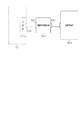
前記主制御基板には、前記制御信号又は前記検出信号のうち少なくとも一方を外部試験装置(性能試験機600)に伝送可能とする試験用配線パターンを設けると共に、前記試験用配線パターンの途中に該試験用配線パターンを伝送する信号に対して所定の電気的処理を施すための電気回路IC(バッファ回路IC551,552)を、前記試験用配線パターンの終端部に該試験用配線パターンを伝送する信号を前記外部試験装置に出力するための外部出力端子部材(試験出力用コネクタ553)を、それぞれ設ける一方、
前記制御信号又は前記検出信号のうち少なくとも一方を入力する入力端子部材(入力用コネクタ562)と、前記制御信号を前記外部試験装置にて使用する情報信号(データ信号DB0〜DB7等)に加工する信号加工回路IC(ラッチ回路564〜567)と、該情報信号を前記外部試験装置に出力する出力端子部材(データ出力用コネクタ563)とを有する信号加工基板装置(試験用中継端子板561)を備え、
前記主制御基板の外部出力端子部材と前記信号加工基板装置の入力端子部材とを電気的に接続したことを特徴とする遊技機用試験システム。
Means 1. Detection signal output means (operation port switch 224, etc.) for detecting the passage of game media and outputting a detection signal;
A main control board (main board 271a) that controls the main game and outputs various control signals (data signals DA0 to DA7) based on the input of the detection signal;
An operation device (symbol display device 41, display control device 214, payout control device 311, etc.) for executing an operation relating to a game based on the control signal from the main control board,
The main control board includes an input terminal member (input connector 549) that receives the detection signal, an arithmetic device (CPU 501) that performs arithmetic processing related to the control signal based on reception of the detection signal, and the arithmetic device And an operation device output terminal member (output port 505) for outputting a control signal calculated in step (a) to the operation device, and an operation wiring pattern (conductor pattern) for electrically connecting them is provided. In a gaming machine test system used for performance testing of gaming machines,
The main control board is provided with a test wiring pattern capable of transmitting at least one of the control signal and the detection signal to an external test apparatus (performance tester 600), and the test control circuit includes a test wiring pattern in the middle of the test wiring pattern. An electric circuit IC (buffer circuits IC551, 552) for performing predetermined electrical processing on a signal for transmitting the test wiring pattern, and a signal for transmitting the test wiring pattern to a terminal portion of the test wiring pattern While providing an external output terminal member (test output connector 553) for outputting to the external test device,
An input terminal member (input connector 562) for inputting at least one of the control signal and the detection signal, and the control signal are processed into information signals (data signals DB0 to DB7, etc.) used in the external test apparatus. A signal processing board device (test relay terminal plate 561) having a signal processing circuit IC (latch circuits 564 to 567) and an output terminal member (data output connector 563) for outputting the information signal to the external test device. Prepared,
A testing system for gaming machines, wherein an external output terminal member of the main control board and an input terminal member of the signal processing board device are electrically connected.

手段1によれば、主制御基板の出力した制御信号に基づいて遊技機の動作装置が動作すると共に、信号加工基板装置では、主制御基板から出力された制御信号が、外部試験装置にて使用される情報信号に加工される。かかる構成とすることにより、外部試験装置にて使用される情報信号が遊技機で通常出力される信号でないとしても、主制御基板を試験用基板に交換することなく必要情報を外部試験装置にて取得することが可能となり、好適に性能確認試験を行うことが可能となる。また、主制御基板が直接的に制御に関与していない情報を外部試験装置にて取得したい場合であっても、信号加工基板装置において制御信号を加工すればよく、任意の試験情報を外部試験装置にて取得することが可能となる。   According to the means 1, the operation device of the gaming machine operates based on the control signal output from the main control board, and the signal processing board device uses the control signal output from the main control board in the external test apparatus. To be processed into an information signal. By adopting such a configuration, even if the information signal used in the external test apparatus is not a signal normally output by the gaming machine, necessary information can be transferred from the external test apparatus without replacing the main control board with the test board. It is possible to obtain the performance confirmation test suitably. Also, even if the main control board wants to acquire information that is not directly involved in control with an external test device, it is only necessary to process the control signal in the signal processing board device, and any test information can be externally tested. It can be acquired by the device.

手段2.上記手段1において、前記試験用配線パターンを、前記動作用配線パターンから分岐するようにして設けたことを特徴とする遊技機用試験システム。   Mean 2. 2. A gaming machine testing system according to claim 1, wherein the test wiring pattern is provided so as to branch from the operation wiring pattern.

手段2によれば、試験用配線パターンは、動作用配線パターンから分岐するようにして設けられている。かかる構成とすることにより、動作装置を動作させるべく動作用配線パターンを伝送する制御信号や検出信号を、好適に外部試験装置に出力することが可能となる。   According to the means 2, the test wiring pattern is provided so as to branch from the operation wiring pattern. With such a configuration, it is possible to suitably output a control signal and a detection signal for transmitting the operation wiring pattern to operate the operation device to the external test device.

手段3.上記手段2において、前記主制御基板に、前記制御信号に対して雑音除去や波形整形等の電気的処理を行うバッファ回路IC(バッファ回路IC286)を、前記演算装置と、前記動作用配線パターンから前記試験用配線パターンが分岐する分岐部との間に実装したことを特徴とする遊技機試験用システム。   Means 3. In the means 2, a buffer circuit IC (buffer circuit IC286) for performing electrical processing such as noise removal and waveform shaping on the control signal is provided on the main control board from the arithmetic unit and the operation wiring pattern. A gaming machine testing system, wherein the testing wiring pattern is mounted between a branching portion and a branching portion.

手段3によれば、主制御基板には、制御信号に雑音除去や波形整形等の電気的処理を行うバッファ回路ICが、演算装置と、動作用配線パターンから試験用配線パターンが分岐する分岐部との間に実装されている。かかる構成とすることにより、動作装置において制御信号が誤認識されることを回避することが可能となり、動作装置が誤作動することを防止することが可能となる。また、外部試験装置に入力された情報信号と、遊技機の動作装置の動作とに不一致が生じることを防止することが可能となる。   According to the means 3, the main control board includes a buffer circuit IC for performing electrical processing such as noise removal and waveform shaping on the control signal, and an arithmetic unit and a branching unit for branching the test wiring pattern from the operation wiring pattern Implemented between and. With this configuration, it is possible to avoid erroneous recognition of the control signal in the operating device, and it is possible to prevent the operating device from malfunctioning. In addition, it is possible to prevent a mismatch between the information signal input to the external test apparatus and the operation of the operation device of the gaming machine.

手段4.上記手段1乃至手段3のいずれかにおいて、前記主制御基板に、前記入力端子部材に入力した検出信号を所定電圧レベルの2値信号に整形する信号整形回路(比較器500)を設け、該信号整形回路により整形された検出信号が、前記演算装置及び前記試験用配線パターンに入力されるよう電気的接続を施したことを特徴とする遊技機試験用システム。   Means 4. In any one of the means 1 to 3, a signal shaping circuit (comparator 500) for shaping a detection signal inputted to the input terminal member into a binary signal having a predetermined voltage level is provided on the main control board, A gaming machine test system characterized in that an electrical connection is made so that a detection signal shaped by a shaping circuit is inputted to the arithmetic unit and the test wiring pattern.

手段4によれば、演算装置及び試験用配線パターンには、信号整形回路によって整形された検出信号が出力される。かかる構成とすることにより、演算装置において検出信号が誤認識されることを回避することが可能となる。また、性能確認試験が行われる際に、演算装置に入力される検出信号と外部試験装置に入力される検出信号とに不一致が生じることを防止することが可能となる。   According to the means 4, the detection signal shaped by the signal shaping circuit is outputted to the arithmetic unit and the test wiring pattern. With such a configuration, it is possible to avoid erroneously recognizing the detection signal in the arithmetic device. In addition, when the performance confirmation test is performed, it is possible to prevent a mismatch between the detection signal input to the arithmetic device and the detection signal input to the external test device.

手段5.上記手段1乃至手段4のいずれかにおいて、前記電気回路ICは、前記試験用配線パターンを伝送する信号に対して雑音除去や波形整形等の電気的処理を行うバッファ回路ICであることを特徴とする遊技機用試験システム。   Means 5. In any one of the above means 1 to 4, the electrical circuit IC is a buffer circuit IC that performs electrical processing such as noise removal and waveform shaping on a signal transmitted through the test wiring pattern. A testing system for gaming machines.

手段5によれば、試験用配線パターンを伝送する信号は、バッファ回路ICにて雑音除去や波形整形等の電気的処理がなされた後に外部試験装置に対して出力される。かかる構成とすることにより、信号加工基板装置や外部試験装置において、入力した信号が誤認識される不具合を防止することが可能となる。   According to the means 5, the signal for transmitting the test wiring pattern is output to the external test apparatus after electrical processing such as noise removal and waveform shaping in the buffer circuit IC. With such a configuration, it is possible to prevent a problem that an input signal is erroneously recognized in the signal processing board device or the external test device.

手段6.上記手段1乃至手段5のいずれかにおいて、前記演算装置から複数の制御信号が動作用配線パターンの複数の電気経路を介して同時に出力され得る遊技機であって、前記主制御基板に設けた前記試験用配線パターンを、前記複数の制御信号を同時に出力可能な複数の電気経路で構成し、該複数の電気経路を1の電気回路ICに電気的に接続される構成としたことを特徴とする遊技機試験用システム。   Means 6. In any one of the above means 1 to 5, a gaming machine capable of simultaneously outputting a plurality of control signals from the arithmetic device via a plurality of electrical paths of an operation wiring pattern, wherein the gaming machine is provided on the main control board. The test wiring pattern is constituted by a plurality of electrical paths capable of outputting the plurality of control signals simultaneously, and the plurality of electrical paths are electrically connected to one electrical circuit IC. Game machine testing system.

手段6によれば、主制御基板には、演算装置から同時に出力された複数の制御信号が1の電気回路ICに入力されるよう試験用配線パターンが設けられている。かかる構成とすることにより、試験用配線パターンの配置を比較的簡単なものとすることが可能となる。   According to the means 6, the test wiring pattern is provided on the main control board so that a plurality of control signals output simultaneously from the arithmetic unit are input to one electric circuit IC. With this configuration, it is possible to make the arrangement of the test wiring pattern relatively simple.

手段7.上記手段1乃至手段6のいずれかにおいて、前記入力端子部材に複数の検出信号が入力され得る遊技機であって、前記主制御基板に設けた前記試験用配線パターンを、前記複数の検出信号を出力可能な複数の電気経路で構成し、該複数の電気経路を1の電気回路ICに電気的に接続される構成としたことを特徴とする遊技機試験用システム。   Mean 7 In any one of the above-described means 1 to 6, a gaming machine in which a plurality of detection signals can be inputted to the input terminal member, the test wiring pattern provided on the main control board is replaced with the plurality of detection signals. A gaming machine testing system comprising a plurality of electrical paths that can be output, and the plurality of electrical paths being electrically connected to one electrical circuit IC.

手段7によれば、主制御基板には、入力端子部材に入力された複数の検出信号が1の電気回路ICに入力されるよう試験用配線パターンが設けられている。かかる構成とすることにより、試験用配線パターンの配置を比較的簡単なものとすることが可能となる。なお、手段6にかかる構成を適用する場合、複数の検出信号を出力可能な複数の電気経路と、複数の制御信号を出力可能な複数の電気経路とを別個の電気回路ICに電気的に接続する構成とすれば、試験用配線パターンの配置をより簡単なものとすることが可能となる。   According to the means 7, a test wiring pattern is provided on the main control board so that a plurality of detection signals inputted to the input terminal member are inputted to one electric circuit IC. With this configuration, it is possible to make the arrangement of the test wiring pattern relatively simple. When the configuration according to the means 6 is applied, a plurality of electrical paths capable of outputting a plurality of detection signals and a plurality of electrical paths capable of outputting a plurality of control signals are electrically connected to separate electrical circuit ICs. If it is set as the structure to perform, it will become possible to make arrangement | positioning of the wiring pattern for a test simpler.

手段8.上記手段1乃至手段7のいずれかにおいて、前記演算装置は、前記制御信号を出力する際に、該制御信号と並行して識別信号(チップセレクト信号CSSG1,CSSG2)を出力することを特徴とする遊技機試験用システム。   Means 8. In any one of the means 1 to 7, the arithmetic unit outputs an identification signal (chip select signals CSSG1, CSSG2) in parallel with the control signal when outputting the control signal. Game machine testing system.

手段8によれば、演算装置は、制御信号を出力する際に、該制御信号と並行して識別信号を出力する。かかる構成とすることにより、1つの電気配線にて複数種の制御信号を出力することが可能となり、外部出力端子部材の小型化を図ることが可能となる。故に、主制御基板が大型化することを抑制することが可能となる。   According to the means 8, the arithmetic unit outputs the identification signal in parallel with the control signal when outputting the control signal. With such a configuration, it is possible to output a plurality of types of control signals with one electrical wiring, and it is possible to reduce the size of the external output terminal member. Therefore, it is possible to prevent the main control board from becoming large.

手段9.上記手段8において、前記信号加工基板装置は、前記信号加工回路ICを複数備え、該複数の信号加工回路ICのうち機能させるべき信号加工回路ICを前記識別信号に基づいて選択することを特徴とする遊技機試験用システム。   Means 9. In the above means 8, the signal processing board device comprises a plurality of the signal processing circuit ICs, and selects a signal processing circuit IC to be functioned from the plurality of signal processing circuits IC based on the identification signal. A system for testing gaming machines.

手段9によれば、信号加工基板装置には、信号加工回路ICが複数設けられており、主制御基板から出力された識別信号に基づいて、複数の信号加工回路ICのうち機能させるべき信号加工回路ICが選択される。かかる構成とすることにより、主制御基板から送信された制御信号と、当該制御信号を加工すべき信号加工回路ICとを密接に関連付けることが可能となり、任意の試験情報を外部試験装置にて取得することが可能となる。   According to the means 9, the signal processing board device is provided with a plurality of signal processing circuits IC, and based on the identification signal output from the main control board, the signal processing to be functioned among the plurality of signal processing circuits IC. A circuit IC is selected. With this configuration, it becomes possible to closely associate the control signal transmitted from the main control board with the signal processing circuit IC to process the control signal, and obtain arbitrary test information with an external test device. It becomes possible to do.

手段10.上記手段8又は手段9において、前記信号加工回路ICは、前記識別信号により指定される所定の期間で前記制御信号をラッチするラッチ回路ICであることを特徴とする遊技機試験用システム。   Means 10. In the above means 8 or 9, the signal processing circuit IC is a latch circuit IC that latches the control signal for a predetermined period specified by the identification signal.

手段10によれば、信号加工回路ICは、識別信号により指定される所定の期間で制御信号をラッチするラッチ回路ICで構成されている。主制御基板から1つの電気配線にて複数種の制御信号を出力可能な構成とした場合、主制御基板から所定の制御信号を継続的に出力することが難しくなる。従って、外部試験装置にて所定の制御信号を所望とするタイミングで取得したり、信号取得後に当該制御信号をその信号レベルのまま継続取得したりすることが難しくなる。そこで、信号加工回路ICとしてラッチ回路ICを用いることにより、信号加工基板装置にて継続的な情報信号を出力することが可能となり、外部試験装置において、任意の試験情報を所望とするタイミングで取得することが可能となる。また、主制御基板が大型化することを抑制することも可能となる。   According to the means 10, the signal processing circuit IC is constituted by a latch circuit IC that latches the control signal in a predetermined period specified by the identification signal. When a configuration in which a plurality of types of control signals can be output from the main control board with a single electric wiring, it is difficult to continuously output predetermined control signals from the main control board. Therefore, it becomes difficult to acquire a predetermined control signal at a desired timing by an external test apparatus, or to continuously acquire the control signal at the signal level after acquiring the signal. Therefore, by using the latch circuit IC as the signal processing circuit IC, it becomes possible to output a continuous information signal in the signal processing board device, and any test information is acquired at a desired timing in the external test device. It becomes possible to do. In addition, the main control board can be prevented from becoming large.

手段11.上記手段8乃至手段10のいずれかにおいて、前記信号加工基板装置は、前記制御信号を、機能させるべき信号加工回路ICを選択するための情報信号(チップセレクト信号CSSG3,CSSG4)に加工する第2信号加工回路IC(ラッチ回路565)を備えることを特徴とする遊技機試験用システム。   Means 11. In any one of the above means 8 to 10, the signal processing board device processes the control signal into information signals (chip select signals CSSG3, CSSG4) for selecting a signal processing circuit IC to be functioned. A gaming machine testing system comprising a signal processing circuit IC (latch circuit 565).

手段11によれば、信号加工基板装置において加工される情報信号の中には、機能させるべき信号加工回路ICを選択するための情報信号がある。かかる構成とすることにより、主制御基板から出力される1の制御信号から試験情報に関する情報信号を複数種取得することが可能となり、好適に性能確認試験を行うことが可能となる。   According to the means 11, among the information signals processed in the signal processing board device, there is an information signal for selecting a signal processing circuit IC to be functioned. With this configuration, it is possible to acquire a plurality of types of information signals related to test information from one control signal output from the main control board, and it is possible to suitably perform a performance confirmation test.

手段12.上記手段1乃至手段11のいずれかにおいて、前記信号加工基板装置に、前記出力端子部材を複数個設けたことを特徴とする遊技機試験用システム。   Means 12. A gaming machine test system according to any one of the above means 1 to 11, wherein a plurality of the output terminal members are provided in the signal processing board device.

手段12によれば、信号加工基板装置には、出力端子部材が複数個設けられている。外部試験装置には複数個の入力端子部材が設けられていることが一般的であるため、遊技機と外部試験装置とを信号加工基板装置を介して接続する構成とすることにより、主制御基板が大型化することを抑制することが可能となる。主制御基板に外部試験装置に設けられた入力端子部材と対応する数の外部出力端子部材を設ける必要がないからである。   According to the means 12, the signal processing board device is provided with a plurality of output terminal members. Since the external test apparatus is generally provided with a plurality of input terminal members, the main control board can be configured by connecting the gaming machine and the external test apparatus via the signal processing board apparatus. Can be prevented from increasing in size. This is because it is not necessary to provide a number of external output terminal members corresponding to the input terminal members provided in the external test apparatus on the main control board.

手段13.上記手段1乃至手段12のいずれかにおいて、前記電気回路IC及び前記外部出力端子部材は、試験時専用部材であることを特徴とする遊技機。   Means 13. In any one of the above means 1 to 12, the electric circuit IC and the external output terminal member are dedicated members for testing.

手段13によれば、電気回路ICと外部出力端子部材は試験時専用のものである。故に、性能確認試験を行わない場合に電気回路ICと外部出力端子部材を搭載しない構成とすれば、当該各部材を悪用して遊技機に不正が行われることを防止することが可能となる。   According to the means 13, the electric circuit IC and the external output terminal member are dedicated for testing. Therefore, if the electric circuit IC and the external output terminal member are not mounted when the performance confirmation test is not performed, it is possible to prevent the gaming machine from being cheated by misusing each member.

手段14.上記手段1乃至手段12のいずれかにおいて、前記外部出力端子部材を取り外し可能な構成としたことを特徴とする遊技機試験用システム。   Means 14. A gaming machine test system according to any one of the means 1 to 12, wherein the external output terminal member is removable.

手段14によれば、主制御基板の外部出力端子部材は取り外し可能な構成となっている。故に、性能確認試験を行わない場合に外部出力端子部材を搭載しない構成とすれば、当該外部出力端子部材を悪用して遊技機に不正が行われることを防止することが可能となる。   According to the means 14, the external output terminal member of the main control board is removable. Therefore, if the external output terminal member is not mounted when the performance confirmation test is not performed, it is possible to prevent the gaming machine from being cheated by misusing the external output terminal member.

手段15.上記手段1乃至手段14のいずれかにおいて、前記電気回路ICと前記外部出力端子部材を、前記主制御基板に近接配置したことを特徴とする遊技機。   Means 15. A gaming machine according to any one of the means 1 to 14, wherein the electric circuit IC and the external output terminal member are disposed close to the main control board.

手段15によれば、電気回路ICと外部出力端子部材は、主制御基板に近接配置されている。かかる構成とすることにより、動作用配線パターンと試験用配線パターンの配置を比較的簡単なものとすることが可能となる。   According to the means 15, the electric circuit IC and the external output terminal member are arranged close to the main control board. With this configuration, it is possible to make the arrangement of the operation wiring pattern and the test wiring pattern relatively simple.

手段16.上記手段15において、前記外部出力端子部材を前記主制御基板の周縁部に配置し、前記電気回路ICを前記外部出力端子部材の近傍に配置したことを特徴とする遊技機。   Means 16. The gaming machine according to claim 15, wherein the external output terminal member is disposed on a peripheral edge of the main control board, and the electric circuit IC is disposed in the vicinity of the external output terminal member.

手段16によれば、外部出力端子部材は主制御基板の周縁部に配置されており、電気回路ICは外部出力端子部材の近傍に配置されている。かかる構成とすることにより、動作用配線パターンと試験用配線パターンの配置を比較的簡単なものとすることが可能となる。   According to the means 16, the external output terminal member is disposed on the peripheral edge of the main control board, and the electric circuit IC is disposed in the vicinity of the external output terminal member. With this configuration, it is possible to make the arrangement of the operation wiring pattern and the test wiring pattern relatively simple.

以下に、以上の各手段を適用し得る各種遊技機の基本構成を示す。   The basic configuration of various gaming machines to which the above means can be applied is shown below.

遊技領域を拡張した遊技機:左右一側部側を中心に左右他側部側が開閉可能となるように構成され、遊技盤(遊技盤30)を支持した遊技機本体(本体枠12等)と、
前記遊技盤の前面に設けられたレール部材(レールユニット50)により略円形状に区画された遊技領域と、
前記遊技機本体の前面側にて前記左右一側部側を中心に前記左右他側部が開閉可能となるよう支持され、閉鎖状態において前記遊技領域を視認可能な視認窓(窓部101)を有した前面扉(前扉枠13)と
を備え、
前記遊技機本体の前記左右一側部には長尺状の補強部材(軸受け金具235)を上下方向へ延びるように設けるとともに、前記遊技機本体の前記左右他側部には前記遊技機本体及び前面扉の開放を禁止するように施錠する施錠装置(シリンダ錠91、連動杆248等)を設け、
該施錠装置は、遊技機本体の前記左右他側部に上下方向へ延びるようにかつ上下方向へ移動可能となるように設けられた長尺状の連動部材(連動杆248)と、遊技機本体の前記左右他側部のうち前記遊技領域の最大幅となる位置とは異なる位置に設けられ前記連動部材を上側又は下側に選択的に移動させる鍵部材(シリンダ錠91)とを備え、該鍵部材の操作による前記連動部材の上下一方への移動により遊技機本体の施錠が解除されるとともに、前記連動部材の上下他方への移動により前記前面扉の施錠が解除されるように構成し、
前記遊技盤を前記遊技機本体の幅内において前記補強部材及び連動部材を左右に振り分けて配置するための領域を残した幅となるように形成するとともに、前記遊技盤の左右両側部には前記遊技機本体の左右両側からの張出領域との干渉を回避するように部分的に凹部(切欠38)を形成し、さらに、前記レール部材のうち、前記遊技領域の最大幅となる位置を、遊技盤の左右端位置に至るように配設することにより、
遊技領域を拡張したことを特徴とする遊技機。
A gaming machine with an expanded gaming area: a gaming machine main body (main body frame 12 or the like) that is configured so that the left and right other side can be opened and closed with the left and right one side as the center, and that supports the gaming board (game board 30). ,
A game area partitioned into a substantially circular shape by a rail member (rail unit 50) provided on the front surface of the game board;
A viewing window (window portion 101) is supported on the front side of the gaming machine main body so that the left and right other side portions can be opened and closed around the left and right side portions, and the gaming area can be seen in the closed state. A front door (front door frame 13) having
A long reinforcing member (bearing bracket 235) is provided on the left and right sides of the gaming machine main body so as to extend in the vertical direction, and the gaming machine main body and the left and right other sides of the gaming machine main body are provided. Provide a locking device (cylinder lock 91, interlocking rod 248, etc.) that locks to prevent the opening of the front door,
The locking device includes a long interlocking member (interlocking rod 248) provided on the other left and right sides of the gaming machine main body so as to extend in the vertical direction and to be movable in the vertical direction, and the gaming machine main body. A key member (cylinder lock 91) that is provided at a position different from the position that is the maximum width of the game area in the left and right other side portions, and that selectively moves the interlocking member upward or downward, The locking of the gaming machine body is released by moving the interlocking member up and down by operating the key member, and the locking of the front door is released by moving the interlocking member up and down,
The game board is formed to have a width that leaves a region for arranging the reinforcing member and the interlocking member to be distributed to the left and right within the width of the gaming machine main body. A recess (notch 38) is partially formed so as to avoid interference with the overhanging area from the left and right sides of the gaming machine body, and the position of the rail member that is the maximum width of the gaming area is By arranging to reach the left and right end positions of the game board,
A gaming machine characterized by an expanded gaming area.

弾球遊技機:遊技者が操作する操作手段(遊技球発射ハンドル18)と、その操作手段の操作に基づいて遊技球を弾いて発射する球発射手段(発射モータ229等)と、その発射された遊技球を所定の遊技領域に導く球通路(レールユニット50の球案内通路)と、遊技領域内に配置された各遊技部品(一般入賞口31、可変入賞装置32、作動口33、可変表示ユニット35等)とを備えた遊技機。   Ball game machine: operation means (game ball launch handle 18) operated by a player, ball launch means (shot motor 229, etc.) for playing and firing game balls based on the operation of the operation means, and its launch A ball path (ball guide path of the rail unit 50) for guiding the game balls to a predetermined game area, and each game component (general winning port 31, variable winning device 32, operating port 33, variable display) arranged in the game area A gaming machine equipped with a unit 35 and the like.

特別表示部及び可変表示装置を備えた弾球遊技機:遊技者が操作する操作手段(遊技球発射ハンドル18)と、その操作手段の操作に基づいて遊技球を弾いて発射する球発射手段(発射モータ229等)と、その発射された遊技球を所定の遊技領域に導く球通路(レールユニット50の球案内通路)と、遊技領域内に配置された作動口(作動口33)、特別表示部(第1特定ランプ部47)、可変表示装置(図柄表示装置41)及び可変入賞装置(可変入賞装置32)とを備え、作動口への遊技球の入球を検知すると特別表示部に表示される表示内容を可変表示し、その停止時の表示内容が特定の表示内容である場合に可変入賞装置を所定態様で開放させるようにした遊技機。   A ball game machine having a special display unit and a variable display device: an operation means (game ball launching handle 18) operated by a player, and a ball launching means for playing and launching a game ball based on the operation of the operation means ( Launch motor 229, etc.), a ball passage (ball guide passage of rail unit 50) for guiding the launched game ball to a predetermined game area, an operation port (operation port 33) arranged in the game region, a special display Unit (first specific lamp unit 47), a variable display device (symbol display device 41), and a variable winning device (variable winning device 32), and when a game ball enters the operating port is detected, it is displayed on the special display unit. A game machine that variably displays displayed content and opens the variable winning device in a predetermined manner when the display content at the time of stoppage is specific display content.

スロットマシン等の回胴式遊技機:「複数の図柄からなる図柄列(具体的には図柄が付されたリール)を変動表示(具体的にはリールの回動)した後に図柄列を最終停止表示する可変表示手段(具体的にはリールユニット)を備え、始動用操作手段(具体的にはスタートレバー)の操作に起因して図柄の変動が開始され、停止用操作手段(具体的にはストップボタン)の操作に起因して又は所定時間経過することにより図柄の変動が停止され、その停止時の最終停止図柄が特定図柄であることを必要条件として遊技者に有利な特別遊技状態(ボーナスゲーム等)を発生させるようにした遊技機。   Slot machines and other spinning machines: “After a symbol row consisting of multiple symbols (specifically, a reel with symbols) is variably displayed (specifically, the reel is rotated), the symbol row is finally stopped. Variable display means for displaying (specifically, a reel unit) is provided, and the variation of the symbol is started due to the operation of the start operating means (specifically, the start lever), and the stop operating means (specifically, the stop operating means) A special gaming state (bonus) that is advantageous to the player as a prerequisite that the change of the symbol is stopped due to the operation of the stop button) or after a predetermined time has elapsed and the final stop symbol at the time of the stop is a specific symbol A game machine that generates a game).

球使用ベルト式遊技機:複数の図柄からなる図柄列(具体的には図柄が付されたリール)を変動表示(具体的にはリールの回動)した後に図柄列を最終停止表示する可変表示手段(具体的にはリールユニット)を備え、始動用操作手段(具体的にはスタートレバー)の操作に起因して図柄の変動が開始され、停止用操作手段(具体的にはストップボタン)の操作に起因して又は所定時間経過することにより図柄の変動が停止され、その停止時の最終停止図柄が特定図柄であることを必要条件として遊技者に有利な特別遊技状態(ボーナスゲーム等)を発生させるようにし、さらに、球受皿(上皿等)を設けてその球受皿から遊技球を取り込む投入処理を行う投入装置と、前記球受皿に遊技球の払出を行う払出装置とを備え、投入装置により遊技球が投入されることにより前記始動用操作手段の操作が有効となるように構成した遊技機。   Ball-operated belt-type game machine: Variable display that displays a symbol string consisting of multiple symbols (specifically, reels with symbols) in a variable manner (specifically, the reels rotate) and then the symbol string is finally stopped. Means (specifically, a reel unit), the change of the symbol is started due to the operation of the start operating means (specifically, the start lever), and the stop operating means (specifically, the stop button) A special game state (bonus game, etc.) that is advantageous to the player is required on the condition that the change of the symbol is stopped due to the operation or when a predetermined time elapses, and the final stop symbol at the time of the stop is a specific symbol. In addition, a ball receiving tray (an upper plate or the like) is provided, and a charging device that loads a game ball from the ball tray and a payout device that pays out the game ball to the ball tray are provided. Play with the device Gaming machine constructed as the operation of the starter operation means becomes effective by the ball is turned.

以下、遊技機の一種であるパチンコ遊技機(以下、「パチンコ機」という)の一実施の形態を、図面に基づいて詳細に説明する。図1はパチンコ機10の正面図、図2はパチンコ機10の主要な構成を展開又は分解して示す斜視図、図3はパチンコ機10を構成する本体枠12の前面構成を示す正面図である。なお、図2、図3では便宜上、パチンコ機10の遊技領域内の構成を空白としている。   Hereinafter, an embodiment of a pachinko gaming machine (hereinafter referred to as “pachinko machine”), which is a type of gaming machine, will be described in detail with reference to the drawings. 1 is a front view of the pachinko machine 10, FIG. 2 is a perspective view showing an exploded or exploded main configuration of the pachinko machine 10, and FIG. 3 is a front view showing a front structure of a main body frame 12 constituting the pachinko machine 10. is there. 2 and 3, the configuration in the game area of the pachinko machine 10 is left blank for convenience.

図1〜図3に示すように、パチンコ機10は、当該パチンコ機10の外殻を形成する外枠11を備えている。外枠11は、遊技ホールへの設置の際に、いわゆる島設備に取り付けられる。外枠11は、木製の板材を全体として矩形枠状に組み合わせた状態とされ、各板材を小ネジ等の離脱可能な締結部材により固定することによって構成されている。従って、釘やリベットを使って各板材を組み付けていた従来構造と比べて構成部材の再利用(リユース)が容易な構成となっている。本実施の形態では、外枠11の上下方向の外寸は809mm(内寸771mm)、左右方向の外寸は518mm(内寸480mm)となっている。なお、外枠11を合成樹脂やアルミニウム等の金属によって構成してもよい。   As shown in FIGS. 1 to 3, the pachinko machine 10 includes an outer frame 11 that forms an outer shell of the pachinko machine 10. The outer frame 11 is attached to a so-called island facility when installed in the game hall. The outer frame 11 is in a state in which wooden plate materials are combined in a rectangular frame shape as a whole, and is configured by fixing each plate material with a detachable fastening member such as a small screw. Therefore, the structure can be easily reused (reused) compared to the conventional structure in which the plate members are assembled using nails and rivets. In the present embodiment, the outer dimension of the outer frame 11 is 809 mm (inner dimension 771 mm) and the outer dimension in the left and right direction is 518 mm (inner dimension 480 mm). In addition, you may comprise the outer frame 11 with metals, such as a synthetic resin and aluminum.

外枠11の一側部には、本体枠12が開閉可能に支持されている。その開閉軸線はパチンコ機10の正面からみて左側に上下へ延びるように設定されており、その開閉軸線を軸心にして本体枠12が前方側に開放できるようになっている。更に言うと、本パチンコ機10には右側に遊技球発射ハンドル18の設置箇所が設けられているため、遊技球発射ハンドル18とは反対側の側部を中心に本体枠12を開閉可能としたということができる。本体枠12は合成樹脂、具体的にはABS樹脂により構成されている。ABS樹脂を用いることにより、比較的低コストで耐衝撃性の高い本体枠12を得ることができる。本体枠12をアルミニウム等の金属によって構成してもよい。なお本実施の形態では、外枠11と本体枠12とにより遊技機本体が構成されている。外枠11に代わる構成として設置枠体を遊技ホール側に予め設けておき、遊技ホールへのパチンコ機10の設置に際しては本体枠12を前記設置枠体に組み付ける構成とすることも可能である。かかる構成では、本体枠12とにより遊技機本体が構成される。   A body frame 12 is supported at one side of the outer frame 11 so as to be openable and closable. The opening / closing axis is set to extend vertically to the left as viewed from the front of the pachinko machine 10, and the main body frame 12 can be opened to the front side with the opening / closing axis as the axis. Furthermore, since the pachinko machine 10 is provided with a game ball launching handle 18 on the right side, the main body frame 12 can be opened and closed around the side opposite to the game ball launching handle 18. It can be said. The main body frame 12 is made of synthetic resin, specifically ABS resin. By using the ABS resin, the main body frame 12 having a relatively low cost and high impact resistance can be obtained. The body frame 12 may be made of a metal such as aluminum. In the present embodiment, the outer frame 11 and the main body frame 12 constitute a gaming machine main body. As an alternative to the outer frame 11, an installation frame body may be provided in advance on the game hall side, and the main body frame 12 may be assembled to the installation frame body when the pachinko machine 10 is installed in the game hall. In such a configuration, the main body frame 12 constitutes a gaming machine main body.

本体枠12の前面側の下部位置には、前面板14が設けられている。前面板14は横長状に形成され、その横幅は本体枠12の横幅とほぼ一致するように構成されている。前面板14は、幅方向ほぼ中央部において手前側へ膨出した膨出部15aを有するベース部15と、ベース部15の膨出部15a内側に設けられ下方にくぼんだ皿形状をなす球受皿としての下皿16と、下皿16の奥側の壁面を構成する奥壁パネル17とを備えている。ベース部15は本体枠12に対してネジ等の締結部材により固定されていることから、ベース部15が本体枠12に対する取付部を構成している。ベース部15には膨出部15aよりも右方に、手前側へ突出するようにして遊技球発射ハンドル18が設けられている。奥壁パネル17には球排出口17aが設けられており、球排出口17aより排出された遊技球が下皿16内に貯留されるようになっている。   A front plate 14 is provided at a lower position on the front side of the main body frame 12. The front plate 14 is formed in a horizontally long shape, and the width thereof is configured to substantially coincide with the width of the main body frame 12. The front plate 14 includes a base portion 15 having a bulging portion 15a that bulges to the near side in a substantially central portion in the width direction, and a ball tray that is provided inside the bulging portion 15a of the base portion 15 and has a dish shape that is recessed downward. And a back wall panel 17 constituting a wall on the back side of the bottom plate 16. Since the base portion 15 is fixed to the main body frame 12 by a fastening member such as a screw, the base portion 15 constitutes an attachment portion for the main body frame 12. A game ball launching handle 18 is provided on the base portion 15 so as to protrude to the right side of the bulging portion 15a. The back wall panel 17 is provided with a ball discharge port 17 a, and the game balls discharged from the ball discharge port 17 a are stored in the lower plate 16.

ベース部15の膨出部15a前面側にはスライド式の球抜きレバー19が設けられている。なお、球抜きレバー19はプッシュ式としてもよい。そして、球抜きレバー19が操作されると下皿16の底面に設けられた図示しない閉鎖板が一体に又はリンクを介して移動して球抜き穴が開放され、下皿16内の貯留球が下方に排出されるよう構成されている。球抜きレバー19には球抜き穴を塞ぐ側へ球抜きレバー19を付勢するコイルバネ等の付勢部材が設けられ、球抜きレバー19の操作が解除された際には付勢部材の付勢力によって閉鎖板が球抜き穴の開放位置に復帰する構成となっている。奥壁パネル17の球排出口17aとは異なる位置には、多数の小孔が集合したスピーカカバー部17bが形成されており、当該パネル17の後方に設置されたスピーカ20の出力音がスピーカカバー部17bを通じて前方に発せられるようになっている。   A slide-type ball removal lever 19 is provided on the front side of the bulging portion 15 a of the base portion 15. The ball removal lever 19 may be a push type. When the ball removal lever 19 is operated, a closing plate (not shown) provided on the bottom surface of the lower plate 16 moves integrally or via a link to open the ball removal hole, and the stored balls in the lower plate 16 are moved. It is configured to be discharged downward. The ball removal lever 19 is provided with a biasing member such as a coil spring that biases the ball removal lever 19 toward the side where the ball removal hole is closed, and the biasing force of the biasing member when the operation of the ball removal lever 19 is released. Thus, the closing plate returns to the opening position of the ball hole. A speaker cover portion 17b in which a large number of small holes are gathered is formed at a position different from the ball discharge port 17a of the back wall panel 17, and the output sound of the speaker 20 installed behind the panel 17 is the speaker cover. It is emitted forward through the portion 17b.

ベース部15には膨出部15aの左方に灰皿21が設けられている。灰皿21は、内部に溜まった吸い殻等を除去しやすいように手前側下方に反転可能に取り付けられており、その右側面と背面とでベース部15に対面している。具体的な図示は省略するが、灰皿21の右側面には当該灰皿21を回動可能な状態で片持ち支持するための支軸が設けられ、同背面には灰皿21が図示のように上方に開口した位置でベース部15に係止される係止部が設けられている。前面板14はその大部分が本体枠12と同様、ABS樹脂にて成形されている。前面板14はパチンコ機10の前面側に露出されるが、ABS樹脂で成形していることによって、装飾等の目的で表面の適宜箇所にメッキを施すことが可能となる。なお、灰皿21が近くに配置されている関係上、下皿16と奥壁パネル17とを構成する部位に関しては難燃性のABS樹脂を用い、仮に誤ってたばこ等を置いても燃えにくくなるよう構成することが好ましい。   The base part 15 is provided with an ashtray 21 on the left side of the bulging part 15a. The ashtray 21 is attached so as to be able to be reversed to the lower side on the front side so as to easily remove the butts and the like accumulated in the inside, and faces the base portion 15 on the right side surface and the back surface thereof. Although a specific illustration is omitted, a support shaft for cantilevering the ashtray 21 in a rotatable state is provided on the right side surface of the ashtray 21, and the ashtray 21 is located upward on the back as shown in the figure. A locking portion that is locked to the base portion 15 is provided at a position that is open to the bottom. Most of the front plate 14 is formed of ABS resin in the same manner as the main body frame 12. The front plate 14 is exposed on the front side of the pachinko machine 10, but by molding it with ABS resin, it is possible to plate appropriate portions of the surface for the purpose of decoration or the like. In addition, since the ashtray 21 is disposed in the vicinity, the portion constituting the lower plate 16 and the back wall panel 17 is made of flame-retardant ABS resin, so that it is difficult to burn even if cigarettes are accidentally placed. It is preferable to configure as described above.

本体枠12の前面側の前面板14を除く範囲には、本体枠12を覆うようにして前面扉としての前扉枠13が設けられている。従って、前面板14と前扉枠13とにより本体枠12の前面側全体が覆われている。前扉枠13は、本体枠12に対して開閉可能に取り付けられており、本体枠12と同様、パチンコ機10の正面からみて左側に上下に延びる開閉軸線を軸心にして前方側に開放できるようになっている。なお、前扉枠13は前面板14と同様、ABS樹脂にて成形されている。前扉枠13はパチンコ機10の前面側に露出されるが、ABS樹脂で成形していることによって、装飾等の目的で表面の適宜箇所にメッキを施すことが可能となる。   A front door frame 13 as a front door is provided in a range excluding the front plate 14 on the front side of the main body frame 12 so as to cover the main body frame 12. Accordingly, the entire front side of the main body frame 12 is covered by the front plate 14 and the front door frame 13. The front door frame 13 is attached to the main body frame 12 so as to be openable and closable. Like the main body frame 12, the front door frame 13 can be opened forward with an opening / closing axis extending vertically to the left when viewed from the front of the pachinko machine 10. It is like that. The front door frame 13 is formed of ABS resin, like the front plate 14. The front door frame 13 is exposed on the front side of the pachinko machine 10, but by molding it with ABS resin, it is possible to plate appropriate portions of the surface for the purpose of decoration or the like.

前扉枠13の下部位置には、下皿16の上方において手前側へ膨出した膨出部22が設けられ、その膨出部22内側には上方に開口した上皿23が設けられている。上皿23は、後述する払出装置より払い出された遊技球を一旦貯留し、一列に整列させながら遊技球発射装置側へ導くための球受皿である。膨出部22前面側には上皿23用の球抜きレバー24が設けられており、この球抜きレバー24を操作すると上皿23の最下流部付近に設けられた球抜き通路(図示略)が開放され、上皿23内の貯留球が下皿16へ排出されるようになっている。なお、上皿23も下皿16等と同様、難燃性のABS樹脂にて構成することが可能である。   A lower portion of the front door frame 13 is provided with a bulging portion 22 that bulges to the near side above the lower plate 16, and an upper plate 23 that opens upward is provided inside the bulging portion 22. . The upper plate 23 is a ball receiving tray for temporarily storing game balls paid out from a payout device, which will be described later, and guiding them to the game ball launching device side while aligning them in a row. A ball removal lever 24 for the upper plate 23 is provided on the front surface side of the bulging portion 22, and when this ball removal lever 24 is operated, a ball removal passage (not shown) provided near the most downstream portion of the upper plate 23. Is opened, and the stored balls in the upper plate 23 are discharged to the lower plate 16. In addition, the upper plate 23 can also be comprised with a flame-retardant ABS resin similarly to the lower plate 16 grade | etc.,.

本パチンコ機10では、ガラス扉枠と前飾り枠とを個別に設けこれらを前面枠(本実施の形態の本体枠に相当)に対して各々開閉可能とすると共に前飾り枠に上皿を設けていた従来構成と異なり、ガラス扉枠と前飾り枠とを1つに統合して前扉枠13とし、前扉枠13に対して一体的に上皿23を設ける構成としている。この場合、ガラス扉枠と前飾り枠とを1つに統合して前扉枠13としたため、当該前扉枠13においてガラス支持構造の強度向上が実現できる。つまり、本パチンコ機10では、遊技領域の拡張を目的とし、その遊技領域拡張に伴い大きめのガラス137を前扉枠13に搭載している。従って、ガラス周囲の枠部分が幅狭になり、強度低下の問題が懸念されるが、ガラス下方に上皿一体の枠部分を設けること等によりガラス支持構造の十分な強度が確保できる。なお、ガラス137の縦横寸法は、従来一般に405mm×405mmであったのに対し、本パチンコ機10では453mm×434mmとしている。   In the pachinko machine 10, a glass door frame and a front decoration frame are individually provided, and these can be opened and closed with respect to the front frame (corresponding to the main body frame of the present embodiment), and an upper plate is provided on the front decoration frame. Unlike the conventional configuration, the glass door frame and the front decoration frame are integrated into a front door frame 13, and the upper plate 23 is provided integrally with the front door frame 13. In this case, since the glass door frame and the front decoration frame are integrated into the front door frame 13, the strength of the glass support structure can be improved in the front door frame 13. That is, in this pachinko machine 10, for the purpose of expanding the game area, a large glass 137 is mounted on the front door frame 13 along with the expansion of the game area. Therefore, although the frame portion around the glass becomes narrow and there is a concern about the problem of strength reduction, sufficient strength of the glass support structure can be ensured by providing a frame portion integrated with the upper plate below the glass. The vertical and horizontal dimensions of the glass 137 are generally 405 mm × 405 mm, whereas the pachinko machine 10 has a size of 453 mm × 434 mm.

また、前扉枠13は、少なくともその開閉の際に遊技球発射ハンドル18と干渉しないようにして下方に拡張されている。具体的な数値を示すと、パチンコ機下端から前扉枠13の下端までの寸法Laは、既存の一機種で例えば約201mmであるのに対し、本パチンコ機10では30mm程小さく、約172mmとなっている。また、これに伴いパチンコ機下端から上皿23の上端までの寸法Lbも小さくなっており、既存の一機種では例えば約298mmであるのに対し、本パチンコ機10では約261mmとなっている。ここで、上皿23の位置を下げたことにより、遊技ホールにおいてパチンコ機10左側に並設される球貸し装置のノズル先端との上下方向の距離が大きくなって貸球のこぼれ落ち等が懸念されるが、本実施の形態では、当該ノズルからの貸球排出部分となる左側部分において、膨出部22の壁面を他の壁面より高くした立ち上げ部22aを形成している。これにより、上皿23の位置を下げた構成にあっても貸球のこぼれ落ち等の不都合が解消されるようになっている。立ち上げ部22aの高さ寸法は上皿23の下げ寸法に見合うものであれば良く、その最大高さ寸法は本実施の形態では25mmとされている。   The front door frame 13 is extended downward so as not to interfere with the game ball launching handle 18 at least when opening and closing the front door frame 13. Specifically, the dimension La from the lower end of the pachinko machine to the lower end of the front door frame 13 is, for example, about 201 mm in one existing model, whereas in this pachinko machine 10, it is about 30 mm smaller, about 172 mm. It has become. Along with this, the dimension Lb from the lower end of the pachinko machine to the upper end of the upper plate 23 is also reduced, which is about 298 mm in the existing model, for example, about 261 mm in the present pachinko machine 10. Here, by lowering the position of the upper plate 23, the vertical distance from the tip of the nozzle of the ball lending device arranged side by side on the left side of the pachinko machine 10 in the game hall increases, and there is a concern that the lending of the ball will spill out. However, in the present embodiment, the rising portion 22a in which the wall surface of the bulging portion 22 is higher than the other wall surface is formed in the left side portion that is the rental ball discharge portion from the nozzle. Thereby, even if it has the structure which lowered | hung the position of the upper plate 23, inconveniences, such as spilling of a rental ball, are eliminated. The height dimension of the rising portion 22a may be anything that matches the lowered dimension of the upper plate 23, and the maximum height dimension is 25 mm in the present embodiment.

なお、前扉枠13においては、上皿形成のための膨出部22が手前側に大きく膨出して設けられるが、上皿23より上方のそれ以外の部位(後述する環状電飾部102等)は、球貸し装置のノズルとの干渉を避けるべく手前側への膨出が制限されている。具体的には、外枠11からの手前側への寸法が45〜50mmに制限されている。   In the front door frame 13, the bulging portion 22 for forming the upper plate is provided so as to bulge greatly toward the front side, but other portions above the upper plate 23 (annular electric decoration portion 102 and the like to be described later) ) Is restricted to bulge to the near side to avoid interference with the nozzle of the ball lending device. Specifically, the dimension from the outer frame 11 toward the front side is limited to 45 to 50 mm.

図3に示すように、本体枠12は、外形が前記外枠11とほぼ同一形状をなす樹脂ベース25を主体に構成されており、樹脂ベース25の中央部には略円形状の窓孔26が形成されている。樹脂ベース25の後側には遊技盤30が着脱可能に装着されている。図4に示すように、遊技盤30は略四角形状の合板よりなり、その周縁部が樹脂ベース25の裏側に当接した状態で取着されている。すなわち、遊技盤30はパチンコ機10後方より取り付けられ、遊技盤30の前面部の略中央部分だけが樹脂ベース25の窓孔26を通じて本体枠12の前面側に露出した状態となっている。なお、遊技盤30は、従来と同様、上下方向の長さは476mm、左右方向の長さは452mmとなっている。   As shown in FIG. 3, the main body frame 12 is mainly composed of a resin base 25 whose outer shape is substantially the same as that of the outer frame 11, and a substantially circular window hole 26 is formed at the center of the resin base 25. Is formed. A game board 30 is detachably mounted on the rear side of the resin base 25. As shown in FIG. 4, the game board 30 is made of a substantially rectangular plywood, and is attached in a state where the peripheral edge thereof is in contact with the back side of the resin base 25. That is, the game board 30 is attached from the rear of the pachinko machine 10, and only the substantially central portion of the front part of the game board 30 is exposed to the front side of the main body frame 12 through the window hole 26 of the resin base 25. Note that the gaming board 30 has a vertical length of 476 mm and a horizontal length of 452 mm, as in the prior art.

次に、遊技盤30の構成を図4に基づいて説明する。遊技盤30には、ルータ加工が施されることによって前後方向に貫通する大小複数の開口部が形成されている。各開口部には一般入賞口31、可変入賞装置32、作動口33、スルーゲート34及び可変表示ユニット35等がそれぞれ設けられている。実際には、一般入賞口31、可変入賞装置32、作動口33、スルーゲート34及び可変表示ユニット35は木ねじ等により遊技盤表面に取り付けられている。本実施の形態では、可変表示ユニット35が遊技盤30の略中央に配置され、その下方に作動口33が配置され、さらにその下方に可変入賞装置32が配置されている。また、可変表示ユニット35の左右両側にスルーゲート34が配置され、遊技盤30の下部両側に一般入賞口31がそれぞれ複数配置されている。作動口33には、所定の条件下で作動状態(開放状態)となる電動役物が付随的に設けられている。前記一般入賞口31、可変入賞装置32及び作動口33に遊技球が入ると、それが後述する検出スイッチにより検出され、その検出結果に基づいて上皿23(場合によっては下皿16)に対し所定数の賞品球が払い出される。その他に、遊技盤30の最下部にはアウト口36が設けられており、各種入賞口等に入らなかった遊技球はアウト口36を通って図示しない球排出路の方へと案内されるようになっている。アウト口36は、遊技盤30の下端略中央を逆U字状に切り欠いて形成されている。そのため、アウト口を穴状に形成していた従来構成に比べ、アウト口形成が容易となる(但し、図4では手前側にレールユニット50が重ねて設けられているため、アウト口36が閉じた状態で示されている)。また、遊技盤30には、遊技球の落下方向を適宜分散、調整等するために多数の釘が植設されていると共に、風車37等の各種部材(役物)が配設されている。   Next, the structure of the game board 30 is demonstrated based on FIG. The game board 30 is formed with a plurality of large and small openings penetrating in the front-rear direction by being subjected to router processing. Each opening is provided with a general winning port 31, a variable winning device 32, an operating port 33, a through gate 34, a variable display unit 35, and the like. Actually, the general winning port 31, the variable winning device 32, the operating port 33, the through gate 34, and the variable display unit 35 are attached to the surface of the game board by wood screws or the like. In the present embodiment, the variable display unit 35 is disposed substantially at the center of the game board 30, the operation port 33 is disposed below the variable display unit 35, and the variable winning device 32 is disposed further below. In addition, through gates 34 are arranged on the left and right sides of the variable display unit 35, and a plurality of general winning holes 31 are arranged on both sides of the lower part of the game board 30. The operating port 33 is additionally provided with an electric accessory that is activated (opened) under a predetermined condition. When a game ball enters the general winning port 31, the variable winning device 32, and the operating port 33, it is detected by a detection switch which will be described later, and based on the detection result, the upper plate 23 (in some cases, the lower plate 16) is detected. A predetermined number of prize balls are paid out. In addition, an out port 36 is provided at the lowermost part of the game board 30 so that game balls that have not entered various winning ports etc. are guided through the out port 36 to a ball discharge path (not shown). It has become. The out port 36 is formed by cutting out the substantially lower center of the game board 30 in an inverted U shape. Therefore, compared to the conventional configuration in which the out port is formed in a hole shape, the out port can be formed more easily (however, in FIG. Is shown). The game board 30 is provided with a large number of nails for appropriately dispersing and adjusting the falling direction of the game balls, and various members (functions) such as a windmill 37 are disposed.

遊技盤30の左右両側部には、組付相手である本体枠12の左右両側からの張出領域との干渉を回避するように凹部としての切欠38が複数箇所に形成されている。   Notches 38 as recesses are formed at a plurality of locations on the left and right sides of the game board 30 so as to avoid interference with the protruding areas from the left and right sides of the body frame 12 that is the assembly partner.

前述したとおり、本パチンコ機10では上皿23の位置を下げられており、それに伴い上皿23の最下流部に設けた遊技球の取込口の位置も同様に下げられている。この場合、遊技球取込口が比較的高い位置にあった従来構成では、遊技球取込口と遊技盤30とが前後に重なり、遊技盤30には遊技球取込口に対応する切欠を設ける必要があったが、本パチンコ機10では、遊技球取込口を下げたことにより遊技球取込口と遊技盤30とが前後に重なることがなく、遊技球取込口用の切欠の形成が不要となる。故に、遊技盤30の製作工程上、有利な構成となる。   As described above, in the pachinko machine 10, the position of the upper plate 23 is lowered, and accordingly, the position of the game ball intake port provided in the most downstream portion of the upper plate 23 is also lowered. In this case, in the conventional configuration in which the game ball inlet is at a relatively high position, the game ball inlet and the game board 30 overlap each other, and the game board 30 has a notch corresponding to the game ball inlet. In this pachinko machine 10, the game ball intake port and the game board 30 do not overlap each other by lowering the game ball intake port. No formation is necessary. Therefore, it becomes an advantageous configuration in the manufacturing process of the game board 30.

可変表示ユニット35には、作動口33への入賞をトリガとして第1図柄(特別図柄)を変動表示する図柄表示装置41が設けられている。可変表示ユニット35には、図柄表示装置41を囲むようにしてセンターフレーム43が配設されている。このセンターフレーム43は、その上部がパチンコ機10前方に延出している。これにより、図柄表示装置41の表示画面の前方を遊技球が落下していくのが防止されており、遊技球の落下により表示画面の視認性が低下するといった不都合が生じない構成となっている。センターフレーム43の上部中央には、第1特定ランプ部47及び第2特定ランプ部48が横並びの状態で設けられている。また、これら両特定ランプ部47,48が配設された領域を挟むように、第1特定ランプ部47及び図柄表示装置41に対応した保留ランプ44が設けられている。遊技球が作動口33を通過した回数は最大4回まで保留され、保留ランプ44の点灯によってその保留個数が表示されるようになっている。なお、保留ランプ44は、図柄表示装置41の一部で変動表示される構成等であっても良い。上述したように、センターフレーム43の上部がパチンコ機10前方に延出していることにより、保留ランプ44、第1特定ランプ部47及び第2特定ランプ部48の視認性が遊技球の落下により阻害されない構成となっている。センターフレーム43の下部には、第2特定ランプ部48に対応した保留ランプ46が設けられている。遊技球がスルーゲート34を通過した回数は最大4回まで保留され、保留ランプ46の点灯によってその保留個数が表示されるようになっている。なお、保留ランプ46は、前記保留ランプ44と同様に、図柄表示装置41の一部で変動表示される構成等であっても良い。   The variable display unit 35 is provided with a symbol display device 41 for variably displaying the first symbol (special symbol) with a winning at the operation port 33 as a trigger. The variable display unit 35 is provided with a center frame 43 so as to surround the symbol display device 41. The center frame 43 has an upper portion extending forward of the pachinko machine 10. As a result, the game ball is prevented from dropping in front of the display screen of the symbol display device 41, and the inconvenience that the visibility of the display screen is lowered due to the fall of the game ball does not occur. . In the upper center of the center frame 43, a first specific lamp portion 47 and a second specific lamp portion 48 are provided side by side. Further, a holding lamp 44 corresponding to the first specific lamp unit 47 and the symbol display device 41 is provided so as to sandwich the area where both the specific lamp units 47 and 48 are disposed. The number of times that the game ball has passed through the operation port 33 is held up to 4 times, and the number of the hold is displayed by turning on the hold lamp 44. Note that the hold lamp 44 may be configured to be variably displayed on a part of the symbol display device 41. As described above, since the upper portion of the center frame 43 extends forward of the pachinko machine 10, the visibility of the holding lamp 44, the first specific lamp portion 47, and the second specific lamp portion 48 is hindered by the fall of the game ball. It is the composition which is not done. A holding lamp 46 corresponding to the second specific lamp portion 48 is provided below the center frame 43. The number of times that the game ball has passed through the through gate 34 is held up to a maximum of 4 times, and the holding number is displayed by turning on the holding lamp 46. Note that the hold lamp 46 may have a configuration in which the display is variably displayed in a part of the symbol display device 41, similarly to the hold lamp 44.

図柄表示装置41は8インチサイズの比較的大型の液晶ディスプレイを備えた液晶表示装置として構成されており、後述する表示制御装置により表示内容が制御される。図柄表示装置41には、例えば左、中及び右に並べて第1図柄が表示され、これらの図柄が上下方向にスクロールされるようにして変動表示されるようになっている。そして、予め設定されている有効ライン上に所定の図柄の組合せが停止表示された場合には、大当たり発生となると共にそれ以降の遊技状態が特別遊技状態としての大当たり状態に移行することとなる。この図柄の変動表示については、後に詳細に説明することとする。なお、図柄表示装置41は、8インチ以外の10インチ,7インチ等の液晶ディスプレイを備えたもの、ワイドサイズのディスプレイを備えたもの、又はCRT,ドットマトリックス,7セグメント等その他のタイプにより表示画面を構成したものであってもよい。   The symbol display device 41 is configured as a liquid crystal display device provided with a relatively large liquid crystal display of 8 inches, and the display content is controlled by a display control device described later. On the symbol display device 41, for example, the first symbols are displayed side by side on the left, middle, and right, and these symbols are variably displayed as they are scrolled up and down. When a predetermined symbol combination is stopped and displayed on a preset active line, a big win is generated and the subsequent gaming state is shifted to a big winning state as a special gaming state. This symbol variation display will be described in detail later. In addition, the symbol display device 41 has a display screen according to other types such as a CRT, a dot matrix, a 7-segment display, or the like provided with a liquid crystal display such as a 10-inch or 7-inch other than the 8-inch. It may be configured.

第1特定ランプ部47には、その内側に赤、緑、青の3色発光タイプのLEDランプが配設されている。そして、作動口33への入賞をトリガとして、所定の順序で発光色の切り替えが行われる。具体的には、作動口33への入賞をトリガとして、赤色光が点灯され、その状態で所定時間が経過すると緑色光に発光色が切り替えられる。そして、緑色光が点灯された状態で前記所定時間が経過すると青色光に発光色が切り替えられる。その後、発光色の切り替え停止時期がくるまで、赤色、緑色、青色という順序で発光色の切り替えが繰り返し行われる。これにより、第1特定ランプ部47には、赤色、緑色、青色が、この順序で繰り返し表示されることとなる。そして、最終的に赤色又は緑色が停止表示された場合には、大当たり発生となると共にそれ以降の遊技状態が大当たり状態に移行し、青色が停止表示された場合には、大当たり発生とならず大当たり状態に移行しない。また、本実施形態では、最終的に赤色で停止表示された場合と、最終的に緑色で停止表示された場合とで移行する大当たり状態が異なっており、後者の方がより遊技者に有利な大当たり状態に移行する。この発光色の切り替えに関しては、後に詳細に説明することとする。   The first specific lamp portion 47 is provided with a red, green, and blue three-color light emission type LED lamp. Then, the emission color is switched in a predetermined order using a winning at the operation port 33 as a trigger. Specifically, red light is turned on with a winning at the operation port 33 as a trigger, and the emission color is switched to green light when a predetermined time elapses in that state. Then, when the predetermined time elapses with the green light turned on, the emission color is switched to blue light. Thereafter, the emission color is repeatedly switched in the order of red, green, and blue until the emission color switching stop time comes. Accordingly, red, green, and blue are repeatedly displayed in this order on the first specific lamp unit 47. Finally, when red or green is stopped and displayed, the jackpot is generated and the subsequent gaming state shifts to the jackpot state. When blue is stopped and displayed, the jackpot is not generated and the jackpot is generated. Does not transition to the state. Further, in the present embodiment, the jackpot state to be transferred is different between the case where the stop is finally displayed in red and the case where the stop is finally displayed in green, and the latter is more advantageous to the player. Transition to jackpot state. The switching of the emission color will be described in detail later.

一方、第2特定ランプ部48には、その内側に赤、緑の2色発光タイプのLEDランプが配設されている。この第2特定ランプ部48は、スルーゲート34の通過をトリガとして、所定の順序で発光色の切り替えが行われる。具体的には、遊技球がスルーゲート34を通過すると、赤色光の点灯と緑色光の点灯とが交互に行われる。これにより、第2特定ランプ部48には、赤色、緑色が交互に表示されることとなる。そして、赤色が停止表示された場合には、作動口33に付随する電動役物が所定時間だけ開放状態となるよう構成されている。   On the other hand, the second specific lamp portion 48 is provided with red and green two-color light emitting type LED lamps inside. In the second specific lamp unit 48, the emission color is switched in a predetermined order with the passage of the through gate 34 as a trigger. Specifically, when the game ball passes through the through gate 34, lighting of red light and lighting of green light are alternately performed. Thus, red and green are alternately displayed on the second specific lamp unit 48. When the red color is stopped and displayed, the electric accessory attached to the operation port 33 is opened for a predetermined time.

可変入賞装置32は、通常は遊技球が入賞できない又は入賞し難い閉状態になっており、大当たり状態に移行すると遊技球が入賞しやすい所定の開放状態に切り換えられるようになっている。より詳しくは、大当たり状態に移行すると、可変入賞装置32が所定の開放状態となり、遊技球が入賞し易い状態となる。可変入賞装置32の開放態様としては、所定時間(例えば30秒間)の経過又は所定個数(例えば10個)の入賞を1ラウンドとして、可変入賞装置32内の継続入賞口への入賞を条件として次ラウンドへの移行条件成立とし、複数ラウンド(例えば16ラウンド)を上限として可変入賞装置32が繰り返し開放されるものが一般的である。   The variable winning device 32 is normally in a closed state in which a game ball cannot be won or difficult to win, and is switched to a predetermined open state in which the game ball is easy to win when it shifts to a big win state. More specifically, when shifting to the big hit state, the variable winning device 32 is in a predetermined open state, and the game ball is easily won. As an opening mode of the variable prize winning device 32, a predetermined time (for example, 30 seconds) or a predetermined number (for example, ten) of winnings is defined as one round, and the following is performed on condition that a winning is made to a continuous prize opening in the variable prize winning device 32. In general, the variable winning device 32 is repeatedly opened with a condition for transition to a round established, with a maximum of a plurality of rounds (for example, 16 rounds).

遊技盤30には、遊技球発射装置から発射された遊技球を遊技盤30上部へ案内するためのレール部材としてのレールユニット50が取り付けられており、遊技球発射ハンドル18の回動操作に伴い発射された遊技球はレールユニット50を通じて所定の遊技領域に案内されるようになっている。レールユニット50はリング状をなす樹脂成型品にて構成されており、より具体的には、摩擦抵抗を低減するべくフッ素配合のポリカーボネート樹脂が用いられている。レールユニット50は、内外二重に設けられた内レール部51と外レール部52とを有する。内レール部51は上方の約1/4ほどを除いて略円環状に形成され、外レール部52は内レール部51の上方開放領域を囲むようにかつ内レール51の左側部と並行するように略半円環状に形成されている。   The game board 30 is provided with a rail unit 50 as a rail member for guiding the game ball launched from the game ball launching device to the upper part of the game board 30. The launched game ball is guided to a predetermined game area through the rail unit 50. The rail unit 50 is composed of a ring-shaped resin molded product, and more specifically, a fluorine-containing polycarbonate resin is used to reduce frictional resistance. The rail unit 50 has an inner rail portion 51 and an outer rail portion 52 that are provided in an inner and outer double. The inner rail portion 51 is formed in a substantially annular shape except for about 1/4 of the upper portion, and the outer rail portion 52 surrounds the upper open area of the inner rail portion 51 and is parallel to the left side portion of the inner rail 51. Are formed in a substantially semi-annular shape.

内レール部51は、他の樹脂部分と一体成型され、遊技盤30の面上にほぼ垂直に起立して設けられている。また、外レール部52は、内レール部51と同様に他の樹脂部分と一体成型され、遊技盤30の面上にほぼ垂直に起立して設けられた支持部52aを有し、その支持部52aの内側面に、遊技球の飛翔をより滑らかなものとするための摺動プレート52bが取り付けられている。摺動プレート52bは、長尺状をなすステンレス製の金属帯よりなり、複数箇所で支持部52aに支持されている。かかる場合、内レール部51と外レール部52とにより誘導レールが構成され、これら各レール部51,52が所定間隔を隔てて対向する部分により球案内通路が形成されている。なお、内外のレール部51,52が対向する部位では、遊技盤30との当接部53により各レール部51,52が連結されており、球案内通路は手前側に開放した溝状に形成されている。   The inner rail portion 51 is integrally formed with other resin portions, and is provided upright substantially vertically on the surface of the game board 30. Further, the outer rail portion 52 has a support portion 52a that is integrally molded with other resin portions in the same manner as the inner rail portion 51, and is provided substantially upright on the surface of the game board 30. A sliding plate 52b is attached to the inner surface of 52a to make the flight of the game ball smoother. The sliding plate 52b is made of a long metal strip made of stainless steel, and is supported by the support portion 52a at a plurality of locations. In such a case, a guide rail is constituted by the inner rail portion 51 and the outer rail portion 52, and a ball guide passage is formed by a portion where these rail portions 51 and 52 face each other with a predetermined interval. In addition, in the site | part which the inner and outer rail parts 51 and 52 oppose, each rail part 51 and 52 is connected by the contact part 53 with the game board 30, and a ball | bowl guide path is formed in the groove shape open | released to the near side. Has been.

レールユニット50において、前記球案内通路より遊技球が飛び出す部位(図4の左上部)には戻り球防止部材54が取着され、該飛び出した遊技球の最大飛翔部分に対応する部位(図4の右上部)には返しゴム55が取着されている。戻り球防止部材54により、一旦球案内通路から遊技盤30の上部へと飛び出した遊技球が球案内通路内に戻ってしまうといった事態が防止される。また、所定以上の勢いで発射された遊技球は返しゴム55に当たり、遊技領域の中央寄りに跳ね返されるようになっている。   In the rail unit 50, a return ball prevention member 54 is attached to a portion (the upper left portion in FIG. 4) from which the game ball jumps out of the ball guide passage, and a portion corresponding to the maximum flight portion of the jumped game ball (FIG. 4). In the upper right part), a return rubber 55 is attached. The return ball prevention member 54 prevents a situation in which a game ball that has once jumped from the ball guide passage to the upper portion of the game board 30 returns to the ball guide passage. In addition, the game ball launched at a predetermined momentum or more hits the return rubber 55 and is rebounded toward the center of the game area.

レールユニット50の外周部には、外方へ張り出した円弧状のフランジ56が形成されている。フランジ56は、遊技盤30に対する取付面を構成する。レールユニット50が遊技盤30に取り付けられる際には、遊技盤30上にフランジ56が当接され、その状態で、当該フランジ56に形成された複数の透孔にネジ等が挿通されて遊技盤30に対するレールユニット50の締結がなされる。ここで、レールユニット50の上下及び左右の各端部は略直線状に形成されている。つまり、レールユニット50の上下及び左右の各端部においてはフランジ56が切り落とされ、パチンコ機10における有限の領域にてレール径の拡張、すなわち遊技盤30上の遊技領域の拡張が図られるようになっている。レールユニット50は、遊技盤30上の遊技領域の最大幅となる位置が遊技盤30の左右端位置に至るように配設されている。なお、レールユニット50の球案内通路に対応する部位のなかでも特に遊技球の受け入れ部位に関しては、当該レールユニット50を強固に取り付けて遊技球の飛びを安定させるべく、該当するフランジ56が他よりも多い箇所(本実施の形態では3カ所、他は2カ所)でネジ止めされている。   An arc-shaped flange 56 projecting outward is formed on the outer periphery of the rail unit 50. The flange 56 constitutes a mounting surface for the game board 30. When the rail unit 50 is attached to the game board 30, the flange 56 is brought into contact with the game board 30, and in this state, screws or the like are inserted into a plurality of through holes formed in the flange 56. The rail unit 50 is fastened to 30. Here, the upper and lower and left and right ends of the rail unit 50 are formed in a substantially linear shape. That is, the flanges 56 are cut off at the upper and lower and left and right ends of the rail unit 50 so that the rail diameter can be expanded in a finite area in the pachinko machine 10, that is, the game area on the game board 30 can be expanded. It has become. The rail unit 50 is disposed such that the position of the gaming area on the gaming board 30 that is the maximum width reaches the left and right end positions of the gaming board 30. Among the parts corresponding to the ball guide passages of the rail unit 50, particularly with respect to the game ball receiving part, the corresponding flange 56 is provided from others in order to firmly attach the rail unit 50 and stabilize the flight of the game ball. There are also many screws (three in this embodiment, two in the other).

内レール部51及び外レール部52間の球案内通路の入口には、同球案内通路の一部を閉鎖するようにして凸部57が形成されている。凸部57は、内レール部51の外周部から下方へ延びるように形成され、遊技領域まで至らず球案内通路内を逆流してくるファール球をファール球通路76(図3参照)に導く機能を有する。遊技盤30の右下隅部及び左下隅部は、証紙等のシールやプレートを貼着するためのスペース(図のSa,Sb)となっており、この貼着スペースを確保するために、フランジ56に切欠58a,58bが形成されている。証紙等のシールを遊技盤30に直接貼り付ける構成とすることで、証紙等の不正な貼り直し等が行いにくいものとなっている。   A convex portion 57 is formed at the entrance of the ball guide passage between the inner rail portion 51 and the outer rail portion 52 so as to close a part of the ball guide passage. The convex portion 57 is formed so as to extend downward from the outer peripheral portion of the inner rail portion 51, and has a function of guiding a foul ball that does not reach the game area and flows backward in the ball guide passage to the foul ball passage 76 (see FIG. 3). Have The lower right corner and the lower left corner of the game board 30 are spaces (Sa, Sb in the figure) for sticking seals and plates such as certificate stamps, and in order to secure this attachment space, the flange 56 Notches 58a and 58b are formed in the upper and lower portions. By adopting a configuration in which a sticker such as a stamp is directly pasted on the game board 30, it is difficult to improperly paste the stamp or the like.

遊技盤30においてレールユニット50よりも外方の左上部には、前後に貫通した中継端子孔59が設けられており、この中継端子孔59を通じて、遊技盤裏面に設置した中継端子板の接続コネクタ60がパチンコ機10前面側に露出されるようになっている。   In the game board 30, a relay terminal hole 59 penetrating in the front-rear direction is provided in the upper left portion outside the rail unit 50, and through this relay terminal hole 59, a connector for connecting a relay terminal plate installed on the back of the game board 60 is exposed to the front side of the pachinko machine 10.

次に、遊技領域について説明する。遊技盤30の盤面はレールユニット50(内外レール部51,52)により内外領域に区画され、略円形状に区画された内側領域が遊技領域とされている。特に本実施の形態では、遊技盤30の盤面上に区画される遊技領域が従来よりもはるかに大きく構成されている。本実施の形態では、外レール部52の最上部地点から遊技盤30下部までの間の距離は445mm(従来品よりも58mm長い)、外レール部52の極左位置から内レール部51の極右位置までの間の距離は435mm(従来品よりも50mm長い)となっている。また、内レール部51の極左位置から内レール部51の極右位置までの間の距離は418mmとなっている。   Next, the game area will be described. The board surface of the game board 30 is divided into inner and outer areas by a rail unit 50 (inner and outer rail portions 51 and 52), and an inner area divided into a substantially circular shape is a game area. In particular, in the present embodiment, the game area partitioned on the board surface of the game board 30 is configured to be much larger than before. In the present embodiment, the distance from the uppermost point of the outer rail portion 52 to the lower part of the game board 30 is 445 mm (58 mm longer than the conventional product), and the extreme left position of the inner rail portion 51 from the extreme left position of the outer rail portion 52. The distance between them is 435 mm (50 mm longer than the conventional product). The distance from the extreme left position of the inner rail portion 51 to the extreme right position of the inner rail portion 51 is 418 mm.

本実施の形態では、遊技領域を、パチンコ機10の正面から見て内レール部51及び外レール部52によって囲まれる領域のうち、内外レール部51,52の対向部分である球案内通路の領域を除いた領域として説明する。つまり、遊技領域は球案内通路部分は含まないため、遊技領域の向かって左側限界位置は外レール部52によってではなく内レール部51によって特定される。また、遊技領域の向かって右側限界位置は内レール部51によって特定され、遊技領域の下側限界位置はアウト口36が形成された遊技盤30の下端位置によって特定され、遊技領域の上側限界位置は外レール部52によって特定される。従って、本実施の形態では、遊技領域の幅(左右方向の最大幅)は、418mmであり、遊技領域の高さ(上下方向の最大幅)は、445mmである。   In the present embodiment, the game area is an area of a ball guide passage that is an opposite part of the inner and outer rail parts 51 and 52 among the areas surrounded by the inner rail part 51 and the outer rail part 52 when viewed from the front of the pachinko machine 10. It demonstrates as an area | region remove | excluding. That is, since the game area does not include the ball guide passage portion, the left limit position toward the game area is specified by the inner rail portion 51 instead of the outer rail portion 52. Further, the right limit position toward the game area is specified by the inner rail portion 51, the lower limit position of the game area is specified by the lower end position of the game board 30 in which the out port 36 is formed, and the upper limit position of the game area. Is specified by the outer rail portion 52. Therefore, in the present embodiment, the width of the gaming area (maximum width in the left-right direction) is 418 mm, and the height of the gaming area (maximum width in the vertical direction) is 445 mm.

ここで、前記遊技領域の幅は、少なくとも380mm以上あることが望ましい。より好ましくは400mm以上、410mm以上、420mm以上、430mm以上、440mm以上、450mm以上、さらに460mm以上であることが望ましい。すなわち、遊技領域の幅寸法は、遊技領域拡大という観点からは大きい程好ましい。また、遊技領域の高さは、少なくとも400mm以上あることが望ましい。より好ましくは410mm以上、420mm以上、430mm以上、440mm以上、450mm以上、さらには460mm以上であることがより望ましい。もちろん、470mm以上又は480mm以上としてもよい。すなわち、遊技領域の高さ寸法は、遊技領域拡大という観点からは大きい程好ましい。なお、上記幅及び高さの組合せについては、上記数値を任意に組み合わせたものとすることができる。なお、遊技領域の幅又は高さが一定値以上となると、遊技領域の一部が遊技盤30の盤面を越えることも考えられるが、その越えた領域については他の部材を遊技盤面に沿って設けること等によって補えばよい。   Here, the width of the gaming area is preferably at least 380 mm. More preferably, it is 400 mm or more, 410 mm or more, 420 mm or more, 430 mm or more, 440 mm or more, 450 mm or more, and further 460 mm or more. That is, the width dimension of the game area is preferably as large as possible from the viewpoint of game area expansion. The height of the game area is preferably at least 400 mm. More preferably, it is 410 mm or more, 420 mm or more, 430 mm or more, 440 mm or more, 450 mm or more, and more preferably 460 mm or more. Of course, it is good also as 470 mm or more or 480 mm or more. In other words, the height of the game area is preferably as large as possible from the viewpoint of game area expansion. In addition, about the combination of the said width | variety and height, it can be set as what combined the said numerical value arbitrarily. If the width or height of the game area exceeds a certain value, a part of the game area may exceed the board surface of the game board 30, but other members are placed along the game board surface in the area beyond the game area. What is necessary is just to supplement by providing.

本実施の形態では、遊技盤30面に対する遊技領域の面積の比率は約70%と、従来に比べ格段に面積比が大きいものとなっている。なお、遊技盤30面に対する遊技領域の面積比は、従来では50%程度に過ぎなかったことから、本実施の形態のように従来と同様の大きさの遊技盤30を使用している前提下では相当に遊技領域を拡大しているといえる。なお、パチンコ機10の外形は遊技ホールへの設置の都合上製造者間でほぼ統一されており、遊技盤30の大きさも同様とせざるを得ない状況下において、上記のように遊技盤30面に対する遊技領域の面積の比率を約20%も高めたことは、遊技領域拡大の観点で非常に有意義である。ここで、前記比率は、少なくとも60%以上であることが望ましい。さらに好ましくは65%以上であり、より好ましくは70%以上である。また、本実施形態の場合を越えて75%以上であれば、一層望ましい。さらには、80%以上であってもよい。なお、80%以上を確保するには遊技領域の形状を略円形状とすることは困難となるため、隅部(例えば右下隅部や右上隅部)を拡張したような形状とすることが好ましい。   In the present embodiment, the ratio of the area of the game area to the surface of the game board 30 is about 70%, which is a much larger area ratio than before. Note that the area ratio of the game area to the surface of the game board 30 has been only about 50% in the related art, so that the game board 30 having the same size as the conventional one is used as in the present embodiment. So, it can be said that the game area is considerably expanded. It should be noted that the outer shape of the pachinko machine 10 is almost uniform among manufacturers for the convenience of installation in the game hall, and in the situation where the size of the game board 30 has to be the same, the surface of the game board 30 as described above. Increasing the ratio of the area of the gaming area to about 20% is very significant from the viewpoint of expanding the gaming area. Here, the ratio is preferably at least 60% or more. More preferably, it is 65% or more, More preferably, it is 70% or more. Further, if it is 75% or more exceeding the case of this embodiment, it is more desirable. Furthermore, it may be 80% or more. In order to secure 80% or more, it is difficult to make the shape of the game area into a substantially circular shape. Therefore, it is preferable to have a shape in which the corner (for example, the lower right corner or the upper right corner) is expanded. .

また、パチンコ機10全体の正面側の面積に対する遊技領域の面積の比率は約40%と、従来に比べ格段に面積比が大きいものとなっている。なお、パチンコ機10全体の正面側の面積に対する遊技領域の面積比は、35パーセント以上であるのが望ましい。もちろん、40パーセント以上としてもよいし、45パーセント以上、又は50パーセント以上としてもよい。   Moreover, the ratio of the area of the game area to the area of the front side of the entire pachinko machine 10 is about 40%, which is a much larger area ratio than before. The area ratio of the game area to the area on the front side of the entire pachinko machine 10 is desirably 35% or more. Of course, it may be 40% or more, 45% or more, or 50% or more.

遊技領域の拡張に関連して、可変表示ユニット35の両側に位置するスルーゲート34は、該ゲート34を通過した遊技球が中央の方へ寄せられるような案内機構を有している。これにより、遊技領域が左右方向に拡張されている場合であっても、遊技球を中央の作動口33や可変入賞装置32の方へと案内することができ、ひいては、遊技領域が拡張されることにより遊技球が入賞しにくくなることによる興趣の低下が抑制されるようになっている。また、遊技領域が左右方向に拡張されていることによって、比較的大型の可変表示ユニット35を遊技領域中央に設けても、可変表示ユニット35の左右両側にスルーゲート34、風車37、複数の釘(遊技球を中央に誘導するための三角釘等の誘導釘)、他の役物などを余裕をもって配設することができ、可変表示ユニット35の左右両側の遊技領域での遊技球の流れが単調とならず、遊技球の挙動を存分に楽しませることができる。   In connection with the expansion of the game area, the through gates 34 located on both sides of the variable display unit 35 have a guide mechanism that allows the game balls that have passed through the gate 34 to be moved toward the center. As a result, even when the game area is expanded in the left-right direction, the game ball can be guided toward the central operation port 33 and the variable prize-winning device 32, and thus the game area is expanded. As a result, a decrease in interest due to the difficulty of winning a game ball is suppressed. Further, since the game area is expanded in the left-right direction, even if a relatively large variable display unit 35 is provided in the center of the game area, the through-gate 34, the windmill 37, and a plurality of nails are provided on the left and right sides of the variable display unit 35. (Guide nails such as a triangular nail for guiding the game ball to the center) and other objects can be provided with a margin, and the flow of the game ball in the game areas on the left and right sides of the variable display unit 35 It is not monotonous and you can fully enjoy the behavior of the game ball.

遊技盤30の左右両側部に切欠38が形成されて本体枠12の左右両側からの張出領域との干渉が回避されていること、レールユニット50において遊技盤30上の遊技領域の最大幅となる位置が遊技盤30の左右端位置にまで至るようになっていることは既に述べたが、更に後述するように、本体枠12の左右両側部に設けられる補強部材(軸受け金具235:図9参照)と施錠装置(基枠247、連動杆248等:図9参照)とを配置するための領域を残した幅となるようにして本体枠12に遊技盤30が取り付けられている。これらのことからも、遊技領域の拡張が図られている。   Notches 38 are formed on both the left and right sides of the game board 30 to avoid interference with the protruding areas from the left and right sides of the main body frame 12, and the maximum width of the game area on the game board 30 in the rail unit 50 It has already been described that the position reaches the left and right end positions of the game board 30, but as will be described later, reinforcing members (bearing brackets 235: FIG. 9) provided on the left and right side portions of the main body frame 12. The game board 30 is attached to the main body frame 12 so as to have a width that leaves an area for arranging the locking device (the base frame 247, the interlocking rod 248, etc .: see FIG. 9). For these reasons, the game area is being expanded.

図3の説明に戻り、前記樹脂ベース25において、窓孔26(遊技盤30)の下方には、遊技球発射装置より発射された直後に遊技球を案内するための発射レール61が取り付けられている。発射レール61は、その後方の金属板62を介して樹脂ベース25に取付固定されており、所定の発射角度(打ち出し角度)にて直線的に延びるよう構成されている。従って、遊技球発射ハンドル18の回動操作に伴い発射された遊技球は、まずは発射レール61に沿って斜め上方に打ち出され、その後球案内通路を通じて遊技領域に案内される。前述のとおり遊技領域が従来よりも大幅に拡張されたことにより、球案内通路の曲率は小さくなっているため、打出球を安定化させるための工夫が必要となる。そこで、本実施の形態では、遊技球の発射位置を低くして発射レール61の傾斜角度(発射角度)を既存のものよりも幾分大きくし(すなわち発射レール61を立ち上げるようにし)、また発射レール61を遊技球発射装置の発射位置から遊技領域の中央位置(アウト口36)を越える位置まで延びるよう形成することで発射レール61の長さを既存のものよりも長くして十分な長さの球誘導距離を確保するようにしている。これにより、遊技球発射装置から発射された遊技球をより安定した状態で球案内通路に案内できるようにしている。さらに打出球の安定化を図るべく、発射レール61を設置した金属板62を大型化すると共に該金属板62を多数箇所(本実施の形態では15〜20カ所)でネジ止めしており、これにより発射レール61が遊技盤30に対して強固に位置決めされている。   Returning to the description of FIG. 3, in the resin base 25, below the window hole 26 (game board 30), a launch rail 61 for guiding the game ball immediately after being launched from the game ball launcher is attached. Yes. The firing rail 61 is fixedly attached to the resin base 25 via a metal plate 62 behind the firing rail 61, and is configured to extend linearly at a predetermined firing angle (launch angle). Accordingly, the game ball that is launched in accordance with the turning operation of the game ball launch handle 18 is first launched obliquely upward along the launch rail 61 and then guided to the game area through the ball guide path. As described above, the curvature of the ball guide passage is reduced because the game area has been greatly expanded as compared with the prior art, and thus a device for stabilizing the launch ball is required. Therefore, in the present embodiment, the launch position of the game ball is lowered so that the inclination angle (launch angle) of the launch rail 61 is somewhat larger than the existing one (that is, the launch rail 61 is raised), and By forming the launch rail 61 so as to extend from the launch position of the game ball launcher to a position beyond the center position (out port 36) of the game area, the launch rail 61 is made longer than the existing one and sufficiently long. The ball guide distance is secured. Thereby, the game ball launched from the game ball launching device can be guided to the ball guide passage in a more stable state. Further, in order to stabilize the launch ball, the metal plate 62 provided with the launch rail 61 is enlarged, and the metal plate 62 is screwed at a number of locations (15 to 20 in this embodiment). Thus, the launch rail 61 is firmly positioned with respect to the game board 30.

発射レール61と球案内通路との間には所定間隔の隙間があり、この隙間より下方にファール球通路76が設けられている。従って、仮に遊技球発射装置から発射された遊技球が戻り球防止部材54まで至らずファール球として球案内通路内を逆戻りする場合には、そのファール球がファール球通路76を介して下皿16に排出される。因みに、本実施の形態の場合、発射レール61の長さは約240mm、発射レール先端部のファール球通路76に通じる隙間の長さ(発射レール61の延長線上の長さ)は約40mmである。   There is a predetermined gap between the firing rail 61 and the ball guide passage, and a foul ball passage 76 is provided below the gap. Therefore, if the game ball launched from the game ball launching device does not reach the return ball prevention member 54 and returns as a foul ball in the ball guide passage, the foul ball passes through the foul ball passage 76 to the lower plate 16. To be discharged. Incidentally, in the case of the present embodiment, the length of the launch rail 61 is about 240 mm, and the length of the gap (the length on the extension line of the launch rail 61) leading to the foul ball passage 76 at the tip of the launch rail is about 40 mm. .

ファール球が球案内通路内を逆流してくる際、その多くは外レール部52に沿って流れ、外レール部52の下端部に到達した時点で下方に落下するが、一部のファール球は球案内通路内で暴れ、内レール部51側へ跳ね上がるものもある。この際、跳ね上がったファール球は、球案内通路入口の前記凸部57に当たり、ファール球通路76に誘導される。これにより、ファール球の全てがファール球通路76に確実に案内され、ファール球と次に発射される遊技球との干渉が抑制される。   When the foul balls flow backward in the ball guide passage, most of them flow along the outer rail portion 52 and fall downward when reaching the lower end portion of the outer rail portion 52. Some rampage in the ball guide passage and jump to the inner rail 51 side. At this time, the splashed foul ball hits the convex portion 57 at the entrance of the ball guide passage and is guided to the foul ball passage 76. Thereby, all of the foul balls are reliably guided to the foul ball passage 76, and interference between the foul balls and the game balls to be fired next is suppressed.

なお、詳しい図面の開示は省略するが、遊技球発射装置には、前扉枠13側の球出口(上皿23の最下流部より通じる球出口)から遊技球が1つずつ供給される。この際、本実施の形態では遊技球の発射位置を低くしたため、前扉枠13側の球出口から前記発射位置への落差が大きくなるが、発射レール61の発射基端部付近にはその右側と手前側にそれぞれガイド部材63,64を設置してある。これにより、前扉枠13側の球出口から供給される遊技球が常に所定の発射位置にセットされ、安定した発射動作が実現できる。また、遊技球発射装置には、基端部を中心に回動可能に支持された打球槌が設けられ、打球槌の回動に伴い遊技球が発射されるが、打球槌に関して軽量化が望まれている。それ故、アルミニウム等の軽金属への材料変更や槌シャフト部寸法の縮小化により打球槌の軽量化を図る一方で、十分な発射力を確保すべく、打球槌のヘッド部(基端部と反対側の先端部)に重り部を設けている。これにより、十分でかつ安定した遊技球の発射が実現できる。打球槌の重り部を上方に突出して設けることにより、打球槌を容易に摘んだりひっかけたりすることができ、槌先の打球強さの調整等がし易くなるという効果も得られる。   Although detailed disclosure of the drawings is omitted, one game ball is supplied to the game ball launching device one by one from the ball outlet on the front door frame 13 side (ball outlet leading from the most downstream portion of the upper plate 23). At this time, since the launch position of the game ball is lowered in this embodiment, the drop from the exit of the ball on the front door frame 13 side to the launch position becomes large, Guide members 63 and 64 are installed on the front side. Thereby, the game ball supplied from the ball exit on the front door frame 13 side is always set at a predetermined launch position, and a stable launch operation can be realized. In addition, the game ball launching device is provided with a ball striking rod that is supported so as to be rotatable about the base end portion, and a game ball is launched along with the rotation of the ball striking ball. It is rare. Therefore, while aiming to reduce the weight of the hitting ball by changing the material to a light metal such as aluminum and reducing the size of the hitting shaft, the head portion of the hitting ball (opposite to the base end) is required to ensure sufficient firing force. A weight is provided at the tip of the side. Thereby, sufficient and stable launch of the game ball can be realized. By providing the weight portion of the hitting ball projecting upward, the hitting ball can be easily picked or caught, and the effect of facilitating adjustment of the hitting strength of the hitting tip can be obtained.

また、本体枠12の前面において発射レール61の左側には、左右一対の排出口66,67が形成されると共に、その前方に、排出口66,67より排出された遊技球を上皿23又は下皿16の何れかに案内するための遊技球案内ユニット70が取り付けられている。便宜上以下の説明では、排出口66を第1排出口、排出口67を第2排出口ともいう。これら排出口66,67は、本体枠12の背面に設けられた遊技球分配部245(図10参照)に通じており、基本的に第1排出口66より遊技球の排出が行われ、この第1排出口66も含め上皿23に通じる通路が遊技球で一杯になると、第1排出口66に代えて第2排出口67より遊技球の排出が行われるようになっている。   A pair of left and right discharge ports 66, 67 are formed on the left side of the launch rail 61 on the front surface of the main body frame 12, and the game balls discharged from the discharge ports 66, 67 are placed in front of the upper plate 23 or A game ball guide unit 70 for guiding one of the lower dishes 16 is attached. For convenience, in the following description, the discharge port 66 is also referred to as a first discharge port, and the discharge port 67 is also referred to as a second discharge port. These discharge ports 66 and 67 communicate with a game ball distribution unit 245 (see FIG. 10) provided on the back surface of the main body frame 12, and game balls are basically discharged from the first discharge port 66. When the passage leading to the upper plate 23 including the first outlet 66 is filled with game balls, the game balls are discharged from the second outlet 67 instead of the first outlet 66.

遊技球案内ユニット70は、ポリカーボネート樹脂等の透明な樹脂材料により内部を視認可能に構成され、本体枠12に対して前扉枠13を閉鎖した状態で本体枠12と前扉枠13との間に収まるよう厚みが比較的薄くなるように形成されている。遊技球案内ユニット70には、前述のファール球通路76が一体的に形成されている。遊技球案内ユニット70には、前記排出口66,67と下皿16とを連通するための球排出通路71が形成されている。遊技球案内ユニット70には、本体枠12の第1排出口66の手前側に、上皿23に連通する連通口72が形成され、連通口72を閉鎖するようにして開閉プレート73が取り付けられている。開閉プレート73は支軸74により回動可能に支持され、付勢手段としてのバネ75により連通口72を閉鎖する位置に常時付勢されている。   The game ball guide unit 70 is configured to be visible with a transparent resin material such as polycarbonate resin, and between the main body frame 12 and the front door frame 13 with the front door frame 13 closed with respect to the main body frame 12. It is formed so that the thickness is comparatively thin so that it can be accommodated. The game ball guide unit 70 is integrally formed with the foul ball passage 76 described above. The game ball guide unit 70 is formed with a ball discharge passage 71 for communicating the discharge ports 66 and 67 with the lower plate 16. In the game ball guide unit 70, a communication port 72 communicating with the upper plate 23 is formed on the front side of the first discharge port 66 of the main body frame 12, and an opening / closing plate 73 is attached so as to close the communication port 72. ing. The opening / closing plate 73 is rotatably supported by a support shaft 74 and is always urged to a position where the communication port 72 is closed by a spring 75 as urging means.

遊技球案内ユニット70の上記構成によれば、前扉枠13を開放した状態ではバネ75の付勢力により開閉プレート73が図示の如く起き上がり、連通口72を閉鎖する。この状態では、第1排出口66より排出される遊技球が球排出通路71を通じて下皿16に案内される。従って、連通口72の上流側に遊技球が貯留されている状態で前扉枠13を開放した場合、その貯留球は連通口72よりこぼれ落ちることなく、球排出通路71を通じて下皿16に流下する。つまり、前飾り枠が省略され前扉枠13に対して上皿23が直接設けられる構成とした本パチンコ機10にあっても、前扉枠13の開放に際し連通口72の上流側にある遊技球がこぼれ落ちてしまうといった不都合が防止できる。これに対し、前扉枠13を閉鎖した状態では、前扉枠13の裏面に設けられた球通路樋138(図2参照)によりバネ75の付勢力に抗して開閉プレート73が押し開けられる。この状態では、第1排出口66より排出される遊技球が連通口72を介して上皿23に案内される。従って、連通口72より上流側の遊技球は上皿23に払い出される。なお、遊技球案内ユニット70の球排出通路71下流側には、下皿16に排出された遊技球が一杯(満タン)になったことを検知する下皿満タンスイッチが取り付けられている。   According to the above configuration of the game ball guide unit 70, the open / close plate 73 rises as shown in the figure by the urging force of the spring 75 when the front door frame 13 is opened, and the communication port 72 is closed. In this state, the game ball discharged from the first discharge port 66 is guided to the lower plate 16 through the ball discharge passage 71. Therefore, when the front door frame 13 is opened in a state where game balls are stored upstream of the communication port 72, the stored balls flow down to the lower plate 16 through the ball discharge passage 71 without spilling from the communication port 72. To do. In other words, even in the present pachinko machine 10 in which the front decorative frame is omitted and the upper plate 23 is directly provided on the front door frame 13, the game on the upstream side of the communication port 72 when the front door frame 13 is opened. The inconvenience of spilling a ball can be prevented. On the other hand, when the front door frame 13 is closed, the opening / closing plate 73 is pushed open against the biasing force of the spring 75 by a ball passage rod 138 (see FIG. 2) provided on the back surface of the front door frame 13. . In this state, the game ball discharged from the first discharge port 66 is guided to the upper plate 23 through the communication port 72. Accordingly, the game ball upstream of the communication port 72 is paid out to the upper plate 23. A lower plate full tank switch for detecting that the game ball discharged to the lower plate 16 is full (full tank) is attached to the downstream side of the ball discharge passage 71 of the game ball guide unit 70.

樹脂ベース25には、窓孔26の右下部に略四角形状の小窓78が設けられている。従って、遊技盤30の右下隅部スペース(図4のSa)に貼られた証紙等は、この小窓78を通じて視認できるようになっている。この小窓78から遊技盤30上に証紙等を直接貼り付けることも可能である。   The resin base 25 is provided with a substantially rectangular small window 78 at the lower right portion of the window hole 26. Accordingly, the stamp or the like attached to the lower right corner space (Sa in FIG. 4) of the game board 30 can be viewed through the small window 78. It is also possible to directly paste a stamp or the like on the game board 30 from the small window 78.

樹脂ベース25には、窓孔26の左上部にも小窓79が設けられている。この小窓79は、図4で説明した遊技盤30の中継端子孔59に対応する位置にそれとほぼ同一の形状で設けられ、中継端子孔59及び小窓79を通じて、遊技盤裏面に設置した中継端子板の接続コネクタ60が本体枠12の前面側に露出される。かかる構成において、前扉枠13側に設けた各種ランプに対しては、本体枠12(樹脂ベース25)の小窓79より露出した接続コネクタ60を介して電気的な接続がなされている。樹脂ベース25の上部には、前扉枠13の開放の状態を検出するための前扉枠開放スイッチ27が設けられている。前扉枠開放スイッチ27は、樹脂ベース25の前面に出没可能なピンを有しており、本体枠12に対して前扉枠13を閉じた状態ではピンが押し込まれて前扉枠13の閉鎖が検知され、本体枠12に対して前扉枠13を開いた状態ではピンが突出位置に戻って前扉枠13の開放が検知されるようになっている。樹脂ベース25の左右2カ所には、本体枠12に対して前扉枠13を閉じた際に前扉枠13背面の金具類(図5に示す補強板131〜134)に接触し、且つその金具類を本体枠12側に導通させてアース(接地)するための金属片28a,28bが取り付けられている。従って、金属片28a,28bを通じて、前扉枠13背面の金具類が本体枠12側の施錠装置やヒンジ金具に導通され、これら施錠装置やヒンジ金具と共にアースされる。   A small window 79 is also provided in the resin base 25 at the upper left portion of the window hole 26. The small window 79 is provided in the position corresponding to the relay terminal hole 59 of the game board 30 described in FIG. 4 in substantially the same shape as that. The connection connector 60 of the terminal board is exposed on the front side of the main body frame 12. In such a configuration, various lamps provided on the front door frame 13 side are electrically connected via the connection connector 60 exposed from the small window 79 of the main body frame 12 (resin base 25). A front door frame opening switch 27 for detecting the open state of the front door frame 13 is provided on the top of the resin base 25. The front door frame opening switch 27 has a pin that can be projected and retracted on the front surface of the resin base 25. When the front door frame 13 is opened with respect to the main body frame 12, the pin returns to the protruding position and the opening of the front door frame 13 is detected. When the front door frame 13 is closed with respect to the main body frame 12, the resin base 25 comes into contact with metal fittings (reinforcing plates 131 to 134 shown in FIG. 5) on the back of the front door frame 13, and Metal pieces 28a and 28b are attached to connect the metal fittings to the main body frame 12 side for grounding. Therefore, the metal fittings on the back of the front door frame 13 are conducted to the locking device and the hinge fitting on the main body frame 12 side through the metal pieces 28a and 28b, and are grounded together with the locking device and the hinge fitting.

本体枠12の左端側(開閉軸線側)には、前扉枠13を開閉可能に支持するための支持機構として、上下一対の支持金具81,82が取り付けられている。上側の支持金具81には手前側に切欠を有する支持孔83が設けられ、下側の支持金具82には上方へ突出する突起軸84が設けられている。なお、支持金具81,82に支持される前扉枠13の具体的構成については後述する。また、本体枠12の右端側(開閉軸線とは反対側)には、前扉枠13裏面側の開放端側に設けた上下一対の鉤金具155,156(図2参照)を挿入するための挿入孔87,88がそれぞれ設けられている。本パチンコ機10では、本体枠12や前扉枠13を施錠状態とするための施錠装置が本体枠12の裏面側に隠れて配置される構成となっている。従って、鉤金具155,156が挿入孔87,88を介して施錠装置に係止されることによって、前扉枠13が本体枠12に対して開放不能に施錠される。   A pair of upper and lower support brackets 81 and 82 are attached to the left end side (opening / closing axis line side) of the main body frame 12 as a support mechanism for supporting the front door frame 13 so that it can be opened and closed. The upper support fitting 81 is provided with a support hole 83 having a notch on the front side, and the lower support fitting 82 is provided with a protruding shaft 84 protruding upward. The specific configuration of the front door frame 13 supported by the support fittings 81 and 82 will be described later. Further, a pair of upper and lower metal fittings 155 and 156 (see FIG. 2) provided on the open end side on the back side of the front door frame 13 is inserted into the right end side (the side opposite to the opening / closing axis) of the main body frame 12. Insertion holes 87 and 88 are provided, respectively. The pachinko machine 10 is configured such that a locking device for locking the main body frame 12 and the front door frame 13 is hidden behind the main body frame 12. Therefore, the front door frame 13 is locked to the main body frame 12 so that it cannot be opened by locking the metal fittings 155 and 156 to the locking device via the insertion holes 87 and 88.

本体枠12の右下隅部には、外枠11に対する本体枠12の施錠及び解錠、並びに本体枠12に対する前扉枠13の施錠及び解錠を行うための鍵部材としてのシリンダ錠91が設置されている。シリンダ錠91は施錠装置に一体化されており、施錠装置のうちシリンダ錠91だけが本体枠12の前方に突出した状態で設けられている。この場合、シリンダ錠91は、遊技領域の最大幅となる位置とは異なる位置に設けられている。シリンダ錠91は、本体枠12の施解錠と前扉枠13の施解錠とを共に賄う機能を有しており、鍵穴に差し込んだキーを左(反時計回り方向)に回すと本体枠12の施錠が解かれ、逆にキーを右(時計回り方向)に回すと前扉枠13の施錠が解かれるようになっている。   A cylinder lock 91 as a key member for locking and unlocking the main body frame 12 with respect to the outer frame 11 and locking and unlocking the front door frame 13 with respect to the main body frame 12 is installed at the lower right corner of the main body frame 12. Has been. The cylinder lock 91 is integrated with the locking device, and only the cylinder lock 91 of the locking device is provided in a state of protruding in front of the main body frame 12. In this case, the cylinder lock 91 is provided at a position different from the position that is the maximum width of the game area. The cylinder lock 91 has a function to cover both the locking and unlocking of the main body frame 12 and the locking and unlocking of the front door frame 13, and when the key inserted into the key hole is turned counterclockwise (counterclockwise direction) When the key is unlocked and the key is turned to the right (clockwise direction), the front door frame 13 is unlocked.

図2に示すように、本体枠12には、シリンダ錠91を囲むようにして縦長状のカバー部材92が取り付けられている。詳細な図示は省略するが、カバー部材92には、その上端部及び下端部に係止部(フック)が形成されている。従って、上側の係止部を本体枠12側に係止させると共に、下側の係止部を本体枠12と前面板14との間に挟み込むことにより、カバー部材92が本体枠12に取り付けられる。前扉枠13には、カバー部材92の形状に合わせて切欠部145が形成されており、前扉枠13を閉鎖した状態ではこの前扉枠13と共にカバー部材92がパチンコ機前面部を構成する。なお、前扉枠13を閉鎖したとき、カバー部材92に形成された鍔部が前扉枠13により押さえられ、カバー部材92のがたつきが防止されるようになっている。   As shown in FIG. 2, a vertically long cover member 92 is attached to the main body frame 12 so as to surround the cylinder lock 91. Although detailed illustration is omitted, the cover member 92 has locking portions (hooks) formed at the upper end portion and the lower end portion thereof. Therefore, the cover member 92 is attached to the main body frame 12 by locking the upper locking portion to the main body frame 12 side and sandwiching the lower locking portion between the main body frame 12 and the front plate 14. . The front door frame 13 is formed with a notch 145 corresponding to the shape of the cover member 92. When the front door frame 13 is closed, the cover member 92 together with the front door frame 13 constitutes the front portion of the pachinko machine. . When the front door frame 13 is closed, the flange formed on the cover member 92 is pressed by the front door frame 13 to prevent the cover member 92 from rattling.

次に、前扉枠13について図1,図5を参照しつつ説明する。なお、図5は、前扉枠13の背面図である。   Next, the front door frame 13 will be described with reference to FIGS. FIG. 5 is a rear view of the front door frame 13.

前扉枠13には遊技領域のほぼ全域を前方から視認することができるようにした視認窓としての窓部101が形成されている。窓部101は、円形に近い略楕円形状をなし、より詳しくは、その左右側の略中央部が上下側に比べて緩やかに湾曲した形状となっている。なお、前記略中央部が直線状になる形状であってもよい。前扉枠13の窓部101上方において、最も狭い部位のフレーム幅は約61mmである。本実施の形態における上記フレーム幅寸法は、本体枠12において外レール部52の最上部(遊技領域の上端)と本体枠12の上端との間の距離とほぼ一致するものであって、85mm〜95mm程度の上記フレーム幅を有する従来機種に比べて著しく短くなっている。これにより、遊技領域における上部領域の視認性が確保されやすくなると共に、大型の可変表示ユニット35も比較的上方に配置することができるようになっている。窓部101上方のフレーム幅(最狭部位)の寸法は80mm以下であることが望ましく、より望ましくは70mm以下であり、さらに望ましくは60mm以下である。もちろん、所定の強度が確保できるのであれば、50mm以下としても差し支えない。   The front door frame 13 is formed with a window portion 101 as a viewing window so that almost the entire game area can be viewed from the front. The window portion 101 has a substantially oval shape that is nearly circular, and more specifically, a substantially central portion on the left and right sides of the window portion 101 is gently curved as compared to the upper and lower sides. The substantially central portion may have a linear shape. Above the window part 101 of the front door frame 13, the frame width of the narrowest part is about 61 mm. The frame width dimension in the present embodiment is substantially the same as the distance between the uppermost portion of the outer rail portion 52 (the upper end of the game area) and the upper end of the main body frame 12 in the main body frame 12, and is 85 mm to It is significantly shorter than the conventional model having the frame width of about 95 mm. Thereby, the visibility of the upper area in the game area can be easily ensured, and the large variable display unit 35 can also be arranged relatively upward. The dimension of the frame width (narrowest part) above the window 101 is desirably 80 mm or less, more desirably 70 mm or less, and further desirably 60 mm or less. Of course, as long as a predetermined strength can be secured, the thickness may be 50 mm or less.

前扉枠13の左右のフレーム部分は、フレーム幅を小さくするには制約があり、前扉枠13自体の強度及びガラス支持強度を確保するのに十分な幅寸法を必要とする。本実施の形態では、左右の各フレーム部分において最も狭い部位のフレーム幅を何れも約44mmとしている。この場合、本パチンコ機10にあっては遊技領域を大幅に拡張したことから、パチンコ機10の正面から見て左側すなわち開閉軸線側では、前扉枠13のフレーム幅が上記の通り約44mmとなるのに対し、レールユニット50の外レール部52の左端位置と本体枠12の左端位置との距離が約21mmとなり、後者の寸法がかなり小さいものとなっている。つまり本構成では、前扉枠13を閉鎖した状態において、球案内通路の一部が、前扉枠13の左側フレーム部分と重複し覆い隠されるようになる。しかしながら、球案内通路において遊技球が一時的に視認困難となったとしても、かかる球案内通路は遊技球が遊技領域に案内されるまでの通過領域に過ぎず、遊技者が主として遊技を楽しむ遊技領域において遊技球が視認困難となるわけではない。そのため、実際の遊技に際しては何ら支障が生じない。以上により、前扉枠13の十分な強度及びガラス支持強度を確保しつつも、遊技に何ら支障を及ぼすことなく遊技領域の拡張が可能となる。   The left and right frame portions of the front door frame 13 are restricted in reducing the frame width, and need a width dimension sufficient to ensure the strength of the front door frame 13 itself and the glass support strength. In the present embodiment, the narrowest part of the left and right frame parts has a frame width of about 44 mm. In this case, since the game area has been greatly expanded in this pachinko machine 10, the frame width of the front door frame 13 is about 44 mm as described above on the left side when viewed from the front of the pachinko machine 10, that is, on the opening / closing axis side. On the other hand, the distance between the left end position of the outer rail portion 52 of the rail unit 50 and the left end position of the main body frame 12 is about 21 mm, and the latter dimension is considerably small. That is, in this configuration, in a state where the front door frame 13 is closed, a part of the ball guide passage overlaps and is covered with the left frame portion of the front door frame 13. However, even if it becomes difficult to visually recognize the game ball in the ball guide passage, the ball guide passage is only a passing area until the game ball is guided to the game area, and the game where the player mainly enjoys the game. The game ball is not difficult to view in the area. Therefore, there is no trouble in actual game. As described above, it is possible to expand the game area without causing any trouble to the game, while ensuring sufficient strength and glass support strength of the front door frame 13.

前扉枠13の下端部における左右両側には、本体枠12表面や遊技盤30表面等(証紙等を含む)の一部を視認できるよう透明樹脂を取り付けた小窓107が設けられている。小窓107に取り付けられる透明樹脂は、その内部の証紙等を工場等で容易に機械読み取りできるよう平坦状に構成される。但し、小窓107に、内部の証紙等をホール作業者等が容易に目視できるよう拡大レンズ部を設けることも可能である。   Small windows 107 to which a transparent resin is attached are provided on both the left and right sides of the lower end portion of the front door frame 13 so that a part of the surface of the main body frame 12 and the surface of the game board 30 (including certificate paper) can be visually recognized. The transparent resin attached to the small window 107 is formed in a flat shape so that the internal certificate paper or the like can be easily machine-read in a factory or the like. However, the small window 107 can be provided with a magnifying lens portion so that the hall operator or the like can easily see the internal certificate paper or the like.

前扉枠13にはその周囲(例えばコーナー部分)に各種ランプ等の発光手段が設けられている。これら発光手段は、大当たり状態下や所定のリーチ演出時等において点灯、点滅のように発光態様が変更制御されることにより、遊技中の演出効果を高める役割を果たす。例えば、窓部101の周縁に沿ってLED等の発光手段を内蔵した環状電飾部102が左右対称に設けられ、環状電飾部102の中央であってパチンコ機10の最上部にはLED等の発光手段を内蔵した中央電飾部103が設けられている。本パチンコ機10では、中央電飾部103が大当たりランプとして機能し、大当たり状態下で点灯や点滅を行うことにより大当たり状態に移行していることを報知する。また、上皿23周りにも、同じくLED等の発光手段を内蔵した上皿電飾部104が設けられている。その他、中央電飾部103の左右側方には、賞球払出中に点灯する賞球ランプ105と所定のエラー時に点灯するエラー表示ランプ106とがそれぞれ設けられている。なお、環状電飾部102は、内外二重の樹脂カバー層とその内側に収容された発射板付き発光体(LED)とよりなり、樹脂カバー層の各々の内側面には各層で縦横に交差する向きに突条(又は波状の突起)が設けられている。外側の樹脂カバー層は透明であり、内側の樹脂カバー層は有色である。従って、環状電飾部102を発光させれば、多数に分散化された状態、又は立体感を伴った状態の電飾が実現できるようになる。樹脂カバー層には、ガラス粉末入りの樹脂材料を用いると良い。このような樹脂カバー層の構成は、他の電飾部(例えば中央電飾部103や賞球ランプ105)に適用することもできる。   The front door frame 13 is provided with light emitting means such as various lamps around the periphery (for example, a corner portion). These light emitting means play a role of enhancing the effect of the game during the game by changing and controlling the light emission mode such as lighting and blinking in a big hit state or at a predetermined reach performance. For example, an annular illumination part 102 incorporating light emitting means such as LEDs is provided symmetrically along the periphery of the window part 101, and an LED or the like is provided at the center of the annular illumination part 102 and at the top of the pachinko machine 10. There is provided a central illumination unit 103 incorporating the light emitting means. In the pachinko machine 10, the central lighting unit 103 functions as a jackpot lamp, and notifies that the jackpot state has been reached by turning on or blinking under the jackpot state. Further, around the upper plate 23, there is also provided an upper plate illumination unit 104 that also incorporates light emitting means such as LEDs. In addition, on the left and right sides of the central illumination unit 103, there are respectively provided a prize ball lamp 105 that is lit during award ball payout and an error display lamp 106 that is lit when a predetermined error occurs. The annular illumination part 102 includes an inner and outer double resin cover layer and a light emitting body (LED) with a launch plate accommodated inside the resin cover layer. The inner surface of each resin cover layer intersects with each layer vertically and horizontally. A protrusion (or a wavy protrusion) is provided in the direction to be turned. The outer resin cover layer is transparent, and the inner resin cover layer is colored. Therefore, if the annular illumination part 102 is caused to emit light, it is possible to realize the illumination in a state of being dispersed in a large number or in a state accompanied with a stereoscopic effect. A resin material containing glass powder may be used for the resin cover layer. Such a configuration of the resin cover layer can also be applied to other electric decoration parts (for example, the central electric decoration part 103 and the prize ball lamp 105).

前扉枠13には、窓部101の下方位置に、貸球操作部120が配設されている。貸球操作部120には球貸しボタン121と、返却ボタン122と、度数表示部123とが設けられている。パチンコ機10の側方に配置されたカードユニット(球貸しユニット)に紙幣やカード等を投入した状態で、貸球操作部120によって球貸し操作、カード返却操作及びカード度数の確認を行うことができる。すなわち、球貸しボタン121は、カード等(記録媒体)に記録された情報に基づいて貸出球を得るために操作されるものであり、カード等に残額が存在する限りにおいて貸出球が払い出される。返却ボタン122は、カードユニットに挿入されたカード等の返却を求める際に操作される。度数表示部123はカード等の残額情報を表示するものである。なお、カードユニットを介さずに球貸し装置等から上皿に遊技球が直接貸し出されるパチンコ機(いわゆる現金機)では貸球操作部120が不要となるが、かかる場合には、貸球操作部120の設置部分に飾りシール等が付されるようになっている。これにより、貸球操作部120を設けた本パチンコ機10の構成において、カードユニットを用いたパチンコ機(いわゆるCR機)と現金機との共用が可能となる。   The front door frame 13 is provided with a ball rental operation portion 120 at a position below the window portion 101. The ball lending operation unit 120 is provided with a ball lending button 121, a return button 122, and a frequency display unit 123. A ball lending operation, a card return operation, and a card frequency check can be performed by the lending operation unit 120 in a state where a bill or a card is inserted into a card unit (a ball lending unit) arranged on the side of the pachinko machine 10. it can. That is, the ball lending button 121 is operated to obtain a lending ball based on information recorded on a card or the like (recording medium), and the lending ball is paid out as long as the remaining amount exists on the card or the like. The return button 122 is operated when requesting the return of a card or the like inserted into the card unit. The frequency display unit 123 displays remaining amount information such as a card. In a pachinko machine (so-called cash machine) in which game balls are rented directly from a ball lending device or the like to a top plate without using a card unit, the ball lending operation unit 120 is unnecessary. A decorative sticker or the like is attached to 120 installation portions. Thereby, in the configuration of the present pachinko machine 10 provided with the lending operation unit 120, the pachinko machine using a card unit (so-called CR machine) and the cash machine can be shared.

前扉枠13の裏側には、窓部101を囲むようにして金属製の各種補強部材が設けられている。詳しくは、図5に示すように、前扉枠13の裏側にあって窓部101の左右及び上下の外側にはそれぞれ補強板131,132,133,134が取り付けられている。これら補強板131〜134は相互に接触して連結されているが、図の左側及び上側の補強板132,133の連結部には直接の接触を避けるための樹脂パーツ135が介在されている。これにより、補強板131〜134による電気経路の閉じたループが切断され、ノイズの原因となる磁界の発生等が防止されている。   On the back side of the front door frame 13, various metal reinforcing members are provided so as to surround the window portion 101. Specifically, as shown in FIG. 5, reinforcement plates 131, 132, 133, and 134 are respectively attached to the back side of the front door frame 13 and on the left and right and upper and lower outer sides of the window portion 101. These reinforcing plates 131 to 134 are connected in contact with each other, but resin parts 135 for avoiding direct contact are interposed at the connecting portions of the left and upper reinforcing plates 132 and 133 in the drawing. Thereby, the closed loop of the electric path by the reinforcing plates 131 to 134 is cut, and the generation of a magnetic field causing noise is prevented.

図5の右側となる開閉軸線側の補強板131にはその上端部及び下端部に、本体枠12に対する組付機構として、組付金具151,152が取り付けられている。そして、本体枠12側の支持金具81,82(図3参照)に対して前扉枠13側の組付金具151,152が取り付けられている。すなわち、下側の組付金具152には下面に開口する軸穴が形成されており、その軸穴に下側の支持金具82の突起軸84が挿入される一方、上側の組付金具151の軸部が上側の支持金具81の支持孔83に挿入されることにより、本体枠12に対して前扉枠13が開閉可能に支持されている。また、同補強板131にはその中間位置にフック状をなす係合爪131aが設けられており、この係合爪131aは、前扉枠13を閉じた状態で本体枠12の孔部12a(図3参照)に挿入されるように構成されている。これにより、上皿23を含む形態で前扉枠13を構成し、その上下の軸支間隔を長くした本パチンコ機10においても、中間位置における前扉枠13の浮き上がりが防止できる。それ故、前扉枠13を浮かしての不正行為等が抑制されるようになっている。   Assembling mechanisms for the main body frame 12 are attached to the upper and lower ends of the opening / closing axis side reinforcing plate 131 on the right side of FIG. And the assembly | attachment metal fittings 151 and 152 by the side of the front door frame 13 are attached with respect to the support metal fittings 81 and 82 (refer FIG. 3) by the side of the main body frame 12. FIG. That is, a shaft hole that opens to the lower surface is formed in the lower mounting bracket 152, and the protruding shaft 84 of the lower support bracket 82 is inserted into the shaft hole, while the upper mounting bracket 151 By inserting the shaft portion into the support hole 83 of the upper support fitting 81, the front door frame 13 is supported to be openable and closable with respect to the main body frame 12. Further, the reinforcing plate 131 is provided with an engaging claw 131a having a hook shape at an intermediate position thereof, and the engaging claw 131a is formed in the hole 12a ( (See FIG. 3). Accordingly, even in the pachinko machine 10 in which the front door frame 13 is configured in a form including the upper plate 23 and the upper and lower shaft support intervals are increased, the front door frame 13 can be prevented from being lifted at the intermediate position. Therefore, an illegal act or the like floating the front door frame 13 is suppressed.

図5の左側となる開閉軸線とは反対側の補強板132には鉤形状をなす上下一対の鉤金具155,156が取り付けられている。これら鉤金具155,156は、後方に延び、本体枠12に設けた挿入孔87,88(図3参照)に対応するようにして設けられている。本体枠12に対して前扉枠13を閉鎖した際、鉤金具155,156が本体枠12側の挿入孔87,88に挿入されて施錠装置により施錠状態とされるようになっている。   A pair of upper and lower hook metal fittings 155 and 156 having a hook shape are attached to the reinforcing plate 132 on the opposite side to the open / close axis on the left side of FIG. These metal fittings 155 and 156 extend rearward and are provided so as to correspond to the insertion holes 87 and 88 (see FIG. 3) provided in the main body frame 12. When the front door frame 13 is closed with respect to the main body frame 12, the metal fittings 155 and 156 are inserted into the insertion holes 87 and 88 on the main body frame 12 side, and are locked by the locking device.

下側の補強板134には、前記発射レール61に対向する位置に樹脂ケース136が取り付けられている。樹脂ケース136には、前記貸球操作部120用の回路基板が収容されている。樹脂ケース136の背面(図5に見える面)は平坦状をなし、前扉枠13を閉じた際に発射レール61の側壁を構成するようになっている。故に、発射レール61から遊技球が前方にこぼれ落ちることが防止される。   A resin case 136 is attached to the lower reinforcing plate 134 at a position facing the firing rail 61. The resin case 136 accommodates a circuit board for the ball rental operation unit 120. The back surface of the resin case 136 (the surface visible in FIG. 5) is flat, and constitutes the side wall of the firing rail 61 when the front door frame 13 is closed. Therefore, the game ball is prevented from spilling forward from the launch rail 61.

下側の補強板134の一部を切り欠いた部位には、パチンコ機10後方に向けて球通路樋138が設置されており、球通路樋138の少なくとも上方には、同じくパチンコ機10後方に向けて延びる庇(ひさし)部139が設けられている。この場合、本体枠12側に前扉枠13を閉じた状態では、球通路樋138と庇部139との間に、本体枠12側の連通口72上辺に沿って延びる突条が入り込むようにして配置される。故に、球通路樋138より針金やフィルム等を侵入させて不正行為を行おうとしても、遊技領域にまで針金やフィルム等を侵入させることが非常に困難となる。結果として、針金やフィルム等を利用して行われる不正行為を防止することができる。   A ball passage rod 138 is installed at a part of the lower reinforcing plate 134 cut out toward the back of the pachinko machine 10, and at least above the ball passage rod 138, the pachinko machine 10 is also behind the pachinko machine 10. An eaves portion 139 extending toward the surface is provided. In this case, in a state where the front door frame 13 is closed on the main body frame 12 side, a ridge extending along the upper side of the communication port 72 on the main body frame 12 side enters between the ball passage rod 138 and the collar portion 139. Arranged. Therefore, even if a wire, a film, or the like is invaded from the ball passage rod 138 to perform an illegal act, it is very difficult to infiltrate the wire, the film, or the like to the game area. As a result, fraudulent acts performed using a wire, a film, or the like can be prevented.

上述した補強板131〜134はガラス支持用の金枠としての機能も兼ね備えており、これら補強板131〜134の内側が後方に折り返されてガラス保持溝が形成されている。ガラス保持溝は前後に2列形成されており、矩形状をなす前後一対のガラス137が各ガラス保持溝にて保持される。これにより、2枚のガラス137が前後に所定間隔を隔てて取着されている。   The reinforcing plates 131 to 134 described above also have a function as a metal frame for supporting the glass, and the inside of these reinforcing plates 131 to 134 is folded back to form a glass holding groove. The glass holding grooves are formed in two rows on the front and rear sides, and a pair of front and rear glasses 137 having a rectangular shape are held in each glass holding groove. Thereby, the two glass 137 is attached to the front and back at a predetermined interval.

前述した通り本実施の形態のパチンコ機10では遊技領域の拡張を図っていることから、前扉枠13を閉じた状態にあっては、内外のレール部51,52間に形成された球案内通路の一部が前扉枠13により覆い隠される構成となっている。それ故、球案内通路では手前側の開放部がガラス137で覆えない部分ができてしまう。かかる場合、例えば、遊技球発射装置より発射された遊技球が戻り球防止部材54まで至らず戻ってくると、遊技球が球案内通路外に飛び出したり、外レール部52とガラス137との間にできる隙間に挟まってしまうおそれがある。そこで本実施の形態では、前扉枠13に、球案内通路の手前側開放部を被覆するためのレールカバー140を取り付けている。レールカバー140は略円弧状をなす板体であって、透明な樹脂により形成されている。レールカバー140は、その円弧形状が前記球案内通路の形状に対応しており、窓部101の周縁部に沿って、球案内通路の基端部から先端部近傍までの区間を覆うようになっている。特にレールカバー140の内径側の寸法・形状は内レール部51のそれにほぼ一致する。また、レールカバー140の右端部(すなわち、レールカバー140を前扉枠13に取着した図5の状態で右端となる部位)には、球案内通路がガラス137の側縁部からはみ出した部分を被覆するための被覆部141が設けられている。以上のレールカバー140の構成により、前扉枠13が閉じられた状態においては、レールカバー140の裏面が球案内通路のほぼ全域を覆うこととなって、遊技球が球案内通路外に飛び出したり、外レール部52とガラス137との間にできる隙間に挟まってしまうといった不具合の発生を防止することができる。   As described above, the pachinko machine 10 according to the present embodiment is designed to expand the game area. Therefore, when the front door frame 13 is closed, the ball guide formed between the inner and outer rail portions 51 and 52 is used. A part of the passage is covered by the front door frame 13. Therefore, in the ball guide passage, a portion where the opening portion on the near side cannot be covered with the glass 137 is formed. In this case, for example, when the game ball launched from the game ball launching device returns without reaching the return ball prevention member 54, the game ball jumps out of the ball guide passage or between the outer rail portion 52 and the glass 137. There is a risk of being caught in a gap that can be made. Therefore, in the present embodiment, a rail cover 140 is attached to the front door frame 13 so as to cover the front side opening portion of the ball guide passage. The rail cover 140 is a plate having a substantially arc shape, and is formed of a transparent resin. The rail cover 140 has an arc shape corresponding to the shape of the spherical guide passage, and covers a section from the base end portion of the spherical guide passage to the vicinity of the distal end portion along the peripheral edge portion of the window portion 101. ing. In particular, the size and shape of the rail cover 140 on the inner diameter side substantially match those of the inner rail portion 51. Further, at the right end portion of the rail cover 140 (that is, the portion that becomes the right end in the state of FIG. 5 where the rail cover 140 is attached to the front door frame 13), the portion where the ball guide passage protrudes from the side edge portion of the glass 137. A covering portion 141 for covering the surface is provided. With the above-described configuration of the rail cover 140, when the front door frame 13 is closed, the back surface of the rail cover 140 covers almost the entire area of the ball guide passage, so that the game ball jumps out of the ball guide passage. It is possible to prevent the occurrence of a problem such as being caught in a gap formed between the outer rail portion 52 and the glass 137.

また、レールカバー140の下部裏側には、その内側縁に沿って円弧状に延び且つ後方へ向けて突出する突条142が形成されている。突条142は、前扉枠13が閉じられた状態において、球案内通路内に入り込んだ状態で内レール部51に重なり合うように配置される。従って、例えば前扉枠13と本体枠12との隙間から針金やフィルム等を侵入させて不正行為を行おうとしても、球案内通路の内側にある遊技領域にまで針金やフィルム等を侵入させることが非常に困難となる。その結果、針金やフィルム等を利用して行われる不正行為を防止することができる。なお、突条142をより広い範囲で、例えばレールカバー140の内側縁の全域に沿って形成する構成としても良く、かかる構成によれば、より広い範囲で針金やフィルム等を侵入させにくくなり、針金やフィルム等を利用して行われる不正行為をより確実に防止することができる。   Further, on the lower back side of the rail cover 140, a ridge 142 extending in an arc shape along the inner edge and protruding rearward is formed. The protrusion 142 is disposed so as to overlap the inner rail portion 51 in a state of entering the ball guide passage when the front door frame 13 is closed. Therefore, for example, even if a wire or a film is intruded through the gap between the front door frame 13 and the main body frame 12 to perform an illegal act, the wire or the film is allowed to enter the game area inside the ball guide passage. Becomes very difficult. As a result, fraudulent acts performed using a wire, a film, or the like can be prevented. The protrusion 142 may be formed in a wider range, for example, along the entire area of the inner edge of the rail cover 140. According to such a configuration, it becomes difficult to infiltrate a wire, a film, or the like in a wider range, It is possible to more reliably prevent fraudulent acts that are performed using wires or films.

次に、パチンコ機10の背面の構成を説明する。なお、図6はパチンコ機10の背面図、図7はパチンコ機10の背面構成を主要部品毎に分解して示す分解斜視図である。   Next, the configuration of the back surface of the pachinko machine 10 will be described. 6 is a rear view of the pachinko machine 10, and FIG. 7 is an exploded perspective view showing the rear structure of the pachinko machine 10 for each major part.

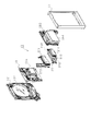
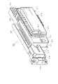
まず、パチンコ機10の背面構成について全体の概要を説明する。パチンコ機10の背面側には、各種制御装置(各種制御基板)が上下左右に並べられるようにして又は前後に重ねられるようにして配置されるとともに、遊技球を供給するための遊技球供給装置(払出機構)や樹脂製の保護カバー等が取り付けられている。本実施の形態では、各種制御装置を2つの取付台に分けて搭載して2つの制御基板ユニットを構成し、それら制御基板ユニットを個別に本体枠12又は遊技盤30の裏面に装着するようにしている。この場合、主制御装置271(主基板271a)と音声ランプ制御装置272(音声ランプ制御基板)とを一方の取付台に搭載してユニット化すると共に、払出制御装置311(払出制御基板)、発射制御装置312(発射制御基板)及び電源装置313(電源基板)を他方の取付台に搭載してユニット化している。以下においては、便宜上、前者のユニットを「第1制御基板ユニット201」と称し、後者のユニットを「第2制御基板ユニット202」と称することとする。また、払出機構及び保護カバーも1ユニットとして一体化され、一般に樹脂部分を裏パックと称することもあるため、ここではそのユニットを「裏パックユニット203」と称する。各ユニット201〜203の詳細な構成については後述する。   First, an overall outline of the rear configuration of the pachinko machine 10 will be described. On the back side of the pachinko machine 10, various control devices (various control boards) are arranged so as to be arranged in the vertical and horizontal directions or stacked in front and back, and a game ball supply device for supplying game balls (Discharge mechanism), a protective cover made of resin, and the like are attached. In the present embodiment, various control devices are separately mounted on two mounting bases to form two control board units, and these control board units are individually attached to the main body frame 12 or the back of the game board 30. ing. In this case, the main controller 271 (main board 271a) and the voice lamp controller 272 (voice lamp control board) are mounted on one mounting base to form a unit, and the payout controller 311 (payout control board) is launched. A control device 312 (launch control board) and a power supply device 313 (power supply board) are mounted on the other mounting base to form a unit. Hereinafter, for the sake of convenience, the former unit is referred to as a “first control board unit 201” and the latter unit is referred to as a “second control board unit 202”. Further, since the dispensing mechanism and the protective cover are also integrated as one unit, and the resin portion is generally referred to as a back pack, this unit is referred to as a “back pack unit 203” herein. The detailed configuration of each unit 201 to 203 will be described later.

第1制御基板ユニット201、第2制御基板ユニット202及び裏パックユニット203は、ユニット単位で何ら工具等を用いずに着脱できるよう構成されるとともに、一部に支軸部を設けて本体枠12又は遊技盤30の裏面に対して展開できる構成となっている。これは、各ユニット201〜203やその他構成が前後に重ねて配置された場合に隠れた部位を容易に確認することを可能とするための工夫でもある。実際には、図8の概略図に示すように、略L字状をなす第1制御基板ユニット201はパチンコ機10のほぼ中央に配置され、その下方に第2制御基板ユニット202が配置されている。また、第1制御基板ユニット201に一部重複する領域に、裏パックユニット203が配置されている。   The first control board unit 201, the second control board unit 202, and the back pack unit 203 are configured to be detachable without using any tools or the like in units of units, and are provided with a support shaft part in a part to form the main body frame 12. Or it has the composition which can be developed to the back of game board 30. This is also a device for making it possible to easily check a hidden portion when the units 201 to 203 and other components are arranged one behind the other. Actually, as shown in the schematic diagram of FIG. 8, the first control board unit 201 having a substantially L-shape is arranged at substantially the center of the pachinko machine 10, and the second control board unit 202 is arranged therebelow. Yes. Further, the back pack unit 203 is disposed in a region partially overlapping with the first control board unit 201.

第1制御基板ユニット201にはパチンコ機10の背面から見て左端部に支軸部M1が設けられ、その支軸部M1による軸線Aを中心に第1制御基板ユニット201が回動可能となっている。また、第1制御基板ユニット201には、その右端部すなわち支軸部M1の反対側となる開放端側に、ナイラッチ(登録商標)等よりなる締結部M2が設けられると共に上端部に係止爪部M3が設けられており、これら締結部M2及び係止爪部M3によって第1制御基板ユニット201がパチンコ機10本体の裏面に沿った状態に保持されるようになっている。また、第2制御基板ユニット202にはパチンコ機10の背面から見て右端部に支軸部M4が設けられ、その支軸部M4による軸線Bを中心に第2制御基板ユニット202が回動可能となっている。また、第2制御基板ユニット202には、その左端部すなわち支軸部M4の反対側となる開放端側に、ナイラッチ等よりなる締結部M5が設けられており、この締結部M5によって第2制御基板ユニット202がパチンコ機10本体の裏面に沿った状態に保持されるようになっている。さらに、裏パックユニット203にはパチンコ機10の背面から見て右端部に支軸部M6が設けられ、その支軸部M6による軸線Cを中心に裏パックユニット203が回動可能となっている。また、裏パックユニット203には、その左端部すなわち支軸部M6の反対側となる開放端側にナイラッチ等よりなる締結部M7が設けられるとともに、上端部及び下端部にそれぞれ回動式の係止部M8,M9が設けられており、これら締結部M7及び係止部M8,M9によって裏パックユニット203がパチンコ機10本体の裏面に沿った状態に保持されるようになっている。   The first control board unit 201 is provided with a support shaft part M1 at the left end portion when viewed from the back of the pachinko machine 10, and the first control board unit 201 can be rotated around an axis A by the support shaft part M1. ing. Further, the first control board unit 201 is provided with a fastening portion M2 made of Nylatch (registered trademark) on the right end portion thereof, that is, on the open end side opposite to the support shaft portion M1, and with a locking claw at the upper end portion. A portion M3 is provided, and the first control board unit 201 is held along the back surface of the main body of the pachinko machine 10 by the fastening portion M2 and the locking claw portion M3. Further, the second control board unit 202 is provided with a support shaft part M4 at the right end when viewed from the back of the pachinko machine 10, and the second control board unit 202 can be rotated around the axis B by the support shaft part M4. It has become. Further, the second control board unit 202 is provided with a fastening portion M5 made of a ny latch or the like at the left end portion thereof, that is, the open end side opposite to the support shaft portion M4, and the second control board unit 202 performs the second control. The substrate unit 202 is held in a state along the back surface of the pachinko machine 10 main body. Further, the back pack unit 203 is provided with a support shaft part M6 at the right end when viewed from the back of the pachinko machine 10, and the back pack unit 203 is rotatable about an axis C by the support shaft part M6. . Further, the back pack unit 203 is provided with a fastening portion M7 made of a ny latch or the like on the left end portion thereof, that is, on the open end side opposite to the support shaft portion M6, and at the upper end portion and the lower end portion, respectively, a rotating engagement member. Stop portions M8 and M9 are provided, and the back pack unit 203 is held along the back surface of the pachinko machine 10 main body by the fastening portions M7 and the locking portions M8 and M9.

各ユニット201〜203を回動可能に支持する支軸部M1,M4,M6は、各ユニット201〜203をパチンコ機10の裏面から開いた状態で容易に取り外し可能なヒンジ構造となっている。簡単に説明すると、第1制御基板ユニット201については、締結部M2の締結及び係止爪部M3の係止を解除すると共に、当該ユニット201を軸線Aを中心に回動させて展開し、その状態で持ち上げる。これにより、裏パックユニット203がない前提であれば、第1制御基板ユニット201を取り外すことができる。また、第2制御基板ユニット202については、締結部M5の締結を解除すると共に、当該ユニット202を軸線Bを中心に回動させて展開し、その状態で持ち上げる。これにより、第2制御基板ユニット202を取り外すことができる。さらに、裏パックユニット203については、締結部M7の締結及び係止部M8,M9の係止を解除すると共に、当該ユニット203を軸線Cを中心に回動させて展開し、その状態で持ち上げる。これにより、裏パックユニット203を取り外すことができる。   The support shaft portions M1, M4, and M6 that rotatably support the units 201 to 203 have a hinge structure that can be easily removed in a state where the units 201 to 203 are opened from the back surface of the pachinko machine 10. Briefly, the first control board unit 201 is developed by releasing the fastening of the fastening part M2 and the locking claw part M3, rotating the unit 201 around the axis A, and expanding the unit 201. Lift in condition. Thereby, if there is no back pack unit 203, the first control board unit 201 can be removed. Further, with respect to the second control board unit 202, the fastening of the fastening portion M5 is released, the unit 202 is rotated about the axis B, is unfolded, and is lifted in that state. Thereby, the 2nd control board unit 202 can be removed. Further, with respect to the back pack unit 203, the fastening portion M7 is fastened and the locking portions M8 and M9 are unlocked, the unit 203 is rotated about the axis C, and is unfolded, and lifted in that state. Thereby, the back pack unit 203 can be removed.

ここで、各ユニット201〜203の展開方向は同一でなく、第1制御基板ユニット201は、パチンコ機10の背面から見て左開きになるのに対し、第2制御基板ユニット202及び裏パックユニット203は、同右開きになるよう構成されている。この場合、第1制御基板ユニット201は、裏パックユニット203に一部重複して設けられるため、裏パックユニット203を開かないことには第1制御基板ユニット201を取り外すことが不可能であり、さらに言うと、第1制御基板ユニット201及び裏パックユニット203が各々逆方向に展開する構成であるため、裏パックユニット203を所定角度以上に大きく開いた状態又は同ユニット203を取り外した状態でなければ第1制御基板ユニット201を取り外すことが不可能である。従って、第1制御基板ユニット201を取り外すことに着目すると、他のユニット202,203に比べて取り外しが困難な構成となっている。さらに、施錠装置をキー操作して外枠11に対して本体枠12を開放しなければ、裏パックユニット203を開くことができない構成となっているため、より一層第1制御基板ユニット201の取り外しが困難なものとなっている。より具体的な構成については後述する。   Here, the unfolding directions of the units 201 to 203 are not the same, and the first control board unit 201 opens to the left when viewed from the back of the pachinko machine 10, whereas the second control board unit 202 and the back pack unit. 203 is configured to open to the right. In this case, since the first control board unit 201 is partially overlapped with the back pack unit 203, it is impossible to remove the first control board unit 201 without opening the back pack unit 203. Furthermore, since the first control board unit 201 and the back pack unit 203 are configured to expand in opposite directions, the back pack unit 203 must be opened largely beyond a predetermined angle or the unit 203 must be removed. For example, it is impossible to remove the first control board unit 201. Accordingly, when attention is paid to removing the first control board unit 201, it is difficult to remove compared to the other units 202 and 203. Furthermore, since the back pack unit 203 cannot be opened unless the main body frame 12 is opened with respect to the outer frame 11 by key operation of the locking device, the first control board unit 201 is further removed. Has become difficult. A more specific configuration will be described later.

次に、本体枠12及び遊技盤30の裏面構成を説明する。なお、図9は本体枠12に遊技盤30を組み付けた状態でかつ前記各ユニット201〜203等を取り外した状態の構成を示す背面図、図10は本体枠12を後方より見た斜視図、図11は遊技盤30を後方より見た斜視図である。   Next, the back surface structure of the main body frame 12 and the game board 30 is demonstrated. 9 is a rear view showing a configuration in a state in which the game board 30 is assembled to the main body frame 12 and the units 201 to 203 are removed. FIG. 10 is a perspective view of the main body frame 12 as viewed from the rear. FIG. 11 is a perspective view of the game board 30 as viewed from the rear.

遊技盤30は、樹脂ベース25に囲まれた四角枠状の設置領域に裏面側より設置され、本体枠12に設けられた複数(本実施の形態では4カ所)の係止固定具211,212によって後方へ脱落しないように固定されている。係止固定具211,212は手動で回動操作することができ、固定位置(ロック位置)と固定解除位置(アンロック位置)とに切り換えることができるよう構成されている。図9にはロック状態を示す。左右3カ所の係止固定具211は金属片を折り曲げ形成したL型の金具であり、遊技盤30の固定状態で本体枠12の外方へ張り出さないよう構成されている。なお、下部1カ所の係止固定具212は合成樹脂製のI型の留め具である。   The game board 30 is installed in a square frame-shaped installation area surrounded by the resin base 25 from the back side, and a plurality (four in this embodiment) of locking fixtures 211 and 212 provided on the main body frame 12. It is fixed so as not to fall backward. The locking fixtures 211 and 212 can be manually rotated, and can be switched between a fixed position (lock position) and a fixed release position (unlock position). FIG. 9 shows a locked state. The left and right three locking fixtures 211 are L-shaped fittings formed by bending metal pieces, and are configured not to protrude outward from the main body frame 12 when the game board 30 is fixed. Note that the locking fixture 212 at one lower portion is an I-shaped fastener made of synthetic resin.

遊技盤30の中央に配置される可変表示ユニット35には、センターフレーム43(図4参照)を背後から覆う合成樹脂製のフレームカバー213が後方に突出して設けられており、そのフレームカバー213の後端に、図柄表示装置41と表示制御手段としての表示制御装置214とが前後に重ねられた状態で着脱可能に取り付けられている。フレームカバー213内には、センターフレーム43に内蔵されたLED等を駆動するためのLED制御基板などが配設されている。   The variable display unit 35 disposed at the center of the game board 30 is provided with a synthetic resin frame cover 213 that covers the center frame 43 (see FIG. 4) from the rear side. At the rear end, a symbol display device 41 and a display control device 214 as display control means are detachably attached in a state where they are overlapped in the front-rear direction. In the frame cover 213, an LED control board for driving LEDs and the like built in the center frame 43 are disposed.

遊技盤30の裏面には、可変表示ユニット35を取り囲むようにして集合板ユニット215が設けられている。集合板ユニット215は、薄板状の枠体として例えばABS樹脂等の合成樹脂により成形されるベースを有し、そのベース面が遊技盤30の裏面に当接されるようにして取り付けられている。集合板ユニット215には、各種入賞口に入賞した遊技球を回収するための遊技球回収機構や、各種入賞口等への遊技球の入賞を検知するための入賞検知機構などが設けられている。   A collective board unit 215 is provided on the back surface of the game board 30 so as to surround the variable display unit 35. The collective plate unit 215 has a base formed of a synthetic resin such as ABS resin as a thin plate-like frame body, and is attached so that the base surface is in contact with the back surface of the game board 30. The collective board unit 215 is provided with a game ball collecting mechanism for collecting game balls won at various winning ports, a winning detection mechanism for detecting winning of game balls at various winning ports, and the like. .

遊技球回収機構について説明すると、集合板ユニット215の下方には、前記一般入賞口31、可変入賞装置32、作動口33の遊技盤開口部に対応し且つ下流側で1カ所に集合する回収通路216が形成されている。また、遊技盤30の下方には、本体枠12にポリカーボネート樹脂等の合成樹脂製の排出通路盤217が取り付けられており、排出通路盤217には排出球をパチンコ機10外部の例えば遊技ホールの島設備等へ案内するための排出通路218が形成されている。従って、図9に仮想線で例示するように、一般入賞口31等に入賞した遊技球は何れも集合板ユニット215の回収通路216を介して集合し、さらに排出通路盤217の排出通路218を介してパチンコ機10外部に排出される。なお、アウト口36も同様に排出通路218に通じており、何れの入賞口にも入賞しなかった遊技球も排出通路218を介してパチンコ機10外部に排出される。上記構成では、遊技盤30の下端面を境界にして、上方に集合板ユニット215(回収通路216)が、下方に排出通路盤217(排出通路218)が設けられており、排出通路盤217が遊技盤30に対して前後方向に重複していない。従って、遊技盤30を本体枠12から取り外す際において、排出通路盤17が遊技盤取り外しの妨げになるといった不都合が生じることもない。   The game ball collecting mechanism will be described. Below the collective plate unit 215, a collecting passage corresponding to the game board opening of the general winning port 31, the variable winning device 32, and the operating port 33 and collecting at one place on the downstream side. 216 is formed. Further, a discharge passage board 217 made of synthetic resin such as polycarbonate resin is attached to the main body frame 12 below the game board 30, and the discharge ball is placed on the discharge passage board 217, for example, in a game hall outside the pachinko machine 10. A discharge passage 218 is formed to guide the island facility or the like. Therefore, as illustrated in phantom lines in FIG. 9, all the game balls won in the general winning opening 31 and the like are gathered through the collection passage 216 of the gathering plate unit 215, and the discharge passage 218 of the discharge passage board 217 is further collected. Through the pachinko machine 10. Similarly, the out port 36 leads to the discharge passage 218, and the game ball that has not won any prize opening is also discharged to the outside of the pachinko machine 10 through the discharge passage 218. In the above configuration, with the lower end surface of the game board 30 as a boundary, the collective plate unit 215 (collection passage 216) is provided above, and the discharge passage board 217 (discharge passage 218) is provided below. There is no overlap in the front-rear direction with respect to the game board 30. Therefore, when the game board 30 is removed from the main body frame 12, there is no inconvenience that the discharge passage board 17 prevents the game board from being removed.

なお、排出通路盤217は、パチンコ機10前面の上皿23の裏側に配置されており、上皿23に至る球排出口(図2の球通路樋138)より針金やフィルム等を差し込み、さらにその針金やフィルム等を本体枠12と排出通路盤217との隙間を通じて遊技領域側に侵入させるといった不正行為が考えられる。そこで、本パチンコ機10では、図10に示すように、排出通路盤217には、球通路樋138の上部位置に対応する高さ位置に、本体枠12に重なり合うようにしてパチンコ機10前方に延びるプレート219を設けた。従って、本体枠12と排出通路盤217との隙間から針金やフィルム等を侵入させようとしてもそれがプレート219にて阻害され、遊技領域にまで針金やフィルム等を侵入させることが非常に困難となる。その結果、針金やフィルム等を利用して可変入賞装置32を強制的に開放する等の不正行為を防止することができる。   The discharge passage board 217 is disposed on the back side of the upper plate 23 in front of the pachinko machine 10, and a wire, a film, or the like is inserted from a ball discharge port (ball passage rod 138 in FIG. 2) leading to the upper plate 23. An illegal act such as allowing the wire, film, or the like to enter the game area side through the gap between the main body frame 12 and the discharge passage board 217 can be considered. Therefore, in the pachinko machine 10, as shown in FIG. 10, the discharge passage board 217 has a height position corresponding to the upper position of the ball passage rod 138 so as to overlap the main body frame 12 and in front of the pachinko machine 10. An extending plate 219 was provided. Therefore, even if it tries to infiltrate a wire, a film, etc. from the clearance gap between the main body frame 12 and the discharge passage board 217, it will be obstructed by the plate 219, and it will be very difficult to infiltrate a wire, a film, etc. to a game area. Become. As a result, an illegal act such as forcibly opening the variable winning device 32 using a wire, a film, or the like can be prevented.

入賞検知機構について説明すると、集合板ユニット215には、遊技盤30表側の一般入賞口31と対応する位置に入賞口スイッチ221が設けられ、可変入賞装置32と対応する位置に特定領域スイッチ222及びカウントスイッチ223が設けられている。特定領域スイッチ222は、可変入賞装置32へ入賞した遊技球が特定領域に入ったことを判定するスイッチである。特定領域とはラウンドの更新可否を判定するための領域であり、Vゾーンとも称されている。カウントスイッチ223は、可変入賞装置32に入賞した遊技球の数をカウントするスイッチである。また、作動口33に対応する位置には作動口33への遊技球の入賞を検知する作動口スイッチ224が設けられ、スルーゲート34に対応する位置にはスルーゲート34の遊技球の通過を検知するゲートスイッチ225が設けられている。入賞口スイッチ221及びゲートスイッチ225は電気配線を通じて盤面中継基板226に接続され、特定領域スイッチ222及びカウントスイッチ223は大入賞口中継基板227に接続されている。そして、盤面中継基板226及び大入賞口中継基板227が主制御装置271に接続されている。作動口スイッチ224は中継基板を介さずに直接主制御装置271に接続されている。その他図示は省略するが、可変入賞装置32には、大入賞口の開閉扉を開放するための大入賞口ソレノイドと、入賞球を特定領域かその他の領域に振り分けるための振分板を駆動する入賞球振分板ソレノイドとが設けられ、作動口33には、それに付随する電動役物を開放するための作動口ソレノイドが設けられている。   Explaining the winning detection mechanism, the collective board unit 215 is provided with a winning port switch 221 at a position corresponding to the general winning port 31 on the front side of the game board 30, and a specific area switch 222 and a position corresponding to the variable winning device 32. A count switch 223 is provided. The specific area switch 222 is a switch for determining that a game ball that has won the variable prize device 32 has entered a specific area. The specific area is an area for determining whether or not a round can be updated, and is also referred to as a V zone. The count switch 223 is a switch that counts the number of game balls won in the variable winning device 32. In addition, an operation port switch 224 for detecting the winning of a game ball to the operation port 33 is provided at a position corresponding to the operation port 33, and a passage of the game ball of the through gate 34 is detected at a position corresponding to the through gate 34. A gate switch 225 is provided. The prize opening switch 221 and the gate switch 225 are connected to the board relay board 226 through electric wiring, and the specific area switch 222 and the count switch 223 are connected to the big prize opening relay board 227. The board surface relay board 226 and the special winning opening relay board 227 are connected to the main controller 271. The operation port switch 224 is directly connected to the main controller 271 without using a relay board. Although not shown in the drawings, the variable winning device 32 is driven with a large winning opening solenoid for opening the opening / closing door of the large winning opening and a distribution plate for distributing the winning balls to a specific area or other areas. A winning ball sorting plate solenoid is provided, and the operating port 33 is provided with an operating port solenoid for opening the electric accessory attached thereto.

上記入賞検知機構にて各々検出された検出結果は主制御装置271に取り込まれ、該主制御装置271よりその都度の入賞状況に応じた払出指令(遊技球の払出個数)が払出制御装置311に送信される。そして、払出制御装置311の出力により所定数の遊技球の払出が実行されるようになっている。ここで、従来のいわゆる証拠球方式では、各種入賞口に入賞した遊技球を入賞球処理装置に一旦集め、その入賞球処理装置で入賞球の存在を1つずつ順番に確認した上で払出を行うようにしていたが、本実施の形態のパチンコ機10では、各種入賞口毎に遊技球の入賞を電気的に検知して払出が直ちに行われるようにしているため、払い出す遊技球が多量にあってもその払出をいち早く実施することが可能となるとともに、入賞球処理装置が不要となる。   The detection results detected by the winning detection mechanism are taken into the main control device 271, and a payout command (the number of game balls to be paid out) corresponding to the winning situation at each time is sent from the main control device 271 to the payout control device 311. Sent. The payout of the predetermined number of game balls is executed by the output of the payout control device 311. Here, in the conventional so-called evidence ball system, the game balls won in various winning openings are once collected in a winning ball processing device, and the winning ball processing device confirms the presence of the winning balls one by one and then pays out. However, in the pachinko machine 10 according to the present embodiment, a lot of game balls are paid out because the winning of the game balls is electrically detected for each prize opening and the payout is immediately performed. In this case, the payout can be performed promptly, and a winning ball processing apparatus is not required.

集合板ユニット215には、その右上部に盤用外部端子板230が設けられている。盤用外部端子板230には、第1図柄の変動が停止(確定)する毎に信号出力するための出力端子と、大当たり状態又は第1図柄の変動時間短縮時に信号出力するための出力端子と、大当たり状態下で信号出力するための出力端子とが設けられている。そして、これらの出力端子を通じて、遊技ホール側の管理制御装置に対して遊技(遊技盤30側の状態)に関する信号が出力される。盤用外部端子板230は、取り外し容易な状態で集合板ユニット215に取り付けられている。なお、図9に示すように、本体枠12裏側の左下部には、打球槌等を備えるセットハンドル228及び発射モータ229が設けられている。   The collective board unit 215 is provided with a board external terminal board 230 at the upper right part thereof. The panel external terminal plate 230 has an output terminal for outputting a signal every time the variation of the first symbol is stopped (determined), and an output terminal for outputting a signal when the jackpot state or the variation time of the first symbol is reduced. And an output terminal for outputting a signal in a big hit state. And, through these output terminals, a signal relating to the game (the state on the game board 30 side) is output to the management control device on the game hall side. The board external terminal board 230 is attached to the collective board unit 215 in an easily removable state. As shown in FIG. 9, a set handle 228 and a firing motor 229 including a hitting ball basket are provided on the lower left side on the back side of the main body frame 12.

集合板ユニット215には、第1制御基板ユニット201を取り付けるための取付機構が設けられている。具体的には、この取付機構として、遊技盤30の裏面から見て左下隅部には上下方向に延びる軸受け金具231が設けられ、この軸受け金具231には同一軸線上に上下一対の軸受け孔231aが形成されている。また、遊技盤30において、軸受け金具231の右方には上下一対の被締結孔(具体的にはナイラッチの取付孔)232が設けられ、軸受け金具231の上方には係止爪片233が設けられている。   The assembly plate unit 215 is provided with an attachment mechanism for attaching the first control board unit 201. Specifically, as this mounting mechanism, a bearing bracket 231 extending in the vertical direction is provided in the lower left corner portion when viewed from the back surface of the game board 30, and the bearing bracket 231 has a pair of upper and lower bearing holes 231 a on the same axis. Is formed. In the game board 30, a pair of upper and lower fastening holes (specifically, a mounting hole for a ny latch) 232 is provided on the right side of the bearing fitting 231, and a locking claw piece 233 is provided above the bearing fitting 231. It has been.

本体枠12の裏面には、第2制御基板ユニット202や裏パックユニット203を取り付けるための取付機構が設けられている。具体的には、本体枠12にはその右端部に長尺状の軸受け金具235が取り付けられている。この軸受け金具235は補強部材としても機能する。図12に示すように、軸受け金具235は遊技盤30よりも下方へ延びる長尺板状の金具本体236を有し、その金具本体236より後方へ起立させるようにして、下部2カ所に第2制御基板ユニット202用の軸受け部237が形成されると共に、上部2カ所に裏パックユニット203用の軸受け部238が形成されている。これら軸受け部237,238にはそれぞれ同軸の軸受け孔が形成されている。なお、第2制御基板ユニット202用の軸受け部237と裏パックユニット203用の軸受け部238とを各々個別の軸受け金具で構成することも可能である。その他、第2制御基板ユニット202用の取付機構として、本体枠12には、遊技盤30設置領域よりも下方左端部に上下一対の被締結孔(具体的には、ナイラッチの取付孔)239が設けられている。また、裏パックユニット203用の取付機構として、本体枠12には、遊技盤30設置領域の左端部に上下一対の被締結孔(具体的には、ナイラッチの取付孔)240が設けられている。本体枠12において遊技盤30の左上方、右寄り上方及び右寄り下方の各位置には、遊技盤30との間に裏パックユニット203を挟み込んで支持するための回動式の固定具241,242,243がそれぞれ設けられている。なお、裏パックユニット203は、その上部に大量の遊技球を貯留することから、裏パックユニット203の上部を支持するための固定具241,242に関しては特に十分な強度を持つ構成とするのが望ましく、本実施の形態では回動式の固定具を用いている。   An attachment mechanism for attaching the second control board unit 202 and the back pack unit 203 is provided on the back surface of the main body frame 12. Specifically, a long bearing fitting 235 is attached to the right end of the main body frame 12. The bearing fitting 235 also functions as a reinforcing member. As shown in FIG. 12, the bearing fitting 235 has a long plate-like fitting main body 236 that extends downward from the game board 30 and is erected rearward from the fitting main body 236 so that the second fitting is located at two lower portions. Bearing portions 237 for the control board unit 202 are formed, and bearing portions 238 for the back pack unit 203 are formed at two upper portions. Coaxial bearing holes are formed in the bearing portions 237 and 238, respectively. Note that the bearing portion 237 for the second control board unit 202 and the bearing portion 238 for the back pack unit 203 may be configured by individual bearing fittings. In addition, as a mounting mechanism for the second control board unit 202, the main body frame 12 has a pair of upper and lower fastening holes (specifically, mounting holes for a ny latch) 239 at the left end below the game board 30 installation area. Is provided. In addition, as a mounting mechanism for the back pack unit 203, the main body frame 12 is provided with a pair of upper and lower fastening holes (specifically, mounting holes for a ny latch) 240 at the left end of the game board 30 installation area. . Rotating fixtures 241, 242 for sandwiching and supporting the back pack unit 203 with the game board 30 at positions on the upper left, upper right and lower right of the game board 30 in the main body frame 12. 243 is provided. Since the back pack unit 203 stores a large amount of game balls in its upper part, the fixtures 241 and 242 for supporting the upper part of the back pack unit 203 should have a particularly strong strength. Desirably, a rotating fixture is used in the present embodiment.

上記の如く本体枠12の左右一側部(図9では右側部)には長尺状の軸受け金具235が設けられる一方、本体枠12の左右他側部(図9では左側部)には施錠装置が設けられている。施錠装置は、上下方向に延び本体枠12に固定された基枠247と、その基枠247に対して上下方向に移動可能に組み付けられた長尺状の連動杆248とを備え、基枠247の下部に前記シリンダ錠91が一体化されている。連動杆248は、シリンダ錠91の操作により上下いずれかの方向に移動する。連動杆248には、鉤形状をなす上下一対の鉤金具249が設けられており、外枠11に対して本体枠12を閉鎖した際には、鉤金具249が外枠11側の支持金具(図示略)に係止され、施錠装置により施錠状態とされるようになっている。この場合、シリンダ錠91の操作によって連動杆248が上方向に移動すると、外枠11に対する本体枠12の施錠が解除される。逆に、シリンダ錠91の操作によって連動杆248が下方向に移動すると、本体枠12に対する前扉枠13の施錠が解除される。   As described above, a long bearing fitting 235 is provided on the left and right sides of the main body frame 12 (right side in FIG. 9), while the left and right other sides (left side in FIG. 9) of the main body frame 12 are locked. A device is provided. The locking device includes a base frame 247 that extends in the vertical direction and is fixed to the main body frame 12, and a long interlocking rod 248 that is assembled to the base frame 247 so as to be movable in the vertical direction. The cylinder lock 91 is integrated in the lower part of the cylinder. The interlocking rod 248 moves in either the up or down direction by operating the cylinder lock 91. The interlocking bar 248 is provided with a pair of upper and lower bar brackets 249 having a hook shape. When the main body frame 12 is closed with respect to the outer frame 11, the bar bracket 249 is attached to the support bracket (on the outer frame 11 side). (Not shown) and locked by a locking device. In this case, when the interlocking rod 248 moves upward by the operation of the cylinder lock 91, the locking of the main body frame 12 with respect to the outer frame 11 is released. On the contrary, when the interlocking rod 248 moves downward by the operation of the cylinder lock 91, the locking of the front door frame 13 with respect to the main body frame 12 is released.

なお、本体枠12の左右側部に軸受け金具235と施錠装置(基枠247、連動杆248等)とが振り分けられる上記構成において、これら軸受け金具235及び施錠装置(基枠247、連動杆248等)を配置するための領域を残した幅となるようにして、本体枠12に前記遊技盤30が取り付けられている。これによっても遊技領域の拡張が図られていることは前述した通りである。   In the above-described configuration in which the bearing bracket 235 and the locking device (base frame 247, interlocking rod 248, etc.) are distributed to the left and right sides of the main body frame 12, these bearing bracket 235 and locking device (base frame 247, interlocking rod 248, etc.) are arranged. The game board 30 is attached to the main body frame 12 so as to have a width that leaves an area for placing a). As described above, the game area is also expanded by this.

本体枠12の背面における遊技盤30の右下部には、後述する払出機構より払い出される遊技球を上皿23、下皿16又は排出通路218の何れかに振り分けるための遊技球分配部245が設けられている。遊技球分配部245は、左側の開口部245aが第1排出口66を介して上皿23に通じ、中央の開口部245bが第2排出口67を介して下皿16に通じ、右側の開口部245cが排出通路218に通じるように、各通路が形成されている。遊技球分配部245は、本体枠12に対してネジ等により強固に取り付けられている。従って、遊技球分配部245の設置部位における浮き上がりが防止され、隙間から針金やフィルム等を侵入させることによる不正行為が防止できるようになっている。なお、本体枠12の下端部には、奥壁パネル17の裏側に設置されたスピーカ20の背後を囲むための合成樹脂製のスピーカボックス246が取り付けられており、スピーカボックス246がスピーカ音を後方へ逃さないように機能することで低音域の音質改善が図られている。   In the lower right portion of the game board 30 on the back surface of the main body frame 12, a game ball distributing unit 245 for distributing game balls paid out by a payout mechanism described later to any of the upper plate 23, the lower plate 16 and the discharge passage 218 is provided. It has been. The game ball distribution unit 245 has a left opening 245a that communicates with the upper plate 23 through the first discharge port 66, and a central opening 245b that communicates with the lower plate 16 through the second discharge port 67, and the right opening. Each passage is formed so that the portion 245c communicates with the discharge passage 218. The game ball distribution unit 245 is firmly attached to the main body frame 12 with screws or the like. Therefore, the floating at the installation site of the game ball distributing unit 245 is prevented, and an illegal act caused by entering a wire, a film, or the like from the gap can be prevented. Note that a synthetic resin speaker box 246 is attached to the lower end portion of the main body frame 12 to surround the back of the speaker 20 installed on the back side of the back wall panel 17, and the speaker box 246 transmits the speaker sound to the rear. The sound quality in the low frequency range is improved by functioning so as not to miss.

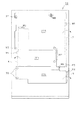
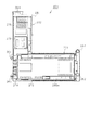
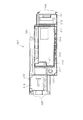
次に、第1制御基板ユニット201の構成を図13〜図17に基づいて説明する。図13は第1制御基板ユニット201の正面図、図14は主基板271aの表側の構成を示す平面図、図15は第1制御基板ユニット201の斜視図、図16は第1制御基板ユニット201の分解斜視図、図17は第1制御基板ユニット201を裏面から見た分解斜視図である。   Next, the configuration of the first control board unit 201 will be described with reference to FIGS. 13 is a front view of the first control board unit 201, FIG. 14 is a plan view showing the configuration of the front side of the main board 271a, FIG. 15 is a perspective view of the first control board unit 201, and FIG. 16 is the first control board unit 201. FIG. 17 is an exploded perspective view of the first control board unit 201 as viewed from the back.

第1制御基板ユニット201は略L字状をなす取付台251を有し、取付台251に主制御装置271と音声ランプ制御装置272とが搭載されている。主制御装置271は主基板271aを具備しており、主基板271aが透明樹脂材料等よりなる被包手段としての基板ボックス273に収容されて構成されている。   The first control board unit 201 has a mounting base 251 having a substantially L shape, and the main control device 271 and the sound lamp control device 272 are mounted on the mounting base 251. The main controller 271 includes a main substrate 271a, and the main substrate 271a is accommodated in a substrate box 273 as an encapsulating means made of a transparent resin material or the like.

主基板271aは、デジタル回路等の電子部品を実装した表側の面と、この表側面とバイアホールを介して電気的に接続される裏側の面とよりなり、これら各面に導体パターンがプリントされた両面プリント基板である。以下、主基板271aの表側面の構成を説明する。図14に示すように、主基板271aの略中央部には、主たる制御を司るCPU501や、CPU501の出力したデータをその都度対応する各種信号に加工する複数のラッチ回路IC284が搭載されている。また、主基板271aの図中における上部及び下部にはコネクタ搭載領域が形成されており、当該領域には、払出制御基板等の他の基板と接続するためのコネクタ285が搭載されている。加えて、主基板271aの図中における右部にはバッファ回路IC搭載領域が形成されており、当該領域には、入力した信号の雑音除去や波形整形等を行うバッファ回路IC286が搭載されている。但し、コネクタ搭載領域には、コネクタ搭載が可能であるが実際には搭載されていないコネクタ非搭載領域285aが1カ所設けられており、バッファ回路IC搭載領域には、バッファ回路IC搭載が可能であるが実際には搭載されていないバッファ回路IC非搭載領域286aが2カ所設けられている。つまり、主基板271aには、電気配線の断線した部位が形成されている。これら各非搭載領域285a,286aは、後述する性能試験を行う際に、対応する電子部品を搭載するための領域である。なお、主基板271aには、実装された各電子部品を結ぶ導体パターンのみならず、各非搭載領域285a,286aを結ぶ導体パターンも予めプリントされている。   The main board 271a is composed of a front side surface on which electronic parts such as a digital circuit are mounted, and a back side surface electrically connected to the front side surface via via holes, and a conductor pattern is printed on each of these surfaces. Double-sided printed circuit board. Hereinafter, the configuration of the front side surface of the main substrate 271a will be described. As shown in FIG. 14, a CPU 501 that performs main control and a plurality of latch circuit ICs 284 that process the data output from the CPU 501 into corresponding signals each time are mounted in a substantially central portion of the main board 271a. Further, connector mounting areas are formed in the upper and lower portions of the main board 271a in the drawing, and connectors 285 for connecting to other boards such as a payout control board are mounted in the areas. In addition, a buffer circuit IC mounting region is formed in the right part of the main substrate 271a in the drawing, and a buffer circuit IC 286 that performs noise removal, waveform shaping, and the like of the input signal is mounted in this region. . However, the connector mounting area has one connector non-mounting area 285a that can be mounted but is not actually mounted. The buffer circuit IC mounting area can be mounted with a buffer circuit IC. There are two buffer circuit IC non-mounting regions 286a that are present but not actually mounted. That is, the broken portion of the electric wiring is formed on the main substrate 271a. Each of these non-mounting areas 285a and 286a is an area for mounting a corresponding electronic component when performing a performance test to be described later. The main board 271a is pre-printed with not only a conductor pattern connecting the mounted electronic components but also a conductor pattern connecting the non-mounting regions 285a and 286a.

基板ボックス273は、略直方体形状のボックスベースと該ボックスベースの開口部を覆うボックスカバーとを備えている。ボックスカバーのうちコネクタ搭載領域と対応する位置には、孔部が形成されている。すなわち、ボックスカバーのうちコネクタ非搭載領域285aと対応する位置にも孔部が形成されている。これらボックスベースとボックスカバーとは封印手段としての封印ユニット274によって開封不能に連結され、これにより基板ボックス273が封印されている。   The substrate box 273 includes a substantially rectangular parallelepiped box base and a box cover that covers an opening of the box base. A hole is formed in the box cover at a position corresponding to the connector mounting area. That is, a hole is formed in the box cover at a position corresponding to the connector non-mounting area 285a. The box base and the box cover are connected so as not to be unsealed by a sealing unit 274 as sealing means, whereby the substrate box 273 is sealed.

封印ユニット274はボックスベースとボックスカバーとを開封不能に連結する構成であれば任意の構成が適用できるが、ここでは図15等に示すように、5つの封印部材が連結された構成となっており、この封印部材の長孔に係止爪を挿入することでボックスベースとボックスカバーとが開封不能に連結されるようになっている。封印ユニット274による封印処理は、その封印後の不正な開封を防止し、また万一不正開封が行われてもそのような事態を早期に且つ容易に発見可能とするものであって、一旦開封した後でも再度封印処理を行うこと自体は可能である。すなわち、封印ユニット274を構成する5つの封印部材のうち、少なくとも一つの封印部材の長孔に係止爪を挿入することにより封印処理が行われる。そして、収容した主基板271aの不具合発生の際や主基板271aの検査の際など基板ボックス273を開封する場合には、係止爪が挿入された封印部材と他の封印部材との連結を切断する。その後、再度封印処理する場合は他の封印部材の長孔に係止爪を挿入する。基板ボックス273の開封を行った旨の履歴を当該基板ボックス273に残しておけば、基板ボックス273を見ることで不正な開封が行われた旨が容易に発見できる。   As long as the sealing unit 274 is configured to connect the box base and the box cover so that they cannot be opened, any configuration can be applied. Here, as shown in FIG. 15 and the like, five sealing members are connected. The box base and the box cover are connected so as not to be opened by inserting a locking claw into the long hole of the sealing member. Sealing processing by the sealing unit 274 prevents unauthorized opening after the sealing, and makes it possible to detect such a situation early and easily even if unauthorized opening is performed. It is possible to perform the sealing process again even after it has been performed. That is, the sealing process is performed by inserting the locking claw into the long hole of at least one sealing member among the five sealing members constituting the sealing unit 274. When the substrate box 273 is opened such as when a failure occurs in the stored main substrate 271a or when the main substrate 271a is inspected, the connection between the sealing member into which the locking claw is inserted and the other sealing member is disconnected. To do. Thereafter, when the sealing process is performed again, the locking claws are inserted into the long holes of the other sealing members. If the history of opening the substrate box 273 is left in the substrate box 273, it can be easily found that the unauthorized opening has been performed by looking at the substrate box 273.

音声ランプ制御装置272は、例えば主制御装置271(主基板271a)又は表示制御装置214からの指示に従い音声やランプ表示の制御を司るCPUや、その他ROM、RAM、各種ポート等を含む音声ランプ制御基板を具備しており、音声ランプ制御基板が透明樹脂材料等よりなる基板ボックス275に収容されて構成されている。音声ランプ制御装置272上には電源中継基板276が搭載されており、電源装置313の電源が電源中継基板276を介して表示制御装置214及び音声ランプ制御装置272に供給されるようになっている。   The voice lamp control device 272 is a voice lamp control including a CPU that controls voice and lamp display in accordance with an instruction from the main control device 271 (main board 271a) or the display control device 214, and other ROM, RAM, various ports, and the like. The sound lamp control board is housed in a board box 275 made of a transparent resin material or the like. A power relay board 276 is mounted on the sound lamp control device 272, and the power of the power supply device 313 is supplied to the display control device 214 and the sound lamp control device 272 via the power relay board 276. .

取付台251は、ポリカーボネート樹脂等の合成樹脂製であり、例えば緑や青等に着色されて不透明とされている。但し、取付台251は無色透明又は半透明であってもよい。取付台251の表面には平坦状をなす2つの基板搭載面252,253が設けられている。これら基板搭載面252,253は縦横に直交する向きに延び、前後方向に段差をもって形成されている。基板搭載面252の上縁部及び下縁部にはそれぞれ、基板搭載面252より起立した起立部254が一体成形されている。そして、横長の基板搭載面252上に主制御装置271が配置されると共に、縦長の基板搭載面253上に音声ランプ制御装置272が配置される。このとき、主制御装置271は、上下の側部が起立部254にて支えられる。また、音声ランプ制御装置172は、複数箇所でネジ等により基板搭載面253に固定される。   The mounting base 251 is made of a synthetic resin such as a polycarbonate resin, and is colored opaque, for example, green or blue. However, the mounting base 251 may be colorless and transparent or translucent. Two flat substrate mounting surfaces 252 and 253 are provided on the surface of the mounting base 251. These substrate mounting surfaces 252 and 253 extend in a direction perpendicular to the length and breadth, and are formed with steps in the front-rear direction. Standing portions 254 erected from the substrate mounting surface 252 are integrally formed on the upper edge portion and the lower edge portion of the substrate mounting surface 252, respectively. The main control device 271 is disposed on the horizontally long substrate mounting surface 252 and the sound lamp control device 272 is disposed on the vertically long substrate mounting surface 253. At this time, the upper and lower sides of main controller 271 are supported by upright portions 254. The sound lamp control device 172 is fixed to the board mounting surface 253 with screws or the like at a plurality of locations.

ここで、図16及び図17に示すように、基板搭載面252には、左右2カ所に横長形状の貫通孔256が形成されている。一方、主制御装置271の基板ボックス273には、その裏面の左右2カ所に回動操作式の固定具277が設けられている。主制御装置271を基板搭載面252に搭載する際には、基板搭載面252の貫通孔256に固定具277が挿通されるように主制御装置271を載置し、その状態で固定具277を回動操作することで主制御装置271がロックされる。従って、主制御装置271は第1制御基板ユニット201の裏面側から固定具277をロック解除しなければ取り外しできないため、基板取り外し等の不正行為に対して抑止効果が得られる。   Here, as shown in FIGS. 16 and 17, the substrate mounting surface 252 is formed with horizontally elongated through holes 256 at two positions on the left and right. On the other hand, the substrate box 273 of the main control device 271 is provided with rotationally operable fixtures 277 at two places on the left and right sides of the back surface thereof. When the main controller 271 is mounted on the board mounting surface 252, the main controller 271 is placed so that the fixing tool 277 is inserted into the through hole 256 of the board mounting surface 252, and the fixing tool 277 is placed in this state. The main control device 271 is locked by the turning operation. Accordingly, since the main control device 271 cannot be removed unless the lock 277 is unlocked from the back side of the first control board unit 201, a deterrent effect such as board removal can be obtained.

また、取付台251において、主制御装置271用の基板搭載面252の下方には、基板搭載面252の裏面空間に通じる開口を遮蔽するための遮蔽部257が設けられている。従って、基板搭載面252の下方より取付台251の裏面に手などを差し入れることが阻止され、固定具277のロック状態を不正に解除することができないようになっている。また、第1制御基板ユニット201をパチンコ機10裏面に搭載した状態では、当該ユニット201の上部が裏パックユニット203により覆われるため、やはり取付台251の裏面に手などを差し入れることが阻止され、固定具277のロック状態を不正に解除することができないようになっている。   Further, in the mounting base 251, a shielding part 257 for shielding an opening leading to the back space of the substrate mounting surface 252 is provided below the substrate mounting surface 252 for the main controller 271. Accordingly, it is possible to prevent a hand or the like from being inserted into the back surface of the mounting base 251 from below the board mounting surface 252 so that the locked state of the fixture 277 cannot be illegally released. Further, when the first control board unit 201 is mounted on the back surface of the pachinko machine 10, the upper portion of the unit 201 is covered with the back pack unit 203, so that it is also prevented that a hand or the like is inserted into the back surface of the mounting base 251. The locked state of the fixture 277 cannot be illegally released.

前述した通り、第1制御基板ユニット201は、裏パックユニット203を所定角度以上に大きく開いた状態又は同ユニット203を取り外した状態でなければ取り外すことが不可能であり、また、施錠装置を正しくキー操作して外枠11に対して本体枠12を開放しなければ、裏パックユニット203を開くことができない構成となっている。つまり、本体枠12を開くことができなければ、結果的に第1制御基板ユニット201を回動させたり取り外すことができず、ひいては主制御装置271の取り外しも不可能となる。それ故、主制御装置271の不正な載せ替えや盗難等を効果的に防止することができる。   As described above, the first control board unit 201 cannot be removed unless the back pack unit 203 is opened at a predetermined angle or larger, or the unit 203 is not removed. The backpack unit 203 cannot be opened unless the main body frame 12 is opened with respect to the outer frame 11 by key operation. That is, if the main body frame 12 cannot be opened, the first control board unit 201 cannot be rotated or removed as a result, and the main controller 271 cannot be removed. Therefore, unauthorized replacement or theft of the main controller 271 can be effectively prevented.

主制御装置271は、パチンコ機10裏面から見て手前側に配置され、音声ランプ制御装置272はその奥側に配置される。この場合、基板搭載面252,253が前後方向に段差をもって形成されているため、これら基板搭載面252,253に主制御装置271及び音声ランプ制御装置272を搭載した状態において各制御装置271,272はその一部を前後に重ねて配置される。つまり、図15等にも見られるように、主制御装置271はその一部(本実施の形態では1/3程度)が浮いた状態で配置される。故に、主制御装置271に重なる領域まで音声ランプ制御装置272を拡張することが可能となり、また別の見方をすれば音声ランプ制御装置272に重なる領域まで主制御装置271を拡張することが可能となり、パチンコ機10という限られた大きさの中にあっても、各制御基板271,272の大型化に良好に対処できるとともに、各制御装置271,272を効率良く設置できる。また、第1制御基板ユニット201を遊技盤30に装着した状態では、基板搭載面252の後方にスペースが確保され、可変入賞装置32やその電気配線等が無理なく設置できるようになっている。なお、基板搭載面252の裏面には格子状のリブ258が設けられており、主制御装置271の支持強度が高められている。   The main control device 271 is arranged on the near side when viewed from the back of the pachinko machine 10, and the sound lamp control device 272 is arranged on the back side. In this case, since the substrate mounting surfaces 252 and 253 are formed with steps in the front-rear direction, the control devices 271 and 272 are mounted in a state where the main controller 271 and the sound lamp controller 272 are mounted on the substrate mounting surfaces 252 and 253. Are arranged with part of them stacked one after the other. That is, as can be seen in FIG. 15 and the like, main controller 271 is arranged in a state where a part thereof (about 1/3 in the present embodiment) is floated. Therefore, it is possible to extend the sound lamp control device 272 to a region overlapping with the main control device 271, and, from another viewpoint, it is possible to extend the main control device 271 to a region overlapping with the sound lamp control device 272. Even within the limited size of the pachinko machine 10, it is possible to satisfactorily cope with the increase in size of the control boards 271 and 272, and the control devices 271 and 272 can be installed efficiently. Further, in a state where the first control board unit 201 is mounted on the game board 30, a space is secured behind the board mounting surface 252, and the variable winning device 32 and its electric wiring can be installed without difficulty. Note that lattice-like ribs 258 are provided on the back surface of the substrate mounting surface 252 to increase the support strength of the main controller 271.

取付台251の左端面には上下一対の掛止ピン261が設けられており、この掛止ピン261を前記軸受け金具231に取り付けることで、第1制御基板ユニット201が遊技盤30に対して回動可能に片持ち支持される。取付台251の右端部には前記被締結孔232にはめ込まれる締結具として上下一対のナイラッチ262が設けられている。取付台251の上端部には前記係止爪片233が係止される長孔263が設けられている。従って、ナイラッチ262を被締結孔232にはめ込むと共に、長孔263に係止爪片233を係止させることで、第1制御基板ユニット201が遊技盤30に固定される。なお、軸受け金具231及び掛止ピン261が前記支軸部M1に、被締結孔232及びナイラッチ262が前記締結部M2に、係止爪片233及び長孔263が前記係止爪部M3に、それぞれ相当する。   A pair of upper and lower retaining pins 261 are provided on the left end surface of the mounting base 251, and the first control board unit 201 is rotated with respect to the game board 30 by attaching the retaining pins 261 to the bearing fitting 231. Cantilevered so that it can move. A pair of upper and lower nai latches 262 are provided at the right end of the mounting base 251 as fasteners to be fitted into the fastening holes 232. A long hole 263 in which the locking claw piece 233 is locked is provided at the upper end portion of the mounting base 251. Therefore, the first control board unit 201 is fixed to the game board 30 by fitting the nail latch 262 into the tightened hole 232 and locking the locking claw piece 233 in the long hole 263. It should be noted that the bearing fitting 231 and the latch pin 261 are in the support shaft portion M1, the fastened hole 232 and the ny latch 262 are in the fastening portion M2, and the locking claw piece 233 and the long hole 263 are in the locking claw portion M3. Each corresponds.

次に、第2制御基板ユニット202の構成を図18〜図20に基づいて説明する。図18は第2制御基板ユニット202の正面図、図19は同ユニット202の斜視図、図20は同ユニット202の分解斜視図である。   Next, the configuration of the second control board unit 202 will be described with reference to FIGS. 18 is a front view of the second control board unit 202, FIG. 19 is a perspective view of the unit 202, and FIG. 20 is an exploded perspective view of the unit 202.

第2制御基板ユニット202は横長形状をなす取付台301を有し、取付台301に払出制御装置311、発射制御装置312、電源装置313及びカードユニット接続基板314が搭載されている。払出制御装置311及び発射制御装置312は制御の中枢をなすCPUや、その他ROM、RAM、各種ポート等を含む制御基板を具備している。払出制御装置311の払出制御基板により、賞品球や貸出球の払出が制御される。発射制御装置312の発射制御基板により、遊技者による遊技球発射ハンドル18の操作に従い発射モータ229の制御が行われる。また、電源装置313の電源基板により、各種制御装置等で要する所定の電源電圧が生成され出力される。カードユニット接続基板314は、パチンコ機前面の貸球操作部120及び図示しないカードユニットに電気的に接続され、主として遊技者による球貸し操作の指令を取り込んでそれを払出制御装置311に出力するものである。なお、カードユニットを介さずに球貸し装置等から上皿に遊技球が直接貸し出される現金機では、カードユニット接続基板314は不要である。   The second control board unit 202 has a horizontally long mounting base 301 on which a payout control device 311, a firing control device 312, a power supply device 313 and a card unit connection board 314 are mounted. The payout control device 311 and the launch control device 312 are provided with a control board including a central control CPU, ROM, RAM, various ports, and the like. The payout control board of the payout control device 311 controls the payout of prize balls and rental balls. The launch control board of the launch control device 312 controls the launch motor 229 in accordance with the operation of the game ball launch handle 18 by the player. A predetermined power supply voltage required by various control devices is generated and output by the power supply board of the power supply device 313. The card unit connection board 314 is electrically connected to the ball lending operation unit 120 on the front surface of the pachinko machine and a card unit (not shown), and mainly receives a ball lending operation command from the player and outputs it to the payout control device 311. It is. Note that the card unit connection board 314 is not necessary in a cash machine in which game balls are lent directly to the upper plate from a ball lending device or the like without using a card unit.

上記払出制御装置311、発射制御装置312、電源装置313及びカードユニット接続基板314は、透明樹脂材料等よりなる基板ボックス315,316,317,318にそれぞれ収容されて構成されている。特に、払出制御装置311では、主制御装置271と同様、被包手段を構成する基板ボックス315がボックスベースとボックスカバーとを備え、それらが封印手段としての封印ユニット319によって開封不能に連結され、これにより基板ボックス315が封印されている。払出制御装置311には状態復帰スイッチ321が設けられている。例えば、後述する払出モータの球詰まり等、払出エラーの発生時において状態復帰スイッチ321が押されると、払出モータが正逆回転され、球詰まりの解消(正常状態への復帰)が図られるようになっている。電源装置313にはRAM消去スイッチ323が設けられている。本パチンコ機10は各種データのバックアップ機能を有しており、万一停電が発生した際でも停電時の状態を保持し、停電からの復帰(復電)の際には停電時の状態に復帰できるようになっている。従って、例えば遊技ホールの営業終了の場合のように通常手順で電源を遮断すると遮断前の状態が記憶保持されるが、RAM消去スイッチ323を押しながら電源を投入すると、RAMデータが初期化されるようになっている。   The payout control device 311, the firing control device 312, the power supply device 313, and the card unit connection substrate 314 are respectively configured to be accommodated in substrate boxes 315, 316, 317, and 318 made of a transparent resin material or the like. In particular, in the payout control device 311, as with the main control device 271, the substrate box 315 constituting the enclosing means includes a box base and a box cover, which are connected to each other so as not to be opened by a sealing unit 319 as a sealing means, As a result, the substrate box 315 is sealed. The payout control device 311 is provided with a state return switch 321. For example, when the state return switch 321 is pressed when a payout error occurs, such as a ball clogging of the payout motor described later, the payout motor is rotated forward and reverse so that the ball clogging is eliminated (return to the normal state). It has become. The power supply device 313 is provided with a RAM erase switch 323. This pachinko machine 10 has a backup function for various data, and even if a power failure occurs, it retains the state at the time of the power failure, and returns to the state at the time of the power failure at the time of recovery from the power failure (power recovery). It can be done. Therefore, for example, when the power supply is turned off in the normal procedure as in the case of the game hall being closed, the state before the turn-off is stored and held. However, if the power is turned on while pressing the RAM erase switch 323, the RAM data is initialized. It is like that.

取付台301は例えば無色透明な樹脂成型品よりなり、その表面に平坦状をなす基板搭載面302が設けられている。基板搭載面302には、発射制御装置312、電源装置313及びカードユニット接続基板314が横並びとなった状態で搭載され、ネジ等で固定されている。電源装置313の基板ボックス317上には略平板状の台座プレート303が載置されるとともに台座プレート303上に払出制御装置311が搭載され、ネジ等で固定されている。払出制御装置311と電源装置313との間には台座プレート303が介在するため、例えばノイズ除去用の金属プレート等を設置するには台座プレート303に金属プレート等を取り付ければ良く、ノイズ対策が簡単に実現できる。   The mounting base 301 is made of, for example, a colorless and transparent resin molded product, and a flat board mounting surface 302 is provided on the surface thereof. On the board mounting surface 302, the firing control device 312, the power supply device 313, and the card unit connection board 314 are mounted side by side and fixed with screws or the like. A substantially flat pedestal plate 303 is placed on the substrate box 317 of the power supply device 313, and a payout control device 311 is mounted on the pedestal plate 303 and fixed with screws or the like. Since the pedestal plate 303 is interposed between the payout control device 311 and the power supply device 313, for example, in order to install a metal plate for noise removal, the metal plate or the like may be attached to the pedestal plate 303, and noise countermeasures are simple. Can be realized.

取付台301には、パチンコ機10後方からみて右端部に上下一対の掛止ピン305が設けられており、掛止ピン305を前記軸受け部237に上方から挿通させることで、第2制御基板ユニット202が本体枠12に対して回動可能に片持ち支持される。取付台301の左端部には締結具として上下一対のナイラッチ306が設けられており、ナイラッチ306を前記被締結孔239にはめ込むことで、第2制御基板ユニット202が本体枠12に固定される。なお、軸受け部237及び掛止ピン305が前記支軸部M4に、被締結孔239及びナイラッチ306が前記締結部M5に、それぞれ相当する。   The mounting base 301 is provided with a pair of upper and lower latching pins 305 at the right end when viewed from the rear of the pachinko machine 10, and the second control board unit is inserted into the bearing 237 from above by inserting the latching pins 305 from above. 202 is cantilevered so as to be rotatable with respect to the main body frame 12. A pair of upper and lower nail latches 306 are provided as fasteners at the left end of the mounting base 301, and the second control board unit 202 is fixed to the main body frame 12 by fitting the nail latch 306 into the tightened hole 239. The bearing portion 237 and the latch pin 305 correspond to the support shaft portion M4, and the fastened hole 239 and the ny latch 306 correspond to the fastening portion M5, respectively.

次に、裏パックユニット203の構成を図21〜図23に基づいて説明する。図21は裏パックユニット203の正面図、図22は裏パックユニット203の分解斜視図である。図23はタンクレールの分解斜視図である。   Next, the configuration of the back pack unit 203 will be described with reference to FIGS. FIG. 21 is a front view of the back pack unit 203, and FIG. 22 is an exploded perspective view of the back pack unit 203. FIG. 23 is an exploded perspective view of the tank rail.

裏パックユニット203は、裏パック351と遊技球の払出機構部352とが一体化されることにより構成されている。裏パック351は例えばABS樹脂等の合成樹脂により一体成型されており、略平坦状のベース部353と、パチンコ機10後方に突出し横長の略直方体形状をなす保護カバー部354とを有する。保護カバー部354は左右側面及び上面が閉鎖され且つ下面のみが開放された形状をなし、少なくとも可変表示ユニット35を囲むのに十分な大きさを有する。但し、本実施の形態では、前述の音声ランプ制御装置272も併せて囲む構成となっている。保護カバー部354の背面には多数の通気孔354aが設けられている。通気孔354aは各々が長孔状をなし、それぞれの通気孔354aが比較的近い位置で隣り合うよう設けられている。従って、隣り合う通気孔354a間にある樹脂部分を切断することにより、裏パック351の背面を容易に開口させることができる。つまり、通気孔354a間の樹脂部分を切断してその内部の表示制御装置214等を露出させることで、所定の検定等を容易に実施することができるようになっている。   The back pack unit 203 is configured by integrating a back pack 351 and a game ball payout mechanism 352. The back pack 351 is integrally formed of, for example, a synthetic resin such as ABS resin, and includes a substantially flat base portion 353 and a protective cover portion 354 that protrudes rearward from the pachinko machine 10 and has a horizontally long substantially rectangular parallelepiped shape. The protective cover portion 354 has a shape in which the left and right side surfaces and the upper surface are closed and only the lower surface is opened, and has a size sufficient to surround at least the variable display unit 35. However, in this embodiment, the above-described sound lamp control device 272 is also enclosed. A large number of ventilation holes 354 a are provided on the back surface of the protective cover portion 354. The vent holes 354a are each formed in a long hole shape, and are provided so that the respective vent holes 354a are adjacent to each other at relatively close positions. Therefore, the back surface of the back pack 351 can be easily opened by cutting the resin portion between the adjacent vent holes 354a. That is, a predetermined test or the like can be easily performed by cutting the resin portion between the air holes 354a and exposing the display control device 214 and the like inside the resin portion.

裏パック351のベース部353には、保護カバー部354を迂回するようにして払出機構部352が配設されている。すなわち、裏パック351の最上部には上方に開口したタンク355が設けられており、タンク355には遊技ホールの島設備から供給される遊技球が逐次補給される。タンク355の下方には、例えば横方向2列(2条)の球通路を有し下流側に向けて緩やかに傾斜するタンクレール356が連結され、タンクレール356の下流側には上下方向に延びるケースレール357が連結されている。払出装置358はケースレール357の最下流部に設けられ、払出制御装置311の制御により払出モータ358aが駆動されて必要個数の遊技球の払出が適宜行われる。払出装置358より払い出された遊技球は払出通路359等を通じて前記上皿23等に供給される。なお、図示は省略するが、ケースレール357の上流部には、タンク355やタンクレール356から供給される遊技球の有無を検出するタンク球無しセンサが設けられている。また、払出装置358には、払出モータ358aの回転を検出する払出回転センサと、払い出される遊技球数をカウントする払出カウントスイッチとが設けられている。   A payout mechanism portion 352 is disposed on the base portion 353 of the back pack 351 so as to bypass the protective cover portion 354. That is, a tank 355 that opens upward is provided at the top of the back pack 351, and game balls supplied from the island facilities of the game hall are sequentially replenished to the tank 355. Below the tank 355, for example, tank rails 356 having two rows (two rows) of spherical passages and gently inclined toward the downstream side are connected. The tank rails 356 extend in the vertical direction on the downstream side. A case rail 357 is connected. The payout device 358 is provided at the most downstream portion of the case rail 357, and the payout motor 358a is driven by the control of the payout control device 311 so that a required number of game balls are paid out appropriately. The game balls paid out from the payout device 358 are supplied to the upper plate 23 and the like through the payout passage 359 and the like. Although not shown, a tank ball absence sensor that detects the presence or absence of a game ball supplied from the tank 355 or the tank rail 356 is provided upstream of the case rail 357. The payout device 358 is provided with a payout rotation sensor that detects the rotation of the payout motor 358a and a payout count switch that counts the number of game balls to be paid out.

タンクレール356には、当該タンクレール356に振動を付加するためのバイブレータ360が取り付けられている。バイブレータ360は、バイブモータとそのバイブモータを収容する合成樹脂製のケースとによりユニット化されており、2本の脚部360aでタンクレール356に取り付けられている。従って、仮にタンクレール356付近で球詰まりが生じた際、バイブレータ360が駆動されることで球詰まりが解消されるようになっている。   A vibrator 360 for applying vibration to the tank rail 356 is attached to the tank rail 356. Vibrator 360 is unitized by a vibrator motor and a synthetic resin case that accommodates the vibrator motor, and is attached to tank rail 356 by two legs 360a. Therefore, if a clogged ball occurs near the tank rail 356, the clogged ball is eliminated by driving the vibrator 360.

タンクレール356の構成ついて詳述すると、図23に示すように、タンクレール356は上方に開口した長尺樋状をなすレール本体361を有している。レール本体361の上流部には球面状の球受部362が形成され、球受部362によりタンク355より落下してきた遊技球が円滑にレール本体361内に取り込まれるようになっている。レール本体361には長手方向に延びる仕切壁363が設けられており、仕切壁363により遊技球が二手に分流されるようになっている。仕切壁363により仕切られた2条の球通路は遊技球の直径よりも僅かに幅広となっている。仕切壁363により仕切られた各球通路の底面には、1筋又は2筋の突条364が設けられると共に、その突条364の側方に塵埃を落下させるための開口部365が設けられている。レール本体361には、その下流側半分程度の天井部分を覆うようにして整流板367が配設されている。整流板367は、下流側ほどタンクレール356内の球通路高さを制限するよう弓なりに反った形状をしており、その下面には長手方向に延びる凸部368が形成されている。これにより、タンクレール356内を流れる各遊技球は最終的には上下に積み重なることなく下流側に流出する。従って、タンクレール356に多量の遊技球が流れ込んできても、遊技球の噛み込みが防止され、タンクレール356内における球詰まりが発生し難くなっている。なお、レール本体361が帯電防止のために黒色の導電性ポリカーボネート樹脂により成形されるのに対し、整流板367は球詰まり等を目視で確認できるように透明のポリカーボネート樹脂により成形されている。整流板367は着脱可能に設けられており、当該整流板367を取り外すことによりタンクレール356内のメンテナンスが容易に実施できるようになっている。整流板367には、遊技球の流下を阻止するための手動式のストッパ369が取り付けられている。   The configuration of the tank rail 356 will be described in detail. As shown in FIG. 23, the tank rail 356 has a rail body 361 having a long bowl shape opened upward. A spherical ball receiving portion 362 is formed in the upstream portion of the rail main body 361 so that the game ball dropped from the tank 355 by the ball receiving portion 362 is smoothly taken into the rail main body 361. The rail body 361 is provided with a partition wall 363 extending in the longitudinal direction, and the game balls are divided into two hands by the partition wall 363. The two ball passages partitioned by the partition wall 363 are slightly wider than the diameter of the game ball. On the bottom surface of each spherical passage partitioned by the partition wall 363, one or two ridges 364 are provided, and an opening 365 for dropping dust is provided on the side of the ridge 364. Yes. The rail body 361 is provided with a rectifying plate 367 so as to cover the ceiling portion of the downstream half. The rectifying plate 367 has a bow shape so as to limit the height of the ball passage in the tank rail 356 toward the downstream side, and a convex portion 368 extending in the longitudinal direction is formed on the lower surface thereof. Thereby, each game ball flowing in the tank rail 356 finally flows out downstream without being stacked up and down. Therefore, even if a large amount of game balls flow into the tank rail 356, the game balls are prevented from being bitten and the ball clogging in the tank rail 356 is difficult to occur. The rail main body 361 is formed of a black conductive polycarbonate resin to prevent electrification, while the rectifying plate 367 is formed of a transparent polycarbonate resin so that a clogging of a ball can be visually confirmed. The rectifying plate 367 is detachably provided. By removing the rectifying plate 367, maintenance in the tank rail 356 can be easily performed. A manual stopper 369 for preventing the game ball from flowing down is attached to the current plate 367.

図21,図22の説明に戻り、払出機構部352には、払出制御装置311から払出装置358への払出指令の信号を中継する払出中継基板381が設置されると共に、外部より主電源を取り込むための電源スイッチ基板382が設置されている。電源スイッチ基板382には、電圧変換器を介して例えば交流24ボルトの主電源が供給され、電源スイッチ382aの切替操作により電源ON又は電源OFFとされるようになっている。   Returning to the description of FIGS. 21 and 22, the payout mechanism unit 352 is provided with a payout relay board 381 that relays a payout command signal from the payout control device 311 to the payout device 358, and takes in the main power from outside. A power switch board 382 is installed. The power switch board 382 is supplied with, for example, AC 24 volt main power via a voltage converter, and is turned on or off by switching the power switch 382a.

タンク355から払出通路359に至るまでの払出機構部352は何れも導電性を有する合成樹脂材料、例えば導電性ポリカーボネート樹脂にて成形され、その一部にてアースされている。これにより、遊技球の帯電によるノイズの発生が抑制されるようになっている。   The discharge mechanism 352 from the tank 355 to the discharge passage 359 is formed of a conductive synthetic resin material such as a conductive polycarbonate resin, and is grounded at a part thereof. Thereby, generation | occurrence | production of the noise by charging of a game ball is suppressed.

裏パック351には、その右上部に枠用外部端子板390が設けられている。枠用外部端子板390には、タンク355やタンクレール356で遊技球が不足した場合に信号出力するための出力端子、所定個数の賞球を払い出す毎に信号出力するための出力端子、所定個数の遊技球を貸し出す毎に信号出力するための出力端子、本体枠12の開放時に信号出力するための出力端子、及び前扉枠13の開放時に信号出力するための出力端子が設けられている。そして、これらの出力端子を通じて、遊技ホール側の管理制御装置に対して枠側の状態に関する信号が出力される。なお、所定個数の遊技球を貸し出す毎に信号出力するための出力端子はいわゆる現金機においては不要である。   The back pack 351 is provided with a frame external terminal plate 390 on the upper right portion thereof. The frame external terminal plate 390 has an output terminal for outputting a signal when a game ball is insufficient in the tank 355 and the tank rail 356, an output terminal for outputting a signal every time a predetermined number of prize balls are paid out, An output terminal for outputting a signal each time a number of game balls are lent, an output terminal for outputting a signal when the main body frame 12 is opened, and an output terminal for outputting a signal when the front door frame 13 is opened are provided. . And the signal regarding the state of a frame side is output with respect to the management control apparatus of the game hall side through these output terminals. Note that an output terminal for outputting a signal every time a predetermined number of game balls are lent out is not necessary in a so-called cash machine.

裏パック351には、枠用外部端子板390に隣接して略四角形状の窓部391が設けられている。従って、裏パックユニット103を本体枠12に取り付けた状態では、窓部391を通じて遊技盤30裏面の盤用外部端子板230が露出し、裏パックユニット103を装着したままで盤用外部端子板230の操作を行うことができるようになっている。前述のとおり、盤用外部端子板230は取り外し容易な状態で集合板ユニット215に取り付けられていることから、盤用外部端子板230の配線を接続したままで、窓部391を介して当該盤用外部端子板230を取り出すことも可能となる。裏パック351の右上部には本体枠12の開放の状態を検出するための本体枠開放スイッチ392が設けられており、外枠11に対して本体枠12を閉じた状態では当該スイッチ392の金属接点が閉じて本体枠12の閉鎖が検知され、外枠11に対して本体枠12を開いた状態では金属接点が開いて本体枠12の開放が検知されるようになっている。   The back pack 351 is provided with a substantially rectangular window 391 adjacent to the frame external terminal plate 390. Therefore, in a state where the back pack unit 103 is attached to the main body frame 12, the board external terminal plate 230 on the back side of the game board 30 is exposed through the window portion 391, and the board external terminal plate 230 remains attached with the back pack unit 103 attached. Can be operated. As described above, since the board external terminal plate 230 is attached to the collective board unit 215 in an easily removable state, the board external terminal board 230 is connected to the board via the window portion 391 while being connected. The external terminal plate 230 can be taken out. A main body frame opening switch 392 for detecting the open state of the main body frame 12 is provided at the upper right portion of the back pack 351. When the main body frame 12 is closed with respect to the outer frame 11, the metal of the switch 392 is provided. The contact is closed and the closing of the main body frame 12 is detected. When the main body frame 12 is opened relative to the outer frame 11, the metal contact is opened and the opening of the main body frame 12 is detected.

裏パック351には、パチンコ機10後方からみて右端部に上下一対の掛止ピン385が設けられており、掛止ピン385を前記軸受け部238に上方から挿通させることで、裏パックユニット203が本体枠12に対して回動可能に片持ち支持される。裏パック351には、左端部に締結具として上下一対のナイラッチ386が設けられると共に、上端部に係止孔387が設けられており、ナイラッチ386を前記被締結孔240にはめ込むと共に、係止孔387に前記固定具242を挿入した上で当該固定具242を回動操作することで、裏パックユニット203が本体枠12に固定される。また、前記固定具241,243によっても裏パックユニット203が本体枠12に固定される。なお、軸受け部238及び掛止ピン385が前記支軸部M6に、被締結孔240及びナイラッチ386が前記締結部M7に、固定具242及び係止孔387が前記係止部M8に、それぞれ相当する。また、固定具243が前記係止部M9に相当する。   The back pack 351 is provided with a pair of upper and lower latch pins 385 at the right end when viewed from the rear of the pachinko machine 10. By inserting the latch pins 385 into the bearing portion 238 from above, the back pack unit 203 is mounted. The body frame 12 is cantilevered so as to be rotatable. The back pack 351 is provided with a pair of upper and lower nai latches 386 as fasteners at the left end portion, and is provided with a locking hole 387 at the upper end portion thereof. The back pack unit 203 is fixed to the main body frame 12 by inserting the fixing tool 242 into 387 and rotating the fixing tool 242. Further, the back pack unit 203 is also fixed to the main body frame 12 by the fixing tools 241 and 243. The bearing portion 238 and the latch pin 385 correspond to the support shaft portion M6, the fastened hole 240 and the ny latch 386 correspond to the fastening portion M7, and the fixture 242 and the locking hole 387 correspond to the locking portion M8, respectively. To do. Further, the fixture 243 corresponds to the locking portion M9.

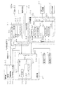
次に、本パチンコ機10の電気的構成について、図24のブロック図に基づいて説明する。   Next, the electrical configuration of the pachinko machine 10 will be described based on the block diagram of FIG.

主制御装置271(主基板271a)には、演算装置である1チップマイコンとしてのCPU501が搭載されている。CPU501には、該CPU501により実行される各種の制御プログラムや固定値データを記憶したROM502と、そのROM502内に記憶される制御プログラムの実行に際して各種のデータ等を一時的に記憶するためのメモリであるRAM503と、時間計数や同期を図る場合などに使用されるクロックパルス発生回路やタイマ回路、割込回路、データ送受信回路などの各種回路が内蔵されている。   The main controller 271 (main board 271a) is equipped with a CPU 501 as a one-chip microcomputer which is an arithmetic unit. The CPU 501 includes a ROM 502 that stores various control programs executed by the CPU 501 and fixed value data, and a memory that temporarily stores various data when the control program stored in the ROM 502 is executed. A certain RAM 503 and various circuits such as a clock pulse generation circuit, a timer circuit, an interrupt circuit, and a data transmission / reception circuit used for time counting and synchronization are incorporated.

RAM503は、パチンコ機10の電源の遮断後においても電源装置313からバックアップ電圧が供給されてデータを保持(バックアップ)できる構成となっており、RAM503には、各種のデータ等を一時的に記憶するためのメモリやエリアの他に、バックアップエリア503aが設けられている。   The RAM 503 is configured to retain (backup) data by being supplied with a backup voltage from the power supply device 313 even after the pachinko machine 10 is powered off. The RAM 503 temporarily stores various data and the like. In addition to the memory and area for this purpose, a backup area 503a is provided.

バックアップエリア503aは、停電などの発生により電源が遮断された場合において、電源遮断時(停電発生時を含む。以下同様)のスタックポインタや、各レジスタ、I/O等の値を記憶しておくためのエリアであり、電源投入時(停電解消による電源投入を含む。以下同様)には、バックアップエリア503aの情報に基づいてパチンコ機10の状態が電源遮断前の状態に復帰できるようになっている。バックアップエリア503aへの書き込みはNMI割込み処理(図37参照)によって電源遮断時に実行され、バックアップエリア503aに書き込まれた各値の復帰は電源投入時のメイン処理(図27参照)において実行される。なお、CPU501のNMI端子(ノンマスカブル割込端子)には、停電等の発生による電源遮断時に、停電監視回路542からの停電信号SG1が入力されるように構成されており、停電の発生により停電時処理としてのNMI割込み処理が即座に実行される。   The backup area 503a stores values such as a stack pointer, each register, and I / O when the power is shut down (including when a power failure occurs, the same applies hereinafter) when the power is shut down due to the occurrence of a power failure or the like. The area of the pachinko machine 10 can be restored to the state before the power cut-off based on the information in the backup area 503a when the power is turned on (including power-on due to power failure cancellation). Yes. Writing to the backup area 503a is executed when the power is shut off by the NMI interrupt process (see FIG. 37), and restoration of each value written in the backup area 503a is executed in the main process (see FIG. 27) when the power is turned on. Note that the power failure signal SG1 from the power failure monitoring circuit 542 is input to the NMI terminal (non-maskable interrupt terminal) of the CPU 501 when the power is interrupted due to the occurrence of a power failure or the like. The NMI interrupt process as a process is immediately executed.

主制御装置271のCPU501には、アドレスバス及びデータバスで構成されるバスライン504を介して入出力ポート505が接続されている。主制御装置271の入力側には、後述するRAM消去スイッチ回路543、払出制御装置311や、その他図示しないスイッチ群や中継基板などが接続されている。一方、主制御装置271の出力側には、払出制御装置311や表示制御装置214が接続されている。また、第1特定ランプ部47に配設されたLEDランプのスイッチや第2特定ランプ部48に配設されたLEDランプのスイッチも接続されている。これにより、第1特定ランプ部47及び第2特定ランプ部48は、主制御装置271により直接的に制御されることとなる。   An input / output port 505 is connected to the CPU 501 of the main control device 271 via a bus line 504 including an address bus and a data bus. On the input side of the main controller 271, a RAM erasing switch circuit 543, a payout controller 311, which will be described later, and other switch groups and relay boards (not shown) are connected. On the other hand, a payout control device 311 and a display control device 214 are connected to the output side of the main control device 271. In addition, an LED lamp switch disposed in the first specific lamp unit 47 and an LED lamp switch disposed in the second specific lamp unit 48 are also connected. As a result, the first specific lamp unit 47 and the second specific lamp unit 48 are directly controlled by the main controller 271.

払出制御装置311は、払出モータ358aにより賞球や貸し球の払出制御を行うものである。演算装置であるCPU511は、そのCPU511により実行される制御プログラムや固定値データ等を記憶したROM512と、ワークメモリ等として使用されるRAM513とを備えている。   The payout control device 311 controls payout of prize balls and rental balls by a payout motor 358a. The CPU 511 that is an arithmetic unit includes a ROM 512 that stores a control program executed by the CPU 511, fixed value data, and the like, and a RAM 513 that is used as a work memory or the like.

払出制御装置311のRAM513は、主制御装置271のRAM503と同様に、パチンコ機10の電源の遮断後においても電源装置313からバックアップ電圧が供給されてデータを保持(バックアップ)できる構成となっており、RAM513には、各種のデータ等を一時的に記憶するためのメモリやエリアの他に、バックアップエリア513aが設けられている。   The RAM 513 of the payout control device 311 is configured to hold (backup) data by being supplied with a backup voltage from the power supply device 313 even after the power of the pachinko machine 10 is shut off, like the RAM 503 of the main control device 271. The RAM 513 is provided with a backup area 513a in addition to a memory and an area for temporarily storing various data.

バックアップエリア513aは、停電などの発生により電源が遮断された場合において、電源遮断時のスタックポインタや、各レジスタ、I/O等の値を記憶しておくためのエリアであり、電源投入時には、このバックアップエリア513aの情報に基づいてパチンコ機10の状態が電源遮断前の状態に復帰できるようになっている。バックアップエリア513aへの書き込みはNMI割込み処理によって電源遮断時に実行され、バックアップエリア513aに書き込まれた各値の復帰は電源投入時のメイン処理において実行される。なお、主制御装置271のCPU501と同様、CPU511のNMI端子にも、停電等の発生による電源遮断時に停電監視回路542から停電信号SG1が入力されるように構成されており、停電の発生により、NMI割込み処理が即座に実行されるようになっている。   The backup area 513a is an area for storing the stack pointer, each register, I / O, and the like when the power is shut down when the power is shut down due to a power failure or the like. Based on the information in the backup area 513a, the state of the pachinko machine 10 can be restored to the state before the power is shut off. Writing to the backup area 513a is executed when the power is shut off by the NMI interrupt process, and restoration of each value written to the backup area 513a is executed in the main process when the power is turned on. As with the CPU 501 of the main controller 271, the power failure signal SG1 is input from the power failure monitoring circuit 542 to the NMI terminal of the CPU 511 when the power is interrupted due to the occurrence of a power failure or the like. The NMI interrupt process is immediately executed.

払出制御装置311のCPU511には、アドレスバス及びデータバスで構成されるバスライン514を介して入出力ポート515が接続されている。入出力ポート515には、RAM消去スイッチ回路543、主制御装置271、発射制御装置312、払出モータ358aなどがそれぞれ接続されている。   An input / output port 515 is connected to the CPU 511 of the payout control device 311 via a bus line 514 including an address bus and a data bus. A RAM erase switch circuit 543, a main control device 271, a firing control device 312, a payout motor 358a, and the like are connected to the input / output port 515, respectively.

発射制御装置312は、発射モータ229による遊技球の発射を許可又は禁止するものであり、発射モータ229は、所定条件が整っている場合に駆動が許可される。具体的には、払出制御装置311から発射許可信号が出力されていること、遊技者が遊技球発射ハンドル18に触れていることをセンサ信号により検出していること、発射を停止させるための発射停止スイッチが操作されていないことを条件に、発射モータ229が駆動され、遊技球発射ハンドル18の操作量に応じた強さで遊技球が発射される。   The launch control device 312 permits or prohibits the launch of the game ball by the launch motor 229, and the launch motor 229 is permitted to drive when a predetermined condition is met. Specifically, the launch control signal is output from the payout control device 311, the player is detecting that the player is touching the game ball launch handle 18, and the launch for stopping the launch. On condition that the stop switch is not operated, the launch motor 229 is driven, and the game ball is launched with a strength corresponding to the operation amount of the game ball launch handle 18.

表示制御装置214は、図柄表示装置41における第1図柄(特別図柄)の変動表示を制御するものである。表示制御装置214は、CPU521と、ROM(プログラムROM)522と、ワークRAM523と、ビデオRAM524と、キャラクタROM525と、画像コントローラ526と、入力ポート527と、2つの出力ポート528,529と、バスライン530,531とを備えている。入力ポート527の入力側には主制御装置271の出力側が接続され、入力ポート527の出力側には、CPU521、ROM522、ワークRAM523、画像コントローラ526が接続されると共にバスライン530を介して出力ポート528が接続されている。出力ポート528の出力側には音声ランプ制御装置272が接続されている。また、画像コントローラ526にはバスライン531を介して出力ポート529が接続されており、その出力ポート529の出力側には図柄表示装置41が接続されている。   The display control device 214 controls the variable display of the first symbol (special symbol) on the symbol display device 41. The display control device 214 includes a CPU 521, a ROM (program ROM) 522, a work RAM 523, a video RAM 524, a character ROM 525, an image controller 526, an input port 527, two output ports 528 and 529, and a bus line. 530 and 531. The input side of the input port 527 is connected to the output side of the main controller 271, and the output side of the input port 527 is connected to the CPU 521, ROM 522, work RAM 523, and image controller 526, and the output port via the bus line 530. 528 is connected. An audio lamp control device 272 is connected to the output side of the output port 528. Further, an output port 529 is connected to the image controller 526 via a bus line 531, and a symbol display device 41 is connected to the output side of the output port 529.

表示制御装置214のCPU521は、主制御装置271から送信される図柄表示コマンドに基づいて図柄表示装置41の表示を制御する。ROM522は、CPU521により実行される各種の制御プログラムや固定値データを記憶するためのメモリであり、ワークRAM523は、CPU521による各種プログラムの実行時に使用されるワークデータやフラグを一時的に記憶するためのメモリである。   The CPU 521 of the display control device 214 controls the display of the symbol display device 41 based on the symbol display command transmitted from the main control device 271. The ROM 522 is a memory for storing various control programs executed by the CPU 521 and fixed value data, and the work RAM 523 is for temporarily storing work data and flags used when the CPU 521 executes various programs. Memory.

ビデオRAM524は、図柄表示装置41に表示される表示データを記憶するためのメモリであり、ビデオRAM524の内容を書き替えることにより、図柄表示装置41の表示内容が変更される。キャラクタROM525は、図柄表示装置41に表示される図柄などのキャラクタデータを記憶するためのメモリである。画像コントローラ526は、CPU521、ビデオRAM524、出力ポート529のそれぞれのタイミングを調整してデータの読み書きに介在すると共に、ビデオRAM524に記憶される表示データを、キャラクタROM525から所定のタイミングで読み出して図柄表示装置41に表示させるものである。   The video RAM 524 is a memory for storing display data displayed on the symbol display device 41, and the display contents of the symbol display device 41 are changed by rewriting the contents of the video RAM 524. The character ROM 525 is a memory for storing character data such as symbols displayed on the symbol display device 41. The image controller 526 adjusts the timings of the CPU 521, the video RAM 524, and the output port 529 to intervene in reading and writing data, and reads display data stored in the video RAM 524 from the character ROM 525 at a predetermined timing to display a symbol. It is displayed on the device 41.

電源装置313は、パチンコ機10の各部に電源を供給するための電源部541と、停電等による電源遮断を監視する停電監視回路542と、RAM消去スイッチ323に接続されてなるRAM消去スイッチ回路543とを備えている。電源部541は、図示しない電源経路を通じて、主制御装置271や払出制御装置311等に対して各々に必要な動作電源を供給する。その概要としては、電源部541は、外部より供給される交流24ボルト電源を取り込み、各種スイッチやモータ等を駆動するための+12V電源、ロジック用の+5V電源、RAMバックアップ用のバックアップ電源などを生成し、これら+12V電源、+5V電源及びバックアップ電源を主制御装置271や払出制御装置311等に対して供給する。なお、発射制御装置312に対しては払出制御装置311を介して動作電源(+12V電源、+5V電源等)が供給される。   The power supply device 313 includes a power supply unit 541 for supplying power to each unit of the pachinko machine 10, a power failure monitoring circuit 542 for monitoring power interruption due to a power failure, and a RAM erase switch circuit 543 connected to the RAM erase switch 323. And has. The power supply unit 541 supplies necessary operating power to the main control device 271 and the payout control device 311 through a power supply path (not shown). As its outline, the power supply unit 541 takes in an AC 24 volt power supply supplied from the outside, and generates a + 12V power supply for driving various switches and motors, a + 5V power supply for logic, a backup power supply for RAM backup, and the like. Then, these + 12V power supply, + 5V power supply and backup power supply are supplied to the main control device 271 and the payout control device 311. Note that operation power (+12 V power, +5 V power, etc.) is supplied to the launch control device 312 via the payout control device 311.

停電監視回路542は、停電等の発生による電源遮断時に、主制御装置271のCPU501及び払出制御装置311のCPU511の各NMI端子へ停電信号SG1を出力するための回路である。停電監視回路542は、電源部541から出力される最大電圧である直流安定24ボルトの電圧を監視し、この電圧が22ボルト未満になった場合に停電(電源遮断)の発生と判断して、停電信号SG1を主制御装置271及び払出制御装置311へ出力する。停電信号SG1の出力によって、主制御装置271及び払出制御装置311は、停電の発生を認識し、NMI割込み処理を実行する。なお、電源部541は、直流安定24ボルトの電圧が22ボルト未満になった後においても、NMI割込み処理の実行に充分な時間の間、制御系の駆動電圧である5ボルトの出力を正常値に維持するように構成されている。よって、主制御装置271及び払出制御装置311は、NMI割込み処理を正常に実行し完了することができる。   The power failure monitoring circuit 542 is a circuit for outputting a power failure signal SG1 to each NMI terminal of the CPU 501 of the main control device 271 and the CPU 511 of the payout control device 311 when the power is cut off due to the occurrence of a power failure or the like. The power failure monitoring circuit 542 monitors the DC stable voltage of 24 volts, which is the maximum voltage output from the power supply unit 541, and determines that a power failure (power shutdown) occurs when this voltage is less than 22 volts. The power failure signal SG1 is output to the main controller 271 and the payout controller 311. Based on the output of the power failure signal SG1, the main control device 271 and the payout control device 311 recognize the occurrence of the power failure and execute the NMI interrupt process. The power supply unit 541 outputs the output of 5 volts, which is the drive voltage of the control system, to a normal value for a time sufficient to execute the NMI interrupt processing even after the DC stable voltage of 24 volts becomes less than 22 volts. Configured to maintain. Therefore, the main control device 271 and the payout control device 311 can normally execute and complete the NMI interrupt processing.

RAM消去スイッチ回路543は、RAM消去スイッチ323のスイッチ信号を取り込み、そのスイッチ323の状態に応じて主制御装置271及び払出制御装置311のバックアップデータをクリアするためのRAM消去信号SG2を出力する回路である。RAM消去スイッチ323が押された際、RAM消去スイッチ回路543は、主制御装置271及び払出制御装置311に対してRAM消去信号SG2を出力する。これにより、RAM消去スイッチ323が押された状態でパチンコ機10の電源が投入されると、主制御装置271及び払出制御装置311においてそれぞれのバックアップエリア503a,513aのデータがクリアされる。   The RAM erase switch circuit 543 receives a switch signal of the RAM erase switch 323, and outputs a RAM erase signal SG2 for clearing backup data of the main controller 271 and the payout controller 311 in accordance with the state of the switch 323. It is. When the RAM erase switch 323 is pressed, the RAM erase switch circuit 543 outputs a RAM erase signal SG2 to the main controller 271 and the payout controller 311. Thereby, when the power of the pachinko machine 10 is turned on while the RAM erase switch 323 is pressed, the data in the backup areas 503a and 513a is cleared in the main controller 271 and the payout controller 311.

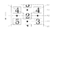
ここで、図柄表示装置41の表示内容について、図25に基づいて説明する。   Here, the display content of the symbol display device 41 will be described with reference to FIG.

図柄表示装置には、左・中・右の3つの図柄列が設定されている。各図柄列は、例えば「0」〜「9」の数字を各々付した主図柄と、例えば菱形状の絵図柄からなる副図柄とにより構成されている。各主図柄及び副図柄がそれぞれ第1図柄を構成している。各図柄列では、数字の昇順又は降順に主図柄が配列されると共に各主図柄の間に副図柄が配されている。すなわち、各図柄列には、10個の主図柄及び10個の副図柄の計20個の第1図柄が備えられている。この場合において、奇数番号(1,3,5,7,9)が付された主図柄は「高確率図柄」に相当し、当該高確率図柄で大当たりが発生した場合、大当たり状態の1つであるノーマル大当たり状態に移行すると共に、さらにその後、特典遊技状態としての高確率状態に移行する。また、偶数番号(2,4,6,8)が付された主図柄は「低確率図柄」に相当し、当該低確率図柄で大当たりが発生した場合、大当たり状態の1つであって前記ノーマル大当たり状態より有利なスーパー大当たり状態に移行するが、高確率状態に移行することなく通常状態に移行する。なお、高確率状態とは、大当たり状態の終了後に付加価値としてその後の大当たり確率がアップした状態、いわゆる確変状態のことをいい、通常状態(低確率状態)とはそのような高確率状態でない遊技状態をいう。また、第1特定ランプ部47においては、ノーマル大当たり状態に移行した後に高確率状態に移行する大当たりの場合に赤色が表示され、スーパー大当たり状態に移行した後に通常状態に移行する大当たりの場合に緑色が表示される。   In the symbol display device, three symbol columns of left, middle, and right are set. Each symbol row is composed of, for example, a main symbol to which numbers “0” to “9” are attached, and a sub-symbol made of, for example, a diamond-shaped symbol. Each main symbol and sub-design constitute a first symbol. In each symbol row, main symbols are arranged in ascending or descending order of numbers, and sub symbols are arranged between the main symbols. That is, each symbol row is provided with a total of 20 first symbols of 10 main symbols and 10 sub symbols. In this case, the main symbol with the odd number (1, 3, 5, 7, 9) corresponds to the “high probability symbol”, and when a big hit occurs in the high probability symbol, it is one of the big hit states. While shifting to a certain normal jackpot state, it further shifts to a high probability state as a privilege gaming state. The main symbol with an even number (2, 4, 6, 8) corresponds to a “low probability symbol”, and when a big hit occurs in the low probability symbol, it is one of the big hit states and the normal Although it shifts to the super jackpot state which is more advantageous than the jackpot state, it shifts to the normal state without shifting to the high probability state. The high probability state means a state in which the subsequent jackpot probability has increased as an added value after the end of the jackpot state, that is, a so-called probability change state, and the normal state (low probability state) is a game that is not such a high probability state. State. Further, in the first specific lamp unit 47, red is displayed in the case of jackpot that shifts to the high probability state after shifting to the normal jackpot state, and green in the case of jackpot that shifts to the normal state after shifting to the super jackpot state. Is displayed.

そして、図柄表示装置41には、各図柄列毎に20個の第1図柄が周期性をもって上から下へとスクロールするように変動表示されるようになっている。特に、左図柄列においては主図柄の数字が降順に現れ、中図柄列及び右図柄列においては主図柄の数字が昇順に現れるように配列されている。図柄表示装置41には、各図柄列毎に上・中・下の3段の第1図柄が表示されるようになっている。従って、図柄表示装置41には、3段×3列の計9個の第1図柄が表示される。また、図柄表示装置41には、5つの有効ライン、すなわち上ラインL1、中ラインL2、下ラインL3、右上がりラインL4、左上がりラインL5が設定されている。そして、左図柄列→右図柄列→中図柄列の順に変動表示が停止し、その停止時にいずれかの有効ライン上に大当たり図柄の組合せ(本実施の形態では、同一の主図柄の組合せ)が揃えば大当たりとして大当たり動画が表示されるようになっている。   On the symbol display device 41, 20 first symbols are variably displayed so as to scroll from top to bottom with periodicity for each symbol row. In particular, the numbers of the main symbols appear in descending order in the left symbol row, and the numbers of the main symbols appear in ascending order in the middle symbol row and the right symbol row. The symbol display device 41 is configured to display the first symbol of the upper, middle, and lower levels for each symbol row. Accordingly, the symbol display device 41 displays a total of nine first symbols of 3 rows × 3 columns. The symbol display device 41 has five effective lines, that is, an upper line L1, a middle line L2, a lower line L3, a right rising line L4, and a left rising line L5. Then, the variable display stops in the order of the left symbol row → the right symbol row → the middle symbol row, and at the time of the stop, the combination of jackpot symbols (the same main symbol combination in the present embodiment) is placed on one of the effective lines. If you arrange it, a big hit video will be displayed as a big hit.

次に、上記の如く構成されたパチンコ機10の動作について説明する。   Next, the operation of the pachinko machine 10 configured as described above will be described.

本実施の形態では、主制御装置271内のCPU501は、遊技に際し各種カウンタ情報を用いて、大当たり抽選、第1特定ランプ部47の発光色の設定や、図柄表示装置41の図柄表示の設定などを行うこととしており、具体的には、図26に示すように、大当たりの抽選に使用する大当たり乱数カウンタC1と、大当たり種別を判定する際に使用する大当たり種別カウンタC2と、図柄表示装置41が外れ変動する際のリーチ抽選に使用するリーチ乱数カウンタC3と、大当たり乱数カウンタC1の初期値設定に使用する乱数初期値カウンタCINIと、図柄表示装置41の変動パターン選択に使用する第1変動種別カウンタCS1と、第1特定ランプ部47に表示される色の切り替えを行う期間を決定する第2変動種別カウンタCS2と、左列、中列及び右列の各外れ図柄の設定に使用する左・中・右の各外れ図柄カウンタCL,CM,CRとを用いることとしている。   In the present embodiment, the CPU 501 in the main control device 271 uses various counter information in the game to make a big hit lottery, set the emission color of the first specific lamp unit 47, set the symbol display of the symbol display device 41, etc. Specifically, as shown in FIG. 26, the jackpot random number counter C1 used for the jackpot lottery, the jackpot type counter C2 used for determining the jackpot type, and the symbol display device 41 Reach random number counter C3 used for reach lottery when out-of-range changes, random number initial value counter CINI used for initial value setting of jackpot random number counter C1, and first variation type counter used for variation pattern selection of symbol display device 41 CS1 and a second variation type counter CS2 that determines a period for switching the color displayed on the first specific lamp unit 47 , Is set to be used left column, the middle column and the right column the off each off symbol counters in the left-and right to use the setting symbol CL of, CM, and CR.

このうち、カウンタC1〜C3,CINI,CS1,CS2は、その更新の都度前回値に1が加算され、最大値に達した後0に戻るループカウンタとなっている。また、外れ図柄カウンタCL,CM,CRは、CPU501内のRレジスタ(リフレッシュレジスタ)を用いてレジスタ値が加算され、結果的に数値がランダムに変化する構成となっている。各カウンタは短時間間隔で更新され、その更新値がRAM503の所定領域に設定されたカウンタ用バッファに適宜格納される。RAM503には、1つの実行エリアと4つの保留エリア(保留第1〜第4エリア)とからなる保留球格納エリアが設けられており、これらの各エリアには、作動口33への遊技球の入賞履歴に合わせて、大当たり乱数カウンタC1、大当たり種別カウンタC2及びリーチ乱数カウンタC3の各値が時系列的に格納されるようになっている。   Among these counters, the counters C1 to C3, CINI, CS1, and CS2 are loop counters that each add 1 to the previous value and return to 0 after reaching the maximum value. Further, the out symbol counters CL, CM, CR are configured such that register values are added using an R register (refresh register) in the CPU 501, and as a result, numerical values change randomly. Each counter is updated at short time intervals, and the updated value is appropriately stored in a counter buffer set in a predetermined area of the RAM 503. The RAM 503 is provided with a holding ball storage area including one execution area and four holding areas (holding first to fourth areas). The values of the jackpot random number counter C1, the jackpot type counter C2 and the reach random number counter C3 are stored in time series in accordance with the winning history.

各カウンタについて詳しくは、大当たり乱数カウンタC1は、例えば0〜676の範囲内で順に1ずつ加算され、最大値(つまり676)に達した後0に戻る構成となっている。特に大当たり乱数カウンタC1が1周した場合、その時点の乱数初期値カウンタCINIの値が当該大当たり乱数カウンタC1の初期値として読み込まれる。なお、乱数初期値カウンタCINIは、大当たり乱数カウンタC1と同様のループカウンタであり(値=0〜676)、タイマ割込み毎に1回更新されると共に通常処理の残余時間内で繰り返し更新される。大当たり乱数カウンタC1は定期的に(本実施の形態ではタイマ割込み毎に1回)更新され、遊技球が作動口33に入賞したタイミングでRAM503の保留球格納エリアに格納される。大当たりとなる乱数の値の数は、低確率状態と高確率状態とで2種類設定されており、低確率状態下で大当たりとなる乱数の値の数は2で、その値は「337,673」であり、高確率状態下で大当たりとなる乱数の値の数は10で、その値は「67,131,199,269,337,401,463,523,601,661」である。   For details of each counter, the jackpot random number counter C1 is configured such that, for example, 1 is sequentially added within a range of 0 to 676, and after reaching the maximum value (that is, 676), it returns to 0. In particular, when the jackpot random number counter C1 makes one round, the value of the random number initial value counter CINI at that time is read as the initial value of the jackpot random number counter C1. The random number initial value counter CINI is a loop counter similar to the jackpot random number counter C1 (value = 0 to 676), and is updated once for each timer interruption and is repeatedly updated within the remaining time of normal processing. The jackpot random number counter C1 is updated periodically (once every timer interruption in the present embodiment) and stored in the reserved ball storage area of the RAM 503 at the timing when the game ball wins the operating port 33. Two types of values of random numbers that are jackpots are set in a low probability state and a high probability state, and the number of random number values that are jackpots in the low probability state is 2, and the values thereof are “337,673”. The number of random numbers that are jackpots under a high probability state is 10, and the values are “67, 131, 199, 269, 337, 401, 463, 523, 601 and 661”.

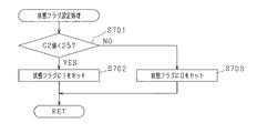
大当たり種別カウンタC2は、0〜49の範囲内で順に1ずつ加算され、最大値(つまり49)に達した後0に戻る構成となっている。そして、本実施の形態では、大当たり種別カウンタC2によって、いずれの大当たり状態に移行させるかと、大当たり状態が終了した後に高確率状態に移行させるか否かとを決定することとしており、例えば、C2=0〜24がノーマル大当たり状態に移行した後に高確率状態に移行する大当たりに該当し、C2=25〜49がスーパー大当たり状態に移行した後に通常状態に移行する大当たりに該当する。なお、大当たり種別カウンタC2により、第1図柄が変動を停止した際の図柄の組合せ及び当該図柄の組合せを停止させる位置も決定される。即ち、本実施の形態では、図柄表示装置41において有効ラインが5ライン設定されており、特定図柄(主図柄)が10通り設定されていることから、50個のカウンタ値によって全てのパターンが設定されていることとなる。そして、C2=0〜24のとき、即ち、ノーマル大当たり状態に移行した後に高確率状態に移行する大当たりのときには、奇数番号の図柄の組合せと当該図柄の組合わせを停止させる位置とが決定される。一方、C2=25〜49のとき、即ち、スーパー大当たり状態に移行した後に通常状態に移行する大当たりのときには、偶数番号の図柄の組合せと当該図柄の組合わせを停止させる位置とが決定される。大当たり種別カウンタC2は定期的に(本実施の形態ではタイマ割込み毎に1回)更新され、遊技球が作動口33に入賞したタイミングでRAM503の保留球格納エリアに格納される。   The jackpot type counter C2 is configured so that one by one is added in order within the range of 0 to 49, and after reaching the maximum value (ie 49), it returns to 0. In this embodiment, the jackpot type counter C2 determines which jackpot state to shift to and whether to shift to a high probability state after the jackpot state ends, for example, C2 = 0. -24 corresponds to the jackpot that shifts to the high probability state after shifting to the normal jackpot state, and C2 = 25 to 49 corresponds to the jackpot that shifts to the normal state after shifting to the super jackpot state. The jackpot type counter C2 also determines the symbol combination when the first symbol stops changing and the position at which the symbol combination is stopped. In other words, in the present embodiment, five effective lines are set in the symbol display device 41, and ten types of specific symbols (main symbols) are set. Therefore, all patterns are set by 50 counter values. Will be. When C2 = 0 to 24, that is, when the jackpot is shifted to the high probability state after the transition to the normal jackpot state, the combination of the odd-numbered symbols and the position where the combination of the symbols is stopped are determined. . On the other hand, when C2 = 25 to 49, that is, when the jackpot is shifted to the normal state after shifting to the super jackpot state, the combination of the even-numbered symbols and the position where the combination of the symbols is stopped are determined. The jackpot type counter C2 is updated periodically (once every timer interruption in the present embodiment), and stored in the reserved ball storage area of the RAM 503 at the timing when the game ball wins the operation port 33.

リーチ乱数カウンタC3は、例えば0〜238の範囲内で順に1ずつ加算され、最大値(つまり238)に達した後0に戻る構成となっている。本実施の形態では、リーチ乱数カウンタC3によって、リーチが発生した後最終停止図柄がリーチ図柄の前後に1つだけずれて停止する「前後外れリーチ」と、同じくリーチが発生した後最終停止図柄がリーチ図柄の前後以外で停止する「前後外れ以外リーチ」と、リーチが発生しない「完全外れ」とを抽選することとしており、例えば、C3=0,1が前後外れリーチに該当し、C3=2〜21が前後外れ以外リーチに該当し、C3=22〜238が完全外れに該当する。なお、リーチの抽選は、遊技状態や変動開始時の作動保留球数等に応じて各々個別に設定されるものであっても良い。リーチ乱数カウンタC3は定期的に(本実施の形態ではタイマ割込み毎に1回)更新され、遊技球が作動口33に入賞したタイミングでRAM503の保留球格納エリアに格納される。   For example, the reach random number counter C3 is incremented one by one within a range of 0 to 238, for example, and reaches a maximum value (that is, 238) and then returns to 0. In the present embodiment, the reach random number counter C3 determines that the final stop symbol after the occurrence of reach is shifted by one shift before and after the reach symbol, and the final stop symbol after the occurrence of reach. “Reach other than front / rear out” that stops at other than the front and rear of the reach symbol and “complete out” that does not generate reach are selected by lottery. For example, C3 = 0, 1 corresponds to front / rear outreach, and C3 = 2. 21 corresponds to reach other than front / rear disengagement, and C3 = 22 to 238 corresponds to complete disengagement. Note that the reach lottery may be set individually according to the game state, the number of activated balls at the start of change, and the like. The reach random number counter C3 is updated periodically (once every timer interruption in this embodiment), and stored in the reserved ball storage area of the RAM 503 at the timing when the game ball wins the operation port 33.

第1変動種別カウンタCS1は、例えば0〜198の範囲内で順に1ずつ加算され、最大値(つまり198)に達した後0に戻る構成となっており、第2変動種別カウンタCS2は、例えば0〜240の範囲内で順に1ずつ加算され、最大値(つまり240)に達した後0に戻る構成となっている。第1変動種別カウンタCS1によって、いわゆるノーマルリーチ、スーパーリーチ、プレミアムリーチ等、第1図柄のリーチ種別やその他大まかな図柄変動態様といった図柄表示装置41の表示態様が決定され、第2変動種別カウンタCS2によって、第1特定ランプ部47に表示される色の切り替えを行う期間としての切替表示時間が決定される。また、この切替表示時間は、図柄表示装置41において変動表示される第1図柄の変動時間に相当する。従って、当該第2変動種別カウンタCS2によって、図柄表示装置41においてリーチが発生した後に最終停止図柄(本実施の形態では中図柄)が停止するまでの経過時間(言い換えれば、変動図柄数)などより細かな図柄変動態様も決定されることとなる。つまり、これらの両変動種別カウンタCS1,CS2を組み合わせることで、第1図柄の変動パターンの多種多様化を容易に実現できる。両変動種別カウンタCS1,CS2は、後述する通常処理が1回実行される毎に1回更新され、当該通常処理内の残余時間内でも繰り返し更新される。そして、第1特定ランプ部47に表示される色の切り替え開始時及び第1図柄の変動開始時における変動パターン決定に際して両変動種別カウンタCS1,CS2のバッファ値が取得される。   The first variation type counter CS1 is, for example, incremented by 1 within a range of 0 to 198, and reaches a maximum value (that is, 198) and then returns to 0. The second variation type counter CS2 includes, for example, Within the range of 0 to 240, 1 is added in order, and after reaching the maximum value (that is, 240), it returns to 0. The first variation type counter CS1 determines the display mode of the symbol display device 41, such as the reach type of the first symbol such as so-called normal reach, super reach, premium reach, and other rough symbol variation modes, and the second variation type counter CS2 The switching display time is determined as a period for switching the color displayed on the first specific lamp unit 47. The switching display time corresponds to the variation time of the first symbol that is variably displayed on the symbol display device 41. Therefore, by the second variation type counter CS2, the elapsed time (in other words, the number of variation symbols) until the final stop symbol (in the present embodiment) stops after reaching occurs in the symbol display device 41, etc. A detailed design variation mode is also determined. That is, by combining these both variation type counters CS1 and CS2, it is possible to easily realize a wide variety of variation patterns of the first symbol. Both variation type counters CS1 and CS2 are updated once every time a normal process to be described later is executed once, and are repeatedly updated even within the remaining time in the normal process. Then, the buffer values of both variation type counters CS1 and CS2 are acquired at the time of determining the variation pattern at the start of switching of the color displayed on the first specific lamp unit 47 and at the start of variation of the first symbol.

左・中・右の各外れ図柄カウンタCL,CM,CRは、大当たり抽選が外れとなった時に左列第1図柄、中列第1図柄、右列第1図柄の外れ停止図柄を決定するためのものであり、各列では主図柄及び副図柄の合わせて20の第1図柄の何れかが表示されることから、各々に20個(0〜19)のカウンタ値が用意されている。外れ図柄カウンタCLにより左図柄列の上・中・下段の各図柄が決定され、外れ図柄カウンタCMにより中図柄列の上・中・下段の各図柄が決定され、外れ図柄カウンタCRにより右図柄列の上・中・下段の各図柄が決定される。   The left, middle and right off symbol counters CL, CM, CR determine the stop symbol of the left row 1 symbol, the middle row 1 symbol, and the right row 1 symbol when the big hit lottery is missed. In each column, any one of the 20 first symbols is displayed in combination with the main symbol and the sub symbol, so 20 counter values (0 to 19) are prepared for each. The left, upper, middle and lower symbols are determined by the out symbol counter CL, the upper, middle and lower symbols are determined by the out symbol counter CM, and the right symbol column is determined by the out symbol counter CR. The top, middle and bottom symbols are determined.

本実施の形態では、CPU501に内蔵のRレジスタの数値を用いることにより各カウンタCL,CM,CRの値をランダムに更新する構成としている。すなわち、各外れ図柄カウンタCL,CM,CRの更新時には、前回値にRレジスタの下位3ビットの値が加算され、その加算結果が最大値を超えた場合に20減算されて今回値が決定される。各外れ図柄カウンタCL,CM,CRは更新時期が重ならないようにして通常処理内で更新され、それら外れ図柄カウンタCL,CM,CRの組み合わせが、RAM503の前後外れリーチ図柄バッファ、前後外れ以外リーチ図柄バッファ及び完全外れ図柄バッファの何れかに格納される。そして、第1図柄の変動開始時における変動パターン決定に際し、リーチ乱数カウンタC3の値に応じて前後外れリーチ図柄バッファ、前後外れ以外リーチ図柄バッファ及び完全外れ図柄バッファの何れかのバッファ値が取得される。   In the present embodiment, the values of the counters CL, CM, and CR are randomly updated by using the value of the R register built in the CPU 501. That is, when each outlier symbol counter CL, CM, CR is updated, the lower 3 bits of the R register are added to the previous value, and when the addition result exceeds the maximum value, 20 is subtracted to determine the current value. The Each outlier symbol counter CL, CM, CR is updated in the normal process so that the update times do not overlap, and the combination of these outlier symbol counters CL, CM, CR is the reach other than the front / rear symbol buffer of the RAM 503, reach other than front / rear out It is stored in either the symbol buffer or the completely off symbol buffer. Then, when determining the variation pattern at the time of starting the variation of the first symbol, the buffer value of any one of the front and rear outreach symbol buffer, the reach symbol buffer other than front and rear outlier, and the completely out symbol symbol buffer is acquired according to the value of the reach random number counter C3. The

なお、各カウンタの大きさや範囲は一例にすぎず任意に変更できる。但し、不規則性を重視すれば、大当たり乱数カウンタC1、リーチ乱数カウンタC3、変動種別カウンタCS1,CS2の大きさは何れも異なる素数とし、いかなる場合にも同期しない数値としておくのが望ましい。また、図示は省略するが、第2特定ランプ部48の抽選には第2特定ランプ乱数カウンタC4が用いられる。第2特定ランプカウンタC4は、例えば0〜250の範囲内で順に1ずつ加算され、最大値(つまり250)に達した後0に戻るループカウンタとして構成されている。第2特定ランプ乱数カウンタC4は定期的に(本実施の形態ではタイマ割込み毎に1回)更新され、遊技球が左右何れかのスルーゲート34を通過したことが検知された時に取得される。当選することとなる乱数の値の数は149あり、その範囲は「5〜153」である。   In addition, the magnitude | size and range of each counter are only examples, and can be changed arbitrarily. However, if importance is attached to irregularity, it is desirable that the jackpot random number counter C1, the reach random number counter C3, and the variation type counters CS1 and CS2 are all different prime numbers and are not synchronized in any case. Although not shown, the second specific lamp random number counter C4 is used for the lottery of the second specific lamp unit 48. For example, the second specific lamp counter C4 is configured as a loop counter that increments one by one within a range of 0 to 250 and returns to 0 after reaching the maximum value (that is, 250). The second specific ramp random number counter C4 is periodically updated (once every timer interruption in the present embodiment), and is acquired when it is detected that the game ball has passed through either the left or right through gate 34. The number of random number values to be won is 149, and the range is “5 to 153”.

次いで、主制御装置271内のCPU501により実行される各制御処理を図27〜図37のフローチャートを参照しながら説明する。かかるCPU501の処理としては大別して、電源投入に伴い起動されるメイン処理と、定期的に(本実施の形態では2msec周期で)起動されるタイマ割込み処理と、NMI端子(ノンマスカブル端子)への停電信号の入力により起動されるNMI割込み処理とがあり、説明の便宜上、はじめにタイマ割込み処理とNMI割込み処理とを説明し、その後メイン処理を説明する。   Next, each control process executed by the CPU 501 in the main controller 271 will be described with reference to the flowcharts of FIGS. The processing of the CPU 501 is roughly divided into main processing that is started when the power is turned on, timer interrupt processing that is started periodically (in this embodiment, at a cycle of 2 msec), and power failure to the NMI terminal (non-maskable terminal). There is NMI interrupt processing activated by signal input. For convenience of explanation, first, timer interrupt processing and NMI interrupt processing will be described, and then main processing will be described.

図35は、タイマ割込み処理を示すフローチャートであり、本処理は主制御装置271のCPU501により例えば2msec毎に実行される。   FIG. 35 is a flowchart showing the timer interrupt process. This process is executed by the CPU 501 of the main controller 271 every 2 msec, for example.

図35において、ステップS901では、各種入賞スイッチの読み込み処理を実行する。すなわち、主制御装置271に接続されている各種スイッチ(但し、RAM消去スイッチ323を除く)の状態を読み込むと共に、当該スイッチの状態を判定して検出情報(入賞検知情報)を保存する。   In FIG. 35, in step S901, various winning switch reading processes are executed. That is, the state of various switches (except for the RAM erase switch 323) connected to the main controller 271 is read, and the state of the switch is determined and the detection information (winning detection information) is stored.

その後、ステップS902では、乱数初期値カウンタCINIの更新を実行する。具体的には、乱数初期値カウンタCINIを1インクリメントすると共に、そのカウンタ値が最大値(本実施の形態では676)に達した際0にクリアする。そして、乱数初期値カウンタCINIの更新値を、RAM503の該当するバッファ領域に格納する。続くステップS903では、大当たり乱数カウンタC1、大当たり種別カウンタC2及びリーチ乱数カウンタC3の更新を実行する。具体的には、大当たり乱数カウンタC1、大当たり種別カウンタC2及びリーチ乱数カウンタC3をそれぞれ1インクリメントすると共に、それらのカウンタ値が最大値(本実施の形態ではそれぞれ、676,49,238)に達した際それぞれ0にクリアする。そして、各カウンタC1〜C3の更新値を、RAM503の該当するバッファ領域に格納する。   Thereafter, in step S902, the random number initial value counter CINI is updated. Specifically, the random number initial value counter CINI is incremented by 1 and cleared to 0 when the counter value reaches the maximum value (676 in the present embodiment). Then, the update value of the random number initial value counter CINI is stored in the corresponding buffer area of the RAM 503. In subsequent step S903, the big hit random number counter C1, the big hit type counter C2, and the reach random number counter C3 are updated. Specifically, the jackpot random number counter C1, the jackpot type counter C2 and the reach random number counter C3 are each incremented by 1 and their counter values reach the maximum values (in the present embodiment, 676, 49 and 238, respectively). Clear to 0 each. Then, the updated values of the counters C1 to C3 are stored in the corresponding buffer area of the RAM 503.

その後、ステップS904では、作動口33への入賞に伴う始動入賞処理を実行する。この始動入賞処理を図36のフローチャートにより説明すると、ステップS1001では、遊技球が作動口33に入賞(始動入賞)したか否かを作動口スイッチ224の検出情報により判別する。遊技球が作動口33に入賞したと判別されると、続くステップS1002では、第1特定ランプ部47及び図柄表示装置41の作動保留球数Nが上限値(本実施の形態では4)未満であるか否かを判別する。作動口33への入賞があり、且つ作動保留球数N<4であることを条件にステップS1003に進み、作動保留球数Nを1インクリメントする。続くステップS1004では、前記ステップS903で更新した大当たり乱数カウンタC1、大当たり種別カウンタC2及びリーチ乱数カウンタC3の各値を、RAM503の保留球格納エリアの空き記憶エリアのうち最初のエリアに格納する。そして、始動入賞処理の後、CPU501は本タイマ割込み処理を一旦終了する。   Thereafter, in step S904, a start winning process associated with winning in the operating port 33 is executed. This start winning process will be described with reference to the flowchart of FIG. 36. In step S1001, whether or not the game ball has won the start opening 33 (start winning prize) is determined based on the detection information of the operation opening switch 224. When it is determined that the game ball has won the operating port 33, in the subsequent step S1002, the number N of the operation reserved balls of the first specific lamp unit 47 and the symbol display device 41 is less than the upper limit value (4 in the present embodiment). It is determined whether or not there is. The process proceeds to step S1003 on the condition that there is a winning at the operation port 33 and the number N of activated balls is <4, and the number N of activated balls is incremented by one. In subsequent step S1004, the values of jackpot random number counter C1, jackpot type counter C2 and reach random number counter C3 updated in step S903 are stored in the first area of the free storage area of the reserved ball storage area of RAM 503. Then, after the start winning process, the CPU 501 once ends the timer interrupt process.

なお、遊技球が作動口33に入賞(始動入賞)した場合、それに伴い図柄表示装置41による第1図柄の変動表示が開始されることとなるが、始動入賞後、第1図柄が変動し図柄停止に至るまでには所定時間(例えば5秒)が経過していなければならないという制約がある。そこで、上記始動入賞処理では、始動入賞が確認された場合、各カウンタ値の格納処理(ステップS1004)の後に、始動入賞後の経過時間を計るためのタイマをセットすることとしている。具体的には、上記始動入賞処理は2msec周期で実行されるため、例えば5秒の経過時間を計測するにはタイマに数値「2500」をセットし、始動入賞処理の都度、タイマ値を1ずつ減算する。このタイマ値は、その時々の各カウンタC1〜C3の値と共に、RAM503の保留球格納エリアに格納され管理される。そして、後述する第1図柄の変動パターン設定に際しては、上記タイマ値が参照され、残り時間に応じて(所定時間経過後に図柄変動が停止されるよう)変動パターンが設定されるようになっている。   When the game ball wins the operating opening 33 (starting winning), the display of the first symbol on the symbol display device 41 is started accordingly, but after the winning winning, the first symbol is changed and the symbol is changed. There is a restriction that a predetermined time (for example, 5 seconds) must elapse before stopping. Therefore, in the start winning process, when the start winning is confirmed, a timer for measuring the elapsed time after the start winning is set after each counter value storing process (step S1004). Specifically, since the start winning process is executed at a cycle of 2 msec, for example, in order to measure an elapsed time of 5 seconds, a numerical value “2500” is set in the timer, and the timer value is incremented by 1 for each start winning process. Subtract. This timer value is stored and managed in the reserved ball storage area of the RAM 503 together with the values of the respective counters C1 to C3. Then, when setting the variation pattern of the first symbol, which will be described later, the timer value is referred to, and a variation pattern is set according to the remaining time (so that the symbol variation is stopped after a predetermined time elapses). .

図37は、NMI割込み処理を示すフローチャートであり、本処理は、主制御装置271のCPU501により停電の発生等によるパチンコ機10の電源遮断時に実行される。このNMI割込みにより、電源遮断時の主制御装置271の状態がRAM503のバックアップエリア503aに記憶される。すなわち、停電の発生等によりパチンコ機10の電源が遮断されると、停電信号SG1が停電監視回路542から主制御装置271内のCPU501のNMI端子に出力され、CPU501は実行中の制御を中断してNMI割込み処理を開始する。図37のNMI割込み処理プログラムは、主制御装置271のROM502に記憶されている。停電信号SG1が出力された後所定時間は、主制御装置271の処理が実行可能となるように電源部541から電源供給がなされており、この所定時間内にNMI割込み処理が実行される。   FIG. 37 is a flowchart showing the NMI interrupt process. This process is executed by the CPU 501 of the main controller 271 when the power of the pachinko machine 10 is shut off due to the occurrence of a power failure or the like. By this NMI interruption, the state of the main controller 271 at the time of power-off is stored in the backup area 503a of the RAM 503. That is, when the power of the pachinko machine 10 is cut off due to the occurrence of a power failure or the like, the power failure signal SG1 is output from the power failure monitoring circuit 542 to the NMI terminal of the CPU 501 in the main controller 271 and the CPU 501 interrupts the control being executed. To start NMI interrupt processing. The NMI interrupt processing program in FIG. 37 is stored in the ROM 502 of the main controller 271. For a predetermined time after the power failure signal SG1 is output, power is supplied from the power supply unit 541 so that the processing of the main controller 271 can be executed, and the NMI interrupt processing is executed within this predetermined time.

NMI割込み処理において、ステップS1101では使用レジスタをRAM503のバックアップエリア503aに退避し、続くステップS1102ではスタックポインタの値を同バックアップエリア503aに記憶する。さらに、ステップS1103では電源遮断の発生情報をバックアップエリア503aに設定し、ステップS1104では電源が遮断されたことを示す電源遮断通知コマンドを他の制御装置に対して送信する。ステップS1105ではRAM判定値を算出し、バックアップエリア503aに保存する。RAM判定値は、例えば、RAM503の作業領域アドレスにおけるチェックサム値である。ステップS1106では、RAMアクセスを禁止する。その後は、電源が完全に遮断して処理が実行できなくなるのに備え、無限ループに入る。   In the NMI interrupt processing, the used register is saved in the backup area 503a of the RAM 503 in step S1101, and the value of the stack pointer is stored in the backup area 503a in the subsequent step S1102. Further, in step S1103, the power-off occurrence information is set in the backup area 503a, and in step S1104, a power-off notification command indicating that the power has been cut off is transmitted to another control device. In step S1105, a RAM determination value is calculated and stored in the backup area 503a. The RAM determination value is, for example, a checksum value at the work area address of the RAM 503. In step S1106, RAM access is prohibited. After that, an infinite loop is entered in preparation for the case where the power supply is completely shut down and processing cannot be executed.

なお、上記のNMI割込み処理は払出制御装置311でも同様に実行され、かかるNMI割込みにより、停電の発生等による電源遮断時の払出制御装置311の状態がRAM513のバックアップエリア513aに記憶される。停電信号SG1が出力された後所定時間は、払出制御装置311の処理が実行可能となるように電源部541から電源供給がなされるのも同様である。すなわち、停電の発生等によりパチンコ機10の電源が遮断されると、停電信号SG1が停電監視回路542から払出制御装置311内のCPU511のNMI端子に出力され、CPU511は実行中の制御を中断して図37のNMI割込み処理を開始する。その内容はステップS1104の電源遮断通知コマンドの送信を行わない点を除き上記説明と同様である。   The above NMI interrupt processing is similarly executed in the payout control device 311, and the state of the payout control device 311 when the power is shut down due to the occurrence of a power failure or the like is stored in the backup area 513 a of the RAM 513 by the NMI interrupt. Similarly, power is supplied from the power supply unit 541 so that the processing of the payout control device 311 can be executed for a predetermined time after the power failure signal SG1 is output. That is, when the power of the pachinko machine 10 is cut off due to the occurrence of a power failure or the like, the power failure signal SG1 is output from the power failure monitoring circuit 542 to the NMI terminal of the CPU 511 in the payout control device 311 and the CPU 511 interrupts the control being executed. The NMI interrupt process of FIG. 37 is started. The contents are the same as described above, except that the power-off notification command is not transmitted in step S1104.

図27は、主制御装置271内のCPU501により実行されるメイン処理の一例を示すフローチャートであり、このメイン処理は電源投入時のリセットに伴い起動される。   FIG. 27 is a flowchart showing an example of a main process executed by the CPU 501 in the main controller 271. This main process is started upon reset when the power is turned on.

メイン処理において、ステップS101では、電源投入に伴う初期設定処理を実行する。具体的には、スタックポインタに予め決められた所定値を設定すると共に、サブ側の制御装置(音声ランプ制御装置272、払出制御装置311等)が動作可能な状態になるのを待つために例えば1秒程度、ウェイト処理を実行する。ステップS102では、払出制御装置311に対して払出許可コマンドを送信し、続くステップS103では、RAMアクセスを許可する。   In the main process, in step S101, an initial setting process associated with power-on is executed. Specifically, in order to set a predetermined value in the stack pointer and wait for the sub-side control devices (audio lamp control device 272, payout control device 311, etc.) to become operable, for example, Wait processing is performed for about 1 second. In step S102, a payout permission command is transmitted to the payout control device 311. In subsequent step S103, RAM access is permitted.

その後、CPU501内のRAM503に関してデータバックアップの処理を実行する。つまり、ステップS104では電源装置313に設けたRAM消去スイッチ323が押されているか否かを判別し、続くステップS105ではRAM503のバックアップエリア503aに電源遮断の発生情報が設定されているか否かを判別する。また、ステップS106ではRAM判定値を算出し、続くステップS107では、そのRAM判定値が電源遮断時に保存したRAM判定値と一致するか否か、すなわちバックアップの有効性を判別する。RAM判定値は、例えばRAM503の作業領域アドレスにおけるチェックサム値である。なお、RAM503の所定のエリアに書き込まれたキーワードが正しく保存されているか否かによりバックアップの有効性を判断することも可能である。   Thereafter, data backup processing is executed for the RAM 503 in the CPU 501. That is, in step S104, it is determined whether or not the RAM erase switch 323 provided in the power supply device 313 is pressed, and in the subsequent step S105, it is determined whether or not the information on occurrence of power shutdown is set in the backup area 503a of the RAM 503. To do. In step S106, a RAM determination value is calculated. In subsequent step S107, it is determined whether or not the RAM determination value matches the RAM determination value stored when the power is turned off, that is, the validity of the backup. The RAM determination value is a checksum value at a work area address of the RAM 503, for example. Note that it is possible to determine the effectiveness of backup based on whether or not the keywords written in a predetermined area of the RAM 503 are correctly stored.

上述したように、本パチンコ機10では、例えばホールの営業開始時など、電源投入時にRAMデータを初期化する場合にはRAM消去スイッチ323を押しながら電源が投入される。従って、RAM消去スイッチ323が押されていれば、RAMの初期化処理(ステップS114〜S116)に移行する。また、電源遮断の発生情報が設定されていない場合や、RAM判定値(チェックサム値等)によりバックアップの異常が確認された場合も同様にRAM503の初期化処理(ステップS114〜S116)に移行する。つまり、ステップS114ではRAM503の使用領域を0にクリアし、続くステップS115ではRAM503の初期化処理を実行する。また、ステップS116では割込み許可を設定し、後述する通常処理に移行する。   As described above, in the pachinko machine 10, when RAM data is initialized when the power is turned on, for example, at the start of business in the hall, the power is turned on while pressing the RAM erase switch 323. Therefore, if the RAM erase switch 323 is pressed, the process proceeds to a RAM initialization process (steps S114 to S116). Similarly, when the occurrence information of power shutdown is not set, or when a backup abnormality is confirmed by the RAM determination value (checksum value or the like), the process proceeds to the initialization process of the RAM 503 (steps S114 to S116). . That is, in step S114, the use area of the RAM 503 is cleared to 0, and in the subsequent step S115, initialization processing of the RAM 503 is executed. In step S116, interrupt permission is set, and the process proceeds to normal processing described later.

一方、RAM消去スイッチ323が押されていない場合には、電源遮断の発生情報が設定されていること、及びRAM判定値(チェックサム値等)が正常であることを条件に、復電時の処理(電源遮断復旧時の処理)を実行する。つまり、ステップS108では電源遮断前のスタックポインタを復帰させ、ステップS109では電源遮断の発生情報をクリアする。ステップS110ではサブ側の制御装置を電源遮断時の遊技状態に復帰させるためのコマンドを送信し、ステップS111では使用レジスタをRAM503のバックアップエリア503aから復帰させる。また、ステップS112,S113では、割込み許可/不許可を電源遮断前の状態に復帰させた後、電源遮断前の番地へ戻る。   On the other hand, if the RAM erase switch 323 has not been pressed, the power-off occurrence information is set, and the RAM judgment value (checksum value, etc.) is normal, the condition at the time of power recovery Execute the process (process when the power supply is restored). That is, in step S108, the stack pointer before power-off is restored, and in step S109, information on occurrence of power-off is cleared. In step S110, a command for returning the sub-side control device to the gaming state at the time of power-off is transmitted, and in step S111, the used register is returned from the backup area 503a of the RAM 503. In steps S112 and S113, the interrupt permission / non-permission is returned to the state before the power shutdown, and then the address before the power shutdown is returned.

次に、通常処理の流れを図28のフローチャートを参照しながら説明する。この通常処理では遊技の主要な処理が実行される。その概要として、ステップS201〜S207の処理が4msec周期の定期処理として実行され、その残余時間でステップS209,S210のカウンタ更新処理が実行される構成となっている。   Next, the flow of normal processing will be described with reference to the flowchart of FIG. In this normal process, the main process of the game is executed. As an outline, the processing of steps S201 to S207 is executed as a periodic processing with a period of 4 msec, and the counter update processing of steps S209 and S210 is executed with the remaining time.

通常処理において、ステップS201では、前回の処理で更新されたコマンド等の出力データをサブ側の各制御装置に送信する。具体的には、入賞検知情報の有無を判別し、入賞検知情報があれば払出制御装置311に対して獲得遊技球数に対応する賞球払出コマンドを送信する。また、図柄表示装置41による第1図柄の変動表示に際して停止図柄コマンド、変動パターンコマンド、最終停止コマンド等を表示制御装置214に送信する。なお、第1図柄の変動開始後において、変動パターンコマンド→左図柄列の停止図柄コマンド→中図柄列の停止図柄コマンド→右図柄列の停止図柄コマンドの順で通常処理の都度1つずつ(すなわち、4msec毎に1つずつ)コマンドが送信され、変動時間経過のタイミングで最終停止コマンドが送信されるようになっている。   In the normal process, in step S201, output data such as a command updated in the previous process is transmitted to each control device on the sub side. Specifically, the presence / absence of winning detection information is determined, and if there is winning detection information, a winning ball payout command corresponding to the number of acquired game balls is transmitted to the payout control device 311. In addition, a stop symbol command, a variation pattern command, a final stop command, and the like are transmitted to the display control device 214 when the symbol display device 41 displays the variation of the first symbol. In addition, after the start of the fluctuation of the first symbol, one each time in the normal processing in the order of the variation pattern command → the left symbol row stop symbol command → the middle symbol row stop symbol command → the right symbol row stop symbol command (i.e. The command is transmitted once every 4 msec), and the final stop command is transmitted at the timing when the fluctuation time elapses.

次に、ステップS202では、両変動種別カウンタCS1,CS2の更新を実行する。具体的には、両変動種別カウンタCS1,CS2を1インクリメントすると共に、それらのカウンタ値が最大値(本実施の形態では198,240)に達した際それぞれの値を0にクリアする。そして、両変動種別カウンタCS1,CS2の更新値を、RAM503の該当するバッファ領域に格納する。続くステップS203では、左図柄列、中図柄列及び右図柄列の各外れ図柄カウンタCL,CM,CRの更新を実行する。   Next, in step S202, the both variation type counters CS1 and CS2 are updated. Specifically, both the variation type counters CS1 and CS2 are incremented by 1, and when these counter values reach the maximum values (198 and 240 in the present embodiment), the respective values are cleared to 0. Then, the update values of both variation type counters CS 1 and CS 2 are stored in the corresponding buffer area of the RAM 503. In subsequent step S203, updating of each outlier symbol counter CL, CM, CR of the left symbol row, the middle symbol row, and the right symbol row is executed.

各外れ図柄カウンタCL,CM,CRの更新処理を説明すると、図29に示すように、ステップS301では、左図柄列の外れ図柄カウンタCLの更新時期か否かを判別し、ステップS302では、中図柄列の外れ図柄カウンタCMの更新時期か否かを判別する。そして、左図柄列の更新時期(ステップS301がYES)であればステップS303に進み、左図柄列の外れ図柄カウンタCLを更新する。また、中図柄列の更新時期(ステップS302がYES)であればステップS304に進み、中図柄列の外れ図柄カウンタCMを更新する。さらに、右図柄列の更新時期(ステップS301,S302が共にNO)であればステップS305に進み、右図柄列の外れ図柄カウンタCRを更新する。ステップS303〜S305の外れ図柄カウンタCL,CM,CRの更新では、前回のカウンタ値にRレジスタの下位3ビットの値を加算すると共にその加算結果が最大値を超えた場合に20を減算し、その演算結果を外れ図柄カウンタCL,CM,CRの今回値とする。上記CL,CM,CRの更新処理によれば、左図柄列、中図柄列及び右図柄列の各外れ図柄カウンタCL,CM,CRが1回の通常処理で1つずつ順に更新され、各カウンタ値の更新時期が重なることはない。これにより、通常処理を3回実行する毎に外れ図柄カウンタCL,CM,CRの1セット分が更新されるようになっている。   The update process of each outlier symbol counter CL, CM, CR will be described. As shown in FIG. 29, in step S301, it is determined whether or not it is time to update the outlier symbol counter CL in the left symbol row. It is determined whether or not it is time to update the symbol counter CM symbol symbol CM. If the update timing of the left symbol row (YES in step S301), the process proceeds to step S303, and the outlier symbol counter CL of the left symbol row is updated. Further, if the update timing of the middle symbol row (YES in step S302), the process proceeds to step S304, and the out-of-middle symbol counter CM is updated. Further, if the update timing of the right symbol sequence (both NO in steps S301 and S302), the process proceeds to step S305, and the outlier symbol counter CR of the right symbol sequence is updated. In updating the outlier symbol counters CL, CM, CR in steps S303 to S305, the value of the lower 3 bits of the R register is added to the previous counter value, and 20 is subtracted when the addition result exceeds the maximum value, The result of the calculation is out of sync and is used as the current value of the symbol counters CL, CM, CR. According to the CL, CM, and CR update processing, the left symbol row, middle symbol row, and right symbol row outlier symbol counters CL, CM, and CR are sequentially updated one by one in one normal process. The update times of the values do not overlap. As a result, every time the normal process is executed three times, the set counter symbols CL, CM, and CR are updated for one set.

その後、ステップS306では、上記更新した外れ図柄カウンタCL,CM,CRの組み合わせが大当たり図柄の組み合わせになっているか否かを判別し、大当たり図柄の組み合わせである場合、そのまま本処理を終了する。大当たり図柄の組み合わせでない場合、ステップS307では、リーチ図柄の組み合わせになっているか否かを判別し、リーチ図柄の組み合わせである場合、さらにステップS308では、それが前後外れリーチであるか否かを判別する。外れ図柄カウンタCL,CM,CRが前後外れリーチの組み合わせである場合、ステップS309に進み、その時の外れ図柄カウンタCL,CM,CRの組み合わせをRAM503の前後外れリーチ図柄バッファに格納する。外れ図柄カウンタCL,CM,CRが前後外れ以外リーチの組み合わせである場合には、ステップS310に進み、その時の外れ図柄カウンタCL,CM,CRの組み合わせをRAM503の前後外れ以外リーチ図柄バッファに格納する。外れ図柄カウンタCL,CM,CRの組み合わせが大当たり図柄の組み合わせでなく、且つリーチ図柄の組み合わせでもない場合(ステップS306,S307が共にNOの場合)、これは外れ図柄カウンタCL,CM,CRの組み合わせが外れ図柄の組み合わせになっていることに相当し、かかる場合には、ステップS311に進み、その時の外れ図柄カウンタCL,CM,CRの組み合わせをRAM503の完全外れ図柄バッファに格納する。   Thereafter, in step S306, it is determined whether or not the combination of the updated off symbol counters CL, CM, and CR is a jackpot symbol combination. If the symbol combination is a jackpot symbol combination, the process is terminated. If it is not a jackpot symbol combination, it is determined in step S307 whether or not it is a reach symbol combination, and if it is a reach symbol combination, in step S308 it is further determined whether or not it is a front-rear reach. To do. If the off symbol counters CL, CM, and CR are combinations of front and rear outreach, the process proceeds to step S309, and the combination of out symbol symbols CL, CM, and CR at that time is stored in the front and rear outreach symbol buffer of the RAM 503. If the out symbol counters CL, CM, CR are a combination of reach other than front / back off, the process proceeds to step S310, and the combination of the out symbol counters CL, CM, CR at that time is stored in the reach symbol buffer other than front / back out of RAM 503. . If the combination of outlier symbol counters CL, CM, CR is not a jackpot symbol combination and not a reach symbol combination (when both steps S306 and S307 are NO), this is a combination of outlier symbol counters CL, CM, CR In this case, the process proceeds to step S 311, and the combination of the off symbol counters CL, CM, and CR at that time is stored in the complete off symbol buffer of the RAM 503.

外れ図柄カウンタCL,CM,CRの更新処理の後、図28のステップS204では、払出制御装置311より受信した賞球計数信号や払出異常信号を読み込む。その後、ステップS205では、第1特定ランプ部47に表示される色の切り替えを行うための第1特定ランプ部制御処理を実行する。この第1特定ランプ部制御処理により、大当たり判定や第1特定ランプ部47に配設されたLEDランプの光源スイッチのオンオフ制御などが行われる。また、第1特定ランプ部制御処理において、図柄表示装置41による第1図柄の変動表示の設定も行われる。但し、第1特定ランプ部制御処理の詳細は後述する。   After update processing of the off symbol counters CL, CM, CR, in step S204 in FIG. Thereafter, in step S205, a first specific lamp unit control process for switching the color displayed on the first specific lamp unit 47 is executed. By the first specific lamp unit control process, the big hit determination, the on / off control of the light source switch of the LED lamp disposed in the first specific lamp unit 47, and the like are performed. In the first specific lamp unit control process, the symbol display device 41 also sets the variable display of the first symbol. However, details of the first specific lamp unit control process will be described later.

その後、ステップS206では、遊技状態を移行させるための遊技状態移行処理を実行する。詳細は後述するが、この遊技状態移行処理により、遊技状態が大当たり状態や高確率状態に移行する。   Thereafter, in step S206, a game state transition process for shifting the game state is executed. Although details will be described later, the gaming state transitions to a jackpot state or a high probability state by this gaming state transition process.

ステップS207では、第2特定ランプ部48に表示される色の切り替え処理を行うための第2特定ランプ部制御処理を実行する。簡単に説明すると、遊技球がスルーゲート34を通過したことを条件に、その都度の第2特定ランプ乱数カウンタC4の値が取得されると共に第2特定ランプ部48に表示される色の切り替え処理が実施される。そして、第2特定ランプ乱数カウンタC4の値により表示される色の抽選が実施され、赤色が選択されると、作動口33に付随する電動役物が所定時間開放される。なお説明は省略したが、第2特定ランプ乱数カウンタC4も、大当たり乱数カウンタC1、大当たり種別カウンタC2及びリーチ乱数カウンタC3と同様に、図35に示すタイマ割込み処理により更新されるようになっている。   In step S207, a second specific lamp unit control process for switching the color displayed on the second specific lamp unit 48 is executed. Briefly, on the condition that the game ball has passed through the through gate 34, the value of the second specific lamp random number counter C4 is acquired and the color switching process displayed on the second specific lamp unit 48 is acquired each time. Is implemented. Then, when the lottery of the color displayed by the value of the second specific lamp random number counter C4 is performed and red is selected, the electric accessory attached to the operation port 33 is opened for a predetermined time. Although the description is omitted, the second specific ramp random number counter C4 is also updated by the timer interrupt process shown in FIG. 35, like the big hit random number counter C1, the big hit type counter C2, and the reach random number counter C3. .

その後、ステップS208では、次の通常処理の実行タイミングに至ったか否か、すなわち前回の通常処理の開始から所定時間(本実施の形態では4msec)が経過したか否かを判別する。そして、次の通常処理の実行タイミングに至るまでの残余時間内において、乱数初期値カウンタCINI及び両変動種別カウンタCS1,CS2の更新を繰り返し実行する(ステップS209,S210)。つまり、ステップS209では、乱数初期値カウンタCINIの更新を実行する。具体的には、乱数初期値カウンタCINIを1インクリメントすると共に、そのカウンタ値が最大値(本実施の形態では676)に達した際0にクリアする。そして、乱数初期値カウンタCINIの更新値を、RAM503の該当するバッファ領域に格納する。また、ステップS210では、両変動種別カウンタCS1,CS2の更新を実行する。具体的には、両変動種別カウンタCS1,CS2を1インクリメントすると共に、それらのカウンタ値が最大値(本実施の形態では198,240)に達した際それぞれの値を0にクリアする。そして、両変動種別カウンタCS1,CS2の更新値を、RAM503の該当するバッファ領域に格納する。   Thereafter, in step S208, it is determined whether or not the next normal process execution timing has been reached, that is, whether or not a predetermined time (4 msec in the present embodiment) has elapsed since the start of the previous normal process. Then, the random number initial value counter CINI and both variation type counters CS1 and CS2 are repeatedly updated within the remaining time until the next normal processing execution timing (steps S209 and S210). That is, in step S209, the random number initial value counter CINI is updated. Specifically, the random number initial value counter CINI is incremented by 1 and cleared to 0 when the counter value reaches the maximum value (676 in the present embodiment). Then, the update value of the random number initial value counter CINI is stored in the corresponding buffer area of the RAM 503. In step S210, both variation type counters CS1 and CS2 are updated. Specifically, both the variation type counters CS1 and CS2 are incremented by 1, and when these counter values reach the maximum values (198 and 240 in the present embodiment), the respective values are cleared to 0. Then, the update values of both variation type counters CS 1 and CS 2 are stored in the corresponding buffer area of the RAM 503.

ここで、ステップS201〜S207の各処理の実行時間は遊技の状態に応じて変化するため、次の通常処理の実行タイミングに至るまでの残余時間は一定でなく変動する。故に、かかる残余時間を使用して乱数初期値カウンタCINIの更新を繰り返し実行することにより、乱数初期値カウンタCINI(すなわち、大当たり乱数カウンタC1の初期値)をランダムに更新することができ、同様に両変動種別カウンタCS1,CS2についてもランダムに更新することができる。   Here, since the execution time of each process of steps S201 to S207 changes according to the state of the game, the remaining time until the execution timing of the next normal process is not constant and varies. Therefore, it is possible to update the random number initial value counter CINI (that is, the initial value of the jackpot random number counter C1) at random by repeatedly executing the update of the random number initial value counter CINI using the remaining time. Both variation type counters CS1 and CS2 can be updated at random.

次に、前記ステップS205の第1特定ランプ部制御処理を図30〜図33のフローチャートを参照して説明する。   Next, the first specific lamp unit control process of step S205 will be described with reference to the flowcharts of FIGS.

第1特定ランプ部制御処理において、ステップS401では、今現在大当たり中であるか否かを判別し、大当たり中である場合にはそのまま本処理を終了する。なお、大当たり中には、大当たりの際に図柄表示装置41で表示される大当たり遊技の最中と大当たり遊技終了後の所定時間の最中とが含まれる。そして、この間、第1特定ランプ部47には、赤色又は緑色が表示され続けている。大当たり中でない場合には、ステップS402にて第1特定ランプ部47が切り替え表示中であるか否かを判別する。第1特定ランプ部47が切り替え表示中でない場合にはステップS403に進み、第1特定ランプ部47及び図柄表示装置41の作動保留球数Nが0よりも大きいか否かを判別する。そして、作動保留球数Nが0である場合には、そのまま本処理を終了する。   In the first specific lamp unit control process, in step S401, it is determined whether or not the jackpot is currently a big hit. The jackpot includes a jackpot game displayed on the symbol display device 41 when the jackpot is won and a predetermined time after the jackpot game ends. During this time, red or green continues to be displayed on the first specific lamp unit 47. If it is not a big hit, it is determined in step S402 whether or not the first specific lamp unit 47 is being switched and displayed. If the first specific lamp unit 47 is not in the switching display mode, the process proceeds to step S403, and it is determined whether or not the number N of the operation reserved balls of the first specific lamp unit 47 and the symbol display device 41 is greater than zero. And when the number N of operation reservation balls is 0, this processing is ended as it is.

作動保留球数N>0であれば、ステップS404に進む。ステップS404では、作動保留球数Nを1減算する。ステップS405では、保留球格納エリアに格納されたデータをシフトさせる処理を実行する。このデータシフト処理は、保留球格納エリアの保留第1〜第4エリアに格納されているデータを実行エリア側に順にシフトさせる処理であって、保留第1エリア→実行エリア、保留第2エリア→保留第1エリア、保留第3エリア→保留第2エリア、保留第4エリア→保留第3エリアといった具合に各エリア内のデータがシフトされる。   If the number of operation hold balls N> 0, the process proceeds to step S404. In step S404, 1 is subtracted from the number N of active suspension balls. In step S405, a process for shifting the data stored in the reserved ball storage area is executed. This data shift process is a process for sequentially shifting the data stored in the reserved first to fourth areas of the reserved ball storage area to the execution area side. The reserved first area → the execution area, the reserved second area → The data in each area is shifted such as the first hold area, the third hold area → the second hold area, the fourth hold area → the third hold area.

その後、ステップS406では、第1特定ランプ部47に表示される色の切り替えを開始する切替開始処理を実行する。具体的には、表示される色の切り替え時期を判断するためにタイマをリセットし、さらに第1特定ランプ部47に配設されたLEDランプの現在オンとなっている光源のスイッチをオフ制御した上で、赤色光源のスイッチをオン制御する。これにより、第1特定ランプ部47には、赤色が表示される。なお、大当たり終了後でない場合には、切り替え表示開始前は青色光源のスイッチがオンとなっており、大当たり終了後である場合には、赤色光源又は緑色光源のスイッチがオンとなっている。また、この切替開始処理においては、上記処理を行うのと共に、RAM503のカウンタ用バッファに格納されている第2変動種別カウンタCS2の値を確認し、第2変動種別カウンタCS2の値に基づいて第1特定ランプ部47に表示される色の切替表示時間を決定する。なお、第2変動種別カウンタCS2の数値と表示される色の切替表示時間との関係は、それぞれにテーブル等により予め規定されている。   Thereafter, in step S406, a switching start process for starting switching of the color displayed on the first specific lamp unit 47 is executed. Specifically, the timer is reset in order to determine the switching time of the displayed color, and the switch of the light source currently turned on of the LED lamp disposed in the first specific lamp unit 47 is turned off. Above, the switch of the red light source is turned on. Accordingly, red is displayed on the first specific lamp unit 47. If it is not after the big hit, the blue light source is turned on before the start of the switching display, and if it is after the big hit, the red light source or the green light source is turned on. In this switching start process, the above process is performed, the value of the second variation type counter CS2 stored in the counter buffer of the RAM 503 is checked, and the second variation type counter CS2 is checked based on the value of the second variation type counter CS2. 1 The switching display time of the color displayed on the specific lamp unit 47 is determined. It should be noted that the relationship between the numerical value of the second variation type counter CS2 and the displayed switching time of the color is defined in advance by a table or the like.

その後、ステップS407では、第1図柄の変動開始処理を実行する。ここで、図31のフローチャートを用いて第1図柄変動開始処理の詳細を説明すると、ステップS501では、保留球格納エリアの実行エリアに格納されている大当たり乱数カウンタC1の値に基づいて大当たりか否かを判別する。大当たりか否かは大当たり乱数カウンタ値とその時々の遊技状態との関係に基づいて判別される。前述した通り、通常状態たる低確率状態下であれば大当たり乱数カウンタC1の数値0〜676のうち「337,673」が当たり値であり、高確率状態下であれば「67,131,199,269,337,401,463,523,601,661」が当たり値である。   Thereafter, in step S407, the first symbol variation start process is executed. Here, the details of the first symbol variation start process will be described with reference to the flowchart of FIG. 31. In step S501, whether or not the big hit is based on the value of the big hit random number counter C1 stored in the execution area of the reserved ball storage area. Is determined. Whether or not it is a big hit is determined based on the relation between the big hit random number counter value and the gaming state at that time. As described above, “337, 673” is a winning value among the numerical values 0 to 676 of the jackpot random number counter C1 in the low probability state that is the normal state, and “67, 131, 199, in the high probability state. 269, 337, 401, 463, 523, 601 and 661 ”are hit values.

大当たりであると判別された場合、ステップS502にてラウンドフラグ設定処理を行う。ラウンドフラグとは、大当たり発生となった際に、いずれの大当たり状態に移行させるかを判別するためのフラグである。ラウンドフラグ設定処理では、図32のフローチャートに示す通り、先ずステップS601にて保留球格納エリアの実行エリアに格納されている大当たり種別カウンタC2の値が25以上か否かを判定する。大当たり種別カウンタC2の値が25以上である場合にはステップS602に進み、RAM503に設けられたラウンドフラグ格納エリアに1をセットして本処理を終了する。また、大当たり種別カウンタC2の値が25より小さい場合には、ステップS603にて前記ラウンドフラグ格納エリアに0をセットして本処理を終了する。   If it is determined that it is a big hit, a round flag setting process is performed in step S502. The round flag is a flag for determining which jackpot state to shift to when a jackpot occurs. In the round flag setting process, first, in step S601, it is determined whether or not the value of the big hit type counter C2 stored in the execution area of the reserved ball storage area is 25 or more. When the value of the big hit type counter C2 is 25 or more, the process proceeds to step S602, 1 is set in the round flag storage area provided in the RAM 503, and this process is terminated. If the value of the big hit type counter C2 is smaller than 25, 0 is set in the round flag storage area in step S603, and the process is terminated.

ラウンドフラグ設定処理に続き、ステップS503では状態フラグ設定処理を行う。状態フラグとは、いずれかの大当たり状態が終了した後に、遊技状態を高確率状態に移行させるか否かを判別するためのフラグである。状態フラグ設定処理では、図33のフローチャートに示す通り、先ずステップS701にて保留球格納エリアの実行エリアに格納されている大当たり種別カウンタC2の値が25より小さいか否かを判定する。大当たり種別カウンタC2の値が25より小さい場合にはステップS702に進み、RAM503に設けられた状態フラグ格納エリアに1をセットして本処理を終了する。また、大当たり種別カウンタC2の値が25以上である場合には、ステップS703にて前記状態フラグ格納エリアに0をセットして本処理を終了する。   Following the round flag setting process, a state flag setting process is performed in step S503. The state flag is a flag for determining whether or not to shift the gaming state to the high probability state after any jackpot state ends. In the state flag setting process, first, in step S701, it is determined whether or not the value of the big hit type counter C2 stored in the execution area of the reserved ball storage area is smaller than 25. If the value of the big hit type counter C2 is smaller than 25, the process proceeds to step S702, 1 is set in the status flag storage area provided in the RAM 503, and this process is terminated. If the value of the big hit type counter C2 is 25 or more, 0 is set in the state flag storage area in step S703, and the process is terminated.

状態フラグ設定処理に続き、ステップS504では、保留球格納エリアの実行エリアに格納されている大当たり種別カウンタC2の値に対応する図柄、すなわち大当たり図柄を図示しないテーブル(大当たり種別カウンタC2の値と図柄との対応関係を表すテーブル)に基づいて求め、その図柄を停止図柄コマンドに設定する。このとき、大当たり種別カウンタC2の数値0〜49は、全5つの有効ライン上における50通りの大当たり図柄の何れかに対応しており、停止図柄コマンドには50通りの大当たり図柄の何れかが設定される。   Subsequent to the state flag setting process, in step S504, a table corresponding to the value of the jackpot type counter C2 stored in the execution area of the reserved ball storage area, that is, a table not showing the jackpot symbol (the value of the jackpot type counter C2 and the symbol). And the symbol is set as a stop symbol command. At this time, the numbers 0 to 49 of the jackpot type counter C2 correspond to any of the 50 jackpot symbols on all five active lines, and any one of the 50 jackpot symbols is set in the stop symbol command. Is done.

次に、ステップS505では、大当たり図柄で停止するまでの第1図柄の変動パターンを決定し、当該変動パターンを変動パターンコマンドに設定する。このとき、RAM503のカウンタ用バッファに格納されている両変動種別カウンタCS1,CS2の値を確認し、第1変動種別カウンタCS1の値に基づいてノーマルリーチ、スーパーリーチ、プレミアムリーチ等のリーチ種別やその他大まかな図柄変動態様を決定すると共に、第2変動種別カウンタCS2の値に基づいてリーチ発生後に最終停止図柄(本実施の形態では中図柄)が停止するまでの経過時間(言い換えれば、変動図柄数)などより細かな図柄変動態様を決定する。なお、第1変動種別カウンタCS1の数値とリーチパターンとの関係、第2変動種別カウンタCS2の数値と停止図柄時間との関係は、それぞれにテーブル等により予め規定されている。但し、上述したように、第2変動種別カウンタCS2の値により第1特定ランプ部47に表示される色の切替表示時間が決定される。従って、第2変動種別カウンタCS2の数値と停止図柄時間との関係を規定するテーブル等は、第2変動種別カウンタCS2の数値と第1特定ランプ部47に表示される色の切替表示時間との関係を規定するテーブル等と対応付けられている。これは、後述する前後外れリーチ表示、前後外れ以外リーチ表示、完全外れ表示を行う場合における変動パターンの設定でも同様である。   Next, in step S505, the variation pattern of the first symbol until it stops at the jackpot symbol is determined, and the variation pattern is set in the variation pattern command. At this time, the values of the two variation type counters CS1 and CS2 stored in the counter buffer of the RAM 503 are confirmed, and the reach type such as normal reach, super reach, premium reach, etc. based on the value of the first variation type counter CS1 and others An approximate symbol variation mode is determined, and the elapsed time (in other words, the number of variation symbols) until the final stop symbol (in the present embodiment) stops after the occurrence of reach based on the value of the second variation type counter CS2. ), Etc., to determine a finer pattern variation mode. The relationship between the numerical value of the first variation type counter CS1 and the reach pattern and the relationship between the numerical value of the second variation type counter CS2 and the stop symbol time are respectively defined in advance by a table or the like. However, as described above, the switching display time of the color displayed on the first specific lamp unit 47 is determined by the value of the second variation type counter CS2. Therefore, the table that defines the relationship between the numerical value of the second variation type counter CS2 and the stop symbol time includes the numerical value of the second variation type counter CS2 and the color switching display time displayed on the first specific lamp unit 47. It is associated with a table that defines the relationship. The same applies to the setting of the fluctuation pattern in the case of performing front / rear out of reach display, reach display other than front / rear out, and complete out of display described later.

ステップS501で大当たりではないと判別された場合には、ステップS506で、保留球格納エリアの実行エリアに格納されているリーチ乱数カウンタC3の値に基づいてリーチ発生か否かを判別し、リーチ発生の場合、さらにステップS507で、同じくリーチ乱数カウンタC3の値に基づいて前後外れリーチであるか否かを判別する。本実施の形態では、リーチ乱数カウンタC3の値は0〜238の何れかであり、そのうち「0,1」が前後外れリーチに該当し、「2〜21」が前後外れ以外リーチに該当し、「22〜238」がリーチなし(完全外れ)に該当する。   If it is determined in step S501 that the game is not a big hit, it is determined in step S506 whether or not a reach has occurred based on the value of the reach random number counter C3 stored in the execution area of the reserved ball storage area. In this case, in step S507, it is further determined whether or not the front / rear reach is based on the value of the reach random number counter C3. In the present embodiment, the value of the reach random number counter C3 is any one of 0 to 238, of which “0, 1” corresponds to the out-of-front reach and “2-21” corresponds to the reach other than the back-and-forth out- “22 to 238” corresponds to no reach (complete detachment).

前後外れリーチ発生の場合、ステップS508に進み、RAM503の前後外れリーチ図柄バッファに格納されている左・中・右の各外れ図柄カウンタCL,CM,CRの各値を停止図柄コマンドに設定する。また、ステップS509では、前後外れリーチ表示のための変動パターンを決定し、当該変動パターンを変動パターンコマンドに設定する。このとき、前記ステップS505と同様に、RAM503のカウンタ用バッファに格納されている両変動種別カウンタCS1,CS2の値を確認し、第1変動種別カウンタCS1の値に基づいてノーマルリーチ、スーパーリーチ、プレミアムリーチ等のリーチ種別やその他大まかな図柄変動態様を決定すると共に、第2変動種別カウンタCS2の値に基づいてリーチ発生後に最終停止図柄(本実施の形態では中図柄)が停止するまでの経過時間(言い換えれば、変動図柄数)などより細かな図柄変動態様を決定する。   If the front / rear outreach has occurred, the process proceeds to step S508, and the left, middle and right outreach symbol counters CL, CM, CR stored in the front / rear outreach symbol buffer of the RAM 503 are set as stop symbol commands. Also, in step S509, a variation pattern for front / rear out of reach display is determined, and the variation pattern is set as a variation pattern command. At this time, as in step S505, the values of the two variation type counters CS1 and CS2 stored in the counter buffer of the RAM 503 are confirmed, and the normal reach, super reach, and premium are determined based on the value of the first variation type counter CS1. Reach type such as reach and other rough symbol variation modes are determined, and the elapsed time until the final stop symbol (medium symbol in the present embodiment) stops after the occurrence of reach based on the value of the second variation type counter CS2. (In other words, the number of variation symbols) and the like, a more detailed symbol variation mode is determined.

前後外れ以外リーチ発生の場合、ステップS510に進み、RAM503の前後外れ以外リーチ図柄バッファに格納されている左・中・右の各外れ図柄カウンタCL,CM,CRの各値を停止図柄コマンドに設定する。また、ステップS511では、前後外れ以外リーチ表示のための変動パターンを決定し、当該変動パターンを変動パターンコマンドに設定する。このとき、RAM503のカウンタ用バッファに格納されている変動種別カウンタCS1,CS2の値に基づいて変動パターンが決定されるのは前記ステップS505等と同様である。   If a reach other than front / rear out occurs, the process proceeds to step S510, and the left, middle, and right outreach counters CL, CM, and CR stored in the reach symbol buffer other than front / rear out of RAM 503 are set as stop symbol commands. To do. In step S511, a variation pattern for reach display other than front / rear deviation is determined, and the variation pattern is set as a variation pattern command. At this time, the variation pattern is determined based on the values of the variation type counters CS1 and CS2 stored in the counter buffer of the RAM 503, as in step S505 and the like.

大当たりでなくリーチでもない場合、ステップS512に進み、RAM503の完全外れ図柄バッファに格納されている左・中・右の各外れ図柄カウンタCL,CM,CRの各値を停止図柄コマンドに設定する。また、ステップS513では、完全外れ表示のための変動パターンを決定し、当該変動パターンを変動パターンコマンドに設定する。このとき、RAM503のカウンタ用バッファに格納されている両変動種別カウンタCS1,CS2の値に基づいて変動パターンが決定されるのは前記ステップS505等と同様である。上記の通り大当たり時、リーチ発生時、リーチ非発生時のいずれかで図柄停止コマンド及び変動パターンコマンドの設定が完了すると、本処理を終了する。   If it is neither big hit nor reach, the process proceeds to step S512, and the left, middle, and right out symbol counters CL, CM, CR stored in the complete out symbol buffer of the RAM 503 are set in the stop symbol command. In step S513, a variation pattern for complete out-of-range display is determined, and the variation pattern is set as a variation pattern command. At this time, the variation pattern is determined based on the values of both variation type counters CS1 and CS2 stored in the counter buffer of the RAM 503, as in step S505 and the like. As described above, when the setting of the symbol stop command and the variation pattern command is completed at the time of jackpot, at the time of reach occurrence, or at the time of no reach occurrence, this processing is terminated.

図30の説明に戻り、ステップS402がYES、すなわち第1特定ランプ部47に表示される色が切り替え表示中である場合には、ステップS408に進み、切替表示時間が経過したか否かを判別する。上述したように、第1特定ランプ部47に表示される色の切替表示時間は予め設定されており、この切替表示時間が経過した時にステップS408が肯定判別される。ステップS408において切替表示時間が経過していないと判別された場合には、ステップS409において表示色切替処理を実行する。この表示色切替処理により、各光源のスイッチがオンオフ制御され、第1特定ランプ部47に表示される色が切り替えられる。具体的には、切替開始処理においてリセットされたタイマが所定時間(例えば、1sec)経過したかどうかが判別され、所定時間経過していた場合には、現在オンとなっている光源のスイッチをオフ制御した上で、予め設定されているフラグを確認し、当該フラグに基づいて所定の光源をオン制御すると共に、フラグのセット及び消去処理を行う。このフラグは第1フラグ、第2フラグというように2種類設定されており、これら2種類のフラグの状態により次にオン制御する光源が決定される。例えば、第1フラグが0であり、第2フラグが1の場合には、緑色光源のスイッチをオン制御し、さらに第2フラグを消去する(両フラグが0の状態となる)。また、両フラグが0の場合には、青色光源のスイッチをオン制御し、さらに第1フラグをセットする(第1フラグが1、第2フラグが0の状態となる)。また、第1フラグが1であり、第2フラグが0の場合には、赤色光源のスイッチをオン制御し、さらに第1フラグを消去し、第2フラグをセットする(第1フラグが0、第2フラグが1の状態となる)。なお、切替開始処理においては、赤色光源のスイッチがオン制御された後に、第1フラグが0、第2フラグが1に設定される。これにより、赤色、緑色、青色の順序で第1特定ランプ部47に表示される色が変更され、前記順序の色の切り替えが繰り返し行われることとなる。一方、前記タイマが所定時間経過していなかった場合には、光源のスイッチのオンオフ制御を行うことなく本処理を終了する。   Returning to the description of FIG. 30, if step S402 is YES, that is, if the color displayed on the first specific lamp unit 47 is being switched, the process proceeds to step S408 to determine whether or not the switching display time has elapsed. To do. As described above, the color switching display time displayed on the first specific lamp unit 47 is set in advance, and when this switching display time has elapsed, an affirmative determination is made in step S408. If it is determined in step S408 that the switching display time has not elapsed, display color switching processing is executed in step S409. By this display color switching process, the switch of each light source is on / off controlled, and the color displayed on the first specific lamp unit 47 is switched. Specifically, it is determined whether the timer reset in the switching start process has passed a predetermined time (for example, 1 sec). If the predetermined time has passed, the light source switch that is currently on is turned off. After the control, a preset flag is confirmed, a predetermined light source is turned on based on the flag, and a flag is set and erased. Two types of flags, such as a first flag and a second flag, are set. The light source to be turned on next is determined by the states of these two types of flags. For example, when the first flag is 0 and the second flag is 1, the switch of the green light source is turned on, and the second flag is erased (both flags are in a 0 state). When both flags are 0, the blue light source switch is turned on, and the first flag is set (the first flag is 1 and the second flag is 0). Further, when the first flag is 1 and the second flag is 0, the switch of the red light source is turned on, the first flag is erased, and the second flag is set (the first flag is 0, The second flag becomes 1). In the switching start process, the first flag is set to 0 and the second flag is set to 1 after the switch of the red light source is turned on. Accordingly, the color displayed on the first specific lamp unit 47 is changed in the order of red, green, and blue, and the switching of the colors in the order is repeatedly performed. On the other hand, if the predetermined time has not elapsed, the process is terminated without performing on / off control of the light source switch.

ステップS408において切替表示時間が経過したと判別された場合には、ステップS410において切替終了処理を実行する。この切替終了処理は、第1特定ランプ部47に表示される色の切り替えを最終的にどの色で停止するかを判別し、判別された色の光源をオン制御するための処理である。具体的には、まず現在オンとなっている光源のスイッチをオフ制御する。その後、RAM503のカウンタ用バッファに格納されている大当たり乱数カウンタC1の値及び大当たり種別カウンタC2の値を再度確認し、ノーマル大当たり状態に移行した後に高確率状態に移行する大当たりが当該遊技回において発生する場合には、赤色光源のスイッチをオン制御し、スーパー大当たり状態に移行した後に通常状態に移行する大当たりが当該遊技回において発生する場合には、緑色光源のスイッチをオン制御し、当該遊技回において大当たりが発生しない場合には、青色光源のスイッチをオン制御する。これにより、それぞれの遊技結果に応じた色が第1特定ランプ部47に表示されることとなる。なお。ここで設定された表示色は、次回の切替開始処理まで維持される。この切替終了処理が行われた後、S411において、停止図柄の確定のために設定されている最終停止コマンドを設定し、その後本処理を終了する。   If it is determined in step S408 that the switching display time has elapsed, a switching end process is executed in step S410. This switching end process is a process for determining in which color the switching of the color displayed on the first specific lamp unit 47 is finally stopped and turning on the light source of the determined color. Specifically, first, the switch of the light source that is currently turned on is turned off. Thereafter, the value of the jackpot random number counter C1 and the value of the jackpot type counter C2 stored in the counter buffer of the RAM 503 is checked again, and a jackpot that shifts to a high probability state after the transition to the normal jackpot state occurs in the game time. In the case where the red light source switch is turned on, and a big hit that shifts to the normal state after shifting to the super jackpot state occurs in the game time, the green light source switch is turned on and the game time In the case where no big hit occurs in step 1, the blue light source switch is turned on. Thereby, the color according to each game result will be displayed on the 1st specific lamp part 47. FIG. Note that. The display color set here is maintained until the next switching start process. After this switching end processing is performed, in S411, the final stop command set for determining the stop symbol is set, and then this processing is ended.

なお、この第1特定ランプ部制御処理において設定された停止図柄コマンドや変動パターンのコマンド、最終停止コマンドなどは、上述した図28の通常処理における外部出力処理において表示制御装置214に対して出力され、表示制御装置214は、これらのコマンドに基づいて図柄の変動態様等の細かな表示内容を決定し、図柄表示装置41を直接的に表示制御する。これにより、図柄表示装置41の表示画面において図柄の変動表示が行われる。   It should be noted that the stop symbol command, the fluctuation pattern command, the final stop command, etc. set in the first specific lamp unit control process are output to the display control device 214 in the external output process in the normal process of FIG. The display control device 214 determines detailed display contents such as a symbol variation mode based on these commands, and directly controls the display of the symbol display device 41. Thereby, the change display of a symbol is performed on the display screen of the symbol display device 41.

次に、前記ステップS206の遊技状態移行処理を図34のフローチャートを参照して説明する。   Next, the gaming state transition processing in step S206 will be described with reference to the flowchart of FIG.

先ず、ステップS801では、大当たりが発生したか否かを判別する。具体的には、保留球格納エリアの実行エリアに格納されている大当たり乱数カウンタC1の値と、切替表示時間の経過とに基づいて判別を行う。大当たりが発生していない場合にはそのまま本処理を終了し、大当たりが発生した場合には、ステップS802〜ステップS809に示す大当たり状態処理を行う。大当たり状態処理では、ステップS802にてラウンドフラグの値が1か否かを判別する。上述した通り、ラウンドフラグとは、大当たり発生となった際に、いずれの大当たり状態に移行させるかを判別するためのフラグである。ラウンドフラグの値が1の場合にはステップS803に進み、RAM503に設けられたラウンドカウンタRCに16をセットする。また、ラウンドフラグの値が1でない場合には、ステップS804にて、RAM503に設けられたラウンドカウンタRCに12をセットする。なお、ノイズの発生等を原因としてラウンドフラグの値が1と認識できない場合には、ステップS802において否定判別がなされ、ステップS804においてラウンドカウンタRCに12がセットされる。ラウンドカウンタRCは、可変入賞装置35の大入賞口を開放する回数をカウントするためのカウンタである。すなわち、ラウンドフラグに1がセットされた場合には、セットされていない場合と比して大入賞口の開放回数が4回多いスーパー大当たり状態に移行することとなる。   First, in step S801, it is determined whether or not a big hit has occurred. Specifically, the determination is made based on the value of the jackpot random number counter C1 stored in the execution area of the reserved ball storage area and the elapse of the switching display time. If a big hit has not occurred, this process is terminated as it is. If a big hit has occurred, the big hit state process shown in steps S802 to S809 is performed. In the big hit state process, it is determined whether or not the value of the round flag is 1 in step S802. As described above, the round flag is a flag for determining which jackpot state to shift to when a jackpot occurs. When the value of the round flag is 1, the process proceeds to step S803, and 16 is set to the round counter RC provided in the RAM 503. If the value of the round flag is not 1, 12 is set in the round counter RC provided in the RAM 503 in step S804. If the round flag value cannot be recognized as 1 due to noise or the like, a negative determination is made in step S802, and 12 is set in the round counter RC in step S804. The round counter RC is a counter for counting the number of times the large winning opening of the variable winning device 35 is opened. That is, when 1 is set in the round flag, the game shifts to a super jackpot state in which the number of times that the big winning opening is opened is four times that in the case where the round flag is not set.

続くステップS805では、可変入賞装置35の大入賞口を開放又は閉鎖するための大入賞口開閉処理を実行する。具体的には、先ずラウンド開始時に大入賞口を開放する処理を行い、その後、大入賞口の最大開放時間が経過したか、又は大入賞口に遊技球が規定数だけ入賞したかを判定する処理を行う。そして、これら何れかの条件が成立すると大入賞口を閉鎖する処理を行う。大入賞口を閉鎖する処理を行った後、ステップS806では、大入賞口に入賞した遊技球がVゾーンを通過したか否かを判別する。当該判別は、特定領域スイッチ222が遊技球の通過を検出したか否かに基づいて行われる。Vゾーンを通過している場合にはステップS807に進み、ラウンドカウンタRCの値を1減算する。続くステップS808では、1減算した結果、ラウンドカウンタRCの値が0となったか否かを判別し、0となっていない場合にはステップS805に戻って大入賞口開閉処理を実行する。また、ステップS806にて遊技球がVゾーンを通過していないと判別した場合、又はステップS808にてラウンドカウンタRCの値が0となった場合には、ステップS809にて大当たり状態を終了させる大当たり状態終了処理を行う。従って、大当たり状態下では、遊技球がVゾーンを通過したことを条件として、ラウンドカウンタRCにセットされた回数を上限とする大入賞口の連続開放が許容される。   In the subsequent step S805, a special winning opening / closing process for opening or closing the special winning opening of the variable winning device 35 is executed. Specifically, first, a process of opening the grand prize opening at the start of the round is performed, and then it is determined whether the maximum opening time of the big prize opening has elapsed or whether a predetermined number of game balls have been won in the big prize opening Process. Then, when any of these conditions is satisfied, a process for closing the special winning opening is performed. After performing the process of closing the big prize opening, in step S806, it is determined whether or not the game ball that won the big prize opening has passed the V zone. This determination is made based on whether or not the specific area switch 222 has detected the passing of the game ball. If it passes through the V zone, the process proceeds to step S807, and 1 is subtracted from the value of the round counter RC. In the subsequent step S808, it is determined whether or not the value of the round counter RC has become 0 as a result of subtracting 1, and if not, the process returns to step S805 to execute the big prize opening / closing process. If it is determined in step S806 that the game ball has not passed through the V zone, or if the value of the round counter RC becomes 0 in step S808, the jackpot that ends the jackpot state in step S809. Perform state termination processing. Therefore, under the big hit state, on the condition that the game ball has passed the V zone, the continuous opening of the big winning opening with the upper limit of the number of times set in the round counter RC is allowed.

大当たり状態処理が終了すると、ステップS810〜ステップS812に示す状態移行処理が行われる。ステップS810では、状態フラグの値が1か否かを判別する。上述した通り、状態フラグとは、いずれかの大当たり状態が終了した後に、遊技状態を高確率状態に移行させるか否かを判別するためのフラグである。状態フラグの値が1の場合にはステップS811に進み、それ以降の遊技状態を高確率状態とする処理を行う。また、状態フラグの値が1でない場合には、ステップS812にて、それ以降の遊技状態を低確率状態とする処理を行う。なお、ノイズの発生等を原因として状態フラグの値が1と認識できない場合には、ステップS810において否定判別がなされ、ステップS812においてそれ以降の遊技状態を低確率状態とする処理が行われる。   When the big hit state process ends, the state transition process shown in steps S810 to S812 is performed. In step S810, it is determined whether or not the value of the status flag is 1. As described above, the state flag is a flag for determining whether or not to shift the gaming state to the high probability state after any jackpot state ends. If the value of the state flag is 1, the process proceeds to step S811, and the subsequent gaming state is set to a high probability state. On the other hand, if the value of the state flag is not 1, in step S812, the subsequent gaming state is set to a low probability state. If the value of the status flag cannot be recognized as 1 due to the occurrence of noise or the like, a negative determination is made in step S810, and processing in which the subsequent gaming state is set to a low probability state is performed in step S812.

ここで、第1特定ランプ部47に表示される色の切り替え態様と、図柄表示装置41における図柄の変動表示との関係を、図38を用いて以下に説明する。図38(a)は、図柄表示装置41の左・中・右の図柄の表示状況と第1特定ランプ部47において表示される色の切り替え表示が行われているかどうかの状況とを示し、図38(b)は、第1特定ランプ部47に表示される色の切り替え制御の詳細な状況を示す。なお、図38においては、前回の遊技回で大当たりが発生せず、ノーマル大当たり状態に移行した後に高確率状態に移行する大当たりが今回の遊技回で発生するパターンを示すが、他のパターンにおいては最初と最後に表示される色が異なるのみで基本的な態様は同様である。   Here, the relationship between the color switching mode displayed on the first specific lamp unit 47 and the symbol variation display on the symbol display device 41 will be described with reference to FIG. FIG. 38A shows the display status of the left, middle, and right symbols of the symbol display device 41 and the status of whether or not the color switching display displayed on the first specific lamp unit 47 is being performed. 38 (b) shows the detailed status of the color switching control displayed on the first specific lamp unit 47. FIG. FIG. 38 shows a pattern in which a jackpot that shifts to a high probability state after shifting to the normal jackpot state does not occur in the previous game round, but occurs in this game round in the other game patterns. The basic mode is the same except that the first and last colors are different.

まずt1のタイミングで、主制御装置271は、第1特定ランプ部47に配設されたLEDランプのスイッチをオンオフ制御することにより、第1特定ランプ部47に表示される色の切り替え制御を開始すると共に、表示制御装置214に対して表示コマンドを出力する。そして、表示制御装置214は、当該表示コマンドに基づいて表示画面において左・中・右の図柄の変動表示を即座に開始させるよう図柄表示装置41を表示制御する。これにより、左・中・右の図柄の変動と第1特定ランプ部47に表示される色の切り替え表示とが同時に開始されることとなる。また、このt1のタイミングで、主制御装置271において第2変動種別カウンタCS2の値に基づき第1特定ランプ部47に表示される色の切替表示時間が決定される。この切替表示時間は、図38におけるt1〜t4までの時間に相当する。その後、表示制御装置214が独自に図柄表示装置41を表示制御することにより、t2のタイミングで左図柄の変動表示が停止され、所定間隔を置いて右図柄の変動表示が停止され、さらにt3のタイミングで中図柄の変動表示が停止される。この間、主制御装置271は、第1特定ランプ部47に配設されたLEDランプの各光源のスイッチをオンオフ制御することにより、第1特定ランプ部47に表示される色の切り替え制御を継続して行っている。具体的には、第1特定ランプ部47には赤色、緑色、青色の順序でそれぞれの色が所定時間ずつ表示され、当該順序で表示される色の切り替えが繰り返し行われる。そして、t4のタイミングで、主制御装置271は、切替表示時間が経過したことを判断し、第1特定ランプ部47に配設されたLEDランプの緑色光源のスイッチをオフ制御し、さらに赤色光源のスイッチをオン制御することにより、第1特定ランプ部47に表示される色の切替終了処理を行い、さらに表示制御装置214に対して最終停止コマンドを出力する。表示制御装置214は、この最終停止コマンドを受信することにより、左・中・右の図柄を最終停止表示させるよう図柄表示装置41を表示制御する。これにより、t4のタイミングで図柄表示装置41の表示画面における図柄の変動表示と第1特定ランプ部47に表示される色の切り替え表示とが同時に終了することとなる。なお、t4のタイミングでは、第1特定ランプ部47に緑色が表示されてから所定時間経過していないが、切替表示時間が経過しているので、それに規制されることなく緑色光源のスイッチがオフ制御され、赤色光源のスイッチがオン制御される。この赤色光源のスイッチのオン状態は、次の遊技回になるまで継続される。   First, at the timing of t1, the main controller 271 starts switching control of the color displayed on the first specific lamp unit 47 by performing on / off control of the switch of the LED lamp disposed in the first specific lamp unit 47. At the same time, a display command is output to the display control device 214. Then, the display control device 214 controls the display of the symbol display device 41 so as to immediately start the variable display of the left, middle and right symbols on the display screen based on the display command. As a result, the left / middle / right symbol variation and the color switching display displayed on the first specific lamp unit 47 are started simultaneously. In addition, at the timing of t1, the main control device 271 determines the color switching display time displayed on the first specific lamp unit 47 based on the value of the second variation type counter CS2. This switching display time corresponds to the time from t1 to t4 in FIG. After that, the display control device 214 independently controls the display of the symbol display device 41, so that the left symbol variation display is stopped at the timing t2, the right symbol variation display is stopped at a predetermined interval, and the t3 The change display of the middle symbol is stopped at the timing. During this time, the main controller 271 continues the switching control of the color displayed on the first specific lamp unit 47 by turning on / off the switches of the respective light sources of the LED lamps arranged in the first specific lamp unit 47. Is going. Specifically, the first specific lamp unit 47 displays each color for a predetermined time in the order of red, green, and blue, and the color displayed in that order is repeatedly switched. Then, at the timing of t4, the main control device 271 determines that the switching display time has elapsed, controls the switch of the green light source of the LED lamp disposed in the first specific lamp unit 47, and further controls the red light source. By turning on the switch, the process of ending the switching of the color displayed on the first specific lamp unit 47 is performed, and a final stop command is output to the display control device 214. Upon receiving this final stop command, the display control device 214 controls display of the symbol display device 41 so that the left, middle, and right symbols are finally stopped and displayed. As a result, the symbol variation display on the display screen of the symbol display device 41 and the color switching display displayed on the first specific lamp unit 47 are simultaneously terminated at the timing t4. At the timing t4, a predetermined time has not elapsed since green is displayed on the first specific lamp unit 47. However, since the switching display time has elapsed, the switch of the green light source is turned off without being restricted thereby. The switch of the red light source is turned on. The on state of the switch of the red light source is continued until the next game time.

次に、払出制御装置311内のCPU511により実行される払出制御について説明する。図39は、払出制御装置311のメイン処理を示すフローチャートであり、このメイン処理は電源投入時のリセットに伴い起動される。   Next, payout control executed by the CPU 511 in the payout control device 311 will be described. FIG. 39 is a flowchart showing the main process of the payout control apparatus 311. This main process is started upon reset when the power is turned on.

まず、ステップS1201では、電源投入に伴う初期設定処理を実行する。具体的には、スタックポインタに予め決められた所定値を設定すると共に、割込みモードを設定する。また、ステップS1202では、主制御装置271から送信される払出許可コマンドを受信するまで待機する。そして、払出許可コマンドを受信した時点でステップS1203に進んでRAMアクセスを許可すると共に、ステップS1204で外部割込みベクタの設定を行う。   First, in step S1201, initial setting processing associated with power-on is executed. Specifically, a predetermined value set in advance is set in the stack pointer, and an interrupt mode is set. In step S1202, the process waits until a payout permission command transmitted from main controller 271 is received. When the payout permission command is received, the process advances to step S1203 to permit RAM access, and an external interrupt vector is set in step S1204.

その後、CPU511内のRAM513に関してデータバックアップの処理を実行する。つまり、ステップS1205では電源装置313に設けたRAM消去スイッチ323が押されているか否かを判別し、続くステップS1206ではRAM513のバックアップエリア513aに電源遮断の発生情報が設定されているか否かを判別する。また、ステップS1207ではRAM判定値を算出し、続くステップS1208では、そのRAM判定値が電源遮断時に保存したRAM判定値と一致するか否か、すなわちバックアップの有効性を判別する。RAM判定値は、例えばRAM513の作業領域アドレスにおけるチェックサム値である。なお、RAM513の所定のエリアに書き込まれたキーワードが正しく保存されているか否かによりバックアップの有効性を判断することも可能である。   Thereafter, data backup processing is executed for the RAM 513 in the CPU 511. That is, in step S1205, it is determined whether or not the RAM erase switch 323 provided in the power supply device 313 is pressed, and in subsequent step S1206, it is determined whether or not the information on occurrence of power shutdown is set in the backup area 513a of the RAM 513. To do. In step S1207, a RAM determination value is calculated. In subsequent step S1208, it is determined whether or not the RAM determination value matches the RAM determination value stored when the power is turned off, that is, the validity of the backup. The RAM determination value is, for example, a checksum value at a work area address in the RAM 513. It should be noted that it is possible to determine the effectiveness of backup based on whether or not the keywords written in a predetermined area of the RAM 513 are correctly stored.

RAM消去スイッチ323が押されていれば、RAMの初期化処理(ステップS1215〜S1218)に移行する。また、電源遮断の発生情報が設定されていない場合や、RAM判定値(チェックサム値等)によりバックアップの異常が確認された場合も同様にRAM513の初期化処理(ステップS1215〜S1218)に移行する。つまり、ステップS1215ではRAM513の全領域を0にクリアし、続くステップS1216ではRAM513の初期化処理を実行する。また、ステップS1217ではCPU周辺デバイスの初期設定を行うと共に、ステップS1218では割込み許可を設定し、後述する払出制御処理に移行する。   If the RAM erase switch 323 has been pressed, the process proceeds to a RAM initialization process (steps S1215 to S1218). Similarly, when the information on occurrence of power shutdown is not set, or when a backup abnormality is confirmed by the RAM determination value (checksum value or the like), the process proceeds to initialization processing of the RAM 513 (steps S1215 to S1218). . That is, in step S1215, the entire area of the RAM 513 is cleared to 0, and in the subsequent step S1216, initialization processing of the RAM 513 is executed. In step S1217, the CPU peripheral device is initialized, and in step S1218, interrupt permission is set, and the process proceeds to a payout control process described later.

一方、RAM消去スイッチ323が押されていない場合には、電源遮断の発生情報が設定されていること、及びRAM判定値(チェックサム値等)が正常であることを条件に、復電時の処理(電源遮断復旧時の処理)を実行する。つまり、ステップS1209では電源遮断前のスタックポインタを復帰させ、ステップS1210では電源遮断の発生情報をクリアする。また、ステップS1211ではCPU周辺デバイスの初期設定を行い、ステップS1212では使用レジスタをRAM513のバックアップエリア513aから復帰させる。さらに、ステップS1213,S1214では、割込み許可/不許可を電源遮断前の状態に復帰させた後、電源遮断前の番地へ戻る。   On the other hand, if the RAM erase switch 323 has not been pressed, the power-off occurrence information is set, and the RAM judgment value (checksum value, etc.) is normal, the condition at the time of power recovery Execute the process (process when the power supply is restored). That is, in step S1209, the stack pointer before the power shutdown is restored, and in step S1210, the information on the occurrence of power shutdown is cleared. In step S1211, the CPU peripheral device is initialized, and in step S1212, the register used is restored from the backup area 513a of the RAM 513. Further, in steps S1213 and S1214, the interrupt permission / non-permission is returned to the state before the power shutdown, and then the address before the power shutdown is returned.

次に、払出制御処理の流れを図40のフローチャートを参照しながら説明する。   Next, the flow of the payout control process will be described with reference to the flowchart of FIG.

図40において、ステップS1301では、主制御装置271からのコマンドを取得し、賞球の総賞球個数を記憶する。ステップS1302では、発射制御装置312に対して発射許可の設定を行う。また、ステップS1303では、状態復帰スイッチ321をチェックして、状態復帰動作開始と判定した場合に状態復帰動作を実行する。   In FIG. 40, in step S1301, a command from the main controller 271 is acquired, and the total number of prize balls is stored. In step S1302, launch permission is set for launch control apparatus 312. In step S1303, the state return switch 321 is checked, and if it is determined that the state return operation has started, the state return operation is executed.

その後、ステップS1304では、下皿16の状態の変化に応じて下皿満タン状態又は下皿満タン解除状態の設定を実行する。すなわち、下皿満タンスイッチの検出信号により下皿16の満タン状態を判別し、下皿満タンになった時、下皿満タン状態の設定を実行し、下皿満タンでなくなった時、下皿満タン解除状態の設定を実行する。また、ステップS1305では、タンク球の状態の変化に応じてタンク球無し状態又はタンク球無し解除状態の設定を実行する。すなわち、タンク球無しスイッチの検出信号によりタンク球無し状態を判別し、タンク球無しになった時、タンク球無し状態の設定を実行し、タンク球無しでなくなった時、タンク球無し解除状態の設定を実行する。   Thereafter, in step S1304, setting of the lower plate full state or the lower plate full state is performed according to the change in the state of the lower plate 16. That is, when the lower pan 16 is determined to be full based on the detection signal of the lower pan full switch, when the lower pan is full, the lower pan full state is set, and when the lower pan is full , Set the lower pan full release state. In step S1305, setting of a tank ball absence state or a tank ball absence release state is executed according to a change in the state of the tank ball. In other words, the tank ball no switch state is determined based on the detection signal of the tank ball no switch. When there is no tank ball, the tank ball no state setting is executed. Perform configuration.

その後、ステップS1306では、報知する状態の有無を判別し、報知する状態が有る場合には払出制御装置311に設けた7セグメントLEDにより報知する。   Thereafter, in step S1306, the presence / absence of a state to be notified is determined.

ステップS1307〜S1309では、賞球払出の処理を実行する。この場合、賞球の払出不可状態でなく且つ前記ステップS1301で記憶した総賞球個数が0でなければ(ステップS1307,S1308が共にNO)、ステップS1309に進み、図41に示した後述する賞球制御処理を開始する。また、賞球の払出不可状態又は総賞球個数が0であれば(ステップS1307,S1308の何れかがYES)、ステップS1310〜S1312の貸球払出の処理に移行する。   In steps S1307 to S1309, prize ball payout processing is executed. In this case, if the prize ball is not payable and the total number of prize balls stored in step S1301 is not 0 (both NO in steps S1307 and S1308), the process proceeds to step S1309, and a prize to be described later shown in FIG. Start the ball control process. If the prize ball is not paid out or the total number of prize balls is 0 (YES in any of steps S1307 and S1308), the process proceeds to the lending / dispensing process in steps S1310 to S1312.

貸球払出の処理において、貸球の払出不可状態でなく且つカードユニットからの貸球払出要求を受信していれば(ステップS1310がNO、S1311がYES)、ステップS1312に進み、図42に示した後述する貸球制御処理を開始する。また、貸球の払出不可状態又は貸球払出要求を受信していなければ(ステップS1310がYES又はS1311がNO)、後続の球抜きの処理を実行する。   In the rental ball payout process, if the rental ball payout is not possible and a rental ball payout request is received from the card unit (NO in step S1310, YES in step S1311), the process proceeds to step S1312, and is shown in FIG. The ball rental control process described later is started. Further, if a rental ball cannot be dispensed or a rental ball dispensing request has not been received (YES in step S1310 or NO in step S1311), subsequent ball removal processing is executed.

ステップS1313では、状態復帰スイッチ321をチェックして球抜き不可状態でないこと、及び球抜き動作開始でないことを条件に、払出モータ358aを駆動させ球抜き処理を実行する。続くステップS1314では、球詰まり状態であることを条件にバイブレータ360の制御(バイブモータ制御)を実行する。その後、本払出制御処理の先頭に戻る。   In step S1313, the state return switch 321 is checked to execute the ball removal process by driving the payout motor 358a on the condition that the ball removal disabled state is not set and the ball removal operation is not started. In the subsequent step S1314, the control of the vibrator 360 (vibration motor control) is executed on the condition that the ball is clogged. Thereafter, the process returns to the top of the payout control process.

ここで、図41に示す賞球制御処理において、ステップS1401では、払出モータ358aを駆動させて賞球の払出を実行する。続くステップS1402では、払出モータ358aの回転が正常であるかを払出回転センサの検出結果により判別する。払出モータ358aの回転が正常でなければ、ステップS1403に進み、払出モータ358aを駆動させてリトライ処理を実行すると共に払出モータ358aの停止処理を実行し、その後、図40の払出制御処理に戻る。   Here, in the prize ball control process shown in FIG. 41, in step S1401, the payout motor 358a is driven to execute the prize ball payout. In the subsequent step S1402, it is determined from the detection result of the dispensing rotation sensor whether the rotation of the dispensing motor 358a is normal. If the rotation of the payout motor 358a is not normal, the process advances to step S1403 to drive the payout motor 358a to execute a retry process and execute a stop process of the payout motor 358a, and then return to the payout control process in FIG.

また、払出モータ358aの回転が正常であれば、ステップS1404に進み、遊技球のカウントが正常に行われているか否かを払出カウントスイッチの検出結果により判別する。遊技球のカウントが正常でなければ、ステップS1405に進み、払出モータ358aを駆動させてリトライ処理を実行すると共に払出モータ358aの停止処理を実行し、その後、図40の払出制御処理に戻る。   If the rotation of the payout motor 358a is normal, the process proceeds to step S1404, and whether or not the game ball is normally counted is determined based on the detection result of the payout count switch. If the game ball count is not normal, the process advances to step S1405 to drive the payout motor 358a to execute a retry process and execute a stop process of the payout motor 358a, and then return to the payout control process of FIG.

さらに、遊技球のカウントが正常であれば、ステップS1406に進み、払出カウントスイッチによる遊技球のカウント数が総賞球個数に達して払出が完了したか否かを判別する。払出が完了していれば、ステップS1407で払出モータ358aの停止処理を実行し、その後、図40の払出制御処理に戻る。   If the game ball count is normal, the process advances to step S1406 to determine whether or not the game ball count by the payout count switch has reached the total number of prize balls and the payout has been completed. If the payout has been completed, a stop process for the payout motor 358a is executed in step S1407, and then the process returns to the payout control process in FIG.

また、図42に示す貸球制御処理において、ステップS1501では、払出モータ358aを駆動させて貸球の払出を実行する。続くステップS1502では、払出モータ358aの回転が正常であるかを払出回転センサの検出結果により判別する。払出モータ358aの回転が正常でなければ、ステップS1503に進み、払出モータ358aを駆動させてリトライ処理を実行すると共に払出モータ358aの停止処理を実行し、その後、図40の払出制御処理に戻る。   In the ball lending control process shown in FIG. 42, in step S1501, the payout motor 358a is driven to pay out a lending ball. In the subsequent step S1502, whether the rotation of the payout motor 358a is normal is determined based on the detection result of the payout rotation sensor. If the rotation of the payout motor 358a is not normal, the process proceeds to step S1503, where the payout motor 358a is driven to execute the retry process and the stop process of the payout motor 358a is executed, and then the process returns to the payout control process of FIG.

また、払出モータ358aの回転が正常であれば、ステップS1504に進み、遊技球のカウントが正常に行われているか否かを払出カウントスイッチの検出結果により判別する。遊技球のカウントが正常でなければ、ステップS1505に進み、払出モータ358aを駆動させてリトライ処理を実行すると共に払出モータ358aの停止処理を実行し、その後、図40の払出制御処理に戻る。   If the rotation of the payout motor 358a is normal, the process advances to step S1504 to determine whether or not the game ball is normally counted based on the detection result of the payout count switch. If the game ball count is not normal, the process advances to step S1505 to drive the payout motor 358a to execute a retry process and execute a stop process of the payout motor 358a, and then return to the payout control process of FIG.

さらに、遊技球のカウントが正常であれば、ステップS1506に進み、払出カウントスイッチによる遊技球のカウント数が所定の貸球個数(25個)に達して払出が完了したか否かを判別する。払出が完了していれば、ステップS1507で払出モータ358aの停止処理を実行し、その後、図40の払出制御処理に戻る。   Further, if the game ball count is normal, the process proceeds to step S1506, and it is determined whether or not the game ball count by the payout count switch has reached a predetermined number of rented balls (25) and the payout is completed. If the payout has been completed, a stop process of the payout motor 358a is executed in step S1507, and then the process returns to the payout control process of FIG.

次に、上記パチンコ機10の性能試験を行う際の構成について説明する。   Next, a configuration for performing a performance test of the pachinko machine 10 will be described.

図43は、性能試験時の試験装置を示す概略構成図である。性能試験を行う際には、図43に示すように、パチンコ機10の主基板271aと試験用中継端子板561とをハーネス等の電気配線を通じて接続し、該試験用中継端子板561と性能試験機600とをハーネス等の電気配線を通じて接続する。上述した通り、主基板271aの表側面には、コネクタ非搭載領域285aとバッファ回路非搭載領域286aとが設けられている(図14参照)。性能試験を行う際には、先ずこれら各非搭載領域285a,286aにバッファ回路IC551,552及び試験用コネクタ553を搭載し、該試験用コネクタ553を介して前記試験用中継端子板561の入力用コネクタ562に接続する。ここで、試験用中継端子板561とは、主基板271aから出力されたデータ信号を加工するためのものであり、性能試験機600とは、試験用中継端子板561から出力されたデータ信号に基づいてパチンコ機10の性能データを取得するためのものである。なお、図43では、主基板271aに試験用コネクタ553が1つ搭載され、試験用中継端子板561にデータ出力用コネクタ563が1つ搭載されている構成として説明したが、実際には以下の通りである。すなわち、主基板271aには、40の出力端子を備えた試験用コネクタ553が1つ搭載される。また、試験用中継端子板561には、68の出力端子を備えたデータ出力用コネクタ563が4つ搭載されている。これは、性能試験機600に68の入力端子を備えたコネクタが4つ搭載されており、試験用中継端子板561に同様のコネクタを備えることが要求されているからである。   FIG. 43 is a schematic configuration diagram showing a test apparatus during a performance test. When performing the performance test, as shown in FIG. 43, the main board 271a of the pachinko machine 10 and the test relay terminal plate 561 are connected through electrical wiring such as a harness, and the test relay terminal plate 561 and the performance test are performed. The machine 600 is connected through electrical wiring such as a harness. As described above, the connector non-mounting area 285a and the buffer circuit non-mounting area 286a are provided on the front side surface of the main board 271a (see FIG. 14). When performing a performance test, first, buffer circuits IC551, 552 and a test connector 553 are mounted in each of these non-mounting regions 285a, 286a, and the test relay terminal plate 561 is input via the test connector 553. Connect to connector 562. Here, the test relay terminal plate 561 is for processing the data signal output from the main board 271a, and the performance tester 600 is the data signal output from the test relay terminal plate 561. Based on this, the performance data of the pachinko machine 10 is obtained. In FIG. 43, a description has been given of a configuration in which one test connector 553 is mounted on the main board 271a, and one data output connector 563 is mounted on the test relay terminal plate 561. Street. That is, one test connector 553 having 40 output terminals is mounted on the main board 271a. The test relay terminal plate 561 is equipped with four data output connectors 563 having 68 output terminals. This is because the performance testing machine 600 is equipped with four connectors having 68 input terminals, and the test relay terminal plate 561 is required to have the same connector.

図44は、主基板271aの電気的構成を示すブロック図である。主基板271aの入力用コネクタ549には、各種装置や各種スイッチからの検出信号が入力される。具体的に説明すると、電源装置313からはRAM消去信号SG2が出力され、払出制御装置311からは賞球計数信号や払出異常信号等の検出信号SG3が出力され、作動口スイッチ224からは作動口入賞信号SG4が出力され、盤面中継基板226からは一般入賞信号やスルーゲート通過信号等の検出信号SG5が出力され、大入賞口中継基板227からは特定領域通過信号やカウント信号等の検出信号SG6が出力される。これら各検出信号SG2〜SG6は、それぞれ対応する比較器550を介してCPU501に取り込まれる。比較器550は、検出信号の入力レベルが所定の閾値電圧より小さい場合に、対応する検出信号をON出力する構成となっている。なお、図示は省略したが、払出制御装置313等のように出力される検出信号が複数種類ある場合には、当該種類の数だけ信号線及び比較器550が設けられている。比較器550から出力された検出信号SG2〜SG6は、CPU501と、性能試験時に主基板271aに搭載された一方のバッファ回路IC552とに入力される。バッファ回路IC552では、検出信号SG2〜SG6の雑音除去、波形整形等を行い、その後、試験用コネクタ553すなわち試験用中継端子板561に対して各検出信号SG2〜SG6を出力する。   FIG. 44 is a block diagram showing an electrical configuration of the main board 271a. Detection signals from various devices and various switches are input to the input connector 549 of the main board 271a. Specifically, the RAM erasing signal SG2 is output from the power supply device 313, the detection signal SG3 such as a prize ball counting signal or a payout abnormality signal is output from the payout control device 311, and the operating port switch 224 is operated from the operating port. A winning signal SG4 is output, a detection signal SG5 such as a general winning signal or a through gate passing signal is output from the board relay board 226, and a detection signal SG6 such as a specific area passing signal or a count signal is output from the large winning opening relay board 227. Is output. Each of these detection signals SG2 to SG6 is taken into the CPU 501 via the corresponding comparator 550. The comparator 550 is configured to output a corresponding detection signal when the input level of the detection signal is smaller than a predetermined threshold voltage. Although illustration is omitted, when there are a plurality of types of detection signals to be output, such as the payout control device 313, signal lines and comparators 550 are provided as many as the types. The detection signals SG2 to SG6 output from the comparator 550 are input to the CPU 501 and one buffer circuit IC552 mounted on the main board 271a during the performance test. The buffer circuit IC552 performs noise removal, waveform shaping, and the like of the detection signals SG2 to SG6, and then outputs the detection signals SG2 to SG6 to the test connector 553, that is, the test relay terminal plate 561.

CPU501は、比較器550から出力された検出信号SG2〜SG6に基づいて、例えば第1特定ランプ部制御処理等の遊技に関する処理を行うと共に、処理の結果生成された例えば変動パターンコマンドデータや停止図柄コマンドデータ等の遊技に関するデータを、データ信号DA0〜DA7として出力する。ちなみに、データ信号DA0〜DA7を伝送する信号線は、複数の信号源からの信号を伝送して、他に送信可能なバス(共通伝送路)で構成されている。また、CPU501は、データ信号DA0〜DA7の出力にあわせて、予め設定されたチップセレクト信号CSSG1,CSSG2のいずれか一方を、性能試験時に主基板271aへ搭載された一方のバッファ回路IC552に対してON出力する。チップセレクト信号CSSG1,CSSG2とは、機能させる電子回路を選択するための信号である。故に、本実施形態では、8本の信号線を用いて出力するデータ信号DA0〜DA7に、遊技に関するデータとしての意味を複数種類持たせることが可能である。故に、主基板271aに搭載するバッファ回路ICや信号線の数、試験用コネクタ553の出力端子数を減少させることが可能となる。また、バッファ回路IC552では、チップセレクト信号CSSG1,CSSG2の雑音除去、波形整形等を行い、その後、試験用コネクタ553すなわち試験用中継端子板561に対してチップセレクト信号CSSG1,CSSG2を出力する。ちなみに、CPU501には、上述した2種類の他にもチップセレクト信号が予め設定されている。但し、当該他のチップセレクト信号は後述するラッチ回路IC284に出力されるものであるため、説明は省略することとする。   Based on the detection signals SG2 to SG6 output from the comparator 550, the CPU 501 performs processing relating to the game, such as first specific lamp unit control processing, for example, and for example, variation pattern command data and stop symbols generated as a result of the processing. Data relating to the game such as command data is output as data signals DA0 to DA7. Incidentally, the signal line for transmitting the data signals DA0 to DA7 is constituted by a bus (common transmission path) that transmits signals from a plurality of signal sources and can be transmitted to others. Further, the CPU 501 applies one of the preset chip select signals CSSG1 and CSSG2 to one buffer circuit IC552 mounted on the main board 271a during the performance test in accordance with the output of the data signals DA0 to DA7. Outputs ON. The chip select signals CSSG1 and CSSG2 are signals for selecting an electronic circuit to function. Therefore, in this embodiment, the data signals DA0 to DA7 output using the eight signal lines can have a plurality of types of meaning as data relating to the game. Therefore, the number of buffer circuits IC and signal lines mounted on the main board 271a and the number of output terminals of the test connector 553 can be reduced. The buffer circuit IC 552 performs noise removal, waveform shaping, and the like of the chip select signals CSSG1 and CSSG2, and then outputs the chip select signals CSSG1 and CSSG2 to the test connector 553, that is, the test relay terminal plate 561. Incidentally, a chip select signal is preset in the CPU 501 in addition to the two types described above. However, since the other chip select signal is output to a latch circuit IC 284 described later, description thereof will be omitted.

CPU501から出力されたデータ信号DA0〜DA7は、バッファ回路IC286に入力される。該バッファ回路IC286では、データ信号DA0〜DA7の雑音除去、波形整形等を行い、その後、ラッチ回路IC284と、性能試験時に主基板271aへ搭載された他方のバッファ回路IC551に対して各データ信号DA0〜DA7を出力する。ラッチ回路IC284では、入力されたデータ信号DA0〜DA7を例えば停止図柄コマンドと対応するコマンド対応信号に加工し、表示制御装置214等の他の制御装置へ出力する。バッファ回路IC551では、再度データ信号DA0〜DA7の雑音除去、波形整形等を行い、その後、試験用コネクタ553すなわち試験用中継端子板561に対して各データ信号DA0〜DA7を出力する。   Data signals DA0 to DA7 output from the CPU 501 are input to the buffer circuit IC286. The buffer circuit IC286 performs noise removal, waveform shaping, and the like of the data signals DA0 to DA7, and then each data signal DA0 to the latch circuit IC284 and the other buffer circuit IC551 mounted on the main board 271a during the performance test. ~ DA7 is output. The latch circuit IC 284 processes the input data signals DA0 to DA7 into a command corresponding signal corresponding to, for example, a stop symbol command, and outputs it to another control device such as the display control device 214. The buffer circuit IC551 performs noise removal and waveform shaping of the data signals DA0 to DA7 again, and then outputs the data signals DA0 to DA7 to the test connector 553, that is, the test relay terminal plate 561.

図45は、試験用中継端子板561の電気的構成を示すブロック図である。試験用中継端子板561の入力用コネクタ562には、主制御装置271(主基板271a)からの出力信号が入力される。すなわち、データ信号DA0〜DA7と、チップセレクト信号CSSG1,CSSG2と、検出信号SG2〜SG6とが入力される。   FIG. 45 is a block diagram showing an electrical configuration of the test relay terminal plate 561. An output signal from the main controller 271 (main board 271a) is input to the input connector 562 of the test relay terminal plate 561. That is, data signals DA0 to DA7, chip select signals CSSG1 and CSSG2, and detection signals SG2 to SG6 are input.

主基板271aから出力されたデータ信号DA0〜DA7は、ラッチ回路IC564とラッチ回路IC565に入力され、チップセレクト信号CSSG1はラッチ回路IC564に、チップセレクト信号CSSG2はラッチ回路IC565に入力される。ここで、ラッチ回路ICについて簡単に説明すると、本実施形態では、ラッチ回路ICとしてDフリップフロップ回路(例えば74HC273)を使用している。ラッチ回路ICでは、チップセレクト信号をクロック端子CKに入力すると共に、データ端子Dにデータ信号を入力する。そして、チップセレクト信号がクロック端子CKに入った時点におけるデータ信号がON信号であれば出力端子QからON信号を出力すると共に、チップセレクト信号がクロック端子CKに入った時点におけるデータ信号がOFF信号と判別されるまで出力端子QからON信号を継続出力する。例えば図46に示すように、チップセレクト信号CSSG1がタイミングt1でラッチ回路IC564のクロック端子CKに入力した際のデータ信号DA0がON信号であった場合、データ信号DB0としてON信号が出力される。データ信号DB0のON出力は、チップセレクト信号CSSG1がラッチ回路IC564のクロック端子CKに入力した際のデータ信号DA0がOFF信号と判別されるまで継続保持される。すなわち、タイミングt2では、チップセレクト信号CSSG1の入力したタイミングでデータ信号DA0がON信号となっているため、データ信号DB0もON信号のままである。続くタイミングt3では、チップセレクト信号CSSG1の入力したタイミングでデータ信号DA0がOFF信号となっているため、データ信号DB0がOFF信号に切り替えられる。なお、本実施形態で使用しているラッチ回路IC(主基板271aに搭載されるラッチ回路ICも含む)は全て同じ動作原理で駆動している。   The data signals DA0 to DA7 output from the main board 271a are input to the latch circuit IC564 and the latch circuit IC565, the chip select signal CSSG1 is input to the latch circuit IC564, and the chip select signal CSSG2 is input to the latch circuit IC565. Here, the latch circuit IC will be briefly described. In this embodiment, a D flip-flop circuit (for example, 74HC273) is used as the latch circuit IC. In the latch circuit IC, a chip select signal is input to the clock terminal CK and a data signal is input to the data terminal D. If the data signal when the chip select signal enters the clock terminal CK is an ON signal, an ON signal is output from the output terminal Q, and the data signal when the chip select signal enters the clock terminal CK is an OFF signal. The ON signal is continuously output from the output terminal Q until it is discriminated. For example, as shown in FIG. 46, when the data signal DA0 is the ON signal when the chip select signal CSSG1 is input to the clock terminal CK of the latch circuit IC564 at the timing t1, the ON signal is output as the data signal DB0. The ON output of the data signal DB0 is continuously held until the data signal DA0 when the chip select signal CSSG1 is input to the clock terminal CK of the latch circuit IC564 is determined to be an OFF signal. That is, at the timing t2, since the data signal DA0 is the ON signal at the timing when the chip select signal CSSG1 is input, the data signal DB0 also remains the ON signal. At the subsequent timing t3, the data signal DA0 is turned off at the timing when the chip select signal CSSG1 is input, so the data signal DB0 is switched to the OFF signal. Note that the latch circuit ICs used in the present embodiment (including the latch circuit IC mounted on the main board 271a) are all driven on the same operation principle.

ラッチ回路IC564では、チップセレクト信号CSSG1をクロックとしてデータ信号DA0〜DA7を加工し、データ信号DB0〜DB7としてラッチ回路IC566及びラッチ回路IC567に対して出力する。また、ラッチ回路IC565では、チップセレクト信号CSSG2をクロックとしてデータ信号DA0,DA1を加工し、チップセレクト信号CSSG3,CSSG4としてラッチ回路IC566又はラッチ回路IC567に対して出力する。続くラッチ回路IC566では、チップセレクト信号CSSG3をクロックとしてデータ信号DB0〜DB7を加工し、データ信号DC0〜DC7としてデータ出力用コネクタ563すなわち性能試験機600に対して出力する。同様に、ラッチ回路IC567では、チップセレクト信号CSSG4をクロックとしてデータ信号DB0〜DB7を加工し、データ信号DD0〜DD7としてデータ出力用コネクタ563すなわち性能試験機600に対して出力する。   The latch circuit IC564 processes the data signals DA0 to DA7 using the chip select signal CSSG1 as a clock and outputs the processed data signals DB0 to DB7 to the latch circuit IC566 and the latch circuit IC567. The latch circuit IC565 processes the data signals DA0 and DA1 using the chip select signal CSSG2 as a clock, and outputs the processed signals to the latch circuit IC566 or the latch circuit IC567 as chip select signals CSSG3 and CSSG4. The subsequent latch circuit IC 566 processes the data signals DB0 to DB7 using the chip select signal CSSG3 as a clock, and outputs the data signals DC0 to DC7 to the data output connector 563, that is, the performance tester 600. Similarly, the latch circuit IC567 processes the data signals DB0 to DB7 using the chip select signal CSSG4 as a clock, and outputs the data signals DD0 to DD7 to the data output connector 563, that is, the performance tester 600.

また、主基板271aから出力された各検出信号SG2〜SG6は、バッファ回路IC568に入力され、該バッファ回路568にて雑音除去や波形整形等が行われた後、データ出力用コネクタ563すなわち性能試験機600に対して出力される。つまり、各検出信号SG2〜SG6は加工が施されることなく性能試験機600に出力される。   The detection signals SG2 to SG6 output from the main board 271a are input to the buffer circuit IC 568. After the noise removal and waveform shaping are performed in the buffer circuit 568, the data output connector 563, that is, a performance test is performed. Output to the machine 600. That is, the detection signals SG2 to SG6 are output to the performance tester 600 without being processed.

ここで、具体的な例として、作動口33を遊技球が通過して第1図柄が変動表示を行う場合について説明する。但し、データ信号の加工に関与しないバッファ回路IC等の説明は省略することとする。作動口33を遊技球が通過した場合、作動口スイッチ224から主基板271aのCPU501に対して検出信号SG4が出力される。CPU501は、検出信号SG4の受信に伴い、停止図柄コマンドや変動パターンコマンド等のデータを、データ信号としてラッチ回路IC284及び試験用中継端子板561に出力する。主基板271aに搭載されたラッチ回路IC284は、当該データ信号を加工して停止図柄コマンドや変動パターンコマンドに対応するコマンド対応信号を生成し、表示制御装置214に対して出力する。また、試験用中継端子板561では、先ずラッチ回路IC564においてデータ信号を加工して停止図柄コマンドや変動パターンコマンドに対応するコマンド対応信号を生成し、ラッチ回路IC566,567においてさらに停止図柄コマンドや変動パターンコマンドに対応するコマンド対応信号を加工し、最終停止する図柄の情報と変動パターンに関する情報とを生成して性能試験機600に対して出力する。また、検出信号SG4は、加工を施されることなく性能試験機600にも出力されているため、作動口スイッチ224からの検出信号を条件として第1図柄の変動が開始されていることと、CPU501の決定した結果と対応する図柄の変動が行われていることとを性能試験機600にて確認することができる。   Here, as a specific example, a case will be described in which a game ball passes through the operation port 33 and the first symbol performs variable display. However, descriptions of buffer circuits IC and the like that are not involved in data signal processing will be omitted. When the game ball passes through the operation port 33, the detection signal SG4 is output from the operation port switch 224 to the CPU 501 of the main board 271a. With the reception of the detection signal SG4, the CPU 501 outputs data such as a stop symbol command and a variation pattern command to the latch circuit IC284 and the test relay terminal plate 561 as data signals. The latch circuit IC 284 mounted on the main board 271a processes the data signal to generate a command corresponding signal corresponding to the stop symbol command or the variation pattern command, and outputs it to the display control device 214. In the test relay terminal board 561, the latch circuit IC 564 first processes the data signal to generate a command corresponding signal corresponding to the stop symbol command or variation pattern command, and the latch circuit IC 566, 567 further stops the symbol command or variation. The command corresponding signal corresponding to the pattern command is processed, and the information on the symbol to be finally stopped and the information on the variation pattern are generated and output to the performance tester 600. In addition, since the detection signal SG4 is also output to the performance tester 600 without being processed, the variation of the first pattern is started on the condition of the detection signal from the operation port switch 224, and It can be confirmed by the performance tester 600 that the change of the symbol corresponding to the result determined by the CPU 501 is performed.

以上詳述した本実施の形態によれば、以下の優れた効果を奏する。   According to the embodiment described in detail above, the following excellent effects are obtained.

主基板271aのCPU501から出力されるデータ信号DA0〜DA7を、試験用中継端子板561にて加工した上で性能試験機600に出力する構成とすることにより、種々の性能データを性能試験機600にて好適に取得することが可能となる。取得したい性能データは、試験用中継端子板561にてデータ信号DA0〜DA7を加工して取得すればよいからである。性能試験機600にて性能データを取得するにあたり、試験用中継端子板561を介すことなく主基板271aと性能試験機600とを接続し、性能試験機600にてデータ信号DA0〜DA7を加工して性能データを取得することも可能である。しかしながら、かかる構成にあっては、パチンコ機10の機種毎に異なった加工処理能力を有する性能試験機600を準備する必要があり、性能試験に要する費用が多大なものとなってしまう。また、主基板271aのラッチ回路IC284にて加工されたデータ信号を性能試験機600に出力して性能データを取得することも可能である。しかしながら、かかる構成にあっては、主制御装置271にて行われる処理と直結した性能データは取得できるが、例えば第1図柄が変動表示されていることを示すデータ等の主制御装置271にて行われる処理と直結していない非直結性能データを取得することができない。加えて、CPU501にて非直結性能データに関するデータ信号を出力する処理を行う構成とした場合、性能試験以外の実際に遊技が行われている際にも前記処理を行う必要が生じ、CPU501の処理負荷が増加してしまうこととなる。つまり、本発明を適用することにより、パチンコ機10や性能試験機600の仕様を変更させることなく任意の性能データを取得することが可能となる。   The data signals DA0 to DA7 output from the CPU 501 of the main board 271a are processed by the test relay terminal board 561 and then output to the performance tester 600, whereby various performance data are output to the performance tester 600. It becomes possible to acquire suitably. This is because the performance data to be acquired may be acquired by processing the data signals DA0 to DA7 on the test relay terminal board 561. When acquiring performance data with the performance tester 600, the main board 271a and the performance tester 600 are connected without using the test relay terminal board 561, and the data signals DA0 to DA7 are processed with the performance tester 600. It is also possible to acquire performance data. However, in such a configuration, it is necessary to prepare a performance tester 600 having different processing capabilities for each model of the pachinko machine 10, and the cost required for the performance test becomes great. It is also possible to acquire the performance data by outputting the data signal processed by the latch circuit IC 284 of the main board 271a to the performance tester 600. However, in such a configuration, performance data directly connected to the processing performed in the main control device 271 can be acquired. However, for example, in the main control device 271 such as data indicating that the first symbol is variably displayed. It is not possible to acquire non-directly connected performance data that is not directly connected to the processing to be performed. In addition, when the CPU 501 is configured to perform processing for outputting data signals related to non-directly connected performance data, it is necessary to perform the processing even when a game is actually being performed other than the performance test. The load will increase. That is, by applying the present invention, it is possible to acquire arbitrary performance data without changing the specifications of the pachinko machine 10 and the performance tester 600.

また、性能試験は、第三者機関に依頼して行うことが一般的である。主基板271aの制御内容は、遊技者側、或いはパチンコ機を設置した遊技ホール側の利益に大きく関与しており、パチンコ機10が適正に動作しないと遊技者側又は遊技ホール側の利益が著しく阻害されることとなる。例えば、大当たりが発生したにも関わらず大入賞口が開放しなければ遊技者の利益が阻害されることとなるし、大当たりが著しく継続するようであれば遊技者の射幸心を過剰に煽ることとなるし遊技ホール側の利益が阻害されることともなる。従って、当該パチンコ機10を製造した製造メーカーではなく第三者機関によって、パチンコ機10が適正に動作するかを確認するのである。かかる場合、パチンコ機10の性能試験を行うにあたり、パチンコ機10側にて性能試験機600から要求される情報信号を出力可能な構成とする必要が生じ、また、性能試験機600の入力用コネクタと対応する数の出力用コネクタを準備する必要が生じる。ところが、パチンコ機10と性能試験機600との間に試験用中継端子板561を接続する構成とすることにより、パチンコ機10(より詳しくは主基板271a)の仕様を性能試験機600と対応させる必要がなくなるため、好適に性能試験を行うことが可能となる。   In general, the performance test is requested by a third party. The control content of the main board 271a is greatly related to the profit on the player side or the game hall side where the pachinko machine is installed, and if the pachinko machine 10 does not operate properly, the profit on the player side or the game hall side is significant. It will be inhibited. For example, if a big win is not opened despite the occurrence of a jackpot, the player's profit will be hindered. As a result, the profit on the game hall side will be hindered. Therefore, it is confirmed whether the pachinko machine 10 operates properly not by the manufacturer that manufactured the pachinko machine 10 but by a third party organization. In such a case, when performing the performance test of the pachinko machine 10, it is necessary to configure the pachinko machine 10 so that the information signal required from the performance tester 600 can be output on the pachinko machine 10 side. It is necessary to prepare a corresponding number of output connectors. However, by adopting a configuration in which the test relay terminal plate 561 is connected between the pachinko machine 10 and the performance tester 600, the specifications of the pachinko machine 10 (more specifically, the main board 271a) are made to correspond to the performance tester 600. Since it is not necessary, a performance test can be suitably performed.

試験用中継端子板561を主基板271aと別個に設ける構成とすることにより、パチンコ機10のコスト低減を図ることが可能となる。試験用中継端子板561に搭載されるラッチ回路IC564等の電子部品を主基板271aに実装する構成とした場合、主基板271aのコストがアップしてしまうからである。また、主基板271aが大型化することを抑制することも可能となる。試験用中継端子板561に搭載される電子部品を主基板271aに実装する構成とした場合、主基板271aの面積を大きくする必要が生じるからである。パチンコ機10の大きさが外枠11の大きさでほぼ制限されており、当該外枠11の範囲内に種々の部材を配置する構成にあって、主基板271aの面積を大きくすることは、配置スペースの関係上多大な問題となる。かかる問題は主基板271aの両面に電子部品を搭載する構成とすれば確かに回避し得るが、これは主基板271aへの不正行為を発見しにくくなるという新たな問題を生じさせることとなる。   By providing the test relay terminal plate 561 separately from the main board 271a, the cost of the pachinko machine 10 can be reduced. This is because when the electronic component such as the latch circuit IC 564 mounted on the test relay terminal plate 561 is mounted on the main board 271a, the cost of the main board 271a increases. In addition, it is possible to suppress an increase in size of the main substrate 271a. This is because when the electronic component mounted on the test relay terminal plate 561 is configured to be mounted on the main board 271a, it is necessary to increase the area of the main board 271a. The size of the pachinko machine 10 is almost limited by the size of the outer frame 11, and in the configuration in which various members are disposed within the range of the outer frame 11, increasing the area of the main board 271a This is a great problem in relation to the arrangement space. Such a problem can surely be avoided if electronic components are mounted on both sides of the main board 271a. However, this causes a new problem that it is difficult to detect an illegal act on the main board 271a.

性能試験用の導体パターンを予めプリントしておくことにより、好適に性能試験を行うことが可能となる。確かに、性能試験用の導電パターンがプリントされた試験用主基板を別途準備し、当該試験用主基板にCPU501等の電子部品を搭載して性能試験を行うことも可能である。しかしながら、試験用主基板を用いて性能試験を行った場合、実際に販売されるパチンコ機10に実装される主基板271aと、性能試験に用いた主基板とが異なっているため、性能試験を行う意味自体が失われてしまうこととなる。取得された性能データが実際に販売されるパチンコ機10の性能データである保証がなくなってしまうからである。さらにいうと、性能試験専用に準備されたCPU等の電子部品を性能試験専用に準備された主基板に搭載して性能試験を行うことも可能であるが、かかる場合には、販売されるパチンコ機10の性能データである保証が全くなくなってしまうため、性能試験を行う意味ばかりでなく価値までもが失われてしまうこととなる。また、コネクタ非搭載領域285aとバッファ回路IC非搭載領域286aとを設けておくことにより、性能試験用のパチンコ機10を準備する際に前記各非搭載領域285a,286aに対応する電子部品を搭載すればよく、性能試験を行わない例えば販売用のパチンコ機10には搭載する必要がないため、パチンコ機10のコスト低減を図ることが可能となる。また、例えば試験用コネクタ553の出力端子から所定の信号をCPU501に入力することでCPU501を誤作動させるといった試験用コネクタ553の出力端子を悪用する不正行為を防止することも可能となる。   A performance test can be suitably performed by printing a conductor pattern for performance test in advance. Certainly, it is also possible to prepare a test main board on which a conductive pattern for performance testing is printed, and perform the performance test by mounting electronic components such as the CPU 501 on the test main board. However, when a performance test is performed using the test main board, the main board 271a mounted on the pachinko machine 10 that is actually sold differs from the main board used for the performance test. The meaning of what it does will be lost. This is because there is no guarantee that the acquired performance data is the performance data of the pachinko machine 10 that is actually sold. Furthermore, it is possible to perform performance tests by mounting electronic components such as CPUs prepared exclusively for performance tests on main boards prepared for performance tests. Since the guarantee which is the performance data of the machine 10 is completely lost, not only the meaning of performing the performance test but also the value is lost. Further, by providing the connector non-mounting area 285a and the buffer circuit IC non-mounting area 286a, when preparing the pachinko machine 10 for performance test, the electronic components corresponding to the non-mounting areas 285a and 286a are mounted. For example, the pachinko machine 10 for sale that is not subjected to a performance test need not be mounted, so that the cost of the pachinko machine 10 can be reduced. Further, for example, it is possible to prevent an illegal act of misusing the output terminal of the test connector 553 such that the CPU 501 is erroneously operated by inputting a predetermined signal from the output terminal of the test connector 553 to the CPU 501.

各種スイッチ等から出力された検出信号SG2〜SG6の信号レベルを比較器500にて所定の閾値電圧と比較し、該閾値電圧より小さい場合にCPU501とバッファ回路IC552とに対してON出力する構成とすることにより、ノイズ等による検出信号SG2〜SG6の信号レベルばらつきを抑えることが可能となり、CPU501とバッファ回路IC552(性能試験機600)とに対して安定した信号の出力を行うことが可能となる。故に、主基板271aのCPU501や性能試験機600が例えばノイズ等によって誤作動することを防止することが可能となる。また、CPU501に入力された検出信号レベルと性能試験機600に入力された検出信号レベルとに不一致が生じる不具合を回避することも可能となる。   A configuration in which the signal levels of the detection signals SG2 to SG6 output from various switches or the like are compared with a predetermined threshold voltage by the comparator 500, and when the threshold level is lower than the threshold voltage, the CPU 501 and the buffer circuit IC552 are turned ON. By doing so, it becomes possible to suppress variations in the signal level of the detection signals SG2 to SG6 due to noise or the like, and it is possible to output a stable signal to the CPU 501 and the buffer circuit IC 552 (performance tester 600). . Therefore, it is possible to prevent the CPU 501 and the performance tester 600 of the main board 271a from malfunctioning due to noise or the like. Further, it is possible to avoid a problem that a mismatch occurs between the detection signal level input to the CPU 501 and the detection signal level input to the performance tester 600.

CPU501からのデータ信号DA0〜DA7及びチップセレクト信号CSSG1,CSSG2を、バッファ回路IC551,552に入力させる構成とすることにより、性能試験機600が例えばノイズ等によって誤作動することを防止することが可能となる。   By configuring the data signals DA0 to DA7 and the chip select signals CSSG1 and CSSG2 from the CPU 501 to the buffer circuits IC551 and 552, it is possible to prevent the performance tester 600 from malfunctioning due to noise or the like, for example. It becomes.

CPU501からのデータ信号DA0〜DA7をバッファ回路IC286に出力する構成とすることにより、表示制御装置214等の他の制御装置や性能試験機600が例えばノイズ等によって誤作動することを防止することが可能となる。また、当該バッファ回路IC286を設けることにより、バッファ回路IC非搭載領域286aに通じる導体パターン(すなわち断線部分)からCPU501に対して不正な信号を入力させようとする不正行為を防止することが可能となる。   By configuring the data signals DA0 to DA7 from the CPU 501 to the buffer circuit IC286, it is possible to prevent other control devices such as the display control device 214 and the performance tester 600 from malfunctioning due to, for example, noise. It becomes possible. Further, by providing the buffer circuit IC 286, it is possible to prevent an illegal act of inputting an unauthorized signal to the CPU 501 from a conductor pattern (that is, a disconnected portion) that communicates with the buffer circuit IC non-mounting area 286a. Become.

試験用中継端子板561にて加工されるデータ信号DA0〜DA7と、加工されないチップセレクト信号CSSG1,CSSG2及び各検出信号SG2〜SG6とを別個のバッファ回路IC552,553に入力させる構成とすることにより、データ信号DA0〜DA7を伝送する信号線(バス)が受ける配置上の制約を緩和させることが可能となり、導体パターン等の電気配線を比較的簡単なものとすることが可能となる。   By adopting a configuration in which the data signals DA0 to DA7 processed by the test relay terminal plate 561 and the chip select signals CSSG1 and CSSG2 and the detection signals SG2 to SG6 that are not processed are input to separate buffer circuits IC552 and 553. Further, it is possible to relax the restrictions on the arrangement received by the signal lines (buses) that transmit the data signals DA0 to DA7, and it is possible to make the electrical wiring such as the conductor pattern relatively simple.

各検出信号SG2〜SG6を加工することなく性能試験機600に出力する構成とすることにより、各種スイッチの検出に起因して主基板271aのCPU501が動作していることを性能試験機600にて確認することができる。   With the configuration in which the detection signals SG2 to SG6 are output to the performance tester 600 without being processed, the performance tester 600 indicates that the CPU 501 of the main board 271a is operating due to detection of various switches. Can be confirmed.

主基板271aのCPU501からチップセレクト信号CSSG1,CSSG2を出力する構成とすることにより、多種類のデータ信号を性能試験機600に出力したい中にあって、1度に出力するデータ信号数を減少させると共に、電気配線を効率的に使用することが可能となる。1つの電気配線から出力されるデータ信号に複数種の意味を持たせることが可能となるからである。また、かかる構成においては主基板271aから1のデータ信号を継続的に出力することが難しくなるが、試験用中継端子板561においてラッチ回路IC564〜567を用いてデータ信号を加工する構成とすることにより、主基板271aから1のデータ信号を断続的に出力しても、試験用中継端子板561にて継続的な情報信号に加工することができるため、任意の試験情報を性能試験装置600にて取得することが可能となる。   By adopting a configuration in which the chip select signals CSSG1 and CSSG2 are output from the CPU 501 of the main board 271a, it is desired to output a variety of data signals to the performance tester 600, thereby reducing the number of data signals to be output at a time. At the same time, the electrical wiring can be used efficiently. This is because it is possible to give a plurality of types of meaning to the data signal output from one electric wiring. In this configuration, it is difficult to continuously output one data signal from the main board 271a. However, the data signal is processed using the latch circuit ICs 564 to 567 in the test relay terminal plate 561. Thus, even if one data signal is intermittently output from the main board 271a, it can be processed into a continuous information signal by the test relay terminal board 561, so that arbitrary test information can be sent to the performance test apparatus 600. Can be obtained.

試験用中継端子板561のラッチ回路ICにおいてもチップセレクト信号を出力する構成とすることにより、主基板271aのCPU501から出力された1のデータ信号に基づいて複数種の試験情報を得ることが可能となる。   The latch circuit IC of the test relay terminal board 561 is configured to output a chip select signal, whereby a plurality of types of test information can be obtained based on one data signal output from the CPU 501 of the main board 271a. It becomes.

基板ボックス273のボックスカバーのうち、コネクタ非搭載領域285aと対応する位置に孔部を形成しておくことにより、性能確認試験を行うための遊技機を準備する場合に、基板ボックス273に孔部形成作業等を行うことなく試験出力用コネクタ553を搭載することが可能となる。また、基板ボックス273に主基板271aを収容した状態で、すなわちパチンコ機10が実際に動作する状態とほぼ等しい状態で性能確認試験を行うことが可能となり、例えば基板ボックス273に主基板271aが収容されていることに伴うノイズの遮断特性等といった種々の性能データを得ることが可能となる。   A hole is formed in the board box 273 when a gaming machine for performing a performance confirmation test is prepared by forming a hole in a position corresponding to the connector non-mounting region 285a in the box cover of the board box 273. It is possible to mount the test output connector 553 without performing a forming operation or the like. In addition, the performance check test can be performed in a state where the main board 271a is accommodated in the board box 273, that is, in a state substantially equal to the state in which the pachinko machine 10 is actually operated. For example, the main board 271a is accommodated in the board box 273. It is possible to obtain various performance data such as noise cutoff characteristics associated with the performance.

第1図柄の変動開始処理において大当たりであると判別された場合、大当たり種別カウンタC2の値に基づいてラウンドフラグと状態フラグとを設定する構成とすることにより、移行すべき遊技状態がノイズ等の発生に起因して変化することを抑制することが可能となる。仮にノイズ等の発生に起因して大当たり種別カウンタC2の値が正確に判別できなくなったとしても、移行すべき大当たり状態、高確率状態に移行させるか否かは、ラウンドフラグと状態フラグの判別結果に基づいてなされるからである。また、ラウンドフラグと状態フラグとを個別に設定することにより、仮にノイズ等が発生したとしても、大当たり種別カウンタC2の値,ラウンドフラグ,状態フラグの少なくともいずれかは正確に判別できる可能性を高めることが可能となる。従って、移行すべき遊技状態がノイズ等の発生に起因して変化することを好適に抑制することが可能となる。   When it is determined that a big hit is made in the first symbol variation start process, the game state to be transferred is set to a noise or the like by setting the round flag and the state flag based on the value of the big hit type counter C2. It is possible to suppress changes due to the occurrence. Even if the value of the jackpot type counter C2 cannot be accurately determined due to the occurrence of noise or the like, whether or not to shift to the jackpot state to be shifted to a high probability state is determined by the determination result of the round flag and the state flag. It is because it is made based on. Further, by setting the round flag and the status flag individually, even if noise or the like occurs, it is possible to increase the possibility that at least one of the value of the big hit type counter C2, the round flag, and the status flag can be accurately determined. It becomes possible. Therefore, it is possible to suitably suppress a change in the gaming state to be transferred due to the occurrence of noise or the like.

第1図柄の変動開始処理において、すなわち第1図柄の変動表示(第1特定ランプ部47の切替表示)が開始される際にラウンドフラグと状態フラグとを設定する構成とすることにより、変動表示が開始された以降にノイズ等が発生しても、ラウンドフラグと状態フラグのうち少なくとも一方を正確に判別できる可能性を高めることが可能となる。故に、移行すべき遊技状態がノイズ等の発生に起因して変化することを好適に抑制することが可能となる。さらにいうと、始動入賞処理において各カウンタ値が格納された際に、ラウンドフラグと状態フラグとをセットする構成も確かに可能である。しかしながら、かかる構成にあっては、保留球格納エリアの各エリアにラウンドフラグ格納エリアと状態フラグ格納エリアとを設ける必要が生じ、RAM503の記憶容量が増大化してしまうという問題が生じる。また、例えば第1図柄の変動表示中に始動入賞処理が行われた場合、当該処理に基づく変動表示が行われるまでにノイズ等が発生し、いずれかの値が正確に判別できなくなる可能性がある。そして、いずれかの値が正確に判別できなかった場合には、高確率図柄の組合せが最終停止表示されたにも関わらず、例えばノーマル大当たり状態に移行した後に高確率状態に移行しないといった不一致が生じることとなる。一方、本実施形態においては、第1図柄の変動表示中に始動入賞処理が行われ、当該処理に基づく変動表示が行われるまでにノイズ等が発生して大当たり種別カウンタC2の値が正確に判別できなくなったとしても、当該判別結果に基づいて最終停止表示される図柄と、移行すべき大当たり状態、高確率状態への移行有無とが設定されるため、前記不一致が生じることがない。   In the first symbol variation start process, that is, when the first symbol variation display (switching display of the first specific lamp unit 47) is started, the round flag and the state flag are set, thereby varying the display. Even if noise or the like occurs after the start of, it is possible to increase the possibility that at least one of the round flag and the status flag can be accurately determined. Therefore, it is possible to suitably suppress the change of the gaming state to be transferred due to the occurrence of noise or the like. Furthermore, a configuration in which a round flag and a status flag are set when each counter value is stored in the start winning process is certainly possible. However, in such a configuration, it is necessary to provide a round flag storage area and a status flag storage area in each area of the reserved ball storage area, which causes a problem that the storage capacity of the RAM 503 increases. Also, for example, when the start winning process is performed during the variation display of the first symbol, noise or the like may occur before the variation display based on the process is performed, and any value may not be accurately determined. is there. If any of the values cannot be accurately determined, there is a discrepancy that, for example, the combination of the high-probability symbols is displayed as a final stop, but the transition to the normal jackpot state is not performed and the high-probability state is not performed. Will occur. On the other hand, in this embodiment, the start winning process is performed during the fluctuation display of the first symbol, and noise or the like is generated until the fluctuation display based on the process is performed, so that the value of the big hit type counter C2 is accurately determined. Even if it becomes impossible, since the symbol that is finally stopped and displayed based on the determination result, the jackpot state to be transferred, and whether or not to shift to the high probability state are set, the mismatch does not occur.

大当たり状態処理及び状態移行処理において、ラウンドフラグ及び状態フラグの値が1と認識できない場合には否定判別をする構成とすることにより、遊技機の外部から意図的にノイズ等を発生させる不正行為を防止することが可能となる。   In the jackpot state process and the state transition process, if the round flag and the state flag value cannot be recognized as 1, the configuration is such that a negative determination is made, and an illegal act that intentionally generates noise or the like from the outside of the gaming machine. It becomes possible to prevent.

大当たりが発生するときは、図柄表示装置41の表示画面に同一図柄の組合せを停止表示させると共に、第1特定ランプ部47において特定の色(赤色又は緑色)を停止表示させ、当該停止表示させた色を次回の遊技回まで継続して表示させる構成とすることにより、表示制御装置214を不正に操作し、あたかも大当たりが発生しているかのような表示を表示画面に行わせた上で、入賞口スイッチ221や特定領域スイッチ222等に不正を施し大量の遊技球の払い出しを行わせるという不正行為が行われたとしても、第1特定ランプ部47には特定表示がなされていないので、遊技ホールの従業員等は、上記不正行為を早期且つ確実に発見することができる。さらに言うと、上記不正行為を遊技ホールの従業員等に発見されないように行おうとすると、表示制御装置214だけでなく第1特定ランプ部47にまで不正を施す必要が生じるので、当該不正行為を行う行為者にとっては手間となり、当該不正行為を抑制することができる。   When a big hit occurs, the combination of the same symbols is stopped and displayed on the display screen of the symbol display device 41, and a specific color (red or green) is stopped and displayed in the first specific lamp unit 47. By displaying the color continuously until the next game round, the display control device 214 is illegally operated, and the display screen is displayed as if a jackpot has been generated. Even if a fraudulent act in which the mouth switch 221 or the specific area switch 222 is fraudulent to cause a large amount of game balls to be paid out is not displayed on the first specific lamp unit 47, the game hall Employees can detect the above-mentioned fraudulent behavior quickly and reliably. Furthermore, if it is attempted to prevent the above fraud from being detected by employees of the game hall, etc., it is necessary to carry out fraud not only to the display control device 214 but also to the first specific lamp unit 47. It becomes troublesome for the actor who performs, and the said fraudulent act can be suppressed.

また、一般的に遊技の進行を統括管理する主制御装置271は、封印ユニット319の存在などにより不正を施しづらくなっており、この主制御装置271により第1特定ランプ部47が直接的に制御されるので、第1特定ランプ部47における表示態様の信用性を高めることができる。   Further, the main control device 271 that generally manages the progress of the game is difficult to perform fraud due to the presence of the sealing unit 319, etc., and the first specific lamp unit 47 is directly controlled by the main control device 271. Therefore, the reliability of the display mode in the first specific lamp unit 47 can be improved.

また、第1特定ランプ部47にはLEDランプが配設されており、そのLEDランプの光源スイッチのオンオフ制御を行うことにより、第1特定ランプ部47における遊技結果の教示が可能となる構成とすることにより、主制御装置271による第1特定ランプ部47に関する制御を簡易なものとすることができる。従って、主制御装置271の処理負荷を増大させることなく、上記効果を得ることができる。   In addition, an LED lamp is disposed in the first specific lamp unit 47, and the game result in the first specific lamp unit 47 can be taught by performing on / off control of the light source switch of the LED lamp. By doing so, the control regarding the 1st specific lamp part 47 by the main-control apparatus 271 can be simplified. Therefore, the above effect can be obtained without increasing the processing load of the main controller 271.

また、第1特定ランプ部47の表示色の切替表示は、図柄表示装置41の表示画面における図柄の変動表示の開始と共に開始され、さらに当該図柄の変動表示が終了した後に停止表示される。従って、遊技者は、従来通りに、表示画面における図柄の変動表示を視認してその態様から大当たり発生への期待感を高めることができる。仮に、表示画面に変動表示されている図柄が停止表示される前に、第1特定ランプ部47の表示色の切替表示を停止する構成すると、遊技者は第1特定ランプ部47に停止表示された色により、遊技結果を判断することができてしまうからである。   The display switching of the display color of the first specific lamp unit 47 is started together with the start of the symbol variation display on the display screen of the symbol display device 41, and is stopped and displayed after the symbol variation display is finished. Therefore, the player can visually recognize the variable display of the symbols on the display screen and increase the expectation for occurrence of the big hit from the aspect as usual. If the display color switching display of the first specific lamp unit 47 is stopped before the symbols variably displayed on the display screen are stopped, the player is stopped and displayed on the first specific lamp unit 47. This is because the game result can be determined by the color.

また、例えば、表示制御装置214に故障などが発生した場合には、図柄表示装置41の表示画面に主制御装置271における大当たり抽選の実際の結果とは異なる表示がされる可能性がある。この場合に、第1特定ランプ部47といった主制御装置271に直接表示制御される表示部がない構成においては、図柄表示装置41の表示内容が正しいかどうかの判断をすることができない。これに対して、本実施の形態であれば、主制御装置271における大当たり抽選の結果が第1特定ランプ部47に直接表示されるので、当該第1特定ランプ部47の表示内容を視認することにより、図柄表示装置41の表示内容が正しいかどうかの判断を明確に行うことができる。その結果、上記のような事態が発生した場合における混乱を抑制することができる。   For example, when a failure or the like occurs in the display control device 214, there is a possibility that the display screen of the symbol display device 41 may display a display different from the actual result of the big win lottery in the main control device 271. In this case, in a configuration in which there is no display unit that is directly displayed and controlled by the main control device 271 such as the first specific lamp unit 47, it cannot be determined whether the display content of the symbol display device 41 is correct. On the other hand, according to the present embodiment, the result of the big hit lottery in the main controller 271 is directly displayed on the first specific lamp unit 47, so that the display content of the first specific lamp unit 47 is visually recognized. Thus, it is possible to clearly determine whether the display content of the symbol display device 41 is correct. As a result, confusion when the above situation occurs can be suppressed.

なお、上述した実施の形態の記載内容に限定されず、例えば次のように実施してもよい。   In addition, it is not limited to the description content of embodiment mentioned above, For example, you may implement as follows.

(a)上記実施の形態では、主基板271aのCPU501の出力側にバッファ回路286を設ける構成としたが、これに加えて、CPU501の入力側にもバッファ回路を設ける構成としても良い。かかる構成とすれば、各検出信号SG2〜SG6をCPU501に対して安定供給することが可能となり、CPU501の誤動作を抑制することが可能となる。また、CPU501の入力側から行う不正行為を抑制することも可能となる。   (A) In the above embodiment, the buffer circuit 286 is provided on the output side of the CPU 501 of the main board 271a. However, in addition to this, a buffer circuit may be provided on the input side of the CPU 501. With this configuration, the detection signals SG2 to SG6 can be stably supplied to the CPU 501, and malfunction of the CPU 501 can be suppressed. It is also possible to suppress fraudulent acts performed from the input side of the CPU 501.

(b)上記実施の形態では、CPU501からチップセレクト信号を出力することにより8個のデータ信号に対して最大16通りの意味を持たせることが可能な構成としたが、チップセレクト信号を出力せずに16個のデータ信号を出力する構成としても良いし、さらに多くのチップセレクト信号を出力することにより1度に出力するデータ信号数を減少させる構成としても良い。   (B) In the above embodiment, the CPU 501 outputs a chip select signal, so that eight data signals can have a maximum of 16 meanings. However, the chip select signal cannot be output. Alternatively, 16 data signals may be output, or more chip select signals may be output to reduce the number of data signals output at a time.

(c)上記実施の形態では、性能試験を行う際に主基板271aの表側面にバッファ回路を2個搭載し、試験用中継端子板561にて加工が施されるデータ信号DA0〜DA7と、試験用中継端子板561にて加工が施されない検出信号SG2〜SG6及びチップセレクト信号CSSG1,CSSG2とを別個のバッファ回路に入力させる構成としたが、同じバッファ回路に入力させる構成としても良い。また、性能試験を行う際に搭載するバッファ回路の個数は任意である。   (C) In the above embodiment, when performing a performance test, two buffer circuits are mounted on the front side surface of the main board 271a, and data signals DA0 to DA7 are processed by the test relay terminal board 561; Although the detection signals SG2 to SG6 and the chip select signals CSSG1 and CSSG2 that are not processed by the test relay terminal plate 561 are input to separate buffer circuits, they may be input to the same buffer circuit. Further, the number of buffer circuits to be mounted when performing the performance test is arbitrary.

(d)上記実施の形態では、試験用中継端子板561のラッチ回路565から2種類のチップセレクト信号CSSG3,CSSG4を出力する構成としたが、3種類以上のチップセレクト信号を出力する構成としてもよい。かかる構成にあっては、搭載されるラッチ回路の個数を増加させれば、性能試験機600にてより多くの性能データを取得することが可能となる。ちなみに、実際の試験用中継端子板にはラッチ回路が7つ搭載されており、ラッチ回路565では、5種類のデータ信号を用いて5種類のチップセレクト信号を出力している。すなわち、最大40種類の性能データを性能試験機600に出力可能な構成としている。   (D) In the above embodiment, two types of chip select signals CSSG3 and CSSG4 are output from the latch circuit 565 of the test relay terminal plate 561. However, three or more types of chip select signals may be output. Good. In such a configuration, if the number of latch circuits mounted is increased, the performance tester 600 can acquire more performance data. Incidentally, seven latch circuits are mounted on the actual test relay terminal board, and the latch circuit 565 outputs five types of chip select signals using five types of data signals. In other words, a maximum of 40 types of performance data can be output to the performance tester 600.

(e)上記実施の形態では、主基板271aのCPU501からチップセレクト信号CSSG1,CSSG2を出力することにより、同一の信号線を通じて送信される信号を選択的に用いることを可能とし、1度に出力するデータ信号数を減少させる構成としたが、かかる構成に限定されるものではなく、例えばサブアドレスを用いる構成であってもよい。つまり、多種類のデータ信号を少ない信号線で出力できる構成であればよい。   (E) In the above embodiment, by outputting the chip select signals CSSG1 and CSSG2 from the CPU 501 of the main board 271a, it is possible to selectively use signals transmitted through the same signal line and output them at a time. However, the present invention is not limited to such a configuration. For example, a configuration using a sub-address may be used. In other words, any configuration that can output many types of data signals with a small number of signal lines is sufficient.

(f)上記実施の形態では、主基板271aのラッチ回路284にて加工されたデータ信号を試験用コネクタ553に出力しない構成としたが、出力する構成としてもよいことはいうまでもない。また、ラッチ回路284にて加工されたデータ信号を試験用コネクタ553に出力する構成とした場合、試験用中継端子板561にて加工されない検出信号SG2〜SG6等が入力されるバッファ回路552に出力することが望ましい。ラッチ回路284にて既にデータ信号が加工されているため、試験用中継端子板561にて加工する必要性に乏しいからである。   (F) In the above embodiment, the data signal processed by the latch circuit 284 of the main board 271a is not output to the test connector 553, but it goes without saying that the data signal may be output. Further, when the data signal processed by the latch circuit 284 is configured to be output to the test connector 553, the detection signals SG2 to SG6 that are not processed by the test relay terminal plate 561 are output to the buffer circuit 552. It is desirable to do. This is because the data signal has already been processed by the latch circuit 284, so that the necessity of processing by the test relay terminal board 561 is scarce.

(g)上記実施の形態では、特別遊技状態としてノーマル大当たり状態とスーパー大当たり状態の2種類を備え、特典遊技状態として高確率状態の1種類を備える構成としたが、かかる構成に限定されるものではなく、特別遊技状態を1種類備え、特典遊技状態を複数備える構成であってもよい。例えば、複数種の特典遊技状態として、大当たり確率がアップする高確率状態と、第2特定ランプ部48の切替時間が短縮されることにより作動口33に付随する電動役物の開放機会が増加する切替短縮状態とを備える構成とする。また、特別遊技状態と特典遊技状態とを共に複数備える構成であってもよいし、備える種類は2種類に限らず3種類以上であってもよい。これら構成にあっても、上記実施の形態と同様の作用効果を奏することが可能である。   (G) In the above embodiment, the special gaming state has two types of normal jackpot state and super jackpot state, and the bonus gaming state has one type of high probability state, but is limited to this configuration. Instead, a configuration in which one type of special gaming state is provided and a plurality of privilege gaming states may be provided. For example, as a plurality of types of privilege gaming states, a high probability state in which the jackpot probability is increased, and the switching time of the second specific lamp unit 48 is shortened, thereby increasing the chance of opening the electric accessory attached to the operation port 33. It is set as the structure provided with a switching shortening state. Moreover, the structure provided with two or more special game states and privilege game states may be sufficient, and the kind provided is not restricted to two types, Three or more types may be sufficient. Even if it is in these structures, there exists an effect similar to the said embodiment.

(h)上記実施の形態では、特典遊技状態として高確率状態の1種類を備え、状態フラグの判別結果に基づいて高確率状態に移行させるか否かが決定される構成としたが、複数の特典遊技状態を備え、大当たり状態の終了後に必ずいずれかの特典遊技状態に移行する構成としてもよい。或いは、複数の特典遊技状態を備え、状態フラグの判別結果に基づいて、特典遊技状態に移行させるか否かと、いずれの特典遊技状態に移行させるかとが決定される構成としてもよい。これら構成にあっても、上記実施の形態と同様の作用効果を奏することが可能である。   (H) In the above embodiment, one type of the high probability state is provided as the privilege gaming state, and it is determined whether to shift to the high probability state based on the determination result of the state flag. It is good also as a structure which is provided with a privilege game state and always transfers to any privilege game state after completion | finish of a jackpot state. Or it is good also as a structure which is provided with a some privilege game state and determines whether it transfers to a privilege game state and which privilege game state to transfer based on the discrimination | determination result of a state flag. Even if it is in these structures, there exists an effect similar to the said embodiment.

(i)上記実施の形態では、高確率図柄で大当たりが発生した場合、ノーマル大当たり状態に移行した後に高確率状態に移行し、低確率図柄で大当たりが発生した場合、スーパー大当たり状態に移行した後に高確率状態に移行しない構成としたが、かかる構成を変更する。すなわち、高確率図柄で大当たりが発生した場合、スーパー大当たり状態に移行した後に高確率状態に移行し、低確率図柄で大当たりが発生した場合、ノーマル大当たり状態に移行した後に高確率状態に移行しない構成とする。当該構成にあっては、いずれの図柄で大当たりが発生するかによって遊技者の有利度合いが大きく異なることとなるため、ノイズ等の発生により大当たり種別カウンタC2の値が変化した場合には、遊技者又は遊技機を設置する遊技場の一方が過剰な不利益を被ることとなる。しかしながら、当該構成においてラウンドフラグと状態フラグとを別個に設定すれば、前記不利益を抑制することが可能となる。   (I) In the above embodiment, when a jackpot is generated with a high probability symbol, the transition is made to a high probability state after shifting to a normal jackpot state, and when a jackpot occurs with a low probability symbol, the transition is made to a super jackpot state. Although the configuration does not shift to the high probability state, the configuration is changed. That is, when a jackpot occurs with a high probability symbol, the transition to a high probability state occurs after transitioning to a super jackpot state, and when a jackpot occurs with a low probability symbol, the transition does not transition to a high probability state after transitioning to a normal jackpot state And In such a configuration, the player's advantage varies greatly depending on which symbol the jackpot is generated. Therefore, if the value of the jackpot type counter C2 changes due to the occurrence of noise or the like, the player Alternatively, one of the game halls where the gaming machines are installed suffers an excessive disadvantage. However, if the round flag and the status flag are separately set in the configuration, the disadvantage can be suppressed.

(j)上記実施の形態では、大当たりが発生すると特別遊技状態としての大当たり状態に移行し、その後、特典遊技状態としての高確率状態に移行するパチンコ機について説明したが、特別遊技状態の終了後に複数の特典遊技状態に連続して移行する構成としてもよい。例えば、大当たり状態の終了後に、第1図柄の変動表示(第1特定ランプ部47の切替表示)が所定回数(例えば7回)行われるまで高確率状態に移行し、該高確率状態が終了すると、第1図柄の変動表示(第1特定ランプ部47の切替表示)が所定回数(例えば50回)行われるまで切替短縮状態に移行する構成とする。かかる構成においても、第1図柄の変動開始処理において大当たりであると判別された場合に、大当たり種別カウンタC2の値に基づいてラウンドフラグと状態フラグと切替短縮フラグとを個別に設定する構成とすれば、上記実施の形態と同様の作用効果を奏することが可能となる。   (J) In the above embodiment, a pachinko machine is described that shifts to a jackpot state as a special gaming state when a jackpot occurs, and then transitions to a high probability state as a special gaming state. It is good also as a structure which transfers to a some privilege game state continuously. For example, after the end of the big hit state, the state shifts to the high probability state until the first symbol variation display (switching display of the first specific lamp unit 47) is performed a predetermined number of times (for example, seven times), and the high probability state ends. The first symbol variation display (switching display of the first specific lamp unit 47) is shifted to the switching shortened state until a predetermined number of times (for example, 50 times) is performed. Even in such a configuration, when it is determined that a big hit is made in the first symbol variation start process, the round flag, the status flag, and the switch shortening flag are individually set based on the value of the big hit type counter C2. As a result, the same operational effects as those of the above-described embodiment can be obtained.

(k)上記実施の形態では、ラウンドフラグと状態フラグの値に0か1かをセットする構成としたが、当該構成に限定されるものではなく、例えば0か55Hかをセットする構成としてもよい。かかる構成にあっても、ラウンドフラグの判別処理(ステップS802)や状態フラグの判別処理(ステップS810)において、各フラグの値が55Hでなければ0と判別する構成とすることにより、上記実施の形態と同様の作用効果を奏することが可能となる。   (K) In the above embodiment, the round flag and the status flag are set to 0 or 1. However, the present invention is not limited to this configuration. For example, 0 or 55H may be set. Good. Even in such a configuration, in the round flag determination process (step S802) and the state flag determination process (step S810), if each flag value is not 55H, it is determined that the value is 0. It is possible to achieve the same effect as the form.

(l)上記実施の形態では、最終停止表示された図柄の組合せと、移行する大当たり状態及び高確率状態への移行有無とが一義的に関連付けられている構成としたが、関連付けられていない構成であってもよい。すなわち、移行する大当たり状態及び高確率状態への移行有無とを、最終停止表示された第1図柄の組合せから遊技者が認識できない構成としてもよい。   (L) In the above-described embodiment, the combination of the symbol that has been displayed in the final stop and the jackpot state to be transferred and the presence / absence of the shift to the high probability state are uniquely associated. It may be. That is, it is good also as a structure which a player cannot recognize from the combination of the 1st symbol by which the last stop display was carried out, and the presence or absence of the transition to the big hit state and high probability state.

(m)上記実施の形態では、主制御装置271において、図柄表示装置41における停止図柄の細かな組合せ、図柄の変動パターンやリーチ演出を決定する構成であったが、これを変更してもよい。例えば、主制御装置271は、図柄表示装置41における停止図柄の細かな組合せ、図柄の変動パターンやリーチ演出を決定せずに、表示制御装置214がこれらを決定する構成であってもよい。この場合、主制御装置271は、ノーマル大当たり状態に移行した後に高確率状態に移行する大当たり、スーパー大当たり状態に移行した後に通常状態に移行する大当たり又は大当たり発生無しのうちのいずれが当該遊技回において発生するかの旨と、第1特定ランプ部47に表示される色の切替表示時間とを含めた表示コマンドを表示制御装置214に対して出力する構成とする。そして、表示制御装置214は、この主制御装置271からの表示コマンドに基づいて、停止図柄の細かな組合せ、図柄の変動パターンやリーチ演出を決定し、切替表示時間の範囲内で図柄の変動表示を制御する。本構成であれば、上記実施の形態における効果を奏しつつ、さらに主制御装置271の処理負荷の軽減を図ることができる。   (M) In the above embodiment, the main control device 271 is configured to determine a fine combination of stop symbols, a symbol variation pattern, and a reach effect in the symbol display device 41, but this may be changed. . For example, the main control device 271 may have a configuration in which the display control device 214 determines these without determining a fine combination of stop symbols, a symbol variation pattern, and a reach effect in the symbol display device 41. In this case, the main control device 271 determines whether the jackpot that shifts to the high probability state after shifting to the normal jackpot state, the jackpot that shifts to the normal state after shifting to the super jackpot state, or no jackpot occurrence occurs in the game time. A display command including whether it occurs and the color switching display time displayed on the first specific lamp unit 47 is output to the display control device 214. Then, the display control device 214 determines a fine combination of stop symbols, a symbol variation pattern, and a reach effect based on the display command from the main controller 271 and displays the symbol variation display within the range of the switching display time. To control. With this configuration, it is possible to further reduce the processing load of the main control device 271 while achieving the effects of the above embodiment.

(n)上記実施の形態では、第1特定ランプ部47が図柄表示装置41の表示画面の上方に配設されている構成であったが、他の位置に配設されている構成であってもよい。例えば、第1特定ランプ部47がアウト口36付近に配設されている構成であってもよい。   (N) In the above embodiment, the first specific lamp portion 47 is disposed above the display screen of the symbol display device 41. However, the first specific lamp portion 47 is disposed at another position. Also good. For example, the 1st specific lamp part 47 may be the structure arrange | positioned in the out port 36 vicinity.

(o)上記実施の形態では、図柄表示装置41の表示画面の全図柄が停止した後に、第1特定ランプ部47に表示される色の切替表示が終了する構成であったが、図柄表示装置41の表示画面の全図柄が停止するのと同時に第1特定ランプ部47に表示される色の切替表示が終了する構成であってもよい。   (O) In the above embodiment, after all the symbols on the display screen of the symbol display device 41 are stopped, the switching display of the color displayed on the first specific lamp unit 47 is ended. The configuration may be such that the switching display of the colors displayed on the first specific lamp unit 47 ends at the same time as all the symbols on the display screen 41 stop.

(p)上記実施の形態では、赤色、緑色、青色の順序を繰り返し表示することにより、第1特定ランプ部47に表示される色の切り替え表示を行う構成であったが、これを変更してもよい。例えば、上記3色がランダムに表示される構成であってもよい。   (P) In the above-described embodiment, the display of the color displayed on the first specific lamp unit 47 is performed by repeatedly displaying the order of red, green, and blue, but this is changed. Also good. For example, the above three colors may be displayed at random.

(q)上記実施の形態では、第1図柄の変動表示を行う図柄表示装置41と別に第1特定ランプ部47を設ける構成としたが、第1特定ランプ部47を設けずともよい。   (Q) In the above embodiment, the first specific lamp unit 47 is provided separately from the symbol display device 41 that performs variable display of the first symbol. However, the first specific lamp unit 47 may not be provided.

(r)上記実施の形態では、従来に比べて遊技領域が比較的大きいパチンコ機10について説明したが、これに限らず、従来のような遊技領域や窓部等を有するパチンコ機等の遊技機にも適用できる。また、上記実施の形態とは異なる他のタイプのパチンコ機等、例えば特別装置の特定領域に遊技球が入ると電動役物が所定回数開放する所謂第2種パチンコ機や、特別装置の特定領域に遊技球が入ると権利が発生して大当たりとなる所謂第3種パチンコ機、他の役物を備えたパチンコ機、アレンジボール機、雀球等の遊技機にも適用できる。また、弾球式でない遊技機、例えばスロットマシン等の回胴式遊技機や、遊技球を投入した上でスタートレバーを操作することで図柄が付されたベルトを周回させ、その周回動作をストップボタンで停止させ、その停止図柄の組合せにより賞球の払出を行なう球使用ベルト式遊技機にも適用できる。   (R) In the above-described embodiment, the pachinko machine 10 having a relatively large gaming area compared to the conventional one has been described. It can also be applied to. Also, other types of pachinko machines different from the above-described embodiment, for example, so-called type 2 pachinko machines that release a predetermined number of times when a game ball enters a specific area of a special device, or a specific area of a special device The game can be applied to a so-called third-class pachinko machine that generates a big hit when a game ball enters, a pachinko machine equipped with other accessories, an arrange ball machine, a sparrow ball, and the like. In addition, non-ballistic gaming machines, for example, revolving type gaming machines such as slot machines, and belts with symbols are circulated by operating the start lever after inserting the gaming balls, and the circulatory motion is stopped. It can also be applied to a ball-type belt-type game machine that is stopped by a button, and award balls are paid out by a combination of the stopped symbols.

一実施の形態におけるパチンコ機を示す正面図である。It is a front view which shows the pachinko machine in one embodiment. パチンコ機の主要な構成を展開又は分解して示す斜視図である。It is a perspective view which expands or shows the main structures of a pachinko machine. パチンコ機を構成する本体枠の前面構成を示す正面図である。It is a front view which shows the front structure of the main body frame which comprises a pachinko machine. 遊技盤の構成を示す正面図である。It is a front view which shows the structure of a game board. 前扉枠の構成を示す背面図である。It is a rear view which shows the structure of a front door frame. パチンコ機の構成を示す背面図である。It is a rear view which shows the structure of a pachinko machine. パチンコ機の背面構成を主要部品毎に分解して示す分解斜視図である。It is a disassembled perspective view which decomposes | disassembles and shows the back surface structure of a pachinko machine for every main part. パチンコ機裏面における第1制御基板ユニット、第2制御基板ユニット及び裏パックユニットの配置を示す模式図である。It is a schematic diagram which shows arrangement | positioning of the 1st control board unit in the back surface of a pachinko machine, a 2nd control board unit, and a back pack unit. 本体枠及び遊技盤の構成を示す背面図である。It is a rear view which shows the structure of a main body frame and a game board. 本体枠の背面構成を示す斜視図である。It is a perspective view which shows the back surface structure of a main body frame. 遊技盤の背面構成を示す斜視図である。It is a perspective view which shows the back surface structure of a game board. 軸受け金具の構成を示す斜視図である。It is a perspective view which shows the structure of a bearing metal fitting. 第1制御基板ユニットの構成を示す正面図である。It is a front view which shows the structure of a 1st control board unit. 主基板の表側の構成を示す平面図である。It is a top view which shows the structure of the front side of a main board | substrate. 第1制御基板ユニットの構成を示す斜視図である。It is a perspective view which shows the structure of a 1st control board unit. 第1制御基板ユニットの分解斜視図である。It is a disassembled perspective view of a 1st control board unit. 第1制御基板ユニットの背面構成を示す分解斜視図である。It is a disassembled perspective view which shows the back surface structure of a 1st control board unit. 第2制御基板ユニットの構成を示す正面図である。It is a front view which shows the structure of a 2nd control board unit. 第2制御基板ユニットの構成を示す斜視図である。It is a perspective view which shows the structure of a 2nd control board unit. 第2制御基板ユニットの分解斜視図である。It is a disassembled perspective view of a 2nd control board unit. 裏パックユニットの構成を示す正面図である。It is a front view which shows the structure of a back pack unit. 裏パックユニットの分解斜視図である。It is a disassembled perspective view of a back pack unit. タンクレールの分解斜視図である。It is a disassembled perspective view of a tank rail. パチンコ機の電気的構成を示すブロック図である。It is a block diagram which shows the electric constitution of a pachinko machine. 図柄表示装置の表示内容を示す説明図である。It is explanatory drawing which shows the display content of a symbol display apparatus. 遊技制御に用いる各種カウンタの概要を示す説明図である。It is explanatory drawing which shows the outline | summary of the various counters used for game control. 主制御装置によるメイン処理を示すフローチャートである。It is a flowchart which shows the main process by the main controller. 通常処理を示すフローチャートである。It is a flowchart which shows a normal process. 外れ図柄カウンタの更新処理を示すフローチャートである。It is a flowchart which shows the update process of an off symbol counter. 第1特定ランプ部制御処理を示すフローチャートである。It is a flowchart which shows a 1st specific lamp part control process. 第1図柄変動開始処理を示すフローチャートである。It is a flowchart which shows a 1st symbol variation start process. ラウンドフラグ設定処理を示すフローチャートである。It is a flowchart which shows a round flag setting process. 状態フラグ設定処理を示すフローチャートである。It is a flowchart which shows a state flag setting process. 遊技状態移行処理を示すフローチャートである。It is a flowchart which shows a game state transfer process. タイマ割込み処理を示すフローチャートである。It is a flowchart which shows a timer interruption process. 始動入賞処理を示すフローチャートである。It is a flowchart which shows a start winning process. NMI割込み処理を示すフローチャートである。It is a flowchart which shows a NMI interruption process. 第1特定ランプ部に表示される色の切替表示と図柄表示装置における図柄の変動表示との相関を示すタイムチャートである。It is a time chart which shows the correlation with the switching display of the color displayed on a 1st specific lamp part, and the fluctuation display of the symbol in a symbol display apparatus. 払出制御装置によるメイン処理を示すフローチャートである。It is a flowchart which shows the main process by the payout control apparatus. 払出制御処理を示すフローチャートである。It is a flowchart which shows payout control processing. 賞球制御処理を示すフローチャートである。It is a flowchart which shows a prize ball control process. 貸球制御処理を示すフローチャートである。It is a flowchart which shows a ball rental control process. 性能試験時の試験装置を示す概略構成図である。It is a schematic block diagram which shows the test apparatus at the time of a performance test. 主基板の電気的構成を示すブロック図である。It is a block diagram which shows the electric constitution of a main board | substrate. 試験用中継端子板の電気的構成を示すブロック図である。It is a block diagram which shows the electrical structure of the relay terminal board for a test. ラッチ回路の動作を示すタイミングチャートである。3 is a timing chart showing an operation of a latch circuit.

符号の説明Explanation of symbols

10…遊技機としてのパチンコ機、11…外枠、12…本体枠、13…前扉枠、30…遊技盤、33…作動口、35…可変表示ユニット、38…切欠、41…絵柄表示装置としての図柄表示装置、47…第2表示手段としての第1特定ランプ部、48…第2特定ランプ部、50…レールユニット、91…シリンダ錠、101…窓部、214…動作装置としての表示制御装置、224…検出信号出力手段を構成する作動口スイッチ、235…軸受け金具、248…連動杆、271…作動検出手段等を備える主制御装置、271a…主制御基板としての主基板、286…バッファ回路IC、500…信号整形回路としての比較器、501…演算装置としてのCPU、549…入力端子部材としての入力用コネクタ、551…信号レベル補強ICとしてのバッファ回路IC、552…電気回路ICとしてのバッファ回路IC、553…外部出力端子部材としての試験用コネクタ、561…信号加工基板装置としての試験用中継端子板、563…出力端子部材としてのデータ出力用コネクタ、564〜567…信号加工回路ICとしてのラッチ回路、600…外部試験装置としての性能試験機。   DESCRIPTION OF SYMBOLS 10 ... Pachinko machine as a game machine, 11 ... Outer frame, 12 ... Main body frame, 13 ... Front door frame, 30 ... Game board, 33 ... Operating port, 35 ... Variable display unit, 38 ... Notch, 41 ... Picture display device Symbol display device as 47, first specific lamp unit as second display means, 48 ... second specific lamp unit, 50 ... rail unit, 91 ... cylinder lock, 101 ... window, 214 ... display as operating device Control device, 224... Operation port switch constituting detection signal output means, 235... Bearing fitting, 248... Interlocking rod, 271 ... Main control device provided with operation detection means, 271a. Buffer circuit IC, 500... Comparator as signal shaping circuit, 501... CPU as arithmetic unit, 549... Input connector as input terminal member, 551. Buffer circuit IC, 552... Buffer circuit IC as electric circuit IC, 553... Test connector as external output terminal member, 561. Test relay terminal plate as signal processing board device, 563. Data output connector, 564 to 567... Latch circuit as signal processing circuit IC, 600... Performance tester as external test device.

Claims (1)

遊技媒体の通過等を検出して検出信号を出力する検出信号出力手段と、
遊技の主要な制御を司ると共に、前記検出信号の入力に基づいて種々の制御信号を出力する主制御基板と、
該主制御基板からの前記制御信号に基づいて遊技に関する動作を実行する動作装置と
を備え、
前記主制御基板には、前記検出信号を受信する入力端子部材と、前記検出信号の受信に基づいて前記制御信号に関する演算処理を行う演算装置と、該演算装置にて演算された制御信号を前記動作装置に出力する動作装置出力端子部材とが搭載されると共に、これらを電気的に接続する動作用配線パターンが設けられた遊技機の性能試験に用いられる遊技機試験用システムにおいて、
前記主制御基板には、前記制御信号又は前記検出信号のうち少なくとも一方を外部試験装置に伝送可能とする試験用配線パターンを設けると共に、前記試験用配線パターンの途中に、該試験用配線パターンを流れる信号に対して所定の電気的処理を施すための電気回路ICを、前記試験用配線パターンの終端部に、該試験用配線パターンを流れる信号を前記外部試験装置に出力するための外部出力端子部材を、それぞれ設ける一方、
前記制御信号又は前記検出信号のうち少なくとも一方を入力する入力端子部材と、前記制御信号を前記外部試験装置から要求される情報信号に加工する信号加工回路ICと、該情報信号を前記外部試験装置に出力する出力端子部材とを有する信号加工基板装置を備え、
前記主制御基板の外部出力端子部材と前記信号加工基板装置の入力端子部材とをハーネス等の信号線部材により接続したことを特徴とする遊技機用試験システム。
Detection signal output means for detecting the passage of game media and outputting a detection signal;
A main control board that controls the main game and outputs various control signals based on the input of the detection signal;
An operation device for performing an operation relating to a game based on the control signal from the main control board,
The main control board includes an input terminal member that receives the detection signal, an arithmetic device that performs arithmetic processing related to the control signal based on reception of the detection signal, and a control signal calculated by the arithmetic device. In the gaming machine test system used for performance testing of gaming machines provided with an operating device output terminal member that outputs to the operating device and provided with an operation wiring pattern that electrically connects them.
The main control board is provided with a test wiring pattern capable of transmitting at least one of the control signal or the detection signal to an external test apparatus, and the test wiring pattern is provided in the middle of the test wiring pattern. An external output terminal for outputting an electric circuit IC for performing predetermined electrical processing to a flowing signal to the terminal portion of the test wiring pattern and a signal flowing through the test wiring pattern to the external test apparatus While providing each member,
An input terminal member for inputting at least one of the control signal and the detection signal, a signal processing circuit IC for processing the control signal into an information signal required from the external test device, and the information signal as the external test device A signal processing board device having an output terminal member for outputting to
A test system for a gaming machine, wherein an external output terminal member of the main control board and an input terminal member of the signal processing board device are connected by a signal line member such as a harness.
JP2004332235A 2004-11-16 2004-11-16 System for game machine testing Pending JP2006141459A (en)

Priority Applications (1)

Application Number Priority Date Filing Date Title
JP2004332235A JP2006141459A (en) 2004-11-16 2004-11-16 System for game machine testing

Applications Claiming Priority (1)

Application Number Priority Date Filing Date Title
JP2004332235A JP2006141459A (en) 2004-11-16 2004-11-16 System for game machine testing

Related Child Applications (1)

Application Number Title Priority Date Filing Date
JP2011032956A Division JP2011092792A (en) 2011-02-18 2011-02-18 System for testing game machine

Publications (2)

Publication Number Publication Date
JP2006141459A true JP2006141459A (en) 2006-06-08
JP2006141459A5 JP2006141459A5 (en) 2008-01-10

Family

ID=36621805

Family Applications (1)

Application Number Title Priority Date Filing Date
JP2004332235A Pending JP2006141459A (en) 2004-11-16 2004-11-16 System for game machine testing

Country Status (1)

Country Link
JP (1) JP2006141459A (en)

Cited By (31)

* Cited by examiner, † Cited by third party
Publication number Priority date Publication date Assignee Title
JP2010017383A (en) * 2008-07-11 2010-01-28 Newgin Co Ltd Game machine and confirmation system for game machine
JP2010017382A (en) * 2008-07-11 2010-01-28 Newgin Co Ltd Game machine and confirmation system for game machine
JP2019146837A (en) * 2018-02-28 2019-09-05 株式会社ソフイア Game machine
JP2019187988A (en) * 2018-04-27 2019-10-31 株式会社三共 Game machine
JP2020195683A (en) * 2019-06-04 2020-12-10 株式会社大一商会 Game machine
JP2021074134A (en) * 2019-11-07 2021-05-20 株式会社ユニバーサルエンターテインメント Game machine
JP2021074135A (en) * 2019-11-07 2021-05-20 株式会社ユニバーサルエンターテインメント Game machine
JP2021074130A (en) * 2019-11-07 2021-05-20 株式会社ユニバーサルエンターテインメント Game machine
JP2021074129A (en) * 2019-11-07 2021-05-20 株式会社ユニバーサルエンターテインメント Game machine
JP2021079269A (en) * 2021-03-05 2021-05-27 株式会社三共 Game machine
JP2021079267A (en) * 2021-03-05 2021-05-27 株式会社三共 Game machine
JP2021079268A (en) * 2021-03-05 2021-05-27 株式会社三共 Game machine
JP2021098085A (en) * 2018-04-27 2021-07-01 株式会社三共 Game machine
JP2021133075A (en) * 2020-02-28 2021-09-13 株式会社大一商会 Game machine
JP2021133080A (en) * 2020-02-28 2021-09-13 株式会社大一商会 Game machine
JP2021133079A (en) * 2020-02-28 2021-09-13 株式会社大一商会 Game machine
JP2021133081A (en) * 2020-02-28 2021-09-13 株式会社大一商会 Game machine
JP2021133074A (en) * 2020-02-28 2021-09-13 株式会社大一商会 Game machine
JP2021133076A (en) * 2020-02-28 2021-09-13 株式会社大一商会 Game machine
JP2021133078A (en) * 2020-02-28 2021-09-13 株式会社大一商会 Game machine
JP2021133077A (en) * 2020-02-28 2021-09-13 株式会社大一商会 Game machine
JP2022027962A (en) * 2018-11-29 2022-02-14 株式会社三共 Game machine
JP7404572B2 (en) 2018-06-04 2023-12-25 株式会社三共 gaming machine
JP7404571B2 (en) 2018-06-04 2023-12-25 株式会社三共 gaming machine
JP7466159B2 (en) 2019-08-01 2024-04-12 株式会社大一商会 Gaming Machines
JP7466160B2 (en) 2019-08-01 2024-04-12 株式会社大一商会 Gaming Machines
JP7475602B2 (en) 2020-04-03 2024-04-30 株式会社大一商会 Gaming Machines
JP7475600B2 (en) 2020-04-03 2024-04-30 株式会社大一商会 Gaming Machines
JP7475603B2 (en) 2020-04-03 2024-04-30 株式会社大一商会 Gaming Machines
JP7475604B2 (en) 2020-04-03 2024-04-30 株式会社大一商会 Gaming Machines
JP7475601B2 (en) 2020-04-03 2024-04-30 株式会社大一商会 Gaming Machines

Citations (6)

* Cited by examiner, † Cited by third party
Publication number Priority date Publication date Assignee Title
JPH11253623A (en) * 1998-03-12 1999-09-21 Sankyo Kk Game machine
JP2002306798A (en) * 2002-02-28 2002-10-22 Sankyo Kk Game machine
JP2003210796A (en) * 2002-01-22 2003-07-29 Takao:Kk Game machine
JP2003260247A (en) * 2002-03-12 2003-09-16 Daikoku Denki Co Ltd Control device of game machine
JP2003325893A (en) * 2002-05-14 2003-11-18 Sankyo Kk Game machine
JP2004000685A (en) * 2000-02-22 2004-01-08 Taiyo Elec Co Ltd Game machine

Patent Citations (6)

* Cited by examiner, † Cited by third party
Publication number Priority date Publication date Assignee Title
JPH11253623A (en) * 1998-03-12 1999-09-21 Sankyo Kk Game machine
JP2004000685A (en) * 2000-02-22 2004-01-08 Taiyo Elec Co Ltd Game machine
JP2003210796A (en) * 2002-01-22 2003-07-29 Takao:Kk Game machine
JP2002306798A (en) * 2002-02-28 2002-10-22 Sankyo Kk Game machine
JP2003260247A (en) * 2002-03-12 2003-09-16 Daikoku Denki Co Ltd Control device of game machine
JP2003325893A (en) * 2002-05-14 2003-11-18 Sankyo Kk Game machine

Cited By (47)

* Cited by examiner, † Cited by third party
Publication number Priority date Publication date Assignee Title
JP2010017382A (en) * 2008-07-11 2010-01-28 Newgin Co Ltd Game machine and confirmation system for game machine
JP2010017383A (en) * 2008-07-11 2010-01-28 Newgin Co Ltd Game machine and confirmation system for game machine
JP2019146837A (en) * 2018-02-28 2019-09-05 株式会社ソフイア Game machine
JP2021098085A (en) * 2018-04-27 2021-07-01 株式会社三共 Game machine
JP2019187988A (en) * 2018-04-27 2019-10-31 株式会社三共 Game machine
JP7058061B2 (en) 2018-04-27 2022-04-21 株式会社三共 Pachinko machine
JP7404572B2 (en) 2018-06-04 2023-12-25 株式会社三共 gaming machine
JP7404571B2 (en) 2018-06-04 2023-12-25 株式会社三共 gaming machine
JP2022027962A (en) * 2018-11-29 2022-02-14 株式会社三共 Game machine
JP2020195683A (en) * 2019-06-04 2020-12-10 株式会社大一商会 Game machine
JP7466160B2 (en) 2019-08-01 2024-04-12 株式会社大一商会 Gaming Machines
JP7466159B2 (en) 2019-08-01 2024-04-12 株式会社大一商会 Gaming Machines
JP2021074134A (en) * 2019-11-07 2021-05-20 株式会社ユニバーサルエンターテインメント Game machine
JP2021074129A (en) * 2019-11-07 2021-05-20 株式会社ユニバーサルエンターテインメント Game machine
JP2021074130A (en) * 2019-11-07 2021-05-20 株式会社ユニバーサルエンターテインメント Game machine
JP7217952B2 (en) 2019-11-07 2023-02-06 株式会社ユニバーサルエンターテインメント game machine
JP7217956B2 (en) 2019-11-07 2023-02-06 株式会社ユニバーサルエンターテインメント game machine
JP7217957B2 (en) 2019-11-07 2023-02-06 株式会社ユニバーサルエンターテインメント game machine
JP7217951B2 (en) 2019-11-07 2023-02-06 株式会社ユニバーサルエンターテインメント game machine
JP2021074135A (en) * 2019-11-07 2021-05-20 株式会社ユニバーサルエンターテインメント Game machine
JP7228255B2 (en) 2020-02-28 2023-02-24 株式会社大一商会 game machine
JP2021133080A (en) * 2020-02-28 2021-09-13 株式会社大一商会 Game machine
JP2021133078A (en) * 2020-02-28 2021-09-13 株式会社大一商会 Game machine
JP2021133075A (en) * 2020-02-28 2021-09-13 株式会社大一商会 Game machine
JP7341485B2 (en) 2020-02-28 2023-09-11 株式会社大一商会 gaming machine
JP7341486B2 (en) 2020-02-28 2023-09-11 株式会社大一商会 gaming machine
JP2021133076A (en) * 2020-02-28 2021-09-13 株式会社大一商会 Game machine
JP2021133074A (en) * 2020-02-28 2021-09-13 株式会社大一商会 Game machine
JP2021133081A (en) * 2020-02-28 2021-09-13 株式会社大一商会 Game machine
JP2021133079A (en) * 2020-02-28 2021-09-13 株式会社大一商会 Game machine
JP7228254B2 (en) 2020-02-28 2023-02-24 株式会社大一商会 game machine
JP7228256B2 (en) 2020-02-28 2023-02-24 株式会社大一商会 game machine
JP7228253B2 (en) 2020-02-28 2023-02-24 株式会社大一商会 game machine
JP2021133077A (en) * 2020-02-28 2021-09-13 株式会社大一商会 Game machine
JP7228258B2 (en) 2020-02-28 2023-02-24 株式会社大一商会 game machine
JP7228257B2 (en) 2020-02-28 2023-02-24 株式会社大一商会 game machine
JP7475602B2 (en) 2020-04-03 2024-04-30 株式会社大一商会 Gaming Machines
JP7475600B2 (en) 2020-04-03 2024-04-30 株式会社大一商会 Gaming Machines
JP7475603B2 (en) 2020-04-03 2024-04-30 株式会社大一商会 Gaming Machines
JP7475604B2 (en) 2020-04-03 2024-04-30 株式会社大一商会 Gaming Machines
JP7475601B2 (en) 2020-04-03 2024-04-30 株式会社大一商会 Gaming Machines
JP7058059B2 (en) 2021-03-05 2022-04-21 株式会社三共 Pachinko machine
JP7058060B2 (en) 2021-03-05 2022-04-21 株式会社三共 Pachinko machine
JP7058058B2 (en) 2021-03-05 2022-04-21 株式会社三共 Pachinko machine
JP2021079268A (en) * 2021-03-05 2021-05-27 株式会社三共 Game machine
JP2021079267A (en) * 2021-03-05 2021-05-27 株式会社三共 Game machine
JP2021079269A (en) * 2021-03-05 2021-05-27 株式会社三共 Game machine

Similar Documents

Publication Publication Date Title
JP2006141460A (en) Game machine
JP2006141459A (en) System for game machine testing
JP2006314442A (en) Game machine
JP2006158424A (en) Game machine
JP5895899B2 (en) Game machine
JP2011092792A (en) System for testing game machine
JP5124909B2 (en) Game machine
JP4670267B2 (en) Game machine
JP4654596B2 (en) Game machine
JP2007000410A (en) Game machine
JP2011000466A (en) Game machine
JP5435047B2 (en) Game machine
JP4375380B2 (en) Game machine
JP2005270148A (en) Assembling error preventing method of control board device in game machine
JP6658929B2 (en) Gaming machine
JP4952825B2 (en) Game machine
JP6658781B2 (en) Gaming machine
JP6409824B2 (en) Game machine
JP2006305163A (en) Game machine
JP2005304639A (en) Game machine
JP6015782B2 (en) Game machine
JP2005287583A (en) Game machine
JP5218481B2 (en) Game machine
JP2013198750A (en) Game machine
JP2013126579A (en) Game machine

Legal Events

Date Code Title Description
A621 Written request for application examination

Free format text: JAPANESE INTERMEDIATE CODE: A621

Effective date: 20071114

A521 Written amendment

Free format text: JAPANESE INTERMEDIATE CODE: A523

Effective date: 20071115

A131 Notification of reasons for refusal

Free format text: JAPANESE INTERMEDIATE CODE: A131

Effective date: 20101221

A521 Written amendment

Free format text: JAPANESE INTERMEDIATE CODE: A523

Effective date: 20110218

A02 Decision of refusal

Free format text: JAPANESE INTERMEDIATE CODE: A02

Effective date: 20110920