JP7467470B2 - Magnetic levitation system - Google Patents
Magnetic levitation system Download PDFInfo
- Publication number
- JP7467470B2 JP7467470B2 JP2021534821A JP2021534821A JP7467470B2 JP 7467470 B2 JP7467470 B2 JP 7467470B2 JP 2021534821 A JP2021534821 A JP 2021534821A JP 2021534821 A JP2021534821 A JP 2021534821A JP 7467470 B2 JP7467470 B2 JP 7467470B2
- Authority
- JP
- Japan
- Prior art keywords
- rail
- magnetic levitation
- wheel
- railway
- track
- Prior art date
- Legal status (The legal status is an assumption and is not a legal conclusion. Google has not performed a legal analysis and makes no representation as to the accuracy of the status listed.)
- Active
Links
- 238000005339 levitation Methods 0.000 title claims description 117
- 230000005291 magnetic effect Effects 0.000 title claims description 102
- 230000008878 coupling Effects 0.000 claims description 41
- 238000010168 coupling process Methods 0.000 claims description 41
- 238000005859 coupling reaction Methods 0.000 claims description 41
- 241001669679 Eleotris Species 0.000 claims description 30
- 230000007246 mechanism Effects 0.000 claims description 26
- 239000000758 substrate Substances 0.000 claims description 18
- 239000000463 material Substances 0.000 claims description 14
- 230000010354 integration Effects 0.000 claims description 8
- 239000010426 asphalt Substances 0.000 claims description 7
- 230000002787 reinforcement Effects 0.000 claims description 7
- 229920000642 polymer Polymers 0.000 claims description 6
- 230000001360 synchronised effect Effects 0.000 claims description 4
- 238000003780 insertion Methods 0.000 claims description 2
- 230000037431 insertion Effects 0.000 claims description 2
- 238000010586 diagram Methods 0.000 description 13
- 239000004567 concrete Substances 0.000 description 7
- 238000009434 installation Methods 0.000 description 7
- 230000003014 reinforcing effect Effects 0.000 description 5
- 239000002131 composite material Substances 0.000 description 4
- 239000004020 conductor Substances 0.000 description 4
- 230000013011 mating Effects 0.000 description 4
- 239000002184 metal Substances 0.000 description 4
- 229910052751 metal Inorganic materials 0.000 description 4
- 230000010287 polarization Effects 0.000 description 4
- 230000001133 acceleration Effects 0.000 description 3
- 230000008901 benefit Effects 0.000 description 3
- 230000008859 change Effects 0.000 description 3
- 238000009826 distribution Methods 0.000 description 3
- 239000002861 polymer material Substances 0.000 description 3
- 238000007789 sealing Methods 0.000 description 3
- 239000010959 steel Substances 0.000 description 3
- 239000004575 stone Substances 0.000 description 3
- XEEYBQQBJWHFJM-UHFFFAOYSA-N Iron Chemical compound [Fe] XEEYBQQBJWHFJM-UHFFFAOYSA-N 0.000 description 2
- 229910000831 Steel Inorganic materials 0.000 description 2
- 230000006978 adaptation Effects 0.000 description 2
- 238000013016 damping Methods 0.000 description 2
- 238000007667 floating Methods 0.000 description 2
- 238000011065 in-situ storage Methods 0.000 description 2
- 230000006698 induction Effects 0.000 description 2
- 238000005096 rolling process Methods 0.000 description 2
- 229910000838 Al alloy Inorganic materials 0.000 description 1
- 229910000851 Alloy steel Inorganic materials 0.000 description 1
- RYGMFSIKBFXOCR-UHFFFAOYSA-N Copper Chemical compound [Cu] RYGMFSIKBFXOCR-UHFFFAOYSA-N 0.000 description 1
- 229910000881 Cu alloy Inorganic materials 0.000 description 1
- CWYNVVGOOAEACU-UHFFFAOYSA-N Fe2+ Chemical compound [Fe+2] CWYNVVGOOAEACU-UHFFFAOYSA-N 0.000 description 1
- 239000000853 adhesive Substances 0.000 description 1
- 238000004026 adhesive bonding Methods 0.000 description 1
- 230000001070 adhesive effect Effects 0.000 description 1
- 229910052782 aluminium Inorganic materials 0.000 description 1
- XAGFODPZIPBFFR-UHFFFAOYSA-N aluminium Chemical compound [Al] XAGFODPZIPBFFR-UHFFFAOYSA-N 0.000 description 1
- 230000005540 biological transmission Effects 0.000 description 1
- 229910052802 copper Inorganic materials 0.000 description 1
- 239000010949 copper Substances 0.000 description 1
- 230000007797 corrosion Effects 0.000 description 1
- 238000005260 corrosion Methods 0.000 description 1
- 238000006073 displacement reaction Methods 0.000 description 1
- 238000005265 energy consumption Methods 0.000 description 1
- 238000001125 extrusion Methods 0.000 description 1
- 230000005294 ferromagnetic effect Effects 0.000 description 1
- 239000003302 ferromagnetic material Substances 0.000 description 1
- 239000000446 fuel Substances 0.000 description 1
- 229910052742 iron Inorganic materials 0.000 description 1
- 238000002955 isolation Methods 0.000 description 1
- 238000005304 joining Methods 0.000 description 1
- 239000000696 magnetic material Substances 0.000 description 1
- 238000012423 maintenance Methods 0.000 description 1
- 238000004519 manufacturing process Methods 0.000 description 1
- 150000002739 metals Chemical class 0.000 description 1
- 238000000034 method Methods 0.000 description 1
- 230000008569 process Effects 0.000 description 1
- 230000009467 reduction Effects 0.000 description 1
- 239000011150 reinforced concrete Substances 0.000 description 1
- 230000006641 stabilisation Effects 0.000 description 1
- 238000011105 stabilization Methods 0.000 description 1
- 238000003466 welding Methods 0.000 description 1
- 238000004804 winding Methods 0.000 description 1
Images


Classifications
-
- B—PERFORMING OPERATIONS; TRANSPORTING
- B60—VEHICLES IN GENERAL
- B60L—PROPULSION OF ELECTRICALLY-PROPELLED VEHICLES; SUPPLYING ELECTRIC POWER FOR AUXILIARY EQUIPMENT OF ELECTRICALLY-PROPELLED VEHICLES; ELECTRODYNAMIC BRAKE SYSTEMS FOR VEHICLES IN GENERAL; MAGNETIC SUSPENSION OR LEVITATION FOR VEHICLES; MONITORING OPERATING VARIABLES OF ELECTRICALLY-PROPELLED VEHICLES; ELECTRIC SAFETY DEVICES FOR ELECTRICALLY-PROPELLED VEHICLES
- B60L13/00—Electric propulsion for monorail vehicles, suspension vehicles or rack railways; Magnetic suspension or levitation for vehicles
- B60L13/04—Magnetic suspension or levitation for vehicles
-
- E—FIXED CONSTRUCTIONS
- E01—CONSTRUCTION OF ROADS, RAILWAYS, OR BRIDGES
- E01B—PERMANENT WAY; PERMANENT-WAY TOOLS; MACHINES FOR MAKING RAILWAYS OF ALL KINDS
- E01B25/00—Tracks for special kinds of railways
- E01B25/30—Tracks for magnetic suspension or levitation vehicles
-
- B—PERFORMING OPERATIONS; TRANSPORTING
- B60—VEHICLES IN GENERAL
- B60L—PROPULSION OF ELECTRICALLY-PROPELLED VEHICLES; SUPPLYING ELECTRIC POWER FOR AUXILIARY EQUIPMENT OF ELECTRICALLY-PROPELLED VEHICLES; ELECTRODYNAMIC BRAKE SYSTEMS FOR VEHICLES IN GENERAL; MAGNETIC SUSPENSION OR LEVITATION FOR VEHICLES; MONITORING OPERATING VARIABLES OF ELECTRICALLY-PROPELLED VEHICLES; ELECTRIC SAFETY DEVICES FOR ELECTRICALLY-PROPELLED VEHICLES
- B60L13/00—Electric propulsion for monorail vehicles, suspension vehicles or rack railways; Magnetic suspension or levitation for vehicles
- B60L13/10—Combination of electric propulsion and magnetic suspension or levitation
-
- E—FIXED CONSTRUCTIONS
- E01—CONSTRUCTION OF ROADS, RAILWAYS, OR BRIDGES
- E01B—PERMANENT WAY; PERMANENT-WAY TOOLS; MACHINES FOR MAKING RAILWAYS OF ALL KINDS
- E01B2/00—General structure of permanent way
Description
本発明は、鉄道システム、特に、既存の鉄道網または道路網に統合され得る磁気浮上式鉄道システムに関する。 The present invention relates to railway systems, in particular magnetic levitation railway systems that can be integrated into existing railway or road networks.
車輪付き列車の既存の鉄道ネットワークは、磁気浮上列車の線路を含むように変更できることが知られている。既存の鉄道線路インフラストラクチャを使用すると、実装のコストと時間を削減する上で大きな利点があるが、既存のインフラストラクチャは通常、磁気浮上システム用に最適化されておらず、パフォーマンスの低下、特に磁気浮上列車の速度の低下につながるため、いくつかの妥協が必要である。実装の容易さ、特に既存の従来の鉄道線路への影響を最小限に抑えながら、磁気浮上システムを統合するための既存のネットワークの適応は重要な要素である。既存の線路にはバラストまたは非バラストのさまざまな表面がある可能性があることを考慮すると、線路に沿ったこれらのさまざまな表面への適応も考慮する必要がある。 It is known that existing rail networks for wheeled trains can be modified to include magnetic levitation train tracks. Using existing rail track infrastructure has significant advantages in reducing the cost and time of implementation, but requires some compromises, as existing infrastructure is usually not optimized for magnetic levitation systems, leading to reduced performance, especially reduced speeds for magnetic levitation trains. Ease of implementation, especially the adaptation of the existing network to integrate magnetic levitation systems while minimizing the impact on existing conventional rail tracks, is a key factor. Considering that existing tracks may have different surfaces, ballasted or non-ballasted, the adaptation to these different surfaces along the track must also be considered.
上記を考慮して、本発明の目的は、既存のインフラストラクチャ、特に既存の鉄道網または既存の道路網に統合することができ、迅速かつ容易に設置でき、しかも優れたパフォーマンスと信頼性を提供する磁気浮上式鉄道システムを提供することである。 In view of the above, it is an object of the present invention to provide a magnetic levitation railway system that can be integrated into an existing infrastructure, in particular an existing rail network or an existing road network, can be quickly and easily installed, and yet provides good performance and reliability.
既存のインフラストラクチャに迅速に展開でき、既存のインフラストラクチャのさまざまな条件に簡単に適応できる、既存の鉄道または道路インフラストラクチャに統合するための磁気浮上式鉄道システムを提供することは有利である。 It would be advantageous to provide a magnetic levitation rail system for integration into existing rail or road infrastructure that can be rapidly deployed in the existing infrastructure and easily adapted to varying conditions in the existing infrastructure.
真空管操作のために費用効果の高い方法でさらにアップグレードすることができる磁気浮上レールシステムを提供することは有利である。 It would be advantageous to provide a magnetic levitation rail system that can be further upgraded in a cost-effective manner for vacuum tube operation.
本発明の目的は、請求項1に記載のシステムを提供することによって達成される。 The object of the present invention is achieved by providing a system as described in claim 1.
本発明の目的は、請求項2に記載のシステムを提供することによって達成される。
The object of the present invention is achieved by providing a system as described in
本発明の目的は、請求項21に記載の磁気浮上式鉄道システム用の結合アダプタを提供することによって達成される。
The object of the present invention is achieved by providing a coupling adapter for a magnetic levitation railway system as described in
本明細書に開示されるのは、リニアモーターおよび車輪鉄道線路の外側に配置された磁気浮上レールを含む磁気浮上式鉄道線路を備える車輪鉄道線路に統合するための磁気浮上式鉄道システムであり、前記磁気浮上レールは、磁石を有する浮上装置を有する磁気浮上式鉄道車両用に構成された少なくとも水平部分を有する導電性ガイドレールを備える。 Disclosed herein is a magnetic levitation rail system for integration into a wheeled railway track comprising a linear motor and a magnetic levitation rail including a magnetic levitation rail disposed outside the wheeled railway track, the magnetic levitation rail comprising a conductive guide rail having at least a horizontal portion configured for a magnetic levitation rail vehicle having a levitation device having a magnet.
本発明の第1の態様によれば、ガイドレールは、磁気浮上式鉄道車両の移動磁石によって生成される起電力による磁気浮上式鉄道車両の受動的な浮上のために構成される。 According to a first aspect of the present invention, the guide rail is configured for passive levitation of a magnetic levitation rail vehicle by electromotive forces generated by moving magnets of the magnetic levitation rail vehicle.
本発明の第2の態様によれば、磁気浮上式鉄道システムは、非バラスト地面支持体に統合するためのものであり、基板に埋め込まれた補強フレームを備える製造されたベースプレートと、製造されたベースプレートに取り付けられた磁気浮上レールとを備え、製造されたベースプレートは、変形可能な応力分散材料を含む地面-プレート界面層を介して、非バラスト地面支持体に取り付けられている。 According to a second aspect of the present invention, a magnetic levitation railway system for integration into a non-ballast ground support comprises a fabricated base plate having a stiffening frame embedded in a substrate, and a magnetic levitation rail attached to the fabricated base plate, the fabricated base plate being attached to the non-ballast ground support via a ground-plate interface layer including a deformable stress dispersing material.
有利な実施形態では、変形可能な応力分散材料は、ポリマーまたはアスファルトを含む。 In an advantageous embodiment, the deformable stress dispersing material comprises a polymer or asphalt.
有利な実施形態においては、非バラスト地面支持体に結合された製造されたベースプレートは、非バラスト地面支持体に対する製造されたベースプレートの位置を記録する地面-プレート位置決めポストを含む。 In an advantageous embodiment, the manufactured base plate coupled to the non-ballast ground support includes ground-plate positioning posts that record the position of the manufactured base plate relative to the non-ballast ground support.
有利な実施形態では、地面-プレート位置決めポストは、実質的に線路の中心線に沿って配置される。 In an advantageous embodiment, the ground-plate positioning posts are positioned substantially along the centerline of the track.
有利な実施形態では、製造されたベースプレートは、基板の固定インサート受容部に取り付けられた固定インサートをさらに含み、磁気浮上レールは固定インサートに固定され、固定インサートは、個別であり、線路の方向に間隔を空けて配置されている。 In an advantageous embodiment, the manufactured base plate further includes fixed inserts mounted in the fixed insert receptacles of the substrate, the magnetic levitation rails being fixed to the fixed inserts, and the fixed inserts being separate and spaced apart in the direction of the track.
有利な実施形態では、システムは、その上に取り付けられた従来の車輪鉄道線路をさらに含み、従来の車輪鉄道線路は、製造されたベースプレートに取り付けられたレールを備える。 In an advantageous embodiment, the system further includes a conventional wheel railway track mounted thereon, the conventional wheel railway track comprising rails mounted to the manufactured base plate.
有利な実施形態では、車輪鉄道線路用のレールは、固定インサートに固定されている。 In an advantageous embodiment, the rails for the wheeled railway track are fixed to the fixing inserts.
有利な実施形態では、少なくとも1つの前記リニアモーターは、線路の中心線に沿って車輪鉄道線路に固定されている。 In an advantageous embodiment, at least one of the linear motors is fixed to the wheeled railway track along the centerline of the track.
有利な実施形態では、リニアモーターは、リニアモーターのいずれかの側面に配置された磁石に磁気的に結合するために垂直に直立した同期モーターを含む。 In an advantageous embodiment, the linear motor includes a vertically upright synchronous motor for magnetically coupling to magnets disposed on either side of the linear motor.
別の実施形態では、リニアモーターは、リニアモーターのいずれかの側面に配置された導電性プレートに結合するために垂直に直立した非同期モーターを含む。 In another embodiment, the linear motor includes a vertically upright asynchronous motor for coupling to conductive plates disposed on either side of the linear motor.
有利な実施形態では、磁気浮上式鉄道線路は、磁気浮上レールに沿って配置され、磁気浮上レールに固定された少なくとも1つのリニアモーターを備える。 In an advantageous embodiment, the magnetic levitation railroad track includes at least one linear motor disposed along and fixed to the magnetic levitation rail.
有利な実施形態では、ガイドレールは、磁気浮上式鉄道車両を横方向に案内するために水平部分から延びる垂直部分を備える。 In an advantageous embodiment, the guide rail includes a vertical portion extending from the horizontal portion for guiding the maglev train laterally.
有利な実施形態では、システムは、補強材を埋め込んだ基板および枕木の上部取付面から直立するアンカー要素を含む枕木をさらに含み、前記アンカー要素は、従来のレール用のアンカー要素を含み、枕木の外側の端に磁気浮上レール用のアンカー要素をさらに含む。 In an advantageous embodiment, the system further includes a sleeper including a substrate having embedded therein the reinforcement and anchor elements upstanding from the upper mounting surface of the sleeper, the anchor elements including anchor elements for a conventional rail and further including anchor elements for a magnetic levitation rail at the outer ends of the sleeper.
有利な実施形態では、ガイドレールは、支持レールまたは支持ピラーに取り付けられ、支持レールまたは支持ピラーは、枕木または製造されたベースプレートに結合されている。 In an advantageous embodiment, the guide rail is attached to a support rail or support pillar, which is in turn connected to a sleeper or a fabricated base plate.
有利な実施形態では、ガイドレールは、ガイドレールの垂直高さおよび/または水平位置を調整するように構成された位置調整機構を含む支持レールに結合される。 In an advantageous embodiment, the guide rail is coupled to a support rail that includes a position adjustment mechanism configured to adjust the vertical height and/or horizontal position of the guide rail.
有利な実施形態では、システムは、車輪鉄道線路用の従来のレールの下側に取り付けるように構成された固定部分を含み、磁気浮上レールのガイドレールをその上に取り付けるための部分をさらに含む結合アダプタをさらに含む。 In an advantageous embodiment, the system further includes a coupling adapter that includes a fixed portion configured to mount to the underside of a conventional rail for wheeled railway tracks and further includes a portion for mounting a guide rail of the magnetic levitation rail thereon.
有利な実施形態では、結合アダプタ車輪レール固定部分は、受容プロファイルと、前記車輪レールの下側に締め付けるためのクランプ機構を備える。 In an advantageous embodiment, the coupling adapter wheel rail fixing portion comprises a receiving profile and a clamping mechanism for clamping to the underside of the wheel rail.
有利な実施形態では、磁気浮上レールは、ガイドレールと支持レールまたは結合アダプタとの間に挿入するための変形可能な材料を含むアダプタ-ガイド界面層を含む。 In an advantageous embodiment, the magnetic levitation rail includes an adapter-guide interface layer that includes a deformable material for insertion between the guide rail and the support rail or mating adapter.
有利な実施形態では、アダプタ-ガイド界面層は、ポリマー材料を含む。 In an advantageous embodiment, the adapter-guide interface layer comprises a polymer material.
また、本発明の第3の態様によれば、車輪鉄道線路に統合するための磁気浮上式鉄道線路を備える鉄道システムのための結合アダプタが開示され、磁気浮上式鉄道線路は、車輪鉄道線路の車輪レールの外側に配置された磁気浮上レールを含む。結合アダプタは、鉄道システムの枕木上または枕木間に取り付けるように構成され、前記車輪レールの底部に取り付けるように適合された形状を有する受容プロファイルと、結合アダプタを車輪レールの下側にしっかりと固定するために締めつけることができるクランプ機構とを備える車輪レール固定部分を備える。 Also, according to a third aspect of the present invention, a coupling adapter for a railway system comprising a magnetic levitation railway track for integration with a wheel railway track is disclosed, the magnetic levitation railway track including a magnetic levitation rail arranged outside a wheel rail of the wheel railway track. The coupling adapter is configured for mounting on or between sleepers of the railway system and comprises a wheel rail fixing portion having a receiving profile having a shape adapted for mounting to a bottom of said wheel rail and a clamping mechanism that can be tightened to securely fix the coupling adapter to the underside of the wheel rail.
有利な実施形態では、クランプシステムは、1つまたは複数の調整可能なクランプフックを備える。 In an advantageous embodiment, the clamping system includes one or more adjustable clamping hooks.
有利な実施形態では、クランプシステムは、磁気浮上レールのガイドレールを取り付けるための支持ピラーと、支持ピラーの位置を調整してそれによってクランプ機構に対するガイドレールの位置を調整するための位置調整機構とを備える。 In an advantageous embodiment, the clamping system includes a support pillar for mounting a guide rail of the magnetic levitation rail, and a position adjustment mechanism for adjusting the position of the support pillar and thereby adjusting the position of the guide rail relative to the clamping mechanism.
有利な実施形態では、支持ピラーは、車輪レールに対するガイドレールの高さを調整するための傾斜した調整ガイド面を備える。支柱ピラーの調整ガイド面は、枕木の傾斜した上部取付面に直接係合するか、あるいは枕木または磁気浮上レールが取り付けられている他の構造物に固定して取り付けられたブロックの上部傾斜面に係合することができる。 In an advantageous embodiment, the support pillar is provided with an inclined adjustment guide surface for adjusting the height of the guide rail relative to the wheel rail. The adjustment guide surface of the support pillar can directly engage the inclined upper mounting surface of the sleeper or can engage the upper inclined surface of a block fixedly attached to the sleeper or other structure to which the maglev rail is attached.
本発明のさらなる目的および有利な態様は、特許請求の範囲から、ならびに以下の詳細な説明および付随する図から明らかになるであろう。
Further objects and advantageous aspects of the present invention will become apparent from the claims, as well as from the following detailed description and the accompanying drawings.
次に、本発明は、本発明の実施形態を例として説明し、以下を含む添付の図面を参照して説明される。 The present invention will now be described by way of example with reference to the accompanying drawings, which illustrate embodiments of the invention and in which:
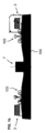
図を参照すると、従来の車輪鉄道車両102を誘導するための従来の車輪鉄道線路103と、磁気浮上式鉄道車両2を誘導するための本発明の実施形態による磁気浮上式鉄道線路3とを含む鉄道システムが示されている。磁気浮上式鉄道線路3は、既存の従来の車輪ベースの鉄道システムに統合することも、新しく設置したインフラストラクチャに従来の車輪ベースの鉄道システムを組み込むことも可能である。鉄道システムには、既存の従来の線路のセクションと、同じネットワークの一部として、または既存の路線に沿った新しいセクションが含まれる場合があり、たとえば、既存の路線の特定のセクションは、鉄道システムの維持状況に応じて新しいセクションに置き換えられる場合がある。したがって、本発明の実施形態は、完全に統合されたシームレスな方法で、鉄道網の新しいセクションのアップグレード、交換、または設置のいずれかを可能にする。
With reference to the figure, a railroad system is shown that includes a conventional
鉄道線路103、3は、バラスト、すなわち砂利および石101aを含むベースであるか、または自動車用の路面、またはたとえば橋やトンネルなどのその他の工学的構造物の一部を形成し得るコンクリートまたはアスファルトなどの非バラスト支持体101bであり得る線路地面支持体101上に支持される。
The
バラスト地面支持体101a上の従来の車輪鉄道線路103は、一般に、プレストレスト鉄筋コンクリート、または特に古いインフラストラクチャでは木製の梁で作られる枕木104を備える。レール105は、固定機構106によって梁に固定されており、このような機構はそれ自体よく知られており、本明細書で詳細に説明する必要はないだろう。
A conventional
本発明の実施形態による磁気浮上式鉄道線路3は、磁気浮上式鉄道車両2を誘導するための磁気浮上レール5と、磁気浮上式鉄道車両2を駆動するための推進力を提供するためのリニアモーター7とを備える。磁気浮上式鉄道線路3は、従来の既存の枕木104、または本発明の実施形態による枕木4、または本発明の実施形態による製造されたベースプレート13上に支持され得る。上記の実施形態のすべてまたは一部は、既存のインフラストラクチャの状態に応じて、その異なるセクションに沿った鉄道線上に見出すことができる。
The magnetic
磁気浮上レール5は、それ自体が周知の基準、例えば構造限界に従った従来の車輪鉄道車両102の底部よりも低い全高を有する従来のレール105の外側に取り付けられている。各磁気浮上レール5は、実施形態に応じて異なるプロファイルを有することができるガイドレール9を備える。ガイドレールは、連続レール10、または結合アダプタ11の個別のピラー28の形態であり得る支持体に、任意選択で、アダプタ‐ガイド界面層42を介して取り付けられる。ガイドレール9および支持レール10または結合アダプタ11は、実施形態に応じて、枕木4、104または製造されたベースプレート13に結合される。
The magnetic levitation rails 5 are attached to the outside of
図3に示されるような第1の実施形態では、ガイドレール9および支持レール10は、枕木4、104に直接結合されている。
In the first embodiment as shown in FIG. 3, the
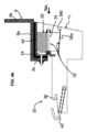
図4aから図4eに示される他の有利な実施形態では、結合アダプタ11は、ガイドレール9を支持するために設けられ、結合アダプタ11は、車輪鉄道線路103のレール105に取り付けるように構成される。
In another advantageous embodiment shown in Figures 4a to 4e, a
第1の実施形態における結合アダプタ11は、図4dに示されるように枕木4、104、または非バラスト支持体(例えば、路面)に取り付けられ得る。第2の実施形態では、結合アダプタ11は、図4eに示されるように、(線路方向において)枕木4、104の間に取り付けられる。第2の実施形態は、既存の枕木がその外端に磁気浮上線路を取り付けるために、またはバラスト地面支持体101aに沿って磁気浮上式鉄道線路をより容易かつより迅速に展開するために十分に適合されていない状況で使用され得る。
The
図4bおよび図4cに最もよく示される本発明の実施形態による結合アダプタ11は、従来のレール105の底部に取り付けるように適合された形態を有する受容プロファイル38を含む車輪レール固定部分30と、結合アダプタ11を従来のレール105の下側にしっかりと固定するために締め付けることができる、例えば1つまたは複数の調整可能なクランプフック40の形態のクランプ機構とを備える。
The
結合アダプタ11は、図4eに示されるように枕木4、104の間のレールのセクションに、または図4dに示されるように枕木4、104上に固定され、枕木は、例えば、クランプ機構が配置されているレールのセクションの下にある砂利および石を除去することによってバラスト表面上で支持される。
The
結合アダプタ11は、すべての枕木の上または間に設置することができ、あるいは2個または3個の枕木ごとに設置することができる。言い換えると、結合アダプタは、結合アダプタが取り付けられていない1つまたは複数の枕木によってレール5の方向に分離され得る。
The
図4b、図4cに示される実施形態では、支持ピラー28の反対側に配置された一対のクランプフック40が設けられる。
In the embodiment shown in Figures 4b and 4c, a pair of clamp hooks 40 are provided, positioned on opposite sides of the
結合アダプタ11は、ガイドレール9を取り付けるための支持ピラー28をさらに備える。支持ピラー28は、一実施形態では、位置調整機構32の一部を形成する調整ガイド面36aを備えてもよく、位置調整機構32は、クランプ機構40および車輪レール固定部分30の受容プロファイル38に対してガイドレール9の位置を調整するための調整ネジ34をさらに備える。例えば板バネで作られたバネ44を調整機構に組み込んで、調整ネジに対して支持ピラー28を弾性的に付勢することができる。
The
図4bの図示の実施形態では、支持ピラー28の調整ガイド面36aは、枕木4の傾斜した上部取付面36bに直接係合するか、あるいは、浮上レール5が取り付けられている枕木または他の構造物に固定して取り付けられたブロック(図示せず)の上部傾斜面に係合する。
In the illustrated embodiment of FIG. 4b, the
図4cおよび図4bの図示の実施形態では、調整ガイド面36a、36bは、水平線に対してわずかに傾斜しており、調整ネジ34を回すことによって支持ピラー28の変位がガイドレール9を上昇または下降させることができる。したがって、車輪レール固定部分30の位置、および線路の近くの部分にある隣接する結合アダプタの位置決め角度に対するその角度をわずかに変える可能性があるレールのベースの不規則性および製造公差を考慮に入れるために、鉄道線路に沿ったガイドレール9の高さを車輪鉄道線路103のレール105に対して調整することができる。
In the illustrated embodiment of Fig. 4c and Fig. 4b, the
ガイドレール9の横方向位置を調整するために、ガイドレール9および支持レール10または結合アダプタ11との間にさらなる位置調整機構を設けることができる。変形例(図示せず)では、支持ピラー28と枕木4との間の位置調整機構の代わりに、あるいは追加して、高さおよび/または横方向位置を調整するための位置調整機構をガイドレール9および支持レール10または結合アダプタ11との間に設けることができることに留意されたい。
To adjust the lateral position of the
アダプタ-ガイド界面層42は、ポリマーまたは複合材料または他の材料で作られ、ガイドレール9と支持レール10または結合アダプタ11との間のある程度の柔軟性を可能にする。これは、ガイドレールと支持レールの間の接触における局所的な応力を減衰させるため、および/またはガイドレールと支持レールまたは結合アダプタ11の間の振動および動きを減衰させるために役立つ場合がある。
The adapter-
アダプタ-ガイド界面層42はまた、ガイドレールと支持レールまたは結合アダプタ11との間の誘電体分離として有利に機能し得る。これは、金属間、特にアルミニウムと鋼の界面のガルバニック腐食を減少することに役立つ場合がある。誘電体層はまた、浮揚を引き起こす起電力を生成する車両上の磁場の通過に起因する渦電流によって引き起こされる磁気浮上力を改善および最適化することができる。
The adapter-
図3に示す実施形態では、支持レール10は、例えば種々の形態で提供することができる固定手段6によって、例えば従来の鉄道路線の固定のためによく知られているボルトおよびクランプによって、または例えば外部環境での高負荷用途に適合した適切な接着剤を使用して、枕木に直接溶接または接着することによって、枕木104、4に直接取り付けられるものとして示されている。
In the embodiment shown in FIG. 3, the
変形例(図示せず)では、結合アダプタを支持レールと枕木の間に挿入することができ、結合アダプタは、例えば、支持レール、したがって、ガイドレール9の高さおよび/または横方向位置の調整を可能にする位置調整機構を備える。
In a variant (not shown), a coupling adapter can be inserted between the support rail and the sleeper, the coupling adapter being provided with a position adjustment mechanism, for example, allowing adjustment of the height and/or lateral position of the support rail and thus the
図示の実施形態では、ガイドレールは、本質的に、磁気浮上車両の垂直位置を案内するための水平部分9aを有する平板またはプレートの形態で示され、有利な実施形態では、ガイドレールは、磁気浮上車両の横方向(水平方向)位置を案内するための垂直部分9bをさらに含み得る。内側には、ガイドレールを支持レール10または支持ピラー28に固定するために、さらなる垂直部分9cを設けることができる。
In the illustrated embodiment, the guide rail is essentially shown in the form of a flat plate or plate having a
ガイドレール9は、導電体の近くの移動磁場によって発生する起電力の周知の物理原理に従って、移動する浮上車両2の浮上要素を押し上げる起電力を発生させるために、導電性材料で形成されている。したがって、本発明の一態様による浮上システムは、車両2が特定の速度で移動すると、車両2上の磁気浮上要素によって浮上力が生成されて、ガイドレール9との接触から車両を持ち上げる浮上力を生成するパッシブシステムである。
The guide rails 9 are formed of a conductive material to generate an electromotive force that pushes up on the levitation elements of the moving levitated
したがって、磁気浮上車両2は、特定の速度が達成されるまでガイドレール9に沿ってスライドまたは転がることを可能にする車輪またはスライド(図示せず)を備えている。実際の例では、十分な浮上力が発生する速度は、通常、時速40~60kmの範囲である。浮上車両がガイドレール9に接触する速度が比較的遅いことを考慮し、さらに、浮上力で持ち上げる前でも、ガイドレールに加えられる車両の重量を減らすことを考慮すると、磁気浮上車両の車輪は、従来の鉄道車両の車輪と比較して、高い機械的強度および抵抗を有する必要はない。したがって、それらは、例えば、ポリマー材料またはポリマー複合材料、またはガイドレールへの過度の圧力および損傷を防ぐポリマー材料でコーティングされた金属で形成され、より小さく、より軽くなり得る。好ましい実施形態では、磁気浮上車両の車輪の表面材料は、ガイドレール9を形成する導電性材料の硬度よりも低い硬度を有する。
The
ガイドレール9の好ましい材料には、鋼およびアルミニウム合金が含まれる。ただし、銅合金などの他の導電性材料を使用することもできる。ガイドレール9はまた、積み重ねられた構造の複数の材料、例えば、互いに結合された複合材料上の金属で形成され得る。
Preferred materials for the
ガイドレール9は、押し出し、圧延、および他のそれ自体よく知られている成形プロセスによって成形することができる。ガイドレールは、特定の実施形態では、支持レール10のセクションにすでに取り付けられているか、または別個の支持レールにその場で取り付けられて供給され得る。ガイドレール9は、磁気分極されないようにしてヒステリシスを低減するために、好ましくは非磁性材料で形成されている。
The guide rails 9 may be formed by extrusion, rolling, and other forming processes well known per se. The guide rails may, in certain embodiments, be supplied already attached to a section of the
特定の実施形態では、支持レール10は、連続レールであり得るか、またはスペースのあるセクションまたはスペースのないセクションで提供され得る。
In certain embodiments, the
ガイドレール9は主に浮上面として機能することを考慮すると、ガイドレールと支持レールの熱膨張を可能にして車輪レール、地面、および磁気浮上レールの間の異なる熱膨張を調整するために、直接結合されるか、または直接結合されないセクションで提供されてもよい。
Considering that the
ガイドレール9は、ほぼ平坦な水平断面および垂直断面を有する構成要素として示されているが、様々な複雑な形状を有することができ、さらに、本発明の範囲から逸脱することなく、単一のレールを形成するように、支持レール10に直接組み込まれるかまたは一体的に形成され得る。
Although the
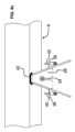
図8aに示されるように、鉄道車両2上の磁気浮上装置12は、磁石12aを含み、これは、好ましい実施形態では、例えば、図8bに示されるように、磁極間で方向が180°変化する、または、または図8cに示すように磁極の方向が90°変化する(既知のハルバッハ配列に対応)交互分極を有する永久磁石の形態であり得る。ただし、たとえば、隣接するセグメントに対して45°または30°回転するセグメントを使用するような他の磁極配置も可能である。ただし、鉄道車両には、永久磁石の代わりに、または永久磁石に加えて電磁石を取り付けることができる。後者の実施形態では、これは、低速でより高い磁気浮上力を生成するために有用であり得、それにより、電磁石をより高速でオフまたはオンにすることができる。
As shown in FIG. 8a, the
実施形態では、鉄道車両は、例えば、以下のような様々な構成を含み得る。
1.始動/減速-エネルギー消費量が多いため、リニアモーターは外部電源から電力を供給される。例えば図9aに概略的に示されているように、浮上と安定化のための永久磁石が存在する。
2.クルーズまたはスピードブースティング(真空システム内)-実質的に一定の速度を維持するために、高出力モーターは必要ない。そのため、鉄道車両の推進電磁石がオンになり、たとえば図9bの概略図に示すように、推進と浮上を同時に提供するように機能する。このような場合、パワーは通常、加速中のピークパワーの3分の1~5分の1になる。
3.真空システム(緊急事態を考慮しない)内では、車両はリニアモーターによって加速され、その後、低空気抵抗により、加速中のリニアモーターのピーク電力の約40分の1~100分の1の低消費電力で運転(惰行)される。
In embodiments, the rail vehicle may include a variety of configurations, such as, for example:
1. Starting/Deceleration - Due to the high energy consumption, linear motors are powered from an external source, for example there are permanent magnets for levitation and stabilization as shown diagrammatically in Figure 9a.
2. Cruise or Speed Boosting (in a vacuum system) - To maintain a substantially constant speed, high power motors are not required. Therefore, the railcar's propulsion electromagnets are turned on and function to provide propulsion and levitation simultaneously, for example as shown in the schematic diagram of Figure 9b. In such cases, the power is typically one third to one fifth of the peak power during acceleration.
3. In a vacuum system (not considering emergency situations), the vehicle is accelerated by the linear motor and then driven (coasting) at low power consumption due to low air resistance, about 40 to 100 times lower than the peak power of the linear motor during acceleration.
アルミニウムなどの可動要素用の導電性プレートは、惰行中の浮上および推進に使用することができる。搭載された電磁石に電力を供給するエネルギーは、バッテリー、燃料電池、ワイヤレス電力伝送、パンタグラフ、またはそれらの任意の組み合わせから得られる。 Conductive plates for the moving elements, such as aluminum, can be used for levitation and propulsion while coasting. Energy to power the on-board electromagnets can come from batteries, fuel cells, wireless power transmission, pantographs, or any combination thereof.
有利なことに、磁気浮上列車が、磁気浮上線路または代わりに別の線路(例えば、既存の従来の車輪レール線路)上に低速で静止することができる車輪を有するパッシブ浮上システムの使用は、既存の鉄道ネットワークに統合することが非常に簡単であり、浮上線路にコイルを設置することによる複雑さを回避する。アクティブ浮揚システムのコイルは、設置の複雑さとコストを増加させるだけでなく、アクティブ浮揚トラックのいずれかのセクションに障害が発生した場合のシステムの信頼性を低下させる。ガイドレールの機械的な取り付けと調整、および高さの調整は、このようなパッシブ浮上システムによって大幅に簡素化され、さらに、ガイドレールにコイルがない場合、システムの堅牢性と耐久性が向上する。 Advantageously, the use of a passive levitation system, in which a magnetically levitated train has wheels that can rest at low speed on the magnetically levitated track or alternatively on another track (e.g. an existing conventional wheel-rail track), is very easy to integrate into existing rail networks and avoids the complications of installing coils on the levitation track. The coils of an active levitation system not only increase the complexity and cost of installation but also reduce the reliability of the system in case of failure of any section of the active levitation track. The mechanical mounting and adjustment of the guide rails and the height adjustment are greatly simplified with such a passive levitation system, and furthermore, the absence of coils on the guide rails increases the robustness and durability of the system.
既存の従来の鉄道路線の外側にガイドレールを設けることは、磁気浮上車両の転がりに対して高い安定性を有するという点でも有利である。 Providing guide rails on the outside of existing conventional railway tracks is also advantageous in that it provides high stability against the rolling of magnetic levitation vehicles.
「水平」および「垂直」という用語の使用は、線路のカーブにおける磁気浮上車両の傾斜を可能にするために、数度の傾斜を含むことを意図していることに留意されたい。 Note that the use of the terms "horizontal" and "vertical" is intended to include several degrees of inclination to allow for the inclination of the maglev vehicle around curves in the track.
図5aから図5cを参照すると、新しい設備のための本発明の実施形態による枕木4が、基板、特にそれ自体が知られている補強材48を有するコンクリート基板46を含む。枕木は、基板に埋め込まれ、枕木の上部取付面を超えて突出する部分を有する複数のアンカー要素50をさらに含み、従来のレールおよび、さらに、枕木の外端の磁気浮上レール両方に固定要素を提供する。
With reference to Figures 5a to 5c, a sleeper 4 according to an embodiment of the invention for a new installation comprises a substrate, in particular a
図6aから図6dを参照すると、本発明の実施形態による鉄道システムで使用され得るリニアモーターの様々な構成が示されている。図6aでは、リニアモーターは、リニアモーターにおいてそれ自体既知の方法で電機子に巻かれた複数のコイル26を保持する電機子24を備える。通常、3相システムのそれぞれに1つずつ、3つのコイルのグループが存在する場合がある。
With reference to Figures 6a to 6d, various configurations of linear motors that may be used in railway systems according to embodiments of the present invention are shown. In Figure 6a, the linear motor comprises an
電機子は、強磁性材料(鉄)でできていても、非強磁性(非鉄)でもよい。好ましい実施形態では、電機子は鉄を含まない。コイルは、ワイヤー、ケーブル、または切断および曲げられた銅板でできている場合がある。 The armature may be made of ferromagnetic material (iron) or non-ferromagnetic (non-ferrous). In a preferred embodiment, the armature is iron-free. The coils may be made of wire, cable, or cut and bent copper sheet.
リニアモーター7は、図1a、図1b、図3および図9aに示されるように、線路の中心線に沿って取り付けられ得る固定子7aを含み、鉄道車両は、それ自体よく知られているように力を提供するためにリニアモーターに磁気的に結合する永久磁石または電磁石を備えた可動要素7bを備える。
The
図6bの構成では、2組のコイルが設けられ、可動磁気要素7bがリニアモーター固定子7aの反対側に設けられ、これは、一般に、図6aに示すような片側のシステムより高い電力を生成することができるという観点から好ましい構成である。
In the configuration of Figure 6b, two sets of coils are provided, with the movable
図6aおよび図6bは同期モーターを示すが、リニアモーターは、図6cおよび図6dに示すように非同期タイプとすることができる。ここで、可動要素は、誘導によって力を生成する導電性要素である。 While Figures 6a and 6b show a synchronous motor, the linear motor can be of the asynchronous type as shown in Figures 6c and 6d, where the moving element is a conductive element that generates force by induction.
リニアモーターの様々な構成はそれ自体よく知られており、本明細書で詳細に説明する必要はないだろう。 The various configurations of linear motors are well known per se and need not be described in detail here.
好ましい実施形態では、リニアモーターは、従来の鉄道線路の中心線に沿って有利に配置され、磁気浮上式鉄道線路3とは独立して設置して、従来の鉄道車両102と干渉することなく迅速かつ容易に設置することができる。リニアモーターの固定子7aが鉄道車両2の可動磁気要素7bの間で垂直に直立している図6bのモーター構成が好ましい。リニアモーターの高さを正確に調整する必要がないため、高さよりも線路間の横方向位置を正確に調整しやすいというメリットがある。
In a preferred embodiment, the linear motor is advantageously positioned along the centre line of the conventional railway track and can be installed independently of the magnetic
しかし、本発明の範囲内で、図9dに示されるようなモーター配置を、図6aまたは6cに対応するモーターと共に有することが可能であり、リニアモーターの固定子が水平に配置され、鉄道車両2のベースに水平に配置されている磁気可動要素に結合する。別の実施形態では、図2および図11a~図13に示されるように、リニアモーターを片側または両側の磁気浮上レール5に沿って配置し、それに結合することも可能であり、それにより、鉄道車両に対するモーターの位置は、ガイドレール9に対する固定位置を考慮して十分に制御される。このモーターは、中心線に沿ったリニアモーターの代わりになる場合もあれば、図11a~図13に示すように追加される場合もある。追加のリニアモーターは、異なるシステムの車両に適応するために使用できる。言い換えると、中央にリニアモーターまたは外側にリニアモーターを備えた鉄道車両に適応するために使用できる。または代わりに特に磁気浮上車両の加速または制動中に力を増加させるための複数のモーターを有するように使用される。電磁的手段により高い制動力を発生させるためには、複数のリニアモーターを使用することが特に有利である可能性がある。
However, within the scope of the present invention, it is possible to have a motor arrangement as shown in FIG. 9d with a motor corresponding to FIG. 6a or 6c, where the stator of the linear motor is arranged horizontally and coupled to a magnetic mobile element arranged horizontally on the base of the
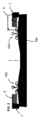
既存の従来の線路に沿って磁気浮上式鉄道線路を設置することに加えて、例えば図10および図10bに示すように、既存の道路インフラストラクチャに沿って磁気浮上式鉄道システムを容易に統合するために本発明の原理を採用することも可能である。図10aにおいて、3車線の道路や高速道路が図示され、例えば、磁気浮上式鉄道システムのための1つのレーンを使用するように改修することができる。後者の場合、磁気浮上式鉄道システムは、有利には真空管8を備え得る。上記のような磁気浮上レール5の様々な特徴は、真空管を備えたシステムでも使用することができる。
In addition to installing maglev tracks along existing conventional tracks, the principles of the present invention can also be employed to easily integrate maglev systems along existing road infrastructure, as shown for example in Figures 10 and 10b. In Figure 10a, a three-lane road or highway is shown, which can be retrofitted to use, for example, one lane for the maglev system. In the latter case, the maglev system can advantageously comprise vacuum tubes 8. The various features of the
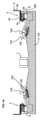
コンクリートまたはアスファルトで形成され得る既存の非バラスト地面支持体101bに取り付ける場合、本発明の一態様によれば、製造されたベースプレート13は、地面-プレート界面層19を介して非バラスト地面支持体101bに取り付けるために提供される。地面-プレート界面層は、アスファルト、ポリマー、または製造されたベースプレート13と非バラスト地面支持体101bとの間に特定の応力分布と減衰接続を提供する他の変形可能な材料でできている場合がある。
When mounting to an existing
レジスタ要素21は、例えば、地面-プレート位置決めポストの形態で、個別の位置に、または製造されたベースプレートの中心線に近接する連続または断続的なレールとして設けることができ、非バラスト地面支持体101bに対してベースプレートを固定して配置することができる。
The
変形可能な地面-プレート界面層19は、表面間の平面性の違いを有利に吸収し、また、ベースプレートと地面との間の応力のより良い分布を可能にする。
The deformable ground-
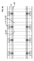
製造されたベースプレート13は、鉄道または道路による従来の輸送を可能にする寸法で提供され、典型的には、幅2メートル~10メートルおよび長さ2メートル~12メートルを有する。製造されたベースプレート上に、線路の方向に間隔を置いて複数の固定インサート18を設けることができる。固定インサート18は、磁気浮上式鉄道線路3を固定するために構成され、さらに、車輪鉄道線路が複合システムに設けられている場合に、車輪鉄道線路103のレール105を固定するために構成される。固定インサート18は、製造されたベースプレートの基板16に設けられた固定インサート受容部20の内側に取り付けることができる。任意選択で、インサート取付インターフェース22を、固定インサートと基板16との間の減衰および/または応力分布のために、固定インサートと受容部との間に設けることができる。インサート取付インターフェース22は、ポリマー、アスファルト、または他の変形可能な材料でできていてもよい。
The manufactured
固定インサートはまた、例えば、特に線路のカーブに対して、線路のわずかな角度傾斜を提供するために、製造されたベースプレート13の基板に対して高さおよび傾斜角を調整することができる。
The fixing inserts can also be adjusted in height and inclination with respect to the substrate of the manufactured
製造されたベースプレート13は、基板16と、基板内に埋め込まれた1つまたは複数の部品の補強フレーム14とを含む。一実施形態では、補強フレーム14は、工場で製造され、設置場所に運ばれ、続いて基板16が補強フレーム14の周りにその場で注がれる。別の構成では、補強フレーム14および基板は、工場で、または設置場所から離れている場所で予め製作部品として形成され、地面支持体101上に取り付けるために設置場所に輸送される。
The manufactured
補強フレーム14は、好ましくは、コンクリートに補強を提供するために金属構造で作られている。
The reinforcing
図13に示されるような有利な実施形態では、真空管8は、磁気浮上式鉄道車両2の通過のための空気抵抗を低減するために管内に部分真空を作り出すために、製造されたベースプレート13に取り付けられ得る。車輪鉄道車両も、加圧されたコンパートメントを備えているため、空気抵抗が減少するというメリットがある。車輪レールは、代替的または追加的に、磁気浮上式車両よりも低速で移動する車輪を有するサービス車両を輸送するのに役立つ場合がある。車輪レールは、代替的または追加的に、従来の車輪線路鉄道インフラストラクチャと相互運用可能な追加の鋼製車輪を有する磁気浮上車両に使用できるため、真空管を離れた後、車両は従来の方法で車輪で移動できる。
In an advantageous embodiment as shown in FIG. 13, the vacuum tube 8 can be attached to a fabricated
鉄道車両用の真空管システム自体は既知である。本発明の実施形態では、真空管は、有利には、共に組み立てられ、上端で共に結合され、基端で製造されたベースプレート13の外側側縁に結合される少なくとも2つの壁部分8a、8bを含み得る。壁部分8a、8bをベースプレート13に組み立てて管を形成した後、部分真空のための実質的に気密シールを提供するために、シール層50a、50bを接合界面に結合またはコーティングすることができる。シーリング層は、亀裂を気密に埋めるように設計されたポリマー材料でできている場合がある。
Vacuum tube systems for rail vehicles are known per se. In an embodiment of the invention, the vacuum tube may advantageously comprise at least two
0 鉄道システム
101 線路地面支持体
101a バラスト(砂利、石)
101b 非バラスト(コンクリート、アスファルト、…)
13 製作されたベースプレート
14 補強フレーム
16 基板(コンクリートなど)
20 固定インサート受容部
18 固定インサート
22 インサート取付インターフェース
19 地面-プレート界面層
21 地面-プレート位置決めポスト
102 車輪鉄道車両
103 車輪鉄道線路
104、4 枕木/非バラストレール支持体
105 レール(車輪用)
106 固定機構
2 磁気浮上式鉄道車両
12 浮上装置
磁石
3 磁気浮上式鉄道線路
4、104 枕木
46 基板(コンクリート)
48 テンションロッド補強材
50 アンカー要素
36b 傾斜ガイド面
6 固定機構
5 磁気浮上レール
9 ガイドレール
10 支持レール
11 結合アダプタ
28 支持ピラー
30 車輪レール固定部分
38 プロファイル受容部
40 クランプフック
32 位置調整機構
34 調整ネジ
36a 調整ガイド面
44 バネ
42アダプターガイドレール界面層
7 リニアモーター
7a 固定子
24 電機子
26 コイル
7b 可動要素
永久磁石
誘導プレート
8 真空管
8a、8b 壁部分
基端
先端
シーリング層52a、52b
0 Railway system 101
101b Non-ballast (concrete, asphalt, ...)
13 Manufactured
20
106
48
38 Profile Receptor
40
34 Adjustment screw
36a Adjustment guide surface
44
Claims (30)
前記ガイドレール(9)が、磁気浮上式鉄道車両(2)を横方向に案内するための水平部分(9a)から延在する垂直部分(9b)を備える、磁気浮上式鉄道システム。 A magnetic levitation railway system for integration into a wheel railway track (103), comprising a magnetic levitation railway track (3) including a linear motor (7) and a magnetic levitation rail (5) arranged outside the wheel railway track (103), the magnetic levitation rail (5) comprising an electrically conductive guide rail (9) having at least a horizontal portion (9a) configured for a magnetic levitation railway vehicle (2) having a levitation device (12) having magnets, the guide rail (9) being configured for passively levitating the magnetic levitation railway vehicle (2) by electromotive forces generated by a moving magnet of the magnetic levitation railway vehicle (2);
The magnetic levitation railway system, wherein the guide rail (9) comprises a vertical portion (9b) extending from a horizontal portion (9a) for guiding the magnetic levitation railway vehicle (2) laterally.
クランプシステムは、1または複数の調整可能なクランプフックを備える、結合アダプタ(11)。 A coupling adapter (11) for a railway system comprising a magnetic levitation railway track (3) for integration into a wheel rail track (103), the magnetic levitation railway track comprising a magnetic levitation rail (5) arranged outside a wheel rail (105) of the wheel rail track (103), the coupling adapter comprising a wheel rail fixing portion (30) configured to be mounted on or between sleepers (4, 104) of the railway system, the wheel rail fixing portion (30) comprising a receiving profile (38) having a shape adapted to be mounted on a bottom of the wheel rail (105) and a clamping mechanism (40) that can be tightened to secure the coupling adapter firmly to the underside of the wheel rail,
The clamping system comprises a coupling adapter (11) that includes one or more adjustable clamping hooks.
)と、前記支持ピラーの位置を調整するための位置調整機構(32)とを備え、それにより前記クランプ機構に対する前記ガイドレールの位置を調整する、請求項21に記載の結合アダプタ。 Support pillars (28) for mounting the guide rails (9) of the magnetic levitation rail (5)
22. The coupling adapter of claim 21, further comprising a position adjustment mechanism (32) for adjusting a position of the support pillar, thereby adjusting a position of the guide rail relative to the clamp mechanism.
前記システムは、結合アダプタをさらに備え、前記結合アダプタは、前記鉄道システムの枕木(4,104)上または間に取り付けられるように構成された、車輪レール(105)の底部に取り付けるよう適合された形状を有する受容プロファイル(38)と、前記結合アダプタを前記車輪レールの下側にしっかり固定するために締め付けることができるクランプ機構(40)とを備える車輪レール固定部分(30)を備える、磁気浮上式鉄道システム。 A magnetic levitation railway system for integration into a wheel railway track (103), comprising a magnetic levitation railway track (3) including a linear motor (7) and a magnetic levitation rail (5) arranged outside the wheel railway track (103), the magnetic levitation rail (5) comprising an electrically conductive guide rail (9) having at least a horizontal portion (9a) configured for a magnetic levitation railway vehicle (2) having a levitation device (12) having magnets, the guide rail (9) being configured for passively levitating the magnetic levitation railway vehicle (2) by electromotive forces generated by a moving magnet of the magnetic levitation railway vehicle (2);
The system further comprises a coupling adapter configured to be mounted on or between sleepers (4, 104) of the railway system, the coupling adapter comprising a wheel rail fixing portion (30) comprising a receiving profile (38) having a shape adapted for mounting to a bottom of a wheel rail (105) and a clamping mechanism (40) that can be tightened to secure the coupling adapter firmly to the underside of the wheel rail.
Applications Claiming Priority (5)
| Application Number | Priority Date | Filing Date | Title |
|---|---|---|---|
| PL426733A PL244061B1 (en) | 2018-08-20 | 2018-08-20 | Method of integrating the conventional rail wheel track with maglev railway track or other than railway track, including road surface of flexible, half-rigid or rigid type, with maglev railway drive system and the integrating block |
| PL426732A PL243657B1 (en) | 2018-08-20 | 2018-08-20 | Method of integrating the conventional rail wheel track with maglev railway track and device integrating conventional railway track with maglev railway track |
| PLP.426733 | 2018-08-20 | ||
| PLP.426732 | 2018-08-20 | ||
| PCT/EP2019/072304 WO2020038964A1 (en) | 2018-08-20 | 2019-08-20 | Magnetic levitation railway system |
Publications (2)
| Publication Number | Publication Date |
|---|---|
| JP2021535309A JP2021535309A (en) | 2021-12-16 |
| JP7467470B2 true JP7467470B2 (en) | 2024-04-15 |
Family
ID=67742398
Family Applications (1)
| Application Number | Title | Priority Date | Filing Date |
|---|---|---|---|
| JP2021534821A Active JP7467470B2 (en) | 2018-08-20 | 2019-08-20 | Magnetic levitation system |
Country Status (8)
| Country | Link |
|---|---|
| US (1) | US20210316616A1 (en) |
| EP (1) | EP3841249B1 (en) |
| JP (1) | JP7467470B2 (en) |
| CN (1) | CN112955605B (en) |
| BR (1) | BR112021002995A2 (en) |
| CA (1) | CA3109727A1 (en) |
| IL (1) | IL280847A (en) |
| WO (1) | WO2020038964A1 (en) |
Families Citing this family (3)
| Publication number | Priority date | Publication date | Assignee | Title |
|---|---|---|---|---|
| CN113415171B (en) * | 2021-07-07 | 2022-10-21 | 西南交通大学 | Suspension driving integrated magnetic suspension system and suspension driving method |
| EP4245630A1 (en) | 2022-03-14 | 2023-09-20 | Nevomo Poland Sp. z O. O. | Interoperability systems for railway infrastructures |
| CN114734826B (en) * | 2022-06-13 | 2022-09-02 | 西南交通大学 | Permanent magnet electric suspension system and guiding method thereof |
Citations (1)
| Publication number | Priority date | Publication date | Assignee | Title |
|---|---|---|---|---|
| JP3074439U (en) | 2000-06-29 | 2001-01-19 | 株式会社富士交通研究所 | Guard angle support device for preventing derailment in curved sections of concrete track tracks of railways |
Family Cites Families (21)
| Publication number | Priority date | Publication date | Assignee | Title |
|---|---|---|---|---|
| DE2247858A1 (en) * | 1972-09-29 | 1974-04-04 | Siemens Ag | MAGNETIC LIFT |
| FR2227982B3 (en) * | 1973-05-02 | 1977-03-04 | Siemens Ag | |
| EP0179188B1 (en) * | 1984-10-23 | 1990-07-25 | Kabushiki Kaisha Toshiba | Transporting system of floated carrier type |
| DE3736943C1 (en) * | 1987-10-31 | 1988-12-08 | Dyckerhoff & Widmann Ag | Railway superstructure, especially for very high speeds |
| JP2723193B2 (en) * | 1990-08-06 | 1998-03-09 | 東海旅客鉄道 株式会社 | Superconducting magnetic levitation railway system, superconducting magnetic levitation railway vehicle guidance device, and methods of constructing them |
| DE4028197C2 (en) * | 1990-09-03 | 1994-06-30 | Hirtz Helmut | Binary route |
| JP3797569B2 (en) * | 1996-03-28 | 2006-07-19 | エイチ・エス・エス・ティ開発株式会社 | Mounting the reaction plate on the rail for the linear motor car |
| US5953996A (en) * | 1998-04-03 | 1999-09-21 | Powell; James R. | System and method for magnetic levitation guideway emplacement on conventional railroad line installations |
| TR200200336T2 (en) * | 1999-08-09 | 2002-06-21 | Max Boegl Bauunternehmung Gmbh & Co.Kg | Route path for a vehicle connected to the rail |
| JP2002227101A (en) * | 2001-02-06 | 2002-08-14 | Odakyu Dentetsu Kk | Sleeper-integrated concrete ballast structure for railway line |
| ITTO20020302A1 (en) * | 2002-04-08 | 2003-10-08 | Fasano Eleonora | SYSTEM SUITABLE FOR BUILDING A CARRIAGE TRACK ON RAILWAY TRACK. |
| CN1827441A (en) * | 2006-03-24 | 2006-09-06 | 王光宇 | Magnetic levitation train system based on common wheel track |
| CN101063287B (en) * | 2006-04-30 | 2011-11-02 | 上海磁浮交通工程技术研究中心 | Track structure of magnetic floating traffic and manufacturing method therefor |
| CN201087316Y (en) * | 2007-08-16 | 2008-07-16 | 同济大学 | Novel magnetic floating track girder |
| CN101481893A (en) * | 2008-01-08 | 2009-07-15 | 李葛亮 | Wheeltrack magnetic levitation universal technology |
| KR101023310B1 (en) * | 2008-08-28 | 2011-03-18 | 한국철도시설공단 | Rail Position Adjusting Apparatus for Guideway Structure for Magnetically Levitated Train |
| CN101935966A (en) * | 2009-06-29 | 2011-01-05 | 上海奇谋能源技术开发有限公司 | Method for building maglev train rail by utilizing conventional railway |
| US9352754B2 (en) * | 2011-10-26 | 2016-05-31 | Hans-Joachim Buse | Vehicle line |
| FR2988063B1 (en) * | 2012-03-14 | 2015-09-04 | Alstom Transport Sa | RAILWAY, RAILWAY VEHICLE FOR CIRCULATING ON THE RAILWAY AND TOGETHER COMPRISING THE RAILWAY AND THE RAILWAY VEHICLE |
| LU100160B1 (en) * | 2017-04-04 | 2018-10-15 | Vision Electric Super Conductors Gmbh | Use of a superconducting conductor arrangement and transport system with a superconducting conductor arrangement |
| US10208431B1 (en) * | 2018-01-22 | 2019-02-19 | John Van Rosendale | Permanent magnet maglev using passive, low-frequency electromagnetic stabilization |
-
2019
- 2019-08-20 US US17/269,493 patent/US20210316616A1/en active Pending
- 2019-08-20 JP JP2021534821A patent/JP7467470B2/en active Active
- 2019-08-20 BR BR112021002995-8A patent/BR112021002995A2/en unknown
- 2019-08-20 WO PCT/EP2019/072304 patent/WO2020038964A1/en unknown
- 2019-08-20 CN CN201980064920.0A patent/CN112955605B/en active Active
- 2019-08-20 EP EP19758678.7A patent/EP3841249B1/en active Active
- 2019-08-20 CA CA3109727A patent/CA3109727A1/en active Pending
-
2021
- 2021-02-14 IL IL280847A patent/IL280847A/en unknown
Patent Citations (1)
| Publication number | Priority date | Publication date | Assignee | Title |
|---|---|---|---|---|
| JP3074439U (en) | 2000-06-29 | 2001-01-19 | 株式会社富士交通研究所 | Guard angle support device for preventing derailment in curved sections of concrete track tracks of railways |
Also Published As
| Publication number | Publication date |
|---|---|
| EP3841249A1 (en) | 2021-06-30 |
| CN112955605A (en) | 2021-06-11 |
| CA3109727A1 (en) | 2020-02-27 |
| EP3841249B1 (en) | 2024-02-07 |
| CN112955605B (en) | 2023-06-27 |
| WO2020038964A1 (en) | 2020-02-27 |
| BR112021002995A2 (en) | 2021-05-11 |
| US20210316616A1 (en) | 2021-10-14 |
| IL280847A (en) | 2021-04-29 |
| EP3841249C0 (en) | 2024-02-07 |
| JP2021535309A (en) | 2021-12-16 |
Similar Documents
| Publication | Publication Date | Title |
|---|---|---|
| JP7467470B2 (en) | Magnetic levitation system | |
| US5953996A (en) | System and method for magnetic levitation guideway emplacement on conventional railroad line installations | |
| US8997955B2 (en) | Transferring electric energy to a vehicle by induction | |
| KR101504106B1 (en) | Guideway structure of bracket burying type for maglev levitation train, and constructing method for the same | |
| KR101541559B1 (en) | Prefabricated module for the track of a self-guided urban transport vehicle on tyres | |
| RU2278194C2 (en) | Railway track, tie and track component unit (versions) | |
| CN113994048B (en) | Vacuum tube railway system | |
| KR20140131731A (en) | Guideway structure having steel upper structure integrated with guide-rail, and constructing method for the same | |
| US3971537A (en) | Adjustable track mounting device in rail system for magnetic-suspension vehicles | |
| KR101106038B1 (en) | Conductor rail line of rubber wheel automated guidway transit type light weight railway | |
| US3882790A (en) | Rail system for magnetic suspension vehicles | |
| US3937149A (en) | Rail system for magnetic-suspension vehicles | |
| KR101469148B1 (en) | Guideway structure having mounting member and concrete girder with end difference, and constructing method for the same | |
| CN102874261A (en) | Travelling mechanism of linear motor train | |
| JP2950983B2 (en) | Track rails for maglev vehicles | |
| EA043955B1 (en) | RAILWAY SYSTEM WITH MAGNETIC LIFTS | |
| KR101359725B1 (en) | Combined rail and girder structure for maglev system | |
| KR101230535B1 (en) | Railway vehicles for adapting space maintaining apparatus of parallel linear induction motor | |
| US7334525B2 (en) | Modular guideway for a magnetic levitation vehicle and method for manufacturing a guideway module | |
| JPH04503544A (en) | Track rails for maglev vehicles | |
| CN110029541A (en) | A kind of beam type high-speed magnetic floating steel construction section of track in length and breadth | |
| CN110241664A (en) | A kind of high speed Maglev steel-concrete combined structure track plates | |
| CN114293412A (en) | Viaduct transition section structure, construction method thereof and low-level line | |
| PL243657B1 (en) | Method of integrating the conventional rail wheel track with maglev railway track and device integrating conventional railway track with maglev railway track | |
| JP2004346735A (en) | Structural system equipped with track for magnetic levitation transportation system supplied with power by linear electric motor |
Legal Events
| Date | Code | Title | Description |
|---|---|---|---|
| A521 | Request for written amendment filed |
Free format text: JAPANESE INTERMEDIATE CODE: A523 Effective date: 20210826 |
|
| A621 | Written request for application examination |
Free format text: JAPANESE INTERMEDIATE CODE: A621 Effective date: 20220817 |
|
| A977 | Report on retrieval |
Free format text: JAPANESE INTERMEDIATE CODE: A971007 Effective date: 20230426 |
|
| A131 | Notification of reasons for refusal |
Free format text: JAPANESE INTERMEDIATE CODE: A131 Effective date: 20230508 |
|
| A601 | Written request for extension of time |
Free format text: JAPANESE INTERMEDIATE CODE: A601 Effective date: 20230808 |
|
| A521 | Request for written amendment filed |
Free format text: JAPANESE INTERMEDIATE CODE: A523 Effective date: 20230901 |
|
| A131 | Notification of reasons for refusal |
Free format text: JAPANESE INTERMEDIATE CODE: A131 Effective date: 20231106 |
|
| A521 | Request for written amendment filed |
Free format text: JAPANESE INTERMEDIATE CODE: A523 Effective date: 20231218 |
|
| TRDD | Decision of grant or rejection written | ||
| A01 | Written decision to grant a patent or to grant a registration (utility model) |
Free format text: JAPANESE INTERMEDIATE CODE: A01 Effective date: 20240304 |
|
| A61 | First payment of annual fees (during grant procedure) |
Free format text: JAPANESE INTERMEDIATE CODE: A61 Effective date: 20240403 |