JP7466975B2 - Method for manufacturing battery case for secondary battery and gas exhaust part - Google Patents
Method for manufacturing battery case for secondary battery and gas exhaust part Download PDFInfo
- Publication number
- JP7466975B2 JP7466975B2 JP2022507871A JP2022507871A JP7466975B2 JP 7466975 B2 JP7466975 B2 JP 7466975B2 JP 2022507871 A JP2022507871 A JP 2022507871A JP 2022507871 A JP2022507871 A JP 2022507871A JP 7466975 B2 JP7466975 B2 JP 7466975B2
- Authority
- JP
- Japan
- Prior art keywords
- gas
- layer
- gas exhaust
- pouch
- secondary battery
- Prior art date
- Legal status (The legal status is an assumption and is not a legal conclusion. Google has not performed a legal analysis and makes no representation as to the accuracy of the status listed.)
- Active
Links
- 238000004519 manufacturing process Methods 0.000 title claims description 21
- 238000000034 method Methods 0.000 title claims description 21
- 239000010410 layer Substances 0.000 claims description 105
- 239000002346 layers by function Substances 0.000 claims description 51
- -1 polypropylene Polymers 0.000 claims description 41
- 239000000463 material Substances 0.000 claims description 26
- 239000000203 mixture Substances 0.000 claims description 26
- 239000004743 Polypropylene Substances 0.000 claims description 25
- 229920001155 polypropylene Polymers 0.000 claims description 25
- 239000004698 Polyethylene Substances 0.000 claims description 22
- 229920000573 polyethylene Polymers 0.000 claims description 22
- 238000007789 sealing Methods 0.000 claims description 21
- 239000002033 PVDF binder Substances 0.000 claims description 18
- 229920001343 polytetrafluoroethylene Polymers 0.000 claims description 18
- 239000004810 polytetrafluoroethylene Substances 0.000 claims description 18
- 229920002981 polyvinylidene fluoride Polymers 0.000 claims description 18
- 239000000565 sealant Substances 0.000 claims description 18
- 229920000642 polymer Polymers 0.000 claims description 17
- 239000010419 fine particle Substances 0.000 claims description 12
- VYPSYNLAJGMNEJ-UHFFFAOYSA-N Silicium dioxide Chemical compound O=[Si]=O VYPSYNLAJGMNEJ-UHFFFAOYSA-N 0.000 claims description 11
- 230000004308 accommodation Effects 0.000 claims description 9
- 238000005507 spraying Methods 0.000 claims description 9
- OKTJSMMVPCPJKN-UHFFFAOYSA-N Carbon Chemical compound [C] OKTJSMMVPCPJKN-UHFFFAOYSA-N 0.000 claims description 6
- 229910052799 carbon Inorganic materials 0.000 claims description 6
- 239000002041 carbon nanotube Substances 0.000 claims description 6
- PNEYBMLMFCGWSK-UHFFFAOYSA-N aluminium oxide Inorganic materials [O-2].[O-2].[O-2].[Al+3].[Al+3] PNEYBMLMFCGWSK-UHFFFAOYSA-N 0.000 claims description 5
- 238000001035 drying Methods 0.000 claims description 5
- 239000002245 particle Substances 0.000 claims description 5
- 239000012466 permeate Substances 0.000 claims description 5
- 235000014113 dietary fatty acids Nutrition 0.000 claims description 4
- 238000005553 drilling Methods 0.000 claims description 4
- 239000000194 fatty acid Substances 0.000 claims description 4
- 229930195729 fatty acid Natural products 0.000 claims description 4
- 150000004665 fatty acids Chemical class 0.000 claims description 4
- NBVXSUQYWXRMNV-UHFFFAOYSA-N fluoromethane Chemical compound FC NBVXSUQYWXRMNV-UHFFFAOYSA-N 0.000 claims description 4
- 229920002545 silicone oil Polymers 0.000 claims description 4
- 239000003792 electrolyte Substances 0.000 description 20
- 239000010408 film Substances 0.000 description 18
- 230000004888 barrier function Effects 0.000 description 13
- 229910052751 metal Inorganic materials 0.000 description 8
- 239000002184 metal Substances 0.000 description 8
- 230000002209 hydrophobic effect Effects 0.000 description 7
- PXHVJJICTQNCMI-UHFFFAOYSA-N Nickel Chemical compound [Ni] PXHVJJICTQNCMI-UHFFFAOYSA-N 0.000 description 6
- 229910052782 aluminium Inorganic materials 0.000 description 6
- XAGFODPZIPBFFR-UHFFFAOYSA-N aluminium Chemical compound [Al] XAGFODPZIPBFFR-UHFFFAOYSA-N 0.000 description 6
- 239000001993 wax Substances 0.000 description 6
- 238000003860 storage Methods 0.000 description 5
- XLYOFNOQVPJJNP-UHFFFAOYSA-N water Substances O XLYOFNOQVPJJNP-UHFFFAOYSA-N 0.000 description 5
- 239000010949 copper Substances 0.000 description 4
- 239000007772 electrode material Substances 0.000 description 4
- 239000007788 liquid Substances 0.000 description 4
- 230000035515 penetration Effects 0.000 description 4
- 229920000139 polyethylene terephthalate Polymers 0.000 description 4
- 239000005020 polyethylene terephthalate Substances 0.000 description 4
- RYGMFSIKBFXOCR-UHFFFAOYSA-N Copper Chemical compound [Cu] RYGMFSIKBFXOCR-UHFFFAOYSA-N 0.000 description 3
- XEEYBQQBJWHFJM-UHFFFAOYSA-N Iron Chemical compound [Fe] XEEYBQQBJWHFJM-UHFFFAOYSA-N 0.000 description 3
- HBBGRARXTFLTSG-UHFFFAOYSA-N Lithium ion Chemical compound [Li+] HBBGRARXTFLTSG-UHFFFAOYSA-N 0.000 description 3
- 239000004677 Nylon Substances 0.000 description 3
- 229910052802 copper Inorganic materials 0.000 description 3
- 230000005611 electricity Effects 0.000 description 3
- 229910001416 lithium ion Inorganic materials 0.000 description 3
- 229920001778 nylon Polymers 0.000 description 3
- 239000011241 protective layer Substances 0.000 description 3
- 239000002002 slurry Substances 0.000 description 3
- 239000002904 solvent Substances 0.000 description 3
- 238000003756 stirring Methods 0.000 description 3
- 239000000126 substance Substances 0.000 description 3
- 239000004952 Polyamide Substances 0.000 description 2
- 239000004642 Polyimide Substances 0.000 description 2
- 239000004809 Teflon Substances 0.000 description 2
- 229920006362 Teflon® Polymers 0.000 description 2
- 238000005299 abrasion Methods 0.000 description 2
- 239000011149 active material Substances 0.000 description 2
- 239000004760 aramid Substances 0.000 description 2
- 229920003235 aromatic polyamide Polymers 0.000 description 2
- 230000008901 benefit Effects 0.000 description 2
- 239000011230 binding agent Substances 0.000 description 2
- 229920002678 cellulose Polymers 0.000 description 2
- 239000001913 cellulose Substances 0.000 description 2
- 239000011651 chromium Substances 0.000 description 2
- 239000002131 composite material Substances 0.000 description 2
- 230000007797 corrosion Effects 0.000 description 2
- 238000005260 corrosion Methods 0.000 description 2
- 238000010586 diagram Methods 0.000 description 2
- 230000000694 effects Effects 0.000 description 2
- 238000003487 electrochemical reaction Methods 0.000 description 2
- 239000003365 glass fiber Substances 0.000 description 2
- 239000011572 manganese Substances 0.000 description 2
- 239000012528 membrane Substances 0.000 description 2
- 229910052759 nickel Inorganic materials 0.000 description 2
- 239000004014 plasticizer Substances 0.000 description 2
- 229920000058 polyacrylate Polymers 0.000 description 2
- 229920002239 polyacrylonitrile Polymers 0.000 description 2
- 229920002647 polyamide Polymers 0.000 description 2
- 229920001230 polyarylate Polymers 0.000 description 2
- 239000004417 polycarbonate Substances 0.000 description 2
- 229920000515 polycarbonate Polymers 0.000 description 2
- 229920000728 polyester Polymers 0.000 description 2
- 229920001721 polyimide Polymers 0.000 description 2
- 239000004800 polyvinyl chloride Substances 0.000 description 2
- 229920000915 polyvinyl chloride Polymers 0.000 description 2
- 239000000047 product Substances 0.000 description 2
- 230000001681 protective effect Effects 0.000 description 2
- 238000003466 welding Methods 0.000 description 2
- VYZAMTAEIAYCRO-UHFFFAOYSA-N Chromium Chemical compound [Cr] VYZAMTAEIAYCRO-UHFFFAOYSA-N 0.000 description 1
- PWHULOQIROXLJO-UHFFFAOYSA-N Manganese Chemical compound [Mn] PWHULOQIROXLJO-UHFFFAOYSA-N 0.000 description 1
- 230000004913 activation Effects 0.000 description 1
- 239000012790 adhesive layer Substances 0.000 description 1
- OJIJEKBXJYRIBZ-UHFFFAOYSA-N cadmium nickel Chemical compound [Ni].[Cd] OJIJEKBXJYRIBZ-UHFFFAOYSA-N 0.000 description 1
- 229910052804 chromium Inorganic materials 0.000 description 1
- 238000000576 coating method Methods 0.000 description 1
- 230000006835 compression Effects 0.000 description 1
- 238000007906 compression Methods 0.000 description 1
- 238000009833 condensation Methods 0.000 description 1
- 230000005494 condensation Effects 0.000 description 1
- 239000004020 conductor Substances 0.000 description 1
- 238000005520 cutting process Methods 0.000 description 1
- 238000007599 discharging Methods 0.000 description 1
- 239000002001 electrolyte material Substances 0.000 description 1
- 238000004880 explosion Methods 0.000 description 1
- 238000001125 extrusion Methods 0.000 description 1
- 239000011888 foil Substances 0.000 description 1
- 230000004927 fusion Effects 0.000 description 1
- 230000017525 heat dissipation Effects 0.000 description 1
- 229910052742 iron Inorganic materials 0.000 description 1
- 235000015110 jellies Nutrition 0.000 description 1
- 239000008274 jelly Substances 0.000 description 1
- 229910003002 lithium salt Inorganic materials 0.000 description 1
- 159000000002 lithium salts Chemical class 0.000 description 1
- 229910052748 manganese Inorganic materials 0.000 description 1
- 229910052987 metal hydride Inorganic materials 0.000 description 1
- 239000011859 microparticle Substances 0.000 description 1
- 238000002156 mixing Methods 0.000 description 1
- 239000012811 non-conductive material Substances 0.000 description 1
- 239000005486 organic electrolyte Substances 0.000 description 1
- 239000003960 organic solvent Substances 0.000 description 1
- 239000005026 oriented polypropylene Substances 0.000 description 1
- 230000001151 other effect Effects 0.000 description 1
- 239000012188 paraffin wax Substances 0.000 description 1
- 230000000149 penetrating effect Effects 0.000 description 1
- 238000005191 phase separation Methods 0.000 description 1
- 229920003023 plastic Polymers 0.000 description 1
- 239000004033 plastic Substances 0.000 description 1
- 229920001690 polydopamine Polymers 0.000 description 1
- 239000005518 polymer electrolyte Substances 0.000 description 1
- 239000002861 polymer material Substances 0.000 description 1
- 229920005672 polyolefin resin Polymers 0.000 description 1
- 229920005989 resin Polymers 0.000 description 1
- 239000011347 resin Substances 0.000 description 1
- 229920001897 terpolymer Polymers 0.000 description 1
- 239000010409 thin film Substances 0.000 description 1
- 230000003313 weakening effect Effects 0.000 description 1
Images


Classifications
-
- H—ELECTRICITY
- H01—ELECTRIC ELEMENTS
- H01M—PROCESSES OR MEANS, e.g. BATTERIES, FOR THE DIRECT CONVERSION OF CHEMICAL ENERGY INTO ELECTRICAL ENERGY
- H01M50/00—Constructional details or processes of manufacture of the non-active parts of electrochemical cells other than fuel cells, e.g. hybrid cells
- H01M50/30—Arrangements for facilitating escape of gases
- H01M50/394—Gas-pervious parts or elements
-
- H—ELECTRICITY
- H01—ELECTRIC ELEMENTS
- H01M—PROCESSES OR MEANS, e.g. BATTERIES, FOR THE DIRECT CONVERSION OF CHEMICAL ENERGY INTO ELECTRICAL ENERGY
- H01M50/00—Constructional details or processes of manufacture of the non-active parts of electrochemical cells other than fuel cells, e.g. hybrid cells
- H01M50/10—Primary casings; Jackets or wrappings
- H01M50/102—Primary casings; Jackets or wrappings characterised by their shape or physical structure
- H01M50/105—Pouches or flexible bags
-
- H—ELECTRICITY
- H01—ELECTRIC ELEMENTS
- H01M—PROCESSES OR MEANS, e.g. BATTERIES, FOR THE DIRECT CONVERSION OF CHEMICAL ENERGY INTO ELECTRICAL ENERGY
- H01M50/00—Constructional details or processes of manufacture of the non-active parts of electrochemical cells other than fuel cells, e.g. hybrid cells
- H01M50/10—Primary casings; Jackets or wrappings
- H01M50/183—Sealing members
- H01M50/186—Sealing members characterised by the disposition of the sealing members
- H01M50/188—Sealing members characterised by the disposition of the sealing members the sealing members being arranged between the lid and terminal
-
- H—ELECTRICITY
- H01—ELECTRIC ELEMENTS
- H01M—PROCESSES OR MEANS, e.g. BATTERIES, FOR THE DIRECT CONVERSION OF CHEMICAL ENERGY INTO ELECTRICAL ENERGY
- H01M50/00—Constructional details or processes of manufacture of the non-active parts of electrochemical cells other than fuel cells, e.g. hybrid cells
- H01M50/10—Primary casings; Jackets or wrappings
- H01M50/116—Primary casings; Jackets or wrappings characterised by the material
- H01M50/124—Primary casings; Jackets or wrappings characterised by the material having a layered structure
- H01M50/126—Primary casings; Jackets or wrappings characterised by the material having a layered structure comprising three or more layers
- H01M50/129—Primary casings; Jackets or wrappings characterised by the material having a layered structure comprising three or more layers with two or more layers of only organic material
-
- H—ELECTRICITY
- H01—ELECTRIC ELEMENTS
- H01M—PROCESSES OR MEANS, e.g. BATTERIES, FOR THE DIRECT CONVERSION OF CHEMICAL ENERGY INTO ELECTRICAL ENERGY
- H01M50/00—Constructional details or processes of manufacture of the non-active parts of electrochemical cells other than fuel cells, e.g. hybrid cells
- H01M50/10—Primary casings; Jackets or wrappings
- H01M50/183—Sealing members
- H01M50/184—Sealing members characterised by their shape or structure
-
- H—ELECTRICITY
- H01—ELECTRIC ELEMENTS
- H01M—PROCESSES OR MEANS, e.g. BATTERIES, FOR THE DIRECT CONVERSION OF CHEMICAL ENERGY INTO ELECTRICAL ENERGY
- H01M50/00—Constructional details or processes of manufacture of the non-active parts of electrochemical cells other than fuel cells, e.g. hybrid cells
- H01M50/30—Arrangements for facilitating escape of gases
- H01M50/317—Re-sealable arrangements
- H01M50/325—Re-sealable arrangements comprising deformable valve members, e.g. elastic or flexible valve members
-
- H—ELECTRICITY
- H01—ELECTRIC ELEMENTS
- H01M—PROCESSES OR MEANS, e.g. BATTERIES, FOR THE DIRECT CONVERSION OF CHEMICAL ENERGY INTO ELECTRICAL ENERGY
- H01M50/00—Constructional details or processes of manufacture of the non-active parts of electrochemical cells other than fuel cells, e.g. hybrid cells
- H01M50/30—Arrangements for facilitating escape of gases
- H01M50/342—Non-re-sealable arrangements
-
- H—ELECTRICITY
- H01—ELECTRIC ELEMENTS
- H01M—PROCESSES OR MEANS, e.g. BATTERIES, FOR THE DIRECT CONVERSION OF CHEMICAL ENERGY INTO ELECTRICAL ENERGY
- H01M2200/00—Safety devices for primary or secondary batteries
- H01M2200/20—Pressure-sensitive devices
-
- Y—GENERAL TAGGING OF NEW TECHNOLOGICAL DEVELOPMENTS; GENERAL TAGGING OF CROSS-SECTIONAL TECHNOLOGIES SPANNING OVER SEVERAL SECTIONS OF THE IPC; TECHNICAL SUBJECTS COVERED BY FORMER USPC CROSS-REFERENCE ART COLLECTIONS [XRACs] AND DIGESTS
- Y02—TECHNOLOGIES OR APPLICATIONS FOR MITIGATION OR ADAPTATION AGAINST CLIMATE CHANGE
- Y02E—REDUCTION OF GREENHOUSE GAS [GHG] EMISSIONS, RELATED TO ENERGY GENERATION, TRANSMISSION OR DISTRIBUTION
- Y02E60/00—Enabling technologies; Technologies with a potential or indirect contribution to GHG emissions mitigation
- Y02E60/10—Energy storage using batteries
Landscapes
- Chemical & Material Sciences (AREA)
- Chemical Kinetics & Catalysis (AREA)
- Electrochemistry (AREA)
- General Chemical & Material Sciences (AREA)
- Sealing Battery Cases Or Jackets (AREA)
- Gas Exhaust Devices For Batteries (AREA)
- Secondary Cells (AREA)
Description
本出願は、2019年08月27日付けの韓国特許出願第10-2019-0105417号に基づく優先権の利益を主張し、該当韓国特許出願の文献に開示された全ての内容は、本明細書の一部として組み込まれる。 This application claims the benefit of priority to Korean Patent Application No. 10-2019-0105417, filed on August 27, 2019, and all contents disclosed in the documents of that Korean patent application are incorporated herein by reference.
本発明は、二次電池用電池ケースおよびガス排出部の製造方法に関し、より詳しくは、パウチの内部圧力が増加すると、内部のガスを外部に排出して圧力を調節することができる、二次電池用電池ケースおよびガス排出部の製造方法に関する。 The present invention relates to a battery case for a secondary battery and a method for manufacturing a gas exhaust part, and more specifically, to a battery case for a secondary battery and a method for manufacturing a gas exhaust part that can adjust the pressure by exhausting the internal gas to the outside when the internal pressure of the pouch increases.
一般的に、二次電池の種類としては、ニッケルカドミウム電池、ニッケル水素電池、リチウムイオン電池、およびリチウムイオンポリマー電池などが挙げられる。かかる二次電池は、デジタルカメラ、P-DVD、MP3P、携帯電話、PDA、携帯ゲーム機(Portable Game Device)、パワーツール(Power Tool)、およびE-バイク(E-bike)などの小型製品だけでなく、電気自動車やハイブリッド自動車のような高出力が求められる大型製品と、余剰の発電電力や再生可能エネルギーを貯蔵する電力貯蔵装置と、バックアップ用電力貯蔵装置にも適用されて用いられている。 Typical types of secondary batteries include nickel-cadmium batteries, nickel-metal hydride batteries, lithium-ion batteries, and lithium-ion polymer batteries. Such secondary batteries are used not only in small products such as digital cameras, P-DVDs, MP3Ps, mobile phones, PDAs, portable game devices, power tools, and E-bikes, but also in large products that require high output such as electric vehicles and hybrid vehicles, power storage devices that store surplus generated power and renewable energy, and backup power storage devices.
二次電池は、電極組立体を収容するケースの材質に応じて、パウチ型(Pouch Type)および缶型(Can Type)などに分類される。パウチ型(Pouch Type)は、軟性のポリマー材質から製造されたパウチに電極組立体を収容する。そして、缶型(Can Type)は、金属またはプラスチックなどの材質から製造されたケースに電極組立体を収容する。 Secondary batteries are classified into pouch type and can type depending on the material of the case that houses the electrode assembly. The pouch type houses the electrode assembly in a pouch made of a soft polymer material. And the can type houses the electrode assembly in a case made of a material such as metal or plastic.
一方、二次電池は、外部衝撃による内部短絡、過充電、過放電などによりガスが発生し得る。または、高温で保管または貯蔵する場合、高い温度が電解質および電極活物質の電気化学的反応を速く促進してガスが発生し得る。 Meanwhile, secondary batteries can generate gas due to internal short circuits caused by external impacts, overcharging, over-discharging, etc. Also, when stored or preserved at high temperatures, the high temperature can rapidly promote the electrochemical reaction of the electrolyte and electrode active materials, resulting in the generation of gas.
この際、前記発生したガスは、二次電池の内部圧力を上昇させて部品間の結合力の弱化、二次電池のケース破損、保護回路の早期作動、電極の変形、内部短絡、爆発などの問題を生じさせる。これを防止するために、缶型(Can Type)二次電池の場合は、CIDフィルタおよび安全ベントのような保護部材が備えられている。よって、ケース内部の圧力が増加すると、電気的連結を物理的に遮断したのである。しかし、従来のパウチ型(Pouch Type)二次電池の場合は、かかる保護部材が十分に備えていない。 At this time, the generated gas increases the internal pressure of the secondary battery, causing problems such as weakening of the bonding strength between components, damage to the secondary battery case, early activation of the protection circuit, deformation of the electrodes, internal short circuit, and explosion. To prevent this, can-type secondary batteries are equipped with protective members such as CID filters and safety vents. Therefore, when the pressure inside the case increases, the electrical connection is physically cut off. However, conventional pouch-type secondary batteries do not have sufficient such protective members.
本発明が解決しようとする課題は、パウチの内部圧力が増加すると、内部のガスを外部に排出して圧力を調節することができる、二次電池用電池ケースおよびガス排出部の製造方法を提供することにある。 The problem that the present invention aims to solve is to provide a method for manufacturing a battery case for a secondary battery and a gas exhaust part that can adjust the pressure by exhausting the internal gas to the outside when the internal pressure of the pouch increases.
本発明の課題は、以上で言及した課題に制限されず、言及していない更なる他の課題は、下記の記載から当業者に明らかに理解できるものである。 The objectives of the present invention are not limited to those mentioned above, and other unmentioned objectives will be clearly understood by those skilled in the art from the following description.
上記の課題を解決するための本発明の実施形態に係る二次電池用電池ケースは、二次電池用電池ケースであって、電極およびセパレータが積層されて形成される電極組立体を収容する収容空間が備えられたカップ部と、前記カップ部の外側方向に延長形成されるシール部と、前記カップ部または前記シール部のうち少なくとも一方に穿孔されて形成されたホールに、内側に付着され、ガスが透過するガス排出部とを含み、前記ガス排出部は、ガスが透過するガス排出層と、前記ガス排出層の外側面に形成され、疎水性を有する外部機能性層とを含む。 The battery case for a secondary battery according to an embodiment of the present invention for solving the above problems is a battery case for a secondary battery, and includes a cup portion having an accommodation space for accommodating an electrode assembly formed by stacking electrodes and separators, a sealing portion extending outward from the cup portion, and a gas exhaust portion attached to the inside of a hole formed by perforating at least one of the cup portion or the sealing portion and through which gas passes, the gas exhaust portion including a gas exhaust layer through which gas passes, and an external functional layer formed on the outer surface of the gas exhaust layer and having hydrophobicity.
また、前記外部機能性層は、外側面に複数の微細突起が分布して形成されてもよい。また、前記微細突起は、直径が50nm~10μmであってもよい。
また、前記微細突起は、直径が100nm~1μmであってもよい。
The outer functional layer may be formed with a plurality of micro-protrusions distributed on an outer surface thereof, and the micro-protrusions may have a diameter of 50 nm to 10 μm.
The fine protrusions may have a diameter of 100 nm to 1 μm.
また、前記外部機能性層は、オイルまたはワックス成分を含んでもよい。また、前記オイルは、フッ化炭素オイル、シリコンオイル、炭素系オイル、脂肪酸アミドのうち少なくとも1つを含んでもよい。 The outer functional layer may also include an oil or wax component. The oil may also include at least one of a fluorocarbon oil, a silicone oil, a carbon-based oil, and a fatty acid amide.
また、前記ガス排出層は、ポリプロピレン(PP)、ポリエチレン(PE)、ポリテトラフルオロエチレン(PTFE)、ポリフッ化ビニリデン(PVDF)のうち少なくとも1つを含んでもよい。また、前記ガス排出層の内側面に形成され、疎水性を有する内部機能性層をさらに含んでもよい。 The gas discharge layer may also include at least one of polypropylene (PP), polyethylene (PE), polytetrafluoroethylene (PTFE), and polyvinylidene fluoride (PVDF). The gas discharge layer may also include an internal functional layer formed on the inner surface of the gas discharge layer and having hydrophobic properties.
また、前記シール部は、前記カップ部に隣接した内側領域と、前記内側領域よりも外側に位置して縁となり、シールされることで前記カップ部を密閉する外側領域とを含み、前記ホールは、前記シール部において、前記内側領域に形成されてもよい。また、前記ガス排出部は、複数で形成されてもよい。 The seal portion may include an inner region adjacent to the cup portion and an outer region located outside the inner region, forming an edge and sealing the cup portion, and the hole may be formed in the inner region of the seal portion. The gas exhaust portion may be formed in multiple portions.
上記の課題を解決するための本発明の実施形態に係るガス排出部の製造方法は、ガスが透過するガス排出層を備えるステップと、微細粒子および高分子溶液を撹拌して混合物を製造するステップと、前記ガス排出層の少なくとも一面に、前記混合物を噴射するステップと、前記混合物を乾燥するステップとを含む。 A method for manufacturing a gas exhaust section according to an embodiment of the present invention for solving the above problems includes the steps of providing a gas exhaust layer through which gas can pass, stirring fine particles and a polymer solution to produce a mixture, spraying the mixture onto at least one surface of the gas exhaust layer, and drying the mixture.
また、前記ガス排出層は、ポリプロピレン(PP)、ポリエチレン(PE)、ポリテトラフルオロエチレン(PTFE)、ポリフッ化ビニリデン(PVDF)のうち少なくとも1つを含んでもよい。 The gas exhaust layer may also include at least one of polypropylene (PP), polyethylene (PE), polytetrafluoroethylene (PTFE), and polyvinylidene fluoride (PVDF).
また、前記高分子溶液は、ポリプロピレン(PP)、ポリエチレン(PE)、ポリテトラフルオロエチレン(PTFE)、ポリフッ化ビニリデン(PVDF)のうち少なくとも1つを含んでもよい。 The polymer solution may also contain at least one of polypropylene (PP), polyethylene (PE), polytetrafluoroethylene (PTFE), and polyvinylidene fluoride (PVDF).
また、前記微細粒子は、シリカ粒子、カーボンナノチューブ(CNT)、アルミナ粒子のうち少なくとも1つを含んでもよい。また、前記シリカ粒子は、0.1~2wt%以下で含まれてもよい。 The fine particles may include at least one of silica particles, carbon nanotubes (CNTs), and alumina particles. The silica particles may be included in an amount of 0.1 to 2 wt % or less.
また、前記混合物を噴射するステップは、前記ガス排出層から8~15cm離れた距離から、ノズルを用いて0.2~0.5MPaの圧力で前記混合物を噴射してもよい。また、前記混合物を噴射するステップおよび前記混合物を乾燥するステップは、2回~4回繰り返し行われてもよい。 The step of spraying the mixture may involve spraying the mixture at a pressure of 0.2 to 0.5 MPa using a nozzle from a distance of 8 to 15 cm from the gas discharge layer. The steps of spraying the mixture and drying the mixture may be repeated two to four times.
上記の課題を解決するための本発明の実施形態に係るパウチ型二次電池は、電極およびセパレータが積層されて形成される電極組立体と、前記電極組立体を内部に収容する電池ケースとを含み、前記電池ケースは、前記電極組立体を収容する収容空間が備えられたカップ部と、前記カップ部の外側方向に延長形成されるシール部と、前記カップ部または前記シール部のうち少なくとも一方に穿孔されて形成されたホールに、内側に付着され、ガスが透過するガス排出部とを含み、前記ガス排出部は、ガスが透過するガス排出層と、前記ガス排出層の外側面に形成され、疎水性を有する外部機能性層とを含む。 A pouch-type secondary battery according to an embodiment of the present invention for solving the above problems includes an electrode assembly formed by stacking electrodes and separators, and a battery case that houses the electrode assembly therein. The battery case includes a cup portion having a storage space for housing the electrode assembly, a sealing portion formed extending in the outward direction of the cup portion, and a gas exhaust portion attached to the inside of a hole formed by perforating at least one of the cup portion or the sealing portion and through which gas can pass, and the gas exhaust portion includes a gas exhaust layer through which gas can pass, and an external functional layer formed on the outer surface of the gas exhaust layer and having hydrophobicity.
上記の課題を解決するための本発明の実施形態に係るパウチ型二次電池の製造方法は、パウチフィルムをドローイング成形してカップ部を形成するステップと、前記カップ部または前記カップ部の外側方向に延長形成されるシール部のうち少なくとも一方に、ホールを穿孔するステップと、前記ホールに、ガスが透過するガス排出部を内側に付着するステップと、前記カップ部に備えられた収容空間に、電極およびセパレータが積層されて形成される電極組立体が収容されるステップと、前記シール部に熱圧着をするステップとを含む。 To solve the above problems, a method for manufacturing a pouch-type secondary battery according to an embodiment of the present invention includes the steps of drawing a pouch film to form a cup portion, drilling holes in at least one of the cup portion or a seal portion extending outward from the cup portion, attaching a gas exhaust portion through which gas can pass to the inside of the hole, accommodating an electrode assembly formed by stacking electrodes and a separator in an accommodating space provided in the cup portion, and performing thermal compression bonding on the seal portion.
また、前記ガス排出部は、ガスが透過するガス排出層と、前記ガス排出層の外側面に形成され、疎水性を有する外部機能性層とを含み、前記パウチフィルムは、ポリマーから製造され、最内層に位置するシーラント層を含み、前記ガス排出部を付着するステップにおいて、前記外部機能性層が、前記シーラント層に熱および圧力が印加されてシールされてもよい。本発明のその他の具体的な事項は、詳細な説明および図面に含まれている。 The gas exhaust section may include a gas exhaust layer through which gas can pass, and an external functional layer formed on the outer surface of the gas exhaust layer and having hydrophobic properties. The pouch film may include a sealant layer made of a polymer and located in the innermost layer. In the step of attaching the gas exhaust section, the external functional layer may be sealed by applying heat and pressure to the sealant layer. Other specific matters of the present invention are included in the detailed description and drawings.
本発明の実施形態によると、少なくとも次のような効果を奏する。電池ケースにホールが穿孔され、かかるホールにガスが透過するガス排出部が付着されており、二次電池の内部圧力が増加すると、内部のガスを外部に排出して圧力を調節することができる。 According to an embodiment of the present invention, at least the following effects are achieved: A hole is drilled in the battery case, and a gas exhaust part through which gas can pass is attached to the hole, so that when the internal pressure of the secondary battery increases, the internal gas can be exhausted to the outside to adjust the pressure.
また、ガス排出部に外部機能性層または内部機能性層が形成されており、外部の水分浸透および内部の電解液漏れを防止することができる。また、ガス排出部がホールに内側に付着されており、ホールの内周面に露出されたガスバリア層の金属が、電解液により腐食するのを防止することができる。 In addition, an external or internal functional layer is formed on the gas exhaust section, which can prevent external moisture penetration and internal electrolyte leakage. In addition, the gas exhaust section is attached to the inside of the hole, which can prevent the metal of the gas barrier layer exposed to the inner surface of the hole from being corroded by the electrolyte.
本発明に係る効果は以上で例示された内容により制限されず、さらに多様な効果が本明細書内に含まれている。 The effects of the present invention are not limited to those exemplified above, and a wide variety of other effects are included within this specification.
本発明の利点および特徴、そしてそれらを達成する方法は、添付図面とともに詳細に後述している実施形態を参照すれば明らかになるであろう。但し、本発明は、以下に開示される実施形態に限定されるものではなく、互いに異なる多様な形態で実現できるものであり、本実施形態は、単に本発明の開示が完全になるようにし、本発明が属する技術分野における通常の知識を有する者に発明の範囲を完全に知らせるために提供されるものであり、本発明は、請求項の範囲によって定義されるのみである。明細書の全体にわたって、同一の参照符号は、同一の構成要素を指し示す。 The advantages and features of the present invention, as well as the methods for achieving them, will become apparent from the detailed description of the embodiments below in conjunction with the accompanying drawings. However, the present invention is not limited to the embodiments disclosed below, and can be realized in various different forms. The embodiments are provided merely to complete the disclosure of the present invention and to fully convey the scope of the invention to those skilled in the art to which the present invention pertains, and the present invention is defined only by the scope of the claims. The same reference numerals refer to the same elements throughout the specification.
他の定義がなければ、本明細書で用いられる全ての用語(技術および科学的用語を含む)は、本発明が属する技術分野における通常の知識を有する者に共通に理解できる意味として用いられてもよい。また、一般的に用いられる辞書に定義されている用語は、明らかに特に定義していない限り、理想的にまたは過度に解釈されない。 Unless otherwise defined, all terms (including technical and scientific terms) used in this specification may be used as meanings commonly understood by those with ordinary skill in the art to which this invention belongs. In addition, terms defined in commonly used dictionaries are not to be interpreted ideally or excessively unless clearly defined otherwise.
本明細書で用いられた用語は、実施形態を説明するためのものであって、本発明を制限しようとするものではない。本明細書において、単数形は、語句において特に言及しない限り、複数形も含む。明細書で用いられる「含む(comprises)」および/または「含む(comprising)」は、言及された構成要素の他に、1つ以上の他の構成要素の存在または追加を排除するものではない。 The terms used in this specification are for the purpose of describing the embodiments and are not intended to limit the present invention. In this specification, the singular form includes the plural form unless otherwise specified in the phrase. The words "comprises" and/or "comprising" used in the specification do not exclude the presence or addition of one or more other components in addition to the components mentioned.
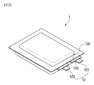
以下、添付図面を参照して、本発明の好ましい実施形態を詳細に説明することにする。図1は、本発明の一実施形態に係るパウチ型二次電池1の組み立て図であり、図2は、本発明の一実施形態に係るパウチ型二次電池1の斜視図である。
Hereinafter, preferred embodiments of the present invention will be described in detail with reference to the accompanying drawings. FIG. 1 is an assembly diagram of a pouch-type
本発明の一実施形態に係るパウチ型二次電池1は、図1に示されたように、正極、負極などの電極およびセパレータが積層されて形成される電極組立体10と、前記電極組立体10を内部に収容するパウチ型の電池ケース13とを含む。
As shown in FIG. 1, a pouch-type
パウチ型二次電池1を製造するために、先ず、電極活物質とバインダーおよび可塑剤を混合したスラリーを正極集電体および負極集電体に塗布し、正極および負極などの電極を製造する。それをセパレータ(Separator)の両側に積層することで所定形状の電極組立体10を形成した後、電極組立体10を電池ケース13に挿入し電解液の注入後にシールする。
To manufacture the pouch-type
具体的に、電極組立体(Electrode Assembly)10は、正極および負極の2種類の電極と、電極を互いに絶縁させるために電極の間に介在されるかまたは何れか1つの電極の左側または右側に配置されるセパレータとを備えた積層構造体であってもよい。前記積層構造体は、所定規格の正極と負極がセパレータを間に置いて積層されてもよく、ゼリーロール(Jelly Roll)形態で巻取りできるなど、制限されずに多様な形態であってもよい。2種類の電極、すなわち、正極および負極は、それぞれアルミニウムおよび銅を含む金属箔または金属メッシュ状の電極集電体に活物質スラリーが塗布された構造である。スラリーは、通常、粒状の活物質、補助導体、バインダー、および可塑剤などが、溶媒が添加された状態で撹拌されて形成されてもよい。溶媒は、後続工程において除去される。
Specifically, the
電極組立体10は、図1に示されたように、電極タブ(Electrode Tab)11を含む。電極タブ11は、電極組立体10の正極および負極とそれぞれ連結され、電極組立体10の外部に突出しており、電極組立体10の内部と外部との間に電子が移動可能な経路となる。電極組立体10の集電体は、電極活物質が塗布された部分と、電極活物質が塗布されていない末端部分、すなわち、無地部から構成される。そして、電極タブ11は、無地部を裁断して形成されるか、または無地部に別の導電部材を超音波溶接などにより連結して形成されてもよい。かかる電極タブ11は、図1に示されたように、電極組立体10の一側から同じ方向に並んで突出してもよいが、これに制限されず、それぞれ異なる方向に突出してもよい。
As shown in FIG. 1, the
電極組立体10の電極タブ11には、電極リード(Electrode Lead)12がスポット(Spot)溶接などにより連結される。そして、電極リード12の一部は、絶縁部14により周りが囲まれる。絶縁部14は、電池ケース13の上部ケース131および下部ケース132が熱融着されるシール部134に限定されて位置し、電池ケース13に接着される。そして、電極組立体10から生成される電気が電極リード12を通して電池ケース13に流れるのを防止し、電池ケース13のシーリングを維持する。よって、かかる絶縁部14は、電気がよく通じない非導電性を有する不導体から製造される。一般的に、絶縁部14としては、電極リード12に付着しやすく、厚さが比較的に薄い絶縁テープを多く用いるが、これに制限されず、電極リード12を絶縁可能であれば多様な部材を用いてもよい。
The
電極リード12は、正極タブ111に一端が連結され、正極タブ111が突出した方向に延びる正極リード121と、負極タブ112に一端が連結され、負極タブ112が突出した方向に延びる負極リード122とを含む。一方、正極リード121および負極リード122は、図1に示されたように、何れも他端が電池ケース13の外部に突出する。それにより、電極組立体10の内部で生成された電気を外部に供給することができる。また、正極タブ111および負極タブ112がそれぞれ多様な方向に向かって突出形成されるため、正極リード121および負極リード122もそれぞれ多様な方向に向かって延びることができる。
The
正極リード121および負極リード122は、その材質が互いに異なってもよい。すなわち、正極リード121は、正極集電体と同一のアルミニウム(Al)材質であり、負極リード122は、負極集電体と同一の銅(Cu)材質またはニッケル(Ni)がコーティングされた銅材質であってもよい。そして、電池ケース13の外部に突出した電極リード12の一部分は、端子部となり、外部端子と電気的に連結される。
The
電池ケース13は、柔軟性を有する材質から製造されたパウチである。そして、電池ケース13は、電極リード12の一部、すなわち、端子部が露出されるように電極組立体10を収容しシールされる。かかる電池ケース13は、図1に示されたように、上部ケース131および下部ケース132とを含む。下部ケース132には、カップ部133が形成されて電極組立体10を収容可能な収容空間1331が備えられ、上部ケース131は、前記電極組立体10が電池ケース13の外部に離脱しないように前記収容空間1331を上部からカバーする。この際、図1に示されたように、上部ケース131にも収容空間1331が備えられたカップ部133が形成され、電極組立体10を上部から収容してもよい。但し、これに制限されず、カップ部133が下部ケース132にのみ形成されるなど、多様に形成されてもよい。また、上部ケース131および下部ケース132は、図1に示されたように一側が互いに連結されて製造されてもよいが、これに制限されず、互いに分離されて別に製造されるなど、多様に製造されてもよい。
The
電池ケース13は、ガスが透過するガス排出部136を含む。ガス排出部136は、カップ部133またはシール部134のうち少なくとも一方に穿孔されて形成されたホール137に、内側に付着される。
The
ホール137は、上部ケース131または下部ケース132のうち少なくとも一方に形成される。すなわち、ホール137は、1つのみ形成されてもよいが、複数で形成されてもよい。そして、図1に示されたように、カップ部133の外側方向に延長形成されたシール部134は、カップ部133に隣接した内側領域1341と、前記内側領域1341よりも外側に位置して縁となり、シールされることで前記カップ部133を密閉する外側領域1342とを含む。この際、ホール137は、シール部134において、外側領域1342よりは内側領域1341に形成されることが好ましい。そして、その後にシール部134をシールする際、ホール137が位置した内側領域1341はシールせず、外側領域1342のみをシールすることが好ましい。それにより、普段は、上部および下部ケース131、132の2つのシール部134が互いに接してホール137を閉鎖して、外部の水分浸透および内部の電解液漏れを防止することができる。そして、二次電池1の内部でガスが多く発生する際には、二次電池1の体積が膨張しつつ、互いに接していた2つのシール部134の内側領域1341が離隔する。すると、ホール137が開放され、ガスがガス排出部136を通して外部に排出されることができる。但し、これに制限されず、ホール137は、カップ部133の一面に形成されるなど、ガスを容易に排出可能であれば、多様な位置に形成されてもよい。
The
ガス排出部136を通して、ガスは容易に透過することができるが、水、電解液などの液体は透過することが容易ではないことが好ましい。ガス排出部136に関する詳しい説明は後述する。
Gas can easily pass through the
電極組立体10の電極タブ11に電極リード12が連結され、電極リード12の一部分に絶縁部14が形成されると、下部ケース132のカップ部133に備えられた収容空間1331に電極組立体10が収容され、上部ケース131が前記空間を上部からカバーする。そして、内部に電解液を注入し、上部ケース131および下部ケース132の縁に形成されたシール部134をシールする。電解液は、二次電池1の充放電時、電極の電気化学的反応により生成されるリチウムイオンを移動させるためのものであり、リチウム塩と高純度の有機溶媒類との混合物である非水系有機電解液、または高分子電解質を用いたポリマーを含んでもよい。かかる方法により、図2に示されたように、パウチ型二次電池1を製造することができる。
When the
図3は、本発明の一実施形態に係るガス排出部136の断面図である。ガス排出部136は、カップ部133またはシール部134のうち少なくとも一方に穿孔されて形成されたホール137に、内側に付着され、ガスが透過する。かかるガス排出部136は、図3に示されたように、ガスが透過するガス排出層1362と、ガス排出層1362の外側面に形成され、疎水性を有する外部機能性層1361とを含む。また、ガス排出層1362の内側面に形成され、疎水性を有する内部機能性層1363をさらに含んでもよい。
Figure 3 is a cross-sectional view of a
ガス排出層1362は、ガスは容易に透過することができるが、水、電解液などの液体は透過することが容易ではない半透膜(Semipermeable Membrane)からなることが好ましい。かかるガス排出層1362は、ポリプロピレン(PP)、ポリエチレン(PE)、ポリテトラフルオロエチレン(PTFE)、ポリフッ化ビニリデン(PVDF)のうち少なくとも1つを含んでもよい。そして、かかるガス排出層1362を製造するために、二軸延伸方法を用いてもよい。すなわち、前記材質が含まれた元の素材を用いてフィルム状に押出した後、押出方向(MD、Mechanical Diraction)および垂直方向(Transverse Direction)にそれぞれ延伸を行ってガス排出層1362を製造してもよい。但し、これに制限されず、相分離方法を用いてもよい。すなわち、前記材質が含まれた元の素材をフィルム状にプレートに塗布し、温度を異にして溶媒を蒸発させた後、前記別の溶液が充填された水槽に浸漬させてガス排出層1362を製造してもよい。
The
本発明の一実施形態によると、電池ケース13に形成されたホール137を開閉する別のカバーは存在しない。仮にカバーが存在するのであれば、カバーがホール137を開放した後に再びホール137を閉鎖することが容易ではない。そして、これを解決するためには、カバーがホール137を開閉するように別のヒンジを設けなければならないなど、構造が複雑となり、耐久性が低下し得る。ところで、カバーが存在しないのであれば、いくらガス排出層1362を通して液体が透過することが容易ではないとしても、ガス排出層1362を通して少量の水分が外部から浸透し得る。
According to one embodiment of the present invention, there is no separate cover that opens and closes the
したがって、図3に示されたように、ガス排出層1362の外側面に、疎水性を有する外部機能性層1361が形成される。ここで、ガス排出層1362の外側面とは、二次電池1が製造された際、二次電池1の外側、すなわち、電極組立体10の反対に向かう方向に形成された面をいう。
Therefore, as shown in FIG. 3, an external
本発明の一実施形態によると、かかる外部機能性層1361は、外側面に複数の微細突起が分布してもよい。すると、複数の微細突起が外部機能性層1361の外側面において水分の凝縮を妨害し、疎水性を有することができる。ここで、外部機能性層1361の外側面は、ガス排出層1362と接着された面の反対面をいう。微細突起の直径は50nm~10μm、好ましくは、直径が100nm~1μmであってもよい。仮に微細突起の直径が過度に小さいのであれば、疎水性が低下し得るし、直径が過度に大きいのであれば、その後にガス排出部136とパウチフィルム135との間の融着力が低下し得るためである。
According to one embodiment of the present invention, the outer
かかる微細突起が分布するために、外部機能性層1361には微細粒子が含まれ、微細粒子は、シリカ粒子、カーボンナノチューブ(CNT)、アルミナ粒子のうち少なくとも1つを含んでもよく、特にカーボンナノチューブ(CNT)を含むことが最も好ましい。ところで、外部機能性層1361は、疎水性を有しなければならないが、シリカ粒子は、親水性を有する。よって、仮に微細粒子がシリカ粒子を含むのであれば、約0.1~2wt%以下の非常に少ない量だけを含むことが好ましい。
To distribute these fine protrusions, the outer
一方、本発明の他の実施形態によると、外部機能性層1361は、オイルまたはワックス成分を有してもよい。オイルまたはワックスは、水分と混合されない親油性を有するため、疎水性を有することができる。ここで、オイルは、フッ化炭素オイル、シリコンオイル、炭素系オイル、脂肪酸アミドのうち少なくとも1つを含んでもよく、ワックスは、パラフィンワックス、炭素系ワックスのうち少なくとも1つを含んでもよい。
Meanwhile, according to another embodiment of the present invention, the outer
仮にホール137にカバーが存在しないのであれば、少量の水分だけが浸透するのではなく、ガス排出層1362を通して少量の電解液が内部から漏出し得る。よって、図3に示されたように、ガス排出層1362の内側面に、疎水性を有する内部機能性層1363が形成されてもよい。ここで、ガス排出層1362の内側面とは、二次電池1が製造された際、二次電池1の内側、すなわち、電極組立体10に向かう方向に形成された面をいう。
If there is no cover on the
本発明の一実施形態によると、内部機能性層1363も、外側面に複数の微細突起が分布してもよい。このために、内部機能性層1363にも微細粒子が含まれ、微細粒子は、シリカ粒子、カーボンナノチューブ(CNT)、アルミナ粒子のうち少なくとも1つを含んでもよい。ここで、内部機能性層1363の外側面は、ガス排出層1362と接着された面の反対面をいう。
According to one embodiment of the present invention, the inner
一方、本発明の他の実施形態によると、内部機能性層1363は、オイルまたはワックス成分を有してもよい。ここで、オイルは、フッ化炭素オイル、シリコンオイル、炭素系オイル、脂肪酸アミドのうち少なくとも1つを含んでもよい。このように、外部機能性層1361および内部機能性層1363が形成されることで、外部の水分浸透および内部の電解液漏れをさらに効果的に防止することができる。
Meanwhile, according to another embodiment of the present invention, the inner
図4は、本発明の一実施形態に係るガス排出部136を製造する方法を示したフローチャートである。
本発明の一実施形態に係るガス排出部136を製造する方法は、ガスが透過するガス排出層1362を備えるステップと、微細粒子および高分子溶液を撹拌して混合物を製造するステップと、前記ガス排出層1362の少なくとも一面に、前記混合物を噴射するステップと、前記混合物を乾燥するステップとを含む。
FIG. 4 is a flow chart illustrating a method of manufacturing a
A method for manufacturing a
具体的に、先ず、ガスが透過するガス排出層1362を備える(S401)。かかるガス排出層1362は、上記で記述したように、ガスは容易に透過することができるが、水、電解液などの液体は透過することが容易ではない半透膜(Semipermeable Membrane)からなることが好ましい。かかるガス排出層1362は、ポリプロピレン(PP)、ポリエチレン(PE)、ポリテトラフルオロエチレン(PTFE)、ポリフッ化ビニリデン(PVDF)のうち少なくとも1つを含んでもよい。
Specifically, first, a
そして、微細粒子および高分子溶液を撹拌して混合物を製造する(S402)。ここで、微細粒子は、シリカ粒子、カーボンナノチューブ(CNT)、アルミナ粒子のうち少なくとも1つを含んでもよい。ところで、外部機能性層1361は、疎水性を有しなければならないが、シリカ粒子は、親水性を有する。よって、仮にシリカ粒子を含むのであれば、約0.1~2wt%以下の非常に少ない量だけを含むことが好ましい。そして、微細粒子の直径は50nm~10μm、好ましくは、直径が100nm~1μmであってもよい。仮に微細粒子の直径が過度に小さい場合は、疎水性が低下し得るし、直径が過度に大きい場合は、その後にガス排出部136とパウチフィルム135との間の融着力が低下し得るためである。
Then, the fine particles and the polymer solution are stirred to produce a mixture (S402). Here, the fine particles may include at least one of silica particles, carbon nanotubes (CNTs), and alumina particles. Meanwhile, the outer
高分子溶液は、ポリプロピレン(PP)、ポリエチレン(PE)、ポリテトラフルオロエチレン(PTFE)、ポリフッ化ビニリデン(PVDF)のうち少なくとも1つを含んでもよい。すなわち、高分子溶液はガス排出層1362と同一または類似した材質を含むため、外部機能性層1361または内部機能性層1363がガス排出層1362に容易に積層されることができる。
The polymer solution may include at least one of polypropylene (PP), polyethylene (PE), polytetrafluoroethylene (PTFE), and polyvinylidene fluoride (PVDF). That is, since the polymer solution includes a material that is the same as or similar to the
そして、ガス排出層1362の少なくとも一面に、前記混合物を噴射する(S403)。仮にガス排出層1362の外側面に噴射するのであれば、外部機能性層1361が形成され、ガス排出層1362の内側面に噴射するのであれば、内部機能性層1363が形成される。
Then, the mixture is sprayed onto at least one surface of the gas exhaust layer 1362 (S403). If the mixture is sprayed onto the outer surface of the
混合物を噴射する際には、スプレーコーティング方法を用いてもよい。例えば、ガス排出層1362から約8~15cm、特に10cm離れた距離から、ノズルを用いて約0.2~0.5MPaの圧力、特に0.4MPaの圧力で前記混合物を噴射してもよい。但し、これに制限されず、多様なコーティング方法を用いてもよい。
When spraying the mixture, a spray coating method may be used. For example, the mixture may be sprayed using a nozzle at a distance of about 8 to 15 cm, particularly 10 cm, from the
その次、熱を印加して混合物を乾燥する(S404)。この際、印加する熱の温度が過度に低いと、混合物の乾燥に過度に多くの時間がかかり、温度が過度に高いと、ガス排出層1362の形状が変形し得る。よって、50~140℃、特に50~100℃の温度で熱を印加することが好ましい。
Next, heat is applied to dry the mixture (S404). If the temperature of the applied heat is too low, it will take too long to dry the mixture, and if the temperature is too high, the shape of the
それにより、外部機能性層1361または内部機能性層1363が形成されることができる。そして、前記S403~S404ステップは、2~4回繰り返し行われてもよい。
As a result, an outer
図5は、本発明の一実施形態に係るパウチフィルム135の断面図である。本発明の一実施形態によると、電池ケース13にホール137が穿孔され、かかるホール137にガスが透過するガス排出部136が付着されており、二次電池1の内部圧力が増加すると、内部のガスを外部に排出して圧力を調節することができる。また、ガス排出部136に外部機能性層1361または内部機能性層1363が形成されており、外部の水分浸透および内部の電解液漏れを防止することができる。また、ガス排出部136がホール137に内側から付着されており、ホール137の内周面1371に露出されたガスバリア層1351の金属が、電解液により腐食するのを防止することができる。
Figure 5 is a cross-sectional view of a
このために、本発明の一実施形態によると、二次電池1用の電池ケース13は、電極およびセパレータが積層されて形成される電極組立体10を収容する収容空間1331が備えられたカップ部133と、前記カップ部133の外側方向に延長形成されるシール部134と、前記カップ部133または前記シール部134のうち少なくとも一方に穿孔されて形成されたホール137に、内側に付着され、ガスが透過するガス排出部136とを含み、この際、前記ガス排出部136は、ガスが透過するガス排出層1362と、前記ガス排出層1362の外面に形成され、疎水性を有する外部機能性層1361とを含む。また、前記ガス排出層1362の内側面に形成され、疎水性を有する内部機能性層1363をさらに含んでもよい。
For this purpose, according to one embodiment of the present invention, the
電池ケース13を製造するために、先ず、パウチフィルム135をドローイング(Drawing)成形して延伸させ、カップ部133を形成する。かかるパウチフィルム135は、図5に示されたように、ガスバリア層(Gas Barrier Layer)1351、表面保護層(Surface Protection Layer)1352、およびシーラント層(Sealant Layer)1353を含む。
To manufacture the
ガスバリア層1351は、電池ケース13の機械的強度を確保し、二次電池1外部のガスまたは水分などの出入りを遮断し、電解液の漏れを防止する。一般的に、ガスバリア層1351は、金属を含み、主にアルミニウム薄膜(Al Foil)が用いられることが好ましい。アルミニウムは、所定レベル以上の機械的強度を確保可能でありながらも、重さが軽く、電極組立体10と電解液による電気化学的性質に対する補完および放熱性などを確保することができる。但し、これに制限されず、多様な材質がガスバリア層1351に含まれてもよい。例えば、鉄(Fe)、炭素(C)、クロム(Cr)、マンガン(Mn)、ニッケル(Ni)、およびアルミニウム(Al)からなる群から選択される1種以上の物質であってもよい。この際、前記ガスバリア層1351が、鉄を含む材質から製造される場合には機械的強度が向上し、アルミニウムを含む材質とする場合には柔軟性が向上するため、それぞれの特性を考慮して用いることができる。
The
表面保護層1352は、ポリマーから製造され、最外層に位置して外部との摩擦および衝突から二次電池1を保護するとともに、電極組立体10を外部から電気的に絶縁させる。ここで、最外層とは、前記ガスバリア層1351を基準に電極組立体10が位置する方向の反対方向に、最も遠く位置した層をいう。かかる表面保護層1352を製造するポリマーは、ポリエチレン、ポリプロピレン、ポリカーボネート、ポリエチレンテレフタレート、ポリ塩化ビニル、アクリル系高分子、ポリアクリロニトリル、ポリイミド、ポリアミド、セルロース、アラミド、ナイロン、ポリエステル、ポリパラフェニレンベンゾビスオキサゾール、ポリアリレート、テフロン(登録商標)、およびガラス繊維からなる群から選択された1種以上の物質であってもよい。特に、主に耐摩耗性および耐熱性を有するナイロン(Nylon)樹脂またはポリエチレンテレフタレート(PET)などのポリマーが用いられることが好ましい。そして、表面保護層1352は、何れか1種の物質からなる単一膜構造を有するか、または2種以上の物質がそれぞれ層をなして形成された複合膜構造を有してもよい。
The surface
シーラント層1353は、ポリマーから製造され、最内層に位置して電極組立体10と直接的に接触する。ここで、最内層とは、前記ガスバリア層1351を基準に電極組立体10が位置する方向に、最も遠く位置した層をいう。よって、ガスバリア層1351は、図5に示されたように、表面保護層1352とシーラント層1353との間に積層される。シーラント層1353は、電極組立体10と直接的に接触するため絶縁性を有しなければならず、電解液とも接触するため耐食性を有しなければならない。また、内部を完全に密閉して内部と外部との間の物質移動を遮断しなければならないため、高いシール性を有しなければならない。すなわち、シーラント層1353同士が接着されたシール部134は、優れた熱接着強度を有しなければならない。一般的に、かかるシーラント層1353を製造するポリマーは、ポリエチレン、ポリプロピレン、ポリカーボネート、ポリエチレンテレフタレート、ポリ塩化ビニル、アクリル系高分子、ポリアクリロニトリル、ポリイミド、ポリアミド、セルロース、アラミド、ナイロン、ポリエステル、ポリパラフェニレンベンゾビスオキサゾール、ポリアリレート、テフロン(登録商標)、およびガラス繊維からなる群から選択された1種以上の物質であってもよい。特に、主にポリプロピレン(PP)またはポリエチレン(PE)などのポリオレフィン系樹脂が用いられることが好ましい。ポリプロピレン(PP)は、引張強度、剛性、表面硬度、耐摩耗性、耐熱性などの機械的物性と、耐食性などの化学的物性に優れており、シーラント層1353を製造するのに主に用いられる。さらに、無延伸ポリプロピレン(Cated Polypropylene)またはポリプロピレン-ブチレン-エチレン三元共重合体から構成されてもよい。また、シーラント層1353は、何れか1種の物質からなる単一膜構造を有するか、または2種以上の物質がそれぞれ層をなして形成された複合膜構造を有してもよい。
The
一方、ガスバリア層1351、表面保護層1352、およびシーラント層1353の間には、これらを互いに接着させる接着層1354がさらに形成されてもよい。上記のような積層構造のパウチフィルム135を、パンチなどを用いてドローイング(Drawing)成形すると、一部が延伸して袋状の収容空間1331を含むカップ部133が形成される。そして、カップ部133またはシール部134のうち少なくとも一方にホール137を穿孔する。
Meanwhile, an
ホール137が穿孔されると、図5に示されたように、前記製造されたガスが透過するガス排出部136が前記ホール137に内側から付着される。ホール137は、1つのみ形成されてもよいが、複数で形成されてもよいため、ガス排出部136も、それに対応して、1つのみ形成されてもよいが、複数で形成されてもよい。
Once the
この際、仮にガス排出部136が外側から付着されるのであれば、ホール137の内周面1371に露出されたガスバリア層1351の金属が、電解液により腐食し得る。よって、ガス排出部136は、前記ホール137に、内側から付着されることで、ホール137の内周面1371に露出されたガスバリア層1351の金属が、電解液により腐食するのを防止することができる。
In this case, if the
ガス排出部136がホール137に付着されると、ガス排出部136の外部機能性層1361がシーラント層1353の一面と接着され、特に電解液により容易に脱着されるのを防止するために、熱および圧力が印加されてシールされることが好ましい。よって、外部機能性層1361がシーラント層1353に容易にシールされるために、シーラント層1353と外部機能性層1361が同一または類似した材質を含むことが好ましい。
When the
カップ部133に備えられた収容空間1331に電極組立体10が内部に収容されると、電解液を注入する。その後、上部ケース131と下部ケース132を互いに接触させ、シール部134に熱圧着をすると、シーラント層1353同士が接着されることで、電池ケース13がシールされる。それにより、本発明の一実施形態に係る二次電池1を製造することができる。
When the
本発明が属する技術分野の通常の知識を有する者であれば、本発明がその技術的思想や必須の特徴を変更せず、他の具体的な形態で実施可能であることを理解することができるであろう。よって、以上で記述された実施形態は、全ての面で例示的なものであって、限定的なものではないことを理解しなければならない。本発明の範囲は上記の詳細な説明よりは後述の特許請求の範囲により示され、特許請求の範囲の意味および範囲、そしてその均等概念から導き出される多様な実施形態が本発明の範囲に含まれるものと解釈しなければならない。 Anyone with ordinary knowledge in the technical field to which the present invention pertains will understand that the present invention can be implemented in other specific forms without changing its technical concept or essential features. Therefore, it should be understood that the above-described embodiments are illustrative in all respects and are not limiting. The scope of the present invention is indicated by the claims below rather than the above detailed description, and various embodiments derived from the meaning and scope of the claims and their equivalent concepts should be interpreted as being included in the scope of the present invention.
1 パウチ型二次電池
10 電極組立体
13 電池ケース
133 カップ部
134 シール部
135 パウチフィルム
136 ガス排出部
137 ホール
1331 収容空間
1341 内側領域
1342 外側領域
1353 シーラント層
1361 外部機能性層
1362 ガス排出層
1363 内部機能性層
REFERENCE SIGNS
Claims (19)
電極およびセパレータが積層されて形成される電極組立体を収容する収容空間が備えられたカップ部と、
前記カップ部の外側方向に延長形成されるシール部と、
ガスが透過するガス排出部であって、前記カップ部または前記シール部のうち少なくとも一方に穿孔されて形成されたホールの内側に付着されたガス排出部とを含み、
前記ガス排出部は、
ガスが透過するガス排出層と、
前記ガス排出層の外側面に形成され、疎水性を有する外部機能性層とを含み、
前記外部機能性層は、
外側面に複数の微細突起が分布して形成される、パウチ型の二次電池用電池ケース。 A pouch-type battery case for a secondary battery,
a cup portion having an accommodation space for accommodating an electrode assembly formed by stacking electrodes and a separator;
a seal portion extending outwardly of the cup portion;
a gas exhaust part through which gas can pass, the gas exhaust part being attached to an inner side of a hole formed by perforating at least one of the cup part and the sealing part;
The gas exhaust section is
a gas discharge layer through which gas permeates;
an outer functional layer formed on an outer surface of the gas release layer and having hydrophobicity;
The outer functional layer is
A pouch- type battery case for a secondary battery, having a plurality of fine protrusions distributed on the outer surface.
直径が50nm~10μmである、請求項1に記載のパウチ型の二次電池用電池ケース。 The fine protrusions are
2. The pouch-type battery case for a secondary battery according to claim 1 , wherein the diameter is 50 nm to 10 μm.
直径が100nm~1μmである、請求項2に記載のパウチ型の二次電池用電池ケース。 The fine protrusions are
3. The pouch-type battery case for a secondary battery according to claim 2 , wherein the diameter is 100 nm to 1 μm.
電極およびセパレータが積層されて形成される電極組立体を収容する収容空間が備えられたカップ部と、
前記カップ部の外側方向に延長形成されるシール部と、
ガスが透過するガス排出部であって、前記カップ部または前記シール部のうち少なくとも一方に穿孔されて形成されたホールの内側に付着されたガス排出部とを含み、
前記ガス排出部は、
ガスが透過するガス排出層と、
前記ガス排出層の外側面に形成され、疎水性を有する外部機能性層とを含み、
前記外部機能性層は、
オイルまたはワックス成分を含む、パウチ型の二次電池用電池ケース。 A pouch-type battery case for a secondary battery,
a cup portion having an accommodation space for accommodating an electrode assembly formed by stacking electrodes and a separator;
a seal portion extending outwardly of the cup portion;
a gas exhaust part through which gas can pass, the gas exhaust part being attached to an inner side of a hole formed by perforating at least one of the cup part and the sealing part;
The gas exhaust section is
a gas discharge layer through which gas permeates;
an outer functional layer formed on an outer surface of the gas release layer and having hydrophobicity;
The outer functional layer is
A pouch- type battery case for a secondary battery, containing an oil or wax component.
フッ化炭素オイル、シリコンオイル、炭素系オイル、脂肪酸アミドのうち少なくとも1つを含む、請求項4に記載のパウチ型の二次電池用電池ケース。 The oil is
5. The pouch-type battery case for a secondary battery according to claim 4 , comprising at least one of a fluorocarbon oil, a silicone oil, a carbon-based oil, and a fatty acid amide.
ポリプロピレン(PP)、ポリエチレン(PE)、ポリテトラフルオロエチレン(PTFE)、ポリフッ化ビニリデン(PVDF)のうち少なくとも1つを含む、請求項1~5の何れか一項に記載のパウチ型の二次電池用電池ケース。 The gas exhaust layer is
The pouch-type battery case for a secondary battery according to any one of claims 1 to 5 , comprising at least one of polypropylene (PP), polyethylene (PE), polytetrafluoroethylene (PTFE), and polyvinylidene fluoride (PVDF).
前記カップ部に隣接した内側領域と、
前記内側領域よりも外側に位置して縁となり、シールされることで前記カップ部を密閉する外側領域とを含み、
前記ホールは、
前記シール部において、前記内側領域に形成される、請求項1~7の何れか一項に記載のパウチ型の二次電池用電池ケース。 The sealing portion is
an inner region adjacent the cup portion;
an outer region that is located outside the inner region and forms a rim and is sealed to close the cup portion;
The hole is
The pouch-type battery case for a secondary battery according to claim 1 , wherein the sealed portion is formed in the inner region.
複数で形成される、請求項1~8の何れか一項に記載のパウチ型の二次電池用電池ケース。 The gas exhaust section is
The pouch-type battery case for a secondary battery according to any one of claims 1 to 8 , which is formed in a plurality of parts.
微細粒子および高分子溶液を撹拌して混合物を製造するステップと、
前記ガス排出層の少なくとも一面に、前記混合物を噴射するステップと、
前記混合物を乾燥するステップとを含む、ガス排出部の製造方法。 providing a gas-permeable gas-dissipating layer;
agitating the fine particles and the polymer solution to produce a mixture;
spraying the mixture onto at least one surface of the gas-emission layer;
and drying the mixture.
ポリプロピレン(PP)、ポリエチレン(PE)、ポリテトラフルオロエチレン(PTFE)、ポリフッ化ビニリデン(PVDF)のうち少なくとも1つを含む、請求項10に記載のガス排出部の製造方法。 The gas exhaust layer is
The method for manufacturing a gas exhaust section according to claim 10 , wherein the material includes at least one of polypropylene (PP), polyethylene (PE), polytetrafluoroethylene (PTFE), and polyvinylidene fluoride (PVDF).
ポリプロピレン(PP)、ポリエチレン(PE)、ポリテトラフルオロエチレン(PTFE)、ポリフッ化ビニリデン(PVDF)のうち少なくとも1つを含む、請求項10または11に記載のガス排出部の製造方法。 The polymer solution is
The method for manufacturing a gas exhaust section according to claim 10 or 11 , wherein the material contains at least one of polypropylene (PP), polyethylene (PE), polytetrafluoroethylene (PTFE), and polyvinylidene fluoride (PVDF).
シリカ粒子、カーボンナノチューブ(CNT)、アルミナ粒子のうち少なくとも1つを含む、請求項10に記載のガス排出部の製造方法。 The fine particles are
The method for manufacturing a gas exhaust portion according to claim 10 , wherein the material contains at least one of silica particles, carbon nanotubes (CNTs), and alumina particles.
0.1~2wt%の範囲内で含まれる、請求項13に記載のガス排出部の製造方法。 The silica particles are
The method for manufacturing a gas exhaust portion according to claim 13 , wherein the content is within a range of 0.1 to 2 wt %.
前記ガス排出層から8~15cm離れた距離から、ノズルを用いて0.2~0.5MPaの圧力で前記混合物を噴射する、請求項10に記載のガス排出部の製造方法。 The step of injecting the mixture includes:
The method for manufacturing a gas discharge section according to claim 10 , wherein the mixture is sprayed at a pressure of 0.2 to 0.5 MPa using a nozzle from a distance of 8 to 15 cm from the gas discharge layer.
2回~4回繰り返し行われる、請求項10に記載のガス排出部の製造方法。 The steps of spraying the mixture and drying the mixture include:
The method for manufacturing a gas exhaust portion according to claim 10 , wherein the method is repeated two to four times.
前記電極組立体を内部に収容する電池ケースとを含み、
前記電池ケースは、
前記電極組立体を収容する収容空間が備えられたカップ部と、
前記カップ部の外側方向に延長形成されるシール部と、
ガスが透過するガス排出部であって、前記カップ部または前記シール部のうち少なくとも一方に穿孔されて形成されたホールの内側に付着されたガス排出部とを含み、
前記ガス排出部は、
ガスが透過するガス排出層と、
前記ガス排出層の外側面に形成され、疎水性を有する外部機能性層とを含み、
前記外部機能性層が外側面に複数の微細突起が分布して形成されるか、またはオイルまたはワックス成分を有する、パウチ型二次電池。 an electrode assembly formed by stacking electrodes and separators;
a battery case that houses the electrode assembly therein,
The battery case is
a cup portion having an accommodation space for accommodating the electrode assembly;
a seal portion extending outwardly of the cup portion;
a gas exhaust part through which gas can pass, the gas exhaust part being attached to an inner side of a hole formed by perforating at least one of the cup part and the sealing part;
The gas exhaust section is
a gas discharge layer through which gas permeates;
an outer functional layer formed on an outer surface of the gas release layer and having hydrophobicity;
The pouch-type secondary battery , wherein the external functional layer is formed with a plurality of fine protrusions distributed on the outer surface, or has an oil or wax component.
前記カップ部または前記カップ部の外側方向に延長形成されるシール部のうち少なくとも一方に、ホールを穿孔するステップと、
前記ホールに、ガスが透過するガス排出部を内側に付着するステップと、
前記カップ部に備えられた収容空間に、電極およびセパレータが積層されて形成される電極組立体が収容されるステップと、
前記シール部に熱圧着をするステップとを含み、
前記ガス排出部は、
ガスが透過するガス排出層と、
前記ガス排出層の外側面に形成され、疎水性を有する外部機能性層とを含み、
前記外部機能性層が外側面に複数の微細突起が分布して形成されるか、またはオイルまたはワックス成分を有する、パウチ型二次電池の製造方法。 forming a cup portion by drawing the pouch film;
Drilling a hole in at least one of the cup portion and a sealing portion extending outwardly of the cup portion;
attaching a gas exhaust part through which gas can pass to the inside of the hole;
receiving an electrode assembly formed by stacking electrodes and a separator in a receiving space of the cup portion;
The step of thermally compressing the sealed portion is included.
The gas exhaust section is
a gas discharge layer through which gas permeates;
an outer functional layer formed on an outer surface of the gas release layer and having hydrophobicity;
The outer functional layer is formed with a plurality of fine protrusions distributed on an outer surface thereof, or has an oil or wax component.
ポリマーから製造され、最内層に位置するシーラント層を含み、
前記ガス排出部を付着するステップにおいて、
前記外部機能性層が、前記シーラント層に熱および圧力が印加されてシールされる、請求項18に記載のパウチ型二次電池の製造方法。 The pouch film is
a sealant layer made of a polymer and positioned at an innermost layer;
In the step of attaching the gas exhaust portion,
The method for manufacturing a pouch-type secondary battery according to claim 18 , wherein the outer functional layer is sealed by applying heat and pressure to the sealant layer.
Priority Applications (1)
| Application Number | Priority Date | Filing Date | Title |
|---|---|---|---|
| JP2023208570A JP2024015341A (en) | 2019-08-27 | 2023-12-11 | Battery case for secondary battery, and method of manufacturing gas exhaustion part |
Applications Claiming Priority (3)
| Application Number | Priority Date | Filing Date | Title |
|---|---|---|---|
| KR1020190105417A KR20210025405A (en) | 2019-08-27 | 2019-08-27 | The Case For Secondary Battery And The Method For Manufacturing Gas Discharger |
| KR10-2019-0105417 | 2019-08-27 | ||
| PCT/KR2020/011270 WO2021040357A1 (en) | 2019-08-27 | 2020-08-24 | Battery case for secondary battery and manufacturing method of gas discharge part |
Related Child Applications (1)
| Application Number | Title | Priority Date | Filing Date |
|---|---|---|---|
| JP2023208570A Division JP2024015341A (en) | 2019-08-27 | 2023-12-11 | Battery case for secondary battery, and method of manufacturing gas exhaustion part |
Publications (2)
| Publication Number | Publication Date |
|---|---|
| JP2022543691A JP2022543691A (en) | 2022-10-13 |
| JP7466975B2 true JP7466975B2 (en) | 2024-04-15 |
Family
ID=74683837
Family Applications (2)
| Application Number | Title | Priority Date | Filing Date |
|---|---|---|---|
| JP2022507871A Active JP7466975B2 (en) | 2019-08-27 | 2020-08-24 | Method for manufacturing battery case for secondary battery and gas exhaust part |
| JP2023208570A Pending JP2024015341A (en) | 2019-08-27 | 2023-12-11 | Battery case for secondary battery, and method of manufacturing gas exhaustion part |
Family Applications After (1)
| Application Number | Title | Priority Date | Filing Date |
|---|---|---|---|
| JP2023208570A Pending JP2024015341A (en) | 2019-08-27 | 2023-12-11 | Battery case for secondary battery, and method of manufacturing gas exhaustion part |
Country Status (6)
| Country | Link |
|---|---|
| US (1) | US20220336922A1 (en) |
| EP (2) | EP4002569A4 (en) |
| JP (2) | JP7466975B2 (en) |
| KR (2) | KR20210025405A (en) |
| CN (1) | CN114175368A (en) |
| WO (1) | WO2021040357A1 (en) |
Families Citing this family (4)
| Publication number | Priority date | Publication date | Assignee | Title |
|---|---|---|---|---|
| EP4322301A4 (en) * | 2021-12-16 | 2024-07-31 | Contemporary Amperex Technology Co Ltd | Exhaust device, battery cell, battery, and electrical device |
| EP4290660A1 (en) * | 2021-12-16 | 2023-12-13 | Contemporary Amperex Technology Co., Limited | Battery cell, battery, electric apparatus, manufacturing method and manufacturing device |
| CN117337513A (en) * | 2022-05-02 | 2024-01-02 | 株式会社 Lg新能源 | Gas releasing member and secondary battery including the same |
| WO2024106944A1 (en) * | 2022-11-15 | 2024-05-23 | 주식회사 엘지에너지솔루션 | Gas-permeable film, pouch exterior material containing same, and secondary battery |
Citations (3)
| Publication number | Priority date | Publication date | Assignee | Title |
|---|---|---|---|---|
| JP2011108433A (en) | 2009-11-16 | 2011-06-02 | Sumitomo Heavy Ind Ltd | Power storage device |
| US20170274416A1 (en) | 2014-09-02 | 2017-09-28 | Sung Wung YEOM | Applying a Coating to a Substrate; Composite Structures formed by Application of a Coating |
| WO2018110067A1 (en) | 2016-12-16 | 2018-06-21 | 株式会社村田製作所 | Secondary cell, cell pack, electric vehicle, power storage system, electric tool, and electronic device |
Family Cites Families (18)
| Publication number | Priority date | Publication date | Assignee | Title |
|---|---|---|---|---|
| JPS5714367U (en) * | 1980-06-26 | 1982-01-25 | ||
| WO1998017746A1 (en) | 1996-10-24 | 1998-04-30 | Fibervisions A/S | Polyolefin fibres and method for the production thereof |
| JP4604441B2 (en) * | 2002-07-18 | 2011-01-05 | 日本電気株式会社 | Film-clad battery and manufacturing method thereof |
| JP3889029B1 (en) | 2006-02-10 | 2007-03-07 | 株式会社パワーシステム | Structure of venting part of electronic parts |
| JP5127258B2 (en) | 2007-02-08 | 2013-01-23 | 株式会社オプトニクス精密 | Gas permeable safety valve and electrochemical element |
| JP5479203B2 (en) | 2010-04-28 | 2014-04-23 | Jmエナジー株式会社 | Power storage device |
| KR20120076914A (en) * | 2010-12-30 | 2012-07-10 | 주식회사 효성 | Process of fabricating hydrophilic membrane by blending carbon nanotube particles |
| KR20150034498A (en) * | 2013-09-26 | 2015-04-03 | 주식회사 엘지화학 | Battery cell with venting cover and Secondary battery comprising the same |
| KR20150135878A (en) * | 2014-05-26 | 2015-12-04 | 킴스테크날리지 주식회사 | Electrochemical Cell with Gas Permeable Membrane |
| JP6106343B2 (en) | 2014-06-16 | 2017-03-29 | 日東電工株式会社 | Hydrogen discharge membrane |
| KR101976171B1 (en) * | 2015-07-22 | 2019-08-28 | 주식회사 엘지화학 | Lithium Metal Foil and Manufacturing Method thereof, Removing Method of Film of Lithium Metal Foil |
| KR102112670B1 (en) | 2015-10-28 | 2020-05-19 | 주식회사 엘지화학 | Battery Cell of Venting Structure Using Taping |
| JP6784509B2 (en) | 2016-05-16 | 2020-11-11 | 株式会社Snt | Textile products and coated articles |
| KR102217448B1 (en) * | 2017-07-13 | 2021-02-22 | 주식회사 엘지화학 | The Secondary Battery And The Method For Manufacturing Therefore |
| KR102425151B1 (en) | 2017-10-16 | 2022-07-26 | 주식회사 엘지에너지솔루션 | Secondary Battery Pouch-Type Case Having Gas Discharge Port |
| KR20210025406A (en) * | 2019-08-27 | 2021-03-09 | 주식회사 엘지화학 | The Case For Secondary Battery And The Method For Manufacturing Pouch Type Secondary Battery |
| KR20210025407A (en) * | 2019-08-27 | 2021-03-09 | 주식회사 엘지화학 | The Case For Secondary Battery And The Method For Manufacturing Pouch Type Secondary Battery |
| KR20210075476A (en) * | 2019-12-13 | 2021-06-23 | 주식회사 엘지에너지솔루션 | Pouch-type Battery Cell Having Venting Part and Method for Preparing the Same |
-
2019
- 2019-08-27 KR KR1020190105417A patent/KR20210025405A/en not_active Application Discontinuation
-
2020
- 2020-08-24 EP EP20857350.1A patent/EP4002569A4/en active Pending
- 2020-08-24 EP EP23211646.7A patent/EP4303989A3/en active Pending
- 2020-08-24 JP JP2022507871A patent/JP7466975B2/en active Active
- 2020-08-24 US US17/630,272 patent/US20220336922A1/en active Pending
- 2020-08-24 WO PCT/KR2020/011270 patent/WO2021040357A1/en unknown
- 2020-08-24 CN CN202080053430.3A patent/CN114175368A/en active Pending
-
2023
- 2023-12-11 JP JP2023208570A patent/JP2024015341A/en active Pending
-
2024
- 2024-04-17 KR KR1020240051715A patent/KR20240054255A/en active Application Filing
Patent Citations (3)
| Publication number | Priority date | Publication date | Assignee | Title |
|---|---|---|---|---|
| JP2011108433A (en) | 2009-11-16 | 2011-06-02 | Sumitomo Heavy Ind Ltd | Power storage device |
| US20170274416A1 (en) | 2014-09-02 | 2017-09-28 | Sung Wung YEOM | Applying a Coating to a Substrate; Composite Structures formed by Application of a Coating |
| WO2018110067A1 (en) | 2016-12-16 | 2018-06-21 | 株式会社村田製作所 | Secondary cell, cell pack, electric vehicle, power storage system, electric tool, and electronic device |
Also Published As
| Publication number | Publication date |
|---|---|
| US20220336922A1 (en) | 2022-10-20 |
| JP2022543691A (en) | 2022-10-13 |
| EP4002569A1 (en) | 2022-05-25 |
| WO2021040357A1 (en) | 2021-03-04 |
| JP2024015341A (en) | 2024-02-01 |
| EP4002569A4 (en) | 2022-10-26 |
| CN114175368A (en) | 2022-03-11 |
| EP4303989A2 (en) | 2024-01-10 |
| KR20210025405A (en) | 2021-03-09 |
| KR20240054255A (en) | 2024-04-25 |
| EP4303989A3 (en) | 2024-08-07 |
Similar Documents
| Publication | Publication Date | Title |
|---|---|---|
| JP7466975B2 (en) | Method for manufacturing battery case for secondary battery and gas exhaust part | |
| US20220263166A1 (en) | Battery Case For Secondary Battery And Method For Manufacturing Pouch Type Secondary Battery | |
| KR20130097881A (en) | Method for manufacturing a secondary battery and the secondary battery manufactured thereby | |
| KR101273472B1 (en) | Manufacturing method for pouch-type secondary battery and pouch-type secondary battery made by the same | |
| JP2020510978A (en) | Pouch type secondary battery | |
| JP7508137B2 (en) | Secondary battery and seal block | |
| KR20140012601A (en) | Secondary battery and electrochemical cell having the same | |
| JP7515951B2 (en) | Electrode assembly and manufacturing method thereof | |
| JP7325892B2 (en) | Battery case for secondary battery and method for manufacturing pouch-type secondary battery | |
| JP2021517710A (en) | Pouch for secondary battery and pouch type secondary battery | |
| KR101174919B1 (en) | Lithium rechargeable battery | |
| JP7378880B2 (en) | Secondary batteries and their repair methods | |
| US20240322362A1 (en) | Battery Case For Secondary Battery And Method For Manufacturing Gas Discharge Part | |
| KR101458259B1 (en) | Pouch type secondary battery and method for manufacturing the same | |
| US20240266645A1 (en) | Pouch Film Stack and Secondary Battery | |
| KR101975988B1 (en) | Pouch for secondary battery and Pouch-typed secondary battery comprising the same | |
| KR20210097483A (en) | The Secondary Battery And The Method For Manufacturing Thereof | |
| KR20240082888A (en) | Manufacturing method for pouch type secondary battery | |
| KR20230050976A (en) | Pouch type battery case and secondary battery including the same | |
| KR20170006046A (en) | Pouch type secondary cell |
Legal Events
| Date | Code | Title | Description |
|---|---|---|---|
| A621 | Written request for application examination |
Free format text: JAPANESE INTERMEDIATE CODE: A621 Effective date: 20220208 |
|
| A977 | Report on retrieval |
Free format text: JAPANESE INTERMEDIATE CODE: A971007 Effective date: 20230215 |
|
| A131 | Notification of reasons for refusal |
Free format text: JAPANESE INTERMEDIATE CODE: A131 Effective date: 20230227 |
|
| A601 | Written request for extension of time |
Free format text: JAPANESE INTERMEDIATE CODE: A601 Effective date: 20230529 |
|
| A521 | Request for written amendment filed |
Free format text: JAPANESE INTERMEDIATE CODE: A523 Effective date: 20230628 |
|
| A131 | Notification of reasons for refusal |
Free format text: JAPANESE INTERMEDIATE CODE: A131 Effective date: 20230911 |
|
| A521 | Request for written amendment filed |
Free format text: JAPANESE INTERMEDIATE CODE: A523 Effective date: 20231211 |
|
| TRDD | Decision of grant or rejection written | ||
| A01 | Written decision to grant a patent or to grant a registration (utility model) |
Free format text: JAPANESE INTERMEDIATE CODE: A01 Effective date: 20240304 |
|
| A61 | First payment of annual fees (during grant procedure) |
Free format text: JAPANESE INTERMEDIATE CODE: A61 Effective date: 20240328 |
|
| R150 | Certificate of patent or registration of utility model |
Ref document number: 7466975 Country of ref document: JP Free format text: JAPANESE INTERMEDIATE CODE: R150 |