JP7465249B2 - Screw Spindle Pump - Google Patents
Screw Spindle Pump Download PDFInfo
- Publication number
- JP7465249B2 JP7465249B2 JP2021189794A JP2021189794A JP7465249B2 JP 7465249 B2 JP7465249 B2 JP 7465249B2 JP 2021189794 A JP2021189794 A JP 2021189794A JP 2021189794 A JP2021189794 A JP 2021189794A JP 7465249 B2 JP7465249 B2 JP 7465249B2
- Authority
- JP
- Japan
- Prior art keywords
- spindle
- driven
- screw
- drive
- pump according
- Prior art date
- Legal status (The legal status is an assumption and is not a legal conclusion. Google has not performed a legal analysis and makes no representation as to the accuracy of the status listed.)
- Active
Links
- 238000000576 coating method Methods 0.000 claims description 35
- 239000011248 coating agent Substances 0.000 claims description 33
- 238000007789 sealing Methods 0.000 claims description 26
- 239000012530 fluid Substances 0.000 claims description 15
- 239000000463 material Substances 0.000 claims description 9
- 239000000126 substance Substances 0.000 claims description 8
- 239000000919 ceramic Substances 0.000 claims description 7
- 235000013305 food Nutrition 0.000 claims description 7
- 229920002943 EPDM rubber Polymers 0.000 claims description 4
- 229920006168 hydrated nitrile rubber Polymers 0.000 claims description 4
- 235000011837 pasties Nutrition 0.000 claims description 4
- 239000004810 polytetrafluoroethylene Substances 0.000 claims description 4
- 229920001343 polytetrafluoroethylene Polymers 0.000 claims description 4
- UUAGAQFQZIEFAH-UHFFFAOYSA-N chlorotrifluoroethylene Chemical compound FC(F)=C(F)Cl UUAGAQFQZIEFAH-UHFFFAOYSA-N 0.000 claims description 3
- 239000002131 composite material Substances 0.000 claims description 3
- 239000002537 cosmetic Substances 0.000 claims description 3
- 239000003814 drug Substances 0.000 claims description 3
- 229920001774 Perfluoroether Polymers 0.000 claims description 2
- 229910052581 Si3N4 Inorganic materials 0.000 claims description 2
- 229940079593 drug Drugs 0.000 claims description 2
- 229920001973 fluoroelastomer Polymers 0.000 claims description 2
- 239000006223 plastic coating Substances 0.000 claims description 2
- 229920000642 polymer Polymers 0.000 claims description 2
- -1 polytetrafluoroethylene Polymers 0.000 claims description 2
- 239000002210 silicon-based material Substances 0.000 claims description 2
- QDOXWKRWXJOMAK-UHFFFAOYSA-N dichromium trioxide Chemical compound O=[Cr]O[Cr]=O QDOXWKRWXJOMAK-UHFFFAOYSA-N 0.000 claims 2
- 239000002184 metal Substances 0.000 claims 1
- 238000005086 pumping Methods 0.000 claims 1
- 230000002441 reversible effect Effects 0.000 description 8
- 238000004140 cleaning Methods 0.000 description 5
- 239000000314 lubricant Substances 0.000 description 5
- 238000006073 displacement reaction Methods 0.000 description 4
- 229910000831 Steel Inorganic materials 0.000 description 3
- 229910010293 ceramic material Inorganic materials 0.000 description 3
- 239000006071 cream Substances 0.000 description 3
- 239000010959 steel Substances 0.000 description 3
- 230000005540 biological transmission Effects 0.000 description 2
- 238000013461 design Methods 0.000 description 2
- 239000003599 detergent Substances 0.000 description 2
- 238000010586 diagram Methods 0.000 description 2
- 238000010348 incorporation Methods 0.000 description 2
- 239000007788 liquid Substances 0.000 description 2
- 238000000034 method Methods 0.000 description 2
- 239000004033 plastic Substances 0.000 description 2
- 238000005096 rolling process Methods 0.000 description 2
- 230000001360 synchronised effect Effects 0.000 description 2
- 235000011330 Armoracia rusticana Nutrition 0.000 description 1
- 240000003291 Armoracia rusticana Species 0.000 description 1
- 244000056139 Brassica cretica Species 0.000 description 1
- 235000003351 Brassica cretica Nutrition 0.000 description 1
- 235000003343 Brassica rupestris Nutrition 0.000 description 1
- 229920000049 Carbon (fiber) Polymers 0.000 description 1
- 108010010803 Gelatin Proteins 0.000 description 1
- XUIMIQQOPSSXEZ-UHFFFAOYSA-N Silicon Chemical compound [Si] XUIMIQQOPSSXEZ-UHFFFAOYSA-N 0.000 description 1
- QKSKPIVNLNLAAV-UHFFFAOYSA-N bis(2-chloroethyl) sulfide Chemical compound ClCCSCCCl QKSKPIVNLNLAAV-UHFFFAOYSA-N 0.000 description 1
- 235000014121 butter Nutrition 0.000 description 1
- 239000004917 carbon fiber Substances 0.000 description 1
- 235000013351 cheese Nutrition 0.000 description 1
- 235000019219 chocolate Nutrition 0.000 description 1
- 239000012459 cleaning agent Substances 0.000 description 1
- 230000003749 cleanliness Effects 0.000 description 1
- 230000006835 compression Effects 0.000 description 1
- 238000007906 compression Methods 0.000 description 1
- 238000010276 construction Methods 0.000 description 1
- 235000013365 dairy product Nutrition 0.000 description 1
- 238000011161 development Methods 0.000 description 1
- 238000004851 dishwashing Methods 0.000 description 1
- 235000013399 edible fruits Nutrition 0.000 description 1
- 235000013601 eggs Nutrition 0.000 description 1
- 239000003925 fat Substances 0.000 description 1
- 235000019197 fats Nutrition 0.000 description 1
- 238000011010 flushing procedure Methods 0.000 description 1
- 229920000159 gelatin Polymers 0.000 description 1
- 239000008273 gelatin Substances 0.000 description 1
- 235000019322 gelatine Nutrition 0.000 description 1
- 235000011852 gelatine desserts Nutrition 0.000 description 1
- 239000003365 glass fiber Substances 0.000 description 1
- 235000012907 honey Nutrition 0.000 description 1
- 230000002706 hydrostatic effect Effects 0.000 description 1
- 235000008960 ketchup Nutrition 0.000 description 1
- 235000021056 liquid food Nutrition 0.000 description 1
- 230000007774 longterm Effects 0.000 description 1
- 239000006210 lotion Substances 0.000 description 1
- 230000001050 lubricating effect Effects 0.000 description 1
- 238000005461 lubrication Methods 0.000 description 1
- 239000008268 mayonnaise Substances 0.000 description 1
- 235000010746 mayonnaise Nutrition 0.000 description 1
- 239000012528 membrane Substances 0.000 description 1
- 235000021243 milk fat Nutrition 0.000 description 1
- 235000010460 mustard Nutrition 0.000 description 1
- 235000015145 nougat Nutrition 0.000 description 1
- 235000014571 nuts Nutrition 0.000 description 1
- 239000003921 oil Substances 0.000 description 1
- 235000019198 oils Nutrition 0.000 description 1
- 239000003973 paint Substances 0.000 description 1
- 235000014059 processed cheese Nutrition 0.000 description 1
- 238000012545 processing Methods 0.000 description 1
- 229910052710 silicon Inorganic materials 0.000 description 1
- 239000010703 silicon Substances 0.000 description 1
- 239000000344 soap Substances 0.000 description 1
- 239000006188 syrup Substances 0.000 description 1
- 235000020357 syrup Nutrition 0.000 description 1
- 235000015112 vegetable and seed oil Nutrition 0.000 description 1
- 239000008158 vegetable oil Substances 0.000 description 1
- 235000013618 yogurt Nutrition 0.000 description 1
Images

Classifications
-
- F—MECHANICAL ENGINEERING; LIGHTING; HEATING; WEAPONS; BLASTING
- F04—POSITIVE - DISPLACEMENT MACHINES FOR LIQUIDS; PUMPS FOR LIQUIDS OR ELASTIC FLUIDS
- F04C—ROTARY-PISTON, OR OSCILLATING-PISTON, POSITIVE-DISPLACEMENT MACHINES FOR LIQUIDS; ROTARY-PISTON, OR OSCILLATING-PISTON, POSITIVE-DISPLACEMENT PUMPS
- F04C2/00—Rotary-piston machines or pumps
- F04C2/08—Rotary-piston machines or pumps of intermeshing-engagement type, i.e. with engagement of co-operating members similar to that of toothed gearing
- F04C2/12—Rotary-piston machines or pumps of intermeshing-engagement type, i.e. with engagement of co-operating members similar to that of toothed gearing of other than internal-axis type
- F04C2/14—Rotary-piston machines or pumps of intermeshing-engagement type, i.e. with engagement of co-operating members similar to that of toothed gearing of other than internal-axis type with toothed rotary pistons
- F04C2/16—Rotary-piston machines or pumps of intermeshing-engagement type, i.e. with engagement of co-operating members similar to that of toothed gearing of other than internal-axis type with toothed rotary pistons with helical teeth, e.g. chevron-shaped, screw type
-
- F—MECHANICAL ENGINEERING; LIGHTING; HEATING; WEAPONS; BLASTING
- F01—MACHINES OR ENGINES IN GENERAL; ENGINE PLANTS IN GENERAL; STEAM ENGINES
- F01C—ROTARY-PISTON OR OSCILLATING-PISTON MACHINES OR ENGINES
- F01C21/00—Component parts, details or accessories not provided for in groups F01C1/00 - F01C20/00
- F01C21/10—Outer members for co-operation with rotary pistons; Casings
- F01C21/104—Stators; Members defining the outer boundaries of the working chamber
- F01C21/108—Stators; Members defining the outer boundaries of the working chamber with an axial surface, e.g. side plates
-
- F—MECHANICAL ENGINEERING; LIGHTING; HEATING; WEAPONS; BLASTING
- F04—POSITIVE - DISPLACEMENT MACHINES FOR LIQUIDS; PUMPS FOR LIQUIDS OR ELASTIC FLUIDS
- F04C—ROTARY-PISTON, OR OSCILLATING-PISTON, POSITIVE-DISPLACEMENT MACHINES FOR LIQUIDS; ROTARY-PISTON, OR OSCILLATING-PISTON, POSITIVE-DISPLACEMENT PUMPS
- F04C15/00—Component parts, details or accessories of machines, pumps or pumping installations, not provided for in groups F04C2/00 - F04C14/00
- F04C15/0003—Sealing arrangements in rotary-piston machines or pumps
- F04C15/0023—Axial sealings for working fluid
-
- F—MECHANICAL ENGINEERING; LIGHTING; HEATING; WEAPONS; BLASTING
- F04—POSITIVE - DISPLACEMENT MACHINES FOR LIQUIDS; PUMPS FOR LIQUIDS OR ELASTIC FLUIDS
- F04C—ROTARY-PISTON, OR OSCILLATING-PISTON, POSITIVE-DISPLACEMENT MACHINES FOR LIQUIDS; ROTARY-PISTON, OR OSCILLATING-PISTON, POSITIVE-DISPLACEMENT PUMPS
- F04C15/00—Component parts, details or accessories of machines, pumps or pumping installations, not provided for in groups F04C2/00 - F04C14/00
- F04C15/0088—Lubrication
-
- F—MECHANICAL ENGINEERING; LIGHTING; HEATING; WEAPONS; BLASTING
- F04—POSITIVE - DISPLACEMENT MACHINES FOR LIQUIDS; PUMPS FOR LIQUIDS OR ELASTIC FLUIDS
- F04C—ROTARY-PISTON, OR OSCILLATING-PISTON, POSITIVE-DISPLACEMENT MACHINES FOR LIQUIDS; ROTARY-PISTON, OR OSCILLATING-PISTON, POSITIVE-DISPLACEMENT PUMPS
- F04C2/00—Rotary-piston machines or pumps
- F04C2/08—Rotary-piston machines or pumps of intermeshing-engagement type, i.e. with engagement of co-operating members similar to that of toothed gearing
- F04C2/12—Rotary-piston machines or pumps of intermeshing-engagement type, i.e. with engagement of co-operating members similar to that of toothed gearing of other than internal-axis type
- F04C2/14—Rotary-piston machines or pumps of intermeshing-engagement type, i.e. with engagement of co-operating members similar to that of toothed gearing of other than internal-axis type with toothed rotary pistons
- F04C2/16—Rotary-piston machines or pumps of intermeshing-engagement type, i.e. with engagement of co-operating members similar to that of toothed gearing of other than internal-axis type with toothed rotary pistons with helical teeth, e.g. chevron-shaped, screw type
- F04C2/165—Rotary-piston machines or pumps of intermeshing-engagement type, i.e. with engagement of co-operating members similar to that of toothed gearing of other than internal-axis type with toothed rotary pistons with helical teeth, e.g. chevron-shaped, screw type having more than two rotary pistons with parallel axes
-
- F—MECHANICAL ENGINEERING; LIGHTING; HEATING; WEAPONS; BLASTING
- F04—POSITIVE - DISPLACEMENT MACHINES FOR LIQUIDS; PUMPS FOR LIQUIDS OR ELASTIC FLUIDS
- F04C—ROTARY-PISTON, OR OSCILLATING-PISTON, POSITIVE-DISPLACEMENT MACHINES FOR LIQUIDS; ROTARY-PISTON, OR OSCILLATING-PISTON, POSITIVE-DISPLACEMENT PUMPS
- F04C2230/00—Manufacture
- F04C2230/60—Assembly methods
- F04C2230/602—Gap; Clearance
-
- F—MECHANICAL ENGINEERING; LIGHTING; HEATING; WEAPONS; BLASTING
- F04—POSITIVE - DISPLACEMENT MACHINES FOR LIQUIDS; PUMPS FOR LIQUIDS OR ELASTIC FLUIDS
- F04C—ROTARY-PISTON, OR OSCILLATING-PISTON, POSITIVE-DISPLACEMENT MACHINES FOR LIQUIDS; ROTARY-PISTON, OR OSCILLATING-PISTON, POSITIVE-DISPLACEMENT PUMPS
- F04C2230/00—Manufacture
- F04C2230/90—Improving properties of machine parts
- F04C2230/91—Coating
-
- F—MECHANICAL ENGINEERING; LIGHTING; HEATING; WEAPONS; BLASTING
- F04—POSITIVE - DISPLACEMENT MACHINES FOR LIQUIDS; PUMPS FOR LIQUIDS OR ELASTIC FLUIDS
- F04C—ROTARY-PISTON, OR OSCILLATING-PISTON, POSITIVE-DISPLACEMENT MACHINES FOR LIQUIDS; ROTARY-PISTON, OR OSCILLATING-PISTON, POSITIVE-DISPLACEMENT PUMPS
- F04C2240/00—Components
- F04C2240/50—Bearings
-
- F—MECHANICAL ENGINEERING; LIGHTING; HEATING; WEAPONS; BLASTING
- F04—POSITIVE - DISPLACEMENT MACHINES FOR LIQUIDS; PUMPS FOR LIQUIDS OR ELASTIC FLUIDS
- F04C—ROTARY-PISTON, OR OSCILLATING-PISTON, POSITIVE-DISPLACEMENT MACHINES FOR LIQUIDS; ROTARY-PISTON, OR OSCILLATING-PISTON, POSITIVE-DISPLACEMENT PUMPS
- F04C2270/00—Control; Monitoring or safety arrangements
- F04C2270/17—Tolerance; Play; Gap
Landscapes
- Engineering & Computer Science (AREA)
- Mechanical Engineering (AREA)
- General Engineering & Computer Science (AREA)
- Rotary Pumps (AREA)
- Details And Applications Of Rotary Liquid Pumps (AREA)
- Reciprocating Pumps (AREA)
Description
本発明は、ハウジング及びその中に収容された駆動スピンドルと、それぞれ2つの末端にある端面を有し、駆動スピンドルと噛み合う少なくとも1つの従動スピンドルと、を備えるスクリュースピンドルポンプに関する。 The present invention relates to a screw spindle pump having a housing, a drive spindle housed therein, and at least one driven spindle having end faces at each of two ends and meshing with the drive spindle.
スクリュースピンドルポンプは、異なった物質、主に流体媒体を搬送するために使用される。既知のように、スクリュースピンドルポンプはスピンドル一式(Spindelpaket)が入ったハウジングを備え、スピンドル一式は、ハウジングから延出した、場合によっては伝動装置を介在させて駆動モータと結合されている駆動スピンドルと、1つ又は複数の従動スピンドルと、を備え、従動スピンドルのスピンドルプロファイルが駆動スピンドルのスピンドルプロファイルと噛み合い、従動スピンドルが駆動スピンドルによって駆動される。スピンドル一式が収容されたハウジングは、外に対して閉ざされもしたポンプハウジングであり得るか、又は外側ハウジング内への挿入物として設計されたハウジングであり得る。 Screw spindle pumps are used to transport different substances, mainly fluid media. As is known, they comprise a housing containing a spindle packet, which comprises a drive spindle extending from the housing and possibly connected to a drive motor via a transmission, and one or more driven spindles, the spindle profile of which meshes with the spindle profile of the drive spindle and which are driven by the drive spindle. The housing in which the spindle packet is accommodated can be a pump housing that is also closed to the outside, or it can be a housing designed as an insert into the outer housing.
通常、1つ又は複数の、大抵の場合は2つ平行に、かつ180°ずらして駆動スピンドルの隣に配置された従動スピンドルは、軸方向に液圧支持され(hydraulisch abgestutzt)、そのために、それぞれの従動スピンドルの端面に隣接してノズルオリフィスを設けることができ、このノズルオリフィスを介して、搬送されるべき流体の引き込まれた部分がスピンドル端面に向かって流れ、これにより軸方向支持圧が発生し、この支持圧によりそれぞれの従動スピンドルが軸方向に支持される。これは、ハウジングが相応に形成されること、及び相応のノズルオリフィスを前提とし、ハウジング内では適切な流路を介して相応の流体供給が提供される必要があり、ノズルオリフィスは、相応の流体圧を生成するために幾何学的にも相応に設計及び指定される必要がある。 Usually, one or more, usually two parallel, driven spindles arranged next to the driving spindle, offset by 180°, are hydraulically supported in the axial direction, for which purpose a nozzle orifice can be provided adjacent to the end face of each driven spindle, through which the drawn-in part of the fluid to be conveyed flows towards the spindle end face, thus generating an axial support pressure, by which the respective driven spindle is axially supported. This presupposes that the housing is appropriately shaped and that there are appropriate nozzle orifices, in which an appropriate fluid supply must be provided via suitable flow paths, and that the nozzle orifices must also be geometrically designed and designated accordingly in order to generate the appropriate fluid pressure.
スクリュースピンドルポンプは、食品分野や医薬品分野での使用が増えつつあり、これはスクリュースピンドルポンプを用いて相応の流動性食品や薬剤が搬送されることを意味する。このような物質を扱う作業は、最高レベルの衛生状態を必要とし、そのため使用されるスクリュースピンドルポンプも相応に短い間隔で洗浄されなければならない。相応の流路などを備える従動スピンドルを軸方向に支持するために、スクリュースピンドルポンプは流体の誘導を考慮して複雑に形成されていることから、すべての領域の洗浄を確保するためには、洗浄のためにスクリュースピンドルポンプを取外し、分解し、洗浄することが必要である。なぜなら、追加の流路、ノズルオリフィスなどが組み込まれることにより、本来の搬送プロセスには関与しないが流体にさらされるかなりの容積が、いわばデッドスペースとして存在するからである。 Screw spindle pumps are increasingly being used in the food and pharmaceutical sectors, which means that the corresponding liquid food products and medicines are conveyed using screw spindle pumps. Working with such substances requires the highest level of hygiene, which is why the screw spindle pumps used must also be cleaned at correspondingly short intervals. Due to the complex design of the screw spindle pumps with regard to the fluid guidance, in order to axially support the driven spindle with the corresponding flow paths etc., it is necessary to dismantle, dismantle and clean the screw spindle pumps for cleaning in order to ensure that all areas are cleaned. This is because, due to the incorporation of additional flow paths, nozzle orifices etc., a considerable volume exists that is not involved in the actual conveying process but is exposed to the fluid, so to speak as dead space.
したがって、本発明の課題は、改良されたスクリュースピンドルポンプを提供することである。 Therefore, the object of the present invention is to provide an improved screw spindle pump.
この問題を解決するために、本発明により、冒頭で述べた種類のスクリュースピンドルポンプにおいて、従動スピンドルの少なくとも1つの端面に軸方向に隣接して当接面(Anlaufflache)が設けられ、従動スピンドルが軸方向の遊びを設けて当接面に対して垂直方向に変位可能に収容されていることが企図される。 To solve this problem, the present invention provides that in a screw spindle pump of the type mentioned at the beginning, an abutment surface is provided axially adjacent to at least one end face of the driven spindle, and the driven spindle is accommodated with axial play so as to be displaceable perpendicularly to the abutment surface.
本発明によるスクリュースピンドルポンプでは、流体による軸推力平衡(hydraulischer axialer Schbausgleich)は企図されない。むしろ、上記の、又は、例えば2つの従動スピンドルが設けられている場合には各従動スピンドルには少なくとも片側に軸方向にそれぞれ1つの当接面が割り当てられ、従動スピンドルは、この当接面に対してわずかな軸方向遊びを設けて収容されている。したがって、この当接面(単数又は複数)は、本来のポンプ室内に入っている。動作中、駆動スピンドルが駆動される。プロファイル係合又は流体圧力にもとづいて、駆動スピンドルとともに1つ又は2つの従動スピンドルも回転し、それによりポンプ室を通じて流体搬送が行われる。駆動スピンドル自体は十分に液圧平衡され(hydraulisch ausgeglichen)、すなわち動作に伴う軸方向力は駆動スピンドルに作用しないか、又は無視できる程度に作用する。これは、駆動スピンドルをハウジングに対して密封するシール要素の加圧される、すなわち圧力下にある面と駆動スピンドルプロファイルの加圧されるプロファイル面とが実質的に同じであることにより達成される。2つの面が異なる方向で軸方向に加圧されるため、それによって力がつり合い、そのことが、駆動スピンドルが液圧平衡されることをもたらす。動作中、従動スピンドルは、ポンプ圧の結果として、当接面又は当接面のうちの1つの方向にごくわずかに軸方向にずれる。ポンプが正逆回転可能(reversierbar)でない場合、従動スピンドルは、動作中に吸込側にわずかに変位するので、当接面は、従動スピンドルの吸込側又は吸込側端部に設けられる。ポンプが正逆回転可能である場合、従動スピンドルごとに2つの当接面が設けられ、それにより搬送方向、したがって従動スピンドルの運動方向に応じて、両側に1つの当接面が設けられる。駆動スピンドルポンプが搬送方向に関して正逆回転可能である場合、このずれ(Versatz)は作動方向に応じて、一方又は他方の当接面に生じる。このずれは、軸方向遊びが小さいことによって可能になり、生じる最大のずれを考慮して軸方向遊びを指定することができる。従動スピンドルのそれぞれの端面は、動作中にそれぞれの軸方向当接ディスク(Anlaufscheibe)に向かって動くことができ、そこでそれぞれの端面は、理想的には薄い流体潤滑膜(hydraulischer Schmierfilm)を介して支承されるか、又はそれぞれの端面が当接面に向かって動く場合には無視できる摩擦しか生じない。これは、当接面に当接するにもかかわらず、上記のように当接面がポンプ室内にあるために、一方で、搬送されるべき流体により相応の支承及び潤滑が生じ、他方で摩耗の心配がないことを意味する。 In the screw spindle pump according to the invention, no hydraulic balancing of the axial thrust is intended. Instead, in the case of the above-mentioned or, for example, two driven spindles, each driven spindle is assigned an axial bearing surface on at least one side, against which the driven spindle is accommodated with a small axial play. The bearing surface or surfaces are thus located within the actual pump chamber. During operation, the drive spindle is driven. Due to the profile engagement or the fluid pressure, the one or two driven spindles also rotate together with the drive spindle, so that a fluid conveyance takes place through the pump chamber. The drive spindle itself is fully hydraulically balanced, i.e. the axial forces involved in operation do not act on the drive spindle or act only to a negligible extent. This is achieved by the fact that the pressurized, i.e. under pressure, surface of the sealing element that seals the drive spindle against the housing and the pressurized profile surface of the drive spindle profile are substantially the same. Since the two surfaces are axially pressurized in different directions, the forces are balanced, which results in the drive spindle being hydraulically balanced. During operation, the driven spindle is very slightly axially displaced in the direction of the abutment surface or one of the abutment surfaces as a result of the pump pressure. If the pump is not reversible, the driven spindle is slightly displaced in the suction side during operation, so that the abutment surface is provided on the suction side or on the suction end of the driven spindle. If the pump is reversible, two abutment surfaces are provided per driven spindle, so that one abutment surface is provided on both sides depending on the conveying direction and thus on the movement direction of the driven spindle. If the drive spindle pump is reversible with respect to the conveying direction, this deviation occurs on one or the other abutment surface depending on the operating direction. This deviation is made possible by the small axial play, which can be specified taking into account the maximum deviation that can occur. During operation, the respective end faces of the driven spindle can move against the respective axial abutment disks, where they are ideally supported via a thin hydrodynamic lubricant film, or where negligible friction occurs when the respective end faces move against the abutment surface. This means that, despite the abutment against the abutment surface, since the abutment surface is in the pump chamber as described above, on the one hand, there is adequate support and lubrication by the fluid to be conveyed, and on the other hand, no wear is to be expected.
したがって、本発明によるスクリュースピンドルポンプは、一方で、従動スピンドルの相応の軸方向の支持を可能にするが、そのために2つの当接ディスクを組み込む他には特別な措置をなにも企図しない。搬送されるべき流体が流れる唯一の容積はポンプ室であり、ポンプ室はいわばデッドスペース最適化されている。これによってもまた、本発明によるスクリュースピンドルポンプが洗浄時に分解される必要がなくなり、洗浄過程を組付け状態で行うことができ、その後に洗浄液がポンプ室を相応に問題なく洗い流すことができる。これは、本発明によるスクリュースピンドルポンプをもってすれば、いわゆる「Cleaning in Place(CIP)」が可能であることを意味する。 Thus, the screw spindle pump according to the invention allows, on the one hand, a corresponding axial support of the driven spindle, without any special measures being envisaged for this purpose apart from the incorporation of two abutment discs. The only volume through which the fluid to be conveyed flows is the pump chamber, which is, so to speak, dead-space optimized. This also means that the screw spindle pump according to the invention does not have to be dismantled when cleaning, but the cleaning process can be carried out in the assembled state, after which the cleaning fluid can flush the pump chamber accordingly and without problems. This means that with the screw spindle pump according to the invention so-called "Cleaning in Place (CIP)" is possible.
すでに述べたように、ポンプが正逆回転可能でない場合、1つの従動スピンドル又は各従動スピンドルの吸込側の端面にのみ当接面を割り当てることができる。ポンプが正逆回転可能である場合、従動スピンドルの2つの端面に軸方向に隣接して当接面を設けることができ、その場合、従動スピンドルは、軸方向の遊びを設けて2つの当接面間に収容される。 As already mentioned, if the pump is not reversible, the abutment surface can be assigned only to the suction end face of one or each driven spindle. If the pump is reversible, the abutment surfaces can be provided axially adjacent to two end faces of the driven spindle, in which case the driven spindle is accommodated between the two abutment surfaces with axial play.
上記のように、スピンドル一式は液圧的に同期され、すなわちスピンドル一式が動作中に自動的に調整される。特に、駆動スピンドルと従動スピンドルとの間に機械的な力の伝達が生じないか、又は無視できる程度に生じ、その結果、運転中の従動スピンドルの軸方向のずれが最小限になる。したがって、従動スピンドルと軸方向の当接面との間の軸方向の遊びも相応に、当然、スクリュースピンドルポンプの所与のサイズに応じて相応に小さく指定することができる。軸方向の遊びは、小さいサイズのスクリュースピンドルポンプでの0.3mmから、非常に大きいサイズのスクリュースピンドルポンプでの5.0mmであり、好ましくは、遊びは1.0~3.0mmの範囲である。遊びは、従動スピンドルの生じる軸方向のずれを考慮して指定され、上記の値は、それぞれ、それぞれの従動スピンドルが2つの当接ディスク間に有する全遊びである。 As mentioned above, the spindle set is hydraulically synchronized, i.e. the spindle set is automatically adjusted during operation. In particular, no or negligible mechanical force transmission occurs between the driving spindle and the driven spindle, so that the axial deviation of the driven spindle during operation is minimal. The axial play between the driven spindle and the axial abutment surface can therefore also be specified accordingly, naturally correspondingly small depending on the given size of the screw spindle pump. The axial play ranges from 0.3 mm for small screw spindle pumps to 5.0 mm for very large screw spindle pumps, preferably the play is in the range of 1.0-3.0 mm. The play is specified taking into account the resulting axial deviation of the driven spindle, the above values being respectively the total play that the respective driven spindle has between the two abutment disks.
当接面の実現に関して、様々な可能性が企図される。したがって、上記又は各当接面をハウジング上のコーティングによって形成することができる。ここでは、すなわちハウジング側に1つ又は複数の相応のハウジング肩部が設けられ、これらのハウジング肩部は、ハウジング肩部のコーティングによって実現される当接面のための基部を形成する。あるいは、上記又は各当接面は、当接ディスクによって実現することもできる。この場合、当接面を実現するために、ハウジング内の対応する位置に特殊な当接ディスクが設置される。当接ディスクの厚さにより遊びを非常に正確に調整することができる。 Various possibilities are envisaged for the realisation of the abutment surface. Thus, the or each abutment surface can be produced by a coating on the housing. In this case, i.e. the housing side is provided with one or more corresponding housing shoulders, which form the base for the abutment surface produced by the coating of the housing shoulder. Alternatively, the or each abutment surface can be produced by an abutment disk. In this case, a special abutment disk is provided at the corresponding position in the housing to produce the abutment surface. The thickness of the abutment disk allows the play to be adjusted very precisely.
当接面として、好ましくは極めて摩耗しにくい面が企図され、すなわち相応に摩耗しにくい材料が使用される。このために、セラミック若しくは炭化物の材料、又はセラミック若しくは炭化物の材料を含む複合材料からなるコーティング又は当接ディスクが適している。これは、基本的に、場合によってはガラス繊維又は炭素繊維で強化され得る工業用セラミックが使用されることを意味する。セラミック材料又はシリコンベースの工業用セラミックが使用されることが目的に合っており、このために、特にSiC若しくはSi3N4、又はWCが適し、この材料を上記のように必要に応じて繊維強化することもできる。Cr2O3の使用も考えられる。これに代えて、コーティングを形成するために超硬合金を使用することができ、同様に、当接ディスク(単数又は複数)が超硬合金からなることができるか、又は硬化した表面を有することもできる。硬度は少なくとも1000HVであるべきである。したがって、当接面若しくはコーティング、又は軸方向ディスクは、上述のように理想的には静水圧潤滑膜を介して当接面若しくはコーティング又は当接ディスク上に滑り支承される(gleitgelagert)鋼製の、好ましくはコールスタライジング処理又は冷窒化処理された従動スピンドルと同様に摩耗しにくい。 As the abutment surface, a surface that is highly wear-resistant is preferably intended, i.e. a material that is correspondingly wear-resistant is used. For this purpose, a coating or abutment disk made of a ceramic or carbide material or a composite material that contains a ceramic or carbide material is suitable. This basically means that technical ceramics are used, which may be reinforced with glass or carbon fibers. It is expedient to use ceramic materials or technical ceramics based on silicon, for which, in particular, SiC or Si 3 N 4 or WC are suitable, which materials can also be fiber-reinforced as required as described above. The use of Cr 2 O 3 is also conceivable. Alternatively, cemented carbide can be used to form the coating, and the abutment disk(s) can also be made of cemented carbide or have a hardened surface. The hardness should be at least 1000 HV. The abutment surface or coating or the axial disk is therefore as resistant to wear as the driven spindle, preferably made of steel and preferably cold sterilized or cold nitrided, which is slidingly supported on the abutment surface or coating or the abutment disk via a hydrostatic lubricant film as described above.
上記又は各従動スピンドルは、駆動スピンドルを収容する駆動スピンドルボアと重なる対応する従動スピンドルボアに収容され、1つ又は2つの従動スピンドルボアは1つ又は2つの軸方向ハウジング肩部により軸方向に画定され、1つ又は2つの軸方向ハウジング肩部にそれぞれの当接面が形成されるか、又は当接ディスクが支持されている。したがって、ハウジング内には定義された肩部が設けられ、これらの肩部はコーティング(単数又は複数)の支持体として、又は当接ディスクのための軸方向の支持箇所として用いられる。すなわちそのようなハウジング肩部にコーティングが直接設けられるか、又はそのようなハウジング肩部に当接ディスクが接触する。その場合、2つのハウジング肩部の軸方向距離を非常に正確に定義及び調整することができ、それにより定義された幾何学的関係が成立し、別個の当接ディスクを使用した場合にそれぞれの従動スピンドルの軸方向の遊びも、相応の当接ディスク厚さを選択することによって相応に正確に調整することができる。 The or each driven spindle is accommodated in a corresponding driven spindle bore which overlaps with the driving spindle bore which accommodates the driving spindle, the or each driven spindle bore being axially defined by one or two axial housing shoulders on which the respective abutment surfaces are formed or on which the abutment disks are supported. Thus, defined shoulders are provided in the housing, which serve as supports for the coating(s) or as axial support points for the abutment disks, i.e. the coating is provided directly on such a housing shoulder or the abutment disks contact such a housing shoulder. In that case, the axial distance between the two housing shoulders can be very precisely defined and adjusted, so that a defined geometric relationship is established, and the axial play of the respective driven spindle in the case of the use of separate abutment disks can also be adjusted correspondingly precisely by selecting the corresponding abutment disk thickness.
上述のように、駆動スピンドルは、駆動スピンドルを一方向に押し動かし、次いで従動スピンドルの変位をもたらすような軸方向力が駆動スピンドルにそれほど作用しないように、液圧平衡されていることが好ましい。いわば軸方向に浮動(fliegend)支持された従動スピンドルは、ポンプハウジング内に発生する圧力だけで、軸方向遊びを利用してわずかに軸方向に動かされ、その限りでプロファイル係合を可能にする。その場合、駆動スピンドル及び従動スピンドルは、駆動スピンドルとハウジングとの間を密封するシール要素、好ましくは単一のシール要素を介して駆動スピンドルの駆動側に対して密封されているポンプ室に収容されている。これは、ポンプ室の片側がただ1つのシール要素で密封されることを意味する。したがって、本発明によれば、このシール要素は、シール要素の軸方向に加圧される面が駆動スピンドル又は駆動スピンドルプロファイルの軸方向に加圧される面に実質的に相当するように、駆動スピンドルの寸法及びジオメトリに関して選択又は指定されている。これにより、軸方向の液圧平衡が行われ、この液圧平衡はスピンドル一式の液圧同期(hydraulische Synchronisierung)、及び動作中に生じる軸方向の従動スピンドルのずれの最小化に関して特に有利であることが明らかになった。駆動スピンドルが貫通する環状シール要素の加圧される面は、つまりは駆動スピンドルの、ポンプ室に向いた軸方向の環状面に相当する。従動スピンドルの2つのスピンドルプロファイルにスピンドルプロファイルが係合する結果として、駆動スピンドルの加圧される面は、スピンドル長手方向視で、既知のようにスピンドルコアから径方向に突出するスピンドルプロファイルの、部分的に鎌形の複数の面区分によって構成される。2つの加圧される面の差異は、最大10%、殊に単に最大5%であり、理想的には当然、ゼロであるべきであり、それにより、生じたとしても、結果としてわずかな軸方向力しか生じず、この軸方向力は、駆動スピンドルの軸方向ずれも、スピンドル支承部へのさほどの荷重ももたらさない。 As mentioned above, the drive spindle is preferably hydraulically balanced so that axial forces acting on it do not act so much, which would push it in one direction and then result in a displacement of the driven spindle. The driven spindle, which is supported so to speak axially floating, is moved slightly axially with the aid of axial play only by the pressure generated in the pump housing, to the extent that it allows profile engagement. In that case, the drive spindle and the driven spindle are accommodated in a pump chamber, which is sealed against the drive side of the drive spindle via a sealing element, preferably a single sealing element, which seals between the drive spindle and the housing. This means that one side of the pump chamber is sealed with only one sealing element. Thus, according to the invention, this sealing element is selected or specified with respect to the dimensions and geometry of the drive spindle, so that the axially pressurized surface of the sealing element substantially corresponds to the axially pressurized surface of the drive spindle or the drive spindle profile. This results in an axial hydraulic balancing, which has proven to be particularly advantageous with regard to the hydraulic synchronization of the spindle set and the minimization of the axial displacement of the driven spindle during operation. The pressurized surface of the annular sealing element through which the drive spindle passes corresponds to the axial annular surface of the drive spindle facing the pump chamber. As a result of the engagement of the spindle profile with the two spindle profiles of the driven spindle, the pressurized surface of the drive spindle, as viewed in the longitudinal direction of the spindle, is constituted by a number of partially sickle-shaped surface sections of the spindle profile which, as is known, protrudes radially from the spindle core. The difference between the two pressurized surfaces should be at most 10%, in particular only at most 5%, and ideally should of course be zero, so that, if any, only small axial forces result, which do not result in axial displacement of the drive spindle or significant loads on the spindle bearing.
シール要素自体は、好ましくはメカニカルシールであり、これは好ましくは駆動スピンドルに配置され、ハウジングにおける対応するシール部又はシール座に対して密封する。 The sealing element itself is preferably a mechanical seal, which is preferably disposed on the drive spindle and seals against a corresponding sealing portion or sealing seat in the housing.
駆動スピンドルの一部がポンプ室から延出し、駆動スピンドル自体は、ハウジングにおいて、作業スピンドル(Arbeitsspindel)及び従動スピンドルを有するポンプ室の外側で片側のみ径方向に回転支承されていることが目的に合っている。このために、ラジアル軸受が使用され、好ましくは唯一のラジアル軸受が使用されることが目的に合っている。このラジアル軸受は、玉軸受、ころ軸受、又は球面ころ軸受などの形式の単列又は複列の軸受、すなわち転がり軸受であり得る。駆動スピンドルの所与の液圧平衡と、駆動スピンドルの隣に180°ずらして配置された2つの従動スピンドルの配置とにもとづいて、動作中、相応の力平衡にもとづいてほぼ負荷がないため、ただ1つの簡単なラジアル軸受を使用することが可能である。 The drive spindle extends partly from the pump chamber, and the drive spindle itself is radially supported on one side only in the housing, outside the pump chamber with the working spindle and the driven spindle. For this purpose, a radial bearing is used, preferably only one radial bearing. This radial bearing can be a single-row or double-row bearing, i.e. a rolling bearing, in the form of a ball bearing, roller bearing or spherical roller bearing. Due to the given hydraulic balance of the drive spindle and the arrangement of the two driven spindles, which are arranged next to the drive spindle and offset by 180°, it is possible to use only one simple radial bearing, since there is practically no load during operation due to the corresponding force balance.
本発明の目的に合う一発展形態は、少なくとも上記又は各従動スピンドルボアが滑り被覆材(Gleitbelag)で内張りされ、従動スピンドルは、この滑り被覆材に対して径方向の遊びを設けて配置されている。従動スピンドルボアを滑り被覆材で内張りすることも、生じ得るデッドスペースを低減するために役立つ。通常動作中、従動スピンドルの径方向の運動は行われず、むしろスピンドル外周面と従動スピンドルボア又は滑り被覆材との間にも薄い流体潤滑膜が形成され、この潤滑膜が従動スピンドルを支承する。その場合、これは、滑り被覆材により従動スピンドルの径方向遊びを相応に小さく抑え、これによりデッドスペースを相応に低減することも可能にする。 In one development that meets the object of the invention, at least the or each driven spindle bore is lined with a sliding coating, and the driven spindle is arranged with radial play relative to this sliding coating. Lining the driven spindle bore with a sliding coating also serves to reduce possible dead spaces. During normal operation, no radial movement of the driven spindle takes place, but rather a thin hydrodynamic lubricant film is formed between the spindle outer surface and the driven spindle bore or the sliding coating, which also supports the driven spindle. This then makes it possible to keep the radial play of the driven spindle to a correspondingly small value by the sliding coating, and thus also to reduce the dead spaces accordingly.
このような滑り被覆材として、特に水素化アクリロニトリルブタジエンゴム(HNBR)、クロロトリフルオロエテン、エチレン-プロピレン-ジエン(モノマー)ゴム(EPDM)、ポリテトラフルオロエチレン(PTFE)、パーフルオロアルコキシポリマー、フッ素ゴム(FKM)、又は過フッ素ゴム(FFKM)などのプラスチック被覆材を使用することが目的に合っている。ただし、この列挙はすべてを網羅しているわけではなく、搬送される媒体を考慮して使用するのに適している限り、他の適切なプラスチック材料を使用することもできる。 As such slip coatings, it is expedient to use plastic coatings, such as hydrogenated acrylonitrile butadiene rubber (HNBR), chlorotrifluoroethene, ethylene-propylene-diene (monomer) rubber (EPDM), polytetrafluoroethylene (PTFE), perfluoroalkoxy polymers, fluororubber (FKM) or perfluororubber (FFKM). However, this list is not exhaustive and other suitable plastic materials can also be used, provided that they are suitable for use having regard to the medium to be transported.
滑り被覆材の厚さは、径方向遊びが0.01~1.00mm、特に0.05~0.5mmになるように調整されることが好ましい。これはまさに動作中にそれほどの径方向の運動が行われないという事情の結果として、この場合、極めて小さい径方向の遊びが生じることを意味する。 The thickness of the sliding coating is preferably adjusted so that the radial play is 0.01 to 1.00 mm, in particular 0.05 to 0.5 mm. This means that in this case, very little radial play occurs, precisely as a result of the fact that no significant radial movement takes place during operation.
スクリュースピンドルポンプをデッドスペース最適に指定することと並んで、軸方向遊び及び径方向遊びの最小化に関してスクリュースピンドルポンプを指定することには、さらに、スクリュースピンドルポンプの効率をこれまでの一般的なスクリュースピンドルポンプと比較して格段に、最大で数10%高めることができるという利点がある。それは遊びが最小限であるため、体積流量が広い圧力範囲にわたって一定に保たれ、所与のギャップが最小限であることから、搬送される媒体の逆流がほとんど起こらないことによるものである。これは、スクリュースピンドルポンプの衛生的な観点で極めて有利な形態とともに、格段に効率的な搬送動作が実現され得ることを意味する。 In addition to the dead-space-optimized specification of the screw spindle pump, the specification of the screw spindle pump with respect to the minimization of axial and radial play has the further advantage that the efficiency of the screw spindle pump can be significantly increased by up to several tens of percent compared to conventional screw spindle pumps up to now. This is because, due to the minimal play, the volume flow rate remains constant over a wide pressure range and, due to the minimal given gap, almost no backflow of the conveyed medium occurs. This means that a significantly more efficient conveying operation can be achieved together with a highly advantageous configuration of the screw spindle pump from a hygienic point of view.
上述のように、スクリュースピンドルポンプは特に、加工時に最高レベルの清潔さが必要とされる重要な物質を搬送するために用いられる。したがって、本発明によるスクリュースピンドルポンプは、粘流動性(zahflussig)又はペースト状の食品、医薬品、化粧品又は化学薬品を搬送するために使用される。粘流動性又はペースト状の食品は、例えば、フレッシュチーズ、クリーム、乳脂、凝乳、バター、又はヨーグルトなどの乳製品であり得る。ケチャップ、マヨネーズ、マスタードなど、西洋わさび、プロセスチーズ、植物油、とき卵、生地又は果肉や、ゼラチン、シロップ、ナッツクリーム又はヌガークリーム、チョコレート、蜂蜜、マジパンその他の油脂などのかなり粘性の(viskos)、又はペースト状の食品を搬送することも考えられる。製薬及び化粧品の分野では、搬送可能な媒体として、例えば、液体石鹸、クリーム、ローション又はそれに類するものを挙げることができる。化学分野では、例示的に、液体洗剤、食器用洗剤、洗浄剤だけでなく、塗料又はそれに類するものも挙げられる。この場合も当然、列挙は網羅的なものではないが、搬送できる材料の粘度(Viskositat)が極めて広い範囲に及ぶことを示す。搬送するために本発明によるスクリュースピンドルポンプを使用することができる搬送可能な物質の粘度は、0.5~100万kg・m-1・s-1の範囲である。 As mentioned above, screw spindle pumps are used in particular for conveying important substances which require the highest level of cleanliness during processing. The screw spindle pump according to the invention is therefore used for conveying viscofluid or pasty foods, pharmaceuticals, cosmetics or chemicals. Viscofluid or pasty foods can be, for example, dairy products such as fresh cheese, cream, milk fat, curd, butter or yogurt. It is also conceivable to convey rather viscous or pasty foods such as ketchup, mayonnaise, mustard etc., horseradish, processed cheese, vegetable oils, beaten eggs, dough or fruit pulp, as well as gelatin, syrup, nut or nougat cream, chocolate, honey, marzipan and other fats and oils. In the pharmaceutical and cosmetic field, the conveyable media can be, for example, liquid soaps, creams, lotions or the like. In the chemical field, examples include liquid detergents, dishwashing detergents, cleaning agents, but also paints or the like. Again, the list is of course not exhaustive, but shows that the viscosities of the materials that can be conveyed cover a very wide range: the viscosities of the conveyable substances for which the screw spindle pump according to the invention can be used to convey are in the range from 0.5 to 1 million kg m -1 s -1 .
本発明の他の利点及び詳細は、以下に記載される実施例及び図面から明らかになる。 Further advantages and details of the present invention will become apparent from the examples and drawings described below.
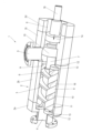
図1は、ここでは例示的に4つのハウジング部材2a、2b、2c及び2dからなるハウジング2を備える部分的に切断された本発明によるスクリュースピンドルポンプ1を示す。すなわちハウジングはモジュラ構造である。ハウジング内部には、軸方向の出入口(Zugang)4と径方向の出入口5とを備えたポンプ室3が形成されている。スクリュースピンドルポンプ1の搬送方向は正逆回転可能であり、すなわち搬送方向に応じて出入口4が吸込連結部であり、出入口5が吐出連結部であるか、又はその逆であることを意味する。ここでは、軸方向の出入口5及び径方向の出入口4が示されているが、出入口の構成が違ってもよく、例えばハウジングの長手軸を中心にずらすこともできる2つの径方向の出入口を備えてもよい。
Figure 1 shows a screw spindle pump 1 according to the invention, partially cut away, with a
ハウジング2は、圧力室(Druckraum)3の他に、以下にさらに説明するように、駆動スピンドルの支承が行われる軸受室6も有する。
In addition to the
スクリュースピンドルポンプ1はさらに、駆動スピンドルプロファイル8を有する中心に配置された駆動スピンドル7と、それぞれ1つの従動スピンドルプロファイル10を有し、横に隣接し、互いに180°ずらして配置された2つの従動スピンドル9とを備えるスピンドル一式を備え、駆動スピンドルプロファイル8は、従動スピンドルプロファイル10と噛み合う。この例では、2つの従動スピンドル9が示されるが、これに代えて、ただ1つの従動スピンドル9又は3つの従動スピンドル9を設けることもできる。
The screw spindle pump 1 further comprises a spindle set comprising a centrally located
駆動スピンドル7又は駆動スピンドルプロファイル8は、ハウジング2又はハウジング部材2bにおける、ここに詳しく示されてない相応の駆動スピンドルボアに収容されるのに対して、2つの従動スピンドル9は、ハウジング2又はハウジング部材2bにおける相応の従動スピンドルボア11に収容されている。2つの従動スピンドルボア11は、既知のように駆動スピンドルボア9と重なり、これらのボアは、ポンプ室3の主要部分をなす。
The
2つのハウジング部材2a及び2cは、2つの従動スピンドルボア11の領域に相応のハウジング肩部12を有し、これらのハウジング肩部はそれぞれ1つの当接ディスク13のための支持面として用いられ、当接ディスクは軸方向に互いに離間され、間にそれぞれ1つの従動スピンドル9を有する。各当接ディスク13は、軸方向に隣接する従動スピンドル9の端面のための当接面をなすか、又はそのような当接面を有する。当接ディスクは、両側が平坦面状であり、すなわち対応するハウジング肩部12に平坦面状に接触し、当接ディスクはまた、従動スピンドル9の対応する平坦な端面に対して面平行に延びる。各従動スピンドル9は、スクリュースピンドルポンプのサイズに応じて0.3~5.0mm、特に1.0~3.0mmのわずかな軸方向遊びを設けて2つの当接ディスク13間に収容され、すなわち軸方向にわずかに変位させることができる。最大軸方向遊びは、使用される当接ディスク13の厚さによって調整され、それによりこの最大軸方向遊びを最小化することができ、そこでのデッドスペースを最小化することができる。
The two
当接ディスク13は、例えば、セラミック材料から、又はセラミック材料を含む複合材料から、好ましくは工業用セラミックからなるディスクである。好ましくは、シリコンベースの材料、特にSiC又はSi3N4が使用される。あるいは、各当接ディスク13が、例えばWCなどの炭化物材料からなることもできる。超硬合金製の当接ディスク13の使用も考えられる。すなわちこれは極めて摩耗しにくい当接ディスク13であり、例えばコールスタライジング処理された又は冷窒化処理された相応の特殊鋼でできているそれぞれの従動スピンドル9も相応に耐摩耗性である。スピンドルとハウジングは両方とも、特に食品産業、医療、製薬、化学産業での使用に適したステンレス特殊鋼でできている。
The
部分断面図が示すように、駆動スピンドル7は、ポンプ室3から軸受室6に案内され、そこで駆動スピンドルは、ラジアル軸受14、殊に単列又は複列の玉軸受又はころ軸受若しくは球面ころ軸受の形式の転がり軸受を介してハウジング2に支承されている。すなわちこれにより、唯一の軸受平面上で駆動スピンドル7の回転支承が行われる。以下にさらに言及されるが、駆動スピンドル7が軸方向に液圧平衡されているため、このような唯一の軸受平面で十分であり、したがって、すなわちポンプ動作中に軸方向力が駆動スピンドル7に作用しないか、又は無視できる程度しか作用しないが、径方向力も作用しないか、又は無視できる程度しか作用しない。これは2つの従動スピンドル7が両側で対称に配置される結果であり、2つの従動スピンドル自体は、液圧支持されるか、又は摺動膜を介して、厳密には軸方向と径方向とに支承される。これについては以下にさらに言及される。
As the partial cross-section shows, the
さらに、唯一のシール要素15が設けられ、このシール要素は、好ましくは、駆動スピンドル7に配置され、ハウジング2内の対応するシール座に対して密封するラジアルメカニカルシールである。ポンプ室3全体は、この1つのスピンドル密封又はシール平面を介して、この側に対して、すなわち駆動側に対して密封されている。これは、流体又は媒体が出入口4から出入口5へ、又はその逆にしか流れることができないことを意味し、(対応する端側の従動スピンドル管片16に本来のポンプ駆動装置が連結される)軸受側又は駆動側に流れることは不可能である。
Furthermore, only one sealing
上記のように、駆動スピンドル7は軸方向に液圧平衡され、それにより軸方向力が駆動スピンドル7に作用しないか、又は全く無視できる程度しか作用しない。これは、シール要素15が駆動スピンドルプロファイル8に関して相応に指定されることにより達成される。この指定は、媒体で加圧されるシール要素15の面、すなわちいわばポンプ室3に向いた面が、作業スピンドルプロファイル8の軸方向に加圧される面と実質的に同じであるようになっている。既知のように、作業スピンドルプロファイル8が従動スピンドルプロファイル10に噛み合う結果として、作業スピンドルプロファイル8の軸方向に加圧される面は、スピンドル長手方向視で、作業スピンドルプロファイル7の複数の部分的に鎌形の、合わせて1つの総体面となる面区分によってできる。この総体面は、シール要素15の、ポンプ室に向いた、軸方向に加圧される環状の面とほぼ同じ大きさ、又は理想的には完全に同じ大きさになる。面に差異があったとしても最大10%、殊に最大5%である。それぞれの面に作用する圧力は、それぞれ互いに反対方向を向き、それにより2つの面に同じ圧力が加えられるので、理想的にも完全な圧力平衡が生じ、その結果、駆動スピンドル7はいわば圧力がないか、又は液圧平衡され、それにより理想的にも駆動スピンドルに軸方向力が作用しないか、又は無視できる程度しか作用しない。
As mentioned above, the
その結果として、さらに、駆動スピンドルは動作中に軸方向に位置固定されているので、2つの従動スピンドルにも駆動スピンドル7からの機械的な力の伝達が行われない。ただ1つだけ、従動スピンドル9の作業圧力にもとづくわずかな軸方向の変位(Verschub)が生じ、このことが、従動スピンドルボア11への従動スピンドル9のわずかな軸方向運動をもたらすとともに、それぞれの従動スピンドル9の対応する端面がそれぞれの当接ディスク13に当接することをもたらす。互いに向かって動く2つの面は、好ましくは搬送されるべき媒体の薄い潤滑膜を介して静水圧で滑り支承され、それによりこの領域に摩耗は生じない。
As a result, furthermore, the drive spindle is axially fixed during operation, so that no mechanical forces are transmitted from the
さらに、所与のギャップからの媒体逆流を最小化することの結果として、デッドスペースをさらに最小化し、効率を改善するために、それぞれの従動スピンドルボア11が滑り被覆材16を備え、この滑り被覆材は、好ましくはHNBR、EPDM、PTFE、CTFE、PFA、FKM又はFFKMなどのプラスチックからなる滑り被覆材16である。滑り被覆材16の厚さは、それぞれの従動スピンドル9、すなわちその外周面と滑り被覆材16との間に最小限の径方向遊びしか生じないように選択され、この径方向遊びは0.01~1.0mm、特に0.05~0.5mmであるべきである。これは、この場合も最小限の遊びしかないことを意味し、それにより逆流が生じたとしても最小限に抑えることができ、これは効率の改善と結びついている。この場合も、いわば相応の媒体潤滑膜が生じ、この媒体潤滑膜を介して従動スピンドル9が滑り被覆材16に対していわば滑り支承され、それによりこの場合も摩損が生じない。
Furthermore, in order to further minimize the dead space and improve efficiency as a result of minimizing the media backflow from a given gap, each driven spindle bore 11 is provided with a sliding
動作中、駆動スピンドル7は、既知のように、駆動装置により駆動され、駆動スピンドルが回転する。プロファイル係合により、従動スピンドル9も強制的に回転させられ、それに対応して駆動スピンドル7の回転方向に応じて、媒体が出入口4から出入口5へ、又はその逆に、すなわち吸込連結部から吐出連結部へ搬送される。当接時、2つの従動スピンドル9は、上述のように、作業圧力の発生によって、かつプロファイル係合の範囲内の最小の軸方向遊びの結果として、軸方向に最小限変位し、2つの従動スピンドルは、それぞれ当接ディスク13の1つに向かって動き、そこでこれらの2つの従動スピンドルは、好ましくは搬送されるべき媒体から生じる滑り膜を介して滑り支承される。ギャップが最小であるため、極めて少ない逆流しか生じず、そのことが効率の改善をもたらす。
During operation, the
図2によるスクリュースピンドルポンプ1の実施例の基本構造は、図1の基本構造に相当する。この場合も、例示的に3つのハウジング部材2a、2b、2c及び2dを備えるモジュラハウジング2が設けられている。ハウジング内部には、軸方向の出入口(Zugang)4と径方向の出入口5とを備えたポンプ室3が形成されている。スクリュースピンドルポンプ1の搬送方向はこの場合も正逆回転可能である。ハウジング2は、圧力室(Druckraum)3の他に、以下にさらに説明するように、駆動スピンドルの支承が行われる軸受室6も有する。
The basic structure of the embodiment of the screw spindle pump 1 according to FIG. 2 corresponds to the basic structure of FIG. 1. Here too, a
この場合も、スクリュースピンドルポンプ1は、駆動スピンドルプロファイル8を有する中心駆動スピンドル7と、それぞれ1つの従動スピンドルプロファイル10を有する、横に隣接し、互いに180°ずらして配置された2つの従動スピンドル9とを備えるスピンドル一式を備え、駆動スピンドルプロファイル8は従動スピンドルプロファイル10と噛み合う。この例では、2つの従動スピンドル9が示されるが、これに代えて、ただ1つの従動スピンドル9又は3つの従動スピンドル9を設けることもできる。
In this case too, the screw spindle pump 1 comprises a spindle set with a
駆動スピンドル7は、ハウジング2の対応する駆動スピンドルボアに収容されるのに対して、2つの従動スピンドル9は、ハウジング2の対応する従動スピンドルボア11に収容されている。2つの従動スピンドルボア11は、既知のように駆動スピンドルボア9と重なり、これらのボアもまたポンプ室3の主要部分をなす。
The
2つのハウジング部材2a及び2cは、2つの従動スピンドルボア11の領域に相応のハウジング肩部12を有する。ハウジング肩部12は、互いに軸方向に離間している。ハウジング肩部間にはそれぞれ1つの従動スピンドル9が収容されている。各ハウジング肩部12には、軸方向に隣接する従動スピンドル9の端面のための当接面を形成するコーティング17が設けられている。コーティング17は、例えば、Si3N4、SiC、WC又はCr2O3からなり、それぞれのハウジング肩部12に直接設けられている。従動スピンドル9の端面は平坦面状であり、すなわち、ハウジング肩部12の対応するコーティング17に対して又はコーティングに平坦面状に接触する。各従動スピンドル9は、スクリュースピンドルポンプのサイズに応じて0.3~5.0mm、特に1.0~3.0mmのわずかな軸方向遊びを設けて、2つのハウジング肩部12間、又は摩耗しにくいコーティング17間に収容され、すなわちわずかに軸方向に変位させることができる。動作中、従動スピンドル9は、この場合も当接面又はコーティング17に向かって動き、理想的にはそこで流体潤滑膜を介して支持されるか、又は滑り支承される。いずれの場合も、コーティングは従動スピンドル自体と同様に極めて摩耗しにくく、それにより長期の動作が確保されている。
The two
すなわち、この場合、当接面は、コーティング17によってハウジング自体に直接実現される。図1による実施例でのような別個の当接ディスクの配置はここでは必要でない。それにもかかわらず、図1による実施例について説明されたのと同じ利点が達成される。
That is, in this case the abutment surface is realized directly on the housing itself by means of the
さらに、図2に示されるスクリュースピンドルポンプ1の構造は、図1の例に対応し、すなわち、この場合も駆動スピンドル7を支承するためにラジアル軸受15が設けられ、さらに少なくとも従動スピンドルボア11が滑り被覆材16で覆われている。したがって、図1のポンプに関する記述を参照されたい。その記述は図2によるポンプにも同じように該当する。
Furthermore, the structure of the screw spindle pump 1 shown in FIG. 2 corresponds to the example of FIG. 1, i.e. in this case too a
スクリュースピンドルポンプ1が正逆回転可能でない場合、従動スピンドルボア11ごとに、当接面を形成するただ1つの当接ディスク13又はコーティング17が、厳密には、それぞれの従動スピンドルボアの吸込側の端部に設けられ、それにより従動スピンドル9が動作中に吸込側に向かって最小限に移動する。
If the screw spindle pump 1 is not reversible, then for each driven spindle bore 11 only one
本発明によるスクリュースピンドルポンプは、食品又は他の衛生的に敏感な媒体を搬送する場合に不利な、従動スピンドル7の流体による推力平衡のための装置なしで済むため、簡単な設計であることがわかる。むしろ、このスクリュースピンドルポンプの形態は、ポンプ室の他には搬送されるべき媒体が入っている可能性のある容積がないため、組立状態で洗浄できることを可能にする。このことは、組付け状態のスクリュースピンドルポンプの簡単な洗い流し、すなわち「Cleaning-in-Place」を可能にする。当接ディスク13を組み込むことにより、従動スピンドル9の許容軸方向遊びを最小化することができ、上記のように、ディスクの直接の当接が行われ、それによりこのポンプ室領域に不利なデッドスペースが生じない。
The screw spindle pump according to the invention proves to be of simple design, since it does not require any device for balancing the thrust of the driven
3つのスピンドル、すなわち駆動スピンドル7と2つの従動スピンドル9とを使用することによって、スクリュースピンドルポンプ1が非常に密なプロファイルを有するので、圧縮に対してより強い搬送特性曲線が可能になる。このことは、高い計量精度での使用を可能にする。密なプロファイルにより吸引挙動も向上し、その結果、効率が改善される。さらに、スクリュースピンドルポンプ1又はスピンドル一式は液圧的に同期もされ、すなわち、動作中に自動的に調整され、駆動スピンドル7と従動スピンドル9との間で機械的な力の伝達が行われない。
The use of three spindles, namely the driving
Claims (17)
ポンプ動作に伴う軸方向力が前記駆動スピンドルに作用しないように前記駆動スピンドルが液圧平衡され、前記ポンプ室(3)が前記駆動スピンドル(7)と前記ハウジング(2)との間を密封するシール要素(15)によって密封され、前記ポンプ室(3)に向いており、媒体で軸方向に加圧される前記シール要素(15)の面が、スピンドルコアから径方向に突出する駆動スピンドルプロファイル(8)の軸方向に加圧される面のサイズに実質的に等しく、前記従動スピンドル(9)の少なくとも1つの端面に軸方向に隣接して当接面(13)が設けられ、前記従動スピンドル(9)が軸方向の遊びを設けて前記当接面(13)に対して垂直方向に変位可能に収容されていることを特徴とする、スクリュースピンドルポンプ。 A screw-spindle pump having at least one driven spindle, comprising a housing (2) having a pump chamber (3) and a drive spindle (7) accommodated therein, and at least one driven spindle (9) having end faces at each of its two ends and meshing with said drive spindle, said screw-spindle pump having no device for balancing the axial thrust of the driven spindle by a fluid,
1. A screw spindle pump comprising: a driving spindle hydraulically balanced such that no axial forces associated with pumping act on the driving spindle; a sealing element sealing between the driving spindle and the housing, the sealing element facing the pump chamber, a surface of the sealing element which is axially pressurized with a medium being substantially equal in size to a surface of the driving spindle profile radially protruding from the spindle core which is axially pressurized; a bearing surface axially adjacent to at least one end face of the driven spindle, the driven spindle being accommodated with axial play such that it is vertically displaceable relative to the bearing surface.
Applications Claiming Priority (2)
| Application Number | Priority Date | Filing Date | Title |
|---|---|---|---|
| DE102020133555.5 | 2020-12-15 | ||
| DE102020133555.5A DE102020133555A1 (en) | 2020-12-15 | 2020-12-15 | screw pump |
Publications (2)
| Publication Number | Publication Date |
|---|---|
| JP2022094929A JP2022094929A (en) | 2022-06-27 |
| JP7465249B2 true JP7465249B2 (en) | 2024-04-10 |
Family
ID=77226691
Family Applications (1)
| Application Number | Title | Priority Date | Filing Date |
|---|---|---|---|
| JP2021189794A Active JP7465249B2 (en) | 2020-12-15 | 2021-11-24 | Screw Spindle Pump |
Country Status (8)
| Country | Link |
|---|---|
| US (1) | US11486392B2 (en) |
| EP (1) | EP4015769B1 (en) |
| JP (1) | JP7465249B2 (en) |
| CN (1) | CN114635847B (en) |
| DE (1) | DE102020133555A1 (en) |
| ES (1) | ES3035156T3 (en) |
| PL (1) | PL4015769T3 (en) |
| WO (1) | WO2022128503A1 (en) |
Families Citing this family (5)
| Publication number | Priority date | Publication date | Assignee | Title |
|---|---|---|---|---|
| USD940205S1 (en) * | 2019-11-06 | 2022-01-04 | Leistritz Pumpen Gmbh | Pump for liquids |
| DE102021133099A1 (en) * | 2021-12-14 | 2023-06-15 | Leistritz Pumpen Gmbh | screw pump |
| EP4536971A1 (en) * | 2022-06-10 | 2025-04-16 | Illinois Tool Works, Inc. | Screw pump and its components |
| EP4474650B1 (en) | 2023-06-09 | 2026-03-25 | Illinois Tool Works Inc. | Screw pump and its components |
| US12533995B2 (en) | 2023-08-31 | 2026-01-27 | Illinois Tool Works Inc. | Battery electric vehicle temperature-regulation system |
Citations (4)
| Publication number | Priority date | Publication date | Assignee | Title |
|---|---|---|---|---|
| JP2005515067A (en) | 2002-01-23 | 2005-05-26 | キャリア コーポレイション | Easy assembly of rough-coated parts |
| JP2005344679A (en) | 2004-06-07 | 2005-12-15 | Kawasaki Precision Machinery Ltd | Screw type machine |
| DE102006049663A1 (en) | 2006-10-18 | 2008-05-08 | Willy Vogel Ag | Screw spindle pump for conveying working fluid, particularly lubricant or cooling lubricant, has pump spindles, which are rotatably mounted in housing, where pump spindles are supported in axial direction by axial bearing in housing |
| JP2011521167A (en) | 2008-05-26 | 2011-07-21 | アトラス コプコ エアーパワー,ナームローゼ フェンノートシャップ | Fluid injection screw compressor element |
Family Cites Families (31)
| Publication number | Priority date | Publication date | Assignee | Title |
|---|---|---|---|---|
| US2693762A (en) * | 1951-10-25 | 1954-11-09 | Laval Steam Turbine Co | Nonpositive screw pump and motor |
| US2693763A (en) | 1951-10-25 | 1954-11-09 | Laval Steam Turbine Co | Nonpositive screw pump or motor |
| CH469198A (en) * | 1964-03-20 | 1969-02-28 | Svenska Rotor Maskiner Ab | Screw compressor |
| DE1901759C3 (en) * | 1969-01-15 | 1975-04-30 | Allweiler Ag, 7760 Radolfzell | Device for absorbing the gearing thrust and the hydraulic axial thrust on the spindles of screw pumps |
| ES400740A1 (en) * | 1971-03-17 | 1975-01-16 | Lamborghini Oleodinamica | Gear pump with balanced side sealing bushes |
| DE2449201A1 (en) * | 1974-10-16 | 1976-04-22 | Allweiler Ag | Worm pump with thrust collars on driven spindles - of unequal lengths on suction side, difference exceeding collar width on longer spindle |
| DE7802765U1 (en) | 1978-01-31 | 1979-10-31 | Allweiler Ag, 7760 Radolfzell | SCREW SCREW MACHINE |
| DE3310701A1 (en) * | 1983-03-24 | 1984-09-27 | Allweiler Ag, 7760 Radolfzell | Screw pump |
| DE3920900A1 (en) | 1989-06-26 | 1991-01-03 | Allweiler Ag | SCREW PUMP |
| JP2973531B2 (en) * | 1991-02-01 | 1999-11-08 | 株式会社日立製作所 | Screw compressor |
| RU2030639C1 (en) | 1992-03-13 | 1995-03-10 | Скрипица Владимир Васильевич | Two-screw pump |
| DE19502173C2 (en) | 1995-01-25 | 1997-07-03 | Leistritz Ag | Screw pump for operation independent of the direction of rotation |
| US6887055B2 (en) * | 2002-10-25 | 2005-05-03 | Mario Antonio Morselli | Positive-displacement rotary pump |
| GB2401401A (en) * | 2003-05-08 | 2004-11-10 | Automotive Motion Tech Ltd | Three rotor screw pump with smaller central rotor |
| CN101270767A (en) * | 2007-03-21 | 2008-09-24 | 张敏 | Automatically hydraulic stepless speed changer |
| CN201306277Y (en) * | 2008-12-05 | 2009-09-09 | 天津泵业机械集团有限公司 | Highly viscous three-screw pump |
| EP2216501A1 (en) * | 2009-02-10 | 2010-08-11 | BP Exploration Operating Company Limited | Pump |
| CN201574926U (en) * | 2009-11-30 | 2010-09-08 | 天津泵业机械集团有限公司 | Economic three-screw pump |
| US8821140B2 (en) * | 2010-04-29 | 2014-09-02 | Dan Paval | Gear pump |
| CN102287368B (en) * | 2011-09-22 | 2013-07-24 | 黄山工业泵制造有限公司 | Composite balance single-suction double-screw pump |
| FR2981993B1 (en) | 2011-11-02 | 2017-03-03 | Snecma | VARIABLE CYLINDER GEAR PUMP FOR AIRCRAFT TURBOMACHINE |
| DE102013102030B3 (en) * | 2013-03-01 | 2014-07-03 | Netzsch Pumpen & Systeme Gmbh | Screw Pump |
| DE102014102390B3 (en) | 2014-02-25 | 2015-03-26 | Leistritz Pumpen Gmbh | Screw Pump |
| DE102015101443B3 (en) * | 2015-02-02 | 2016-05-12 | Leistritz Pumpen Gmbh | Fuel pump |
| JP2017036667A (en) * | 2015-08-06 | 2017-02-16 | 株式会社日本自動車部品総合研究所 | Screw pump |
| DE102017112743B3 (en) * | 2017-06-09 | 2018-10-25 | Leistritz Pumpen Gmbh | Modular system for producing a screw pump |
| DE102017210767B4 (en) | 2017-06-27 | 2019-10-17 | Continental Automotive Gmbh | Screw pump, fuel delivery unit and fuel delivery unit |
| DE102017210771B4 (en) | 2017-06-27 | 2019-05-29 | Continental Automotive Gmbh | Screw pump, fuel delivery unit and fuel delivery unit |
| DE102017210770B4 (en) | 2017-06-27 | 2019-10-17 | Continental Automotive Gmbh | Screw pump, fuel delivery unit and fuel delivery unit |
| DE102017121882B3 (en) * | 2017-09-21 | 2019-01-24 | Leistritz Pumpen Gmbh | Screw Pump |
| WO2019077097A1 (en) * | 2017-10-19 | 2019-04-25 | Sanofi | A medical pump |
-
2020
- 2020-12-15 DE DE102020133555.5A patent/DE102020133555A1/en active Pending
-
2021
- 2021-08-05 EP EP21189862.2A patent/EP4015769B1/en active Active
- 2021-08-05 ES ES21189862T patent/ES3035156T3/en active Active
- 2021-08-05 PL PL21189862.2T patent/PL4015769T3/en unknown
- 2021-08-10 US US17/398,250 patent/US11486392B2/en active Active
- 2021-09-14 CN CN202111073188.9A patent/CN114635847B/en active Active
- 2021-11-24 JP JP2021189794A patent/JP7465249B2/en active Active
- 2021-12-02 WO PCT/EP2021/083940 patent/WO2022128503A1/en not_active Ceased
Patent Citations (4)
| Publication number | Priority date | Publication date | Assignee | Title |
|---|---|---|---|---|
| JP2005515067A (en) | 2002-01-23 | 2005-05-26 | キャリア コーポレイション | Easy assembly of rough-coated parts |
| JP2005344679A (en) | 2004-06-07 | 2005-12-15 | Kawasaki Precision Machinery Ltd | Screw type machine |
| DE102006049663A1 (en) | 2006-10-18 | 2008-05-08 | Willy Vogel Ag | Screw spindle pump for conveying working fluid, particularly lubricant or cooling lubricant, has pump spindles, which are rotatably mounted in housing, where pump spindles are supported in axial direction by axial bearing in housing |
| JP2011521167A (en) | 2008-05-26 | 2011-07-21 | アトラス コプコ エアーパワー,ナームローゼ フェンノートシャップ | Fluid injection screw compressor element |
Also Published As
| Publication number | Publication date |
|---|---|
| BR102021013276A2 (en) | 2022-06-28 |
| PL4015769T3 (en) | 2025-09-15 |
| EP4015769A1 (en) | 2022-06-22 |
| US11486392B2 (en) | 2022-11-01 |
| JP2022094929A (en) | 2022-06-27 |
| EP4015769B1 (en) | 2025-04-30 |
| ES3035156T3 (en) | 2025-08-29 |
| WO2022128503A1 (en) | 2022-06-23 |
| US20220186726A1 (en) | 2022-06-16 |
| CN114635847B (en) | 2024-06-28 |
| CN114635847A (en) | 2022-06-17 |
| DE102020133555A1 (en) | 2022-06-15 |
Similar Documents
| Publication | Publication Date | Title |
|---|---|---|
| JP7465249B2 (en) | Screw Spindle Pump | |
| CA2580385C (en) | Vane pump comprising a two-part stator | |
| US7462022B2 (en) | Rotary displacement pump comprising scraper and guide of the scraper | |
| RU2785559C1 (en) | Screw pump and application thereof | |
| HUT71691A (en) | Pump for feeding or transporting liquids and liqui form materials | |
| JP2619642B2 (en) | Eccentric screw pump | |
| BR102021013276B1 (en) | THREADED SPINDLE PUMP AND USE OF A THREADED SPINDLE PUMP | |
| US4331070A (en) | Apparatus for heating liquids, in particular foodstuffs and luxury foodstuffs, for the purpose of pasteurization, sterilization and the like | |
| JP4908762B2 (en) | Volumetric pump for food cream and food production apparatus equipped with the same | |
| WO2025253184A1 (en) | A piston assembly for a homogenizing apparatus | |
| Siev et al. | Metering Pumps | |
| Hauser | Hygienic design of moving parts of machines in the food industry. I | |
| Orchard | Laboratories and industry provide opportunities for peristaltic pumps | |
| GB2054742A (en) | Rotary pumps | |
| HK1114533B (en) | Rotary displacement pump comprising scraper and guide of the scraper | |
| JP2014001670A (en) | Uniaxial eccentric screw pump | |
| Pumpen et al. | Quality, flexibility and innovation: The best solutions for hygienic and sterile applications | |
| CN106194627A (en) | Micro-metering Pumps | |
| JP2014020258A (en) | Uniaxial eccentric screw pump |
Legal Events
| Date | Code | Title | Description |
|---|---|---|---|
| A621 | Written request for application examination |
Free format text: JAPANESE INTERMEDIATE CODE: A621 Effective date: 20211214 |
|
| A524 | Written submission of copy of amendment under article 19 pct |
Free format text: JAPANESE INTERMEDIATE CODE: A524 Effective date: 20220204 |
|
| A131 | Notification of reasons for refusal |
Free format text: JAPANESE INTERMEDIATE CODE: A131 Effective date: 20221115 |
|
| A977 | Report on retrieval |
Free format text: JAPANESE INTERMEDIATE CODE: A971007 Effective date: 20221116 |
|
| A521 | Request for written amendment filed |
Free format text: JAPANESE INTERMEDIATE CODE: A523 Effective date: 20230208 |
|
| A131 | Notification of reasons for refusal |
Free format text: JAPANESE INTERMEDIATE CODE: A131 Effective date: 20230606 |
|
| A521 | Request for written amendment filed |
Free format text: JAPANESE INTERMEDIATE CODE: A523 Effective date: 20230829 |
|
| A131 | Notification of reasons for refusal |
Free format text: JAPANESE INTERMEDIATE CODE: A131 Effective date: 20231003 |
|
| A521 | Request for written amendment filed |
Free format text: JAPANESE INTERMEDIATE CODE: A523 Effective date: 20231218 |
|
| TRDD | Decision of grant or rejection written | ||
| A01 | Written decision to grant a patent or to grant a registration (utility model) |
Free format text: JAPANESE INTERMEDIATE CODE: A01 Effective date: 20240319 |
|
| A61 | First payment of annual fees (during grant procedure) |
Free format text: JAPANESE INTERMEDIATE CODE: A61 Effective date: 20240329 |
|
| R150 | Certificate of patent or registration of utility model |
Ref document number: 7465249 Country of ref document: JP Free format text: JAPANESE INTERMEDIATE CODE: R150 |