JP7455290B1 - Heat exchangers and air conditioners - Google Patents

Heat exchangers and air conditioners Download PDF

Info

Publication number
JP7455290B1
JP7455290B1 JP2023571865A JP2023571865A JP7455290B1 JP 7455290 B1 JP7455290 B1 JP 7455290B1 JP 2023571865 A JP2023571865 A JP 2023571865A JP 2023571865 A JP2023571865 A JP 2023571865A JP 7455290 B1 JP7455290 B1 JP 7455290B1
Authority
JP
Japan
Prior art keywords
heat exchanger
refrigerant
tube
tubes
header
Prior art date
Legal status (The legal status is an assumption and is not a legal conclusion. Google has not performed a legal analysis and makes no representation as to the accuracy of the status listed.)
Active
Application number
JP2023571865A
Other languages
Japanese (ja)
Inventor
七海 岸田
洋次 尾中
理人 足立
Current Assignee (The listed assignees may be inaccurate. Google has not performed a legal analysis and makes no representation or warranty as to the accuracy of the list.)
Mitsubishi Electric Corp
Original Assignee
Mitsubishi Electric Corp
Priority date (The priority date is an assumption and is not a legal conclusion. Google has not performed a legal analysis and makes no representation as to the accuracy of the date listed.)
Filing date
Publication date
Application filed by Mitsubishi Electric Corp filed Critical Mitsubishi Electric Corp
Application granted granted Critical
Publication of JP7455290B1 publication Critical patent/JP7455290B1/en
Active legal-status Critical Current
Anticipated expiration legal-status Critical

Links

Images

Abstract

熱交換器は、複数の伝熱管と、複数の伝熱管を貫通しており、内部を冷媒が流れる配管と、を備え、複数の伝熱管のそれぞれには、両端部よりも内側に形成されており、複数の伝熱管のそれぞれの内部空間と外部とを連通させる複数の第1貫通孔と、一対の第2貫通孔と、が形成されており、複数の伝熱管は、複数の伝熱管の内、隣り合う伝熱管の複数の第1貫通孔同士を連結して形成された複数のヘッダ部であって、複数の伝熱管の幅よりも小さく形成されており、複数の伝熱管のそれぞれの内部空間との間で冷媒を連通させ、複数の伝熱管により構成された伝熱管群の冷媒の出入口となる複数のヘッダ部を含み、配管が、一対の第2貫通孔に挿入されているものである。The heat exchanger includes a plurality of heat exchanger tubes and a pipe that passes through the plurality of heat exchanger tubes and through which a refrigerant flows, and each of the plurality of heat exchanger tubes has a pipe formed inside of both ends. A plurality of first through-holes and a pair of second through-holes are formed to communicate the internal space of each of the plurality of heat exchanger tubes with the outside, and the plurality of heat exchanger tubes are connected to each other. Among them, a plurality of header parts are formed by connecting a plurality of first through holes of adjacent heat exchanger tubes, and are formed smaller than the width of the plurality of heat exchanger tubes, and are formed by connecting the plurality of first through holes of the plurality of heat exchanger tubes. A device that communicates refrigerant with the internal space and includes a plurality of header portions that serve as inlets and outlets for the refrigerant of a heat exchanger tube group composed of a plurality of heat exchanger tubes, and the piping is inserted into a pair of second through holes. It is.

Description

本開示は、熱交換器及びこの熱交換器を備えた空気調和装置に関するものである。 The present disclosure relates to a heat exchanger and an air conditioner equipped with the heat exchanger.

従来、熱交換器には、フィンに伝熱管を貫通させたフィンチューブ型熱交換器が用いられている。フィンチューブ型熱交換器は、伝熱管の細径化を図って熱交換効率の向上及び小型化が進められていたが構造的な困難さもあり限界がある。これに対し、プレートフィン積層型熱交換器は、伝熱流路の断面積をフィンチューブ型の伝熱管に比べさらに小さくでき、熱交換効率を高め小型化することができる。また、従来の熱交換器には、熱交換効率を高めるために熱交換器そのものに内部熱交換器(HIC:Heat Inter Changer)あるいは気液分離などの機能を持たせる熱交換器が提案されている(例えば、特許文献1参照)。 Conventionally, a fin tube type heat exchanger in which heat exchanger tubes are passed through fins has been used as a heat exchanger. Fin tube type heat exchangers have been improved in heat exchange efficiency and downsized by reducing the diameter of the heat transfer tubes, but there are limitations due to structural difficulties. On the other hand, in the plate-fin stacked heat exchanger, the cross-sectional area of the heat transfer channel can be made smaller than that of the fin-tube type heat exchanger tube, and the heat exchange efficiency can be improved and the heat exchanger can be made smaller. In addition, as conventional heat exchangers, heat exchangers have been proposed in which the heat exchanger itself has functions such as an internal heat exchanger (HIC: Heat Inter Changer) or gas-liquid separation in order to increase heat exchange efficiency. (For example, see Patent Document 1).

特開2012-107775号公報Japanese Patent Application Publication No. 2012-107775

特許文献1の熱交換器は、ヘッダ部に加工を施して内部熱交換器を実現させているが、ヘッダ部に加工を施すため、ヘッダ部の大型化につながり、ヘッダ部に加工を施していない熱交換器と比較して熱交換器が大型化する恐れがある。 The heat exchanger of Patent Document 1 implements an internal heat exchanger by processing the header part, but since the header part is processed, the header part becomes larger, and the header part is not processed. There is a risk that the heat exchanger will be larger than one without.

本開示は、上記のような課題を解決するためのものであり、熱交換効率を向上させつつ小型化させた熱交換器及び空気調和装置の提供を目的としている。 The present disclosure is intended to solve the above-mentioned problems, and aims to provide a heat exchanger and an air conditioner that are miniaturized while improving heat exchange efficiency.

本開示に係る熱交換器は、第1方向に配列され、それぞれが第1方向と交差する第2方向に延伸しており、第2方向の両端部が封止され内部を第2方向に冷媒が流れる複数の伝熱管と、複数の伝熱管を第1方向に貫通しており、内部を冷媒が流れる配管と、を備え、複数の伝熱管のそれぞれには、第2方向における両端部よりも内側に形成されており、複数の伝熱管のそれぞれの内部空間と外部とを連通させる複数の第1貫通孔と、第1方向において互いに対向するように形成された一対の第2貫通孔と、が形成されており、複数の伝熱管は、複数の伝熱管のそれぞれの内部空間との間で冷媒を連通させ、複数の伝熱管により構成された伝熱管群の冷媒の出入口となる第1ヘッダ部及び第2ヘッダ部が、複数の伝熱管の内、隣り合う伝熱管の複数の第1貫通孔同士を連結して形成されており、第1ヘッダ部及び第2ヘッダ部はそれぞれ、第1方向及び第2方向に直交する第3方向において、複数の伝熱管の幅よりも小さく形成されており配管が、一対の第2貫通孔に挿入されて、第1ヘッダ部と第2ヘッダ部との間の部分で冷媒が流れる複数の伝熱管の内部空間を貫通するものである。 The heat exchanger according to the present disclosure is arranged in a first direction, each extending in a second direction intersecting the first direction, both ends in the second direction are sealed, and the inside is arranged in a second direction. a plurality of heat exchanger tubes through which a refrigerant flows, and a pipe that penetrates the plurality of heat exchanger tubes in a first direction and through which a refrigerant flows, each of the plurality of heat exchanger tubes has a a plurality of first through holes that are formed on the inside and communicate the internal space of each of the plurality of heat exchanger tubes with the outside; a pair of second through holes that are formed so as to face each other in the first direction; is formed, and the plurality of heat exchanger tubes have a first inlet/outlet for communicating the refrigerant with the internal space of each of the plurality of heat exchanger tubes, and serves as an inlet/outlet for the refrigerant of the heat exchanger tube group constituted by the plurality of heat exchanger tubes. A header portion and a second header portion are formed by connecting a plurality of first through holes of adjacent heat exchanger tubes among the plurality of heat exchanger tubes , and each of the first header portion and the second header portion is formed by connecting a plurality of first through holes of adjacent heat exchanger tubes. In a third direction orthogonal to the first direction and the second direction, the width is smaller than the width of the plurality of heat exchanger tubes , and the pipe is inserted into the pair of second through holes to connect the first header part and the second header part. The refrigerant passes through the internal spaces of the plurality of heat transfer tubes through which the refrigerant flows .

また、本開示に係る空気調和装置は、圧縮機と、上記の熱交換器から構成されており、室外空気と内部を流れる冷媒との間で熱交換を行う室外側熱交換器と、内部を流れる冷媒を減圧する膨張弁と、室内空気と内部を流れる冷媒との間で熱交換を行う室内側熱交換器と、を備えたものである。 In addition, an air conditioner according to the present disclosure includes a compressor and the above-mentioned heat exchanger, and includes an outdoor heat exchanger that exchanges heat between outdoor air and a refrigerant flowing inside; It is equipped with an expansion valve that reduces the pressure of the flowing refrigerant, and an indoor heat exchanger that exchanges heat between indoor air and the refrigerant flowing inside.

本開示に係る熱交換器及び空気調和装置では、第1貫通孔同士を連結して形成された複数のヘッダ部を備えた伝熱管及び伝熱管の第2貫通孔に配置された配管によって、内部熱交換器としての機能を有する構成を、伝熱管群の構成範囲内に設けることができる。すなわち、熱交換器は、伝熱管の外部に内部熱交換器としての機能を有する構成を設ける必要がなく、また、内部熱交換器としての機能を内蔵させることで、当該機能を有していないヘッダ部よりも大型のヘッダ部を設ける必要もない。したがって、熱交換器は、ヘッダ部を備えた伝熱管及び配管によって、内部熱交換器としての機能を発揮させて熱交換効率を向上させつつ伝熱管群の外部に当該機能をもたせた熱交換器と比較して小型化させることができる。 In the heat exchanger and air conditioner according to the present disclosure, the heat exchanger tube includes a plurality of header parts formed by connecting the first through holes, and the piping arranged in the second through hole of the heat exchanger tube allows the internal A configuration having a function as a heat exchanger can be provided within the configuration range of the heat exchanger tube group. In other words, the heat exchanger does not need to have a structure that functions as an internal heat exchanger on the outside of the heat exchanger tube, and by incorporating the function as an internal heat exchanger, the heat exchanger does not have the function. There is no need to provide a header section larger than the header section. Therefore, a heat exchanger is a heat exchanger that uses heat exchanger tubes and piping equipped with a header part to perform the function as an internal heat exchanger and improve heat exchange efficiency, while also providing the function outside the heat exchanger tube group. It can be made smaller compared to

実施の形態1に係る熱交換器の概略構成を示す斜視図である。1 is a perspective view showing a schematic configuration of a heat exchanger according to Embodiment 1. FIG. 実施の形態1に係る熱交換器の縦断面図である。1 is a longitudinal cross-sectional view of a heat exchanger according to Embodiment 1. FIG. 実施の形態1に係る熱交換器の伝熱管を第1方向に見た図である。FIG. 3 is a diagram of heat exchanger tubes of the heat exchanger according to Embodiment 1, viewed in a first direction. 実施の形態1に係る熱交換器において、図3の伝熱管のA-A線位置の断面を矢視方向に見た概念図である。FIG. 4 is a conceptual diagram of a cross section taken along line AA of the heat exchanger tubes in FIG. 3, viewed in the direction of arrows, in the heat exchanger according to the first embodiment. 実施の形態1に係る熱交換器の変形例の縦断面図である。FIG. 3 is a longitudinal cross-sectional view of a modification of the heat exchanger according to the first embodiment. 実施の形態1に係る熱交換器における、変形例の伝熱管を第1方向に見た図である。FIG. 7 is a diagram of a heat exchanger tube of a modification example viewed in the first direction in the heat exchanger according to the first embodiment. 実施の形態1に係る熱交換器を搭載した空気調和装置の冷房運転時の冷媒回路図である。FIG. 2 is a refrigerant circuit diagram during cooling operation of the air conditioner equipped with the heat exchanger according to the first embodiment. 実施の形態1に係る熱交換器を搭載した空気調和装置のデフロスト運転時の冷媒回路図である。FIG. 2 is a refrigerant circuit diagram during defrost operation of the air conditioner equipped with the heat exchanger according to the first embodiment. 実施の形態1に係る熱交換器を搭載した空気調和装置のデフロスト運転時の他の冷媒回路図である。FIG. 3 is another refrigerant circuit diagram during defrost operation of the air conditioner equipped with the heat exchanger according to the first embodiment. 実施の形態1に係る熱交換器を搭載した空気調和装置の暖房運転時の冷媒回路図である。FIG. 2 is a refrigerant circuit diagram during heating operation of the air conditioner equipped with the heat exchanger according to the first embodiment. 実施の形態2に係る熱交換器の概略構成を示す斜視図である。FIG. 2 is a perspective view showing a schematic configuration of a heat exchanger according to a second embodiment. 実施の形態2に係る熱交換器の変形例の縦断面図である。7 is a longitudinal cross-sectional view of a modification of the heat exchanger according to Embodiment 2. FIG. 実施の形態2の熱交換器を搭載した空気調和装置の暖房運転時の冷媒回路図である。FIG. 7 is a refrigerant circuit diagram during heating operation of an air conditioner equipped with a heat exchanger according to a second embodiment.

以下、実施の形態1に係る熱交換器及びこの熱交換器を備えた空気調和装置について図面等を参照しながら説明する。なお、図1を含む以下の図面では、各構成部材の相対的な寸法の関係及び形状等が実際のものとは異なる場合がある。また、以下の図面において、同一の符号を付したものは、同一又はこれに相当するものであり、このことは明細書の全文において共通することとする。また、理解を容易にするために方向を表す用語(例えば「上」、「下」、「右」、「左」、「前」、「後」など)を適宜用いるが、それらの表記は、説明の便宜上、そのように記載しているだけであって、装置あるいは部品の配置及び向きを限定するものではない。明細書中において、各構成部材同士の位置関係、各構成部材の延伸方向、及び各構成部材の配列方向は、原則として、熱交換器が使用可能な状態に設置されたときのものである。 Hereinafter, a heat exchanger according to Embodiment 1 and an air conditioner equipped with this heat exchanger will be described with reference to the drawings and the like. Note that in the following drawings including FIG. 1, the relative dimensional relationships, shapes, etc. of each component may differ from the actual ones. In addition, in the following drawings, parts with the same reference numerals are the same or equivalent, and this is common throughout the entire specification. In addition, to facilitate understanding, we use terms that indicate directions (for example, "top", "bottom", "right", "left", "front", "back", etc.), but these notations are as follows: This is only described for convenience of explanation, and does not limit the arrangement or orientation of the device or parts. In the specification, the positional relationship between each component, the stretching direction of each component, and the arrangement direction of each component are, in principle, those when the heat exchanger is installed in a usable state.

実施の形態1.
[熱交換器100の構成]
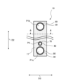
図1は、実施の形態1に係る熱交換器100の概略構成を示す斜視図である。なお、図1に示す白抜き矢印は、冷媒の流れる方向の一例を示している。図1を用いて熱交換器100の構成について説明する。なお、以下に白抜き矢印で示す冷媒の方向は、一例であり、熱交換器100が蒸発器又は凝縮器として機能する場合によって冷媒の流れる方向が図示と逆方向になる場合がある。
Embodiment 1.
[Configuration of heat exchanger 100]
FIG. 1 is a perspective view showing a schematic configuration of a heat exchanger 100 according to the first embodiment. In addition, the white arrow shown in FIG. 1 has shown an example of the direction in which a refrigerant|coolant flows. The configuration of the heat exchanger 100 will be explained using FIG. 1. Note that the direction of the refrigerant indicated by the white arrow below is an example, and depending on the case where the heat exchanger 100 functions as an evaporator or a condenser, the direction in which the refrigerant flows may be opposite to that shown in the drawing.

熱交換器100は、熱交換器100の内部を流れる冷媒と熱交換器100の外部を流れる流体との間で熱交換を行う機器である。熱交換器100は、空気調和装置の場合、熱交換器100の内部を流れる冷媒と熱交換器100の外部を流れる空気との間で熱交換を行う。熱交換器100は、他の熱交換器及び圧縮機等と冷媒配管よって接続されており、冷媒回路を構成する各種機器の一部を構成している。 The heat exchanger 100 is a device that performs heat exchange between a refrigerant flowing inside the heat exchanger 100 and a fluid flowing outside the heat exchanger 100. In the case of an air conditioner, the heat exchanger 100 performs heat exchange between the refrigerant flowing inside the heat exchanger 100 and the air flowing outside the heat exchanger 100. The heat exchanger 100 is connected to other heat exchangers, a compressor, and the like through refrigerant piping, and constitutes a part of various devices that constitute a refrigerant circuit.

図2は、実施の形態1に係る熱交換器100の縦断面図である。図3は、実施の形態1に係る熱交換器100の伝熱管10を第1方向D1に見た図である。図4は、実施の形態1に係る熱交換器100において、図3の伝熱管10のA-A線位置の断面を矢視方向に見た概念図である。なお、図2に示す断面図は、第1方向D1及び第2方向D2に沿った平面における熱交換器100の断面を示している。また、図2は、熱交換器100の一部を示している。また、図2及び図3では、第2方向D2の一部の図示を省略している。以下、図1~図4を用いて、熱交換器100の構造について詳しく説明する。図1及び図2では、熱交換器100が後述する室外側熱交換器に用いられる場合における、冷媒の流れの方向を実線の白抜き矢印で示している。 FIG. 2 is a longitudinal sectional view of the heat exchanger 100 according to the first embodiment. FIG. 3 is a diagram of heat exchanger tubes 10 of heat exchanger 100 according to Embodiment 1, viewed in first direction D1. FIG. 4 is a conceptual diagram of a cross section of the heat exchanger tube 10 of FIG. 3 taken along line AA in the heat exchanger 100 according to the first embodiment, as viewed in the arrow direction. Note that the cross-sectional view shown in FIG. 2 shows a cross section of the heat exchanger 100 in a plane along the first direction D1 and the second direction D2. Moreover, FIG. 2 shows a part of the heat exchanger 100. Moreover, in FIGS. 2 and 3, illustration of a part of the second direction D2 is omitted. The structure of the heat exchanger 100 will be described in detail below using FIGS. 1 to 4. In FIGS. 1 and 2, solid white arrows indicate the flow direction of the refrigerant when the heat exchanger 100 is used as an outdoor heat exchanger to be described later.

熱交換器100は、第1方向D1に配列され、それぞれが第1方向D1と交差する第2方向D2に延伸しており、第2方向D2の両端部が封止され内部を第2方向D2に冷媒が流れる複数の伝熱管10を備える。また、熱交換器100は、複数の伝熱管10を第1方向D1に貫通しており、内部を冷媒が流れる配管70を備える。 The heat exchangers 100 are arranged in a first direction D1, each extending in a second direction D2 that intersects the first direction D1, and both ends of the heat exchanger 100 in the second direction D2 are sealed and the inside is opened in the second direction D2. A plurality of heat transfer tubes 10 through which a refrigerant flows are provided. The heat exchanger 100 also includes a pipe 70 that penetrates the plurality of heat exchanger tubes 10 in the first direction D1, and through which a refrigerant flows.

(伝熱管10)
図1に示すように、熱交換器100は、第1方向D1に配列され互いに連結された複数の伝熱管10を有する。伝熱管10は、一例として、扁平管であり、管軸Axが延びる方向(以下、管軸方向ともいう)に延伸し、管軸Axと垂直な断面において一方向に長い扁平形状を呈する。なお、伝熱管10は、扁平管が好ましいが、扁平管に限定されるものではない。
(Heat transfer tube 10)
As shown in FIG. 1, the heat exchanger 100 includes a plurality of heat exchanger tubes 10 arranged in a first direction D1 and connected to each other. The heat exchanger tube 10 is, for example, a flat tube, extends in the direction in which the tube axis Ax extends (hereinafter also referred to as the tube axis direction), and has a flat shape that is long in one direction in a cross section perpendicular to the tube axis Ax. In addition, although the heat exchanger tube 10 is preferably a flat tube, it is not limited to a flat tube.

以下の説明では、複数の伝熱管10が配列する第1方向D1を配列方向といい、伝熱管10の管軸方向を第2方向D2あるいは伝熱管10の長手方向といい、伝熱管10の断面の長手方向を第3方向D3あるいは伝熱管10の短手方向という場合がある。第3方向D3は、第1方向D1及び第2方向D2に直交する方向である。 In the following description, a first direction D1 in which a plurality of heat exchanger tubes 10 are arranged is referred to as an array direction, a tube axis direction of the heat exchanger tubes 10 is referred to as a second direction D2 or a longitudinal direction of the heat exchanger tubes 10, and a cross section of the heat exchanger tubes 10 is referred to as a second direction D2 or a longitudinal direction of the heat exchanger tubes 10. The longitudinal direction may be referred to as the third direction D3 or the lateral direction of the heat exchanger tube 10. The third direction D3 is a direction perpendicular to the first direction D1 and the second direction D2.

また、以下の説明では、図1に示すように、熱交換器100は、伝熱管10の配列方向(第1方向D1)が左右方向となるように設置されているものと定義する。そして、各伝熱管10は、その管軸Axが、配列方向(第1方向D1)と直交する上下方向となり、その短手方向(第3方向D3)が、管軸方向及び配列方向と直交する前後方向となるように配置されているものと定義する。 Moreover, in the following description, as shown in FIG. 1, the heat exchanger 100 is defined as being installed so that the arrangement direction (first direction D1) of the heat exchanger tubes 10 is the left-right direction. The tube axis Ax of each heat exchanger tube 10 is in the vertical direction perpendicular to the arrangement direction (first direction D1), and the transverse direction (third direction D3) is perpendicular to the tube axis direction and the arrangement direction. It is defined as being arranged in the front-back direction.

なお、熱交換器100の配置、あるいは、熱交換器100における伝熱管10の配列方向(第1方向D1)と各伝熱管10の管軸方向(第2方向D2)との角度は、上記の場合に限定されない。例えば、各伝熱管10の管軸方向が上下方向に対して傾斜した方向となるように、熱交換器100が傾いて配置されてもよい。あるいは、伝熱管10の配列方向(第1方向D1)が左右方向となるように熱交換器100が設置された場合において各伝熱管10の管軸方向が上下方向に対して傾斜した方向となるように、熱交換器100を構成してもよい。 The arrangement of the heat exchanger 100 or the angle between the arrangement direction (first direction D1) of the heat exchanger tubes 10 in the heat exchanger 100 and the tube axis direction (second direction D2) of each heat exchanger tube 10 is as described above. Not limited to cases. For example, the heat exchanger 100 may be arranged in an inclined manner so that the tube axis direction of each heat exchanger tube 10 is inclined with respect to the vertical direction. Alternatively, in a case where the heat exchanger 100 is installed so that the arrangement direction (first direction D1) of the heat exchanger tubes 10 is the left-right direction, the tube axis direction of each heat exchanger tube 10 is a direction inclined with respect to the up-down direction. The heat exchanger 100 may be configured as follows.

伝熱管10の配列方向(第1方向D1)において隣り合う伝熱管10の管壁11間には、空気の流路P2である隙間が形成されており、熱交換器100において各隙間には、伝熱管10の短手方向(第3方向D3)に沿って空気が流通する。伝熱管10内に流通する流体は、冷媒である。伝熱管10の内部には、冷媒が流れる伝熱流路P1aが設けられている。なお、伝熱管10内に流通する流体は、冷媒の代わりに、水又はブライン等の他の流体でもよい。 A gap, which is an air flow path P2, is formed between the tube walls 11 of adjacent heat exchanger tubes 10 in the arrangement direction (first direction D1) of the heat exchanger tubes 10, and in each gap in the heat exchanger 100, Air flows along the lateral direction (third direction D3) of the heat exchanger tube 10. The fluid flowing within the heat exchanger tubes 10 is a refrigerant. A heat transfer channel P1a through which a refrigerant flows is provided inside the heat transfer tube 10. Note that the fluid flowing inside the heat transfer tube 10 may be water or other fluid such as brine instead of the refrigerant.

伝熱管10の長手方向(第2方向D2)両側の端部は封止されている。具体的には、熱交換器100は、伝熱管10の長手方向(第2方向D2)両側の各開口端10eを閉塞する管封止部20を備える。図2の例では、管封止部20は、扁平管の上側及び下側の2箇所に、伝熱管10毎に設けられる。管封止部20は、例えば、伝熱管10の開口端10eにロウ付け又は接着剤等の接合手段により接合されている。 Both ends of the heat exchanger tube 10 in the longitudinal direction (second direction D2) are sealed. Specifically, the heat exchanger 100 includes a tube sealing portion 20 that closes each open end 10e on both sides of the heat exchanger tube 10 in the longitudinal direction (second direction D2). In the example of FIG. 2, the tube sealing portions 20 are provided for each heat exchanger tube 10 at two locations, on the upper side and the lower side of the flat tube. The tube sealing portion 20 is, for example, joined to the open end 10e of the heat exchanger tube 10 by a joining means such as brazing or adhesive.

図2~図4に示すように、複数の伝熱管10のそれぞれは、内部空間に流体が流通する伝熱流路P1aが設けられた管壁11を有する。伝熱管10は、その長手方向(第2方向D2)にわたり、すなわち管壁11の上端から下端まで、冷媒が流通する内部空間が保たれた管構造を有する。 As shown in FIGS. 2 to 4, each of the plurality of heat transfer tubes 10 has a tube wall 11 provided with a heat transfer channel P1a through which fluid flows in the internal space. The heat exchanger tube 10 has a tube structure in which an internal space through which the refrigerant flows is maintained over its longitudinal direction (second direction D2), that is, from the upper end to the lower end of the tube wall 11.

伝熱管10の管壁11は、第1方向D1で向かい合う略平板状の管側壁部10a及び管側壁部10bを有する。また、伝熱管10の管壁11は、管側壁部10a及び管側壁部10bの第3方向D3両側の各端部において管側壁部10aと管側壁部10bとを接続する曲面状の接続壁部10c及び接続壁部10dを有する。なお、以下の説明では、管側壁部10a及び管側壁部10bを、管側壁部10a等と記載する場合がある。 The tube wall 11 of the heat exchanger tube 10 has a substantially flat tube side wall portion 10a and a tube side wall portion 10b that face each other in the first direction D1. Further, the tube wall 11 of the heat exchanger tube 10 is a curved connection wall portion that connects the tube side wall portion 10a and the tube side wall portion 10b at each end on both sides of the third direction D3 of the tube side wall portion 10a and the tube side wall portion 10b. 10c and a connecting wall portion 10d. In addition, in the following description, the tube side wall part 10a and the tube side wall part 10b may be described as the tube side wall part 10a, etc.

管側壁部10a及び管側壁部10bはそれぞれ、伝熱管10の長手方向(第2方向D2)に長辺が延び、伝熱管10の短手方向(第3方向D3)に短辺が延びた長方形状を有する。管側壁部10a及び管側壁部10bはそれぞれ平板状であるが、本願でいう「平板状」は完全に平面で構成された面でなくてもよく、全体として平面的に広がって見える構造であれば良い。例えば、管側壁部10a及び管側壁部10bは、平面的に広がる領域の一部に窪み、突起、波形が形成されていてもよい。図2では、管壁11の左側の壁部が管側壁部10aであり、管壁11の右側の壁部が管側壁部10bである。なお、伝熱管10が円管である場合は、管壁11は円筒状形成されている。 The tube side wall portion 10a and the tube side wall portion 10b each have a rectangular shape with a long side extending in the longitudinal direction of the heat exchanger tube 10 (second direction D2) and a short side extending in the lateral direction of the heat exchanger tube 10 (third direction D3). has a condition. Although the tube side wall portion 10a and the tube side wall portion 10b each have a flat plate shape, “flat plate shape” as used in this application does not necessarily have to be a completely flat surface, and may have a structure that appears to spread out in a plane as a whole. Good. For example, the tube side wall portion 10a and the tube side wall portion 10b may have a depression, a protrusion, or a waveform formed in a part of a planarly expanding area. In FIG. 2, the left side wall of the tube wall 11 is the tube side wall 10a, and the right side wall of the tube wall 11 is the tube side wall 10b. Note that when the heat exchanger tube 10 is a circular tube, the tube wall 11 is formed in a cylindrical shape.

図2及び図3に示すように、複数の伝熱管10のそれぞれには、第2方向D2における両端部よりも内側に形成されており、複数の伝熱管10のそれぞれの内部空間と外部とを連通させる複数の第1貫通孔30が形成されている。また、複数の伝熱管10のそれぞれには、第1方向D1において互いに対向するように形成された一対の第2貫通孔40が形成されている。 As shown in FIGS. 2 and 3, each of the plurality of heat exchanger tubes 10 is formed inside of both ends in the second direction D2, and the inner space of each of the plurality of heat exchanger tubes 10 and the outside are separated. A plurality of first through holes 30 are formed to communicate with each other. Moreover, a pair of second through holes 40 are formed in each of the plurality of heat exchanger tubes 10 so as to face each other in the first direction D1.

図2及び図3に示すように、管側壁部10a及び管側壁部10bには、第1貫通孔30が形成されている。左側の管側壁部10aには、第1方向D1に貫通する第1貫通孔30a及び第1貫通孔30cが形成され、右側の管側壁部10bには、第1方向D1に貫通する第1貫通孔30b及び第1貫通孔30dが形成されている。 As shown in FIGS. 2 and 3, a first through hole 30 is formed in the tube side wall portion 10a and the tube side wall portion 10b. A first through hole 30a and a first through hole 30c penetrating in the first direction D1 are formed in the left tube side wall 10a, and a first through hole 30c penetrating in the first direction D1 is formed in the right tube side wall 10b. A hole 30b and a first through hole 30d are formed.

第1貫通孔30a及び第1貫通孔30bは、後述する第1ヘッダ部51を構成する貫通孔である。第1貫通孔30a及び第1貫通孔30bは、第1方向D1において互いに対向する位置に形成されている。第1貫通孔30c及び第1貫通孔30dは、後述する第2ヘッダ部52を構成する貫通孔である。第1貫通孔30c及び第1貫通孔30dは、第1方向D1において互いに対向する位置に形成されている。なお、第1貫通孔30は、第1貫通孔30a、第1貫通孔30b、第1貫通孔30c及び第1貫通孔30dの総称である。第1貫通孔30は、第1貫通孔30a、第1貫通孔30b、第1貫通孔30c及び第1貫通孔30dは、後述するヘッダ部50を構成する貫通孔である。 The first through hole 30a and the first through hole 30b are through holes that constitute a first header section 51, which will be described later. The first through hole 30a and the first through hole 30b are formed at positions facing each other in the first direction D1. The first through hole 30c and the first through hole 30d are through holes that constitute a second header section 52, which will be described later. The first through hole 30c and the first through hole 30d are formed at positions facing each other in the first direction D1. Note that the first through hole 30 is a general term for the first through hole 30a, the first through hole 30b, the first through hole 30c, and the first through hole 30d. The first through hole 30, the first through hole 30a, the first through hole 30b, the first through hole 30c, and the first through hole 30d are through holes that constitute a header section 50, which will be described later.

図2及び図3に示すように、管側壁部10a及び管側壁部10bには、第1方向D1に貫通する第2貫通孔40が形成されている。第2貫通孔40には、配管70が挿入される。 As shown in FIGS. 2 and 3, a second through hole 40 penetrating in the first direction D1 is formed in the tube side wall portion 10a and the tube side wall portion 10b. A pipe 70 is inserted into the second through hole 40 .

図2に示すように、隣り合う伝熱管10は、互いの管壁11を連結するための連結部12を有する。隣り合う伝熱管10は、管壁11同士を接続し、且つ管壁11の内部の伝熱流路P1a同士を連通させる連結部12を有する。各伝熱管10は、管壁11と、管壁11から外側の第1方向D1に延びた、連結部12を構成する連結突起部12a及び連結突起部12bとを有する。また、各伝熱管10は、管壁11と、管壁11から外側の第1方向D1に延びた、連結部12を構成する連結突起部12c及び連結突起部12dとを有する。 As shown in FIG. 2, adjacent heat exchanger tubes 10 have connecting portions 12 for connecting the tube walls 11 of each other. Adjacent heat transfer tubes 10 have connecting portions 12 that connect tube walls 11 to each other and allow heat transfer channels P1a inside the tube walls 11 to communicate with each other. Each heat exchanger tube 10 has a tube wall 11, and a connecting protrusion 12a and a connecting protrusion 12b that extend outward from the tube wall 11 in the first direction D1 and constitute the connecting portion 12. Moreover, each heat exchanger tube 10 has a tube wall 11 and a connecting protrusion 12c and a connecting protrusion 12d that extend outward from the tube wall 11 in the first direction D1 and constitute the connecting portion 12.

隣り合う伝熱管10の連結部12は、第1方向D1に貫通する中空部Sgが形成された筒形状を有する。連結部12は、連結突起部12a及び連結突起部12bを組み合わせて形成されている。また、連結部12は、連結突起部12c及び連結突起部12dを組み合わせて形成されている。図2の例では、連結部12は、連結突起部12bが連結突起部12aに挿入されて形成されている。連結部12を構成する連結突起部12aと連結突起部12bとは、例えば嵌まり合う構成となっている。 The connecting portions 12 of adjacent heat exchanger tubes 10 have a cylindrical shape in which a hollow portion Sg penetrating in the first direction D1 is formed. The connecting portion 12 is formed by combining a connecting protrusion 12a and a connecting protrusion 12b. Further, the connecting portion 12 is formed by combining a connecting protrusion 12c and a connecting protrusion 12d. In the example of FIG. 2, the connecting portion 12 is formed by inserting a connecting protrusion 12b into a connecting protrusion 12a. The connecting protrusion 12a and the connecting protrusion 12b constituting the connecting portion 12 are configured to fit into each other, for example.

また、連結部12は、連結突起部12dが連結突起部12cに挿入されて形成されている。連結部12を構成する連結突起部12cと連結突起部12dとは、例えば嵌まり合う構成となっている。なお、以下の説明では、連結突起部12a、連結突起部12b、連結突起部12c及び連結突起部12dを連結突起部12a等と記載する場合がある。連結部12は、隣り合う伝熱管10の対向する管側壁部10a等の少なくとも一方に形成された、第1貫通孔30の周縁部から第1方向D1へ突出する連結突起部12a等により構成されている。 Further, the connecting portion 12 is formed by inserting a connecting protrusion 12d into a connecting protrusion 12c. The connecting protrusion 12c and the connecting protrusion 12d forming the connecting part 12 are configured to fit into each other, for example. In addition, in the following description, the connection protrusion part 12a, the connection protrusion part 12b, the connection protrusion part 12c, and the connection protrusion part 12d may be described as the connection protrusion part 12a etc. The connecting portion 12 includes a connecting protrusion 12a, etc., which is formed on at least one of the opposing tube side wall portions 10a, etc. of the adjacent heat exchanger tubes 10, and protrudes from the peripheral edge of the first through hole 30 in the first direction D1. ing.

なお、連結部12は、連結突起部12aと連結突起部12bとが嵌まり合う構成でなくともよい。例えば、連結部12は、ロウ付け又は接着剤等の接合手段により連結突起部12aと連結突起部12bとを接合する構成でもよい。連結突起部12cと連結突起部12dも上記の接合手段により接合されてもよい。 Note that the connecting portion 12 does not need to have a configuration in which the connecting protrusion 12a and the connecting protrusion 12b fit into each other. For example, the connecting portion 12 may have a configuration in which the connecting protrusion 12a and the connecting protrusion 12b are joined by a joining means such as brazing or adhesive. The connecting protrusion 12c and the connecting protrusion 12d may also be joined by the above-mentioned joining means.

連結部12は、隣り合う伝熱管10において対向する管側壁部10a及び管側壁部10bの内、少なくとも一方の管側壁部10a又は管側壁部10bに設けられた連結突起部12a又は連結突起部12bで構成される。連結突起部12aは、第1貫通孔30aの周縁部から、対向する管側壁部10b側へ延びている。連結突起部12bは、第1貫通孔30bの周縁部から、対向する管側壁部10aの側へ延びている。 The connecting portion 12 is a connecting protrusion 12a or a connecting protrusion 12b provided on at least one of the opposing tube side wall portions 10a and 10b of the adjacent heat exchanger tubes 10. Consists of. The connecting protrusion 12a extends from the peripheral edge of the first through hole 30a toward the opposing tube side wall 10b. The connecting protrusion 12b extends from the peripheral edge of the first through hole 30b toward the opposing tube side wall 10a.

連結部12は、隣り合う伝熱管10において対向する管側壁部10a及び管側壁部10bの内、少なくとも一方の管側壁部10a又は管側壁部10bに設けられた連結突起部12c又は連結突起部12dで構成される。連結突起部12cは、第1貫通孔30cの周縁部から、対向する管側壁部10b側へ延びている。連結突起部12dは、第1貫通孔30dの周縁部から、対向する管側壁部10aの側へ延びている。 The connecting portion 12 is a connecting protrusion 12c or a connecting protrusion 12d provided on at least one of the tube side wall portions 10a and 10b of the opposing tube side wall portions 10a and 10b of the adjacent heat exchanger tubes 10. Consists of. The connecting protrusion 12c extends from the peripheral edge of the first through hole 30c toward the opposing tube side wall 10b. The connecting protrusion 12d extends from the peripheral edge of the first through hole 30d toward the opposing tube side wall 10a.

図2では、連結部12は、隣り合う伝熱管10において対向する管側壁部10a及び管側壁部10bの双方の管側壁部に形成された円筒形状の連結突起部12a及び連結突起部12bで構成されている。また、連結部12は、隣り合う伝熱管10において対向する管側壁部10a及び管側壁部10bの双方の管側壁部に形成された円筒形状の連結突起部12c及び連結突起部12dで構成されている。 In FIG. 2, the connecting portion 12 is composed of a cylindrical connecting protrusion 12a and a connecting protrusion 12b formed on both the opposing tube side walls 10a and 10b of the adjacent heat exchanger tubes 10. has been done. Further, the connecting portion 12 is composed of a cylindrical connecting protrusion 12c and a connecting protrusion 12d formed on both the opposing tube side walls 10a and 10b of the adjacent heat exchanger tubes 10. There is.

このような第1貫通孔30a及び第1貫通孔30bと連結突起部12a及び連結突起部12bとは、たとえば伝熱管10の平板部分に穴をあけ、その周縁の平板部分を筒状に立ち上げるように変形するバーリング加工によって形成することができる。第1貫通孔30c及び第1貫通孔30dと連結突起部12c及び連結突起部12dとは、同様にバーリング加工等によって形成することができる。 The first through hole 30a, the first through hole 30b, the connecting protrusion 12a, and the connecting protrusion 12b are formed by, for example, making a hole in a flat plate part of the heat exchanger tube 10, and raising the flat plate part on the periphery into a cylindrical shape. It can be formed by a burring process that deforms as follows. The first through hole 30c, the first through hole 30d, the connecting protrusion 12c, and the connecting protrusion 12d can be similarly formed by burring or the like.

図2に示すように、連結部12は、管側壁部10a及び管側壁部10bに設けられた第1貫通孔30aと第1貫通孔30bとを中空部Sgによって接続することで隣り合う管壁11の内部空間同士を連通させる。同様に、連結部12は、管側壁部10a及び管側壁部10bに設けられた第1貫通孔30cと第1貫通孔30dとを中空部Sgによって接続することで隣り合う管壁11の内部空間同士を連通させる。また、連結部12は、その内側の中空部Sgと、連結部12の外側の空間である空気の流路P2とを隔てる機能を有する。 As shown in FIG. 2, the connecting portion 12 connects the first through hole 30a and the first through hole 30b provided in the tube side wall portion 10a and the tube side wall portion 10b by a hollow portion Sg, thereby connecting adjacent tube walls. 11 internal spaces are communicated with each other. Similarly, the connecting portion 12 connects the first through hole 30c and the first through hole 30d provided in the tube side wall portion 10a and the tube side wall portion 10b by the hollow portion Sg, thereby forming the inner space of the adjacent tube wall 11. communicate with each other. Further, the connecting portion 12 has a function of separating the hollow portion Sg inside the connecting portion 12 from the air flow path P2, which is a space outside the connecting portion 12.

図2及び図3に示すように、第1貫通孔30及び連結部12は、伝熱管10の長手方向(第2方向D2)において両側の開口端10eよりも内側に形成される。具体的には、図1のように配置された熱交換器100では、各伝熱管10の第1貫通孔30、連結突起部12a及び連結突起部12bは、伝熱管10の上側の開口端10eよりも下側且つ伝熱管10の下側の開口端10eよりも上側に形成されている。 As shown in FIGS. 2 and 3, the first through hole 30 and the connecting portion 12 are formed inside the opening ends 10e on both sides in the longitudinal direction (second direction D2) of the heat exchanger tube 10. Specifically, in the heat exchanger 100 arranged as shown in FIG. and above the lower open end 10e of the heat exchanger tube 10.

このような伝熱管10は、例えば、伝熱管10の元になる部材に予め第1貫通孔30と連結突起部12a及び連結突起部12bとを形成しておき、その部材をロールフォーミングにより成形することで製造することができる。また、連結突起部12a及び連結突起部12bは、伝熱管10の元になる部材において第1貫通孔30を形成する際に穴周縁部を起こすことで形成するようにしてもよい。伝熱管10には、例えば、アルミニウム、銅又は真鍮等の高い熱伝導性を有する金属材料が用いられる。 Such a heat exchanger tube 10 can be produced, for example, by forming the first through hole 30, the connecting protrusions 12a, and the connecting protrusions 12b in advance in a member that is the source of the heat exchanger tube 10, and then forming the member by roll forming. It can be manufactured by Further, the connecting protrusions 12a and the connecting protrusions 12b may be formed by raising the peripheral edge of the hole when forming the first through hole 30 in the member that is the source of the heat exchanger tube 10. For example, a metal material having high thermal conductivity such as aluminum, copper, or brass is used for the heat exchanger tube 10.

熱交換器100における冷媒の流路は、各伝熱管10の管壁11内に設けられ、伝熱管10の長手方向(第2方向D2)に延伸する伝熱流路P1aを有する。また、熱交換器100における冷媒の流路は、複数の伝熱管10の配列方向(第1方向D1)に延伸し、複数の伝熱管10の伝熱流路P1aを連通させるヘッダ流路P1bを有する。また、熱交換器100における冷媒の流路は、複数の伝熱管10の配列方向(第1方向D1)に延伸し、複数の伝熱管10の伝熱流路P1aを連通させるヘッダ流路P1cを有する。 The refrigerant flow path in the heat exchanger 100 has a heat transfer path P1a that is provided in the tube wall 11 of each heat transfer tube 10 and extends in the longitudinal direction of the heat transfer tube 10 (second direction D2). The refrigerant flow path in the heat exchanger 100 also includes a header flow path P1b that extends in the arrangement direction (first direction D1) of the plurality of heat transfer tubes 10 and connects the heat transfer flow paths P1a of the plurality of heat transfer tubes 10. . The refrigerant flow path in the heat exchanger 100 also includes a header flow path P1c that extends in the arrangement direction (first direction D1) of the plurality of heat transfer tubes 10 and connects the heat transfer flow paths P1a of the plurality of heat transfer tubes 10. .

伝熱流路P1aは、伝熱管10の長手方向(第2方向D2)において、伝熱流路P1aの一方の端部側で、ヘッダ流路P1bと連通しており、伝熱流路P1aの他方の端部側で、ヘッダ流路P1cと連通している。ヘッダ流路P1b及びヘッダ流路P1cは、それぞれ複数の伝熱流路P1aと連通している。熱交換器100の冷媒の流路は、複数の伝熱流路P1aと、熱交換器100の上部に設けられたヘッダ流路P1bと、熱交換器100の下部に設けられたヘッダ流路P1cと、により構成されている。 The heat transfer channel P1a communicates with the header channel P1b at one end of the heat transfer channel P1a in the longitudinal direction (second direction D2) of the heat transfer tube 10, and communicates with the header channel P1b at the other end of the heat transfer channel P1a. It communicates with the header flow path P1c on the side. The header flow path P1b and the header flow path P1c each communicate with a plurality of heat transfer flow paths P1a. The refrigerant flow path of the heat exchanger 100 includes a plurality of heat transfer paths P1a, a header flow path P1b provided at the top of the heat exchanger 100, and a header flow path P1c provided at the bottom of the heat exchanger 100. , is composed of.

上述した第1貫通孔30a、第1貫通孔30b及び連結部12の中空部Sg等は、ヘッダ流路P1bを構成するものであり、中空部Sgには冷媒が流通する。第1貫通孔30c、第1貫通孔30d及び連結部12の中空部Sg等は、ヘッダ流路P1cを構成するものであり、中空部Sgには冷媒が流通する。 The first through hole 30a, the first through hole 30b, the hollow portion Sg of the connecting portion 12, etc. described above constitute the header flow path P1b, and the refrigerant flows through the hollow portion Sg. The first through hole 30c, the first through hole 30d, the hollow portion Sg of the connecting portion 12, and the like constitute a header flow path P1c, and a refrigerant flows through the hollow portion Sg.

熱交換器100において、連結部12は、伝熱管10の一部で構成され、そして、ヘッダ流路P1b及びヘッダ流路P1cの内、伝熱管10の管壁11間に配置される部分は、連結部12の内側の中空部Sgである。したがって、熱交換器100では、熱交換部材である伝熱管10にヘッダ流路P1b及びヘッダ流路P1cが形成されるので、複数の伝熱管10の外側にヘッダ部を備える必要が無い構成となっている。In the heat exchanger 100, the connecting portion 12 is formed of a part of the heat transfer tube 10, and the portion of the header flow path P1b and the header flow path P1c that is arranged between the tube walls 11 of the heat transfer tube 10 is the hollow portion Sg inside the connecting portion 12. Therefore, in the heat exchanger 100, the header flow path P1b and the header flow path P1c are formed in the heat transfer tube 10, which is a heat exchange member, so that there is no need to provide a header portion on the outside of the multiple heat transfer tubes 10.

複数の伝熱管10は、複数の伝熱管10の内、隣り合う伝熱管10の複数の第1貫通孔30同士を連結して形成された複数のヘッダ部50を有する。ヘッダ部50は、例えば、水平方向に延びるように形成されている。ヘッダ部50は、第1方向D1及び第2方向D2に直交する第3方向D3において、複数の伝熱管10の幅よりも小さく形成されている。ヘッダ部50は、図1に示すように複数の伝熱管10のそれぞれの内部空間との間で冷媒を連通させ、複数の伝熱管10により構成された伝熱管群15の冷媒の出入口51a及び出入口52aとなる。なお、ヘッダ部50の出入口51a及び出入口52aの反対側の端部は、管壁11等により閉塞されている。 The plurality of heat exchanger tubes 10 have a plurality of header parts 50 formed by connecting the plurality of first through holes 30 of adjacent heat exchanger tubes 10 among the plurality of heat exchanger tubes 10. The header portion 50 is formed, for example, to extend in the horizontal direction. The header portion 50 is formed to be smaller in width than the plurality of heat exchanger tubes 10 in a third direction D3 perpendicular to the first direction D1 and the second direction D2. As shown in FIG. 1, the header section 50 communicates the refrigerant with the internal space of each of the plurality of heat exchanger tubes 10, and the refrigerant inlet/outlet 51a and the inlet/outlet of the heat exchanger tube group 15 constituted by the plurality of heat exchanger tubes 10. It becomes 52a. Note that the opposite end of the header section 50 to the entrance/exit 51a and the entrance/exit 52a is closed by the tube wall 11 or the like.

ヘッダ部50は、伝熱管群15に流入する冷媒を、複数の伝熱管10に分配する分配機構として機能する。また、ヘッダ部50は、冷媒が、伝熱管群15から流出する際に、複数の伝熱管10から流出する冷媒が合流する際の合流機構として機能する。 The header section 50 functions as a distribution mechanism that distributes the refrigerant flowing into the heat exchanger tube group 15 to the plurality of heat exchanger tubes 10. Further, the header section 50 functions as a merging mechanism when the refrigerant flowing out from the plurality of heat exchanger tubes 10 joins together when the refrigerant flows out from the heat exchanger tube group 15 .

ヘッダ部50は、少なくとも第1ヘッダ部51と、第2ヘッダ部52とを含む。ヘッダ部50は、第1ヘッダ部51及び第2ヘッダ部52の総称である。図1及び図2に示すように、複数のヘッダ部50は、第2方向D2において、伝熱管10の一方の端部側に設けられた第1ヘッダ部51と、伝熱管10の他方の端部側に設けられた第2ヘッダ部52とを有する。なお、ヘッダ部50は、伝熱管10の第2方向D2における端部よりも内側に設けられている。 The header section 50 includes at least a first header section 51 and a second header section 52. The header section 50 is a general term for the first header section 51 and the second header section 52. As shown in FIGS. 1 and 2, the plurality of header sections 50 include a first header section 51 provided at one end of the heat exchanger tube 10 and a first header section 51 provided at the other end of the heat exchanger tube 10 in the second direction D2. It has a second header part 52 provided on the side. Note that the header portion 50 is provided inside the end of the heat exchanger tube 10 in the second direction D2.

複数の伝熱管10は、上述したように、複数の伝熱管10の内、隣り合う伝熱管10の複数の第1貫通孔30同士を直接連結させた複数の連結部12を有し、複数のヘッダ部50のそれぞれは、複数の連結部12により構成されている。熱交換器100は、第1貫通孔30に設けられた連結部12によって、直接、第1貫通孔30同士を連結している。 As described above, the plurality of heat exchanger tubes 10 have a plurality of connecting portions 12 that directly connect the plurality of first through holes 30 of adjacent heat exchanger tubes 10 among the plurality of heat exchanger tubes 10, and Each of the header sections 50 is made up of a plurality of connecting sections 12. In the heat exchanger 100, the first through holes 30 are directly connected to each other by the connecting portion 12 provided in the first through holes 30.

熱交換器100における内部熱交換器(HIC:Heat Inter Changer)の部分は、伝熱管群15の一部でも全部でもよい。熱交換器100における内部熱交換器(HIC:Heat Inter Changer)の部分が伝熱管群15の一部である場合、例えば、熱交換器100は、連結部12の一部が仕切板(図示は省略)等によって閉塞される。 The internal heat exchanger (HIC) portion of the heat exchanger 100 may be part or all of the heat exchanger tube group 15. When the internal heat exchanger (HIC) part of the heat exchanger 100 is part of the heat exchanger tube group 15, for example, in the heat exchanger 100, a part of the connecting part 12 is a partition plate (not shown). omitted) etc.

(配管70)
配管70は、上述したように、複数の伝熱管10を第1方向D1に貫通しており、内部を冷媒が流れる。配管70を流れる冷媒の流れは、ヘッダ部50を流れる冷媒の流れる方向に対して対向流でも並行流でもよい。配管70には、ヘッダ部50を流れる冷媒とは別系統の冷媒が流れる。
(Piping 70)
As described above, the piping 70 penetrates the plurality of heat exchanger tubes 10 in the first direction D1, and the refrigerant flows inside. The flow of the refrigerant flowing through the pipe 70 may be a counter flow or a parallel flow with respect to the flow direction of the refrigerant flowing through the header section 50. A refrigerant of a different system from the refrigerant flowing through the header section 50 flows through the pipe 70 .

配管70は、各伝熱管10において一対の第2貫通孔40に挿入されている。すなわち、配管70は、伝熱管群15において複数の第2貫通孔40に挿入されている。 The piping 70 is inserted into a pair of second through holes 40 in each heat exchanger tube 10 . That is, the piping 70 is inserted into the plurality of second through holes 40 in the heat exchanger tube group 15.

配管70は、第1ヘッダ部51又は第2ヘッダ部52のいずれか一方のヘッダ部50により近くなるように配置されている。配管70は、例えば、第2方向D2における第1ヘッダ部51と第2ヘッダ部52との中心よりもいずれか一方のヘッダ部50側に寄って配置されている。配管70は、後述する空気調和装置200が冷房運転時において、冷媒が流入する側のヘッダ部50の近くに配置されていることが好ましい。配管70は、例えば、第2方向D2において、第1ヘッダ部51と第2ヘッダ部52との間に配置されている。 The piping 70 is arranged closer to either the first header section 51 or the second header section 52 . For example, the pipe 70 is disposed closer to one of the header parts 50 than the center of the first header part 51 and the second header part 52 in the second direction D2. The pipe 70 is preferably arranged near the header section 50 on the side into which the refrigerant flows when the air conditioner 200 described later is in cooling operation. The pipe 70 is arranged, for example, between the first header section 51 and the second header section 52 in the second direction D2.

配管70の配管径は、第3方向D3における伝熱管10の内径よりも小さい。配管70の配管径は、ヘッダ部50の配管径よりも小さい。配管70は、断面形状が円筒状の円管である。なお、配管70は、円管に限定されるものではなく、断面形状が円筒とは異なる他の形状の管でもよい。 The pipe diameter of the pipe 70 is smaller than the inner diameter of the heat exchanger tube 10 in the third direction D3. The pipe diameter of the pipe 70 is smaller than the pipe diameter of the header section 50. The pipe 70 is a circular pipe with a cylindrical cross-sectional shape. Note that the pipe 70 is not limited to a circular pipe, and may be a pipe having a cross-sectional shape different from a cylinder.

熱交換器100は、第1ヘッダ部51又は第2ヘッダ部52のいずれか一方のヘッダ部50に対して1本の配管70を有している。なお、配管70の数は、1本に限定されるものではなく、複数用いられてもよい。 The heat exchanger 100 has one pipe 70 for either the first header section 51 or the second header section 52 . Note that the number of pipes 70 is not limited to one, and a plurality of pipes may be used.

実施の形態1では、配管70を流れる冷媒は、ヘッダ部50に流入する冷媒とは異なる冷媒が流れる。実施の形態1では、配管70には、各伝熱管10の内部空間と連通する貫通孔は形成されていない。そのため、配管70は、複数の伝熱管10のそれぞれの内部空間とは連通していない。熱交換器100は、配管70の内部を流れる冷媒と、複数の伝熱管10の内部を流れる冷媒との間で熱交換が行われる。配管70は、熱交換器100の外部の回路から冷媒が流入流出し、伝熱管10内の冷媒と熱交換を行う。 In the first embodiment, the refrigerant flowing through the pipe 70 is different from the refrigerant flowing into the header section 50 . In the first embodiment, the piping 70 does not have a through hole that communicates with the internal space of each heat exchanger tube 10 . Therefore, the piping 70 does not communicate with each internal space of the plurality of heat exchanger tubes 10. In the heat exchanger 100, heat exchange is performed between the refrigerant flowing inside the piping 70 and the refrigerant flowing inside the plurality of heat transfer tubes 10. A refrigerant flows into and out of the pipe 70 from a circuit outside the heat exchanger 100, and exchanges heat with the refrigerant inside the heat exchanger tube 10.

[熱交換器100の変形例]
図5は、実施の形態1に係る熱交換器100の変形例の縦断面図である。図6は、実施の形態1に係る熱交換器100における、変形例の伝熱管10を第1方向D1に見た図である。なお、図5及び図6では、第2方向D2の一部の図示を省略している。また、図5は、熱交換器100の一部を示している。図5及び図6を用いて、熱交換器100の変形例について説明する。
[Modified example of heat exchanger 100]
FIG. 5 is a longitudinal sectional view of a modification of the heat exchanger 100 according to the first embodiment. FIG. 6 is a diagram of heat exchanger tubes 10 of a modified example in heat exchanger 100 according to Embodiment 1, viewed in first direction D1. Note that in FIGS. 5 and 6, illustration of a part of the second direction D2 is omitted. Moreover, FIG. 5 shows a part of the heat exchanger 100. A modified example of the heat exchanger 100 will be described using FIGS. 5 and 6.

熱交換器100は、ヘッダ部50の構成に当たり、連結部12を用いず、ヘッダ管80を有してもよい。すなわち、熱交換器100は、第1貫通孔30同士の連結に当たり、連結部12の代わりにヘッダ管80を用いてもよい。熱交換器100は、第1貫通孔30同士を、ヘッダ管80を用いて伝熱管10とは別部材で連結してもよい。 The heat exchanger 100 may have a header pipe 80 without using the connecting part 12 in the configuration of the header part 50. That is, the heat exchanger 100 may use the header pipe 80 instead of the connecting portion 12 to connect the first through holes 30 to each other. The heat exchanger 100 may connect the first through holes 30 to each other using a header pipe 80 using a member separate from the heat exchanger tubes 10.

複数の伝熱管10は、複数の第1貫通孔30に挿入され、複数の伝熱管10の内、隣り合う伝熱管10の複数の第1貫通孔30同士を連結させる複数のヘッダ管80を有する。複数のヘッダ部50のそれぞれは、第1貫通孔30に挿入されたヘッダ管80により構成されている。ヘッダ管80には、複数の伝熱管10のそれぞれの内部空間と連通する複数の穴82が形成されている。 The plurality of heat exchanger tubes 10 are inserted into the plurality of first through holes 30 and have a plurality of header tubes 80 that connect the plurality of first through holes 30 of adjacent heat exchanger tubes 10 among the plurality of heat exchanger tubes 10. . Each of the plurality of header parts 50 is configured by a header pipe 80 inserted into the first through hole 30. The header tube 80 is formed with a plurality of holes 82 that communicate with the internal spaces of the plurality of heat exchanger tubes 10 .

複数の伝熱管10のそれぞれは、内部空間に流体が流通する伝熱流路P1aが設けられた管壁11を有する。管壁11は、第1方向D1で向かい合う管側壁部10a等を有し、管側壁部10a等には、ヘッダ管80が挿入される第1貫通孔30が形成されている。熱交換器100は、ヘッダ管80によって、間接的に第1貫通孔30同士を連結している。 Each of the plurality of heat transfer tubes 10 has a tube wall 11 provided with a heat transfer channel P1a through which a fluid flows in the internal space. The tube wall 11 has tube side wall portions 10a and the like that face each other in the first direction D1, and a first through hole 30 into which the header tube 80 is inserted is formed in the tube side wall portions 10a and the like. In the heat exchanger 100, the first through holes 30 are indirectly connected to each other by the header pipe 80.

ヘッダ管80は、上述したように、複数の伝熱管10を第1方向D1に貫通しており、内部を冷媒が流れる。ヘッダ管80の配管径は、配管70の配管径よりも大きい。ヘッダ管80は、例えば、断面形状が円筒状の円管である。なお、ヘッダ管80は、円管に限定されるものではなく、断面形状が円筒とは異なる他の形状の管でもよい。 As described above, the header tube 80 penetrates the plurality of heat exchanger tubes 10 in the first direction D1, and the refrigerant flows inside. The pipe diameter of the header pipe 80 is larger than the pipe diameter of the pipe 70. The header tube 80 is, for example, a circular tube having a cylindrical cross-sectional shape. Note that the header tube 80 is not limited to a circular tube, and may be a tube having a cross-sectional shape different from a cylinder.

ヘッダ管80又は連結部12の内部には、ヘッダ流路P1b又はヘッダ流路P1cが形成されている。例えば、第1ヘッダ部51を構成するヘッダ管80又は連結部12は、ヘッダ流路P1bを構成し、第2ヘッダ部52を構成するヘッダ管80又は連結部12は、ヘッダ流路P1cを構成する。 Inside the header pipe 80 or the connecting portion 12, a header flow path P1b or a header flow path P1c is formed. For example, the header pipe 80 or the connecting part 12 that constitutes the first header part 51 constitutes the header passage P1b, and the header pipe 80 or the connecting part 12 that constitutes the second header part 52 constitutes the header passage P1c. do.

次に、図1及び図2を用いて、熱交換器100の動作の一例について説明する。図1に白抜き矢印で示すように、高温高圧のガス状態の冷媒が、第1ヘッダ部51の冷媒の出入口51aから熱交換器100内に流入する。図2に示すように、熱交換器100において高温高圧のガス状態の冷媒は、まず、複数の伝熱管10の上部を左右方向に貫通する第1ヘッダ部51のヘッダ流路P1bに流入し、ヘッダ流路P1bを流れる。その過程で、高温高圧のガス状態の冷媒は、複数の伝熱管10のそれぞれの管壁11内に設けられた伝熱流路P1aに分配され流入する。 Next, an example of the operation of the heat exchanger 100 will be described using FIGS. 1 and 2. As shown by the white arrow in FIG. 1, a high-temperature, high-pressure gaseous refrigerant flows into the heat exchanger 100 from the refrigerant inlet/outlet 51a of the first header portion 51. As shown in FIG. 2, in the heat exchanger 100, the high-temperature, high-pressure gaseous refrigerant first flows into the header flow path P1b of the first header section 51 that passes through the upper portions of the plurality of heat exchanger tubes 10 in the left-right direction. It flows through the header flow path P1b. In the process, the high-temperature, high-pressure gaseous refrigerant is distributed and flows into the heat transfer channels P1a provided in the tube walls 11 of each of the plurality of heat transfer tubes 10.

各伝熱流路P1aに流入した高温高圧のガス状態の冷媒は、管壁11の内部空間を下方へ流れる。このとき、高温高圧のガス状態の冷媒は、伝熱管10の管壁11同士の隙間(すなわち空気の流路P2)を流通する空気と、管壁11を介して熱交換することによって空気に放熱して凝縮し、高圧の気液二相状態の冷媒となる。高圧の気液二相状態の冷媒は、複数の伝熱流路P1aから複数の伝熱管10の下部を貫通する第2ヘッダ部52のヘッダ流路P1cに流入し、ヘッダ流路P1cにおいて合流する。ヘッダ流路P1cにおいて合流した高圧の気液二相状態の冷媒は、ヘッダ流路P1cを流れ、第2ヘッダ部52の冷媒の出入口52a(図1参照)から熱交換器100の外部へ流出する。 The high-temperature, high-pressure gaseous refrigerant that has flowed into each heat transfer channel P1a flows downward through the internal space of the tube wall 11. At this time, the high-temperature, high-pressure gaseous refrigerant exchanges heat with the air flowing through the gap between the tube walls 11 of the heat transfer tubes 10 (i.e., the air flow path P2) via the tube walls 11, thereby radiating heat to the air. It condenses and becomes a high-pressure gas-liquid two-phase refrigerant. The high-pressure gas-liquid two-phase refrigerant flows from the plurality of heat transfer channels P1a into the header channel P1c of the second header section 52 that passes through the lower portions of the plurality of heat transfer tubes 10, and merges in the header channel P1c. The high-pressure gas-liquid two-phase refrigerant that has merged in the header flow path P1c flows through the header flow path P1c and flows out of the heat exchanger 100 from the refrigerant inlet/outlet 52a (see FIG. 1) of the second header section 52. .

なお、図1~図6に示した熱交換器100は、本開示の熱交換器100の一例であり、伝熱管10、配管70、伝熱流路P1a、ヘッダ流路P1b及びヘッダ流路P1cの数、形状、配置等は、適宜変更できる。 Note that the heat exchanger 100 shown in FIGS. 1 to 6 is an example of the heat exchanger 100 of the present disclosure, and includes the heat exchanger tubes 10, the piping 70, the heat transfer passages P1a, the header passages P1b, and the header passages P1c. The number, shape, arrangement, etc. can be changed as appropriate.

[空気調和装置200]
図7は、実施の形態1に係る熱交換器100を搭載した空気調和装置200の冷房運転時の冷媒回路図である。図8は、実施の形態1に係る熱交換器100を搭載した空気調和装置200のデフロスト運転時の冷媒回路図である。図9は、実施の形態1に係る熱交換器100を搭載した空気調和装置200のデフロスト運転時の他の冷媒回路図である。図10は、実施の形態1に係る熱交換器100を搭載した空気調和装置200の暖房運転時の冷媒回路図である。図7~図10に示すように、熱交換器100は、空気調和装置200において冷媒が循環する冷媒回路250の一部を構成する。
[Air conditioner 200]
FIG. 7 is a refrigerant circuit diagram during cooling operation of the air conditioner 200 equipped with the heat exchanger 100 according to the first embodiment. FIG. 8 is a refrigerant circuit diagram during defrost operation of the air conditioner 200 equipped with the heat exchanger 100 according to the first embodiment. FIG. 9 is another refrigerant circuit diagram during defrost operation of the air conditioner 200 equipped with the heat exchanger 100 according to the first embodiment. FIG. 10 is a refrigerant circuit diagram during heating operation of the air conditioner 200 equipped with the heat exchanger 100 according to the first embodiment. As shown in FIGS. 7 to 10, the heat exchanger 100 forms part of a refrigerant circuit 250 in which refrigerant circulates in the air conditioner 200.

空気調和装置200は、圧縮機201と、冷媒の流路を切り替える流路切替装置202と、熱交換器100から構成されており、室外空気と内部を流れる冷媒との間で熱交換を行う室外側熱交換器203と、を有する。また、空気調和装置200は、内部を流れる冷媒を減圧する膨張弁204と、室内空気と内部を流れる冷媒との間で熱交換を行う室内側熱交換器205と、を備える。なお、空気調和装置200は、流路切替装置202を有していなくともよい。この場合、空気調和装置200の冷媒回路250は、流路切替装置202の部分では、各図に示す流路切替装置202の回路構成のように冷媒回路250が構成される。 The air conditioner 200 is composed of a compressor 201, a flow path switching device 202 that switches a refrigerant flow path, and a heat exchanger 100, and is a chamber that exchanges heat between outdoor air and the refrigerant flowing inside. It has an outer heat exchanger 203. The air conditioner 200 also includes an expansion valve 204 that reduces the pressure of the refrigerant flowing inside, and an indoor heat exchanger 205 that exchanges heat between indoor air and the refrigerant flowing inside. Note that the air conditioner 200 does not need to include the flow path switching device 202. In this case, in the refrigerant circuit 250 of the air conditioner 200, the refrigerant circuit 250 is configured in the flow path switching device 202 portion like the circuit configuration of the flow path switching device 202 shown in each figure.

図7~図10では、空気調和装置200は、圧縮機201、流路切替装置202、室外側熱交換器203及び膨張弁204が室外機ユニット231に設けられ、室内側熱交換器205が室内機ユニット232に設けられている。熱交換器100の冷媒の出入口となるヘッダ部50(図2参照)は、冷媒回路250の流路切替装置202及び膨張弁204に接続されている。 7 to 10, the air conditioner 200 includes a compressor 201, a flow path switching device 202, an outdoor heat exchanger 203, and an expansion valve 204 in an outdoor unit 231, and an indoor heat exchanger 205 in an indoor unit. It is provided in the machine unit 232. A header section 50 (see FIG. 2) that serves as an inlet and outlet for the refrigerant of the heat exchanger 100 is connected to the flow path switching device 202 and the expansion valve 204 of the refrigerant circuit 250.

空気調和装置200は、圧縮機201、流路切替装置202、室外側熱交換器203、膨張弁204、室内側熱交換器205が冷媒配管255で接続され、冷媒が循環する冷媒回路250を構成している。図7~図10に示す空気調和装置200は、流路切替装置202の切り替えにより冷房運転及び暖房運転の両方が運転可能である。 In the air conditioner 200, a compressor 201, a flow path switching device 202, an outdoor heat exchanger 203, an expansion valve 204, and an indoor heat exchanger 205 are connected by a refrigerant pipe 255, and constitute a refrigerant circuit 250 in which refrigerant circulates. are doing. The air conditioner 200 shown in FIGS. 7 to 10 can perform both cooling operation and heating operation by switching the flow path switching device 202.

圧縮機201は、低温低圧の冷媒を吸入し、吸入した冷媒を圧縮し、高温高圧の冷媒を吐出する。流路切替装置202は、例えば四方弁であり、冷媒の流れる方向を切り替えることにより、冷房運転と暖房運転との切り替えを行う。流路切替装置202は、暖房運転時に圧縮機201の吐出側と室内側熱交換器205とを接続させ、冷房運転時に圧縮機201の吐出側と室外側熱交換器203とを接続させる。 The compressor 201 sucks in low-temperature, low-pressure refrigerant, compresses the sucked refrigerant, and discharges high-temperature, high-pressure refrigerant. The flow path switching device 202 is, for example, a four-way valve, and switches between cooling operation and heating operation by switching the direction in which the refrigerant flows. The flow path switching device 202 connects the discharge side of the compressor 201 and the indoor heat exchanger 205 during heating operation, and connects the discharge side of the compressor 201 and the outdoor heat exchanger 203 during cooling operation.

室外側熱交換器203は、熱交換器100で構成されている。室外側熱交換器203は、室外空気と室外側熱交換器203の内部を流れる冷媒との間で熱交換を行う。室外側熱交換器203は、図7に示すように、冷房運転の際に、冷媒の熱を室外空気に放熱して冷媒を凝縮させる凝縮器221として機能する。また、室外側熱交換器203は、図10に示すように、暖房運転の際に、冷媒を蒸発させ、その際の気化熱により室外空気を冷却する蒸発器222として機能する。図7~図10に示すように、室外側熱交換器203には、気液二相の冷媒が流れる。 The outdoor heat exchanger 203 is composed of the heat exchanger 100. The outdoor heat exchanger 203 performs heat exchange between outdoor air and the refrigerant flowing inside the outdoor heat exchanger 203 . As shown in FIG. 7, the outdoor heat exchanger 203 functions as a condenser 221 that radiates heat from the refrigerant to outdoor air to condense the refrigerant during cooling operation. Further, as shown in FIG. 10, the outdoor heat exchanger 203 functions as an evaporator 222 that evaporates the refrigerant during heating operation and cools the outdoor air with the heat of vaporization at that time. As shown in FIGS. 7 to 10, a gas-liquid two-phase refrigerant flows through the outdoor heat exchanger 203.

膨張弁204は、例えば絞りの開度を調整することができる電子式膨張弁であり、開度を調整することによって室外側熱交換器203又は室内側熱交換器205に流入する冷媒の圧力を制御する。なお、実施の形態では、膨張弁204は、室外機ユニット231に設けられているが、室内機ユニット232に設けられていてもよく、設置箇所は限定されない。 The expansion valve 204 is, for example, an electronic expansion valve that can adjust the opening degree of the throttle, and by adjusting the opening degree, the pressure of the refrigerant flowing into the outdoor heat exchanger 203 or the indoor heat exchanger 205 can be adjusted. Control. In addition, in the embodiment, the expansion valve 204 is provided in the outdoor unit 231, but it may be provided in the indoor unit 232, and the installation location is not limited.

室内側熱交換器205は、室内空気と室内側熱交換器205の内部を流れる冷媒との間で熱交換を行う。室内側熱交換器205は、図7に示すように、冷房運転の際に、冷媒を蒸発させ、その際の気化熱により室外空気を冷却する蒸発器222として機能する。また、室内側熱交換器205は、図10に示すように、暖房運転の際に、冷媒の熱を室外空気に放熱して冷媒を凝縮させる凝縮器221として機能する。 The indoor heat exchanger 205 performs heat exchange between the indoor air and the refrigerant flowing inside the indoor heat exchanger 205. As shown in FIG. 7, the indoor heat exchanger 205 functions as an evaporator 222 that evaporates the refrigerant during cooling operation and cools the outdoor air with the heat of vaporization at that time. Further, as shown in FIG. 10, the indoor heat exchanger 205 functions as a condenser 221 that radiates heat of the refrigerant to outdoor air to condense the refrigerant during heating operation.

なお、空気調和装置200は、室外側熱交換器203及び室内側熱交換器205に空気を送風するための室外ファン203a及び室内ファン205aを有してもよい。室外ファン203a及び室内ファン205aは、隣接する伝熱管10同士の間の流路P2(図2参照)を流れる空気の流れを形成する。 Note that the air conditioner 200 may include an outdoor fan 203a and an indoor fan 205a for blowing air to the outdoor heat exchanger 203 and the indoor heat exchanger 205. The outdoor fan 203a and the indoor fan 205a form a flow of air that flows through the flow path P2 (see FIG. 2) between adjacent heat exchanger tubes 10.

図7~図10に示すように、冷媒回路250は、主回路251と分岐回路252とを含んでいる。主回路251は、圧縮機201、流路切替装置202、室外側熱交換器203、膨張弁204及び室内側熱交換器205が冷媒配管255を介して接続され、冷媒が循環する回路である。分岐回路252は、室外側熱交換器203の配管70に接続されており、主回路251から分岐し、配管70を経由して主回路251に合流する冷媒が流れる冷媒配管255により構成される回路である。 As shown in Figures 7 to 10, the refrigerant circuit 250 includes a main circuit 251 and a branch circuit 252. The main circuit 251 is a circuit in which the compressor 201, flow switching device 202, outdoor heat exchanger 203, expansion valve 204, and indoor heat exchanger 205 are connected via refrigerant piping 255, and refrigerant circulates. The branch circuit 252 is connected to piping 70 of the outdoor heat exchanger 203, and is a circuit constituted by refrigerant piping 255 through which refrigerant flows that branches off from the main circuit 251 and merges with the main circuit 251 via piping 70.

図7に示す空気調和装置200の分岐回路252は、一端が膨張弁204と室外側熱交換器203との間の主回路251に接続されており、配管70を経由して、他端が圧縮機201の吸入側の主回路251に接続されている。圧縮機201の吸入側の主回路251とは、冷房運転時における圧縮機201と流路切替装置202との間の部分の主回路251であり、換言すれば、冷房運転時における圧縮機201と室内側熱交換器205との間の部分の主回路251である。 A branch circuit 252 of the air conditioner 200 shown in FIG. 7 is connected at one end to the main circuit 251 between the expansion valve 204 and the outdoor heat exchanger 203, and via piping 70 to the It is connected to the main circuit 251 on the suction side of the machine 201. The main circuit 251 on the suction side of the compressor 201 is the main circuit 251 between the compressor 201 and the flow path switching device 202 during cooling operation, and in other words, the main circuit 251 on the suction side of the compressor 201 during cooling operation. This is the main circuit 251 between the indoor heat exchanger 205 and the main circuit 251 .

分岐回路252には、逆止弁206と、固定流体抵抗207と、配管70とが設けられている。逆止弁206と、固定流体抵抗207と、配管70とは、冷房運転時に分岐回路252を流れる冷媒の流れる方向において、逆止弁206、固定流体抵抗207、配管70の順に設けられている。冷房運転時に分岐回路252を流れる冷媒の流れる方向において、逆止弁206及び固定流体抵抗207は、配管70の上流側に設けられている。熱交換器100は、冷房運転時には、分岐回路252を固定流体抵抗207によって高温高圧冷媒の一部を取り出し減圧された気液二相の低圧の冷媒が流れる。 The branch circuit 252 is provided with a check valve 206, a fixed fluid resistance 207, and a pipe 70. The check valve 206, the fixed fluid resistance 207, and the piping 70 are provided in this order in the flow direction of the refrigerant flowing through the branch circuit 252 during cooling operation. The check valve 206 and the fixed fluid resistance 207 are provided on the upstream side of the pipe 70 in the direction in which the refrigerant flows through the branch circuit 252 during cooling operation. In the heat exchanger 100, during cooling operation, a part of the high-temperature, high-pressure refrigerant is extracted through the fixed fluid resistance 207 through the branch circuit 252, and a reduced pressure gas-liquid two-phase low-pressure refrigerant flows through the branch circuit 252.

図8に示す空気調和装置200の分岐回路252は、一端が圧縮機201の吐出側の主回路251に接続されており、配管70を経由して、他端が圧縮機201の吸入側の主回路251に接続されている。圧縮機201の吐出側の主回路251とは、デフロスト運転時における圧縮機201と流路切替装置202との間の部分の主回路251であり、換言すれば、デフロスト運転時における圧縮機201と室外側熱交換器203との間の部分の主回路251である。圧縮機201の吸入側の主回路251とは、デフロスト運転時における流路切替装置202と圧縮機201との間の部分の主回路251であり、換言すれば、デフロスト運転時における室内側熱交換器205と圧縮機201との間の部分の主回路251である。 The branch circuit 252 of the air conditioner 200 shown in FIG. It is connected to circuit 251. The main circuit 251 on the discharge side of the compressor 201 is the main circuit 251 between the compressor 201 and the flow path switching device 202 during defrost operation, and in other words, the main circuit 251 on the discharge side of the compressor 201 during defrost operation. This is the main circuit 251 between the outdoor heat exchanger 203 and the main circuit 251 . The main circuit 251 on the suction side of the compressor 201 is the main circuit 251 between the flow path switching device 202 and the compressor 201 during the defrost operation, in other words, the indoor heat exchange during the defrost operation. This is the main circuit 251 between the compressor 205 and the compressor 201.

分岐回路252には、バイパス弁208と、配管70とが設けられている。バイパス弁208及び配管70は、デフロスト運転時に分岐回路252を流れる冷媒の流れる方向において、バイパス弁208、配管70の順に設けられている。デフロスト運転時に分岐回路252を流れる冷媒の流れる方向において、バイパス弁208は、配管70の上流側に設けられている。熱交換器100は、図8に示す暖房運転時には、圧縮機201から吐出された冷媒の一部であるホットガスがバイパス弁208によって取り出され分岐回路252を流れ、デフロスト運転時の凝縮器221の出口付近を流れる。 The branch circuit 252 is provided with a bypass valve 208 and a pipe 70. The bypass valve 208 and the pipe 70 are provided in this order in the flow direction of the refrigerant flowing through the branch circuit 252 during the defrost operation. The bypass valve 208 is provided on the upstream side of the pipe 70 in the flow direction of the refrigerant flowing through the branch circuit 252 during the defrost operation. In the heat exchanger 100, during the heating operation shown in FIG. 8, hot gas, which is a part of the refrigerant discharged from the compressor 201, is taken out by the bypass valve 208 and flows through the branch circuit 252, and the hot gas is removed from the condenser 221 during the defrosting operation. Flows near the exit.

図9に示す空気調和装置200の分岐回路252は、一端が流路切替装置202と室外側熱交換器203との間の主回路251に接続されており、配管70を経由して、他端が膨張弁204と室外側熱交換器203との間の主回路251に接続されている。換言すれば、空気調和装置200の分岐回路252は、一端が圧縮機201と室外側熱交換器203との間の主回路251に接続されており、配管70を経由して、他端が膨張弁204と室外側熱交換器203との間の主回路251に接続されている。 The branch circuit 252 of the air conditioner 200 shown in FIG. 9 has one end connected to the main circuit 251 between the flow path switching device 202 and the outdoor heat exchanger 203, and the other end is connected to the main circuit 251 between the expansion valve 204 and the outdoor heat exchanger 203. In other words, one end of the branch circuit 252 of the air conditioner 200 is connected to the main circuit 251 between the compressor 201 and the outdoor heat exchanger 203, and the other end is connected to the main circuit 251 between the compressor 201 and the outdoor heat exchanger 203. It is connected to the main circuit 251 between the valve 204 and the outdoor heat exchanger 203.

分岐回路252には、バイパス弁209と、配管70とが設けられている。バイパス弁209及び配管70は、デフロスト運転時に分岐回路252を流れる冷媒の流れる方向において、バイパス弁209、配管70の順に設けられている。デフロスト運転時に分岐回路252を流れる冷媒の流れる方向において、バイパス弁209は、配管70の上流側に設けられている。熱交換器100は、図9に示すデフロスト運転時には、凝縮器221の上流から流出した高温且つ高圧の冷媒の一部をバイパス弁209によって抜き取り、分岐回路252を流れ、デフロスト運転時の凝縮器221に流入させ、霜の融解を促進する。 The branch circuit 252 is provided with a bypass valve 209 and a pipe 70. The bypass valve 209 and the pipe 70 are provided in this order in the flow direction of the refrigerant flowing through the branch circuit 252 during the defrost operation. The bypass valve 209 is provided on the upstream side of the pipe 70 in the direction in which the refrigerant flows through the branch circuit 252 during the defrost operation. During the defrost operation shown in FIG. 9, the heat exchanger 100 extracts a portion of the high temperature and high pressure refrigerant flowing out from the upstream of the condenser 221 through the bypass valve 209, flows through the branch circuit 252, and transfers it to the condenser 221 during the defrost operation. to promote frost melting.

図10に示す空気調和装置200の分岐回路252は、一端が室内側熱交換器205と膨張弁204との間の主回路251に接続されており、配管70を経由して、他端が室外側熱交換器203と流路切替装置202との間の主回路251に接続されている。換言すれば、空気調和装置200の分岐回路252は、一端が室内側熱交換器205と膨張弁204との間の主回路251に接続されており、配管70を経由して、他端が室外側熱交換器203と圧縮機201の吸入側との間の主回路251に接続されている。 The branch circuit 252 of the air conditioner 200 shown in FIG. 10 has one end connected to the main circuit 251 between the indoor heat exchanger 205 and the expansion valve 204, and the other end connected to the indoor It is connected to the main circuit 251 between the outer heat exchanger 203 and the flow path switching device 202. In other words, one end of the branch circuit 252 of the air conditioner 200 is connected to the main circuit 251 between the indoor heat exchanger 205 and the expansion valve 204, and the other end is connected to the indoor side via the piping 70. It is connected to the main circuit 251 between the outer heat exchanger 203 and the suction side of the compressor 201.

分岐回路252には、バイパス弁209と、配管70と、固定流体抵抗210と、が設けられている。バイパス弁209、配管70及び固定流体抵抗210は、暖房運転時に分岐回路252を流れる冷媒の流れる方向において、バイパス弁209、配管70、固定流体抵抗210の順に設けられている。暖房運転時に分岐回路252を流れる冷媒の流れる方向において、バイパス弁209は、配管70の上流側に設けられている。暖房運転時に分岐回路252を流れる冷媒の流れる方向において、固定流体抵抗210は、配管70の下流側に設けられている。熱交換器100は、図10に示す暖房運転時には、凝縮器221から流出した高温且つ高圧の冷媒の一部が分岐回路252を流れる。 The branch circuit 252 is provided with a bypass valve 209, a pipe 70, and a fixed fluid resistance 210. The bypass valve 209, the piping 70, and the fixed fluid resistance 210 are provided in this order in the flow direction of the refrigerant flowing through the branch circuit 252 during heating operation. The bypass valve 209 is provided on the upstream side of the pipe 70 in the direction in which the refrigerant flows through the branch circuit 252 during heating operation. The fixed fluid resistance 210 is provided on the downstream side of the pipe 70 in the direction in which the refrigerant flows through the branch circuit 252 during heating operation. In the heat exchanger 100, during the heating operation shown in FIG. 10, a portion of the high temperature and high pressure refrigerant flowing out from the condenser 221 flows through the branch circuit 252.

空気調和装置200は、図10に示すように熱交換器100が蒸発器222として働く場合に、次のような効果を発揮させることができる。空気調和装置200は、凝縮器221の出口から膨張弁204までの間の冷媒回路250から高温高圧冷媒を抜き取り、蒸発器222の出口付近に設けられた配管70に流入させる。そして、空気調和装置200は、配管70から流出した冷媒を固定流体抵抗210に通して減圧し、圧縮機201に吸入される冷媒と均一にする。空気調和装置200は、配管70を有する分岐回路252を、圧縮機201に吸入される冷媒が流れる主回路251の配管に接続させる。空気調和装置200は、二相冷媒を熱交換器100の出口付近で熱交換させ、ガス化させることで、熱交換器100内の二相冷媒の割合を増やすことによって圧損を低減させ、性能を向上させることができる。 The air conditioner 200 can exhibit the following effects when the heat exchanger 100 works as the evaporator 222 as shown in FIG. The air conditioner 200 extracts high-temperature, high-pressure refrigerant from the refrigerant circuit 250 between the outlet of the condenser 221 and the expansion valve 204, and causes it to flow into a pipe 70 provided near the outlet of the evaporator 222. Then, the air conditioner 200 reduces the pressure of the refrigerant flowing out from the pipe 70 through the fixed fluid resistance 210, and makes it equal to the refrigerant sucked into the compressor 201. The air conditioner 200 connects a branch circuit 252 having a pipe 70 to a pipe of a main circuit 251 through which refrigerant sucked into the compressor 201 flows. The air conditioner 200 exchanges heat with the two-phase refrigerant near the outlet of the heat exchanger 100 and gasifies it, thereby increasing the proportion of the two-phase refrigerant in the heat exchanger 100 to reduce pressure loss and improve performance. can be improved.

空気調和装置200は、圧縮機201が動作することにより、圧縮機201、室外側熱交換器203、膨張弁204及び室内側熱交換器205を冷媒が相変化しながら循環する冷凍サイクルが行われる。 In the air conditioner 200, when the compressor 201 operates, a refrigeration cycle is performed in which the refrigerant circulates through the compressor 201, the outdoor heat exchanger 203, the expansion valve 204, and the indoor heat exchanger 205 while changing its phase. .

図7に示す空気調和装置200の冷房運転時には、圧縮機201で圧縮された冷媒が室外側熱交換器203へ送られる。室外側熱交換器203では、冷媒が室外の空気へ熱を放出して凝縮される。この後、冷媒は、膨張弁204へ送られ、膨張弁204で減圧された後、室内側熱交換器205へ送られる。この後、冷媒は、室内側熱交換器205で室内の空気から熱を取り込んで蒸発した後、圧縮機201へ戻る。したがって、空気調和装置200の冷房運転時には、室外側熱交換器203が凝縮器221として機能し、室内側熱交換器205が蒸発器222として機能する。なお、図8及び図9に示すデフロスト運転において主回路251に冷媒が流れる場合には、冷媒は図7で説明したように流れる。 During cooling operation of the air conditioner 200 shown in FIG. 7, refrigerant compressed by the compressor 201 is sent to the outdoor heat exchanger 203. In the outdoor heat exchanger 203, the refrigerant emits heat to the outdoor air and is condensed. Thereafter, the refrigerant is sent to the expansion valve 204 , where the pressure is reduced, and then sent to the indoor heat exchanger 205 . Thereafter, the refrigerant takes in heat from the indoor air in the indoor heat exchanger 205 and evaporates, and then returns to the compressor 201. Therefore, during cooling operation of the air conditioner 200, the outdoor heat exchanger 203 functions as a condenser 221, and the indoor heat exchanger 205 functions as an evaporator 222. Note that when the refrigerant flows through the main circuit 251 in the defrost operation shown in FIGS. 8 and 9, the refrigerant flows as explained in FIG. 7.

なお、空気調和装置200の暖房運転時には、圧縮機201で圧縮された冷媒が室内側熱交換器205へ送られる。室内側熱交換器205では、冷媒が室内の空気へ熱を放出して凝縮される。この後、冷媒は、膨張弁204へ送られ、膨張弁204で減圧された後、室外側熱交換器203へ送られる。この後、冷媒は、室外側熱交換器203で室外の空気から熱を取り込んで蒸発した後、圧縮機201へ戻る。したがって、空気調和装置200の暖房運転時には、室外側熱交換器203が蒸発器222として機能し、室内側熱交換器205が凝縮器221として機能する。 Note that during heating operation of the air conditioner 200, the refrigerant compressed by the compressor 201 is sent to the indoor heat exchanger 205. In the indoor heat exchanger 205, the refrigerant emits heat to the indoor air and is condensed. Thereafter, the refrigerant is sent to the expansion valve 204 , and after being depressurized by the expansion valve 204 , it is sent to the outdoor heat exchanger 203 . Thereafter, the refrigerant takes in heat from the outdoor air in the outdoor heat exchanger 203 and evaporates, and then returns to the compressor 201. Therefore, during heating operation of the air conditioner 200, the outdoor heat exchanger 203 functions as the evaporator 222, and the indoor heat exchanger 205 functions as the condenser 221.

なお、図7~図10に示した空気調和装置200では、熱交換器100は、室外側熱交換器203に用いられているが、熱交換器100は、室内側熱交換器205に用いられてもよい。また、図7~図10に示した空気調和装置200では、熱交換器100の出口付近に配管70を設置する形態について説明したが、配管70は、熱交換器100内のヘッダ部50の中に二重管構造のようにして設置することも可能である。 Note that in the air conditioner 200 shown in FIGS. 7 to 10, the heat exchanger 100 is used for the outdoor heat exchanger 203, but the heat exchanger 100 is used for the indoor heat exchanger 205. You can. Furthermore, in the air conditioner 200 shown in FIGS. 7 to 10, a configuration in which the piping 70 is installed near the outlet of the heat exchanger 100 has been described; It is also possible to install it in a double pipe structure.

[熱交換器100の作用効果]
熱交換器100は、第1方向D1に配列され、それぞれが第1方向D1と交差する第2方向D2に延伸しており、第2方向D2の両端部が封止され内部を第2方向D2に冷媒が流れる複数の伝熱管10を備える。また、熱交換器100は、複数の伝熱管10を第1方向D1に貫通しており、内部を冷媒が流れる配管70を備える。複数の伝熱管10のそれぞれには、第2方向D2における両端部よりも内側に形成されており、複数の伝熱管10のそれぞれの内部空間と外部とを連通させる複数の第1貫通孔30が形成されている。また、複数の伝熱管10のそれぞれには、第1方向D1において互いに対向するように形成された一対の第2貫通孔40が形成されている。複数の伝熱管10は、複数の伝熱管10の内、隣り合う伝熱管10の複数の第1貫通孔30同士を連結して形成された複数のヘッダ部50を含む。複数のヘッダ部50は、第1方向D1及び第2方向D2に直交する第3方向D3において、複数の伝熱管10の幅よりも小さく形成されている。複数のヘッダ部50は、複数の伝熱管10のそれぞれの内部空間との間で冷媒を連通させ、複数の伝熱管10により構成された伝熱管群15の冷媒の出入口となる。そして、配管70が、一対の第2貫通孔40に挿入されている。
[Effects of heat exchanger 100]
The heat exchangers 100 are arranged in a first direction D1, each extending in a second direction D2 that intersects the first direction D1, and both ends of the heat exchanger 100 in the second direction D2 are sealed and the inside is opened in the second direction D2. A plurality of heat transfer tubes 10 through which a refrigerant flows are provided. The heat exchanger 100 also includes a pipe 70 that penetrates the plurality of heat exchanger tubes 10 in the first direction D1, and through which a refrigerant flows. Each of the plurality of heat exchanger tubes 10 has a plurality of first through holes 30 that are formed inside both ends in the second direction D2 and communicate the internal space of each of the plurality of heat exchanger tubes 10 with the outside. It is formed. Moreover, a pair of second through holes 40 are formed in each of the plurality of heat exchanger tubes 10 so as to face each other in the first direction D1. The plurality of heat exchanger tubes 10 include a plurality of header parts 50 formed by connecting the plurality of first through holes 30 of adjacent heat exchanger tubes 10 among the plurality of heat exchanger tubes 10. The plurality of header sections 50 are formed to have a width smaller than the width of the plurality of heat exchanger tubes 10 in the third direction D3 orthogonal to the first direction D1 and the second direction D2. The plurality of header sections 50 communicate the refrigerant with the respective internal spaces of the plurality of heat exchanger tubes 10, and serve as entrances and exits for the refrigerant of the heat exchanger tube group 15 constituted by the plurality of heat exchanger tubes 10. Then, the piping 70 is inserted into the pair of second through holes 40.

熱交換器100は、第1貫通孔30同士を連結して形成された複数のヘッダ部50を備えた伝熱管10及び伝熱管10の第2貫通孔40に配置された配管70によって、内部熱交換器としての機能を有する構成を、伝熱管群15の構成範囲内に設けることができる。すなわち、熱交換器100は、伝熱管10の外部に内部熱交換器としての機能を有する構成を設ける必要がなく、また、内部熱交換器としての機能を内蔵させることで、当該機能を有していないヘッダ部よりも大型のヘッダ部を設ける必要もない。したがって、熱交換器100は、ヘッダ部50を備えた伝熱管10及び配管70によって、内部熱交換器としての機能を発揮させて熱交換効率を向上させつつ伝熱管群15の外部に当該機能をもたせた熱交換器と比較して小型化させることができる。そのため、熱交換器100は、伝熱管群15の外部に当該機能をもたせた熱交換器と比較して設置するためのスペースを小さくすることができる。 The heat exchanger 100 uses a heat exchanger tube 10 having a plurality of header sections 50 formed by connecting first through holes 30 and piping 70 disposed in a second through hole 40 of the heat exchanger tube 10 to remove internal heat. A configuration having a function as an exchanger can be provided within the configuration range of the heat exchanger tube group 15. That is, the heat exchanger 100 does not need to have a structure that functions as an internal heat exchanger on the outside of the heat exchanger tubes 10, and by incorporating the function as an internal heat exchanger, the heat exchanger 100 can have the function. There is no need to provide a larger header section than the header section that is not included. Therefore, the heat exchanger 100 uses the heat exchanger tubes 10 and the piping 70 provided with the header section 50 to perform the function as an internal heat exchanger and improve heat exchange efficiency, while also providing the function to the outside of the heat exchanger tube group 15. It can be made smaller compared to a built-in heat exchanger. Therefore, the heat exchanger 100 can be installed in a smaller space than a heat exchanger that has this function outside the heat exchanger tube group 15.

また、熱交換器100は、配管70を用いることによって、簡易的な構造で配管70から熱交換器100内にもたらされた外部冷媒と、伝熱管10内を流れる冷媒との間で熱交換を行うことができる。 Moreover, by using the piping 70, the heat exchanger 100 has a simple structure, and heat exchange is performed between the external refrigerant brought into the heat exchanger 100 from the piping 70 and the refrigerant flowing inside the heat transfer tubes 10. It can be performed.

熱交換器において、内部熱交換器としての機能をヘッダ部にもたせる場合、ヘッダ部の製造工程が複雑になりコストアップが生じる恐れがある。熱交換器100は、内部熱交換器としての機能をヘッダ部にもたせる場合と比較して、配管70を設けるだけでよいので、ヘッダ部に加工を施して内部熱交換器としての機能を実現させるよりも製造が容易でコストを削減できる。熱交換器100は、上記の構成を有することで、小型かつ性能のよい、高コストパフォーマンスな熱交換器を提供できる。 In a heat exchanger, when a header section is provided with a function as an internal heat exchanger, the manufacturing process of the header section becomes complicated and there is a possibility that the cost will increase. Compared to the case where the function as an internal heat exchanger is provided in the header part, the heat exchanger 100 only needs to provide the piping 70, so the header part is processed to realize the function as an internal heat exchanger. It is easier to manufacture and can reduce costs. By having the above configuration, the heat exchanger 100 can provide a heat exchanger that is small in size, has good performance, and has high cost performance.

また、複数のヘッダ部50は、第2方向D2において、伝熱管10の一方の端部側に設けられた第1ヘッダ部51と、伝熱管10の他方の端部側に設けられた第2ヘッダ部52とを有する。配管70は、第1ヘッダ部51又は第2ヘッダ部52のいずれか一方のヘッダ部50により近くなるように配置されている。熱交換器100が凝縮器221の場合、凝縮器221の内部の二相状態の冷媒と、配管70の内部の冷媒との間で熱交換が行われる。配管70を冷房運転時にガス冷媒が流入する側のヘッダ部50の近くに配置した場合、伝熱管10の内部の冷媒は、液状態よりもガス状態に近い側で先に配管70によって熱交換されるので熱交換効率の高い二相状態になりやすくなる。そのため、熱交換器100は、伝熱管10の内部の冷媒と伝熱管10の外部の空気との間で熱交換を行いやすくなる。 Further, in the second direction D2, the plurality of header parts 50 include a first header part 51 provided at one end of the heat exchanger tube 10 and a second header part 51 provided at the other end of the heat exchanger tube 10. It has a header part 52. The piping 70 is arranged closer to either the first header section 51 or the second header section 52 . When the heat exchanger 100 is the condenser 221, heat exchange is performed between the two-phase refrigerant inside the condenser 221 and the refrigerant inside the pipe 70. When the piping 70 is placed near the header section 50 on the side into which the gas refrigerant flows during cooling operation, the refrigerant inside the heat transfer tubes 10 undergoes heat exchange through the piping 70 first on the side closer to the gas state than the liquid state. This facilitates a two-phase state with high heat exchange efficiency. Therefore, the heat exchanger 100 easily exchanges heat between the refrigerant inside the heat exchanger tubes 10 and the air outside the heat exchanger tubes 10.

複数の伝熱管10は、複数の伝熱管10の内、隣り合う伝熱管10の複数の第1貫通孔30同士を直接連結させた複数の連結部12を有する。複数のヘッダ部50のそれぞれは、複数の連結部12により構成されている。熱交換器100は、当該構成を有することによって、伝熱管10の外部にヘッダ部を設けた熱交換器と比較して、熱交換器100を小型化することができる。そのため、熱交換器100は、伝熱管群15の外部にヘッダ部を有する熱交換器と比較して設置するためのスペースを小さくすることができる。 The plurality of heat exchanger tubes 10 have a plurality of connecting portions 12 that directly connect the plurality of first through holes 30 of adjacent heat exchanger tubes 10 among the plurality of heat exchanger tubes 10 . Each of the plurality of header sections 50 is constituted by a plurality of connecting sections 12. By having the configuration, the heat exchanger 100 can be downsized compared to a heat exchanger in which a header section is provided outside the heat exchanger tubes 10. Therefore, the heat exchanger 100 can be installed in a smaller space than a heat exchanger having a header section outside the heat exchanger tube group 15.

また、隣り合う伝熱管10は、管壁11同士を接続し、且つ管壁11の内部の伝熱流路P1a同士を連通させる連結部12を有する。連結部12は、隣り合う伝熱管10の対向する管側壁部10a等の少なくとも一方に形成された、第1貫通孔30の周縁部から第1方向D1へ突出する連結突起部12a及び連結突起部12bにより構成されている。また連結部12は、連結突起部12aと同様な構造の連結突起部12c及び連結突起部12dにより構成されている。 Further, adjacent heat transfer tubes 10 have connection portions 12 that connect tube walls 11 to each other and allow heat transfer channels P1a inside the tube walls 11 to communicate with each other. The connecting portion 12 includes a connecting protrusion 12a and a connecting protrusion that are formed on at least one of the opposing tube side walls 10a of adjacent heat exchanger tubes 10 and protrude from the peripheral edge of the first through hole 30 in the first direction D1. 12b. Further, the connecting portion 12 includes a connecting protrusion 12c and a connecting protrusion 12d, which have the same structure as the connecting protrusion 12a.

熱交換器100は、連結部12の長さの変更により空気の流路P2(すなわち管壁11間の隙間)の第1方向D1の幅を変更できるので、流体の伝熱流路P1aの第1方向D1の幅を狭めることなく空気の流路P2の第1方向D1の幅を広げることができる。よって、ヘッダレスの熱交換器100において空気の流路P2の設計の自由度を高めることができる。 The heat exchanger 100 can change the width of the air flow path P2 (that is, the gap between the tube walls 11) in the first direction D1 by changing the length of the connecting portion 12. The width of the air flow path P2 in the first direction D1 can be increased without narrowing the width in the direction D1. Therefore, the degree of freedom in designing the air flow path P2 in the headerless heat exchanger 100 can be increased.

また、連結部12は、隣り合う伝熱管10の対向する管側壁部10a及び管側壁部10bの双方に形成された連結突起部12a及び連結突起部12b、あるいは、連結突起部12c及び連結突起部12dにより構成されたものである。また、連結突起部12a及び連結突起部12bは、第1方向D1において少なくとも一部が重なる。また、連結突起部12c及び連結突起部12dは、第1方向D1において少なくとも一部が重なる。これにより、連結部12の一部を二重壁構造にでき、連結部12の強度を高めることができる。 The connecting portions 12 include a connecting protrusion 12a and a connecting protrusion 12b, or a connecting protrusion 12c and a connecting protrusion, which are formed on both the opposing tube side wall portions 10a and 10b of adjacent heat exchanger tubes 10. 12d. Further, the connecting protrusion 12a and the connecting protrusion 12b at least partially overlap in the first direction D1. Further, the connecting protrusion 12c and the connecting protrusion 12d at least partially overlap in the first direction D1. Thereby, a portion of the connecting portion 12 can be formed into a double wall structure, and the strength of the connecting portion 12 can be increased.

また、複数の伝熱管10は、複数の第1貫通孔30に挿入され、複数の伝熱管10の内、隣り合う伝熱管10の複数の第1貫通孔30同士を連結させる複数のヘッダ管80を有する。複数のヘッダ部50のそれぞれは、第1貫通孔30に挿入されたヘッダ管80により構成されており、ヘッダ管80には、複数の伝熱管10のそれぞれの内部空間と連通する複数の穴82が形成されている。熱交換器100は、当該構成を有することによって、伝熱管10の外部にヘッダ部を設けた熱交換器と比較して、熱交換器100を小型化することができる。そのため、熱交換器100は、伝熱管群15の外部にヘッダ部を有する熱交換器と比較して設置するためのスペースを小さくすることができる。 Moreover, the plurality of heat exchanger tubes 10 are inserted into the plurality of first through holes 30, and the plurality of header tubes 80 connect the plurality of first through holes 30 of adjacent heat exchanger tubes 10 among the plurality of heat exchanger tubes 10. has. Each of the plurality of header parts 50 is configured with a header pipe 80 inserted into the first through hole 30, and the header pipe 80 has a plurality of holes 82 communicating with the internal spaces of the plurality of heat exchanger tubes 10. is formed. By having the configuration, the heat exchanger 100 can be downsized compared to a heat exchanger in which a header section is provided outside the heat exchanger tubes 10. Therefore, the heat exchanger 100 can be installed in a smaller space than a heat exchanger having a header section outside the heat exchanger tube group 15.

複数の伝熱管10のそれぞれは、内部空間に流体が流通する伝熱流路P1aが設けられた管壁11を有し、管壁11は、第1方向D1で向かい合う管側壁部10a等を有し、管側壁部10a等にはヘッダ管80が挿入される第1貫通孔30が形成されている。熱交換器100は、第1貫通孔30にヘッダ管80を挿入することでヘッダ部50を構成することができるので、伝熱管群15の外部にヘッダ部を設ける構成と比較して、製造が容易でありコストを低減できる。 Each of the plurality of heat transfer tubes 10 has a tube wall 11 provided with a heat transfer channel P1a through which a fluid flows in the internal space, and the tube wall 11 includes tube side walls 10a facing each other in the first direction D1. A first through hole 30 into which a header tube 80 is inserted is formed in the tube side wall portion 10a and the like. Since the header section 50 of the heat exchanger 100 can be configured by inserting the header tube 80 into the first through hole 30, the manufacturing process is easier compared to a configuration in which the header section is provided outside the heat exchanger tube group 15. It is easy and can reduce costs.

また、配管70は、複数の伝熱管10のそれぞれの内部空間とは連通しておらず、配管70の内部を流れる冷媒と、複数の伝熱管10の内部を流れる冷媒との間で熱交換が行われる。熱交換器100は、配管70を有することによって、伝熱管10の外部に内部熱交換器としての機能を有する構成を設ける必要がなく、また、内部熱交換器としての機能を内蔵させることで、当該機能を有していないヘッダ部よりも大型のヘッダ部を設ける必要もない。したがって、熱交換器100は、配管70によって、内部熱交換器としての機能を発揮させて熱交換効率を向上させつつ伝熱管群15の外部に当該機能をもたせた熱交換器と比較して小型化させることができる。そのため、熱交換器100は、伝熱管群15の外部に当該機能をもたせた熱交換器と比較して設置するためのスペースを小さくすることができる。 Further, the piping 70 is not in communication with the internal space of each of the plurality of heat exchanger tubes 10, and heat exchange is not possible between the refrigerant flowing inside the piping 70 and the refrigerant flowing inside the plurality of heat exchanger tubes 10. It will be done. By having the piping 70, the heat exchanger 100 eliminates the need to provide a configuration having a function as an internal heat exchanger outside the heat exchanger tube 10, and by incorporating the function as an internal heat exchanger, There is no need to provide a larger header section than a header section that does not have this function. Therefore, the heat exchanger 100 is smaller in size than a heat exchanger in which the piping 70 functions as an internal heat exchanger to improve heat exchange efficiency, and the function is provided outside the heat transfer tube group 15. can be made into Therefore, the heat exchanger 100 can be installed in a smaller space than a heat exchanger that has this function outside the heat exchanger tube group 15.

また、空気調和装置200は、圧縮機201と、熱交換器100から構成され室外側熱交換器203と、内部を流れる冷媒を減圧する膨張弁204と、室内空気と内部を流れる冷媒との間で熱交換を行う室内側熱交換器205と、を備える。空気調和装置200は、熱交換器100を備えているため、上述した熱交換器100の効果を発揮することができる。 The air conditioner 200 also includes a compressor 201, a heat exchanger 100, an outdoor heat exchanger 203, an expansion valve 204 that reduces the pressure of the refrigerant flowing inside, and a space between indoor air and the refrigerant flowing inside. and an indoor heat exchanger 205 that performs heat exchange. Since the air conditioner 200 includes the heat exchanger 100, it can exhibit the effects of the heat exchanger 100 described above.

また、空気調和装置200は、圧縮機201と、熱交換器100から構成された室外側熱交換器203と、膨張弁204と、室内側熱交換器205と、を備えている。空気調和装置200は、主回路251と分岐回路252とを含む冷媒回路250を構成する。主回路251は、圧縮機201、室外側熱交換器203、膨張弁204及び室内側熱交換器205が冷媒配管255を介して接続され、冷媒が循環する回路である。分岐回路252は、室外側熱交換器203の配管70に接続されており、主回路251から分岐し、配管70を経由して主回路251に合流する冷媒が流れる冷媒配管255により構成される回路である。 The air conditioner 200 also includes a compressor 201 , an outdoor heat exchanger 203 made up of the heat exchanger 100 , an expansion valve 204 , and an indoor heat exchanger 205 . The air conditioner 200 configures a refrigerant circuit 250 including a main circuit 251 and a branch circuit 252. The main circuit 251 is a circuit in which the compressor 201, the outdoor heat exchanger 203, the expansion valve 204, and the indoor heat exchanger 205 are connected via a refrigerant pipe 255, and the refrigerant circulates. The branch circuit 252 is connected to the pipe 70 of the outdoor heat exchanger 203, and is a circuit configured by a refrigerant pipe 255 that branches from the main circuit 251 and flows through the refrigerant that joins the main circuit 251 via the pipe 70. It is.

空気調和装置200は、上記構成を有することで、図7に示すように熱交換器100が凝縮器221として働く場合に、次のような効果を発揮させることができる。空気調和装置200は、凝縮器221の出口から流出した冷媒の一部を分岐回路252でバイパスさせ低温低圧状態にし、凝縮器221の出口部分のヘッダ部50付近を流れる高圧冷媒と熱交換させる。このような場合、空気調和装置200は、凝縮器221の出口部分の過冷却度をつきやすくし、凝縮器221内での気液二相領域を増加させ熱交換器性能を向上させることができる。 By having the above configuration, the air conditioner 200 can exhibit the following effects when the heat exchanger 100 works as the condenser 221 as shown in FIG. 7. The air conditioner 200 bypasses a portion of the refrigerant flowing out from the outlet of the condenser 221 through a branch circuit 252 to bring it into a low temperature and low pressure state, and exchanges heat with the high pressure refrigerant flowing near the header section 50 at the outlet of the condenser 221. In such a case, the air conditioner 200 can easily increase the degree of subcooling at the outlet of the condenser 221, increase the gas-liquid two-phase region within the condenser 221, and improve heat exchanger performance. .

また、空気調和装置200は、分岐回路252により、凝縮器221の出口から流出した冷媒の一部をバイパスさせて凝縮器221の出口部分のヘッダ部50付近を熱交換させ、圧縮機201に流入する主回路251に合流させた場合、次のような効果を発揮できる。空気調和装置200は、当該構成により、凝縮器221の出口を流出した後、膨張弁204を介して流入する蒸発器222に流れる冷媒量を削減することで、蒸発器222での圧損増加による性能低下を抑制できる。 In addition, the air conditioner 200 bypasses a part of the refrigerant flowing out from the outlet of the condenser 221 through the branch circuit 252 to exchange heat near the header section 50 at the outlet of the condenser 221, and then flows into the compressor 201. When the main circuit 251 is connected to the main circuit 251, the following effects can be achieved. With this configuration, the air conditioner 200 reduces the amount of refrigerant that flows into the evaporator 222 after flowing out of the outlet of the condenser 221 and flowing into the evaporator 222 through the expansion valve 204, thereby improving performance due to increased pressure loss in the evaporator 222. The decline can be suppressed.

また、空気調和装置200は、図8に示すように熱交換器100がデフロスト運転時に凝縮器221として働く場合に、次のような効果を発揮させることができる。空気調和装置200は、外気が低温条件下での運転時、熱交換器100が着霜しデフロスト運転に切り替わった際に、圧縮機201から突出されたホットガスである冷媒の一部を分岐回路252により熱交換器100に流すことで着霜部分の霜の融解を促し、低温性能を向上させることができる。 Further, the air conditioner 200 can exhibit the following effects when the heat exchanger 100 functions as a condenser 221 during defrost operation as shown in FIG. When the air conditioner 200 operates under low outside air conditions, when the heat exchanger 100 becomes frosted and switches to defrost operation, a portion of the refrigerant, which is hot gas, discharged from the compressor 201 is routed to a branch circuit. 252 into the heat exchanger 100, it is possible to promote melting of frost in frosted parts and improve low temperature performance.

また、空気調和装置200は、上記構成を有することで、図9に示すように熱交換器100がデフロスト運転時に凝縮器221として働く場合に、次のような効果を発揮させることができる。空気調和装置200は、外気が低温条件下での運転時、熱交換器100が着霜した際に、凝縮器221の入口手前から高温高圧冷媒の一部を分岐回路252により熱交換器100に流すことで着霜部分の霜の融解を促し、低温性能を向上させることができる。 Further, by having the above configuration, the air conditioner 200 can exhibit the following effects when the heat exchanger 100 works as the condenser 221 during the defrost operation as shown in FIG. When the air conditioner 200 is operated under low outside air conditions and the heat exchanger 100 is frosted, a portion of the high-temperature, high-pressure refrigerant is transferred to the heat exchanger 100 from before the inlet of the condenser 221 via the branch circuit 252. By flushing, it is possible to promote the melting of frost in frosted areas and improve low-temperature performance.

実施の形態2.
図11は、実施の形態2に係る熱交換器100の概略構成を示す斜視図である。図12は、実施の形態2に係る熱交換器100の変形例の縦断面図である。なお、図11及び図12は、熱交換器100の一部を示している。また、図11及び図12では、第2方向D2の一部の図示を省略している。図11及び図12では、冷媒の流れの方向を実線の白抜き矢印で示している。実施の形態2の熱交換器100は、実施の形態1の熱交換器100における配管70の構成を変更したものである。なお、実施の形態1と同一の機能及び作用を有する構成要素については、同一の符号を付してその説明を省略する。
Embodiment 2.
FIG. 11 is a perspective view showing a schematic configuration of a heat exchanger 100 according to the second embodiment. FIG. 12 is a longitudinal sectional view of a modification of the heat exchanger 100 according to the second embodiment. Note that FIGS. 11 and 12 show a part of the heat exchanger 100. Moreover, in FIGS. 11 and 12, illustration of a part of the second direction D2 is omitted. In FIGS. 11 and 12, the flow direction of the refrigerant is indicated by a solid white arrow. Heat exchanger 100 of Embodiment 2 is obtained by changing the configuration of piping 70 in heat exchanger 100 of Embodiment 1. Note that components having the same functions and actions as those in Embodiment 1 are given the same reference numerals, and their explanations are omitted.

実施の形態2に係る熱交換器100の配管70には、複数の伝熱管10の内部空間と連通する少なくとも1つ以上の連通孔72が形成されている。熱交換器100は、連通孔72を介して、複数の伝熱管10の内部を流れる冷媒の一部が配管70の内部に流入する。連通孔72は、重力方向において、配管70の下側の部分に設けられている。連通孔72の開口径は、伝熱管10の第1方向D1及び第3方向D3の内径よりも小さい。すなわち、連通孔72は、伝熱管10の内部空間に形成されている。 The piping 70 of the heat exchanger 100 according to the second embodiment is formed with at least one communication hole 72 that communicates with the internal spaces of the plurality of heat exchanger tubes 10 . In the heat exchanger 100 , a portion of the refrigerant flowing inside the plurality of heat transfer tubes 10 flows into the inside of the piping 70 through the communication hole 72 . The communication hole 72 is provided at a lower portion of the piping 70 in the direction of gravity. The opening diameter of the communication hole 72 is smaller than the inner diameter of the heat exchanger tube 10 in the first direction D1 and the third direction D3. That is, the communication hole 72 is formed in the internal space of the heat exchanger tube 10.

配管70は、伝熱管10の内部を流れる気液二相状態の冷媒から、ガス(気相)のみを抜き出す気液分離器の役割を果たす。配管70の内部は、伝熱管10の内部を流れる気液二相状態の冷媒から抜き出したガス(気相)の冷媒が流れる。熱交換器100は、配管70によってガス成分を抜き、残りの液を伝熱管10に流す気液分離機能を有しており、配管70を有していない場合と比較して高効率化を図ることができる。 The pipe 70 serves as a gas-liquid separator that extracts only gas (gas phase) from the gas-liquid two-phase refrigerant flowing inside the heat transfer tube 10 . Inside the pipe 70, a gas (gas phase) refrigerant extracted from the gas-liquid two-phase refrigerant flowing inside the heat transfer tube 10 flows. The heat exchanger 100 has a gas-liquid separation function that removes gas components through the piping 70 and flows the remaining liquid to the heat transfer tubes 10, and achieves higher efficiency compared to a case without the piping 70. be able to.

熱交換器100における気液分離器の部分は、伝熱管群15の一部でも全部でもよい。熱交換器100における気液分離器の部分が伝熱管群15の一部である場合、例えば、熱交換器100は、配管70に連通孔72を有していない部分を有し、当該部分が伝熱管10の内部を貫通している。配管70において連通孔72を有していない部分は、伝熱管10の内部空間と連通しない。 The gas-liquid separator portion of the heat exchanger 100 may be part or all of the heat exchanger tube group 15. When the gas-liquid separator part of the heat exchanger 100 is part of the heat exchanger tube group 15, for example, the heat exchanger 100 has a part in the piping 70 that does not have the communication hole 72, and the part is It penetrates the inside of the heat exchanger tube 10. A portion of the piping 70 that does not have the communication hole 72 does not communicate with the internal space of the heat exchanger tube 10 .

図13は、実施の形態2の熱交換器100を搭載した空気調和装置200の暖房運転時の冷媒回路図である。図13に示すように、熱交換器100は、空気調和装置200において冷媒が循環する冷媒回路250の一部を構成する。実施の形態2の空気調和装置200の冷媒回路250における主回路251の構成は、実施の形態1の空気調和装置200の主回路251の構成と同様である。 FIG. 13 is a refrigerant circuit diagram during heating operation of the air conditioner 200 equipped with the heat exchanger 100 of the second embodiment. As shown in FIG. 13, the heat exchanger 100 forms part of a refrigerant circuit 250 in which refrigerant circulates in the air conditioner 200. The configuration of the main circuit 251 in the refrigerant circuit 250 of the air conditioner 200 of the second embodiment is similar to the configuration of the main circuit 251 of the air conditioner 200 of the first embodiment.

空気調和装置200は、圧縮機201と、冷媒の流路を切り替える流路切替装置202と、熱交換器100から構成されており、室外空気と内部を流れる冷媒との間で熱交換を行う蒸発器222と、を有する。また、空気調和装置200は、内部を流れる冷媒を減圧する膨張弁204と、室内空気と内部を流れる冷媒との間で熱交換を行う凝縮器221と、を備える。 The air conditioner 200 is composed of a compressor 201, a flow path switching device 202 that switches a refrigerant flow path, and a heat exchanger 100, and is an evaporator that exchanges heat between outdoor air and the refrigerant flowing inside. It has a container 222. The air conditioner 200 also includes an expansion valve 204 that reduces the pressure of the refrigerant flowing inside, and a condenser 221 that exchanges heat between indoor air and the refrigerant flowing inside.

冷媒回路250は、主回路251と合流回路254とを含んでいる。主回路251は、圧縮機201、蒸発器222、膨張弁204及び凝縮器221が冷媒配管255を介して接続され、冷媒が循環する回路である。合流回路254は、蒸発器222の配管70に接続されており、蒸発器222の冷媒出口よりも下流側の位置において主回路251の冷媒配管255に冷媒を流入させる冷媒配管255により構成される回路である。 Refrigerant circuit 250 includes a main circuit 251 and a merging circuit 254. The main circuit 251 is a circuit in which the compressor 201, evaporator 222, expansion valve 204, and condenser 221 are connected via a refrigerant pipe 255, and refrigerant circulates. The merging circuit 254 is connected to the pipe 70 of the evaporator 222 and is a circuit configured by a refrigerant pipe 255 that causes refrigerant to flow into the refrigerant pipe 255 of the main circuit 251 at a position downstream from the refrigerant outlet of the evaporator 222. It is.

空気調和装置200の合流回路254は、一端が蒸発器222の配管70に接続されており、他端が圧縮機201の吸入側の主回路251に接続されている。圧縮機201の吸入側の主回路251とは、暖房運転時における蒸発器222と流路切替装置202との間の部分の主回路251であり、換言すれば、暖房運転時における蒸発器222と圧縮機201との間の部分の主回路251である。 The merging circuit 254 of the air conditioner 200 has one end connected to the pipe 70 of the evaporator 222 and the other end connected to the main circuit 251 on the suction side of the compressor 201. The main circuit 251 on the suction side of the compressor 201 is the main circuit 251 between the evaporator 222 and the flow path switching device 202 during heating operation. This is the main circuit 251 between the compressor 201 and the compressor 201.

合流回路254には、固定流体抵抗210と、配管70とが設けられている。固定流体抵抗210と、配管70とは、暖房運転時に合流回路254を流れる冷媒の流れる方向において、配管70、固定流体抵抗207の順に設けられている。暖房運転時に合流回路254を流れる冷媒の流れる方向において、固定流体抵抗210は、配管70の下流側に設けられている。熱交換器100は、暖房運転時には、熱交換器100内の気液二相状態の冷媒からガス成分を一部抜き取り、合流回路254をガス(気相)状の冷媒が流れ、固定流体抵抗210によって圧縮機201に吸入される冷媒と均一になるように減圧される。 The merging circuit 254 is provided with a fixed fluid resistance 210 and a pipe 70. The fixed fluid resistance 210 and the piping 70 are provided in the order of the piping 70 and the fixed fluid resistance 207 in the flow direction of the refrigerant flowing through the merging circuit 254 during heating operation. The fixed fluid resistance 210 is provided on the downstream side of the pipe 70 in the direction in which the refrigerant flows through the merging circuit 254 during heating operation. During heating operation, the heat exchanger 100 extracts a part of the gas component from the gas-liquid two-phase refrigerant in the heat exchanger 100, and the gas (gas phase) refrigerant flows through the confluence circuit 254, and the fixed fluid resistance 210 The pressure of the refrigerant is reduced to be equal to that of the refrigerant sucked into the compressor 201.

空気調和装置200は、熱交換器100が蒸発器222として働くとき、伝熱管10を流れる気液二相冷媒の一部を連通孔72から抜き取り、抜き取った冷媒を熱交換器100の出口よりも下流の冷媒配管255の任意の位置で合流させる。 When the heat exchanger 100 works as the evaporator 222 , the air conditioner 200 extracts a part of the gas-liquid two-phase refrigerant flowing through the heat exchanger tubes 10 from the communication hole 72 , and directs the extracted refrigerant to the outlet of the heat exchanger 100 . The refrigerant pipes 255 are merged at an arbitrary position on the downstream refrigerant pipe 255.

[熱交換器100の作用効果]
実施の形態2の配管70には、複数の伝熱管10の内部空間と連通する少なくとも1つ以上の連通孔72が形成されており、連通孔72を介して、複数の伝熱管10の内部を流れる冷媒の一部が配管70の内部に流入する。熱交換器100は、配管70を有することによって、伝熱管10の内部を流れる気液二相状態の冷媒から、ガス(気相)を抜き出すことができ気液分離器の役割を果たすことができる。熱交換器100は、配管70を用いて、伝熱管10内を流れる気液二相状態の冷媒からガス(気相)のみを抜き出すことにより、熱交換器100内でガス冷媒よりも熱交換効率の高い液相の冷媒により多く熱交換できるため、熱交換器性能が向上する。熱交換器100は、連通孔72を有する配管70を用いて、圧損が大きいガス冷媒を抜き取ることで熱交換器100の圧損が低くなり、熱交換器性能が向上する。
[Effects of heat exchanger 100]
The piping 70 of the second embodiment is formed with at least one communication hole 72 that communicates with the internal space of the plurality of heat exchanger tubes 10, and the inside of the plurality of heat exchanger tubes 10 is communicated with the inner space of the plurality of heat exchanger tubes 10 through the communication hole 72. A portion of the flowing refrigerant flows into the interior of the pipe 70. By having the piping 70, the heat exchanger 100 can extract gas (gas phase) from the gas-liquid two-phase refrigerant flowing inside the heat exchanger tube 10, and can function as a gas-liquid separator. . The heat exchanger 100 uses the piping 70 to extract only gas (gas phase) from the gas-liquid two-phase refrigerant flowing inside the heat exchanger tubes 10, thereby achieving higher heat exchange efficiency than gas refrigerant in the heat exchanger 100. Heat exchanger performance improves because more heat can be exchanged with the liquid-phase refrigerant, which has a high temperature. The heat exchanger 100 uses the piping 70 having the communication holes 72 to extract the gas refrigerant with a large pressure loss, thereby reducing the pressure loss of the heat exchanger 100 and improving the heat exchanger performance.

熱交換器100は、連通孔72を備えた配管70によって、気液分離器としての機能を有する構成を、伝熱管群15の構成範囲内に設けることができる。すなわち、熱交換器100は、伝熱管10の外部に気液分離器としての機能を有する構成を設ける必要がなく、また、気液分離器としての機能を内蔵させることで、当該機能を有していないヘッダ部よりも大型のヘッダ部を設ける必要もない。したがって、熱交換器100は、連通孔72を備えた配管70によって、気液分離器としての機能を発揮させて熱交換効率を向上させつつ伝熱管群15の外部に当該機能をもたせた熱交換器と比較して小型化させることができる。そのため、熱交換器100は、伝熱管群15の外部に当該機能をもたせた熱交換器と比較して設置するためのスペースを小さくすることができる。 The heat exchanger 100 can be provided within the range of the heat exchanger tube group 15 with a function as a gas-liquid separator by means of the piping 70 having the communication holes 72 . That is, the heat exchanger 100 does not require a structure having a function as a gas-liquid separator outside the heat exchanger tubes 10, and by incorporating the function as a gas-liquid separator, the heat exchanger 100 can have the function. There is no need to provide a larger header section than the header section that is not included. Therefore, the heat exchanger 100 functions as a gas-liquid separator by using the piping 70 provided with the communication holes 72 to improve heat exchange efficiency, while also providing the function outside the heat exchanger tube group 15. It can be made smaller compared to the container. Therefore, the heat exchanger 100 can be installed in a smaller space than a heat exchanger that has this function outside the heat exchanger tube group 15.

また、連通孔72は、重力方向において、配管70の下側の部分に設けられている。熱交換器100は、当該構成を有することで、連通孔72を介して配管70内に液冷媒よりもガス冷媒が流入しやすくなり、気液分離器としての機能を向上させることができる。 Further, the communication hole 72 is provided in a lower portion of the pipe 70 in the direction of gravity. With this configuration, the heat exchanger 100 allows gas refrigerant to flow into the piping 70 more easily than liquid refrigerant through the communication holes 72, and can improve its function as a gas-liquid separator.

また、空気調和装置200は、圧縮機201と、熱交換器100から構成され室外側熱交換器203と、内部を流れる冷媒を減圧する膨張弁204と、室内空気と内部を流れる冷媒との間で熱交換を行う室内側熱交換器205と、を備える。空気調和装置200は、実施の形態2の熱交換器100を備えているため、上述した熱交換器100の効果を発揮することができる。 The air conditioner 200 also includes a compressor 201, a heat exchanger 100, an outdoor heat exchanger 203, an expansion valve 204 that reduces the pressure of the refrigerant flowing inside, and a space between indoor air and the refrigerant flowing inside. and an indoor heat exchanger 205 that performs heat exchange. Since the air conditioner 200 includes the heat exchanger 100 of the second embodiment, it can exhibit the effects of the heat exchanger 100 described above.

また、空気調和装置200は、圧縮機201と、熱交換器100から構成された蒸発器222と、膨張弁204と、凝縮器221と、を備える。空気調和装置200は、主回路251と合流回路254とを含む冷媒回路250を構成する。主回路251は、圧縮機201、蒸発器222、膨張弁204及び凝縮器221が冷媒配管255を介して接続され、冷媒が循環する回路である。合流回路254は、蒸発器222の配管70に接続されており、蒸発器222の冷媒出口よりも下流側の位置において主回路251の冷媒配管255に冷媒を流入させる冷媒配管255により構成される回路である。 The air conditioner 200 also includes a compressor 201, an evaporator 222 made up of the heat exchanger 100, an expansion valve 204, and a condenser 221. The air conditioner 200 configures a refrigerant circuit 250 including a main circuit 251 and a merging circuit 254. The main circuit 251 is a circuit in which the compressor 201, evaporator 222, expansion valve 204, and condenser 221 are connected via a refrigerant pipe 255, and refrigerant circulates. The merging circuit 254 is connected to the pipe 70 of the evaporator 222 and is a circuit configured by a refrigerant pipe 255 that causes refrigerant to flow into the refrigerant pipe 255 of the main circuit 251 at a position downstream from the refrigerant outlet of the evaporator 222. It is.

熱交換器100は、配管70によって気液二相状態の冷媒からガス(気相)のみを抜き出し、熱交換器100の出口よりも下流の主回路251の冷媒配管255に流入させることにより、伝熱管10の内部の液相の冷媒の構成を多くすることができる。熱交換器100は、熱交換器100内でガス冷媒よりも熱交換効率の高い液相の冷媒によって、配管70を用いていない場合と比較して、より多く熱交換できるため、熱交換器性能が向上させることができる。 The heat exchanger 100 improves transmission by extracting only gas (gas phase) from the gas-liquid two-phase refrigerant through the piping 70 and letting it flow into the refrigerant piping 255 of the main circuit 251 downstream from the outlet of the heat exchanger 100. The composition of the liquid phase refrigerant inside the heat tube 10 can be increased. The heat exchanger 100 can exchange more heat with the liquid phase refrigerant, which has higher heat exchange efficiency than the gas refrigerant, in the heat exchanger 100 compared to the case where the piping 70 is not used, so the heat exchanger performance is improved. can be improved.

実施の形態について説明したが、本開示は上述した実施の形態のみに限定されるものではない。例えば、各実施の形態を組み合わせて構成されていてもよい。 Although the embodiments have been described, the present disclosure is not limited only to the embodiments described above. For example, each embodiment may be combined.

10 伝熱管、10a 管側壁部、10b 管側壁部、10c 接続壁部、10d 接続壁部、10e 開口端、11 管壁、12 連結部、12a 連結突起部、12b 連結突起部、12c 連結突起部、12d 連結突起部、15 伝熱管群、20 管封止部、30 第1貫通孔、30a 第1貫通孔、30b 第1貫通孔、30c 第1貫通孔、30d 第1貫通孔、40 第2貫通孔、50 ヘッダ部、51 第1ヘッダ部、51a 出入口、52 第2ヘッダ部、52a 出入口、70 配管、72 連通孔、80 ヘッダ管、82 穴、100 熱交換器、200 空気調和装置、201 圧縮機、202 流路切替装置、203 室外側熱交換器、203a 室外ファン、204 膨張弁、205 室内側熱交換器、205a 室内ファン、206 逆止弁、207 固定流体抵抗、208 バイパス弁、209 バイパス弁、210 固定流体抵抗、221 凝縮器、222 蒸発器、231 室外機ユニット、232 室内機ユニット、250 冷媒回路、251 主回路、252 分岐回路、254 合流回路、255 冷媒配管、Ax 管軸、D1 第1方向、D2 第2方向、D3 第3方向、P1 流路、P1a 伝熱流路、P1b ヘッダ流路、P1c ヘッダ流路、P2 流路、Sg 中空部。 Reference Signs List 10 heat exchanger tube, 10a tube side wall, 10b tube side wall, 10c connection wall, 10d connection wall, 10e open end, 11 tube wall, 12 connection, 12a connection protrusion, 12b connection protrusion, 12c connection protrusion , 12d connecting protrusion, 15 heat exchanger tube group, 20 tube sealing part, 30 first through hole, 30a first through hole, 30b first through hole, 30c first through hole, 30d first through hole, 40 second Through hole, 50 Header section, 51 First header section, 51a Entrance/exit, 52 Second header section, 52a Entrance/exit, 70 Piping, 72 Communication hole, 80 Header pipe, 82 Hole, 100 Heat exchanger, 200 Air conditioner, 201 Compressor, 202 Flow path switching device, 203 Outdoor heat exchanger, 203a Outdoor fan, 204 Expansion valve, 205 Indoor heat exchanger, 205a Indoor fan, 206 Check valve, 207 Fixed fluid resistance, 208 Bypass valve, 209 Bypass valve, 210 Fixed fluid resistance, 221 Condenser, 222 Evaporator, 231 Outdoor unit, 232 Indoor unit, 250 Refrigerant circuit, 251 Main circuit, 252 Branch circuit, 254 Merging circuit, 255 Refrigerant piping, Ax pipe shaft, D1 first direction, D2 second direction, D3 third direction, P1 flow path, P1a heat transfer flow path, P1b header flow path, P1c header flow path, P2 flow path, Sg hollow section.

Claims (12)

第1方向に配列され、それぞれが前記第1方向と交差する第2方向に延伸しており、前記第2方向の両端部が封止され内部を前記第2方向に冷媒が流れる複数の伝熱管と、
前記複数の伝熱管を前記第1方向に貫通しており、内部を冷媒が流れる配管と、
を備え、
前記複数の伝熱管のそれぞれには、
前記第2方向における前記両端部よりも内側に形成されており、前記複数の伝熱管のそれぞれの内部空間と外部とを連通させる複数の第1貫通孔と、
前記第1方向において互いに対向するように形成された一対の第2貫通孔と、
が形成されており、
前記複数の伝熱管は、
前記複数の伝熱管のそれぞれの前記内部空間との間で冷媒を連通させ、前記複数の伝熱管により構成された伝熱管群の冷媒の出入口となる第1ヘッダ部及び第2ヘッダ部が、前記複数の伝熱管の内、隣り合う伝熱管の前記複数の第1貫通孔同士を連結して形成されており、
前記第1ヘッダ部及び前記第2ヘッダ部はそれぞれ、
前記第1方向及び前記第2方向に直交する第3方向において、前記複数の伝熱管の幅よりも小さく形成されており
前記配管が、
前記一対の第2貫通孔に挿入されて、前記第1ヘッダ部と前記第2ヘッダ部との間の部分で冷媒が流れる前記複数の伝熱管の前記内部空間を貫通する熱交換器。
A plurality of heat transfer tubes arranged in a first direction, each extending in a second direction intersecting the first direction, both ends of which are sealed in the second direction, and a refrigerant flows inside the tubes in the second direction. and,
Piping that penetrates the plurality of heat transfer tubes in the first direction and through which a refrigerant flows;
Equipped with
Each of the plurality of heat exchanger tubes includes:
a plurality of first through holes that are formed inside the both end portions in the second direction and communicate the internal space of each of the plurality of heat exchanger tubes with the outside;
a pair of second through holes formed to face each other in the first direction;
is formed,
The plurality of heat exchanger tubes include :
A first header portion and a second header portion that communicate a refrigerant with the internal space of each of the plurality of heat exchanger tubes and serve as an inlet/outlet for the refrigerant of a heat exchanger tube group constituted by the plurality of heat exchanger tubes; formed by connecting the plurality of first through holes of adjacent heat exchanger tubes among the plurality of heat exchanger tubes ,
The first header section and the second header section each include:
In a third direction perpendicular to the first direction and the second direction, the width is smaller than the width of the plurality of heat exchanger tubes ,
The piping is
A heat exchanger that is inserted into the pair of second through holes and penetrates the internal spaces of the plurality of heat transfer tubes through which refrigerant flows in a portion between the first header section and the second header section .
記第2方向において、前記第1ヘッダ部は、前記伝熱管の一方の端部側に設けられており前記第2ヘッダ部は、前記伝熱管の他方の端部側に設けられており
前記配管は、
前記第1ヘッダ部又は前記第2ヘッダ部のいずれか一方のヘッダ部により近くなるように配置されている請求項1に記載の熱交換器。
In the second direction, the first header section is provided on one end side of the heat exchanger tube, and the second header section is provided on the other end side of the heat exchanger tube. ,
The piping is
The heat exchanger according to claim 1, wherein the heat exchanger is arranged closer to one of the first header section and the second header section.
前記複数の伝熱管は、
前記複数の伝熱管の内、前記隣り合う伝熱管の前記複数の第1貫通孔同士を直接連結させた複数の連結部を有し、
前記第1ヘッダ部及び前記第2ヘッダ部のそれぞれは、
前記複数の連結部により構成されている請求項に記載の熱交換器。
The plurality of heat exchanger tubes are
having a plurality of connecting portions that directly connect the plurality of first through holes of the adjacent heat exchanger tubes among the plurality of heat exchanger tubes,
Each of the first header section and the second header section is
The heat exchanger according to claim 1 , comprising the plurality of connecting parts.
前記複数の伝熱管のそれぞれは、
前記内部空間に流体が流通する伝熱流路が設けられた管壁を有し、
前記管壁は、前記第1方向で向かい合う管側壁部を有し、前記管側壁部には前記第1貫通孔が形成されており、
前記隣り合う伝熱管は、前記管壁同士を接続し、且つ前記管壁の内部の前記伝熱流路同士を連通させる前記連結部を有し、
前記連結部は、前記隣り合う伝熱管の対向する前記管側壁部の少なくとも一方に形成された、前記第1貫通孔の周縁部から前記第1方向へ突出する連結突起部により構成されている請求項3に記載の熱交換器。
Each of the plurality of heat exchanger tubes is
having a tube wall provided with a heat transfer channel through which fluid flows in the internal space,
The tube wall has tube side wall portions facing each other in the first direction, and the first through hole is formed in the tube side wall portion,
The adjacent heat transfer tubes have the connection portion that connects the tube walls and communicates the heat transfer channels inside the tube walls,
The connecting portion is configured by a connecting protrusion that is formed on at least one of the opposing tube side wall portions of the adjacent heat exchanger tubes and that protrudes from the peripheral edge of the first through hole in the first direction. The heat exchanger according to item 3.
前記複数の伝熱管は、
前記複数の第1貫通孔に挿入され、前記複数の伝熱管の内、前記隣り合う伝熱管の前記複数の第1貫通孔同士を連結させる複数のヘッダ管を有し、
前記第1ヘッダ部及び前記第2ヘッダ部のそれぞれは、
前記複数の第1貫通孔に挿入された前記ヘッダ管により構成されており、
前記ヘッダ管には、前記複数の伝熱管のそれぞれの前記内部空間と連通する複数の穴が形成されている請求項に記載の熱交換器。
The plurality of heat exchanger tubes are
having a plurality of header tubes inserted into the plurality of first through holes and connecting the plurality of first through holes of the adjacent heat exchanger tubes among the plurality of heat exchanger tubes,
Each of the first header section and the second header section is
configured by the header pipe inserted into the plurality of first through holes,
The heat exchanger according to claim 1 , wherein the header tube has a plurality of holes that communicate with the internal spaces of each of the plurality of heat exchanger tubes.
前記複数の伝熱管のそれぞれは、
前記内部空間に流体が流通する伝熱流路が設けられた管壁を有し、
前記管壁は、前記第1方向で向かい合う管側壁部を有し、前記管側壁部には前記ヘッダ管が挿入される前記第1貫通孔が形成されている請求項5に記載の熱交換器。
Each of the plurality of heat exchanger tubes is
having a tube wall provided with a heat transfer channel through which fluid flows in the internal space,
The heat exchanger according to claim 5, wherein the tube wall has tube side wall portions facing each other in the first direction, and the first through hole into which the header tube is inserted is formed in the tube side wall portion. .
前記配管は、
前記複数の伝熱管のそれぞれの前記内部空間とは連通しておらず、
前記配管の内部を流れる冷媒と、前記複数の伝熱管の内部を流れる冷媒との間で熱交換が行われる請求項1~6のいずれか1項に記載の熱交換器。
The piping is
does not communicate with the internal space of each of the plurality of heat exchanger tubes,
The heat exchanger according to claim 1, wherein heat exchange is performed between the refrigerant flowing inside the pipe and the refrigerant flowing inside the plurality of heat transfer tubes.
前記配管には、
前記複数の伝熱管の前記内部空間と連通する少なくとも1つ以上の連通孔が形成されており、前記連通孔を介して、前記複数の伝熱管の内部を流れる冷媒の一部が前記配管の内部に流入する請求項1~6のいずれか1項に記載の熱交換器。
The piping includes
At least one or more communication holes are formed that communicate with the internal spaces of the plurality of heat exchanger tubes, and a portion of the refrigerant flowing inside the plurality of heat exchanger tubes flows through the communication holes into the interior of the piping. The heat exchanger according to any one of claims 1 to 6, which flows into the heat exchanger according to any one of claims 1 to 6.
前記連通孔は、
重力方向において、前記配管の下側の部分に設けられている請求項8に記載の熱交換器。
The communication hole is
The heat exchanger according to claim 8, wherein the heat exchanger is provided at a lower portion of the piping in the direction of gravity.
圧縮機と、
請求項1~のいずれか1項に記載の熱交換器から構成されており、室外空気と内部を流れる冷媒との間で熱交換を行う室外側熱交換器と、
内部を流れる冷媒を減圧する膨張弁と、
室内空気と内部を流れる冷媒との間で熱交換を行う室内側熱交換器と、
を備えた空気調和装置。
a compressor;
An outdoor heat exchanger configured from the heat exchanger according to any one of claims 1 to 6 , which exchanges heat between outdoor air and a refrigerant flowing inside;
an expansion valve that reduces the pressure of the refrigerant flowing inside;
an indoor heat exchanger that exchanges heat between indoor air and refrigerant flowing inside;
Air conditioner with.
圧縮機と、
請求項1~のいずれか1項に記載の熱交換器から構成されており、室外空気と内部を流れる冷媒との間で熱交換を行う室外側熱交換器と、
内部を流れる冷媒を減圧する膨張弁と、
室内空気と内部を流れる冷媒との間で熱交換を行う室内側熱交換器と、
を備え、
前記圧縮機、前記室外側熱交換器、前記膨張弁及び前記室内側熱交換器が冷媒配管を介して接続され、冷媒が循環する主回路と、
前記室外側熱交換器の前記配管に接続されており、前記主回路から分岐し、前記配管を経由して前記主回路に合流する冷媒が流れる前記冷媒配管により構成される分岐回路と、
を含む冷媒回路が構成された空気調和装置。
a compressor;
An outdoor heat exchanger configured from the heat exchanger according to any one of claims 1 to 6 , which exchanges heat between outdoor air and a refrigerant flowing inside;
an expansion valve that reduces the pressure of the refrigerant flowing inside;
an indoor heat exchanger that exchanges heat between indoor air and refrigerant flowing inside;
Equipped with
a main circuit in which the compressor, the outdoor heat exchanger, the expansion valve, and the indoor heat exchanger are connected via refrigerant piping, and in which the refrigerant circulates;
A branch circuit connected to the piping of the outdoor heat exchanger and configured by the refrigerant piping that branches from the main circuit and flows through the refrigerant that joins the main circuit via the piping;
An air conditioner configured with a refrigerant circuit that includes.
圧縮機と、
請求項に記載の熱交換器から構成されており、室外空気と内部を流れる冷媒との間で熱交換を行う蒸発器と、
内部を流れる冷媒を減圧する膨張弁と、
室内空気と内部を流れる冷媒との間で熱交換を行う凝縮器と、
を備え、
前記圧縮機、前記蒸発器、前記膨張弁及び前記凝縮器が冷媒配管を介して接続され、冷媒が循環する主回路と、
前記蒸発器の前記配管に接続されており、前記蒸発器の冷媒出口よりも下流側の位置において前記主回路の前記冷媒配管に冷媒を流入させる前記冷媒配管により構成される合流回路と、
を含む冷媒回路が構成された空気調和装置。
a compressor;
An evaporator comprising the heat exchanger according to claim 8 and performing heat exchange between outdoor air and a refrigerant flowing inside;
an expansion valve that reduces the pressure of the refrigerant flowing inside;
A condenser that exchanges heat between indoor air and the refrigerant flowing inside;
Equipped with
a main circuit in which the compressor, the evaporator, the expansion valve, and the condenser are connected via refrigerant piping, and the refrigerant circulates;
a merging circuit configured by the refrigerant piping connected to the piping of the evaporator and causing refrigerant to flow into the refrigerant piping of the main circuit at a position downstream from the refrigerant outlet of the evaporator;
An air conditioner configured with a refrigerant circuit that includes.
JP2023571865A 2023-06-01 2023-06-01 Heat exchangers and air conditioners Active JP7455290B1 (en)

Applications Claiming Priority (1)

Application Number Priority Date Filing Date Title
JP2023020444 2023-06-01

Publications (1)

Publication Number Publication Date
JP7455290B1 true JP7455290B1 (en) 2024-03-25

Family

ID=90367107

Family Applications (1)

Application Number Title Priority Date Filing Date
JP2023571865A Active JP7455290B1 (en) 2023-06-01 2023-06-01 Heat exchangers and air conditioners

Country Status (1)

Country Link
JP (1) JP7455290B1 (en)

Citations (6)

* Cited by examiner, † Cited by third party
Publication number Priority date Publication date Assignee Title
JP2000130983A (en) 1998-08-20 2000-05-12 Showa Alum Corp Lamination type heat exchanger
US20020029871A1 (en) 2000-05-23 2002-03-14 Josef Kern Heat exchanger block
JP2004184057A (en) 2002-10-11 2004-07-02 Showa Denko Kk Heat exchanger and its manufacturing method
JP2006300415A (en) 2005-04-20 2006-11-02 Isuzu Motors Ltd Heat exchanger device
JP2007053307A (en) 2005-08-19 2007-03-01 Denso Corp Stacked heat exchanger and its manufacturing method
JP2016118335A (en) 2014-12-22 2016-06-30 株式会社ケーヒン・サーマル・テクノロジー Heat exchanger

Patent Citations (6)

* Cited by examiner, † Cited by third party
Publication number Priority date Publication date Assignee Title
JP2000130983A (en) 1998-08-20 2000-05-12 Showa Alum Corp Lamination type heat exchanger
US20020029871A1 (en) 2000-05-23 2002-03-14 Josef Kern Heat exchanger block
JP2004184057A (en) 2002-10-11 2004-07-02 Showa Denko Kk Heat exchanger and its manufacturing method
JP2006300415A (en) 2005-04-20 2006-11-02 Isuzu Motors Ltd Heat exchanger device
JP2007053307A (en) 2005-08-19 2007-03-01 Denso Corp Stacked heat exchanger and its manufacturing method
JP2016118335A (en) 2014-12-22 2016-06-30 株式会社ケーヒン・サーマル・テクノロジー Heat exchanger

Similar Documents

Publication Publication Date Title
JP6012857B2 (en) Laminated header, heat exchanger, and air conditioner
JP6567176B2 (en) Laminated header, heat exchanger, and air conditioner
KR101951050B1 (en) Evaporator, and method of conditioning air
JP2009085569A (en) Evaporator unit
TW200921030A (en) Economized vapor compression circuit
US10041710B2 (en) Heat exchanger and air conditioner
KR20160131577A (en) Heat exchanger for air conditioner
KR20030072622A (en) Duplex-type heat exchanger and refrigeration system equipped with said heat exchanger
JP4358981B2 (en) Air conditioning condenser
US11280551B2 (en) Micro channel type heat exchanger
JP6890509B2 (en) Air conditioner
JP6253814B2 (en) Heat exchanger and refrigeration cycle apparatus
JP7455290B1 (en) Heat exchangers and air conditioners
JP6198976B2 (en) Heat exchanger and refrigeration cycle apparatus
JP6929451B2 (en) Air conditioner and heat exchanger
US20220268497A1 (en) Heat exchanger
US20190024954A1 (en) Heat Exchange System
WO2021250743A1 (en) Heat exchanger and air conditioning device in which same is used
JP2002228299A (en) Composite heat exchanger
US11898781B2 (en) Gas header, heat exchanger, and refrigeration cycle apparatus
JP6987227B2 (en) Heat exchanger and refrigeration cycle equipment
JPH09126592A (en) Outdoor heat exchanger for heat pump type refrigerating cycle
CN115298507A (en) Heat exchanger
JP7459402B1 (en) Heat exchangers and air conditioners
WO2021192902A1 (en) Heat exchanger

Legal Events

Date Code Title Description
A521 Request for written amendment filed

Free format text: JAPANESE INTERMEDIATE CODE: A523

Effective date: 20231120

A621 Written request for application examination

Free format text: JAPANESE INTERMEDIATE CODE: A621

Effective date: 20231120

A871 Explanation of circumstances concerning accelerated examination

Free format text: JAPANESE INTERMEDIATE CODE: A871

Effective date: 20231120

TRDD Decision of grant or rejection written
A01 Written decision to grant a patent or to grant a registration (utility model)

Free format text: JAPANESE INTERMEDIATE CODE: A01

Effective date: 20240213

A61 First payment of annual fees (during grant procedure)

Free format text: JAPANESE INTERMEDIATE CODE: A61

Effective date: 20240312

R150 Certificate of patent or registration of utility model

Ref document number: 7455290

Country of ref document: JP

Free format text: JAPANESE INTERMEDIATE CODE: R150