JP7449236B2 - Electronic eraser and writing information processing system - Google Patents
Electronic eraser and writing information processing system Download PDFInfo
- Publication number
- JP7449236B2 JP7449236B2 JP2020555952A JP2020555952A JP7449236B2 JP 7449236 B2 JP7449236 B2 JP 7449236B2 JP 2020555952 A JP2020555952 A JP 2020555952A JP 2020555952 A JP2020555952 A JP 2020555952A JP 7449236 B2 JP7449236 B2 JP 7449236B2
- Authority
- JP
- Japan
- Prior art keywords
- electronic
- erasing
- eraser
- position indicator
- section
- Prior art date
- Legal status (The legal status is an assumption and is not a legal conclusion. Google has not performed a legal analysis and makes no representation as to the accuracy of the status listed.)
- Active
Links
- 230000010365 information processing Effects 0.000 title claims description 9
- 238000001514 detection method Methods 0.000 claims description 94
- 230000005674 electromagnetic induction Effects 0.000 claims description 14
- 238000010168 coupling process Methods 0.000 claims description 6
- 230000010355 oscillation Effects 0.000 claims description 4
- 230000008878 coupling Effects 0.000 claims description 3
- 238000005859 coupling reaction Methods 0.000 claims description 3
- 239000004020 conductor Substances 0.000 claims 1
- 238000012545 processing Methods 0.000 description 30
- 238000010586 diagram Methods 0.000 description 24
- 229910000859 α-Fe Inorganic materials 0.000 description 20
- 230000005540 biological transmission Effects 0.000 description 14
- 238000000034 method Methods 0.000 description 9
- 239000011347 resin Substances 0.000 description 8
- 229920005989 resin Polymers 0.000 description 8
- 230000007246 mechanism Effects 0.000 description 7
- 239000003990 capacitor Substances 0.000 description 6
- 239000002184 metal Substances 0.000 description 6
- 239000006096 absorbing agent Substances 0.000 description 4
- 230000008859 change Effects 0.000 description 4
- 230000004048 modification Effects 0.000 description 4
- 238000012986 modification Methods 0.000 description 4
- 230000035939 shock Effects 0.000 description 4
- 238000006243 chemical reaction Methods 0.000 description 3
- 230000008569 process Effects 0.000 description 3
- 230000008054 signal transmission Effects 0.000 description 3
- 238000006073 displacement reaction Methods 0.000 description 2
- 238000005516 engineering process Methods 0.000 description 2
- 239000011521 glass Substances 0.000 description 2
- 239000004973 liquid crystal related substance Substances 0.000 description 2
- 239000000463 material Substances 0.000 description 2
- 230000001681 protective effect Effects 0.000 description 2
- 230000004044 response Effects 0.000 description 2
- 238000012937 correction Methods 0.000 description 1
- 238000012217 deletion Methods 0.000 description 1
- 230000037430 deletion Effects 0.000 description 1
- 230000000694 effects Effects 0.000 description 1
- 238000004804 winding Methods 0.000 description 1
Images


Classifications
-
- G—PHYSICS
- G06—COMPUTING; CALCULATING OR COUNTING
- G06F—ELECTRIC DIGITAL DATA PROCESSING
- G06F3/00—Input arrangements for transferring data to be processed into a form capable of being handled by the computer; Output arrangements for transferring data from processing unit to output unit, e.g. interface arrangements
- G06F3/01—Input arrangements or combined input and output arrangements for interaction between user and computer
- G06F3/03—Arrangements for converting the position or the displacement of a member into a coded form
- G06F3/0304—Detection arrangements using opto-electronic means
- G06F3/0317—Detection arrangements using opto-electronic means in co-operation with a patterned surface, e.g. absolute position or relative movement detection for an optical mouse or pen positioned with respect to a coded surface
-
- G—PHYSICS
- G06—COMPUTING; CALCULATING OR COUNTING
- G06F—ELECTRIC DIGITAL DATA PROCESSING
- G06F3/00—Input arrangements for transferring data to be processed into a form capable of being handled by the computer; Output arrangements for transferring data from processing unit to output unit, e.g. interface arrangements
- G06F3/01—Input arrangements or combined input and output arrangements for interaction between user and computer
- G06F3/03—Arrangements for converting the position or the displacement of a member into a coded form
- G06F3/041—Digitisers, e.g. for touch screens or touch pads, characterised by the transducing means
- G06F3/0416—Control or interface arrangements specially adapted for digitisers
- G06F3/04162—Control or interface arrangements specially adapted for digitisers for exchanging data with external devices, e.g. smart pens, via the digitiser sensing hardware
-
- G—PHYSICS
- G06—COMPUTING; CALCULATING OR COUNTING
- G06F—ELECTRIC DIGITAL DATA PROCESSING
- G06F3/00—Input arrangements for transferring data to be processed into a form capable of being handled by the computer; Output arrangements for transferring data from processing unit to output unit, e.g. interface arrangements
- G06F3/01—Input arrangements or combined input and output arrangements for interaction between user and computer
- G06F3/03—Arrangements for converting the position or the displacement of a member into a coded form
- G06F3/033—Pointing devices displaced or positioned by the user, e.g. mice, trackballs, pens or joysticks; Accessories therefor
- G06F3/0346—Pointing devices displaced or positioned by the user, e.g. mice, trackballs, pens or joysticks; Accessories therefor with detection of the device orientation or free movement in a 3D space, e.g. 3D mice, 6-DOF [six degrees of freedom] pointers using gyroscopes, accelerometers or tilt-sensors
-
- G—PHYSICS
- G06—COMPUTING; CALCULATING OR COUNTING
- G06F—ELECTRIC DIGITAL DATA PROCESSING
- G06F3/00—Input arrangements for transferring data to be processed into a form capable of being handled by the computer; Output arrangements for transferring data from processing unit to output unit, e.g. interface arrangements
- G06F3/01—Input arrangements or combined input and output arrangements for interaction between user and computer
- G06F3/03—Arrangements for converting the position or the displacement of a member into a coded form
- G06F3/033—Pointing devices displaced or positioned by the user, e.g. mice, trackballs, pens or joysticks; Accessories therefor
- G06F3/0354—Pointing devices displaced or positioned by the user, e.g. mice, trackballs, pens or joysticks; Accessories therefor with detection of 2D relative movements between the device, or an operating part thereof, and a plane or surface, e.g. 2D mice, trackballs, pens or pucks
- G06F3/03545—Pens or stylus
-
- G—PHYSICS
- G06—COMPUTING; CALCULATING OR COUNTING
- G06F—ELECTRIC DIGITAL DATA PROCESSING
- G06F3/00—Input arrangements for transferring data to be processed into a form capable of being handled by the computer; Output arrangements for transferring data from processing unit to output unit, e.g. interface arrangements
- G06F3/01—Input arrangements or combined input and output arrangements for interaction between user and computer
- G06F3/03—Arrangements for converting the position or the displacement of a member into a coded form
- G06F3/041—Digitisers, e.g. for touch screens or touch pads, characterised by the transducing means
- G06F3/0414—Digitisers, e.g. for touch screens or touch pads, characterised by the transducing means using force sensing means to determine a position
-
- G—PHYSICS
- G06—COMPUTING; CALCULATING OR COUNTING
- G06F—ELECTRIC DIGITAL DATA PROCESSING
- G06F3/00—Input arrangements for transferring data to be processed into a form capable of being handled by the computer; Output arrangements for transferring data from processing unit to output unit, e.g. interface arrangements
- G06F3/01—Input arrangements or combined input and output arrangements for interaction between user and computer
- G06F3/03—Arrangements for converting the position or the displacement of a member into a coded form
- G06F3/041—Digitisers, e.g. for touch screens or touch pads, characterised by the transducing means
- G06F3/044—Digitisers, e.g. for touch screens or touch pads, characterised by the transducing means by capacitive means
-
- G—PHYSICS
- G06—COMPUTING; CALCULATING OR COUNTING
- G06F—ELECTRIC DIGITAL DATA PROCESSING
- G06F3/00—Input arrangements for transferring data to be processed into a form capable of being handled by the computer; Output arrangements for transferring data from processing unit to output unit, e.g. interface arrangements
- G06F3/01—Input arrangements or combined input and output arrangements for interaction between user and computer
- G06F3/03—Arrangements for converting the position or the displacement of a member into a coded form
- G06F3/041—Digitisers, e.g. for touch screens or touch pads, characterised by the transducing means
- G06F3/046—Digitisers, e.g. for touch screens or touch pads, characterised by the transducing means by electromagnetic means
Description
この発明は、例えば、タブレットPC(Personal Computer)などに対して、書き込むようにした情報を、文房具の消しゴムと同様の使用態様で消去できるようにする電子消去具及び当該電子消去具を用いて構成するシステムに関する。 The present invention relates to an electronic erasing tool that allows information written on a tablet PC (Personal Computer) to be erased in a manner similar to that of a stationery eraser, and a configuration using the electronic erasing tool. related to the system.
LCD(Liquid Crystal Display)などの薄型の表示装置と位置検出センサとを備えたタブレットPCや高機能携帯電話端末などの電子機器が広く利用されるようになってきている。このような電子機器に対しては、いわゆる電子ペンを用いることによって、文字、図形、記号などを、使用者による筆跡情報として入力することができる。筆跡情報の入力に際しては、電子ペンの指示位置に応じた表示装置の表示画面上の位置に筆跡情報に応じた筆跡画像が表示されるので、使用者は用紙に鉛筆で記録する場合と同様にして電子機器に筆跡情報を入力できる。 BACKGROUND ART Electronic devices such as tablet PCs and high-performance mobile phone terminals that are equipped with thin display devices such as LCDs (Liquid Crystal Displays) and position detection sensors are becoming widely used. By using a so-called electronic pen, characters, figures, symbols, etc. can be input into such electronic devices as handwriting information by the user. When inputting handwriting information, a handwriting image corresponding to the handwriting information is displayed at a position on the display screen of the display device corresponding to the indicated position of the electronic pen, so the user can input it in the same way as when recording on paper with a pencil. You can enter handwriting information into electronic devices using
電子機器に対して電子ペンを用いて入力した筆跡情報を修正したい場合には、筆跡情報の入力時とは異なる信号を送出するイレーサ(消しゴム)機能を用いて、筆跡情報を消去する。イレーサ機能は、後に記す特許文献1に開示されているように、電子ペンの後端部に設けられる。すなわち、後端部に消しゴムが付いた鉛筆の場合と同様に、電子ペンの一方の端部が筆記機能となり、他方の端部がイレーサ機能となるイレーサ機能付き電子ペンが利用される。そして、使用者は、表示装置の表示画面に表示された筆跡画像を確認しながら、消去したい部分にイレーサ機能が設けられている電子ペンの後端部を近づけて、修正したい部分の筆跡情報を消去する。
When it is desired to correct handwriting information input into an electronic device using an electronic pen, the handwriting information is erased using an eraser function that sends a signal different from that used when handwriting information is input. The eraser function is provided at the rear end of the electronic pen, as disclosed in
しかし、後端に消しゴムが付いた鉛筆を使用している場合であっても、用紙に書いた筆跡を消す場合には、当該鉛筆の後端に設けられた消しゴムが使用されることは少なく、独立型の消しゴムが利用されることが多い。その理由の1つは、独立型の消しゴムの方が使い慣れており、鉛筆の後端に設けられた消しゴムを使用するよりも、使用者が思った通りに綺麗に筆跡を消去できるためであると考えられる。このため、電子ペンにより電子機器に入力した筆跡情報を消去する場合にも、後に記す特許文献2に開示されているように、筆跡情報の消去機能だけを備えた独立型の電子消去具も実現されている。
However, even when using a pencil with an eraser on the back end, the eraser on the back end of the pencil is rarely used to erase handwriting written on paper. A stand-alone eraser is often used. One of the reasons for this is that a stand-alone eraser is more familiar to use and allows the user to erase handwriting exactly as they wish, rather than using an eraser attached to the back end of a pencil. Conceivable. Therefore, even when erasing handwriting information input into an electronic device with an electronic pen, a stand-alone electronic erasing tool that only has the function of erasing handwriting information is also realized, as disclosed in
しかしながら、特許文献2に開示されているような筆跡情報の消去機能だけを備えた独立型の電子消去具の場合には、特許文献2にも開示されているように、信号を放射する側の端面全面が指示位置となる。このため、従来の独立型の電子消去具の場合には、ごく狭い範囲の筆跡情報の消去がし難い。そこで、独立型の電子消去具についても、文房具の消しゴムの角を使って行うような、細かな部分の消去も簡単に行うことができるようにすることが望まれている。
However, in the case of a stand-alone electronic eraser that only has the function of erasing handwriting information, as disclosed in
近年においては、タブレットPCなどの電子機器が、小学校や中学校といった教育現場において、児童、生徒によって利用されることも多くなってきている。このため、用紙に鉛筆で筆跡を残すように、電子機器に電子ペンで筆跡情報を入力できるだけでなく、用紙に書いた筆跡を消しゴムで消すように、電子機器に入力した筆跡情報を使用者の意図する通りに消去ができるようにすることが望まれている。 In recent years, electronic devices such as tablet PCs have been increasingly used by children and students in educational settings such as elementary schools and junior high schools. For this reason, not only can handwriting information be input into an electronic device using an electronic pen, just as handwriting is left on a piece of paper with a pencil, but also handwriting information input into an electronic device can be input by the user, just as handwriting written on paper can be erased with an eraser. It is desirable to be able to erase data as intended.
以上のことに鑑み、この発明は、文房具の消しゴムを使用する場合と同様にして、タブレットPCなどの電子機器に対して入力するようにした筆跡情報等を、使用者の意図に合致して消去できるようにすることを目的とする。 In view of the above, the present invention erases handwriting information, etc. input into an electronic device such as a tablet PC, in a manner consistent with the user's intention, in the same way as when using a stationery eraser. The purpose is to make it possible.
上記課題を解決するため、
筐体と、
底面と前記底面の外縁から延伸された側面の少なくとも一部とを、前記筐体の端面から突出させると共に、前記筐体に対して摺動可能に取り付けられる消去部と、
前記消去部に包含され、芯体と前記芯体に加えられる圧力を検出する圧力検出部とを有し、前記芯体による消去位置を示す位置指示信号と、前記圧力検出部で検出された圧力を示す情報とを出力する位置指示器と
を備え、
表示装置と位置検出装置とを備えた電子機器の消去対象画像が表示される表示画面に対応する操作面に対して、前記筐体を所定の角度で傾けるようにして前記消去部を接触させるようにした場合に、前記消去部の前記底面と前記側面とが形成する角部が前記操作面に接触する接点と、前記芯体の先端部から前記操作面に対して降ろした垂線と前記操作面との交差位置とが、前記筐体の傾きに応じて接近することで、消去可能エリアが形成される
ことを特徴とする電子消去具を提供する。
In order to solve the above issues,
A casing and
an erasing section that causes a bottom surface and at least a portion of a side surface extending from an outer edge of the bottom surface to protrude from an end surface of the casing, and is slidably attached to the casing;
The eraser includes a core body and a pressure detection unit that detects pressure applied to the core body, and a position instruction signal indicating an erase position by the core body, and a pressure detected by the pressure detection unit. and a position indicator that outputs information indicating.
The erasing unit is brought into contact with an operation surface of an electronic device including a display device and a position detection device, which corresponds to a display screen on which an image to be erased is displayed, by tilting the casing at a predetermined angle. , a contact point where a corner formed by the bottom surface and the side surface of the erasing section contacts the operation surface, a perpendicular line drawn from the tip of the core body to the operation surface, and the operation surface. The present invention provides an electronic erasing tool, characterized in that an erasable area is formed by the intersecting position of the casing approaching the casing according to the inclination of the casing.
これにより、指示位置に対応する表示装置の表示画面上の位置を基準にして、消去部にかけられている圧力に応じた範囲(消去可能エリア)の消去対象画像(表示されている筆跡情報等)を消去するように制御できる。なお、この明細書において「摺動」は、例えばピストンのように、滑るようにして、入ったり、出たり、移動することを意味する。 As a result, the image to be erased (displayed handwriting information, etc.) in the range (erasable area) corresponding to the pressure applied to the erasing section, based on the position on the display screen of the display device corresponding to the indicated position. can be controlled to be erased. In this specification, "sliding" means sliding in, out, or moving like a piston, for example.
以下、この発明による電子消去具の実施の形態と、当該電子消去具と電子機器とからなる筆記情報処理システムの実施の形態とについて、図を参照しながら説明する。この発明の電子消去具は、LCD(Liquid Crystal Display)などの薄型の表示装置と位置検出装置とが搭載された、タブレットPC(Personal Computer)やスマートホンなどの電子機器に対して用いられるものである。 DESCRIPTION OF THE PREFERRED EMBODIMENTS Hereinafter, embodiments of an electronic erasing tool according to the present invention and embodiments of a writing information processing system comprising the electronic erasing tool and an electronic device will be described with reference to the drawings. The electronic eraser of this invention is used for electronic devices such as tablet PCs (Personal Computers) and smartphones, which are equipped with a thin display device such as an LCD (Liquid Crystal Display) and a position detection device. be.
すなわち、この発明の電子消去具は、当該電子機器に対して電子ペン(記録用の位置指示器)が用いられて入力された文字、記号、図形などの筆跡情報等を消去する場合に用いられるものであり、電子消しゴムとも呼べるものである。そして、この発明の筆記情報処理システムは、電子消去具とタブレットPCやスマートホンなどの電子機器とによって構成され、電子ペンが用いられて入力されて表示されている情報を、電子消去具を用いて消去がしやすいように工夫されたものである。 That is, the electronic erasing tool of the present invention is used when erasing handwriting information such as characters, symbols, figures, etc. input to the electronic device using an electronic pen (position pointing device for recording). It can also be called an electronic eraser. The handwritten information processing system of the present invention is composed of an electronic erasing tool and an electronic device such as a tablet PC or a smartphone, and uses the electronic erasing tool to input and display information using an electronic pen. It has been devised so that it can be easily erased.
[電磁誘導方式とアクティブ静電結合方式の概要]
まず、位置検出装置及び位置指示器(電子ペン)の概略構成について説明する。位置検出装置及び位置指示器(電子ペン)の方式には、例えば、電磁誘導方式(EMR(Electro Magnetic Resonance technology)方式)とアクティブ静電結合方式(AES(Active Electrostatic)方式)とがある。
[Overview of electromagnetic induction method and active capacitive coupling method]
First, the schematic configuration of the position detection device and the position indicator (electronic pen) will be explained. Methods of position detection devices and position indicators (electronic pens) include, for example, an electromagnetic induction method (EMR (Electro Magnetic Resonance technology) method) and an active electrostatic coupling method (AES (Active Electrostatic) method).
電磁誘導方式は、X軸方向とY軸方向とのそれぞれに複数のループコイルを配設したセンサ部を位置検出装置が備える。そして、当該センサ部の複数のループコイルに順次に電力を供給して磁界を発生させる送信期間と、電力の供給を停止し外部からの磁界を受信する受信期間とを交互に設ける。対応する位置指示器は、コイルとコンデンサとからなる共振回路を備え、当該センサ部からの磁界に応じて、当該コイルに電流が流れることにより信号(磁界)を発生させ、この信号に筆圧情報を含めて位置検出センサに送信する。これを受信期間において位置検出装置が受信して、電子ペンによる指示位置と筆圧を検出する。 In the electromagnetic induction method, a position detection device includes a sensor section in which a plurality of loop coils are arranged in each of the X-axis direction and the Y-axis direction. Then, a transmission period in which power is sequentially supplied to the plurality of loop coils of the sensor unit to generate a magnetic field, and a reception period in which power supply is stopped and a magnetic field from the outside is received are provided alternately. The corresponding position indicator is equipped with a resonant circuit consisting of a coil and a capacitor, and in response to the magnetic field from the sensor, current flows through the coil to generate a signal (magnetic field), and this signal contains pen pressure information. and send it to the position detection sensor. The position detection device receives this during the reception period and detects the position indicated by the electronic pen and the writing pressure.
アクティブ静電結合方式の場合には、電子ペンは、電子ペンに搭載された発振回路からの信号に筆圧情報をも含めて送信し、これを位置検出装置で受信して、指示位置と筆圧を検出する。この発明の電子消去具は、電磁誘導方式の位置検出装置用にも構成できるし、また、アクティブ静電結合方式の位置検出装置用にも構成できる。以下に説明する実施の形態においては、説明を簡単にするため、電磁誘導方式(EMR方式)の位置検出装置に対して用いることができるように構成した電子消去具の場合を例にして説明する。 In the case of the active capacitive coupling method, the electronic pen transmits a signal from an oscillator circuit installed in the electronic pen including pen pressure information, and receives this information with a position detection device to determine the indicated position and the pen pressure. Detect pressure. The electronic eraser of the present invention can be configured for use in an electromagnetic induction type position detection device, or can be configured for an active capacitive coupling type position detection device. In the embodiments described below, in order to simplify the explanation, an example of an electronic eraser configured to be used for an electromagnetic induction type (EMR type) position detection device will be described. .
[第1の実施の形態]
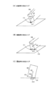
図1は、第1の実施の形態の電子消去具1を説明するための図である。図1(A)の外観図に示すように、電子消去具1は、円筒形状の筐体2の長手方向の一方の端部(前端)に消去部3を設け、他方の端部(後端)からは後述する位置指示器5が装着されて保持された保持部4を挿入して固定することにより構成される。消去部3は、円形の底面3aと、底面3aの外周(外縁)から筒状に延びた側面3bを有する。
[First embodiment]
FIG. 1 is a diagram for explaining an
図1(B)は、電子消去具1の筐体2及び消去部3を長手方向に半分に切断し、その手前側部分を取り除いて示した図である。消去部3は、凹部を有するカップ形状のものであり、当該凹部の開口部側の端部が外側に張り出した形状を有している。消去部3と位置指示器5が装着された保持部4とが筐体2に取り付けられると、位置指示器5の芯体の先端部は、消去部3の底面内面に僅かに接触するようにされる。
FIG. 1(B) is a diagram showing the
この状態では、芯体が位置指示器5の軸心方向に必要以上に押し込まれることはない。消去部3の底面3aと側面3bとは、図1(B)に示したように所定の厚みを有している。このため、電子消去具1が使用されていない状態では、位置指示器5の芯体の先端部は、消去部3の底面3aの外側の面及び側面3bの外側の面から所定距離、離隔された位置に保持される。
In this state, the core body is not pushed in the axial direction of the
また、消去部3は、外側より押圧されれば、筐体2の内部側に摺動可能(移動可能)になっている。このため、消去部3に加えられる圧力が位置指示器5の芯体に伝達され、位置指示器5に搭載されている圧力検出部によって、消去部3に加えられた圧力を検出できる。また、消去部3に加えられた圧力が解除されれば、位置指示器5は消去部3を押し戻し、消去部3は元の位置に復帰する。
Further, the erasing
図1(C)は、位置指示器5の構成を説明するための図である。図1(C)に示すように、コイル51が巻回された磁性体コア、この例ではフェライトコア52が筒状部53と結合されている。そして、中空のパイプの構成とされた金属芯棒54が、フェライトコア52の軸心方向の中心線を含む位置に嵌合固定される。したがって、フェライトコア52の中心線を含む位置には、当該フェライトコア52の貫通孔に対してぴったりと合うようにパイプ形状の金属芯棒54が入れ込まれて固定(固着)されている。
FIG. 1(C) is a diagram for explaining the configuration of the
そして、位置指示器5においては、パイプ形状の金属芯棒の中空の部分(貫通孔)に、芯体55が挿通され、その先端部55aはパイプ形状の金属芯棒54から突出してペン先を構成し、他端は筒状部53内に設けられている圧力検出部6を押圧するようになっている。また、筒状部53内には、コイル51と圧力検出部6と共に、共振回路を構成するコンデンサ7などの回路部品なども搭載されている。
In the
なお、電子消去具1の筐体2は、例えば、PET樹脂などの硬質樹脂により形成される。また、消去部3や保持部4は、POM樹脂などの比較的硬質で弾性を有する樹脂材料により形成される。これにより、消去部3が、電子機器の表示装置の表示画面上に保護ガラスなどが設けられて構成される操作面に傷を付けることもないし、筐体2に対して保持部4を強固に嵌合させることもできる。
The
そして、電子機器に対して、電子ペンを用いて描画するなどして入力した筆跡情報が表示装置の表示画面に入力画像情報として表示された後に、当該入力画像情報の一部を消去する必要が生じたとする。この場合に、当該入力画像情報の消去する部分に対応する操作面上の位置に、電子消去具1を傾けて底面3aと側面3bとが形成する角部、即ち、底面の外縁を接触させて押圧し、入力画像情報の消去部分が含まれる狭い範囲を擦るように移動させるようにする。
Then, after the handwriting information input to the electronic device by drawing with an electronic pen is displayed as input image information on the display screen of the display device, it is necessary to erase a part of the input image information. Suppose that it occurs. In this case, tilt the electronic erasing
すなわち、図1(D)の電子消去具1の底面図に示すように、電子消去具1の筐体2の内側に消去部3が位置し、その中心に位置指示器5の芯体55が位置している。従って、電子消去具1を傾けて使用した場合には、底面3aと側面3bとが形成する角部、即ち、底面3aの外縁部分が操作面との接触部となって、円柱状の消しゴムの角部で筆跡を消す場合と同様に電子消去具1を使用して、入力された消去対象画像の消去を行える。
That is, as shown in the bottom view of the electronic erasing
電子消去具1がどちら側にどれだけ傾いているかは、位置検出装置において、電子消去具1に搭載された位置指示器5から放射された信号(磁界)の受信態様(受信した信号の波形の大きさ)に応じて判別可能である。傾けることで、検出される位置はずれてくるので補正により、位置指示器の先端部の位置検出装置における位置(座標)は先端部からの操作面へ垂線を引いた操作面との交差位置(以下、「交差位置」とする)に設定されている。
The degree to which the electronic erasing
電子消去具1の角部で対象物を消去するには、電子消去具1を傾けたとき、内蔵されている位置指示器5の先端部の交差位置と角部が一致することである。この角部を表示対象物に押し付けることで、圧力が加わり、消去のための信号が位置検出装置で検出される。この状態で操作面上を擦るよう動かすと、対象物を消去することができる。なお、電子消去具1を傾ける角度は、位置指示器5の電子消去具内の位置に依存する。
In order to erase an object with a corner of the electronic erasing
図1(E)は、電子消去具1の位置指示器5と電子機器の操作面Sとの関係を説明するための図である。電子消去具1を操作面Sに対して例えば45度傾けて消去部3を当該操作面Sに接触させた場合を考える。この場合、この例においては、図1(E)に示すように、電子消去具1に搭載されている位置指示器5の芯体55の先端部55aから操作面Sに降ろした垂線と操作面Sとの交差位置が、ちょうど消去部3と操作面Sとの接触位置(接触点)Pに一致するようになっている。この部分を角部で擦ることで消去が行われる。
FIG. 1(E) is a diagram for explaining the relationship between the
なお、電子消去具を傾ける角度は、正確に45度でなくてもよい。例えば35度から55度でも位置指示器5の電子消去具1内の位置を変更することで、角部と消去範囲を一致させることができる。ただし、使いやすい角部の角度は45度であることは、言うまでもない。
Note that the angle at which the electronic eraser is tilted does not have to be exactly 45 degrees. For example, by changing the position of the
なお、上述したように、位置指示器5では、消去部3にかけられた圧力(押圧力)も検出でき、この検出結果を磁界として送出される位置指示信号に含むようにして送信できる。このため、電子機器側においては、指示位置と共に消去部3にかけられている圧力も検出できるので、その圧力に応じて、指示位置を基準として消去範囲を広げたり、狭めたりすることが可能になる。これにより、文房具としての消しゴムを使用する場合と同様に、電子消去具1の消去部3にかかる圧力に応じて、消去範囲を制御することもできる。
Note that, as described above, the
また、電子消去具1を、消去部3を下向きにして落としたり、消去部を壁などに強くぶつけてしまったりする場合もあると考えられる。この場合には、電子消去具1を消去に用いる場合のように、消去部3に比較的にゆっくりと徐々に圧力が加わるのではなく、消去部3に急激に過大な圧力がかかり、これが位置指示器5に印加されることになる。しかし、この第1の実施の形態の保持部4の内部には、いわゆるショックアブソーバ機構が設けられており、消去部3及び位置指示器5に急激に過大な圧力がかかった場合には、これをショックアブソーバ機構が吸収する。これにより、消去部3や位置指示器の破損を防止している。
It is also conceivable that the electronic erasing
[第2の実施の形態]
図2は、第2の実施の形態の電子消去具1Aを説明するための図である。図2(A)の外観図に示すように、電子消去具1Aは、いわゆるカク型のものであり、筐体2Aと消去部3Aと、保持部4Aとを備える。筐体2Aは、外観が略直方体形状で中は中空となっている。消去部3Aは、筐体2Aの長手方向の一方の端部(前端)に設けられる。筐体2Aの長手方向の他方の端部(後端)からは後述する位置指示器5が装着されて保持された保持部4Aを挿入して固定される。
[Second embodiment]
FIG. 2 is a diagram for explaining an
図2(B)は、電子消去具1Aの筐体2A、消去部3A、保持部4Aについて透明なものとしてその内部を見えるように示した図である。図2(B)に示すように、消去部3Aは、凹部を有するカップ形状のものであるが、当該凹部の開口部側の一方の端部が、保持部4Aの先端側の支点SPに回動可能なように取り付けられている。これにより、消去部3Aは、支点SPを中心にして他方の端部側が筐体2A内に押し込まれたり、復帰したりするように摺動(移動)することができるようになっている。
FIG. 2(B) is a diagram showing the inside of the electronic erasing
また、図2(B)に示すように、位置指示器5が保持部4Aに装着されて保持されている。位置指示器5は、図1(C)を用いて説明したものと同様のものである。そして、消去部3Aと位置指示器5が装着された保持部4Aとが筐体2Aに取り付けられると、位置指示器5の芯体55の先端部55aは、消去部3Aの底面の内側の面に僅かに接触するようにされる。しかし、この状態では、芯体55が位置指示器5の軸心方向に必要以上に押し込まれることはない。消去部3Aの底面3Aaと側面3Abとは、図2(B)に示したように所定の厚みを有している。このため、電子消去具1Aが使用されていない状態では、位置指示器5の芯体55の先端部55aは、消去部3Aの底面3Aaの外側の面及び側面3Abの外側の面から所定距離、離隔された位置に保持される。
Further, as shown in FIG. 2(B), the
そして、電子機器に対して、電子ペンを用いて描画するなどして入力した情報が表示装置の表示画面に入力画像情報として表示された後に、当該入力画像情報の一部を消去する必要が生じたとする。この場合に、当該入力画像情報の消去する部分に対応する操作面上の位置に、電子消去具1Aを傾けて図2(C)に示した消去部3の半円形になった部分の外縁3Xを接触させて押圧し、入力画像情報の消去部分が含まれる狭い範囲を擦るように移動させるようにする。この外縁3Xは、底面3Aaと側面3Abとが形成する角部が形成する部分であり、消去部3Aの角部である。
Then, after information input to an electronic device by drawing with an electronic pen or the like is displayed as input image information on the display screen of a display device, it becomes necessary to erase a part of the input image information. Suppose that In this case, the electronic erasing
この場合、上述した第1の実施の形態の電子消去具1の場合と同様に、操作面に接触している消去部3Aの底面の外縁3X部分が消去位置を示すように機能する。そして、図2(C)に示したように、電子消去具1Aの筐体2Aの内側に消去部3Aが位置し、その半円形に形成された部分の当該半円形の直径の中心に位置指示器5の芯体55が位置している。したがって、電子消去具1Aを傾けて、底面3Aaと側面3Abとが形成する角部の部分、即ち、底面3Aaの半円形部分の外縁3Xの部分を操作面に接触させると、この接触部分が消去位置を示す位置となる。これにより、円柱状の消しゴムの角で筆跡を消す場合と同様に、この第2の実施の形態の電子消去具1Aを使用して、入力画像情報の消去を行える。
In this case, as in the case of the
図2(D)は、電子消去具1Aの位置指示器5と操作面との関係を説明するための図である。電子消去具1Aを操作面Sに対して例えば45度傾けて消去部3Aの外縁3Xを当該操作面Sに接触させた場合を考える。この場合、図2(D)に示すように、電子消去具1Aに搭載されている位置指示器5の芯体55の先端部(ペン先)55aから操作面Sに降ろした垂線と操作面Sとの交差位置が、ちょうど消去部3Aの外縁3Xと操作面Sとの接触位置Pに一致するように位置指示器5は電子消去具1Aの内部に組み込まれている。
FIG. 2(D) is a diagram for explaining the relationship between the
従って、この第2の実施の形態の電子消去具1Aにおいても、図1(E)を用いて説明した第1の実施の形態の電子消去具1の場合と同様にして、消去部3Aの外縁3Xが操作面Sに接触したこと、及びその接触位置を特定できるので、ちょうど、この位置に角部がくるように位置指示器5を電子消去具1Aに組み込むようにして、角部を擦ることで対象物を消去可能としている。
Therefore, in the electronic erasing
また、第1の実施の形態の電子消去具1の場合と同様に、電子消去具1Aに搭載された位置指示器5の圧力検出部6において検出される消去部3Aにかけられる圧力に応じて、指示位置を基準として消去範囲を広げたり、狭めたりすることが可能になる。これにより、文房具としての消しゴムを使用する場合と同様に、電子消去具1Aの消去部3Aにかかる圧力に応じて、消去範囲を制御することもできる。
Further, as in the case of the electronic erasing
また、電子消去具1Aは、略直方体形状のものであり、第1の実施の形態のチョーク型の電子消去具1よりも大きい。このため、図2(B)に示したように、筐体2A内に収納される保持部4Aの一部分の替え芯55(1)、55(2)、…と、芯抜き8を収納する収納部4Aaを設けている。筆記用の電子ペンに用いられる替え芯は短く細いものであるので、これを単体で保持使用とする紛失したり、破損したりする可能性が高い。
Further, the
しかし、替え芯55(1)、55(2)、…と芯抜き8とを、電子消去具の保持部4Aに設けられた収納部4Aaに収納しておくことにより、紛失したり、破損したりすることなく、持ち運ぶことができる。なお、保持部4Aの収納部4Aaは、図2(B)に示したように、収納部4Aaの付属蓋を例えばスライド移動させることにより、収納部4Aaの開口が露呈する。そして、当該開口より替え芯55(1)、55(2)、…や芯抜き8を収納したり、取り出したりできる。なお、芯抜き8は、電子ペンに装着されている芯体55の先端部55aを挟み込んで引っ張ることにより、簡単に芯体55を電子ペンから取り外すことができるようにするものである。
However, by storing the refills 55 (1), 55 (2), ... and the
更に、保持部4Aの位置指示器5を保持する部分には、第1の実施の形態の電子消去具1の場合と同様に、いわゆるショックアブソーバ機構が設けられている。これにより、消去部3A及び位置指示器5に急激に過大な圧力がかかった場合には、これをショックアブソーバ機構が吸収し、消去部3や位置指示器5の破損を防止できる。なお、第2の実施の形態の電子消去具1Aにおいても、筐体2Aは、例えば、PET樹脂などの硬質樹脂により形成される。また、消去部3Aや保持部4Aは、POM樹脂などの比較的硬質で弾性を有する樹脂材料により形成される。
Furthermore, a so-called shock absorber mechanism is provided in the portion of the holding
[第2の実施の形態の変形例]
図3は、第2の実施の形態の他の例の電子消去具1Bを説明するための図である。図2を用いて説明した第2の実施の形態の電子消去具1Aの消去部3Aは、図2(C)を用いて説明したように、長方形の1つの短辺が半円形になった形状の底面3Aaと、底面3Aaの外縁から筒状に延びた側面3Abを有するものであった。
[Modification of second embodiment]
FIG. 3 is a diagram for explaining another example of the
これに対して、この変形例の電子消去具1Bは、消去部3Bの形状が、図3(A)に示すように、長方形の底面3Baと、この底面3Baの4つの辺のそれぞれから延びた側面3Bb(1)、3Bb(2)、3Bb(3)、3Bb(4)を有するものである。従って、図3(B)に示すように、電子消去具1Bはその消去部3Bを含めて、文房具の一般的な消しゴムと同様にほぼ直方体形状(マッチ箱の形状)のものとなる。そして、消去部3Bの底面3Baの4つの角部をC1、C2、C3、C4とする。
On the other hand, in the electronic erasing
図4は、文房具である直方体形状の消しゴムの使用態様を示す図である。この変形例の電子消去具1Bは、ほぼ直方体形状のものであるので、図4に示した一般的な文房具の直方体形状の消しゴムの使用態様と全く同じ態様で使用することが可能になる。すなわち、消去部3Bの角部C1、C2を用いて消去したり、消去部3Bの角部C1と角部C2を結ぶ直線状角部を用いて消去したりすることが可能になる。
FIG. 4 is a diagram showing how a rectangular parallelepiped eraser, which is a stationery item, is used. Since the
図5は、この変形例の電子消去具1Bの使用態様について説明するための図である。図5(A)に示すように、電子消去具1Bを操作面Sに対して所定の角度、例えば45度傾けて、消去部3Bの角部C1を電子機器の操作面Sに接触させたとする。この場合、この例の電子消去具1Bに内蔵された位置指示器5の芯体55の先端部55aから操作面Sに降ろした垂線と操作面Sとの交差位置が操作面Sと接触している角部C1と一致するようになっている。従って、電子消去具1Bにおける位置指示器5の配置位置は決まっているので、位置指示器5の芯体55の先端部55aから操作面Sに降ろした垂線を基準にして消去部3Bの角部と操作面Sとの接触位置を特定できる。この特定した接触位置を基準として消去可能エリアAr1を設定し、消去対象画像の消去ができる。
FIG. 5 is a diagram for explaining how the
なお、電子消去具1Bを傾ける角度は、正確に45度でなくてもよい。例えば35度から55度でも位置指示器5ペンの電子消去具1B内の位置を変更することで、角部と消去範囲を一致させることができる。ただし、使いやすい角部の角度は45度であることは、言うまでもない。
Note that the angle at which the
また、図5(B)に示すように、電子消去具1Bを操作面Sに対して所定の角度、例えば45度傾けて、角部C1と角部C2を結ぶ直線状角部を電子機器の操作面Sに接触させたとする。この場合、この例の電子消去具1Bに内蔵された位置指示器5の芯体55の先端部55aから操作面Sに降ろした垂線が操作面Sと接触している直線状角部と一致する。従って、電子消去具1Bにおける位置指示器5の配置位置は決まっているので、位置指示器5の芯体55の先端部55aから操作面Sに降ろした垂線を基準にして消去部3Bの角部C1と角部C2を結ぶ直線状角部と操作面Sとの接触位置を特定できる。そして、この特定した接触位置を基準として消去可能エリアAr2を設定し、消去対象画像の消去ができるようにしている。
Further, as shown in FIG. 5(B), the electronic erasing
また、図5(C)に示すように、消去部3Bの角部C1と角部C2を結ぶ直線角部を操作面Sに接触させるが、操作面Sに対して電子消去具1Bを傾ける角度を小さくしたとする。例えば、操作面Sと電子消去具1Bの側面とのなす角の角度が55度より大きく90度未満である場合を考える。この場合には、電子消去具1Bに内蔵された位置指示器5の芯体55の先端部55aから操作面Sに降ろした垂線と操作面Sとの交差位置は、消去部3Bと操作面Sとの実際の接触位置と大きく乖離する。
Further, as shown in FIG. 5C, the straight corner connecting the corner C1 and the corner C2 of the erasing
そこで、電子消去具1Bの傾きが小さい場合には、消去部3Bと操作面Sとの実際の接触位置を消去可能エリアの設定するための基準とはせずに、実際の接触位置の前方、すなわち、位置指示器5の芯体55の先端部55aから操作面Sに降ろした垂線と操作面Sとの交差位置を基準にして消去可能エリアAr3を設定するようにする。
Therefore, when the inclination of the electronic erasing
これとは逆に、電子消去具1Bを傾ける角度を大きくしたとする。例えば、操作面Sと電子消去具1Bの側面とのなす角の角度が0度より大きく35度未満である場合を考える。この場合にも、電子消去具1Bに内蔵された位置指示器5の芯体55の先端部55aから操作面Sに降ろした垂線と操作面Sとの交差位置は、消去部3Bと操作面Sとの実際の接触位置と大きく乖離する。
On the contrary, assume that the angle at which the
そこで、電子消去具1Bの傾きが大きい場合にも、消去部3Bと操作面Sとの実際の接触位置を消去可能エリアの設定するための基準とはしない。この場合には、実際の接触位置の後方、すなわち、位置指示器5の芯体55の先端部55aから操作面Sに降ろした垂線と操作面Sとの交差位置を基準にして消去可能エリアAr3を設定するようにする。これらの場合には、文房具の消しゴムの使用態様とは異なるが、消去対象画像を目視して確認しながら消去を行うことが可能である。
Therefore, even if the
このように、電子消去具1Bの使用態様によって消去可能エリアを変えるようにするためには、電子消去具1Bによる指示位置を電子機器の位置検出装置において検出できるだけでなく、電子消去具1Bの傾き及び回転を検出できるようにしなければならない。上述した実施の形態の電子消去具に搭載されている位置指示器5は、上述もしたように、電磁誘導方式のものである。このため、電子消去具1Bの傾きは、位置指示器5のコイル51から位置指示信号として放射される磁界の位置検出装置側での受信領域に応じて検知可能である。簡単には、位置指示器のコイルの傾きにより位置検出装置の受信する信号(磁界)の波形が異なる。この波形の大きさを比較することで、傾きを算出することができる。
In this way, in order to change the erasable area depending on how the electronic erasing
電子消去具1Bの回転は、電子消去具1Bに搭載される位置指示器5のフェライトコア及びコイルの搭載態様を工夫する必要がある。すなわち、円筒形のフェライトコア52の側面にコイル51を巻回して構成した部分を次のように構成する。まず、円筒形のフェライトコアを長手方向に2分割してハーフパイプ形状の第1及び第2のフェライトコアを形成し、これらの切断面を対向して組み合わせることにより、筒孔が形成される筒状のコア部材を用意する。
To rotate the electronic erasing
第2のフェライトコアに第2のコイルを巻回し、第1のフェライトコアの切断面を対向させて筒状にする。そして、この第1のフェライトコアと第2のコイルを巻回した第2のフェライトコアからなるコア部材を合わせた状態で第1のコイルを巻回する。このようにして形成されたコア部材が、図1(C)に示した位置指示器5のフェライトコア52とコイル51とからなる部分に替えられる。そして、第1のコイルと第2のコイルへ交互に電流を流すことで、位置検出装置側で座標変位を検出することができる。この変位に基づいて、回転角を算出することができる。なお、電磁誘導方式の位置指示器の回転を検出する構成等については、特開2010-191588号公報に詳しく説明されている。
A second coil is wound around the second ferrite core, and the cut surfaces of the first ferrite core are made to face each other to form a cylindrical shape. Then, the first coil is wound in a state where the core member consisting of the first ferrite core and the second ferrite core around which the second coil is wound are combined. The core member formed in this manner is replaced with a portion consisting of the
回転角を検出することにより回転角に応じた消去エリアの更なる例として、図5(B)に示す角部C1と角部C2を結ぶ直線状角部が操作面Sに接しているときは、細長い消去可能エリアAr2が表示され、徐々に回転させて角部C1で接する場合は、図5(A)に示すように狭い消去可能エリアAr1が表示され、更に回転させることで、角部C1と角部C4を結ぶ直線状角部が操作面Sに接する場合は、図には示していないが、角部C1と角部C4を含む細長い消去エリアが表示され、この消去エリアが消去の対象となる。 As a further example of erasing areas according to the rotation angle by detecting the rotation angle, when a straight corner connecting the corner C1 and the corner C2 shown in FIG. 5(B) is in contact with the operation surface S, , a long and narrow erasable area Ar2 is displayed, and when it is gradually rotated so that it touches the corner C1, a narrow erasable area Ar1 is displayed as shown in FIG. 5(A), and by further rotation, the corner C1 If a straight corner connecting corner C4 and corner C4 touches the operation surface S, a long and narrow erasing area including corner C1 and corner C4 will be displayed, although it is not shown in the figure, and this erasing area will be the target of erasing. becomes.
このようにして、図3~図5を用いて第2の実施の形態の変形例の電子消去具1Bの場合には、電子機器側において、電子消去具1Bの使用態様を特定し、その使用態様に応じた消去対象エリアを形成して、入力画像情報(消去対象画像)の消去を行うようにできる。具体的には、図5(A)に示した頂点接触状態(点接触状態)と、図5(B)に示した短辺接触状態(辺接触状態)と、図5(C)に示した底面指示状態とを、電子機器側で特定し、そのそれぞれに状態に応じて消去可能エリアを特定して入力画像情報の消去を行える。
In this way, in the case of the electronic erasing
[筆記情報処理システムの構成]
図6は、電子消去具1Bと電子機器100とからなる筆記情報処理システムについて説明するための図である。上述したように、電子消去具1、1A、1Bは、電子機器と協働することによって、電子機器に対して電子ペンを用いて入力し、表示するようにした入力画像情報の消去を可能にする。このため、電子機器の概略構成を説明すると共に、電子消去具1Bと電子機器とからなる筆記情報処理システムの利用態様の一例について説明する。
[Configuration of writing information processing system]
FIG. 6 is a diagram for explaining a writing information processing system including the
図6に示すように、電子機器100には、薄型の表示装置としてLCD10と、ループコイルがX軸方向とY軸方向とに複数配列されて形成された位置検出センサ部と、制御処理部30とが積層されて筐体に収納されることによって構成される。なお、LCD10はバックライトなどを含み、その上面には保護ガラスが設けられる。また、制御処理部30は、いわゆるマザーボード上に電子回路として構成される。また、これらが収納される筐体については省略している。
As shown in FIG. 6, the
そして、位置検出センサ部20と制御処理部30の検出処理部31とで位置検出装置を構成している。また、LCD10と表示処理部32とで表示装置を構成している。検出処理部31は、使用するループコイルの切り替え制御、送信期間と受信期間の切り替え制御を行う。また、検出処理部31は、受信期間においては、位置検出センサ部20を通じて受信した位置指示器からの磁界(位置指示信号)に基づいて、電子消去具1Bの指示位置、傾き、回転、電子消去具1Bの消去部3Bにかけられている押圧力を検出する。そして、検出処理部31は、検出結果を表示処理部32に通知する。
The position detection sensor section 20 and the
表示処理部32は、検出処理部31からの指示位置、傾き、回転、押圧力に基づいて、電子消去具1Bの姿勢を特定し、図6において消去可能エリアAr1が示すように、消去可能範囲を示すようにする。具体的には、消去可能範囲を線で囲んで示したり、消去可能範囲を反転表示させたりするなどの処理を行う。そして、電子消去具1Bの指示位置の変化に応じて、消去可能エリアに表示されている入力画像情報を消去する消去処理を実行する。当該消去処理は、LCD10の表示画面の消去可能エリアに表示されている入力画像情報を消去すると共に、当該入力画像情報に対応する蓄積対象の画像データをも消去する。これにより、電子消去具1Bの使用者は、自分の意図に応じて、目的とする入力画像情報の消去を行うことができる。
The
[押圧力等の別経路での送信]
上述した実施の形態では、例えば位置指示器5から送出される位置指示信号に、消去部3、3A、3Bにかけられる押圧力を示す情報も含めて送出した。しかし、これに限るものではない。少なくとも消去部3、3A、3Bにかけられる押圧力は、位置指示器5側で検出可能である。このため、当該押圧力は、位置指示信号とは別に位置検出装置側に送信することもできる。図7は、電子消去具に用いられる位置指示器の他の例を説明するための図である。図8は、図7に示した位置指示器が搭載された電子消去具が使用される電子機器を説明するための図である。
[Transmission of pressing force, etc. via a different route]
In the embodiment described above, for example, the position pointing signal sent from the
この他の例の位置指示器5Xは、図7に示すように、圧力検出機構部501と圧力信号送信部502とを備える。圧力検出機構部501は、圧力検出部6Xを備えると共に、図1(C)を用いて説明した位置指示器5の場合と同様、フェライトコア52、コイル51、金属芯棒54、芯体55を備えた部分となる。また、フェライトコア52とコイル51とに替えて、上述したように、第1、第2のフェライトコアと、第1、第2のコイルと、第2のフェライトコアに巻回されたコイルへの導通制御を行うスイッチを備えた構成とすることもできる。この例の位置指示器5Xは、後者の回転の検出も可能にする構成を備えたものである。
The position indicator 5X of this other example includes a pressure detection mechanism section 501 and a pressure signal transmission section 502, as shown in FIG. The pressure detection mechanism section 501 includes a pressure detection section 6X, and also includes a
そして、圧力検出部6Xは、その検出出力を圧力信号送信部502の信号変換部502a(図7では「IC」と記載。)に供給する。信号変換部502aは、圧力検出部6Xからの検出出力はアナログ信号であるので、これをデジタル信号に変換し、送信回路502bに供給する。送信回路502bは、信号変換部502aからの押圧力を示すデジタル信号を送信用のフォーマットに準拠した送信信号を形成し、これを送信アンテナ502cを通じて送出して位置検出装置側に送信する。
The pressure detection section 6X then supplies the detection output to the
この例の位置指示器5Xに対応する電子機器200は、例えばタブレットPCであり、図8に示すように、電磁誘導方式の位置検出センサ部210と、圧力等信号受信部220と、検出処理部230とを備える。これら位置検出センサ部210と圧力等信号受信部220と検出処理部230とにより位置検出装置が構成される。従って、図8には図示していないが、位置検出センサ部210の上面側には、LCDなどの薄型の表示装置が積層配置されている。
The electronic device 200 corresponding to the position indicator 5X in this example is, for example, a tablet PC, and as shown in FIG. 230. These position detection sensor section 210, pressure etc.
位置検出センサ部210は、検出処理部230の制御に応じて、送信期間においては、選択されたループコイルに電流が供給されることにより、磁界を発生させて送信するようにする。また、受信期間においては、ループコイルを通じて位置指示器5Xからの位置指示信号を受信し、検出処理部230に供給する。また、圧力等信号受信部220は、位置指示器5Xの送信回路502bを通じて送信される圧力信号を受信し、これを自機において処理可能な形式の信号に変換して検出処理部230に供給する。
In accordance with the control of the
検出処理部230は、ループコイルの切り替え制御や送信期間と受信期間の切り替え制御を行う。また、検出処理部230は、受信期間において位置検出センサ部210を通じて受信した位置指示器5Xからの位置指示信号と受信したループコイルの位置に基づいて、指示位置、傾き、回転を検出する。更に、検出処理部230は、圧力等信号受信部220からの信号に基づいて、消去部にかけられた押圧力を検出する。そして、検出処理部230は、これら検出した指示位置、傾き、回転、押圧力を、図8には図示していないが、表示制御回路に供給する。
The
当該表示処理部は、検出処理部230からの指示位置、傾き、回転、押圧力に基づいて、位置指示器5Xが搭載された電子消去具の姿勢をも特定する。そして、当該表示処理部は、例えば図5の消去可能エリアAr1、Ar2、Ar3が示すように、消去可能範囲を示すように消去エリアの表示制御ができる。また、当該表示制御部は、位置指示器5Xが搭載された電子消去具の指示位置の変化に応じて、消去可能エリアに表示されている入力画像情報を消去する消去処理を実行することができる。
The display processing section also specifies the posture of the electronic erasing tool on which the position indicator 5X is mounted, based on the indicated position, tilt, rotation, and pressing force from the
なお、ここでは、圧力検出部6Xで検出された押圧力を示す情報だけを送信回路502bと送信アンテナ502cを通じて送信するようにしたが、これに限るものではない。例えば、電子消去具から送信されたものであることを示す情報を、送信回路502bと送信アンテナ502cを通じて送信するようにしてもよい。これにより、位置検出センサ部210で受信されている位置指示信号が、情報入力用の電子ペンから送出される信号と同じ周波数の信号であっても、当該位置指示信号は、消去を指示するものであること検出処理部230で検出し、これを表示処理部に通知できる。
Note that here, only the information indicating the pressing force detected by the pressure detection unit 6X is transmitted through the
[位置指示器の筐体内での配置態様]
図9は、電子消去具の筐体への位置指示器の配置態様について説明するための図である。図2(B)にも示し、また、図9(A)にも示すように、直方体形状のいわゆる角型の電子消去具の場合であっても、位置指示器5は、筐体2の側面と平行に配置するようにしていた。しかしこれに限るものではない。例えば、図9(B)に示すように、筐体2内において、位置指示器5を側面と所定の角度θ分斜めになるように配置するようにしてもよい。
[Arrangement of position indicator within the housing]
FIG. 9 is a diagram for explaining how the position indicator is arranged in the housing of the electronic eraser. As shown in FIG. 2B and also in FIG. I tried to place it parallel to the However, it is not limited to this. For example, as shown in FIG. 9(B), the
このようにすることによって、位置指示器5の芯体55の先端部55aと、電子消去具の消去部3A、3Bの操作面に対して接触させるべき角部との距離を近づけることができる。更に、芯体55が配置されている位置を通って放射するようにされる磁界の多くが、集中して操作面に当たるようにできるので、位置検出装置側での磁界の受信位置を狭くすると共に受信レベルを高くすることができる。
By doing so, the distance between the
[電磁誘導方式の位置指示器と静電結合方式の位置指示器]
上述した実施の形態では、電磁誘導方式の位置指示器と位置検出装置とを用いるものとして説明した。しかし、静電容量方式の位置指示器と位置検出装置とを用いる場合にもこの発明を適用できる。図10は、電磁誘導方式の位置指示器の等価回路の一例と、静電容量方式の位置指示器の等価回路の一例を示す図である。
[Electromagnetic induction type position indicator and capacitive coupling type position indicator]
In the embodiment described above, the electromagnetic induction type position indicator and position detection device are used. However, the present invention can also be applied when using a capacitance type position indicator and position detection device. FIG. 10 is a diagram showing an example of an equivalent circuit of an electromagnetic induction type position indicator and an example of an equivalent circuit of a capacitance type position indicator.
上述した実施の形態で用いた電磁誘導方式の位置指示器5は、図10(A)に示すように、コイル51と、コンデンサ7と、圧力検出部6を構成する可変容量コンデンサとから構成されるものであった。この構成の位置指示器5により、指示位置、傾き、押圧力を、位置指示器5から放射される位置指示信号(磁界)によって、位置検出装置に伝達できた。更に、位置指示器の回転をも伝達できるようにするためには、上述もしたように、フェライトコア52とコイル51とからなる部分を、第1、第2のフェライトコアと、第1、第2のコイルと、第2のコイルの導通制御を行うスイッチとかなる構成に変更する。これにより、当該位置指示器が搭載された電子消去具1Bの回転についても位置検出装置に伝達できる。
The electromagnetic induction
また、静電容量方式の位置指示器9は、例えば、図10(B)に示すように、導電性の芯体81と、導電線82と、発振回路83と、芯体81により押圧される圧力検出部としての可変容量コンデンサ84と、駆動電力を供給する電源回路85により構成できる。これにより、指示位置と芯体にかかる押圧力は、芯体から出力される信号によって、位置検出装置に伝達できる。この構成の位置指示器9により、図1、図2に示した態様の静電容量方式の電子消去具を実現できる。
Further, the capacitive position indicator 9 is pressed by a
なお、静電容量方式の位置指示器において、位置指示器の傾きや回転を位置検出装置に伝達できるようにするためには、例えば、芯体は非導電性のもとのとし、この芯体に対して、また、この芯体の近傍に、複数(2つ以上)の電極を設けるようにする。この複数の電極の中から予め決められた選択パターンに基づき選択された電極に交流信号を供給するように切替回路を設ける。そして、切替回路によって設定されたパターンが切替えられた際に設定されたパターンの種類を示すパターン情報をタブレットに対して送信する。このパターン情報を位置検出装置において解析することによって、位置指示器の回転や傾きを検出するようにできる。なお、この技術については、特開2014-35631号公報に詳述されている。 In addition, in a capacitive position indicator, in order to be able to transmit the tilt and rotation of the position indicator to the position detection device, for example, the core must be non-conductive. In addition, a plurality of (two or more) electrodes are provided near the core. A switching circuit is provided to supply an AC signal to an electrode selected from among the plurality of electrodes based on a predetermined selection pattern. Then, when the pattern set by the switching circuit is switched, pattern information indicating the type of pattern set is transmitted to the tablet. By analyzing this pattern information in the position detection device, rotation and tilt of the position indicator can be detected. Note that this technology is detailed in Japanese Patent Application Laid-Open No. 2014-35631.
[実施の形態の効果]
上述した実施の形態の電子消去具1、1A、1Bは、文房具の消しゴムを使用する場合と同様にして、タブレットPCなどの電子機器に対して入力するようにした筆跡情報を、使用者の意図に合致して消去することができる。具体的には、電子消去具1、1Aの消去部3、3Aの底面と側面とが形成する角部を基準にして、また、電子消去具1Bの消去部3Bの頂点(点)、短辺(直線)、底面(面)を基準にして、消去可能エリアを特定し、消去対象画像の消去を行うことができる。従って、電子機器専用の電子消しゴムが実現できる。
[Effects of embodiment]
The electronic erasing
また、実施の形態の電子消去具1、1A、1Bと電子機器とからなるシステムの場合、電子消去具の使用態様に応じて、消去可能エリアを使用者が認識可能な態様で示すことができるので、消し間違えを防止することができる。具体的には、消去可能範囲を、消去部3、3A、3Bの角に集中して設けることができるシステムが実現できる。
Furthermore, in the case of a system including the electronic erasing
また、上述したように、位置指示器からの信号によって位置指示器の回転、即ち、電子消去具の絶対的な回転角を電子機器において検出可能な場合には、電気機器の表示制御部の機能によって、回転角に対応する辺に応じた消去可能エリアを設定することもできる。すなわち、図5(A)に示したように、消去部3Bの頂点を基準にして消去可能エリアを設定したり、図5(B)に示したように、消去部3Bの短辺を基準にして消去可能エリアを設定したりすることができる。
In addition, as described above, if the rotation of the position indicator, that is, the absolute rotation angle of the electronic erasing tool, can be detected in the electronic device based on the signal from the position indicator, the display control section of the electrical device will function. It is also possible to set an erasable area according to the side corresponding to the rotation angle. That is, as shown in FIG. 5(A), the erasable area is set based on the vertex of the erasing
[変形例]
なお、図5を用いて説明したように、電子消去具1、1A、1Bによる消去可能範囲は、電子消去具1、1A、1Bを傾けた側と反対の方向に設け、これを表示可能にした。しかし、これに限るものではない。電子消去具1、1A、1Bによる消去可能範囲は、電子消去具1、1A、1Bを傾けた側と同一方向に設け、これを表示することも可能である。また、どちらを消去可能範囲にするかを、ユーザが電子機器に設定するようにしてもよい。
[Modified example]
As explained using FIG. 5, the range that can be erased by the electronic erasing
また、電子機器側において、電子消去具1、1A、1Bの消去部3、3A、3Bにかけられた圧力に応じて、消去可能エリアを大きくしたり、小さくしたりすることもできる。また、電子機器側において、電子消去具1、1A、1Bの傾きに応じて、消去可能エリアを変化させることもできる。この場合、傾けなさ過ぎても、また、傾けすぎても、消去可能エリアをどの程度にするかの制御が難しくなるため、電子消去具1、1A、1Bは、操作面に対して、35度~55度の範囲で傾けて使用することが好ましい。
Further, on the electronic device side, the erasable area can be made larger or smaller depending on the pressure applied to the erasing
また、電子消去具1、1A、1Bの消去部3、3A、3Bを操作面に接触させて、移動させるようにした場合には、消去動作が行われているので、電子機器側で消去の強度を高め、消去可能範囲の消去対象画像を確実に消去できるように制御するようにしてもよい。
In addition, when the erasing
また、消去部の底面の形状は、消去部3に示したように、円形であってもよいし、消去部3Aに示したように、半円形または半円形を含むものであってもよいし、また、消去部3Bに示したように四角形であってもよい。また、消去部の底面は、四角形以外にも、3角形以上の多角形とすることもできる。すなわち、消去部の底面は、側面と共に角をなすように構成できる種々の形状とすることができる。
Further, the shape of the bottom surface of the erasing section may be circular as shown in the erasing
また、電子消去具1、1A、1Bの操作面Sに対するか傾きが、例えば35度から55度の範囲内においては、接触位置Pは、電子消去具1、1A、1Bの操作面Sに対する傾きが45度の場合と同じであると位置検出装置側で特定することができる。このようにすれば、電子消去具1、1A、1Bの操作面Sに対するか傾きが、例えば35度から55度の範囲内であれば、傾き変わっても接触位置Pを基準にして消去可能エリアを設定し、消去処理をシームレスに行うことができる。
Furthermore, if the inclination of the electronic erasing
1、1A、1B…電子消去具、2、2A…筐体、3、3A、3B…消去部、3a、3Aa、3Ba…底面、3b、3Ab、3Bb(1)、3Bb(2)、3Bb(3)、3Bb(4)…側面、4、4A…保持部、4Aa…収納部、5、9…位置指示器、51…コイル、52…フェライトコア、53…筒状部、54…金属芯棒、55…芯体、55(1)…替え芯、55a…先端部、6…圧力検出部、7…コンデンサ、8…芯抜き、Ar1、Ar2、Ar3…消去可能エリア、10…LCD、20…位置検出センサ、30…制御処理部、31…検出処理部、32…表示処理部、100…電子機器、200…電子機器、210…位置検出センサ部、220…圧力等信号受信部、230…検出処理部、5X…位置指示器、501…圧力検出機構部、6X…圧力検出部、502…圧力信号送信部、502a…信号変換部、502b…送信回路、502c…送信アンテナ、81…芯体、82…導電線、83…発振回路、84…圧力検出部、85…電源回路 1, 1A, 1B...electronic eraser, 2, 2A...casing, 3, 3A, 3B...erasing section, 3a, 3Aa, 3Ba...bottom, 3b, 3Ab, 3Bb (1), 3Bb (2), 3Bb ( 3), 3Bb (4)... Side surface, 4, 4A... Holding part, 4Aa... Storage part, 5, 9... Position indicator, 51... Coil, 52... Ferrite core, 53... Cylindrical part, 54... Metal core rod , 55... core body, 55 (1)... refill, 55a... tip, 6... pressure detection section, 7... capacitor, 8... core removal, Ar1, Ar2, Ar3... erasable area, 10... LCD, 20... Position detection sensor, 30... Control processing section, 31... Detection processing section, 32... Display processing section, 100... Electronic device, 200... Electronic device, 210... Position detection sensor section, 220... Pressure etc. signal receiving section, 230... Detection Processing unit, 5X... Position indicator, 501... Pressure detection mechanism unit, 6X... Pressure detection unit, 502... Pressure signal transmission unit, 502a... Signal conversion unit, 502b... Transmission circuit, 502c... Transmission antenna, 81... Core body, 82... Conductive wire, 83... Oscillation circuit, 84... Pressure detection section, 85... Power supply circuit
Claims (9)
底面と前記底面の外縁から延伸された側面の少なくとも一部とを、前記筐体の端面から突出させると共に、前記筐体に対して摺動可能に取り付けられる消去部と、
前記消去部に包含され、芯体と前記芯体に加えられる圧力を検出する圧力検出部とを有し、前記芯体による消去位置を示す位置指示信号と、前記圧力検出部で検出された圧力を示す情報とを出力する位置指示器と
を備え、
表示装置と位置検出装置とを備えた電子機器の消去対象画像が表示される表示画面に対応する操作面に対して、前記筐体を所定の角度で傾けるようにして前記消去部を接触させるようにした場合に、前記消去部の前記底面と前記側面とが形成する角部が前記操作面に接触する接点と、前記芯体の先端部から前記操作面に対して降ろした垂線と前記操作面との交差位置とが、前記筐体の傾きに応じて接近することで、消去可能エリアが形成される
ことを特徴とする電子消去具。 A casing and
an erasing section that causes a bottom surface and at least a portion of a side surface extending from an outer edge of the bottom surface to protrude from an end surface of the casing, and is slidably attached to the casing;
The eraser includes a core body and a pressure detection unit that detects pressure applied to the core body, and a position instruction signal indicating an erase position by the core body, and a pressure detected by the pressure detection unit. and a position indicator that outputs information indicating.
The erasing unit is brought into contact with an operation surface of an electronic device including a display device and a position detection device, which corresponds to a display screen on which an image to be erased is displayed, by tilting the casing at a predetermined angle. , a contact point where a corner formed by the bottom surface and the side surface of the erasing section contacts the operation surface, a perpendicular line drawn from the tip of the core body to the operation surface, and the operation surface. An electronic erasing device characterized in that an erasable area is formed by the intersecting position of the casing approaching the casing according to the inclination of the casing.
前記位置指示器の前記芯体は、前記消去部とは別体に構成され、
前記位置指示器は、前記芯体の先端部が、前記消去部の前記底面の内側の面に接するように、前記筐体内に固定される
ことを特徴とする電子消去具。 The electronic eraser according to claim 1,
The core body of the position indicator is configured separately from the erasing unit,
The electronic erasing device is characterized in that the position indicator is fixed within the housing so that the tip of the core is in contact with the inner surface of the bottom surface of the erasing section.
前記位置指示器は、前記芯体の先端部が前記消去部の底面の外側の面から離されると共に、前記消去部に加えられる圧力が前記芯体に伝達されるように前記筐体内に固定される
ことを特徴とする電子消去具。 The electronic eraser according to claim 1 or 2,
The position indicator is fixed within the housing such that the tip of the core is separated from the outer bottom surface of the eraser and the pressure applied to the eraser is transmitted to the core. Ru
An electronic eraser characterized by:
前記消去部の前記底面の形状は、円形、半円形、多角形のいずれかである
ことを特徴とする電子消去具。 The electronic eraser according to claim 1,
The electronic erasing tool is characterized in that the shape of the bottom surface of the erasing section is one of a circle, a semicircle, and a polygon.
前記位置指示器は、前記圧力検出部において検出された前記圧力を示す情報と、位置検出装置において前記位置指示器の傾きを検出するための情報と、前記位置検出装置において前記位置指示器の軸心を中心とする回転を検出するための情報とを、前記位置指示信号に含めて送信する
ことを特徴とする電子消去具。 The electronic eraser according to claim 1,
The position indicator includes information indicating the pressure detected by the pressure detection unit, information for detecting the tilt of the position indicator in the position detection device , and information indicating the axis of the position indicator in the position detection device. An electronic eraser characterized in that information for detecting rotation around the heart is included in the position instruction signal and transmitted.
無線送信部を備え、
前記圧力を示す情報と自機が電子消去具であることを示す情報の一方または両方を、前記無線送信部を通じて位置検出装置に送信する
ことを特徴とする電子消去具。 The electronic eraser according to claim 1,
Equipped with a wireless transmitter,
An electronic erasing device, characterized in that one or both of information indicating the pressure and information indicating that the device is an electronic erasing device is transmitted to a position detecting device through the wireless transmitter.
前記位置指示器は共振回路を備え、
表示装置と電磁誘導方式の位置検出装置とを備えた電子機器の前記位置検出装置との間で信号の送受信を行うことによって、前記電子機器の前記表示装置の表示画面に対応する操作面上の消去位置を指示する電磁誘導授受方式の位置指示器である
ことを特徴とする電子消去具。 The electronic eraser according to claim 1,
The position indicator includes a resonant circuit,
By transmitting and receiving signals between the position detection device of an electronic device including a display device and an electromagnetic induction type position detection device, An electronic erasing tool characterized by being an electromagnetic induction type position indicator that indicates the erasing position.
前記位置指示器は発振回路を備え、
前記発振回路からの信号を、導電性材料により形成された前記芯体を通じて送出することによって、表示装置と静電結合方式の位置検出装置を備えた電子機器の前記表示装置の表示画面に対応する操作面上の消去位置を指示する静電結合方式の位置指示器である
ことを特徴とする電子消去具。 The electronic eraser according to claim 1,
The position indicator includes an oscillation circuit,
By sending a signal from the oscillation circuit through the core formed of a conductive material, the display screen of the display device of an electronic device including a display device and a capacitive coupling type position detection device is provided. An electronic erasing tool characterized by being a capacitively coupled position indicator that indicates the erasing position on an operation surface.
前記電子消去具は、
筐体と、
底面と前記底面の外縁から延伸された側面の少なくとも一部とを、前記筐体の端面から突出させると共に、前記筐体に対して摺動可能に取り付けられる消去部と、
芯体と前記芯体に加えられる圧力を検出する圧力検出部とを有し、前記芯体による消去位置を示す位置指示信号と、前記圧力検出部で検出された圧力を示す情報とを出力する位置指示器と
を備え、
前記位置指示器は、前記消去部に包含され、前記芯体の先端部が前記消去部の底面の外側の面から離されると共に、前記消去部に加えられる圧力が前記芯体に伝達されるように前記筐体内に固定されるものであり、
前記電子機器は、
前記位置検出装置からの検出出力に基づいて、前記表示装置に対して消去エリアを表示するように制御する表示制御部を備え、
前記表示制御部は、前記筐体を所定の角度で傾け、更に前記筐体を回転させた場合、前記筐体の回転位置に応じて、消去可能エリアを変更し表示させるように制御する
ことを特徴とする筆記情報処理システム。 A writing information processing system comprising an electronic device equipped with a display device and a position detection device, and an electronic erasing tool,
The electronic eraser is
A casing and
an erasing section that causes a bottom surface and at least a portion of a side surface extending from an outer edge of the bottom surface to protrude from an end surface of the casing, and is slidably attached to the casing;
It has a core body and a pressure detection unit that detects the pressure applied to the core body, and outputs a position instruction signal indicating an erase position by the core body and information indicating the pressure detected by the pressure detection unit. Equipped with a position indicator and
The position indicator is included in the erasing section, and the tip of the core is separated from the outer bottom surface of the erasing section, and the pressure applied to the erasing section is transmitted to the core. is fixed within the housing,
The electronic device is
a display control unit that controls the display device to display an erasure area based on a detection output from the position detection device ;
The display control unit controls so that when the casing is tilted at a predetermined angle and the casing is further rotated, the erasable area is changed and displayed according to the rotational position of the casing.
A written information processing system characterized by:
Applications Claiming Priority (3)
| Application Number | Priority Date | Filing Date | Title |
|---|---|---|---|
| JP2018211309 | 2018-11-09 | ||
| JP2018211309 | 2018-11-09 | ||
| PCT/JP2019/041845 WO2020095710A1 (en) | 2018-11-09 | 2019-10-25 | Electronic erasing tool and written information processing system |
Publications (2)
| Publication Number | Publication Date |
|---|---|
| JPWO2020095710A1 JPWO2020095710A1 (en) | 2021-10-07 |
| JP7449236B2 true JP7449236B2 (en) | 2024-03-13 |
Family
ID=70610982
Family Applications (1)
| Application Number | Title | Priority Date | Filing Date |
|---|---|---|---|
| JP2020555952A Active JP7449236B2 (en) | 2018-11-09 | 2019-10-25 | Electronic eraser and writing information processing system |
Country Status (4)
| Country | Link |
|---|---|
| US (2) | US11385725B2 (en) |
| JP (1) | JP7449236B2 (en) |
| CN (1) | CN112930515A (en) |
| WO (1) | WO2020095710A1 (en) |
Families Citing this family (2)
| Publication number | Priority date | Publication date | Assignee | Title |
|---|---|---|---|---|
| WO2020095710A1 (en) * | 2018-11-09 | 2020-05-14 | 株式会社ワコム | Electronic erasing tool and written information processing system |
| JP2022014973A (en) * | 2020-07-08 | 2022-01-21 | 株式会社ワコム | Method performed by stylus and sensor controller, stylus, and sensor controller |
Citations (5)
| Publication number | Priority date | Publication date | Assignee | Title |
|---|---|---|---|---|
| JP2010191588A (en) | 2009-02-17 | 2010-09-02 | Wacom Co Ltd | Position indicator, circuit component and input device |
| JP2016095833A (en) | 2015-08-21 | 2016-05-26 | 株式会社ワコム | Position indicator |
| WO2016143498A1 (en) | 2015-03-06 | 2016-09-15 | 株式会社ワコム | Electronic pen and body part for electronic pen |
| JP2017004381A (en) | 2015-06-12 | 2017-01-05 | シャープ株式会社 | Eraser device and instruction input system |
| JP2018037014A (en) | 2016-09-02 | 2018-03-08 | 三菱鉛筆株式会社 | Handwriting input device |
Family Cites Families (36)
| Publication number | Priority date | Publication date | Assignee | Title |
|---|---|---|---|---|
| US6259438B1 (en) * | 1998-06-04 | 2001-07-10 | Wacom Co., Ltd. | Coordinate input stylus |
| JPS6370326A (en) * | 1986-09-12 | 1988-03-30 | Wacom Co Ltd | Position detector |
| JPH02155020A (en) | 1988-12-07 | 1990-06-14 | Wacom Co Ltd | Position indicator |
| US5475401A (en) * | 1993-04-29 | 1995-12-12 | International Business Machines, Inc. | Architecture and method for communication of writing and erasing signals from a remote stylus to a digitizing display |
| US5661269A (en) * | 1994-02-03 | 1997-08-26 | Wacom Co., Ltd. | Position pointing device having resonant circuit with sequentially changed characteristics and combination thereof with position detecting device |
| JP3414517B2 (en) | 1994-08-26 | 2003-06-09 | 株式会社ワコム | Position indicator and coordinate input device using the same |
| JP2717774B2 (en) * | 1995-01-13 | 1998-02-25 | 株式会社ワコム | Pressure sensitive element and stylus pen with pressure sensitive function |
| JPH08227336A (en) * | 1995-02-20 | 1996-09-03 | Wacom Co Ltd | Pressure sensing mechanism and stylus pen |
| JP2767098B2 (en) * | 1995-06-06 | 1998-06-18 | 株式会社ワコム | Position indicating unit and stylus pen |
| US5914708A (en) * | 1996-04-04 | 1999-06-22 | Cirque Corporation | Computer input stylus method and apparatus |
| JP3837812B2 (en) * | 1997-01-30 | 2006-10-25 | 株式会社ワコム | Cordless electronic pen with cartridge |
| USD417206S (en) * | 1998-08-05 | 1999-11-30 | Wacom Co., Ltd. | Digitizer stylus |
| US6850230B1 (en) * | 2001-10-16 | 2005-02-01 | Hewlett-Packard Development Company, L.P. | Electronic writing and erasing pencil |
| US7685538B2 (en) * | 2003-01-31 | 2010-03-23 | Wacom Co., Ltd. | Method of triggering functions in a computer application using a digitizer having a stylus and a digitizer system |
| US7310091B2 (en) * | 2003-09-16 | 2007-12-18 | Acer Incorporated | Handwriting pen capable of simulating different strokes |
| USD531217S1 (en) * | 2004-11-12 | 2006-10-31 | Wacom Co., Ltd. | Marker pen |
| US20070146351A1 (en) * | 2005-12-12 | 2007-06-28 | Yuji Katsurahira | Position input device and computer system |
| US8536471B2 (en) * | 2008-08-25 | 2013-09-17 | N-Trig Ltd. | Pressure sensitive stylus for a digitizer |
| USD614623S1 (en) * | 2009-04-16 | 2010-04-27 | Wacom Co., Ltd. | Electronic pen |
| US20120086664A1 (en) * | 2009-06-29 | 2012-04-12 | Gerald Leto | Multifunctional writing apparatus with capacitive touch screen stylus |
| US9122322B2 (en) * | 2011-03-17 | 2015-09-01 | Microsoft Technology Licensing, Llc | Interacting tips for a digitizer stylus |
| JP6021174B2 (en) | 2012-08-08 | 2016-11-09 | 株式会社ワコム | Position detecting device and position indicator thereof |
| KR20140117137A (en) * | 2013-03-26 | 2014-10-07 | 삼성전자주식회사 | Portable apparatus using touch pen and mehtod for controlling application using the portable apparatus |
| US9939934B2 (en) * | 2014-01-17 | 2018-04-10 | Osterhout Group, Inc. | External user interface for head worn computing |
| US20150212600A1 (en) * | 2014-01-27 | 2015-07-30 | Nvidia Corporation | Stylus tool with deformable tip |
| WO2016006272A1 (en) * | 2014-07-11 | 2016-01-14 | 株式会社ワコム | Position indicator, position detection device, and input control method for position detection device |
| TW201604722A (en) * | 2014-07-31 | 2016-02-01 | 佳世達科技股份有限公司 | Handwriting input system and handwriting input method |
| WO2017004381A1 (en) | 2015-06-30 | 2017-01-05 | St. Jude Children's Research Hospital, Inc. | Method for treating schizophrenia |
| US10534449B2 (en) * | 2016-08-19 | 2020-01-14 | Microsoft Technology Licensing, Llc | Adjustable digital eraser |
| US10061411B2 (en) * | 2016-08-19 | 2018-08-28 | Microsoft Technology Licensing, Llc | Dual-function switch for stylus tail eraser |
| DE102016115614A1 (en) | 2016-08-23 | 2018-03-01 | Aixtron Se | Susceptor for a CVD reactor |
| US10838520B2 (en) * | 2016-09-02 | 2020-11-17 | Mitsubishi Pencil Company, Limited | Handwriting input device |
| WO2018043488A1 (en) * | 2016-09-02 | 2018-03-08 | 三菱鉛筆株式会社 | Handwriting input apparatus |
| KR102293320B1 (en) * | 2017-03-03 | 2021-08-25 | 가부시키가이샤 와코무 | Position indicator and handwriting information processing device |
| JP6952591B2 (en) * | 2017-12-11 | 2021-10-20 | 株式会社ワコム | Electronic pen and electronic pen body |
| WO2020095710A1 (en) * | 2018-11-09 | 2020-05-14 | 株式会社ワコム | Electronic erasing tool and written information processing system |
-
2019
- 2019-10-25 WO PCT/JP2019/041845 patent/WO2020095710A1/en active Application Filing
- 2019-10-25 CN CN201980071165.9A patent/CN112930515A/en active Pending
- 2019-10-25 JP JP2020555952A patent/JP7449236B2/en active Active
-
2021
- 2021-04-28 US US17/243,399 patent/US11385725B2/en active Active
-
2022
- 2022-06-07 US US17/834,782 patent/US11662834B2/en active Active
Patent Citations (5)
| Publication number | Priority date | Publication date | Assignee | Title |
|---|---|---|---|---|
| JP2010191588A (en) | 2009-02-17 | 2010-09-02 | Wacom Co Ltd | Position indicator, circuit component and input device |
| WO2016143498A1 (en) | 2015-03-06 | 2016-09-15 | 株式会社ワコム | Electronic pen and body part for electronic pen |
| JP2017004381A (en) | 2015-06-12 | 2017-01-05 | シャープ株式会社 | Eraser device and instruction input system |
| JP2016095833A (en) | 2015-08-21 | 2016-05-26 | 株式会社ワコム | Position indicator |
| JP2018037014A (en) | 2016-09-02 | 2018-03-08 | 三菱鉛筆株式会社 | Handwriting input device |
Also Published As
| Publication number | Publication date |
|---|---|
| US20210247851A1 (en) | 2021-08-12 |
| WO2020095710A1 (en) | 2020-05-14 |
| US20220300092A1 (en) | 2022-09-22 |
| US11385725B2 (en) | 2022-07-12 |
| US11662834B2 (en) | 2023-05-30 |
| JPWO2020095710A1 (en) | 2021-10-07 |
| CN112930515A (en) | 2021-06-08 |
Similar Documents
| Publication | Publication Date | Title |
|---|---|---|
| US11662834B2 (en) | Electronic erasing device and writing information processing system | |
| JP6544775B2 (en) | Position indicator, position detection device, input control method for position detection device, and input device | |
| KR102184288B1 (en) | Mobile terminal for providing haptic effect with an input unit and method therefor | |
| JP4872111B2 (en) | Position indicator | |
| JP6660222B2 (en) | Electronic pen and position detection system | |
| JP6127548B2 (en) | Pen-type input device and electronic information board system | |
| US20110164000A1 (en) | Communicating stylus | |
| US10234963B2 (en) | Touch pen apparatus, system, and method | |
| KR20160064719A (en) | Pen input device, method for correction input coordinate thereof and electronic device for suppoting the same | |
| TW201516766A (en) | Stylus | |
| KR20150007780A (en) | Input device for electronic device and input method using the same | |
| EP3614240A1 (en) | Capacitive stylus, touch device, and electronic system thereof | |
| JP6754643B2 (en) | Handwriting input device | |
| US10838520B2 (en) | Handwriting input device | |
| US10990198B2 (en) | Wireless stylus with grip force expression capability | |
| JPH07239745A (en) | Information input device and position recognition system in information input | |
| WO2018043488A1 (en) | Handwriting input apparatus | |
| KR100980691B1 (en) | Multi-functional ultrasonic input signal generation device | |
| CN215867789U (en) | Telescopic electronic pen | |
| KR20180043761A (en) | Apparatus for recognizing writing applied to the portable device and system including the same | |
| JP2015032010A (en) | Digitizer pen | |
| JP6858546B2 (en) | Handwriting input device | |
| JPH1195903A (en) | Coordinate indicator for coordinate reader, device and system for reading coordinate | |
| JP2016085566A (en) | Input device and electronic information board system | |
| TWM474187U (en) | Stylus |
Legal Events
| Date | Code | Title | Description |
|---|---|---|---|
| A521 | Request for written amendment filed |
Free format text: JAPANESE INTERMEDIATE CODE: A523 Effective date: 20210324 |
|
| A621 | Written request for application examination |
Free format text: JAPANESE INTERMEDIATE CODE: A621 Effective date: 20221019 |
|
| A131 | Notification of reasons for refusal |
Free format text: JAPANESE INTERMEDIATE CODE: A131 Effective date: 20230823 |
|
| A521 | Request for written amendment filed |
Free format text: JAPANESE INTERMEDIATE CODE: A523 Effective date: 20230831 |
|
| A131 | Notification of reasons for refusal |
Free format text: JAPANESE INTERMEDIATE CODE: A131 Effective date: 20231121 |
|
| A521 | Request for written amendment filed |
Free format text: JAPANESE INTERMEDIATE CODE: A523 Effective date: 20231129 |
|
| TRDD | Decision of grant or rejection written | ||
| A01 | Written decision to grant a patent or to grant a registration (utility model) |
Free format text: JAPANESE INTERMEDIATE CODE: A01 Effective date: 20240221 |
|
| A61 | First payment of annual fees (during grant procedure) |
Free format text: JAPANESE INTERMEDIATE CODE: A61 Effective date: 20240301 |
|
| R150 | Certificate of patent or registration of utility model |
Ref document number: 7449236 Country of ref document: JP Free format text: JAPANESE INTERMEDIATE CODE: R150 |