JP7447914B2 - Electric vehicle drive device - Google Patents
Electric vehicle drive device Download PDFInfo
- Publication number
- JP7447914B2 JP7447914B2 JP2021560755A JP2021560755A JP7447914B2 JP 7447914 B2 JP7447914 B2 JP 7447914B2 JP 2021560755 A JP2021560755 A JP 2021560755A JP 2021560755 A JP2021560755 A JP 2021560755A JP 7447914 B2 JP7447914 B2 JP 7447914B2
- Authority
- JP
- Japan
- Prior art keywords
- bearing
- rotor shaft
- shaft
- rotor
- drive device
- Prior art date
- Legal status (The legal status is an assumption and is not a legal conclusion. Google has not performed a legal analysis and makes no representation as to the accuracy of the status listed.)
- Active
Links
- 230000005540 biological transmission Effects 0.000 claims description 53
- 239000012530 fluid Substances 0.000 claims description 3
- 230000002093 peripheral effect Effects 0.000 description 10
- 239000004519 grease Substances 0.000 description 9
- 238000004519 manufacturing process Methods 0.000 description 5
- 229920001971 elastomer Polymers 0.000 description 4
- 230000004323 axial length Effects 0.000 description 3
- 230000007423 decrease Effects 0.000 description 3
- 238000003780 insertion Methods 0.000 description 3
- 230000037431 insertion Effects 0.000 description 3
- 229910000831 Steel Inorganic materials 0.000 description 2
- 230000033228 biological regulation Effects 0.000 description 2
- 239000003638 chemical reducing agent Substances 0.000 description 2
- 230000000694 effects Effects 0.000 description 2
- 238000010030 laminating Methods 0.000 description 2
- 238000000034 method Methods 0.000 description 2
- 238000005096 rolling process Methods 0.000 description 2
- 239000010959 steel Substances 0.000 description 2
- 239000000872 buffer Substances 0.000 description 1
- 238000005266 casting Methods 0.000 description 1
- 238000010168 coupling process Methods 0.000 description 1
- 238000005859 coupling reaction Methods 0.000 description 1
- 239000013013 elastic material Substances 0.000 description 1
- 239000000806 elastomer Substances 0.000 description 1
- 230000005611 electricity Effects 0.000 description 1
- 238000012423 maintenance Methods 0.000 description 1
- 239000002184 metal Substances 0.000 description 1
- 238000012986 modification Methods 0.000 description 1
- 230000004048 modification Effects 0.000 description 1
- 229920001296 polysiloxane Polymers 0.000 description 1
- 238000003825 pressing Methods 0.000 description 1
- 238000004804 winding Methods 0.000 description 1
Images


Classifications
-
- H—ELECTRICITY
- H02—GENERATION; CONVERSION OR DISTRIBUTION OF ELECTRIC POWER
- H02K—DYNAMO-ELECTRIC MACHINES
- H02K7/00—Arrangements for handling mechanical energy structurally associated with dynamo-electric machines, e.g. structural association with mechanical driving motors or auxiliary dynamo-electric machines
- H02K7/003—Couplings; Details of shafts
-
- H—ELECTRICITY
- H02—GENERATION; CONVERSION OR DISTRIBUTION OF ELECTRIC POWER
- H02K—DYNAMO-ELECTRIC MACHINES
- H02K7/00—Arrangements for handling mechanical energy structurally associated with dynamo-electric machines, e.g. structural association with mechanical driving motors or auxiliary dynamo-electric machines
- H02K7/08—Structural association with bearings
- H02K7/083—Structural association with bearings radially supporting the rotary shaft at both ends of the rotor
-
- H—ELECTRICITY
- H02—GENERATION; CONVERSION OR DISTRIBUTION OF ELECTRIC POWER
- H02K—DYNAMO-ELECTRIC MACHINES
- H02K7/00—Arrangements for handling mechanical energy structurally associated with dynamo-electric machines, e.g. structural association with mechanical driving motors or auxiliary dynamo-electric machines
- H02K7/14—Structural association with mechanical loads, e.g. with hand-held machine tools or fans
Landscapes
- Engineering & Computer Science (AREA)
- Power Engineering (AREA)
- Motor Or Generator Frames (AREA)
Description
本発明は、回転電機に関する。 The present invention relates to a rotating electrical machine.
JP2014-225971Aには、ロータシャフトを有するロータと、ロータを取り囲むように設けられるステータと、ロータ及びステータを収容するモータハウジングと、を備える電動モータが開示されている。電動モータのロータシャフトの一端は、変速機の回転軸に連結されている。変速機は、ロータシャフトの回転動力を減速させてドライブシャフトに伝達するよう構成されている。 JP2014-225971A discloses an electric motor that includes a rotor having a rotor shaft, a stator provided to surround the rotor, and a motor housing that accommodates the rotor and the stator. One end of the rotor shaft of the electric motor is connected to the rotating shaft of the transmission. The transmission is configured to reduce the rotational power of the rotor shaft and transmit it to the drive shaft.
上述した電動モータにおいては、ロータシャフトの一端を支持するボールベアリングと、ロータシャフトの他端を支持するボールベアリングとがモータハウジングに設けられている。つまり、この電動モータは、シャフト軸方向に離間して配置された一端側ボールベアリングと他端側ボールベアリングのそれぞれによりロータシャフトが回転自在に軸受けされる構成となっている。このような構成の電動モータ(回転電機)では、ロータシャフトの一端側と他端側にボールベアリングが配置されるため、電動機の全体構成が複雑となるだけなく、モータ駆動時に一端側及び他端側のボールベアリングによる摩擦損失が発生してしまうという課題がある。 In the electric motor described above, a ball bearing that supports one end of the rotor shaft and a ball bearing that supports the other end of the rotor shaft are provided in the motor housing. In other words, this electric motor is configured such that the rotor shaft is rotatably supported by one end ball bearing and the other end ball bearing, which are spaced apart in the shaft axial direction. In an electric motor (rotating electric machine) with such a configuration, ball bearings are arranged at one end and the other end of the rotor shaft, which not only complicates the overall configuration of the motor, but also causes the ball bearings to be disposed at one end and the other end when the motor is driven. There is a problem in that friction loss occurs due to the side ball bearings.
このような課題に対して、ロータシャフトの一端側のみをボールベアリングで支持し、他端側を変速機の回転軸にスプライン等により接続させる構成も考えられる。このような構成では、摩擦損失を低減することはできるが、ロータシャフトと回転軸との間で発生する振動がベアリングに伝達され、ベアリングの耐久性の確保に課題が生じる。 To solve this problem, a configuration may be considered in which only one end of the rotor shaft is supported by a ball bearing, and the other end is connected to the rotating shaft of the transmission by a spline or the like. Although such a configuration can reduce friction loss, vibrations generated between the rotor shaft and the rotating shaft are transmitted to the bearing, creating a problem in ensuring the durability of the bearing.
本発明は、簡素な構成で摩擦損失を抑制しながら、ベアリングの耐久性を確保できる回転電機を提供することを目的とする。 SUMMARY OF THE INVENTION An object of the present invention is to provide a rotating electric machine that has a simple configuration and can ensure bearing durability while suppressing friction loss.
本発明の一態様によれば、ハウジング内にロータ及びステータを備える回転電機と、動力伝達シャフトを有し、ロータのロータシャフトが動力伝達シャフトに接続される変速機と、を備える電動車両の駆動装置であって、ハウジングにはベアリングが設けられ、ロー タシャフトの一端部は、ベアリングを介して支持されており、ロータシャフトの他端部は、動力伝達シャフトに対して嵌合するインロー継手構造により動力伝達シャフトとの間で相対回転不能に結合され、ベアリングの内輪とロータシャフトの一端部との間に弾性部材が備えられ、ベアリングの外輪はハウジングに圧入固定される。ベアリングを支持する一端部の径は、段差部によって縮小し、ベアリングと段差部との間にバネ部材が配置され、壁状部材がベアリングを挟んでバネ部材の反対側において、一端部に固定され、ベアリングがバネ部材により壁状部材に向けて付勢される。 According to one aspect of the present invention, driving an electric vehicle that includes a rotating electric machine that includes a rotor and a stator in a housing, and a transmission that has a power transmission shaft and a rotor shaft of a rotor is connected to the power transmission shaft. The device is provided with a bearing in the housing, one end of the rotor shaft is supported via the bearing, and the other end of the rotor shaft has a spigot joint structure that fits into the power transmission shaft. The rotor shaft is connected to the power transmission shaft so as not to rotate relative to each other, an elastic member is provided between the inner ring of the bearing and one end of the rotor shaft, and the outer ring of the bearing is press-fitted into the housing. The diameter of the one end supporting the bearing is reduced by the step, a spring member is disposed between the bearing and the step, and a wall member is fixed to the one end on the opposite side of the spring member across the bearing. , the bearing is biased toward the wall member by the spring member.
以下、図面を参照して、本発明の実施形態について説明する。 Embodiments of the present invention will be described below with reference to the drawings.
<第1実施形態>
図1は、本発明の第1実施形態のモータシステム100の一部断面図である。図2は、ベアリング40を中心とした拡大図である。 <First embodiment>
FIG. 1 is a partial cross-sectional view of a
図1に示すように、モータシステム100(回転電機システム)は、モータ50と、変速機60とを備えて構成される。モータシステム100は、例えば電気自動車用の駆動装置として構成される。なお、本実施形態のモータシステム100は、電気自動車用の駆動装置として説明するが、自動車以外の装置、例えば各種電気機器又は産業機械の駆動装置として用いられてもよい。 As shown in FIG. 1, a motor system 100 (rotating electric machine system) includes a
モータ50は、図示しないバッテリ等の電源から電力の供給を受けて回転し、車両の車輪を駆動する電動機として機能する。また、モータ50は、車輪の回転により駆動されて発電(回生)する発電機としても機能する。従って、モータ50は、電動機及び発電機として機能するいわゆるモータジェネレータ(回転電機)として構成される。 The
モータ50は、ロータ10と、ロータ10を取り囲むように配置されるステータ20と、ロータ10及びステータ20を収容するハウジング30と、を備えて構成される。 The
ロータ10は、電磁鋼板を複数枚積層して形成されると共に永久磁石が内装された円筒状のロータコア11と、ロータコア11の挿入孔11A内に固定されるロータシャフト12と、を備える。ロータ10は、ステータ20の内部で回転可能に配置される。ロータシャフト12は、ロータコア11の両端面から軸方向外側に突出する軸部材として構成される。ロータシャフト12の一端部121(左端)はハウジング30に固定されたベアリング40により回転自在に支持されており、ロータシャフト12の他端部122(右端)は変速機60の回転軸61に連結される。ロータシャフト12及び回転軸61は、それらの回転中心が同一線上に位置する。 The
ステータ20は電磁鋼板を複数枚積層して形成された円筒状部材であり、U相、V相及びW相のコイルが巻回されて構成される。ステータ20の外周面は、ハウジング30の内周面に固定される。 The
ハウジング30は、ロータ10及びステータ20を収容するケース部材であり、例えば金属部材の鋳造により形成される。モータ50と変速機60とは隣接して配置されており、ハウジング30の右側面はボルト等の締結手段により変速機60の変速機ケース62の左側面に固定される。 The
ハウジング30右側面には、ロータシャフト12の他端部122をハウジング30の外側に通過させる貫通孔31が形成される。 A through
変速機60は、変速機ケース62内に回転軸61と図示しない複数のギアとを備え、ロータシャフト12の回転動力を変速して車輪へと伝達する動力伝達装置として構成される。回転軸61は、変速機ケース62に設けられたボールベアリング63により回転自在に支持される。 The
変速機ケース62の左側面には、回転軸61の左端部(先端部位)を変速機ケース62の外側に通過させる貫通孔64が形成される。変速機ケース62の貫通孔64は、ハウジング30の貫通孔31と連通するように配置される。 A through
次に、モータ50のロータシャフト12の支持構造について説明する。 Next, a support structure for the
図1に示すように、モータ50のロータシャフト12は、ロータコア11の挿入孔11Aに固定される中央部123と、中央部123から変速機60側とは反対側に延設される一端部121と、中央部123から変速機60側に延設される他端部122とから構成される。一端部121及び他端部122の外径は中央部123の外径よりも小さく形成されており、一端部121及び他端部122は中央部123よりも細い軸部材となっている。 As shown in FIG. 1, the
ロータシャフト12の他端部122は、先端に向かって段階的に小径となる軸部材として構成される。変速機60の回転軸61は左側の端部に軸方向に窪むように形成されたシャフト孔61Aを有する。ロータシャフト12の他端部122の先端部位は回転軸61の端部に形成されたシャフト孔61A(インロー孔)に挿入され、他端部122の外周面がシャフト孔61Aの内周面に対して嵌合する。このように、ロータシャフト12の他端部122は、変速機60の回転軸61に対して嵌合するインロー継手構造により回転軸61と接続される。 The
なお、回転軸61のシャフト孔61Aは、回転軸61の左端部を構成する部位に直線的に形成されるが、左先端面から回転軸61の中央部123又は中央部123よりも右端部寄りの位置まで直線的に形成されてもよい。したがって、ロータシャフト12の他端部122は、回転軸61の中央部123又は中央部123よりも右端寄りの位置で当該回転軸61のシャフト孔61Aに対してインロー接続するよう構成されてもよい。 Note that the
ロータシャフト12の他端部122は、先端よりも中央部123寄りの位置、つまり回転軸61に嵌合する部位(インロー接続部位)とは異なる位置における外周面に、シャフト孔61Aの内周面に対してスプライン結合するスプライン部122Aを備える。このスプライン部122Aを介してロータシャフト12と回転軸61とがスプライン結合することにより、ロータシャフト12と回転軸61との間における相対回転が規制される。 The
なお、ロータシャフト12において、スプライン部122Aを他端部122の先端寄りの位置に設け、回転軸61に嵌合する部位(インロー接続部位)をスプライン部122Aよりも中央部123寄りの位置に設けてもよい。 In addition, in the
また、本実施形態では、ロータシャフト12と回転軸61との相対回転の規制はスプライン継手構造により実現されているが、スプライン継手構造以外の継手構造により実現されてもよい。スプライン継手構造以外の継手構造としては、フランジ継手構造、オルダム継手構造、及びローテックス継手構造等が挙げられる。 Further, in the present embodiment, regulation of the relative rotation between the
ハウジング30の左側面内側にはベアリング40を支持する円筒状の軸受支持部32が突出形成されており、ロータシャフト12の一端部121は軸受支持部32の内周面に固定されたベアリング40により回転自在に支持される。このように、モータ50単体で見れば、ロータ10のロータシャフト12は一端部121のみがベアリング40により支持された状態となっている。ベアリング40は、複列アンギュラボールベアリングとして構成される。 A cylindrical
ロータシャフト12の一端部121を支持するベアリング40が複列アンギュラボールベアリングとして構成されるため、ロータシャフト12に軸方向の力が作用した場合であっても、複列アンギュラボールベアリングによりその力を受けつつ回転することが可能となる。これにより、ロータシャフト12をより安定的に支持することができる。 Since the
モータ50と変速機60の組み付け前においては、ロータシャフト12は、ベアリング40を介してハウジング30に対して片持ち支持された状態となっている。ロータシャフト12の一端部121がベアリング40によりしっかりと支持されていない場合、ロータシャフト12の他端部122側が振れて、ロータシャフト12に取り付けられたロータコア11がステータ20に干渉してしまう可能性がある。 Before the
しかしながら、本実施形態のモータ50では、ベアリング40は複列アンギュラボールベアリングとして構成されるため、ロータシャフト12の他端部122が振れることなく一端部121をしっかりと支持することができる。そのため、ロータシャフト12が変速機60の回転軸61に連結される前の状態において、ロータコア11とステータ20との干渉を抑制することが可能となる。 However, in the
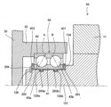
次に、図2を参照して、ベアリング40の詳細を説明する。 Next, details of the
ベアリング40は、内輪41と外輪42との間に、シャフト軸方向に2列の転動体43a、43bが設けられ、各列において内輪41、転動体43a、43b、及び外輪42の接触点を結ぶ直線(線A及びB)がシャフト径方向に対して傾きを有する構成である。外側列の線Aは内輪41から外輪42に向かうにつれて他端部122側に傾斜し、内側列の線Bは内輪41から外輪42に向かうにつれて一端部121側に傾斜する。 The
ベアリング40の内輪41は、ロータシャフト12の一端部121の外周面に固定される。ベアリング40の外輪42は、軸受支持部32の内周面に固定される。 The
ロータシャフト12の一端部121は、その径がステップ状に縮小するように変化しており、このステップ状の段差部分を「段差部124」と呼ぶ。ベアリング40は、段差部124によりその軸方向の位置が固定される。 The diameter of one
より具体的には、ベアリング40の右側の端部(以降、「第1端部401」と呼ぶ)と段差部124との間には、第1の壁状部材201が装着される。第1の壁状部材201は円環形状を有し、ロータシャフト12に嵌装されて段差部124に突き当たることで固定される。第1の壁状部材201は、波バネ形状となっており、板圧方向に圧縮されることにより付勢力を発揮するバネ部材として構成される。 More specifically, the
ベアリング40の第1端部401とは逆側、すなわち左側の端部(以降、「第2端部402」と呼ぶ)には、第2の壁状部材202が装着される。第2の壁状部材202は円環形状を有し、ロータシャフト12に嵌装されて、さらにスナップリング204をロータシャフト12に形成された溝126に嵌装することで、軸方向に移動不可能に固定される。なお、第2の壁状部材202は、スナップリング204ではなく、圧入等による摩擦ばめによりロータシャフト12の一端部121に固定されてもよいし、ねじ止め等により固定されてもよい。 A second wall-
第1の壁状部材201がバネ部材として構成されると共に第2の壁状部材202が移動不可能に構成されるので、ベアリング40の内輪41は、バネ部材である第1の壁状部材201により軸方向に付勢されて第2の壁状部材202側に押圧される。これにより、ベアリング40は第1の壁状部材201と第2の壁状部材202との間で挟持され、その位置がしっかりと固定される。 Since the
ベアリング40の内輪41とロータシャフト12の一端部121との間には、二つのOリング203a、203bが介在する。 Two O-
より具体的には、一端部121の外周には、軸方向に並列に二つの溝125a、125bが周状に形成される。溝125a、125bには、それぞれOリング203a、203bが並列に嵌装される。Oリング203a、203bは、ゴム等の弾性部材により円環状かつ断面が略円形に形成され、その断面の径が溝125a、125bの深さよりも大きく形成される。 More specifically, two
すなわち、Oリング203a、203bが溝125a、125bに嵌装されている状態では、一端部121の外周の径よりも、Oリング203a、203bの部分が大きくなる。ベアリング40の内輪41の内径は一端部121の外周の径よりも僅かに大きく形成されており、ベアリング40をロータシャフト12の一端部121に取り付けた場合は、ベアリング40の内輪41がOリング203a、203bを押しつぶし、ベアリング40の内輪41の内周が一端部121の外周から僅かに離れた位置で、軸方向に並列に備えられたOリング203a、203bの弾性力により支持される。 That is, when the O-
さらに、ベアリング40の内輪41と一端部121との間には、粘性流体であるグリスが充填される。すなわち、ベアリング40の内輪41の内周と一端部121の外周との隙間であって、第1の壁状部材201と第2の壁状部材202とに挟まれた空間に、グリスが充填される。 Furthermore, the space between the
このように、ベアリング40がロータシャフト12に対してOリング203a、203bを介して取り付けられる構成により、ロータシャフト12の振動がベアリング40に伝わることが緩衝される。さらに、ベアリング40とロータシャフト12との間にグリスが充填されることにより、ベアリング40の内輪41の内周とロータシャフト12の一端部121の外周との接触を防止するので、これらの摩耗が防止される。 In this manner, the structure in which the
なお、ベアリング40は、二つのOリング203a、203bにより支持される構成としたが、これに限られない。例えば、一端部121に溝を設けず、ベアリング40と一端部121との間に平板のベルト状の弾性部材が介装されていてもよい。また、Oリング203a、203bは、ゴムでなくシリコンやエラストマ等の弾性を有する部材で構成されていてもよい。 Although the
また、第1の壁状部材201は、波バネではなく皿バネ等の他のバネにより構成されていてもよい。また、第1の壁状部材201がゴム等の弾性を有する素材で形成されていてもよい。また、第1の壁状部材201ではなく、第2の壁状部材202がバネ部材で構成されていてもよく、第1の壁状部材201と第2の壁状部材202とのいずれもがバネ部材であってもよい。なお、本実施形態においては、グリスの飛散の防止を考慮すると、段差部124に当接する第1の壁状部材201のみがバネ部材であることが好適である。 Moreover, the first wall-
次に、第1の実施形態のロータシャフト12にベアリング40を取り付ける方法を説明する。 Next, a method of attaching the
まず、ロータシャフト12の一端部121の溝125a、125bに、それぞれOリング203a、203bを嵌装しておく。 First, O-
次に、ロータシャフト12の一端部121の開放端から第1の壁状部材201を軸通させる。第1の壁状部材201は、段差部124へと突き当たるまで移動させる。 Next, the
次に、ロータシャフト12の一端部121のOリング203a、203bの周囲にグリスを塗布する。 Next, grease is applied around the O-
次に、ロータシャフト12の一端部121の開放端から、ベアリング40をロータシャフト12へと軸通させる。ベアリング40は、第1の壁状部材201に突き当たる位置まで移動させる。 Next, the
次に、ロータシャフト12の一端部121の開放端から、第2の壁状部材202をロータシャフト12へと軸通させ、ベアリング40の第2端部402へと突き当たる位置まで移動させる。この状態で、スナップリング204を溝126に嵌装する。 Next, the
このようにして、ロータシャフト12の一端部121にベアリング40が取り付けられる。その後、ロータシャフト12をハウジング30に取り付ける際に、ハウジング30の軸受支持部32にベアリング40の外輪42を圧入等により固定する。これにより、ベアリング40がハウジング30に固定され、ロータシャフト12が支持される。 In this way, the
上記した本発明の第1実施形態によるモータ50(回転電機)によれば、以下の作用効果を得ることができる。 According to the motor 50 (rotating electric machine) according to the first embodiment of the present invention described above, the following effects can be obtained.
本実施形態によるモータ50は、ハウジング30内にロータ10及びステータ20を備え、ロータ10のロータシャフト12が変速機60(動力伝達装置)の回転軸61(動力伝達シャフト)に接続される。ハウジング30にはベアリング40が設けられ、ロータシャフト12の一端部121は、ベアリング40を介して支持されており、ロータシャフト12の他端部122は、回転軸61に対して嵌合するインロー継手構造により回転軸61に支持される。そして、ベアリング40とロータシャフト12との間には、Oリング203a、203b(弾性部材)が備えられる。 The
本実施形態では、ロータシャフト12の他端部122が変速機60の回転軸61にインロー接続されることで、ロータシャフト12の他端部122を支持するためのベアリングをハウジング30に設ける必要がない。モータ50においては、ハウジング30に設けられた一端部121用のベアリング40と、変速機60の回転軸61とによりロータシャフト12を回転自在に両端支持することができるため、ロータシャフト12の他端部122用のベアリングを省略することが可能となる。その結果、モータ50の全体構成を簡素化することができる。また、他端部122にベアリングを配置しない分だけ、ロータシャフト12の回転時における摩擦抵抗を低減することができ、モータ50の製造コストも低減することができる。 In this embodiment, the
さらに、ベアリング40とロータシャフト12との間にOリング203a、203b(弾性部材)を備えたので、他端部122側がインロー継手構造であることによるロータシャフト12の振動がベアリング40に伝達されることが緩衝され、ベアリング40及びロータシャフト12の摩耗や破損を防止でき、ベアリング40の耐久性を確保できる。 Furthermore, since the O-
また、本実施形態によるモータ50は、弾性部材はロータシャフト12に固定されたOリング203a、203bであるので、簡易で安価な構成により、ベアリング40及びロータシャフト12の摩耗や破損を防止できる。 Further, in the
また、本実施形態によるモータ50は、2つのOリング203a、203bが、ベアリング40とロータシャフト12との間において軸方向に並列に備えられるので、ベアリング40及びロータシャフト12の摩耗や破損をより確実に防止できる。 Furthermore, since the
また、本実施形態によるモータ50は、Oリング203a、203bによりベアリング40とロータシャフト12との間に形成された隙間に、粘性流体としてのグリスが充填されているので、ベアリング40の内輪41の内周とロータシャフト12の一端部121の外周との接触を防止でき、これらの摩耗がさらに防止される。 Furthermore, in the
また、本実施形態によるモータ50は、ベアリング40は複列アンギュラボールベアリングであるので、ロータシャフト12に軸方向の力が作用した場合であっても、複列アンギュラボールベアリングによりその力を受けることが可能となる。これにより、ロータシャフト12をより安定的に支持することができる。 Further, in the
また、本実施形態によるモータ50は、ロータシャフト12には、ベアリング40の両端に、ベアリング40の軸方向への移動を規制する壁状部材(第1の壁状部材201及び第2の壁状部材202)が備えられるので、ベアリング40は第1の壁状部材201と第2の壁状部材202との間でローターシャフト12での位置が固定される。 In addition, the
また、本実施形態によるモータ50は、壁状部材(第1の壁状部材201及び第2の壁状部材202)の少なくとも一方(第1の壁状部材201)は、ベアリング40を軸方向に付勢するバネ部材として構成されるので、ベアリング40は、バネ部材である第1の壁状部材201により付勢されて第2の壁状部材202側に押圧される。これにより、ベアリング40は第1の壁状部材201と第2の壁状部材202との間でローターシャフト12上での位置がしっかりと固定される。さらに、第1の壁状部材201と第2の壁状部材202とでベアリング40を挟持することで、ベアリング40とロータシャフト12との間に充填されたグリスが外部に飛散することが防止される。 Further, in the
<第2実施形態>
次に、図3を参照して、本実施形態の第2実施形態に係るモータ50と、変速機60とを備えるモータシステム100について説明する。第2実施形態のモータ50と第1実施形態のモータ50とは、ベアリングの構成において相違する。 <Second embodiment>
Next, with reference to FIG. 3, a
図3に示すように、本実施形態によるモータ50において、複列アンギュラボールベアリングにより構成されたベアリング40ではなく、一列の単列ボールベアリング(深溝玉軸受)により構成されるベアリング140を備えた。その他の構成は上述した第1実施形態と同様であるため、説明を省略する。 As shown in FIG. 3, the
複列アンギュラボールベアリングが軸方向(スラスト方向)とラジアル方向との両方の荷重を受けつつ回転することができるのに対して、単列ボールベアリングは、構成が簡易であり安価であると共に、主にラジアル方向の荷重を受けることが特徴である。 While double-row angular ball bearings can rotate while receiving loads in both the axial direction (thrust direction) and the radial direction, single-row ball bearings have a simple configuration and are inexpensive, as well as being able to rotate in the main direction. It is characterized by being subjected to loads in the radial direction.
従って、モータシステム100において、モータ50と変速機60との荷重やインロー継手の構成等を考慮して、単列ボールベアリングであるベアリング140を採用することができる。これにより、モータシステム100の製造コスト及びメンテナンスコストを抑制することができる。 Therefore, in the
<第3実施形態>
次に、図4を参照して、本実施形態の第3実施形態に係るモータ50と、変速機60とを備えるモータシステム100について説明する。第3実施形態のモータ50と第1実施形態のモータ50とは、ロータシャフト12の他端部122と変速機60の回転軸61とのインロー接続の仕方において相違する。 <Third embodiment>
Next, with reference to FIG. 4, a
図4に示すように、本実施形態によるモータ50において、ロータシャフト12の他端部122の先端部には、軸方向に窪むシャフト孔122B(インロー孔)が形成される。また、変速機60の回転軸61の左端部は、先端に向かって段階的に小径となる軸部材として構成される。シャフト孔122Bに変速機60の回転軸61の左端部(先端部位)が挿入され、他端部122の先端面寄りに位置するシャフト孔122Bの内周面は回転軸61の端部外周面に対して嵌合する。その他の構成は上述した第1実施形態と同様であるため、説明を省略する。 As shown in FIG. 4, in the
ロータシャフト12の他端部122に形成されるシャフト孔122Bは、先端よりも中央部123寄りの位置、つまり回転軸61に嵌合する部位(インロー接続部位)とは異なる位置における内周面に、回転軸61の外周面に対してスプライン結合するスプライン部122Cを備える。このスプライン部122Cを介してロータシャフト12と回転軸61とがスプライン結合することにより、ロータシャフト12と回転軸61との間における相対回転が規制される。なお、ロータシャフト12において、スプライン部122Cを他端部122の先端寄りの位置に設け、回転軸61に嵌合する部位(インロー接続部位)をスプライン部122Cよりも中央部123寄りの位置に設けてもよい。 The
このように、ロータシャフト12の他端部122は、変速機60の回転軸61に対して嵌合するインロー継手構造により回転軸61と接続される。 In this way, the
なお、ロータシャフト12のシャフト孔122Bは、他端部122を構成する部位に直線的に形成されているが、右先端面からロータシャフト12の中央部123又は中央部123よりも一端部121寄りの位置まで直線的に形成されてもよい。したがって、ロータシャフト12は、中央部123又は中央部123よりも一端部121寄りの位置で変速機60の回転軸61とインロー接続されるように構成されてもよい。 Incidentally, the
また、ロータシャフト12と回転軸61との相対回転の規制は、スプライン継手構造以外の継手構造により実現されてもよい。スプライン継手構造以外の継手構造としては、フランジ継手構造、オルダム継手構造、及びローテックス継手構造等が挙げられる。 Further, the regulation of relative rotation between the
このように構成された本実施形態によるモータ50は、ロータシャフト12の他端部122が変速機60の回転軸61にインロー接続されることで、ロータシャフト12の他端部122を支持するためのベアリングをハウジング30に設ける必要がなく、第1実施形態と同様の作用効果を得ることが可能となる。 The
また、第1実施形態によるモータ50においてはロータシャフト12の他端部122が回転軸61のシャフト孔61Aに挿入されるため、ロータシャフト12の軸太さを回転軸61よりも太くすることはできない。しかしながら、本実施形態のモータ50は、ロータシャフト12の他端部122のシャフト孔122Bが回転軸61の端部に外嵌めされる構成であるため、回転軸61の軸太さによらず他端部122を任意の太さに形成することができる。その結果、ロータシャフト12の他端部122と変速機60の回転軸61との接続強度を必要に応じて高めることが可能となる。 Further, in the
特に、ロータシャフト12においては中央部123が太く形成されているため、他端部122を中央部123よりも外径が大きくならない範囲で容易に任意の太さに形成することができる。例えば、ロータシャフト12の他端部122と中央部123とを同じ外径とすれば、一端部121のみを他の部分によりも小径に形成するだけでよく、ロータシャフト12の製造コストを低減することができる。一方、接続強度を高めるため、外径がほぼ一定の回転軸61において当該回転軸61の端部のみを第1実施形態のように太く形成する場合には製造コストが増加してしまう。したがって、本実施形態によるロータシャフト12によれば、製造コストの増加を招くことなく、ロータシャフト12と回転軸61との接続強度を高めることが可能となる。 In particular, since the
また、本実施形態によるモータ50では、ロータシャフト12の他端部122のシャフト孔122Bは、回転軸61に嵌合する部位とは異なる位置における内周面に、回転軸61の外周面に対してスプライン結合するスプライン部122Cを備える。このように、ロータシャフト12の他端部122には、回転軸61にインロー接続される部位と、回転軸61にスプライン結合される部位とが形成されることとなる。そのため、回転軸61に対するロータシャフト12の接続範囲が広くなり、ロータシャフト12の他端部122をより安定的に支持することが可能となる。 Furthermore, in the
さらに、ロータシャフト12の他端部122において、回転軸61に嵌合する部位は、スプライン部122Cよりも回転軸61寄りの位置、例えば他端部122の先端部位におけるシャフト孔122Bに設けられる。これにより、ロータシャフト12において、ベアリング40により支持される部位と回転軸61により支持される部位とをできる限り離して配置することができる。このような構成により、ロータシャフト12の傾きをより抑制した状態でロータシャフト12を両端支持することができ、ロータシャフト12を安定的に支持することが可能となる。 Further, in the
<第4実施形態>
次に、図5を参照して、本発明の第4実施形態によるモータ50と、変速機60とを備えるモータシステム100について説明する。第4実施形態と第1実施形態とは、ロータコア11を支持する構造において相違する。 <Fourth embodiment>
Next, with reference to FIG. 5, a
図5に示すように、本実施形態によるモータ50のロータ10は、ロータコア11と、ロータシャフト12と、コア支持部13と、接続部14とから構成される。その他の構成は上述した第1実施形態と同様であるため、説明を省略する。 As shown in FIG. 5, the
ロータ10のコア支持部13は、円筒形状であって、円筒状のロータコア11を内側から支持する部材である。コア支持部13は、その軸方向長さがロータコア11の軸方向長さよりも僅かに長くなるよう形成される。コア支持部13はロータコア11の挿入孔11A内に挿入され、ロータコア11はコア支持部13の外周に対して外嵌めされた状態でコア支持部13上に固定される。 The
ロータシャフト12はコア支持部13の内側に配置される。ロータシャフト12とコア支持部13とは接続部14を介して接続される。接続部14は、ロータシャフト12の中央部123の外周面からシャフト径方向に突出する円板状壁部として形成されており、ロータシャフト12の中央部123の外周面とコア支持部13の内周面とを接続する。接続部14の板厚は、ロータシャフト12及びコア支持部13の軸方向長さと比較して薄く設定される。 The
ロータシャフト12では、一端部121がベアリング40に支持され、他端部122が変速機60の回転軸61の端部に外接した状態で当該回転軸61にインロー接続される。 In the
なお、図5に示す例では、図3で示した第2実施形態と同様に、ロータシャフト12の他端部122のシャフト孔122Bに、回転軸61の先端部位が挿入されたインロー継ぎ手構造として構成されているが、図1に示す第1実施形態のように、回転軸61のシャフト孔61Aにロータシャフト12の他端部122の先端部位が挿入されてたインロー継手構造であってもよい。 In addition, in the example shown in FIG. 5, similarly to the second embodiment shown in FIG. However, as in the first embodiment shown in FIG. 1, it may be a spigot joint structure in which the tip portion of the
本実施形態のモータ50では、ハウジング30は左側ハウジング30Lと右側ハウジング30Rとにより形成されており、左側ハウジング30Lの中央部位33はコア支持部13の内側に入り込むようにシャフト軸方向に窪んで構成される。左側ハウジング30Lの中央部位33には軸受支持部32が形成されており、この軸受支持部32にベアリング40が固定される。つまり、ベアリング40は、ロータコア11及びコア支持部13の内側に位置するように左側ハウジング30Lの中央部位33に設けられて固定される。ベアリング40は、複列アンギュラボールベアリングとして構成される。 In the
また、ロータシャフト12の一端部121とベアリング40との固定は、前述した第1実施形態と同様である。すなわち、ベアリング40の第1端部401側では、ロータシャフト12とコア支持部13を接続する接続部14と一端部121との境界付近に形成された段差部124にバネ部材である第1の壁状部材201が固定され、ベアリング40の第2端部402は第2の壁状部材で固定される。ベアリング40の内輪41の内周側とロータシャフト12の一端部121の外周側との間にはOリング203a、203bが介装されると共に、グリスが充填される。 Furthermore, the fixing between the one
なお、接続部14と一端部121との境界付近に形成された段差部124に第1の壁状部材201を押し当てて固定するのではなく一端部121から垂直方向に接続部14が延設されており、この接続部14に第1の壁状部材201を押し当てるような形状であってもよい。 Note that instead of pressing and fixing the
このように構成された本実施形態によるモータ50によれば、ロータ10は、ロータコア11を内側から支持するコア支持部13と、ロータシャフト12の外周面からシャフト径方向に突出する円板状部材であって、ロータシャフト12の外周面とコア支持部13の内周面とを接続する接続部14と、を備える。そして、ハウジング30を構成する左側ハウジング30Lは中央部位33(一部)がコア支持部13の内側に入り込むように形成される。接続部14とベアリング40の第1端部401(一端側)との間に、ベアリング40を軸方向に付勢するバネ部材である第1の壁状部材201が備えられ、ベアリング40の第2端部402(他端側)に、前記ベアリングの軸方向への移動を規制する第2の壁状部材202が備えられる。 According to the
このように、モータ50では、コア支持部13の内側に入り込んだ部位に設けられたベアリング40によりロータシャフト12の一端部121が支持されるため、モータ50自体の軸方向における幅を他の実施形態のモータ50よりも薄くすることができる。これにより、モータ50のコンパクト化を図ることが可能となる。さらに、ベアリング40は、接続部14に突き当たる形で固定されるため、グリスの飛散を防止することができる。 In this way, in the
以上、本発明の実施形態について説明したが、上記実施形態は、本発明の適用例の一部を示したに過ぎず、本発明の技術的範囲を、上記実施形態の具体的構成に限定する趣旨ではない。上記実施形態に対し、特許請求の範囲に記載した事項の範囲内で様々な変更及び修正が可能である。 Although the embodiments of the present invention have been described above, the above embodiments merely show a part of the application examples of the present invention, and the technical scope of the present invention is limited to the specific configuration of the above embodiments. That's not the purpose. Various changes and modifications can be made to the above embodiments within the scope of the claims.
また、各実施形態で説明した技術的思想は、技術的な矛盾が生じない範囲で適宜組み合わせてもよい。 Furthermore, the technical ideas described in each embodiment may be combined as appropriate to the extent that no technical contradiction occurs.
上述した各実施形態において説明したロータコア11、ステータ20、及びコア支持部13等は、円筒状の部材としたが、多角形状の筒部材であってもよい。 Although the
また、上述した各実施形態では、モータ50は動力伝達装置としての変速機60に組み付けられるが、モータ50は減速機等の動力伝達装置に組み付けられてもよい。この場合においても、各実施形態における技術思想を適用することで、モータ50のロータシャフト12と減速機の回転軸とを連結することができる。 Further, in each of the embodiments described above, the
Claims (6)
前記ハウジングにはベアリングが設けられ、
前記ロータシャフトの一端部は、前記ベアリングを介して支持されており、
前記ロータシャフトの他端部は、前記動力伝達シャフトに対して嵌合するインロー継手構造により前記動力伝達シャフトとの間で相対回転不能に結合され、
前記ベアリングの内輪と前記ロータシャフトの一端部との間に弾性部材が備えられ、前記ベアリングの外輪は前記ハウジングに圧入固定され、
前記ベアリングを支持する前記一端部の径は、段差部によって縮小し、
前記ベアリングと前記段差部との間にバネ部材が配置され、
壁状部材が前記ベアリングを挟んで前記バネ部材の反対側において、前記一端部に固定され、前記ベアリングが前記バネ部材により前記壁状部材に向けて付勢される
電動車両の駆動装置。 A drive device for an electric vehicle, comprising: a rotating electric machine having a rotor and a stator in a housing; and a transmission having a power transmission shaft, the rotor shaft of the rotor being connected to the power transmission shaft;
The housing is provided with a bearing,
one end of the rotor shaft is supported via the bearing,
The other end of the rotor shaft is coupled to the power transmission shaft in a relatively non-rotatable manner by a spigot joint structure that fits into the power transmission shaft;
an elastic member is provided between the inner ring of the bearing and one end of the rotor shaft, and the outer ring of the bearing is press- fitted into the housing;
The diameter of the one end portion supporting the bearing is reduced by a stepped portion,
A spring member is disposed between the bearing and the stepped portion,
A wall-like member is fixed to the one end portion on the opposite side of the spring member with the bearing in between, and the bearing is biased toward the wall-like member by the spring member.
Drive device for electric vehicles.
前記弾性部材は、前記ロータシャフトに固定されたOリングとして構成される
電動車両の駆動装置。 The drive device for an electric vehicle according to claim 1 ,
The elastic member is configured as an O-ring fixed to the rotor shaft. The drive device for an electric vehicle.
2つの前記Oリングが、前記ベアリングと前記ロータシャフトとの間において軸方向に並列に備えられる
電動車両の駆動装置。 The drive device for an electric vehicle according to claim 2 ,
A drive device for an electric vehicle, wherein the two O-rings are provided in parallel in the axial direction between the bearing and the rotor shaft.
前記弾性部材により前記ベアリングと前記ロータシャフトとの間に形成された隙間に、粘性流体が充填されている
電動車両の駆動装置。 The drive device for an electric vehicle according to claim 3 ,
A drive device for an electric vehicle, wherein a gap formed between the bearing and the rotor shaft by the elastic member is filled with viscous fluid.
前記ベアリングは、複列アンギュラボールベアリングとして構成される、
電動車両の駆動装置。 The drive device for an electric vehicle according to claim 4 ,
The bearing is configured as a double row angular ball bearing.
Drive device for electric vehicles.
前記ロータは、前記ロータシャフトの外周面からシャフト径方向に突出する円板状部材であって、前記ロータシャフトの外周面とロータコアの内周面とを接続する接続部を備える
電動車両の駆動装置。 The drive device for an electric vehicle according to claim 1 ,
The rotor is a disc-shaped member that protrudes from the outer circumferential surface of the rotor shaft in the shaft radial direction, and includes a connecting portion that connects the outer circumferential surface of the rotor shaft and the inner circumferential surface of the rotor core.
Drive device for electric vehicles.
Applications Claiming Priority (1)
| Application Number | Priority Date | Filing Date | Title |
|---|---|---|---|
| PCT/IB2019/001337 WO2021105735A1 (en) | 2019-11-26 | 2019-11-26 | Rotary electric machine |
Publications (3)
| Publication Number | Publication Date |
|---|---|
| JPWO2021105735A1 JPWO2021105735A1 (en) | 2021-06-03 |
| JPWO2021105735A5 JPWO2021105735A5 (en) | 2022-09-15 |
| JP7447914B2 true JP7447914B2 (en) | 2024-03-12 |
Family
ID=76130434
Family Applications (1)
| Application Number | Title | Priority Date | Filing Date |
|---|---|---|---|
| JP2021560755A Active JP7447914B2 (en) | 2019-11-26 | 2019-11-26 | Electric vehicle drive device |
Country Status (3)
| Country | Link |
|---|---|
| EP (1) | EP4068587A4 (en) |
| JP (1) | JP7447914B2 (en) |
| WO (1) | WO2021105735A1 (en) |
Citations (11)
| Publication number | Priority date | Publication date | Assignee | Title |
|---|---|---|---|---|
| JP2000356256A (en) | 1999-06-16 | 2000-12-26 | Fuji Electric Co Ltd | Torque detecting device |
| JP2002136007A (en) | 2000-10-20 | 2002-05-10 | Fujitsu General Ltd | Rotor for motor and manufacturing method for the rotor |
| JP2002233112A (en) | 2001-02-05 | 2002-08-16 | Showa Corp | Motor-driven power steering device |
| JP2003237599A (en) | 2002-02-18 | 2003-08-27 | Koyo Seiko Co Ltd | Electric power steering device |
| JP2005096622A (en) | 2003-09-25 | 2005-04-14 | Toyoda Mach Works Ltd | Electric type power steering device |
| JP2007247711A (en) | 2006-03-14 | 2007-09-27 | Nsk Ltd | Rolling bearing for underwater rotary device |
| JP2010154751A (en) | 2010-03-30 | 2010-07-08 | Shingo Sekiguchi | Structure of induction type electric motor |
| JP2014025553A (en) | 2012-07-27 | 2014-02-06 | Jtekt Corp | Actuator unit and vehicular steering device equipped therewith |
| JP2015200384A (en) | 2014-04-09 | 2015-11-12 | 株式会社ジェイテクト | Rotating shaft support device and electric motor |
| JP2017093076A (en) | 2015-11-05 | 2017-05-25 | 日産自動車株式会社 | Rotary electric machine |
| WO2019197856A1 (en) | 2018-04-12 | 2019-10-17 | 日産自動車株式会社 | Rotating electric machine |
Family Cites Families (3)
| Publication number | Priority date | Publication date | Assignee | Title |
|---|---|---|---|---|
| DE4139984A1 (en) * | 1991-12-04 | 1993-06-09 | Robert Bosch Gmbh, 7000 Stuttgart, De | DC motor for motor vehicle antilocking or drive slip regulated braking - has resilient element providing cushioning between motor shaft bearing pin and bearing seat to reduce noise |
| JP2010112490A (en) * | 2008-11-07 | 2010-05-20 | Ntn Corp | Creep-preventive and conductive rolling bearing |
| JP6118633B2 (en) | 2013-05-16 | 2017-04-19 | 本田技研工業株式会社 | Electric motor |
-
2019
- 2019-11-26 WO PCT/IB2019/001337 patent/WO2021105735A1/en unknown
- 2019-11-26 JP JP2021560755A patent/JP7447914B2/en active Active
- 2019-11-26 EP EP19954450.3A patent/EP4068587A4/en active Pending
Patent Citations (11)
| Publication number | Priority date | Publication date | Assignee | Title |
|---|---|---|---|---|
| JP2000356256A (en) | 1999-06-16 | 2000-12-26 | Fuji Electric Co Ltd | Torque detecting device |
| JP2002136007A (en) | 2000-10-20 | 2002-05-10 | Fujitsu General Ltd | Rotor for motor and manufacturing method for the rotor |
| JP2002233112A (en) | 2001-02-05 | 2002-08-16 | Showa Corp | Motor-driven power steering device |
| JP2003237599A (en) | 2002-02-18 | 2003-08-27 | Koyo Seiko Co Ltd | Electric power steering device |
| JP2005096622A (en) | 2003-09-25 | 2005-04-14 | Toyoda Mach Works Ltd | Electric type power steering device |
| JP2007247711A (en) | 2006-03-14 | 2007-09-27 | Nsk Ltd | Rolling bearing for underwater rotary device |
| JP2010154751A (en) | 2010-03-30 | 2010-07-08 | Shingo Sekiguchi | Structure of induction type electric motor |
| JP2014025553A (en) | 2012-07-27 | 2014-02-06 | Jtekt Corp | Actuator unit and vehicular steering device equipped therewith |
| JP2015200384A (en) | 2014-04-09 | 2015-11-12 | 株式会社ジェイテクト | Rotating shaft support device and electric motor |
| JP2017093076A (en) | 2015-11-05 | 2017-05-25 | 日産自動車株式会社 | Rotary electric machine |
| WO2019197856A1 (en) | 2018-04-12 | 2019-10-17 | 日産自動車株式会社 | Rotating electric machine |
Also Published As
| Publication number | Publication date |
|---|---|
| EP4068587A4 (en) | 2022-11-30 |
| JPWO2021105735A1 (en) | 2021-06-03 |
| EP4068587A1 (en) | 2022-10-05 |
| WO2021105735A1 (en) | 2021-06-03 |
Similar Documents
| Publication | Publication Date | Title |
|---|---|---|
| JP5023606B2 (en) | Electric drive | |
| US9490679B2 (en) | Wheel driving device | |
| JP5519337B2 (en) | In-wheel motor drive device | |
| JP5709373B2 (en) | In-wheel motor drive device | |
| JPWO2009128288A1 (en) | Hybrid vehicle drive device | |
| JP6962454B2 (en) | Rotating machine | |
| JP2015048872A (en) | Wheel drive unit | |
| JP4647683B2 (en) | Flexible coupling structure and marine thruster apparatus including the same | |
| CN113692504A (en) | Motor unit | |
| JP2010071462A (en) | In-wheel motor driving device | |
| JP7447914B2 (en) | Electric vehicle drive device | |
| CN107222052B (en) | Bearing unit of driving motor | |
| WO2020225582A1 (en) | Dynamo-electric machine | |
| CN109538733B (en) | Vibration reduction belt pulley | |
| KR101413190B1 (en) | Motor structure for Electric vehicle | |
| JP2008168821A (en) | In-wheel motor drive unit | |
| JP2018071645A (en) | Shaft joint mechanism | |
| CN116325442A (en) | Electric machine with central support base for stator, rotor and connecting shaft | |
| JP4380493B2 (en) | Electric wheel drive device | |
| JP2008208911A (en) | In-wheel motor drive mechanism | |
| JP2008168822A (en) | In-wheel motor drive unit | |
| CN220273446U (en) | Motor and driving unit | |
| KR102534827B1 (en) | Rotary type reduction actuator | |
| WO2021095674A1 (en) | In-wheel motor drive device | |
| KR20130087848A (en) | Axle assembly and method for connecting axle assembly |
Legal Events
| Date | Code | Title | Description |
|---|---|---|---|
| A521 | Request for written amendment filed |
Free format text: JAPANESE INTERMEDIATE CODE: A523 Effective date: 20220524 |
|
| A621 | Written request for application examination |
Free format text: JAPANESE INTERMEDIATE CODE: A621 Effective date: 20220524 |
|
| A131 | Notification of reasons for refusal |
Free format text: JAPANESE INTERMEDIATE CODE: A131 Effective date: 20230425 |
|
| A521 | Request for written amendment filed |
Free format text: JAPANESE INTERMEDIATE CODE: A523 Effective date: 20230622 |
|
| A131 | Notification of reasons for refusal |
Free format text: JAPANESE INTERMEDIATE CODE: A131 Effective date: 20231010 |
|
| A521 | Request for written amendment filed |
Free format text: JAPANESE INTERMEDIATE CODE: A523 Effective date: 20231107 |
|
| TRDD | Decision of grant or rejection written | ||
| A01 | Written decision to grant a patent or to grant a registration (utility model) |
Free format text: JAPANESE INTERMEDIATE CODE: A01 Effective date: 20240130 |
|
| A61 | First payment of annual fees (during grant procedure) |
Free format text: JAPANESE INTERMEDIATE CODE: A61 Effective date: 20240212 |
|
| R151 | Written notification of patent or utility model registration |
Ref document number: 7447914 Country of ref document: JP Free format text: JAPANESE INTERMEDIATE CODE: R151 |