JP7440397B2 - brushless motor - Google Patents

brushless motor Download PDF

Info

Publication number
JP7440397B2
JP7440397B2 JP2020199218A JP2020199218A JP7440397B2 JP 7440397 B2 JP7440397 B2 JP 7440397B2 JP 2020199218 A JP2020199218 A JP 2020199218A JP 2020199218 A JP2020199218 A JP 2020199218A JP 7440397 B2 JP7440397 B2 JP 7440397B2
Authority
JP
Japan
Prior art keywords
substrate
wiring
connection
phase
coils
Prior art date
Legal status (The legal status is an assumption and is not a legal conclusion. Google has not performed a legal analysis and makes no representation as to the accuracy of the status listed.)
Active
Application number
JP2020199218A
Other languages
Japanese (ja)
Other versions
JP2022086919A (en
Inventor
哲也 渡邉
龍之 齋藤
Current Assignee (The listed assignees may be inaccurate. Google has not performed a legal analysis and makes no representation or warranty as to the accuracy of the list.)
Mitsuba Corp
Original Assignee
Mitsuba Corp
Priority date (The priority date is an assumption and is not a legal conclusion. Google has not performed a legal analysis and makes no representation as to the accuracy of the date listed.)
Filing date
Publication date
Application filed by Mitsuba Corp filed Critical Mitsuba Corp
Priority to JP2020199218A priority Critical patent/JP7440397B2/en
Publication of JP2022086919A publication Critical patent/JP2022086919A/en
Application granted granted Critical
Publication of JP7440397B2 publication Critical patent/JP7440397B2/en
Active legal-status Critical Current
Anticipated expiration legal-status Critical

Links

Images

Description

本発明は、ブラシレスモータに関する。 The present invention relates to a brushless motor.

特許文献1のブラシレスモータは、複数のコイルを周方向に配列したステータと、コイルに電力が供給された際に発生する回転磁界により回転するロータと、を備える。また、ステータの軸方向端部には、複数のコイルに接続されるバスバーユニットが設けられている。バスバーユニットは、U相、V相及びW相(三相)のそれぞれのコイルに電力を供給(分配)するようになっている。 The brushless motor of Patent Document 1 includes a stator in which a plurality of coils are arranged in a circumferential direction, and a rotor that rotates by a rotating magnetic field generated when power is supplied to the coils. Furthermore, a busbar unit connected to the plurality of coils is provided at the axial end of the stator. The busbar unit is configured to supply (distribute) power to each of the U-phase, V-phase, and W-phase (three-phase) coils.

特許第5907699号公報Patent No. 5907699

ところで、ブラシレスモータでは、その使用用途やユーザからの要求等に応じて、モータ特性(定格出力等)が異なるものが求められる。このため、求められるモータ特性に応じて、コイルの巻線仕様(線径や巻数)を調整することがある。この場合、ブラシレスモータの製造ライン上にある自動巻線機にセットされるコイル(線材)を別のものに変更したり、自動巻線機のプログラムを別のものに変更したりする必要があり、ブラシレスモータの生産性の悪化を招いていた。 Incidentally, brushless motors are required to have different motor characteristics (rated output, etc.) depending on their intended use and user requests. For this reason, the coil winding specifications (wire diameter and number of turns) may be adjusted depending on the required motor characteristics. In this case, it is necessary to change the coil (wire) set in the automatic winding machine on the brushless motor production line to a different one, or to change the program of the automatic winding machine to a different one. This caused a deterioration in the productivity of brushless motors.

また、ステータのステータコアがステータの軸方向に積層した複数の鋼板によって構成される場合には、求められるモータ特性に応じて、鋼板の積層枚数を変更する(ステータコアの軸方向長さを変える)こともある。しかしながら、この場合においても、自動組み立て装置のプログラムを別のものに変更したりする必要があり、モータ特性のバリエーションを増やすには限界が生じていた。 In addition, when the stator core of the stator is composed of multiple steel plates laminated in the axial direction of the stator, the number of laminated steel plates may be changed (change the axial length of the stator core) depending on the required motor characteristics. There is also. However, even in this case, it is necessary to change the program of the automatic assembly device to another one, and there is a limit to increasing the variation of motor characteristics.

本発明は、コイルの巻線仕様やステータコアを構成する鋼板の積層枚数を変更することなく、モータ特性のバリエーションを容易に増やすことが可能なブラシレスモータを提供するものである。 The present invention provides a brushless motor that can easily increase variations in motor characteristics without changing the coil winding specifications or the number of laminated steel plates constituting the stator core.

上記課題を解決するため、本発明に係るブラシレスモータは、周方向に配列された複数のコイルを有するステータと、界磁マグネットを有し、前記ステータに対して回転するロータと、前記ステータに装着され、複数の前記コイルにそれぞれ接続される接続パターンを有する基板と、を備え、前記接続パターンは、複数の前記コイルにそれぞれ接続されることで前記コイルの結線パターンを構成し、前記基板は、多層配線基板であり、前記接続パターンは、前記基板の厚さ方向に並ぶ複数の層にそれぞれ形成された複数の接続配線によって構成され、複数の前記接続配線はそれぞれ、前記基板の外周部で前記コイルに接続される端末結線部を有し、複数の前記端末結線部は、前記基板の厚さ方向において互いに重ならないように、前記基板の周方向に間隔を開けて配列され、前記ステータには、互いに異なる前記接続パターンを有することで互いに異なる前記コイルの結線パターンを構成し得る複数種類の前記基板を、選択的に装着可能であることを特徴とする。 In order to solve the above problems, a brushless motor according to the present invention includes a stator having a plurality of coils arranged in a circumferential direction, a rotor having a field magnet and rotating with respect to the stator, and a rotor attached to the stator. and a board having a connection pattern connected to each of the plurality of coils, the connection pattern forming a connection pattern of the coil by being connected to each of the plurality of coils, and the board comprising: It is a multilayer wiring board, and the connection pattern is constituted by a plurality of connection wirings formed in a plurality of layers arranged in the thickness direction of the board, and each of the plurality of connection wirings is connected to the The stator has a terminal connection portion connected to the coil, and the plurality of terminal connection portions are arranged at intervals in the circumferential direction of the substrate so as not to overlap each other in the thickness direction of the substrate. The present invention is characterized in that a plurality of types of the substrates having mutually different connection patterns and thereby configuring mutually different connection patterns of the coils can be selectively mounted.

本発明に係るブラシレスモータは、周方向に配列された複数のコイルを有するステータと、界磁マグネットを有し、前記ステータに対して回転するロータと、前記ステータに装着され、前記ロータの回転位置を検出する位置検出センサを有する基板と、を備え、前記基板には、複数の前記コイルにそれぞれ接続されて前記コイルの結線パターンを構成する接続パターンが設けられ、前記基板は、多層配線基板であり、前記接続パターンは、前記基板の厚さ方向に並ぶ複数の層にそれぞれ形成された複数の接続配線によって構成され、複数の前記接続配線はそれぞれ、前記基板の外周部で前記コイルに接続される端末結線部を有し、複数の前記端末結線部は、前記基板の厚さ方向において互いに重ならないように、前記基板の周方向に間隔を開けて配列されていることを特徴とする。 A brushless motor according to the present invention includes a stator having a plurality of coils arranged in a circumferential direction, a rotor having a field magnet and rotating with respect to the stator, and a rotor that is attached to the stator and has a rotational position of the rotor. a board having a position detection sensor for detecting a position detection sensor; the board is provided with a connection pattern connected to each of the plurality of coils to constitute a wiring pattern of the coils ; the board is a multilayer wiring board; The connection pattern includes a plurality of connection wirings formed in a plurality of layers arranged in a thickness direction of the substrate, and each of the plurality of connection wirings is connected to the coil at an outer peripheral portion of the substrate. The plurality of terminal connection parts are arranged at intervals in the circumferential direction of the substrate so as not to overlap with each other in the thickness direction of the substrate .

本発明によれば、基板には、コイルの結線パターンを構成する接続パターンが設けられている。このため、互いに異なる接続パターンを有する複数種類の基板から一つの基板を選択してステータに装着するだけで、異なるモータ特性を有するブラシレスモータを得ることができる。したがって、コイルの巻線仕様などを変更することなく、ブラシレスモータのモータ特性のバリエーションを容易に増やすことができる。 According to the present invention, the board is provided with a connection pattern that constitutes a coil connection pattern. Therefore, by simply selecting one substrate from a plurality of types of substrates having mutually different connection patterns and mounting it on the stator, a brushless motor having different motor characteristics can be obtained. Therefore, variations in the motor characteristics of the brushless motor can be easily increased without changing the coil winding specifications or the like.

本発明の実施形態におけるブラシレスモータを含む電動アクチュエータを示す斜視図である。FIG. 1 is a perspective view showing an electric actuator including a brushless motor in an embodiment of the present invention. 図1に示す電動アクチュエータの断面図である。FIG. 2 is a cross-sectional view of the electric actuator shown in FIG. 1. FIG. 図1に示す電動アクチュエータの分解斜視図である。FIG. 2 is an exploded perspective view of the electric actuator shown in FIG. 1. FIG. 図1~3のブラシレスモータにおけるコイルの結線パターンの第一例を示す電気回路図である。FIG. 4 is an electric circuit diagram showing a first example of a coil connection pattern in the brushless motor of FIGS. 1 to 3. FIG. 図4に示す第一例の結線パターンを構成するための基板の接続パターンの第一例を示す平面図である。FIG. 5 is a plan view showing a first example of a connection pattern of a board for configuring the first example wiring pattern shown in FIG. 4; 図5に示す第一例の接続パターンを4つの層に分けて示す平面図であり、(a)は第1層を示し、(b)は第2層を示し、(c)は第3層を示し、(d)は第4層を示す。6 is a plan view showing the connection pattern of the first example shown in FIG. 5 divided into four layers, in which (a) shows the first layer, (b) shows the second layer, and (c) shows the third layer. , and (d) shows the fourth layer. 図1~3のブラシレスモータにおけるコイルの結線パターンの第二例を示す電気回路図である。4 is an electric circuit diagram showing a second example of a coil connection pattern in the brushless motor of FIGS. 1 to 3. FIG. 図7に示す第二例の結線パターンを構成するための基板の接続パターンの第二例を示す平面図である。FIG. 8 is a plan view showing a second example of a connection pattern of a board for configuring the second example wiring pattern shown in FIG. 7; 図8に示す第二例の接続パターンを4つの層に分けて示す平面図であり、(a)は第1層を示し、(b)は第2層を示し、(c)は第3層を示し、(d)は第4層を示す。9 is a plan view showing the connection pattern of the second example shown in FIG. 8 divided into four layers, in which (a) shows the first layer, (b) shows the second layer, and (c) shows the third layer. , and (d) shows the fourth layer.

本実施形態に係るブラシレスモータは、電動アクチュエータに適用される。本実施形態の電動アクチュエータは、電動歩行補助車の駆動源として当該歩行補助車の車輪に内蔵される。すなわち、本実施形態の電動アクチュエータは、電動歩行補助車の駆動源として当該歩行補助車に搭載されるインホイールモータである。ただし、本発明が適用される電動アクチュエータの用途は、電動歩行補助車の駆動源に限定されない。 The brushless motor according to this embodiment is applied to an electric actuator. The electric actuator of this embodiment is built into the wheel of the electric walking auxiliary vehicle as a drive source of the electric walking auxiliary vehicle. That is, the electric actuator of this embodiment is an in-wheel motor that is mounted on the electric walking auxiliary vehicle as a drive source of the electric walking auxiliary vehicle. However, the use of the electric actuator to which the present invention is applied is not limited to the drive source of an electric walking auxiliary vehicle.

図1~3に示すように、本実施形態に係る電動アクチュエータ1は、ハウジング10と、ブラシレスモータ30と、減速機構70と、を備える。 As shown in FIGS. 1 to 3, the electric actuator 1 according to the present embodiment includes a housing 10, a brushless motor 30, and a speed reduction mechanism 70.

ハウジング10は、後述するブラシレスモータ30を収容する。ハウジング10は、扁平な円盤状の外形を有し、カバー11と、ブラケット12と、を備える。カバー11及びブラケット12は、ブラシレスモータ30を間に挟むように設けられる。カバー11とブラケット12とは、複数本のねじSC(図1)によって互いに固定される。 The housing 10 accommodates a brushless motor 30, which will be described later. The housing 10 has a flat disk-like outer shape and includes a cover 11 and a bracket 12. The cover 11 and the bracket 12 are provided so that the brushless motor 30 is sandwiched therebetween. The cover 11 and the bracket 12 are fixed to each other by a plurality of screws SC (FIG. 1).

カバー11は、円盤状の底壁13と、底壁13の周縁から立ち上がる筒状の側壁14と、を有する。カバー11の側壁14には、2つのケーブル固定部15が設けられている。各ケーブル固定部15には、コネクタ付きケーブル16,17が固定される。各コネクタ付きケーブル16,17の一端側は、ケーブル固定部15を通してカバー11(ハウジング10)内に引き入れられ、後述するブラシレスモータ30の基板60にそれぞれ接続される。各コネクタ付きケーブル16,17の他端側には、バッテリ、操作スイッチコントローラなどの外部機器に接続するための外部コネクタ16A,17Aが設けられている。 The cover 11 has a disc-shaped bottom wall 13 and a cylindrical side wall 14 rising from the periphery of the bottom wall 13. Two cable fixing parts 15 are provided on the side wall 14 of the cover 11. Cables 16 and 17 with connectors are fixed to each cable fixing portion 15 . One end side of each of the cables 16 and 17 with connectors is drawn into the cover 11 (housing 10) through the cable fixing part 15, and connected to a board 60 of a brushless motor 30, which will be described later. External connectors 16A, 17A for connecting to external devices such as a battery, an operation switch controller, etc. are provided on the other end side of each cable with connector 16, 17.

ブラケット12は、ハウジング10の外側から見て段付きの筒形状に形成されている。ブラケット12の外周部には、カバー11に固定されるフランジ部18が設けられている。 The bracket 12 is formed into a stepped cylindrical shape when viewed from the outside of the housing 10. A flange portion 18 fixed to the cover 11 is provided on the outer periphery of the bracket 12 .

図2,3に示すように、ブラシレスモータ30は、その軸方向D1がハウジング10のカバー11及びブラケット12の配列方向に向くようにしてハウジング10に収容される。ブラシレスモータ30は、軸方向寸法が径方向寸法よりも小さい扁平形状に形成されている。ブラシレスモータ30は、ステータ40と、ロータ50と、基板60と、を備えている。 As shown in FIGS. 2 and 3, the brushless motor 30 is housed in the housing 10 with its axial direction D1 facing in the direction in which the cover 11 and bracket 12 of the housing 10 are arranged. The brushless motor 30 is formed into a flat shape with an axial dimension smaller than a radial dimension. The brushless motor 30 includes a stator 40, a rotor 50, and a substrate 60.

ステータ40は、ステータコア41と、複数のコイル42と、を有する。
ステータコア41は、積層された複数の鋼板によって環状に形成されている。ステータコア41は、ハウジング10のブラケット12に固定されている。ステータコア41には、電気的な絶縁材料によって形成されたインシュレータ43が装着されている。インシュレータ43は、例えばPBT樹脂(ポリブチレンテレフタレート)等の合成樹脂によって形成されている。
Stator 40 includes a stator core 41 and a plurality of coils 42.
The stator core 41 is formed into an annular shape by a plurality of laminated steel plates. Stator core 41 is fixed to bracket 12 of housing 10. An insulator 43 made of an electrically insulating material is attached to the stator core 41. The insulator 43 is made of synthetic resin such as PBT resin (polybutylene terephthalate).

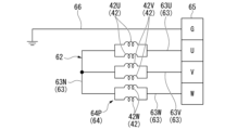
コイル42は、ステータコア41の周方向に複数配列されている。各コイル42は、導線がインシュレータ43によって覆われたステータコア41のティースに巻き付けられることで構成されている。すなわち、各コイル42とステータコア41との間にはインシュレータ43が介在している。これにより、各コイル42とステータコア41とが電気的に絶縁されている。これら複数のコイル42には、外部の電力が、2つのコネクタ付きケーブル16,17のうち第一コネクタ付きケーブル16、及び、後述する基板60の接続パターン62(図4,5)を介して供給される。複数のコイル42は、3相(U相、V相、W相)構造となるように、基板60の接続パターン62によって結線される。すなわち、複数のコイル42は、図4に例示するように、2つのU相コイル42Uと、2つのV相コイル42Vと、2つのW相コイル42Wと、を有する。 A plurality of coils 42 are arranged in the circumferential direction of the stator core 41. Each coil 42 is constructed by winding a conductive wire around the teeth of the stator core 41 covered by an insulator 43. That is, an insulator 43 is interposed between each coil 42 and stator core 41. Thereby, each coil 42 and stator core 41 are electrically insulated. External power is supplied to these plurality of coils 42 via the first connector-equipped cable 16 of the two connector-equipped cables 16 and 17 and a connection pattern 62 (FIGS. 4 and 5) of the board 60, which will be described later. be done. The plurality of coils 42 are connected by a connection pattern 62 on the substrate 60 so as to have a three-phase (U-phase, V-phase, W-phase) structure. That is, as illustrated in FIG. 4, the plurality of coils 42 include two U-phase coils 42U, two V-phase coils 42V, and two W-phase coils 42W.

図2,3に示すように、ロータ50は、界磁マグネット51を有し、ステータ40に対して回転するように設けられている。界磁マグネット51は、永久磁石であって、例えばステータコア41のコイル42に対向する側にN極とS極とが交互に現れるように、ロータ50の周方向に複数配列されてよい。また、界磁マグネット51は、例えばN極に着磁された部分とS極に着磁された部分とがロータ50の周方向に交互に並ぶ環状に形成されてもよい。 As shown in FIGS. 2 and 3, the rotor 50 has a field magnet 51 and is provided to rotate with respect to the stator 40. The field magnets 51 are permanent magnets, and may be arranged in plural in the circumferential direction of the rotor 50 so that, for example, N poles and S poles appear alternately on the side of the stator core 41 facing the coil 42. Further, the field magnet 51 may be formed in a ring shape, for example, in which portions magnetized to the north pole and portions magnetized to the south pole are arranged alternately in the circumferential direction of the rotor 50.

ロータ50の中央にはロータ軸52が設けられている。ロータ軸52は、ロータ50に固定され、ロータ50と一体に回転する。ロータ軸52は、軸受を介してブラケット12に回転可能に支持されている。このため、ロータ50が回転すると、ロータ軸52がブラケット12に対して回転する。
本実施形態のブラシレスモータ30では、界磁マグネット51がロータ50の外周に設けられ、ロータ50がステータ40の内側に配置されている。すなわち、本実施形態のブラシレスモータ30は、インナーロータ型のブラシレスモータである。
A rotor shaft 52 is provided at the center of the rotor 50. The rotor shaft 52 is fixed to the rotor 50 and rotates together with the rotor 50. The rotor shaft 52 is rotatably supported by the bracket 12 via a bearing. Therefore, when the rotor 50 rotates, the rotor shaft 52 rotates with respect to the bracket 12.
In the brushless motor 30 of this embodiment, the field magnet 51 is provided on the outer periphery of the rotor 50, and the rotor 50 is arranged inside the stator 40. That is, the brushless motor 30 of this embodiment is an inner rotor type brushless motor.

基板60は、ステータ40に装着される。基板60は、その厚さ方向をブラシレスモータ30の軸方向D1に向けた状態で、ブラシレスモータ30の軸方向D1においてステータ40及びロータ50に隣り合わせて配置される。 Substrate 60 is attached to stator 40 . The substrate 60 is arranged adjacent to the stator 40 and the rotor 50 in the axial direction D1 of the brushless motor 30, with its thickness direction facing the axial direction D1 of the brushless motor 30.

基板60は、ロータ50の回転位置を検出する位置検出センサ61を有する。位置検出センサ61は、軸方向D1においてステータ40及びロータ50に対向する基板60の第一面60aに設けられている。本実施形態の位置検出センサ61は、ロータ50の界磁マグネット51を検出する。すなわち、位置検出センサ61は、ロータ50の回転に伴う界磁マグネット51の磁界変化を検出するホール素子である。
位置検出センサ61は、界磁マグネット51の検出(磁界変化)に応じた信号を出力する。位置検出センサ61から出力された信号は、基板60及び2つのコネクタ付きケーブル16,17のうち第二コネクタ付きケーブル17を介して不図示のコントローラ等に入力される。
The substrate 60 has a position detection sensor 61 that detects the rotational position of the rotor 50. The position detection sensor 61 is provided on the first surface 60a of the substrate 60 facing the stator 40 and rotor 50 in the axial direction D1. The position detection sensor 61 of this embodiment detects the field magnet 51 of the rotor 50. That is, the position detection sensor 61 is a Hall element that detects a change in the magnetic field of the field magnet 51 as the rotor 50 rotates.
The position detection sensor 61 outputs a signal according to the detection (magnetic field change) of the field magnet 51. The signal output from the position detection sensor 61 is input to a controller (not shown) or the like via the substrate 60 and the second connector-equipped cable 17 of the two connector-equipped cables 16 and 17.

図5に示すように、基板60は接続パターン62を有する。接続パターン62は、基板60をステータ40に装着した状態で複数のコイル42にそれぞれ接続される。
本実施形態における接続パターン62は、図4に例示するように、スター結線方式で複数のコイル42を結線する。具体的に、接続パターン62は、U相コイル42Uに接続されるU相用配線63Uと、V相コイル42Vに接続されるV相用配線63Vと、W相コイル42Wに接続されるW相用配線63Wと、U相コイル42U、V相コイル42V及びW相コイル42Wに接続される中性点用配線63Nと、を有する。
As shown in FIG. 5, the substrate 60 has a connection pattern 62. The connection patterns 62 are respectively connected to the plurality of coils 42 with the substrate 60 mounted on the stator 40.
The connection pattern 62 in this embodiment connects the plurality of coils 42 using a star connection method, as illustrated in FIG. 4 . Specifically, the connection pattern 62 includes a U-phase wiring 63U connected to the U-phase coil 42U, a V-phase wiring 63V connected to the V-phase coil 42V, and a W-phase wiring 63V connected to the W-phase coil 42W. It has a wiring 63W and a neutral point wiring 63N connected to the U-phase coil 42U, V-phase coil 42V, and W-phase coil 42W.

そして、基板60の接続パターン62は、複数のコイル42と共にコイル42の結線パターン64を構成する。図4に例示するコイル42の結線パターン64は、各相の2つのコイル42が並列に接続された結線パターン64P(並列結線パターン64P)である。このため、接続パターン62としてのU相用配線63U、V相用配線63V、W相用配線63W及び中性点用配線63Nは1つずつとなる。U相用配線63U、V相用配線63V、W相用配線63Wは、それぞれ基板60の接続コネクタ65に接続される。
接続コネクタ65は、図2に示すように、第一面60aと反対側に向く基板60に第二面60b(カバー11の底壁13に対向する面)に設けられ、前述した第一コネクタ付きケーブル16に接続される。これにより、外部の電力を、第一コネクタ付きケーブル16、及び、基板60の接続パターン62(U相用配線63U、V相用配線63V、W相用配線63W、中性点用配線63N)を介して複数のコイル42に供給することができる。
The connection pattern 62 of the board 60 constitutes a connection pattern 64 of the coil 42 together with the plurality of coils 42 . The wiring pattern 64 of the coils 42 illustrated in FIG. 4 is a wiring pattern 64P (parallel wiring pattern 64P) in which two coils 42 of each phase are connected in parallel. Therefore, as the connection pattern 62, there is one U-phase wiring 63U, one V-phase wiring 63V, one W-phase wiring 63W, and one neutral point wiring 63N. The U-phase wiring 63U, the V-phase wiring 63V, and the W-phase wiring 63W are each connected to a connector 65 on the board 60.
As shown in FIG. 2, the connection connector 65 is provided on the second surface 60b (the surface facing the bottom wall 13 of the cover 11) of the substrate 60 facing opposite to the first surface 60a, and is attached to the first connector described above. Connected to cable 16. This allows external power to be connected to the cable 16 with the first connector and the connection pattern 62 of the board 60 (U-phase wiring 63U, V-phase wiring 63V, W-phase wiring 63W, neutral point wiring 63N). A plurality of coils 42 can be supplied through the power supply.

図5,6に示すように、基板60は、上記した接続パターン62の他に、グランド用配線66やセンサ用配線67も有する。グランド用配線66は、接続コネクタ65と、接地されているハウジング10の金属部分と、を接続する。図示しないが、センサ用配線67は、位置検出センサ61と第二コネクタ付きケーブル17とを接続する。 As shown in FIGS. 5 and 6, the substrate 60 includes ground wiring 66 and sensor wiring 67 in addition to the connection pattern 62 described above. The ground wiring 66 connects the connection connector 65 and the grounded metal part of the housing 10 . Although not shown, the sensor wiring 67 connects the position detection sensor 61 and the second cable with connector 17.

本実施形態における基板60は、多層配線基板である。そして、基板60の接続パターン62は、図5,6に例示するように、基板60の厚さ方向に並ぶ複数の層L1~L4(第一層L1、第二層L2、第三層L3、第四層L4)にそれぞれ形成された複数の接続配線63(U相用配線63U、V相用配線63V、W相用配線63W、中性点用配線63N)によって構成されている。各接続配線63は、コイル42に接続される端末結線部63Tを有する。端末結線部63Tは、基板60の外周部に位置することで、コイル42に接続することができる。複数の端末結線部63Tは、基板60の厚さ方向において互いに重ならないように、基板60の周方向に間隔をあけて配列されている。 The substrate 60 in this embodiment is a multilayer wiring board. As illustrated in FIGS. 5 and 6, the connection pattern 62 of the substrate 60 includes a plurality of layers L1 to L4 (first layer L1, second layer L2, third layer L3, It is constituted by a plurality of connection wirings 63 (U-phase wiring 63U, V-phase wiring 63V, W-phase wiring 63W, and neutral point wiring 63N) formed in the fourth layer L4). Each connection wire 63 has a terminal connection portion 63T connected to the coil 42. The terminal connection portion 63T can be connected to the coil 42 by being located on the outer periphery of the substrate 60. The plurality of terminal connection portions 63T are arranged at intervals in the circumferential direction of the substrate 60 so as not to overlap each other in the thickness direction of the substrate 60.

図5,6に例示する基板60の接続パターン62では、複数の接続配線63ができるだけ基板60の厚さ方向において互いに重ならないように位置している。具体的に、互いに異なる層に位置する接続配線63は、基板60の厚さ方向から見て交差するだけであり、接続配線63の長手方向が互いに平行した状態では重ならない。これにより、互いに異なる層に位置する接続配線63が積極的に重なる場合と比較して、通電による接続配線63の熱が基板60の内部において籠ることを抑制することができる。 In the connection pattern 62 of the substrate 60 illustrated in FIGS. 5 and 6, the plurality of connection wires 63 are positioned so as not to overlap each other in the thickness direction of the substrate 60 as much as possible. Specifically, the connection wires 63 located in different layers only intersect when viewed from the thickness direction of the substrate 60, and do not overlap when the longitudinal directions of the connection wires 63 are parallel to each other. Thereby, compared to the case where the connection wires 63 located in different layers overlap each other actively, it is possible to suppress the heat of the connection wires 63 due to energization from being trapped inside the substrate 60.

以下、図4~6に示す第一例の基板60の配線構造について、より具体的に説明する。
接続パターン62のU相用配線63Uは、基板60の第一層L1と第三層L3とに跨って形成されている。U相用配線63Uは、基板60の中央部分を通るように帯状に延びている。U相用配線63Uの両端の端末結線部63Tは、U相用配線63Uの他の部分よりも径方向外側に位置する。
接続パターン62のV相用配線63Vは、基板60の第一層L1と第二層L2とに跨って形成されている。V相用配線63Vは、基板60の中央部分を通るように帯状に延びている。V相用配線63Vの両端の端末結線部63Tは、V相用配線63Vの他の部分よりも径方向外側に位置する。
The wiring structure of the first example substrate 60 shown in FIGS. 4 to 6 will be described in more detail below.
The U-phase wiring 63U of the connection pattern 62 is formed across the first layer L1 and the third layer L3 of the substrate 60. The U-phase wiring 63U extends in a band shape so as to pass through the center of the board 60. Terminal connection portions 63T at both ends of the U-phase wiring 63U are located radially outward from other parts of the U-phase wiring 63U.
The V-phase wiring 63V of the connection pattern 62 is formed across the first layer L1 and the second layer L2 of the substrate 60. The V-phase wiring 63V extends in a band shape so as to pass through the center of the substrate 60. The terminal connection portions 63T at both ends of the V-phase wiring 63V are located radially outward from other parts of the V-phase wiring 63V.

接続パターン62のW相用配線63Wは、基板60の第一層L1のみに形成されている。W相用配線63Wは、基板60の中央部分を通るように帯状に延びている。W相用配線63Wの両端の端末結線部63Tは、W相用配線63Wの他の部分よりも径方向外側に位置する。
接続パターン62の中性点用配線63Nは、基板60の第四層L4のみに形成されている。中性点用配線63Nは、基板60の外周部において周方向に延びる円環状に形成されている。中性点用配線63Nの6つの端末結線部63Tは、円環状の部分から径方向外側に延びている。U相用配線63U、V相用配線63V、W相用配線63Wの端末結線部63Tは、それぞれ中性点用配線63Nの円環状の部分と交差し、当該円環状の部分よりも径方向外側に位置する。
The W-phase wiring 63W of the connection pattern 62 is formed only on the first layer L1 of the substrate 60. The W-phase wiring 63W extends in a band shape so as to pass through the center of the substrate 60. The terminal connection portions 63T at both ends of the W-phase wiring 63W are located radially outward from other parts of the W-phase wiring 63W.
The neutral point wiring 63N of the connection pattern 62 is formed only on the fourth layer L4 of the substrate 60. The neutral point wiring 63N is formed in an annular shape extending in the circumferential direction on the outer periphery of the substrate 60. The six terminal connection portions 63T of the neutral point wiring 63N extend radially outward from the annular portion. The terminal connection portions 63T of the U-phase wiring 63U, V-phase wiring 63V, and W-phase wiring 63W each intersect with the annular portion of the neutral point wiring 63N, and are located radially outward from the annular portion. Located in

グランド用配線66は、基板60の第一層L1及び第三層L3に形成されている。グランド用配線66は、第一層L1において帯状に形成され、第三層L3のほぼ全体に形成されている。具体的に、グランド用配線66は、第三層L3において、U相用配線63Uの形成領域、及び、基板60の外周部のうち端末結線部63Tと重なり得る領域、を除く領域に形成されている。
センサ用配線67は、基板60の第一層L1、第二層L2及び第四層L4に形成されている。センサ用配線67は、第四層L4において中性点用配線63Nの径方向内側の領域に形成されている。
なお、図5においては、第三層L3に形成されたU相用配線63U及びグランド用配線66(図6(c)参照)を省略している。
The ground wiring 66 is formed on the first layer L1 and the third layer L3 of the substrate 60. The ground wiring 66 is formed in a band shape in the first layer L1, and is formed almost entirely in the third layer L3. Specifically, the ground wiring 66 is formed in the third layer L3 in an area excluding the area where the U-phase wiring 63U is formed and an area of the outer circumference of the substrate 60 that may overlap with the terminal connection part 63T. There is.
The sensor wiring 67 is formed on the first layer L1, second layer L2, and fourth layer L4 of the substrate 60. The sensor wiring 67 is formed in a region radially inside the neutral point wiring 63N in the fourth layer L4.
In addition, in FIG. 5, the U-phase wiring 63U and the ground wiring 66 (see FIG. 6(c)) formed in the third layer L3 are omitted.

本実施形態のブラシレスモータ30では、互いに異なる接続パターン62を有することで互いに異なるコイル42の結線パターン64を構成し得る複数種類の基板60を、ステータ40に対して選択的に装着可能である。すなわち、本実施形態のブラシレスモータ30は、図4に例示したコイル42の結線パターン64を構成する基板60だけではなく、別の結線パターン64を構成する別の基板60をステータ40に装着することができる。
以下、図7~9を参照して、別のコイル42の結線パターン64と、当該結線パターン64を構成する別の基板60の接続パターン62について説明する。なお、図4~6と同じ構成要素については、同じ符号を付してその説明を省略する。
In the brushless motor 30 of this embodiment, a plurality of types of substrates 60 that have mutually different connection patterns 62 and can configure mutually different wiring patterns 64 of the coils 42 can be selectively attached to the stator 40. That is, in the brushless motor 30 of this embodiment, not only the substrate 60 configuring the wiring pattern 64 of the coil 42 illustrated in FIG. 4 but also another substrate 60 configuring another wiring pattern 64 is attached to the stator 40. I can do it.
The connection pattern 64 of another coil 42 and the connection pattern 62 of another board 60 that constitutes the connection pattern 64 will be described below with reference to FIGS. 7 to 9. Note that the same components as in FIGS. 4 to 6 are given the same reference numerals, and their explanations are omitted.

図7に示す第二例のコイル42の結線パターン64は、図4に例示したコイル42の結線パターン64と同様に、スター結線方式で結線されたパターンである。ただし、図7に例示するコイル42の結線パターン64は、各相の2つのコイル42が直列に接続された結線パターン64S(直列結線パターン64S)である。このため、接続パターン62は、2つのU相用配線63U1,63U2(第一U相用配線63U1、第二U相用配線63U2)、2つのV相用配線63V1,63V2(第一V相用配線63V1、第二V相用配線63V2)、2つのW相用配線63W1,63W2(第一W相用配線63W1、第二W相用配線63W2)及び1つの中性点用配線63Nを有する。第一U相用配線63U1は2つのU相コイル42U同士を接続する。第一V相用配線63V1は2つのV相コイル42V同士を接続する。第一W相用配線63W1は2つのW相コイル42W同士を接続する。第二U相用配線63U2、第二V相用配線63V2、第二W相用配線63W2は、それぞれ基板60の接続コネクタ65に接続される。 The connection pattern 64 of the coil 42 of the second example shown in FIG. 7 is a pattern connected by a star connection method, similar to the connection pattern 64 of the coil 42 illustrated in FIG. However, the connection pattern 64 of the coils 42 illustrated in FIG. 7 is a connection pattern 64S (serial connection pattern 64S) in which two coils 42 of each phase are connected in series. Therefore, the connection pattern 62 includes two U-phase wirings 63U1, 63U2 (first U-phase wiring 63U1, second U-phase wiring 63U2) and two V-phase wirings 63V1, 63V2 (first V-phase wiring 63U1, second U-phase wiring 63U2). It has a wiring 63V1, a second V-phase wiring 63V2), two W-phase wirings 63W1 and 63W2 (a first W-phase wiring 63W1, a second W-phase wiring 63W2), and one neutral point wiring 63N. The first U-phase wiring 63U1 connects the two U-phase coils 42U. The first V-phase wiring 63V1 connects the two V-phase coils 42V. The first W-phase wiring 63W1 connects the two W-phase coils 42W. The second U-phase wiring 63U2, the second V-phase wiring 63V2, and the second W-phase wiring 63W2 are each connected to the connector 65 of the board 60.

図8,9は、図7に示す第二例のコイル42の結線パターン64を実現する基板60の配線構造を示している。図8,9の基板60は、多層配線基板である。基板60の接続パターン62は、基板60の厚さ方向に並ぶ複数の層L1~L4(第一層L1、第二層L2、第三層L3、第四層L4)にそれぞれ形成された複数の接続配線63(2つのU相用配線63U1,63U2、2つのV相用配線63V1,63V2、2つのW相用配線63W1,63W2、1つの中性点用配線63N)によって構成されている。 8 and 9 show the wiring structure of the substrate 60 that realizes the wiring pattern 64 of the coil 42 of the second example shown in FIG. The board 60 in FIGS. 8 and 9 is a multilayer wiring board. The connection pattern 62 of the substrate 60 includes a plurality of connection patterns formed in each of the plurality of layers L1 to L4 (first layer L1, second layer L2, third layer L3, and fourth layer L4) arranged in the thickness direction of the substrate 60. It is constituted by connection wiring 63 (two U-phase wiring 63U1, 63U2, two V-phase wiring 63V1, 63V2, two W-phase wiring 63W1, 63W2, one neutral point wiring 63N).

図8,9に例示する基板60の接続パターン62では、複数の接続配線63が基板60の中央部分60Cを避けて位置している。すなわち、複数の接続配線63が基板60の周囲部分にのみ位置している。これにより、接続配線63が基板60の中央部分60Cに位置する場合と比較して、通電による接続配線63の熱が基板60の中央部分60Cに籠ることを抑制することができる。すなわち、接続配線63で発生した熱を効率よく外部に放散することができる。 In the connection pattern 62 of the board 60 illustrated in FIGS. 8 and 9, a plurality of connection wirings 63 are located avoiding the central portion 60C of the board 60. That is, the plurality of connection wires 63 are located only in the peripheral portion of the substrate 60. Thereby, compared to the case where the connection wire 63 is located at the center portion 60C of the substrate 60, it is possible to suppress the heat of the connection wire 63 due to energization from being trapped in the center portion 60C of the substrate 60. That is, the heat generated in the connection wiring 63 can be efficiently dissipated to the outside.

以下、図7~9に示す第二例の基板60の配線構造について、より具体的に説明する。
接続パターン62の第一U相用配線63U1は、基板60の第四層L4のみに形成され、基板60の外周部において周方向に延びる円弧状に形成されている。第一U相用配線63U1の両端の端末結線部63Tは、その円弧状の部分から径方向外側に延びている。第二U相用配線63U2は、基板60の第一層L1のみに形成され、基板60の外周部において延びる帯状に形成されている。第二U相用配線63U2の一端の端末結線部63Tは、第二U相用配線63U2の他の部分よりも径方向外側に位置する。
The wiring structure of the second example substrate 60 shown in FIGS. 7 to 9 will be described in more detail below.
The first U-phase wiring 63U1 of the connection pattern 62 is formed only on the fourth layer L4 of the substrate 60, and is formed in an arc shape extending in the circumferential direction at the outer periphery of the substrate 60. The terminal connection portions 63T at both ends of the first U-phase wiring 63U1 extend radially outward from the arc-shaped portions. The second U-phase wiring 63U2 is formed only on the first layer L1 of the substrate 60, and is formed in a band shape extending on the outer periphery of the substrate 60. The terminal connection portion 63T at one end of the second U-phase wiring 63U2 is located radially outward from other parts of the second U-phase wiring 63U2.

接続パターン62の第一V相用配線63V1は、基板60の第二層L2のみに形成され、基板60の外周部のうち第一U相用配線63U1よりも径方向内側において周方向に延びる円弧状に形成されている。このため、第一U相用配線63U1と第一V相用配線63V1とは、基板60の厚さ方向において重ならない。また、第一V相用配線63V1は、周方向において第一U相用配線63U1に対してずれて位置している。第一V相用配線63V1の両端の端末結線部63Tは、第一V相用配線63V1の円弧状の部分から径方向外側に延びている。第二V相用配線63V2は、基板60の第一層L1のみに形成され、基板60の外周部において延びる帯状に形成されている。第二V相用配線63V2の一端の端末結線部63Tは、第二V相用配線63V2の他の部分よりも径方向外側に位置する。 The first V-phase wiring 63V1 of the connection pattern 62 is formed only on the second layer L2 of the substrate 60, and is a circle extending in the circumferential direction on the radially inner side of the first U-phase wiring 63U1 on the outer periphery of the substrate 60. It is formed in an arc shape. Therefore, the first U-phase wiring 63U1 and the first V-phase wiring 63V1 do not overlap in the thickness direction of the substrate 60. Further, the first V-phase wiring 63V1 is positioned offset from the first U-phase wiring 63U1 in the circumferential direction. Terminal connection portions 63T at both ends of the first V-phase wiring 63V1 extend radially outward from the arc-shaped portion of the first V-phase wiring 63V1. The second V-phase wiring 63V2 is formed only on the first layer L1 of the substrate 60, and is formed in a band shape extending on the outer periphery of the substrate 60. The terminal connection portion 63T at one end of the second V-phase wiring 63V2 is located radially outward from other parts of the second V-phase wiring 63V2.

接続パターン62の第一W相用配線63W1は、基板60の第三層L3のみに形成され、基板60の外周部において周方向に延びる円弧状に形成されている。第一W相用配線63W1は、周方向において第一U相用配線63U1や第一V相用配線63V1に対してずれて位置している。第一W相用配線63W1の両端の端末結線部63Tは、第一W相用配線63W1の円弧状の部分から径方向外側に延びている。第二W相用配線63W2は、基板60の第一層L1のみに形成され、基板60の外周部において延びる帯状に形成されている。第二W相用配線63W2の一端の端末結線部63Tは、第二W相用配線63W2の他の部分よりも径方向外側に位置する。 The first W-phase wiring 63W1 of the connection pattern 62 is formed only on the third layer L3 of the substrate 60, and is formed in an arc shape extending in the circumferential direction at the outer periphery of the substrate 60. The first W-phase wiring 63W1 is positioned offset from the first U-phase wiring 63U1 and the first V-phase wiring 63V1 in the circumferential direction. The terminal connection portions 63T at both ends of the first W-phase wiring 63W1 extend radially outward from the arc-shaped portion of the first W-phase wiring 63W1. The second W-phase wiring 63W2 is formed only on the first layer L1 of the substrate 60, and is formed in a band shape extending on the outer periphery of the substrate 60. The terminal connection portion 63T at one end of the second W-phase wiring 63W2 is located radially outward from other parts of the second W-phase wiring 63W2.

接続パターン62の中性点用配線63Nは、基板60の第四層L4のみに形成され、基板60の外周部において周方向に延びる円弧状に形成されている。中性点用配線63Nは、周方向において円弧状に形成された第一U相用配線63U1、第一V相用配線63V1、第一W相用配線63W1に対してずれて位置する。特に、中性点用配線63Nは、同じ第四層L4に形成された第一U相用配線63U1に対して周方向に間隔をあけて位置するため、第一U相用配線63U1と干渉しない。また、中性点用配線63Nは、第二層L2に形成された第一V相用配線63V1よりも径方向外側に位置するため、第一V相用配線63V1と重ならない。中性点用配線63Nの3つの端末結線部63Tは、中性点用配線63Nの円弧状の部分から径方向外側に延びている。 The neutral point wiring 63N of the connection pattern 62 is formed only on the fourth layer L4 of the substrate 60, and is formed in an arc shape extending in the circumferential direction at the outer periphery of the substrate 60. The neutral point wiring 63N is positioned offset from the first U-phase wiring 63U1, the first V-phase wiring 63V1, and the first W-phase wiring 63W1, which are formed in an arc shape in the circumferential direction. In particular, the neutral point wiring 63N is located with an interval in the circumferential direction from the first U-phase wiring 63U1 formed in the same fourth layer L4, so it does not interfere with the first U-phase wiring 63U1. . Further, the neutral point wiring 63N is located radially outward from the first V-phase wiring 63V1 formed in the second layer L2, and therefore does not overlap with the first V-phase wiring 63V1. The three terminal connection portions 63T of the neutral point wiring 63N extend radially outward from the arc-shaped portion of the neutral point wiring 63N.

第一V相用配線63V1、第二V相用配線63V2、第二W相用配線63W2の端末結線部63Tは、第一U相用配線63U1や中性点用配線63Nの円弧状の部分と交差し、当該円弧状の部分よりも径方向外側に位置する。第二U相用配線63U2の端末結線部63Tは、第一U相用配線63U1や中性点用配線63Nの円弧状の部分と交差しないが、当該円弧状の部分よりも径方向外側に位置する。 The terminal connection portions 63T of the first V-phase wiring 63V1, the second V-phase wiring 63V2, and the second W-phase wiring 63W2 are connected to the arc-shaped portions of the first U-phase wiring 63U1 and the neutral point wiring 63N. They intersect and are located radially outward from the arc-shaped portion. The terminal connection portion 63T of the second U-phase wiring 63U2 does not intersect with the arc-shaped portion of the first U-phase wiring 63U1 or the neutral point wiring 63N, but is located radially outside of the arc-shaped portion. do.

グランド用配線66は、基板60の第一層L1の一部、及び、第三層L3のほぼ全体に形成されている。具体的に、グランド用配線66は、第三層L3において、第一W相用配線63W1の形成領域、及び、基板60の外周部のうち端末結線部63Tと重なり得る領域、を除く領域に形成されている。センサ用配線67は、基板60の第一層L1、第二層L2及び第四層L4に形成されている。センサ用配線67は、第四層L4において中性点用配線63Nの径方向内側の領域に形成されている。
なお、図8においては、第三層L3に形成された第一W相用配線63W1及びグランド用配線66(図9(c)参照)を省略している。
The ground wiring 66 is formed in a part of the first layer L1 and almost the entire third layer L3 of the substrate 60. Specifically, the ground wiring 66 is formed in the third layer L3 in an area excluding the area where the first W-phase wiring 63W1 is formed and the area of the outer circumference of the substrate 60 that may overlap with the terminal connection portion 63T. has been done. The sensor wiring 67 is formed on the first layer L1, second layer L2, and fourth layer L4 of the substrate 60. The sensor wiring 67 is formed in a region radially inside the neutral point wiring 63N in the fourth layer L4.
In addition, in FIG. 8, the first W-phase wiring 63W1 and the ground wiring 66 (see FIG. 9(c)) formed in the third layer L3 are omitted.

ステータ40に装着可能な基板60の種類、また基板60の接続パターン62によって構成されるコイル42の結線パターン64は、上記した2つに限定されない。また、コイル42の結線パターン64は、スター結線方式に限らず、例えばデルタ結線方式で結線されたパターンであってもよい。 The type of substrate 60 that can be attached to the stator 40 and the connection pattern 64 of the coil 42 formed by the connection pattern 62 of the substrate 60 are not limited to the above two. Further, the connection pattern 64 of the coil 42 is not limited to the star connection method, but may be a pattern in which the wires are connected, for example, in the delta connection method.

図1~3に示すように、減速機構70は、ハウジング10の外側においてブラケット12の中央に設けられた凹部19に嵌め入れられることで、ブラケット12に固定される。すなわち、減速機構70は、ハウジング10に一体化されている。
減速機構70は、アウターギヤ71、インナーギヤ72、出力回転体73等によって構成されるハイポサイクロイド減速機構であって、ブラシレスモータ30(ロータ軸52)から出力される動力の回転速度を減じて出力する。本実施形態における減速機構70の減速比は10:1~40:1の範囲内のいずれかの比率である。減速機構70の出力回転体73は、電動歩行補助車の車輪に(ホイール)に連結される。
As shown in FIGS. 1 to 3, the deceleration mechanism 70 is fixed to the bracket 12 by being fitted into a recess 19 provided at the center of the bracket 12 on the outside of the housing 10. That is, the speed reduction mechanism 70 is integrated into the housing 10.
The deceleration mechanism 70 is a hypocycloid deceleration mechanism composed of an outer gear 71, an inner gear 72, an output rotating body 73, etc., and reduces the rotational speed of the power output from the brushless motor 30 (rotor shaft 52). do. The speed reduction ratio of the speed reduction mechanism 70 in this embodiment is any ratio within the range of 10:1 to 40:1. The output rotating body 73 of the deceleration mechanism 70 is connected to the wheels of the electric walking auxiliary vehicle.

以上説明したように、本実施形態のブラシレスモータ30によれば、基板60には、コイル42の結線パターン64を構成する接続パターン62が設けられている。このため、互いに異なる接続パターン62を有する複数種類の基板60から一つの基板60を選択してステータ40に装着するだけで、異なるモータ特性を有するブラシレスモータ30を得ることができる。したがって、コイル42の巻線仕様やステータコア41を構成する鋼板の枚数などを変更することなく、ブラシレスモータ30のモータ特性のバリエーションを容易に増やすことができる。 As explained above, according to the brushless motor 30 of this embodiment, the connection pattern 62 that constitutes the connection pattern 64 of the coil 42 is provided on the board 60. Therefore, by simply selecting one substrate 60 from a plurality of types of substrates 60 having mutually different connection patterns 62 and mounting it on the stator 40, a brushless motor 30 having different motor characteristics can be obtained. Therefore, variations in the motor characteristics of the brushless motor 30 can be easily increased without changing the winding specifications of the coil 42 or the number of steel plates constituting the stator core 41.

また、本実施形態のブラシレスモータ30によれば、位置検出センサ61と接続パターン62とが同一の基板60に設けられている。このため、位置検出センサ61と接続パターン62とが別個の部品で構成される場合と比較して、ブラシレスモータ30を組み立てる段階におけるブラシレスモータ30の部品点数を少なく抑えることができる。これにより、ブラシレスモータ30の組み立て工数を減らして、ブラシレスモータ30の製造効率の向上を図ることができる。 Further, according to the brushless motor 30 of this embodiment, the position detection sensor 61 and the connection pattern 62 are provided on the same substrate 60. Therefore, compared to the case where the position detection sensor 61 and the connection pattern 62 are composed of separate parts, the number of parts of the brushless motor 30 can be reduced at the stage of assembling the brushless motor 30. Thereby, the number of steps required to assemble the brushless motor 30 can be reduced, and the manufacturing efficiency of the brushless motor 30 can be improved.

また、本実施形態のブラシレスモータ30によれば、位置検出センサ61は界磁マグネット51を検出する。このため、位置検出センサ61によって検出する専用の検出対象をロータ50に設ける場合と比較して、軸方向D1におけるロータ50と位置検出センサ61との間隔を小さく抑えることができる。これにより、ブラシレスモータ30の軸長を短くすることができる。また、ロータ50の回転位置を検出するための構成部品点数を少なく抑えることができる。 Further, according to the brushless motor 30 of this embodiment, the position detection sensor 61 detects the field magnet 51. Therefore, compared to the case where the rotor 50 is provided with a dedicated detection target to be detected by the position detection sensor 61, the distance between the rotor 50 and the position detection sensor 61 in the axial direction D1 can be kept small. Thereby, the axial length of the brushless motor 30 can be shortened. Further, the number of component parts for detecting the rotational position of the rotor 50 can be kept small.

以上、本発明に係る実施形態について説明したが、本発明は上記の実施形態に限定されるものではなく、その趣旨を逸脱しない範囲において適宜変更可能である。 Although the embodiments of the present invention have been described above, the present invention is not limited to the above embodiments, and can be modified as appropriate without departing from the spirit thereof.

本発明のブラシレスモータにおいて、複数のコイル42に接続される基板60の接続パターン62は、基板60に形成される配線に限らず、例えば基板60に設けられるボンディングワイヤによって構成されてもよい。 In the brushless motor of the present invention, the connection pattern 62 of the substrate 60 connected to the plurality of coils 42 is not limited to wiring formed on the substrate 60, but may be formed of a bonding wire provided on the substrate 60, for example.

本発明のブラシレスモータにおいて、基板60の位置検出センサ61は、例えばロータ50に設けられる専用の検出対象を検出してもよい。 In the brushless motor of the present invention, the position detection sensor 61 on the substrate 60 may detect a dedicated detection target provided on the rotor 50, for example.

1…電動アクチュエータ、10…ハウジング、11…カバー、12…ブラケット、13…底壁、14…側壁、15…ケーブル固定部、16…第一コネクタ付きケーブル、17…第二コネクタ付きケーブル、16A,17A…外部コネクタ、18…フランジ部、19…凹部、30…ブラシレスモータ、40…ステータ、41…ステータコア、42…コイル、42U…U相コイル、42V…V相コイル、42W…W相コイル、43…インシュレータ、50…ロータ、51…界磁マグネット、52…ロータ軸、60…基板、60a…第一面、60b…第二面、60C…中央部分、61…位置検出センサ、62…接続パターン、63…接続配線、63N…中性点用配線、63T…端末結線部、63U…U相用配線、63U1…第一U相用配線、63U2…第二U相用配線、63V…V相用配線、63V1…第一V相用配線、63V2…第二V相用配線、63W…W相用配線、63W1…第一W相用配線、63W2…第二W相用配線、64…コイル42の結線パターン、64P…並列結線パターン、64S…直列結線パターン、65…接続コネクタ、66…グランド用配線、67…センサ用配線、70…減速機構、71…アウターギヤ、72…インナーギヤ、73…出力回転体、D1…軸方向、L1…第一層、L2…第二層、L3…第三層、L4…第四層 DESCRIPTION OF SYMBOLS 1... Electric actuator, 10... Housing, 11... Cover, 12... Bracket, 13... Bottom wall, 14... Side wall, 15... Cable fixing part, 16... Cable with first connector, 17... Cable with second connector, 16A, 17A...External connector, 18...Flange part, 19...Concave part, 30...Brushless motor, 40...Stator, 41...Stator core, 42...Coil, 42U...U phase coil, 42V...V phase coil, 42W...W phase coil, 43 ...Insulator, 50...Rotor, 51...Field magnet, 52...Rotor shaft, 60...Substrate, 60a...First surface, 60b...Second surface, 60C...Central portion, 61...Position detection sensor, 62...Connection pattern, 63...Connection wiring, 63N...Wiring for neutral point, 63T...Terminal connection section, 63U...Wiring for U phase, 63U1...Wiring for first U phase, 63U2...Wiring for second U phase, 63V...Wiring for V phase , 63V1...Wiring for first V phase, 63V2...Wiring for second V phase, 63W...Wiring for W phase, 63W1...Wiring for first W phase, 63W2...Wiring for second W phase, 64...Wiring of coil 42 Pattern, 64P...Parallel connection pattern, 64S...Series connection pattern, 65...Connector, 66...Ground wiring, 67...Sensor wiring, 70...Deceleration mechanism, 71...Outer gear, 72...Inner gear, 73...Output rotation body, D1... axial direction, L1... first layer, L2... second layer, L3... third layer, L4... fourth layer

Claims (3)

周方向に配列された複数のコイルを有するステータと、
界磁マグネットを有し、前記ステータに対して回転するロータと、
前記ステータに装着され、複数の前記コイルにそれぞれ接続される接続パターンを有する基板と、を備え、
前記接続パターンは、複数の前記コイルにそれぞれ接続されることで前記コイルの結線パターンを構成し、
前記基板は、多層配線基板であり、
前記接続パターンは、前記基板の厚さ方向に並ぶ複数の層にそれぞれ形成された複数の接続配線によって構成され、
複数の前記接続配線はそれぞれ、前記基板の外周部で前記コイルに接続される端末結線部を有し、
複数の前記端末結線部は、前記基板の厚さ方向において互いに重ならないように、前記基板の周方向に間隔を開けて配列され、
前記ステータには、互いに異なる前記接続パターンを有することで互いに異なる前記コイルの結線パターンを構成し得る複数種類の前記基板を、選択的に装着可能であることを特徴とするブラシレスモータ。
a stator having a plurality of coils arranged in a circumferential direction;
a rotor having a field magnet and rotating with respect to the stator;
a substrate mounted on the stator and having a connection pattern connected to each of the plurality of coils,
The connection pattern constitutes a connection pattern of the coils by being connected to each of the plurality of coils,
The board is a multilayer wiring board,
The connection pattern is constituted by a plurality of connection wirings each formed in a plurality of layers arranged in the thickness direction of the substrate,
Each of the plurality of connection wires has a terminal connection portion connected to the coil at the outer periphery of the substrate,
The plurality of terminal connection portions are arranged at intervals in the circumferential direction of the substrate so as not to overlap each other in the thickness direction of the substrate,
The brushless motor is characterized in that a plurality of types of substrates that have mutually different connection patterns and can configure mutually different coil connection patterns can be selectively mounted on the stator.
周方向に配列された複数のコイルを有するステータと、
界磁マグネットを有し、前記ステータに対して回転するロータと、
前記ステータに装着され、前記ロータの回転位置を検出する位置検出センサを有する基板と、を備え、
前記基板には、複数の前記コイルにそれぞれ接続されて前記コイルの結線パターンを構成する接続パターンが設けられ
前記基板は、多層配線基板であり、
前記接続パターンは、前記基板の厚さ方向に並ぶ複数の層にそれぞれ形成された複数の接続配線によって構成され、
複数の前記接続配線はそれぞれ、前記基板の外周部で前記コイルに接続される端末結線部を有し、
複数の前記端末結線部は、前記基板の厚さ方向において互いに重ならないように、前記基板の周方向に間隔を開けて配列されていることを特徴とするブラシレスモータ。
a stator having a plurality of coils arranged in a circumferential direction;
a rotor having a field magnet and rotating with respect to the stator;
a board that is attached to the stator and has a position detection sensor that detects the rotational position of the rotor;
The substrate is provided with a connection pattern that is connected to each of the plurality of coils to constitute a connection pattern of the coils ,
The board is a multilayer wiring board,
The connection pattern is constituted by a plurality of connection wirings each formed in a plurality of layers arranged in the thickness direction of the substrate,
Each of the plurality of connection wires has a terminal connection portion connected to the coil at an outer periphery of the substrate,
The brushless motor is characterized in that the plurality of terminal connection portions are arranged at intervals in the circumferential direction of the substrate so as not to overlap each other in the thickness direction of the substrate .
前記位置検出センサは、前記界磁マグネットを検出することを特徴とする請求項2に記載のブラシレスモータ。 The brushless motor according to claim 2, wherein the position detection sensor detects the field magnet.
JP2020199218A 2020-11-30 2020-11-30 brushless motor Active JP7440397B2 (en)

Priority Applications (1)

Application Number Priority Date Filing Date Title
JP2020199218A JP7440397B2 (en) 2020-11-30 2020-11-30 brushless motor

Applications Claiming Priority (1)

Application Number Priority Date Filing Date Title
JP2020199218A JP7440397B2 (en) 2020-11-30 2020-11-30 brushless motor

Publications (2)

Publication Number Publication Date
JP2022086919A JP2022086919A (en) 2022-06-09
JP7440397B2 true JP7440397B2 (en) 2024-02-28

Family

ID=81894560

Family Applications (1)

Application Number Title Priority Date Filing Date
JP2020199218A Active JP7440397B2 (en) 2020-11-30 2020-11-30 brushless motor

Country Status (1)

Country Link
JP (1) JP7440397B2 (en)

Citations (3)

* Cited by examiner, † Cited by third party
Publication number Priority date Publication date Assignee Title
JP2002058186A (en) 2000-08-07 2002-02-22 Matsushita Seiko Co Ltd Dc motor
JP2010187434A (en) 2009-02-10 2010-08-26 Minebea Co Ltd Motor
JP2014003799A (en) 2012-06-18 2014-01-09 Sanyo Denki Co Ltd Brushless motor

Patent Citations (3)

* Cited by examiner, † Cited by third party
Publication number Priority date Publication date Assignee Title
JP2002058186A (en) 2000-08-07 2002-02-22 Matsushita Seiko Co Ltd Dc motor
JP2010187434A (en) 2009-02-10 2010-08-26 Minebea Co Ltd Motor
JP2014003799A (en) 2012-06-18 2014-01-09 Sanyo Denki Co Ltd Brushless motor

Also Published As

Publication number Publication date
JP2022086919A (en) 2022-06-09

Similar Documents

Publication Publication Date Title
US8138644B2 (en) Motor
US10326321B2 (en) Stator and motor using the same
US9422939B2 (en) Electric motor and electric unit including the same
CN108631477B (en) Electric motor
CN108206598B (en) Motor device and stator thereof
CN109428407B (en) Stator core
CN108631473B (en) Electric motor
WO2018135375A1 (en) Electric motor
JP7060595B2 (en) Cover assembly, motor and electric steering device including it
WO2017110419A1 (en) Rotating electrical machine
JP3663401B2 (en) Rotating electric machine
WO2005034307A1 (en) Electromagnetic motor
JP5459561B2 (en) Rotating electric machine
JP7440397B2 (en) brushless motor
WO2011148501A1 (en) Stator
JP5906029B2 (en) Electric motor
JP5487733B2 (en) Switching element integrated rotating electric machine
WO2017145613A1 (en) Axial-gap rotary electric machine
JPH0614773B2 (en) Brushless motor
JPH07264820A (en) Capacitor induction motor
JP7264021B2 (en) Slotless rotating electric machine
JP7194631B2 (en) Stator, motor and wiper motor
WO2024034183A1 (en) Armature and rotating electric machine
JP2019037103A (en) Stator and motor
KR102446183B1 (en) Motor

Legal Events

Date Code Title Description
A621 Written request for application examination

Free format text: JAPANESE INTERMEDIATE CODE: A621

Effective date: 20230328

A131 Notification of reasons for refusal

Free format text: JAPANESE INTERMEDIATE CODE: A131

Effective date: 20231114

A977 Report on retrieval

Free format text: JAPANESE INTERMEDIATE CODE: A971007

Effective date: 20231116

A521 Request for written amendment filed

Free format text: JAPANESE INTERMEDIATE CODE: A523

Effective date: 20231220

TRDD Decision of grant or rejection written
A01 Written decision to grant a patent or to grant a registration (utility model)

Free format text: JAPANESE INTERMEDIATE CODE: A01

Effective date: 20240206

A61 First payment of annual fees (during grant procedure)

Free format text: JAPANESE INTERMEDIATE CODE: A61

Effective date: 20240215

R150 Certificate of patent or registration of utility model

Ref document number: 7440397

Country of ref document: JP

Free format text: JAPANESE INTERMEDIATE CODE: R150