JP7439035B2 - Data processing device, image forming device, control method thereof, and program - Google Patents
Data processing device, image forming device, control method thereof, and program Download PDFInfo
- Publication number
- JP7439035B2 JP7439035B2 JP2021177093A JP2021177093A JP7439035B2 JP 7439035 B2 JP7439035 B2 JP 7439035B2 JP 2021177093 A JP2021177093 A JP 2021177093A JP 2021177093 A JP2021177093 A JP 2021177093A JP 7439035 B2 JP7439035 B2 JP 7439035B2
- Authority
- JP
- Japan
- Prior art keywords
- job
- image forming
- forming apparatus
- settings
- information
- Prior art date
- Legal status (The legal status is an assumption and is not a legal conclusion. Google has not performed a legal analysis and makes no representation as to the accuracy of the status listed.)
- Active
Links
- 238000000034 method Methods 0.000 title claims description 47
- 230000008569 process Effects 0.000 claims description 33
- 230000005540 biological transmission Effects 0.000 claims description 22
- 230000010365 information processing Effects 0.000 claims description 20
- 238000004891 communication Methods 0.000 description 50
- 230000006870 function Effects 0.000 description 25
- 238000010586 diagram Methods 0.000 description 11
- KNMAVSAGTYIFJF-UHFFFAOYSA-N 1-[2-[(2-hydroxy-3-phenoxypropyl)amino]ethylamino]-3-phenoxypropan-2-ol;dihydrochloride Chemical compound Cl.Cl.C=1C=CC=CC=1OCC(O)CNCCNCC(O)COC1=CC=CC=C1 KNMAVSAGTYIFJF-UHFFFAOYSA-N 0.000 description 7
- 230000004044 response Effects 0.000 description 4
- 230000008859 change Effects 0.000 description 3
- 238000004590 computer program Methods 0.000 description 2
- 230000007704 transition Effects 0.000 description 2
- 238000001514 detection method Methods 0.000 description 1
- 238000005516 engineering process Methods 0.000 description 1
- 239000000284 extract Substances 0.000 description 1
- 238000007639 printing Methods 0.000 description 1
- 230000000717 retained effect Effects 0.000 description 1
Images


Classifications
-
- H—ELECTRICITY
- H04—ELECTRIC COMMUNICATION TECHNIQUE
- H04N—PICTORIAL COMMUNICATION, e.g. TELEVISION
- H04N1/00—Scanning, transmission or reproduction of documents or the like, e.g. facsimile transmission; Details thereof
- H04N1/0035—User-machine interface; Control console
- H04N1/00405—Output means
- H04N1/00408—Display of information to the user, e.g. menus
- H04N1/00411—Display of information to the user, e.g. menus the display also being used for user input, e.g. touch screen
-
- G—PHYSICS
- G06—COMPUTING; CALCULATING OR COUNTING
- G06F—ELECTRIC DIGITAL DATA PROCESSING
- G06F3/00—Input arrangements for transferring data to be processed into a form capable of being handled by the computer; Output arrangements for transferring data from processing unit to output unit, e.g. interface arrangements
- G06F3/12—Digital output to print unit, e.g. line printer, chain printer
- G06F3/1201—Dedicated interfaces to print systems
- G06F3/1202—Dedicated interfaces to print systems specifically adapted to achieve a particular effect
- G06F3/1203—Improving or facilitating administration, e.g. print management
-
- H—ELECTRICITY
- H04—ELECTRIC COMMUNICATION TECHNIQUE
- H04N—PICTORIAL COMMUNICATION, e.g. TELEVISION
- H04N1/00—Scanning, transmission or reproduction of documents or the like, e.g. facsimile transmission; Details thereof
- H04N1/0035—User-machine interface; Control console
- H04N1/00405—Output means
- H04N1/00474—Output means outputting a plurality of functional options, e.g. scan, copy or print
-
- G—PHYSICS
- G06—COMPUTING; CALCULATING OR COUNTING
- G06F—ELECTRIC DIGITAL DATA PROCESSING
- G06F3/00—Input arrangements for transferring data to be processed into a form capable of being handled by the computer; Output arrangements for transferring data from processing unit to output unit, e.g. interface arrangements
- G06F3/12—Digital output to print unit, e.g. line printer, chain printer
- G06F3/1201—Dedicated interfaces to print systems
- G06F3/1223—Dedicated interfaces to print systems specifically adapted to use a particular technique
- G06F3/1237—Print job management
- G06F3/1253—Configuration of print job parameters, e.g. using UI at the client
-
- G—PHYSICS
- G06—COMPUTING; CALCULATING OR COUNTING
- G06F—ELECTRIC DIGITAL DATA PROCESSING
- G06F3/00—Input arrangements for transferring data to be processed into a form capable of being handled by the computer; Output arrangements for transferring data from processing unit to output unit, e.g. interface arrangements
- G06F3/12—Digital output to print unit, e.g. line printer, chain printer
- G06F3/1201—Dedicated interfaces to print systems
- G06F3/1278—Dedicated interfaces to print systems specifically adapted to adopt a particular infrastructure
- G06F3/1285—Remote printer device, e.g. being remote from client or server
-
- G—PHYSICS
- G06—COMPUTING; CALCULATING OR COUNTING
- G06F—ELECTRIC DIGITAL DATA PROCESSING
- G06F3/00—Input arrangements for transferring data to be processed into a form capable of being handled by the computer; Output arrangements for transferring data from processing unit to output unit, e.g. interface arrangements
- G06F3/12—Digital output to print unit, e.g. line printer, chain printer
- G06F3/1201—Dedicated interfaces to print systems
- G06F3/1278—Dedicated interfaces to print systems specifically adapted to adopt a particular infrastructure
- G06F3/1292—Mobile client, e.g. wireless printing
-
- H—ELECTRICITY
- H04—ELECTRIC COMMUNICATION TECHNIQUE
- H04N—PICTORIAL COMMUNICATION, e.g. TELEVISION
- H04N1/00—Scanning, transmission or reproduction of documents or the like, e.g. facsimile transmission; Details thereof
- H04N1/00127—Connection or combination of a still picture apparatus with another apparatus, e.g. for storage, processing or transmission of still picture signals or of information associated with a still picture
- H04N1/00281—Connection or combination of a still picture apparatus with another apparatus, e.g. for storage, processing or transmission of still picture signals or of information associated with a still picture with a telecommunication apparatus, e.g. a switched network of teleprinters for the distribution of text-based information, a selective call terminal
- H04N1/00315—Connection or combination of a still picture apparatus with another apparatus, e.g. for storage, processing or transmission of still picture signals or of information associated with a still picture with a telecommunication apparatus, e.g. a switched network of teleprinters for the distribution of text-based information, a selective call terminal with a radio transmission apparatus
-
- H—ELECTRICITY
- H04—ELECTRIC COMMUNICATION TECHNIQUE
- H04N—PICTORIAL COMMUNICATION, e.g. TELEVISION
- H04N1/00—Scanning, transmission or reproduction of documents or the like, e.g. facsimile transmission; Details thereof
- H04N1/0035—User-machine interface; Control console
- H04N1/00352—Input means
- H04N1/00384—Key input means, e.g. buttons or keypads
-
- H—ELECTRICITY
- H04—ELECTRIC COMMUNICATION TECHNIQUE
- H04N—PICTORIAL COMMUNICATION, e.g. TELEVISION
- H04N1/00—Scanning, transmission or reproduction of documents or the like, e.g. facsimile transmission; Details thereof
- H04N1/0035—User-machine interface; Control console
- H04N1/00352—Input means
- H04N1/00392—Other manual input means, e.g. digitisers or writing tablets
-
- H—ELECTRICITY
- H04—ELECTRIC COMMUNICATION TECHNIQUE
- H04N—PICTORIAL COMMUNICATION, e.g. TELEVISION
- H04N1/00—Scanning, transmission or reproduction of documents or the like, e.g. facsimile transmission; Details thereof
- H04N1/0035—User-machine interface; Control console
- H04N1/00405—Output means
- H04N1/00482—Output means outputting a plurality of job set-up options, e.g. number of copies, paper size or resolution
-
- H—ELECTRICITY
- H04—ELECTRIC COMMUNICATION TECHNIQUE
- H04N—PICTORIAL COMMUNICATION, e.g. TELEVISION
- H04N1/00—Scanning, transmission or reproduction of documents or the like, e.g. facsimile transmission; Details thereof
- H04N1/44—Secrecy systems
- H04N1/4406—Restricting access, e.g. according to user identity
- H04N1/4413—Restricting access, e.g. according to user identity involving the use of passwords, ID codes or the like, e.g. PIN
-
- Y—GENERAL TAGGING OF NEW TECHNOLOGICAL DEVELOPMENTS; GENERAL TAGGING OF CROSS-SECTIONAL TECHNOLOGIES SPANNING OVER SEVERAL SECTIONS OF THE IPC; TECHNICAL SUBJECTS COVERED BY FORMER USPC CROSS-REFERENCE ART COLLECTIONS [XRACs] AND DIGESTS
- Y02—TECHNOLOGIES OR APPLICATIONS FOR MITIGATION OR ADAPTATION AGAINST CLIMATE CHANGE
- Y02D—CLIMATE CHANGE MITIGATION TECHNOLOGIES IN INFORMATION AND COMMUNICATION TECHNOLOGIES [ICT], I.E. INFORMATION AND COMMUNICATION TECHNOLOGIES AIMING AT THE REDUCTION OF THEIR OWN ENERGY USE
- Y02D10/00—Energy efficient computing, e.g. low power processors, power management or thermal management
Landscapes
- Engineering & Computer Science (AREA)
- Multimedia (AREA)
- Signal Processing (AREA)
- Human Computer Interaction (AREA)
- Theoretical Computer Science (AREA)
- Physics & Mathematics (AREA)
- General Engineering & Computer Science (AREA)
- General Physics & Mathematics (AREA)
- Computer Networks & Wireless Communication (AREA)
- Facsimiles In General (AREA)
- Accessory Devices And Overall Control Thereof (AREA)
Description
本発明は、データ処理装置と画像形成装置が無線通信することでジョブを実行する情報処理システムに関する。 The present invention relates to an information processing system that executes a job through wireless communication between a data processing device and an image forming device.
近年、スマートフォンと呼ばれる高性能なモバイル端末の普及と共に、そのモバイル端末と連携する画像形成装置も増えている。例えば、モバイル端末から画像形成装置に対して無線通信を用いてプリントジョブの実行指示を出すことができる。モバイル端末は、ユーザから操作を受け付け、選択されたプリントデータと設定された各種ジョブの設定情報(例えば、カラー設定、印刷部数の情報)を基にプリントジョブ情報を作成し、当該プリントジョブ情報をMFPに送信することでMFPにプリント処理を実行させることができる。このとき、モバイル端末と画像形成装置のネットワーク通信は、例えば、無線LAN(Local Area Network)、NFC、Bluetooth(登録商標)等の通信プロトコルに従って確立されるものであり、公知の技術で実現することができる。特許文献1にはユーザがジョブの設定情報を「お気に入り」として端末に予め登録しておき、登録した「お気に入り」を呼び出して端末から画像形成装置にジョブを実行させる場合のユーザビリティを向上させる方法が開示されている。 In recent years, with the spread of high-performance mobile terminals called smartphones, the number of image forming apparatuses that cooperate with the mobile terminals has also increased. For example, a mobile terminal can issue a print job execution instruction to an image forming apparatus using wireless communication. The mobile terminal receives an operation from the user, creates print job information based on the selected print data and various job setting information (for example, color settings, information on the number of copies to be printed), and prints the print job information. By transmitting the information to the MFP, it is possible to cause the MFP to execute print processing. At this time, network communication between the mobile terminal and the image forming apparatus is established according to a communication protocol such as wireless LAN (Local Area Network), NFC, Bluetooth (registered trademark), etc., and can be realized using known technology. I can do it. Patent Document 1 discloses a method for improving usability when a user registers job setting information in advance as a "favorite" in a terminal, calls up the registered "favorite", and causes an image forming apparatus to execute the job from the terminal. Disclosed.
しかし特許文献1の方法では、ユーザが端末に登録した設定情報に実行エラーとなる設定が含まれる可能性もあり、使用できない設定情報が端末に登録されてしまう可能性もある。そこで本発明は、使用可能なジョブの設定情報を端末に登録できる方法を提供することを目的とする。 However, with the method of Patent Document 1, there is a possibility that the setting information registered by the user in the terminal includes settings that cause an execution error, and there is also a possibility that unusable setting information is registered in the terminal. Therefore, an object of the present invention is to provide a method that allows setting information of available jobs to be registered in a terminal.
画像形成装置と通信可能な情報処理装置のコンピュータに制御方法を実行させるためのプログラムであって、前記制御方法は、前記画像形成装置に実行させるジョブの設定画面でユーザからジョブの設定を受け付ける受付工程と、前記受付工程で受け付けた設定に基づいてジョブ情報を生成し、前記画像形成装置に当該ジョブ情報を送信する送信工程と、前記送信工程で送信したジョブ情報を実行できない場合の要因を判定する判定工程と、を有し、前記送信工程で送信したジョブ情報が所定の条件を満たすと前記受け付けた設定を前記情報処理装置に保存可能とし、前記判定工程において、前記画像形成装置が自装置の状態が要因でジョブを実行できないと判定された場合、前記受け付けた設定でジョブ情報を再送信するボタンを表示し、前記判定工程において、前記送信工程で送信したジョブ情報に含まれる設定で前記画像形成装置がジョブを実行できないと判定された場合、ジョブを実行させるための設定画面を表示することを特徴とするプログラム。 A program for causing a computer of an information processing device capable of communicating with an image forming apparatus to execute a control method, the control method including accepting job settings from a user on a job setting screen to be executed by the image forming apparatus. a transmission step of generating job information based on the settings received in the reception step and transmitting the job information to the image forming apparatus; and determining a cause when the job information transmitted in the transmission step cannot be executed. a determination step in which the accepted settings can be stored in the information processing device if the job information transmitted in the transmission step satisfies a predetermined condition, and in the determination step, the image forming device automatically If it is determined that the job cannot be executed due to the device status, a button to resend the job information with the accepted settings will be displayed, and in the determination step, the job information will be re-sent using the settings included in the job information sent in the sending step. A program characterized in that, when it is determined that the image forming apparatus cannot execute the job, a setting screen for executing the job is displayed .
本発明により、使用可能なジョブの設定情報を端末に登録可能となる。 According to the present invention, setting information of usable jobs can be registered in a terminal.
以下、本発明を実施するための形態について図面を用いて説明する。尚、以下の実施の形態は特許請求の範囲に係る発明を限定するものでなく、また実施の形態で説明されている特徴の組み合わせの全てが発明の解決手段に必須のものとは限らない。以下の説明では情報処理装置の一例として画像形成装置を用いて説明を行うがこれに限らない。 EMBODIMENT OF THE INVENTION Hereinafter, the form for implementing this invention is demonstrated using drawings. Note that the following embodiments do not limit the claimed invention, and not all combinations of features described in the embodiments are essential to the solution of the invention. In the following description, an image forming apparatus will be used as an example of an information processing apparatus, but the invention is not limited to this.
(実施例1)
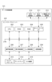
図1は、本実施例に係る情報処理システム構成示す図である。情報処理システム100は、データ処理装置101、無線LAN(Local Area Network)ターミナル102、画像形成装置104、及びクラウドサーバー105で構成され、それらはネットワーク103を介して接続される。
(Example 1)
FIG. 1 is a diagram showing the configuration of an information processing system according to this embodiment. The
データ処理装置101は、スマートフォンなどのモバイル端末であり、小型端末用のオペレーティングシステムや、通話、データ通信を制御するプログラムが動作していても構わない。もしくは、音声制御や位置検出制御、携帯電話データ通信等を備えないパーソナルコンピューター(PC)であっても構わない。また、データ処理装置101は、無線LANターミナル102によりネットワーク103に接続している。無線LANターミナル102は、一般的なネットワーク・ルーター機能を有した無線LANの親機であって、家庭内や事務所などの中で無線LANを提供している。画像形成装置104は、プリンタ機能、コピー機能、スキャナ機能、ファクス送信機能等各種ジョブ実行機能を備えるデジタル複合機である。ユーザは、データ処理装置101を操作することで、画像形成装置104に対しジョブ実行を指示し、画像形成装置104の各種機能を実行することができる。クラウドサーバー105は、ネットワーク103を介して、データ処理装置101や画像形成装置104で利用されるデータの管理や、各種機能の拡張処理等を行う。なお、本実施例では、画像形成装置104やクラウドサーバー105はネットワーク103と有線接続する形態となっているが、データ処理装置101と同様に無線LANターミナル102を利用して無線接続してもよい。さらに、データ処理装置101及び画像形成装置104は、NFC(Near Field Communication)やBLE(Bluetooth Low Energy)等の無線信号を介して近距離無線通信が可能である。画像形成装置104は後述するNFC通信部やBLE通信部に画像形成装置104と無線LAN接続するための情報(IPアドレスやMACアドレス等)を持ち、データ処理装置101が近距離無線通信で接続情報を取得する。そして、取得した情報に基づいてデータ処理装置101と画像形成装置104の通信を開始する。
The
図2は、本実施例に係るデータ処理装置101のハードウェア構成図である。データ処理装置101は、コントローラユニット201を持つ。コントローラユニット201は、NFC通信部210、BLE通信部211及び無線LAN通信部212の各種通信部やマイク・スピーカ213、ディスプレイ214及び入力装置215の各種UI部を制御する。
FIG. 2 is a hardware configuration diagram of the
コントローラユニット201は、CPU202、ROM203、RAM204,ネットワークI/F205、音声制御部206、表示制御部207、入力制御部208及び記憶装置209で構成され、それらはシステムバス216で接続される。
The
CPU202は、データ処理装置101のシステム全体を制御する。ROM203は、データ処理装置101のオペレーティングシステム及び、通話、データ通信等を制御するプログラムが記憶されており、CPU202が各種プログラムを実行する。RAM204は、CPU202の主メモリ、ワークエリア等の一時記憶領域として用いられる。
The
記憶装置209は、不揮発性の記憶装置であり、データ処理装置101の再起動後も保持しておく必要のある各種動作モードの設定や、稼働ログ等を記録する。
The
ネットワークI/F205は、NFC通信部210、BLE通信部211及び無線LAN通信部212と接続され、画像形成装置104と各種無線通信でデータのやり取りを行う。
The network I/F 205 is connected to the
音声制御部206は、マイク・スピーカ213を介した音声データの入出力制御を行う。表示制御部207は、ディスプレイ214で表示する画面の出力制御を行う。入力制御部208は、ユーザがボタンやタッチパネル等の入力装置215を介して指示した情報の入力制御を行う。データ処理装置101で実行される各種アプリケーションはこれら音声制御部206、表示制御部207、入力制御部208等を利用する。
The
図3は、本実施例に係る画像形成装置104のハードウェア構成図である。画像形成装置104は、コントローラユニット301を持ち、コントローラユニット301は、NFC通信部310、BLE通信部311及び無線LAN通信部312の各種通信部や操作部307、スキャナ313及びプリンタ314を制御する。ユーザが画像形成装置104のコピー機能を利用する場合、コントローラユニット301は、スキャナ313を制御して原稿の画像データを取得し、プリンタ314を制御して画像を用紙に印刷し出力する。また、ユーザがスキャンして送信機能を利用する場合、コントローラユニット301は、スキャナ313を制御して原稿の画像データを取得してコードデータに変換する。そしてネットワークI/F308を介してデータ処理装置101等へ送信する。また、ユーザがプリント機能を利用する場合、コントローラユニット301はデータ処理装置101からネットワークI/F308を介して画像データ(コードデータ)を受信する。そして、コントローラユニット301は受信した画像データをプリンタ314に送信する。プリンタ314は、受信した画像データに基づき、画像を用紙に印刷して出力する。また、画像形成装置104は、ISDN等からデータを受信してプリントするFAX受信機能や、ISDN等へスキャンしたデータを送信するFAX送信機能も有する。以上に示したような各機能を実行するために、ユーザが設定等を行った処理対象の仕事をジョブと呼び、画像形成装置104はジョブ情報に従って所定のジョブを実行する。
FIG. 3 is a hardware configuration diagram of the
コントローラユニット301は、CPU302、RAM303、ROM304、HDD305、操作部I/F306、ネットワークI/F308及びデバイスI/F309で構成され、それらはシステムバス315で接続される。
The
CPU302は、画像形成装置104のシステム全体を制御する。RAM303はCPU302が動作するためのシステムワークメモリであり、画像データ等を一時記憶する。また、スキャナ313で読み取られたスキャン画像データを格納したり、データ処理装置101からネットワーク103を介して受信したプリント画像データを格納したりする。ROM304はシステムのブートプログラム、アプリケーション等が格納されている。ハードディスクドライブ(HDD)305はオペレーティングシステムやシステムソフトウェア、アプリケーションソフトウェア、画像データ、設定データなどを格納する。
The
操作部307は、ユーザに対して情報を表示したり、ユーザからの操作を受け付ける。たとえばタッチパネルディスプレイのような操作パネルが含まれる。
The
操作部I/F306は操作部307に表示する情報を操作部307に対して出力する。また、操作部I/F306は操作部307からユーザが入力した情報を受け付ける。ネットワークI/F308はNFC通信部310、BLE通信部311及び無線LAN通信部312と接続され、データ処理装置101やクラウドサーバー105と各種通信で情報のやり取りを行う。無線LAN通信部312は、ネットワーク103を介してデータ処理装置101と無線LAN通信を行う。また、NFC通信部310、BLE通信部311は、データ処理装置101と近距離無線通信を行う。画像形成装置104は、ネットワークI/F308を介して、データ処理装置101からジョブの設定情報や画像データ、ジョブ実行コマンド等を受信し、ジョブを実行する。デバイスI/F309は、画像データの読み取りや印刷を実行するスキャナ313やプリンタ314とコントローラユニット301を接続し、画像データの入出力を行う。
The operation unit I/
図4は、本実施例に係るデータ処理装置101のアプリケーションの構成を示す。CPU202がROM203や記憶装置209に記憶されている制御プログラムを読み出すことで実現されるソフトウェアの機能ブロック図である。
FIG. 4 shows the configuration of an application of the
アプリケーション401は、データ処理装置101にインストールされたアプリケーションであり画像形成装置104に対して動作指示するためのアプリケーションである。アプリケーション401上で設定を行ってプリントジョブ情報やスキャンジョブ情報を生成し、当該ジョブ情報を画像形成装置104に送信することができる。データ処理装置101には、このアプリケーション401の他に様々なアプリケーションがインストールされているが、説明は省略する。以下にアプリケーション401の構成を示す。
An
ユーザインタフェース(UI)制御部402は、ユーザが入力装置215で入力したジョブの設定情報等を受け付け、入力制御部208を介して、受け付けた内容をジョブ設定管理部406やジョブ制御部407に送信する。また、UI制御部402は、ジョブ設定管理部406やジョブ制御部407からの応答を受信し、表示制御部207を介して、受信した内容に応じた画面をディスプレイ214に出力する。さらに、UI制御部402は、ユーザが入力装置215で入力したユーザ情報、パスワードなどの画像形成装置104にログインするための認証情報を受け付け、入力制御部208を介して、認証設定管理部403に送信する。
A user interface (UI)
認証設定管理部403は、UI制御部402から受信したユーザ情報等の認証情報を登録しておく。そして登録された認証情報に基づいて画像形成装置104にログインする処理を行う。具体的には、認証情報をネットワーク制御部405に渡す。その認証情報は、ネットワーク103を介して画像形成装置104に送信される。画像形成装置104は受信した認証情報を用いてログイン処理を行い、結果をデータ処理装置101に返す。登録された認証情報はジョブ情報を送信する際に付与することもできる。
The authentication
デバイス接続部404は、データ処理装置101と画像形成装置104との間でたとえば、NFCやBLEを用いた近距離無線通信やネットワーク103を介した無線LAN通信を確立する。例えば、NFCの場合、ユーザがデータ処理装置101のNFC通信部210と画像形成装置104のNFC通信部310を近づけることで、近距離無線通信が開始される。また、BLEの場合、画像形成装置104のBLE通信部311がBLEビーコンを送信し、データ処理装置101のBLE通信部211が送信されたビーコンを受信する。ユーザがデータ処理装置101を画像形成装置104に近づけることで、データ処理装置101が受信したビーコンの電波強度が一定以上となったと判定すると近距離無線通信が開始される。このように、ユーザがデータ処理装置101と画像形成装置104のNFC、BLEの通信部を近づけることで、デバイス接続部404は、画像形成装置104と近距離無線通信を行う。そして当該近距離無線通信を介して、画像形成装置104から無線LAN通信に必要な接続情報を含む機器情報を取得する。デバイス接続部404は、取得した接続情報を用いてネットワーク103を介した画像形成装置104との無線LAN通信を開始する。
The
ネットワーク制御部405は、画像形成装置104に対してジョブ情報(設定情報やジョブ実行指示コマンド、画像データ、ユーザ認証情報等)を、ネットワーク103を介して送信する。スキャンした画像データを設定した宛先に送信するジョブ情報を構成する場合、ジョブの設定情報とは、データを送信する宛先(例えばメールアドレス)やスキャンに関する設定(例えばカラー設定解像度など)等である。さらに、ネットワーク制御部405は、画像形成装置104に格納されたジョブの設定情報等を、ネットワーク103を介して受信することもできる。
The network control unit 405 transmits job information (setting information, job execution instruction command, image data, user authentication information, etc.) to the
ジョブ設定管理部406は、UI制御部402が受け付けたユーザが入力したジョブの設定情報や、ネットワーク制御部405により画像形成装置104から受信したジョブの設定情報をRAM204や記憶装置209に格納する。このとき、ジョブ設定管理部406は、これらのジョブの設定情報をユーザがよく使う設定として「お気に入り」登録しても良い。また、ジョブ設定管理部406は、アプリケーション401のインストール時に所定のジョブの設定情報を「プリセット」として登録しておくようにしても良い。
The job setting management unit 406 stores the job setting information input by the user and received by the
ジョブ制御部407は、画像形成装置104で実行する処理を制御する。例えばジョブ設定管理部406で登録された「お気に入り」や「プリセット」に含まれるジョブの設定情報やユーザ操作で設定したジョブの設定情報からジョブ情報を生成し、ネットワーク103を介して画像形成装置104に対するジョブの実行指示を送信する。また、ジョブ制御部407は、ジョブ実行状況や、スキャナ313やプリンタ314のデバイスの動作状態を、ネットワーク103を介して画像形成装置104から取得し、UI制御部402に送信する。
A job control unit 407 controls processing executed by the
図5は、本実施例に係る画像形成装置104のソフトウェア構成を示す。CPU302がROM304やHDD305に記憶されている制御プログラムを読み出すことで実現されるソフトウェアの機能ブロック図である。
FIG. 5 shows the software configuration of the
システムソフトウェア501は画像形成装置104のCPU302が実行するソフトウェアであり、RAM303に格納されている。ユーザインタフェース(UI)制御部502は、ユーザが操作部307を介して入力したジョブの設定情報等を受け付け、ジョブ設定管理部506やジョブ制御部507に渡す。また、UI制御部502は、ジョブ設定管理部506やジョブ制御部507からの応答を受信し、操作部307に応答に基づく画面を出力する。
認証部503は、データ処理装置101から受信した認証情報に基づいてログイン処理を行い、その結果を返す。画像形成装置104は、ログインしたユーザに対応するメールアドレス等の各種情報を保持している。
The
デバイス接続部504は、データ処理装置101との間で例えば無線LAN通信を確立する。ネットワーク制御部505は、データ処理装置101からジョブの設定情報やジョブ実行指示コマンド、画像データ、ユーザ認証情報等を、ネットワーク103を介して受信する。さらに、ネットワーク制御部505は、画像形成装置104に格納されたジョブの設定情報を、ネットワーク103を介してデータ処理装置101に対し送信する。
The
ジョブ設定管理部506は、実行するジョブの状態等を管理する。またUI制御部502によりユーザが入力したジョブの設定情報や、ネットワーク制御部505によりデータ処理装置101から受信したジョブの設定情報等を含むジョブに関する情報をRAM303やHDD305に格納する。このとき、ジョブ設定管理部506は、これらのジョブの設定情報をユーザがよく使う設定として「お気に入り」登録しても良い。また、ジョブ設定管理部506は、所定のジョブの設定情報を「プリセット」として登録しておくようにしても良い。また、画像形成装置104で実行されたジョブを「履歴」として管理する。
The job setting management unit 506 manages the status of jobs to be executed. Further, job-related information including job setting information input by the user through the
ジョブ制御部507は、受信したジョブ情報に応じ、スキャン処理部511、コピー処理部512、プリント処理部513及びファクス処理部514の各処理部を制御し、各種ジョブを実行する。例えば、ジョブ制御部507は、ユーザが操作部307で設定したジョブの設定情報や、ジョブ実行管理部506で登録された「お気に入り」や「プリセット」のジョブの設定情報を用いて各種ジョブを実行する。さらに、ジョブ制御部507は、ネットワーク103を介して、データ処理装置101等から受信したジョブ実行要求を受信し、受信したジョブの設定情報やジョブ実行指示に応じて、各種ジョブを実行する。また、ジョブ制御部507は、ジョブ実行状況や、スキャナ313やプリンタ314のデバイスの動作状態を、ネットワーク103を介してデータ処理装置101へ送信する。
The job control unit 507 controls each processing unit including a
図6はデータ処理装置101の画像形成装置104への接続処理を説明するフローチャートである。図6に示す各動作は、CPU202がROM203又は記憶装置209に記憶された各制御モジュールを実現するためのプログラムをRAM204に読み出し、実行することにより実現する。接続処理により、データ処理装置101は接続した画像形成装置104に対しジョブの実行指示を行うことができる。
FIG. 6 is a flowchart illustrating the process of connecting the
ユーザはデータ処理装置101を用いて画像形成装置104から接続情報を取得するための操作を行う。図11(a)はデータ処理装置101のディスプレイ214に表示する画像形成装置104への接続画面の一例である。接続画面1101において、1102は、デバイスの接続方法の選択項目であり、「自動探索」、「手動探索」、「QRコード(登録商標)」、「近くのプリンタ」がある。
A user performs an operation to obtain connection information from the
「自動探索」は、デバイス接続部404がWi-Fi(登録商標)等を利用して無線LANターミナル102経由でネットワーク103上のデータ処理装置101と通信可能な画像形成装置104をmDNS(multicast Domain Name System)で探索する。ユーザは、探索により検出した画像形成装置104を選択することで、デバイス接続部404を経由して画像形成装置104に接続する。
"Automatic search" is when the
「手動探索」はユーザが接続する画像形成装置104の識別情報(IPアドレスなど)を入力装置215を用いて入力することで、デバイス接続部404を経由して画像形成装置104に接続する。
In "manual search", the user inputs identification information (IP address, etc.) of the
「QRコード」は、画像形成装置104の識別情報を保持したQRコードをデータ処理装置201に搭載したカメラによって読み込むことで、デバイス接続部404を経由して画像形成装置104に接続する。
The "QR code" is connected to the
「近くのプリンタ」は、ユーザがデータ処理装置101と画像形成装置104のNFCやBLEの通信部を近づける操作を行うことで、デバイス接続部404を経由して画像形成装置104に接続する。
The "nearby printer" is connected to the
デバイス接続部404は上記のいずれかの方法で接続情報が取得できたか否かを判定し(S601)、接続情報が取得できなければS601に戻り、接続情報の取得待ちを継続する。接続情報を取得した場合、取得した接続情報により画像形成装置104を探索する(S602)。画像形成装置104が探索できたか否かを判断し(S603)、画像形成装置104が探索できた場合、デバイス接続部404は画像形成装置104との接続を開始し(S604)、処理を終了する。画像形成装置104が探索できなかった場合、ユーザにエラーを通知し処理を終了する。
The
図11(b)、(c)はデータ処理装置101がユーザからジョブの設定を受け付け、ジョブ情報を画像形成装置104に送信する際にUI制御部402が表示する画面の一例を示す。
FIGS. 11B and 11C show examples of screens displayed by the
図11(b)はジョブ選択画面1111を示し、ユーザが所望のジョブを選択する画面である。「お気に入り」ボタン1112、1114はユーザが予め登録したジョブの設定を呼び出すためのボタンであり、押下されると登録されたジョブの設定情報が反映されたジョブの設定画面に遷移する。編集ボタン1113は「お気に入り」ボタンに紐付く設定を変更するためのボタンである。追加ボタン1115は新たに「お気に入り」ボタンを追加するためのボタンであり、押下されると設定を登録するための画面に遷移する。プリセットボタン1116~1118はデフォルトの設定値が紐付いたボタンであり、押下されるとデフォルトの設定値が反映されたそれぞれの機能の設定画面が表示される。ここでは一例として、コピー、スキャンして送信、プリント機能のボタンが表示されている。対象画像形成装置ボタン1119には、図6に示す接続処理で接続した画像形成装置104の情報が表示される。対象画像形成装置ボタン1119で示される画像形成装置104がジョブ情報の送信対象となる。対象画像形成装置1119ボタンが押下されると対象となる画像形成装置を変更することが可能である。
FIG. 11B shows a
スキャン設定画面1121は、ジョブ選択画面1111でスキャンして送信ボタン1117が選択されると表示される設定画面である。画像の送信先を設定する項目1122、スキャンの設定を行うための項目1123が含まれる。ユーザはそれぞれの項目を選択することでジョブの設定を行う。スタートボタン1124が押下されると、スキャン設定画面1121においてユーザから受け付けた設定を基にジョブ情報を構成し、画像形成装置104に当該ジョブ情報を送信する。
The
図7はデータ処理装置101におけるユーザからジョブの設定を受け付ける処理を説明するフローチャートである。図7に示す動作は、CPU202がROM203又は記憶装置209に記憶された各制御モジュールを実現するためのプログラムをRAM204に読み出し、実行することにより実現する。ここでは一例としてのジョブ選択画面1111からスキャンして送信ボタン1117が選択された場合を例にして説明を行う。
FIG. 7 is a flowchart illustrating a process of accepting job settings from a user in the
UI制御部402は、実行するジョブを選択するためのジョブ選択画面1111を表示し(S701)、ユーザからの実行ジョブの選択を受け付ける(S702)。ユーザから送信ボタン1117の選択を受け付け、実行するジョブの選択を受け付けると、UI制御部402はスキャン設定画面1121を表示する(S703)。
The
UI制御部402は、送信先の設定やスキャンの設定を変更する入力があるか否かを判断し(S704)、入力があった場合は、変更された設定を含むジョブの設定情報を一時的にRAM204に保存し(S705)、処理を終了する。入力がない場合は処理を終了する。
The
図8はデータ処理装置101が画像形成装置104へジョブ情報を送信する処理を説明するフローチャートである。図8に示す動作は、CPU202がROM203又は記憶装置209に記憶された各制御モジュールを実現するためのプログラムをRAM204に読み出し、実行することにより実現する。ここでは一例としてスキャン設定画面1121でスタートボタン1124の押下を受け付けた場合を説明する。
FIG. 8 is a flowchart illustrating a process in which the
スキャン設定画面1121においてユーザからのスタートボタン1124の押下を受け付けると、UI制御部402を経由してジョブ制御部407は、設定画面において設定されているジョブの設定情報を取得する(S801)。以降、ジョブ実行のために必要な送信先やスキャン設定をまとめてジョブの設定情報と称す。次いでジョブ制御部407は、RAM204、あるいは記憶装置209に記憶されたユーザ名やパスワードといったユーザ情報を取得し(S802)、画像形成装置104に対して、リモート認証要求を行う(S803)。リモート認証は、データ処理装置101と画像形成装置104との通信の開始を許可するための認証であり、リモート認証に成功すると画像形成装置104はデータ処理装置101からジョブ情報の受け付けが可能となる。ジョブ制御部407はリモート認証が成功したか否かを判断する(S804)。リモート認証の失敗の通知をジョブ制御部407から受信すると、UI制御部402は、ディスプレイ214にエラー画面を表示し(S807)、処理を終了する。リモート認証が成功した場合、ジョブ制御部407は、取得したジョブの設定情報、ユーザ情報等に基づいてジョブ情報を生成し(S805)、接続している画像形成装置104に対し、ジョブ情報を送信し(S806)、処理を終了する。
When the user presses the
図12はデータ処理装置101が送信するジョブ情報の構成を示すテーブルの一例である。ジョブ情報テーブル1201において、1202列はユーザ名、1203列はログインパスワード、1204列は送信先設定、1205はスキャン設定をそれぞれ示している。1行が1つのジョブ情報を示している。ここではスキャンして送信ジョブのジョブ情報を示したがコピージョブやプリントジョブも同様の構成である。
FIG. 12 is an example of a table showing the structure of job information transmitted by the
図9は画像形成装置104のジョブ情報の受信処理を説明するフローチャートである。図9に示す動作は、CPU302がROM304又はHDD305に記憶された各制御モジュールを実現するためのプログラムをRAM303に読み出し、実行することにより実現する。
FIG. 9 is a flowchart illustrating job information reception processing by the
ジョブ制御部507は、ネットワーク制御部505を経由してデータ処理装置101からのジョブ情報を受信する(S901)。次いで、ジョブ制御部507は、受信したジョブ情報からユーザ情報を抽出し(S902)、認証部503に対し、抽出したユーザ情報でのローカル認証を行う(S903)。ローカル認証は、画像形成装置104の操作部307上での操作をユーザに許可するための認証である。ジョブ制御部507は、ローカル認証に成功したか否かを判定し(S904)、失敗した場合、データ処理装置101にエラーを送信し(S911)、処理を終了する。ローカル認証に成功した場合、画像形成装置104の状態情報を取得する(S905)。画像形成装置104の状態情報とは、ジョブを実行中であるか、他のユーザがログイン中であるかを示す情報などである。
The job control unit 507 receives job information from the
取得した画像形成装置104の状態情報からジョブの実行が可能か否かを判定する(S906)。画像形成装置104がジョブを実行中であったり、他のユーザが画像形成装置104にログイン中の場合はジョブの実行が不可と判定し、画像形成装置104の状態による要因によってジョブの実行が不可である旨をデータ処理装置101に送信し(S912)、処理を終了する。ジョブの実行が可能な場合、ジョブの設定情報を抽出し(S907)、画像形成装置104で実行可能な設定情報であるか否かを判定する(S908)。実行可能な設定情報である場合、ジョブ情報の受付完了をデータ処理装置101に送信し(S909)、ジョブを実行して(S910)、処理を終了する。ここでは例えばジョブ情報に含まれるスキャン設定でスキャン処理を行い、ジョブ情報に含まれる送信先にスキャンして生成した画像データを送信する。
Based on the acquired status information of the
実行可能な設定情報でない場合、ジョブの設定情報の要因によるエラーをデータ処理装置101に送信し(S913)、処理を終了する。 If the setting information is not executable, an error caused by the setting information of the job is transmitted to the data processing apparatus 101 (S913), and the process ends.
本実施例において、S906の判断処理とS908の判断処理は順序が逆であっても良い。以上のフローチャートの処理によりデータ処理装置から送信されたジョブ情報に基づいて画像形成装置104はジョブを実行することができる。また画像形成装置は受信したジョブが実行できない場合、ジョブの設定情報によるエラーであるのか、画像形成装置104の状態によるエラーなのかをデータ処理装置101に通知することができる。
In this embodiment, the order of the determination process in S906 and the determination process in S908 may be reversed. The
図11(d)~(f)は、画像形成装置104のジョブ情報の受付結果に対するデータ処理装置101の処理を説明するための画面の例であり、UI制御部402が表示する画面の一例である。
FIGS. 11(d) to 11(f) are examples of screens for explaining the processing of the
図11(d)は、画像形成装置104がジョブ情報の受信を完了した、つまりデータ処理装置101が送信したジョブ情報を画像形成装置104に投入できた場合にUI制御部402が表示する画面を示す。ジョブ送信完了画面1131には、ジョブの送信がエラーなく完了したことを示すメッセージ1132と、送信したジョブの設定情報をデータ処理装置101に保存するための保存ボタン1133とジョブの設定情報を保存せずに処理を終了させるOKボタン1134が含まれる。保存ボタン1133が押下されると、ジョブの設定情報がアプリケーション401に保存され、ジョブ選択画面1151に示すように、保存された設定情報を呼びだすための「お気に入り」ボタン1152が新たにジョブ選択画面に登録される。「お気に入り」ボタン1152が押下されると保存された設定情報が反映されたジョブの設定画面が表示される。保存ボタン1133が押下された際に「お気に入り」ボタンに表示するボタンの名称を入力する画面を表示するようにしても良い。
FIG. 11D shows a screen displayed by the
図11(e)は、ジョブ情報を受信した画像形成装置104が他のジョブを実行中等の要因で受信したジョブ情報を実行できない場合にUI制御部402が表示する画面を示す。リトライ画面1141には、画像形成装置104の状態が要因でジョブが実行できない旨を示すメッセージ1142と、送信したジョブ情報を再送信するためのリトライボタン1143と設定情報を保存せずに処理を終了するためのキャンセルボタン1144が含まれる。リトライボタン1143を押下する前に対象画像形成装置1119ボタンを押下してジョブ情報の送信対象を変更できるようにしても良い。そうすることでジョブの設定情報を破棄することなく、他の画像形成装置にジョブ情報を送信することができる。
FIG. 11E shows a screen displayed by the
図10は、画像形成装置104のジョブ情報の受付結果に対するデータ処理装置101の処理を説明するフローチャートである。図10に示す動作は、CPU202がROM203又は記憶装置209に記憶された各制御モジュールを実現するためのプログラムをRAM204に読み出し、実行することにより実現する。
FIG. 10 is a flowchart illustrating the processing performed by the
ジョブ制御部407は、画像形成装置104から送信したジョブ情報の受付結果をネットワークI/F205を経由して受信する(S1001)。結果がS909に対応するジョブ情報の受付完了であるか否かを判定し(S1002)、受付完了であった場合、ジョブ設定管理部406はアプリケーション401に保存済みのジョブの設定情報にS705で一時的にRAM204に保存したジョブの設定情報と同じものがあるか否かを判定する(S1003)。保存されている設定情報であれば処理を終了する。保存されていないジョブの設定情報であれば、UI制御部402はジョブの設定情報を保存するか否かをユーザに追い合わせるジョブ送信完了画面1131をディスプレイ214に表示する(S1004)。UI制御部402はジョブ送信完了画面1131においてユーザから設定情報の保存指示があるか否かを判定し(S1005)、保存指示があった場合は、一時的にRAM204に保存したジョブの設定情報を記憶装置209に保存し(S1006)、そうでない場合は処理を終了する。保存指示とは具体的には保存ボタン1133が押下されることである。保存されたジョブの設定情報を呼び出すためのボタンはジョブ選択画面に表示される。ここでは保存指示をユーザから受け付けるとジョブの設定情報を保存する例を示したが、ユーザの指示を受け付けることなく自動で保存するような構成にしても良い。
The job control unit 407 receives the job information reception result transmitted from the
S1002でジョブ情報の受付が完了しなかった場合、ジョブ制御部407はエラー情報を解析する(S1007)。ここで画像形成装置104からS913に対応する通知を受けたか、S912に対応する通知を受けたかを判断する。解析した結果に基づいて画像形成装置の状態が要因のエラーであるか否かを判定し(S1008)、画像形成装置の状態が要因である場合は、UI制御部402はリトライ画面1141を表示する(S1009)。リトライ画面1141においてUI制御部402はユーザからのリトライ指示を受け付けたか否かを判定し(S1010)、リトライ指示を受け付けた場合、ジョブ制御部407はRAM204に保存したジョブ情報を画像形成装置104に送信する処理を行い(S1011)、リトライ指示を受けなかった場合は処理を終了する。具体的にはリトライボタン1143の押下をユーザから受け付けると、S705で一時的にRAM204に保存したジョブの設定情報を画像形成装置104に送信する。この処理は図8のフローチャートの処理と同じであるため説明を割愛する。S1010でリトライ指示を受け付けていないと判定されると処理を終了する。
If reception of job information is not completed in S1002, the job control unit 407 analyzes error information (S1007). Here, it is determined whether a notification corresponding to S913 or S912 has been received from the
S1008において、画像形成装置の状態の要因ではないエラーの場合、ジョブ制御部407はジョブの設定情報の要因であるか否かを判定する(S1013)。設定情報の要因である場合、UI制御部402はジョブの設定画面(例えばスキャン設定画面1121)を表示する(S1014)。ここで表示される設定画面は送信したジョブの設定情報が反映されたものでも良いし、すべての設定値がクリアされた設定画面であっても良い。
In S1008, if the error is not caused by the state of the image forming apparatus, the job control unit 407 determines whether the error is caused by job setting information (S1013). If the cause is setting information, the
S1013において、設定情報の要因ではないと判定された場合、エラーをユーザに通知し(S1015)、処理を終了する。 If it is determined in S1013 that the setting information is not the cause, the user is notified of the error (S1015), and the process ends.
以上のフローチャートの処理により、データ処理装置が画像形成装置にジョブを投入できたという条件を満たす場合は、当該ジョブの設定情報をデータ処理装置に保存することが可能となり。使用可能なジョブの設定情報を簡単に呼びだすことが可能となる。ジョブの投入に成功し、なおかつデータ処理装置に保存されていない設定情報である場合のみ設定情報を保存可能とするため不要な設定情報が保存されることを防ぐことができる。 Through the processing in the above flowchart, if the condition that the data processing apparatus was able to input the job to the image forming apparatus is satisfied, the setting information of the job can be saved in the data processing apparatus. Setting information of available jobs can be easily called up. Since setting information can be saved only when the job is successfully submitted and the setting information is not saved in the data processing device, it is possible to prevent unnecessary setting information from being saved.
またデータ処理装置が画像形成装置にジョブを投入できなかった場合、エラーの種類に応じて処理を変更することができる。具体的には画像形成装置が他のジョブを実行中等の理由、つまり画像形成装置の状態によるエラーである場合は、ジョブ情報を再送信可能なように構成する。こうすることで画像形成装置がジョブ実行可能となった時にジョブ情報を再送信することができ、データ処理装置上で一から設定をやり直す必要が無い。一方でジョブの設定情報によるエラーの場合はデータ処理装置上でユーザに設定をやり直させる。 Further, if the data processing device cannot submit a job to the image forming device, the processing can be changed depending on the type of error. Specifically, the configuration is such that job information can be retransmitted if the error is due to the image forming apparatus executing another job, that is, the state of the image forming apparatus. By doing so, the job information can be retransmitted when the image forming apparatus becomes capable of executing the job, and there is no need to redo the settings from scratch on the data processing apparatus. On the other hand, if the error is due to job setting information, the user is forced to redo the settings on the data processing device.
以上の実施例ではジョブの投入ができた場合にジョブの設定情報を保存可能とする例を示したが、これに限らず、データ処理装置が画像形成装置にジョブ情報を送信出来た時点でジョブの設定情報を登録するかユーザに問い合わせるようにしても良いし、画像形成装置がジョブ情報に基づいてジョブを開始した時点でジョブの設定情報を登録するかユーザに問い合わせるようにしても良いし、ジョブ情報を受信した画像形成装置がエラーなくジョブを実行完了した場合にジョブの設定情報を登録するかユーザに問い合わせるようにしても良い。 Although the above embodiment shows an example in which job setting information can be saved when the job is successfully submitted, the present invention is not limited to this. The user may be asked whether to register setting information for the job, or the user may be asked whether to register setting information for a job at the time when the image forming apparatus starts a job based on the job information. If the image forming apparatus that has received the job information completes execution of the job without error, the image forming apparatus may inquire of the user whether to register the job setting information.
(その他の実施例)
実施例1ではジョブ選択画面には1111に示すようにプリント機能、スキャンして送信機能、コピー機能など複数の機能のお気に入りボタンを同一画面に表示するようにしていたが、機能ごとにそれぞれ異なる画面を設けるようにしても良い。この画面例を図13(a)に示す。送信ジョブ選択画面1301は、スキャンして送信機能のお気に入りボタンを表示する画面である。送信ジョブ選択画面1301にはスキャンして送信機能を利用するジョブのボタンのみが表示され、プリセットボタン1302はデフォルトの設定値で設定画面を開くためのボタンである。S1006で保存されるジョブの設定情報を呼び出すお気に入りボタンは、それぞれ対応する機能の画面に表示されるようになる。
(Other examples)
In the first embodiment, favorite buttons for multiple functions such as the print function, scan and send function, and copy function are displayed on the same screen as shown in 1111 on the job selection screen, but each function has a different screen. may be provided. An example of this screen is shown in FIG. 13(a). The transmission
また実施例1では、ジョブ情報を受信した画像形成装置がジョブ実行不可の状態であれば、データ処理装置からリトライ指示できる例を示したがこれに限らず、データ処理装置101は送信したジョブ情報を一時保存してジョブ選択画面から呼び出せるように構成しても良い。この画面例を図13(b)に示す。ジョブ選択画面1311には一時保存したジョブの設定情報を呼び出すボタン1312が含まれる。ボタン1312が押下されると保存された設定情報を反映したジョブの設定画面が表示される。ボタン1312は例えばアプリケーション401がデータ処理装置101上で終了されたり、バックグラウンドにされると非表示となり、保存されたジョブの設定情報も削除されるようにしても良い。またタン1312が選択されてジョブが実行された場合に保存されたジョブの設定情報を削除するようにしても良い。
Furthermore, in the first embodiment, if the image forming apparatus that has received the job information is in a state where the job cannot be executed, the data processing apparatus can instruct a retry, but the
本発明は、以下の処理を実行することによっても実現される。即ち、上述した実施形態の機能を実現するソフトウェア(プログラム)を、ネットワーク又は各種記憶媒体を介してシステム或いは装置に供給し、そのシステム或いは装置のコンピュータ(またはCPUやMPU等)がプログラムを読み出して実行する処理である。この場合、そのコンピュータプログラム、及び該コンピュータプログラムを記憶した記憶媒体は本発明を構成することになる。 The present invention is also realized by performing the following processing. That is, the software (program) that realizes the functions of the embodiments described above is supplied to a system or device via a network or various storage media, and the computer (or CPU, MPU, etc.) of the system or device reads the program. This is the process to be executed. In this case, the computer program and the storage medium storing the computer program constitute the present invention.
100 情報処理システム
101 データ処理装置
102 無線LANターミナル
103 ネットワーク
104 画像形成装置
105 クラウドサーバー
100
Claims (13)
前記制御方法は、
前記画像形成装置に実行させるジョブの設定画面でユーザからジョブの設定を受け付ける受付工程と、
前記受付工程で受け付けた設定に基づいてジョブ情報を生成し、前記画像形成装置に当該ジョブ情報を送信する送信工程と、
前記送信工程で送信したジョブ情報を実行できない場合の要因を判定する判定工程と、を有し、
前記送信工程で送信したジョブ情報が所定の条件を満たすと前記受け付けた設定を前記情報処理装置に保存可能とし、
前記判定工程において、前記画像形成装置が自装置の状態が要因でジョブを実行できないと判定された場合、前記受け付けた設定でジョブ情報を再送信するボタンを表示し、
前記判定工程において、前記送信工程で送信したジョブ情報に含まれる設定で前記画像形成装置がジョブを実行できないと判定された場合、ジョブを実行させるための設定画面を表示することを特徴とするプログラム。 A program for causing a computer of an information processing device capable of communicating with an image forming device to execute a control method,
The control method includes:
a reception step of accepting job settings from a user on a job setting screen to be executed by the image forming apparatus;
a transmission step of generating job information based on the settings received in the reception step and transmitting the job information to the image forming apparatus;
a determination step of determining a cause when the job information transmitted in the transmission step cannot be executed;
When the job information transmitted in the sending step satisfies a predetermined condition, the accepted settings can be saved in the information processing device;
In the determination step, if it is determined that the image forming apparatus cannot execute the job due to its own state, displaying a button to resend job information with the accepted settings;
A program characterized in that, in the determination step, if it is determined that the image forming apparatus cannot execute the job based on the settings included in the job information transmitted in the transmission step, a setting screen for executing the job is displayed. .
前記受け付けた設定を前記情報処理装置に保存する保存工程と、
ユーザ操作を受け付けると前記保存工程で保存した設定を呼び出す呼び出し工程をさらに有することを特徴とする請求項1から4のいずれか一項に記載のプログラム。 The control method includes:
a storage step of storing the accepted settings in the information processing device;
5. The program according to claim 1, further comprising a calling step of calling the settings saved in the saving step when a user operation is received.
前記画像形成装置に実行させるジョブの設定画面でユーザからジョブの設定を受け付ける受付手段と、
前記受付手段で受け付けた設定に基づいてジョブ情報を生成し、前記画像形成装置に当該ジョブ情報を送信する送信手段と、
前記送信手段により送信したジョブ情報を実行できない場合の要因を判定する判定手段と、を有し、
前記送信手段で送信したジョブ情報が所定の条件を満たすと前記受け付けた設定を前記情報処理装置に保存可能とし、
前記判定手段により、前記画像形成装置が自装置の状態が要因でジョブを実行できないと判定された場合、前記受け付けた設定でジョブ情報を再送信するボタンを表示し、
前記判定手段により、前記送信手段で送信したジョブ情報に含まれる設定で前記画像形成装置がジョブを実行できないと判定された場合、ジョブを実行させるための設定画面を表示することを特徴とする情報処理装置。 An information processing device capable of communicating with an image forming device,
a reception unit that receives job settings from a user on a job setting screen to be executed by the image forming apparatus;
a transmitting unit that generates job information based on the settings received by the accepting unit and transmits the job information to the image forming apparatus;
a determining means for determining a cause when the job information transmitted by the transmitting means cannot be executed;
When the job information transmitted by the transmitting means satisfies a predetermined condition, the accepted settings can be stored in the information processing device;
If the determination means determines that the image forming apparatus cannot execute the job due to its own state, displaying a button to resend the job information with the accepted settings;
Information characterized in that when the determination means determines that the image forming apparatus cannot execute the job with the settings included in the job information transmitted by the transmission means , a settings screen for executing the job is displayed. Processing equipment.
前記画像形成装置に実行させるジョブの設定画面でユーザからジョブの設定を受け付ける受付工程と、
前記受付工程で受け付けた設定に基づいてジョブ情報を生成し、前記画像形成装置に当該ジョブ情報を送信する送信工程と、
前記送信工程で送信したジョブ情報を実行できない場合の要因を判定する判定工程と、を有し、
前記送信工程で送信したジョブ情報が所定の条件を満たすと前記受け付けた設定を前記情報処理装置に保存可能とし、
前記判定工程において、前記画像形成装置が自装置の状態が要因でジョブを実行できないと判定された場合、前記受け付けた設定でジョブ情報を再送信するボタンを表示し、
前記判定工程において、前記送信工程で送信したジョブ情報に含まれる設定で前記画像形成装置がジョブを実行できないと判定された場合、ジョブを実行させるための設定画面を表示することを特徴とする制御方法。 A control method executed by an information processing device capable of communicating with an image forming device, the method comprising:
a reception step of accepting job settings from a user on a job setting screen to be executed by the image forming apparatus;
a transmission step of generating job information based on the settings received in the reception step and transmitting the job information to the image forming apparatus;
a determination step of determining a cause when the job information transmitted in the transmission step cannot be executed;
When the job information transmitted in the sending step satisfies a predetermined condition, the accepted settings can be saved in the information processing device;
In the determination step, if it is determined that the image forming apparatus cannot execute the job due to its own state, displaying a button to resend job information with the accepted settings;
In the determination step, if it is determined that the image forming apparatus cannot execute the job based on the settings included in the job information transmitted in the transmission step, a setting screen for executing the job is displayed. Method.
Priority Applications (5)
| Application Number | Priority Date | Filing Date | Title |
|---|---|---|---|
| JP2021177093A JP7439035B2 (en) | 2021-10-29 | 2021-10-29 | Data processing device, image forming device, control method thereof, and program |
| CN202211316409.5A CN116074448A (en) | 2021-10-29 | 2022-10-26 | Data processing apparatus, control method for data processing apparatus, and storage medium |
| US18/050,426 US20230134842A1 (en) | 2021-10-29 | 2022-10-27 | Data processing apparatus, method of controlling data processing apparatus, and storage medium |
| GB2215911.5A GB2614397B (en) | 2021-10-29 | 2022-10-27 | Data processing apparatus, method of controlling data processing apparatus, and storage medium |
| JP2024019185A JP2024056836A (en) | 2021-10-29 | 2024-02-13 | Data processing apparatus, image forming apparatus and control method for the same, and program |
Applications Claiming Priority (1)
| Application Number | Priority Date | Filing Date | Title |
|---|---|---|---|
| JP2021177093A JP7439035B2 (en) | 2021-10-29 | 2021-10-29 | Data processing device, image forming device, control method thereof, and program |
Related Child Applications (1)
| Application Number | Title | Priority Date | Filing Date |
|---|---|---|---|
| JP2024019185A Division JP2024056836A (en) | 2021-10-29 | 2024-02-13 | Data processing apparatus, image forming apparatus and control method for the same, and program |
Publications (2)
| Publication Number | Publication Date |
|---|---|
| JP2023066477A JP2023066477A (en) | 2023-05-16 |
| JP7439035B2 true JP7439035B2 (en) | 2024-02-27 |
Family
ID=84839415
Family Applications (2)
| Application Number | Title | Priority Date | Filing Date |
|---|---|---|---|
| JP2021177093A Active JP7439035B2 (en) | 2021-10-29 | 2021-10-29 | Data processing device, image forming device, control method thereof, and program |
| JP2024019185A Pending JP2024056836A (en) | 2021-10-29 | 2024-02-13 | Data processing apparatus, image forming apparatus and control method for the same, and program |
Family Applications After (1)
| Application Number | Title | Priority Date | Filing Date |
|---|---|---|---|
| JP2024019185A Pending JP2024056836A (en) | 2021-10-29 | 2024-02-13 | Data processing apparatus, image forming apparatus and control method for the same, and program |
Country Status (4)
| Country | Link |
|---|---|
| US (1) | US20230134842A1 (en) |
| JP (2) | JP7439035B2 (en) |
| CN (1) | CN116074448A (en) |
| GB (1) | GB2614397B (en) |
Citations (3)
| Publication number | Priority date | Publication date | Assignee | Title |
|---|---|---|---|---|
| JP2011258216A (en) | 2011-07-23 | 2011-12-22 | Canon Inc | Information processing device, information processing method, and medium for storing control program to execute the same method |
| JP2014026163A (en) | 2012-07-27 | 2014-02-06 | Konica Minolta Inc | Image forming apparatus, control program of image forming apparatus, and image forming system |
| JP2016167764A (en) | 2015-03-10 | 2016-09-15 | キヤノン株式会社 | Image processing apparatus and control method of the same, and program |
Family Cites Families (4)
| Publication number | Priority date | Publication date | Assignee | Title |
|---|---|---|---|---|
| JP2017007239A (en) * | 2015-06-24 | 2017-01-12 | 株式会社沖データ | Image forming apparatus, information processor, information processing program, information processing method and information processing system |
| JP6906969B2 (en) * | 2017-01-31 | 2021-07-21 | キヤノン株式会社 | Image processing device, control method of image processing device, and program |
| US10616426B2 (en) * | 2017-04-26 | 2020-04-07 | Kyocera Document Solutions Inc. | Information processing in which setting item list is scrolled when selection gesture is performed on shortcut button |
| JP2020154450A (en) * | 2019-03-18 | 2020-09-24 | キヤノン株式会社 | Information processor and control method thereof and program |
-
2021
- 2021-10-29 JP JP2021177093A patent/JP7439035B2/en active Active
-
2022
- 2022-10-26 CN CN202211316409.5A patent/CN116074448A/en active Pending
- 2022-10-27 US US18/050,426 patent/US20230134842A1/en active Pending
- 2022-10-27 GB GB2215911.5A patent/GB2614397B/en active Active
-
2024
- 2024-02-13 JP JP2024019185A patent/JP2024056836A/en active Pending
Patent Citations (3)
| Publication number | Priority date | Publication date | Assignee | Title |
|---|---|---|---|---|
| JP2011258216A (en) | 2011-07-23 | 2011-12-22 | Canon Inc | Information processing device, information processing method, and medium for storing control program to execute the same method |
| JP2014026163A (en) | 2012-07-27 | 2014-02-06 | Konica Minolta Inc | Image forming apparatus, control program of image forming apparatus, and image forming system |
| JP2016167764A (en) | 2015-03-10 | 2016-09-15 | キヤノン株式会社 | Image processing apparatus and control method of the same, and program |
Also Published As
| Publication number | Publication date |
|---|---|
| US20230134842A1 (en) | 2023-05-04 |
| GB2614397B (en) | 2024-04-03 |
| JP2023066477A (en) | 2023-05-16 |
| GB202215911D0 (en) | 2022-12-14 |
| JP2024056836A (en) | 2024-04-23 |
| GB2614397A (en) | 2023-07-05 |
| CN116074448A (en) | 2023-05-05 |
Similar Documents
| Publication | Publication Date | Title |
|---|---|---|
| JP6351241B2 (en) | System, image processing apparatus, and control method | |
| JP6071949B2 (en) | Information processing apparatus, control method thereof, and program | |
| JP6371825B2 (en) | Information processing apparatus, control method thereof, and program | |
| JP2016168708A (en) | Image processing device and image processing system | |
| JP6887748B2 (en) | Data transmission device, data transmission method and program | |
| JP7527815B2 (en) | Information processing apparatus, image forming apparatus, control method thereof, and program | |
| US8275105B2 (en) | IP telephone terminal | |
| JP7439035B2 (en) | Data processing device, image forming device, control method thereof, and program | |
| JP2019175001A (en) | Information processing apparatus, communication system, communication method, and program | |
| JP6950053B2 (en) | Information processing device and control method of information processing device | |
| US11843730B2 (en) | Information processing method that converts a telephone function code included in destination information to a fax transmission function code, and storage medium | |
| JP7475874B2 (en) | Information processing apparatus, image forming apparatus, control method thereof, and program | |
| JP2023050734A (en) | Data processing apparatus, image forming apparatus and method for controlling the same, and program | |
| US20230109068A1 (en) | Information processing system and control method for controlling information processing system | |
| JP2023021790A (en) | Information processing device and control method thereof, and information processing system and program | |
| JP2023157059A (en) | Data processing system, data processing method, multifunctional machine, and program | |
| JP2024014484A (en) | Data processing apparatus, image forming apparatus and method for controlling the same, and program | |
| JP2024089782A (en) | Information processing apparatus, control method for information processing apparatus, program, and image forming system | |
| JP2023165196A (en) | Information processing system, information processing apparatus, information processing method, and program | |
| JP2023082794A (en) | Information processing system, information processing device, control method therefor, and program | |
| JP2022145443A (en) | Data processing device, image forming apparatus, control method for the same, and program | |
| JP2023065045A (en) | Image processing device, system, control method for image processing device, and program | |
| JP2024039295A (en) | Information processing system, image processing device, information processing device, and program | |
| JP2023050735A (en) | Data processing apparatus, image forming apparatus and method for controlling the same, and program | |
| JP2022098641A (en) | Information processing apparatus, image processing apparatus and method for controlling the same, and program |
Legal Events
| Date | Code | Title | Description |
|---|---|---|---|
| A621 | Written request for application examination |
Free format text: JAPANESE INTERMEDIATE CODE: A621 Effective date: 20220328 |
|
| A131 | Notification of reasons for refusal |
Free format text: JAPANESE INTERMEDIATE CODE: A131 Effective date: 20230523 |
|
| A521 | Request for written amendment filed |
Free format text: JAPANESE INTERMEDIATE CODE: A523 Effective date: 20230724 |
|
| A131 | Notification of reasons for refusal |
Free format text: JAPANESE INTERMEDIATE CODE: A131 Effective date: 20231031 |
|
| RD01 | Notification of change of attorney |
Free format text: JAPANESE INTERMEDIATE CODE: A7421 Effective date: 20231213 |
|
| A521 | Request for written amendment filed |
Free format text: JAPANESE INTERMEDIATE CODE: A523 Effective date: 20231226 |
|
| TRDD | Decision of grant or rejection written | ||
| A01 | Written decision to grant a patent or to grant a registration (utility model) |
Free format text: JAPANESE INTERMEDIATE CODE: A01 Effective date: 20240116 |
|
| A61 | First payment of annual fees (during grant procedure) |
Free format text: JAPANESE INTERMEDIATE CODE: A61 Effective date: 20240214 |
|
| R151 | Written notification of patent or utility model registration |
Ref document number: 7439035 Country of ref document: JP Free format text: JAPANESE INTERMEDIATE CODE: R151 |