JP6071949B2 - Information processing apparatus, control method thereof, and program - Google Patents
Information processing apparatus, control method thereof, and program Download PDFInfo
- Publication number
- JP6071949B2 JP6071949B2 JP2014130688A JP2014130688A JP6071949B2 JP 6071949 B2 JP6071949 B2 JP 6071949B2 JP 2014130688 A JP2014130688 A JP 2014130688A JP 2014130688 A JP2014130688 A JP 2014130688A JP 6071949 B2 JP6071949 B2 JP 6071949B2
- Authority
- JP
- Japan
- Prior art keywords
- information
- user
- tag
- processing apparatus
- printing apparatus
- Prior art date
- Legal status (The legal status is an assumption and is not a legal conclusion. Google has not performed a legal analysis and makes no representation as to the accuracy of the status listed.)
- Active
Links
- 238000000034 method Methods 0.000 title claims description 98
- 230000010365 information processing Effects 0.000 title claims description 29
- 238000004891 communication Methods 0.000 claims description 68
- 238000000060 site-specific infrared dichroism spectroscopy Methods 0.000 claims description 14
- 230000008569 process Effects 0.000 description 58
- 238000012545 processing Methods 0.000 description 29
- 238000010586 diagram Methods 0.000 description 18
- 238000012360 testing method Methods 0.000 description 14
- 230000007704 transition Effects 0.000 description 13
- 230000004913 activation Effects 0.000 description 10
- 238000012790 confirmation Methods 0.000 description 7
- 230000004044 response Effects 0.000 description 7
- 230000006870 function Effects 0.000 description 5
- 238000002360 preparation method Methods 0.000 description 5
- 238000000859 sublimation Methods 0.000 description 4
- 230000008022 sublimation Effects 0.000 description 4
- 230000008901 benefit Effects 0.000 description 2
- 238000003860 storage Methods 0.000 description 2
- 230000009471 action Effects 0.000 description 1
- 230000005540 biological transmission Effects 0.000 description 1
- 230000008859 change Effects 0.000 description 1
- 230000005674 electromagnetic induction Effects 0.000 description 1
- 238000004519 manufacturing process Methods 0.000 description 1
- 238000012986 modification Methods 0.000 description 1
- 230000004048 modification Effects 0.000 description 1
- 238000012546 transfer Methods 0.000 description 1
Images


Classifications
-
- H—ELECTRICITY
- H04—ELECTRIC COMMUNICATION TECHNIQUE
- H04N—PICTORIAL COMMUNICATION, e.g. TELEVISION
- H04N1/00—Scanning, transmission or reproduction of documents or the like, e.g. facsimile transmission; Details thereof
- H04N1/23—Reproducing arrangements
- H04N1/2307—Circuits or arrangements for the control thereof, e.g. using a programmed control device, according to a measured quantity
- H04N1/2338—Circuits or arrangements for the control thereof, e.g. using a programmed control device, according to a measured quantity according to user specified instructions, e.g. user selection of reproduction mode
-
- H—ELECTRICITY
- H04—ELECTRIC COMMUNICATION TECHNIQUE
- H04W—WIRELESS COMMUNICATION NETWORKS
- H04W4/00—Services specially adapted for wireless communication networks; Facilities therefor
- H04W4/80—Services using short range communication, e.g. near-field communication [NFC], radio-frequency identification [RFID] or low energy communication
-
- H—ELECTRICITY
- H04—ELECTRIC COMMUNICATION TECHNIQUE
- H04N—PICTORIAL COMMUNICATION, e.g. TELEVISION
- H04N1/00—Scanning, transmission or reproduction of documents or the like, e.g. facsimile transmission; Details thereof
- H04N1/00127—Connection or combination of a still picture apparatus with another apparatus, e.g. for storage, processing or transmission of still picture signals or of information associated with a still picture
- H04N1/00281—Connection or combination of a still picture apparatus with another apparatus, e.g. for storage, processing or transmission of still picture signals or of information associated with a still picture with a telecommunication apparatus, e.g. a switched network of teleprinters for the distribution of text-based information, a selective call terminal
- H04N1/00307—Connection or combination of a still picture apparatus with another apparatus, e.g. for storage, processing or transmission of still picture signals or of information associated with a still picture with a telecommunication apparatus, e.g. a switched network of teleprinters for the distribution of text-based information, a selective call terminal with a mobile telephone apparatus
-
- H—ELECTRICITY
- H04—ELECTRIC COMMUNICATION TECHNIQUE
- H04W—WIRELESS COMMUNICATION NETWORKS
- H04W12/00—Security arrangements; Authentication; Protecting privacy or anonymity
- H04W12/06—Authentication
- H04W12/068—Authentication using credential vaults, e.g. password manager applications or one time password [OTP] applications
-
- H—ELECTRICITY
- H04—ELECTRIC COMMUNICATION TECHNIQUE
- H04W—WIRELESS COMMUNICATION NETWORKS
- H04W48/00—Access restriction; Network selection; Access point selection
- H04W48/16—Discovering, processing access restriction or access information
-
- H—ELECTRICITY
- H04—ELECTRIC COMMUNICATION TECHNIQUE
- H04W—WIRELESS COMMUNICATION NETWORKS
- H04W52/00—Power management, e.g. TPC [Transmission Power Control], power saving or power classes
- H04W52/02—Power saving arrangements
- H04W52/0209—Power saving arrangements in terminal devices
- H04W52/0225—Power saving arrangements in terminal devices using monitoring of external events, e.g. the presence of a signal
- H04W52/0229—Power saving arrangements in terminal devices using monitoring of external events, e.g. the presence of a signal where the received signal is a wanted signal
-
- H—ELECTRICITY
- H04—ELECTRIC COMMUNICATION TECHNIQUE
- H04W—WIRELESS COMMUNICATION NETWORKS
- H04W76/00—Connection management
- H04W76/10—Connection setup
- H04W76/14—Direct-mode setup
-
- H—ELECTRICITY
- H04—ELECTRIC COMMUNICATION TECHNIQUE
- H04B—TRANSMISSION
- H04B5/00—Near-field transmission systems, e.g. inductive or capacitive transmission systems
-
- H—ELECTRICITY
- H04—ELECTRIC COMMUNICATION TECHNIQUE
- H04W—WIRELESS COMMUNICATION NETWORKS
- H04W84/00—Network topologies
- H04W84/18—Self-organising networks, e.g. ad-hoc networks or sensor networks
-
- H—ELECTRICITY
- H04—ELECTRIC COMMUNICATION TECHNIQUE
- H04W—WIRELESS COMMUNICATION NETWORKS
- H04W88/00—Devices specially adapted for wireless communication networks, e.g. terminals, base stations or access point devices
- H04W88/08—Access point devices
Landscapes
- Engineering & Computer Science (AREA)
- Signal Processing (AREA)
- Computer Networks & Wireless Communication (AREA)
- Computer Security & Cryptography (AREA)
- Multimedia (AREA)
- Human Computer Interaction (AREA)
- Facsimiles In General (AREA)
- Accessory Devices And Overall Control Thereof (AREA)
- Theoretical Computer Science (AREA)
- Mobile Radio Communication Systems (AREA)
- Physics & Mathematics (AREA)
- General Physics & Mathematics (AREA)
- General Engineering & Computer Science (AREA)
Description
本発明は、情報処理装置、その制御方法、及びプログラムに関する。 The present invention relates to an information processing apparatus, a control method thereof, and a program.
NFC(Near Field Communication)を搭載した印刷装置があり、そのNFCには印刷装置の接続情報(IPアドレスやMACアドレス)等のデバイスを特定する情報が記録されている。またNFCの内容を読み取ることができる携帯端末があり、その携帯端末では画像やドキュメントを印刷するアプリケーションが動作できる。例えば特許文献1には、そのような携帯端末でアプリケーションを起動して画像を表示した状態で、その携帯端末を印刷装置のNFCにタッチしてNFCの情報を読み取り、その情報を用いてハンドオーバーを行って印刷装置により印刷することが記載されている。 There is a printing apparatus equipped with NFC (Near Field Communication), and information specifying a device such as connection information (IP address or MAC address) of the printing apparatus is recorded in the NFC. In addition, there is a portable terminal that can read the contents of NFC, and an application for printing images and documents can be operated on the portable terminal. For example, in Patent Document 1, in such a state that an application is activated on such a portable terminal and an image is displayed, the NFC of the printing apparatus is touched with the portable terminal to read NFC information, and handover is performed using the information. And printing with a printing apparatus is described.
上記特許文献1に記載されているようにNFCを使う場合、印刷装置のNFCに予め接続情報(印刷装置のIPアドレスやMACアドレス)を書き込む必要がある。このときタグシールのように、印刷装置のコントローラと通信できない部分には、書き込みアプリケーション等で外部から必要な情報を書き込む必要がある。このとき、ユーザが手動で接続情報を入力すると入力ミスが発生する恐れがあり、このような入力ミスが含まれる接続情報をNFCに書き込むと、その印刷装置を使用した印刷ができなくなるという問題がある。 When using NFC as described in Patent Document 1, it is necessary to write connection information (IP address or MAC address of the printing apparatus) in advance in NFC of the printing apparatus. At this time, it is necessary to write necessary information from the outside by a writing application or the like in a portion that cannot communicate with the controller of the printing apparatus, such as a tag sticker. At this time, if the user manually inputs connection information, an input error may occur. If connection information including such an input error is written in NFC, printing using the printing apparatus cannot be performed. is there.
本発明の目的は、上記従来技術の問題点を解決することにある。 An object of the present invention is to solve the above-mentioned problems of the prior art.
本発明の特徴は、通信に利用するNFCのタグ情報を印刷装置に書き込む際に、ユーザの入力ミスが発生するのを防止できる技術を提供することにある。 A feature of the present invention is to provide a technique capable of preventing a user input error from occurring when NFC tag information used for communication is written in a printing apparatus .
上記目的を達成するために本発明の一態様に係る情報処理装置は以下のような構成を備える。即ち、
印刷装置を探索する探索手段と、
前記探索手段による印刷装置の探索結果を表示する表示手段と、
前記探索結果の中からユーザにより選択された印刷装置の識別情報に基づいて、NFCタグに書き込むタグ情報を生成する生成手段と、
前記生成手段によって生成された前記タグ情報を、NFCタグに書き込む書き込み手段と、を有し、
前記生成手段が前記タグ情報を生成すると、前記表示手段は、前記タグ情報をNFCタグに書き込むことをユーザに促す表示を行うことを特徴とする。
In order to achieve the above object, an information processing apparatus according to an aspect of the present invention has the following arrangement. That is,
A search means you search look for the printing device,
Display means for displaying a search result of the printing apparatus by the search means;
Based on the identification information of more selected printing device to the user from among the search results, and generating means for generating tag information written to the NFC tag,
Writing means for writing the tag information generated by the generating means to an NFC tag ,
When the generation unit generates the tag information, the display unit performs display for prompting the user to write the tag information in an NFC tag .
本発明によれば、通信に利用するNFCのタグ情報を印刷装置に書き込む際に、ユーザの入力ミスが発生するのを防止できるという効果がある。 According to the present invention, it is possible to prevent occurrence of a user input error when writing NFC tag information used for communication in a printing apparatus .
本発明のその他の特徴及び利点は、添付図面を参照とした以下の説明により明らかになるであろう。なお、添付図面においては、同じ若しくは同様の構成には、同じ参照番号を付す。 Other features and advantages of the present invention will become apparent from the following description with reference to the accompanying drawings. In the accompanying drawings, the same or similar components are denoted by the same reference numerals.
添付図面は明細書に含まれ、その一部を構成し、本発明の実施の形態を示し、その記述と共に本発明の原理を説明するために用いられる。
以下、添付図面を参照して本発明の実施形態を詳しく説明する。尚、以下の実施形態は特許請求の範囲に係る本発明を限定するものでなく、また本実施形態で説明されている特徴の組み合わせの全てが本発明の解決手段に必須のものとは限らない。 Hereinafter, embodiments of the present invention will be described in detail with reference to the accompanying drawings. The following embodiments do not limit the present invention according to the claims, and all combinations of features described in the embodiments are not necessarily essential to the solution means of the present invention. .
[実施形態1]
図1(A)は、本発明の実施形態1に係る通信システムの構成を説明する図である。
[Embodiment 1]
FIG. 1A is a diagram illustrating the configuration of a communication system according to Embodiment 1 of the present invention.
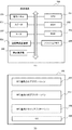
本実施形態1に係る通信システムは、スマートフォン等の携帯端末100、印刷装置110、NFC(Near Field Communication)タグ111、アクセスポイント120を含んでいる。印刷装置110は、例えば印刷機能、スキャン機能、FAX機能等を有する複合機で、アクセスポイント120との間でWi−Fi等の無線通信を実行する。尚、アクセスポイント120と印刷装置110との間の通信は無線通信に限らず、LANケーブル等を用いた有線通信であってもよい。携帯端末100は、Wi−Fi等の無線通信を実行可能である。ユーザがアクセスポイント120のSSIDやセキュリティキーを携帯端末100に入力することで、携帯端末100はアクセスポイント120と接続し、そのアクセスポイント120を介して印刷装置110と通信できる。また携帯端末100は、アクセスポイント120を介して接続されている接続されている印刷装置110や、他の装置(不図示)に印刷ジョブを送信することができる。携帯端末100から印刷装置110に印刷ジョブを送信すると、その印刷ジョブを受信した印刷装置110は、その印刷ジョブに従って印刷を実行する。
The communication system according to the first embodiment includes a
また携帯端末100と印刷装置110は、NFC等の近接無線通信を実行することができる。実施形態1では、印刷装置110はNFCタグ111(無線通信タグ)を備えており、そのNFCタグ111には、印刷装置110に接続するための接続情報(印刷装置110のIPアドレスやMACアドレスやモデル名等)が記憶されている。そして携帯端末100のユーザが、そのNFCタグ111の携帯端末100を近づけることにより、そのNFCタグ111から接続情報を読み取って取得したり、また情報を書き込むことができる。こうして携帯端末100や別の携帯端末(不図示)は、NFCを用いて印刷装置110のNFCタグ111に記憶された接続情報を取得し、その接続情報に基づいてアクセスポイント120に接続できる。このように、NFC等の近接無線通信で取得した情報を用いて、携帯端末100と印刷装置110との接続をWi−Fi等の無線通信に切り替えることをハンドオーバーと呼ぶ。このハンドオーバーによって、携帯端末100のユーザは、アクセスポイント120に接続するための情報(アクセスポイント120のSSIDやセキュリティキー)を携帯端末100に入力する手間が省けるという利点がある。
Further, the
図1(B)は、実施形態1に係るNFCタグ111のハードウェア構成を説明するブロック図である。
FIG. 1B is a block diagram illustrating a hardware configuration of the
アンテナ1111はコントローラ1112と接続している。アンテナ1111に携帯端末100の近接無線通信部208(図2(A))から電磁誘導によって電力が供給されると、その電力をコントローラ1112の動作電力としてコントローラ1112に供給する。更にこの状態でアンテナ1111は、携帯端末100の近接無線通信部208との間の無線通信のアンテナとして動作する。コントローラ1112は、アンテナ1111を介して携帯端末100と通信を行うとともに、通信による読み書きの指示に従って、メモリ1113への読み書きを行う。こうして、後述するIPアドレスなどの印刷装置110の情報をメモリ1113に書き込み、必要に応じてその情報をアンテナ1111を介して、例えば携帯端末100等に通知することができる。
The antenna 1111 is connected to the
図2(A)は、実施形態1に係る携帯端末100のハードウェア構成を説明するブロック図である。尚、実施形態1に係る携帯端末100は、例えばスマートフォンやタブレットPC等の装置を想定しているが、無線通信を実行可能な情報処理装置であれば他の装置であってもよい。
FIG. 2A is a block diagram illustrating a hardware configuration of the
CPU201はROM202やフラッシュメモリ204に記憶されている制御プログラムを読み出して、携帯端末100の動作を制御する。ROM202は制御プログラムや各種設定データ等を記憶している。RAM203は、CPU201の主メモリ、ワークエリア等の一時記憶領域として用いられる。フラッシュメモリ204は、写真や電子文書等の様々なデータを記憶するのに使用される。また図2(B)を参照して後述するOS(オペレーティングシステム)、NFC書き込みアプリケーション、NFC連携印刷アプリケーション、NFC連携スキャンアプリケーション等のアプリケーションプログラムもフラッシュメモリ204に記憶されている。尚、以下の説明では、携帯端末100の処理は、1つのCPU201が後述するフローチャートに示す処理を実行することにより達成されるものとしているが、他の態様であっても構わない。例えば、複数のCPUが協働して後述するフローチャートに示す各処理を実行するようにしても良い。
The
操作パネル205は、ユーザのタッチ操作を検出可能なタッチパネル機能を有するとともに、フラッシュメモリ204に記憶されているアプリケーションプログラムにより提供される各種画面を表示する。ユーザは操作パネル205にタッチ操作を行って所望の操作指示を入力できる。尚、携帯端末100は更に不図示のハードウェアキーを備えており、ユーザは、これらハードウェアキーを用いて携帯端末100に操作指示を入力できる。スピーカ206とマイク207は、ユーザが他の携帯端末や固定電話と電話をする際に使用する。近接無線通信部208は、NFC等の近接無線通信を実行する。実施形態1では、印刷装置110がNFCタグ111を有し、ユーザが携帯端末100を印刷装置110のNFCタグ111に近付けることで、近接無線通信部208と印刷装置110のNFCタグ111との間で近接無線通信が確立される。近接無線通信が確立された状態で、近接無線通信部208は、NFCタグ111の情報を取得したり、書き換えることができる。
The
無線通信部209はWi−Fi等の無線通信を実行する。携帯端末100は、この無線通信部209を介して探索パケットを送信することで、アクセスポイント120を経由して通信できる印刷装置110を探索して発見することができる。また携帯端末100はハンドオーバーを用いることで、ユーザにとって簡単な操作で無線通信部209による無線通信を実現できる。具体的には、印刷装置110のNFCタグ111から近接無線通信部208が取得した接続情報(アクセスポイント120のSSIDやパスワード)を用いることで、無線通信部209がアクセスポイント120に接続することができる。
The
図2(B)は、実施形態1に係る携帯端末100のソフトウェア構成を説明する機能ブロック図である。図2(B)は、CPU201がROM202やフラッシュメモリ204に記憶されているアプリケーションプログラムを読み出すことで実現されるソフトウェアの機能ブロック図である。
FIG. 2B is a functional block diagram illustrating the software configuration of the
OS223は、携帯端末100の基本動作を制御するためのオペレーティングシステムである。携帯端末100には、後述する3つのアプリケーション220〜222を含めて、様々なアプリケーションプログラムをインストールすることができる。OS223はこれらのアプリケーションプログラムとの間で情報をやり取りし、アプリケーションプログラムから受けた指示に従って、操作パネル205に画面を表示したり、無線通信部209による無線通信を実行する。
The
NFC書き込みアプリケーション220は携帯端末100にインストールされたアプリケーションプログラムで、アクセスポイント120を経由して利用できる印刷装置110と通信するための情報をNFCタグ111に書き込むことができる。NFC連携印刷アプリケーション221は携帯端末100にインストールされたアプリケーションプログラムで、NFCタグ111に書き込まれた印刷装置110と通信するための情報を用いて、印刷装置110に接続して印刷処理を行う。NFC連携スキャンアプリケーション222は携帯端末100にインストールされたアプリケーションプログラムで、NFCタグ111に書き込まれた印刷装置110の通信するための情報を用いて、印刷装置110と接続してスキャン処理を行うことができる。尚、携帯端末100には、上述のアプリケーションプログラムの他に様々なアプリケーションプログラムがインストールされているが、それらの説明は省略する。
The
図3及び図4は、実施形態1に係る携帯端末100でNFC書き込みアプリケーション220を実行することにより操作パネル205に表示される画面の遷移例を説明する図である。
3 and 4 are diagrams for explaining an example of transition of screens displayed on the
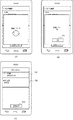
図3(A)は、NFC書き込みアプリケーション220を携帯端末100で起動したときの操作パネル205の表示例を示す。このときは印刷装置は未設定であるため、表示エリア311には、印刷装置が未設定である旨が表示されている。書き込みボタン312はグレー表示されており、ユーザが書き込みボタン312にタッチしても何も反応しない状態であることを示している。図3(A)で、ユーザが表示エリア311にタッチすると図3(B)に示す画面に遷移する。
FIG. 3A shows a display example of the
図3(B)は、通信相手となる相手機器である印刷装置の探索をデバイス探索と直接入力のいずれかで実施するように切り替える画面例を示す。ユーザがデバイス探索エリア321にタッチするとデバイス探索が開始され、デバイス探索の結果として、例えば図3(C)の画面が表示される。図3(C)では、探索結果、2つの印刷装置が見つかり、これら2つの印刷装置の機器情報(印刷装置の名称とIPアドレス)を取得して表示している。
FIG. 3B shows an example of a screen that is switched to search for a printing apparatus, which is a counterpart device to be a communication partner, by either device search or direct input. When the user touches the
一方、ユーザが直接入力エリア322にタッチすると、直接入力のためのIPアドレス又はDNS名を入力するための画面である、例えば図3(D)の画面を表示する。尚、「AP-NRT-01」は、無線接続しているアクセスポイント120のSSIDである。
On the other hand, when the user touches the
図3(C)は、デバイス探索での探索結果の一例を示している。エリア331,332は、デバイス探索で見つかった印刷装置の情報を表示している。ここではプリンタの名称と、そのIPアドレスが表示されている。この画面でユーザが、これらエリア331,332のいずれかにタッチすると、NFCタグ111に書き込む印刷装置の情報が決定されて図4(A)の画面に移行する。
FIG. 3C shows an example of a search result in device search.
図3(D)は、直接入力のためのIPアドレス又はDNS名を入力するための画面例を示す。ここでユーザは、入力ボックス341にIPアドレス或いはDNS名を入力する。図3(D)では、入力ボックス341にIPアドレスが入力されている状態を示している。そしてユーザがOKボタン343にタッチすると、そのIPアドレス又はDNS名を用いて印刷装置に対して接続確認を行って、その印刷装置名とIPアドレスを取得する。こうして印刷装置名とIPアドレスの取得に成功すると図4(A)の画面に遷移する。ユーザがキャンセル(Cancel)ボタン342にタッチするとこの画面を消去して図3(B)の画面に戻る。
FIG. 3D shows an example of a screen for inputting an IP address or DNS name for direct input. Here, the user inputs an IP address or DNS name in the input box 341. FIG. 3D shows a state where an IP address is input in the input box 341. When the user touches the
図4(A)は、図3(C)でユーザがエリア331にタッチしたとき、或いは図3(D)でユーザがOKボタン343にタッチしたときの操作パネル205の表示例を示す。この画面でユーザは、エリア351に表示されている印刷装置名とIPアドレスを確認する。そして、この画面でユーザが書き込みボタン352にタッチすると図4(B)の画面に遷移する。尚、図4(A)では、書き込みボタン352は通常表示されて、ユーザの指示を受付可能になっている。
FIG. 4A shows a display example of the
図4(B)は、図4(A)で確認した印刷装置名とIPアドレスをNFCタグ111に書き込む状態の時に表示される。この状態で、近接無線通信部208がNFCタグ111に書き込むことができる状態になる。そして、ユーザが携帯端末100を印刷装置110のNFCタグ111にかざすと、印刷装置110の印刷装置名とIPアドレスをNFCタグ111に書き込む。この例では、印刷装置名「Printer01」とIPアドレス「192.167.127.22」及びMACアドレスが書き込まれる。尚、キャンセルボタン361は、NFCタグ111への書き込みをキャンセルする場合にユーザがタッチする。
FIG. 4B is displayed when the printing apparatus name and IP address confirmed in FIG. 4A are written in the
図5は、実施形態1において、携帯端末100が印刷装置110のNFCタグ111に書き込む処理を説明するフローチャートである。このフローチャートに示す各ステップはCPU201がROM202やフラッシュメモリ204に格納された制御プログラムを実行することによって達成される。
FIG. 5 is a flowchart for describing processing in which the
まずS501でCPU201は、携帯端末100のユーザから印刷装置の探索指示があるかを判断する。具体的には、図3(A)において、操作パネル205のエリア311がタッチされたかどうかを判定する。エリア311がタッチされたときは、印刷装置の探索が指示されたと判定してS502に進み、タッチされない場合にはS501に戻る。S502でCPU201は、図3(B)に示す画面を操作パネル205に表示し、ユーザがデバイス探索或いは直接入力のいずれかを選択するのを待つ。ここでユーザが直接入力エリア322にタッチしたときはS505に進み、デバイス探索エリア321をタッチしたときはS503に進む。
First, in step S <b> 501, the
S503でCPU201は、アクセスポイント120を経由して、通信できる印刷装置を探索し、その結果を、例えば図3(C)のように表示する。デバイス探索の場合、携帯端末100はブロードキャストでパケットを送信し、そのパケットに回答した印刷装置それぞれのIPアドレスに対してSNMP接続を行う。そしてそのレスポンスより存在確認と各印刷装置の印刷装置名(図3(C)の例では、Printer01やPrinter02)と、そのIPアドレスとMACアドレスを取得する。次にS504に進みCPU201は、ユーザが、図3(C)のエリア331或いは332にタッチすることにより選択した印刷装置の選択結果を取得してS509に進む。
In step S503, the
一方、S502でユーザが直接入力エリア322を選択した場合はS505に進みCPU201は、操作パネル205に、例えば図3(D)に示すような、IPアドレス又はDNS名を入力する画面を表示する。そしてその画面を介してユーザにより入力されるIPアドレス或いはホスト名を取得する。次にS506に進みCPU201は、そのIPアドレス又はDNS名に対して接続テストを行い、実際に存在する印刷装置であるかを判定するための接続確認テストを行う。具体的には、入力されたIPアドレス又はDNS名に対してSNMP接続を行い、その装置の存在確認と印刷装置の名称及びIPアドレス及びMACアドレスを取得する。次にS507に進みCPU201は、S506の接続確認テストの結果、印刷装置の名称及びIPアドレスを取得できた場合にはS509に進み、接続に失敗した場合にはユーザに接続失敗を通知してS502に戻る。
On the other hand, if the user directly selects the
以上の処理により、S503〜S504のデバイス探索による印刷装置の選択や、S505〜507の直接入力によって印刷装置が特定できる。こうして接続先の印刷装置を特定すると、S509でCPU201は、例えば図4(A)に示す画面を操作パネル205に表示する。
With the above processing, the printing apparatus can be specified by selecting the printing apparatus by device search in S503 to S504 or by directly inputting in S505 to 507. When the connection destination printing apparatus is specified in this way, the
S509でCPU201は、ユーザが、図4(A)の書き込み開始ボタン352にタッチして、NFCタグ111への書き込み指示を入力したかどうかを判定する。ここで書き込み指示が入力されたと判定するとS510に進み、書き込み指示が無い場合はS509に戻る。S510でCPU201は、NFCタグ111へ書き込むための準備処理を行う。具体的には、デバイス探索や直接入力で得た、印刷装置110のIPアドレスや印刷装置名を、NFCタグ111のフォーマットに変換してRAM203に保持する。そして操作パネル205の表示を、例えば図4(B)に示すようなNFCタグへの書き込みを指示する画面に切り替える。
In step S <b> 509, the
図12(A)は、S510で作成したNFCタグに書き込むデータフォーマットの一例を示す図である。 FIG. 12A is a diagram illustrating an example of a data format to be written in the NFC tag created in S510.
一つ目は、起動アプリケーション情報で、携帯端末100をNFCタグ111にタッチした場合に起動するアプリケーション名を記載する。ここでは「com.example.printapp」という名前のNFC連携印刷アプリケーションを起動することを示している。二つ目は、ネットワーク接続情報であるMACアドレスのレコードである。これは、探索した印刷装置のMACアドレスを示している。図12(A)では、MACアドレスのみを記載しているが、IPアドレスやUUID等のような、印刷装置110を区別できる情報の組み合わせであってもよい。三つ目は、デバイス名情報を格納するレコードである。ここには印刷装置の名称である「Printer01」が格納される。
The first is activation application information, which describes an application name to be activated when the
次にS511に進みCPU201は、ユーザが携帯端末100をNFCタグ111に近接させてタッチしたか否かを判定し、タッチしない場合にはS511に戻るが、タッチした場合にはS512に進む。S512でCPU201は、近接無線通信部208を経由してNFCタグ111に、S510で作成した情報を書き込む。そしてS513でCPU201は、NFCタグ111への書き込みに成功したかを判定する。ここで成功したと判定するとS514に処理を進め、書き込みに成功したことを、例えばスピーカ206を用いて音声による通知、及び/或いは操作パネル205に成功を示す表示(不図示)を行う。こうしてユーザにNFCタグ111への書き込みが成功したことを通知すると、この処理を終了する。一方、S513で書き込みに失敗したと判定した場合はS515に進み、例えばスピーカ206を用いて音声による通知、操作パネル205に失敗を示す表示(不図示)を行って、ユーザにNFCタグ111への書き込みが失敗したことを通知してS511に戻る。
Next, proceeding to S511, the
以上説明した処理により、NFCタグ111に書き込まれる情報は、書き込まれる前にS503〜S504のデバイス探索、或いはS506で接続確認テストが完了した情報であるために、誤った情報がNFCタグ111に書き込まれるのを防止できる。
By the processing described above, the information written in the
図13は、実施形態1に係る携帯端末100が、印刷装置110のNFCタグ111を読み取って、印刷装置110に印刷させる処理を説明するフローチャートである。尚、このフローチャートで示す各ステップは、CPU201がROM202やフラッシュメモリ204に格納された制御プログラムを実行することによって達成される。
FIG. 13 is a flowchart for describing processing in which the
まずS1301でCPU201は、ユーザが印刷装置110のNFCタグ111に携帯端末100をタッチしたことを近接無線通信部208により検出したかどうかを判定する。ここでユーザが携帯端末100をNFCタグ111にタッチしたと判定するとS1302に進むが、そうでないときはS1301を実行する。S1302でCPU201は、近接無線通信部208により、そのタッチしたNFCタグ111に記録されているデータを読み取る。ここで携帯端末100は、そのNFCタグ111に記録されている印刷装置110のIPアドレスとMACアドレスを取得する。次にS1303に進みCPU201は、S1302で読み取ったデータのフォーマットが正常かどうかを判定する。ここでNFCタグ111に書き込まれているデータが正しくなかったり、NFCタグ111の読み取りに失敗したと判定した時はS1304に処理を進める。S1304でCPU201は、操作パネル205にエラー表示(不図示)して、ユーザにNFCタグ111の読み取り失敗したことを通知して、この処理を終了する。
First, in step S <b> 1301, the
一方、S1303でCPU201が、NFCタグ111のデータの読み取りに成功して、そのデータのフォーマットが正常であると判定するとS1305に進む。S1305でCPU201は、無線通信部209より、アクセスポイント120を介して印刷装置に対してブロードキャストパケットを用いて、取得したIPアドレスの印刷装置の存在を問い合わせる。これは図5のS506の処理と同様にして実行される。そしてS1306に進みCPU201は、S1302で取得したIPアドレスの印刷装置が存在するか否かを判定する。ここで取得したIPアドレスと同じIPアドレスの印刷装置が存在すると判定するとS1310に進んで印刷装置を特定し、その印刷装置のIPアドレスに印刷ジョブを送信して印刷させる。このときMACアドレスは使用しない。
On the other hand, if the
一方、S1306でIPアドレスが一致する印刷装置が存在しないと判定するとS1307に進む。尚、ここで取得したIPアドレスの印刷装置が存在しない場合とは、例えば、DHCP環境やユーザによる設定変更等で印刷装置のIPアドレスが変更される場合を想定している。S1307でCPU201は、無線通信部209より、アクセスポイント120を介して印刷装置に対してブロードキャストパケットを用いて印刷装置の存在を問い合わせる。次にS1308に進みCPU201は、無線通信部209より、印刷装置からのレスポンスパケット(応答)を受け取ると、その印刷装置に対してSNMPを用いて印刷装置のMACアドレスの問い合わせを行い、その印刷装置から回答を受け取る。この問い合わせパケットに対する応答にはMACアドレスとIPアドレスが含まれている。尚、S1308でCPU201は、SNMP経由で印刷装置のMACアドレスを取得するが、OS223のMACアドレステーブル(ARPテーブル)を検索して、そのMACアドレスを取得しても良い。
On the other hand, if it is determined in S1306 that there is no printing apparatus having the same IP address, the process proceeds to S1307. Note that the case where there is no printing apparatus with the IP address acquired here assumes that the IP address of the printing apparatus is changed due to, for example, a DHCP environment or a setting change by a user. In step S <b> 1307, the
次にS1309に進みCPU201は、S1302で読みとったNFCタグ111に記載されているMACアドレスと、S1308で取得したMACアドレスとを比較する。ここで、これらが一致した場合はS1310に進み、一致しない場合には、タイムアウトかどうかを判定するためにS1312に処理を進める。尚、NFCタグから取得したMACアドレスと応答パケットのMACアドレスが一致しない場合は、NFCタグを有する印刷装置の電源がオフされていることが想定される。S1310でCPU201は、S1308でレスポンスパケットを送信した印刷装置のIPアドレスを、NFCタグ111が添付された印刷装置110のIPアドレスとし、そのIPアドレスを印刷を実行する印刷装置のIPアドレスとする。そしてS1311に進みCPU201は、S1310で決定したIPアドレスの印刷装置110に対して印刷データを送信して印刷処理を行う。具体的には、CPU201は、ユーザが操作パネル205を操作して選択したファイル(画像データ)を、S1308で決定したIPアドレスを有する印刷装置110に送信して印刷させ、印刷が終了すると、この処理を終了する。
In step S1309, the
一方、S1312でCPU201は、S1307からの経過時間を計時し、所定時間以上(例えば10秒以上)経過するとタイムアウトとしてS1313に処理を進める。S1313でCPU201は、NFCタグ111に書き込まれた印刷装置を発見できなかったことを操作パネル205にエラー表示(不図示)して、この処理を終了する。一方、S1312でタイムアウトでないときはS1308の処理に戻る。
On the other hand, in step S1312, the
以上説明したように実施形態1によれば、印刷装置との接続確認ができた場合のみ、その印刷装置のNFCタグ111へ書き込みを行うことで、誤った印刷装置の情報をNFCタグに書き込むのを防止できる。また、携帯端末をNFCタグにタッチするだけで、容易に印刷装置との通信接続の設定及び印刷装置を使用した印刷処理を行うことができる。尚、実施形態1では、IPアドレスによってまず、対象となる印刷装置を探索する。これはMACアドレスを比較するのに比べて処理に要する時間が短くなるためである。従って、まずIPアドレスが一致するかどうかを判定することにより印刷装置を探索して印刷ジョブの送信に要する時間を短くしている。
As described above, according to the first embodiment, only when the connection with the printing apparatus can be confirmed, by writing to the
[実施形態2]
次に本発明の実施形態2を説明する。上述の実施形態1では、図3、図4において、印刷装置を探索し、印刷装置を特定して、その印刷装置のNFCタグ111に接続情報を書き込む例を説明した。これに対して実施形態2では、上記構成に加えて無線通信(Wi−Fi)の接続情報もNFCタグ111に書き込む例を説明する。尚、実施形態2に係る通信システムの構成、及び携帯端末のハードウェア構成は前述の実施形態1と同様であるため、その説明を省略する。
[Embodiment 2]
Next, a second embodiment of the present invention will be described. In the first embodiment described above, the example in which the printing device is searched for, the printing device is specified, and the connection information is written in the
以下では、無線通信の接続先を特定するためにアクセスポイント120に設定されたSSID(Service Set Identifier)と、同様に設定されたセキュリティを保持するためのパスワードを用いた場合を示す。
In the following, a case where an SSID (Service Set Identifier) set in the
図6〜図8は、実施形態2に係る携帯端末100でNFC書き込みアプリケーション220を実行することにより操作パネル205に表示される画面の遷移例を説明する図である。このNFC書き込みアプリケーション220の動作の詳細は、図9のフローチャートを参照して詳しく後述する。尚、実施形態1と共通の図4(B)の書き込み画面などは、その旨を記載して図6〜図8に記載しない。
FIGS. 6 to 8 are diagrams for explaining transition examples of screens displayed on the
図6(A)は、実施形態2に係る携帯端末100を起動したときに操作パネル205に表示される画面例を示す図である。
FIG. 6A is a diagram illustrating an example of a screen displayed on the
図6(A)では、Wi−Fi接続表示エリア611と、印刷装置の表示エリア612がいずれも未設定で表示されている。また書き込みボタン613はグレー表示されて、ユーザがタッチしても反応しない状態であることを示している。ここでユーザが、Wi−Fi接続表示エリア611にタッチすると図6(B)に示す画面に移行する。
In FIG. 6A, both the Wi-Fi
図6(B)は、Wi−Fi接続情報の設定方法を選択する画面例を示す図である。 FIG. 6B is a diagram illustrating an example of a screen for selecting a Wi-Fi connection information setting method.
ボタン622は、SSIDを指定しない場合で、実施形態1と同様に、図12(A)に示すNFCタグ情報を書き込むように指示するボタンである。即ち、NFCタグには、起動アプリ、ネットワーク接続情報、印刷装置名だけが書き込まれる。ボタン623は、その時点で接続中の無線通信のSSIDを用いるように指示するボタンである。ボタン624は、その時点で接続可能なアクセスポイントのリストを表示して無線接続を選択させるように指示するボタンである。ボタン625は、ユーザが手動でSSIDを入力するように指示するボタンである。
The
図6(C)は、図6(B)で、ユーザがボタン623にタッチした時に表示される画面例を示す。図6(C)では、631に、その時点で接続しているアクセスポイント120のSSIDである「AP-NRT-01」が自動的に表示されている。そして、ユーザが、パスワード入力フィールド632にパスワードを入力中であることを示している。ここでユーザはパスワードの入力が完了した後、接続テストボタン633にタッチすると図7(A)の画面に移行する。尚、図6(C)では、SSIDは携帯端末100の内部情報から取得しているが、パスワード情報はセキュリティの関係で取得できないために、ユーザにより入力させている。
FIG. 6C illustrates an example of a screen displayed when the user touches the
図7(A)は、図6(C)で入力したSSIDやパスワードに基づく、無線通信の接続テスト画面である。ここでは接続テスト中であることを示すメッセージと図形が表示されている。ここで接続が確認できると図7(B)に示す画面に移行する。図7(B)の画面でユーザが、OKボタン701を押下すると図7(C)の画面に移行する。
FIG. 7A is a connection test screen for wireless communication based on the SSID and password input in FIG. Here, a message and a graphic indicating that a connection test is in progress are displayed. If the connection can be confirmed here, the screen shifts to the screen shown in FIG. When the user presses the
図7(C)は、アクセスポイント120を介して無線接続テストで通信が確認できた状態を示している。ここでエリア702には、無線接続テストで通信が確認できたアクセスポイント120のSSID「AP-NRT-01」が表示されている。尚、ここでは依然として、印刷装置が未設定のままであるため、エリア703には、印刷装置が未設定であることが表示されている。ここでユーザが、エリア703にタッチすると、前述の図3(B)に示す印刷装置の探索画面に移行する。そして、これ以降は前述の実施形態1と同様にして、印刷先となる印刷装置を探すことになる。
FIG. 7C shows a state in which communication can be confirmed through a wireless connection test via the
図8(A)は、図3(B)〜図3(D)の操作で印刷装置の探索が終了した時の画面である。即ち、図7(C)の画面でユーザがエリア703にタッチして印刷装置の設定を指示すると図3(B)の画面に移行し、図3及び図4を参照して前述したようにして、印刷装置を設定する。そして、ユーザが書き込みボタン613にタッチすると、図4(B)に示すNFCタグ111への書き込み画面に遷移する。
FIG. 8A is a screen when the search for the printing apparatus is completed by the operations of FIGS. 3B to 3D. That is, when the user touches the
図8(B)は、図6(B)で、ユーザがWi−Fi選択のボタン624にタッチすることにより、その時点で接続可能なアクセスポイントのリストを表示した画面例を示す。ここでユーザは、接続したいアクセスポイントをエリア801〜803にタッチして選択すると、図6(C)に示す画面に移行して、ユーザにパスワードの入力を求める。
FIG. 8B shows an example of a screen displaying a list of access points that can be connected at that time when the user touches the Wi-
図8(C)は、図6(B)で、ユーザが手動入力のボタン625にタッチしたときに表示される画面例を示す。ここでユーザが、SSIDの入力エリア804に「AP-NRT-secret-01」を入力し、この後、パスワードの入力エリア805にパスワードを入力する。そして接続テストボタン806にタッチすると図7(A)の画面に遷移して、前述したような接続テストを行う。
FIG. 8C shows an example of a screen displayed when the user touches the
図9は、実施形態2に係る携帯端末100が無線により印刷装置110を探索して、その印刷装置のNFCタグに接続情報を書き込む処理を説明するフローチャートである。このフローチャートに示す各ステップはCPU201がROM202やフラッシュメモリ204に格納された制御プログラムを実行することによって達成される。この処理は、前述の図5の印刷装置の選択処理(S502〜S509)とNFCタグへのデータの書き込み(S511〜S515)の前の処理として、無線通信のための設定情報を準備する処理が加わったものである。
FIG. 9 is a flowchart for describing processing in which the
まずS901でCPU201は、携帯端末100のユーザが、図6(A)の画面でWi−Fi接続情報の設定方法を選択するのを待つ。具体的には、図6(A)の画面でユーザがWi−Fi接続表示エリア611にタッチしたかどうかを判断する。ユーザがWi−Fi接続表示エリア611にタッチした場合はS902に進み、そうでないときはS901に戻る。S902でCPU201は、例えば図6(B)の画面を表示し、携帯端末100のユーザによる選択操作に応じて、各ステップに分岐する。図6(B)の画面でユーザがSSIDを指定しないボタン622にタッチした場合はS911に進む。S911でCPU201は、SSIDを書き込まないことをRAM203に記録してS912に進み、S913の書き込み準備でその情報を用いる。従って、この場合は、SSIDを含まないNFCタグ情報を生成することになる。
First, in step S901, the
またユーザが、現在接続中のWi−Fiを選択するボタン623にタッチした場合はS903に進み、CPU201は、現在接続中の無線通信部209からSSIDを取得してS907に進む。
If the user touches the
またユーザがWi−Fi選択のボタン624にタッチしたときはS904に進みCPU201は、例えば図8(B)に示すように、その時点で接続可能なアクセスポイントのリストを表示する。S904は接続可能なSSIDから選択する場合で、CPU201は、現在接続可能なSSIDのリストを無線通信部209から取得して、接続可能なアクセスポイントのリストを表示する。そしてS905でCPU201は、ユーザの操作より選択されたSSIDを取得して、S907のパスワード入力処理に移行する。
If the user touches the Wi-
またユーザが手動入力のボタン625にタッチしたときはS906に進み、CPU201は、例えば図8(C)に示す画面を表示し、その画面を介してユーザが手動で入力したSSIDを取得してS907に進む。
When the user touches the
S907でCPU201は、例えば図6(C)の画面を表示して、この画面を介してユーザが入力したパスワードを取得する。そしてS908に進みCPU201は、ユーザが図6(C)の接続テストボタン633にタッチするのを待ち、ユーザが接続テストボタン633にタッチするとS909に進んで接続テストを実施する。その結果、接続に成功するとS912に進むが、接続できない場合はS910に進んで、接続失敗をユーザに通知してS902に戻る。
In step S907, the
S912でCPU201は印刷装置の選択処理を実行する。この処理は実施形態1で説明した図5のS501からS509までの処理と同一である。そのためここでは詳細は述べない。S912で印刷装置を選択した結果、その印刷装置の機器情報を記憶する。次にS913に進みCPU201は、NFCタグ111へデータを書き込むための準備処理を行う。具体的には、S902〜S911までのSSID設定と、S912で得た印刷装置110のMACアドレス(或いはIPアドレス)と印刷装置の名称を、NFCタグのフォーマット(NDEF)に変換してRAM209に保持する。そして操作画面を図4(B)の書き込み状態画面に切り替えてS914に進む。
In step S912, the
ここで、S913で作成したNFCタグに書き込むフォーマットを説明する。S911でSSIDなしとした場合は、実施形態1の図12(A)と同じフォーマットとなる。一方、S902で、ユーザが、ボタン623〜625のいずれかを選択した場合は、図12(B)に示したフォーマットを用いる。
Here, the format written in the NFC tag created in S913 will be described. If no SSID is set in S911, the format is the same as that in FIG. On the other hand, when the user selects any of the
図12(B)で、起動アプリケーション情報と、ネットワーク接続情報、印刷装置名情報は、前述の実施形態1の図12(A)のそれぞれのレコードと同一である。図12(B)では、印刷装置110に接続できるアクセスポイント120のSSIDとパスワード情報とを含むWi−Fi接続情報が追加されている。
In FIG. 12B, the startup application information, the network connection information, and the printing apparatus name information are the same as the respective records in FIG. 12A of the first embodiment. In FIG. 12B, Wi-Fi connection information including the SSID and password information of the
S914は、CPU201によるNFCタグ111への書き込み処理である。この処理は実施形態1のS511からS515までの処理と同一である。そのためここでは詳細は述べない。S914のNFC書き込み処理の結果、NFCタグ111への書き込みが完了する。
S <b> 914 is a writing process to the
以上説明したように実施形態2によれば、アクセスポイント120への接続確認と印刷装置110への接続確認ができた場合のみNFCタグ111への書き込みを行う。これにより、誤ったアクセスポイント120のSSIDやパスワード情報、並びに、印刷装置110の情報をNFCタグ111に書き込むのを防止できる。またNFCタグ情報として、無線接続用のSSIDやパスワード等を含む接続情報を記録できる。
As described above, according to the second embodiment, writing to the
[実施形態3]
次に、本発明の実施形態3を説明する。前述の実施形態2では、実施形態1の図4(A)で印刷装置を決定した。そして加えて図6(B)以降の操作で、無線通信ネットワークの接続先情報を決定してNFCタグ111に書き込む例を説明した。これに対して実施形態3では、上記構成に加えて、印刷方式と起動アプリケーションの情報もNFCタグ111に書き込む場合を説明する。尚、実施形態3に係る通信システムの構成、及び携帯端末100のハードウェア構成は前述の実施形態1と同様であるため、その説明を省略する。
[Embodiment 3]
Next,
印刷方式や起動アプリケーションを選択させるのは、印刷装置が昇華型か、レーザ方式であるかに応じて、対応するアプリケーションが異なるため、NFCタグ111に書き込む図12(B)の起動アプリケーション情報を変更する必要があるためである。
Since the corresponding application differs depending on whether the printing device is a sublimation type or a laser method, the printing method and activation application shown in FIG. 12B written in the
図10は、実施形態3に係る携帯端末100において操作パネル205に表示される画面例を示す図である。ここでは、印刷方式、利用アプリケーション、無線通信接続情報を確定して印刷装置110を探索し、それによってNFCタグ111に書き込む操作の例を示す。このNFC書き込みアプリケーションの動作詳細は、図11のフローチャートを参照して詳しく後述する。尚、前述の実施形態1や実施形態2と共通の設定画面はその旨を記載して、図10には記載しない。
FIG. 10 is a diagram illustrating a screen example displayed on the
図10(A)は、実施形態3に係る携帯端末100を起動したときに操作パネル205に表示される画面例を示す。印刷方法のエリア1011、利用アプリのエリア1012、Wi−Fi接続表示エリア1013と印刷装置の設定エリア1014はいずれも未設定である。また書き込みボタン1015はグレー表示で、ユーザがタッチしても反応しない状態を示している。ここで、ユーザが印刷方式のエリア1011にタッチすると図10(B)の画面に移行する。
FIG. 10A shows an example of a screen displayed on the
図10(B)は、ユーザに印刷方式を選択させる画面例を示す。ボタン1016とボタン1017はそれぞれ、印刷装置110の印刷方式として、昇華型とレーザ方式を選択するためのボタンである。ここで、ユーザがボタン1016とボタン1017のいずれかにタッチすると図10(C)の画面に遷移する。
FIG. 10B shows an example of a screen that allows the user to select a printing method. A
図10(C)は、起動アプリケーションを選択する画面例を示す。ボタン1018とボタン1019は、印刷装置110に対する操作として、印刷アプリケーション又はスキャンアプリケーションを選択するためのボタンである。ユーザが、これらボタン1018とボタン1019のいずれかにタッチすると図6(B)のWi−Fi接続の選択画面に遷移する。
FIG. 10C shows an example of a screen for selecting a startup application. A
図10(D)は、図10(B)〜(C)で印刷方式と起動アプリケーションを選択し、図6〜図8を参照して説明した操作で無線通信設定が完了し、図3(B)〜図3(D)の操作で印刷装置の探索が終了した状態の画面例を示す。ここで、ユーザが書き込みボタン1015にタッチすると図4(B)に示す書き込み画面に遷移する。
In FIG. 10D, the printing method and the activation application are selected in FIGS. 10B to 10C, the wireless communication setting is completed by the operation described with reference to FIGS. 6 to 8, and FIG. ) To FIG. 3D show examples of screens in a state where the search for the printing apparatus is completed. Here, when the user touches the
図11は、実施形態3に係る携帯端末100の処理を説明するフローチャートである。この処理は、図9の無線通信設定の選択(S901〜S911)と、図5の印刷装置の選択(S502〜S509)とNFCタグへの書き込み(S511〜S515)の前の処理として、印刷方式、起動アプリケーションを選択する処理を加えたものである。このフローチャートに示す各ステップはCPU201がROM202やフラッシュメモリ204に格納された制御プログラムを実行することによって達成される。
FIG. 11 is a flowchart for explaining processing of the
まずS1101でCPU201は、携帯端末100のユーザが印刷方式の選択指示を行ったかどうかを判定する。具体的には、図10(A)の印刷方式のエリア1011をユーザがタッチしたかどうかを判定する。ユーザが印刷方式の選択を指示したときはS1102に進み、そうでないときはS1101に戻る。S1102でCPU201は、例えば図10(B)に示す画面を表示し、携帯端末100のユーザがタッチしたボタンに応じて分岐する。ここでユーザが昇華型のボタン1016にタッチした場合はS1103に進みCPU201は、印刷方式を昇華型(sublimation)としてRAM203に記憶してS1105に進む。一方、ユーザがレーザのボタン1017にタッチした場合はS1104に進みCPU201は、印刷方式をレーザ(laser)としてRAM203に記憶してS1105に進む。
First, in step S <b> 1101, the
S1105でCPU201は、例えば図10(C)の画面を表示し、携帯端末100のユーザによるアプリケーションの選択操作を待つ。ユーザがアプリケーションを選択する操作を行うとS1106に進みCPU201は、ユーザ選択したアプリケーションを判定する。S1106でCPU201は、ユーザが印刷アプリのボタン1018を選択したと判定するとS1107に進みCPU201は、起動アプリケーションとして印刷アプリをRAM203に記憶してS1109に進む。一方、S1106でCPU201は、ユーザがスキャンアプリのボタン1019を選択したと判定するとS1108に進み、起動アプリケーションとしてスキャンアプリをRAM203に記憶してS1109に進む。
In step S <b> 1105, the
S1109でCPU201は、Wi−Fi接続情報の選択処理を実行する。この処理は前述の実施形態2の図9のS901からS911までの処理と同一であるため、ここではその説明を省略する。次にS1110に進みCPU201は、印刷装置の選択処理を実行する。この処理は、前述の実施形態1の図5のS501からS509までの処理と同一であるため、その説明を省略する。こうしてS1101〜S1108で、印刷方式と起動アプリケーションの選択、及びS1109でのWi−Fi接続情報の選択、S1110での印刷装置の選択処理を実行すると、NFCタグ111への書き込みの準備が完了する。
In step S1109, the
S1111でCPU201は、NFCタグ111へ書き込むための準備処理を行う。具体的には、S1103或いはS11004で決定された印刷方式と、S1107或いはS1108で決定された起動アプリケーションの情報を取得する。更に、S902〜S911でのSSID設定と、S912で得た印刷装置110のMACアドレス(或いはIPアドレス)と印刷装置名を、NFCタグ111のフォーマットに変換してRAM203に保持する。ここでNFCタグに書き込むフォーマットは、実施形態2の図12(B)と同じフォーマットである。しかし、印刷方式と起動アプリケーションによって、起動するアプリケーション情報が変わるため、CPU201は図12(C)に示すような、ROM202に保持したテーブルを参照して、起動アプリケーション名を決定してNFCタグフォーマットを決定する。
In step S1111, the
図12(C)では、印刷方式と、印刷アプリ、スキャンアプリに対応付けて起動アプリケーションが登録されている。 In FIG. 12C, a startup application is registered in association with a printing method, a printing application, and a scanning application.
そしてS1112に進みCPU201は、操作画面を図4(B)の書き込み状態画面に遷移して、携帯端末100が印刷装置110のNFCタグ111にタッチされると、そのNFCタグ111に、S1111で準備した情報を書き込む。この処理は、実施形態1のS511からS515までの処理と同一であるため、ここでは詳細は述べない。こうしてNFCタグ111への書き込みが完了する。
Then CPU201 proceeds to S1112, the operation screen transitions to write state screen of FIG. 4 (B), when the
以上説明したように本実施形態3によれば、印刷装置の印刷方式、起動アプリケーション、アクセスポイントへの接続確認と、印刷装置との接続確認ができた場合のみ、その印刷装置のNFCタグへの書き込みを行う。これにより、誤った起動アプリケーションや誤ったアクセスポイントのSSIDやパスワード情報、並びに、印刷装置の情報がNFCタグに書き込まれるのを防止できる。 As described above, according to the third embodiment, only when the printing method of the printing apparatus, the startup application, the connection confirmation to the access point, and the connection confirmation with the printing apparatus can be confirmed, the NFC tag of the printing apparatus is connected. Write. As a result, it is possible to prevent the SFC and password information of the wrong start application, wrong access point, and information on the printing apparatus from being written to the NFC tag.
(その他の実施形態)
また、本発明は、以下の処理を実行することによっても実現される。即ち、上述した実施形態の機能を実現するソフトウェア(プログラム)を、ネットワーク又は各種記憶媒体を介してシステム或いは装置に供給し、そのシステム或いは装置のコンピュータ(又はCPUやMPU等)がプログラムを読み出して実行する処理である。
(Other embodiments)
The present invention can also be realized by executing the following processing. That is, software (program) that realizes the functions of the above-described embodiments is supplied to a system or apparatus via a network or various storage media, and a computer (or CPU, MPU, etc.) of the system or apparatus reads the program. It is a process to be executed.
本発明は上記実施の形態に制限されるものではなく、本発明の精神及び範囲から離脱することなく、様々な変更及び変形が可能である。従って、本発明の範囲を公にするために、以下の請求項を添付する。 The present invention is not limited to the above-described embodiment, and various changes and modifications can be made without departing from the spirit and scope of the present invention. Therefore, in order to make the scope of the present invention public, the following claims are attached.
100…携帯端末、110…印刷装置、111…NFCタグ、120…アクセスポイント、201…CPU,202…ROM,203…RAM,204…フラッシュメモリ、205…操作パネル、208…近接無線通信部、209…無線通信部。
DESCRIPTION OF
Claims (25)
前記探索手段による印刷装置の探索結果を表示する表示手段と、
前記探索結果の中からユーザにより選択された印刷装置の識別情報に基づいて、NFCタグに書き込むタグ情報を生成する生成手段と、
前記生成手段によって生成された前記タグ情報を、NFCタグに書き込む書き込み手段と、を有し、
前記生成手段が前記タグ情報を生成すると、前記表示手段は、前記タグ情報をNFCタグに書き込むことをユーザに促す表示を行うことを特徴とする情報処理装置。 A search means you search look for the printing device,
Display means for displaying a search result of the printing apparatus by the search means;
Based on the identification information of more selected printing device to the user from among the search results, and generating means for generating tag information written to the NFC tag,
Writing means for writing the tag information generated by the generating means to an NFC tag ,
When the generation unit generates the tag information, the display unit performs display for prompting a user to write the tag information in an NFC tag .
前記探索手段による印刷装置の探索結果を表示する表示手段と、Display means for displaying a search result of the printing apparatus by the search means;
前記探索結果の中からユーザにより選択された印刷装置の識別情報に基づいて、NFCタグに書き込むタグ情報を生成する生成手段と、Generating means for generating tag information to be written in the NFC tag based on the identification information of the printing apparatus selected by the user from the search results;
前記生成手段によって生成された前記タグ情報をNFCタグに書き込む書き込み手段と、を有し、Writing means for writing the tag information generated by the generating means into an NFC tag,
前記生成手段が前記タグ情報を生成すると、前記表示手段は、前記情報処理装置をNFCタグにタッチすることをユーザに促す表示を行うことを特徴とする情報処理装置。When the generation unit generates the tag information, the display unit performs display for prompting a user to touch the information processing apparatus to an NFC tag.
アクセスポイントへの接続が可能であると前記第1の判定手段によって判定された場合に、前記生成手段は前記タグ情報を生成し、アクセスポイントへの接続が可能ではないと前記第1の判定手段によって判定された場合に、前記生成手段は前記タグ情報を生成しないことを特徴とする請求項3乃至8のいずれか1項に記載の情報処理装置。 First determination means for determining whether or not connection to an access point is possible using the wireless connection information;
When the first determination unit determines that connection to the access point is possible, the generation unit generates the tag information, and if the connection to the access point is not possible, the first determination unit when it is determined by the information processing apparatus according to any one of claims 3 to 8 wherein the generating means characterized in that it does not generate the tag information.
前記受付手段が印刷装置の識別情報の入力をユーザから受け付けた場合に、前記生成手段は、ユーザから受け付けた前記識別情報に基づいて、前記タグ情報を生成することを特徴とする請求項1又は2に記載の情報処理装置。 The said generating means generates the said tag information based on the said identification information received from the user, when the said receiving means receives the input of the identification information of a printing apparatus from a user. 2. The information processing apparatus according to 2.
通信が可能であると前記第2の判定手段によって判定された場合に、前記生成手段は前記タグ情報を生成し、通信が可能ではないと前記第2の判定手段によって判定された場合に、前記生成手段は前記タグ情報を生成しないことを特徴とする請求項10に記載の情報処理装置。When the second determination unit determines that communication is possible, the generation unit generates the tag information, and when the second determination unit determines that communication is not possible, The information processing apparatus according to claim 10, wherein the generation unit does not generate the tag information.
印刷装置を探索する探索ステップと、
印刷装置の探索結果を表示する第1の表示ステップと、
前記探索結果の中からユーザにより選択された印刷装置の識別情報に基づいて、NFCタグに書き込むタグ情報を生成する生成ステップと、
前記タグ情報を生成すると、前記タグ情報をNFCタグに書き込むことをユーザに促す表示を行う第2の表示ステップと、
前記生成ステップで生成された前記タグ情報をNFCタグに書き込む書き込みステップと、
を有することを特徴とする情報処理装置の制御方法。 A method for controlling an information processing apparatus,
A search step you search look for the printing device,
A first display step for displaying a search result of the printing apparatus ;
Based on the identification information of more selected printing device to the user from among the search results, a generation step of generating a tag information written to the NFC tag,
Generating the tag information, a second display step for performing a display prompting the user to write the tag information to the NFC tag;
A writing step of writing the tag information generated in the generation step into an NFC tag;
A method for controlling an information processing apparatus, comprising:
印刷装置を探索する探索ステップと、A search step for searching for a printing device;
印刷装置の探索結果を表示する第1の表示ステップと、A first display step for displaying a search result of the printing apparatus;
前記探索結果の中からユーザにより選択された印刷装置の識別情報に基づいて、NFCタグに書き込むタグ情報を生成する生成ステップと、Generating a tag information to be written to the NFC tag based on the identification information of the printing device selected by the user from the search results;
前記タグ情報を生成すると、前記情報処理装置をNFCタグにタッチすることをユーザに促す表示を行う第2の表示ステップと、Generating the tag information, a second display step for performing a display prompting the user to touch the NFC tag with the information processing apparatus;
前記生成ステップで生成された前記タグ情報をNFCタグに書き込む書き込みステップとを有することを特徴とする情報処理装置の制御方法。And a writing step of writing the tag information generated in the generating step into an NFC tag.
アクセスポイントへの接続が可能であると前記第1の判定ステップで判定された場合に前記タグ情報が生成され、アクセスポイントへの接続が可能ではないと前記第1の判定ステップで判定された場合に前記タグ情報が生成されないことを特徴とする請求項15乃至20のいずれか1項に記載の情報処理装置の制御方法。 A first determination step of determining whether or not a connection to an access point is possible using the wireless connection information;
Before Symbol tag information when it is determined that it is possible to connect to the access point in the first determination step is generated, it is determined by the and is not connectable to the access point first determination step control method according to any one of claims 15 to 20 before Symbol tag information and wherein the not generated when.
印刷装置の識別情報の入力をユーザから受け付けた場合に、ユーザから受け付けた前記識別情報に基づいて、前記タグ情報が生成されることを特徴とする請求項13又は14に記載の情報処理装置の制御方法。The information processing apparatus according to claim 13 or 14, wherein when the input of identification information of the printing apparatus is received from a user, the tag information is generated based on the identification information received from the user. Control method.
通信が可能であると前記第2の判定ステップで判定された場合に前記タグ情報が生成され、通信が可能ではないと前記第2の判定ステップで判定された場合に前記タグ情報が生成されないことを特徴とする請求項22に記載の情報処理装置の制御方法。The tag information is generated when it is determined in the second determination step that communication is possible, and the tag information is not generated when it is determined in the second determination step that communication is not possible. The method of controlling an information processing apparatus according to claim 22.
Priority Applications (7)
| Application Number | Priority Date | Filing Date | Title |
|---|---|---|---|
| JP2014130688A JP6071949B2 (en) | 2014-06-25 | 2014-06-25 | Information processing apparatus, control method thereof, and program |
| EP15001644.2A EP2961078B1 (en) | 2014-06-25 | 2015-06-02 | Information processing apparatus, method of controlling the same, and storage medium |
| US14/739,161 US9693177B2 (en) | 2014-06-25 | 2015-06-15 | Information processing apparatus, method of controlling the same, and storage medium |
| KR1020150088186A KR101830201B1 (en) | 2014-06-25 | 2015-06-22 | Information processing apparatus, method of controlling the same, and storage medium |
| CN201510349890.1A CN105282361B (en) | 2014-06-25 | 2015-06-23 | Information processing unit and its control method |
| US15/621,294 US10412566B2 (en) | 2014-06-25 | 2017-06-13 | Information processing apparatus, method of controlling the same, and storage medium |
| US16/528,822 US11197141B2 (en) | 2014-06-25 | 2019-08-01 | Information processing apparatus, method of controlling the same, and storage medium |
Applications Claiming Priority (1)
| Application Number | Priority Date | Filing Date | Title |
|---|---|---|---|
| JP2014130688A JP6071949B2 (en) | 2014-06-25 | 2014-06-25 | Information processing apparatus, control method thereof, and program |
Related Child Applications (1)
| Application Number | Title | Priority Date | Filing Date |
|---|---|---|---|
| JP2016254087A Division JP6371825B2 (en) | 2016-12-27 | 2016-12-27 | Information processing apparatus, control method thereof, and program |
Publications (3)
| Publication Number | Publication Date |
|---|---|
| JP2016010067A JP2016010067A (en) | 2016-01-18 |
| JP2016010067A5 JP2016010067A5 (en) | 2016-02-25 |
| JP6071949B2 true JP6071949B2 (en) | 2017-02-01 |
Family
ID=53396122
Family Applications (1)
| Application Number | Title | Priority Date | Filing Date |
|---|---|---|---|
| JP2014130688A Active JP6071949B2 (en) | 2014-06-25 | 2014-06-25 | Information processing apparatus, control method thereof, and program |
Country Status (5)
| Country | Link |
|---|---|
| US (3) | US9693177B2 (en) |
| EP (1) | EP2961078B1 (en) |
| JP (1) | JP6071949B2 (en) |
| KR (1) | KR101830201B1 (en) |
| CN (1) | CN105282361B (en) |
Families Citing this family (35)
| Publication number | Priority date | Publication date | Assignee | Title |
|---|---|---|---|---|
| JP6008617B2 (en) * | 2012-06-29 | 2016-10-19 | キヤノン株式会社 | COMMUNICATION DEVICE, ITS CONTROL METHOD, AND PROGRAM |
| JP6323841B2 (en) * | 2014-03-13 | 2018-05-16 | 株式会社Fuji | Display device for work equipment |
| JP6302399B2 (en) * | 2014-11-17 | 2018-03-28 | キヤノン株式会社 | Image forming apparatus provided with short-range wireless communication unit, control method thereof, and program |
| DE102014118290A1 (en) * | 2014-12-10 | 2016-06-16 | Océ Printing Systems GmbH & Co. KG | Method for configuring a control device for a production system and such a production system |
| JP6558134B2 (en) * | 2015-08-05 | 2019-08-14 | ブラザー工業株式会社 | COMMUNICATION DEVICE AND COMPUTER PROGRAM FOR COMMUNICATION DEVICE |
| JP6240125B2 (en) | 2015-08-10 | 2017-11-29 | キヤノン株式会社 | Information processing apparatus, program for controlling information processing apparatus, and control method thereof |
| JP6314951B2 (en) * | 2015-10-08 | 2018-04-25 | コニカミノルタ株式会社 | Image forming system and program |
| JP6887748B2 (en) * | 2015-12-11 | 2021-06-16 | キヤノン株式会社 | Data transmission device, data transmission method and program |
| JP6184580B1 (en) * | 2016-01-29 | 2017-08-23 | キヤノン株式会社 | Information processing apparatus, control method, and program |
| JP6623872B2 (en) * | 2016-03-18 | 2019-12-25 | 富士ゼロックス株式会社 | Information processing apparatus, image forming apparatus, and information processing program |
| JP6619682B2 (en) | 2016-03-31 | 2019-12-11 | キヤノン株式会社 | Information processing apparatus, control method, and program |
| JP6772566B2 (en) * | 2016-06-06 | 2020-10-21 | 富士ゼロックス株式会社 | Information processing equipment and programs |
| JP2018013951A (en) * | 2016-07-21 | 2018-01-25 | 京セラドキュメントソリューションズ株式会社 | Electronic apparatus and information update program |
| CN106530393B (en) * | 2016-11-07 | 2019-04-19 | 广东电网有限责任公司佛山供电局 | A kind of novel nameplate production method and device |
| CN106572433A (en) * | 2016-11-12 | 2017-04-19 | 江苏速度信息科技股份有限公司 | Data exchange and identification tag based boundary marker processing method |
| JP6556187B2 (en) * | 2017-05-19 | 2019-08-07 | キヤノン株式会社 | Program, storage medium, portable terminal control method, and portable terminal |
| JP6984213B2 (en) * | 2017-07-31 | 2021-12-17 | セイコーエプソン株式会社 | Terminal devices, processing systems, programs, and control methods for terminal devices |
| JP7027084B2 (en) * | 2017-09-14 | 2022-03-01 | キヤノン株式会社 | Information processing equipment, its control method, and programs |
| JP6932586B2 (en) * | 2017-09-14 | 2021-09-08 | キヤノン株式会社 | Information processing equipment, its control method, and programs |
| CN107911855A (en) * | 2017-11-15 | 2018-04-13 | 北京小米移动软件有限公司 | WLAN selection processing method, device and terminal |
| JP2019121875A (en) * | 2017-12-28 | 2019-07-22 | キヤノン株式会社 | Terminal device, information processing method, and program |
| JP7051444B2 (en) * | 2018-01-09 | 2022-04-11 | キヤノン株式会社 | Information processing equipment, its control method and program |
| JP7016705B2 (en) * | 2018-01-23 | 2022-02-07 | キヤノン株式会社 | Communication equipment, communication systems, information processing methods and programs |
| JP7114911B2 (en) | 2018-01-25 | 2022-08-09 | セイコーエプソン株式会社 | Terminal equipment, communication system and program |
| JP7183559B2 (en) * | 2018-03-30 | 2022-12-06 | ブラザー工業株式会社 | Printers and computer programs for printers |
| JP7210945B2 (en) * | 2018-09-06 | 2023-01-24 | セイコーエプソン株式会社 | Terminal equipment, communication system and program |
| JP7324001B2 (en) * | 2018-12-28 | 2023-08-09 | キヤノン株式会社 | COMMUNICATION DEVICE, COMMUNICATION DEVICE CONTROL METHOD, AND PROGRAM |
| US11106405B2 (en) * | 2019-03-05 | 2021-08-31 | Toshiba Tec Kabushiki Kaisha | Printer and printer search system |
| JP7500984B2 (en) | 2020-02-13 | 2024-06-18 | セイコーエプソン株式会社 | Setting device control method, setting device, program, and image display system |
| JP7056680B2 (en) * | 2020-02-13 | 2022-04-19 | セイコーエプソン株式会社 | Electronic devices, setting devices, control methods for setting devices, and programs |
| JP7074153B2 (en) * | 2020-03-30 | 2022-05-24 | コニカミノルタ株式会社 | Information processing equipment and programs |
| JP7547071B2 (en) * | 2020-04-10 | 2024-09-09 | キヤノン株式会社 | Image forming apparatus, method and program for controlling image forming apparatus |
| US11811996B2 (en) * | 2021-03-25 | 2023-11-07 | Fujifilm Business Innovation Corp. | Information processing system, terminal device, and non-transitory computer readable medium |
| CN115514396B (en) * | 2021-06-23 | 2023-06-13 | 广州视源电子科技股份有限公司 | Screen transmission equipment connection method and device based on NFC and computer equipment |
| CN115240484A (en) * | 2022-06-06 | 2022-10-25 | 深圳市羽恒科技有限公司 | Learning auxiliary instrument with wrong question analysis function and auxiliary method |
Family Cites Families (16)
| Publication number | Priority date | Publication date | Assignee | Title |
|---|---|---|---|---|
| JP5035001B2 (en) * | 2008-02-14 | 2012-09-26 | セイコーエプソン株式会社 | Printing device management system, printing device management method, and printing device management program |
| US20090282130A1 (en) * | 2008-05-12 | 2009-11-12 | Nokia Corporation | Resource sharing via close-proximity wireless communication |
| EP2373073B1 (en) * | 2008-12-26 | 2016-11-09 | Panasonic Intellectual Property Corporation of America | Communication device |
| EP2508999A4 (en) * | 2009-11-30 | 2014-03-05 | Panasonic Corp | Portable communication apparatus, communication method, integrated circuit, and program |
| US8560012B2 (en) * | 2009-11-30 | 2013-10-15 | Panasonic Corporation | Communication device |
| US8548992B2 (en) * | 2010-10-28 | 2013-10-01 | Cary Scott Abramoff | User interface for a digital content management system |
| CN103098108B (en) * | 2010-11-25 | 2017-09-08 | 松下电器(美国)知识产权公司 | Communication equipment |
| KR101807286B1 (en) | 2011-02-11 | 2017-12-08 | 삼성전자주식회사 | Method and apparatus for performing function in mobile terminal using short range communication |
| JP2013157736A (en) | 2012-01-27 | 2013-08-15 | Canon Inc | Communication device, and control method and program therefor |
| US20130215467A1 (en) * | 2012-02-21 | 2013-08-22 | Zih Corp. | Method and apparatus for implementing near field communications with a printer |
| CN103298144A (en) | 2012-03-02 | 2013-09-11 | 中兴通讯股份有限公司 | Method, system and terminal for Wi-Fi connection through NFC |
| EP2893736B1 (en) * | 2012-09-10 | 2021-05-19 | Assa Abloy Ab | Method, apparatus, and system for providing and using a trusted tag |
| JP6142495B2 (en) * | 2012-10-11 | 2017-06-07 | ブラザー工業株式会社 | Image forming apparatus, information processing apparatus, and image forming system |
| KR20150132499A (en) * | 2013-03-15 | 2015-11-25 | 멘터 그래픽스 코포레이션 | Cloud services platform |
| KR102077821B1 (en) * | 2013-06-03 | 2020-02-14 | 휴렛-팩커드 디벨롭먼트 컴퍼니, 엘.피. | System and method for mobile printing using near field communication |
| KR102064500B1 (en) * | 2013-08-01 | 2020-01-09 | 휴렛-팩커드 디벨롭먼트 컴퍼니, 엘.피. | Method and Apparatus for managing NFC related services of an image forming apparatus |
-
2014
- 2014-06-25 JP JP2014130688A patent/JP6071949B2/en active Active
-
2015
- 2015-06-02 EP EP15001644.2A patent/EP2961078B1/en active Active
- 2015-06-15 US US14/739,161 patent/US9693177B2/en active Active
- 2015-06-22 KR KR1020150088186A patent/KR101830201B1/en active IP Right Grant
- 2015-06-23 CN CN201510349890.1A patent/CN105282361B/en active Active
-
2017
- 2017-06-13 US US15/621,294 patent/US10412566B2/en not_active Expired - Fee Related
-
2019
- 2019-08-01 US US16/528,822 patent/US11197141B2/en active Active
Also Published As
| Publication number | Publication date |
|---|---|
| US20170289746A1 (en) | 2017-10-05 |
| US20150382136A1 (en) | 2015-12-31 |
| EP2961078A1 (en) | 2015-12-30 |
| US10412566B2 (en) | 2019-09-10 |
| US11197141B2 (en) | 2021-12-07 |
| CN105282361B (en) | 2019-02-12 |
| JP2016010067A (en) | 2016-01-18 |
| CN105282361A (en) | 2016-01-27 |
| US9693177B2 (en) | 2017-06-27 |
| KR101830201B1 (en) | 2018-02-20 |
| EP2961078B1 (en) | 2018-03-14 |
| US20190357030A1 (en) | 2019-11-21 |
| KR20160000854A (en) | 2016-01-05 |
Similar Documents
| Publication | Publication Date | Title |
|---|---|---|
| JP6071949B2 (en) | Information processing apparatus, control method thereof, and program | |
| JP6371825B2 (en) | Information processing apparatus, control method thereof, and program | |
| JP6544976B2 (en) | Communication system, image processing apparatus and control method therefor, and program | |
| JP6204882B2 (en) | Information processing apparatus, control method, and program | |
| JP6351241B2 (en) | System, image processing apparatus, and control method | |
| JP6562660B2 (en) | COMMUNICATION DEVICE, ITS CONTROL METHOD, AND PROGRAM | |
| GB2544914A (en) | Communication apparatus, control method, and program | |
| JP6560559B2 (en) | Information processing apparatus, information processing apparatus control method, and program | |
| JP2017063389A (en) | Communication device, communication system and application program | |
| JP7302050B2 (en) | Communication device, control method and program | |
| JP6749729B2 (en) | Information processing apparatus, control method of information processing apparatus, and program | |
| US10708447B2 (en) | Image forming apparatus sharing connection information with a terminal device | |
| JP2021073548A (en) | Information processor, control method thereof, and program | |
| JP2019201410A (en) | Communication system, image processing device, control method thereof, and program | |
| JP7439035B2 (en) | Data processing device, image forming device, control method thereof, and program | |
| JP6622878B2 (en) | Information processing apparatus, control method therefor, and program | |
| JP6814271B2 (en) | Information processing equipment, its control method, and programs | |
| JP6407377B2 (en) | Information processing apparatus and control method thereof | |
| JP7475874B2 (en) | Information processing apparatus, image forming apparatus, control method thereof, and program | |
| JP2020078088A (en) | Communication system, image processing device, control method thereof, and program | |
| JP2023126298A (en) | Information processing apparatus and method for controlling the same, and program |
Legal Events
| Date | Code | Title | Description |
|---|---|---|---|
| A521 | Request for written amendment filed |
Free format text: JAPANESE INTERMEDIATE CODE: A523 Effective date: 20151214 |
|
| A621 | Written request for application examination |
Free format text: JAPANESE INTERMEDIATE CODE: A621 Effective date: 20151214 |
|
| A977 | Report on retrieval |
Free format text: JAPANESE INTERMEDIATE CODE: A971007 Effective date: 20160831 |
|
| A131 | Notification of reasons for refusal |
Free format text: JAPANESE INTERMEDIATE CODE: A131 Effective date: 20160902 |
|
| A521 | Request for written amendment filed |
Free format text: JAPANESE INTERMEDIATE CODE: A523 Effective date: 20161027 |
|
| TRDD | Decision of grant or rejection written | ||
| A01 | Written decision to grant a patent or to grant a registration (utility model) |
Free format text: JAPANESE INTERMEDIATE CODE: A01 Effective date: 20161205 |
|
| A61 | First payment of annual fees (during grant procedure) |
Free format text: JAPANESE INTERMEDIATE CODE: A61 Effective date: 20161227 |
|
| R151 | Written notification of patent or utility model registration |
Ref document number: 6071949 Country of ref document: JP Free format text: JAPANESE INTERMEDIATE CODE: R151 |