JP7437337B2 - Internal state imaging device and internal state imaging method - Google Patents
Internal state imaging device and internal state imaging method Download PDFInfo
- Publication number
- JP7437337B2 JP7437337B2 JP2021032888A JP2021032888A JP7437337B2 JP 7437337 B2 JP7437337 B2 JP 7437337B2 JP 2021032888 A JP2021032888 A JP 2021032888A JP 2021032888 A JP2021032888 A JP 2021032888A JP 7437337 B2 JP7437337 B2 JP 7437337B2
- Authority
- JP
- Japan
- Prior art keywords
- internal state
- detector
- state imaging
- radiation
- radiation source
- Prior art date
- Legal status (The legal status is an assumption and is not a legal conclusion. Google has not performed a legal analysis and makes no representation as to the accuracy of the status listed.)
- Active
Links
- 238000003384 imaging method Methods 0.000 title claims description 115
- 230000005855 radiation Effects 0.000 claims description 168
- 238000000034 method Methods 0.000 claims description 46
- 238000005259 measurement Methods 0.000 claims description 32
- 238000001228 spectrum Methods 0.000 claims description 19
- 238000001514 detection method Methods 0.000 claims description 17
- 230000001678 irradiating effect Effects 0.000 claims description 3
- 230000002194 synthesizing effect Effects 0.000 claims 1
- 238000010586 diagram Methods 0.000 description 12
- 230000008569 process Effects 0.000 description 11
- 238000007689 inspection Methods 0.000 description 10
- 230000000694 effects Effects 0.000 description 7
- 230000005251 gamma ray Effects 0.000 description 7
- 230000007547 defect Effects 0.000 description 6
- 238000012545 processing Methods 0.000 description 6
- 239000004065 semiconductor Substances 0.000 description 5
- 238000002591 computed tomography Methods 0.000 description 3
- 230000032683 aging Effects 0.000 description 2
- LYQFWZFBNBDLEO-UHFFFAOYSA-M caesium bromide Chemical compound [Br-].[Cs+] LYQFWZFBNBDLEO-UHFFFAOYSA-M 0.000 description 2
- 230000008859 change Effects 0.000 description 2
- 238000005516 engineering process Methods 0.000 description 2
- 238000012360 testing method Methods 0.000 description 2
- 229910004613 CdTe Inorganic materials 0.000 description 1
- 229910004611 CdZnTe Inorganic materials 0.000 description 1
- 230000008901 benefit Effects 0.000 description 1
- 238000005266 casting Methods 0.000 description 1
- 230000008094 contradictory effect Effects 0.000 description 1
- 230000007246 mechanism Effects 0.000 description 1
- 239000002184 metal Substances 0.000 description 1
- 238000012986 modification Methods 0.000 description 1
- 230000004048 modification Effects 0.000 description 1
- 230000002285 radioactive effect Effects 0.000 description 1
Images


Description
本発明は、放射線によって構造物の内部の状態を可視化するための内部状態画像化装置および内部状態画像化方法に関する。 The present invention relates to an internal state imaging device and an internal state imaging method for visualizing the internal state of a structure using radiation.
高い放射線エネルギを必要とせず、鋳物などの検査対象物の表面近傍の有無を、後方散乱放射線を利用して確実に判定することのできる装置の一例として、特許文献1には、放射線発生源からの放射線照射方向前方に、検査対象物を保持して回転を与える回転テーブルを設けるとともに、その回転テーブル上の検査対象物からの後方散乱放射線をコリメータを介して検出する放射線検出器、およびその放射線検出器の出力を用いてCT画像を構築する再構成演算装置を備え、検査対象物を、その検査領域の中心がコリメータの集光点に略一致し、かつ、その検査領域内を回転テーブルの回転軸が通るように当該回転テーブル上に配置した状態で、その回転テーブルを180°の角度範囲内で回転させて後方散乱放射線データを収集して断層像の構築に供することで、検査対象物を透過せずにその表面近傍の検査領域に到達する程度のエネルギの放射線を用いて表面近傍の欠陥の有無の検査を行う、ことが記載されている。
As an example of a device that does not require high radiation energy and can reliably determine the presence or absence of an object near the surface of an object to be inspected, such as a casting, by using backscattered radiation,
また、後方散乱放射線を用いた対象物撮像システムの一例として、特許文献2には以下の技術が記載されている。撮像システムは対象物を照射する放射線源を含み、放射線源は対象物の周りで回転可動である。撮像システムは、対象物からの後方散乱放射線を検出する検出器をも含む。検出器は、光源と検出器が対象物を中心に回転移動可能となるように対象物の実質的に同じ側に配置される。検出器は、各セグメントが対象物を通した射影の単一の視線を有しており、その視線に沿ってだけ放射線を検出するように複数の検出器セグメントに分離され得る。制限された視線は、各検出セグメントが後方散乱放射線の所望の成分を分離可能とする。放射線源と検出器は、異なる回転角度で対象物の複数の画像を収集し、対象物について互いに独立して移動ができる。複数の画像は、対象物の三次元復元を生成するために使用できる。 Further, as an example of an object imaging system using backscattered radiation, Patent Document 2 describes the following technology. The imaging system includes a radiation source that illuminates the object, and the radiation source is rotationally movable about the object. The imaging system also includes a detector that detects backscattered radiation from the object. The detector is positioned on substantially the same side of the object such that the light source and detector are rotationally movable about the object. The detector may be separated into multiple detector segments such that each segment has a single line of sight of projection through the object and detects radiation only along that line of sight. The restricted line of sight allows each detection segment to separate the desired components of the backscattered radiation. The radiation source and detector collect multiple images of the object at different rotation angles and can be moved independently of each other about the object. Multiple images can be used to generate a three-dimensional reconstruction of the object.
橋梁やトンネル、電力ケーブル、鉄道に代表される社会インフラ機器の老朽化が進んでいる。これらのインフラ機器を維持管理していくためには、検査技術の高度化による自動化、高効率化が求められている。 Social infrastructure equipment, such as bridges, tunnels, power cables, and railways, is aging rapidly. In order to maintain and manage these infrastructure devices, there is a need for automation and higher efficiency through the advancement of inspection technology.
老朽化により生じる欠陥には、表面に現れるものと内部に生じるものとがあるが、特に、内部に生じる欠陥を早期に発見することが事故を防ぐために重要である。 Defects caused by aging include those that appear on the surface and those that occur internally, but early detection of internal defects is particularly important in order to prevent accidents.
内部を検査するには、レーダやX線、ガンマ線など、対象物を透過する電磁波を用いて対象物の密度情報を取得する方法を用いることが一般的である。例えば、放射線透過試験や、X線CT(Computed Tomography)がある。 To inspect the interior, it is common to use a method of acquiring density information of the object using electromagnetic waves such as radar, X-rays, and gamma rays that pass through the object. Examples include radiographic examination and X-ray CT (Computed Tomography).
しかし、これらの方法は、対象物を線源とセンサとで挟み込んで走査する必要があり、大型構造物や片面にしかアクセスできない対象物に適用することは困難である。 However, these methods require scanning the object while being sandwiched between a radiation source and a sensor, and are difficult to apply to large structures or objects to which only one side can be accessed.
また、放射線透過試験のような複雑な走査を用いないものであっても、透過信号は放射線の照射方向(以下、深さ方向)に沿って積分された信号であるため、対象物に生じる欠陥位置を三次元的に決定することは困難である。 In addition, even in tests that do not use complicated scanning, such as radiographic tests, since the transmitted signal is a signal integrated along the radiation irradiation direction (hereinafter referred to as the depth direction), defects that occur in the object It is difficult to determine the position three-dimensionally.
このような課題に対応する方法として、例えば、特許文献1には、放射線発生源と、回転テーブルと、放射線検出器と、放射線検出器と回転テーブル上の検査対象物との間に設けられたコリメータと、再構成演算装置を備えるとともに、検査領域の中心が上記コリメータの集光点に一致し、その回転テーブルを180°以内の角度範囲内で回転させ、断層像を構築する方法について記載がある。
As a method for dealing with such problems, for example,
また、特許文献2には放射線源とセンサを対象物の同じ側に配置し、放射線を対象物に照射した際に生じる対象物からの後方散乱放射線を検出し、推定値から復元した後方散乱放射と検出した後方散乱放射線の差を最小化するように反復計算することで、対象物の密度分布を復元する方法について記載がある。 In addition, in Patent Document 2, a radiation source and a sensor are placed on the same side of an object, backscattered radiation from the object that is generated when the object is irradiated with radiation is detected, and the backscattered radiation is restored from the estimated value. There is a description of a method for restoring the density distribution of an object by performing repeated calculations to minimize the difference between the detected backscattered radiation and the detected backscattered radiation.
特許文献1記載の方法では、放射線源とセンサを対象物の同じ側に配置し、片側からのアクセスを可能としているものの、コリメータによって放射線の経路を限定し、回転させることで画像化している。しかし、後方散乱光子の数の計数率は一般に少ないため、放射線の経路を限定し、一点一点計測すると全体の計測には多くの時間を要する。
In the method described in
また、特許文献2記載の検査方法では、放射線源とセンサを対象物の同じ側に配置し、対象物の三次元的な密度分布を推定することを可能としている。しかし、散乱放射線強度に関する非線形積分方程式を立式し、対象物の密度分布を推定して差を最小化する逆問題の計算は非常に複雑である。散乱放射線が微小信号で、ノイズが大きい環境では誤差の影響が大きく、逆問題を解くことは一般に困難である。 Furthermore, in the inspection method described in Patent Document 2, the radiation source and the sensor are placed on the same side of the object, making it possible to estimate the three-dimensional density distribution of the object. However, calculating the inverse problem of formulating a nonlinear integral equation regarding the scattered radiation intensity, estimating the density distribution of the object, and minimizing the difference is extremely complicated. In an environment where the scattered radiation is a small signal and there is a lot of noise, the influence of errors is large, and it is generally difficult to solve the inverse problem.
すなわち、コリメータによって放射線の経路を限定したり、逆問題を解いたりすることなく、広範囲に放射線を照射し、一括して検査領域の内部状態を画像化することができれば、より高速かつ効率的に内部検査が可能となることが期待できる。しかしながら、広範囲に放射線を照射すると、放射線が対象物内部で散乱した位置を特定できないため、対応する画素を順問題的に求めることができず、画像化することができない。 In other words, if it were possible to irradiate a wide range of radiation and image the internal state of the inspection area all at once without limiting the radiation path using a collimator or solving an inverse problem, it would be faster and more efficient. It is expected that internal inspections will become possible. However, if a wide range of radiation is irradiated, the position where the radiation is scattered inside the object cannot be specified, and therefore the corresponding pixel cannot be determined in a forward-problematic manner, making it impossible to image the object.
本発明は、上記課題に鑑みなされたものであって、放射線散乱計測において、従来に比べて速やかに検査領域の内部状態を画像化できる内部状態画像化装置および内部状態画像化方法を提供することを目的とする。 The present invention has been made in view of the above-mentioned problems, and an object of the present invention is to provide an internal state imaging device and an internal state imaging method that can image the internal state of an inspection area more quickly than before in radiation scattering measurement. With the goal.
本発明は、上記課題を解決する手段を複数含んでいるが、その一例を挙げるならば、放射線散乱計測による対象物の内部状態を画像化する内部状態画像化装置であって、前記対象物に向けて単色放射線を範囲で放出する放射線源と、前記放射線源から放出された前記単色放射線により生じた散乱光子を異なる位置で検出する検出器と、前記検出器で検出された前記散乱光子の光子エネルギーと強度を計測するエネルギー計測装置と、前記エネルギー計測装置において計測された光子エネルギーと強度から散乱位置と対応する1つ以上の画素を算出して画素値を演算して、演算した前記画素値を複数の検出器の位置分だけカウントアップする画像再構成装置と、を備えることを特徴とする。 The present invention includes a plurality of means for solving the above problems, and one example is an internal state imaging device that images the internal state of an object by radiation scattering measurement. a radiation source that emits monochromatic radiation over a range towards the radiation source; a detector that detects scattered photons caused by the monochromatic radiation emitted from the radiation source at different positions; and photons of the scattered photons detected by the detector; an energy measurement device that measures energy and intensity; and one or more pixels corresponding to the scattering position from the photon energy and intensity measured by the energy measurement device, and a pixel value calculated, and the calculated pixel value. and an image reconstruction device that counts up by the positions of a plurality of detectors .
本発明によれば、従来に比べて速やかに検査領域の内部状態を画像化することができる。上記した以外の課題、構成および効果は、以下の実施例の説明により明らかにされる。 According to the present invention, the internal state of the inspection area can be imaged more quickly than in the past. Problems, configurations, and effects other than those described above will be made clear by the description of the following examples.
以下に本発明の内部状態画像化装置および内部状態画像化方法の実施例を、図面を用いて説明する。なお、本明細書で用いる図面において、同一のまたは対応する構成要素には同一、または類似の符号を付け、これらの構成要素については繰り返しの説明を省略する場合がある。 Embodiments of the internal state imaging device and internal state imaging method of the present invention will be described below with reference to the drawings. In the drawings used in this specification, the same or corresponding components are given the same or similar symbols, and repeated description of these components may be omitted.
<第1実施例>
本発明の内部状態画像化装置および内部状態画像化方法の第1実施例について図1乃至図7を用いて説明する。
<First example>
A first embodiment of an internal state imaging device and an internal state imaging method of the present invention will be described with reference to FIGS. 1 to 7.
最初に、内部状態画像化装置の全体構成について図1を用いて説明する。図1は内部状態画像化装置の全体構成を示している。 First, the overall configuration of the internal state imaging device will be described using FIG. 1. FIG. 1 shows the overall configuration of an internal state imaging device.
図1に示す本実施例の内部状態画像化装置1は、放射線散乱計測による被検体102の内部状態を画像化するための装置であり、単色放射線を放出する放射線源101と、散乱光子を検出する複数の検出器106と、光子エネルギーと強度を計測するエネルギー計測装置107と、画像再構成装置108と、表示装置109と、記録装置110と、を備える。
The internal
放射線源101は、被検体102に向けて単色放射線を範囲で放出する放射線源であり、例えば単色のガンマ線源である。なお、単色に限らず、準単色でもよい。更には、特定エネルギーの放射線を放出する元素も放射線源101として使用可能である。
The
なお、ここで、準単色の放射線とは、エネルギースペクトルにおいて単一のピークをもつがその広がり(半値幅)が無視できない放射線を意味し、単色の放射線とは、単一のピークをもち、その広がりが実質的に無視できる放射線を意味するものとする。あるいは、単色の放射線は、準単色の放射線のうち半値幅が特に小さな放射線を意味するものとする。 Note that quasi-monochromatic radiation here means radiation that has a single peak in the energy spectrum but whose spread (half-width) cannot be ignored, and monochromatic radiation has a single peak and its shall mean radiation whose extent is substantially negligible. Alternatively, monochromatic radiation refers to quasi-monochromatic radiation whose half width is particularly small.
具体的な種類としては、例えば、放射性同位体であるCs-137、Zn-65、Be-7、Cr-51、Co-58、Mn-54、Hg-203、Sr-85、F-18、Ga-68、Al-28、およびK-42がある。また、レーザ逆コンプトン散乱によって生じるガンマ線も単色と見なすことができる。 Specific types include, for example, radioactive isotopes Cs-137, Zn-65, Be-7, Cr-51, Co-58, Mn-54, Hg-203, Sr-85, F-18, There are Ga-68, Al-28, and K-42. Furthermore, gamma rays generated by laser inverse Compton scattering can also be considered monochromatic.
放射線源101から照射されるガンマ線104は、被検体102に対して広い範囲を照射する。例えば、放射線源101が点線源であるとすると、360度に放射されるガンマ線104のうち、被検体102の照射したい範囲に開口したカバーに点線源となる放射線源101を入れることが考えられる。この時、コリメータなどの機構を開口部に備えることによって、いわゆるファンビームあるいはコーンビームを形成することで一定の指向性を持たせて、ビーム照射範囲に注目領域を限定することもできる。
放射線源101から照射されたガンマ線104は被検体102の内部でコンプトン散乱によって散乱放射線105を生じ、複数の検出器106のいずれかで検出される。被検体102はコンクリートや金属などのインフラ構造物であり、内部には異物混入,割れ,剥離などの欠陥103が生じていることがある。
検出器106は、エネルギー分解能を有する複数のガンマ線検出器であり、放射線源101から放出された単色放射線により生じた散乱光子を異なる位置で検出するために複数設けられる。それぞれの検出器106の放射線源101を原点とする相対座標(xi,yi,zi)は既知であるか、相対座標を計測する構成によって計測可能である。複数の検出器106の各々は、好適には、被検体102の表面に対して、放射線源101と同一方向に配置されている。
The
ガンマ線検出器としては、例えば、Ge半導体、CdTe半導体、CdZnTe半導体、Si半導体、Perovskite構造半導体、LaBr3シンチレータ、CsBr3シンチレータ、LYSOシンチレータ、LSOシンチレータ、GAGGシンチレータ、CsIシンチレータ、NaIシンチレータ、BGOシンチレータ、GSOシンチレータ、GPSシンチレータ、La-GPSシンチレータ、LuAGシンチレータ、およびSrIシンチレータなどのうちいずれか1つ以上を用いることができる。 Examples of gamma ray detectors include Ge semiconductors, CdTe semiconductors, CdZnTe semiconductors, Si semiconductors, Perovskite structure semiconductors, LaBr 3 scintillators, CsBr 3 scintillators, LYSO scintillators, LSO scintillators, GAGG scintillators, CsI scintillators, NaI scintillators, BGO scintillators, Any one or more of a GSO scintillator, a GPS scintillator, a La-GPS scintillator, a LuAG scintillator, a SrI scintillator, etc. can be used.
エネルギー計測装置107は複数の検出器106で検出された散乱光子の光子エネルギーと強度とを計測するための装置であり、複数の検出器106のうち第i番目(iは任意の自然数)の検出器106iで検出したガンマ線光子(散乱光子)の波高値を処理し、光子エネルギーEiを算出する。図1に示すように、エネルギー計測装置107は、検出器106と同数の処理装置群から構成されるものとすることができるが、一つの処理装置とすることができる。
The
画像再構成装置108は、エネルギー計測装置107において計測された光子エネルギーと強度から散乱位置と対応する1つ以上の画素を複数の検出器106ごとに算出して画素値を演算する装置である。以下、図2乃至図5を用いて、画像再構成装置108の動作原理を説明する。
The
画像再構成装置108は、第i番目の検出器の信号をエネルギー計測装置107で処理して得られた光子エネルギーEiと放射線源101の放出エネルギーEinに基づいて、数式(1)に従って、被検体102の内部で生じたコンプトン散乱の散乱角θiを算出する。
The

ここで、E0は約511keVである。放射線源を原点(0,0,0)とすると、第i番目の検出器106iの相対座標(xi,yi,zi)と算出した散乱角θiから求められる散乱点の候補(x,y,z)は無数に存在し、一点に絞ることができない。 Here, E0 is approximately 511 keV. Assuming that the radiation source is the origin (0, 0, 0), the scattering point candidate (x, y, z ) exist in countless numbers and cannot be narrowed down to just one.
しかし、そのような散乱点の候補(x,y,z)の集合は、図2に示すような図形になる。図2では、放射線源101から放射されるガンマ線104の照射範囲を扇形のファンビームで表しており、このファンビームを含む平面と紙面とが一致するような座標で上記の位置関係を示したものである。ただし、これは本発明を分かりやすく説明するためのものであり、本発明の構成はこれによって限定されるものではない。当然、コーンビーム照射などのより広範囲の照射方法でも同様の方法を適用することが可能である。
However, a set of such scattering point candidates (x, y, z) has a shape as shown in FIG. In FIG. 2, the irradiation range of
図2において、まず、放射線源101の座標(0,0,0)と検出器106iの座標(xi,yi,zi)、真の散乱点202の座標(xs,ys,zs)を通る円を考える。
In FIG. 2, first, a circle passing through the coordinates (0, 0, 0) of the
次に、放射線源101の座標(0,0,0)と検出器106iの座標(xi,yi,zi)を結ぶ直線を軸に、この円を回転させたときの真の散乱点202の座標(xs,ys,zs)を含む側の回転面(このような点の集合は等エネルギー面203を形成する)とガンマ線104の照射範囲201の交わる点が散乱点の候補(x,y,z)の集合204である。真の散乱点202の座標(xs,ys,zs)が未知であっても、円周角の定理から、散乱角θiであるような散乱点の候補(x,y,z)の集合204を求めることができる。
Next, when this circle is rotated around the straight line connecting the coordinates (0, 0, 0) of the
画像再構成装置108は、実空間に対応する領域を適当なサイズで分割した画素(ボクセルまたはピクセル)を有する3次元(または2次元)画像を保有している。第i番目の検出器で光子を検出するごとに、以上のようにして散乱点の候補(x,y,z)を求め、それらの点を含むすべての画素の画素値をカウントアップする。
The
上記のように、画像再構成装置108は、複数ある散乱点の候補点(x,y,z)を含むすべての画素の画素値をカウントアップするため、1個の検出器106のカウント結果からでは、内部状態を反映した画像にはならない。
As described above, the
図3は、検出器2個(106、106’)を用いた場合を示している。 FIG. 3 shows the case where two detectors (106, 106') are used.
図3に示すように、複数の検出器106を用いることで検出器106の数だけ等エネルギー面203,203’、すなわち集合204,204’が得られるが、真の散乱点202の座標(xs,ys,zs)は検出器106の数、すなわち集合204,204’の数だけ画素値が積算される。これに対し、集合204,204’のうち、真の散乱点202以外の候補点では、1個分の検出器106、または検出器106’だけしか画素値が積算されない。
As shown in FIG. 3, by using a plurality of
したがって、検出器106の数が増えれば増えるほど真の散乱点202の座標(xs,ys,zs)を含む画素強調されていくのに対し、候補点を含む画素値は1つの検出器106の加算しかないため、最終的に小さなノイズ(一般にアーチファクトと呼ばれる)として処理できるようになる。
Therefore, as the number of
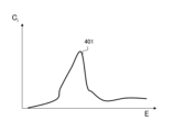
図4は、第i番目の検出器106iで得られるエネルギースペクトル401の一例である。図4において、エネルギーEを指定すると、そのエネルギーを持って検出器106で検出された光子数Ci(E)が得られる。N個の検出器106を用いるとこのようなエネルギースペクトルがNセット得られる。
FIG. 4 is an example of an
図5は、エネルギースペクトル401から画像化領域501における画素502および画素値I(x,y,z)の算出方法を示す概念図である。画素値は以下の数式(2)に従って計算できる。
FIG. 5 is a conceptual diagram showing a method of calculating a

ここで、(x,y,z)は画素502の座標であり、画素502に対応する第i番目の検出器106iで検出した光子エネルギーEi(x,y,z)は以下の数式(3)に従って計算できる。
Here, (x, y, z) are the coordinates of the

E0は前述の通り、約511keVである。さらに、cosθiは以下の数式(4)に従って計算できる。 As mentioned above, E0 is approximately 511 keV. Furthermore, cosθi can be calculated according to the following equation (4).

ここで、エネルギースペクトルCi(E)は被検体102の内部状態を反映したコンプトン散乱のみではなく、周囲からの入射光子がバックグラウンド信号として含まれていることがある。このようなバックグラウンドを除去するために、被検体102を置かずに計測し、得られたエネルギースペクトルを用いて算出した画素値を、被検体102を置いて得られたエネルギースペクトルから差し引くこともできる。 Here, the energy spectrum Ci(E) may include not only Compton scattering reflecting the internal state of the subject 102 but also incident photons from the surroundings as a background signal. In order to remove such background, the pixel value calculated using the energy spectrum obtained by measuring without placing the subject 102 may be subtracted from the energy spectrum obtained with the subject 102 placed. can.
以上のようにして、画素値を計算することができる。 In the manner described above, pixel values can be calculated.
図1に戻り、表示装置109は、画像再構成装置108において算出された画素値を表示するディスプレイなどの表示機器である。表示方法についてはディスプレイに三次元表示させるようにしてもよいし、メモリあるいはハードディスクといったコンピュータの記録装置110にデータとして記録する形態とすることができる。
Returning to FIG. 1, the
次に、上述した本実施例における内部状態画像化装置1により好適に実行される、本実施例に係る放射線散乱計測による被検体102の内部状態を画像化する方法について図6および図7を参照して説明する。図6は第1の内部状態画像化方法を示すフローチャート、図7は第2の内部状態画像化方法を示すフローチャートである。
Next, refer to FIGS. 6 and 7 for a method of imaging the internal state of the subject 102 by radiation scattering measurement according to the present embodiment, which is suitably executed by the internal
まず、放射線源101および複数の検出器106を被検体102の測定用のポイントに配置する(ステップS11)。このステップS11が、放射線源101および検出器106を測定ポイントに配置するステップに相当する。この際、好適には複数の検出器106の各々を、被検体102の表面に対して、放射線源101と同一方向に配置する。
First, a
次に、放射線源101および複数の検出器106の各々の位置を記録する(ステップS12)。このステップS12が、放射線源101および検出器106の配置位置を記録するステップに相当する。
Next, the positions of the
その後、放射線源101からガンマ線104を被検体102の広範囲に対して照射する。そして、このガンマ線104の照射により被検体102の内部で生じた散乱光子を複数の検出器106の各々で検出するとともに、検出値からエネルギー計測装置107によりエネルギースペクトルを記録する(ステップS13)。このステップS13が、放射線源101から放射線を照射し、被検体102の内部で生じた散乱光子を検出器106で検出するステップ、および検出器106で検出された放射線のエネルギースペクトルを記録するステップに相当する。
Thereafter, a wide range of the subject 102 is irradiated with
次に、画像再構成装置108において、先に記録したエネルギースペクトルから、実空間の照射領域に対応する画素を1つ選定する(ステップS14)。このステップS14が、放射線照射領域に対応する画素を選定するステップに相当する。
Next, the
その後は、数式(2)~数式(4)に従って、ステップS14で選定した画素の画素値を計算する(ステップS15)。このステップS15が、放射線源101、検出器106、および画素の位置関係から対応するエネルギーを算出するステップ、および算出されたエネルギーと記録されたエネルギースペクトルから画素に加算する画素値を算出するステップに相当する。
Thereafter, the pixel value of the pixel selected in step S14 is calculated according to formulas (2) to (4) (step S15). This step S15 is a step of calculating the corresponding energy from the positional relationship between the
次いで、全画素の画素値の演算が終了しているかを判定する(ステップS16)。まだ画素が残っていると判定されたときはステップS14に処理を戻して、別の画素を選定して再度演算を実施する。 Next, it is determined whether the calculation of the pixel values of all pixels has been completed (step S16). If it is determined that there are still pixels remaining, the process returns to step S14, another pixel is selected, and the calculation is performed again.
これに対し、すべての画素の画素値の演算が完了していると判定されたときは処理をステップS17に進め、演算結果を表示装置109にて表示する(ステップS17)とともに、記録装置110に記録して処理を完了する。このステップS17が、画素値を表示するステップに相当する。
On the other hand, when it is determined that the calculation of the pixel values of all pixels has been completed, the process advances to step S17, and the calculation results are displayed on the display device 109 (step S17), and the calculation results are displayed on the
以上、エネルギースペクトルを計測した後に、画像再構成を実施する場合の手順を述べた。 The above describes the procedure for performing image reconstruction after measuring the energy spectrum.
この図6に示す手順とは別に、光子を検出するたびに対応する画素を算出し、画素値を算出することで、リアルタイムに演算結果を表示することが可能である。以下その手順について図7を用いて説明する。 Apart from the procedure shown in FIG. 6, by calculating the corresponding pixel each time a photon is detected and calculating the pixel value, it is possible to display the calculation results in real time. The procedure will be explained below using FIG. 7.
まず、放射線源101と検出器106を測定ポイントに配置するとともに、画素値を0に初期化する(ステップS21)。このステップS21の一部が、放射線源101および検出器106を測定ポイントに配置するステップに相当する。
First, the
次に、ステップS21で配置した放射線源101および複数の検出器106の各々の位置を記録する(ステップS22)。このステップS22が、放射線源101および検出器106の配置位置を記録するステップに相当する。
Next, the positions of the
その後、放射線源101からガンマ線104を被検体102の広範囲に照射し、検出器106で光子1個を検出するが、その検出したタイミングで、エネルギー計測装置107でその光子のエネルギーを記録する(ステップS23)。このステップS23が、放射線源101から放射線を照射し、被検体102の内部で生じた散乱光子を検出器106で検出するステップ、および検出器106で検出された放射線のエネルギーを記録するステップに相当する。
After that,
次に、放射線源101および検出器106の位置、ならびにエネルギーから、数式(1)に従い、散乱角θiを算出するとともに、図1乃至図3を用いて説明した散乱点の候補点(x,y,z)の集合、すなわち等エネルギー面203とガンマ線104の照射範囲との交点を求める。そして、そのような候補点(x,y,z)を含む複数の画素を選定する(ステップS24)。このステップS24が、放射線源101および検出器106の位置、ならびにエネルギーから散乱角を算出するステップ、および散乱角が同一となる画素を選定するステップに相当する。
Next, from the positions and energy of the
次いで、ステップS24で選定した複数の画素に対して画素値をカウントアップ(+1)する(ステップS25)。このステップS25が、画素に検出数を加算するステップ相当する。 Next, the pixel values of the plurality of pixels selected in step S24 are counted up (+1) (step S25). This step S25 corresponds to the step of adding the number of detections to the pixels.
次いで、現在の計数値が目的の内部状態画像化精度に対して十分な統計量となったか否かを判定する(ステップS26)。まだ統計量が十分でないと判定されたときは処理をステップS23に戻して、再び散乱光子を検出し、再度画素の選定及び画素値の演算を実施する。 Next, it is determined whether the current count value has become a sufficient statistic for the target internal state imaging accuracy (step S26). If it is determined that the statistical amount is still insufficient, the process returns to step S23, scattered photons are detected again, and pixel selection and pixel value calculation are performed again.
これに対し、ステップS26にて十分な統計量が得られたと判定されたときは計測を終了して処理をステップS27に進め、演算結果を表示装置109にて表示する(ステップS27)とともに、記録装置110に記録して処理を完了する。このステップS27が、検出数が加算された画素を表示するステップに相当する。
On the other hand, when it is determined in step S26 that sufficient statistics have been obtained, the measurement is ended and the process proceeds to step S27, where the calculation results are displayed on the display device 109 (step S27) and recorded. Recording is performed on the
次に、本実施例の効果について説明する。 Next, the effects of this embodiment will be explained.
上述した本発明の第1実施例の内部状態画像化装置1は、被検体102に向けて単色放射線を範囲で放出する放射線源101と、放射線源101から放出された単色放射線により生じた散乱光子を異なる位置で検出する検出器106と、検出器106で検出された散乱光子の光子エネルギーと強度を計測するエネルギー計測装置107と、エネルギー計測装置107において計測された光子エネルギーと強度から散乱位置と対応する1つ以上の画素を算出して画素値を演算する画像再構成装置108と、を備える。
The internal
これによって、被検体102内の内部領域に広範囲に放射線を照射し、一括して検査領域の内部状態を画像化することが可能となる。従って、複雑な処理を行うことなく、かつ全体の計測に要する時間が長くなることを避けることができる。 This makes it possible to irradiate a wide range of radiation to the internal region within the subject 102 and image the internal state of the examination region all at once. Therefore, it is possible to avoid an increase in the time required for the entire measurement without performing complicated processing.
また、放射線散乱計測による被検体102の内部状態を画像化する方法では、放射線源101および検出器106を測定ポイントに配置するステップと、放射線源101および検出器106の配置位置を記録するステップと、放射線源101から放射線を照射し、被検体102の内部で生じた散乱光子を検出器106で検出するステップと、検出器106で検出された放射線のエネルギースペクトルを記録するステップと、放射線照射領域に対応する画素を選定するステップと、放射線源101、検出器106、および画素の位置関係から対応するエネルギーを算出するステップと、算出されたエネルギーと記録されたエネルギースペクトルから画素に加算する画素値を算出するステップと、を有することによって、上述の内部状態画像化装置1によって得られる効果と同じ効果が得られる。
Further, the method of imaging the internal state of the subject 102 by radiation scattering measurement includes a step of arranging the
更に、放射線散乱計測による被検体102の内部状態を画像化する方法であって、放射線源101および検出器106を測定ポイントに配置するステップと、放射線源101および検出器106の配置位置を記録するステップと、放射線源101から放射線を照射し、被検体102の内部で生じた散乱光子を検出器106で検出するステップと、検出器106で検出された放射線のエネルギーを記録するステップと、放射線源101および検出器106の位置、ならびにエネルギーから散乱角を算出するステップと、散乱角が同一となる画素を選定するステップと、画素に検出数を加算するステップと、検出数が加算された画素を表示するステップと、を有することによっても、上述の内部状態画像化装置1によって得られる効果と同じ効果が得られる。また、本方法では、リアルタイムで画素値が得られる、との効果が得られる。
Furthermore, the method includes the steps of arranging the
また、複数の検出器106は、被検体102の表面に対して放射線源101と同一方向に配置されるため、簡易に検出器106を複数配置することができるとともに、検出結果の演算処理に要する時間をより短くすることができる。
In addition, since the plurality of
更に、画像再構成装置108において算出された画素値を表示する表示装置109を更に備えることで、得られた結果を容易に把握することができる。
Furthermore, by further providing a
<第2実施例>
本発明の第2実施例の内部状態画像化装置および内部状態画像化方法について図8および図9を用いて説明する。図8は第2実施例に係る内部状態画像化装置および方法の概念図、図9は内部状態画像化方法を示すフローチャートである。
<Second example>
An internal state imaging device and internal state imaging method according to a second embodiment of the present invention will be described using FIGS. 8 and 9. FIG. FIG. 8 is a conceptual diagram of an internal state imaging apparatus and method according to the second embodiment, and FIG. 9 is a flowchart showing the internal state imaging method.
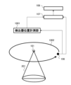
第2実施例の内部状態画像化装置では、検出器として一般的にコンプトンカメラ801と呼ばれている検出器を用いる。図8に示すように、コンプトンカメラ801では、散乱光子を検出すると光子エネルギーを測定するとともに、光子の入射方向の候補をコンプトンカメラ801を頂点とする円錐802の側面に限定することができる。
The internal state imaging device of the second embodiment uses a detector generally called a
この円錐802の頂角はコンプトンカメラ801により算出可能であり、形成される円錐802は、一般にコンプトンコーンと呼ばれる。この原理を用いて、第1実施例で説明した演算処理と同様の処理により、散乱光子エネルギーとコンプトンカメラ801の位置から算出した散乱点の候補(x,y,z)となる集合である等エネルギー面203とガンマ線104の照射範囲201とコンプトンコーン802との交点803,804を算出することで、さらに候補点の画素を絞ることができる。
The apex angle of this
なお、1つのコンプトンカメラ801により求められる散乱点の候補(x,y,z)は複数存在し、一点に絞ることはできないことは第1実施例と同様であり、コンプトンカメラ801を複数設ける。
Note that, as in the first embodiment, there are multiple scattering point candidates (x, y, z) found by one
なお、用いる検出器はすべてコンプトンカメラ801である必要は無く、コンプトンカメラ801と混ぜて複数のうち一つ以上を第1実施例と同様にガンマ線検出器等を用いることができる。
Note that all the detectors used do not need to be the
次いで、本実施例の内部状態画像化方法について図9を用いて説明する。 Next, the internal state imaging method of this embodiment will be explained using FIG. 9.
図9に示す本実施例の処理では、図7で説明した内部状態画像化の各ステップのうち、ステップS24に換わってステップS31およびステップS32が実行される。 In the process of this embodiment shown in FIG. 9, among the internal state imaging steps described in FIG. 7, step S31 and step S32 are executed in place of step S24.
図9に示すように、ステップS23の後、コンプトンコーン802を算出する(ステップS31)。続いて、等エネルギー面203と照射範囲とコンプトンコーン802の交点に対応する候補画素を選定する(ステップS32)。
As shown in FIG. 9, after step S23, a
また、ステップS25では、第1実施例と同様に、ステップS24で選定した複数の画素に対して画素値をカウントアップ(+1)する。 Furthermore, in step S25, as in the first embodiment, the pixel values of the plurality of pixels selected in step S24 are counted up (+1).
その他の構成・動作は前述した第1実施例の内部状態画像化装置および内部状態画像化方法と略同じ構成・動作であり、詳細は省略する。 The other configurations and operations are substantially the same as those of the internal state imaging device and internal state imaging method of the first embodiment described above, and the details will be omitted.
本発明の第2実施例の内部状態画像化装置および内部状態画像化方法においても、前述した第1実施例の内部状態画像化装置および内部状態画像化方法とほぼ同様な効果が得られる。 The internal state imaging device and internal state imaging method according to the second embodiment of the present invention also provide substantially the same effects as the internal state imaging device and internal state imaging method according to the first embodiment described above.
また、検出器106として、コンプトンカメラ801を利用し、画素を選定するステップにおいて、コンプトンコーン802を算出し、コンプトンコーン802と同一の散乱角となる画素の交点を候補画素として選定することにより、光子の入射方向の候補を限定できるため、演算負荷を軽減することができる。従って、より速やかに画素値を得ることができるとともに、装置構成を簡略化することができる。
Furthermore, by using the
<第3実施例>
本発明の第3実施例の内部状態画像化装置および内部状態画像化方法について図10および図11を用いて説明する。図10は第3実施例に係る内部状態画像化装置および方法の概念図、図11は内部状態画像化方法を示すフローチャートである。
<Third Example>
An internal state imaging device and internal state imaging method according to a third embodiment of the present invention will be described with reference to FIGS. 10 and 11. FIG. 10 is a conceptual diagram of an internal state imaging apparatus and method according to the third embodiment, and FIG. 11 is a flowchart showing the internal state imaging method.
第3実施例の内部状態画像化装置では、第1実施例の内部状態画像化装置1とは異なり、検出器106を1つとするとともに、放射線源101と検出器106との相対位置を可変として、その相対位置関係1002が時々刻々変化するようにしたものである。そのため、検出器106が光子を検出したタイミングにおける放射線源101に対する検出器106の相対座標を計測する位置計測部1001を更に設けている。
In the internal state imaging device of the third embodiment, unlike the internal
本実施例では、検出器106の位置が変化しているため、異なる測定位置で散乱光子の検出データが複数得られることから、単一の検出器106のみで内部状態の画像を再構成することができる。当然、検出器106を複数で構成することも可能であり、その場合はより速やかに画素値が得られる。
In this example, since the position of the
次いで、本実施例の内部状態画像化方法について図11を用いて説明する。 Next, the internal state imaging method of this example will be explained using FIG. 11.
図11に示す本実施例の処理では、図7で説明した内部状態画像化の各ステップのうち、ステップS22に換わってステップS41が実行される。 In the process of this embodiment shown in FIG. 11, among the steps of internal state imaging described in FIG. 7, step S41 is executed in place of step S22.
図11に示すように、ステップS21の後、位置が可変の検出器106で光子を検出したタイミングにおける放射線源101に対する検出器106の相対位置を計測して記録する(ステップS41)。
As shown in FIG. 11, after step S21, the relative position of the
以後のステップS23~S27は第1実施例と同様であるが、ステップS24では、計測した放射線源101と検出器106との相対位置を用いて候補画素を選定する。また、ステップS26で十分な統計量が得られていないと判定されたときは、ステップS41まで戻って再び散乱光子を検出し、検出器106の放射線源101に対する相対位置を計測、画素の選定及び画素値の演算を実施する。ステップS26にて十分な統計量が得られていると判定されれば計測を終了し、ステップS28にて演算結果を表示装置109に表示し、記録装置110に記録する。
Subsequent steps S23 to S27 are similar to those in the first embodiment, but in step S24, candidate pixels are selected using the measured relative positions of the
その他の構成・動作は前述した第1実施例の内部状態画像化装置および内部状態画像化方法と略同じ構成・動作であり、詳細は省略する。 The other configurations and operations are substantially the same as those of the internal state imaging device and internal state imaging method of the first embodiment described above, and the details will be omitted.
本発明の第3実施例の内部状態画像化装置および内部状態画像化方法においても、前述した第1実施例の内部状態画像化装置および内部状態画像化方法とほぼ同様な効果が得られる。 The internal state imaging device and internal state imaging method according to the third embodiment of the present invention also provide substantially the same effects as the internal state imaging device and internal state imaging method according to the first embodiment described above.
また、放射線源101と検出器106との相対位置を可変とし、放射線源101と検出器106の位置を記録するステップでは、放射線源101に対する検出器106の相対位置を計測し、画素を選定するステップでは、計測した放射線源101と検出器106との相対位置を用いて候補画素を選定することにより、検出器106を複数設ける必要がなくなる、との効果が得られる。
Furthermore, in the step of making the relative position between the
なお、本実施例における検出器106は、第2実施例のようにコンプトンカメラ801を用いることができる。
Note that, as the
<第4実施例>
本発明の第4実施例の内部状態画像化装置および内部状態画像化方法について図12乃至図14を用いて説明する。図12および図13は第4実施例に係る内部状態画像化装置および方法の概念図、図14は内部状態画像化方法を示すフローチャートである。
<Fourth example>
An internal state imaging device and an internal state imaging method according to a fourth embodiment of the present invention will be described with reference to FIGS. 12 to 14. FIG. 12 and 13 are conceptual diagrams of an internal state imaging apparatus and method according to the fourth embodiment, and FIG. 14 is a flowchart showing the internal state imaging method.
第4実施例の内部状態画像化装置では、第1実施例の内部状態画像化装置1のうち、図11に示すように、エネルギー計測装置107Cは、放射線検出時間を計測し、既定の時間幅の中で検出した放射線が同時か否かを判定する同時検出判定部1201を有する。
In the internal state imaging device of the fourth embodiment, as shown in FIG. 11 in the internal
また、画像再構成装置108Cは、図11に示すように、同時に検出器106に到達したと判定された放射線を検出した検出器106の位置(すなわち、検出器106に到達した放射線の位置といえる)と光子エネルギーから画素と画素値を演算する計算部1202を有する。
In addition, as shown in FIG. 11, the
図12は、第i番目の検出器106iと第j番目の検出器106jとで非同時に散乱光子を検出した場合の画素値の算出方法を示している。図12に示すように、非同時に散乱光子を検出した場合は第1実施例で示した方法で候補画素を算出する。
FIG. 12 shows a method for calculating pixel values when scattered photons are detected non-simultaneously by the i-
図13は、図12と同じ検出器106の位置関係において、第i番目の検出器106iと第j番目の検出器106jとで同時に散乱光子を検出した場合の画素値の算出方法を示している。このように、同時に散乱光子を検出した場合は、片方の検出器106i、もしくは検出器106jの内部でコンプトン散乱が生じ、もう一方の検出器106j、もしくは検出器106iでその散乱光子を検出したものと考えることができる。
FIG. 13 shows a method of calculating pixel values when scattered photons are simultaneously detected by the i-
第i番目の検出器106iでコンプトン散乱が生じ、第j番目の検出器106jでその散乱光子を検出したとすると、第2実施例と同様に、コンプトンコーン802を以下のように描くことができる。コンプトンコーン802は第i番目の検出器106iと第j番目の検出器106jの座標を結んだ直線を中心軸とし、半頂角θcは次の数式(5)に従って計算される。
Assuming that Compton scattering occurs at the i-

ここで、Eiは被検体102の内部で散乱した光子が第i番目の検出器106iに付与したエネルギー、Ejは第i番目の検出器106iでコンプトン散乱した散乱光子が第j番目の検出器106jに付与したエネルギーであり、E0は511keVである。
Here, Ei is the energy imparted to the i-
等エネルギー面203は、放射線源101の位置に対する第i番目の検出器106iの相対座標と、数式(1)においてEiをEi+Ejに置き換えたものから算出した散乱角を用いて描画することができる。
The
図12で示した非同時事象と、図13で示した同時事象は互いに背反であるため、それぞれの事象を用いた内部状態の画像化が可能である。最終的な画像の表示においては、それらを独立に表示することも可能であるし、画素値を重み付き加算することによりアーチファクトを小さくしつつ、検出事象を有効に利用して短時間に画像化が可能となる。 Since the non-simultaneous event shown in FIG. 12 and the simultaneous event shown in FIG. 13 are contradictory to each other, it is possible to image the internal state using each event. When displaying the final image, it is possible to display them independently, or to reduce artifacts by weighted addition of pixel values, while effectively utilizing detected events to create an image in a short time. becomes possible.
次いで、本実施例の内部状態画像化方法について図14を用いて説明する。 Next, the internal state imaging method of this example will be explained using FIG. 14.
図14に示すように、図7で説明した内部状態画像化の処理におけるステップS23で光子エネルギーを記録した後、同時検知かどうかを判定する(ステップS51)。このステップS51が、放射線の検出時間を計測し、既定の時間幅の中で検出した放射線が同時か否かを判定するステップに相当する。 As shown in FIG. 14, after photon energy is recorded in step S23 in the internal state imaging process described in FIG. 7, it is determined whether simultaneous detection is performed (step S51). This step S51 corresponds to a step of measuring the detection time of radiation and determining whether or not the radiations detected within a predetermined time width are simultaneous.
ステップS51において同時でないと判定されたときは、ステップS24に進め、第1実施例と同様に等エネルギー面203と放射線の照射範囲との交点を候補画素として選定する(ステップS24)。その後、非同時事象に対する画素値の重みを設定(ステップS52)し、これらの重み付きで選定した画素の画素値をカウントアップ(+重み)する(ステップS54)。その後、現在の計数値が目的の内部状態画像化精度に対して十分な統計量となったか否かを判定する(ステップS26)。
If it is determined in step S51 that they are not simultaneous, the process proceeds to step S24, and the intersection of the
これに対し、ステップS51にて同時と判定された場合は、コンプトンコーン802を算出する(ステップS31)。続いて、等エネルギー面203と照射範囲とコンプトンコーン802との交点を候補画素をとして選定する(ステップS32)。
On the other hand, if it is determined in step S51 that they are simultaneous, the
その後、同時事象に対する画素値の重みを設定(ステップS53)したうえで、これらの重み付きで選定した画素の画素値をカウントアップ(+重み)する(ステップS54)。その後、現在の計数値が目的の内部状態画像化精度に対して十分な統計量となったか否かを判定する(ステップS26)。 After that, weights of pixel values for simultaneous events are set (step S53), and the pixel values of the pixels selected with these weights are counted up (+weight) (step S54). Thereafter, it is determined whether the current count value has become a sufficient statistic for the target internal state imaging accuracy (step S26).
上述のステップS52、あるいはステップS53において選定する重みは、何らかの入力部を用いてあらかじめ与えておくことができる。 The weight selected in step S52 or step S53 described above can be given in advance using some kind of input unit.
なお、リアルタイムに画素値をカウントアップする方法に変えて、非同時事象と同時事象で独立に画像化した後に、重みを変化させてそれぞれの画像を重み付きで加算して表示することができる。この場合、重み付きで加算して表示することができる。 Note that instead of counting up pixel values in real time, it is possible to image the non-simultaneous events and the simultaneous events independently, and then change the weights and add the respective images with weights for display. In this case, the values can be added and displayed with weights.
その他の構成・動作は前述した第1実施例の内部状態画像化装置および内部状態画像化方法と略同じ構成・動作であり、詳細は省略する。 The other configurations and operations are substantially the same as those of the internal state imaging device and internal state imaging method of the first embodiment described above, and the details will be omitted.
本発明の第4実施例の内部状態画像化装置および内部状態画像化方法においても、前述した第1実施例の内部状態画像化装置および内部状態画像化方法とほぼ同様な効果が得られる。 The internal state imaging device and internal state imaging method according to the fourth embodiment of the present invention also provide substantially the same effects as the internal state imaging device and internal state imaging method according to the first embodiment described above.
また、放射線の検出時間を計測し、既定の時間幅の中で検出した放射線が同時か否かを判定するステップを更に有し、画素を選定するステップでは、同時と判定されなかった場合は、放射線源101の位置、検出器106の位置、およびエネルギーから散乱角を算出し、同一散乱角となる画素を選定し、同時と判定された場合には、コンプトンコーン802を算出するとともにコンプトンコーン802と同一散乱角となる画素の交点を候補画素として選定することにより、それぞれの事象を用いた内部状態の可視化を図れ、被検体102の内部をより正確に写した精度の高い画素値を得ることができる。
The method further includes a step of measuring radiation detection time and determining whether or not the radiations detected within a predetermined time width are simultaneous; A scattering angle is calculated from the position of the
更に、同時と判定されない場合と同時と判定される場合のそれぞれ重みを設定し、選定した画素の画素値を重み付きで加算することで、アーチファクトを小さくしつつ、検出事象を有効に利用して短時間に画像化が可能となる。 Furthermore, by setting weights for cases in which it is not determined to be simultaneous and cases in which it is determined to be simultaneous, the pixel values of the selected pixels are added with weights, thereby reducing artifacts and making effective use of detected events. Imaging can be done in a short time.
また、同時と判定されない場合と同時と判定される場合のそれぞれの内部状態画像を保有し、内部状態画像を演算して合成することにより、より精度の高い画素値が得られるようになる。 In addition, by holding internal state images for cases in which it is not determined to be simultaneous and cases in which it is determined to be simultaneous, and by calculating and composing the internal state images, more accurate pixel values can be obtained.
<その他>
なお、本発明は、上記の実施例に限定されるものではなく、様々な変形例が含まれる。上記の実施例は本発明を分かりやすく説明するために詳細に説明したものであり、必ずしも説明した全ての構成を備えるものに限定されるものではない。
<Others>
Note that the present invention is not limited to the above-described embodiments, and includes various modifications. The above-mentioned embodiments have been described in detail to explain the present invention in an easy-to-understand manner, and the present invention is not necessarily limited to having all the configurations described.
また、ある実施例の構成の一部を他の実施例の構成に置き換えることも可能であり、また、ある実施例の構成に他の実施例の構成を加えることも可能である。また、各実施例の構成の一部について、他の構成の追加・削除・置換をすることも可能である。 Further, it is also possible to replace a part of the configuration of one embodiment with the configuration of another embodiment, and it is also possible to add the configuration of another embodiment to the configuration of one embodiment. Furthermore, it is also possible to add, delete, or replace some of the configurations of each embodiment with other configurations.
1…内部状態画像化装置
101…放射線源
102…被検体(対象物)
103…欠陥
104…ガンマ線
105…散乱放射線
106,106’,106a,106b,106c,106d,106e,106f,106i,106j…検出器
107,107C…エネルギー計測装置
108,108C…画像再構成装置
109…表示装置
110…記録装置
201…照射範囲
202…真の散乱点
203,203’…等エネルギー面
204,204’…選定する画素の候補点の集合
401…エネルギースペクトル
501…画像化領域
502…画素
801…コンプトンカメラ
802…円錐,コンプトンコーン
803,804…コンプトンコーンと等エネルギー面の交点
1001…位置計測部(位置センサ)
1002…相対位置関係
1201…同時検出判定部(同時計数部)
1202…計算部
1... Internal
103... Defect 104...
1002... Relative
1202...Calculation section
Claims (14)
前記対象物に向けて単色放射線を範囲で放出する放射線源と、
前記放射線源から放出された前記単色放射線により生じた散乱光子を異なる位置で検出する検出器と、
前記検出器で検出された前記散乱光子の光子エネルギーと強度を計測するエネルギー計測装置と、
前記エネルギー計測装置において計測された光子エネルギーと強度から散乱位置と対応する1つ以上の画素を算出して画素値を演算して、演算した前記画素値を複数の検出器の位置分カウントアップする画像再構成装置と、を備える
ことを特徴とする内部状態画像化装置。 An internal state imaging device that images the internal state of a target by radiation scattering measurement,
a radiation source that emits a range of monochromatic radiation toward the object;
a detector for detecting scattered photons produced by the monochromatic radiation emitted from the radiation source at different positions;
an energy measurement device that measures photon energy and intensity of the scattered photons detected by the detector;
One or more pixels corresponding to the scattering position are calculated from the photon energy and intensity measured by the energy measuring device, a pixel value is calculated, and the calculated pixel value is counted up by the positions of the plurality of detectors. An internal state imaging device comprising: an image reconstruction device.
前記検出器は、前記対象物の表面に対して前記放射線源と同一方向に配置される
ことを特徴とする内部状態画像化装置。 The internal state imaging device according to claim 1,
An internal state imaging device, wherein the detector is arranged in the same direction as the radiation source with respect to the surface of the object.
前記検出器として、コンプトンカメラを利用する
ことを特徴とする内部状態画像化装置。 The internal state imaging device according to claim 1,
An internal state imaging device characterized in that a Compton camera is used as the detector.
前記検出器は、前記放射線源に対する相対位置が可変であり、
前記放射線源に対する前記検出器の相対位置を計測する位置センサを更に有する
ことを特徴とする内部状態画像化装置。 The internal state imaging device according to claim 1,
The detector has a variable position relative to the radiation source,
An internal state imaging device further comprising a position sensor that measures the relative position of the detector with respect to the radiation source.
前記エネルギー計測装置は、放射線検出時間を計測し、既定の時間幅の中で検出した放射線が同時か否かを判定する同時計数部を有しており、
前記画像再構成装置は、同時に前記検出器に到達した放射線の位置とエネルギーから画素と画素値を演算する計算部を有している
ことを特徴とする内部状態画像化装置。 The internal state imaging device according to claim 1,
The energy measurement device has a coincidence unit that measures radiation detection time and determines whether or not the radiation detected within a predetermined time width is simultaneous;
The internal state imaging device, wherein the image reconstruction device includes a calculation unit that calculates pixels and pixel values from the position and energy of radiation that simultaneously reaches the detector.
前記画像再構成装置において算出された前記画素値を表示する表示装置を更に備える
ことを特徴とする内部状態画像化装置。 The internal state imaging device according to claim 1,
An internal state imaging device further comprising a display device that displays the pixel values calculated by the image reconstruction device.
放射線源および検出器を測定ポイントに配置するステップと、
前記放射線源および前記検出器の配置位置を記録するステップと、
前記放射線源から放射線を照射し、前記対象物の内部で生じた散乱光子を前記検出器で検出するステップと、
前記検出器で検出された放射線のエネルギースペクトルを記録するステップと、
放射線照射領域に対応する画素を選定するステップと、
前記放射線源、前記検出器、および画素の位置関係から対応するエネルギーを算出するステップと、
算出された前記エネルギーと記録された前記エネルギースペクトルから前記画素に加算する画素値を算出するステップと、を有し、
上記の各ステップを異なる位置あるいはタイミングで複数回実行し、
得られた、配置位置を変えた際の、それぞれの配置位置で取得される画素値を加算するステップを更に有する
ことを特徴とする内部状態画像化方法。 A method of imaging the internal state of an object by radiation scattering measurement, the method comprising:
placing a radiation source and a detector at the measurement point;
recording the placement positions of the radiation source and the detector;
irradiating radiation from the radiation source and detecting scattered photons generated inside the object with the detector;
recording an energy spectrum of radiation detected by the detector;
a step of selecting pixels corresponding to the radiation irradiation area;
calculating the corresponding energy from the positional relationship of the radiation source, the detector, and the pixel;
calculating a pixel value to be added to the pixel from the calculated energy and the recorded energy spectrum ,
Execute each step above multiple times at different positions or timings,
An internal state imaging method characterized by further comprising the step of adding the obtained pixel values obtained at each arrangement position when the arrangement position is changed .
放射線源および検出器を測定ポイントに配置するステップと、
前記放射線源および前記検出器の配置位置を記録するステップと、
前記放射線源から放射線を照射し、前記対象物の内部で生じた散乱光子を前記検出器で検出するステップと、
前記検出器で検出された放射線のエネルギーを記録するステップと、
前記放射線源および前記検出器の位置、ならびに前記エネルギーから散乱角を算出するステップと、
前記散乱角が同一となる画素を選定するステップと、
前記画素に検出数を加算するステップと、
前記検出数が加算された前記画素を表示するステップと、を有し、
上記の各ステップを異なる位置あるいはタイミングで複数回実行する
ことを特徴とする内部状態画像化方法。 A method of imaging the internal state of an object by radiation scattering measurement, the method comprising:
placing a radiation source and a detector at the measurement point;
recording the placement positions of the radiation source and the detector;
irradiating radiation from the radiation source and detecting scattered photons generated inside the object with the detector;
recording the energy of radiation detected by the detector;
calculating a scattering angle from the positions of the radiation source and the detector and the energy;
selecting pixels with the same scattering angle;
adding a detection number to the pixel;
displaying the pixels to which the number of detections has been added ;
An internal state imaging method characterized by performing each of the above steps multiple times at different positions or timings .
前記検出器として、コンプトンカメラを利用し、
前記画素を選定するステップにおいて、コンプトンコーンを算出し、コンプトンコーンと同一の散乱角となる画素の交点を候補画素として選定する
ことを特徴とする内部状態画像化方法。 The internal state imaging method according to claim 8,
A Compton camera is used as the detector,
An internal state imaging method characterized in that, in the step of selecting the pixels, a Compton cone is calculated, and an intersection point of pixels having the same scattering angle as the Compton cone is selected as a candidate pixel.
前記放射線源と前記検出器との相対位置を可変とし、
前記放射線源および前記検出器の位置を記録するステップでは、前記放射線源に対する前記検出器の相対位置を計測し、
前記画素を選定するステップでは、前記計測した前記放射線源と前記検出器との相対位置を用いて候補画素を選定する
ことを特徴とする内部状態画像化方法。 The internal state imaging method according to claim 7 or 8,
The relative position of the radiation source and the detector is variable;
In the step of recording the positions of the radiation source and the detector, measuring the relative position of the detector with respect to the radiation source;
An internal state imaging method, wherein in the step of selecting the pixel, a candidate pixel is selected using the measured relative position between the radiation source and the detector.
前記放射線の検出時間を計測し、既定の時間幅の中で検出した前記放射線が同時か否かを判定するステップを更に有し、
前記画素を選定するステップでは、
同時と判定されなかった場合は、前記放射線源の位置、前記検出器の位置、および前記エネルギーから前記散乱角を算出し、同一の散乱角となる画素を選定し、
同時と判定された場合には、コンプトンコーンを算出するとともに前記コンプトンコーンと同一の散乱角となる画素の交点を候補画素として選定する
ことを特徴とする内部状態画像化方法。 The internal state imaging method according to claim 8,
further comprising the step of measuring the detection time of the radiation and determining whether or not the radiation detected within a predetermined time width is simultaneous;
In the step of selecting the pixels,
If it is determined that they are not simultaneous, calculate the scattering angle from the position of the radiation source, the position of the detector, and the energy, and select pixels with the same scattering angle,
If it is determined that they are simultaneous, a Compton cone is calculated, and an intersection of pixels having the same scattering angle as the Compton cone is selected as a candidate pixel.
同時と判定されない場合と同時と判定される場合のそれぞれ重みを設定し、選定した前記画素の画素値を重み付きで加算する
ことを特徴とする内部状態画像化方法。 The internal state imaging method according to claim 11,
An internal state imaging method characterized by setting weights for cases in which it is not determined to be simultaneous and cases in which it is determined to be simultaneous, and adding pixel values of the selected pixels with weights.
同時と判定されない場合と同時と判定される場合のそれぞれの内部状態画像を保有し、内部状態画像を演算して合成する
ことを特徴とする内部状態画像化方法。 The internal state imaging method according to claim 11,
An internal state imaging method characterized by having internal state images for cases in which it is not determined to be simultaneous and cases in which it is determined to be simultaneous, and calculating and synthesizing the internal state images.
前記画素値を表示するステップを更に有する
ことを特徴とする内部状態画像化方法。 The internal state imaging method according to claim 7,
An internal state imaging method, further comprising the step of displaying the pixel values.
Priority Applications (1)
| Application Number | Priority Date | Filing Date | Title |
|---|---|---|---|
| JP2021032888A JP7437337B2 (en) | 2021-03-02 | 2021-03-02 | Internal state imaging device and internal state imaging method |
Applications Claiming Priority (1)
| Application Number | Priority Date | Filing Date | Title |
|---|---|---|---|
| JP2021032888A JP7437337B2 (en) | 2021-03-02 | 2021-03-02 | Internal state imaging device and internal state imaging method |
Publications (3)
| Publication Number | Publication Date |
|---|---|
| JP2022133928A JP2022133928A (en) | 2022-09-14 |
| JP2022133928A5 JP2022133928A5 (en) | 2023-03-02 |
| JP7437337B2 true JP7437337B2 (en) | 2024-02-22 |
Family
ID=83229716
Family Applications (1)
| Application Number | Title | Priority Date | Filing Date |
|---|---|---|---|
| JP2021032888A Active JP7437337B2 (en) | 2021-03-02 | 2021-03-02 | Internal state imaging device and internal state imaging method |
Country Status (1)
| Country | Link |
|---|---|
| JP (1) | JP7437337B2 (en) |
Citations (6)
| Publication number | Priority date | Publication date | Assignee | Title |
|---|---|---|---|---|
| JP2008302212A (en) | 2007-04-11 | 2008-12-18 | Searete Llc | Volumetric type compton scattered x-ray depth visualization, imaging or information provider |
| JP2010249785A (en) | 2009-04-20 | 2010-11-04 | Central Res Inst Of Electric Power Ind | Nondestructive inspection method and its apparatus |
| JP2019090619A (en) | 2017-11-10 | 2019-06-13 | シャープ株式会社 | X-ray measurement instrument |
| WO2019117147A1 (en) | 2017-12-13 | 2019-06-20 | 株式会社ニコン | X-ray apparatus and method for manufacturing structure |
| JP2020046231A (en) | 2018-09-14 | 2020-03-26 | 株式会社千代田テクノル | Method and device for three-dimensional display of radiation distribution |
| JP2020180816A (en) | 2019-04-24 | 2020-11-05 | 国立大学法人千葉大学 | Reflection type tomographic apparatus |
-
2021
- 2021-03-02 JP JP2021032888A patent/JP7437337B2/en active Active
Patent Citations (6)
| Publication number | Priority date | Publication date | Assignee | Title |
|---|---|---|---|---|
| JP2008302212A (en) | 2007-04-11 | 2008-12-18 | Searete Llc | Volumetric type compton scattered x-ray depth visualization, imaging or information provider |
| JP2010249785A (en) | 2009-04-20 | 2010-11-04 | Central Res Inst Of Electric Power Ind | Nondestructive inspection method and its apparatus |
| JP2019090619A (en) | 2017-11-10 | 2019-06-13 | シャープ株式会社 | X-ray measurement instrument |
| WO2019117147A1 (en) | 2017-12-13 | 2019-06-20 | 株式会社ニコン | X-ray apparatus and method for manufacturing structure |
| JP2020046231A (en) | 2018-09-14 | 2020-03-26 | 株式会社千代田テクノル | Method and device for three-dimensional display of radiation distribution |
| JP2020180816A (en) | 2019-04-24 | 2020-11-05 | 国立大学法人千葉大学 | Reflection type tomographic apparatus |
Also Published As
| Publication number | Publication date |
|---|---|
| JP2022133928A (en) | 2022-09-14 |
Similar Documents
| Publication | Publication Date | Title |
|---|---|---|
| US7778383B2 (en) | Effective dual-energy x-ray attenuation measurement | |
| US10521936B2 (en) | Device and method for image reconstruction at different X-ray energies, and device and method for X-ray three-dimensional measurement | |
| US9459358B2 (en) | Reference calibration in photon counting based spectral CT | |
| JP2019025331A (en) | Radiation transmission/fluorescence ct imaging system and imaging method | |
| EP2978377B1 (en) | Method of phase gradient radiography and arrangement of an imaging system for application of the method | |
| JP2015520365A (en) | Image processing system and image processing method | |
| JP2007508559A (en) | Fan beam coherent scattering computed tomography | |
| KR20140059012A (en) | Nondestructive test system | |
| WO2021166295A1 (en) | Radiation measurement device and radiation measurement method | |
| US8199878B2 (en) | Methods and systems for performing differential radiography | |
| JP2009175065A (en) | Simultaneous three-dimensional distribution-visualization observation-measurement method of a plurality of elements by neutron prompt gamma-ray analysis, and device thereof | |
| JP7437337B2 (en) | Internal state imaging device and internal state imaging method | |
| US20190025231A1 (en) | A method of detection of defects in materials with internal directional structure and a device for performance of the method | |
| CN112649451B (en) | Fast industrial computed tomography for large objects | |
| JP6983129B2 (en) | Gamma camera | |
| JP2007518986A (en) | Computer tomograph and radiation detector for measuring light scattered elastically in the object | |
| Bernardi et al. | Nuclear waste drum characterization with 2 MeV x-ray and gamma-ray tomography | |
| JP2022180690A (en) | Radiation measuring device and its measurement method | |
| JP7449821B2 (en) | Internal condition inspection system and internal condition inspection method | |
| Cosentino et al. | Particle beam and X-ray imaging with thin CsI scintillating plates | |
| Grigorova et al. | Optimisation of a neutron imaging system using the modulation transfer function | |
| CN115980104A (en) | Multi-angle scanning coded hole X-ray diffraction tomography system and imaging method | |
| Ewert et al. | A benchmark concept for simulation in radiographic testing | |
| JP2005121557A (en) | X-ray ct equipment and imaging method by the x-ray ct equipment | |
| GB2534091A (en) | Method for determining the danger zone between a test object and an x-ray inspection system |
Legal Events
| Date | Code | Title | Description |
|---|---|---|---|
| A521 | Request for written amendment filed |
Free format text: JAPANESE INTERMEDIATE CODE: A523 Effective date: 20230221 |
|
| A621 | Written request for application examination |
Free format text: JAPANESE INTERMEDIATE CODE: A621 Effective date: 20230221 |
|
| A977 | Report on retrieval |
Free format text: JAPANESE INTERMEDIATE CODE: A971007 Effective date: 20231211 |
|
| A131 | Notification of reasons for refusal |
Free format text: JAPANESE INTERMEDIATE CODE: A131 Effective date: 20231226 |
|
| A521 | Request for written amendment filed |
Free format text: JAPANESE INTERMEDIATE CODE: A523 Effective date: 20240112 |
|
| TRDD | Decision of grant or rejection written | ||
| A01 | Written decision to grant a patent or to grant a registration (utility model) |
Free format text: JAPANESE INTERMEDIATE CODE: A01 Effective date: 20240206 |
|
| A61 | First payment of annual fees (during grant procedure) |
Free format text: JAPANESE INTERMEDIATE CODE: A61 Effective date: 20240209 |
|
| R150 | Certificate of patent or registration of utility model |
Ref document number: 7437337 Country of ref document: JP Free format text: JAPANESE INTERMEDIATE CODE: R150 |