JP7435242B2 - Dynamic image analysis device, dynamic image analysis method and program - Google Patents
Dynamic image analysis device, dynamic image analysis method and program Download PDFInfo
- Publication number
- JP7435242B2 JP7435242B2 JP2020085930A JP2020085930A JP7435242B2 JP 7435242 B2 JP7435242 B2 JP 7435242B2 JP 2020085930 A JP2020085930 A JP 2020085930A JP 2020085930 A JP2020085930 A JP 2020085930A JP 7435242 B2 JP7435242 B2 JP 7435242B2
- Authority
- JP
- Japan
- Prior art keywords
- dynamic image
- display
- change
- feature
- dynamic
- Prior art date
- Legal status (The legal status is an assumption and is not a legal conclusion. Google has not performed a legal analysis and makes no representation as to the accuracy of the status listed.)
- Active
Links
- 238000010191 image analysis Methods 0.000 title claims description 32
- 238000003703 image analysis method Methods 0.000 title claims description 8
- 238000003384 imaging method Methods 0.000 claims description 73
- 238000004364 calculation method Methods 0.000 claims description 16
- 238000000034 method Methods 0.000 claims description 14
- 239000000284 extract Substances 0.000 claims description 10
- 238000002601 radiography Methods 0.000 claims description 8
- 238000004458 analytical method Methods 0.000 claims description 5
- 230000002123 temporal effect Effects 0.000 claims description 4
- 238000011156 evaluation Methods 0.000 claims description 2
- 230000005855 radiation Effects 0.000 description 50
- 210000004072 lung Anatomy 0.000 description 35
- 230000033001 locomotion Effects 0.000 description 25
- 238000004891 communication Methods 0.000 description 13
- 238000010586 diagram Methods 0.000 description 13
- 238000001514 detection method Methods 0.000 description 11
- 238000003745 diagnosis Methods 0.000 description 11
- 238000012545 processing Methods 0.000 description 11
- 210000000038 chest Anatomy 0.000 description 10
- 230000029058 respiratory gaseous exchange Effects 0.000 description 9
- 230000008602 contraction Effects 0.000 description 7
- 238000003708 edge detection Methods 0.000 description 7
- 238000010835 comparative analysis Methods 0.000 description 5
- 210000001519 tissue Anatomy 0.000 description 5
- 230000037182 bone density Effects 0.000 description 3
- 238000006243 chemical reaction Methods 0.000 description 3
- 238000002438 flame photometric detection Methods 0.000 description 3
- 230000001678 irradiating effect Effects 0.000 description 3
- 230000010349 pulsation Effects 0.000 description 3
- 239000004065 semiconductor Substances 0.000 description 3
- 238000001356 surgical procedure Methods 0.000 description 3
- 230000005540 biological transmission Effects 0.000 description 2
- 210000004204 blood vessel Anatomy 0.000 description 2
- 238000006073 displacement reaction Methods 0.000 description 2
- 238000009826 distribution Methods 0.000 description 2
- 210000000936 intestine Anatomy 0.000 description 2
- 210000003127 knee Anatomy 0.000 description 2
- 239000011159 matrix material Substances 0.000 description 2
- 238000005259 measurement Methods 0.000 description 2
- 230000000241 respiratory effect Effects 0.000 description 2
- 239000000758 substrate Substances 0.000 description 2
- 210000001015 abdomen Anatomy 0.000 description 1
- 230000002159 abnormal effect Effects 0.000 description 1
- 238000005452 bending Methods 0.000 description 1
- 239000003086 colorant Substances 0.000 description 1
- 238000002316 cosmetic surgery Methods 0.000 description 1
- 238000013480 data collection Methods 0.000 description 1
- 238000013500 data storage Methods 0.000 description 1
- 238000002059 diagnostic imaging Methods 0.000 description 1
- 201000010099 disease Diseases 0.000 description 1
- 208000037265 diseases, disorders, signs and symptoms Diseases 0.000 description 1
- 229940079593 drug Drugs 0.000 description 1
- 239000003814 drug Substances 0.000 description 1
- 230000000694 effects Effects 0.000 description 1
- 210000001513 elbow Anatomy 0.000 description 1
- 210000003238 esophagus Anatomy 0.000 description 1
- 239000011521 glass Substances 0.000 description 1
- 210000000876 intercostal muscle Anatomy 0.000 description 1
- 239000004973 liquid crystal related substance Substances 0.000 description 1
- 230000008855 peristalsis Effects 0.000 description 1
- 238000002360 preparation method Methods 0.000 description 1
- 230000002685 pulmonary effect Effects 0.000 description 1
- 210000002784 stomach Anatomy 0.000 description 1
- 208000024891 symptom Diseases 0.000 description 1
- 239000010409 thin film Substances 0.000 description 1
Images


Classifications
-
- G—PHYSICS
- G06—COMPUTING; CALCULATING OR COUNTING
- G06T—IMAGE DATA PROCESSING OR GENERATION, IN GENERAL
- G06T7/00—Image analysis
- G06T7/0002—Inspection of images, e.g. flaw detection
- G06T7/0012—Biomedical image inspection
-
- G—PHYSICS
- G06—COMPUTING; CALCULATING OR COUNTING
- G06T—IMAGE DATA PROCESSING OR GENERATION, IN GENERAL
- G06T7/00—Image analysis
- G06T7/0002—Inspection of images, e.g. flaw detection
- G06T7/0012—Biomedical image inspection
- G06T7/0014—Biomedical image inspection using an image reference approach
- G06T7/0016—Biomedical image inspection using an image reference approach involving temporal comparison
-
- G—PHYSICS
- G06—COMPUTING; CALCULATING OR COUNTING
- G06T—IMAGE DATA PROCESSING OR GENERATION, IN GENERAL
- G06T7/00—Image analysis
- G06T7/10—Segmentation; Edge detection
- G06T7/12—Edge-based segmentation
-
- G—PHYSICS
- G06—COMPUTING; CALCULATING OR COUNTING
- G06T—IMAGE DATA PROCESSING OR GENERATION, IN GENERAL
- G06T7/00—Image analysis
- G06T7/20—Analysis of motion
- G06T7/246—Analysis of motion using feature-based methods, e.g. the tracking of corners or segments
-
- G—PHYSICS
- G06—COMPUTING; CALCULATING OR COUNTING
- G06T—IMAGE DATA PROCESSING OR GENERATION, IN GENERAL
- G06T2207/00—Indexing scheme for image analysis or image enhancement
- G06T2207/10—Image acquisition modality
- G06T2207/10016—Video; Image sequence
-
- G—PHYSICS
- G06—COMPUTING; CALCULATING OR COUNTING
- G06T—IMAGE DATA PROCESSING OR GENERATION, IN GENERAL
- G06T2207/00—Indexing scheme for image analysis or image enhancement
- G06T2207/10—Image acquisition modality
- G06T2207/10116—X-ray image
-
- G—PHYSICS
- G06—COMPUTING; CALCULATING OR COUNTING
- G06T—IMAGE DATA PROCESSING OR GENERATION, IN GENERAL
- G06T2207/00—Indexing scheme for image analysis or image enhancement
- G06T2207/30—Subject of image; Context of image processing
- G06T2207/30004—Biomedical image processing
- G06T2207/30061—Lung
Description
本発明は、動態画像解析装置、動態画像解析方法及びプログラムに関する。 The present invention relates to a dynamic image analysis device, a dynamic image analysis method, and a program.
近年、放射線撮影により、極短時間の連続撮影を行うことで生体における対象部位(検査および診断の対象となる部位)の動きを捉えた画像(動態画像という)を取得することが可能となっている。
例えば胸部を撮影した動態画像に対して画像解析を行うことにより、横隔膜や肺野辺縁の一撮影内における経時的変化を把握することのできる情報を取得することが可能である。
In recent years, radiography has made it possible to obtain images (known as dynamic images) that capture the movement of target areas in living organisms (areas targeted for examination and diagnosis) by performing continuous imaging over extremely short periods of time. There is.
For example, by performing image analysis on dynamic images taken of the chest, it is possible to obtain information that allows understanding of changes over time in the diaphragm or the edges of the lung fields within one photograph.
しかし、疾病の診断等を正確かつ効果的に行うためには、対象部位の状態について,術前術後の比較や治療開始からの経過観察等、ある程度の期間をおいての複数回の撮影における経時的な変化を知ることも重要である。
この点、例えば特許文献1には、骨密度分布を示す情報を測定日とともに記憶しておき、同じ患者の同一部位について測定日の異なる骨密度分布を比較し、骨密度の変化量を取得することが開示されている。
However, in order to accurately and effectively diagnose diseases, etc., it is necessary to compare the condition of the target area before and after surgery, and to observe the progress from the start of treatment, by taking multiple images at a certain period of time. It is also important to know changes over time.
In this regard, for example, in
しかしながら、特許文献1に記載の技術のように一般的な放射線撮影では、異なる時点に取得された瞬間的な撮影画像間での対象部位の状態の経時変化を把握することはできるが、一撮影内における経時変化を捉えることは困難である。
診断が進展するに連れて、診察内容も変わっていくものである。このため、診断等に有用な情報を医師等に提供するためには、こうした変化していく診察内容に応じて必要となる様々な観点から経時変化を捉えたいとの要望があるところ、既存の一般的な放射線撮影では、その画像の用途、検査目的等が確立され、診断に供される情報がある程度固定化してしまっているために、他の用途等に柔軟に適用し活用することが難しい。
However, in general radiography such as the technique described in
As the diagnosis progresses, the content of the examination will also change. For this reason, in order to provide doctors with useful information for diagnosis, etc., there is a desire to understand changes over time from various viewpoints that are necessary according to the changing content of examinations. In general radiography, the purpose of the image, the purpose of the examination, etc. is established, and the information provided for diagnosis is fixed to some extent, making it difficult to apply and utilize it flexibly for other purposes. .
本発明の課題は、様々な観点から捉えた対象部位の状態の経時変化の情報を提供することのできる動態画像解析装置、動態画像解析方法及びプログラムを提供することである。 An object of the present invention is to provide a dynamic image analysis device, a dynamic image analysis method, and a program that can provide information on changes in the state of a target region over time from various viewpoints.
上記課題を解決するため、請求項1に記載の発明の動態画像解析装置は、
生体における対象部位を含む被写体を放射線撮影することにより得られ一撮影のデータが複数のフレーム画像で構成される動態画像について、前記動態画像の類別に資する項目についてタグ付けを行うタグ設定部と、
前記動態画像を構成する1以上のフレーム画像から特徴量を抽出し、この特徴量の時間方向における変化量を算出する特徴変化量算出部と、
第1の前記動態画像と同じ前記対象部位を含む別撮影により得られた第2の前記動態画像が入力された場合に、前記タグ設定部により設定されたタグから前記第2の動態画像と関連性があると判断される前記第1の動態画像である関連動態画像、及び前記第1の動態画像、前記第2の動態画像から抽出可能な特徴量を選定するデータ選定部と、
前記動態画像の前記一撮影を構成する前記フレーム画像間における経時変化を表示可能であるとともに、前記第2の動態画像及び前記第2の動態画像から抽出される特徴量と、前記データ選定部によって選定された前記関連動態画像及び前記関連動態画像から抽出される特徴量との間の経時変化を表示可能である表示部と、
前記表示部の表示を制御する表示制御部と、
を備え、
前記タグ設定部は、撮影時のポジショニング、撮影時の撮影条件のうち少なくともいずれかの項目について前記動態画像にタグ付けを行うものであることを特徴とする。
In order to solve the above problem, a dynamic image analysis device of the invention according to
a tag setting unit that tags an item contributing to the classification of the dynamic image with respect to a dynamic image obtained by radiographing a subject including a target part in a living body and in which data of one scan is composed of a plurality of frame images;
a feature change amount calculation unit that extracts a feature amount from one or more frame images constituting the dynamic image and calculates the amount of change in the feature amount in the time direction;
When the second dynamic image obtained by separate imaging that includes the same target region as the first dynamic image is input, it is associated with the second dynamic image from the tag set by the tag setting section. a data selection unit that selects a related dynamic image that is the first dynamic image that is determined to have a certain characteristic, and a feature amount that can be extracted from the first dynamic image and the second dynamic image;
The change over time between the frame images constituting the one shooting of the dynamic image can be displayed, and the second dynamic image and the feature amount extracted from the second dynamic image and the data selection unit can display a display unit capable of displaying a change over time between the selected related dynamic image and the feature amount extracted from the related dynamic image;
a display control unit that controls display on the display unit;
Equipped with
The tag setting section tags the dynamic image with respect to at least one of positioning at the time of photographing and photographing conditions at the time of photographing .
また、請求項9に記載の動態画像解析方法は、
生体における対象部位を含む被写体を放射線撮影することにより得られ一撮影のデータが複数のフレーム画像で構成される動態画像について、前記動態画像の類別に資する項目についてタグ付けを行うタグ設定工程と、
前記動態画像を構成する1以上のフレーム画像から特徴量を抽出し、この特徴量の時間方向における変化量を算出する特徴変化量算出工程と、
第1の前記動態画像と同じ前記対象部位を含む別撮影により得られた第2の前記動態画像が入力された場合に、前記タグ設定工程において設定されたタグから前記第2の動態画像と関連性があると判断される前記第1の動態画像である関連動態画像、及び前記第1の動態画像、前記第2の動態画像から抽出可能な特徴量を選定するデータ選定工程と、
表示部に、前記動態画像の前記一撮影を構成する前記フレーム画像間における経時変化を表示させるとともに、前記第2の動態画像及び前記第2の動態画像から抽出される特徴量と、前記データ選定工程において選定された前記関連動態画像及び前記関連動態画像から抽出される特徴量との間の経時変化を表示させる表示工程と、
を含み、
前記タグ設定工程では、撮影時のポジショニング、撮影時の撮影条件のうち少なくともいずれかの項目について前記動態画像にタグ付けが行われることを特徴とする。
Furthermore, the dynamic image analysis method according to claim 9 includes:
a tag setting step of tagging an item contributing to the classification of the dynamic image with respect to a dynamic image obtained by radiographing a subject including a target part in a living body and in which data of one scan is composed of a plurality of frame images;
a feature change amount calculation step of extracting a feature amount from one or more frame images constituting the dynamic image and calculating the amount of change in the feature amount in the time direction;
When a second dynamic image obtained by separate imaging that includes the same target region as the first dynamic image is input, it is associated with the second dynamic image from the tag set in the tag setting step. a data selection step of selecting a related dynamic image that is the first dynamic image that is determined to have a certain characteristic, and a feature amount that can be extracted from the first dynamic image and the second dynamic image;
Displaying on a display unit a change over time between the frame images constituting the one shooting of the dynamic image, and the second dynamic image and the feature amount extracted from the second dynamic image, and the data selection. a display step of displaying a change over time between the related dynamic image selected in the step and the feature amount extracted from the related dynamic image;
including;
In the tag setting step, the dynamic image is tagged with respect to at least one of positioning at the time of photographing and photographing conditions at the time of photographing .
また、請求項10に記載のプログラムは、
コンピューターに、
生体における対象部位を含む被写体を放射線撮影することにより得られ一撮影のデータが複数のフレーム画像で構成される動態画像について、前記動態画像の類別に資する項目についてタグ付けを行うタグ設定機能と、
前記動態画像を構成する1以上のフレーム画像から特徴量を抽出し、この特徴量の時間方向における変化量を算出する特徴変化量算出機能と、
第1の前記動態画像と同じ前記対象部位を含む別撮影により得られた第2の前記動態画像が入力された場合に、前記タグ設定機能により設定されたタグから前記第2の動態画像と関連性があると判断される前記第1の動態画像である関連動態画像、及び前記第1の動態画像、前記第2の動態画像から抽出可能な特徴量を選定するデータ選定機能と、
表示部に、前記動態画像の前記一撮影を構成する前記フレーム画像間における経時変化を表示させるとともに、前記第2の動態画像及び前記第2の動態画像から抽出される特徴量と、前記データ選定機能によって選定された前記関連動態画像及び前記関連動態画像から抽出される特徴量との間の経時変化を表示させる表示機能と、
を実現させ、
前記タグ設定機能は、撮影時のポジショニング、撮影時の撮影条件のうち少なくともいずれかの項目について前記動態画像にタグ付けを行うものであることを特徴とする。
Further, the program according to claim 10,
to the computer,
a tag setting function for tagging an item contributing to the classification of the dynamic image with respect to a dynamic image obtained by radiographing a subject including a target part in a living body and in which data of one scan is composed of a plurality of frame images;
a feature change amount calculation function that extracts a feature amount from one or more frame images constituting the dynamic image and calculates the amount of change in the feature amount in the time direction;
When a second dynamic image obtained by separate imaging that includes the same target region as the first dynamic image is input, it is associated with the second dynamic image from the tag set by the tag setting function. a data selection function that selects a related dynamic image that is the first dynamic image that is determined to have a certain characteristic, and a feature amount that can be extracted from the first dynamic image and the second dynamic image;
Displaying on a display unit a change over time between the frame images constituting the one shooting of the dynamic image, and the second dynamic image and the feature amount extracted from the second dynamic image, and the data selection. a display function that displays a change over time between the related dynamic image selected by the function and the feature amount extracted from the related dynamic image;
Realize ,
The tag setting function is characterized in that the dynamic image is tagged with respect to at least one of the positioning at the time of photographing and the photographing conditions at the time of photographing .
本発明によれば、様々な観点から捉えた対象部位の状態の経時変化の情報を提供することができる。 According to the present invention, it is possible to provide information on changes over time in the state of a target region viewed from various viewpoints.
以下、図1から図11を参照して、本発明にかかる動態画像解析装置、動態画像解析方法及びプログラムの一実施形態について説明する。
ただし、以下に述べる実施形態には、本発明を実施するために技術的に好ましい種々の限定が付されているが、本発明の技術的範囲を以下の実施形態及び図示例に限定するものではない。
DESCRIPTION OF THE PREFERRED EMBODIMENTS An embodiment of a dynamic image analysis device, a dynamic image analysis method, and a program according to the present invention will be described below with reference to FIGS. 1 to 11.
However, although the embodiments described below have various limitations that are technically preferable for implementing the present invention, the technical scope of the present invention is not limited to the embodiments and illustrated examples below. do not have.
本実施形態における動態画像解析装置は、医用画像システム内に設けられて、各種のモダリティーによって取得された画像(医用画像)のうち特に動態画像D(図5参照)の解析を行うものであり、
図1は、本実施形態における医用画像システム100の全体構成を示す図である。
図1に示すように、医用画像システム100は、撮影装置1と、撮影用コンソール2とが通信ケーブル等により接続され、撮影用コンソール2と、診断用コンソール3とがLAN(Local Area Network)等の通信ネットワークNTを介して接続されて構成されている。医用画像システム100を構成する各装置は、DICOM(Digital Image and Communications in Medicine)規格に準じており、各装置間の通信は、DICOMに則って行われる。
後述するように、本実施形態では診断用コンソール3が動態画像解析装置として機能する。
The dynamic image analysis device in this embodiment is installed in a medical image system and specifically analyzes dynamic image D (see FIG. 5) among images (medical images) acquired by various modalities.
FIG. 1 is a diagram showing the overall configuration of a
As shown in FIG. 1, in the
As described later, in this embodiment, the
〔撮影装置1の構成〕
撮影装置1は、例えば、呼吸運動に伴う肺の膨張及び収縮の形態変化、心臓の拍動等の、生体の動態を撮影する撮影手段である。
図1に示すように、撮影装置1は、放射線源11、放射線照射制御装置12、放射線検出部13、読取制御装置14を含んでいる。
[Configuration of photographing device 1]
The photographing
As shown in FIG. 1, the
ここで動態撮影とは、生体における対象部位(例えば胸部の肺野周辺や心臓等)を含む被写体を放射線撮影することにより画像を得るものであり、被写体に対し、X線等の放射線をパルス状にして所定時間間隔で繰り返し照射するか(パルス照射)、もしくは、低線量率にして途切れなく継続して照射する(連続照射)ことで、複数の画像を取得することをいう。動態撮影により得られた一連の画像を動態画像Dと呼ぶ。動態画像Dは、一撮影のデータが複数の画像で構成されており、動態画像Dを構成する画像をフレーム画像(図5においてフレーム画像d1~dn)と呼ぶ。
なお、以下の実施形態では、パルス照射により動態撮影を行う場合を例にとり説明する。また、以下の実施形態では、診断の対象となる対象部位を胸部の肺野周辺(肺野や横隔膜)とした場合を例にとり説明するが、これに限定されるものではない。例えば、胸部であればこのほか心臓、肺血管、肋間筋、胸郭、胃部であれば腸類や食道等、その他例えば膝、肘、首、背骨等、様々な整形部位や各種組織等を対象部位としてもよい。
Here, dynamic imaging refers to obtaining images by radiographing a subject including target parts in a living body (for example, the area around the lung field in the chest, the heart, etc.). This refers to the acquisition of multiple images by repeatedly irradiating at a predetermined time interval (pulse irradiation) or by continuously irradiating at a low dose rate without interruption (continuous irradiation). A series of images obtained by dynamic imaging is called a dynamic image D. The dynamic image D is composed of a plurality of images as data of one photograph, and the images forming the dynamic image D are called frame images (frame images d1 to dn in FIG. 5).
Note that in the following embodiments, a case where dynamic imaging is performed by pulse irradiation will be described as an example. Further, in the following embodiments, a case will be described in which the target region to be diagnosed is set around the lung field of the chest (lung field and diaphragm), but the present invention is not limited to this. For example, in the case of the chest, the target areas include the heart, pulmonary blood vessels, intercostal muscles, and ribcage; in the case of the stomach, the targets include the intestines and esophagus; and other parts, such as the knees, elbows, neck, and spine, as well as various surgical sites and tissues. It can also be used as a body part.
放射線源11は、被写体Mを挟んで放射線検出部13と対向する位置に配置され、放射線照射制御装置12の制御に従って、被写体Mに対し放射線(X線)を照射する。
放射線照射制御装置12は、撮影用コンソール2に接続されており、撮影用コンソール2から入力された放射線照射条件に基づいて放射線源11を制御して放射線撮影を行う。撮影用コンソール2から入力される放射線照射条件は、例えば、パルスレート、パルス幅、パルス間隔、一撮影あたりの撮影フレーム数、X線管電流の値、X線管電圧の値、付加フィルター種等である。パルスレートは、1秒あたりの放射線照射回数であり、後述するフレームレートと一致している。パルス幅は、放射線照射1回当たりの放射線照射時間である。パルス間隔は、1回の放射線照射開始から次の放射線照射開始までの時間であり、後述するフレーム間隔と一致している。
The
The radiation
放射線検出部13は、FPD等の半導体イメージセンサーにより構成される。FPDは、例えば、ガラス基板等を有しており、基板上の所定位置に、放射線源11から照射されて少なくとも被写体Mを透過した放射線をその強度に応じて検出し、検出した放射線を電気信号に変換して蓄積する複数の検出素子(画素)がマトリックス状に配列されている。各画素は、例えばTFT(Thin Film Transistor)等のスイッチング部を備えて構成されている。FPDにはX線をシンチレーターを介して光電変換素子により電気信号に変換する間接変換型、X線を直接的に電気信号に変換する直接変換型があるが、何れを用いてもよい。本実施形態において、放射線検出部13において生成される画像データの画素値(濃度値)は、放射線の透過量が多いほど高いものとする。
放射線検出部13は、被写体Mを挟んで放射線源11と対向するように設けられている。
The
The
読取制御装置14は、撮影用コンソール2に接続されている。読取制御装置14は、撮影用コンソール2から入力された画像読取条件に基づいて放射線検出部13の各画素のスイッチング部を制御して、当該各画素に蓄積された電気信号の読み取りをスイッチングしていき、放射線検出部13に蓄積された電気信号を読み取ることにより、画像データを取得する。この画像データがフレーム画像d1~dnである。そして、読取制御装置14は、取得したフレーム画像を撮影用コンソール2に出力する。画像読取条件は、例えば、フレームレート、フレーム間隔、画素サイズ、画像サイズ(マトリックスサイズ)等である。フレームレートは、1秒あたりに取得するフレーム画像数であり、パルスレートと一致している。フレーム間隔は、1回のフレーム画像の取得動作開始から次のフレーム画像の取得動作開始までの時間であり、パルス間隔と一致している。
The
ここで、放射線照射制御装置12と読取制御装置14は互いに接続され、互いに同期信号をやりとりして放射線照射動作と画像の読み取りの動作を同調させるようになっている。
Here, the radiation
〔撮影用コンソール2の構成〕
撮影用コンソール2は、放射線照射条件や画像読取条件を撮影装置1に出力して撮影装置1による放射線撮影及び放射線画像の読み取り動作を制御するとともに、撮影装置1により取得された動態画像を撮影技師等の撮影実施者によるポジショニングの確認や診断に適した画像であるか否かの確認用に表示する。
撮影用コンソール2は、図1に示すように、制御部21、記憶部22、操作部23、表示部24、通信部25を備えて構成され、各部はバス26により接続されている。
[Configuration of shooting console 2]
The
As shown in FIG. 1, the photographing
制御部21は、CPU(Central Processing Unit)、RAM(Random Access Memory)等により構成される。制御部21のCPUは、操作部23の操作に応じて、記憶部22に記憶されているシステムプログラムや各種処理プログラムを読み出してRAM内に展開し、展開されたプログラムに従って後述する撮影制御処理を始めとする各種処理を実行し、撮影用コンソール2各部の動作や、撮影装置1の放射線照射動作及び読み取り動作を集中制御する。
The
記憶部22は、不揮発性の半導体メモリーやハードディスク等により構成される。記憶部22は、制御部21で実行される各種プログラムやプログラムにより処理の実行に必要なパラメーター、或いは処理結果等のデータを記憶する。例えば、記憶部22は、図2に示す撮影制御処理を実行するためのプログラムを記憶している。また、記憶部22は、撮影部位に対応付けて放射線照射条件及び画像読取条件を記憶している。各種プログラムは、読取可能なプログラムコードの形態で格納され、制御部21は、当該プログラムコードに従った動作を逐次実行する。
The
操作部23は、カーソルキー、数字入力キー、及び各種機能キー等を備えたキーボードと、マウス等のポインティングデバイスを備えて構成され、キーボードに対するキー操作やマウス操作により入力された指示信号を制御部21に出力する。また、操作部23は、表示部24の表示画面にタッチパネルを備えても良く、この場合、タッチパネルを介して入力された指示信号を制御部21に出力する。
The
表示部24は、LCD(Liquid Crystal Display)やCRT(Cathode Ray Tube)等のモニターにより構成され、制御部21から入力される表示信号の指示に従って、操作部23からの入力指示やデータ等を表示する。
The
通信部25は、LANアダプターやモデムやTA(Terminal Adapter)等を備え、通信ネットワークNTに接続された各装置との間のデータ送受信を制御する。
The
〔診断用コンソール3の構成〕
診断用コンソール3は、撮影用コンソール2から動態画像Dを取得し、取得した動態画像Dを解析して解析結果としての画像や各種のデータを生成し、生成した解析結果を表示して医師の診断を支援する情報を提供する動態画像解析装置である。
診断用コンソール3は、図1に示すように、制御部31、記憶部32、操作部33、表示部34、通信部35を備えて構成され、各部はバス36により接続されている。
[Configuration of diagnostic console 3]
The
As shown in FIG. 1, the
制御部31は、CPU、RAM等により構成される。制御部31のCPUは、操作部33の操作に応じて、記憶部32に記憶されているシステムプログラムや、各種処理プログラムを読み出してRAM内に展開し、展開されたプログラムに従って、後述する画像解析処理を始めとする各種処理を実行し、診断用コンソール3各部の動作を集中制御する。
The
本実施形態の制御部31は、後述するように、動態画像Dの類別に資する項目についてタグ付けを行うタグ設定部として機能する。
また制御部31は、動態画像Dを構成する1以上のフレーム画像から特徴量を抽出し、この特徴量の時間方向における変化量を算出する特徴変化量算出部として機能する。
また制御部31は、過去に撮影されたある動態画像D(これを「第1の動態画像」という)と同じ対象部位を含む別撮影により得られた新たな動態画像D(これを「第2の動態画像」という)が入力された場合に、タグ設定部として機能する制御部31により設定されたタグから第2の動態画像Dと関連性があると判断される第1の動態画像Dである関連動態画像(すなわち関連する過去の動態画像D)、及び第1の動態画像D、第2の動態画像Dから抽出可能な特徴量を選定するデータ選定部として機能する。
さらに制御部31は、表示部34の表示を制御する表示制御部としても機能する。
なお、制御部31の上記各機能については、後に詳述する。
The
Further, the
The
Furthermore, the
Note that each of the above functions of the
記憶部32は、不揮発性の半導体メモリーやハードディスク等により構成される。記憶部32は、制御部31で画像解析処理等を実行するためのプログラムを始めとする各種プログラムやプログラムにより処理の実行に必要なパラメーター、或いは処理結果等のデータを記憶する。これらの各種プログラムは、読取可能なプログラムコードの形態で格納され、制御部31は、当該プログラムコードに従った動作を逐次実行する。
また記憶部32には、過去に取得された動態画像Dや動態画像Dを解析することで得られた特徴量、特徴量の変化量等の各種データが格納される。なお、動態画像Dや動態画像Dを解析することで得られる各種データは、診断用コンソール3内の記憶部32に記憶されている場合に限定されない。例えば診断用コンソール3の外部に設けられた記憶部やサーバー等に記憶されていてもよい。
The
Further, the
操作部33は、カーソルキー、数字入力キー、及び各種機能キー等を備えたキーボードと、マウス等のポインティングデバイスを備えて構成され、キーボードに対するキー操作やマウス操作により入力された指示信号を制御部31に出力する。また、操作部33は、表示部34の表示画面にタッチパネルを備えても良く、この場合、タッチパネルを介して入力された指示信号を制御部31に出力する。
The
表示部34は、LCDやCRT等のモニターにより構成され、制御部31から入力される表示信号の指示に従って、各種表示を行う。
本実施形態の表示部34は、動態画像Dの一撮影を構成するフレーム画像d1~dn間における経時変化を表示可能であるとともに、第2の動態画像D及び第2の動態画像Dから抽出される特徴量と、データ選定部としての制御部31によって選定された関連動態画像及び関連動態画像から抽出される特徴量との間の経時変化等を表示可能となっている。
なお、表示部34における具体的な表示については、後に詳述する。
The
The
Note that the specific display on the
通信部35は、LANアダプターやモデムやTA等を備え、通信ネットワークNTに接続された各装置との間のデータ送受信を制御する。
The
〔動態画像解析装置としての診断用コンソールの動作〕
次に、上記動態画像解析装置としての診断用コンソール3の動作について説明する。
[Operation of the diagnostic console as a dynamic image analysis device]
Next, the operation of the
まず前提として、動態画像を取得するための撮影装置1、撮影用コンソール2による撮影動作について説明する。
First, as a premise, the photographing operation by the photographing
撮影を行う際には、まず撮影実施者により撮影用コンソール2の操作部23が操作され、被検者(被写体M)の患者情報(患者の氏名、身長、体重、年齢、性別等)や検査情報等の入力が行われる。
検査情報としては、例えば、撮影対象となる対象部位(例えば肺野や横隔膜等)や、対象部位の動作・組織変化の種類・方法(拡縮動作なのか、上下動なのか等)、撮影時のポジショニング(正面、側面等)、撮影時の撮影条件(管電圧、照射角度、撮影時間等)である。
次に、放射線照射条件が記憶部22から読み出されて放射線照射制御装置12に設定されるとともに、画像読取条件が記憶部22から読み出されて読取制御装置14に設定され、操作部23の操作による放射線照射の指示が待機される状態となる。
ここで、撮影実施者は、被写体Mを放射線源11と放射線検出部13の間に配置してポジショニングを行う。
When performing imaging, the operator first operates the
Examination information includes, for example, the target area to be imaged (e.g. lung field, diaphragm, etc.), the type and method of movement/tissue change in the target area (whether it is expansion/contraction movement or vertical movement, etc.), and information at the time of imaging. These include positioning (front, side, etc.), and imaging conditions during imaging (tube voltage, irradiation angle, imaging time, etc.).
Next, the radiation irradiation conditions are read out from the
Here, the person performing the imaging positions the subject M between the
また、例えば肺野の拡縮動作や横隔膜の上下動を動態画像Dとしてとらえる場合には、呼吸状態下で撮影を行うため、被検者(被写体M)に楽にするように指示し、安静呼吸を促す。撮影準備が整った時点で、操作部23を操作して放射線照射指示を入力する。
なお本実施形態では、後述するように、新たな撮影が行われた際に過去画像との比較評価が行われる。この比較評価においては経時変化が起こる条件を同一にしないと誤診に繋がるおそれがある。このため、検査時の対象部位や、体位・方向といったポジショニングの条件(例えば胸部側面を撮影する場合には被検者(被写体M)を所定の位置に立たせる等)、撮影時間等を一定に揃えることが好ましい他、呼吸等の撮影時の動作方法についても所定の撮影プロトコルに則って行うことで、撮影時の条件同一性を確保した状態で撮影を行うことが好ましい。
このように撮影時の条件を揃えておくことにより、画像解析について将来新たなアルゴリズムが登場した場合に、過去に撮影された画像であっても当該新たなアルゴリズムを用いて再処理を行うことができ、解析データを新たなアルゴリズムに基づいたものに最新化することが可能となる。
For example, when capturing the expansion/contraction movement of the lung field or the vertical movement of the diaphragm as a dynamic image D, the subject (subject M) should be instructed to take it easy and breathe quietly, since the images will be taken under breathing conditions. prompt. When preparations for imaging are completed, the user operates the
Note that in this embodiment, as will be described later, when a new image is taken, a comparative evaluation with a past image is performed. In this comparative evaluation, if the conditions under which changes over time occur are not the same, there is a risk of misdiagnosis. For this reason, the target area during the examination, positioning conditions such as body position and direction (for example, when photographing the side of the chest, the examinee (subject M) must stand in a predetermined position), and the photographing time must be kept constant. In addition, it is preferable to perform imaging while ensuring the same conditions during imaging by following a predetermined imaging protocol regarding the movement method during imaging, such as breathing.
By aligning the shooting conditions in this way, if a new algorithm for image analysis appears in the future, even images taken in the past can be reprocessed using the new algorithm. This makes it possible to update analysis data based on new algorithms.
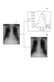
例えば、図3は、肺野の拡縮動作や横隔膜の上下動を動態画像としてとらえる際の撮影プロトコルの一例を模式的に示した説明図である。
図3に示す例では、自動の音声案内(図中「オートボイス」)によって息を吸うタイミング、息を止めるタイミング、息を吐くタイミングの誘導を行う。
そして、音声による呼吸タイミングの誘導に合わせてX線等の放射線をパルス照射することにより動態撮影を行う。
このようにすることで、被検者(被写体M)が大きく息を吸った後の息止めから息を吐いていく「呼気相」、息を吐き切った後の息止めから息を吸っていく「吸気相」という、呼吸における一サイクルを一撮影内に収めることができる。
For example, FIG. 3 is an explanatory diagram schematically showing an example of an imaging protocol when capturing the expansion/contraction movement of the lung field or the vertical movement of the diaphragm as a dynamic image.
In the example shown in FIG. 3, automatic voice guidance ("auto voice" in the figure) guides the user as to when to inhale, when to hold the breath, and when to exhale.
Then, dynamic imaging is performed by irradiating pulses of radiation such as X-rays in accordance with the guidance of breathing timing by voice.
By doing this, the subject (Subject M) takes a deep breath, holds the breath, and then exhales, during the exhalation phase, and after exhaling, holds the breath, and then inhales. One cycle of breathing, called the "inhalation phase," can be captured in one photograph.
操作部23により放射線照射指示が入力されると、放射線照射制御装置12及び読取制御装置14に撮影開始指示が出力され、動態撮影が開始される。即ち、放射線照射制御装置12に設定されたパルス間隔で放射線源11により放射線が照射され、放射線検出部13によりフレーム画像d1~dnが取得される。
When a radiation irradiation instruction is input through the
予め定められたフレーム数の撮影が終了すると、制御部21により放射線照射制御装置12及び読取制御装置14に撮影終了の指示が出力され、撮影動作が停止される。撮影されるフレーム数は特に限定されないが、例えば図3に示すような呼吸による部位の変化を撮影する場合であれば、少なくとも1呼吸サイクルが撮影できる枚数からなる動態画像Dを取得する。
When imaging for a predetermined number of frames is completed, the
次に、本実施形態における動態画像Dの解析方法について図3及び図4等を参照しつつ説明する。
撮影装置1により動態画像Dが撮影されると、動態画像Dを構成するフレーム画像d1~dnが順次撮影用コンソール2に入力され、撮影順を示す番号(フレーム番号)と対応付けられる。
そして、通信部35を介して撮影用コンソール2から動態画像Dの一連のフレーム画像d1~dnが診断用コンソール3において受信される。これによって動態画像D(第1の動態画像)が診断用コンソール3に取得され(ステップS1)、制御部31と記憶部32に記憶されているプログラムとの協働により図3及び図4に示す動態画像解析処理が実行される。
Next, a method for analyzing the dynamic image D in this embodiment will be explained with reference to FIGS. 3, 4, and the like.
When the dynamic image D is photographed by the photographing
Then, a series of frame images d1 to dn of the dynamic image D are received by the
具体的にはまず、取得した動態画像Dについて、制御部31がタグ設定部として、動態画像Dの類別に資する項目についてタグ付けを行う(ステップS2)。
ここで「類別に資する項目」は、記憶部32等に蓄積されていく動態画像Dを後日検索することを可能とするためのインデックスとしての機能を果たすものである。
タグ設定部としての制御部によって設定されるタグは、例えば撮影時のポジショニング(正面か側面か、右方向か左方向か等)、対象部位(例えば肘や膝等の整形部位や胸部、腹部等)の動作・組織変化の種類や方法(例えば呼吸による肺野の拡縮、横隔膜の上下動、腸の蠕動、心臓や血管の拍動、脈動、関節等の曲げ伸ばし、部位の左右動等)や実際の組織の内容、各種の検査条件(例えば撮影時間、撮影間隔(フレームレート)、照射角度、線量、管球位置等の各種撮影条件等、撮影機器の型番等の情報)のうち少なくともいずれかの項目について設定されることが好ましい。
この他、例えば患者情報(例えば患者氏名や患者ID、患者の性別、年齢等)、撮影日、撮影時刻等、DICOM形式で画像データのヘッダ領域に書き込まれる付帯情報についてもタグ付けされる。
Specifically, first, the
Here, the "item contributing to classification" functions as an index that allows the dynamic images D stored in the
The tags set by the control unit as the tag setting unit include, for example, the positioning at the time of shooting (front or side, right or left direction, etc.), the target area (for example, plastic surgery areas such as elbows and knees, chest, abdomen, etc.) ) and the types and methods of movement and tissue changes (e.g. expansion and contraction of the lung field due to breathing, vertical movement of the diaphragm, peristalsis of the intestines, pulsation and pulsation of the heart and blood vessels, bending and stretching of joints, left and right movement of parts, etc.) At least one of the following: actual tissue content, various examination conditions (for example, various imaging conditions such as imaging time, imaging interval (frame rate), irradiation angle, dose, tube position, etc., information such as model number of imaging equipment, etc.) It is preferable that the following items be set.
In addition, additional information written in the header area of the image data in DICOM format, such as patient information (for example, patient name, patient ID, patient's sex, age, etc.), photographing date, photographing time, etc., is also tagged.
なお、タグ設定部としての制御部31は、これら動態画像Dの「類別に資する項目」について、単一の項目についてタグ付けを行ってもよいし、複数の項目の組み合わせについてタグ付けを行ってもよい。
例えば、ある動態画像Dについて、胸部の画像であるとの単一のタグを付してもよいし、胸部の画像かつ肺野の拡縮を捉えた画像であるとの複数項目の組み合わせでタグを付してもよい。
タグが設定されると、制御部31は動態画像Dをタグと対応付けて記憶部32に記憶させる(ステップS3)。
Note that the
For example, a certain dynamic image D may be tagged with a single tag indicating that it is an image of a chest, or with a combination of multiple items such as an image of a chest and an image that captures expansion and contraction of the lung field. May be attached.
When the tag is set, the
そして、新たに動態画像D(第2の動態画像)が取得されると(ステップS4)、当該動態画像D(第2の動態画像)についても同様に、タグ設定部としての制御部31が各種の「類別に資する項目」についてタグ付けを行い(ステップS5)、動態画像Dをタグと対応付けて記憶部32に記憶させる(ステップS6)。
Then, when a new dynamic image D (second dynamic image) is acquired (step S4), the
そして制御部31は、一撮影で得られた動態画像D内の経時変化の表示を行うか否かを随時判断する(ステップS7)。なおこの判断は、新たな動態画像D(第2の動態画像)が取得されるごとに行ってもよいし、それ以外の所定のタイミングで行ってもよい。
一撮影内での経時変化の表示を行う場合(ステップS7;YES)には、動態画像Dを構成するフレーム画像d1~dn間の経時変化を表示部34に表示させる(ステップS8)。
Then, the
When displaying the change over time within one shooting (step S7; YES), the change over time between the frame images d1 to dn constituting the dynamic image D is displayed on the display unit 34 (step S8).
他方、一撮影内での経時変化の表示を行わない場合(ステップS7;NO)及び一撮影内での経時変化の表示を行う場合にはさらに、異なる時点で撮影された複数の動態画像D間における経時変化の表示を行うか否かを判断する(ステップS9)。
異なる時点で撮影された動態画像間での経時変化の表示を行う場合(ステップS9;YES)には、動態画像D間における経時変化の比較評価を行い、その結果等を表示部34に表示させる(ステップS10)。
On the other hand, if the change over time within one shooting is not displayed (step S7; NO) or when the change over time within one shot is to be displayed, furthermore, between multiple dynamic images D taken at different times. It is determined whether or not to display the change over time in (step S9).
When displaying changes over time between dynamic images taken at different times (step S9; YES), a comparative evaluation of changes over time between dynamic images D is performed, and the results are displayed on the
動態画像Dの一撮影内での経時変化の表示と、異なる時点で撮影された動態画像D間での経時変化の比較評価及びその結果の表示とを行う場合の手順について、図4等を参照しつつ説明する。
この場合、制御部31はデータ選定部として機能し、タグの情報に基づいて、記憶部32内の動態画像D(過去に撮影された第1の動態画像)のうちから、第2の動態画像Dと関連性があると判断されるものを関連動態画像として選定・抽出する(ステップS21)。
例えば、制御部31は、第2の動態画像Dと同じ被検者(被写体M)に対する胸部の動態画像で、正面を向いたポジショニングで撮影されたもの、といったタグで検索をかけることにより、既に取得されている第1の動態画像Dの中から関連動態画像を選定・抽出する。
なお、検索に用いるタグは医師等が自分の求めるデータに応じて入力してもよいし、第2の動態画像に付されているタグに基づいて、自動的に選定するようにしてもよい。
See Figure 4, etc. for the procedure for displaying changes over time in dynamic images D within one shooting, comparative evaluation of changes over time between dynamic images D taken at different times, and displaying the results. I will explain as I go along.
In this case, the
For example, the
Note that the tag used for the search may be input by a doctor or the like according to the data he/she desires, or may be automatically selected based on the tag attached to the second dynamic image.
なお、選定・抽出する範囲は関連性があると判断された動態画像D全てでもよいし、例えば直近2年以内に取得された画像等、範囲を限定してもよい。また本実施形態では、新たに取得された(すなわち最新の)動態画像Dを第2の動態画像とし、これに関連する動態画像Dを過去画像から選定する場合を例示するが、第2の動態画像Dは新たな動態画像に限定されず、例えばある手術の直後に撮影された動態画像Dがある場合に、これを第2の動態画像として、当該動態画像Dに関連する過去から直近までの(すなわち第2の動態画像の前後の)動態画像Dを関連動態画像として選定してもよい。 Note that the range to be selected and extracted may be all dynamic images D determined to be relevant, or may be limited to images acquired within the last two years, for example. In addition, in this embodiment, a case will be exemplified in which a newly acquired (i.e., the latest) dynamic image D is set as a second dynamic image, and a dynamic image D related to this is selected from past images. The image D is not limited to a new dynamic image. For example, if there is a dynamic image D taken immediately after a certain surgery, this can be used as a second dynamic image and images from the past to the most recent related to the dynamic image D can be used. The dynamic image D (that is, before and after the second dynamic image) may be selected as the related dynamic image.
そしてデータ選定部としての制御部31は、動態画像D(第2の動態画像及び第1の動態画像(関連動態画像))を構成する複数のフレーム画像d1~dn間の経時変化(一撮影内の経時変化)を解析し、比較評価可能なデータを得る(ステップS22)。
例えば図5(a)は、呼吸動作を行いながら動態撮影を行うことで一撮影内に呼吸によって生じる横隔膜の上下動(経時的な変化)の様子を取得した例を説明する図である。
図5(a)に示すように、動態画像Dを構成するフレーム画像d1~dn間における横隔膜の上下動を解析してグラフに表すと、図5(a)の右端の図に示すような、一撮影内の経時変化を比較評価可能なグラフとなる。
The
For example, FIG. 5(a) is a diagram illustrating an example in which dynamic imaging is performed while a person performs a breathing motion, thereby obtaining the vertical movement (change over time) of the diaphragm caused by breathing within one imaging.
As shown in FIG. 5(a), when the vertical movement of the diaphragm between the frame images d1 to dn constituting the dynamic image D is analyzed and expressed in a graph, as shown in the rightmost diagram of FIG. 5(a), This is a graph that allows you to compare and evaluate changes over time within one shooting.
動態画像Dからどのような比較評価可能なデータを解析・抽出できるかは、動態画像Dに適用されるアルゴリズムによって異なる。また本実施形態では、前述のように、撮影条件等を揃えて撮影を行うことにより、過去の画像に新たなアルゴリズムを適用することで、抽出可能な特徴量のデータをアップデートすることができるように構成されている。
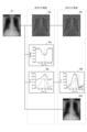
図6は、動態画像に適用されるアルゴリズムによって解析・抽出することのできる比較評価可能なデータの違いを示す説明図である。
図6に示す例は、2018年12月時点に適用されていたアルゴリズムでは、動態画像Dから強調画像Dh、画像信号値のデータ(信号値グラフGa)、左右の横隔膜の位置(高さ位置)を追跡したデータ(横隔膜追跡グラフGb)を解析・抽出可能であったことを示している。これに対して、2019年12月時点のアルゴリズムを動態画像Dに適用すると、強調画像Dh、左右の横隔膜の位置(高さ位置)を追跡したデータ(横隔膜追跡グラフGb)、肺野辺縁検出データDolを解析・抽出することができるようになっている。
What kind of comparatively evaluable data can be analyzed and extracted from the dynamic image D depends on the algorithm applied to the dynamic image D. Furthermore, in this embodiment, as described above, by taking pictures with the same shooting conditions, etc., it is possible to update the data of extractable features by applying a new algorithm to past images. It is composed of
FIG. 6 is an explanatory diagram showing differences in data that can be compared and evaluated and that can be analyzed and extracted by algorithms applied to dynamic images.
The example shown in FIG. 6 is based on the algorithm applied as of December 2018, from the dynamic image D to the emphasized image Dh, image signal value data (signal value graph Ga), and the positions of the left and right diaphragms (height positions). This shows that it was possible to analyze and extract the tracked data (diaphragm tracking graph Gb). On the other hand, when the algorithm as of December 2019 is applied to the dynamic image D, the highlighted image Dh, the data tracking the position (height position) of the left and right diaphragms (diaphragm tracking graph Gb), the lung field edge detection data It is now possible to analyze and extract Dol.
このため、2019年12月時点のアルゴリズムが適用されるようになる前に取得され、記憶されていた動態画像Dについても、画像取得時とは異なる2019年12月時点のアルゴリズムを適用することにより、例えば画像取得時には得られなかった肺野辺縁検出データDolを過去に取得された動態画像Dから抽出することが可能となる。
これにより、関連動態画像として選定した画像が古いアルゴリズムの下で解析されたものであって、新たな動態画像(第2の動態画像)と共通する比較評価可能なデータがない場合でも、新たな動態画像と同じアルゴリズムを関連動態画像に適用することで、共通する比較評価可能なデータを得ることが可能となる。
このように、本実施形態では、新たなアルゴリズムによってデータをアップデートすることにより、過去の動態画像Dのデータも有効に活用することができる。
Therefore, even for the dynamic image D that was acquired and stored before the algorithm as of December 2019 was applied, by applying the algorithm as of December 2019 that is different from the one at the time of image acquisition. For example, it becomes possible to extract lung field edge detection data Dol, which was not obtained at the time of image acquisition, from the dynamic image D acquired in the past.
As a result, even if the image selected as the related dynamic image was analyzed under the old algorithm and there is no data that can be compared and evaluated in common with the new dynamic image (second dynamic image), the new dynamic image By applying the same algorithm to related dynamic images as for dynamic images, it becomes possible to obtain data that can be commonly compared and evaluated.
In this manner, in this embodiment, data of past dynamic images D can also be effectively utilized by updating the data using a new algorithm.
各動態画像Dの一撮影内の経時変化を解析すると、特徴変化量算出部としての制御部31は、動態画像D(第2の動態画像及び第1の動態画像(関連動態画像))を構成する複数のフレーム画像d1~dnから動態画像D同士を比較評価することが可能な特徴量を抽出し、各動態画像Dをサマライズする(ステップS23)。
本実施形態では、動態画像D内の経時変化に関する各種のデータについて、データの収集、保存、表示等、あらゆる場面においてサマライズ(集約)することが可能となっている。
When analyzing the change over time within one shooting of each dynamic image D, the
In this embodiment, it is possible to summarize various data related to changes over time in the dynamic image D in all situations such as data collection, storage, and display.
例えば図7に示すように、ある動態画像Dから横隔膜追跡グラフGb及び肺野辺縁検出データDolを解析・抽出することができた場合、左右の横隔膜の最大移動量(最大の移動地点を図中破線丸印で示す)を抜き出すことで、複数のフレーム画像d1~dnからなる動態画像Dに関するデータを1つの値に集約することができる。
すなわち、複数のフレーム画像d1~dn間で経時的に変化しばらつきのある数値を、図8に示すように、右の横隔膜の最大移動量32mm、左の横隔膜の最大移動量49mmという単一の数値にまとめることができる。
同様に、肺野辺縁検出データDolについて、肺野辺縁の検出座標から最大/最小面積を抜き出すことで、複数のフレーム画像d1~dnからなる動態画像Dに関するデータを1つの値に集約することができる。また肺野の面積は経時変化するため、面積の最大/最小という変化をさらに定量化して観察するということもできる。
For example, as shown in FIG. 7, if it is possible to analyze and extract the diaphragm tracking graph Gb and the lung field edge detection data Dol from a certain dynamic image D, the maximum movement amount of the left and right diaphragms (the maximum movement point is (indicated by a broken line circle), it is possible to aggregate data regarding the dynamic image D consisting of a plurality of frame images d1 to dn into one value.
In other words, as shown in FIG. 8, numerical values that change over time and vary among multiple frame images d1 to dn are combined into a single value, ie, the maximum movement of the right diaphragm is 32 mm, and the maximum movement of the left diaphragm is 49 mm. It can be summarized in numbers.
Similarly, for the lung field edge detection data Dol, by extracting the maximum/minimum area from the detected coordinates of the lung field edge, data regarding the dynamic image D consisting of multiple frame images d1 to dn can be aggregated into one value. can. Furthermore, since the area of the lung field changes over time, changes in the maximum/minimum area can be further quantified and observed.
例えば図5(a)に示すような、一撮影内における横隔膜の上下動の経時変化からは、何に着目するかによって様々な特徴量を抽出することができる。
例えば、グラフの始点(左端)から終点(右端)までの振幅の平均値をとっていく手法もある。図5(b)に示す例では、横隔膜が最も高い位置に来た時の値(最高位hp)と横隔膜が最も低い位置に来た時の値(最低位lp)とを特徴量として抽出する。このように一撮影内における最高位hpと最低位lpとを抽出することで、複数のフレーム画像d1~dnからなる動態画像Dを他の動態画像Dと比較評価することが可能な1つの値に集約(サマライズ)する。
For example, as shown in FIG. 5A, various feature amounts can be extracted from the temporal change in the vertical movement of the diaphragm within one imaging session, depending on what is focused on.
For example, there is a method of taking the average value of the amplitude from the starting point (left end) to the ending point (right end) of the graph. In the example shown in FIG. 5(b), the value when the diaphragm is at the highest position (highest position hp) and the value when the diaphragm is at the lowest position (lowest position lp) are extracted as feature quantities. . By extracting the highest level hp and lowest level lp within one shooting in this way, one value can be obtained that allows a dynamic image D consisting of a plurality of frame images d1 to dn to be compared and evaluated with other dynamic images D. Summarize.
一撮影内の動態画像Dの経時変化をすべてデータとして抽出して、これをそのまま動態画像D同士の比較に用いると、比較対象が明確とならず、動態画像D同士を正しく比較評価することができない。
この点、各動態画像Dを着目すべきポイントを絞ってサマライズ(集約)することで、意味のある比較評価を行うことができるようになる。
すなわち、各動態画像D(第2の動態画像及び第1の動態画像(関連動態画像))が1つの値に集約(サマライズ)されることによって、特徴変化量算出部としての制御部31は、容易に各値の変化量を算出する(ステップS24)ことが可能となる。
特徴変化量算出部としての制御部31は、1以上のフレーム画像d1~dn間の時間方向における変化に基づいて各値の変化量を算出する。
なお、制御部31は、動態画像Dを構成する1以上のフレーム画像d1~dnから変化量を算出すればよく、必ずしも動態画像Dに含まれるデータがサマライズ(集約)されている場合に限定されない。
If all the changes over time of the dynamic images D within one shooting are extracted as data and used as is to compare the dynamic images D, the comparison target will not be clear and it will be difficult to compare and evaluate the dynamic images D correctly. Can not.
In this regard, by narrowing down and summarizing each dynamic image D by focusing on the points of interest, it becomes possible to perform a meaningful comparative evaluation.
That is, by summarizing each dynamic image D (the second dynamic image and the first dynamic image (related dynamic image)) into one value, the
The
Note that the
例えば図5(c)に示す例では、異なる時点(図5(c)では、右から左に向かって順に最新のデータ、1か月前、2か月前、3か月前、4か月前)に撮影された複数の動態画像D同士を1つのグラフ等の上に比較評価可能に表現している。
同様に、肺野辺縁検出データDolから、肺野辺縁の検出座標に基づき、図9に示すように、右の肺野の最大/最小面積、左の肺野の最大/最小面積、左右の肺野を合計した場合の最大/最小面積、右の肺野の面積変化率、左の肺野の面積変化率、左右の肺野の面積変化率を特徴量として得ることができる。
For example, in the example shown in Figure 5(c), data at different points in time (in Figure 5(c), from right to left, the latest data, 1 month ago, 2 months ago, 3 months ago, 4 months ago) The plurality of dynamic images D photographed in the above) are expressed on one graph or the like so that they can be compared and evaluated.
Similarly, from the lung field edge detection data Dol, based on the detected coordinates of the lung field edge, the maximum/minimum area of the right lung field, the maximum/minimum area of the left lung field, the left and right lung field The maximum/minimum area when the fields are summed, the area change rate of the right lung field, the area change rate of the left lung field, and the area change rate of the left and right lung fields can be obtained as feature quantities.
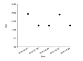
肺野辺縁検出データDolから抽出されるこれらの値の経時的な変化を動態画像D同士で比較評価することで、図10、図11のようなグラフを得ることができる。
このうち図10は、肺野面積の変化率の、動態画像D間での経時的な変化を示すグラフであり、グラフの左から右に行くにつれて新しいデータとなっている。図10では、2018年3月1日から2019年の7月26日までの約16か月の間の肺野面積の変化率の推移を見ることができる。
また、図11は、肺野面積の最大/最小値の、動態画像D間での経時的な変化を示すグラフであり、グラフの左から右に行くにつれて新しいデータとなっている。図11では、2018年3月1日から2019年の7月26日までの約16か月の間の肺野面積の最大/最小値の推移を見ることができる。
By comparing and evaluating changes over time in these values extracted from the lung field edge detection data Dol between the dynamic images D, graphs such as those shown in FIGS. 10 and 11 can be obtained.
Of these, FIG. 10 is a graph showing the change rate of the lung field area over time between the dynamic images D, and the data becomes newer from the left to the right of the graph. In FIG. 10, changes in the rate of change in lung field area can be seen over a period of about 16 months from March 1, 2018 to July 26, 2019.
Further, FIG. 11 is a graph showing changes over time in the maximum/minimum values of the lung field area between the dynamic images D, and the data becomes newer from the left to the right of the graph. In FIG. 11, it is possible to see changes in the maximum/minimum values of the lung field area for about 16 months from March 1, 2018 to July 26, 2019.
制御部31は表示制御部として、表示部34の表示を制御し、一撮影内の経時変化を表示部34に表示させる(ステップS25)。
具体的には、動態画像Dの一撮影を構成する各フレーム画像d1~dnや、図5(a)に示すグラフ、図6に示す強調画像Dh、信号値グラフGa、横隔膜追跡グラフGb、肺野辺縁検出データDol、数値を一覧とした図8、図9に示すような各種の表等、動態画像Dを解析することで得られる一撮影内の経時変化を示す各種データを表示部34に表示させる。
The
Specifically, each frame image d1 to dn constituting one shooting of the dynamic image D, the graph shown in FIG. 5(a), the emphasized image Dh shown in FIG. 6, the signal value graph Ga, the diaphragm tracking graph Gb, and the lung The
さらに制御部31は表示制御部として、表示部34の表示を制御し、撮影時点の異なる複数の動態画像D間(すなわち、第2の動態画像とデータ選定部としての制御部31によって選定された関連動態画像との間)における経時変化を表示部34に表示させる(ステップS26)。
具体的には、図5(c)に示すグラフ、図10、図11に示すグラフのように、各動態画像D(第2の動態画像及び第1の動態画像(関連動態画像))についてサマライズ(集約)された数値同士を比較評価可能な状態で表示部34に表示させる。また、第2の動態画像や関連動態画像の画像そのものを表示させてもよい。
Further, the
Specifically, each dynamic image D (second dynamic image and first dynamic image (related dynamic image)) is summarized as shown in the graph shown in FIG. 5(c), FIG. 10, and FIG. 11. The (aggregated) numerical values are displayed on the
また、表示部34に表示される解析結果は医学的な評価に用いられるものであるため、医師等が見たときに医学的な観点から違和感を覚えることのないような表示を行う必要がある。
この点、例えば横隔膜の周辺には一般的に左側に心臓という大きな部位が配置される。このために、常に右側が低く左側が高い、というように画像上の絶対値としては必ず左右差が生じてしまう。しかし、左右の横隔膜がどの程度上下動するか、という機能的な観点からは、図7に示す横隔膜追跡グラフGbのように、左右の最低値を揃えて、横隔膜が機能的にどこまで上昇するかを表現することが好ましい。
そこで本実施形態では、表示制御部としての制御部31は、対象部位の機能的な変化における基点を揃えて(すなわち、横隔膜の上下動を見る場合であれば左右の横隔膜の最低値をゼロ等に揃えて)特徴量の変化を表示部34に表示させるようになっている。
また例えば、図10、図11のようなグラフにおいて、ある時点をクリックすると、当該時点のデータと、過去のデータや最新のデータとを比較可能に表示させてもよい。
Furthermore, since the analysis results displayed on the
In this respect, for example, a large region called the heart is generally placed on the left side around the diaphragm. For this reason, there is always a difference between the left and right sides in terms of absolute values on the image, such that the right side is always lower and the left side is higher. However, from a functional point of view, how much the left and right diaphragms move up and down, as shown in the diaphragm tracking graph Gb shown in Figure 7, how far can the diaphragm functionally rise when the left and right minimum values are aligned? It is preferable to express
Therefore, in this embodiment, the
For example, in graphs such as those shown in FIGS. 10 and 11, by clicking on a certain point in time, the data at that point in time may be displayed in a manner that allows comparison with past data or the latest data.
このように、動態画像Dの一撮影内の経時変化と、撮影時点の異なる複数の動態画像D間における経時変化とを表示部34に表示させることで、診断に役立つ資料として医師等に提供することができる。
In this way, by displaying on the
以上説明したように、本実施形態における動態画像解析装置である診断用コンソール3によれば、動態画像Dにタグ付けを行うとともに、動態画像Dを構成する複数のフレーム画像d1~dnから特徴量を抽出し、この特徴量の時間方向における変化量を算出し、第1の動態画像Dと同じ対象部位を含む別撮影により得られた第2の動態画像Dが入力された場合に、タグから第2の動態画像Dと関連性があると判断される第1の動態画像Dである関連動態画像、及び第1の動態画像D、第2の動態画像Dから抽出可能な特徴量を選定する制御部31と、動態画像Dの一撮影を構成するフレーム画像d1~dn間における経時変化を表示可能であるとともに、第2の動態画像D及び第2の動態画像Dから抽出される特徴量と、選定された関連動態画像及び関連動態画像から抽出される特徴量との間の経時変化を表示可能である表示部34と、を備える。
これにより、一撮影内において経時変化を捉えることのできる動態画像Dを用いて、動態画像D間における経時変化を捉えることが可能となる。
このため、例えば呼吸の一サイクル等、一撮影で得られるごく短い時間内での対象部位の経時的変化(例えば横隔膜の移動変化、肺野面積の拡縮変化等)と、こうした一撮影における経時変化を定量化して、複数時点での撮影で得られた動態画像D同士を比較したときの経時変化との両方を診断のための情報として提供することができ、両者を組み合わせた診断を可能とする。
例えば、肺等の活動状況の比較を行うためには、術前術後や治療開始から現在までの経過等、比較的長いスパンでの比較検討、状況把握が必要であるとともに、いつの時点ではどのような動き方をしていたのか、といったある時点での動作状況を適切に把握することも重要である。本実施形態における動態画像解析装置によれば、こうした両者を組み合わせた視点で患者の経過観察を行うことが可能となり、優れた臨床価値を実現する。
As explained above, according to the
This makes it possible to capture changes over time between dynamic images D using dynamic images D that can capture changes over time within one shooting.
For this reason, for example, changes over time in the target area within a very short period of time obtained in one imaging, such as one cycle of breathing (for example, changes in movement of the diaphragm, changes in expansion and contraction of the lung field area, etc.), and changes over time in such one imaging can be quantified and provided as information for diagnosis, both of which are changes over time when dynamic images D obtained by imaging at multiple points are compared, and diagnosis that combines the two is possible. .
For example, in order to compare the activity status of the lungs, etc., it is necessary to compare and understand the situation over a relatively long period, such as before and after surgery, and from the start of treatment to the present. It is also important to properly understand the state of movement at a certain point in time, such as whether the person was moving in a certain way. According to the dynamic image analysis device of this embodiment, it becomes possible to perform follow-up observation of a patient from a viewpoint that combines both of these aspects, and achieves excellent clinical value.
また本実施形態では、タグ設定部としての制御部31が、撮影時のポジショニング、対象部位の動作・組織変化の種類、方法、撮影時の撮影条件のうち少なくともいずれかの項目について動態画像Dにタグ付けを行う。
このため、多角的な視点で画像を分類することができ、適切な関連動態画像を選定することが可能となる。
Further, in this embodiment, the
Therefore, images can be classified from multiple viewpoints, and appropriate related dynamic images can be selected.
また本実施形態では、タグ設定部としての制御部31が、動態画像Dの類別に資する項目について、単一で又は複数の項目の組み合わせでタグ付けを行う。
このように、単一のタグのみならず複数のタグを組み合わせるため、より適切な関連動態画像を選定することが可能となる。
Further, in this embodiment, the
In this way, since not only a single tag but also a plurality of tags are combined, it becomes possible to select a more appropriate related dynamic image.
また本実施形態では、特徴変化量算出部としての制御部31が、1以上のフレーム画像d1~dnから変化量を算出する。
このため、適切に定量化された動態画像Dから変化量を算出することができる。
Further, in this embodiment, the
Therefore, the amount of change can be calculated from the appropriately quantified dynamic image D.
また本実施形態では、特徴変化量算出部としての制御部31が、1以上のフレーム画像間の時間方向における変化に基づいて変化量を算出する。
これにより、動態画像D内における経時的変化を適切に捉えることができる。
Further, in this embodiment, the
Thereby, changes over time within the dynamic image D can be appropriately captured.
また本実施形態では、特徴変化量算出部としての制御部31が、過去に取得された動態画像Dについて画像取得時とは異なるアルゴリズムを適用した上で特徴量を抽出し、この特徴量の時間方向における変化量を算出することが可能となっている。
これにより、新たに発見され適用されるアルゴリズムがあり、当該アルゴリズムを用いれば過去の画像取得時には抽出できなかった新たなデータ等がある場合に、当該アルゴリズムを過去に取得された動態画像Dに適用することでデータをアップデートすることができる。
これにより、過去に取得された動態画像Dについても有効に利用することができる。
Further, in this embodiment, the
As a result, if there is an algorithm that is newly discovered and applied, and if there is new data that could not be extracted when the image was acquired in the past, the algorithm is applied to the dynamic image D that was acquired in the past. You can update the data by doing this.
Thereby, dynamic images D acquired in the past can also be effectively used.
また本実施形態では、表示制御部としての制御部31が、動態画像Dの一撮影を構成するフレーム画像d1~dn間における経時変化を表示部34に表示させるとともに、第2の動態画像及び第2の動態画像から抽出される特徴量と、データ選定部によって選定された関連動態画像及び関連動態画像から抽出される特徴量との間の経時変化を比較評価可能な状態で表示部34表示させる。
これにより、一撮影で得られるごく短い時間内での対象部位の経時的変化と、複数時点での撮影で得られた動態画像D同士を比較したときの経時変化との両方を、診断を支援する情報として提供することができる。
Further, in the present embodiment, the
This helps diagnose both the changes over time in the target area within a very short period of time obtained in one imaging, and the changes over time when comparing dynamic images D obtained by imaging at multiple points in time. This information can be provided as information.
また本実施形態では、表示制御部としての制御部31が、対象部位の機能的な変化における基点を揃えて特徴量の変化を表示部34表示させる。
このため、絶対値で見たときには医学的な見地から必ず差異が生じるような場合に、違和感なく分かりやすい表示を行うことができる。
Further, in the present embodiment, the
Therefore, even if a difference inevitably occurs from a medical standpoint when viewed in terms of absolute values, it is possible to provide a display that is easy to understand and does not feel strange.
なお、以上本発明の実施形態について説明したが、本発明は、かかる実施形態に限定されず、その要旨を逸脱しない範囲で、種々変形が可能であることは言うまでもない。 Although the embodiments of the present invention have been described above, it goes without saying that the present invention is not limited to these embodiments and can be modified in various ways without departing from the spirit thereof.
例えば、本実施形態では、医用画像システム100内の診断用のコンソール3が動態画像解析装置として機能する場合を例示したが、動態画像解析装置はこれに限定されない。例えば医用画像システム100外に、独立した動態画像解析ワークステーションが設けられ、各種ネットワーク等を介して医用画像システム100から動態画像Dを取得する構成としてもよい。
For example, in this embodiment, a case has been exemplified in which the
また例えば、動態画像解析装置において解析処理が行われる動態画像Dは、医用画像システム100内で取得されたものではなく、各種ネットワークを介して外部の装置から提供されたものであってもよい。
このように構成することで、1人の患者が複数の医療機関を受診しているような場合に、過去に受診した別の医療機関で撮影された動態画像Dも有効に活用することが可能となる。
なお、この場合、経時的変化を適切に比較することができるように、同一の撮影プロトコル等、共通のルールに則って撮影時の条件の同一性が確保された撮影された動態画像Dであることが好ましい。
Further, for example, the dynamic image D to be analyzed by the dynamic image analysis device may not be acquired within the
With this configuration, when one patient has been examined at multiple medical institutions, it is possible to effectively utilize dynamic images D taken at other medical institutions visited in the past. becomes.
In this case, the dynamic images D are taken in such a way that the same imaging conditions are ensured according to common rules, such as the same imaging protocol, so that changes over time can be appropriately compared. It is preferable.
また例えば、表示部34において経時変化をグラフ等で表示する場合に、正常値を示しているデータと異常値となっているデータとで色を変える等により、変化の状況、傾向等を区別して表示させてもよい。
これにより、症状が改善傾向であるか否か等を視覚的に分かりやすく伝えることができる。
For example, when displaying changes over time in a graph or the like on the
Thereby, it is possible to visually and clearly convey whether the symptoms are improving or not.
その他、動態画像解析装置(本実施形態では診断用コンソール3)を構成する各部の細部構成及び細部動作に関しても、本発明の趣旨を逸脱することのない範囲で適宜変更可能である。
In addition, the detailed configuration and detailed operation of each part constituting the dynamic image analysis device (
100 医用画像システム
1 撮影装置
11 放射線源
12 放射線照射制御装置
13 放射線検出部
14 読取制御装置
2 撮影用コンソール
21 制御部
22 記憶部
23 操作部
24 表示部
25 通信部
26 バス
3 診断用コンソール
31 制御部
32 記憶部
33 操作部
34 表示部
35 通信部
36 バス
100
Claims (10)
前記動態画像を構成する1以上のフレーム画像から特徴量を抽出し、この特徴量の時間方向における変化量を算出する特徴変化量算出部と、
第1の前記動態画像と同じ前記対象部位を含む別撮影により得られた第2の前記動態画像が入力された場合に、前記タグ設定部により設定されたタグから前記第2の動態画像と関連性があると判断される前記第1の動態画像である関連動態画像、及び前記第1の動態画像、前記第2の動態画像から抽出可能な特徴量を選定するデータ選定部と、
前記動態画像の前記一撮影を構成する前記フレーム画像間における経時変化を表示可能であるとともに、前記第2の動態画像及び前記第2の動態画像から抽出される特徴量と、前記データ選定部によって選定された前記関連動態画像及び前記関連動態画像から抽出される特徴量との間の経時変化を表示可能である表示部と、
前記表示部の表示を制御する表示制御部と、
を備え、
前記タグ設定部は、撮影時のポジショニング、撮影時の撮影条件のうち少なくともいずれかの項目について前記動態画像にタグ付けを行うものであることを特徴とする動態画像解析装置。 a tag setting unit that tags an item contributing to the classification of the dynamic image with respect to a dynamic image obtained by radiographing a subject including a target part in a living body and in which data of one scan is composed of a plurality of frame images;
a feature change amount calculation unit that extracts a feature amount from one or more frame images constituting the dynamic image and calculates the amount of change in the feature amount in the time direction;
When the second dynamic image obtained by separate imaging that includes the same target region as the first dynamic image is input, it is associated with the second dynamic image from the tag set by the tag setting section. a data selection unit that selects a related dynamic image that is the first dynamic image that is determined to have a certain characteristic, and a feature amount that can be extracted from the first dynamic image and the second dynamic image;
The change over time between the frame images constituting the one shooting of the dynamic image can be displayed, and the second dynamic image and the feature amount extracted from the second dynamic image and the data selection unit can display a display unit capable of displaying a change over time between the selected related dynamic image and the feature amount extracted from the related dynamic image;
a display control unit that controls display on the display unit;
Equipped with
The dynamic image analysis device is characterized in that the tag setting unit tags the dynamic image with respect to at least one of positioning at the time of photographing and photographing conditions at the time of photographing .
前記動態画像を構成する1以上のフレーム画像から特徴量を抽出し、この特徴量の時間方向における変化量を算出する特徴変化量算出工程と、
第1の前記動態画像と同じ前記対象部位を含む別撮影により得られた第2の前記動態画像が入力された場合に、前記タグ設定工程において設定されたタグから前記第2の動態画像と関連性があると判断される前記第1の動態画像である関連動態画像、及び前記第1の動態画像、前記第2の動態画像から抽出可能な特徴量を選定するデータ選定工程と、
表示部に、前記動態画像の前記一撮影を構成する前記フレーム画像間における経時変化を表示させるとともに、前記第2の動態画像及び前記第2の動態画像から抽出される特徴量と、前記データ選定工程において選定された前記関連動態画像及び前記関連動態画像から抽出される特徴量との間の経時変化を表示させる表示工程と、
を含み、
前記タグ設定工程では、撮影時のポジショニング、撮影時の撮影条件のうち少なくともいずれかの項目について前記動態画像にタグ付けが行われることを特徴とする動態画像解析方法。 a tag setting step of tagging an item contributing to the classification of the dynamic image with respect to a dynamic image obtained by radiographing a subject including a target part in a living body and in which data of one scan is composed of a plurality of frame images;
a feature change amount calculation step of extracting a feature amount from one or more frame images constituting the dynamic image and calculating the amount of change in the feature amount in the time direction;
When a second dynamic image obtained by separate imaging that includes the same target region as the first dynamic image is input, it is associated with the second dynamic image from the tag set in the tag setting step. a data selection step of selecting a related dynamic image that is the first dynamic image that is determined to have a certain characteristic, and a feature amount that can be extracted from the first dynamic image and the second dynamic image;
Displaying on a display unit a change over time between the frame images constituting the one shooting of the dynamic image, and the second dynamic image and the feature amount extracted from the second dynamic image, and the data selection. a display step of displaying a change over time between the related dynamic image selected in the step and the feature amount extracted from the related dynamic image;
including;
The dynamic image analysis method is characterized in that, in the tag setting step, the dynamic image is tagged with respect to at least one of positioning at the time of photographing and photographing conditions at the time of photographing .
生体における対象部位を含む被写体を放射線撮影することにより得られ一撮影のデータが複数のフレーム画像で構成される動態画像について、前記動態画像の類別に資する項目についてタグ付けを行うタグ設定機能と、
前記動態画像を構成する1以上のフレーム画像から特徴量を抽出し、この特徴量の時間方向における変化量を算出する特徴変化量算出機能と、
第1の前記動態画像と同じ前記対象部位を含む別撮影により得られた第2の前記動態画像が入力された場合に、前記タグ設定機能により設定されたタグから前記第2の動態画像と関連性があると判断される前記第1の動態画像である関連動態画像、及び前記第1の動態画像、前記第2の動態画像から抽出可能な特徴量を選定するデータ選定機能と、
表示部に、前記動態画像の前記一撮影を構成する前記フレーム画像間における経時変化を表示させるとともに、前記第2の動態画像及び前記第2の動態画像から抽出される特徴量と、前記データ選定機能によって選定された前記関連動態画像及び前記関連動態画像から抽出される特徴量との間の経時変化を表示させる表示機能と、
を実現させ、
前記タグ設定機能は、撮影時のポジショニング、撮影時の撮影条件のうち少なくともいずれかの項目について前記動態画像にタグ付けを行うものであることを特徴とするプログラム。 to the computer,
a tag setting function for tagging an item contributing to the classification of the dynamic image with respect to a dynamic image obtained by radiographing a subject including a target part in a living body and in which data of one scan is composed of a plurality of frame images;
a feature change amount calculation function that extracts a feature amount from one or more frame images constituting the dynamic image and calculates the amount of change in the feature amount in the time direction;
When a second dynamic image obtained by separate imaging that includes the same target region as the first dynamic image is input, it is associated with the second dynamic image from the tag set by the tag setting function. a data selection function that selects a related dynamic image that is the first dynamic image that is determined to have a certain characteristic, and a feature amount that can be extracted from the first dynamic image and the second dynamic image;
Displaying on a display unit a change over time between the frame images constituting the one shooting of the dynamic image, and the second dynamic image and the feature amount extracted from the second dynamic image, and the data selection. a display function that displays a change over time between the related dynamic image selected by the function and the feature amount extracted from the related dynamic image;
Realize ,
The program is characterized in that the tag setting function tags the dynamic image with respect to at least one of positioning at the time of photographing and photographing conditions at the time of photographing .
Priority Applications (2)
| Application Number | Priority Date | Filing Date | Title |
|---|---|---|---|
| JP2020085930A JP7435242B2 (en) | 2020-05-15 | 2020-05-15 | Dynamic image analysis device, dynamic image analysis method and program |
| US17/232,327 US11810295B2 (en) | 2020-05-15 | 2021-04-16 | Dynamic image analysis apparatus, dynamic image analysis method, and storage medium |
Applications Claiming Priority (1)
| Application Number | Priority Date | Filing Date | Title |
|---|---|---|---|
| JP2020085930A JP7435242B2 (en) | 2020-05-15 | 2020-05-15 | Dynamic image analysis device, dynamic image analysis method and program |
Publications (2)
| Publication Number | Publication Date |
|---|---|
| JP2021178111A JP2021178111A (en) | 2021-11-18 |
| JP7435242B2 true JP7435242B2 (en) | 2024-02-21 |
Family
ID=78509731
Family Applications (1)
| Application Number | Title | Priority Date | Filing Date |
|---|---|---|---|
| JP2020085930A Active JP7435242B2 (en) | 2020-05-15 | 2020-05-15 | Dynamic image analysis device, dynamic image analysis method and program |
Country Status (2)
| Country | Link |
|---|---|
| US (1) | US11810295B2 (en) |
| JP (1) | JP7435242B2 (en) |
Citations (7)
| Publication number | Priority date | Publication date | Assignee | Title |
|---|---|---|---|---|
| JP2008052544A (en) | 2006-08-25 | 2008-03-06 | Konica Minolta Medical & Graphic Inc | Database system, program, image retrieval method, and report retrieval method |
| JP2013081579A (en) | 2011-10-07 | 2013-05-09 | Konica Minolta Medical & Graphic Inc | Dynamic medical image forming system |
| JP2018078974A (en) | 2016-11-15 | 2018-05-24 | コニカミノルタ株式会社 | Dynamic image processing system |
| JP2018148964A (en) | 2017-03-10 | 2018-09-27 | コニカミノルタ株式会社 | Dynamic analysis system |
| US20180330501A1 (en) | 2017-05-10 | 2018-11-15 | Konica Minolta, Inc. | Image processing apparatus and computer-readable recording medium |
| JP2019030608A (en) | 2017-08-10 | 2019-02-28 | コニカミノルタ株式会社 | Dynamic image analysis apparatus |
| WO2019082635A1 (en) | 2017-10-27 | 2019-05-02 | パラマウントベッド株式会社 | Moving image recording system |
Family Cites Families (5)
| Publication number | Priority date | Publication date | Assignee | Title |
|---|---|---|---|---|
| JP5520078B2 (en) | 2010-02-19 | 2014-06-11 | 日立アロカメディカル株式会社 | Bone density image providing device |
| CN105246406A (en) * | 2013-05-31 | 2016-01-13 | 柯尼卡美能达株式会社 | Image processing device and program |
| WO2015039051A1 (en) * | 2013-09-13 | 2015-03-19 | CAPTUREPROOF, Inc. | Imaging uniformity system |
| AU2019205878A1 (en) * | 2018-01-05 | 2020-08-06 | Mediott Co., Ltd. | Diagnostic support program |
| JP6897656B2 (en) | 2018-11-22 | 2021-07-07 | コニカミノルタ株式会社 | Image display control system, image display system, image analyzer, image display control program and image display control method |
-
2020
- 2020-05-15 JP JP2020085930A patent/JP7435242B2/en active Active
-
2021
- 2021-04-16 US US17/232,327 patent/US11810295B2/en active Active
Patent Citations (7)
| Publication number | Priority date | Publication date | Assignee | Title |
|---|---|---|---|---|
| JP2008052544A (en) | 2006-08-25 | 2008-03-06 | Konica Minolta Medical & Graphic Inc | Database system, program, image retrieval method, and report retrieval method |
| JP2013081579A (en) | 2011-10-07 | 2013-05-09 | Konica Minolta Medical & Graphic Inc | Dynamic medical image forming system |
| JP2018078974A (en) | 2016-11-15 | 2018-05-24 | コニカミノルタ株式会社 | Dynamic image processing system |
| JP2018148964A (en) | 2017-03-10 | 2018-09-27 | コニカミノルタ株式会社 | Dynamic analysis system |
| US20180330501A1 (en) | 2017-05-10 | 2018-11-15 | Konica Minolta, Inc. | Image processing apparatus and computer-readable recording medium |
| JP2019030608A (en) | 2017-08-10 | 2019-02-28 | コニカミノルタ株式会社 | Dynamic image analysis apparatus |
| WO2019082635A1 (en) | 2017-10-27 | 2019-05-02 | パラマウントベッド株式会社 | Moving image recording system |
Also Published As
| Publication number | Publication date |
|---|---|
| JP2021178111A (en) | 2021-11-18 |
| US20210358118A1 (en) | 2021-11-18 |
| US11810295B2 (en) | 2023-11-07 |
Similar Documents
| Publication | Publication Date | Title |
|---|---|---|
| JP6436182B2 (en) | Dynamic image analyzer | |
| JP5408399B1 (en) | Image generation device | |
| JP6597548B2 (en) | Dynamic analysis system | |
| JP6743662B2 (en) | Dynamic image processing system | |
| JP6418091B2 (en) | Chest image display system and image processing apparatus | |
| JP2017176202A (en) | Dynamics analysis system | |
| JP2020014562A (en) | Dynamic image analysis apparatus, dynamic image analysis method, and program | |
| JP7047574B2 (en) | Dynamic image analysis device, dynamic image analysis system, dynamic image analysis program and dynamic image analysis method | |
| JP7073661B2 (en) | Dynamic analysis device and dynamic analysis system | |
| JP6848261B2 (en) | Radiation image processing equipment and programs | |
| JP2023133736A (en) | Image processing device, image processing system, and program | |
| JP2021194140A (en) | Image processing device and image processing method | |
| US20190298290A1 (en) | Imaging support apparatus and radiographic imaging system | |
| JP7255725B2 (en) | Dynamic image analysis system and dynamic image analysis program | |
| JP7435242B2 (en) | Dynamic image analysis device, dynamic image analysis method and program | |
| JP2016209267A (en) | Medical image processor and program | |
| JP2009148336A (en) | Dynamic image diagnosis supporting system | |
| JP2013013737A (en) | Radiographic imaging system | |
| JP7143747B2 (en) | Image display device, image display method and image display program | |
| JP2020195589A (en) | Image processing apparatus, image processing method, and program | |
| JP6888721B2 (en) | Dynamic image processing device, dynamic image processing program and dynamic image processing method | |
| JP6874484B2 (en) | Dynamic image processing system | |
| JP2023027550A (en) | Control program and case retrieval device | |
| JP2020168172A (en) | Dynamic analysis apparatus, dynamic analysis system, and program | |
| JP2021186410A (en) | Program, image processing device, and image processing method |
Legal Events
| Date | Code | Title | Description |
|---|---|---|---|
| A621 | Written request for application examination |
Free format text: JAPANESE INTERMEDIATE CODE: A621 Effective date: 20221223 |
|
| A977 | Report on retrieval |
Free format text: JAPANESE INTERMEDIATE CODE: A971007 Effective date: 20230810 |
|
| A131 | Notification of reasons for refusal |
Free format text: JAPANESE INTERMEDIATE CODE: A131 Effective date: 20230822 |
|
| A601 | Written request for extension of time |
Free format text: JAPANESE INTERMEDIATE CODE: A601 Effective date: 20231019 |
|
| A521 | Request for written amendment filed |
Free format text: JAPANESE INTERMEDIATE CODE: A523 Effective date: 20231212 |
|
| TRDD | Decision of grant or rejection written | ||
| A01 | Written decision to grant a patent or to grant a registration (utility model) |
Free format text: JAPANESE INTERMEDIATE CODE: A01 Effective date: 20240109 |
|
| A61 | First payment of annual fees (during grant procedure) |
Free format text: JAPANESE INTERMEDIATE CODE: A61 Effective date: 20240122 |
|
| R150 | Certificate of patent or registration of utility model |
Ref document number: 7435242 Country of ref document: JP Free format text: JAPANESE INTERMEDIATE CODE: R150 |