JP7430552B2 - Spray gun support device for painting equipment - Google Patents
Spray gun support device for painting equipment Download PDFInfo
- Publication number
- JP7430552B2 JP7430552B2 JP2020047352A JP2020047352A JP7430552B2 JP 7430552 B2 JP7430552 B2 JP 7430552B2 JP 2020047352 A JP2020047352 A JP 2020047352A JP 2020047352 A JP2020047352 A JP 2020047352A JP 7430552 B2 JP7430552 B2 JP 7430552B2
- Authority
- JP
- Japan
- Prior art keywords
- spray gun
- air supply
- arm
- support device
- supply path
- Prior art date
- Legal status (The legal status is an assumption and is not a legal conclusion. Google has not performed a legal analysis and makes no representation as to the accuracy of the status listed.)
- Active
Links
- 239000007921 spray Substances 0.000 title claims description 213
- 238000010422 painting Methods 0.000 title claims description 23
- 239000003973 paint Substances 0.000 claims description 82
- 239000011248 coating agent Substances 0.000 claims description 23
- 238000000576 coating method Methods 0.000 claims description 23
- 238000000034 method Methods 0.000 description 8
- 239000003086 colorant Substances 0.000 description 6
- 238000004140 cleaning Methods 0.000 description 5
- 238000000889 atomisation Methods 0.000 description 4
- 238000010586 diagram Methods 0.000 description 3
- 239000003595 mist Substances 0.000 description 2
- 239000002904 solvent Substances 0.000 description 2
- 238000005507 spraying Methods 0.000 description 2
- 239000002699 waste material Substances 0.000 description 2
- 238000007796 conventional method Methods 0.000 description 1
- 238000003780 insertion Methods 0.000 description 1
- 230000037431 insertion Effects 0.000 description 1
- 238000004519 manufacturing process Methods 0.000 description 1
- 239000000203 mixture Substances 0.000 description 1
Images


Landscapes
- Details Or Accessories Of Spraying Plant Or Apparatus (AREA)
- Spray Control Apparatus (AREA)
Description
本発明は塗装装置用スプレーガン支持装置に係り、より詳しくは、複数のスプレーガンを支持するとともに、使用するスプレーガンを切り替えることでカラーチェンジを可能にした塗装装置において、スプレーガンにエアーを供給するエアー供給ホースの本数を減らすことで装置全体の小型化を図ることを特徴とした塗装装置用スプレーガン支持装置に関する。 The present invention relates to a spray gun support device for a painting device, and more specifically, the present invention relates to a spray gun support device for a painting device, and more specifically, in a painting device that supports a plurality of spray guns and makes it possible to change colors by switching the spray guns used, the present invention supplies air to the spray guns. The present invention relates to a spray gun support device for a coating device, which is characterized by reducing the size of the entire device by reducing the number of air supply hoses.
従来から塗装装置は、被塗装物(以下「ワーク」という。)に向けて塗料を噴射するためのスプレーガンと、塗料ホースを介してスプレーガンに塗料を供給するための塗料供給手段を有しており、塗料供給手段からスプレーガンに塗料を供給しながら、この供給された塗料をスプレーガンよりワークに向けて噴射している。そして、ワークの塗装において塗料の色を替える場合には、スプレーガンを替えることなく、1個のスプレーガンのみで、供給する塗料のカラーチェンジを行いながらスプレーガンに塗料を供給する方法が採用されていた。 Conventionally, painting equipment includes a spray gun for spraying paint onto an object to be painted (hereinafter referred to as a "work") and a paint supply means for supplying paint to the spray gun via a paint hose. The paint is supplied from the paint supply means to the spray gun, and the supplied paint is sprayed from the spray gun toward the workpiece. When changing the color of paint when painting a workpiece, a method is adopted in which paint is supplied to the spray gun while changing the color of the supplied paint using only one spray gun, without changing the spray gun. was.
ここで、従来のカラーチェンジの方法ついて説明すると、従来のカラーチェンジの方法では、互いに色の異なる複数種類の塗料を、マニホールド等を介して1個のスプレーガンに供給可能とし、使用する色に応じてスプレーガンに供給する塗料を切り替える方法としている。即ち、一つの塗料による塗装が完了した後に、スプレーガン及び塗料供給ホース内を洗浄した後に、バルブ等によって他の塗料をスプレーガンに供給可能な状態にして、カラーチェンジを可能にしていた。従ってこの方法によれば、1個のスプレーガンによって、複数の塗料による塗装を行うことが可能となる。 Here, to explain the conventional color change method, in the conventional color change method, multiple types of paint with different colors can be supplied to one spray gun via a manifold etc. The method is to switch the paint supplied to the spray gun depending on the situation. That is, after painting with one paint is completed, the interior of the spray gun and paint supply hose is cleaned, and then another paint can be supplied to the spray gun using a valve or the like, thereby making it possible to change the color. Therefore, according to this method, it is possible to perform coating with a plurality of paints using one spray gun.
しかしながら、このような方法を採用した場合には、塗料の色替えを行うたびごとに、スプレーガン、及び塗料ホースを洗浄しなければならず、煩わしさに耐えず、また、作業効率の低下を招いてしまっていた。 However, if such a method is adopted, the spray gun and paint hose must be cleaned every time the paint color is changed, which is a hassle and reduces work efficiency. I had already invited her.
更に、塗料の色替えのたびごとにスプレーガン及び塗料ホースを洗浄する場合には、ホース内に残っている塗料が無駄になってしまうとともにシンナー等の洗浄溶剤が必要であり、無駄が多かった。特に、近年は多品種少量生産のワークが増加しているために、従来の方法では、このような洗浄作業による作業効率の低下、残塗料の無駄や洗浄溶剤の使用は、コストの増加にもつながっていた。 Furthermore, when cleaning the spray gun and paint hose every time the paint color is changed, the paint remaining in the hose is wasted, and cleaning solvents such as thinner are required, resulting in a lot of waste. . In particular, in recent years there has been an increase in the number of high-mix, low-volume production workpieces, so with conventional methods, such cleaning work reduces work efficiency, wastes leftover paint, and uses cleaning solvents, which also increases costs. We were connected.
この点、カラーチェンジの際に、スプレーガンを塗装機から取り外して交換する交換する方法も考えられるが、この方法では、スプレーガンの着脱作業が大変であり作業効率が悪いという問題点が考えられる。 Regarding this point, when changing the color, it is possible to remove the spray gun from the paint sprayer and replace it, but this method has the problem that it is difficult to attach and detach the spray gun and the work efficiency is low. .
そのため、このような問題点を解決する方法として、それぞれにスプレーガンを備えた複数のスプレーガン支持アームをマニホールドに連結して、マニホールドを回転することによって、使用するスプレーガンを切り替え、それによりカラーチェンジを可能にしたスプレーガン支持装置が提案されており、このスプレーガン支持装置によれば、スプレーガンを交換することなく、また、スプレーガン内を洗浄すること無く、カラーチェンジが可能である。 Therefore, as a way to solve this problem, multiple spray gun support arms each equipped with a spray gun are connected to a manifold, and by rotating the manifold, the spray gun to be used can be switched. A changeable spray gun support device has been proposed, and with this spray gun support device, the color can be changed without replacing the spray gun or cleaning the inside of the spray gun.
ところで、スプレーガンは一般的に、先端の吐出口より塗料を吐出するとともに、この塗料を霧化エアーにより霧状にして噴射することでワークの塗装を行うことが行われる。また、このとき、霧化した塗料をパターンエアーによって所定のパターンにして噴射することが行われる。更に、塗料を吐出する吐出口は通常はニードルによって閉鎖されており、塗装を行うときにニードルを後方に退避させて吐出口を解放し、塗装が完了した後にニードルを前進させて吐出口を閉鎖するが、このニードルの進退はニードル稼働用エアーによって行う。 Incidentally, a spray gun generally sprays paint from a discharge port at its tip, and sprays the paint in the form of a mist using atomizing air to paint a workpiece. Also, at this time, the atomized paint is sprayed in a predetermined pattern using pattern air. Furthermore, the discharge port that discharges paint is normally closed by a needle, and when painting, the needle is moved backward to release the discharge port, and after painting is completed, the needle is advanced to close the discharge port. However, this movement of the needle is performed by air for operating the needle.
従って、一つのスプレーガンを稼働するためには、塗料ホース1本のほかに、霧化エアー供給用ホース、パターンエアー供給用ホース及びニードル稼働用エアー供給ホースの3本のエアーホースをスプレーガンに連結する必要がある。 Therefore, in order to operate one spray gun, in addition to one paint hose, three air hoses must be connected to the spray gun: an atomization air supply hose, a pattern air supply hose, and a needle operation air supply hose. Need to be connected.
そして、前述のような、複数のスプレーガン支持アームをマニホールドに連結し、それぞれのスプレーガン支持アームにスプレーガンを備えたスプレーガン支持装置では、スプレーガンの数に対応した塗料ホース及びエアーホースをマニホールドに連結する必要がある。 In the above-mentioned spray gun support device in which a plurality of spray gun support arms are connected to a manifold and each spray gun support arm is equipped with a spray gun, paint hoses and air hoses corresponding to the number of spray guns are connected. Must be connected to the manifold.
そのために、このようなスプレーガン支持装置では、スプレーガンの数が増えていくと、マニホールドに連結する塗料ホース及びエアーホースの数が多くなってしまい、装置の大型化を招いてしまうという問題点が考えられる。例えば、マニホールドに4本の支持アームを連結した場合には、塗料ホース4本の他に、霧化エアー供給用ホース、パターンエアー供給用ホース及びニードル稼働用エアー供給ホースの3本のエアーホースを4本ずつで合計12本のエアーホースをマニホールドに連結しなければならず、塗装装置全体が大型してしまう。 Therefore, with such a spray gun support device, as the number of spray guns increases, the number of paint hoses and air hoses connected to the manifold increases, leading to an increase in the size of the device. is possible. For example, when four support arms are connected to a manifold, in addition to the four paint hoses, three air hoses are required: an atomization air supply hose, a pattern air supply hose, and a needle operation air supply hose. A total of 12 air hoses, 4 each, must be connected to the manifold, which increases the size of the entire painting apparatus.
また、このようなスプレーガン支持装置では、前述したように、使用するスプレーガンを切り替える際にはマニホールドを回転する必要があり、それによりホースがねじれるが、マニホールドに連結する塗料ホース及びエアーホースの数が多くなると、多数のホースがねじれるために取り扱いが大変であるとともに、マニホールドにホースを連結するための継ぎ手が壊れてしまうことも考えられる。 In addition, with such a spray gun support device, as mentioned above, it is necessary to rotate the manifold when switching the spray gun to be used, which causes the hoses to twist, but the paint hose and air hose connected to the manifold are When the number of hoses increases, it becomes difficult to handle the hoses because they become twisted, and the joints used to connect the hoses to the manifold may break.
そこで本発明は、複数のスプレーガンを支持するとともに、使用するスプレーガンを切り替えることでカラーチェンジを可能にした塗装装置において、スプレーガンの数が多くなった場合でも、連結するホースの数が多くなることを防止して、装置全体が大型化することを防止可能にした塗装装置用スプレーガン支持装置を提供することを課題としている。 Therefore, the present invention provides a painting device that supports multiple spray guns and makes it possible to change colors by switching the spray guns used. An object of the present invention is to provide a spray gun support device for a coating device that can prevent the entire device from increasing in size.
本発明の塗装装置用スプレーガン支持装置は、
塗装装置のアームに支持される支持装置本体と、
該支持装置本体に装着された、複数のスプレーガンを備えたスプレーガンユニットと、
前記支持装置本体に装着された、前記スプレーガンユニットに支持されたスプレーガンにエアーを供給するためのエアー供給手段と、を具備した塗装用スプレーガン支持装置であって、
前記スプレーガンユニットは、
前記支持装置本体に水平方向に回動自在に装着された回転体と、
該回転体の下方側に連結された、それぞれの先端側にスプレーガンが装着される複数本のアーム本体を有するスプレーガン支持アームと、を具備するとともに、
前記回転体内には、スプレーガンの数に対応した回転体側塗料供給路が形成され、
前記アーム本体のそれぞれの内部には、前記回転体側塗料供給路に連結されたアーム側塗料供給路と、スプレーガンにエアーを供給するためのアーム側エアー供給路が形成され、
前記エアー供給手段は、
前記支持装置本体に装着された本体部と、
該本体部の内部に上下方向に可動自在に備えられた可動部と、
該可動部内に形成された可動部側エアー供給路と、を具備するとともに、
前記可動部を下降することで、使用するスプレーガンが装着されたアーム本体に形成されたアーム側エアー供給路と可動部側エアー供給路とを連結し、連結した状態で前記可動部を上昇することで、アーム側エアー供給路と可動部側エアー供給路の連結を解除する、ことを特徴としている。
The spray gun support device for coating equipment of the present invention includes:
a support device main body supported by an arm of the coating device;
a spray gun unit equipped with a plurality of spray guns attached to the support device main body;
A spray gun support device for painting, comprising: an air supply means attached to the support device main body for supplying air to the spray gun supported by the spray gun unit,
The spray gun unit includes:
a rotating body rotatably mounted on the support device main body in a horizontal direction;
a spray gun support arm connected to the lower side of the rotating body and having a plurality of arm bodies each having a spray gun attached to its tip side;
Rotating body side paint supply paths corresponding to the number of spray guns are formed in the rotating body,
An arm-side paint supply path connected to the rotating body-side paint supply path and an arm-side air supply path for supplying air to the spray gun are formed inside each of the arm bodies,
The air supply means includes:
a main body portion attached to the support device main body;
a movable part provided inside the main body so as to be movable in the vertical direction;
a movable part side air supply path formed within the movable part;
By lowering the movable part, the arm side air supply path formed in the arm body to which the spray gun to be used is attached is connected to the movable part side air supply path, and the movable part is raised in the connected state. This feature is characterized in that the arm-side air supply path and the movable part-side air supply path are disconnected from each other.
本発明の塗装装置用スプレーガン支持装置は、スプレーガンにエアーを供給するためのエアー供給手段を、支持装置本体に装着された本体部と、この本体部の内部に上下方向に可動自在に備えられた可動部と、可動部内に形成された可動部側エアー供給路を具備する構成にするとともに、可動部を下降することで、使用するスプレーガンが装着されたアーム本体に形成されたアーム側エアー供給路と可動部側エアー供給路とを連結可能としている。即ち、スプレーガンに各種のエアーを供給するためのエアー供給手段を各スプレーガンが共有することとしている。そのために、スプレーガンの数が多くなった場合でも、装置全体が大型化することを防止することが可能である。 The spray gun support device for a coating device of the present invention includes a main body portion attached to the support device main body, and an air supply means for supplying air to the spray gun, which is movable in the vertical direction inside the main body portion. In addition, by lowering the movable part, the arm side formed in the arm body to which the spray gun to be used is attached is constructed. The air supply path and the movable part side air supply path can be connected. That is, each spray gun shares an air supply means for supplying various types of air to the spray gun. Therefore, even when the number of spray guns increases, it is possible to prevent the entire device from increasing in size.
本発明の塗装装置用スプレーガン支持装置は、塗装装置のアームに支持される支持装置本体を有している。そして、この支持装置本体には、スプレーガンユニットが装着されており、スプレーガンユニットは複数のスプレーガンを備えている。 The spray gun support device for a coating device of the present invention has a support device main body that is supported by an arm of the coating device. A spray gun unit is attached to the main body of the support device, and the spray gun unit includes a plurality of spray guns.
また、支持装置本体にはエアー供給手段が装着されており、このエアー供給手段は、スプレーガンユニットに備えられたスプレーガンにエアーを供給するためのエアー供給手段が装着されている。 Further, the support device main body is equipped with an air supply means, and this air supply means is equipped with an air supply means for supplying air to the spray gun provided in the spray gun unit.
そして、スプレーガンユニットは、支持装置本体に水平方向に回動自在に装着された回転体を有しており、この回転体の下方側には、複数本のアーム本体を有したスプレーガン支持アームが連結され、アーム本体のそれぞれに、スプレーガンが装着されている。 The spray gun unit has a rotating body that is horizontally rotatably attached to the support device body, and a spray gun support arm that has a plurality of arm bodies is attached to the lower side of the rotating body. are connected, and a spray gun is attached to each arm body.
また、回転体の内部には、スプレーガンの数に対応した回転体側塗料供給路が形成されており、スプレーガン支持アームを構成するアーム本体のそれぞれの内部には、回転体側塗料供給路に連結されたアーム側塗料供給路と、スプレーガンにエアーを供給するためのアーム側エアー供給路が形成されている。 In addition, paint supply passages on the rotation body side corresponding to the number of spray guns are formed inside the rotation body, and inside each of the arm bodies that make up the spray gun support arm are connected to the paint supply passages on the rotation body side. An arm-side paint supply path and an arm-side air supply path for supplying air to the spray gun are formed.
一方、エアー供給手段は、支持装置本体に装着された本体部を有しており、この本体部の内部には、上下方向に可動自在にして、可動部が備えられている。 On the other hand, the air supply means has a main body part attached to the support device main body, and a movable part is provided inside the main body part so as to be movable in the vertical direction.
そして、可動部の内部には、可動部側エアー供給路が形成されており、可動部を下降することで、使用するスプレーガンが装着されたアーム本体に形成されたアーム側エアー供給路と、可動部側エアー供給路が連結されることとしている。一方、アーム側エアー供給路と可動部側エアー供給路とが連結された状態で、可動部を上昇することで、アーム側エアー供給路と可動部側エアー供給路の連結が解除されることとしている。 A movable part side air supply path is formed inside the movable part, and by lowering the movable part, an arm side air supply path formed in the arm body to which the spray gun to be used is attached, The air supply path on the movable part side is connected. On the other hand, when the arm side air supply passage and the movable part side air supply passage are connected, by raising the movable part, the connection between the arm side air supply passage and the movable part side air supply passage is released. There is.
ここで、スプレーガンユニット及びエアー供給手段はそれぞれ、少なくとも支持装置本体の両端側に装着するとよく、これにより、2か所以上においてワークの塗装を行うことが可能となる。 Here, the spray gun unit and the air supply means are each preferably attached to at least both ends of the support device main body, thereby making it possible to paint the workpiece at two or more locations.
また、アーム本体を4本備え、それぞれのスプレーガン支持アームにスプレーガンを装着するとよく、それにより、スプレーガンユニットを回動することで、少なくとも4種類の色の塗料を用いることが可能となる。 In addition, it is preferable to have four arm bodies and attach a spray gun to each spray gun support arm, thereby making it possible to use at least four different colors of paint by rotating the spray gun unit. .
そして、スプレーガンユニットを構成する回転体に無端状の駆動ベルトを連結するとともに、この駆動ベルトにモーターを連結し、モーターを駆動することで、駆動ベルトを介して回転体を回動するとよく、これにより、回転体を容易に回転させることが可能となる。 Then, an endless drive belt is connected to the rotating body that constitutes the spray gun unit, and a motor is connected to this drive belt, and the rotating body is rotated via the drive belt by driving the motor. This makes it possible to easily rotate the rotating body.
また、エアー供給手段を構成する可動部は、エアシリンダーによって上下方向に可動自在にするとよく、これにより、可動部の稼働を容易にすることが可能である。 Further, the movable part constituting the air supply means is preferably made vertically movable by an air cylinder, thereby making it possible to easily operate the movable part.
そして、可動部内に形成された可動部側エアー供給路と、スプレーガン支持アームを構成するアーム本体の内部に形成されたアーム側エアー供給路はそれぞれ、霧化エアー供給路、パターンエアー供給路及びニードル稼働用エアー供給路にするとよく、これにより、スプレーガンによる塗料の噴霧を確実に行うことが可能となる。 The movable part side air supply passage formed inside the movable part and the arm side air supply passage formed inside the arm body constituting the spray gun support arm are respectively an atomizing air supply passage, a pattern air supply passage and It is preferable to use this as an air supply path for operating the needle, thereby making it possible to reliably spray the paint with the spray gun.
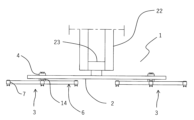
本発明の塗装装置用スプレーガン支持装置(以下単に「スプレーガン支持装置」と言う。)の実施例について図を参照して説明すると、図1、2は、本実施例のスプレーガン支持装置を説明するための図であり、図1は本実施例のスプレーガン支持装置を上面側から示しており、図2は本実施例のスプレーガン支持装置を正面側から示しており、図において1が、本実施例のスプレーガン支持装置である。 An embodiment of the spray gun support device for coating equipment of the present invention (hereinafter simply referred to as "spray gun support device") will be described with reference to the drawings. Figures 1 and 2 show the spray gun support device of the present embodiment. FIG. 1 shows the spray gun support device of this embodiment from the top side, and FIG. 2 shows the spray gun support device of this embodiment from the front side. , is the spray gun support device of this embodiment.
そして、本実施例のスプレーガン支持装置は、支持装置本体を有しており、この支持装置本体が、塗装装置としての塗装ロボットのロボットアームに支持され、それにより本実施例のスプレーガン支持装置1は、塗装装置に取り付けられることとしている。
The spray gun support device of this embodiment has a support device main body, and this support device main body is supported by a robot arm of a painting robot serving as a coating device, whereby the spray gun support device of this
即ち、図2において、22は塗装ロボットのロボットアームであり、また、図において2は支持装置本体であり、支持装置本体2は、ロボットアーム22の先端部分に備えられた取付部材23に連結されており、取付部材23は、上下方向に回動自在にして、ロボットアームの先端に連結されている。
That is, in FIG. 2, 22 is a robot arm of a painting robot, and in the figure, 2 is a support device main body, and the support device
そして、前記支持装置本体2は、厚みを有する長尺の板状としており、両端部にはそれぞれ、スプレーガンユニットが装着されている。即ち、図において3がスプレーガンユニットであり、本実施例において前記スプレーガンユニット3は2個としており、それぞれのスプレーガンユニット3には、複数個のスプレーガンが備えられている。
The support device
ここで、図3を参照して前記スプレーガンユニット3について説明すると、図3はスプレーガンユニット3の縦断正面構造を示す図であり、図において4は回転体である。即ち、スプレーガンユニット3は回転体4を有している。そしてこの回転体4は、円柱状としており、前記支持装置本体2を貫通する形態で、支持装置本体2に回動自在に装着されている。なお、図において5は軸受けであり、前記回転体4はこの軸受け5によって、支持装置本体2に回動自在に装着されている。
Here, the
次に、図において6はスプレーガン支持アームである。即ち、前記回転体4の下端にはスプレーガン支持アーム6が連結されており、スプレーガン支持アーム6は、回転体4の挿入方向に直交する横方向に向いた複数本のアーム本体19を有しており、アーム本体19の先端にスプレーガン7が装着されている。そして、スプレーガン支持アーム6は、回転体4の下端に連結されているため、回転体4の回転とともに回転し、それによりスプレーガン7の位置を変えることが可能となっている。
Next, in the figure, 6 is a spray gun support arm. That is, a spray
なお、図4はスプレーガン支持アーム6及びアーム本体19の先端に装着されたスプレーガン7を上側から示した図であり、図に示されるように、本実施例においては、スプレーガン支持アーム6を構成するアーム本体19は、約90度の角度をあけて4本具備されている。そして、これにより、スプレーガンユニット3のそれぞれには、4個のスプレーガンが装着され、合計で8個のスプレーガンが、支持装置本体2に備えられている。但し、スプレーガン支持アーム6の本数は特に4本には限定されず、2本でもよく、あるいは3本でも良い。
Note that FIG. 4 is a view showing the spray
次に、図3において8、9は、スプレーガン7に塗料を供給するための塗料供給路である。即ち、前記回転体4には、スプレーガン7の数に対応した本数の塗料供給路8が形成されている。そして、アーム本体19の内部にはそれぞれ、1本ずつのアーム側塗料供給路9が形成され、アーム側塗料供給路9の先端はそれぞれ、アーム本体19の先端に装着されたスプレーガン7の塗料供給路に連結されている。
Next, in FIG. 3,
また、アーム側塗料供給路9の基端側はそれぞれ、スプレーガン支持アーム6の中央部分で開口とされており(図4参照)、この開口部分において、回転体側塗料供給路8のいずれかに連結されている。
Further, the base end sides of the arm-side
更に、回転体側塗料供給路8はそれぞれ、上端部に連結ジョイント10が備えられており、この連結ジョイント10を介して、回転体側塗料供給路8は図示しない塗料ホースに連結される。
Further, each of the rotating body side
次に、図3において11は、前記回転体4を回転させるためのタイミングベルトである。即ち、前記支持装置本体2の内部において、両端の回転体4にはタイミングベルト11が巻き掛けられており、このタイミングベルト11を駆動用モーターで移動させることで、回転体4のそれぞれを同一の方向へ回転可能としている。この関係を説明するための図が図6であり、支持装置本体2の内部を示しているとともに、支持装置本体2とスプレーガン支持アーム6とスプレーガン7を示している。また、図において11がタイミングベルト、12が駆動用モーターであり、更に13は、タイミングベルト11の張力調整のためのアイドラユニットであり、このこうせいにおいて、駆動用モーター12を駆動してタイミングベルト11を移動することで、回転体4のそれぞれが同一の方向へ回転する。
Next, in FIG. 3, 11 is a timing belt for rotating the
そして、本実施例においては、前記回転体4を回転させて、それぞれのスプレーガン支持アーム6のうちの2本が支持装置本体2と平行になるようにしたときに、支持装置本体2の正面側に位置したスプレーガン7が、ワークを塗装するために用いられるスプレーガンになる。
In this embodiment, when the
次に、図1において14は、スプレーガン7にエアーを供給するためのエアー供給手段である。即ち、前述したように、スプレーガンによってワークに向けて塗料を噴霧するためには、ニードル稼働用エアーを供給してニードルを稼働して塗料吐出口を解放するとともに、塗料吐出口の近傍に霧化エアー及びパターンエアーを供給しなければならす、そのために、スプレーガンより塗料を噴霧するためには、3本のエアーホースを用いて、ニードル稼働用エアー、霧化エアー、パターンエアーをスプレーガンに供給する必要がある。一方、スプレーガンごとに3本のエアーホースを連結していたのでは、ホースの数が多くなってしまう。例えばスプレーガンユニットに4個のスプレーガンを備えた場合には、塗料ホースも含めて、合計で16本のホースをスプレーガンユニットに連結する必要があり、スプレーガン支持装置本体全体が大型化してしまう。
Next, in FIG. 1, 14 is an air supply means for supplying air to the
そこで、本実施例のスプレーガン支持装置では、スプレーガンに各種のエアーを供給するエアーホースを、1個のスプレーガンユニット3に対して1組のみにしており、それにより、スプレーガンの数に影響されずにエアーホースの本数を一定にし、スプレーガン支持装置の大型化を防止することとした。
Therefore, in the spray gun support device of this embodiment, there is only one set of air hoses for supplying various types of air to the spray guns for each
即ち、図1において、本実施例のスプレーガン支持装置1では、支持装置本体2における回転体4の外側に、スプレーガンにエアーを供給するためのエアー供給手段14を配置して、このエアー供給手段14によって、スプレーガンユニット3に備えたスプレーガン7のすべてにエアーを供給することとしている。
That is, in FIG. 1, in the spray
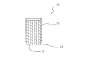
ここで、エアー供給手段14について図5を参照して説明すると、図5は前記エアー供給手段14の内部構造を説明するための図であり、図において15は、支持装置本体2に装着される本体部である。
Here, the air supply means 14 will be explained with reference to FIG. 5. FIG. 5 is a diagram for explaining the internal structure of the air supply means 14, and in the figure, 15 is attached to the support device
即ち、前記エアー供給手段14は本体部15を有しており、この本体部15は、支持装置本体2を貫通する形態で、前記回転体4の外側において、支持装置本体2に装着されている。そして本実施例においては、前記回転体4の正面側に本体部15を配置しており、これにより、ワークを塗装するために用いられるスプレーガンに各種エアーを供給可能としている。なお、エアー供給手段14を配置する箇所は特に限定はされず、必ずしも、回転体4の正面側に配置する必要は無い。
That is, the air supply means 14 has a
次に、図において16は可動部である。即ち、前記本体部15の内部には、上下方向に可動自在にして、可動部16が備えられている。そして、可動部16の内部には、可動部側エアー供給路17が形成されており、この可動部側エアー供給路17は、可動部側霧化エアー供給路、可動部側パターンエアー供給路及び可動部側ニードル稼働用エアー供給路の3本としている。そして、可動部側エアー供給路17の上端側にそれぞれ、エアーホースを連結することとし、下端は開口としている。
Next, in the figure, 16 is a movable part. That is, a
一方、図3において、前記スプレーガン支持アーム6を構成するアーム本体19の内部にはそれぞれ、アーム側エアー供給路18が形成されており、このアーム側エアー供給路18は、アーム側霧化エアー供給路、アーム側パターンエアー供給路及びアーム側ニードル稼働用エアー供給路の3本としている。そして、アーム側エアー供給路18の基端側は支持装置本体2側に開口としており(図4参照)、先端側は、スプレーガンにおける、霧化エアー供給路、パターンエアー供給路及びニードル稼働用エアー供給路のそれぞれに連結されている。
On the other hand, in FIG. 3, an arm-side
そして、前記回転体4を回転させ、それぞれのスプレーガン支持アーム6のうちの2本が支持装置本体2と平行になり、支持装置本体2の正面側に位置したスプレーガン7、即ち、ワークを塗装するために用いられるスプレーガン7を支持するアーム本体19におけるアーム側霧化エアー供給路、アーム側パターンエアー供給路及びアーム側ニードル稼働用エアー供給路の基端側の開口が、エアー供給手段14における可動部側エアー供給路17の下端の開口に対向した状態にしなった後に、可動部16を下降させると、可動部側霧化エアー供給路とアーム側霧化エアー供給路、可動部側パターンエアー供給路とアーム側パターンエアー供給路、及び可動部側ニードル稼働用エアー供給路とアーム側ニードル稼働用エアー供給路が連結し、それにより、スプレーガンに、霧化エアー、パターンエアー及びニードル稼働エアーを供給可能となる。
Then, the
一方、可動部側霧化エアー供給路とアーム側霧化エアー供給路、可動部側パターンエアー供給路とアーム側パターンエアー供給路、及び可動部側ニードル稼働用エアー供給路とアーム側ニードル稼働用エアー供給路が連結している状態で、可動部16を上昇することで、連結を解除することが可能である。
On the other hand, the movable part side atomizing air supply passage and the arm side atomizing air supply passage, the movable part side pattern air supply passage and the arm side pattern air supply passage, and the movable part side needle operation air supply passage and the arm side needle operation air supply passage. It is possible to release the connection by lifting the
従って、予め、特定のスプレーガンが塗料を行う位置に配置されたときに、可動部16を下降させることで、そのスプレーガンを支持するアーム本体の内部に形成されたアーム側霧化エアー供給路、アーム側パターンエアー供給路、及びアーム側ニードル稼働用エアー供給路が、可動部側霧化エアー供給路、可動部側パターンエアー供給路、及び可動部側ニードル稼働用エアー供給路に連結されるようにしておくとよい。なお、可動部16を上下動させる方法は特に限定されないが、例えば、可動部16にエアシリンダーを連結し、エアシリンダーの作用によって可動部16を上下動すると良い。
Therefore, by lowering the
次に、このように構成される本実施例のスプレーガン支持装置1の作用について説明すると、本実施例のスプレーガン支持装置1を用いてワークの塗装を行う場合には、スプレーガンユニットのそれぞれの塗料供給路8に所定の塗料ホースを連結し、各スプレーガンより異なった色の塗料を噴霧可能とする。
Next, to explain the operation of the spray
そしてそれとともに、エアー供給手段14における3本の可動部側エアー供給路17、即ち可動部側霧化エアー供給路、可動部側パターンエアー供給路及び可動部側ニードル稼働用エアー供給路の上端に、エアーホースを連結する。
At the same time, the three movable part side
更に、アーム本体19のそれぞれのアーム側塗料供給路9、及びアーム側エアー供給路18の先端部を、スプレーガンにおける塗料供給路、及び各種のエアー供給路に連結し、それにより、スプレーガンに塗料及びエアーを供給可能な状態にしておく。
Furthermore, the tips of the arm-side
そして、この状態で回転体4を回転することで、塗料の噴霧を行うスプレーガンを所定の位置に配置した後に、可動部16を下降させる。そうすると、塗料の噴霧を行うスプレーガンを支持しているアーム本体19の内部に形成されたアーム側霧化エアー供給路、アーム側パターンエアー供給路、及びアーム側ニードル稼働用エアー供給路が、可動部側霧化エアー供給路、可動部側パターンエアー供給路、及び可動部側ニードル稼働用エアー供給路に連結され、塗料の噴霧を行うスプレーガンに霧化エアー、パターンエアー及びニードル稼働用エアーを供給可能になる。従って、これにより、スプレーガンに塗料及び各種エアーを供給することで、ワークに向けて塗料を噴霧して塗装を行うことが可能となる。
Then, by rotating the
そして、塗装が終了してカラーチェンジを行う場合には可動部16を上昇することで、可動部側霧化エアー供給路とアーム側霧化エアー供給路、可動部側パターンエアー供給路とアーム側パターンエアー供給路、及び可動部側ニードル稼働用エアー供給路とアーム側ニードル稼働用エアー供給路との連結を解除する。
When the color is changed after painting is completed, the
そしてその後は、前述と同様に、回転体4を回転することで、次の色の塗料の噴霧を行うスプレーガンを所定の位置に配置した後に、可動部16を下降させて、次の色の塗料の噴霧を行うスプレーガンを支持しているアーム本体19の内部に形成されたアーム側霧化エアー供給路、アーム側パターンエアー供給路、及びアーム側ニードル稼働用エアー供給路を、可動部側霧化エアー供給路、可動部側パターンエアー供給路、及び可動部側ニードル稼働用エアー供給路に連結し、その後は、スプレーガンに塗料及び各種エアーを供給することで、新たな色の塗料によるワークの塗装を行う。
After that, as described above, by rotating the
このように、本実施例のスプレーガン支持装置は、スプレーガンユニットに備えられたスプレーガンに各種エアーを供給するエアー供給手段を一つにしているために、スプレーガンの数にかかわらず、スプレーガンに各種のエアーを供給するエアーホースの本数を一定にすることができる。従って、スプレーガンの数が多くなった場合でも、エアーホースの本数が多くなることが無いために、ホースの取り扱いが容易となり、装置全体が大型化することも防止することが可能である。 In this way, the spray gun support device of this embodiment has a single air supply means for supplying various types of air to the spray guns provided in the spray gun unit, so it is possible to spray regardless of the number of spray guns. The number of air hoses that supply various types of air to the gun can be kept constant. Therefore, even if the number of spray guns increases, the number of air hoses does not increase, making it easier to handle the hoses and preventing the entire device from becoming larger.
本発明の塗装装置用スプレーガン支持装置は、複数のスプレーガンを有することでスプレーガンを交換することなくカラーチェンジを可能にした塗装装置において、1つのエアー供給手段によって、複数のスプレーガンに対するエアーの供給を可能にしているため、複数のスプレーガンを有することでカラーチェンジを可能にした塗装装置の全般に適用可能である。 The spray gun support device for a painting device of the present invention provides air supply to a plurality of spray guns using one air supply means in a painting device that has a plurality of spray guns and thus enables color changes without replacing the spray guns. It can be applied to all painting equipment that has multiple spray guns and can change colors.
1 スプレーガン支持装置
2 支持装置本体
3 スプレーガンユニット
4 回転体
5 軸受け
6 スプレーガン支持アーム
7 スプレーガン
8 回転体側塗料供給路
9 アーム側塗料供給路
10 連結ジョイント
11 タイミングベルト
12 駆動用モーター
13 アイドラユニット
14 エアー供給手段
15 本体部
16 可動部
17 可動部側エアー供給路
18 アーム側エアー供給路
19 アーム本体
22 ロボットアーム
23 取付部材
1 Spray
Claims (6)
該支持装置本体(2)に装着された、複数のスプレーガンを備えたスプレーガンユニット(3)と、
前記支持装置本体(2)に装着された、前記スプレーガンユニット(3)に支持されたスプレーガン(7)にエアーを供給するためのエアー供給手段(14)と、を具備した塗装装置用スプレーガン支持装置であって、
前記スプレーガンユニット(3)は、
前記支持装置本体(2)に水平方向に回動自在に装着された回転体(4)と、
該回転体(4)の下方側に連結された、それぞれの先端側にスプレーガンが装着される複数本のアーム本体(19)を有するスプレーガン支持アーム(6)と、を具備するとともに、
前記回転体(4)の内部には、スプレーガンの数に対応した回転体側塗料供給路(8)が形成され、
前記アーム本体(19)の内部には、前記回転体側塗料供給路(8)に連結されたアーム側塗料供給路(9)と、スプレーガンにエアーを供給するためのアーム側エアー供給路(18)が形成され、
前記エアー供給手段(14)は、
前記支持装置本体(2)に装着された本体部(15)と、
該本体部(5)の内部に上下方向に可動自在に備えられた可動部(16)と、
該可動部(16)内に形成された可動部側エアー供給路(17)と、を具備するとともに、
前記可動部(16)を下降することで、使用するスプレーガンが装着されたアーム本体(19)に形成されたアーム側エアー供給路(18)と前記可動部側エアー供給路(17)とを連結し、連結した状態で前記可動部(16)を上昇することで、アーム側エアー供給路(18)と可動部側エアー供給路(17)の連結を解除する、ことを特徴とする塗装装置用スプレーガン支持装置。 a support device main body (2) supported by an arm of the coating device;
a spray gun unit (3) equipped with a plurality of spray guns attached to the support device main body (2);
An air supply means (14) for supplying air to the spray gun (7) supported by the spray gun unit (3), which is attached to the support device main body (2). A gun support device,
The spray gun unit (3) includes:
a rotating body (4) rotatably mounted on the support device main body (2) in a horizontal direction;
a spray gun support arm (6) connected to the lower side of the rotating body (4) and having a plurality of arm bodies (19) each having a spray gun attached to its tip end;
Rotating body side paint supply passages (8) corresponding to the number of spray guns are formed inside the rotating body (4),
Inside the arm body (19), there are an arm-side paint supply path (9) connected to the rotating body-side paint supply path (8), and an arm-side air supply path (18) for supplying air to the spray gun. ) is formed,
The air supply means (14)
a main body part (15) attached to the support device main body (2);
a movable part (16) provided inside the main body part (5) so as to be movable in the vertical direction;
A movable part side air supply path (17) formed in the movable part (16),
By lowering the movable part (16), the arm side air supply path (18) formed in the arm body (19) to which the spray gun to be used is attached and the movable part side air supply path (17) are connected. A painting device characterized in that the arm side air supply path (18) and the movable portion side air supply path (17) are disconnected by connecting and lifting the movable portion (16) in the connected state. spray gun support device.
Priority Applications (1)
| Application Number | Priority Date | Filing Date | Title |
|---|---|---|---|
| JP2020047352A JP7430552B2 (en) | 2020-03-18 | 2020-03-18 | Spray gun support device for painting equipment |
Applications Claiming Priority (1)
| Application Number | Priority Date | Filing Date | Title |
|---|---|---|---|
| JP2020047352A JP7430552B2 (en) | 2020-03-18 | 2020-03-18 | Spray gun support device for painting equipment |
Publications (2)
| Publication Number | Publication Date |
|---|---|
| JP2021146257A JP2021146257A (en) | 2021-09-27 |
| JP7430552B2 true JP7430552B2 (en) | 2024-02-13 |
Family
ID=77850238
Family Applications (1)
| Application Number | Title | Priority Date | Filing Date |
|---|---|---|---|
| JP2020047352A Active JP7430552B2 (en) | 2020-03-18 | 2020-03-18 | Spray gun support device for painting equipment |
Country Status (1)
| Country | Link |
|---|---|
| JP (1) | JP7430552B2 (en) |
Citations (2)
| Publication number | Priority date | Publication date | Assignee | Title |
|---|---|---|---|---|
| JP2002159896A (en) | 2000-11-29 | 2002-06-04 | Takubo Engineering Co Ltd | Spray gun support arm for coating apparatus |
| JP2015208729A (en) | 2014-04-28 | 2015-11-24 | 東芝機械株式会社 | Spray unit and painting system |
-
2020
- 2020-03-18 JP JP2020047352A patent/JP7430552B2/en active Active
Patent Citations (2)
| Publication number | Priority date | Publication date | Assignee | Title |
|---|---|---|---|---|
| JP2002159896A (en) | 2000-11-29 | 2002-06-04 | Takubo Engineering Co Ltd | Spray gun support arm for coating apparatus |
| JP2015208729A (en) | 2014-04-28 | 2015-11-24 | 東芝機械株式会社 | Spray unit and painting system |
Also Published As
| Publication number | Publication date |
|---|---|
| JP2021146257A (en) | 2021-09-27 |
Similar Documents
| Publication | Publication Date | Title |
|---|---|---|
| US7975645B2 (en) | Paint coating system | |
| US4830882A (en) | Method of and apparatus for cleaning paint spray guns | |
| JP3648134B2 (en) | Automatic painting equipment | |
| JP4428973B2 (en) | Rotating atomizing coating apparatus and coating method | |
| KR20100072285A (en) | Robot comprising a cleaning device and associated operating method | |
| CA2661738A1 (en) | Bell cup cleaning system and method | |
| KR100557735B1 (en) | Automatic coating device using double pipe | |
| US5800614A (en) | Adhesive applier for screen printing machine | |
| JP7430552B2 (en) | Spray gun support device for painting equipment | |
| JP2011230075A (en) | Coating gun and coating method using the same | |
| JP2010051891A (en) | Coating robot | |
| KR20010023128A (en) | Painting device | |
| JP3050034B2 (en) | Cleaning method of painting robot | |
| CN100473466C (en) | Method of washing paint gun | |
| US4692358A (en) | Apparatus and method for applying material to articles | |
| JP5355462B2 (en) | Painting gun | |
| JPH0653240B2 (en) | Paint gun cleaning equipment | |
| JP4881644B2 (en) | Painting equipment | |
| JP7501999B2 (en) | Paint spray gun support device | |
| JP4398662B2 (en) | Spray gun for painting | |
| WO2007000853A1 (en) | Bell type coating device | |
| JP2025086833A (en) | Paint spray gun unit | |
| JP2007130531A (en) | Painting system | |
| JP2025086832A (en) | Paint spray gun unit | |
| JPH0122824B2 (en) |
Legal Events
| Date | Code | Title | Description |
|---|---|---|---|
| A621 | Written request for application examination |
Free format text: JAPANESE INTERMEDIATE CODE: A621 Effective date: 20230307 |
|
| A977 | Report on retrieval |
Free format text: JAPANESE INTERMEDIATE CODE: A971007 Effective date: 20240118 |
|
| TRDD | Decision of grant or rejection written | ||
| A01 | Written decision to grant a patent or to grant a registration (utility model) |
Free format text: JAPANESE INTERMEDIATE CODE: A01 Effective date: 20240123 |
|
| A61 | First payment of annual fees (during grant procedure) |
Free format text: JAPANESE INTERMEDIATE CODE: A61 Effective date: 20240131 |
|
| R150 | Certificate of patent or registration of utility model |
Ref document number: 7430552 Country of ref document: JP Free format text: JAPANESE INTERMEDIATE CODE: R150 |