JP7424924B2 - Magnetic adsorption wheels and vehicles - Google Patents

Magnetic adsorption wheels and vehicles Download PDF

Info

Publication number
JP7424924B2
JP7424924B2 JP2020109947A JP2020109947A JP7424924B2 JP 7424924 B2 JP7424924 B2 JP 7424924B2 JP 2020109947 A JP2020109947 A JP 2020109947A JP 2020109947 A JP2020109947 A JP 2020109947A JP 7424924 B2 JP7424924 B2 JP 7424924B2
Authority
JP
Japan
Prior art keywords
wheel
shaft
permanent magnet
spherical
vehicle
Prior art date
Legal status (The legal status is an assumption and is not a legal conclusion. Google has not performed a legal analysis and makes no representation as to the accuracy of the status listed.)
Active
Application number
JP2020109947A
Other languages
Japanese (ja)
Other versions
JP2022007174A (en
Inventor
晴彦 衞藤
Current Assignee (The listed assignees may be inaccurate. Google has not performed a legal analysis and makes no representation or warranty as to the accuracy of the list.)
Sumitomo Heavy Industries Ltd
Original Assignee
Sumitomo Heavy Industries Ltd
Priority date (The priority date is an assumption and is not a legal conclusion. Google has not performed a legal analysis and makes no representation as to the accuracy of the date listed.)
Filing date
Publication date
Application filed by Sumitomo Heavy Industries Ltd filed Critical Sumitomo Heavy Industries Ltd
Priority to JP2020109947A priority Critical patent/JP7424924B2/en
Publication of JP2022007174A publication Critical patent/JP2022007174A/en
Priority to JP2024005978A priority patent/JP7669628B2/en
Application granted granted Critical
Publication of JP7424924B2 publication Critical patent/JP7424924B2/en
Active legal-status Critical Current
Anticipated expiration legal-status Critical

Links

Images

Landscapes

  • Motorcycle And Bicycle Frame (AREA)
  • Electric Propulsion And Braking For Vehicles (AREA)

Description

特許法第30条第2項適用 2020年5月31日に、下記アドレスのウェブサイトで学会参加者限定で公開した。https://events.infovaya.com/presentation?id=69616Application of Article 30, Paragraph 2 of the Patent Act On May 31, 2020, it was released exclusively to conference participants on the website at the address below. https://events. infovaya. com/presentation? id=69616

本開示は、磁気吸着車輪及び車両に関する。 The present disclosure relates to magnetic adsorption wheels and vehicles.

造船や大型クレーン等の製造現場において、曲面形状をした大型の鉄鋼部材表面に磁気吸着して走行する磁気吸着車輪を有し、溶接・塗装・外観検査等の作業を行う車両が知られている。 At manufacturing sites such as shipbuilding and large cranes, vehicles are known that have magnetic adsorption wheels that run while magnetically adhering to the surface of large, curved steel members, and are used for work such as welding, painting, and visual inspection. .

特許文献1には、車軸と車輪フランジの間の空間の一部に、軸心を回転中心として揺動可能な外面円弧状の磁石を車輪フランジとは分離状態に設け、車軸と鋼製壁面との間に強い車輪押付け力が発生するように前記磁石を磁石の最大磁力の方向が常に鋼製壁面に向くように配設したことを特徴とする磁石内蔵タイプの吸着車輪が開示されている。 Patent Document 1 discloses that a magnet with an arcuate outer surface that can swing around its axis is provided in a part of the space between the axle and the wheel flange, separated from the wheel flange, and the axle and the steel wall are connected to each other. Disclosed is a magnet built-in type attraction wheel characterized in that the magnet is arranged so that the direction of the maximum magnetic force of the magnet always faces the steel wall surface so that a strong wheel pressing force is generated.

また、特許文献2には、永久磁石が非強磁性の材料から成る球体内に埋め込まれており、該球体が球形シェル内にあらゆる方向に回転可能に支承され、球形シェルが磁力により吸引可能なベース上を転動する、転動要素が開示されている。 Further, in Patent Document 2, a permanent magnet is embedded in a sphere made of a non-ferromagnetic material, the sphere is supported rotatably in all directions within a spherical shell, and the spherical shell can be attracted by magnetic force. A rolling element is disclosed that rolls on a base.

特許第2639895号公報Patent No. 2639895 特許第5650224号公報Patent No. 5650224

ところで、特許文献1に開示された吸着車輪及び特許文献2に開示された転動要素において、磁石の回転はいずれも受動的である。このため、特許文献1に開示された吸着車輪及び特許文献2に開示された転動要素において、磁気吸着力が発生していない状態では、磁石の方向を調整することができない。 By the way, in the adsorption wheel disclosed in Patent Document 1 and the rolling element disclosed in Patent Document 2, the rotation of the magnet is passive. Therefore, in the attraction wheel disclosed in Patent Document 1 and the rolling element disclosed in Patent Document 2, the direction of the magnet cannot be adjusted in a state where no magnetic attraction force is generated.

そこで、本発明は、好適に壁面を走行可能な磁気吸着車輪及び車両を提供する。 Therefore, the present invention provides a magnetic adsorption wheel and a vehicle that can suitably run on a wall surface.

上記課題を解決するために、一の態様によれば、磁気吸着面に接触する外周面が球面形状をを有する球殻車輪と、前記球殻車輪の内側に配置され、永久磁石を保持する永久磁石保持部と、前記球殻車輪の回転軸と同軸に配置され、前記球殻車輪とは独立して回転し、前記永久磁石保持部を第1回転方向に回転可能な第1シャフトと、前記第1シャフトとともに前記第1回転方向に回転し、前記第1シャフトの軸と直交する軸を有して該軸に揺動可能に前記永久磁石保持部を懸架する第2シャフトと、前記球殻車輪を回転駆動する車輪駆動部と、前記第1シャフトを回転駆動することで前記永久磁石を回転させる磁石駆動部と、を備え、前記車輪駆動部は、車輪駆動用モータと、前記車輪駆動用モータの回転動力を前記球殻車輪に伝達する第1動力伝達部と、を有し、前記磁石駆動部は、磁石駆動用モータと、前記磁石駆動用モータの回転動力を前記球殻車輪に伝達する第2動力伝達部と、を有する、磁気吸着車輪が提供される。 In order to solve the above problems, according to one aspect, there is provided a spherical wheel having a spherical outer peripheral surface that contacts a magnetic attraction surface, and a permanent magnet disposed inside the spherical wheel and holding a permanent magnet. a first shaft that is arranged coaxially with the rotation axis of the magnet holding part and the spherical shell wheel, rotates independently of the spherical shell wheel, and is capable of rotating the permanent magnet holding part in a first rotation direction; a second shaft that rotates together with the first shaft in the first rotational direction, has an axis perpendicular to the axis of the first shaft, and swingably suspends the permanent magnet holder on the axis; and the spherical shell. The wheel drive unit includes a wheel drive unit that rotationally drives a wheel, and a magnet drive unit that rotates the permanent magnet by rotationally driving the first shaft, and the wheel drive unit includes a wheel drive motor and a wheel drive motor. a first power transmission section that transmits the rotational power of a motor to the spherical wheel; the magnet drive section includes a magnet drive motor; and a first power transmission section that transmits the rotational power of the magnet drive motor to the spherical wheel. A magnetic attraction wheel is provided, having a second power transmission section.

一の側面によれば、好適に壁面を走行可能な磁気吸着車輪及び車両を提供することができる。 According to one aspect, it is possible to provide a magnetic adsorption wheel and a vehicle that can suitably run on a wall surface.

本実施形態に係る車両の斜視図。FIG. 1 is a perspective view of a vehicle according to the present embodiment. 本実施形態に係る車両の正面図。FIG. 1 is a front view of a vehicle according to the present embodiment. 本実施形態に係る車両の側面図。FIG. 1 is a side view of a vehicle according to the present embodiment. 本実施形態に係る磁気吸着車輪の部分切断斜視図。FIG. 1 is a partially cutaway perspective view of a magnetic attraction wheel according to the present embodiment. 本実施形態に係る磁気吸着車輪の断面図。FIG. 1 is a sectional view of a magnetic attraction wheel according to the present embodiment. 本実施形態に係る磁気吸着車輪の部分拡大断面図。FIG. 1 is a partially enlarged cross-sectional view of a magnetic attraction wheel according to the present embodiment. 第1シャフト回りの回転角と、永久磁石によって永久磁石保持部に働く回転トルクとの関係の一例を示すグラフ。The graph which shows an example of the relationship between the rotation angle around a 1st shaft, and the rotation torque which acts on a permanent magnet holding part by a permanent magnet. 車輪駆動部及び磁石駆動部の構成を説明する模式図。The schematic diagram explaining the structure of a wheel drive part and a magnet drive part. 本実施形態に係る車両が種々の曲面形状の壁面に吸着している際の永久磁石の配置の一例を示す図。FIG. 3 is a diagram showing an example of the arrangement of permanent magnets when the vehicle according to the present embodiment is attracted to walls of various curved shapes. 車両が床面から壁面に移動する際の動作を示すフローチャート。The flowchart which shows the operation|movement when a vehicle moves from a floor surface to a wall surface. 床面から壁面に移動する際の各時点における車両の状態を示す模式図。FIG. 3 is a schematic diagram showing the state of the vehicle at each point in time when moving from a floor surface to a wall surface. 車両が壁面から壁面(または天井面)に移動する際の動作を示すフローチャート。A flowchart showing operations when a vehicle moves from a wall surface to a wall surface (or ceiling surface). 第1壁面から第2壁面に移動する際の各時点における車両の状態を示す模式図。The schematic diagram which shows the state of a vehicle at each time when moving from a 1st wall surface to a 2nd wall surface.

以下、図面を参照して本開示を実施するための形態について説明する。各図面において、同一構成部分には同一符号を付し、重複した説明を省略する場合がある。 Hereinafter, embodiments for implementing the present disclosure will be described with reference to the drawings. In each drawing, the same components are given the same reference numerals, and redundant explanations may be omitted.

<車両>
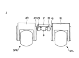
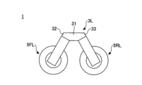
本実施形態に係る車両1について、図1から図3を用いて説明する。図1は、本実施形態に係る車両1の斜視図である。図2は、本実施形態に係る車両1の正面図である。図3は、本実施形態に係る車両1の側面図である。なお、以下の説明において、車両1の進退方向を車両1の前後方向、車両1の車幅方向を車両1の左右方向、前後方向及び左右方向と垂直な方向を車両1の上下方向として、説明する。
<Vehicle>
A vehicle 1 according to this embodiment will be explained using FIGS. 1 to 3. FIG. 1 is a perspective view of a vehicle 1 according to this embodiment. FIG. 2 is a front view of the vehicle 1 according to this embodiment. FIG. 3 is a side view of the vehicle 1 according to this embodiment. In addition, in the following explanation, the advancing and retreating direction of the vehicle 1 is the longitudinal direction of the vehicle 1, the vehicle width direction of the vehicle 1 is the left-right direction of the vehicle 1, and the longitudinal direction and the direction perpendicular to the left-right direction is the vertical direction of the vehicle 1. do.

車両1は、ボディ2と、ロッカーリンク3L,3Rと、シャフト4L,4Rと、磁気吸着車輪5(5FL,5FR,5RL,5RR)と、ディファレンシャルギア6と、を備えている。 The vehicle 1 includes a body 2, rocker links 3L, 3R, shafts 4L, 4R, magnetic adsorption wheels 5 (5FL, 5FR, 5RL, 5RR), and a differential gear 6.

車両1は、磁気吸着車輪5が有する磁石(後述する永久磁石52)で吸着可能な物体であれば、その位置、危険度にかかわらず、例えば高所であったり狭所であっても、遠隔又は無人で移動することができる。ボディ2には、例えば、溶接・塗装・外観検査等の作業を行うための作業用アタッチメント(図示せず)を固定するための固定部(図示せず)を有し、固定部に作業用アタッチメントが搭載されていてもよい。これにより、車両1は、移動先で作業用アタッチメントを用いて所望の作業を実現することができる。また、ボディ2には、磁気吸着車輪5(後述する車輪駆動部56、磁石駆動部57)の動作を制御する制御部(図示せず)が設けられている。なお、車両1は、オペレータの操作を受け付けるコントローラ(図示せず)を有していてもよい。コントローラは、有線又は無線で制御部と通信可能に接続される。制御部は、オペレータによるコントローラの操作に基づいて、磁気吸着車輪5を制御してもよい。また、制御部は、予め入力されたプログラムに基づいて、磁気吸着車輪5を制御してもよい。これにより、車両1は、オペレータが近くにいない場面で、無人又は遠隔により操作される。 The vehicle 1 can remotely pick up any object that can be picked up by the magnets (permanent magnets 52 described later) of the magnetically attracting wheels 5, regardless of its location or degree of danger, for example, even if it is at a high place or in a narrow space. Or it can be moved unmanned. The body 2 has a fixing part (not shown) for fixing a work attachment (not shown) for performing work such as welding, painting, appearance inspection, etc., and the work attachment is attached to the fixing part. may be installed. Thereby, the vehicle 1 can perform desired work using the work attachment at the destination. Further, the body 2 is provided with a control section (not shown) that controls the operation of the magnetic attraction wheels 5 (wheel drive section 56 and magnet drive section 57, which will be described later). Note that the vehicle 1 may include a controller (not shown) that receives operations from an operator. The controller is communicatively connected to the control unit by wire or wirelessly. The control unit may control the magnetic attraction wheel 5 based on the operation of the controller by the operator. Further, the control unit may control the magnetic adsorption wheels 5 based on a program input in advance. Thereby, the vehicle 1 is operated unmanned or remotely in a situation where an operator is not nearby.

左右のロッカーリンク3L,3Rは、中央のボディ2を挟んで配置される。 The left and right rocker links 3L and 3R are arranged with the center body 2 in between.

ロッカーリンク3Lは、前後両端に磁気吸着車輪5(5FL,5RL)が設けられ、シャフト4Lを回転軸として回転可能に支持される部材である。具体的には、ロッカーリンク3Lは、側面視して、略逆V字形状に形成される部材であり、中央部31と、中央部31から前方下向きに伸びる前方部32と、中央部31から後方下向きに伸びる後方部33と、を有する。中央部31には、円柱状の軸部材であるシャフト4Lが固定される。また、シャフト4Lは、ボディ2の軸受21に回転自在に支持されている。ロッカーリンク3Lの前方部32には磁気吸着車輪5FLが設けられ、後方部33には磁気吸着車輪5RLが設けられている。ロッカーリンク3Lは、軸受21に回転自在に支持されるシャフト4Lを回転軸として回転することにより、磁気吸着車輪5FL及び磁気吸着車輪5RLの両方を磁気吸着面(吸着対象面)に接触(接地)させることができる。 The rocker link 3L is a member that is provided with magnetic adsorption wheels 5 (5FL, 5RL) at both front and rear ends and is rotatably supported around a shaft 4L as a rotation axis. Specifically, the rocker link 3L is a member formed in a substantially inverted V shape when viewed from the side, and includes a center portion 31, a front portion 32 extending forward and downward from the center portion 31, and a front portion 32 extending downward from the center portion 31. It has a rear part 33 extending rearward and downward. A shaft 4L, which is a cylindrical shaft member, is fixed to the central portion 31. Further, the shaft 4L is rotatably supported by a bearing 21 of the body 2. A magnetic attraction wheel 5FL is provided at the front portion 32 of the rocker link 3L, and a magnetic attraction wheel 5RL is provided at the rear portion 33. The rocker link 3L rotates around a shaft 4L rotatably supported by a bearing 21, thereby bringing both the magnetic attraction wheel 5FL and the magnetic attraction wheel 5RL into contact (grounding) with the magnetic attraction surface (surface to be attracted). can be done.

同様に、ロッカーリンク3Rは、前後両端に磁気吸着車輪5(5FR,5RR)が設けられ、シャフト4Rを回転軸として回転可能に支持される部材である。具体的には、ロッカーリンク3Rは、側面視して、略逆V字形状に形成される部材であり、中央部34と、中央部34から前方下向きに伸びる前方部35と、中央部34から後方下向きに伸びる後方部36と、を有する。中央部34には、円柱状の軸部材であるシャフト4Rが固定される。また、シャフト4Rは、ボディ2の軸受22に回転自在に支持されている。ロッカーリンク3Rの前方部35には磁気吸着車輪5FRが設けられ、後方部36には磁気吸着車輪5RRが設けられている。ロッカーリンク3Rは、軸受22に回転自在に支持されるシャフト4Rを回転軸として回転することにより、磁気吸着車輪5FR及び磁気吸着車輪5RRの両方を磁気吸着面に接触(接地)させることができる。 Similarly, the rocker link 3R is a member that is provided with magnetic adsorption wheels 5 (5FR, 5RR) at both front and rear ends and is rotatably supported about the shaft 4R as a rotation axis. Specifically, the rocker link 3R is a member formed in a substantially inverted V shape when viewed from the side, and includes a central portion 34, a front portion 35 extending forward and downward from the central portion 34, and a front portion 35 extending downward from the central portion 34. It has a rear part 36 extending rearward and downward. A shaft 4R, which is a cylindrical shaft member, is fixed to the central portion 34. Further, the shaft 4R is rotatably supported by a bearing 22 of the body 2. A magnetic attraction wheel 5FR is provided at the front portion 35 of the rocker link 3R, and a magnetic attraction wheel 5RR is provided at the rear portion 36. The rocker link 3R rotates around the shaft 4R, which is rotatably supported by the bearing 22, so that both the magnetic attraction wheel 5FR and the magnetic attraction wheel 5RR can contact (ground) the magnetic attraction surface.

シャフト4Lとシャフト4Rとは、同軸に配置されている。また、シャフト4Lとシャフト4Rとは、独立して回転可能に設けられている。シャフト4Lの一端(車幅方向の外側)は、ロッカーリンク3Lの中央部31と固定される。シャフト4Rの一端(車幅方向の外側)は、ロッカーリンク3Rの中央部34と固定される。シャフト4Lの軸部分は、軸受21に回転自在に支持される。シャフト4Rの軸部分は、軸受22に回転自在に支持される。また、シャフト4Lの他端(車幅方向の内側)とシャフト4Rの他端(車幅方向の内側)とは、ディファレンシャルギア6を介して接続されている。 The shaft 4L and the shaft 4R are arranged coaxially. Further, the shaft 4L and the shaft 4R are provided to be rotatable independently. One end (outside in the vehicle width direction) of the shaft 4L is fixed to the center portion 31 of the rocker link 3L. One end (outside in the vehicle width direction) of the shaft 4R is fixed to the center portion 34 of the rocker link 3R. The shaft portion of the shaft 4L is rotatably supported by a bearing 21. The shaft portion of the shaft 4R is rotatably supported by a bearing 22. Further, the other end of the shaft 4L (inner side in the vehicle width direction) and the other end of the shaft 4R (inner side in the vehicle width direction) are connected via a differential gear 6.

ディファレンシャルギア(回転機構)6は、シャフト4Lとシャフト4Rとを独立して回転可能に接続する装置である。また、ディファレンシャルギア6は、シャフト4Lの回転とシャフト4Rの回転との差動に基づいてボディ2の前後方向の傾斜角(ピッチ角)を規定する装置である。 The differential gear (rotation mechanism) 6 is a device that independently rotatably connects the shaft 4L and the shaft 4R. Further, the differential gear 6 is a device that defines the inclination angle (pitch angle) of the body 2 in the longitudinal direction based on the differential between the rotation of the shaft 4L and the rotation of the shaft 4R.

ディファレンシャルギア6は、例えば、第1の傘歯車、第2の傘歯車、第3の傘歯車、枠部(いずれも図示せず)を有する。第1の傘歯車は、シャフト4Lの端部と固定され、シャフト4Lが回転することによって第1の傘歯車も回転する。第2の傘歯車は、シャフト4Rの端部と固定され、シャフト4Rが回転することによって第2の傘歯車も回転する。第1の傘歯車と第2の傘歯車とは、同軸に配置される。第3の傘歯車は、第1の傘歯車及び第2の傘歯車の回転軸と直交する回転軸に配置され、第1の傘歯車及び第2の傘歯車とそれぞれ噛み合わされる。枠部は、第1の傘歯車、第2の傘歯車、第3の傘歯車を回転自在に支持する。また、枠部はボディ2と固定される。 The differential gear 6 includes, for example, a first bevel gear, a second bevel gear, a third bevel gear, and a frame (all not shown). The first bevel gear is fixed to the end of the shaft 4L, and as the shaft 4L rotates, the first bevel gear also rotates. The second bevel gear is fixed to the end of the shaft 4R, and as the shaft 4R rotates, the second bevel gear also rotates. The first bevel gear and the second bevel gear are coaxially arranged. The third bevel gear is disposed on a rotation axis perpendicular to the rotation axes of the first bevel gear and the second bevel gear, and meshes with the first bevel gear and the second bevel gear, respectively. The frame rotatably supports the first bevel gear, the second bevel gear, and the third bevel gear. Further, the frame portion is fixed to the body 2.

ここで、シャフト4Rに対してシャフト4Lを回転させた場合、シャフト4Lの回転によって第1の傘歯車が回転し、第1の傘歯車と第2の傘歯車との回転の差動分に応じて第3の傘歯車が回転する。また、第2の傘歯車に対して第3の傘歯車が回転することにより、枠部が第2の傘歯車の回転軸(第1の傘歯車の回転軸)を回転軸として回転する。この際、枠部の回転角は、シャフト4Lの回転角の半分となる。シャフト4Lに対してシャフト4Rを回転させた場合も同様である。 Here, when the shaft 4L is rotated with respect to the shaft 4R, the first bevel gear rotates due to the rotation of the shaft 4L, and according to the difference in rotation between the first bevel gear and the second bevel gear. The third bevel gear rotates. Further, as the third bevel gear rotates with respect to the second bevel gear, the frame rotates about the rotation axis of the second bevel gear (the rotation axis of the first bevel gear). At this time, the rotation angle of the frame is half the rotation angle of the shaft 4L. The same applies when the shaft 4R is rotated with respect to the shaft 4L.

このように、車両1は、同軸に配置されるシャフト4L,4Rを回転軸(揺動軸)として、ロッカーリンク3Lとロッカーリンク3Rとを個別に回転(揺動)させることができる。よって、ロッカーリンク3Lは、軸受21に回転自在に支持されるシャフト4Lを回転軸として回転することにより、磁気吸着車輪5FL及び磁気吸着車輪5RLの両方を磁気吸着面に接触(接地)させることができる。また、ロッカーリンク3Rは、軸受22に回転自在に支持されるシャフト4Rを回転軸として回転することにより、磁気吸着車輪5FR及び磁気吸着車輪5RRの両方を磁気吸着面に接触(接地)させることができる。即ち、車両1は、磁気吸着面が曲面や凹凸を有する面であっても、4つの磁気吸着車輪5(5FL,5FR,5RL,5RR)の全てを磁気吸着面に接触(接地)させることができる。 In this way, the vehicle 1 can individually rotate (swing) the rocker link 3L and the rocker link 3R using the coaxially arranged shafts 4L and 4R as rotation axes (swing axes). Therefore, by rotating the shaft 4L rotatably supported by the bearing 21 as the rotation axis, the rocker link 3L can bring both the magnetic attraction wheel 5FL and the magnetic attraction wheel 5RL into contact (ground) with the magnetic attraction surface. can. Furthermore, by rotating the shaft 4R that is rotatably supported by the bearing 22 as the rotation axis, the rocker link 3R can bring both the magnetic adsorption wheel 5FR and the magnetic adsorption wheel 5RR into contact (ground) with the magnetic adsorption surface. can. That is, in the vehicle 1, even if the magnetic attraction surface is a curved surface or an uneven surface, all of the four magnetic attraction wheels 5 (5FL, 5FR, 5RL, 5RR) can be brought into contact (ground) with the magnetic attraction surface. can.

また、ボディ2の前後方向の傾斜角(ピッチ角)は、ロッカーリンク3Lの前後方向の傾斜角とロッカーリンク3Rの前後方向の傾斜角との中間の傾斜角となる。これにより、ボディ2の前後方向の傾斜角(ピッチ角)の変動は、ロッカーリンク3Lの前後方向の傾斜角の変動及びロッカーリンク3Rの前後方向の傾斜角の変動よりも、小さくすることができる。これにより、車両1が凹凸の変化が激しい磁気吸着面を走行する場合であっても、ボディ2の振動を抑制することができる。 Further, the longitudinal inclination angle (pitch angle) of the body 2 is an intermediate inclination angle between the longitudinal inclination angle of the rocker link 3L and the longitudinal inclination angle of the rocker link 3R. As a result, the variation in the longitudinal inclination angle (pitch angle) of the body 2 can be made smaller than the variation in the longitudinal inclination angle of the rocker link 3L and the variation in the longitudinal inclination angle of the rocker link 3R. . Thereby, even when the vehicle 1 travels on a magnetic attraction surface with large variations in unevenness, vibrations of the body 2 can be suppressed.

なお、4つの磁気吸着車輪5の全てを磁気吸着面に接触させるためには、ロッカーリンク3Lとロッカーリンク3Rとを個別に揺動させることができればよく、ディファレンシャルギア6に代えて、ロッカーリンク3Lとロッカーリンク3Rとが回転機構によって接続されていてもよい。 In addition, in order to bring all four magnetic attraction wheels 5 into contact with the magnetic attraction surface, it is only necessary to swing the rocker link 3L and the rocker link 3R individually, and instead of the differential gear 6, the rocker link 3L and the rocker link 3R may be connected by a rotation mechanism.

<磁気吸着車輪>
次に、車両1が備える磁気吸着車輪5(5FL,5FR,5RL,5RR)について、図4から図8を用いてさらに説明する。ここで、車両1が備える4つの磁気吸着車輪5FL,5FR,5RL,5RRは、同様の構成を有している。このため、以下の説明では、磁気吸着車輪5FRを例に説明し、磁気吸着車輪5FL,5RL,5RRについての説明を省略する。
<Magnetic adsorption wheel>
Next, the magnetic attraction wheels 5 (5FL, 5FR, 5RL, 5RR) included in the vehicle 1 will be further described using FIGS. 4 to 8. Here, the four magnetic adsorption wheels 5FL, 5FR, 5RL, and 5RR included in the vehicle 1 have the same configuration. Therefore, in the following description, the magnetic attraction wheel 5FR will be explained as an example, and the description of the magnetic attraction wheels 5FL, 5RL, and 5RR will be omitted.

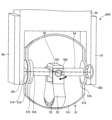
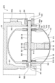
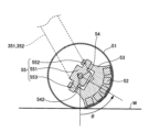
図4は、本実施形態に係る磁気吸着車輪5FRの部分切断斜視図である。図5は、本実施形態に係る磁気吸着車輪5FRの断面図である。図6は、本実施形態に係る磁気吸着車輪5FRの部分拡大断面図である。なお、図4において、球殻車輪51の一部を切断(取り外し)して、球殻車輪51の内部の構造が見えるように図示している。また、図5は、第1シャフト54の軸中心を通る垂直な面で切断した断面図を示す。図6は、第1シャフト54と垂直な面で切断した断面図を示す。 FIG. 4 is a partially cutaway perspective view of the magnetic attraction wheel 5FR according to the present embodiment. FIG. 5 is a sectional view of the magnetic adsorption wheel 5FR according to this embodiment. FIG. 6 is a partially enlarged sectional view of the magnetic adsorption wheel 5FR according to the present embodiment. In addition, in FIG. 4, a part of the spherical shell wheel 51 is cut away (removed) so that the internal structure of the spherical shell wheel 51 can be seen. Further, FIG. 5 shows a cross-sectional view taken along a perpendicular plane passing through the axial center of the first shaft 54. As shown in FIG. FIG. 6 shows a cross-sectional view taken along a plane perpendicular to the first shaft 54. As shown in FIG.

磁気吸着車輪5は、球殻車輪51と、永久磁石52と、永久磁石保持部53と、第1シャフト54と、第2シャフト55と、車輪駆動部56と、磁石駆動部57と、ベアリング58~60と、を備えている。 The magnetic adsorption wheel 5 includes a spherical wheel 51, a permanent magnet 52, a permanent magnet holding section 53, a first shaft 54, a second shaft 55, a wheel drive section 56, a magnet drive section 57, and a bearing 58. It is equipped with ~60.

ロッカーリンク3Rの前方部35には、二又に分岐して磁気吸着車輪5を支持する支持部351,352と、支持部351と支持部352とを接続する接続部353と、が形成されている。 The front portion 35 of the rocker link 3R is formed with support portions 351 and 352 that bifurcate and support the magnetic attraction wheel 5, and a connection portion 353 that connects the support portion 351 and the support portion 352. There is.

球殻車輪51は、球面部511を有する中空形状を有している。具体的には、球殻車輪51は、球面部511と、平面部512,513と、を有する。球面部511は、磁気吸着面に接触(接地)する面であり、外周面が球面形状を有している。これにより、磁気吸着面が車幅方向に傾斜していても、球殻車輪51を磁気吸着面に接触(接地)することができる。平面部512,513は、球殻車輪51の回転軸に対して垂直な面である。換言すれば、球殻車輪51の外形状は、球形状から左右を一部切断した形状を有している。球殻車輪51に平面部512,513を設けることにより、車幅方向の寸法を短くすることができる。球殻車輪51は、例えば、アルミニウム等の非磁性体材料で形成される。これにより、球殻車輪51の内部に配置された永久磁石52と磁気吸着面との間に磁気吸引力を発生させることができる。なお、球殻車輪51の材料は、永久磁石52と磁気吸着面との間に磁気吸引力を発生させることができる材料であればよく、アルミニウムに限られるものではない。球殻車輪51は、支持部351と支持部352との間に配置される。 The spherical wheel 51 has a hollow shape with a spherical portion 511. Specifically, the spherical wheel 51 includes a spherical portion 511 and flat portions 512 and 513. The spherical portion 511 is a surface that contacts (grounds) the magnetic attraction surface, and has a spherical outer peripheral surface. Thereby, even if the magnetic attraction surface is inclined in the vehicle width direction, the spherical wheel 51 can be brought into contact (ground) with the magnetic attraction surface. The plane portions 512 and 513 are surfaces perpendicular to the rotation axis of the spherical wheel 51. In other words, the outer shape of the spherical wheel 51 has a shape obtained by partially cutting off the left and right sides of a spherical shape. By providing the flat portions 512 and 513 on the spherical wheel 51, the dimension in the vehicle width direction can be shortened. The spherical wheel 51 is made of a non-magnetic material such as aluminum, for example. Thereby, a magnetic attraction force can be generated between the permanent magnet 52 arranged inside the spherical wheel 51 and the magnetic attraction surface. Note that the material of the spherical wheel 51 may be any material that can generate a magnetic attraction force between the permanent magnet 52 and the magnetic attraction surface, and is not limited to aluminum. The spherical wheel 51 is arranged between the support part 351 and the support part 352.

車輪駆動部56は、支持部351の側に設けられている。車輪駆動部56の出力軸561は、支持部351の貫通部351aを貫通し、球殻車輪51の平面部512と固定される。具体的には、球殻車輪51の平面部512の外側には、シャフトホルダ514が設けられている。シャフトホルダ514は、図示しないボルト、ナット等によって、球殻車輪51と固定されている。シャフトホルダ514は、車輪駆動部56の出力軸561と球殻車輪51とを接続する部材である。シャフトホルダ514には、車輪駆動部56の出力軸561が挿入される。車輪駆動部56の出力軸561が挿入されるシャフトホルダ514の内周面には、キー溝を有する。また、シャフトホルダ514に挿入する車輪駆動部56の出力軸561の外周面には、キー溝を有する。シャフトホルダ514のキー溝及び車輪駆動部56の出力軸561のキー溝には、キー562が配置される。キー562は、車輪駆動部56の出力軸561の回転動力をシャフトホルダ514に伝達するための機械要素である。これにより、車輪駆動部56の出力軸561、シャフトホルダ514、球殻車輪51は共に回転する。 The wheel drive section 56 is provided on the support section 351 side. The output shaft 561 of the wheel drive unit 56 passes through the penetration part 351a of the support part 351 and is fixed to the flat part 512 of the spherical wheel 51. Specifically, a shaft holder 514 is provided outside the flat portion 512 of the spherical wheel 51 . The shaft holder 514 is fixed to the spherical wheel 51 with bolts, nuts, etc. (not shown). The shaft holder 514 is a member that connects the output shaft 561 of the wheel drive unit 56 and the spherical wheel 51. The output shaft 561 of the wheel drive unit 56 is inserted into the shaft holder 514 . The inner peripheral surface of the shaft holder 514 into which the output shaft 561 of the wheel drive unit 56 is inserted has a keyway. Further, the outer peripheral surface of the output shaft 561 of the wheel drive unit 56 inserted into the shaft holder 514 has a key groove. A key 562 is arranged in the keyway of the shaft holder 514 and the keyway of the output shaft 561 of the wheel drive unit 56. The key 562 is a mechanical element for transmitting the rotational power of the output shaft 561 of the wheel drive unit 56 to the shaft holder 514. As a result, the output shaft 561 of the wheel drive unit 56, the shaft holder 514, and the spherical wheel 51 rotate together.

第1シャフト54は、球殻車輪51の回転軸(車輪駆動部56の出力軸561)と同軸に配置され、球殻車輪51の両端に取り付けられたベアリング58,59によって、回転自在に支持されている。 The first shaft 54 is disposed coaxially with the rotation axis of the spherical wheel 51 (the output shaft 561 of the wheel drive unit 56), and is rotatably supported by bearings 58 and 59 attached to both ends of the spherical wheel 51. ing.

具体的には、球殻車輪51の平面部512の内面側(球殻車輪51の内部空間側)には、ベアリング支持部材515及び押さえ部材516が設けられている。ベアリング支持部材515は、ベアリング58の外輪を挿入可能な穴を有する板状(円環状)の部材である。押さえ部材516は、ベアリング58の外径よりも小さく、第1シャフト54の直径よりも大きな径の穴を有する板状(円環状)の部材である。ベアリング支持部材515及び押さえ部材516は、図示しないボルト、ナット等によって、球殻車輪51と固定されている。ベアリング支持部材515は、ベアリング支持部材515の穴の軸が球殻車輪51の回転軸と一致するようにして平面部512の内面側に固定される。また、押さえ部材516は、押さえ部材516の穴の軸が球殻車輪51の回転軸と一致するようにしてベアリング支持部材515に固定される。ベアリング58の外輪は、ベアリング支持部材515の穴に配置され、押さえ部材516によって抜け止めされている。ベアリング58の内輪は、第1シャフト54の一端を支持する。 Specifically, a bearing support member 515 and a pressing member 516 are provided on the inner surface side of the flat portion 512 of the spherical wheel 51 (on the inner space side of the spherical wheel 51). The bearing support member 515 is a plate-shaped (annular) member having a hole into which the outer ring of the bearing 58 can be inserted. The holding member 516 is a plate-shaped (circular) member having a hole having a diameter smaller than the outer diameter of the bearing 58 and larger than the diameter of the first shaft 54 . The bearing support member 515 and the pressing member 516 are fixed to the spherical wheel 51 with bolts, nuts, etc. (not shown). The bearing support member 515 is fixed to the inner surface of the flat portion 512 such that the axis of the hole in the bearing support member 515 coincides with the rotation axis of the spherical wheel 51. Further, the holding member 516 is fixed to the bearing support member 515 such that the axis of the hole in the holding member 516 coincides with the rotational axis of the spherical wheel 51. The outer ring of the bearing 58 is placed in a hole in the bearing support member 515 and is prevented from coming off by a pressing member 516. The inner ring of the bearing 58 supports one end of the first shaft 54.

また、球殻車輪51の平面部513には、第1シャフト54が貫通する貫通孔517が形成されている。球殻車輪51の平面部513の内側には押さえ部材518が設けられている。球殻車輪51の平面部513の外側には押さえ部材519が設けられている。押さえ部材518,519は、ベアリング59の外径よりも小さく、第1シャフト54の直径よりも大きな径の穴を有する板状(円環状)の部材である。押さえ部材518,519は、図示しないボルト、ナット等によって、球殻車輪51と固定されている。押さえ部材518は、押さえ部材518の穴の軸が球殻車輪51の回転軸と一致するようにして平面部513の内面側に固定される。押さえ部材519は、押さえ部材518の穴の軸が球殻車輪51の回転軸と一致するようにして平面部513の外面側に固定される。ベアリング59の外輪は、貫通孔517に配置され、押さえ部材518,519によって抜け止めされている。ベアリング59の内輪は、貫通孔517を貫通する第1シャフト54を支持する。 Further, a through hole 517 through which the first shaft 54 passes is formed in the flat portion 513 of the spherical wheel 51 . A pressing member 518 is provided inside the flat portion 513 of the spherical wheel 51. A pressing member 519 is provided on the outside of the flat portion 513 of the spherical wheel 51. The holding members 518 and 519 are plate-shaped (annular) members having holes with a diameter smaller than the outer diameter of the bearing 59 and larger than the diameter of the first shaft 54. The holding members 518 and 519 are fixed to the spherical wheel 51 with bolts, nuts, etc. (not shown). The holding member 518 is fixed to the inner surface of the flat portion 513 such that the axis of the hole in the holding member 518 coincides with the rotation axis of the spherical wheel 51. The holding member 519 is fixed to the outer surface of the flat portion 513 such that the axis of the hole in the holding member 518 coincides with the rotation axis of the spherical wheel 51. The outer ring of the bearing 59 is arranged in the through hole 517 and is prevented from coming off by pressing members 518 and 519. The inner ring of the bearing 59 supports the first shaft 54 passing through the through hole 517.

支持部352には、第1シャフト54が貫通する貫通孔352aが形成されている。ベアリング60の外輪は、貫通孔352aに配置されている。ベアリング60の内輪は、貫通孔352aを貫通する第1シャフト54を支持する。なお、ベアリング60の外輪は、球殻車輪51側の側面で支持部352と接し、ベアリング60の内輪が他方の側面でカプラ572と接することにより、ベアリング60は位置決めされている。 A through hole 352a through which the first shaft 54 passes is formed in the support portion 352. The outer ring of the bearing 60 is arranged in the through hole 352a. The inner ring of the bearing 60 supports the first shaft 54 passing through the through hole 352a. The outer ring of the bearing 60 is in contact with the support portion 352 on the spherical wheel 51 side, and the inner ring of the bearing 60 is in contact with the coupler 572 on the other side, thereby positioning the bearing 60.

磁石駆動部57は、支持部352の側に設けられている。磁石駆動部57は、ブラケット352bを介して、支持部352に固定される。磁石駆動部57の出力軸571には、カプラ572が固定されている。カプラ572は、磁石駆動部57の出力軸571と第1シャフト54とを接続する部材である。カプラ572には、第1シャフト54の他端が挿入される。第1シャフト54の他端が挿入されるカプラ572の内周面には、キー溝を有する。また、カプラ572に挿入する第1シャフト54の他端の外周面には、キー溝を有する。キー541を介して、カプラ572と固定されている。なお、磁石駆動部57は、例えばサーボ機能を有するサーボモータであって、第1シャフト54の回転角度、トルク等を制御可能とすることが好ましい。シャフトホルダ514には、車輪駆動部56の出力軸561が挿入される。車輪駆動部56の出力軸561が挿入されるシャフトホルダ514の内周面には、キー溝を有する。また、シャフトホルダ514に挿入する車輪駆動部56の出力軸561の外周面には、キー溝を有する。カプラ572のキー溝及び第1シャフト54のキー溝には、キー541が配置される。キー541は、カプラ572(磁石駆動部57の出力軸571)の回転動力を第1シャフト54に伝達するための機械要素である。これにより、磁石駆動部57の出力軸571、カプラ572、第1シャフト54は共に回転する。 The magnet drive section 57 is provided on the support section 352 side. The magnet drive section 57 is fixed to the support section 352 via the bracket 352b. A coupler 572 is fixed to the output shaft 571 of the magnet drive section 57. The coupler 572 is a member that connects the output shaft 571 of the magnet drive section 57 and the first shaft 54. The other end of the first shaft 54 is inserted into the coupler 572 . The inner peripheral surface of the coupler 572 into which the other end of the first shaft 54 is inserted has a keyway. Further, the outer peripheral surface of the other end of the first shaft 54 inserted into the coupler 572 has a key groove. It is fixed to a coupler 572 via a key 541. Note that the magnet drive unit 57 is preferably a servo motor having a servo function, for example, and is capable of controlling the rotation angle, torque, etc. of the first shaft 54. The output shaft 561 of the wheel drive unit 56 is inserted into the shaft holder 514 . The inner peripheral surface of the shaft holder 514 into which the output shaft 561 of the wheel drive unit 56 is inserted has a keyway. Further, the outer peripheral surface of the output shaft 561 of the wheel drive unit 56 inserted into the shaft holder 514 has a key groove. A key 541 is arranged in the keyway of the coupler 572 and the keyway of the first shaft 54. The key 541 is a mechanical element for transmitting the rotational power of the coupler 572 (output shaft 571 of the magnet drive unit 57) to the first shaft 54. As a result, the output shaft 571, coupler 572, and first shaft 54 of the magnet drive unit 57 rotate together.

このような構成により、球殻車輪51は、車輪駆動部56(出力軸561)及び第1シャフト54によって、支持部351,352に回転自在に支持される。また、車輪駆動部56は、球殻車輪51を回転駆動させることができる。 With such a configuration, the spherical wheel 51 is rotatably supported by the support parts 351 and 352 by the wheel drive part 56 (output shaft 561) and the first shaft 54. Further, the wheel drive unit 56 can rotate the spherical wheel 51.

また、第1シャフト54は、球殻車輪51とは独立して回転することができる。また、磁石駆動部57は、第1シャフト54を回転駆動させることができる。 Further, the first shaft 54 can rotate independently of the spherical wheel 51. Further, the magnet drive unit 57 can rotate the first shaft 54 .

球殻車輪51の内部には、第1シャフト54とともに回転する第2シャフト55が設けられている。第2シャフト55は、ベース551と、軸部552,553と、を有する。ベース551は、第1シャフト54が挿通する貫通孔551aを有する。貫通孔551aの内周面には、キー溝を有する。また、貫通孔551aに挿入する第1シャフト54の外周面には、キー溝を有する。貫通孔551aのキー溝及び第1シャフト54のキー溝には、キー542が配置される。キー542は、第1シャフト54の回転動力をベース551(第2シャフト55)に伝達するための機械要素である。これにより、第1シャフト54、ベース551(第2シャフト55)は共に回転する。軸部552,553は、同軸に配置され、第1シャフト54の回転軸と直交する。 A second shaft 55 that rotates together with the first shaft 54 is provided inside the spherical wheel 51 . The second shaft 55 has a base 551 and shaft portions 552 and 553. The base 551 has a through hole 551a through which the first shaft 54 is inserted. The inner peripheral surface of the through hole 551a has a key groove. Further, the outer peripheral surface of the first shaft 54 inserted into the through hole 551a has a key groove. A key 542 is arranged in the key groove of the through hole 551a and the key groove of the first shaft 54. The key 542 is a mechanical element for transmitting the rotational power of the first shaft 54 to the base 551 (second shaft 55). As a result, the first shaft 54 and the base 551 (second shaft 55) rotate together. The shaft portions 552 and 553 are arranged coaxially and perpendicular to the rotation axis of the first shaft 54.

第1シャフト54には、円筒状のカラー543,544が配置されている。カラー543は、一端がベアリング58の内輪と接し、他端が第2シャフト55のベース551と接する。カラー544は、一端がベアリング59の内輪と接し、他端が第2シャフト55のベース551と接する。これにより、第2シャフト55のベース551は、左右方向の位置が位置決めされる。具体的には、軸部552,553の軸が球殻車輪51(球面部511)の中心を通るように位置決めされる。 Cylindrical collars 543 and 544 are arranged on the first shaft 54 . The collar 543 has one end in contact with the inner ring of the bearing 58 and the other end in contact with the base 551 of the second shaft 55. The collar 544 has one end in contact with the inner ring of the bearing 59 and the other end in contact with the base 551 of the second shaft 55 . Thereby, the base 551 of the second shaft 55 is positioned in the left-right direction. Specifically, the axes of the shaft parts 552 and 553 are positioned so as to pass through the center of the spherical wheel 51 (spherical part 511).

永久磁石保持部53は、第2シャフト55の軸部552,553に懸架されている。即ち、永久磁石保持部53は、第2シャフト55の軸部552,553を回転軸として揺動することができるようになっている。また、永久磁石保持部53は、第1シャフト54を軸として、回転することができるように構成されている。 The permanent magnet holding portion 53 is suspended from the shaft portions 552 and 553 of the second shaft 55. That is, the permanent magnet holding section 53 can swing around the shaft sections 552 and 553 of the second shaft 55 as rotational axes. Further, the permanent magnet holding section 53 is configured to be able to rotate around the first shaft 54 .

永久磁石52は、永久磁石保持部53に埋め込まれ、球殻車輪51の外径よりも内側に配置されている。例えば、永久磁石52は、永久磁石保持部53に設けられた凹部に収容され、押さえ部材531で抜け止めされている。永久磁石保持部53は、球殻車輪51の内面に沿う扇状の形状と有している。これにより、永久磁石52を磁気吸着面にできるだけ近づけることができる。永久磁石52は、例えば、図6に示すように、5個のネオジウム磁石が円弧状に配置されている。また、5個のネオジウム磁石でハルバッハ配列を構成することにより、小さな磁石体積で強力な磁力が得られる。なお、永久磁石保持部53は、球殻車輪51の内面に沿う扇状の形状を有している。永久磁石保持部53の外径は、球殻車輪51の内径以下に形成される。永久磁石保持部53の外面は、球殻車輪51の内面と接していてもよく、離れていてもよい。なお、永久磁石保持部53の外面と球殻車輪51の内面が接する構成においては、両者の間に潤滑剤を塗布してもよい。 The permanent magnet 52 is embedded in the permanent magnet holding part 53 and is arranged inside the outer diameter of the spherical wheel 51. For example, the permanent magnet 52 is housed in a recess provided in the permanent magnet holder 53 and is prevented from coming off by a pressing member 531. The permanent magnet holding portion 53 has a fan-like shape along the inner surface of the spherical wheel 51. Thereby, the permanent magnet 52 can be brought as close as possible to the magnetic attraction surface. For example, as shown in FIG. 6, the permanent magnet 52 includes five neodymium magnets arranged in an arc shape. Furthermore, by forming a Halbach array with five neodymium magnets, a strong magnetic force can be obtained with a small magnet volume. Note that the permanent magnet holding portion 53 has a fan-like shape along the inner surface of the spherical wheel 51. The outer diameter of the permanent magnet holding portion 53 is formed to be equal to or smaller than the inner diameter of the spherical wheel 51 . The outer surface of the permanent magnet holding portion 53 may be in contact with the inner surface of the spherical wheel 51, or may be apart. In addition, in the structure where the outer surface of the permanent magnet holding part 53 and the inner surface of the spherical wheel 51 are in contact with each other, a lubricant may be applied between the two.

以上のように、永久磁石保持部53に保持された永久磁石52は、球殻車輪51内に配置され、第1シャフト54回り(第1回転方向、図4において白抜き矢印で示す。)に能動的または受動的に回転可能であり、第2シャフト55回り(第2回転方向、図4において黒塗り矢印で示す。)に受動的に回転(揺動)可能に構成されている。 As described above, the permanent magnet 52 held by the permanent magnet holding part 53 is arranged inside the spherical wheel 51, and rotates around the first shaft 54 (first rotation direction, indicated by the white arrow in FIG. 4). It is configured to be actively or passively rotatable, and passively rotatable (swingable) around the second shaft 55 (second rotational direction, indicated by a black arrow in FIG. 4).

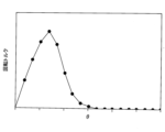
図7は、第1シャフト54回りの回転角θと、永久磁石52によって永久磁石保持部53に働く回転トルクとの関係の一例を示すグラフである。ここで、図7に示すグラフにおいて、横軸は、永久磁石52が壁面(磁気吸着面)Wの方向を向いた状態を角度θ=0°とする回転角θを示し、縦軸はその回転角におけるトルクを示す。なお、永久磁石保持部53に働くトルクは、3次元磁場解析によって計算された磁気吸着力から求めた。この例では、トルクの最大値は、2.4Nmでる。このため、例えば、ストールトルクが6Nmの磁石駆動部57を用いることにより、磁気吸着力に逆らって永久磁石保持部53を回転させ、永久磁石保持部53を壁面Wから遠ざけることができる。換言すれば、壁面Wに対する磁気吸着車輪5の磁気吸着を解除することができる。 FIG. 7 is a graph showing an example of the relationship between the rotation angle θ around the first shaft 54 and the rotational torque exerted on the permanent magnet holder 53 by the permanent magnet 52. Here, in the graph shown in FIG. 7, the horizontal axis indicates the rotation angle θ when the angle θ=0° when the permanent magnet 52 faces the wall surface (magnetic attraction surface) W, and the vertical axis indicates the rotation. Shows the torque at the corner. Note that the torque acting on the permanent magnet holder 53 was determined from the magnetic attraction force calculated by three-dimensional magnetic field analysis. In this example, the maximum value of torque is 2.4 Nm. Therefore, for example, by using the magnet drive section 57 with a stall torque of 6 Nm, the permanent magnet holding section 53 can be rotated against the magnetic attraction force, and the permanent magnet holding section 53 can be moved away from the wall surface W. In other words, the magnetic attraction of the magnetic attraction wheel 5 to the wall surface W can be released.

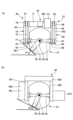
ここで、車輪駆動部56及び磁石駆動部57について、さらに説明する。図8は、車輪駆動部56及び磁石駆動部57の構成を説明する模式図である。図8(a)は、本実施形態に係る磁気吸着車輪5の例を示す。図8(b)は、参考例に係る磁気吸着車輪5Xの例を示す。 Here, the wheel drive section 56 and the magnet drive section 57 will be further explained. FIG. 8 is a schematic diagram illustrating the configuration of the wheel drive section 56 and the magnet drive section 57. FIG. 8(a) shows an example of the magnetic adsorption wheel 5 according to this embodiment. FIG. 8(b) shows an example of a magnetic adsorption wheel 5X according to a reference example.

図8(a)に示すように、本実施形態の車輪駆動部56は、車輪駆動用モータ71と、動力伝達部72と、を備える。車輪駆動用モータ71は、接続部353内に設けられている。換言すれば、車輪駆動用モータ71の出力軸と、球殻車輪51の回転軸とは異なる位置に配置されている。 As shown in FIG. 8(a), the wheel drive section 56 of this embodiment includes a wheel drive motor 71 and a power transmission section 72. The wheel drive motor 71 is provided within the connection portion 353. In other words, the output shaft of the wheel drive motor 71 and the rotating shaft of the spherical wheel 51 are arranged at different positions.

動力伝達部72は、車輪駆動用モータ71の回転動力を球殻車輪51(出力軸561)に伝達する。動力伝達部72は、第1プーリ73と、第2プーリ74と、タイミングベルト75と、ベアリング76~78と、を備える。第1プーリ73は、車輪駆動用モータ71の出力軸と接続される。第1プーリ73は、ベアリング76によって、回転自在に支持される。第2プーリ74は、出力軸561と接続される。第2プーリ74は、ベアリング77,78によって、回転自在に支持される。タイミングベルト75は、第1プーリ73と第2プーリ74とに亘ってかけ渡されている。 The power transmission section 72 transmits the rotational power of the wheel drive motor 71 to the spherical wheel 51 (output shaft 561). The power transmission section 72 includes a first pulley 73, a second pulley 74, a timing belt 75, and bearings 76 to 78. The first pulley 73 is connected to the output shaft of the wheel drive motor 71. The first pulley 73 is rotatably supported by a bearing 76. The second pulley 74 is connected to the output shaft 561. The second pulley 74 is rotatably supported by bearings 77 and 78. The timing belt 75 is stretched across the first pulley 73 and the second pulley 74.

また、図8(a)に示すように、本実施形態の磁石駆動部57は、磁石駆動用モータ81と、動力伝達部82と、を備える。磁石駆動用モータ81は、接続部353内に設けられている。換言すれば、磁石駆動用モータ81の出力軸と、第1シャフト54の回転軸とは異なる位置に配置されている。 Further, as shown in FIG. 8A, the magnet drive section 57 of this embodiment includes a magnet drive motor 81 and a power transmission section 82. The magnet drive motor 81 is provided within the connection portion 353. In other words, the output shaft of the magnet drive motor 81 and the rotation axis of the first shaft 54 are arranged at different positions.

動力伝達部82は、磁石駆動用モータ81の回転動力を球殻車輪51(出力軸561)に伝達する。動力伝達部82は、第1プーリ83と、第2プーリ84と、タイミングベルト85と、ベアリング86~88と、を備える。第1プーリ83は、磁石駆動用モータ81の出力軸と接続される。第1プーリ83は、ベアリング86によって、回転自在に支持される。第2プーリ84は、出力軸561と接続される。第2プーリ84は、ベアリング87,88によって、回転自在に支持される。タイミングベルト85は、第1プーリ83と第2プーリ84とに亘ってかけ渡されている。 The power transmission section 82 transmits the rotational power of the magnet drive motor 81 to the spherical wheel 51 (output shaft 561). The power transmission section 82 includes a first pulley 83, a second pulley 84, a timing belt 85, and bearings 86 to 88. The first pulley 83 is connected to the output shaft of the magnet drive motor 81. The first pulley 83 is rotatably supported by a bearing 86. The second pulley 84 is connected to the output shaft 561. The second pulley 84 is rotatably supported by bearings 87 and 88. The timing belt 85 is stretched across the first pulley 83 and the second pulley 84.

ここで、参考例に係る磁気吸着車輪5Xについて説明する。参考例に係る磁気吸着車輪5Xは、車輪駆動部56Xと、磁石駆動部57Xと、を備える。参考例の車輪駆動部56Xにおいて、車輪駆動用モータは支持部351の外側に設けられている。また、参考例の磁石駆動部57Xにおいて、磁石駆動用モータは支持部352の外側に設けられている。このような構成により、参考例に係る磁気吸着車輪5Xにおいて、壁面Wの車幅方向の傾斜角θ2となると、車輪駆動部56Xが壁面Wと干渉する。このため、磁気吸着車輪5Xにおける磁気吸着可能領域が限定されてしまう。 Here, a magnetic adsorption wheel 5X according to a reference example will be explained. The magnetic attraction wheel 5X according to the reference example includes a wheel drive section 56X and a magnet drive section 57X. In the wheel drive section 56X of the reference example, the wheel drive motor is provided outside the support section 351. Further, in the magnet drive section 57X of the reference example, the magnet drive motor is provided outside the support section 352. With such a configuration, in the magnetic adsorption wheel 5X according to the reference example, when the wall surface W reaches an inclination angle θ2 in the vehicle width direction, the wheel drive portion 56X interferes with the wall surface W. For this reason, the area in which magnetic attraction is possible in the magnetic attraction wheel 5X is limited.

これに対し、本実施形態に係る磁気吸着車輪5では、車輪駆動用モータ71及び磁石駆動用モータ81を壁面Wと干渉しない位置に配置される。具体的には、図8(a)に示すように接続部353に配置される。これにより、磁気吸着車輪5が吸着可能な壁面の傾斜角θ1を傾斜角θ2よりも大きくすることができる。換言すれば、本実施形態に係る磁気吸着車輪5における磁気吸着可能領域を、参考例に係る磁気吸着車輪5Xにおける磁気吸着可能領域よりも広くすることができる。 On the other hand, in the magnetic attraction wheel 5 according to the present embodiment, the wheel drive motor 71 and the magnet drive motor 81 are arranged at a position where they do not interfere with the wall surface W. Specifically, it is arranged at the connection part 353 as shown in FIG. 8(a). Thereby, the inclination angle θ1 of the wall surface that can be attracted by the magnetic attraction wheel 5 can be made larger than the inclination angle θ2. In other words, the magnetically attractive area of the magnetically attractive wheel 5 according to the present embodiment can be made wider than the magnetically attractive area of the magnetically attractive wheel 5X according to the reference example.

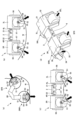
図9は、本実施形態に係る車両1が種々の曲面形状の壁面に吸着している際の永久磁石52の配置の一例を示す。なお、図9において、磁気吸着力の向きを黒塗り矢印で示す。 FIG. 9 shows an example of the arrangement of the permanent magnets 52 when the vehicle 1 according to the present embodiment is attracted to walls of various curved shapes. In addition, in FIG. 9, the direction of the magnetic attraction force is indicated by a black arrow.

図9(a)は、車両1の進行方向に沿って湾曲する面に車両1を吸着させる際の永久磁石52の向きを示す。ここでは、磁石駆動用モータ81への電源供給が絶たれており、磁石駆動用モータ81の出力軸(磁石駆動部57の出力軸571、第1シャフト54)は外部トルクによって受動的に回転可能なバックドライブ状態となっている。永久磁石52の磁力によって、永久磁石保持部53が第1シャフト54周りに受動的に回転させられ、永久磁石52の磁力方向を磁気吸着面の法線方向に向けることができる。これにより、永久磁石保持部53は、任意角度の壁面Wの方向を向くことが自動的に達成され、車両1を壁面Wに吸着させることができる。 FIG. 9A shows the orientation of the permanent magnet 52 when the vehicle 1 is attracted to a surface that curves along the traveling direction of the vehicle 1. Here, the power supply to the magnet drive motor 81 is cut off, and the output shaft of the magnet drive motor 81 (output shaft 571 of the magnet drive unit 57, first shaft 54) can be passively rotated by external torque. It is in a back drive state. The permanent magnet holder 53 is passively rotated around the first shaft 54 by the magnetic force of the permanent magnet 52, and the direction of the magnetic force of the permanent magnet 52 can be directed in the normal direction of the magnetic attraction surface. Thereby, the permanent magnet holding part 53 can automatically face the wall surface W at any angle, and the vehicle 1 can be attracted to the wall surface W.

図9(b)は、車両1の車体幅方向に沿って凹状に湾曲する曲面に車両1を吸着させる際の永久磁石52の向きを示す。永久磁石保持部53が第2シャフト55を揺動軸として揺動することにより、永久磁石52の磁力方向を磁気吸着面の法線方向に向けることができる。 FIG. 9B shows the orientation of the permanent magnet 52 when the vehicle 1 is attracted to a curved surface that is concavely curved along the width direction of the vehicle body. By swinging the permanent magnet holder 53 using the second shaft 55 as a swing axis, the direction of the magnetic force of the permanent magnet 52 can be directed to the normal direction of the magnetic attraction surface.

図9(c)は、車両1の車体幅方向に沿って凸状に湾曲する曲面に車両1を吸着させる際の永久磁石52の向きを示す。永久磁石保持部53が第2シャフト55を揺動軸として揺動することにより、永久磁石52の磁力方向を磁気吸着面の法線方向に向けることができる。 FIG. 9C shows the orientation of the permanent magnet 52 when the vehicle 1 is attracted to a curved surface that curves convexly along the width direction of the vehicle body. By swinging the permanent magnet holder 53 using the second shaft 55 as a swing axis, the direction of the magnetic force of the permanent magnet 52 can be directed to the normal direction of the magnetic attraction surface.

図9(d)は、4輪すべての接触面(図9(d)において破線で示す。)の位置および法線方向が異なる場合を示す。車両1はロッカー機構を有することにより、4輪すべてを磁気吸着面に吸着させることができる。 FIG. 9(d) shows a case where the positions and normal directions of the contact surfaces (indicated by broken lines in FIG. 9(d)) of all four wheels are different. Since the vehicle 1 has a rocker mechanism, all four wheels can be attracted to the magnetic attraction surface.

<吸着動作フロー>
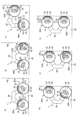
次に、車両1が床面から壁面に移動する際の車両1の動作について、図10及び図11を用いて説明する。図10は、車両1が床面W1から壁面W2に移動する際の動作を示すフローチャートである。図11は、各時点における車両1の状態を示す模式図である。なお、図11は、車両1を水平方向から見た図である。
<Adsorption operation flow>
Next, the operation of the vehicle 1 when it moves from the floor surface to the wall surface will be explained using FIGS. 10 and 11. FIG. 10 is a flowchart showing the operation when the vehicle 1 moves from the floor surface W1 to the wall surface W2. FIG. 11 is a schematic diagram showing the state of the vehicle 1 at each point in time. Note that FIG. 11 is a diagram of the vehicle 1 viewed from the horizontal direction.

ステップS101において、制御部は、磁石駆動用モータ81を制御して、前後輪(磁気吸着車輪5FL,5FR,5RL,5RR)の永久磁石保持部53をボディ2の方向に向ける(図11(a)参照)。そして、制御部は、永久磁石保持部53の向きを維持するように磁石駆動用モータ81を制御する。また、制御部は、車輪駆動用モータ71を制御して、球殻車輪51を駆動させる(図11(a)白抜き矢印参照)。これにより、車両1が床面W1を走行する際、磁気吸着力によって駆動トルクが増加することを抑制することができる。また、床面W1上の砂鉄等の磁性体異物を吸着することを抑制することができる。前輪(磁気吸着車輪5FL,5FR)が壁面W2に到達すると、制御部は、車輪駆動用モータ71を停止させてステップS102に進む。 In step S101, the control section controls the magnet drive motor 81 to direct the permanent magnet holding sections 53 of the front and rear wheels (magnetic adsorption wheels 5FL, 5FR, 5RL, 5RR) toward the body 2 (Fig. 11(a) )reference). The control unit then controls the magnet drive motor 81 to maintain the orientation of the permanent magnet holding unit 53. The control unit also controls the wheel drive motor 71 to drive the spherical wheel 51 (see the white arrow in FIG. 11(a)). Thereby, when the vehicle 1 travels on the floor surface W1, it is possible to suppress the drive torque from increasing due to the magnetic attraction force. Further, it is possible to suppress adsorption of magnetic foreign matter such as iron sand on the floor surface W1. When the front wheels (magnetic attraction wheels 5FL, 5FR) reach the wall surface W2, the control unit stops the wheel drive motor 71 and proceeds to step S102.

ステップS102において、制御部は、前輪(磁気吸着車輪5FL,5FR)の永久磁石52を壁面W2に向ける(図11(b)参照黒塗り矢印参照)。即ち、制御部は、磁石駆動用モータ81への電源供給を制御して、永久磁石保持部53を壁面W2に向ける。これにより、永久磁石52が磁気吸着面(壁面W2)を吸着する。以降は、磁石駆動用モータ81への電源供給を遮断して磁石駆動用モータ81の出力軸(磁石駆動部57の出力軸571、第1シャフト54)をバックドライブ状態とすることで、永久磁石52の磁気吸着力により永久磁石52の磁力方向が壁面W2を向くように永久磁石保持部53が回転する。 In step S102, the control unit directs the permanent magnets 52 of the front wheels (magnetic attraction wheels 5FL, 5FR) toward the wall surface W2 (see black arrows in FIG. 11(b)). That is, the control section controls the power supply to the magnet drive motor 81 to direct the permanent magnet holding section 53 toward the wall surface W2. As a result, the permanent magnet 52 attracts the magnetic attraction surface (wall surface W2). From then on, the permanent magnet The permanent magnet holder 53 rotates due to the magnetic attraction force of the permanent magnet 52 so that the direction of the magnetic force of the permanent magnet 52 faces the wall surface W2.

ステップS103において、制御部は、磁石駆動用モータ81を制御して、後輪(磁気吸着車輪5RL,5RR)の永久磁石保持部53をボディ2の方向に向けたまま、車輪駆動用モータ71を制御して、球殻車輪51を駆動させる(図11(c)参照)。これにより、壁面W2に磁気吸着された前輪は、壁面W2を上る(図11(c)白抜き矢印参照)。床面W1上の後輪は、壁面W2に向かってさらに前進する(図11(c)白抜き矢印参照)。後輪が壁面W2に到達すると(図11(d)参照)、制御部は、車輪駆動用モータ71を停止させてステップS104に進む。 In step S103, the control section controls the magnet drive motor 81 to turn the wheel drive motor 71 while the permanent magnet holding section 53 of the rear wheels (magnetic adsorption wheels 5RL, 5RR) is directed toward the body 2. The spherical wheel 51 is controlled to drive the spherical wheel 51 (see FIG. 11(c)). As a result, the front wheel magnetically attracted to the wall surface W2 moves up the wall surface W2 (see the white arrow in FIG. 11(c)). The rear wheels on the floor surface W1 move further toward the wall surface W2 (see the white arrow in FIG. 11(c)). When the rear wheel reaches the wall surface W2 (see FIG. 11(d)), the control unit stops the wheel drive motor 71 and proceeds to step S104.

ステップS104において、制御部は、後輪(磁気吸着車輪5RL,5RR)の永久磁石52を壁面W2に向ける(図11(e)参照)。即ち、制御部は、磁石駆動用モータ81への電源供給を制御して、永久磁石保持部53を壁面W2に向ける。これにより、永久磁石52が磁気吸着面(壁面W2)を吸着する。以降は、磁石駆動用モータ81への電源供給を遮断して磁石駆動用モータ81の出力軸(磁石駆動部57の出力軸571、第1シャフト54)をバックドライブ状態とすることで、永久磁石52の磁気吸着力により永久磁石52の磁力方向が壁面W2を向くように永久磁石保持部53が回転する。 In step S104, the control unit directs the permanent magnets 52 of the rear wheels (magnetic attraction wheels 5RL, 5RR) toward the wall surface W2 (see FIG. 11(e)). That is, the control section controls the power supply to the magnet drive motor 81 to direct the permanent magnet holding section 53 toward the wall surface W2. As a result, the permanent magnet 52 attracts the magnetic attraction surface (wall surface W2). From then on, the permanent magnet The permanent magnet holder 53 rotates due to the magnetic attraction force of the permanent magnet 52 so that the direction of the magnetic force of the permanent magnet 52 faces the wall surface W2.

ステップS105において、制御部は、車輪駆動用モータ71を制御して球殻車輪51を駆動させる(図11(f)参照)。これにより、壁面W2に磁気吸着された車両1の前後輪(磁気吸着車輪5FL,5FR,5RL,5RR)は、壁面W2を上る(図11(f)白抜き矢印参照)。 In step S105, the control unit controls the wheel drive motor 71 to drive the spherical wheel 51 (see FIG. 11(f)). As a result, the front and rear wheels of the vehicle 1 (magnetically attracted wheels 5FL, 5FR, 5RL, 5RR) magnetically attracted to the wall W2 move up the wall W2 (see the white arrows in FIG. 11(f)).

以上のように、本実施形態に係る車両1によれば、床面W1に接地された状態から、壁面W2を上ることができる。これにより、車両1の設置を容易に行うことができる。 As described above, according to the vehicle 1 according to the present embodiment, it is possible to climb up the wall surface W2 from a state where the vehicle 1 is grounded on the floor surface W1. Thereby, the vehicle 1 can be installed easily.

<吸着動作フロー>
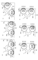
次に、車両1が壁面から他の壁面に移動する際の車両1の動作について、図12及び図13を用いて説明する。図12は、車両1が第1壁面W3から第2壁面W4に移動する際の動作を示すフローチャートである。図13は、各時点における車両1の状態を示す模式図である。なお、図13は、車両1を鉛直方向から見た図である。
<Adsorption operation flow>
Next, the operation of the vehicle 1 when it moves from one wall surface to another wall surface will be explained using FIGS. 12 and 13. FIG. 12 is a flowchart showing the operation when the vehicle 1 moves from the first wall surface W3 to the second wall surface W4. FIG. 13 is a schematic diagram showing the state of the vehicle 1 at each point in time. Note that FIG. 13 is a diagram of the vehicle 1 viewed from the vertical direction.

なお、開始時においては、車両1は、第1壁面W3に吸着されている。即ち、車両1の前後輪(磁気吸着車輪5FL,5FR,5RL,5RR)の永久磁石保持部53は、第1壁面を向いた状態である。 Note that at the start, the vehicle 1 is attracted to the first wall surface W3. That is, the permanent magnet holding portions 53 of the front and rear wheels (magnetic attraction wheels 5FL, 5FR, 5RL, 5RR) of the vehicle 1 are in a state facing the first wall surface.

ステップS201において、制御部は、前後輪(磁気吸着車輪5FL,5FR,5RL,5RR)の永久磁石保持部53が第1壁面W3を向いた状態で、車輪駆動用モータ71を制御して、球殻車輪51を駆動させる(図13(a)白抜き矢印参照)。ここでは、磁石駆動用モータ81への電源供給を遮断して磁石駆動用モータ81の出力軸(磁石駆動部57の出力軸571、第1シャフト54)をバックドライブ状態とすることで、永久磁石52の磁気吸着力により永久磁石52の磁力方向が第1壁面W3を向くように永久磁石保持部53が回転する。これにより、車両1が第1壁面W3に吸着して走行することができる。前輪(磁気吸着車輪5FL,5FR)が第2壁面W4に到達すると、制御部は、車輪駆動用モータ71を停止させてステップS202に進む。 In step S201, the control unit controls the wheel drive motor 71 to generate a ball with the permanent magnet holding parts 53 of the front and rear wheels (magnetic adsorption wheels 5FL, 5FR, 5RL, 5RR) facing the first wall surface W3. The shell wheel 51 is driven (see the white arrow in FIG. 13(a)). Here, by cutting off the power supply to the magnet drive motor 81 and putting the output shaft of the magnet drive motor 81 (the output shaft 571 of the magnet drive unit 57, the first shaft 54) into a backdrive state, the permanent magnet The permanent magnet holder 53 rotates due to the magnetic attraction force of the permanent magnet 52 so that the direction of the magnetic force of the permanent magnet 52 faces the first wall surface W3. Thereby, the vehicle 1 can travel while adhering to the first wall surface W3. When the front wheels (magnetic adsorption wheels 5FL, 5FR) reach the second wall surface W4, the control unit stops the wheel drive motor 71 and proceeds to step S202.

ステップS202において、制御部は、前輪(磁気吸着車輪5FL,5FR)の永久磁石52を第2壁面W4に向ける(図13(b)参照黒塗り矢印参照)。即ち、制御部は、磁石駆動用モータ81への電源供給を制御して、永久磁石保持部53を第2壁面W4に向ける。これにより、永久磁石52が磁気吸着面(第2壁面W4)を吸着する。以降は、磁石駆動用モータ81への電源供給を遮断して磁石駆動用モータ81の出力軸(磁石駆動部57の出力軸571、第1シャフト54)をバックドライブ状態とすることで、永久磁石52の磁気吸着力により永久磁石52の磁力方向が第2壁面W4を向くように永久磁石保持部53が回転する。 In step S202, the control unit directs the permanent magnets 52 of the front wheels (magnetic adsorption wheels 5FL, 5FR) toward the second wall surface W4 (see black arrow in FIG. 13(b)). That is, the control section controls the power supply to the magnet drive motor 81 to direct the permanent magnet holding section 53 toward the second wall surface W4. As a result, the permanent magnet 52 attracts the magnetic attraction surface (second wall surface W4). From then on, the permanent magnet The permanent magnet holder 53 rotates due to the magnetic attraction force of the permanent magnet 52 so that the direction of the magnetic force of the permanent magnet 52 faces the second wall surface W4.

ここで、制御部は、前輪(磁気吸着車輪5FL,5FR)の永久磁石52の一方を第1壁面W3の法線方向から第2壁面W4の法線方向に向ける。次に、制御部は、前輪(磁気吸着車輪5FL,5FR)の永久磁石52の他方を第1壁面W3の法線方向から第2壁面W4の法線方向に向ける。即ち、車両1は、4輪のうち、少なくとも3輪が壁面W3,W4に吸着されている状態で、1輪の永久磁石保持部53を回転させる。これにより、車両1は少なくとも3輪以上の磁気吸着車輪5で壁面W3,W4に吸着させることができるので、車両1が壁面W3,W4から落下することを防止することができる。 Here, the control unit directs one of the permanent magnets 52 of the front wheels (magnetic attraction wheels 5FL, 5FR) from the normal direction of the first wall surface W3 to the normal direction of the second wall surface W4. Next, the control unit directs the other of the permanent magnets 52 of the front wheels (magnetic attraction wheels 5FL, 5FR) from the normal direction of the first wall surface W3 to the normal direction of the second wall surface W4. That is, the vehicle 1 rotates the permanent magnet holding portion 53 of one wheel in a state where at least three of the four wheels are attracted to the wall surfaces W3 and W4. Thereby, the vehicle 1 can be attracted to the walls W3, W4 by at least three or more magnetic attraction wheels 5, so that the vehicle 1 can be prevented from falling from the walls W3, W4.

ステップS203において、制御部は、前輪(磁気吸着車輪5FL,5FRR)の永久磁石保持部53が第2壁面W4を向いた状態、かつ、後輪(磁気吸着車輪5RL,5RR)の永久磁石保持部53が第1壁面W3を向いた状態で、車輪駆動用モータ71を制御して、球殻車輪51を駆動させる(図13(c)参照)。これにより、第2壁面W4に磁気吸着された前輪は、第2壁面W4を進む(図13(c)白抜き矢印参照)。第1壁面W3上の後輪は、第2壁面W4に向かってさらに前進する(図13(c)白抜き矢印参照)。後輪が第2壁面W4に到達すると(図13(d)参照)、制御部は、車輪駆動用モータ71を停止させてステップS204に進む。 In step S203, the control unit controls the permanent magnet holding portions 53 of the front wheels (magnetic adsorption wheels 5FL, 5FRR) facing the second wall surface W4, and the permanent magnet holding portions of the rear wheels (magnetic adsorption wheels 5RL, 5RR). 53 faces the first wall surface W3, the wheel drive motor 71 is controlled to drive the spherical shell wheel 51 (see FIG. 13(c)). As a result, the front wheel magnetically attracted to the second wall surface W4 moves along the second wall surface W4 (see the white arrow in FIG. 13(c)). The rear wheel on the first wall surface W3 further moves forward toward the second wall surface W4 (see the white arrow in FIG. 13(c)). When the rear wheel reaches the second wall surface W4 (see FIG. 13(d)), the control unit stops the wheel drive motor 71 and proceeds to step S204.

ステップS204において、制御部は、後輪(磁気吸着車輪5RL,5RR)の永久磁石52を第2壁面W4に向ける(図13(e)参照)。即ち、制御部は、磁石駆動用モータ81への電源供給を制御して、永久磁石保持部53を第2壁面W4に向ける。これにより、永久磁石52が磁気吸着面(第2壁面W4)を吸着する。以降は、磁石駆動用モータ81への電源供給を遮断して磁石駆動用モータ81の出力軸(磁石駆動部57の出力軸571、第1シャフト54)をバックドライブ状態とすることで、永久磁石52の磁気吸着力により永久磁石52の磁力方向が第2壁面W4を向くように永久磁石保持部53が回転する。 In step S204, the control unit directs the permanent magnets 52 of the rear wheels (magnetic attraction wheels 5RL, 5RR) toward the second wall surface W4 (see FIG. 13(e)). That is, the control section controls the power supply to the magnet drive motor 81 to direct the permanent magnet holding section 53 toward the second wall surface W4. As a result, the permanent magnet 52 attracts the magnetic attraction surface (second wall surface W4). From then on, the permanent magnet The permanent magnet holder 53 rotates due to the magnetic attraction force of the permanent magnet 52 so that the direction of the magnetic force of the permanent magnet 52 faces the second wall surface W4.

ここで、制御部は、後輪(磁気吸着車輪5RL,5RR)の永久磁石52の一方を第1壁面W3の法線方向から第2壁面W4の法線方向に向ける。次に、制御部は、後輪(磁気吸着車輪5RL,5RR)の永久磁石52の他方を第1壁面W3の法線方向から第2壁面W4の法線方向に向ける。即ち、車両1は、4輪のうち、少なくとも3輪が壁面W3,W4に吸着されている状態で、1輪の永久磁石保持部53を回転させる。これにより、車両1は少なくとも3輪以上の磁気吸着車輪5で壁面W3,W4に吸着させることができるので、車両1が壁面W3,W4から落下することを防止することができる。 Here, the control unit directs one of the permanent magnets 52 of the rear wheels (magnetic attraction wheels 5RL, 5RR) from the normal direction of the first wall surface W3 to the normal direction of the second wall surface W4. Next, the control unit directs the other of the permanent magnets 52 of the rear wheels (magnetic attraction wheels 5RL, 5RR) from the normal direction of the first wall surface W3 to the normal direction of the second wall surface W4. That is, the vehicle 1 rotates the permanent magnet holding portion 53 of one wheel in a state where at least three of the four wheels are attracted to the wall surfaces W3 and W4. Thereby, the vehicle 1 can be attracted to the walls W3, W4 by at least three or more magnetic attraction wheels 5, so that the vehicle 1 can be prevented from falling from the walls W3, W4.

ステップS205において、制御部は、前後輪(磁気吸着車輪5FL,5FR,5RL,5RR)の永久磁石保持部53が第2壁面W4を向いた状態で、車輪駆動用モータ71を制御して、球殻車輪51を駆動させる(図13(f)白抜き矢印参照)。これにより、第2壁面W4に磁気吸着された車両1の前後輪(磁気吸着車輪5FL,5FR,5RL,5RR)は、第2壁面W4を進む(図13(f)白抜き矢印参照)。 In step S205, the control unit controls the wheel drive motor 71 to generate a ball with the permanent magnet holding parts 53 of the front and rear wheels (magnetic adsorption wheels 5FL, 5FR, 5RL, 5RR) facing the second wall surface W4. The shell wheel 51 is driven (see the white arrow in FIG. 13(f)). As a result, the front and rear wheels of the vehicle 1 (magnetically attracted wheels 5FL, 5FR, 5RL, 5RR) magnetically attracted to the second wall surface W4 move along the second wall surface W4 (see the white arrows in FIG. 13(f)).

なお、図12及び図13を用いて、車両1が壁面から壁面に移動する場合を例に説明したが、同様の動作により、車両1は、壁面から天井面、天井面から壁面に移動することができる。また、車両1は、壁面から床面に移動することもできる。 In addition, although the case where the vehicle 1 moves from a wall surface to a wall surface was explained using FIG. 12 and FIG. 13 as an example, the vehicle 1 can also move from a wall surface to a ceiling surface and from a ceiling surface to a wall surface by the same operation. Can be done. Moreover, the vehicle 1 can also move from a wall surface to a floor surface.

以上、本実施形態に係る磁気吸着車輪5を有する車両1について説明したが、本開示は上記実施形態等に限定されるものではなく、特許請求の範囲に記載された本開示の要旨の範囲内において、種々の変形、改良が可能である。 Although the vehicle 1 having the magnetic adsorption wheels 5 according to the present embodiment has been described above, the present disclosure is not limited to the above embodiments, etc., and is within the scope of the gist of the present disclosure described in the claims. Various modifications and improvements are possible.

動力伝達部72,82は、ベルト/プーリによって回転動力を伝達する構成を例に説明したが、これに限られるものではない。例えば、チェーン/スプロケットによって回転動力を伝達する構成であってもよく、ギアによって回転動力を伝達する構成であってもよい。 Although the power transmission sections 72 and 82 have been described using an example of a configuration in which rotational power is transmitted using belts/pulleys, the present invention is not limited to this. For example, a structure may be adopted in which rotational power is transmitted by a chain/sprocket, or a structure in which rotational power is transmitted by a gear.

1,1A 車両
2 ボディ
21 軸受
22 軸受
3L,3R ロッカーリンク
351,352 支持部
4L,4R シャフト
5,5FL,5FR,5RL,5RR 磁気吸着車輪
6 ディファレンシャルギア(回転機構)
351 支持部
351a 貫通部
51 球殻車輪
52 永久磁石
53 永久磁石保持部
54 第1シャフト
55 第2シャフト
56 車輪駆動部
561 出力軸
57 磁石駆動部
571 出力軸
572 カプラ
58~60 ベアリング
71 車輪駆動用モータ
72 動力伝達部
73 第1プーリ
74 第2プーリ
75 タイミングベルト
76~78 ベアリング
81 磁石駆動用モータ
82 動力伝達部
83 第1プーリ
84 第2プーリ
85 タイミングベルト
86~88 ベアリング
1,1A Vehicle 2 Body 21 Bearing 22 Bearing 3L, 3R Rocker link 351, 352 Support part 4L, 4R Shaft 5, 5FL, 5FR, 5RL, 5RR Magnetic adsorption wheel 6 Differential gear (rotation mechanism)
351 Support part 351a Penetration part 51 Spherical wheel 52 Permanent magnet 53 Permanent magnet holding part 54 First shaft 55 Second shaft 56 Wheel drive part 561 Output shaft 57 Magnet drive part 571 Output shaft 572 Couplers 58 to 60 Bearing 71 For wheel drive Motor 72 Power transmission section 73 First pulley 74 Second pulley 75 Timing belt 76-78 Bearing 81 Magnet drive motor 82 Power transmission section 83 First pulley 84 Second pulley 85 Timing belt 86-88 Bearing

Claims (5)

磁気吸着面に接触する外周面が球面形状をを有する球殻車輪と、
前記球殻車輪の内側に配置され、永久磁石を保持する永久磁石保持部と、
前記球殻車輪の回転軸と同軸に配置され、前記球殻車輪とは独立して回転し、前記永久磁石保持部を第1回転方向に回転可能な第1シャフトと、
前記第1シャフトとともに前記第1回転方向に回転し、前記第1シャフトの軸と直交する軸を有して該軸に揺動可能に前記永久磁石保持部を懸架する第2シャフトと、
前記球殻車輪を回転駆動する車輪駆動部と、
前記第1シャフトを回転駆動することで前記永久磁石を回転させる磁石駆動部と、を備え、
前記車輪駆動部は、車輪駆動用モータと、前記車輪駆動用モータの回転動力を前記球殻車輪に伝達する第1動力伝達部と、を有し、
前記磁石駆動部は、磁石駆動用モータと、前記磁石駆動用モータの回転動力を前記球殻車輪に伝達する第2動力伝達部と、を有する、磁気吸着車輪。
a spherical wheel having a spherical outer peripheral surface in contact with a magnetic attraction surface;
a permanent magnet holding part that is arranged inside the spherical wheel and holds a permanent magnet;
a first shaft that is disposed coaxially with the rotation axis of the spherical wheel, rotates independently of the spherical wheel, and is capable of rotating the permanent magnet holding part in a first rotation direction;
a second shaft that rotates together with the first shaft in the first rotational direction, has an axis perpendicular to the axis of the first shaft, and swingably suspends the permanent magnet holder on the axis;
a wheel drive unit that rotationally drives the spherical wheel;
a magnet drive unit that rotates the permanent magnet by rotationally driving the first shaft,
The wheel drive unit includes a wheel drive motor and a first power transmission unit that transmits rotational power of the wheel drive motor to the spherical wheel,
The magnet drive unit is a magnetic attraction wheel, including a magnet drive motor and a second power transmission unit that transmits rotational power of the magnet drive motor to the spherical wheel.
前記車輪駆動用モータ及び/又は前記磁石駆動用モータは、前記球殻車輪の回転軸とは異なる位置に配置される、
請求項1に記載の磁気吸着車輪。
The wheel drive motor and/or the magnet drive motor are arranged at a different position from the rotation axis of the spherical wheel.
The magnetic adsorption wheel according to claim 1.
前記第1動力伝達部及び/または第2動力伝達部は、ベルトプーリ機構を有する、
請求項1または請求項2に記載の磁気吸着車輪。
The first power transmission section and/or the second power transmission section has a belt pulley mechanism,
The magnetic adsorption wheel according to claim 1 or claim 2.
前方及び後方に請求項1乃至請求項3のいずれか1項に記載の磁気吸着車輪を設ける一対の部材と、
前記一対の部材を独立して回転可能に接続する回転機構と、
前記回転機構と固定されるボディと、を備える車両。
A pair of members provided with the magnetic adsorption wheels according to any one of claims 1 to 3 at the front and rear;
a rotation mechanism that independently rotatably connects the pair of members;
A vehicle comprising the rotation mechanism and a body fixed to the rotation mechanism.
該車両が床面を走行する際、前記床面と接する前記磁気吸着車輪の前記永久磁石保持部は、前記第1回転方向において、前記ボディの方向を向く、
請求項4に記載の車両。
When the vehicle runs on a floor surface, the permanent magnet holding portion of the magnetic attraction wheel in contact with the floor surface faces toward the body in the first rotation direction.
The vehicle according to claim 4.
JP2020109947A 2020-06-25 2020-06-25 Magnetic adsorption wheels and vehicles Active JP7424924B2 (en)

Priority Applications (2)

Application Number Priority Date Filing Date Title
JP2020109947A JP7424924B2 (en) 2020-06-25 2020-06-25 Magnetic adsorption wheels and vehicles
JP2024005978A JP7669628B2 (en) 2020-06-25 2024-01-18 Magnetic attraction wheel control method, vehicle control method, magnetic attraction wheel and vehicle

Applications Claiming Priority (1)

Application Number Priority Date Filing Date Title
JP2020109947A JP7424924B2 (en) 2020-06-25 2020-06-25 Magnetic adsorption wheels and vehicles

Related Child Applications (1)

Application Number Title Priority Date Filing Date
JP2024005978A Division JP7669628B2 (en) 2020-06-25 2024-01-18 Magnetic attraction wheel control method, vehicle control method, magnetic attraction wheel and vehicle

Publications (2)

Publication Number Publication Date
JP2022007174A JP2022007174A (en) 2022-01-13
JP7424924B2 true JP7424924B2 (en) 2024-01-30

Family

ID=80111102

Family Applications (2)

Application Number Title Priority Date Filing Date
JP2020109947A Active JP7424924B2 (en) 2020-06-25 2020-06-25 Magnetic adsorption wheels and vehicles
JP2024005978A Active JP7669628B2 (en) 2020-06-25 2024-01-18 Magnetic attraction wheel control method, vehicle control method, magnetic attraction wheel and vehicle

Family Applications After (1)

Application Number Title Priority Date Filing Date
JP2024005978A Active JP7669628B2 (en) 2020-06-25 2024-01-18 Magnetic attraction wheel control method, vehicle control method, magnetic attraction wheel and vehicle

Country Status (1)

Country Link
JP (2) JP7424924B2 (en)

Families Citing this family (4)

* Cited by examiner, † Cited by third party
Publication number Priority date Publication date Assignee Title
WO2023182337A1 (en) 2022-03-23 2023-09-28 住友重機械工業株式会社 Wall-traversing vehicle
CN115157920A (en) * 2022-06-23 2022-10-11 江苏镌极特种设备有限公司 A magnet follower wheel and wall-climbing robot
CN120957912A (en) * 2023-04-19 2025-11-14 住友重机械工业株式会社 Mobile device, control method and control procedure for mobile device
CN121464080A (en) * 2023-08-08 2026-02-03 住友重机械工业株式会社 Mobile device, control method for mobile device, and control program

Citations (4)

* Cited by examiner, † Cited by third party
Publication number Priority date Publication date Assignee Title
JP2000052702A (en) 1998-08-11 2000-02-22 Gijutsu Kaihatsu Kenkyusho:Kk Attractive wheel for magnetic body running incorporating running drive mechanism
JP2010202154A (en) 2009-03-06 2010-09-16 Hakusan Kogyo Kk Spherical wheel device
US20160325794A1 (en) 2015-03-09 2016-11-10 Alstom Technology Ltd Magnetic roller
CN109484507A (en) 2018-12-29 2019-03-19 衡昇科技有限公司 Oriented attachment permanent magnetism magnet-wheel two-wheel climbing robot for complicated magnetic conduction wall surface

Family Cites Families (7)

* Cited by examiner, † Cited by third party
Publication number Priority date Publication date Assignee Title
US5220869A (en) * 1991-08-07 1993-06-22 Osaka Gas Company, Ltd. Vehicle adapted to freely travel three-dimensionally and up vertical walls by magnetic force and wheel for the vehicle
JP2639895B2 (en) 1994-05-31 1997-08-13 本州四国連絡橋公団 Adsorption wheel with built-in magnet and gondola moving on the wall using the adsorption wheel
JPH0911893A (en) * 1995-06-30 1997-01-14 Osaka Gas Co Ltd Pipe inside traveling robot
JP3076546B2 (en) * 1997-12-27 2000-08-14 川崎重工業株式会社 Magnetic adsorption traveling device
CH701817A1 (en) 2009-08-31 2011-03-15 Alstom Technology Ltd Rolling element for the mutual process of a vehicle and vehicle having such a rolling element.
CH702282A1 (en) 2009-11-27 2011-05-31 Alstom Technology Ltd Vehicle for independent inspection of hard to reach interiors of.
CN110435352A (en) 2019-09-17 2019-11-12 衡昇科技有限公司 A kind of obstacle detouring magnet-wheel

Patent Citations (4)

* Cited by examiner, † Cited by third party
Publication number Priority date Publication date Assignee Title
JP2000052702A (en) 1998-08-11 2000-02-22 Gijutsu Kaihatsu Kenkyusho:Kk Attractive wheel for magnetic body running incorporating running drive mechanism
JP2010202154A (en) 2009-03-06 2010-09-16 Hakusan Kogyo Kk Spherical wheel device
US20160325794A1 (en) 2015-03-09 2016-11-10 Alstom Technology Ltd Magnetic roller
CN109484507A (en) 2018-12-29 2019-03-19 衡昇科技有限公司 Oriented attachment permanent magnetism magnet-wheel two-wheel climbing robot for complicated magnetic conduction wall surface

Also Published As

Publication number Publication date
JP2022007174A (en) 2022-01-13
JP2024026849A (en) 2024-02-28
JP7669628B2 (en) 2025-04-30

Similar Documents

Publication Publication Date Title
JP7424924B2 (en) Magnetic adsorption wheels and vehicles
JP7491538B2 (en) Wall-climbing vehicle with adaptive magnetic wheels
JP5292283B2 (en) Omnidirectional drive device and omnidirectional vehicle using the same
JP6079997B2 (en) Group moving body of magnetic adsorption vehicle
JP6870032B2 (en) Hinged vehicle chassis
JP7487023B2 (en) Magnetic attraction wheels and vehicles
WO2010064408A1 (en) Wheel, friction drive apparatus, and omnidirectional moving body
WO2010052890A1 (en) Friction-type drive device and omnidirectional movable body using same
EP2003044B1 (en) Automotive inspection vehicle
CN102346482A (en) In-situ steering wheel type robot base mechanism
JPWO2018012284A1 (en) Traction device for automatic guided vehicle and automatic guided vehicle equipped with the same
JP2019166863A (en) Movable body
JP7591459B2 (en) Traveling vehicle
JP3498043B2 (en) Omnidirectional moving device using spherical drive wheels
JP7487022B2 (en) Magnetic attraction wheels and vehicles
JP3498044B2 (en) Control device for omnidirectional mobile device
KR100937752B1 (en) A robot for self travelling and welding steel pipes
KR102597420B1 (en) Modular dual swivel wheel and platform including the same
JP6641655B2 (en) Traveling robot
WO2019176094A1 (en) Electrically driven vehicle
JP2023044065A (en) moving body
CN117177892B (en) Walking vehicle
KR102622794B1 (en) driving sphere
CN107128377A (en) A kind of ball shape robot
EP0876871A1 (en) Welding vehicle

Legal Events

Date Code Title Description
A80 Written request to apply exceptions to lack of novelty of invention

Free format text: JAPANESE INTERMEDIATE CODE: A80

Effective date: 20200707

A621 Written request for application examination

Free format text: JAPANESE INTERMEDIATE CODE: A621

Effective date: 20230413

A977 Report on retrieval

Free format text: JAPANESE INTERMEDIATE CODE: A971007

Effective date: 20231124

TRDD Decision of grant or rejection written
A01 Written decision to grant a patent or to grant a registration (utility model)

Free format text: JAPANESE INTERMEDIATE CODE: A01

Effective date: 20231219

A61 First payment of annual fees (during grant procedure)

Free format text: JAPANESE INTERMEDIATE CODE: A61

Effective date: 20240118

R150 Certificate of patent or registration of utility model

Ref document number: 7424924

Country of ref document: JP

Free format text: JAPANESE INTERMEDIATE CODE: R150