JP7422127B2 - Attachment parts and tool assemblies for power tools - Google Patents
Attachment parts and tool assemblies for power tools Download PDFInfo
- Publication number
- JP7422127B2 JP7422127B2 JP2021500926A JP2021500926A JP7422127B2 JP 7422127 B2 JP7422127 B2 JP 7422127B2 JP 2021500926 A JP2021500926 A JP 2021500926A JP 2021500926 A JP2021500926 A JP 2021500926A JP 7422127 B2 JP7422127 B2 JP 7422127B2
- Authority
- JP
- Japan
- Prior art keywords
- attachment part
- sleeve member
- attachment
- gear
- connection
- Prior art date
- Legal status (The legal status is an assumption and is not a legal conclusion. Google has not performed a legal analysis and makes no representation as to the accuracy of the status listed.)
- Active
Links
- 230000000712 assembly Effects 0.000 title 1
- 238000000429 assembly Methods 0.000 title 1
- 238000007689 inspection Methods 0.000 description 4
- 238000012423 maintenance Methods 0.000 description 4
- 238000009434 installation Methods 0.000 description 2
- 230000002411 adverse Effects 0.000 description 1
- 210000000078 claw Anatomy 0.000 description 1
- 230000001747 exhibiting effect Effects 0.000 description 1
- 239000012530 fluid Substances 0.000 description 1
- 239000000463 material Substances 0.000 description 1
- 238000000034 method Methods 0.000 description 1
- 230000002093 peripheral effect Effects 0.000 description 1
Images


Classifications
-
- B—PERFORMING OPERATIONS; TRANSPORTING
- B25—HAND TOOLS; PORTABLE POWER-DRIVEN TOOLS; MANIPULATORS
- B25B—TOOLS OR BENCH DEVICES NOT OTHERWISE PROVIDED FOR, FOR FASTENING, CONNECTING, DISENGAGING OR HOLDING
- B25B21/00—Portable power-driven screw or nut setting or loosening tools; Attachments for drilling apparatus serving the same purpose
- B25B21/002—Portable power-driven screw or nut setting or loosening tools; Attachments for drilling apparatus serving the same purpose for special purposes
-
- B—PERFORMING OPERATIONS; TRANSPORTING
- B25—HAND TOOLS; PORTABLE POWER-DRIVEN TOOLS; MANIPULATORS
- B25B—TOOLS OR BENCH DEVICES NOT OTHERWISE PROVIDED FOR, FOR FASTENING, CONNECTING, DISENGAGING OR HOLDING
- B25B13/00—Spanners; Wrenches
- B25B13/48—Spanners; Wrenches for special purposes
- B25B13/481—Spanners; Wrenches for special purposes for operating in areas having limited access
-
- B—PERFORMING OPERATIONS; TRANSPORTING
- B25—HAND TOOLS; PORTABLE POWER-DRIVEN TOOLS; MANIPULATORS
- B25B—TOOLS OR BENCH DEVICES NOT OTHERWISE PROVIDED FOR, FOR FASTENING, CONNECTING, DISENGAGING OR HOLDING
- B25B17/00—Hand-driven gear-operated wrenches or screwdrivers
-
- B—PERFORMING OPERATIONS; TRANSPORTING
- B25—HAND TOOLS; PORTABLE POWER-DRIVEN TOOLS; MANIPULATORS
- B25B—TOOLS OR BENCH DEVICES NOT OTHERWISE PROVIDED FOR, FOR FASTENING, CONNECTING, DISENGAGING OR HOLDING
- B25B21/00—Portable power-driven screw or nut setting or loosening tools; Attachments for drilling apparatus serving the same purpose
- B25B21/007—Attachments for drilling apparatus for screw or nut setting or loosening
Description
本開示は、一般には電動工具に関する。具体的には、本開示は、電動工具用のアタッチメント部品に関する。 TECHNICAL FIELD This disclosure relates generally to power tools. Specifically, the present disclosure relates to attachment components for power tools.
電動工具アタッチメント部品は、一般に、締められる又は緩められる継ぎ手のボルト又はナットにアクセスするのが困難なために、通常のナットランナーなどの通常の電動工具を使用できない限られた空間で使用される。アタッチメント部品は、クローフート、フロントパーツアタッチメント、オフセットアタッチメント、又はオフセット歯車ヘッドとしても知られている。以下ではアタッチメント部品として言及することにする。 Power tool attachment components are commonly used in confined spaces where conventional power tools, such as conventional nutrunners, cannot be used due to difficulty in accessing the bolts or nuts of the fittings to be tightened or loosened. Attachment parts are also known as claw feet, front part attachments, offset attachments, or offset gearheads. In the following, we will refer to it as an attachment part.
アタッチメント部品は、回転運動を、入力接続部を備えた入力歯車から出力接続部を備えた出力歯車に伝達する複数の歯車を含む。いわゆるクローズドエンドアタッチメント部品では、歯車は、一般に、細長いハウジングの内部で噛み合う関係性で一直線の列で配置される。オープンエンドアタッチメント部品では、出力歯車及び出力接続部は、パイプを取り囲むナットなどと係合するために出力接続部がパイプなどと半径方向に係合するのを可能にするためのスリットを備える。従って、オープンエンドアタッチメント部品では、出力歯車は、2つの中間歯車と噛み合い、この中間歯車は一直線に配置された複数の歯車のうちの最後の歯車と噛み合う。 The attachment part includes a plurality of gears that transmit rotational motion from an input gear with an input connection to an output gear with an output connection. In so-called closed-end attachment parts, the gears are generally arranged in a straight line in interlocking relationship inside an elongated housing. In open-end attachment parts, the output gear and the output connection are provided with a slit to allow the output connection to engage radially with the pipe, etc. to engage a nut or the like surrounding the pipe. Thus, in an open-end attachment part, the output gear meshes with two intermediate gears, which in turn mesh with the last gear of a plurality of gears arranged in a straight line.
いずれの場合も、ハウジングは、入力歯車を収納する第1の端部、出力歯車を収納する第2の端部、並びに第1及び第2の端部を連結する中間部分を備える。多くの場合、入力歯車は、電動工具の出力シャフトからトルクを伝達するための、入力歯車と同軸に配置された入力接続部に接続されるか又はこれと一体形成される。通常、電動工具の出力シャフトは、正方形駆動手段で形成され、入力接続部は、正方形駆動手段の寸法に対応する寸法を有する正方形凹部を備える。一般に使用される多くの電動工具及びアングルヘッドの正方形駆動手段は、伝達されるトルクに応じて、特定の寸法、通常は1/4インチ、3/8インチ、1/2インチ又は1インチで標準化されている。このような標準化された正方形駆動手段を受け入れるために、時として、入力接続部の直径は、トルクを出力接続部に伝達するためにハウジングに配置された歯車よりも大きくする必要がある。このことは、通常、入力接続部が、この入力接続部を取り囲む軸受で支持される必要があり、さらにアタッチメント部品のためのアダプタへの接続を形成する必要があることと相まって、多くの場合、ハウジングの第1の端部がハウジングの第2の端部及び中間部分よりも大きな寸法を有することにつながる。通常、第1の端部は、ハウジングの略円筒部分を形成し、その直径は、細長い第2の端部及び中間部分の幅よりも大きい。 In either case, the housing includes a first end housing the input gear, a second end housing the output gear, and an intermediate portion connecting the first and second ends. In many cases, the input gear is connected to, or formed integrally with, an input connection coaxially arranged with the input gear for transmitting torque from the output shaft of the power tool. Typically, the output shaft of the power tool is formed with a square drive means and the input connection comprises a square recess with dimensions corresponding to the dimensions of the square drive means. The square drive means of many commonly used power tools and angle heads are standardized in specific dimensions, typically 1/4 inch, 3/8 inch, 1/2 inch or 1 inch, depending on the torque to be transmitted. has been done. In order to accommodate such standardized square drive means, the diameter of the input connection sometimes needs to be larger than the gear wheel arranged in the housing to transmit the torque to the output connection. This, coupled with the fact that the input connection typically has to be supported by a bearing surrounding it and also the need to form a connection to an adapter for the attachment part, often results in This leads to the first end of the housing having larger dimensions than the second end and intermediate portion of the housing. Typically, the first end defines a generally cylindrical portion of the housing, the diameter of which is greater than the width of the elongated second end and the intermediate portion.
さらに、アタッチメント部品の寸法は、歯車の数と寸法、歯車を支持する軸受、並びに入力及び出力接続部の寸法によって部分的に定められる。加えて、ハウジング部の壁厚は、アタッチメント部品の全体寸法の増加の一因となる。 Furthermore, the dimensions of the attachment parts are determined in part by the number and size of the gears, the bearings supporting the gears, and the dimensions of the input and output connections. In addition, the wall thickness of the housing portion contributes to an increase in the overall dimensions of the attachment part.
アタッチメント部品は、通常、締結される又は緩められるファスナーに到達してアクセスが難しい限られた空間での用途で使用されるので、アタッチメント部品の寸法は、可能な限り小さくすることが非常に望ましい。アタッチメント部品を構成要素の点検、保守、及び交換を可能にするために、容易に分解して再組立てすることができればさらに有利である。 Since attachment parts are typically used in confined space applications where it is difficult to reach and access the fasteners to be fastened or loosened, it is highly desirable that the dimensions of the attachment parts be as small as possible. It would be further advantageous if the attachment parts could be easily disassembled and reassembled to allow for inspection, maintenance, and replacement of components.
公知のアタッチメント部品では、通常、上部及び下部ハウジング部は、複数の固定ねじによって一緒に固定され、固定ねじは、ハウジングの周囲全体に分散されその各々が上部及び下部ハウジング部に係合する。国際公開第2014/095517号には、このようなアタッチメント部品が開示されている。 In known attachment parts, the upper and lower housing parts are usually secured together by a plurality of fixing screws, which are distributed around the circumference of the housing and each engages the upper and lower housing parts. International Publication No. 2014/095517 discloses such an attachment component.
公知のアタッチメント部品では、ハウジング全体に分散された固定ねじの使用は、上部及び下部ハウジング部の壁厚が、ねじを収容して、ねじを取り囲む壁部に十分な強度をもたらすために、十分に大きいことを必要とする。従って、このように必要とされる壁厚は、逆にアタッチメント部品の合計寸法を増加させる。加えて、ハウジング部のしっかりした相互接続に必要な比較的多数の固定ねじは、アタッチメント部品の組立及び分解を面倒で時間のかかるものにする。結果的に、アタッチメント部品の内部構成要素の点検、保守、及び交換に必要な作業及び時間が増える。 In known attachment parts, the use of fixing screws distributed throughout the housing ensures that the wall thickness of the upper and lower housing parts is sufficient to accommodate the screws and provide sufficient strength to the walls surrounding the screws. It needs to be big. Therefore, the wall thickness required in this way adversely increases the total dimensions of the attachment part. In addition, the relatively large number of fixing screws required for secure interconnection of the housing parts makes assembly and disassembly of the attachment parts cumbersome and time-consuming. As a result, the effort and time required to inspect, maintain, and replace the internal components of the attachment parts increases.
従って、本発明の目的は、従来の問題を解決又は少なくとも軽減する電動工具のための改良されたアタッチメント部品を提供することである。 Accordingly, it is an object of the present invention to provide an improved attachment part for a power tool that solves or at least alleviates the problems of the prior art.
別の目的は、トルク容量を維持しながら外形寸法を低減できるようなアタッチメント部品を提供することである。 Another object is to provide an attachment component whose external dimensions can be reduced while maintaining torque capacity.
さらなる目的は、少なくとも一部の内部構成要素の点検、保守、及び交換に必要な作業及び時間を低減するようなアタッチメント部品を提供することである。 A further object is to provide an attachment part that reduces the effort and time required to inspect, maintain, and replace at least some internal components.
従って、本開示の第1の態様によれば、電動工具のためのアタッチメント部品が提供され、アタッチメント部品は、上部ハウジング部と、下部ハウジング部と、上部及び下部ハウジング部を相互接続するための相互接続手段を含む細長いハウジングを備える。電動工具の出力シャフトに接続するための入力歯車は、ハウジングの第1の端部に配置される。出力接続部を備える出力歯車は、ハウジングの第2の端部に配置される。相互接続手段は、入力歯車を収容し、上部ハウジング部の第1の端部の第1の中心穴を貫通して延びるスリーブ部材と、下部ハウジング部の第1の端部の第2の中心穴を貫通して延び、上部及び下部ハウジング部を締め付けるためにスリーブ部材に固定されるように配置される固定部材と、を備える。 Thus, according to a first aspect of the present disclosure, there is provided an attachment part for a power tool, the attachment part comprising an upper housing part, a lower housing part, and an interconnect for interconnecting the upper and lower housing parts. An elongate housing including connection means is provided. An input gear for connection to the output shaft of the power tool is located at the first end of the housing. An output gear with an output connection is located at the second end of the housing. The interconnection means includes a sleeve member receiving the input gear and extending through a first central hole in the first end of the upper housing part and a second central hole in the first end of the lower housing part. a securing member extending through the sleeve member and arranged to be secured to the sleeve member for tightening the upper and lower housing portions.
上部及び下部ハウジング部を締め付けるために一緒に固定することができるように、上部及び下部ハウジング部の第1の端部でそれぞれの穴を貫通して延びるスリーブ部材及び固定部材を配置することにより、少なくともハウジングの第1の端部で、上部ハウジング部と下部ハウジング部との間の十分な相互接続が達成される。このようにして、第1の端部の周りに何らかの固定ねじを配置して、ハウジングの第1の端部で、上部及び下部ハウジング部の壁部を貫通して延在させる必要はない。従って、第1の端部において、上部及び下部ハウジング部の壁厚を低減することができ、結果的にアタッチメント部品の全体寸法が減少する。このように全体寸法を低減させることにより、従来可能であったものよりもさらにいっそう限られた空間でボルト、ネジなどを締結するためのアタッチメント部品を使用することができる。 by arranging a sleeve member and a locking member extending through the respective holes at the first ends of the upper and lower housing parts such that the upper and lower housing parts can be fastened together; Sufficient interconnection between the upper and lower housing parts is achieved at least at the first end of the housing. In this way, there is no need to place any fixing screws around the first end and extend through the walls of the upper and lower housing parts at the first end of the housing. Thus, at the first end, the wall thickness of the upper and lower housing parts can be reduced, resulting in a reduction in the overall dimensions of the attachment part. This reduction in overall dimensions allows the use of attachment parts for fastening bolts, screws, etc. in even more limited space than was previously possible.
加えて、固定ねじ数の低減は、ハウジングの取り付け及び取り外しを容易にし、結果的に、アタッチメント部品の内部構成要素の点検、保守、及び交換に必要な時間及び労力を低減する。 In addition, the reduced number of fixation screws facilitates the installation and removal of the housing, resulting in reduced time and effort required for inspection, maintenance, and replacement of internal components of the attachment part.
さらに、上部及び下部ハウジング部の第1の端部に配置されたそれぞれの中心穴を貫通して延びるスリーブ部材及び固定部材の配置は、ハウジングの第1の端部に配置された内部構成要素へのアクセスを大幅に向上させる。固定部材をスリーブ部材から緩めることで、これらの2つの部材をそれぞれの中心穴から引き抜くことが可能である。これにより、ハウジングの第1の端部の内部は、外側からアクセスできるようになり、例えば、第1の歯車、第1の歯車を支持する軸受、及びハウジングの第1の端部に配置された追加の内部構成要素を上部及び下部ハウジング部を分離することなく取り外して、中心穴を介して交換することができるようになっている。このことは、内部構成要素の点検、保守、及び交換を非常に容易にして迅速化する。 Further, the arrangement of the sleeve member and the securing member extending through the respective central holes disposed at the first ends of the upper and lower housing portions provides for access to internal components disposed at the first ends of the housing. significantly improve access. By loosening the fixing member from the sleeve member, it is possible to withdraw these two members from their respective central holes. The interior of the first end of the housing is thereby accessible from the outside, and includes, for example, the first gear, the bearing supporting the first gear, and the interior of the first end of the housing. Additional internal components can be removed and replaced through the central hole without separating the upper and lower housing parts. This greatly facilitates and speeds up inspection, maintenance, and replacement of internal components.
スリーブ部材及び/又は固定パーツは、少なくとも1つの半径方向に突出する締め付けフランジを備えることができる。 The sleeve member and/or the fixing part can be provided with at least one radially projecting clamping flange.
スリーブ部材及び固定パーツは、固定パーツをスリーブ部材に固定するための協働ねじ山を備えることができる。 The sleeve member and the securing part may include cooperating threads for securing the securing part to the sleeve member.
スリーブ部材は、少なくとも1つの第1の軸受支持面を備えることができる。 The sleeve member can include at least one first bearing support surface.
固定部材は、少なくとも1つの第2の軸受支持面を備えることができる。 The fixation member can include at least one second bearing support surface.
スリーブ部材は、入力歯車が出力歯車と噛み合うことを、又は入力歯車と出力歯車との間に配置された補助歯車と噛み合うことを可能にするように配置された開口部を備えることができる。 The sleeve member may include an opening arranged to allow the input gear to mesh with the output gear or to mesh with an auxiliary gear disposed between the input gear and the output gear.
スリーブ部材の半径方向に突出する締め付けフランジは、上部ハウジング部の第1の中心穴の周りに配置されている第1の外側接触面と締め付け接触状態で配置することができる。 A radially projecting clamping flange of the sleeve member can be placed in clamping contact with a first outer contact surface disposed about the first central bore of the upper housing part.
もしくは、スリーブ部材の半径方向に突出する締め付けフランジは、前記締め付けフランジと上部ハウジング部の外面との間に配置された中間構成要素と締め付け接触状態で配置することができる。 Alternatively, a radially projecting clamping flange of the sleeve member can be arranged in clamping contact with an intermediate component disposed between said clamping flange and the outer surface of the upper housing part.
中間構成要素は、アタッチメント部品を電動工具又はアングルヘッドに接続するための接続ヘッドの一部を形成することができる。 The intermediate component may form part of a connection head for connecting the attachment part to a power tool or an angle head.
固定部材の半径方向に突出する締め付けフランジは、下部ハウジング部の第2の外部接触面と締め付け接触状態で配置することができ、第2の接触面は、第2の中心穴の周りに配置される。 A radially projecting clamping flange of the fixation member can be arranged in clamping contact with a second external contact surface of the lower housing part, the second contact surface being arranged about the second central hole. Ru.
アタッチメント部品は、アタッチメント部品を電動工具に接続するための接続ヘッドをさらに備えることができる。 The attachment part may further include a connection head for connecting the attachment part to the power tool.
接続ヘッドは、スリーブ部材と一体形成することができる。 The connecting head can be integrally formed with the sleeve member.
もしくは、接続ヘッド及びスリーブ部材は、別個の構成要素を成すことができる。 Alternatively, the connecting head and sleeve member can constitute separate components.
入力歯車は、電動工具の出力シャフトに接続するための入力接続部と一体形成することができる。 The input gear can be integrally formed with an input connection for connection to the output shaft of the power tool.
第2の態様によれば、電動工具及び上記のアタッチメント部品を備える工具組立体が提供される。 According to a second aspect, there is provided a tool assembly comprising a power tool and an attachment component as described above.
工具組立体は、電動工具とアタッチメント部品との間に動作可能に配置されたアングルヘッドをさらに備えることができる。 The tool assembly can further include an angle head operably disposed between the power tool and the attachment component.
電動工具は、ナットランナーとすることができる。 The power tool can be a nutrunner.
一般に、特許請求の範囲で使用されるすべての用語は、本明細書で明示的に別段の定めがない限り、本技術分野における通常の意味に従って解釈されるべきである。「単数形の要素、装置、構成要素、手段、ステップなど」へのすべての言及は、特に明記しない限り、要素、装置、構成要素、手段、ステップなどの少なくとも1つの実例を参照するものとして素直に解釈されるべきである。本明細書に開示される何らかの方法ステップは、明示的に特段の定めがない限り、開示されたのと全く同じ順番で実行される必要はない。 Generally, all terms used in the claims are to be interpreted according to their ordinary meaning in the art, unless expressly defined otherwise herein. All references to the "singular element, device, component, means, step, etc." shall be taken as references to at least one instance of the element, device, component, means, step, etc., unless expressly stated otherwise. should be interpreted as follows. Any method steps disclosed herein do not have to be performed in the exact order disclosed, unless explicitly stated otherwise.
以下、本発明は、例示的に添付図面を参照して説明される。 Hereinafter, the present invention will be explained by way of example with reference to the accompanying drawings.
次に、本発明は、添付の本発明の特定の実施形態が示されている図面を参照して以下により完全に説明される。しかしながら、本発明は、多くの異なる形態で具体化することができ、本明細書に記載の実施形態に限定されると解釈されるべきではなく、むしろ、これらの実施形態は、本開示が詳細で完全であり、本発明の範囲を当業者に完全に伝えることができるように、例示的に提供される。同様の番号は、説明を通じて同様の要素を指す。 The invention will now be described more fully below with reference to the accompanying drawings, in which certain embodiments of the invention are shown. However, this invention may be embodied in many different forms and should not be construed as limited to the embodiments set forth herein; rather, these embodiments may be embodied in many different forms and should not be construed as limited to the embodiments set forth herein. is provided by way of example only, and will fully convey the scope of the invention to those skilled in the art. Like numbers refer to like elements throughout the description.
図1は、アダプタによって電動工具(図示せず)のアングルヘッド10に取り付けられた本発明の第1の実施形態によるアタッチメント部品100を示す。図示の実施例では、アダプタ20は、アタッチメント部品100をアングルヘッド20に関して角度調整することを可能にする割り出しアダプタである。換言すれば、アタッチメント部品100は、垂直軸の周りを回転し(図1に示すように)、アタッチメント部品の長手方向がアングルヘッドの長手方向に対して異なる角度に設定されるように、アングルヘッド10に対して異なる回転位置に固定できる。アタッチメント部品のこのような角度調整は、通常、割り出しと呼ばれる。このようにして、限られた空間で、締められる又は緩められるナット、ボルトなどへのアクセスが容易になる。
FIG. 1 shows an
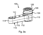
図2a-2fを参照すると、アタッチメント部品100は、クローズドエンドタイプであり、細長いハウジング110及び接続ヘッド120を備える。接続ヘッド120は、ハウジング110の上に突出しており略円筒形である。接続ヘッドは、アタッチメント部品が電動工具に接続され、電動工具に対して割り出されることを可能にするための、図1に示すアダプタ20の対応する手段と協働するように配置された、上部半径方向突出フランジ部分122及び下部半径方向突出長手方向スプライン124を備える。
Referring to FIGS. 2a-2f, the
細長いハウジングは、上部ハウジング部111及び下部ハウジング部112を備え、この各ハウジング部は、長手方向の正中面に沿って相互接続される。ハウジング110は、上部ハウジング部111及び下部ハウジング部112と全く同じように第1の端部113及び第2の端部114を備える。第1の端部113及び第2の端部114は、丸みを帯びており、第1の端部113は、第2の端部114の場合の曲率半径よりも大きい曲率半径を示す。第1の端部113及び第2の端部114は、さらに略正方形断面の中間部分115によって連結される。中間部分115の側壁は、第1の端部113から第2の端部114に向かって僅かにテーパー付けされている。しかしながら、一部の代替的な実施形態では、中間部分の側壁は、互いに平行であるか又は第2の端部に向かって末広がりになることができる。上部ハウジング部111はさらに、第1の端部113の中心に配置された第1の穴117を備えている。下部ハウジング部112は、第1の端部113の中心に配置された第2の穴118(図2d)を備えている。
The elongated housing includes an
平らで直線的な歯車列130は、ハウジング110に収容されている。歯車列は、アングルヘッド10の出力軸(図示せず)からアタッチメント部品100の出力接続部に回転運動及びトルクを伝達するために配置される。歯車列130は、ハウジング110の第1の端部113に配置された入力歯車131と、ハウジング110の第2の端部114に配置された出力歯車132とを備える。図示の実施例では、3つの中間歯車133、134、135は、入力歯車131と出力歯車132との間に配置され、入力歯車131が中間歯車133と噛み合い、中間歯車133もまた中間歯車134と噛み合い、中間歯車134もまた中間歯車135と噛み合い、中間歯車135もまた出力歯車132と噛み合うようになっている。中間歯車133-135は、それぞれのシャフト上に配置された軸受によって支持され、このシャフトは、上部ハウジング部111及び下部ハウジング部112に設けられた対応する開口部に収容される。出力歯車132は、ハウジング部111、112に収容された滑り軸受によって支持される。
A flat,
入力歯車121は、アングルヘッド10の出力シャフト(図示せず)で正方形駆動手段(図示せず)を受け入れるために配置されかつ寸法決めされた正方形凹部を呈する入力接続部136と一体形成される。通常、入力接続部136は、標準化された正方形駆動手段を受け入れるように構成することができる。図示の実施例では、入力接続部136は、3/8インチの正方形駆動手段を受け入れるように構成される。しかしながら、入力接続部は、アングルヘッド又は電動工具の他の出力シャフトへの接続用に構成することもでき、この出力シャフトは、多くの他の幾何学的形状を有することができる。さらに、入力歯車及び入力接続部は、一部の実施形態では、別個の相互接続された構成要素として形成することができる。
The input gear 121 is integrally formed with an
出力歯車132は、出力接続部132aを備える。出力接続部132aは、軸方向穴132bを備えた管状であり、出力歯車132の内部で同軸に配置される。この実施例では、出力接続部132aは、穴132bに配置された内壁(見えない)を備え、壁は、正方形駆動手段を備えた標準化された工具又はねじビット(図示せず)を受け入れるように構成された正方形の貫通開口部を備える。しかしながら、出力接続部は、多くの他の方法で構成することができる。例えば、出力接続部は、締められる又は緩められるボルト、ナットなどに直接に係合するために六角形の幾何学的形状で構成することができる。また、出力接続部は、ハウジング110から突出する正方形駆動手段などとして配置することができる。
The
アタッチメント部品100は、スリーブ部材140、固定部材150、及び接続ヘッド120をさらに備える。これらの部材140、150、120は、第1の端部113で各ハウジング部を締め付けることによって、上部ハウジング部111及び下部ハウジング部112と相互接続するように配置される。スリーブ部材140は、スリーブ141の上縁に配置された4つの半径方向外向きに突出する締め付けフランジ142を備えた、略円筒形のスリーブ141を備える。貫通開口部143は、スリーブの下縁から上方に延びる。貫通開口部143は、入力歯車131が中間歯車133と噛み合うのを可能にするように構成される。雌ねじ144は、スリーブ141の内部で下縁の近くに配置される。
固定部材150は、概して回転対称であり、上部円筒シャフト151、中間円筒部分152、及び円筒部分152の下縁から半径方向外向きに突出する下部締め付けフランジ153を備える。円筒部分152は、スリーブ部材140の雌ねじ144に対応する雄ねじ154を備えている。
The
図2dで最もよく分かるように、スリーブ部材140及び固定部材150及び接続ヘッド120は、協働して以下の方法で上部ハウジング部111及び下部ハウジング部112を締め付ける。さらに、図2b及び図2fで最もよく分かるように、この実施形態ではスリーブ部材及び接続ヘッドは2つの別個の構成要素として形成される。アタッチメント部品100を組み立てる際に、出力歯車132及び中間歯車133-135は、下部ハウジング部112内に位置決めされ、上部ハウジング部111は、位置合わせされて下部ハウジング部112と接触状態にされる。その後、2つのハウジング部は、固定ねじ(図示せず)によって相互接続される。固定ねじは、下部ハウジング部112の第2の端部114及び中間部分115の側壁に配置された固定穴116を貫通して挿入され、上部ハウジング部111の第2の端部の側壁及び中間部分に配置された対応する穴(図示せず)に螺合される。
As best seen in Figure 2d, the
その後、スリーブ部材140、接続ヘッド120、及び固定部材150は、上部ハウジング部111及び下部ハウジング部112の第1の端部113の強固かつしっかりした相互接続を実現するために取り付けられる。最初に、接続ヘッド120は、上部ハウジング部111が第1の穴117を取り囲むように上部ハウジング部111の上に位置決めされる。その後、スリーブ部材は、締め付けフランジ142が接続ヘッド120の内部に突出する半径方向フランジ125と支持接触するまで、接続ヘッド120及び第1の穴117を貫通して上方から挿入される。スリーブ部材140は、取り付け時に、貫通開口部143が中間歯車133-135の方に向いて、中間歯車133の一部が入力歯車131と噛み合うことが可能であるよう開口部143を貫通して延びることができるように、回転して方向付ける必要がある。
Thereafter, the
次に、第1の軸受137は、入力歯車131の内部に取り付けられる。固定部材115は、第2の穴118を貫通して下方から挿入され、外ねじ154は、固定部材150を回転させることによって、スリーブ部材の内ねじ144と係合する。このために、固定部材150の下部外面は、凹部(図示せず)を受け入れる適切な工具を備えることができる。固定部材の回転時、固定部材の締め付けフランジ153は、第2の穴118の周りで、下部ハウジング部112の下面に接触する。固定部材150の適切かつしっかりした位置決めのために、下部ハウジング部112は、第2の穴118の縁部に配置され、固定部材150の締め付けフランジ153の直径に対応する直径を有する円形の位置決め凹部119を備える。固定部材150をスリーブ部材140に対してこのように固定する間に、対応する締め付け力をもたらす適切な固定トルクを選択することが可能であり、これによって上部ハウジング部111及び下部ハウジング部112が共に押し付けられる。このようにして、上部ハウジング部111及び下部ハウジング部112は、ハウジング110の第1の端部113で簡単に相互接続されてしっかり保持される。
Next, the
ハウジング部111、112が相互接続される際に、接続ヘッド120の中に入力接続部136を支持するための第2の軸受138が挿入される。次に、入力接続部136を備えた第1の歯車131は、接続ヘッド120及びスリーブ部材140を貫通して上方から挿入され、第1の歯車311の下部穴139及び第1の軸受137が固定部材150のシャフト151を受け入れる。このように取り付けられる場合、第1の歯車311は、第1の軸受によって支持され、第1の軸受は、固定部材のシャフト151上の円周方向の外部軸受支持面によって支持される。入力接続部136の外周面は、第2の軸受138によって支持され、第2の軸受138は、接続ヘッド120の内部軸受支持面によって支持される。
A
最後に、第1の歯車311及び入力接続部136は、止めワッシャ160を接続ヘッドの内周溝の中に挿入することによって適切な位置で軸方向に係止される。
Finally, the
図3a-3cは、本発明の第2の実施形態によるアタッチメント部品200を示す。各図面では、割り出しアダプタ270に接続された場合のアタッチメント部品が示される。このアタッチメント部品200は、オープンエンドタイプである。従って、出力接続部232a及び出力歯車232は、半径方向のスリット232cを備え、出力接続部は、パイプなどの上を半径方向にスライドし、パイプ上にねじ込まれてこれを取り囲むナット、ボルトなどと係合するようになっている。従って、オープンエンドアタッチメント部品は、例えば、自動車のブレーキ液パイプなどのパイプを取り囲むナットを締めるために及び緩めるために使用することができる。
Figures 3a-3c show an
アタッチメント部品200は、ハウジング210及びこのハウジング210から上向きに突出する接続ヘッド220を備える。ハウジング210は、このハウジング210の長手方向平面に沿って相互接続された上部ハウジング部211及び下部ハウジング部210を備える。ハウジング210、上部ハウジング部211、及び下部ハウジング部212は、第1の端部213及び第2の端部214を備える。この実施形態では、第2の端部214は、長手方向にオープンである。
The
入力歯車131は、入力接続部236と一体に作られており、入力歯車131は、第1の端部213でハウジング210の内部に配置される。出力歯車232は、第2の端部214でハウジング210の内部に配置される。出力接続部232aは、出力歯車232の内部に同軸に配置される。中間歯車233、234a、234bは、第1の端部213と第2の端部214との間のハウジング210の中間部分215の内部に配置される。
中間歯車は、入力歯車231及び並列に配置された2つの追加の中間歯車234a、234bと噛み合う、1つの中間歯車233を含む。2つの追加の中間歯車234a、234bは、出力歯車232と噛み合う。これによって、出力歯車232に配置された半径方向のスリットにもかかわらず、出力歯車232を完全に回転させることができる。アタッチメント部品200は、逆転停止デバイス260をさらに備える。逆転停止デバイス260は、逆回転中、入力歯車231と協働して、出力接続部232a及び出力歯車232の半径方向のスリット232cが、ハウジングのオープンな第2の端214と整列するとすぐに、出力歯車の回転を停止させる。このようにして、締結又は締結解除の終了時、確実に出力接続部232aをナット、ボルトなどから容易に取り外すことができる。このような逆転停止デバイスは、当業者にはよく知られており、ここではより詳細に説明しない。
The intermediate gears include one
上部ハウジング部211及び下部ハウジング部212の第2の端部214及び中間部分215は、固定ねじ216aによって相互接続され、固定ねじは、下部ハウジング部の貫通穴216を貫通して延び、上部ハウジング部211の対応する穴(図示せず)に螺合される。
The
第1の端部213では、上部ハウジング部211及び下部ハウジング部212は、一緒に固定されるスリーブ部材240及び固定部材250によって相互接続される。この実施形態では、スリーブ部材240は、接続ヘッド220と一体形成され、これらの部材が単一の構成要素を形成するようになっている。スリーブ部材240は、逆転停止デバイス260の環状開口部及び上部ハウジング部211の第1の端部に配置された第1の中心穴217を貫通して延びる。固定部材250は、下部ハウジング部212の第1の端部213に配置された第2の中心穴218を貫通して延びる。
At the
スリーブ部材240は、逆転停止デバイス260の上面に当接する第1の半径方向に突出する締め付けフランジ242を備える。逆転停止デバイス260の下面は、上部ハウジング部211の上面に当接して第1の穴217を取り囲む。固定部材250は、固定部材250の中間部分251に配置されかつスリーブ部材240の底壁部分245に配置された対応する雌ねじ244と協働する雄ねじ254によって、スリーブ部材240に固定される。固定部材250は、下部ハウジング部212の凹型の下面に当接する、半径方向に突出する締め付けフランジ253を備える。固定部材250をスリーブ部材240に回転で締め付けることにより、上部ハウジング部211及び下部ハウジング部212は、逆転停止デバイス260及び固定部材250の締め付けフランジ253を介して、スリーブ部材の第1の締め付けフランジ242によって締め付けられる。
加えて、この実施形態では、スリーブ部材240は、アダプタ270の一部を形成する第1のアダプタリング271の下部の半径方向内向きに突出する部分に当接するように配置された第2の半径方向外向きに突出するフランジ246を備える。アダプタ270は、第2のアダプタリングをさらに備える。図3bは、2つのこのような代替的な第2のアダプタリング272、273を示す。
Additionally, in this embodiment, the
加えて、図面に示されるように、スリーブ部材240及び接続ヘッド220によって形成される構成要素、並びに逆転停止デバイス260は、これらの構成要素の間の相対回転を防止するための上部ハウジング部211の対応する手段と協働する外形係止手段を備える。
In addition, as shown in the figures, the components formed by
この実施形態では、スリーブ部材240及び固定部材250は、第1の端部213で上部ハウジング部211及び下部ハウジング部212と相互接続するためだけでなく、逆転停止デバイス260及びアダプタ270をアタッチメント部品200に固定するためにも使用される。
In this embodiment, the
さらに、この実施形態では、固定部材250は、上向きに延びるシャフト251を備え、シャフトの円周面は、入力歯車231の内部に配置された第1の軸受237の支持面を形成する。また、スリーブ部材240の上部には、入力接続部236の周囲に支持的に配置された第2の軸受238のための軸受支持面を形成する内部円筒面245がある。
Furthermore, in this embodiment, the fixing
上記の第1の実施形態と同様に、スリーブ部材240は、中間歯車233が入力歯車231と噛み合うことを可能にするための開口部243を備える。
Similar to the first embodiment described above,
図4には第3の実施形態によるアタッチメント部品が示される。アタッチメント部品300は、上部ハウジング部311及び下部ハウジング部312を含むハウジング310を備える。ハウジング310、上部ハウジング部311及び下部ハウジング部312は、第1の端部313、第2の端部314、及び中間部分315を備える。第1の中心穴317は、上部ハウジング部311の第1の端部に配置され、第2の穴318は、下部ハウジング部312の第1の端部313に配置される。2つの中間歯車及び出力歯車を備える駆動装置(図示せず)は、ハウジング310の第2の端部314及び中間部分315の内部に配置される。第1の端部313には、外部に突出する入力接続部336と一体形成された入力歯車331が配置される。第1の端部313において、上部ハウジング部311及び下部ハウジング部312は、一緒に固定されたスリーブ部材340及び固定部材250によって相互接続される。
FIG. 4 shows an attachment component according to a third embodiment. Attachment part 300 includes a
スリーブ部材340は、第1の直径を有する下部円筒部分341aと、第1の直径よりも大きい第2の直径を有する上部円筒部分341bとを備える。下部341aと上部341b部分との間の結合部では、締め付けフランジ342が形成され、締め付けフランジ342は下部341aの上縁から半径方向外向きに突出する。下端では、スリーブ部材340は、下部円筒部分341aの下縁から内向きに延びる底壁部分345を備える。底壁部分345は、雌ねじ344を備えた中心の円形貫通開口部を備える。
固定部材350は、上部の垂直方向に延びるシャフト351、雄ねじ354を備えた円筒形中間部分352、及び下部の半径方向外向きに突出する締め付けフランジ353を備える。
The fixing member 350 comprises an upper vertically extending
上部ハウジング部311及び下部ハウジング部312の第1の端部313を相互接続するために、スリーブ部材340の下部円筒部分341aは、スリーブ部材の締め付けフランジ342が第1の穴317の周りの上面と接触するまで、第1の穴317を通して上から挿入される。固定部材350は、第2の穴318を通して下から挿入される。固定部材350を回転させることにより、中間部分352の雄ネジ354は、底壁部分345の雌ねじ344と係合する。固定部材350の継続的な締結回転により、固定部材350の締め付けフランジ353が第2の穴318の周りの凹面と接触することになる。このようにして、上部ハウジング部311及び下部ハウジング部312は、2つの締め付けフランジ342、353の間で締め付けられ、結果的に、強固かつしっかり相互接続される。この実施形態では、固定部材350のシャフト351は、入力歯車331の内部に配置された第1の軸受337の軸受支持面を形成する。スリーブ部材340の上部341bの内側円筒面は、入力接続部336の外側に配置された第2の軸受338のための支持面を形成する。
To interconnect the first ends 313 of the
図示されていない実施形態では、スリーブ部材及び固定部材は、ねじ山以外の固定手段を備える。このような固定手段の例としては、バヨネット式の協働係合部材、スナップ係合部材、及び他の外形係止構成を挙げることができる。 In embodiments not shown, the sleeve member and the securing member include securing means other than threads. Examples of such securing means may include cooperating bayonet engagement members, snap engagement members, and other profile locking arrangements.
別の図示されていない実施形態では、スリーブ部材の締め付けフランジは、接続ヘッド、又は逆転停止デバイス以外の中間構成要素と締め付け接触状態になるように配置され、中間構成要素は、この締め付けフランジと上部ハウジング部との間に配置される。このような中間構成要素の実施例は、アダプタの一部を形成するアダプタリング、及び、他の補助デバイスの一部を形成するリング、スリーブ、及び他の構成要素を備える。 In another non-illustrated embodiment, the clamping flange of the sleeve member is arranged in clamping contact with the connecting head or an intermediate component other than the reversal stop device, and the intermediate component is in contact with the clamping flange and the upper and the housing part. Examples of such intermediate components include adapter rings forming part of an adapter, and rings, sleeves, and other components forming part of other auxiliary devices.
様々な実施形態の上記の説明から容易に理解されるように、上部ハウジング部及び下部ハウジング部を締め付けるための一緒に固定されたスリーブ部材及び固定部材の構成は、上部ハウジング部と下部ハウジング部との間の強固かつしっかりした相互接続を達成するための迅速かつ容易な方法を提供する。加えて、この構成は、入力歯車、入力接続部、これらの構成要素を支持する軸受、及びハウジングの第1の端部の内部に配置された何らかの他の構成要素の点検、保守、及び交換を容易にするための迅速かつ容易な取り外しを可能にする。このため、これらの内部構成要素は、固定部材及び場合によってはスリーブ部材を単に取り外すことによって、第1の穴及び/又は第2の穴を通して直接アクセスすること、取り外すこと、及び交換することができることに留意されたい。また、この構成は、第1の端部の周りで、ハウジング部の側壁を貫通する複数の固定ねじなどを設ける必要性を排除する。このことは、結果的に、ハウジング部の材料の厚さを低減し、これによってアタッチメント部品の全体的寸法を低減するのを可能にする。 As will be readily appreciated from the above description of the various embodiments, the configuration of the sleeve member and securing member secured together for tightening the upper and lower housing portions is similar to that of the upper and lower housing portions. provides a quick and easy way to achieve strong and secure interconnections between In addition, this configuration facilitates inspection, maintenance, and replacement of the input gears, input connections, bearings supporting these components, and any other components located within the first end of the housing. Allows for quick and easy removal. These internal components can thus be directly accessed, removed and replaced through the first hole and/or the second hole by simply removing the fixing member and possibly the sleeve member. Please note. This configuration also eliminates the need for multiple fixation screws or the like to pass through the side wall of the housing portion around the first end. This in turn makes it possible to reduce the material thickness of the housing part and thereby reduce the overall dimensions of the attachment part.
本発明は、主としていくつかの実施形態を参照して上述されている。しかしながら、当業者であれば容易に理解できるように、上記に開示されたもの以外の実施形態は、同様に特許請求の範囲によって定義される本発明の範囲内で可能である。 The invention has been described above primarily with reference to several embodiments. However, as one skilled in the art will readily appreciate, embodiments other than those disclosed above are possible within the scope of the invention as well, as defined by the claims.
111 上部ハウジング部
112 下部ハウジング部
113 第1の端部
116 固定穴
117 第1の穴
120 接続ヘッド
122 フランジ部分
124 長手方向スプライン
130 歯車列
131 入力歯車
132 出力歯車
132a 出力接続部
132b 軸方向穴
133 中間歯車
134 中間歯車
135 中間歯車
136 入力接続部
137 第1の軸受
138 第2の軸受
140 スリーブ部材
141 スリーブ
142 締め付けフランジ
143 貫通開口部
144 雌ねじ
150 固定部材
151 シャフト
152 円筒部分
153 締め付けフランジ
154 雄ねじ
160 止めワッシャ
111
Claims (14)
上部ハウジング部(111、211、311)及び下部ハウジング部(112、212、312)を含む細長いハウジング(110、210、310)と、
前記上部ハウジング部及び前記下部ハウジング部を相互接続するための相互接続手段と、
前記ハウジングの第1の端部(113、213、313)に配置され、電動工具の出力シャフトに接続するための入力歯車(131、231、331)と、
前記ハウジングの第2の端部(114、214、314)に配置され、出力接続部(132a、232a)を備える出力歯車(132、232、332)と、
を備え、
前記相互接続手段は、前記入力歯車を収容し、前記上部ハウジング部の前記第1の端部で第1の中心穴(117、217、317)を貫通して延びるスリーブ部材(140、240、340)と、前記下部ハウジング部の前記第1の端部で第2の中心穴(118、218、318)を貫通して延び、前記上部ハウジング部及び前記下部ハウジング部を締め付けるために前記スリーブ部材に固定されるように配置される固定部材(150、250、350)とを備え、
前記スリーブ部材(140、240、340)は、前記入力歯車(131、231、331)が前記出力歯車と噛み合うことを、又は前記入力歯車と前記出力歯車(132、232)との間に配置された補助歯車(133、233)と噛み合うことを可能にするように配置された開口部(143、243)を備える、アタッチメント部品(100、200、300)。 An attachment part (100, 200, 300) for a power tool,
an elongate housing (110, 210, 310) including an upper housing portion (111, 211, 311) and a lower housing portion (112, 212, 312);
interconnection means for interconnecting the upper housing part and the lower housing part;
an input gear (131, 231, 331) located at the first end (113, 213, 313) of the housing for connection to the output shaft of the power tool;
an output gear (132, 232, 332) located at the second end (114, 214, 314) of the housing and comprising an output connection (132a, 232a);
Equipped with
The interconnection means includes a sleeve member (140, 240, 340) that accommodates the input gear and extends through a first central hole (117, 217, 317) at the first end of the upper housing part. ) extending through a second central hole (118, 218, 318) at the first end of the lower housing portion and attached to the sleeve member for tightening the upper housing portion and the lower housing portion. A fixing member (150, 250, 350) arranged to be fixed,
The sleeve member (140, 240, 340) prevents the input gear (131, 231, 331) from meshing with the output gear, or is arranged between the input gear and the output gear (132, 232). an attachment part (100, 200, 300) comprising an opening (143, 243) arranged to allow engagement with an auxiliary gear (133, 233);
Applications Claiming Priority (3)
| Application Number | Priority Date | Filing Date | Title |
|---|---|---|---|
| SE1850890A SE542280C2 (en) | 2018-07-12 | 2018-07-12 | Attachment part for a power tool and a tool assemby |
| SE1850890-3 | 2018-07-12 | ||
| PCT/EP2019/066336 WO2020011510A1 (en) | 2018-07-12 | 2019-06-20 | Attachment part for a power tool and a tool assembly |
Publications (3)
| Publication Number | Publication Date |
|---|---|
| JP2021524387A JP2021524387A (en) | 2021-09-13 |
| JPWO2020011510A5 JPWO2020011510A5 (en) | 2022-06-21 |
| JP7422127B2 true JP7422127B2 (en) | 2024-01-25 |
Family
ID=67003500
Family Applications (1)
| Application Number | Title | Priority Date | Filing Date |
|---|---|---|---|
| JP2021500926A Active JP7422127B2 (en) | 2018-07-12 | 2019-06-20 | Attachment parts and tool assemblies for power tools |
Country Status (7)
| Country | Link |
|---|---|
| US (1) | US11724367B2 (en) |
| EP (1) | EP3820647B1 (en) |
| JP (1) | JP7422127B2 (en) |
| KR (1) | KR102637875B1 (en) |
| CN (1) | CN112399905B (en) |
| SE (1) | SE542280C2 (en) |
| WO (1) | WO2020011510A1 (en) |
Families Citing this family (6)
| Publication number | Priority date | Publication date | Assignee | Title |
|---|---|---|---|---|
| DE102018118853A1 (en) * | 2018-08-02 | 2020-02-06 | Johannes Lübbering Gmbh | Screwing device, drive torque generating means, screwing system and method for torque control |
| SE544125C2 (en) * | 2019-07-24 | 2022-01-04 | Atlas Copco Ind Technique Ab | Power tool attachment part with a torque sensor detecting radial forces |
| EP3771519B1 (en) * | 2019-08-02 | 2023-03-15 | Johannes Lübbering GmbH | Screwing device with integrated sensing means |
| CN111975693B (en) * | 2020-07-06 | 2022-05-10 | 中车青岛四方机车车辆股份有限公司 | Wrench used in narrow space and application thereof |
| US11772242B1 (en) * | 2020-12-18 | 2023-10-03 | Atlas Copco Industrial Technique Ab | Torque transmitting assembly for a power tool |
| CN114029891A (en) * | 2021-11-05 | 2022-02-11 | 江西科技学院 | Simple multifunctional automobile repairing tool |
Citations (1)
| Publication number | Priority date | Publication date | Assignee | Title |
|---|---|---|---|---|
| US20170001288A1 (en) | 2015-06-30 | 2017-01-05 | Klein Tools, Inc. | Offset wrench |
Family Cites Families (13)
| Publication number | Priority date | Publication date | Assignee | Title |
|---|---|---|---|---|
| US4942794A (en) * | 1988-09-15 | 1990-07-24 | Raymond Engineering Inc. | Torque tool |
| US5179876A (en) * | 1991-04-10 | 1993-01-19 | Gadea Mantilla Carlos E | Device for rotary torque enhancement |
| CA2351993C (en) * | 2001-06-29 | 2003-02-18 | New World Technologie Inc. | Torque tool |
| US7631580B2 (en) * | 2007-11-13 | 2009-12-15 | Gm Global Technology Operations, Inc. | Wrench for tightening pipe nuts |
| US7703356B2 (en) * | 2008-03-12 | 2010-04-27 | Jamie Bass | Tool assembly, system and method, for driving threaded members |
| US7874232B2 (en) * | 2008-10-16 | 2011-01-25 | Huck Patents, Inc. | Quick-change socket and hex key retainer assembly for a fastener installation tool |
| US8671804B2 (en) * | 2012-01-16 | 2014-03-18 | Michael Edward Galat | Fastener installation tool with quick change key |
| US20130233131A1 (en) * | 2012-03-09 | 2013-09-12 | John A. Badiali | Power wrench attachment |
| EP2934818B1 (en) | 2012-12-21 | 2020-02-05 | Atlas Copco Industrial Technique AB | Power tool attachment part |
| EP2988908B1 (en) * | 2013-04-24 | 2020-06-10 | Hytorc Division Unex Corporation | Apparatus for tightening threaded fasteners |
| US9969067B2 (en) * | 2015-02-17 | 2018-05-15 | Snap-On Incorporated | Methods and systems for increasing the efficiency of a remote wrench |
| CN105291031A (en) * | 2015-11-16 | 2016-02-03 | 沧州渤海防爆特种工具集团有限公司 | Arm type rapid nut dismounting machine tool |
| TWM560979U (en) * | 2017-12-08 | 2018-06-01 | Shi hua chang | Screw locking auxiliary device |
-
2018
- 2018-07-12 SE SE1850890A patent/SE542280C2/en unknown
-
2019
- 2019-06-20 KR KR1020217000267A patent/KR102637875B1/en active IP Right Grant
- 2019-06-20 EP EP19732980.8A patent/EP3820647B1/en active Active
- 2019-06-20 JP JP2021500926A patent/JP7422127B2/en active Active
- 2019-06-20 WO PCT/EP2019/066336 patent/WO2020011510A1/en active Search and Examination
- 2019-06-20 CN CN201980046440.1A patent/CN112399905B/en active Active
- 2019-06-20 US US17/258,799 patent/US11724367B2/en active Active
Patent Citations (1)
| Publication number | Priority date | Publication date | Assignee | Title |
|---|---|---|---|---|
| US20170001288A1 (en) | 2015-06-30 | 2017-01-05 | Klein Tools, Inc. | Offset wrench |
Also Published As
| Publication number | Publication date |
|---|---|
| WO2020011510A1 (en) | 2020-01-16 |
| SE542280C2 (en) | 2020-03-31 |
| EP3820647A1 (en) | 2021-05-19 |
| KR20210031892A (en) | 2021-03-23 |
| JP2021524387A (en) | 2021-09-13 |
| KR102637875B1 (en) | 2024-02-19 |
| CN112399905B (en) | 2022-06-10 |
| CN112399905A (en) | 2021-02-23 |
| EP3820647B1 (en) | 2022-08-03 |
| SE1850890A1 (en) | 2020-01-13 |
| US11724367B2 (en) | 2023-08-15 |
| US20210276163A1 (en) | 2021-09-09 |
Similar Documents
| Publication | Publication Date | Title |
|---|---|---|
| JP7422127B2 (en) | Attachment parts and tool assemblies for power tools | |
| JPH01503400A (en) | Fixing devices and tools for fixing the devices | |
| WO2018002244A1 (en) | Separating device | |
| US9771983B2 (en) | Coupling assembly | |
| US7118300B2 (en) | Shaft coupling | |
| CN108991727A (en) | The lifting device of same table | |
| US10920830B2 (en) | Mixer comprising a clamping sleeve assembly | |
| EP2603723B1 (en) | Securing assembly for screwed hose end connectors | |
| EP2927116B1 (en) | Eccentric tool | |
| EP1565684B1 (en) | Pipe coupling | |
| JP2014173639A (en) | Coupling device and its nut attaching/detaching jig used for assembling/disassembling the same | |
| JP7416752B2 (en) | power tool attachment parts | |
| US9845840B2 (en) | Eccentric tool | |
| CN1230644C (en) | Connecting device for housing-parts of turbochargers | |
| CN219673048U (en) | Same side locking bolt | |
| US11679474B2 (en) | Peep-hole socket driving shank assembly | |
| CN116669907B (en) | Torque transmission assembly for a power tool | |
| CN210637348U (en) | Limit screw and threaded connection system | |
| GB2495974A (en) | Shaft connection having a collet with projections that engage a circumferential groove on a further shaft | |
| KR20150001774U (en) | Shaft connecting structure |
Legal Events
| Date | Code | Title | Description |
|---|---|---|---|
| A521 | Request for written amendment filed |
Free format text: JAPANESE INTERMEDIATE CODE: A523 Effective date: 20220613 |
|
| A621 | Written request for application examination |
Free format text: JAPANESE INTERMEDIATE CODE: A621 Effective date: 20220613 |
|
| A131 | Notification of reasons for refusal |
Free format text: JAPANESE INTERMEDIATE CODE: A131 Effective date: 20230626 |
|
| A977 | Report on retrieval |
Free format text: JAPANESE INTERMEDIATE CODE: A971007 Effective date: 20230629 |
|
| A131 | Notification of reasons for refusal |
Free format text: JAPANESE INTERMEDIATE CODE: A131 Effective date: 20231005 |
|
| A521 | Request for written amendment filed |
Free format text: JAPANESE INTERMEDIATE CODE: A523 Effective date: 20231129 |
|
| TRDD | Decision of grant or rejection written | ||
| A01 | Written decision to grant a patent or to grant a registration (utility model) |
Free format text: JAPANESE INTERMEDIATE CODE: A01 Effective date: 20231214 |
|
| A61 | First payment of annual fees (during grant procedure) |
Free format text: JAPANESE INTERMEDIATE CODE: A61 Effective date: 20240115 |
|
| R150 | Certificate of patent or registration of utility model |
Ref document number: 7422127 Country of ref document: JP Free format text: JAPANESE INTERMEDIATE CODE: R150 |