以下、実施形態を説明する。同一の構成要素には同一の符号を付し、重複する説明を省略する。各図面では、説明の便宜のため、適宜、構成要素を省略、拡大、縮小する。図面は符号の向きに合わせて見るものとする。本明細書での「接続」、「固定」、「取り付け」とは、特に明示がない限り、言及する条件を二者が直接的に満たす場合の他に、他の部材を介して満たす場合も含む。
Embodiments will be described below. Identical components are given the same reference numerals and redundant explanations will be omitted. In each drawing, constituent elements are omitted, enlarged, or reduced as appropriate for convenience of explanation. The drawings should be viewed according to the direction of the symbols. Unless otherwise specified, the terms "connection," "fixation," and "attachment" as used herein refer not only to cases in which two parties directly satisfy the mentioned conditions, but also to cases in which they are satisfied through other members. include.
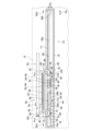
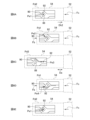
(第1の実施の形態)図1を参照する。引込装置10は、スライド式開閉部材12に用いられる。開閉部材12は、外部部材14に開閉方向Daにスライド可能に支持される。本実施形態において、開閉部材12は建具の引き戸であり、外部部材14は建具のサッシである。開閉部材12は、開閉方向Daのスライドによって開閉可能である。開閉部材12は、可動範囲の一方側にある全閉じ位置と、可動範囲の他方側にある全開き位置との間を移動可能である。
(First Embodiment) Refer to FIG. 1. The retracting device 10 is used for a sliding opening/closing member 12. The opening/closing member 12 is supported by the external member 14 so as to be slidable in the opening/closing direction Da. In this embodiment, the opening/closing member 12 is a sliding door of fittings, and the external member 14 is a sash of fittings. The opening/closing member 12 can be opened/closed by sliding in the opening/closing direction Da. The opening/closing member 12 is movable between a fully closed position on one side of the movable range and a fully open position on the other side of the movable range.
引込装置10は、開閉部材12を引込方向Db1に引き込むことによって、開閉部材12を引込完了位置Paに保持可能である。本実施形態の引込完了位置Paは全閉じ位置である。引込方向Db1は、開閉部材12の開閉方向Daの一方側をいう。以下、開閉方向Daにおいて引込方向Db1とは反対方向を反引込方向Db2という。この他に、説明の便宜のため、図の向きに従って、引込方向Db1を左側、左向きともいい、反引込方向Db2を右側、右向きともいう。
The retraction device 10 can hold the opening/closing member 12 at the retraction completion position Pa by pulling the opening/closing member 12 in the retraction direction Db1. The retraction completion position Pa of this embodiment is a fully closed position. The retraction direction Db1 refers to one side of the opening/closing direction Da of the opening/closing member 12. Hereinafter, the direction opposite to the retraction direction Db1 in the opening/closing direction Da will be referred to as a counter-retraction direction Db2. In addition, for convenience of explanation, the retraction direction Db1 is also referred to as the left side or leftward, and the anti-retraction direction Db2 is also referred to as the rightward or rightward direction, according to the orientation of the drawings.
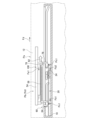
図2を参照する。引込装置10は、引込装置10の他の構成要素を収容するケーシング16を備える。「他の構成要素」とは、後述する前段伝動経路20、変速機構22、後段伝動経路24等である。ケーシング16は、外部部材14に固定される。
See FIG. 2. The retraction device 10 includes a casing 16 that houses other components of the retraction device 10. "Other components" include the front-stage transmission path 20, the transmission mechanism 22, the rear-stage transmission path 24, etc., which will be described later. Casing 16 is secured to outer member 14 .
(引込部材)引込装置10は、引込部材18を備える。本実施形態の引込部材18は引張コイルばね、つまり、弾性体である。引込部材18の一端部は、ケーシング16に設けられる固定部16aに固定され、その他端部は前段伝動経路20の入力部材42(後述する)に固定される。引込部材18は、開閉方向Daに弾性変形可能であり、その弾性変形に起因する弾性反発力を左向き(引込方向Db1)の付勢力として蓄積可能である。
(Retraction member) The retraction device 10 includes a retraction member 18. The retraction member 18 of this embodiment is a tension coil spring, that is, an elastic body. One end of the retracting member 18 is fixed to a fixing part 16a provided on the casing 16, and the other end is fixed to an input member 42 (described later) of the front-stage transmission path 20. The retracting member 18 can be elastically deformed in the opening/closing direction Da, and can accumulate the elastic repulsive force resulting from the elastic deformation as a leftward biasing force (retracting direction Db1).
(伝動経路)引込装置10は、引込部材18から付勢力が第1引込荷重Fa1として入力される前段伝動経路20と、前段伝動経路20に変速機構22を介して接続される後段伝動経路24とを備える。前段伝動経路20と後段伝動経路24は、引込部材18の付勢力を伝達可能な直列的な荷重伝達経路を構成する。
(Transmission Path) The retraction device 10 has a front transmission path 20 into which the urging force from the retraction member 18 is input as the first retraction load Fa1, and a rear transmission path 24 connected to the front transmission path 20 via a transmission mechanism 22. Equipped with The front-stage transmission path 20 and the rear-stage transmission path 24 constitute a serial load transmission path capable of transmitting the biasing force of the retracting member 18.
前段伝動経路20は、引込部材18が接続される第1索状部材26と、第1索状部材26が巻き回される第1巻胴28と、第1巻胴28と一体的に回転可能な第1シャフト30と、第1シャフト30と一体的に回転可能な大径歯車32とを備える。
The front transmission path 20 is rotatable integrally with the first rope member 26 to which the retraction member 18 is connected, the first winding drum 28 around which the first rope member 26 is wound, and the first winding drum 28. A first shaft 30 and a large diameter gear 32 that can rotate integrally with the first shaft 30 are provided.
後段伝動経路24は、大径歯車32と噛み合う小径歯車34と、小径歯車34と一体的に回転可能な第2シャフト36と、第2シャフト36と一体的に回転可能な第2巻胴38と、第2巻胴38に巻き回される第2索状部材40とを備える。
The rear transmission path 24 includes a small diameter gear 34 that meshes with the large diameter gear 32, a second shaft 36 that can rotate integrally with the small diameter gear 34, and a second winding drum 38 that can rotate integrally with the second shaft 36. , and a second rope member 40 wound around the second winding drum 38.
索状部材26、40は、ワイヤー、チェーン等の索状の物体である。第1索状部材26は、引込部材18の付勢力が引込部材18から直接に入力される入力部材42として機能する。引込部材18は、入力部材42に対して左側に配置される。シャフト30、36は、ケーシング16に軸受(不図示)を介して回転自在に支持される。引込部材18の付勢力は、第1索状部材26→第1巻胴28→第1シャフト30→大径歯車32→小径歯車34→第2シャフト36→第2巻胴38→第2索状部材40の順で伝達される。
The cable members 26, 40 are cable-shaped objects such as wires or chains. The first cable member 26 functions as an input member 42 to which the biasing force of the retracting member 18 is directly input from the retracting member 18 . The retraction member 18 is arranged on the left side with respect to the input member 42. The shafts 30 and 36 are rotatably supported by the casing 16 via bearings (not shown). The biasing force of the retracting member 18 is as follows: first rope-like member 26 → first winding drum 28 → first shaft 30 → large-diameter gear 32 → small-diameter gear 34 → second shaft 36 → second winding drum 38 → second rope-like member It is transmitted in the order of member 40.
前段伝動経路20は、開閉方向Daに沿って直動可能な前段直動部分44を備える。本実施形態の前段直動部分44は、第1巻胴28から繰り出される第1索状部材26の繰り出し部分である。後段伝動経路24は、開閉方向Daに沿って直動可能な後段直動部分46を備える。本実施形態の後段直動部分46は、第2巻胴38から繰り出される第2索状部材40の繰り出し部分である。
The front-stage transmission path 20 includes a front-stage translational portion 44 that is linearly movable along the opening/closing direction Da. The front linear motion portion 44 of this embodiment is a portion of the first cable member 26 that is fed out from the first winding drum 28 . The rear-stage transmission path 24 includes a rear-stage linearly moving portion 46 that is linearly movable along the opening/closing direction Da. The rear linear motion portion 46 of this embodiment is a portion of the second cable member 40 that is fed out from the second winding drum 38 .
(変速機構)引込装置10は、変速機構22を備える。変速機構22は、前述の小径歯車34と大径歯車32によって構成される歯車機構である。変速機構22は、前段伝動経路20から入力される第1引込荷重Fa1を後段伝動経路24に出力する。このとき、変速機構22は、第1引込荷重Fa1よりも小さい第2引込荷重Fa2に変換し、第2引込荷重Fa2を後段伝動経路24に出力する。これにより、前段伝動経路20に作用する第1引込荷重Fa1と後段伝動経路24に作用する第2引込荷重Fa2とを変化させることができる。
(Transmission mechanism) The retraction device 10 includes a transmission mechanism 22. The transmission mechanism 22 is a gear mechanism including the small diameter gear 34 and the large diameter gear 32 described above. The transmission mechanism 22 outputs the first pulling load Fa1 input from the front transmission path 20 to the rear transmission path 24. At this time, the transmission mechanism 22 converts the first retraction load Fa1 into a second retraction load Fa2, which is smaller than the first retraction load Fa1, and outputs the second retraction load Fa2 to the rear transmission path 24. Thereby, the first pulling load Fa1 acting on the front-stage transmission path 20 and the second pulling load Fa2 acting on the rear-stage transmission path 24 can be changed.
図2、図10を参照する。変速機構22の変速比は、後段直動部分46の移動距離La2に対する前段直動部分44の移動距離La1の比として表すことができる。変速機構22の変速比は、第2引込荷重Fa2に対する第1引込荷重Fa1の比の逆比に比例した大きさとなり、La1:La2=(1/Fa1):(1/Fa2)として表すことができる。たとえば、変速機構22によって、第1引込荷重Fa1が45N、第2引込荷重Fa2が15Nに変換されるとき、La1:La2=1(=1/45):3(=1/15)となる。つまり、後段直動部分46の移動距離La2は、前段直動部分44の移動距離La1よりも大きくなる。大径歯車32の半径をra1、小径歯車34の半径をra2とする。変速比は、たとえば、歯車機構を用いる場合、歯車比の逆比に比例した大きさとなり、La1:La2=(1/ra1):(1/ra2)として表すことができる。
Refer to FIGS. 2 and 10. The gear ratio of the transmission mechanism 22 can be expressed as a ratio of the moving distance La1 of the front linearly moving section 44 to the moving distance La2 of the rear linearly moving section 46. The gear ratio of the transmission mechanism 22 is proportional to the inverse ratio of the first pull-in load Fa1 to the second pull-in load Fa2, and can be expressed as La1:La2=(1/Fa1):(1/Fa2). can. For example, when the first retraction load Fa1 is converted to 45N and the second retraction load Fa2 is converted to 15N by the transmission mechanism 22, La1:La2=1 (=1/45):3 (=1/15). In other words, the moving distance La2 of the rear linearly moving portion 46 is larger than the moving distance La1 of the preceding linearly moving portion 44. Let the radius of the large diameter gear 32 be ra1, and the radius of the small diameter gear 34 be ra2. For example, when a gear mechanism is used, the gear ratio is proportional to the inverse ratio of the gear ratio, and can be expressed as La1:La2=(1/ra1):(1/ra2).
図2を参照する。以下、変速機構22を構成する回転要素48の回転軸線に沿った方向を高さ方向Dcという。ここでの回転要素48とは、本実施形態では小径歯車34及び大径歯車32である。開閉方向Da及び高さ方向Dcと直交する方向を幅方向Dd(不図示)という。
See FIG. 2. Hereinafter, the direction along the rotational axis of the rotating element 48 that constitutes the transmission mechanism 22 will be referred to as the height direction Dc. The rotating element 48 here is the small diameter gear 34 and the large diameter gear 32 in this embodiment. A direction perpendicular to the opening/closing direction Da and the height direction Dc is referred to as a width direction Dd (not shown).
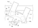
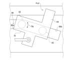
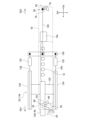
(経路切替機構)引込装置10は、前段伝動経路20及び後段伝動経路24から開閉部材12に引込荷重を伝達可能に接続する経路切替機構50を備える。経路切替機構50は、開閉部材12に固定される固定部材52と、固定部材52に対して開閉方向Daにスライド可能に取り付けられるスライダ54と、を備える。経路切替機構50は、固定部材52に対してスライダ54をロック可能なロック機構56と、スライダ54を付勢可能なスライダ付勢手段58と、を備える。経路切替機構50は、前段伝動経路20にスライダ54を接続する前段接続機構60と、後段伝動経路24に固定部材52を接続する後段接続機構62と、を備える。
(Route Switching Mechanism) The retracting device 10 includes a route switching mechanism 50 that connects the front-stage transmission path 20 and the rear-stage transmission path 24 to the opening/closing member 12 so as to be able to transmit the retracting load. The route switching mechanism 50 includes a fixing member 52 fixed to the opening/closing member 12 and a slider 54 slidably attached to the fixing member 52 in the opening/closing direction Da. The route switching mechanism 50 includes a locking mechanism 56 that can lock the slider 54 with respect to the fixing member 52, and a slider biasing means 58 that can bias the slider 54. The path switching mechanism 50 includes a front connection mechanism 60 that connects the slider 54 to the front transmission path 20 and a rear connection mechanism 62 that connects the fixing member 52 to the rear transmission path 24.
(スライダ)固定部材52及びスライダ54は、開閉方向Daに沿って延びる長尺体である。スライダ54は、固定部材52に設けられる不図示のレールを介して、固定部材52に対してスライド可能である。前段伝動経路20は、前段接続機構60を介して、スライダ54の左側の端部に接続される。前段伝動経路20は、スライダ54を介して固定部材52に接続されることになる。後段伝動経路24は、後段接続機構62を介して、固定部材52の右側の端部に接続される。後段伝動経路24は、スライダ54を介さずに、固定部材52に接続されることになる。スライダ54は、可動範囲の右側にある末端位置を初期位置Pbとして、初期位置Pbから左向きの方向Deに固定部材52に対して相対移動可能である。
(Slider) The fixing member 52 and the slider 54 are elongated bodies extending along the opening/closing direction Da. The slider 54 is slidable with respect to the fixing member 52 via a rail (not shown) provided on the fixing member 52. The front transmission path 20 is connected to the left end of the slider 54 via the front connection mechanism 60. The front transmission path 20 is connected to the fixed member 52 via the slider 54. The rear-stage transmission path 24 is connected to the right end of the fixing member 52 via the rear-stage connection mechanism 62 . The rear-stage transmission path 24 is connected to the fixed member 52 without going through the slider 54. The slider 54 is movable relative to the fixed member 52 in a leftward direction De from the initial position Pb, with an end position on the right side of the movable range being an initial position Pb.
本実施形態のスライダ付勢手段58は、スライダ54とは別体に設けられる引張コイルばね、つまり、弾性体である。スライダ付勢手段58は、固定部材52に対して初期位置Pbから左向きの方向Deにスライダ54が移動したとき、右向きにスライダ54を付勢可能である。本実施形態のスライダ付勢手段58は、固定部材52とスライダ54を接続している。
The slider biasing means 58 of this embodiment is a tension coil spring provided separately from the slider 54, that is, an elastic body. The slider biasing means 58 is capable of biasing the slider 54 to the right when the slider 54 moves from the initial position Pb to the leftward direction De with respect to the fixed member 52. The slider biasing means 58 of this embodiment connects the fixing member 52 and the slider 54.
(前段接続機構)前段接続機構60は、第1引込荷重Fa1を伝達可能に前段伝動経路20に連結される第1フック64と、スライダ54に固定される第1ピン66と、第1フック64を案内する第1案内溝68とを備える。本実施形態の第1フック64は、引込部材18と前段伝動経路20との接続箇所69に連結される。本実施形態の第1案内溝68はケーシング16に形成される。第1案内溝68は、開閉方向Daに直線状に延びる第1直線領域68aと、第1直線領域68aの右側端部に曲げ部を介して連なる第1端部領域68bとを備える。
(Front stage connection mechanism) The front stage connection mechanism 60 includes a first hook 64 connected to the front stage transmission path 20 so as to be able to transmit the first drawing load Fa1, a first pin 66 fixed to the slider 54, and a first hook 64. and a first guide groove 68 for guiding. The first hook 64 of this embodiment is connected to a connection point 69 between the retracting member 18 and the front-stage transmission path 20. The first guide groove 68 of this embodiment is formed in the casing 16. The first guide groove 68 includes a first linear region 68a that extends linearly in the opening/closing direction Da, and a first end region 68b that continues to the right end of the first linear region 68a via a bent portion.
第1フック64は、第1案内溝68に沿って摺動可能な一対の第1摺動突起70と、第1ピン66に右側から引っ掛け可能な第1引掛部72と、第1ピン66を左側から受けることができる受け部74とを備える。
The first hook 64 includes a pair of first sliding protrusions 70 that can be slid along the first guide groove 68, a first hook portion 72 that can be hooked onto the first pin 66 from the right side, and a first hook 72 that can be hooked onto the first pin 66 from the right side. A receiving portion 74 that can be received from the left side is provided.
第1摺動突起70は、右側に動いたとき、第1直線領域68a、第1端部領域68bの順で第1案内溝68を摺動する。第1直線領域68aは、第1フック64が開閉方向Daに直動するように、第1摺動突起70を案内する。第1端部領域68bは、左側の第1摺動突起70周りの方向Dfに第1フック64が回転するように、右側の第1摺動突起70を案内する(図3参照)。前段接続機構60は、第1フック64の開閉方向Daでの動きに連動して第1フック64を回転させることになる。
When the first sliding protrusion 70 moves to the right, it slides in the first guide groove 68 in the order of the first linear region 68a and the first end region 68b. The first linear region 68a guides the first sliding protrusion 70 so that the first hook 64 moves linearly in the opening/closing direction Da. The first end region 68b guides the right first sliding protrusion 70 such that the first hook 64 rotates in the direction Df around the left first sliding protrusion 70 (see FIG. 3). The front-stage connection mechanism 60 rotates the first hook 64 in conjunction with the movement of the first hook 64 in the opening/closing direction Da.
第1フック64は、回転することによって、引掛姿勢Pc1(図2参照)と引掛解除姿勢Pc2(図3参照)との間で姿勢を変更可能である。第1フック64が引掛姿勢Pc1にあるとき、第1ピン66に対して第1引掛部72が右側から引っ掛け可能となる。第1フック64が引掛解除姿勢Pc2にあるとき、第1ピン66に対する第1引掛部72の引っ掛けが解除される。このように、第1フック64は、引掛姿勢Pc1と引掛解除姿勢Pc2との間で姿勢を変更することで、第1ピン66に対する引っ掛けの有無を切り替え可能である。
The first hook 64 can change its posture between a hooking posture Pc1 (see FIG. 2) and a hooking release posture Pc2 (see FIG. 3) by rotating. When the first hook 64 is in the hooking posture Pc1, the first hooking portion 72 can be hooked onto the first pin 66 from the right side. When the first hook 64 is in the hook release position Pc2, the hook of the first hook portion 72 on the first pin 66 is released. In this way, the first hook 64 can switch whether or not it is hooked to the first pin 66 by changing the posture between the hooking posture Pc1 and the hooking release posture Pc2.
第1フック64が引掛姿勢Pc1にあるとき、第1フック64及び第1ピン66を介して、前段伝動経路20からスライダ54に第1引込荷重Fa1を伝達可能となる。このとき、前段接続機構60は、第1引込荷重Fa1を伝達可能に前段伝動経路20にスライダ54を接続することになる。
When the first hook 64 is in the hooking attitude Pc1, the first retraction load Fa1 can be transmitted from the front-stage transmission path 20 to the slider 54 via the first hook 64 and the first pin 66. At this time, the front-stage connection mechanism 60 connects the slider 54 to the front-stage transmission path 20 so as to be able to transmit the first retraction load Fa1.
第1フック64が引掛解除姿勢Pc2にあるとき、前段伝動経路20による拘束を受けることなく、スライダ54が動くことができる。このとき、前段接続機構60は、前段伝動経路20に対するスライダ54の接続を解除することになる。
When the first hook 64 is in the hook release position Pc2, the slider 54 can move without being restrained by the front-stage transmission path 20. At this time, the front-stage connection mechanism 60 releases the connection of the slider 54 to the front-stage transmission path 20.
(後段接続機構)後段接続機構62は、第2引込荷重Fa2を伝達可能に後段伝動経路24に連結される第2フック76と、固定部材52に固定される第2ピン78と、第2フック76を案内する第2案内溝80とを備える。本実施形態の第2案内溝80はケーシング16に形成される。第2案内溝80は、開閉方向Daに直線状に延びる第2直線領域80aと、第2直線領域80aの右側端部に曲げ部を介して連なる第2端部領域80bとを備える。
(Rear-stage connection mechanism) The rear-stage connection mechanism 62 includes a second hook 76 connected to the rear-stage transmission path 24 so as to be able to transmit the second drawing load Fa2, a second pin 78 fixed to the fixing member 52, and a second hook. A second guide groove 80 for guiding the guide member 76 is provided. The second guide groove 80 of this embodiment is formed in the casing 16. The second guide groove 80 includes a second linear region 80a that extends linearly in the opening/closing direction Da, and a second end region 80b that continues to the right end of the second linear region 80a via a bent portion.
第2フック76は、第2案内溝80に沿って摺動可能な一対の第2摺動突起82と、第2ピン78に右側から引っ掛け可能な第2引掛部84とを備える。第2フック76は、第1フック64とは異なり、第2ピン78を左側から受ける受け部を備えていない。第2端部領域80bは、第1端部領域68bと同様、左側の第2摺動突起82周りの方向Dgに第2フック76が回転するように、右側の第2摺動突起82を案内する(図4参照)。後段接続機構62は、前段接続機構60と同様、第2フック76の開閉方向Daでの動きに連動して第2フック76を回転させることができる。
The second hook 76 includes a pair of second sliding protrusions 82 that are slidable along the second guide groove 80 and a second hook portion 84 that can be hooked onto the second pin 78 from the right side. The second hook 76 differs from the first hook 64 in that it does not include a receiving portion for receiving the second pin 78 from the left side. Like the first end region 68b, the second end region 80b guides the second sliding protrusion 82 on the right side so that the second hook 76 rotates in the direction Dg around the second sliding protrusion 82 on the left side. (See Figure 4). Like the front-stage connection mechanism 60, the rear-stage connection mechanism 62 can rotate the second hook 76 in conjunction with the movement of the second hook 76 in the opening/closing direction Da.
第2フック76は、第1フック64と同様、回転することによって、引掛姿勢Pc1(図2参照)と引掛解除姿勢Pc2(図4参照)との間で姿勢を変更可能である。第2フック76は、第1フック64と同様、引掛姿勢Pc1と引掛解除姿勢Pc2との間で姿勢を変更することで、第2ピン78に対する引っ掛けの有無を切り替え可能である。
Like the first hook 64, the second hook 76 can change its posture between a hooking posture Pc1 (see FIG. 2) and a hooking release posture Pc2 (see FIG. 4) by rotating. Like the first hook 64, the second hook 76 can switch whether or not it is hooked to the second pin 78 by changing its posture between the hooking posture Pc1 and the hooking release posture Pc2.
第2フック76が引掛姿勢Pc1にあるとき、第2フック76及び第2ピン78を介して、後段伝動経路24から固定部材52に第2引込荷重Fa2を伝達可能となる。このとき、後段接続機構62は、後段伝動経路24から固定部材52に第2引込荷重Fa2を伝達可能に後段伝動経路24に固定部材52を接続することになる。
When the second hook 76 is in the hooking attitude Pc1, the second retraction load Fa2 can be transmitted from the rear transmission path 24 to the fixed member 52 via the second hook 76 and the second pin 78. At this time, the rear-stage connection mechanism 62 connects the fixing member 52 to the rear-stage transmission path 24 such that the second pull-in load Fa2 can be transmitted from the rear-stage transmission path 24 to the fixing member 52.
第2フック76が引掛解除姿勢Pc2にあるとき、後段伝動経路24による拘束を受けることなく、固定部材52が動くことができる。このとき、後段接続機構62は、後段伝動経路24に対する固定部材52の接続を解除することになる。
When the second hook 76 is in the hook release position Pc2, the fixing member 52 can move without being restrained by the rear transmission path 24. At this time, the rear-stage connection mechanism 62 releases the connection of the fixing member 52 to the rear-stage transmission path 24.
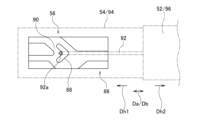
(ロック機構)図5を参照する。本図は、図2の下側からロック機構56を見た図でもある。本実施形態のロック機構56はハートカム機構86を備える。ハートカム機構86そのものは公知のため、ここでは説明を簡易にとどめる。
(Lock mechanism) See FIG. 5. This figure is also a view of the locking mechanism 56 from the bottom side of FIG. 2. The lock mechanism 56 of this embodiment includes a heart cam mechanism 86. Since the heart cam mechanism 86 itself is well known, the explanation will be kept brief here.
ハートカム機構86は、ハートカム部88と、ハートカム部88の周りに形成されるカム溝90と、ハートカム部88に対して進退方向Dhに相対移動可能なフォロアピン92を備える。ここでの進退方向Dhとは開閉方向Daに沿った方向である。進退方向Dhのうちの一方を進み方向Dh1といい、そのうちの他方を退き方向Dh2という。本実施形態では進み方向Dh1は左向きであり、退き方向Dh2は右向きである。
The heart cam mechanism 86 includes a heart cam portion 88, a cam groove 90 formed around the heart cam portion 88, and a follower pin 92 that is movable relative to the heart cam portion 88 in the advance/retreat direction Dh. The advance/retreat direction Dh here is a direction along the opening/closing direction Da. One of the advancing and retreating directions Dh is referred to as an advancing direction Dh1, and the other is referred to as a retreating direction Dh2. In this embodiment, the advancing direction Dh1 is to the left, and the retreating direction Dh2 is to the right.
ハートカム部88は、スライダ54及び固定部材52のうちの一方部材94(本実施形態ではスライダ54)に設けられる。フォロアピン92は、スライダ54及び固定部材52のうちの他方部材96(本実施形態では固定部材52)ととともに進退方向Dhに移動可能に設けられる。フォロアピン92の一端部92aは、ハートカム部88に対するフォロアピン92の進退方向Dhでの相対移動に追従してカム溝90に沿って摺動可能である。
The heart cam portion 88 is provided on one member 94 of the slider 54 and the fixing member 52 (slider 54 in this embodiment). The follower pin 92 is provided movably in the advance/retreat direction Dh together with the slider 54 and the other member 96 of the fixing members 52 (fixing member 52 in this embodiment). One end 92a of the follower pin 92 is slidable along the cam groove 90 following the relative movement of the follower pin 92 with respect to the heart cam portion 88 in the advance/retreat direction Dh.
図6A~図6Eを参照する。図6A→図6B→図6C→図6D→図6Eの順でロック機構56の状態が遷移する。
See FIGS. 6A-6E. The state of the locking mechanism 56 changes in the order of FIG. 6A → FIG. 6B → FIG. 6C → FIG. 6D → FIG. 6E.
スライダ54は、固定部材52に対する相対位置を、切替位置Pd1(図6B、図6D参照)、ロック位置Pd2(図6A、図6E参照)及びロック解除位置Pd3(図6C参照)の中から切り替え可能である。切替位置Pd1は、ロック位置Pd2よりも右側に位置し、ロック解除位置Pd3は、ロック位置Pd2よりも左側に位置する。
The slider 54 can change its relative position with respect to the fixed member 52 from switching position Pd1 (see FIGS. 6B and 6D), locking position Pd2 (see FIGS. 6A and 6E), and unlocking position Pd3 (see FIG. 6C). It is. The switching position Pd1 is located to the right of the lock position Pd2, and the unlocking position Pd3 is located to the left of the lock position Pd2.
図6Aに示すように、スライダ54がロック位置Pd2にあるとき、フォロアピン92は、ハートカム部88により退き方向Dh2でのハートカム部88に対する相対移動が拘束される拘束位置Pe1に配置される。これにより、ロック機構56は、固定部材52に対するスライダ54の左向きの動きをロックするロック状態となる。このように、ロック状態とは、スライダ54の左向き(引込方向Db1)の動きを少なくともロックする状態をいう。スライダ54は、コイルスプリング等のロック付勢手段(不図示)から左向きの付勢力Fcが付与されることで、ロック位置Pd2に保持される。
As shown in FIG. 6A, when the slider 54 is in the lock position Pd2, the follower pin 92 is placed in a restraining position Pe1 where the heart cam part 88 restrains its relative movement with respect to the heart cam part 88 in the withdrawal direction Dh2. As a result, the locking mechanism 56 enters a locked state in which it locks the leftward movement of the slider 54 with respect to the fixing member 52. As described above, the locked state refers to a state in which at least the leftward movement (retraction direction Db1) of the slider 54 is locked. The slider 54 is held at the lock position Pd2 by applying a leftward biasing force Fc from a lock biasing means (not shown) such as a coil spring.
図6A~図6Cに示すように、スライダ54は、ロック位置Pd2にあるとき、右向きの力Fbを入力することで、ロック付勢部材の左向きの付勢力Fcに抗して、切替位置Pd1まで右向きに動かすことができる。このとき、スライダ54の左向きの動きは、ロック機構56ではなく、スライダ54に入力される右向きの力Fbによって拘束される。このとき、ロック機構56そのものは、スライダ54の左向きの動きのロックを解除するアンロック状態にある。スライダ54に対する力Fbの入力を解除すると、ロック付勢部材の付勢力Fcによって、スライダ54は、切替位置Pd1からロック解除位置Pd3まで左向きに動かされる。この過程において、フォロアピン92は、拘束位置Pe1→第1限界位置Pe2→拘束解除位置Pe3の順で動くように、カム溝90によってガイドされる。
As shown in FIGS. 6A to 6C, when the slider 54 is at the lock position Pd2, by inputting a rightward force Fb, the slider 54 resists the leftward biasing force Fc of the lock biasing member and reaches the switching position Pd1. It can be moved to the right. At this time, the leftward movement of the slider 54 is restrained not by the locking mechanism 56 but by the rightward force Fb input to the slider 54. At this time, the locking mechanism 56 itself is in an unlocked state in which the leftward movement of the slider 54 is unlocked. When the input of force Fb to the slider 54 is released, the slider 54 is moved leftward from the switching position Pd1 to the unlocking position Pd3 by the biasing force Fc of the lock biasing member. In this process, the follower pin 92 is guided by the cam groove 90 so as to move in the order of restraint position Pe1 -> first limit position Pe2 -> restraint release position Pe3.
図6Cに示すように、スライダ54がロック解除位置Pd3にあるとき、フォロアピン92は、ハートカム部88によるフォロアピン92の拘束が解除される拘束解除位置Pe3に配置される。これにより、ロック機構56は、スライダ54の左向きの動きのロックを解除するアンロック状態になる。このとき、スライダ54は、ロック付勢部材による付勢力を受けることなく、固定部材52に対して開閉方向Daに自由に動かせるようになる。
As shown in FIG. 6C, when the slider 54 is in the unlocked position Pd3, the follower pin 92 is placed in a restraint released position Pe3 where the restraint of the follower pin 92 by the heart cam portion 88 is released. As a result, the locking mechanism 56 enters an unlocked state in which the leftward movement of the slider 54 is unlocked. At this time, the slider 54 can freely move in the opening/closing direction Da with respect to the fixed member 52 without receiving the biasing force from the lock biasing member.
図6C~図6Eに示すように、スライダ54は、ロック解除位置Pd3にあるとき、右向きの力Fbを入力することで、ロック付勢部材の左向きの付勢力Fcに抗して、切替位置Pd1まで右向きに動かすことができる。スライダ54に対する力Fbの入力を解除すると、ロック付勢部材の付勢力Fcによって、スライダ54は、切替位置Pd1からロック位置Pd2まで左向きに動かされる。この過程において、フォロアピン92は、拘束解除位置Pe3→第2限界位置Pe4→拘束位置Pe1の順で動くように、カム溝90によってガイドされる。このように、スライダ54は、右向きの力Fbが入力されることで切替位置Pd1まで動く毎に、ロック機構56によって、ロック位置Pd2とロック解除位置Pd3の間で静止位置を切り替え可能である。
As shown in FIGS. 6C to 6E, when the slider 54 is at the unlock position Pd3, by inputting the rightward force Fb, the slider 54 resists the leftward biasing force Fc of the lock biasing member and moves to the switching position Pd1. It can be moved to the right. When the input of force Fb to the slider 54 is released, the slider 54 is moved leftward from the switching position Pd1 to the locking position Pd2 by the biasing force Fc of the lock biasing member. In this process, the follower pin 92 is guided by the cam groove 90 so as to move in the order of restraint release position Pe3 → second limit position Pe4 → restraint position Pe1. In this way, each time the slider 54 moves to the switching position Pd1 by inputting the rightward force Fb, the locking mechanism 56 can switch the rest position between the locking position Pd2 and the unlocking position Pd3.
図8、図12を参照する。経路切替機構50は、前段伝動経路20及び後段伝動経路24から開閉部材12に荷重が伝達される経路を、複数の荷重伝達経路98、100の中から選択的に切り替え可能である。複数の荷重伝達経路98、100は、引込動作時に用いられる引込動作用経路98(図12参照)と、開閉操作時に用いられる開閉操作用経路100(図8参照)とを含む。
Refer to FIGS. 8 and 12. The path switching mechanism 50 is capable of selectively switching the path through which the load is transmitted from the front-stage transmission path 20 and the rear-stage transmission path 24 to the opening/closing member 12 from among the plurality of load transmission paths 98 and 100. The plurality of load transmission paths 98, 100 include a retracting operation path 98 (see FIG. 12) used during a retracting operation, and an opening/closing operation path 100 (see FIG. 8) used during an opening/closing operation.
図12を参照する。引込動作用経路98は、ロック機構56がロック状態になるときに形成される。引込動作用経路98は、前段伝動経路20から、前段接続機構60、スライダ54及びロック機構56を経由して、固定部材52に至る。引込動作用経路98は、後段接続機構62を経由しない。引込動作用経路98は、前段伝動経路20から開閉部材12に第1引込荷重Fa1を実引込荷重として伝達可能である。
Refer to FIG. 12. The retracting operation path 98 is formed when the locking mechanism 56 is in the locked state. The retracting operation path 98 extends from the front transmission path 20 to the fixing member 52 via the front connection mechanism 60, the slider 54, and the lock mechanism 56. The retracting operation path 98 does not pass through the subsequent connection mechanism 62. The retracting operation path 98 is capable of transmitting the first retracting load Fa1 from the front transmission path 20 to the opening/closing member 12 as an actual retracting load.
図8を参照する。開閉操作用経路100は、ロック機構56がアンロック状態になるときに形成される。開閉操作用経路100は、後段伝動経路24から、後段接続機構62を経由して、固定部材52に至る。開閉操作用経路100は、前段接続機構60、スライダ54及びロック機構56を経由しない。開閉操作用経路100は、後段伝動経路24から開閉部材12に第2引込荷重Fa2を実引込荷重として伝達可能である。
Refer to FIG. The opening/closing operation path 100 is formed when the lock mechanism 56 is in the unlocked state. The opening/closing operation path 100 extends from the rear transmission path 24 to the fixing member 52 via the rear connection mechanism 62. The opening/closing operation path 100 does not pass through the pre-stage connection mechanism 60, the slider 54, and the lock mechanism 56. The opening/closing operation path 100 is capable of transmitting the second retraction load Fa2 from the rear transmission path 24 to the opening/closing member 12 as an actual retraction load.
以上の引込装置10の動作を説明する。まず、開閉操作時の動作を説明する。図7~図10を参照する。図7→図8→図9→図10の順で引込装置10の状態が遷移する。
The operation of the above retracting device 10 will be explained. First, the operation during opening and closing operations will be explained. Please refer to FIGS. 7 to 10. The state of the retracting device 10 changes in the order of FIG. 7 → FIG. 8 → FIG. 9 → FIG. 10.
図7を参照する。開閉操作の開始時には開閉部材12は引込完了位置Paに配置される。スライダ54は、ロック位置Pd2から、初期位置Pbとしての切替位置Pd1(図6B参照)に動いた状態で保持される。つまり、ロック機構56は、アンロック状態になる。第1フック64及び第2フック76は引掛姿勢Pc1になる。つまり、前段接続機構60は、前段伝動経路20に対してスライダ54を接続した状態となり、後段接続機構62は、後段伝動経路24に対して固定部材52を接続した状態となる。これにより、経路切替機構50は、開閉操作の開始時に、開閉操作用経路100に切り替えた状態となる。
See FIG. 7. At the start of the opening/closing operation, the opening/closing member 12 is placed at the retraction completion position Pa. The slider 54 is kept moved from the lock position Pd2 to the switching position Pd1 (see FIG. 6B), which is the initial position Pb. In other words, the lock mechanism 56 is in the unlocked state. The first hook 64 and the second hook 76 are in the hooking posture Pc1. That is, the front-stage connection mechanism 60 is in a state in which the slider 54 is connected to the front-stage transmission path 20, and the rear-stage connection mechanism 62 is in a state in which the fixing member 52 is connected to the rear-stage transmission path 24. Thereby, the route switching mechanism 50 is in a state where it is switched to the opening/closing operation route 100 at the start of the opening/closing operation.
引込完了位置Paから開閉部材12を右向きに動かそうとすると、後段伝動経路24から開閉操作用経路100を介して左向きの第2引込荷重Fa2が実引込荷重として開閉部材12に伝達される。開閉部材12に第2引込荷重Fa2を超える右向きの初動操作荷重Fdを入力することで、第2引込荷重Fa2に抗して開閉部材12を右向きに動かすことができる。
When an attempt is made to move the opening/closing member 12 rightward from the retraction completion position Pa, a second leftward retracting load Fa2 is transmitted to the opening/closing member 12 as an actual retracting load from the rear-stage transmission path 24 via the opening/closing operation path 100. By inputting to the opening/closing member 12 a rightward initial operation load Fd that exceeds the second pulling load Fa2, the opening/closing member 12 can be moved rightward against the second pulling load Fa2.
本実施形態のスライダ付勢手段58は、固定部材52とスライダ54を接続している。よって、開閉部材12に右向きの初動操作荷重Fdを入力しようとすると、スライダ付勢手段58が弾性変形することで、スライダ付勢手段58の左向きの付勢力Fe1が開閉部材12に作用する。このため、本実施形態では、開閉部材12を右向きに動かすため、スライダ付勢手段58の付勢力Fe1と第2引込荷重Fa2との合力を超える初動操作荷重Fdを開閉部材12に入力すればよい。
The slider biasing means 58 of this embodiment connects the fixing member 52 and the slider 54. Therefore, when an attempt is made to input a rightward initial operating load Fd to the opening/closing member 12, the slider biasing means 58 is elastically deformed, so that a leftward biasing force Fe1 of the slider biasing means 58 acts on the opening/closing member 12. Therefore, in the present embodiment, in order to move the opening/closing member 12 to the right, it is only necessary to input an initial operating load Fd to the opening/closing member 12 that exceeds the resultant force of the urging force Fe1 of the slider urging means 58 and the second retraction load Fa2. .
スライダ付勢手段58の付勢力Fe1と第2引込荷重Fa2の合力が第1引込荷重Fa1を超えてしまうと、前段伝動経路20から開閉部材12に第1引込荷重Fa1が伝達されてしまう。つまり、経路切替機構50において開閉操作用経路100が形成されなくなってしまう。これを避けるため、スライダ付勢手段58のばね定数k2は、開閉部材12を右向きに動かすときに、第1引込荷重Fa1と第2引込荷重Fa2の差分よりも小さい付勢力を生じさせる大きさに設定されると好ましい。また、初動操作荷重Fdを軽くするうえで、スライダ付勢手段58の付勢力は、引込部材18の付勢力と比較して十分に小さくすることが好ましい。この観点から、スライダ付勢手段58のばね定数k2は、例えば、引込部材18のばね定数k1の0.1倍以下であると好ましい。
If the resultant force of the biasing force Fe1 of the slider biasing means 58 and the second retraction load Fa2 exceeds the first retraction load Fa1, the first retraction load Fa1 will be transmitted from the front stage transmission path 20 to the opening/closing member 12. In other words, the opening/closing operation path 100 is no longer formed in the path switching mechanism 50. In order to avoid this, the spring constant k2 of the slider biasing means 58 is set to a value that generates a biasing force smaller than the difference between the first retracting load Fa1 and the second retracting load Fa2 when the opening/closing member 12 is moved rightward. Preferably set. Further, in order to reduce the initial operating load Fd, it is preferable that the biasing force of the slider biasing means 58 be sufficiently smaller than the biasing force of the retracting member 18. From this point of view, it is preferable that the spring constant k2 of the slider biasing means 58 is, for example, 0.1 times or less the spring constant k1 of the retracting member 18.
図8を参照する。ロック機構56がアンロック状態にあるため、固定部材52の動きにスライダ54が拘束されない。よって、開閉部材12を固定部材52とともに右向きに動かすと、固定部材52に対してスライダ54が相対的に左向きに動く。これにより、スライダ54は、初期位置Pb(切替位置Pd1)からロック解除位置Pd3(図6C参照))に動くことになる。
Refer to FIG. Since the locking mechanism 56 is in the unlocked state, the slider 54 is not restrained by the movement of the fixing member 52. Therefore, when the opening/closing member 12 is moved rightward together with the fixing member 52, the slider 54 moves leftward relative to the fixing member 52. As a result, the slider 54 moves from the initial position Pb (switching position Pd1) to the unlocking position Pd3 (see FIG. 6C).
開閉部材12を第2ピン78とともに右向きに動かすと、第2ピン78によって、後段伝動経路24の後段直動部分46とともに第2フック76が右側に動かされる。これと同時に、前段伝動経路20の前段直動部分44が第1フック64とともに右向きに動かされる。スライダ54は、第1フック64の第1引掛部72に第1ピン66が当たるまで、スライダ付勢手段58の付勢力によって右向きに動かされる。スライダ54は、固定部材52に対して相対的に左向きに動きつつ、絶対的に右向きに動くことになる。
When the opening/closing member 12 is moved to the right together with the second pin 78, the second hook 76 is moved to the right together with the rear linear motion portion 46 of the rear transmission path 24 by the second pin 78. At the same time, the front translational portion 44 of the front transmission path 20 is moved rightward together with the first hook 64. The slider 54 is moved rightward by the biasing force of the slider biasing means 58 until the first pin 66 hits the first hook 72 of the first hook 64 . The slider 54 moves leftward relative to the fixed member 52, while absolutely moving rightward.
図9を参照する。開閉部材12を引込解除位置Pfまで右向きに動かすと、この動きに連動して第2フック76が右側に動くことで、第2フック76が引掛姿勢Pc1から引掛解除姿勢Pc2に姿勢を変更する。これと同時に、第1フック64は、開閉部材12に連動して右側に動くことで、引掛姿勢Pc1から引掛解除姿勢Pc2に姿勢を変更する。この結果、各伝動経路20、24に対する経路切替機構50の接続が解除される。これにより、引込装置10による引き込みが解除され、開閉部材12を自由に動かせるようになる。
See FIG. 9. When the opening/closing member 12 is moved rightward to the retraction release position Pf, the second hook 76 moves to the right in conjunction with this movement, thereby changing the posture of the second hook 76 from the hooking posture Pc1 to the hooking release posture Pc2. At the same time, the first hook 64 moves to the right in conjunction with the opening/closing member 12, thereby changing its posture from the hooking posture Pc1 to the hooking release posture Pc2. As a result, the connection of the path switching mechanism 50 to each transmission path 20, 24 is released. As a result, the retraction by the retraction device 10 is released, and the opening/closing member 12 can be freely moved.
図10を参照する。各伝動経路20、24に対する経路切替機構50の接続が解除されると、スライダ付勢手段58の付勢力によって、固定部材52に対して初期位置Pb側(右向き)にスライダ54が動かされる。スライダ54は、スライダ付勢手段58の付勢力によって、ロック解除位置Pd3から切替位置Pd1まで右向きに動かされる(図6Dも参照)。この後、スライダ54は、ロック付勢部材の付勢力Fcによって、切替位置Pd1からロック位置Pd2まで左向きに動かされる(図6Eも参照)。以上の一連の動きによって、ロック機構56はアンロック状態からロック状態に切り替えられる。
See FIG. 10. When the path switching mechanism 50 is disconnected from each of the transmission paths 20 and 24, the slider 54 is moved toward the initial position Pb (to the right) with respect to the fixed member 52 by the urging force of the slider urging means 58. The slider 54 is moved rightward from the lock release position Pd3 to the switching position Pd1 by the urging force of the slider urging means 58 (see also FIG. 6D). Thereafter, the slider 54 is moved leftward from the switching position Pd1 to the locking position Pd2 by the biasing force Fc of the lock biasing member (see also FIG. 6E). Through the above series of movements, the locking mechanism 56 is switched from the unlocked state to the locked state.
図3、図4、図10を参照する。各伝動経路20、24に対する経路切替機構50の接続が解除されるときを考える。このとき、第1案内溝68の第1端部領域68bに対して右側の第1摺動突起70が引っ掛かることによって、引込部材18の付勢力(第1引込荷重Fa1)に抗して第1フック64の位置が保持される。ひいては、引込部材18の付勢力に抗して前段伝動経路20及び後段伝動経路24の位置も保持され、後段伝動経路24に連結される第2フック76の位置も保持される。
Please refer to FIGS. 3, 4, and 10. Consider a case where the connection of the path switching mechanism 50 to each transmission path 20, 24 is released. At this time, the first sliding protrusion 70 on the right side is caught on the first end region 68b of the first guide groove 68, so that the first sliding protrusion 70 resists the urging force (first retracting load Fa1) of the retracting member 18. The position of hook 64 is maintained. In turn, the positions of the front-stage transmission path 20 and the rear-stage transmission path 24 are held against the biasing force of the retracting member 18, and the position of the second hook 76 connected to the rear-stage transmission path 24 is also held.
次に、引込動作時の動作を説明する。図11~図13を参照する。図11→図12→図13の順で引込装置10の状態が遷移する。
Next, the operation during the retracting operation will be explained. Please refer to FIGS. 11 to 13. The state of the retracting device 10 changes in the order of FIG. 11→FIG. 12→FIG. 13.
引込動作の開始時には、前述の通り、スライダ54は、ロック位置Pd2に配置される。ロック機構56はロック状態になる。第1フック64及び第2フック76は引掛解除姿勢Pc2になる。つまり、前段接続機構60は、前段伝動経路20に対するスライダ54の接続を解除した状態となり、後段接続機構62は、後段伝動経路24に対する固定部材52の接続を解除した状態となる。
At the start of the retraction operation, the slider 54 is placed at the lock position Pd2, as described above. The locking mechanism 56 is in a locked state. The first hook 64 and the second hook 76 are in the hook release position Pc2. In other words, the front-stage connection mechanism 60 is in a state in which the slider 54 is disconnected from the front-stage transmission path 20, and the rear-stage connection mechanism 62 is in a state in which the fixing member 52 is disconnected from the rear-stage transmission path 24.
開閉部材12を引込開始位置Pgまで左向きに動かすと引込装置10による引込動作が開始される。この引込開始位置Pgは、引込解除位置Pf(図9参照)よりも左側に位置する。引込装置10による引き込みが解除された状態にある開閉部材12を引込開始位置Pgまで動かす過程で、第2ピン78は、第2フック76に当たることなく、開閉部材12とともに左向きに動く。
When the opening/closing member 12 is moved leftward to the retraction start position Pg, the retraction operation by the retraction device 10 is started. This retraction start position Pg is located to the left of the retraction release position Pf (see FIG. 9). In the process of moving the opening/closing member 12 in a state where retraction by the retracting device 10 is released to the retraction start position Pg, the second pin 78 moves to the left together with the opening/closing member 12 without hitting the second hook 76.
開閉部材12を引込開始位置Pgまで動かすと、開閉部材12とともに左向きに動く第1ピン66が、引掛解除姿勢Pc2にある第1フック64の受け部74によって受けられる。図12に示すように、この状態で、第1ピン66を開閉部材12とともに左向きに動かすことで、第1フック64は、左向きの動きを伴い、第1案内溝68によって、引掛解除姿勢Pc2から引掛姿勢Pc1に姿勢を変更する。これと同時に、前段伝動経路20の前段直動部分44、後段伝動経路24の後段直動部分46及び第2フック76が左向きに動かされる。これにより、第2フック76は、第2案内溝80によって、引掛解除姿勢Pc2から引掛姿勢Pc1に姿勢を変更する。
When the opening/closing member 12 is moved to the retraction start position Pg, the first pin 66 that moves leftward together with the opening/closing member 12 is received by the receiving portion 74 of the first hook 64 in the hook release position Pc2. As shown in FIG. 12, in this state, by moving the first pin 66 leftward together with the opening/closing member 12, the first hook 64 moves leftward and is moved from the hook release position Pc2 by the first guide groove 68. The posture is changed to the hooking posture Pc1. At the same time, the front linear motion portion 44 of the front transmission path 20, the rear linear motion portion 46 of the rear transmission path 24, and the second hook 76 are moved leftward. Thereby, the second hook 76 changes its posture from the hooking release posture Pc2 to the hooking posture Pc1 by the second guide groove 80.
第1フック64が引掛姿勢Pc1に姿勢を変更することにより、前段伝動経路20に対して経路切替機構50が接続される。これにより、前段伝動経路20の第1引込荷重Fa1によって、前段伝動経路20の前段直動部分44とともに第1フック64を左向きに動かすことができるようになる。つまり、経路切替機構50は、引込動作用経路98に切り替えられる。これにより、引込動作用経路98を介して、前段伝動経路20から開閉部材12に第1引込荷重Fa1を伝達できる。
By changing the posture of the first hook 64 to the hooking posture Pc1, the path switching mechanism 50 is connected to the front-stage transmission path 20. Thereby, the first hook 64 can be moved leftward together with the front translational portion 44 of the front transmission path 20 by the first retraction load Fa1 of the front transmission path 20. In other words, the route switching mechanism 50 is switched to the retracting operation route 98. Thereby, the first retracting load Fa1 can be transmitted from the front-stage transmission path 20 to the opening/closing member 12 via the retracting operation path 98.
図13に示すように、この第1引込荷重Fa1によって、開閉部材12は、引込完了位置Paまで左向きに動かされる。ロック機構56は、引込完了位置Paまで開閉部材12を左向きに動かしたときに、ロック位置Pd2にあるスライダ54を右向きに弾性的に押圧する押圧部材102を備える。引込完了位置Paまで開閉部材12を動かしたとき、押圧部材102の弾性変形を伴いスライダ54がロック位置Pd2から切替位置Pd1(初期位置Pb)まで右向きに押圧される。これにより、ロック機構56がロック状態からアンロック状態に切り替わる。
As shown in FIG. 13, the opening/closing member 12 is moved leftward to the retraction completion position Pa by this first retraction load Fa1. The locking mechanism 56 includes a pressing member 102 that elastically presses the slider 54 in the locking position Pd2 rightward when the opening/closing member 12 is moved leftward to the retraction completion position Pa. When the opening/closing member 12 is moved to the retraction completion position Pa, the slider 54 is pressed rightward from the lock position Pd2 to the switching position Pd1 (initial position Pb) with elastic deformation of the pressing member 102. Thereby, the lock mechanism 56 switches from the locked state to the unlocked state.
以上のように、第1フック64は、開閉部材12の開閉方向Daでの動きに連動して、第1ピン66に対する引っ掛けの有無を切り替え可能である。前段接続機構60は、開閉部材12の開閉方向Daでの動きに連動して、前段伝動経路20に対するスライダ54の接続の有無を切り替え可能であるともいえる。この他に、第2フック76は、開閉部材12の開閉方向Daでの動きに連動して、第2ピン78に対する引っ掛けの有無を切り替え可能である。後段接続機構62は、開閉部材12の開閉方向Daでの動きに連動して、後段伝動経路24に対する固定部材52の接続の有無を切り替え可能であるともいえる。
As described above, the first hook 64 can switch whether or not it hooks onto the first pin 66 in conjunction with the movement of the opening/closing member 12 in the opening/closing direction Da. It can also be said that the front-stage connection mechanism 60 is capable of switching whether or not the slider 54 is connected to the front-stage transmission path 20 in conjunction with the movement of the opening/closing member 12 in the opening/closing direction Da. In addition, the second hook 76 can switch whether or not to hook the second pin 78 in conjunction with the movement of the opening/closing member 12 in the opening/closing direction Da. It can also be said that the rear-stage connection mechanism 62 is capable of switching whether or not the fixing member 52 is connected to the rear-stage transmission path 24 in conjunction with the movement of the opening/closing member 12 in the opening/closing direction Da.
以上の引込装置10の効果を説明する。
The effects of the above retracting device 10 will be explained.
(A)引込装置10は、引込動作用経路98(図12参照)と開閉操作用経路100(図7参照)を切り替え可能な経路切替機構50を備える。これにより、引込動作時には、引込動作用経路98に切り替えることで、第1引込荷重Fa1を実引込荷重として開閉部材12に伝達できる。開閉操作時には、開閉操作用経路100に切り替えることで、第1引込荷重Fa1よりも小さい第2引込荷重Fa2を実引込荷重として開閉部材12に伝達できる。このとき、第2引込荷重Fa2を超える初動操作荷重Fdを開閉部材12に付与すれば、開閉部材12の開閉操作を開始できる。つまり、引込動作時に開閉部材12に付与される実引込荷重(第1引込荷重Fa1)を大きくしつつ、開閉操作時に開閉部材12に付与すべき初動操作荷重Fdを軽くできる。
(A) The retracting device 10 includes a route switching mechanism 50 that can switch between a retracting operation route 98 (see FIG. 12) and an opening/closing operation route 100 (see FIG. 7). Thereby, during the retracting operation, by switching to the retracting operation path 98, the first retracting load Fa1 can be transmitted to the opening/closing member 12 as an actual retracting load. At the time of the opening/closing operation, by switching to the opening/closing operation path 100, the second retracting load Fa2, which is smaller than the first retracting load Fa1, can be transmitted to the opening/closing member 12 as an actual retracting load. At this time, if the initial operation load Fd exceeding the second retraction load Fa2 is applied to the opening/closing member 12, the opening/closing operation of the opening/closing member 12 can be started. That is, while increasing the actual retracting load (first retracting load Fa1) applied to the opening/closing member 12 during the retracting operation, it is possible to reduce the initial operation load Fd to be applied to the opening/closing member 12 during the opening/closing operation.
引込部材18(図7参照)の付勢力は、引込部材18の弾性変形量に比例する大きさとなる。よって、初動操作荷重Fdは、開閉部材12の右向きの移動量が大きくなるに連れて増大する。本実施形態では、開閉部材12を引込解除位置Pfまで動かしたときに初動操作荷重Fdがピーク荷重となる。この初動操作荷重のピーク荷重を軽くできる点で有効となる。
The biasing force of the retracting member 18 (see FIG. 7) is proportional to the amount of elastic deformation of the retracting member 18. Therefore, the initial operation load Fd increases as the amount of rightward movement of the opening/closing member 12 increases. In this embodiment, the initial operation load Fd becomes the peak load when the opening/closing member 12 is moved to the retraction release position Pf. This is effective in that the peak load of this initial operation load can be reduced.
前段伝動経路20と後段伝動経路24とは変速機構22を介して接続される。よって、前段伝動経路20の前段直動部分44と後段伝動経路24の後段直動部分46とは、開閉方向Daでの移動距離が異なっている。このため、前段伝動経路20に対する経路切替機構50の接続位置と、後段伝動経路24に対する経路切替機構50の接続位置との移動距離を同じにしてしまうと、次の問題が生じる。この問題とは、開閉操作時に、前段伝動経路20に対する経路切替機構50の接続位置を介して、前段伝動経路20から第1引込荷重Fa1が実引込荷重として開閉部材12に伝達されることである。
The front transmission path 20 and the rear transmission path 24 are connected via a transmission mechanism 22 . Therefore, the front linear motion portion 44 of the front transmission path 20 and the rear linear motion portion 46 of the rear transmission path 24 have different moving distances in the opening/closing direction Da. Therefore, if the moving distance between the connection position of the route switching mechanism 50 to the front-stage transmission path 20 and the connection position of the route switching mechanism 50 to the rear-stage transmission path 24 is made the same, the following problem will occur. This problem is that during the opening/closing operation, the first retraction load Fa1 is transmitted from the front transmission path 20 to the opening/closing member 12 as an actual retraction load via the connection position of the path switching mechanism 50 to the front transmission path 20. .
(B)この点、本実施形態によれば、開閉操作用経路100に切り替えたとき、ロック機構56がアンロック状態になるため、開閉部材12の右向きの動きをスライダ54によって拘束させずに済む。よって、引込完了位置Paから右向きに開閉部材12を動かすとき、前段伝動経路20に対する経路切替機構50の接続位置を介して、前段伝動経路20から第1引込荷重が開閉部材12に伝達される事態を避けることができる。
(B) In this regard, according to the present embodiment, when switching to the opening/closing operation path 100, the locking mechanism 56 is in the unlocked state, so the rightward movement of the opening/closing member 12 is not restricted by the slider 54. . Therefore, when the opening/closing member 12 is moved rightward from the retraction completion position Pa, the first retracting load is transmitted from the front transmission path 20 to the opening/closing member 12 via the connection position of the path switching mechanism 50 to the front transmission path 20. can be avoided.
この他に、本実施形態によれば、引込動作用経路98に切り替えたとき、ロック機構56がロック状態になるため、スライダ54の左向きの動きを開閉部材12によって拘束させることができる。よって、前段伝動経路20に対する経路切替機構50の接続位置を介して、前段伝動経路20から第1引込荷重Fa1を開閉部材12に伝達できる。
In addition, according to the present embodiment, when switching to the retracting operation path 98, the locking mechanism 56 is in a locked state, so that the leftward movement of the slider 54 can be restrained by the opening/closing member 12. Therefore, the first pull-in load Fa1 can be transmitted from the front-stage transmission path 20 to the opening/closing member 12 via the connection position of the path switching mechanism 50 with respect to the front-stage transmission path 20.
(C)引込装置10は、開閉部材12の開閉方向での動きに連動して接続の有無を切り替え可能な前段接続機構60及び後段接続機構62を備える。よって、開閉部材12が右側に動いたときは開閉部材12及びスライダ54の各伝動経路20、24に対する接続を解除することで、引込装置10に対して開閉部材12を自由に動かせるようになる。
(C) The retracting device 10 includes a front-stage connection mechanism 60 and a rear-stage connection mechanism 62 that can be switched between connection and non-connection in conjunction with the movement of the opening/closing member 12 in the opening/closing direction. Therefore, when the opening/closing member 12 moves to the right, the opening/closing member 12 can be freely moved relative to the retracting device 10 by disconnecting the opening/closing member 12 and the slider 54 from the transmission paths 20, 24.
(D)前段接続機構60は、第1フック64と第1ピン66を用いて構成される。よって、簡易な構成によって、前段接続機構60を実現できる。
(D) The front-stage connection mechanism 60 is configured using a first hook 64 and a first pin 66. Therefore, the front-stage connection mechanism 60 can be realized with a simple configuration.
(E)後段接続機構62は、第2フック76と第2ピン78を用いて構成される。よって、簡易な構成によって、後段接続機構62を実現できる。
(E) The rear-stage connection mechanism 62 is configured using a second hook 76 and a second pin 78. Therefore, the rear-stage connection mechanism 62 can be realized with a simple configuration.
(F)本実施形態の第2フック76は第2ピン78を左側から受ける受け部を備えていない。よって、引込動作時に、第1フック64の受け部74に第1ピン66が当たるよりも先に、第2フック76に第2ピン78が当たる事態を避けることができる。ひいては、後段接続機構62の索状部材40の弛みを抑えることができ、その弛みに起因する不具合の発生を防止できる。ここでの不具合とは、例えば、索状部材40が周辺構造物に絡まることである。
(F) The second hook 76 of this embodiment does not include a receiving portion for receiving the second pin 78 from the left side. Therefore, it is possible to avoid a situation in which the second pin 78 hits the second hook 76 before the first pin 66 hits the receiving part 74 of the first hook 64 during the retracting operation. As a result, it is possible to suppress the loosening of the cable member 40 of the rear-stage connecting mechanism 62, and to prevent the occurrence of problems caused by the loosening. The problem here is, for example, that the cable member 40 becomes entangled with surrounding structures.
(G)ロック機構56は、開閉部材12の開閉方向Daでの動きに連動して、ロック状態とアンロック状態を切り替え可能である。よって、開閉部材12を開閉方向Daに動かすだけで、無電源でロック状態とアンロック状態を切り替えることができる。
(G) The lock mechanism 56 can be switched between a locked state and an unlocked state in conjunction with the movement of the opening/closing member 12 in the opening/closing direction Da. Therefore, by simply moving the opening/closing member 12 in the opening/closing direction Da, it is possible to switch between the locked state and the unlocked state without a power source.
第1実施形態の引込装置10の他の特徴を説明する。図2を参照する。第2索状部材40は、第2索状部材40を縮み方向に付勢する縮み付勢部104を備える。本実施形態の縮み付勢部104は第2索状部材40全体に設けられる。これは、例えば、伸縮性を持つケーブルによって第2索状部材40を構成することで実現される。縮み付勢部104は、開閉部材12が引込完了位置Paにあるときに弾性的に伸び変形した状態となる。これにより、縮み付勢部104は、弾性変形に起因する弾性反発力によって、第2索状部材40を縮み方向に付勢する。第2索状部材40は縮み付勢部104によって張力が付与された状態となる。
Other features of the retracting device 10 of the first embodiment will be explained. See FIG. 2. The second rope-like member 40 includes a contraction urging section 104 that urges the second rope-like member 40 in the contraction direction. The contraction biasing portion 104 of this embodiment is provided on the entire second cable member 40. This is realized, for example, by constructing the second rope member 40 with a stretchable cable. The contraction biasing portion 104 is in an elastically expanded and deformed state when the opening/closing member 12 is at the retraction completion position Pa. As a result, the contraction urging section 104 urges the second rope-like member 40 in the contraction direction by the elastic repulsive force caused by the elastic deformation. The second cable member 40 is compressed and is in a state where tension is applied by the biasing portion 104.
(H)第1フック64が引掛解除姿勢Pc2にあるとき、引込部材18の付勢力に抗して第1フック64の位置が保持される。このとき、後段伝動経路24には引込部材18の付勢力が伝達されないため、第2索状部材40に弛みが生じ得る。この場合でも、本実施形態によれば、縮み付勢部104によって第2索状部材40に張力を付与した状態を維持でき、第2索状部材40の弛みを抑制できる。
(H) When the first hook 64 is in the hook release position Pc2, the position of the first hook 64 is maintained against the biasing force of the retracting member 18. At this time, since the biasing force of the retracting member 18 is not transmitted to the rear-stage transmission path 24, the second cable member 40 may become slack. Even in this case, according to the present embodiment, it is possible to maintain the state in which tension is applied to the second cord-like member 40 by the contraction urging section 104, and it is possible to suppress slack of the second cord-like member 40.
図14A、図14Bを参照する。第1ピン66に対する第1フック64の引掛箇所を第1引掛箇所Lb1とする。第2ピン78に対する第2フック76の引掛箇所を第2引掛箇所Lb2とする。このとき、第1引掛箇所Lb1と第2引掛箇所Lb2とは、開閉部材12の開閉方向Daと平行な直線Lb上に設けられる。この条件は、高さ方向Dcから見たとき(図14Bの視点から見たとき)に満たされ、かつ、幅方向Ddから見たとき(図14Aの視点から見たとき)に満たされる。ここでの「平行」は、字句通りに開閉方向Daと平行な場合の他に、開閉方向Daに対してほぼ平行な場合との両方を含む。
See FIGS. 14A and 14B. The hooking location of the first hook 64 to the first pin 66 is referred to as a first hooking location Lb1. The hooking location of the second hook 76 with respect to the second pin 78 is referred to as a second hooking location Lb2. At this time, the first hooking point Lb1 and the second hooking point Lb2 are provided on a straight line Lb parallel to the opening/closing direction Da of the opening/closing member 12. This condition is satisfied when viewed from the height direction Dc (when viewed from the viewpoint of FIG. 14B) and when viewed from the width direction Dd (when viewed from the viewpoint of FIG. 14A). Here, "parallel" includes both literally parallel to the opening/closing direction Da as well as substantially parallel to the opening/closing direction Da.
(I)第1引掛箇所Lb1には引込動作時に大荷重(第1引込荷重)が付与され、第2引掛箇所Lb2には開閉操作時に大荷重(初動操作荷重)が付与される。このような大荷重の入力箇所を直線上Lbに配置することによって、引込装置10の可動要素(フック64、76等)を開閉方向Daに沿って真っ直ぐに動かし易くなる。よって、引込装置10の可動要素が姿勢の変化を伴いつつ動く場合と比べ、他要素に対する可動要素の摩擦を抑えられる。ひいては、摩擦に起因する実引込荷重の損失の他に、初動操作荷重の増大を避けられる。
(I) A large load (first retracting load) is applied to the first hooking portion Lb1 during the retracting operation, and a large load (initial operation load) is applied to the second hooking portion Lb2 during the opening/closing operation. By arranging such a large load input point on the straight line Lb, it becomes easy to move the movable elements (hooks 64, 76, etc.) of the retraction device 10 straight along the opening/closing direction Da. Therefore, compared to the case where the movable element of the retraction device 10 moves while changing its posture, the friction of the movable element with respect to other elements can be suppressed. As a result, in addition to the loss of actual retraction load due to friction, an increase in initial operation load can be avoided.
(J)図3、図15を参照する。前述の通り、第1フック64は、第1フック64の右側への動きに連動して回転することによって、引掛姿勢Pc1から引掛解除姿勢Pc2に姿勢を変更可能である。前段接続機構60は、前段伝動経路20の前段直動部分44に対して第1フック64を回転可能に接続する接続軸106と、接続軸106に支持される回転付勢部材108とを備える。回転付勢部材108は、例えば、ねじりバネである。ねじりバネは、弾性的なねじれ変形に起因する弾性反発力を第1フック64及び前段直動部分44のそれぞれに付与する。これにより、回転付勢部材108は、引掛姿勢Pc1から引掛解除姿勢Pc2に向かう回転方向に第1フック64を付勢する。これにより、回転付勢部材108の付勢力によって、第1引込荷重Fa1に抗して、第1フック64を引掛解除姿勢Pc2に安定的に維持できる。
(J) See FIGS. 3 and 15. As described above, the first hook 64 can change its posture from the hooking posture Pc1 to the hooking release posture Pc2 by rotating in conjunction with the movement of the first hook 64 to the right. The front-stage connection mechanism 60 includes a connection shaft 106 that rotatably connects the first hook 64 to the front-stage translational portion 44 of the front-stage transmission path 20, and a rotation urging member 108 supported by the connection shaft 106. The rotation biasing member 108 is, for example, a torsion spring. The torsion spring applies an elastic repulsion force resulting from elastic torsional deformation to each of the first hook 64 and the front linear motion portion 44 . Thereby, the rotational biasing member 108 biases the first hook 64 in the rotational direction from the hooking position Pc1 to the hooking release position Pc2. Thereby, the first hook 64 can be stably maintained in the hook release position Pc2 by the urging force of the rotational urging member 108 against the first retraction load Fa1.
(第2実施形態)図2を参照する。第1実施形態において、第1案内溝68の第1直線領域68a及び第2案内溝80の第2直線領域80aは、幅方向Ddから見て、開閉方向Daに沿った直線Lc上に配置された。図16を参照する。本実施形態の第1案内溝68の第1直線領域68a及び第2案内溝80の第2直線領域80aは、幅方向Ddから見て、開閉方向Daに沿った異なる直線Ld1、Ld2上に配置される。このように、各案内溝68、80の位置関係は特に限定されない。
(Second Embodiment) Refer to FIG. 2. In the first embodiment, the first linear region 68a of the first guide groove 68 and the second linear region 80a of the second guide groove 80 are arranged on a straight line Lc along the opening/closing direction Da when viewed from the width direction Dd. Ta. See FIG. 16. The first linear region 68a of the first guide groove 68 and the second linear region 80a of the second guide groove 80 of this embodiment are arranged on different straight lines Ld1 and Ld2 along the opening/closing direction Da when viewed from the width direction Dd. be done. In this way, the positional relationship between the guide grooves 68 and 80 is not particularly limited.
(第3実施形態)図17、図18を参照する。本実施形態の引込装置10は、第1実施形態と比べて、前段伝動経路20、後段伝動経路24及び変速機構22の点で異なる。本図では、ケーシング16、接続機構60、62の案内溝68、80を省略する。
(Third Embodiment) Refer to FIGS. 17 and 18. The retracting device 10 of this embodiment is different from the first embodiment in terms of a front-stage transmission path 20, a rear-stage transmission path 24, and a transmission mechanism 22. In this figure, the guide grooves 68 and 80 of the casing 16 and the connection mechanisms 60 and 62 are omitted.
本実施形態の前段伝動経路20は、引込部材18が接続されるラック120を備える。ラック120は、引込部材18の付勢力が引込部材18から直接に入力される入力部材42として機能する。本実施形態の後段伝動経路24は、ラック120と噛み合うピニオン122と、ピニオン122と一体的に回転可能な一対の第3巻胴124とを備える。後段伝動経路24は、一対の第3巻胴124に巻き回される個別の第3索状部材126と、個別の第3索状部材126が固定される可動部材128と、可動部材128に固定される第4索状部材130とを備える。引込部材18の付勢力は、ラック120→ピニオン122→第3巻胴124→第3索状部材126→可動部材128→第4索状部材130の順で伝達される。
The front transmission path 20 of this embodiment includes a rack 120 to which the retracting member 18 is connected. The rack 120 functions as an input member 42 to which the urging force of the retracting member 18 is directly inputted from the retracting member 18 . The latter stage transmission path 24 of this embodiment includes a pinion 122 that meshes with the rack 120, and a pair of third winding drums 124 that are rotatable integrally with the pinion 122. The rear transmission path 24 includes an individual third cable member 126 wound around a pair of third winding drums 124, a movable member 128 to which the individual third cable member 126 is fixed, and a movable member 128 fixed to the movable member 128. and a fourth cable-like member 130. The biasing force of the retracting member 18 is transmitted in the order of rack 120 → pinion 122 → third winding drum 124 → third cable member 126 → movable member 128 → fourth cable member 130.
引込装置10は、第3巻胴124から送り出される第3索状部材126を巻き掛けるプーリ132を備える。プーリ132は、可動部材128に対する第3索状部材126の巻き掛け位置を高さ方向Dcに合わせるために用いられる。
The retracting device 10 includes a pulley 132 around which the third cable member 126 sent out from the third winding drum 124 is wound. The pulley 132 is used to adjust the position at which the third cable member 126 is wound around the movable member 128 in the height direction Dc.
本実施形態の前段伝動経路20の前段直動部分44は、ラック120である。本実施形態の後段伝動経路24の後段直動部分46は、第3巻胴124から繰り出される第3索状部材126の繰り出し部分、可動部材128及び第4索状部材130である。
The front linear motion portion 44 of the front transmission path 20 of this embodiment is a rack 120. The rear linear motion portion 46 of the rear transmission path 24 of this embodiment is a portion of the third rope-like member 126 that is let out from the third winding drum 124, the movable member 128, and the fourth rope-like member 130.
本実施形態の変速機構22は、ケーシング16に回転可能に支持される輪軸134である。輪軸134は、ピニオン122が設けられる小径部134aと、第3巻胴124が設けられる大径部134bとを備える。小径部134aと大径部134bは共通の回転軸線Le周りに回転可能である。変速機構22の変速比は、輪軸を用いる場合、大径部134bの半径rb2に対する小径部134aの半径rb1の比に比例した大きさとなり、La1:La2=rb1:rb2として表すことができる。変速機構22の変速比は、第1実施形態と同様、La1:La2=(1/Fa1):(1/Fa2)として表すことができる。
The transmission mechanism 22 of this embodiment is a wheel set 134 rotatably supported by the casing 16. The wheel shaft 134 includes a small diameter portion 134a in which the pinion 122 is provided, and a large diameter portion 134b in which the third winding drum 124 is provided. The small diameter portion 134a and the large diameter portion 134b are rotatable around a common rotation axis Le. When a wheel set is used, the speed ratio of the transmission mechanism 22 is proportional to the ratio of the radius rb1 of the small diameter portion 134a to the radius rb2 of the large diameter portion 134b, and can be expressed as La1:La2=rb1:rb2. The speed ratio of the speed change mechanism 22 can be expressed as La1:La2=(1/Fa1):(1/Fa2) as in the first embodiment.
以上の引込装置10の動作を説明する。まず、開閉操作時の動作を説明する。図19~図22を参照する。図19→図20→図21→図22の順で引込装置10の状態が遷移する。
The operation of the above retracting device 10 will be explained. First, the operation during opening and closing operations will be explained. Please refer to FIGS. 19 to 22. The state of the retracting device 10 changes in the order of FIG. 19→FIG. 20→FIG. 21→FIG. 22.
図19を参照する。開閉操作時の動作は、第1実施形態と同様である。開閉部材12は引込完了位置Paに配置される。スライダ54は、初期位置Pbとしての切替位置Pd1(図6B参照)に動いた状態で保持される。つまり、ロック機構56は、アンロック状態になる。第1フック64及び第2フック76は引掛姿勢Pc1になる。これにより、経路切替機構50は、開閉操作の開始時に、開閉操作用経路100に切り替えた状態となる。
See FIG. 19. The operation during the opening/closing operation is similar to that of the first embodiment. The opening/closing member 12 is arranged at the retraction completion position Pa. The slider 54 is kept moved to the switching position Pd1 (see FIG. 6B), which is the initial position Pb. In other words, the lock mechanism 56 is in the unlocked state. The first hook 64 and the second hook 76 are in the hooking posture Pc1. Thereby, the route switching mechanism 50 is in a state where it is switched to the opening/closing operation route 100 at the start of the opening/closing operation.
図20を参照する。引込完了位置Paにある開閉部材12に第2引込荷重Fa2を超える右向きの初動操作荷重を入力することで、第2引込荷重Fa2に抗して開閉部材12を右向きに動かすことができる。開閉部材12を右向きに動かすと、第2ピン78、第2フック76、後段伝動経路24の後段直動部分46、前段伝動経路20の前段直動部分44、第1フック64が右向きに動かされる。これに連動して、スライダ54は、固定部材52に対して相対的に左向きに動きつつ、絶対的に右向きに動かされる。これにより、スライダ54は、初期位置Pb(切替位置Pd1)からロック解除位置Pd3に動くことになる。
See FIG. 20. By inputting a rightward initial operation load that exceeds the second retraction load Fa2 to the opening and closing member 12 at the retraction completion position Pa, the opening and closing member 12 can be moved rightward against the second retraction load Fa2. When the opening/closing member 12 is moved to the right, the second pin 78, the second hook 76, the rear linear motion portion 46 of the rear transmission path 24, the front linear motion portion 44 of the front transmission path 20, and the first hook 64 are moved to the right. . In conjunction with this, the slider 54 is moved to the left relative to the fixed member 52, while being moved absolutely to the right. Thereby, the slider 54 moves from the initial position Pb (switching position Pd1) to the unlocking position Pd3.
図21を参照する。開閉部材12を引込解除位置Pfまで右向きに動かすと、この動きに連動して第2フック76及び第1フック64が引掛姿勢Pc1から引掛解除姿勢Pc2に姿勢を変更する。この結果、各伝動経路20、24に対する経路切替機構50の接続が解除される。これにより、図22に示すように、スライダ付勢手段58の付勢力によって右向きに動くことで、スライダ54は、ロック解除位置Pd3から切替位置Pd1を経由してロック位置Pd2まで動かされる。これにより、ロック機構56は、アンロック状態からロック状態に切り替えられる。
Refer to FIG. 21. When the opening/closing member 12 is moved rightward to the retraction release position Pf, the second hook 76 and the first hook 64 change their postures from the hooking position Pc1 to the hooking release position Pc2 in conjunction with this movement. As a result, the connection of the path switching mechanism 50 to each transmission path 20, 24 is released. As a result, as shown in FIG. 22, the slider 54 is moved rightward by the biasing force of the slider biasing means 58, thereby moving the slider 54 from the lock release position Pd3 to the lock position Pd2 via the switching position Pd1. Thereby, the lock mechanism 56 is switched from the unlocked state to the locked state.
次に、引込動作時の動作を説明する。図23~図25を参照する。図23→図24→図25の順で引込装置10の状態が遷移する。
Next, the operation during the retracting operation will be explained. Please refer to FIGS. 23 to 25. The state of the retracting device 10 changes in the order of FIG. 23→FIG. 24→FIG. 25.
図23を参照する。引込動作時の動作は、第1実施形態と同様である。引込動作の開始時には、第1実施形態と同様、スライダ54はロック位置Pd2に配置される。ロック機構56はロック状態になる。第1フック64及び第2フック76は引掛解除姿勢Pc2になる。
See FIG. 23. The operation during the retracting operation is similar to that of the first embodiment. At the start of the retraction operation, the slider 54 is placed at the lock position Pd2, similar to the first embodiment. The locking mechanism 56 is in a locked state. The first hook 64 and the second hook 76 are in the hook release position Pc2.
開閉部材12を引込開始位置Pgまで左向きに動かすと、引込装置10による引込動作が開始される。図24を参照する。開閉部材12を引込開始位置Pgまで動かすと、第1フック64は、引掛解除姿勢Pc2から引掛姿勢Pc1に姿勢を変更する。これにより、経路切替機構50は引込動作用経路98に切り替えられる。この結果、引込動作用経路98を介して、前段伝動経路20から開閉部材12に第1引込荷重Fa1を伝達できる。
When the opening/closing member 12 is moved leftward to the retraction start position Pg, the retraction operation by the retraction device 10 is started. Refer to FIG. 24. When the opening/closing member 12 is moved to the retracting start position Pg, the first hook 64 changes its posture from the hooking release posture Pc2 to the hooking posture Pc1. Thereby, the route switching mechanism 50 is switched to the retracting operation route 98. As a result, the first retracting load Fa1 can be transmitted from the front-stage transmission path 20 to the opening/closing member 12 via the retracting operation path 98.
図25に示すように、この第1引込荷重Fa1によって、開閉部材12は、引込完了位置Paまで左向きに動かされる。引込完了位置Paまで開閉部材12を動かしたとき、押圧部材102によって右向きにスライダ54が押圧されることで、スライダ54がロック位置Pd2から切替位置Pd1(初期位置Pb)まで右向きに押圧される。これにより、ロック機構56がロック状態からアンロック状態に切り替わる。
As shown in FIG. 25, the opening/closing member 12 is moved leftward to the retraction completion position Pa by this first retraction load Fa1. When the opening/closing member 12 is moved to the retraction completion position Pa, the slider 54 is pressed rightward by the pressing member 102, thereby pressing the slider 54 rightward from the lock position Pd2 to the switching position Pd1 (initial position Pb). Thereby, the lock mechanism 56 switches from the locked state to the unlocked state.
本実施形態の引込装置10も、前述した(A)~(J)で説明した構成要素(図示せず)を備え、それらの説明に対応する効果を得られる。
The retracting device 10 of this embodiment also includes the components (not shown) described in (A) to (J) above, and can obtain effects corresponding to those descriptions.
(第4実施形態)図26、図27を参照する。本実施形態の引込装置10は、第3実施形態と比べて、引込部材18の点で異なる。本実施形態の引込部材18は圧縮コイルばねである。引込部材18は、前段伝動経路20の入力部材42(ラック120)に対して右側に配置される。引込部材18は、高さ方向Dcから見て、後段伝動経路24の一部(例えば、可動部材128)と重なる位置に配置される。これにより、入力部材42に対して左側に引込部材18を配置する場合と比べ、引込装置10の開閉方向Daでの寸法の小型化を企図できる。このように、入力部材42に対する引込部材18の配置位置は、特に限定されない。
(Fourth Embodiment) Refer to FIGS. 26 and 27. The retracting device 10 of this embodiment differs from the third embodiment in the retracting member 18. The retraction member 18 of this embodiment is a compression coil spring. The retracting member 18 is arranged on the right side of the input member 42 (rack 120) of the front-stage transmission path 20. The retracting member 18 is arranged at a position overlapping a part of the rear-stage transmission path 24 (for example, the movable member 128) when viewed from the height direction Dc. Thereby, compared to the case where the retracting member 18 is arranged on the left side with respect to the input member 42, it is possible to plan for reducing the size of the retracting device 10 in the opening/closing direction Da. In this way, the arrangement position of the retracting member 18 with respect to the input member 42 is not particularly limited.
(第5実施形態)図28を参照する。本実施形態の引込装置10は、第1実施形態と比べて、ロック機構56、スライダ付勢手段58の点で異なる。
(Fifth Embodiment) Refer to FIG. 28. The retraction device 10 of this embodiment differs from the first embodiment in a locking mechanism 56 and a slider biasing means 58.
図29A~図29Eを参照する。図29A→図29B→図29C→図29D→図29Eの順でロック機構56の状態が遷移する。
See FIGS. 29A-29E. The state of the locking mechanism 56 changes in the order of FIG. 29A → FIG. 29B → FIG. 29C → FIG. 29D → FIG. 29E.
ロック機構56は、ノック機構150を備える。ノック機構150は、押込荷重Fgが入力されるノック部材152と、ノック部材152を押込方向Djに沿った方向に移動自在に支持する外筒部材154とを備える。ノック部材152は、外筒部材154に対する相対位置を、切替位置Pj1(図29B、図29D参照)、押込位置Pj2(図29A、図29E参照)及び押込解除位置Pj3(図29C参照)の中から切り替え可能である。切替位置Pj1は、押込位置Pj2よりも押込方向Djに位置し、押込解除位置Pj3は、押込位置Pj2よりも反押込方向Dkに位置する。ノック部材152は、押込解除位置Pj3にあるとき、押込位置Pj2にあるときよりも、外筒部材154からの反押込方向Dkでの突出量が大きくなる。
The lock mechanism 56 includes a knock mechanism 150. The knocking mechanism 150 includes a knocking member 152 into which the pushing load Fg is input, and an outer cylinder member 154 that supports the knocking member 152 so as to be movable in the direction along the pushing direction Dj. The knocking member 152 can be positioned relative to the outer cylinder member 154 from among a switching position Pj1 (see FIGS. 29B and 29D), a push-in position Pj2 (see FIGS. 29A and 29E), and a push-release position Pj3 (see FIG. 29C). Switchable. The switching position Pj1 is located further in the pushing direction Dj than the pushing position Pj2, and the pushing release position Pj3 is located in the opposite pushing direction Dk than the pushing position Pj2. When the knock member 152 is at the push-release position Pj3, the amount of protrusion in the opposite push-in direction Dk from the outer cylinder member 154 is larger than when it is at the push-in position Pj2.
ノック部材152は、コイルスプリング等の押込付勢手段(不図示)の付勢力Fhに抗して押し込み可能である。図29A~図29Cに示すように、押込位置Pj2にあるノック部材152に押込荷重Fgを入力してから解除すると、ノック機構150は、押込位置Pj2→切替位置Pj1→押込解除位置Pj3の順でノック部材152を動かすことができる。図29C~図29Eに示すように、押込解除位置Pj3にあるノック部材152に押込荷重Fgを入力してから解除すると、ノック機構150は、押込解除位置Pj3→切替位置Pj1→押込位置Pj2の順でノック部材152を動かすことができる。つまり、ノック部材152は、切替位置Pj1まで押し込む毎に、ノック機構150によって、押込解除位置Pj3と押込位置Pj2の間で静止位置を切り替え可能である。これは、ノック機構150の回転子、カム機構、押込付勢手段(何れも不図示)を用いることによって実現できる。ここまでのノック機構150の構成は公知のため、ここでは説明を簡易にとどめる。
The knocking member 152 can be pushed in against a biasing force Fh of a pushing biasing means (not shown) such as a coil spring. As shown in FIGS. 29A to 29C, when a pushing load Fg is input to the knock member 152 at the pushing position Pj2 and then released, the knocking mechanism 150 moves in the order of pushing position Pj2 → switching position Pj1 → pushing release position Pj3. Knock member 152 can be moved. As shown in FIGS. 29C to 29E, when a push load Fg is input to the knock member 152 at the push release position Pj3 and then released, the knock mechanism 150 moves in the order of push release position Pj3→switching position Pj1→push position Pj2. The knocking member 152 can be moved by pressing the button. That is, each time the knock member 152 is pushed to the switching position Pj1, the rest position can be switched between the push-release position Pj3 and the push-in position Pj2 by the knock mechanism 150. This can be realized by using the rotor of the knock mechanism 150, a cam mechanism, and a push-biasing means (all not shown). Since the configuration of the knock mechanism 150 up to this point is well known, the explanation will be kept simple here.
図28に戻る。固定部材52は、外筒部材154が取り付けられる取付孔156を備える。ノック機構150は、ノック部材152と一体的に押込方向Djに沿った方向に移動可能なロックピン158を備える。スライダ54は、ロックピン158を差し込むためのロック孔160を備える。
Return to FIG. 28. The fixing member 52 includes an attachment hole 156 into which the outer cylinder member 154 is attached. The knock mechanism 150 includes a lock pin 158 that is movable integrally with the knock member 152 in the direction along the pushing direction Dj. The slider 54 includes a lock hole 160 into which a lock pin 158 is inserted.
ロック機構56は、ノック部材152の開閉方向Daでの動きに連動してノック部材152を押し込み可能な複数の押込部162A、162Bを備える。複数の押込部162A、162Bは、開閉方向Daに間隔を空けてケーシング16に設けられ、ケーシング16から固定部材52側に突出している。複数の押込部162A、162Bは、開閉部材12が引込完了位置Paにあるときにノック部材152を押し込み可能な第1押込部162Aと、第1押込部162Aよりも右側に設けられる第2押込部162Bとを備える。第2押込部162Bは、弾性変形可能な弾性体である。
The locking mechanism 56 includes a plurality of pushing parts 162A and 162B that can push the knocking member 152 in conjunction with the movement of the knocking member 152 in the opening/closing direction Da. The plurality of push-in portions 162A and 162B are provided on the casing 16 at intervals in the opening/closing direction Da, and protrude from the casing 16 toward the fixing member 52 side. The plurality of push-in portions 162A and 162B include a first push-in portion 162A into which the knocking member 152 can be pushed in when the opening/closing member 12 is in the retraction completion position Pa, and a second push-in portion provided on the right side of the first push-in portion 162A. 162B. The second pushing part 162B is an elastic body that can be elastically deformed.
図37を参照する。ノック部材152が押込位置Pj2にあるとき、ロックピン158はロック孔160に差し込まれる。このとき、固定部材52に対するスライダ54の開閉方向Daでの動きがロックピン158によってロックされる。つまり、ノック部材152が押込位置Pj2にあるとき、ロック機構56はロック状態となる。
See FIG. 37. When the knock member 152 is in the push-in position Pj2, the lock pin 158 is inserted into the lock hole 160. At this time, the movement of the slider 54 in the opening/closing direction Da relative to the fixing member 52 is locked by the lock pin 158. That is, when the knocking member 152 is at the pushed-in position Pj2, the locking mechanism 56 is in a locked state.
図31を参照する。ノック部材152が押込解除位置Pj3にあるとき、ロックピン158はロック孔160から抜け出た状態となる。このとき、固定部材52に対するスライダ54の開閉方向Daでのロックピン158によるロックが解除される。つまり、ノック部材152が押込解除位置Pj3にあるとき、ロック機構56はアンロック状態となる。
See FIG. 31. When the knock member 152 is in the push-release position Pj3, the lock pin 158 is in a state of being pulled out of the lock hole 160. At this time, the lock pin 158 of the slider 54 in the opening/closing direction Da with respect to the fixing member 52 is released. That is, when the knock member 152 is in the push-release position Pj3, the lock mechanism 56 is in the unlocked state.
図32を参照する。押込解除位置Pj3にあるノック部材152は、ロックピン158がロック孔160と押込方向Djに重ならない位置にあるとき、押込部162A、162Bによって、切替位置Pj1まで押し込み不能となる。これは、ノック部材152を押し込んだとしても、スライダ54にロックピン158が当たるためである。図36を参照する。これに対して、押込解除位置Pj3にあるノック部材152は、ロックピン158がロック孔160と押込方向Djに重なる位置にあるとき、押込部162A、162Bによって、切替位置Pj1まで押し込み可能である。
See FIG. 32. The knocking member 152 in the push-release position Pj3 cannot be pushed to the switching position Pj1 by the push-in portions 162A and 162B when the lock pin 158 is in a position that does not overlap the lock hole 160 in the push-in direction Dj. This is because the lock pin 158 hits the slider 54 even if the knock member 152 is pushed in. See FIG. 36. On the other hand, the knocking member 152 in the push-release position Pj3 can be pushed to the switching position Pj1 by the push-in portions 162A and 162B when the lock pin 158 is in a position overlapping the lock hole 160 in the push-in direction Dj.
図28に戻る。本実施形態のロック機構56は、スライダ54の右向きの動きを規制することによって、固定部材52に対するスライダ54の相対位置を初期位置Pbに保持するストッパ164を備える。
Return to FIG. 28. The locking mechanism 56 of this embodiment includes a stopper 164 that maintains the relative position of the slider 54 with respect to the fixing member 52 at the initial position Pb by restricting the rightward movement of the slider 54.
スライダ付勢手段58は、スライダ54そのものの自重によって構成される。スライダ54の自重によって、スライダ54を右向きに移動させるため、スライダ54及び固定部材52は次の条件を満たす。詳しくは、スライダ54は、固定部材52に接触するとともに固定部材52に支持される接触面54aを備える。スライダ54の接触面54aは、右側に向かって下向きに延びるように水平面に対して傾斜している。これにより、スライダ54の自重の一部をスライダ54を右向きに移動させる荷重として作用させることができ、スライダ54を右向きに移動させることができる。
The slider biasing means 58 is constituted by the weight of the slider 54 itself. Since the slider 54 is moved rightward by its own weight, the slider 54 and the fixing member 52 satisfy the following conditions. Specifically, the slider 54 includes a contact surface 54a that contacts the fixing member 52 and is supported by the fixing member 52. The contact surface 54a of the slider 54 is inclined with respect to the horizontal plane so as to extend downward toward the right side. Thereby, a part of the weight of the slider 54 can act as a load to move the slider 54 rightward, and the slider 54 can be moved rightward.
以上の引込装置10の動作を説明する。まず、開閉操作時の動作を説明する。図30~図35を参照する。図30→図31→図32→図33→図34→図35の順で引込装置10の状態が遷移する。
The operation of the above retracting device 10 will be explained. First, the operation during opening and closing operations will be explained. Please refer to FIGS. 30 to 35. The state of the retraction device 10 changes in the order of FIG. 30→FIG. 31→FIG. 32→FIG. 33→FIG. 34→FIG. 35.
図30を参照する。引込動作の開始時には開閉部材12は引込完了位置Paに配置される。スライダ54は初期位置Pbに配置される。ノック部材152は、第1押込部162Aによって、押込位置Pj2から切替位置Pj1(図29B参照)まで押し込まれた状態で保持される。つまり、ロック機構56はロック状態となる。第1フック64及び第2フック76は、引掛姿勢Pc1にある。
See FIG. 30. At the start of the retraction operation, the opening/closing member 12 is placed at the retraction completion position Pa. The slider 54 is placed at the initial position Pb. The knocking member 152 is held in a pushed state from the pushing position Pj2 to the switching position Pj1 (see FIG. 29B) by the first pushing part 162A. In other words, the lock mechanism 56 is in a locked state. The first hook 64 and the second hook 76 are in the hooking posture Pc1.
図31を参照する。引込完了位置Paにある開閉部材12を僅かに右向きに動かすと、第1押込部162Aによるノック部材152の押し込みが解除される。これにより、ノック部材152は、切替位置Pj1から押込解除位置Pj3(図29C参照)まで戻される。ひいては、ロック機構56はアンロック状態になる。経路切替機構50は、開閉操作の開始直後に、開閉操作用経路100に切り替えた状態となる。これにより、第1実施形態と同様、開閉部材12に第2引込荷重Fa2を超える右向きの初動操作荷重Fdを入力することで、第2引込荷重Fa2に抗して開閉部材12を右向きに動かすことができる。
See FIG. 31. When the opening/closing member 12 at the retraction completion position Pa is moved slightly to the right, the pushing of the knocking member 152 by the first pushing portion 162A is released. Thereby, the knocking member 152 is returned from the switching position Pj1 to the push-release position Pj3 (see FIG. 29C). As a result, the lock mechanism 56 becomes unlocked. Immediately after starting the opening/closing operation, the route switching mechanism 50 is switched to the opening/closing operation route 100. As a result, as in the first embodiment, by inputting a rightward initial operation load Fd that exceeds the second retraction load Fa2 to the opening and closing member 12, the opening and closing member 12 can be moved rightward against the second retraction load Fa2. I can do it.
この状態で開閉部材12を右向きに動かすと、第1実施形態と同様、第2ピン78、第2フック76、後段伝動経路24の後段直動部分46、前段伝動経路20の前段直動部分44、第1フック64が右向きに動かされる。スライダ54は、第1実施形態と同様、固定部材52に対して相対的に左向きに動きつつ、絶対的に右向きに動く。この結果、ロックピン158がロック孔160と押込方向Djに重ならない位置に配置される。
When the opening/closing member 12 is moved rightward in this state, as in the first embodiment, the second pin 78, the second hook 76, the rear linear motion part 46 of the rear transmission route 24, and the front translation part 44 of the front transmission route 20 , the first hook 64 is moved to the right. As in the first embodiment, the slider 54 moves to the left relative to the fixing member 52 while absolutely moving to the right. As a result, the lock pin 158 is arranged at a position that does not overlap the lock hole 160 in the pushing direction Dj.
図32を参照する。開閉部材12を引込完了位置Paから引込解除位置Pfまで右向きに動かす途中に、押込解除位置Pj3にあるノック部材152は、第2押込部162Bによって押込方向Djに押し込まれる。このとき、ロックピン158がロック孔160と押込方向Djに重ならない位置に配置されるため、押込解除位置Pj3にあるノック部材152は、切替位置Pj1(図29D参照)まで押し込み不能となる。第2押込部162Bは、このようにノック部材152を押し込み不能なとき、ノック部材152の開閉方向Daでの動きを許容できる程度の硬さを持つ弾性体によって構成される。図33に示すように、開閉部材12を更に右向きに動かすと、第2押込部162Bによる押し込みが解除され、ノック部材152は押込解除位置Pj3に戻される。
See FIG. 32. While moving the opening/closing member 12 rightward from the retraction completion position Pa to the retraction release position Pf, the knock member 152 at the push-release position Pj3 is pushed in the push-in direction Dj by the second push-in portion 162B. At this time, since the lock pin 158 is disposed at a position that does not overlap the lock hole 160 in the pushing direction Dj, the knocking member 152 at the pushing release position Pj3 cannot be pushed to the switching position Pj1 (see FIG. 29D). The second pushing part 162B is made of an elastic body having a hardness enough to allow movement of the knocking member 152 in the opening/closing direction Da when the knocking member 152 cannot be pushed in as described above. As shown in FIG. 33, when the opening/closing member 12 is further moved to the right, the pushing by the second pushing part 162B is released, and the knocking member 152 is returned to the pushing release position Pj3.
図34を参照する。開閉部材12を引込完了位置Paまで動かすと、第1実施形態と同様、各フック64、76が引掛姿勢Pc1から引掛解除姿勢Pc2に姿勢を変更する。この結果、各伝動経路20、24に対する経路切替機構50の接続が解除される。図35を参照する。各伝動経路20、24に対する経路切替機構50の接続が解除されると、スライダ付勢手段58の付勢力(スライダ54の自重)によって、固定部材52に対して初期位置Pb側(右向き)にスライダ54が動かされる。スライダ54は、アンロック状態にあるとき、自重によって右向きに移動可能であるといえる。これにより、スライダ54とは別体にスライダ付勢手段58を設ける必要がなくなる。スライダ54は、ストッパ164によって右向きの動きが規制され、初期位置Pbにて開閉部材12に対する位置が保持される。この結果、ロックピン158がロック孔160と押込方向Djに重なる位置に配置される。
See FIG. 34. When the opening/closing member 12 is moved to the retraction completion position Pa, each hook 64, 76 changes its posture from the hooking posture Pc1 to the hooking release posture Pc2, as in the first embodiment. As a result, the connection of the path switching mechanism 50 to each transmission path 20, 24 is released. See FIG. 35. When the connection of the path switching mechanism 50 to each of the transmission paths 20 and 24 is released, the slider is moved toward the initial position Pb side (toward the right) with respect to the fixed member 52 by the urging force of the slider urging means 58 (self-weight of the slider 54). 54 is moved. It can be said that when the slider 54 is in the unlocked state, it can be moved rightward by its own weight. This eliminates the need to provide the slider biasing means 58 separately from the slider 54. The rightward movement of the slider 54 is restricted by the stopper 164, and the position relative to the opening/closing member 12 is maintained at the initial position Pb. As a result, the lock pin 158 is arranged at a position overlapping the lock hole 160 in the pushing direction Dj.
次に、引込動作時の動作を説明する。図36~図38を参照する。図36→図37→図38の順で引込装置10の状態が遷移する。
Next, the operation during the retracting operation will be explained. Please refer to FIGS. 36 to 38. The state of the retracting device 10 changes in the order of FIG. 36→FIG. 37→FIG. 38.
図36を参照する。引込装置10による引き込みが解除された状態にあるとき、ストッパ164と固定部材52の接触によって、固定部材52ととともにスライダ54を左向きに動かすことができる。つまり、ロックピン158がロック孔160と押込方向Djに重なる位置に配置した状態のまま、開閉部材12を左向きに動かすことができる。
See FIG. 36. When the retraction by the retraction device 10 is released, the contact between the stopper 164 and the fixing member 52 allows the slider 54 to be moved leftward together with the fixing member 52. That is, the opening/closing member 12 can be moved leftward while the lock pin 158 is placed in a position overlapping the lock hole 160 in the pushing direction Dj.
開閉部材12を引込開始位置Pgより右側にある押込動作位置Pkまで左向きに動かすと、押込解除位置Pj3にあるノック部材152は、第2押込部162Bによって押込方向Djに押し込まれる。このとき、ロックピン158がロック孔160と押込方向Djに重なる位置に配置されるため、第2押込部162Bによって、ノック部材152を切替位置Pj1(図29D参照)まで押し込むことができる。この状態で開閉部材12を左向きに動かすと、図37に示すように、第2押込部162Bによる押し込みが解除され、ノック部材152は押込位置Pj2(図29E参照)に戻される。これにより、ノック機構150は、ロック状態となる。
When the opening/closing member 12 is moved leftward from the retraction start position Pg to the pushing operation position Pk located on the right side, the knocking member 152 in the pushing release position Pj3 is pushed in the pushing direction Dj by the second pushing part 162B. At this time, since the lock pin 158 is arranged at a position overlapping the lock hole 160 in the pushing direction Dj, the knocking member 152 can be pushed to the switching position Pj1 (see FIG. 29D) by the second pushing part 162B. When the opening/closing member 12 is moved leftward in this state, as shown in FIG. 37, the pushing by the second pushing part 162B is released, and the knocking member 152 is returned to the pushing position Pj2 (see FIG. 29E). Thereby, the knock mechanism 150 enters the locked state.
この後、開閉部材12を引込開始位置Pgまで左向きに動かすと、第1実施形態と同様の要領で、引込装置10は引込動作を開始する。引込動作を開始すると、各フック64、76が引掛解除姿勢Pc2から引掛姿勢Pc1に姿勢を変更する。これにより、経路切替機構50は、引込動作用経路98に切り替えられる。この結果、引込動作用経路98を介して、前段伝動経路20から開閉部材12に第1引込荷重Fa1を伝達できる。
Thereafter, when the opening/closing member 12 is moved leftward to the retraction start position Pg, the retraction device 10 starts the retraction operation in the same manner as in the first embodiment. When the retracting operation is started, each hook 64, 76 changes its posture from the hooking release posture Pc2 to the hooking posture Pc1. Thereby, the route switching mechanism 50 is switched to the retracting operation route 98. As a result, the first retracting load Fa1 can be transmitted from the front-stage transmission path 20 to the opening/closing member 12 via the retracting operation path 98.
図38を参照する。引込装置10によって引込完了位置Paまで開閉部材12が引き込まれると、押込位置Pj2にあるノック部材152は、第1押込部162Aによって押込方向Djに押し込まれる。この結果、ノック部材152は、第1押込部162Aによって切替位置Pj1(図29B参照)まで押し込まれた状態で保持される。
See FIG. 38. When the opening/closing member 12 is retracted by the retracting device 10 to the retracting completion position Pa, the knocking member 152 at the retracting position Pj2 is pushed in the retracting direction Dj by the first pressing portion 162A. As a result, the knocking member 152 is held in a state where it is pushed to the switching position Pj1 (see FIG. 29B) by the first pushing portion 162A.
本実施形態の引込装置10も、前述した(A)~(J)で説明した構成要素(図示せず)を備え、それらの説明に対応する効果を得られる。
The retracting device 10 of this embodiment also includes the components (not shown) described in (A) to (J) above, and can obtain effects corresponding to those descriptions.
各構成要素の他の変形例を説明する。
Other modifications of each component will be explained.
開閉部材12は、実施形態とは異なり、戸棚等の什器の引き戸、抽斗でもよい。この場合、外部部材14は、什器の本体となる。
Unlike the embodiment, the opening/closing member 12 may be a sliding door or a drawer of a fixture such as a cupboard. In this case, the external member 14 becomes the main body of the fixture.
引込完了位置Paは、実施形態とは異なり、全開き位置でもよい。つまり、引込装置10は、全開き位置に開閉部材12を引き込んでもよい。引込方向Db1は、説明の便宜から、図の向きに従って、図の左向きである例を説明した。この他にも、引込方向Db1は、図の右向きであってもよい。
Unlike the embodiment, the retraction completion position Pa may be a fully open position. That is, the retracting device 10 may retract the opening/closing member 12 to the fully open position. For convenience of explanation, an example has been described in which the retraction direction Db1 is directed to the left in the figure according to the orientation of the figure. In addition to this, the retraction direction Db1 may be toward the right in the figure.
前段伝動経路20及び後段伝動経路24は、引込部材18の付勢力を伝達可能であればよく、その具体例は実施形態に限定されない。実施形態のように、索状部材、歯車、ラック、シャフト等の他、ベルト、チェーン等が用いられてもよい。
The front-stage transmission path 20 and the rear-stage transmission path 24 only need to be able to transmit the biasing force of the retracting member 18, and their specific examples are not limited to the embodiments. As in the embodiments, belts, chains, etc. may be used in addition to cable members, gears, racks, shafts, etc.
後段伝動経路24の第2索状部材40は縮み付勢部104を備えなくともよい。縮み付勢部104は、実施形態とは異なり、第2索状部材40の一部によって構成されてもよい。これは、伸縮性のないケーブルと、伸縮性を持つケーブル、コイルバネ等を組み合わせることで実現される。
The second cable-like member 40 of the rear-stage transmission path 24 does not need to include the compression biasing portion 104. Unlike the embodiment, the contraction biasing portion 104 may be formed by a part of the second rope-like member 40. This is achieved by combining non-stretchable cables, stretchable cables, coil springs, etc.
変速機構22の具体例は特に限定されない。変速機構22は、例えば、実施形態とは異なり、ベルト、チェーン、スプロケット等を用いてもよい。
A specific example of the transmission mechanism 22 is not particularly limited. For example, unlike the embodiment, the transmission mechanism 22 may use a belt, a chain, a sprocket, or the like.
経路切替機構50は、電動式の前段接続機構と、電動式の後段接続機構とを備え、スライダ54及びロック機構56を備えなくともよい。これら前段接続機構及び後段接続機構は、制御装置による制御のもと、前段伝動経路20及び後段伝動経路24に対する接続の有無を切り替え可能である。開閉操作時には前段伝動経路20の接続を解除し、後段伝動経路24を接続することで、開閉操作用経路100が形成される。引込動作時には前段伝動経路20を接続し、後段伝動経路24の接続を解除することで、引込動作用経路98が形成される。このように、経路切替機構50は、引込動作用経路98と開閉操作用経路100を形成できればよく、その具体的な構成は特に限定されない。
The route switching mechanism 50 includes an electric front-stage connection mechanism and an electric rear-stage connection mechanism, and does not need to include the slider 54 and the lock mechanism 56. These front-stage connection mechanisms and rear-stage connection mechanisms can be switched between being connected to the front-stage transmission path 20 and the rear-stage transmission path 24 under the control of the control device. At the time of opening/closing operation, the opening/closing operation path 100 is formed by disconnecting the front transmission path 20 and connecting the rear transmission path 24. At the time of retracting operation, the front-stage transmission path 20 is connected and the rear-stage transmission path 24 is disconnected, thereby forming a retracting operation path 98. In this way, the route switching mechanism 50 only needs to form the retracting operation route 98 and the opening/closing operation route 100, and its specific configuration is not particularly limited.
接続機構60、62は、開閉部材12の開閉方向Daでの動きに連動して接続の有無を切り替え可能であればよく、その具体例は実施形態に限定されない。前段接続機構60は、たとえば、前段伝動経路20の引張力を回転力として伝達可能なピニオンと、スライダ54に固定されるラックとを備えてもよい。この場合、ピニオンは、ラックの開閉方向での動きに連動して、ラックに対する噛み合いの有無を切り替え可能であればよい。ラックに対してピニオンが噛み合う状態にあるとき、第1引込荷重を伝達可能に前段伝動経路20に対してスライダ54が接続される。一方、ラックに対するピニオンの噛み合いが解除された状態にあるとき、前段伝動経路20に対するスライダ54の接続が解除される。同様の構成は後段接続機構62に用いられてもよい。
The connection mechanisms 60 and 62 only need to be able to switch between connection and non-connection in conjunction with the movement of the opening and closing member 12 in the opening and closing direction Da, and the specific example thereof is not limited to the embodiment. The front-stage connection mechanism 60 may include, for example, a pinion capable of transmitting the tensile force of the front-stage transmission path 20 as rotational force, and a rack fixed to the slider 54. In this case, the pinion only needs to be capable of switching whether or not it engages with the rack in conjunction with the movement of the rack in the opening/closing direction. When the pinion is in mesh with the rack, the slider 54 is connected to the front transmission path 20 so as to be able to transmit the first retraction load. On the other hand, when the pinion is disengaged from the rack, the slider 54 is disconnected from the front transmission path 20. A similar configuration may be used for the downstream connection mechanism 62.
第2フック76は、第2ピン78を左側から受けることができる受け部を備えてもよい。
The second hook 76 may include a receiving portion that can receive the second pin 78 from the left side.
第1引掛箇所Lb1と第2引掛箇所Lb2は開閉方向Daに沿った直線上に設けられていなくともよい。
The first hooking point Lb1 and the second hooking point Lb2 may not be provided on a straight line along the opening/closing direction Da.
スライダ54は、複数段のスライダ部材を組み合わせることで、開閉方向に伸縮可能に構成されてもよい。
The slider 54 may be configured to be expandable and retractable in the opening and closing direction by combining multiple stages of slider members.
ロック機構56は、実施形態とは異なり、電動式のロック機構56を用いて、制御装置による制御のもと、ロック状態とアンロック状態を切り替え可能でもよい。
Unlike the embodiment, the locking mechanism 56 may be switchable between a locked state and an unlocked state using an electric locking mechanism 56 under the control of a control device.
回転付勢部材108は、前述の回転方向に第1フック64を付勢できればよく、その具体例は、ねじりバネに限定されない。回転付勢部材108は、例えば、コイルバネ等の弾性体を用いて構成されてもよい。
The rotational biasing member 108 only needs to be able to bias the first hook 64 in the aforementioned rotational direction, and its specific example is not limited to a torsion spring. The rotation biasing member 108 may be configured using an elastic body such as a coil spring, for example.
以上の実施形態及び変形例は例示に過ぎない。これらを抽象化した技術的思想は、実施形態及び変形例の内容に限定されない。実施形態及び変形例の内容は、構成要素の変更、追加、削除等の多くの設計変更が可能である。前述の実施形態では、このような設計変更が可能な内容に関して、「実施形態」との表記を付して強調している。しかしながら、そのような表記のない内容でも設計変更が許容される。図面の断面に付したハッチングは、ハッチングを付した対象の材質を限定しない。
The above embodiments and modifications are merely examples. These abstracted technical ideas are not limited to the contents of the embodiments and modified examples. The content of the embodiments and modifications may be subject to many design changes such as changes, additions, and deletions of constituent elements. In the embodiments described above, the content that allows such design changes is emphasized by adding the notation "embodiment". However, design changes are allowed even if there is no such notation. The hatching added to the cross section of the drawing does not limit the material of the hatched object.
以上の構成要素の任意の組み合わせも有効である。たとえば、実施形態に対して他の実施形態の任意の説明事項を組み合わせてもよいし、変形例に対して実施形態及び他の変形例の任意の説明事項を組み合わせてもよい。
Any combination of the above components is also effective. For example, the embodiment may be combined with any description of other embodiments, or the modification may be combined with any description of the embodiment and other modifications.