JP7414414B2 - antenna - Google Patents
antenna Download PDFInfo
- Publication number
- JP7414414B2 JP7414414B2 JP2019119560A JP2019119560A JP7414414B2 JP 7414414 B2 JP7414414 B2 JP 7414414B2 JP 2019119560 A JP2019119560 A JP 2019119560A JP 2019119560 A JP2019119560 A JP 2019119560A JP 7414414 B2 JP7414414 B2 JP 7414414B2
- Authority
- JP
- Japan
- Prior art keywords
- antenna
- opposing
- main
- substrate
- holding member
- Prior art date
- Legal status (The legal status is an assumption and is not a legal conclusion. Google has not performed a legal analysis and makes no representation as to the accuracy of the status listed.)
- Active
Links
- 239000000758 substrate Substances 0.000 claims description 45
- 239000004020 conductor Substances 0.000 claims description 9
- 230000002093 peripheral effect Effects 0.000 description 26
- 239000010410 layer Substances 0.000 description 12
- 239000003990 capacitor Substances 0.000 description 4
- 230000005855 radiation Effects 0.000 description 3
- 239000000853 adhesive Substances 0.000 description 1
- 230000001070 adhesive effect Effects 0.000 description 1
- 239000012790 adhesive layer Substances 0.000 description 1
- 238000010586 diagram Methods 0.000 description 1
- 230000000694 effects Effects 0.000 description 1
- 238000004519 manufacturing process Methods 0.000 description 1
- 230000000149 penetrating effect Effects 0.000 description 1
- 239000011347 resin Substances 0.000 description 1
- 229920005989 resin Polymers 0.000 description 1
Images


Classifications
-
- H—ELECTRICITY
- H01—ELECTRIC ELEMENTS
- H01Q—ANTENNAS, i.e. RADIO AERIALS
- H01Q1/00—Details of, or arrangements associated with, antennas
- H01Q1/36—Structural form of radiating elements, e.g. cone, spiral, umbrella; Particular materials used therewith
- H01Q1/38—Structural form of radiating elements, e.g. cone, spiral, umbrella; Particular materials used therewith formed by a conductive layer on an insulating support
-
- H—ELECTRICITY
- H01—ELECTRIC ELEMENTS
- H01Q—ANTENNAS, i.e. RADIO AERIALS
- H01Q7/00—Loop antennas with a substantially uniform current distribution around the loop and having a directional radiation pattern in a plane perpendicular to the plane of the loop
Description
本発明は、アンテナに関し、特に、基板上に形成された主部と、基板とは別体の対向部とを有するアンテナに関する。 The present invention relates to an antenna, and particularly to an antenna having a main portion formed on a substrate and a facing portion separate from the substrate.
特許文献1は、スプリットリング共振器構造を有するアンテナを開示している。図19に示されるように、特許文献1のアンテナ90は、誘電体層910と、誘電体層910の一対の主面の一方に形成された導体層920と、誘電体層910の他方の主面に形成された給電線930とを有している。導体層920は、C字形状に形成されている。また、導体層920の両端部は、互いに離れて対向し、キャパシタとして動作する対向部940を形成している。導体層920と給電線930とは、誘電体層910を貫通するビア950を用いて互いに接続されている。詳しくは、ビア950は、給電線930の端部を導体層920の一方の端部の近傍に接続している。
Patent Document 1 discloses an antenna having a split ring resonator structure. As shown in FIG. 19, the
特許文献1のアンテナは、プリント基板を用いて製造される。プリント基板を用いて製造されたアンテナは、製造ばらつき等によって所望の特性が得られなかった場合に、インダクタやキャパシタ等の整合回路を後付けするか、基板自体を製造し直す必要がある。そのため、特許文献1のアンテナには、アンテナ特性のばらつきを調整することが困難であるという問題がある。 The antenna of Patent Document 1 is manufactured using a printed circuit board. When an antenna manufactured using a printed circuit board cannot obtain desired characteristics due to manufacturing variations, it is necessary to add a matching circuit such as an inductor or capacitor, or to remanufacture the board itself. Therefore, the antenna of Patent Document 1 has a problem in that it is difficult to adjust variations in antenna characteristics.
そこで、本発明は、アンテナ特性のばらつきを容易に調整することができるよう、基板とは別体のディスクリート部品を対向部として備えるアンテナを提供することを目的とする。 SUMMARY OF THE INVENTION Therefore, an object of the present invention is to provide an antenna that includes a discrete component separate from a substrate as a facing portion so that variations in antenna characteristics can be easily adjusted.
本発明は、第1のアンテナとして、基板上に形成されたアンテナ主部と、基板とは別体の対向部とを有するアンテナであって、
前記アンテナ主部は、切れ目のある環状の形状を有するとともに、前記基板に平行な横方向において互いに離れて位置して前記切れ目を形成する第1端部と第2端部とを有しており、
前記対向部は、保持部材と、導電材料から形成された第1対向部及び第2対向部とを有しており、
前記第1対向部と前記第2対向部とは、互いに離れて位置するように、前記保持部材に保持されており、
前記第1対向部は、第1主部と、前記第1主部から延びて前記第1端部に接続された第1被接続部とを有しており、
前記第2対向部は、前記第1主部と対向する第2主部と、前記第2主部から延びて前記第2端部に接続された第2被接続部とを有している
アンテナを提供する。
The present invention is an antenna having, as a first antenna, an antenna main part formed on a substrate, and a facing part separate from the substrate,
The antenna main portion has an annular shape with a cut, and has a first end portion and a second end portion located apart from each other in a lateral direction parallel to the substrate to form the cut. ,
The facing part has a holding member, and a first facing part and a second facing part made of a conductive material,
The first opposing part and the second opposing part are held by the holding member so as to be located apart from each other,
The first opposing part has a first main part and a first connected part extending from the first main part and connected to the first end part,
The second opposing part is an antenna having a second main part facing the first main part and a second connected part extending from the second main part and connected to the second end part. I will provide a.
また、本発明は、第2のアンテナとして、第1のアンテナであって、
前記基板と直交する直交方向に沿って見た場合に、前記第1主部と前記第2主部とは、前記保持部材と重なっていない
アンテナを提供する。
Further, the present invention provides a first antenna as the second antenna,
The first main portion and the second main portion provide an antenna that does not overlap the holding member when viewed along a direction perpendicular to the substrate.
また、本発明は、第3のアンテナとして、第2のアンテナであって、
前記保持部材は、前記直交方向に沿って見た場合に、中央に貫通孔を有するロの字形状を有しており、
前記対向部の前記第1主部及び前記第2主部は、前記直交方向に沿って見た場合に、前記貫通孔内に配置されている
アンテナを提供する。
The present invention also provides a second antenna as the third antenna,
The holding member has a square shape with a through hole in the center when viewed along the orthogonal direction,
The first main portion and the second main portion of the opposing portion provide an antenna disposed within the through hole when viewed along the orthogonal direction.
また、本発明は、第4のアンテナとして、第1から第3のアンテナのいずれかであって、
前記保持部材に、前記基板に搭載される搭載部が設けられている
アンテナを提供する。
Further, the present invention provides any one of the first to third antennas as the fourth antenna,
An antenna is provided in which the holding member is provided with a mounting portion that is mounted on the substrate.
さら、本発明は、第5のアンテナとして、第1から第3のアンテナのいずれかであって、
前記第1対向部及び前記第2対向部の夫々に、前記基板に搭載される搭載部が設けられている
アンテナを提供する。
Furthermore, the present invention provides any one of the first to third antennas as the fifth antenna,
An antenna is provided in which each of the first facing part and the second facing part is provided with a mounting part that is mounted on the substrate.
本発明のアンテナは、基板上に形成されたアンテナ主部と、基板とは別体の対向部とを有している。対向部が基板とは別体であることから、対向部を変更することにより、アンテナ特性のばらつきを容易に調整することができる。 The antenna of the present invention has an antenna main portion formed on a substrate and a facing portion separate from the substrate. Since the facing part is separate from the substrate, variations in antenna characteristics can be easily adjusted by changing the facing part.
また、本発明のアンテナの対向部において、第1対向部と第2対向部とは、互いに離れて位置するように保持部材に保持されている。保持部材によって第1対向部と第2対向部との相対位置が固定されるので、基板への取り付けの際の位置ずれによる特性のばらつきが防止される。 Further, in the facing part of the antenna of the present invention, the first facing part and the second facing part are held by the holding member so as to be located apart from each other. Since the relative positions of the first opposing part and the second opposing part are fixed by the holding member, variations in characteristics due to positional shift during attachment to the substrate are prevented.
(第1の実施の形態)
図1及び図2を参照すると、本発明の第1の実施の形態によるアンテナ10は、第1端子12と、第2端子14と、第1端子12に接続されたLC共振器16と、LC共振器16及び第2端子14に接続されたグランドプレーン18とを備えている。本実施の形態において、LC共振器16は、基板20上に形成されたアンテナ主部22と、基板20上に搭載された対向部30とを有している。換言すると、本実施の形態において、アンテナ10は、基板20と一体のアンテナ主部22と、基板20とは別体のディスクリート部品としての対向部30とを備えている。本実施の形態において、アンテナ主部22はインダクタ(L)として働くものであり、対向部30はキャパシタ(C)として働くものである。
(First embodiment)
Referring to FIGS. 1 and 2, the
図1及び図2から理解されるように、アンテナ主部22は、基板20と直交する直交方向に沿って見たとき、切れ目221のある環状の形状を有している。換言すると、本実施の形態において、アンテナ主部22は、直交方向に沿って見たとき角張ったC字形状を有している。本実施の形態において、直交方向は、上下方向に一致するZ方向である。+Z方向が上方であり、-Z方向が下方である。
As understood from FIGS. 1 and 2, the antenna
図1及び図2に示されるように、アンテナ主部22は、基板20の上面に形成された第1部分223と第2部分225とを有している。アンテナ主部22は、さらに、基板20の内部導電層(図示せず)及び下面に形成された下面導電層(図示せず)のいずれか一つ以上に形成された一つ以上の付加部分(図示せず)を有している。付加部分は、上下方向に沿って見たとき、第1部分223及び第2部分225の双方と重なるように形成されている。また、付加部分は、上下方向において第1部分223及び第2部分225の双方と電気的に接続されている。これにより、アンテナ主部22の第1部分223と第2部分225とは、付加部分を介して互いに電気的に接続される。
As shown in FIGS. 1 and 2, the antenna
図1及び図2に示されるように、アンテナ主部22は、基板20と平行な横方向において互いに離れて位置する第1端部227と第2端部229とを有している。第1端部227と第2端部229とが、アンテナ主部22の切れ目221を形成する。第1端部227及び第2端部229に対向部30が接続される。本実施の形態において、横方向は、X方向である。
As shown in FIGS. 1 and 2, the antenna
図1及び図2から理解されるように、第2端子14とグランドプレーン18とは一体に形成されている。本実施の形態において、グランドプレーン18は、第1部分181と第2部分183とを有している。第2端子14は、第2部分183と一体に形成されている。
As understood from FIGS. 1 and 2, the
図1及び図2に示されるように、グランドプレーン18の第1部分181は、アンテナ主部22の第1部分223と一体に形成されている。また、グランドプレーン18の第2部分183は、アンテナ主部22の第2部分225と一体に形成されている。グランドプレーン18の第1部分181は、横方向においてアンテナ主部22の第1部分223の外側へ延びるとともに、前後方向においてアンテナ主部22の第1部分223の後方へ延びている。また、グランドプレーン18の第2部分183は、横方向においてアンテナ主部22の第2部分225の外側へ延びるとともに、前後方向においてアンテナ主部22の第2部分225の後方へ延びている。グランドプレーン18の第1部分181と第2部分183とは、基板20の内部導電層(図示せず)又は下面に形成された補助グランドプレーンを介して電気的に互いに接続されている。本実施の形態において、前後方向はY方向である。-Y方向が前方であり、+Y方向が後方である。
As shown in FIGS. 1 and 2, the
図1及び図2に示されるように、第1端子12には給電線24が接続されている。給電線24は、グランドプレーン18の第1部分181と第2部分183との間、及びアンテナ主部22の第1部分223と第2部分225との間を通って第1端子12から前方へ延びている。そして、給電線24は、アンテナ主部22の第1端部227の近くにおいて、アンテナ主部22の第1部分223に接続されている。本実施の形態において第1端子12及び給電線24は、基板20の上面に形成されているが、本発明はこれに限られない。第1端子12及び給電線24は、基板20の下面(図示せず)に形成されてもよい。その場合、アンテナ主部22の第1部分223と第2部分225とは一体に形成することができる。同様に、グランドプレーン18の第1部分181と第2部分183とは一体に形成することができる。
As shown in FIGS. 1 and 2, a
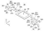
図3を参照すると、対向部30は、第1対向部32と、第2対向部36と、保持部材50とを有している。第1対向部32と第2対向部36とは、同一の導電材料から形成される。保持部材50は、片面に接着層を有する絶縁テープである。但し、本発明はこれに限られない。保持部材50は、絶縁樹脂製の薄板であってもよい。その場合、保持部材50は、接着剤や両面テープを用いて第1対向部32及び第2対向部36に接着されてよい。
Referring to FIG. 3, the opposing
図9から理解されるように、第1対向部32と第2対向部36とは、互いに別体である。第1対向部32と第2対向部36とは、互いに離れた状態で、保持部材50によって保持される。詳しくは、保持部材50は、第1対向部32及び第2対向部36に接着され、第1対向部32及び第2対向部36を保持する。これにより、第1対向部32と第2対向部36との相対位置は固定される。
As understood from FIG. 9, the first opposing
図3、図4及び図9に示されるように、第1対向部32は、第1主部320と、第1主部320から延びる第1被接続部351と、第1主部320から延びる第1被固定部353と、第1主部320から延びる第1被保持部355とを有している。
As shown in FIGS. 3, 4, and 9, the first opposing
図3から図8までに示されるように、第1主部320は、第1中央板部321と、第1周辺板部331と、これらを連結する第1曲げ部341とを有している。第1中央板部321は、基部323と、基部323から斜め後方へ延びる本体部325とを有している。第1周辺板部331は、基部333と、基部333から延びる延長部335とを有している。延長部335は、基部333から後方へ延びた後、横方向へ延び、さらに前方へ延びている。第1曲げ部341は、第1中央板部321の基部323と第1周辺板部331の基部333とを上下方向において連結している。
As shown in FIGS. 3 to 8, the first
図3、図4及び図8から理解されるように、第1中央板部321と第1周辺板部331とは、上下方向と直交するように配置されるとともに、上下方向において互いに離れて位置している。本実施の形態において、第1中央板部321は、第1周辺板部331よりも、上下方向において下方に位置している。
As understood from FIGS. 3, 4, and 8, the first
図3から図9までに示されるように、第1被接続部351は、第1周辺板部331の基部333から横方向外側へ延びた後、下方へ延びている。
As shown in FIGS. 3 to 9, the first
図4、図6から図9までに示されるように、第1被固定部353は、第1周辺板部331の後縁から後方へ延びた後、下方へ延びている。第1被固定部353は、基板20に搭載される搭載部として利用される。
As shown in FIGS. 4 and 6 to 9, the first fixed
図3から図6まで、及び図9に示されるように、第1被保持部355は、第1周辺板部331の後縁の近くに位置し、第1周辺板部331の側部の縁から横方向へ延びている。第1被保持部355は、横方向において、第1被固定部353とは逆へ延びている。
As shown in FIGS. 3 to 6 and 9, the first held
図3、図4及び図9に示されるように、第2対向部36は、第2主部360と、第2主部360から延びる第2被接続部391と、第2主部360から延びる第2被固定部393と、第2主部360から延びる第2被保持部395とを有している。
As shown in FIGS. 3, 4, and 9, the second opposing
図3から図6までの図から理解されるように、第2主部360は、第1主部320を上下反転させたものに等しい。詳しくは、第2主部360は、第2中央板部361と、第2周辺板部371と、これらを連結する第2曲げ部381とを有している。第2中央板部361は、基部363と、基部363から斜め後方へ延びる本体部365とを有している。第2周辺板部371は、基部373と、基部373から延びる延長部375とを有している。延長部375は、基部373から後方へ延びた後、横方向へ延び、さらに前方へ延びている。第2曲げ部381は、第2中央板部361の基部363と第2周辺板部371の基部373とを上下方向において連結している。
As understood from the figures from FIGS. 3 to 6, the second
図3、図4及び図8から理解されるように、第2中央板部361と第2周辺板部371とは、上下方向と直交するように配置されるとともに、上下方向において互いに離れて位置している。本実施の形態において、第2中央板部361は、第2周辺板部371よりも、上下方向において上方に位置している。
As understood from FIGS. 3, 4, and 8, the second
図3から図7まで、及び図9に示されるように、第2被接続部391は、第2中央板部361の基部363から横方向外側へ延びた後、下方へ延びている。
As shown in FIGS. 3 to 7 and 9, the second
図4、図6から図9までに示されるように、第2被固定部393は、第2周辺板部371の後縁から後方へ延びた後、下方へ延びている。第2被固定部393は、基板20に搭載される搭載部として利用される。
As shown in FIGS. 4 and 6 to 9, the second fixed
図3から図9までに示されるように、第2被保持部395は、第2周辺板部371の後縁の近くに位置し、第2周辺板部371の側部の縁から横方向へ延びた後、上方へ延び、さらに横方向へ延びている。第2被保持部395は、横方向において、第2被固定部393とは逆へ延びている。図4から理解されるように、上下方向において、第2被保持部395の先端部は、第1被保持部355と同じ位置にある。
As shown in FIGS. 3 to 9, the second held
図5から図8までの図から理解されるように、第1中央板部321と第2周辺板部371とは同一平面上にある。また、第1周辺板部331と第2中央板部361とは同一平面上にある。図5及び図6から理解されるように、上下方向に沿って見たとき、第1中央板部321の本体部325と第2中央板部361の本体部365とは、概ね一致している。また、上下方向に沿って見たとき、第1周辺板部331の延長部335と第2周辺板部371の延長部375とは、概ね一致している。
As understood from the figures from FIG. 5 to FIG. 8, the first
図5に示されるように、第1周辺板部331は、第2中央板部361から離れて、第2中央板部361の本体部365の周りを囲っている。また、図6に示されるように、第2周辺板部371は、第1中央板部321から離れて、第1中央板部321の本体部325の周りを囲っている。第1周辺板部331の端面と第2中央板部361の端面とは、部分的に対向し、第2周辺板部371の端面と第1中央板部321の端面とは部分的に対向している。このように、第1主部320と第2主部360とは互いに対向してキャパシタを構成する。但し、本発明はこれに限られない。第1対向部32の構成及び第2対向部36の構成は任意に変更可能である。例えば、第1主部320及び第2主部360は、夫々単一の板部を有するものであってもよい。
As shown in FIG. 5, the first
図7に示されるように、第1被接続部351、第2被接続部391、第1被固定部353及び第2被固定部393の下端は、上下方向において同じ位置にある。これにより、対向部30の基板20への搭載を適切に行うことができる。なお、第1被接続部351及び第2被接続部391の下端は、アンテナ主部22の第1端部227(図2参照)及び第2端部229(図2参照)に夫々接続される。第1被固定部353及び第2被固定部393の下端は、基板20の上面に形成された第1固定部251(図2参照)及び第2固定部253(図2参照)に夫々固定される。
As shown in FIG. 7, the lower ends of the first
図9に示されるように、保持部材50は、四辺を有するフレーム形状を有している。換言すると、保持部材50は、上下方向に沿って見たとき、その中央に貫通孔52を有するロの字形状を有している。保持部材50は、上下方向の寸法が比較的小さい板状である。但し、本発明はこれに限られない。保持部材50は、上下方向に沿って見たとき、多角形や円形又は楕円形であってもよい。しかしながら、その寸法や取り扱いの容易さ等を考慮すると、保持部材50はフレーム形状を有することが好ましい。
As shown in FIG. 9, the holding
図4及び図7から理解されるように、保持部材50は、上下方向において、対向部30の上に位置している。詳しくは、保持部材50は、第1被保持部355、第2被保持部395、第1被固定部353、第2被固定部393を上方から保持している。図5及び図6に示されるように、上下方向に沿って見たとき、保持部材50は、第1主部320及び第2主部360と重なっていない。換言すると、基板20と直交する直交方向、即ち上下方向に沿って見たとき、第1主部320と第2主部360とは、保持部材50の貫通孔52内に配置されている。この構成によれば、第1主部320と第2主部360との間は低比誘電率の空気層となる。その結果、アンテナ10の放射効率を高めることができる。特に、アンテナ10を高周波数で使用したときでも、高い放射効率を得ることができる。
As understood from FIGS. 4 and 7, the holding
図2に示されるように、基板20の上面には、アンテナ主部22の第1端部227及び第2端部229の他に、第1固定部251と第2固定部253が形成されている。対向部30が基板20に搭載される際、第1固定部251には、第1対向部32の第1被固定部353(図4参照)が搭載され、第2固定部253には、第2対向部36の第2被固定部393(図4参照)が搭載される。そして、第1対向部32の第1被固定部353は、その下端において第1固定部251に接続され、第2対向部36の第2被固定部393は、その下端において第2固定部253に接続される。加えて、第1対向部32の第1被接続部351は、その下端において第1端部227に接続され、第2対向部36の第2被接続部391は、その下端において第2端部229に接続される。
As shown in FIG. 2, in addition to the
本実施の形態によれば、対向部30において、第1対向部32と第2対向部36とは保持部材50によって保持され、その相対位置が固定されている。それゆえ、対向部30の基板20への搭載が容易に行えるとともに、第1対向部32と第2対向部36との相対位置の変化を防止することができる。これにより、第1対向部32と第2対向部36との相対位置のばらつきによるアンテナ10の特性のばらつきを防止することができる。また、対向部30の取り扱いが容易なことから、対向部30の変更を容易に行えるので、アンテナ10の特性のばらつきを容易に調整することができる。
According to this embodiment, in the opposing
(第2の実施の形態)
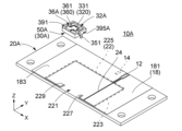
図10及び図11を参照すると、本発明の第2の実施の形態によるアンテナ10Aは、基板20Aと対向部30Aとを備えている。基板20Aは、第1固定部251(図2参照)及び第2固定部253(図2参照)を有していない点で、第1の実施の形態の基板20と異なる。また、対向部30Aは、第1の実施の形態の保持部材50(図4及び図5参照)とは異なる形状の保持部材50Aを有している。加えて、第1対向部32A及び第2対向部36Aの形状も第1実施の形態の第1対向部32(図9参照)及び第2対向部36(図9参照)の形状と異なっている。
(Second embodiment)
Referring to FIGS. 10 and 11, an
図18を参照すると、保持部材50Aは、上下方向において所定の寸法を有する四つの壁部502,504,506,508を備えている。壁部502,504,506,508は上下方向に沿って見たとき、フレーム形状となるように連結されている。そして、保持部材50Aは、上下方向に沿って見たとき、その中央に貫通孔52を有するロの字形状を有している。保持部材50Aは、第1の実施の形態の保持部材50に比べて上下方向の寸法が大きい。
Referring to FIG. 18, the holding
図12及び図13から理解されるように、保持部材50Aは、第1対向部32Aと第2対向部36Aとを互いに離れた状態で保持している。本実施の形態において、保持部材50Aは、第1対向部32A及び第2対向部36Aと一体成形される。
As understood from FIGS. 12 and 13, the holding
図12から図15までの図から理解されるように、保持部材50Aは、上下方向と直交する直交面内において、第1対向部32Aの第1主部320及び第2対向部36Aの第2主部360を囲っている。図16及び図17に示されるように、前後方向及び横方向の夫々において、第1主部320及び第2主部360を目視することはできない。一方、図14及び図15に示されるように、上下方向に沿って見たとき、保持部材50Aは、第1主部320及び第2主部360と重なっていない。換言すると、基板20Aと直交する直交方向に沿って見たとき、第1主部320と第2主部360とは、保持部材50Aの貫通孔52内に配置されている。
As understood from the drawings from FIG. 12 to FIG. 15, the holding
図15から図18までの図から理解されるように、第1対向部32Aの第1被接続部351と第2対向部36Aの第2被保持部395Aとは、横方向において壁部502を貫通している。また、第1対向部32Aの第1被保持部355と第2対向部36Aの第2被接続部391とは、横方向において壁部506を貫通している。第1対向部32Aの第1被保持部355及び第2対向部36Aの第2被保持部395Aの端部は、横方向において外側へ向けられている。この構成により、保持部材50Aは、第1の実施の形態の保持部材50よりもしっかりと第1対向部32A及び第2対向部36Aを保持することができる。しかも、第1の実施の形態のアンテナ10と同様に、アンテナ10Aは高い放射効率を得ることができる。
As can be understood from the drawings from FIG. 15 to FIG. 18, the first
図16及び図17から理解されるように、第1対向部32Aの第1被接続部351及び第2対向部36Aの第2被接続部391の下端は、壁部502,504,506,508の下縁よりも下方に位置している。一方、壁部504の下縁には、搭載部54が形成されている。搭載部54は、第1の実施の形態における第1被固定部353(図4参照)及び第2被固定部393(図4参照)の代わりに基板20Aの上面に搭載される部分である。搭載部54の下端は、上下方向において、第1対向部32Aの第1被接続部351及び第2対向部36Aの第2被接続部391の下端と一致する。これにより、対向部30Aを基板20Aに搭載したとき、壁部502,504,506,508の下縁と基板20Aの上面との間に隙間を形成することができるとともに、三点で安定して固定することができる。この構成によれば、第1の実施の形態における第1被固定部353(図4参照)及び第2被固定部393(図4参照)が不要なので、第1対向部32A及び第2対向部36Aの構成を第1の実施の形態の第1対向部32及び第2対向部36に比べて簡略化することができる。但し、本発明はこれに限られない。第1の実施の形態と同様に、第1対向部32A及び第2対向部36Aは、第1被固定部353及び第2被固定部393を夫々備えていてもよい。
As understood from FIGS. 16 and 17, the lower ends of the first
本実施の形態による対向部30Aも、第1の実施の形態による対向部30と同様に、第1対向部32Aと第2対向部36Aとが保持部材50Aによって保持され、それらの相対位置が固定されている。よって、本実施の形態において、第1の実施の形態と同様の効果が得られる。
Also in the facing
以上、本発明について、いくつかの実施の形態を掲げて具体的に説明してきたが、本発明はこれに限定されるものではなく、種々の変形が可能である。例えば、基板20又は20Aとして、両面基板を用いてもよいし、多層基板を用いてもよい。また、第1対向部32又は32A及び第2対向部36又は36Aの夫々形状は、上記実施の形態の形状と異なるものであってもよい。一例を挙げれば、第1対向部32又は32A及び第2対向部36又は36Aは、夫々櫛歯状に形成され、インタディジタル形に配置されてもよい。
Although the present invention has been specifically described above with reference to several embodiments, the present invention is not limited thereto and can be modified in various ways. For example, a double-sided substrate or a multilayer substrate may be used as the
10,10A アンテナ
12 第1端子
14 第2端子
16 LC共振器
18 グランドプレーン
181 第1部分
183 第2部分
20,20A 基板
22 アンテナ主部
221 切れ目
223 第1部分
225 第2部分
227 第1端部
229 第2端部
24 給電線
251 第1固定部
253 第2固定部
30,30A 対向部
32,32A 第1対向部
320 第1主部
321 第1中央板部
323 基部
325 本体部
331 第1周辺板部
333 基部
335 延長部
341 第1曲げ部
351 第1被接続部
353 第1被固定部(搭載部)
355 第1被保持部
36,36A 第2対向部
360 第2主部
361 第2中央板部
363 基部
365 本体部
371 第2周辺板部
373 基部
375 延長部
381 第2曲げ部
391 第2被接続部
393 第2被固定部(搭載部)
395 第2被保持部
50,50A 保持部材
502,504,506,508 壁部
52 貫通孔
54 搭載部
10,
355 First held
395 Second held
Claims (5)
前記アンテナ主部は、切れ目のある環状の形状を有するとともに、前記基板に平行な横方向において互いに離れて位置して前記切れ目を形成する第1端部と第2端部とを有しており、
前記対向部は、保持部材と、導電材料から形成された第1対向部及び第2対向部とを有しており、
前記第1対向部と前記第2対向部とは、互いに離れて位置するように、前記保持部材に保持されており、
前記第1対向部は、第1主部と、前記第1主部から延びて前記第1端部に接続された第1被接続部とを有しており、
前記第2対向部は、前記第1主部と対向する第2主部と、前記第2主部から延びて前記第2端部に接続された第2被接続部とを有しており、
前記アンテナ主部に給電線が接続される
アンテナ。 An antenna having an antenna main part formed on a substrate and a facing part separate from the substrate,
The antenna main portion has an annular shape with a cut, and has a first end portion and a second end portion located apart from each other in a lateral direction parallel to the substrate to form the cut. ,
The facing part has a holding member, and a first facing part and a second facing part made of a conductive material,
The first opposing part and the second opposing part are held by the holding member so as to be located apart from each other,
The first opposing part has a first main part and a first connected part extending from the first main part and connected to the first end part,
The second opposing part has a second main part facing the first main part, and a second connected part extending from the second main part and connected to the second end part ,
A feed line is connected to the main part of the antenna.
antenna.
前記基板と直交する直交方向に沿って見た場合に、前記第1主部と前記第2主部とは、前記保持部材と重なっていない
アンテナ。 The antenna according to claim 1,
When viewed along the orthogonal direction perpendicular to the substrate, the first main portion and the second main portion do not overlap with the holding member.
前記保持部材は、前記直交方向に沿って見た場合に、中央に貫通孔を有するロの字形状を有しており、
前記対向部の前記第1主部及び前記第2主部は、前記直交方向に沿って見た場合に、前記貫通孔内に配置されている
アンテナ。 The antenna according to claim 2,
The holding member has a square shape with a through hole in the center when viewed along the orthogonal direction,
The first main part and the second main part of the opposing part are arranged in the through hole when viewed along the orthogonal direction.
前記保持部材に、前記基板に搭載される搭載部が設けられている
アンテナ。 The antenna according to any one of claims 1 to 3,
An antenna in which the holding member is provided with a mounting portion that is mounted on the substrate.
前記第1対向部及び前記第2対向部の夫々に、前記基板に搭載される搭載部が設けられている
アンテナ。 The antenna according to any one of claims 1 to 3,
An antenna, wherein each of the first opposing section and the second opposing section is provided with a mounting section that is mounted on the substrate.
Priority Applications (2)
| Application Number | Priority Date | Filing Date | Title |
|---|---|---|---|
| JP2019119560A JP7414414B2 (en) | 2019-06-27 | 2019-06-27 | antenna |
| US16/848,898 US11228101B2 (en) | 2019-06-27 | 2020-04-15 | Antenna |
Applications Claiming Priority (1)
| Application Number | Priority Date | Filing Date | Title |
|---|---|---|---|
| JP2019119560A JP7414414B2 (en) | 2019-06-27 | 2019-06-27 | antenna |
Publications (3)
| Publication Number | Publication Date |
|---|---|
| JP2021005823A JP2021005823A (en) | 2021-01-14 |
| JP2021005823A5 JP2021005823A5 (en) | 2022-06-16 |
| JP7414414B2 true JP7414414B2 (en) | 2024-01-16 |
Family
ID=74043814
Family Applications (1)
| Application Number | Title | Priority Date | Filing Date |
|---|---|---|---|
| JP2019119560A Active JP7414414B2 (en) | 2019-06-27 | 2019-06-27 | antenna |
Country Status (2)
| Country | Link |
|---|---|
| US (1) | US11228101B2 (en) |
| JP (1) | JP7414414B2 (en) |
Families Citing this family (4)
| Publication number | Priority date | Publication date | Assignee | Title |
|---|---|---|---|---|
| JP7216577B2 (en) * | 2019-03-05 | 2023-02-01 | 日本航空電子工業株式会社 | antenna |
| JP7196008B2 (en) | 2019-04-17 | 2022-12-26 | 日本航空電子工業株式会社 | antenna |
| JP7414415B2 (en) | 2019-06-27 | 2024-01-16 | 日本航空電子工業株式会社 | Intermediate products for antennas and opposing parts used for them |
| KR102347785B1 (en) * | 2019-10-31 | 2022-01-06 | 주식회사 아모텍 | Antenna module |
Citations (4)
| Publication number | Priority date | Publication date | Assignee | Title |
|---|---|---|---|---|
| JP2010206550A (en) | 2009-03-03 | 2010-09-16 | Tdk Corp | Antenna device and antenna element used therefor |
| WO2015151430A1 (en) | 2014-03-31 | 2015-10-08 | 日本電気株式会社 | Antenna, array antenna and wireless communication device |
| JP2016225956A (en) | 2015-06-04 | 2016-12-28 | 日本電気株式会社 | Antenna and radio communication equipment |
| US20170133765A1 (en) | 2015-11-10 | 2017-05-11 | Dialog Semiconductor B.V. | Miniature Antenna |
Family Cites Families (19)
| Publication number | Priority date | Publication date | Assignee | Title |
|---|---|---|---|---|
| US6567047B2 (en) * | 2000-05-25 | 2003-05-20 | Tyco Electronics Logistics Ag | Multi-band in-series antenna assembly |
| JP3790249B2 (en) | 2004-01-13 | 2006-06-28 | 株式会社東芝 | Loop antenna and wireless communication device equipped with loop antenna |
| US7079079B2 (en) | 2004-06-30 | 2006-07-18 | Skycross, Inc. | Low profile compact multi-band meanderline loaded antenna |
| US7446712B2 (en) | 2005-12-21 | 2008-11-04 | The Regents Of The University Of California | Composite right/left-handed transmission line based compact resonant antenna for RF module integration |
| US8866691B2 (en) * | 2007-04-20 | 2014-10-21 | Skycross, Inc. | Multimode antenna structure |
| US7728783B2 (en) | 2007-07-26 | 2010-06-01 | Cheng Uei Precision Industry Co., Ltd. | Antenna structure |
| JP5035323B2 (en) | 2009-11-06 | 2012-09-26 | 株式会社村田製作所 | antenna |
| KR101281613B1 (en) | 2009-11-30 | 2013-07-03 | 한국전자통신연구원 | Small antenna using SRR structure and method for manufacturing thereof in a wireless communication system |
| JP2012019281A (en) | 2010-07-06 | 2012-01-26 | Toshiba Corp | Antenna device, and wireless device |
| FI20115072A0 (en) | 2011-01-25 | 2011-01-25 | Pulse Finland Oy | Multi-resonance antenna, antenna module and radio unit |
| CN103620870B (en) | 2011-06-23 | 2017-02-15 | 加利福尼亚大学董事会 | Electrically small vertical split-ring resonator antennas |
| CN104781986B (en) | 2012-11-12 | 2019-07-12 | 日本电气株式会社 | Antenna and wireless telecom equipment |
| WO2015135188A1 (en) | 2014-03-13 | 2015-09-17 | 华为终端有限公司 | Antenna and terminal |
| EP3381081B1 (en) | 2015-11-27 | 2021-08-04 | AGC Glass Europe | A two bidimensional multiband antenna and a glazing panel with the antenna printed thereon |
| CN109478881B (en) * | 2016-07-26 | 2022-07-29 | 京瓷株式会社 | Elastic wave device and communication apparatus |
| JP6659519B2 (en) | 2016-11-02 | 2020-03-04 | 株式会社東芝 | Antenna device |
| WO2019082671A1 (en) | 2017-10-24 | 2019-05-02 | 株式会社村田製作所 | High-frequency circuit, multiplexer, high-frequency front-end circuit, and communication device |
| JP7196008B2 (en) | 2019-04-17 | 2022-12-26 | 日本航空電子工業株式会社 | antenna |
| JP7414415B2 (en) | 2019-06-27 | 2024-01-16 | 日本航空電子工業株式会社 | Intermediate products for antennas and opposing parts used for them |
-
2019
- 2019-06-27 JP JP2019119560A patent/JP7414414B2/en active Active
-
2020
- 2020-04-15 US US16/848,898 patent/US11228101B2/en active Active
Patent Citations (4)
| Publication number | Priority date | Publication date | Assignee | Title |
|---|---|---|---|---|
| JP2010206550A (en) | 2009-03-03 | 2010-09-16 | Tdk Corp | Antenna device and antenna element used therefor |
| WO2015151430A1 (en) | 2014-03-31 | 2015-10-08 | 日本電気株式会社 | Antenna, array antenna and wireless communication device |
| JP2016225956A (en) | 2015-06-04 | 2016-12-28 | 日本電気株式会社 | Antenna and radio communication equipment |
| US20170133765A1 (en) | 2015-11-10 | 2017-05-11 | Dialog Semiconductor B.V. | Miniature Antenna |
Also Published As
| Publication number | Publication date |
|---|---|
| JP2021005823A (en) | 2021-01-14 |
| US20200411975A1 (en) | 2020-12-31 |
| US11228101B2 (en) | 2022-01-18 |
Similar Documents
| Publication | Publication Date | Title |
|---|---|---|
| JP7414414B2 (en) | antenna | |
| JP5712964B2 (en) | Antenna device | |
| JP7414415B2 (en) | Intermediate products for antennas and opposing parts used for them | |
| TW201535859A (en) | Multi-band planar inverted-F (PIFA) antennas and systems with improved isolation | |
| JP2009171163A (en) | Portable wireless apparatus | |
| JP2005039754A (en) | Antenna system | |
| JP7146418B2 (en) | patch antenna | |
| US9142884B2 (en) | Antenna device | |
| JP2005124056A (en) | Patch antenna | |
| JP2020178198A (en) | antenna | |
| JPWO2019208140A5 (en) | ||
| WO2012008177A1 (en) | Antenna device | |
| JP5035323B2 (en) | antenna | |
| JP2007208692A (en) | Patch antenna | |
| JP4626547B2 (en) | In-vehicle dielectric antenna and method for adjusting resonance frequency of antenna element | |
| JP3983224B2 (en) | Patch antenna | |
| JP2006197188A (en) | Antenna | |
| JP2004023210A (en) | Wireless communication card for information processing apparatus | |
| US20230026240A1 (en) | Antenna module | |
| WO2020158578A1 (en) | Vehicle-mounted antenna device | |
| WO2013168690A1 (en) | Antenna device | |
| JP6776979B2 (en) | Antenna device | |
| JP2014241549A (en) | Antenna device | |
| JP2004096180A (en) | Antenna unit | |
| JP6015399B2 (en) | Antenna device |
Legal Events
| Date | Code | Title | Description |
|---|---|---|---|
| A521 | Request for written amendment filed |
Free format text: JAPANESE INTERMEDIATE CODE: A523 Effective date: 20220608 |
|
| A621 | Written request for application examination |
Free format text: JAPANESE INTERMEDIATE CODE: A621 Effective date: 20220608 |
|
| A977 | Report on retrieval |
Free format text: JAPANESE INTERMEDIATE CODE: A971007 Effective date: 20230710 |
|
| A131 | Notification of reasons for refusal |
Free format text: JAPANESE INTERMEDIATE CODE: A131 Effective date: 20230719 |
|
| A521 | Request for written amendment filed |
Free format text: JAPANESE INTERMEDIATE CODE: A523 Effective date: 20230915 |
|
| TRDD | Decision of grant or rejection written | ||
| A01 | Written decision to grant a patent or to grant a registration (utility model) |
Free format text: JAPANESE INTERMEDIATE CODE: A01 Effective date: 20231206 |
|
| A61 | First payment of annual fees (during grant procedure) |
Free format text: JAPANESE INTERMEDIATE CODE: A61 Effective date: 20231228 |
|
| R150 | Certificate of patent or registration of utility model |
Ref document number: 7414414 Country of ref document: JP Free format text: JAPANESE INTERMEDIATE CODE: R150 |