JP7406372B2 - Laminated bodies and electronic devices - Google Patents
Laminated bodies and electronic devices Download PDFInfo
- Publication number
- JP7406372B2 JP7406372B2 JP2019506198A JP2019506198A JP7406372B2 JP 7406372 B2 JP7406372 B2 JP 7406372B2 JP 2019506198 A JP2019506198 A JP 2019506198A JP 2019506198 A JP2019506198 A JP 2019506198A JP 7406372 B2 JP7406372 B2 JP 7406372B2
- Authority
- JP
- Japan
- Prior art keywords
- boron nitride
- insulating layer
- inorganic filler
- volume
- metal
- Prior art date
- Legal status (The legal status is an assumption and is not a legal conclusion. Google has not performed a legal analysis and makes no representation as to the accuracy of the status listed.)
- Active
Links
- 229910052582 BN Inorganic materials 0.000 claims description 230
- PZNSFCLAULLKQX-UHFFFAOYSA-N Boron nitride Chemical compound N#B PZNSFCLAULLKQX-UHFFFAOYSA-N 0.000 claims description 230
- 229910052751 metal Inorganic materials 0.000 claims description 152
- 239000002184 metal Substances 0.000 claims description 152
- 239000011256 inorganic filler Substances 0.000 claims description 109
- 229910003475 inorganic filler Inorganic materials 0.000 claims description 109
- 239000002245 particle Substances 0.000 claims description 86
- 239000000463 material Substances 0.000 claims description 80
- 150000001875 compounds Chemical class 0.000 claims description 78
- 229920001187 thermosetting polymer Polymers 0.000 claims description 77
- 239000000758 substrate Substances 0.000 claims description 53
- 239000003795 chemical substances by application Substances 0.000 claims description 35
- 239000004593 Epoxy Substances 0.000 claims description 31
- 239000004065 semiconductor Substances 0.000 claims description 23
- 239000003054 catalyst Substances 0.000 claims description 20
- -1 oxetane compound Chemical class 0.000 claims description 20
- TWNQGVIAIRXVLR-UHFFFAOYSA-N oxo(oxoalumanyloxy)alumane Chemical group O=[Al]O[Al]=O TWNQGVIAIRXVLR-UHFFFAOYSA-N 0.000 claims description 11
- PMHQVHHXPFUNSP-UHFFFAOYSA-M copper(1+);methylsulfanylmethane;bromide Chemical compound Br[Cu].CSC PMHQVHHXPFUNSP-UHFFFAOYSA-M 0.000 claims description 7
- AXZKOIWUVFPNLO-UHFFFAOYSA-N magnesium;oxygen(2-) Chemical compound [O-2].[Mg+2] AXZKOIWUVFPNLO-UHFFFAOYSA-N 0.000 claims description 7
- 239000000395 magnesium oxide Substances 0.000 claims description 6
- CPLXHLVBOLITMK-UHFFFAOYSA-N magnesium oxide Inorganic materials [Mg]=O CPLXHLVBOLITMK-UHFFFAOYSA-N 0.000 claims description 6
- 229920001296 polysiloxane Polymers 0.000 claims description 4
- HBMJWWWQQXIZIP-UHFFFAOYSA-N silicon carbide Chemical compound [Si+]#[C-] HBMJWWWQQXIZIP-UHFFFAOYSA-N 0.000 claims description 4
- 229910010271 silicon carbide Inorganic materials 0.000 claims description 4
- 238000000034 method Methods 0.000 description 29
- 229920005989 resin Polymers 0.000 description 28
- 239000011347 resin Substances 0.000 description 28
- RYGMFSIKBFXOCR-UHFFFAOYSA-N Copper Chemical compound [Cu] RYGMFSIKBFXOCR-UHFFFAOYSA-N 0.000 description 20
- 229910052802 copper Inorganic materials 0.000 description 19
- 239000010949 copper Substances 0.000 description 19
- 230000000052 comparative effect Effects 0.000 description 16
- 230000003287 optical effect Effects 0.000 description 13
- ISWSIDIOOBJBQZ-UHFFFAOYSA-N Phenol Chemical compound OC1=CC=CC=C1 ISWSIDIOOBJBQZ-UHFFFAOYSA-N 0.000 description 12
- 239000004643 cyanate ester Substances 0.000 description 12
- 229910052782 aluminium Inorganic materials 0.000 description 8
- XAGFODPZIPBFFR-UHFFFAOYSA-N aluminium Chemical group [Al] XAGFODPZIPBFFR-UHFFFAOYSA-N 0.000 description 8
- 238000007789 sealing Methods 0.000 description 8
- IISBACLAFKSPIT-UHFFFAOYSA-N bisphenol A Chemical compound C=1C=C(O)C=CC=1C(C)(C)C1=CC=C(O)C=C1 IISBACLAFKSPIT-UHFFFAOYSA-N 0.000 description 7
- 238000009826 distribution Methods 0.000 description 7
- 230000005484 gravity Effects 0.000 description 7
- 238000004519 manufacturing process Methods 0.000 description 7
- 238000005259 measurement Methods 0.000 description 7
- 229920003986 novolac Polymers 0.000 description 7
- ZUOUZKKEUPVFJK-UHFFFAOYSA-N diphenyl Chemical compound C1=CC=CC=C1C1=CC=CC=C1 ZUOUZKKEUPVFJK-UHFFFAOYSA-N 0.000 description 6
- 239000011342 resin composition Substances 0.000 description 6
- 239000000853 adhesive Substances 0.000 description 5
- 230000001070 adhesive effect Effects 0.000 description 5
- QGBSISYHAICWAH-UHFFFAOYSA-N dicyandiamide Chemical compound NC(N)=NC#N QGBSISYHAICWAH-UHFFFAOYSA-N 0.000 description 5
- 238000005530 etching Methods 0.000 description 5
- 150000002989 phenols Chemical class 0.000 description 5
- 239000000919 ceramic Substances 0.000 description 4
- 239000011888 foil Substances 0.000 description 4
- PCHJSUWPFVWCPO-UHFFFAOYSA-N gold Chemical compound [Au] PCHJSUWPFVWCPO-UHFFFAOYSA-N 0.000 description 4
- 229910052737 gold Inorganic materials 0.000 description 4
- 239000010931 gold Substances 0.000 description 4
- 230000017525 heat dissipation Effects 0.000 description 4
- 239000007769 metal material Substances 0.000 description 4
- 239000011164 primary particle Substances 0.000 description 4
- 238000001694 spray drying Methods 0.000 description 4
- 238000012360 testing method Methods 0.000 description 4
- ZWEHNKRNPOVVGH-UHFFFAOYSA-N 2-Butanone Chemical compound CCC(C)=O ZWEHNKRNPOVVGH-UHFFFAOYSA-N 0.000 description 3
- BQCADISMDOOEFD-UHFFFAOYSA-N Silver Chemical compound [Ag] BQCADISMDOOEFD-UHFFFAOYSA-N 0.000 description 3
- 235000010290 biphenyl Nutrition 0.000 description 3
- 239000004305 biphenyl Substances 0.000 description 3
- 239000013078 crystal Substances 0.000 description 3
- 238000010586 diagram Methods 0.000 description 3
- 239000003822 epoxy resin Substances 0.000 description 3
- 239000000945 filler Substances 0.000 description 3
- 238000010438 heat treatment Methods 0.000 description 3
- RAXXELZNTBOGNW-UHFFFAOYSA-N imidazole Natural products C1=CNC=N1 RAXXELZNTBOGNW-UHFFFAOYSA-N 0.000 description 3
- 150000002460 imidazoles Chemical class 0.000 description 3
- 238000009413 insulation Methods 0.000 description 3
- 239000005011 phenolic resin Substances 0.000 description 3
- 150000003003 phosphines Chemical class 0.000 description 3
- 229920000647 polyepoxide Polymers 0.000 description 3
- 238000003825 pressing Methods 0.000 description 3
- 229910052709 silver Inorganic materials 0.000 description 3
- 239000004332 silver Substances 0.000 description 3
- 239000000126 substance Substances 0.000 description 3
- KXGFMDJXCMQABM-UHFFFAOYSA-N 2-methoxy-6-methylphenol Chemical compound [CH]OC1=CC=CC([CH])=C1O KXGFMDJXCMQABM-UHFFFAOYSA-N 0.000 description 2
- QGZKDVFQNNGYKY-UHFFFAOYSA-N Ammonia Chemical compound N QGZKDVFQNNGYKY-UHFFFAOYSA-N 0.000 description 2
- NLXLAEXVIDQMFP-UHFFFAOYSA-N Ammonia chloride Chemical compound [NH4+].[Cl-] NLXLAEXVIDQMFP-UHFFFAOYSA-N 0.000 description 2
- 238000012935 Averaging Methods 0.000 description 2
- VTYYLEPIZMXCLO-UHFFFAOYSA-L Calcium carbonate Chemical compound [Ca+2].[O-]C([O-])=O VTYYLEPIZMXCLO-UHFFFAOYSA-L 0.000 description 2
- OKTJSMMVPCPJKN-UHFFFAOYSA-N Carbon Chemical compound [C] OKTJSMMVPCPJKN-UHFFFAOYSA-N 0.000 description 2
- XEEYBQQBJWHFJM-UHFFFAOYSA-N Iron Chemical compound [Fe] XEEYBQQBJWHFJM-UHFFFAOYSA-N 0.000 description 2
- UFWIBTONFRDIAS-UHFFFAOYSA-N Naphthalene Chemical compound C1=CC=CC2=CC=CC=C21 UFWIBTONFRDIAS-UHFFFAOYSA-N 0.000 description 2
- PXHVJJICTQNCMI-UHFFFAOYSA-N Nickel Chemical compound [Ni] PXHVJJICTQNCMI-UHFFFAOYSA-N 0.000 description 2
- KDLHZDBZIXYQEI-UHFFFAOYSA-N Palladium Chemical compound [Pd] KDLHZDBZIXYQEI-UHFFFAOYSA-N 0.000 description 2
- VYPSYNLAJGMNEJ-UHFFFAOYSA-N Silicium dioxide Chemical compound O=[Si]=O VYPSYNLAJGMNEJ-UHFFFAOYSA-N 0.000 description 2
- 229910045601 alloy Inorganic materials 0.000 description 2
- 239000000956 alloy Substances 0.000 description 2
- PNEYBMLMFCGWSK-UHFFFAOYSA-N aluminium oxide Inorganic materials [O-2].[O-2].[O-2].[Al+3].[Al+3] PNEYBMLMFCGWSK-UHFFFAOYSA-N 0.000 description 2
- MWPLVEDNUUSJAV-UHFFFAOYSA-N anthracene Chemical compound C1=CC=CC2=CC3=CC=CC=C3C=C21 MWPLVEDNUUSJAV-UHFFFAOYSA-N 0.000 description 2
- PXKLMJQFEQBVLD-UHFFFAOYSA-N bisphenol F Chemical compound C1=CC(O)=CC=C1CC1=CC=C(O)C=C1 PXKLMJQFEQBVLD-UHFFFAOYSA-N 0.000 description 2
- 150000001639 boron compounds Chemical class 0.000 description 2
- 238000005516 engineering process Methods 0.000 description 2
- 125000003700 epoxy group Chemical group 0.000 description 2
- NIHNNTQXNPWCJQ-UHFFFAOYSA-N fluorene Chemical compound C1=CC=C2CC3=CC=CC=C3C2=C1 NIHNNTQXNPWCJQ-UHFFFAOYSA-N 0.000 description 2
- 238000005469 granulation Methods 0.000 description 2
- 230000003179 granulation Effects 0.000 description 2
- 229910002804 graphite Inorganic materials 0.000 description 2
- 239000010439 graphite Substances 0.000 description 2
- 239000011159 matrix material Substances 0.000 description 2
- 150000007974 melamines Chemical class 0.000 description 2
- 238000001000 micrograph Methods 0.000 description 2
- 239000000203 mixture Substances 0.000 description 2
- 238000000059 patterning Methods 0.000 description 2
- 229920001568 phenolic resin Polymers 0.000 description 2
- BASFCYQUMIYNBI-UHFFFAOYSA-N platinum Chemical compound [Pt] BASFCYQUMIYNBI-UHFFFAOYSA-N 0.000 description 2
- 238000002360 preparation method Methods 0.000 description 2
- 238000012545 processing Methods 0.000 description 2
- 229910000679 solder Inorganic materials 0.000 description 2
- RIOQSEWOXXDEQQ-UHFFFAOYSA-N triphenylphosphine Chemical compound C1=CC=CC=C1P(C=1C=CC=CC=1)C1=CC=CC=C1 RIOQSEWOXXDEQQ-UHFFFAOYSA-N 0.000 description 2
- DPZSNGJNFHWQDC-ARJAWSKDSA-N (z)-2,3-diaminobut-2-enedinitrile Chemical compound N#CC(/N)=C(/N)C#N DPZSNGJNFHWQDC-ARJAWSKDSA-N 0.000 description 1
- HCNHNBLSNVSJTJ-UHFFFAOYSA-N 1,1-Bis(4-hydroxyphenyl)ethane Chemical compound C=1C=C(O)C=CC=1C(C)C1=CC=C(O)C=C1 HCNHNBLSNVSJTJ-UHFFFAOYSA-N 0.000 description 1
- HECLRDQVFMWTQS-RGOKHQFPSA-N 1755-01-7 Chemical compound C1[C@H]2[C@@H]3CC=C[C@@H]3[C@@H]1C=C2 HECLRDQVFMWTQS-RGOKHQFPSA-N 0.000 description 1
- VILCJCGEZXAXTO-UHFFFAOYSA-N 2,2,2-tetramine Chemical compound NCCNCCNCCN VILCJCGEZXAXTO-UHFFFAOYSA-N 0.000 description 1
- BGCSUUSPRCDKBQ-UHFFFAOYSA-N 2,4,8,10-tetraoxaspiro[5.5]undecane Chemical compound C1OCOCC21COCOC2 BGCSUUSPRCDKBQ-UHFFFAOYSA-N 0.000 description 1
- VPWNQTHUCYMVMZ-UHFFFAOYSA-N 4,4'-sulfonyldiphenol Chemical compound C1=CC(O)=CC=C1S(=O)(=O)C1=CC=C(O)C=C1 VPWNQTHUCYMVMZ-UHFFFAOYSA-N 0.000 description 1
- 229930185605 Bisphenol Natural products 0.000 description 1
- ZOXJGFHDIHLPTG-UHFFFAOYSA-N Boron Chemical compound [B] ZOXJGFHDIHLPTG-UHFFFAOYSA-N 0.000 description 1
- VYZAMTAEIAYCRO-UHFFFAOYSA-N Chromium Chemical compound [Cr] VYZAMTAEIAYCRO-UHFFFAOYSA-N 0.000 description 1
- RPNUMPOLZDHAAY-UHFFFAOYSA-N Diethylenetriamine Chemical compound NCCNCCN RPNUMPOLZDHAAY-UHFFFAOYSA-N 0.000 description 1
- 229920000877 Melamine resin Polymers 0.000 description 1
- ZOKXTWBITQBERF-UHFFFAOYSA-N Molybdenum Chemical compound [Mo] ZOKXTWBITQBERF-UHFFFAOYSA-N 0.000 description 1
- 239000004642 Polyimide Chemical class 0.000 description 1
- XUIMIQQOPSSXEZ-UHFFFAOYSA-N Silicon Chemical compound [Si] XUIMIQQOPSSXEZ-UHFFFAOYSA-N 0.000 description 1
- ATJFFYVFTNAWJD-UHFFFAOYSA-N Tin Chemical compound [Sn] ATJFFYVFTNAWJD-UHFFFAOYSA-N 0.000 description 1
- RTAQQCXQSZGOHL-UHFFFAOYSA-N Titanium Chemical compound [Ti] RTAQQCXQSZGOHL-UHFFFAOYSA-N 0.000 description 1
- NRTOMJZYCJJWKI-UHFFFAOYSA-N Titanium nitride Chemical compound [Ti]#N NRTOMJZYCJJWKI-UHFFFAOYSA-N 0.000 description 1
- GSEJCLTVZPLZKY-UHFFFAOYSA-N Triethanolamine Chemical compound OCCN(CCO)CCO GSEJCLTVZPLZKY-UHFFFAOYSA-N 0.000 description 1
- HCHKCACWOHOZIP-UHFFFAOYSA-N Zinc Chemical compound [Zn] HCHKCACWOHOZIP-UHFFFAOYSA-N 0.000 description 1
- VYGUBTIWNBFFMQ-UHFFFAOYSA-N [N+](#[C-])N1C(=O)NC=2NC(=O)NC2C1=O Chemical compound [N+](#[C-])N1C(=O)NC=2NC(=O)NC2C1=O VYGUBTIWNBFFMQ-UHFFFAOYSA-N 0.000 description 1
- 150000008065 acid anhydrides Chemical class 0.000 description 1
- NIXOWILDQLNWCW-UHFFFAOYSA-N acrylic acid group Chemical group C(C=C)(=O)O NIXOWILDQLNWCW-UHFFFAOYSA-N 0.000 description 1
- ORILYTVJVMAKLC-UHFFFAOYSA-N adamantane Chemical group C1C(C2)CC3CC1CC2C3 ORILYTVJVMAKLC-UHFFFAOYSA-N 0.000 description 1
- 230000004931 aggregating effect Effects 0.000 description 1
- 238000004220 aggregation Methods 0.000 description 1
- 230000002776 aggregation Effects 0.000 description 1
- WNROFYMDJYEPJX-UHFFFAOYSA-K aluminium hydroxide Chemical compound [OH-].[OH-].[OH-].[Al+3] WNROFYMDJYEPJX-UHFFFAOYSA-K 0.000 description 1
- 150000001412 amines Chemical class 0.000 description 1
- 229910021529 ammonia Inorganic materials 0.000 description 1
- 235000019270 ammonium chloride Nutrition 0.000 description 1
- 229910052787 antimony Inorganic materials 0.000 description 1
- WATWJIUSRGPENY-UHFFFAOYSA-N antimony atom Chemical compound [Sb] WATWJIUSRGPENY-UHFFFAOYSA-N 0.000 description 1
- 239000003963 antioxidant agent Substances 0.000 description 1
- 230000003078 antioxidant effect Effects 0.000 description 1
- 125000003710 aryl alkyl group Chemical group 0.000 description 1
- 230000015572 biosynthetic process Effects 0.000 description 1
- MRNZSTMRDWRNNR-UHFFFAOYSA-N bis(hexamethylene)triamine Chemical compound NCCCCCCNCCCCCCN MRNZSTMRDWRNNR-UHFFFAOYSA-N 0.000 description 1
- 229910052797 bismuth Inorganic materials 0.000 description 1
- JCXGWMGPZLAOME-UHFFFAOYSA-N bismuth atom Chemical compound [Bi] JCXGWMGPZLAOME-UHFFFAOYSA-N 0.000 description 1
- 229910052796 boron Inorganic materials 0.000 description 1
- 229910052793 cadmium Inorganic materials 0.000 description 1
- BDOSMKKIYDKNTQ-UHFFFAOYSA-N cadmium atom Chemical compound [Cd] BDOSMKKIYDKNTQ-UHFFFAOYSA-N 0.000 description 1
- 229910000019 calcium carbonate Inorganic materials 0.000 description 1
- BRPQOXSCLDDYGP-UHFFFAOYSA-N calcium oxide Chemical compound [O-2].[Ca+2] BRPQOXSCLDDYGP-UHFFFAOYSA-N 0.000 description 1
- ODINCKMPIJJUCX-UHFFFAOYSA-N calcium oxide Inorganic materials [Ca]=O ODINCKMPIJJUCX-UHFFFAOYSA-N 0.000 description 1
- 239000000292 calcium oxide Substances 0.000 description 1
- 239000000378 calcium silicate Substances 0.000 description 1
- 229910052918 calcium silicate Inorganic materials 0.000 description 1
- OYACROKNLOSFPA-UHFFFAOYSA-N calcium;dioxido(oxo)silane Chemical compound [Ca+2].[O-][Si]([O-])=O OYACROKNLOSFPA-UHFFFAOYSA-N 0.000 description 1
- 239000006229 carbon black Substances 0.000 description 1
- 150000004649 carbonic acid derivatives Chemical class 0.000 description 1
- 239000002738 chelating agent Substances 0.000 description 1
- 238000006243 chemical reaction Methods 0.000 description 1
- 229910052804 chromium Inorganic materials 0.000 description 1
- 239000011651 chromium Substances 0.000 description 1
- 229910017052 cobalt Inorganic materials 0.000 description 1
- 239000010941 cobalt Substances 0.000 description 1
- GUTLYIVDDKVIGB-UHFFFAOYSA-N cobalt atom Chemical compound [Co] GUTLYIVDDKVIGB-UHFFFAOYSA-N 0.000 description 1
- 239000011231 conductive filler Substances 0.000 description 1
- 238000001816 cooling Methods 0.000 description 1
- 239000011889 copper foil Substances 0.000 description 1
- 150000003983 crown ethers Chemical class 0.000 description 1
- 229910002026 crystalline silica Inorganic materials 0.000 description 1
- 238000005520 cutting process Methods 0.000 description 1
- DIOQZVSQGTUSAI-NJFSPNSNSA-N decane Chemical group CCCCCCCCC[14CH3] DIOQZVSQGTUSAI-NJFSPNSNSA-N 0.000 description 1
- 238000007865 diluting Methods 0.000 description 1
- ZZTCPWRAHWXWCH-UHFFFAOYSA-N diphenylmethanediamine Chemical compound C=1C=CC=CC=1C(N)(N)C1=CC=CC=C1 ZZTCPWRAHWXWCH-UHFFFAOYSA-N 0.000 description 1
- 239000002270 dispersing agent Substances 0.000 description 1
- BXKDSDJJOVIHMX-UHFFFAOYSA-N edrophonium chloride Chemical compound [Cl-].CC[N+](C)(C)C1=CC=CC(O)=C1 BXKDSDJJOVIHMX-UHFFFAOYSA-N 0.000 description 1
- 230000000694 effects Effects 0.000 description 1
- 230000005684 electric field Effects 0.000 description 1
- 238000007772 electroless plating Methods 0.000 description 1
- 238000009713 electroplating Methods 0.000 description 1
- RTZKZFJDLAIYFH-UHFFFAOYSA-N ether Substances CCOCC RTZKZFJDLAIYFH-UHFFFAOYSA-N 0.000 description 1
- 238000011156 evaluation Methods 0.000 description 1
- 239000012530 fluid Substances 0.000 description 1
- 125000000524 functional group Chemical group 0.000 description 1
- 229910052732 germanium Inorganic materials 0.000 description 1
- GNPVGFCGXDBREM-UHFFFAOYSA-N germanium atom Chemical compound [Ge] GNPVGFCGXDBREM-UHFFFAOYSA-N 0.000 description 1
- 230000009477 glass transition Effects 0.000 description 1
- 229910052738 indium Inorganic materials 0.000 description 1
- APFVFJFRJDLVQX-UHFFFAOYSA-N indium atom Chemical compound [In] APFVFJFRJDLVQX-UHFFFAOYSA-N 0.000 description 1
- 229910003437 indium oxide Inorganic materials 0.000 description 1
- PJXISJQVUVHSOJ-UHFFFAOYSA-N indium(iii) oxide Chemical compound [O-2].[O-2].[O-2].[In+3].[In+3] PJXISJQVUVHSOJ-UHFFFAOYSA-N 0.000 description 1
- 239000004615 ingredient Substances 0.000 description 1
- 229910052742 iron Inorganic materials 0.000 description 1
- 238000010030 laminating Methods 0.000 description 1
- 239000011133 lead Substances 0.000 description 1
- ZLNQQNXFFQJAID-UHFFFAOYSA-L magnesium carbonate Chemical compound [Mg+2].[O-]C([O-])=O ZLNQQNXFFQJAID-UHFFFAOYSA-L 0.000 description 1
- 239000001095 magnesium carbonate Substances 0.000 description 1
- 229910000021 magnesium carbonate Inorganic materials 0.000 description 1
- VTHJTEIRLNZDEV-UHFFFAOYSA-L magnesium dihydroxide Chemical compound [OH-].[OH-].[Mg+2] VTHJTEIRLNZDEV-UHFFFAOYSA-L 0.000 description 1
- 239000000347 magnesium hydroxide Substances 0.000 description 1
- 229910001862 magnesium hydroxide Inorganic materials 0.000 description 1
- JDSHMPZPIAZGSV-UHFFFAOYSA-N melamine Chemical compound NC1=NC(N)=NC(N)=N1 JDSHMPZPIAZGSV-UHFFFAOYSA-N 0.000 description 1
- 150000002736 metal compounds Chemical class 0.000 description 1
- 229910000000 metal hydroxide Inorganic materials 0.000 description 1
- 150000004692 metal hydroxides Chemical class 0.000 description 1
- 229910044991 metal oxide Inorganic materials 0.000 description 1
- 150000004706 metal oxides Chemical class 0.000 description 1
- 229910052914 metal silicate Inorganic materials 0.000 description 1
- UJNZOIKQAUQOCN-UHFFFAOYSA-N methyl(diphenyl)phosphane Chemical compound C=1C=CC=CC=1P(C)C1=CC=CC=C1 UJNZOIKQAUQOCN-UHFFFAOYSA-N 0.000 description 1
- 229910052750 molybdenum Inorganic materials 0.000 description 1
- 239000011733 molybdenum Substances 0.000 description 1
- 229910052759 nickel Inorganic materials 0.000 description 1
- 150000004767 nitrides Chemical class 0.000 description 1
- 150000007524 organic acids Chemical class 0.000 description 1
- 150000002894 organic compounds Chemical class 0.000 description 1
- 150000002921 oxetanes Chemical class 0.000 description 1
- AFEQENGXSMURHA-UHFFFAOYSA-N oxiran-2-ylmethanamine Chemical compound NCC1CO1 AFEQENGXSMURHA-UHFFFAOYSA-N 0.000 description 1
- 229910052763 palladium Inorganic materials 0.000 description 1
- 125000000951 phenoxy group Chemical class [H]C1=C([H])C([H])=C(O*)C([H])=C1[H] 0.000 description 1
- XYFCBTPGUUZFHI-UHFFFAOYSA-O phosphonium Chemical compound [PH4+] XYFCBTPGUUZFHI-UHFFFAOYSA-O 0.000 description 1
- 229910052697 platinum Inorganic materials 0.000 description 1
- 229920001721 polyimide Chemical class 0.000 description 1
- 239000002685 polymerization catalyst Substances 0.000 description 1
- 239000004814 polyurethane Chemical class 0.000 description 1
- 229920002635 polyurethane Chemical class 0.000 description 1
- 239000011148 porous material Substances 0.000 description 1
- 125000002924 primary amino group Chemical class [H]N([H])* 0.000 description 1
- 230000005855 radiation Effects 0.000 description 1
- 230000002829 reductive effect Effects 0.000 description 1
- 102220104593 rs879254294 Human genes 0.000 description 1
- 150000003839 salts Chemical class 0.000 description 1
- 150000004760 silicates Chemical class 0.000 description 1
- 229910052710 silicon Inorganic materials 0.000 description 1
- 239000010703 silicon Substances 0.000 description 1
- 235000012239 silicon dioxide Nutrition 0.000 description 1
- 239000012279 sodium borohydride Substances 0.000 description 1
- 229910000033 sodium borohydride Inorganic materials 0.000 description 1
- 239000007962 solid dispersion Substances 0.000 description 1
- 239000007921 spray Substances 0.000 description 1
- 238000005507 spraying Methods 0.000 description 1
- 238000003756 stirring Methods 0.000 description 1
- 125000003011 styrenyl group Chemical class [H]\C(*)=C(/[H])C1=C([H])C([H])=C([H])C([H])=C1[H] 0.000 description 1
- 150000003512 tertiary amines Chemical class 0.000 description 1
- FAGUFWYHJQFNRV-UHFFFAOYSA-N tetraethylenepentamine Chemical compound NCCNCCNCCNCCN FAGUFWYHJQFNRV-UHFFFAOYSA-N 0.000 description 1
- 229910052716 thallium Inorganic materials 0.000 description 1
- BKVIYDNLLOSFOA-UHFFFAOYSA-N thallium Chemical compound [Tl] BKVIYDNLLOSFOA-UHFFFAOYSA-N 0.000 description 1
- 150000003573 thiols Chemical class 0.000 description 1
- 229910052718 tin Inorganic materials 0.000 description 1
- 239000011135 tin Substances 0.000 description 1
- 239000010936 titanium Substances 0.000 description 1
- 229910052719 titanium Inorganic materials 0.000 description 1
- QQOWHRYOXYEMTL-UHFFFAOYSA-N triazin-4-amine Chemical group N=C1C=CN=NN1 QQOWHRYOXYEMTL-UHFFFAOYSA-N 0.000 description 1
- 150000003918 triazines Chemical class 0.000 description 1
- TUQOTMZNTHZOKS-UHFFFAOYSA-N tributylphosphine Chemical compound CCCCP(CCCC)CCCC TUQOTMZNTHZOKS-UHFFFAOYSA-N 0.000 description 1
- WLPUWLXVBWGYMZ-UHFFFAOYSA-N tricyclohexylphosphine Chemical compound C1CCCCC1P(C1CCCCC1)C1CCCCC1 WLPUWLXVBWGYMZ-UHFFFAOYSA-N 0.000 description 1
- WFKWXMTUELFFGS-UHFFFAOYSA-N tungsten Chemical compound [W] WFKWXMTUELFFGS-UHFFFAOYSA-N 0.000 description 1
- 229910052721 tungsten Inorganic materials 0.000 description 1
- 239000010937 tungsten Substances 0.000 description 1
- 229920006305 unsaturated polyester Chemical class 0.000 description 1
- 229910052725 zinc Inorganic materials 0.000 description 1
- 239000011701 zinc Substances 0.000 description 1
Images


Classifications
-
- B—PERFORMING OPERATIONS; TRANSPORTING
- B32—LAYERED PRODUCTS
- B32B—LAYERED PRODUCTS, i.e. PRODUCTS BUILT-UP OF STRATA OF FLAT OR NON-FLAT, e.g. CELLULAR OR HONEYCOMB, FORM
- B32B3/00—Layered products comprising a layer with external or internal discontinuities or unevennesses, or a layer of non-planar shape; Layered products comprising a layer having particular features of form
- B32B3/10—Layered products comprising a layer with external or internal discontinuities or unevennesses, or a layer of non-planar shape; Layered products comprising a layer having particular features of form characterised by a discontinuous layer, i.e. formed of separate pieces of material
-
- H—ELECTRICITY
- H01—ELECTRIC ELEMENTS
- H01L—SEMICONDUCTOR DEVICES NOT COVERED BY CLASS H10
- H01L23/00—Details of semiconductor or other solid state devices
- H01L23/34—Arrangements for cooling, heating, ventilating or temperature compensation ; Temperature sensing arrangements
- H01L23/36—Selection of materials, or shaping, to facilitate cooling or heating, e.g. heatsinks
- H01L23/373—Cooling facilitated by selection of materials for the device or materials for thermal expansion adaptation, e.g. carbon
- H01L23/3735—Laminates or multilayers, e.g. direct bond copper ceramic substrates
-
- B—PERFORMING OPERATIONS; TRANSPORTING
- B32—LAYERED PRODUCTS
- B32B—LAYERED PRODUCTS, i.e. PRODUCTS BUILT-UP OF STRATA OF FLAT OR NON-FLAT, e.g. CELLULAR OR HONEYCOMB, FORM
- B32B15/00—Layered products comprising a layer of metal
- B32B15/04—Layered products comprising a layer of metal comprising metal as the main or only constituent of a layer, which is next to another layer of the same or of a different material
- B32B15/08—Layered products comprising a layer of metal comprising metal as the main or only constituent of a layer, which is next to another layer of the same or of a different material of synthetic resin
-
- B—PERFORMING OPERATIONS; TRANSPORTING
- B32—LAYERED PRODUCTS
- B32B—LAYERED PRODUCTS, i.e. PRODUCTS BUILT-UP OF STRATA OF FLAT OR NON-FLAT, e.g. CELLULAR OR HONEYCOMB, FORM
- B32B15/00—Layered products comprising a layer of metal
-
- B—PERFORMING OPERATIONS; TRANSPORTING
- B32—LAYERED PRODUCTS
- B32B—LAYERED PRODUCTS, i.e. PRODUCTS BUILT-UP OF STRATA OF FLAT OR NON-FLAT, e.g. CELLULAR OR HONEYCOMB, FORM
- B32B15/00—Layered products comprising a layer of metal
- B32B15/04—Layered products comprising a layer of metal comprising metal as the main or only constituent of a layer, which is next to another layer of the same or of a different material
- B32B15/08—Layered products comprising a layer of metal comprising metal as the main or only constituent of a layer, which is next to another layer of the same or of a different material of synthetic resin
- B32B15/092—Layered products comprising a layer of metal comprising metal as the main or only constituent of a layer, which is next to another layer of the same or of a different material of synthetic resin comprising epoxy resins
-
- B—PERFORMING OPERATIONS; TRANSPORTING
- B32—LAYERED PRODUCTS
- B32B—LAYERED PRODUCTS, i.e. PRODUCTS BUILT-UP OF STRATA OF FLAT OR NON-FLAT, e.g. CELLULAR OR HONEYCOMB, FORM
- B32B27/00—Layered products comprising a layer of synthetic resin
- B32B27/18—Layered products comprising a layer of synthetic resin characterised by the use of special additives
- B32B27/20—Layered products comprising a layer of synthetic resin characterised by the use of special additives using fillers, pigments, thixotroping agents
-
- B—PERFORMING OPERATIONS; TRANSPORTING
- B32—LAYERED PRODUCTS
- B32B—LAYERED PRODUCTS, i.e. PRODUCTS BUILT-UP OF STRATA OF FLAT OR NON-FLAT, e.g. CELLULAR OR HONEYCOMB, FORM
- B32B27/00—Layered products comprising a layer of synthetic resin
- B32B27/18—Layered products comprising a layer of synthetic resin characterised by the use of special additives
- B32B27/26—Layered products comprising a layer of synthetic resin characterised by the use of special additives using curing agents
-
- B—PERFORMING OPERATIONS; TRANSPORTING
- B32—LAYERED PRODUCTS
- B32B—LAYERED PRODUCTS, i.e. PRODUCTS BUILT-UP OF STRATA OF FLAT OR NON-FLAT, e.g. CELLULAR OR HONEYCOMB, FORM
- B32B27/00—Layered products comprising a layer of synthetic resin
- B32B27/28—Layered products comprising a layer of synthetic resin comprising synthetic resins not wholly covered by any one of the sub-groups B32B27/30 - B32B27/42
- B32B27/283—Layered products comprising a layer of synthetic resin comprising synthetic resins not wholly covered by any one of the sub-groups B32B27/30 - B32B27/42 comprising polysiloxanes
-
- B—PERFORMING OPERATIONS; TRANSPORTING
- B32—LAYERED PRODUCTS
- B32B—LAYERED PRODUCTS, i.e. PRODUCTS BUILT-UP OF STRATA OF FLAT OR NON-FLAT, e.g. CELLULAR OR HONEYCOMB, FORM
- B32B27/00—Layered products comprising a layer of synthetic resin
- B32B27/38—Layered products comprising a layer of synthetic resin comprising epoxy resins
-
- C—CHEMISTRY; METALLURGY
- C08—ORGANIC MACROMOLECULAR COMPOUNDS; THEIR PREPARATION OR CHEMICAL WORKING-UP; COMPOSITIONS BASED THEREON
- C08K—Use of inorganic or non-macromolecular organic substances as compounding ingredients
- C08K3/00—Use of inorganic substances as compounding ingredients
- C08K3/01—Use of inorganic substances as compounding ingredients characterized by their specific function
- C08K3/013—Fillers, pigments or reinforcing additives
-
- C—CHEMISTRY; METALLURGY
- C08—ORGANIC MACROMOLECULAR COMPOUNDS; THEIR PREPARATION OR CHEMICAL WORKING-UP; COMPOSITIONS BASED THEREON
- C08K—Use of inorganic or non-macromolecular organic substances as compounding ingredients
- C08K3/00—Use of inorganic substances as compounding ingredients
- C08K3/18—Oxygen-containing compounds, e.g. metal carbonyls
- C08K3/20—Oxides; Hydroxides
- C08K3/22—Oxides; Hydroxides of metals
-
- C—CHEMISTRY; METALLURGY
- C08—ORGANIC MACROMOLECULAR COMPOUNDS; THEIR PREPARATION OR CHEMICAL WORKING-UP; COMPOSITIONS BASED THEREON
- C08K—Use of inorganic or non-macromolecular organic substances as compounding ingredients
- C08K3/00—Use of inorganic substances as compounding ingredients
- C08K3/28—Nitrogen-containing compounds
-
- C—CHEMISTRY; METALLURGY
- C08—ORGANIC MACROMOLECULAR COMPOUNDS; THEIR PREPARATION OR CHEMICAL WORKING-UP; COMPOSITIONS BASED THEREON
- C08K—Use of inorganic or non-macromolecular organic substances as compounding ingredients
- C08K3/00—Use of inorganic substances as compounding ingredients
- C08K3/34—Silicon-containing compounds
-
- C—CHEMISTRY; METALLURGY
- C08—ORGANIC MACROMOLECULAR COMPOUNDS; THEIR PREPARATION OR CHEMICAL WORKING-UP; COMPOSITIONS BASED THEREON
- C08K—Use of inorganic or non-macromolecular organic substances as compounding ingredients
- C08K3/00—Use of inorganic substances as compounding ingredients
- C08K3/38—Boron-containing compounds
-
- H—ELECTRICITY
- H01—ELECTRIC ELEMENTS
- H01L—SEMICONDUCTOR DEVICES NOT COVERED BY CLASS H10
- H01L21/00—Processes or apparatus adapted for the manufacture or treatment of semiconductor or solid state devices or of parts thereof
- H01L21/02—Manufacture or treatment of semiconductor devices or of parts thereof
- H01L21/04—Manufacture or treatment of semiconductor devices or of parts thereof the devices having potential barriers, e.g. a PN junction, depletion layer or carrier concentration layer
- H01L21/48—Manufacture or treatment of parts, e.g. containers, prior to assembly of the devices, using processes not provided for in a single one of the subgroups H01L21/06 - H01L21/326
- H01L21/4814—Conductive parts
- H01L21/4871—Bases, plates or heatsinks
- H01L21/4882—Assembly of heatsink parts
-
- H—ELECTRICITY
- H01—ELECTRIC ELEMENTS
- H01L—SEMICONDUCTOR DEVICES NOT COVERED BY CLASS H10
- H01L23/00—Details of semiconductor or other solid state devices
- H01L23/34—Arrangements for cooling, heating, ventilating or temperature compensation ; Temperature sensing arrangements
- H01L23/36—Selection of materials, or shaping, to facilitate cooling or heating, e.g. heatsinks
- H01L23/373—Cooling facilitated by selection of materials for the device or materials for thermal expansion adaptation, e.g. carbon
-
- H—ELECTRICITY
- H01—ELECTRIC ELEMENTS
- H01L—SEMICONDUCTOR DEVICES NOT COVERED BY CLASS H10
- H01L24/00—Arrangements for connecting or disconnecting semiconductor or solid-state bodies; Methods or apparatus related thereto
- H01L24/73—Means for bonding being of different types provided for in two or more of groups H01L24/10, H01L24/18, H01L24/26, H01L24/34, H01L24/42, H01L24/50, H01L24/63, H01L24/71
-
- B—PERFORMING OPERATIONS; TRANSPORTING
- B32—LAYERED PRODUCTS
- B32B—LAYERED PRODUCTS, i.e. PRODUCTS BUILT-UP OF STRATA OF FLAT OR NON-FLAT, e.g. CELLULAR OR HONEYCOMB, FORM
- B32B2250/00—Layers arrangement
- B32B2250/03—3 layers
-
- B—PERFORMING OPERATIONS; TRANSPORTING
- B32—LAYERED PRODUCTS
- B32B—LAYERED PRODUCTS, i.e. PRODUCTS BUILT-UP OF STRATA OF FLAT OR NON-FLAT, e.g. CELLULAR OR HONEYCOMB, FORM
- B32B2264/00—Composition or properties of particles which form a particulate layer or are present as additives
- B32B2264/10—Inorganic particles
- B32B2264/102—Oxide or hydroxide
- B32B2264/1023—Alumina
-
- B—PERFORMING OPERATIONS; TRANSPORTING
- B32—LAYERED PRODUCTS
- B32B—LAYERED PRODUCTS, i.e. PRODUCTS BUILT-UP OF STRATA OF FLAT OR NON-FLAT, e.g. CELLULAR OR HONEYCOMB, FORM
- B32B2264/00—Composition or properties of particles which form a particulate layer or are present as additives
- B32B2264/10—Inorganic particles
- B32B2264/107—Ceramic
-
- B—PERFORMING OPERATIONS; TRANSPORTING
- B32—LAYERED PRODUCTS
- B32B—LAYERED PRODUCTS, i.e. PRODUCTS BUILT-UP OF STRATA OF FLAT OR NON-FLAT, e.g. CELLULAR OR HONEYCOMB, FORM
- B32B2264/00—Composition or properties of particles which form a particulate layer or are present as additives
- B32B2264/12—Mixture of at least two particles made of different materials
-
- B—PERFORMING OPERATIONS; TRANSPORTING
- B32—LAYERED PRODUCTS
- B32B—LAYERED PRODUCTS, i.e. PRODUCTS BUILT-UP OF STRATA OF FLAT OR NON-FLAT, e.g. CELLULAR OR HONEYCOMB, FORM
- B32B2264/00—Composition or properties of particles which form a particulate layer or are present as additives
- B32B2264/20—Particles characterised by shape
-
- B—PERFORMING OPERATIONS; TRANSPORTING
- B32—LAYERED PRODUCTS
- B32B—LAYERED PRODUCTS, i.e. PRODUCTS BUILT-UP OF STRATA OF FLAT OR NON-FLAT, e.g. CELLULAR OR HONEYCOMB, FORM
- B32B2307/00—Properties of the layers or laminate
- B32B2307/20—Properties of the layers or laminate having particular electrical or magnetic properties, e.g. piezoelectric
- B32B2307/202—Conductive
-
- B—PERFORMING OPERATIONS; TRANSPORTING
- B32—LAYERED PRODUCTS
- B32B—LAYERED PRODUCTS, i.e. PRODUCTS BUILT-UP OF STRATA OF FLAT OR NON-FLAT, e.g. CELLULAR OR HONEYCOMB, FORM
- B32B2307/00—Properties of the layers or laminate
- B32B2307/20—Properties of the layers or laminate having particular electrical or magnetic properties, e.g. piezoelectric
- B32B2307/206—Insulating
-
- B—PERFORMING OPERATIONS; TRANSPORTING
- B32—LAYERED PRODUCTS
- B32B—LAYERED PRODUCTS, i.e. PRODUCTS BUILT-UP OF STRATA OF FLAT OR NON-FLAT, e.g. CELLULAR OR HONEYCOMB, FORM
- B32B2307/00—Properties of the layers or laminate
- B32B2307/30—Properties of the layers or laminate having particular thermal properties
- B32B2307/302—Conductive
-
- B—PERFORMING OPERATIONS; TRANSPORTING
- B32—LAYERED PRODUCTS
- B32B—LAYERED PRODUCTS, i.e. PRODUCTS BUILT-UP OF STRATA OF FLAT OR NON-FLAT, e.g. CELLULAR OR HONEYCOMB, FORM
- B32B2307/00—Properties of the layers or laminate
- B32B2307/30—Properties of the layers or laminate having particular thermal properties
- B32B2307/304—Insulating
-
- B—PERFORMING OPERATIONS; TRANSPORTING
- B32—LAYERED PRODUCTS
- B32B—LAYERED PRODUCTS, i.e. PRODUCTS BUILT-UP OF STRATA OF FLAT OR NON-FLAT, e.g. CELLULAR OR HONEYCOMB, FORM
- B32B2457/00—Electrical equipment
-
- B—PERFORMING OPERATIONS; TRANSPORTING
- B32—LAYERED PRODUCTS
- B32B—LAYERED PRODUCTS, i.e. PRODUCTS BUILT-UP OF STRATA OF FLAT OR NON-FLAT, e.g. CELLULAR OR HONEYCOMB, FORM
- B32B2457/00—Electrical equipment
- B32B2457/14—Semiconductor wafers
-
- C—CHEMISTRY; METALLURGY
- C08—ORGANIC MACROMOLECULAR COMPOUNDS; THEIR PREPARATION OR CHEMICAL WORKING-UP; COMPOSITIONS BASED THEREON
- C08K—Use of inorganic or non-macromolecular organic substances as compounding ingredients
- C08K3/00—Use of inorganic substances as compounding ingredients
- C08K3/18—Oxygen-containing compounds, e.g. metal carbonyls
- C08K3/20—Oxides; Hydroxides
- C08K3/22—Oxides; Hydroxides of metals
- C08K2003/2217—Oxides; Hydroxides of metals of magnesium
- C08K2003/222—Magnesia, i.e. magnesium oxide
-
- C—CHEMISTRY; METALLURGY
- C08—ORGANIC MACROMOLECULAR COMPOUNDS; THEIR PREPARATION OR CHEMICAL WORKING-UP; COMPOSITIONS BASED THEREON
- C08K—Use of inorganic or non-macromolecular organic substances as compounding ingredients
- C08K3/00—Use of inorganic substances as compounding ingredients
- C08K3/18—Oxygen-containing compounds, e.g. metal carbonyls
- C08K3/20—Oxides; Hydroxides
- C08K3/22—Oxides; Hydroxides of metals
- C08K2003/2227—Oxides; Hydroxides of metals of aluminium
-
- C—CHEMISTRY; METALLURGY
- C08—ORGANIC MACROMOLECULAR COMPOUNDS; THEIR PREPARATION OR CHEMICAL WORKING-UP; COMPOSITIONS BASED THEREON
- C08K—Use of inorganic or non-macromolecular organic substances as compounding ingredients
- C08K3/00—Use of inorganic substances as compounding ingredients
- C08K3/28—Nitrogen-containing compounds
- C08K2003/282—Binary compounds of nitrogen with aluminium
-
- C—CHEMISTRY; METALLURGY
- C08—ORGANIC MACROMOLECULAR COMPOUNDS; THEIR PREPARATION OR CHEMICAL WORKING-UP; COMPOSITIONS BASED THEREON
- C08K—Use of inorganic or non-macromolecular organic substances as compounding ingredients
- C08K3/00—Use of inorganic substances as compounding ingredients
- C08K3/38—Boron-containing compounds
- C08K2003/382—Boron-containing compounds and nitrogen
- C08K2003/385—Binary compounds of nitrogen with boron
-
- C—CHEMISTRY; METALLURGY
- C08—ORGANIC MACROMOLECULAR COMPOUNDS; THEIR PREPARATION OR CHEMICAL WORKING-UP; COMPOSITIONS BASED THEREON
- C08K—Use of inorganic or non-macromolecular organic substances as compounding ingredients
- C08K2201/00—Specific properties of additives
- C08K2201/016—Additives defined by their aspect ratio
-
- H—ELECTRICITY
- H01—ELECTRIC ELEMENTS
- H01L—SEMICONDUCTOR DEVICES NOT COVERED BY CLASS H10
- H01L2224/00—Indexing scheme for arrangements for connecting or disconnecting semiconductor or solid-state bodies and methods related thereto as covered by H01L24/00
- H01L2224/01—Means for bonding being attached to, or being formed on, the surface to be connected, e.g. chip-to-package, die-attach, "first-level" interconnects; Manufacturing methods related thereto
- H01L2224/26—Layer connectors, e.g. plate connectors, solder or adhesive layers; Manufacturing methods related thereto
- H01L2224/31—Structure, shape, material or disposition of the layer connectors after the connecting process
- H01L2224/32—Structure, shape, material or disposition of the layer connectors after the connecting process of an individual layer connector
- H01L2224/321—Disposition
- H01L2224/32151—Disposition the layer connector connecting between a semiconductor or solid-state body and an item not being a semiconductor or solid-state body, e.g. chip-to-substrate, chip-to-passive
- H01L2224/32221—Disposition the layer connector connecting between a semiconductor or solid-state body and an item not being a semiconductor or solid-state body, e.g. chip-to-substrate, chip-to-passive the body and the item being stacked
- H01L2224/32225—Disposition the layer connector connecting between a semiconductor or solid-state body and an item not being a semiconductor or solid-state body, e.g. chip-to-substrate, chip-to-passive the body and the item being stacked the item being non-metallic, e.g. insulating substrate with or without metallisation
-
- H—ELECTRICITY
- H01—ELECTRIC ELEMENTS
- H01L—SEMICONDUCTOR DEVICES NOT COVERED BY CLASS H10
- H01L2224/00—Indexing scheme for arrangements for connecting or disconnecting semiconductor or solid-state bodies and methods related thereto as covered by H01L24/00
- H01L2224/73—Means for bonding being of different types provided for in two or more of groups H01L2224/10, H01L2224/18, H01L2224/26, H01L2224/34, H01L2224/42, H01L2224/50, H01L2224/63, H01L2224/71
- H01L2224/732—Location after the connecting process
- H01L2224/73251—Location after the connecting process on different surfaces
- H01L2224/73265—Layer and wire connectors
-
- H—ELECTRICITY
- H01—ELECTRIC ELEMENTS
- H01L—SEMICONDUCTOR DEVICES NOT COVERED BY CLASS H10
- H01L2924/00—Indexing scheme for arrangements or methods for connecting or disconnecting semiconductor or solid-state bodies as covered by H01L24/00
- H01L2924/049—Nitrides composed of metals from groups of the periodic table
- H01L2924/0503—13th Group
- H01L2924/05032—AlN
-
- H—ELECTRICITY
- H01—ELECTRIC ELEMENTS
- H01L—SEMICONDUCTOR DEVICES NOT COVERED BY CLASS H10
- H01L2924/00—Indexing scheme for arrangements or methods for connecting or disconnecting semiconductor or solid-state bodies as covered by H01L24/00
- H01L2924/053—Oxides composed of metals from groups of the periodic table
- H01L2924/0532—2nd Group
-
- H—ELECTRICITY
- H01—ELECTRIC ELEMENTS
- H01L—SEMICONDUCTOR DEVICES NOT COVERED BY CLASS H10
- H01L2924/00—Indexing scheme for arrangements or methods for connecting or disconnecting semiconductor or solid-state bodies as covered by H01L24/00
- H01L2924/053—Oxides composed of metals from groups of the periodic table
- H01L2924/0543—13th Group
- H01L2924/05432—Al2O3
-
- H—ELECTRICITY
- H01—ELECTRIC ELEMENTS
- H01L—SEMICONDUCTOR DEVICES NOT COVERED BY CLASS H10
- H01L2924/00—Indexing scheme for arrangements or methods for connecting or disconnecting semiconductor or solid-state bodies as covered by H01L24/00
- H01L2924/15—Details of package parts other than the semiconductor or other solid state devices to be connected
- H01L2924/151—Die mounting substrate
- H01L2924/156—Material
- H01L2924/15786—Material with a principal constituent of the material being a non metallic, non metalloid inorganic material
- H01L2924/15787—Ceramics, e.g. crystalline carbides, nitrides or oxides
-
- H—ELECTRICITY
- H01—ELECTRIC ELEMENTS
- H01L—SEMICONDUCTOR DEVICES NOT COVERED BY CLASS H10
- H01L2924/00—Indexing scheme for arrangements or methods for connecting or disconnecting semiconductor or solid-state bodies as covered by H01L24/00
- H01L2924/15—Details of package parts other than the semiconductor or other solid state devices to be connected
- H01L2924/151—Die mounting substrate
- H01L2924/156—Material
- H01L2924/15798—Material with a principal constituent of the material being a combination of two or more materials in the form of a matrix with a filler, i.e. being a hybrid material, e.g. segmented structures, foams
Landscapes
- Chemical & Material Sciences (AREA)
- Engineering & Computer Science (AREA)
- Microelectronics & Electronic Packaging (AREA)
- Power Engineering (AREA)
- Computer Hardware Design (AREA)
- Health & Medical Sciences (AREA)
- Chemical Kinetics & Catalysis (AREA)
- Medicinal Chemistry (AREA)
- Polymers & Plastics (AREA)
- Organic Chemistry (AREA)
- General Physics & Mathematics (AREA)
- Condensed Matter Physics & Semiconductors (AREA)
- Physics & Mathematics (AREA)
- Materials Engineering (AREA)
- Ceramic Engineering (AREA)
- Manufacturing & Machinery (AREA)
- Laminated Bodies (AREA)
- Insulated Metal Substrates For Printed Circuits (AREA)
- Structure Of Printed Boards (AREA)
- Cooling Or The Like Of Semiconductors Or Solid State Devices (AREA)
Description
本発明は、金属基板と絶縁層と金属層とを備える積層体に関する。 The present invention relates to a laminate including a metal substrate, an insulating layer, and a metal layer.
近年、電子機器の小型化及び高性能化が進行しており、電子部品の実装密度が高くなっている。このため、狭いスペースの中で電子部品から発生する熱を、如何に放熱するかが問題となっている。電子部品から発生した熱は、電子機器の信頼性に直結するので、発生した熱の効率的な放散が緊急の課題となっている。 2. Description of the Related Art In recent years, electronic devices have become smaller and more sophisticated, and the density of electronic components has increased. Therefore, the problem is how to dissipate the heat generated from electronic components in a narrow space. Since the heat generated from electronic components is directly linked to the reliability of electronic equipment, efficient dissipation of the generated heat has become an urgent issue.
上記の課題を解決する一つの手段としては、パワー半導体デバイス等を実装する放熱基板に、高い熱伝導性を有するセラミックス基板を用いる手段が挙げられる。このようなセラミックス基板としては、アルミナ基板及び窒化アルミニウム基板等が挙げられる。 One means for solving the above problem is to use a ceramic substrate with high thermal conductivity as a heat dissipation substrate on which power semiconductor devices and the like are mounted. Examples of such ceramic substrates include alumina substrates and aluminum nitride substrates.
しかしながら、上記セラミックス基板を用いる手段では、多層化が困難であり、加工性が悪く、コストが非常に高いという課題がある。さらに、上記セラミックス基板と銅回路との線膨張係数の差が大きいので、冷熱サイクル時に銅回路が剥がれやすいという課題もある。 However, the method using the ceramic substrate has problems in that multilayering is difficult, processability is poor, and cost is extremely high. Furthermore, since there is a large difference in linear expansion coefficient between the ceramic substrate and the copper circuit, there is also the problem that the copper circuit is likely to peel off during cooling/heating cycles.
そこで、線膨張係数が低い窒化ホウ素、特に六方晶窒化ホウ素を用いた樹脂組成物が、放熱材料として注目されている。六方晶窒化ホウ素の結晶構造は、グラファイトに類似した六角網目の層状構造であり、六方晶窒化ホウ素の粒子形状は、鱗片状である。このため、六方晶窒化ホウ素は、面方向の熱伝導率が厚さ方向の熱伝導率よりも高く、かつ熱伝導率に異方性がある性質を有することが知られている。上記樹脂組成物は、樹脂シートやプリプレグ等の絶縁層として用いられることがある。 Therefore, resin compositions using boron nitride, particularly hexagonal boron nitride, which has a low coefficient of linear expansion, are attracting attention as heat dissipation materials. The crystal structure of hexagonal boron nitride is a hexagonal network layered structure similar to graphite, and the particle shape of hexagonal boron nitride is scale-like. Therefore, it is known that hexagonal boron nitride has a property that the thermal conductivity in the plane direction is higher than the thermal conductivity in the thickness direction and that the thermal conductivity is anisotropic. The above resin composition may be used as an insulating layer of a resin sheet, prepreg, or the like.
窒化ホウ素を含む樹脂組成物の一例として、下記の特許文献1には、熱伝導性のフィラーが、熱硬化性の樹脂マトリクス中に分散された熱硬化性樹脂組成物が開示されている。上記フィラーは一次粒子を凝集させた二次凝集体である。上記樹脂マトリクスは硬化後のガラス転移温度が170℃以上であり、かつ、硬化が始まる前の100℃における粘度が20Pa・s以下である。上記一次粒子は窒化ホウ素の結晶である。 As an example of a resin composition containing boron nitride,
また、下記の特許文献2には、熱硬化性接着剤から構成される絶縁樹脂層を有する放熱用部材が開示されている。上記放熱用部材の使用時には、上記絶縁樹脂層の一面側を被着体に接着硬化させて、上記被着体の熱を上記絶縁樹脂層を通じて放熱させる。上記熱硬化性接着剤は、窒化ホウ素粒子(A)とエポキシ樹脂(B)とフェノール樹脂(C)とテトラフェニルホスホニウムテトラフェニルボレート(D1)とを含有する。上記熱硬化性接着剤における上記窒化ホウ素粒子(A)の含有量は40体積%以上65体積%以下である。上記熱硬化性接着剤は、上記エポキシ樹脂(B)として、トリスヒドロキシフェニルメタン型エポキシ樹脂(B1)を含む。上記熱硬化性接着剤は、上記フェノール樹脂(C)として、フェノールノボラック樹脂(C1)、フェノールアラルキル樹脂(C2)、又はトリスヒドロキシフェニルメタン型フェノール樹脂(C3)を含む。 Further,
従来の窒化ホウ素を含む樹脂組成物等は、樹脂シート等に成形されて絶縁層として用いられることがある。上記絶縁層は銅箔や金属板等の金属層と積層されて、積層体として用いられることがある。上記積層体では、上記金属層をエッチング等により処理することで、回路パターンが形成されることがある。 A conventional resin composition containing boron nitride is sometimes formed into a resin sheet or the like and used as an insulating layer. The above-mentioned insulating layer may be laminated with a metal layer such as a copper foil or a metal plate to be used as a laminate. In the laminate, a circuit pattern may be formed by processing the metal layer by etching or the like.
近年、パワーデバイス等の上記回路パターンでは、パワーデバイス等の大電流化及び熱負荷低減に対応するために、回路パターンを形成する金属層の厚みが厚くなっており、例えば、回路用の銅パターンを大幅に厚くする厚銅化が進行している。 In recent years, the thickness of the metal layer forming the circuit pattern has become thicker in order to cope with the increase in current and reduction of heat load in the above-mentioned circuit patterns for power devices, etc. For example, the thickness of the metal layer forming the circuit pattern has become thicker. Copper is becoming thicker, making it significantly thicker.
上記回路パターンが厚銅である場合、特許文献1,2に記載のような従来の窒化ホウ素を含む樹脂組成物等を用いた絶縁層では、窒化ホウ素を用いているために熱伝導性を高めることはできるものの、上記回路パターン(厚銅)と上記絶縁層との接着性を高めることは困難である。従来の窒化ホウ素を含む絶縁層では、熱伝導性と接着性とを両立させることは困難である。 When the circuit pattern is made of thick copper, insulating layers using conventional resin compositions containing boron nitride, such as those described in
本発明の目的は、パターン状の金属層の厚みが比較的厚いにもかかわらず、熱伝導性と接着性とを効果的に高めることができる積層体を提供することである。また、本発明の目的は、上記積層体を用いた電子装置を提供することである。 An object of the present invention is to provide a laminate that can effectively improve thermal conductivity and adhesiveness despite the relatively thick patterned metal layer. Another object of the present invention is to provide an electronic device using the above-mentioned laminate.
本発明の広い局面によれば、金属基板と、前記金属基板の一方の表面に積層された絶縁層と、前記絶縁層の前記金属基板側とは反対側の表面に積層されたパターン状の金属層とを備え、前記金属層の厚みが、300μm以上であり、前記絶縁層が、窒化ホウ素と、窒化ホウ素以外の無機フィラーとを含む、積層体が提供される。 According to a broad aspect of the present invention, a metal substrate, an insulating layer laminated on one surface of the metal substrate, and a patterned metal layer laminated on a surface of the insulating layer opposite to the metal substrate side. layer, the metal layer has a thickness of 300 μm or more, and the insulating layer contains boron nitride and an inorganic filler other than boron nitride.
本発明に係る積層体のある特定の局面では、前記窒化ホウ素の平均アスペクト比が、2以上であり、前記窒化ホウ素以外の無機フィラーの平均アスペクト比が、2未満である。 In a particular aspect of the laminate according to the present invention, the average aspect ratio of the boron nitride is 2 or more, and the average aspect ratio of the inorganic filler other than boron nitride is less than 2.
本発明に係る積層体のある特定の局面では、前記窒化ホウ素以外の無機フィラーの材料が、酸化アルミニウム、窒化アルミニウム、酸化マグネシウム、又は炭化ケイ素である。 In a particular aspect of the laminate according to the present invention, the material of the inorganic filler other than boron nitride is aluminum oxide, aluminum nitride, magnesium oxide, or silicon carbide.
本発明に係る積層体のある特定の局面では、前記絶縁層の金属層側における前記窒化ホウ素以外の無機フィラーの含有量が、前記絶縁層の金属基板側における前記窒化ホウ素以外の無機フィラーの含有量よりも多い。 In a particular aspect of the laminate according to the present invention, the content of the inorganic filler other than boron nitride on the metal layer side of the insulating layer is the content of the inorganic filler other than boron nitride on the metal substrate side of the insulating layer. More than quantity.
本発明に係る積層体のある特定の局面では、前記絶縁層が、前記窒化ホウ素を、窒化ホウ素凝集粒子として含む。 In a particular aspect of the laminate according to the present invention, the insulating layer contains the boron nitride as boron nitride aggregate particles.
本発明に係る積層体のある特定の局面では、前記絶縁層が、熱硬化性化合物と、熱硬化剤又は硬化触媒とを含む。 In a particular aspect of the laminate according to the present invention, the insulating layer includes a thermosetting compound and a thermosetting agent or a curing catalyst.
本発明に係る積層体のある特定の局面では、前記熱硬化性化合物が、エポキシ化合物、オキセタン化合物、エピスルフィド化合物又はシリコーン化合物を含む。 In a particular aspect of the laminate according to the present invention, the thermosetting compound includes an epoxy compound, an oxetane compound, an episulfide compound, or a silicone compound.
本発明に係る積層体のある特定の局面では、前記金属層の前記絶縁層側とは反対側の表面上に、半導体チップを配置して用いられる。 In a particular aspect of the laminate according to the present invention, a semiconductor chip is disposed on the surface of the metal layer opposite to the insulating layer.
本発明の広い局面によれば、上述した積層体と、前記積層体における前記金属層の前記絶縁層側とは反対側の表面上に配置された半導体チップとを備える、電子装置が提供される。 According to a broad aspect of the present invention, there is provided an electronic device comprising the above-described laminate and a semiconductor chip disposed on a surface of the metal layer on the opposite side to the insulating layer in the laminate. .
本発明に係る積層体は、金属基板と、上記金属基板の一方の表面に積層された絶縁層と、上記絶縁層の上記金属基板側とは反対側の表面に積層されたパターン状の金属層とを備える。本発明に係る積層体では、上記金属層の厚みが、300μm以上である。本発明に係る積層体では、上記絶縁層が、窒化ホウ素と、窒化ホウ素以外の無機フィラーとを含む。本発明に係る積層体では、上記の構成が備えられているので、パターン状の金属層の厚みが比較的厚いにもかかわらず、熱伝導性と接着性とを効果的に高めることができる。 The laminate according to the present invention includes a metal substrate, an insulating layer laminated on one surface of the metal substrate, and a patterned metal layer laminated on the surface of the insulating layer opposite to the metal substrate side. Equipped with. In the laminate according to the present invention, the thickness of the metal layer is 300 μm or more. In the laminate according to the present invention, the insulating layer contains boron nitride and an inorganic filler other than boron nitride. Since the laminate according to the present invention has the above-mentioned configuration, it is possible to effectively improve thermal conductivity and adhesiveness even though the thickness of the patterned metal layer is relatively thick.
以下、本発明を詳細に説明する。 The present invention will be explained in detail below.
(積層体)
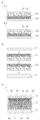
本発明に係る積層体は、金属基板と、絶縁層と、金属層とを備える。上記絶縁層は、上記金属基板の一方の表面に積層されている。上記金属層は、上記絶縁層の上記金属基板側とは反対側の表面に積層されている。上記金属基板の他方の表面にも、上記絶縁層が積層されていてもよい。上記金属層は、パターン状であり、パターン形成された金属層である。上記パターン状の金属層は、例えば、回路パターンである金属層であることが好ましい。上記金属層は、上記絶縁層の上記金属基板側とは反対側の表面の一部の領域に配置されている。上記積層体では、上記絶縁層の上記金属基板側とは反対側の表面にて、上記金属層が配置されていない領域が存在する。(laminate)
A laminate according to the present invention includes a metal substrate, an insulating layer, and a metal layer. The insulating layer is laminated on one surface of the metal substrate. The metal layer is laminated on the surface of the insulating layer opposite to the metal substrate side. The insulating layer may also be laminated on the other surface of the metal substrate. The metal layer is patterned and is a patterned metal layer. The patterned metal layer is preferably a metal layer that is a circuit pattern, for example. The metal layer is arranged in a part of the surface of the insulating layer on the side opposite to the metal substrate. In the laminate, there is a region on the surface of the insulating layer opposite to the metal substrate, where the metal layer is not disposed.
本発明に係る積層体では、上記金属層の厚みは、300μm以上である。上記金属層は、厚みが300μm以上であるので、比較的厚い。本発明に係る積層体では、上記絶縁層は、窒化ホウ素と、窒化ホウ素以外の無機フィラーとを含む。 In the laminate according to the present invention, the thickness of the metal layer is 300 μm or more. The metal layer has a thickness of 300 μm or more, so it is relatively thick. In the laminate according to the present invention, the insulating layer contains boron nitride and an inorganic filler other than boron nitride.
本発明に係る積層体では、上記の構成が備えられているので、パターン状の金属層の厚みが比較的厚いにもかかわらず、熱伝導性と接着性とを効果的に高めることができる。 Since the laminate according to the present invention has the above-mentioned configuration, it is possible to effectively improve thermal conductivity and adhesiveness even though the thickness of the patterned metal layer is relatively thick.
本発明者らは、積層体の金属層の厚みが300μm未満である場合(すなわち、金属層の厚みが比較的薄い場合)と、積層体の金属層の厚みが300μm以上である場合(すなわち、金属層の厚みが比較的厚い場合)とでは、絶縁層と金属層との剥離が生じる際に、剥離の生じるメカニズムが異なることを発見した。本発明者らは、積層体の金属層の厚みが300μm以上である場合、絶縁層と金属層との剥離が生じる際に、絶縁層の層間における脆弱な箇所を起点に亀裂が生じ、絶縁層が裂けるという課題を見出した。この課題は、積層体の金属層の厚みが300μm以上である場合に生じる。本発明者らは、絶縁層の層間における亀裂の発生を抑制するために鋭意検討した結果、窒化ホウ素と、窒化ホウ素以外の無機フィラーとを併用することで、絶縁層に負荷される応力を分散させることができ、絶縁層の層間における亀裂の発生を抑制することができることを見出した。結果として、絶縁層と金属層との接着性をより一層効果的に高めることができる。 The present inventors found that when the thickness of the metal layer of the laminate is less than 300 μm (i.e., the thickness of the metal layer is relatively thin), and when the thickness of the metal layer of the laminate is 300 μm or more (i.e., when the thickness of the metal layer is relatively thin), The inventors have discovered that the mechanism by which peeling occurs between the insulating layer and the metal layer is different when the metal layer is relatively thick (the thickness of the metal layer is relatively thick). The present inventors found that when the thickness of the metal layer of the laminate is 300 μm or more, when the insulating layer and the metal layer peel off, cracks occur starting from weak points between the insulating layers, and the insulating layer We found that the problem was that the parts were torn. This problem occurs when the thickness of the metal layer of the laminate is 300 μm or more. As a result of intensive studies to suppress the occurrence of cracks between the layers of the insulating layer, the present inventors discovered that by using boron nitride and an inorganic filler other than boron nitride in combination, the stress applied to the insulating layer was dispersed. It has been found that the occurrence of cracks between the insulating layers can be suppressed. As a result, the adhesion between the insulating layer and the metal layer can be further effectively improved.
本発明に係る積層体では、上記の構成が備えられているので、熱伝導性を高めることと、絶縁層と金属層との接着性を高めることとの双方を両立させることができる。 Since the laminate according to the present invention has the above-mentioned configuration, it is possible to both increase thermal conductivity and increase adhesiveness between the insulating layer and the metal layer.
本発明では、厚みが300μm以上であるパターン状の金属層を備える積層体において、絶縁層が、窒化ホウ素と、窒化ホウ素以外の無機フィラーとを含む構成を採用することが重要である。 In the present invention, in a laminate including a patterned metal layer having a thickness of 300 μm or more, it is important to adopt a configuration in which the insulating layer contains boron nitride and an inorganic filler other than boron nitride.
本発明に係る積層体では、上記金属層の厚みは、300μm以上である。熱伝導性をより一層効果的に高める観点からは、上記金属層の厚みは、好ましくは350μm以上、より好ましくは400μm以上である。積層体の過度の大型化を避ける観点からは、上記金属層の厚みは、好ましくは3000μm以下、より好ましくは2000μm以下である。 In the laminate according to the present invention, the thickness of the metal layer is 300 μm or more. From the viewpoint of increasing thermal conductivity even more effectively, the thickness of the metal layer is preferably 350 μm or more, more preferably 400 μm or more. From the viewpoint of avoiding excessive enlargement of the laminate, the thickness of the metal layer is preferably 3000 μm or less, more preferably 2000 μm or less.
熱伝導性と接着性とをより一層効果的に高める観点からは、上記絶縁層の厚みは、好ましくは60μm以上、より好ましくは70μm以上であり、好ましくは500μm以下、より好ましくは400μm以下である。 From the viewpoint of increasing thermal conductivity and adhesiveness even more effectively, the thickness of the insulating layer is preferably 60 μm or more, more preferably 70 μm or more, and preferably 500 μm or less, more preferably 400 μm or less. .
熱伝導性をより一層効果的に高める観点からは、上記金属基板の厚みは、好ましくは300μm以上、より好ましくは500μm以上であり、好ましくは5000μm以下、より好ましくは4000μm以下である。 From the viewpoint of increasing thermal conductivity even more effectively, the thickness of the metal substrate is preferably 300 μm or more, more preferably 500 μm or more, and preferably 5000 μm or less, more preferably 4000 μm or less.
(絶縁層)
本発明に係る積層体では、上記絶縁層は、窒化ホウ素と、窒化ホウ素以外の無機フィラーとを含む。(insulating layer)
In the laminate according to the present invention, the insulating layer contains boron nitride and an inorganic filler other than boron nitride.
窒化ホウ素:
本発明に係る積層体では、上記絶縁層は、窒化ホウ素を含む。上記窒化ホウ素は特に限定されない。上記窒化ホウ素としては、六方晶窒化ホウ素、立方晶窒化ホウ素、ホウ素化合物とアンモニアとの還元窒化法により作製された窒化ホウ素、ホウ素化合物とメラミン等の含窒素化合物とから作製された窒化ホウ素、及び、ホウ水素ナトリウムと塩化アンモニウムとから作製された窒化ホウ素等が挙げられる。熱伝導性をより一層効果的に高める観点からは、上記窒化ホウ素は、六方晶窒化ホウ素であることが好ましい。Boron nitride:
In the laminate according to the present invention, the insulating layer contains boron nitride. The boron nitride mentioned above is not particularly limited. Examples of the boron nitride include hexagonal boron nitride, cubic boron nitride, boron nitride produced by a reductive nitridation method using a boron compound and ammonia, boron nitride produced from a boron compound and a nitrogen-containing compound such as melamine, and , boron nitride made from sodium borohydride and ammonium chloride, and the like. From the viewpoint of further effectively increasing thermal conductivity, the boron nitride is preferably hexagonal boron nitride.
熱伝導性と接着性とをより一層効果的に高める観点からは、上記窒化ホウ素の平均アスペクト比は、好ましくは2以上、より好ましくは4以上であり、好ましくは20以下、より好ましくは15以下である。 From the viewpoint of increasing thermal conductivity and adhesiveness even more effectively, the average aspect ratio of the boron nitride is preferably 2 or more, more preferably 4 or more, and preferably 20 or less, more preferably 15 or less. It is.
上記窒化ホウ素のアスペクト比は、長径/短径を示す。上記窒化ホウ素の平均アスペクト比は、任意に選択された50個の各窒化ホウ素を電子顕微鏡又は光学顕微鏡にて観察し、各窒化ホウ素の長径/短径を測定し、平均値を算出することにより求めることが好ましい。 The aspect ratio of the boron nitride indicates the major axis/the minor axis. The average aspect ratio of the boron nitride is determined by observing 50 arbitrarily selected boron nitrides using an electron microscope or an optical microscope, measuring the major axis/minor axis of each boron nitride, and calculating the average value. It is preferable to ask.
熱伝導性と接着性とをより一層効果的に高める観点からは、上記窒化ホウ素の平均長径は、好ましくは1μm以上、より好ましくは2μm以上であり、好ましくは40μm以下、より好ましくは30μm以下である。 From the viewpoint of increasing thermal conductivity and adhesiveness even more effectively, the average major axis of the boron nitride is preferably 1 μm or more, more preferably 2 μm or more, and preferably 40 μm or less, more preferably 30 μm or less. be.
上記窒化ホウ素の平均長径は、任意に選択された50個の各窒化ホウ素を電子顕微鏡又は光学顕微鏡にて観察し、各窒化ホウ素の長径を測定し、平均値を算出することにより求めることが好ましい。 The average major axis of the boron nitride is preferably determined by observing each of the 50 arbitrarily selected boron nitrides using an electron microscope or an optical microscope, measuring the major axis of each boron nitride, and calculating the average value. .
熱伝導性と接着性とをより一層効果的に高める観点からは、上記絶縁層100体積%中、上記窒化ホウ素の含有量は、好ましくは20体積%以上、より好ましくは30体積%以上であり、好ましくは80体積%以下、より好ましくは70体積%以下である。 From the viewpoint of increasing thermal conductivity and adhesiveness even more effectively, the content of the boron nitride in 100 volume% of the insulating layer is preferably 20 volume% or more, more preferably 30 volume% or more. , preferably 80% by volume or less, more preferably 70% by volume or less.
熱伝導性と接着性とをより一層効果的に高める観点からは、上記絶縁層は、窒化ホウ素凝集粒子を含むことが好ましい。上記絶縁層は、上記窒化ホウ素を、窒化ホウ素凝集粒子として含むことが好ましい。上記絶縁層に含まれる上記窒化ホウ素は、窒化ホウ素凝集粒子であることが好ましい。 From the viewpoint of further effectively increasing thermal conductivity and adhesiveness, it is preferable that the insulating layer contains boron nitride agglomerated particles. The insulating layer preferably contains the boron nitride in the form of boron nitride agglomerated particles. The boron nitride contained in the insulating layer is preferably boron nitride aggregate particles.
窒化ホウ素凝集粒子:
熱伝導性と接着性とをより一層効果的に高める観点からは、上記窒化ホウ素凝集粒子の平均アスペクト比は、好ましくは0.6以上、より好ましくは0.8以上であり、好ましくは1.8以下、より好ましくは1.6以下である。Boron nitride aggregate particles:
From the viewpoint of increasing thermal conductivity and adhesiveness even more effectively, the average aspect ratio of the boron nitride agglomerated particles is preferably 0.6 or more, more preferably 0.8 or more, and preferably 1. It is 8 or less, more preferably 1.6 or less.
上記窒化ホウ素凝集粒子のアスペクト比は、長径/短径を示す。上記窒化ホウ素凝集粒子の平均アスペクト比は、任意に選択された50個の各窒化ホウ素凝集粒子を電子顕微鏡又は光学顕微鏡にて観察し、各窒化ホウ素凝集粒子の長径/短径を測定し、平均値を算出することにより求めることが好ましい。 The aspect ratio of the boron nitride agglomerated particles indicates the major axis/the minor axis. The average aspect ratio of the boron nitride agglomerated particles is determined by observing each of 50 randomly selected boron nitride agglomerated particles using an electron microscope or an optical microscope, and measuring the major axis/breadth axis of each boron nitride agglomerated particle. It is preferable to obtain the value by calculating the value.
熱伝導性と接着性とをより一層効果的に高める観点からは、上記窒化ホウ素凝集粒子の粒子径は、好ましくは10μm以上、より好ましくは15μm以上であり、好ましくは200μm以下、より好ましくは150μm以下である。 From the viewpoint of increasing thermal conductivity and adhesiveness even more effectively, the particle size of the boron nitride agglomerated particles is preferably 10 μm or more, more preferably 15 μm or more, and preferably 200 μm or less, more preferably 150 μm. It is as follows.
上記窒化ホウ素凝集粒子の粒子径は、体積基準での粒子径を平均した平均粒子径であることが好ましい。上記窒化ホウ素凝集粒子の粒子径は、マルバーン社製「レーザー回折式粒度分布測定装置」を用いて測定することができる。上記窒化ホウ素凝集粒子の粒子径は、任意に選択された50個の上記窒化ホウ素凝集粒子を電子顕微鏡又は光学顕微鏡にて観察し、各窒化ホウ素凝集粒子の粒子径を測定し、平均値を算出することにより求めることもできる。電子顕微鏡又は光学顕微鏡での観察では、1個当たりの窒化ホウ素凝集粒子の粒子径は、円相当径での粒子径として求められる。電子顕微鏡又は光学顕微鏡での観察において、任意の50個の窒化ホウ素凝集粒子の円相当径での平均粒子径は、球相当径での平均粒子径とほぼ等しくなる。レーザー回折式粒度分布測定装置を用いた測定では、1個当たりの窒化ホウ素凝集粒子の粒子径は、球相当径での粒子径として求められる。上記窒化ホウ素凝集粒子の平均粒子径は、レーザー回折式粒度分布測定装置を用いた測定により算出することが好ましい。 The particle diameter of the boron nitride agglomerated particles is preferably an average particle diameter obtained by averaging the particle diameters on a volume basis. The particle size of the boron nitride agglomerated particles can be measured using a "laser diffraction particle size distribution analyzer" manufactured by Malvern. The particle diameter of the boron nitride aggregated particles is determined by observing 50 arbitrarily selected boron nitride aggregate particles using an electron microscope or optical microscope, measuring the particle diameter of each boron nitride aggregate particle, and calculating the average value. It can also be found by In observation using an electron microscope or an optical microscope, the particle diameter of each boron nitride agglomerated particle is determined as the particle diameter in equivalent circle diameter. In observation using an electron microscope or an optical microscope, the average particle diameter of any 50 boron nitride agglomerated particles in equivalent circle diameter is approximately equal to the average particle diameter in equivalent sphere diameter. In the measurement using a laser diffraction particle size distribution analyzer, the particle diameter of each boron nitride agglomerated particle is determined as the particle diameter in equivalent sphere diameter. The average particle diameter of the boron nitride agglomerated particles is preferably calculated by measurement using a laser diffraction particle size distribution analyzer.
熱伝導性をより一層効果的に高める観点からは、上記窒化ホウ素凝集粒子の熱伝導率は、好ましくは5W/m・K以上、より好ましくは10W/m・K以上である。上記窒化ホウ素凝集粒子の熱伝導率の上限は特に限定されない。上記窒化ホウ素凝集粒子の熱伝導率は、1000W/m・K以下であってもよい。 From the viewpoint of increasing thermal conductivity even more effectively, the thermal conductivity of the boron nitride agglomerated particles is preferably 5 W/m·K or more, more preferably 10 W/m·K or more. The upper limit of the thermal conductivity of the boron nitride agglomerated particles is not particularly limited. The thermal conductivity of the boron nitride agglomerated particles may be 1000 W/m·K or less.
熱伝導性と接着性とをより一層効果的に高める観点からは、上記絶縁層100体積%中、上記窒化ホウ素凝集粒子の含有量は、好ましくは20体積%以上、より好ましくは30体積%以上であり、好ましくは80体積%以下、より好ましくは70体積%以下である。 From the viewpoint of increasing thermal conductivity and adhesiveness even more effectively, the content of the boron nitride aggregate particles in 100 volume% of the insulating layer is preferably 20 volume% or more, more preferably 30 volume% or more. The content is preferably 80% by volume or less, more preferably 70% by volume or less.
上記窒化ホウ素凝集粒子の製造方法としては特に限定されず、噴霧乾燥方法及び流動層造粒方法等が挙げられる。上記窒化ホウ素凝集粒子の製造方法は、噴霧乾燥(スプレードライとも呼ばれる)方法であることが好ましい。噴霧乾燥方法は、スプレー方式によって、二流体ノズル方式、ディスク方式(ロータリ方式とも呼ばれる)、及び超音波ノズル方式等に分類でき、これらのどの方式でも適用できる。全細孔容積をより一層容易に制御できる観点から、超音波ノズル方式が好ましい。 The method for producing the boron nitride agglomerated particles is not particularly limited, and examples include a spray drying method and a fluidized bed granulation method. The method for producing the boron nitride agglomerated particles is preferably a spray drying (also called spray drying) method. Spray drying methods can be classified into two types, such as a two-fluid nozzle method, a disk method (also called a rotary method), and an ultrasonic nozzle method, depending on the spray method, and any of these methods can be applied. The ultrasonic nozzle method is preferred from the viewpoint of being able to control the total pore volume even more easily.
また、窒化ホウ素凝集粒子の製造方法としては、必ずしも造粒工程は必要ではない。窒化ホウ素の結晶の成長に伴い、窒化ホウ素の一次粒子が自然に集結することで形成された窒化ホウ素凝集粒子であってもよい。また、窒化ホウ素凝集粒子の粒子径をそろえるために、粉砕した窒化ホウ素凝集粒子であってもよい。 Furthermore, the method for producing boron nitride aggregate particles does not necessarily require a granulation step. Boron nitride agglomerated particles may be formed by natural aggregation of primary particles of boron nitride as boron nitride crystals grow. Further, in order to make the particle diameters of the boron nitride aggregate particles uniform, pulverized boron nitride aggregate particles may be used.
上記窒化ホウ素凝集粒子は、窒化ホウ素の一次粒子を材料として製造されることが好ましい。上記窒化ホウ素凝集粒子の材料となる窒化ホウ素としては特に限定されず、上述した窒化ホウ素が挙げられる。上記窒化ホウ素凝集粒子の熱伝導性をより一層効果的に高める観点からは、窒化ホウ素凝集粒子の材料となる窒化ホウ素は、六方晶窒化ホウ素であることが好ましい。 The boron nitride agglomerated particles are preferably manufactured using primary particles of boron nitride. The boron nitride that is the material for the boron nitride aggregate particles is not particularly limited, and examples include the boron nitrides mentioned above. From the viewpoint of further effectively increasing the thermal conductivity of the boron nitride aggregated particles, the boron nitride used as the material of the boron nitride aggregated particles is preferably hexagonal boron nitride.
窒化ホウ素以外の無機フィラー:
本発明に係る積層体では、上記絶縁層は、窒化ホウ素以外の無機フィラーを含む。上記窒化ホウ素以外の無機フィラーは、絶縁性を有することが好ましい。上記窒化ホウ素以外の無機フィラーは、絶縁性粒子であることが好ましい。Inorganic fillers other than boron nitride:
In the laminate according to the present invention, the insulating layer contains an inorganic filler other than boron nitride. The inorganic filler other than boron nitride preferably has insulation properties. The inorganic filler other than boron nitride is preferably insulating particles.
熱伝導性と接着性とをより一層効果的に高める観点からは、上記窒化ホウ素以外の無機フィラーの平均アスペクト比は、2未満であることが好ましく、1.5以下であることがより好ましい。上記窒化ホウ素以外の無機フィラーの平均アスペクト比の下限は特に限定されない。上記窒化ホウ素以外の無機フィラーの平均アスペクト比は、1以上であってもよい。 From the viewpoint of increasing thermal conductivity and adhesiveness even more effectively, the average aspect ratio of the inorganic filler other than boron nitride is preferably less than 2, and more preferably 1.5 or less. The lower limit of the average aspect ratio of the inorganic filler other than boron nitride is not particularly limited. The average aspect ratio of the inorganic filler other than boron nitride may be 1 or more.
上記窒化ホウ素以外の無機フィラーのアスペクト比は、長径/短径を示す。上記窒化ホウ素以外の無機フィラーの平均アスペクト比は、任意に選択された50個の各窒化ホウ素以外の無機フィラーを電子顕微鏡又は光学顕微鏡にて観察し、各窒化ホウ素以外の無機フィラーの長径/短径を測定し、平均値を算出することにより求めることが好ましい。 The aspect ratio of the above-mentioned inorganic filler other than boron nitride indicates the major axis/breadth axis. The average aspect ratio of the above inorganic fillers other than boron nitride was determined by observing 50 arbitrarily selected inorganic fillers other than boron nitride using an electron microscope or an optical microscope. It is preferable to obtain the diameter by measuring the diameter and calculating the average value.
熱伝導性と接着性とをより一層効果的に高める観点からは、上記窒化ホウ素以外の無機フィラーの粒子径は、好ましくは0.1μm以上、より好ましくは0.5μm以上であり、好ましくは100μm以下、より好ましくは80μm以下である。 From the viewpoint of increasing thermal conductivity and adhesiveness even more effectively, the particle size of the inorganic filler other than boron nitride is preferably 0.1 μm or more, more preferably 0.5 μm or more, and preferably 100 μm. The thickness is more preferably 80 μm or less.
上記窒化ホウ素以外の無機フィラーの粒子径は、窒化ホウ素以外の無機フィラーが真球状である場合には直径を意味し、窒化ホウ素以外の無機フィラーが真球状以外の形状である場合には、窒化ホウ素以外の無機フィラーの体積相当の真球と仮定した際の直径を意味する。 The particle diameter of the inorganic filler other than boron nitride means the diameter if the inorganic filler other than boron nitride is true spherical, and if the inorganic filler other than boron nitride has a shape other than true spherical, the particle size of the inorganic filler other than boron nitride means the diameter. Means the diameter assuming a true sphere equivalent to the volume of inorganic filler other than boron.
上記窒化ホウ素以外の無機フィラーの粒子径は、体積基準での粒子径を平均した平均粒子径であることが好ましい。上記窒化ホウ素以外の無機フィラーの粒子径は、マルバーン社製「レーザー回折式粒度分布測定装置」を用いて測定することができる。上記窒化ホウ素以外の無機フィラーの粒子径は、任意に選択された50個の上記窒化ホウ素以外の無機フィラーを電子顕微鏡又は光学顕微鏡にて観察し、各窒化ホウ素以外の無機フィラーの粒子径を測定し、平均値を算出することにより求めることもできる。電子顕微鏡又は光学顕微鏡での観察では、1個当たりの窒化ホウ素以外の無機フィラーの粒子径は、円相当径での粒子径として求められる。電子顕微鏡又は光学顕微鏡での観察において、任意の50個の窒化ホウ素以外の無機フィラーの円相当径での平均粒子径は、球相当径での平均粒子径とほぼ等しくなる。レーザー回折式粒度分布測定装置を用いた測定では、1個当たりの窒化ホウ素以外の無機フィラーの粒子径は、球相当径での粒子径として求められる。 The particle diameter of the inorganic filler other than boron nitride is preferably an average particle diameter obtained by averaging the particle diameters on a volume basis. The particle size of the inorganic filler other than boron nitride can be measured using a "laser diffraction particle size distribution analyzer" manufactured by Malvern. The particle size of the inorganic filler other than boron nitride is determined by observing 50 arbitrarily selected inorganic fillers other than boron nitride using an electron microscope or optical microscope, and measuring the particle size of each inorganic filler other than boron nitride. However, it can also be determined by calculating the average value. In observation using an electron microscope or an optical microscope, the particle diameter of each inorganic filler other than boron nitride is determined as the particle diameter in equivalent circle diameter. In observation using an electron microscope or an optical microscope, the average particle diameter of any 50 inorganic fillers other than boron nitride in equivalent circle diameter is approximately equal to the average particle diameter in equivalent sphere diameter. In the measurement using a laser diffraction particle size distribution analyzer, the particle diameter of each inorganic filler other than boron nitride is determined as the particle diameter in equivalent sphere diameter.
上記窒化ホウ素以外の無機フィラーの材料は特に限定されない。上記窒化ホウ素以外の無機フィラーは、絶縁性フィラーであることが好ましい。上記窒化ホウ素以外の無機フィラーの材料としては、酸化アルミニウム(アルミナ)、酸化カルシウム、及び酸化マグネシウム等の金属酸化物、窒化アルミニウム、及び窒化チタン等の金属窒化物、水酸化アルミニウム、及び水酸化マグネシウム等の金属水酸化物、炭酸カルシウム、及び炭酸マグネシウム等の炭酸金属塩、ケイ酸カルシウム等のケイ酸金属塩、水和金属化合物、結晶性シリカ、非結晶性シリカ、並びに炭化ケイ素等が挙げられる。上記窒化ホウ素以外の無機フィラーの材料は、1種のみが用いられてもよく、2種以上が併用されてもよい。 The material of the inorganic filler other than the boron nitride is not particularly limited. The inorganic filler other than boron nitride is preferably an insulating filler. Inorganic filler materials other than boron nitride include metal oxides such as aluminum oxide (alumina), calcium oxide, and magnesium oxide, metal nitrides such as aluminum nitride and titanium nitride, aluminum hydroxide, and magnesium hydroxide. Metal hydroxides such as calcium carbonate, metal carbonates such as magnesium carbonate, metal silicate salts such as calcium silicate, hydrated metal compounds, crystalline silica, amorphous silica, and silicon carbide. . Only one type of inorganic filler material other than boron nitride may be used, or two or more types may be used in combination.
熱伝導性と接着性とをより一層効果的に高める観点からは、上記窒化ホウ素以外の無機フィラーの材料は、酸化アルミニウム、窒化アルミニウム、酸化マグネシウム、又は炭化ケイ素であることが好ましい。熱伝導性と接着性とを更に一層効果的に高める観点からは、上記窒化ホウ素以外の無機フィラーの材料は、酸化アルミニウム、窒化アルミニウム、又は酸化マグネシウムであることがより好ましく、酸化アルミニウム、又は窒化アルミニウムであることがさらに好ましい。 From the viewpoint of increasing thermal conductivity and adhesiveness even more effectively, the material of the inorganic filler other than boron nitride is preferably aluminum oxide, aluminum nitride, magnesium oxide, or silicon carbide. From the viewpoint of further effectively increasing thermal conductivity and adhesiveness, the material of the inorganic filler other than boron nitride is more preferably aluminum oxide, aluminum nitride, or magnesium oxide; More preferably, it is aluminum.
熱伝導性をより一層効果的に高める観点からは、上記窒化ホウ素以外の無機フィラーの熱伝導率は、好ましくは10W/m・K以上、より好ましくは20W/m・K以上である。上記窒化ホウ素以外の無機フィラーの熱伝導率の上限は特に限定されない。上記窒化ホウ素以外の無機フィラーの熱伝導率は、300W/m・K以下であってもよく、200W/m・K以下であってもよい。上記窒化ホウ素以外の無機フィラーの熱伝導率が、上記の好ましい範囲であると、熱伝導性と接着性とをより一層効果的に高めることができる。 From the viewpoint of increasing thermal conductivity even more effectively, the thermal conductivity of the inorganic filler other than boron nitride is preferably 10 W/m·K or more, more preferably 20 W/m·K or more. The upper limit of the thermal conductivity of the inorganic filler other than boron nitride is not particularly limited. The thermal conductivity of the inorganic filler other than boron nitride may be 300 W/m·K or less, or 200 W/m·K or less. When the thermal conductivity of the inorganic filler other than boron nitride is within the above preferable range, thermal conductivity and adhesiveness can be further effectively improved.
熱伝導性と接着性とをより一層効果的に高める観点からは、上記絶縁層の金属層側における上記窒化ホウ素以外の無機フィラーの含有量は、上記絶縁層の金属基板側における上記窒化ホウ素以外の無機フィラーの含有量よりも多いことが好ましい。熱伝導性と接着性とをより一層効果的に高める観点からは、金属層側に位置する絶縁層の厚みの1/2の領域における上記窒化ホウ素以外の無機フィラーの含有量は、上記金属基板側に位置する絶縁層の厚みの1/2の領域における上記窒化ホウ素以外の無機フィラーの含有量よりも多いことが好ましい。 From the viewpoint of increasing thermal conductivity and adhesiveness even more effectively, the content of the inorganic filler other than the boron nitride on the metal layer side of the insulating layer is the same as the content of the inorganic filler other than the boron nitride on the metal substrate side of the insulating layer. The content of the inorganic filler is preferably higher than that of the inorganic filler. From the viewpoint of increasing thermal conductivity and adhesion even more effectively, the content of the inorganic filler other than boron nitride in the region of 1/2 the thickness of the insulating layer located on the metal layer side should be It is preferable that the content of the inorganic filler other than boron nitride is greater than the content of the inorganic filler other than boron nitride in a region half the thickness of the insulating layer located on the side.
上記絶縁層の金属層側の表面から上記絶縁層の金属基板側の表面に向かって厚み30%の領域(R1)の100体積%中における上記窒化ホウ素以外の無機フィラーの含有量を、第1の含有量とする。上記絶縁層の金属基板側の表面から上記絶縁層の金属層側の表面に向かって厚み70%の領域(R2)の100体積%中における上記窒化ホウ素以外の無機フィラーの含有量を、第2の含有量とする。熱伝導性と接着性とをより一層効果的に高める観点からは、上記第1の含有量は、上記第2の含有量よりも多いことが好ましい。上記領域(R1)に、上記窒化ホウ素以外の無機フィラーが多く含まれることが好ましい。上記領域(R1)は、図3において、第1の表面2aと破線L1との間の領域である。上記領域(R2)は、図3において、第2の表面2bと破線L1との間の領域である。 The content of the inorganic filler other than boron nitride in 100 volume % of the region (R1) having a thickness of 30% from the surface of the insulating layer on the metal layer side to the surface of the insulating layer on the metal substrate side is determined as follows: The content of The content of the inorganic filler other than boron nitride in 100 volume % of the 70% thick region (R2) from the surface of the insulating layer on the metal substrate side to the surface of the insulating layer on the metal layer side is determined by the second The content of From the viewpoint of increasing thermal conductivity and adhesiveness even more effectively, the first content is preferably greater than the second content. It is preferable that the region (R1) contains a large amount of inorganic filler other than the boron nitride. The region (R1) is the region between the
熱伝導性と接着性とをより一層効果的に高める観点からは、上記絶縁層100体積%中、上記窒化ホウ素以外の無機フィラーの含有量は、好ましくは3体積%以上、より好ましくは5体積%以上であり、好ましくは60体積%以下、より好ましくは50体積%以下、さらに好ましくは45体積%以下である。 From the viewpoint of increasing thermal conductivity and adhesiveness even more effectively, the content of the inorganic filler other than boron nitride in 100 volume % of the insulating layer is preferably 3 volume % or more, more preferably 5 volume %. % or more, preferably 60 volume % or less, more preferably 50 volume % or less, still more preferably 45 volume % or less.
熱伝導性と接着性とをより一層効果的に高める観点からは、上記領域(R1)100体積%中における上記窒化ホウ素以外の無機フィラーの第1の含有量は、好ましくは5体積%以上、より好ましくは10体積%以上であり、好ましくは60体積%以下、より好ましくは50体積%以下である。 From the viewpoint of increasing thermal conductivity and adhesiveness even more effectively, the first content of the inorganic filler other than boron nitride in 100 volume % of the region (R1) is preferably 5 volume % or more, The content is more preferably 10% by volume or more, preferably 60% by volume or less, and even more preferably 50% by volume or less.
熱伝導性と接着性とをより一層効果的に高める観点からは、上記領域(R2)100体積%中における上記窒化ホウ素以外の無機フィラーの第2の含有量は、好ましくは1体積%以上、より好ましくは3体積%以上であり、好ましくは50体積%以下、より好ましくは45体積%以下である。 From the viewpoint of increasing thermal conductivity and adhesiveness even more effectively, the second content of the inorganic filler other than boron nitride in 100 volume % of the region (R2) is preferably 1 volume % or more, The content is more preferably 3% by volume or more, preferably 50% by volume or less, and even more preferably 45% by volume or less.
熱伝導性と接着性とをより一層効果的に高める観点からは、上記第1の含有量と上記第2の含有量との差の絶対値は、好ましくは3体積%以上、より好ましくは5体積%以上であり、好ましくは50体積%以下、より好ましくは40体積%以下である。 From the viewpoint of increasing thermal conductivity and adhesiveness even more effectively, the absolute value of the difference between the first content and the second content is preferably 3% by volume or more, more preferably 5% by volume. It is at least 50% by volume, preferably at most 50% by volume, more preferably at most 40% by volume.
上記領域(R1)100体積%中における上記窒化ホウ素以外の無機フィラーの第1の含有量、及び上記領域(R2)100体積%中における上記窒化ホウ素以外の無機フィラーの第2の含有量は、上記積層体の断面の電子顕微鏡画像から算出することができる。 The first content of the inorganic filler other than boron nitride in 100% by volume of the region (R1) and the second content of the inorganic filler other than boron nitride in 100% by volume of the region (R2) are: It can be calculated from an electron microscope image of a cross section of the laminate.
熱硬化性化合物:
上記絶縁層は、熱硬化性化合物と、熱硬化剤又は硬化触媒とを含むことが好ましい。上記熱硬化性化合物は特に限定されない。上記熱硬化性化合物としては、スチレン化合物、フェノキシ化合物、オキセタン化合物、エポキシ化合物、エピスルフィド化合物、(メタ)アクリル化合物、フェノール化合物、アミノ化合物、不飽和ポリエステル化合物、ポリウレタン化合物、シリコーン化合物及びポリイミド化合物等が挙げられる。上記熱硬化性化合物は、1種のみが用いられてもよく、2種以上が併用されてもよい。Thermosetting compound:
The insulating layer preferably contains a thermosetting compound and a thermosetting agent or a curing catalyst. The above thermosetting compound is not particularly limited. Examples of the thermosetting compounds include styrene compounds, phenoxy compounds, oxetane compounds, epoxy compounds, episulfide compounds, (meth)acrylic compounds, phenol compounds, amino compounds, unsaturated polyester compounds, polyurethane compounds, silicone compounds, and polyimide compounds. Can be mentioned. Only one kind of the above-mentioned thermosetting compound may be used, or two or more kinds thereof may be used in combination.
熱伝導性と接着性とをより一層効果的に高める観点からは、上記熱硬化性化合物は、エポキシ化合物、オキセタン化合物、エピスルフィド化合物又はシリコーン化合物を含むことが好ましく、エポキシ化合物を含むことがより好ましい。上記エポキシ化合物は、少なくとも1個のエポキシ基を有する有機化合物である。上記エポキシ化合物は、1種のみが用いられてもよく、2種以上が併用されてもよい。 From the viewpoint of further effectively increasing thermal conductivity and adhesiveness, the thermosetting compound preferably contains an epoxy compound, an oxetane compound, an episulfide compound, or a silicone compound, and more preferably contains an epoxy compound. . The epoxy compound is an organic compound having at least one epoxy group. The above epoxy compounds may be used alone or in combination of two or more.
上記エポキシ化合物としては、ビスフェノールA型エポキシ化合物、ビスフェノールF型エポキシ化合物、ビスフェノールS型エポキシ化合物、グリコール変性エポキシ化合物、グリシジルアミン型エポキシ化合物、フェノールノボラック型エポキシ化合物、ビフェニル型エポキシ化合物、ビフェニルノボラック型エポキシ化合物、ビフェノール型エポキシ化合物、ナフタレン型エポキシ化合物、フルオレン型エポキシ化合物、フェノールアラルキル型エポキシ化合物、ナフトールアラルキル型エポキシ化合物、ジシクロペンタジエン型エポキシ化合物、アントラセン型エポキシ化合物、アダマンタン骨格を有するエポキシ化合物、トリシクロデカン骨格を有するエポキシ化合物、ナフチレンエーテル型エポキシ化合物、及びトリアジン核を骨格に有するエポキシ化合物等が挙げられる。 The above-mentioned epoxy compounds include bisphenol A type epoxy compounds, bisphenol F type epoxy compounds, bisphenol S type epoxy compounds, glycol-modified epoxy compounds, glycidylamine type epoxy compounds, phenol novolac type epoxy compounds, biphenyl type epoxy compounds, and biphenyl novolac type epoxy compounds. Compounds, biphenol type epoxy compounds, naphthalene type epoxy compounds, fluorene type epoxy compounds, phenol aralkyl type epoxy compounds, naphthol aralkyl type epoxy compounds, dicyclopentadiene type epoxy compounds, anthracene type epoxy compounds, epoxy compounds with an adamantane skeleton, tricyclo Examples include epoxy compounds having a decane skeleton, naphthylene ether type epoxy compounds, and epoxy compounds having a triazine nucleus in the skeleton.
熱伝導性と接着性とをより一層効果的に高める観点からは、上記エポキシ化合物は、ビスフェノールA型エポキシ化合物であることが好ましい。 From the viewpoint of increasing thermal conductivity and adhesiveness even more effectively, the epoxy compound is preferably a bisphenol A type epoxy compound.
熱伝導性と接着性とをより一層効果的に高める観点からは、上記絶縁層100体積%中、上記熱硬化性化合物の含有量は、好ましくは5体積%以上、より好ましくは10体積%以上であり、好ましくは80体積%以下、より好ましくは70体積%以下である。熱伝導性と接着性とをより一層効果的に高める観点からは、上記絶縁層100体積%中、上記熱硬化性化合物に由来する成分の含有量は、好ましくは5体積%以上、より好ましくは10体積%以上であり、好ましくは80体積%以下、より好ましくは70体積%以下である。 From the viewpoint of increasing thermal conductivity and adhesiveness even more effectively, the content of the thermosetting compound is preferably 5% by volume or more, more preferably 10% by volume or more in 100% by volume of the insulating layer. The content is preferably 80% by volume or less, more preferably 70% by volume or less. From the viewpoint of increasing thermal conductivity and adhesiveness even more effectively, the content of the component derived from the thermosetting compound in 100% by volume of the insulating layer is preferably 5% by volume or more, more preferably The content is 10% by volume or more, preferably 80% by volume or less, more preferably 70% by volume or less.
熱硬化剤:
上記絶縁層は、熱硬化性化合物と、熱硬化剤又は硬化触媒とを含むことが好ましい。上記熱硬化剤は特に限定されない。上記熱硬化剤として、上記熱硬化性化合物を硬化させることができる熱硬化剤を適宜用いることができる。接着性をより一層効果的に高める観点からは、上記絶縁層では、上記熱硬化剤と上記効果触媒とを併用することが好ましい。上記熱硬化剤は、1種のみが用いられてもよく、2種以上が併用されてもよい。Thermosetting agent:
The insulating layer preferably contains a thermosetting compound and a thermosetting agent or a curing catalyst. The above thermosetting agent is not particularly limited. As the thermosetting agent, a thermosetting agent capable of curing the thermosetting compound can be appropriately used. From the viewpoint of increasing adhesiveness even more effectively, it is preferable to use the thermosetting agent and the effect catalyst in combination in the insulating layer. The above thermosetting agents may be used alone or in combination of two or more.
上記熱硬化剤としては、シアネートエステル化合物(シアネートエステル硬化剤)、フェノール化合物(フェノール熱硬化剤)、アミン化合物(アミン熱硬化剤)、チオール化合物(チオール熱硬化剤)、イミダゾール化合物、ホスフィン化合物、酸無水物、活性エステル化合物、及びカルボジイミド化合物等が挙げられる。上記熱硬化剤は、上記エポキシ化合物のエポキシ基と反応可能な官能基を有することが好ましい。 Examples of the thermosetting agents include cyanate ester compounds (cyanate ester curing agents), phenol compounds (phenol thermosetting agents), amine compounds (amine thermosetting agents), thiol compounds (thiol thermosetting agents), imidazole compounds, phosphine compounds, Examples include acid anhydrides, active ester compounds, and carbodiimide compounds. The thermosetting agent preferably has a functional group capable of reacting with the epoxy group of the epoxy compound.
上記シアネートエステル化合物としては、ノボラック型シアネートエステル樹脂、ビスフェノール型シアネートエステル樹脂、並びにこれらが一部三量化されたプレポリマー等が挙げられる。上記ノボラック型シアネートエステル樹脂としては、フェノールノボラック型シアネートエステル樹脂及びアルキルフェノール型シアネートエステル樹脂等が挙げられる。上記ビスフェノール型シアネートエステル樹脂としては、ビスフェノールA型シアネートエステル樹脂、ビスフェノールE型シアネートエステル樹脂及びテトラメチルビスフェノールF型シアネートエステル樹脂等が挙げられる。 Examples of the cyanate ester compound include novolak-type cyanate ester resins, bisphenol-type cyanate ester resins, and prepolymers obtained by partially trimerizing these. Examples of the novolac cyanate ester resins include phenol novolac cyanate ester resins and alkylphenol cyanate ester resins. Examples of the bisphenol type cyanate ester resin include bisphenol A type cyanate ester resin, bisphenol E type cyanate ester resin, and tetramethylbisphenol F type cyanate ester resin.
上記フェノール化合物としては、ノボラック型フェノール、ビフェノール型フェノール、ナフタレン型フェノール、ジシクロペンタジエン型フェノール、アラルキル型フェノール及びジシクロペンタジエン型フェノール等が挙げられる。 Examples of the above-mentioned phenol compounds include novolac-type phenol, biphenol-type phenol, naphthalene-type phenol, dicyclopentadiene-type phenol, aralkyl-type phenol, and dicyclopentadiene-type phenol.
上記フェノール化合物の市販品としては、ノボラック型フェノール(DIC社製「TD-2091」)、ビフェニルノボラック型フェノール(明和化成社製「MEHC-7851」)、アラルキル型フェノール化合物(明和化成社製「MEH-7800」)、並びにアミノトリアジン骨格を有するフェノール(DIC社製「LA1356」及び「LA3018-50P」)等が挙げられる。 Commercial products of the above-mentioned phenol compounds include novolac type phenol ("TD-2091" manufactured by DIC Corporation), biphenyl novolac type phenol ("MEHC-7851" manufactured by Meiwa Kasei Co., Ltd.), and aralkyl type phenol compound ("MEH" manufactured by Meiwa Kasei Co., Ltd.). -7800''), and phenols having an aminotriazine skeleton (“LA1356” and “LA3018-50P” manufactured by DIC Corporation).
上記アミン化合物としては、ジシアンジアミド等が挙げられる。 Examples of the amine compound include dicyandiamide and the like.
上記絶縁層100体積%中、上記熱硬化性化合物と上記熱硬化剤との合計の含有量は、好ましくは20体積%以上、より好ましくは25体積%以上であり、好ましくは50体積%以下、より好ましくは45体積%以下である。上記絶縁層100体積%中、上記熱硬化性化合物及び上記熱硬化剤に由来する成分の合計の含有量は、好ましくは20体積%以上、より好ましくは25体積%以上であり、好ましくは50体積%以下、より好ましくは45体積%以下である。上記の合計の含有量が、上記下限以上及び上記上限以下であると、熱伝導性をより一層効果的に高めることができ、接着性をより一層効果的に高めることができる。上記熱硬化性化合物と上記熱硬化剤との含有量比は、熱硬化性化合物が硬化するように適宜選択される。 In 100 volume% of the insulating layer, the total content of the thermosetting compound and the thermosetting agent is preferably 20 volume% or more, more preferably 25 volume% or more, and preferably 50 volume% or less, More preferably, it is 45% by volume or less. The total content of components derived from the thermosetting compound and the thermosetting agent in 100% by volume of the insulating layer is preferably 20% by volume or more, more preferably 25% by volume or more, and preferably 50% by volume. % or less, more preferably 45 volume % or less. When the above-mentioned total content is at least the above-mentioned lower limit and below the above-mentioned upper limit, thermal conductivity can be further effectively improved, and adhesiveness can be further effectively improved. The content ratio of the thermosetting compound and the thermosetting agent is appropriately selected so that the thermosetting compound is cured.
上記熱硬化性化合物が良好に硬化するように、上記熱硬化剤の含有量は適宜選択される。上記熱硬化性化合物100重量部に対して、上記熱硬化剤の含有量は、好ましくは1重量部以上、より好ましくは3重量部以上であり、好ましくは100重量部以下、より好ましくは80重量部以下である。上記熱硬化剤の含有量が、上記下限以上であると、熱硬化性化合物を十分に硬化させることがより一層容易になる。上記熱硬化剤の含有量が、上記上限以下であると、硬化に関与しない余剰な熱硬化剤が発生し難くなる。このため、上記熱硬化剤の含有量が上記下限以上及び上記上限以下であると、硬化物の耐熱性及び接着性がより一層高くなる。 The content of the thermosetting agent is appropriately selected so that the thermosetting compound can be cured well. With respect to 100 parts by weight of the thermosetting compound, the content of the thermosetting agent is preferably 1 part by weight or more, more preferably 3 parts by weight or more, and preferably 100 parts by weight or less, more preferably 80 parts by weight. below. When the content of the thermosetting agent is equal to or higher than the lower limit, it becomes even easier to fully cure the thermosetting compound. When the content of the thermosetting agent is below the above upper limit, excess thermosetting agent that does not participate in curing is unlikely to be generated. Therefore, when the content of the thermosetting agent is not less than the above lower limit and not more than the above upper limit, the heat resistance and adhesiveness of the cured product will be even higher.
硬化触媒:
上記絶縁層は、熱硬化性化合物と、熱硬化剤又は硬化触媒とを含むことが好ましい。上記硬化触媒は特に限定されない。上記硬化触媒は、上記熱硬化性化合物と上記熱硬化剤との反応において硬化触媒として作用する。また、上記硬化触媒は、上記熱硬化剤を用いない場合に、重合触媒として作用する。接着性をより一層効果的に高める観点からは、上記絶縁層では、上記熱硬化剤と上記硬化触媒とを併用することが好ましい。上記硬化触媒は、1種のみが用いられてもよく、2種以上が併用されてもよい。Curing catalyst:
The insulating layer preferably contains a thermosetting compound and a thermosetting agent or a curing catalyst. The curing catalyst is not particularly limited. The curing catalyst acts as a curing catalyst in the reaction between the thermosetting compound and the thermosetting agent. Further, the curing catalyst acts as a polymerization catalyst when the thermosetting agent is not used. From the viewpoint of increasing adhesiveness even more effectively, it is preferable to use the thermosetting agent and the curing catalyst together in the insulating layer. As for the said curing catalyst, only 1 type may be used, and 2 or more types may be used together.
上記硬化触媒としては、三級アミン、三級アミン塩、四級オニウム塩、三級ホスフィン、クラウンエーテル錯体、及びホスホニウムイリド等が挙げられる。具体的には、上記硬化触媒としては、イミダゾール化合物、イミダゾール化合物のイソシアヌル酸塩、ジシアンジアミド、ジシアンジアミドの誘導体、メラミン化合物、メラミン化合物の誘導体、ジアミノマレオニトリル、ジエチレントリアミン、トリエチレンテトラミン、テトラエチレンペンタミン、ビス(ヘキサメチレン)トリアミン、トリエタノールアミン、ジアミノジフェニルメタン、有機酸ジヒドラジド等のアミン化合物、1,8-ジアザビシクロ[5,4,0]ウンデセン-7、3,9-ビス(3-アミノプロピル)-2,4,8,10-テトラオキサスピロ[5,5]ウンデカン、並びに、トリフェニルホスフィン、トリシクロヘキシルホスフィン、トリブチルホスフィン及びメチルジフェニルホスフィン等の有機ホスフィン化合物等が挙げられる。 Examples of the curing catalyst include tertiary amines, tertiary amine salts, quaternary onium salts, tertiary phosphines, crown ether complexes, and phosphonium ylides. Specifically, the curing catalysts include imidazole compounds, isocyanurates of imidazole compounds, dicyandiamide, derivatives of dicyandiamide, melamine compounds, derivatives of melamine compounds, diaminomaleonitrile, diethylenetriamine, triethylenetetramine, tetraethylenepentamine, Amine compounds such as bis(hexamethylene)triamine, triethanolamine, diaminodiphenylmethane, organic acid dihydrazide, 1,8-diazabicyclo[5,4,0]undecene-7,3,9-bis(3-aminopropyl)- Examples include 2,4,8,10-tetraoxaspiro[5,5]undecane, and organic phosphine compounds such as triphenylphosphine, tricyclohexylphosphine, tributylphosphine, and methyldiphenylphosphine.
上記熱硬化性化合物が良好に硬化するように、上記硬化触媒の含有量は適宜選択される。上記熱硬化性化合物100重量部に対して、上記硬化触媒の含有量は、好ましくは0.05重量部以上、より好ましくは0.1重量部以上であり、好ましくは10重量部以下、より好ましくは5重量部以下である。上記硬化触媒の含有量が、上記下限以上及び上記上限以下であると、上記熱硬化性化合物を良好に硬化させることができる。 The content of the curing catalyst is appropriately selected so that the thermosetting compound is cured well. The content of the curing catalyst is preferably 0.05 parts by weight or more, more preferably 0.1 parts by weight or more, and preferably 10 parts by weight or less, more preferably 10 parts by weight or less, based on 100 parts by weight of the thermosetting compound. is 5 parts by weight or less. When the content of the curing catalyst is not less than the lower limit and not more than the upper limit, the thermosetting compound can be cured well.
他の成分:
上記絶縁層は、上述した成分の他に、分散剤、キレート剤、酸化防止剤等の熱伝導性シート及び積層体等に一般に用いられる他の成分を含んでいてもよい。Other ingredients:
In addition to the above-mentioned components, the insulating layer may contain other components commonly used in thermally conductive sheets, laminates, etc., such as a dispersant, a chelating agent, and an antioxidant.
(金属基板)
上記金属基板の熱伝導率は、好ましくは10W/m・K以上である。上記金属基板としては、適宜の材料を用いることができる。上記金属基板は、金属材を用いることが好ましい。上記金属材としては、金属箔及び金属板等が挙げられる。上記金属基板は、上記金属箔又は上記金属板であることが好ましく、上記金属板であることがより好ましい。(metal substrate)
The thermal conductivity of the metal substrate is preferably 10 W/m·K or more. An appropriate material can be used for the metal substrate. It is preferable that the metal substrate is made of a metal material. Examples of the metal material include metal foil and metal plate. The metal substrate is preferably the metal foil or the metal plate, more preferably the metal plate.
上記金属材の材料としては、アルミニウム、銅、金、銀、及びグラファイトシート等が挙げられる。熱伝導性をより一層効果的に高める観点からは、上記金属材の材料は、アルミニウム、銅、又は金であることが好ましく、アルミニウム又は銅であることがより好ましい。 Examples of the metal material include aluminum, copper, gold, silver, and graphite sheets. From the viewpoint of increasing thermal conductivity even more effectively, the material of the metal material is preferably aluminum, copper, or gold, and more preferably aluminum or copper.
(金属層)
上記金属層の材料は特に限定されない。上記金属層の材料としては、金、銀、パラジウム、銅、白金、亜鉛、鉄、錫、鉛、アルミニウム、コバルト、インジウム、ニッケル、クロム、チタン、アンチモン、ビスマス、タリウム、ゲルマニウム、カドミウム、ケイ素、タングステン、モリブデン及びこれらの合金等が挙げられる。また、上記合金としては、錫ドープ酸化インジウム(ITO)及びはんだ等が挙げられる。熱伝導性をより一層効果的に高める観点からは、上記金属層の材料は、アルミニウム、銅又は金であることが好ましく、アルミニウム又は銅であることがより好ましい。(metal layer)
The material of the metal layer is not particularly limited. The materials for the metal layer include gold, silver, palladium, copper, platinum, zinc, iron, tin, lead, aluminum, cobalt, indium, nickel, chromium, titanium, antimony, bismuth, thallium, germanium, cadmium, silicon, Examples include tungsten, molybdenum, and alloys thereof. Furthermore, examples of the above-mentioned alloy include tin-doped indium oxide (ITO) and solder. From the viewpoint of increasing thermal conductivity even more effectively, the material of the metal layer is preferably aluminum, copper, or gold, and more preferably aluminum or copper.
本発明に係る積層体では、上記金属層はパターン状であり、パターン形成された金属層である。金属層をパターン状にする方法は特に限定されない。金属層をパターン状にする方法としては、金属層を形成した後、該金属層の一部を除去し、パターン状にする方法が挙げられる。上記金属層を形成する方法としては、無電解めっきによる方法、電気めっきによる方法、及び上記絶縁層と金属箔とを加熱圧着する方法等が挙げられる。金属層の形成が簡便であるので、上記絶縁層と金属箔とを加熱圧着する方法が好ましい。金属層をパターン状にする方法としては、エッチング等が挙げられる。 In the laminate according to the present invention, the metal layer is patterned and is a patterned metal layer. The method of patterning the metal layer is not particularly limited. Examples of a method for forming a metal layer into a pattern include forming a metal layer and then removing a portion of the metal layer to form a pattern. Examples of the method for forming the metal layer include a method using electroless plating, a method using electroplating, and a method of heat-pressing the insulating layer and metal foil. Since the formation of the metal layer is simple, a method of heat-pressing the insulating layer and the metal foil is preferred. Etching and the like can be cited as a method for patterning the metal layer.
図1は、本発明の一実施形態に係る積層体を模式的に示す断面図である。なお、図1では、図示の便宜上、実際の大きさ及び厚みとは異なっている。 FIG. 1 is a cross-sectional view schematically showing a laminate according to an embodiment of the present invention. In addition, in FIG. 1, for convenience of illustration, the actual size and thickness are different.
図1に示す積層体1は、絶縁層2と、金属層3と、金属基板4とを備える。絶縁層2、金属層3、及び金属基板4は、上述した絶縁層、金属層、及び金属基板である。 The
絶縁層2は、一方の表面2a(第1の表面)と、他方の表面2b(第2の表面)とを有する。金属層3は、一方の表面3a(第1の表面)と、他方の表面3b(第2の表面)とを有する。金属基板4は、一方の表面4a(第1の表面)と、他方の表面4b(第2の表面)とを有する。 Insulating
絶縁層2の一方の表面2a(第1の表面)側に、金属層3が積層されている。絶縁層2の他方の表面2b(第2の表面)側に、金属基板4が積層されている。金属層3の他方の表面3b(第2の表面)側に、絶縁層2が積層されている。金属基板4の一方の表面4a(第1の表面)側に、絶縁層2が積層されている。金属層3と金属基板4との間に絶縁層2が配置されている。 A
上記積層体の製造方法は、特に限定されない。上記積層体の製造方法としては、上記金属基板と、上記絶縁層と、上記金属層とを積層し、真空プレス等により加熱圧着する方法等が挙げられる。 The method for manufacturing the laminate is not particularly limited. Examples of the method for manufacturing the laminate include a method in which the metal substrate, the insulating layer, and the metal layer are laminated and bonded under heat and pressure using a vacuum press or the like.
図4(a)~(c)は、本発明に係る積層体を製造する方法の一例の各工程を説明するための模式図である。なお、図4(b)中の矢印は積層方向である。 FIGS. 4(a) to 4(c) are schematic diagrams for explaining each step of an example of a method for manufacturing a laminate according to the present invention. Note that the arrow in FIG. 4(b) indicates the stacking direction.
図4(a)に示すように、離型フィルム33上に、熱硬化性化合物及び熱硬化剤等に窒化ホウ素12及び窒化ホウ素以外の無機フィラー13を分散した第1の硬化性材料34を塗布した第1の絶縁層材料31を用意する。また、離型フィルム33上に、熱硬化性化合物及び熱硬化剤等に窒化ホウ素12及び窒化ホウ素以外の無機フィラー13を分散した第2の硬化性材料35を塗布した第2の絶縁層材料32を用意する。第1の硬化性材料34と第2の硬化性材料35とは同一の組成であってもよく、異なる組成であってもよい。第1の硬化性材料34及び第2の硬化性材料35は、離型フィルム33上に塗布された後に加熱等によって半硬化状態にあることが好ましく、半硬化物であることが好ましい。第1の絶縁層材料31及び第2の絶縁層材料32は、加熱等によって半硬化状態にあることが好ましく、半硬化物であることが好ましい。上記半硬化物は、完全に硬化しておらず、硬化がさらに進行され得る。 As shown in FIG. 4(a), a first
上記絶縁層材料中では、上記窒化ホウ素及び上記窒化ホウ素以外の無機フィラーの比重が上記熱硬化性化合物等の比重よりも大きいため、上記絶縁層材料中の上記窒化ホウ素及び上記窒化ホウ素以外の無機フィラーに分布が生じる。上記絶縁層材料の空気界面側(上記絶縁層材料の離型フィルム側とは反対側)の上記窒化ホウ素及び上記窒化ホウ素以外の無機フィラーの濃度よりも、上記絶縁層材料の離型フィルム側の上記窒化ホウ素及び上記窒化ホウ素以外の無機フィラーの濃度が高くなる。上記窒化ホウ素の比重よりも上記窒化ホウ素以外の無機フィラーの比重が大きい場合には、上記絶縁層材料の空気界面側の上記窒化ホウ素以外の無機フィラーの濃度よりも、上記絶縁層材料の離型フィルム側の上記窒化ホウ素以外の無機フィラーの濃度が高くなる。 In the insulating layer material, the specific gravity of the boron nitride and the inorganic filler other than the boron nitride is higher than the specific gravity of the thermosetting compound, etc. A distribution occurs in the filler. The concentration of the boron nitride and the inorganic filler other than boron nitride on the air interface side of the insulating layer material (the side opposite to the release film side of the insulating layer material) is higher than that of the inorganic filler on the release film side of the insulating layer material. The concentration of the boron nitride and the inorganic filler other than the boron nitride becomes high. When the specific gravity of the inorganic filler other than boron nitride is higher than the specific gravity of the boron nitride, the release of the insulating layer material is higher than the concentration of the inorganic filler other than boron nitride on the air interface side of the insulating layer material. The concentration of the inorganic filler other than boron nitride on the film side becomes high.
次に、図4(b)に示すように、金属基板4、第2の絶縁層材料、第1の絶縁層材料及び金属層3を積層してプレスすることで、図4(c)に示すように、本発明に係る積層体1を得ることができる。 Next, as shown in FIG. 4(b), the
具体的には、図4(b)に示すように、金属基板4に、第2の絶縁層材料32を空気界面側から積層し、離型フィルムを剥がす。次に、第2の絶縁層材料32に、第1の絶縁層材料31を空気界面側から積層して、第1,2の絶縁層材料を張り合わせて、離型フィルムを剥がす。次に、第1の絶縁層材料31に、金属層3を積層してプレスすることで、絶縁層材料の界面がなくなり絶縁層が形成される。次いで、エッチングにより金属層をパターン状にし、絶縁層上の一部の領域に、金属層がない開口部を形成することで、本発明に係る積層体1を得ることができる。上記絶縁層は、連続した層である。 Specifically, as shown in FIG. 4(b), the second insulating
本発明に係る積層体では、上記絶縁層材料の上記窒化ホウ素及び上記窒化ホウ素以外の無機フィラーの濃度が高い面と、上記絶縁層材料の上記窒化ホウ素及び上記窒化ホウ素以外の無機フィラーの濃度が低い面とを張り合わせている。上記絶縁層材料の上記窒化ホウ素及び上記窒化ホウ素以外の無機フィラーの濃度が高い面と、上記絶縁層材料の上記窒化ホウ素及び上記窒化ホウ素以外の無機フィラーの濃度が低い面とを張り合わせることで、熱伝導率の低い空気を押し出すことで熱伝導率を高めることができ、ボイド等の空隙を抑制することで絶縁特性を高めることができる。 In the laminate according to the present invention, the concentration of the boron nitride and the inorganic filler other than the boron nitride of the insulating layer material is high, and the concentration of the boron nitride and the inorganic filler other than the boron nitride of the insulating layer material is high. It is attached to the lower surface. By laminating a surface of the insulating layer material with a high concentration of boron nitride and an inorganic filler other than boron nitride to a surface of the insulating layer material with a low concentration of boron nitride and an inorganic filler other than boron nitride. Thermal conductivity can be increased by pushing out air with low thermal conductivity, and insulation properties can be improved by suppressing voids and other voids.
上記絶縁層材料の上記窒化ホウ素及び上記窒化ホウ素以外の無機フィラーの濃度が高い面同士を張り合わせる場合には、界面部分において樹脂が不足しやすくなりボイド等の空隙の発生により絶縁特性を高めることが困難となる。また、界面部分の樹脂が不足していることに起因して界面剥離が生じやすくなり接着性を高めることが困難となる。 When the surfaces of the insulating layer material having a high concentration of boron nitride and inorganic filler other than boron nitride are bonded to each other, the resin tends to be insufficient at the interface, and the insulation properties are improved due to the generation of voids and other voids. becomes difficult. Furthermore, due to the lack of resin at the interface, interfacial peeling tends to occur, making it difficult to improve adhesiveness.
本実施形態に係る積層体1では、絶縁層2は、硬化物部11と、窒化ホウ素12と、窒化ホウ素以外の無機フィラー13とを含む。窒化ホウ素12及び窒化ホウ素以外の無機フィラー13は、上述した窒化ホウ素及び窒化ホウ素以外の無機フィラーである。 In the
本実施形態に係る積層体1では、硬化物部11は、熱硬化性化合物が硬化した部分である。硬化物部11は、熱硬化性化合物と熱硬化剤とが硬化した部分であってもよく、熱硬化性化合物と熱硬化剤と硬化触媒とが硬化した部分であってもよく、熱硬化性化合物と硬化触媒とが硬化した部分であってもよい。 In the
上記積層体は、熱伝導性及び機械的強度等が高いことが求められる様々な用途に用いることができる。上記積層体は、上記金属層の上記絶縁層側とは反対側の表面上に、半導体チップを配置して用いられることが好ましい。上記積層体は、例えば、電子機器において、発熱部品と放熱部品との間に配置されて用いられる。例えば、上記積層体は、CPUとフィンとの間に設置される放熱体、又は電気自動車のインバーター等で利用されるパワーカードの放熱体として用いられる。また、上記積層体のパターン状の金属層は、回路として作用することができるので、上記積層体を絶縁回路基板として用いることができる。 The above-mentioned laminate can be used in various applications requiring high thermal conductivity, high mechanical strength, and the like. Preferably, the laminate is used with a semiconductor chip disposed on a surface of the metal layer opposite to the insulating layer. The above-mentioned laminate is used, for example, in an electronic device by being placed between a heat generating component and a heat radiating component. For example, the above-mentioned laminate is used as a heat radiator installed between a CPU and a fin, or as a heat radiator of a power card used in an inverter of an electric vehicle. Further, since the patterned metal layer of the laminate can function as a circuit, the laminate can be used as an insulated circuit board.
(電子装置)
本発明に係る電子装置は、上述した積層体と、半導体チップとを備える。上記半導体チップは、上記積層体における上記金属層の上記絶縁層側とは反対側の表面上に配置されている。上記半導体チップは、接続導電部を介して、上記金属層の表面上に積層されていてもよい。上記積層体は、半導体チップが積層された電子装置を得るために好適に用いることができる。(electronic equipment)
An electronic device according to the present invention includes the above-described laminate and a semiconductor chip. The semiconductor chip is arranged on the surface of the metal layer on the side opposite to the insulating layer in the laminate. The semiconductor chip may be stacked on the surface of the metal layer via a connecting conductive part. The above-mentioned laminate can be suitably used to obtain an electronic device in which semiconductor chips are stacked.
図2は、本発明の一実施形態に係る積層体を用いた電子装置の一例を模式的に示す断面図である。なお、図2では、図示の便宜上、実際の大きさ及び厚みとは異なっている。 FIG. 2 is a cross-sectional view schematically showing an example of an electronic device using a laminate according to an embodiment of the present invention. In addition, in FIG. 2, for convenience of illustration, the actual size and thickness are different.
図2に示す電子装置21は、絶縁層2と、金属層3と、金属基板4とを備える。電子装置21では、図1に示す積層体1が用いられている。図2では、図示の便宜上、絶縁層2に含まれる硬化物部11と、窒化ホウ素12と、窒化ホウ素以外の無機フィラー13とは省略されている。 The
図2に示す電子装置21は、上記の構成の他に、接続導電部5と、半導体チップ6と、リード7と、ワイヤ(金属配線)8と、封止樹脂9とを備える。リード7は、電極を有する。 The
接続導電部5は、一方の表面5a(第1の表面)と、他方の表面5b(第2の表面)とを有する。半導体チップ6は、一方の表面6a(第1の表面)と、他方の表面6b(第2の表面)とを有する。 The connecting
接続導電部5の一方の表面5a(第1の表面)側に、半導体チップ6が積層されている。接続導電部5の他方の表面5b(第2の表面)側に、金属層3が積層されている。半導体チップ6の他方の表面6b(第2の表面)側に、接続導電部5が積層されている。半導体チップ6と金属層3との間に接続導電部5が配置されている。半導体チップ6は、接続導電部5によって、金属層3の一方の表面3a(第1の表面)側に固定されている。上記固定されている半導体チップの個数は、1個であってもよく、2個以上であってもよい。上記接続導電部は、銀ペーストにより形成されていてもよく、はんだにより形成されていてもよい。上記金属層は、エッチング等によってパターン状に形成されている。 A
本実施形態に係る電子装置21では、半導体チップ6の一方の表面6a(第1の表面)及び他方の表面6b(第2の表面)に回路パターン(図示せず)が形成されている。半導体チップ6の一方の表面6a(第1の表面)に形成された回路パターンは、ワイヤ8を介して、リード7の電極に対して電気的に接続されている。 In the
金属層3は、金属により形成されているため、ヒートシンクとして機能する場合がある。金属層3と金属基板4とは、同一の材料で形成されていてもよい。金属層3と金属基板4とは、銅で形成されていてもよい。 Since the
封止樹脂9は、半導体チップ6と、接続導電部5と、金属層3と、ワイヤ8と、リード7の一部とを内部に封止している。リード7は、封止樹脂9の側面から、封止樹脂9の外部に突出している部分を有する。絶縁層2の一方の表面2a(第1の表面)側に、封止樹脂9が積層されている。絶縁層2及び金属基板4は、封止樹脂9により封止されておらず、封止樹脂9の外部に露出している。 The sealing resin 9 seals the
熱伝導性をより一層効果的に高める観点からは、上記金属基板の他方の表面(第2の表面)側に、放熱フィンが設置されていてもよい。 From the viewpoint of increasing thermal conductivity even more effectively, a radiation fin may be installed on the other surface (second surface) side of the metal substrate.
上記電子装置の具体例としては、半導体パッケージ等が挙げられる。上記電子装置は、上記半導体パッケージに限定されない。 Specific examples of the electronic device include semiconductor packages and the like. The electronic device is not limited to the semiconductor package.
以下、本発明の具体的な実施例及び比較例を挙げることにより、本発明を明らかにする。本発明は以下の実施例に限定されない。 Hereinafter, the present invention will be clarified by giving specific examples and comparative examples of the present invention. The invention is not limited to the following examples.
熱硬化性化合物:
(1)三菱化学社製「エピコート828US」、エポキシ化合物Thermosetting compound:
(1) “Epicote 828US” manufactured by Mitsubishi Chemical Corporation, epoxy compound
熱硬化剤:
(1)東京化成工業社製「ジシアンジアミド」
(2)四国化成工業社製「2MZA-PW」、イソシアヌル変性固体分散型イミダゾールThermosetting agent:
(1) "Dicyandiamide" manufactured by Tokyo Kasei Kogyo Co., Ltd.
(2) "2MZA-PW" manufactured by Shikoku Kasei Kogyo Co., Ltd., isocyanuric modified solid dispersion imidazole
窒化ホウ素:
(1)昭和電工社製「UHP-G1H」、平均アスペクト比:11、平均長径:3.2μm、粒子径:35μmBoron nitride:
(1) "UHP-G1H" manufactured by Showa Denko, average aspect ratio: 11, average major axis: 3.2 μm, particle size: 35 μm
窒化ホウ素以外の無機フィラー:
(1)昭和電工社製「A20S」、平均アスペクト比:1、粒子径:20μm、酸化アルミニウム
(2)アドマテックス社製「AO-502」、平均アスペクト比:1、粒子径:0.7μm、酸化アルミニウム
(3)河合石灰工業社製「BMF-B」、平均アスペクト比:30、粒子径:5μm、酸化アルミニウム
(4)宇部マテリアルズ社製「RF-10C」、平均アスペクト比:1、粒子径:10μm、酸化マグネシウム
(5)ThruTek社製「ALN200SF」、平均アスペクト比:1、粒子径:20μm、窒化アルミニウムInorganic fillers other than boron nitride:
(1) “A20S” manufactured by Showa Denko, average aspect ratio: 1, particle size: 20 μm, aluminum oxide (2) “AO-502” manufactured by Admatex, average aspect ratio: 1, particle size: 0.7 μm, Aluminum oxide (3) "BMF-B" manufactured by Kawai Lime Industries, average aspect ratio: 30, particle size: 5 μm, aluminum oxide (4) "RF-10C" manufactured by Ube Materials, average aspect ratio: 1, particles Diameter: 10 μm, magnesium oxide (5) “ALN200SF” manufactured by ThruTek, average aspect ratio: 1, particle size: 20 μm, aluminum nitride
(窒化ホウ素及び窒化ホウ素以外の無機フィラーの平均アスペクト比)
窒化ホウ素及び窒化ホウ素以外の無機フィラーの平均アスペクト比を以下のようにして測定した。(Average aspect ratio of boron nitride and inorganic fillers other than boron nitride)
The average aspect ratios of boron nitride and inorganic fillers other than boron nitride were measured as follows.
窒化ホウ素及び窒化ホウ素以外の無機フィラーの平均アスペクト比の測定方法:
任意に選択された50個の窒化ホウ素又は窒化ホウ素以外の無機フィラーを電子顕微鏡又は光学顕微鏡にて観察し、各窒化ホウ素又は各窒化ホウ素以外の無機フィラーの長径/短径を測定し、平均値を算出することにより求めた。Method for measuring the average aspect ratio of boron nitride and inorganic fillers other than boron nitride:
Observe 50 arbitrarily selected boron nitrides or inorganic fillers other than boron nitride with an electron microscope or optical microscope, measure the long axis/breadth axis of each boron nitride or each inorganic filler other than boron nitride, and calculate the average value. It was obtained by calculating.
(窒化ホウ素の平均長径)
窒化ホウ素の平均長径を以下のようにして測定した。(Average major axis of boron nitride)
The average major axis of boron nitride was measured as follows.
窒化ホウ素の平均長径の測定方法:
任意に選択された50個の各窒化ホウ素を電子顕微鏡又は光学顕微鏡にて観察し、各窒化ホウ素の長径を測定し、平均値を算出することにより求めた。How to measure the average major axis of boron nitride:
It was determined by observing 50 arbitrarily selected boron nitrides using an electron microscope or an optical microscope, measuring the long axis of each boron nitride, and calculating the average value.
(窒化ホウ素以外の無機フィラーの粒子径)
窒化ホウ素以外の無機フィラーの粒子径を以下のようにして測定した。(Particle size of inorganic filler other than boron nitride)
The particle size of inorganic fillers other than boron nitride was measured as follows.
窒化ホウ素以外の無機フィラーの粒子径の測定方法:
任意に選択された50個の各窒化ホウ素以外の無機フィラーを電子顕微鏡又は光学顕微鏡にて観察し、各窒化ホウ素以外の無機フィラーの粒子径を測定し、平均値を算出することにより求めた。Method for measuring particle size of inorganic fillers other than boron nitride:
It was determined by observing 50 arbitrarily selected inorganic fillers other than boron nitride with an electron microscope or optical microscope, measuring the particle diameter of each inorganic filler other than boron nitride, and calculating the average value.
(実施例1)
(1)第1,2の硬化性材料の作製
熱硬化性化合物と熱硬化剤とを、三菱化学社製「エピコート828US」100重量部に対して、東京化成工業社製「ジシアンジアミド」10重量部、四国化成工業社製「2MZA-PW」1重量部となるように配合した。次に、下記の表1に示す窒化ホウ素及び窒化ホウ素以外の無機フィラーを下記の表1に示す含有量(体積%)で配合した。次いで、メチルエチルケトンで適宜希釈し、遊星式攪拌機を用いて500rpmで25分間攪拌することにより、第1,2の硬化性材料を得た。(Example 1)
(1) Preparation of first and second curable materials A thermosetting compound and a thermosetting agent were added to 100 parts by weight of "Epicote 828US" manufactured by Mitsubishi Chemical Corporation, and 10 parts by weight of "dicyandiamide" manufactured by Tokyo Chemical Industry Co., Ltd. and 1 part by weight of "2MZA-PW" manufactured by Shikoku Kasei Kogyo Co., Ltd. Next, boron nitride and inorganic fillers other than boron nitride shown in Table 1 below were blended in the contents (volume %) shown in Table 1 below. Next, the first and second curable materials were obtained by appropriately diluting with methyl ethyl ketone and stirring for 25 minutes at 500 rpm using a planetary stirrer.
(2)積層体の作製
得られた第1の硬化性材料を離型PETシート(厚み50μm)上に、厚み120μmになるように塗工し、50℃のオーブン内で20分間乾燥して第1の絶縁層材料を形成した。次に、得られた第2の硬化性材料を離型PETシート(厚み50μm)上に、厚み280μmになるように塗工し、50℃のオーブン内で20分間乾燥して第2の絶縁層材料を形成した。このとき、絶縁層材料中では、窒化ホウ素及び窒化ホウ素以外の無機フィラーの比重が熱硬化性化合物等よりも大きいため、絶縁層材料中の窒化ホウ素及び窒化ホウ素以外の無機フィラーに分布が生じた。また、窒化ホウ素の比重よりも窒化ホウ素以外の無機フィラーの比重が大きいので、絶縁層材料の空気界面側の窒化ホウ素以外の無機フィラーの濃度よりも、絶縁層材料の離型フィルム側の窒化ホウ素以外の無機フィラーの濃度が高くなった。(2) Preparation of laminate The obtained first curable material was coated on a release PET sheet (thickness 50 μm) to a thickness of 120 μm, and dried in an oven at 50°C for 20 minutes. An insulating layer material of No. 1 was formed. Next, the obtained second curable material was coated onto a release PET sheet (thickness 50 μm) to a thickness of 280 μm, and dried in an oven at 50° C. for 20 minutes to form a second insulating layer. Formed material. At this time, since the specific gravity of boron nitride and inorganic fillers other than boron nitride in the insulating layer material is higher than that of thermosetting compounds, a distribution occurred in boron nitride and inorganic fillers other than boron nitride in the insulating layer material. . In addition, since the specific gravity of inorganic fillers other than boron nitride is higher than the specific gravity of boron nitride, the concentration of inorganic fillers other than boron nitride on the air interface side of the insulating layer material is higher than that of boron nitride on the release film side of the insulating layer material. The concentration of other inorganic fillers increased.
その後、アルミニウム板(厚み:1.0mm)に、第2の絶縁層材料の空気界面側から積層して離型PETシートを剥がした。次に、第2の絶縁層材料に、第1の絶縁層材料の空気界面側から積層して、第1,2の絶縁層材料を張り合わせて、離型PETシートを剥がした。次に、第1の絶縁層材料の離型PETシートを剥がした側、即ち窒化ホウ素以外の無機フィラーの濃度が高い側に銅板(厚み:500μm)を積層して、温度200℃、圧力10MPaの条件で真空プレスした。プレスにより、第1,2の絶縁層材料の界面がなくなり絶縁層が形成された。次いで、エッチングにより銅板をパターン状にし、絶縁層上の一部の領域に、金属層がない開口部を形成した。このようにして積層体を作製した。得られた積層体において、絶縁層は、第1の絶縁層材料の硬化物と第2の絶縁層材料の硬化物とにより形成されており、連続した層であった。得られた積層体において、絶縁層は、第1の硬化性材料の硬化物と第2の硬化性材料の硬化物とにより形成された。得られた積層体の絶縁層の厚みは245μmであった。 Thereafter, the second insulating layer material was laminated on an aluminum plate (thickness: 1.0 mm) from the air interface side, and the release PET sheet was peeled off. Next, the first and second insulating layer materials were laminated on the second insulating layer material from the air interface side, and the release PET sheet was peeled off. Next, a copper plate (thickness: 500 μm) was laminated on the side from which the release PET sheet of the first insulating layer material was peeled off, that is, the side with a high concentration of inorganic filler other than boron nitride, and the temperature was 200°C and the pressure was 10 MPa. It was vacuum pressed under the following conditions. By pressing, the interface between the first and second insulating layer materials was eliminated and an insulating layer was formed. Next, the copper plate was patterned by etching, and openings where there was no metal layer were formed in some areas on the insulating layer. A laminate was produced in this way. In the obtained laminate, the insulating layer was formed of a cured product of the first insulating layer material and a cured product of the second insulating layer material, and was a continuous layer. In the obtained laminate, the insulating layer was formed of a cured product of the first curable material and a cured product of the second curable material. The thickness of the insulating layer of the obtained laminate was 245 μm.
(実施例2~9、参考例10,11、比較例1~3)
窒化ホウ素及び窒化ホウ素以外の無機フィラーの種類及び含有量(体積%)、並びに積層体の絶縁層の厚みを下記の表1~3に示すように変更したこと以外は実施例1と同様にして、第1の硬化性材料、第2の硬化性材料及び積層体を作製した。
(Examples 2 to 9, Reference Examples 10 and 11, Comparative Examples 1 to 3)
Example 1 was carried out in the same manner as in Example 1, except that the type and content (volume %) of boron nitride and inorganic fillers other than boron nitride, and the thickness of the insulating layer of the laminate were changed as shown in Tables 1 to 3 below. , a first curable material, a second curable material, and a laminate were produced.
(評価)
(1)窒化ホウ素以外の無機フィラーの含有量
得られた積層体の断面をクロスセクションポリッシャー(日本電子社製「IB-19500CP」)にて平滑に加工し、加工後の積層体の断面を電界放出形走査電子顕微鏡(日立ハイテクノロジーズ社製「S-4800」)で観察した。エネルギー分散型X線分光器(日立ハイテクノロジーズ社製「S-4800EN-EDS」)により窒化ホウ素以外の無機フィラーを特定した。得られた電子顕微鏡画像から、絶縁性シート(絶縁層)の第1の表面から絶縁性シートの第2の表面に向かって厚み30%の領域の100体積%中における窒化ホウ素以外の無機フィラーの第1の含有量を算出した。また、絶縁性シート(絶縁層)の第2の表面から絶縁性シートの第1の表面に向かって厚み70%の領域の100体積%中における窒化ホウ素以外の無機フィラーの第2の含有量を算出した。(evaluation)
(1) Content of inorganic fillers other than boron nitride The cross-section of the obtained laminate was smoothed using a cross-section polisher (“IB-19500CP” manufactured by JEOL Ltd.), and the cross-section of the laminate after processing was polished using an electric field. Observation was made using an emission scanning electron microscope ("S-4800" manufactured by Hitachi High Technologies). Inorganic fillers other than boron nitride were identified using an energy dispersive X-ray spectrometer ("S-4800EN-EDS" manufactured by Hitachi High Technologies). From the obtained electron microscope image, it was found that inorganic fillers other than boron nitride in 100% by volume of the 30% thick region from the first surface of the insulating sheet (insulating layer) to the second surface of the insulating sheet. The first content was calculated. In addition, the second content of inorganic filler other than boron nitride in 100% by volume of a region with a thickness of 70% from the second surface of the insulating sheet (insulating layer) to the first surface of the insulating sheet. Calculated.
(2)熱伝導率
得られた積層体を1cm角にカットした後、両面にカーボンブラックをスプレーすることで測定サンプルを作製した。得られた測定サンプルを用いて、レーザーフラッシュ法により熱伝導率を算出した。熱伝導率は、比較例1の値を1.0とした相対値を算出し、以下の基準で判定した。(2) Thermal conductivity After cutting the obtained laminate into 1 cm square pieces, a measurement sample was prepared by spraying carbon black on both sides. Using the obtained measurement sample, thermal conductivity was calculated by the laser flash method. Thermal conductivity was calculated as a relative value with the value of Comparative Example 1 as 1.0, and was determined based on the following criteria.
[熱伝導率の判定基準]
○○:比較例1の熱伝導率を1.0としたとき、熱伝導率が1.5以上
○:比較例1の熱伝導率を1.0としたとき、熱伝導率が1.0を超え1.5未満
△:比較例1(1.0)、又は、比較例1の熱伝導率を1.0としたとき、熱伝導率が比較例1(1.0)と同等
×:比較例1の熱伝導率を1.0としたとき、熱伝導率が1.0未満[Judgment criteria for thermal conductivity]
○○: When the thermal conductivity of Comparative Example 1 is 1.0, the thermal conductivity is 1.5 or more. ○: When the thermal conductivity of Comparative Example 1 is 1.0, the thermal conductivity is 1.0. More than 1.5 △: Comparative example 1 (1.0), or when the thermal conductivity of comparative example 1 is 1.0, the thermal conductivity is equivalent to that of comparative example 1 (1.0) ×: When the thermal conductivity of Comparative Example 1 is 1.0, the thermal conductivity is less than 1.0.
(3)90度ピール強度(引きはがし強さ)
得られた積層体を50mm×120mmの大きさに切り出して、テストサンプルを得た。得られたテストサンプルの中央幅10mmの銅板が残るように銅板を剥がし、中央幅10mmの銅板に対して、JIS C 6481に準拠して、銅板の引きはがし強さを測定した。上記ピール強度測定装置としては、オリエンテック社製「テンシロン万能試験機」を用いた。20個のテストサンプルについて、銅板の引きはがし強さを測定し、20個の90度ピール強度の測定値を得た。20個の90度ピール強度の測定値の平均値を、90度ピール強度とした。90度ピール強度は、比較例1の値を1.0とした相対値を算出し、以下の基準で判定した。(3) 90 degree peel strength (peel strength)
The obtained laminate was cut into a size of 50 mm x 120 mm to obtain a test sample. The copper plate of the obtained test sample was peeled off so that a copper plate with a center width of 10 mm remained, and the peel strength of the copper plate was measured according to JIS C 6481 for the copper plate with a center width of 10 mm. As the peel strength measuring device, "Tensilon Universal Testing Machine" manufactured by Orientech Co., Ltd. was used. The peel strength of the copper plate was measured for 20 test samples, and 20 90 degree peel strength measurements were obtained. The average value of the 20 90 degree peel strength measurements was taken as the 90 degree peel strength. The 90 degree peel strength was calculated as a relative value with the value of Comparative Example 1 as 1.0, and was determined based on the following criteria.
[90度ピール強度(引きはがし強さ)の判定基準]
○○:比較例1の90度ピール強度を1.0としたとき、90度ピール強度が1.5以上
○:比較例1の90度ピール強度を1.0としたとき、90度ピール強度が1.0を超え1.5未満
△:比較例1(1.0)、又は、比較例1の90度ピール強度を1.0としたとき、90度ピール強度が比較例1(1.0)と同等
×:比較例1の90度ピール強度を1.0としたとき、90度ピール強度が1.0未満[Judgment criteria for 90 degree peel strength (peel strength)]
○○: 90 degree peel strength is 1.5 or more when the 90 degree peel strength of Comparative Example 1 is 1.0 ○: 90 degree peel strength when the 90 degree peel strength of Comparative Example 1 is 1.0 is more than 1.0 and less than 1.5 Δ: Comparative Example 1 (1.0), or when the 90 degree peel strength of Comparative Example 1 is 1.0, the 90 degree peel strength is Comparative Example 1 (1.0). Same as 0) ×: When the 90 degree peel strength of Comparative Example 1 is 1.0, the 90 degree peel strength is less than 1.0.
詳細及び結果を下記の表1~3に示す。 Details and results are shown in Tables 1 to 3 below.


1…積層体
2…絶縁層
2a…一方の表面(第1の表面)
2b…他方の表面(第2の表面)
3…金属層
3a…一方の表面(第1の表面)
3b…他方の表面(第2の表面)
4…金属基板
4a…一方の表面(第1の表面)
4b…他方の表面(第2の表面)
5…接続導電部
5a…一方の表面(第1の表面)
5b…他方の表面(第2の表面)
6…半導体チップ
6a…一方の表面(第1の表面)
6b…他方の表面(第2の表面)
7…リード
8…ワイヤ(金属配線)
9…封止樹脂
11…硬化物部(熱硬化性化合物が硬化した部分)
12…窒化ホウ素
13…窒化ホウ素以外の無機フィラー
21…電子装置
31…第1の絶縁層材料
32…第2の絶縁層材料
33…離型フィルム
34…第1の硬化性材料
35…第2の硬化性材料1...
2b...Other surface (second surface)
3...
3b...Other surface (second surface)
4...
4b...Other surface (second surface)
5... Connection
5b...Other surface (second surface)
6...
6b...Other surface (second surface)
7...Lead 8...Wire (metal wiring)
9... Sealing
12...
Claims (11)
前記金属層の厚みが、300μm以上であり、
前記絶縁層が、窒化ホウ素と、窒化ホウ素以外の無機フィラーと、熱硬化性化合物と、熱硬化剤又は硬化触媒とを含み、
前記窒化ホウ素の平均アスペクト比が、2以上であり、
前記絶縁層100体積%中、前記窒化ホウ素の含有量が、30体積%以上であり、
前記熱硬化性化合物が、エポキシ化合物、オキセタン化合物、エピスルフィド化合物又はシリコーン化合物を含み、
前記絶縁層の金属層側における前記窒化ホウ素以外の無機フィラーの含有量が、前記絶縁層の金属基板側における前記窒化ホウ素以外の無機フィラーの含有量よりも多い、積層体。 A metal substrate, an insulating layer laminated on one surface of the metal substrate, and a patterned metal layer laminated on a surface of the insulating layer opposite to the metal substrate,
The thickness of the metal layer is 300 μm or more,
The insulating layer contains boron nitride, an inorganic filler other than boron nitride , a thermosetting compound, and a thermosetting agent or curing catalyst ,
The average aspect ratio of the boron nitride is 2 or more,
The content of the boron nitride is 30% by volume or more in 100% by volume of the insulating layer,
The thermosetting compound includes an epoxy compound, an oxetane compound, an episulfide compound or a silicone compound,
A laminate, wherein the content of the inorganic filler other than boron nitride on the metal layer side of the insulating layer is greater than the content of the inorganic filler other than boron nitride on the metal substrate side of the insulating layer.
前記金属基板と、前記第2の絶縁層材料に由来する部分と、前記第1の絶縁層材料に由来する部分と、前記金属層とをこの順に有する、請求項1~7のいずれか1項に記載の積層体。Any one of claims 1 to 7, comprising the metal substrate, a portion originating from the second insulating layer material, a portion originating from the first insulating layer material, and the metal layer in this order. The laminate described in .
前記積層体における前記金属層の前記絶縁層側とは反対側の表面上に配置された半導体チップとを備える、電子装置。 The laminate according to any one of claims 1 to 10 ,
and a semiconductor chip disposed on a surface of the metal layer opposite to the insulating layer side of the laminate.
Applications Claiming Priority (3)
| Application Number | Priority Date | Filing Date | Title |
|---|---|---|---|
| JP2017236233 | 2017-12-08 | ||
| JP2017236233 | 2017-12-08 | ||
| PCT/JP2018/045121 WO2019112048A1 (en) | 2017-12-08 | 2018-12-07 | Laminate and electronic device |
Publications (2)
| Publication Number | Publication Date |
|---|---|
| JPWO2019112048A1 JPWO2019112048A1 (en) | 2020-10-08 |
| JP7406372B2 true JP7406372B2 (en) | 2023-12-27 |
Family
ID=66750963
Family Applications (1)
| Application Number | Title | Priority Date | Filing Date |
|---|---|---|---|
| JP2019506198A Active JP7406372B2 (en) | 2017-12-08 | 2018-12-07 | Laminated bodies and electronic devices |
Country Status (7)
| Country | Link |
|---|---|
| US (1) | US11798863B2 (en) |
| EP (1) | EP3722091B1 (en) |
| JP (1) | JP7406372B2 (en) |
| KR (1) | KR20200092932A (en) |
| CN (1) | CN111372771A (en) |
| TW (1) | TWI835762B (en) |
| WO (1) | WO2019112048A1 (en) |
Families Citing this family (4)
| Publication number | Priority date | Publication date | Assignee | Title |
|---|---|---|---|---|
| JP6844066B2 (en) * | 2018-04-17 | 2021-03-17 | 積水化学工業株式会社 | Insulation sheets, laminates, and substrates |
| JP2020100144A (en) * | 2018-12-21 | 2020-07-02 | 積水化学工業株式会社 | Laminate |
| US11359094B2 (en) * | 2020-01-08 | 2022-06-14 | TE Connectivity Services Gmbh | Silicone composite for high temperature applications |
| JP7342905B2 (en) * | 2021-03-19 | 2023-09-12 | 株式会社豊田中央研究所 | Composite manufacturing method |
Citations (8)
| Publication number | Priority date | Publication date | Assignee | Title |
|---|---|---|---|---|
| US20030040563A1 (en) | 2001-08-23 | 2003-02-27 | Sagal E. Mikhail | Substantially non-abrasive thermally conductive polymer composition containing boron nitride |
| JP2006210597A (en) | 2005-01-27 | 2006-08-10 | Mitsubishi Electric Corp | Insulating sheet and its manufacturing method, and power module using same |
| WO2013061975A1 (en) | 2011-10-24 | 2013-05-02 | 住友化学株式会社 | Laminated board for circuit boards and metal base circuit board |
| WO2014007327A1 (en) | 2012-07-06 | 2014-01-09 | 日本発條株式会社 | Laminate for circuit boards, metal-based circuit board, and power module |
| WO2016093248A1 (en) | 2014-12-08 | 2016-06-16 | 日立化成株式会社 | Epoxy resin composition, resin sheet, prepreg, metal foil with resin, metal substrate and power semiconductor device |
| WO2016190260A1 (en) | 2015-05-22 | 2016-12-01 | 日立化成株式会社 | Epoxy resin composition, thermoconductive material precursor, b-stage sheet, prepreg, heat-dissipating material, laminated plate, metal substrate, and printed circuit board |
| WO2017155110A1 (en) | 2016-03-10 | 2017-09-14 | デンカ株式会社 | Ceramic resin composite body |
| JP2017168825A (en) | 2016-03-09 | 2017-09-21 | 東洋インキScホールディングス株式会社 | Composite member |
Family Cites Families (8)
| Publication number | Priority date | Publication date | Assignee | Title |
|---|---|---|---|---|
| JPH08148781A (en) | 1994-09-19 | 1996-06-07 | Denki Kagaku Kogyo Kk | Metal base multilayer circuit board |
| JP3282776B2 (en) | 1995-04-13 | 2002-05-20 | 電気化学工業株式会社 | Metal-based multilayer circuit board |
| US6175084B1 (en) * | 1995-04-12 | 2001-01-16 | Denki Kagaku Kogyo Kabushiki Kaisha | Metal-base multilayer circuit substrate having a heat conductive adhesive layer |
| JP3199599B2 (en) | 1995-04-12 | 2001-08-20 | 電気化学工業株式会社 | Metal-based multilayer circuit board |
| JP2801896B2 (en) | 1995-09-12 | 1998-09-21 | 電気化学工業株式会社 | Manufacturing method of metal-based multilayer circuit board |
| JP6088731B2 (en) | 2011-10-14 | 2017-03-01 | 日東シンコー株式会社 | Heat dissipation member and method for manufacturing semiconductor module |
| CN104160491B (en) * | 2012-03-07 | 2018-05-11 | 琳得科株式会社 | Chip is with resin film formation sheet material |
| JP6000749B2 (en) | 2012-08-23 | 2016-10-05 | 三菱電機株式会社 | Thermosetting resin composition, method for producing thermally conductive resin sheet, thermally conductive resin sheet, and power semiconductor device |
-
2018
- 2018-12-07 WO PCT/JP2018/045121 patent/WO2019112048A1/en unknown
- 2018-12-07 EP EP18885222.2A patent/EP3722091B1/en active Active
- 2018-12-07 CN CN201880075435.9A patent/CN111372771A/en active Pending
- 2018-12-07 KR KR1020207000403A patent/KR20200092932A/en not_active Application Discontinuation
- 2018-12-07 JP JP2019506198A patent/JP7406372B2/en active Active
- 2018-12-07 TW TW107144208A patent/TWI835762B/en active
- 2018-12-07 US US16/770,186 patent/US11798863B2/en active Active
Patent Citations (8)
| Publication number | Priority date | Publication date | Assignee | Title |
|---|---|---|---|---|
| US20030040563A1 (en) | 2001-08-23 | 2003-02-27 | Sagal E. Mikhail | Substantially non-abrasive thermally conductive polymer composition containing boron nitride |
| JP2006210597A (en) | 2005-01-27 | 2006-08-10 | Mitsubishi Electric Corp | Insulating sheet and its manufacturing method, and power module using same |
| WO2013061975A1 (en) | 2011-10-24 | 2013-05-02 | 住友化学株式会社 | Laminated board for circuit boards and metal base circuit board |
| WO2014007327A1 (en) | 2012-07-06 | 2014-01-09 | 日本発條株式会社 | Laminate for circuit boards, metal-based circuit board, and power module |
| WO2016093248A1 (en) | 2014-12-08 | 2016-06-16 | 日立化成株式会社 | Epoxy resin composition, resin sheet, prepreg, metal foil with resin, metal substrate and power semiconductor device |
| WO2016190260A1 (en) | 2015-05-22 | 2016-12-01 | 日立化成株式会社 | Epoxy resin composition, thermoconductive material precursor, b-stage sheet, prepreg, heat-dissipating material, laminated plate, metal substrate, and printed circuit board |
| JP2017168825A (en) | 2016-03-09 | 2017-09-21 | 東洋インキScホールディングス株式会社 | Composite member |
| WO2017155110A1 (en) | 2016-03-10 | 2017-09-14 | デンカ株式会社 | Ceramic resin composite body |
Also Published As
| Publication number | Publication date |
|---|---|
| KR20200092932A (en) | 2020-08-04 |
| US20200388551A1 (en) | 2020-12-10 |
| JPWO2019112048A1 (en) | 2020-10-08 |
| EP3722091A1 (en) | 2020-10-14 |
| WO2019112048A1 (en) | 2019-06-13 |
| TW201930074A (en) | 2019-08-01 |
| CN111372771A (en) | 2020-07-03 |
| US11798863B2 (en) | 2023-10-24 |
| EP3722091A4 (en) | 2021-07-21 |
| TWI835762B (en) | 2024-03-21 |
| EP3722091B1 (en) | 2023-11-15 |
Similar Documents
| Publication | Publication Date | Title |
|---|---|---|
| JP7406372B2 (en) | Laminated bodies and electronic devices | |
| JP7092676B2 (en) | Heat dissipation sheet, manufacturing method of heat dissipation sheet and laminated body | |
| JP7271176B2 (en) | RESIN MATERIAL, RESIN MATERIAL MANUFACTURING METHOD AND LAMINATED PRODUCT | |
| JP6450504B1 (en) | Insulating sheet and laminate | |
| JP6475897B1 (en) | Insulating sheet and laminate | |
| US20200216659A1 (en) | Resin material, method for producing resin material, and laminate | |
| JP6475896B1 (en) | Insulating sheet and laminate |
Legal Events
| Date | Code | Title | Description |
|---|---|---|---|
| A521 | Request for written amendment filed |
Free format text: JAPANESE INTERMEDIATE CODE: A523 Effective date: 20211130 |
|
| A621 | Written request for application examination |
Free format text: JAPANESE INTERMEDIATE CODE: A621 Effective date: 20211130 |
|
| A131 | Notification of reasons for refusal |
Free format text: JAPANESE INTERMEDIATE CODE: A131 Effective date: 20221115 |
|
| A601 | Written request for extension of time |
Free format text: JAPANESE INTERMEDIATE CODE: A601 Effective date: 20221226 |
|
| A521 | Request for written amendment filed |
Free format text: JAPANESE INTERMEDIATE CODE: A523 Effective date: 20230313 |
|
| A131 | Notification of reasons for refusal |
Free format text: JAPANESE INTERMEDIATE CODE: A131 Effective date: 20230523 |
|
| A601 | Written request for extension of time |
Free format text: JAPANESE INTERMEDIATE CODE: A601 Effective date: 20230710 |
|
| A521 | Request for written amendment filed |
Free format text: JAPANESE INTERMEDIATE CODE: A523 Effective date: 20230908 |
|
| TRDD | Decision of grant or rejection written | ||
| A01 | Written decision to grant a patent or to grant a registration (utility model) |
Free format text: JAPANESE INTERMEDIATE CODE: A01 Effective date: 20231121 |
|
| A61 | First payment of annual fees (during grant procedure) |
Free format text: JAPANESE INTERMEDIATE CODE: A61 Effective date: 20231215 |
|
| R151 | Written notification of patent or utility model registration |
Ref document number: 7406372 Country of ref document: JP Free format text: JAPANESE INTERMEDIATE CODE: R151 |