JP7399076B2 - Aerodynamic noise reduction structure of current collector and its manufacturing method - Google Patents
Aerodynamic noise reduction structure of current collector and its manufacturing method Download PDFInfo
- Publication number
- JP7399076B2 JP7399076B2 JP2020219066A JP2020219066A JP7399076B2 JP 7399076 B2 JP7399076 B2 JP 7399076B2 JP 2020219066 A JP2020219066 A JP 2020219066A JP 2020219066 A JP2020219066 A JP 2020219066A JP 7399076 B2 JP7399076 B2 JP 7399076B2
- Authority
- JP
- Japan
- Prior art keywords
- aerodynamic noise
- noise reduction
- current collector
- cover
- reduction structure
- Prior art date
- Legal status (The legal status is an assumption and is not a legal conclusion. Google has not performed a legal analysis and makes no representation as to the accuracy of the status listed.)
- Active
Links
- 230000009467 reduction Effects 0.000 title claims description 108
- 238000004519 manufacturing process Methods 0.000 title claims description 24
- 238000000034 method Methods 0.000 claims description 34
- 238000005520 cutting process Methods 0.000 claims description 3
- 239000011148 porous material Substances 0.000 description 30
- 229910052751 metal Inorganic materials 0.000 description 27
- 239000002184 metal Substances 0.000 description 27
- 238000012360 testing method Methods 0.000 description 15
- 239000000843 powder Substances 0.000 description 11
- 230000000694 effects Effects 0.000 description 10
- 239000012212 insulator Substances 0.000 description 9
- 229920005989 resin Polymers 0.000 description 8
- 239000011347 resin Substances 0.000 description 8
- 239000000463 material Substances 0.000 description 7
- 229920002430 Fibre-reinforced plastic Polymers 0.000 description 6
- 238000010586 diagram Methods 0.000 description 6
- 239000011151 fibre-reinforced plastic Substances 0.000 description 6
- 238000000926 separation method Methods 0.000 description 6
- 238000005259 measurement Methods 0.000 description 5
- 239000007769 metal material Substances 0.000 description 5
- 238000000465 moulding Methods 0.000 description 5
- 238000010894 electron beam technology Methods 0.000 description 4
- 238000007493 shaping process Methods 0.000 description 4
- 241001669679 Eleotris Species 0.000 description 3
- 239000000853 adhesive Substances 0.000 description 3
- 230000001070 adhesive effect Effects 0.000 description 3
- 238000005553 drilling Methods 0.000 description 3
- 238000009434 installation Methods 0.000 description 3
- 230000001678 irradiating effect Effects 0.000 description 3
- 238000003475 lamination Methods 0.000 description 3
- 238000003754 machining Methods 0.000 description 3
- 230000008018 melting Effects 0.000 description 3
- 238000002844 melting Methods 0.000 description 3
- 238000012545 processing Methods 0.000 description 3
- RNFJDJUURJAICM-UHFFFAOYSA-N 2,2,4,4,6,6-hexaphenoxy-1,3,5-triaza-2$l^{5},4$l^{5},6$l^{5}-triphosphacyclohexa-1,3,5-triene Chemical compound N=1P(OC=2C=CC=CC=2)(OC=2C=CC=CC=2)=NP(OC=2C=CC=CC=2)(OC=2C=CC=CC=2)=NP=1(OC=1C=CC=CC=1)OC1=CC=CC=C1 RNFJDJUURJAICM-UHFFFAOYSA-N 0.000 description 2
- CURLTUGMZLYLDI-UHFFFAOYSA-N Carbon dioxide Chemical compound O=C=O CURLTUGMZLYLDI-UHFFFAOYSA-N 0.000 description 2
- 238000004026 adhesive bonding Methods 0.000 description 2
- 238000000149 argon plasma sintering Methods 0.000 description 2
- 238000005266 casting Methods 0.000 description 2
- 210000003850 cellular structure Anatomy 0.000 description 2
- 239000003063 flame retardant Substances 0.000 description 2
- 238000010438 heat treatment Methods 0.000 description 2
- 239000007788 liquid Substances 0.000 description 2
- 230000007246 mechanism Effects 0.000 description 2
- 238000011160 research Methods 0.000 description 2
- 238000000110 selective laser sintering Methods 0.000 description 2
- 238000005507 spraying Methods 0.000 description 2
- 229920003002 synthetic resin Polymers 0.000 description 2
- 239000000057 synthetic resin Substances 0.000 description 2
- LPVJWXJBZPCDLM-HUWNQDJBSA-N 7-boat Chemical compound O([C@H]1\C(C)=C/[C@]23O[C@@]2(C([C@H](C)[C@@H](OC(C)=O)[C@H]2[C@H](C2(C)C)[C@@H]1OC(C)=O)=O)C[C@H]([C@H]3OC(C)=O)C)C(=O)C1=CC=CC=C1 LPVJWXJBZPCDLM-HUWNQDJBSA-N 0.000 description 1
- OKTJSMMVPCPJKN-UHFFFAOYSA-N Carbon Chemical compound [C] OKTJSMMVPCPJKN-UHFFFAOYSA-N 0.000 description 1
- 229910052769 Ytterbium Inorganic materials 0.000 description 1
- 238000004458 analytical method Methods 0.000 description 1
- 238000005452 bending Methods 0.000 description 1
- 230000000903 blocking effect Effects 0.000 description 1
- 238000007664 blowing Methods 0.000 description 1
- 230000003139 buffering effect Effects 0.000 description 1
- 229910052799 carbon Inorganic materials 0.000 description 1
- 229910002092 carbon dioxide Inorganic materials 0.000 description 1
- 239000001569 carbon dioxide Substances 0.000 description 1
- 230000001413 cellular effect Effects 0.000 description 1
- 238000011960 computer-aided design Methods 0.000 description 1
- 238000007796 conventional method Methods 0.000 description 1
- 230000008021 deposition Effects 0.000 description 1
- 238000013461 design Methods 0.000 description 1
- 238000006073 displacement reaction Methods 0.000 description 1
- 230000003028 elevating effect Effects 0.000 description 1
- 230000007613 environmental effect Effects 0.000 description 1
- 239000012530 fluid Substances 0.000 description 1
- 238000002347 injection Methods 0.000 description 1
- 239000007924 injection Substances 0.000 description 1
- 230000010354 integration Effects 0.000 description 1
- 230000003993 interaction Effects 0.000 description 1
- 230000003137 locomotive effect Effects 0.000 description 1
- 239000011159 matrix material Substances 0.000 description 1
- 238000012986 modification Methods 0.000 description 1
- 230000004048 modification Effects 0.000 description 1
- 238000005457 optimization Methods 0.000 description 1
- 230000008569 process Effects 0.000 description 1
- 230000006641 stabilisation Effects 0.000 description 1
- 238000011105 stabilization Methods 0.000 description 1
- 229920002803 thermoplastic polyurethane Polymers 0.000 description 1
- 238000011144 upstream manufacturing Methods 0.000 description 1
- 238000003466 welding Methods 0.000 description 1
- NAWDYIZEMPQZHO-UHFFFAOYSA-N ytterbium Chemical compound [Yb] NAWDYIZEMPQZHO-UHFFFAOYSA-N 0.000 description 1
Images


Landscapes
- Current-Collector Devices For Electrically Propelled Vehicles (AREA)
Description
この発明は、集電装置から発生する空力音を低減する集電装置の空力音低減構造とその製造方法に関する。 The present invention relates to an aerodynamic noise reduction structure for a current collector that reduces aerodynamic noise generated from the current collector, and a method for manufacturing the same.
(多孔質材による空力音低減について)
新幹線(登録商標)の高速化にとって、車両各部から放射される空力音の低減は重要な課題である。パンタグラフは主要な空力音源であり、パンタグラフの各部材のなかでも、舟体・舟支え部は最も寄与が大きい空力音源である。舟体の空力音低減には断面形状の平滑化・貫通孔の適用が有効だが、それだけでは十分ではなく、舟体・舟支え部の流れの干渉を緩和する必要がある。舟体・舟支え部の流れの干渉を緩和する手法の一つとして、舟支え部の頂点カバーの表面に連続気孔を有する多孔質材を適用する(貼り付ける)手法を提案している。
(Regarding aerodynamic noise reduction using porous materials)
In order to increase the speed of Shinkansen (registered trademark) trains, reducing aerodynamic noise emitted from each part of the vehicle is an important issue. A pantograph is a major aerodynamic sound source, and of all the parts of a pantograph, the hull and support section make the largest contribution to the aerodynamic sound source. Smoothening the cross-sectional shape and applying through holes are effective ways to reduce aerodynamic noise in the hull, but this alone is not sufficient; it is also necessary to alleviate flow interference between the hull and the boat support. As one method to alleviate the flow interference between the hull and the boat support, we have proposed a method of applying (pasting) a porous material with continuous pores to the surface of the apex cover of the boat support.
従来の空力音低減構造は、空力音を低減する連続気泡の多孔質体を物体の表面に備えている(例えば、特許文献1参照)。多孔質材の表面貼付による空力音低減効果と集電装置への応用では、円柱供試体の表面に多孔質材を貼付して空力音を低減している(例えば、非特許文献1参照)。パンタグラフの舟支え部への多孔質材適用による空力音低減では、多孔質材を必要最小限の領域に埋め込むことによって空力音を低減する手法を提案している(例えば、非特許文献2参照)。 A conventional aerodynamic noise reduction structure includes an open-cell porous body on the surface of an object to reduce aerodynamic noise (see, for example, Patent Document 1). Regarding the aerodynamic noise reduction effect by attaching a porous material to the surface and its application to a current collector, a porous material is attached to the surface of a cylindrical specimen to reduce aerodynamic noise (see, for example, Non-Patent Document 1). In order to reduce aerodynamic noise by applying porous material to the boat support part of a pantograph, a method of reducing aerodynamic noise by embedding porous material in the minimum necessary area has been proposed (for example, see Non-Patent Document 2). .
(多孔質材の現車への適用と取り付け方法について)
風洞試験では、加工が容易なウレタン樹脂製多孔質材を使用しているが、現車への適用においては、金属製多孔質材を使用し、対象物に強固に取り付ける必要がある。金属多孔質材の取り付けに関しては、接着、リベット止め、又はFRP母材との順次積層などの技術がある。従来のセル構造多孔質金属材の設置構造は、多孔質材及び被固定部材の貫通孔を貫通するリベット体によって多孔質材を非固定部材に固定している(例えば、特許文献2参照)。従来のセル構造多孔質金属材の取付構造は、多孔質材の表面にFRPの皮膜形成材を塗布して固定層を形成し、この固定層と被固定部材とをねじで固定している(例えば、特許文献3参照)。従来の多孔質金属を非固定部材上に与える方法は、多孔質金属の成形パネルの表面に接合層樹脂を浸入させて硬化させ、この接合層樹脂の表面にFRP層を形成している(例えば、特許文献4参照)。
(About the application and installation method of porous materials to existing vehicles)
In the wind tunnel tests, porous urethane resin material, which is easy to process, was used, but when applied to actual vehicles, it is necessary to use porous metal material and firmly attach it to the object. Techniques for attaching porous metal materials include gluing, riveting, or sequential lamination with an FRP matrix. In a conventional installation structure for a porous metal material having a cellular structure, a porous material is fixed to a non-fixed member using a rivet body that passes through a through hole in the porous material and a fixed member (see, for example, Patent Document 2). The conventional mounting structure for cellular porous metal materials is to apply an FRP film-forming material to the surface of the porous material to form a fixing layer, and then fix the fixing layer and the member to be fixed with screws. For example, see Patent Document 3). The conventional method of applying porous metal onto a non-fixed member is to infiltrate a bonding layer resin into the surface of a molded porous metal panel and harden it, and then form an FRP layer on the surface of this bonding layer resin (for example, , see Patent Document 4).
従来のセル構造多孔質金属材の設置構造などは、パンタグラフ部材の表面に金属多孔質材を接着などで取り付けるものであり、加工上の制約から複雑な三次元曲面への適用が困難であることや、一体成型のような強度の高い方法での製作ができないといった課題がある。 Conventional cellular structure porous metal material installation structures involve attaching the metal porous material to the surface of the pantograph member with adhesive, etc., and it is difficult to apply to complex three-dimensional curved surfaces due to processing constraints. There are also issues such as the inability to manufacture using high-strength methods such as integral molding.
この発明の課題は、簡単な加工で部材に適用でき高強度に取り付けることができて、造形技術によって一体成型することができる集電装置の空力音低減構造とその製造方法を提供する。 An object of the present invention is to provide an aerodynamic noise reduction structure for a current collector that can be applied to a member with simple processing, can be attached with high strength, and can be integrally molded using a molding technique, and a method for manufacturing the same.
この発明は、以下に記載するような解決手段により、前記課題を解決する。
なお、この発明の実施形態に対応する符号を付して説明するが、この実施形態に限定するものではない。
請求項1の発明は、図7、図10~図13及び図15に示すように、集電装置(3)から発生する空力音を低減する集電装置の空力音低減構造であって、前記集電装置の頂点カバー(8)の内部に流れ(F)を流入させ、この流入した流れをこの頂点カバーの内部から流出させる複数の開口部(23)と、前記複数の開口部同士を接続する複数の流路(24a~24c)とを備え、前記複数の流路は、前記頂点カバーの内部に複数方向(X,Y,Z)に間隔をあけて配列されており、この頂点カバーの表面の高圧部の開口部から流入した流れを、この頂点カバーの表面の低圧部の開口部から流出させ、前記空力音低減構造の上面部及び側面部は、前記頂点カバーの上面部(8a)及び側面部(8c)と同じ高さになるように、この頂点カバーの一部を構成しており、前記複数の開口部は、前記頂点カバーの上側稜角部(8e)に沿って、この頂点カバーの上面部及び側面部に形成されていることを特徴とする集電装置の空力音低減構造(20A,20B)である。
The present invention solves the above problems by means of solving the problem as described below.
Note that although the description will be given with reference numerals corresponding to the embodiments of the present invention, the present invention is not limited to these embodiments.
The invention of
請求項2の発明は、請求項1に記載の集電装置の空力音低減構造において、図10、図12、図13及び図15に示すように、前記複数の流路は、前記頂点カバーの内部を三軸方向(X,Y,Z)に延びており、各軸方向に延びる流路が交差部(25)で交差することを特徴とする集電装置の空力音低減構造である。 According to a second aspect of the present invention, in the aerodynamic noise reduction structure for a current collector according to the first aspect, as shown in FIGS. This aerodynamic noise reduction structure for a current collector is characterized in that the interior extends in three axial directions (X, Y, Z), and flow paths extending in each axial direction intersect at an intersection (25).
請求項3の発明は、請求項1又は請求項2に記載の集電装置の空力音低減構造において、図10及び図13に示すように、前記空力音低減構造は、前記頂点カバーの上側稜角部を切り欠くように形成された装着部(8g)に装着されており、前記頂点カバーによって覆われる舟支え部(7)と前記空力音低減構造との間にこの頂点カバーを挟み込むように、この空力音低減構造をこの頂点カバーとともにこの舟支え部に着脱自在に固定する固定部(26)を備えることを特徴とする集電装置の空力音低減構造である。
The invention according to
請求項4の発明は、集電装置(3)から発生する空力音を低減する集電装置の空力音低減構造の製造方法であって、請求項1から請求項3までのいずれか1項に記載の集電装置の空力音低減構造(20A,20B)を造形装置によって製造することを特徴とする集電装置の空力音低減構造の製造方法である。
The invention of
この発明によると、簡単な加工で部材に適用でき高強度に取り付けることができて、造形技術によって一体成型することができる。 According to this invention, it can be applied to a member with simple processing, it can be attached with high strength, and it can be integrally molded using a molding technique.
(第1実施形態)
以下、図面を参照して、この発明の第1実施形態について詳しく説明する。
図1、図2及び図4~図6に示す架線1は、線路上空に架設される架空電車線である。架線1は、所定の間隔をあけて支持点で支持されている。トロリ線1aは、集電装置3が接触移動する電線である。トロリ線1aは、集電装置3が摺動することによって、車両2に負荷電流を供給する。図2及び図4~図6に示す車両2は、電車又は電気機関車などの電気車である。車両2は、例えば、高速で走行する新幹線などの鉄道車両である。車体2aは、乗客又は貨物を積載し輸送するための構造物である。
(First embodiment)
Hereinafter, a first embodiment of the present invention will be described in detail with reference to the drawings.
An
図1~図7に示す集電装置3は、トロリ線1aから車両2に電力を導くための装置である。集電装置3は、図1~図6に示すすり板4と、図1~図7、図9及び図10に示す舟体(集電舟)5と、図1~図6に示す枠組6と、図6に示す台枠17と、図2~図6に示す風防カバー18と、図2及び図4~図6に示すがいし19と、図1~図13に示す空力音低減構造20A,20Bなどを備えている。図1~図7に示す集電装置3は、図1、図2及び図6に示すように、車両2の進行方向Dに対して非対称であり、一方向又は双方向に使用可能なシングルアーム式パンタグラフである。集電装置3は、図1、図2及び図6に示すように、車両2の進行方向前側に中間ヒンジ13が位置するなびき方向で使用したときには空力音が比較的小さくなり、車両2の進行方向後側に中間ヒンジ13が位置する反なびき方向で使用したときには空力音が比較的大きくなる。図1~図7に示す集電装置3は、車両2の進行方向前側に中間ヒンジ13が位置するなびき方向に移動している。
The
図1~図6に示すすり板4は、トロリ線1aと摺動する部材である。すり板4は、図1及び図3~図5に示すように、車両2の進行方向Dと直交する方向(まくらぎ方向)に伸びた金属製又は炭素製の板状部材である。すり板4は、舟体5とは別個に製造される別部品であり、舟体5の長さ方向(まくらぎ方向)に複数並べた状態で、この舟体5の上部に取り付けられている。すり板4は、舟体5との間で相対変位可能なようにばねなどの弾性体によって支持されている。
The
図1~図7、図9及び図10に示す舟体5は、すり板4を支持する部材である。舟体5は、一般にトロリ線1aと直交する方向(まくらぎ方向)に伸びた細長い金属製の柱状部材である。舟体5は、例えば、図2に示すように、この舟体5の中心軸に対して前後対称であり、前後がいずれも同一形状に形成されている。舟体5は、流れ(気流)Fのはく離を可能な限り防止するために断面形状が流線型又は流線型に近似した曲面で構成されており、滑らかな曲線によって構成されている。舟体5は、例えば、数値流体力学(Computational Fluid Dynamics(CFD))解析及び最適化手法を組み合わせた手法によって、空力音低減及び揚力特性安定化を両立可能なように舟体断面形状が平滑化されている平滑化舟体(平滑形状舟体)である。図1~図7、図9及び図10に示す舟体5は、例えば、トロリ線1aに対する追従性能を向上させた新幹線用(高速用)パンタグラフ舟体である。舟体5は、図1~図5に示すように、ホーン5aなどを備えている。
The
ホーン5aは、車両2が分岐器を通過するときに、この分岐器の上方で交差する2本のトロリ線1aのうち車両2の進行方向とは異なる方向のトロリ線1aへの割込みを防止するための部材である。ホーン5aは、舟体5の長さ方向の両端部から突出しており、図1、図4及び図5に示すように先端部が下方に向かって湾曲して形成された金属製の部材である。
The
図1~図6に示す枠組6は、舟体5を支持する部材である。枠組6は、舟体5を支持した状態で上下方向に動作可能なリンク機構を備えている。枠組6は、図1、図4~図10に示す舟支え部7と、図1~図10に示す頂点カバー8と、図1~図10に示す上枠9と、図6に示す舟支えリンク(平衡棒)10と、図1、図2、図4~図6に示す下枠11と、図6に示す釣り合い棒12と、図1~図6に示す中間ヒンジ(屈曲部)13などを備えている。枠組6は、使用時には図6に示す主ばね16の付勢力によって上昇し、非使用時(折畳時)には主ばね16の付勢力に抗してシリンダ装置が発生する駆動力によって下降する。
The
図1、図4~図10に示す舟支え部7は、舟体5を支持する部分である。舟支え部7は、舟体5を架線1に対して水平に押上げるとともに、舟体5にばねによる緩衝作用を与える。舟支え部7は、舟体5の平衡維持を図るとともに、トロリ線1aへの追従性を向上させる。舟支え部7は、図1、図2、図4~図9に示すように、上枠9の頂部に支持されている。
The
図1~図10に示す頂点カバー8は、舟支え部7を覆う部材である。頂点カバー8は、図6に示すように、上枠9及び舟支えリンク10と舟支え部7とを回転自在に連結するヒンジ部(頂点ヒンジ部)を覆うように、上枠9の上端部(頂部)に着脱自在に装着されており、図1、図2及び図7~図9に示すように流れFを妨げないような形状に形成されている。頂点カバー8は、舟支え部7内に流れFが侵入して大きな空力音が発生するのを防ぐとともに、空気抵抗が増加するのを防ぐ。頂点カバー8は、例えば、不燃性又は難燃性を有する金属製又は繊維強化プラスチック(Fiber Reinforced Plastics(FRP))製の被覆部材である。頂点カバー8は、図8に示すように平面形状が略U字状であり、図10に示すように縦断面形状が略U次字状の部材である。頂点カバー8は、図7~図11及び図13に示す上面部8aと、図7、図9及び図10に示す下面部8bと、図7及び図9~図13に示す側面部8cと、図7~図9に示す背面部8dと、図7~図11及び図13に示す上側稜角部(上側縁部)8eと、図7、図9及び図10に示す下側稜角部(下側縁部)8fと、図7~図10に示す装着部8gと、図10に示す貫通孔8hなどを備えている。頂点カバー8は、図7に示すように、上面部8a、下面部8b、側面部8c及び背面部8dから構成される多面体であり、図10に示すように多面体の隣り合う二面が上側稜角部8e及び下側稜角部8fで交わっている。
The
図7~図11及び図13に示す上面部8aは、頂点カバー8の上面を構成する部分である。上面部8aは、図7及び図9に示すように、上枠9の上面と略同じ高さ(面一)になるように平坦な傾斜面に形成されている。図7、図9及び図10に示す下面部8bは、頂点カバー8の下面を構成する部分である。下面部8bは、図10に示すように、前側が上枠9の下面と略同じ高さ(面一)であり、後側が上枠9の下面よりも高く(下方に突出)、図9に示すように前側から後側に向かって複数の傾斜角度で傾斜する平坦な傾斜面に形成されている。
The
図7及び図9~図13に示す側面部8cは、頂点カバー8の両側面を構成する部分である。側面部8cは、図7及び図10に示すように、上枠9の上端部の両側面を挟み込むように、上枠9の上端部の両側面にそれぞれ着脱自在に取り付けられる。側面部8cは、図7及び図9に示すように、前側及び後側に丸みが形成された平坦な板状部である。図7~図9に示す背面部8dは、頂点カバー8の背面を構成する部分である。背面部8dは、図8及び図9に示すように、外観が略球面状に形成されており、上面部8a、下面部8b及び側面部8cの後側を接続するように、上面部8a、下面部8b及び側面部8cと同じ高さ(面一)に形成されている。
The
図7~図11及び図13に示す上側稜角部8eは、上面部8aと側面部8cとが交わる部分である。上側稜角部8eは、図7~図9に示すように、上面部8a及び側面部8cの長さ方向に沿って直線状に形成されており、図10に示すように断面形状が角に形成されている。図7、図9及び図10に示す下側稜角部8fは、下面部8bと側面部8cとが交わる部分である。下側稜角部8fは、図7及び図9に示すように、下面部8b及び側面部8cの長さ方向に沿って曲線状及び直線状に形成されており、図10に示すように断面形状が角に形成されている。
The
図7~図10に示す装着部8gは、空力音低減構造20A,20Bを装着する部分である。装着部8gは、図10に示すように、上面部8a及び側面部8cに所定の深さで形成された凹部であり、上側稜角部8eを切り欠くように、図8~図10に示すように所定の長さ及び幅で形成されている。装着部8gは、空力音低減構造20A,20Bが着脱自在に嵌合するように、図8及び図9に示すように平面形状及び側面形状が四角形に形成されている。図10に示す貫通孔8hは、頂点カバー8を貫通する部分である。貫通孔8hは、頂点カバー8の側面部8cを貫通するように形成されている。
The mounting
図1~図10に示す上枠9は、舟支え部7に回転自在に連結される部材である。上枠9は、枠組6の上半分を構成する筒状部材であり、図6に示す舟支えリンク10を内部に収容している。上枠9は、この上枠9の一端が舟支え部7に回転自在に連結されており、この上枠9の他端が下枠11に回転自在に連結されている。舟支えリンク10は、舟体5及び舟支え部7を所定の姿勢に維持する部材である。舟支えリンク10は、この舟支えリンク10の一端が舟支え部7に回転自在に連結されており、この舟支えリンク10の他端が下枠11に回転自在に連結されている。
The
図1~図10に示す下枠11は、台枠17に回転自在に連結される部材である。下枠11は、枠組6の下半分を構成する筒状部材であり、図6に示す釣り合い棒12を内部に収容している。下枠11は、この下枠11の一端が上枠9に回転自在に連結されており、この下枠11の他端が主軸14に連結されている。釣り合い棒12は、舟体5を上下変位させる軌跡を調整するための部材である。釣り合い棒12は、この釣り合い棒12の一端が上枠9に回転自在に連結され、この釣り合い棒12の他端が主軸14に回転自在に連結されている。図1~図6に示す中間ヒンジ13は、上枠9と下枠11とを回転自在に連結する部分である。中間ヒンジ13は、図6に示すように、上枠9と下枠11とを連結する関節部として機能する。
The
図6に示す主軸14は、枠組6を昇降動作させる部材である。主軸14は、枠組6と連動して動作し、正逆方向に回転することによって枠組6を昇降動作させる。主軸14は、台枠17に回転自在に支持されており、下枠11の下端部と一体となって回転する。てこ部15は、直線運動を回転運動に変換する部分である。てこ部15は、主軸14を支点として主軸14と一体となって回転する。主ばね16は、枠組6に上昇力を付与する部材である。主ばね16は、主軸14が回転して枠組6が上昇するように主軸14を付勢する押上げ用ばねである、主ばね16は、この主ばね16の一端が台枠17に回転自在に連結されており、この主ばね16の他端がてこ部15に回転自在に連結されている。
The
図6に示す台枠17は、枠組6を支持する部材である。台枠17は、枠組6の基部を支持した状態で、がいし18を介して車体2aの屋根上に設置されている。台枠17は、枠組6を昇降動作させる主軸14、てこ部15及び主ばね16などから構成される昇降機構部を支持する。
The
図2~図6に示す風防カバー18は、台枠17を被覆する部材である。風防カバー18は、図6に示すように、主軸14、てこ部15、主ばね16及び台枠17などを被覆しており、図2及び図3に示すように流れFを妨げないような形状に形成されている。風防カバー18は、台枠17内に流れFが侵入して大きな空力音が発生するのを防ぐとともに、空気抵抗が増加するのを防ぐ。風防カバー18は、例えば、FRP製の被覆部材である。
The
図2及び図4~図6に示すがいし19は、車体2aと台枠17との間を電気的に絶縁する部材である。がいし19は、例えば、空力音の発生に対して抑制効果のある形状に形成されている低騒音がいしである。がいし19は、このがいし19の後縁部に発生する渦の放出を抑制するために、水平面で切断したときの断面が略楕円形に形成されている。がいし19は、台枠17の両縁部寄りの底面をそれぞれ支持する。
The
図1~図13に示す空力音低減構造20A,20Bは、集電装置3から発生する空力音を低減する構造である。空力音低減構造20A,20Bは、集電装置3の空力音発生源から発生する空力音を低減する。ここで、空力音発生源とは、頂点カバー8の隣り合う上面部8a及び側面部8cが交わる上側稜角部8eである。空力音低減構造20A,20Bは、頂点カバー8の装着部8gに着脱自在に装着される合成樹脂製又は金属製の流路付き板であり、図7~図10に示すように装着部8gの長さ、幅及び深さと略同じ長さ、幅及び厚さに形成されている。空力音低減構造20A,20Bは、例えば、板厚が10mmである。空力音低減構造20A,20Bは、図7に示すように、頂点カバー8に装着されたときに、この頂点カバー8の中心線を中心として対称構造である。
The aerodynamic
空力音低減構造20A,20Bは、頂点カバー8の装着部8gに装着されたときに、頂点カバー8の一部を構成しており、この空力音低減構造20A,20Bの上面部、側面部及び上側稜角部が頂点カバー8の上面部8a、側面部8c及び上側稜角部8eの一部をそれぞれ構成する。空力音低減構造20A,20Bは、図7、図9~図11に示すように、空力音低減構造20A,20Bの上面が、頂点カバー8の上面部8aと同じ高さ(面一)になるように平坦面に形成されており、図9及び図11に示すように頂点カバー8の背面部8d寄りの空力音低減構造20A,20Bの上端部が平坦な傾斜面に形成されている。空力音低減構造20A,20Bは、図7、図8及び図10に示すように、空力音低減構造20A,20Bの側面部が、頂点カバー8の側面部8cと同じ高さ(面一)になるように平坦面に形成されている。空力音低減構造20A,20Bは、いずれも同一構造であり、以下では一方の空力音低減構造20Aについて説明し、他方の空力音低減構造20Bについては詳細な説明を省略する。空力音低減構造20A,20Bは、図9~図11に示す接合部21a~21dと、図9及び図10に示す貫通孔22と、図10~図13に示す複数の開口部23と、複数の流路24a~24cと、図10、図12及び図13に示す交差部25と、図7~図10に示す固定部26などを備えている。
The aerodynamic
図9~図11に示す接合部21a~21dは、頂点カバー8の装着部8gと接合する部分である。図9及び図11に示すように、接合部21aは装着部8gの前側の壁部と接合し、接合部21bは装着部8gの後側の壁部と接合し、接合部21cは装着部8gの下側の壁部と接合し、図10に示すように接合部21dは装着部8gの底部と接合する。図9及び図10に示す貫通孔22は、空力音低減構造20A,20Bを貫通する部分である。貫通孔22は、図10に示すように、頂点カバー8の貫通孔8hと対応する位置に形成されている。
The
図10~図13に示す開口部23は、頂点カバー8の内部に流れFを流入させ、この流入した流れFをこの頂点カバー8の内部から流出させる部分である。開口部23は、図7~図11に示すように、空力音低減構造20A,20Bの上面部8a及び側面部8cに複数形成されている。開口部23は、頂点カバー8の周辺の流れが頂点カバー8の内部に流入し、この頂点カバー8の内部に流入した流れがこの頂点カバー8からこの頂点カバー8の周辺に流出するように、流れFの入口及び出口を兼ねた入出口として機能する。開口部23は、図7~図9及び図11に示すように、頂点カバー8の上側稜角部8eに沿って、頂点カバー8の上面部8a及び側面部8cに形成されている。開口部23は、この開口部23の形状が円形であり、上面部8a及び側面部8cの長さ方向及び幅方向に間隔をあけて並列に2列配置されている。
The
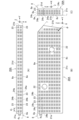
開口部23は、図10~図13に示すように、上面部8aの幅方向(空力音低減構造20A,20Bの幅方向(以下、X軸方向という))と、上面部8a及び側面部8cの長さ方向(空力音低減構造20A,20Bの長さ方向(以下、Y軸方向という))と、側面部8cの高さ方向(空力音低減構造20A,20Bの高さ方向(以下、Z軸方向という))とに間隔をあけて形成されている。開口部23は、例えば、図11に示すように、この開口部23の直径φ=2mmであり、隣り合う開口部23の長さ方向における間隔(中心間距離)d1=5.2mmであり、隣り合う開口部23の幅方向及び高さ方向における間隔(中心間距離)d2=4.0mmである。開口部23は、例えば、図11(A)に示すように上面部8aに54個形成されており、図11(B)に示すように側面部8cに48個形成されている。
As shown in FIGS. 10 to 13, the
図10~図13に示す流路24a~24cは、複数の開口部23同士を接続する部分である。流路24a~24cは、頂点カバー8の内部に三軸方向(X軸方向、Y軸方向及びZ軸方向)に規則的に配置されている。流路24a~24cは、頂点カバー8の内部で複数の開口部23同士をつなぎ、ある開口部23から他の開口部23に流れFを通過させる。流路24a~24cは、頂点カバー8の内部に複数方向に間隔をあけて配列されており、頂点カバー8の表面の高圧部の開口部23から流入した流れFを、頂点カバー8の表面の低圧部の開口部23から流出させる。流路24a~24cは、例えば、頂点カバー8の表面のよどみ点などの高圧部の開口部23から頂点カバー8の内部に流入した気流を、頂点カバー8の表面のはく離点近傍などの低圧部の開口部23から自然に流出させる。
流路24a~24cは、図10、図12及び図13に示すように頂点カバー8の内部で三軸方向に延びており、各軸方向に延びる流路24a~24cが交差部25で交差する。流路24aは、図10~図13に示すように、頂点カバー8の内部をX軸方向に直線状に伸びる管路(横管)であり、側面部8cに対して直交するように配列されている。流路24bは、図11及び図12に示すように、頂点カバー8の内部をY軸方向に直線状に伸びる管路(横管)であり、流路24aに対して直交し、かつ、側面部8cに対して平行になるように配列されている。流路24cは、図10、図11及び図13に示すように、頂点カバー8の内部をZ軸方向に直線状に伸びる管路(縦管)であり、流路24a,24bに対して直交し、かつ、側面部8cに対して平行になるように配列されている。
The
図10、図12及び図13に示す交差部25は、流路24a~24cが交差する部分である。交差部25は、流路24a~24cとの間で流れFが相互に通過可能なように、流路24a~24cを接続する。交差部25は、頂点カバー8の内部に間隔をあけて形成されており、流路24a~24cと同様にX軸方向、Y軸方向及びZ軸方向に間隔をあけて規則的に配置されている。交差部25は、流路24a~24c内を自由に流れFが通過するように、この交差部25で流路24a~24cが互いに直交するように流路24a~24cを接続している。交差部25は、図11に示すように、この交差部25を原点とする3次元の直交座標系を想定したときに、この交差部25を原点としてX軸方向、Y軸方向及びZ軸方向に流路24a~24cが延びている。
The
図7~図10に示す固定部26は、空力音低減構造20A,20Bを固定する手段である。固定部26は、図10に示すように、舟支え部7の側面部に形成された雌ねじ部と噛み合う雄ねじ部を有するボルトなどの締結部材である。固定部26は、空力音低減構造20A,20Bの貫通孔22及び頂点カバー8の貫通孔8hに挿入されて、空力音低減構造20A,20Bを舟支え部7に着脱自在に固定する。固定部26は、空力音低減構造20A,20Bと舟支え部7との間に頂点カバー8を挟み込むように、空力音低減構造20A,20Bを頂点カバー8とともに舟支え部7に締結(共締め)している。
The fixing
次に、この発明の第1実施形態に係る集電装置の空力音低減構造の作用を説明する。
図14は、円柱表面に多孔質材を適用した場合の風洞試験による流れ場の変化を示す写真である。図14(A)に示す空力音低減構造は、図11に示す空力音低減構造20A,20Bを模擬した多孔質材である。多孔質材は、気孔同士の壁に微小な孔が形成されており、気孔同士が連通している連続気孔のような三次元の骨格網状構造を有する。多孔質材は、難燃性又は不燃性の金属製の多孔質材のような硬質多孔質材である。
Next, the operation of the aerodynamic noise reduction structure of the current collector according to the first embodiment of the present invention will be explained.
FIG. 14 is a photograph showing changes in the flow field in a wind tunnel test when a porous material is applied to the surface of a cylinder. The aerodynamic noise reduction structure shown in FIG. 14(A) is a porous material that simulates the aerodynamic
図14(A)に示す流れ場の円柱の表面が空力音低減構造を備えていない場合には、図14(B)(C)に示すように円柱の最大幅部よりも僅かに上流側の表面上の剥離点で、矢印方向の流れFが剥離して、この円柱の下流側に空気が交互に回り込む。このため、円柱の表面の剥離せん断層から発生する渦の相互作用によってカルマン渦が発生し、このカルマン渦に起因する騒音や振動が発生する。一方、図14(A)に示す流れ場の円柱の表面が空力音低減構造を備えている場合には、図14(D)(E)に示すように空力音低減構造の内部に流れFが流入し、空力音低減構造内の流れFが剥離点近傍などの低圧部から自然に流出する。その結果、流れ場が安定化して渦の放出が弱まり空力音が低減する。 If the surface of the cylinder in the flow field shown in Fig. 14(A) is not equipped with an aerodynamic sound reduction structure, the surface of the cylinder in the flow field shown in Fig. 14(A) is slightly upstream of the maximum width part of the cylinder as shown in Fig. 14(B) and (C). At the separation point on the surface, the flow F in the direction of the arrow separates, and air alternately flows around the downstream side of this cylinder. Therefore, a Karman vortex is generated by the interaction of vortices generated from the separation shear layer on the surface of the cylinder, and noise and vibration are generated due to this Karman vortex. On the other hand, when the surface of the cylinder in the flow field shown in FIG. 14(A) is equipped with an aerodynamic noise reduction structure, the flow F is inside the aerodynamic noise reduction structure as shown in FIGS. 14(D) and (E). The flow F in the aerodynamic noise reduction structure naturally flows out from a low pressure area such as near the separation point. As a result, the flow field is stabilized, vortex shedding is weakened, and aerodynamic noise is reduced.
図1~図5に示す進行方向Dに車両2が走行すると、図7~図10に示す集電装置3の直線的な上側稜角部8eにおいて流れFの剥離が生ずる。図7~図11に示す頂点カバー8の表面のよどみ点などの高圧部の開口部23から流れFが流入する。高圧部の開口部23から流れFが流入すると、図10~図13に示す流路24a~24c及び交差部25を流れFが通過して、図7~図11に示す頂点カバー8の表面の剥離点近傍などの低圧部の開口部23から流れFが自然に流出する。その結果、流れ場が安定化して渦の放出が弱まり空力音が低減する。
When the
次に、この発明の第1実施形態に係る集電装置の空力音低減構造の製造方法について説明する。
図1~図13に示す空力音低減構造20A,20Bは、造形装置、機械加工、成形又は鋳造によって製造される。ここで、造形装置は、任意の形状の物体を製造する装置である。造形装置は、例えば、仮想の3次元空間上に立体的な形状をコンピュータによって設計する3DCAD(3 Dimensional Computer Aided Design)、又は仮想の3次元空間上に立体的な形状をコンピュータによって作成する3DCG(3 Dimensional Computer Graphics)などによって生成された3次元的なデータで構成された3次元ディジタル・モデルに基づいて物体を製造する3Dプリンタなどである。
Next, a method for manufacturing the aerodynamic noise reduction structure for a current collector according to the first embodiment of the present invention will be described.
The aerodynamic
空力音低減構造20A,20Bを樹脂3Dプリンタによって製造する場合には、例えば、液状樹脂に紫外線などを照射して少しずつ硬化させて物体を製造する光造形法、熱で溶解した樹脂を少しずつ積み重ねて物体を製造する熱溶解積層法(Fused Deposition Modeling(FDM)法)、シート材を物体の断面形状に切断して各層を接着及び溶接しながら積層し紫外線を照射又は加熱し硬化させ物体を製造するシート積層法、粉末樹脂に接着剤を吹き付けて物体を製造する粉末固着法、液体の光硬化性樹脂又はワックスをノズルから吹き付けて紫外線を照射又は加熱し硬化させ物体を製造する材料噴射法などによって、空力音低減構造20A,20Bを製造する。
When manufacturing the aerodynamic
空力音低減構造20A,20Bを金属3Dプリンタによって製造する場合には、例えば、金属粉末にレーザ光を照射してこの金属粉末を焼結し物体を製造するレーザ焼結法(Selective laser sintering(SLS)法)、レーザ焼結法の炭酸ガスレーザに代えてイッテルビウムレーザ光を金属粉末に照射してこの金属粉末を焼結し物体を製造する直接金属レーザ焼結法(Direct metal laser sintering(DMLS)法)、金属粉末にレーザ光を照射してこの金属粉末を溶融させ物体を製造するレーザ溶融法(Selective laser melting(SLM)法)、金属粉末に電子ビームを照射してこの金属粉末を溶融させ物体を製造する電子ビーム溶解法(Electron Beam Melting(EBM)法、電子ビーム溶解法の金属粉末に代えて金属ワイヤに電子ビームを照射してこの金属ワイヤを溶融させ物体を製造する溶融金属積層法、ノズルから金属粉末を溶融プールに落としレーザ光で焼結して物体を製造するレーザ直接積層法(Laser engineered net shaping(LENS)法などによって、空力音低減構造20A,20Bを製造する。
When manufacturing the aerodynamic
空力音低減構造20A,20Bを機械加工によって製造する場合には、金属製又は合成樹脂製の板材を切削加工することによって、図11に示す板状部材を製造し、この板状部材に穴あけ加工して開口部23及び流路24a~24cを製造する。例えば、Y軸方向に長いドリルを使用して穴あけ加工した後に不要な流路を塞ぐことによって製造する。空力音低減構造20A,20Bを機械加工又は成形によって製造する場合には、Y軸方向の流路24bを上下半分に分割した分割板を3層に分けて製造し、この分割板を積層して一体化した後に、開口部23及び流路24a,24cを穴あけ加工して製造する。空力音低減構造20A,20Bを鋳造によって製造する場合には、開口部23及び流路24a~24cが予め形成された鋳型に溶融金属を注入して製造する。
When manufacturing the aerodynamic
この発明の第1実施形態に係る集電装置の空力音低減構造とその製造方法には、以下に記載するような効果がある。
(1) この第1実施形態では、頂点カバー8の内部に複数の開口部23が流れFを流入させ、この流入した流れFをこの頂点カバー8の内部から複数の開口部23が流出させ、複数の開口部23同士を複数の流路24a~24cが接続する。また、この第1実施形態では、頂点カバー8の内部に複数方向に間隔をあけて複数の流路24a~24cが配列されており、この頂点カバー8の表面の高圧部の開口部23から流入した流れFを、この頂点カバー8の表面の低圧部の開口部23から複数の流路24a~24cが流出させる。このため、部材表面で流れFの流入及び流出を自然に生じさせるような流路24a~24cを設けることによって、空力音を低減することができる。また、従来の多孔質材よりも適用が容易な構造によって空力音低減効果を図ることができるとともに、従来の多孔質材を流路付きの部材によって簡単に代替することができる。
The aerodynamic noise reduction structure of the current collector and the manufacturing method thereof according to the first embodiment of the present invention have the following effects.
(1) In the first embodiment, the plurality of
(2) この第1実施形態では、頂点カバー8の内部を複数の流路24a~24cが三軸方向に延びており、各軸方向に延びる流路24a~24cが交差部25で交差する。このため、部材に穴あけ加工などを行うだけで頂点カバー8に適用可能であり、多孔質材などに比べて実施が容易であり、単純な形状の簡単な構造によって空力音を低減することができる。また、母材への穴加工であるため頂点カバー8から剥がれることがなく、多孔質材の接着よりも信頼性を向上させることができるとともに、頂点カバー8に容易に適用することができる。
(2) In the first embodiment, a plurality of
(3) この第1実施形態では、頂点カバー8の上側稜角部8eに沿って、頂点カバー8の上面部8a及び側面部8cに複数の開口部23が形成されている。このため、集電装置3において主要な空力音発生源である頂点カバー8から空力音が発生するのを抑えることができる。
(3) In the first embodiment, a plurality of
(4) この第1実施形態では、空力音低減構造20A,20Bを造形装置によって造形する。このため、高強度樹脂や金属を3Dプリンタのような造形装置によって出力し、集電装置3を構成する部材と一体成型することができる。また、従来の多孔質材では接着して取り付けることが困難であった三次元曲面などに簡単に取り付けることができる。その結果、空力音低減構造20A,20Bを容易に製造することができるとともに、空力音低減構造20A,20Bを集電装置3に容易に適用することができる。
(4) In this first embodiment, the aerodynamic
(第2実施形態)
以下では、図1~図13に示す部分と同一の部分については、同一の符号を付して詳細な説明を省略する。
図15に示す空力音低減構造20A,20Bは、図11に示す空力音低減構造20A,20Bとは異なり、側面部8cに形成されている開口部23の個数が多く、側面部8cの略全面に開口部23を備えている。開口部23は、例えば、図15(B)に示すように側面部8cに222個形成されている。この第2実施形態には、第1実施形態と同様の効果がある。
(Second embodiment)
In the following, parts that are the same as those shown in FIGS. 1 to 13 are given the same reference numerals and detailed explanations will be omitted.
Unlike the aerodynamic
次に、この発明の実施例について説明する。
(風洞試験)
図17に示すように、平滑化舟体を備える実物の新幹線パンタグラフの頂点カバーに供試体A~Cを取り付けて、風洞試験により空力音の評価を行った。風洞試験は、公益財団法人鉄道総合技術研究所の開放胴型の風洞試験装置を使用した。図16に示すように、風洞試験装置の風洞測定部の第1模型支持台車上に実物の新幹線パンタグラフを支持した状態で、風洞測定部内の新幹線用パンタグラフに吹き出しノズルから風速360km/hの空気を吹き出し、この空気の流れによって新幹線パンタグラフから発生する空力音を空力音測定マイクによって測定した。
Next, embodiments of the invention will be described.
(Wind tunnel test)
As shown in FIG. 17, specimens A to C were attached to the apex cover of an actual Shinkansen pantograph equipped with a smoothed hull, and aerodynamic noise was evaluated through wind tunnel tests. The wind tunnel test used an open-body wind tunnel test device provided by the Railway Technical Research Institute. As shown in Figure 16 , with an actual Shinkansen pantograph supported on the first model support cart of the wind tunnel measurement section of the wind tunnel test equipment, air at a wind speed of 360 km/h is supplied from the blowing nozzle to the Shinkansen pantograph in the wind tunnel measurement section. The aerodynamic sound generated from the Shinkansen pantograph due to the air flow was measured using an aerodynamic sound measurement microphone.
(供試体)
図17(A)に示す供試体Aは、現用品の新幹線パンタグラフの頂点カバーである。供試体Aは、図11に示す頂点カバー8の装着部8gに、開口部23のない板を装着している。図17(B)に示す供試体Bは、現用品の新幹線パンタグラフの頂点カバーの側面部の略全面に開口部が形成されている。供試体Bは、図15に示す第2実施形態であり、側面部8cの略全面に開口部23を有する流路付き板を頂点カバー8の装着部8gに装着している。図17(C)に示す供試体Cは、現用品の新幹線パンタグラフの頂点カバーの角部に位置する2列のみに開口部が形成されている。供試体Cは、図11に示す第1実施形態であり、上側稜角部8eに沿って上面部8a及び側面部8cに開口部23をそれぞれ2列のみ有する流路付き板を頂点カバー8の装着部8gに装着している。図17(B)(C)に示す供試体B,Cは、厚さ10mmの板材に対して直交する三軸方向に直径2mmの流路が形成されている。
(Specimen)
Specimen A shown in FIG. 17(A) is a vertex cover of a current Shinkansen pantograph. In the specimen A, a plate without an
(空力音の測定結果)
図17は、風洞試験による供試体A~Cの空力音の測定結果である。図17に示す縦軸は、騒音レベルOA値(dB(A))である。その結果、供試体Aに比べて供試体BはOA値を0.2dB程度低減できることが確認された。また、供試体Aに比べて供試体CはOA値を0.4dB程度低減できることが確認された。さらに、供試体Cのほうが供試体Bに比べて空力音低減効果が高いことが確認された。
(Aerodynamic sound measurement results)
FIG. 17 shows the measurement results of aerodynamic noise of specimens A to C in a wind tunnel test. The vertical axis shown in FIG. 17 is the noise level OA value (dB(A)). As a result, it was confirmed that the OA value of specimen B could be reduced by approximately 0.2 dB compared to specimen A. Furthermore, it was confirmed that the OA value of specimen C could be reduced by approximately 0.4 dB compared to specimen A. Furthermore, it was confirmed that specimen C had a higher aerodynamic sound reduction effect than specimen B.
(他の実施形態)
この発明は、以上説明した実施形態に限定するものではなく、以下に記載するように種々の変形又は変更が可能であり、これらもこの発明の範囲内である。
(1) この実施形態では、集電装置3としてシングルアーム式パンタグラフを例に挙げて説明したが、菱型パンタグラフなどの他の形式のパンタグラフについても、この発明を適用することができる。また、この実施形態では、車両2の進行方向前側に中間ヒンジ13が位置するなびき方向に集電装置3が移動する場合を例に挙げて説明したが、車両2の進行方向後側に中間ヒンジ13が位置する反なびき方向に集電装置3が移動する場合についても、この発明を適用することができる。さらに、この実施形態では、隣り合う複数面が交わる稜角部が空力音発生源である場合を例に挙げて説明したが、複数の部材が接合又は近接する箇所の周辺部のような空力音発生源についても、この発明を適用することができる。同様に、この実施形態では、集電装置3の空力音発生源として頂点カバー8の上側稜角部8eを例に挙げて説明したが、上側稜角部8eにこの発明を限定するものではない。例えば、頂点カバー8の下側稜角部8fや、中間ヒンジ13の上側稜角部又は下側稜角部や、風防カバー18の上側稜角部、下側稜角部又は風防カバー18とがいし19との接合部などの空力音発生源から発生する空力音を低減する場合についても、この発明を適用することができる。
(Other embodiments)
This invention is not limited to the embodiments described above, and various modifications and changes can be made as described below, and these are also within the scope of this invention.
(1) Although this embodiment has been described using a single-arm pantograph as an example of the
(2) この実施形態では、頂点カバー8の上側稜角部8eの断面形状が角である場合を例に挙げて説明したが、上側稜角部8eの断面形状が丸である場合についても、この発明を適用することができる。また、この実施形態では、頂点カバー8の上面部8a及び側面部8cの長さ方向に開口部23を2列配置する場合を例に挙げて説明したが、開口部23の配列数を2列配置する場合にこの発明を限定するものではない。例えば、頂点カバー8の上面部8a及び側面部8cの長さ方向に開口部23を1列又は3列以上配置する場合についても、この発明を適用することもできる。また、この実施形態では、開口部23の形状が円形である場合を例に挙げて説明したが、開口部23の形状が楕円形、四角形又は多角形などである場合であっても、この発明を適用することができる。さらに、この実施形態では、空力音低減構造20A,20Bを頂点カバー8とともに舟支え部7に固定部26によって締結する場合を例に挙げて説明したが、このような締結方法にこの発明に限定するものではない。例えば、固定部26の雄ねじ部と噛み合う雌ねじ部を頂点カバー8の側面部8cに形成し、空力音低減構造20A,20Bを頂点カバー8に固定部26によって締結する場合についても、この発明を適用することができる。
(2) In this embodiment, the case in which the cross-sectional shape of the upper
(3) この実施形態では、X軸方向、Y軸方向及びZ軸方向に開口部23を等間隔に並列に配置した場合を例に挙げて説明したが、X軸方向、Y軸方向及びZ軸方向に開口部23を千鳥状に配列する場合についても、この発明を適用することができる。また、この実施形態では、X軸方向、Y軸方向及びZ軸方向に流路24a~24cを配列する場合を例に挙げて説明したが、流れFの流入と流出が起こる開口部23を接続するように、一方向又は二方向に流路24a~24cを配列する場合についても、この発明を適用することができる。さらに、この実施形態では、流路24a~24cが交差部25で直交する場合を例に挙げて説明したが、流路24a~24cが交差部25で任意の角度で交差する場合についても、この発明を適用することができる。
(3) In this embodiment, the case where the
1 架線
1a トロリ線
2 車両
2a 車体
3 集電装置
4 すり板
5 舟体
6 枠組
7 舟支え部
8 頂点カバー
8a 上面部
8b 下面部
8c 側面部
8d 背面部
8e 上側稜角部(空力音発生源)
8f 下側稜角部
8g 装着部
8h 雌ねじ部
9 上枠
11 下枠
13 中間ヒンジ
17 台枠
20A,20B 空力音低減構造
21a~21d 接合部
22 貫通孔
23 開口部
24a~24c 流路
25 交差部
26 固定部
F 流れ
D 進行方向
1
8f
Claims (4)
前記集電装置の頂点カバーの内部に流れを流入させ、この流入した流れをこの頂点カバーの内部から流出させる複数の開口部と、
前記複数の開口部同士を接続する複数の流路とを備え、
前記複数の流路は、前記頂点カバーの内部に複数方向に間隔をあけて配列されており、この頂点カバーの表面の高圧部の開口部から流入した流れを、この頂点カバーの表面の低圧部の開口部から流出させ、
前記空力音低減構造の上面部及び側面部は、前記頂点カバーの上面部及び側面部と同じ高さになるように、この頂点カバーの一部を構成しており、
前記複数の開口部は、前記頂点カバーの上側稜角部に沿って、この頂点カバーの上面部及び側面部に形成されていること、
を特徴とする集電装置の空力音低減構造。 An aerodynamic noise reduction structure for a current collector that reduces aerodynamic noise generated from the current collector,
a plurality of openings for allowing flow to flow into the interior of the apex cover of the current collector and for allowing the flow to flow out from the interior of the apex cover ;
a plurality of flow paths connecting the plurality of openings,
The plurality of flow paths are arranged at intervals in a plurality of directions inside the apex cover , and the flow flowing in from the opening of the high pressure section on the surface of the apex cover is directed to the low pressure section on the surface of the apex cover. flow out from the opening of
The top surface part and side surface part of the aerodynamic noise reduction structure constitute a part of the vertex cover so as to be at the same height as the top surface part and side surface part of the vertex cover,
The plurality of openings are formed in the top and side surfaces of the vertex cover along the upper edge corner of the vertex cover;
Aerodynamic noise reduction structure for current collector featuring:
前記複数の流路は、前記頂点カバーの内部を三軸方向に延びており、各軸方向に延びる流路が交差部で交差すること、
を特徴とする集電装置の空力音低減構造。 The aerodynamic noise reduction structure of the current collector according to claim 1,
The plurality of channels extend in triaxial directions inside the apex cover, and the channels extending in each axial direction intersect at an intersection,
Aerodynamic noise reduction structure for current collector featuring:
前記空力音低減構造は、前記頂点カバーの上側稜角部を切り欠くように形成された装着部に装着されており、
前記頂点カバーによって覆われる舟支え部と前記空力音低減構造との間にこの頂点カバーを挟み込むように、この空力音低減構造をこの頂点カバーとともにこの舟支え部に着脱自在に固定する固定部を備えること、
を特徴とする集電装置の空力音低減構造。 In the aerodynamic noise reduction structure of the current collector according to claim 1 or 2,
The aerodynamic noise reduction structure is attached to a mounting portion formed by cutting out an upper edge corner portion of the apex cover,
A fixing part that removably fixes the aerodynamic noise reduction structure to the boat support part together with the apex cover so as to sandwich the apex cover between the boat support part covered by the apex cover and the aerodynamic noise reduction structure. be prepared,
Aerodynamic noise reduction structure for current collector featuring:
請求項1から請求項3までのいずれか1項に記載の集電装置の空力音低減構造を造形装置によって造形すること、
を特徴とする集電装置の空力音低減構造の製造方法。 A method for manufacturing an aerodynamic noise reduction structure for a current collector that reduces aerodynamic noise generated from the current collector, the method comprising:
modeling the aerodynamic sound reduction structure of the current collector according to any one of claims 1 to 3 using a modeling device;
A method for manufacturing an aerodynamic noise reduction structure for a current collector, characterized by:
Priority Applications (1)
| Application Number | Priority Date | Filing Date | Title |
|---|---|---|---|
| JP2020219066A JP7399076B2 (en) | 2020-12-28 | 2020-12-28 | Aerodynamic noise reduction structure of current collector and its manufacturing method |
Applications Claiming Priority (1)
| Application Number | Priority Date | Filing Date | Title |
|---|---|---|---|
| JP2020219066A JP7399076B2 (en) | 2020-12-28 | 2020-12-28 | Aerodynamic noise reduction structure of current collector and its manufacturing method |
Publications (2)
| Publication Number | Publication Date |
|---|---|
| JP2022104076A JP2022104076A (en) | 2022-07-08 |
| JP7399076B2 true JP7399076B2 (en) | 2023-12-15 |
Family
ID=82279463
Family Applications (1)
| Application Number | Title | Priority Date | Filing Date |
|---|---|---|---|
| JP2020219066A Active JP7399076B2 (en) | 2020-12-28 | 2020-12-28 | Aerodynamic noise reduction structure of current collector and its manufacturing method |
Country Status (1)
| Country | Link |
|---|---|
| JP (1) | JP7399076B2 (en) |
Citations (5)
| Publication number | Priority date | Publication date | Assignee | Title |
|---|---|---|---|---|
| WO2001098109A1 (en) | 2000-06-19 | 2001-12-27 | Stephen James Atkins | A vehicle appendage and components therefor |
| JP2009089561A (en) | 2007-10-02 | 2009-04-23 | Railway Technical Res Inst | Aerodynamic sound reduction structure |
| JP2015119601A (en) | 2013-12-20 | 2015-06-25 | 西日本旅客鉄道株式会社 | Pantagraph vertex cover and pantagraph having vertex cover |
| JP2018177042A (en) | 2017-04-14 | 2018-11-15 | 日本飛行機株式会社 | Noise absorbing panel |
| JP2020172076A (en) | 2019-04-12 | 2020-10-22 | 株式会社ブリヂストン | Method for manufacturing seat pad, seat pad, and three-dimensional modelling data |
-
2020
- 2020-12-28 JP JP2020219066A patent/JP7399076B2/en active Active
Patent Citations (5)
| Publication number | Priority date | Publication date | Assignee | Title |
|---|---|---|---|---|
| WO2001098109A1 (en) | 2000-06-19 | 2001-12-27 | Stephen James Atkins | A vehicle appendage and components therefor |
| JP2009089561A (en) | 2007-10-02 | 2009-04-23 | Railway Technical Res Inst | Aerodynamic sound reduction structure |
| JP2015119601A (en) | 2013-12-20 | 2015-06-25 | 西日本旅客鉄道株式会社 | Pantagraph vertex cover and pantagraph having vertex cover |
| JP2018177042A (en) | 2017-04-14 | 2018-11-15 | 日本飛行機株式会社 | Noise absorbing panel |
| JP2020172076A (en) | 2019-04-12 | 2020-10-22 | 株式会社ブリヂストン | Method for manufacturing seat pad, seat pad, and three-dimensional modelling data |
Also Published As
| Publication number | Publication date |
|---|---|
| JP2022104076A (en) | 2022-07-08 |
Similar Documents
| Publication | Publication Date | Title |
|---|---|---|
| EP2565022B1 (en) | Method for manufacturing of parts | |
| US10724227B2 (en) | Lining panel with integrated electric lines for an aircraft and method for manufacturing a lining panel | |
| US20130291979A1 (en) | Plasma-enhanced active laminar flow actuator system | |
| ES2767741T3 (en) | Aircraft wings, aircraft, and related methods | |
| ES2907850T3 (en) | Robotic Arm Assembly Construction | |
| JP6910801B2 (en) | Laminar flow panel | |
| CN102548841B (en) | Device for boundary layer suction and the composite component for it | |
| US20130062004A1 (en) | Aerodynamic surfaces having drag-reducing riblets and method of fabricating the same | |
| CN105936335B (en) | Thermoplastic truss structure and method of manufacture | |
| ES2936471T3 (en) | Method for manufacturing an aeronautical structure | |
| CN103569348B (en) | Overall composite construction for the vehicles | |
| US20200247561A1 (en) | Methods of forming and assembling a rotor blade using additive manufacturing processes | |
| JP7399076B2 (en) | Aerodynamic noise reduction structure of current collector and its manufacturing method | |
| US10967966B2 (en) | Method of fabricating a rotor blade filler body, and a rotor blade filler body comprising at least one cellular assembly having closed cells | |
| US20130062469A1 (en) | Surface entity for the reduction of the air resistance of an aviation vehicle | |
| JP2012122903A (en) | Flow rate regulating structure for wind tunnel testing apparatuses, and wind tunnel testing apparatus | |
| JP6601985B2 (en) | Vehicle fall prevention structure | |
| JP2022174891A (en) | Aerodynamic noise reduction structure of pantograph | |
| CN115715252A (en) | Apparatus for manufacturing composite airfoils and composite structure | |
| US11866172B2 (en) | Flow body for a vehicle and method for manufacturing a flow body | |
| Wiedemann et al. | The suction panel-xHLFC and structural solution for energy efficient aviation | |
| US11319052B2 (en) | Leading-edge arrangement for a flow body of a vehicle | |
| JP2021069206A (en) | Aerodynamic sound reduction structure of current collector | |
| Keidel et al. | Design and testing of a lattice morphing wing | |
| JP6953045B1 (en) | Metal-organic frameworks and composite members, and methods for manufacturing composite members |
Legal Events
| Date | Code | Title | Description |
|---|---|---|---|
| A621 | Written request for application examination |
Free format text: JAPANESE INTERMEDIATE CODE: A621 Effective date: 20230206 |
|
| A977 | Report on retrieval |
Free format text: JAPANESE INTERMEDIATE CODE: A971007 Effective date: 20230816 |
|
| A131 | Notification of reasons for refusal |
Free format text: JAPANESE INTERMEDIATE CODE: A131 Effective date: 20230817 |
|
| A521 | Request for written amendment filed |
Free format text: JAPANESE INTERMEDIATE CODE: A523 Effective date: 20230830 |
|
| TRDD | Decision of grant or rejection written | ||
| A01 | Written decision to grant a patent or to grant a registration (utility model) |
Free format text: JAPANESE INTERMEDIATE CODE: A01 Effective date: 20231204 |
|
| A61 | First payment of annual fees (during grant procedure) |
Free format text: JAPANESE INTERMEDIATE CODE: A61 Effective date: 20231205 |
|
| R150 | Certificate of patent or registration of utility model |
Ref document number: 7399076 Country of ref document: JP Free format text: JAPANESE INTERMEDIATE CODE: R150 |